model 72-8155: operating manualdenethor.wlu.ca/pc221/493500.pdf · use the proper terminals,...
TRANSCRIPT

Model 72-8155: OPERATING MANUAL
1
Table of ContentsTitle PageOverviewInspectionSafety InformationRules For Safe OperationInternational Electrical SymbolsThe Meter StructureFunctional ButtonsDisplay SymbolsMeasurement Operation A. Measuring Resistance B. Diode and Continuity Test C. Capacitance Measurement D. Inductance Measurement E. Transistor hFE MeasurementGeneral SpecificationsAccuracy Specifications A. Resistance Test B. Continuity & Diodes C. Capacitance Test D. Inductance Test E. TransistorMaintenance A. General Service B. Replacing the Battery C. Replacing the Fuse
3445789101111131517181920202121222223232425

Model 72-8155: OPERATING MANUAL
2
To avoid electric shock or personal injury, read the“Safety Information” and “Rules for Safety Operation”carefully before using the Meter.
Warning
Model 72-8155: OPERATING MANUAL
3
OverviewThis Operating Manual covers information on safety andcautions. Please read the relevant information carefullyand observe all the Warnings and Notes strictly.
Digital Inductance Capacitance Meter Model 72-8155(hereafter referred to as “the Meter”) is a 3 1/2 digits withsteady operations, fashionable design and highly reliablehand-held measuring instrument.
The Model 72-8155 will measure capacitance, inductance,resistance, transistor hFE and test diodes. It will also testcontinuity with an audible buzzer.

Model 72-8155: OPERATING MANUAL
4
InspectionOpen the package case and take out the Meter. Checkthe following items carefully to see if any items are missingor damaged.
Item Description Qty1
2
3
Operating Manual
Test Clip
9V Alkaline Battery (NEDA1604, 6F22
or 006P) (installed)
1 piece
1 pair
1 piece
In the event you find any items missing or damaged, pleasecontact your dealer immediately.
Safety InformationThis Meter complies with the standards EMC EN61326.Use the Meter only as specified in this operating manual,otherwise the protection provided by the Meter may beimpaired.
In this manual, a Warning identifies conditions and actionsthat pose hazards to the user, and may damage the Meteror the equipment under test.
A Note identifies the information that user should payattention to.
International electrical symbols used on the Meter and inthis Operating Manual are explained on page 7.

To avoid possible electric shock or personal injury,and to avoid possible damage to the Meter or to theequipment under test, adhere to the following rules:
Warning
Before using the Meter inspect the case. Do not usethe Meter if it is damaged or the case (or part of thecase) is removed. Look for cracks or missing plastic.Pay attention to the insulation around the connectors.Inspect the test clips for damaged insulation orexposed metal. Check the test clips for continuity.Replace damaged test clips with identical modelnumber or electrical specifications before using theMeter.Do not apply voltage to the Meter.The rotary switch should be placed in the correctposition and no change of range made duringmeasurement , to prevent damage to the Meter.Use the proper terminals, function, and range foryour measurements.Do not use or store the Meter in an environment ofhigh temperature, humidity, explosive, inflammableand strong magnetic field. The performance of theMeter may deter iorate af ter dampened.Disconnect circuit power and discharge all high-voltage capacitors before testing resistance,continuity, capacitance or diodes.Replace the battery as soon as the battery indicator appears. With a low battery, the Meter mightproduce false readings that can lead to electric shockand personal injury.
l
l
ll
l
l
l
l
Rules For Safe Operation
Model 72-8155: OPERATING MANUAL
5

Remove test clips from the Meter and turn the Meterpower off before opening the Meter case.When servicing the Meter, use only the same modelnumber or identical electrical specificationsreplacement parts.The internal circuit of the Meter shall not be alteredat will to avoid damage of the Meter and any accident.Soft cloth and mild detergent should be used toclean the surface of the Meter when servicing. Noabrasive and solvent should be used to prevent thesurface of the Meter from corrosion, damage andaccident.Remove the battery when not used for a prolongedperiod to avoid damage to the Meter.Periodically check the battery as it may leak aftersome time. If leakage is apparent, the battery shouldbe immediately replaced to prevent damage to theMeter.
l
l
l
l
l
l
Model 72-8155: OPERATING MANUAL
6

Lx
Model 72-8155: OPERATING MANUAL
7
International Electrical Symbols
Ground
Double Insulated
Low Battery.
Continuity Test.
Diode.
Capacitance Test
Inductance Test
Fuse.
Warning. Refer to the Operating Manual.
Conforms to Standards of European Union.

Model 72-8155: OPERATING MANUAL
8
The Meter Structure (see figure 1)
1. LCD Display2. L-C switch3. Transistor Jack4. Resistance, Diode and Continuity Input Terminal5. Capacitance and Inductance Input Terminal6. Rotary Switch7. Power.
(figure 1)

Power
L-C
Model 72-8155: OPERATING MANUAL
9
Functional ButtonsThe following table provides information regarding thefunctional button operation.
Button Description
Press the Power down to turn the Meter on.
Press the Power again to turn the Meter power off.
Press L-C down to enter the Capacitance
measurement mode.
Press L-C up to enter the Inductance measurement
mode.

β
Model 72-8155: OPERATING MANUAL
10
Display Symbols (see figure 2)
(figure 2)
Data hold is active.
The battery is low.
Warning: To avoid false readings,
which could lead to possible electric shock
or personal injury, replace the battery as
soon as the battery indicator appears.
Transistor Test
Diode test
The continuity buzzer is on.
Farad. The unit of capacitance
pF: Picofarad. 1 x 10-12 or 0.000000000001
farads.
nF: Nanofarad. 1 x 10⁻⁹ or 0.000000001
farads.
µF: Microfarad.1 x 10-6 or 0.000001 farads.
mF: Millifarad. 1 x 10⁻³ or 0.001 farads.
: Ohm. The unit of resistance
k : kilohm. 1 x 10³ or 1000 ohms
M : Megaohm. 1 x 10⁶ or 1,000,000 ohms
H: Henry. The unit of Inductance.
mH: Millihenry. 1 x 10⁻³ or 0.001 henry.
No. Symbol Meaning
1
2
3
4
5
6
7
8
pF
nF
µF
mF
k
M
H
mH

Make sure the Low Battery Display is not on,otherwise false readings may be provided.Pay extra attention to the symbol, beforemeasurement, which is located besides the inputterminals of the Meter.
l
l
To avoid damage to the Meter or to the devices undertest, disconnect circuit power and discharge all thehigh-voltage capacitors before measuring resistance.
Warning
The resistance ranges are 20 , 200 , 2k , 20k , 200k ,2M , 20M and 2000M .
Insert the red test clip into the terminal andthe black test clip into COM terminal.Set the rotary switch to range.Connect the test clips across with the object beingmeasured.The measured value shows on the display.
1.
2.3.
To measure resistance, please connect the Meter asfollows:
Model 72-8155: OPERATING MANUAL
11
Measurement Operation
A. Measuring Resistance (see figure 3)
(figure 3)
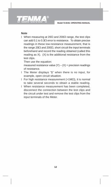
When measuring at 20 and 200 range, the test clipscan add 0.1 to 0.3 error to resistance. To obtain precisereadings in these low-resistance measurement, that isthe range 20 and 200 , short circuit the input terminalsbeforehand and record the reading obtained (called thisreading as X). (X) is the additional resistance from thetest clips.Then use the equation:measured resistance value (Y) – (X) = precision readingsof resistance.The Meter displays “1” when there is no input, forexample, open circuit situation.For high resistance measurement (>1M ), it is normalto take several seconds to obtain a stable reading.When resistance measurement has been completed,disconnect the connection between the test clips andthe circuit under test and remove the test clips from theinput terminals of the Meter.
l
l
l
l
Model 72-8155: OPERATING MANUAL
12
Note

To avoid damage to the Meter or to the devices undertest, disconnect circuit power and discharge all thehigh-voltage capacitors before measuring diodes andcontinuity.
Warning
Testing Diodes
Insert the red test clip into the terminal andthe black test clip into the COM terminal.Set the rotary switch to .For forward voltage drop readings on any semiconductorcomponent, place the red test clip on the component’sanode and place the black test clip on the component’scathode.The display shows the diode forward voltage drop’snearest value.
1.
2.3.
Use the diode test to check diodes, transistors, and othersemiconductor devices. The diode test sends a currentthrough the semiconductor junction, and then measuresthe voltage drop across the junction. A good silicon junctiondrops between 500mV and 800mV.
To test a diode out of a circuit, connect the Meter as follows:
Model 72-8155: OPERATING MANUAL
13
(figure 4)

In a circuit, a good diode should still produce a forwardvoltage drop reading of 500mV to 800mV; however, thereverse voltage drop reading can vary depending on theresistance of other pathways between the probe tips.Connect the test clips to the proper terminals as saidabove to avoid error display. The LCD will display “1”indicating open-circuit for wrong connection. The unit ofdiode is Volt (V), displaying the positive-connectionvoltage-drop value.When diode test has been completed, disconnect theconnection between the test clips and the circuit undertest and remove the test clips from the input terminalsof the Meter.
l
l
l
Testing for Continuity
Insert the red test clip into the terminal andthe black test clip into the COM terminal.Set the rotary switch to .Connect the test clips across with the object beingmeasured.The beeper sounds continuously when the resistancevalue of the tested circuit 10 . The beeper may ormay not come on when the resistance value of the testcircuit>10The Meter displays the value of the test resistance.
To test for continuity, connect the Meter as below:1.
2.3.
4.
5.
The LCD displays “1” indicating the circuit being testedis open.When continuity test has been completed, disconnectthe connection between the test clips and the circuitunder test and remove the test clips from the inputterminals of the Meter.
l
l
Model 72-8155: OPERATING MANUAL
14
Note
Note

To avoid damage to the Meter or to the equipmentunder test, disconnect circuit power and discharge allhigh-voltage capacitors before measuring capacitance.
Warning
The Meter’s capacitance ranges are: 2nF, 20nF, 200nF,2µF, 20µF, 200µF and 600µF.
To measure capacitance, connect the Meter as follows:Set the rotary switch to F measurement mode. If thevalue of capacitor to be measured is unknown, use themaximum measurement position 600µF and decreasethe range step by step until a satisfactory reading isobtained and the overload icon "1" is not showing.Insert the red test clip into the CAP + terminal and blacktest clip into the CAP – terminal. For small valuecapacitor measurement, insert the capacitor into thesmall value jack.When testing polarized capacitors, use the red test clipon the capacitor’s positive lead, and the black test clipon the capacitor’s negative lead. With non-polarizedcapaci tors, e i ther d i rect ion is acceptable.The measured value shows on the display.
1.
2.
3.
4.
Model 72-8155: OPERATING MANUAL
15
C. Capacitance Measurement (72-8155 only, see figure 5)
(figure 5)
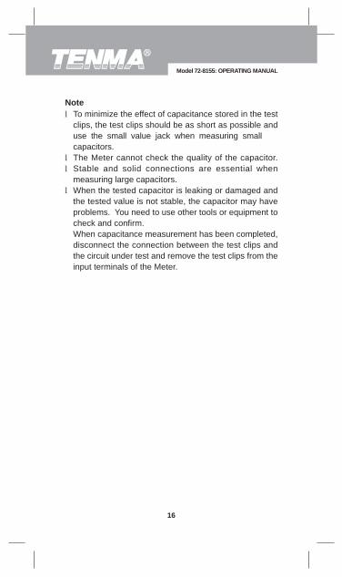
To minimize the effect of capacitance stored in the testclips, the test clips should be as short as possible anduse the small value jack when measuring small capacitors.The Meter cannot check the quality of the capacitor.Stable and solid connections are essential whenmeasuring large capacitors.When the tested capacitor is leaking or damaged andthe tested value is not stable, the capacitor may haveproblems. You need to use other tools or equipment tocheck and confirm.When capacitance measurement has been completed,disconnect the connection between the test clips andthe circuit under test and remove the test clips from theinput terminals of the Meter.
l
ll
l
Model 72-8155: OPERATING MANUAL
16
Note

To test the inductance, please follow the following procedure:Set the rotary switch to Lx measurement mode.If the tested inductance value is unknown, use themaximum measurement position and decrease the rangestep by step until a satisfactory reading is obtained.Insert the test clips into the corresponding Lx inputterminals.The measured value shows on the display.
When measuring inductors in the 2mH range, you shouldfirst short circuit the test leads and note the measuredinductance value of the leads. Then thecorrect reading is the measured reading, minus the shortcircuit reading.The small value jack on the surface of the meter shouldbe used when measuring small value inductors.The Meter cannot check the quality of the inductance.When inductance measurement has been completed,disconnect the connection between the test clips andthe circuit under test and remove the test clips from theinput terminals of the Meter.
l
l
ll
Model 72-8155: OPERATING MANUAL
17
D. Inductance Measurement (see figure 6)
(figure 6)
1.2.
3.
4.
Remarks:

Testing transistors:
Set the rotary switch to hFE measurement mode.Check that the transistor is PNP or NPN type.Insert the Insert the transistor to be measured to thecorresponding Transistor JackThe Meter displays the tested transistor’s nearest value
When transistor measurement has been completed,disconnect the connection between the test clips andthe circuit under test and remove the test clips from theinput terminals of the Meter.
l
Model 72-8155: OPERATING MANUAL
18
E. Transistor hFE Measurement (see figure 7)
(figure 7)
1.2.3.
4.
Note:

Fuse Protection for Inductance and capacitance InputTerminal: 0.315A, 250V, fast type fuse, 5x20 mm.Maximum Display: Display: 1999.Measurement Speed: Updates 2-3 times /second.Polarity: Auto. (Display “-“ when negative)Overloading: Display “1”Range: Manual RangingTemperature:
Operating: 0oC~40oC (32oF ~104oF).Storage: -10oC~50oC (14oF~122oF).
Relative Humidity: 75% @ 0oC - 30oC;50% @ 31 - 40oC.
Altitude: Operating: 2000 m.Storage: 10000 m.
Battery Type:One piece of 9V Alkaline (NEDA1604 or0062 or 6F22 or 006P).Low Battery: DisplayDimensions: 6.77" (H) x 3.27" (W) x 1.50"(D).Weight: Approximate 11 oz. (including battery).Safety/Compliances: EMC EN61326.Certification: .
l
llllll
l
l
l
lllll
Model 72-8155: OPERATING MANUAL
19
General Specifications

Overload protection: 250V DC or AC rms at all ranges.At 20M range, short circuit test lead, LCD displaying12 digits is normal. During measurement minus these12 digits from the obtained reading.When measuring 20 and 200 range, short circuit testclips to display the resistance value of the test lead.Subtract this value from the measurement value to obtainthe correct tested value.
ll
l
Accuracy: (a% reading + b digits),guarantee for 1 year.Operating temperature: 23oC 5oC.Relative humidity: < 75%.Temperature coefficient: 0.1 x (specified accuracy) / 1oC
Model 72-8155: OPERATING MANUAL
20
Accuracy Specifications
A. Resistance Test
Range Resolution Accuracy
200
2k
20k
200k
2M
20M
0.1
1
10
100
1k
10k
Remarks:
(0.8%+3)
(0.8%+1)
[2%(rdg-12)+5]
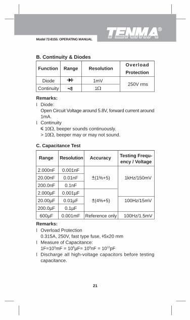
Diode:Open Circuit Voltage around 5.8V, forward current around1mA.Continuity
10 , beeper sounds continuously.> 10 , beeper may or may not sound.
l
l
Overload Protection0.315A, 250V, fast type fuse, 5x20 mmMeasure of Capacitance:1F=103mF = 106µF= 109nF = 1012pFDischarge all high-voltage capacitors before testingcapacitance.
l
l
l
Model 72-8155: OPERATING MANUAL
21
B. Continuity & Diodes
Range ResolutionOverload
ProtectionFunction
Diode
Continuity
1mV
1250V rms
Remarks:
C. Capacitance Test
Range Resolution Accuracy Testing Frequ-ency / Voltage
2.000nF
20.00nF
200.0nF
2.000µF
20.00µF
200.0µF
600µF
0.001nF
0.01nF
0.1nF
0.001µF
0.01µF
0.1µF
0.001mF
(1%+5)
(4%+5)
Reference only
1kHz/150mV
100Hz/15mV
100Hz/1.5mV
Remarks:
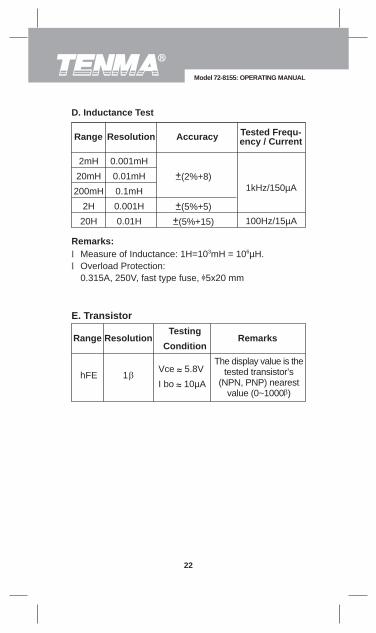
Measure of Inductance: 1H=103mH = 106µΗ.Overload Protection:0.315A, 250V, fast type fuse, 5x20 mm
ll
The display value is thetested transistor’s
(NPN, PNP) nearestvalue (0~1000 )
Model 72-8155: OPERATING MANUAL
22
E. Transistor
Range Resolution Remarks
hFEVce 5.8V
I bo 10µA
Testing
Condition
1
D. Inductance Test
Range Resolution Accuracy Tested Frequ-ency / Current
2mH
20mH
200mH
2H
20H
0.001mH
0.01mH
0.1mH
0.001H
0.01H
(2%+8)
(5%+5)
(5%+15)
1kHz/150µA
100Hz/15µA
Remarks:
This section provides basic maintenance informationincluding battery and fuse replacement instruction.
Do not attempt to repair or service your Meter unlessyou are qualified to do so and have the relevantcalibration, performance test, and service information.
To avoid electrical shock or damage to the Meter, donot allow water inside the case.
Warning
Periodically wipe the case with a damp cloth and milddetergent. Do not use abrasives or solvents.To clean the terminals with cotton bar with detergent, asdirt or moisture in the terminals can affect readings.Turn the Meter power off when it is not in use and takeout the battery when not using for a long time.Do not store the Meter in a place of humidity, hightemperature and strong magnetic field.
l
l
l
l
Model 72-8155: OPERATING MANUAL
23
Maintenance
A. General Service

To avoid false readings, which could lead to possibleelectric shock or personal injury, replace the batteryas soon as the battery indicator “ ” appears.
Warning
Turn the Meter power off and remove all connectionsfrom the terminals.Remove the screw from the battery compartment, andseparate the battery compartment from the case bottom.Remove the battery from the battery compartment.Replace the battery with a new 9V alkaline battery(NEDA1604 or 0062 or 6F22 or 006P)Replace the case bottom and battery compartment, andreinstall the screw.
1.
2.
3.4.
5.
Model 72-8155: OPERATING MANUAL
24
B. Replacing the Battery (see figure 8)
(figure 8)
To replace the battery:
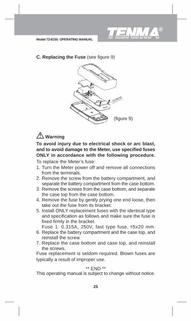
To avoid injury due to electrical shock or arc blast,and to avoid damage to the Meter, use specified fusesONLY in accordance with the following procedure.
Warning
To replace the Meter’s fuse:Turn the Meter power off and remove all connectionsfrom the terminals.Remove the screw from the battery compartment, andseparate the battery compartment from the case bottom.Remove the screws from the case bottom, and separatethe case top from the case bottom.Remove the fuse by gently prying one end loose, thentake out the fuse from its bracket.Install ONLY replacement fuses with the identical typeand specification as follows and make sure the fuse isfixed firmly in the bracket.Fuse 1: 0.315A, 250V, fast type fuse, 5x20 mm.Replace the battery compartment and the case top, andreinstall the screw.Replace the case bottom and case top, and reinstallthe screws.
1.
2.
3.
4.
5.
6.
7.
Fuse replacement is seldom required. Blown fuses aretypically a result of improper use.
** END **This operating manual is subject to change without notice.
C. Replacing the Fuse (see figure 9)
(figure 9)
SCREW
25
Model 72-8155: OPERATING MANUAL

Copyright 2006 Tenma Test Equipment.All rights reserved.
Tenma Test Equipment405 S. Pioneer Blvd.Springboro,Ohio 45066www.tenma.com
26
Model 72-8155: OPERATING MANUAL