model 70200 universal oil primary control
TRANSCRIPT

Model 70200 Universal Oil
Primary Control Installation and
Operating Instructions
For Use By Qualified Service Technicians Only
It is important that the installation of the oil burner, piping and fittings, safety devices, controls, electrical wiring and equipment be done in accordance with national and/or local regulations of the authorities having jurisdiction over such installation.
126 Bailey Rd North Haven, CT 06473Ph 203-680-9401 Fx 203-680-9403
Tech Support 800-989-2275 carlincombustion.com© Copyright 2019 — Carlin Combustion Technology, Inc.
Car l in Combustion Technology, Inc.
• Universal Replacement – for Carlin, Beckett, Honeywell and ICM Controls
• On-Board LCD Screen – no special tool needed
• Fully Programmable Settings • 32 Cycle Fault History• Alarm Contacts• Communications Port• Serviceman Reset Protection• Blocked Vent Protection• Built-in Pump Prime• Recessed Spade Connectors • Provides CAD Cell Reading in OHMS
Power input (red/white wire) ................................ 120 VAC, 60 HZ, 9 VA
Limit circuit input (black wire) .............................................. 120 VAC, 60 HZ
Motor load (orange wire) .........10 FLA / 60 LRA (reduce by valve load)
Ignitor load (blue wire) .................................... 120 VAC, 60 HZ, 500 VA
Valve load (violet wire) .......................................... 120 VAC, 60 HZ, 2A
Vent load ................................................................. 0.1 amp
Line heater ................................................................ 1 amp
Alarm contacts (dry contacts)....................24V, AC/DC, 2A
Operating temperature limits ..................+32°F to +140°F
Storage temperature limits ...................... -40°F to +185°F
Thermostat anticipator current ..........................0.1 A, AC
Agencies .............................. UL recognized (US & Canada)

2Carlin Combustion Technology, Inc. MN70200B 062819
WA R N I N G S 1. Warning – Do not attempt to confirm combustion simply by inspecting the flame visually. You must use combustion test instru-
ments. Failure to properly verify/adjust combustion could allow unsafe operation of the burner, resulting in severe personal injury, death or substantial property damage. Refer to the burner manual for proper setup instructions.
2. Warning – Never test an ignitor by placing a screwdriver (or other metallic object) across the high voltage clips. Check ignitors only by observing spark at appliance ignition electrodes, with fuel supply OFF. Using any other method could cause ignitor damage and severe personal injury.
3. Danger – Fire, explosion, or carbon monoxide hazard. Water damage can lead to unreliable operation or cause the control to malfunction which could lead to severe personal injury or death. Do not install the control module where it can get wet. Always replace the control if it gets wet or if it has any signs of water residue.
4. Warning – Electrical shock hazard. To prevent electrical shock, death, or equipment damage, disconnect power supply before installing or servicing control. Only qualified personnel may install or service this control in accordance with local codes and ordi-nances. Read instructions completely before proceeding.
5. Warning – Electrical shock hazard. The ignition circuit of the control can produce over 10,000 volts which can cause severe injury or death.
6. Warning – Frozen pipes/water damage. Central heating systems are prone to shut down as a result of power or fuel outages, safety related fault conditions or equipment failure. Installation of freeze protection monitoring or other precautions are recommend-ed for unattended dwellings in climates subject to sustain below—freezing temperatures.
7. Warning – All work must be performed by a qualified and licensed professional in accordance with all applicable codes and ordi-nances.
8. Notice – Read these instructions completely before proceeding with the installation.
9. Notice – Retain these instructions for future reference.
10. Notice – All wiring must comply with the National Electric Code or any other state or local codes or regulations.
Hazard Definitions
The following defined terms are used throughout this manual to bring attention to the presence of hazards of various risk levels or to important information concerning the life of the product.
Indicates presence of hazards that will cause severe personal injury, death or sub-stantial property damage.
Indicates presence of hazards that will cause severe personal injury, death or sub-stantial property damage.
Indicates presence of hazards that will cause minor personal injury or property damage.
Indicates special instructions on installation, operation or maintenance that are important but not related to personal injury or property damage.

3Carlin Combustion Technology, Inc. MN70200B 062819
Installing and Wiring
The 70200 control must be installed and serviced only by a qualified service technician.
Always disconnect power source before wiring to avoid electrical shock or damage to the control. All wiring must comply with applicable codes and ordinances.
Mounting
The control may be mounted on a 4" x 4" junction box in any convenient location on the burner, furnace or wall. The location must not exceed the ambient temperature limit, 140°F.
Wiring
Wiring must comply with local and national electrical codes, and with the following wiring diagrams.
6-Wire Recommended Wiring
3-Wire Replacement Wiring
When con-necting to BLACK power harness wire, without constant L1 power, wire nut together L1 (RED) and Limit In (BLACK) from control.
M
OV
OILVALVE
IGNITION
NOZZLELINE HTR
(OPTIONAL)
WHT
WHT
WHT
WHT
BLACK
BLUE
ORANGE
VIOLET
BURNERMOTOR
GN
WH
T
RE
D/W
HT
BLA
CK
WHT
WHT
M
IGNITION
ORANGE
BLUE
BURNERMOTOR
WHT
RED
WHTBLKGN

4
Pressing the E button again will leave the setting as is and move to the next option –
To Change a Setting: Scroll to the desired Setting Mode option using the E button (as described in table on page 5), then press the or H button to scroll through the avail-able Settings. When the desired setting is displayed on the screen press the E / ENTER button. The display will briefly indicate that the new setting has been “Entered” and the new setting will replace the previous setting on the second line of the screen. Continue pressing the E button to view the cur-rent setting for all options or H button to make any desired changes.
To Exit the Setup Menu: Press the F / ESCAPE button for 3 seconds. NOTE: The control will automatically exit the Setup menu after 30 seconds of inactivity or by a call for heat.
Initial Start-up/Power-upWhen powered-up for the first time, the control will display a scrolling message “Does Burner Have A Solenoid Valve?”. Press G for Yes or H for No. This information is needed for proper operation of the control. NOTE: The control will not operate until this question is answered.
“Does Burner Have Solenoid Valve” will scroll on screen.
NOTE: This selection can be changed in the Settings Mode (see below for how to change settings)
View or Change Control SettingsNOTE: The settings mode cannot be accessed during a run cycle, the burner must be in standby mode (or lockout) to enter setup.
To enter the Settings Mode: Press the G and E buttons simultaneously for 2 seconds. The display will show –
Carlin Combustion Technology, Inc. MN70200B 062819
Trial for Ign 15 Seconds
Do not start the burner if the combustion chamber contains oil or oil vapor.
Trial for Ign 30 Seconds
Does Burner...Press =No =Yes
Settings PressTo Exit Hold
To View Current Settings: Press the E button to scroll through all Setting Modes (see table at the top of page 5 for Setting Mode options). The second line of the screen will display the current setting for each Setting Mode –
Valve Delay On 30 Seconds
SOLENOID
5Carlin Combustion Technology, Inc. MN70200B 062819
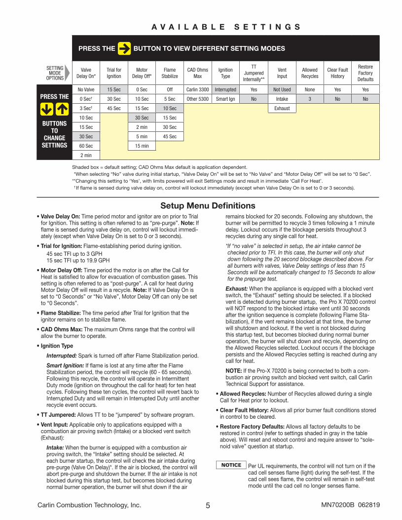
PRESS THE BUTTON TO VIEW DIFFERENT SETTING MODES
ValveDelay On*
Trial forIgnition
MotorDelay Off*
FlameStabilize
CAD OhmsMax
IgnitionType
TTJumperedInternally**
VentInput
AllowedRecycles
Clear FaultHistory
RestoreFactoryDefaults
PRESS THE
BUTTONSTO
CHANGESETTINGS
No Valve 15 Sec 0 Sec Off Carlin 3300 Interrupted Yes Not Used None Yes Yes
0 Sec† 30 Sec 10 Sec 5 Sec Other 5300 Smart Ign No Intake 3 No No
3 Sec† 45 Sec 15 Sec 10 Sec Exhaust
10 Sec 30 Sec 15 Sec
15 Sec 2 min 30 Sec
30 Sec 5 min 45 Sec
60 Sec 15 min
2 min
Shaded box = default setting; CAD Ohms Max default is application dependent.** When selecting “No” valve during initial startup, “Valve Delay On” will be set to “No Valve” and “Motor Delay Off” will be set to “0 Sec”.**Changing this setting to ‘Yes’, with limits powered will exit Settings mode and result in immediate ‘Call For Heat’. * † If flame is sensed during valve delay on, control will lockout immediately (except when Valve Delay On is set to 0 or 3 seconds).
A V A I L A B L E S E T T I N G S
Setup Menu Definitions• Valve Delay On: Time period motor and ignitor are on prior to Trial
for Ignition. This setting is often referred to as “pre-purge”. Note: If flame is sensed during valve delay on, control will lockout immedi-ately (except when Valve Delay On is set to 0 or 3 seconds).
• Trial for Ignition: Flame-establishing period during ignition. 45 sec TFI up to 3 GPH 15 sec TFI up to 19.9 GPH
• Motor Delay Off: Time period the motor is on after the Call for Heat is satisfied to allow for evacuation of combustion gases. This setting is often referred to as “post-purge”. A call for heat during Motor Delay Off will result in a recycle. Note: If Valve Delay On is set to “0 Seconds” or “No Valve”, Motor Delay Off can only be set to “0 Seconds”.
• Flame Stabilize: The time period after Trial for Ignition that the ignitor remains on to stabilize flame.
• CAD Ohms Max: The maximum Ohms range that the control will allow the burner to operate.
• Ignition Type
Interrupted: Spark is turned off after Flame Stabilization period.
Smart Ignition: If flame is lost at any time after the Flame Stabilization period, the control will recycle (60 - 65 seconds). Following this recycle, the control will operate in Intermittent Duty mode (ignition on throughout the call for heat) for ten heat cycles. Following these ten cycles, the control will revert back to Interrupted Duty and will remain in Interrupted Duty until another recycle event occurs.
• TT Jumpered: Allows TT to be “jumpered” by software program.
• Vent Input: Applicable only to applications equipped with a combustion air proving switch (Intake) or a blocked vent switch (Exhaust):
Intake: When the burner is equipped with a combustion air proving switch, the “Intake” setting should be selected. At each burner startup, the control will check the air intake during pre-purge (Valve On Delay)*. If the air is blocked, the control will abort pre-purge and shutdown the burner. If the air intake is not blocked during this startup test, but becomes blocked during normal burner operation, the burner will shut down if the air
remains blocked for 20 seconds. Following any shutdown, the burner will be permitted to recycle 3 times following a 1 minute delay. Lockout occurs if the blockage persists throughout 3 recycles during any single call for heat.
* If “no valve” is selected in setup, the air intake cannot be checked prior to TFI. In this case, the burner will only shut down following the 20 second blockage described above. For all burners with valves, Valve Delay settings of less than 15 Seconds will be automatically changed to 15 Seconds to allow for the prepurge test.
Exhaust: When the appliance is equipped with a blocked vent switch, the “Exhaust” setting should be selected. If a blocked vent is detected during burner startup, the Pro X 70200 control will NOT respond to the blocked intake vent until 30 seconds after the ignition sequence is complete (following Flame Sta-bilization), if the vent remains blocked at that time, the burner will shutdown and lockout. If the vent is not blocked during this startup test, but becomes blocked during normal burner operation, the burner will shut down and recycle, depending on the Allowed Recycles selected. Lockout occurs if the blockage persists and the Allowed Recycles setting is reached during any call for heat.
NOTE: If the Pro-X 70200 is being connected to both a com-bustion air proving switch and blocked vent switch, call Carlin Technical Support for assistance.
• Allowed Recycles: Number of Recycles allowed during a single Call for Heat prior to lockout.
• Clear Fault History: Allows all prior burner fault conditions stored in control to be cleared.
• Restore Factory Defaults: Allows all factory defaults to be restored in control (refer to settings shaded in gray in the table above). Will reset and reboot control and require answer to “sole-noid valve” question at startup.
Per UL requirements, the control will not turn on if the cad cell senses flame (light) during the self-test. If the cad cell sees flame, the control will remain in self-test mode until the cad cell no longer senses flame.
SETTINGMODE
OPTIONS

6Carlin Combustion Technology, Inc. MN70200B 062819
Status IconsStatus Icons will appear at the top of the 70200 display to indicate the control’s current operating condition.
POWER Indicates that the control is powered (flashes if voltage is too low or too high)TT Displayed when the TT terminals are physically jumpered, jumpered in the set-up menu, or when thermostat
is calling for heat.LIMIT Indicates that the burner limit circuit is powered.IGNITOR Indicates that the ignitor is energized (flashes if ignitor not detected)MOTOR Indicates that the motor is energized (flashes if motor not detected)VALVE Indicates that the valve is energized (on entry to pump prime will flash if not detected)BV Indicates vent input is active (when vent input is selected)FAULT Flashes in unison with other status icons indicating a problem exists in that areaFLAME Indicates the CAD cell is sensing flame
Operating SequenceWith power to the control and all manual oil line valves open, set thermostat (and limit) to call for heat. NOTE: The ther-mostat circuit must be closed and power must be coming to black wire from limit circuit.
Following a 3 sec Pre-Ignition, the control advances to Valve Delay On –
During Valve Delay On, motor starts. After set timing, valve opens and the control advances to Trial for Ignition when the countdown clock expires. NOTE: For the Valve Delay to oper-ate, the burner must be equipped with a solenoid valve that is wired to the violet terminal.
During Trial for Ignition, the CAD cell must sense flame or the control will go into lockout. When flame is detected, the screen will briefly display “Flame Detected” and then return to the “Trial for Ign”. When the countdown timer expires, the control advances to Flame Stabilization
NOTE: Push View Ohms button anytime during burner opera-tion to view the CAD Ohms reading.
When the Flame Stabilize timer expires, the ignitor will turn off and the burner will continue to fire until the Call for Heat ends or the limit string opens. The screen will display “Burner Running”. Note: If Smart Ignition is selected in the Setup Menu, the screen will alternate between “Burner Running” and “Smart Ign Active” at any time the ignitor is running in intermittent mode.
When the Call for Heat ends (or a limit control interrupts the burner circuit), the oil valve (if installed) will turn off within 2 seconds. The motor remains on for the Motor Delay Off period. When the Motor Delay Off timer expires, the control returns to Standby mode awaiting the next call for heat.
Pre-Ignition XX Sec
Valve Delay On XX Sec
Trial for Ign XX Sec Motor Delay Off
XX Sec
Flame Stabilize XX Sec
Standby 59 SecNo Call for Heat
Burner Running 59 Sec
Pump Prime (Bleeding)The 70200 control is equipped with a 120 second pump prime feature. To enter Pump Prime, there must be a Call for Heat. NOTE: If a flame is present, the control will not enter Pump Prime mode.
To bleed the oil line, with Limit icon on, push and hold red Reset button for 10 seconds. The display will read Pump Prime.
The motor, valve and ignitor remain on for up to 2 minutes while in Pump Prime mode. To end Pump Prime mode, press the red Reset button. NOTE: If flame is sensed, Pump Prime mode ends in 5 sec.
Pump prime cannot be entered when the control is in Lockout or Latch-up.

7
Fault HistoryThe 70200 stores information from the last 32 cycles in which a fault condition occurred. To Enter the Fault History , simul-taneously press and hold the H and E buttons for 2 seconds. The display below will appear –
Press the E button to scroll through the history of fault conditions. Fault 1 is the most recent cycle in which a fault occurred. To view faults experienced in earlier run cycles, continue to press the E button. The control will display Fault 2 followed by Fault 3, etc.
To view the details of any fault (ex. Fault 1 in the screen above), press the H button to see the Fault Message.
Press the H button again to determine how many cycles ago the fault occurred.
Press the H button again to determine if the fault resulted in a lockout or a recycle.
Press the H button again to examine the Ohms at the time of the fault.
View 13 FaultsTo Exit Hold
Total History To Exit Hold
Carlin Combustion Technology, Inc. MN70200B 062819
Fault 1 MessageNo Flame Check Vlv
Fault 1 X X X X cycles ago
Fault 1 Result Lockout
Fault 1 CAD XXXXX O h m s
Continue pressing the H button to examine the following information recorded during the fault cycle.
• Line Voltage
• Motor Amps (OK or Low)
• Ignitor Amps (OK or Low)
• Valve Amps (OK or Low)
• Recycle (Yes or No)
• Burn Time
• Flame Delay
On any fault detail screen listed above, the E button can be pressed to view the same data in the previous fault cycle. For example, if in Fault 1 (the most recent fault), the Ignitor Amps were low, by pressing the E button, the Ignitor Amps in Fault 2 (the previous fault cycle) will be displayed.
To Exit Fault History: Press and hold the F / ESCAPE but-ton for 3 seconds at any time.
Total/Run HistoryIn addition to the Fault History (left),the 70200 also logs the total run history of the control. To enter this menu, simultane-ously press the E and F buttons for 3 seconds. The display below will appear.
To Exit Total History: Press and hold the / ESCAPE but-ton for 3 seconds at any time.
Press H button to scroll through the history which includes: • Total On Time • Max Line Volts• Total Burn Time • Min Line Volts• Total Burner Run Cycles • Total Recycles• Faults Cleared (cycles ago)
Fault 1 DetailsView Fault 2
PRESS THE BUTTON TO VIEW NEXT FAULT
FAULT 1 FAULT 2 FAULT 3 FAULT 4 FAULT 5
PRESS THE
BUTTONSTO
VIEWFAULT
DETAILS
Message No Flame ck vlv No Flame ck vlv No Flame ck vlv No Flame ck vlv No Flame ck vlv
Cycles Ago 2 3 4 5 6
Result Lockout Lockout Lockout Lockout Lockout
CAD Ohms 999999 3300 2500 1500 1500
Line Volts 114 114 114 114 114
Motor Amps OK Low OK OK OK
Ignitor Amps OK OK Low OK OK
Valve Amps Low OK OK Low Low
Recycle Y/N No No No No No
Burn Time 16 sec 16 sec 16 sec 16 sec 16 sec
Flame Delay 15 sec 15 sec 15 sec 15 sec 15 sec
F A U L T H I S T O R Y
NOTE: Fault information in chart is representation only.

8
MN70200B 062819© Copyright 2019 — Carlin Combustion Technology, Inc.
T E C H S U P P O R T H O T L I N E 8 0 0 - 9 8 9 - 2 2 7 5
Carlin Combustion Technology, Inc.126 Bailey Road North Haven, CT 06473 Phone 203–680–9401 Fax 203–764–1714e-mail us at: [email protected] visit our website: www.carlincombustion.com
FROZEN PIPES/WATER DAMAGEThis is not a freeze protection device. Suitable freeze protection monitoring or other precautions are recommended to protect against ruptured pipes/water damage caused by fuel outage, safety related fault conditions or equipment failure.
Service and TroubleshootingLast Fault Display: When the control is reset from a lockout condition, if the burner resumes normal operation, the screen will toggle the last fault and its cause for five days (longer du-ration if control is not wired for constant power). This feature is designed to allow the service technician to easily see what caused the condition in the event the homeowner reset the control prior to his arrival. The screen will alternate between displaying what the last fault was and displaying how to clear the message hold ESC for 3 seconds.
Display Voltage and Current: Press + for 3 seconds to display real time voltage and current.
Lockout: If lockout occurs, the screen turns on, the fault icon flashes and a fault message is displayed on the screen. To Reset Push in and hold the red Reset button for 1 second, then release. NOTE: Recycling power to the control will not reset it from it from a lockout condition.
Two fault conditions result in an immediate lockout. These include; Flame detected during pre-purge and flame failure during Trial for Ignition. All other faults will result in a Recycle (unless the Allowed Recycles is set to ‘None’ in the Set-up Menu). A Recycle results in the burner shutting down for 60 seconds then resuming operation in Standby (if there is no Call for Heat) or initiating the Operating Sequence above (if there is a Call for Heat).
Latch-up: If the control locks out 3 times during a single Call for Heat, Latch-Up will be displayed on screen. To Reset the control after latch-up, press and hold the red Reset button for 30 seconds. WARNING: Only a qualified service technician should attempt to reset the control after latch-up. The problem that caused the repeat lock-outs must be corrected before returning the burner to normal operation. NOTE: Recycling power to the control will not reset it from it from a latch-up condition.
Burner will not fire• Check line voltage to the control (at least 102 vac).• Check all electrical connections.• Is CAD cell seeing light?• Light is leaking into the burner housing• CAD cell is defective• There is a problem with the CAD cell wiring or holder• If appliance was recently shut down, CAD cell may see
residual hot spots in chamber. To troubleshoot, press the G button to display cad cell Ohms. Dark resistance should be over 50,000 ohms and room light resistance (control flipped open) should be less than 10,000 ohms. Replace cell if necessary, or reinstall and close the burner housing. Check for stray light by measuring the CAD cell resistance looking into the inactive combustion chamber. It should read greater than 50,0000 ohms.
Other no start problems:• Valve lead voltage on too early. Correct bad connection.• Motor relay welded. If valve has no voltage, and line voltage
is okay (102 - 132 VAC), the issue is a welded motor relay. Replace the control.
• Motor current less than 0.2 Amps.
Blocked vent – not recycling:• Recycle only works on non-manual reset vent switch
Repeated flame failures• CAD cell is defective. Replace.• Air leaking into oil line causing flame out – check oil line
connections and filter gasket.• Defective nozzle causing flame to be erratic – change
nozzle.• Excessive airflow or draft causing flame to leave burner
head. Check for proper air band setting and draft.• Excessive back pressure causing flame to be erratic –
check appliance and flue for sooting/plugging.
Control locks out at end of TFI• No oil to burner – check oil supply, filters, lines.• Shorted electrodes – inspect for cracked porcelain and
replace as needed.• Poor spark – check electrode spacing and condition per
burner manual. Replace or realign if necessary.• Nozzle clogged – replace nozzle.• Airflow too high – check air band setting.• Ignitor module defective – replace if no spark.• CAD cell defective.• Oil valve (if used) stuck in closed position.• Check wiring connections.
Amps = 7 mA Line = 115 VAC
Toggle
Last Fault No Flame Chk Ign
To Clear Message Hold 3 Sec