model: 43t bermad pressure relief valve
TRANSCRIPT
Rev.C1_01.08.17 Page 1 of 10
IOM
Model: 43T
Bermad Pressure Relief Valve
Installation
Operation
Maintenance
Manual (IOM)

Rev.C1_01.08.17 Page 2 of 10
IOM
Safety First BERMAD believes that the safety of personnel working with and around our equipment is the most important consideration. Please read all safety information below and any other relevant source before attempting to perform any maintenance function. Comply with all approved and established precautions for working with your type of equipment and/or environment. Authorized personnel should perform all maintenance tasks. Prior to performing a procedure, read it through to the end and understand it. If anything is not clear, ask the appropriate authority. When performing a procedure, follow the steps in succession without omission.
1. Description Bermad 43T Bermad Pressure‐ Relief Valve is a pilot‐operated, diaphragm‐actuated, straight‐through flow type with low pressure‐loss. It is an automatic pressure control high performance valve. The Model 43T Pressure‐Relief Valve reliably relives excess system pressure to sump or atmosphere, meeting all NFPA, UL and FM requirements for fire pump service. The Diaphragm Elastomeric design enables quick and smooth valve action. According to the inlet pressure, the pilot valve regulates the main valve throttling. This valve requires only existing line pressure to operate.
2. Pressure and Flow ratings 2.1 Models and sizes covered by this document include the Bermad 43T Pressure‐Relief Valve, shows in table 1.
Table 1: Relief Valve Sizes and capacity: Sizing shall be not less than stated
Relief Valve Size Maximum Pump Flow Capacity
inch (mm) GPM m³/h L/min
1.5" (40) 100 24 400
2" (50 250 57 946
2.5" (65) 300 68 1136
3” (80) 500 114 1892
4” (100) 1000 227 3785
6” (150) 2500 568 9462
8” (200) 4000 908 15140
10” (250) 5700 1295 21580
Note: Maximum Differential pressure across the valve shall not accede 12 bar (175 psi) during flow discharge.
2.2 The Bermad 43T Pressure‐Relief Valves are rated to the maximum set pressure as followings: Class #150 / PN16: 4 – 15 bar (60 – 235 psi) Class #300 / PN25: 7 – 25 bar (100 – 365 psi)
Table 2: Operating Pressure Rating and Pilot Valve Types:
Valve Size inch (mm) 1.5” (40) 2‐2.5” (50‐65) 3” (80) 4” (100) 6” (150) 8” (200) 10” (250)
Class #150 / PN16 bar (psi)
3‐PB‐16 Pilot Valve Set Range: 4 – 15 (60 – 235)
3‐UL‐16 Pilot Valve Set Range: 4 – 15 (60 – 235)
Class #300 / PN25 bar (psi)
3‐PB‐25 Pilot Valve Set Range: 8.6 ‐25 (125 – 365)
3‐UL‐30 Pilot Valve Set Range: 8.6 – 25 (125 – 365)
2.3 Optional Features / Accessories
2.3.1 Valve Position‐Flow Indicator (code I): provides the means for Visual Indicating of the Valve Position at all times, by detecting the motion of main the valve internal assembly. This feature must be ordered in advance and therefore not field retrofit‐able.
2.3.2 Valve Position Limit Switch (code S or SS): provides Remote Valve Position Signaling, it shall be assembled and installed according to instructions within its package, consult Bermad if any field adjustment is to be made.
2.3.3 Large Control Filter (code F): provides extra capacity means for filtering of the water supplied to the water control pilot system to achieve the essential level of debris free water. It is recommended for those cases where there is any doubt as to the level of particulate matter in the water.
2.3.4 Differential Pressure Sensing (code 06): provides capability to control the upstream pressure according to differential points selected in the system, see figure 3A and 3B option "06" for specific arrangement.
2.3.5 Non‐Return Feature (code 20): additional feature allowing the valve to act also as hydraulic check valve, see figure 3C and 3D for specific arrangement.

Rev.C1_01.08.17 Page 3 of 10
IOM
3. Approvals The Bermad 43T Pressure Relief Valve is UL‐Listed and FM Approved, refer to the current UL and/or FM fire protection equipment directory. Consult Bermad for any component approval recently to appear in any equipment directory.
4. Installation 4.1 Before the valve is installed, flush the pipeline to remove any dirt, scale, debris, etc. Not flushing the line might result in the valve
being rendered inoperable. 4.2 In cases where the valve is used for individual pump pressure‐relief, locate the relief valve between the pump and the pump
discharge check valve. It should be attached in a way that it can be readily removed for repairs without disturbing the piping. 4.3 Allow enough room around the valve assembly for any adjustments and future maintenance/disassembly work. 4.4 Install the valve in the pipeline with the valve flow arrow on the body casting in the proper direction. Use the lifting eye provided
on the main valve cover for lifting and lowering the valve. 4.5 For best performance, install the valve horizontally with the cover up. However, other positions are acceptable. Ensure that the
valve is positioned so that the actuator can be easily removed for future maintenance. 4.6 After installation, carefully inspect/correct any damaged accessories, piping, tubing/fittings and ensure that there are no leaks.
Figure 1: Installation Drawing
5. Operation
The Pressure‐Relief Pilot Valve (#1, fig.2) senses inlet pressure and modulates the control chamber causing the main valve to throttle,
thus sustaining constant inlet pressure. When the inlet pressure rises above the setting, the pilot valve opens pressure in the control‐
chamber decreases and the main valve modulates open to relieve inlet pressure and sustain pilot valve setting.
The pressure‐relief pilot valve is equipped with an adjusting screw (#4, fig.2) to preset the desired inlet pressure.

Rev.C1_01.08.17 Page 4 of 10
IOM
Figure 2A: Operation Drawing for Size 1.5" to 6"
Figure 2B: Operation Drawing for Size 8" & 10"
5.1 Starting –up
5.1.1 Provide pump shut‐off pressure to the 43T Pressure‐Relief Valve inlet, allow no system demand. 5.1.2 Create sufficient pressure (higher than the valve set pressure) to allow flow through the relief valve. 5.1.3 While relief valve is operating, wait for the valve inlet pressure to stabilize.
The pressure on the inlet side of the relief valve should be according to the factory pre‐set adjusted pressure. 5.1.4 Slowly allow system flow so that system pressure falls below the relief‐valve adjusted pressure.
The relief‐valve should slowly shut to drip‐tight.
5.2 Readjusting Procedure
Tools required:
Flat head screwdriver
Adjustable wrench The pilot valve is factory pre‐set, the setting is clearly indicated on the pilot valve data‐plate. If readjustment to either the pressure or valve response is required, follow the following steps. 5.2.1 Ensure that there is nominal flow through the relief‐valve.

Rev.C1_01.08.17 Page 5 of 10
IOM
5.2.2 Release the tension between the adjusting screw on the pressure‐relief pilot valve and the fastening nut by turning the fastening nut counterclockwise.
5.2.3 By alternately turning the adjusting screw (#4, fig.2) on the pilot valve (#3, fig.2) a half turn and then reading the inlet pressure, gradually adjust the pressure: Counterclockwise to decrease (‐) the inlet pressure or Clockwise to increase (+) the inlet pressure.
Note: Valve response adjustment affects pre‐set pressure. Any adjustment to valve response requires rechecking pre‐set pressure, see steps 5.1.1 – 5.1.4 5.2.4 Repeat the Starting‐up procedure, sections 5.1.1 – 5.1.4 5.2.5 Valve size 8" and 10" are equipped with adjustable needle valve to allow presetting of the valve closing speed. By turning the
needle valve screw (#5, fig.2B) on the pilot valve bottom, adjust the valve response. Turn: Clockwise (while facing the screw) to decrease (‐) the closing speed of the main valve
5.2.6 Or Counterclockwise to increase (+) the closing speed of the main valve. Repeat the Starting‐up procedure, sections 5.1.1 – 5.1.4
6. Maintenance and Inspection Test Warning: Do not turn off the water supply, to make repairs, without notifying local security guards or firefighting officials.
In any of the following inspections or testing procedures, if an abnormal condition exists, see Troubleshooting for possible cause and corrective action.
The 43T valve is to be inspected, tested and maintained in accordance with the Maintenance Instructions of the plant, this Maintenance Manual, as well as the Standard for the Inspection, Testing and Maintenance of Water‐Based Fire Protection Systems, NFPA 25.
6.1 Weekly Inspection
6.1.1 The system should be inspected under flow conditions. 6.1.2 Check that the main valve, pilot system, accessories, tubing & fittings, are all in good condition, damage free and not leaking. 6.1.3 The fastening nut, of the pilot valve (3 in fig.2) adjusting screw, should be fastened tightly. 6.1.4 For circulation type installations, verify that sufficient water flows through the valve when fire pump is operating at shut‐off
pressure (churn) to prevent the pump from overheating. 6.1.5 Verify that the pressure upstream of the relief valve fittings in the fire pump discharge piping does not exceed the pressure for
which the system components are rated.
6.2 Monthly Inspection and Test 6.2.1 Complete Weekly Inspection. 6.2.2 During the monthly fire pump flow test, verify that the pressure relief valve is correctly adjusted and set to relieve at the
appropriate pressure and closes below the pressure setting.
6.3 Five‐Years Inspection and Test 6.3.1 Complete Weekly and Monthly inspections. 6.3.2 Place the system out of service (See “Removing the System from Service” above). 6.3.3 The interior of the Control Valve should be cleaned and inspected. 6.3.4 The Elastomeric Diaphragm Assembly shall be inspected for wear, and shall be replaced with a new Diaphragm. 6.3.5 Place the system back in service. (See instructions "Placing the System in Service"). 6.3.6 The valve and the pilot system must be activated at full flow. 6.3.7 Take all additional measures as required by NFPA‐25 "Standard for the Inspection Testing and Maintenance of Water‐Based
Fire Protection Systems."
7. Abnormal Conditions – Troubleshooting
Symptom Probable cause Remedy
Valve fails to regulate
Restrictor is blocked Clean and flash the restriction
Filter (#6 in fig.2) blocked Remove filter cap and screen to clean
Air trapped in main valve cover Loosen cover tube fitting at the highest point, bleed air and re‐tighten
Valve fails to open
Insufficient inlet pressure Check/create inlet pressure
Pilot valve is adjusted to high Readjust according to paragraph 5.2
Valve fails to seal properly
Filter (#6 in fig.2) blocked Remove filter cap and screen to clean, see Note below
Debris trapped in main valve Remove the valve cover, clean the seat and the interiors from debris
Diaphragm in main valve is leaking Inspect the diaphragm and replace if damaged

Rev.C1_01.08.17 Page 6 of 10
IOM
5 General Arrangement (GA) & Outline Dimension Drawings
Figure 3A: Model 43T GA Drawing for Size 1.5" ‐ 6"
Notes : 1) L1 dimensions are for ANSI#150RF/ISO PN16 Flanged and Grooved valves 2) L2 dimensions are for ANSI#300RF/ISO PN25 Flanged Valves 3) Add 45mm when using visual valve position indicator and 120mm for enclosed limit switch 4) All dimensions are in metric mm unless mentioned otherwise 5) Provide ample clearance for future maintenance
Rev.C1_01.08.17 Page 7 of 10
IOM
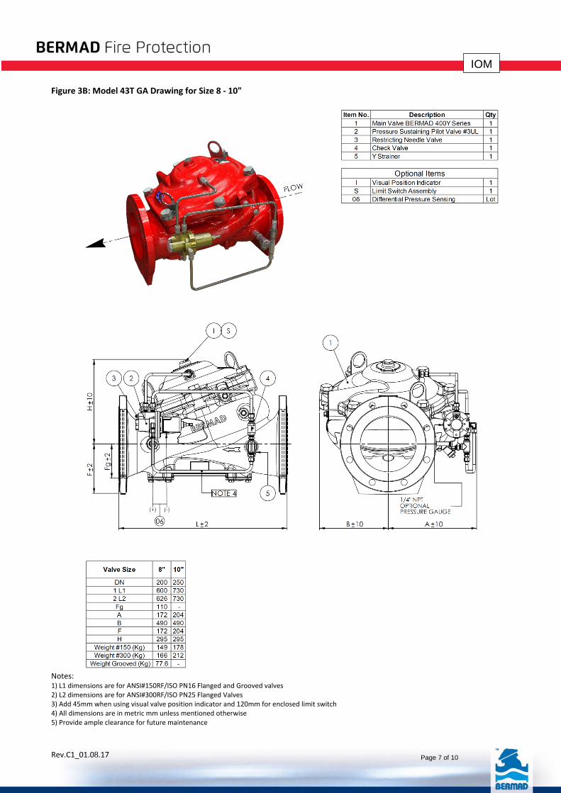
Figure 3B: Model 43T GA Drawing for Size 8 ‐ 10"
Notes: 1) L1 dimensions are for ANSI#150RF/ISO PN16 Flanged and Grooved valves 2) L2 dimensions are for ANSI#300RF/ISO PN25 Flanged Valves 3) Add 45mm when using visual valve position indicator and 120mm for enclosed limit switch 4) All dimensions are in metric mm unless mentioned otherwise 5) Provide ample clearance for future maintenance

Rev.C1_01.08.17 Page 8 of 10
IOM
Figure 3C: Model 43T with 20 Non‐Return, GA Drawing for Size 1.5" ‐ 6"
Notes: 1) L1 dimensions are for ANSI#150RF/ISO PN16 Flanged and Grooved valves 2) L2 dimensions are for ANSI#300RF/ISO PN25 Flanged Valves 3) Add 45mm when using visual valve position indicator and 120mm for enclosed limit switch 4) All dimensions are in metric mm unless mentioned otherwise 5) Provide ample clearance for future maintenance

Rev.C1_01.08.17 Page 9 of 10
IOM
Figure 3D: Model 43T with 20 Non‐Return, GA Drawing for Size 8" ‐ 10"
Notes: 1) L1 dimensions are for ANSI#150RF/ISO PN16 Flanged and Grooved valves 2) L2 dimensions are for ANSI#300RF/ISO PN25 Flanged Valves 3) Add 45mm when using visual valve position indicator and 120mm for enclosed limit switch 4) All dimensions are in metric mm unless mentioned otherwise 5) Provide ample clearance for future maintenance

Rev.C1_01.08.17 Page 10 of 10
IOM
2 3 4 5 6 7 8 9 10 11 12 13 14 15 16 17 18 19 20 21 22 23 24 25
0
200
400
600
800
1000
1200
1400
1600
0
1000
2000
3000
4000
5000
6000
7000
30 50 70 90 110 130 150 170 190 210 230 250 270 290 310 330 350 370
Discharge Flow (gpm)
Inlet Pressure (psi)
3"
4"
6"
10"
8"
2-2.5"
1.5"
Inlet Pressure (bar)
Discharge Flow (m³/h)
Table 3: Discharge Chart
Bermad 43T Pressure Relief Valve Discharge Chart
Inlet Pressure as Function of Discharge Flow Capacity