model 3050 table of contents - …019dd73.netsolhost.com/pdf/3050recorderiom.pdfscope of manual this...
TRANSCRIPT
SCOPE OF MANUAL This manual contains information concerning the installation, operation and maintenance of the Model 3050 Recorder. To ensure proper performance of the meter, the instructions given in this manual should be thoroughly understood and followed.
Keep the manual in a readily accessible location for future reference. Changes and additions to the original edition of this manual will be covered by a "CHANGE NOTICE" supplied with the manual. The change notice will explain any changes made to the product described in this manual.
MODEL 3050 TABLE OF CONTENTS
Page Page OPERATION Unpacking and Inspection................................. 1 General Description................................................ 7 General Specifications ...................................... 2 Status Mode............................................................ 8 Calibration Mode.................................................... 9 INSTALLATION PROCEDURE Error Screens .......................................................... 16 Electronics Hexadecimal Conversions...................................... 17 Enclosure Mounting.......................................... 3 Illustrated Parts List ............................................... 19 Wiring Connections .......................................... 5 Troubleshooting Diagram ...................................... 21
UNPACKING & INSPECTION
To avoid damage in transit, Badger products are shipped to the customer in special shipping containers. Upon receipt of the product, perform the following unpacking and inspection procedures: NOTE: If damage to the shipping container is evident upon receipt, request the carrier to be present when the product is unpacked. a. Carefully open the shipping container following any instructions that may be marked on the box. Remove all cushioning material surrounding the product and carefully lift the product from the container.
Retain the container and all packing material for possible use in reshipment or storage. b. Visually inspect the product and applicable accessories for any physical damage such as scratches, loose or broken parts, or any other sign of damage that may have occurred during shipment. NOTE: If damage is found, request an inspection by the carrier's agent within 48 hours of delivery and file a claim with the carrier. A claim for equipment damage in transit is the sole responsibility of the customer.
941314 3-971

2
GENERAL SPECIFICATIONS
INPUTS 3 Selectable Analog Channels: 0-20 mADC, 4-20 mADC or 1-5 VDC single input or summation. Pulse: 0-150 ppm to 0-1000 pps, field adjustable.
4-20 mADC signal into max. 800 ohms OUTPUTS 2 dry contact SPDT relays assignable to any of the following: High or low alarms, contact integrator, loss of input signal, EEPROM failure. Rated for 0.25 amp @ 120 VAC or 0.5 amp @ 24 VDC.
2 line, 24 alphanumeric character per line Liquid Crystal Display. DISPLAY Displays instantaneous flow rate (or pressure, or temperature), totalization, alarm indication and is used to program the recorder through menu driven prompts.
RECORDING 12 inch circular chart with 24 hour, 7 day or 31 day selectable chart speed, single disposable red ink pen.
PROGRAMMING Menu driven display prompt with 5 key tactile feedback keypad.
ENCLOSURE Indoor: NEMA 12, metallic; Outdoor: NEMA 4X, non-metallic.
TEMPERATURE Indoor: 32° F to 150° F (0° C to 65° C) LIMITS Outdoor: -40° F to 150° F (-40° C to 65° C)
POWER Standard: 117 VAC, 50/60 Hz +/- 10% REQUIREMENTS Optional: 230 VAC, 50/60 Hz +/- 10%
Recording Indicating Totalization Accuracy: +/- 0.5% of span +/- 1% or 1 LSD +/- 0.25% PERFORMANCE Linearity: +/- 0.5% of span +/- 0.5% Hysteresis: +/- 0.5% of span Repeatability: +/- 0.5% of span

INSTALLATION
ENCLOSURE DESCRIPTION The Model 3050 Recorder is housed in either a NEMA 12 or NEMA 4X enclosure and is capable of accommodating the input signal from 1, 2 or 3 DP Cells and provide a single output for indicating, totalizing and recording flow or level. The NEMA 12 enclosure is suitable for indoor use and designed to be panel mounted. It can be supplied with heater and thermostat for indoor installations in buildings that are not heated in the winter. Mounting hardware is provided for panel mounting of the enclosure. Care should be taken when selecting the mounting location so that the recorder door can be opened completely for access when changing charts.
INDOOR ENCLOSURE DIMENSIONS
15-5/8"
19-3/16"
8-13/16"
7 " The NEMA 4X enclosure is suitable for outdoor use and can be wall or pole mounted. It comes equipped with heater and thermostat. The door can be supplied with or without a window. The door is provided with two lockable latches. Caution should be used when mounting the enclosure so that it is not exposed to direct sunlight. A sun shield is recommended to prevent the temperature inside the enclosure reaching above the maximum rating of the electronics (see temperature specification under General Specifications). Viewing window is optional.
OUTDOOR ENCLOSURE DIMENSIONS
16"
20"
7-7/8"
INDOOR PANEL MOUNTING Prior to mounting the enclosure, it is recommended that the knockouts for the conduit fittings be removed. This should be done with the enclosure resting on a solid surface. A hole 17-7/8" high by 14-1/4" wide is required for inserting the enclosure in a panel. Slide the recorder into the panel. Install the four mounting brackets into the slots in the sides of the enclosure as shown below. Tighten the mounting screws until the enclosure is secure to the panel.
14-1/4 "
17-7/8 "PANEL
OPENINGCUTOUT
MOUNTINGBRACKETS4 EACH
3

OUTDOOR ENCLOSURE MOUNTING The NEMA 4X outdoor enclosure is provided with four mounting feet which are to be installed by the user at the orientation desired. Pictured below is the installation detail of the feet and the mounting hole dimensions.
If the outdoor enclosure has the window option, do not mount facing the sun or install a sun shade to prevent overheating of the electronics inside the enclosure. See below for DP cell wiring connections.
WIRING CONNECTIONS
+ 4-20 MAOUTPUT
NOC SW 1NCNOC SW 2
CHANNEL 1 LOW
CHANNEL 2 MEDIUM
CHANNEL 3 HIGH
NOTUSED
+
FREQ IN
PWRPWR
NC
12345678
123456
123
117/230VACFACTORYWIRED
TB1
TB2
TB3
TB4
TB5
123
+
+
+
H N G117 / 230 VACCONNECTIONS
MOUNTING FEET
14.55 "
17.03 "
10.40 "20.96 "
+
4

The indoor case has six 7/8" diameter knockouts for use of 3/4" conduit connections. Three are located on the bottom of the case and three on the back of the case. The three you use will depend on whether you panel or wall mount the enclosure. To reduce the chance of noise on the signal input wires, the input wires should be routed in separate conduit from the power wiring. Local regulations for proper grounding and connection of the power to the recorder should be strictly followed. The power wires are connected to the terminals located on the inside back of the recorder. The AC voltage which the recorder has been setup will be clearly marked near the terminal strip. Verify that you are connecting the proper voltage to the recorder. The terminal labeled H is the High (black) wire, the terminal labeled N is the Neutral (white) wire and the terminal labeled G is the Ground (green) wire. The power wires from the terminal strip to the circuit board are prewired at the factory. MULTIPLE DP CELL INPUTS
The following channels are available for up to three DP Cell inputs.
123456
TB4
CHANNEL 1 LOW
CHANNEL 2 MEDIUM
CHANNEL 3 HIGH
The above wiring diagram shows the wiring connections for current or voltage input signals from the DP cells. The Data Sheet furnished in the front of this manual will indicate recorder setup. If this is different from the output of your DP cell, contact the factory for corrective action. The terminal blocks on the circuit board have snap on connectors. To connect the input and output wires, pull off the connectors from the terminal strips. Route the signal wires through the flexible wiring raceway between the back case and front door. Loosen the screws on the connectors. Strip off about 1/4 inch of insulation from the wires. Insert the wire into the proper connector and tighten the screw securely. After connecting all of the wires to the connector, snap the connector back on the terminal strip.
5
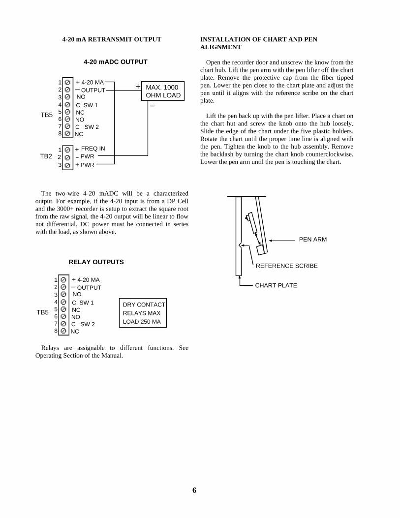
4-20 mA RETRANSMIT OUTPUT
MAX. 1000OHM LOAD
+
FREQ IN
PWRPWRTB2
123
+ 4-20 MAOUTPUT
NOC SW 1NCNOC SW 2NC
12345678
TB5
+
4-20 mADC OUTPUT
The two-wire 4-20 mADC will be a characterized output. For example, if the 4-20 input is from a DP Cell and the 3000+ recorder is setup to extract the square root from the raw signal, the 4-20 output will be linear to flow not differential. DC power must be connected in series with the load, as shown above.
DRY CONTACTRELAYS MAXLOAD 250 MA
+ 4-20 MAOUTPUT
NOC SW 1NCNOC SW 2NC
12345678
TB5
RELAY OUTPUTS
Relays are assignable to different functions. See Operating Section of the Manual.
INSTALLATION OF CHART AND PEN ALIGNMENT Open the recorder door and unscrew the know from the chart hub. Lift the pen arm with the pen lifter off the chart plate. Remove the protective cap from the fiber tipped pen. Lower the pen close to the chart plate and adjust the pen until it aligns with the reference scribe on the chart plate. Lift the pen back up with the pen lifter. Place a chart on the chart hut and screw the knob onto the hub loosely. Slide the edge of the chart under the five plastic holders. Rotate the chart until the proper time line is aligned with the pen. Tighten the knob to the hub assembly. Remove the backlash by turning the chart knob counterclockwise. Lower the pen arm until the pen is touching the chart.
PEN ARM
REFERENCE SCRIBE
CHART PLATE
6

OPERATION
GENERAL DESCRIPTION
7
The Model 3050 Recorder is a circular chart recorder with microprocessor-based electronics. The unit is designed to accommodate the input from up to three (3) "stacked" DP cells, providing a single output of flow. The unit is supplied with a LCD display for indicating rate and totalization. The rate is displayed with 4 digits and its multiplier and unit of measurement. The totalizer is displayed with 8 digits and its multiplier and unit of measurement. The display is also used to program the recorder through menu driven prompts. The programming is activated via front panel keys. These keys also activate a Status Mode which will indicate if there are any alarms tripped and perform a self-test operation of the recorder. The following will describe in detail the various functions of the Model 3050 Recorder and programming steps to recalibrate the recorder in the field if necessary. INITIAL POWER UP After installation and wiring of the Model 3050 Recorder, power may be turned on by the power switch on the lower right hand corner of the chart plate. When power is applied, the display screen will have a solid line across the top of the display for a few seconds. Then the following screen will appear:
3050 RECORDER BADGER METER INC
This screen informs the user of the Model of the recorder. This screen will be displayed for a few seconds. The next screen to be displayed is the following:
SOFTWARE REVISION X.XX SERIAL NUMBER 12345678
This screen identifies the software revision the recorder is operating with and the serial number of the unit. This screen will be displayed for a few seconds. The next screen shown is the screen that will be displayed during normal operation of the recorder.
*FLOW 1234 X 10,000 GPM 12345678 X 100,000 GAL
The top line displays the flow rate with its multiplier and the unit of measurement. The second line displays the totalized flow (8 digits) with its multiplier and unit of measurement. The asterisk that is to the left of FLOW may or may not be present. If it is present, it indicates that an alarm has been tripped. The various alarms will be discussed in the Status Mode Section of this manual. The recorder should be fully operational if there is an input signal from a transmitter. The recorder is programmed at the factory with the information supplied by the user and the Zero and Span have been calibrated. If the flashing asterisk is present proceed to the Status Mode Section to determine the cause and proper action. If the user desires to reset the Zero and Span or change any of the parameters of the recorder, proceed to the Calibration Section of this manual.

STATUS MODE The Status Mode contains the Alarms Tripped screen and the Self Test screen. To enter into the Status Mode press the MENU key and the following screen will appear:
PRESS UP FOR CALIBRATION PRESS DOWN FOR STATUS
Pressing the DOWN arrow key will allow entry into the Status Mode screens. If you decide not to enter the Status Mode, press the MENU key and you will return to the normal operation screen. Press the DOWN arrow key and the following screen appears:
- ALARMS TRIPPED - IN LO HI CHT INT EE
The Alarms Tripped screen will display any conditions that have occurred. To clear the alarms press the DOWN arrow key. Should an alarm still be tripped, it will still be shown on the display. The definition of the alarms are as follows: IN = There is no 4-20 mA signal or the input current is below the pen arm zero current value. LO = This indicates that the low alarm set point has been tripped. This set point may be changed, refer to the Calibration Section of this manual. HI = This indicates that the high alarm set point has been tripped. This set point may be changed, refer to the Calibration Section of this manual. CHT = This indicates that the chart has made a complete rotation and the chart needs to be changed. INT = Indicates a contact integrator pulse output has occurred. EE = EEPROM read/write error which indicates a failure in the microprocessor. Consult the factory.
To return to the normal operating screen press the MENU key. To enter the Self Test screen press the ENTER key and the following screen will appear:
- SELF TEST - PRESS UP TO ACTIVATE
If you decide not to enter into the Self Test section, press the MENU key and you will return to the normal display screen. To enter into the Self Test section press the UP arrow key and the following screen will appear:
- SELF TEST - EEPROM TEST=> PASSED
This tests the EEPROM and indicates if it passed or failed. This takes a few seconds and then the following screen will appear:
- SELF TEST - VREF TEST=> PASSED
This tests the reference voltage and indicates if it passed or failed. The following screen will appear:
- SELF TEST - SERVO TEST=> PASSED
This tests the servo drive system and indicates if it passed or failed. Should any of the screens indicate a failure, contact the factory for the appropriate action to be taken. Upon completion of the Self Test the unit will return to the normal operating display screen. This completes the Status Mode Section.
8

*FLOW 1234 X 100 GPM 12345678 X 10 GAL
PRESS UP FOR CALIBRATION PRESS DOWN FOR STATUS
FULLSCALE UNITS= GPMFULLSCALE= 0000 X 10
ENTER FULLSCALE FLOWRATE
ENTER
UNIT MULTIPLIER GPM X 10X.001, X.01, X .1, X 1, X 10,X 100, X 1000 X 10000
ENTER
MEASUREMENTS UNITS UNIT INITIALS= GPM
GPM, GPD, MGD, CFS, CFM,CFH, CMM, OPTION
DISPLAYS:
MENU
ENTER
MEASUREMENT UNITS OPTION INITIALS= XXX
DISPLAY FLOW LABEL AND TOTALIZER? YES
NO
FLOW OPTION:
THREE CHARACTER ALPHA- NUMERIC LABEL
ENTER
ENTER
TOTALIZER MULTIPLIER X 10
X.01, X .1, X 1, X 10, X 100,X 1000 X 10000, X 100000
TO DO BUTTONS: MENU ENTER
ENTER
CHART REVOLUTION SPEED1 REVOLUTION IN 1 DAY
2 MINUTES, 24 MINUTES, 1 HOUR,1 DAY, 7 DAYS, 31 DAYS
RECORDER DAMPINGDAMPING TIME= 6 SECS.
NONE, 6, 16, 40,100, 240, 600
-TOTALIZER WORD- 0000 0000 0000
TOTALIZER MULTIPLIERMAX FLOW IN UNITS/SEC. X 2,000,000=HEX
TOTALIZER UNITUNIT INITIALS= AAA
TOTALIZER OPTION:
THREE CHARACTER ALPHA- NUMERIC LABEL
ENTER
ENTER
ENTER
ENTER
-FUNCTION SELECTION- POWER= > 1/2
LINEAR, 1.55, 1.58, 1.9, 1/2,3/2, 5/2, OPTION
ENTER
INPUT SELECTIONS:
GO TO NEXT PAGE
ENTER
ENTER
3050+MDP CALIBRATION DISPLAY FLOW CHART
ENTER
Page 11
Page 15
Page 15
Page 12
Page 11
Page 11
Page 11
Page 11
Page 11
Page 12
9
INPUT SELECTIONCHANNEL= FREQUENCY
INPUT SELECTIONCHANNEL= #1>#2>#3
INPUT SELECTIONCHANNEL= ANALOG #1
FREQUENCY INPUT MODE PPS PPM
FREQUENCY ZERO0000 PULSES PER MINUTE
FREQUENCY SPAN0150 PULSES PER MINUTE
CHANNEL #01 WEIGHTINGOF FULL SCALE= .XXXX
CHANNEL #03 WEIGHTINGOF FULL SCALE= .9999
CHANNEL #02 WEIGHTINGOF FULL SCALE= .XXXX
#1-LOW RANGE, #2-MID RANGE#3-HIGH RANGE
% OF FULL SCALE
% OF FULL SCALE
ENTER ENTER
ENTER
ENTER
ENTER
ENTER
ENTER
ENTER
-CHART PEN ZEROUP OR DOWN TO MOVE PEN
4.00 MADC INPUT REQUIRED
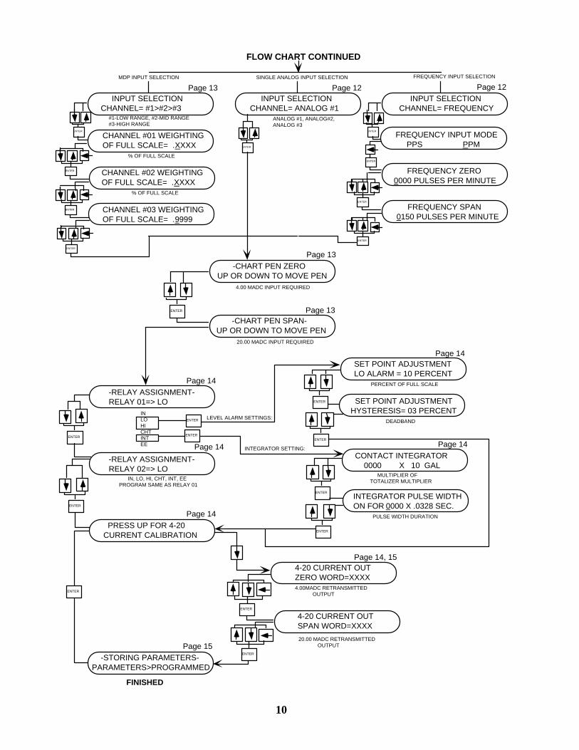
FLOW CHART CONTINUED
-CHART PEN SPAN-UP OR DOWN TO MOVE PEN
20.00 MADC INPUT REQUIRED
ENTER
-RELAY ASSIGNMENT-RELAY 01=> LO
INLOHICHTINTEE
CONTACT INTEGRATOR 0000 X 10 GAL
ENTER
ENTER
ANALOG #1, ANALOG#2,ANALOG #3
SET POINT ADJUSTMENTLO ALARM = 10 PERCENT
SET POINT ADJUSTMENTHYSTERESIS= 03 PERCENT
-RELAY ASSIGNMENT-RELAY 02=> LO
IN, LO, HI, CHT, INT, EE PROGRAM SAME AS RELAY 01
ENTER
ENTER
ENTER
INTEGRATOR PULSE WIDTHON FOR 0000 X .0328 SEC.
ENTER
ENTER
PRESS UP FOR 4-20CURRENT CALIBRATION
ENTER
LEVEL ALARM SETTINGS:
INTEGRATOR SETTING:
4-20 CURRENT OUTSPAN WORD=XXXX
4-20 CURRENT OUTZERO WORD=XXXX
ENTER
ENTER -STORING PARAMETERS-PARAMETERS>PROGRAMMED
4.00MADC RETRANSMITTED OUTPUT
20.00 MADC RETRANSMITTED OUTPUT
MULTIPLIER OFTOTALIZER MULTIPLIER
PULSE WIDTH DURATION
PERCENT OF FULL SCALE
DEADBAND
Page 13 Page 12 Page 12
Page 13
Page 13
Page 14
Page 14
Page 14
Page 14
Page 14
Page 14, 15
Page 15
ENTER
ENTER
FINISHED
MDP INPUT SELECTION SINGLE ANALOG INPUT SELECTION FREQUENCY INPUT SELECTION
10

CALIBRATION MODE The Calibration Mode allows the user to reprogram the 3050 Recorder to different parameters, calibrate the Zero and Span and assign and set the relay outputs. To enter the Calibration Mode, press the MENU key and the following display screen will appear:
PRESS UP FOR CALIBRATION PRESS DOWN FOR STATUS
11
If you decide not to enter the Calibration Mode, press the MENU key and the display will return to the normal operating screen. When in the Calibration Mode and the desired change has been made and no other changes are desired, you may skip to the end of the calibration screens by pressing the MENU key. To enter the Calibration Mode, press the UP arrow key and the following screen will appear:
MEASUREMENTS UNITS UNIT INITIALS=GPM
This screen allows the user to select the engineering unit of measure for the flow rate. To change the units, press the UP or DOWN arrow keys until the desired unit is shown. The engineering units available are: GPM = Gallons per Minute GPD = Gallons per Day MGD = Million Gallons per Day CFS = Cubic Feet per Second CFM = Cubic Feet per Minute CFH = Cubic Feet per Hour CMM = cubic Meters per Minute OPTION = Any three letter label can be entered After you have selected the unit desired, press the ENTER key. If you have selected OPTION, skip to the section entitled OPTION on Page 15. The next screen, after selecting a standard measurement, allows the selection of the multiplier for the unit of measurement and will appear as follows:
UNIT MULTIPLIER GPM X 1,000
Press the UP or DOWN arrow key to select the desired flow multiplier. The following multipliers are available: X.001 X.01 X.1 X1 X10 X100 X1,000 X10,000 Press the ENTER key to store the multiplier. The ollowing screen will appear: f
FULLSCALE UNITS=GPM
FULLSCALE = 0000 X 1,000 This screen allows the setting of the full scale range. Press the UP or DOWN arrow keys to change each digit to the desired value and the RIGHT arrow key to move the cursor under each digit. Press the ENTER key and the following screen will appear:
TOTALIZER MULTIPLIER X 1,000
This screen allows the selection of the totalizer multiplier. Press the UP or DOWN arrow keys to select the desired multiplier and then the ENTER key. The following multipliers are available: X.01 X100 X.1 X1000 X1 X10,000 X10 X100,000 The following screen will appear:
CHART REVOLUTION SPEED 1 REVOLUTION IN 1 DAY
This screen allows the selection of the chart rotation speed. The following speeds are available: 1 REVOLUTION IN 2 MINUTES 1 REVOLUTION IN 24 MINUTES 1 REVOLUTION IN 1 HOUR 1 REVOLUTION IN 1 DAY 1 REVOLUTION IN 7 DAYS 1 REVOLUTION IN 31 DAYS - - - - - - - - -
The two dash line positions are for future chart revolution speeds.
Press the UP or DOWN arrow keys to select the desired chart speed and press the ENTER key. The following screen will appear:
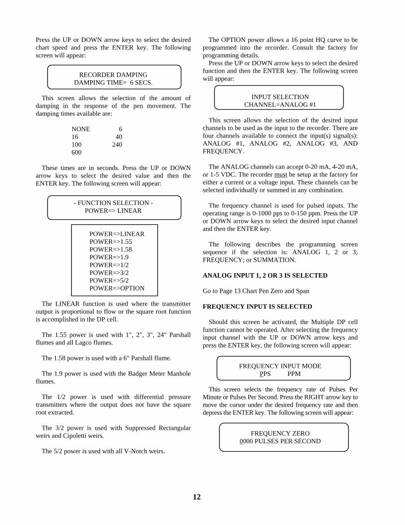
RECORDER DAMPING DAMPING TIME= 6 SECS.
12
This screen allows the selection of the amount of damping in the response of the pen movement. The damping times available are: NONE 6 16 40 100 240 600 These times are in seconds. Press the UP or DOWN arrow keys to select the desired value and then the ENTER key. The following screen will appear:
- FUNCTION SELECTION - POWER=> LINEAR
POWER=>LINEAR POWER=>1.55 POWER=>1.58 POWER=>1.9 POWER=>1/2 POWER=>3/2 POWER=>5/2 POWER=>OPTION The LINEAR function is used where the transmitter output is proportional to flow or the square root function is accomplished in the DP cell. The 1.55 power is used with 1", 2", 3", 24" Parshall flumes and all Lagco flumes. The 1.58 power is used with a 6" Parshall flume. The 1.9 power is used with the Badger Meter Manhole flumes. The 1/2 power is used with differential pressure transmitters where the output does not have the square root extracted. The 3/2 power is used with Suppressed Rectangular weirs and Cipoletti weirs. The 5/2 power is used with all V-Notch weirs.
The OPTION power allows a 16 point HQ curve to be programmed into the recorder. Consult the factory for programming details. Press the UP or DOWN arrow keys to select the desired function and then the ENTER key. The following screen will appear:
INPUT SELECTION CHANNEL=ANALOG #1
This screen allows the selection of the desired input channels to be used as the input to the recorder. There are four channels available to connect the input(s) signal(s): ANALOG #1, ANALOG #2, ANALOG #3, AND FREQUENCY. The ANALOG channels can accept 0-20 mA, 4-20 mA, or 1-5 VDC. The recorder must be setup at the factory for either a current or a voltage input. These channels can be selected individually or summed in any combination. The frequency channel is used for pulsed inputs. The operating range is 0-1000 pps to 0-150 ppm. Press the UP or DOWN arrow keys to select the desired input channel and then the ENTER key. The following describes the programming screen sequence if the selection is: ANALOG 1, 2 or 3; FREQUENCY; or SUMMATION. ANALOG INPUT 1, 2 OR 3 IS SELECTED Go to Page 13 Chart Pen Zero and Span FREQUENCY INPUT IS SELECTED Should this screen be activated, the Multiple DP cell function cannot be operated. After selecting the frequency input channel with the UP or DOWN arrow keys and press the ENTER key, the following screen will appear:
FREQUENCY INPUT MODE PPS PPM
This screen selects the frequency rate of Pulses Per Minute or Pulses Per Second. Press the RIGHT arrow key to move the cursor under the desired frequency rate and then depress the ENTER key. The following screen will appear:
FREQUENCY ZERO 0000 PULSES PER SECOND

This screen allows the setting of frequency which represents zero. Press the UP or DOWN arrow keys to change the value of each digit and the RIGHT arrow key to move the cursor under the digit to be changed. Press the ENTER key to store this value. The following screen
ill appear: w
FREQUENCY SPAN 0000 PULSES PER SECOND
13
This screen allows the setting of the frequency which represents zero. Press the UP or DOWN arrow keys to change the value of each digit and the RIGHT arrow key to move the cursor under the digit to be changed. Press the ENTER key to store this value. Go to Page 13 Chart Pen Zero and Span. MULTIPLE DP CELL INPUT SELECTION The 3050 is capable of accommodating one (1), two (2), or three (3) analog inputs from DP cells. In other words, "stacking" DP cells for extending the range for a differential pressure producer. The 3050 Recorder must be installed per the following sequence or improper operation will occur. Channel 1 must be dedicated to the lowest range DP cell. If only two (2) DP cells are used, the channel selection for the third input should not be ctivated. For two inputs the selection is as follows: a
INPUT SELECTION
CHANNEL 1 = #1 > #2
If three (3) inputs are selected, the combination has to be:
#1 - Low Range #2 - Mid Range #3 - High Range In the input Selection screen there is the following channel combinations that can be selected: Channel = #1>#2, or Channel = #1>#2>#3. Use the UP and DOWN arrow keys to select the channels to be summed and press the ENTER key. This selects input channels for active inputs to the system. The switching function between each DP cell is accomplished through the lower range cell. For example, in a three (3) cell input as the input reaches a predetermined percentage in the low range cell is switches to the mid range cell. As the input increases the active input switches to the high range cell. The next two following screens will set the percentage angle of each cell as a function of either differential in inches or flow. Remember: The inputs from the dP cells will be used for channel weighting.
CHANNEL #1 WEIGHTING OF FULL SCALE=.XXXX
This screen sets the low range value by inputting the full scale flow or (differential in inches) number as a percentage of the full scale value of cell #2. For example, if the high range cell is 0-200 GPM (200"), and the low range cell is 0-20 GPM (20"), then the ratio of the full scale flow or (differential in inches) value of each dP cell is:
20/200 = .1 Use the UP or DOWN arrow keys to adjust the percent value. Press the ENTER key to store this value. After the ENTER key has been pressed, the following screen will ppear: a
CHANNEL #2 WEIGHTING OFF FULL SCALE = .XXXX
This channel must be set to read .9999 using the UP or DOWN arrow keys. Should three channels be used, then the third channel would be set to .9999. CHART PEN ZERO AND SPAN
- CHART PEN ZERO - UP OR DOWN TO MOVE PEN
This screen calibrates the pen zero point on the chart paper to the zero of the input signal. It is important that the pen be properly aligned and the 4 mA is being applied to the input before making this adjustment. The zero value of the input signals of all the channels to be stacked must be input to the recorder when making this adjustment. For example, if the input signal is 4-20 mA for 0 to 100%, then 4 mA must be input to all channels to be summed to make the pen zero adjustment. Press the UP or DOWN arrow keys to move the pen to the proper position. No changes will be made to the previously stored zero value unless the UP or DOWN arrow keys are pressed. So if the user is stepping through the program to access another programming screen, the input does not need to be at the zero value if the UP or DOWN arrow keys are not pressed. When pressing the UP or DOWN arrow keys the display will indicate the direction of the pen movement. Once the pen is positioned to zero on the chart, then press the ENTER key. Be sure to press the ENTER key before changing the input signal. The following screen will appear:
- CHART PEN SPAN - UP OR DOWN TO MOVE PEN
This screen calibrates the pen span point on the chart paper to the span of the input signal. The span value of the input signal for all channels to be summed must be input to the recorder when making this adjustment. For example, if the input signal is 4-20 mA for 0 to 100%, then 20 mA must be input to all channels to be summed, to make the pen span

14
adjustment.
Press the UP or DOWN arrow keys to move the pen to the proper position. No changes will be made to the previously stored span value unless the UP or DOWN arrow keys are pressed. So if the user is stepping through the program to access another programming screen, the input does not need to be at the span value if the UP or DOWN arrow keys are not pressed. When pressing the UP or DOWN arrow keys the display will indicate the direction of the pen movement. Once the pen is positioned to span on the chart, press the ENTER key. Be sure to press the ENTER key before changing the input signal. The next screen to appear will be the Relay Assignment screen.
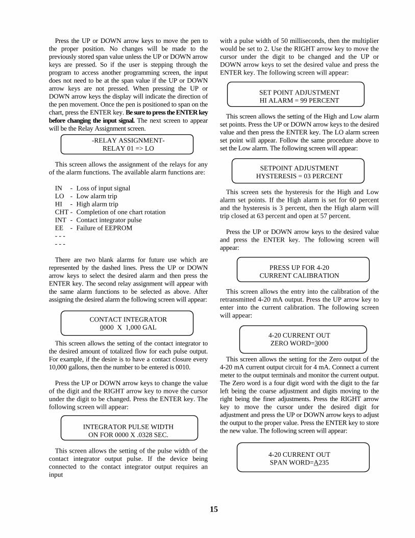
with a pulse width of 50 milliseconds, then the multiplier would be set to 2. Use the RIGHT arrow key to move the cursor under the digit to be changed and the UP or DOWN arrow keys to set the desired value and press the ENTER key. The following screen will appear:
SET POINT ADJUSTMENT HI ALARM = 99 PERCENT
This screen allows the setting of the High and Low alarm set points. Press the UP or DOWN arrow keys to the desired value and then press the ENTER key. The LO alarm screen set point will appear. Follow the same procedure above to set the Low alarm. The following screen will appear:
15
-RELAY ASSIGNMENT-
RELAY 01 => LO This screen allows the assignment of the relays for any
of the alarm functions. The available alarm functions are: SETPOINT ADJUSTMENT HYSTERESIS = 03 PERCENT IN - Loss of input signal This screen sets the hysteresis for the High and Low
alarm set points. If the High alarm is set for 60 percent and the hysteresis is 3 percent, then the High alarm will trip closed at 63 percent and open at 57 percent.
LO - Low alarm trip HI - High alarm trip CHT - Completion of one chart rotation INT - Contact integrator pulse EE - Failure of EEPROM Press the UP or DOWN arrow keys to the desired value
and press the ENTER key. The following screen will appear:
- - - - - -
There are two blank alarms for future use which are represented by the dashed lines. Press the UP or DOWN arrow keys to select the desired alarm and then press the ENTER key. The second relay assignment will appear with the same alarm functions to be selected as above. After assigning the desired alarm the following screen will appear:
PRESS UP FOR 4-20 CURRENT CALIBRATION
This screen allows the entry into the calibration of the retransmitted 4-20 mA output. Press the UP arrow key to enter into the current calibration. The following screen will appear:
CONTACT INTEGRATOR 0000 X 1,000 GAL 4-20 CURRENT OUT ZERO WORD=3000 This screen allows the setting of the contact integrator to
the desired amount of totalized flow for each pulse output. For example, if the desire is to have a contact closure every 10,000 gallons, then the number to be entered is 0010.
This screen allows the setting for the Zero output of the 4-20 mA current output circuit for 4 mA. Connect a current meter to the output terminals and monitor the current output. The Zero word is a four digit word with the digit to the far left being the coarse adjustment and digits moving to the right being the finer adjustments. Press the RIGHT arrow key to move the cursor under the desired digit for adjustment and press the UP or DOWN arrow keys to adjust the output to the proper value. Press the ENTER key to store the new value. The following screen will appear:
Press the UP or DOWN arrow keys to change the value of the digit and the RIGHT arrow key to move the cursor under the digit to be changed. Press the ENTER key. The following screen will appear:
INTEGRATOR PULSE WIDTH ON FOR 0000 X .0328 SEC. This screen allows the setting of the pulse width of the
contact integrator output pulse. If the device being connected to the contact integrator output requires an input
4-20 CURRENT OUT SPAN WORD=A235

This screen allows the setting of the Span output of the 4-20 mA current output circuit for 20 mA. Connect a current meter to the output terminals and monitor the current output. The Span word is a four digit word with the digit to the far left being coarse adjustment and digits moving to the right being the finer adjustments. Press the RIGHT arrow key to move the cursor under the desired digit for adjustment and press the UP or DOWN arrow keys to adjust the output to the proper value. Press the ENTER key to store the new value. The following screen will appear:
-STORING PARAMETERS- PARAMETERS>PROGRAMMED
This screen indicates that the new parameters have been stored in the recorder. The display will then return to the normal operating screen. This completes the Calibration Section.
OPTION (FOR FLOW UNITS SCREEN) Selecting OPTION in the Flow Units screen allows the entering of any three letter label for special engineering units. Press the ENTER key with OPTION selected and the following screen will appear:
MEASUREMENT UNITS OPTION INITIALS=AAA
There will be a cursor under the first letter. Use the UP or DOWN arrow keys to select the desired letter. Press the RIGHT arrow key to move the cursor to the second and third letter and select the desired letter. Press the ENTER key to enter the OPTION INITIALS. The following screen will appear:
DISPLAY FLOW LABEL AND TOTALIZER ? YES
This screen asks if the FLOW label is to be displayed on the normal operating screen. If the recorder is to be used to record temperature or some other measurement not related to flow or requires totalization, then selecting NO will remove the FLOW label and the totalizer value from the screen. Use the UP or DOWN arrow keys to select YES or NO and press the ENTER key. The following screen will appear:
UNIT MULTIPLIER AAA X 1,000
This screen allows the selection of the desired flow rate multiplier. Press the UP or DOWN arrow keys to select the desired multiplier and then press the ENTER key. The following screen will appear:
FULLSCALE UNITS=AAA FULLSCALE = 0
16
000 X 1,000
This screen allows the entering of the full scale flow rate desired. Press the UP or DOWN arrow keys to select the desired value and the RIGHT arrow key to move the cursor under the digit to be changed. After the desired value is selected, press the ENTER key. If NO was selected, the next screen will be the Chart Revolution Speed screen. Go back to Page 11. If YES was selected, the following screen will appear:
TOTALIZER UNIT UNIT INITIALS=AAA
This screen allows the entering of the desired totalizer unit label. Press the UP or DOWN arrow keys to select the desired letter and the RIGHT arrow key to move the cursor under the letter to be changed. After the desired letters are selected press the ENTER
ey. The following screen will appear: k
TOTALIZER MULTIPLIER X 1,000
This screen allows the selection of the desired totalizer multiplier. Press the UP or DOWN arrow keys to select the desired multiplier and then depress the ENTER key. The following screen will appear:
-TOTALIZER WORD- 0000 0000 0000
The Totalizer Word is required to setup the time base to properly totalizer in the selected option units. The totalizer word is defined as follows:
HEX 2,000,000 x ecin Units/S Flow Max.
MultiplierTotalizer =
EXAMPLE: Maximum flow = 1800 x 1 BPM (Barrels/min) Totalizer multiplier = BAR x 100 Totalizer Word = (100/(1800/60))x2,000,000 = 6666666.6

Converted to Hexadecimal = 65B9AA (see the Decimal to Hexadecimal Conversion Section). The TOTALIZER WORD is 0000 0065 B9AA Note: The totalizer word must be greater than Hex 1000.
Use the UP and DOWN arrow keys to change each digit to the required value and the RIGHT arrow to move the cursor. The ENTER key must be depressed after each set of four digits. Return to Page 10 where the next screen will be the Chart Speed selection.
17
ERROR SCREENS There are several Error Screens that will be displayed by the recorder if the microprocessor detects errors in the values programmed into the recorder.
-CHART PEN ZERO- <INPUT ZERO ERROR>
OR
-CHART PEN SPAN- <INPUT SPAN ERROR>
If either of the two above Error Screens appear during the chart pen adjusting procedure, one of the following problems probably occurred: 1. There was not a 4-20 mADC analog signal to the recorder analog channel you selected while adjusting the chart zero span. 2. An analog input signal channel was selected without adjusting the chart pen zero and span of this channel.
3. The Zero and Span of the recorder have been adjusted too close to the same input value. To correct these errors, readjust the Chart Pen Zero and Span while inputting the 4-20 mADC analog signal to the proper selected recorder channel. Refer to the Calibration Mode Section of this manual.
-STORING PARAMETERS- <TOTALIZER WORD ERROR>
If the above Error Screen appears after pressing the ENTER key to store the calibration adjustments, this indicates that you have selected a totalizer multiplier that is too low for your selected flow rate. To correct this error, re-enter the Calibration Mode and when the Totalizer Multiplier Screen appears, increase the totalizer multiplier and press the ENTER key. Then press the MENU key to store the new multiplier and return to the normal operating screen. If you still have a Totalizer Word Error message in the Storing Parameters screen, repeat the above procedure until the error is not present.

18
HEXADECIMAL SYSTEM The purpose of the hexadecimal number system is simply to reduce the number of units necessary for representing any given numerical figure, thereby reducing the amount of space in memory necessary to retain it.
Herein, a decimal (normal) number is converted to a correct hexadecimal number which consists of fewer characters. The hexadecimal number system consists of only 16 characters which are shown below by the boldface characters.
0 = 0 1 = 1 2 = 2 3 = 3 4 = 4 5 = 5 6 = 6 7 = 7 8 = 8 9 = 9 10 = A 11 = B 12 = C 13 = D 14 = E 15 = F These characters may be arranged in various sequences to produce an infinite number of representations of decimal numbers. For example: 6D4C = 27,980. CONVERSION OF DECIMAL WHOLE NUMBER TO HEXADECIMAL NUMBER 1. Divide the decimal number by 16. Example: 57420/16 = 3588.75 2. Multiply only the fractional part of the product by 16 to arrive at the first character in the hexadecimal equivalent. Remember, all numbers produced I this step are shown above. Also note that the product may have no fraction (.000) which would result in zero as the hexadecimal number. Example: .75 x 16 = 12 = C
3. Divide the whole number portion of the product by 16 thereby producing yet another number. Example: 3588/16 = 224.25 4. Repeat steps 2 and 3 in a cyclical fashion until the numerator to be divided in Step 3 is less than 16. At that point, the numerator represents the final character in the hexadecimal sequence.
EXAMPLE: Convert 57,420 into a hexadecimal number:
1.) 57,420/16 = 3588.75
2.) .75 X 16 = 12 = C
3.) 3,588/16 = 224.25 2.) .25 X 16 = 4
3.) 224/16 = 14.00
2.) .00 X 16 = 0
3.) 14 = E 57,420 = E04C

19
CONVERSION OF A WHOLE HEXADECIMAL NUMBER TO A DECIMAL NUMBER 1. Multiply the left most character in the hexadecimal number by 16. Example: E = 14 X 16 = 224 2. Add to the product previously found the value of the next character. Example: 224 + 0 = 224 3. Multiply the previously found product by 16. Example: 224 X 16 = 3584 4. Repeat steps 2 and 3 in a cyclical fashion until you have added the last hexadecimal character. Do not multiply beyond that point. EXAMPLE: Convert E04C into a decimal number. 1.) E = 14; 14 X 16 = 224 2.) 224 + 0 = 224 3.) 224 X 16 = 3584 2.) 3584 + 4 = 3588 3.) 3588 X 16 = 57,408 4.) 57,408 + 12 = 57,420 E04C = 57,420

20
INSERT DWG 600663-9999 3050 RECORDER ASSY DWG

21
CHART PLATE ASSEMBLY PARTS LIST ITEM PART NUMBER DESCRIPTION U/M QTY 12 543744-0001 SERVO MECH ASSY EA 1.0 13 400001-0088 HEX NUT 2-56 X 7/16 EA 4.0 14 430002-0106 FLAT WASHER EA 4.0 15 501401-0001 SPACER #2 EA 2.0 16 151960-0001 PCB MOTHER BOARD EA 1.0 17 510031-0131 SPRING EA 1.0 18 543075-0001 LCD DISPLAY EA 1.0 19 500050-0043 SPACER EA 4.0 20 410001-0007 HEX NUT 6-32 EA 13.0 22 512645 HINGE EA 1.0 23 512594 CHART PLATE EA 1.0 24 501078 MEMBRANE SWITCH EA 1.0 27 540769 CHAIN ASSY EA 1.0 29 400002-0015 SCREW 6-32 X 5/16 EA 11.0 30 400005-0017 SCREW 2-56 X 3/16 EA 2.0 31 501132-0005 CONNECTOR HOUSING EA 1.0 32 501425-0002 STEPPER MOTOR EA 1.0 33 500050-0015 SPACER #6 EA 2.0 34 400006-0025 SET SCREW 4-40 X 3/16 EA 1.0 35 524720 CHART CLAMP BODY EA 1.0 36 400006-0071 SET SCREW 5-40 X 5/16 EA 1.0 37 512610 COVER W/LOGO EA 1.0 38 524743 CHART KNOB EA 1.0 39 400002-0010 SCREW 6-32 X 5/8 EA 2.0 40 512114 PEN ARM EA 1.0 41 500638-0003 ON/OFF SWITCH EA 1.0 42 430002-0105 FLAT WASHER EA 5.0 43 500983-0001 SNAP FASTENER EA 5.0 44 512224 PEN REPLACEMENT DECAL EA 1.0 45 500724-0001 RED FIBER TIP PEN EA 2.0 46 440005 RETAINER EA 2.0 47 501276-0002 SCREW EA 2.0 48 500146-0005 LOCTITE EA 0.01 49 501239 BELT CLAMP EA 1.0 50 525733 PEN LIFTER EA 1.0 52 430003-0002 WASHER EA 11.0 79 500014 ON/OFF NAMEPLATE EA 1.0
CASE ASSEMBLY PART LIST 51 512599 CASE EA 1.0 52 430003-0002 WASHER EA 1.0 53 500023-0037 TERMINAL BLOCK EA 1.0 54 512633 MTG BRACKET EA 4.0 55 400013-0064 MTG SCREW 5/16-18 X 4.5 EA 4.0 56 501275-0001 CLIP EA 2.0
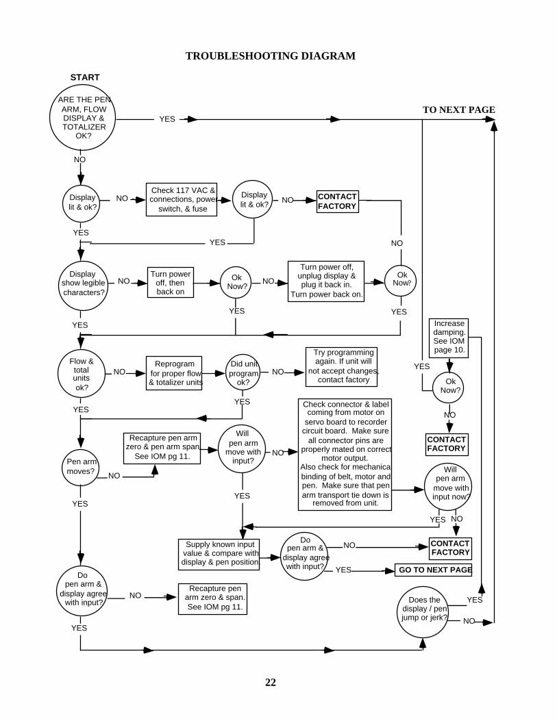
TROUBLESHOOTING DIAGRAM
YES
NO Displaylit & ok? NO CONTACT
FACTORY
Turn poweroff, thenback on
OkNow?
Turn power off,unplug display &plug it back in.
Turn power back on.
OkNow?
NO
YESYES
Reprogramfor proper flow& totalizer units
Did unitprogram
ok?
Try programmingagain. If unit will
not accept changes,contact factory
Check connector & labelcoming from motor on
servo board to recordercircuit board. Make sure
all connector pins areproperly mated on correct
motor output.Also check for mechanicalbinding of belt, motor andpen. Make sure that penarm transport tie down is
removed from unit.
Increasedamping.See IOMpage 10.
OkNow?
CONTACTFACTORY
Willpen arm
move withinput now?
CONTACTFACTORY
YES
GO TO NEXT PAGE
Dopen arm &
display agreewith input?
Supply known inputvalue & compare withdisplay & pen position.
Recapture penarm zero & span.See IOM pg 11.
Does thedisplay / penjump or jerk?
START
ARE THE PENARM, FLOWDISPLAY &TOTALIZER
OK?
NO
Displayshow legiblecharacters?
Flow &totalunitsok?
Pen armmoves?
Dopen arm &
display agreewith input?
YES
YES
YES
YES
NO NO
NO
NOYES
NO NO
YESYES
Recapture pen armzero & pen arm span.
See IOM pg 11.
Willpen arm
move withinput?
YES
YES
NO
YES
NO
NO
NO
YES
NO
TO NEXT PAGE
Check 117 VAC &connections, power
switch, & fuseDisplaylit & ok?
22

See IOM pg 13
Check:chart speed, connection
of chart motor tocircuit board, AC power& chart knob tightness.
4-20 mAretransmitter
ok?NOTE:
Retransmitterfollows pen
arm & display.
Accessoryoutputs ok?
Sampler problemscheck: pulse rate
vs pulse width, propersampler multiplier,
totalizer multiplier andnormally open / normallyclosed relay terminals.
Ok now?
Inoperative
Inaccurate
Check zero & span words.See IOM pg 13 for
adjustments. Make surethe total load is less
than 1000 ohms.
Complete Loop.
Check:chart rotation speed,chart knob tightness,
power outages &motor backlash.
Chartturn ok?
CONTACTFACTORY
Chartturn ok?
YES
NOFast / Slow
Not at all
NO
YES
YES
3000+should be
operating properly.
STOP
YES
NO
Relaysok?
Ok now?Check relayassignment.NO NO CONTACT
FACTORY
NO NO CONTACTFACTORY
YES orsamplernot used
YES
YES
There must be powersupplied for the
retransmitter. Checkwiring connections. See
IOM pg 6 for wiring.
Isretransmitterinoperative orinaccurate?
NOIs current
loopcomplete?
STOP
Procedurecompleted
CONTACT FACTORYNO3000+
operatingproperly ?
YES
Ok now?
NO
YES
NO
4-20 mAretransmittercorrect now?
YESYES
NO
YES
Sampler outputclosing at
proper rate?
Badger Meter Customer Service
(918) 836-8411
23

INSERT 3050 RECORDER WIRING DIAGRAM PICTURE

WARRANTY Badger warrants meters and parts manufactured by it and supplied hereunder to be free from defects in materials and workmanship for a period of 18 months from date of shipment or 12 months from date of installation, whichever period shall be shorter. If within such period any meters or parts shall be proved to Seller's satisfaction to be defective, such meters or parts shall be repaired or replaced at Seller's option. Seller's obligation hereunder shall be limited to such repair and replacement and shall be conditioned upon Seller's receiving written notice of any alleged defect within 10 days after its discovery and, at Seller's option, return of such meters or parts f.o.b. to Seller's factory. THE FOREGOING WARRANTY IS EXCLUSIVE AND IN LIEU OF ALL OTHER EXPRESS OR IMPLIED WARRANTIES WHATSOEVER INCLUDING BUT NOT LIMITED TO IMPLIED WARRANTIES (EXCEPT OF TITLE) OF MERCHANTABILITY AND FITNESS FOR A PARTICULAR PURPOSE. Badger shall not be liable for any defects attributable to acts or omissions of others after shipment, nor any consequential, incidental or contingent damage whatsoever.
NUCLEAR DISCLAIMER Equipment sold by Badger Meter, Inc. Is not intended for use in connection with any nuclear facility or activity unless covered by a specific quotation where the conditions of such usage will be detailed. If equipment is used in a nuclear facility or activity without a supporting quotation, Badger Meter disclaims all liability for any damage, injury or contamination, and the buyer shall indemnify and hold Badger Meter, its officers, agents, employees, successors, assigns and customers, whether direct or indirect, harmless from and against any and all losses, damages or expenses of whatever form or nature (including attorney's fees and other costs of defending any action) which they, or any of them, may sustain or incur, whether as a result of breach of contract, warranty, tort (including negligence), strict liability or other theories of law, by reason of such use.
All rights reserved. All data subject to change without notice.