model 10a manual - fox thermal instruments · the model 10a is an advanced thermal mass ... nlpm,...
TRANSCRIPT
MODEL 10A
INSTALLATION AND INSTRUCTION
MANUAL
399 RESERVATION ROAD MARINA, CA 93933
100133 Revision P

Revision P ECO0675 05/10/10
NOTICE This publication must be read in its entirety before performing any operation. Failure to understand and follow these Instructions could result in serious personal injury and/or damage to the equipment. Should this equipment require repair or adjustment beyond the procedures given herein, contact the factory at:
FOX THERMAL INSTRUMENTS, INC. 399 RESERVATION ROAD
MARINA, CA 93933 (831) 384-4300
FAX: (831) 384-4312 Email: [email protected]
Download Technical Data Sheets from our website: www.foxthermalinstruments.com
Fox Thermal Instruments believes that the information provided herein is accurate, however be advised that the information contained herein is NOT a guarantee for satisfactory results. Specifically, this information is neither a warranty nor guarantee, expressed or implied, regarding performance; merchantability; fitness; or any other matter with respect to the products; nor recommendation for the use of the product/process information in conflict with any patent. Please note that Fox Thermal Instruments, Inc. reserves the right to change and/or improve the product design and specifications without notice.

TABLE OF CONTENTS Page
Page i
SECTION 1 - INTRODUCTION ................................................................................................... 1 1 Theory of Operation................................................................................................................ 1
1.1 Dimension Details........................................................................................................... 2 1.2 Remote Dimension Details ............................................................................................. 3 1.3 Specifications.................................................................................................................. 4
SECTION 2 - INSTALLATION .................................................................................................... 5 2 Installation of Sensors............................................................................................................. 5
2.1 Installation (Insertion Style) ........................................................................................... 5 2.1.1 Mounting - Insertion Style...................................................................................... 5 2.1.2 Installation depth..................................................................................................... 5 2.1.3 Sensor Orientation - Insertion Style........................................................................ 6 2.1.4 Insertion Flowmeter Placement .............................................................................. 6 2.1.5 Flow Body Flowmeter Placement........................................................................... 7 2.1.6 Mounting - Flow Body Style .................................................................................. 7 2.1.7 Sensor Orientation - Flow Body Style.................................................................... 8
SECTION 3 - DISPLAY ................................................................................................................ 9 3 Display .................................................................................................................................... 9
3.1 Display: Scientific Notation........................................................................................... 9 3.2 Menu Options ............................................................................................................... 10 3.3 Display Mode................................................................................................................ 11
3.3.1 Default Display ..................................................................................................... 11 3.3.2 Alternating Display............................................................................................... 11
SECTION 4 - PROGRAMMING................................................................................................. 12 4 Program Access .................................................................................................................... 12
4.1 Cancel ........................................................................................................................... 12 4.2 Duct Area Setup............................................................................................................ 12
4.2.1 Insertion Style ....................................................................................................... 12 4.2.2 Flowbody Style ..................................................................................................... 13
4.3 4-20mA Setup .............................................................................................................. 13 4.3.1 20mA Set .............................................................................................................. 13 4.3.2 4mA Set ................................................................................................................ 14
4.4 Alarm Setup .................................................................................................................. 14 4.4.1 Standard/Failsafe mode......................................................................................... 15 4.4.2 High alarm set ....................................................................................................... 15 4.4.3 Low Alarm Set ...................................................................................................... 16
4.5 Damping Setup............................................................................................................. 16 4.6 Total Reset .................................................................................................................... 16
SECTION 5 - WIRING ................................................................................................................ 18 5 Wiring ................................................................................................................................... 18
5.1 Wiring Installation ........................................................................................................ 18 5.2 Power Input Wiring and Grounding ............................................................................. 18 5.3 4-20mA Output Wiring (Isolated) ................................................................................ 19 5.4 4-20mA Output Wiring (Non-Isolated) ........................................................................ 19 5.5 Alarm Output Wiring.................................................................................................... 19

TABLE OF CONTENTS Page
Page ii
5.6 Remote Wiring Installation........................................................................................... 20 5.6.1 Explosion-Proof Remote Enclosure...................................................................... 20
5.6 Remote Wiring Installation continued.... ...................................................................... 21 5.6.2 Nema 4X Remote Enclosure................................................................................. 21
SECTION 6 - PREVENTATIVE MAINTENANCE ................................................................... 22 6 Preventive Maintenance........................................................................................................ 22
6.1 Access to Electronics .................................................................................................... 22 6.2 Sensor Cleaning ............................................................................................................ 22 6.3 Breakage or Damage of Probe ...................................................................................... 22 6.4 Calibration .................................................................................................................... 22 6.5 Fuse Replacement (Standard and NFP versions).......................................................... 22
6.5.1 To replace bad fuse: .............................................................................................. 23SECTION 7 - TROUBLESHOOTING......................................................................................... 24 7 Troubleshooting .................................................................................................................... 24 7.1 Customer Service and Shipping Instructions................................................................ 25 Warranty ....................................................................................................................................... 26

100133 Model 10A
SECTION 1 - INTRODUCTION
The Model 10A is an advanced Thermal Mass Flowmeter. It is Microprocessor-Based and field programmable. The Fox Power Pro Sensor is designed to be highly sensitive to changes in gas flow resulting in improved accuracy, response time, repeatability and greater operating range (turndown). Turndown of up to 100:1 is typical.
1 Theory of Operation The Thermal Sensor, in the Model 10A, operates on the law that fluids absorb heat. Therefore, a heated sensor placed in a fluid stream transfers heat in proportion to the streams mass velocity. Accurate flow measurements over large temperature and pressure differences can be maintained by putting two sensors in a Balanced Bridge circuit, one sensor detects the fluid temperature and a second sensor is maintained at a constant temperature above the fluid's temperature. The power into the bridge to maintain the constant temperature difference can be directly translated into the mass flow rate. Mass flow The Model 10A measures mass flow directly, an advantage over most flowmeters, which measure volume flow rate. With direct measurement of mass the inaccuracies of multiple process measurements associated with volumetric flow devices are eliminated. Volume flow is incomplete because temperature and pressure are unknown and must be measured separately. For example, the mass of a volume of Gas depends on its temperature and pressure. As temperature and pressure changes the gas volume changes but not its mass. Therefore a device measuring mass flow is independent of temperature and pressure. By defining a Standard as 70°F and 1 Atmosphere, 1 Standard cubic foot of gas equals the mass that is in 1 cubic foot of this gas at 70°F and 1 Atmosphere. The Model 10A measures gas flow directly in mass units including Standard Cubic Feet per Minute (SCFM), Normal Cubic Meters per Hour (NM³/Hr) or Kilograms per Hour (Kg/Hr). Temperature and pressure compensation is not required.
Fox Thermal Instruments Inc., 399 Reservation Road, Marina CA 93933(831) 384-4300 Page 1

Model 10A 100133
Note: Dimensions in parenthesis are centimeters. 1.1 Dimension Details
FLOW BODY STYLE with NPT Connections L H 0.25” 5.80 (14.7) 12.5 (31.8)0.50” 12.0 (30.5) 12.5 (31.8)0.75” 12.0 (30.5) 12.5 (31.8)1.00” 15.0 (38.1) 12.5 (31.8)1.50” 12.0 (30.5) 12.5 (31.8)2.00” 12.0 (30.5) 12.5 31.8)2.50” 18.0 (45.7) 12.6 (32.0)3.00” 18.0 (45.7) 12.6 (32.0)4.00” 18.0 (45.7) 13.1 (33.3)6.00” 24.0 (61.0) 14.2 (36.1)
FLOW BODY STYLE with FLANGE Connections
INSERTION STYLE
0.87"
"LL"1.5"
Length "LL" in inches (cm)
4.0 (10.2)
6.0 (15.2)
9.0 (22.9)
12.0 (30.5)
18.0 (45.7)
24.0 (61.0)
30.0 (76.2)
36.0 (91.4)
Page 2 Fox Thermal Instruments Inc., 399 Reservation Road, Marina, CA 93933 (831) 384-4300
100133 Model 10A
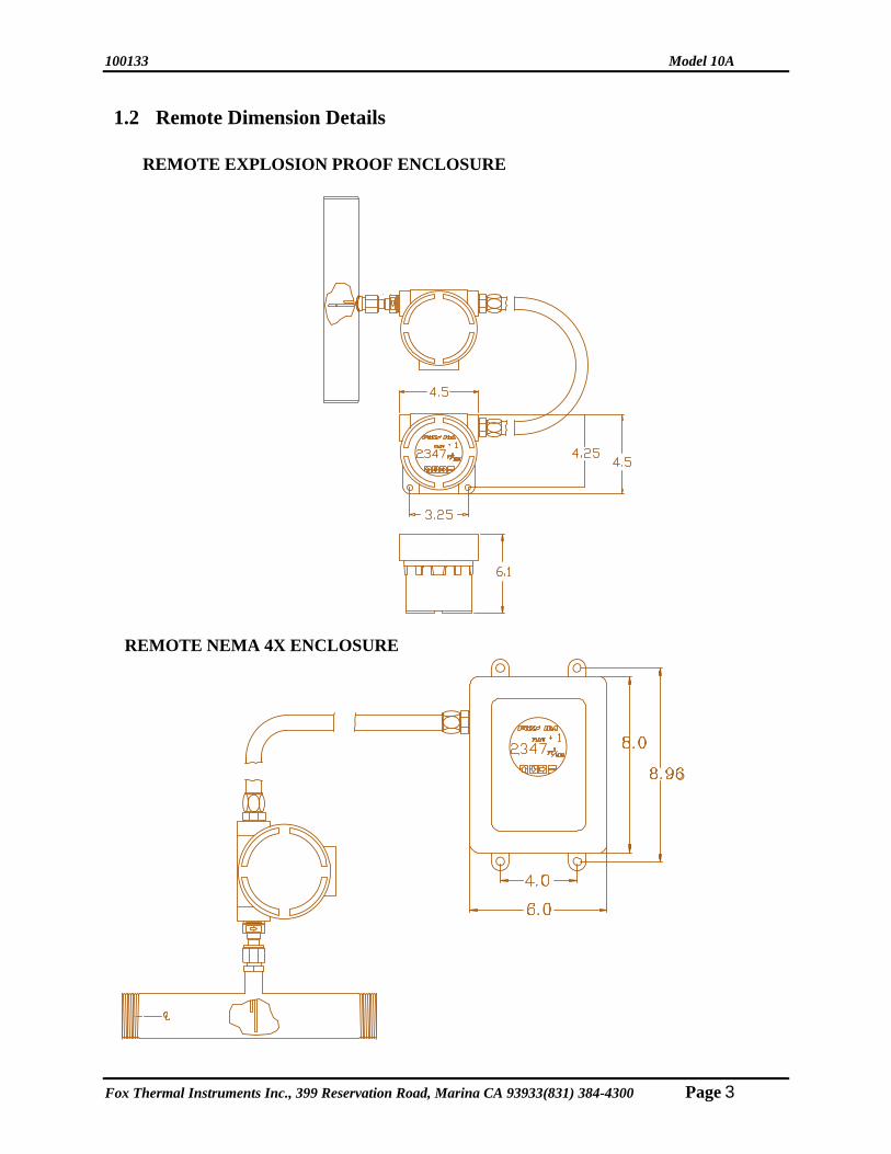
1.2 Remote Dimension Details REMOTE EXPLOSION PROOF ENCLOSURE
REMOTE NEMA 4X ENCLOSURE
Fox Thermal Instruments Inc., 399 Reservation Road, Marina CA 93933(831) 384-4300 Page 3

Model 10A 100133
1.3 Specifications In-Line Flowmeter:
PERFORMANCE SPECS NPT 500 psig (34.5 barg) Accuracy: 150# Flange 230 psig (16 barg) +/- 1.0% of reading + 0.2% of full scale Note: Pressure ratings stated for 100°F (38°C). Calibration: Temperature: NIST traceable Sensor -40 to 250°F (-40 to 121°C) HS Sensor 32 to 400°F (0 to 204°C) Repeatability: Enclosure -40 to 131°F (-40 to 55°C) +/- 0.2% of full scale Input Power: Response Time: Explosion proof enclosure 0.9 seconds (One time constant) 24 VDC +/- 10% 0.75 amp Remote NEMA 4X enclosure OPERATING SPECS 85-250 VAC, 50/60 Hz, 25 Watts Units of Measurement: SCFM, SCFH, NM3H, NLPM, KG/HR, Output: LBS/H, LBS/M, NMPS, SFPM 4-20mA, isolated FlowRates: Alarm relay; dry contact; Insertion Flowmeter 50 VAC, 30 VDC, 3 amps 0 to 32,000 SFPM (0 to 163 NMPS). Here are flow rates for common pipe sizes.
PHYSICAL SPECS
Pipe Size SCFM NM³/Hr 1-½” (40mm) 0-450 0-760 2” (50mm) 0-750 0-1280 3” (80mm) 0-1600 0-2720 4” (100mm) 0-2880 0-4893 6” (150mm) 0-6400 0-10870 8” (200mm) 0-11100 0-18860 10” (250mm) 0-18200 0-30920 12” (300mm) 0-24900 0-42300
Display Parameters: Flow scfm (nm3/h) Total scf (nm3) Elapsed time (hrs) Alternates between readings Remote cabling: 2 conductor, twisted shielded, 18 AWG, 500 ft. max Explosion Proof Enclosure: In-line Flowmeter Cast aluminum; FM and CSA approved Flow range for pipe size for Class 1, Divisions 1, Groups B, C, & D Size SCFM NM³/Hr
0.25” 0-16 0-27 0.50” 0-48 0-82 0.75” 0-120 0-204 1.00” 0-192 0-326 1.25” 0-332 0-564 1.50” 0-450 0-760 2.00” 0-750 0-1280 2.50” 0-1090 0-1855 3.00” 0-1600 0-2720 4.00” 0-2880 0-4893 6.00” 0-6400 0-
10870
T3C (160°C) FM approved Dust Ignition Proof for Class II/III Division 1, Groups E, F & G; indoor/outdoor NEMA Type 4. CE Approved Remote NEMA 4X Enclosure: Fiberglass; Non-explosion proof; NEMA 4X Not FM or CE Approved Sensor Wetted Materials: 316 Stainless Steel, Hastelloy C-276 optional
Note: Standard conditions of air at 70°F and one atmosphere. Consult factory for other gases.
Insertion Flowmeter: Probe diameter 1/2-inch
Installation Coupling 3/4-inch NPT Gas Pressure (maximum): Insertion Flowmeter 500 psig (34.5 barg)
Page 4 Fox Thermal Instruments Inc., 399 Reservation Road, Marina, CA 93933 (831) 384-4300
100133 Model 10A
SECTION 2 - INSTALLATION WARNING! All installation procedures must be performed with the power OFF.
2 Installation of Sensors 2.1 Installation (Insertion Style)
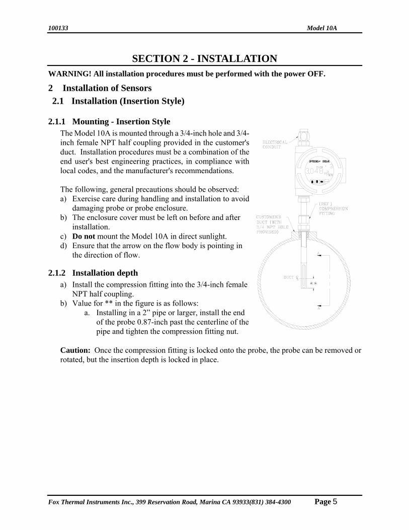
2.1.1 Mounting - Insertion Style The Model 10A is mounted through a 3/4-inch hole and 3/4-inch female NPT half coupling provided in the customer's duct. Installation procedures must be a combination of the end user's best engineering practices, in compliance with local codes, and the manufacturer's recommendations.
The following, general precautions should be observed: a) Exercise care during handling and installation to avoid
damaging probe or probe enclosure. b) The enclosure cover must be left on before and after
installation. c) Do not mount the Model 10A in direct sunlight. d) Ensure that the arrow on the flow body is pointing in
the direction of flow.
2.1.2 Installation depth a) Install the compression fitting into the 3/4-inch female
NPT half coupling. b) Value for ** in the figure is as follows:
a. Installing in a 2” pipe or larger, install the end of the probe 0.87-inch past the centerline of the pipe and tighten the compression fitting nut.
Caution: Once the compression fitting is locked onto the probe, the probe can be removed or rotated, but the insertion depth is locked in place.
Fox Thermal Instruments Inc., 399 Reservation Road, Marina CA 93933(831) 384-4300 Page 5

Model 10A 100133
2.1.3 Sensor Orientation - Insertion Style a) Install the shorter sensor probe upstream from the longer one.
(View A-A) b) Ensure that the arrow on the flow body is pointing in the
direction of flow. c) Install unit with sensor probes parallel to flow within ±10°.
(Section B-B)
Note: In extreme low flow measurements (below 30 ft/min), convection heat from the longer probe can contact the shorter probe (see View A-A). In these applications, choose a mounting that prevents this from occurring. (ex. horizontal mounting)
2.1.4 Insertion Flowmeter Placement Install the Model 10A Insertion style flowmeter so that it is far enough away from corners, obstructions, or changes in line sizes (fifteen diameters upstream and ten diameters downstream) to ensure a consistent flow profile.
Page 6 Fox Thermal Instruments Inc., 399 Reservation Road, Marina, CA 93933 (831) 384-4300
100133 Model 10A
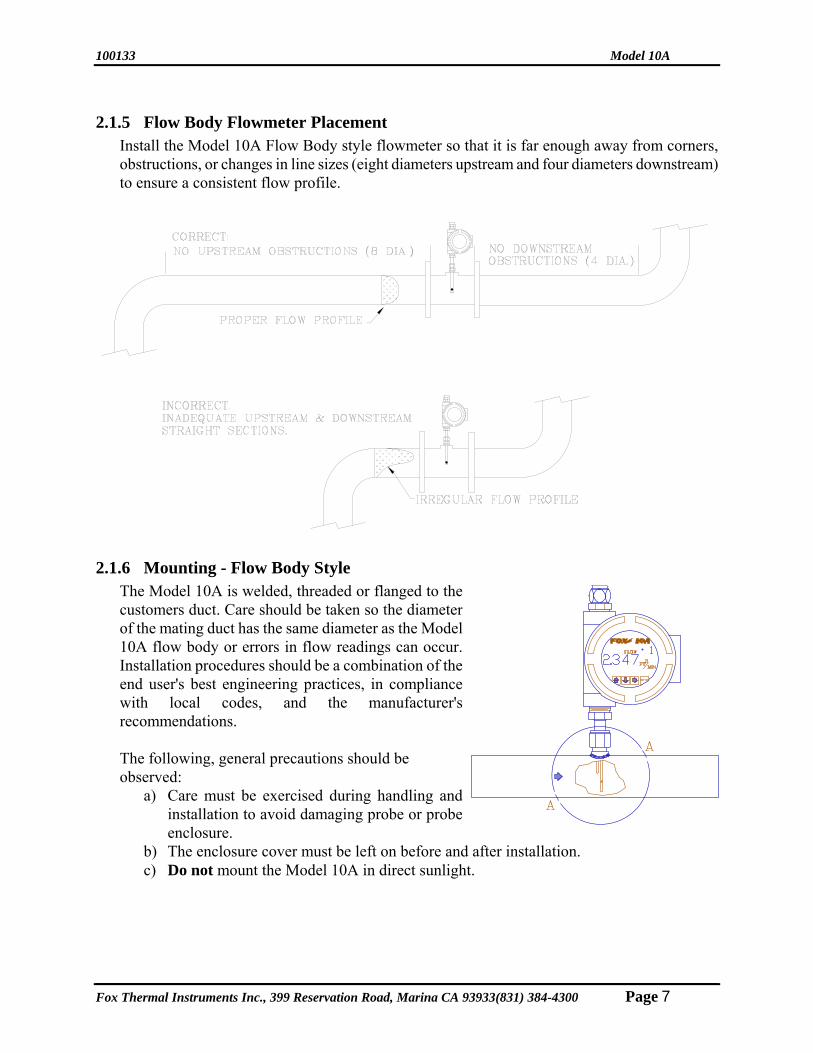
2.1.5 Flow Body Flowmeter Placement Install the Model 10A Flow Body style flowmeter so that it is far enough away from corners, obstructions, or changes in line sizes (eight diameters upstream and four diameters downstream) to ensure a consistent flow profile.
2.1.6 Mounting - Flow Body Style The Model 10A is welded, threaded or flanged to the customers duct. Care should be taken so the diameter of the mating duct has the same diameter as the Model 10A flow body or errors in flow readings can occur. Installation procedures should be a combination of the end user's best engineering practices, in compliance with local codes, and the manufacturer's recommendations.
The following, general precautions should be observed:
a) Care must be exercised during handling and installation to avoid damaging probe or probe enclosure.
b) The enclosure cover must be left on before and after installation. c) Do not mount the Model 10A in direct sunlight.
Fox Thermal Instruments Inc., 399 Reservation Road, Marina CA 93933(831) 384-4300 Page 7

Model 10A 100133
2.1.7 Sensor Orientation - Flow Body Style a) Install the flow body so that the arrow on the outside of the
flow body is in the direction of flow. This will insure the shorter sensor is upstream from the longer one.
Note: In extreme low flow measurements (below 30 ft/min), convection heat from the longer probe can contact the shorter probe (see View A-A). In these applications, choose a mounting that prevents this from occurring. (ex. horizontal mounting).
Page 8 Fox Thermal Instruments Inc., 399 Reservation Road, Marina, CA 93933 (831) 384-4300

100133 Model 10A
SECTION 3 - DISPLAY 3 Display
The display is made up of LEDs with an overlay. The overlay allows only the backlit information to be visible. .
3.1 Display: Scientific Notation
The Model 10A displays in Scientific Notation. Scientific Notation consists of two factors. The first factor is a number greater than or equal to one (1) and less than ten (10). The second factor is a power of ten (10). See illustrated examples below.
Example 1: 4 foot diameter duct:
π/4 x (4FT)2 = 12.57 FT2 12.57 = 1.257x101
Shown as 1.257 +1 FT2
Example 2: 2 inch diameter duct: π/4 x (2/12FT)2 = 0.02182 FT2 0.02182 = 2.182x10⁻²
Shown as 2.182 -2 FT2
Fox Thermal Instruments Inc., 399 Reservation Road, Marina CA 93933(831) 384-4300 Page 9
Model 10A 100133
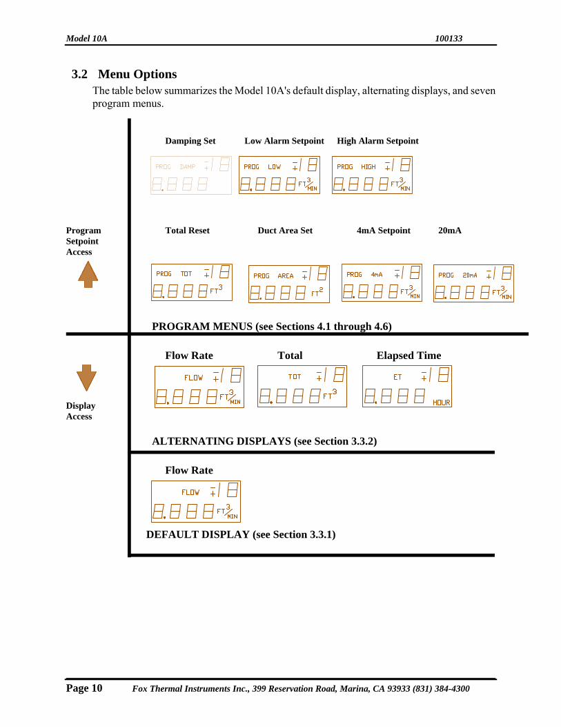
3.2 Menu Options The table below summarizes the Model 10A's default display, alternating displays, and seven program menus.
Damping Set Low Alarm Setpoint High Alarm Setpoint Program Total Reset Duct Area Set 4mA Setpoint 20mA Setpoint Access
PROGRAM MENUS (see Sections 4.1 through 4.6)
Flow Rate Total Elapsed Time
Display Access
ALTERNATING DISPLAYS (see Section 3.3.2)
Flow Rate
DEFAULT DISPLAY (see Section 3.3.1)
Page 10 Fox Thermal Instruments Inc., 399 Reservation Road, Marina, CA 93933 (831) 384-4300

100133 Model 10A
3.3 Display Mode There are two display types available; Default and Alternating. The Default display is factory configured. If the Alternating display is desired, the jumper to the right (bottom side of center board, see illustration) must be removed. (Cutting the jumper out is acceptable.)
3.3.1 Default Display In default mode, the Model 10A displays "FLOW" (Standard Volumetric) continuously.
"FLOW" (Standard Volumetric flow) is expressed in "Ft³/MIN" (cubic feet per minute).
3.3.2 Alternating Display Three displays are available under Alternating Display; Flow Rate, Total Standard Volume (TOT), and Elapsed Time (ET). The Display Jumper must be removed to access these displays (as shown above). Each display will alternate at 5 second intervals.
"FLOW" (Standard Volumetric flow) is expressed in "Ft³/MIN" (cubic feet per minute).
"TOT" (Total Standard Volume) is expressed in "Ft3" (cubic feet). "ET" (Elapsed time) is expressed in "Hour" (hours).
Fox Thermal Instruments Inc., 399 Reservation Road, Marina CA 93933(831) 384-4300 Page 11
Model 10A 100133
SECTION 4 - PROGRAMMING
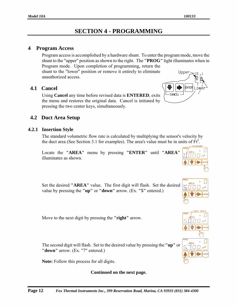
4 Program Access Program access is accomplished by a hardware shunt. To enter the program mode, move the shunt to the "upper" position as shown to the right. The "PROG" light illuminates when in Program mode. Upon completion of programming, return the shunt to the "lower" position or remove it entirely to eliminate unauthorized access.
4.1 Cancel
Using Cancel any time before revised data is ENTERED, exits the menu and restores the original data. Cancel is initiated by pressing the two center keys, simultaneously.
4.2 Duct Area Setup
4.2.1 Insertion Style The standard volumetric flow rate is calculated by multiplying the sensor's velocity by the duct area (See Section 3.1 for examples). The area's value must be in units of Ft2.
Locate the "AREA" menu by pressing "ENTER" until "AREA" illuminates as shown.
Set the desired "AREA" value. The first digit will flash. Set the desired value by pressing the "up" or "down" arrow. (Ex. "5" entered.)
Move to the next digit by pressing the "right" arrow.
The second digit will flash. Set to the desired value by pressing the "up" or "down" arrow. (Ex. "7" entered.) Note: Follow this process for all digits.
Continued on the next page.
Page 12 Fox Thermal Instruments Inc., 399 Reservation Road, Marina, CA 93933 (831) 384-4300

100133 Model 10A
4.2 Duct Area Setup (Insertion Style Only) continued...
Move to the exponent digits by pressing the "right" arrow.
Set the desired value by pressing the "up" or "down" arrow. (Ex: "+ 2" entered.) Note: Once the complete value is entered, any portion can be changed as outlined above.
Press "ENTER" to record the desired value. "OK" will flash signifying the "AREA" value has been accepted. The unit will automatically proceed to the next program setup.
4.2.2 Flowbody Style The duct area setup for flowbody (also known as Inline) style units are configured at the factory. No other adjustments are necessary.
4.3 4-20mA Setup
The 4-20mA output indicates any flow rate that the customer selects as long as the flow meter has been calibrated within that range.
4.3.1 20mA Set Locate the "20mA" program menu by pressing "ENTER" until "20mA" illuminates as shown.
Set the desired "20mA" value. The first digit will flash. Set the desired value by pressing the "up" or "down" arrow. (Ex. "5" entered.)
Move to the next digit by pressing the "right" arrow.
Continued on the next page.
4.3.1 20mA set continued...
Fox Thermal Instruments Inc., 399 Reservation Road, Marina CA 93933(831) 384-4300 Page 13
Model 10A 100133
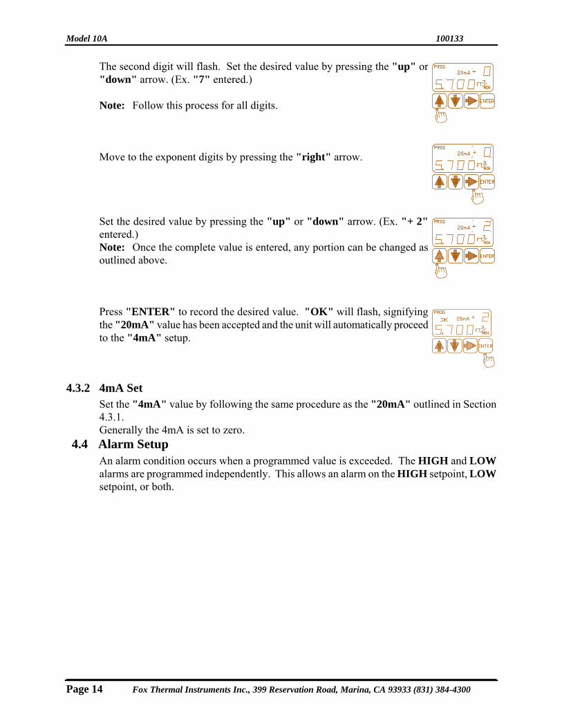
The second digit will flash. Set the desired value by pressing the "up" or "down" arrow. (Ex. "7" entered.)
Note: Follow this process for all digits. Move to the exponent digits by pressing the "right" arrow.
Set the desired value by pressing the "up" or "down" arrow. (Ex. "+ 2" entered.)
Note: Once the complete value is entered, any portion can be changed as outlined above.
Press "ENTER" to record the desired value. "OK" will flash, signifying the "20mA" value has been accepted and the unit will automatically proceed to the "4mA" setup.
4.3.2 4mA Set Set the "4mA" value by following the same procedure as the "20mA" outlined in Section 4.3.1. Generally the 4mA is set to zero.
4.4 Alarm Setup An alarm condition occurs when a programmed value is exceeded. The HIGH and LOW alarms are programmed independently. This allows an alarm on the HIGH setpoint, LOW setpoint, or both.
Page 14 Fox Thermal Instruments Inc., 399 Reservation Road, Marina, CA 93933 (831) 384-4300

100133 Model 10A
4.4.1 Standard/Failsafe mode The standard alarm mode energizes the relay during an alarm condition. In Failsafe mode, the relay is energized upon power up and de-energizes during an alarm condition or power failure. If Failsafe mode is desired, the jumper to the left (bottom side of center board, see illustration) must be removed. (Cutting the jumper out is acceptable.)
4.4.2 High alarm set Locate the "HIGH" program menu by pressing "ENTER" until "HIGH" illuminates as shown.
Note: The alarm can be disabled by setting the value to 0.000 + 0.
Set the desired "HIGH" alarm value. The first digit will flash. Set the desired value by pressing the "up" or "down" arrow. (Ex. "5" entered.)
Move to the next digit by pressing the "right" arrow.
The second digit will flash. Set the desired value by pressing the "up" or "down" arrow. (Ex. "7" entered.) Note: Follow this process for all digits.
Fox Thermal Instruments Inc., 399 Reservation Road, Marina CA 93933(831) 384-4300 Page 15

Model 10A 100133
Move to the exponent digits by pressing the "right" arrow. Set the desired value by pressing the "up" or "down" arrow. (Ex. "+ 2" entered.)
Note: Once the complete value is entered, any portion can be changed following the procedure outlined above.
Press "ENTER" to record the desired value. "OK" will flash, signifying the "HIGH" alarm value has been accepted. The unit will automatically proceed to the "LOW" setup.
4.4.3 Low Alarm Set Set the "LOW" alarm value by following same the procedure as outlined in 4.4.2. 4.5 Damping Setup
"Damping" is an output filter that is extremely useful when noisy flow environments cause the display and output to fluctuate, making the display difficult to read. (Output updates at 2000 times per second. Dampening range is 2-20,000.)
For example: A Damping value of "5" takes the last 5 readings, computes the average, and sends it to the output. During each update, the oldest reading is thrown out, the last 5 readings are gathered, the average is computed, and sent to the output.
Locate the "DAMP" (damping) program menu by pressing "ENTER" until "DAMP" illuminates as shown.
Set the desired "DAMP" value. The right digit will flash. Set the desired value by pressing the "up" or "down" arrow. (Ex. "5" entered.) Move to the next digit by pressing the "right" arrow. Note:"0" was acceptable in this example and did not need to be changed.
Press "ENTER" to record the desired value. "OK" will flash, signifying the "DAMP" value has been reset. The unit will automatically proceed to the next program setup.
4.6 Total Reset
"TOTAL" is a count of standard volumetric flow (standard cubic feet) over an elapsed time. Totaling halts when the system is in program mode. To begin a new total and elapsed time,
Page 16 Fox Thermal Instruments Inc., 399 Reservation Road, Marina, CA 93933 (831) 384-4300

100133 Model 10A
the values must be "reset" to zero.
Locate the "TOT" (Total) program menu by pressing "ENTER" until "TOT" and the first digit illuminates as shown.
Press both the "up" and "down" arrow simultaneously to reset the total value to "zero".
Press "ENTER" to record the desired value. "OK" will flash, signifying the "TOT" value has been reset. The unit will automatically proceed to the next program setup. Note: Cycle through the Program Setup Menus to reach "TOT" again to verify the Total Volume has been reset to zero. "ET" (Elapsed time) is also reset to zero when "TOT" is reset.
Fox Thermal Instruments Inc., 399 Reservation Road, Marina CA 93933(831) 384-4300 Page 17

Model 10A 100133
SECTION 5 - WIRING WARNING! All installation procedures must be performed with the power OFF. 5 Wiring
Wiring is for power and signal connections. All plumbing and electrical installations of flow meters must be a combination of the end user's best engineering practices, in compliance with local codes, and the manufacturer's recommendations.
5.1 Wiring Installation
Wiring is accomplished by removing the Circuit board "Assembly" as shown in the figure to the right. a. Place Allen wrench (7/64" shipped with flow meter)
in both top panel holes and loosen the 2 cap screws completely. Carefully lift assembly out of enclosure.
b. Bring customer supplied wires into enclosure through conduit hole. Cut wires to 4" service loop length (use Stranded copper wire, no larger than 16 gauge).
Caution: Wires must not become pinched between the assembly's heat sink and enclosure upon reinstallation. c. Using wiring diagrams in Section 5.2, 5.3 and 5.4,
attach wires to terminal block. d. Before placing assembly back into enclosure check
the position of the 4 holes located in the enclosure bottom. Rotate assembly to the desired view angle, which will allow the Cap screws to be reinstalled into 2 of these holes.
e. Install the assembly into enclosure. Using the Allen wrench, tighten both Cap screws into enclosure holes.
Caution: The assembly must be installed into enclosure to prevent electronics from overheating causing shut down of the Model 10A.
5.2 Power Input Wiring and Grounding a. Power required 24Vdc +/- 10% 1 amp. b. Enclosure must be properly grounded to protect electronics from static discharges.
(Grounding lugs are provided on the outside of the enclosure.)
Page 18 Fox Thermal Instruments Inc., 399 Reservation Road, Marina, CA 93933 (831) 384-4300

100133 Model 10A
5.3 4-20mA Output Wiring (Isolated)
5.4 4-20mA Output Wiring (Non-Isolated)
5.5 Alarm Output Wiring a. Maximum load 3amp at 50 VAC or 30 VDC. b. It is recommended that a RC Surge suppressor be installed across the load to
minimize transient voltages and extend relay life.
Fox Thermal Instruments Inc., 399 Reservation Road, Marina CA 93933(831) 384-4300 Page 19

Model 10A 100133
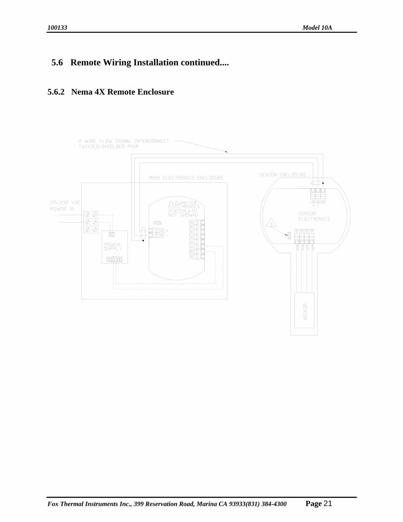
5.6 Remote Wiring Installation WARNING! All installation procedures must be performed with the power OFF. All plumbing and electrical installations of flow meters must be a combination of the end user's best engineering practices, in compliance with local codes, and the manufacturer's recommendations. Note: Both enclosures must be properly grounded to protect electronics from static discharges. (Grounding lugs are provided on the outside of the enclosures.) Wiring installation is performed in two (2) areas: 24 VDC power input and flow signal interconnect (2 wires).
5.6.1 Explosion-Proof Remote Enclosure 24 VDC Input Two (2) 3/4 NPT female holes are provided in the Remote Electronics Enclosure. (Reference Section 1.3 for more information.) Place power wires through the most convenient hole for (8 pin) 24 VDC Power-In terminal. Connect wires to the terminals as shown in the diagram below. 2 Wire Flow Signal Interconnect Connect the flow signal through the remaining clearance hole. Install 16 gauge, two wire, twisted/shielded pair through the proper conduit. Connect to proper terminal locations as shown in illustration below.
Page 20 Fox Thermal Instruments Inc., 399 Reservation Road, Marina, CA 93933 (831) 384-4300
100133 Model 10A
5.6 Remote Wiring Installation continued....
5.6.2 Nema 4X Remote Enclosure
Fox Thermal Instruments Inc., 399 Reservation Road, Marina CA 93933(831) 384-4300 Page 21

Model 10A 100133
SECTION 6 - PREVENTATIVE MAINTENANCE
6 Preventive Maintenance WARNING! Before attempting any maintenance take the necessary safety precautions before removing probe from duct (ex., purge lines of toxic and/or explosive gas, depressurize line, etc.). WARNING! Turn input power OFF before removing or installing circuit board assembly from enclosure.
Page 22 Fox Thermal Instruments Inc., 399 Reservation Road, Marina, CA 93933 (831) 384-4300
6.1 Access to Electronics The explosion proof enclosure contains the Circuit board "Assembly" (CBA) as shown in the figure to the right. To remove the CBA for fuse replacement or to remove a jumper, loosen the 2 cap screws (7/64”Allen wrench), which holds the enclosure to the base of the flow meter. Carefully lift assembly out of enclosure. Keep in mind the enclosure is attached to the flow meter via the wires connecting the CBAs to the connector. There is enough service loop to allow access to all the internal components. Before placing assembly back into enclosure check the position of the 4 holes located in the enclosure bottom. Rotate assembly to the desired view angle, which will allow the Cap screws to be reinstalled into 2 of these holes. Install the assembly into enclosure. Using the Allen wrench, tighten both Cap screws into enclosure holes. 6.2 Sensor Cleaning
Even though the sensor is insensitive to small amounts of contamination, continued use in dirty environments will necessitate periodic cleaning. Remove the unit from duct, exposing the sensor elements. If they are visibly dirty, clean them with water or alcohol (ethanol) and an artist’s brush until they appear clean again. Even though the sensor elements are rugged and breakage resistant, avoid touching them with any solid object and use a light touch while cleaning them. 6.3 Breakage or Damage of Probe
If the sensor is broken or damaged, the probe and electronics must be returned to the factory. A new sensor will be installed and calibrated. Refer to Section 7.1, Customer Service and Shipping Instructions. 6.4 Calibration
To insure the continuing high accuracy of your Model 10A Flow Meter, Fox Thermal Instruments Inc. provides a full NIST traceable calibration. 6.5 Fuse Replacement (Standard and NFP versions)
WARNING! Turn input power OFF before removing or installing circuit board assembly from enclosure and before removing or installing fuses. Use only recommended fuse replacements.
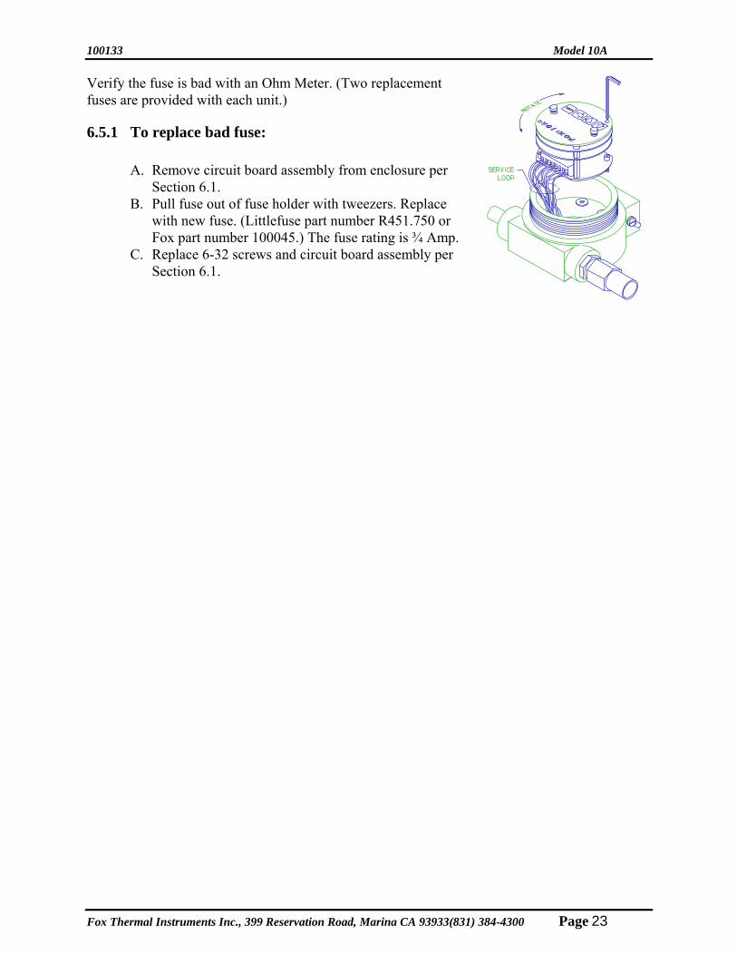
100133 Model 10A Verify the fuse is bad with an Ohm Meter. (Two replacement fuses are provided with each unit.)
6.5.1 To replace bad fuse:
A. Remove circuit board assembly from enclosure per Section 6.1.
B. Pull fuse out of fuse holder with tweezers. Replace with new fuse. (Littlefuse part number R451.750 or Fox part number 100045.) The fuse rating is ¾ Amp.
C. Replace 6-32 screws and circuit board assembly per Section 6.1.
Fox Thermal Instruments Inc., 399 Reservation Road, Marina CA 93933(831) 384-4300 Page 23
Model 10A 100133
Page 24 Fox Thermal Instruments Inc., 399 Reservation Road, Marina, CA 93933 (831) 384-4300
SECTION 7 - TROUBLESHOOTING
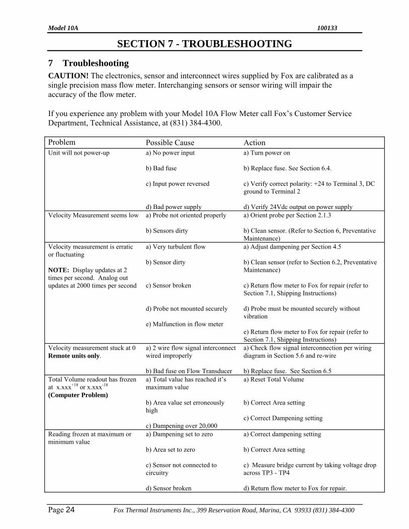
7 Troubleshooting CAUTION! The electronics, sensor and interconnect wires supplied by Fox are calibrated as a single precision mass flow meter. Interchanging sensors or sensor wiring will impair the accuracy of the flow meter. If you experience any problem with your Model 10A Flow Meter call Fox’s Customer Service Department, Technical Assistance, at (831) 384-4300. Problem Possible Cause Action Unit will not power-up a) No power input
b) Bad fuse c) Input power reversed d) Bad power supply
a) Turn power on b) Replace fuse. See Section 6.4. c) Verify correct polarity: +24 to Terminal 3, DC ground to Terminal 2 d) Verify 24Vdc output on power supply
Velocity Measurement seems low a) Probe not oriented properly b) Sensors dirty
a) Orient probe per Section 2.1.3 b) Clean sensor. (Refer to Section 6, Preventative Maintenance)
Velocity measurement is erratic or fluctuating NOTE: Display updates at 2 times per second. Analog out updates at 2000 times per second
a) Very turbulent flow b) Sensor dirty c) Sensor broken d) Probe not mounted securely e) Malfunction in flow meter
a) Adjust dampening per Section 4.5 b) Clean sensor (refer to Section 6.2, Preventative Maintenance) c) Return flow meter to Fox for repair (refer to Section 7.1, Shipping Instructions) d) Probe must be mounted securely without vibration e) Return flow meter to Fox for repair (refer to Section 7.1, Shipping Instructions)
Velocity measurement stuck at 0 Remote units only.
a) 2 wire flow signal interconnect wired improperly b) Bad fuse on Flow Transducer
a) Check flow signal interconnection per wiring diagram in Section 5.6 and re-wire b) Replace fuse. See Section 6.5
Total Volume readout has frozen at x.xxx+18 or x.xxx-18
(Computer Problem)
a) Total value has reached it’s maximum value b) Area value set erroneously high c) Dampening over 20,000
a) Reset Total Volume b) Correct Area setting c) Correct Dampening setting
Reading frozen at maximum or minimum value
a) Dampening set to zero b) Area set to zero c) Sensor not connected to circuitry d) Sensor broken
a) Correct dampening setting b) Correct Area setting c) Measure bridge current by taking voltage drop across TP3 - TP4 d) Return flow meter to Fox for repair.

100133 Model 10A
Fox Thermal Instruments Inc., 399 Reservation Road, Marina CA 93933(831) 384-4300 Page 25
Problem Possible Cause Action Reading won’t zero a) Out of calibration
b) Sensor broken
a) Refer to Section 6, Preventative Maintenance a1) Measure bridge current by taking voltage drop across TP3 - TP4 b) Return flow meter to Fox for repair (refer to Section 7.1, Shipping Instructions)
4-20 mA output not indicating 4 mA at zero flow
a) Input connection reversed b) Excessive current loop resistance. Loop resistance must be less than 600 ohms
a) Verify correct polarity b) Use larger gauge wire or change load resistance
7.1 Customer Service and Shipping Instructions
The Fox Thermal Instruments, Inc. Customer Service Department can be reached at (831) 3 84-4300. Please have the model and serial number available when you call. If it becomes necessary to return a Model 10A Mass Flow Meter to Fox, obtain a Return Material Authorization from the Customer Service Department. Unless specifically instructed to do otherwise, the entire flow meter must be returned, including all electronics. Use extreme care to protect the sensor/probe when packaging for return to Fox. We highly recommend placing a piece of PVC pipe over insertion flowmeters sensor/probe and taping in place. Return inline flowmeters installed in its flow body. Surround the flowmeter with foam or bubble wrap and tape to ensure it stays in place. Popcorn packing material is not recommended. Fox recommends returning the entire flowmeter. This allows us to perform complete diagnostic tests. Fox recommends returning electronic circuit boards in the flowmeter enclosure. This will help avoid shipping damage and help prevent circuit board failures due to electrostatic discharge. Clean and decontaminate all wetted parts. Please include information describing the difficulties experienced, purchase order number under which the equipment was purchased, and a contact name and phone number.
Be sure to include complete return shipping instructions. We cannot deliver to post office boxes. Ship to the following address:
Fox Thermal Instruments, Inc. 399 Reservation Road
Marina, CA 93933 ATTN: SERVICE DEPT.
RMA NUMBER:
Model 10A 100133
Page 26 Fox Thermal Instruments Inc., 399 Reservation Road, Marina, CA 93933 (831) 384-4300
Warranty a. FOX warrants that the products furnished under this Agreement will be free from
defects in material and workmanship for a period of one year from the date of shipment. The customer shall provide notice of any defect to FOX, within one week after the Customer’s discovery of such defect. The sole obligation and liability of FOX under this warranty shall be to repair or replace, at its option, without cost to the Customer, the defective product or part.
b. Upon request by FOX, the product or part claimed to be defective shall immediately be returned at the Customer's expense to FOX. Replaced or repaired products or parts will be shipped to the Customer at the expense of FOX. FOX shall have the right of final determination as to the existence and cause of defect.
c. There shall be no warranty or liability for any products or parts that have been subject to misuse, accident, negligence, failure of electric power or modification by the Customer without the written approval of FOX. This warranty does not cover damage caused by Customer’s exposure of the goods to corrosive or abrasive environments. Final determination of warranty eligibility shall be made by FOX. If a warranty claim is considered invalid for any reason, the Customer will be charged for services performed and expenses incurred by FOX in handling and shipping the returned unit.
d. The liability of FOX shall be limited to replacing or repairing, at its option, any defective parts which are returned. Labor and related expenses incurred by the Customer to install replacement parts are not covered by this warranty.
e. As to replacement parts supplied or repairs made during the original warranty period, the warranty period for the replacement or repaired part shall terminate with the termination of the warranty period of the original product or part.
f. The use of FOX products are under exclusive control of the buyer. No warranty, express or implied, is given for the calibration, accuracy or workmanship of end-use product into which Fox products are installed. FOX can only be held responsible for the calibration and accuracy of product supplied by FOX. FOX specifically denies any liability arising from the buyer’s application of FOX products including any physical injuries or death arising directly or indirectly out of or in connection with the manufacture, sale, use, or defect of the products sold hereunder.
g. No warranty is made with respect to custom equipment or products produced to Buyer's specifications except as specifically stated in writing by FOX and contained in the agreement.
h. THE FOREGOING WARRANTY CONSTITUTES THE SOLE LIABILITY OF FOX AND THE CUSTOMER'S SOLE REMEDY WITH RESPECT TO THE PRODUCT AND IS IN-LIEU OF ALL OTHER WARRANTIES. FOX DISCLAIMS ALL WARRANTIES, EXPRESS OR IMPLIED, INCLUDING ANY WARRANTY OF MERCHANTABILITY OR FITNESS FOR A PARTICULAR PURPOSE.
i. In no case are products to be returned without first obtaining permission and a Return Authorization number from FOX.

100133 Model 10A
Fox Thermal Instruments Inc., 399 Reservation Road, Marina CA 93933(831) 384-4300 Page 27
NOTES

Fox Thermal Instruments, Inc.
399 Reservation Road Marina, CA, 93933 Phone: (831) 384-4300 FAX: (831) 384-4312