mode 1 wiring diagram - directeddealers.com · 3. when the remote starter is engaged, the led will...
TRANSCRIPT

© 2006 Directed Electronics, All rights reserved. N1100X 05-06
PRODUCT DESCRIPTION
The 1100X interface module is used when installing remote start products in Toyota/Lexus vehicles equipped with a factory immobilizer. The 1100X allows for easy interfacing between the remote start and the factory immobilizer, while maintaining the integrity of the OEM system. The factory transponder-based anti-theft system uses a small electronic chip hidden in the key to send a code to the vehicle’s transceiver when the ignition is energized. The key must be placed in the ignition and turned to the RUN position. This energizes a coil surrounding the key, which in turn energizes the chip, which sends a code to the vehicle. If the vehicle does not detect the code being sent, the vehicle will start and then immediately shut off or will just crank, and the anti-theft light will fl ash. The 1100X provides a valid code to the vehicle whenever it is remote started, but does not affect the immobilizer system during normal vehicle operation; the immobilizer system remains fully functional.
PROGRAMMING INSTRUCTIONS
STEP 1: SELECTS INSTALLATION MODEThis procedure determines the module will operate using a conventional manner using the ground when running signal.CAUTION: For security purposes this step is programmable only once. Please ensure the proper mode is activated. To change the installation mode, the module must be reset and repro-grammed (see Factory Reset procedure). 1. Complete wire connections to vehicle and insert harnesses into module. 2. Press programming button once or twice to select the installation type. The LED will fl ash green the same number of times to confi rm selection.
1 x green fl ash = Unused mode. 2 x green fl ashes = Standard installation mode (for directed systems).
3. After selecting the correct mode, press and hold the programming button until the LED displays a solid green light. 4. The installation mode is now selected and programmed.
STEP 2: PROGRAMMING PROCEDURE MODE 1 1. Insert the vehicle key into the ignition and turn to “run” position.2. The module LED will illuminate green to confi rm learning procedure has been completed.3. If LED illuminates red, remove key and follow LED diagnostic nstructions.
LED DIAGNOSTICS 1. During STEP 2, if the LED fl ashes red this indicates the wire connections are incorrect. Insure connections are soldered, no T-Taps or Scotch Locs 2. Once programming has been completed, if the LED fl ashes red, the module failed to learn correctly. Reset module and repeat the programming procedure. 3. When the remote starter is engaged, the LED will fl ash green to indicate the module has been correctly pro grammed. If the LED remains illuminated red, the device is incorrectly programmed.
FACTORY RESET 1. Unplug all connectors from the module. 2. Press and hold the programming button while inserting the 4-PIN standard connector. 3. The LED will begin to fl ash red. Immediately release the program ming button. The LED will turn on solid for 2 seconds to confi rm module reset. 4. Plug remaining connectors and return to: STEP 1: SELECT INSTALLATION MODE.
1100X INSTALLATION GUIDEMODE 1
MODE 1 WIRING DIAGRAMPlease refer to the Vehicle Wiring Cross Reference Chart to identify vehicle-specifi c pin locations & wire colors.
BLUE/RED - SYNCHRO BLUE/YELLOW (NC)GREEN/RED - DATAGREEN/YELLOW (NC)GRAY/RED - CLOCK CAR SIDEGRAY/YELLOW (NC)ORANGE - KEY B (+)PINK/BLACK - DATA KEY SIDEPINK - DATA ECM SIDE
KEY
WH
ITE
/BLA
CK
- C
LOC
K-K
EY
SID
E
WH
ITE
/RE
D -
CLO
CK
-CA
R S
IDE
W
HIT
E (N
C)
RED - 12V BLACK - GROUNDNO WIRE (NC)BLUE/WHITE - GROUND-OUT WHEN RUNING REMOTE
STARTER
Programming Button
LED
( )1 AMP DIODE
Use isolated ground-out when running from remote starter to power key sense.
WARNING! READ MANUAL PRIOR TO INSTALLATION

© 2006 Directed Electronics, All rights reserved. N1100X 05-06
MODE 1 VEHICLE WIRING CROSS REFERENCE CHART*IMMOBILIZER CONNECTOR
MODEL YEAR PIN KEY B (+) PIN DATA PIN CLOCK PIN SYNCRO PIN GROUND (-) KEY SENSE*
CONNECT.
Avalon 1998-1999 1 Light Green 2 Black/Red 3 Yellow 4 Green 5 White/Black Red/Yellow* A
Avalon 2000-2004 1 Black/White 2 Pink/Green 3 Blue/Orange 4 Blue/yellow 5 White/Black Red/White* A
Camry 1998-2001 1 Black/Yellow 2 Green/White 3 Red/Blue 4 Blue/Yellow 5 White/Black Blue/Black* A
Camry 4cyl. 2002-2005 1 Black/Red 4 Green/White 3 Red/Blue 5 Blue/Yellow 7 White/Black Blue* B
Camry 6cyl. 2002-2005 1 Black/Red 4 Green/White 3 Red/Blue 5 Blue/Yellow 7 White/Black Blue* B
ES300 1998-2001 1 Black/Yellow 2 Green/White 3 Red/Blue 4 Blue/Yellow 5 White/Black Blue/Black* E
ES300 2002-2003 1 Black/Red 4 Green/White 3 Red/Blue 5 Blue/Yellow 7 White/Black Blue* B
GS 300 1998-2005 1 Black/Red 2 Green/Black 3 Black/white 4 Blue/Red 5 White/Black Yellow* A
GS 400 1998-2000 1 Black/Red 2 Green/Black 3 Black/white 4 Blue/Red 5 White/Black Yellow*
GS 430 2001-2005 1 Black/Red 2 Green/Black 3 Black/white 4 Blue/Red 5 White/Black Yellow* A
Highlander 1999-2000 1 White/Blue 2 Grey/Red 3 Red/Black 4 Pink/Black 5 Brown Yellow/Red*
Highlander 2001-2003 1 White 4 Grey/Blue 3 Pink 5 Grey 7 White/Black Blue* B
IS 300 2001 1 Black/Red 2 Green 3 Purple 4 Pink 5 White/Black Black/Yellow* A
IS 300 2002-2005 1 Black/Red 2 Green/Black 3 Purple 4 Pink/Black 5 White/Black Black/Yellow* A
Land Cruiser 1998-2002 1 Black/Yellow 2 Blue/Black 3 Purple/Green 4 Red/Yellow 5 White/Black Red/Black*
LS 400 1998-2000 1 White 2 Red/White 3 Red/Black 4 Red 5 White/Black Yellow*
LX 470 1998-2002 1 Black/Yellow 2 Blue/Black 3 Violet/Green 4 Red/Yellow 5 White/Black Red/White* B
RAV4 2001-2003 5 Black/Red 2 Yellow/Green 4 Yellow 1 Yellow/Black 3 White/Black Blue/Red* C
RX 300 1999 1 Blue/White 2 Purple 3 Black 4 Grey 5 White/Black Blue*
RX 300 2000 1 Blue/White 2 Purple 3 Pink 4 Grey 5 White/Black Blue*
RX 300 2001-2003 1 Black/Red 2 Purple 3 Pink 4 Grey 5 White/Black Blue*
SC 300 1998-2000 1 Black/Red 2 Black/Orange 3 Blue 4 Green/Orange 5 White/Green Yellow*
SC 400 1998-2000 1 Black/Red 2 Black/Orange 3 Blue 4 Green/Orange 5 White/Green Yellow*
Sequoia 2001-2002 1 Black/Red 4 Red/Yellow 5 Light Green 6 Yellow/Green 2 Orange Yellow/Green* D
Sienna 1999-2003 1 Black/Red 2 Brown/White 3 Brown/Red 4 Brown/Yellow 5 White/Black Blue/Black* A
Solara 1999-2003 1 Red 2 Green/White 3 Red/Blue 4 Blue/Yellow 5 White/Black Blue/Black* A
VEHICLE IMMOBILIZER CONNECTOR (Front View)
*If vehicle model is not listed above, see reverse.
Located at transponder module beside the key barrel
NOTICE: The manufacturer will accept no responsibility for any electrical damage resulting from improper installation of this product, be that either damage to the vehicle itself or to the installed device. This device must be installed by a certifi ed technician. This guide has been written for properly trained technicians; a certain level of skill and knowledge is therefore assumed. Please review the Installation Guide care-fully before beginning any work.
= Connector picture not determined. Refer to wire colors for proper connections.
A B C D E
1100X INSTALLATION GUIDEMODE 1
l
l
l
l
l
ll
l
l
l
1 2 3 4 5 6 7
1 2 3 4 5 53
1
4 6
22 3 4 5 6
© 2006 Directed Electronics, All rights reserved. N1100X 05-06
PRODUCT DESCRIPTION
The 1100X interface module is used when installing remote start products in Toyota/Lexus vehicles equipped with a factory immobilizer. The 1100X allows for easy interfacing between the remote start and the factory immobilizer, while maintaining the integrity of the OEM system. The factory transponder-based anti-theft system uses a small electronic chip hidden in the key to send a code to the vehicle’s transceiver when the ignition is energized. The key must be placed in the ignition and turned to the RUN position. This energizes a coil surrounding the key, which in turn energizes the chip, which sends a code to the vehicle. If the vehicle does not detect the code being sent, the vehicle will start and then immediately shut off or will just crank, and the anti-theft light will flash. The 1100X provides a valid code to the vehicle whenever it is remote started, but does not affect the immobilizer system during normal vehicle operation; the immobilizer system remains fully functional.
PROGRAMMING INSTRUCTIONS
STEP 1: SElECT INSTAllATION MODEThis procedure determines the module will operate in a conventional manner using the ground when running signal.Caution: For security purposes this step is programmable only once. Please ensure the proper mode is activated. to change the installation mode, the module must be reset and repro-grammed (see Factory Reset procedure). 1. Complete wire connections to vehicle and insert harnesses into module. 2. Press programming button to select the installation type. The LED will flash green the same number of times to confirm selection.
1 x green flash = unused mode.
2 x green flashes = Standard installation mode (for Directed systems).
3. To register your selection, press and hold the programming button until the LED displays a solid green light. 4. The installation mode is now selected.
STEP 2: PROGRAMMING PROCEDURE MODE 21. Insert the key into the ignition and start the vehicle.2. The module LED will illuminate green to confirm learning procedure has been completed.3. If LED illuminates red, remove key and see diagnostic section.
lED DIAGNOSTICS 1. If the LED displays a red light while the ignition is on, the module failed to learn correctly. Check your connection, reset the unit and repeat the programing from step 1. 2. When the remote starter is engaged, the LED will flash green to indicate the module has been correctly programmed. If the LED remains illuminated red, the device is incorrectly programmed.
FACTORy RESET 1. Unplug all connectors from the module. 2. Press and hold the programming button while inserting either the 4-PIN standard or 4-PIN optional iDatalink connector. 3. The LED will begin to flash red. Immediately release the programming button. The LED will turn on solid for 2 seconds to confirm module reset. 4. Plug remaining connectors and return to: STEP 1: SELECT NSTALLATION MODE.
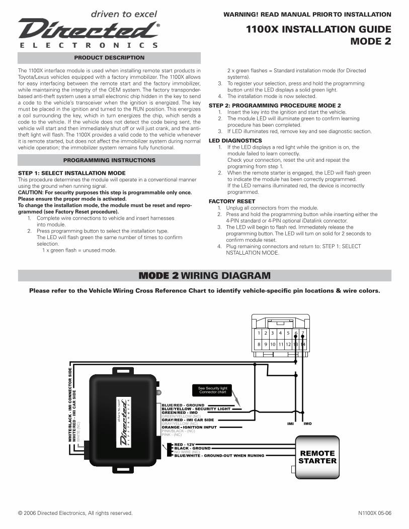
MODE 2 wIRING DIAGRAM
1100x INSTAllATION GUIDEMODE 2
1 2 3 4 5 6 7 8 9 10 11 12 13 14
wARNING! READ MANUAl PRIOR TO INSTAllATION
Please refer to the Vehicle wiring Cross Reference Chart to identify vehicle-specific pin locations & wire colors.

© 2006 Directed Electronics, All rights reserved. N1100X 05-06
MODE 2 VEHIClE wIRING CROSS REFERENCE CHART*
Model Year IMO Wire Pin # IMI wire Pin # Sec. light wire Pin # Con # Theft ECU location
4 Runner 2003-2006 Blu/red 7 wht/red 6 vio/wht 3 A Above and behind glove boxAvalon 2005-2006 blue 12 brown 13 pink 8 B drivers side left of steering columnCorolla 2005-2006 black 7 white 6 red/wt 3 A high left of steering columnES 330 2004-2006 blu/yel 12 red/blu 13 vio 8 B Above and behind glove boxGX470 2003-2006 blu/red 7 wht/red 6 vio/wht 3 A Above and behind glove boxHighlander Hybrid 2006 violet 7 orange 6 white 3 A behind glove boxHighlander 2004-2006 violet 7 black 6 white 3 A behind glove boxLand Cruiser 2003-2006 yellow 7 white 6 grn/red 3 A Above and behind glove boxLS430 2002-2006 gry/red 7 blk/yel 6 red Note1 A left of steering column/Transponder key computerLX470 2003-2006 yellow 7 white 6 grn/red 3 A Above and behind glove boxMatrix 2005-2006 black 7 white 6 red/wt 3 A high left of steering columnRAV4 2004-2005 red 7 red/grn 6 grn/red 3 A high left of steering columnRAV4 2006 lt grn 12 pink 13 yellow 8 B right of steering column/behind radio areaSC430 2002-2005 wht/blu 7 wt/blu 6 blk Note 2 A Behind instrument cluster right side/Tran- sponder key computerSC430 2006 lt grn 7 lt blu 6 blk Note 2 A Behind instrument cluster right side/Tran- sponder key computerSequoia 2003-2006 lt blu/yel 10 pink/grn 11 grn/blk 7 B right of steering column/behind radio areaSienna 2004-2006 brn/wt 7 brn/red 6 blk 3 A Above and behind glove boxSolara coupe 2004-2006 brn/wt 7 vio/grn 6 red/wt 3 A behind glove boxSolaraconvertible 2004-2006 brn/wt 7 brn/red 6 violet 3 A behind glove boxTacoma 2005-2006 lt grn/blk 12 lt blu/wt 13 vio/wt 8 B at firewall behind instrument clusterTundra 2006 pink 10 wht/grn 11 blk/org 7 B right of steering column/behind radio areaYaris 2006 orange 12 white 11 lt green 8 B right of steering column/behind radio area
SECURITy lIGHT CONNECTORS*if vehicle model is not listed above, see reverse.
NOTICE: The manufacturer will accept no responsibility for any electrical damage resulting from improper installation of this product, be that either damage to the vehicle itself or to the installed device. This device must be installed by a certified technician. This guide has been written for properly trained technicians; a certain level of skill and knowledge is therefore assumed. Please review the Installation Guide care-fully before beginning any work.
= Connector picture not determined. Refer to wire colors for proper connections.!
1 2 3 4 5 6 7
8 9 10 11 12 13 14
A B C
1100x INSTAllATION GUIDEMODE 2
iMMoBiLiZER ConnECtoR
Note 1 Security light wire available at theft ECU above and behind glove box. Pin 3 connector CNote 2 Security light wire available at theft ECU high in drivers kick. Pin 3 connector C
T-5
IK-1
ECM
LIMITED ONE-YEAR CONSUMER WARRANTY
For a period of ONE YEAR from the date of purchase of a Directed Electronics remote start or security accessory product, Directed Electronics. (hereinafter “DIRECTED”) promises to the original purchaser, to repair or replace (at DIRECTED’s election) with a comparable reconditioned piece, the security or remote start accessory piece (hereinafter the “Part”), which proves to be defective in workmanship or material under normal use, provided the following conditions are met: the Part was purchased from an authorized DIRECTED dealer in the United States; and the Part is returned to DIRECTED, postage prepaid, along with a clear, legible copy of the receipt or bill of sale bearing the following information: consumer’s name, address, telephone number, the authorized licensed dealer’s name, date of purchase and complete product and Part description. This warranty is non-transferable and is automatically void if the Part has been modified or used in a manner contrary to its intended purpose or if the Part has been damaged by accident, abuse, unreasonable use, neglect, water, theft, improper service, installation or other causes not arising out of defect in materials or construction. This warranty is automatically void if any Part has had the serial number defaced, altered, or removed. This warranty is automatically void if the Part has had Repair Service performed by anyone other than the Directed Repair Department. This warranty does not cover damage to any Part caused by installation or removal of the Part or any system related thereto. This warranty does not cover labor costs for the removal or reinstallation of the Part.
TO THE MAXIMUM EXTENT ALLOWED BY LAW, ALL WARRANTIES, INCLUDING BUT NOT LIMITED TO EXPRESS WARRANTY, IMPLIED WARRANTY, WARRANTY OF MERCHANTABILITY, FITNESS FOR PAR-TICULAR PURPOSE AND WARRANTY OF NON-INFRINGEMENT OF INTELLECTUAL PROPERTY, ARE EXPRESSLY EXCLUDED TO THE MAXIMUM EXTENT PERMITTED BY LAW; AND DIRECTED NEITHER ASSUMES NOR AUTHORIZES ANY PERSON OR ENTITY TO ASSUME FOR IT ANY DUTY, OBLIGATION OR LIABILITY IN CONNECTION WITH ITS PRODUCTS. DIRECTED HEREBY DISCLAIMS AND HAS ABSOLUTELY NO LIABILITY FOR ANY AND ALL ACTS OF THIRD PARTIES INCLUDING DEALERS OR INSTALLERS. IN THE EVENT OF A CLAIM OR A DISPUTE INVOLVING DIRECTED OR ITS SUBSIDIARY, THE PROPER VENUE SHALL BE SAN DIEGO COUNTY IN THE STATE OF CALIFORNIA. CALIFORNIA STATE LAWS AND APPLICABLE FEDERAL LAWS SHALL APPLY AND GOVERN THE DISPUTE. THE MAXIMUM RECOVERY UNDER ANY CLAIM AGAINST DIRECTED SHALL BE STRICTLY LIMITED TO THE AUTHORIZED DIRECTED DEALER’S PURCHASE PRICE OF THE PART. DIRECTED SHALL NOT BE RE-SPONSIBLE FOR ANY DAMAGES WHATSOEVER, INCLUDING BUT NOT LIMITED TO, ANY CONSEQUENTIAL DAMAGES, INCIDENTAL DAMAGES, DAMAGES FOR THE LOSS OF TIME, LOSS OF EARNINGS, COMMERCIAL LOSS, LOSS OF ECONOMIC OPPORTUNITY AND THE LIKE.
Some states do not allow limitations on how long an implied warranty will last or the exclusion or limitation of incidental or consequential damages. This warranty gives you specific legal rights and you may also have other rights that vary from State to State. DIRECTED does not and has not authorized any person or entity to create for it any other obligation, promise, duty or obligation in connection with this Part.