modbus tcpip protocol - maguire · modbus tcp/ip command example 13 modbus tcp/ip reference numbers...
TRANSCRIPT

MODBUS TCP/IP PROTOCOL MANUAL
September 12, 2001 Revised January 3 2002
Maguire WSB Blender MLAN Gateway
Blender Data Communications
Integrated to Maguire MLAN Protocol

2
Table of Contents: PRODUCT OVERVIEW
EXTERNAL / INTERNAL GATEWAY SPECIFICATIONS 4 OPERATION � MLAN GATEWAY
POWER REQUIREMENTS � EXTERNAL UNITS ONLY 4 LED OPERATION 4 INSTALLATION � DEFAULT IP ADDRESS 4 ETHERNET CONNECTOR 5
PROGRAMMING OVERVIEW
INTRODUCTION 6 PROGRAMMING CONSIDERATIONS 6 MLAN COMMAND HISTORY 8
MODBUS TCP/IP COMMUNICATION FOR WSB
GENERAL INFORMATION 9 ERROR CODE EXPLANATIONS 11 ADDITIONS TO THE MLAN COMMAND DESCRIPTIONS FOR USE WITH MODBUS TCP/IP 12 MODBUS TCP/IP COMMAND EXAMPLE 13 MODBUS TCP/IP REFERENCE NUMBERS FOR BLENDER PARAMETERS 14
DATA COMMANDS
CLEAR TOTALS 15 CLEAR TOTALS IMMEDIATELY 16 GET ALL PARAMETERS 17 GET BATCH INFO 18 GET CYCLE WEIGHT AND TIME 20 GET DISPLAY 21 GET PARAMETER 23 GET SETTINGS 24 GET STATUS 29 GET STEADY STATE RATE 32 GET TARGET THROUGHPUT & STATUS 33 GET TOTALS 35 GET TYPE 39 GET VERSION 40 GET WEIGHT UNITS 41 SEND KEYSTROKE 42 SEND SETTINGS 44 SET BATCH WEIGHT 48 SET DATE AND TIME 50

3
SET STEADY STATE RATE 54 SET TAG 55 SET TARGET THROUGHPUT 57 SET WEIGHT UNITS 58 SILENCE ALARM 59 START/STOP/STATUS 60 STOP CYCLE / STOP RETRY 62 PARAMETER TABLE FOR 12 COMPONENT BLENDER SOFTWARE (SAMPLE AS OF VERSION 01003T) 64
Trademark Credits Microsoft and MS-DOS are trademarks of Microsoft Corporation. IBM is a trademark of International Business Machine Corporation. Ethernet is a trademark of Xerox Corporation.

4
Product Overview The MLAN Gateway has been designed to connect to a 10BaseT Ethernet network. Connecting to a company or factory network utilising other Ethernet wirings standards (e.g. 10Base2, 10Base5, 100BaseT etc.) can be achieved by the use of hubs. External / Internal Gateway Specifications
External Size H90 x W105 x D60mm Mounting Direct onto 35mm DIN rail Network Interface 10BaseT Ethernet Host Interface MLAN Operating Temperature 0-55 °C
General
Operating Humidity 30-90% non-condensing Supply Voltage 5 � 24Volts dc Power Requirements Maximum Power 2 Watts
Operation � MLAN Gateway Power Requirements � External Units Only The External MLAN Gateway unit requires 5 to 24 Volts DC to be connected via the 3-way plug in connector. LED Operation The 2 (yellow & green) front LEDs represents the Ethernet network status and have the following meaning.
Ethernet State: LED Colour: Network Traffic Yellow Ethernet Link Active (i.e. connected) Green
The 2 (yellow & green) LEDs within the gateway represent the Comms status between the MLAN unit and Ethernet gateway and have the following meaning.
MLAN Comms State: LED Colour: Data Traffic from Ethernet gateway to MLAN Yellow Data Traffic from MLAN to Ethernet gateway Green
Installation � Default IP Address The Gateway is shipped with a default IP address and subnet mask. Use of a node-commissioning software tool provided with the Gateway allows the user to set the IP address and subnet mask to the required values for the network. This configuration information is stored in non-volatile memory on the Gateway.

5
Ethernet Connector The Ethernet connector on the Gateway is located on the left hand side of the unit in the form of a standard 8-Way RJ45 connector. This connector contains the transformer isolation and filtering compliant with the Ethernet 10BaseT specification. When utilizing the Internal MLAN Gateway Card this replaces the standard RS232 Serial Port.
6
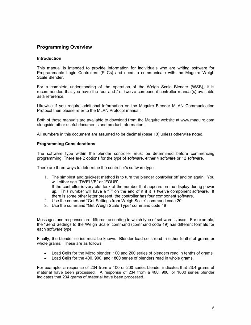
Programming Overview Introduction This manual is intended to provide information for individuals who are writing software for Programmable Logic Controllers (PLCs) and need to communicate with the Maguire Weigh Scale Blender. For a complete understanding of the operation of the Weigh Scale Blender (WSB), it is recommended that you have the four and / or twelve component controller manual(s) available as a reference. Likewise if you require additional information on the Maguire Blender MLAN Communication Protocol then please refer to the MLAN Protocol manual. Both of these manuals are available to download from the Maguire website at www.maguire.com alongside other useful documents and product information. All numbers in this document are assumed to be decimal (base 10) unless otherwise noted. Programming Considerations The software type within the blender controller must be determined before commencing programming. There are 2 options for the type of software, either 4 software or 12 software. There are three ways to determine the controller�s software type:
1. The simplest and quickest method is to turn the blender controller off and on again. You will either see �TWELVE� or �FOUR�. If the controller is very old, look at the number that appears on the display during power up. This number will have a �T� on the end of it if it is twelve component software. If there is some other letter present, the controller has four component software.
2. Use the command �Get Settings from Weigh Scale� command code 20 3. Use the command �Get Weigh Scale Type� command code 49
Messages and responses are different according to which type of software is used. For example, the �Send Settings to the Weigh Scale� command (command code 19) has different formats for each software type. Finally, the blender series must be known. Blender load cells read in either tenths of grams or whole grams. These are as follows:
• Load Cells for the Micro blender, 100 and 200 series of blenders read in tenths of grams. • Load Cells for the 400, 900, and 1800 series of blenders read in whole grams.
For example, a response of 234 from a 100 or 200 series blender indicates that 23.4 grams of material have been processed. A response of 234 from a 400, 900, or 1800 series blender indicates that 234 grams of material have been processed.

7
Summary of all MLAN commands MLAN Command Code Description Clear Totals 24 Resets all materials totals to zero at the end of the next blender cycle. Clear Totals Immediately
28 Resets all materials totals to zero immediately.
Get Address 54 Returns Controller Address *** Not supported by the MLAN Gateway Adapter ***
Get All Parameters 22 Returns all of the parameters and their values *** Not supported by the MLAN Gateway Adapter ***
Get Batch Info 84 Returns the batch weight, current portion of the batch, accumulated total and batch count number. (See WSB Manual for more information on how the WSB operates)
Get Cycle Weight & Time
50 Returns the size of the last batch / cycle and the duration of time between the last two cycles.
Get Display 56 Returns the current display buffer. Get Parameter 69 Returns the value of a specific parameter. Get Settings 20 Returns the mix percentages and component types along with the recipe, work
order and operator number. Get Status 53 Returns the current state of all signal inputs and outputs. Get Steady State Rate 64 Returns the steady state throughput rate of the blender. Get Target Throughput & Status
29 Returns the current target throughput and the extrusion control status.
Get Totals 16 Returns the current totals and resets the internal flag Get Totals 17 Returns the current totals without resetting the internal flag Get Type 49 Returns the controller software type (4 or 12) and load cell type (tenths of grams
or full grams) Get Version 80 Returns the version of software in the controller. Get Weigh Units 85 Returns the units that the blender is using to display totals � Pounds, Kilograms,
Ounces or Grams Send Keystroke 87 Sends a virtual keystroke to the keypad on the controller � see Set Remote
Keypad Send Settings 19 Sets the mix percentages and material types � also sets work order and operator
numbers. Set Batch Weight 83 Sets the size of a single batch in blender in grams. Set Date & Time 81 Sets the Date and Time of a blender. Set Parameter 68 Sets the value of a specific parameter. Set Remote Keypad 88 Enable / Disable Controller Keypad and or the �Send Keystroke� command Set Steady Rate 65 Sets the steady state throughput rate of the blender � this tells the blender the rate
to report back for the �Get Steady State Rate� command Set Tag 90 Sets either recipe, operator or work order number on the controller. Set Target Throughput 30 Sets the target throughput rate for extrusion control mode. Set Weight Units 86 Sets the weight unit used by the blender to display totals such as pounds or kilos. Silence Alarm 82 Silences the alarm for a specific blender Start / Stop / Status 55 Instructs the blender to stop at the end of the current cycle, start up, or return
current operating status. Stop Cycle / Stop Retry 27 Instructs the blender to abort current cycle or current material dispense.
Aborting current cycle cause blender to start a new cycle. Aborting current dispense causes the blender to start dispensing the next material in its current settings.

8
MLAN Command History The following table documents when commands have been added to the MLAN software. The chip version number can be found on the MLAN chip within the controller.
In most cases with the introduction of new commands to the software in MLAN chips, 12 software chips were either first to be updated or both the 12 software and the 4 software chips were updated at the same time.
Not all chips are listed below. What are listed are chips that marked a change in the software and were available for testing. If your chip is not listed, it may indicate that your chip did not mark a change in the software or possibly it was not available for testing when this information was compiled.
Chips versions numbers indicate a date. For instance chip "60603A" means 1996 (6), June (06), 3rd (03) followed by "T" or �TC� for twelve software or "A" or �WS� for four software. Your chip version number may fall somewhere in between the chips listed below if it is not directly listed.
Other Notes:
• Controllers using chips prior to 60603A (06/03/1996) have an earlier circuit board, which would need replacement if the chip is to be updated.
• Chips after 90317A (03/17/1999) will have all parameters available.
• Chips prior to 90317A (03/17/1999), please see chart on the following page.
MLAN Command Chip Version Printed on Chip
MLAN Command Chip Version Printed on Chip
Get Version
60603A
Get Weight Units
60710T
Clear Totals 20414A Set Remote Keypad 60911T Clear Totals Immediately 80609A Send Keystroke 60911T Get Address 50925A Send Settings 20414T Get All Parameters 60809A Set Batch Weight 60603A Get Batch Info 60603A Set Date & Time 60603A Get Cycle, Weight & Time 30913A Set Parameter 70529A Get Display 50925A Set Steady State Rate 70916T Get Parameter 70205T Set Tag 60710T Get Settings 20414A Set Target Throughput 90317A Get Status 41019A Set Weight Units 60710T Get Steady State Rate 60603A Silence Alarm 60603A Get Target Throughput Status
90317A Start / Stop / Status 60603A
Get Totals 20414A Stop Cycle / Stop Retry 71222T Get Type 20414A XT Parameters 60603A
PLEASE NOTE: Depending on the date of the chip in your controller, all commands may not be available. The chips can be upgraded, so if you need a newer chip, please contact your nearest Maguire reseller.

9
Modbus TCP/IP Communication for WSB General Information The Modbus TCP/IP command protocol data format used has been designed to be as consistent as possible with the MLAN command set. A full description of the Modbus TCP/IP specification can be found at www.modicon.com/openmbus The Modbus registers are Word (two-byte) values. Values shown are decimal (base 10) values. Command Format (Write)
Output Byte
Modbus TCP/IP Description Name Range MLAN Description
0 Transaction ID Usually 0 1 Transaction ID Usually 0 2 Protocol ID Usually 0 3 Protocol ID Usually 0 4 Total Data Length 0 5 Total Data Length 7 to 255 6 Slave Address MLAN Address 7 Function Code 15 or 16 8 Register Hi Command Code 24 MLAN Command 9 Register Lo 0
10 Register Count Hi 0 11 Register Count Lo 0 to N 12 Data Byte Count 0 to (N+1)*2 13 Data Word 0 Hi 14 Data Word 0 Lo . . . . X Data Word N Hi
X+1 Data Word N Lo
Response Format (Write)
Input Byte Modbus Description Name Range Description
0 Transaction ID Usually 0 1 Transaction ID Usually 0 2 Protocol ID Usually 0 3 Protocol ID Usually 0 4 Total Data Length 0 5 Total Data Length 2 6 Slave Address MLAN Address 7 Function Code 15 or 16 Top bit set on error

10
Command Format (Read)
Output Byte Modbus Description Name Range MLAN Description
0 Transaction ID Usually 0 1 Transaction ID Usually 0 2 Protocol ID Usually 0 3 Protocol ID Usually 0 4 Total Data Length 0 5 Total Data Length 6 6 Slave Address MLAN Address 7 Function Code 3 or 4
8 Register Hi Command Code 84 Get Batch Information Command
9 Register Lo 0 10 Point Count Hi 0 11 Point Count Lo N
Response Format (Read)
Input Byte Modbus Description Name Range Description
0 Transaction ID Usually 0 1 Transaction ID Usually 0 2 Protocol ID Usually 0 3 Protocol ID Usually 0 4 Total Data Length 0 5 Total Data Length 3 to 255 6 Slave Address MLAN Address 7 Function Code 3 or 4 Top bit set on error 8 Byte Count 0 to (N+1)*2 9 Data Word 0 Hi
10 Data Word 0 Lo . . . . X Data Word N Hi
X+1 Data Word N Lo The Modbus register fields are used to hold the command codes and are the same as those used for the MLAN communication. The number denoting each command is shown in table 3.

11
Note: One potential source of confusion is the relationship between the reference numbers used in MODBUS functions, and the �register numbers� used in Modicon PLC�s. For historical reasons, user reference numbers were expressed as decimal numbers with a starting offset of 1. However MODBUS uses the more natural software interpretation of an unsigned integer index starting at zero. So a modbus message requesting the read of a register at offset 0 would return the value known to the application programmer as found in register 4:00001 (memory type 4 = output register, reference 00001) The checksum specified in the MLAN protocol is NOT used in the Modbus TCP/IP communication. Error checking is taken care of automatically by the Modbus TCP/IP software as each Ethernet frame contains it's own CRC. When the blender controller has executed the command, the Modbus function code is echoed in the reply Modbus TCP/IP data packet. If an error is encountered the top bit of the reply function code will be set and will be followed by a single byte indicating the reason for the error. Response Format with Error (Write/Read)
Input Byte Modbus Description Name Range Description
0 Transaction ID Usually 0 1 Transaction ID Usually 0 2 Protocol ID Usually 0 3 Protocol ID Usually 0 4 Total Data Length 0 5 Total Data Length 3 6 Slave Address MLAN Address
7 Function Code 131, 132, 143 or 144
8 Error Code Reason for failure Error Code Explanations The Modbus TCP/IP Error Code byte can take the following values:
07 Communication error (NAK negative-acknowledge). 01 This means that the command is not supported. 06 Communication Error (Time-out). 03 Invalid parameter passed in the command.

12
Additions to the MLAN Command Descriptions for use with Modbus TCP/IP The �Set-Parameter� (68) and �Get-Parameter� (69) commands use an integer value to identify the particular parameter requested. Table 4 shows how this number relates to the three-letter parameter abbreviation. �Four-component� software and the �Twelve-component� software options are shown. For the parameters 50 upwards, a second variable is required. This specifies the component number. The number is 1 to 12 for the �Twelve� software. For the �Four� software: 1 = Regrind 2 = Natural 3 = Colour 4 = Additive

13
Modbus TCP/IP Command Example The example below illustrates the �Get-Parameter _LA (Lag Time) for component 3� command over Modbus TCP/IP on MLAN address 1. The Purpose of this would be to retrieve the setting for the Lag Time (LA parameter) for hopper / component number 3 on a blender: Example Get Parameter Command _LA component 3
Output Byte Modbus Description Name Range MLAN Description
0 Transaction ID 0 1 Transaction ID 0 2 Protocol ID 0 3 Protocol ID 0 4 Total Data Length 0 5 Total Data Length 6 6 Slave Address 1 MLAN Address = 1 7 Function Code 3 or 4
8 Register Hi Command Code 69 MLAN Command Code Get Parameter
9 Register Lo 75
Reference number for the LA Parameter + Hopper / Component number 3
10 Point Count Hi 0 11 Point Count Lo 1
Table 2: Input Data: Reply to Command
Input Byte Modbus Description Name Range Description
0 Transaction ID 0 1 Transaction ID 0 2 Protocol ID 0 3 Protocol ID 0 4 Total Data Length 0 5 Total Data Length 5 6 Slave Address 1 MLAN Address 7 Function Code 3 or 4 Top bit set on error 8 Byte Count 2 9 Data Word 0 Hi 0
10 Data Word 0 Lo 20 _AL value
Please refer to Table 4 on the next page to see the Modbus TCP/IP reference number for other MLAN parameters.

14
Modbus TCP/IP Reference Numbers for Blender Parameters
(Reference Table 4)
Modbus Register Reference # (Lo Byte)
4 Software Parameters
12 Software Parameters
Modbus Register Reference # (Lo Byte)
4 Software Parameters
4 Software Component #
12 Software Parameters
12 Software Component #
1 FLG FLG 50 to 61 _TY 1 TO 12 2 MIX MIX 62 to 73 _CS 1 TO 12 3 FCV FCV 74 to 85 RAL 1 _AL 1 TO 12 4 DTI DTI NAL 2 5 KDF KDF CAL 3 6 WDF WDF AAL 4 7 BER BER 86 to 97 CXT 3 _XT 1 TO 12 8 ROC ROC AXT 4 9 ROV ROV 98 to 109 RSE 1 _SE 1 TO 12 10 RHL RHL CSE 3 11 FUL FUL ASE 4 12 MAX MAX 110 to 121 RWT 1 _WT 1 TO 12 13 TH TH NWT 2 14 TL TL CWT 3 15 PRT PRT AWT 4 16 RLO 122 to 133 RTI 1 _TI 1 TO 12 17 DLY DLY NTI 2 18 LT1 CTI 3 19 LT2 ATI 4 20 PRC PRC 134 to 145 RMI 1 _MI 1 TO 12 21 STL STL NMI 2 22 LCL LCL CMI 3 23 LCH LCH AMI 4 24 LCF LCF 146 to 157 RNC 1 _NC 1 TO 12 25 LCZ LCZ NNC 2 26 DS1 CNC 3 27 DS2 ANC 4 28 SCR SCR 158 to 169 RPT 1 _PT 1 TO 12 28 BCR BCR NPT 2 30 XCV XCV CPT 3 31 XRC XRC APT 4 32 TCV TCV 170 to 181 RRP 1 _RP 1 TO 12 33 TRC TRC NRP 2 34 XTP XTP CRP 3 35 XAL XAL ARP 4 36 XUL XUL 182 to 193 RRD 1 _RD 1 TO 12 37 CPL CPL NRD 2 38 MPO MPO CRD 3 ARD 4 194 to 205 RLA 1 _LA 1 TO 12 NLA 2 CLA 3

15
Data Commands
Clear Totals Description: Resets the totals to zero. Command Format
Output Byte Modbus Description Name Range MLAN Description 0 Transaction ID 0 1 Transaction ID 0 2 Protocol ID 0 3 Protocol ID 0 4 Total Data Length 0 5 Total Data Length 7 6 Slave Address MLAN Address 7 Function Code 16 8 Register Hi Command Code 24 Clear Totals Command 9 Register Lo 0
10 Register Count Hi 0 11 Register Count Lo 0 12 Data Byte Count 0
Response Format
Input Byte Modbus Description Name Range Description 0 Transaction ID 0 1 Transaction ID 0 2 Protocol ID 0 3 Protocol ID 0 4 Total Data Length 0 5 Total Data Length 2 6 Slave Address MLAN Address 7 Function Code 16 Top bit set on error
NOTE: The totals will not be erased until the end of the current cycle. If the blender is idle, the totals will be cleared at the end of the next cycle.

16
Clear Totals Immediately Description: Resets the totals to zero. Command Format
Output Byte Modbus Description Name Range MLAN Description 0 Transaction ID 0 1 Transaction ID 0 2 Protocol ID 0 3 Protocol ID 0 4 Total Data Length 0 5 Total Data Length 7 6 Slave Address MLAN Address 7 Function Code 16
8 Register Hi Command Code 28 Clear Totals Immediately Command
9 Register Lo 0 10 Register Count Hi 0 11 Register Count Lo 0 12 Data Byte Count 0
Response Format
Input Byte Modbus Description Name Range Description 0 Transaction ID 0 1 Transaction ID 0 2 Protocol ID 0 3 Protocol ID 0 4 Total Data Length 0 5 Total Data Length 2 6 Slave Address MLAN Address 7 Function Code 16 Top bit set on error
NOTE: The totals will be erased immediately.

17
Get All Parameters Description: Gets all of the parameters and their values. *** This MLAN command is not supported ***

18
Get Batch Info Description: Returns the batch weight, current portion, accumulated total, and batch count. Command Format
Output Byte Modbus Description Name Range MLAN Description 0 Transaction ID 0 1 Transaction ID 0 2 Protocol ID 0 3 Protocol ID 0 4 Total Data Length 0 5 Total Data Length 6 6 Slave Address MLAN Address 7 Function Code 3 or 4
8 Register Hi Command Code 84 Get Batch Information Command
9 Register Lo 0 10 Point Count Hi 0 11 Point Count Lo 4
Response Format
Input Byte Modbus Description Name Range Description 0 Transaction ID 0 1 Transaction ID 0 2 Protocol ID 0 3 Protocol ID 0 4 Total Data Length 0 5 Total Data Length 11 6 Slave Address MLAN Address 7 Function Code 3 or 4 Top bit set on error 8 Byte Count 8 9 Data Word 0 Hi Batch Weight
10 Data Word 0 Lo Batch Weight 0 to 65535 Batch Weight (Pounds or Kilos only)
11 Data Word 1 Hi Current portion
12 Data Word 1 Lo Current portion 0 to 65535 Completed portion of current batch
13 Data Word 2 Hi Accumulative Total
14 Data Word 2 Lo Accumulative Total 0 to 65535
Total weight of all completed batches
15 Data Word 3 Hi Batch Count
16 Data Word 3 Lo Batch Count 0 to 65535 Total number of completed batches

19
Note 1: Batch weight is given in pounds if "Get Weight Units" returns either pounds or ounces.
If "Get Weight Units" returns either kilograms or grams, then batch weight is in kilograms.

20
Get Cycle Weight and Time Description: Returns the size of the last batch/cycle and the duration of time between the last two cycles. Command Format
Output Byte Modbus Description Name Range MLAN Description 0 Transaction ID 0 1 Transaction ID 0 2 Protocol ID 0 3 Protocol ID 0 4 Total Data Length 0 5 Total Data Length 6 6 Slave Address MLAN Address 7 Function Code 3 or 4
8 Register Hi Command Code 50 Get Cycle Weight and Time Command
9 Register Lo 0 10 Point Count Hi 0 11 Point Count Lo 3
Response Format
Input Byte Modbus Description Name Range Description 0 Transaction ID 0 1 Transaction ID 0 2 Protocol ID 0 3 Protocol ID 0 4 Total Data Length 0 5 Total Data Length 9 6 Slave Address MLAN Address 7 Function Code 3 or 4 Top bit set on error 8 Byte Count 6 9 Data Word 0 Hi Cycle Weight
10 Data Word 0 Lo Cycle Weight 0 to 65535 Grams (or tenths of grams) in last cycle
11 Data Word 1 Hi Cycle Time 12 Data Word 1 Lo Cycle Time 13 Data Word 2 Hi Cycle Time
14 Data Word 2 Lo Cycle Time 0 to 4294967295
Number of interrupts during the last cycle (244/sec)

21
Get Display Description: Returns the current light emitting diode (LED) buffer. Command Format
Output Byte Modbus Description Name Range MLAN Description 0 Transaction ID 0 1 Transaction ID 0 2 Protocol ID 0 3 Protocol ID 0 4 Total Data Length 0 5 Total Data Length 6 6 Slave Address MLAN Address 7 Function Code 3 or 4 8 Register Hi Command Code 56 Get Display Command 9 Register Lo 0
10 Point Count Hi 0 11 Point Count Lo 8
Response Format
Input Byte Modbus Description Name Range Description 0 Transaction ID 0 1 Transaction ID 0 2 Protocol ID 0 3 Protocol ID 0 4 Total Data Length 0 5 Total Data Length 19 6 Slave Address MLAN Address 7 Function Code 3 or 4 Top bit set on error 8 Byte Count 16 9 Data Word 0 Hi Display
10 Data Word 0 Lo Display 11 Data Word 1 Hi Display 12 Data Word 1 Lo Display 13 Data Word 2 Hi Display 14 Data Word 2 Lo Display 15 Data Word 3 Hi Display 16 Data Word 3 Lo Display 17 Data Word 4 Hi Display 18 Data Word 4 Lo Display 19 Data Word 5 Hi Display

22
20 Data Word 5 Lo Display 21 Data Word 6 Hi Display 22 Data Word 6 Lo Display 23 Data Word 7 Hi Display
24 Data Word 7 Lo Display
ASCII ASCII characters currently displayed on LED. 1 Char per Word
Data Word 0 is the leftmost character

23
Get Parameter
Description: Gets a single parameter. Command Format
Output Byte Modbus Description Name Range MLAN Description 0 Transaction ID 0 1 Transaction ID 0 2 Protocol ID 0 3 Protocol ID 0 4 Total Data Length 0 5 Total Data Length 6 6 Slave Address MLAN Address 7 Function Code 3 or 4 8 Register Hi Command Code 69 Get Parameter Command
Parameter Ref. 0 to 255
Parameter number � please refer to table below
9 Register Lo Component Num.
0 � 3 = 4 Software (R,N,C,A) 0 � 11= 12 Software (0,1,2,3,4,5,6,7,8,9,10,11)
10 Point Count Hi 0 11 Point Count Lo 1
Response Format
Input Byte Modbus Description Name Range Description 0 Transaction ID 0 1 Transaction ID 0 2 Protocol ID 0 3 Protocol ID 0 4 Total Data Length 0 5 Total Data Length 5 6 Slave Address MLAN Address 7 Function Code 3 or 4 Top bit set on error 8 Byte Count 2 9 Data Word 0 Hi Parameter Value
10 Data Word 0 Lo Parameter Value 0 to 65535 The value of the parameter.
NOTE: Parameter definitions are given in the blender manual.

24
Get Settings Description: Returns the mix percentages, component types, work order #, and operator #. Command Format (type 1 - Four Component Software)
Output Byte Modbus Description Name Range MLAN Description 0 Transaction ID 0 1 Transaction ID 0 2 Protocol ID 0 3 Protocol ID 0 4 Total Data Length 0 5 Total Data Length 6 6 Slave Address MLAN Address 7 Function Code 3 or 4 8 Register Hi Command Code 20 Get Settings Command 9 Register Lo 0
10 Point Count Hi 0 11 Point Count Lo 30
Response Format Type 1 - Four Component Software
Input Byte Modbus Description Name Range Description 0 Transaction ID 0 1 Transaction ID 0 2 Protocol ID 0 3 Protocol ID 0 4 Total Data Length 0 5 Total Data Length 63 6 Slave Address MLAN Address 7 Function Code 3 or 4 Top bit set on error 8 Byte Count 60 9 Data Word 0 Hi System Type 0
10 Data Word 0 Lo System Type 2, 3, 9, or 10 2=tenths of grams, also, NO change in totals
Since last get total cmd (16)
3=tenths of grams, also, change in totals
Since last get total cmd (16)
9=grams, also, NO change in totals
Since last get total cmd (16)
10=grams, also, change in totals
Since last get total cmd (16 11 Data Word 1 Hi Software Type 0 12 Data Word 1 Lo Software Type 4 4=four component software

25
13 Data Word 2 Hi Type Hopper 1 0
14 Data Word 2 Lo Type Hopper 1 0 Always zeros (implied
1=regrind) 15 Data Word 3 Hi Setting Hopper 1 16 Data Word 3 Lo Setting Hopper 1 0 to 999 Implied decimal point ##.#
17 to 20 Data Word 4 to 5 Pad 2 0 Padding always zero 21 Data Word 6 Hi Type Hopper 3 0
22 Data Word 6 Lo Type Hopper 3 0 Always zeros (implied
3=color) Response Format Type 1 - Four Component Software - continued
23 Data Word 7 Hi Setting Hopper 3 0 24 Data Word 7 Lo Setting Hopper 3 0 to 999 Implied decimal point ##.# 25 Data Word 8 Hi Type Hopper 4 0
26 Data Word 8 Lo Type Hopper 4 0 Padding always zeros (implied 3=additive)
27 Data Word 9 Hi Setting Hopper 4 28 Data Word 9 Lo Setting Hopper 4 0 to 999 Implied decimal point ##.#
29 to 60 Data Word 10 to 25 Pad 5 - 12 0 Padding always zero 61 Data Word 26 Hi Recipe Number 62 Data Word 26 Lo Recipe Number 100 to 65535 Recipe number 63 Data Word 27 Hi Operator Number 64 Data Word 27 Lo Operator Number 0 to 999 Operator number
65 Data Word 28 Hi Work Order Number
66 Data Word 28 Lo Work Order Number
67 Data Word 29 Hi Work Order Number
68 Data Word 29 Lo Work Order Number 0 to 999999 Work order number
Response Format Type 2 - Twelve Component Software
Input Byte Modbus Description Name Range Description 0 Transaction ID 0 1 Transaction ID 0 2 Protocol ID 0 3 Protocol ID 0 4 Total Data Length 0 5 Total Data Length 63 6 Slave Address MLAN Address 7 Function Code 3 or 4 Top bit set on error 8 Byte Count 60

26
9 Data Word 0 Hi System Type 0
10 Data Word 0 Lo System Type 2, 3, 9, or 10 2=tenths of grams, also, NO change in totals
Since last get total cmd (16)
3=tenths of grams, also, change in totals
Since last get total cmd (16)
9=grams, also, NO change in totals
Since last get total cmd (16)
10=grams, also, change in totals
Since last get total cmd (16 11 Data Word 1 Hi Software Type 0
12 Data Word 1 Lo Software Type 12 12=twelve component software
Response Format Type 2 - Twelve Component Software - continued
13 Data Word 2 Hi Type Hopper 1 0
14 Data Word 2 Lo Type Hopper 1 0 to 3 1=regrind, 2=natural,
3=additive/color, 0=none 15 Data Word 3 Hi Setting Hopper 1
16 Data Word 3 Lo Setting Hopper 1 0 to 999 Implied decimal point r/a ##.#
or n ### 17 Data Word 4 Hi Type Hopper 2 0 Padding always zero
18 Data Word 4 Lo Type Hopper 2 0 to 3 1=regrind, 2=natural, 3=additive/color, 0=none
19 Data Word 5 Hi Setting Hopper 2
20 Data Word 5 Lo Setting Hopper 2 0 to 999 Implied decimal point r/a ##.# or n ###
21 Data Word 6 Hi Type Hopper 3 0
22 Data Word 6 Lo Type Hopper 3 0 to 3 1=regrind, 2=natural,
3=additive/color, 0=none 23 Data Word 7 Hi Setting Hopper 3 0
24 Data Word 7 Lo Setting Hopper 3 0 to 999 Implied decimal point r/a ##.# or n ###
25 Data Word 8 Hi Type Hopper 4 0
26 Data Word 8 Lo Type Hopper 4 0 to 3 1=regrind, 2=natural, 3=additive/color, 0=none
27 Data Word 9 Hi Setting Hopper 4
28 Data Word 9 Lo Setting Hopper 4 0 to 999 Implied decimal point r/a ##.#
or n ### 29 Data Word 10 Hi Type Hopper 5 0
30 Data Word 10 Lo Type Hopper 5 0 to 3 1=regrind, 2=natural, 3=additive/color, 0=none
31 Data Word 11 Hi Setting Hopper 5
32 Data Word 11 Lo Setting Hopper 5 0 to 999 Implied decimal point r/a ##.#
or n ### 33 Data Word 12 Hi Type Hopper 6 0
34 Data Word 12 Lo Type Hopper 6 0 to 3 1=regrind, 2=natural, 3=additive/color, 0=none

27
35 Data Word 13 Hi Setting Hopper 6
36 Data Word 13 Lo Setting Hopper 6 0 to 999 Implied decimal point r/a ##.#
or n ### 37 Data Word 14 Hi Type Hopper 7 0
38 Data Word 14 Lo Type Hopper 7 0 to 3 1=regrind, 2=natural, 3=additive/color, 0=none
39 Data Word 15 Hi Setting Hopper 7
40 Data Word 15 Lo Setting Hopper 7 0 to 999 Implied decimal point r/a ##.#
or n ### 41 Data Word 16 Hi Type Hopper 8 0
42 Data Word 16 Lo Type Hopper 8 0 to 3 1=regrind, 2=natural, 3=additive/color, 0=none
43 Data Word 17 Hi Setting Hopper 8 Response Format Type 2 - Twelve Component Software - continued
44 Data Word 17 Lo Setting Hopper 8 0 to 999 Implied decimal point r/a ##.#
or n ### 45 Data Word 18 Hi Type Hopper 9 0
46 Data Word 18 Lo Type Hopper 9 0 to 3 1=regrind, 2=natural, 3=additive/color, 0=none
47 Data Word 19 Hi Setting Hopper 9
48 Data Word 19 Lo Setting Hopper 9 0 to 999 Implied decimal point r/a ##.#
or n ### 49 Data Word 20 Hi Type Hopper 10 0
50 Data Word 20 Lo Type Hopper 10 0 to 3 1=regrind, 2=natural, 3=additive/color, 0=none
51 Data Word 21 Hi Setting Hopper 10
52 Data Word 21 Lo Setting Hopper 10 0 to 999 Implied decimal point r/a ##.#
or n ### 53 Data Word 22 Hi Type Hopper 11 0
54 Data Word 22 Lo Type Hopper 11 0 to 3 1=regrind, 2=natural, 3=additive/color, 0=none
55 Data Word 23 Hi Setting Hopper 11
56 Data Word 23 Lo Setting Hopper 11 0 to 999 Implied decimal point r/a ##.#
or n ### 57 Data Word 24 Hi Type Hopper 12 0
58 Data Word 24 Lo Type Hopper 12 0 to 3 1=regrind, 2=natural, 3=additive/color, 0=none
59 Data Word 25 Hi Setting Hopper 12
60 Data Word 25 Lo Setting Hopper 12 0 to 999 Implied decimal point r/a ##.#
or n ### 61 Data Word 26 Hi Recipe Number 62 Data Word 26 Lo Recipe Number 100 to 65535 Recipe number 63 Data Word 27 Hi Operator Number 64 Data Word 27 Lo Operator Number 0 to 999 Operator number
65 Data Word 28 Hi Work Order Number
66 Data Word 28 Lo Work Order Number

28
67 Data Word 29 Hi Work Order Number
68 Data Word 29 Lo Work Order Number 0 to 999999 Work order number

29
Get Status Description: Returns the current state of all signal inputs and outputs. Command Format
Output Byte Modbus Description Name Range MLAN Description 0 Transaction ID 0 1 Transaction ID 0 2 Protocol ID 0 3 Protocol ID 0 4 Total Data Length 0 5 Total Data Length 6 6 Slave Address MLAN Address 7 Function Code 3 or 4 8 Register Hi Command Code 53 Get Status Command 9 Register Lo 0
10 Point Count Hi 0 11 Point Count Lo 3
Response Format
Input Byte Modbus Description Name Range Description 0 Transaction ID 0 1 Transaction ID 0 2 Protocol ID 0 3 Protocol ID 0 4 Total Data Length 0 5 Total Data Length 9 6 Slave Address MLAN Address 7 Function Code 3 or 4 Top bit set on error 8 Byte Count 6 9 Data Word 0 Hi Output Status
10 Data Word 0 Lo Output Status 0 to 65535 See note 1 11 Data Word 1 Hi Alarm Status 0 12 Data Word 1 Lo Alarm Status 0 to 255 See note 2 13 Data Word 2 Hi Sensor Status 0 14 Data Word 2 Lo Sensor Status 0 to 255 See note 3
Note 1a - Output status for FOUR component software
BIT Name Value Description 0 Mixer Valve 1=open 0=closed Rightmost bit 1 Reserved 1=open 0=closed 2 Reserved 1=open 0=closed

30
3 Reserved 1=open 0=closed 4 Reserved 1=open 0=closed 5 Reserved 1=open 0=closed 6 Reserved 1=open 0=closed 7 Reserved 1=open 0=closed 8 Mix Motor 1=open 0=closed 9 Alarm 1=open 0=closed
10 Weigh Bin Valve 1=open 0=closed 11 Additive 1=open 0=closed 12 Color 1=open 0=closed 13 Natural 1=on 0=off 14 Regrind 1=open 0=closed 15 Reserved 1=on 0=off Leftmost bit
31
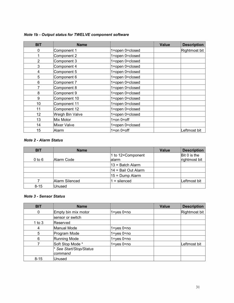
Note 1b - Output status for TWELVE component software
BIT Name Value Description 0 Component 1 1=open 0=closed Rightmost bit 1 Component 2 1=open 0=closed 2 Component 3 1=open 0=closed 3 Component 4 1=open 0=closed 4 Component 5 1=open 0=closed 5 Component 6 1=open 0=closed 6 Component 7 1=open 0=closed 7 Component 8 1=open 0=closed 8 Component 9 1=open 0=closed 9 Component 10 1=open 0=closed
10 Component 11 1=open 0=closed 11 Component 12 1=open 0=closed 12 Weigh Bin Valve 1=open 0=closed 13 Mix Motor 1=on 0=off 14 Mixer Valve 1=open 0=closed 15 Alarm 1=on 0=off Leftmost bit
Note 2 - Alarm Status
BIT Name Value Description
0 to 6 Alarm Code 1 to 12=Component alarm
Bit 0 is the rightmost bit
13 = Batch Alarm 14 = Bail Out Alarm 15 = Dump Alarm 7 Alarm Silenced 1 = silenced Leftmost bit
8-15 Unused Note 3 - Sensor Status
BIT Name Value Description 0 Empty bin mix motor 1=yes 0=no Rightmost bit
sensor or switch 1 to 3 Reserved
4 Manual Mode 1=yes 0=no 5 Program Mode 1=yes 0=no 6 Running Mode 1=yes 0=no 7 Soft Stop Mode * 1=yes 0=no Leftmost bit
* See Start/Stop/Status command
8-15 Unused

32
Get Steady State Rate Description: Returns throughput rate. Command Format
Output Byte Modbus Description Name Range MLAN Description 0 Transaction ID 0 1 Transaction ID 0 2 Protocol ID 0 3 Protocol ID 0 4 Total Data Length 0 5 Total Data Length 6 6 Slave Address MLAN Address 7 Function Code 3 or 4
8 Register Hi Command Code 64 Get Steady State Rate Command
9 Register Lo 0 10 Point Count Hi 0 11 Point Count Lo 2
Response Format
Input Byte Modbus Description Name Range Description 0 Transaction ID 0 1 Transaction ID 0 2 Protocol ID 0 3 Protocol ID 0 4 Total Data Length 0 5 Total Data Length 7 6 Slave Address MLAN Address 7 Function Code 3 or 4 Top bit set on error 8 Byte Count 4 9 Data Word 0 Hi Steady State Rate
10 Data Word 0 Lo Steady State Rate 11 Data Word 1 Hi Steady State Rate
12 Data Word 1 Lo Steady State Rate 0 to 4294967295
Grams (or tenths of grams) per hour

33
Get Target Throughput & Status Description: Returns the target throughput rate for extrusion control. See XCV parameter in blender manual for more information. Command Format
Output Byte Modbus Description Name Range MLAN Description 0 Transaction ID 0 1 Transaction ID 0 2 Protocol ID 0 3 Protocol ID 0 4 Total Data Length 0 5 Total Data Length 6 6 Slave Address MLAN Address 7 Function Code 3 or 4
8 Register Hi Command Code 29 Get Target Throughput & Status Command
9 Register Lo 0 10 Point Count Hi 0 11 Point Count Lo 3
Response Format
Input Byte Modbus Description Name Range Description 0 Transaction ID 0 1 Transaction ID 0 2 Protocol ID 0 3 Protocol ID 0 4 Total Data Length 0 5 Total Data Length 9 6 Slave Address MLAN Address 7 Function Code 3 or 4 Top bit set on error 8 Byte Count 6 9 Data Word 0 Hi Status 0
10 Data Word 0 Lo Status 255 See note 1 11 Data Word 1 Hi Steady State Rate 12 Data Word 1 Lo Steady State Rate 13 Data Word 2 Hi Steady State Rate
14 Data Word 2 Lo Steady State Rate 0 to 4294967295
Grams (or tenths of grams) per hour
Note 1 � Status
BIT Name Value Description 0 Extrusion control 1=on Bit 0 is the rightmost bit

34
0=off
1 1=steady 0=not steady T or no T on display
2 1=Throughput 0=Voltage Controlling mode
3 1=Grams 0=Tenths of Grams Weight unit of rate
4 1=Yield 0=Weight See note 2 5 - 15 Reserved Leftmost bit
Note 2: If the extrusion process is being controlled by weight, then the output will be a steady weight per time (e.g. lbs/hr). If however the extrusion process is being controlled by yield, then the output will be a steady weight per length (e.g. lbs/foot).
35
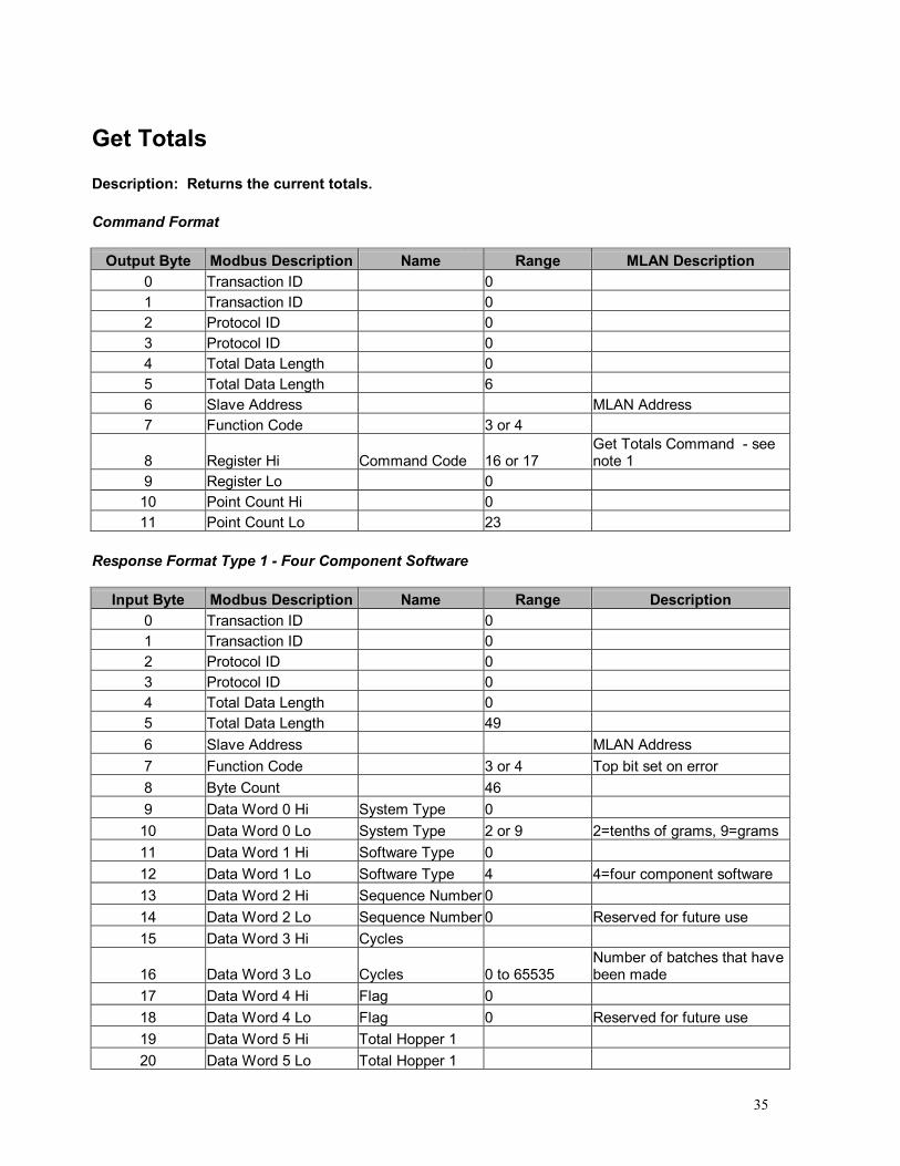
Get Totals
Description: Returns the current totals. Command Format
Output Byte Modbus Description Name Range MLAN Description 0 Transaction ID 0 1 Transaction ID 0 2 Protocol ID 0 3 Protocol ID 0 4 Total Data Length 0 5 Total Data Length 6 6 Slave Address MLAN Address 7 Function Code 3 or 4
8 Register Hi Command Code 16 or 17 Get Totals Command - see note 1
9 Register Lo 0 10 Point Count Hi 0 11 Point Count Lo 23
Response Format Type 1 - Four Component Software
Input Byte Modbus Description Name Range Description 0 Transaction ID 0 1 Transaction ID 0 2 Protocol ID 0 3 Protocol ID 0 4 Total Data Length 0 5 Total Data Length 49 6 Slave Address MLAN Address 7 Function Code 3 or 4 Top bit set on error 8 Byte Count 46 9 Data Word 0 Hi System Type 0
10 Data Word 0 Lo System Type 2 or 9 2=tenths of grams, 9=grams 11 Data Word 1 Hi Software Type 0 12 Data Word 1 Lo Software Type 4 4=four component software 13 Data Word 2 Hi Sequence Number 0 14 Data Word 2 Lo Sequence Number 0 Reserved for future use 15 Data Word 3 Hi Cycles
16 Data Word 3 Lo Cycles 0 to 65535 Number of batches that have been made
17 Data Word 4 Hi Flag 0 18 Data Word 4 Lo Flag 0 Reserved for future use 19 Data Word 5 Hi Total Hopper 1 20 Data Word 5 Lo Total Hopper 1

36
21 Data Word 6 Hi Total Hopper 1
22 Data Word 6 Lo Total Hopper 1 0 to 4294967295
Grams (or tenths of grams) used
23 Data Word 7 Hi Total Hopper 2 24 Data Word 7 Lo Total Hopper 2 25 Data Word 8 Hi Total Hopper 2
26 Data Word 8 Lo Total Hopper 2 0 to 4294967295
Grams (or tenths of grams) used
27 Data Word 9 Hi Total Hopper 3 28 Data Word 9 Lo Total Hopper 3 29 Data Word 10 Hi Total Hopper 3
30 Data Word 10 Lo Total Hopper 3 0 to 4294967295
Grams (or tenths of grams) used
31 Data Word 11 Hi Total Hopper 4 31 Data Word 12 Hi Total Hopper 4 31 Data Word 13 Hi Total Hopper 4
32 Data Word 14 Lo Total Hopper 4 0 to 4294967295
Grams (or tenths of grams) used
33 to 54 Data Word 15 to 23 Pad 5 -12 0 Padding always zero

37
Response Format Type 2 - Twelve Component Software
Input Byte Modbus Description Name Range Description 0 Transaction ID 0 1 Transaction ID 0 2 Protocol ID 0 3 Protocol ID 0 4 Total Data Length 0 5 Total Data Length 49 6 Slave Address MLAN Address 7 Function Code 3 or 4 Top bit set on error 8 Byte Count 46 9 Data Word 0 Hi System Type 0
10 Data Word 0 Lo System Type 2 or 9 2=tenths of grams, 9=grams 11 Data Word 1 Hi Software Type 0 12 Data Word 1 Lo Software Type 4 4=four component software 13 Data Word 2 Hi Sequence Number 0 14 Data Word 2 Lo Sequence Number 0 Reserved for future use 15 Data Word 3 Hi Cycles
16 Data Word 3 Lo Cycles 0 to 65535 Number of batches that have been made
17 Data Word 4 Hi Flag 0 18 Data Word 4 Lo Flag 0 Reserved for future use 19 Data Word 5 Hi Total Hopper 1 20 Data Word 5 Lo Total Hopper 1 21 Data Word 6 Hi Total Hopper 1
22 Data Word 6 Lo Total Hopper 1 0 to 4294967295
Grams (or tenths of grams) used
23 Data Word 7 Hi Total Hopper 2 24 Data Word 7 Lo Total Hopper 2 25 Data Word 8 Hi Total Hopper 2
26 Data Word 8 Lo Total Hopper 2 0 to 4294967295
Grams (or tenths of grams) used
27 Data Word 9 Hi Total Hopper 3 28 Data Word 9 Lo Total Hopper 3 29 Data Word 10 Hi Total Hopper 3
30 Data Word 10 Lo Total Hopper 3 0 to 4294967295
Grams (or tenths of grams) used
31 Data Word 11 Hi Total Hopper 4 32 Data Word 11 Lo Total Hopper 4 33 Data Word 12 Hi Total Hopper 5
34 Data Word 12 Lo Total Hopper 5 0 to 4294967295
Grams (or tenths of grams) used
35 Data Word 13 Hi Total Hopper 6 36 Data Word 13 Lo Total Hopper 6 37 Data Word 14 Hi Total Hopper 7

38
38 Data Word 14 Lo Total Hopper 7 0 to 4294967295
Grams (or tenths of grams) used
39 Data Word 15 Hi Total Hopper 8 40 Data Word 15 Lo Total Hopper 9 41 Data Word 16 Hi Total Hopper 9
42 Data Word 16 Lo Total Hopper 9 0 to 4294967295
Grams (or tenths of grams) used
43 Data Word 17 Hi Total Hopper 10 44 Data Word 17 Lo Total Hopper 10 45 Data Word 18 Hi Total Hopper 10
46 Data Word 18 Lo Total Hopper 10 0 to 4294967295
Grams (or tenths of grams) used
47 Data Word 19 Hi Total Hopper 11 48 Data Word 19 Lo Total Hopper 11 49 Data Word 20 Hi Total Hopper 11
50 Data Word 20 Lo Total Hopper 11 0 to 4294967295
Grams (or tenths of grams) used
51 Data Word 21 Hi Total Hopper 12 52 Data Word 21 Lo Total Hopper 12 53 Data Word 22 Hi Total Hopper 12
54 Data Word 22 Lo Total Hopper 12 0 to 4294967295
Grams (or tenths of grams) used
Note 1: If the "Command Code" is set to 16, the controller will reset an internal flag indicating that the totals have been received. If, however, "Command Code" is set to 17, the flag will NOT be reset. See the "System Type" part of the "Get Settings" command for how the internal flag is used.

39
Get Type Description: Returns the software type (4 or 12) and load cell type (2 or 9), (tenths of grams or whole grams) Command Format
Output Byte Modbus Description Name Range MLAN Description 0 Transaction ID 0 1 Transaction ID 0 2 Protocol ID 0 3 Protocol ID 0 4 Total Data Length 0 5 Total Data Length 6 6 Slave Address MLAN Address 7 Function Code 3 or 4 8 Register Hi Command Code 49 Get Type Command 9 Register Lo 0
10 Point Count Hi 0 11 Point Count Lo 2
Response Format
Input Byte Modbus Description Name Range Description 0 Transaction ID 0 1 Transaction ID 0 2 Protocol ID 0 3 Protocol ID 0 4 Total Data Length 0 5 Total Data Length 7 6 Slave Address MLAN Address 7 Function Code 3 or 4 Top bit set on error 8 Byte Count 4 9 Data Word 0 Hi System Type 0
10 Data Word 0 Lo System Type 2 or 9 2=tenths of grams, 9=grams 11 Data Word 1 Hi Software Type 12 Data Word 1 Lo Software Type 4 or 12 4=four component software
12=twelve component software

40
Get Version Description: Returns the version of the software in the controller. Command Format
Output Byte Modbus Description Name Range MLAN Description 0 Transaction ID 0 1 Transaction ID 0 2 Protocol ID 0 3 Protocol ID 0 4 Total Data Length 0 5 Total Data Length 6 6 Slave Address MLAN Address 7 Function Code 3 or 4 8 Register Hi Command Code 80 Get Version Command 9 Register Lo 0
10 Point Count Hi 0 11 Point Count Lo 6
Response Format
Input Byte Modbus Description Name Range Description 0 Transaction ID 0 1 Transaction ID 0 2 Protocol ID 0 3 Protocol ID 0 4 Total Data Length 0 5 Total Data Length 15 6 Slave Address MLAN Address 7 Function Code 3 or 4 Top bit set on error 8 Byte Count 12
9 to 14 Data Word 0 to 5 Version Number ASCII Software version number (ASCII)

41
Get Weight Units Description: Returns the units that the blender is using to display totals, such as pounds or kilograms. This command is needed to interpret the Get Batch Info command. Command Format
Output Byte Modbus Description Name Range MLAN Description 0 Transaction ID 0 1 Transaction ID 0 2 Protocol ID 0 3 Protocol ID 0 4 Total Data Length 0 5 Total Data Length 6 6 Slave Address MLAN Address 7 Function Code 3 or 4 8 Register Hi Command Code 85 Get Version Command 9 Register Lo 0
10 Point Count Hi 0 11 Point Count Lo 1
Response Format
Input Byte Modbus Description Name Range Description 0 Transaction ID 0 1 Transaction ID 0 2 Protocol ID 0 3 Protocol ID 0 4 Total Data Length 0 5 Total Data Length 5 6 Slave Address MLAN Address 7 Function Code 3 or 4 Top bit set on error 8 Byte Count 2 9 Data Word 0 Hi Weight units 0
10 Data Word 0 Lo Weight units 0, 1, 2, or 4 0=pounds, 1=ounces, 2=grams, 4=kilograms

42
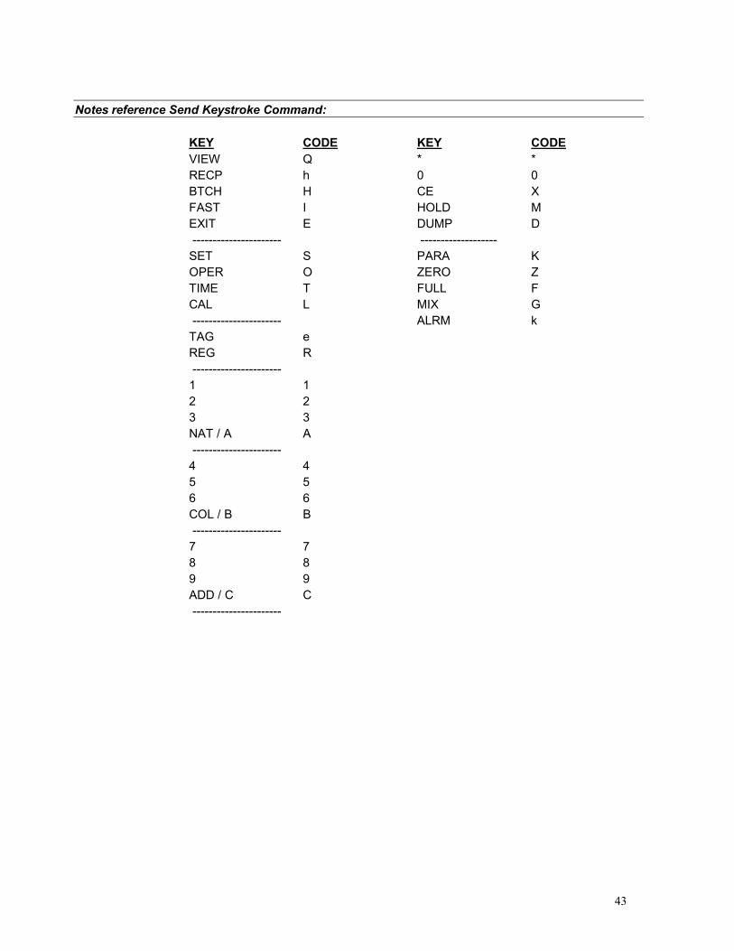
Send Keystroke Description: Sends a keystroke. (See "Set Remote Keypad" command) Command Format
Output Byte Modbus Description Name Range MLAN Description 0 Transaction ID 0 1 Transaction ID 0 2 Protocol ID 0 3 Protocol ID 0 4 Total Data Length 0 5 Total Data Length 7 6 Slave Address MLAN Address 7 Function Code 16 8 Register Hi Command Code 87 Send Keystroke Command 9 Register Lo Code ASCII See note 1
10 Register Count Hi 0 11 Register Count Lo 0 12 Data Byte Count 0
Response Format
Input Byte Modbus Description Name Range Description 0 Transaction ID 0 1 Transaction ID 0 2 Protocol ID 0 3 Protocol ID 0 4 Total Data Length 0 5 Total Data Length 2 6 Slave Address MLAN Address 7 Function Code 16 Top bit set on error
Please refer to notes on the next page:
43
Notes reference Send Keystroke Command:
KEY CODE KEY CODE
VIEW Q * * RECP h 0 0 BTCH H CE X FAST I HOLD M EXIT E DUMP D ---------------------- ------------------- SET S PARA K OPER O ZERO Z TIME T FULL F CAL L MIX G ---------------------- ALRM k TAG e REG R ---------------------- 1 1 2 2 3 3 NAT / A A ---------------------- 4 4 5 5 6 6 COL / B B ---------------------- 7 7 8 8 9 9 ADD / C C ----------------------

44
Send Settings Description: Sets the mix percentages, component types, work order #, and operator #. Command Format Type 1 - Four Component Software
Output Byte Modbus Description Name Range MLAN Description 0 Transaction ID 0 1 Transaction ID 0 2 Protocol ID 0 3 Protocol ID 0 4 Total Data Length 0 5 Total Data Length 63 6 Slave Address MLAN Address 7 Function Code 16 8 Register Hi Command Code 19 Send Settings Command 9 Register Lo 0
10 Register Count Hi 0 11 Register Count Lo 28 12 Data Byte Count 56 13 Data Word 0 Hi Type Hopper 1 0 14 Data Word 0 Lo Type Hopper 1 1 Always 1=regrind 15 Data Word 1 Hi Setting Hopper 1 16 Data Word 1 Lo Setting Hopper 1 0 to 999 Implied decimal point ##.# 17 Data Word 2 Hi Type Hopper 2 0 18 Data Word 2 Lo Type Hopper 2 2 Always 2=natural 19 Data Word 3 Hi Setting Hopper 2 0 20 Data Word 3 Lo Setting Hopper 2 0 Always on 21 Data Word 4 Hi Type Hopper 3 0 22 Data Word 4 Lo Type Hopper 3 3 Always 3=color 23 Data Word 5 Hi Setting Hopper 3 0 24 Data Word 5 Lo Setting Hopper 3 0 to 255 Implied decimal point ##.# 25 Data Word 6 Hi Type Hopper 4 0 26 Data Word 6 Lo Type Hopper 4 3 Always 3=additive 27 Data Word 7 Hi Setting Hopper 4 0 28 Data Word 7 Lo Setting Hopper 4 0 to 255 Implied decimal point ##.# 29 Data Word 8 to 12 Padding 0 Padding always zero 61 Data Word 24 Hi Recipe number 62 Data Word 24 Lo Recipe number 100 to 65536 Recipe number
63 Data Word 25 Hi Work Order Number
64 Data Word 25 Lo Work Order Number Recipe number
65 Data Word 26 Hi Work Order Number
66 Data Word 26 Lo Work Order Number 0 to 999999 Work order number

45
Command Format Type 1 - Four Component Software � continued
67 Data Word 27 Hi Operator number 68 Data Word 27 Lo Operator number 0 to 999 Operator number
Command Format Type 2 - Twelve Component Software
Output Byte Modbus Description Name Range MLAN Description 0 Transaction ID 0 1 Transaction ID 0 2 Protocol ID 0 3 Protocol ID 0 4 Total Data Length 0 5 Total Data Length 63 6 Slave Address MLAN Address 7 Function Code 16 8 Register Hi Command Code 19 Send Settings Command 9 Register Lo 0
10 Register Count Hi 0 11 Register Count Lo 28 12 Data Byte Count 56 13 Data Word 0 Hi Type Hopper 1 0
14 Data Word 0 Lo Type Hopper 1 0 to 3 1=regrind, 2=natural, 3=additive/color, 0=none
15 Data Word 1 Hi Setting Hopper 1
16 Data Word 1 Lo Setting Hopper 1 0 to 999 Implied decimal point r/a ##.# or n ###
17 Data Word 2 Hi Type Hopper 2 0
18 Data Word 2 Lo Type Hopper 2 0 to 3 1=regrind, 2=natural, 3=additive/color, 0=none
19 Data Word 3 Hi Setting Hopper 2 0
20 Data Word 3 Lo Setting Hopper 2 0 to 999 Implied decimal point r/a ##.# or n ###
21 Data Word 4 Hi Type Hopper 3 0
22 Data Word 4 Lo Type Hopper 3 0 to 3 1=regrind, 2=natural, 3=additive/color, 0=none
23 Data Word 5 Hi Setting Hopper 3 0
24 Data Word 5 Lo Setting Hopper 3 0 to 999 Implied decimal point r/a ##.# or n ###
25 Data Word 6 Hi Type Hopper 4 0
26 Data Word 6 Lo Type Hopper 4 0 to 3 1=regrind, 2=natural, 3=additive/color, 0=none
27 Data Word 7 Hi Setting Hopper 4 0
28 Data Word 7 Lo Setting Hopper 4 0 to 999 Implied decimal point r/a ##.# or n ###
29 Data Word 8 Hi Type Hopper 5 0
30 Data Word 8 Lo Type Hopper 5 0 to 3 1=regrind, 2=natural, 3=additive/color, 0=none

46
31 Data Word 9 Hi Setting Hopper 5 0
32 Data Word 9 Lo Setting Hopper 5 0 to 999 Implied decimal point r/a ##.# or n ###
33 Data Word 10 Hi Type Hopper 6 0
34 Data Word 10 Lo Type Hopper 6 0 to 3 1=regrind, 2=natural, 3=additive/color, 0=none
35 Data Word 11 Hi Setting Hopper 6 0
36 Data Word 11 Lo Setting Hopper 6 0 to 999 Implied decimal point r/a ##.# or n ###
37 Data Word 12 Hi Type Hopper 7 0
38 Data Word 12 Lo Type Hopper 7 0 to 3 1=regrind, 2=natural, 3=additive/color, 0=none
39 Data Word 13 Hi Setting Hopper 7
40 Data Word 13 Lo Setting Hopper 7 0 to 999 Implied decimal point r/a ##.# or n ###
41 Data Word 14 Hi Type Hopper 8 0
42 Data Word 14 Lo Type Hopper 8 0 to 3 1=regrind, 2=natural, 3=additive/color, 0=none
43 Data Word 15 Hi Setting Hopper 8 0
44 Data Word 15 Lo Setting Hopper 8 0 to 999 Implied decimal point r/a ##.# or n ###
45 Data Word 16 Hi Type Hopper 9 0
46 Data Word 16 Lo Type Hopper 9 0 to 3 1=regrind, 2=natural, 3=additive/color, 0=none
47 Data Word 17 Hi Setting Hopper 9 0
48 Data Word 17 Lo Setting Hopper 9 0 to 999 Implied decimal point r/a ##.# or n ###
49 Data Word 18 Hi Type Hopper 10 0
50 Data Word 18 Lo Type Hopper 10 0 to 3 1=regrind, 2=natural, 3=additive/color, 0=none
51 Data Word 19 Hi Setting Hopper 10 0
52 Data Word 19 Lo Setting Hopper 10 0 to 999 Implied decimal point r/a ##.# or n ###
53 Data Word 20 Hi Type Hopper 11 0
54 Data Word 20 Lo Type Hopper 11 0 to 3 1=regrind, 2=natural, 3=additive/color, 0=none
55 Data Word 21 Hi Setting Hopper 11 0
56 Data Word 21 Lo Setting Hopper 11 0 to 999 Implied decimal point r/a ##.# or n ###
57 Data Word 22 Hi Type Hopper 12 0
58 Data Word 22 Lo Type Hopper 12 0 to 3 1=regrind, 2=natural, 3=additive/color, 0=none
59 Data Word 23 Hi Setting Hopper 12 0
60 Data Word 23 Lo Setting Hopper 12 0 to 999 Implied decimal point r/a ##.# or n ###
61 Data Word 24 Hi Recipe number 62 Data Word 24 Lo Recipe number 100 to 999 Recipe number
63 Data Word 25 Hi Work Order Number
64 Data Word 25 Lo Work Order Number
65 Data Word 26 Hi Work Order

47
Number
66 Data Word 26 Lo Work Order Number 0 to 999999 Work order number
67 Data Word 27 Hi Operator number 68 Data Word 27 Lo Operator number 0 to 999 Operator number
Response Format
Input Byte Modbus Description Name Range Description 0 Transaction ID 0 1 Transaction ID 0 2 Protocol ID 0 3 Protocol ID 0 4 Total Data Length 0 5 Total Data Length 2 6 Slave Address MLAN Address 7 Function Code 16 Top bit set on error

48
Set Batch Weight Description: Sets the batch flag parameter and the batch weight. Command Format
Output Byte Modbus Description Name Range MLAN Description 0 Transaction ID 0 1 Transaction ID 0 2 Protocol ID 0 3 Protocol ID 0 4 Total Data Length 0 5 Total Data Length 11 6 Slave Address MLAN Address 7 Function Code 16 8 Register Hi Command Code 83 Set Batch Weight Command 9 Register Lo
10 Register Count Hi 0 11 Register Count Lo 2 12 Data Byte Count 4 13 Data Word 0 Hi Batch Weight
14 Data Word 0 Lo Batch Weight 0 to 65536
Batch weight (pounds or kilograms only) (See "Get Weight Units" command for units) See note 2
15 Data Word 1 Hi Flag
16 Data Word 1 Lo Flag 0, 1 or 2
0=no batch, 1=alarm & stop, 2=alarm & cont. See note 1
Response Format
Input Byte Modbus Description Name Range Description 0 Transaction ID 0 1 Transaction ID 0 2 Protocol ID 0 3 Protocol ID 0 4 Total Data Length 0 5 Total Data Length 2 6 Slave Address MLAN Address 7 Function Code 16 Top bit set on error
NOTE 1: A flag of 0 means to stop running batches. A flag of 1 means to sound the alarm and stop running at the end of the batch. A flag of 2 means to sound the alarm but continue running at the end of the batch.

49
NOTE 2: Batch weight is given in pounds if "Get Weight Units" returns either pounds or ounces.
If "Get Weight Units" returns either kilograms or grams, then batch weight is in kilograms.

50
Set Date And Time Description: Sets the date and time for a particular blender. If the address is 0, all WSBs are set with the new date and time and NO response is sent back. Command Format
Output Byte Modbus Description Name Range MLAN Description 0 Transaction ID 0 1 Transaction ID 0 2 Protocol ID 0 3 Protocol ID 0 4 Total Data Length 0 5 Total Data Length 15 6 Slave Address MLAN Address 7 Function Code 16
8 Register Hi Command Code 81 Set Date and Time Command
9 Register Lo 10 Register Count Hi 0 11 Register Count Lo 4 12 Data Byte Count 8 13 Data Word 0 Hi 14 Data Word 0 Lo 15 Data Word 1 Hi 16 Data Word 1 Lo 17 Data Word 2 Hi 18 Data Word 2 Lo 19 Data Word 4 Hi
20 Data Word 4 Lo Date and Time See note 1 Set Date and Time Command
Note 1 - Date and Time
Bit # Name Range Description 0 to 7 Padding 0 8 to 11 Seconds (ones place) 0 to 9 yy/mm/dd hh:mm:sS 12 to 14 Seconds (tens place) 0 to 5 yy/mm/dd hh:mm:Ss 15 Padding 0 16 to 19 Minutes (ones place) 0 to 9 yy/mm/dd hh:mM:ss 20 to 22 Minutes (tens place) 0 to 5 yy/mm/dd hh:Mm:ss 23 Padding 0 24 to 27 Hours (ones place) 0 to 9 yy/mm/dd hH:mm:ss 28 to 29 Hours (tens place) 0 to 2 yy/mm/dd Hh:mm:ss 30 Padding 0 31 One 1 32 to 34 Day of week 1 to 7 1 = sunday, 2=monday, ..., 7=saturday

51
35 Padding 0 36 One 1 37 Padding 0 38 to 39 Padding 0 40 to 43 Day (ones place) 0 to 9 yy/mm/dD hh:mm:ss 44 to 45 Day (tens place) 0 to 3 yy/mm/Dd hh:mm:ss 46 to 47 Padding 0 48 to 51 Month (ones place) 0 to 9 yy/mM/dd hh:mm:ss 52 Month (tens place) 0 or 1 yy/Mm/dd hh:mm:ss 53 to 55 Padding 0 56 to 59 Year (ones place) 0 to 9 yY/mm/dd hh:mm:ss 60 to 63 Years (tens place) 0 to 9 Yy/mm/dd hh:mm:ss
Response Format
Input Byte Modbus Description Name Range Description 0 Transaction ID 0 1 Transaction ID 0 2 Protocol ID 0 3 Protocol ID 0 4 Total Data Length 0 5 Total Data Length 2 6 Slave Address MLAN Address 7 Function Code 16 Top bit set on error

52
Set Parameter Description: Sets a single parameter. Command Format
Output Byte Modbus Description Name Range MLAN Description 0 Transaction ID 0 1 Transaction ID 0 2 Protocol ID 0 3 Protocol ID 0 4 Total Data Length 0 5 Total Data Length 13 6 Slave Address MLAN Address 7 Function Code 16 8 Register Hi Command Code 68 Set Parameter Command 9 Register Lo 0
10 Register Count Hi 0 11 Register Count Lo 3 12 Data Byte Count 6 13 Data Word 0 Hi 0
14 Data Word 0 Lo Parameter reference number 0 to 63
Parameter number � please refer to table below
15 Data Word 1 Hi
16 Data Word 1 Lo Component Number
1 to 4 1 to 12
1 � 4 = 4 Software (R,N,C,A) 1 � 12= 12 Software (1,2,3,4,5,6,7,8,9,10,11,12)
17 Data Word 2 Hi 18 Data Word 2 Lo Parameter Value 0 to 65535 Value of the Parameter
Response Format Input Byte Modbus Description Name Range Description
0 Transaction ID 0 1 Transaction ID 0 2 Protocol ID 0 3 Protocol ID 0 4 Total Data Length 0 5 Total Data Length 2 6 Slave Address MLAN Address 7 Function Code 16 Top bit set on error
NOTE: Parameters explanations are given in the blender manual.

53
Set Remote Keypad Description: Enables or disables the controller's keypad and/or the "Send Keystroke" MLAN command. Command Format
Output Byte Modbus Description Name Range MLAN Description 0 Transaction ID 0 1 Transaction ID 0 2 Protocol ID 0 3 Protocol ID 0 4 Total Data Length 0 5 Total Data Length 9 6 Slave Address MLAN Address 7 Function Code 16
8 Register Hi Command Code 88 Set Remote Keypad Command
9 Register Lo 0 10 Register Count Hi 0 11 Register Count Lo 1 12 Data Byte Count 2 13 Data Word 0 Hi 0 14 Data Word 0 Lo Flag 0 to 1 See note 1
Response Format
Input Byte Modbus Description Name Range Description 0 Transaction ID 0 1 Transaction ID 0 2 Protocol ID 0 3 Protocol ID 0 4 Total Data Length 0 5 Total Data Length 2 6 Slave Address MLAN Address 7 Function Code 16 Top bit set on error
Note 1:
A flag of 0 enables the keypad on the controller and disables the "Send Keystroke" MLAN command. A flag of 1 disables the keypad and enables the command.

54
Set Steady State Rate Description: Sets throughput rate. Note however that the blender will continue to reset the rate accordingly to how much material is being consumed. This is useful if you know that the rate just changed, such as in extrusion control, and you don't want to wait until the blender figures it out. Command Format
Output Byte Modbus Description Name Range MLAN Description 0 Transaction ID 0 1 Transaction ID 0 2 Protocol ID 0 3 Protocol ID 0 4 Total Data Length 0 5 Total Data Length 15 6 Slave Address MLAN Address 7 Function Code 16
8 Register Hi Command Code 65 Set Steady State Rate Command
9 Register Lo 0 10 Register Count Hi 0 11 Register Count Lo 4 12 Data Byte Count 8 13 Data Word 0 Hi Steady State Rate 14 Data Word 0 Lo Steady State Rate 15 Data Word 1 Hi Steady State Rate 16 Data Word 1 Lo Steady State Rate 17 Data Word 2 Hi Steady State Rate 18 Data Word 2 Lo Steady State Rate 19 Data Word 3 Hi Steady State Rate
20 Data Word 3 Lo Steady State Rate 0 to 4294967295
Grams (or tenths of grams) per hour
Response Format
Input Byte Modbus Description Name Range Description 0 Transaction ID 0 1 Transaction ID 0 2 Protocol ID 0 3 Protocol ID 0 4 Total Data Length 0 5 Total Data Length 2 6 Slave Address MLAN Address 7 Function Code 16 Top bit set on error

55
Set Tag Description: Sets a tag value, recipe, work order, and operator #. Command Format
Output Byte Modbus Description Name Range MLAN Description 0 Transaction ID 0 1 Transaction ID 0 2 Protocol ID 0 3 Protocol ID 0 4 Total Data Length 0 5 Total Data Length 15 6 Slave Address MLAN Address 7 Function Code 16 8 Register Hi Command Code 90 Set Tag Command 9 Register Lo 0
10 Register Count Hi 0 11 Register Count Lo 4 12 Data Byte Count 8 13 Data Word 0 Hi Tag ID 14 Data Word 0 Lo Tag ID 15 Data Word 1 Hi Tag ID
16 Data Word 1 Lo Tag ID ASCII Two letter acronym designating tag.
"RC" = Recipe (1 char per word)
"WO" = Work Order (1 char per word)
"OP" = Operator (1 char per word)
17 Data Word 2 Hi Tag Value 18 Data Word 2 Lo Tag Value 19 Data Word 3 Hi Tag Value
20 Data Word 3 Lo Tag Value 0 to 4294967295 The value of the tag.
Recipe numbers: 0 to 65,536. Work order numbers: 0 to 999,999. Operator numbers: 0 to 999.

56
Response Format
Input Byte Modbus Description Name Range Description 0 Transaction ID 0 1 Transaction ID 0 2 Protocol ID 0 3 Protocol ID 0 4 Total Data Length 0 5 Total Data Length 2 6 Slave Address MLAN Address 7 Function Code 16 Top bit set on error

57
Set Target Throughput Description: Sets the Target Throughput for extrusion control. See XCV parameter in blender manual for more information. Command Format
Output Byte Modbus Description Name Range MLAN Description 0 Transaction ID 0 1 Transaction ID 0 2 Protocol ID 0 3 Protocol ID 0 4 Total Data Length 0 5 Total Data Length 11 6 Slave Address MLAN Address 7 Function Code 16
8 Register Hi Command Code 30 Set Target Throughput Command
9 Register Lo 0 10 Register Count Hi 0 11 Register Count Lo 2 12 Data Byte Count 4 13 Data Word 0 Hi Target Throughput 14 Data Word 0 Lo Target Throughput 15 Data Word 1 Hi Target Throughput
16 Data Word 1 Lo Target Throughput 0 to 4294967295
Response Format
Input Byte Modbus Description Name Range Description 0 Transaction ID 0 1 Transaction ID 0 2 Protocol ID 0 3 Protocol ID 0 4 Total Data Length 0 5 Total Data Length 2 6 Slave Address MLAN Address 7 Function Code 16 Top bit set on error

58
Set Weight Units Description: Sets the units that the blender uses to display totals, such as pounds or kilograms. Command Format
Output Byte Modbus Description Name Range MLAN Description 0 Transaction ID 0 1 Transaction ID 0 2 Protocol ID 0 3 Protocol ID 0 4 Total Data Length 0 5 Total Data Length 9 6 Slave Address MLAN Address 7 Function Code 16 8 Register Hi Command Code 86 Set Weight Units Command 9 Register Lo 0
10 Register Count Hi 0 11 Register Count Lo 1 12 Data Byte Count 2 13 Data Word 0 Hi Weight units 0
14 Data Word 0 Lo Weight units 0, 1, 2, or 4 0=pounds, 1=ounces, 2=grams, 4=kilograms
Response Format
Input Byte Modbus Description Name Range Description 0 Transaction ID 0 1 Transaction ID 0 2 Protocol ID 0 3 Protocol ID 0 4 Total Data Length 0 5 Total Data Length 2 6 Slave Address MLAN Address 7 Function Code 16 Top bit set on error

59
Silence Alarm Description: Has the same effect as if the silence alarm button was pressed. Command Format
Output Byte Modbus Description Name Range MLAN Description 0 Transaction ID 0 1 Transaction ID 0 2 Protocol ID 0 3 Protocol ID 0 4 Total Data Length 0 5 Total Data Length 7 6 Slave Address MLAN Address 7 Function Code 16 8 Register Hi Command Code 82 Silence Alarm Command 9 Register Lo 0
10 Register Count Hi 0 11 Register Count Lo 0 12 Data Byte Count 0
Response Format
Input Byte Modbus Description Name Range Description 0 Transaction ID 0 1 Transaction ID 0 2 Protocol ID 0 3 Protocol ID 0 4 Total Data Length 0 5 Total Data Length 2 6 Slave Address MLAN Address 7 Function Code 16 Top bit set on error

60
Start/Stop/Status Description: Either causes the WSB to stop at the end of the current cycle, start up again, or return its current status. Command Format (Subcommand 1:stop or 2:start)
Output Byte Modbus Description Name Range MLAN Description 0 Transaction ID 0 1 Transaction ID 0 2 Protocol ID 0 3 Protocol ID 0 4 Total Data Length 0 5 Total Data Length 7 6 Slave Address MLAN Address 7 Function Code 16
8 Register Hi Command Code 55 Start / Stop / Status Command
9 Register Lo Subcommand 1 or 2 0=mode status, 1=soft stop, 2=soft start
10 Register Count Hi 0 11 Register Count Lo 0 12 Data Byte Count 0
Command Format (Subcommand 0:mode status)
Output Byte Modbus Description Name Range MLAN Description 0 Transaction ID 0 1 Transaction ID 0 2 Protocol ID 0 3 Protocol ID 0 4 Total Data Length 0 5 Total Data Length 6 6 Slave Address MLAN Address 7 Function Code 3 or 4
8 Register Hi Command Code 55 Start / Stop / Status Command
9 Register Lo Subcommand 0 0=mode status 10 Point Count Hi 0 11 Point Count Lo 0

61
Response Format (Subcommand 1:stop or 2:start)
Input Byte Modbus Description Name Range Description 0 Transaction ID 0 1 Transaction ID 0 2 Protocol ID 0 3 Protocol ID 0 4 Total Data Length 0 5 Total Data Length 2 6 Slave Address MLAN Address 7 Function Code 16 Top bit set on error
Response Format (Subcommand 0:mode status)
Input Byte Modbus Description Name Range Description 0 Transaction ID 0 1 Transaction ID 0 2 Protocol ID 0 3 Protocol ID 0 4 Total Data Length 0 5 Total Data Length 5 6 Slave Address MLAN Address 7 Function Code 3 or 4 Top bit set on error 8 Byte Count 2 9 Data Word 0 Hi Mode 0
10 Data Word 0 Lo Mode 0,1 or 2
0 = Hard Stop 1= Soft stop 2 = Automatic Mode / Running Mode

62
Stop Cycle / Stop Retry Description: Either causes the WSB to abort the current cycle or the current dispense. Aborting the current cycle causes the WSB to start the next cycle. Aborting the current dispense causes the WSB to start dispensing the next component. Command Format
Output Byte Modbus Description Name Range MLAN Description 0 Transaction ID 0 1 Transaction ID 0 2 Protocol ID 0 3 Protocol ID 0 4 Total Data Length 0 5 Total Data Length 7 6 Slave Address MLAN Address 7 Function Code 16
8 Register Hi Command Code 27 Stop Cycle / Stop / Retry Command
9 Register Lo Subcommand 1 or 2 1 = Stop Cycle; 2 = Stop Retry
10 Register Count Hi 0 11 Register Count Lo 0 12 Data Byte Count 0
Response Format
Input Byte Modbus Description Name Range Description 0 Transaction ID 0 1 Transaction ID 0 2 Protocol ID 0 3 Protocol ID 0 4 Total Data Length 0 5 Total Data Length 2 6 Slave Address MLAN Address 7 Function Code 16 Top bit set on error

63
Parameter Table from Four Component Blender Software - Sample
Name Value Name Value FLG 0 NWT 20800 RAL 0 NTI 7808 NAL 4 CWT 1024 CAL 4 CTI 31232 AAL 4 AWT 1024 MIX 3010 ATI 31232 FCV 5 RMI 325 DTI 10 NMI 325 KDF 2 CMI 4 WDF 2 AMI 1 BER 200 RNC 1 CXT 0 NNC 1 AXT 0 CNC 1 ROC 0 ANC 1 ROV 0 RRP 10 RHL 0 NRP 10 FUL 4000 CRP 10 MAX 6000 ARP 10 TH 200 RRD 81 TL 100 NRD 81
PRT 0 CRD 2 RSE 1000 ARD 5 CSE 1000 RLA 20 ASE 1000 NLA 20 RLO 50 CLA 15 DLY 488 ALA 15 LT1 0 PRC 10 LT2 0 STL 244 RPT 0 LCL 80 NPT 0 LCH 120 CPT 0 LCF 79 APT 0 LCZ 583 RWT 20800 XTP 20010 RTI 7808

64
Parameter Table for 12 Component Blender Software (Sample as of version 01003T) Prior chip versions may not contain all listed parameters, future chip versions may contain additional parameters.
Name Value Name Value Name Value Name Value FLG 00000 2TY 00002 5PT 00000 9SE 01000 MIX 03010 2CS 00000 5RP 00010 9WT 26000 FCV 00006 2AL 00004 5RD 00500 9TI 00976 DTI 00006 2XT 00000 5LA 00020 9MI 00001 KDF 00010 2SE 01000 5PO 00000 9NC 00010 WDF 00010 2WT 26000 6TY 00002 9PT 00000 BER 01000 2TI 00976 6CS 00000 9RP 00010 ROC 00000 2MI 00001 6AL 00004 9RD 00500 ROV 00000 2NC 00010 6XT 00000 9LA 00020 RHL 00000 2PT 00000 6SE 01000 9PO 00000 FUL 20000 2RP 00010 6WT 26000 ATY 00002 MAX 30000 2RD 00500 6TI 00976 ACS 00000 TH 01000 2LA 00020 6MI 00001 AAL 00004 TL 00500 2PO 00000 6NC 00010 AXT 00000 PRT 00000 3TY 00002 6PT 00000 ASE 01000 DLY 00488 3CS 00000 6RP 00010 AWT 26000 PRC 00010 3AL 00004 6RD 00500 ATI 00976 STL 00122 3XT 00000 6LA 00020 AMI 00001 LCL 00027 3SE 01000 6PO 00000 ANC 00010 LCH 00039 3WT 26000 7TY 00002 APT 00000 LCF 00079 3TI 00976 7CS 00000 ARP 00010 LCZ 00583 3MI 00001 7AL 00004 ARD 00500 DS1 00000 3NC 00010 7XT 00000 ALA 00020 DS2 00000 3PT 00000 7SE 01000 APO 00000 XCV 00000 3RP 00010 7WT 26000 BTY 00002 XRC 00001 3RD 00500 7TI 00976 BCS 00000 TCV 00000 3LA 00020 7MI 00001 BAL 00004 TRC 00004 3PO 00000 7NC 00010 BXT 00000 XTP 05050 4TY 00002 7PT 00000 BSE 01000 MPO 00183 4CS 00000 7RP 00010 BWT 26000 SCR 00000 4AL 00004 7RD 00500 BTI 00976 XAL 00005 4XT 00000 7LA 00020 BMI 00001 XUL 00200 4SE 01000 7PO 00000 BNC 00010 BCR 00000 4WT 26000 8TY 00002 BPT 00000 CPL 00000 4TI 00976 8CS 00000 BRP 00010 PTD 00020 4MI 00001 8AL 00004 BRD 00500 MCT 00000 4NC 00010 8XT 00000 BLA 00020 1TY 00002 4PT 00000 8SE 01000 BPO 00000 1CS 00000 4RP 00010 8WT 26000 CTY 00002 1AL 00004 4RD 00500 8TI 00976 CCS 00000 1XT 00000 4LA 00020 8MI 00001 CAL 00004 1SE 01000 4PO 00000 8NC 00010 CXT 00000 1WT 26000 5TY 00002 8PT 00000 CSE 01000 1TI 00976 5CS 00000 8RP 00010 CWT 26000 1MI 00001 5AL 00004 8RD 00500 CTI 00976 1NC 00010 5XT 00000 8LA 00020 CMI 00001 1PT 00000 5SE 01000 8PO 00000 CNC 00010 1RP 00010 5WT 26000 9TY 00002 CPT 00000 1RD 00500 5TI 00976 9CS 00000 CRP 00010 1LA 00020 5MI 00001 9AL 00004 CRD 00500 1PO 00000 5NC 00010 9XT 00000 CLA 00020
CPO 00000