modbus installation and operating instructions · modbus is a mono master system, which means that...
TRANSCRIPT

DS 400 Side 1 of 36
EN - English
Modbus Installation and operating instructions
Intelligent paperless recorder
DS 400

Foreword
DS 400 Side 1 of 36
I. Foreword
Dear customer,
thank you very much for deciding in favour of the DS 400. Please read this installation and operation manual carefully before mounting and initiating the device and follow our advice. A riskless operation and a correct functioning of the DS 400 are only guaranteed in case of careful observation of the described instructions and notes.
Sales Office South/Geschäftsstelle Süd
Zindelsteiner Str. 15 D-78052 VS-Tannheim
Tel.: +49 (0) 7705 978 99 0 Fax: +49 (0) 7705 978 99 20
Mail: [email protected] Web: http://www.cs-instruments.com
Sales Office North/Geschäftsstelle Nord
Am Oxer 28c D-24955 Harrislee
Tel.: +49 (0) 461 700 20 25 Fax: +49 (0) 461 700 20 26
Mail: [email protected] Web: http://www.cs-instruments.com

Inhaltsverzeichnis
DS 400 Side 2 of 36
II. Table of Contents
I. Foreword ....................................................................................................................... 1
II. Table of Contents ...................................................................................................... 2
1 Safety Instructions ........................................................................................................ 4
2 Instructions ................................................................................................................... 5
2.1 Definitions and abbreviations ................................................................................................ 5
2.2 References ............................................................................................................................... 5
3 Technical data DS 400 .................................................................................................. 6
3.1 DS400 MODBUS RTU specification....................................................................................... 6
3.2 DS400 MODBUS/ TCP specification ...................................................................................... 6
3.3 General Modbus Information ................................................................................................. 6 3.3.1 Serial transmission modes (RTU) ...................................................................................... 7 3.3.2 Ethernet transmission modes ............................................................................................ 7
4 Installation ..................................................................................................................... 8
4.1 RS485 bus wiring (Modbus RTU) – Connection diagram connector „E“ ......................... 8
4.2 Ethernet connection for Modbus/TCP .................................................................................. 9
5 Modbus RTU communication settings .......................................................................10
5.1 Accessing and changing Modbus settings ........................................................................ 10
6 Modbus TCP communication settings .......................................................................11
7 Modbus addressing model ..........................................................................................12
7.1 Function Code 3 (Read holding register) ........................................................................... 12
7.2 Function code 16 (Write multiple registers) ....................................................................... 13
8 Modbus Holding Register ............................................................................................14
8.1 Basic Values Register .......................................................................................................... 14
8.2 Values register ...................................................................................................................... 15
8.3 Status register ....................................................................................................................... 18 8.3.1 Status register Values 1..4 ............................................................................................. 18 8.3.2 Status register Values 5..8 ............................................................................................. 20
8.4 Channel description.............................................................................................................. 22
8.5 Alarm Settings ....................................................................................................................... 26
8.6 Value extended ...................................................................................................................... 27
8.7 Data format test ..................................................................................................................... 29
8.8 Data Bit description .............................................................................................................. 30
8.9 User Units .............................................................................................................................. 32

DS 400 Side 3 of 36
9 Appendix ......................................................................................................................35
9.1 APPENDIX A - Exception codes .......................................................................................... 35

Safety instructions
DS 400 Side 4 of 36
1 Safety Instructions
Please check whether this manual corresponds with the device type.
Please attend to all notes indicated in this instruction manual. It contains essential information which has to be followed during installation, operation and maintenance. Therefore this instruction manual has to be read categorically by the technician as well as by the responsible user/qualified personnel before installation, initiation and maintenance.
This instruction manual has to be available at any time at the operation site of the DS 400.
Regional and national regulations respectively, have to be observed in addition to this instruction manual if necessary.
In case of any obscurities or questions with regard to this manual or the instrument please contact CS Instruments GmbH.
Warning!
Supply voltage!
Contact with supply voltage carrying non-insulated parts may cause an electric shock with injury and death.
Measures:
• Note all applicable regulations for electrical installations (e. g. VDE 0100)!
• Carry out maintenance only in strainless state!
• All electric works are only allowed to be carried out by authorized qualified personnel.
Warning!
Inadmissible operating parameters!
Undercutting and exceeding respectively of limit values may cause danger to persons and material and may lead to functional and operational disturbances.
Measures:
• Make sure that the DS 400 is only operated within the admissible limit values indicated on the type label.
• Strict observance of the performance data of the DS 400 in connection with the application.
• Do not exceed the admissible storage and transportation temperature.
Further safety instructions:
• Attention should also be paid to the applicable national regulations and safety instructions during installation and operation.
• The DS 400 is not allowed to be used in explosive areas.
Additional remarks:
• Do not overheat the instrument!
Attention!
Malfunctions at the DS 400!
Faulty installation and insufficient maintenance may lead to malfunctions of the DS 400 which may affect the measuring results and which may lead to misinterpretations.
r
r

DS 400 Side 5 of 36
2 Instructions
This manual is intended to provide instructions for the installation and use of the DS 400
MODBUS function. The DS 400 MODBUS function can let the MODBUS master device to
read out the online measurement values.
This manual is not intended to be a complete tutorial on the MODBUS RTU protocol, and it
is assumed the end user already has a general working knowledge of MODBUS RTU
Communications, especially in respect of master station configuration and operation.
However an overview is included in the following section to explain some of the
fundamental aspects of the protocol.
2.1 Definitions and abbreviations
CRC
Cyclic Redundancy Check
Used for error—checking in MODBUS RTU. See appendix
Modbus Master A MODBUS device, which is able to access data in one or more connected MODBUS slaves
Modbus Slave A MODBUS device, which is able to respond to requests from a
single MODBUS master
Modbus Adresse Throughout this document the following notation is used to address MODBUS RTU registers see chapter 8 Addressing: Holding Register 1009 is addressed in messages by 1008
PDU MODBUS protocol data unit
ADU MODBUS application data unit
MBAP MODBUS application protocol
RS485 Refers to the 2—wire communication standard defined by EIA/TIA-485. (Physical layer)
Ethernet
2.2 References
1. MODBUS over Serial Line Specification and Implementation Guide V1.02 modbus.org 2006 Dec 20
2. MODBUS APPLICATION PROTOCOL SPECIFICATION V1.1b modbus.org 2006 Dec 28
3. MODBUS Messaging on TCP/IP implementation Guide V1.0b 2006 Oct 34
4. DS 400 operation manual

DS 400 Side 6 of 36
3 Technical data DS 400
3.1 DS400 MODBUS RTU specification
Device type Slave
Baud Rates 1200,2400, 4800, 9600, 19200, 38400 bps
Device address range 1...247
Electrical Interface RS485, 2 wire (Internal Connector X4.1)
Protocol RTU
Supported function code 3 read holding register
16 write multiple register
Broadcast No
Standard Modbus over serial line V1.02
3.2 DS400 MODBUS/ TCP specification
Device type Slave
Device address range 1...247
Electrical Interface Ethernet, RJ45
Protocol MODBUS/TCP
IP address Obtained from DHCP or static
Port 502
Supported function code 3 read holding register
16 write multiple register
Standard Modbus Messaging on TCP/IP Implementation Guide V1.0b
3.3 General Modbus Information
The DS 400 Modbus module complies with the Modbus serial line protocol [Reference 1].
Among other things this implies a master-slave protocol at level 2 of the OSI model. One
node (the master) issues explicit commands to one of the ,,sIave"-nodes and processes
responses. Slave nodes will not transmit data without a request from the master node, and
do not communicate with other slaves.
Modbus is a mono master system, which means that only one master can be connected
at the time.

DS 400 Side 7 of 36
3.3.1 Serial transmission modes (RTU)
The DS 400 Modbus mode support only one serial transmission modes; the RTU
mode. The transmission mode defines the bit contents of message fields
transmitted serially on the line. It determines how information is packed into the message
fields and decoded.
The transmission mode and serial port parameters must be the same for all devices on a
Modbus serial line.
RTU mode Modbus Application Data Unit (ADU) frame is shown below, and is valid for
both requests and responses
Slave address Function code Data CRC
1 byte 1byte 0 up to 252 byte(s) 2 bytes
Tabelle 1
Further details of the Modbus protocol can be found in Reference 1 and 2.
3.3.2 Ethernet transmission modes
The DS 400 Modbus mode supports the Modbus/TCP only
The transmission mode defines the bit contents of message fields transmitted serially on the line. It determines how information is packed into the message fields and decoded.
The transmission mode and serial port parameters must be the same for all devices on a
Modbus serial line.
Modbus/TCP mode Modbus Application Data Unit (ADU) frame is shown below, and is
valid for both requests and responses
Modbus/TCP MBAP Header PDU
Transaction Id
Protocol Id
Length Unit Id Function Code
Data
2 byte 2 byte 2 byte 1 byte 1byte 0 up to 252 byte (s)
Tabelle 2

Installation
DS 400 Side 8 of 36
4 Installation
4.1 RS485 bus wiring (Modbus RTU) – Connection diagram connector „E“
1 2 3 4 5 6
Co
mm
on
RS
48
5 (
B)
RS
48
5 (
A)
Co
mm
on
RS
48
5 (
B)
RS
48
5 (
A)
Slave 1 Slave n
A
BCommon
T TR R
Master
TR
1 2 3 4 5 6
Co
mm
on
RS
48
5 (
B)
RS
48
5 (
A)
Co
mm
on
RS
48
5 (
B)
RS
48
5 (
A)
DS 400 Ethernet Board Stecker „E“
A
B
Common
Slave n
TR
Bus cable:
Only cables according to the recommendations of EIA 485 standard should be used. A
maximum of 64 devices may be connected to one segment. The bus cable must be laid at
a distance of at least 20 cm from other cables. It should be laid in a separate, conductive,
and earthed cable trunking. It must be ensured that no potential differences occur between
the individual devices on the bus.
Cable specification:
Impedance: 135 -165 Ohm @ 3 to 20 Mhz
Cable capacity: < 30pF/m
Cable diameter: > 0.64 mm
Cross section: > 0.34 mm2, conforms to AWG 22
Loop resistance < 110 Ohm per km
Screening: Cu shielding braid or shielding braid and shielding foil

DS 400 Side 9 of 36
4.2 Ethernet connection for Modbus/TCP
For easy Ethernet cable connection to your network an ordinary RJ45 Ethernet cable connection is provided.
Cable:
An Ethernet cable with category 5 or better is to be used.

DS 400 Side 10 of 36
5 Modbus RTU communication settings
Before communication with the master, baudrate, address, and framing must be defined
5.1 Accessing and changing Modbus settings
First step: Main menu Settings Device settings Modbus settings
The settings are all protected by a password!
Inputs and changes have to be confirmed by pressing OK in general!
Enter Password
If an incorrect password is entered there appears Enter password or New password repeat in red font. If you can’t remember the password, please use Master password in order to enter a new password. Remark: The master password is supplied together with the instrument’s documentation.
Factory settings for password at the time of delivery: 0000 (4 times zero). If required, the password can be changed in the Password settings. The new password must be entered two times in a row and in each case confirmed with OK.

DS 400 Side 11 of 36
Main menu Settings Device settings Modbus settings
In case the DS400 is at the bus end (last Slave in the bus) then the Modbus have to be terminated. This is done for the DS400 by SW by activation of the Term and Bias Button
Note:
It is recommended NOT to use the default address in a multi-slave network. It is of great
importance to ensure at the time of the procedure of device addressing, that there
is not two devices with the same address. In such a case, an abnormal behavior of the
whole serial bus can occur, the master being then in the impossibility to communicate with
all present slaves on the bus.
6 Modbus TCP communication settings
By communication via Modbus TCP the Modbus Id have to be set only and confirmed by pressing Apply button
Here please define your communication parameters. Modbus Id, Baudrate,Stopbits,Parity, Term and Bias.. Enable the RTU Modbus by activation of the enable Modbus button. Confirm the changes by pressing the button Apply Remark: Only in case of changes the button Apply appears else to go back with button Back By pressing the button Set to Default the default values will be defined. Default values: Baudrate: 19200bps
Parity: even Stopbits 1

DS 400 Side 12 of 36
7 Modbus addressing model
The DS400 RS485 Modbus allows read/write access according chapter 8
Not defined registers are not accessible / not supported.
Byte Order:
The size of each Modbus-register is 2 Byte. For a 32 bit value two Modbusregister will be read out by the DS400. Accordingly for a 16bit Value only one register is read.
Ausgabeformat DS400:
Single Word Double Word
For verification of a correct dataformat please read out register 64000 or 64004.
Result should be.
Register 64000: Long Integer Value =1 000 000
Register 64004: Float Value = 1 000 000
7.1 Function Code 3 (Read holding register)
General exceptions:
• Requesting less than 1 or more than 125 registers => Exception 3 (Illegal data value)
• Requesting more than max. message size (27 registers) => Exception 2(Illegal data address)
• Requesting data out of defined range of registers chapter 8 => Exception 2 (Illegal data address)
Application exceptions:
• Application errors => Exception 4 (Slave device error)
Holes/register alignment:
• The read command always returns data if no exception is given. Bad
Start/end alignment will result in only parts of the data item being read.
HByte LByte 18 => 00 12 Data Order 1. Byte 2. Byte 12 00
HWord LWord HByte LByte HByte LByte 29235175522 => AE 41 56 52 Data Order 1.Byte 2.Byte 3.byte 4.Byte 56 52 AE 41

DS 400 Side 13 of 36
7.2 Function code 16 (Write multiple registers)
In general only status register (register 2001 – 2064) are writable.
General exceptions: • Writing less than 1 or more than 63 registers => Exception 3 (Illegal data value) • If ByteCount is not exactly 2 times NoOfRegisters => Exception 3 (Illegal data value) • Exceeding max. message size (27 registers) => Exception 2 (Illegal data address) • Writing data out of defined register range chapter 8 =>Exception 2 (Illegal data address) Application exceptions: • Application errors => Exception 4 (Slave device error) • Application errors include writing to ReadOnIy holding registers Holes / register alignment: • If start-address is not the start of a mapped holding register => Exception 2 (Illegal data address) • Writing to holes is allowed (ie ignored - and no exception occurs) — except for the condition described above

DS 400 Side 14 of 36
8 Modbus Holding Register
8.1 Basic Values Register
Modbus Register
Modbus Address
No.of Byte
Data Type Description
Default Setting
Read Write Comment
1 0 4 Dword Serial Number 0 R
3 2 8 String HostName 0 R
7 6 4 Dword HardwareVersion 0 R sprintf(str,"%u.%02u",hw>>16,hw&0xffff);
9 8 4 Dword Softwareversion 0 R sprintf(str,"%u.%02u",sw>>16,sw&0xffff);
11 10 8 Byte(6) MAC Adress 0 R Upper 2 bytes are zero
15 14 4 Dword Calibration Date 0 R Unix Time
17 16 4 Dword Betriebsstundenzähler
0 R Wert in Sekunden
19 18 4 Dword Uhrzeit 0 R Unix Time
21 20 16 String Brand Name 0 R
29 28 2 Word Modbus ID 0 R Modbus ID
30 29 2 Word free 0 R free
31 30 4 Dword MbRTU Rx Packets OK
0 R valid RTU telegrams received
33 32 4 Dword MbRTU Tx Packets
0 R RTU telegrams transmitted
35 34 4 Dword MbRTU CRC Errors
0 R CRC Errors
37 36 4 Dword MbRtu Parity Errors
0 R Parity Errors
DS 400 Side 15 of 36
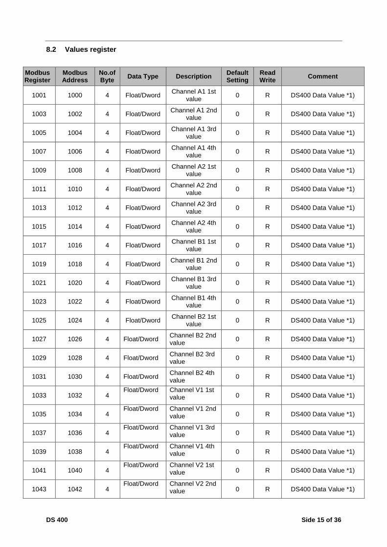
8.2 Values register
Modbus Register
Modbus Address
No.of Byte
Data Type Description Default Setting
Read Write
Comment
1001 1000 4 Float/Dword Channel A1 1st
value 0 R DS400 Data Value *1)
1003 1002 4 Float/Dword Channel A1 2nd
value 0 R DS400 Data Value *1)
1005 1004 4 Float/Dword Channel A1 3rd
value 0 R DS400 Data Value *1)
1007 1006 4 Float/Dword Channel A1 4th
value 0 R DS400 Data Value *1)
1009 1008 4 Float/Dword Channel A2 1st
value 0 R DS400 Data Value *1)
1011 1010 4 Float/Dword Channel A2 2nd
value 0 R DS400 Data Value *1)
1013 1012 4 Float/Dword Channel A2 3rd
value 0 R DS400 Data Value *1)
1015 1014 4 Float/Dword Channel A2 4th
value 0 R DS400 Data Value *1)
1017 1016 4 Float/Dword Channel B1 1st
value 0 R DS400 Data Value *1)
1019 1018 4 Float/Dword Channel B1 2nd
value 0 R DS400 Data Value *1)
1021 1020 4 Float/Dword Channel B1 3rd
value 0 R DS400 Data Value *1)
1023 1022 4 Float/Dword Channel B1 4th
value 0 R DS400 Data Value *1)
1025 1024 4 Float/Dword Channel B2 1st
value 0 R DS400 Data Value *1)
1027 1026 4 Float/Dword Channel B2 2nd value
0 R DS400 Data Value *1)
1029 1028 4 Float/Dword Channel B2 3rd value
0 R DS400 Data Value *1)
1031 1030 4 Float/Dword Channel B2 4th value
0 R DS400 Data Value *1)
1033 1032 4 Float/Dword Channel V1 1st
value 0 R DS400 Data Value *1)
1035 1034 4 Float/Dword Channel V1 2nd
value 0 R DS400 Data Value *1)
1037 1036 4 Float/Dword Channel V1 3rd
value 0 R DS400 Data Value *1)
1039 1038 4 Float/Dword Channel V1 4th
value 0 R DS400 Data Value *1)
1041 1040 4 Float/Dword Channel V2 1st
value 0 R DS400 Data Value *1)
1043 1042 4 Float/Dword Channel V2 2nd
value 0 R DS400 Data Value *1)

DS 400 Side 16 of 36
Modbus Register
Modbus Address
No.of Byte
Data Type Description Default Setting
Read Write
Comment
1045 1044 4 Float/Dword Channel V2 3rd value
0 R DS400 Data Value *1)
1047 1046 4 Float/Dword Channel V2 4th value
0 R DS400 Data Value *1)
1049 1048 4 Float/Dword Channel V3 1st value
0 R DS400 Data Value *1)
1051 1050 4 Float/Dword Channel V3 2nd value
0 R DS400 Data Value *1)
1053 1052 4 Float/Dword Channel V3 3rd value
0 R DS400 Data Value *1)
1055 1054 4 Float/Dword Channel V3 4th value
0 R DS400 Data Value *1)
1057 1056 4 Float/Dword Channel V4 1st value
0 R DS400 Data Value *1)
1059 1058 4 Float/Dword Channel V4 2nd value
0 R DS400 Data Value *1)
1061 1060 4 Float/Dword Channel V4 3rd value
0 R DS400 Data Value *1)
1063 1062 4 Float/Dword Channel V4 4th value
0 R DS400 Data Value *1)
1201 1200 4 Float/Dword Channel A1 5th value
0 R DS400 Data Value *1)
1203 1202 4 Float/Dword Channel A1 6th value
0 R DS400 Data Value *1)
1205 1204 4 Float/Dword Channel A1 7th value
0 R DS400 Data Value *1)
1207 1206 4 Float/Dword Channel A1 8th value
0 R DS400 Data Value *1)
1209 1208 4 Float/Dword Channel A2 5th value
0 R DS400 Data Value *1)
1211 1210 4 Float/Dword Channel A2 6th value
0 R DS400 Data Value *1)
1213 1212 4 Float/Dword Channel A2 7th value
0 R DS400 Data Value *1)
1215 1214 4 Float/Dword Channel A2 8th value
0 R DS400 Data Value *1)
1217 1216 4 Float/Dword Channel B1 5th value
0 R DS400 Data Value *1)
1219 1218 4 Float/Dword Channel B1 6th Value
0 R DS400 Data Value *1)
1221 1220 4 Float/Dword Channel B1 7th value
0 R DS400 Data Value *1)
1223 1222 4 Float/Dword Channel B1 8th value
0 R DS400 Data Value *1)

DS 400 Side 17 of 36
Modbus Register
Modbus Address
No.of Byte
Data Type Description Default Setting
Read Write
Comment
1225 1224 4 Float/Dword Channel B2 5th value
0 R DS400 Data Value *1)
1227 1226 4 Float/Dword Channel B2 6th Value
0 R DS400 Data Value *1)
1229 1228 4 Float/Dword Channel B2 7th value
0 R DS400 Data Value *1)
1231 1230 4 Float/Dword Channel B2 8th value
0 R DS400 Data Value *1)
1201 1200 4 Float/Dword Channel V1 5th value
0 R DS400 Data Value *1)
1203 1202 4 Float/Dword Channel V1 6th Value
0 R DS400 Data Value *1)
1205 1204 4 Float/Dword Channel V1 7th value
0 R DS400 Data Value *1)
1207 1206 4 Float/Dword Channel V1 8th value
0 R DS400 Data Value *1)
1209 1208 4 Float/Dword Channel V2 5th value
0 R DS400 Data Value *1)
1211 1210 4 Float/Dword Channel V2 6th Value
0 R DS400 Data Value *1)
1213 1212 4 Float/Dword Channel V2 7th value
0 R DS400 Data Value *1)
1215 1214 4 Float/Dword Channel V2 8th value
0 R DS400 Data Value *1)
1217 1216 4 Float/Dword Channel V3 5th value
0 R DS400 Data Value *1)
1219 1218 4 Float/Dword Channel V3 6th Value
0 R DS400 Data Value *1)
1221 1220 4 Float/Dword Channel V3 7th value
0 R DS400 Data Value *1)
1223 1222 4 Float/Dword Channel V3 8th value
0 R DS400 Data Value *1)
1225 1224 4 Float/Dword Channel V4 5th value
0 R DS400 Data Value *1)
1227 1226 4 Float/Dword Channel V4 6th Value
0 R DS400 Data Value *1)
1229 1228 4 Float/Dword Channel V4 7th value
0 R DS400 Data Value *1)
1231 1230 4 Float/Dword Channel V4 8th value
0 R DS400 Data Value *1)
DS 400 Side 18 of 36
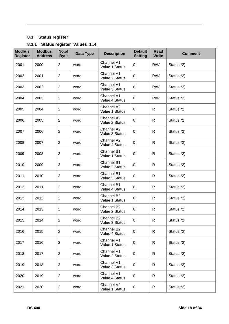
8.3 Status register
8.3.1 Status register Values 1..4
Modbus Register
Modbus Address
No.of Byte
Data Type Description Default Setting
Read Write
Comment
2001 2000 2 word Channel A1 Value 1 Status
0 R/W Status *2)
2002 2001 2 word Channel A1 Value 2 Status
0 R/W Status *2)
2003 2002 2 word Channel A1 Value 3 Status
0 R/W Status *2)
2004 2003 2 word Channel A1 Value 4 Status
0 R/W Status *2)
2005 2004 2 word Channel A2 Value 1 Status
0 R Status *2)
2006 2005 2 word Channel A2 Value 2 Status
0 R Status *2)
2007 2006 2 word Channel A2 Value 3 Status
0 R Status *2)
2008 2007 2 word Channel A2 Value 4 Status
0 R Status *2)
2009 2008 2 word Channel B1 Value 1 Status
0 R Status *2)
2010 2009 2 word Channel B1 Value 2 Status
0 R Status *2)
2011 2010 2 word Channel B1 Value 3 Status
0 R Status *2)
2012 2011 2 word Channel B1 Value 4 Status
0 R Status *2)
2013 2012 2 word Channel B2 Value 1 Status
0 R Status *2)
2014 2013 2 word Channel B2 Value 2 Status
0 R Status *2)
2015 2014 2 word Channel B2 Value 3 Status
0 R Status *2)
2016 2015 2 word Channel B2 Value 4 Status
0 R Status *2)
2017 2016 2 word Channel V1 Value 1 Status
0 R Status *2)
2018 2017 2 word Channel V1 Value 2 Status
0 R Status *2)
2019 2018 2 word Channel V1 Value 3 Status
0 R Status *2)
2020 2019 2 word Channel V1 Value 4 Status
0 R Status *2)
2021 2020 2 word Channel V2 Value 1 Status
0 R Status *2)

DS 400 Side 19 of 36
Modbus Register
Modbus Address
No.of Byte
Data Type Description Default Setting
Read Write
Comment
2022 2021 2 word Channel V2 Value 2 Status
0 R Status *2)
2023 2022 2 word Channel V2 Value 3 Status
0 R Status *2)
2024 2023 2 word Channel V2 Value 4 Status
0 R Status *2)
2025 2024 2 word Channel V3 Value 1 Status
0 R Status *2)
2026 2025 2 word Channel V3 Value 2 Status
0 R Status *2)
2027 2026 2 word Channel V3 Value 3 Status
0 R Status *2)
2028 2027 2 word Channel V3 Value 4 Status
0 R Status *2)
2029 2028 2 word Channel V4 Value 1 Status
0 R Status *2)
2030 2029 2 word Channel V4 Value 2 Status
0 R Status *2)
2031 2030 2 word Channel V4 Value 3 Status
0 R Status *2)
2032 2031 2 word Channel V4 Value 4 Status
0 R Status *2)

DS 400 Side 20 of 36
8.3.2 Status register Values 5..8
Modbus Register
Modbus Address
No.of Byte
Data Type Description Default Setting
Read Write
Comment
2101 2100 2 word Channel A1 Value 5 Status
0 R Status *2)
2102 2101 2 word Channel A1 Value 6 Status
0 R Status *2)
2103 2102 2 word Channel A1 Value 7 Status
0 R Status *2)
2104 2103 2 word Channel A1 Value 8 Status
0 R Status *2)
2105 2104 2 word Channel A2 Value 5 Status
0 R Status *2)
2106 2105 2 word Channel A2 Value 6 Status
0 R Status *2)
2107 2106 2 word Channel A2 Value 7 Status
0 R Status *2)
2108 2107 2 word Channel A2 Value 8 Status
0 R Status *2)
2109 2108 2 word Channel B1 Value 5 Status
0 R Status *2)
2110 2109 2 word Channel B1 Value 6 Status
0 R Status *2)
2111 2110 2 word Channel B1 Value 7 Status
0 R Status *2)
2112 2111 2 word Channel B1 Value 8 Status
0 R Status *2)
2113 2112 2 word Channel B2 Value 5 Status
0 R Status *2)
2114 2113 2 word Channel B2 Value 6 Status
0 R Status *2)
2115 2114 2 word Channel B2 Value 7 Status
0 R Status *2)
2116 2115 2 word Channel B2 Value 8 Status
0 R Status *2)
2117 2116 2 word Channel V1 Value 5 Status
0 R Status *2)
2118 2117 2 word Channel V1 Value 6 Status
0 R Status *2)
2119 2118 2 word Channel V1 Value 7 Status
0 R Status *2)
2120 2119 2 word Channel V1 Value 8 Status
0 R Status *2)

DS 400 Side 21 of 36
Modbus Register
Modbus Address
No.of Byte
Data Type Description Default Setting
Read Write
Comment
2121 2120 2 word Channel V2 Value 5 Status
0 R Status *2)
2122 2121 2 word Channel V2 Value 6 Status
0 R Status *2)
2123 2122 2 word Channel V2 Value 7 Status
0 R Status *2)
2124 2123 2 word Channel V2 Value 8 Status
0 R Status *2)
2125 2124 2 word Channel V3 Value 5 Status
0 R Status *2)
2126 2125 2 word Channel V3 Value 6 Status
0 R Status *2)
2127 2126 2 word Channel V3 Value 7 Status
0 R Status *2)
2128 2127 2 word Channel V3 Value 8 Status
0 R Status *2)
2129 2128 2 word Channel V4 Value 5 Status
0 R Status *2)
2130 2129 2 word Channel V4 Value 6 Status
0 R Status *2)
2131 2130 2 word Channel V4 Value 7 Status
0 R Status *2)
2132 2131 2 word Channel V4 Value 8 Status
0 R Status *2)

DS 400 Side 22 of 36
8.4 Channel description
Modbus Register
Modbus Address
No.of Byte
Data Type Description Default Setting
Read Write
Comment
3001 3000 2 word Channel A1 sensor type
0 R Sensor Type *3)
3002 3001 24 string Channel Name 0 R Sensor Name *4)
3014 3013 2 word name/unit index value 1
0 R Value description *5)
3015 3014 2 word name/unit index value 2
0 R Value description *5)
3016 3015 2 word name/unit index value 3
0 R Value description *5)
3017 3016 2 word name/unit index value 4
0 R Value description *5)
3018 3017 2 word name/unit index value 5
0 R Value description *5)
3019 3018 2 word name/unit index value 6
0 R Value description *5)
3020 3019 2 word name/unit index value 7
0 R Value description *5)
3021 3020 2 word name/unit index value 8
0 R Value description *5)
3033 3032 2 word Channel A2 sensor type
0 R Sensor Type *3)
3034 3033 24 string Channel Name 0 R Sensor Name *4)
3046 3045 2 word name/unit index value 1
0 R Value description *5)
3047 3046 2 word name/unit index value 2
0 R Value description *5)
3048 3047 2 word name/unit index value 3
0 R Value description *5)
3049 3048 2 word name/unit index value 4
0 R Value description *5)
3050 3049 2 word name/unit index value 5
0 R Value description *5)
3051 3050 2 word name/unit index value 6
0 R Value description *5)
3052 3051 2 word name/unit index value 7
0 R Value description *5)
3053 3052 2 word name/unit index value 8
0 R Value description *5)

DS 400 Side 23 of 36
Modbus Register
Modbus Address
No.of Byte
Data Type Description Default Setting
Read Write
Comment
3065 3064 2 word Channel B1 sensor type
0 R Sensor Type *3)
3066 3065 24 string Channel Name 0 R Sensor Name *4)
3078 3077 2 word name/unit index value 1
0 R Value description *5)
3079 3078 2 word name/unit index value 2
0 R Value description *5)
3080 3079 2 word name/unit index value 3
0 R Value description *5)
3081 3080 2 word name/unit index value 4
0 R Value description *5)
3082 3081 2 word name/unit index value 5
0 R Value description *5)
3083 3082 2 word name/unit index value 6
0 R Value description *5)
3084 3083 2 word name/unit index value 7
0 R Value description *5)
3085 3084 2 word name/unit index value 8
0 R Value description *5)
3097 3096 2 word Channel B2 sensor type
0 R Sensor Type *3)
3098 3097 24 string Channel Name 0 R Sensor Name *4)
3110 3109 2 word name/unit index value 1
0 R Value description *5)
3111 3110 2 word name/unit index value 2
0 R Value description *5)
3112 3111 2 word name/unit index value 3
0 R Value description *5)
3113 3112 2 word name/unit index value 4
0 R Value description *5)
3114 3113 2 word name/unit index value 5
0 R Value description *5)
3115 3114 2 word name/unit index value 6
0 R Value description *5)
3116 3115 2 word name/unit index value 7
0 R Value description *5)
3117 3116 2 word name/unit index value 8
0 R Value description *5)

DS 400 Side 24 of 36
Modbus Register
Modbus Address
No.of Byte
Data Type Description Default Setting
Read Write
Comment
3129 3128 2 word Channel V1 sensor type
0 R Sensor Type *3)
3130 3129 24 string Channel Name 0 R Sensor Name *4)
3142 3141 2 word name/unit index value 1
0 R Value description *5)
3143 3142 2 word name/unit index value 2
0 R Value description *5)
3144 3143 2 word name/unit index value 3
0 R Value description *5)
3145 3144 2 word name/unit index value 4
0 R Value description *5)
3146 3145 2 word name/unit index value 5
0 R Value description *5)
3147 3146 2 word name/unit index value 6
0 R Value description *5)
3148 3147 2 word name/unit index value 7
0 R Value description *5)
3149 3148 2 word name/unit index value 8
0 R Value description *5)
3161 3160 2 word Channel V2 sensor type
0 R Sensor Type *3)
3162 3161 24 string Channel Name 0 R Sensor Name *4)
3174 3173 2 word name/unit index value 1
0 R Value description *5)
3175 3174 2 word name/unit index value 2
0 R Value description *5)
3176 3175 2 word name/unit index value 3
0 R Value description *5)
3177 3176 2 word name/unit index value 4
0 R Value description *5)
3178 3177 2 word name/unit index value 5
0 R Value description *5)
3179 3178 2 word name/unit index value 6
0 R Value description *5)
3180 3179 2 word name/unit index value 7
0 R Value description *5)
3181 3180 2 word name/unit index value 8
0 R Value description *5)

DS 400 Side 25 of 36
Modbus Register
Modbus Address
No.of Byte
Data Type Description Default Setting
Read Write
Comment
3193 3192 2 word Channel V3 sensor type
0 R Sensor Type *3)
3194 3193 24 string Channel Name 0 R Sensor Name *4)
3206 3205 2 word name/unit index value 1
0 R Value description *5)
3207 3206 2 word name/unit index value 2
0 R Value description *5)
3208 3207 2 word name/unit index value 3
0 R Value description *5)
3209 3208 2 word name/unit index value 4
0 R Value description *5)
3210 3209 2 word name/unit index value 5
0 R Value description *5)
3211 3210 2 word name/unit index value 6
0 R Value description *5)
3212 3211 2 word name/unit index value 7
0 R Value description *5)
3213 3212 2 word name/unit index value 8
0 R Value description *5)
3225 3224 2 word Channel V4 sensor type
0 R Sensor Type *3)
3226 3225 24 string Channel Name 0 R Sensor Name *4)
3238 3237 2 word name/unit index value 1
0 R Value description *5)
3239 3238 2 word name/unit index value 2
0 R Value description *5)
3240 3239 2 word name/unit index value 3
0 R Value description *5)
3241 3240 2 word name/unit index value 4
0 R Value description *5)
3242 3241 2 word name/unit index value 5
0 R Value description *5)
3243 3242 2 word name/unit index value 6
0 R Value description *5)
3244 3243 2 word name/unit index value 7
0 R Value description *5)
3245 3244 2 word name/unit index value 8
0 R Value description *5)

DS 400 Side 26 of 36
8.5 Alarm Settings
Modbus Register
Modbus Address
No.of Byte
Data Type Description Default Setting
Read Write
Comment
4001 4000 2 word Channel / Value 0 R Alarmsettings #1 *6)
4002 4001 2 word Relais 0 R relais setting *7)
4003 4002 4 float upper warning value
0 R
4005 4004 4 float Hysteresis for above
0 R
4007 4006 4 float upper alarm value
0 R
4009 4008 4 float Hysteresis for above
0 R
4011 4010 4 float lower warning value
0 R
4013 4012 4 float Hysteresis for above
0 R
4015 4014 4 float lower alarm value
0 R
4017 4016 4 float Hysteresis for above
0 R
4019 4018 4 float Reserved
4021 4020 2 word Channel / Value 0 R Alarmsettings #2 *6)
4022 4021 2 word Relais 0 R relais setting *7)
4023 4022 4 float upper warning value
0 R
4025 4024 4 float Hysteresis for above
0 R
4027 4026 4 float upper alarm value
0 R
4029 4028 4 float Hysteresis for above
0 R
4031 4030 4 float lower warning value
0 R
4033 4032 4 float Hysteresis for above
0 R
4035 4034 4 float lower alarm value
0 R
4037 4036 4 float Hysteresis for above
0 R
4039 4038 4 float Reserved

DS 400 Side 27 of 36
8.6 Value extended
Modbus Register
Modbus Address
No.of Byte
Data Type Description Default Setting
Read Write
Comment
10001 10000 12 string A1a Value Name long
0 R string max 10 character
10007 10006 6 string A1a Value Name short
0 R string max 3 character
10010 10009 2 word A1a Value Resolution
0 R 0..5
10011 10010 30 free A1a future use 0 R
10026 10025 12 string A1b Value Name long
0 R string max 10 character
10032 10031 6 string A1b Value Name short
0 R string max 3 character
10035 10034 2 word A1b Value Resolution
0 R 0..5
10036 10035 30 free A1b future use 0 R
10051 10050 12 string A1c Value Name long
0 R string max 10 character
10057 10056 6 string A1c Value Name short
0 R string max 3 character
10060 10059 2 word A1c Value Resolution
0 R 0..5
10061 10060 30 free A1c future use 0 R
10076 10075 12 string A1d Value Name long
0 R string max 10 character
10082 10081 6 string A1d Value Name short
0 R string max 3 character
10085 10084 2 word A1d Value Resolution
0 R 0..5
10086 10085 30 free A1d future use 0 R
10101 10100 12 string A1e Value Name long
0 R string max 10 character
10107 10106 6 string A1e Value Name short
0 R string max 3 character
10110 10109 2 word A1e Value Resolution
0 R 0..5
10111 10110 30 free A1e future use 0 R
10126 10125 12 string A1f Value Name long
0 R string max 10 character
10132 10131 6 string A1f Value Name short
0 R string max 3 character

DS 400 Side 28 of 36
Modbus Register
Modbus Address
No.of Byte
Data Type Description Default Setting
Read Write
Comment
10135 10134 2 word A1f Value Resolution
0 R 0..5
10136 10135 30 free A1f future use 0 R
10151 10150 12 string A1g Value Name long
0 R string max 10 character
10157 10156 6 string A1g Value Name short
0 R string max 3 character
10160 10159 2 word A1g Value Resolution
0 R 0..5
10161 10160 30 free A1g future use 0 R
10176 10175 12 string A1h Value Name long
0 R string max 10 character
10182 10181 6 string A1h Value Name short
0 R string max 3 character
10185 10184 2 word A1h Value Resolution
0 R 0..5
10186 10185 30 free A1h future use 0 R
10201 10200 8*25 xxx Channel A2 0 R similar to channel A1
10401 10400 8*25 xxx Channel A3 0 R similar to channel A1
10601 10600 8*25 xxx Channel A4 0 R similar to channel A1
10801 10800 8*25 xxx Channel B1 0 R similar to channel A1
11001 11000 8*25 xxx Channel B2 0 R similar to channel A1
11201 11200 8*25 xxx Channel B3 0 R similar to channel A1
11401 11400 8*25 xxx Channel B4 0 R similar to channel A1
11601 11600 8*25 xxx Channel C1 0 R similar to channel A1
11801 11800 8*25 xxx Channel C2 0 R similar to channel A1
12001 12000 8*25 xxx Channel C3 0 R similar to channel A1
12201 12200 8*25 xxx Channel C4 0 R similar to channel A1

DS 400 Side 29 of 36
Modbus Register
Modbus Address
No.of Byte
Data Type Description Default Setting
Read Write
Comment
11401 11400 8*25 xxx Channel B4 0 R similar to channel A1
11601 11600 8*25 xxx Channel C1 0 R similar to channel A1
11801 11800 8*25 xxx Channel C2 0 R similar to channel A1
12001 12000 8*25 xxx Channel C3 0 R similar to channel A1
12201 12200 8*25 xxx Channel C4 0 R similar to channel A1
12401 12400 8*25 xxx Channel V1 0 R similar to channel A1
12601 12600 8*25 xxx Channel V2 0 R similar to channel A1
12801 12800 8*25 xxx Channel V3 0 R similar to channel A1
13001 13000 8*25 xxx Channel V4 0 R similar to channel A1
8.7 Data format test
Modbus Register
Modbus Address
No.of Byte
Data Type Description Default Setting
Read Write
Comment
64001 64000 4 Dword 1000000 x R format test for Dword
64003 64002 4 float 1000000.0 x R format test for float

DS 400 Side 30 of 36
8.8 Data Bit description
*1) Data Value
Format (Dword / Float) depends on Value Description Bit 15 see below *5)
Position of Dezimal Point depends on Value Descrition Bit 14..12
see below *5)
*2) Data Status
Write 1 to these bits clears Status
Bit 15 Sensor changed different sensor
Bit 14 Sensor setting changed mayor parameter changed
Bit 13 Sensor Alarm settings changed Alarm settings changed
Bit 12 Sensor name changed minor change
Bit 11 Lower Alarm active
Bit 10 Lower Warning active
Bit 9 Upper Alarm active
Bit 8 Upper Warning active
Bit 7 tbd Value status
Bit 6 Channel Error Value status
Bit 5 Value Error Value status
Bit 4 out of range Value status
Bit 3 Stopped Value status
Bit 2 UVP status Value status
Bit 1 OCP status Value status
Bit 0 Channel Disconnected Value status
*3) Sensor Type
Bit 15..8 Sensor Basic type 0..255 0 = no sensor
Bit 7..0 Sensor Subtype 0..255
*4) Channel Name
Name coding in UTF8 (max 24 Byte)
*5) Value description
Bit 15 1 = Dword , 0 = float 0,1
Bit 14..12 position of dezimal point 0..7
Bit 11..7 index of value name 0..31
Bit 6..0 index of unit name 0..127 0 = value not used

DS 400 Side 31 of 36
*6) Alarm Channel / Value
Bit 11 lower Alarm used
Bit 10 lower Warning used
Bit 9 upper Alarm used
Bit 8 upper Warning used
Bit 7 Alarm used (valid) Alarm settings used
Bit 6..4 Value Nr 0..7
Bit 3..0 Channel 0..11
*7) Alarm Relais
Bit 15
Bit 14
Bit 13 Lower alarm Relais 2 used
Bit 12 Lower alarm Relais 1 used
Bit 11
Bit 10
Bit 9 Lower warning Relais 2 used
Bit 8 Lower warning Relais 1 used
Bit 7
Bit 6
Bit 5 Upper alarm Relais 2 used
Bit 4 Upper alarm Relais 1 used
Bit 3
Bit 2
Bit 1 Upper warning Relais 2 used
Bit 0 Upper warning Relais 1 used

DS 400 Side 32 of 36
8.9 User Units
Modbus Register
Modbus Address
No.of Byte
Data Type Description Default Setting
Read Write
Comment
14001 14000 10 string Unit Name 1 °C R UTF8 string (max 10 character)
14009 14008 10 string Unit Name 2 °F R UTF8 string (max 10 character)
14017 14016 10 string Unit Name 3 %RH R UTF8 string (max 10 character)
14025 14024 10 string Unit Name 4 °Ctd R UTF8 string (max 10 character)
14033 14032 10 string Unit Name 5 °Ftd R UTF8 string (max 10 character)
14041 14040 10 string Unit Name 6 mg/kg R UTF8 string (max 10 character)
14049 14048 10 string Unit Name 7 mg/m³ R UTF8 string (max 10 character)
14057 14056 10 string Unit Name 8 g/kg R UTF8 string (max 10 character)
14065 14064 10 string Unit Name 9 g/m³ R UTF8 string (max 10 character)
14073 14072 10 string Unit Name 10 m/s R UTF8 string (max 10 character)
14081 14080 10 string Unit Name 11 Ft/min R UTF8 string (max 10 character)
14089 14088 10 string Unit Name 12 Nm/s R UTF8 string (max 10 character)
14097 14096 10 string Unit Name 13 Nft/min R UTF8 string (max 10 character)
14105 14104 10 string Unit Name 14 m³/h R UTF8 string (max 10 character)
14113 14112 10 string Unit Name 15 m³/min R UTF8 string (max 10 character)
14121 14120 10 string Unit Name 16 ltr/min R UTF8 string (max 10 character)
14129 14128 10 string Unit Name 17 ltr/s R UTF8 string (max 10 character)
14137 14136 10 string Unit Name 18 cfm R UTF8 string (max 10 character)
14145 14144 10 string Unit Name 19 Nm³/h R UTF8 string (max 10 character)
14153 14152 10 string Unit Name 20 Nm³/min R UTF8 string (max 10 character)
14161 14160 10 string Unit Name 21 Nl/min R UTF8 string (max 10 character)
14169 14168 10 string Unit Name 22 Nl/min R UTF8 string (max 10 character)

DS 400 Side 33 of 36
Modbus Register
Modbus Address
No.of Byte
Data Type Description Default Setting
Read Write
Comment
14177 14176 10 string Unit Name 23 Ncfm R UTF8 string (max 10 character)
14185 14184 10 string Unit Name 24 m³ R UTF8 string (max 10 character)
14193 14192 10 string Unit Name 25 ltr R UTF8 string (max 10 character)
14201 14200 10 string Unit Name 26 cf R UTF8 string (max 10 character)
14209 14208 10 string Unit Name 27 Nm³ R UTF8 string (max 10 character)
14217 14216 10 string Unit Name 28 Nltr R UTF8 string (max 10 character)
14225 14224 10 string Unit Name 29 Ncf R UTF8 string (max 10 character)
14233 14232 10 string Unit Name 30 ppm R UTF8 string (max 10 character)
14241 14240 10 string Unit Name 31 atm°C R UTF8 string (max 10 character)
14249 14248 10 string Unit Name 32 atm°F R UTF8 string (max 10 character)
14257 14256 10 string Unit Name 33 pa R UTF8 string (max 10 character)
14265 14264 10 string Unit Name 34 hpa R UTF8 string (max 10 character)
14273 14272 10 string Unit Name 35 kpa R UTF8 string (max 10 character)
14281 14280 10 string Unit Name 36 Mpa R UTF8 string (max 10 character)
14289 14288 10 string Unit Name 37 mbar R UTF8 string (max 10 character)
14297 14296 10 string Unit Name 38 bar R UTF8 string (max 10 character)
14305 14304 10 string Unit Name 39 psi R UTF8 string (max 10 character)
14313 14312 10 string Unit Name 40 mV R UTF8 string (max 10 character)
14321 14320 10 string Unit Name 41 V R UTF8 string (max 10 character)
14329 14328 10 string Unit Name 42 µV R UTF8 string (max 10 character)
14337 14336 10 string Unit Name 43 kV R UTF8 string (max 10 character)
14345 14344 10 string Unit Name 44 mA R UTF8 string (max 10 character)

DS 400 Side 34 of 36
Modbus Register
Modbus Address
No.of Byte
Data Type Description Default Setting
Read Write
Comment
14353 14352 10 string Unit Name 45 A R UTF8 string (max 10 character)
14361 14360 10 string Unit Name 46 kg/s R UTF8 string (max 10 character)
14369 14368 10 string Unit Name 47 kg R UTF8 string (max 10 character)
14377 14376 10 string Unit Name 48 Ø m³/h R UTF8 string (max 10 character)
14385 14384 10 string Unit Name 49 Ø l/h R UTF8 string (max 10 character)
14393 14392 10 string Unit Name 50 Ø kg/h R UTF8 string (max 10 character)
14401 14400 10 string Unit Name 51 Ø cf/h R UTF8 string (max 10 character)
14409 14408 10 string Unit Name 52 kg/h R UTF8 string (max 10 character)
14417 14416 10 string Unit Name 53 kg/min R UTF8 string (max 10 character)
14425 14424 10 string Unit Name 54 Ω R UTF8 string (max 10 character)
14433 14432 10 string Unit Name 55 Hz R UTF8 string (max 10 character)
14441 14440 10 string Unit Name 56 % R UTF8 string (max 10 character)
14449 14448 10 string Unit Name 57 kW R UTF8 string (max 10 character)
14457 14456 10 string Unit Name 58 kWh R UTF8 string (max 10 character)
14465 14464 10 string Unit Name 59 PCS R UTF8 string (max 10 character)
14473 14472 10 string Unit Name 60 kVA R UTF8 string (max 10 character)
14481 14480 10 string Unit Name 61 kVAr R UTF8 string (max 10 character)
14489 14488 10 string Unit Name 62 - R UTF8 string (max 10 character)
14497 14496 10 string Unit Name 63 € R UTF8 string (max 10 character)

DS 400 Side 35 of 36
9 Appendix
9.1 APPENDIX A - Exception codes
The DS400 Modbus uses the following exception codes when responding to the master
Exception Code Exception name
0x01 Illegal function
0x02 Illegal data address
0x03 Illegal data value
0x04 Slave device failure
0x05 Acknowledge
0x06 Slave device busy
Stand:21.09.2015 , version 1.01