modal analysis and testing of rotating structures -...
TRANSCRIPT

Modal Analysis and Testing of Rotating StructuresAuthor(s): I. Bucher and D. J. EwinsSource: Philosophical Transactions: Mathematical, Physical and Engineering Sciences, Vol. 359,No. 1778, Experimental Modal Analysis (Jan. 15, 2001), pp. 61-96Published by: The Royal SocietyStable URL: http://www.jstor.org/stable/3066394Accessed: 31/03/2010 10:44
Your use of the JSTOR archive indicates your acceptance of JSTOR's Terms and Conditions of Use, available athttp://www.jstor.org/page/info/about/policies/terms.jsp. JSTOR's Terms and Conditions of Use provides, in part, that unlessyou have obtained prior permission, you may not download an entire issue of a journal or multiple copies of articles, and youmay use content in the JSTOR archive only for your personal, non-commercial use.
Please contact the publisher regarding any further use of this work. Publisher contact information may be obtained athttp://www.jstor.org/action/showPublisher?publisherCode=rsl.
Each copy of any part of a JSTOR transmission must contain the same copyright notice that appears on the screen or printedpage of such transmission.
JSTOR is a not-for-profit service that helps scholars, researchers, and students discover, use, and build upon a wide range ofcontent in a trusted digital archive. We use information technology and tools to increase productivity and facilitate new formsof scholarship. For more information about JSTOR, please contact [email protected].
The Royal Society is collaborating with JSTOR to digitize, preserve and extend access to PhilosophicalTransactions: Mathematical, Physical and Engineering Sciences.
http://www.jstor.org
I4 THE ROYAL 10.1098/rsta.2000.0714 WJ SOCIETY
Modal analysis and testing of rotating structures
BY I. BUCHER1 AND D. J. EWINS2
1Faculty of Mechanical Engineering, Technion, Haifa 32000, Israel ([email protected])
2Department of Mechanical Engineering, Imperial College of Science, Technology and Medicine,
London SW7 2BX, UK ([email protected])
This paper surveys the state of the art of modal testing or experimental modal analy- sis of rotating structures. When applied to ordinary, non-rotating structures, modal testing is considered to be well established. Rotating structures, on the other hand, impose special difficulties when one seeks to obtain the parameters of the dynamical model experimentally. This paper focuses on the necessary experimental techniques and their relationship to the current state of the existing theory. Existing modal analysis methods, models and techniques, and their advantages, limitations and rel- evance are outlined and compared. In addition, some new developments allowing us to circumvent some of the above-mentioned difficulties are presented.
Rotating machines appear in almost every aspect of our modern life: cars, aero- planes, vacuum cleaners and steam-turbines all have many rotating structures whose dynamics need to be modelled, analysed and improved. The reliability, stability and the response levels of these machines, predicted by analytical models, are generally not satisfactory until validated by experimentally obtained data. For this purpose, modal testing has to be employed and further advance is essential in order to over- come the difficulties in this area.
In this paper, the differences between the mathematical models used for dynamic analysis of non-rotating and rotating structures are clarified. The implications of the model structure, in the latter case, on the application of modal testing are presented, as this is a point of great importance when experimental modal analysis is employed for rotating structures. Models with different degrees of complexity are being used for different types of rotating machines. A classification of such models is outlined in this work and the underlying assumptions and features are described in terms of a hierarchical complexity. Several applications of modal testing are reported here and some experimental evidence to support the validity of the theory is presented. Desired future activities, which are required to advance the theory and practice of this field, are summarized in conclusion.
Keywords: rotating structures; modal testing; speed-dependent parameters; whirling mode shapes
1. Introduction
Rotating machines appear in almost every aspect of modern life, ranging from domes- tic appliances to automobiles, power plants and aeroplanes. The tendency to create
Phil. Trans. R. Soc. Lond. A (2001) 359. 61-96 ? 2001 The Royal Society 61

I. Bucher and D. J. Ewins
faster and better rotating machines, fuelled by the desire to increase their productiv- ity, increasingly requires deep knowledge of their dynamical behaviour and therefore accurate models are needed. The efficiency of rotating machines is greatly improved by maintaining small gaps between rotating and non-rotating parts. This can be achieved only when the designers of the machines have great confidence in the dynam- ical models of these machines, thus knowing that no failure due to excessive vibration levels may occur. The most reliable means of obtaining a dynamical model describing the dynamic behaviour of a machine involves an experimental procedure as it better reflects reality. However, machines that contain rotating elements are often difficult to model reliably using theory, mainly due to inherent uncertainties as to the operat- ing and boundary conditions and, in these cases, properly conducted in situ testing is by far the most reliable approach. In modal testing, we seek to extract the vibra- tion modes (i.e. natural frequencies, mode shapes and damping coefficients) from measured data, and this allows us to describe the dynamical behaviour effectively.
In this survey, we pursue the general methodology of modal testing and discuss some aspects of applying this method to structures having rotating elements. The present paper is meant to serve three main purposes.
(1) To provide an initial guide or road map for newcomers and a summary for practitioners.
(2) To outline some of the assumptions and experimental procedures currently being used.
(3) To present some new results in modal testing of rotating structures.
The structure of the paper is as follows. Section 1 provides an introduction to the subject and outlines briefly the basic theory of modal analysis with special refer- ence to rotating structures. In this section, both shaft- and disc-related equations of motion are presented and the role of stiffness isotropy and of damping in the modal decomposition are outlined. Section 2 is devoted to experimental methods. In ? 3 some excitation techniques are compared, the required and recommended signal- processing procedures are described and some experimental results presented and discussed. The final section concludes the paper and summarizes the current state of the art of this emerging topic.
(a) Rotating structures: structural dynamics models and their modal decomposition
In our introduction of the various mathematical models of rotating structures, we confine ourselves to models which describe 'small' vibrations. Testing and modelling the dynamics of rotating machines is a very broad area and the current text con- centrates on a fraction of this discipline. Within this subset of models we further restrict ourselves to linear models formulated in terms of a finite number of degrees of freedom (DOFs) (i.e. to a discretized model) which are an approximation of the governing partial differential equation of the model. Such a system of equations is generally time varying (Yakubovich & Starzhinskii 1975) as, due to the rotation, some properties may change periodically with time,
M(t)i(t) + C(t)q(t) + K(t)q(t) = f(t), q(t), f(t) e RNX1 (1.1)
Phil. Trans. R. Soc. Lond. A (2001)
62

Modal analysis and testing of rotating structures
load
/ external \ 4 disc
drivig \ force anisotropic, driving Ocracked element
bearings transmission
foundation, K'~ N
F- l l bearings r
Figure 1. A schematic description of a machine containing rotating components.
Such time variations can be a result of non-isotropic shaft segments (Genta 1988) or cracked shafts (Gasch & Pfutzner 1975; Gasch 1976). A hypothetical but repre- sentative system is depicted schematically in figure 1. This system contains driving elements, shafts, motion-coupling devices, bearings, gears and transmission elements. In addition, there could be discs (possibly bladed) and some external loads, which may affect the dynamics.
A common assumption which is often made is that the structure under test contains only isotropic rotating elements (i.e. it is assumed that both inertia and stiffness properties are not a function of the instantaneous angle of rotation). When the former assumptions hold and when the measurements are performed in an inertial coordinate system, we obtain an additional simplification under which the matrices in (1.1) are no longer time dependent but are only speed dependent (Lalanne & Ferraris 1990),
M(Q)q(t) + C(Q)q(t) + K(t)q(t) = f(t). (1.2)
For a constant speed of rotation 97, equation (1.2) represents a general linear time- invariant (LTI) system and, as a result, commonly available tools can be used to analyse the dynamic behaviour of such a system. The differential equation of motion (1.2), which represents a rotating structure, is said to be non-self-adjoint (NSA). Passive non-rotating structures are generally self-adjoint and so their fre- quency response and their system matrices are symmetric (Meirovitch 1980; Han & Zu 1995). The effect of rotation on components gives rise to a non-symmetric (and NSA) equation of motion and to a non-symmetric frequency-response func- tion (FRF) matrix. Models of self-adjoint structures can be completely expanded in terms of a single set of eigenvectors (modes) and eigenvalues. On the other hand, NSA structures require two sets of eigenvectors with a set of eigenvalues to describe their dynamic behaviour fully.
The main differences between static and rotating structures stem from the follow- ing facts.
(i) Rotating structures have speed- (and possibly time-) dependent properties (see figure 2) (Genta 1988).
(ii) The response and the excitation parameters often operate in different (sta- tionary or rotating) frames of reference. This may give rise to a complicated
Phil. Trans. R. Soc. Lond. A (2001)
63

I. Bucher and D. J. Ewins
250- (a) 22 A (b) (
200-
, 100-
50 o *-
0 2000 4000 6000 8000 H(Q) speed of rotation, Q2
Figure 2. Variation of structure's dynamics with rotation speed. (a) The variation of natural
frequencies with speed of rotation for a typical rotating structure. (b) The variation of FRF with
frequency and speed of rotation (shown at two distinct speeds of rotation).
relationship between the frequencies of the excitation and those appearing in the response (see Tobias & Arnold 1957; Lee 1991; Irretier & Reuter 1994).
(iii) Rotating structures are non-self-adjoint in general. This gives rise (unlike non- rotating structures) to non-symmetric matrices in the equation of motion (see Nordmann 1983; Geradin & Rixen 1994; Xu & Gasch 1995).
(iv) Damping and stiffness for shafts, splines, press-fits in fluid-film bearings can give rise to 'non-conservative stiffness' due to internal energy dissipation in a rotating element. These effects may convert rotational energy into vibratory response which may be unstable (see Ehrich 1992; Childs 1993; Kramer 1993).
(v) As rotating structures are mostly axisymmetric, they possess almost identi- cal pairs of natural frequencies and therefore special measures are needed for accurate extraction of their modes.
(vi) A considerable amount of kinetic energy is stored in high-speed rotating ele- ments. This energy may be coupled to the vibratory response giving rise to phenomena not directly caused by the applied excitation during an experimen- tal procedure (Gasch & Pfutzner 1975).
(vii) Nonlinear effects that are most notable when the response levels are high are commonly found in bearings and coupling elements (Tondl 1965; Gasch 1976).
If one wishes to obtain a model to describe the dynamics of such a structure experimentally, in a way that allows us to predict the structural response to an arbitrary excitation, all the aforementioned effects need to be taken into account. In particular, the effects of rotation, as demonstrated in figure 2, cannot be ignored for high-speed rotating elements.
Figure 2 illustrates the dependence of the natural frequencies and the FRFs upon the speed of rotation.
As mentioned earlier, application of the existing methodology of modal testing is explored here and the experimental extraction of mode shapes will be described in ? 2.
Phil. Trans. R. Soc. Lond. A (2001)
64
Modal analysis and testing of rotating structures
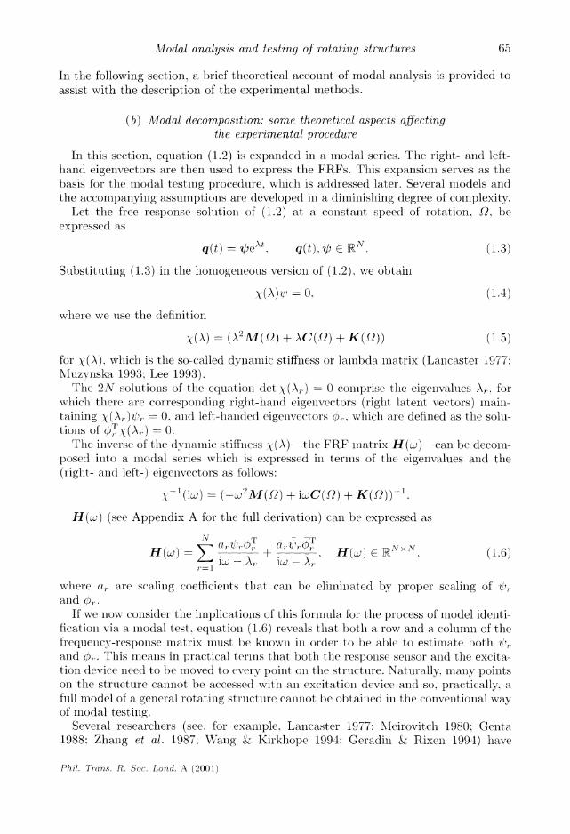
In the following section, a brief theoretical account of modal analysis is provided to assist with the description of the experimental methods.
(b) Modal decomposition: some theoretical aspects affecting the experimental procedure
In this section, equation (1.2) is expanded in a modal series. The right- and left- hand eigenvectors are then used to express the FRFs. This expansion serves as the basis for the modal testing procedure, which is addressed later. Several models and the accompanying assumptions are developed in a diminishing (legree of complexity.
Let the free response solution of (1.2) at a constant speed of rotation, Q, be expressed as
q(t) = ext. q(t) C RN. (1.3)
Substituting (1.3) in the homogeneous version of (1.2), we obtain
X(A = o0. (1.4)
where we use the definition
X(A) = (A2M() + AC(Q) + K(Q)) (1.5)
for X(A), which is the so-called dynamic stiffness or lambda matrix (Lancaster 1977; Muzynska 1993; Lee 1993).
The 2N solutions of the equation det X(Ar) = 0 comprise the eigenvalues A,, for which there are corresponding right-hand eigenvectors (right latent vectors) main- taining X(A,r)r - 0, and left-handed eigenvectors r,, which are defined as the solu- tions of (;rXY(A) = .
The inverse of the dynamic stiffness y(A)---the FRF matrix H(u)-can be decom- posed into a modal series which is expressed in terms of the eigenvalues and the (right- and left-) eigenvectors as follows:
X-1(i:) = (-W2M(j) + iC(Q) + K(Q))-1.
H(uj) (see Appendix A for the fill derivation) can be expressed as
N /,T +Or(/T'r H(w,) - C
r , 1, H(w)
R NxN (1.6) -L'U -- \ iLAJ - Ar
where a, are scaling coefficients that can be eliminated by proper scaling of /,. and (r,.
If we now consider the implications of this formula for the process of model identi- fication via a modal test, equation (1.6) reveals that both a row and a column of the frequency-response matrix must be known in order to be able to estimate both V'r
and 0,r. This means in practical terms that both the response sensor and the excita- tion device need to be moved to every point on the structure. Naturally, many points on the structure cannot be accessed with an excitation device and so, practically, a full model of a general rotating structure cannot be obtained in the conventional way of modal testing.
Several researchers (see, for example, Lancaster 1977; Meirovitch 1980; Genta 1988; Zhang et al. 1987; Wang & Kirkhope 1994: Geradin & Rixen 1994) have
Phil. Trans. R. Soc. Lond. A (2001)
65

I. Bucher and D. J. Ewins
considered some simplified theoretical versions of (1.2). In their formulations, the mass, gyroscopic/damping and stiffness matrices can take some special forms, result- ing in some special relationship between the left- and the right-hand eigenvectors. These relationships can potentially simplify the experimental procedure and thus require fewer measurements, necessitating less accessibility to the tested structure. Zhang et al. (1987) have shown that the left-eigenvectors can be deduced from the right-eigenvectors in some special cases even when the stiffness matrix is asymmetric (e.g. when the rotor is supported by fluid-film bearings or seals (Childs 1993)). This result has mainly a theoretical value, as real systems would generally not obey the constraints indicated in his work. We shall confine ourselves here to the (admittedly restricted) case of bearings exhibiting symmetric stiffness (and damping) matrices (e.g. systems supported on anti-friction, ball- and active magnetic-bearings). In some of these cases, we can show that the application of an excitation force at a few points, or even a single point, on the structure can still yield a complete model.
(c) Undamped gyroscopic systems
Undamped gyroscopic vibrating structures (see Meirovitch (1980) for a definition) differ from non-gyroscopic ones by an extra speed-(of rotation)-dependent term. In order to isolate effects attributed to the gyroscopic terms we can further sim- plify (1.2). Assuming that there is no damping and that the mass and stiffness matrices are speed independent, one obtains a simplified equation,
Mq(t) + QGq(t) + Kq(t) = f(t). (1.7)
Here, G describes the gyroscopic effects and it can be shown (Meirovitch 1980) that
M =MT, K =KT, G=-GT. (1.8)
For this system, the left-hand eigenvectors can be computed directly from the right- hand eigenvectors (see Appendix C for proof) and consequently the FRF matrix H(w), which is still non-symmetric, has a known form,
H(W) Z = Earr a.rvr T
1 iAJ - Ar ig - AX r=1
(iw - Ar)ar4r'Or + (iw -Ar)a-rl)r<
E (ia- X-)arT(L - A+ (iw - A~)ar r (1.9)
or N
i& Re(a,r<r T) + rw Im(ar -) H(w) -
-~Rr(a,i, 2 2 r=l r
The last expression shows that we could potentially significantly simplify the testing procedure if damping could indeed be neglected. In any case, it is clear from (1.9) that a single row or column of the FRF matrix (using, for example, a single excitation point) is all that is required to obtain a complete set of modal parameters. Naturally, other issues, such as observability of certain parameters with respect to a single excitation, should be raised. In the absence of gyroscopic coupling (e.g. slow rotation), there might be no response in any direction other than that of the excitation.
Phil. Trans. R. Soc. Lond. A (2001)
66

Modal analysis and testing of rotating structures
Figure 3. Foundation and bearing supporting a rotating shaft segment.
(d) Shaft-bending dynamics
Shaft or rotor vibration is one of the most important factors affecting rotating machines. In this section, we concentrate on some special cases of shaft-bending vibration, where we seek further simplifications of the model and a correspondingly simplified testing procedure.
As most rotating elements (e.g. shafts and discs) are axisymmetric, the bound- ary conditions (foundations or the bearings) have a significant effect on the overall
dynamical behaviour. Typically, a shaft is mounted in some type of bearing that
usually resides on a foundation, as shown in figure 3. The motion of the shaft is measured in the x- and y-directions and the vector of DOFs can be conveniently divided (Lee 1993; Joh & Lee 1993) as
q(t) ((t)) (1.10)
where x(t) and y(t) may include both linear and angular DOFs. In this section, we will discuss the influence of the foundation and, in particular,
the influence of its stiffness matrix (neglecting the damping matrix) on the required model. It will prove convenient to use a numerical example where a specific rotor represented by a finite-element (FE) model (Genta 1994) is considered.
Example 1.1 (rotor FE model). In this example (see figure 4), the bearings have an elastic stiffness supporting the shaft in both the x- and y-directions. The shaft has a total length of 600 mm, and is symmetric around the centre bearing. The shaft is divided into 12 equal elements having a length of 50 mm. The shaft material properties are taken as: Young's modulus E = 70 GPa and density 3200 kg m-3; Poisson's ratio v = 0.3, while the rigid discs have a density of 7800 kg m-3. This model will be used to illustrate both the free and the forced response properties of rotating structures having various types of supports, thus illustrating various effects.
(i) Perfectly axisymmetric shaft, with isotropic bearings: undamped case
The first model we shall focus on is the simplest. In this model, the foundations exhibit isotropic stiffness behaviour and have no damping. Consequently, the rotor
Phil. Trans. R. Soc. Lond. A (2001)
67

I. Bucher and D. J. Ewins
disc element
15 min
U
IL
shaft clement- 126 mm dia. 80 mm
~/~~ ~L dia. 5 mm 13 mm dia. r di
bearing element stiffness and damping
Figlure 4. Simiple rotor FE 1iiodel with elastic slupl)orts at the b)earings.
Figure 5. Isotropic slupporl t (J\A = Kr) shlowing tile directiols of tle appliedl force and( tlle response.
(n 1)0 allalyse('d ill 011 directioll (say, .1) froml wllicli the response in the other diirec- tioil (y) can 1)e (directly computed. This type of structure will have Ilo(le sliapes in whih each(' point traces plerfect circular orl)its (see figllre 6). Isotropic slll))orts are cllaracterized( })y the fact that any displacemlent will be exactly in the salme directionl of tlhe applied force (see figure 5).
Ill the isotropic case (tlie imodel in figllre 4). we use three idenltical bearings liavillg all i(lentical stiffness AK KB of 106 N m1111 in both the x- and(I y-directions. One of the mlo(de shapes of tllis imodel, computed for a rotation speed( of 3000 rpm. is shown in
figure 6. Rotors iimoullted( on isotropic suppIorts have mode shapIes that are always contained
in one )lalle. tils plane is rotating (either forward of backward) at a freqllency which is equal to the iatulral frequency of the specific mode. Indlee.d figure 6, whicl shows tlhe deflected shaft and a surface conllecting the benlt shaft to its unbent state, illlstrates thie imotion of tihe shaft dllrilg a complete rotation (at speed( of rotation of 3()()0 rlpm). In this case, eac p)Oillt on the shaft traces a perfectly circullar orbit in the xty-plane il each cycle.
For an isotropic rotor system (shaft and bearings), thle mass, gyroscopic and stiff- lness imatrices have a special forml (as described il Appendix C). Furthermlore, it lias bieen shown (see, for examlple, Lee 1993) that all appropriate selection of coor(dinates
(in accordance witli (1.10)) yields a special form of these matrices (Lee & Youllg-Don
Phil. 7TIan.S. R. Soc. Loud. A (2001)
68

Modal analysis and testing of rotating structures
/ 1
Figure 6. A circular backward whirling Lmodle shape (6th miode, natural frequency at 172 Hz) of a rotating rotor (at 3000 rpm) having isotropic siipports. The thick line indicates the location of the shaft centre at t = 0.
1993) (see also (1.8)),
o 0 G
0 Go K- Ko 0 IR2unx2n
0 Alo= _-GT 0 0 K ? C I
q -- ii f C iixl '
E . 2-x I q = {} e 221x f = f{ } R R2nx1 }
(1.11)
Here, llo and Ko represent the motion in one (lirection (either x or y) and Go represents the gyroscopic coupling between the x- and y-planes.
Another property of this selection of coordinates is mlathematically expressed as
AMo = Ao AI o = Ao. Go- = Go RC ' (1.12)
As stated above, the y-direction part of the nmode shape is lagging (for a backward whirling miode) or leading (for a forward whirling mode) the .-direction part by 90? and therefore we can write, in this case.
(i x (.
a ER 2n XI (1.13)
where a e RN/2 is real. The FRF matrix is conveniently partitioned, as shown in Appendix C, and the
part solely related to the x-direction (both in terms of excitation and response, and hence one quarter of the full matrix H((c)) is obtained by substitution of (1.13)
Phil. Trans. R. Soc. Lond. A (2001)
69

I. Bucher and D. J. Ewins
Tz lulsol? Ibrg#2 Ky
x, Lx 4 Kx X... .. Figure 7. A rotating system with only gyroscopic cross-coupling and a special type of bearings.
into (1.9) (see also Wang & Kirkhope 1994, eqn (51)),
N/2 fiaraaT N/2 T (1.14)
r=1
where the constants 3r are real and, as shown in Appendix C, so is Hxx(w). A similar argument leads to the conclusion that the response in the x-direction
to a force in the orthogonal y-direction consists of a purely imaginary FRF (again, provided there is no damping present),
N/2 ir waraT H (a)=i Elf_J2rr (1.15) Hxy(w) = iS z 2:a (1.15)
r=l r
It is now clear (for this case) that the complete modal base can, theoretically, be obtained from n = N/2 measured FRFs in one direction, while using a single exci- tation point. This point was noted by Zhang et al. (1987) and Lee (1993).
Some complication arises when the supports are not isotropic or when the damping cannot be neglected. Lee (1993) has proposed the use of a perturbed modal set and, indeed, this approach is only suitable for small deviations from isotropy. In a paper by Wang & Kirkhope (1994), a method for the efficient calculation of eigen-properties was proposed and the model considered there was exploited for the approach devel- oped here. This approach is described in the following section (see also Bucher & Ewins 1996).
(ii) Axisymmetric shaft mounted on a special type of undamped non-isotropic bearings
The particular model presented here considers the case where the bearings have greater stiffness in one direction than the other but where the principal axes of stiffness coincide for all the bearings on which the rotor is mounted. Such a situation is depicted schematically in figure 7.
The distance of each point on the ellipse (in figure 7) from its the centre indicates the value of stiffness in the direction indicated by a line connecting the centre and the specific point on the ellipse. It has been shown (Wang & Kirkhope 1994) that,
Phil. Trans. R. Soc. Lond. A (2001)
70

Modal analysis and testing of rotating structures
KA 10 5 )105 N m
"K N KB=( - 105 N m-1
0( 1%
(lO 0/10m
Figure 8. Rotor mounted on a general (non-isotropic) type of foundation.
in this case (assuming, without loss of generality, that the x-axis coincides with one of the principal axes of stiffness), the mode shapes can be expressed as
()r +ib) a
r =rP r=1,...,N. (1.16)
This special case gives rise to mode shapes in which the deflected shaft is always contained in a plane which is rotating at a rate corresponding to the specific natural frequency of vibration. Such motion is essentially described in figure 6, except that, in the present case, each point on the shaft traces an elliptical orbit, rather than the circle in the isotropic case. The FRF for this case can expressed by the following expression (Bucher & Ewins 1996):
N/2 - _ T H(w) =r2(a a 0 r
)+ i (- 0
rab ) /(3w2_-_w2) (1.17) N/2)=
- o brbT) -b2aT
r=l -
It is evident from (1.17) (see also Appendix C) that the real part of the FRF rep- resents the in-plane response while the imaginary part represents the cross-coupling between the x- and y-planes. Cross-coupling is caused by the gyroscopic effects, but the damping (which is excluded from (1.17)) may be another reason for the cross-coupling. It is worth mentioning that, when the damping is very small, equa- tion (1.17) provides a reasonable estimate of the FRF, particularly in a region away from the natural frequencies. This will be illustrated later by some experimental results.
Theoretically, a single column of the FRF matrix will suffice in order to derive the complete modal model. In this case, a single exciter (say, in the x-direction, DOF number j) can be used, and the measured FRFs can be modelled, by
N/2- 2
Hj(w)- = E rj (-iwwrb) -(
2 ). (1.18)
r=1 -
Due to the rotation of the rotor, or more precisely due to the gyroscopic coupling that it produces, we can extract the information in a direction which is orthogonal to the excitation. In this case, the rotation simplifies some aspects of the experimental procedure.
Phil. Trans. R. Soc. Lond. A (2001)
71

I. Bucher and D. J. Ewins
Figure 9. A mode shape at Q = 3000 rpm having a natural frequency at 144.9 Hz. Due to the non-isotropic bearings, the Imotion is iion-planar.
(iii) General anisotropic bearings
In general, it cannot be guaranteed that the bearings will always comnply with the regular niodlels presented in ? 1 d (i) and 1 d (ii). A more general type of foundation. as illustrated in figure 8, gives rise to non-planar mode shapes. In order to illustrate the effect of such anisotropic foundations on the modal properties. the FE model from figure 4 was combined with the bearing properties of figure 8 to yield the mode shape depicted in figure 9. In this case. the bearing foundations are no longer isotropic and their principal axes do not coincide.
The model in figure 6 was combined with the foundation in figure 8 to conpuite the mode shapes. One mode shape is depicted in figure 9, where it can b)e observed that this modle is no longer planar.
A rotor with anisotropic bearings and, in particular, a structure that incliudes damping, cannot be filly modelled from measuremenlts using excitation in just one or two DOFs. Measurement of a complete row and column (of the FRFs) are needed. The only possibility in this case is to use perturbed models, under the assumption that the deviation fromi the isotropic miodel, or, alternatively, from the undamped miodel, is small.
(iv) Models with small anisotropy or light damping
It has been shown by Lee (1991) that a smiall deviation from isotropy can be represented in terms of perturbed eigenvectors. Here, a slightly more general model (the one presenited in ? 1 d (ii)) will be used as a basis. To this iiodel, a small amount
Phil. Trn7s. R. Soc. Lond. A (2001)
72

Modal analysis and testing of rotating structures
of damping is added and it will be shown that it is still possible to extract a complete model given two columns of the FRF matrix. The two columns are to be measured using an excitation at one point along the shaft in both the x- and y-directions. The perturbed mode shapes of this system are expressed as (Bucher & Ewins 1996)
-- (t)r =.(a[b-ib),a 07~- r A,.-- r?w,1-=/Cl-/(2cW (1.19)
where ag, b, are small perturbation vectors of the rth mode representing the devia- tion from the model in ? 1 d (iii), which is represented by
al -ib
The subscript r is omitted from ihere on, but it should be understood that both a and ac, for example, are vectors related to the rth mode.
Substituting (1.19) into (A 11) in the appendix (see also Bucher & Ewins 1996), one obtains
;N W2D,, + iwFr
H(w) = E1 ,2 (1.20) H() - 2 - 2 + 2iCr,rW'
where a first-order approximation leads to (again omitting the indices for brevity)
??( ba^aT + baT bbT , D aaT abT - a -bT
Dr baT ba +ba bbT Fr (r kr baT + baT bbT (1.21)
1 (agaT +aaT abT 1 r (- K -baT bEbT + bbT .
By applying an excitation in both the x- and y-directions at a single point along the shaft, one obtains 4n complex equations from which the 4n entries in the vectors a, b, ag, b C Rn 1 (in addition to the eigenvalues) can be extracted for every mode (Bucher & Ewins 1996). Equations (1.20) and (1.21) are revisited in ? 4b (i), where some experimental results are shown and analysed.
(e) Anisotropic rotor mounted on anisotropic bearings
Practical engineering structures sometimes contain both anisotropic rotating ele- ments (i.e. rectangular cross-section, Hooke joints) and anisotropic supports. Such structural elements are schematically depicted schematically in figure 10.
The anisotropic rotor resting on anisotropic supports (as shown in figure 10a) possesses time-varying inertia properties, whether observed in stationary or rotat- ing coordinates. Similarly, the gear-system shown in figure 1Ob has angle-dependent stiffness, which depends on the instantaneous state of meshing. Such systems should be described by (1.1), where, for constant speed of rotation, the mass and stiffness matrices are periodic functions of time. Very few experimental results are reported for such systems, and Nordmann & Schwibinger (1989) describe one of the very few
Phil. Trans. R. Soc. Lond. A (2001)
73

I. Bucher and D. J. Ewins
iXA
(2
(a) (b)
Figure 10. Structural elements possessing angle-dependent properties.
attempts. These systems need to be described using Floquet's theory (Genta 1988; Yakubovich & Starzhinskii 1975), where the response to a pure sinusoidal excita- tion Fo cos wt gives rise to a large number of frequencies in the response spectrum, i.e. n2Q ? pw, n,p integers (Bucher et al. 1994). In this case, the natural frequencies and the mode shapes are themselves periodic functions of time, and a general pro- cedure with which one could obtain the modal parameters experimentally still does not exist.
2. Disc dynamics
Rotating discs, including bladed discs and impellers, are often dealt with separately from shaft dynamics. This fact is partly justified as most disc modes, apart from the 0- and 1-nodal diameters modes are decoupled from the shaft bending (Bienzo & Grammel 1954; Ewins 1976, 1980).
The discussion here is mostly confined to models related to testing of rotating discs in situ (Tobias & Arnold 1957; Radcliffe & Mote 1983). In this case, the excita- tion means are limited and one usually has to rely on the natural excitation existing while operating in normal working conditions. Rotating discs, being mostly decou- pled from shaft dynamics, need to be directly excited (i.e. not through the shaft), usually by a stationary exciter (Radcliffe & Mote 1983). The response is measured in the stationary (Irretier & Reuter 1994) or rotating (Bucher et al. 1994) frames of reference (see ? 3 for a description of measurement methods). The use of different frames of reference alters the apparent frequencies that are observed in each coordi- nate system. A stationary sensor, for example, will measure many frequencies other than the frequency of excitation, partly due to the relative motion of vibrating disc, with respect to the sensor. An additional complication is caused by the fact that some excitation forms are stationary while others may be rotating and thus a large number of frequencies may compose the measured dynamic response of the disc.
A complete derivation of the rather lengthy expressions involved in rotating disc dynamics is beyond the scope of this paper and the reader is referred to Irretier & Reuter (1995) and Khader & Loewy (1991) for this material. Only a brief account of the required mathematics is provided here in order to facilitate the application of modal testing methods.
A schematic description of an experimental system and a photograph of this sys- tem are shown in figures 11 and 12. Both the electrodynamic actuators and the electromagnetic exciter (see figure 11) are being used to excite the system. Figure 11 assists in defining the coordinate systems, which will be used in the presented math- ematical formulation. A photograph of the actual experimental system is presented as figure 12.
Phil. Trans. R. Soc. Lond. A (2001)
74

Modal analysis and testing of rotating structures
sensor -
bb, A iA
electromagnetic exciter
0
x
Q
Figure 11. Disc (i.e. rotating) coordinate system, the excitation and measurement device.
Figure 12. An experimental system showing a flexible disc with shaft and disc excitation devices (see Bucher et al. 1994; Bucher & Ewins 1996).
Some experimental results from the rig shown in figure 12 are provided later in this paper.
(a) A brief account of modal analysis theory for rotating discs
In modal analysis of rotating discs, one usually assumes that the disc is perfectly axisymmetric (or cyclically symmetric in the case of a bladed disc). In such cases, it
Phil. Trans. R. Soc. Lond. A (2001)
75
OE

I. Bucher and D. J. Ewins
may be assulmed that the mode shapes can be expressed in polar coordinates as
COSr () = RC() cos(0), , (r, 0) = Rs (r) sii (n(H). (2.1)
where r and 0 are polar coordinates attached to the disc (as described in figure 11) and the indices n and s denote the number of nodal diameters an(ld odal circles. respectively.
In this type of structure, both sine- and cosine-related mode shapes exist at eacl natural frequency, except for the case of modes where n = 0.
It has been shown (see, for example, Tobias & Arnold 1957: Irretier & Ruleter 1995) that the response of a perfectly axisymmetric disc, as measured by a stationary observer (such as a proximity probe at a fixed location), to a harmonic excitation of the forlm f(t) = Foei(t-3). also applied by a stationary device, can be expresse(l as (Irretier & Reuter 1995)
n=O
(2.2)
where
H () (-Rsin (A)Rsn (E) + RcS (rA)Rq?s( E)) , Hn
( ) - sin c- /A++ cos A(-t _ 2)
e
and we use the definition for Asin (a), which is a function of ca - ?: ? n?. as
(,s5) a+ 2i(,sin ,Sill (2.3)
We use the definition of coordinates shown in figure 11, where rA and rE denote the radial locations of the response measurement and excitation DOFs, respectively.
Equation (2.2) shows that the measured response is composed of waves travelling in a co-rotating and counter-rotating direction. The rotation gives rise to a frequency shift of +2nQ for a co-rotating wave and -2mni for a counter-rotating wave. Curi- ously enough, the disc resonates (the denominators in (2.2) attain a minimum) at several frequencies maintaining wu ? n - a n,s, while the measured response will be at completely different frequencies from the frequency of excitation. Equation (2.2) illustrates one of the difficulties which the experimenter faces when measuring the dynamic response of a rotating disc. The many modes contributing to the total response to a fixed harmonic excitation give rise to a multitude of response frequen- cies. In addition, for every frequency component existing in the excitation, a large number of frequency terms are observed. Indeed, examining (2.2), we can see that a single excitation frequency cw results in an infinite number of frequency terms in the response. These frequencies are all functions of the excitation frequency and the speed of rotation; to be more specific, one may expect all combinations of w + 2n?7. n - 0, ?l, ?2, ?3....
In Irretier & Rueter (1994), a method for extracting the modal parameters is described. Due to the large number of spectral lines, generated by a single frequency excitation, appearing in the response, an effective method for eliminating most of the harmonics is to choose an excitation frequency close to resonance, e.g. w n? -Q w .7i
(Bucher et al. 1994). This makes one mode dominant and reduces the complexity
Phil. Trans. R. Soc. Lond. A (2001)

Modal analysis and testing of rotating structures
of the measured signal considerably. Other aspects of the testing procedure are dis- cussed in ? 3.
When the perfect angular symmetry assumption is relaxed (i.e. to accommodate defects, residual stresses or simply due to geometric imperfection), one is forced to assume a more general form of (still periodic) mode shapes (Okubo et al. 1995; Irretier & Rueter 1995).
cos c
0) = E Cns() + u) n,S?r. 0) > R> (r) cos(u(o + 0 t(r/)))
ix; (2.4)
/sin (r, 0) E Rlsi (r) sin(u( + 0Snll ((r))). n, s n, s, n, S, u '0 )
Further complications may be encountered, especially when a non-axisymmetric structure rests on non-isotropic foundations. In this case, the equations of motion, whether represented in stationary or rotating coordinates, give rise to time-varying coefficients (Genta 1988; Nordmann & Schwibinger 1989). Consequently, a sinusoidal excitation, whether applied in stationary or in rotating coordinates, will give rise to a more general expression for the anticipated frequency terms in the response, i.e. ?+p + (?n ? m)Q. n, , n,p = 0, 1, 2, 3....
3. Test methods: selection of excitation method measurement
approach and curve fitting
Modal testing is basically composed of two steps: (i) acquisition of response data (typically, FRFs); and (ii) curve fitting the measured response functions to obtain an assumed parametric (modal) model (which was described in ? 1).
The test methods can be divided into several groups, each one dealing with some specific parts of the rotating machine. Here, we describe the methods that are associ- ated with the shaft and disc dynamics separately. The reader is referred to the litera- ture for a more comprehensive treatment of bearing characteristics (see, for example, Childs 1993; Kramer 1993; Ehrich 1992), and to Ewins (1980) for studies of bladed discs. Gears, transmissions, etc., are generally treated in the machine dynamics or machine diagnostics related literature and overall machine and foundation dynamics are discussed in Kramer (1993).
(a) Experimental methods for extracting shaft dynamics
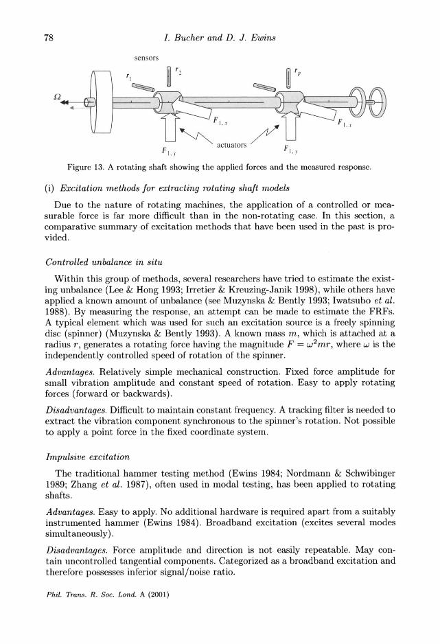
Shaft-dynamic models can be obtained by using the standard approach as in ordi- nary modal testing (Ewins 1984; Lee & Hong 1993; Joh & Lee 1993; Gahler & F6rch 1994; Irretier & Renter 1994; Irretier 1999). In the general approach, a known force is applied at one or more locations and the response is simultaneously measured at several locations along the shaft in the x- and y-directions. Such an arrangement is shown schematically in figure 13.
Special excitation methods are needed for each category of structural component, e.g. shafts, discs and bearings.
Phil. Trans. R. Soc. Lond. A (2001)
77
I. Bucher and D. J. Ewins
sensors
?2 ?2 r Fr
FI.x ~
Fi,x
F, actuators F,
Figure 13. A rotating shaft showing the applied forces and the measured response.
(i) Excitation methods for extracting rotating shaft models
Due to the nature of rotating machines, the application of a controlled or mea- surable force is far more difficult than in the non-rotating case. In this section, a comparative summary of excitation methods that have been used in the past is pro- vided.
Controlled unbalance in situ
Within this group of methods, several researchers have tried to estimate the exist- ing unbalance (Lee & Hong 1993; Irretier & Kreuzing-Janik 1998), while others have applied a known amount of unbalance (see Muzynska & Bently 1993; Iwatsubo et al.
1988). By measuring the response, an attempt can be made to estimate the FRFs. A typical element which was used for such an excitation source is a freely spinning disc (spinner) (Muzynska & Bently 1993). A known mass m, which is attached at a radius r, generates a rotating force having the magnitude F = w2mr, where w is the independently controlled speed of rotation of the spinner.
Advantages. Relatively simple mechanical construction. Fixed force amplitude for small vibration amplitude and constant speed of rotation. Easy to apply rotating forces (forward or backwards).
Disadvantages. Difficult to maintain constant frequency. A tracking filter is needed to extract the vibration component synchronous to the spinner's rotation. Not possible to apply a point force in the fixed coordinate system.
Impulsive excitation
The traditional hammer testing method (Ewins 1984; Nordmann & Schwibinger 1989; Zhang et al. 1987), often used in modal testing, has been applied to rotating shafts.
Advantages. Easy to apply. No additional hardware is required apart from a suitably instrumented hammer (Ewins 1984). Broadband excitation (excites several modes
simultaneously).
Disadvantages. Force amplitude and direction is not easily repeatable. May con- tain uncontrolled tangential components. Categorized as a broadband excitation and therefore possesses inferior signal/noise ratio.
Phil. Trans. R. Soc. Lond. A (2001)
78

Modal analysis and testing of rotating structures
motor
force |shaker transducers
acc. sensors
shaft
Figure 14. The experimental system showing the shaft, discs, motor and exciters.
Electrodynamic shakers connected via auxiliary bearing
In this approach (Rogers & Ewins 1989; BRITE 1996; Stanbridge & Ewins 1996) (see figures 12, 14), one or two electrodynamic shakers are attached to the rotating shaft via a low friction (e.g. ball) bearing. This arrangement allows one to vary the amplitude, frequency and the spatial direction of the force at the bearings, which are applied at a specific location on the shaft.
Advantages. Force amplitude and frequency can be controlled from a standard signal generator. Forward and backward rotating forces can be generated and a good signal to noise ratio (sine excitation) is obtained.
Disadvantages. Requires a special attachment to the shaft. The applied forces can be greatly affected by shaft motion (see ? 4 for a discussion of signal-processing and external effects).
Active magnetic bearings (AMBs)
These rather sophisticated, emerging, devices, which replace conventional support bearings in some high-speed machines, can be used to apply and to measure forces to/on the shaft while maintaining their primary role of supporting the shaft (Lee et al. 1995; BRITE 1996; Gahler & Mohler 1996).
Advantages. A relatively small effort is required (mainly software) to add an ability to generate a controlled sinusoidal (or other chosen) excitation to a system which is already supported by AMBs. Typically, several forces (two per bearing) can be applied simultaneously, giving rise to a truly multiple-input experimental system.
Disadvantages. Requires a considerable amount of knowledge to operate. Can cause damage to the tested machine as these devices usually support the machine. Occa- sionally provides only the 'free-free' dynamics of the shaft as forces are measured at the interface between the bearings and the shaft. The electromagnetic force is greatly affected by shaft dynamics, thereby giving rise to feedback in the system that may result in biased estimates of the FRFs (see ? 4 d (i)).
Phil. Trans. R. Soc. Lond. A (2001)
79
I. Bucher and D. J. Ewins
Ordinary excitation methods applied to the foundation
This approach seems natural as it may, in many cases, be the only possible approach due to accessibility limitations (Kramer 1993).
Advantages. Straightforward to apply using standard modal testing techniques and equipment.
Disadvantages. Many. Most of the shaft and disc dynamics cannot be easily excited from the foundation and so much information may be missed. On the other hand. modes of the foundation that do not affect the rotating parts may dominate and thus the modes related to the rotating part might be masked by much larger signals.
(b) Identification of modal parameters of rotating structures: curve fitting
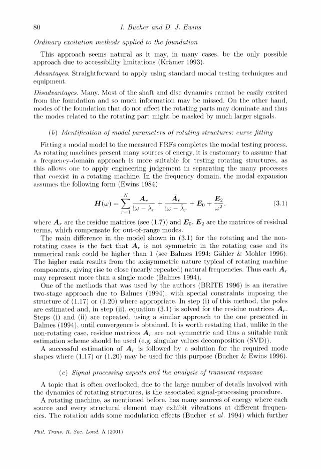
Fitting a modal model to the measured FRFs completes the modal testing process. As rotating machines present many sources of energy, it is customary to assume that a frequency-domain approach is more suitable for testing rotating structures, as this allows one to apply engineering judgement in separating the many processes that coexist in a rotating machine. In the frequency domain, the modal expansion assumes the following form (Ewins 1984)
N A Ar
H(wj)- i A + A- + Eo+ 2 (3.1) --- \w - - \r
2
where Ar are the residue matrices (see (1.7)) and E0, E2 are the matrices of residual terms, which compensate for out-of-range modes.
The main difference in the model shown in (3.1) for the rotating and the non-
rotating cases is the fact that Ar is not symmetric in the rotating case and its numerical rank could be higher than 1 (see Balmes 1994; Gahler & Mohler 1996). The higher rank results from the axisymmetric nature typical of rotating machine
components, giving rise to close (nearly repeated) natural frequencies. Thus each A, may represent more than a single mode (Balmes 1994).
One of the methods that was used by the authors (BRITE 1996) is an iterative
two-stage approach due to Balmes (1994), with special constraints imposing the structure of (1.17) or (1.20) where appropriate. In step (i) of this method, the poles are estimated and, in step (ii), equation (3.1) is solved for the residue matrices Ar. Steps (i) and (ii) are repeated, using a similar approach to the one presented in Balmes (1994), until convergence is obtained. It is worth restating that. unlike in the
non-rotating case, residue matrices Ar are not symmetric and thiis a suitable rank estimation scheme should be used (e.g. singular values decomposition (SVD)).
A successful estimation of Ar is followed by a solution for the required mode
shapes where (1.17) or (1.20) may be used for this purpose (Bucher & Ewins 1996).
(c) Signal processing aspects and the analysis of transient response
A topic that is often overlooked, due to the large number of details involved with the dynamics of rotating structures, is the associated signal-processing procedure.
A rotating machine, as mentioned before, has many sources of energy where each source and every structural element may exhibit vibrations at different frequen- cies. The rotation adds some modulation effects (Bucher et al. 1994) which further
Phil. Trans. R. Soc. Lond. A (2001)
80

Modal analysis and testing of rotating structures
increase the spectral complexity. Another reason for the existence of a large number of spectral lines in the response measured on real machines is the fact that that the structural supports and the connecting elements often have some degree of nonlinear behaviour. Indeed, it is often possible to notice that numerous harmonics (multiples of rotation speed) exist in measured response signals during rotation. Several works have dealt with the proper selection of excitation signals. For example, Muszynska & Bently (1993) used harmonic excitation created by unbalance, while Lee et al. (1995) presented a special broadband signal which generated a forward or backward rotating force. Gahler & Mohler (1996) and BRITE (1996) have used sinusoidal exci- tation and have demonstrated its advantages over broadband excitation. In general, an electro-mechanical excitation device may be strongly coupled to the mechanical vibrating part (due to nonlinear feedback). In this case, a multi-harmonic excitation (BRITE 1996) will provide better signal-to-noise ratio than a simple sinusoidal or a broadband excitation. A short discussion (see Bucher (1998) for a complete dis- cussion) of coupling mechanisms between the excitation device and the machine is presented below.
(i) Effect of feedback on accuracy of the estimated FRF
It is well known that the forces exerted by electrodynamic and electromagnetic excitation devices can depend on the response as well as on the input currents. This phenomenon can be explained by Faraday's law,
.1Rmi(t) + d dt
which relates the induced voltage v to the current i, ohmic resistance Rm and mag- netic flux ?. The change rate of the magnetic flux,
do q) 9i 90a Ox - : dt Oi Ot Ox t '
depends on the relative motion of the excited structure (Ox/Ot, where x symbol- izes a spatial coordinate) and the magnetic coils. The force which is expressed by f(t) = ac)2 (a constant) has a nonlinear dependence upon the dynamic response x(t). The term 90/0x, often addressed as the instantaneous back EMF coefficient, gives rise to a force which depends on the motion of the structure. and is often affected by other sources than the induced current I (To & Ewins 1991; Bucher 1998).
An excitation scheme where the force is also a function of the response (feedback) is illustrated in figure 15. Here, Fnm(w) is the applied force vector, X( () the response vector and H(w) the FRF matrix of the structure under test. Also, I(w) is a vector of input signals, Fe(w) is a disturbance force vector (due to internal or internal sources) and Kf is a feedback matrix term which determines the amount of force dependency upon the response.
It has been shown that a standard estimator for the FRF which uses the cross- and auto-spectrum estimates of the actually applied force and the measured response (see, for example, To & Ewins 1991; Bendat 1996; Bucher 1998),
HI (w) - S (3.2) Suu
Phil. Trans. R. Soc. Lond. A (2001)
81

I. Bucher and D. J. Ewins
lI() --- Ki V
H(w) + X
Fe I H,()
Figure 15. Block diagram of a response-dependent excitation scheme in the frequency domain.
is biased and is related to the exact FRF H(w) by (Bucher & Ewins 1996)
He (w)SUF, HI(w) = H(w) + He
(3.3) Suu
where the error term
He(W)SUF _ KflHe(w)2 SFeFe
Suu 1 - KfH* (w) SFmFm
depends upon the feedback term and upon the significance of the external distur- bances on the response.
It is well known that the magnitude of the disturbances (due to unbalance and other sources) is often larger for rotating structures than is the directly applied force. Therefore, it can be concluded from (3.3) that the presence of feedback may cause a significant deviation of the estimated FRF from the true value. When sine excitation is being used, unlike random excitation, frequencies different from that of the excitation can be ruled out and therefore, in such cases, stepped-sine is the
preferred method.
(ii) Sine excitation for rotating structures
Although stepped-sine excitation techniques have been used for decades, some
particular features are worth mentioning in the case of rotating structures. Among these are (i) the consideration of slightly nonlinear behaviour, (ii) the additional
input due to unbalance and (iii) the assumptions behind the applied least-squares technique by which the FRFs are extracted from the measurements (Bjorck 1996).
The sine-testing procedure extracts the FRFs at a number of discrete frequencies by stepping through the desired frequency range. At each frequency of interest, the
amplitudes and phases of the 2q forces and 2p responses are measured. The mea- surements of the excitation and the response are curve fitted in the time domain to form vectors of sine and cosine coefficients,
f = (fT fT )T = (f,cos Jsin)
= (fl,cos f2,cos ... fj,sin ... f2p,cos) E R X ,
T (3.4) T=(T,T,, T2pxl (rl,cos cos sin 2pcos)
(ri- 0 r'0 . r,~ C R12px'l,
Phil. Trans. R. Soc. Lond. A (2001)
82
Modal analysis and testing of rotating structures
where, for example, the force and response at the jth DOF would be
fj = fj,cos cos wt + fj,sin sin wt, rj = rjj, cos cO +t + rj, sin sint. (3.5)
It can be shown, by using standard linear systems theory, that f and r are related by means of the sought frequency-response matrix, i.e.
rcos - irsin = H(U)(fcos -ifsin). (3.6)
It is clear that H(w) C WRXq can be extracted by a combination of q independent sets of excitation vectors, f (and therefore requires q vector measurements per frequency).
This approach has been universally used and, indeed, using the unbalance pertur- bation approach, Muszynska (1994) and Muszynska & Bently (1993) have used four forces (q = 2) by rotating the unbalance in co- and counter-rotating directions in seeking a linear model of the rotating structure.
At this point it is worth mentioning that a linearized (rather than linear) model is usually sought, while behind the direct usage of (3.6) is the assumption that the real and imaginary parts of the FRF are related (see Ruh 1981; Pirard 1989). Indeed, the steady-state response of a linear system to a sinusoidal excitation,
f (t) = fcos cOs wt + fsin sin t,
gives rise to r(t) r= rCS cos Wt + rsin sint,
which can be shown to yield
Trcos_ HR () HI(w) (fcos rsin --HI(w) HR(w)_ \fsin ()
where H(w) = HR(w) + iHi(w). But the special structure of a skew-symmetric matrix such as that shown in (3.7)
cannot be guaranteed to exist, even for slightly nonlinear systems. Consequently, it is necessary to estimate four independent parameters instead of two (the real and imaginary parts of the FRF).
In order to be able to accommodate some nonlinear behaviour, the higher-order FRF approach (Ruh 1981) can be adopted. Assuming a polynomial model (the term is defined in Ruh 1981), one can include several harmonics in both the excitation and the response, i.e.
Q Q
f(t) = f fcos c nwt + fs sin nt, r(t) cos t + r sin nwt, n=l n=l
(3.8) where the amplitudes of the sine and cosine coefficients in both the force and the response are related (as a consequence of a series expansion (Bucher 1998)) by a matrix representing the higher-order FRFs at a single frequency (Storer & Tomlinson 1993),
/' 1 - i \i~A1^1 A1,1 * A1,^ ~ \Nnl
\rsi ANnl ,1 A^1-l 1 A4/
- scon, cos , sin cos,sin -
__'sin,sin sin,sin (39)
N~nfNnI sin,1 A 1 ...N l,Nn inl
_sin,cos sin,sin
Phil. Trans. R. Soc. Lond. A (2001)
83
I. Bucher and D. J. Ewins
+f(Hz) A
-f(Hz) I
forward
0 back
speed (rpm)
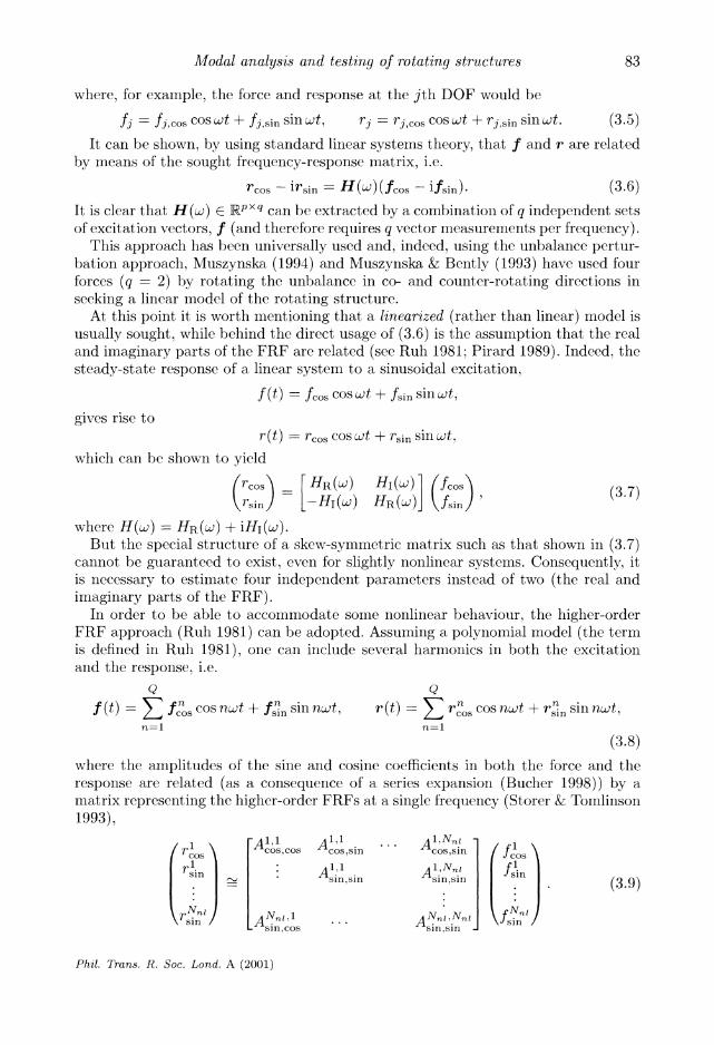
Figure 16. Double-sided Campbell diagraml separating the forward from the backward whirl.
Here, the ith harmonic of the response is related to the jth harmonic of the excitation by A';j 5r'/f coy Ac's,Slll = OFcos/Ofsill
Equation (3.9) presents a true linearized FRF that provides higher accuracv in exchange for a more elaborate experimental procedure.
(iii) Solving for the FRF
As one wishes to obtain the coefficients from which the FRF can be estimated. (As sin), one needs to apply 2qQ independent sets of forces (see (3.8)). where q is the number of excited degrees of freedom and Q is the number of harmonics to be considered. Performing the required number of measurements, one can augment the estimated force and response coefficients to form
R= AF. (3.10)
where
- ( r1 N cos 1 sin
R =
r51
fNnl \ cos / i
( r j N Cos sinl 1
sin1 2 2qQ..
A direct solution of (3.10) for A may yield a biased estimate as both R and F are formed from measured quantities and thus contain some noise. One should assess the amount of noise in the response and force measurements and form a solution method that takes this into account. A possible strategy could make use of the total least-squares approach (see Bjorck 1996; Golub & Van Loan 1996), which assumes that there is some uncertainty in both the right- and left-hand sides of (3.10).
Phil. Trans. R. Soc. Lond. A (2001)
84

Modal analysis and testing of rotating structures
sensors ..
backward )rward
Figiire 17. Vil)ratioll patteiril dolll)le-si(lc(l C(Iliplcll (liagraiii.
11= 1 . ~ ~ ~ - . ?I
+ tforwalrd
.~~~~~~~~~~~~~~~~~~~~~~~~~~~~~~~~~~~~~~~~~~ ." . r~ ..~ C C
5 s,'
_ _ "~~~~~~~~~~~~~~~~~~~~~~~~~~~~~~~~~~~~~~~~~~~~~~~~~~~~~~
. . ' ' '- ' ..
-backwvard ...
. .
11=2 _. 11=3
r( Z'VL
j? .. -? ..?dr
t 1 -,? C: rr'` 'I? ?--
,?I ?h? '' *e C' r, .r L-
C-. ?? r* c -rj ir ?ictclrr
speed Q
Figure 18. Three double-sided spectrogralms for three different wavelelgtlls (the considered numbers of nodal dialneters are n = 1, 2, 3).
Note that by making use of the pseudo-inverse of F (which is often implemented as A = RFT(FFT)-1) we inherently assume that all the uncertainty is confined to the response measurements r, and hence R.
It can therefore be concluded that the method presented in Muzynska (1994), for example, is illlherenltly limited and cannot truly estimate a linearized FRF, since only two possible excitation sets (instead of the required four) can be generated with a rotating-unbalance excitation.
(d) Estimation of operation deflection shapes and natural frequencies from transients
Any machine is occasionally exposed to run-up and run-down conditions where the speed of rotation is varied until the normal operating conditions are reached. During
Phil. Trans. R. Soc. Lond. A (2001)
85
m
I
fc
r, ,.,,,
-.i
I. Bucher and D. J. Ewins
60 - (a) force singular , values
0- 0-^< X~/~ ~.~ , response singular
-60dB / - ,values dB -
-60-
-120 -
0 100 200 300 frequency (Hz)
100 - (b) force singular / values
50- i
response singular 0 -
~ , --'-' values
dB -50 -
-100 -
0 100 200 300
frequency (Hz)
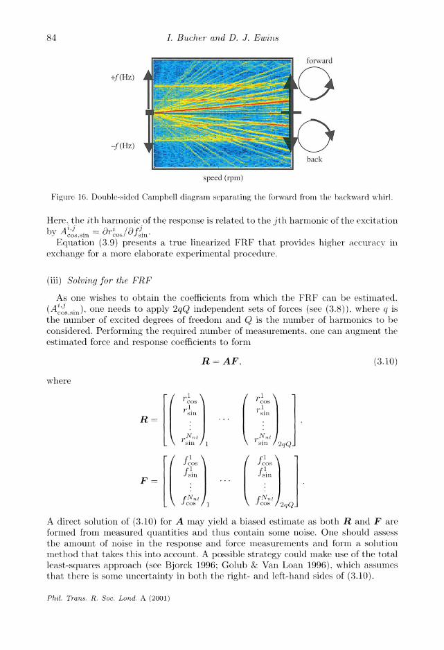
Figure 19. A typical measured FRF at (a) Q = 0 and (b) Q = 1000 rpm and the singular values of the force and response matrices.
this time, the response signals can be measured and displayed in a format commonly called a waterfall, a Campbell diagram or Z-mod plot (Bucher & Ewins 1997). In this display, the variation of the response spectrum is presented as a function of speed and frequency. As described in figure 2, the unbalance naturally creates an excitation with a frequency equal to the speed of rotation Q, thus, along the line w = Q (see figure 2), one may expect high levels of response when this line coincides with one of the natural frequencies. Such a coincidence is termed a 'critical speed' and indicates a resonance condition and the possibility of high response levels. A rapid variation of the speed of rotation can avoid these high levels being established but still gives rise to an excitation of natural modes in situ. As mentioned before, most disc modes are unaffected by shaft unbalance and thus, when disc modes are to be investigated, some additional means of external forcing (electromagnetic, fluid) is required, in case the normal operating conditions do not provide such an excitation. The Campbell diagram can be displayed in a format which separates the forward travelling modes from the backward travelling ones. These modes are usually overlapped in the con- ventional Campbell diagram (Lee 1993) and so the modified two-sided approach provides a better alternative (Bucher & Ewins 1997).
The generation of figure 16 requires simultaneous processing of signals measured in two orthogonal directions (x and y) (Bucher & Ewins 1997), but this diagram
Phil. Trans. R. Soc. Lond. A (2001)
86
Modal analysis and testing of rotating structures
has the advantage that it allows one to observe the effects of rotation upon natural frequencies and to visualize the extent by to each mode participates in the dynamic response.
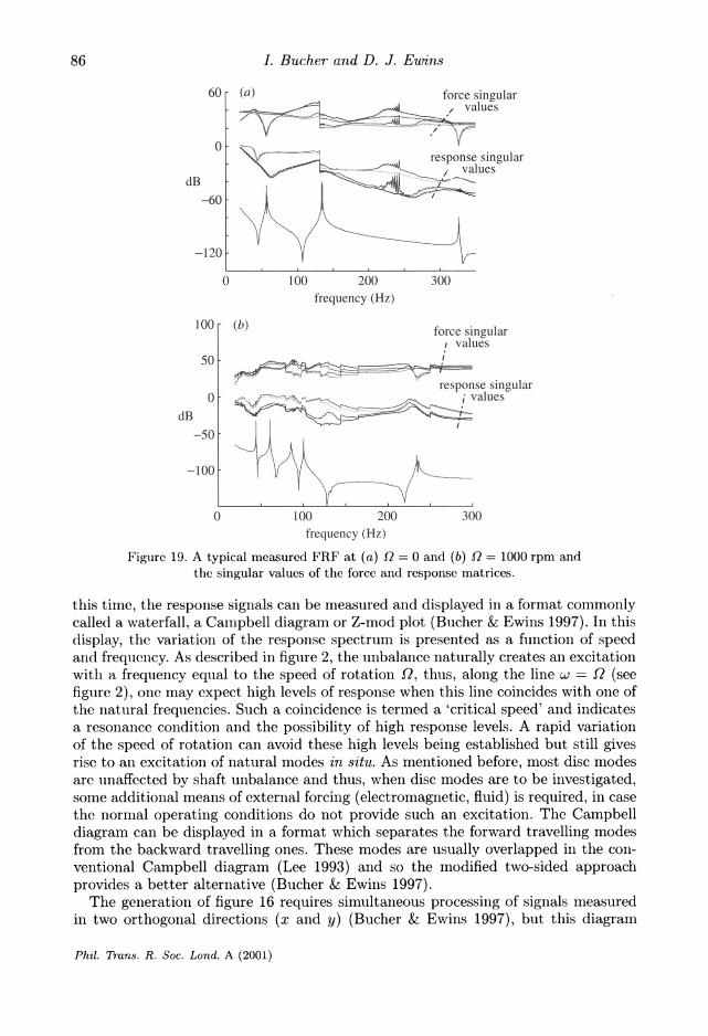
An extended approach has been developed for discs for which a diagram that has several dimensions can be constructed. The additional dimensions separate the disc modes according to the different numbers of nodal diameters (wavelengths). Fig- ure 12 shows an arrangement in which a number of sensors are distributed as shown in figure 17. This arrangement allows one to process the signals from all sensor posi- tions simultaneously and to separate the response into components associated with individual numbers of nodal diameters. As illustrated in figure 17, an array of sensors at a fixed radius will measure the variation of the disc deflection so that applying the Fourier transform in both time and space (Bucher & Ewins 1997; Schmiechen 1997) yields separations as depicted in figure 18. These measurements were performed on the rig photographed in figure 12.
The presented signal-processing method allows one to display the spectral contents of the response measured from a rotating machine in considerable detail. This method provides a qualitative estimate of the natural frequencies and allows one to isolate the contribution of a particular mode shape from the total response. The method is suitable for any type of rotating structure and is not restricted to time-invariant models. Through examination of these diagrams, the existence of periodically varying coefficients can be detected.
4. Illustrative examples and case studies
Several examples for the application of modal testing to rotating structures are pro- vided in this section. Special features of rotating machines are emphasized and rotat- ing versus non-rotating conditions are compared.
(a) Application of active magnetic bearings
The test rig which is shown in figure 20 and described in BRITE (1996) and Gahler & Mohler (1996) was used to measure the FRFs by applying a stepped-sine excitation approach (Bucher & Ewins 1996). This test rig contained two magnetic bearings, each capable of applying a force in two perpendicular directions, giving rise to a total of four excited DOFs. Since the shaft itself was very lightly damped, the method which was described in ?? 1 d and 1 c could be applied in this case.
A typical measured FRF is depicted in figure 19, with some additional information as explained below.
Figure 19 shows a typical FRF measured at speeds of 0 and 1000 rpm. These mea- surements illustrate the wide dynamic range which was obtained with the stepped- sine excitation method. The anticipated difficulties which were mentioned in ? 3 c (i) can be observed in this case by inspection of the singular values of the force matrix (F in (3.10)) which is shown in figure 19a for each measured frequency. In this plot, the number of independent force vectors drops near each natural frequency and therefore (3.10) becomes ill-conditioned. This singularity is more dominant for the non-rotating case (figure 19a) and can explain the deterioration in the accuracy of the FRF near resonance. The singular values that were computed for the response matrix R show that a rank of 2 is preserved for the whole frequency range. This
Phil. Trans. R. Soc. Lond. A (2001)
87

I. Bucher and D. J. Ewins
Figulre 20. Experimental rig showing the mlotor and the miagnetic bearings, witli tc Illmeasure( andIl predicted forward whirling mode shape ovcrlaid. at 3000 rpim.
(a) (b) -60 -60
-100 -100-
dB \ dB -140
' - ^ - -140
-140 -180
-220r 0 100 200 300 0 100 200 300
frequency (Hz) frequency (Hz)
Figure 21. Singular values of the 4 x 4 FRF matrix at (a) 0 and (b) 2400 rpm.
fact strengthens the assumption that at least two measurements need to be taken for complete determination of the response (and hence the FRF) at each node or a second measurement.
Indeed, this system provided sufficiently accurate data to estimate the whirling mode shapes, one of which is depicted in figure 20.
Although this method generally proved successful, one must take into account that the reported experiments were conducted under laboratory conditions, where a considerable effort was needed to obtain the reported results.
(b) Validation of the theory
A closer inspection of the results shows that the potential problems associated with feedback (see ? 3 c (i)) do arise, as can be deduced from the singular values plot in figure 19a. The selection of the four perturbation vectors needed at each measured
Phil. Trans. R. Soc. Lond. A (2001)
88

Modal analysis and testing of rotating structures
dB
-100 frequency response
300 310 320 330 340 350
frequency (Hz)
Figlll 22. Sillglar values of the 4 x 4 FRF matrix at 0 rplll an(d a typical FR'.
frequencl y was therefore adjusted il order to minilnize this phenomenon. An FRF lllatrix was lneasire(l b)y processing four excitatiol and four response measurements, all taken at the mIagletic bearings in the x- and y-directions. An SVD algorithm decomllosed this FRF matrix (at each frequiency) in or(der to reveal its rank, which is a result of the number of participating lmodes at every fieqiuency. The results are lel)ictedl ill figure 21.
Figure 21 sllows the four singular values of the 4 x 4 FRF imatrix as a fiuction of frequelncy. This plot clearly iml(licates that tlle rank of the FRF mlatrix does inot (1rop )below 2 in tle Illeasure(l frequency range for thle lnon-rotating case. Il tlle
rotatillg case, on tlle othler lhalld, one llod(le prevails, especially ill thle vicinity of tlle natural flrequencies. It call tllls be concliuded tllat a sinlgle shaker would not have beenl sufficient for extracting the FRF lmatrix correctly in the rotating case, wliile tlis is llot true for the nion-rotating one.
A closer look (at figure 21) arolnd the naturlal fi'equencies reveals a few miore details. and these are described below.
The irregularity in tlle curves in figure 22 is assumiled to be due to the large feedback effect arollll(l resollance. This feedback (which exists in all clectrodylalmiic shakers close to resoinamce) gives rise to a singularity and therefore to a numllerically sensitive complll)ltatioll process (see ?3 c). Ill this case, thle loisy estimate was inldeed close to resollnance all(1 onle lmay suspect that a Ineasurelment systemll of lesser quality than tlce one sllown ill figure 20 mlliglit have lead to severely deteriorated results.
(i) Fitting equation (1.20) to the measurements
Tlle mleasured FRF llmatrix was used ill order to fit a miiodel aiid extract tlle resi(llues. A typical result, wllicll was llmeaslred at a speed of 1800 rpmI , was fitted
I'il. Tran7s. R. So:. Lond. A (2001)
89
I. Bucher and D. J. Ewins
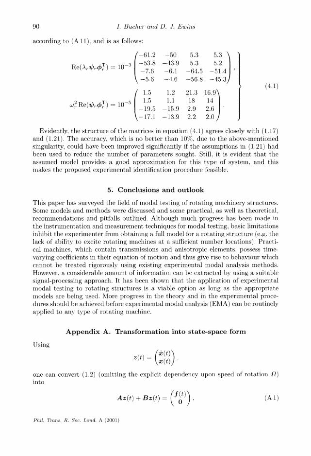
according to (A 11), and is as follows:
(-61.2 -50 5.3 5.3 \
e br T) = 103 -53.8 -43.9 5.3 5.2 Rp~c(/~ie /JrT)= 10_3 -5 3.8 -7.6 -6.1 -64.5 -51.4
-5.6 -4.6 -56.8 -45.3/ ~,> (4.1)
/ 1.5 1.2 21.3 16.9\
i2 RerT) = io-5 1.5 1.1 18 14 2 Re( r?0Tr) _ 10 1. 5
-19.5 -15.9 2.9 2.6
\-17.1 -13.9 2.2 2.0/
Evidently, the structure of the matrices in equation (4.1) agrees closely with (1.17) and (1.21). The accuracy, which is no better than 10%, due to the above-mentioned singularity, could have been improved significantly if the assumptions in (1.21) had been used to reduce the number of parameters sought. Still, it is evident that the assumed model provides a good approximation for this type of system, and this makes the proposed experimental identification procedure feasible.
5. Conclusions and outlook
This paper has surveyed the field of modal testing of rotating machinery structures. Some models and methods were discussed and some practical, as well as theoretical, recommendations and pitfalls outlined. Although much progress has been made in the instrumentation and measurement techniques for modal testing, basic limitations inhibit the experimenter from obtaining a full model for a rotating structure (e.g. the lack of ability to excite rotating machines at a sufficient number locations). Practi- cal machines, which contain transmissions and anisotropic elements, possess time- varying coefficients in their equation of motion and thus give rise to behaviour which cannot be treated rigorously using existing experimental modal analysis methods. However, a considerable amount of information can be extracted by using a suitable signal-processing approach. It has been shown that the application of experimental modal testing to rotating structures is a viable option as long as the appropriate models are being used. More progress in the theory and in the experimental proce- dures should be achieved before experimental modal analysis (EMA) can be routinely applied to any type of rotating machine.
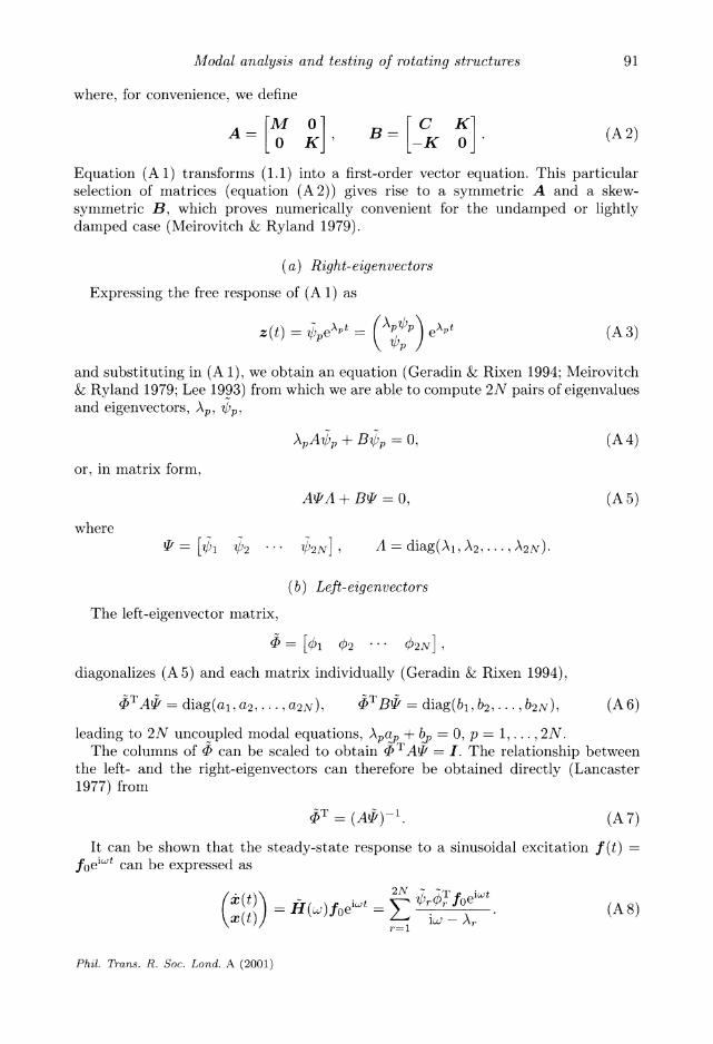
Appendix A. Transformation into state-space form
Using
z (t) (z (t)
one can convert (1.2) (omitting the explicit dependency upon speed of rotation Q?) into
Az(t) + Bz(t) =(f() (Al)
Phil. Trans. R. Soc. Lond. A (2001)
90
Modal analysis and testing of rotating structures
where, for convenience, we define
M 0 C K A K B=- K (A2) A- 0 K K (A 2)
Equation (A1) transforms (1.1) into a first-order vector equation. This particular selection of matrices (equation (A2)) gives rise to a symmetric A and a skew- symmetric B, which proves numerically convenient for the undamped or lightly damped case (Meirovitch & Ryland 1979).
(a) Right-eigenvectors
Expressing the free response of (A 1) as
z(t) =- peAP (Ap'Ip eApt (A 3)
and substituting in (A 1), we obtain an equation (Geradin & Rixen 1994; Meirovitch & Ryland 1979; Lee 1993) from which we are able to compute 2N pairs of eigenvalues and eigenvectors, Ap, )p,
ApACp + Bp -0, (A 4)
or, in matrix form,
AiA + B = O, (A 5)
where
t- =
[1 ?2 ... 2N], A = diag(Al, A2,..., 2N)-
(b) Left-eigenvectors
The left-eigenvector matrix,
< = [01 02 ... 02N],
diagonalizes (A 5) and each matrix individually (Geradin & Rixen 1994),
OTA diag(a a a2) T = diag(a 2, ), diag(b1, b2,..., b2N) (A6)
leading to 2N uncoupled modal equations, Apap +b = 0, p = 1,...,2N. The columns of P can be scaled to obtain (TAI = I. The relationship between
the left- and the right-eigenvectors can therefore be obtained directly (Lancaster 1977) from
AT = . (A (A 7)
It can be shown that the steady-state response to a sinusoidal excitation f(t) foeiwt can be expressed as
K( gut))V=1it r or (A8) /"(t) = H() foe- i - (A 8) \?ct,l ~~~~~r-1 w,
Phil. Trans. R. Soc. Lond. A (2001)
91
I. Bucher and D. J. Ewins
Given (A 8). we are able to express the FRF matrix H(Cw) explicitly.
x(t) = H(w)'feiwt ( + foT ) eflw (A 9) 1o e - \r UiJ - A\l
Note that
H(&) = X-l(i~:) = (-:2M(9) + iwC(Q) + K(Q))-1. (A 10)
This FRF can be reformulated using a second-order denominator (for which we have
Ar, =-(,rg ? i\/1 - C2 ). as is customary in vibration analysis (Bucher &( Ewils 1996).
H()
w Re( 'i, 1. -iw Re( At,. i) (A. ) HK) ^ S 2 - &2 + 2i(WLL(1
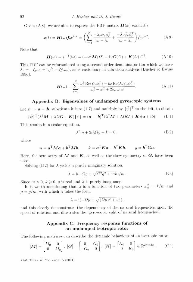
Appendix B. Eigenvalues of undamped gyroscopic systems
Let tr, = a + ib. substitute it into (1.7) and multiply by {4/}T to the left. to obtain
{Il}T(A2M + XAG + K){'} = (a -ib)T (XM + XAG + K)(a + ib). (B )
This results in a scalar equation.
A2'n, + 2iASg + k = 0. (B 2)
where
in =- a Ma + bMb. k =- a Ka + b Kb, ( = bTGa.
Here, the symlmetry of AM and K, as well as the skew-symmletry of G. have been
used.
Solving (B 2) for A yields a purely imaginary solution,
A = i(-Qgq ? /229g2 + mk)/ m,. (B 3)
Since 7n > 0. k > 0, g is real and A is pllrely imaginary. It is worth mentioning that A is a fuinction of two parameters 2, = A/, alll
t/ = g/in. with which A takes the form
A = i(-1 - + V/( /7)2 + 2).
and this clearly demonstrates the dependency of the natural freqiuencies liponl the
speed of rotation and illustrates the 'gyroscopic split of natural frequencies'.
Appendix C. Frequency response functions of an undamped isotropic rotor
The following matrices can describe the dynamlic behaviour of all isotropic rotor:
A[M ? I I Ko o I(22 (x 11 [nMl [G] -G jo [K] 0R A - o (C: )
...... Go 0 I
Phil. Trans. R. Soc. Lond. A (200)1)
92

Modal analysis and testing of rotating structures
The FRF matrix, which is defined by (A 10), can be partitioned into x- and y-related terms as
H Hxx Hxy H yx H yy_
It call be observed that the various sllb-matrices have the following form:
zxx
Zyx
(C 2)
(C 3)
(C4)
HXX - (Z,x Z,~ Zuxy Zyx).
Zxy _ Ko - w AIo i0Go
Zyy --iJGo Ko - - 2AI()
Using the previous identities, we can show that
H,X = (Ko - 21o - 2Go(Ko - 2Alo)-'Go)-
is a purely real matrix. Denotillg ZO0= = K - o 2w2A10o, we obtain
H = ( Z0 ? - 0
Go (Z O)0-1Go 1 ^xx - " { O
~ -
1O! G -0)
(C 5)
(C 6)
H - i_ ,Z 70=0 G(Zo7=0 2Go Zo:7Q=O) - -1
and also Hx - ,i0 tZo Go (Zo =0 2Go (Zo=O)-1 Go-1 yx - -l/o jQ(o - Uoo / WO
are both purely imaginary.
Appendix D. Nomenclature
(C 7)
mass, viscous damping plus gyroscopic and stiffness matrices gyroscopic matrix vector of coordinates (DOF) describing the response (displacement) vector of external forces response amplitude vectors multiplying to cosine and sine time functions force amplitude vectors imultiplying to cosine and sine time functions response and force (respectively) amplitude matrices for a single frecquency speed of rotation (rpml or rad s-1) right-eigenvector complex conjugate of C eigenvalue (A, the rth eigenvalue) dynamic stiffiess left-eigenvector scaling coefficients related to the rth mode cosine and sine related (respectively) eigenfunctions (in polar coordinates)
and
M(t). C(t), K(t) G q(t)
f(t) /cos sinl
fcos fsini
R, F
,(1,
A ,(A)
/30 ,3-, a,r
(,,C.o o) ,,'l (r. 0) '71-~ , r n, s
Phil. Traris. R. Soc. Lond. A (2001)
93

I. Bucher and D. J. Ewins
Mo, K0, Go mass, stiffness and gyroscopic matrices defined per direction (plane), e.g. x or y
NSA non-self-adjoint FRF frequency-response function SVD singular values decomposition
References
Balmes, E. 1994 New results on the identification of Normal modes from experimental complex modes. In 12th Int. Modal Analysis Conference, Honolulu.
Bendat, J. S. 1996 Measurement and analysis of random data. Wiley. Bienzo, C. B. & Grammel, R. 1954 Engineering dynamics, vol. III. London: Blackie & son.
Bjorck, A. 1996 Numerical methods for least squares problems. Philadelphia, PA: SIAM. BRITE 1996 BRITE/EURAM Project no. 5464-92. Development of validated structural
dynamic modelling and testing techniques for vibration predictions in rotating machinery. Final report submitted to the European Commission.
Bucher, I. 1998 Exact adjustment of dynamic forces in presence of non-linear feedback and singularity-theory and algorithm. J. Sound Vib. 218, 1-27.
Bucher, I. & Ewins, D. J. 1996 Modal testing of rotating structures: difficulties, assumptions and practical approach. In IMechE 6th Int. Conf. on Vibrations in Rotating Machinery, Oxford, UK, September.
Bucher, I. & Ewins, D. J. 1997 Multi-dimensional decomposition of time-varying vibration response signals in rotating machinery. Mech. Sys. Signal Processing 2, 576-601.
Bucher, I., Schmiechen, P., Robb, D. A. & Ewins, D. J. 1994 A laser-based measurement system for measuring the vibration on rotating discs. In Int. Conf. on Vibration Measurement by Laser Techniques, Ancona, Italy, October.
Childs, D. 1993 Turbomachinery rotordynamics. Wiley. Ehrich, F. 1992 Handbook of rotordynamics. McGraw-Hill.
Ewins, D. J. 1976. An experimental investigation of the forced vibration of bladed discs due to aerodynamic excitation. ASME publication on structural dynamical aspects of bladed-disc assemblies, pp. 15-27.
Ewins, D. J. 1980 Bladed disc vibration-a review of techniques and characteristics. In Proc. Int. Conf. on Recent Advances in Structural Dynamics, Southampton, UK.
Ewins, D. J. 1984 Modal testing: theory and practise. Taunton: Research Studies.
Gahler, C. & Forch, P. 1994 A precise magnetic bearing exciter for rotordynamic experiments. In 4th Int. Symp. on Magnetic Bearings, ETH, Zurich, August.
Gahler, C. & Mohler, M. 1996 Multivariable identification of active magnetic bearing systems. In 5th Int. Symp. on Magnetic Bearings, Kanazawa, Japan, August.
Gasch, R. 1976 Dynamic behaviour of a simple rotor with a cross-sectional crack. In Conf. on Vibrations in Rotating Machinery, University of Cambridge.
Gasch, R. & Pfutzner, H. 1975 Rotordynamic Eine. Springer. Genta, G. 1988 Whirling of unsymmetrical rotors: a finite element approach based on complex
coordinates. J. Sound Vib. 124, 27-53.
Genta, G. 1994 Vibration of structures and machines. Springer. Geradin, M. & Rixen, D. 1994 Mechanical vibrations: theory and application to structural dynam-
ics. Wiley. Golub, G. H. & Van Loan, C. F. 1996 Matrix computations. Baltimore: Johns Hopkins University
Press.
Han, R. P. S. & Zu, J. W. 1995 Pseudo non-selfadjoint and non-selfadjoint systems in sturctural dynamics. J. Sound Vib. 184, 725-742.
Phil. Trans. R. Soc. Lond. A (2001)
94

Modal analysis and testing of rotating structures
Irretier, H. 1999 Mathematical foundations of experimental modal analysis in rotor dynamics. Mech. Sys. Signal Processing 13, 183-191.
Irretier, H. & Kreuzing-Janik, T. 1998 Experimental modal analysis-a tool for unbalance iden- tification of rotating machines. In 5th Int. Federation for Theory of Macines and Mechanisms, Darmstadt, Germany.
Irretier, H. & Reuter, F. 1994 Experimentelle Modalanalyse in rotierenden Maschinen. Ab- schlussbericht DFG, Universitat/Gesamthochschule Kassel.
Irretier, H. & Reuter, F. 1995 Experimental modal analyse of rotating disk systems. In Proc. 15th ASME Biennial Conf. Mech. Vib. Noise, Boston, USA, pp. 1201-1206.
Iwatsubo, T. et al. 1988 An experimental study on the static and dynamic characteristics of pump annular seals. Rotordynamic instability problems in high-performance turbomachinery. In Proc. NASA Workshop CP3026, College Station, TX, pp. 229-252.
Joh, Y. D. & Lee, C. W. 1993 Excitation methods and modal parameter identification in complex modal testing of rotating machinery. Int. J. Analytical Experimental Modal Analysis 8, 179- 203.
Khader, N. & Loewy, R. G. 1991 Structural dynamics of rotating bladed-disk assemblies coupled with flexible shaft motions. J. Sound Vib. 149, 471-88.
Kramer, E. 1993 Dynamics of rotors and foundations. Springer. Lalanne, NI. & Ferraris, G. 1990 Rotordynamics prediction in engineering. Wiley. Lancaster, P. 1977 Theory of matrices. Academic.
Lee, C. W. 1991 Complex modal testing theory for rotating machinery. Mech. Sys. Signal Pro- cessing 5, 119-137.
Lee, C. W. 1993 Vibration analysis of rotors. Dordrecht: Kluwer Academic. Lee, C. W. & Hong, W. W. 1993 Identification of bearing dynamic coefficients by unbalance
response measurements. IMechE Proc. Inst. Mech. Engrs 203, 93-101. Lee, C. W. & Young-Don, J. 1993 Theory of excitation methods and estimation of frequency
response functions in complex modal testing of rotating machinery. Mech. Sys. Signal Pro- cessing 7, 57-74.
Lee, C. W., Ha, Y. H. & Cheol-Soon, K. 1995 Modal testing and parameter identification of active magnetic bearing system. In ASME Design Engineering Technical Conference, vol. 3.
Meirovitch, L. 1980 Computational methods in structural dynamics. Sijthoff & Noordhoff. Meirovitch, L. & Ryland, G. 1979 Response of slightly damped gyroscopic systems. J. Sound
Vib. 67, 1-19. Muszynska, A. 1994 Identification of modal parameters and the existence of a backward quadra-
ture resonance in an anisotropic rotor system with fluid interaction. Bently Nevada Corp. information pack.
Muszynska, A. & Bently, D. E. 1993 Applications of sweep frequency rotating force perturba- tion methodology in rotating machinery for dynamic stiffness identification. ASME Trans. J. Engng Gas Turbines Power 115, 266-271.
Nordmann, R. 1983 Identification of modal parameters of an elastic rotor with oil film bearings. J. Vibration Acoustics Stress Reliability Design.
Nordmann, R. & Schwibinger, P. 1989 Identification of natural frequencies of a shaft with unequal moments of inertia. J. Vibration Acoustics Stress Reliability Design.
Okubo, M., Evensen, H. & Van Karsen, C. D. 1995 Composition methods for evaluating mode shapes in local coordinates from FRFs measured on a rotating disc. In Int. Modal Analysis Conf., Orlando, FL, no. 13.
Pirard, A. B. 1989 The physics of vibration. Cambridge University Press. Radcliffe, C. J. & Mote, C. D. 1983 Identification and control of rotating disk vibration. J. Dyn.
Sys. Measurement Control 105, 39--45. Rogers, P. J. & Ewins, D. J. 1989 Modal testing of an operating rotor system using a structural
dynamics approach. In Proc. 7th IMA C, Las Vegas, NV.
Phil. Trans. R. Soc. Lond. A (2001)
95

I. Bucher and D. J. Ewins
Ruh, W. J. 1981 Nonlinear system theory. Baltimore: Johns Hopkins University Press. Schmiechen, P. 1997 Travelling wave speed coincidence. PhD thesis, Dynamics Section. Inperial
College of Science, Technology and Medicine, London.
Stanbridge, A. B. & Ewins, D. J. 1996 Modal testing of unconstratined rotors. In IMechE 6th Int. Conf. on Vibrations in Rotating Machinery, Oxford, UK, September.
Storer, D. M. & Tomlinson, G. R. 1993 Recent developments in the measurement and inter- pretation of higher order transfer functions from non-linear structures. Mech. Systems Signal Processing 7, 173 189.
To, W. M. & Ewins, D. J. 1991 A closed-loop model for single/multi-shaker Ino(lal testing. Mech. Sys. Signal Processing 5, 305-316.
Tobias, S. A. & Arnold, R. N. 1957 The influence of dynamical imperfection on the vibration of rotating disks. Proc. Inst. AIech. Engrs 171, 666-690.
Tondl. A. 1965 Some problems of rotor dynamics. London: Chapman & Hall.
Wang, W. & Kirkhope, J. 1994 New eigensolutions and Inodal analysis for gyroscopic/rotor systems. Part 1. Undamped systems. J. Sound Vib. 175. 159-170.
Xu, J. & Gasch. R. 1995 Modale Behandlung linearer periodisch zeitvarianter Bewegungs gle- ichungen. Arch. Appl. Mech. 65, 178-193.
Yakubovich. V. A. & Starzhinskii. V. M. 1975 Linear differential equations 'with periodic coefJi- cients. Wiley.
Zhang, Q., Lallelnent, G. & Fillod. R. 1987 Identification of the clynamic characteristics of oil-film bearings. Rotating Machinery Dyn. 2, 57-62.
Phil. Trans. R. Soc. Lond. A (2001)
96