duralocsynthes.vo.llnwd.net/o16/llnwmb8/int mobile/synthes international... · the radiographs...
TRANSCRIPT

Acetabular Cup System
Surgical Technique
DURALOC®


Table of Contents
Surgical Technique Templating and Pre–Operative Planning 2
Preparation of the Acetabulum 4
Trial Sizing and Impaction of the Shell 5
Cup Positioning 6
Joint Stability 7
Trial Sizing and Impaction of the Polyethylene Liner 8
Polyethylene Liner Extraction 9
DURALOC Constrained Liners 10
Ordering Information 14
Surgical Technique DURALOC® Acetabular Cup DePuy Synthes 1

Figure 1.
The primary goal of total hip arthroplasty is the anatomic reconstruction of the hip joint, resulting in favourable prosthetic joint load and function. Mechanically, the goals are to create a stable articulation with an optimised range of motion, restore biomechanics for muscular efficiency and equalise limb lengths. Meeting these goals begins with a thorough analysis of the hip with comparison to the contralateral side in anteroposterior (A/P) and lateral projections.
The desired magnification for all imaging should be 15 percent, which corresponds to the templates provided for the DURALOC Acetabular Cup (Figure 1). Magnification markers taped to the patient’s leg at the level of the trochanter will assist in determining actual magnification.
For the A/P projection, place both extremities in 15° of internal rotation to position the head and neck parallel to the coronal plane. Centre the beam on the symphysis pubis and ensure the proximal femoral shaft is included in the radiograph.
Templating and Pre–Operative Planning
1 DePuy Synthes DURALOC® Acetabular Cup Surgical Technique

The radiographs should clearly demonstrate the acetabular configuration and the endosteal and periosteal contours of the femoral head, neck and proximal femur (Figure 2).
DURALOC® Acetabular Cup templates allow assessment of the most likely size of cup to be implanted. The acetabular component should be placed on structurally sound bone to optimise the opportunity for bone ingrowth.
The cup should be placed so that the head centre is as near to the anatomical position as possible and the most inferomedial aspect of the cup should normally be at the level of the bottom of the teardrop (Figure 3).
Figure 2.
Figure 3.
Surgical Technique DURALOC® Acetabular Cup DePuy Synthes 3

Figure 5.
Preparation of the Acetabulum
After removal of the femoral head, a capsulectomy is performed. The surgeon should ensure complete exposure of the entire acetabular rim. Any excess soft tissues and osteophytes should be removed from the rim and bed of the acetabulum.
The acetabulum may now be reamed starting with the smallest reamer to remove soft tissues in the bed. A range of reamers are available in 1 mm increments.
The reamers should be introduced in either 35° – 40° or 45° of abduction (Figure 4), depending on the cup selected and 15° – 20° of anteversion (Figure 5). In a lateral decubitus position, the pelvis may be slightly flexed and a 30° – 35° anteversion is recommended.
Progressively increase the reamer size to remove cartilage and medial osteophytes until healthy, bleeding subchondral bone is exposed and a symmetrical, hemispherical dome is obtained.
Care should be taken to avoid penetration of the medial wall of the acetabulum and to maintain as much of the sub-chondral plate as possible, removing only sclerotic bone.
If adequate healthy bone is not obtained, larger reamers should be used. Only the periphery should be reamed and further medialisation should be avoided. The anterior and posterior columns should be regularly assessed for thickness and strength. To achieve optimal press-fit, under-reaming of 1 to 2 mm to the templated acetabular cup size is required. Usually a cup of 54 mm or smaller requires 1 mm under-reaming.
A cup of 56 mm or larger mostly requires 2 mm under-reaming to obtain adequate stability. The quality of the bone should be taken into account when determining the actual amount of under-reaming. If the component does not appear to achieve adequate stability, adjunctive fixation is recommended.
40° – 45°
15° – 20°
Figure 4.
4 DePuy Synthes DURALOC® Acetabular Cup Surgical Technique
Trial Sizing and Impaction of the Shell
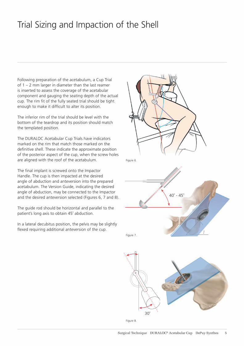
Following preparation of the acetabulum, a Cup Trial of 1 – 2 mm larger in diameter than the last reamer is inserted to assess the coverage of the acetabular component and gauging the seating depth of the actual cup. The rim fit of the fully seated trial should be tight enough to make it difficult to alter its position.
The inferior rim of the trial should be level with the bottom of the teardrop and its position should match the templated position.
The DURALOC Acetabular Cup Trials have indicators marked on the rim that match those marked on the definitive shell. These indicate the approximate position of the posterior aspect of the cup, when the screw holes are aligned with the roof of the acetabulum.
The final implant is screwed onto the Impactor Handle. The cup is then impacted at the desired angle of abduction and anteversion into the prepared acetabulum. The Version Guide, indicating the desired angle of abduction, may be connected to the Impactor and the desired anteversion selected (Figures 6, 7 and 8).
The guide rod should be horizontal and parallel to the patient’s long axis to obtain 45˚ abduction.
In a lateral decubitus position, the pelvis may be slightly flexed requiring additional anteversion of the cup.
40˚ - 45˚
30˚
Figure 6.
Figure 7.
Figure 8.
Surgical Technique DURALOC® Acetabular Cup DePuy Synthes 5

Peer reviewed publications highlight the importance of acetabular component positioning in relation to short and long term outcomes during total hip arthroplasty for all types of bearing materials.1-4
Cup positioning should be varied to optimise fixation, range of motion and dislocation resistance and minimise the likelihood of subluxation, impingement and edge loading. This may be assessed during pre-operative planning, acetabular preparation and cup trialling. Sub-optimal component positioning may lead to edge loading, dislocation, increased wear and polyethylene fracture.1-4
The target cup inclination (as determined) should be 40° – 45° taking into account local soft tissue and anatomic landmarks. The target cup anteversion (as determined) should be 15° – 20° taking into account local soft tissue and anatomic landmarks.
An alignment guide is provided to assist with cup positioning; however, cup orientation in the patient depends on patient position. The alignment guide does not allow for variation in patient position with respect to the operating table and it should be noted that patient orientation can vary throughout the procedure.
Cup Positioning
1 DePuy Synthes DURALOC® Acetabular Cup Surgical Technique
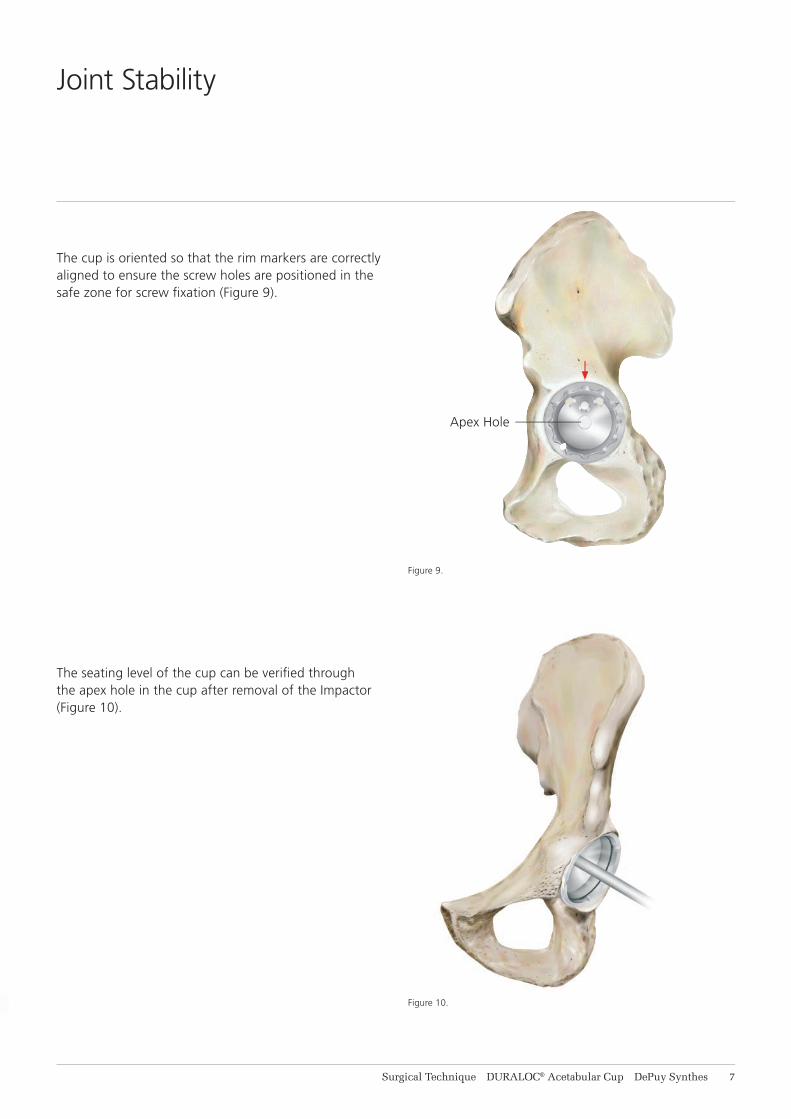
Figure 9.
Figure 10.
The cup is oriented so that the rim markers are correctly aligned to ensure the screw holes are positioned in the safe zone for screw fixation (Figure 9).
The seating level of the cup can be verified through the apex hole in the cup after removal of the Impactor (Figure 10).
Apex Hole
Joint Stability
Surgical Technique DURALOC® Acetabular Cup DePuy Synthes 7

Figure 11. DURALOC Liner
Figure 12.
A trial liner is inserted and the femoral side is prepared. After completion of the femoral side, the screw-in trial liner can be used to assess joint stability and range of motion.
If the hip shows a tendency to dislocate, an angled or hooded trial liner can be chosen to provide additional coverage of the head. The optimum position of the hood may be marked with diathermy on the rim of the acetabulum for later reference. The trial liner is removed and the apex hole may be closed using an apex hole plug. Soft tissues at the acetabular rim may hamper the locking mechanism and should be removed.
If an angled or hooded liner is used, it should be positioned so that it corresponds with the mark made on the rim during trial reduction. The insert is seated using firm hand pressure only.
Final impaction into the shell is completed using the polyethylene headed liner impactor, until the liner locks into place (Figures 11).
Before the polyethylene liner is inserted, the locking ring (packaged with the shell) is introduced to the locking ring groove in the shell. Starting with one end of the ring, each bend is introduced progressively until the ring is fully seated in the groove (Figure 12).
The definitive polyethylene liner is inserted in the same position as the trial liner (Figures 11).
Trial Sizing and Impaction of the Polyethylene Liner
8 DePuy Synthes DURALOC® Acetabular Cup Surgical Technique

Figure 13.
If required, the polyethylene liner can be removed using the polyethylene liner extractor.
The blunt jaw is located on the rim of the shell while the ‘claw’ jaw is used to bite into the liner, breaking the seal and allowing extraction to be completed (Figure 13).
Warning: An extracted liner should not be re-used.
Polyethylene Liner Extraction
Surgical Technique DURALOC® Acetabular Cup DePuy Synthes 9
Introduction
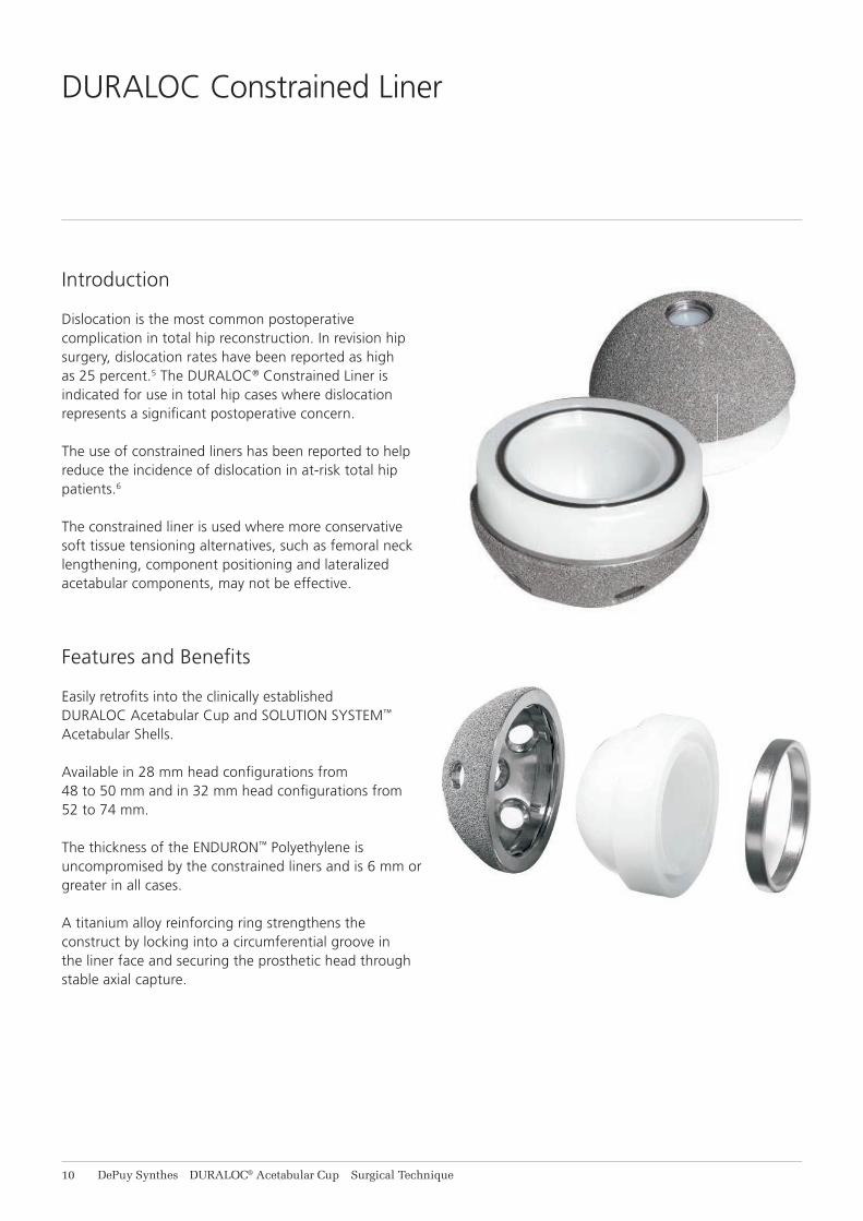
Dislocation is the most common postoperative complication in total hip reconstruction. In revision hip surgery, dislocation rates have been reported as high as 25 percent.5 The DURALOC® Constrained Liner is indicated for use in total hip cases where dislocation represents a significant postoperative concern.
The use of constrained liners has been reported to help reduce the incidence of dislocation in at-risk total hip patients.6
The constrained liner is used where more conservative soft tissue tensioning alternatives, such as femoral neck lengthening, component positioning and lateralized acetabular components, may not be effective.
Features and Benefits
Easily retrofits into the clinically established DURALOC Acetabular Cup and SOLUTION SYSTEM™ Acetabular Shells.
Available in 28 mm head configurations from 48 to 50 mm and in 32 mm head configurations from 52 to 74 mm.
The thickness of the ENDURON™ Polyethylene is uncompromised by the constrained liners and is 6 mm or greater in all cases.
A titanium alloy reinforcing ring strengthens the construct by locking into a circumferential groove in the liner face and securing the prosthetic head through stable axial capture.
DURALOC Constrained Liner
10 DePuy Synthes DURALOC® Acetabular Cup Surgical Technique

Step 1
Implant Acetabular Shell
After reaming, place the appropriate trial shell in the acetabulum at the desired anteversion and inclination. Select a nonconstrained standard trial liner insert and complete trial reduction. If necessary, adjust the trial shell to establish the most favorable orientation, joint stability and functional range of motion. Implant the appropriate acetabular shell in a position that accurately reproduces the trial shell position.
Step 2Adjunctive Fixation
If desired, secure the implanted shell with screw fixation.An additional trial reduction with a nonconstrained standard trial liner insert and trial head may be performed to confirm shell position.
Step 3Replace Dynamic Locking Ring
If the DURALOC Constrained Liner is being retrofit into a DURALOC Acetabular Cup or SOLUTION SYSTEM™ Shell, insert a new dynamic locking ring into the acetabular component.
Surgical Technique
Surgical Technique DURALOC® Acetabular Cup DePuy Synthes 11

Step 4Insert Constrained Liner into Shell
Select the appropriate DURALOC Constrained Liner and place it into the acetabular shell (28 mm IDs are available for 48 and 50 mm shells, 32 mm IDs should be used with shells that are size 52 mm and larger whenever femoral head size permits). The use of a 22 mm DURALOC Acetabular Cup impaction device is recommended to impact the liner into position. Once the constrained liner is in place, do not perform trial reduction. Due to the liner constraining mechanism, the trial head will be very difficult to remove from the constrained liner.
Step 5Reinforcement Ring Placed Around Femoral Component Neck
Place the constrained liner reinforcement ring over the head and neck of the femoral prosthesis. Both edges of the constraining ring are bevelled to ease ring placement.
Skirted femoral heads are contraindicated for use with constrained liners.
Step 6Insert Femoral Head into Constrained LinerThe initial reduction of the head into the constrained liner requires some force but is usually straightforward. However after this initial reduction a further reduction is required to fully seat the head within the liner. The best method of doing this is for the surgeon and their assistant to apply a sharp compressive force over the greater trochanter perpendicular to the femoral neck. This may result in a palpable click or clunk as the head fully seats.
Surgical Technique
11 DePuy Synthes DURALOC® Acetabular Cup Surgical Technique

Step 7Insertion of Reinforcement Ring
Ensure that both the inside of the reinforcement ring and the circular constrained liner reinforcement ring groove are free of debris. Using the appropriate size (28 or 32 mm) DURALOC Constrained Liner ring inserter, place the grooves of the inserter on the reinforcement ring. Gently impact the strike plate of the inserter until the inserter is in contact with the constrained liner. The reinforcement ring will remain slightly proud from the constrained liner.
If the reinforcement ring cannot be assembled ensure that the femoral head is fully seated (as per Step 6 in this ST).
Step 8
Final Seating of Reinforcement Ring
Use the bone tamp to perform the final seating of the reinforcement ring by tapping around the circumference of the ring until the ring is flush with the surface of the liner face.
Surgical Technique
Surgical Technique DURALOC® Acetabular Cup DePuy Synthes 13

Ordering Information
Bantam Cups (38 - 46 mm)1245-38-503 DURALOC Bantam Cup 38 mm1245-40-503 DURALOC Bantam Cup 40 mm1245-42-503 DURALOC Bantam Cup 42 mm1245-44-503 DURALOC Bantam Cup 44 mm1245-46-503 DURALOC Bantam Cup 46 mm
Bantam ENDURON™ 10° Liners 22.225 mm (38 - 46 mm)1241-38-526 DURALOC ENDURON 10˚ Liner 22.225 mm x 38 mm1241-40-526 DURALOC ENDURON 10˚ Liner 22.225 mm x 40 mm1241-42-526 DURALOC ENDURON 10˚ Liner 22.225 mm x 42 mm1241-44-526 DURALOC ENDURON 10˚ Liner 22.225 mm x 44 mm1241-46-526 DURALOC ENDURON 10˚ Liner 22.225 mm x 46 mm
Sector Cups (48 - 66 mm)1245-80-055 DURALOC Sector Cup 48 mm1245-80-056 DURALOC Sector Cup 50 mm1245-80-049 DURALOC Sector Cup 52 mm1245-80-050 DURALOC Sector Cup 54 mm1245-80-051 DURALOC Sector Cup 56 mm1245-80-052 DURALOC Sector Cup 58 mm1245-80-053 DURALOC Sector Cup 60 mm1245-80-054 DURALOC Sector Cup 62 mm1245-80-057 DURALOC Sector Cup 64 mm1245-80-058 DURALOC Sector Cup 66 mm
MARATHON® 0°Liners 28 mm (48 - 66 mm)1220-28-048 DURALOC MARATHON 0° Liner 28 mm x 48 mm1220-28-050 DURALOC MARATHON 0° Liner 28 mm x 50 mm1220-28-052 DURALOC MARATHON 0° Liner 28 mm x 52 mm1220-28-054 DURALOC MARATHON 0° Liner 28 mm x 54 mm1220-28-056 DURALOC MARATHON 0° Liner 28 mm x 56 mm OR 68 mm1220-28-058 DURALOC MARATHON 0° Liner 28 mm x 58 mm OR 70 mm1220-28-060 DURALOC MARATHON 0° Liner 28 mm x 60 mm OR 72 mm1220-28-062 DURALOC MARATHON 0° Liner 28 mm x 62 mm OR 74 mm1220-28-064 DURALOC MARATHON 0° Liner 28 mm x 64 mm1220-28-066 DURALOC MARATHON 0° Liner 28 mm x 66 mm
14 DePuy Synthes DURALOC® Acetabular Cup Surgical Technique

MARATHON 10° Liners 28 mm (48 - 66 mm)1220-28-148 DURALOC MARATHON 10° Liner 28 mm x 48 mm1220-28-150 DURALOC MARATHON 10° Liner 28 mm x 50 mm1220-28-152 DURALOC MARATHON 10° Liner 28 mm x 52 mm1220-28-154 DURALOC MARATHON 10° Liner 28 mm x 54 mm1220-28-156 DURALOC MARATHON 10° Liner 28 mm x 56 mm OR 68 mm1220-28-158 DURALOC MARATHON 10° Liner 28 mm x 58 mm OR 70 mm1220-28-160 DURALOC MARATHON 10° Liner 28 mm x 60 mm OR 72 mm1220-28-162 DURALOC MARATHON 10° Liner 28 mm x 62 mm OR 74 mm1220-28-164 DURALOC MARATHON 10° Liner 28 mm x 64 mm1220-28-166 DURALOC MARATHON 10° Liner 28 mm x 66 mm
MARATHON 0° Neutral Liners 32 mm (52 - 66 mm)1220-32-052 DURALOC MARATHON 0° Liner 32 mm x 52 mm1220-32-054 DURALOC MARATHON 0° Liner 32 mm x 54 mm1220-32-056 DURALOC MARATHON 0° Liner 32 mm x 56 mm OR 68 mm1220-32-058 DURALOC MARATHON 0° Liner 32 mm x 58 mm OR 70 mm1220-32-060 DURALOC MARATHON 0° Liner 32 mm x 60 mm OR 72 mm1220-32-062 DURALOC MARATHON 0° Liner 32 mm x 62 mm OR 74 mm1220-32-064 DURALOC MARATHON 0° Liner 32 mm x 64 mm1220-32-066 DURALOC MARATHON 0° Liner 32 mm x 66 mm
MARATHON 10° Liners 32 mm (52 - 66 mm)1220-32-152 DURALOC MARATHON 10° Liner 32 mm x 52 mm1220-32-154 DURALOC MARATHON 10° Liner 32 mm x 54 mm1220-32-156 DURALOC MARATHON 10° Liner 32 mm x 56 mm OR 68 mm1220-32-158 DURALOC MARATHON 10° Liner 32 mm x 58 mm OR 70 mm1220-32-160 DURALOC MARATHON 10° Liner 32 mm x 60 mm OR 72 mm1220-32-162 DURALOC MARATHON 10° Liner 32 mm x 62 mm OR 74 mm1220-32-164 DURALOC MARATHON 10° Liner 32 mm x 64 mm1220-32-166 DURALOC MARATHON 10° Liner 32 mm x 66 mm
Constrained ENDURON 0° Liners 28 mm (48 - 66 mm)1241-08-527 DURALOC ENDURON 0° Liner 28 mm x 48 mm1241-10-527 DURALOC ENDURON 0° Liner 28 mm x 50 mm1241-12-527 DURALOC ENDURON 0° Liner 28 mm x 52 mm1241-14-527 DURALOC ENDURON 0° Liner 28 mm x 54 mm1241-16-527 DURALOC ENDURON 0° Liner 28 mm x 56 mm OR 68 mm1241-18-527 DURALOC ENDURON 0° Liner 28 mm x 58 mm OR 70 mm1241-20-527 DURALOC ENDURON 0° Liner 28 mm x 60 mm OR 72 mm1241-22-527 DURALOC ENDURON 0° Liner 28 mm x 62 mm OR 74 mm1241-24-527 DURALOC ENDURON 0° Liner 28 mm x 64 mm1241-26-527 DURALOC ENDURON 0° Liner 28 mm x 66 mm
Surgical Technique DURALOC® Acetabular Cup DePuy Synthes 15

Constrained ENDURON 0° Liners 32 mm (52 - 66 mm)1242-12-527 DURALOC ENDURON 0° Liner 32 mm x 52 mm1242-14-527 DURALOC ENDURON 0° Liner 32 mm x 54 mm1242-16-527 DURALOC ENDURON 0° Liner 32 mm x 56 mm OR 68 mm1242-18-527 DURALOC ENDURON 0° Liner 32 mm x 58 mm OR 70 mm1242-20-527 DURALOC ENDURON 0° Liner 32 mm x 60 mm OR 72 mm1242-22-527 DURALOC ENDURON 0° Liner 32 mm x 62 mm OR 74 mm1242-24-527 DURALOC ENDURON 0° Liner 32 mm x 64 mm1242-26-527 DURALOC ENDURON 0° Liner 32 mm x 66 mm
Apex Hole Eliminator1246-03-000 Apex Hole Eliminator
Cancellous Bone Screws1172-20-000 Cancellous Bone Screw 6.5 mm x 20 mm1172-30-000 Cancellous Bone Screw 6.5 mm x 30 mm1172-40-000 Cancellous Bone Screw 6.5 mm x 40 mm1172-50-000 Cancellous Bone Screw 6.5 mm x 50 mm
Dynamic Locking Rings1249-38-503 Dynamic Locking Ring 38 mm1249-40-503 Dynamic Locking Ring 40 mm1249-42-503 Dynamic Locking Ring 42 mm1249-44-503 Dynamic Locking Ring 44 mm1249-46-503 Dynamic Locking Ring 46 mm1249-48-000 Dynamic Locking Ring 48 mm1249-50-000 Dynamic Locking Ring 50 mm1249-52-000 Dynamic Locking Ring 52 mm1249-54-000 Dynamic Locking Ring 54 mm1249-56-000 Dynamic Locking Ring 56/68 mm1249-58-000 Dynamic Locking Ring 58/70 mm1249-60-000 Dynamic Locking Ring 60/72 mm1249-62-000 Dynamic Locking Ring 62/74 mm1249-64-000 Dynamic Locking Ring 64 mm1249-66-000 Dynamic Locking Ring 66 mm
+ Associated Instruments
11 DePuy Synthes DURALOC® Acetabular Cup Surgical Technique


Johnson & Johnson Medical Limited PO BOX 1988, Simpson Parkway, Livingston, West Lothian, EH54 0AB, United Kingdom.Incorporated and registered in Scotland under company number SC132162.
depuysynthes.com
0086
DePuy (Ireland)LoughbegRingaskiddyCo. CorkIrelandTel: +353 21 4914 000 Fax: +353 21 4914 199
DePuy Orthopaedics, Inc. 700 Orthopaedic DriveWarsaw, IN 46582USATel: +1 (800) 366 8143Fax: +1 (800) 669 2530
DePuy International LtdSt Anthony’s RoadLeeds LS11 8DTEnglandTel: +44 (0)113 270 0461
The third party trademarks used herein are the trademarks of their respective owners. This publication is not intended for distribution in the USA.
© DePuy Synthes Joint Reconstruction, a division of Johnson & Johnson Medical Limited. 2018. All rights reserved.
DSEM/JRC/0615/0317(2) 03/18
References
1. Udomkiat P, Dorr LD, Wan Z. Cementless hemispheric porous-coated sockets implanted with press-fit technique without screws: average ten-year follow-up. J Bone Joint Surg. 2002;84A:1195-200.
2. Schmalzried TP, Guttmann D, Grecula M, Amstutz H. The relationship between the design, position, and articular wear of acetabular components inserted without cement and the development of pelvic osteolysis. J Bone Joint Surg. 1994;76A:677-688.
3. Kennedy JG, Rogers WB, Soffee KE, et al. Effect of acetabular component orientation on recurrent dislocation, pelvic osteolysis, polyethylene wear and component migration. J Arthroplasty 1998;13:530-534.
4. Tower SS, Currier JH, Currier BH, Lyford KA, Van Citters DW, Mayor MB. Rim cracking of the cross-linked longevity polyethylene acetabular liner after total hip arthroplasty. J Bone Joint Surg Am. 2007 Oct;89(10):2212-7.
5. Olerud, S. and G. Karlstrom.“Recurrent Dislocation After Total Hip Replacement.” Journal of Bone and Joint Surgery Mar. 1985: 402-405.
6. Lombardi Jr., A.V., et al. “Preliminary Report on the S-ROM Constraining Acetabular Insert: A Retrospective Clinical Experience.” Orthopedics Mar. 1991: 297-303.