kicksynthes.vo.llnwd.net/o16/llnwmb8/int mobile/synthes... · 2017-05-08 · 1.2 symbols warnings...
TRANSCRIPT

KICKVersion 1.2
SYSTEM USER GUIDE
REVISION 1.0
Copyright 2015, Brainlab AG Germany. All rights reserved.


TABLE OF CONTENTS
GENERAL INFORMATION ...................................................................................................7
Contact Data and Legal Information ......................................................................................................7
Legal Information .........................................................................................................................................9
Symbols .....................................................................................................................................................10
Hardware Symbols.....................................................................................................................................11
Intended Use .............................................................................................................................................14
Compatibility with Medical Devices .....................................................................................................16
Training and Documentation .................................................................................................................17
Documentation...........................................................................................................................................18
SYSTEM OVERVIEW ..............................................................................................................19
System Components ...............................................................................................................................19
System Setup ............................................................................................................................................21
Kick System ...............................................................................................................................................22
OR Setups .................................................................................................................................................23
Proper System Handling ........................................................................................................................24
Inspections ................................................................................................................................................27
Weekly and Monthly Inspections ................................................................................................................28
Annual Electrical Safety Inspection ............................................................................................................29
Malfunctions and Return Instructions.................................................................................................30
Return Instructions.....................................................................................................................................31
MONITOR CART..........................................................................................................................33
Components..............................................................................................................................................33
Monitor .......................................................................................................................................................35
Range of Motion.........................................................................................................................................37
Moving Parts ..............................................................................................................................................38
Monitor Cart Ventilation..........................................................................................................................39
3rd-Party Connections ............................................................................................................................40
Back Panel Connections ............................................................................................................................42
Cabling .......................................................................................................................................................43
Cable Storage ............................................................................................................................................46
TABLE OF CONTENTS
Kick Ver. 1.2 / System User Guide Rev. 1.0 / DePuy Synthes 3
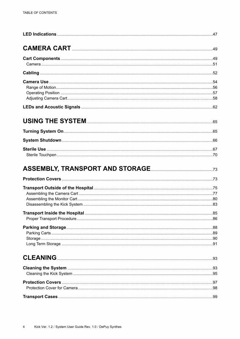
LED Indications ........................................................................................................................................47
CAMERA CART ...........................................................................................................................49
Cart Components .....................................................................................................................................49
Camera ......................................................................................................................................................51
Cabling .......................................................................................................................................................52
Camera Use ...............................................................................................................................................54
Range of Motion.........................................................................................................................................56
Operating Position .....................................................................................................................................57
Adjusting Camera Cart...............................................................................................................................58
LEDs and Acoustic Signals ...................................................................................................................62
USING THE SYSTEM ..............................................................................................................65
Turning System On ..................................................................................................................................65
System Shutdown ....................................................................................................................................66
Sterile Use .................................................................................................................................................67
Sterile Touchpen ........................................................................................................................................70
ASSEMBLY, TRANSPORT AND STORAGE ......................................................73
Protection Covers ....................................................................................................................................73
Transport Outside of the Hospital ........................................................................................................75
Assembling the Camera Cart .....................................................................................................................77
Assembling the Monitor Cart ......................................................................................................................80
Disassembling the Kick System .................................................................................................................83
Transport Inside the Hospital ................................................................................................................85
Proper Transport Procedure.......................................................................................................................86
Parking and Storage................................................................................................................................88
Parking Carts .............................................................................................................................................89
Storage ......................................................................................................................................................90
Long Term Storage ....................................................................................................................................91
CLEANING ........................................................................................................................................93
Cleaning the System ...............................................................................................................................93
Cleaning the Kick System ..........................................................................................................................95
Protection Covers ....................................................................................................................................97
Protection Cover for Camera......................................................................................................................98
Transport Cases .......................................................................................................................................99
TABLE OF CONTENTS
4 Kick Ver. 1.2 / System User Guide Rev. 1.0 / DePuy Synthes

INDEX ..................................................................................................................................................101
TABLE OF CONTENTS
Kick Ver. 1.2 / System User Guide Rev. 1.0 / DePuy Synthes 5

TABLE OF CONTENTS
6 Kick Ver. 1.2 / System User Guide Rev. 1.0 / DePuy Synthes
1 GENERAL INFORMATION
1.1 Contact Data and Legal Information
Manufacturer
This product is manufactured by Brainlab and exclusively distributed by DePuy Synthes.
Brainlab AG
Kapellenstr. 12
85622 Feldkirchen
Germany
Distributor
DePuy Synthes Sales, Inc.
325 Paramount Drive
Raynham, MA 02767
USA
Support
If you cannot find information you need in this guide, or if you have questions or problems, contact
support:
Region Telephone and Fax
United States, Canada, Central and South Ameri-
caTel: +1 (866) 473 7823
Europe, Middle East, Africa Tel: +32 2 352 16 66
Asia, Australia Tel: +65 6827 6154
Support and service of the system may be done either by Brainlab service and support personnel
or personnel of third parties certified or authorized by Brainlab. Within this manual, both
possibilities are included when Brainlab support or service is mentioned.
Expected Service Life
Brainlab provides a minimum of eight years of service for platforms. During this period of time,
spare parts as well as field support are offered.
The Kick system lifetime is dependent on factors such as method and duration of each use, and
handling between uses. Careful functional testing and inspection of the Kick system before use is
the best method for determining the end of lifetime.
The end of lifetime is normally determined by wear and tear damage due to use. As part of
preventive service, follow the maintenance instructions.
GENERAL INFORMATION
Kick Ver. 1.2 / System User Guide Rev. 1.0 / DePuy Synthes 7
Feedback
Despite careful review, this manual may contain errors.
Please contact us at [email protected] if you have suggestions as to how we can
improve this manual.
Contact Data and Legal Information
8 Kick Ver. 1.2 / System User Guide Rev. 1.0 / DePuy Synthes
1.1.1 Legal Information
Copyright
This guide contains proprietary information protected by copyright. No part of this guide may be
reproduced or translated without express written permission of Brainlab.
Brainlab Trademarks
• Kick® is a trademark of Brainlab AG in Germany and/or the US.
CE Label
• The CE label shows that the Brainlab product complies with the essential re-
quirements of Council Directive 93/42/EEC (the "MDD").
• According to the principles set out in the MDD, Kick is a Class IIb product.
NOTE: The validity of the CE label can only be confirmed for products manufactured by Brainlab.
Disposal Instructions
Only dispose of electrical and electronic equipment in accordance with statutory regu-
lations. For information regarding the WEEE (Waste Electrical and Electronic Equip-
ment) directive, visit:
http://www.brainlab.com/weee
For more information or recycling instructions, please contact Brainlab.
Sales in the US
US federal law restricts this device to sale by or on the order of a physician.
Federal Communications Commission (FCC) Statement
This equipment has been tested and found to comply with the limits for a Class A digital device,
pursuant to part 15 of the FCC Rules. These limits are designed to provide reasonable protection
against harmful interference when the equipment is operated in a commercial environment. This
equipment generates, uses, and can radiate radio frequency energy and, if not installed and used
in accordance with the instruction manual, may cause harmful interference to radio
communications. Operation of this equipment in a residential area is likely to cause harmful
interference in which case the user will be required to correct the interference at their expense.
Any changes or modifications not expressly approved by the party responsible for
compliance could void the user’s authority to operate this equipment.
This device complies with part 15 of the FCC Rules. Operation is subject to the following two
conditions: (1) This device may not cause harmful interference, and (2) this device must accept
any interference received, including interference that may cause undesired operation.
The WLAN module included in this product cannot be accessed by end users. The FCC ID of the
WLAN module is listed on the WLAN label attached to the Monitor Cart. Please contact Brainlab
Support in case of any related questions.
GENERAL INFORMATION
Kick Ver. 1.2 / System User Guide Rev. 1.0 / DePuy Synthes 9
1.2 Symbols
Warnings
Warnings are indicated by triangular warning symbols. They contain safety-critical
information regarding possible injury, death or other serious consequences associated
with equipment misuse.
Cautions
Cautions are indicated by circular caution symbols. They contain safety-critical information
regarding possible problems with the device. Such problems include device malfunctions,
device failure, damage to device or damage to property.
Notes
NOTE: Notes are formatted in italic type and indicate additional useful hints.
Symbols
10 Kick Ver. 1.2 / System User Guide Rev. 1.0 / DePuy Synthes
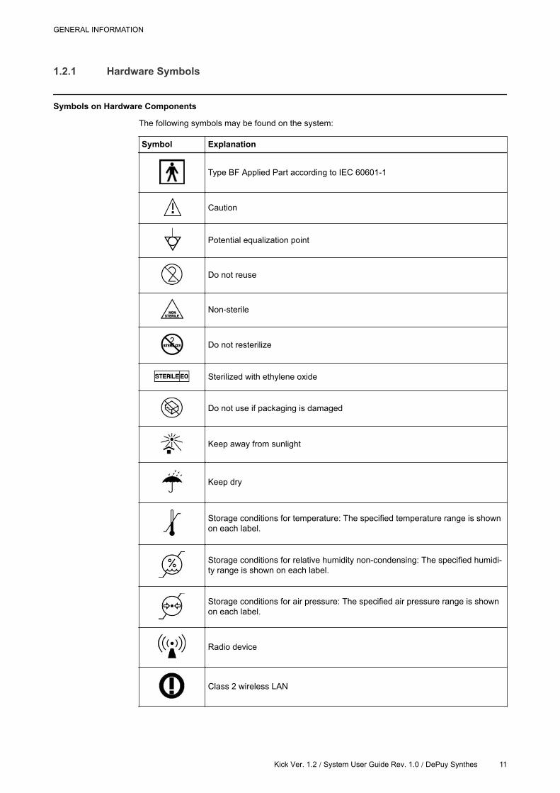
1.2.1 Hardware Symbols
Symbols on Hardware Components
The following symbols may be found on the system:
Symbol Explanation
Type BF Applied Part according to IEC 60601-1
Caution
Potential equalization point
Do not reuse
Non-sterile
Do not resterilize
Sterilized with ethylene oxide
Do not use if packaging is damaged
Keep away from sunlight
Keep dry
Storage conditions for temperature: The specified temperature range is shown
on each label.
Storage conditions for relative humidity non-condensing: The specified humidi-
ty range is shown on each label.
Storage conditions for air pressure: The specified air pressure range is shown
on each label.
Radio device
Class 2 wireless LAN
GENERAL INFORMATION
Kick Ver. 1.2 / System User Guide Rev. 1.0 / DePuy Synthes 11
Symbol Explanation
Quantity of products in packaging
Batch number
Serial Number
Article number
Use by month YYYY
Date of manufacture
Manufacturer
Authorized representative in the European Community
IPXY
Ingress Protection according to IEC 60529
• X = Protection against ingress of solid objects
• Y = Protection against ingress of liquid
Strong magnetic field
Danger of clamping hand or other body parts in equipment
Do not look directly into the laser beam or point laser beam into the patient’s
face or eyes
Laser radiation emitted from aperture
Do not stare into beam
Class 2 laser product
max. output 1mW wavelength 635 nm
Danger of tilting: Do not move system when brakes are locked or if device is
blocked by obstacles
Standby switch to bring the device into standby mode.
Consult the operating instructions
Symbols
12 Kick Ver. 1.2 / System User Guide Rev. 1.0 / DePuy Synthes

Symbol Explanation
Consult accompanying documentation
GENERAL INFORMATION
Kick Ver. 1.2 / System User Guide Rev. 1.0 / DePuy Synthes 13
1.3 Intended Use
Intended System Use
The Kick system is a navigation platform used for Image Guided Surgery (IGS) incorporating:
• A tracking system
• A computer unit that runs the software
• A display unit to display the navigation, including touch functionality for the user to interact with
the software.
Place of Use
The system is only for use indoors, in a hospital operating room.
Frequency of Use
The frequency of use is defined to be between once per month and several times per week.
Patient Population
The patient population consists of patients that could be treated via Brainlab application software
that are released for this Image Guided Surgery (IGS) device.
For details refer to the relevant Software User Guide.
Intended User Profile
The following describes the intended users of the system and their respective tasks:
• Trained hospital personnel (e.g., nurses) are responsible for setting up the system before the
surgical procedure and for removing the system after the surgical procedure.
- System setup and removal includes: moving and positioning, plugging cables in/out, startup/
shutdown, cleaning of the system, connecting/disconnecting 3rd party devices.
• Sterile nurse is responsible for maintaining sterility during surgery, including the draping of
devices.
• Surgeons and/or surgical assistants steer and interact with the Brainlab software running on
the system using the system touchscreen. For detailed information on use of the software, see
the relevant Software User Guide.
• Brainlab authorized personnel are responsible for system maintenance and support.
Essential Performance
As essential performance is defined by the clinical function(s), it is dependent on the Brainlab
application used and the clinical procedure. Consult the corresponding Software User Guide to
see if an essential performance is defined, and if so, which essential performance.
Careful Hardware Handling
Only trained medical personnel may operate system components and accessory
instrumentation.
System components and accessory instrumentation comprise precise mechanical parts.
Handle them carefully.
Intended Use
14 Kick Ver. 1.2 / System User Guide Rev. 1.0 / DePuy Synthes
Plausibility Review
Before patient treatment, review the plausibility of all information input to and output from
the system.
GENERAL INFORMATION
Kick Ver. 1.2 / System User Guide Rev. 1.0 / DePuy Synthes 15
1.4 Compatibility with Medical Devices
Brainlab Medical Instruments
Compatible Brainlab Medical Instruments
Kick is compatible with:
• Kick Monitor Drape
• Sterile Touchpen
Other Brainlab Instruments
Additional instrumentation may become available after release of this manual. Contact Brainlab or
Brainlab authorized support if you have any questions regarding instrument compatibility with
Brainlab software.
Only use instruments and spare parts specified by Brainlab. Using unauthorized
instruments/spare parts may adversely affect safety and/or effectiveness of the medical
device and endanger safety of patient, user and/or environment.
Compatibility with Medical Devices
16 Kick Ver. 1.2 / System User Guide Rev. 1.0 / DePuy Synthes
1.5 Training and Documentation
Brainlab Training
To ensure safe and appropriate use, before using the system all users should participate in a
training program held by a Brainlab authorized representative.
Supervised Support
Before using the system for surgical procedures where computer-aided navigation is considered
critical, perform a sufficient number of complete procedures with a Brainlab authorized
representative present to provide guidance where necessary.
Responsibility
This system solely provides assistance to the surgeon and does not substitute or replace
the surgeon’s experience and/or responsibility during its use.
GENERAL INFORMATION
Kick Ver. 1.2 / System User Guide Rev. 1.0 / DePuy Synthes 17
1.5.1 Documentation
Intended Audience
This user guide is intended for surgeons and hospital staff.
Relevant System Configurations
The information in this guide is relevant for the system configurations below:
System Configuration Art.-No. Device Art.-No.
Kick Navigation Station 18080Monitor Cart 18081
Camera Cart 18082
NOTE: All device article numbers are listed on the system plates on the back side of the Monitor
Cart.
Reading User Guides
User guides describe complex medical devices and surgical navigation software that must be
used with care.
It is important that all users of system, instruments and software:
• Read the user guides carefully before handling the equipment
• Have access to the user guides at all times
Disregarding information in the user guides, in particular the disregard of warning and cautions, is
considered to be abnormal use.
Available User Guides
User Guide Contents
Software User Guides
• Overview of treatment planning and image-guided navigation
• Description of OR system setup
• Detailed software instructions
Instrument User Guides Detailed instructions on instrument handling
Cleaning, Disinfection and
Sterilization GuideDetails on cleaning, disinfecting and sterilizing instruments
System User Guides Comprehensive information on system setup
Technical User GuideDetailed technical information on the system, including specifica-
tions and compliances
NOTE: Available user guides vary depending on the Brainlab product. If you have questions
regarding the user guides you received, contact Brainlab authorized support.
Training and Documentation
18 Kick Ver. 1.2 / System User Guide Rev. 1.0 / DePuy Synthes
2 SYSTEM OVERVIEW
2.1 System Components
Kick System
Kick is a navigation platform used for Image Guided Surgery (IGS) incorporating:
• A tracking system (optical tracking see page 49)
• A computer unit that runs the software (see Technical User Guide)
• A display unit to display the navigation, including touch functionality for the user to interact with
the software (see page 33)
Kick provides a touchscreen and buttons for user interaction. Additionally, the system offers
several PC interfaces for connecting video sources, data transfer devices, network integration, or
other 3rd-party devices.
The camera can be adjusted in height by usage of the telescopic post and further in rotation
around vertical and horizontal axis to achieve a good tracking position.
The monitor can be declined to receive a good viewing angle for the user. For sterile use, the Kick
Monitor Drape shall be used or the Sterile Touchpen.
Optical Tracking
Optical tracking is achieved by a camera unit that emits and detects flashes of infrared light.
• Reflective elements, affixed to reference arrays on the patient and to instrumentation, reflect
the infrared signals back to the camera unit.
• Reflected signals from the reflective elements are captured and digitized by each camera lens
from a different angle.
• Brainlab software applications use the camera input to calculate the relative three-dimensional
positions of the instruments and the patient reference arrays.
SYSTEM OVERVIEW
Kick Ver. 1.2 / System User Guide Rev. 1.0 / DePuy Synthes 19
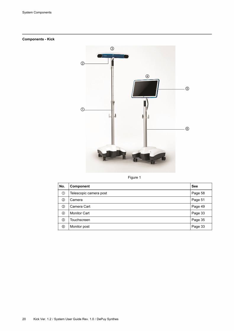
Components - Kick
Figure 1
No. Component See
Telescopic camera post Page 58
Camera Page 51
Camera Cart Page 49
Monitor Cart Page 33
Touchscreen Page 35
Monitor post Page 33
System Components
20 Kick Ver. 1.2 / System User Guide Rev. 1.0 / DePuy Synthes
2.2 System Setup
System Position
Ensure that the system is set up so it is not possible for the patient to touch or come in
contact with the equipment.
Ensure that the system is set up in a way that the mains power plug is easily accessible. In
case of malfunction, you must be able to easily unplug the mains power cable.
Sterile Field
The Kick systems are unsterile. If draped, the Monitor Cart may be used within the patient
environment (see page 67).
Do not allow any system parts to enter the sterile field.
Electromagnetic Compatibility
Special precautions regarding electromagnetic compatibility (EMC) must be installed and put into
service according to the EMC information provided in this guide and the Technical User Guide.
For EMC reasons, do not use system components adjacent to or stacked on other
equipment. If it is unavoidable, verify that the Kick system operates normally.
SYSTEM OVERVIEW
Kick Ver. 1.2 / System User Guide Rev. 1.0 / DePuy Synthes 21
2.2.1 Kick System
General Information
Monitor Cart and Camera Cart are delivered pre-installed and ready for use.
All system components are suitable for continuous use during surgical procedures.
How to Safely Position the System
Steps See
1. Remove protection covers before entering the OR. Page 86
2. Move equipment into the OR. Page 86
3.
Position the system in the OR.
NOTE: Do not position the camera, monitor or any other part of the Kick
system directly over the patient.Page 23
4. Lock all brakes on the Monitor Cart and Camera Cart. Page 88
5. Move monitor into desired position. Page 37
6. Move camera into desired position. Page 58
7. Connect all cables at the connection panel. Page 34
Interference
If camera’s infrared light interferes with other devices, reposition these devices and/or the camera
so that the interference is resolved.
The camera’s infrared light may interfere with other IR-based OR equipment, such as
remote controls, pulse oximeters or IR-sensitive microscopes.
The system produces electromagnetic fields that may interfere with other sensitive
equipment, and can itself be disturbed by other electromagnetic fields.
MR Safety
The Kick system has not been tested in an MR environment.
System Setup
22 Kick Ver. 1.2 / System User Guide Rev. 1.0 / DePuy Synthes
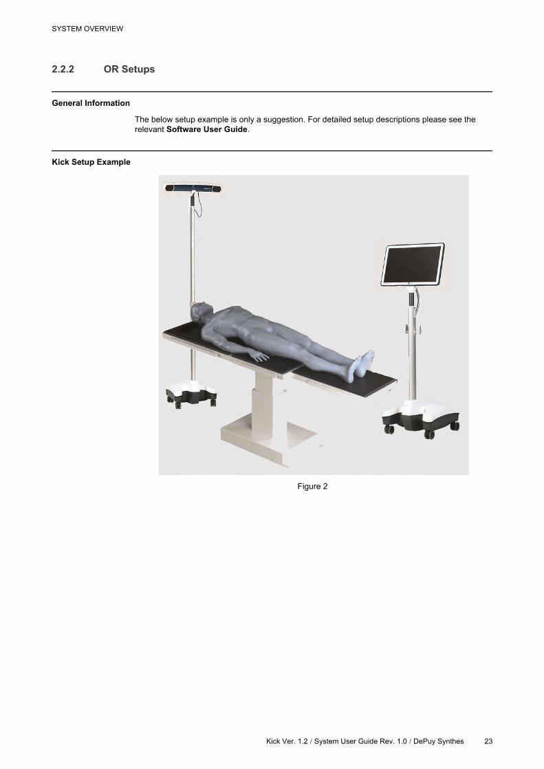
2.2.2 OR Setups
General Information
The below setup example is only a suggestion. For detailed setup descriptions please see the
relevant Software User Guide.
Kick Setup Example
Figure 2
SYSTEM OVERVIEW
Kick Ver. 1.2 / System User Guide Rev. 1.0 / DePuy Synthes 23
2.3 Proper System Handling
Classification - Monitor Cart and Camera Cart
The Monitor Cart and the Camera Cart are classified as Class I Equipment according to IEC
60601-1 and must be tested accordingly.
Classification Definition
Class I
Refers to equipment classification regarding protection against electric shock.
Protective means are provided for metallic accessible parts or metallic internal
parts, such as connection to PE (protective earth).
Proper Handling
Prior to surgery, perform a visual inspection of the system inside the OR. Ensure that
mains power cable is properly attached before starting the procedure. Do not use
equipment if you suspect that it is damaged in any way.
Prior to surgery, perform a functional test. Ensure that system boots correctly and patient
data is correctly loaded in the relevant navigation application.
Only individuals trained by Brainlab may use the system in a clinical environment.
Do not sit or stand on the carts. Do not lean against the carts as it creates a tilting hazard.
Patient Safety
System components should never come into direct physical contact with the patient.
Modification
Do not make any modifications to the Kick system. Only Brainlab certified personnel may modify
the system.
Only use the system components as delivered by Brainlab. Do not modify the system in
any way. Altering the system or using it outside of its intended use may result in severe
harm to the patient, user or third-party.
Risk of Electrical Shock
To prevent electrical shock or permanent system damage, do not expose the monitor,
tracking system or carts to excessive moisture.
Never touch the patient and any system parts or electrical interfaces at the same time, due
to possible electrostatic discharge.
Only connect the Monitor Cart to a mains power supply with protective earth. Failure to do
so may result in personal injury.
Proper System Handling
24 Kick Ver. 1.2 | System User Guide Rev. 1.0 / DePuy Synthes
Do not touch the electrical contacts of plugs.
Tracking Unit and Monitor
The tracking unit and monitor are highly precise and fragile electrical equipment. Handle
them carefully.
Appropriate Positioning
To avoid damage to the Kick system, other equipment or people, always move, park and
operate in the respective appropriate position.
The system may only be used on level surfaces.
Fully brake the Kick system during operation.
Do not place Camera Cart, Monitor Cart or any parts thereof over the patient.
Radio Interference
This equipment is intended for use by health care professionals only. It may cause radio
interference or may disrupt the operation of other nearby equipment. It may be necessary
to take mitigation measures, such as reorienting or relocating the device or shielding the
location.
Portable and mobile radio frequency communication may affect the equipment.
Other OR equipment may cause an interference with the Kick system, even if it is CISPR
emission compliant.
Restrictions to Environment
System components are not suitable for use in the presence of flammable anesthetic
mixtures containing air, oxygen or nitrous oxide.
Do not let liquids enter system components.
Do not place system components on unstable ground where the system could tip over and
be seriously damaged.
NOTE: For more information on the operating and storage environment restrictions, see the
Technical User Guide.
SYSTEM OVERVIEW
Kick Ver. 1.2 / System User Guide Rev. 1.0 / DePuy Synthes 25
Protection Covers
Keep protection covers in a clean and dry place during surgery.
Proper System Handling
26 Kick Ver. 1.2 / System User Guide Rev. 1.0 / DePuy Synthes
2.4 Inspections
Interval
A detailed inspection must be performed by Brainlab authorized support once a year.
See the Technical User Guide for detailed inspection information.
The Kick system should be maintained and inspected on a regular basis to ensure
functionality and safety.
Authorization
Only Brainlab and/or authorized partners are allowed to repair the system and equipment.
Risk of electrical shock: There are no user-serviceable parts in the Kick system. Do not
remove any covers. All servicing and maintenance is to be carried out by trained Brainlab
authorized technicians.
SYSTEM OVERVIEW
Kick Ver. 1.2 | System User Guide Rev. 1.0 / DePuy Synthes 27
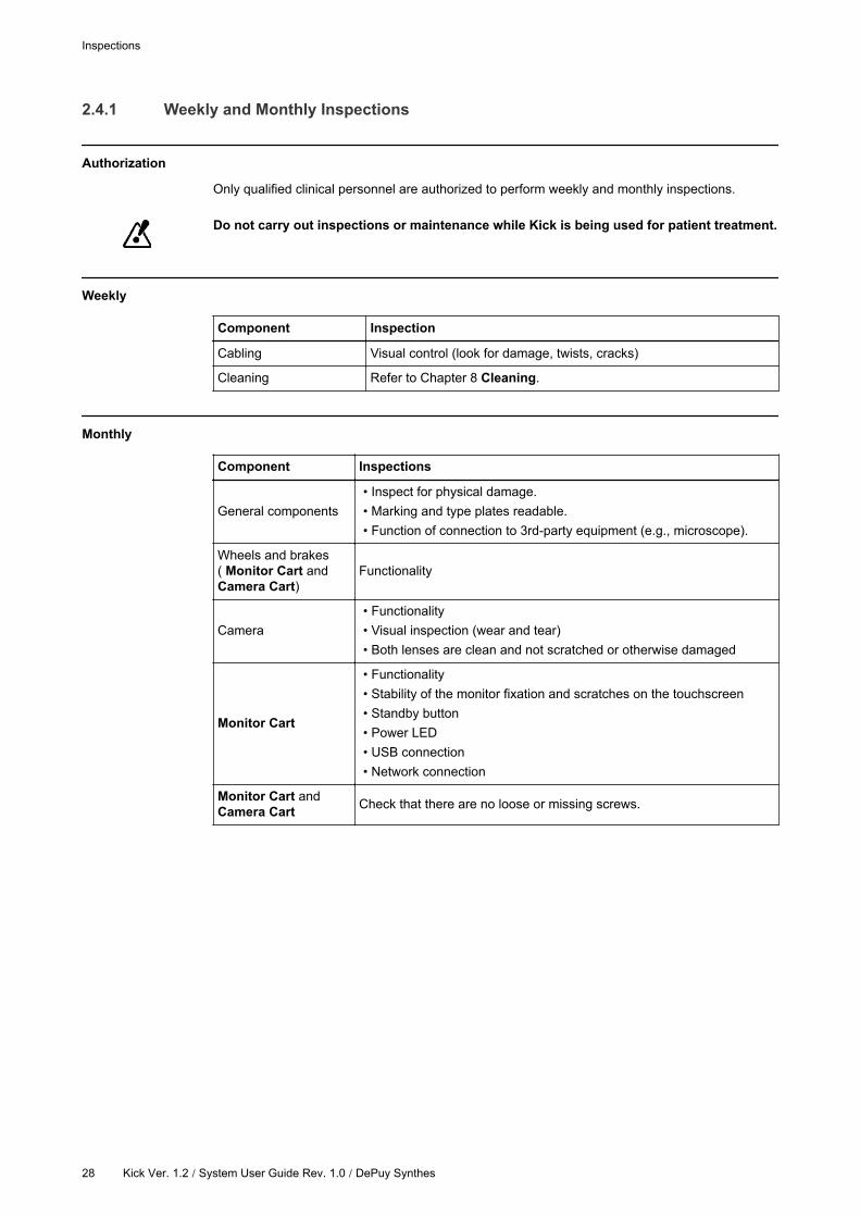
2.4.1 Weekly and Monthly Inspections
Authorization
Only qualified clinical personnel are authorized to perform weekly and monthly inspections.
Do not carry out inspections or maintenance while Kick is being used for patient treatment.
Weekly
Component Inspection
Cabling Visual control (look for damage, twists, cracks)
Cleaning Refer to Chapter 8 Cleaning.
Monthly
Component Inspections
General components
• Inspect for physical damage.
• Marking and type plates readable.
• Function of connection to 3rd-party equipment (e.g., microscope).
Wheels and brakes
( Monitor Cart and
Camera Cart)
Functionality
Camera
• Functionality
• Visual inspection (wear and tear)
• Both lenses are clean and not scratched or otherwise damaged
Monitor Cart
• Functionality
• Stability of the monitor fixation and scratches on the touchscreen
• Standby button
• Power LED
• USB connection
• Network connection
Monitor Cart and
Camera CartCheck that there are no loose or missing screws.
Inspections
28 Kick Ver. 1.2 / System User Guide Rev. 1.0 / DePuy Synthes
2.4.2 Annual Electrical Safety Inspection
Interval
An electrical safety inspection should be performed once a year.
Scope
An electrical safety inspection must include all items specified on the test report form.
See the Technical User Guide for detailed information on safety inspections.
Authorization
Only Brainlab authorized support or qualified engineers are authorized to perform annual
inspections.
Inspections by Non-Brainlab Personnel
Only trained and skilled personnel are allowed to perform electrical safety tests.
The test must be performed by a qualified engineer who:
• Is qualified to carry out safety inspections on electrical medical equipment.
• Is familiar with the product safety information and product instructions, and has read and
understood the user guides.
• Is up-to-date with current local regulations regarding industrial and non-industrial accident
prevention.
• Informs Brainlab immediately in writing if the equipment is deemed unsafe.
Inspections by Brainlab Personnel or Brainlab Authorized Personnel
• If a suitably qualified person is not available at the customer site, Brainlab authorized support
will perform this inspection for a set fee.
• Brainlab performs an inspection at the end of the warranty at no charge.
• If you require a Brainlab authorized support specialist, contact your local support representative
or distributor.
Arrangement
Service Contract Available Annual Inspection
YesAutomatically performed by Brainlab or Brainlab authorized
providers.
No Contact Brainlab authorized support for arrangement.
How to Use the Test Report Form
Steps
1. Copy the test report from the Technical User Guide.
2. Enter inspection results.
3. Keep it as a record of inspection.
SYSTEM OVERVIEW
Kick Ver. 1.2 / System User Guide Rev. 1.0 / DePuy Synthes 29
2.5 Malfunctions and Return Instructions
System Damage or Failure
Do not continue to use the system if:
• The mains power cable or plug is damaged or frayed
• Liquid has been spilled into the device
• The system does not operate normally when operating instructions are followed
• A cart has tipped over or cover has been damaged
• System components exhibit a distinct decrease in performance, indicating need for servicing
• Liquids leak from system
• System emits smoke
• The LEDs indicate an error
If a error message appears on the touchscreen or if the error LEDs are lit (see page 47
and page 62), contact Brainlab authorized support. Do not use the system.
How to Respond to Damage or Failure
Steps
1. Turn off system.
2. Unplug system from wall outlet.
3. Contact support.
4.Attach a notice such as “DO NOT USE” to equipment to prevent it from being used inad-
vertently.
If you continue to use equipment that has been found to be defective during an inspection,
you risk causing injury to the patient.
Malfunctions and Return Instructions
30 Kick Ver. 1.2 / System User Guide Rev. 1.0 / DePuy Synthes

2.5.1 Return Instructions
Reporting Damaged Equipment
Any defective components should be immediately reported to Brainlab authorized support (see
page 7).
Brainlab authorized support asks you for:
• Component article numbers (listed on the system plate on the back side of the monitor)
• Description of problem
Repair and Replacement
Brainlab authorized support:
• Provides you with cost estimate for repair or replacement
• Informs you when your system is expected to be operational again (usually within 48 hours)
Removing Components
Only remove defective components if instructed by Brainlab authorized support.
How to Return Components
Steps
1. Protect the component from further damage by wrapping it and safely packaging it.
2.Complete and return the form that was faxed to you or that accompanied replacement
part.
3. Securely tape the box shut.
4.Ship the defective component to relevant return address or follow instructions given by
Brainlab authorized support.
Return Addresses
Before returning the system inform your direct DePuy Synthes representative and inquire about
your local return address.
SYSTEM OVERVIEW
Kick Ver. 1.2 / System User Guide Rev. 1.0 | DePuy Synthes 31

Malfunctions and Return Instructions
32 Kick Ver. 1.2 / System User Guide Rev. 1.0 / DePuy Synthes
3 MONITOR CART
3.1 Components
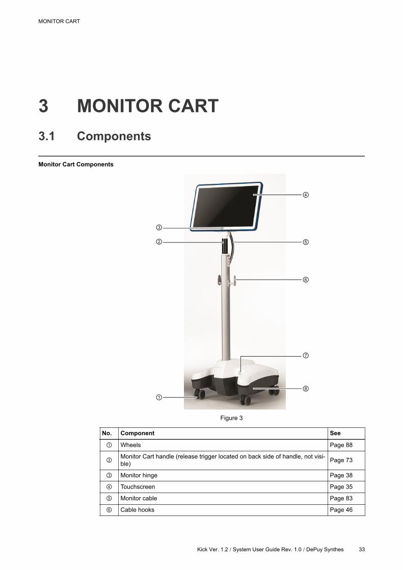
Monitor Cart Components
Figure 3
No. Component See
Wheels Page 88
Monitor Cart handle (release trigger located on back side of handle, not visi-
ble)Page 73
Monitor hinge Page 38
Touchscreen Page 35
Monitor cable Page 83
Cable hooks Page 46
MONITOR CART
Kick Ver. 1.2 / System User Guide Rev. 1.0 / DePuy Synthes 33
No. Component See
Standby button Page 65
Monitor Cart base, containing:
• Medical computer unit
• Connection panel
Page 34
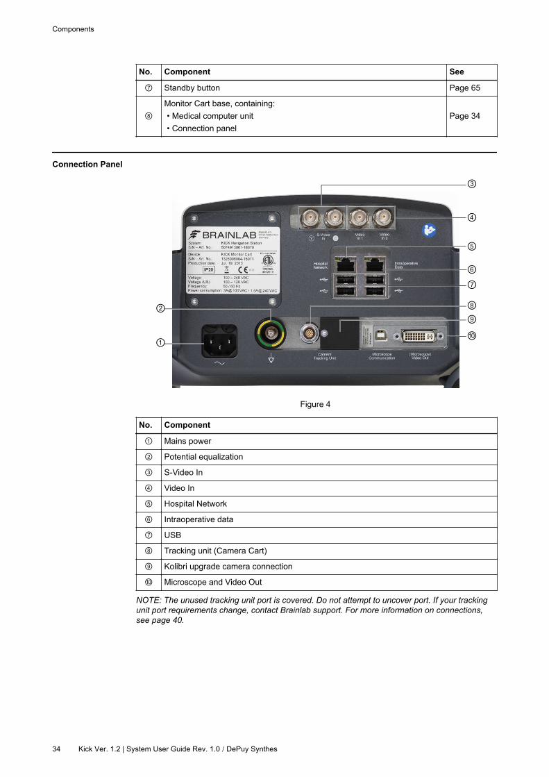
Connection Panel
Figure 4
No. Component
Mains power
Potential equalization
S-Video In
Video In
Hospital Network
Intraoperative data
USB
Tracking unit (Camera Cart)
Kolibri upgrade camera connection
Microscope and Video Out
NOTE: The unused tracking unit port is covered. Do not attempt to uncover port. If your tracking
unit port requirements change, contact Brainlab support. For more information on connections,
see page 40.
Components
34 Kick Ver. 1.2 | System User Guide Rev. 1.0 / DePuy Synthes
3.2 Monitor
General Information
The Monitor Cart is equipped with a touchscreen monitor.
Viewing options vary depending on the software application and user preferences. For more
information see the relevant Software User Guide.
Not for Diagnostic Use
The Kick touchscreen does not comply with DIN EN 6868 and it is not intended for
diagnostic use. Video images are not suitable for diagnostic use.
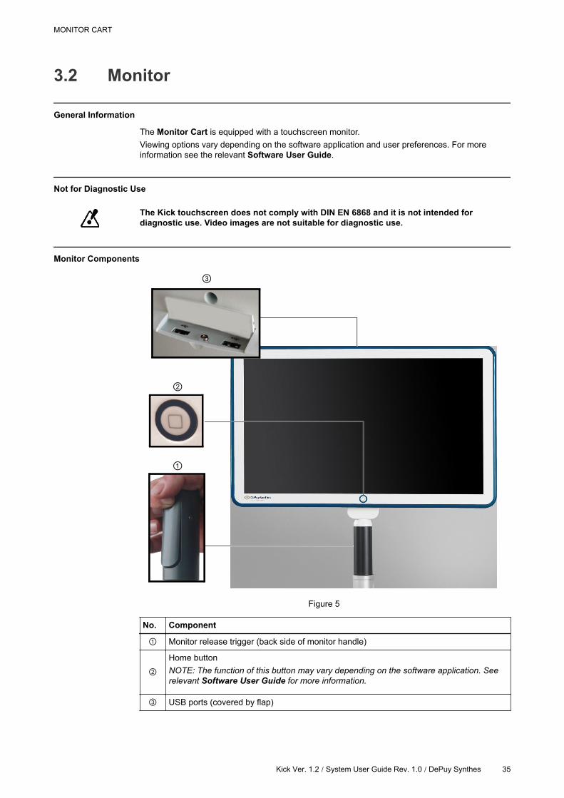
Monitor Components
Figure 5
No. Component
Monitor release trigger (back side of monitor handle)
Home button
NOTE: The function of this button may vary depending on the software application. See
relevant Software User Guide for more information.
USB ports (covered by flap)
MONITOR CART
Kick Ver. 1.2 / System User Guide Rev. 1.0 / DePuy Synthes 35

Touchscreen Use
• When the system is powered on, the touchscreen is always on and can be used.
• Only one interaction is recognized at a time.
• Position monitor so as to not interfere with surgery or movement of the OR staff.
Clean the touchscreen before use.
NOTE: For more information, see page 67.
Protecting Touchscreen Surface
Do not use damaged touchscreen. Always check touchscreen condition before beginning a
procedure.
Do not use sharp tools on the touchscreen.
Proper Cart Use
Do not attach or hang anything on the Monitor Cart and do not lean on the Monitor Cart.
Doing so may cause the cart to tip over.
Monitor
36 Kick Ver. 1.2 | System User Guide Rev. 1.0 / DePuy Synthes

3.2.1 Range of Motion
Monitor Rotation
The monitor can be rotated via the monitor hinge on the horizontal plane:
• 22° backward
• 10° forward
The viewing angle of the monitor is at least 80° in all four directions.
Figure 6
MONITOR CART
Kick Ver. 1.2 / System User Guide Rev. 1.0 / DePuy Synthes 37
3.2.2 Moving Parts
Precautions
Touchscreen colors may be displayed incorrectly if the monitor is not positioned correctly.
The user’s line of vision must be perpendicular to the touchscreen to ensure that colors
are viewed correctly.
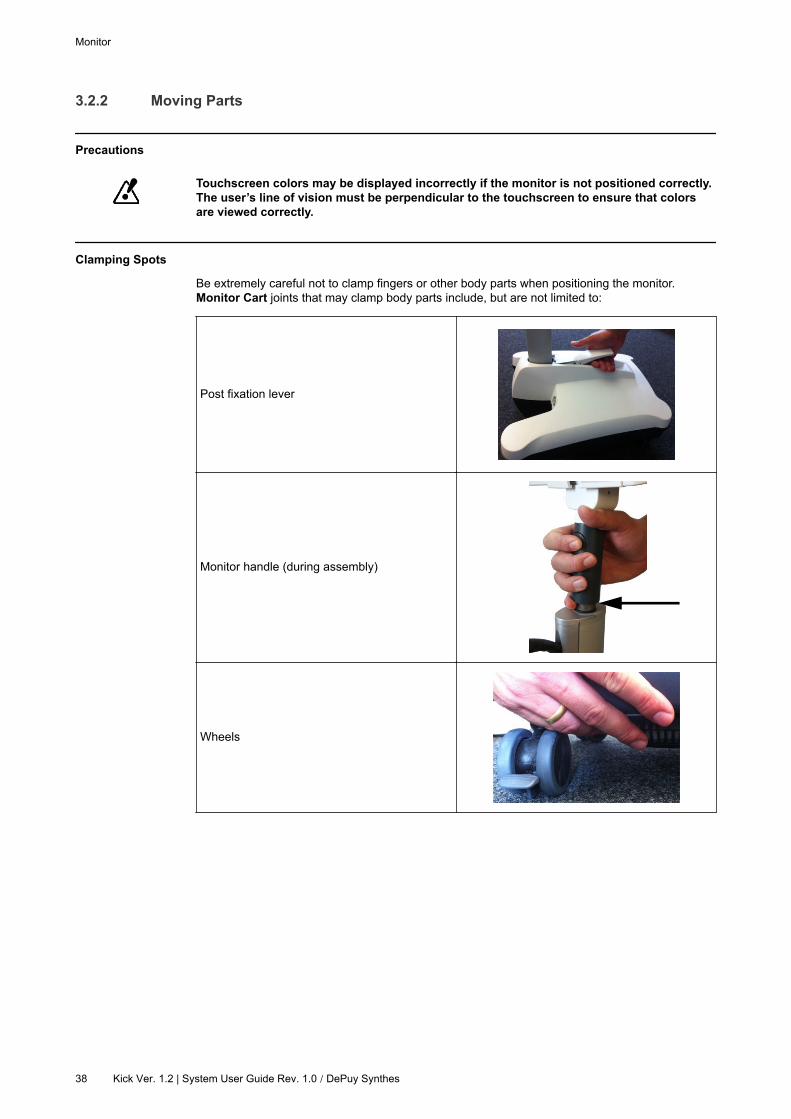
Clamping Spots
Be extremely careful not to clamp fingers or other body parts when positioning the monitor.
Monitor Cart joints that may clamp body parts include, but are not limited to:
Post fixation lever
Monitor handle (during assembly)
Wheels
Monitor
38 Kick Ver. 1.2 | System User Guide Rev. 1.0 / DePuy Synthes

3.3 Monitor Cart Ventilation
Ventilation Area
Figure 7
No. Ventilation Area
Underside of Monitor Cart base (on both sides)
Ensuring Ventilation
Do not block or cover ventilation openings on the system, for example, with drapes. Air
must be allowed to circulate through the vents to ensure proper operation and to avoid
overheating.
Do not place system near or over a radiator or heat register or in direct sunlight.
MONITOR CART
Kick Ver. 1.2 / System User Guide Rev. 1.0 / DePuy Synthes 39
3.4 3rd-Party Connections
General Information
It is possible to connect 3rd-party devices to Kick using compatible connection cables (see page
42).
Interfaces
All 3rd-party connection and electrical interfaces are located on the back side of the carts.
USB
USB ports are located on the connection panel and the top of the touchscreen monitor.
Scan USB flash drives with an antivirus software before connecting them to the system.
Only connect low-power or self-powered USB devices to the system for which compliance
has been tested (e.g., USB flash drive, mouse, keyboard, footswitch). Do not connect high-
power USB devices (e.g., external hard drive, smartphones, portable music players).
Otherwise safety and effectiveness of the equipment cannot be guaranteed.
Restrictions Connecting Equipment to Panels
Only connect equipment to Kick that is specified by Brainlab or for which Brainlab has
declared compatibility.
Additional equipment connected to medical electrical equipment must comply with the
respective IEC or ISO standards (e.g., IEC 60950 for data processing equipment and IEC
60601-1 for medical equipment). Furthermore, all configurations shall comply with the
requirements for medical electrical systems (see IEC 60601-1-1 or clause 16 of the 3rd
edition of IEC 60601-1, respectively). Anyone connecting additional equipment to medical
electrical equipment configures a medical system and is therefore responsible that the
system complies with the requirements for medical electrical systems. Please note that
local laws take priority over the above-mentioned requirements. In doubt, consult your
local representative or the technical service department.
Unless otherwise specified, the use of multiple socket outlet(s) or extension cords is not
permitted.
LAN Connection
Depending on the Brainlab application that is running on the system and the integration into the
hospital network, connecting a system to the network offers patient data transfer, remote access,
streaming and session sharing.
Only connect IEC compliant devices to the LAN ports.
Wireless LAN Connection
It may be possible to connect the system to the hospital network via a wireless LAN connection.
The availability of wireless LAN connection depends on your region.
Networks must comply with the definitions in standard 802.11n.
3rd-Party Connections
40 Kick Ver. 1.2 | System User Guide Rev. 1.0 / DePuy Synthes
In case of a weak connection or no wireless connection, use a LAN cable to connect. For patient
data transfer use e.g. USB flash drives.
The wireless system communication may interfere with other nearby wireless devices.
Verify the correct function of the wireless system connection and other necessary devices
prior to surgery.
Network Environment
Only operate the system in secured network environments. Make sure the network is
protected against unauthorized access (e.g. user authentication, firewall) and against
malicious software. Otherwise, system function cannot be guaranteed due to possible
malicious software infections.
MONITOR CART
Kick Ver. 1.2 / System User Guide Rev. 1.0 / DePuy Synthes 41
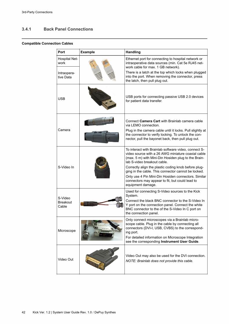
3.4.1 Back Panel Connections
Compatible Connection Cables
Port Example Handling
Hospital Net-
work
Ethernet port for connecting to hospital network or
intraoperative data sources (min. Cat 5e RJ45 net-
work cable for max. 1 GB network).
There is a latch at the top which locks when plugged
into the port. When removing the connector, press
the latch, then pull plug out.
Intraopera-
tive Data
USBUSB ports for connecting passive USB 2.0 devices
for patient data transfer.
Camera
Connect Camera Cart with Brainlab camera cable
via LEMO connection.
Plug in the camera cable until it locks. Pull slightly at
the connector to verify locking. To unlock the con-
nector, pull the bayonet back, then pull plug out.
S-Video In
To interact with Brainlab software video, connect S-
video source with a 26 AWG miniature coaxial cable
(max. 5 m) with Mini-Din Hosiden plug to the Brain-
lab S-video breakout cable.
Correctly align the plastic coding knob before plug-
ging in the cable. This connector cannot be locked.
Only use 4 Pin Mini-Din Hosiden connectors. Similar
connectors may appear to fit, but could lead to
equipment damage.
S-Video
Breakout
Cable
Used for connecting S-Video sources to the Kick
System.
Connect the black BNC connector to the S-Video In
Y port on the connection panel. Connect the white
BNC connector to the of the S-Video In C port on
the connection panel.
Microscope
Only connect microscopes via a Brainlab micro-
scope cable. Plug in the cable by connecting all
connectors (DVI-I, USB, CVBS) to the correspond-
ing port.
For detailed information on Microscope Integration
see the corresponding Instrument User Guide.
Video OutVideo Out may also be used for the DVI connection.
NOTE: Brainlab does not provide this cable.
3rd-Party Connections
42 Kick Ver. 1.2 | System User Guide Rev. 1.0 / DePuy Synthes
3.5 Cabling
General Information
This section provides information on the connection of Kick system cables, including:
• Potential equalization cable
• Mains power cable
Safe Handling of Cables
Do not use broken or damaged cables.
Do not tug on or pull cables.
Do not connect or disconnect cables when system is turned on.
Risk of electrical shock: Do not touch cable plugs when Monitor Cart is turned on.
Ensure that tracking system cable is not attached to any other device than the Monitor Cart
and tracking system.
Check that cables are in good condition before using the system.
Disconnect and store all cables on the cable hooks (see page 46) when system is not in
use or before moving it. Do not pull cables.
Ensure that there is sufficient slack when connecting cables. Do not strain or place the
attached cables under tension.
Potential Equalization (Yellow/Green) Cable
• Equalizes potentials between different metal parts that can be touched simultaneously.
• Reduces differences of potential that can occur between medical electrical devices and other
conductive parts of other objects during operation.
Before using the system, connect the potential equalization cable to the Monitor Cart and
the corresponding wall outlet.
MONITOR CART
Kick Ver. 1.2 / System User Guide Rev. 1.0 / DePuy Synthes 43
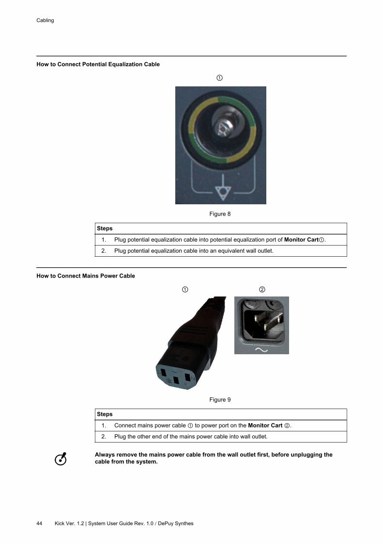
How to Connect Potential Equalization Cable
Figure 8
Steps
1. Plug potential equalization cable into potential equalization port of Monitor Cart .
2. Plug potential equalization cable into an equivalent wall outlet.
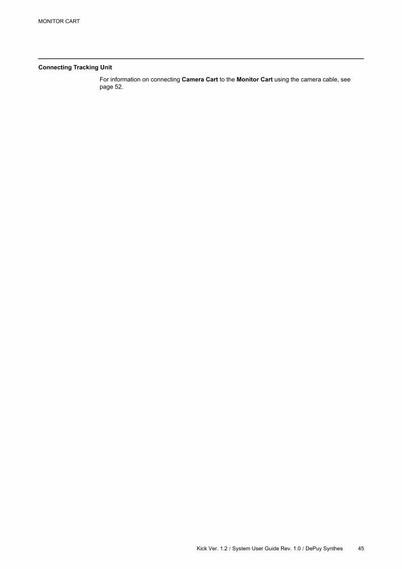
How to Connect Mains Power Cable
Figure 9
Steps
1. Connect mains power cable to power port on the Monitor Cart .
2. Plug the other end of the mains power cable into wall outlet.
Always remove the mains power cable from the wall outlet first, before unplugging the
cable from the system.
Cabling
44 Kick Ver. 1.2 | System User Guide Rev. 1.0 / DePuy Synthes
Connecting Tracking Unit
For information on connecting Camera Cart to the Monitor Cart using the camera cable, see
page 52.
MONITOR CART
Kick Ver. 1.2 / System User Guide Rev. 1.0 / DePuy Synthes 45
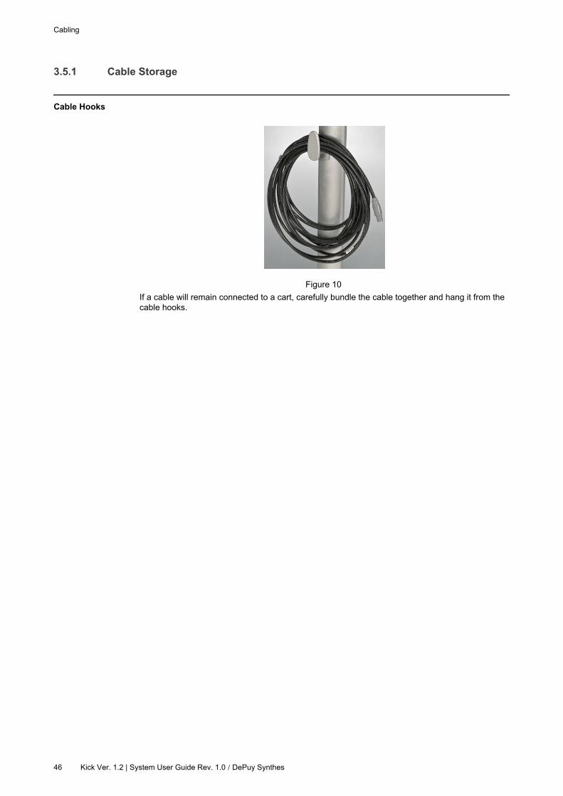
3.5.1 Cable Storage
Cable Hooks
Figure 10
If a cable will remain connected to a cart, carefully bundle the cable together and hang it from the
cable hooks.
Cabling
46 Kick Ver. 1.2 | System User Guide Rev. 1.0 / DePuy Synthes
3.6 LED Indications
Power Standby LED
The power standby LED is located in the standby button on the Monitor Cart (see page 65).
Color Status Explanation
Green
Off Electronic components are off.
Slow
flashingElectronic components are booting. Wait until LED is solid before use.
Solid Electronic components are on. System is ready for use.
Quick
flashingError detected. Contact support.
MONITOR CART
Kick Ver. 1.2 / System User Guide Rev. 1.0 / DePuy Synthes 47

LED Indications
48 Kick Ver. 1.2 | System User Guide Rev. 1.0 / DePuy Synthes
4 CAMERA CART
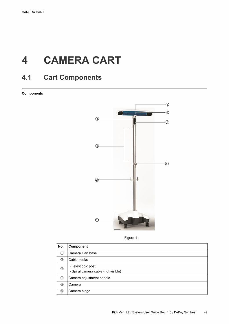
4.1 Cart Components
Components
Figure 11
No. Component
Camera Cart base
Cable hooks
• Telescopic post
• Spiral camera cable (not visible)
Camera adjustment handle
Camera
Camera hinge
CAMERA CART
Kick Ver. 1.2 / System User Guide Rev. 1.0 / DePuy Synthes 49
No. Component
Camera handle
Clamping lever
Cart Components
50 Kick Ver. 1.2 | System User Guide Rev. 1.0 / DePuy Synthes
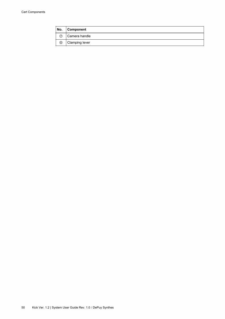
4.1.1 Camera
Camera Components
Figure 12
No. Component
Camera release trigger
Camera handle
Positioning laser
Lens
Illuminator filter
Camera adjustment handle
Laser trigger
NOTE: The camera does not contain any user-serviceable parts.
Infrared LED Array
The infrared LED array is located around the inner ring of the lenses.
The infrared LED array is a “Class I LED product”.
Do not directly look into the infrared LED array at a distance less than 15 cm.
CAMERA CART
Kick Ver. 1.2 / System User Guide Rev. 1.0 / DePuy Synthes 51
4.2 Cabling
General Information
This section provides information on the connection of Kick system cables, including:
• Kick camera cable
• Kolibri upgrade cable
Cabling Precautions
Risk of electrical shock: Do not touch cable plugs when Monitor Cart is turned on.
Do not connect or disconnect cables when system is turned on.
Ensure that camera cable is not attached to any other device than the Monitor Cart.
Do not tug on or pull cables with any force.
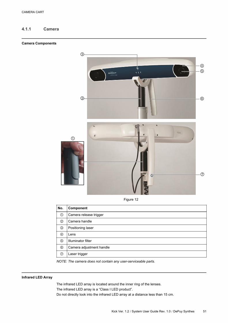
How to Connect Camera Cart to Monitor Cart
Figure 13
Steps
1. Ensure that Monitor Cart is turned off.
2.
If necessary, connect camera cable to camera port on the Monitor Cart.
NOTE: Usually, camera cable is connected during system installation and does not need
to be disconnected.
3. Connect camera cable to camera port on the Camera Cart .
4. Lightly pull the cable at each end to check that locking mechanism is engaged.
5. Connect mains power to Monitor Cart and wall power outlet.
6. Power up system by switching on the Monitor Cart.
Cabling
52 Kick Ver. 1.2 | System User Guide Rev. 1.0 / DePuy Synthes

Disconnecting Camera Cable
Figure 14
When disconnecting camera cable, do not twist the plug. Grasp the plug, rather than the
cable, and pull it straight out.
CAMERA CART
Kick Ver. 1.2 / System User Guide Rev. 1.0 / DePuy Synthes 53
4.3 Camera Use
General Information
The Camera Cart:
• Enables mobile positioning of camera
• Allows adjustment of angle and height of camera
• Is attached via cable to the Monitor Cart
Safe Use
Only one person should operate the Camera Cart at any given time.
Before use, ensure that the camera and all parts of the Camera Cart are functioning properly and
there is sufficient space for camera movement.
To avoid risk of electrical shock, do not touch patient, Camera Cart, and/or camera
simultaneously.
Do not step or sit on Camera Cart base.
Do not attach or hang anything on the Camera Cart, due to risk of the Camera Cart tipping
over.
Do not use the Camera Cart if cables are visibly damaged.
Do not place Camera Cart on uneven surfaces. Otherwise, it could move on its own,
resulting in serious damage.
Use with Active Wireless Instruments
Do not use the system with any active wireless instruments that are not specified by Brainlab.
Do not attempt to use more than one active wireless instrument at a time.
Communication with wireless instruments (e.g., Z-touch) may be established even when the
camera is still warming up.
Compatibility
Only use the Camera Cart with approved Brainlab navigation systems.
Do not make any changes to the camera components. Changes to the equipment may
cause severe harm to the patient, user or 3rd party.
Absolute Measurements
The camera is not intended for absolute measurements. The camera is designed to provide the
relative location of trackable instruments.
Careful Handling
The camera is a highly sensitive optical device. Handle it with care.
Camera Use
54 Kick Ver. 1.2 / System User Guide Rev. 1.0 / DePuy Synthes
Damages and Cleanliness
Always inspect the camera for cleanliness and possible damage before the procedure. Do
not use the camera if it is damaged or if there are any scratches on the inner ring of the
lenses.
Do not use Camera Cart if it does not steadily hold the camera in position.
Do not use camera if illuminator filter or lenses are dirty.
Air Flow
Do not obstruct normal air flow around the camera, e.g., by draping. Doing so could affect
the camera’s operational environment beyond its recommended thresholds. Do not attempt
to protect or cover the camera with methods unapproved by Brainlab.
Turning the Camera On
When the Camera Cart is connected via cable to the Monitor Cart, the Camera Cart is powered
on as soon as the Monitor Cart is turned on (see page 65).
Warm-up Time
Every time camera is powered on, it generally requires a warm-up time of two minutes. If camera
is stored at low temperatures, warm-up time may be longer.
CAMERA CART
Kick Ver. 1.2 / System User Guide Rev. 1.0 / DePuy Synthes 55
4.3.1 Range of Motion
General Information
Assess the range of motion of the telescopic arm and ensure that you have sufficient
space so that it will not collide with the ceiling, equipment or people.
Camera Cart Height
The camera cart offers a maximum height of 235 cm from the floor to the top of the camera.
The maximum height to the midpoint of the camera lenses is 223 cm.
Camera Range of Motion
• Horizontal axis: 10° to 65° below horizontal axis
• Vertical axis: ± 45°
Camera Use
56 Kick Ver. 1.2 / System User Guide Rev. 1.0 / DePuy Synthes
4.3.2 Operating Position
How to Put Camera Cart into Operating Position
Steps
1. Ensure that Camera Cart is in transport position (see page 86).
2.Using the camera handle, move Camera Cart to desired location.
NOTE: Remove protection covers before entering the OR.
3. Lock all four wheel brakes (see page 88).
4. Adjust camera height as desired (see page 58).
5.Grip camera adjustment handle and move camera into desired position, using the camera
positioning laser as needed.
6. Plug camera cable into Monitor Cart.
Positioning Considerations
In case of interference with other devices caused by the IR light emitted by the camera, reposition
the camera and/or affected device until there is no longer interference.
Reflections of IR light, e.g., from drapes or shiny surfaces, may interfere with the camera’s
ability to correctly track instruments. The same may be true of the camera’s IR light, which
can interfere with other devices, e.g., pulse oximeter, remote control systems or IR
sensitive microscopes.
Safe Positioning
Lock all four wheel brakes when Camera Cart is in operating position.
Do not place Camera Cart or any of its parts over the patient.
CAMERA CART
Kick Ver. 1.2 / System User Guide Rev. 1.0 / DePuy Synthes 57
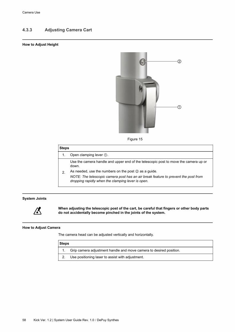
4.3.3 Adjusting Camera Cart
How to Adjust Height
Figure 15
Steps
1. Open clamping lever .
2.
Use the camera handle and upper end of the telescopic post to move the camera up or
down.
As needed, use the numbers on the post as a guide.
NOTE: The telescopic camera post has an air break feature to prevent the post from
dropping rapidly when the clamping lever is open.
System Joints
When adjusting the telescopic post of the cart, be careful that fingers or other body parts
do not accidentally become pinched in the joints of the system.
How to Adjust Camera
The camera head can be adjusted vertically and horizontally.
Steps
1. Grip camera adjustment handle and move camera to desired position.
2. Use positioning laser to assist with adjustment.
Camera Use
58 Kick Ver. 1.2 | System User Guide Rev. 1.0 / DePuy Synthes

Positioning Laser
Figure 16
Press the laser trigger to activate the positioning laser.
The positioning laser is marked with the words “LASER APERTURE” .
Do not cover the laser aperture.
Do not look directly into the laser-emitting aperture. The Class 2 laser module of the
camera emits visible radiation that may be harmful to the human eye. Looking directly at
the laser diode emission at close range can cause eye damage.
Use of the positioning laser other than is described in this manual may result in hazardous
radiation exposure.
Do not point the positioning laser directly into the eyes of the patient or user(s). It is
important to consider that some users’ movement may be restricted during the procedure
and patients may not have the ability to e.g., close their eyes or turn their head away from
the emitted laser.
CAMERA CART
Kick Ver. 1.2 / System User Guide Rev. 1.0 / DePuy Synthes 59
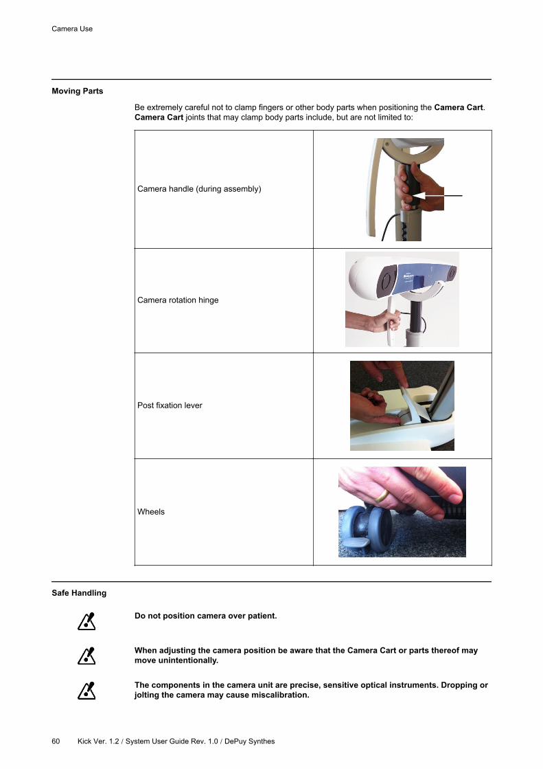
Moving Parts
Be extremely careful not to clamp fingers or other body parts when positioning the Camera Cart.
Camera Cart joints that may clamp body parts include, but are not limited to:
Camera handle (during assembly)
Camera rotation hinge
Post fixation lever
Wheels
Safe Handling
Do not position camera over patient.
When adjusting the camera position be aware that the Camera Cart or parts thereof may
move unintentionally.
The components in the camera unit are precise, sensitive optical instruments. Dropping or
jolting the camera may cause miscalibration.
Camera Use
60 Kick Ver. 1.2 / System User Guide Rev. 1.0 / DePuy Synthes
Do not touch the camera lenses. Smudges on lenses can distort tracking.
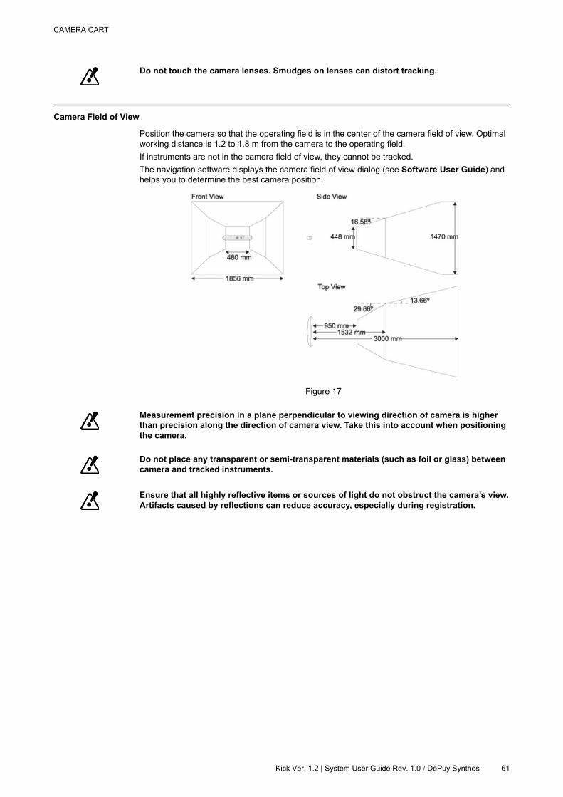
Camera Field of View
Position the camera so that the operating field is in the center of the camera field of view. Optimal
working distance is 1.2 to 1.8 m from the camera to the operating field.
If instruments are not in the camera field of view, they cannot be tracked.
The navigation software displays the camera field of view dialog (see Software User Guide) and
helps you to determine the best camera position.
Figure 17
Measurement precision in a plane perpendicular to viewing direction of camera is higher
than precision along the direction of camera view. Take this into account when positioning
the camera.
Do not place any transparent or semi-transparent materials (such as foil or glass) between
camera and tracked instruments.
Ensure that all highly reflective items or sources of light do not obstruct the camera’s view.
Artifacts caused by reflections can reduce accuracy, especially during registration.
CAMERA CART
Kick Ver. 1.2 | System User Guide Rev. 1.0 / DePuy Synthes 61
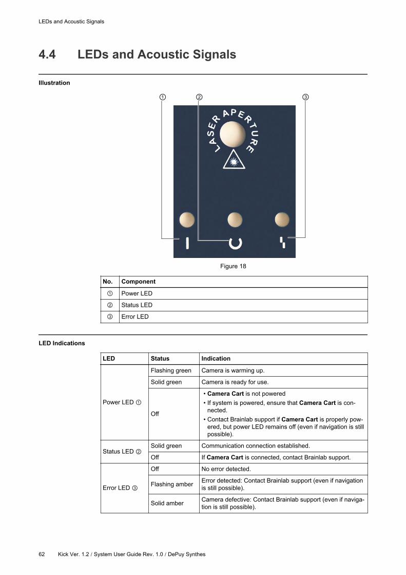
4.4 LEDs and Acoustic Signals
Illustration
Figure 18
No. Component
Power LED
Status LED
Error LED
LED Indications
LED Status Indication
Power LED
Flashing green Camera is warming up.
Solid green Camera is ready for use.
Off
• Camera Cart is not powered
• If system is powered, ensure that Camera Cart is con-
nected.
• Contact Brainlab support if Camera Cart is properly pow-
ered, but power LED remains off (even if navigation is still
possible).
Status LED Solid green Communication connection established.
Off If Camera Cart is connected, contact Brainlab support.
Error LED
Off No error detected.
Flashing amberError detected: Contact Brainlab support (even if navigation
is still possible).
Solid amberCamera defective: Contact Brainlab support (even if naviga-
tion is still possible).
LEDs and Acoustic Signals
62 Kick Ver. 1.2 / System User Guide Rev. 1.0 / DePuy Synthes

NOTE: If there is no signal from the power LED or status LED, contact Brainlab support (even if
navigation is still possible).
Acoustic Signals
Camera emits two beeps when:
• Reset is performed
• Power is applied to system
• Connection is made to Brainlab software
CAMERA CART
Kick Ver. 1.2 | System User Guide Rev. 1.0 / DePuy Synthes 63

LEDs and Acoustic Signals
64 Kick Ver. 1.2 / System User Guide Rev. 1.0 / DePuy Synthes
5 USING THE SYSTEM
5.1 Turning System On
Power Supply
Operate system using the power source indicated on type plate. If you are unsure of type
of power available, consult Brainlab support or your local power company. Using the
wrong power source could seriously damage system.
Only establish or interrupt an electrical connection when all associated devices are fully
turned off.
Only operate the system using the mains power cable(s) provided with the system. Do not
use extension cords.
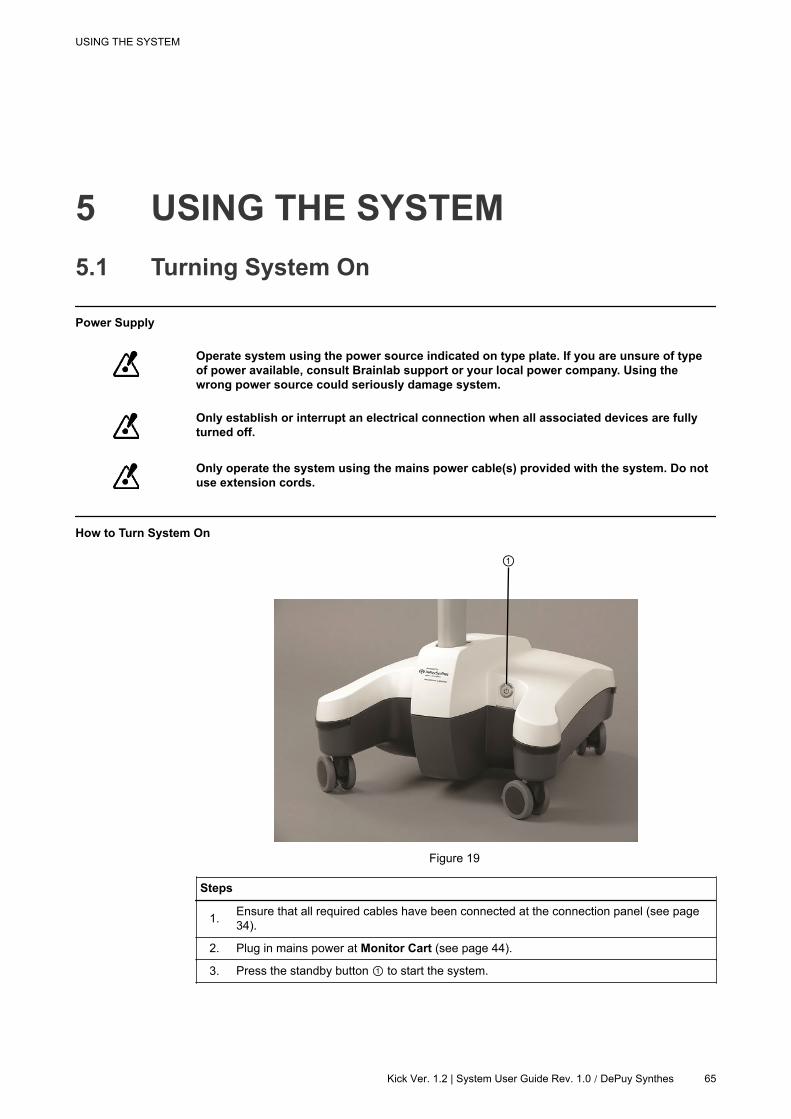
How to Turn System On
Figure 19
Steps
1.Ensure that all required cables have been connected at the connection panel (see page
34).
2. Plug in mains power at Monitor Cart (see page 44).
3. Press the standby button to start the system.
USING THE SYSTEM
Kick Ver. 1.2 | System User Guide Rev. 1.0 / DePuy Synthes 65
5.2 System Shutdown
Loss of Data
Unplug mains power only after equipment has fully shut down. Failure to follow system
shutdown procedure prior to disconnecting power may result in irreversible loss of data.
How to Shut Down
Steps
1. Shut down system using the software or by pressing standby button briefly.
2.When the Monitor Cart power LED turns off, unplug and secure all cables and storage
devices.
Unplug mains power before connecting or disconnecting other cables.
The standby button does not disconnect the Monitor Cart from mains voltage. Unplug
mains power cable to ensure complete voltage disconnection.
How to Reset
Step
To reset the computer (if system has frozen or has not completely shut down) press standby but-
ton for four seconds, until the system is turned off.
Wait ten seconds, then press the standby button again to restart.
Waiting Periods
When disconnecting the system from line voltage, wait at least 10 seconds before
reconnecting it.
Do not turn off system during boot-up. Otherwise, configuration files and other data on
hard disk may be damaged or lost.
Emergency
In case of emergency only, unplug detachable mains power cable to simultaneously
disconnect all supply poles.
System Shutdown
66 Kick Ver. 1.2 / System User Guide Rev. 1.0 / DePuy Synthes
5.3 Sterile Use
Sterile Kick Monitor Drape
General Information
The monitor may be draped using the Kick Monitor Drape provided by Brainlab.
The drape allows you to intraoperatively access all software functions and position monitor during
surgery without compromising the sterile field.
Packaging
The Kick Monitor Drape is delivered sterile. Ensure that drape packaging does not have any
holes or tears.
Before use, check expiration date on drape packaging. If date has expired, dispose of the
drape and do not use it.
Do not use drape if packaging is broken.
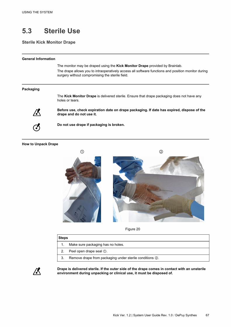
How to Unpack Drape
Figure 20
Steps
1. Make sure packaging has no holes.
2. Peel open drape seal .
3. Remove drape from packaging under sterile conditions .
Drape is delivered sterile. If the outer side of the drape comes in contact with an unsterile
environment during unpacking or clinical use, it must be disposed of.
USING THE SYSTEM
Kick Ver. 1.2 | System User Guide Rev. 1.0 / DePuy Synthes 67

How to Drape the Monitor
Figure 21
Steps
1. Hold drape with your hands to the left and right of orientation arrow .
2.Place drape flap over monitor so that the orientation arrow is on the back side of the mon-
itor and pointing down .
How to Secure Drape
Figure 22
Sterile Use
68 Kick Ver. 1.2 / System User Guide Rev. 1.0 / DePuy Synthes

Steps
1.
Peel the adhesive liner off one of the adhesive strips on the upper part of the drape
and attach it to the back of the monitor.
Repeat until all three strips are attached to the back of the monitor.
2.
Peel the adhesive liner off one of the adhesive strips on the lower part of the drape and
attach it to monitor post.
Repeat for the second adhesive strip on the lower part of the drape.
Draped Kick
Figure 23
Operating Draped Touchscreen
Do not touch drape with sharp tools.
To keep sterile field, only touch touchscreen and monitor housing where covered by drape.
Disposal
Dispose of the drape after use.
USING THE SYSTEM
Kick Ver. 1.2 | System User Guide Rev. 1.0 / DePuy Synthes 69
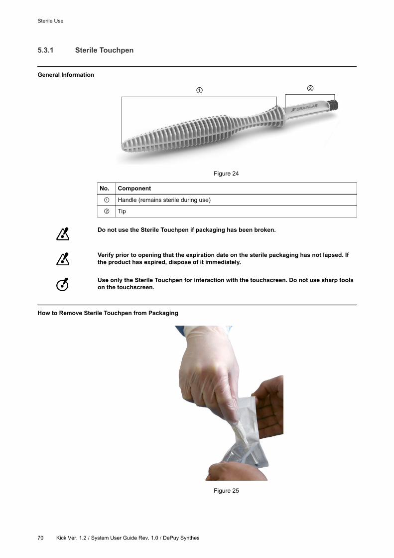
5.3.1 Sterile Touchpen
General Information
Figure 24
No. Component
Handle (remains sterile during use)
Tip
Do not use the Sterile Touchpen if packaging has been broken.
Verify prior to opening that the expiration date on the sterile packaging has not lapsed. If
the product has expired, dispose of it immediately.
Use only the Sterile Touchpen for interaction with the touchscreen. Do not use sharp tools
on the touchscreen.
How to Remove Sterile Touchpen from Packaging
Figure 25
Sterile Use
70 Kick Ver. 1.2 / System User Guide Rev. 1.0 / DePuy Synthes
Steps
1.Have a second person remove packaged Sterile Touchpen from the dispenser and pull
apart the opening flaps to expose the handle.
2.With the second person holding the opening flaps, remove Sterile Touchpen from the
packaging while holding the handle.
Always use the opening flaps, do not break through the sterile packaging with the Sterile
Touchpen.
The Sterile Touchpen is delivered sterile. If the Sterile Touchpen comes in contact with an
unsterile environment during unpacking or use, dispose of it immediately.
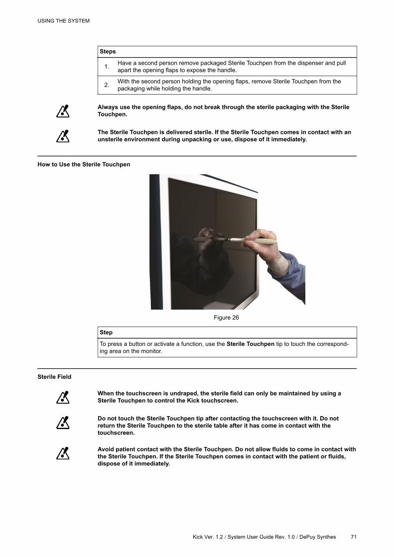
How to Use the Sterile Touchpen
Figure 26
Step
To press a button or activate a function, use the Sterile Touchpen tip to touch the correspond-
ing area on the monitor.
Sterile Field
When the touchscreen is undraped, the sterile field can only be maintained by using a
Sterile Touchpen to control the Kick touchscreen.
Do not touch the Sterile Touchpen tip after contacting the touchscreen with it. Do not
return the Sterile Touchpen to the sterile table after it has come in contact with the
touchscreen.
Avoid patient contact with the Sterile Touchpen. Do not allow fluids to come in contact with
the Sterile Touchpen. If the Sterile Touchpen comes in contact with the patient or fluids,
dispose of it immediately.
USING THE SYSTEM
Kick Ver. 1.2 / System User Guide Rev. 1.0 / DePuy Synthes 71

Disposal
To maintain sterility, dispose of the Sterile Touchpen after each touchscreen interaction.
Sterile Use
72 Kick Ver. 1.2 | System User Guide Rev. 1.0 / DePuy Synthes
6 ASSEMBLY, TRANSPORT AND
STORAGE
6.1 Protection Covers
General Information
The monitor and camera protection covers must be used during transport and storage to protect
the sensitive components from damage.
Do not cover camera or monitor with protection covers when system is running. Otherwise
system could overheat and be seriously damaged. Ensure that system has been turned off
and is completely cooled down before applying the protection covers.
To avoid damage, place protection covers over monitor and camera before transport or
storage.
Clean touchscreen before applying the monitor protection cover (see page 93).
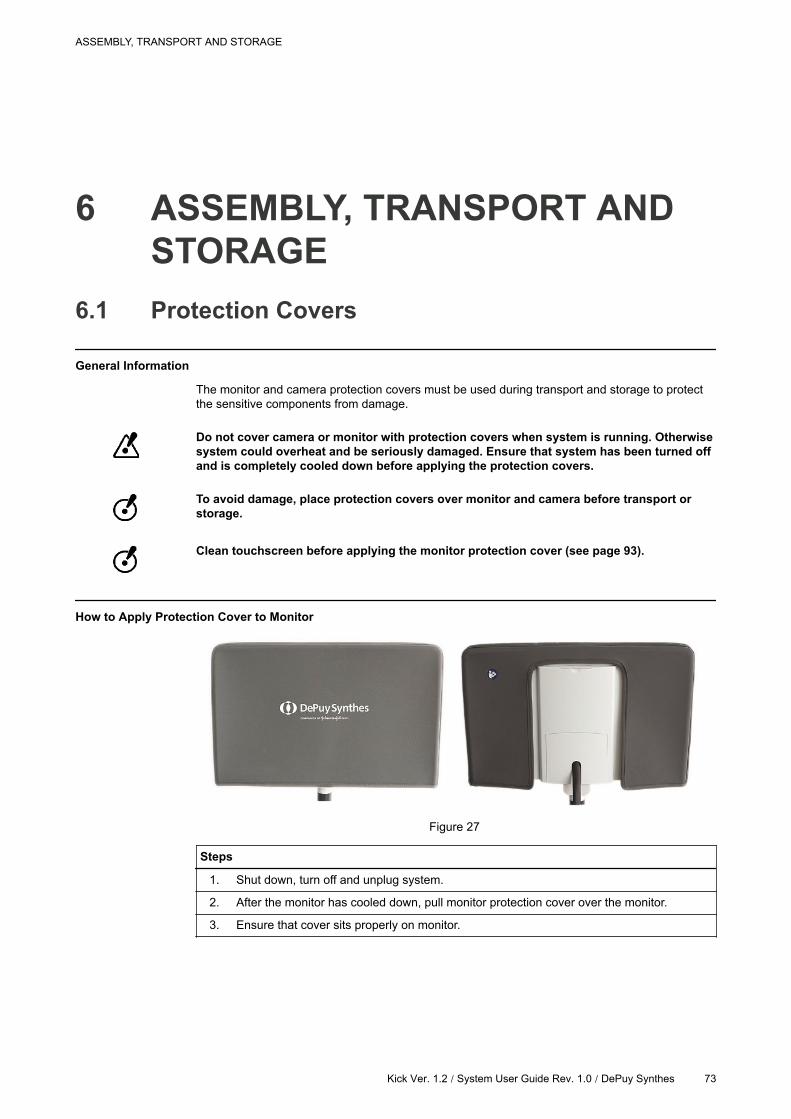
How to Apply Protection Cover to Monitor
Figure 27
Steps
1. Shut down, turn off and unplug system.
2. After the monitor has cooled down, pull monitor protection cover over the monitor.
3. Ensure that cover sits properly on monitor.
ASSEMBLY, TRANSPORT AND STORAGE
Kick Ver. 1.2 / System User Guide Rev. 1.0 / DePuy Synthes 73
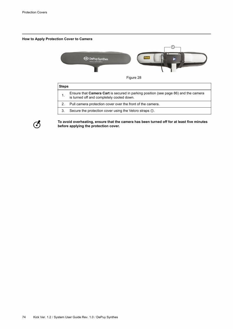
How to Apply Protection Cover to Camera
Figure 28
Steps
1.Ensure that Camera Cart is secured in parking position (see page 86) and the camera
is turned off and completely cooled down.
2. Pull camera protection cover over the front of the camera.
3. Secure the protection cover using the Velcro straps .
To avoid overheating, ensure that the camera has been turned off for at least five minutes
before applying the protection cover.
Protection Covers
74 Kick Ver. 1.2 / System User Guide Rev. 1.0 / DePuy Synthes
6.2 Transport Outside of the Hospital
Precautions
Consider the weight of the components before beginning assembly and disassembly (see
Technical User Guide).
After assembly ensure that all levers on both carts are securely closed. Verify that all
mechanical connections are correct and secure.
During assembly and disassembly, system components should only be lifted by people
who are bodily able (e.g., not by pregnant women).
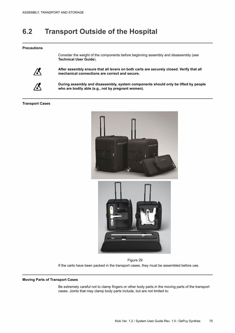
Transport Cases
Figure 29
If the carts have been packed in the transport cases, they must be assembled before use.
Moving Parts of Transport Cases
Be extremely careful not to clamp fingers or other body parts in the moving parts of the transport
cases. Joints that may clamp body parts include, but are not limited to:
ASSEMBLY, TRANSPORT AND STORAGE
Kick Ver. 1.2 / System User Guide Rev. 1.0 / DePuy Synthes 75
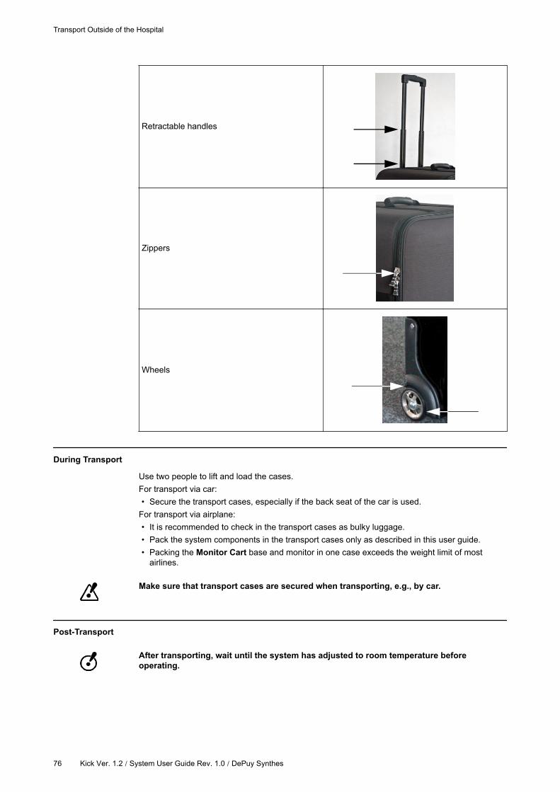
Retractable handles
Zippers
Wheels
During Transport
Use two people to lift and load the cases.
For transport via car:
• Secure the transport cases, especially if the back seat of the car is used.
For transport via airplane:
• It is recommended to check in the transport cases as bulky luggage.
• Pack the system components in the transport cases only as described in this user guide.
• Packing the Monitor Cart base and monitor in one case exceeds the weight limit of most
airlines.
Make sure that transport cases are secured when transporting, e.g., by car.
Post-Transport
After transporting, wait until the system has adjusted to room temperature before
operating.
Transport Outside of the Hospital
76 Kick Ver. 1.2 / System User Guide Rev. 1.0 / DePuy Synthes
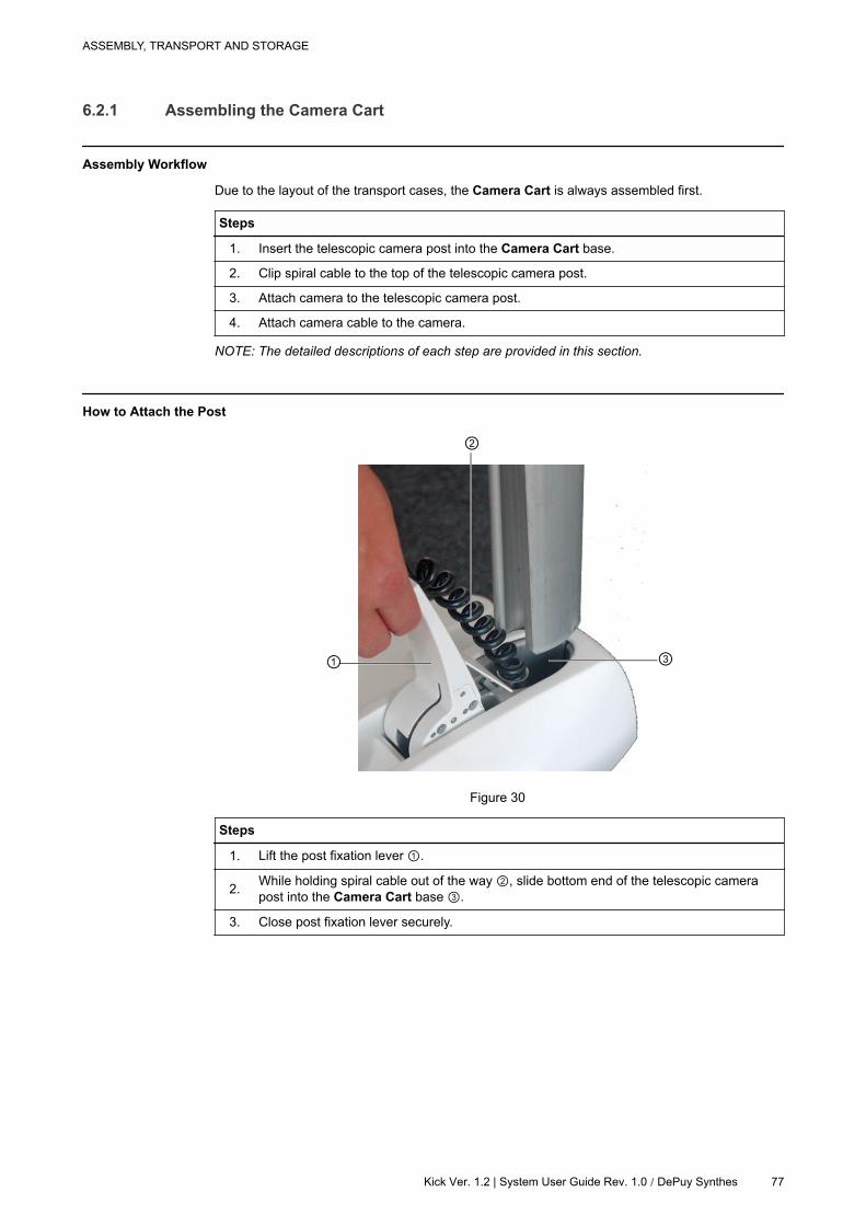
6.2.1 Assembling the Camera Cart
Assembly Workflow
Due to the layout of the transport cases, the Camera Cart is always assembled first.
Steps
1. Insert the telescopic camera post into the Camera Cart base.
2. Clip spiral cable to the top of the telescopic camera post.
3. Attach camera to the telescopic camera post.
4. Attach camera cable to the camera.
NOTE: The detailed descriptions of each step are provided in this section.
How to Attach the Post
Figure 30
Steps
1. Lift the post fixation lever .
2.While holding spiral cable out of the way , slide bottom end of the telescopic camera
post into the Camera Cart base .
3. Close post fixation lever securely.
ASSEMBLY, TRANSPORT AND STORAGE
Kick Ver. 1.2 | System User Guide Rev. 1.0 / DePuy Synthes 77
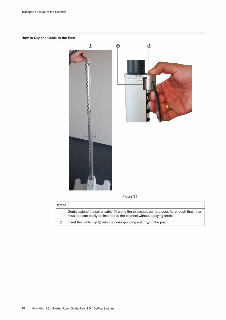
How to Clip the Cable to the Post
Figure 31
Steps
1.Gently extend the spiral cable along the telescopic camera post, far enough that it nar-
rows and can easily be inserted to the channel without applying force.
2. Insert the cable clip into the corresponding notch in the post.
Transport Outside of the Hospital
78 Kick Ver. 1.2 / System User Guide Rev. 1.0 / DePuy Synthes
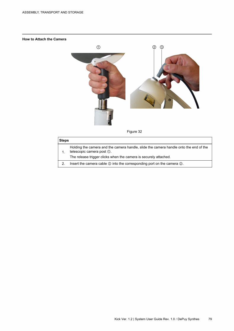
How to Attach the Camera
Figure 32
Steps
1.
Holding the camera and the camera handle, slide the camera handle onto the end of the
telescopic camera post .
The release trigger clicks when the camera is securely attached.
2. Insert the camera cable into the corresponding port on the camera .
ASSEMBLY, TRANSPORT AND STORAGE
Kick Ver. 1.2 | System User Guide Rev. 1.0 / DePuy Synthes 79
6.2.2 Assembling the Monitor Cart
Assembly Workflow
Steps
1. Insert the monitor post into the Monitor Cart base.
2. Clip monitor cable to the top of the monitor post.
3. Attach monitor to the monitor post.
4. Attach monitor cable to monitor.
NOTE: The detailed descriptions of each step are provided in this section.
How to Attach the Post
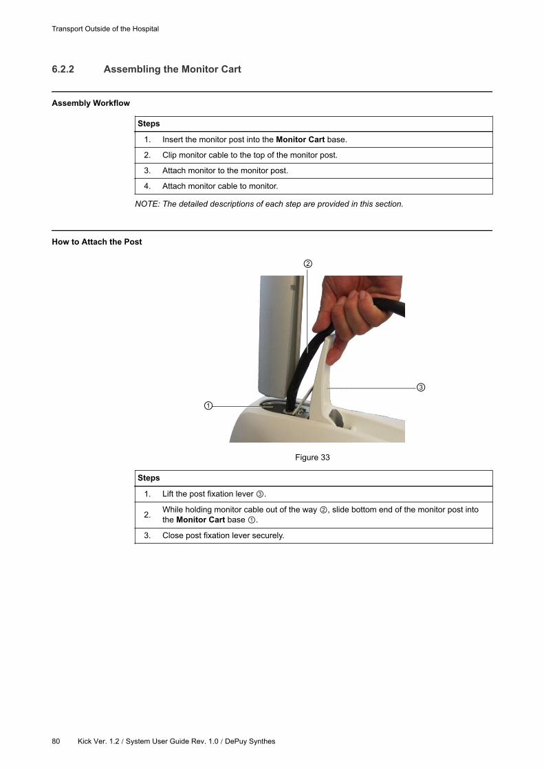
Figure 33
Steps
1. Lift the post fixation lever .
2.While holding monitor cable out of the way , slide bottom end of the monitor post into
the Monitor Cart base .
3. Close post fixation lever securely.
Transport Outside of the Hospital
80 Kick Ver. 1.2 / System User Guide Rev. 1.0 / DePuy Synthes

How to Clip the Cable to the Post
Figure 34
Steps
1. Run the monitor cable up the monitor post channel.
2. Insert the cable clip into the corresponding notch in the post.
How to Attach the Monitor
Figure 35
ASSEMBLY, TRANSPORT AND STORAGE
Kick Ver. 1.2 | System User Guide Rev. 1.0 / DePuy Synthes 81
Steps
1.
Holding the monitor frame and the monitor handle, slide the monitor handle onto the end
of the monitor post .
The release trigger clicks when the monitor is securely attached.
2. Open the flap on the back of the monitor .
3.Attach monitor cable to the monitor and secure latching pins .
Once attached, close the flap on the back of the monitor .
Transport Outside of the Hospital
82 Kick Ver. 1.2 / System User Guide Rev. 1.0 / DePuy Synthes
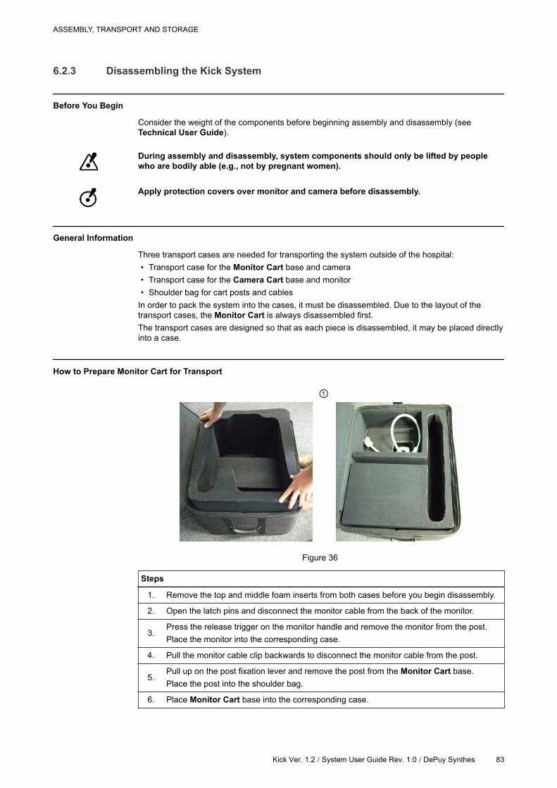
6.2.3 Disassembling the Kick System
Before You Begin
Consider the weight of the components before beginning assembly and disassembly (see
Technical User Guide).
During assembly and disassembly, system components should only be lifted by people
who are bodily able (e.g., not by pregnant women).
Apply protection covers over monitor and camera before disassembly.
General Information
Three transport cases are needed for transporting the system outside of the hospital:
• Transport case for the Monitor Cart base and camera
• Transport case for the Camera Cart base and monitor
• Shoulder bag for cart posts and cables
In order to pack the system into the cases, it must be disassembled. Due to the layout of the
transport cases, the Monitor Cart is always disassembled first.
The transport cases are designed so that as each piece is disassembled, it may be placed directly
into a case.
How to Prepare Monitor Cart for Transport
Figure 36
Steps
1. Remove the top and middle foam inserts from both cases before you begin disassembly.
2. Open the latch pins and disconnect the monitor cable from the back of the monitor.
3.Press the release trigger on the monitor handle and remove the monitor from the post.
Place the monitor into the corresponding case.
4. Pull the monitor cable clip backwards to disconnect the monitor cable from the post.
5.Pull up on the post fixation lever and remove the post from the Monitor Cart base.
Place the post into the shoulder bag.
6. Place Monitor Cart base into the corresponding case.
ASSEMBLY, TRANSPORT AND STORAGE
Kick Ver. 1.2 / System User Guide Rev. 1.0 / DePuy Synthes 83
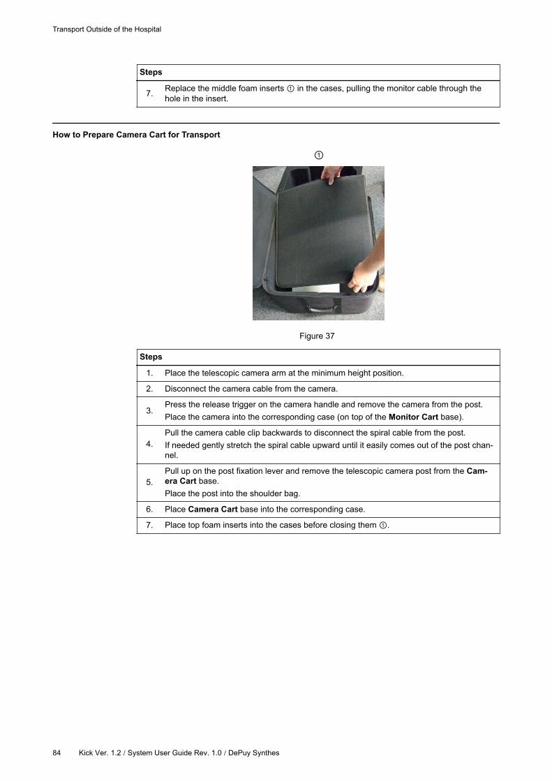
Steps
7.Replace the middle foam inserts in the cases, pulling the monitor cable through the
hole in the insert.
How to Prepare Camera Cart for Transport
Figure 37
Steps
1. Place the telescopic camera arm at the minimum height position.
2. Disconnect the camera cable from the camera.
3.Press the release trigger on the camera handle and remove the camera from the post.
Place the camera into the corresponding case (on top of the Monitor Cart base).
4.
Pull the camera cable clip backwards to disconnect the spiral cable from the post.
If needed gently stretch the spiral cable upward until it easily comes out of the post chan-
nel.
5.
Pull up on the post fixation lever and remove the telescopic camera post from the Cam-
era Cart base.
Place the post into the shoulder bag.
6. Place Camera Cart base into the corresponding case.
7. Place top foam inserts into the cases before closing them .
Transport Outside of the Hospital
84 Kick Ver. 1.2 / System User Guide Rev. 1.0 / DePuy Synthes
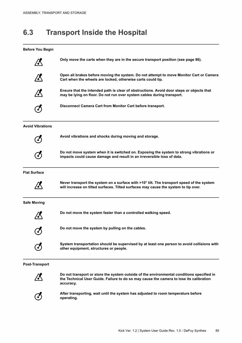
6.3 Transport Inside the Hospital
Before You Begin
Only move the carts when they are in the secure transport position (see page 86).
Open all brakes before moving the system. Do not attempt to move Monitor Cart or Camera
Cart when the wheels are locked, otherwise carts could tip.
Ensure that the intended path is clear of obstructions. Avoid door steps or objects that
may be lying on floor. Do not run over system cables during transport.
Disconnect Camera Cart from Monitor Cart before transport.
Avoid Vibrations
Avoid vibrations and shocks during moving and storage.
Do not move system when it is switched on. Exposing the system to strong vibrations or
impacts could cause damage and result in an irreversible loss of data.
Flat Surface
Never transport the system on a surface with >10° tilt. The transport speed of the system
will increase on tilted surfaces. Tilted surfaces may cause the system to tip over.
Safe Moving
Do not move the system faster than a controlled walking speed.
Do not move the system by pulling on the cables.
System transportation should be supervised by at least one person to avoid collisions with
other equipment, structures or people.
Post-Transport
Do not transport or store the system outside of the environmental conditions specified in
the Technical User Guide. Failure to do so may cause the camera to lose its calibration
accuracy.
After transporting, wait until the system has adjusted to room temperature before
operating.
ASSEMBLY, TRANSPORT AND STORAGE
Kick Ver. 1.2 | System User Guide Rev. 1.0 / DePuy Synthes 85
6.3.1 Proper Transport Procedure
Parking and Transport Position
Monitor Cart:
• Must be in upright position for transport.
• Mains power cable and any other cables that shall remain attached to the Monitor Cart must
be hung on the cable hooks.
Camera Cart:
• Must be in upright position and oriented to the front.
• Set to the minimum height with all levers securely closed, otherwise the telescopic camera post
may collide, e.g., with a door frame or other equipment.
• Camera cable must be hung on the cable hooks.
How to Transport the Kick System
Figure 38
Steps
1. Use the handle to transport the Camera Cart.
2. Use the handle to transport the Monitor Cart.
Only move the carts by holding onto the above-mentioned handles. Do not use the monitor
cable or camera cable to move the carts.
Transport Inside the Hospital
86 Kick Ver. 1.2 / System User Guide Rev. 1.0 / DePuy Synthes
How to Overcome Obstructions During Transport - Kick
If a clear, flat path is unavailable (e.g., an unavoidable depth variation between rooms), follow the
proper procedure to overcome this obstruction.
Steps
1.
Pull the Camera Cart to the point of depth variation, then carefully tilt the cart slightly and
move one wheel at a time over the step.
NOTE: Do not lift the entire cart. Be careful not to tilt the cart so much that it tips over.
2.
Pull the Monitor Cart to the point of depth variation, then carefully tilt the cart slightly and
move one wheel at a time over the step.
NOTE: Do not lift the entire cart. Be careful not to tilt the cart so much that it tips over.
ASSEMBLY, TRANSPORT AND STORAGE
Kick Ver. 1.2 / System User Guide Rev. 1.0 / DePuy Synthes 87
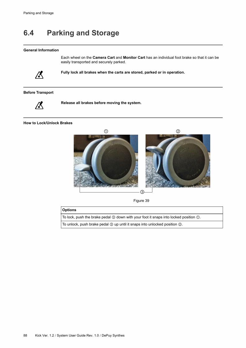
6.4 Parking and Storage
General Information
Each wheel on the Camera Cart and Monitor Cart has an individual foot brake so that it can be
easily transported and securely parked.
Fully lock all brakes when the carts are stored, parked or in operation.
Before Transport
Release all brakes before moving the system.
How to Lock/Unlock Brakes
Figure 39
Options
To lock, push the brake pedal down with your foot it snaps into locked position .
To unlock, push brake pedal up until it snaps into unlocked position .
Parking and Storage
88 Kick Ver. 1.2 / System User Guide Rev. 1.0 / DePuy Synthes
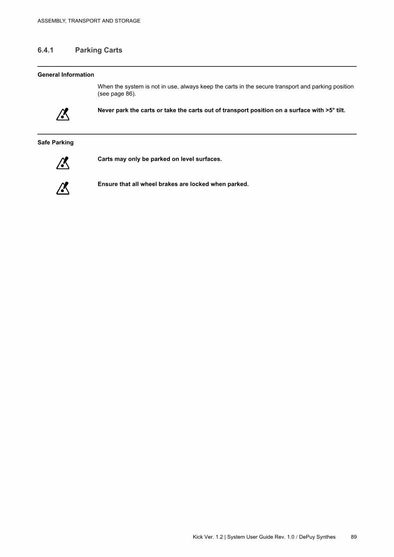
6.4.1 Parking Carts
General Information
When the system is not in use, always keep the carts in the secure transport and parking position
(see page 86).
Never park the carts or take the carts out of transport position on a surface with >5° tilt.
Safe Parking
Carts may only be parked on level surfaces.
Ensure that all wheel brakes are locked when parked.
ASSEMBLY, TRANSPORT AND STORAGE
Kick Ver. 1.2 | System User Guide Rev. 1.0 / DePuy Synthes 89

6.4.2 Storage
Safe Storage
When storing the system, always use the protection covers (see page 73).
Environmental Requirements
See the Technical User Guide for detailed environmental restrictions.
Parking and Storage
90 Kick Ver. 1.2 / System User Guide Rev. 1.0 / DePuy Synthes

6.4.3 Long Term Storage
General Information
Before and after placing the system into storage for an extended period of time, steps must be
taken to ensure proper functioning.
Storage for 1-6 Months
Before storing system for one to six months:
Steps
1. Unplug all external cabling and store it together with the equipment.
2. Cover camera and monitor with protection covers.
3. Store equipment in a dry place with a temperature between 21°C (70°F) to 30°C (86°F).
Before using equipment that has been stored for approximately three months:
Steps
1. Clean the equipment (see page 93).
2. Start system and verify correct function before using it for surgery (see page 65).
Storage for 6 Months or Longer
Before storing system for six months or longer:
Steps
1. Unplug all external cabling and store it together with the equipment.
2. Cover camera and monitor with protection covers.
3. Store equipment in a dry place with a temperature between 21°C (70°F) to 30°C (86°F).
Before using equipment that has been stored for six months or longer:
Steps
1. Clean the equipment (see page 93).
2.Perform a recurrent test to verify safety and effectiveness of equipment (offered by Brain-
lab, see Technical User Guide).
3. Start system and verify correct function before using it for surgery (see page 65).
Disposal
If you do not intend to use the system again, refer to the disposal information on page 9.
ASSEMBLY, TRANSPORT AND STORAGE
Kick Ver. 1.2 | System User Guide Rev. 1.0 / DePuy Synthes 91

Parking and Storage
92 Kick Ver. 1.2 / System User Guide Rev. 1.0 / DePuy Synthes
7 CLEANING
7.1 Cleaning the System
Before You Begin
Ensure that the system is fully shut down and disconnected from mains power before
beginning cleaning.
Risk of electrical shock: Prior to and during all cleaning and disinfection work, ensure that
tracking system is disconnected from Monitor Cart.
No Automatic Disinfection
Do not use automatic cleaning and disinfection procedures for Kick components.
Do not expose the Kick system to direct UV light, as it may damage equipment.
No Sterilization
Do not sterilize Kick system components. High temperatures from sterilization may
damage components.
Disinfectant Compatibility
The Kick system shall only be cleaned using the following disinfectant types:
Disinfectant Type Example
Alcohol-based Meliseptol, Mikrozid AF Liquid
Alkylamine-based Incidin Plus 2%
Active oxygen-based Perform
Aldehyde/chloride-based Antiseptica Kombi - Flächendesinfektion
NOTE: Use only surface disinfectants released in your specific market.
NOTE: Surface disinfectants may leave a residue. This can be easily removed using a dry cloth.
Always closely follow the directions of the disinfectant manufacturer.
CLEANING
Kick Ver. 1.2 / System User Guide Rev. 1.0 / DePuy Synthes 93
Using cleaning fluids, disinfection wipes or cleaning procedures others than those
specified may damage equipment. It is suggested to only use disinfectants verified by
Brainlab to avoid damaging the system.
No Liquids
Ensure that liquids do not enter the Kick components, as this could damage the
component and/or the electronics. System components are not protected against the
ingress of liquids.
Use only a moist cloth for cleaning. Other methods could allow liquids to enter the system
and cause damage.
Cleaning the System
94 Kick Ver. 1.2 / System User Guide Rev. 1.0 / DePuy Synthes
7.1.1 Cleaning the Kick System
How to Clean Monitor Cart
Steps
1. Shut down system and unplug mains power (see page 66).
2.Clean all housing surfaces using a surface disinfectant, following the disinfectant manu-
facturer’s recommendations.
3. Carefully clean interfaces, ensuring that no liquids enter the system.
4. Clean touchscreen with lint-free wipe using a streak-free surface disinfectant.
How to Clean Camera Cart
Steps
1. After the Monitor Cart is shut down (see page 66) disconnect the camera cable.
2.
With exception of the camera, clean all other surfaces using a surface disinfectant, follow-
ing the disinfectant manufacturer’s recommendations.
NOTE: Take care not to wipe debris from the camera case onto the illuminator filters and
lenses.
3. Carefully clean interfaces, ensuring that no liquids enter the system.
How to Clean Lens and Illuminator Filter
Steps
1. After the Monitor Cart is shut down (see page 66) disconnect the camera cable.
2.Remove dust from illuminator filters and lenses using a photographic lens duster (brush).
Gently wipe surface in one direction only, by pulling brush across surface.
3.Gently wipe surface of illuminator filters and lenses with disinfectant wipes containing
70% Isopropanol or Meliseptol.
4.
• Clean camera cover using a surface disinfectant.
• Follow disinfectant manufacturer’s recommendations.
• Take care not to wipe debris from camera onto illuminator filters and lenses.
• Avoid prolonged contact between wipes and camera.
5.
• Clean illuminator filters and lenses using a commercial lens cleaning solution for multi-
coated lenses (such as AR66) and a clean knitted microfiber optical cleaning cloth
(such as Hitecloth).
• Avoid prolonged contact between lens cleaner and illuminator filter and lenses.
Do not use any paper products for cleaning. Paper products may scratch illuminator filters.
The system must be completely powered down and disconnected from mains power before
cleaning.
Do not sterilize the camera.
CLEANING
Kick Ver. 1.2 / System User Guide Rev. 1.0 / DePuy Synthes 95

Camera Cleaning Intervals
As frequency of cleaning depends on how frequently the camera is used, Brainlab cannot give
general recommendation on cleaning intervals. This is within the user’s responsibility.
Regularly inspect illuminator filter and lenses for cleanness, however only clean them when
necessary.
Post-Cleaning
After cleaning, ensure that the telescope post of the Camera Cart is completely dry before
retracting the post.
Cleaning the System
96 Kick Ver. 1.2 / System User Guide Rev. 1.0 / DePuy Synthes
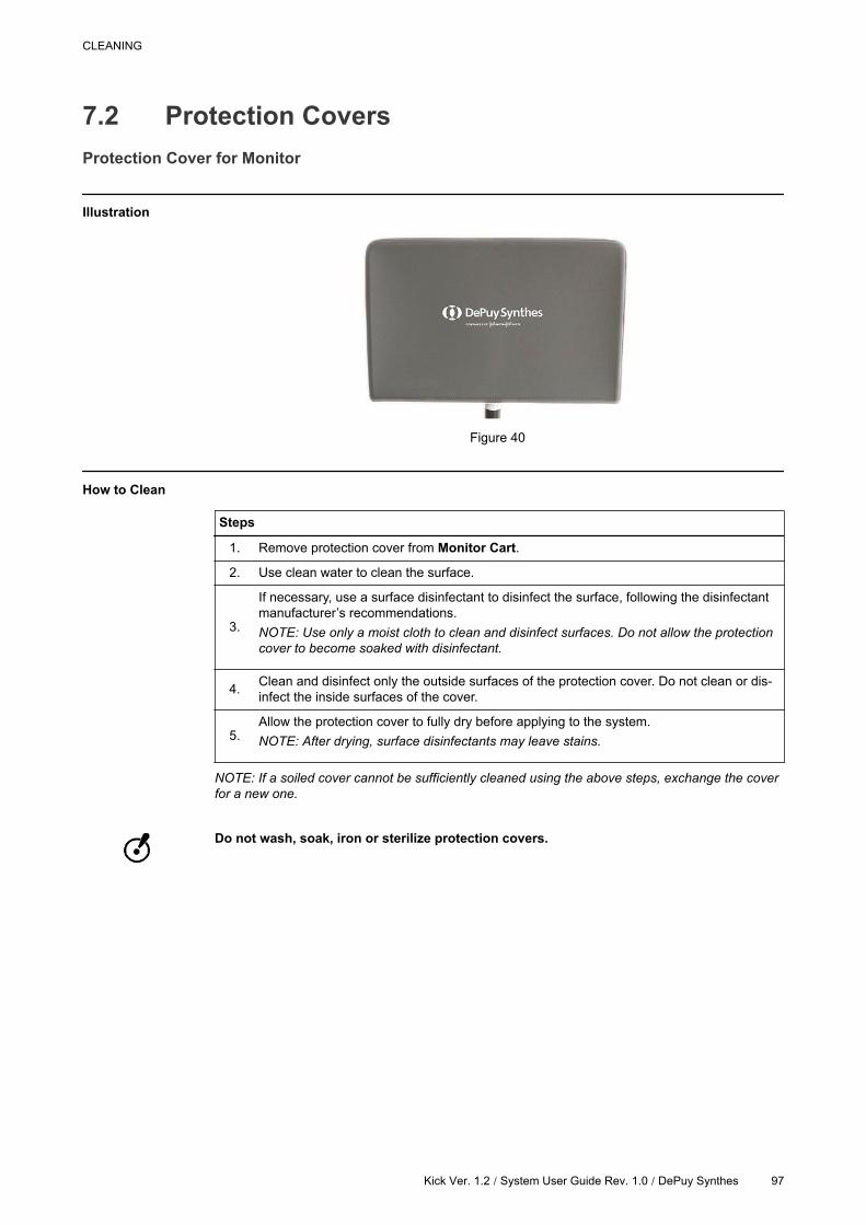
7.2 Protection Covers
Protection Cover for Monitor
Illustration
Figure 40
How to Clean
Steps
1. Remove protection cover from Monitor Cart.
2. Use clean water to clean the surface.
3.
If necessary, use a surface disinfectant to disinfect the surface, following the disinfectant
manufacturer’s recommendations.
NOTE: Use only a moist cloth to clean and disinfect surfaces. Do not allow the protection
cover to become soaked with disinfectant.
4.Clean and disinfect only the outside surfaces of the protection cover. Do not clean or dis-
infect the inside surfaces of the cover.
5.Allow the protection cover to fully dry before applying to the system.
NOTE: After drying, surface disinfectants may leave stains.
NOTE: If a soiled cover cannot be sufficiently cleaned using the above steps, exchange the cover
for a new one.
Do not wash, soak, iron or sterilize protection covers.
CLEANING
Kick Ver. 1.2 / System User Guide Rev. 1.0 / DePuy Synthes 97
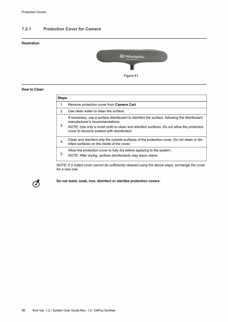
7.2.1 Protection Cover for Camera
Illustration
Figure 41
How to Clean
Steps
1. Remove protection cover from Camera Cart.
2. Use clean water to clean the surface.
3.
If necessary, use a surface disinfectant to disinfect the surface, following the disinfectant
manufacturer’s recommendations.
NOTE: Use only a moist cloth to clean and disinfect surfaces. Do not allow the protection
cover to become soaked with disinfectant.
4.Clean and disinfect only the outside surfaces of the protection cover. Do not clean or dis-
infect surfaces on the inside of the cover.
5.Allow the protection cover to fully dry before applying to the system.
NOTE: After drying, surface disinfectants may leave stains.
NOTE: If a soiled cover cannot be sufficiently cleaned using the above steps, exchange the cover
for a new one.
Do not wash, soak, iron, disinfect or sterilize protection covers.
Protection Covers
98 Kick Ver. 1.2 / System User Guide Rev. 1.0 / DePuy Synthes
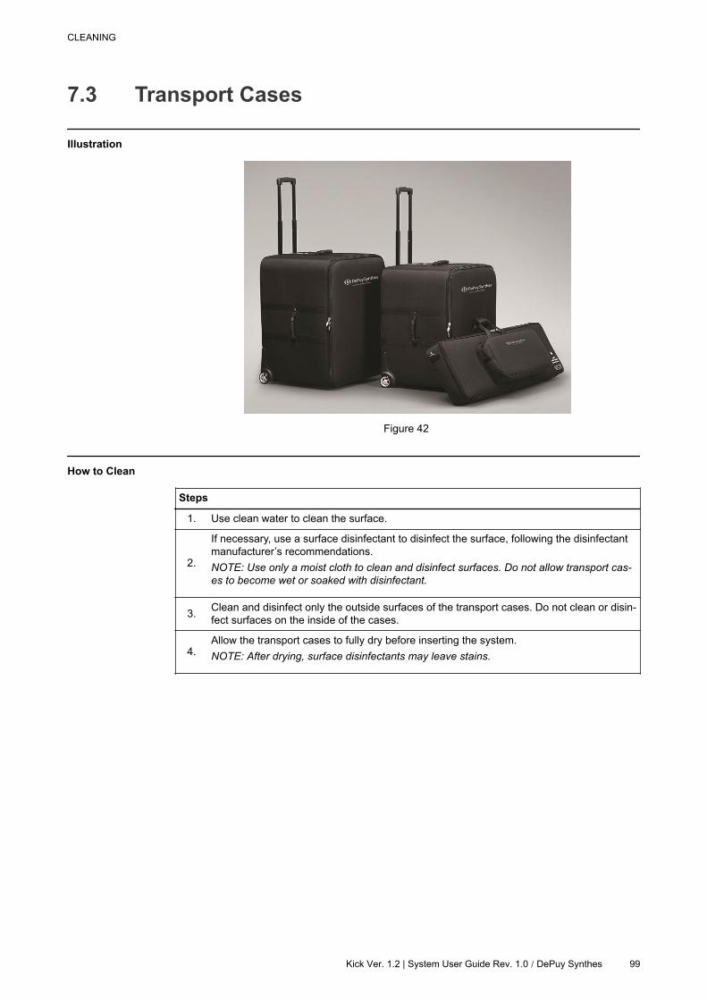
7.3 Transport Cases
Illustration
Figure 42
How to Clean
Steps
1. Use clean water to clean the surface.
2.
If necessary, use a surface disinfectant to disinfect the surface, following the disinfectant
manufacturer’s recommendations.
NOTE: Use only a moist cloth to clean and disinfect surfaces. Do not allow transport cas-
es to become wet or soaked with disinfectant.
3.Clean and disinfect only the outside surfaces of the transport cases. Do not clean or disin-
fect surfaces on the inside of the cases.
4.Allow the transport cases to fully dry before inserting the system.
NOTE: After drying, surface disinfectants may leave stains.
CLEANING
Kick Ver. 1.2 | System User Guide Rev. 1.0 / DePuy Synthes 99

Transport Cases
100 Kick Ver. 1.2 / System User Guide Rev. 1.0 / DePuy Synthes
INDEXNumerics
3rd-party connections.................................................................40
A
annual inspection....................................................................... 29
attaching
camera....................................................................................79
monitor....................................................................................81
C
cables
3rd-party connections............................................................. 40
camera cart.............................................................................52
connection......................................................................... 40,43
storage....................................................................................46
camera
beeps......................................................................................63
field of view.............................................................................61
laser........................................................................................59
positioning.............................................................................. 58
protection cover...................................................................... 74
rotation....................................................................................56
camera cart
cabling.................................................................................... 52
height.................................................................................56,58
operating position................................................................... 57
CE label........................................................................................9
classification
camera cart.............................................................................24
monitor cart.............................................................................24
cleaning
camera cart.............................................................................95
camera lens............................................................................ 95
disinfectants............................................................................93
illuminator filter....................................................................... 95
monitor cart.............................................................................95
protection covers............................................................... 97,98
compatibility
Brainlab instruments...............................................................16
connecting
camera....................................................................................79
contact information....................................................................... 7
D
disinfectants............................................................................... 93
disposal instructions..................................................................... 9
documentation............................................................................18
drape.......................................................................................... 67
E
electrical safety inspection......................................................... 29
F
FCC Statement.............................................................................9
field of view
camera....................................................................................61
frozen system............................................................................. 66
G
guides.........................................................................................18
H
height adjustment....................................................................... 58
I
inspections
annual.....................................................................................29
authorization........................................................................... 27
electrical safety.......................................................................29
interval.................................................................................... 27
monthly................................................................................... 28
weekly.....................................................................................28
interference
IR light.................................................................................... 22
radio........................................................................................25
L
laser
camera....................................................................................59
LED indicators....................................................................... 47,62
locks
brakes.....................................................................................88
M
mains power cable..................................................................... 44
malfunctions
procedure............................................................................... 30
manuals......................................................................................18
manufacturer................................................................................ 7
medical electrical systems..........................................................40
monitor cart
positioning.............................................................................. 38
protection cover...................................................................... 73
ventilation............................................................................... 39
monitor drape............................................................................. 67
monthly inspection......................................................................28
moving the system................................................................ 75,86
O
operating position....................................................................... 57
optical tracking........................................................................... 19
OR setup............................................................................... 22,23
P
PE cable..................................................................................... 44
positioning
camera....................................................................................58
laser........................................................................................59
monitor....................................................................................37
system............................................................................... 22,23
potential equalization cable........................................................ 44
INDEX
Kick Ver. 1.2 / System User Guide Rev. 1.0 / DePuy Synthes 101

powering system on................................................................... 65
protection cover
camera....................................................................................74
monitor....................................................................................73
R
range of motion
camera cart.............................................................................56
monitor....................................................................................37
reset system............................................................................... 66
returning equipment
addresses............................................................................... 31
rotation of camera...................................................................... 56
S
safety inspection.........................................................................29
shutdown.................................................................................... 66
sterile drape................................................................................67
sterile touchpen.......................................................................... 70
sterile use.............................................................................. 67,70
storage....................................................................................... 91
support......................................................................................... 7
symbols
hardware components............................................................ 11
user guide...............................................................................10
system components
Kick.........................................................................................20
system setup
Kick.........................................................................................23
system transport.........................................................................86
system ventilation.......................................................................39
T
third-party connections............................................................... 40
touchscreen use............................................................... 36,69,71
training........................................................................................17
transport procedure............................................................... 75,86
turning system off....................................................................... 66
turning system on....................................................................... 65
U
user guides.................................................................................18
V
ventilation................................................................................... 39
W
WEEE...........................................................................................9
weekly inspection....................................................................... 28
INDEX
102 Kick Ver. 1.2 | System User Guide Rev. 1.0 / DePuy Synthes


DePuy Synthes Sales, Inc.
325 Paramount Drive
Raynham, MA 02767
www.depuysynthes.com
Art-No. 60915-24EN
*60915-24EN*
DS
US
/SP
N/0
615/0
919
DS
EM
/SP
N/0
615
/0314
06/1
5