mobile wimax/td-lte smart mbs, u-ras flexible v2 · pdf filethis manual describes how to...
TRANSCRIPT

Ver.
2600-00F1W8GAA 4.0
Mobile WiMAX/TD-LTE Smart MBS,
U-RAS Flexible V2 RRH-B4
Installation Manual

Ver.
2600-00F1W8GAA 4.0
COPYRIGHT
This manual is proprietary to SAMSUNG Electronics Co., Ltd. and is protected by copyright.
No information contained herein may be copied, translated, transcribed or duplicated for any commercial
purposes or disclosed to the third party in any form without the prior written consent of SAMSUNG Electronics
Co., Ltd.
TRADEMARKS
Product names mentioned in this manual may be trademarks and/or registered trademarks of their respective
companies.
This manual should be read and used as a guideline for properly installing and operating the product.
This manual may be changed for the system improvement, standardization and other technical reasons without prior
notice.
If you need updated manuals or have any questions concerning the contents of the manuals, contact our Document
Center at the following address or Web site:
Address: Document Center 3rd Floor Jeong-bo-tong-sin-dong. Dong-Suwon P.O. Box 105, 416, Maetan-3dong
Yeongtong-gu, Suwon-si, Gyeonggi-do, Korea 442-600
Homepage: http://www.samsungdocs.com
© 2012 SAMSUNG Electronics Co., Ltd. All rights reserved.
Ver.
Mobile WiMAX/TD-LTE Smart MBS, U-RAS Flexible V2 RRH-B4 Installation Manual
© SAMSUNG Electronics Co., Ltd. I
2600-00F1W8GAA 4.0
INTRODUCTION
Purpose
This manual describes how to install the RRH-B4 and how to connect cables. RRH-B4 can
be connected to the following systems:
U-RAS Flexible V2 DU, which is a Base Station (BS) of Mobile WiMAX/TD-LTE
multi-mode
Smart MBS UADU, which is an eNB of TD-LTE
Document Content and Organization
This document consists of 4 Chapters, 7 Annex and Abbreviation, which are summarized as
follows:
CHAPTER 1. Before Installation
This chapter introduces the safety rules that must be understood for installing the RRH-B4
and describes the block diagram of the RRH-B4.
CHAPTER 2. Installing System
This chapter describes the procedures to install the RRH-B4.
CHAPTER 3. Connecting Cables
This chapter describes the procedures to connect the cables to the RRH-B4 installed.
CHAPTER 4. Checking Installation Status
This chapter describes the procedures of inspecting installation status after RRH-B4
installation and cabling is completed.
ANNEX A. Sector Antenna Installation
This annex describes the sector antenna configurations and its installation requirements.
ANNEX B. Installing Feeder Cable
This annex describes cautions and allowed radius of curvature when installing feeder line.
Ver.
INTRODUCTION
II © SAMSUNG Electronics Co., Ltd.
2600-00F1W8GAA 4.0
ANNEX C. Connector Assembly
This annex describes the procedure of assembling the connector.
ANNEX D. Cleaning Optic Connector
This annex describes the procedure of cleaning the optic connector and cleaning tool.
ANNEX E. Cable Gland Assembly
This annex describes the procedure of assembling the cable gland.
ANNEX F. Pressure Terminal Assembly
This annex describes the procedure of assembling the pressure terminal.
ANNEX G. Standard Torque
This annex describes the standard torque when tightening the bolt.
ABBREVIATION
Describes the acronyms used in this manual.
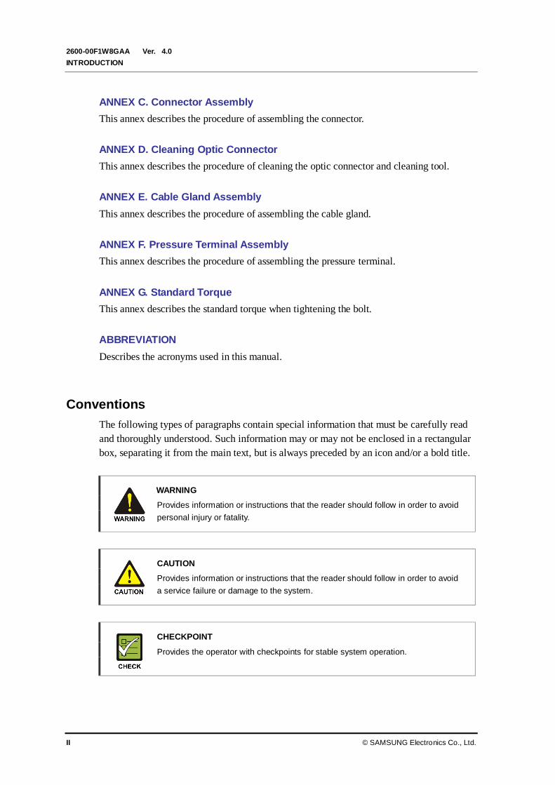
Conventions
The following types of paragraphs contain special information that must be carefully read
and thoroughly understood. Such information may or may not be enclosed in a rectangular
box, separating it from the main text, but is always preceded by an icon and/or a bold title.
WARNING
Provides information or instructions that the reader should follow in order to avoid
personal injury or fatality.
CAUTION
Provides information or instructions that the reader should follow in order to avoid
a service failure or damage to the system.
CHECKPOINT
Provides the operator with checkpoints for stable system operation.

Ver.
Mobile WiMAX/TD-LTE Smart MBS, U-RAS Flexible V2 RRH-B4 Installation Manual
© SAMSUNG Electronics Co., Ltd. III
2600-00F1W8GAA 4.0
NOTE
Indicates additional information as a reference.
Revision History
VERSION DATE OF ISSUE REMARKS
4.0 11. 2012. Changed ‘Specifications’ (Main Specifications, Environmental
Condition, and RF Specification)
3.0 10. 2012. - Changed ‘System Consumption Current’ (1.2)
- Changed Cable Gland Specification: M20 22051y7 M25
2253y8 (Figure 1.2 and Figure 3.22)
2.0 09. 2012. - Added contents for Smart MBS
- U-RAS Flexible V2: WiMAX only WiMAX/TD-LTE multi-
mode support
1.0 08. 2012. First Version

Ver.
INTRODUCTION
IV © SAMSUNG Electronics Co., Ltd.
2600-00F1W8GAA 4.0
This page is intentionally left blank.

Ver.
Mobile WiMAX/TD-LTE Smart MBS, U-RAS Flexible V2 RRH-B4 Installation Manual
© SAMSUNG Electronics Co., Ltd. V
2600-00F1W8GAA 4.0
SAFETY CONCERNS
The purpose of the Safety Concerns section is to ensure the safety of users and prevent
property damage. Please read this document carefully for proper use.
Symbols
Caution
Indication of a general caution
Restriction
Indication for prohibiting an action for a product
Instruction
Indication for commanding a specifically required action

Ver.
SAFETY CONCERNS
VI © SAMSUNG Electronics Co., Ltd.
2600-00F1W8GAA 4.0
Warning
Power and Grounding
Cautions When Using Insulation Tester
Pay attention to the followings to prevent any personal injury caused by an
electric shock when using an insulation tester.
- Make sure the polarity is correct when connecting the Earth COM (black) and
AC.V (red) lead lines. And do not touch the connected probes (inspecting part of
the lead line) with a hand and avoid body contact.
- Avoid body contact to the system when measuring an insulation resistance.
Watches, rings, and other metallic accessories
Do not wear accessories such as watches and rings in order to prevent electrical
shock.
Power Switch Off
Make sure the power switch of power supplier is off when installing the system.
Installing the system with power switch on may cause system damage or fatal
human injury when cables are not correctly connected.
Connecting Ground Cable
When connecting the cables, always connect the ground cable first.
If worker contacts the equipment, connect a cable or perform maintenance
without connecting the ground cable, the system can be damaged or a worker
may be injured due to static electricity and short circuit.
Turning Off the Circuit Breaker before Connecting the Power Cable
Since power is applied to the system where the power cable is connected by
manipulating the circuit breaker of the rectifier, be sure to check the rectifier’s
breaker is turned off (open) before connecting the power cable to the power
connector. If the system is installed while the circuit breaker is on, the worker may
be critically injured as soon as the cable is connected in the wrong way.
WARNING

Ver.
Mobile WiMAX/TD-LTE Smart MBS, U-RAS Flexible V2 RRH-B4 Installation Manual
© SAMSUNG Electronics Co., Ltd. VII
2600-00F1W8GAA 4.0
Installation
Warning for Laser Beam Running through Optical Cables
In the system, the laser beam emitting light runs through the optical cable.
The exposure of the laser beam on worker’s eye may cause serious injury so that
it should be handled with care.
Warning for Worker’s Injury
When installing cables in a small area, do not apply excessive force. Worker may
bump against a wall or equipment.
Protection gloves and goggles
Make sure that worker wears protection gloves and goggles to prevent damages
from debris while drilling holes in a wall or ceiling.
Ver.
SAFETY CONCERNS
VIII © SAMSUNG Electronics Co., Ltd.
2600-00F1W8GAA 4.0
Caution
Power and Feeder line
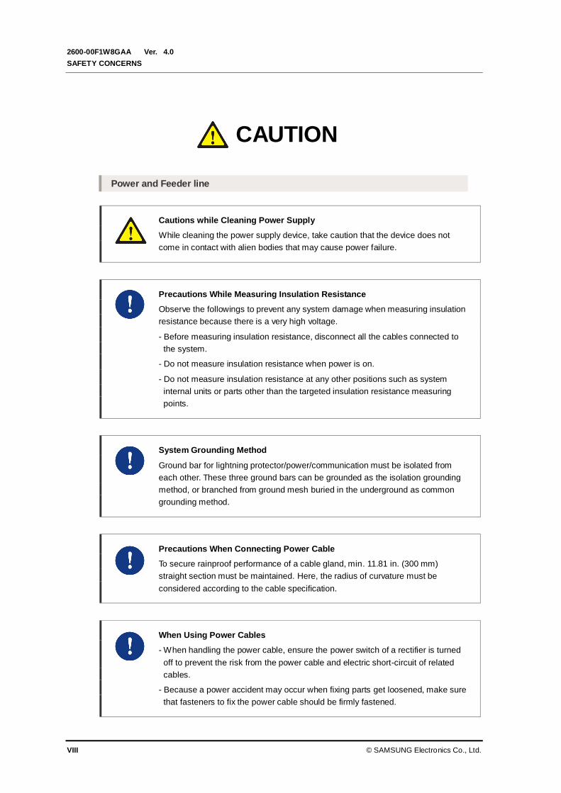
Cautions while Cleaning Power Supply
While cleaning the power supply device, take caution that the device does not
come in contact with alien bodies that may cause power failure.
Precautions While Measuring Insulation Resistance
Observe the followings to prevent any system damage when measuring insulation
resistance because there is a very high voltage.
- Before measuring insulation resistance, disconnect all the cables connected to
the system.
- Do not measure insulation resistance when power is on.
- Do not measure insulation resistance at any other positions such as system
internal units or parts other than the targeted insulation resistance measuring
points.
System Grounding Method
Ground bar for lightning protector/power/communication must be isolated from
each other. These three ground bars can be grounded as the isolation grounding
method, or branched from ground mesh buried in the underground as common
grounding method.
Precautions When Connecting Power Cable
To secure rainproof performance of a cable gland, min. 11.81 in. (300 mm)
straight section must be maintained. Here, the radius of curvature must be
considered according to the cable specification.
When Using Power Cables
- When handling the power cable, ensure the power switch of a rectifier is turned
off to prevent the risk from the power cable and electric short-circuit of related
cables.
- Because a power accident may occur when fixing parts get loosened, make sure
that fasteners to fix the power cable should be firmly fastened.
CAUTION

Ver.
Mobile WiMAX/TD-LTE Smart MBS, U-RAS Flexible V2 RRH-B4 Installation Manual
© SAMSUNG Electronics Co., Ltd. IX
2600-00F1W8GAA 4.0
Check When Fixing the Power Cable
Fix the power cable and the power cable bracket using a stainless steel tie for
preventing loose contact due to cable tension and leakage problems.
It is recommended to use the designated tools to tighten the stainless steel tie.
Caution for Rain-proof Gasket Damage
Be careful the rain-proof gasket is not damaged during work, and check again the
gasket is not damaged before closing power/DTA window cover. If the rain-proof
gasket is damaged, replace the RRH-B4.
Power Window Cover
Be sure to check the circuit breaker for RRH-B4 is turned off before opening or
closing the power window cover. If the cover is open or close while the circuit
breaker is on, the system can be damaged or a worker may be critically injured
due to electrical short-circuit.
Precautions When Cutting Power Cable
Install the power cable to the power port of system by considering the radius of
curvature of its cable specification and then cut the cable.
If you install the cable after cutting, there may be length difference among the
core wires at the end of the cable because of cable curvature. This may result in
poor contact after the cable is connected to the power port.
Installing the Antenna
When you install the antenna, the antenna must be within the protective angle
(left/right side 45° each from the central axis) to prevent the antenna from
lightning damage.
Checking VSWR for Minimum Cable Bend Radius and Length of RF Cable
If the VSWR value for minimum cable bend radius and length of RF cable is not
applied, system may not work properly because RF signals cannot transmit or
receive smoothly. So, the VSWR value for minimum cable bend radius and length
of RF cable must be checked and applied.

Ver.
SAFETY CONCERNS
X © SAMSUNG Electronics Co., Ltd.
2600-00F1W8GAA 4.0
Cautions When Measuring VSWR
When measuring VSWR, if you open the antenna port when the transmission
output is not completely off, a spike signal may flow into the reception path, which
may cause damage to LNA. Make sure the transmission output is completely off
when measuring VSWR.
Cable Work Sequence
When performing cable work for the system, proceed with the ground work before
any other work to prevent errors occurring due to static electricity and other
reasons.
Radius of Curvature of Feeder Line
When installing a feeder line, the radius of curvature of the sections where cables
bent should be larger than the allowed radius of curvature. If the radius of
curvature for the feeder line installation is less than the allowed radius of
curvature, it may affect the performance of the system.
Connection of Feeder Cable Connector
Connecting the feeder cable connector is critical process, so the qualified workers
who finished the related education should perform.
Installation
Cautions while Cleaning the Rack
Make sure that worker does not damage installed cables while cleaning the rack.
Do not Work by Yourself
Worker must not work alone in any key process.
Managing Unused Ports
Never allow foreign substances to be inserted into unused ports by covering them
with a dust cap.
Ver.
Mobile WiMAX/TD-LTE Smart MBS, U-RAS Flexible V2 RRH-B4 Installation Manual
© SAMSUNG Electronics Co., Ltd. XI
2600-00F1W8GAA 4.0
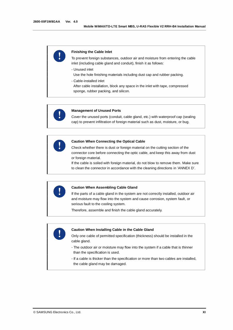
Finishing the Cable Inlet
To prevent foreign substances, outdoor air and moisture from entering the cable
inlet (including cable gland and conduit), finish it as follows:
- Unused inlet
Use the hole finishing materials including dust cap and rubber packing.
- Cable-installed inlet
After cable installation, block any space in the inlet with tape, compressed
sponge, rubber packing, and silicon.
Management of Unused Ports
Cover the unused ports (conduit, cable gland, etc.) with waterproof cap (sealing
cap) to prevent infiltration of foreign material such as dust, moisture, or bug.
Caution When Connecting the Optical Cable
Check whether there is dust or foreign material on the cutting section of the
connector core before connecting the optic cable, and keep this away from dust
or foreign material.
If the cable is soiled with foreign material, do not blow to remove them. Make sure
to clean the connector in accordance with the cleaning directions in ‘ANNEX D’.
Caution When Assembling Cable Gland
If the parts of a cable gland in the system are not correctly installed, outdoor air
and moisture may flow into the system and cause corrosion, system fault, or
serious fault to the cooling system.
Therefore, assemble and finish the cable gland accurately.
Caution When Installing Cable in the Cable Gland
Only one cable of permitted specification (thickness) should be installed in the
cable gland.
- The outdoor air or moisture may flow into the system if a cable that is thinner
than the specification is used.
- If a cable is thicker than the specification or more than two cables are installed,
the cable gland may be damaged.

Ver.
SAFETY CONCERNS
XII © SAMSUNG Electronics Co., Ltd.
2600-00F1W8GAA 4.0
Checking Assembly State of the Unused Cable Gland
All components of the unused cable gland must be secured in the original factory
configuration. If the cable gland nut is fitted without the waterproof filler or the
protection cover in place, reassemble them as illustrated in ‘Unused Cable Gland
Inspection and Assembly’.
California USA Only
This Perchlorate warning applies only to primary CR (Manganese Dioxide)
Lithium coin cells in the product sold or distributed ONLY in California USA
‘Perchlorate Material-special handling may apply, See
www.dtsc.ca.gov/hazardouswaste/perchlorate.’
Ver.
Mobile WiMAX/TD-LTE Smart MBS, U-RAS Flexible V2 RRH-B4 Installation Manual
© SAMSUNG Electronics Co., Ltd. XIII
2600-00F1W8GAA 4.0
TABLE OF CONTENTS
INTRODUCTION I
Purpose ............................................................................................................................................................... I
Document Content and Organization .............................................................................................................. I
Conventions .......................................................................................................................................................II
Revision History................................................................................................................................................III
SAFETY CONCERNS V
Symbols ............................................................................................................................................................. V
Warning............................................................................................................................................................. VI
Caution............................................................................................................................................................ VIII
California USA Only ....................................................................................................................................... XII
CHAPTER 1. Before Installation 1-1
1.1 System Configuration............................................................................................................ 1-1
1.2 Specifications......................................................................................................................... 1-3
1.3 Cautions for Installation ........................................................................................................ 1-6
1.4 Pre-survey .............................................................................................................................. 1-8
1.5 Installation Tools ................................................................................................................... 1-9
CHAPTER 2. Installing System 2-1
2.1 Installing the RRH-B4 ............................................................................................................ 2-1
2.2 Foundation Work ................................................................................................................... 2-2
2.2.1 System Arrangement ..................................................................................................................... 2-2
2.2.2 Marking and Drilling ....................................................................................................................... 2-4
2.3 Unpacking and Transporting ................................................................................................ 2-6
2.3.1 Importing Items ............................................................................................................................... 2-6
2.3.2 Unpacking Items ............................................................................................................................. 2-6
2.4 Fixing System......................................................................................................................... 2-7
2.4.1 Fixing Unit Mounting Bracket ........................................................................................................ 2-7
Ver.
TABLE OF CONTENTS
XIV © SAMSUNG Electronics Co., Ltd.
2600-00F1W8GAA 4.0
2.4.2 Fixing RRH-B4................................................................................................................................2-9
2.5 System Leveling ................................................................................................................... 2-14
2.6 Insulation Test...................................................................................................................... 2-15
CHAPTER 3. Connecting Cables 3-1
3.1 Work Flow for Cabling ........................................................................................................... 3-1
3.2 Cabling .................................................................................................................................... 3-6
3.3 Grounding ............................................................................................................................... 3-8
3.3.1 Grounding the System ...................................................................................................................3-9
3.4 Power Cabling ...................................................................................................................... 3-11
3.4.1 Connecting the RRH-B4 Power Cable ..................................................................................... 3-12
3.4.2 Power Test .................................................................................................................................... 3-31
3.5 External Interface Construction......................................................................................... 3-32
3.5.1 RRH-B4 Interface (CPRI) Cable Connection........................................................................... 3-32
3.5.2 RET Cable Connection ............................................................................................................... 3-70
3.5.3 RF Cable Connection .................................................................................................................. 3-73
CHAPTER 4. Checking Installation Status 4-1
4.1 Installation Checking Procedure ........................................................................................... 4-1
ANNEX A. Sector Antenna Installation A-1
A.1 Cautions when Installing a Sector Antenna ........................................................................ A-1
A.2 Sector Antenna Layout ......................................................................................................... A-1
A.3 Sector Antenna Installation .................................................................................................. A-2
ANNEX B. Installing Feeder Cable B-1
B.1 Cautions When Installing Feeder Cable .............................................................................. B-1
B.2 7/8 in. Feeder Line Ground ................................................................................................... B-4
B.3 Tower Ground Construction ................................................................................................. B-8
ANNEX C. Connector Assembly C-1
C.1 RJ-45 (Shield Type) ............................................................................................................... C-1
C.2 RJ-45 (Normal Type) .............................................................................................................. C-3
C.3 N type-male (LMR-400) .......................................................................................................... C-4

Ver.
Mobile WiMAX/TD-LTE Smart MBS, U-RAS Flexible V2 RRH-B4 Installation Manual
© SAMSUNG Electronics Co., Ltd. XV
2600-00F1W8GAA 4.0
C.4 TNC-male (LMR-400) .............................................................................................................. C-6
C.5 N type-male (1/2 in. feeder line) ............................................................................................ C-8
C.6 Din type-male (1/2 in. Feeder Line) ..................................................................................... C-12
C.7 Finishing the Connector Connection Part by Tape ........................................................... C-14
C.8 How to Shrink the Heat Shrink Tube .................................................................................. C-15
C.8.1 When Assembling a Connector to the Feeder Line................................................................ C-15
C.8.2 When Connecting a Connector to another Connector........................................................... C-17
ANNEX D. Cleaning Optic Connector D-1
D.1 Cleaning Optic Connector ..................................................................................................... D-1
D.2 IBCTM
Brand Cleaner .............................................................................................................. D-2
D.2.1 IBCTM
Brand Type Cleaner (P/N 9393) ...................................................................................... D-2
ANNEX E. Cable Gland Assembly E-1
E.1 Cable Gland Components ..................................................................................................... E-2
E.2 Cable Gland Assembly and Cabling ..................................................................................... E-3
E.3 Unused Cable Gland Inspection and Assembly .................................................................. E-6
ANNEX F. Pressure Terminal Assembly F-1
F.1 Preparations ........................................................................................................................... F-1
F.2 Pressure Reference Table ..................................................................................................... F-2
F.3 Assembling Pressure Terminal............................................................................................. F-5
ANNEX G. Standard Torque G-1
ABBREVIATION I
C ~ U ................................................................................................................................................................... I
V ..................................................................................................................................................................II

Ver.
TABLE OF CONTENTS
XVI © SAMSUNG Electronics Co., Ltd.
2600-00F1W8GAA 4.0
LIST OF FIGURES
Figure 1.1 RRH-B4 Configuration .......................................................................................... 1-1
Figure 1.2 External Interface of RRH-B4................................................................................. 1-2
Figure 2.1 Procedure to Install the RRH-B4 ............................................................................ 2-1
Figure 2.2 RRH-B4 Arragement (Wall Type) ........................................................................... 2-2
Figure 2.3 RRH-B4 Arragement (Sector Pole Type)................................................................ 2-3
Figure 2.4 System Marking-Wall Type..................................................................................... 2-4
Figure 2.5 Fixing Unit Mounting Bracket ................................................................................. 2-8
Figure 2.6 Fixing RRH-B4 (Wall Type) .................................................................................. 2-10
Figure 2.7 Fixing RRH-B4 (Pole Type) .................................................................................. 2-12
Figure 2.8 Leveling Using a Level (Example)........................................................................ 2-14
Figure 2.9 Schematic Diagram for Insulation Test (Wall Type) .............................................. 2-16
Figure 2.10 Schematic Diagram for Insulation Test (Pole Type)............................................ 2-16
Figure 3.1 Work Flow for System Cabling ............................................................................... 3-1
Figure 3.2 Detailed Cabling Procedure ................................................................................... 3-2
Figure 3.3 Cabling Diagram .................................................................................................... 3-6
Figure 3.4 Connection of the RRH-B4 Ground Cable ........................................................... 3-10
Figure 3.5 Power Equipment Diagram .................................................................................. 3-11
Figure 3.6 Connecting the RRH-B4 Power Cable_AWG8 (1) ............................................... 3-14
Figure 3.7 Connecting the RRH-B4 Power Cable_AWG8 (2) ............................................... 3-15
Figure 3.8 Connecting the RRH-B4 Power Cable_AWG8 (3) ............................................... 3-17
Figure 3.9 Connecting the RRH-B4 Power Cable_AWG8 (4) ............................................... 3-18
Figure 3.10 Connecting the RRH-B4 Power Cable_AWG8 (5) ............................................. 3-19
Figure 3.11 Connecting the RRH-B4 Power Cable_AWG8 (6).............................................. 3-20
Figure 3.12 Connecting the RRH-B4 Power Cable_AWG8 (7) ............................................. 3-21
Figure 3.13 Connecting the RRH-B4 Power Cable_AWG10 (1) ........................................... 3-24
Figure 3.14 Connecting the RRH-B4 Power Cable_AWG10 (2) ........................................... 3-25
Figure 3.15 Connecting the RRH-B4 Power Cable_AWG10 (3) ........................................... 3-26
Figure 3.16 Connecting the RRH-B4 Power Cable_AWG10 (4) ........................................... 3-27
Figure 3.17 Connecting the RRH-B4 Power Cable_AWG10 (5) ........................................... 3-28
Figure 3.18 Connecting the RRH-B4 Power Cable_AWG10 (6) ........................................... 3-29
Figure 3.19 Connecting the RRH-B4 Power Cable_AWG10 (7) ........................................... 3-30
Figure 3.20 Specifications of CPRI Cable and Connector ..................................................... 3-32
Figure 3.21 RRH-B4 Interface (CPRI) Cable Connection (1) ................................................ 3-33
Figure 3.22 RRH-B4 Interface (CPRI) Cable Connection (2) ................................................ 3-34
Figure 3.23 RRH-B4 Interface (CPRI) Cable Connection (3) ................................................ 3-35
Ver.
Mobile WiMAX/TD-LTE Smart MBS, U-RAS Flexible V2 RRH-B4 Installation Manual
© SAMSUNG Electronics Co., Ltd. XVII
2600-00F1W8GAA 4.0
Figure 3.24 RRH-B4 Interface (CPRI) Cable Connection (4) ............................................... 3-36
Figure 3.25 RRH-B4 Interface (CPRI) Cable Connection (5) ............................................... 3-37
Figure 3.26 CPRI Cable Pin Map (U-RAS Flexible V2, Case #1) ......................................... 3-39
Figure 3.27 CPRI Cable Connection_U-RAS Flexible V2, Case #1 (1) ................................ 3-40
Figure 3.28 CPRI Cable Connection_U-RAS Flexible V2, Case #1 (2) ................................ 3-41
Figure 3.29 CPRI Cable Pin Map (U-RAS Flexible V2, Case #2) ......................................... 3-43
Figure 3.30 CPRI Cable Connection_U-RAS Flexible V2, Case #2 (1) ................................ 3-44
Figure 3.31 CPRI Cable Connection_U-RAS Flexible V2, Case #2 (2) ................................ 3-45
Figure 3.32 CPRI Cable Pin Map (U-RAS Flexible V2, Case #3) ......................................... 3-47
Figure 3.33 CPRI Cable Connection_U-RAS Flexible V2, Case #3 (1) ................................ 3-48
Figure 3.34 CPRI Cable Connection_U-RAS Flexible V2, Case #3 (2) ................................ 3-49
Figure 3.35 CPRI Cable Pin Map (Smart MBS, Case #1) .................................................... 3-51
Figure 3.36 CPRI Cable Connection_Smart MBS, Case #1 (1) ........................................... 3-52
Figure 3.37 CPRI Cable Connection_Smart MBS, Case #1 (2) ........................................... 3-53
Figure 3.38 CPRI Cable Pin Map (Smart MBS, Case #2) .................................................... 3-54
Figure 3.39 CPRI Cable Connection_Smart MBS, Case #2 (1) ........................................... 3-55
Figure 3.40 CPRI Cable Connection_Smart MBS, Case #2 (2) ........................................... 3-56
Figure 3.41 CPRI Cable Pin Map (Stacking, Case #1) ......................................................... 3-58
Figure 3.42 CPRI Cable Connection_Stacking, Case #1 (1) ................................................ 3-59
Figure 3.43 CPRI Cable Connection_Stacking, Case #1 (2) ................................................ 3-60
Figure 3.44 CPRI Cable Pin Map (Stacking, Case #2) ......................................................... 3-62
Figure 3.45 CPRI Cable Connection_Stacking, Case #2 (1) ................................................ 3-63
Figure 3.46 CPRI Cable Connection_Stacking, Case #2 (2) ................................................ 3-64
Figure 3.47 CPRI Cable Connection_Stacking, Case #2 (3) ................................................ 3-65
Figure 3.48 CPRI Cable Pin Map (Stacking, Case #3) ......................................................... 3-67
Figure 3.49 CPRI Cable Connection_Stacking, Case #3 (1) ................................................ 3-68
Figure 3.50 CPRI Cable Connection_Stacking, Case# 3 (2) ................................................ 3-69
Figure 3.51 RET Cable Connection (1) ................................................................................ 3-70
Figure 3.52 RET Cable Connection (2) ................................................................................ 3-71
Figure 3.53 RET Cable Connector ....................................................................................... 3-72
Figure 3.54 RF Cable Configuration ..................................................................................... 3-75
Figure 3.55 RF Cable Connection (1) ................................................................................... 3-76
Figure 3.56 RF Cable Connection (2) ................................................................................... 3-77
Figure 4.1 Installation Checking Procedure ............................................................................ 4-1
Figure A.1 Sector Antenna...................................................................................................... A-3
Figure B.1 7/8 in. Feeder Line Grounding (1) ......................................................................... B-4

Ver.
TABLE OF CONTENTS
XVIII © SAMSUNG Electronics Co., Ltd.
2600-00F1W8GAA 4.0
Figure B.2 7/8 in. Feeder Line Grounding (2)......................................................................... B-5
Figure B.3 7/8 in. Feeder Line Grounding (3)......................................................................... B-6
Figure B.4 7/8 in. Feeder Line Grounding (4)......................................................................... B-7
Figure B.5 Connecting the Tower Ground Cable .................................................................... B-8
Figure C.1 Assembling the RJ-45 Connector (Shield Type) (1) ............................................. C-1
Figure C.2 Assembling the RJ-45 Connector (Shield Type) (2) ............................................. C-2
Figure C.3 Assembling the RJ-45 Connector (Normal Type) ................................................. C-3
Figure C.4 N type-male Connector Assembling (1) ................................................................ C-4
Figure C.5 N type-male Connector Assembling (2) ................................................................ C-5
Figure C.6 TNC-male Connector Assembling (1) ................................................................... C-6
Figure C.7 TNC-male Connector Assembling (2) ................................................................... C-7
Figure C.8 Assembling the N type-male (1/2 in. Feeder Line) Connector (1)......................... C-8
Figure C.9 Assembling the N type-male (1/2 in. Feeder Line) Connector (2)......................... C-9
Figure C.10 Assembling the N type-male (1/2 in. Feeder Line) Connector (3)..................... C-10
Figure C.11 Assembling the N type-male (1/2 in. Feeder Line) Connector (4) ..................... C-11
Figure C.12 Assembling the Din type-male (1/2 in. Feeder Line) Connector (1) .................. C-12
Figure C.13 Assembling the Din type-male (1/2 in. Feeder Line) Connector (2) .................. C-13
Figure C.14 Finishing the Connector Connection Part by Tape ........................................... C-14
Figure C.15 Shrinking the Heat Shrink Tube_Feeder Line (1) ............................................. C-15
Figure C.16 Shrinking the Heat Shrink Tube_Feeder Line (2) ............................................. C-16
Figure C.17 Shrinking the Heat Shrink Tube_Connection between Connectors (1)............. C-17
Figure C.18 Shrinking the Heat Shrink Tube_Connection between Connectors (2)............. C-18
Figure C.19 Shrinking the Heat Shrink Tube_Connection between Connectors (3)............. C-19
Figure D.1 Optic Connector Cleaner (IBCTM
Brand Type Cleaner: P/N 9393)........................ D-2
Figure D.2 Optic Module Cleaning (LC Type Jack) ................................................................ D-3
Figure D.3 Optic Cable Connector Cleaning (LC Type Plug) ................................................. D-4
Figure D.4 Measuring the Optical Output and Connecting the Optic Connector .................... D-5
Figure E.1 Cable Gland Components .................................................................................... E-2
Figure E.2 Cable Gland Assembly and Cabling (1) ................................................................ E-3
Figure E.3 Cable Gland Assembly and Cabling (2) ................................................................ E-4
Figure E.4 Cable Gland Assembly and Cabling (3) ................................................................ E-5
Figure E.5 Unused Cable Gland Inspection and Assembly .................................................... E-6
Figure F.1 Preparations ...........................................................................................................F-1
Figure F.2 Pressure Reference Drawing (Handheld Compressor) ..........................................F-2
Figure F.3 Pressure Reference Drawing (Hydraulic Press) .....................................................F-3
Ver.
Mobile WiMAX/TD-LTE Smart MBS, U-RAS Flexible V2 RRH-B4 Installation Manual
© SAMSUNG Electronics Co., Ltd. XIX
2600-00F1W8GAA 4.0
Figure F.4 Stripping Cable Sheath (1)..................................................................................... F-5
Figure F.5 Stripping Cable Sheath (2)..................................................................................... F-6
Figure F.6 Fixing Pressure Terminal_Handheld Compressor (1) ............................................ F-8
Figure F.7 Fixing Pressure Terminal_Handheld Compressor (2) ............................................ F-9
Figure F.8 Fixing Pressure Terminal_Hydraulic Press (1) ..................................................... F-10
Figure F.9 Fixing Pressure Terminal_Hydraulic Press (2) ..................................................... F-11
Figure F.10 Assembling Heat Shrink Tube ........................................................................... F-13
LIST OF TABLES
Table 1.1 Basic Installation Tools ............................................................................................ 1-9
Table 2.1 Recommended Distances for RRH-B4 Installation.................................................. 2-2
Table 2.2 Anchor Bolt Drill Bits and Hole Depth...................................................................... 2-5
Table 2.3 Unit Mounting Bracket Fixing Parts And Tool .......................................................... 2-7
Table 2.4 RRH-B4 Fixing Parts and Tools (Wall Type) ............................................................ 2-9
Table 2.5 RRH-B4 Fixing Parts and Tools (Pole Type) ..........................................................2-11
Table 2.6 Leveling Using a Level .......................................................................................... 2-14
Table 2.7 Insulation Test ...................................................................................................... 2-15
Table 3.1 Recommended Minimum Allowed Cable Bend Radius ........................................... 3-3
Table 3.2 RRH-B4 Connection Cable .................................................................................... 3-7
Table 3.3 Grounding the RRH-B4 (MGB~RRH-B4) ................................................................ 3-9
Table 3.4 Connecting the DC Power Cable (AWG8, DC Distributor~RRH-B4) ..................... 3-12
Table 3.5 Connecting the DC Power Cable (AWG10, DC Distributor~RRH-B4) ................... 3-22
Table 3.6 Interface (CPRI) Cable Connection ...................................................................... 3-32
Table 3.7 CPRI Cable Connector Pin Map (U-RAS Flexible V2, Case #1) ........................... 3-38
Table 3.8 CPRI Cable Connector Pin Map (U-RAS Flexible V2, Case #2) ........................... 3-42
Table 3.9 CPRI Cable Connector Pin Map (U-RAS Flexible V2, Case #3) ........................... 3-46
Table 3.10 CPRI Cable Connector Pin Map (Smart MBS, Case #1) .................................... 3-50
Table 3.11 CPRI Cable Connector Pin Map (Smart MBS, Case #2) ..................................... 3-54
Table 3.12 CPRI Cable Connector Pin Map (Stacking, Case #1) ......................................... 3-57
Table 3.13 CPRI Cable Connector Pin Map (Stacking, Case #2) ......................................... 3-61
Table 3.14 CPRI Cable Connector Pin Map (Stacking, Case #3) ......................................... 3-66
Table 3.15 RET Cable Connection ....................................................................................... 3-70
Table 3.16 RET Cable Connector Pin Map ........................................................................... 3-72
Table 3.17 RF Cable Connection .......................................................................................... 3-73
Table 3.18 RF Cable Connection at Antenna Connection Area ............................................ 3-74
Table 3.19 RF Cable Identification Tag ................................................................................. 3-75
Ver.
TABLE OF CONTENTS
XX © SAMSUNG Electronics Co., Ltd.
2600-00F1W8GAA 4.0
Table 4.1 Construction Situation Checklist .............................................................................. 4-2
Table B.1 Curvature Radius of Feeder Cable for Outdoor...................................................... B-1
Table B.2 Curvature Radius of Feeder Cable for Indoor (Based on LS Feeder Line) ............ B-2
Table B.3 Curvature Radius of LMR-400 (Based on Times Microwave System).................... B-2
Table B.4 Connector Connection Torque Value ...................................................................... B-3
Table B.5 TGB Installation Example ....................................................................................... B-7
Table F.1 Pressure Reference Table for Pressure Terminal ....................................................F-2
Table F.2 Compressor Specifications per Cable Thickness .....................................................F-4
Table G.1 Standard Torque Value for Tightening Bolts ........................................................... G-1
Table G.2 Brass Bolts Torque Value ....................................................................................... G-1

Ver.
Mobile WiMAX/TD-LTE Smart MBS, U-RAS Flexible V2 RRH-B4 Installation Manual
© SAMSUNG Electronics Co., Ltd. 1-1
2600-00F1W8GAA 4.0
CHAPTER 1. Before Installation
1.1 System Configuration
RRH-B4 Configuration
The configuration of RRH-B4 is as follows:
Figure 1.1 RRH-B4 Configuration
13.78 (350)
[Front View] [Right View] [Left View] [Rear View]
Unit: in. (mm)
21.6
5 (
550
)
[Bottom View]
[Top View]
8.1
7 (
207.5
)
13.78 (350)

Ver.
CHAPTER 1. Before Installation
1-2 © SAMSUNG Electronics Co., Ltd.
2600-00F1W8GAA 4.0
External Interface of RRH-B4
The external interface structure of RRH-B4 is as follows:
Figure 1.2 External Interface of RRH-B4
[Bottom View]
DC Power (Gland M25: 22553y16) RET
ANT_0
Optic (Gland M25: 22553y8)
Ground Terminal
ANT_1 ANT_2 ANT_3

Ver.
Mobile WiMAX/TD-LTE Smart MBS, U-RAS Flexible V2 RRH-B4 Installation Manual
© SAMSUNG Electronics Co., Ltd. 1-3
2600-00F1W8GAA 4.0
1.2 Specifications
Main Specifications
The table below lists the main specifications of the system.
Category System Capacity
Air specification WiMAX/TD-LTE
Channel Bandwidth - Mobile WiMAX: 10 MHz
- TD-LTE: 20 MHz
Operating Frequency 2,496~2,690 MHz (BC41)
RRH-B4 Capacity - WiMAX 4 Carriers
- TD-LTE 2 Carriers
Interface between DU and RRH-B4 - WiMAX: 1.25 Gbps CPRI
- TD-LTE: 2.5 Gbps CPRI
Output Antenna port based
- WiMAX: 5 W/Carrier/Path
- TD-LTE: 20 W/Carrier/Path
Input Power
The table below lists the power standard for the RRH-B4. The RRH-B4satisfies the
electrical safety standard prescribed in UL60950. If an operator wants to use AC system
input voltage, the operator can supply power using an external rectifier (provided by a
service provider).
Category Standard
System Input Voltage -48 VDC (Voltage Variation Range: -40~-56 VDC)
System Consumption Current 9.27 A AVG. @ 48 V, 28: 18 (DL UL ratio)
* Each of the DU (UADU) and RRH-B4 receives -48 VDC of power for its operation.
Unit Size and Weight
The table below lists the size and weight of the RRH-B4.
Category Standard
Size [W × D × H, in. (mm)] 13.8 (350) × 8 (207.5) × 21.7 (550)
Weight [lb (kg)] About 50.7 (23)
Ver.
CHAPTER 1. Before Installation
1-4 © SAMSUNG Electronics Co., Ltd.
2600-00F1W8GAA 4.0
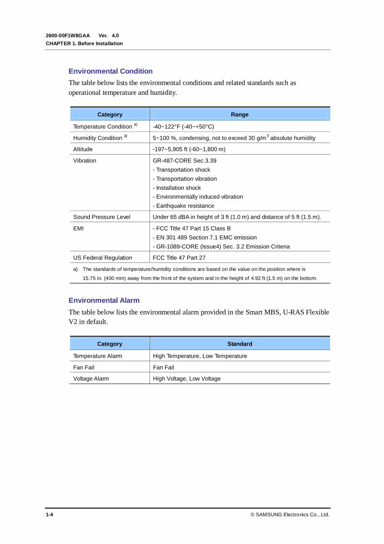
Environmental Condition
The table below lists the environmental conditions and related standards such as
operational temperature and humidity.
Category Range
Temperature Condition a)
-40~122°F (-40~+50°C)
Humidity Condition a) 5~100 %, condensing, not to exceed 30 g/m
3 absolute humidity
Altitude -197~5,905 ft (-60~1,800 m)
Vibration GR-487-CORE Sec.3.39
- Transportation shock
- Transportation vibration
- Installation shock
- Environmentally induced vibration
- Earthquake resistance
Sound Pressure Level Under 65 dBA in height of 3 ft (1.0 m) and distance of 5 ft (1.5 m).
EMI - FCC Title 47 Part 15 Class B
- EN 301 489 Section 7.1 EMC emission
- GR-1089-CORE (Issue4) Sec. 3.2 Emission Criteria
US Federal Regulation FCC Title 47 Part 27
a) The standards of temperature/humidity conditions are based on the value on the position where is
15.75 in. (400 mm) away from the front of the system and in the height of 4.92 ft (1.5 m) on the bottom.
Environmental Alarm
The table below lists the environmental alarm provided in the Smart MBS, U-RAS Flexible
V2 in default.
Category Standard
Temperature Alarm High Temperature, Low Temperature
Fan Fail Fan Fail
Voltage Alarm High Voltage, Low Voltage
Ver.
Mobile WiMAX/TD-LTE Smart MBS, U-RAS Flexible V2 RRH-B4 Installation Manual
© SAMSUNG Electronics Co., Ltd. 1-5
2600-00F1W8GAA 4.0
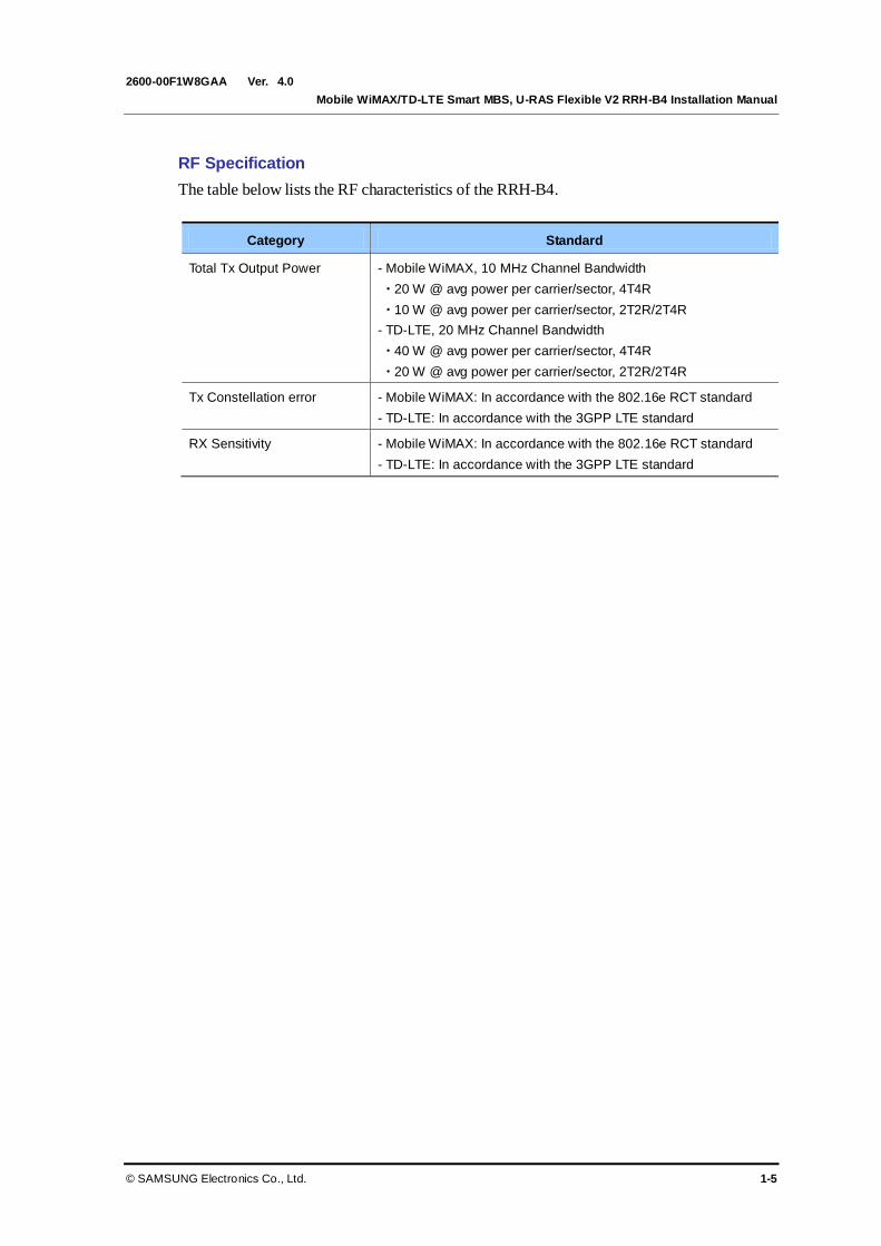
RF Specification
The table below lists the RF characteristics of the RRH-B4.
Category Standard
Total Tx Output Power - Mobile WiMAX, 10 MHz Channel Bandwidth
20 W @ avg power per carrier/sector, 4T4R
10 W @ avg power per carrier/sector, 2T2R/2T4R
- TD-LTE, 20 MHz Channel Bandwidth
40 W @ avg power per carrier/sector, 4T4R
20 W @ avg power per carrier/sector, 2T2R/2T4R
Tx Constellation error - Mobile WiMAX: In accordance with the 802.16e RCT standard
- TD-LTE: In accordance with the 3GPP LTE standard
RX Sensitivity - Mobile WiMAX: In accordance with the 802.16e RCT standard
- TD-LTE: In accordance with the 3GPP LTE standard

Ver.
CHAPTER 1. Before Installation
1-6 © SAMSUNG Electronics Co., Ltd.
2600-00F1W8GAA 4.0
1.3 Cautions for Installation
Observe the following safety instructions when installing the RRH-B4:
Before Installing
Post warning signs in areas where high-voltage cables are installed.
Post ‘off limit’ signs in areas where accidents are most expected.
With guardrails or fences, block open areas such as connecting parts, roof, and scaffold.
While Installing
The power must be cut off before installing.
Be careful that boards mounted on the system and the cables among the boards are
damaged or scratched when the system is transported or installed.
Wearing Protective Gloves and Glasses
The workers should wear the protective gloves and glasses because they can be
injured by the debris generated when drilling holes on walls or ceilings.
Do Not Wear Metal Things such as Watch, Ring, Etc.
Do not let the electric short circuit occur due to metal things such as watch or ring.
Warning for Worker’s Injury
When installing cables in a small area, do not apply excessive force. Worker may
bump against a wall or equipment.
Do not Work by Yourself
Worker must not work alone in any key process.
Managing Unused Ports
Never allow foreign substances to be inserted into unused ports by covering them
with a dust cap.

Ver.
Mobile WiMAX/TD-LTE Smart MBS, U-RAS Flexible V2 RRH-B4 Installation Manual
© SAMSUNG Electronics Co., Ltd. 1-7
2600-00F1W8GAA 4.0
Finishing the Cable Inlet
To prevent foreign substances, outdoor air and moisture from entering the cable
inlet (including cable gland and conduit), finish it as follows:
- Unused inlet
Use the hole finishing materials including dust cap and rubber packing.
- Cable-installed inlet
After cable installation, block any space in the inlet with tape, compressed
sponge, rubber packing, and silicon.
Outdoor Fastening Materials
The outdoor fastening materials such as stud bolts, hex. nuts, spring washers and
plane washers must be made of stainless steel (STS 304).
Otherwise, it may cause corrosion and rust to fixing materials.
After Installing
Cover the cable holes drilled on the floor with a solid cover.
Remove any debris produced during the work and clean up the installation site.
Warning for Laser Beam Running through Optical Cables
In the system, the laser beam emitting light runs through the optical cable.
The exposure of the laser beam on worker’s eye may cause serious injury so that
it should be handled with care.
Cautions while Cleaning the Rack
Make sure that worker does not damage installed cables while cleaning the rack.
Cautions while Cleaning Power Supply
While cleaning the power supply device, take caution that the device does not
come in contact with alien bodies that may cause power failure.

Ver.
CHAPTER 1. Before Installation
1-8 © SAMSUNG Electronics Co., Ltd.
2600-00F1W8GAA 4.0
1.4 Pre-survey
To enable seamless construction, the installer and the service provider should perform pre-
construction inspection to examine and analyze the following items.
Examination about the conformance and the economical efficiency of the place that
the system is transported or installed.
Status of external interfaces
Power capacity and wiring status
Possibility of system extension
Review if the place has the enough space to operate and maintain.
If there is a need for improvement or an issue, the installer and the service provider must
discuss measures to resolve any issue arising.
Ver.
Mobile WiMAX/TD-LTE Smart MBS, U-RAS Flexible V2 RRH-B4 Installation Manual
© SAMSUNG Electronics Co., Ltd. 1-9
2600-00F1W8GAA 4.0
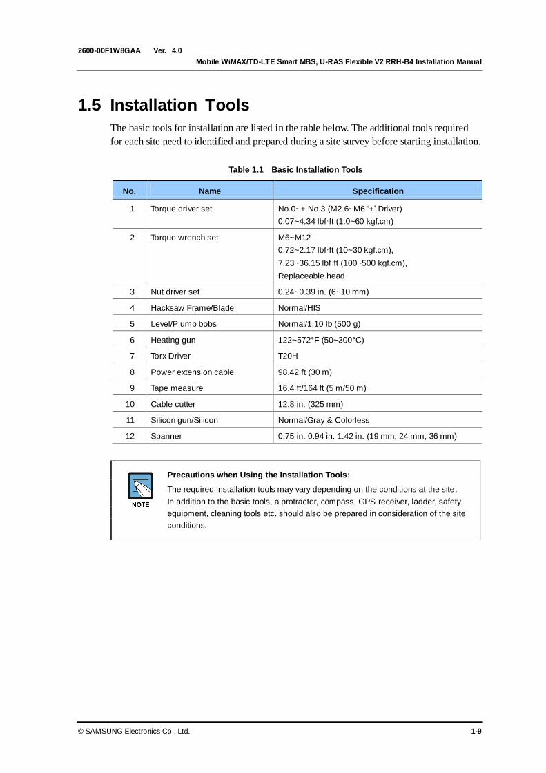
1.5 Installation Tools
The basic tools for installation are listed in the table below. The additional tools required
for each site need to identified and prepared during a site survey before starting installation.
Table 1.1 Basic Installation Tools
No. Name Specification
1 Torque driver set No.0~+ No.3 (M2.6~M6 ‘+’ Driver)
0.07~4.34 lbf·ft (1.0~60 kgf.cm)
2 Torque wrench set M6~M12
0.72~2.17 lbf·ft (10~30 kgf.cm),
7.23~36.15 lbf·ft (100~500 kgf.cm),
Replaceable head
3 Nut driver set 0.24~0.39 in. (6~10 mm)
4 Hacksaw Frame/Blade Normal/HIS
5 Level/Plumb bobs Normal/1.10 lb (500 g)
6 Heating gun 122~572°F (50~300°C)
7 Torx Driver T20H
8 Power extension cable 98.42 ft (30 m)
9 Tape measure 16.4 ft/164 ft (5 m/50 m)
10 Cable cutter 12.8 in. (325 mm)
11 Silicon gun/Silicon Normal/Gray & Colorless
12 Spanner 0.75 in. 0.94 in. 1.42 in. (19 mm, 24 mm, 36 mm)
Precautions when Using the Installation Tools:
The required installation tools may vary depending on the conditions at the site.
In addition to the basic tools, a protractor, compass, GPS receiver, ladder, safety
equipment, cleaning tools etc. should also be prepared in consideration of the site
conditions.

Ver.
CHAPTER 1. Before Installation
1-10 © SAMSUNG Electronics Co., Ltd.
2600-00F1W8GAA 4.0
This page is intentionally left blank.

Ver.
Mobile WiMAX/TD-LTE Smart MBS, U-RAS Flexible V2 RRH-B4 Installation Manual
© SAMSUNG Electronics Co., Ltd. 2-1
2600-00F1W8GAA 4.0
CHAPTER 2. Installing System
2.1 Installing the RRH-B4
The procedure to install the RRH-B4 is listed in the flow chart below.
Figure 2.1 Procedure to Install the RRH-B4
Foundation Work
Unpacking and Transporting
Marking and Drilling
System Arrangement
Fixing System
System Leveling
Installation Test
Unpacking Items
Importing Items

Ver.
CHAPTER 2. Installing System
2-2 © SAMSUNG Electronics Co., Ltd.
2600-00F1W8GAA 4.0
2.2 Foundation Work
2.2.1 System Arrangement
A minimum distance must be secured around the RRH-B4, in each direction for installation
and maintenance.
Table 2.1 Recommended Distances for RRH-B4 Installation
Category Recommended Distances
Front/Rear 31.5 in. (800 mm) or more
Side 23.62 in. (600 mm) or more
Figure 2.2 RRH-B4 Arragement (Wall Type)
[Left View]
15.35 (390)
[Top View]
21.6
5 (
550
)
8.1
7 (
207.5
)
Unit: in. (mm)

Ver.
Mobile WiMAX/TD-LTE Smart MBS, U-RAS Flexible V2 RRH-B4 Installation Manual
© SAMSUNG Electronics Co., Ltd. 2-3
2600-00F1W8GAA 4.0
Figure 2.3 RRH-B4 Arragement (Sector Pole Type)
System Installation Spaces
The space specifications in the figure above apply when the pole diameter is 3 in.
(76.3 mm). The dimensions may vary depending on the diameter of the pole.
[Front View]
13.78 (350)
[Top View]
21.6
5 (
550
)
11.8
1 (
300
)
Unit: in. (mm)
5.57
(141.6)
Ver.
CHAPTER 2. Installing System
2-4 © SAMSUNG Electronics Co., Ltd.
2600-00F1W8GAA 4.0
2.2.2 Marking and Drilling
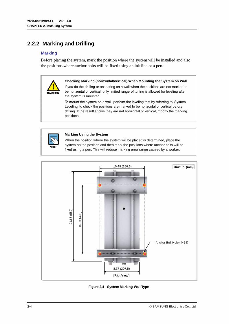
Marking
Before placing the system, mark the position where the system will be installed and also
the positions where anchor bolts will be fixed using an ink line or a pen.
Checking Marking (horizontal/vertical) When Mounting the System on Wall
If you do the drilling or anchoring on a wall when the positions are not marked to
be horizontal or vertical, only limited range of tuning is allowed for leveling after
the system is mounted.
To mount the system on a wall, perform the leveling test by referring to ‘System
Leveling’ to check the positions are marked to be horizontal or vertical before
drilling. If the result shows they are not horizontal or vertical, modify the marking
positions.
Marking Using the System
When the position where the system will be placed is determined, place the
system on the position and then mark the positions where anchor bolts will be
fixed using a pen. This will reduce marking error range caused by a worker.
Figure 2.4 System Marking-Wall Type
[Rigt View]
15.9
4 (
405
)
Anchor Bolt Hole (Ф 14)
Unit: in. (mm)
8.17 (207.5)
21.6
5 (
550
)
10.49 (266.5)

Ver.
Mobile WiMAX/TD-LTE Smart MBS, U-RAS Flexible V2 RRH-B4 Installation Manual
© SAMSUNG Electronics Co., Ltd. 2-5
2600-00F1W8GAA 4.0
Drilling
When marking is completed, drill holes for anchor bolts.
Table 2.2 Anchor Bolt Drill Bits and Hole Depth
Category Anchor Bolt Drill Bits Hole Depth
RRH-B4 (Wall Type) M12 0.67 in. (17 mm) 2.17 in. (55 mm)
Ver.
CHAPTER 2. Installing System
2-6 © SAMSUNG Electronics Co., Ltd.
2600-00F1W8GAA 4.0
2.3 Unpacking and Transporting
This paragraph describes the work to unpack cabinets and other components and transport
them to the place to be installed. The cabinet is externally packed and cabinet and other
components are individually packed.
The external packing must be unpacked in the outside. If necessary, the packing can be
unpacked after transported into the area near installation place.
Transport the cabinet to the installation place. Beware of the damage of walls, pillars,
and bottom of the passage when transporting the cabinet.
Transport other components with packing and sort by types.
2.3.1 Importing Items
Bring in items, taking care of the followings:
Regarding equipment weight and size, check the path to bring the equipment.
Lay Iron and veneer boards on stairs or doorsills to make the transportation easy.
When bring in equipment, beware of damage or impairment of main entrance, walls,
pillars, and floors of the station. Prepare protection materials and fix them with a high-
strength adhesive.
Vibration Level for Transportation
When carrying the system, tighten the system firmly not to exceed the proper vibration
level from 1 to 500 Hz.
When carrying system, use a cart or lift to prevent accidents. However, if the system must
be carried by people, enough people are required to carry the system.
Before moving the system, check the storage place for the system and remove obstacles in
advance. While moving system, boards and other devices should not be shocked physically
and damaged caused by dust, moisture, and static electricity.
When installing the items imported, system must be installed in a location whose access is
not easy from outside.
2.3.2 Unpacking Items
The procedure to unpack items is as follows:
The packing items must be packed until they reach the installation place.
The items are classified in accordance with each job specification and stored on a
place that does not interfere with working.
Unpacked systems must be installed immediately. If not installed immediately, the
systems must be stored in the installation place temporarily.
Unpack the inner packaging after each system is placed on its installation location.
Do not recycle packaging waste. Dispose of it in accordance with waste management act.

Ver.
Mobile WiMAX/TD-LTE Smart MBS, U-RAS Flexible V2 RRH-B4 Installation Manual
© SAMSUNG Electronics Co., Ltd. 2-7
2600-00F1W8GAA 4.0
2.4 Fixing System
2.4.1 Fixing Unit Mounting Bracket
The procedure for fixing the unit mounting bracket is as follows:
Table 2.3 Unit Mounting Bracket Fixing Parts And Tool
Classification Description
Parts Unit Mounting
Bracket Ass’y (1 Set)
Unit Mounting Bracket_Top 1 EA/1 Set
Unit Mounting Bracket_Bottom 1 EA/1 Set
Bakelite_Top1 1 EA/1 Set
Bakelite_Top2 1 EA/1 Set
Bakelite_Bottom 1 EA/1 Set
Fastener - M8 Plane Washer
- M8 Spring Washer
- M8 × 25L Hex. Bolt
- Insulation Bushing
6 EA/1 Set
6 EA/1 Set
6 EA/1 Set
6 EA/1 Set
Recommended
Torque Value
M8 × 25L Hex. Bolt 5.96~8.94 lbf.ft (82.4~123.6 kgf.cm)
Working Tools Torque Wrench and Level
Checking Top/Bottom When Fixing Unit Mount Bracket
To install the system accurately, fix the unit mounting brackets by distinguishing
its top and bottom as shown below.
Ver.
CHAPTER 2. Installing System
2-8 © SAMSUNG Electronics Co., Ltd.
2600-00F1W8GAA 4.0
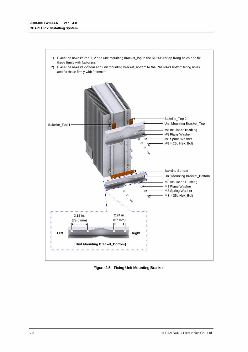
Figure 2.5 Fixing Unit Mounting Bracket
1) Place the bakelite-top 1, 2 and unit mounting bracket_top to the RRH-B4's top fixing holes and fix
these firmly with fasteners.
2) Place the bakelite-bottom and unit mounting bracket_bottom to the RRH-B4's bottom fixing holes
and fix these firmly with fasteners.
Bakelite_Top 2
[Unit Mounting Bracket_Bottom]
Left Right
3.13 in.
(79.5 mm)
2.24 in.
(57 mm)
Unit Mounting Bracket_Top
M8 Insulation Bushing
M8 Plane Washer
M8 Spring Washer
M8 × 25L Hex. Bolt
Bakelite_Top 1
Bakelite-Bottom
M8 Insulation Bushing
M8 Plane Washer
M8 Spring Washer
M8 × 25L Hex. Bolt
Unit Mounting Bracket_Bottom
Ver.
Mobile WiMAX/TD-LTE Smart MBS, U-RAS Flexible V2 RRH-B4 Installation Manual
© SAMSUNG Electronics Co., Ltd. 2-9
2600-00F1W8GAA 4.0
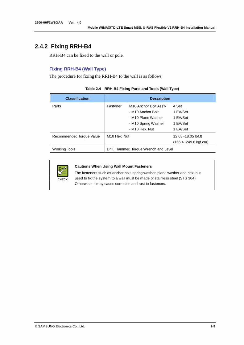
2.4.2 Fixing RRH-B4
RRH-B4 can be fixed to the wall or pole.
Fixing RRH-B4 (Wall Type)
The procedure for fixing the RRH-B4 to the wall is as follows:
Table 2.4 RRH-B4 Fixing Parts and Tools (Wall Type)
Classification Description
Parts Fastener M10 Anchor Bolt Ass’y
- M10 Anchor Bolt
- M10 Plane Washer
- M10 Spring Washer
- M10 Hex. Nut
4 Set
1 EA/Set
1 EA/Set
1 EA/Set
1 EA/Set
Recommended Torque Value M10 Hex. Nut 12.03~18.05 lbf.ft
(166.4~249.6 kgf.cm)
Working Tools Drill, Hammer, Torque Wrench and Level
Cautions When Using Wall Mount Fasteners
The fasteners such as anchor bolt, spring washer, plane washer and hex. nut
used to fix the system to a wall must be made of stainless steel (STS 304).
Otherwise, it may cause corrosion and rust to fasteners.

Ver.
CHAPTER 2. Installing System
2-10 © SAMSUNG Electronics Co., Ltd.
2600-00F1W8GAA 4.0
Figure 2.6 Fixing RRH-B4 (Wall Type)
Fix unit mounting bracket_top and unit mounting bracket_bottom (attached to the RRH-B4) to the wall
with fasteners.
M10 Anchor Bolt
Unit Mounting Bracket_Top
M10 Plane Washer
M10 Spring Washer
M10 Hex. Nut
RRH-B4
Unit Mounting Bracket_Top
Unit Mounting Bracket_Bottom
Ver.
Mobile WiMAX/TD-LTE Smart MBS, U-RAS Flexible V2 RRH-B4 Installation Manual
© SAMSUNG Electronics Co., Ltd. 2-11
2600-00F1W8GAA 4.0
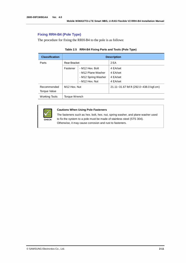
Fixing RRH-B4 (Pole Type)
The procedure for fixing the RRH-B4 to the pole is as follows:
Table 2.5 RRH-B4 Fixing Parts and Tools (Pole Type)
Classification Description
Parts Rear Bracket 2 EA
Fastener - M12 Hex. Bolt
- M12 Plane Washer
- M12 Spring Washer
- M12 Hex. Nut
4 EA/set
4 EA/set
4 EA/set
4 EA/set
Recommended
Torque Value
M12 Hex. Nut 21.11~31.67 lbf.ft (292.0~438.0 kgf.cm)
Working Tools Torque Wrench
Cautions When Using Pole Fasteners
The fasteners such as hex. bolt, hex. nut, spring washer, and plane washer used
to fix the system to a pole must be made of stainless steel (STS 304).
Otherwise, it may cause corrosion and rust to fasteners.
Ver.
CHAPTER 2. Installing System
2-12 © SAMSUNG Electronics Co., Ltd.
2600-00F1W8GAA 4.0
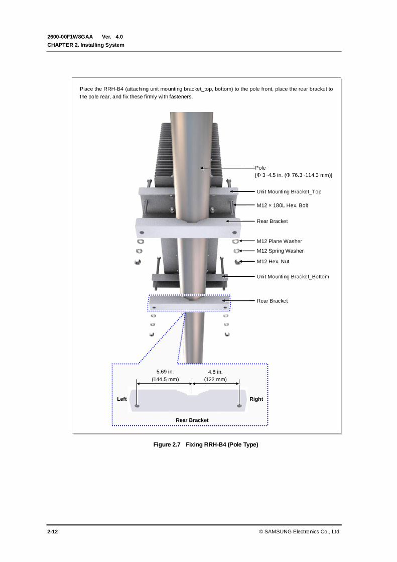
Figure 2.7 Fixing RRH-B4 (Pole Type)
Place the RRH-B4 (attaching unit mounting bracket_top, bottom) to the pole front, place the rear bracket to
the pole rear, and fix these firmly with fasteners.
M12 × 180L Hex. Bolt
Pole
[Φ 3~4.5 in. (Φ 76.3~114.3 mm)]
Unit Mounting Bracket_Top
Rear Bracket
M12 Plane Washer
M12 Spring Washer
M12 Hex. Nut
Rear Bracket
Unit Mounting Bracket_Bottom
Left Right
5.69 in.
(144.5 mm)
4.8 in.
(122 mm)
Rear Bracket
Ver.
Mobile WiMAX/TD-LTE Smart MBS, U-RAS Flexible V2 RRH-B4 Installation Manual
© SAMSUNG Electronics Co., Ltd. 2-13
2600-00F1W8GAA 4.0
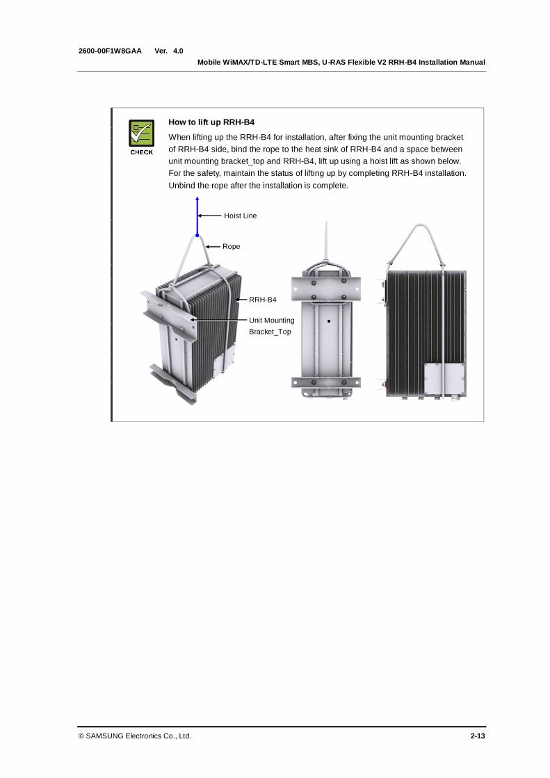
How to lift up RRH-B4
When lifting up the RRH-B4 for installation, after fixing the unit mounting bracket
of RRH-B4 side, bind the rope to the heat sink of RRH-B4 and a space between
unit mounting bracket_top and RRH-B4, lift up using a hoist lift as shown below.
For the safety, maintain the status of lifting up by completing RRH-B4 installation.
Unbind the rope after the installation is complete.
Rope
Hoist Line
RRH-B4
Unit Mounting
Bracket_Top

Ver.
CHAPTER 2. Installing System
2-14 © SAMSUNG Electronics Co., Ltd.
2600-00F1W8GAA 4.0
2.5 System Leveling
Leveling refers to compensating for the level difference on the floor that is generated
during floor work to install devices horizontally or vertically. Leveling can be carried out
using a vinyl hose, a balance weight, or a level.
In this manual, a commonly used method, which uses a spirit level, is described.
Leveling Using a Level
Leveling method using a level is as follows:
Table 2.6 Leveling Using a Level
Classification Description
Test method The level is measured based on the position of a bubble after attaching the
spirit level to the top and side of the system.
Evaluation criteria Good Poor
If it is leveled, the bubble of the spirit level is positioned at the center of both
lines.
Corrective
measures for poor
leveling
Use an aid such as bakelite on the back side of the system or an auxiliary
fixture to adjust the height.
Adjust the position of fasteners used to fix the system or its leveling status.
Figure 2.8 Leveling Using a Level (Example)
[Measuring Vertical Position]
[Measuring Horizontal Position]

Ver.
Mobile WiMAX/TD-LTE Smart MBS, U-RAS Flexible V2 RRH-B4 Installation Manual
© SAMSUNG Electronics Co., Ltd. 2-15
2600-00F1W8GAA 4.0
2.6 Insulation Test
Insulation test procedure is as follows:
Table 2.7 Insulation Test
Classification Description
Test method The insulation tester (Megger) is used for measurement.
Position of lead
line of insulation
tester
Wall Type Lead line_A Bracket fixing anchor bolt
Lead line_B System’s screw
Pole Type Lead line_A Bracket fixing Hex. Bolt.
Lead line_B System’s screw
Evaluation
criteria
Good Poor
500 V/100 MΩ or more Less than 500 V/100 MΩ
Corrective
measures for
poor leveling
- Check the contact between the system and anchor bolt and re-assemble it.
(But, the anchor bolt must be shielded using an insulator such as an insulation
bushing, etc.)
- Check damage of an insulator such as an insulation busing or bakelite, etc. and
replace it.
Cautions When Using Insulation Tester
Pay attention to the followings to prevent any personal injury caused by an
electric shock when using an insulation tester.
- Make sure the polarity is correct when connecting the Earth COM (black) and
AC.V (red) lead lines. And do not touch the connected probes inspecting part of
the lead line) with a hand and avoid body contact.
- Avoid body contact to the system when measuring an insulation resistance.
Precautions While Measuring Insulation Resistance
Observe the followings to prevent any system damage when measuring insulation
resistance because there is a very high voltage.
- Before measuring insulation resistance, disconnect all the cables connected to
the system.
- Do not measure insulation resistance when power is on.
- Do not measure insulation resistance at any other positions such as system
internal units or parts other than the targeted insulation resistance measuring
points.
Probe
(Inspecting part of the
lead line)

Ver.
CHAPTER 2. Installing System
2-16 © SAMSUNG Electronics Co., Ltd.
2600-00F1W8GAA 4.0
Figure 2.9 Schematic Diagram for Insulation Test (Wall Type)
Figure 2.10 Schematic Diagram for Insulation Test (Pole Type)
[Megger]
[System’s screw]
[Bracket Fixing Anchor Bolt]
[Megger]
[System’s screw]
[Bracket Fixing Hex.Bolt]

Ver.
Mobile WiMAX/TD-LTE Smart MBS, U-RAS Flexible V2 RRH-B4 Installation Manual
© SAMSUNG Electronics Co., Ltd. 3-1
2600-00F1W8GAA 4.0
CHAPTER 3. Connecting Cables
3.1 Work Flow for Cabling
The cable workflow for the system is as follows:
Figure 3.1 Work Flow for System Cabling
Grounding
Power Cabling
External Interface Cabling
CPRI Cable Connection
RET/RF Cable Connection

Ver.
CHAPTER 3. Connecting Cables
3-2 © SAMSUNG Electronics Co., Ltd.
2600-00F1W8GAA 4.0
The detailed procedure of cabling is as follows:
Figure 3.2 Detailed Cabling Procedure
Considerations when Cutting the Cable after Installation
When cutting the cable after installation, make sure that the connector is
disconnected. Installation of the cable with the connector connected to the system
may cause contact failure or damage to the connector assembled to the system
and the cable due to cable tension or the operator’s mistakes.
Cabling Workflow
The sequence of cable cutting and installation of the cable workflow can be
changed depending on the field situation such as ‘cutting after installing’ or
‘installing after cutting’.
Cable Path Inspection
When installing a cable that connects between the rectifier, Main Ground Bar (MGB), and
backhaul device, etc. within the system, the cable path length and the cable installation
method, etc. must be inspected.
Follow these guidelines when inspecting the cabling path.
A minimum cable length must be selected provided that it does not affect the cable
installation and maintenance.
The cable must be placed in a location where it will not be damaged by external
factors. (power line, flooding, footpaths, etc.)
In areas where the cable may be damaged by external factors, ensure that measures are
taken to prevent damage to the cable. (cable tray, ducts, flexible pipe, etc.)
Cable Installation
Cable Binding
Connector Attachment
Identification Tag Attachment
Connector Assembly When assembling the
connector at the site
Cable Path Inspection
Cable Cutting
Ver.
Mobile WiMAX/TD-LTE Smart MBS, U-RAS Flexible V2 RRH-B4 Installation Manual
© SAMSUNG Electronics Co., Ltd. 3-3
2600-00F1W8GAA 4.0
Cable Cutting
Measure the exact distance, carefully checking the route, and cut the cable using a cutting tool.
Follow these guidelines when cutting the cable.
Cut the cable to the length determined in the Cable Path Inspection step.
Use a dedicated cable cutting tool.
Cut the cable at right angles.
Be careful to keep the cable away from any moisture, iron, lead, dust or other foreign
material when cutting.
Remove any foreign material attached to the cable using solvent and a brush.
Cable Installation
Cable installation involves running the cable along the cabling path to the target connector
of the system or an auxiliary device after cable path inspection and cable cutting have been
completed.
Follow these guidelines when installing a cable.
Be careful not to damage the cable.
If the cable is damaged, cut out the damaged section before installing.
When installing the cable over other cables, make sure the cable is installed on the
other cables. Pay more attention to the vertical and horizontal cross sections where the
cables are usually reversed.
Always use the maximum curvature radius possible, and make sure that the minimum
curvature radius specification is complied with.
If the cable needs to be protected, use a PVC channel, spiral sleeve, flexible pipe, and
cable tray, etc.
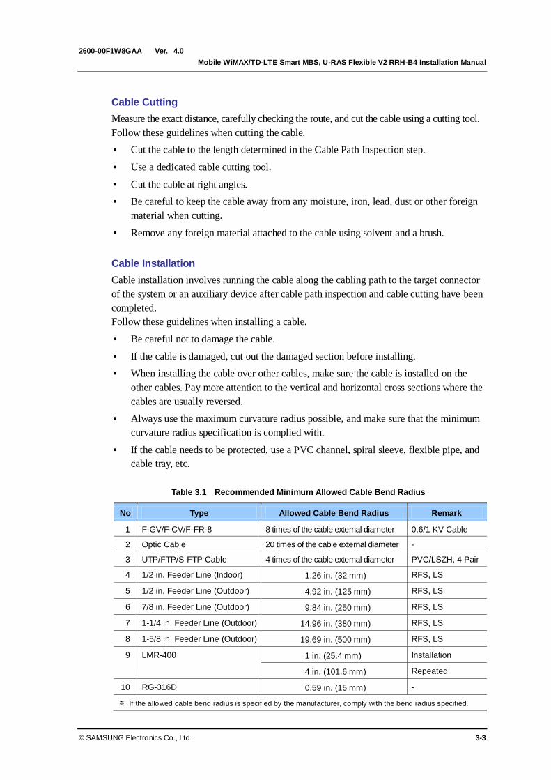
Table 3.1 Recommended Minimum Allowed Cable Bend Radius
No Type Allowed Cable Bend Radius Remark
1 F-GV/F-CV/F-FR-8 8 times of the cable external diameter 0.6/1 KV Cable
2 Optic Cable 20 times of the cable external diameter -
3 UTP/FTP/S-FTP Cable 4 times of the cable external diameter PVC/LSZH, 4 Pair
4 1/2 in. Feeder Line (Indoor) 1.26 in. (32 mm) RFS, LS
5 1/2 in. Feeder Line (Outdoor) 4.92 in. (125 mm) RFS, LS
6 7/8 in. Feeder Line (Outdoor) 9.84 in. (250 mm) RFS, LS
7 1-1/4 in. Feeder Line (Outdoor) 14.96 in. (380 mm) RFS, LS
8 1-5/8 in. Feeder Line (Outdoor) 19.69 in. (500 mm) RFS, LS
9 LMR-400 1 in. (25.4 mm) Installation
4 in. (101.6 mm) Repeated
10 RG-316D 0.59 in. (15 mm) -
※ If the allowed cable bend radius is specified by the manufacturer, comply with the bend radius specified.
Ver.
CHAPTER 3. Connecting Cables
3-4 © SAMSUNG Electronics Co., Ltd.
2600-00F1W8GAA 4.0
Cable Binding
Cable binding involves fixing and arranging an installed cable using binding thread, cable
ties, binding wire, and ram clamps, etc.
Follow these guidelines when binding a cable.
Be careful not to damage the cable during binding.
Use appropriate cable binding tools according to the target location (indoor or outdoor,
etc.) and the use of the cable (power supply cable, optical cable, feeder line, etc.).
Do not let the cutting section of a cable tie and binding line, etc. be exposed to the
outside. This may cause damage to cables or personal injury. Make sure that the
cutting sections of cables are not exposed to the outside.
Trim the cable binding cord at about 5 cm (1.97 in.) distance from its knob and insert
it into the knot so that the knot does not loosen.
If there is a danger that contact failure may occur in a connector connection due to
tension, install the cable as short as possible.
Assembling and Connecting Connectors
Connector connection involves assembling a connector to an installed cable and connecting
the assembled connector to a device.
Follow these guidelines when assembling and connecting connectors.
Make sure you are fully aware of the connector assembly method before assembling a
connector. Assemble the connector in accordance with its pin map.
Each connector has a hook to prevent its core positions from being changed.
Check the corresponding grooves before connecting a connector to another connector.
Use a heat shrink tube at a connector connection for cables that are installed outdoor,
such as feeder lines, to prevent water leakage and corrosion from occurring at the part
exposed to the outside.
Connect each cable of the connector assembly in a straight line.
Be careful when connecting a cable so that contact failure does not occur at a
connector connection due to tension.
Identification Tag Attachment
Identification tag attachment involves attaching a marker cable tie, nameplate, and label, etc.
to the both ends of a cable (connections to a connector) to identify its use and cabling path.
Marker Cable Tie
On the marker cable tie, a label can be attached.
The appearance and specification may differ depending
on the type and manufacturer.

Ver.
Mobile WiMAX/TD-LTE Smart MBS, U-RAS Flexible V2 RRH-B4 Installation Manual
© SAMSUNG Electronics Co., Ltd. 3-5
2600-00F1W8GAA 4.0
Follow these guidelines when attaching an identification tag.
When installing a cable outdoor, use relief engraving and coated labels, etc. to prevent
the markings from being erased.
Since the form and attachment method for identification tags are different for each
provider, consult with the provider before attaching them.
Connecting Ground Cable
When connecting the cables, always connect the ground cable first. If worker
contacts the equipment, connect a cable or perform maintenance without
connecting the ground cable, the system can be damaged or a worker may be
injured due to static electricity and short circuit.
Management of Unused Ports
Cover the unused ports (conduit, cable gland, etc.) with waterproof cap (sealing
cap) to prevent infiltration of foreign material such as dust, moisture, or bug.
Cable Installation Checklist
When installing, take care not to overlap or tangle the cables; also, consider
future expansion. Install the DC power cable and data transmission cable away
from the AC power cable to prevent electromagnetic induction.
Cable Works
The cable works require the knowledge for the cabling works such as cable install
ation/tying.

Ver.
CHAPTER 3. Connecting Cables
3-6 © SAMSUNG Electronics Co., Ltd.
2600-00F1W8GAA 4.0
3.2 Cabling
The cabling diagram of the RRH-B4 is as follows:
Figure 3.3 Cabling Diagram
3)
R
RH
-B4 G
rou
nd C
able
[RF Antenna]
[MGB]
2) TGB Ground Cable
[TGB]
Fee
der
Lin
e G
roun
d C
able
(When
Usin
g G
roun
d K
it/7
/8 in.
Feed
er
Lin
e)
※ TGB and Ground Kit are used when using the 7/8 in. feeder line or more.
[Rectifier] [Smart MBS UADU]
4)
P
ow
er
Cable
1) MGB Ground Cable
5) CPRI Cable
6) RET Cable
7) RF Cable
[U-RAS Flexible V2 DU]

Ver.
Mobile WiMAX/TD-LTE Smart MBS, U-RAS Flexible V2 RRH-B4 Installation Manual
© SAMSUNG Electronics Co., Ltd. 3-7
2600-00F1W8GAA 4.0
Table 3.2 RRH-B4 Connection Cable
From To Cable
Underground
ground
MGB (Main Ground Bar) 1) MGB Ground Cable
: AWG4/0, F-GV 95 mm2 × 1C
(However, this can be changed depending on
the standards of each provider.)
TGB (Tower Ground Bar) 2) TGB Ground Cable
: AWG2, F-GV 35 mm2 × 1C
(However, this can be changed depending on
the standards of each provider.)
RRH-B4 MGB 3) RRH-B4 Ground Cable
: AWG8, F-GV 6 mm2 × 1C
Rectifier 4) Power Cable
: AWG10, F-CV 4 mm2 × 2C
(or AWG8, F-CV 6 mm2 × 2C)
Smart MBS UADU 5) CPRI Cable
: Optic Cable (Single Mode) U-RAS Flexible V2 DU
RF Antenna 6) RET Cable Ass’y (Using Shield Cable)
7) RF Cable
: 1/2 in. or 7/8 in. Feeder Line
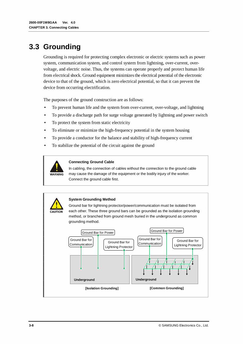
Ver.
CHAPTER 3. Connecting Cables
3-8 © SAMSUNG Electronics Co., Ltd.
2600-00F1W8GAA 4.0
3.3 Grounding
Grounding is required for protecting complex electronic or electric systems such as power
system, communication system, and control system from lightning, over-current, over-
voltage, and electric noise. Thus, the systems can operate properly and protect human life
from electrical shock. Ground equipment minimizes the electrical potential of the electronic
device to that of the ground, which is zero electrical potential, so that it can prevent the
device from occurring electrification.
The purposes of the ground construction are as follows:
To prevent human life and the system from over-current, over-voltage, and lightning
To provide a discharge path for surge voltage generated by lightning and power switch
To protect the system from static electricity
To eliminate or minimize the high-frequency potential in the system housing
To provide a conductor for the balance and stability of high-frequency current
To stabilize the potential of the circuit against the ground
Connecting Ground Cable
In cabling, the connection of cables without the connection to the ground cable
may cause the damage of the equipment or the bodily injury of the worker.
Connect the ground cable first.
System Grounding Method
Ground bar for lightning protector/power/communication must be isolated from
each other. These three ground bars can be grounded as the isolation grounding
method, or branched from ground mesh buried in the underground as common
grounding method.
Ground Bar for
Communication
Ground Bar for Power
Ground Bar for
Lightning Protector
Ground Bar for
Communication
Ground Bar for Power
Ground Bar for
Lightning Protector
Underground
[Isolation Grounding] [Common Grounding]
Underground

Ver.
Mobile WiMAX/TD-LTE Smart MBS, U-RAS Flexible V2 RRH-B4 Installation Manual
© SAMSUNG Electronics Co., Ltd. 3-9
2600-00F1W8GAA 4.0
3.3.1 Grounding the System
The way to connect the ground cable of RRH-B4 is as follows:
Table 3.3 Grounding the RRH-B4 (MGB~RRH-B4)
Classification Description
Installation Section MGB~RRH-B4 Grounding Terminal
Cable AWG8, F-GV 6 mm2 × 1C
Heat Shrink Tube
(Spec/Color/Length)
Φ 0.39 in. (10 mm)/Green/1.96 in. (50 mm)
Pressure Terminal MGB Checking MGB specifications per site and preparing fasteners
RRH-B4 AWG8 (6 mm2), 2 Hole, Hole Dia.: 1/4 in. (6.35 mm), Hole
Space: 0.63 in. (16 mm)
Fastener MGB Checking MGB specifications per site and preparing fasteners
RRH-B4 M6 × 10L SEMS/2 EA
Recommended
Torque Value
M6 SEMS 5.96~8.94 lbf.ft (82.4~123.6 kgf.cm)
Working Tools Cable Cutter, Wire Stripper, Compressor, Heating Gun, Torque Driver (+),
Torque Wrench, Nipper
Pressure Terminal for Grounding
As for the pressure terminal or the cable, the UL certified products or equivalent
should be used.
Ex) Manufacturer: Panduit
RRH-B4: AWG8 (6 mm2) Pressure Terminal (LCD8-14AF-L)
Assembling a Pressure Terminal and a Heat Shrink Tube
Refer to the ‘ANNEX F’ to see how to assemble a pressure terminal and a heat
shrink tube to a cable.

Ver.
CHAPTER 3. Connecting Cables
3-10 © SAMSUNG Electronics Co., Ltd.
2600-00F1W8GAA 4.0
Figure 3.4 Connection of the RRH-B4 Ground Cable
RRH-B4
‘A’
Ground Cable(AWG8, F-GV 6 mm2 × 1C)
M6 × 10L SEMS
Ground Cable (AWG8, F-GV 6 mm2 × 1C)
From MGB (Main Ground Bar)
Heat Shrink Tube (Green)
Detail ‘A’
AWG8 (6 mm2) Pressure Terminal
(2 Hole, 90°, hole dia.: 1/4 in., hole space: 0.63 in.)
Power Cable Bracket
1) Install the ground cable from the MGB to the RRH-B4 ground terminal.
2) Assemble a pressure terminal and a heat shrink tube at the end of the RRH-B4 ground cable.
3) Align the pressure terminal assembled to a ground cable to the mounting hole of the RRH-B4 ground
terminal.
4) Firmly fix the pressure terminal onto the RRH-B4 ground terminal using fasteners.
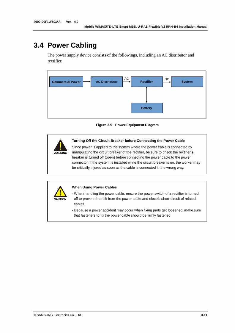
Ver.
Mobile WiMAX/TD-LTE Smart MBS, U-RAS Flexible V2 RRH-B4 Installation Manual
© SAMSUNG Electronics Co., Ltd. 3-11
2600-00F1W8GAA 4.0
3.4 Power Cabling
The power supply device consists of the followings, including an AC distributor and
rectifier.
Figure 3.5 Power Equipment Diagram
Turning Off the Circuit Breaker before Connecting the Power Cable
Since power is applied to the system where the power cable is connected by
manipulating the circuit breaker of the rectifier, be sure to check the rectifier’s
breaker is turned off (open) before connecting the power cable to the power
connector. If the system is installed while the circuit breaker is on, the worker may
be critically injured as soon as the cable is connected in the wrong way.
When Using Power Cables
- When handling the power cable, ensure the power switch of a rectifier is turned
off to prevent the risk from the power cable and electric short-circuit of related
cables.
- Because a power accident may occur when fixing parts get loosened, make sure
that fasteners to fix the power cable should be firmly fastened.
AC AC Distributor
Commercial Power DC
System Rectifier
Battery
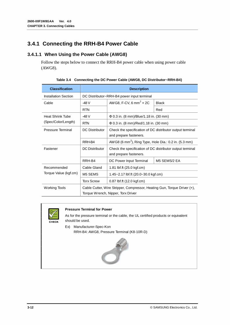
Ver.
CHAPTER 3. Connecting Cables
3-12 © SAMSUNG Electronics Co., Ltd.
2600-00F1W8GAA 4.0
3.4.1 Connecting the RRH-B4 Power Cable
3.4.1.1 When Using the Power Cable (AWG8)
Follow the steps below to connect the RRH-B4 power cable when using power cable
(AWG8).
Table 3.4 Connecting the DC Power Cable (AWG8, DC Distributor~RRH-B4)
Classification Description
Installation Section DC Distributor~RRH-B4 power input terminal
Cable -48 V AWG8, F-CV, 6 mm2 × 2C Black
RTN Red
Heat Shrink Tube
(Spec/Color/Length)
-48 V Φ 0.3 in. (8 mm)/Blue/1.18 in. (30 mm)
RTN Φ 0.3 in. (8 mm)/Red/1.18 in. (30 mm)
Pressure Terminal DC Distributor Check the specification of DC distributor output terminal
and prepare fasteners.
RRH-B4 AWG8 (6 mm2), Ring Type, Hole Dia.: 0.2 in. (5.3 mm)
Fastener DC Distributor Check the specification of DC distributor output terminal
and prepare fasteners.
RRH-B4 DC Power Input Terminal M5 SEMS/2 EA
Recommended
Torque Value (kgf.cm)
Cable Gland 1.81 lbf.ft (25.0 kgf.cm)
M5 SEMS 1.45~2.17 lbf.ft (20.0~30.0 kgf.cm)
Torx Screw 0.87 lbf.ft (12.0 kgf.cm)
Working Tools Cable Cutter, Wire Stripper, Compressor, Heating Gun, Torque Driver (+),
Torque Wrench, Nipper, Torx Driver
Pressure Terminal for Power
As for the pressure terminal or the cable, the UL certified products or equivalent
should be used.
Ex) Manufacturer-Spec-Kon
RRH-B4: AWG8, Pressure Terminal (K8-10R-D)

Ver.
Mobile WiMAX/TD-LTE Smart MBS, U-RAS Flexible V2 RRH-B4 Installation Manual
© SAMSUNG Electronics Co., Ltd. 3-13
2600-00F1W8GAA 4.0
Circuit Breaker Installation
To supply stable power to the system, a circuit breaker must be installed to a
power supplier. The capacity of -48 VDC circuit breaker is 32 A.
Assembling a Pressure Terminal and a Heat Shrink Tube
Refer to the ‘ANNEX F’ to see how to assemble a pressure terminal and a heat
shrink tube to a cable.
Tools to Tighten Stainless Steel Tie
It is recommended to use the following tools or their equivalents to tighten the
stainless steel tie that is used to fix an external power cable support bracket and
a power cable.
Ex) Manufacture-Dong A bestech
Part No: DAS 250

Ver.
CHAPTER 3. Connecting Cables
3-14 © SAMSUNG Electronics Co., Ltd.
2600-00F1W8GAA 4.0
Disassembling the Cover of RRH-B4 Power Window
Figure 3.6 Connecting the RRH-B4 Power Cable_AWG8 (1)
Open the power window at the rear bottom of RRH-B4 by loosening the Torx screws for fixing cover with a
Torx driver (T20).
Cover Fixing
Torx Screw(T20)
Power Window Cover

Ver.
Mobile WiMAX/TD-LTE Smart MBS, U-RAS Flexible V2 RRH-B4 Installation Manual
© SAMSUNG Electronics Co., Ltd. 3-15
2600-00F1W8GAA 4.0
Connecting the RRH-B4 Power Cable
Figure 3.7 Connecting the RRH-B4 Power Cable_AWG8 (2)
1) Install power cable up to the power port of RRH-B4, referring to the ‘Cautions When Installing Power
Cable’.
2) Cut the power cable installed to the power port, strip the cable sheath, and strip the core wire.
3) Insert a heat shrink tube to each core, and install the compression terminal and compressing it.
4) Place the heat shrink tube on the pressure terminal assembly (-48 V: blue, RTN: red), and shrink it
using a heating gun.
DC Power Cable (AWG8)
0.58~0.6 in.
(14.7~15.4mm)
1.77 in. (45 mm)
0.39 in.(10 mm)
0.59 in.
(15 mm)
RTN
-48 V
DC Power Cable (AWG8)
DC Power Cable (AWG8)
1.38 in. (35 mm)
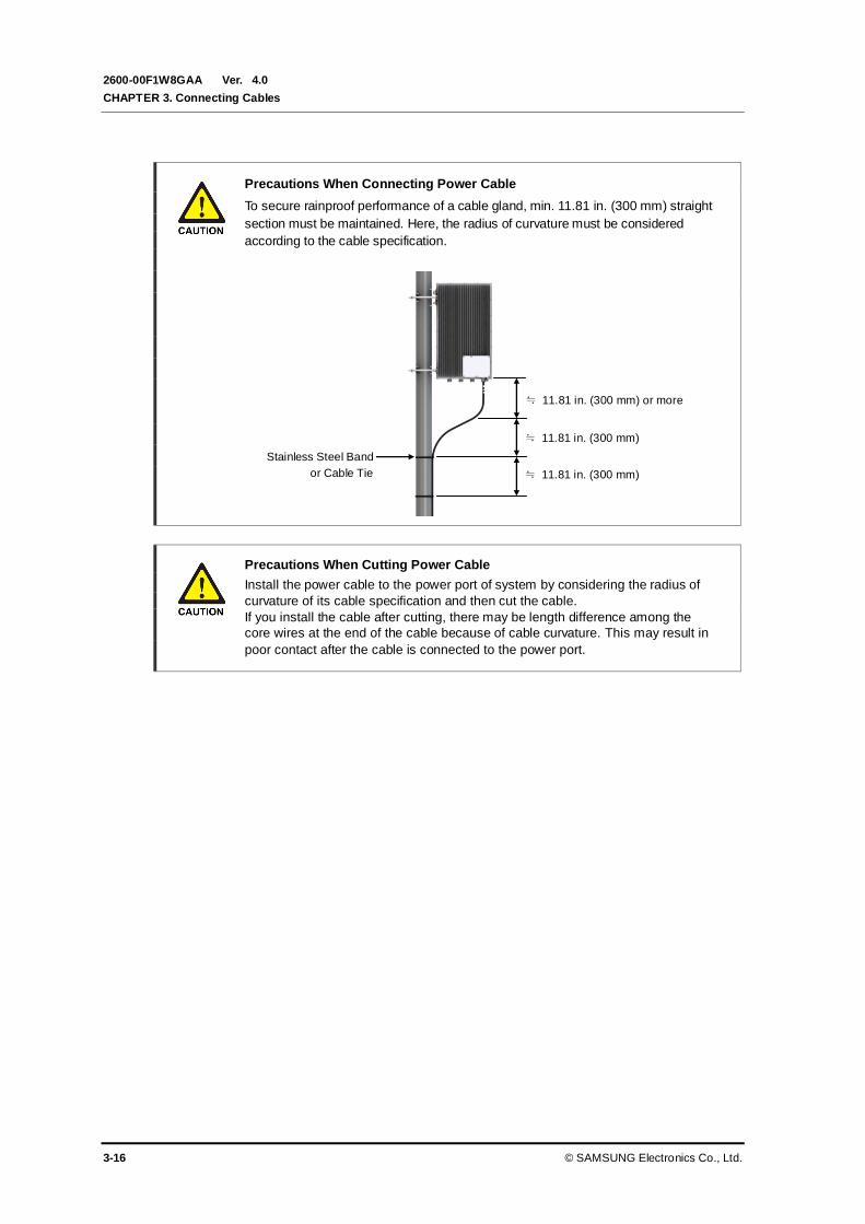
Ver.
CHAPTER 3. Connecting Cables
3-16 © SAMSUNG Electronics Co., Ltd.
2600-00F1W8GAA 4.0
Precautions When Connecting Power Cable
To secure rainproof performance of a cable gland, min. 11.81 in. (300 mm) straight
section must be maintained. Here, the radius of curvature must be considered
according to the cable specification.
Precautions When Cutting Power Cable
Install the power cable to the power port of system by considering the radius of
curvature of its cable specification and then cut the cable.
If you install the cable after cutting, there may be length difference among the
core wires at the end of the cable because of cable curvature. This may result in
poor contact after the cable is connected to the power port.
Stainless Steel Band
or Cable Tie
≒ 11.81 in. (300 mm) or more
≒ 11.81 in. (300 mm)
≒ 11.81 in. (300 mm)
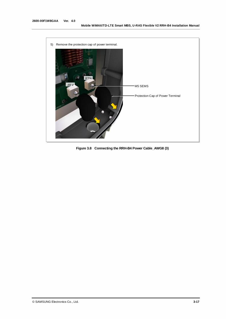
Ver.
Mobile WiMAX/TD-LTE Smart MBS, U-RAS Flexible V2 RRH-B4 Installation Manual
© SAMSUNG Electronics Co., Ltd. 3-17
2600-00F1W8GAA 4.0
Figure 3.8 Connecting the RRH-B4 Power Cable_AWG8 (3)
5) Remove the protection cap of power terminal.
RTN
-48 V
Protection Cap of Power Terminal
M5 SEMS
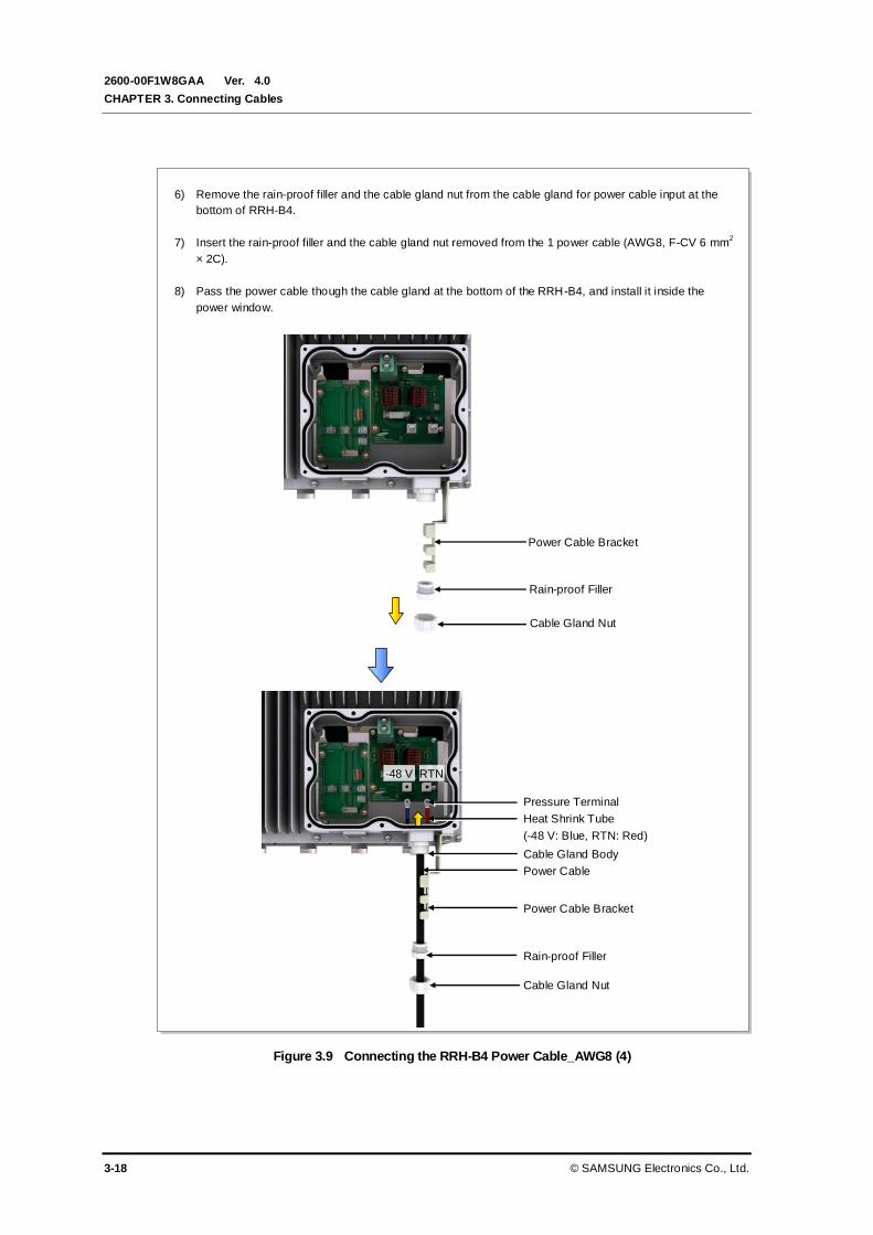
Ver.
CHAPTER 3. Connecting Cables
3-18 © SAMSUNG Electronics Co., Ltd.
2600-00F1W8GAA 4.0
Figure 3.9 Connecting the RRH-B4 Power Cable_AWG8 (4)
6) Remove the rain-proof filler and the cable gland nut from the cable gland for power cable input at the
bottom of RRH-B4.
7) Insert the rain-proof filler and the cable gland nut removed from the 1 power cable (AWG8, F-CV 6 mm2
× 2C).
8) Pass the power cable though the cable gland at the bottom of the RRH-B4, and install it inside the
power window.
Power Cable Bracket
RTN -48 V
Rain-proof Filler
Cable Gland Nut
Cable Gland Nut
Rain-proof Filler
Pressure Terminal
Cable Gland Body
Heat Shrink Tube
(-48 V: Blue, RTN: Red)
Power Cable Bracket
Power Cable

Ver.
Mobile WiMAX/TD-LTE Smart MBS, U-RAS Flexible V2 RRH-B4 Installation Manual
© SAMSUNG Electronics Co., Ltd. 3-19
2600-00F1W8GAA 4.0
Figure 3.10 Connecting the RRH-B4 Power Cable_AWG8 (5)
9) Place the pressure terminal installed to the power cable according to the polarity of the power terminal
block, and fix it with fasteners.
Power Cable
(-48 V: Black, RTN: Red)
Pressure Terminal
RTN
-48 V
Heat Shrink Tube
(-48 V: Blue, RTN: Red)
M5 SEMS
Protection Cap of Power Terminal
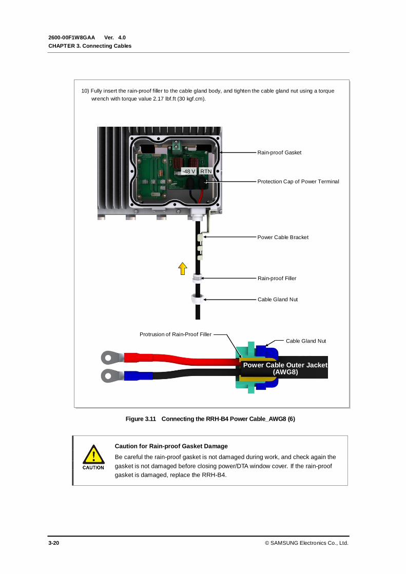
Ver.
CHAPTER 3. Connecting Cables
3-20 © SAMSUNG Electronics Co., Ltd.
2600-00F1W8GAA 4.0
Figure 3.11 Connecting the RRH-B4 Power Cable_AWG8 (6)
Caution for Rain-proof Gasket Damage
Be careful the rain-proof gasket is not damaged during work, and check again the
gasket is not damaged before closing power/DTA window cover. If the rain-proof
gasket is damaged, replace the RRH-B4.
Rain-proof Filler
10) Fully insert the rain-proof filler to the cable gland body, and tighten the cable gland nut using a torque
wrench with torque value 2.17 lbf.ft (30 kgf.cm).
Protrusion of Rain-Proof Filler
Cable Gland Nut
Power Cable Bracket
RTN -48 V
Power Cable Outer Jacket (AWG8)
Cable Gland Nut
Rain-proof Gasket
Protection Cap of Power Terminal

Ver.
Mobile WiMAX/TD-LTE Smart MBS, U-RAS Flexible V2 RRH-B4 Installation Manual
© SAMSUNG Electronics Co., Ltd. 3-21
2600-00F1W8GAA 4.0
Figure 3.12 Connecting the RRH-B4 Power Cable_AWG8 (7)
11) Close the power window, and tighten the Torx screws with a torque driver (T20) with torque value
0.87 lbf.ft (12 kgf.cm). Tightening order is .
12) Fix the RRH-B4 power cable and the power cable bracket using a stainless steel tie.
Stainless Steel Tie
Power Cable
(AWG 8, F-CV 6 mm2 × 2C)
Power Cable Bracket
Cover Fixing
Torx Screw (T20)
Power
Window Cover
Torque Driver
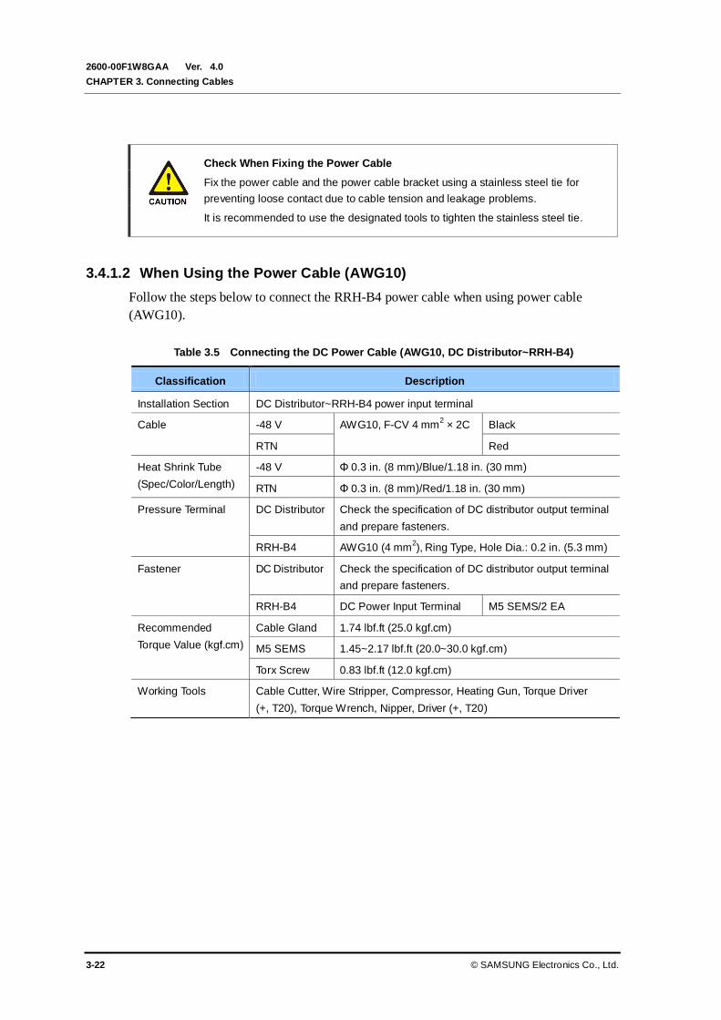
Ver.
CHAPTER 3. Connecting Cables
3-22 © SAMSUNG Electronics Co., Ltd.
2600-00F1W8GAA 4.0
Check When Fixing the Power Cable
Fix the power cable and the power cable bracket using a stainless steel tie for
preventing loose contact due to cable tension and leakage problems.
It is recommended to use the designated tools to tighten the stainless steel tie.
3.4.1.2 When Using the Power Cable (AWG10)
Follow the steps below to connect the RRH-B4 power cable when using power cable
(AWG10).
Table 3.5 Connecting the DC Power Cable (AWG10, DC Distributor~RRH-B4)
Classification Description
Installation Section DC Distributor~RRH-B4 power input terminal
Cable -48 V AWG10, F-CV 4 mm2 × 2C Black
RTN Red
Heat Shrink Tube
(Spec/Color/Length)
-48 V Φ 0.3 in. (8 mm)/Blue/1.18 in. (30 mm)
RTN Φ 0.3 in. (8 mm)/Red/1.18 in. (30 mm)
Pressure Terminal DC Distributor Check the specification of DC distributor output terminal
and prepare fasteners.
RRH-B4 AWG10 (4 mm2), Ring Type, Hole Dia.: 0.2 in. (5.3 mm)
Fastener DC Distributor Check the specification of DC distributor output terminal
and prepare fasteners.
RRH-B4 DC Power Input Terminal M5 SEMS/2 EA
Recommended
Torque Value (kgf.cm)
Cable Gland 1.74 lbf.ft (25.0 kgf.cm)
M5 SEMS 1.45~2.17 lbf.ft (20.0~30.0 kgf.cm)
Torx Screw 0.83 lbf.ft (12.0 kgf.cm)
Working Tools Cable Cutter, Wire Stripper, Compressor, Heating Gun, Torque Driver
(+, T20), Torque Wrench, Nipper, Driver (+, T20)
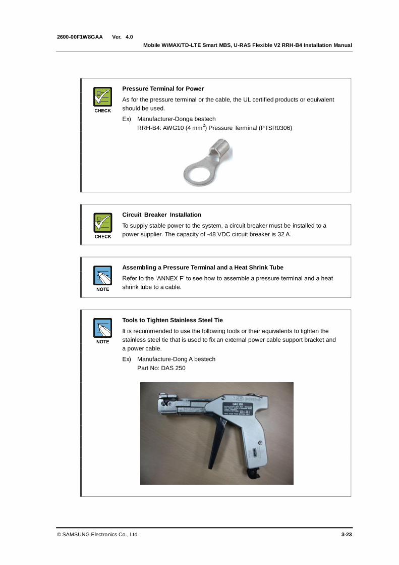
Ver.
Mobile WiMAX/TD-LTE Smart MBS, U-RAS Flexible V2 RRH-B4 Installation Manual
© SAMSUNG Electronics Co., Ltd. 3-23
2600-00F1W8GAA 4.0
Pressure Terminal for Power
As for the pressure terminal or the cable, the UL certified products or equivalent
should be used.
Ex) Manufacturer-Donga bestech
RRH-B4: AWG10 (4 mm2) Pressure Terminal (PTSR0306)
Circuit Breaker Installation
To supply stable power to the system, a circuit breaker must be installed to a
power supplier. The capacity of -48 VDC circuit breaker is 32 A.
Assembling a Pressure Terminal and a Heat Shrink Tube
Refer to the ‘ANNEX F’ to see how to assemble a pressure terminal and a heat
shrink tube to a cable.
Tools to Tighten Stainless Steel Tie
It is recommended to use the following tools or their equivalents to tighten the
stainless steel tie that is used to fix an external power cable support bracket and
a power cable.
Ex) Manufacture-Dong A bestech
Part No: DAS 250
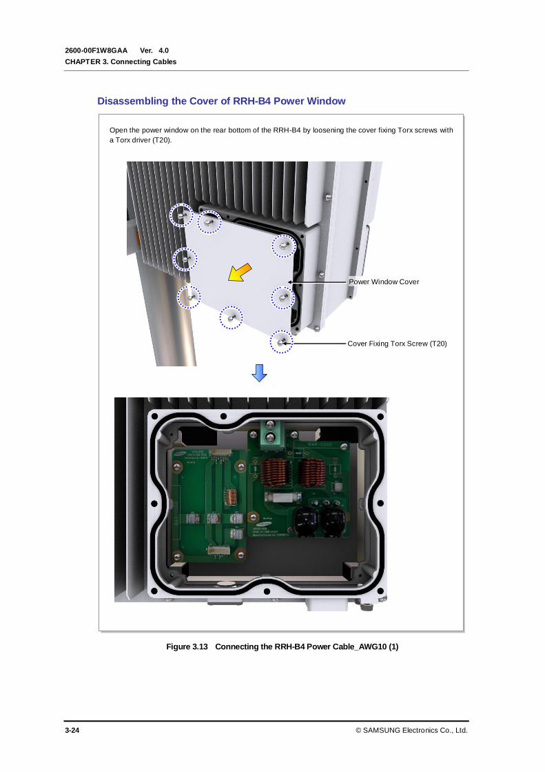
Ver.
CHAPTER 3. Connecting Cables
3-24 © SAMSUNG Electronics Co., Ltd.
2600-00F1W8GAA 4.0
Disassembling the Cover of RRH-B4 Power Window
Figure 3.13 Connecting the RRH-B4 Power Cable_AWG10 (1)
Power Window Cover
Cover Fixing Torx Screw (T20)
Open the power window on the rear bottom of the RRH-B4 by loosening the cover fixing Torx screws with
a Torx driver (T20).
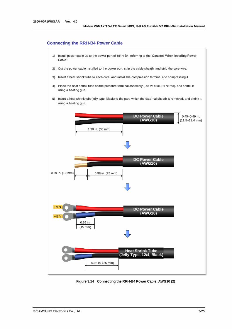
Ver.
Mobile WiMAX/TD-LTE Smart MBS, U-RAS Flexible V2 RRH-B4 Installation Manual
© SAMSUNG Electronics Co., Ltd. 3-25
2600-00F1W8GAA 4.0
Connecting the RRH-B4 Power Cable
Figure 3.14 Connecting the RRH-B4 Power Cable_AWG10 (2)
1) Install power cable up to the power port of RRH-B4, referring to the ‘Cautions When Installing Power
Cable’.
2) Cut the power cable installed to the power port, strip the cable sheath, and strip the core wire.
3) Insert a heat shrink tube to each core, and install the compression terminal and compressing it.
4) Place the heat shrink tube on the pressure terminal assembly (-48 V: blue, RTN: red), and shrink it
using a heating gun.
5) Insert a heat shrink tube(jelly type, black) to the part, which the external sheath is removed, and shrink it
using a heating gun.
DC Power Cable (AWG10)
0.45~0.49 in.
(11.5~12.4 mm)
1.38 in. (35 mm)
0.59 in.
(15 mm)
RTN
-48 V
0.98 in. (25 mm) 0.39 in. (10 mm)
Heat Shrink Tube (Jelly Type, 12/4, Black)
0.98 in. (25 mm)
DC Power Cable (AWG10)
DC Power Cable (AWG10)
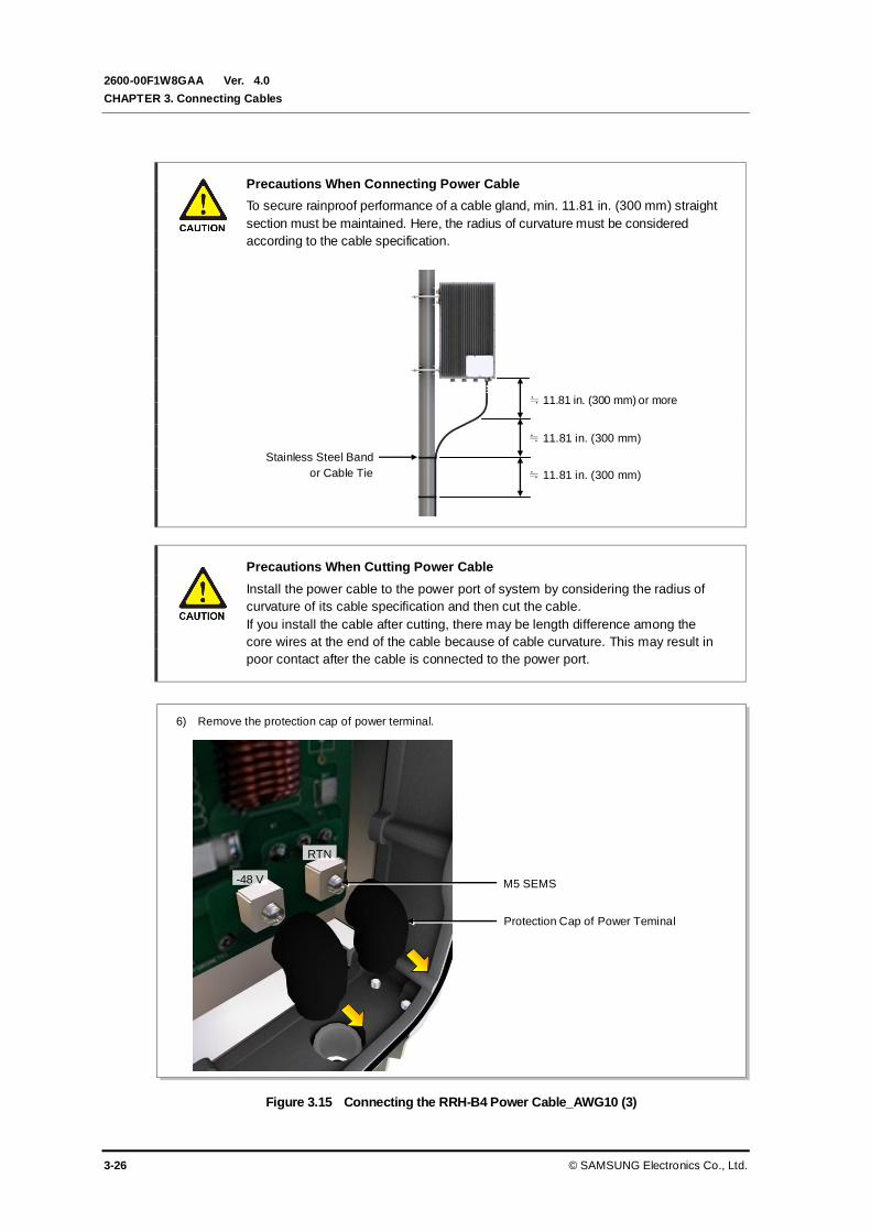
Ver.
CHAPTER 3. Connecting Cables
3-26 © SAMSUNG Electronics Co., Ltd.
2600-00F1W8GAA 4.0
Precautions When Connecting Power Cable
To secure rainproof performance of a cable gland, min. 11.81 in. (300 mm) straight
section must be maintained. Here, the radius of curvature must be considered
according to the cable specification.
Precautions When Cutting Power Cable
Install the power cable to the power port of system by considering the radius of
curvature of its cable specification and then cut the cable.
If you install the cable after cutting, there may be length difference among the
core wires at the end of the cable because of cable curvature. This may result in
poor contact after the cable is connected to the power port.
Figure 3.15 Connecting the RRH-B4 Power Cable_AWG10 (3)
Stainless Steel Band
or Cable Tie
≒ 11.81 in. (300 mm) or more
≒ 11.81 in. (300 mm)
≒ 11.81 in. (300 mm)
6) Remove the protection cap of power terminal.
RTN
-48 V
Protection Cap of Power Teminal
M5 SEMS

Ver.
Mobile WiMAX/TD-LTE Smart MBS, U-RAS Flexible V2 RRH-B4 Installation Manual
© SAMSUNG Electronics Co., Ltd. 3-27
2600-00F1W8GAA 4.0
Figure 3.16 Connecting the RRH-B4 Power Cable_AWG10 (4)
7) Remove the rain-proof filler and the cable gland nut from the cable gland for power cable input at the
bottom of RRH-B4.
8) Insert the rain-proof filler and the cable gland nut removed from the 1 power cable (AWG10, F-CV
4 mm2 × 2C).
9) Pass the power cable though the cable gland at the bottom of the RRH-B4, and install it inside the
power window.
Rain-proof Filler
Rain-proof Filler
Power Cable Bracket
RTN -48 V
Cable Gland Nut
Cable Gland Nut
Pressure Terminal
Cable Gland Body
Heat Shrink Tube
(-48 V: Blue, RTN:Red)
Power Cable Bracket
Power Cable

Ver.
CHAPTER 3. Connecting Cables
3-28 © SAMSUNG Electronics Co., Ltd.
2600-00F1W8GAA 4.0
Figure 3.17 Connecting the RRH-B4 Power Cable_AWG10 (5)
Power Cable
(-48 V: Black, RTN: Red)
Pressure Terminal
RTN
-48 V
Heat Shrink Tube
(-48 V: Blue, RTN: Red)
M5 SEMS
Protection Cap of Power Terminal
10) Place the pressure terminal installed to the power cable according to the polarity of the power terminal
block, and fix it with fasteners.

Ver.
Mobile WiMAX/TD-LTE Smart MBS, U-RAS Flexible V2 RRH-B4 Installation Manual
© SAMSUNG Electronics Co., Ltd. 3-29
2600-00F1W8GAA 4.0
Figure 3.18 Connecting the RRH-B4 Power Cable_AWG10 (6)
Caution for Rain-proof Gasket Damage
Be careful the rain-proof gasket is not damaged during work, and check again the
gasket is not damaged before closing power/DTA window cover. If the rain-proof
gasket is damaged, replace the RRH-B4.
Rain-proof Filler
11) Fully insert the rain-proof filler to the cable gland body, and tighten the cable gland nut using a torque
wrench with torque value 2.17 lbf.ft (30 kgf.cm).
Protrusion of Rain-Proof Filler
Cable Gland Nut
Power Cable Bracket
RTN -48 V
Heat Shrink Tube (Jelly type, 12/4)
Cable Gland Nut
DC Power Cable Outer Jacket
(AWG10, F-CV 4 mm2 × 2C, Φ 0.45~0.49 in./Φ 11.5~12.4 mm)
0.39 in. (10 mm)
Protection Cap of Power Terminal
Rain-proof Gasket
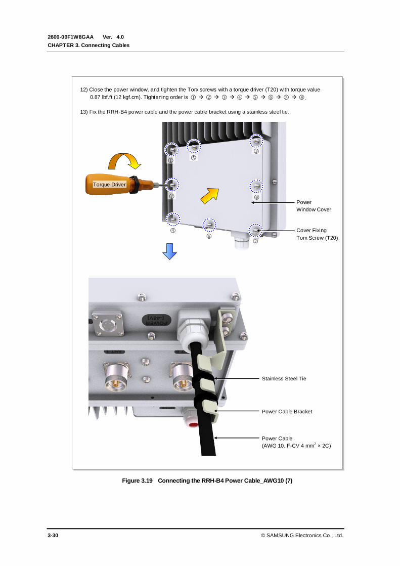
Ver.
CHAPTER 3. Connecting Cables
3-30 © SAMSUNG Electronics Co., Ltd.
2600-00F1W8GAA 4.0
Figure 3.19 Connecting the RRH-B4 Power Cable_AWG10 (7)
12) Close the power window, and tighten the Torx screws with a torque driver (T20) with torque value
0.87 lbf.ft (12 kgf.cm). Tightening order is .
13) Fix the RRH-B4 power cable and the power cable bracket using a stainless steel tie.
Stainless Steel Tie
Power Cable
(AWG 10, F-CV 4 mm2 × 2C)
Power Cable Bracket
Cover Fixing
Torx Screw (T20)
Power
Window Cover
Torque Driver

Ver.
Mobile WiMAX/TD-LTE Smart MBS, U-RAS Flexible V2 RRH-B4 Installation Manual
© SAMSUNG Electronics Co., Ltd. 3-31
2600-00F1W8GAA 4.0
Check When Fixing the Power Cable
Fix the power cable and the power cable bracket using a stainless steel tie for
preventing loose contact due to cable tension and leakage problems.
It is recommended to use the designated tools to tighten the stainless steel tie.
3.4.2 Power Test
Perform the power test of the system for the following areas.
Power cable connection stability check
Check the power cable connection for the power source such as a rectifier and verify if
the power cable is securely tightened into the RRH-B4 input terminal.
Supply voltage of the power source
Use a digital voltage meter to check if the power supplied is within the allowed input
voltage range of the RRH-B4. (Rated input voltage: -48 V, Allowed input voltage:
-40~-56 V)
Power on/off test
Turn the power switch on/off to check if the system operates normally.
Power Window Cover
Be sure to check the circuit breaker for RRH-B4 is turned off before opening or
closing the power window cover. If the cover is open or close while the circuit
breaker is on, the system can be damaged or a worker may be critically injured
due to electrical short-circuit.
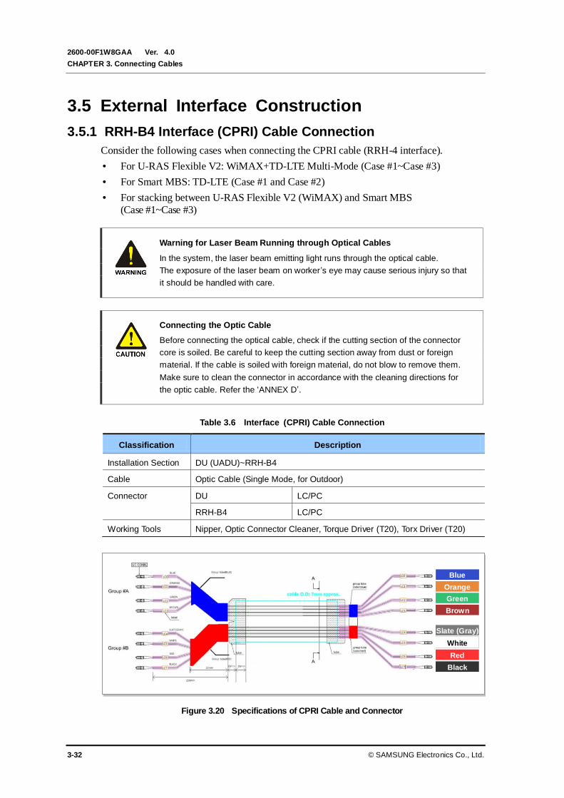
Ver.
CHAPTER 3. Connecting Cables
3-32 © SAMSUNG Electronics Co., Ltd.
2600-00F1W8GAA 4.0
3.5 External Interface Construction
3.5.1 RRH-B4 Interface (CPRI) Cable Connection
Consider the following cases when connecting the CPRI cable (RRH-4 interface).
For U-RAS Flexible V2: WiMAX+TD-LTE Multi-Mode (Case #1~Case #3)
For Smart MBS: TD-LTE (Case #1 and Case #2)
For stacking between U-RAS Flexible V2 (WiMAX) and Smart MBS
(Case #1~Case #3)
Warning for Laser Beam Running through Optical Cables
In the system, the laser beam emitting light runs through the optical cable.
The exposure of the laser beam on worker’s eye may cause serious injury so that
it should be handled with care.
Connecting the Optic Cable
Before connecting the optical cable, check if the cutting section of the connector
core is soiled. Be careful to keep the cutting section away from dust or foreign
material. If the cable is soiled with foreign material, do not blow to remove them.
Make sure to clean the connector in accordance with the cleaning directions for
the optic cable. Refer the ‘ANNEX D’.
Table 3.6 Interface (CPRI) Cable Connection
Classification Description
Installation Section DU (UADU)~RRH-B4
Cable Optic Cable (Single Mode, for Outdoor)
Connector DU LC/PC
RRH-B4 LC/PC
Working Tools Nipper, Optic Connector Cleaner, Torque Driver (T20), Torx Driver (T20)
Figure 3.20 Specifications of CPRI Cable and Connector
Blue
Orange
Green
Brown
Slate (Gray)
White
Red
Black

Ver.
Mobile WiMAX/TD-LTE Smart MBS, U-RAS Flexible V2 RRH-B4 Installation Manual
© SAMSUNG Electronics Co., Ltd. 3-33
2600-00F1W8GAA 4.0
Follow the steps below to connect the interface (CPRI) cable.
Disassembling the Cover of RRH-B4 DTA Window
Figure 3.21 RRH-B4 Interface (CPRI) Cable Connection (1)
1) Open the DTA window on the bottom left of the RRH-B4 by loosening the cover fixing screws with a
Torx driver (T20).
DTA Window
Cover
Cover Fixing
Screw (T20)
Optic0 (LTE0)
Optic1 (LTE1)
Optic2 (LTE2)
Optic3 (LTE3)
Optic6 (WiMAX2)
Optic5 (WiMAX1)
Optic7 (WiMAX3)
Optic4 (WiMAX0)

Ver.
CHAPTER 3. Connecting Cables
3-34 © SAMSUNG Electronics Co., Ltd.
2600-00F1W8GAA 4.0
Figure 3.22 RRH-B4 Interface (CPRI) Cable Connection (2)
RRH-B4 Interface (CPRI)
Cable
2) Remove the cable gland nut and the rain-proof filler from the optic cable gland (M25) at the left bottom
of RRH-B4.
3) Insert the cable gland nut cable and then the rain-proof filler to the RRH-B4 interface (CPRI) cable.
Place the rain-proof filler top-end on the end of heat shrink tube.
Rain-proof Filler
Cable Gland Nut
End of Heat Shrink Tube
Rain-proof Filler
Cable Gland Nut
Heat Shrink Tube
End of Heat Shrink Tube
RRH-B4 Interface
(CPRI) Cable

Ver.
Mobile WiMAX/TD-LTE Smart MBS, U-RAS Flexible V2 RRH-B4 Installation Manual
© SAMSUNG Electronics Co., Ltd. 3-35
2600-00F1W8GAA 4.0
Figure 3.23 RRH-B4 Interface (CPRI) Cable Connection (3)
4) Insert the RRH-B4 interface (CPRI) cable from the bottom of the RRH-B4 through the optic cable gland
and install it inside the DTA window.
5) Fully insert the rain-proof filler to the cable gland body, and tighten the cable gland nut using a torque
wrench with torque value 2.17 lbf.ft (25 kgf.cm).
6) Connect the RRH-B4 interface (CPRI) optic connector to the SFP module
, in order of figure 3.24. (See the cable color of figure 3.20.)
Cable Gland Nut
RRH-B4 interface(CPRI) Cable
Heat Shrink Tube
Group Tube
Bending radius: 0.79 in.(20 mm)
0.59 in. (15 mm)
0.79 in. (20 mm)

Ver.
CHAPTER 3. Connecting Cables
3-36 © SAMSUNG Electronics Co., Ltd.
2600-00F1W8GAA 4.0
Figure 3.24 RRH-B4 Interface (CPRI) Cable Connection (4)

Ver.
Mobile WiMAX/TD-LTE Smart MBS, U-RAS Flexible V2 RRH-B4 Installation Manual
© SAMSUNG Electronics Co., Ltd. 3-37
2600-00F1W8GAA 4.0
Figure 3.25 RRH-B4 Interface (CPRI) Cable Connection (5)
Caution for Rain-proof Gasket Damage
Be careful the rain-proof gasket is not damaged during work, and check again the
gasket is not damaged before closing power/DTA window cover. If the rain-proof
gasket is damaged, replace the RRH-B4.
DTA Window Cover
Cover Fixing Screw (T20)
7) Close the DTA window cover, and tighten the screws using a torque driver (T20) with torque value
0.87 lbf.ft (12 kgf.cm).
Rain-proof Gasket
Torque Driver
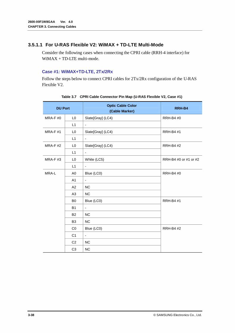
Ver.
CHAPTER 3. Connecting Cables
3-38 © SAMSUNG Electronics Co., Ltd.
2600-00F1W8GAA 4.0
3.5.1.1 For U-RAS Flexible V2: WiMAX + TD-LTE Multi-Mode
Consider the following cases when connecting the CPRI cable (RRH-4 interface) for
WiMAX + TD-LTE multi-mode.
Case #1: WiMAX+TD-LTE, 2Tx/2Rx
Follow the steps below to connect CPRI cables for 2Tx/2Rx configuration of the U-RAS
Flexible V2.
Table 3.7 CPRI Cable Connector Pin Map (U-RAS Flexible V2, Case #1)
DU Port Optic Cable Color
(Cable Marker) RRH-B4
MRA-F #0 L0 Slate[Gray] (LC4) RRH-B4 #0
L1 -
MRA-F #1 L0 Slate[Gray] (LC4) RRH-B4 #1
L1 -
MRA-F #2 L0 Slate[Gray] (LC4) RRH-B4 #2
L1 -
MRA-F #3 L0 White (LC5) RRH-B4 #0 or #1 or #2
L1 -
MRA-L A0 Blue (LC0) RRH-B4 #0
A1 -
A2 NC
A3 NC
B0 Blue (LC0) RRH-B4 #1
B1 -
B2 NC
B3 NC
C0 Blue (LC0) RRH-B4 #2
C1 -
C2 NC
C3 NC

Ver.
Mobile WiMAX/TD-LTE Smart MBS, U-RAS Flexible V2 RRH-B4 Installation Manual
© SAMSUNG Electronics Co., Ltd. 3-39
2600-00F1W8GAA 4.0
Figure 3.26 CPRI Cable Pin Map (U-RAS Flexible V2, Case #1)
[U-RAS Flexible V2 DU]
Optic0 (LTE0)
Optic1 (LTE1)
Optic2 (LTE2)
Optic3 (LTE3)
[RRH-B4 #0~#2]
RRH-B4 #0 or #1 or #2
MRA-L
MRA-F #3
MRA-F #2
MRA-F #1
MRA-F #0
Optic4 (WiMAX0)
Optic6 (WiMAX2)
Optic5 (WiMAX1)
Optic7 (WiMAX3)
L0
L0
L1
L0 L1
L0 L1
L1
A0 A1 A2 A3 B0 B1 B2 B3 C0 C1 C2 C3
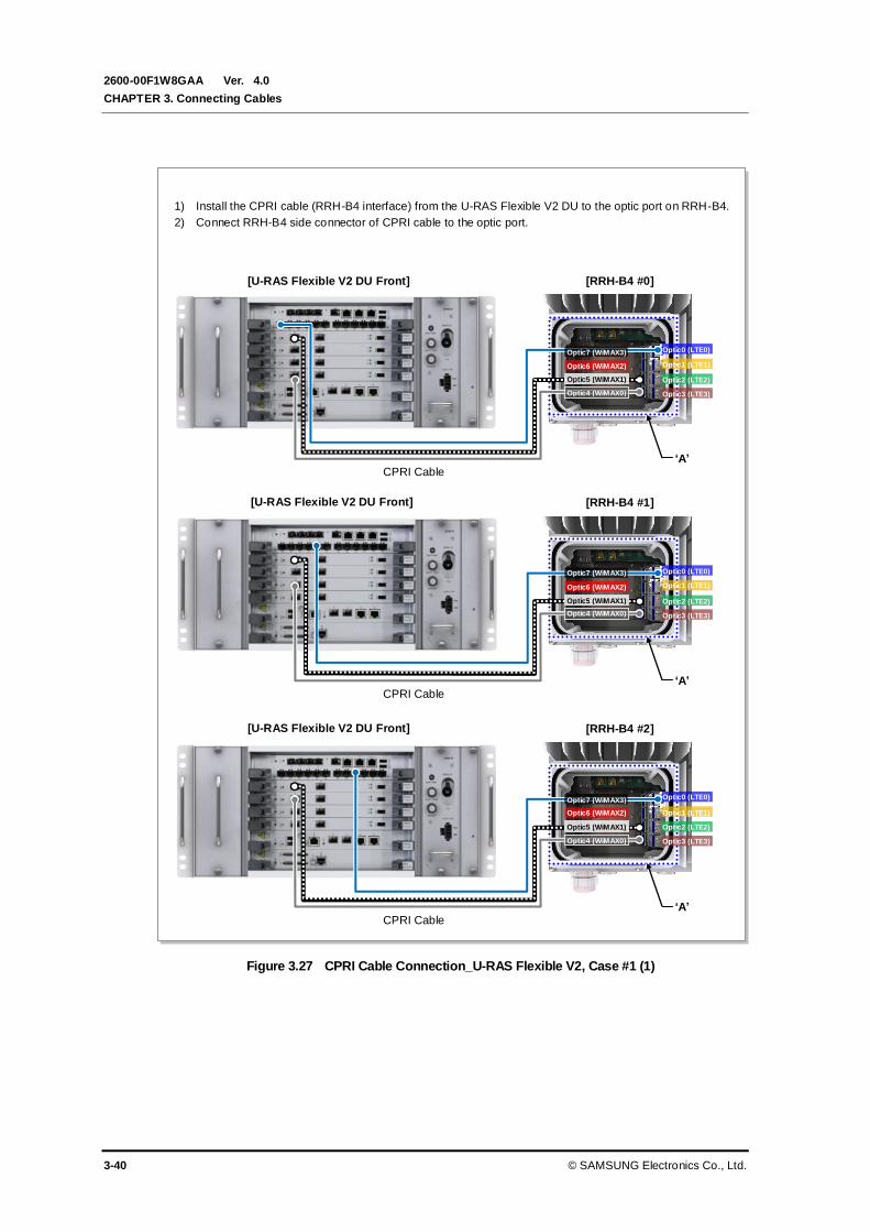
Ver.
CHAPTER 3. Connecting Cables
3-40 © SAMSUNG Electronics Co., Ltd.
2600-00F1W8GAA 4.0
Figure 3.27 CPRI Cable Connection_U-RAS Flexible V2, Case #1 (1)
1) Install the CPRI cable (RRH-B4 interface) from the U-RAS Flexible V2 DU to the optic port on RRH-B4.
2) Connect RRH-B4 side connector of CPRI cable to the optic port.
‘A’
‘A’
[RRH-B4 #0] [U-RAS Flexible V2 DU Front]
[RRH-B4 #1] [U-RAS Flexible V2 DU Front]
‘A’
[RRH-B4 #2] [U-RAS Flexible V2 DU Front]
CPRI Cable
CPRI Cable
CPRI Cable
Optic4 (WiMAX0)
Optic6 (WiMAX2)
Optic5 (WiMAX1)
Optic7 (WiMAX3)
Optic4 (WiMAX0)
Optic6 (WiMAX2)
Optic5 (WiMAX1)
Optic4 (WiMAX0)
Optic6 (WiMAX2)
Optic5 (WiMAX1)
Optic7 (WiMAX3)
Optic7 (WiMAX3)
Optic0 (LTE0)
Optic1 (LTE1)
Optic3 (LTE3)
Optic2 (LTE2)
Optic0 (LTE0)
Optic1 (LTE1)
Optic2 (LTE2)
Optic3 (LTE3)
Optic0 (LTE0)
Optic1 (LTE1)
Optic2 (LTE2)
Optic3 (LTE3)
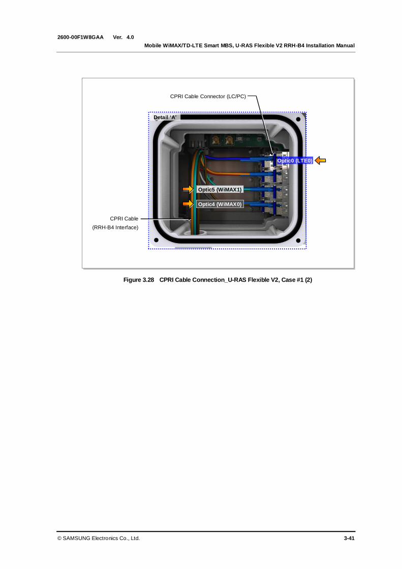
Ver.
Mobile WiMAX/TD-LTE Smart MBS, U-RAS Flexible V2 RRH-B4 Installation Manual
© SAMSUNG Electronics Co., Ltd. 3-41
2600-00F1W8GAA 4.0
Figure 3.28 CPRI Cable Connection_U-RAS Flexible V2, Case #1 (2)
Detail ‘A’
CPRI Cable
(RRH-B4 Interface)
CPRI Cable Connector (LC/PC)
Optic0 (LTE0)
Optic4 (WiMAX0)
Optic5 (WiMAX1)

Ver.
CHAPTER 3. Connecting Cables
3-42 © SAMSUNG Electronics Co., Ltd.
2600-00F1W8GAA 4.0
Case #2: WiMAX 4 Subcells+TD-LTE 1 Carrier/3 Sector, 2Tx/2Rx
Follow the steps below to connect CPRI cables for WiMAX 4 subcells + TD-LTE
1 Carrier/3 Sector 2Tx/2Rx configuration of U-RAS Flexible V2.
When U-RAS Flexible V2 supports WiMAX/TD-LTE multi-mode, up to 4 WiMAX
channel cards (MRA-F) can be mounted on the U-RAS Flexible V2 to support 4 subcells.
The operator can set operating sectors and frequencies for each subcell.
The following example shows the pin map where an alpha sector has 3 and a beta sector
has 1 respectively among 6 WiMAX subcells.
Table 3.8 CPRI Cable Connector Pin Map (U-RAS Flexible V2, Case #2)
DU Port Optic Cable Color
(Cable Marker) RRH-B4
MRA-F #0 L0 Slate[Gray] (LC4) RRH-B4 #0
L1 -
MRA-F #1 L0 White (LC5) RRH-B4 #0
L1 -
MRA-F #2 L0 Red (LC6) RRH-B4 #0
L1 -
MRA-F #3 L0 Slate[Gray] (LC4) RRH-B4 #1
L1 -
MRA-L A0 Blue (LC0) RRH-B4 #0
A1 -
A2 NC
A3 NC
B0 Blue (LC0) RRH-B4 #1
B1 -
B2 NC
B3 NC
C0 Blue (LC0) RRH-B4 #2
C1 -
C2 NC
C3 NC

Ver.
Mobile WiMAX/TD-LTE Smart MBS, U-RAS Flexible V2 RRH-B4 Installation Manual
© SAMSUNG Electronics Co., Ltd. 3-43
2600-00F1W8GAA 4.0
Figure 3.29 CPRI Cable Pin Map (U-RAS Flexible V2, Case #2)
Optic0 (LTE0)
Optic1 (LTE1)
Optic2 (LTE2)
Optic3 (LTE3) Optic4 (WiMAX0)
Optic6 (WiMAX2)
Optic5 (WiMAX1)
Optic7 (WiMAX3) Optic0 (LTE0)
Optic1 (LTE1)
Optic2 (LTE2)
Optic3 (LTE3) Optic4(WiMAX0)
Optic6(WiMAX2)
Optic5(WiMAX1)
Optic7(WiMAX3)
MRA-L
MRA-F #3
MRA-F #2
MRA-F #1
MRA-F #0 L0
L0
L1
L1
L0 L1
L1
A0 A1 A2 A3 B0 B1 B2 B3 P
o
w
e
r
C
a
b
l
e
B
r
a
c
k
e
t
C0
C1 C2 C3
[U-RAS Flexible V2 DU]
[RRH-B4 #0] [RRH-B4 #1]
[RRH-B4 #2]
L0
Optic0 (LTE0)
Optic1 (LTE1)
Optic2 (LTE2)
Optic3 (LTE3) Optic4 (WiMAX0)
Optic6 (WiMAX2)
Optic5 (WiMAX1)
Optic7 (WiMAX3)

Ver.
CHAPTER 3. Connecting Cables
3-44 © SAMSUNG Electronics Co., Ltd.
2600-00F1W8GAA 4.0
Figure 3.30 CPRI Cable Connection_U-RAS Flexible V2, Case #2 (1)
Optic0 (LTE0)
Optic1 (LTE1)
Optic2 (LTE2)
Optic3 (LTE3)
Optic0 (LTE0)
Optic1 (LTE1)
Optic2 (LTE2)
Optic3 (LTE3)
Optic0 (LTE0)
Optic1 (LTE1)
Optic2(LTE2)
Optic3 (LTE3)
‘B’
‘A’
[RRH-B4 #0]
1) Install the CPRI cable (RRH-B4 interface) from the U-RAS Flexible V2 DU to the optic port on RRH-B4.
2) Connect RRH-B4 side connector of CPRI cable to the optic port.
[U-RAS Flexible V2 DU Front]
[RRH-B4 #1] [U-RAS Flexible V2 DU Front]
‘C’
[U-RAS Flexible V2 DU Front]
Optic4 (WiMAX0)
Optic6 (WiMAX2)
Optic5 (WiMAX1)
Optic7 (WiMAX3)
Optic4 (WiMAX0)
Optic6 (WiMAX2)
Optic5 (WiMAX1)
Optic7 (WiMAX3)
Optic4 (WiMAX0)
Optic6 (WiMAX2)
Optic5 (WiMAX1)
Optic7 (WiMAX3)

Ver.
Mobile WiMAX/TD-LTE Smart MBS, U-RAS Flexible V2 RRH-B4 Installation Manual
© SAMSUNG Electronics Co., Ltd. 3-45
2600-00F1W8GAA 4.0
Figure 3.31 CPRI Cable Connection_U-RAS Flexible V2, Case #2 (2)
CPRI Cable
(RRH-B4 Interface)
CPRI Cable Connector
(LC/PC)
Optic0 (LTE0)
CPRI Cable
(RRH-B4 Interface)
CPRI Cable Connector
(LC/PC)
Optic0 (LTE0)
Detail ‘A’
CPRI Cable
(RRH-B4 Interface)
CPRI Cable Connector
(LC/PC)
Detail ‘B’
Detail ‘C’
Optic0 (LTE0)
Optic4 (WiMAX0)
Optic6 (WiMAX2)
Optic5 (WiMAX1)
Optic4 (WiMAX0)
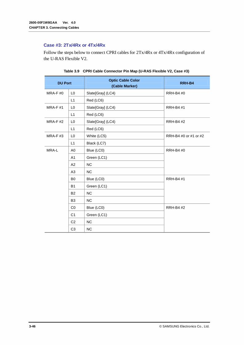
Ver.
CHAPTER 3. Connecting Cables
3-46 © SAMSUNG Electronics Co., Ltd.
2600-00F1W8GAA 4.0
Case #3: 2Tx/4Rx or 4Tx/4Rx
Follow the steps below to connect CPRI cables for 2Tx/4Rx or 4Tx/4Rx configuration of
the U-RAS Flexible V2.
Table 3.9 CPRI Cable Connector Pin Map (U-RAS Flexible V2, Case #3)
DU Port Optic Cable Color
(Cable Marker) RRH-B4
MRA-F #0 L0 Slate[Gray] (LC4) RRH-B4 #0
L1 Red (LC6)
MRA-F #1 L0 Slate[Gray] (LC4) RRH-B4 #1
L1 Red (LC6)
MRA-F #2 L0 Slate[Gray] (LC4) RRH-B4 #2
L1 Red (LC6)
MRA-F #3 L0 White (LC5) RRH-B4 #0 or #1 or #2
L1 Black (LC7)
MRA-L A0 Blue (LC0) RRH-B4 #0
A1 Green (LC1)
A2 NC
A3 NC
B0 Blue (LC0) RRH-B4 #1
B1 Green (LC1)
B2 NC
B3 NC
C0 Blue (LC0) RRH-B4 #2
C1 Green (LC1)
C2 NC
C3 NC
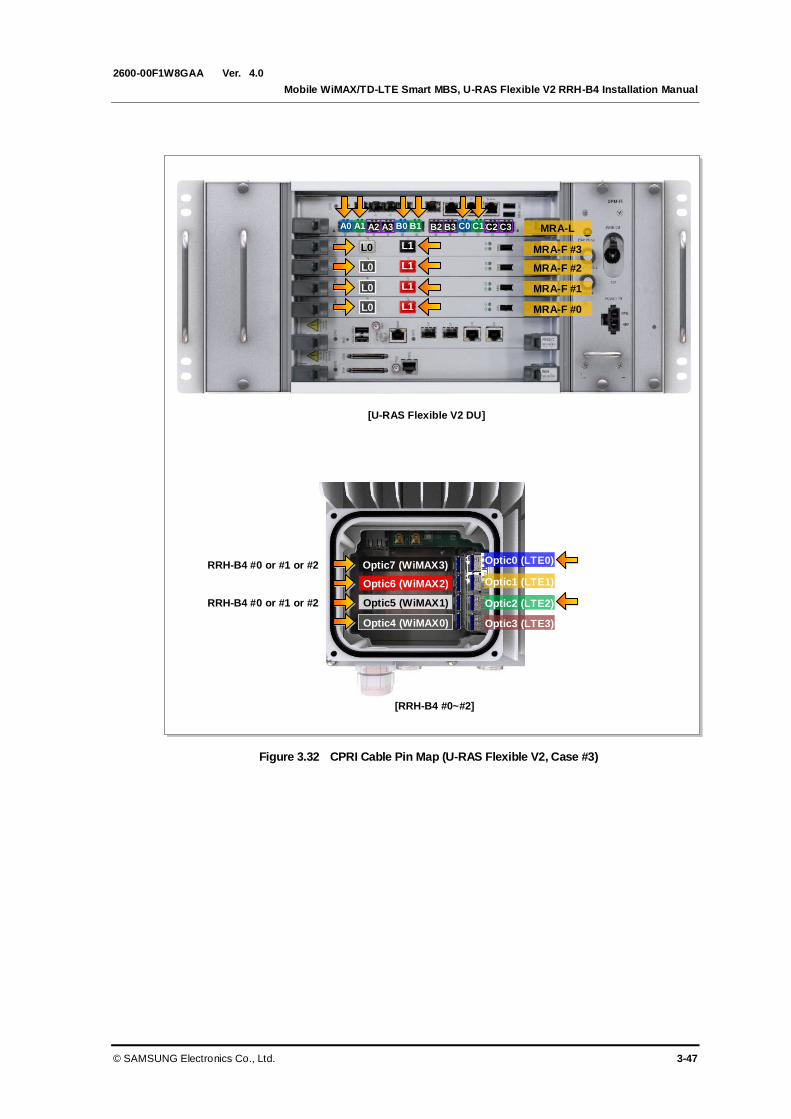
Ver.
Mobile WiMAX/TD-LTE Smart MBS, U-RAS Flexible V2 RRH-B4 Installation Manual
© SAMSUNG Electronics Co., Ltd. 3-47
2600-00F1W8GAA 4.0
Figure 3.32 CPRI Cable Pin Map (U-RAS Flexible V2, Case #3)
[U-RAS Flexible V2 DU]
Optic0 (LTE0)
Optic1 (LTE1)
Optic2 (LTE2)
Optic3 (LTE3)
[RRH-B4 #0~#2]
RRH-B4 #0 or #1 or #2
MRA-L
MRA-F #3
MRA-F #2
MRA-F #1
MRA-F #0
Optic4 (WiMAX0)
Optic6 (WiMAX2)
Optic5 (WiMAX1)
Optic7 (WiMAX3)
L0
L0
L1
L0 L1
L0 L1
L1
A0 A1 A2 A3 B0 B1 B2 B3 C0 C1 C2 C3
RRH-B4 #0 or #1 or #2

Ver.
CHAPTER 3. Connecting Cables
3-48 © SAMSUNG Electronics Co., Ltd.
2600-00F1W8GAA 4.0
Figure 3.33 CPRI Cable Connection_U-RAS Flexible V2, Case #3 (1)
‘A’
[RRH-B4 #0]
1) Install the CPRI cable (RRH-B4 interface) from the U-RAS Flexible V2 DU to the optic port on RRH-B4.
2) Connect RRH-B4 side connector of CPRI cable to the optic port.
[U-RAS Flexible V2 DU Front]
‘A’
[RRH-B4 #1] [U-RAS Flexible V2 DU Front]
‘A’
[RRH-B4 #2] [U-RAS Flexible V2 DU Front]
Optic4 (WiMAX0)
Optic6 (WiMAX2)
Optic5 (WiMAX1)
Optic7 (WiMAX3)
Optic4 (WiMAX0)
Optic6 (WiMAX2)
Optic5 (WiMAX1)
Optic7 (WiMAX3)
Optic4 (WiMAX0)
Optic6 (WiMAX2)
Optic 5(WiMAX1)
Optic7 (WiMAX3) Optic0 (LTE0)
Optic1 (LTE1)
Optic2 (LTE2)
Optic3 (LTE3)
Optic0 (LTE0)
Optic1 (LTE1)
Optic2 (LTE2)
Optic3 (LTE3)
Optic0 (LTE0)
Optic1 (LTE1)
Optic2 (LTE2)
Optic3 (LTE3)

Ver.
Mobile WiMAX/TD-LTE Smart MBS, U-RAS Flexible V2 RRH-B4 Installation Manual
© SAMSUNG Electronics Co., Ltd. 3-49
2600-00F1W8GAA 4.0
Figure 3.34 CPRI Cable Connection_U-RAS Flexible V2, Case #3 (2)
Detail ‘A’
CPRI Cable
(RRH-B4 Interface)
CPRI Cable Connector
(LC/PC)
Optic0 (LTE0)
Optic2 (LTE2)
Optic4 (WiMAX0)
Optic6 (WiMAX2)
Optic5 (WiMAX1)
Optic7 (WiMAX3)

Ver.
CHAPTER 3. Connecting Cables
3-50 © SAMSUNG Electronics Co., Ltd.
2600-00F1W8GAA 4.0
3.5.1.2 For Smart MBS: TD-LTE
Consider the following cases when connecting the CPRI cable (RRH-4 interface) for TD-
LTE.
Case #1: TD-LTE 2 Carrier/3 Sector 2Tx/2Rx
Follow the steps below to connect CPRI cables for TD-LTE 2 Carrier/3 Sector 2Tx/2Rx
configuration of the Smart MBS.
Table 3.10 CPRI Cable Connector Pin Map (Smart MBS, Case #1)
UADU Port Optic Cable Color
(Cable Marker) RRH-B4
L9CA #0 L0 Blue (LC0) RRH-B4 #0
L1 -
L2 Blue (LC0) RRH-B4 #1
L3 -
L4 Blue (LC0) RRH-B4 #2
L5 -
L9CA #0 L0 Orange (LC1) RRH-B4 #0
L1 -
L2 Orange (LC1) RRH-B4 #1
L3 -
L4 Orange (LC1) RRH-B4 #2
L5 -

Ver.
Mobile WiMAX/TD-LTE Smart MBS, U-RAS Flexible V2 RRH-B4 Installation Manual
© SAMSUNG Electronics Co., Ltd. 3-51
2600-00F1W8GAA 4.0
Figure 3.35 CPRI Cable Pin Map (Smart MBS, Case #1)
L0
L9CA #0
L2 L4
[UADU]
L0 L2 L4
Optic0 (LTE0)
Optic1 (LTE1)
Optic2 (LTE2)
Optic3 (LTE3) Optic4 (WiMAX0)
Optic6 (WiMAX2)
Optic5 (WiMAX1)
Optic7 (WiMAX3)
[RRH-B4 #0~#2]
L1 L3 L5
L1 L3 L5
L9CA #1
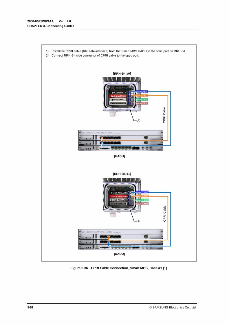
Ver.
CHAPTER 3. Connecting Cables
3-52 © SAMSUNG Electronics Co., Ltd.
2600-00F1W8GAA 4.0
Figure 3.36 CPRI Cable Connection_Smart MBS, Case #1 (1)
Optic4 (WiMAX0)
Optic6 (WiMAX2)
Optic5 (WiMAX1)
Optic7 (WiMAX3)
‘A’
[RRH-B4 #0]
Optic4 (WiMAX0)
Optic6 (WiMAX2)
Optic5 (WiMAX1)
Optic7 (WiMAX3)
1) Install the CPRI cable (RRH-B4 interface) from the Smart MBS UADU to the optic port on RRH-B4.
2) Connect RRH-B4 side connector of CPRI cable to the optic port.
[UADU]
‘A’
CP
RI C
able
C
PR
I C
able
[UADU]
[RRH-B4 #1]
Optic0 (LTE0)
Optic1 (LTE1)
Optic2 (LTE2)
Optic3 (LTE3)
Optic0 (LTE0)
Optic1 (LTE1)
Optic2 (LTE2)
Optic3 (LTE3)
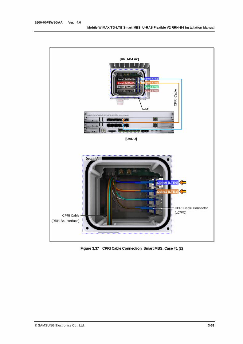
Ver.
Mobile WiMAX/TD-LTE Smart MBS, U-RAS Flexible V2 RRH-B4 Installation Manual
© SAMSUNG Electronics Co., Ltd. 3-53
2600-00F1W8GAA 4.0
Figure 3.37 CPRI Cable Connection_Smart MBS, Case #1 (2)
Optic4 (WiMAX0)
Optic6 (WiMAX2)
Optic5 (WiMAX1)
Optic7 (WiMAX3)
‘A’
[UADU]
CP
RI C
able
[RRH-B4 #2]
Detail ‘A’
CPRI Cable
(RRH-B4 Interface)
CPRI Cable Connector
(LC/PC)
Optic0 (LTE0)
Optic1 (LTE1)
Optic0 (LTE0)
Optic1 (LTE1)
Optic2 (LTE2)
Optic3 (LTE3)

Ver.
CHAPTER 3. Connecting Cables
3-54 © SAMSUNG Electronics Co., Ltd.
2600-00F1W8GAA 4.0
Case #2: TD-LTE 2 Carrier/3 Sector 2Tx/4Rx or 4Tx/4Rx
Follow the steps below to connect CPRI cables for TD-LTE 2 Carrier/3 Sector 2Tx/4Rx or
4Tx/4Rx configuration of the Smart MBS.
Table 3.11 CPRI Cable Connector Pin Map (Smart MBS, Case #2)
UADU Port Optic Cable Color
(Cable Marker) RRH-B4
L9CA #0 L0 Blue (LC0) RRH-B4 #0
L1 Green (LC2)
L2 Blue (LC0) RRH-B4 #1
L3 Green (LC2)
L4 Blue (LC0) RRH-B4 #2
L5 Green (LC2)
L9CA #1 L0 Orange (LC1) RRH-B4 #0
L1 Brown (LC3)
L2 Orange (LC1) RRH-B4 #1
L3 Brown (LC3)
L4 Orange (LC1) RRH-B4 #2
L5 Brown (LC3)
Figure 3.38 CPRI Cable Pin Map (Smart MBS, Case #2)
Optic0 (LTE0)
Optic1 (LTE1)
Optic2 (LTE2)
Optic3 (LTE3)
[RRH-B4 #0~2]
L0 L9CA #1
L9CA #0
L2 L4 L1 L3 L5
[UADU]
L0 L2 L4 L1 L3 L5
Optic4 (WiMAX0)
Optic6 (WiMAX2)
Optic5 (WiMAX1)
Optic7 (WiMAX3)

Ver.
Mobile WiMAX/TD-LTE Smart MBS, U-RAS Flexible V2 RRH-B4 Installation Manual
© SAMSUNG Electronics Co., Ltd. 3-55
2600-00F1W8GAA 4.0
Figure 3.39 CPRI Cable Connection_Smart MBS, Case #2 (1)
Optic4 (WiMAX0)
Optic6 (WiMAX2)
Optic5 (WiMAX1)
Optic7 (WiMAX3)
‘A’
[RRH-B4 #0]
Optic4 (WiMAX0)
Optic6 (WiMAX2)
Optic5 (WiMAX1)
Optic7 (WiMAX3)
1) Install the CPRI cable (RRH-B4 interface) from the Smart MBS UADU to the optic port on RRH-B4.
2) Connect RRH-B4 side connector of CPRI cable to the optic port.
‘A’
[RRH-B4 #1]
[UADU]
CP
RI C
able
[UADU]
CP
RI C
able
Optic0 (LTE0)
Optic1 (LTE1)
Optic2 (LTE2)
Optic3 (LTE3)
Optic0 (LTE0)
Optic1 (LTE1)
Optic2 (LTE2)
Optic3 (LTE3)
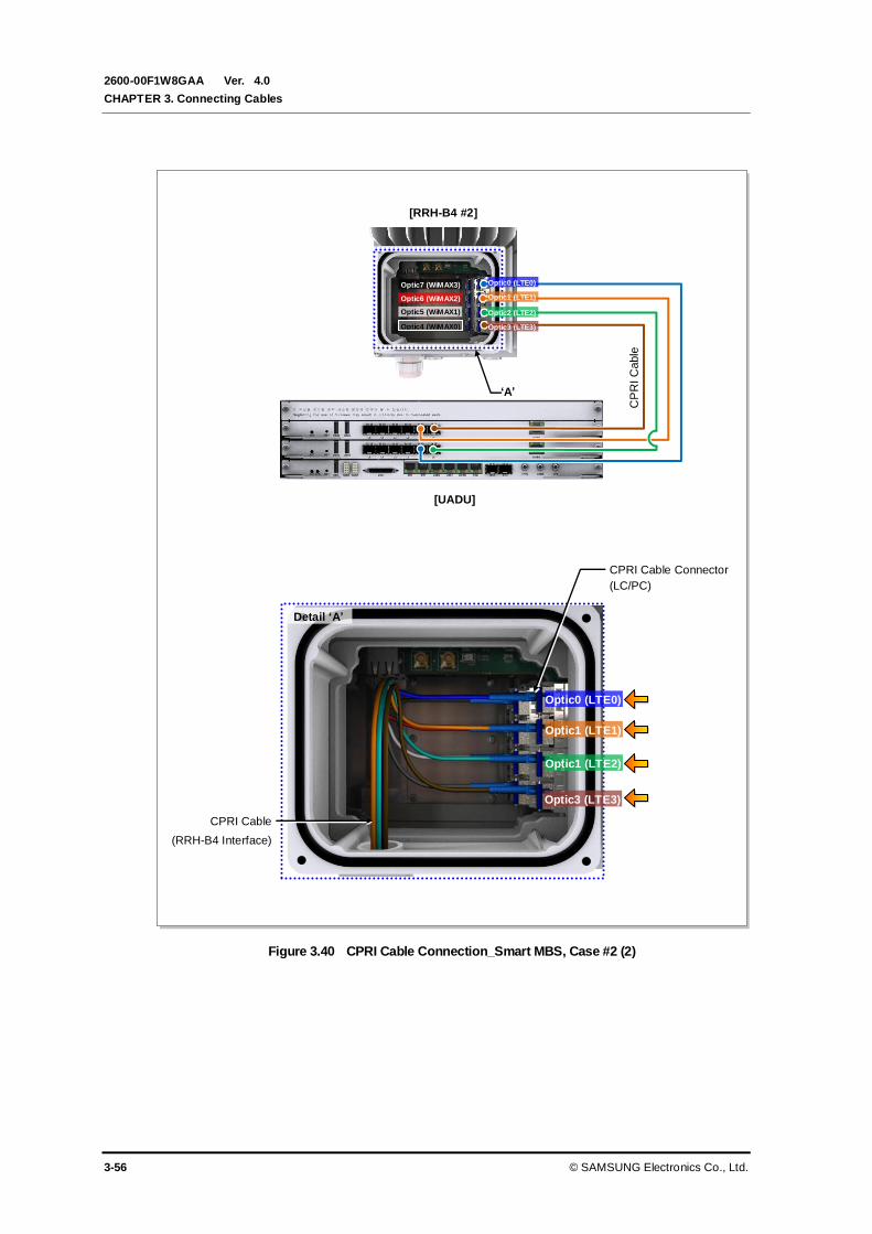
Ver.
CHAPTER 3. Connecting Cables
3-56 © SAMSUNG Electronics Co., Ltd.
2600-00F1W8GAA 4.0
Figure 3.40 CPRI Cable Connection_Smart MBS, Case #2 (2)
Optic4 (WiMAX0)
Optic6 (WiMAX2)
Optic5 (WiMAX1)
Optic7 (WiMAX3)
‘A’
[RRH-B4 #2]
Detail ‘A’
CPRI Cable
(RRH-B4 Interface)
CPRI Cable Connector
(LC/PC)
Optic0 (LTE0)
Optic1 (LTE1)
CP
RI C
able
[UADU]
Optic3 (LTE3)
Optic1 (LTE2)
Optic0 (LTE0)
Optic1 (LTE1)
Optic2 (LTE2)
Optic3 (LTE3)

Ver.
Mobile WiMAX/TD-LTE Smart MBS, U-RAS Flexible V2 RRH-B4 Installation Manual
© SAMSUNG Electronics Co., Ltd. 3-57
2600-00F1W8GAA 4.0
3.5.1.3 For Stacking between U-RAS Flexible V2 (WiMAX) and Smart MBS
Following shows how to connect CPRI cables for stacking between U-RAS Flexible V2
(WiMAX) and Smart MBS (TD-LTE).
Case#1: WiMAX 2 Carrier/3 Sector 2Tx/2Rx+TD-LTE 2 Carrier/3 Sector 2Tx/2Rx
Follow the steps below to connect CPRI cables for WiMAX 2 Carrier/3 Sector 2Tx/2Rx +
TD-LTE 2 Carrier/3 Sector 2Tx/2Rx configuration of U-RAS Flexible V2 and Smart MBS.
Table 3.12 CPRI Cable Connector Pin Map (Stacking, Case #1)
DU (UADU) DU (UADU) Port Optic Cable Color
(Cable Marker) RRH-B4
U-RAS Flexible V2 MRA-F #0 L0 Slate[Gray] (LC4) RRH-B4 #0
L1 -
MRA-F #1 L0 Slate[Gray] (LC4) RRH-B4 #1
L1 -
MRA-F #2 L0 Slate[Gray] (LC4) RRH-B4 #2
L1 -
MRA-F #3 L0 White (LC5) RRH-B4 #0
L1 -
MRA-F #4 L0 White (LC5) RRH-B4 #1
L1 -
MRA-F #5 L0 White (LC5) RRH-B4 #2
L1 -
Smart MBS L9CA #0 L0 Blue (LC0) RRH-B4 #0
L1 -
L2 Blue (LC0) RRH-B4 #1
L3 -
L4 Blue (LC0) RRH-B4 #2
L5 -
L9CA #1 L0 Orange (LC1) RRH-B4 #0
L1 -
L2 Orange (LC1) RRH-B4 #1
L3 -
L4 Orange (LC1) RRH-B4 #2
L5 -
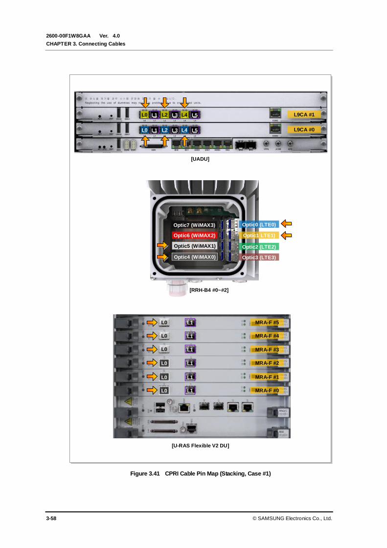
Ver.
CHAPTER 3. Connecting Cables
3-58 © SAMSUNG Electronics Co., Ltd.
2600-00F1W8GAA 4.0
Figure 3.41 CPRI Cable Pin Map (Stacking, Case #1)
L0 L9CA #1
L9CA #0
L2 L4
Optic0 (LTE0)
Optic1 LTE1)
Optic2 (LTE2)
Optic3 (LTE3)
L1 L3 L5
[UADU]
[RRH-B4 #0~#2]
L0 L2 L4 L1 L3 L5
[U-RAS Flexible V2 DU]
L0
L0
L0
L0
L0
L0
MRA-F #5
MRA-F #4
MRA-F #3
MRA-F #2
MRA-F #1
MRA-F #0
L1
L1
L1
L1
L1
L1
Optic4 (WiMAX0)
Optic6 (WiMAX2)
Optic5 (WiMAX1)
Optic7 (WiMAX3)
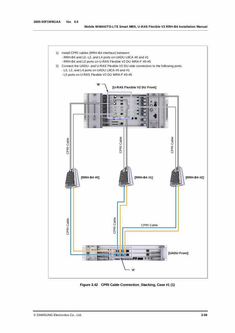
Ver.
Mobile WiMAX/TD-LTE Smart MBS, U-RAS Flexible V2 RRH-B4 Installation Manual
© SAMSUNG Electronics Co., Ltd. 3-59
2600-00F1W8GAA 4.0
Figure 3.42 CPRI Cable Connection_Stacking, Case #1 (1)
1) Install CPRI cables (RRH-B4 interface) between:
- RRH-B4 and L0, L2, and L4 ports on UADU L9CA #0 and #1
- RRH-B4 and L0 ports on U-RAS Flexible V2 DU MRA-F #0-#5
2) Connect the UADU- and U-RAS Flexible V2 DU-side connectors to the following ports.
- L0, L2, and L4 ports on UADU L9CA #0 and #1
- L0 ports on U-RAS Flexible V2 DU MRA-F #0-#5
CPRI Cable
[RRH-B4 #0]
[UADU Front]
‘A’
[RRH-B4 #1] [RRH-B4 #2]
CP
RI C
able
CP
RI C
able
[U-RAS Flexible V2 DU Front] ‘B’
CP
RI C
able
CP
RI C
able
CP
RI C
able

Ver.
CHAPTER 3. Connecting Cables
3-60 © SAMSUNG Electronics Co., Ltd.
2600-00F1W8GAA 4.0
Figure 3.43 CPRI Cable Connection_Stacking, Case #1 (2)
Detail ‘A’
CPRI Cable
(RRH-B4 Interface)
CPRI Cable Connector
(LC/PC)
Optic0 (LTE0)
Optic1 (LTE1) Optic6 (WiMAX2)
Optic7 (WiMAX3)

Ver.
Mobile WiMAX/TD-LTE Smart MBS, U-RAS Flexible V2 RRH-B4 Installation Manual
© SAMSUNG Electronics Co., Ltd. 3-61
2600-00F1W8GAA 4.0
Case #2: WiMAX 2 Carrier/3 Sector 2Tx/4Rx + TD-LTE 2 Carrier/3 Sector
2Tx/4Rx
Follow the steps below to connect CPRI cables for WiMAX 2 Carrier/3 Sector 2Tx/4Rx +
TD-LTE 2 Carrier/3 Sector 2Tx/4Rx configuration of U-RAS Flexible V2 and Smart MBS.
Table 3.13 CPRI Cable Connector Pin Map (Stacking, Case #2)
DU (UADU) DU (UADU) Port Optic Cable Color
(Cable Marker) RRH-B4
U-RAS Flexible V2 MRA-F #0 L0 Slate[Gray] (LC4) RRH-B4 #0
L1 Red (LC6)
MRA-F #1 L0 Slate[Gray] (LC4) RRH-B4 #1
L1 Red (LC6)
MRA-F #2 L0 Slate[Gray] (LC4) RRH-B4 #2
L1 Red (LC6)
MRA-F #3 L0 White (LC5) RRH-B4 #0
L1 Black (LC7)
MRA-F #4 L0 White (LC5) RRH-B4 #1
L1 Black (LC7)
MRA-F #5 L0 White (LC5) RRH-B4 #2
L1 Black (LC7)
Smart MBS L9CA #0 L0 Blue (LC0) RRH-B4 #0
L1 Green (LC2)
L2 Blue (LC0) RRH-B4 #1
L3 Green (LC2)
L4 Blue (LC0) RRH-B4 #2
L5 Green (LC2)
L9CA #1 L0 Orange (LC1) RRH-B4 #0
L1 Brown (LC3)
L2 Orange (LC1) RRH-B4 #1
L3 Brown (LC3)
L4 Orange (LC1) RRH-B4 #2
L5 Brown (LC3)

Ver.
CHAPTER 3. Connecting Cables
3-62 © SAMSUNG Electronics Co., Ltd.
2600-00F1W8GAA 4.0
Figure 3.44 CPRI Cable Pin Map (Stacking, Case #2)
L0 L9CA #1
L9CA #0
L2 L4
Optic0 (LTE0)
Optic1 (LTE1)
Optic2 (LTE2)
Optic3 (LTE3)
L1 L3 L5
[UADU]
[RRH-B4 #0~#2]
L0 L2 L4 L1 L3 L5
[U-RAS Flexible V2 DU]
L0
L0
L0
L0
L0
L0
MRA-F #5
MRA-F #4
MRA-F #3
MRA-F #2
MRA-F #1
MRA-F #0
L1
L1
L1
L1
L1
L1
Optic4 (WiMAX0)
Optic6 (WiMAX2)
Optic5 (WiMAX1)
Optic7 (WiMAX3)

Ver.
Mobile WiMAX/TD-LTE Smart MBS, U-RAS Flexible V2 RRH-B4 Installation Manual
© SAMSUNG Electronics Co., Ltd. 3-63
2600-00F1W8GAA 4.0
Figure 3.45 CPRI Cable Connection_Stacking, Case #2 (1)
[U-RAS Flexible V2 DU Front]
1) Install CPRI cables (RRH-B4 interface) between:
- RRH-B4 and L0~L5 ports on UADU L9CA #0 and #1
- RRH-B4 and L0 and L1 ports on U-RAS Flexible V2 DU MRA-F #0-#5
2) Connect the UADU- and U-RAS Flexible V2 DU-side connectors to the following ports.
- L0~L5 ports on UADU L9CA #0 and #1
- L0 and L1 ports on U-RAS Flexible V2 DU MRA-F #0-#5
[RRH-B4 #0]
[UADU Front]
‘A’
‘B’
CP
RI C
able
C
PR
I C
able
[U-RAS Flexible V2 DU Front]
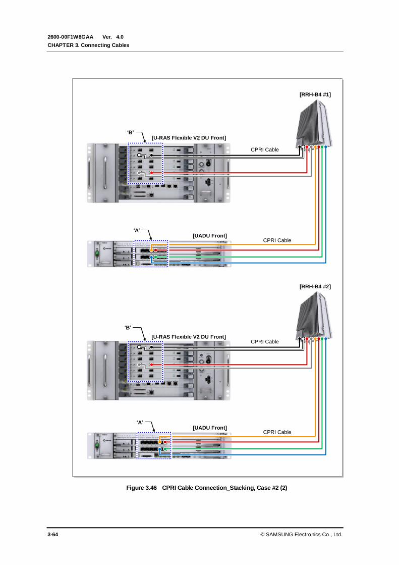
Ver.
CHAPTER 3. Connecting Cables
3-64 © SAMSUNG Electronics Co., Ltd.
2600-00F1W8GAA 4.0
Figure 3.46 CPRI Cable Connection_Stacking, Case #2 (2)
[UADU Front]
[U-RAS Flexible V2 DU Front]
[UADU Front]
[U-RAS Flexible V2 DU Front]
[RRH-B4 #1]
‘A’
CPRI Cable
CPRI Cable
‘B’
[RRH-B4 #2]
‘A’
CPRI Cable
CPRI Cable
‘B’
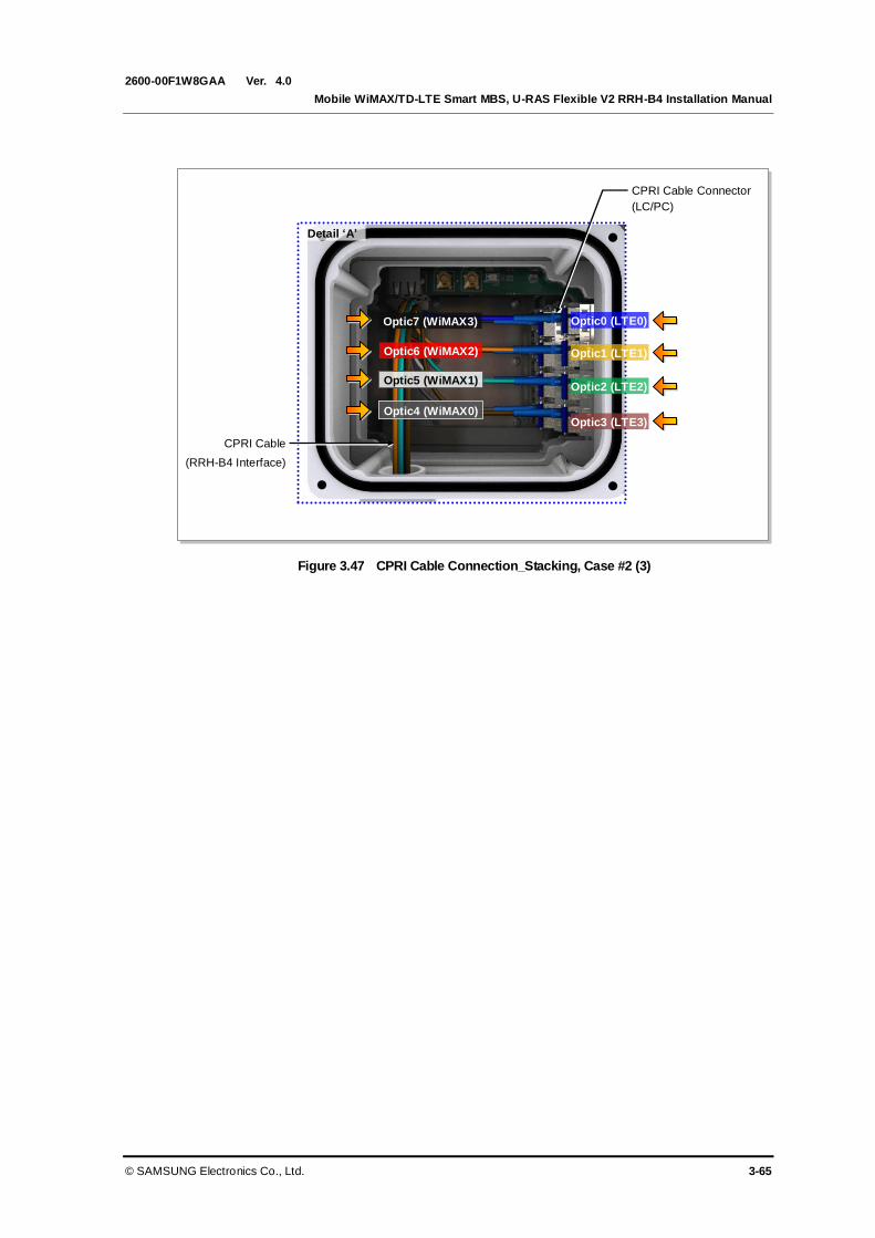
Ver.
Mobile WiMAX/TD-LTE Smart MBS, U-RAS Flexible V2 RRH-B4 Installation Manual
© SAMSUNG Electronics Co., Ltd. 3-65
2600-00F1W8GAA 4.0
Figure 3.47 CPRI Cable Connection_Stacking, Case #2 (3)
Detail ‘A’
CPRI Cable
(RRH-B4 Interface)
CPRI Cable Connector
(LC/PC)
Optic0 (LTE0)
Optic1 (LTE1)
Optic2 (LTE2)
Optic3 (LTE3) Optic4 (WiMAX0)
Optic6 (WiMAX2)
Optic5 (WiMAX1)
Optic7 (WiMAX3)

Ver.
CHAPTER 3. Connecting Cables
3-66 © SAMSUNG Electronics Co., Ltd.
2600-00F1W8GAA 4.0
Case #3: WiMAX 6 Subcell 2Tx/2Rx + TD-LTE 2 Carrier/3 Sector 2Tx/2Rx
U-RAS Flexible V2 DU interfaces with Smart MBS to support the WiMAX and TD-LTE
services simultaneously. Up to 6 WiMAX channel cards (MRA-F) can be mounted on the
U-RAS Flexible V2 to support 6 subcells. The operator can set operating sectors and
frequencies for each subcell.
The following example shows the pin map where an alpha sector has 4 and a beta sector
has 2 respectively among 6 WiMAX subcells.
Table 3.14 CPRI Cable Connector Pin Map (Stacking, Case #3)
DU (UADU) DU (UADU) Port Optic Cable Color
(Cable Marker) RRH-B4
U-RAS Flexible V2 MRA-F #0 L0 Slate[Gray] (LC4) RRH-B4 #0
L1 -
MRA-F #1 L0 White (LC5) RRH-B4 #0
L1 -
MRA-F #2 L0 Red (LC6) RRH-B4 #0
L1 -
MRA-F #3 L0 Black (LC7) RRH-B4 #0
L1 -
MRA-F #4 L0 Slate[Gray] (LC4) RRH-B4 #1
L1 -
MRA-F #5 L0 White (LC5) RRH-B4 #1
L1 -
Smart MBS L9CA #0 L0 Blue (LC0) RRH-B4 #0
L1 -
L2 Blue (LC0) RRH-B4 #1
L3 -
L4 Blue (LC0) RRH-B4 #2
L5 -
L9CA #1 L0 Orange (LC1) RRH-B4 #0
L1 -
L2 Orange (LC1) RRH-B4 #1
L3 -
L4 Orange (LC1) RRH-B4 #2
L5 -