mobile substations - umn ccaps · mobile substations 2015 minnesota power systems conference scott...
TRANSCRIPT

MOBILE SUBSTATIONS
2015 MINNESOTA POWER SYSTEMS CONFERENCE
Scott Storrar Contributors: Bill Hansen, Kyle Reddell, Tom McGrath
2
Basic Mobile Sub Design
Equipment mounted on semi-trailer
Power transformer
High and Low side disconnects
High and Low side protection devices
Cooling equipment for Transformer
Regulators or LTC
2

3
NSP MS-06
3

4
Basic Mobile Sub Design
4

5
External Equipment
5
Source connection, aka Flying Tap
3 single phase voltage regulators
Drag cables to connect load side
Temporary switch between drags and load

6
External Equipment
6

7
Source & Load
Connections
7
8
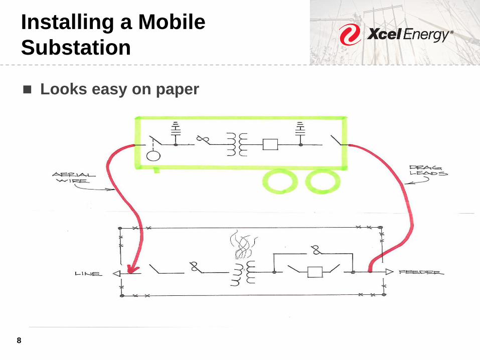
Installing a Mobile
Substation
Looks easy on paper
8

9
Electrical Design of Mobile
Installation
Select mobile with correct primary & secondary
voltages
Select mobile with correct MVA rating for load served
Choose tap settings so turns ratios are close to same
value
Correct phase shift
Protection settings for new configuration
9

10
Example: Tap Settings
10
Station Transformer DETC Tap position 1 =
70725V : 12990V. Ratio of 5.44
Using low side of Mobile Sub Transformer
chosen, 13.09 kV x 5.44 = 71.269kV
Closest options for Mobile Sub Transformer
DETC Tap are 72.4kV or 70.6kV, yielding ratio of
5.5 or 5.39
Tap setting that yields ratio of 5.39 chosen since
it is closer to 5.44

11
Transformer Phase Angles
11
Phase angle shift of mobile should match that
of substation transformer it replaces
If not, swapping 2 phases on source
connection can fix this or do a drop and pick

12
Physical Installation Design
Location to park mobile substation
Typically under source line
Close to distribution bus or line
Far away from scheduled activity
Room enough for clearances
Level location
Temporary Fencing
Tie to substation ground grid
12

13
Physical Installation Design
Generally the further away mobile is from work
area, the better
Sometimes this requires parking mobile on private
or public property (vacant lot, corn field, ditch,
street)
13

14
Physical Installation Design
Prepare one line sketch showing where mobile will
be connected to transmission line and distribution
line
Prepare location plan showing where mobile will be
parked, temporary transmission and distribution
poles & lines and physical access
Meet on site with personnel for transmission,
substation, distribution, Siting & Land Rights, etc.
14

15
Physical Installation Design
Location plan drawing
15
16
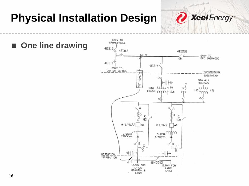
Physical Installation Design
One line drawing
16

17
Serving Load During
Substation Rebuilds
If project is to upgrade or replace an existing
substation
Will mobile be needed for an extended period of
time?
Will mobile be clear of substation construction
activity?
17

18
Serving Load During
Substation Rebuilds
Has issue to build temporary distribution and
transmission facilities for connection of mobile been
considered?
Can a mobile be tied up for entire construction
period?
Are there alternatives that don’t require use of a
mobile?
18

19
Testing
19
Overall power factor
Transformer turns ratio
Winding resistance
Excitation
Oil sampled for baseline DGA
Relay settings

20
Installation Checklist
20
Guide for installing and energizing mobile
substation
Unique to each mobile substation
Used by Foreman and Engineer on-site to verify
correct installation
Detailed steps to energize a ‘lights out’ system or
parallel with substation transformer

21
Safety Considerations
21
Electrical clearances
Onboard equipment failures awareness
(equipment is low to ground, new installation)
Oil containment considerations
Personnel escape plan
Adequate grounding

22
Lessons Learned – Load
Check
22
Circuit breaker with shunt trip coils
Current ratios must be correct
Load current could cause trip

23
Lessons Learned – Phase
Check
Map out how phases connect
Order of H1, H2, H3 is more important than A,B,C
Mobile transformer are Delta-Wye, 30-degree
lagging
Occasionally substations are 30 leading
Proper phase check will catch if mobile is
incorrectly installed
23
24
Lessons Learned –
Functionality Test
Tests circuit breaker
Problems can be discovered
Vacuum recloser stopped working
Called manufacturer to solve problem
24

25
Lessons Learned –
Sensitive Relays
Electro-mechanical relays can be sensitive to
vibrations
Tripped a mobile while shutting cabinet door
CO relay for thermal overload
Could not replicate problem
Shut door gently, kept fingers crossed
25

26
Lessons Learned – Review
Checklist When Conditions
Change
Mobile transformer taken out of service via high side
fuses - was energized single phase
Blew secondary fuses on oil pumps
Status of pumps not checked when TR was re-
energized
Transformer failed within hours
Verify all systems working with checklist
26

27
Lessons Learned – Field
Testing
De-energized tap switch broke when operated
No testing, so this was not known
Mobile energized and fuses operated
Changes resulting from this near miss
Test mobile before any installation
30-second time delay on high side MOD
2 exit gates on temporary fence
27
28
Lessons Learned –
Location
Mobile Sub used to support construction project,
also near active rail line
Vibrations of truck and train traffic loosened blade
of high side switch
Blades were not seated properly in the jaws
Repairs were made in the field
Visit mobiles that are installed for long periods to
check for issues and IR it
28

29
Lessons Learned – Replace
a Grounding Bank
69-23.9kV delta-delta TR with a grounding bank for
relay protection and ground source
Ground bank failed
Mobile sub installed to take its place
Low side connected to system
High side left disconnected
29

THANK YOU