mobile offshore units 2018 - abs
TRANSCRIPT

P a r t 3 : H u l l C o n s t r u c t i o n a n d E q u i p m e n t
RULES FOR BUILDING AND CLASSING
MOBILE OFFSHORE UNITS 2018
PART 3 HULL CONSTRUCTION AND EQUIPMENT
(Updated July 2018 – see next page)
American Bureau of Shipping Incorporated by Act of Legislature of the State of New York 1862
2017-2018 American Bureau of Shipping. All rights reserved. 1701 City Plaza Drive Spring, TX 77389 USA

Updates
July 2018 consolidation includes: • March 2018 version plus Notice No. 1 and Corrigenda/Editorials
March 2018 consolidation includes: • January 2018 version plus Corrigenda/Editorials
R u l e C h a n g e N o t i c e ( 2 0 1 8 )
Rule Change Notice (2018) The effective date of each technical change since 1993 is shown in parenthesis at the end of the subsection/paragraph titles within the text of each Part. Unless a particular date and month are shown, the years in parentheses refer to the following effective dates:
(2000) and after 1 January 2000 (and subsequent years) (1996) 9 May 1996 (1999) 12 May 1999 (1995) 15 May 1995 (1998) 13 May 1998 (1994) 9 May 1994 (1997) 19 May 1997 (1993) 11 May 1993
Listing by Effective Dates of Changes from the 2018 Rules
Notice No. 1 (effective on 1 July 2018) to the 2018 Rules, is summarized below.
EFFECTIVE DATE 1 July 2018 – shown as (1 July 2018) (based on the contract date for new construction between builder and Owner)
Part/Para. No. Title/Subject Status/Remarks 3-3-1/3 Inclining Experiment To provide additional guidance on the Inclining Experiment.
(Incorporates Notice No. 1)
ABS RULES FOR BUILDING AND CLASSING MOBILE OFFSHORE UNITS . 2018 iii

P A R T T a b l e o f C o n t e n t s
3 Hull Construction and Equipment
CONTENTS CHAPTER 1 General .................................................................................................... 1
Section 1 Definitions .............................................................................. 4 Section 2 Plans and Design Data to be Submitted ................................ 9 Section 3 Environmental Loadings ...................................................... 11 Section 4 Material Selection ................................................................ 17 Appendix 1 Shallow Water Wave Theory ............................................... 24 Appendix 2 Wave Theory for Deep Water .............................................. 46
CHAPTER 2 Hull Structures and Arrangements ..................................................... 50
Section 1 Structural Analysis ............................................................... 55 Section 2 Common Structures ............................................................. 61 Section 3 Self-elevating Units .............................................................. 72 Section 4 Column-stabilized Units ....................................................... 83 Section 5 Surface-type Drilling Units ................................................... 93 Section 6 Welding, Forming & Weld Design – Weld Design ............... 99 Appendix 1 Strengthening of Mobile Offshore Units for
Navigation in Ice ................................................................ 105 Appendix 2 Response Analysis –Selecting Design Waves for
Structural Analysis of Column-Stabilized Units (Twin-Hull Semi-Submersible) .................................. 109
Appendix 3 Guide for the Allowable Stresses for Localized Highly-Stressed Areas .................................................................. 114
CHAPTER 3 Subdivision and Stability ................................................................... 115
Section 1 General .............................................................................. 118 Section 2 Stability and Watertight/Weathertight Integrity................... 120 Appendix 1 Application of Dynamic Response Based Intact Stability
Criteria for Column-Stabilized Mobile Offshore Units ................................................................................... 131
Appendix 1a Sample Calculations .......................................................... 136 Appendix 1b Direct Analysis of Dynamic Motion Responses ................. 138 Appendix 1c Environmental Conditions and Representations ............... 141 Appendix 2 Onboard Computers for Stability Calculations ................... 144
iv ABS RULES FOR BUILDING AND CLASSING MOBILE OFFSHORE UNITS . 2018

CHAPTER 4 Mooring Systems and Equipment .................................................... 152 Section 1 Mooring Systems and Equipment ...................................... 153 Appendix 1 Position Mooring Systems ................................................. 165
ABS RULES FOR BUILDING AND CLASSING MOBILE OFFSHORE UNITS . 2018 v

This Page Intentionally Left Blank

P A R T C h a p t e r 1 : G e n e r a l
3 C H A P T E R 1 General
CONTENTS SECTION 1 Definitions ............................................................................................... 4
1 General ............................................................................................... 4 1.1 Unit .................................................................................................. 4 1.3 Drilling Unit ...................................................................................... 4 1.5 Self-Propelled Unit .......................................................................... 4 1.7 Non-Self-Propelled Unit ................................................................... 4
3 Types of Unit ....................................................................................... 4 3.1 Self-Elevating Unit ........................................................................... 4 3.3 Column-Stabilized Unit .................................................................... 4 3.5 Surface-Type Drilling Unit ................................................................ 5 3.7 Other Types of Unit ......................................................................... 5
5 Dimensions ......................................................................................... 5 5.1 General............................................................................................ 5 5.3 Draft ................................................................................................ 5
7 Water Depth ........................................................................................ 5 9 Molded Base Line ............................................................................... 5 11 Bulkhead Deck .................................................................................... 5 13 Freeboard Deck .................................................................................. 5 15 Lightweight .......................................................................................... 5 16 Total Elevated Load ............................................................................ 6 17 Mode of Operation .............................................................................. 6
17.1 Normal Operating Condition ............................................................ 6 17.3 Severe Storm Condition .................................................................. 6 17.5 Transit Conditions ........................................................................... 6
19 Weathertight ........................................................................................ 6 21 Watertight ............................................................................................ 6 23 Systems of Measurement ................................................................... 6 25 Service Temperature .......................................................................... 6 27 Wind Velocity or Speed ....................................................................... 7 29 Critical Structural Areas ...................................................................... 7 31 Downflooding ...................................................................................... 8 FIGURE 1 Commonly Used Definitions of Temperatures .......................... 7
SECTION 2 Plans and Design Data to be Submitted ............................................... 9
1 Hull and Design Data .......................................................................... 9 3 Calculations ...................................................................................... 10
ABS RULES FOR BUILDING AND CLASSING MOBILE OFFSHORE UNITS . 2018 1

SECTION 3 Environmental Loadings ...................................................................... 11 1 Loading Criteria ................................................................................. 11
1.1 General .......................................................................................... 11 1.3 Wind Loadings ............................................................................... 11 1.5 Wave Loadings .............................................................................. 13 1.7 Current Loading ............................................................................. 14 1.9 Loadings due to Vortex Shedding .................................................. 16 1.11 Gravity and Functional Loads ........................................................ 16
TABLE 1 Values of Cs ............................................................................. 12 TABLE 2 Values of Ch ............................................................................. 12 FIGURE 1 Current Velocity Profile ........................................................... 15
SECTION 4 Material Selection ................................................................................. 17
1 Materials ............................................................................................ 17 1.1 General .......................................................................................... 17 1.3 Characteristics ............................................................................... 17 1.5 Toughness ..................................................................................... 17 1.7 Materials Other than Steel ............................................................. 18 1.9 Service Temperature ..................................................................... 18
3 Hull Steel Grades .............................................................................. 18 3.1 Ordinary and Higher Strength Steel ............................................... 18 3.3 Extra High Strength Steel .............................................................. 18 3.5 Additional Requirements ................................................................ 18 3.7 Other Grades ................................................................................. 18
5 Selection of Grades .......................................................................... 18 5.1 General .......................................................................................... 18 5.3 Material Application Categories ..................................................... 19 5.5 Selection Criteria for ABS Grades of Steel .................................... 19 5.7 Criteria for Other Steels ................................................................. 19
TABLE 1 Material Selection Requirements for ABS Ordinary and
Higher Strength Steels ............................................................ 22 TABLE 2 Material Selection for ABS Extra High Strength Steel
Grades .................................................................................... 22 APPENDIX 1 Shallow Water Wave Theory ................................................................ 23
1 Equations .......................................................................................... 23 3 Nomenclature .................................................................................... 23 5 Example ............................................................................................ 24 7 Compute ............................................................................................ 24 FIGURE 1 Ratio of Crest Elevation to Wave Height ................................ 27 FIGURE 2 Relative Wave Height ............................................................. 29 FIGURE 3 Wave Length Correction Factor .............................................. 31
2 ABS RULES FOR BUILDING AND CLASSING MOBILE OFFSHORE UNITS . 2018

FIGURE 4 Drag Force Factor ................................................................... 33 FIGURE 5 Ratio of Drag Force Lever to Still Water Depth ...................... 35 FIGURE 6 Inertial Force Factor ................................................................ 37 FIGURE 7 Ratio of Inertial Force Lever to Still Water Depth ................... 39 FIGURE 8 Ratio of Total Force to Drag Force ......................................... 41 FIGURE 9 Angular Position of Maximum Moment ................................... 43
APPENDIX 2 Wave Theory for Deep Water .............................................................. 45
1 Surface Wave Equation .................................................................... 45 3 Equations for Water Velocity ............................................................ 46 5 Equations for Water Acceleration ..................................................... 46 7 Equation for Dynamic Pressure ........................................................ 46 9 Example of Determining Inertia Force in Deep Water ...................... 47 11 Caisson ............................................................................................. 47 13 Drag Force in Deep Water ................................................................ 48 15 Recommended Mass Factors ........................................................... 48
I Two-Dimensional Values of Cm ...................................................... 48 II Three-Dimensional Correction to Cm.............................................. 49 III Application ..................................................................................... 49 IV Nomenclature ................................................................................ 49
ABS RULES FOR BUILDING AND CLASSING MOBILE OFFSHORE UNITS . 2018 3
P A R T S e c t i o n 1 : D e f i n i t i o n s
3 C H A P T E R 1 General
S E C T I O N 1 Definitions
1 General For the purpose of these Rules, the terms have the following meaning unless stated otherwise.
1.1 Unit A mobile offshore structure or vessel not fixed to the sea bed, capable of engaging in offshore operations other than production, storage, or handling of hydrocarbons, whether designed for operation afloat or supported on sea bed.
1.3 Drilling Unit A unit capable of engaging in drilling operation for the exploration for or exploitation of resources beneath the sea bed.
1.5 Self-Propelled Unit A unit designed with means of propulsion capable of propelling the unit during long distance ocean transits without external assistance.
The declaration of the unit as self-propelled is to be requested by the Owner, specified in the contract between the Owner and the builder and confirmed by ABS and the Flag Administration.
1.7 Non-Self-Propelled Unit A unit that is not a self-propelled unit. Units with machinery used exclusively for positioning, unassisted short field moves as allowed by the Flag Administration and/or Coastal State and to provide assistance during towing operations may be considered non-self-propelled units.
The declaration of the unit as non-self-propelled is to be requested by the Owner, specified in the contract between the Owner and the builder and confirmed by ABS and the Flag Administration.
3 Types of Unit
3.1 Self-Elevating Unit A unit with movable legs capable of raising its hull above the surface of the sea and lowering it back into the sea.
The hull has sufficient buoyancy to transport the unit to the desired location. Once on location, the hull is raised to a predetermined elevation above the sea surface on its legs, which are supported by the sea bed.
The legs of such units may be designed to penetrate the sea bed, may be fitted with enlarged sections or footings, or may be attached to a bottom mat.
3.3 Column-Stabilized Unit A unit with the main deck connected to the underwater hull or footings by columns or caissons.
The unit depends upon the buoyancy of columns or caissons for flotation and stability for all afloat modes of operation, or in the raising or lowering of the unit. Lower hulls or footings may be provided at the bottom of the columns for additional buoyancy or to provide sufficient area to support the unit on the sea bed.
4 ABS RULES FOR BUILDING AND CLASSING MOBILE OFFSHORE UNITS . 2018

Part 3 Hull Construction and Equipment Chapter 1 General Section 1 Definitions 3-1-1
3.3.1 Semi-Submersible Unit A column-stabilized unit designed for offshore operation, either afloat or supported by sea bed.
3.3.2 Submersible Unit A column-stabilized unit designed for offshore operation solely when supported by sea bed.
3.5 Surface-Type Drilling Unit A unit with displacement hull of single or multiple hull construction designed for drilling operation in the floating condition.
3.5.1 Ship-Type Drilling Unit or Drillship A surface-type drilling unit with propulsion machinery.
3.5.2 Barge-Type Drilling Unit A surface-type drilling unit without propulsion machinery.
3.7 Other Types of Unit A unit which is designed as mobile offshore unit but does not fall into any of the above categories.
5 Dimensions
5.1 General Dimensions such as length, breadth, depth, etc., used to define the overall size of the unit will be published in the Record together with other pertinent particulars.
5.3 Draft The Molded Draft is the vertical distance from the molded base line to the assigned load waterline.
7 Water Depth The Water Depth is the vertical distance from the sea bed to the nominal water level plus the height of the astronomical and storm tides.
9 Molded Base Line The Molded Base Line is a horizontal line through the upper surface of the bottom shell, lower hull bottom shell or caisson bottom shell.
11 Bulkhead Deck The Bulkhead Deck in the case of surface-type or self-elevating units is the highest deck to which watertight bulkheads extend and are made effective.
13 Freeboard Deck The Freeboard Deck in the case of surface-type or self-elevating units is normally the uppermost continuous deck having permanent means of closing all openings.
15 Lightweight Lightweight is the displacement of the complete unit with all of its machinery, equipment and outfit, including permanent ballast, required spare parts and liquids in machinery and piping to their working levels but without liquids in storage or reserve supply tanks, items of consumable or variable loads, stores or crews and their effects.
ABS RULES FOR BUILDING AND CLASSING MOBILE OFFSHORE UNITS . 2018 5

Part 3 Hull Construction and Equipment Chapter 1 General Section 1 Definitions 3-1-1
16 Total Elevated Load The Total Elevated Load of a Self-Elevating Unit is the combination of:
• The lightweight as specified in 3-1-1/15, but excluding the weight of the legs and spud cans,
• All shipboard and drilling equipment and associated piping,
• Liquid variables,
• Solid variables, and
• Combined drilling loads where applicable
17 Mode of Operation A Mode of Operation is a condition or manner in which a unit may operate or function while on location or in transit and includes the following.
17.1 Normal Operating Condition A Normal Operating Condition is a condition wherein a unit is on location to perform its functions, and combined environmental and operational loading are within the appropriate design limits established for such operations. The unit may be either afloat or supported by the sea bed.
17.3 Severe Storm Condition A Severe Storm Condition is a condition wherein a unit may be subjected to the most severe environmental loadings for which it is designed. Operations are assumed to have been discontinued due to the severity of the environmental loadings. The unit may be either afloat or supported by the sea bed, as applicable.
17.5 Transit Conditions Transit Conditions are all unit movements from one geographical location to another.
19 Weathertight Weathertight means that in any sea condition associated with the mode of operation, water will not penetrate into the unit.
21 Watertight Watertight means the capability of preventing the passage of water through the structure in any direction under a head of water for which the surrounding structure is designed.
23 Systems of Measurement These Rules are written in three systems of units, (i.e., SI units, MKS units and US customary units). Each system is to be used independently of any other system.
The format of presentation in the Rules of the three systems of units, unless indicated otherwise, is as follows:
SI units (MKS units, US customary units)
25 Service Temperature The service temperature of the unit refers to the minimum temperature of the steel in all modes of operation and is to be taken as the lowest mean daily average air temperature based on available meteorological data for anticipated areas of operation.
6 ABS RULES FOR BUILDING AND CLASSING MOBILE OFFSHORE UNITS . 2018
Part 3 Hull Construction and Equipment Chapter 1 General Section 1 Definitions 3-1-1
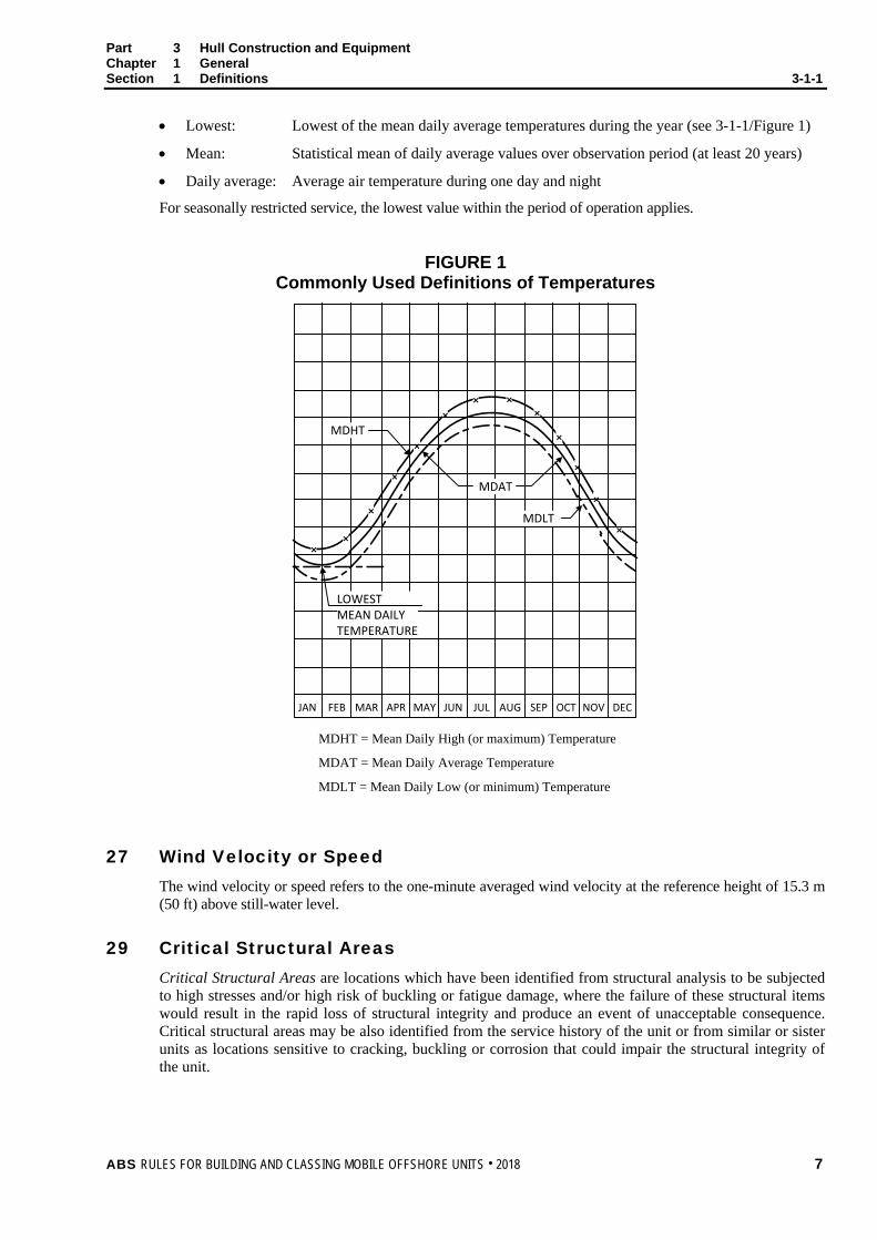
• Lowest: Lowest of the mean daily average temperatures during the year (see 3-1-1/Figure 1)
• Mean: Statistical mean of daily average values over observation period (at least 20 years)
• Daily average: Average air temperature during one day and night
For seasonally restricted service, the lowest value within the period of operation applies.
FIGURE 1 Commonly Used Definitions of Temperatures
××
×
×
×
×× ×
×
×
×
×
×
MDHT
MDAT
MDLT
LOWESTMEAN DAILYTEMPERATURE
JAN FEB MAR APR MAY JUN JUL AUG SEP OCT NOV DEC
MDHT = Mean Daily High (or maximum) Temperature
MDAT = Mean Daily Average Temperature
MDLT = Mean Daily Low (or minimum) Temperature
27 Wind Velocity or Speed The wind velocity or speed refers to the one-minute averaged wind velocity at the reference height of 15.3 m (50 ft) above still-water level.
29 Critical Structural Areas Critical Structural Areas are locations which have been identified from structural analysis to be subjected to high stresses and/or high risk of buckling or fatigue damage, where the failure of these structural items would result in the rapid loss of structural integrity and produce an event of unacceptable consequence. Critical structural areas may be also identified from the service history of the unit or from similar or sister units as locations sensitive to cracking, buckling or corrosion that could impair the structural integrity of the unit.
ABS RULES FOR BUILDING AND CLASSING MOBILE OFFSHORE UNITS . 2018 7

Part 3 Hull Construction and Equipment Chapter 1 General Section 1 Definitions 3-1-1
31 Downflooding Downflooding means any flooding of the interior of any part of the buoyant structure of a unit through openings which cannot be closed watertight or weathertight, as appropriate, in order to meet the intact or damage stability criteria, or which are required for operational reasons to be left open. Note: Unprotected openings are usually considered as downflooding points in intact and damage stability calculations.
8 ABS RULES FOR BUILDING AND CLASSING MOBILE OFFSHORE UNITS . 2018
P A R T S e c t i o n 2 : P l a n s a n d D e s i g n D a t a t o b e S u b m i t t e d
3 C H A P T E R 1 General
S E C T I O N 2 Plans and Design Data to be Submitted
1 Hull and Design Data Plans showing the scantlings, arrangements and details of the principal parts of the structure of each unit to be built under survey are to be submitted for review and approved before the work of construction are commenced. These plans are to clearly indicate the scantlings, joint details and welding, or other methods of connection.
In general, these plans are to include the following where applicable.
• General arrangement
• Inboard and outboard profile
• An arrangement plan of watertight compartmentation
• Diagrams showing the extent to which the watertight and weathertight integrity is intended to be maintained, including the location, type and disposition of watertight and weathertight closures.
• Summary of distributions of fixed and variable weights for each reviewed condition.
• Type, location and quantities of permanent ballast.
• Loadings for all decks
• Transverse sections showing scantlings
• Longitudinal sections showing scantlings
• Decks
• Structural fire protection layout plan for decks and bulkheads
• Fiber Reinforced Plastic (FRP) layout drawing
• Plans or a booklet of joiner work details of construction for all decks, bulkheads and doors
• Ventilation plan showing all horizontal and vertical duct work listing all materials, duct size and gauge
• Penetration details through bulkheads and decks to accommodate ventilation, piping, electrical, etc.
• Escape plan (depicting escape routes as determined by 5-3-1/1)
• Helicopter deck with helicopter particulars and its supporting structure (See 3-2-2/3.1)
• Framing
• Shell plating
• Watertight bulkheads and flats
• Structural bulkheads and flats
• Tank bulkheads and flats with level of top of overflows and air pipes
• Pillars and girders
ABS RULES FOR BUILDING AND CLASSING MOBILE OFFSHORE UNITS . 2018 9
Part 3 Hull Construction and Equipment Chapter 1 General Section 2 Plans and Design Data to be Submitted 3-1-2
• Diagonals and struts
• Legs
• Structure in way of jacking or other elevating arrangements
• Structures supporting the drilling derrick
• Stability columns and intermediate columns
• Hulls, pontoons, footings, spudcans, pads or mats
• Superstructures and deck houses
• Arrangement and details of watertight doors and hatches
• Foundations for anchoring equipment, industrial equipment, etc., where attached to hull structure, superstructures or deckhouses
• Welding details and procedures
• Lines and offsets
• Curves of form or equivalent data
• Wind heeling moment curves or equivalent data
• Capacity plan
• Tank sounding tables
• Corrosion control arrangements
• Methods and locations for nondestructive testing
• Plans for conducting underwater inspections in lieu of drydocking
• A description of environmental conditions for each mode of operation, including the service temperature of the unit (see 3-1-1/25) and minimum expected sea temperatures
• Hull Construction and Monitoring Plan (HCMP) as determined by 7-1-2/4, indicating critical structural areas identified in structural analyses (see 3-1-1/29)
3 Calculations The following calculations are to be submitted:
• Structural analysis, including fatigue analysis
• Resultant forces and moments from wind, waves, current, mooring and other environmental loadings
• Effects of icing on structural loadings and stability
• Wind resistance area of exposed structural elements
• Stability calculations, both intact and damaged
• Significant operational loads from drilling derrick, riser tensioners and other similar type significant loadings where applicable
• Calculations substantiating adequacy of structure to transmit forces between legs and hull through the jacking or other self-elevating system
• Evaluation of the unit’s ability to resist overturning while bearing on the sea bed
Submitted calculations are to be suitably referenced.
Results from model tests or dynamic response calculations may be submitted as alternatives or a substantiation for required calculations.
10 ABS RULES FOR BUILDING AND CLASSING MOBILE OFFSHORE UNITS . 2018

P A R T S e c t i o n 3 : E n v i r o n m e n t a l L o a d i n g s
3 C H A P T E R 1 General
S E C T I O N 3 Environmental Loadings
1 Loading Criteria
1.1 General A unit’s modes of operation should be investigated using anticipated loads, including gravity and functional loads together with relevant environmental loads due to the effects of wind, waves, currents, and where deemed necessary by the Owner or designer, the effects of earthquake, sea bed supporting capabilities, ambient temperature, fouling, ice, etc. Where applicable, the loads indicated herein are to be adhered to for all types of mobile offshore units. The Owner is to specify the environmental conditions for which the plans for the unit are to be approved. These design environmental conditions are to be recorded in the Operating Manual [see 1-2-5/1.3i) of the ABS Rules for Conditions of Classification – Offshore Units and Structures (Part 1)].
1.3 Wind Loadings 1.3.1 General
The minimum wind velocity for unrestricted offshore service for all normal operating and transit conditions is not to be less than 36 m/s (70 kn). All units in unrestricted offshore service are to have the capability to withstand a severe storm condition wherein a wind velocity of not less than 51.5 m/s (100 kn) is assumed. In order to comply with a severe storm condition, all units are to show compliance with this requirement at all times or have the capability to change their mode of operation. The steps to be taken to comply with the 51.5 m/s (100 kn) criteria from the 36 m/s (70 kn) criteria are the responsibility of the Owner. Units which, due to intended limited service, are not designed to meet the above criteria may be considered for restricted service classification. For any restricted classification, the minimum wind velocity is to be taken at not less than 25.7 m/s (50 kn).
1.3.2 Wind Pressure In the calculation of wind pressure, P, the following equation is to be used and the vertical height is to be subdivided approximately in accordance with the values listed in 3-1-3/Table 2.
P = f Vk2 Ch Cs N/m2 (kgf/m2, lbf/ft2)
where
f = 0.611 (0.0623, 0.00338)
Vk = wind velocity in m/s (m/s, kn)
Ch = height coefficient from 3-1-3/Table 2
Cs = shape coefficient from 3-1-3/Table 1
ABS RULES FOR BUILDING AND CLASSING MOBILE OFFSHORE UNITS . 2018 11
Part 3 Hull Construction and Equipment Chapter 1 General Section 3 Environmental Loadings 3-1-3
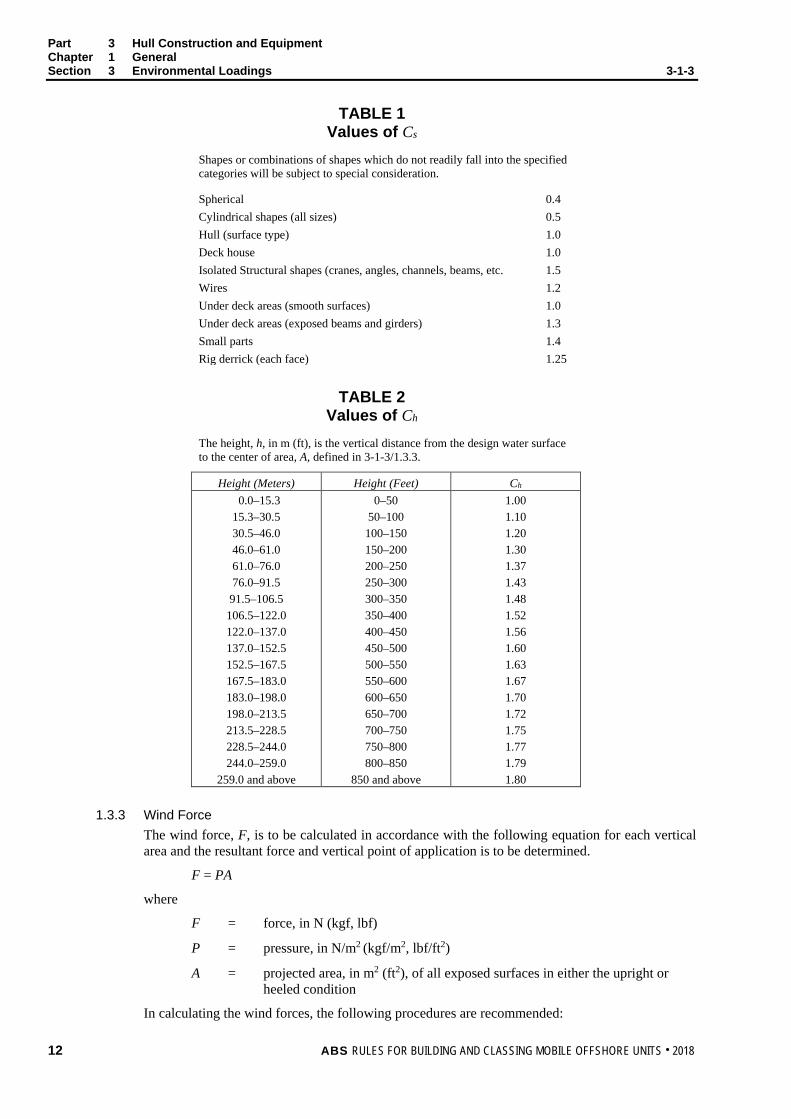
TABLE 1 Values of Cs
Shapes or combinations of shapes which do not readily fall into the specified categories will be subject to special consideration. Spherical Cylindrical shapes (all sizes) Hull (surface type) Deck house Isolated Structural shapes (cranes, angles, channels, beams, etc. Wires Under deck areas (smooth surfaces) Under deck areas (exposed beams and girders) Small parts Rig derrick (each face)
0.4 0.5 1.0 1.0 1.5 1.2 1.0 1.3 1.4 1.25
TABLE 2 Values of Ch
The height, h, in m (ft), is the vertical distance from the design water surface to the center of area, A, defined in 3-1-3/1.3.3.
Height (Meters) Height (Feet) Ch
0.0–15.3 15.3–30.5 30.5–46.0 46.0–61.0 61.0–76.0 76.0–91.5 91.5–106.5
106.5–122.0 122.0–137.0 137.0–152.5 152.5–167.5 167.5–183.0 183.0–198.0 198.0–213.5 213.5–228.5 228.5–244.0 244.0–259.0
259.0 and above
0–50 50–100 100–150 150–200 200–250 250–300 300–350 350–400 400–450 450–500 500–550 550–600 600–650 650–700 700–750 750–800 800–850
850 and above
1.00 1.10 1.20 1.30 1.37 1.43 1.48 1.52 1.56 1.60 1.63 1.67 1.70 1.72 1.75 1.77 1.79 1.80
1.3.3 Wind Force
The wind force, F, is to be calculated in accordance with the following equation for each vertical area and the resultant force and vertical point of application is to be determined.
F = PA
where
F = force, in N (kgf, lbf)
P = pressure, in N/m2 (kgf/m2, lbf/ft2)
A = projected area, in m2 (ft2), of all exposed surfaces in either the upright or heeled condition
In calculating the wind forces, the following procedures are recommended:
12 ABS RULES FOR BUILDING AND CLASSING MOBILE OFFSHORE UNITS . 2018
Part 3 Hull Construction and Equipment Chapter 1 General Section 3 Environmental Loadings 3-1-3
1.3.3(a) In the case of units with columns, the projected areas of all columns are to be included (i.e., no shielding allowance is to be taken).
1.3.3(b) Areas exposed due to heel, such as underdecks, etc., are to be included using the appropriate shape coefficients.
1.3.3(c) The block projected area of a clustering of deck houses may be used in lieu of calculating each individual area. The shape coefficient may be assumed to be 1.1.
1.3.3(d) Isolated houses, structural shapes, cranes, etc., are to be calculated individually using the appropriate shape coefficient from 3-1-3/Table 1.
1.3.3(e) Open truss work commonly used for derrick towers, booms and certain types of masts may be approximated by taking 30% of the projected block areas of both the front and back sides, i.e., 60% of the projected block area of one side for double sided truss work. The shape coefficient is to be taken in accordance with 3-1-3/Table 1.
1.5 Wave Loadings 1.5.1 General
Wave criteria specified by the Owner may be described by means of wave energy spectra or by deterministic waves having shape, size and period appropriate to the depth of water in which the unit is to operate. Waves are to be considered as coming from any direction relative to the unit. Consideration is to be given to waves of less than maximum height where due to their period, the effects on various structural elements may be greater.
1.5.2 Determination of Wave Loads The determination of wave loads for use in structural design is to be based on acceptable calculations, model tests or full scale measurements. For structures comprised of slender members which do not significantly alter the incident wave field, semi-empirical formulations such as Morison’s equation may be used. For calculations of wave loads on structural configurations which significantly alter the incident wave field, diffraction methods are to be used which account for both the incident wave force (i.e., Froude-Krylov force) and the forces resulting from wave diffraction and radiation.
In general, Morison’s equation may be used for structures comprised of slender members the diameters (or equivalent diameters giving the same cross-sectional areas parallel to the flow) of which are less than 20% of the wave lengths being considered and are small in relation to the distances between structural members subject to wave loading (e.g., self-elevating units in the elevated condition and most column-stabilized units).
For each combination of wave height, wave period and water depth being considered, a range of wave crest positions relative to the structure is to be investigated to ensure an accurate determination of the maximum wave force on the structure.
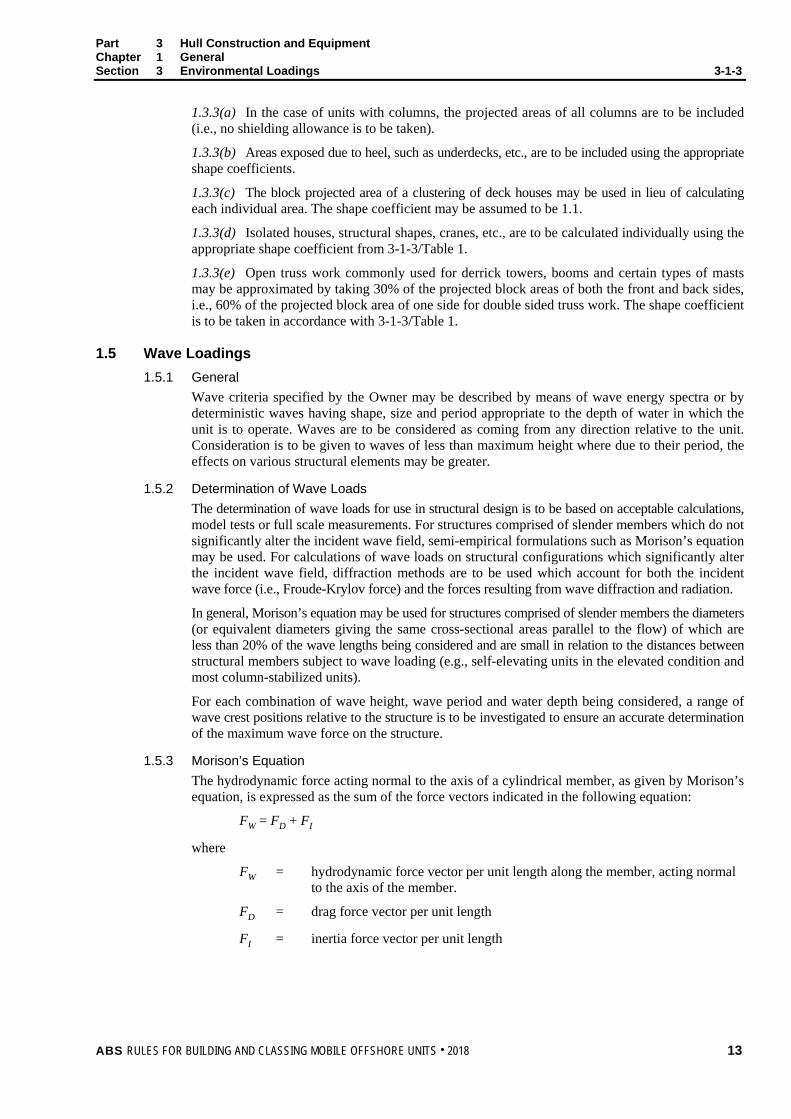
1.5.3 Morison’s Equation The hydrodynamic force acting normal to the axis of a cylindrical member, as given by Morison’s equation, is expressed as the sum of the force vectors indicated in the following equation:
FW = FD + FI
where
FW = hydrodynamic force vector per unit length along the member, acting normal to the axis of the member.
FD = drag force vector per unit length
FI = inertia force vector per unit length
ABS RULES FOR BUILDING AND CLASSING MOBILE OFFSHORE UNITS . 2018 13

Part 3 Hull Construction and Equipment Chapter 1 General Section 3 Environmental Loadings 3-1-3
The drag force vector per unit length for a stationary, rigid member is given by:
FD = (C/2) D CD un |un| kN/m (tf/m, lbf/ft)
where
C = 1.025 (0.1045, 1.99)
D = projected width, in m (ft), of the member in the direction of the cross-flow component of velocity (in the case of a circular cylinder, D denotes the diameter)
CD = drag coefficient (dimensionless)
un = component of the velocity vector, normal to the axis of the member, in m/s (ft/s)
|un| = absolute value of un, in m/s (ft/s)
The inertia force vector per unit length for a stationary, rigid member is given by:
F1 = C (π D2/4) CM an kN/m (tf/m, lbf/ft)
where
CM = inertia coefficient based on the displaced mass of fluid per unit length (dimensionless)
an = component of the fluid acceleration vector normal to the axis of the member, in m/s2 (ft/s2)
For structures which exhibit substantial rigid body oscillations due to wave action, the modified form of Morison’s equation given below may be used to determine the hydrodynamic force.
Fw = FD + FI
= C/2 D CD (un − un′) | un − un′| + C (π D2/4)an + C (π D2/4) Cm (an − an′)
where
un′ = component of the velocity vector of the structural member normal to its axis, in m/s (ft/s)
Cm = added mass coefficient (i.e., Cm = CM − 1)
an′ = component of the acceleration vector of the structural member normal to its axis, in m/s2 (ft/s2)
For structural shapes other than circular cylinders, the term π D2/4 in the above equations is to be replaced by the actual cross-sectional area of the shape.
Values of un and an for use in Morison’s equation are to be determined using wave theories appropriate to the wave heights, wave periods and water depths being considered. Drag and inertia coefficients vary considerably with section shape. Reynold’s number, Keulegan-Carpenter number and surface roughness are to be based on reliable data obtained from literature, model or full scale tests. For circular cylindrical members at Reynold’s numbers greater than 1 × 10⁶, CD and CM may be taken at 0.62 and 1.8, respectively, provided that marine fouling is prevented or periodically removed.
1.7 Current Loading 1.7.1 Current Associated with Waves
When determining loads due to the simultaneous occurrence of waves and current using Morison’s equation, the current velocity is to be added vectorially to the wave particle velocity before the total force is computed. When diffraction methods are used for calculating wave force, the drag force due to current should be calculated in accordance with 3-1-3/1.7.2 and added vectorially to the calculated wave force.
14 ABS RULES FOR BUILDING AND CLASSING MOBILE OFFSHORE UNITS . 2018

Part 3 Hull Construction and Equipment Chapter 1 General Section 3 Environmental Loadings 3-1-3
The current velocity is to include components due to tidal current, storm surge current and wind driven current. In lieu of defensible alternative methods, the vertical distribution of current velocity in still water and its modification in the presence of waves, as shown in 3-1-3/Figure 1, are recommended, where:
Vc = Vt + Vs + Vw [(h − z)/h], for z ≤ h
Vc = Vt + Vs for z > h
where
Vc = current velocity, m/s (ft/s) Vt = component of tidal current velocity in the direction of the wind, m/s (ft/s) Vs = component of storm surge current, m (ft) Vw = wind driven current velocity, m/s (ft/s) h = reference depth for wind driven current, m (ft). (in the absence of other data,
h may be taken as 5 m (16.4 ft). z = distance below still water level under consideration, m (ft) d = still water depth, m (ft)
In the presence of waves, the current velocity profile is to be modified, as shown in 3-1-3/Figure 1, such that the current velocity at the instantaneous free surface is a constant.
FIGURE 1 Current Velocity Profile
X
Vt Vs Vw
Vt + Vs + Vw Vt + Vs + Vw
Vt + Vs
Vt + Vs
x (+)
x (− )
(d + x)d
(d − h)
(d + x)d
(d − h)
d
h
Z
ABS RULES FOR BUILDING AND CLASSING MOBILE OFFSHORE UNITS . 2018 15

Part 3 Hull Construction and Equipment Chapter 1 General Section 3 Environmental Loadings 3-1-3
1.7.2 Drag Force When calculating the drag force on submerged parts of the structure due to current alone, the following equation may be used.
fD = C/2 D CD uc |uc|
where
fD = current drag force vector per unit length along the member, acting normal to the axis of the member in kN/m (tf/m, lbf/ft)
uc = component of the current velocity vector, Vc, normal to the axis of the member
C, D and CD are as defined in 3-1-3/1.5.3.
All of the above values are to be taken in a consistent system of units, CD being dimensionless. Drag coefficients in steady flow vary considerably with section shape, Reynold’s number and surface roughness and are to be based on reliable data obtained from literature, model or full scale tests.
1.9 Loadings due to Vortex Shedding Consideration is to be given to the possibility of flutter of structural members due to vortex shedding.
1.11 Gravity and Functional Loads 1.11.1 General
The gravity loads are steel, equipment and outfitting weights, liquid and solid variables, and live loads and should be taken into account in the design of the structural strength and stability. The load effects due to operations such as drilling (rotary/hook loads and tensioner loads), work over and well servicing should also be taken into account.
1.11.2 Combinations of Gravity and Functional Loads for Design For all modes of operation, the combinations of gravity and function loads are to be specified by the Owners or Designers as per the operations designed. However, maximums (or minimums) of the combinations that produce the most unfavorable load effects in the strength or stability of the unit should be taken for design.
1.11.3 Deck Loadings As indicated in 3-1-2/1, a loading plan is to be prepared for each design. This plan is to show the maximum uniform and concentrated loadings to be considered for all areas for each mode of operation. In the preparation of this plan, the following loadings are to be considered as minimums.
Crew spaces (walkways, general traffic areas, etc.)
4510 N/m2 (460 kgf/m2, 94 lbf/ft2) or 0.64 m (2.1 ft) head
Work areas
9020 N/m2 (920 kgf/m2, 188 lbf/ft2) or 1.28 m (4.2 ft) head
Storage areas
13000 N/m2 (1325 kgf/m2, 272 lbf/ft2) or 1.84 m (6.0 ft) head
16 ABS RULES FOR BUILDING AND CLASSING MOBILE OFFSHORE UNITS . 2018

P A R T S e c t i o n 4 : M a t e r i a l S e l e c t i o n
3 C H A P T E R 1 General
S E C T I O N 4 Material Selection
1 Materials
1.1 General This Section covers materials used for the construction of mobile offshore units. Structural materials are to be suitable for intended service conditions. Preferably, materials used in the construction of the hull of units are to be in accordance with the ABS Rules for Materials and Welding (Part 2).
Non-ABS grade steels to other recognized specifications, can be considered for hull structure application and other structural members, subject to witnessed testing and approval in accordance with 3-1-4/3.7. Note: The tensile specification requirement for ABS Grades of steel plate and sections remains constant with increased
thickness.
1.1.1 Cast Nodes Used as Special or Primary Application Structure Cast nodes used in special or primary application structure are to be produced by an ABS approved foundry and witness tested by an ABS Surveyor.
1.1.2 Rack and Chord Elements used as Primary Application Structure of Legs for Self-Elevating Units. Welded assemblies of rack and chord elements used as primary application structure in lattice type leg members are to be produced by an ABS approved mill and witness tested by an ABS Surveyor.
1.1.3 Seamless and Welded Steel Pipes used as Primary Application Structure of Legs for Self-Elevating Units and Column-stabilized Units. Seamless steel pipes and welded steel pipes used as primary application structure of tubular leg members are to be produced by an ABS approved mill and witness tested by an ABS Surveyor.
1.1.4 Seamless and Welded Steel Pipes used as Secondary Application Structure of Legs for Self-Elevating Units Seamless steel pipes and welded steel pipes used as secondary application structure of legs on a self-elevating unit need not be produced by an ABS approved mill nor witness tested by an ABS Surveyor. Material Test Reports (MTR) representing each member are to be available to the Surveyor before fabrication.
1.3 Characteristics Materials used are required to exhibit satisfactory formability and weldability characteristics. For materials other than those indicated in 2-1-2/Tables 1 through 4 and 2-1-3/Tables 1 through 4 of the above-referenced Part 2, evidence of satisfactory formability and weldability are to be submitted for review.
1.5 Toughness Materials are to exhibit fracture toughness which is satisfactory for the intended application, as evidenced by previous satisfactory service experience or appropriate toughness tests.
ABS RULES FOR BUILDING AND CLASSING MOBILE OFFSHORE UNITS . 2018 17

Part 3 Hull Construction and Equipment Chapter 1 General Section 4 Material Selection 3-1-4
1.7 Materials Other than Steel When material other than steel is used as a structural material, documentation is to indicate the mechanical properties, toughness, fatigue, and corrosion characteristics of the proposed material. Where such materials are used in combination with steel, galvanic effects should be taken into account, as applicable.
1.9 Service Temperature Units intended for unrestricted service are to have a service temperature (see 3-1-1/25) equal to or below 0°C (32°F). When the service temperature of the unit is above 0°C (32°F), the unit is to have the notation Restricted Service.
3 Hull Steel Grades
3.1 Ordinary and Higher Strength Steel 2-1-2/Tables 1 through 4 and 2-1-3/Tables 1 through 4 of the ABS Rules for Materials and Welding (Part 2) show the chemical, mechanical properties, and heat treatment specifications for the various grades of ABS ordinary and higher strength hull structural steel.
3.3 Extra High Strength Steel 2-1-8/Tables 1, 2, 3, 4a, 4b, 5a and 5b of the ABS Rules for Materials and Welding (Part 2) show the chemical and mechanical properties for the various grades of ABS extra high strength hull structural steel and are to be used for reference when considering material selection for self-elevating and column stabilized units.
3.5 Additional Requirements In cases where principal loads from either service or weld residual stresses are imposed perpendicular to the plate thickness, the use of special plate with improved through thickness (Z direction) properties may be required.
3.7 Other Grades Materials, test specimens and mechanical testing procedures having characteristics differing from those prescribed herein may be approved upon application, due regard being given to the material specification proposed, the steel manufacturer, the manufacturing process, the established practices in the country in which the material is produced and the purpose for which the material is intended. Note: The tensile specification requirements for steel plate of several widely applied recognized standards, permit the
properties to decrease with increased thickness, and this must be accounted for in the design phase.
Non-ABS Grades are to be Charpy impact tested in accordance with 3-1-4/5.7.
5 Selection of Grades
5.1 General For the classification of self-elevating, column-stabilized, and surface-type units, it is necessary to take into account service temperature of the unit and structural element category when selecting structural materials. The various parts of self-elevating, column stabilized, and surface-type units are grouped according to their material application categories. The structural elements falling into these categories are described, in general, in 3-2-3/3.1, 3-2-4/1.7 and 3-2-5/3.
18 ABS RULES FOR BUILDING AND CLASSING MOBILE OFFSHORE UNITS . 2018

Part 3 Hull Construction and Equipment Chapter 1 General Section 4 Material Selection 3-1-4
5.3 Material Application Categories The structural elements are grouped into the following categories depending on the criticality of the application:
5.3.1 Special Application (Most Critical) Failure of special application structural elements may cause catastrophic structural damage to the unit with high risk of loss of life and environmental pollution. The special application structural elements are most critical for the survivability of the unit.
5.3.2 Primary Application (Intermediate) Failure of primary application structural elements may cause significant structural damage to the unit with moderate risk of loss of life and environmental pollution. The primary application structural elements have an intermediate criticality for the survivability of the unit.
5.3.3 Secondary Application (Least Critical) Failure of secondary application structural elements may cause minor structural damage to the unit with low risk of loss of life and environmental pollution. The secondary application structural elements are the least critical for the survivability of the unit.
5.5 Selection Criteria for ABS Grades of Steel 3-1-4/Table 1 shows selection criteria for each structural element category for ABS grades of ordinary and higher strength hull structural steels to be used in self-elevating and column-stabilized units expected to experience service temperatures as low as –30°C (–22°F). Requirements for selection of ABS extra high strength steels are given in 3-1-4/Table 2. Service temperature refers to the minimum temperature of the steel. See 3-1-1/25. Where the steel temperature in specific structural areas is shown to be warmer than the service temperature of the unit, the warmer temperature may be applied. Where the minimum steel temperature is 0°C (32°F) or warmer, the material requirements indicated for 0°C (32°F) are generally applicable. In addition, where material being considered is located in close proximity to, or below, the minimum waterline, the material selection may be based on that indicated for the 0°C (32°F) temperature.
These requirements are applicable for units that are limited to areas of operation where ice strengthening is not required.
Where it is desired to use steels other than those in 3-1-4/Table 1 and 3-1-4/Table 2 or thicknesses above the maximum indicated in 3-1-4/Table 1, they are to be specially considered.
5.7 Criteria for Other Steels 5.7.1 General
Appropriate supporting information or test data is to indicate that the toughness of the steels will be adequate for their intended application in the unit’s structure at the service temperature of the unit. In the absence of supporting data, tests are required to demonstrate that steels would meet the following Charpy V-Notch (CVN) impact requirements.
5.7.2 CVN Requirements Steels in the 235 to 420 N/mm2 (24 to 43 kgf/mm2, 34 to 61 ksi) yield strength range are to meet the following CVN requirements:
Specified Minimum Yield Strength (2)
Longitudinal CVN Joules (kgf-m, ft-lbf) at 2 mm (0.08 in.) Sub-surface Thickness mm (in.) (1, 4)
N/mm2 kgf/mm2 ksi t ≤ 50 (t ≤ 2.0)
50 < t ≤ 70 (2.0 < t ≤ 2.8)
70 < t ≤ 100 (2.8 < t ≤ 4.0)
100 < t ≤ 150 (2) (4.0 < t ≤ 6.0)
150 < t ≤ 200 (2) (6.0 < t ≤ 8.0)
235(5) 24 34 27 (2.8, 20) 35 (3.6, 26) 42 (4.3, 31) 48 (4.9, 35) 54 (5.5, 40) 275 28 40 27 (2.8, 20) 35 (3.6, 26) 42 (4.3, 31) 48 (4.9, 35) 54 (5.5, 40) 355 36 51 35 (3.6, 26) 42 (4.3, 31) 48 (4.9, 35) 54 (5.5, 40) 60 (6.1, 44) 420 43 61 42 (4.3, 31) 48 (4.9, 35) 54 (5.5, 40) 60 (6.1, 44) 66 (6.7, 49)
ABS RULES FOR BUILDING AND CLASSING MOBILE OFFSHORE UNITS . 2018 19

Part 3 Hull Construction and Equipment Chapter 1 General Section 4 Material Selection 3-1-4
Notes: 1 For thicknesses above 40 mm (1.6 in.) the Charpy tests are to be taken at 1/4t.
2 For plate over 100 mm (4.0 in.) thick, in addition to note 1 Charpy tests at mid t are to be carried out and are to achieve at least 2/3 of the required Joule value indicated in the above table for sub-surface specimens. Alternatively the mid t test can be carried out at 10°C (18°F) above the specified CVN test temperature to achieve the same Charpy value specified for the sub-surface specimen. Mid t Charpy testing may not be required in cases where it has been established by first article testing and satisfactory manufacturing production control, that adequate mid thickness Charpy values and internal quality are maintained, and the necessary supporting documents are submitted to ABS Materials department for review. However in such cases, when deemed necessary by ABS Materials department, random mid t Charpy sampling may be required.
3 For intermediate yield strength values, the CVN values are based upon the Yield MPa/10 up to 50 mm (2.0 in.) and then incremented by the same scale for thickness increase.
4 For thickness above 200 mm (8.0 in.), in general the same CVN criteria for 150 mm to 200 mm (6.0 in. to 8.0 in.) applies to 1/4t and mid t, see Note 2. However, the criticality and component detail for each application is to be assessed and alternative criteria may be accepted or requested.
5 Steel for appurtenant or secondary structure fabricated to recognized Standards, is to be verified by, or tested to the satisfaction of the ABS Surveyor, and may be used in ABS Grade A applications without additional CVN test provided:
i) Service temperature is -10°C (14° F) or above
ii) Max thickness is 12.5 mm (0.5 in.) for plate, and 19 mm (0.75 in.) for sections
iii) The structure does not contribute to the hull watertight integrity or leg structural integrity.
5.7.3 CVN Temperatures The CVN requirements are to be obtained when tested at the following temperatures:
Secondary application structure: service temperature
Primary application structure: 10°C (18°F) below service temperature
Special application structure: 30°C (54°F) below service temperature
5.7.4 Extra High Strength Steels Steels in the 460 to 960 N/mm2 (47 to 98 kgf/mm2, 67 to 139 ksi) yield strength range are to meet the following CVN requirements at the following test temperatures.
Specified Minimum Yield Strength (3, 5)
Longitudinal CVN Joules (kgf-m, ft-lbf) at 2 mm (0.08 in.) Sub-surface Thickness, mm (in.) (1, 4)
N/mm2 kg/mm2 ksi t ≤ 100 (t ≤ 4.0)
100 < t ≤ 200 (2) (4.0 < t ≤ 8.0)
460 47 67 46 (4.7, 34) 46 (4.7, 34) 500 51 73 50 (5.1, 37) 50 (5.1, 37) 550 56 80 55 (5.6, 41) 55 (5.6, 41) 620 63 90 62 (6.3, 46) 62 (6.3, 46) 690 70 100 69 (7.0, 51) 69 (7.0, 51) 890 91 129 69 (7.0, 51) 69 (7.0, 51) 960 98 139 69 (7.0, 51) 69 (7.0, 51)
Notes: 1 For thicknesses above 40 mm (1.6 in.) the Charpy tests are to be taken at 1/4t.
2 For plate over 100 mm (4.0 in.) thick, in addition to note 1 Charpy tests are to be carried out at mid t and are to achieve at least 2/3 of the required Joule value indicated in the above table for sub-surface specimens. Alternatively the mid t test can be carried out at 10°C above the specified CVN test temperature to achieve the same Charpy value specified for the sub-surface specimen.
3 For intermediate yield strength values, the CVN values are based upon the Yield MPa/10.
4 For thickness above 200 mm (8.0 in.), in general the same CVN criteria for 100 mm to 200 mm (4.0 in. to 8.0 in.) applies to 1/4t and mid t, see Note 2. However, the criticality and component detail for each application is to be assessed and alternative criteria may be accepted or requested.
20 ABS RULES FOR BUILDING AND CLASSING MOBILE OFFSHORE UNITS . 2018
Part 3 Hull Construction and Equipment Chapter 1 General Section 4 Material Selection 3-1-4
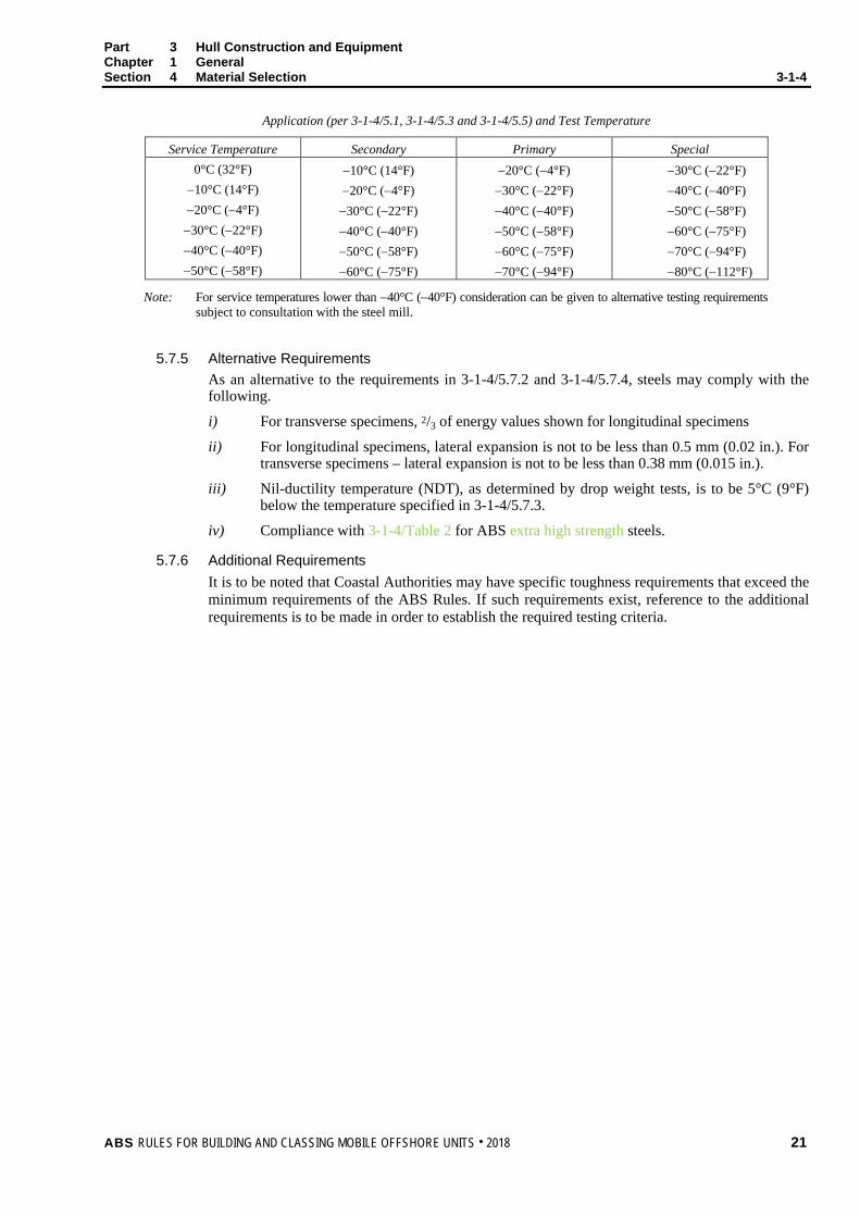
Application (per 3-1-4/5.1, 3-1-4/5.3 and 3-1-4/5.5) and Test Temperature
Service Temperature Secondary Primary Special 0°C (32°F)
−10°C (14°F) −20°C (−4°F)
−30°C (−22°F) −40°C (−40°F) −50°C (−58°F)
−10°C (14°F) −20°C (−4°F) −30°C (−22°F) −40°C (−40°F) −50°C (−58°F) −60°C (−75°F)
−20°C (−4°F) −30°C (−22°F) −40°C (−40°F) −50°C (−58°F) −60°C (−75°F) −70°C (−94°F)
−30°C (−22°F) −40°C (−40°F) −50°C (−58°F) −60°C (−75°F) −70°C (−94°F) −80°C (−112°F)
Note: For service temperatures lower than −40°C (−40°F) consideration can be given to alternative testing requirements subject to consultation with the steel mill.
5.7.5 Alternative Requirements
As an alternative to the requirements in 3-1-4/5.7.2 and 3-1-4/5.7.4, steels may comply with the following.
i) For transverse specimens, 2/3 of energy values shown for longitudinal specimens
ii) For longitudinal specimens, lateral expansion is not to be less than 0.5 mm (0.02 in.). For transverse specimens – lateral expansion is not to be less than 0.38 mm (0.015 in.).
iii) Nil-ductility temperature (NDT), as determined by drop weight tests, is to be 5°C (9°F) below the temperature specified in 3-1-4/5.7.3.
iv) Compliance with 3-1-4/Table 2 for ABS extra high strength steels.
5.7.6 Additional Requirements It is to be noted that Coastal Authorities may have specific toughness requirements that exceed the minimum requirements of the ABS Rules. If such requirements exist, reference to the additional requirements is to be made in order to establish the required testing criteria.
ABS RULES FOR BUILDING AND CLASSING MOBILE OFFSHORE UNITS . 2018 21

Part 3 Hull Construction and Equipment Chapter 1 General Section 4 Material Selection 3-1-4
TABLE 1 Material Selection Requirements for ABS Ordinary and Higher Strength Steels
Numbers in table are maximum thicknesses in mm (in.)
Blank areas indicate no application
Service Temperature °C (°F) Secondary Applications Primary Applications Special Applications
Grade 0
(32) −10 (14)
−20 (−4)
−30 (−22)
−40* (−40)*
−50* (−58)*
0 (32)
−10 (14)
−20 (−4)
−30 (−22)
−40* (−40)*
−50* (−58)*
0 (32)
−10 (14)
−20 (−4)
−30 (−22)
−40* (−40)*
−50* (−58)*
A 100 (4.00)
19 (0.75)
12.5 (0.50)
— — — 19
(0.75) 12.5
(0.50) — — — — — — — — — —
B 100 (4.00)
25 (1.00)
19 (0.75)
12.5 (0.50)
— — 25
(1.00) 19
(0.75) 12.5
(0.50) — — —
16 (0.63)
— — — — —
D 100 (4.00)
35 (1.375)
35 (1.375)
22.5 (0.89)
12.5 (0.50)
— 35
(1.375) 35
(1.375) 22.5
(0.89) 12.5
(0.50) — —
22.5 (0.89)
16 (0.63)
— — — —
DN 100 (4.00)
100 (4.00)
100 (4.00)
27.5 (1.08)
22.5 (0.89)
16 (0.63)
100 (4.00)
100 (4.00)
27.5 (1.08)
22.5 (0.89)
16 (0.63)
— 27.5
(1.08) 22.5
(0.89) 16
(0.63) — — —
E 100 (4.00)
100 (4.00)
100 (4.00)
100 (4.00)
100 (4.00)
27.5 (1.08)
100 (4.00)
100 (4.00)
100 (4.00)
100 (4.00)
27.5 (1.08)
16 (0.63)
100 (4.00)
100 (4.00)
27.5 (1.08)
16 (0.63)
12.5 (0.50)
AH 100 (4.00)
25 (1.00)
19 (0.75)
12.5 (0.50)
— — 19
(0.75) 19
(0.75) 12.5
(0.50) — — —
19 (0.75)
— — — — —
DH 100 (4.00)
100 (4.00)
100 (4.00)
19 (0.75)
12.5 (0.50)
— 100
(4.00) 100
(4.00) 19
(0.75) 12.5
(0.50) — —
19 (0.75)
16 (0.63)
— — — —
DHN 100 (4.00)
100 (4.00)
100 (4.00)
27.5 (1.08)
22.5 (0.89)
16 (0.63)
100 (4.00)
100 (4.00)
27.5 (1.08)
22.5 (0.89)
16 (0.63)
— 27.5
(1.08) 22.5
(0.89) 16
(0.63) — — —
EH 100 (4.00)
100 (4.00)
100 (4.00)
100 (4.00)
100 (4.00)
27.5 (1.08)
100 (4.00)
100 (4.00)
100 (4.00)
100 (4.00)
27.5 (1.08)
16 (0.63)
100 (4.00)
100 (4.00)
27.5 (1.08)
16 (0.63)
12.5 (0.50)
—
FH 100
(4.00) 100
(4.00) 100
(4.00) 100
(4.00) 100
(4.00) 100
(4.00) 100
(4.00) 100
(4.00) 100
(4.00) 100
(4.00) 100
(4.00) 27.5
(1.08) 100
(4.00) 100
(4.00) 100
(4.00) 100
(4.00) 27.5
(1.08) 16
(0.63)
Note: Material selection/testing proposal is to be submitted to ABS Materials Dept. for review, in case:
• Steels with thicknesses above maximum indicated in the table are selected
• Design service temperature is lower than –50°C (–58°F)
TABLE 2 Material Selection for ABS Extra High Strength Steel Grades(1)
Service Temperature °C (°F) Secondary * Primary Special 0 (32) AQ43 to AQ70 DQ43 to DQ70 EQ43 to EQ70 −10 (14) EQ43 to EQ70 EQ43 to EQ70 EQ43 to EQ70 −20 (−4) EQ43 to EQ70 EQ43 to EQ70 EQ43 to EQ70
−30 (−22) EQ43 to EQ70 EQ43 to EQ70 EQ43 to EQ70 −40 (−40) FQ43 to FQ70 FQ43 to FQ70 FQ43 to FQ70 −50 (−58) FQ43 to FQ70 FQ43 to FQ70 —
* For Secondary members, toughness criteria may be relaxed.
Note:
1 Selection of grades 91 and 98 will be specially considered depending on the application and weldability.
22 ABS RULES FOR BUILDING AND CLASSING MOBILE OFFSHORE UNITS . 2018
P A R T A p p e n d i x 1 : S h a l l o w W a t e r W a v e T h e o r y
3 C H A P T E R 1 General
A P P E N D I X 1 Shallow Water Wave Theory
The method presented is a simplification based on an interpolation between the solitary and Airy theories, and several others. The analysis is based on vertical cylindrical structures and thus may be used for units having structural and stability columns or, without serious error, truss type legs with non-cylindrical components. The method also assumes that the structure extends to the bottom of the sea. In the event that the legs or columns stop short of the bottom, it may either be assumed that the forces have diminished greatly at such point, and the nonexistent portion below ignored, or an adjustment may be made, finding the effective wave height at that distance below the water, and making another calculation of the imaginary portion below the actual structure, and subtracting from the original value.
1 Equations FDm = 0.5CD ρDhw
2KDm
Fim = 0.5CmρD2hwKim
Lw = (Lw/La)(La/Lo)KT2
MDm = SDFDm
Mim = SiFim
MTm = (Fm/FDm)MDm
3 Nomenclature CD = drag coefficient (use 0.71 for following example)
Cm = inertial or mass coefficient (use 2.00 for following example)
D = pile diameter, m (ft)
FDm = maximum value of total horizontal drag force (occurs at wave crest), N (kgf, lbf)
Fim = maximum value of total horizontal inertial force (occurs at between crest and 1/4 of wave length), N (kgf, lbf)
Fm = maximum value of combined drag and inertia forces, N (kgf, lbf)
g = acceleration of gravity
h = still-water depth, m (ft)
hw = wave height, crest to trough, m (ft)
K = 1.56 m/s2 (5.12 ft/s2)
KDm = drag force factor at crest, m/s2 (ft/s2)
Kim = inertial force factor, m/s2 (ft/s2)
La = linear theory wave length for period T and depth h, m (ft)
Lo = deepwater linear theory wave length = 1.56T2 m (5.12T2 ft)
ABS RULES FOR BUILDING AND CLASSING MOBILE OFFSHORE UNITS . 2018 23

Part 3 Hull Construction and Equipment Chapter 1 General Appendix 1 Shallow Water Wave Theory 3-1-A1
Lw = wave length, including the effect of finite wave height, m (ft)
MDm = moment on pile about bottom associated with maximum drag force, N-m (kgf-m, ft-lbf)
Mim = moment on pile about bottom associated with maximum inertial force, N-m (kgf-m, ft-lbf)
MTm = maximum total moment on pile about bottom, N-m (kgf-m, ft-lbf)
S = lever arm for Fm, m (ft)
SD = lever arm for FDm, m (ft)
Si = lever arm for Fim, m (ft)
T = wave period, sec
W = unit weight of sea water, kg/m3 (lb/ft3)
β = angular position of maximum moment ahead of wave crest, degrees
ρ = mass density = W/g kg/m3 (slug/ft3)
ζo = crest elevation above still water, m (ft)
5 Example Given:
Wave height hw = 35 ft
Still-water depth h = 85 ft
Wave period T = 12 sec
Pile diameter D = 8 ft
Drag coefficient CD = 0.71
Inertia coefficient Cm = 2.00
7 Compute 1 hw/T2 = 35/144
= 0.243 ft/s2
2 h/T2 = 85/144
= 0.590 ft/s2
3 hw/h = 35/85
= 0.412
From 3-1-A1/Figure 1, using equations 1 and 2, determine ζo/hw = 0.68
then ζo = 0.68 (hw)
= 0.68 (35)
= 23.8 ft
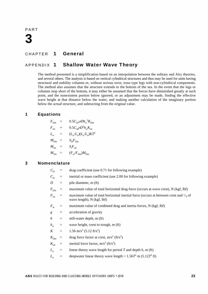
From 3-1-A1/Figure 2, using equation 2, determine La/Lo = 0.75
From 3-1-A1/Figure 3, using equations 1 and 2, determine Lw/La = 1.04
as Lw = (Lw/La)(La/Lo)KT2
then Lw = (1.04)(0.75)(5.12)(12)2
= 575 ft
24 ABS RULES FOR BUILDING AND CLASSING MOBILE OFFSHORE UNITS . 2018

Part 3 Hull Construction and Equipment Chapter 1 General Appendix 1 Shallow Water Wave Theory 3-1-A1
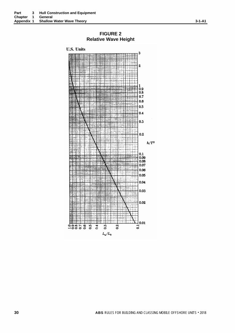
From 3-1-A1/Figure 4, using equations 1 and 2, determine KDm = 13.0 ft/s2
as FDm = 0.5CDρDhw2KDm
then FDm = 0.5(0.71)(1.993)(8)(35)2(13.0)
= 90,200 lbf
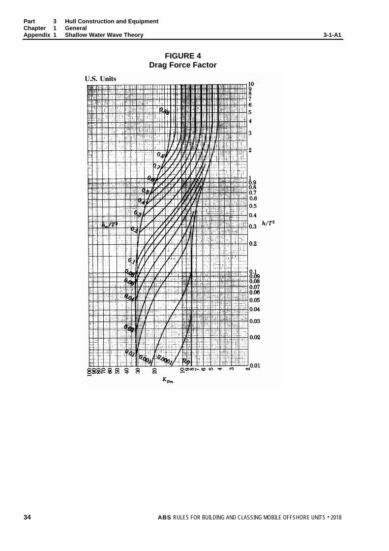
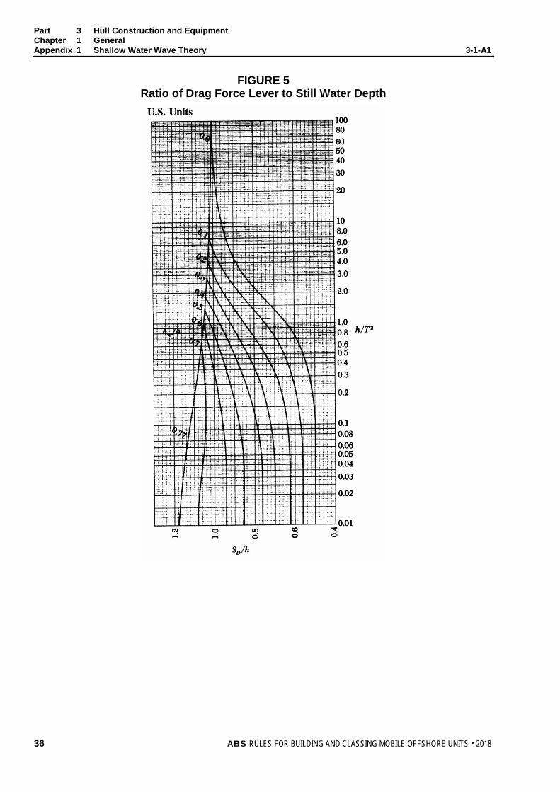
From 3-1-A1/Figure 5, using equations 2 and 3, determine SD/h = 0.91
then SD = 0.91(h)
= 0.91(85)
= 77.4 feet
and as MDm = FDmSD
then MDm = 90,200 (77.4)
= 6,980,000 ft-lbf
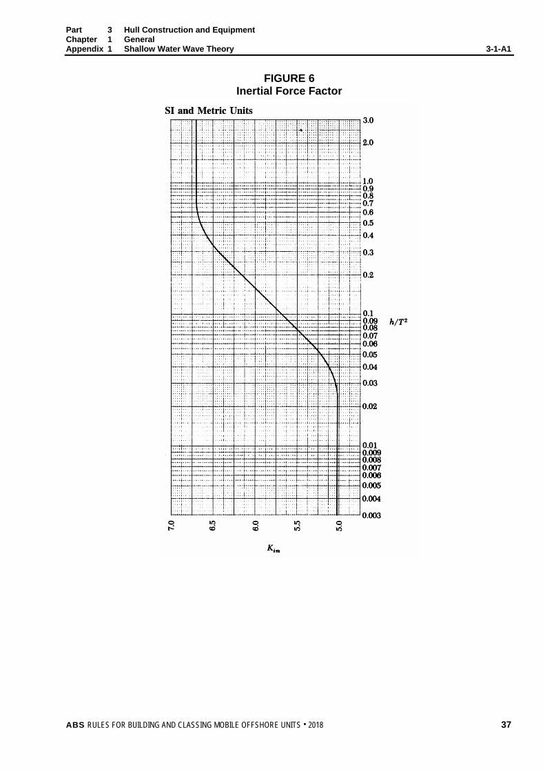
From 3-1-A1/Figure 6, using equation 2, determine Kim = 19.5 feet/sec2
as Fim = 0.5CmρD2hwKim
then Fim = 0.5(2.00)(1.993)(8)2(35)(19.5)
= 87,200 lbf
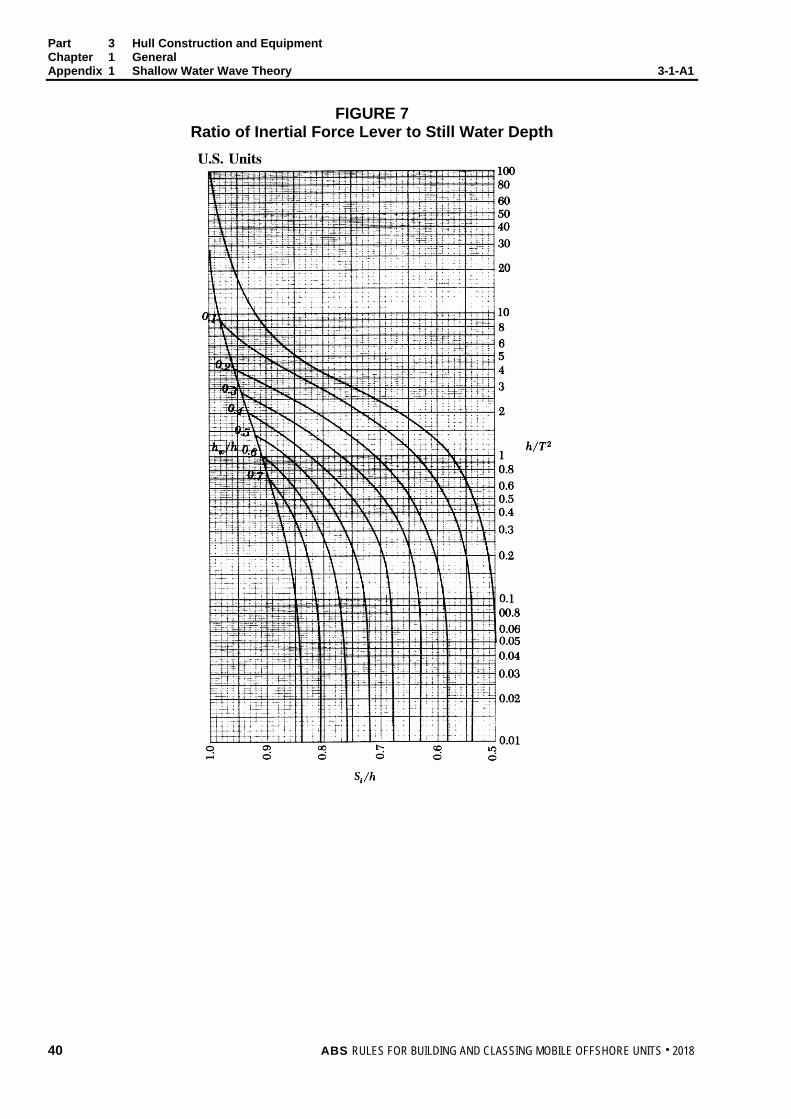
From 3-1-A1/Figure 7, using equations 2 and 3, determine Si/h = 0.78
then Si = 0.78(h)
= 0.78(85)
= 66.3 ft
as Mim = FimSi
then Mim = 87,200(66.3)
= 5,780,000 ft-lbf
and Fim/FDm = 87,200/90,200
= 0.967
From 3-1-A1/Figure 8, using Fim/FDm = 0.967, determine Fm/FDm = 1.37
then Fm = 1.37FDm
= 1.37(90,200)
= 123,500 lbf
and as MTm = (Fm/FDm)MDm
then MTm = 1.37MDm
= 1.37(6,980,000)
= 9,560,000 ft-lbf
Maximum total force:
Fm = 123,500 lbf
Maximum total moment:
MTm = 9,560,000 ft-lbf
as S = MTm/Fm
then S = 9,560,000/123,500
= 77.4 ft
ABS RULES FOR BUILDING AND CLASSING MOBILE OFFSHORE UNITS . 2018 25

Part 3 Hull Construction and Equipment Chapter 1 General Appendix 1 Shallow Water Wave Theory 3-1-A1
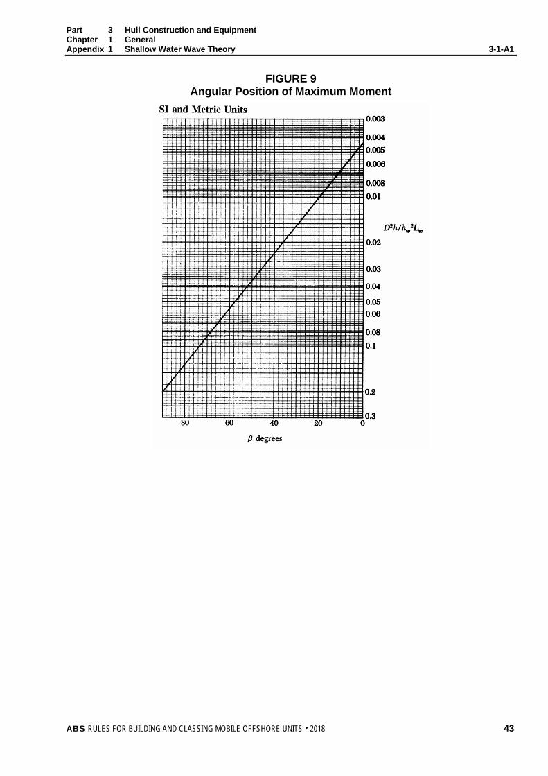
From 3-1-A1/Figure 9, position of maximum moment ahead of wave crest:
as D2h/hw2Lw = (8)2(85)/(35)2(575)
= 0.00772
then β = 13 degrees
26 ABS RULES FOR BUILDING AND CLASSING MOBILE OFFSHORE UNITS . 2018

Part 3 Hull Construction and Equipment Chapter 1 General Appendix 1 Shallow Water Wave Theory 3-1-A1
FIGURE 1 Ratio of Crest Elevation to Wave Height
ABS RULES FOR BUILDING AND CLASSING MOBILE OFFSHORE UNITS . 2018 27

Part 3 Hull Construction and Equipment Chapter 1 General Appendix 1 Shallow Water Wave Theory 3-1-A1
FIGURE 1 Ratio of Crest Elevation to Wave Height
28 ABS RULES FOR BUILDING AND CLASSING MOBILE OFFSHORE UNITS . 2018

Part 3 Hull Construction and Equipment Chapter 1 General Appendix 1 Shallow Water Wave Theory 3-1-A1
FIGURE 2 Relative Wave Height
ABS RULES FOR BUILDING AND CLASSING MOBILE OFFSHORE UNITS . 2018 29
Part 3 Hull Construction and Equipment Chapter 1 General Appendix 1 Shallow Water Wave Theory 3-1-A1
FIGURE 2 Relative Wave Height
30 ABS RULES FOR BUILDING AND CLASSING MOBILE OFFSHORE UNITS . 2018

Part 3 Hull Construction and Equipment Chapter 1 General Appendix 1 Shallow Water Wave Theory 3-1-A1
FIGURE 3 Wave Length Correction Factor
ABS RULES FOR BUILDING AND CLASSING MOBILE OFFSHORE UNITS . 2018 31

Part 3 Hull Construction and Equipment Chapter 1 General Appendix 1 Shallow Water Wave Theory 3-1-A1
FIGURE 3 Wave Length Correction Factor
32 ABS RULES FOR BUILDING AND CLASSING MOBILE OFFSHORE UNITS . 2018

Part 3 Hull Construction and Equipment Chapter 1 General Appendix 1 Shallow Water Wave Theory 3-1-A1
FIGURE 4 Drag Force Factor
ABS RULES FOR BUILDING AND CLASSING MOBILE OFFSHORE UNITS . 2018 33
Part 3 Hull Construction and Equipment Chapter 1 General Appendix 1 Shallow Water Wave Theory 3-1-A1
FIGURE 4 Drag Force Factor
34 ABS RULES FOR BUILDING AND CLASSING MOBILE OFFSHORE UNITS . 2018
Part 3 Hull Construction and Equipment Chapter 1 General Appendix 1 Shallow Water Wave Theory 3-1-A1
FIGURE 5 Ratio of Drag Force Lever to Still Water Depth
ABS RULES FOR BUILDING AND CLASSING MOBILE OFFSHORE UNITS . 2018 35
Part 3 Hull Construction and Equipment Chapter 1 General Appendix 1 Shallow Water Wave Theory 3-1-A1
FIGURE 5 Ratio of Drag Force Lever to Still Water Depth
36 ABS RULES FOR BUILDING AND CLASSING MOBILE OFFSHORE UNITS . 2018
Part 3 Hull Construction and Equipment Chapter 1 General Appendix 1 Shallow Water Wave Theory 3-1-A1
FIGURE 6 Inertial Force Factor
ABS RULES FOR BUILDING AND CLASSING MOBILE OFFSHORE UNITS . 2018 37

Part 3 Hull Construction and Equipment Chapter 1 General Appendix 1 Shallow Water Wave Theory 3-1-A1
FIGURE 6 Inertial Force Factor
38 ABS RULES FOR BUILDING AND CLASSING MOBILE OFFSHORE UNITS . 2018

Part 3 Hull Construction and Equipment Chapter 1 General Appendix 1 Shallow Water Wave Theory 3-1-A1
FIGURE 7 Ratio of Inertial Force Lever to Still Water Depth
ABS RULES FOR BUILDING AND CLASSING MOBILE OFFSHORE UNITS . 2018 39
Part 3 Hull Construction and Equipment Chapter 1 General Appendix 1 Shallow Water Wave Theory 3-1-A1
FIGURE 7 Ratio of Inertial Force Lever to Still Water Depth
40 ABS RULES FOR BUILDING AND CLASSING MOBILE OFFSHORE UNITS . 2018

Part 3 Hull Construction and Equipment Chapter 1 General Appendix 1 Shallow Water Wave Theory 3-1-A1
FIGURE 8 Ratio of Total Force to Drag Force
ABS RULES FOR BUILDING AND CLASSING MOBILE OFFSHORE UNITS . 2018 41

Part 3 Hull Construction and Equipment Chapter 1 General Appendix 1 Shallow Water Wave Theory 3-1-A1
FIGURE 8 Ratio of Total Force to Drag Force
42 ABS RULES FOR BUILDING AND CLASSING MOBILE OFFSHORE UNITS . 2018
Part 3 Hull Construction and Equipment Chapter 1 General Appendix 1 Shallow Water Wave Theory 3-1-A1
FIGURE 9 Angular Position of Maximum Moment
ABS RULES FOR BUILDING AND CLASSING MOBILE OFFSHORE UNITS . 2018 43

Part 3 Hull Construction and Equipment Chapter 1 General Appendix 1 Shallow Water Wave Theory 3-1-A1
FIGURE 9 Angular Position of Maximum Moment
44 ABS RULES FOR BUILDING AND CLASSING MOBILE OFFSHORE UNITS . 2018
P A R T A p p e n d i x 2 : W a v e T h e o r y f o r D e e p W a t e r
3 C H A P T E R 1 General
A P P E N D I X 2 Wave Theory for Deep Water
This Appendix is a development of the sine wave theory for deep water waves and may be used for determining the drag and inertial forces on the underwater portions of units which may be operating in deep water zones. The application of this Appendix is limited to waves where the linear wave theory can be used on the basis of the water depth and wave characteristics (wave height and period) as determined by API RP 2A or other recognized standards. Other methods of determining the force which may be deemed appropriate will be considered, provided they are referenced and supported by calculations.
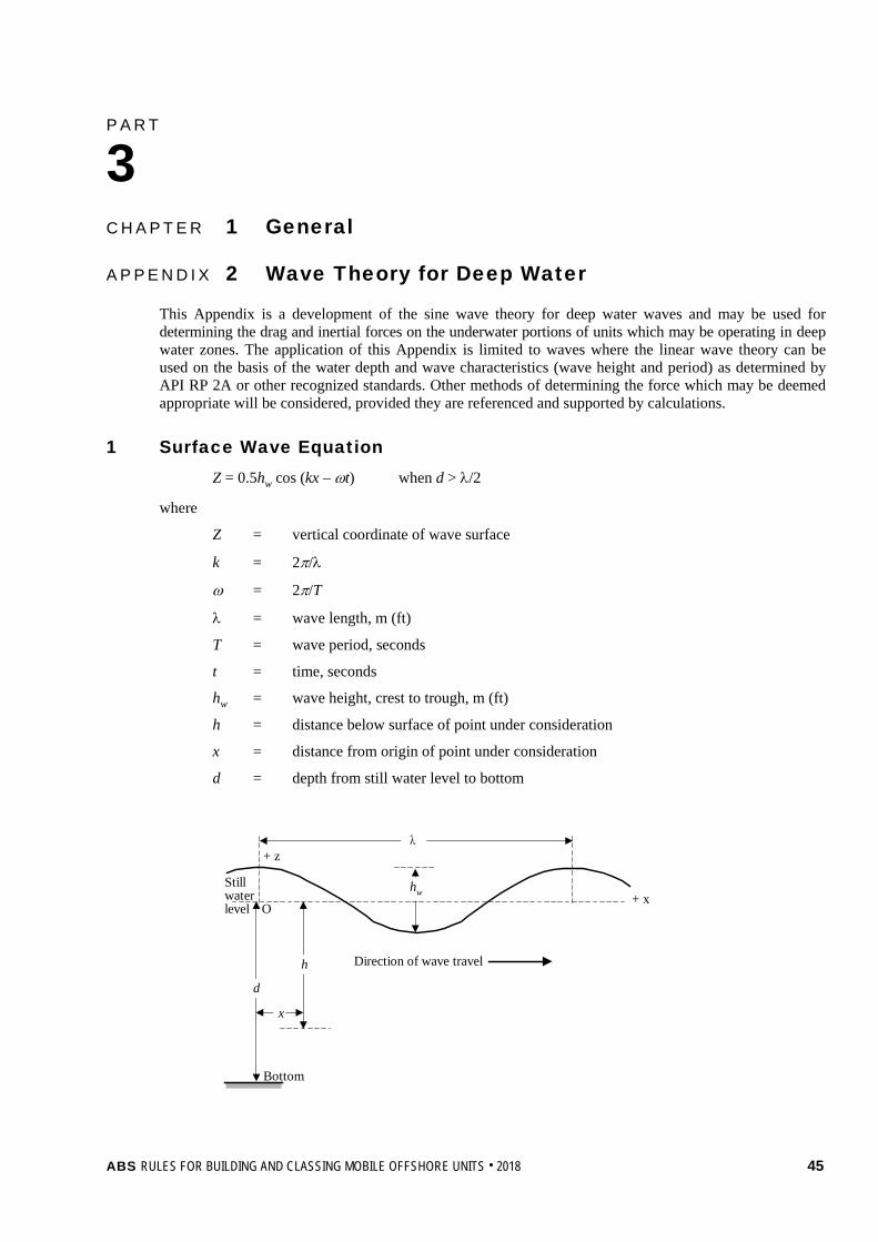
1 Surface Wave Equation Z = 0.5hw cos (kx – ωt) when d > λ/2
where
Z = vertical coordinate of wave surface
k = 2π/λ
ω = 2π/T
λ = wave length, m (ft)
T = wave period, seconds
t = time, seconds
hw = wave height, crest to trough, m (ft)
h = distance below surface of point under consideration
x = distance from origin of point under consideration
d = depth from still water level to bottom
Direction of wave travel
Bottom
Stillwaterlevel
+ z
+ xhw
h
d
x
O
λ
ABS RULES FOR BUILDING AND CLASSING MOBILE OFFSHORE UNITS . 2018 45

Part 3 Hull Construction and Equipment Chapter 1 General Appendix 2 Wave Theory for Deep Water 3-1-A2
3 Equations for Water Velocity
Horizontal Vx = 0.5ωhwe−kh cos (kx – ωt)
Vertical Vz = 0.5ωhwe−kh sin (kx – ωt)
5 Equations for Water Acceleration
Horizontal αx = 0.5ω2hwe−kh sin (kx – ωt)
Vertical αz = −0.5ω2hwe−kh cos (kx – ωt)
7 Equation for Dynamic Pressure
P = 0.5ρghwe−kh cos (kx – ωt)
where
g = acceleration of gravity
ρ = mass density of water, kilograms mass/cubic meter (slugs/cubic foot)
λ = gT2/2π
1. The total pressure at any point at a distance, h, below the surface is the static pressure, ρgh, plus the wave dynamic pressure given above.
Variation of dynamic pressure with xDynamicStatic
Surface
h
O → x
2. Note that the slope of the dynamic pressure diagram is equal to the water acceleration.
∆p
∆h ∆p
∆x
∆p/∆h =ρ × Vertical acceleration
∆p/∆x =−ρ × Horizontal acceleration
Thus, for a narrow body, in the direction of flow, accelerations may be used instead of differences in pressure to determine inertia forces.
46 ABS RULES FOR BUILDING AND CLASSING MOBILE OFFSHORE UNITS . 2018
Part 3 Hull Construction and Equipment Chapter 1 General Appendix 2 Wave Theory for Deep Water 3-1-A2
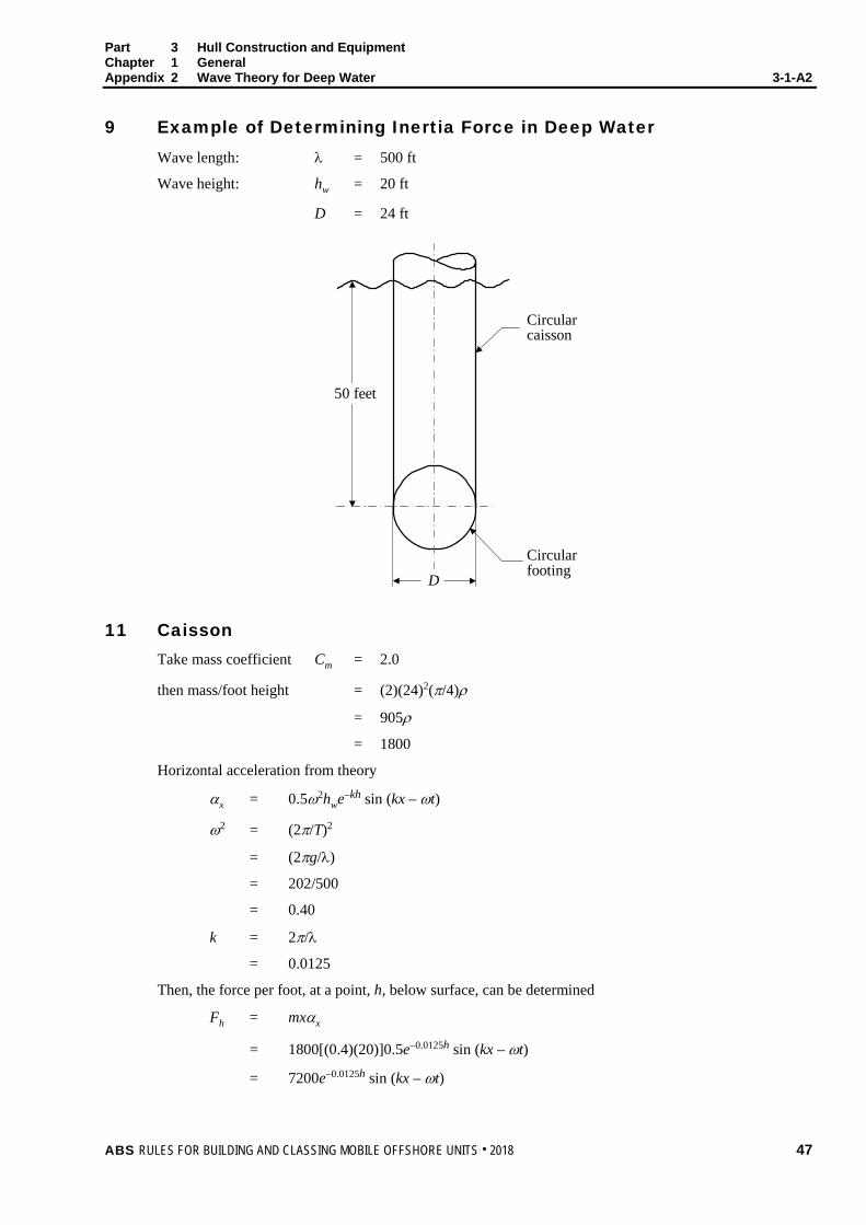
9 Example of Determining Inertia Force in Deep Water Wave length: λ = 500 ft
Wave height: hw = 20 ft
D = 24 ft
50 feet
D
Circularfooting
Circularcaisson
11 Caisson Take mass coefficient Cm = 2.0
then mass/foot height = (2)(24)2(π/4)ρ
= 905ρ
= 1800
Horizontal acceleration from theory
αx = 0.5ω2hwe−kh sin (kx – ωt)
ω2 = (2π/T)2
= (2πg/λ)
= 202/500
= 0.40
k = 2π/λ
= 0.0125
Then, the force per foot, at a point, h, below surface, can be determined
Fh = mxαx
= 1800[(0.4)(20)]0.5e−0.0125h sin (kx – ωt)
= 7200e−0.0125h sin (kx – ωt)
ABS RULES FOR BUILDING AND CLASSING MOBILE OFFSHORE UNITS . 2018 47

Part 3 Hull Construction and Equipment Chapter 1 General Appendix 2 Wave Theory for Deep Water 3-1-A2
The total force and its center may be determined by calculating several values for h between 0 and 50 ft and using Simpson’s rule, or by integrating as follows:
Total force on caisson
Fc = 7200 sin (kx – ωt) ∫ −50
0
0125.0 dhe h
= (7200/0.0125)[1 – e−0.625 sin(kx – ωt)]
= 267,500 sin (kx – ωt) lbf
Moment of force from surface
Mc = 7200 sin (kx – ωt) ∫ −50
0
0125.0 dhhe h
= [7200/(0.0125)2][1 – 1.625e−0.625 sin (kx – ωt)]
= 5,980,000 sin (kx – ωt) ft-lbf
Footing – with same mass/foot as caisson, and h = 50 feet
Force per foot of length
Ft = 7200 e(−0.0125×50) sin (kx – ωt)
= 3850 sin (kx – ωt) lbf/ft
13 Drag Force in Deep Water Where appropriate, the drag forces are calculated in a manner similar to the inertia forces, as shown in Appendix 3-1-A2, using the velocity equations shown in Appendix 3-1-A2, and drag coefficients as listed in Section 3-1-3 of these Rules.
15 Recommended Mass Factors
I Two-Dimensional Values of Cm Condition Shape Cm
Submerged Circular 2.0 for diameters of 3.5 m (12 ft) or greater 1.5 for diameters of 2.5 m (8 ft) or less (linear variation for intermediate diameters)
Submerged Ellipse 1.0 + b/h Submerged Flat Plate 1.0
(with cylinder area; πb2/4) Submerged Rectangle 1.0 + b/h Floating Rectangle 1.0 + b/2h (vertical) Floating Rectangle 1.0 + b/2h (horizontal) On-Bottom Rectangle 1.0 + 2b/h (horizontal)
48 ABS RULES FOR BUILDING AND CLASSING MOBILE OFFSHORE UNITS . 2018

Part 3 Hull Construction and Equipment Chapter 1 General Appendix 2 Wave Theory for Deep Water 3-1-A2
II Three-Dimensional Correction to Cm For all shapes, multiply Cm by factor, K
K = (/b)2/[1 + (/b)2]
b
hFlow
III Application Immersed
Total mass = (volume of body) × K × Cm × ρ
ρ is mass density of water = gravity
weightunit
IV Nomenclature h is dimension parallel to flow
b is section breadth normal to flow
is length of body (normal to flow)
(b is plane normal to flow)
ABS RULES FOR BUILDING AND CLASSING MOBILE OFFSHORE UNITS . 2018 49
P A R T C h a p t e r 2 : H u l l S t r u c t u r e s a n d A r r a n g e m e n t s
3 C H A P T E R 2 Hull Structures and Arrangements
CONTENTS SECTION 1 Structural Analysis ............................................................................... 55
1 Structural Analysis ............................................................................ 55 1.1 Analysis of Primary Structure ......................................................... 55 1.3 Consideration of Local Stresses .................................................... 55 1.5 Combination of Stress Components .............................................. 55 1.7 Consideration of Buckling .............................................................. 55 1.9 Determination of Bending Stresses ............................................... 55 1.11 Determination of Shear Stresses ................................................... 56 1.13 Stress Concentration ..................................................................... 56 1.15 Analysis and Details of Structural Connections ............................. 56 1.17 Fatigue Analysis ............................................................................ 56 1.19 Plastic Analysis .............................................................................. 56
3 Allowable Stresses ............................................................................ 57 3.1 General .......................................................................................... 57 3.3 Individual Stresses ......................................................................... 57 3.5 Buckling Considerations ................................................................ 57 3.7 Members Subjected to Combined Axial Load and Bending ........... 57 3.9 Column Buckling Stresses ............................................................. 59 3.11 Equivalent Stress Criteria for Plated Structures ............................. 60
SECTION 2 Common Structures ............................................................................. 61
1 General ............................................................................................. 61 1.1 Materials ........................................................................................ 61 1.3 Scantlings ...................................................................................... 61 1.5 Protection of Steel Work ................................................................ 61
3 Helicopter Deck ................................................................................. 61 3.1 General .......................................................................................... 61 3.3 Structure ........................................................................................ 62
5 Watertight Bulkheads and Watertight Flats ...................................... 63 5.1 General .......................................................................................... 63 5.3 Plating ............................................................................................ 63 5.5 Stiffeners and Beams..................................................................... 64 5.7 Corrugated Bulkheads ................................................................... 66 5.9 Girders and Webs .......................................................................... 66 5.11 Openings ....................................................................................... 67
50 ABS RULES FOR BUILDING AND CLASSING MOBILE OFFSHORE UNITS . 2018

7 Tank Bulkheads and Tank Flats ....................................................... 67 7.1 General.......................................................................................... 67 7.3 Plating ........................................................................................... 68 7.5 Stiffeners and Beams .................................................................... 68 7.7 Corrugated Bulkheads ................................................................... 68 7.9 Girders and Webs ......................................................................... 69 7.11 Drainage and Air Escape ............................................................... 69
9 Appurtenant Structure ....................................................................... 69 9.1 General.......................................................................................... 69 9.3 Lifeboat Platform ........................................................................... 70 9.5 Crane Pedestal and Foundation .................................................... 70
11 Higher-strength Materials .................................................................. 70 11.1 General.......................................................................................... 70 11.3 Watertight Bulkheads and Flats and Tank Bulkheads and Flats ... 70
TABLE 1 Allowable Factors of Safety Based on Fy for Helicopter
Decks ...................................................................................... 62 TABLE 2 Thickness and Flange Width of Brackets and Knees ............. 65 TABLE 3 Values of Q .............................................................................. 71 FIGURE 1 Corrugated Bulkhead .............................................................. 66 FIGURE 2 Corrugated Bulkhead End Connections ................................. 66
SECTION 3 Self-Elevating Units.............................................................................. 72
1 Application ........................................................................................ 72 3 General Requirements for Materials and Scantlings ........................ 72
3.1 Material Selection .......................................................................... 72 3.3 Scantlings ...................................................................................... 74
5 Units Elevated Modes ....................................................................... 74 5.1 General.......................................................................................... 74 5.3 Safety Against Overturning ............................................................ 74 5.5 Wave Clearance ............................................................................ 74 5.7 Preload .......................................................................................... 74 5.9 Wave-Induced Dynamic Responses ............................................. 75
7 Legs .................................................................................................. 75 7.1 Legs in Elevated Condition ............................................................ 75 7.3 Legs in the Transit Condition ......................................................... 77
9 Hull Interface Structure with Legs ..................................................... 77 11 Hull Structure .................................................................................... 77 13 Spudcan and Bottom Mat ................................................................. 78
13.1 Spudcan ........................................................................................ 78 13.3 Bottom Mat .................................................................................... 79
15 Deckhouses ...................................................................................... 79 15.1 General.......................................................................................... 79 15.3 Design Head .................................................................................. 80 15.5 Plating ........................................................................................... 81 15.7 Stiffeners ....................................................................................... 81
ABS RULES FOR BUILDING AND CLASSING MOBILE OFFSHORE UNITS . 2018 51

15.9 House Sides .................................................................................. 81 15.11 End Attachment ............................................................................. 81 15.13 Racking Resistance ....................................................................... 81
FIGURE 1 Typical Grades for Self-Elevating Units .................................. 73 FIGURE 2 Typical Hull Construction ........................................................ 82
SECTION 4 Column-Stabilized Units ...................................................................... 83
1 General ............................................................................................. 83 1.1 Application ..................................................................................... 83 1.3 Special Considerations Regarding Stresses .................................. 83 1.5 Effect of Mooring Forces on Local Structure .................................. 83 1.7 Material Selection .......................................................................... 83
3 Upper Structure ................................................................................. 85 3.1 General .......................................................................................... 85 3.3 Deck Plating ................................................................................... 85 3.5 Beams ............................................................................................ 85 3.7 Girders ........................................................................................... 86 3.9 Stanchions and Pillars ................................................................... 86 3.11 Non-buoyant Upper Structure Not Subjected to Wave Loading ..... 87 3.13 Buoyant Upper Structure ............................................................... 87 3.15 Upper Structure Subjected to Wave Loading ................................. 88
5 Columns, Lower Hulls, and Footings ................................................ 88 5.1 General .......................................................................................... 88 5.3 Scantlings of Framed Shells .......................................................... 88 5.5 Scantlings of Unframed Shells ....................................................... 88 5.7 Scantlings of Structural Flats ......................................................... 88 5.9 Additional Structural Requirements ............................................... 88 5.11 Bracing Members ........................................................................... 89 5.13 Openings in Columns..................................................................... 89
7 Deckhouses ...................................................................................... 90 7.1 General .......................................................................................... 90 7.3 Storage Tanks on Upper Structure ................................................ 90
9 Wave Clearance................................................................................ 90 9.1 Afloat Modes of Operation ............................................................. 90 9.3 On-Bottom Modes of Operation ..................................................... 90
11 Structural Redundancy ..................................................................... 91 11.1 Assumed Damage ......................................................................... 91 11.3 Analysis ......................................................................................... 91 11.5 Upper Structure ............................................................................. 91
13 Higher-strength Materials .................................................................. 91 13.1 General .......................................................................................... 91 13.3 Upper Structure ............................................................................. 91
TABLE 1 Values of Q .............................................................................. 92 FIGURE 1 Typical Grades for Column-Stabilized Units ........................... 84
52 ABS RULES FOR BUILDING AND CLASSING MOBILE OFFSHORE UNITS . 2018

SECTION 5 Surface-Type Drilling Units ................................................................. 93 1 General ............................................................................................. 93 3 Material Selection ............................................................................. 93
3.1 Ship-Type Drilling Unit ................................................................... 93 3.3 Barge-Type Drilling Unit ................................................................ 94 3.5 Hull Interface Structures ................................................................ 95
5 Structural Design .............................................................................. 95 5.1 Hull Scantlings and Local Supporting Structure ............................ 95 5.3 Hull Girder Strength ....................................................................... 96 5.5 Structural Design and Analysis of the Hull..................................... 96 5.7 Fatigue Analysis ............................................................................ 96 5.9 Design Loads for Local Structures ................................................ 97 5.11 Superstructures, Deckhouses and Helicopter Decks .................... 98
7 Dynamic Loading Approach .............................................................. 98 9 Drilling Well ....................................................................................... 98 11 Hatches ............................................................................................. 98 13 Effect of Mooring Forces on Local Structure .................................... 98 FIGURE 1 Typical Grades for Surface-Type Drilling Units ....................... 94
SECTION 6 Welding, Forming and Weld Design – Weld Design .......................... 99
1 Fillet Welds ....................................................................................... 99 1.1 Plans and Specifications ............................................................... 99 1.3 Tee Connections ........................................................................... 99 1.5 Tee-Type End Connections ......................................................... 100 1.7 Ends of Unbracketed Stiffeners ................................................... 100 1.9 Reduced Weld Size ..................................................................... 100 1.11 Lapped Joints .............................................................................. 100 1.13 Plug Welds or Slot Welds ............................................................ 101
3 Full or Partial Penetration Corner or Tee Joints ............................. 101 5 Alternatives ..................................................................................... 101 TABLE 1 Weld Factors ......................................................................... 102
APPENDIX 1 Strengthening of Mobile Offshore Units for Navigation in Ice ....... 105
1 Application ...................................................................................... 105 1.1 Column Stabilized Unit ................................................................ 105 1.3 Units of Other Type ..................................................................... 105 1.5 Novel Features ............................................................................ 105
3 Ice Class Selection ......................................................................... 105 5 Ice Waterline ................................................................................... 106 7 Clearance ........................................................................................ 106 9 Ice Belt ............................................................................................ 106 11 Design Ice Loads ............................................................................ 107
11.1 Design Ice Pressure .................................................................... 107 11.3 Global Design Ice Load ............................................................... 108
ABS RULES FOR BUILDING AND CLASSING MOBILE OFFSHORE UNITS . 2018 53
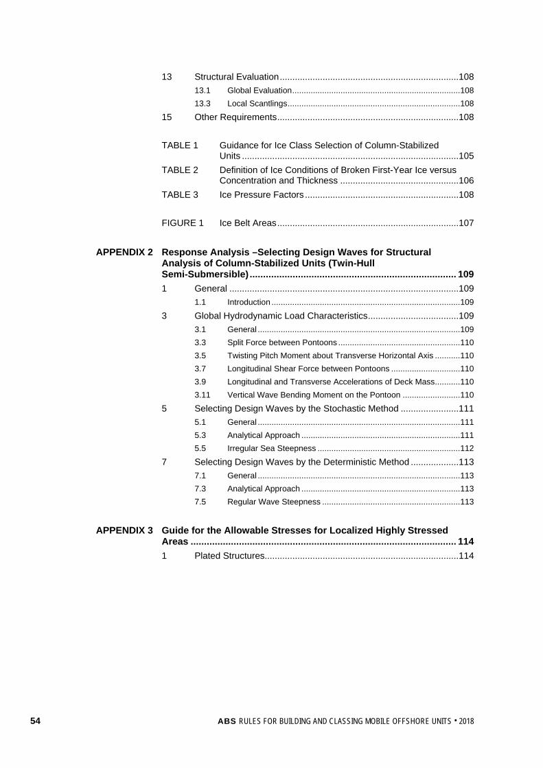
13 Structural Evaluation ....................................................................... 108 13.1 Global Evaluation ......................................................................... 108 13.3 Local Scantlings ........................................................................... 108
15 Other Requirements ........................................................................ 108 TABLE 1 Guidance for Ice Class Selection of Column-Stabilized
Units ...................................................................................... 105 TABLE 2 Definition of Ice Conditions of Broken First-Year Ice versus
Concentration and Thickness ............................................... 106 TABLE 3 Ice Pressure Factors ............................................................. 108 FIGURE 1 Ice Belt Areas ........................................................................ 107
APPENDIX 2 Response Analysis –Selecting Design Waves for Structural
Analysis of Column-Stabilized Units (Twin-Hull Semi-Submersible) ............................................................................. 109 1 General ........................................................................................... 109
1.1 Introduction .................................................................................. 109 3 Global Hydrodynamic Load Characteristics .................................... 109
3.1 General ........................................................................................ 109 3.3 Split Force between Pontoons ..................................................... 110 3.5 Twisting Pitch Moment about Transverse Horizontal Axis ........... 110 3.7 Longitudinal Shear Force between Pontoons .............................. 110 3.9 Longitudinal and Transverse Accelerations of Deck Mass........... 110 3.11 Vertical Wave Bending Moment on the Pontoon ......................... 110
5 Selecting Design Waves by the Stochastic Method ....................... 111 5.1 General ........................................................................................ 111 5.3 Analytical Approach ..................................................................... 111 5.5 Irregular Sea Steepness .............................................................. 112
7 Selecting Design Waves by the Deterministic Method ................... 113 7.1 General ........................................................................................ 113 7.3 Analytical Approach ..................................................................... 113 7.5 Regular Wave Steepness ............................................................ 113
APPENDIX 3 Guide for the Allowable Stresses for Localized Highly Stressed
Areas ................................................................................................... 114 1 Plated Structures............................................................................. 114
54 ABS RULES FOR BUILDING AND CLASSING MOBILE OFFSHORE UNITS . 2018
P A R T S e c t i o n 1 : S t r u c t u r a l A n a l y s i s
3 C H A P T E R 2 Hull Structures and Arrangements
S E C T I O N 1 Structural Analysis
1 Structural Analysis The structural design criteria specified in this Chapter is presented in the Working Stress Design (WSD) format, also known as the Allowable Stress (or Strength) Design (ASD) format. Alternative structural design criteria for self-elevating drilling units and column-stabilized drilling units in a Load and Resistance Factor Design (LRFD) format are provided in the ABS Guide for Load and Resistance Factor Design (LRFD) Criteria for Offshore Structures. In general, WSD and LRFD criteria are not to be mixed within the analysis.
1.1 Analysis of Primary Structure The primary structure of the unit is to be analyzed using the loading conditions stipulated below and the resultant stresses are to be determined. To determine critical cases, conditions representative of all modes of operation are to be considered. Calculations for critical conditions are to be submitted for review. The analysis is to be performed using recognized calculation methods and is to be fully documented and referenced.
For each loading condition considered, the following stresses are to be determined, and are not to exceed the allowable stresses given in 3-2-1/3.
i) Stresses due to static loadings only, where the static loads include operational gravity loadings and weight of the unit, with the unit afloat or resting on the sea bed in calm water.
ii) Stresses due to combined loadings, where the applicable static loads in i) are combined with relevant environmental loadings, including acceleration and heeling forces.
1.3 Consideration of Local Stresses Local stresses are to be combined with primary stresses, where applicable, to determine total stress levels.
1.5 Combination of Stress Components The scantlings are to be determined on the basis of a method included in a recognized standard which combines the individual stress components acting on the various structural elements of the unit.
1.7 Consideration of Buckling The possibility of buckling of structural elements is to be considered.
1.9 Determination of Bending Stresses 1.9.1 Effective Flange Area
The required section modulus of members such as girders, webs, etc., supporting frames and stiffeners is to be obtained on an effective width of plating basis in accordance with the following criteria. The section is to include the structural member in association with an effective width of plating not exceeding one-half the sum of spacing on each side of the member or 33% of the unsupported span , whichever is less. For girders and webs along hatch openings, an effective breadth of plating not exceeding one-half the spacing or 16.5% of the unsupported span , whichever is less, is to be used. The required section modulus of frames and stiffeners is assumed to be provided by the stiffener and a maximum of one frame space of the plating to which it is attached.
ABS RULES FOR BUILDING AND CLASSING MOBILE OFFSHORE UNITS . 2018 55

Part 3 Hull Construction and Equipment Chapter 2 Hull Structures and Arrangements Section 1 Structural Analysis 3-2-1
1.9.2 Eccentric Axial Loading Where appropriate, elastic deflections are to be taken into account when determining the effects of eccentricity of axial loading, and the resulting bending moments are to be superimposed on the bending moments computed for other types of loadings.
1.11 Determination of Shear Stresses When computing shear stresses in structural members, only the effective shear area of the web of the member is to be considered as being effective. In this regard, the total depth of the member may be used as the web depth.
1.13 Stress Concentration The effect of notches, stress raisers and local stress concentrations is to be taken into account when considering load carrying elements. When stress concentrations are considered to be of high intensity in certain elements, the acceptable stress levels will be subject to special consideration.
1.15 Analysis and Details of Structural Connections Unless connections of structural members are specifically detailed as hinged joints, proper consideration is to be given in the structural analysis to the degree of restraint at such connections. Structural connections are to be detailed in such a manner as to ensure full transmission of stresses between members joined, and to minimize stress concentrations. The following details are to be considered, as may be appropriate.
i) Shear web plates, continuous through the joint, to transmit tension and compression loads between members by means of shear in the web plate
ii) Flaring or transitioning of the joint, to lower stress levels or to minimize concentrations of stress or both
iii) Thicker joint material, high strength steel, or both, consistent with good weldability, to reduce the effect of high stress levels
iv) Brackets or other supplemental transition members, with scallops and proper end attachment details to minimize high stress concentrations
Critical connections that depend upon the transmission of tensile stresses through the thickness of the plating of one of the members may result in lamellar tearing and are to be avoided wherever possible. Where unavoidable, plate material with suitable through-thickness (Z direction) properties may be required with appropriate inspection procedures.
1.17 Fatigue Analysis The possibility of fatigue damage due to cyclic loading is to be considered in the design of the major structure of self-elevating, column-stabilized and surface-type units.
The type and extent of the fatigue analysis will be dependent on the intended mode and areas of operations to be considered in the unit’s design. An appropriate loading spectrum, in accordance with accepted theories, is to be used in the fatigue analysis.
The calculated fatigue life of the structure should be at least the design life of the unit, but not less than 20 years.
1.19 Plastic Analysis Plastic analysis methods will be subject to special consideration.
56 ABS RULES FOR BUILDING AND CLASSING MOBILE OFFSHORE UNITS . 2018

Part 3 Hull Construction and Equipment Chapter 2 Hull Structures and Arrangements Section 1 Structural Analysis 3-2-1
3 Allowable Stresses
3.1 General The scantlings of effective structural elements of the primary frame of the unit, analyzed in accordance with 3-2-1/1, are to be determined on the basis of the allowable stresses specified herein for self-elevating and column stabilized units. For allowable stresses of ship-type units see the ABS Guide for Building and Classing Drillships (Drillship Guide) and the ABS Rules for Building and Classing Marine Vessels (Marine Vessel Rules).
3.3 Individual Stresses Individual stress components and, as applicable, direct combinations of such stresses are not to exceed the allowable stress F, as obtained from the following equation.
F = Fy /F.S.
where
Fy = specified minimum yield point or yield strength, as defined in Chapter 1 of the ABS Rules for Materials and Welding (Part 2).
F.S. = factor of safety
for static loadings, as defined in 3-2-1/1.1i)
= 1.67 for axial or bending stress
= 2.50 for shear stress
for combined loadings, as defined in 3-2-1/1.1ii)
= 1.25 for axial or bending stress
= 1.88 for shear stress
3.5 Buckling Considerations Where buckling of a structural element due to compressive or shear stresses, or both, is a consideration, the compressive or shear stress is not to exceed the corresponding allowable stress, F, as obtained from the following equation.
F = Fcr/F.S.
where
Fcr = critical compressive or shear buckling stress of the structural element, appropriate to its dimensional configuration, boundary conditions, loading pattern, material, etc.
F.S. = factor of safety
= 1.67 for static loadings, as defined in 3-2-1/1.1i)
= 1.25 for combined loadings, as defined in 3-2-1/1.1ii)
3.7 Members Subjected to Combined Axial Load and Bending 3.7.1
When structural members are subjected to axial compression in combination with compression due to bending, the computed stresses are to comply with the following requirements:
when fa/Fa ≤ 0.15 (fa/Fa) + (fb/Fb) ≤ 1.0
when fa/Fa > 0.15 (fa/Fa) + bea
bm
FFffC
)/1( ′− ≤ 1.0
ABS RULES FOR BUILDING AND CLASSING MOBILE OFFSHORE UNITS . 2018 57

Part 3 Hull Construction and Equipment Chapter 2 Hull Structures and Arrangements Section 1 Structural Analysis 3-2-1
and in addition, at ends of members:
1.67(fa/Fy) + (fb/Fb) ≤ 1.0 for static loadings, as defined in 3-2-1/1.1i)
1.25(fa/Fy) + (fb/Fb) ≤ 1.0 for combined loadings, as defined in 3-2-1/1.1ii)
3.7.2 When structural members are subjected to axial tension in combination with tension due to bending, the computed stresses are to comply with the following requirements:
fa + fb ≤ Fy/1.67 for static loadings, as defined in 3-2-1/1.1i)
fa + fb ≤ Fy/1.25 for combined loadings, as defined in 3-2-1/1.1ii)
However, the computed bending compressive stress, fb, taken alone shall not exceed Fb.
where
fa = computed axial compressive or tensile stress
fb = computed compressive or tensile stress due to bending
Fa = allowable axial compressive stress, which is to be the least of the following:
i) Yield stress divided by factor of safety for axial stress specified in 3-2-1/3.3
ii) Overall buckling stress divided by factor of safety specified in 3-2-1/3.9.1
iii) Local buckling stress divided by factor of safety for axial stress specified in 3-2-1/3.9.2
Fb = allowable axial compressive stress due to bending, determined by dividing the yield stress or local buckling stress, whichever is less, by the factor of safety specified in 3-2-1/3.3
Fe′ = 2)/(15.5
rKE
Fe′ = Euler buckling stress, may be increased 1/3 for combined loadings, as defined in 3-2-1/1.1ii)
E = Modulus of Elasticity
= unsupported length of column
K = effective length factor which accounts for support conditions at ends of length . For cases where lateral deflection of end supports may exist, K is not to be considered less than 1.0.
r = radius of gyration
Cm = is a coefficient as follows
i) For compression members in frames subject to joint translation (sideways), Cm = 0.85.
ii) For restrained compression members in frames braced against joint translation and not subject to transverse loading between their supports, in the plane of bending,
Cm = 0.6 − 0.4(M1/M2)
58 ABS RULES FOR BUILDING AND CLASSING MOBILE OFFSHORE UNITS . 2018
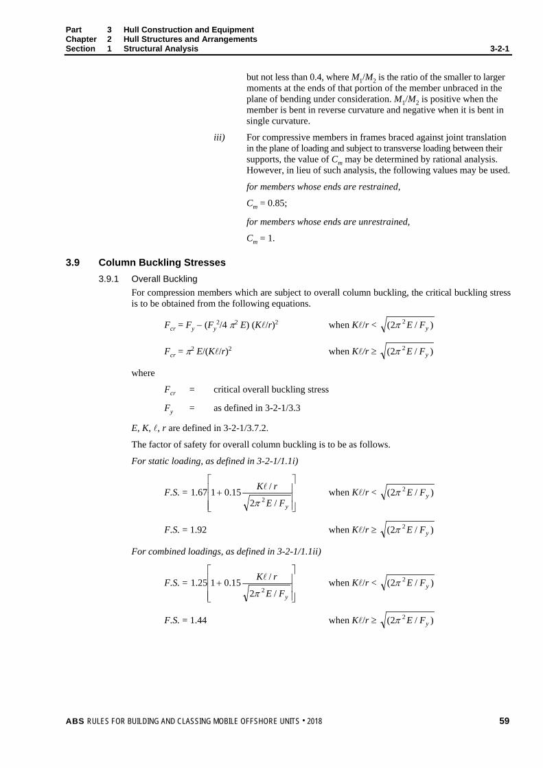
Part 3 Hull Construction and Equipment Chapter 2 Hull Structures and Arrangements Section 1 Structural Analysis 3-2-1
but not less than 0.4, where M1/M2 is the ratio of the smaller to larger moments at the ends of that portion of the member unbraced in the plane of bending under consideration. M1/M2 is positive when the member is bent in reverse curvature and negative when it is bent in single curvature.
iii) For compressive members in frames braced against joint translation in the plane of loading and subject to transverse loading between their supports, the value of Cm may be determined by rational analysis. However, in lieu of such analysis, the following values may be used.
for members whose ends are restrained,
Cm = 0.85;
for members whose ends are unrestrained,
Cm = 1.
3.9 Column Buckling Stresses 3.9.1 Overall Buckling
For compression members which are subject to overall column buckling, the critical buckling stress is to be obtained from the following equations.
Fcr = Fy − (Fy2/4 π2 E) (K/r)2 when K/r < )/2( 2
yFEπ
Fcr = π2 E/(K/r)2 when K/r ≥ )/2( 2yFEπ
where
Fcr = critical overall buckling stress
Fy = as defined in 3-2-1/3.3
E, K, , r are defined in 3-2-1/3.7.2.
The factor of safety for overall column buckling is to be as follows.
For static loading, as defined in 3-2-1/1.1i)
F.S. =
+
yFE
rK
/2
/15.0167.12π
when K/r < )/2( 2yFEπ
F.S. = 1.92 when K/r ≥ )/2( 2yFEπ
For combined loadings, as defined in 3-2-1/1.1ii)
F.S. =
+
yFE
rK
/2
/15.0125.12π
when K/r < )/2( 2yFEπ
F.S. = 1.44 when K/r ≥ )/2( 2yFEπ
ABS RULES FOR BUILDING AND CLASSING MOBILE OFFSHORE UNITS . 2018 59

Part 3 Hull Construction and Equipment Chapter 2 Hull Structures and Arrangements Section 1 Structural Analysis 3-2-1
3.9.2 Local Buckling Members which are subjected to axial compression or compression due to bending are to be investigated for local buckling, as appropriate, in addition to overall buckling, as specified in 3-2-1/3.9.1.
In the case of unstiffened or ring-stiffened cylindrical shells, local buckling is to be investigated if the proportions of the shell conform to the following relationship.
D/t > E/9Fy
where
D = mean diameter of cylindrical shell
t = thickness of cylindrical shell (expressed in the same units as D)
E and Fy are defined in 3-2-1/3.9.1.
3.11 Equivalent Stress Criteria for Plated Structures For plated structures, members may be designed according to the von Mises equivalent stress criterion, where the equivalent stress σeqv, defined as follows, is not to exceed Fy/F.S.
σeqv = 222 3 xyyxyx τσσσσ +−+
where
σx = calculated in-plane stress in the x direction
σy = calculated in-plane stress in the y direction
τxy = calculated in-plane shear stress
Fy = as defined in 3-2-1/3.3
F.S. = 1.43 for static loading, as defined in 3-2-1/1.1i)
= 1.11 for combined loading, as defined in 3-2-1/1.1ii) Note: The Factor of Safety will be specially considered when the stress components account for
surface stresses due to lateral pressures.
The buckling strength of plated structures is to be designed according to the latest version of the ABS Guide for Buckling and Ultimate Strength Assessment for Offshore Structures, or other recognized standard acceptable to ABS.
60 ABS RULES FOR BUILDING AND CLASSING MOBILE OFFSHORE UNITS . 2018

P A R T S e c t i o n 2 : C o m m o n S t r u c t u r e s
3 C H A P T E R 2 Hull Structures and Arrangements
S E C T I O N 2 Common Structures
1 General
1.1 Materials These Rules, except where specified otherwise, are intended for mobile offshore units constructed of steel, manufactured and having the properties as specified in Chapter 1 of the ABS Rules for Materials and Welding (Part 2). Where it is intended to use steel or other material having properties differing from those specified in Chapter 1 of the above referenced Part 2, the use of such material and the corresponding scantlings will be specially considered.
1.3 Scantlings Scantlings of the major structural elements of the unit are to be determined in accordance with these Rules. Scantlings of structural elements which are subjected to local loads only, and which are not considered to be effective components of the primary structural frame of the unit, are to comply with the applicable requirements of the Marine Vessel Rules, Drillship Guide, or the Barge Rules.
1.5 Protection of Steel Work Unless otherwise approved for spaces with low corrosion rate in regard to the intended service life, all steel work is to be suitably protected by corrosion protection systems, such as a protective coating system and/or a cathodic protection system.
All dedicated seawater ballast tanks (including preload tanks on self-elevating units) are to have a protective coating system. Reference may be made to IMO resolution MSC.215(82) standard or other recognized industry standard requested by owner.
The effectiveness of the corrosion protection and control system is to be sustainable for the design life of the unit.
1.5.1 Performance Standards for Protective Coating (PSPC) Where requested by the Owner, a unit with protective coatings which are found to comply with the requirements in the ABS Guide for the Class Notation Coating Performance Standard (CPS) will be assigned and distinguished in the Record with the class notation CPS.
3 Helicopter Deck
3.1 General Plans showing the arrangement, scantlings and details of the helicopter deck are to be submitted. The arrangement plan is to show the overall size of the helicopter deck and the designated landing area. If the arrangement provides for the securing of a helicopter or helicopters to the deck, the predetermined position(s) selected to accommodate the secured helicopter, in addition to the locations of deck fittings for securing the helicopter, are to be shown. The type of helicopter to be considered is to be specified and calculations for appropriate loading conditions are to be submitted.
ABS RULES FOR BUILDING AND CLASSING MOBILE OFFSHORE UNITS . 2018 61

Part 3 Hull Construction and Equipment Chapter 2 Hull Structures and Arrangements Section 2 Common Structures 3-2-2
3.3 Structure Scantlings of helicopter decks and supporting structure are to be determined on the basis of the following loading conditions, whichever is greater, in association with the allowable factors of safety shown in 3-2-2/Table 1.
TABLE 1 Allowable Factors of Safety Based on Fy for Helicopter Decks
Fy = specified minimum yield strength of the material
Plating Beams
Girders, Stanchions, Truss Supports, etc.
(See Note 3) Overall Distributed Loading 1.67 1.67 1.67 Helicopter Landing Impact Loading (See Note 1)
1.00 (2) 1.00 1.10
Stowed Helicopter Loading 1.00 1.10 1.25
Notes: 1 The minimum plate thickness, t, is generally not to be less than that obtained from the following:
Beam Spacing t Beam Spacing t 460 mm 610 mm 760 mm
4.0 mm 5.0 mm 6.0 mm
18 in. 24 in. 30 in.
0.16 in. 0.20 in. 0.24 in.
2 Alternatively, ultimate state limit methods may be considered.
3 For members subjected to axial compression, the factor of safety is to be based on the yield stress or critical buckling stress, whichever is less.
4 Helicopters fitted with landing gear other than wheels will be specially considered.
5 Calculations are to consider anticipated wind and wave impact loadings on helicopter decks and their supporting structures.
3.3.1 Overall Distributed Loading A minimum distributed loading of 2010 N/m2 (205 kgf/m2, 42 lbf/ft2) is to be taken over the entire helicopter deck.
3.3.2 Helicopter Landing Impact Loading A load of not less than 75% of the helicopter maximum take-off weight is to be taken on each of two square areas, 0.3 m × 0.3 m (1 ft × 1 ft). Alternatively, the manufacturer’s recommended wheel impact loading will be considered. The deck is to be considered for helicopter landings at any location within the designated landing area. The structural weight of the helicopter deck is to be added to the helicopter impact loading when considering girders, stanchions, truss supports, etc. Where the upper deck of a superstructure or deckhouse is used as a helicopter deck and the spaces below are normally manned (quarters, bridge, control room, etc.), the impact loading is to be multiplied by a factor of 1.15.
3.3.3 Stowed Helicopter Loading If provisions are made to accommodate helicopters secured to the deck in a predetermined position, the structure is to be considered for a local loading equal to the manufacturer’s recommended wheel loadings at maximum take-off weight, multiplied by a dynamic amplification factor based on the predicted motions of the unit for this condition, as may be applicable for the unit under consideration.
62 ABS RULES FOR BUILDING AND CLASSING MOBILE OFFSHORE UNITS . 2018
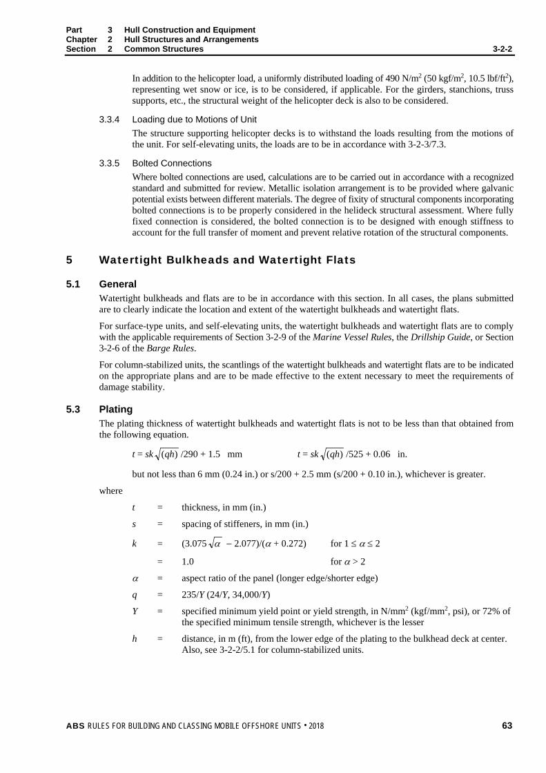
Part 3 Hull Construction and Equipment Chapter 2 Hull Structures and Arrangements Section 2 Common Structures 3-2-2
In addition to the helicopter load, a uniformly distributed loading of 490 N/m2 (50 kgf/m2, 10.5 lbf/ft2), representing wet snow or ice, is to be considered, if applicable. For the girders, stanchions, truss supports, etc., the structural weight of the helicopter deck is also to be considered.
3.3.4 Loading due to Motions of Unit The structure supporting helicopter decks is to withstand the loads resulting from the motions of the unit. For self-elevating units, the loads are to be in accordance with 3-2-3/7.3.
3.3.5 Bolted Connections Where bolted connections are used, calculations are to be carried out in accordance with a recognized standard and submitted for review. Metallic isolation arrangement is to be provided where galvanic potential exists between different materials. The degree of fixity of structural components incorporating bolted connections is to be properly considered in the helideck structural assessment. Where fully fixed connection is considered, the bolted connection is to be designed with enough stiffness to account for the full transfer of moment and prevent relative rotation of the structural components.
5 Watertight Bulkheads and Watertight Flats
5.1 General Watertight bulkheads and flats are to be in accordance with this section. In all cases, the plans submitted are to clearly indicate the location and extent of the watertight bulkheads and watertight flats.
For surface-type units, and self-elevating units, the watertight bulkheads and watertight flats are to comply with the applicable requirements of Section 3-2-9 of the Marine Vessel Rules, the Drillship Guide, or Section 3-2-6 of the Barge Rules.
For column-stabilized units, the scantlings of the watertight bulkheads and watertight flats are to be indicated on the appropriate plans and are to be made effective to the extent necessary to meet the requirements of damage stability.
5.3 Plating The plating thickness of watertight bulkheads and watertight flats is not to be less than that obtained from the following equation.
t = sk )(qh /290 + 1.5 mm t = sk )(qh /525 + 0.06 in.
but not less than 6 mm (0.24 in.) or s/200 + 2.5 mm (s/200 + 0.10 in.), whichever is greater.
where
t = thickness, in mm (in.)
s = spacing of stiffeners, in mm (in.)
k = (3.075 α − 2.077)/(α + 0.272) for 1 ≤ α ≤ 2
= 1.0 for α > 2
α = aspect ratio of the panel (longer edge/shorter edge)
q = 235/Y (24/Y, 34,000/Y)
Y = specified minimum yield point or yield strength, in N/mm2 (kgf/mm2, psi), or 72% of the specified minimum tensile strength, whichever is the lesser
h = distance, in m (ft), from the lower edge of the plating to the bulkhead deck at center. Also, see 3-2-2/5.1 for column-stabilized units.
ABS RULES FOR BUILDING AND CLASSING MOBILE OFFSHORE UNITS . 2018 63
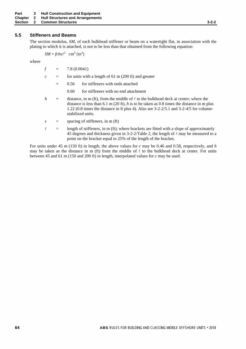
Part 3 Hull Construction and Equipment Chapter 2 Hull Structures and Arrangements Section 2 Common Structures 3-2-2
5.5 Stiffeners and Beams The section modulus, SM, of each bulkhead stiffener or beam on a watertight flat, in association with the plating to which it is attached, is not to be less than that obtained from the following equation:
SM = fchs2 cm3 (in3)
where
f = 7.8 (0.0041)
c = for units with a length of 61 m (200 ft) and greater
= 0.56 for stiffeners with ends attached
0.60 for stiffeners with no end attachment
h = distance, in m (ft), from the middle of to the bulkhead deck at center; where the distance is less than 6.1 m (20 ft), h is to be taken as 0.8 times the distance in m plus 1.22 (0.8 times the distance in ft plus 4). Also see 3-2-2/5.1 and 3-2-4/5 for column-stabilized units.
s = spacing of stiffeners, in m (ft)
= length of stiffeners, in m (ft); where brackets are fitted with a slope of approximately 45 degrees and thickness given in 3-2-2/Table 2, the length of may be measured to a point on the bracket equal to 25% of the length of the bracket.
For units under 45 m (150 ft) in length, the above values for c may be 0.46 and 0.58, respectively, and h may be taken as the distance in m (ft) from the middle of to the bulkhead deck at center. For units between 45 and 61 m (150 and 200 ft) in length, interpolated values for c may be used.
64 ABS RULES FOR BUILDING AND CLASSING MOBILE OFFSHORE UNITS . 2018
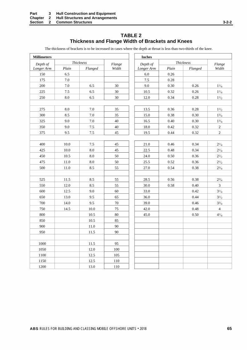
Part 3 Hull Construction and Equipment Chapter 2 Hull Structures and Arrangements Section 2 Common Structures 3-2-2
TABLE 2 Thickness and Flange Width of Brackets and Knees
The thickness of brackets is to be increased in cases where the depth at throat is less than two-thirds of the knee.
Millimeters Inches
Depth of Longer Arm
Thickness Flange Width
Depth of Longer Arm
Thickness Flange Width Plain Flanged Plain Flanged
150 6.5 6.0 0.26 175 7.0 7.5 0.28 200 7.0 6.5 30 9.0 0.30 0.26 11/4 225 7.5 6.5 30 10.5 0.32 0.26 11/4 250 8.0 6.5 30 12.0 0.34 0.28 11/2
275 8.0 7.0 35 13.5 0.36 0.28 11/2 300 8.5 7.0 35 15.0 0.38 0.30 13/4 325 9.0 7.0 40 16.5 0.40 0.30 13/4 350 9.0 7.5 40 18.0 0.42 0.32 2 375 9.5 7.5 45 19.5 0.44 0.32 2
400 10.0 7.5 45 21.0 0.46 0.34 21/4 425 10.0 8.0 45 22.5 0.48 0.34 21/4 450 10.5 8.0 50 24.0 0.50 0.36 21/2 475 11.0 8.0 50 25.5 0.52 0.36 21/2 500 11.0 8.5 55 27.0 0.54 0.38 23/4
525 11.5 8.5 55 28.5 0.56 0.38 23/4 550 12.0 8.5 55 30.0 0.58 0.40 3 600 12.5 9.0 60 33.0 0.42 31/4 650 13.0 9.5 65 36.0 0.44 31/2 700 14.0 9.5 70 39.0 0.46 33/4 750 14.5 10.0 75 42.0 0.48 4 800 10.5 80 45.0 0.50 41/4 850 10.5 85 900 11.0 90 950 11.5 90
1000 11.5 95 1050 12.0 100 1100 12.5 105 1150 12.5 110 1200 13.0 110
ABS RULES FOR BUILDING AND CLASSING MOBILE OFFSHORE UNITS . 2018 65

Part 3 Hull Construction and Equipment Chapter 2 Hull Structures and Arrangements Section 2 Common Structures 3-2-2
5.7 Corrugated Bulkheads 5.7.1 Plating
The plating thickness of corrugated bulkheads is to be as required by 3-2-2/5.3, with the following modification. The spacing to be used is the greater of the dimensions a or c as indicated in 3-2-2/Figure 1. The angle φ is to be 45 degrees or greater.
5.7.2 Stiffeners The section modulus of a corrugated bulkhead, as a stiffener, is to be as required by 3-2-2/5.5 using the coefficient c = 0.56. The developed section modulus, SM, may be obtained from the following equation, where a, t and d are as indicated in 3-2-2/Figure 1, in cm (in.).
SM = td2/6 + adt/2
The above equation is only valid for identical corrugations at both sides of the bulkhead. For other arrangements, the developed section modulus will be specially considered. The spacing of stiffeners in connection with the above equation is to be taken as a + b as indicated in 3-2-2/Figure 1.
5.7.3 End Connections The structural arrangements and size of welding at the ends of corrugations are to be designed to develop the required strength of corrugated stiffeners. Joints within 10% of the depth of corrugation from the outer surface of corrugation, d1, are to have double continuous welds with fillet weld leg size w not less than 0.7 times the thickness of bulkhead plating or penetration welds of equal strength. See also 3-2-6/3 and 3-2-2/Figure 2.
FIGURE 1 Corrugated Bulkhead
tφ
dc
b a b
FIGURE 2 Corrugated Bulkhead End Connections
0.7t
0.1d1
t
d1
5.9 Girders and Webs 5.9.1 Strength Requirements
Girders and webs which support framing members on watertight bulkheads and flats are to be in accordance with the requirements given in this paragraph. In addition, the girders and webs are to meet the requirements of 3-2-3/3 or 3-2-4/3, where applicable. The section modulus, SM, of each girder or web is not to be less than that obtained from the following equation.
66 ABS RULES FOR BUILDING AND CLASSING MOBILE OFFSHORE UNITS . 2018

Part 3 Hull Construction and Equipment Chapter 2 Hull Structures and Arrangements Section 2 Common Structures 3-2-2
SM = f h s 2 cm3 (in3)
where
f = 4.7 (0.0025)
h = distances, in m (ft), from the middle of the area supported to the bulkhead deck at center, where that distance is less than 6.1 m (20 ft), the value of h is to be 0.8 times the distance in meters plus 1.22 (0.80 times the distance in feet plus 4). (See 3-2-2/5.1 and 3-2-4/5 for column-stabilized units.)
s = sum of half lengths, in m (ft) (on each side of girder or web), of the stiffeners or beams supported
= length, in m (ft), between supports, where brackets are fitted at shell, deck or bulkhead supports, and the brackets are in accordance with 3-2-2/Table 2 and have a slope of approximately 45 degrees, the length may be measured to a point on the bracket located at the distance from the toe equal to 25% of the length of the bracket.
5.9.2 Proportions Girders and webs are to have a depth not less than /12. The thickness is not to be less than one percent of depth plus 3 mm (0.12 in.), but need not exceed 11 mm (0.44 in.). In general, the depth of girders or webs is not to be less than twice the depth of cutouts.
5.9.3 Tripping Brackets Girders and webs are to be supported by tripping brackets at intervals of about 3 m (10 ft) and near the change of the section. Where the width of the unsupported face plate exceeds 200 mm (8 in.), the tripping brackets are to support the face plate.
5.11 Openings Where stiffeners are cut in way of watertight doors, the openings are to be framed and bracketed to maintain the full strength of the bulkheads without taking the strength of the doorframes into consideration. Reference is made to 6-1-2/9 for watertight door construction, inspection and testing.
7 Tank Bulkheads and Tank Flats
7.1 General The arrangement of all tanks, together with their intended service and the height of the air and overflow pipes, are to be clearly indicated on the plans submitted for approval. Tank boundary bulkheads and flats are to have scantlings in accordance with the requirements of this section, where they exceed the requirements of 3-2-2/5 for watertight bulkheads and flats. However, tight divisional bulkheads and flats between tanks, which will be subjected to equal pressure from both sides at all times, may have scantlings based on 3-2-2/5. In such cases, the tanks are to be provided with suitable means to ensure that the divisions are subjected to equal pressure from both sides at all times.
When the specific gravity of the liquid contents of a tank is greater than 1.05, the head, h, specified below, is to be increased by a factor equal to the ratio of the specific gravity to 1.0.
Tank bulkheads and flats in surface-type units are to meet the requirements of Section 3-2-10 of the Marine Vessel Rules or Section 3-2-7 of the Barge Rules, as applicable. Also, see 3-2-4/5 for column-stabilized units.
ABS RULES FOR BUILDING AND CLASSING MOBILE OFFSHORE UNITS . 2018 67

Part 3 Hull Construction and Equipment Chapter 2 Hull Structures and Arrangements Section 2 Common Structures 3-2-2
7.3 Plating Plating is to be of the thickness derived from the following equation:
t = sk )(qh /254 + 2.5 mm t = sk )(qh /460 + 0.10 in.
but not less than 6.5 mm (0.25 in.) or s/150 + 2.5 mm (s/150 + 0.10 in.), whichever is greater.
where
t = thickness, in mm (in.)
s = stiffener spacing, in mm (in.)
k = (3.075 α − 2.077)/(α + 0.272) for 1 ≤ α ≤ 2
= 1.0 for α > 2
α = aspect ratio of the panel (longer edge/shorter edge)
q = 235/Y (24/Y, 34,000/Y)
Y = specified minimum yield point or yield strength, in N/mm2 (kgf/mm2, psi), or 72% of the specified minimum tensile strength, whichever is the lesser
h = greatest of the following distances, in m (ft), from the lower edge of the plate to:
i) a point located two-thirds of the distance from the top of the tank to the top of the overflow;
ii) a point located 0.91 m (3 ft) above the top of the tank;
iii) a point representing the load line;
iv) a point located at two-thirds of the distance to the freeboard deck.
7.5 Stiffeners and Beams The section modulus, SM, of each bulkhead stiffener or beam on a flat, in association with the plating to which it is attached, is not to be less than that obtained from the following equation:
SM = fchs2 cm3 (in3)
where
f = 7.8 (0.0041)
c = 0.9 for stiffeners having clip attachments to decks or flats at to the ends or having such attachments at one end with the other end supported by girders
= 1.00 for stiffeners supported at both ends by girders
h = greatest of the distances, in m (ft), from the middle of to the same points to which h for plating is measured (see 3-2-2/7.3)
s = spacing of stiffeners, in m (ft)
= length, in m (ft) between supports; where brackets are fitted at shell, deck or bulkhead supports, and the brackets are in accordance with 3-2-2/Table 2 and have a slope of approximately 45 degrees, the length may be measured to a point on the bracket located at a distance from the toe equal to 25% of the length of the bracket.
7.7 Corrugated Bulkheads Where corrugated bulkheads are used as deep-tank boundaries, the scantlings may be developed from 3-2-2/5.7. The plating thickness t and values of h are to be as required by 3-2-2/7.3 and 3-2-2/7.5, respectively, and c = 0.90.
68 ABS RULES FOR BUILDING AND CLASSING MOBILE OFFSHORE UNITS . 2018

Part 3 Hull Construction and Equipment Chapter 2 Hull Structures and Arrangements Section 2 Common Structures 3-2-2
7.9 Girders and Webs 7.9.1 Strength Requirements
Girders and webs which support framing members on tank bulkheads and flats are to be in accordance with the requirements given in this paragraph. In addition, the girders and webs are to meet the requirements of 3-2-3/3 or 3-2-4/3, where applicable. The section modulus, SM, of each girder or web is not to be less than that obtained from the following equation:
SM = fchs2 cm3 (in3)
where
f = 4.74 (0.0025)
c = 1.5
h = greatest of the distances, in m (ft), from the middle of s in the case of girders or from the middle of in the case of webs, to the same points to which h for plating is measured (see 3-2-2/7.3)
s = sum of half lengths, in m (ft) (on each side of girder or web) of the stiffeners or beams supported
= length, in m (ft), between supports; where brackets are fitted at shell, deck or bulkhead supports, and the brackets are in accordance with 3-2-2/Table 2 and have a slope of approximately 45 degrees, the length may be measured to a point on the bracket located at a distance from the toe equal to 25% of the length of the bracket
Where efficient struts are fitted, connecting girders or webs on each side of the tanks, the spacing of the struts is not more than four times the depth of the girder or web, the section modulus, SM, for each girder or web may be one-half that obtained from the above.
7.9.2 Proportions Girders and webs are to have a depth not less than 0.125 where no struts or ties are fitted, and 0.0833 where struts are fitted. The thickness is not to be less than 1 percent of depth plus 3 mm (0.12 in.), but need not exceed 11 mm (0.44 in.). In general, the depth is not to be less than 2.5 times the depth of cutouts.
7.9.3 Tripping Brackets Girders and webs are to be supported by tripping brackets at intervals of about 3 m (10 ft) near the change of the section. Where the width of the unsupported face plate exceeds 200 mm (8 in.), tripping brackets are to support the face plate.
7.11 Drainage and Air Escape Limber and air holes are to be cut in all parts of the structure as required to ensure the free flow to the section pipes and the escape of air to the vents. Efficient arrangements are to be made for venting the tops of tanks.
9 Appurtenant Structure
9.1 General Structures which do not contribute directly to the overall strength of the unit, i.e., their loss or damage would not impair the structural integrity of the unit, are considered appurtenant structures.
Appurtenant structures, which are necessary components of safety systems covered by these Rules, or designed to support heavy loads, are to be adequate for the nature and magnitude of applied loads in all modes of operation. Raw Water (seawater intake) structure, flare boom support structure, lifeboat platform for life saving, crane pedestal and pipe racks are considered in this category. Unless noted otherwise, allowable stresses specified in 3-2-1/3 are to be used as the stress limits, except for those structural parts whose primary function is to absorb energy during deformation, in which case, sufficient ductility is to be demonstrated.
ABS RULES FOR BUILDING AND CLASSING MOBILE OFFSHORE UNITS . 2018 69
Part 3 Hull Construction and Equipment Chapter 2 Hull Structures and Arrangements Section 2 Common Structures 3-2-2
9.3 Lifeboat Platform The strength of the lifeboat platform structure supporting the lifesaving appliances is to be designed to meet the following requirements:
i) The most adverse combination of list and trim for which life boat launching is possible with Safe Working Load (total weight of lifeboat, passengers and supplies) with allowable stresses equal to Ultimate Tensile stress divided by a factor of 4.5.
ii) The most critical motion at the transit draft with allowable stresses equal to the minimum yield stress divided by a factor of 1.25. For self-elevating units the worst motion can be taken as 15° single amplitude rolling or pitching with 10 second period without a motion calculation.
9.5 Crane Pedestal and Foundation The crane pedestal is to be designed in accordance with the recognized standard that the crane is certified to, such as Chapter 2, “Guide for Certification of Cranes” of the ABS Guide for Certification of Lifting Appliances, or API Spec. 2C.
In addition, it should also be designed to resist motion-induced loads in severe storm, normal operating and transit conditions using the allowable stresses defined in 3-2-1/3, considering the operating limits of the crane.
The hull structure supporting the pedestal should also be designed to resist the same applied loads as the pedestal using the allowable stresses defined in 3-2-1/3.
11 Higher-strength Materials
11.1 General In general, applications of higher-strength materials for stiffeners, beams, girders and webs are to meet the requirements of this section, but may be modified as permitted by the following paragraphs. Calculations are to be submitted to show adequate provision to resist buckling.
11.3 Watertight Bulkheads and Flats and Tank Bulkheads and Flats Each stiffener, beam, girder and web of higher-strength material, in association with the higher-strength plating to which it is attached, is to comply with the requirements of the appropriate preceding paragraphs of this section and is to have a section modulus SMhts not less than obtained from the following equation:
SMhts = SM (Q)
where
SM = required section modulus in ordinary-strength material as determined in 3-2-2/5.5, 3-2-2/5.9, 3-2-2/7.5, and 3-2-2/7.9, respectively
Q = See 3-2-2/Table 3 below
70 ABS RULES FOR BUILDING AND CLASSING MOBILE OFFSHORE UNITS . 2018
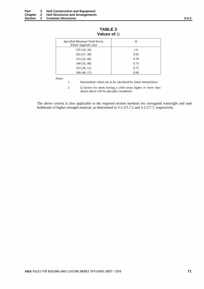
Part 3 Hull Construction and Equipment Chapter 2 Hull Structures and Arrangements Section 2 Common Structures 3-2-2
TABLE 3 Values of Q
Specified Minimum Yield Stress, N/mm2 (kgf/mm2, ksi)
Q
235 (24, 34) 265 (27, 38) 315 (32, 46) 340 (35, 49) 355 (36, 51) 390 (40, 57)
1.0 0.93 0.78 0.74 0.72 0.68
Notes: 1 Intermediate values are to be calculated by linear interpolation.
2 Q factors for steels having a yield stress higher or lower than shown above will be specially considered.
The above criteria is also applicable to the required section modulus for corrugated watertight and tank bulkheads of higher-strength material, as determined in 3-2-2/5.7.2 and 3-2-2/7.7, respectively.
ABS RULES FOR BUILDING AND CLASSING MOBILE OFFSHORE UNITS . 2018 71
P A R T S e c t i o n 3 : S e l f - E l e v a t i n g U n i t s
3 C H A P T E R 2 Hull Structures and Arrangements
S E C T I O N 3 Self-Elevating Units
1 Application This Section applies to self-elevating units, as defined in 3-1-1/3.1
3 General Requirements for Materials and Scantlings
3.1 Material Selection The following structural elements of a self-elevating unit are typically grouped according to their material application categories such as Special, Primary and Secondary (see 3-2-3/Figure 1).
3.1.1 Special Application Structures (Most Critical) i) Vertical columns in way of intersection with the mat structure
ii) Intersections of lattice type leg structures which incorporate novel construction, including the use of steel cast nodes and/or other steel castings
3.1.2 Primary Application Structures (Intermediate) i) External plating of cylindrical legs
ii) Main structural members of lattice type legs such as rack and chord assemblies, seamless and welded steel pipes used as face diagonals, horizontals and gussets
iii) Combinations of bulkhead, deck, side and bottom plating within the upper hull, which form “Box” or “I” type main supporting structure (i.e., a deep bulkhead together with its deck and bottom plating forming “Box” or an “I” beam)
iv) Jack-house supporting structure and bottom footing structure which receives initial transfer of load from legs
v) Internal bulkheads, shell and deck of bottom mat or spud-can supporting structures which distribute major loads, either uniform or concentrated. (Reference may be made to the 0°C (32°F) temperature of 3-1-4/Table 1 and 3-1-4/Table 2 for such applications.)
vi) Fixed frames in jacking or other self-elevating systems
vii) Moveable cantilever structures supporting the drilling derrick
viii) Crane pedestal and support structure
3.1.3 Secondary Application Structures (Least Critical) i) Internal framing of cylindrical legs
ii) Structural members of lattice type legs such as seamless and welded steel pipes used as internal bracings
iii) Bulkhead, deck, side and bottom plating within the upper hull, which do not form “Box” or “I” type main supporting structure, and the internal members attached to such plating
72 ABS RULES FOR BUILDING AND CLASSING MOBILE OFFSHORE UNITS . 2018
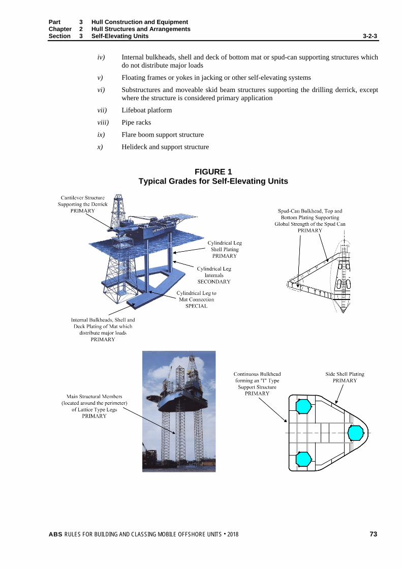
Part 3 Hull Construction and Equipment Chapter 2 Hull Structures and Arrangements Section 3 Self-Elevating Units 3-2-3
iv) Internal bulkheads, shell and deck of bottom mat or spud-can supporting structures which do not distribute major loads
v) Floating frames or yokes in jacking or other self-elevating systems
vi) Substructures and moveable skid beam structures supporting the drilling derrick, except where the structure is considered primary application
vii) Lifeboat platform
viii) Pipe racks
ix) Flare boom support structure
x) Helideck and support structure
FIGURE 1 Typical Grades for Self-Elevating Units
ABS RULES FOR BUILDING AND CLASSING MOBILE OFFSHORE UNITS . 2018 73
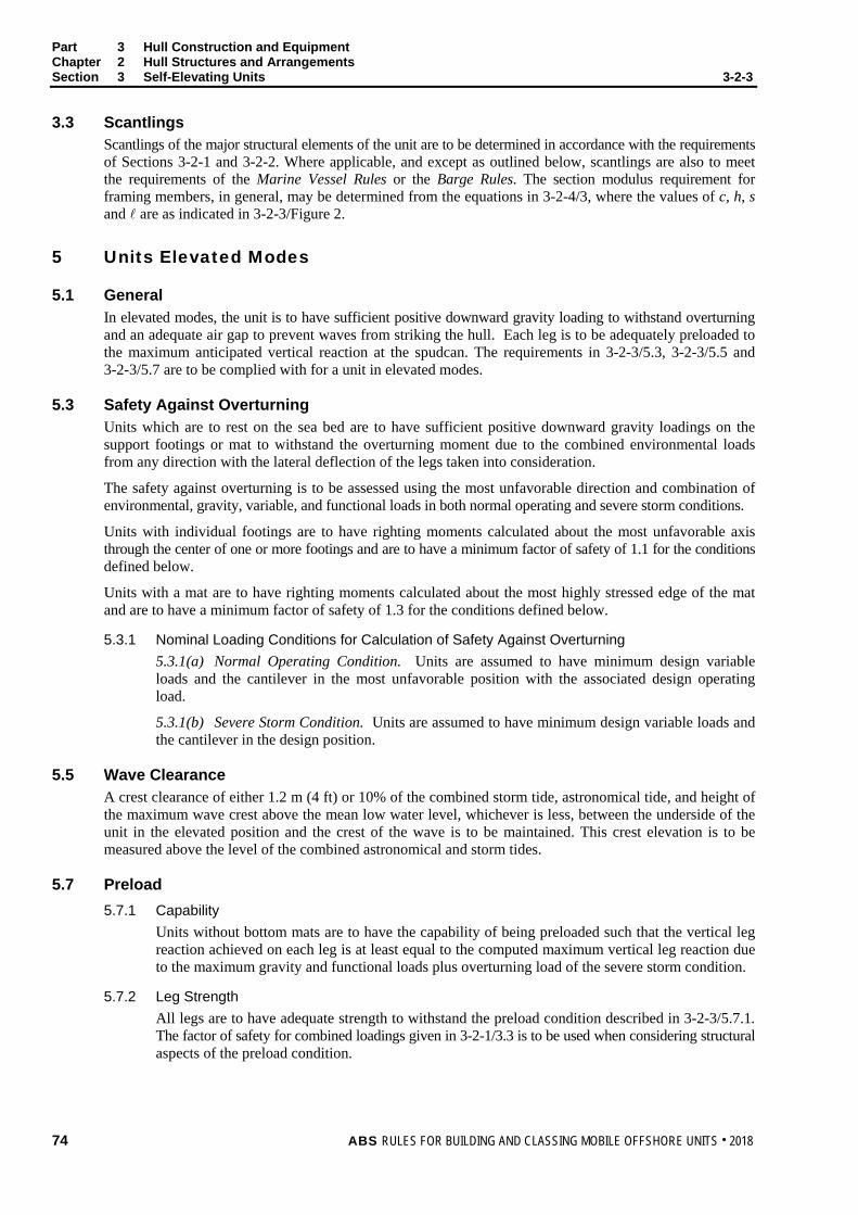
Part 3 Hull Construction and Equipment Chapter 2 Hull Structures and Arrangements Section 3 Self-Elevating Units 3-2-3 3.3 Scantlings
Scantlings of the major structural elements of the unit are to be determined in accordance with the requirements of Sections 3-2-1 and 3-2-2. Where applicable, and except as outlined below, scantlings are also to meet the requirements of the Marine Vessel Rules or the Barge Rules. The section modulus requirement for framing members, in general, may be determined from the equations in 3-2-4/3, where the values of c, h, s and are as indicated in 3-2-3/Figure 2.
5 Units Elevated Modes
5.1 General In elevated modes, the unit is to have sufficient positive downward gravity loading to withstand overturning and an adequate air gap to prevent waves from striking the hull. Each leg is to be adequately preloaded to the maximum anticipated vertical reaction at the spudcan. The requirements in 3-2-3/5.3, 3-2-3/5.5 and 3-2-3/5.7 are to be complied with for a unit in elevated modes.
5.3 Safety Against Overturning Units which are to rest on the sea bed are to have sufficient positive downward gravity loadings on the support footings or mat to withstand the overturning moment due to the combined environmental loads from any direction with the lateral deflection of the legs taken into consideration.
The safety against overturning is to be assessed using the most unfavorable direction and combination of environmental, gravity, variable, and functional loads in both normal operating and severe storm conditions.
Units with individual footings are to have righting moments calculated about the most unfavorable axis through the center of one or more footings and are to have a minimum factor of safety of 1.1 for the conditions defined below.
Units with a mat are to have righting moments calculated about the most highly stressed edge of the mat and are to have a minimum factor of safety of 1.3 for the conditions defined below.
5.3.1 Nominal Loading Conditions for Calculation of Safety Against Overturning 5.3.1(a) Normal Operating Condition. Units are assumed to have minimum design variable loads and the cantilever in the most unfavorable position with the associated design operating load.
5.3.1(b) Severe Storm Condition. Units are assumed to have minimum design variable loads and the cantilever in the design position.
5.5 Wave Clearance A crest clearance of either 1.2 m (4 ft) or 10% of the combined storm tide, astronomical tide, and height of the maximum wave crest above the mean low water level, whichever is less, between the underside of the unit in the elevated position and the crest of the wave is to be maintained. This crest elevation is to be measured above the level of the combined astronomical and storm tides.
5.7 Preload 5.7.1 Capability
Units without bottom mats are to have the capability of being preloaded such that the vertical leg reaction achieved on each leg is at least equal to the computed maximum vertical leg reaction due to the maximum gravity and functional loads plus overturning load of the severe storm condition.
5.7.2 Leg Strength All legs are to have adequate strength to withstand the preload condition described in 3-2-3/5.7.1. The factor of safety for combined loadings given in 3-2-1/3.3 is to be used when considering structural aspects of the preload condition.
74 ABS RULES FOR BUILDING AND CLASSING MOBILE OFFSHORE UNITS . 2018

Part 3 Hull Construction and Equipment Chapter 2 Hull Structures and Arrangements Section 3 Self-Elevating Units 3-2-3 5.9 Wave-Induced Dynamic Responses
Consideration is to be given to the possibility of structural vibrations induced by the action of waves in the case of self-elevating units in elevated condition. The dynamic response induced by the actions of waves or waves acting with current is to be considered if either of the following conditions is met.
• The natural vibratory period, Tn (in seconds), of the unit in a global translational mode (i.e., either lateral deck sway or surge displacement) is in the range 0.9 to 1.1 of the wave period, T (in seconds).
• The dynamic amplification factor (DAF), obtained in the manner described below is greater than 1.10.
Tn can be determined from the following equation applied to one leg:
Tn = 2π )/( ee KM
where
Me = effective mass associated with one leg. This is to consider: the mass representing the Total Elevated Load (3-1-1/16) divided by the number of legs; the mass of a leg above its effective clamping location; and one half the mass of a leg below the effective clamping location, excluding the spudcan, but including the added mass of water displaced by the leg.
Ke = effective bending stiffness of one leg to resist horizontal displacement at the level of the elevated hull. The determination of the leg bending stiffness is to consider: the leg as being pin-ended at least 3 m (10 ft) below the sea bed, the hull to leg stiffness, and the effects of lateral frame displacement on the leg with the highest compressive load due to the supported weight and the other environmental load effects acting with considered wave and current.
The dynamic amplification factor, DAF is determined from the following equation:
DAF =
5.0222
21
−
+
−
TT
cTT nn
where:
c = fraction of critical damping (to be taken ≤ 7 percent)
Tn and T are as previously defined.
7 Legs
7.1 Legs in Elevated Condition 7.1.1 Leg Types
Legs may be either shell type or truss type. Shell type legs may be considered as either stiffened or unstiffened shells. Legs may have individual footings or may be attached to a bottom mat.
7.1.2 Leg Scantlings Legs are to be designed to adequately resist the anticipated total elevated loads and environmental loads for all elevated modes of operation. Leg scantlings are to be determined in accordance with an acceptable method of rational analysis. Calculations are to be submitted for review.
When computing stresses in legs, the maximum overturning moment or base shear on the unit, using the most adverse combination of applicable variable loadings together with the loadings as outlined in Section 3-1-2 is to be considered. Forces and moments due to lateral frame deflection of the legs (P-∆ effect) and wave induced dynamic response as outlined in 3-2-3/5.9 are to be taken into account. Procedures described in ABS Guidance Notes on Dynamic Analysis Procedure for Self-Elevating Units may be used for this purpose.
ABS RULES FOR BUILDING AND CLASSING MOBILE OFFSHORE UNITS . 2018 75

Part 3 Hull Construction and Equipment Chapter 2 Hull Structures and Arrangements Section 3 Self-Elevating Units 3-2-3
7.1.3 Spudcan-Soil Interaction Legs without mats, which may penetrate the sea bed, are to be considered pinned at least 3 m (10 ft) below the sea bed. However when considering a loading condition that includes the unit’s dynamic response, credit may be given to the added stiffness provided by spudcan-soil interaction in accordance with 3-2-3/7.1.4 below. But where use is made of the added spudcan-soil stiffness to offset the effects of dynamic response, it is required that the limiting wave or wave with current condition that satisfies the Rules without the added stiffness is to be established.
7.1.4 Sea Bed Conditions Where it is desired, as permitted in 3-2-3/7.1.3, to consider the added stiffness provided by the spudcan-soil interaction, the rotational stiffness from the interaction is limited to a maximum value based on the equations below. The Owner may select individual values of the rotational stiffness from zero (representing the pinned condition) to the maximum as the basis of the conditions that are reviewed in the unit’s classification and listed in the Operating Manual. Note: It is suggested that the sensitivity of the unit’s strength and dynamic response be investigated using a
range of values for the spudcan-soil stiffness.
The maximum extent to which this rotational stiffness can be applied to the system, Krs, maximum is defined by the following equations.
Krs, maximum = min
/C
LEI .......................................................................................................... [1]
Cmin = FJJ
+−5.1 .................................................................................................................. [2]
J = 1 + 28.7LAI
s
................................................................................................................... [3]
F = 2
12
AY
IFg ........................................................................................................................ [4]
where:
I = Equivalent Leg Moment of Inertia, in m4 (ft4)
A = Equivalent Leg Axial Area, in m2 (ft2)
As = Equivalent Leg Shear Area, in m2 (ft2)
L = leg length, in m (ft), taken as the sum of the distance from the underside of the hull to the sea bed plus the sea bed penetration [min. of 3 m (1 ft)]. The minimum leg lengths to be used in determination of values of Krs, maximum is Lmin = 4.35 (I/As)
0.5. For leg lengths less than Lmin, the Krs, maximum is to be set at the value obtained when the leg length is Lmin.
E = elastic modulus of the leg material as 200 GPa (4.176 × 10⁶ Kip/ft2) for steel
Fg = parameter to reflect the number of legs
= 1.125 (for 3 leg unit), 1.0 (for 4 leg unit)
Y = for a 3-leg unit, is the distance, in m (ft), between the centerline of one leg and a line joining the centers of the other two legs
= or for a 4-leg unit, is the distance, in m (ft), between the centers of leeward and windward rows of legs; in the direction being considered
Krs, maximum is in the units of N-m/rad (Kip-ft/rad)
76 ABS RULES FOR BUILDING AND CLASSING MOBILE OFFSHORE UNITS . 2018
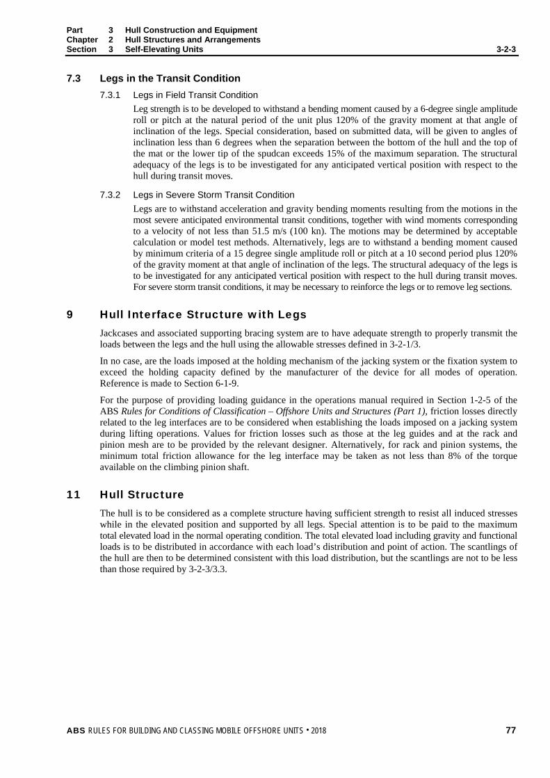
Part 3 Hull Construction and Equipment Chapter 2 Hull Structures and Arrangements Section 3 Self-Elevating Units 3-2-3 7.3 Legs in the Transit Condition
7.3.1 Legs in Field Transit Condition Leg strength is to be developed to withstand a bending moment caused by a 6-degree single amplitude roll or pitch at the natural period of the unit plus 120% of the gravity moment at that angle of inclination of the legs. Special consideration, based on submitted data, will be given to angles of inclination less than 6 degrees when the separation between the bottom of the hull and the top of the mat or the lower tip of the spudcan exceeds 15% of the maximum separation. The structural adequacy of the legs is to be investigated for any anticipated vertical position with respect to the hull during transit moves.
7.3.2 Legs in Severe Storm Transit Condition Legs are to withstand acceleration and gravity bending moments resulting from the motions in the most severe anticipated environmental transit conditions, together with wind moments corresponding to a velocity of not less than 51.5 m/s (100 kn). The motions may be determined by acceptable calculation or model test methods. Alternatively, legs are to withstand a bending moment caused by minimum criteria of a 15 degree single amplitude roll or pitch at a 10 second period plus 120% of the gravity moment at that angle of inclination of the legs. The structural adequacy of the legs is to be investigated for any anticipated vertical position with respect to the hull during transit moves. For severe storm transit conditions, it may be necessary to reinforce the legs or to remove leg sections.
9 Hull Interface Structure with Legs Jackcases and associated supporting bracing system are to have adequate strength to properly transmit the loads between the legs and the hull using the allowable stresses defined in 3-2-1/3.
In no case, are the loads imposed at the holding mechanism of the jacking system or the fixation system to exceed the holding capacity defined by the manufacturer of the device for all modes of operation. Reference is made to Section 6-1-9.
For the purpose of providing loading guidance in the operations manual required in Section 1-2-5 of the ABS Rules for Conditions of Classification – Offshore Units and Structures (Part 1), friction losses directly related to the leg interfaces are to be considered when establishing the loads imposed on a jacking system during lifting operations. Values for friction losses such as those at the leg guides and at the rack and pinion mesh are to be provided by the relevant designer. Alternatively, for rack and pinion systems, the minimum total friction allowance for the leg interface may be taken as not less than 8% of the torque available on the climbing pinion shaft.
11 Hull Structure The hull is to be considered as a complete structure having sufficient strength to resist all induced stresses while in the elevated position and supported by all legs. Special attention is to be paid to the maximum total elevated load in the normal operating condition. The total elevated load including gravity and functional loads is to be distributed in accordance with each load’s distribution and point of action. The scantlings of the hull are then to be determined consistent with this load distribution, but the scantlings are not to be less than those required by 3-2-3/3.3.
ABS RULES FOR BUILDING AND CLASSING MOBILE OFFSHORE UNITS . 2018 77

Part 3 Hull Construction and Equipment Chapter 2 Hull Structures and Arrangements Section 3 Self-Elevating Units 3-2-3 13 Spudcan and Bottom Mat
13.1 Spudcan 13.1.1 General
The structure of a spudcan is to be designed for the loads imposed on it in both the afloat and the elevated modes of operation. In the afloat mode, the structure is to be capable of withstanding the hydrostatic pressure, taking into account whether or not the spudcan is freely vented to the sea once it is submerged. In the elevated mode, the structure is to be capable of withstanding the loads imposed on it by the leg, and be able to transfer these loads effectively to the foundation beneath it. These loads are composed of the gravity load of the leg and hull; variable and functional loads; the environmental loads from wind, waves, and current acting on the leg and hull; and the effects of any applicable preload conditions. It is important to note that the leg-to-spudcan connections represent a primary load path, and they are to be carefully designed to avoid stress concentrations. It is equally important to consider that a self-elevating unit may be sited in a wide variety of sea bottom conditions, including rocky foundations with virtually zero penetration, soft clay bottoms with deep penetrations, hard sandy bottoms which are prone to scour, and sloping strata that lead to eccentric contact area and therefore eccentric loading on the spudcan.
13.1.2 Afloat Mode Loading Conditions To address the afloat mode loading conditions, the scantlings of a spudcan are to be designed using the deep tank requirements with appropriate design heads, h. The following values of h are to be used in the formulas given in 3-2-2/7.3 and 3-2-2/7.5.
i) For a spudcan that is vented freely to the sea:
a) Plating: h = the distance from the lower edge of the plate to the free flooding point or 50 ft, whichever is greater.
b) Stiffeners: h = the distance from the middle of to the same points to which h for plating is measured (see above)
c) Girders: h = the distance from the middle of to the same points to which h for plating is measured (see above)
ii) For a spudcan that is not vented freely to the sea:
a) Plating: h = the distance from the lower edge of the plate to the maximum water level, taking into consideration the astronomical and storm tides
b) Stiffeners: h = the distance from the middle of to the same points to which h for plating is measured (see above)
c) Girders: h = the distance from the middle of to the same points to which h for plating is measured (see above)
13.1.3 Elevated Mode Loading Conditions To address the elevated mode loading conditions, the scantlings of the plating, stiffeners, and girders of the spudcan are to be adequate to resist a load equal to the maximum required preload, evenly distributed over 50% of the bottom area.
In addition, the spudcans, including the leg-to-spudcan connections, are also to be adequate to transmit the forces and moments from the leg to the foundation, as follows:
i) Preload Condition. The spudcan and the leg-to-spudcan connections are to be designed for a load equal to the maximum required preload, concentrically distributed over a range of bearing areas, from the minimum design penetration up to and including full embedment.
78 ABS RULES FOR BUILDING AND CLASSING MOBILE OFFSHORE UNITS . 2018

Part 3 Hull Construction and Equipment Chapter 2 Hull Structures and Arrangements Section 3 Self-Elevating Units 3-2-3
ii) Normal Operating and Severe Storm Conditions.
Pin-ended support. The spudcan and the leg-to-spudcan connections are to be designed for the maximum vertical reaction and the associated horizontal reaction in conjunction with 35% of the maximum calculated moment at the lower guide, (to account for the eccentric effects of possible scour and uneven bottom conditions) acting in the most unfavorable direction. The maximum lower guide bending moment is to be calculated with pin-ended conditions.
Partially-fixed support. The spudcan and the leg-to-spudcan connections are to be designed for the following loads:
a) The maximum vertical reaction, in conjunction with the associated horizontal reaction and spudcan-soil fixity moment, acting in the most unfavorable direction.
b) The maximum spudcan-soil fixity moment in conjunction with the associated vertical and horizontal reactions, acting in the most unfavorable direction.
Notes: 1 If the spudcans are not freely vented to the sea, the effects of hydrostatic pressure are
to be included when checking the strength of the spudcans in the preload, normal operating, severe storm, and uneven bottom conditions.
2 The above requirements are for the design of the spudcan and leg-chord-to-spudcan connections. See Section 3-2-1, “Structural Analysis” for loading and allowable stress requirements for self-elevating unit global structural analysis and 3-2-3/7.1.4, “Sea Bed Conditions” for assumptions of sea bed conditions to be used for structural analyses. Stresses are not to exceed those permitted by 3-2-1/3.
13.3 Bottom Mat Mat compartments are to be in accordance with 3-2-3/3. Particular attention is to be given to the attachment, framing and bracing of the mat in order that loads are properly transmitted between the legs and mat. (See 3-2-2/7.11 regarding drainage and air escape.) The boundary plating of the tanks which are not vented freely to the sea is not to be less in thickness than would be required for tanks, using a head to the maximum water level, taking into account the astronomical and storm tides. The mat is to be further investigated while resting on the sea bed with 20% of the bottom bearing area washed away due to scouring. See 3-2-4/5.9.4. Where skirt plates are provided, consideration will be given to their effectiveness in preventing such loss of bottom support due to scouring.
15 Deckhouses
15.1 General Deckhouses on the main deck are to have sufficient strength for their size and location. When a unit is in elevated mode, deckhouses are subjected to the load effects caused by wind, steel weights, and live loads. However, when the unit is in the transit mode, deckhouses are subjected to the load effects caused by waves in addition to the load effects in the elevated mode. The load effects caused by waves include motion induced inertia and gravity effect due to unit’s static inclinations.
Deckhouses are to be designed to adequately resist these load effects in accordance with the following Paragraphs. Paragraphs 3-2-3/15.3 through 3-2-3/15.11 provide the requirements for basic scantlings of the deckhouses in association with their locations on the deck and functions. Paragraph 3-2-3/15.13 provides the requirements for the overall strength of the deckhouse in transit.
Deckhouses, which are used as protection for openings leading to spaces below main deck, are also to be designed as a watertight boundary. For deckhouses that are cantilevered over the bow of a unit, the possibility of wave slamming and impact during transit is also to be considered.
ABS RULES FOR BUILDING AND CLASSING MOBILE OFFSHORE UNITS . 2018 79

Part 3 Hull Construction and Equipment Chapter 2 Hull Structures and Arrangements Section 3 Self-Elevating Units 3-2-3 15.3 Design Head
The design head for side and end bulkhead plating and stiffeners of deckhouses on the freeboard deck is to be obtained from the following:
h = c hb
where
h = design head, in m (ft)
hb = 0.133 L − 3.0 m (L ≤ 100 m)
= 0.133 L − 9.8 ft (L ≤ 328 ft)
but not to be less than 2.8 m (9.2 ft)
c = 1.0 for front bulkheads
= 0.6 for aft bulkheads
= See 3-2-3/15.9 for side bulkheads
L = length of the unit, in m (ft).
The design head for side and end bulkhead plating and stiffeners of deckhouses on the deck above the freeboard deck is to be obtained from the following:
h = chbk but h is not to be taken less than hm
where
h = design head, in m (ft)
hb = 0.16L1 – 4.0 m for L1 ≤ 100 m
= 0.16L1 – 13 ft for L1 ≤ 328 ft
for second tier unprotected front bulkheads
c = 0.5 where fbd ≤ 0.02L1 m (ft)
= 0.14 where fbd ≥ 0.02L1 + 0.01L2 + 1.05 m
≥ 0.02L1 + 0.01L2 + 3.445 ft
hm = 1.4 m (4.6 ft)
for second tier aft bulkheads
c = 0.3 where fbd ≤ 0.02L1 m (ft)
= 0.14 where fbd ≥ 0.02L1 + 0.01L2 + 1.05 m
≥ 0.02L1 + 0.01L2 + 3.445 ft
hm = 1.4 m (4.6 ft)
for second tier side bulkheads, See 3-2-3/15.9.
for all other bulkheads
c = 0.14
hm = 1.4 m (4.6 ft)
Intermediate values of fbd, c and hm may be obtained by linear interpolation.
L1 = length of unit, as defined in 3-1-1/3 of the Barge Rules.
L2 = length of unit, as defined in 3-1-1/3 of the Barge Rules, but is not to be taken less than 75 m (246 ft)
fbd = the assigned freeboard, in m (ft)
80 ABS RULES FOR BUILDING AND CLASSING MOBILE OFFSHORE UNITS . 2018
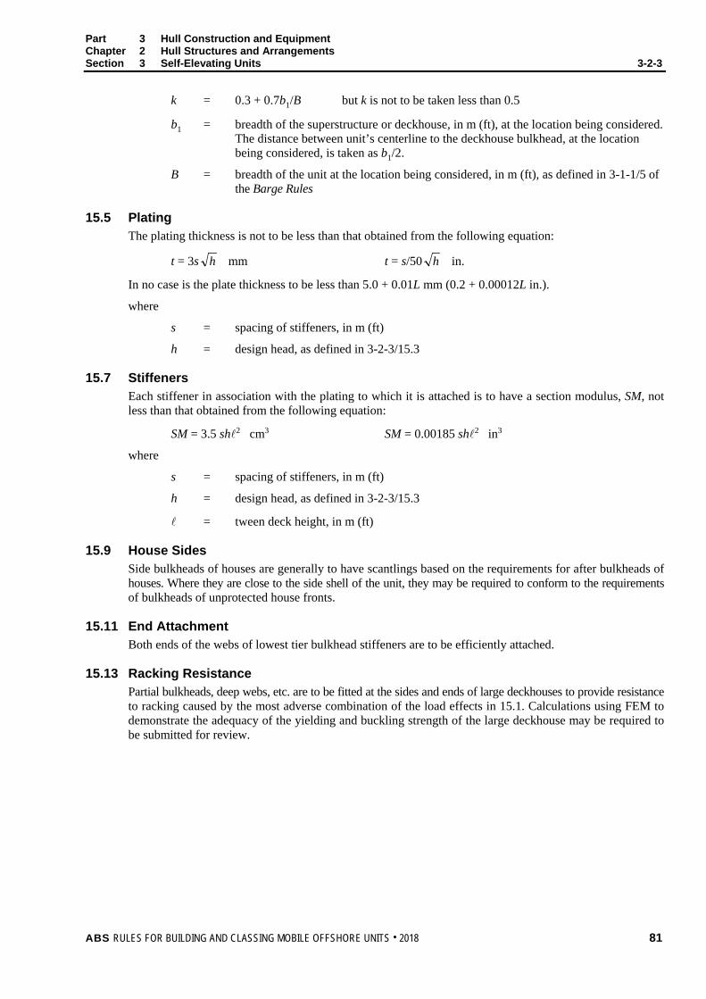
Part 3 Hull Construction and Equipment Chapter 2 Hull Structures and Arrangements Section 3 Self-Elevating Units 3-2-3
k = 0.3 + 0.7b1/B but k is not to be taken less than 0.5
b1 = breadth of the superstructure or deckhouse, in m (ft), at the location being considered. The distance between unit’s centerline to the deckhouse bulkhead, at the location being considered, is taken as b1/2.
B = breadth of the unit at the location being considered, in m (ft), as defined in 3-1-1/5 of the Barge Rules
15.5 Plating The plating thickness is not to be less than that obtained from the following equation:
t = 3s h mm t = s/50 h in.
In no case is the plate thickness to be less than 5.0 + 0.01L mm (0.2 + 0.00012L in.).
where
s = spacing of stiffeners, in m (ft)
h = design head, as defined in 3-2-3/15.3
15.7 Stiffeners Each stiffener in association with the plating to which it is attached is to have a section modulus, SM, not less than that obtained from the following equation:
SM = 3.5 sh2 cm3 SM = 0.00185 sh2 in3
where
s = spacing of stiffeners, in m (ft)
h = design head, as defined in 3-2-3/15.3
= tween deck height, in m (ft)
15.9 House Sides Side bulkheads of houses are generally to have scantlings based on the requirements for after bulkheads of houses. Where they are close to the side shell of the unit, they may be required to conform to the requirements of bulkheads of unprotected house fronts.
15.11 End Attachment Both ends of the webs of lowest tier bulkhead stiffeners are to be efficiently attached.
15.13 Racking Resistance Partial bulkheads, deep webs, etc. are to be fitted at the sides and ends of large deckhouses to provide resistance to racking caused by the most adverse combination of the load effects in 15.1. Calculations using FEM to demonstrate the adequacy of the yielding and buckling strength of the large deckhouse may be required to be submitted for review.
ABS RULES FOR BUILDING AND CLASSING MOBILE OFFSHORE UNITS . 2018 81

Part 3 Hull Construction and Equipment Chapter 2 Hull Structures and Arrangements Section 3 Self-Elevating Units 3-2-3
FIGURE 2 Typical Hull Construction
LC
h for stanchions and bottom members
h for deck members•
(see 3-1-3/1.11.3)
h for sidelong'ls andbhd. stiffs.
h for sidewebs
for sidewebs
/2 for bhd.
webs
h for bhd. webs
(see 3-2-2/5.9)
for deck andbottom transv.
b for stanchions
s for long'ls
A
A
s for transv.and stanchions
for stanchions
for long'ls
Section A-A
*Not to be less than L/50 + 0.762 meters (L/50 + 2.5 feet), maximum 2.9 m (9.5 ft) where L is the length of the unit in m (ft).
Note: Typical transverse section (longitudinal framing) shown.
Bottom transverses (or girders) c = 1.50 Bottom long’ls (or frames) c = 1.34 Side webs (or girders) c = 1.50 Side long’ls (or frames) c = 1.00 Deck transverses (or girders) c = 1.00 Deck long’ls (or beams) c = 0.60 Bulkhead webs (or girders) c = 1.00 Bulkhead stiffeners c = 0.70
Stanchions W = fbhs kN (tf, Ltf) f = 10.5 (1.07, 0.03)
b, h and s in meters (feet) In way of tanks, scantlings are also to meet the requirements of 3-2-2/7.
82 ABS RULES FOR BUILDING AND CLASSING MOBILE OFFSHORE UNITS . 2018
P A R T S e c t i o n 4 : C o l u m n - S t a b i l i z e d D r i l l i n g U n i t s
3 C H A P T E R 2 Hull Structures and Arrangements
S E C T I O N 4 Column-Stabilized Units
1 General
1.1 Application This Section applies to column-stabilized units, as defined in 3-1-1/3.3.
1.3 Special Considerations Regarding Stresses On column-stabilized units, the highest stresses in some members may be associated with environmental conditions less severe than the maximums specified by the Owner. Where considered necessary, such stresses and the increased probability of their occurrence are to be taken into account by either or both of the following.
i) Suitable reduction of the allowable stress levels given in 3-2-1/3 for combined loadings, as defined in 3-2-1/1.1ii).
ii) Detailed investigation of the fatigue properties in order to evaluate the possibility of high stresses in association with probability of occurrence.
Particular attention is also to be given to the structural details in critical areas such as bracing members, joint connections, etc.
1.5 Effect of Mooring Forces on Local Structure Local structure in way of fairleads, winches, etc., forming part of the position mooring system, is to be capable of withstanding forces equivalent to the breaking strength of the mooring line with the allowable stresses of combined loading conditions defined in 3-2-1/3.
1.7 Material Selection The following structural elements of a column-stabilized unit are typically grouped according to their material application categories such as Special, Primary and Secondary (see 3-2-4/Figure 1).
1.7.1 Special Application Structures (Most Critical) i) External shell structure in way of intersections of vertical columns, decks, and lower hulls
ii) Portions of deck plating, heavy flanges and bulkheads within the upper hull or platform which form “Box” or “I” type support structure and which receive major concentrated loads
iii) Major intersection of bracing members
iv) External brackets, portions of bulkheads, flats and frames which receive concentrated loads at intersections of major structural members
v) “Through” material used at connections of vertical columns, upper platform decks, and upper or lower hulls which provide proper alignment and adequate load transfer
1.7.2 Primary Application Structures (Intermediate) i) External shell structure of vertical columns, lower and upper hulls, and diagonal and
horizontal braces (For lower hull plating, reference may be made to the 0°C (32°F) temperature of 3-1-4/Table 1 and 3-1-A3/Table 5.)
ABS RULES FOR BUILDING AND CLASSING MOBILE OFFSHORE UNITS . 2018 83

Part 3 Hull Construction and Equipment Chapter 2 Hull Structures and Arrangements Section 4 Column-Stabilized Units 3-2-4
ii) Deck plating, heavy flanges and bulkheads within the upper hull or platform which form “Box” or “I” type support for substructure or drilling derrick and which do not receive major concentrated loads
iii) Bulkheads, flats or decks, framing, and seamless and welded steel pipes which provide local reinforcement or continuity of structure in way of intersections, except where the structure is considered special application
iv) Crane pedestal and support structure
v) Thruster foundation
vi) Fairlead foundation
1.7.3 Secondary Application Structures (Least Critical) i) Internal structure, including bulkheads girders and tubulars in vertical columns, decks,
lower hulls, and diagonal and horizontal bracing
ii) Upper platform decks or decks of upper hulls, except where the structure is considered primary or special application
iii) Certain large diameter vertical columns with low length-to-diameter ratios, except at intersections
iv) Lifeboat platform
v) Pipe racks
vi) Flare boom support structure
vii) Helideck and support structure
FIGURE 1 Typical Grades for Column-Stabilized Units
Crane Pedestal and Support Structure
PRIMARYLower Hull Shell
PlatingPRIMARY
Column Shell Plating
PRIMARY
Bracing PlatingPRIMARY
HelideckSECONDARY
Through Brackets in Columns
OR Major Intersections
of BracingsSPECIAL
Deck PlatingSECONDARY
Longitudinal and/or Transverse "Box" Type
Girder Support StructuresPRIMARY
84 ABS RULES FOR BUILDING AND CLASSING MOBILE OFFSHORE UNITS . 2018

Part 3 Hull Construction and Equipment Chapter 2 Hull Structures and Arrangements Section 4 Column-Stabilized Units 3-2-4
3 Upper Structure
3.1 General The upper structure is the structure built on top of the columns to provide areas for operations and living quarters for the crew. The upper structure also ties all columns, braces, and lower hull together to form the global strength of a column-stabilized unit. The upper structure can be in a form of a barge hull or a single deck.
The scantlings of the upper structure are not to be less than those required by the following Subparagraphs in association with the loadings indicated on the deck loading plan. These loadings are not to be less than the minimums specified in 3-1-3/1.11. In addition, when any portion of the upper structure is considered to be an effective member of the overall structural frame of the unit, the scantlings are to be sufficient to withstand actual local loadings plus any additional loadings superimposed due to frame action, within the stress limitations of 3-2-1/3.
3.3 Deck Plating 3.3.1 General
The thickness of deck or platform plating is not to be less than that required for the purposes of overall strength of the unit, and for local loading.
3.3.2 Storage Area Decks The thickness of the deck plating in storage areas is to be adequate for the intended service and is not to be less than that obtained from the following equation:
t = K Sb h + a mm (in.) but not less than 5.0 mm (0.20 in.)
where
K = 0.0039 (0.00218)
Sb = spacing of deck beams, in mm (in.)
a = 1.5 mm (0.06 in.)
h = tween deck height, in m (ft). When a design load is specified, h is to be taken as p/n, where p is the specified design load, in kN/m2 (kgf/m2, lbf/ft2) and n is defined as 7.05 (715, 45)
3.3.3 Decks in Way of Tanks In way of tanks, the deck plating thickness is not to be less than that required by 3-2-2/7.3.
3.3.4 Provision for Fork-Lift Trucks Where provision is to be made for the use of forklift trucks, and after all other adjustments have been made, the thickness of plated steel decks may be determined as indicated in Section 3-2-3 of the Marine Vessel Rules.
3.5 Beams Each beam, in association with the plating to which it is attached, is to have a section modulus, SM, not less than that obtained from the following equation:
SM = fchs2 cm3 (in3)
where
f = 7.8 (0.0041)
c = 0.6 for beams clear of tanks
= 1.00 for beams in way of tanks
ABS RULES FOR BUILDING AND CLASSING MOBILE OFFSHORE UNITS . 2018 85

Part 3 Hull Construction and Equipment Chapter 2 Hull Structures and Arrangements Section 4 Column-Stabilized Units 3-2-4
h = height, in m (ft), equivalent to the design loading, as specified on the design loading plan, but not less than the height specified in 3-1-3/1.11, or in the case of beams of over tanks, two-thirds of the distance, in m (ft), from the top of the tank to the top of the overflow, if that be greater. In cases where the specific gravity of the liquid is greater than 1.05, the required SM is to be multiplied by the specific gravity.
s = spacing of beams, in m (ft)
= length, in m (ft), from the inner edge of the beam knee to the nearest line of girder support, or between girder supports, whichever is greater.
3.7 Girders 3.7.1 Strength Requirements
Each deck or platform girder is to have a section modulus, SM, not less than that obtained from the following equation:
SM = fchb2 cm3 (in3)
where
f = 4.74 (0.0025)
c = 1.0 for girders clear of tanks
1.5 for girders in way of tanks
h = height, in m (ft), as required by 3-2-4/3.5
b = mean breadth of the area of the deck supported
= length, in m (ft), of the area of the deck supported between the stanchion and bulkhead; where brackets are fitted at the bulkhead, and the brackets are in accordance with 3-2-2/Table 2 and have a slope of approximately 45 degrees, the length may be measured to a point on the bracket equal to 25% of the length of the bracket.
3.7.2 Proportions Girders on bulkheads and decks clear of tanks are to have a depth not less than 0.0583 and, in general, the depth of girders clear of tanks is not to be less than twice the depth of the cutouts for beams and stiffeners. Girders in tanks are to have a depth not less than 0.125 and, in general, the depth of girders in tanks is not to be less than 2.5 times the depth of the cutout. The thickness is not to be less than 1 percent of depth plus 3 mm (0.12 in.), but need not exceed 11 mm (0.44 in.), provided adequate shear area is maintained as necessary.
3.7.3 Tripping Brackets Girders are to be supported by tripping brackets at intervals of about 3 m (10 ft), and where the width of the unsupported face plate exceeds 200 mm (8 in.), the tripping brackets are to support the face plate.
3.9 Stanchions and Pillars 3.9.1 Permissible Load
The permissible load, Wa, on a stanchion, pillar or strut is to be obtained from the following equation which will, in all cases, be equal to or greater than the calculated load, W.
Wa = (m − n/r)A kN (tf, Ltf)
where
= unsupported span of the stanchion or pillar, in m (ft)
r = least radius of gyration, in cm (in.)
A = area of the stanchion or pillar, in cm2 (in2)
86 ABS RULES FOR BUILDING AND CLASSING MOBILE OFFSHORE UNITS . 2018
Part 3 Hull Construction and Equipment Chapter 2 Hull Structures and Arrangements Section 4 Column-Stabilized Units 3-2-4
m = 12.09 (1.232, 7.83) ordinary strength steel
= 16.11 (1.643, 10.43) HT32 strength steel
= 18.12 (1.848, 11.73) HT36 strength steel
n = 4.44 (0.452, 0.345) ordinary strength steel
= 7.47 (0.762, 0.581) HT32 strength steel
= 9.00 (0.918, 0.699) HT36 strength steel
3.9.2 Length The length, ,for use in the equation is to be measured from the top of the deck or other structure on which the stanchions are based to the underside of the beam or girder supported.
3.9.3 Calculated Load The calculated load, W, for a specific stanchion or pillar is to be obtained from the following equation:
W = fbhs kN (tf, Ltf)
where
f = 7.04 (0.715, 0.02)
b = mean breadth of the area supported, in m (ft)
h = height above the area supported, as defined in 3-2-4/3.5.
s = length of the area supported by the pillar, in m (ft)
c = 0.1035 (1.015, 0.16) ordinary strength steel
= 0.0776 (0.761, 0.12) HT32 strength steel
= 0.069 (0.677, 0.107) HT36 strength steel
3.9.4 Pillars under the Tops of Tanks Pillars under the tops of tanks are not to be less than required by the foregoing. They are to be of solid sections and to have not less area than 1.015W cm2 or 0.16W in2, where W is obtained from the following equation:
W = fbhs kN (tf, Ltf)
where
f = 10.5 (1.07, 0.03)
b = breadth of the area at the top of the tank supported by the pillar, in m (ft)
h = height, as required by 3-2-4/3.5, for the beams of the top of the tank, in m (ft)
s = length of the area of the top of the tank supported by the pillar, in m (ft)
3.11 Non-buoyant Upper Structure Not Subjected to Wave Loading Where it can be shown that the upper structure is not subject to wave loading, required in any mode of operation to be watertight, nor within the watertight integrity [see plan to be submitted under 1-2-4/1 of the ABS Rules for Conditions of Classification – Offshore Units and Structures (Part 1)], the scantlings can be determined not taking into consideration of the watertightness nor the effects of the wave loads.
3.13 Buoyant Upper Structure Where the upper structure is designed to be buoyant in any mode of operation, or to meet any stability requirement, it will be subject to special consideration. The upper structure is to be designed in accordance with the requirements for watertight bulkheads and watertight flats in 3-2-2/5 using the final damaged waterline.
ABS RULES FOR BUILDING AND CLASSING MOBILE OFFSHORE UNITS . 2018 87

Part 3 Hull Construction and Equipment Chapter 2 Hull Structures and Arrangements Section 4 Column-Stabilized Units 3-2-4
3.15 Upper Structure Subjected to Wave Loading Unless adequate wave clearance (3-2-4/9) can be ensured for all afloat modes of operation, the effect of wave impact is to be taken into account in determining the scantlings of upper structure.
5 Columns, Lower Hulls, and Footings
5.1 General Main stability columns, lower hulls or footings may be considered either as framed or unframed shells. Ring stiffeners, bulkheads or other suitable diaphragms which are used are to be adequate to maintain shape and stiffness under all anticipated loadings in association with established shell analysis methods.
5.3 Scantlings of Framed Shells Where the components of columns, lower hulls or footings incorporate stiffened plating, the minimum scantlings of plating, framing, girders, etc., for shells and interior boundary bulkheads and flats may be determined in accordance with the requirements for tanks, as given in 3-2-2/7, in association with the following.
5.3.1 Tank Space Where the internal space is a tank, the head, h, is to be taken to a point located at two-thirds of the distance from the top of the tank to the top of the overflow, or to a point 0.91 m (3 ft) above the top of the tank, whichever is greater. For tanks intended to carry contents with a specific gravity in excess of 1.05, the head is to be suitably increased in accordance with 3-2-2/7.1.
5.3.2 Void Compartment Spaces Where the internal space is a void compartment, the head is to be taken to the maximum permissible draft of the unit in service.
5.3.3 Areas Subject to Wave Immersion For all areas subject to wave immersion, the minimum head is to be 6.1 m (20 ft).
5.3.4 Minimum Scantlings In general, the scantlings of boundaries are not to be less than those required by 3-2-2/5, in association with a head to the maximum damaged waterline.
5.5 Scantlings of Unframed Shells Where columns, lower hulls or footings do not incorporate framing members, the minimum scantlings of shell plating and ring stiffeners are to be determined on the basis of established shell analysis methods using the heads given in 3-2-4/5.3 and factors of safety appropriate to the method employed. Interior boundary bulkheads and flats are to be considered on the basis of framed shells, as given in 3-2-4/5.3.
5.7 Scantlings of Structural Flats Scantlings of structural flats which are not required to be watertight are to be determined in accordance with the applicable requirements of 3-2-4/3.
5.9 Additional Structural Requirements 5.9.1 Provision for Wave and Current Loadings
Scantlings of columns, lower hulls and footings, as determined above, are minimum requirements for hydrostatic loads. Where wave and current loadings are superimposed, the scantlings of the local structure of the shell are to be increased as necessary, to meet the strength requirements of 3-2-1/3.
5.9.2 Provision for Frame Action When the column, lower hull or footing is considered to be an effective member of the overall structural frame of the unit, the scantlings are to be sufficient to meet the requirements of 3-2-4/5, plus any additional stresses superimposed due to frame action, within the stress limitations of 3-2-1/3.
88 ABS RULES FOR BUILDING AND CLASSING MOBILE OFFSHORE UNITS . 2018
Part 3 Hull Construction and Equipment Chapter 2 Hull Structures and Arrangements Section 4 Column-Stabilized Units 3-2-4
5.9.3 Consideration for High Local Loadings Particular consideration is to be given to structural details, reinforcement, etc., in areas subject to high local loadings, or to such loadings that may cause shell distortion, for example:
i) Bottom bearing loads, where applicable
ii) Partially filled tanks
iii) Local strength against external damage
iv) Wave impacts
5.9.4 Scouring Consideration For units intended to rest on the sea bed, the effect of scouring and possible loss of bottom support is to be considered, as follows.
i) For a broad mat type (lower hull) support, 20% of the bottom bearing area is to be considered unsupported.
ii) When there are individual footings or pads, any one such support is to be considered unsupported on 50% of its bottom bearing area.
iii) Other configurations will be specially considered.
Where skirt plates are provided, consideration will be given to their effectiveness in preventing loss of bottom support due to scouring.
5.11 Bracing Members 5.11.1 General
Stresses in bracing members due to all anticipated loadings are to be determined in accordance with the following requirements in conjunction with the relevant requirements of Section 3-2-1.
5.11.2 Loading Conditions Bracing members are to be capable of transmitting loadings and making the overall structure effective against environmental forces, and when the unit is supported by the sea bed, against the possibility of uneven bottom bearing loads. Although considered primarily as brace members of the overall structure under the designated loadings, the bracing must also be investigated for superimposed local bending stresses due to buoyancy, wave and current forces, if applicable.
5.11.3 Effect of Wave Impact Where relevant, consideration is to be given to local stresses due to wave impact.
5.11.4 Reinforcement of Tubular Bracing Members When bracing members are of tubular section, ring frames may be required to maintain stiffness and shape.
5.11.5 Watertight Bracing Members When bracing members are watertight, they are to be suitably designed to prevent collapse from external hydrostatic pressure. Underwater bracing members are normally to be made watertight and have a leak detection system to make it possible to detect fatigue cracks at an early stage.
5.13 Openings in Columns Portlights or other similar openings are not to be fitted in columns.
ABS RULES FOR BUILDING AND CLASSING MOBILE OFFSHORE UNITS . 2018 89
Part 3 Hull Construction and Equipment Chapter 2 Hull Structures and Arrangements Section 4 Column-Stabilized Units 3-2-4
7 Deckhouses
7.1 General Deck houses which are not an integral part of the upper deck structure are to have sufficient strength for their size, function and location, with due consideration given to the environmental conditions to which the unit may be exposed. Special considerations should be given to deck houses which act as foundations for vital machinery or equipment.
In general, deckhouses are subjected to the load effects of wind forces, motion-induced inertial forces, live loads, dead weight, and inclination of the unit. Hence, they are to be designed adequately to resist these load effects using the allowable stresses for combined loadings defined in 3-2-1/3.3.
Partial bulkheads, deep webs, brackets and adequate supports under main deck are to be fitted at the sides and ends of deckhouses subject to differential deflections of the global hull structure to provide resistance to the most adverse combination of the load effects above. Calculations to demonstrate the adequacy of the yielding and buckling strength of such deckhouse and its underneath main deck supporting structure may be required to be submitted for review.
Depending on the upper structures, the following should also be taken into consideration when designing the deckhouses.
7.1.1 Deckhouses on an Upper Structure Not Subjected to Wave Loading Deckhouses installed on a non-buoyant upper structure not subjected to wave loading (3-2-4/3.11) are to be designed to resist the load effects mentioned in 3-2-4/7.1 above.
7.1.2 Deckhouses on an Upper Structure Subjected to Wave Loading Deckhouses installed on an upper structure that will be subjected to wave loading (3-2-4/3.15) are to take the possibility of wave impact loading into consideration in addition to the load effects mentioned in 3-2-4/7.1 above.
7.1.3 Deckhouses on a Buoyant Upper Structure Deckhouses installed on a buoyant upper structure (3-2-4/3.13) should take the required stability requirements into consideration. If the deckhouses are required to be buoyant, they should also be designed as a watertight boundary in accordance with 3-2-2/5 using the final damage waterline in addition to the load effects mentioned in 3-2-4/7.1.1 or 3-2-4/7.1.2 above.
7.3 Storage Tanks on Upper Structure Storage tanks built into or on upper structure are to have scantlings as required for tanks, as given in 3-2-2/7.
9 Wave Clearance
9.1 Afloat Modes of Operation Unless the upper structure and deckhouses are satisfactorily designed for wave impact, reasonable clearance between the deck structures and the wave crests is to be ensured for all afloat modes of operation, taking into account the predicted motion of the unit relative to the surface of the sea. Calculations, model test results or prototype experiences are to be submitted for consideration.
9.3 On-Bottom Modes of Operation For on-bottom modes of operation, clearances are to be in accordance with those specified in 3-2-3/5.5 for self-elevating units.
90 ABS RULES FOR BUILDING AND CLASSING MOBILE OFFSHORE UNITS . 2018

Part 3 Hull Construction and Equipment Chapter 2 Hull Structures and Arrangements Section 4 Column-Stabilized Units 3-2-4
11 Structural Redundancy
11.1 Assumed Damage When assessing structural redundancy for column-stabilized units, the unit’s structure is to be able to withstand the loss of a slender bracing member without causing overall collapse of the unit’s structure.
11.3 Analysis Structural redundancy analyses will be based on the applicable requirements of 3-2-1/1 and 3-2-1/3, except:
i) Maximum calculated stresses in the structure remaining after the loss of a slender bracing member are to be in accordance with 3-2-1/1, and 3-2-1/3, in association with a factor of safety of 1.0. This criteria may be exceeded for local areas, provided redistribution of forces due to yielding or buckling is taken into consideration.
ii) When considering environmental factors, the applied loads are not to be less than 80% of the loads associated with the severe storm condition. (See 3-1-1/17.3.)
11.5 Upper Structure The structural arrangement of the upper structure is to be considered with regard to the structural integrity of the unit after the failure of any relevant element of any primary structural component. Where considered necessary, a structural analysis may be required with loading conditions and strength criteria as in 3-2-4/11.3.
13 Higher-strength Materials
13.1 General In general, applications of higher-strength materials for plates, beams, and girders are to meet the requirements of this section, but may be modified as permitted by the following paragraphs. Calculations are to be submitted to show adequate provision to resist buckling.
13.3 Upper Structure 13.3.1 Plate Thickness
The thickness of deck plating, where constructed of higher-strength material, is to be not less than obtained from the following equation:
thts = (tms − C)Q + C mm (in.) but not less than 5.0 mm (0.20 in.)
where
tms = thickness of ordinary-strength steel, in mm (in.), as obtained from 3-2-4/3.3.2
C = 4.3 mm (0.17 in.)
Q = is as defined in 3-2-4/Table 1
13.3.2 Beam and Girder Section Modulus Each beam and girder of higher-strength material, in association with the higher-strength plating to which it is attached, is to comply with the requirements of the appropriate preceding paragraphs of this section and is to have a section modulus SMhts not less than obtained from the following equation:
SMhts = SM (Q)
where
SM = required section modulus in ordinary-strength material as determined in 3-2-4/3.5 and 3-2-4/3.7, respectively
Q = See 3-2-4/Table 1 below
ABS RULES FOR BUILDING AND CLASSING MOBILE OFFSHORE UNITS . 2018 91
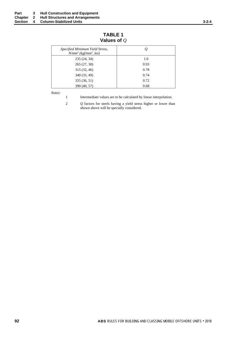
Part 3 Hull Construction and Equipment Chapter 2 Hull Structures and Arrangements Section 4 Column-Stabilized Units 3-2-4
TABLE 1 Values of Q
Specified Minimum Yield Stress, N/mm2 (kgf/mm2, ksi)
Q
235 (24, 34) 265 (27, 38) 315 (32, 46) 340 (35, 49) 355 (36, 51) 390 (40, 57)
1.0 0.93 0.78 0.74 0.72 0.68
Notes: 1 Intermediate values are to be calculated by linear interpolation.
2 Q factors for steels having a yield stress higher or lower than shown above will be specially considered.
92 ABS RULES FOR BUILDING AND CLASSING MOBILE OFFSHORE UNITS . 2018

P A R T S e c t i o n 5 : S u r f a c e - T y p e D r i l l i n g U n i t s
3 C H A P T E R 2 Hull Structures and Arrangements
S E C T I O N 5 Surface-Type Drilling Units
1 General This Section applies to surface-type drilling units as defined in 3-1-1/3.5.
3 Material Selection Grades for surface-type drilling units are to be in accordance with 3-1-2/3 of the ABS Rules for Building and Classing Marine Vessels (Marine Vessel Rules) or 3-1-2/3 of the ABS Rules for Building and Classing Steel Barges (Barge Rules). Alternatively, the selection of material grades in accordance with 3-1-4/5 may be used.
3.1 Ship-Type Drilling Unit On a ship-type drilling unit (drillship), special, primary and secondary application structures are equivalent to Class III, Class II and Class I structures respectively as defined in 3-1-2/Table 2A, 2B of the Marine Vessel Rules. The following structures will typically be considered as special, primary and secondary application (see 3-2-5/Figure 1). For a complete classification of grades, refer to 3-1-2/3 of the Marine Vessel Rules.
3.1.1 Special Application Structures (equivalent to Class III structures) i) Sheer strake at strength deck within 0.4L amidships
ii) Stringer plate in strength deck within 0.4L amidships
iii) Deck strake at longitudinal bulkhead within 0.4L amidships
iv) Deck or bottom plating located at corners of the moonpool opening
v) Bilge strake within 0.4L amidships
3.1.2 Primary Application Structures (equivalent to Class II structures) i) Bottom plating, including keel plate, within 0.4L amidships
ii) Strength deck plating within 0.4L amidships, except where the structure is considered special application
iii) Continuous longitudinal members above strength deck within 0.4L amidships
iv) Uppermost strake in longitudinal bulkhead within 0.4L amidships
v) Sheer strake at strength deck outside 0.4L but within 0.6L amidships
vi) Stringer plate in strength deck outside 0.4L but within 0.6L amidships
vii) Deck strake at longitudinal bulkhead outside 0.4L but within 0.6L amidships
viii) Inner bottom plating located at corners of the moonpool opening
ABS RULES FOR BUILDING AND CLASSING MOBILE OFFSHORE UNITS . 2018 93

Part 3 Hull Construction and Equipment Chapter 2 Hull Structures and Arrangements Section 5 Surface-Type Drilling Units 3-2-5
3.1.3 Secondary Application Structures (equivalent to Class I structures) i) Longitudinal bulkhead strakes within 0.4L amidships, except where the structure is considered
primary application
ii) Deck plating exposed to weather within 0.4L amidships, except where the structure is considered primary or special application
iii) Side plating within 0.4L amidships
iv) Sheer strake at strength deck outside 0.6L amidships
v) Stringer plate in strength deck outside 0.6L amidships
vi) Deck strake at longitudinal bulkhead outside 0.6L amidships
vii) Bilge strake outside 0.6L amidships
FIGURE 1 Typical Grades for Surface-Type Drilling Units
Strength Deck within 0.4LPRIMARY
Bottom Plating within 0.4LPRIMARY Bilge Strake within 0.4L
SPECIALThruster Foundation
PRIMARY
Sheer Strake/Stringer Plate outside 0.6L
SECONDARY
Helideck and Support StructureSECONDARY
Sheer Strake/Stringer Plate within 0.4LSPECIAL
Deck/Bottom Corners of the Moonpool OpeningSPECIALCrane Pedestal and Support Structure
PRIMARY
Sheer Strake/Stringer Plate outside 0.4 but within 0.6L
PRIMARY
Side Plating within 0.4LSECONDARY
3.3 Barge-Type Drilling Unit On a barge-type drilling unit, special application structures are equivalent to Class V and Class IV structures as defined in 3-1-2/Table 1 of the Barge Rules, primary application structures are equivalent to Class III structures and secondary application structures are equivalent to Class II and Class I structures. The following structures will typically be considered as special, primary and secondary. For a complete classification of grades, refer to 3-1-2/3 of the Barge Rules.
3.3.1 Special Application Structures (equivalent to Class IV and VI structures) i) Bilge strake within 0.4L amidships
ii) Sheer strake at strength deck within 0.4L amidships
iii) Stringer plate in strength deck within 0.4L amidships
iv) Strength deck strake on tank barge at longitudinal bulkhead within 0.4L amidships
v) Deck or bottom plating located at corners of the moonpool opening
94 ABS RULES FOR BUILDING AND CLASSING MOBILE OFFSHORE UNITS . 2018
Part 3 Hull Construction and Equipment Chapter 2 Hull Structures and Arrangements Section 5 Surface-Type Drilling Units 3-2-5
3.3.2 Primary Application Structures (equivalent to Class III structures) i) Bottom plating including keel plate within 0.4L amidships
ii) Strength deck plating within 0.4L amidships
iii) Uppermost strake including that of the top wing tank within 0.4L amidships
iv) Continuous longitudinal members above strength deck within 0.4L amidships
v) Bilge strake outside 0.4L but within 0.6L amidships
vi) Shear strake at strength deck outside 0.4L amidships
vii) Stringer plate in strength deck outside 0.4L amidships
viii) Strength deck strake on tank barge at longitudinal bulkhead outside 0.4L amidships
ix) Inner bottom plating located at corners of the moonpool opening
3.3.3 Secondary Application Structures (equivalent to Class I and II structures) i) Side shell plating within and outside 0.4L amidships
ii) Strength deck plating within line of hatches and exposed to weather, in general; within and outside 0.4L amidships
iii) Lowest strake in single bottom barges within and outside 0.4L amidships
iv) Bottom plating including keel plate outside 0.4L amidships
v) Strength deck plating outside 0.4L amidships
vi) Uppermost strake including that of the top wing tank outside 0.4L amidships
vii) Continuous longitudinal members above strength deck outside 0.4L amidships
viii) Strength members not referred to in above categories and local structures
3.5 Hull Interface Structures The following structures will typically be considered as primary and secondary (see 3-2-5/Figure 1). Material grades are referred to in 3-1-4/5.
3.5.1 Primary Application Structures i) Topside module stools
ii) Crane pedestal and support structure
iii) Thruster foundation
iv) Flare boom support structure
3.5.2 Secondary Application Structures i) Lifeboat platform
ii) Pipe racks
iii) Helideck and support structure
5 Structural Design
5.1 Hull Scantlings and Local Supporting Structure The structure of a surface-type drilling unit to be considered within the scope of Classification includes hull structure, superstructures and deckhouses, helicopter deck, local structures that support drilling derricks and other drilling related equipment and local structures that support required safety related features and equipment, such as lifeboat platforms.
ABS RULES FOR BUILDING AND CLASSING MOBILE OFFSHORE UNITS . 2018 95

Part 3 Hull Construction and Equipment Chapter 2 Hull Structures and Arrangements Section 5 Surface-Type Drilling Units 3-2-5
The design of the structure is to consider two general loading situations:
i) Transit Condition as an ocean-going vessel where the drilling and other equipment are appropriately configured and secured for transit
ii) On-Site Condition when the unit is at an operating site where the drilling and related equipment are configured for operations, and subjected to environmental conditions that are specified by the Owner (see 3-1-3/1.1). The Owner specified environmental conditions are to include the Normal Operating Condition as defined in 3-1-1/17.1 and Severe Storm Condition as defined in 3-1-1/17.3. If it is necessary to alter the configuration, stowage or support of equipment in preparation for severe environmental conditions, the required procedures and feasibility to accomplish them are to be appropriately reflected in the unit’s Operating Manual (see Section 1-2-5).
The unit is to be designed for unrestricted service, unless a Restricted Service notation is requested.
5.3 Hull Girder Strength Longitudinal strength is to be based on Section 3-2-1 of the Marine Vessel Rules (except 3-2-1/3.3.3 and 3-2-1/3.3.4) for drillships or 3-2-1 of the Barge Rules for barge-type drilling units. The total hull girder bending moment, Mt [used in 3-2-1/3.7.1(a) of the Marine Vessel Rules] is to be considered as the maximum algebraic sum of the maximum still water bending moment (Msw) for on-site conditions (drilling or severe storm conditions) or transit condition combined with the corresponding wave-induced bending moment (Mw) for on-site or transit. In lieu of directly calculated wave-induced hull girder vertical bending moments and shear forces for the on-site condition, recourse can be made to the use of the Environmental Severity Factor (ESF) approach described in the Drillship Guide. The ESF approach can be applied for the on-site conditions to modify the Marine Vessel Rules wave-induced hull girder bending moment and shear force formulas described in the Drillship Guide.
In addition to the above longitudinal strength requirements for drillships, the hull structure is also to be verified for compliance with the hull girder ultimate strength requirements given in the Drillship Guide.
5.5 Structural Design and Analysis of the Hull Scantlings of plating, stiffeners and deep supporting members of drillships are first to be determined in accordance with 3-2-5/5.5.1. A total strength assessment of the structure with the scantlings so determined is to be carried out in accordance with 3-2-5/5.5.2.
5.5.1 Initial Hull Scantlings The initial thickness of plating, the section modulus of longitudinals/stiffeners, the scantlings of the main supporting structures, and the hull girder strength are to be determined in accordance with the Drillship Guide.
5.5.2 Total Strength Assessment A total strength assessment of the structure in accordance with the Drillship Guide, with scantlings initially selected in accordance with 3-2-5/5.5.1, is to be carried out against three modes of failure (i.e., yielding, buckling/ultimate strength and fatigue) to confirm the adequacy of the structural configuration and initially selected scantlings.
Scantlings of the hull structure of barge-type drilling units are to meet the applicable requirements of Part 3 of the Barge Rules.
5.7 Fatigue Analysis The fatigue strength of welded joints and details at terminations located in highly stressed areas and in fatigue prone locations in the hull of drillships are to be assessed in accordance with the Drillship Guide, especially where higher strength steel is used. These fatigue and/or fracture mechanics analyses, based on the combined effect of loading, material properties and flaw characteristics, are performed to predict the service life of the structure and to determine the most effective inspection plan. Special attention is to be given to structural notches, cut-outs, bracket toes and abrupt changes of structural sections. The Owner supplied vessel loading and environmental data is to indicate the assumed exposure time to such loads in a manner that is suitable for the fatigue analysis. The accumulated fatigue damage during transit voyages and at operating sites is to be included in the overall fatigue damage assessment.
96 ABS RULES FOR BUILDING AND CLASSING MOBILE OFFSHORE UNITS . 2018

Part 3 Hull Construction and Equipment Chapter 2 Hull Structures and Arrangements Section 5 Surface-Type Drilling Units 3-2-5
The hull structure of drillships is to be designed for a minimum design fatigue life of twenty (20) years. The hull mounted equipment interface structures must satisfy fatigue lives of at least 20 × FDF, where FDF is the fatigue design factor specified in the Drillship Guide.
Fatigue analysis of the hull structure of barge-type drilling units is to meet the requirements of 3-2-1/1.17.
5.9 Design Loads for Local Structures For drillships, the following design loads for local structures are to be applied. Design loads for local structures in barge-type drilling units are to meet the applicable requirements of Part 3 of the Barge Rules.
5.9.1 Forebody Loads Impact loads on the forebody structure are to be determined for transit and on-site conditions.
i) Bottom Slamming
• Transit Condition. For drillships with heavy weather ballast draft forward equal to or less than 0.04L and greater than 0.025L, the bottom slamming pressures are to be calculated using the Drillship Guide and the scantlings determined in accordance with the Drillship Guide. Drillships with heavy weather ballast draft forward equal to or less than 0.025L will be subject to special consideration.
• On-site Condition. For the determination of loads for the on-site condition, refer to the Drillship Guide.
ii) Bowflare Slamming
• Transit Condition. For drillships having a bowflare shape parameter greater than 21 m in the forebody, bowflare slamming loads are to be calculated in accordance with the Drillship Guide and the scantlings determined in accordance with the Drillship Guide.
• On-site Condition. For the determination of loads for the on-site condition, refer to the Drillship Guide.
iii) Bow Impact Loads
• Transit Condition. Where experimental data are not available or direct calculation is not carried out, nominal bow pressures above LWL from the forward end to the collision bulkhead may be obtained from the Drillship Guide.
• On-site Condition. For the determination of loads for the on-site condition, refer to the Drillship Guide.
iv) Green Water
• Transit Condition. Where experimental data are not available or direct calculation is not carried out, nominal green water pressure on deck from FP to 0.30L aft, including the extension beyond the FP, may be obtained from 5C-3-3/5.5.4(b) of the Marine Vessel Rules. Minimum deck scantlings may then be determined using 5C-3-6/9 of the Marine Vessel Rules.
• On-site Condition. For the determination of loads for the on-site condition, refer to the Drillship Guide.
5.9.2 Deck Loads Loads due to the drilling derrick, pipe racks, mud tanks and other associated equipment as described in the Drillship Guide are to be considered in the strength analysis of local structures.
ABS RULES FOR BUILDING AND CLASSING MOBILE OFFSHORE UNITS . 2018 97

Part 3 Hull Construction and Equipment Chapter 2 Hull Structures and Arrangements Section 5 Surface-Type Drilling Units 3-2-5
5.11 Superstructures, Deckhouses and Helicopter Decks 5.11.1 Superstructures and Deckhouses
The design of superstructures and deckhouses is to comply with the requirements of Section 3-2-11 of the Marine Vessel Rules. The structural arrangement of forecastle decks in 3-2-11/9 of the Marine Vessel Rules is to be satisfied, regardless of speed.
5.11.2 Helicopter Deck The design of the helicopter deck structure is to comply with the requirements of 3-2-2/3. In addition to the required loadings defined in 3-2-2/3, the structural strength of the helicopter deck and its supporting structures are to be evaluated considering the on-site environments, if applicable.
5.11.3 Other Structures Appurtenant structures such as lifeboat platform, crane pedestal and pipe racks, for example, are to comply with the requirements in 3-2-2/9. The design criteria for other hull structures where not addressed in these Rules or the referenced Rules and Guides are to conform to recognized practices acceptable to ABS.
7 Dynamic Loading Approach Where requested, the ABS Dynamic Loading Approach and notation DLA may be applied to assess the adequacy of the surface-type drilling unit structure. In such cases, the drilling unit will be classed and distinguished in the Record by the notation DLA. The DLA notation will be placed after the appropriate hull classification notation. The application of the dynamic loading approach is optional.
The dynamic load components considered in the evaluation of the hull structure are to include the external hydrodynamic pressure loads, internal dynamic loads (fluids stored onboard, ballast, derrick structure, major equipment items, etc.) and inertial loads of the hull structure. The magnitude of the load components and their combinations are to be determined from appropriate ship motion response calculations for loading conditions that represent the envelope of maximum dynamically-induced stresses in the drilling unit. The adequacy of the hull structure for all combinations of the dynamic loadings in transit condition using the wave environment of the North Atlantic with a 20-year service life is to be evaluated using an acceptable finite element analysis method. In no case are the structural scantlings to be less than those obtained from other requirements in these Rules.
9 Drilling Well The required longitudinal strength of the unit is to be maintained in way of the drilling well, and the transition of fore and aft members is to be developed so as to maintain continuity of the longitudinal material. In addition, the plating of the well is to be suitably stiffened to prevent damage due to foreign objects which may become trapped in the well while the unit is underway. The scantlings of the well plating are to be at least equivalent to those of the hull’s side shell.
Cofferdams surrounding the drilling well may not be required, provided the spaces adjacent to the drilling well do not contain fuel oil or any other hazardous liquid (except hazardous drains) and are easily accessible for inspection (immediately after being pumped-out, in the case of a tank).
11 Hatches The deck area in way of large hatches is to be compensated, where necessary, to maintain the strength of the unit.
Small hatches on the exposed fore deck are to comply with 3-2-15/13 of the Marine Vessel Rules.
13 Effect of Mooring Forces on Local Structure Structure in way of fairleads, winches, etc., forming part of the position mooring system, is to be capable of withstanding forces equivalent to the breaking strength of the mooring line.
98 ABS RULES FOR BUILDING AND CLASSING MOBILE OFFSHORE UNITS . 2018

P A R T S e c t i o n 6 : W e l d i n g , F o r m i n g & W e l d D e s i g n – W e l d D e s i g n
3 C H A P T E R 2 Hull Structures and Arrangements
S E C T I O N 6 Welding, Forming and Weld Design – Weld Design
1 Fillet Welds
1.1 Plans and Specifications The actual sizes of fillet welds are to be indicated on detail drawings or on a separate welding schedule and submitted for approval in each individual case.
1.3 Tee Connections 1.3.1 Size of Fillet Welds
Tee connections are generally to be formed by continuous or intermittent fillet welds on each side, as required by 3-2-6/Table 1. The leg size, w, of fillet welds (see figure in 3-2-6/Table 1) is obtained from the following equations.
w = tp × C × s/ + 2.0 mm
or
w = tp × C × s/ + 0.08 in.
wmin = 0.3 tp or 4.5 mm (0.18 in.) [4.0 mm (0.16 in.) where 3-2-6/1.9 is applicable], if that be greater
where
= actual length of weld fillet, clear of crater, in mm (in.)
s = distance between successive weld fillets, from center to center, in mm (in.)
s/ = 1.0 for continuous fillet welding
tp = thickness of the thinner of the two members being joined, in mm (in.)
C = weld factors given in 3-2-6/Table 1
In selecting the leg size and spacing of matched fillet welds, the leg size is to be taken as the lesser of the designed leg size or 0.7tp + 2.00 mm (0.7tp + 0.08 in.).
In determining weld sizes based on the above equations, the nearest half millimeter or one-thirty second of an inch may be used.
The throat size, t, is to be not less than 0.70w.
The weld size for tp less than 6.5 mm (0.25 in.) will be specially considered.
1.3.2 Length and Arrangement of Fillet Where an intermittent weld is permitted by 3-2-6/Table 1, the length of each fillet weld is to be not less than 75 mm (3 in.) for tp of 7 mm (0.28 in.) or more nor less than 65 mm (2.5 in.) for lesser tp. The unwelded length is to be not more than 32 tp.
ABS RULES FOR BUILDING AND CLASSING MOBILE OFFSHORE UNITS . 2018 99

Part 3 Hull Construction and Equipment Chapter 2 Hull Structures and Arrangements Section 6 Welding, Forming and Weld Design – Weld Design 3-2-6
1.3.3 Intermittent Welding at Intersection Where beams, stiffeners, frames, etc., are intermittently welded and pass through slotted girders, shelves, or stringers, there is to be a pair of matched intermittent welds on each side of each such intersection and the beams, stiffeners and frames are to be efficiently attached to the girders, shelves and stingers.
1.3.4 Welding of Longitudinals to Plating Welding of longitudinals to plating is to have double continuous welds at the ends and in way of transverses equal in length to the depth of the longitudinal. For deck longitudinals only, a matched pair of welds is required at the transverses.
1.3.5 Stiffeners and Webs to Hatch Covers Unbracketed stiffeners and webs of hatch covers are to be welded continuously to the plating and to the face plate for a length at ends equal to the end depth of the member.
1.5 Tee-Type End Connections Tee-type end connections where fillet welds are used are to have continuous welds on each side. In general, the leg sizes of the welds are to be in accordance with 3-2-6/Table 1 for unbracketed end attachment, but in special cases where heavy members are attached to relatively light plating, the sizes may be modified. Where only the webs of girders, beams and stiffeners are required to be attached to plating, it is recommended that the unattached face plates or flanges be cut back.
1.7 Ends of Unbracketed Stiffeners Unbracketed stiffeners of shell, watertight and oiltight bulkheads and house fronts are to have double continuous welds for one-tenth of their length at each end.
Unbracketed stiffeners of nontight structural bulkheads, deckhouse sides and after ends are to have a pair of matched intermittent welds at each end.
1.9 Reduced Weld Size Reduction in fillet weld sizes may be specially approved by the Surveyor in accordance with either 3-2-6/1.9.1 or 3-2-6/1.9.2, provided the requirements of 3-2-6/1.3 are satisfied.
1.9.1 Controlled Gaps Where quality control facilitates working to a gap between members being attached of 1 mm (0.04 in.) or less, a reduction in fillet weld leg size, w, of 0.5 mm (0.02 in.) may be permitted.
1.9.2 Deep Penetration Welds Where automatic double continuous fillet welding is used and quality control facilitates working to a gap between members being attached of 1 mm (0.04 in.) or less, a reduction in fillet weld leg size of 1.5 mm (1/16 in.) may be permitted, provided that the penetration at the root is at least 1.5 mm (1/16 in.) into the members being attached.
1.11 Lapped Joints Lapped joints are generally to have overlaps of not less width than twice the thinner plate thickness plus 25 mm (1 in.).
1.11.1 Overlapped End Connections Overlapped end connections of structural members which are considered to be effective in the overall strength of the unit are to have continuous fillet welds on both edges, each equal in size w to the thickness of the thinner of the two members joined. All other overlapped end connections are to have continuous welds on each edge of sizes w such that the sum of the two is not less than 1.5 times the thickness of the thinner member.
100 ABS RULES FOR BUILDING AND CLASSING MOBILE OFFSHORE UNITS . 2018

Part 3 Hull Construction and Equipment Chapter 2 Hull Structures and Arrangements Section 6 Welding, Forming and Weld Design – Weld Design 3-2-6
1.11.2 Overlapped Seams Overlapped seams are to have continuous welds on both edges of the sizes required by 3-2-6/Table 1 for the boundaries of deep tank or watertight bulkheads, except that for seams of plates 12.5 mm (0.5 in.) or less clear of tanks, one edge may have intermittent welds in accordance with 3-2-6/Table 1 for watertight bulkhead boundaries.
1.13 Plug Welds or Slot Welds Plug welds or slot welds may be specially approved for particular applications. Where used in the body of doublers and similar locations, such welds may be spaced about 305 mm (12 in.) between centers in both directions.
3 Full or Partial Penetration Corner or Tee Joints Measures taken to achieve full or partial penetration corner or tee joints, where specified, are to be to the satisfaction of the attending Surveyor. The designer is to give consideration to minimizing the possibility of lamellar tearing in such joints. Ultrasonic inspection of the plate in way of the connection may be required prior to and after fabrication to assure the absence of possible laminations and lamellar tearing.
5 Alternatives The foregoing are considered minimum requirements for electric-arc welding for structural applications, but alternative arrangements and details will be considered for approval. Fillet weld sizes may be determined from structural analyses based on other sound engineering principles, provided they meet the overall strength standards of the Rules.
ABS RULES FOR BUILDING AND CLASSING MOBILE OFFSHORE UNITS . 2018 101
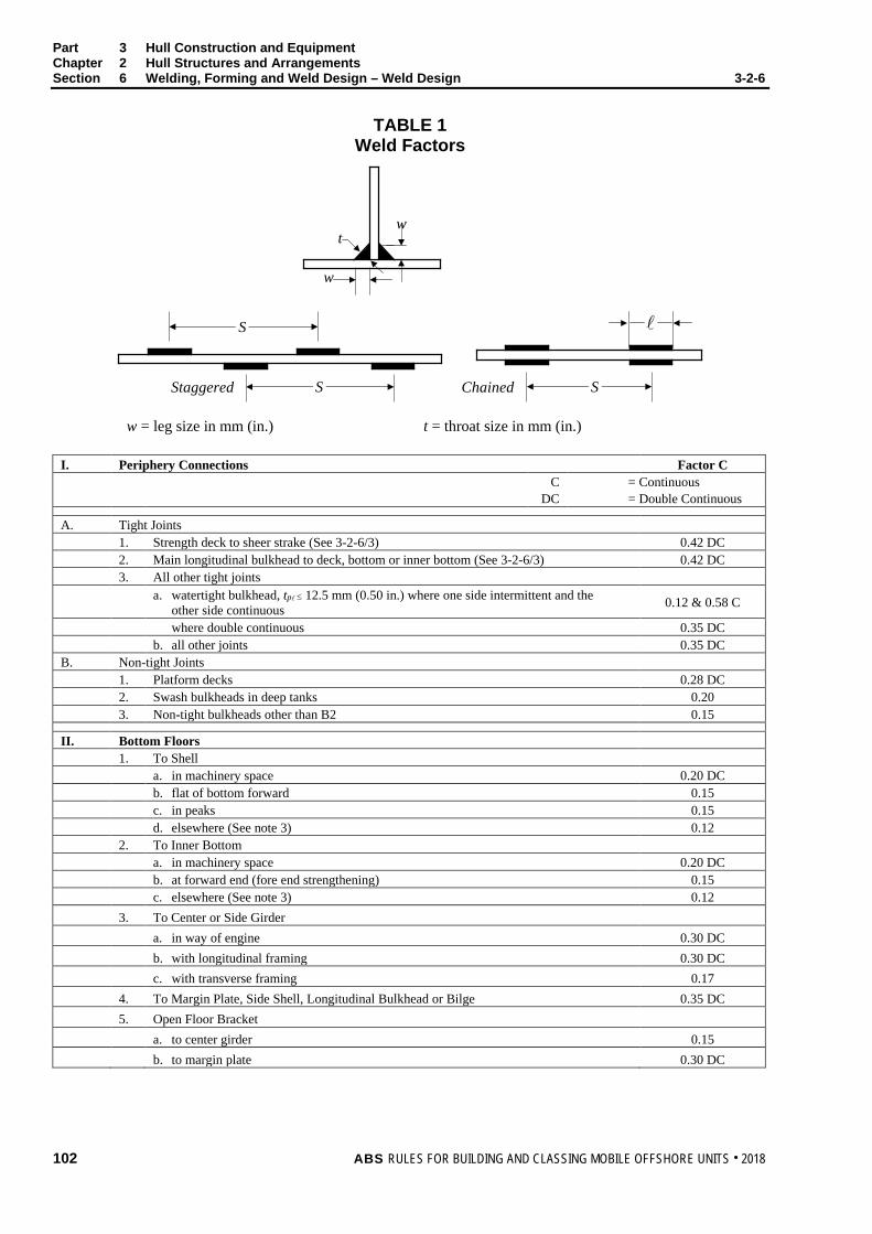
Part 3 Hull Construction and Equipment Chapter 2 Hull Structures and Arrangements Section 6 Welding, Forming and Weld Design – Weld Design 3-2-6
TABLE 1 Weld Factors
Staggered Chained
S
w
wt
SS
w = leg size in mm (in.) t = throat size in mm (in.)
I. Periphery Connections Factor C C = Continuous DC = Double Continuous
A. Tight Joints 1. Strength deck to sheer strake (See 3-2-6/3) 0.42 DC 2. Main longitudinal bulkhead to deck, bottom or inner bottom (See 3-2-6/3) 0.42 DC 3. All other tight joints a. watertight bulkhead, tp ≤ 12.5 mm (0.50 in.) where one side intermittent and the
other side continuous 0.12 & 0.58 C
where double continuous 0.35 DC b. all other joints 0.35 DC B. Non-tight Joints 1. Platform decks 0.28 DC 2. Swash bulkheads in deep tanks 0.20 3. Non-tight bulkheads other than B2 0.15
II. Bottom Floors 1. To Shell a. in machinery space 0.20 DC b. flat of bottom forward 0.15 c. in peaks 0.15 d. elsewhere (See note 3) 0.12 2. To Inner Bottom a. in machinery space 0.20 DC b. at forward end (fore end strengthening) 0.15 c. elsewhere (See note 3) 0.12 3. To Center or Side Girder a. in way of engine 0.30 DC b. with longitudinal framing 0.30 DC c. with transverse framing 0.17 4. To Margin Plate, Side Shell, Longitudinal Bulkhead or Bilge 0.35 DC 5. Open Floor Bracket a. to center girder 0.15 b. to margin plate 0.30 DC
102 ABS RULES FOR BUILDING AND CLASSING MOBILE OFFSHORE UNITS . 2018

Part 3 Hull Construction and Equipment Chapter 2 Hull Structures and Arrangements Section 6 Welding, Forming and Weld Design – Weld Design 3-2-6
TABLE 1 (continued) Weld Factors
III. Bottom Girder 1. Center Girder a. to inner bottom in way of engine 0.30 DC b. to inner bottom clear of engine, non-tight 0.23 c. to shell, non-tight 0.25 DC 2. Side Girder a. to floors in way of transverse bulkheads 0.35 DC b. to shell—flat of bottom forward 0.23 —elsewhere 0.15 c. to inner bottom—in way of engine 0.23 —elsewhere 0.15
IV. Web Frames, Stringers, Deck Girders and Deck Transverses 1. To Plating a. in tanks 0.20 b. elsewhere 0.15 2. To Face Plates a. face area ≤ 64.5 cm2 (10 in2) 0.12 b. face area > 64.5 cm2 (10 in2) 0.15 3. End Attachment a. unbracketed (see note 1) 0.55 DC b. bracketed 0.40 DC
V. Frames, Beams and Stiffeners 1. To Shell a. flat of bottom forward 0.25 DC b. 0.125L forward 0.15 c. in peaks 0.12 2. To plating elsewhere 0.12 3. End attachment a. unbracketed (see note 1) 0.45 DC b. bracketed 0.35 DC
VI. Hatch Covers 1. Oiltight Joints 0.40 DC 2. Watertight Joints Outside 0.40 C Inside 0.15 3. Stiffeners and Webs to Plating and to Face Plate (see note 2) 0.12 4. Stiffeners and Web to Side Plating or other stiffeners —unbracketed (see note 1) 0.45 DC —bracketed 0.35 DC
ABS RULES FOR BUILDING AND CLASSING MOBILE OFFSHORE UNITS . 2018 103

Part 3 Hull Construction and Equipment Chapter 2 Hull Structures and Arrangements Section 6 Welding, Forming and Weld Design – Weld Design 3-2-6
TABLE 1 (continued) Weld Factors
VII. Hatch Coamings and Ventilators 1. To Deck a. at hatch corner 0.45 DC b. elsewhere 0.25 DC 2. Coaming stays a. to deck 0.20 DC b. to coaming 0.15 DC
VIII. Foundations (See 3-2-6/3) 1. Main Engine and Major Auxiliaries 0.40 DC 2. Boilers and other Auxiliaries 0.35 DC
IX. Rudders—Diaphragms 1. To Side Plating a. in way of rudder axis 0.45 DC b. elsewhere 0.20 c. slot welds (size to be determined from the thickness of the side plating) 0.45 DC 2. To Diaphragms a. to vertical diaphragms in way of rudder axis 0.45 DC b. elsewhere 0.20 c. to top and bottom casting in way of rudder axis Full penetration
welds ,
Notes: 1 The weld size is to be determined from the thickness of the member being attached.
2 Unbracketed stiffeners and webs of hatch covers are to be welded continuously to the plating and to the face plate for a length at ends equal to the end depth of the member.
3 With longitudinal framing, the weld size is to be increased to give an equivalent weld area to that obtained without cut-outs for longitudinals.
104 ABS RULES FOR BUILDING AND CLASSING MOBILE OFFSHORE UNITS . 2018

P A R T Appendix 1: Strengthening of Mobile Offshore Drilling Units for Navigation in Ice
3 C H A P T E R 2 Hull Structures and Arrangements
A P P E N D I X 1 Strengthening of Mobile Offshore Units for Navigation in Ice
1 Application
1.1 Column Stabilized Unit Subsections 3-2-A1/3 through 3-2-A1/15 of this Appendix are intended for column-stabilized units navigating in ice. Column-stabilized units constructed in accordance with this Appendix will be distinguished in the Record by Ice Class followed by ice class A0, B0, C0 or D0 to indicate the degree of strengthening adopted.
1.3 Units of Other Type 1.3.1 Surface-Type Units
Ice strengthening for surface-type units is to be in accordance with any ice class in Part 6, Chapter 1 of the Marine Vessel Rules, including 6-1-5/31 for non-self-propelled units.
1.3.2 Self-Elevating Units Self-elevating units will be treated as non-self-propelled surface-type units.
1.5 Novel Features Ice strengthening notations and requirements for units of novel type or design will be specially considered.
3 Ice Class Selection It is the responsibility of the Owner to select the ice class most suitable for the intended service. Ice conditions for the transit of a unit are given in 3-2-A1/Table 1 and 3-2-A1/Table 2 for guidance in selecting ice class.
TABLE 1 Guidance for Ice Class Selection of Column-Stabilized Units
Ice Class
Self-propelled transit in broken first-year ice under conditions as defined in 3-2-A1/Table 2 Without Icebreaker Assistance With Icebreaker Assistance
A0 B0 C0 D0
Severe Medium
Light Very Light
Very Severe Severe
Medium Light
ABS RULES FOR BUILDING AND CLASSING MOBILE OFFSHORE UNITS . 2018 105

Part 3 Hull Construction and Equipment Chapter 2 Hull Structures and Arrangements Appendix 1 Strengthening of Mobile Offshore Units for Navigation in Ice 3-2-A1
TABLE 2 Definition of Ice Conditions of Broken First-Year Ice
versus Concentration and Thickness
Thickness of Level Ice Floes in m (ft)
Concentration of Broken Ice More than 6/10 6/10 or less and more than 3/10 3/10 or less
1.0 (3.3) and above From 0.6 (2) to 1.0 (3.3) From 0.3 (1) to 0.6 (2) Less than 0.3 (1)
Extreme Very Severe
Severe Medium
Very Severe Severe
Medium Light
Severe Medium
Light Very Light
Notes: 1 These ratios of mean area of ice in a given area are from the “World Meteorological Organization Sea
Ice Nomenclature,” Appendix B.7 and give the ratio of area covered by ice floes to the total area of sea surface within some large geographical locale.
2 The levels of severity of ice conditions are categorized with the assumption that the ice cover in the transit path of the unit is broken either due to environmental processes or by an icebreaking vessel. No icebreaking by the transiting unit is expected.
5 Ice Waterline The design waterline for navigation in ice is defined as the ice waterline. The deepest and lightest ice waterlines are to be clearly indicated on the drawings and defined as upper and lower ice waterlines, respectively.
7 Clearance The air clearance between the underside of the lowest cross-bracing members and the upper ice waterline is to be not less than the following:
1.83 m (6 ft) for ice class A0
1.52 m (5 ft) for ice classes B0, C0 and D0
9 Ice Belt The ice belt is the zone of the shell from A meters (ft) above the upper ice waterline to B meters (feet) below the lower ice waterline, as shown in 3-2-A1/Figure 1, where A and B are as given in 6-1-5/Table 3 of the Marine Vessel Rules.
The ice belt is divided into bow, midbody and aft areas. For units with two or more hulls, the midbody area is subdivided into the outboard and inboard midbody areas. For units of ice class D0, only the bow area is ice-strengthened.
For barge-type, cylindrical or similar-shaped hulls, the bow ice belt area is to extend forward from the section 0.025Lw aft of either the point where the rake intersects the bottom or where the lower ice waterline reaches its greatest breadth, whichever is further aft (see 3-2-A1/Figure 1). The aft ice belt area is to extend 0.025Lw forward of the aftermost point of the lower ice waterline. The midbody area of the ice belt extends between the bow and aft ice belt areas.
106 ABS RULES FOR BUILDING AND CLASSING MOBILE OFFSHORE UNITS . 2018
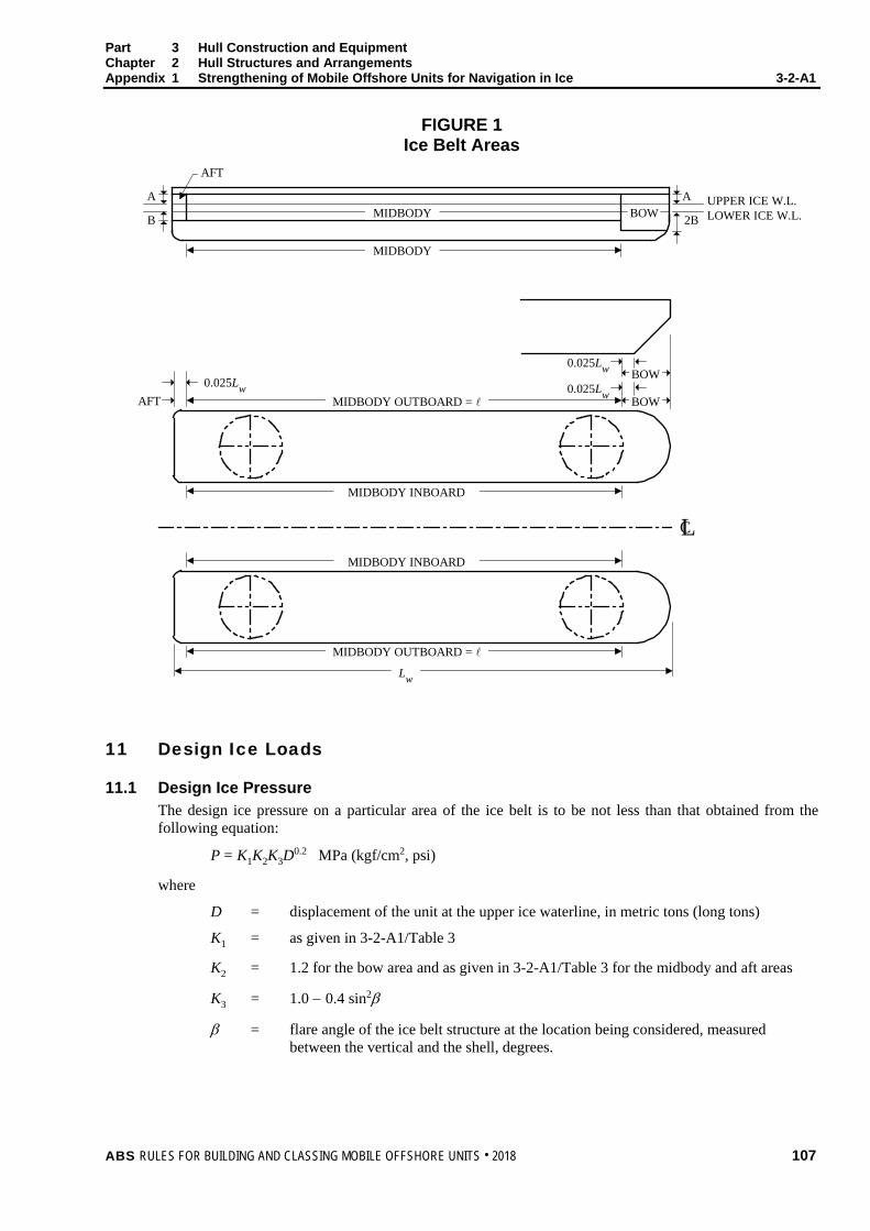
Part 3 Hull Construction and Equipment Chapter 2 Hull Structures and Arrangements Appendix 1 Strengthening of Mobile Offshore Units for Navigation in Ice 3-2-A1
FIGURE 1 Ice Belt Areas
MIDBODY
MIDBODY
AFT
BOWA
B
A
2BUPPER ICE W.L.LOWER ICE W.L.
BOW
BOW0.025Lw
0.025Lw0.025Lw
AFT MIDBODY OUTBOARD =
MIDBODY INBOARD
MIDBODY INBOARD
Lw
LC
MIDBODY OUTBOARD =
11 Design Ice Loads
11.1 Design Ice Pressure The design ice pressure on a particular area of the ice belt is to be not less than that obtained from the following equation:
P = K1K2K3D0.2 MPa (kgf/cm2, psi)
where
D = displacement of the unit at the upper ice waterline, in metric tons (long tons)
K1 = as given in 3-2-A1/Table 3
K2 = 1.2 for the bow area and as given in 3-2-A1/Table 3 for the midbody and aft areas
K3 = 1.0 − 0.4 sin2β
β = flare angle of the ice belt structure at the location being considered, measured between the vertical and the shell, degrees.
ABS RULES FOR BUILDING AND CLASSING MOBILE OFFSHORE UNITS . 2018 107
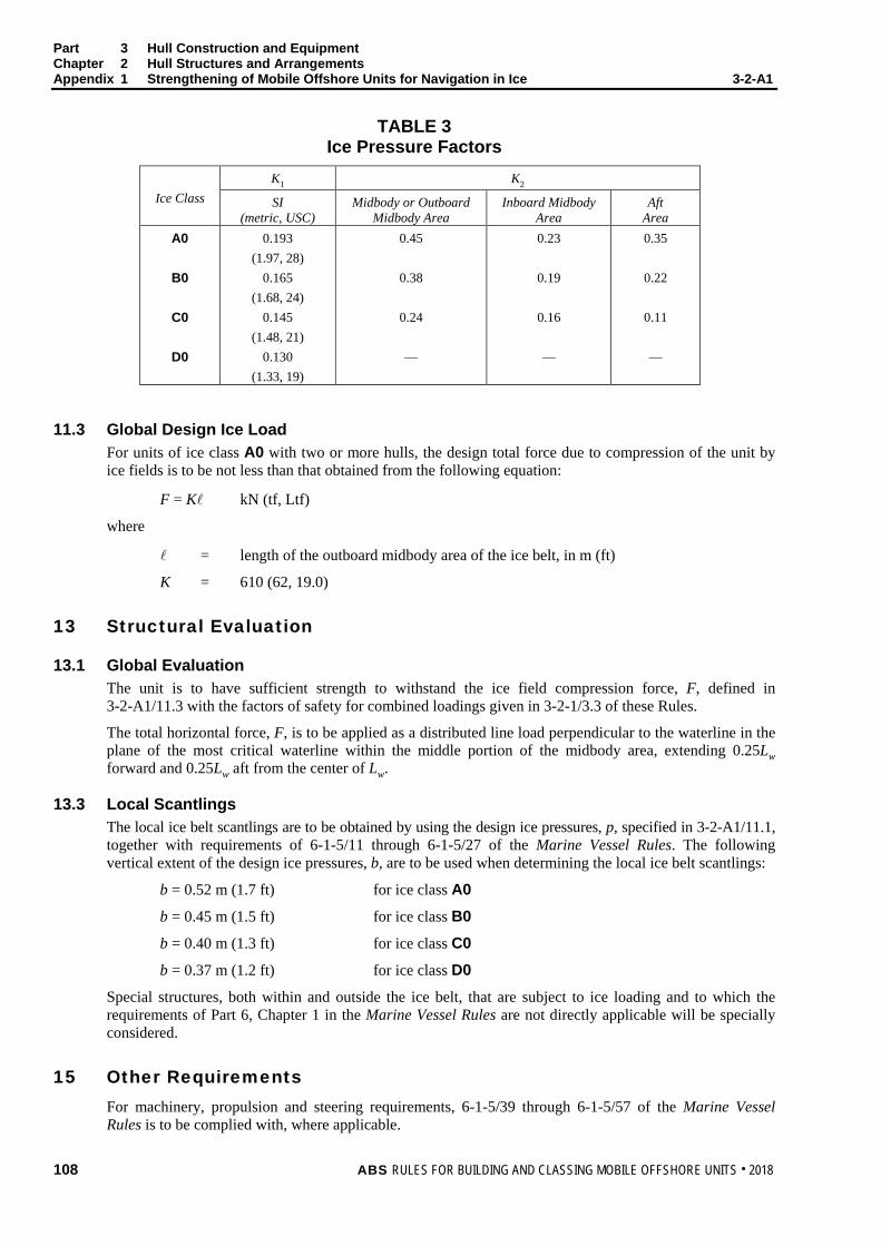
Part 3 Hull Construction and Equipment Chapter 2 Hull Structures and Arrangements Appendix 1 Strengthening of Mobile Offshore Units for Navigation in Ice 3-2-A1
TABLE 3 Ice Pressure Factors
Ice Class K1 K2
SI (metric, USC)
Midbody or Outboard Midbody Area
Inboard Midbody Area
Aft Area
A0
B0
C0
D0
0.193 (1.97, 28)
0.165 (1.68, 24)
0.145 (1.48, 21)
0.130 (1.33, 19)
0.45
0.38
0.24
—
0.23
0.19
0.16
—
0.35
0.22
0.11
—
11.3 Global Design Ice Load For units of ice class A0 with two or more hulls, the design total force due to compression of the unit by ice fields is to be not less than that obtained from the following equation:
F = K kN (tf, Ltf)
where
= length of the outboard midbody area of the ice belt, in m (ft)
K = 610 (62, 19.0)
13 Structural Evaluation
13.1 Global Evaluation The unit is to have sufficient strength to withstand the ice field compression force, F, defined in 3-2-A1/11.3 with the factors of safety for combined loadings given in 3-2-1/3.3 of these Rules.
The total horizontal force, F, is to be applied as a distributed line load perpendicular to the waterline in the plane of the most critical waterline within the middle portion of the midbody area, extending 0.25Lw forward and 0.25Lw aft from the center of Lw.
13.3 Local Scantlings The local ice belt scantlings are to be obtained by using the design ice pressures, p, specified in 3-2-A1/11.1, together with requirements of 6-1-5/11 through 6-1-5/27 of the Marine Vessel Rules. The following vertical extent of the design ice pressures, b, are to be used when determining the local ice belt scantlings:
b = 0.52 m (1.7 ft) for ice class A0
b = 0.45 m (1.5 ft) for ice class B0
b = 0.40 m (1.3 ft) for ice class C0
b = 0.37 m (1.2 ft) for ice class D0
Special structures, both within and outside the ice belt, that are subject to ice loading and to which the requirements of Part 6, Chapter 1 in the Marine Vessel Rules are not directly applicable will be specially considered.
15 Other Requirements For machinery, propulsion and steering requirements, 6-1-5/39 through 6-1-5/57 of the Marine Vessel Rules is to be complied with, where applicable.
108 ABS RULES FOR BUILDING AND CLASSING MOBILE OFFSHORE UNITS . 2018
P A R T Appendix 2: Response Analysis – Selecting Design Waves for Structural Analysis of Column-Stabilized Drilling Units (Twin-Hull Semi-Submersible)
3 C H A P T E R 2 Hull Structures and Arrangements
A P P E N D I X 2 Response Analysis –Selecting Design Waves for Structural Analysis of Column-Stabilized Units (Twin-Hull Semi-Submersible)
1 General
1.1 Introduction Paragraph 3-1-2/1.5 requires that “Consideration is to be given to waves of less than maximum height where, due to their period, the effects on various structural elements may be greater.” For a twin-hull semi-submersible, large waves with long periods are not necessarily critical to the design of the primary structural elements. Only the waves with critical periods and headings (as characterized in 3-2-A2/3) that generate a significant amount of hydrodynamic loads are critical to the design of the primary structural elements.
In addition, the wave load distributions on the submerged hulls of a MODU are required in the global structural response analysis. Both stochastic and regular wave approaches can be utilized in the response analysis. The stochastic approach usually follows a frequency domain procedure via a spectral analysis. In the stochastic approach, the vital distribution information on simultaneous load and stress is lost. In contrast, the regular wave approach retains the flow of load and stress, and therefore is more useful in the structural design evaluation.
For each characterized load case, the response analysis determines the critical wave period that generates the maximum hydrodynamic loads. It further finds an equivalent regular wave height which will generate the same amount of the hydrodynamic loads as calculated in the response analysis. The found wave period and wave height, noted as “Design Wave”, are to be used for the design of the global strength of a twin-hull semi-submersible.
The response analysis can be performed using a stochastic or deterministic approach, depending on the wave information available. This Appendix covers the details of the response analysis using these two approaches.
For MODU classification, ABS requires the Owner to select the wave environment for which the semi-submersible unit will be designed.
3 Global Hydrodynamic Load Characteristics
3.1 General The following hydrodynamic loads generally govern the global strength of a twin-hull semi-submersible:
i) Split Force between Pontoons,
ii) Twisting Pitch Moment about Transverse Horizontal Axis,
iii) Longitudinal Shear Force between Pontoons,
iv) Inertia Forces induced by Longitudinal and Transverse Accelerations of Deck Mass, and
v) Vertical Wave Bending Moment on the Pontoon.
ABS RULES FOR BUILDING AND CLASSING MOBILE OFFSHORE UNITS . 2018 109
Part 3 Hull Construction and Equipment Chapter 2 Hull Structures and Arrangements Appendix 2 Response Analysis –Selecting Design Waves for Structural Analysis of Column-Stabilized
Units (Twin-Hull Semi-Submersible) 3-2-A2
3.3 Split Force between Pontoons A beam wave (90 degrees from the bow) with a length of about two times the outer breadth between the pontoons induces the maximum design split loads, which are critical to the following joints or members:
i) Horizontal Bracings, or
ii) Main Deck Structures if no bracings,
iii) Column Connections to Upper Hull if no bracings.
3.5 Twisting Pitch Moment about Transverse Horizontal Axis A diagonal wave (30 to 60 degrees from the bow) with a length of about the diagonal distance between pontoon ends will induce the maximum design twisting pitch moments, which are critical to the following locations or members:
i) Diagonal Horizontal and Vertical Bracings, or
ii) Main Deck Structure if no bracings.
Since split loads occur simultaneously with twisting moments, using only twisting moments to determine the critical wave direction for the design of these members may not be sufficient. The split loads will not contribute to the twisting moments but it induces additional stresses to those induced by twisting moments. Therefore, more than one wave direction are to be considered in order to obtain the most critical combined stress effect of these two loads for the design.
3.7 Longitudinal Shear Force between Pontoons A diagonal wave (30 to 60 degrees from the bow) with a length of about one and half times the diagonal distance between pontoon ends will induce the maximum design longitudinal shear force between the pontoons. In this load case, the longitudinal forces on the two pontoons and columns are maximized and acting in the opposite directions. Thus, the horizontal bracings will be subject to the maximum bending moment.
Since split loads occur simultaneously with longitudinal shears, using only longitudinal shear to determine the critical wave direction for the design of these members may not be sufficient. For the same reason indicated in 3-2-A2/3.5, more than one wave direction are to be considered in order to obtain the most critical combined stress effect of these two loads for the design.
3.9 Longitudinal and Transverse Accelerations of Deck Mass The critical wave directions are head and beam seas, respectively, for inducing the maximum design longitudinal and transverse accelerations of deck mass. These responses are usually larger at smaller drafts of the vessel, and therefore may govern the limiting transit condition. The accelerations of deck mass will introduce shear forces with corresponding bending moments in the columns connecting the deck and the pontoon if there are no diagonal bracing between columns or columns and the deck. With diagonal bracings, these responses will be developed as axial forces in these bracings and columns, as well as bending moments in the columns. The distribution of these loads is dependent upon the stiffness properties of these structural members.
3.11 Vertical Wave Bending Moment on the Pontoon A head wave (0 degrees from the bow) with a length of about the pontoon length will induce the maximum design vertical bending moments on the pontoon at the following two positions:
i) Wave Crest in the Midship of a Pontoon, and
ii) Wave Trough in the Midship of a Pontoon.
110 ABS RULES FOR BUILDING AND CLASSING MOBILE OFFSHORE UNITS . 2018
Part 3 Hull Construction and Equipment Chapter 2 Hull Structures and Arrangements Appendix 2 Response Analysis –Selecting Design Waves for Structural Analysis of Column-Stabilized
Units (Twin-Hull Semi-Submersible) 3-2-A2 5 Selecting Design Waves by the Stochastic Method
5.1 General The stochastic method is used when the wave environment is described in spectral form (irregular waves). This method will find the regular design wave amplitude and period based on the maximum responses of various load characteristics described above. In this approach, only sea states with the extreme steepness of Owner selection are to be considered for a range of irregular wave periods. The irregular sea steepness is defined in terms of significant wave height (HS) and average zero-up crossing wave period (TZ), as described in 3-2-A2/5.5 below.
5.3 Analytical Approach The method for deriving the critical wave period and the regular design wave amplitude for structural analysis is described in steps as follows:
5.3.1 Determine the critical wave heading and length, LC (or approximate critical wave period, TC) based on the hull geometry of a semi-submersible and its global hydrodynamic load characteristics, as described in 3-2-A2/3.
The relationship between the critical wave length, LC and period, TC is:
LC = π2g * TC
2
where
g = gravitational acceleration = 9.81 m/sec2 or 32.2 ft/sec2
5.3.2 Calculate Response Amplitude Operators (RAOs) (per unit wave amplitude) for each load characterized in 3-2-A2/3 and for a range of regular wave periods between 3 to 25 seconds. Finer wave period intervals (say 0.2 to 0.5 second) around TC are to be considered in order to capture the critical peak RAOC. At the critical peak RAOC, a more precise critical wave period, TC, can be determined. For wave periods away from the critical wave period, TC, larger waver period intervals (say 1.0 to 2.0 second) may be used.
5.3.3 In the process of deriving the RAO for each regular wave period, the real and imaginary parts are to be calculated separately at two time instances. The real part (R) is corresponding to the time instance when the wave crest is at the midship location. With 90 degrees phase lag, the imaginary part (I) is corresponding to the time instance when the wave zero crossing is at the midship location. The total hydrodynamic load amplitude (Load) at any time instance (t) in a regular wave with frequency ω in radians per second can be expressed as the combination of the real and imaginary parts:
Load(t) = R * cos (ω t) + I * sin (ω t), and
RAO(ω) = 22 IR +
5.3.4 Calculate design significant wave heights based on the Owner-selected sea steepness using the formula described in 3-2-A2/5.5 for the average zero up-crossing wave periods (TZ) ranging from 3 to 18 seconds with one (1.0) second interval.
ABS RULES FOR BUILDING AND CLASSING MOBILE OFFSHORE UNITS . 2018 111

Part 3 Hull Construction and Equipment Chapter 2 Hull Structures and Arrangements Appendix 2 Response Analysis –Selecting Design Waves for Structural Analysis of Column-Stabilized
Units (Twin-Hull Semi-Submersible) 3-2-A2
5.3.5 Derive the wave energy spectrum for each irregular sea state found in 3-2-A2/5.3.4 as a function of significant wave height (HS) and average zero-up crossing wave period (TZ). Pierson-Moskovitz (P-M), JONSWAP wave spectrum or any other type of wave energy spectrum appropriate for the geographic area under consideration may be used.
5.3.6 Combine RAO(ω) squared from those derived from 3-2-A2/5.3.3 with wave energy spectral densities, SW(ω), derived from 3-2-A2/5.3.5 to calculate the response spectrum, SR(ω), as a function of frequencies in radians per second for each irregular sea state in 3-2-A2/5.3.4.
5.3.7 Predict the maximum response, Rmax, for each irregular sea state in 3-2-A2/5.3.4 as follows:
Rmax = 0m * [ ])ln(*2 N
where
m0 = area of the response spectrum defined below with n = 0
ln = natural log function
N = number of response cycles = D/Ta
D = storm duration, usually three hours (10800 seconds) is assumed
Ta = average response zero up-crossing periods in seconds
= 2π * 20 / mm
mn = ωωω dSRn )(
0∫∞
SR(ω) = [RAO(ω)]2 * SW(ω)
5.3.8 Select the maximum response, Rmax, among the irregular sea states considered.
5.3.9 Calculate the design regular wave amplitude, AD, as follows:
AD = (Rmax/RAOC) * LF
where
RAOC = peak response amplitude operator at the critical wave period (TC)
LF = Load Factor which is ranging between 1.1 to 1.3, and to be calibrated for various geographic areas
Finally, the selected design regular wave amplitude (AD) and critical wave period (TC) will be used in the structural design evaluation.
5.5 Irregular Sea Steepness The irregular sea steepness, SS, is defined as:
SS = 22
Z
S
TH
gπ
112 ABS RULES FOR BUILDING AND CLASSING MOBILE OFFSHORE UNITS . 2018

Part 3 Hull Construction and Equipment Chapter 2 Hull Structures and Arrangements Appendix 2 Response Analysis –Selecting Design Waves for Structural Analysis of Column-Stabilized
Units (Twin-Hull Semi-Submersible) 3-2-A2
where
g = gravitational acceleration = 9.81 m/sec2 or 32.2 ft/sec2
HS = significant wave height
TZ = zero up-crossing wave period
7 Selecting Design Waves by the Deterministic Method
7.1 General The deterministic method will find the design regular wave height based on the maximum regular wave steepness, which is selected by the Owner, as described in 3-2-A2/7.5.
7.3 Analytical Approach The method for deriving the design regular wave height and critical wave period for each characterized hydrodynamic load is described below:
i) Determine the critical wave heading and length (or approximate critical wave period) based on the hull geometry of a semi-submersible and its global hydrodynamic load characteristics, as described in 3-2-A2/3.
ii) Calculate the Response Amplitude Operators (RAOs), as described in 3-2-A2/5.3.2 and 3-2-A2/5.3.3.
iii) Using the formula described in 3-2-A2/7.5 and the Owner-selected design wave environment (regular wave steepness and the maximum design wave height) to calculate the “limiting regular wave heights” for wave periods ranging from 3 to 15 seconds.
iv) Calculate the response load by multiplying the RAO with the “limiting regular wave height” at each wave period.
v) The corresponding wave height and wave period at the maximum response load calculated in 3-2-A2/7.3iv) for all of the “limiting regular wave heights” is the “Design Wave “, which will be used in the structural design evaluation.
7.5 Regular Wave Steepness The regular wave steepness, S, is defined as:
22
TH
gS π=
where
g = gravitational acceleration = 9.81 m/sec2 or 32.2 ft/sec2
H = regular wave height
T = regular wave period
ABS RULES FOR BUILDING AND CLASSING MOBILE OFFSHORE UNITS . 2018 113

P A R T Appendix 3: Guide for the Allowable Stresses for Localized Highly Stressed Areas
3 C H A P T E R 2 Hull Structures and Arrangements
A P P E N D I X 3 Guide for the Allowable Stresses for Localized Highly Stressed Areas
1 Plated Structures The effects of notches, stress risers and local stress concentrations are to be taken into account for plated structures. When stress concentrations are considered to be of high intensity in certain elements, the acceptable stress levels will be subject to special consideration. For local detail Finite Element Analyses (localized highly stressed area, 50 × 50 mm element size. In no case is the plate element size required to be less than the plate thickness), the following allowable von Mises equivalent stress σeqv may be used in such conditions, provided that the fatigue criteria as specified in 3-2-1/1.17 is satisfied for the local detail:
For static loading, as defined in 3-2-1/1.1(i):
σeqv < 0.97SmFy
For combined loadings, as defined in 3-2-1/1.1(ii):
σeqv < 1.25SmFy
where
σeqv = as defined in 3-2-1/3.11
Fy = as defined in 3-2-1/3.3
Sm = 1.0 for ordinary strength steel
= 0.95 for Grade HT32
= 0.908 for Grade HT36
= 0.875 for Grade HT40
= 0.85 for Grade QT43
= 0.826 for Grade QT47
= 0.825 for Grade QT51
For element sizes other than 50 × 50 mm and for materials other than the above, the allowable von Mises equivalent stress σeqv will be specially considered.
For drillships, reference is made to the Drillship Guide.
114 ABS RULES FOR BUILDING AND CLASSING MOBILE OFFSHORE UNITS . 2018

P A R T C h a p t e r 3 : S u b d i v i s i o n a n d S t a b i l i t y
3 C H A P T E R 3 Subdivision and Stability
CONTENTS SECTION 1 General ................................................................................................ 118
1 Load Line ........................................................................................ 118 3 Inclining Experiment ........................................................................ 118
SECTION 2 Stability and Watertight/Weathertight Integrity ............................... 120
1 Stability............................................................................................ 120 1.1 General........................................................................................ 120 1.3 Stability Afloat .............................................................................. 120
3 Stability Criteria ............................................................................... 121 3.1 General........................................................................................ 121 3.3 Righting Moment ......................................................................... 122 3.5 Extent of Damage for Damage Stability Studies .......................... 126 3.7 Heeling Moment .......................................................................... 127 3.9 Wind Tunnel Tests ...................................................................... 127 3.11 Alternative Stability Criteria ......................................................... 127
5 Watertight/Weathertight Integrity .................................................... 128 5.1 Weathertight Integrity .................................................................. 128 5.3 Watertight Integrity ...................................................................... 129 5.5 Penetrations ................................................................................ 130
7 Onboard Computers for Stability Calculations ................................ 130 FIGURE 1 Intact Stability Curve ............................................................. 122 FIGURE 2 Damage Stability Curve (All Units)........................................ 123 FIGURE 3 Residual Damage Stability Requirements for
Self-Elevating Units ............................................................... 124 FIGURE 4A Residual Damage Stability Requirements for
Column-Stabilized Units – Collision Damage ....................... 125 FIGURE 4B Residual Damage Stability Requirements for
Column-Stabilized Units – Remote Flooding ........................ 125 FIGURE 5 Minimum Weathertight Integrity Requirements for
Column-Stabilized Units ........................................................ 129 APPENDIX 1 Application of Dynamic Response Based Intact Stability Criteria
for Column-Stabilized Mobile Offshore Units .................................. 131 1 Introduction ..................................................................................... 131 3 Definitions and Symbols ................................................................. 131
ABS RULES FOR BUILDING AND CLASSING MOBILE OFFSHORE UNITS . 2018 115
5 General ........................................................................................... 132 5.1 Scope .......................................................................................... 132 5.3 Conditions for Compliance ........................................................... 132 5.5 Dynamic-Response-Based Criteria .............................................. 132
7 Dynamic-Response-Based Criteria ................................................ 133 7.1 Criteria ......................................................................................... 133 7.3 Conditions of Assessment ........................................................... 134
9 Determination of Dynamic Responses ........................................... 134 9.1 Empirical Approximations ............................................................ 134 9.3 Application Limits of Empirical Approximations ........................... 135 9.5 Direct Calculation......................................................................... 135
FIGURE 1 Capsize Criteria Format ........................................................ 133 FIGURE 2 Downflooding Criteria Concepts ........................................... 133
APPENDIX 1a Sample Calculations .......................................................................... 136
1 Capsize Criteria Assessment (Metric Units) ................................... 136 Input Data .................................................................................................. 136 Calculation Iteration ................................................................................... 136 Determine .................................................................................................. 136 Results ....................................................................................................... 136 Interpolation ............................................................................................... 136
3 Downflooding Criteria Assessment (Metric Units) .......................... 137 Input Data .................................................................................................. 137 Calculation Iteration ................................................................................... 137 Determine .................................................................................................. 137 Results ....................................................................................................... 137 Interpolation ............................................................................................... 137
APPENDIX 1b Direct Analysis of Dynamic Motion Responses .............................. 138
1 General ........................................................................................... 138 3 Analysis Methods and Theoretical Background .............................. 138 5 Analysis Conditions ......................................................................... 138
5.1 Environmental Conditions ............................................................ 138 5.3 Heading ....................................................................................... 139 5.5 Hydrodynamic Coefficients .......................................................... 139 5.7 Radii of Gyration .......................................................................... 139 5.9 Mooring Arrangement .................................................................. 139
7 Representation of Environment ...................................................... 139 7.1 Wind Loads .................................................................................. 139 7.3 Wave Loads ................................................................................. 139 7.5 Current Effects ............................................................................. 139
9 Results of Analyses and Format ..................................................... 139 11 Model Tests..................................................................................... 140
116 ABS RULES FOR BUILDING AND CLASSING MOBILE OFFSHORE UNITS . 2018

APPENDIX 1c Environmental Conditions and Representations ............................ 141 1 General ........................................................................................... 141 3 ABS Average Measured Wind Spectrum ........................................ 141 5 Wave Spectra ................................................................................. 142
5.1 Fetch-limited Regions .................................................................. 142 5.3 Open Seas .................................................................................. 142
FIGURE 1 Joint Probabilities of Occurrence of Wind Speed and
Wave Height .......................................................................... 143 APPENDIX 2 Computer Software for Onboard Stability Calculations ................. 144
1 General ........................................................................................... 144 1.1 Scope .......................................................................................... 144 1.3 Design ......................................................................................... 144
3 Calculation Systems ....................................................................... 144 5 Types of Stability Software ............................................................. 144 7 Functional Requirements ................................................................ 145
7.1 Calculation Program .................................................................... 145 7.3 Direct Damage Stability Calculations .......................................... 145 7.5 Warning ....................................................................................... 145 7.7 Data Printout ............................................................................... 145 7.9 Date and Time ............................................................................. 145 7.11 Information of Program ................................................................ 146 7.13 Units ............................................................................................ 146 7.15 Computer Model .......................................................................... 146 7.17 Further Requirements for Type 4 Stability Software .................... 146
9 Acceptable Tolerances ................................................................... 148 9.1 Calculation Program of the Approved Stability Information ......... 148 9.3 Independent Program for Assessment of Stability ....................... 148
11 Approval Procedure ........................................................................ 150 11.1 Conditions of Approval of the Onboard Software for Stability
Calculations ................................................................................. 150 11.3 General Approval (optional) ......................................................... 150 11.5 Specific Approval ......................................................................... 150
13 Operation Manual ........................................................................... 151 15 Testing and Inspection .................................................................... 151 TABLE 1 Acceptable Tolerances ......................................................... 149
ABS RULES FOR BUILDING AND CLASSING MOBILE OFFSHORE UNITS . 2018 117
P A R T S e c t i o n 1 : G e n e r a l
3 C H A P T E R 3 Subdivision and Stability
S E C T I O N 1 General
1 Load Line Every mobile unit is to have marks which designate the maximum permissible draft when the unit is in the afloat condition. Such markings are to be placed at suitable visible locations on the structure, to the satisfaction of ABS. On column-stabilized units, where practical, these marks are to be visible to the person in charge of mooring, lowering or otherwise operating the unit.
The load lines are to be established under the terms of the International Convention on Load Lines. Where minimum freeboards cannot be computed by the normal methods laid down by the Convention, they are to be determined on the basis of compliance with the intact or damage stability requirements for afloat modes of operation. The requirement that the draft of the unit not exceed the assigned load line may be considered temporarily not applicable for bottom-supported units when raising, lowering or resting on the sea bed.
The requirements of the International Convention on Load Lines with respect to weathertightness and watertightness of decks, superstructures, deckhouses, doors, hatchway covers, other openings, ventilators, air pipes, scuppers, inlets and discharges, etc., are to be taken as a basis for all units in the afloat condition. (For column-stabilized units, see also 3-3-2/5.1.)
3 Inclining Experiment (1 July 2018) An inclining test will be required for the first unit of a series, when as near to completion as practical, to determine the lightweight and positions of center of gravity (LCG, VCG and TCG).
The inclining experiment is to be conducted in accordance with Part B Chapter 8 and Annex 1 of the 2008 Intact Stability Code and ASTM Standard F-1321-14, “Standard Guide for Conducting a Stability Test (Lightweight Survey and Inclining Experiment) to Determine the Light Ship Displacement and Centers of Gravity of a Vessel”. Deviation from these guidelines for non-ship shaped units may be considered provided the purpose of the procedure is met.
Prior to the performance of each inclining experiment or lightweight survey, a test procedure is to be submitted for approval. The procedure is to include the following data, as applicable:
• Identification of the unit to be inclined.
• Date and location of the experiment.
• Inclining weight data.
• Pendulum locations and lengths. Alternate measuring devices may be proposed for use.
• Approximate draft and trim of the unit, including location of draft and freeboard readings.
• Condition of each tank.
• Estimated items to be installed, removed, or relocated after the experiment, including the weight and location of each item.
• Schedule of events.
• Details of weight movements
• Person or persons responsible for conducting the experiment.
118 ABS RULES FOR BUILDING AND CLASSING MOBILE OFFSHORE UNITS . 2018

Part 3 Hull Construction and Equipment Chapter 3 Subdivision and Stability Section 1 General 3-3-1
The inclining test or lightweight survey is to be carried out in the presence of an ABS Surveyor.
For successive units of a series, which are considered by ABS to be identical with regard to hull form and arrangement, the lightweight data of the first unit of a series may be accepted by ABS in lieu of an inclining test, provided the difference of lightweight displacement or position of center gravity due to weight changes for minor differences in machinery, outfit, etc., confirmed by the results of a lightweight survey, is less than 1% of the values of the lightweight displacement and principal horizontal dimensions as determined for the first unit of a series.
Special care is to be given to the detailed weight calculation and comparison with the first unit of a series of column-stabilized, semi-submersible types, as these, even though identical by design, are recognized as being unlikely to attain an acceptable similarity of weight or center of gravity to warrant a waiver of the inclining test.
The results of the inclining test, or lightweight survey and inclining experiment adjusted for weight differences, are to be reviewed. The results of the inclining experiment and lightweight survey are to be broken into the independently movable components of the unit (legs, platform, cantilever, skid unit, etc.) and are to indicate clearly the position of these components. The results of the inclining test, or those of the lightweight survey together with the inclining test results, for the first unit are to be indicated in the operating manual.
If an inclining is to be carried out using a cantilever package, then the cantilever weighing procedure and its results are to be submitted in support of the lightweight reports prior to inclining test procedure. The cantilever weighing is to take place as near as possible to the time of the inclining, and any additions or removals of items from the cantilever are to be noted.
Inclining with water is subject to special consideration, and is only to be used where conventional inclining is impossible due to deck space restrictions. The client is to submit a case showing the use of solid weights is not practical.
ABS RULES FOR BUILDING AND CLASSING MOBILE OFFSHORE UNITS . 2018 119
P A R T S e c t i o n 2 : S t a b i l i t y a n d W a t e r t i g h t / W e a t h e r t i g h t I n t e g r i t y
3 C H A P T E R 3 Subdivision and Stability
S E C T I O N 2 Stability and Watertight/Weathertight Integrity
1 Stability
1.1 General All units are to have positive metacentric height in calm water equilibrium position for all afloat conditions, including temporary positions when raising or lowering. For the purpose of determining compliance with the stability requirements contained herein, it is to be assumed that the unit is floating free of mooring restraints. However, detrimental effects of catenary mooring systems or of the thrusters for dynamically positioned units are to be considered.
The metacentric height is to be specified for each mode of operation and guidance is to be included in the Operating Manual on the procedure to determine and satisfy the expected metacentric height. This may be accomplished by including the minimum metacentric height in the calculation of the allowable KG.
The wind speeds referenced in this Section are to be used to calculate heeling moments for intact and damage stability calculations. These wind speeds are not intended to represent actual environmental limits.
1.3 Stability Afloat All units are to meet stability requirements set forth herein for all applicable conditions. However, units designed to ballast or deballast through designated draft ranges or “zones” need only comply with the specific metacentric height when ballasting or deballasting through these designated “zones”.
1.3.1 Intact Stability (All Units) All units are to have sufficient stability (righting stability) to withstand the heeling moment equivalent to the one produced by a wind from any horizontal direction and speed as given below in accordance with the stability criteria given in 3-3-2/3. The wind speed for unrestricted offshore service for normal operating and transit conditions is not to be less than 36 m/sec (70 kn). In addition, the unit is to be capable of withstanding a severe storm condition applying a wind speed of not less than 51.5 m/s (100 kn). In all cases, the wind speed is to be specified. Units not designed to withstand the above heeling moments will be considered for classification for “Restricted Service” in association with a heeling moment equivalent to a minimum wind speed of 25.8 m/s (50 kn).
1.3.2 Damage Stability (All Units) All units are to have sufficient buoyancy and stability to withstand a heeling moment equivalent to a 25.8 m/s (50 kn) wind superimposed from any direction with the following causes of flooding, which are to be individually applied to the unit.
1.3.2(a) Collision Damage. Flooding from the sea of compartments in accordance with the applicable damage penetration requirements of 3-3-2/3.5 for the type of unit under consideration. Such damage need only be applied at drafts associated with normal operating and transit conditions.
1.3.2(b) Remote Flooding. Flooding of any single watertight compartment adjacent to the sea.
1.3.2(c) Self-Elevating Units. Additionally, for self-elevating units, flooding of any single watertight compartment.
120 ABS RULES FOR BUILDING AND CLASSING MOBILE OFFSHORE UNITS . 2018

Part 3 Hull Construction and Equipment Chapter 3 Subdivision and Stability Section 2 Stability and Watertight/Weathertight Integrity 3-3-2
1.3.2(d) Column-Stabilized Units. Additionally, for column-stabilized units, flooding of any single watertight compartment located wholly or partially below the draft associated with any mode of operation afloat (see 3-1-1/17), which is a pump-room or a room containing machinery with a sea water cooling system.
1.3.3 Damage Stability – General Conditions In 3-3-2/1.3.2(d) above, only those spaces required to be functional in the afloat condition need be considered. In condition 3-3-2/1.3.2(b) and 3-3-2/1.3.2(c) above, for compartments designed to carry a specified amount of water ballast and so stipulated in the operating manual, the flooding of that compartment may be limited to the portion of the compartment not occupied by the specified water ballast.
For calculation purposes, flooded compartments are to be assumed to be free flooding to the damage waterline (i.e., as if they are in direct communication with the sea.).
For the purpose of damage stability calculations the following minimum permeability values are recommended:
Storerooms 0.95
Machinery spaces 0.85
Accommodation spaces 0.95
Tanks and voids 0.95
Other values may be used if adequately supported by calculations.
The ability to compensate for damage incurred, by pumping out or by ballasting other compartments, etc., is not to be considered as alleviating the requirements of 3-3-2/3.3.2, 3-3-2/3.3.3 and 3-3-2/3.3.4.
1.3.4 Alternatives for Treatment of Void Spaces 1.3.4(a) For each void not provided with bilge or drainage systems complying with 4-2-4/3.3 but with a sounding arrangement complying with 4-2-3/3.1, the effects of undrainable flooding of the void on the unit’s weight and center of gravity location are to be determined for all afloat conditions, including temporary positions when ballasting or deballasting.
1.3.4(b) For voids not provided with systems complying with 4-2-4/3.3 and 4-2-3/3.1, the unit’s maximum allowable KG at each draft, as determined in accordance with this Subsection, is to be reduced by an amount equal to the largest vertical moment above baseline of a non-complying void divided by the unit’s displacement at that draft.
1.3.4(c) The Operating Manual is to include the information and procedures to account for the flooding of undrainable voids.
3 Stability Criteria
3.1 General Righting moment curves and heeling moment curves with supporting calculations are to be prepared for the full range of anticipated operating drafts, including those in transit conditions. The righting moment curves and wind heeling moment curves are to be related to the most critical axes. Account is to be taken of the free surface of liquids in tanks.
The calculations are to be performed in a manner to obtain the lever of the wind overturning force as indicated in 3-3-2/3.7. For purposes of these calculations, the configuration of the unit is to reflect the actual condition of the unit during afloat operation, such as the location of drilling tower or skid unit, the operation of cranes and the position of legs for self-elevating units.
ABS RULES FOR BUILDING AND CLASSING MOBILE OFFSHORE UNITS . 2018 121

Part 3 Hull Construction and Equipment Chapter 3 Subdivision and Stability Section 2 Stability and Watertight/Weathertight Integrity 3-3-2
3.3 Righting Moment 3.3.1 Intact Stability Criteria
For self-elevating units and surface type units, the righting energy (area under the righting moment curve) at or before the angle of the second intercept of the righting and the heeling moment curves or the downflooding angle, whichever is less, is to reach a value of not less than 40% in excess of the area under the heeling moment curve to the same limiting angle as indicated in 3-3-2/Figure 1.
For column-stabilized units, the righting energy (area under the righting moment curve) at or before the angle of the second intercept of the righting and the heeling moment curves or the downflooding angle, whichever is less, is to reach a value of not less than 30% in excess of the area under the heeling moment curve to the same limiting angle as indicated in 3-3-2/Figure 1.
For all units, the righting moment curve is to be positive over the entire range of angles from upright to the second intercept angle. Documentation demonstrating that the chosen axis of inclination is the most critical for the unit is to be submitted.
FIGURE 1 Intact Stability Curve
Minimum extent of weathertight integrity provided (see 3-3-2/5.1)
Minimum extent of watertight integrity provided (see 3-3-2/5.3)
Mom
ent
Inclination about the critical axis
Heeling moment
Righting moment
Second intercept
First interceptAngle of area ratio (see 3-3-2/3.3)
A
BC
K = 1.3 for column-stabilized unitsK = 1.4 for all other units
Area[A+B] ≥ K Area[B+C]
3.3.2 Damage Stability Criteria The final waterline, after assuming damage under 3-3-2/1.3.2 with an a heeling moment equivalent to a 25.8 m/s (50 kn) wind superimposed from any direction (See 3-3-2/Figure 2), is not to exceed the levels to which watertight integrity has been shown on the diagrams submitted in accordance with 3-1-2/1.
122 ABS RULES FOR BUILDING AND CLASSING MOBILE OFFSHORE UNITS . 2018
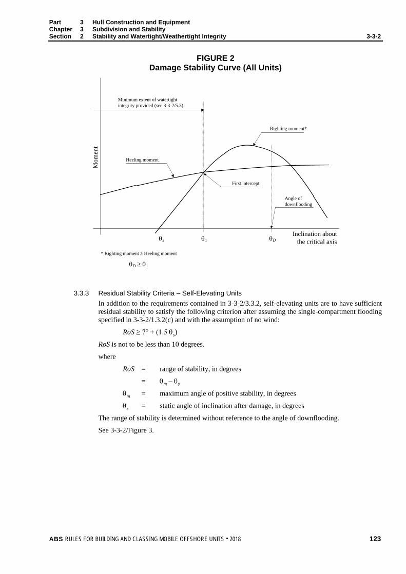
Part 3 Hull Construction and Equipment Chapter 3 Subdivision and Stability Section 2 Stability and Watertight/Weathertight Integrity 3-3-2
FIGURE 2 Damage Stability Curve (All Units)
Minimum extent of watertight integrity provided (see 3-3-2/5.3)
Mom
ent
Inclination about the critical axis
Righting moment*
Angle of downflooding
First intercept
Heeling moment
* Righting moment ≥ Heeling moment
θs θD
θD ≥ θ1
θ1
3.3.3 Residual Stability Criteria – Self-Elevating Units In addition to the requirements contained in 3-3-2/3.3.2, self-elevating units are to have sufficient residual stability to satisfy the following criterion after assuming the single-compartment flooding specified in 3-3-2/1.3.2(c) and with the assumption of no wind:
RoS ≥ 7° + (1.5 θs)
RoS is not to be less than 10 degrees.
where
RoS = range of stability, in degrees
= θm – θs
θm = maximum angle of positive stability, in degrees
θs = static angle of inclination after damage, in degrees
The range of stability is determined without reference to the angle of downflooding.
See 3-3-2/Figure 3.
ABS RULES FOR BUILDING AND CLASSING MOBILE OFFSHORE UNITS . 2018 123
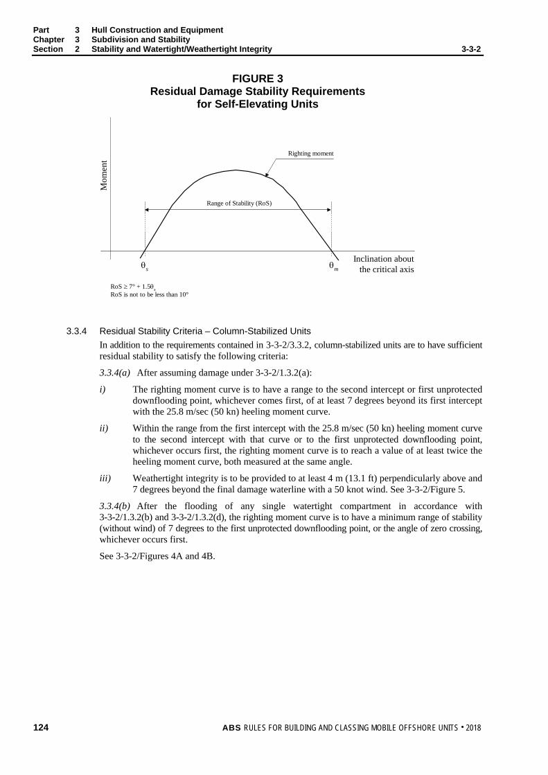
Part 3 Hull Construction and Equipment Chapter 3 Subdivision and Stability Section 2 Stability and Watertight/Weathertight Integrity 3-3-2
FIGURE 3 Residual Damage Stability Requirements
for Self-Elevating Units M
omen
t
Inclination aboutthe critical axis
Righting moment
θs θm
Range of Stability (RoS)
RoS ≥ 7° + 1.5θsRoS is not to be less than 10°
3.3.4 Residual Stability Criteria – Column-Stabilized Units In addition to the requirements contained in 3-3-2/3.3.2, column-stabilized units are to have sufficient residual stability to satisfy the following criteria:
3.3.4(a) After assuming damage under 3-3-2/1.3.2(a):
i) The righting moment curve is to have a range to the second intercept or first unprotected downflooding point, whichever comes first, of at least 7 degrees beyond its first intercept with the 25.8 m/sec (50 kn) heeling moment curve.
ii) Within the range from the first intercept with the 25.8 m/sec (50 kn) heeling moment curve to the second intercept with that curve or to the first unprotected downflooding point, whichever occurs first, the righting moment curve is to reach a value of at least twice the heeling moment curve, both measured at the same angle.
iii) Weathertight integrity is to be provided to at least 4 m (13.1 ft) perpendicularly above and 7 degrees beyond the final damage waterline with a 50 knot wind. See 3-3-2/Figure 5.
3.3.4(b) After the flooding of any single watertight compartment in accordance with 3-3-2/1.3.2(b) and 3-3-2/1.3.2(d), the righting moment curve is to have a minimum range of stability (without wind) of 7 degrees to the first unprotected downflooding point, or the angle of zero crossing, whichever occurs first.
See 3-3-2/Figures 4A and 4B.
124 ABS RULES FOR BUILDING AND CLASSING MOBILE OFFSHORE UNITS . 2018
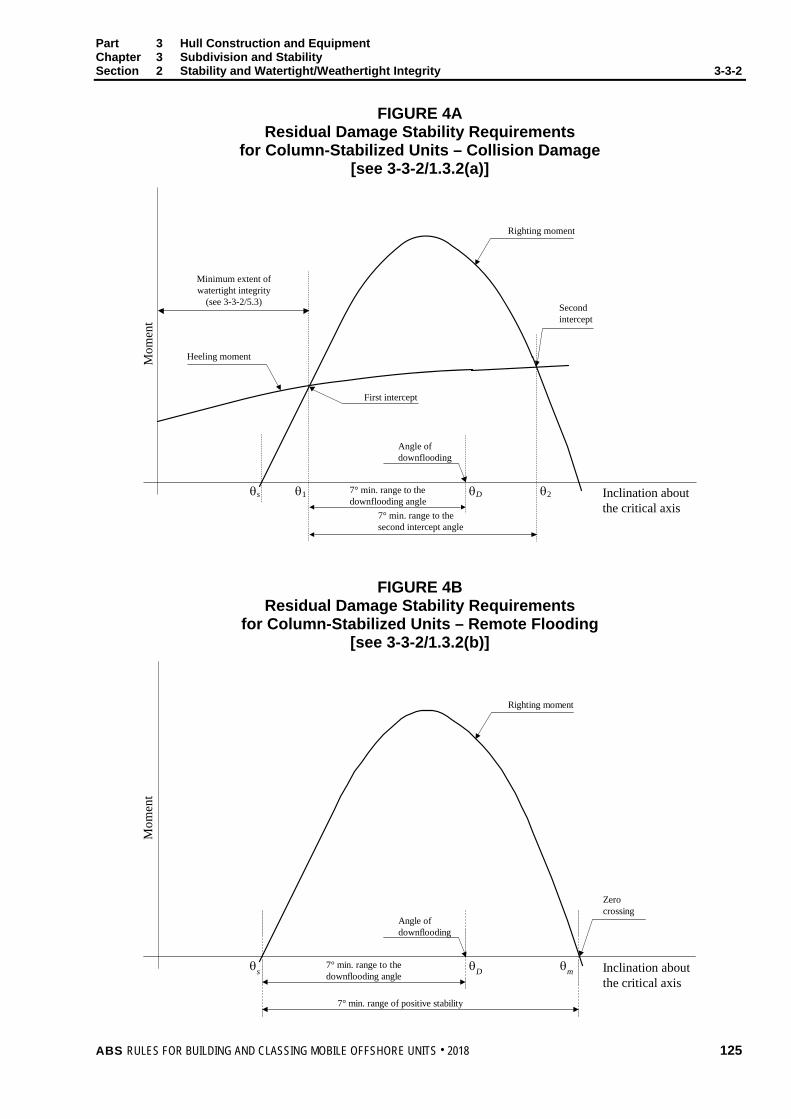
Part 3 Hull Construction and Equipment Chapter 3 Subdivision and Stability Section 2 Stability and Watertight/Weathertight Integrity 3-3-2
FIGURE 4A Residual Damage Stability Requirements
for Column-Stabilized Units – Collision Damage [see 3-3-2/1.3.2(a)]
Minimum extent of watertight integrity
(see 3-3-2/5.3)
Mom
ent
Inclination about the critical axis
Righting moment
Angle of downflooding
First intercept
Heeling moment
θs θDθ1
Second intercept
7° min. range to the second intercept angle
7° min. range to the downflooding angle
θ2
FIGURE 4B Residual Damage Stability Requirements
for Column-Stabilized Units – Remote Flooding [see 3-3-2/1.3.2(b)]
Mom
ent
Inclination aboutthe critical axis
Righting moment
Angle ofdownflooding
θs θD
Zerocrossing
7° min. range of positive stability
7° min. range to thedownflooding angle
θm
ABS RULES FOR BUILDING AND CLASSING MOBILE OFFSHORE UNITS . 2018 125

Part 3 Hull Construction and Equipment Chapter 3 Subdivision and Stability Section 2 Stability and Watertight/Weathertight Integrity 3-3-2
3.5 Extent of Damage for Damage Stability Studies In assessing the damage stability of mobile offshore units, as required by 3-3-2/1.3.2, the following extent of damage is to be assumed.
If damage of a lesser extent results in a more severe condition, such lesser extent is to be assumed.
All piping, ventilating systems, trunks, etc., within the assumed damage area are to be considered damaged. Positive means of closure are to be provided to preclude progressive flooding of other intact spaces. See 3-2-2/5 for specific requirements for watertight bulkheads and flats.
3.5.1 Self-Elevating Units For self-elevating units, the following extent of damage is to be assumed to occur between effective watertight bulkheads.
i) Horizontal depth of penetration 1.5 m (5 ft)
ii) Vertical extent of damage from the bottom shell upwards without limit. Where a bottom mat is fitted, assumed damage penetration simultaneous to both the mat and the upper hull need only be considered when the lightest draft allows any part of the mat to fall within 1.5 m (5 ft) vertically of the waterline, and the difference in horizontal dimension of the upper hull and mat is less than 1.5 m (5 ft) in the area under consideration.
For drilling units, the recessed ends and sides of the drilling slot need not be subject to consideration of horizontal penetration, provided precautions are taken to prevent boats from entering the drilling slot when the unit is afloat.
The distance between effective watertight bulkheads or their nearest stepped portions which are positioned within the assumed extent of horizontal penetration should not be less than 3.0 m (10 ft). Where there is a lesser distance, one or more of the adjacent bulkheads are to be disregarded.
3.5.2 Column-Stabilized Units For column-stabilized units, the following assumptions apply at the designated operating drafts.
i) Only those columns on the periphery of the unit are to be assumed damaged with the damage confined to the exposed outer portions of the columns.
ii) Damage is assumed to occur for a vertical distance of 3 m (10 ft) at any level between 5.0 m (16.4 ft) above and 3.0 m (10 ft) below the draft under consideration. Where a watertight flat is located within this zone, the damage is to be assumed to have occurred in both compartments above and below the watertight flat in question.
iii) One of the following criteria for the extent of horizontal damage is to be applied along the periphery of the columns in way of the waterline. The same criterion for the extent of horizontal damage is to be applied to all exposed columns. The selected extent is to be included in the Operating Manual.
a) No vertical bulkhead is to be assumed damaged, except where bulkheads are spaced closer than a distance one-eighth of the column perimeter at the draft under consideration, measured at the periphery, in which case, one or more of the bulkheads is to be considered as damaged.
b) Damage anywhere along the exposed part of the waterline with an extent of 3.0 m (10 ft). Where watertight bulkheads are located within this zone, the bulkheads within the extent of damage are to be assumed damaged.
iv) Damage to the columns is to assume a horizontal depth of penetration of 1.5 m (5 ft).
126 ABS RULES FOR BUILDING AND CLASSING MOBILE OFFSHORE UNITS . 2018
Part 3 Hull Construction and Equipment Chapter 3 Subdivision and Stability Section 2 Stability and Watertight/Weathertight Integrity 3-3-2
v) Lower hulls or footings are to be treated as damaged when operating at a light or transit condition in the same manner as indicated in i), ii) and iv) and having regard to their shape, either in the same manner as indicated in iii), or between effective watertight bulkheads.
The distance between effective watertight bulkheads or their nearest stepped portions which are positioned within the assumed extent of horizontal penetration should be not less than 3.0 m. Where there is a lesser distance, one or more of the adjacent bulkheads are to be disregarded.
If damage of a lesser extent results in a more severe final equilibrium condition, such less extent is to be assumed.
3.5.3 Surface-Type Units For surface-type units, the following extent of damage is to be assumed to occur between effective watertight bulkheads.
i) Horizontal depth of penetration of 1.5 m (5 ft)
ii) Vertical extent of damage from the bottom shell upwards without limit
The distance between effective watertight bulkheads or their nearest stepped portions which are positioned within the assumed extent of horizontal penetration should be not less than 3.0 m (10 ft). Where there is a lesser distance, one or more of the adjacent bulkheads are to be disregarded.
3.7 Heeling Moment Heeling moments represent an idealization of the total environmental loads on the unit. For purposes of calculations they are taken as the moments which result from wind forces on the unit at the speeds specified in 3-3-2/1.3, calculated in accordance with Section 3-1-2 or developed from wind tunnel tests.
The heeling moment is to be calculated at several angles of inclination for each mode of operation. The calculations are to be performed in a manner to reflect the range of stability about the critical axis. The lever for the heeling force is to be taken vertically from the center of lateral resistance or, if available, the center of hydrodynamic pressure of the underwater body to the center of pressure of the areas subject to wind loading.
For dynamically-positioned units, the heeling moment is to be taken as the sum of a wind force up to the aggregate thrust of the thruster system in each direction analyzed with a lever arm equal to the distance from the center of wind pressure to the center of the thruster propeller disc and the remaining wind force (if any) with a lever arm equal to the distance from the center of wind pressure to the center of lateral resistance. For this purpose, the aggregate thrust need not be taken greater than the wind force.
For self-elevating units, the heeling moment of the unit is to be investigated for any anticipated leg position relative to the hull.
In calculating heeling moments for surface type units having no independent platforms, the curve may be assumed to vary as the cosine function of the inclination angle.
3.9 Wind Tunnel Tests Heeling moments derived from wind tunnel tests on a representative model of the unit may be considered as alternatives to the method given herein. Such heeling moment determination is to include both lift and drag effects at appropriate inclination angles. Testing should include the full range of possible drafts, wind direction and angles of heel, to the maximum extent possible. The testing program is to be submitted for review.
3.11 Alternative Stability Criteria 3.11.1 General
Alternative stability criteria may be considered acceptable by ABS, provided the criteria affords adequate righting moment to resist the overturning effects of operating and environmental forces and sufficient margins to preclude downflooding and capsizing in intact and damaged conditions.
ABS RULES FOR BUILDING AND CLASSING MOBILE OFFSHORE UNITS . 2018 127
Part 3 Hull Construction and Equipment Chapter 3 Subdivision and Stability Section 2 Stability and Watertight/Weathertight Integrity 3-3-2
3.11.2 Guidelines The following will be considered in determining the adequacy of alternative criteria submitted for review:
i) Environmental conditions representing realistic winds (including gusts) and waves appropriate for various modes of operation
ii) Dynamic response of a unit. Where appropriate, the analysis should include the results of wind tunnel tests, wave tank model tests and nonlinear simulation. Any wind and wave spectra used should cover sufficient frequency ranges to ensure that critical motion responses are obtained.
iii) Potential for downflooding, taking into account dynamic responses and wave profile
iv) Susceptibility to capsizing, considering the unit’s restoration energy and maximum dynamic response
v) A safety margin consistent with the methodology to account for uncertainties
vi) Damage assumptions at least equivalent to present Rule requirements
3.11.3 Alternative Intact Stability Criteria Specific reference may be made to Appendix 3-3-A1 “Application of Dynamic Response Based Intact Stability Criteria for Column-stabilized Mobile Offshore Units”. This Appendix and associated Appendices 3-3-A1a through 3-3-A1c provide a means of determining adequate intact stability in severe storm conditions.
5 Watertight/Weathertight Integrity
5.1 Weathertight Integrity Closing appliances are to be as prescribed by applicable load line requirements. Special consideration will be given to openings in the upper deck of column-stabilized units. In all cases, external openings whose lower edges are below the levels to which weathertight integrity is to be ensured, as shown by the diagrams to be submitted in accordance with 3-1-2/1 are to have weathertight closing appliances. The referenced diagrams may define different extents of weathertight integrity for each mode of operation afloat (See 3-1-1/17). Openings fitted with appliances to ensure weathertight integrity are to effectively resist the ingress of water due to intermittent immersion of the closure in complying with the intact stability criteria (See 3-3-2/3.3.1).
A plan, identifying the disposition (open or closed) of all non-automatic closing devices and locations of all watertight and weathertight closures, for each mode of operation afloat is to be submitted for review prior to the unit’s delivery. Upon satisfactory review, the plan is to be incorporated into the Operating Manual.
128 ABS RULES FOR BUILDING AND CLASSING MOBILE OFFSHORE UNITS . 2018

Part 3 Hull Construction and Equipment Chapter 3 Subdivision and Stability Section 2 Stability and Watertight/Weathertight Integrity 3-3-2
FIGURE 5 Minimum Weathertight Integrity Requirements
for Column-Stabilized Units
Zone A
Zone B
Final Damage WaterlineIncluding 50 kt Wind
Initial Waterline
4 m (13.1 ft)
Zone A - Minimum 4 m (13.1 ft) zone of weathertight integrityZone B - Minimum 7° range of weathertight integrity
7°
5.3 Watertight Integrity All internal and external openings whose lower edges are below the levels to which watertight integrity is to be ensured, as shown by the diagrams submitted in accordance with 3-1-2/1, are to be fitted with appliances to ensure watertight integrity.
The closing appliances are to have strength, tightness and means for securing which are sufficient to maintain watertightness under the water pressure of the watertight boundary under consideration.
5.3.1 Internal Openings Used for Access While Afloat Internal openings fitted with appliances to ensure watertight integrity, which are used during operation of the unit while afloat, are to comply with the following.
5.3.1(a) Doors and hatch covers are to be capable of being remotely controlled from a normally manned central position, such as the bridge or ballast control room, as well as being operable locally from both sides of the bulkhead. See Note 6 of 4-3-3/Table 1. Open/shut indicators are to be provided at the control station. In addition, remotely operated doors provided to ensure the watertight integrity of internal openings which are used while afloat are to be sliding watertight doors with audible alarm. The power, control and indicators are to be operable in the event of main power failure. Particular attention is to be paid to minimizing the effect of control system failure. Each power-operated sliding watertight door is to be provided with an individual hand-operated mechanism. It shall be possible to open and close the door by hand at the door itself from both sides.
5.3.1(b) Except for doors placed at or below the deepest load line draft in column-stabilized and surface units, the provisions regarding remote control under 3-3-2/5.3.1(a) are not required for doors which are normally closed while the unit is afloat, provided the doors are of the quick-acting type and an indicating system (e.g., light signals) is arranged showing personnel, both locally and at a normally manned central position, whether the doors in question are open or secured closed. Hatch covers required for watertight integrity are to have similar indicators. In addition, a sign is to be posted near the opening to the effect that the closing appliance is to be secured closed while afloat and opened only during actual use.
ABS RULES FOR BUILDING AND CLASSING MOBILE OFFSHORE UNITS . 2018 129

Part 3 Hull Construction and Equipment Chapter 3 Subdivision and Stability Section 2 Stability and Watertight/Weathertight Integrity 3-3-2
5.3.2 Internal Openings Permanently Closed While Afloat Internal openings fitted with appliances to ensure watertight integrity, which are kept permanently closed while the unit is afloat, are to comply with the following.
5.3.2(a) A sign to the effect that the opening is to be secured closed while afloat during normal operation is to be posted near the opening.
5.3.2(b) Opening and closing of such closure devices is to be noted in the unit’s logbook.
5.3.2(c) Manholes fitted with bolted covers need not be dealt with as under 3-3-2/5.3.2(a).
5.3.3 External Openings Used While Afloat External openings which are used during operation of the unit while afloat are to comply with the following requirements.
5.3.3(a) The lower edges of all openings, including air pipes, ventilators, ventilation intakes and outlets (regardless of closing appliances), non-watertight hatches and weathertight doors, are to be above the levels to which watertight integrity is to be ensured.
5.3.3(b) Normally closed openings fitted with appliances to provide watertight integrity, such as non-opening side scuttles, manholes and small hatches, may be located below the level of watertight integrity, except as noted in 3-2-4/5.13 for portlights or windows including those of the non-opening type. Small hatches are those which are normally used for access by personnel. Such small hatches, which may be submerged in case of damage, are to be closed by approved quick-acting watertight covers of steel or equivalent material. An indicating system, e.g., light signals, is to be arranged showing personnel, both locally and at a central position, whether the hatch covers in question are open or secured closed. In addition, a sign is to be posted near the opening to the effect that the closing appliance is to be secured closed while the unit is afloat and opened only during actual use. Such openings are not to be regarded as emergency exits.
5.3.3(c) Where flooding of chain lockers or other buoyant volumes may occur, the openings to these spaces should be considered as downflooding points.
5.3.4 External Openings Permanently Closed While Afloat External openings fitted with appliances to ensure watertight integrity, which are kept permanently closed while the unit is afloat, are to comply with the requirements of 3-3-2/5.3.2.
5.5 Penetrations Where watertight bulkheads and flats are necessary for damage stability, they are to be made watertight throughout. Where individual lines, ducts or piping systems serve more than one compartment or are within the extent of damage, satisfactory arrangements are to be provided to preclude the possibility of progressive flooding through the system. For watertight closure requirements, see 4-2-2/27.
7 Onboard Computers for Stability Calculations
The use of onboard computers for stability calculations is not a requirement of class. However, if stability software is installed onboard units contracted on or after 1 July 2005, it should cover all stability requirements applicable to the unit and is to be approved by ABS for compliance with the requirements of Appendix 3-3-A2, “Onboard Computers for Stability Calculations”.
130 ABS RULES FOR BUILDING AND CLASSING MOBILE OFFSHORE UNITS . 2018
P A R T Appendix 1: Application of Dynamic Response Based Intact Stability Criteria for Column-Stabilized Mobile Offshore Drilling Units
3 C H A P T E R 3 Subdivision and Stability
A P P E N D I X 1 Application of Dynamic Response Based Intact Stability Criteria for Column-Stabilized Mobile Offshore Units
1 Introduction This Appendix has been developed based on the research findings reported on by the ABC Joint Industry Project on Mobile Offshore Drilling Unit Stability, Phase II, August 1989 and was originally published in 1990 as a separate publication titled, ABS Guide for the Application of Dynamic-Response-Based Intact Stability Criteria for Column-Stabilized Mobile Offshore Drilling Units.
An alternative intact stability criteria is given herein for column-stabilized MOUs, which provides an equivalent level of safety in a severe storm mode of operation for unrestricted service classification. A distinct advantage of these criteria is that a more rational safety margin against capsizing and downflooding is achieved since dynamic motion response characteristics are now incorporated into the stability criteria.
The dynamic-response-based stability criteria include empirical formulae to approximate motions which are then used in the criteria format. These empirical approximations are based on the motion responses predicted for a matrix of generic semi-submersible units and loading conditions which cover almost every existing semi-submersible design. In order that the criteria undergo continual scrutiny, direct analysis of dynamic motion responses is encouraged. For this purpose, Appendices are also provided describing the general concepts and procedures for performing such analyses that are acceptable to ABS. These procedures are in place to encourage advances in technology and improved analytical techniques to more accurately predict the motion responses and resulting stability margins of column-stabilized MOUs.
3 Definitions and Symbols A = restoring coefficient
Aw = upright effective wind area; product of projected area, and shape and height coefficients, m2 (ft2)
AWP = area of waterplane attributable to columns and bracing, m2 (ft2)
BM = vertical distance from center of buoyancy to metacenter, m (ft)
C = correlation coefficient: θDYN vs. parameters, m−1 (ft−1)
dM = initial severe storm molded draft, m (ft)
DFD0 = initial downflooding distance to dM, m (ft)
FBD0 = initial freeboard from top of exposed weather deck to dM, m (ft)
GM = metacentric height, m (ft)
IWP = waterplane moment of inertia, in4 (ft4)
k = correlation coefficient: 1st and 2nd order responses
ABS RULES FOR BUILDING AND CLASSING MOBILE OFFSHORE UNITS . 2018 131

Part 3 Hull Construction and Equipment Chapter 3 Subdivision and Stability Appendix 1 Application of Dynamic Response Based Intact Stability Criteria for Column-Stabilized
Mobile Offshore Units 3-3-A1
KB = vertical height of center of buoyancy above baseline, m (ft)
LCCC = longitudinal span between centers of corner columns, m (ft)
LPTN = overall length of pontoon, m (ft)
N = wind speed, (knots)
Or = orientation angle describing axis of heel, (deg)
QSD1 = reduction in DFD0 due to static wind, m (ft)
RDFD = reduction in downflooding distance due to RMT, m (ft)
RER = reserve energy area ratio
RMW = relative motion due to waves, m (ft)
SPTN = transverse separation of pontoon centerlines, m (ft)
θ1N = 1st intercept angle of wind righting moment curves, (deg)
θ2N = 2nd intercept angle of wind righting moment curves, (deg)
θDYN = dynamic heel angle due to wind and waves, (deg)
θmax = maximum dynamic heel angle, (deg)
VCOL = volume of column and vertical bracing, m3 (ft3)
VCG = vertical center of gravity measured above baseline, m (ft)
VCP = vertical center of wind pressure above dM, m (ft)
VPTN = volume of pontoons and horizontal bracing, m3 (ft3)
VSUR = volume of displacement at dM, m3 (ft3)
VTOT = total enclosed volume to DFD0, m3 (ft3)
X = correlation coefficient: RMW vs. parameters
5 General
5.1 Scope The stability criteria contained herein are applicable to column-stabilized units of twin-pontoon configuration. The criteria provide an acceptable means of determining the maximum allowable intact VCG as an alternative to the unrestricted service classification requirements contained in 3-3-2/3.3.
5.3 Conditions for Compliance Units intended to be classed under this alternative intact stability criteria are to comply with both the Capsize Criteria and the Downflooding Criteria, given hereafter in 3-3-A1/7.1.1 and 3-3-A1/7.1.2, respectively. Compliance with these criteria is not to not be taken to obviate the need for compliance with the positive stability requirements of 3-3-2/1.1, intact stability requirements for normal operating and transit conditions of 3-3-2/1.3.1 and damage stability requirements of 3-3-2/1.3.2. Wave clearance requirements of 3-2-4/9.1 remain applicable.
5.5 Dynamic-Response-Based Criteria The stability criteria provide a means to determine a minimum GM value based on hydrostatic properties and dynamic responses to realistic severe storm environments. The criteria separately evaluate capsize and downflooding, considering extreme environmental conditions and corresponding motion response parameters. Empirical approximations for motion responses are provided, as well as a set of specifications addressing acceptable approaches for performing dynamic motion analysis. Application of the empirical approximations used in the format include some limitations.
132 ABS RULES FOR BUILDING AND CLASSING MOBILE OFFSHORE UNITS . 2018
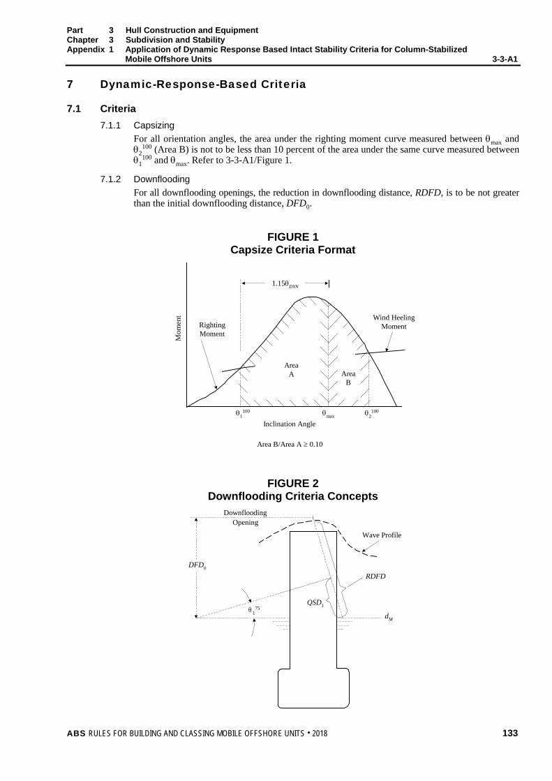
Part 3 Hull Construction and Equipment Chapter 3 Subdivision and Stability Appendix 1 Application of Dynamic Response Based Intact Stability Criteria for Column-Stabilized
Mobile Offshore Units 3-3-A1 7 Dynamic-Response-Based Criteria
7.1 Criteria 7.1.1 Capsizing
For all orientation angles, the area under the righting moment curve measured between θmax and θ2
100 (Area B) is not to be less than 10 percent of the area under the same curve measured between θ1
100 and θmax. Refer to 3-3-A1/Figure 1.
7.1.2 Downflooding For all downflooding openings, the reduction in downflooding distance, RDFD, is to be not greater than the initial downflooding distance, DFD0.
FIGURE 1 Capsize Criteria Format
RightingMoment
Wind HeelingMoment
Inclination Angle
Area B/Area A ≥ 0.10
Mom
ent
θ1100 θmax θ2
100
1.15θDYN
AreaA Area
B
FIGURE 2 Downflooding Criteria Concepts
θ 175
DFD0
QSD1
RDFD
dM
Wave Profile
DownfloodingOpening
ABS RULES FOR BUILDING AND CLASSING MOBILE OFFSHORE UNITS . 2018 133

Part 3 Hull Construction and Equipment Chapter 3 Subdivision and Stability Appendix 1 Application of Dynamic Response Based Intact Stability Criteria for Column-Stabilized
Mobile Offshore Units 3-3-A1 7.3 Conditions of Assessment
7.3.1 Parameters θmax and RDFD may be determined by the empirical approximations given in 3-3-A1/9.1 or by direct calculation, as referred to in 3-3-A1/9.5. Appendix 3-3-A1a provides sample calculations using the empirical approximations for an existing semi-submersible design. Several cases are performed for different GM values to determine by extrapolation the minimum GM at the critical orientation angle.
7.3.2 Detrimental effects of catenary mooring systems or of thrusters for dynamically positioned units are to be considered. Any beneficial effects are not to be included.
7.3.3 Wind force and moment are to be determined by calculation per 3-1-3/1.3 or by model wind tunnel tests. A mean wind speed of 100 knots and 75 knots is to be assumed under 3-3-A1/7.1.1 and 3-3-A1/7.1.2, respectively.
7.3.4 Downflooding openings are those openings which may be required to remain open or which are not fitted with, as a minimum, an automatic weathertight closure.
9 Determination of Dynamic Responses
9.1 Empirical Approximations The empirical equations given in 3-3-A1/9.1.1 and 3-3-A1/9.1.2 can be used to approximate the responses that comprise θmax and RDFD. The equations are applicable to units that possess operating parameters, geometric proportions and total size within the range of parameters specified in 3-3-A1/9.3.
9.1.1 Maximum Dynamic Response Angle, θmax
The parameter θmax can be approximated using the following equation:
θmax = θ1100 + 1.15 θDYN
θDYN = )]28.046.1/(0.1[
)80.173.10(BMGM
C++
+ (SI and MKS units)
= )]28.046.1/(0.1[
)80.173.10(BMGM
C++
+ (US units)
where
C = )( 3/5
3/13/5
TOTWP
PTNCOLwWLPTN
VIVVAVCPL
⋅
⋅⋅⋅⋅
9.1.2 Reduction in Downflooding Distance, RDFD RDFD is determined from the following equation:
RDFD = 1.10 (k QSD1 + RMW)
where
k = 0.55 + 0.08(A − 4.0) + 0.056(1.52 − GM) (SI and MKS units)
= 0.55 + 0.08(A − 4.0) + 0.017(5.0 − GM) (US units)
A = (FBD0/Dm)(SPTN LCCC)/AWP A to be taken not less than 4.0
134 ABS RULES FOR BUILDING AND CLASSING MOBILE OFFSHORE UNITS . 2018

Part 3 Hull Construction and Equipment Chapter 3 Subdivision and Stability Appendix 1 Application of Dynamic Response Based Intact Stability Criteria for Column-Stabilized
Mobile Offshore Units 3-3-A1
QSD1 = DFD0 − DFD1 DFD0 = initial downflooding distance DFD1 = downflooding distance at θ1
75
RMW = 9.30 + 0.11(X − 12.19) (SI and MKS units)
= 30.5 + 0.11(X − 40.0) (US units)
X = dM (VTOT/VPTN)(AWP2/IWP)(LCCC/LPTN). X to be taken as not less than 12.19 m
or 40.0 ft
9.3 Application Limits of Empirical Approximations The empirical approximations for θMAX and RDFD apply only to twin-pontoon, column-stabilized units that possess characteristics within the following categories:
9.3.1 Geometric Parameters The following ranges are applicable:
i) VPTN/VTOT 0.48 to 0.58
ii) AWP/(VCOL)2/3 0.72 to 1.00
iii) 2 IWP/VCOL LPTN 0.40 to 0.70
Application of the empirical approximations to column-stabilized units with total buoyant volumes (VTOT) less than 2.52 × 10⁴ m3 (8.9 × 105 ft3) or greater than 5.04 × 10⁴ m3 (17.79 × 105 ft3] are to be carefully considered.
9.3.2 Operating Parameters The GM values are to be taken not less than 0.0 (based on positive GM criteria) and not more than 2.44 m (8.0 ft), limited by the data base used to obtain the correlation coefficient, k. The criteria apply to severe storm drafts established by design air gaps, ballast system capabilities, environment, etc.
9.5 Direct Calculation Appendix 3-3-A1b provides a general procedure to perform a dynamic response motion analysis to determine the values of θmax and RDFD given in 3-3-A1/9.1.1 and 3-3-A1/9.1.2, respectively.
ABS RULES FOR BUILDING AND CLASSING MOBILE OFFSHORE UNITS . 2018 135

P A R T A p p e n d i x 1 a : S a m p l e C a l c u l a t i o n s
3 C H A P T E R 3 Subdivision and Stability
A P P E N D I X 1a Sample Calculations
1 Capsize Criteria Assessment (Metric Units)
Input Data dM draft = 16.0 m Or orientation angle = 0 deg IWP waterplane moment of inertia at dM = 322,711 m4 BM metacentric radius = 16.58 m VCPWL vertical center of pressure above dM = 24.64 m AW effective wind area at zero inclination = 2,188 m3 VTOT total buoyant volume to column top = 28,033.3 m3 VCOL total volume of columns = 12,409.3 m3 VPTN total volume of pontoons = 15,624 m3 LPTN length of pontoon = 104.5 m
Calculation Iteration Case A1.1 Case A1.2 Case A1.3 GM metacentric height = 1.70 m 2.20 m 2.70 m
Determine C LPTN
5/3 VCPWL AW VCOL1/3 VPTN/(IWP
5/3 VTOT) 1.028 m−1 θDYN (10.3 + 17.80C)/1.0 + (GM/{1.46 + 0.28BM}) = 22.37 deg 21.02 deg 19.83 deg θ1
100 first intercept due to 100 kt mean wind = 17.78 deg 17.17 deg 16.48 deg θ2
100 second intercept due to 100 kt mean wind = 41.66 deg 42.75 deg 43.88 deg Area A righting area from θ1
100 to [θ1100 + 1.15(θDYN)] = 1.409 m-r 1.459 m-r 1.466 m-r
Area B righting area from [θ1100 + 1.15(θDYN)] to θ2 = −0.055 m-r 0.054 m-r 0.213 m-r
Results RER Area B/Area A = −0.039 0.037 0.145
Interpolation RER Reserve Energy Ratio = 0.10 @ GM = 2.52 m (VCG = 19.16 m)
136 ABS RULES FOR BUILDING AND CLASSING MOBILE OFFSHORE UNITS . 2018

Part 3 Hull Construction and Equipment Chapter 3 Subdivision and Stability Appendix 1a Sample Calculations 3-3-A1a
3 Downflooding Criteria Assessment (Metric Units)
Input Data dM draft = 16.0 m Or orientation angle = 51 deg DFD0 downflooding distance to initial waterline = 19.72 m FBD0 distance from dM to top of exposed weather deck = 19.00 m VTOT total buoyant volume to column top = 28,033.3 m3 VPTN total volume of both pontoons = 15,624.0 m3 AWP waterplane area at dM = 454.33 m2 LCCC longitudinal separation of corner columns = 66.0 m LPTN length of pontoon = 104.5 m
SPTN transverse separation of pontoon centers = 55.0 m IWP waterplane moment of inertia at dM = 324,276 m4
Calculation Iteration Case A1.1 Case A1.2 Case A1.3 GM metacentric height = 1.50 m 2.00 m 2.44 m
Determine X dM (VTOT/VPTN)(AWP
2/IWP)(LCCC/LPTN) = 11.54 m RMW 9.30 + 0.11(X − 12.19) = 9.30 m A (FBD0/dM)(SPTN * LCCC)/AWP = 9.49 k 0.55 + 0.08(A − 4.0) + 0.056(1.52 − GM) = 0.990 0.962 0.938 θ1
75 first intercept with 75 kt wind = 11.13 deg 10.67 deg 10.24 deg DFD1 downflooding distance at θ1
75 = 9.720 m 10.23 m 10.70 m QSD1 DFD0 − DFD1 = 10.00 m 9.490 m 9.020 m RDFD SF (k * QSD1 + RMW); SF = 1.10 = 21.12 m 20.27 m 19.54 m
Results Downflooding margin = DFD0 − RDFD = −1.40 m −0.55 m 0.18 m
Interpolation Downflooding margin: 0.0 m @ GM = 2.33 m (VCG = 19.43 m)
ABS RULES FOR BUILDING AND CLASSING MOBILE OFFSHORE UNITS . 2018 137
P A R T A p p e n d i x 1 b : D i r e c t A n a l y s i s o f D y n a m i c M o t i o n R e s p o n s e s
3 C H A P T E R 3 Subdivision and Stability
A P P E N D I X 1b Direct Analysis of Dynamic Motion Responses
1 General The following guidelines are presented for the performance and submission of direct calculations together with supporting derivations and data for review by ABS. The guidelines have been developed based primarily on the analytical techniques used to predict dynamic motion responses in the ABS Joint Industry Project on MODU Stability. Alternative techniques employing advanced levels of technology or adequately substantiated simplified approaches may also be acceptable to ABS. Representative analytical results should be verified by model test results.
3 Analysis Methods and Theoretical Background A nonlinear time domain analysis considering six-degree-of-freedom motion and relative motion can be performed to predict θmax and RDFD. A nonlinear time domain analysis should allow for the prediction of large amplitude motions and the effects of several nonlinear terms, including drag force over the instantaneous wetted surface area due to waves, unsteady wind forces and mooring forces. Rigid body state variable equations of motions should be solved by an acceptable integration scheme. Environmental forces causing slowly varying responses should also be considered in the analysis.
The time domain simulation should be performed for time periods commensurate with durations of severe storm conditions. Wind dominant storms such as hurricanes are expected to produce extreme conditions for at least one hour whereas wave dominant storms, characteristic of fully developed low pressure storm systems, would exhibit extreme conditions for at least a three hour period. Based on the influence of wave height on RDFD and wind speed on θmax, RDFD and θmax should be predicted considering three and one hour time histories, respectively. If this is not feasible, at least a 30 minute simulation should be performed. An acceptable method of statistical extrapolation, such as a generalized Gamma or Rayleigh distribution, should then be used to extrapolate the results to one or three hours for the calculation of extreme values. Representative results from analyses should be verified by model test results of the same or similar platform design.
Where appropriate, simplified linear techniques, such as frequency domain analyses, can be used to screen environmental spectrum to obtain critical excitation loads. Direct use of such techniques to predict dynamic motion responses is not recommended unless adequate safety margins and precautions are employed.
5 Analysis Conditions
5.1 Environmental Conditions The representation of a realistic severe storm environment should be based on the joint probability of occurrence of wind and wave, with both wind and wave represented in a spectral format. Two distribution curves derived from simultaneously measured wind and wave data for hurricanes and simultaneously measured buoy data in the major offshore regions worldwide are provided in 3-3-A1c/Figure 1. Minimum acceptable magnitudes denoted by Set I and Set II for a 100-year return period (corresponding to a probability of exceedance of 0.01 annually) should be used for extreme conditions. Different magnitudes may be considered, provided additional refined environmental data is submitted for review.
138 ABS RULES FOR BUILDING AND CLASSING MOBILE OFFSHORE UNITS . 2018

Part 3 Hull Construction and Equipment Chapter 3 Subdivision and Stability Appendix 1b Direct Analysis of Dynamic Motion Responses 3-3-A1b
5.3 Heading The analysis should consider motion responses and environmental loads resulting from beam, quartering and, if necessary, longitudinal headings in determining the critical direction for capsize and downflooding.
5.5 Hydrodynamic Coefficients Values of hydrodynamic coefficients such as Coefficients of Drag (CD) and Mass (CM) for structural members should be chosen based on representative model tests.
5.7 Radii of Gyration Radii of gyration for pitch and roll should be determined based on representative loading conditions considering the minimum GM value and distribution of deck load and ballast.
5.9 Mooring Arrangement Dynamic motion responses used to assess downflooding and capsize should not include the restoring effects of mooring systems. If, however, the analytical technique requires a mooring system to be used to maintain the unit in a relative coordinate system, the restoring effects of the mooring system can be circumvented by superpositioning principal first order responses on mean free-floating unit displacements. In such a case, at least two water depths (maximum designed water depth and an intermediate depth) should be used, each with appropriate high and low mooring pretensions.
7 Representation of Environment
7.1 Wind Loads Motion responses from steady and unsteady wind loads should be investigated. Wind force and center of pressure can be determined using the method described in 3-1-3/1.3 or by wind tunnel tests, using minimum acceptable wind speeds. The unsteady wind load component of the turbulent wind energy spectrum measured over a seaway should possess sufficient energy at the low frequency end of the spectrum, since this has been shown to appreciably affect roll responses of semi-submersible MODUs. Appendix 3-3-A1c offers a means to calculate this turbulent wind energy spectrum. A matrix of parameters, accommodating the time dependent roll response and fluctuating wind speed, with the position (draft & roll) dependent center of pressure and effective wind area should be used when applying the total wind load.
7.3 Wave Loads A family of wave spectra should be used to model random waves. ABS recommends using either the Ochi Six-Parameter or the JONSWAP spectra, as detailed in Appendix 3-3-A1c. Wave spectra should contain adequate distribution of energy to cover the frequency dependent responses of semi-submersibles. The wave loads must be calculated using accepted methods. It is preferred that either a 2-D or 3-D diffraction theory be used on vertical members, although Morison’s equation may be used on all members. The random wave model must be comprised of at least 25 components.
7.5 Current Effects Current effects can be either beneficial or detrimental, depending on their application relative to the direction of wind and wave. Provided a margin for possible detrimental effects has been included in determining the minimum allowable GM, the effects of current drag forces need not be directly considered.
9 Results of Analyses and Format The following information obtained from the analyses described above, should be submitted to ABS for review.
i) Time history plots of dynamic responses for six degrees-of-freedom motion and relative motion for the downflooding points analyzed.
ii) Statistics tables of motions presented in 3-3-A1b/9i) which show mean, maximum, root mean square and significant responses.
ABS RULES FOR BUILDING AND CLASSING MOBILE OFFSHORE UNITS . 2018 139
Part 3 Hull Construction and Equipment Chapter 3 Subdivision and Stability Appendix 1b Direct Analysis of Dynamic Motion Responses 3-3-A1b
iii) Tables of dynamic angles of positive and negative roll, pitch and diagonal responses, depending on the heading analyzed, based on the effects of co-linearly applied wind, wind gust and wave. The extreme rotational and relative motion responses without mooring effects which represent θmax and RDFD, respectively, in the criteria given in 3-3-A1/7.1.
11 Model Tests Model tests used for the calibration of analytical tools and validation of simulations must be carried out in an acceptable and proven fashion. The following information should be submitted to ABS for review:
i) Model test motion results for six degrees-of-freedom motion and relative motion for at least four reference points along with the mooring line tensions corresponding to those motions.
ii) Description of input and measured wave spectra.
iii) Response spectra and Response Amplitude Operators, presented in tabular form for a range of periods (or frequencies) not to exceed one second intervals.
iv) Tables of statistics, showing mean, maximum, root mean square and significant values of the motions in 3-3-A1b/11i).
140 ABS RULES FOR BUILDING AND CLASSING MOBILE OFFSHORE UNITS . 2018
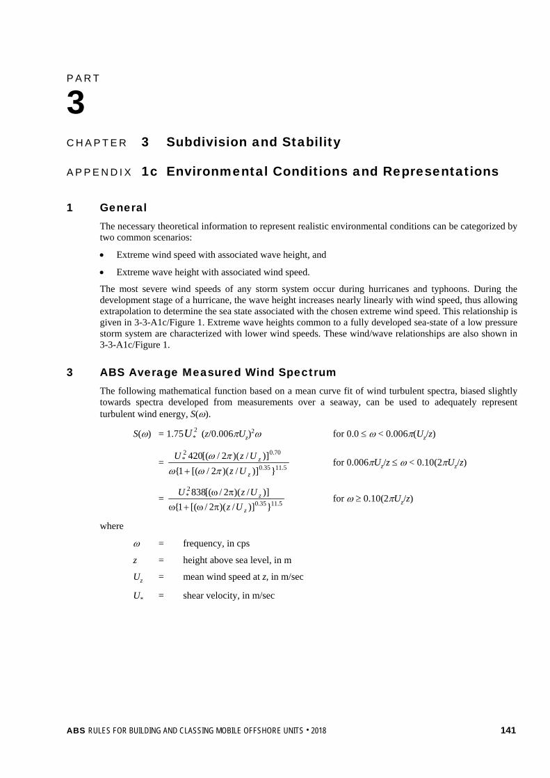
P A R T A p p e n d i x 1 c : E n v i r o n m e n t a l C o n d i t i o n s a n d R e p r e s e n t a t i o n s
3 C H A P T E R 3 Subdivision and Stability
A P P E N D I X 1c Environmental Conditions and Representations
1 General The necessary theoretical information to represent realistic environmental conditions can be categorized by two common scenarios:
• Extreme wind speed with associated wave height, and
• Extreme wave height with associated wind speed.
The most severe wind speeds of any storm system occur during hurricanes and typhoons. During the development stage of a hurricane, the wave height increases nearly linearly with wind speed, thus allowing extrapolation to determine the sea state associated with the chosen extreme wind speed. This relationship is given in 3-3-A1c/Figure 1. Extreme wave heights common to a fully developed sea-state of a low pressure storm system are characterized with lower wind speeds. These wind/wave relationships are also shown in 3-3-A1c/Figure 1.
3 ABS Average Measured Wind Spectrum The following mathematical function based on a mean curve fit of wind turbulent spectra, biased slightly towards spectra developed from measurements over a seaway, can be used to adequately represent turbulent wind energy, S(ω).
S(ω) = 1.75 2*U (z/0.006πUz)
2ω for 0.0 ≤ ω < 0.006π(Uz/z)
= 5.1135.0
70.02*
})]/)(2/[(1{)]/)(2/[(420
z
z
UzUzU
πωωπω
+ for 0.006πUz/z ≤ ω < 0.10(2πUz/z)
= 5.1135.0
2*
})]/)(2/[(1{)]/)(2/[(838
z
z
UzUzU
πω+ωπω for ω ≥ 0.10(2πUz/z)
where
ω = frequency, in cps
z = height above sea level, in m
Uz = mean wind speed at z, in m/sec
U* = shear velocity, in m/sec
ABS RULES FOR BUILDING AND CLASSING MOBILE OFFSHORE UNITS . 2018 141

Part 3 Hull Construction and Equipment Chapter 3 Subdivision and Stability Appendix 1c Environmental Conditions and Representations 3-3-A1c
5 Wave Spectra To adequately represent the distribution and amount of wave energy statistically, wave spectra characteristic of fetch-limited and open sea regions are to be considered.
5.1 Fetch-limited Regions The energy of wind-generated seaways which occur in fetch-limited regions are represented by the JONSWAP Spectral family given by the following for five spectral members:
S(ω) = α(g2/ω5)4)/(25.1 ωωme− γ
)222/(2)( mme ωσωω−−
where
γ = 3.3 for mean JONSWAP spectrum
σ = 0.07 for ω < ωm
= 0.09 for ω > ωm
ω = frequency, in cps
ωm = modal frequency, in cps
α = 0.076 (g d/U2)−0.22
d = fetch, in nautical miles
U = mean wind speed, in knots
g = acceleration of gravity, in m/sec2
The extreme wind corresponding to a specified return period and distance of fetch generates the wave energy distribution.
5.3 Open Seas The wave energy distribution of an open sea wave system is based on the Ochi Six-parameter wave spectral family of eleven members. This spectral family is composed of two parts, each possessing three parameters that are determined numerically, such that the differences between theoretical and observed spectra is minimal: significant wave height (Hs), modal frequency (ωm), and shape parameter (λ) which controls the sharpness of the distribution peak. The following spectral formula is used to generate a lower frequency and a higher frequency spectrum.
S(ω) = )14(
)/)(25.0(24 4
)(])25.0[(25.0
+
+−
×+
λ
ωωλλ
ωλΓωλ meH sm
where:
Hs = significant wave height, in m
Γ(λ) = gamma function
The two-component spectra are then superimposed to form a six-parameter spectral representation.
142 ABS RULES FOR BUILDING AND CLASSING MOBILE OFFSHORE UNITS . 2018
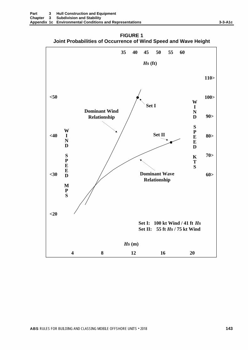
Part 3 Hull Construction and Equipment Chapter 3 Subdivision and Stability Appendix 1c Environmental Conditions and Representations 3-3-A1c
FIGURE 1 Joint Probabilities of Occurrence of Wind Speed and Wave Height
Dominant WaveRelationship
Dominant WindRelationship
Set I
Set II
Hs (ft)
35 40 45 50 55 60
<50
110>
100>
90>
80><40
<30
70>
60>
<20
Hs (m)
4 8 12 16 20
100 kt Wind / 41 ft Hs55 ft Hs / 75 kt Wind
Set I:Set II:
WIND
SPEED
MPS
WIND
SPEED
KTS
ABS RULES FOR BUILDING AND CLASSING MOBILE OFFSHORE UNITS . 2018 143

P A R T A p p e n d i x 2 : C o m p u t e r S o f t w a r e f o r O n b o a r d S t a b i l i t y C a l c u l a t i o n s
3 C H A P T E R 3 Subdivision and Stability
A P P E N D I X 2 Computer Software for Onboard Stability Calculations
1 General
1.1 Scope The scope of stability calculation software is to be in accordance with the stability information as approved by the flag Administration or ABS on behalf of the flag Administration. The software is at least to include all information and perform all calculations or checks as necessary to ensure compliance with the applicable stability requirements.
Approved stability software is not a substitute for the approved stability information, and is used as a supplement to the approved stability information to facilitate stability calculations.
1.3 Design The input/output information is to be easily comparable with approved stability information so as to avoid confusion and possible misinterpretation by the operator relative to the approved stability information.
An operation manual is to be provided for the onboard computer stability software.
The language in which the stability information is displayed and printed out as well as the operation manual is written is to be the same as used in the unit’s approved stability information. The primary language is to be English.
The onboard computer for stability calculations is to be unit specific equipment and the results of the calculations are to be only applicable to the unit for which it has been approved.
In case of modifications implying changes in the main data or internal arrangement of the unit, the software is to be modified accordingly and approved.
3 Calculation Systems This Appendix covers either system, a passive system that requires manual data entry or an active system, which replaces the manual with the automatic entry with sensors reading and entering the contents of tanks, etc., provided the active system is in the off-line operation mode. However, an integrated system, which controls or initiates actions based on the sensor-supplied inputs is not within the scope of this Appendix.
5 Types of Stability Software Four types of calculations performed by stability software are acceptable depending upon a unit’s stability requirements:
• Type 1 Software calculating intact stability only (for units not required to meet a damage stability criterion)
• Type 2 Software calculating intact stability and checking damage stability on basis of a limit curve or checking all the stability requirements (intact and damage stability) on the basis of a limit curve
144 ABS RULES FOR BUILDING AND CLASSING MOBILE OFFSHORE UNITS . 2018

Part 3 Hull Construction and Equipment Chapter 3 Subdivision and Stability Appendix 2 Computer Software for Onboard Stability Calculations 3-2-A2
• Type 3 Software calculating intact stability and damage stability by direct application of preprogrammed damage cases based on the relevant Conventions or Codes for each operating condition
• Type 4 Software calculating damage stability associated with an actual loading condition and actual flooding case, using direct application of user defined damage, for the purpose of providing operational information for safe return to port (SRtP).
Damage stability of both Type 3 and Type 4 stability software is to be based on a hull form model, that is, directly calculated from a full three-dimensional geometric model.
7 Functional Requirements
7.1 Calculation Program The calculation program is to present relevant parameters of each operating condition in order to assist the Master in their judgment on whether the unit is loaded within the approval limits. The following parameters are to be presented for a given operating condition:
• Variable Load data or Deadweight data
• Lightship data, including the weight and center of gravity of the independent components such as legs, cantilever and platform
• Trim
• Draft at the draft marks and perpendiculars
• Summary of operating condition displacement, VCG, LCG and TCG
• Downflooding angle and corresponding downflooding opening or boundaries of watertight and weathertight protection (not applicable for Type 2 software which uses limit curve for checking all the stability requirements. However, if intact stability criteria are given in addition to the limit curve, downflooding angle and the corresponding downflooding opening is to be indicated).
• Compliance with stability criteria: Listing of all calculated stability criteria, the limit values, the obtained values and the conclusions (criteria fulfilled or not fulfilled) (not applicable for Type 2 software which uses limit curve for checking all the stability requirements. However, if intact stability criteria are given in addition to the limit curve, the limit values, the obtained values and the conclusion is to be indicated).
7.3 Direct Damage Stability Calculations If direct damage stability calculations are performed, the relevant damage cases according to the applicable rules are to be pre-defined for automatic check of a given operating condition.
7.5 Warning A clear warning is to be given on screen and in hard copy printout if any of the operating limitations are not complied with.
Loading limitations are to include, but may not be limited to, the following:
• Trim, draft, liquid densities, tank filling levels, initial heel
• Use of limit KG/GM curves in conjunction with above for Type 2
7.7 Data Printout The data are to be presented on screen and in hard copy printout in a clear unambiguous manner.
7.9 Date and Time The date and time of a saved calculation are to be part of the screen display and hard copy printout.
ABS RULES FOR BUILDING AND CLASSING MOBILE OFFSHORE UNITS . 2018 145
Part 3 Hull Construction and Equipment Chapter 3 Subdivision and Stability Appendix 2 Computer Software for Onboard Stability Calculations 3-2-A2
7.11 Information of Program Each hard copy printout is to include identification of the calculation program with version number.
7.13 Units Units of measurement are to be clearly identified and used consistently within an operating calculation.
7.15 Computer Model For Type 3 and Type 4 software, the system is to be pre-loaded with a detailed computer model of the complete hull, including appendages, all compartments, tanks and the relevant parts of the superstructure considered in the damage stability calculation, wind profile, down-flooding openings (or boundaries of watertight and weathertight boundaries), up-flooding openings, cross-flooding arrangements, internal compartment connections and escape routes, as applicable and according to the type of stability software.
For Type 1 and Type 2 software, in case a full three dimensional model is used for stability calculations, the requirements of the computer model are to be as per the paragraph above to the extent as applicable and according to the type of stability software.
7.17 Further Requirements for Type 4 Stability Software 7.17.1
The normal (Type 1, 2 and 3) and SRtP (Type 4) software need not be “totally separated”. Where the normal and SRtP software are not totally separated:
• The function of switching between normal software and Type 4 software is to be provided.
• The actual intact loading condition is to be the same for both functions (normal operation and SRtP); and
• The SRtP module needs only to be activated in case of an incident.
Approval of Type 4 (SRtP) software is for stability only.
7.17.2 In units which are subject to SRtP and have an onboard stability computer and shore-based support, such software need not be identical.
7.17.3 Each internal space is to be assigned its permeability as shown below, unless a more accurate permeability has been reflected in the approved stability information.
Spaces Permeability
Default Full Partially Filled Empty Cargo liquids 0.95 0.70 0.80 0.95 Intended for consumable liquids 0.95 0.95 0.95 0.95 Stores 0.95 0.60 0.60 0.95 Occupied by machinery 0.85 Void spaces 0.95 Occupied by accommodation 0.95
7.17.4 The system is to be capable of accounting for applied moments such as wind, lifeboat launching, cargo shifts and crew/passenger relocation.
7.17.5 The system is to account for the effect of wind as per 3-1-3/1.3.
146 ABS RULES FOR BUILDING AND CLASSING MOBILE OFFSHORE UNITS . 2018

Part 3 Hull Construction and Equipment Chapter 3 Subdivision and Stability Appendix 2 Computer Software for Onboard Stability Calculations 3-2-A2
7.17.6 The system is to be capable of assessing the impact of open main watertight doors on stability (e.g., for each damage case provided for verification, additional damage stability calculation is to be done and presented, taking into account any watertight door located within the damaged compartment(s)).
7.17.7 The system is to utilize the latest approved lightship weight and center of gravity information.
7.17.8 The output of the software is to be such that it provides the master with sufficient clear unambiguous information to enable quick and accurate assessment of the stability of the unit for any actual damage, the impact of flooding on the means of escape and the controls of devices necessary for managing and/or controlling the stability of the unit.
When the actual loading condition is input in the SRtP software, the following output (intact stability) is to be available:
• Deadweight data
• Lightship data
• Trim
• Heel
• Draft at the draft marks and perpendiculars
• Summary of loading condition displacement, VCG, LCG and TCG
• Downflooding angle and corresponding downflooding opening
• Free surfaces
• GM value
• GZ values relevant to an adequate range of heeling (not less than 60°) available indicatively at the following intervals: 0 5 10 15 20 25 30 40 50 60 deg
• Compliance with relevant intact stability criteria: listing of all calculated intact stability criteria, the limiting values, the obtained values and the evaluation (criteria fulfilled or not fulfilled)
• GM/KG limiting curve
When the actual loading condition is associated to the actual damage case(s) due to the casualty, the following output (damage stability) is to be available:
• Trim
• Heel
• Draft at the draft marks and perpendiculars
• Progressive flooding angle and corresponding progressive flooding openings
• GM value
• GZ values relevant to an adequate range of heeling (not less than 60°) available indicatively at the following intervals: 0 5 10 15 20 25 30 40 50 60 deg
• Compliance with stability criteria: listing of all calculated stability criteria, the limit values, the obtained values and the conclusions (criteria fulfilled or not fulfilled)
• The survivability criteria for Type 4 software (SRtP) are left to the discretion of the Administration
• Relevant flooding points (unprotected or weathertight) with the distance from the damage waterline to each point
ABS RULES FOR BUILDING AND CLASSING MOBILE OFFSHORE UNITS . 2018 147
Part 3 Hull Construction and Equipment Chapter 3 Subdivision and Stability Appendix 2 Computer Software for Onboard Stability Calculations 3-2-A2
• List of all flooded compartments with the permeability considered
• Amount of water in each flooded compartment
• Escape route immersion angles
• A profile view, deck views and cross-sections of the unit indicating the flooded water-plane and the damaged compartments
9 Acceptable Tolerances Depending on the type and scope of programs, the acceptable tolerances are to be determined differently, according to 3-3-A2/9.1 or 3-3-A2/9.3. In general, deviation from these tolerances is not to be accepted unless a satisfactory explanation for the difference is submitted for review and the same is satisfactorily confirmed by ABS that there would be no adverse effect on the safety of the unit.
Examples of pre-programmed input data include the following:
• Hydrostatic data: Displacement, LCB, LCF, VCB, KMt, MCT and KMl vs. draft
• Stability data: KN or MS values at appropriate heel/trim angles vs. displacement, stability limits or allowable VCG.
• Compartment data: Volume, LCG, VCG, TCG and FSM (transverse, longitudinal and maximum) vs. level of the compartment’s contents.
Examples of output data include the following:
• Hydrostatic data: Displacement, LCB, LCF, VCB, KMt, KMl and MCT versus draft, as well as actual drafts, trim.
• Stability data: FSC (free surface correction), GZ-values, KG, GM, KG/GM limits, derived stability criteria (e.g., areas under the GZ curve), weather criteria.
• Compartment data: Calculated Volume, LCG, VCG, TCG and FSM (transverse, longitudinal, and maximum) vs. level of the compartment’s contents
The computational accuracy of the calculation program results is to be within the acceptable tolerances specified in 3-3-A2/9.1 or 3-3-A2/9.3, of the results using an independent program or the approved stability information with identical input.
9.1 Calculation Program of the Approved Stability Information Programs which use only pre-programmed data from the approved stability information as the basis for stability calculations are to have zero tolerances for the printouts of input data.
Output data tolerances are to be close to zero. However, small differences associated with calculation rounding or abridged input data are acceptable. Additionally differences associated with the use of hydrostatic and stability data for trims that differ from those in the approved stability information are acceptable subject to review by ABS.
9.3 Independent Program for Assessment of Stability Programs which use hull form models as their basis for stability calculations are to have tolerances for the printouts of basic calculated data established against either data from the approved stability information or data obtained using the approval authority’s model. Acceptable tolerances shall be in accordance with 3-3-A2/Table 1.
148 ABS RULES FOR BUILDING AND CLASSING MOBILE OFFSHORE UNITS . 2018

Part 3 Hull Construction and Equipment Chapter 3 Subdivision and Stability Appendix 2 Computer Software for Onboard Stability Calculations 3-2-A2
TABLE 1 Acceptable Tolerances
Hull Form Dependent Acceptable Tolerance (1) Displacement ±2% Longitudinal center of buoyancy, from AP ±1% or 50 cm, whichever is greater Vertical center of buoyancy ±1% or 5 cm, whichever is greater Transverse center of buoyancy ±0.5% of B or 5 cm, whichever is greater Longitudinal center of flotation, from AP ±1% or 50 cm, whichever is greater Moment to trim 1 cm ±2% Transverse metacentric height ±1% or 5 cm, whichever is greater Longitudinal metacentric height ±1% or 50 cm, whichever is greater Cross curves of stability ±5 cm
Compartment Dependent Acceptable Tolerance (1) Volume or deadweight ±2% Longitudinal center of gravity, from AP ±1% or 50 cm, whichever is greater Vertical center of gravity ±1% or 5 cm, whichever is greater Transverse center of gravity ±0.5% of B or 5 cm, whichever is greater Free surface moment ±2% Shifting moment ±5% Level of contents ±2%
Trim and Stability Acceptable Tolerance (1) Drafts (forward, aft, mean) ±1% or 5 cm, whichever is greater GMt (both solid and corrected for free surfaces) ±1% or 5 cm, whichever is greater GMl (both solid and corrected for free surfaces) ±1% or 50 cm, whichever is greater GZ values ±1% or 5 cm, whichever is greater Downflooding angle ±2° Equilibrium angles ±1° Distance from WL to unprotected and weathertight openings, or other relevant point, if applicable
±5% or 5 cm, whichever is greater
Areas under righting arm curve ±5% or 0.0012 mrad
Notes: 1 Deviation in % = [(base value – applicant’s value)/base value] × 100.
where the “base value” may be from the approved stability information or the society’s computer model.
2 When applying a tolerance in 3-3-A2/Table 1 that contains two values, the allowable tolerance is the greater of the two values.
3 Where differences in calculation methodology exist between the programs used in the comparison, this may be a basis for accepting deviations greater than that specified in 3-3-A2/Table 1 provided a software examination is carried out in sufficient detail to clearly document that such differences are technically justifiable.
4 Deviation from these tolerances are not to be accepted unless ABS considers that there is a satisfactory explanation for the difference and that it is clearly evident from ABS’s stability calculations that the deviation does not impact compliance with the required stability criteria for the unit under consideration.
5 Where the KMt and KMl of a unit are of the same magnitude, use the tolerance for the KMt for both values. For such units, the tolerance for GMt may be used for GMl.
ABS RULES FOR BUILDING AND CLASSING MOBILE OFFSHORE UNITS . 2018 149
Part 3 Hull Construction and Equipment Chapter 3 Subdivision and Stability Appendix 2 Computer Software for Onboard Stability Calculations 3-2-A2
11 Approval Procedure
11.1 Conditions of Approval of the Onboard Software for Stability Calculations The onboard software used for stability calculations is subject to approval, which is to include:
• Verification of type approval, if any,
• Verification that the data used is consistent with the current condition of the unit (see 3-3-A2/11.5),
• Verification and approval of the test conditions, and
• Verification that the software is appropriate for the type of unit and stability calculations required.
• Verification that the software is installed so that failure of the primary computer or server does not prevent the stability calculation from being carried out (this is to be demonstrated onboard as noted below).
• Verification of functional requirements under 3-3-A2/7.
The satisfactory operation of the software for stability calculations is to be verified by testing upon installation on the primary computer or server and at least one back-up computer or redundant server onboard (see 3-3-A2/15). A copy of the approved test conditions and the operation manual for the computer/software are to be available onboard.
11.3 General Approval (optional) Upon receipt of application for general approval of the calculation program, ABS may provide the applicant with test data consisting of two or more design data sets, each of which is to include a unit’s hull form data, compartmentation data, lightship characteristics and deadweight data, in sufficient detail to accurately define the unit and its operating condition.
Acceptable hull form and compartmentation data may be in the form of surface coordinates for modeling the hull form and compartment boundaries (e.g., a table of offsets) or in the form of pre-calculated tabular data (e.g., hydrostatic tables, capacity tables) depending upon the form of data used by the software being submitted for approval. Alternatively, the general approval may be given based on at least two test units agreed upon between the applicant and ABS.
In general, the software is to be tested for two types of units for which approval is requested, with at least one design data set for each of the two types. Where approval is requested for only one type of unit, a minimum of two data sets for different hull forms of that type of unit are required to be tested.
For calculation software which is based on the input of hull form data, design data sets are to be provided for three types of units for which the software is to be approved, or a minimum of three data sets for different hull forms if approval is requested for only one type of unit. Representative unit types are those which, due to their different hull forms, typical arrangements, and nature of cargo, require different design data sets.
The test data sets are to be used by the applicant to run the calculation program for the test units. The results obtained, together with the hydrostatic data and cross-curve data developed by the program, if appropriate are to be submitted to ABS for the assessment of the program’s computational accuracy. ABS is to perform parallel calculations using the same data sets and a comparison of these results will be made against the applicant’s submitted program’s results.
11.5 Specific Approval ABS is to verify the accuracy of the computational results and actual unit data used by the calculation program for the particular unit on which the program will be installed.
Upon receipt of application for data verification, ABS and the applicant are to agree on a minimum of four operating conditions, taken from the unit’s approved stability information, which are to be used as the test conditions.
150 ABS RULES FOR BUILDING AND CLASSING MOBILE OFFSHORE UNITS . 2018
Part 3 Hull Construction and Equipment Chapter 3 Subdivision and Stability Appendix 2 Computer Software for Onboard Stability Calculations 3-2-A2
For units carrying liquids in bulk, at least one of the conditions is to include partially filled tanks. Within the test conditions each compartment is to be loaded at least once. The test conditions normally are to cover the range of load drafts from the deepest envisaged loaded condition to the light ballast condition for both transit and afloat operation conditions.
For Type 4 stability software for SRtP, ABS is to examine at least three damage cases, each of them associated with at least three loading conditions taken from the unit’s approved stability information. Output of the software is to be compared with results of corresponding load/damage case in the approved damage stability booklet or an alternative independent software source.
ABS is to verify that the following data, submitted by the applicant, is consistent with arrangements and most recently approved lightship characteristics of the unit according to current plans and documentation on file with ABS, subject to possible further verification onboard:
• Identification of the calculation program including version number.
• Main dimensions, hydrostatic particulars and, if applicable, the unit profile.
• The position of the forward and after perpendiculars, and if appropriate, the calculation method to derive the forward and after drafts at the actual position of the unit’s draft marks.
• Unit lightweight and center of gravity derived from the most recently approved inclining test or light weight check.
• Lines plan, offset tables or other suitable presentation of hull form data if necessary for ABS to model the unit.
• Compartment definitions, including frame spacing, and centers of volume, together with capacity tables (sounding/ullage tables), free surface corrections, if appropriate
• Variable Load (if applicable) and consumables distribution for each operating condition.
Verification by ABS does not absolve the applicant and unit owner of responsibility for ensuring that the information programmed into the onboard computer software is consistent with the current condition of the unit.
13 Operation Manual A simple and straightforward operation manual is to be provided, containing descriptions and instructions, as appropriate, for at least the following:
• Installation
• Function keys
• Menu displays
• Input and output data
• Required minimum hardware to operate the software
• Use of the test operating conditions
• Computer-guided dialogue steps
• List of warnings
15 Testing and Inspection Testing and inspection are to be in accordance with 7-1-2/21, 7-1-A2, 7-2-4/1.1.16 and 7-2-5/1.11.
ABS RULES FOR BUILDING AND CLASSING MOBILE OFFSHORE UNITS . 2018 151

P A R T C h a p t e r 4 : P o s i t i o n M o o r i n g S y s t e m s
3 C H A P T E R 4 Mooring Systems and Equipment
CONTENTS SECTION 1 Mooring Systems and Equipment ..................................................... 153
1 General ........................................................................................... 153 3 Temporary Mooring Equipment ...................................................... 153
3.1 General ........................................................................................ 153 3.3 Alternative Requirements ............................................................ 153
5 Position Mooring Equipment ........................................................... 154 7 Position Mooring Systems .............................................................. 154 9 Anchoring and Mooring Equipment ................................................ 154 11 Equipment Mass and Size .............................................................. 155 13 Tests ............................................................................................... 156 15 Anchor Types .................................................................................. 156 17 Windlass Support Structure and Cable Stopper ............................. 157
17.1 General ........................................................................................ 157 17.3 Support Structure......................................................................... 157 17.5 Trial .............................................................................................. 158
19 Hawse Pipes ................................................................................... 160 TABLE 1 Values of Cs ........................................................................... 156 TABLE 2 Equipment for Self-propelled Ocean-going Units ................. 161 FIGURE 1 Direction of Forces and Weight ............................................. 159 FIGURE 2 Sign Convention .................................................................... 159
APPENDIX 1 Position Mooring Systems ................................................................ 165
1 General ........................................................................................... 165 3 Anchoring Systems ......................................................................... 165
3.1 General ........................................................................................ 165 3.3 Design ......................................................................................... 165
5 Equipment ....................................................................................... 167 5.1 Winches and Windlasses ............................................................. 167 5.3 Fairleads and Sheaves ................................................................ 167
7 Anchor Lines ................................................................................... 167 9 Anchors ........................................................................................... 168 11 Quality Control ................................................................................ 168 13 Control Stations .............................................................................. 168
152 ABS RULES FOR BUILDING AND CLASSING MOBILE OFFSHORE UNITS . 2018

P A R T S e c t i o n 1 : M o o r i n g S y s t e m s a n d E q u i p m e n t
3 C H A P T E R 4 Mooring Systems and Equipment
S E C T I O N 1 Mooring Systems and Equipment
1 General Except as specified hereunder, the symbols Á,  and à are not required as a condition of classification.
All self-propelled units are to have temporary mooring equipment for anchoring while the unit is in the transit mode. The symbol Á is a condition of classification for self-propelled units except as noted in 3-4-1/3.3 below.
For non-self-propelled units, when requested by the Owner, the symbol Á may be placed after the symbols of classification in the Record.
3 Temporary Mooring Equipment
3.1 General The symbol Á placed after the symbols of classification in the Record, thus: À A1 Á, will signify that the equipment for temporary mooring, for anchoring while the unit is in the transit mode, is in compliance with the applicable requirements of 3-4-1/9 to 3-4-1/19 or with requirements corresponding to the service limitation noted in the unit’s classification, which have been specially approved for the particular service. For units with symbol Ã, this requirement may be met if position mooring equipment can be released in an emergency while the unit is in the transit mode.
Temporary mooring equipment for self-elevating units in Restricted Service may be established in accordance with 3-5-1/3.5 of the ABS Guide for Building and Classing Liftboats. For such units in Domestic Service, the criteria of the flag state may be applied.
3.3 Alternative Requirements For self-propelled Column Stabilized Units classed with the notation DPS-2 or DPS-3 and self-propelled Self-Elevating Units fitted with thrusters to maintain afloat position while lowering legs, an alternative to the requirement for symbol Á to be a condition of classification maybe specially considered subject to the following.
i) At least a single set of anchoring and mooring equipment is to be provided.
ii) The set of anchoring and mooring equipment is to be based on specifications provided by the Owner. These specifications are to be submitted to ABS.
iii) Justification to demonstrate adequacy of the proposed anchoring and mooring equipment for environmental condition to be considered based on wind speed of 25 m/s, current speed of 2.5 m/s and a scope of 6 through 10 (the scope being the ratio between length of chain paid out and water depth).
iv) Procedure for deploying the temporary anchor and activation of DP system after a propulsion failure during transit is to be included in the unit’s Operation Manual.
v) When a unit is equipped with wire rope, an inspection, maintenance and replacement procedure to demonstrate the wire rope availability and capability to be deployed when required is to be submitted to ABS for approval.
ABS RULES FOR BUILDING AND CLASSING MOBILE OFFSHORE UNITS . 2018 153

Part 3 Hull Construction and Equipment Chapter 4 Mooring Systems and Equipment Section 1 Mooring Systems and Equipment 3-4-1
vi) The mooring equipment, anchors, chain or wire rope which have been specified by the Owner are to be tested in accordance with the specifications of the Owner and in the presence of a Surveyor.
vii) Applicable requirements of 3-4-1/13, 3-4-1/15 and 3-4-1/19 are to be complied with.
viii) When a unit with single bower anchor arrangement is anchored for periods longer than 21 days, additional means of anchoring or external assistance such as a stand-by towing vessel will need to be provided and instructions in this regard are to be included in the Operating Manual.
In addition, for self-propelled Column Stabilized Units classed with the notation DPS-2 or DPS-3, anchoring equipment will not be required if the following are satisfied:
a) Unit is assisted by tugs when in transit near/within harbor, coast or busy waters.
b) Special arrangement is made when the unit is anchored in shallow waters.
The above items are to be addressed by use of a risk based study and any recommended contingencies or operational restrictions (arising for the study) included in the Operating Manual.
When requested by the owner and with the requirements in this section satisfied, the symbol Á will not be required as a condition of classification.
5 Position Mooring Equipment When requested by the Owner, the symbol  may be placed after the symbols of classification in the Record, thus: À A1 Â, which will signify that the mooring equipment, anchors, chain or wire rope which have been specified by the Owner for position mooring have been tested in accordance with the specifications of the Owner and in the presence of a Surveyor. See 7-1-A1/1.
7 Position Mooring Systems When requested by the Owner, ABS is prepared to certify the position mooring capability of the unit in accordance with the requirements outlined in Appendix 3-4-A1. A unit so certified for position mooring will be designated in the Record by the symbol à placed after the symbols of classification in the Record, thus: À A1 Ã.
9 Anchoring and Mooring Equipment The mass per anchor of bower anchors, given in 3-4-1/Table 2, is for anchors of equal mass. The mass of individual anchors may vary 7% plus or minus from the tabular mass, provided that the combined mass of all anchors is not less than that required for anchors of equal mass. The total length of chain required to be carried onboard, as given in 3-4-1/Table 2, is to be reasonably divided between the two bower anchors.
Cables which are intended to form part of the equipment are not to be used as check chains when the unit is launched. The inboard ends of the cables of the bower anchors are to be secured by efficient means.
Two bower anchors and their cables are to be connected and positioned, ready for use in transit mode. Where three anchors are given in 3-4-1/Table 2, the third anchor is intended as a spare bower anchor and is listed for guidance only; it is not required as a condition of classification.
Units with DPS-2 or DPS-3 notation intended for deep water operations may be provided with a single bower anchor installed onboard and half of the chain cable length given in 3-4-1/Table 2. When a unit with single bower anchor arrangement is anchored for periods longer than 21 days, additional means of anchoring or external assistance such as a stand-by towing vessel will need to be provided and instructions in this regard are to be included in the Operating Manual.
Means are to be provided for stopping each cable as it is paid out, and the windlass should be capable of heaving in either cable.
The length of chain cable required by 3-4-1/Table 2 can be equally distributed between the two bower anchors connected and ready for use. Where the chain is arranged so that one anchor has a longer length for mooring it is to be verified that the windlass has sufficient capability for heaving in the longer length of chain.
Suitable arrangements are to be provided for securing the anchors and stowing the cables.
154 ABS RULES FOR BUILDING AND CLASSING MOBILE OFFSHORE UNITS . 2018
Part 3 Hull Construction and Equipment Chapter 4 Mooring Systems and Equipment Section 1 Mooring Systems and Equipment 3-4-1
11 Equipment Mass and Size The requirements herein are intended for temporary mooring of a unit within a harbor or other areas of sheltered water. The “Equipment Number” equation is based on 2.5 m/s (8.2 ft/s) current, 25 m/s (49 knots) wind and a scope of 6 through 10, the scope being the ratio of length of chain paid out to the water depth. Anchors and chains are to be in accordance with 3-4-1/Table 2 and the numbers, mass and sizes of these are to be regulated by the equipment number (EN) obtained from the following equation:
Equipment Number = hk(∆/h)2/3 + mΣqCsChAf + nΣqCsChAp
where
k = 1.0 (1.0, 1.012)
m = 2 (2, 0.186)
n = 0.1 (0.1, 0.00929)
h = number of hulls or pontoons of the unit
∆ = molded displacement of the unit in metric tons (long tons), excluding appendages, taken at the transit draft
ΣqCsChAf = total frontal area exposed to the wind in m2 (ft2) at the transit draft
q = 1.0 for hull, superstructure and deck houses
0.3 for other wind areas
Cs = shape coefficient, as shown in 3-4-1/Table 1
Ch = height coefficient as shown in 3-1-3/Table 2
Af = frontal projected area of each major element exposed to the wind, in m2 (ft2), including columns, upper structure, deck members, superstructures and deck houses, trusses, large cranes, derrick substructure and drilling derrick as well as the portion of the hull above the transit waterline, as applicable to the type of unit. Wind shielding in accordance with acceptable methods may be considered.
ΣqCsChAp = total profile area exposed to the wind in m2 (ft2) at the transit draft
Ap = profile area of each major element exposed to the wind, in m2 (ft2), including columns, upper structure, deck members, superstructure and deck houses, trusses, large cranes, derrick substructure and drilling derrick as well as the portion of the hull above the transit waterline, as applicable to the type of unit. Wind shielding in accordance with acceptable methods may be considered.
In calculating the wind areas, the following conditions are to be considered:
i) Tiers of superstructures or deck houses having a breadth at any point no greater than 0.25B, where B is the molded breadth of the unit, may be excluded, provided that their projected area is less than 1/100 of the total projected area of the unit.
ii) Screens and bulwarks more than 1.5 m (4.9 ft) in height are to be included.
iii) In the case of units with columns, the projected areas of all columns are to be included (i.e. no shielding allowance is to be taken). However, a shape coefficient of 0.5 may be used for the column’s cylindrical surfaces.
iv) The block projected area of a clustering of deck houses may be used in lieu of calculating each individual area. In this case, the shape coefficient is to be taken as 1.1.
v) Large isolated structures such as cranes and derricks are to be calculated individually using the appropriate shape coefficients from 3-4-1/Table 1.
vi) Small isolated structures with a projected area less than 1/100 of the total projected area of the unit may be excluded.
ABS RULES FOR BUILDING AND CLASSING MOBILE OFFSHORE UNITS . 2018 155

Part 3 Hull Construction and Equipment Chapter 4 Mooring Systems and Equipment Section 1 Mooring Systems and Equipment 3-4-1
vii) Open truss work commonly used for derrick towers, booms and certain types of masts may be approximated by taking 30% of the projected block areas of both the front and back sides (i.e., 60% of the projected block area of one side for double sided truss work). The shape coefficient is to be taken in accordance with 3-4-1/Table 1. Note: Lateral wind areas (larger side) of open truss work in dual derrick towers may be approximated by taking
25% of the projected block areas of both the front and back sides. In all open truss derrick towers, the wind areas in the V-door levels may be approximated by taking 20% of the projected block areas of both the front and back sides.
Alternatively, the effective wind areas may be calculated by using the results of wind tunnel tests or recognized computational fluid dynamics (CFD) software with a representative model of the unit or designated item, including all the elements that can contribute to the wind resistance, and subjected to the wind conditions equivalent to 25 m/s (49 knots) or over. Documentation and calculations demonstrating the effective wind areas by the alternative methodology are to be submitted for review. Note: When the effective wind areas are obtained from the results of wind tests or CFD analysis and the percentage of
wind area related to hull, superstructures and deckhouses cannot be estimated, a value not less than 75% (frontal) and 50% (profile) of the resulting effective wind areas may be used in the equipment numeral equation in lieu of the total frontal area and the total profile area, respectively.
For mobile offshore units where the temporary mooring system is arranged to face the wind in a direction other than the bow of the unit, special consideration will be made to adapt the calculation of the Equipment Number and the required anchors and chains to the specific mooring conditions.
TABLE 1 Values of Cs
Shapes or combinations of shapes which do not readily fall into the specified categories will be subject to special consideration.
Spherical 0.4 Cylindrical shapes (all sizes) 0.5 Flat surfaces 1.0 Hull 1.0 Upper structure (column-stabilized unit) 1.0 Superstructure or deck house 1.0 Isolated Structural shapes (large cranes) 1.5 Under deck areas (smooth surfaces) 1.0 Under deck areas (exposed beams and girders) 1.3 Open truss rig derrick (each face) 1.25 Wires (total surface exposed in transit) 1.2
13 Tests Tests are to be in accordance with the requirements of Chapter 2 of the ABS Rules for Materials and Welding (Part 2) for the respective sizes of anchors and chains. See Sections 2-2-1 and 2-2-2.
15 Anchor Types Anchors are to be of the stockless type. The mass of the head of a stockless anchor, including pins and fittings, is not to be less than three-fifths of the total mass of the anchor. Where specifically requested by the Owners, ABS is prepared to give consideration to the use of special types of anchors and where these are of proven superior holding ability, consideration may also be given to some reduction in the mass, up to a maximum of 25% from the mass specified in 3-4-1/Table 2. In such cases, the notation RW will be made in the Record.
156 ABS RULES FOR BUILDING AND CLASSING MOBILE OFFSHORE UNITS . 2018

Part 3 Hull Construction and Equipment Chapter 4 Mooring Systems and Equipment Section 1 Mooring Systems and Equipment 3-4-1
17 Windlass Support Structure and Cable Stopper
17.1 General Where fitted, an independent cable stopper and its components are to be adequate for the load imposed. The arrangements and details of the cable stopper are to be submitted for review.
The windlass supporting structures are to meet the requirements in 3-4-1/17.3. Where the mooring winch is integral with the windlass, it is to be considered as a part of the windlass for the purpose of said paragraph.
17.3 Support Structure The windlass is to be bolted down to a substantial foundation, which is to meet the following load cases and associated criteria.
17.3.1 Operating Loads 17.3.1(a) Load on Windlass Support Structure. The following load is to be applied in the direction of the chain.
With cable stopper not attached to windlass: 45% of B.S.
With cable stopper attached to windlass: 80% of B.S.
Without cable stopper: 80% of B.S.
B.S. = minimum breaking strength of the chain, as indicated in 2-2-2/Tables 2 and 3 of the Rules for Materials and Welding (Part 2).
17.3.1(b) Load on Cable Stopper and Support Structure. A load of 80% of B.S. is to be applied in the direction of the chain.
17.3.1(c) Allowable Stress. The stresses in the structures supporting the windlass and cable stopper are not to exceed the yield point.
17.3.2 Sea Loads 17.3.2(a) Pressures. The following pressures and associated areas are to be applied (see 3-4-1/Figure 1):
- 200 kN/m2 (20.4 tf/m2, 4178 lbf/ft2) normal to the shaft axis and away from the forward perpendicular, over the projected area in this direction,
- 150 kN/m2 (15.3 tf/m2, 3133 lbf/ft2) parallel to the shaft axis and acting both inboard and outboard separately, over the multiple of f times the projected area in this direction,
where f is defined as:
f = 1 + B/H, f need not be taken as greater than 2.5
B = width of windlass measured parallel to the shaft axis
H = overall height of windlass.
17.3.2(b) Forces. Forces in the bolts, chocks and stoppers securing the windlass to the deck are to be calculated. The windlass is supported by N groups of bolts, each containing one or more bolts, see 3-4-1/Figure 1.
i) Axial Forces. The aggregate axial force Ri in respective group of bolts (or bolt) i, positive in tension, may be calculated from the following equations:
Rxi = Px hsxi Ai/Ix
Ryi = Py hsyi Ai/Iy
and
Ri = Rxi + Ryi – Rsi
ABS RULES FOR BUILDING AND CLASSING MOBILE OFFSHORE UNITS . 2018 157

Part 3 Hull Construction and Equipment Chapter 4 Mooring Systems and Equipment Section 1 Mooring Systems and Equipment 3-4-1
where
Px = force, kN (tf, lbf), acting normal to the shaft axis
Py = force, kN (tf, lbf), acting parallel to the shaft axis, either inboard or outboard, whichever gives the greater force in bolt group i
hs = shaft height above the windlass mounting, cm (in.)
xi, yi = x and y coordinates of bolt group i from the centroid of all N bolt groups, positive in the direction opposite to that of the applied force, cm (in.)
Ai = cross-sectional area of all bolts in group i, cm2 (in2)
Ix = Ai xi2 for N bolt groups
Iy = Ai yi2 for N bolt groups
Rsi = static reaction at bolt group i, due to weight of windlass.
ii) Shear forces. Aggregated shear forces, Fxi, Fyi, applied to the respective bolt group, i, of bolts, and the resultant combined force, Fi, may be calculated from:
Fxi = (Px – αgM)/N
Fyi = (Py – αgM)/N
and
Fi = ( 2xiF + 2
yiF )0.5
where:
α = coefficient of friction (0.5)
M = mass of windlass, in tonnes (Ltons)
g = gravity: 9.81 m/sec2 (32.2 ft/sec2)
N = number of groups of bolts
The axial tensile/compressive and lateral forces from the above equations are also to be considered in the design of the supporting structure.
17.3.2(c) Stresses in Bolts. Tensile axial stresses in the individual bolts in each group of bolts i are to be calculated. The horizontal forces, Fxi and Fyi, are normally to be reacted by shear chocks. Where “fitted” bolts are designed to support these shear forces in one or both directions, the von Mises equivalent stresses in the individual “fitted” bolts are to be calculated and compared to the stress under proof load. Where pourable resins are incorporated in the holding down arrangements, due account is to be taken in the calculations.
17.3.2(d) Allowable Stress
i) Bolts. The safety factor against bolt proof strength is to be not less than 2.0.
ii) Supporting Structures. The stresses in the above deck framing and the hull structure supporting the windlass are not to exceed the following values.
• Bending Stress 85% of the yield strength of the material
• Shearing Stress 60% of the yield strength of the material
17.5 Trial See 7-1-A1/5.1. Anchor windlass trials are to be performed in accordance with 3-7-2/1 of the Marine Vessel Rules.
158 ABS RULES FOR BUILDING AND CLASSING MOBILE OFFSHORE UNITS . 2018
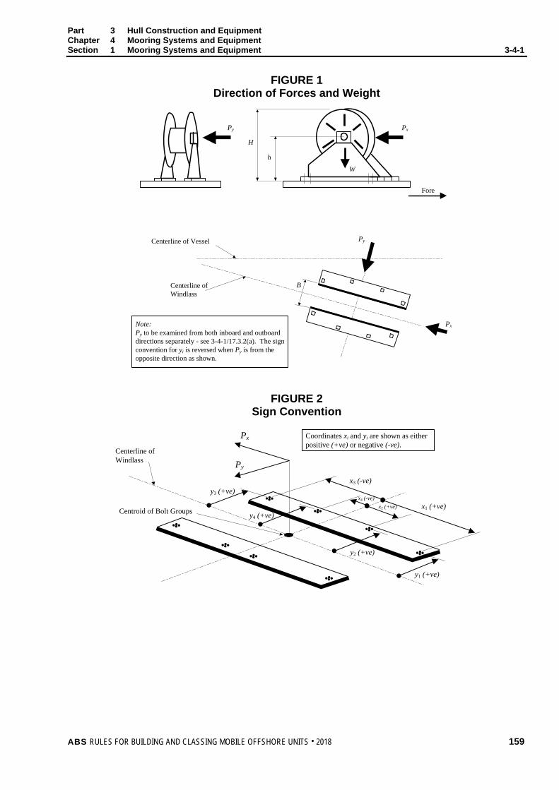
Part 3 Hull Construction and Equipment Chapter 4 Mooring Systems and Equipment Section 1 Mooring Systems and Equipment 3-4-1
FIGURE 1 Direction of Forces and Weight
Py
H
h
W
Px
Fore
Px
PyCenterline of Vessel
Centerline of Windlass
Note:Py to be examined from both inboard and outboard directions separately - see 3-4-1/17.3.2(a). The sign convention for yi is reversed when Py is from the opposite direction as shown.
B
FIGURE 2 Sign Convention
Centerline of Windlass
Centroid of Bolt Groups
Px
Py
y3 (+ve)
y4 (+ve)
y2 (+ve)
y1 (+ve)
x1 (+ve)x2 (+ve)x4 (-ve)
x3 (-ve)
Coordinates xi and yi are shown as either positive (+ve) or negative (-ve).
ABS RULES FOR BUILDING AND CLASSING MOBILE OFFSHORE UNITS . 2018 159
Part 3 Hull Construction and Equipment Chapter 4 Mooring Systems and Equipment Section 1 Mooring Systems and Equipment 3-4-1
19 Hawse Pipes Hawse pipes are to be of ample size and strength. They are to have full rounded flanges and the least possible lead, in order to minimize the nip on the cables. They are to be securely attached to thick doubling or insert plates by continuous welds the size of which are to be in accordance with Section 3-2-6 for the plating thickness and type of joint selected. When in position, they are to be thoroughly tested for watertightness by means of a hose in which the water pressure is not to be less than 2.06 bar (2.1 kgf/cm2, 30 psi). Hawse pipes for stockless anchors are to provide ample clearances. The anchors are to be shipped and unshipped so that the Surveyor may be satisfied that there is no risk of the anchor jamming in the hawse pipe. Care is to be taken to ensure a fair lead for the chain from the windlass to the hawse pipes and to the chain pipes.
160 ABS RULES FOR BUILDING AND CLASSING MOBILE OFFSHORE UNITS . 2018
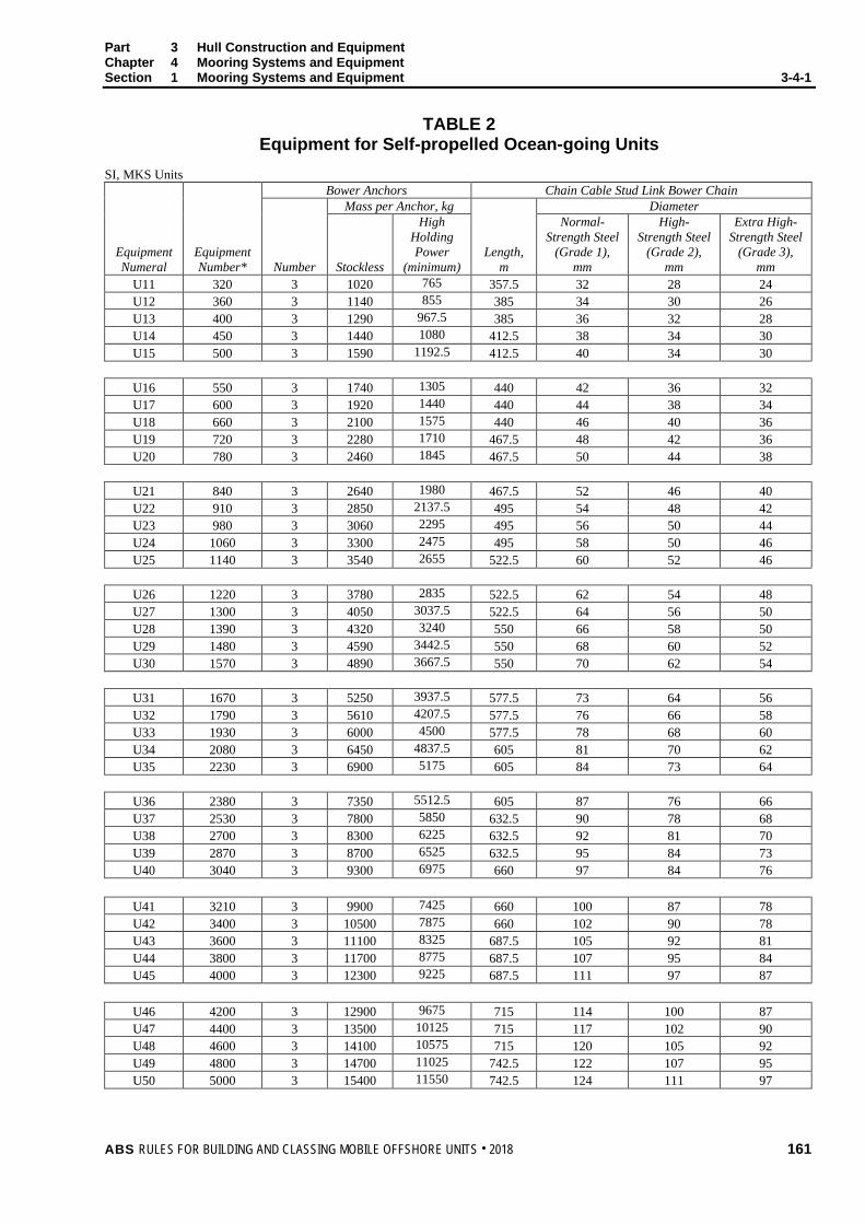
Part 3 Hull Construction and Equipment Chapter 4 Mooring Systems and Equipment Section 1 Mooring Systems and Equipment 3-4-1
TABLE 2 Equipment for Self-propelled Ocean-going Units
SI, MKS Units Bower Anchors Chain Cable Stud Link Bower Chain Mass per Anchor, kg Diameter
Equipment Numeral
Equipment Number* Number Stockless
High Holding Power
(minimum) Length,
m
Normal- Strength Steel
(Grade 1), mm
High- Strength Steel
(Grade 2), mm
Extra High-Strength Steel
(Grade 3), mm
U11 320 3 1020 765 357.5 32 28 24 U12 360 3 1140 855 385 34 30 26 U13 400 3 1290 967.5 385 36 32 28 U14 450 3 1440 1080 412.5 38 34 30 U15 500 3 1590 1192.5 412.5 40 34 30
U16 550 3 1740 1305 440 42 36 32 U17 600 3 1920 1440 440 44 38 34 U18 660 3 2100 1575 440 46 40 36 U19 720 3 2280 1710 467.5 48 42 36 U20 780 3 2460 1845 467.5 50 44 38
U21 840 3 2640 1980 467.5 52 46 40 U22 910 3 2850 2137.5 495 54 48 42 U23 980 3 3060 2295 495 56 50 44 U24 1060 3 3300 2475 495 58 50 46 U25 1140 3 3540 2655 522.5 60 52 46
U26 1220 3 3780 2835 522.5 62 54 48 U27 1300 3 4050 3037.5 522.5 64 56 50 U28 1390 3 4320 3240 550 66 58 50 U29 1480 3 4590 3442.5 550 68 60 52 U30 1570 3 4890 3667.5 550 70 62 54
U31 1670 3 5250 3937.5 577.5 73 64 56 U32 1790 3 5610 4207.5 577.5 76 66 58 U33 1930 3 6000 4500 577.5 78 68 60 U34 2080 3 6450 4837.5 605 81 70 62 U35 2230 3 6900 5175 605 84 73 64
U36 2380 3 7350 5512.5 605 87 76 66 U37 2530 3 7800 5850 632.5 90 78 68 U38 2700 3 8300 6225 632.5 92 81 70 U39 2870 3 8700 6525 632.5 95 84 73 U40 3040 3 9300 6975 660 97 84 76
U41 3210 3 9900 7425 660 100 87 78 U42 3400 3 10500 7875 660 102 90 78 U43 3600 3 11100 8325 687.5 105 92 81 U44 3800 3 11700 8775 687.5 107 95 84 U45 4000 3 12300 9225 687.5 111 97 87
U46 4200 3 12900 9675 715 114 100 87 U47 4400 3 13500 10125 715 117 102 90 U48 4600 3 14100 10575 715 120 105 92 U49 4800 3 14700 11025 742.5 122 107 95 U50 5000 3 15400 11550 742.5 124 111 97
ABS RULES FOR BUILDING AND CLASSING MOBILE OFFSHORE UNITS . 2018 161

Part 3 Hull Construction and Equipment Chapter 4 Mooring Systems and Equipment Section 1 Mooring Systems and Equipment 3-4-1
TABLE 2 (continued) Equipment for Self-propelled Ocean-going Units
SI, MKS Units Bower Anchors Chain Cable Stud Link Bower Chain Mass per Anchor, kg Diameter
Equipment Numeral
Equipment Number* Number Stockless
High Holding Power
(minimum) Length,
m
Normal- Strength Steel
(Grade 1), mm
High- Strength Steel
(Grade 2), mm
Extra High-Strength Steel
(Grade 3), mm
U51 5200 3 16100 12075 742.5 127 111 97 U52 5500 3 16900 12675 742.5 130 114 100 U53 5800 3 17800 13350 742.5 132 117 102 U54 6100 3 18800 14100 742.5 — 120 107 U55 6500 3 20000 15000 770 — 124 111
U56 6900 3 21500 16125 770 — 127 114 U57 7400 3 23000 17250 770 — 132 117 U58 7900 3 24500 18375 770 — 137 122 U59 8400 3 26000 19500 770 — 142 127 U60 8900 3 27500 20625 770 — 147 132 U61 9400 3 29000 21750 770 — 152 132
U62 10000 3 31000 23250 770 — — 137 U63 10700 3 33000 24750 770 — — 142 U64 11500 3 35500 26625 770 — — 147 U65 12400 3 38500 28875 770 — — 152 U66 13400 3 42000 31500 770 — — 157 U67 14600 3 46000 34500 770 — — 162
* For intermediate values of equipment number, use equipment complement in sizes and weights given for the lower equipment
number in the table.
Notes: 1 The use of chain of material grade superior to Grade 3 may be accepted, provided that:
a. The breaking strength with respect to the chain diameter is in accordance with Table 5 of the ABS Guide for Certification of Offshore Mooring Chain.
b. The length of the chain is suitably increased based on a scope of 10 (scope being the ratio of length paid out to the water depth).
c. The use of chain of superior material grade is taken into consideration in the mooring analysis and is documented in the Operating Manual of the unit.
d. Welding of studs in chain of superior material grade is not permitted unless specially approved.
2 In general, the use of steel wire ropes instead of anchor chain is not acceptable. When the unit has 4 points of anchoring or more, the use of steel wire ropes instead of anchor chain will be specially considered.
3 The third anchor is intended as a spare bower anchor and is listed for guidance only; it is not required as a condition of classification. See 3-4-1/9.
4 For superior holding power anchors, see 3-4-1/15.
162 ABS RULES FOR BUILDING AND CLASSING MOBILE OFFSHORE UNITS . 2018

Part 3 Hull Construction and Equipment Chapter 4 Mooring Systems and Equipment Section 1 Mooring Systems and Equipment 3-4-1
TABLE 2 Equipment for Self-propelled Ocean-going Units
US Units Bower Anchors Chain Cable Stud Link Bower Chain Mass per Anchor, lbs Diameter
Equipment Numeral
Equipment Number* Number Stockless
High Holding Power
(minimum) Length, fathoms
Normal- Strength Steel
(Grade 1), inches
High- Strength Steel
(Grade 2), inches
Extra High-Strength Steel
(Grade 3), inches
U11 320 3 2250 1687.5 195 1 1/4 1 1/8 15/16 U12 360 3 2510 1882.5 210 1 5/16 1 3/16 1 U13 400 3 2840 2130 210 1 7/16 1 1/4 1 1/8 U14 450 3 3170 2377.5 225 1 1/2 1 5/16 1 3/16 U15 500 3 3500 2625 225 1 9/16 1 5/16 1 3/16
U16 550 3 3830 2872.5 240 1 5/8 1 7/16 1 1/4 U17 600 3 4230 3172.5 240 1 3/4 1 1/2 1 5/16 U18 660 3 4630 3472.5 240 1 13/16 1 9/16 1 7/16 U19 720 3 5020 3765 255 1 7/8 1 5/8 1 7/16 U20 780 3 5420 4065 255 2 1 3/4 1 1/2
U21 840 3 5820 4365 255 2 1/16 1 13/16 1 9/16 U22 910 3 6280 4710 270 2 1/8 1 7/8 1 5/8 U23 980 3 6740 5055 270 2 3/16 1 15/16 1 3/4 U24 1060 3 7270 5452.5 270 2 5/16 2 1 13/16 U25 1140 3 7800 5850 285 2 3/8 2 1/16 1 13/16
U26 1220 3 8330 6247.5 285 2 7/16 2 1/8 1 7/8 U27 1300 3 8930 6697.5 285 2 1/2 2 3/16 2 U28 1390 3 9520 7140 300 2 5/8 2 5/16 2 U29 1480 3 10120 7590 300 2 11/16 2 3/8 2 1/16 U30 1570 3 10800 8100 300 2 3/4 2 7/16 2 1/8
U31 1670 3 11600 8700 315 2 7/8 2 1/2 2 3/16 U32 1790 3 12400 9300 315 3 2 5/8 2 5/16 U33 1930 3 13200 9900 315 3 1/16 2 11/16 2 3/8 U34 2080 3 14200 10650 330 3 3/16 2 3/4 2 7/16 U35 2230 3 15200 11400 330 3 5/16 2 7/8 2 1/2
U36 2380 3 16200 12150 330 3 7/16 3 2 5/8 U37 2530 3 17200 12900 345 3 9/16 3 1/16 2 11/16 U38 2700 3 18300 13725 345 3 5/8 3 3/16 2 3/4 U39 2870 3 19200 14400 345 3 3/4 3 5/16 2 7/8 U40 3040 3 20500 15375 360 3 7/8 3 5/16 3
U41 3210 3 21800 16350 360 3 15/16 3 7/16 3 1/16 U42 3400 3 23100 17325 360 4 3 9/16 3 1/16 U43 3600 3 24500 18375 375 4 1/8 3 5/8 3 3/16 U44 3800 3 25800 19350 375 4 1/4 3 3/4 3 5/16 U45 4000 3 27100 20325 375 4 3/8 3 7/8 3 7/16
U46 4200 3 28400 21300 390 4 1/2 3 15/16 3 7/16 U47 4400 3 29800 22350 390 4 5/8 4 3 9/16 U48 4600 3 31100 23325 390 4 3/4 4 1/8 3 5/8 U49 4800 3 32400 24300 405 4 3/4 4 1/4 3 3/4 U50 5000 3 33900 25425 405 4 7/8 4 3/8 3 7/8
ABS RULES FOR BUILDING AND CLASSING MOBILE OFFSHORE UNITS . 2018 163

Part 3 Hull Construction and Equipment Chapter 4 Mooring Systems and Equipment Section 1 Mooring Systems and Equipment 3-4-1
TABLE 2 (continued) Equipment for Self-propelled Ocean-going Units
US Units Bower Anchors Chain Cable Stud Link Bower Chain Mass per Anchor, lbs Diameter
Equipment Numeral
Equipment Number* Number Stockless
High Holding Power
(minimum) Length, fathoms
Normal- Strength Steel
(Grade 1), inches
High- Strength Steel
(Grade 2), inches
Extra High-Strength Steel
(Grade 3), inches
U51 5200 3 35500 26625 405 5 4 3/8 3 7/8 U52 5500 3 37200 27900 405 5 1/8 4 1/2 3 15/16 U53 5800 3 39200 29400 405 5 1/8 4 5/8 4 U54 6100 3 41400 31050 405 — 4 3/4 4 1/4 U55 6500 3 44000 33000 420 — 4 7/8 4 3/8
U56 6900 3 47400 35550 420 — 5 4 1/2 U57 7400 3 50700 38025 420 — 5 1/8 4 5/8 U58 7900 3 54000 40500 420 — 5 3/8 4 3/4 U59 8400 3 57300 42975 420 — 5 5/8 5 U60 8900 3 60600 45450 420 — 5 3/4 5 1/8 U61 9400 3 63900 47925 420 — 6 5 1/8
U62 10000 3 68000 51000 420 — — 5 3/8 U63 10700 3 72500 54375 420 — — 5 5/8 U64 11500 3 78000 58500 420 — — 5 3/4 U65 12400 3 85000 63750 420 — — 6 U66 13400 3 92500 69375 420 — — 6 1/8 U67 14600 3 101500 76125 420 — — 6 3/8
* For intermediate values of equipment number, use equipment complement in sizes and weights given for the lower equipment
number in the table.
Notes: 1 The use of chain of material grade superior to Grade 3 may be accepted, provided that:
a. The breaking strength with respect to the chain diameter is in accordance with Table 1 of the ABS Guide for Certification of Offshore Mooring Chain 2009.
b. The length of the chain is suitably increased based on a scope of 10 (scope being the ratio of length paid out to the water depth).
c. The use of chain of superior material grade is taken into consideration in the mooring analysis and is documented in the Operating Manual of the unit.
d. Welding of studs in grades R4, R4S and R5 chain is not permitted unless specially approved. A welded stud may be accepted for grade R3 and R3S chains.
e. The manufacturer is approved to produce the grade of chain in accordance with the Guide for the Certification of Offshore Mooring Chain 2009.
2 In general, the use of steel wire ropes instead of anchor chain is not acceptable. When the unit has 4 points of anchoring or more, the use of steel wire ropes instead of anchor chain will be specially considered.
3 The third anchor is intended as a spare bower anchor and is listed for guidance only; it is not required as a condition of classification. See 3-4-1/9.
4 For superior holding power anchors, see 3-4-1/15.
164 ABS RULES FOR BUILDING AND CLASSING MOBILE OFFSHORE UNITS . 2018
P A R T A p p e n d i x 1 : P o s i t i o n M o o r i n g S y s t e m s
3 C H A P T E R 4 Mooring Systems and Equipment
A P P E N D I X 1 Position Mooring Systems
1 General
1.1 Units provided with position mooring systems, in accordance with this Appendix, will be designated in the Record by the optional classification notation Ã.
3 Anchoring Systems
3.1 General Plans showing the arrangement and complete details of the anchoring system, including anchors, shackles, anchor lines consisting of chain, wire or rope, together with details of fairleads, windlasses, winches and any other components of the anchoring system and their foundations and attachments to the unit are to be submitted for review.
3.3 Design 3.3.1
An analysis of the anchoring arrangements expected to be utilized in the unit’s operation is to be submitted. Among the items to be addressed are:
i) Design environmental conditions of waves, winds, currents, tides and ranges of water depth.
ii) Air and sea temperature.
iii) Description of analysis methodology.
3.3.2 The anchoring system is to be designed to prevent a failure of any single component causing progressive failure of the remaining anchoring arrangements.
3.3.3 Anchoring system components are to be designed utilizing adequate factors of safety (FOS) and a design methodology suitable to identify the most severe loading condition for each component. In particular, sufficient numbers of heading angles together with the most severe combination of wind, current and wave are to be considered, usually from the same direction, to determine the maximum tension in each mooring line.
3.3.4 When a quasi-static analysis method is applied, the tension in each anchor line is to be calculated at the maximum excursion for each design condition defined in 3-4-A1/3.3.5, combining the following steady state and dynamic responses of the unit:
3.3.4(a) steady mean offset due to the defined wind, current and steady wave forces;
ABS RULES FOR BUILDING AND CLASSING MOBILE OFFSHORE UNITS . 2018 165
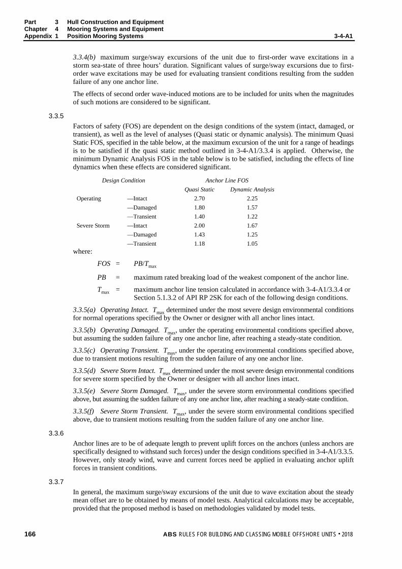
Part 3 Hull Construction and Equipment Chapter 4 Mooring Systems and Equipment Appendix 1 Position Mooring Systems 3-4-A1
3.3.4(b) maximum surge/sway excursions of the unit due to first-order wave excitations in a storm sea-state of three hours’ duration. Significant values of surge/sway excursions due to first-order wave excitations may be used for evaluating transient conditions resulting from the sudden failure of any one anchor line.
The effects of second order wave-induced motions are to be included for units when the magnitudes of such motions are considered to be significant.
3.3.5 Factors of safety (FOS) are dependent on the design conditions of the system (intact, damaged, or transient), as well as the level of analyses (Quasi static or dynamic analysis). The minimum Quasi Static FOS, specified in the table below, at the maximum excursion of the unit for a range of headings is to be satisfied if the quasi static method outlined in 3-4-A1/3.3.4 is applied. Otherwise, the minimum Dynamic Analysis FOS in the table below is to be satisfied, including the effects of line dynamics when these effects are considered significant.
Design Condition Anchor Line FOS Quasi Static Dynamic Analysis
Operating Severe Storm
—Intact —Damaged —Transient —Intact —Damaged —Transient
2.70 1.80 1.40 2.00 1.43 1.18
2.25 1.57 1.22 1.67 1.25 1.05
where:
FOS = PB/Tmax
PB = maximum rated breaking load of the weakest component of the anchor line.
Tmax = maximum anchor line tension calculated in accordance with 3-4-A1/3.3.4 or Section 5.1.3.2 of API RP 2SK for each of the following design conditions.
3.3.5(a) Operating Intact. Tmax determined under the most severe design environmental conditions for normal operations specified by the Owner or designer with all anchor lines intact.
3.3.5(b) Operating Damaged. Tmax, under the operating environmental conditions specified above, but assuming the sudden failure of any one anchor line, after reaching a steady-state condition.
3.3.5(c) Operating Transient. Tmax, under the operating environmental conditions specified above, due to transient motions resulting from the sudden failure of any one anchor line.
3.3.5(d) Severe Storm Intact. Tmax determined under the most severe design environmental conditions for severe storm specified by the Owner or designer with all anchor lines intact.
3.3.5(e) Severe Storm Damaged. Tmax, under the severe storm environmental conditions specified above, but assuming the sudden failure of any one anchor line, after reaching a steady-state condition.
3.3.5(f) Severe Storm Transient. Tmax, under the severe storm environmental conditions specified above, due to transient motions resulting from the sudden failure of any one anchor line.
3.3.6 Anchor lines are to be of adequate length to prevent uplift forces on the anchors (unless anchors are specifically designed to withstand such forces) under the design conditions specified in 3-4-A1/3.3.5. However, only steady wind, wave and current forces need be applied in evaluating anchor uplift forces in transient conditions.
3.3.7 In general, the maximum surge/sway excursions of the unit due to wave excitation about the steady mean offset are to be obtained by means of model tests. Analytical calculations may be acceptable, provided that the proposed method is based on methodologies validated by model tests.
166 ABS RULES FOR BUILDING AND CLASSING MOBILE OFFSHORE UNITS . 2018

Part 3 Hull Construction and Equipment Chapter 4 Mooring Systems and Equipment Appendix 1 Position Mooring Systems 3-4-A1
3.3.8 Other analysis methodologies may be acceptable, provided that a level of safety equivalent to that required by 3-4-A1/3.3.4 and 3-4-A1/3.3.5 is attained.
3.3.9 Special consideration will be given to arrangements where the anchoring systems are used in conjunction with thrusters to maintain the unit on station.
5 Equipment
5.1 Winches and Windlasses 5.1.1
The design of mooring winches and windlasses is to provide for adequate dynamic braking capacity to control normal combinations of loads from the anchor, anchor line and anchor handling vessel during the deployment of the anchors at the maximum design payout speed of the winch or windlass. Winch and windlass foundations and adjacent hull structures are to be designed to withstand an anchor line load at the winch or windlass at least equal to the rated breaking load of the anchor line.
5.1.2 Each winch or windlass is to be provided with two independent, power operated brakes and each brake is to be capable of holding a static load in the anchor line of at least 50 percent of the anchor line’s rated breaking strength. One of the brakes may be replaced by a manually operated brake.
5.1.3 On loss of power to the winches or windlasses, the power operated braking system is to be automatically applied and be capable of holding against 50 percent of the total static braking capacity of the windlass.
5.3 Fairleads and Sheaves 5.3.1
Fairleads and sheaves are to be designed to prevent excessive bending and wear of the anchor lines. The attachments to the hull or structure are to be such as to withstand the stresses imposed when an anchor line is loaded to its rated breaking strength.
7 Anchor Lines
7.1 Anchor lines are to be of a type that is compatible with the design conditions of the anchoring system. Details are to be submitted.
7.3 Means are to be provided to enable the anchor lines to be released from the unit after loss of main power.
7.5 Means are to be provided for measuring anchor line tensions and for initial and periodic calibration of line tension measuring instrumentation.
ABS RULES FOR BUILDING AND CLASSING MOBILE OFFSHORE UNITS . 2018 167
Part 3 Hull Construction and Equipment Chapter 4 Mooring Systems and Equipment Appendix 1 Position Mooring Systems 3-4-A1
9 Anchors
9.1 The type and design of anchors are to be submitted for review, together with documentation estimating their holding power in various types of soil.
9.3 Suitable anchor stowage arrangements are to be provided to prevent movement of the anchors during transit.
11 Quality Control
11.1 Details of the quality control of the manufacturing process of the individual anchoring system components are to be submitted. Components are to be designed, manufactured and tested in accordance with recognized standards insofar as possible and practical. Equipment so tested is to, insofar as practical, be legibly and permanently marked with the Surveyor’s stamp and delivered with documentation which records the results of the tests.
13 Control Stations
13.1 A manned central control station is to be provided with means to indicate anchor line tensions and to indicate wind speed and direction.
13.3 Reliable means are to be provided to communicate between locations critical to the anchoring operation.
13.5 Each winch or windlass is to be capable of being controlled from a position which provides a good view of the operation. Means are to be provided at the individual winch or windlass control positions to monitor anchor line tension, winch or windlass power load and to indicate the amount of anchor line paid out.
168 ABS RULES FOR BUILDING AND CLASSING MOBILE OFFSHORE UNITS . 2018