mobile elevating work platforms — design calculations - mewp
TRANSCRIPT

prEN 280:2009 (E)
1
CEN/TC 98 Date: 2009-02
prEN 280:2009
CEN/TC 98
Secretariat: DIN
Mobile elevating work platforms — Design calculations — Stability criteria — Construction — Safety — Examinations and tests
Fahrbare Hubarbeitsbühnen — Berechnung — Standsicherheit — Bau — Sicherheit — Prüfungen
Plates-formes élévatrices mobiles de personnel — Calculs — Stabilité — Construction — Sécurité — Examens et essais
ICS:
Descriptors:

prEN 280:2009 (E)
2
Contents Page
Introduction .........................................................................................................................................................3 1 Scope ......................................................................................................................................................5 2 Normative references ............................................................................................................................7 3 Terms and definitions ...........................................................................................................................8 4 List of hazards..................................................................................................................................... 13 5 Safety requirements and/or measures ............................................................................................. 17 5.1 General................................................................................................................................................. 17 5.2 Structural and stability calculations................................................................................................. 17 5.3 Chassis and stabilisers...................................................................................................................... 29 5.4 Extending structure............................................................................................................................ 35 5.5 Extending structure drive systems................................................................................................... 38 5.6 Work platform...................................................................................................................................... 43 5.7 Controls ............................................................................................................................................... 46 5.8 Electrical equipment........................................................................................................................... 48 5.9 Hydraulic systems .............................................................................................................................. 49 5.10 Hydraulic cylinders............................................................................................................................. 50 5.11 Safety devices..................................................................................................................................... 54 6 Verification of the safety requirements and/or measures .............................................................. 56 6.1 Examinations and tests...................................................................................................................... 56 6.2 Type tests of MEWPs ......................................................................................................................... 60 6.3 Tests before placing on the market .................................................................................................. 60 7 Information for use ............................................................................................................................. 60 7.1 Instruction handbook ......................................................................................................................... 60 7.2 Marking ................................................................................................................................................ 63 Annex A (informative) Use of MEWPs in wind speeds greater than 12,5 m/s (Beaufort-Scale)............... 66 Annex B (informative) Dynamic factors in stability and structural calculations ....................................... 67 B.1 Stability calculations .......................................................................................................................... 67 B.2 Structural calculations ....................................................................................................................... 68 Annex C (normative) Calculation of wire rope drive systems..................................................................... 69 C.1 General................................................................................................................................................. 69 C.2 Calculation of wire rope drive systems............................................................................................ 69 C.3 Calculation of rope diameters (coefficient c)................................................................................... 70 C.4 Calculation of the diameters of rope drums, rope pulleys and compensating pulleys
[coefficient (h1 · h
2)] ............................................................................................................................ 70
C.5 Efficiency of wire rope drive systems .............................................................................................. 73 Annex D (informative) Calculation example – wire rope drive systems..................................................... 75 D.1 Method used to determine the coefficients and ratios used for 5.5.2 (wire rope drive
systems) using the load cycle figures in 5.2.5.3 and operating speeds in 5.4.5.......................... 75 D.2 Calculation of the diameters of rope drums, pulleys and static pulleys ...................................... 79 Annex E (informative) Calculation example – factor "s", kerb test............................................................. 81 Annex F (normative) Additional requirements for wireless controls and control systems ..................... 83 Annex ZA (informative) Relationship between this European Standard and the Essential
Requirements of EU Directive 2006/42/EC ....................................................................................... 85 Bibliography..................................................................................................................................................... 86

prEN 280:2009 (E)
3
Foreword
This document (prEN 280:2009) has been prepared by Technical Committee CEN/TC 98 “Lifting platforms”, the secretariat of which is held by DIN.
This document is currently submitted to CEN-Enquiry.
This document will supersede EN 280:2001.
This European Standard has been prepared under a mandate given to CEN by the European Commission and the European Free Trade Association, and supports essential requirements of EU Directive(s).
For relationship with EU Directive(s), see informative Annex ZA, which is an integral part of this standard.

prEN 280:2009 (E)
4
Introduction
This standard is a type C standard as stated in EN ISO 12100.
The object of this European Standard is to define rules for safeguarding persons and objects against the risk of accidents associated with the operation of Mobile Elevating Work Platforms (MEWPs).
⎯ This European Standard does not repeat all the general technical rules applicable to every electrical, mechanical or structural component.
⎯ The safety requirements of this European Standard have been drawn up on the basis that MEWPs are periodically maintained according to manufacturers' instructions, working conditions, frequency of use and national regulations.
It is also assumed that MEWPs are checked for function daily before start of work and are not put into operation unless all required control and safety devices are available and in working order.
If a MEWP is seldom used, the checks may be made before start of work.
Furthermore it is assumed that persons on the work platform in case of power supply failure are not incapacitated and can assist in the operation of the overriding emergency device.
⎯ As far as possible this European Standard sets out only the requirements that materials and equipment have to meet in the interest of safety, and it is assumed that persons operating MEWPs are adequately trained.
⎯ Where for clarity an example of a safety measure is given in the text, this shall not be considered as the only possible solution. Any other solution leading to the same risk reduction is permissible if an equivalent level of safety is achieved.
⎯ As no satisfactory explanation could be found for the dynamic factors used for stability calculations in previous national standards, the results of the tests carried out by the former CEN/TC 98/WG 1 to determine a suitable factor and stability calculation method for MEWPs have been adopted. The test method is described in Annex B (informative) as a guide for manufacturers wishing to use higher or lower operating speeds and to take advantage of developments in control systems.
Similarly, to avoid the unexplained inconsistencies in coefficients of utilisation for wire ropes found in other standards for lifting devices, appropriate extracts of the widely accepted standard DIN 15020 have been taken into 5.5.2 and Annex C (normative) with a worked example in Annex D (informative).
prEN 280:2009 (E)
5
1 Scope
1.1 This European Standard specifies technical safety requirements and measures for all types and sizes of Mobile Elevating Work Platform (MEWP) intended to move persons to working positions where they are carrying out work from the work platform (WP) with the intention that persons are getting on and off the work platform only at access positions at ground level or on the chassis.
1.2 This European Standard is applicable to the structural design calculations and stability criteria, construction, safety examinations and tests before MEWPs are first put into service. It identifies the hazards arising from the use of MEWPs and describes methods for the elimination or reduction of these hazards.
It does not cover the hazards arising from:
a) use in potentially explosive atmospheres;
b) electromagnetic incompatibility;
c) work on live electric systems;
d) use of compressed gases for load bearing components;
e) getting on and off the work platform at changing levels.
1.3 This European standard does not apply to:
a) permanently installed personnel lifting appliances serving defined levels (see e.g. EN 81-1:1998 and EN 81-2:1998);
b) fire-fighting and fire rescue appliances (see e.g. EN 1777:2004);
c) unguided work cages suspended from lifting appliances (see e.g. EN 1808:1999);
d) elevating operator position on rail dependent storage and retrieval equipment (see EN 528:1996);
e) tail lifts (see EN 1756-1:2001 + A1:2008 and EN 1756-2:2004);
f) mast climbing work platforms (see EN 1495:1997);
g) fairground equipment;
h) lifting tables with a lifting height of less than 2 m (see EN 1570:1998);
i) builders hoists for persons and materials (see EN 12159:2000);
j) aircraft ground support equipment (see e.g. EN 1915-1 and 2:2001);
k) elevating operator positions on industrial trucks (see EN 1726-2:2004).
1.4 Classification
MEWPs are divided into two main groups:
Group A: MEWPs where the vertical projection of the centre of the area of the platform in all platform configurations at the maximum chassis inclination specified by the manufacturer is always inside the tipping lines.
Group B: All other MEWPs.

prEN 280:2009 (E)
6
Relating to travelling, MEWPs are divided into three types:
Type 1 Travelling is only allowed with the MEWP in its transport configuration;
Type 2 Travelling with raised work platform is controlled from a point of control at the chassis;
Type 3 Travelling with raised work platform is controlled from a point of control at the work platform.
NOTE The types 2 and 3 can be combined.
1.5 This standard applies to machines which are manufactured 12 months after publication of this standard.

prEN 280:2009 (E)
7
2 Normative references
The following referenced documents are indispensable for the application of this document. For dated references, only the edition cited applies. For undated references, the latest edition of the referenced document (including any amendments) applies.
EN ISO 12100-1:2003, Safety of machinery – Basic concept, general principles for design – Part 1: Basic terminology, methodology (ISO 12100-1:2003)
EN ISO 12100-2:2003, Safety of machinery – Basic concept, general principles for design – Part 2: Technical principles (ISO 12100-1:2003)
EN 349, Safety of machinery — Minimum gaps to avoid crushing of parts of the human body
EN ISO 13850, Safety of machinery — Emergency stop — Principles for design
prEN 15746-1:2007, Railway applications — Track — Road-rail machines and associated equipment — Part 1: Technical requirements for running and working
prEN 15746-2:2007, Railway applications — Track — Road-rail machines and associated equipment — Part 2: General safety requirements
EN ISO 13857:2008, Safety of machinery - Safety distances to prevent hazard zones being reached by upper and lower limbs (ISO 13857:2008)
EN ISO 13849-1:2008, Safety of machinery — Safety related parts of control systems — Part 1: General principles for design (ISO 13849-1:2006)
EN ISO 13849-2:2003, Safety of machinery — Safety related parts of control systems — Part 2: Validation
EN 60204-1:2006, Safety of machinery — Electrical equipment of machines — Part 1: General requirements (IEC 60204-1:2006)
EN 60204-32:2008, Safety of machinery — Electrical equipment of machines — Part 1: Requirements for hoisting machines (IEC 60204-32:2008)
EN 60529:1991, Degrees of protection provided by enclosures (IP code) (IEC 60529:1989)
ISO 3864-1:2002, Safety colours and safety signs – Part1: Design principles for safety signs in work places and public areas
ISO 4302, Cranes — Wind load assessment
ISO 4305, Mobile cranes — Determination of stability
ISO 4309, Cranes — Wire ropes — Code of practice for examination and discard

prEN 280:2009 (E)
8
3 Terms and definitions
For the purposes of this European Standard, the terms and definitions of EN ISO 12100-1:2003 and EN ISO 12100-2:2003 and the following apply:
3.1 mobile elevating work platform (MEWP) mobile machine that is intended to move persons to working positions where they are carrying out work from the work platform with the intention that persons are getting on and off the work platform only at access positions at ground level or on the chassis and which consists as a minimum of a work platform with controls, an extending structure and a chassis. In this standard the abbreviation MEWP is used for mobile elevating work platform
3.2 work platform (see Figure 1) fenced platform or a cage which can be moved under load to the required working position and from which erection, repair, inspection or similar work can be carried out
3.3 extending structure (see Figure 1) structure which is connected to the chassis and supports the work platform. It allows movement of the work platform to its required position. It may, for example, be a single or a telescoping or a articulating boom or ladder, or a scissors mechanism or any combination of them, and may or may not slew on the base
3.4 chassis (see Figure 1) base of the MEWP. It may be pulled, pushed, self propelled, etc.
3.5 stabilisers (see Figure 1) all devices and systems used to stabilise MEWPs by supporting and/or levelling the complete MEWP or the extending structure, e.g. jacks, suspension locking devices, extending axles
3.6 access position1) position(s) to provide access to and from the work platform
3.7 transport configuration1) configuration of the MEWP prescribed by the manufacturer in which the MEWP is intended to be delivered to the work site
3.8 lowering (see Figure 2) all operations to move the work platform to a lower level
3.9 raising (see Figure 2) all operations to move the work platform to a higher level
3.10 rotating (see Figure 2) circular movement of the work platform about a vertical axis
1)Access position and transport configuration can be identical
prEN 280:2009 (E)
9
3.11 slewing (see Figure 2) circular movement of the extending structure about a vertical axis
3.12 travelling (see Figure 2) all movements of the chassis with work platform out of transport configuration
3.13 vehicle mounted MEWP MEWP that has travelling controls located within the cab of the vehicle
3.14 pedestrian controlled MEWP MEWP that has the controls for powered transport located so that they are capable of being operated by a person walking close to the MEWP
3.15 self propelled MEWP MEWP that has the travelling controls located at the work platform
3.16 rated load load for which the MEWP has been designed for normal operation. The rated load is composed of persons, tools and material acting vertically on the work platform
NOTE A MEWP can have more than one rated load.
3.17 load cycle cycle starting from the access position, carrying out work and returning to the access position
3.18 wire rope drive system system that comprises one or more wire rope(s) running on rope drums and on or over rope pulleys as well as any associated rope drums, rope pulleys and compensating pulleys
3.19 chain drive system system that comprises one or more chain(s) running on chain sprockets and on or over chain pulleys as well as any associated chain sprockets, chain pulleys and compensating pulleys
3.20 type test test on the representative model of a new design or one incorporating significant changes to an existing design, carried out by or on behalf of the manufacturer or his authorised representative
3.21 totally manually operated MEWP MEWP with movement powered only by manual effort
3.22 rail mounted MEWP MEWP where travelling is guided by rails
3.23 load sensing system system of monitoring the vertical load and vertical forces on the work platform (see 3.2)
prEN 280:2009 (E)
10
NOTE The system includes the measuring device(s), the method of mounting the measuring devices and the signal processing system.
3.24 moment sensing system system of monitoring the moment acting about the tipping line tending to overturn the MEWP
NOTE The system includes the measuring device(s), the method of mounting the measuring devices and the signal processing system.
3.25 wireless control means by which the MEWP operator’s commands are transmitted without any physical connection for at least part of the distance between the control consol and the MEWP
3.26 Self revealing failure or fault failure or fault of a component where the failure or fault is apparent to the MEWP operator:
• through changes of operating characteristics • visual, audible or other evidence.
This evidence can be revealed without the use of monitoring devices
3.27 working envelope space in which the work platform is designed to work within the specified loads and forces under normal operating conditions
NOTE MEWPS can have more than one working envelope.

prEN 280:2009 (E)
11
Key 1 work platform (see 3.2) 2 extending structure (see 3.3) 3 chassis (see 3.4) 4 stabilisers (see 3.5)
Figure 1 — Illustration of some definitions (1)

prEN 280:2009 (E)
12
lowering/raising (see 3.8 and 3.9)
rotating (see 3.10)
slewing (see 3.11)
travelling (see 3.12)
Figure 2 — Illustration of some definitions (2)

prEN 280:2009 (E)
13
4 List of hazards
The hazards have been identified by the risk assessment procedure and the corresponding requirements formulated.
A hazard which is not significant and for which, therefore, no requirements are formulated, is shown in the Corresponding Requirements column as NS (not significant).
Table 1 — List of significant hazards
Significant hazards Relevant clauses in this standard
1 Mechanical hazards -
1.1 Crushing hazard 5.3.4, 5.3.5, 5.3.22, 5.4.3, 5.6.9, 5.7.1, 7.2.15
1.2 Shearing hazard 5.4.4, 5.7.1, 7.2.15
1.3 Cutting or severing hazard NS
1.4 Entanglement hazard 5.3.19, 7.2.15
1.5 Drawing-in or trapping hazard 5.3.19, 7.2.15
1.6 Impact hazard 5.3.5, 5.3.24, 7.1.1.2 h)
1.7 Stabbing or puncture hazard NS
1.8 Friction or/abrasion hazard 7.1.1.7 e)
1.9 High pressure fluid injection hazard 5.9.1, 5.9.2, 5.9.3, 5.9.4, 5.9.5, 5.9.10
1.10 Ejection of parts NS
1.11 Loss of stability (of machinery and machine parts) 5.2, 5.3.2, 5.3.6, 5.3.7, 5.3.8, 5.3.10, 5.3.11, 7.2.1l)
1.12 Slip, trip and fall hazards 5.6.2, 5.6.3, 5.6.4, 5.6.5, 5.6.6, 5.6.7, 7.2.15
2 Electrical hazards, caused for example by: -
2.1 Electrical contact (direct or indirect) 5.8, 7.1.1.2.g)
2.2 Electrostatic phenomena NS
2.3 Thermal radiation NS
2.4 External influences on electrical equipment 5.8.1
3 Thermal hazards for example resulting in: -
3.1 Burns and scalds by a possible contact of persons by flames or explosions and also by the radiation of heat sources
5.3.19
3.2 Health-damaging effects by hot or cold work environment 5.3.19
4 Hazards generated by noise, resulting for example in: 7.1.1.2 v)
4.1 Hearing losses (deafness), other physiological disorders (e.g. loss of balance, loss of awareness etc.)
NS
4.2 Interference with speech communication, acoustic signals etc. NS

prEN 280:2009 (E)
14
Table 2 (continued)
Significant hazards Relevant clauses in this standard
5 Hazards generated by vibration (resulting in a variety of neurological and vascular disorders)
5.3.23, 7.1.1.2 l)
6 Hazards generated by radiation, especially by: -
6.1 Electrical arcs 7.1.1.2 g)
6.2 Lasers NS
6.3 Ionising radiation sources NS
.4 Machine making use of high frequency electromagnetic fields 5.8.1
7 Hazards generated by materials and substances processed, used or exhausted by machinery for example:
-
7.1 Hazards resulting from contact with or inhalation of harmful fluids, gases, mists, dusts and fumes
5.3.20, 5.3.24
7.2 Fire or explosion hazard 5.3.21
7.3 Biological and microbiological (viral or bacterial) hazards NS
8 Hazards generated by neglecting ergonomic principles in machine design (mismatch of machinery with human characteristics and abilities) caused for example by:
-
8.1 Unhealthy postures or excessive efforts 5.6.6, 5.6.7
8.2 Inadequate consideration of human hand-arm or foot-leg anatomy
NS
8.3 Neglected use of personal protection equipment NS
8.4 Inadequate area lighting NS
8.5 Mental overload or underload, stress, etc. NS
8.6 Human error 5.7.1, 5.7.3
9 Hazard combinations -
10 Hazards caused by failure of energy supply, breaking down of machinery parts, and other functional disorders, for example:
-
10.1 Failure of energy supply (of energy and/or control circuits) 5.3.12, 5.7.6, 5.7.7, 5.7.8, 5.9.6, 5.9.7, 5.9.8, 5.9.9, 5.11.3
10.2 Unexpected ejection of machine parts or fluids NS
10.3 Failure/malfunction of control system 5.3.26, 5.7.7
10.4 Errors of fitting 5.8.1, 5.9.11
10.5 Overturn, unexpected loss of machine stability 5.2, 5.3.2, 5.3.6, 5.3.7, 5.3.8, 7.2.1 l)
11 Hazards caused by (temporary) missing and/or incorrectly positioned safety-related measures/means, for example:
-
11.1 All kinds of guard 5.3.19
11.2 All kinds of safety related (protection) devices 5.3.10, 5.11

prEN 280:2009 (E)
15
Table 2 (continued)
Significant hazards Relevant clauses in this standard
11.3 Starting and stopping devices 5.3.1, 5.4.4, 5.5.2.7, 5.5.3.7, 5.5.5.2, 5.6.3, 5.7.1, 5.7.2, 5.7.4, 5.7.5, 5.7.7, 5.7.8, 5.11
11.4 Safety signs and signals 5.3.2, 5.6.10, 5.7.3, 5.9.10
11.5 All kinds of information or warning devices 5.3.2, 5.3.14, 5.6.11,
7.1.1.2 c), 7.2
11.6 Energy supply disconnecting devices 5.3.26
11.7 Emergency devices 5.7.5
11.8 Feeding/removal means of work pieces NS
11.9 Essential equipment and accessories for safe adjusting and/or maintaining
5.4.4, 5.9.1, 7.1.1.7d), 7.1.1.7l)
11.10 Equipment evacuating gases, etc. 5.3.20
12 Inadequate lighting of moving/working area NS
13 Hazards due to sudden movement/instability during handling
5.2, 5.3.2, 5.3.3, 5.3.6, 5.3.7, 5.3.9, 5.3.10, 5.3.13, 5.6.1, 5.7.1, 5.7.4, 5.7.5, 5.7.10
14 Inadequate/inergonomic design of driving/operating position
5.6.9
14.1 Hazards due to dangerous environments (contact with moving parts exhaust gases etc.)
5.3.19, 5.3.20
14.2 Inadequate visibility from driver's/operator's position 5.3.2, 5.3.22
14.3 Inadequate seat/seating (seat index point) 5.3.23
14.4 Inadequate/non-ergonomic design/positioning of controls 5.6.9
14.5 Starting/moving of self-propelled machinery 5.3.14, 5.3.15, 5.3.16, 5.3.17, 5.3.18, 5.3.22, 5.7.1, 5.7.2, 5.7.4
14.6 Road traffic of self-propelled machinery 5.3.12, 5.3.16, 5.3.17, 5.3.19,
14.7 Movement of pedestrian controlled machinery 5.3.18, 5.7.2
15 Mechanical hazards -
15.1 Hazards to exposed persons due to uncontrolled movement 5.2.4, 5.4.4, 5.7.1
15.2 Hazards due to break-up and/or ejection of parts NS
15.3 Hazards due to rolling over (ROPs) NS
15.4 Hazards due to falling objects (FOPs) NS
15.5 Inadequate means of access 5.6.6, 5.6.7
15.6 Hazards caused due to towing, coupling, connecting, transmission
NS
15.7 Hazards due to batteries, fire, emissions etc. 5.3.20, 5.3.21, 5.3.24
16 Hazards due to lifting operation -

prEN 280:2009 (E)
16
Table 2 (continued)
Significant hazards Relevant clauses in this standard
16.1 Lack of stability 5.2, 5.3.2, 5.3.6, 5.3.7, 5.3.8, 5.3.10, 5.3.11, 5.4.1, 7.2.1 l)
16.2 Derailment of machinery 5.3.25
16.3 Loss of mechanical strength of machinery and lifting accessories
5.2.5, 5.4.1, 5.4.6, 5.6.13, 7.1.1.3 a) and b)
16.4 Uncontrolled movements 5.3.3, 5.3.4, 5.3.5, 5.4, 5.5, 5.6.1,
17 Inadequate view of trajectories of the moving parts 5.3.22
18 Hazards caused by lightning NS
19 Hazards due to loading/overloading 5.4.1
20 Hazards due to lifting persons -
20.1 Mechanical strength 5.5.2, 5.5.3
20.2 Loading control 5.4.1
21 Controls -
21.1 Movement of work platform 5.4, 5.6.1, 5.7.1, 5.7.4, 5.7.5, 5.7.10, Annex C
21.2 Safe travel control 5.7.1, 5.7.2, 5.7.4, 5.7.5
21.3 Safe speed control 5.3.1, 5.3.17, 5.3.18, 5.4.5
22 Falling of persons -
22.1 Personal protective equipment 5.6.2
22.2 Trapdoors 5.6.8
22.3 Work platform tilt control 5.6.1
23 Work platform falling/overturning -
23.1 Falling/overturning 5.2, 5.3.2, 5.3.3, 5.3.6, 5.3.7, 5.3.8, 5.3.10, 5.3.11, 5.3.13, 5.4.1, 5.4.2, 5.6.12, 5.9, 5.10
23.2 Acceleration/braking 5.3.17, 5.4.5, 5.5.1.6
24 Markings 7.2
25 Hazards of trapping, shearing or crushing generated by the triggering of safety devices that cause the stopping of the machine’s movements
5.7.9

prEN 280:2009 (E)
17
5 Safety requirements and/or measures
5.1 General
The manufacturer shall meet the requirements detailed in this clause.
In addition, machines shall comply, as appropriate, with EN ISO 12100-1:2003 and EN ISO 12100-2:2003 for hazards which are not covered by this standard.
5.2 Structural and stability calculations
5.2.1 General
It is the manufacturer's responsibility:
a) for structural calculations, to evaluate the individual loads and forces in their positions, directions and combinations producing the most unfavourable stresses in the components and
b) for stability calculations, to identify the various positions of the MEWP and combinations of loads and forces creating together conditions of minimum stability.
5.2.2 Loads and forces
The following loads and forces shall be taken into account:
a) rated load (see 5.2.3.1);
b) structural loads (see 5.2.3.2);
c) wind loads (see 5.2.3.3);
d) manual forces (see 5.2.3.4);
e) special loads and forces (see 5.2.3.5).
5.2.3 Determination of loads and forces
5.2.3.1 Rated load
The rated load m is:
ep mmnm +⋅= (1)
where:
pm 80 kg (mass of a person)
em ≥ 40 kg (minimum mass of tools and material)
n the permitted number of persons on the work platform.
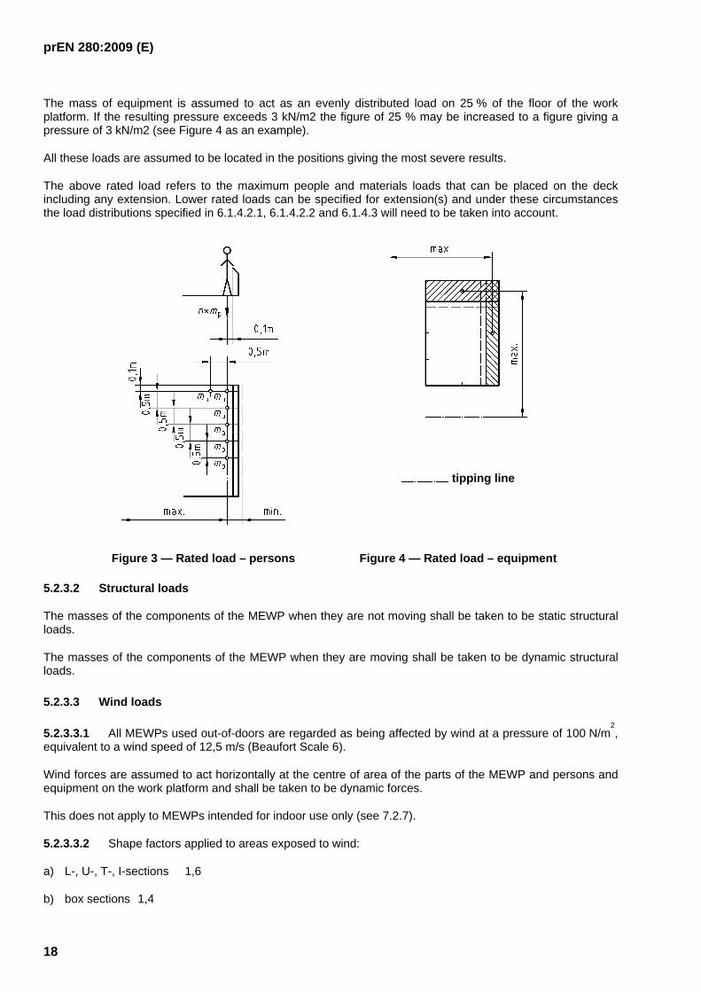
The mass of each person is assumed to act as a point load on the work platform and any platform extension at a horizontal distance of 0,1 m from the upper inside edge of the top rail. The distance between the point loads shall be 0,5 m (see Figure 3 as an example).
prEN 280:2009 (E)
18
The mass of equipment is assumed to act as an evenly distributed load on 25 % of the floor of the work platform. If the resulting pressure exceeds 3 kN/m2 the figure of 25 % may be increased to a figure giving a pressure of 3 kN/m2 (see Figure 4 as an example).
All these loads are assumed to be located in the positions giving the most severe results.
The above rated load refers to the maximum people and materials loads that can be placed on the deck including any extension. Lower rated loads can be specified for extension(s) and under these circumstances the load distributions specified in 6.1.4.2.1, 6.1.4.2.2 and 6.1.4.3 will need to be taken into account.
tipping line
Figure 3 — Rated load – persons Figure 4 — Rated load – equipment
5.2.3.2 Structural loads
The masses of the components of the MEWP when they are not moving shall be taken to be static structural loads.
The masses of the components of the MEWP when they are moving shall be taken to be dynamic structural loads.
5.2.3.3 Wind loads
5.2.3.3.1 All MEWPs used out-of-doors are regarded as being affected by wind at a pressure of 100 N/m2,
equivalent to a wind speed of 12,5 m/s (Beaufort Scale 6).
Wind forces are assumed to act horizontally at the centre of area of the parts of the MEWP and persons and equipment on the work platform and shall be taken to be dynamic forces.
This does not apply to MEWPs intended for indoor use only (see 7.2.7).
5.2.3.3.2 Shape factors applied to areas exposed to wind:
a) L-, U-, T-, I-sections 1,6
b) box sections 1,4
prEN 280:2009 (E)
19
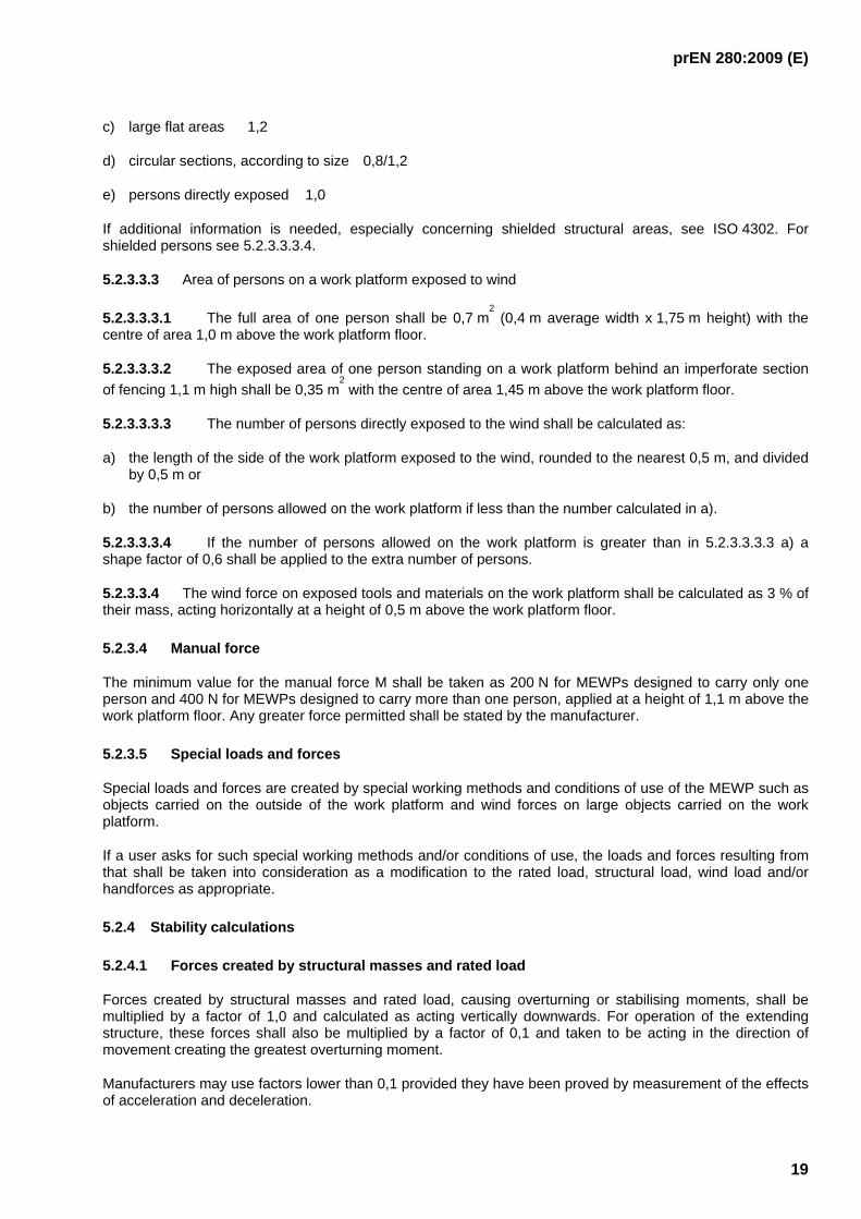
c) large flat areas 1,2
d) circular sections, according to size 0,8/1,2
e) persons directly exposed 1,0
If additional information is needed, especially concerning shielded structural areas, see ISO 4302. For shielded persons see 5.2.3.3.3.4.
5.2.3.3.3 Area of persons on a work platform exposed to wind
5.2.3.3.3.1 The full area of one person shall be 0,7 m2 (0,4 m average width x 1,75 m height) with the
centre of area 1,0 m above the work platform floor.
5.2.3.3.3.2 The exposed area of one person standing on a work platform behind an imperforate section of fencing 1,1 m high shall be 0,35 m
2 with the centre of area 1,45 m above the work platform floor.
5.2.3.3.3.3 The number of persons directly exposed to the wind shall be calculated as:
a) the length of the side of the work platform exposed to the wind, rounded to the nearest 0,5 m, and divided by 0,5 m or
b) the number of persons allowed on the work platform if less than the number calculated in a).
5.2.3.3.3.4 If the number of persons allowed on the work platform is greater than in 5.2.3.3.3.3 a) a shape factor of 0,6 shall be applied to the extra number of persons.
5.2.3.3.4 The wind force on exposed tools and materials on the work platform shall be calculated as 3 % of their mass, acting horizontally at a height of 0,5 m above the work platform floor.
5.2.3.4 Manual force
The minimum value for the manual force M shall be taken as 200 N for MEWPs designed to carry only one person and 400 N for MEWPs designed to carry more than one person, applied at a height of 1,1 m above the work platform floor. Any greater force permitted shall be stated by the manufacturer.
5.2.3.5 Special loads and forces
Special loads and forces are created by special working methods and conditions of use of the MEWP such as objects carried on the outside of the work platform and wind forces on large objects carried on the work platform.
If a user asks for such special working methods and/or conditions of use, the loads and forces resulting from that shall be taken into consideration as a modification to the rated load, structural load, wind load and/or handforces as appropriate.
5.2.4 Stability calculations
5.2.4.1 Forces created by structural masses and rated load
Forces created by structural masses and rated load, causing overturning or stabilising moments, shall be multiplied by a factor of 1,0 and calculated as acting vertically downwards. For operation of the extending structure, these forces shall also be multiplied by a factor of 0,1 and taken to be acting in the direction of movement creating the greatest overturning moment.
Manufacturers may use factors lower than 0,1 provided they have been proved by measurement of the effects of acceleration and deceleration.

prEN 280:2009 (E)
20
For the travelling movements of MEWP of types 2 and 3 the factor of 0,1 shall be replaced by a factor 'z' representing the forces produced by acceleration and deceleration or the kerb test (see 6.1.4.2.2.2). This factor shall be determined by calculation or tests (see Annex E (informative) for a calculation example).
5.2.4.2 Wind forces
Wind forces shall be multiplied by a factor of 1,1 and taken to be acting horizontally.
5.2.4.3 Manual forces
Manual forces applied by persons on the work platform shall be multiplied by a factor of 1,1 and taken to be acting in the direction creating the greatest overturning moment.
NOTE Examples for forces are given in Figures 4, 5, 7, 8.
5.2.4.4 Calculation of overturning and stabilising moments
The maximum overturning and corresponding stabilising moments shall be calculated about the most unfavourable tipping lines.
Tipping lines shall be determined in accordance with ISO 4305 but for solid and foam-filled tyres the tipping lines may be taken at 1/4 of the tyre ground contact width from the outside of the ground contact width.
The calculations shall be made with the MEWP in the most unfavourable extended and/or retracted positions with the maximum allowable inclination of the chassis defined by the manufacturer. All loads and forces, which can act simultaneously shall be taken into account in their most unfavourable combinations. An allowance of 0,5o for inaccuracy in setting-up the MEWP shall be added to the maximum allowable inclination of the chassis permitted by the manufacturer. Examples are shown in Table 2 and Figures 5 to 8. Graphical methods may be used.
In each case the calculated stabilising moment shall be greater than the calculated overturning moment.
In the calculation the following influences shall be taken into account:
a) tolerances in the manufacture of the components;
b) play in the connections of the extending structure;
c) elastic deformations due to the effects of forces;
d) failure of any one tyre in the case of MEWPs supported by pneumatic tyres in the working position;
e) performance characteristics of the load sensing system, moment sensing system and position control;
f) effects of failure of non-rigid suspensions.
g) This shall include at least the following:
⎯ transitory peaks caused by short term dynamic effects;
⎯ hysteresis;
⎯ chassis inclination;
⎯ ambient temperature;
⎯ different positions and distribution of load on work platform;
prEN 280:2009 (E)
21
⎯ accuracy of the system.
The determination of the elastic deformations shall be obtained by experiment or by calculation.
5.2.5 Structural calculations
5.2.5.1 General
The calculations shall conform with the laws and principles of applied mechanics and strength of materials. If special formulae are used, the sources shall be given, if they are generally available. Otherwise the formulae shall be developed from first principles, so that their validity can be checked.
Except where otherwise stated the individual loads and forces shall be taken to act in the positions, directions and combinations which will produce the most unfavourable conditions.
For all load bearing components and joints the required information on stresses or safety factors shall be included in the calculations in a clear and verifiable form. If necessary for checking the calculation, details of the main dimensions, cross-sections and materials for the individual components and joints shall be given.
5.2.5.2 Calculation methods
The method of calculation shall comply with any one of the recognised national design standards, such as those of the EEA countries for lifting appliances, which includes fatigue stress calculation methods, until a suitable European or international standard is available.
Requirements laid down in 5.2.2 and 5.2.4 above are to be considered for the determination of loads and forces to be used in the calculations. The use of a national standard shall not alter these requirements.
The elastic deformations of slender components shall be taken into account.
The analysis defined in 5.2.5.3 shall be made for the worst load combinations and shall include the effects of the overload test (see 6.1.4.3) and the functional test (see 6.1.4.5).
The calculated stresses shall not exceed the permissible values. The calculated safety factors shall not fall below the required values.
The permissible values of stresses and the required values of safety factors depend on the material, the load combination and the calculation method.
prEN 280:2009 (E)
22
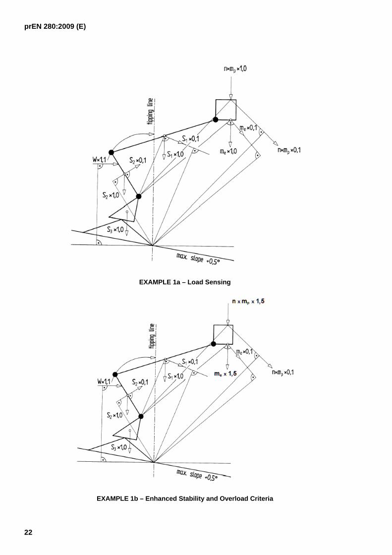
EXAMPLE 1a – Load Sensing
EXAMPLE 1b – Enhanced Stability and Overload Criteria

prEN 280:2009 (E)
23
EXAMPLE 2a - Load Sensing
EXAMPLE 2b - Enhanced Stability and Overload Criteria Key 1 tipping line 2 travelling direction
Figure 5 — Examples 1a/1b and 2a/2b of maximum overturning load and force moment combinations (see Table 2)

prEN 280:2009 (E)
24
EXAMPLE 3a - Load Sensing
EXAMPLE 3b - Enhanced Stability and Overload Criteria

prEN 280:2009 (E)
25
EXAMPLE 4a - Load Sensing
EXAMPLE 4b - Enhanced Stability and Overload Criteria Key 1 tipping line
Figure 6 — Examples 3a/3b and 4a/4b of maximum overturning load and force moment combinations (see Table 2)

prEN 280:2009 (E)
26
EXAMPLE 5
EXAMPLE 6
Figure 7 — Examples 5 and 6 of overturning load and force moment combinations (see Table 2)

prEN 280:2009 (E)
27
EXAMPLE 7
EXAMPLE 8
Figure 8 — Examples 7 and 8 of maximum overturning load and force moment combinations (see Table 2)
prEN 280:2009 (E)
28
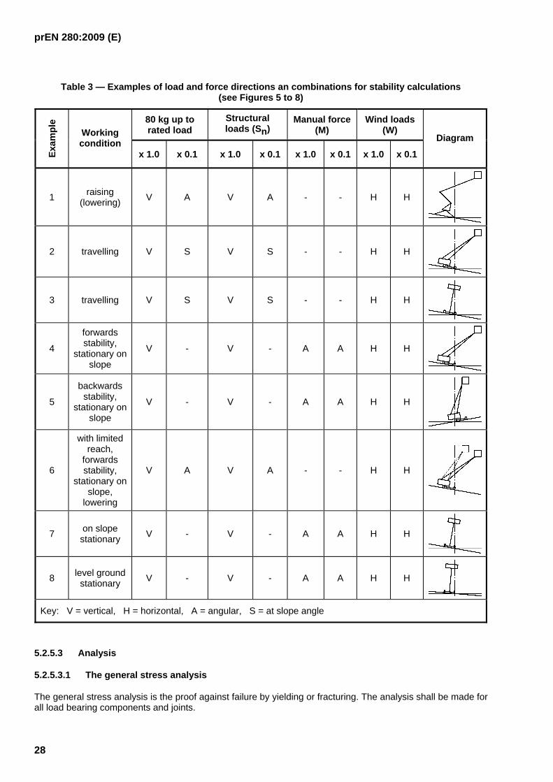
Table 3 — Examples of load and force directions an combinations for stability calculations (see Figures 5 to 8)
80 kg up to rated load
Structural loads (Sn)
Manual force (M)
Wind loads (W)
Exam
ple
Working condition
x 1.0 x 0.1 x 1.0 x 0.1 x 1.0 x 0.1 x 1.0 x 0.1
Diagram
1 raising (lowering) V A V A - - H H
2 travelling V S V S - - H H
3 travelling V S V S - - H H
4
forwards stability,
stationary on slope
V - V - A A H H
5
backwards stability,
stationary on slope
V - V - A A H H
6
with limited reach,
forwards stability,
stationary on slope,
lowering
V A V A - - H H
7 on slope stationary V - V - A A H H
8 level ground stationary V - V - A A H H
Key: V = vertical, H = horizontal, A = angular, S = at slope angle
5.2.5.3 Analysis
5.2.5.3.1 The general stress analysis
The general stress analysis is the proof against failure by yielding or fracturing. The analysis shall be made for all load bearing components and joints.
prEN 280:2009 (E)
29
5.2.5.3.2 Elastic stability analysis
The elastic stability analysis is the proof against failure by elastic instability (e.g. buckling, crippling). The analysis shall be made for all load bearing components subjected to compressive loads.
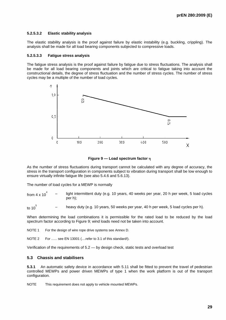
5.2.5.3.3 Fatigue stress analysis
The fatigue stress analysis is the proof against failure by fatigue due to stress fluctuations. The analysis shall be made for all load bearing components and joints which are critical to fatigue taking into account the constructional details, the degree of stress fluctuation and the number of stress cycles. The number of stress cycles may be a multiple of the number of load cycles.
Figure 9 — Load spectrum factor η
As the number of stress fluctuations during transport cannot be calculated with any degree of accuracy, the stress in the transport configuration in components subject to vibration during transport shall be low enough to ensure virtually infinite fatigue life (see also 5.4.6 and 5.6.13).
The number of load cycles for a MEWP is normally
from 4 x 10⁴ – light intermittent duty (e.g. 10 years, 40 weeks per year, 20 h per week, 5 load cycles
per h);
to 105 – heavy duty (e.g. 10 years, 50 weeks per year, 40 h per week, 5 load cycles per h).
When determining the load combinations it is permissible for the rated load to be reduced by the load spectrum factor according to Figure 9; wind loads need not be taken into account.
NOTE 1 For the design of wire rope drive systems see Annex D.
NOTE 2 For ...... see EN 13001 (....refer to 3.1 of this standard!).
Verification of the requirements of 5.2 — by design check, static tests and overload test
5.3 Chassis and stabilisers
5.3.1 An automatic safety device in accordance with 5.11 shall be fitted to prevent the travel of pedestrian controlled MEWPs and power driven MEWPs of type 1 when the work platform is out of the transport configuration.
NOTE This requirement does not apply to vehicle mounted MEWPs.

prEN 280:2009 (E)
30
Any travel speed restriction for self propelled MEWPs, when the work platform is out of the transport configuration, shall be automatic.
Verification — by design check and functional test
5.3.2 Every MEWP shall have a device that gives an easily identifiable visual or acoustic signal to indicate that the inclination of the chassis has reached the limits permitted by the manufacturer.
For MEWPs of type 1 with stabilisers the device can be replaced by a spirit level. For MEWPs with power driven stabilisers the indication shall be clearly visible from each control position of the stabilisers.
On MEWPs of type 2 and 3 while travelling out of the transport configuration the device shall prevent the chassis reaching the limits of inclination permitted by the manufacturer. Before reaching these limits an audible warning shall be given. After the chassis has reached the limits of inclination and the safety device according to 5.11.3 has been triggered it shall prevent continuation of travel in the selected direction.
This device shall be protected against damage, accidental change of its setting and unauthorised operation (e.g. sealed or locked).
The device shall be constructed to meet the requirements of 5.11.
Verification — by functional test
5.3.3 Any locking pins shall be secured against unintentional disengagement (e.g. spring pin) and loss (e.g. chain).
Verification — by visual examination
5.3.4 Control-bars of pedestrian controlled MEWPs and tow bars shall be securely fastened to the chassis; unintentional detachment shall not be possible if detachable locking pins in accordance with 5.3.3 are used.
Verification — by visual examination and test
5.3.5 If control-bars and tow bars, when not in use, are raised to vertical position (e.g. by hook), an automatic device shall be provided to hold the bars in this position; unintentional release shall not be possible.
For multi-axle chassis the minimum clearance between the fully lowered control-bar or tow bar and the ground shall be 120 mm.
Verification — by visual examination, test and measurement
5.3.6 For MEWPs which are constructed for operation with stabilisers, the stabilisers shall be capable of levelling the chassis to within the maximum allowable inclination when operating on the maximum slope permitted by the manufacturer.
Verification — by functional test and measurement
5.3.7 The stabiliser feet shall be constructed to accommodate ground unevenness of at least 10 degrees.
Verification — by visual examination and measurement
5.3.8 Use of stabilisers
5.3.8.1 MEWPs shall be fitted with a safety device in accordance with 5.11 which prevents the work platform operating outside permitted positions unless the stabilisers are set in accordance with the operating instructions.
Verification — by design check and functional test

prEN 280:2009 (E)
31
5.3.8.2 MEWPs which are constructed for operation without stabilisers for a limited range of operation shall be equipped with safety devices in accordance with 5.11 which prevent operation outside that limited range without stabilisers.
Verification — by design check and functional test
5.3.9 The requirements of 5.3.8 are not mandatory to MEWPs which are totally manually operated and have a height of the floor of the work platform above ground level not exceeding 5 m (see 7.2.17).
These MEWPs are also exempted from all safety requirements which cannot be met without power supply.
Verification — by design check
5.3.10 MEWPs with powered stabilisers shall be fitted with a safety device in accordance with 5.11 to prevent movements of the stabilisers unless the work platform is in the transport configuration or within the limited range in accordance with 5.3.8. When the work platform is inside the limited range, the operation of the stabilisers shall not create an unstable situation.
Verification — by design check and functional test
5.3.11 Manually operated stabilisers shall be designed to prevent unintentional movement (e.g. by self-sustaining screw).
Verification — by design check and functional test
5.3.12 All MEWPS shall be equipped with brakes to prevent from unintended movements. Self propelled MEWPs shall be equipped with brakes on at least two wheels on the same axis which engage automatically when power to the brakes is removed or fails, and shall be able to stop the MEWP in accordance with 5.3.17 and keep it in stopped position.
Brakes shall not rely on hydraulic or pneumatic pressure or electric power to remain engaged.
Verification — by design check and functional test
5.3.13 The movements of stabilisers shall be limited by mechanical stops. Hydraulic cylinders fulfil this requirement if designed for that purpose.
Mechanical means shall be provided to prevent uncontrolled movements of the stabilisers from the transport configuration. The stabilisers shall be locked in the transport configuration by two separate locking devices for each stabiliser, at least one of which operates automatically, e.g. a gravity locking pin plus a detent.
Powered stabilisers meeting the requirements of 5.5.1.1 and 5.10 are regarded to meet this requirement.
Verification — by design check
5.3.14 Vehicle mounted MEWPs shall be equipped with an indicator visible from the travelling controls within the cab to indicate if any component of the MEWP is not in its transport configuration.
Verification — by functional test
5.3.15 MEWPs shall be equipped with a device to prevent unauthorised use (e.g. lockable switch).
Verification — by functional test
5.3.16 By the use of safety device(s) in accordance with 5.11 it shall not be possible to exceed the following travel speeds with manned work platforms out of the transport configuration on MEWPs of types 2 and 3:
a) 1,5 m/s for vehicle mounted MEWPs when using the travelling controls inside the cab;

prEN 280:2009 (E)
32
b) 3,0 m/s for rail mounted MEWPs;
c) 0,7 m/s for all other self-propelled MEWPs of types 2 and 3.
Verification — by design check and functional test
5.3.17 MEWPs travelling at the aforesaid maximum speeds on the maximum slope allowed by the manufacturer shall be capable of being stopped in distances not greater than given in Figure 10. This figure is based on an average deceleration of 0,5 m/s2.
NOTE Minimum braking distances depend on factor 'z' (see 5.2.4.1).
Verification — by functional test
5.3.18 Maximum travel speed of pedestrian controlled MEWPs with the work platform in the transport configuration shall not exceed 1,7 m/s.
Verification — by measurement
5.3.19 Guards shall be provided to prevent persons at control positions, or standing adjacent to the MEWP at ground level or at other points of access, touching hot parts or dangerous parts of drive systems. Opening or removal of these guards shall only be possible by devices located in fully enclosed and lockable enclosures (e.g. cabs, compartments) or by the use of tools or keys provided with the MEWP. When it is foreseen (e.g. maintenance) that the fixed guards will be removed regularly then the fastenings shall remain attached to the guards or to the machine.
This requirement does not apply to the exhaust systems of vehicles conforming with road traffic regulations.
Verification — by visual examination

prEN 280:2009 (E)
33
Key: A for vehicle mounted MEWPs (controls inside cab) B for rail mounted MEWPs C for all other self-propelled MEWPs v speed s braking distance
Figure 10 — Maximum braking distances for MEWPS of types 2 and 3
5.3.20 The exhaust from internal combustion engines shall be directed away from control positions.
Verification — by visual examination
5.3.21 The filling points of fluid reservoirs (other than for fire resistant fluids) shall be positioned to avoid any fire from escape or spillage onto very hot parts (e.g. engine exhausts).
Verification — by visual examination
5.3.22 Any control position at the base or ground level shall provide the operator with visual contact with the resulting movements where these might create a hazard. This especially is valid for the operating position for powered stabilisers which make contact with the ground and/or move beyond the width of the chassis.
Travel controls fixed to the chassis and operated from ground level shall be positioned as to cause the operator to stand of at least 1 m from the vertical tangent to wheels or crawlers.
Verification — by visual examination
5.3.23 Any driving seat shall enable the driver to maintain a stable position and be designed with due regard to ergonomic principles. The seat shall be designed to reduce vibrations transmitted to the driver to the lowest level that can be reasonably achieved. The seat mountings must withstand all stresses to which they can be subjected. Where there is no floor beneath the driver's seat the driver shall have footrests covered with a slip-resistant material.

prEN 280:2009 (E)
34
Verification — by visual examination
5.3.24 Batteries and containers of all MEWPs shall be constrained to prevent displacement which gives rise to danger. Means shall be provided so that in the event of overturning the battery assembly will be constrained, so as to avoid the risk of injury to the operator which could occur by the battery being displaced or electrolyte being ejected.
Suitable ventilation holes shall be provided in the battery container, compartment or cover so that dangerous accumulations of gases do not occur in places occupied by operators.
NOTE 1 Experience has indicated, when openings are positioned such that gases can escape freely, ventilation apertures are usually satisfactory if they provide a cross section (in mm²) that results from the multiplication of the 5 h rated capacity (in Ah) with half the number of cells. This level is however not intended to cover the charging condition.
Verification — by visual examination
5.3.25 Rail mounted MEWPs having four or more rail wheels, operating with the rail wheels braked and without travelling along the track, shall be considered to be stable if the static stability requirements of EN280 are met and all wheels remain braked and in contact with the rails.
Rail mounted MEWPs that are operated whilst travelling along the track must meet the following requirements:-
• For MEWPs operating on tracks other than railway or tramway systems, the manufacturer must ensure that the MEWP rail wheels always maintain contact with the track.
For MEWPs operating on railway or tramway systems the manufacturer must ensure that the MEWP meets the requirements in sub-clause 5.11.3 of prEN 15746-1:2007 and prEN 15746-2:2007.
and the requirements of the infra structure manager
Rail mounted MEWPs shall be provided with devices to remove obstacles on the rails which might cause derailment.
Verification — by visual examination
5.3.26 A means shall be provided to disconnect MEWPs safely from any external power supply (see also 5.8.2).
Verification — by functional test
5.3.27 MEWPs equipped with one or more oscillating axles, in which stability of the machine when operating is dependent on systems which control or lock the oscillating axle(s), shall satisfy the following requirements:
On MEWPs of Type 1, a safety device in accordance with 5.11 shall prevent deployment of the extending structure until oscillation of the axle(s) is controlled or locked.
On MEWPs of Types 2 and 3, it shall be shown by demonstration that the inclinations of the chassis and/or the superstructure during elevated travel on the maximum permitted slope remain within the limits specified by the manufacturer. Safety devices which control or lock the tilting shall be in accordance with 5.11.
Hydraulic cylinders, if used as positional control or locking devices, shall comply with 5.10.
Verification — by functional test
5.3.28 MEWPs equipped with tilting chassis and/or superstructure in which stability of the machine when operating is dependent on control or locking of the tilting shall satisfy the following requirements:

prEN 280:2009 (E)
35
On MEWPs of Type 1 in which stability is dependent on control or locking of the tilting mechanism(s), a safety device in accordance with 5.11 shall prevent deployment of the extending structure until tilting of the chassis and/or superstructure is positively controlled or locked.
On MEWPs of Types 2 and 3 in which stability is dependent on control or locking of the tilting mechanism(s), it shall be shown by demonstration that the inclinations of the chassis and/or the superstructure remain within the limits specified by the manufacturer when the inclination of the chassis is at the maximum value permitted by the manufacturer. Safety devices which control or lock the tilting shall be in accordance with 5.11.
Hydraulic cylinders, if used as positional control or locking devices, shall comply with section 5.10.
Verification — by functional test
5.3.29 MEWPs of type 2 and 3 shall be stable while travelling on a horizontal surface in all working configurations. This requirement is met if the MEWP does not become unstable during the kerb and depression tests (6.1.4.2.2).
5.4 Extending structure
5.4.1 Methods to avoid overturning and exceeding permissible stresses
5.4.1.1 General
In addition to the provisions of 5.2.4.4 MEWPs shall be provided with control devices that reduce the risk of overturning and the risk of exceeding permissible stresses by one of the following equivalent solutions indicated by a cross in Table 3:
Table 4 — Solutions for the reduction of risk of overturning an the risk of exceeding permissible stresses
Group (see 1.4)
Load sensing system and position control (see 5.4.1.2
and 5.4.1.3)
Load and moment sensing systems (see 5.4.1.2 and
5.4.1.4)
Moment sensing system with
enhanced overload criteria (see 5.4.1.4
and 5.4.1.6)
Position control with enhanced stability
and overload criteria (see 5.4.1.3, 5.4.1.5
and 5.4.1.6)
A X X
B X X X X
NOTE It should be noted that load or moment controls are not able to protect against an overload that grossly exceeds the rated load.
5.4.1.2 Load sensing system
The load sensing system is a safety device and shall operate in the following way:
a) It shall trigger after the rated load is reached and before 120 % of the rated load is exceeded.
b) When the load sensing system is triggered a warning consisting of a flashing red light at the preselected control position together with an acoustic signal audible at each control position shall be activated. The light shall continue to flash all the time the overload prevails and the acoustic alarm shall sound for periods of at least 5 seconds repeated every minute.

prEN 280:2009 (E)
36
c) If the load sensing system is triggered while the work platform is stationary it shall prevent all normal movement of the work platform. Normal movement can only restart if the overload is removed.
d) If the load sensing system is triggered during normal movement of the work platform the possibility of normal movement shall remain.
NOTE This movement may be used to release a trapped person.
For MEWPs of group A, type 1, where the vertical projection of the centre of gravity of the load is always inside the tipping lines, it is permitted for the load-control device to be effective only when raising the extending structure from the lowest position. In this case, for the overload test described in 6.1.4.3, the test load shall be 150 % of the rated load.
For MEWPs of group A the load-sensing device need not be activated until the work platform is elevated more than 1 m height or 10 % of lift height, whichever is the greater, above the lowest position. If an overload condition is sensed at or above this height, further elevation shall be prevented.
The load sensing system shall comply with the requirements of 5.11.
5.4.1.3 Position control
5.4.1.3.1 To avoid overturning of the MEWP or exceeding the permissible stresses in the structure of the MEWP, the permissible positions of the extending structure shall be limited automatically by mechanical stops (see 5.4.1.3.2) or non-mechanical limiting devices (see 5.4.1.3.3).
5.4.1.3.2 Where permissible positions are limited by mechanical stops, these shall be designed to resist without permanent deformation the maximum forces exerted. Hydraulic cylinders fulfil this requirement if designed for that purpose.
5.4.1.3.3 Where non-mechanical limiting devices are used, permissible positions of the extending structure shall be limited by a device which measures positions of the extending structure, and operates through the control systems to limit movements to the working envelope. This device shall be backed up by a safety device in accordance with 5.11.
5.4.1.4 Moment sensing system
The moment sensing system is a safety device and shall operate in the following way:
- when the permissible overturning moment (see 5.2.4.4) is reached a visual warning shall be given and further movements shall be prevented except those which reduce the overturning moment.
- the control system for the moment sensing system shall comply with the requirements of 5.11.
5.4.1.5 Enhanced stability criteria for limited size of work platforms
MEWPs for up to 2 persons may be excluded from the requirement of load and moment sensing systems if they follow "enhanced stability requirements".
To meet the requirement of "enhanced stability", the MEWP shall be designed according to the following criteria:
1) Outside dimensions of the work platform including any extension at any horizontal section shall:
⎯ For 1 person:
give a surface not more than 0,6 m2 with no side more than 0,85 m.
⎯ For 2 persons:
prEN 280:2009 (E)
37
give a surface not more than 1,0 m2 with no side more than 1,4 m.
2) For the static test described in sub-clause 6.1.4.2.1 only, instead of rated load 1,5 times the rated load shall be used in the calculation of the test load(s). The other load and force combinations shall remain as specified in 5.2.4.1, 5.2.4.2, 5.2.4.3 and 5.2.4.4.
5.4.1.6 Enhanced overload criteria for limited size of work platforms
MEWPs for up to 2 persons may be excluded from the requirement of load sensing systems if they follow "enhanced overload requirements".
To meet the requirement of "enhanced overload", the MEWP shall be designed according to the following criteria:
1. Outside dimensions of the work platform at any horizontal section shall:
⎯ For 1 person:
give a surface not more than 0,6 m2 with no side more than 0,85 m.
⎯ For 2 persons:
give a surface not more than 1,0 m2 with no side more than 1,4 m.
2. For the overload test described in sub-clause 6.1.4.3 only, the test load shall be 150 % of the rated load.
5.4.1.7 Variable working envelope by manual selection of more than one rated load.
MEWPs with more than one rated load and more than one working envelope shall have an indicator of the selected combination that is visible at the work platform. An indicator can be a physical change (e.g. platform extension) to the configuration of the platform that affects its rated load.
An indicator is not necessary for MEWPS in which the working envelope is limited by a moment sensing system.
The selection shall only be possible if the work platform is in the working envelope for the new selected rated load.
5.4.1.8 Variable working envelope with one rated load
For MEWPs with one rated load and a variable working envelope (e.g. MEWPs with variable positions of stabilisers) selection by manual means is acceptable. In that case the selection shall only be possible with the extending structure in the access position.
Verification of all requirements of 5.4.1 — by design check and tests (see 6.1.4)
5.4.2 When the extending structure needs to be extended or retracted in a specific sequence to avoid overloading and/or overturning, this sequence shall be automatic. The automatic sequence shall be part of the position control (see 5.4.1.3) or moment sensing system (see 5.4.1.4).
Verification — by design check and functional test
5.4.3 Trapping and shearing points between moving parts which are within reach of persons (see EN ISO 13857:2008) on the platform or standing adjacent to the MEWP at ground level shall be avoided by providing safe clearances or guarding in accordance with EN 349.

prEN 280:2009 (E)
38
Only where this is not possible, clearly visible warning strips and warning signs, instructing to keep clear, shall be permanently attached in the area of the hazard.
Instead of a rigid or flexible guard on scissor lifts the following solution is permitted:
The downward movement shall be automatically stopped by a safety device in a position, the ‘first descent limit’, where between the outer ends of the scissors the vertical distance is not less than 50 mm, so that crushing and shearing of fingers cannot occur. Further downward movement shall only be possible after a time delay of at least 3 seconds. A further lowering command by the operator shall cause a distinctive, readily audible alarm to sound and a distinctive visual warning to operate for at least 1.5 seconds before lowering of the extending structure at a speed not greater than 50% of the average lowering speed above the ‘first descent limit’ commences. Stopping and resumption of descent at any position of the extending structure between the ‘first descent limit’ and the access position shall be subject to these conditions of delay, warning and speed. In all cases the audible alarm and visual warning shall continue to operate throughout any lowering of the extending structure below the ‘first descent limit’.
If the average lowering speed above "the first descent limit" is not greater than 0,2 m/s, speed reduction is not necessary.
Verification — by measurement and visual examination
5.4.4 When the work platform of a MEWP needs to be raised for routine servicing purposes, a captive chock shall be provided to enable the extending structure to be held in the required position. This chock shall be capable of supporting an unloaded work platform and of being operated from a safe position; it shall not cause damage to any part of the MEWP (see 7.2.16).
Verification — by visual examination and functional test
5.4.5 It shall not be possible to exceed the following speeds:
a) 0,4 m/s for raising and lowering of the work platform;
b) 0,4 m/s for telescoping of the boom ;
c) 0,7 m/s for slewing or rotation (horizontal speed at the outer edge of the work platform measured at maximum range).
Verification — by functional test
5.4.6 The extending structure shall be supported in the transport configuration in such a way as to avoid harmful vibrations during transport (see 5.2.5.3.3).
Verification — by design check and visual examination
5.5 Extending structure drive systems
5.5.1 General
5.5.1.1 Drive systems shall be designed and constructed to prevent any inadvertent movements of the extending structure.
Verification — by design check and functional test
5.5.1.2 If the power source is capable of producing greater power than the extending structure and/or work platform drive system requires, protection shall be provided to the extending structure and/or work platform drive system to prevent damage (e.g. by pressure limiting device).
The use of friction couplings does not fulfil the requirement.
prEN 280:2009 (E)
39
Verification — by design check
5.5.1.3 Transmission chains or belts shall only be used in drive systems provided inadvertent movements of a work platform are automatically prevented if failure of a chain or belt occurs. That can be achieved by a self-sustaining gear box or monitoring the chain/belt by a safety device in accordance with 5.11.
Flat belts shall not be used.
Verification — by design check and functional test
5.5.1.4 Manual drive systems shall be designed and constructed to prevent kick-back of handles.
Verification — by design check and visual examination
5.5.1.5 If both powered and manual drive systems are provided for the same movement (e.g. in over-riding emergency system) and if there is a risk of injury from engaging both systems at the same time, this shall be prevented e.g. by interlocks, shut-off valves or bypass valves.
Verification — by design check and functional test
5.5.1.6 A braking system shall be provided on all drives. For raising movements this system shall be an automatic lock or self-sustaining device. The braking system shall be automatically applied when the drive is no longer energised.
The braking system shall ensure that the work platform, loaded with 1.1- times the rated load can be stopped and held at any position under all possible conditions of operation. Unintentional release of these devices shall not be possible.
Verification — by design check and functional test
5.5.2 Wire rope drive systems
5.5.2.1 Wire rope, drum and pulley diameters shall be calculated in accordance with Annex C, assuming that all the load is taken on one wire rope system. Traction drive systems shall not be used.
Wire rope drive systems shall have a device or system which in the event of a wire rope drive system failing limits the vertical movement of the fully loaded work platform to 0,2 m. This requirement shall be met by:
a) a mechanical device operating by engaging with the extending structure. This safety device shall gradually bring the work platform plus the rated load to a stop and hold it in the event of the wire rope drive system failing. The average deceleration shall not exceed 1,0 gn. The proper functioning of the device shall be demonstrated by calculation and test(s). Any spring operating this device shall be a guided compression spring with secured ends, or with wire diameter more than half the pitch in the operating condition, to limit the shortening of the spring if it should fail, or
b) a second wire rope system designed according to the first system with a device to give approximately equal tension in the two wire rope systems, thus doubling the working coefficient, or
c) a second wire rope system designed according to the first system, with a device to ensure that the second system takes less than half of the load in the operating condition, but is able to take the full load if the first system fails, or
d) second wire rope system according to b).1) with larger drum and pulley diameters to increase the fatigue life of the second system to at least twice the calculated life time of the first system.
Failure of the first system shall be self-revealing.
NOTE Friction in the driving system does not fulfil the requirement of 5.5.2.1.a

prEN 280:2009 (E)
40
Verification — by design check and visual examination
5.5.2.2 Load carrying wire ropes shall be made from galvanised steel wires and have the following characteristics:
a) diameter: 8 mm minimum;
b) number of wires: 114 minimum;
c) tensile grade of the wires: 1 570 N/mm2 minimum;
a. 1 960 N/mm2 maximum.
The minimum breaking load of the wire ropes shall be shown on a certificate.
Wire ropes used directly for lifting or supporting the work platform shall not include any splicing except at their ends.
Stainless steel wire ropes may be used with appropriate provisions.
Verification — by design check and visual examination
5.5.2.3 If more than one wire rope is attached at one point a device shall be provided for approximately equalising the tension of the wire ropes.
Verification — by design check and visual examination
5.5.2.4 It shall be possible to re-tension wire ropes.
Verification — by design check and visual examination
5.5.2.5 For the terminations of wire ropes only
⎯ splices;
⎯ aluminium pressed ferrules;
⎯ non-ageing steel pressed ferrules;
⎯ or wedge socket anchorages
may be used. U-bolt grips shall not be used as wire rope terminations for load carrying wire ropes.
The junction between the wire rope and the wire rope termination shall be able to resist at least 80 % of the minimum breaking load of the wire rope.
Verification — by design check and visual examination
5.5.2.6 Visual examination of wire ropes and wire rope terminations shall be possible preferably without the removal of the wire ropes or major disassembly of the structural components of the MEWP.
If this is proved not to be possible by inspection openings, the manufacturers shall provide detailed instructions for examination (see 7.1.1.7.f)).
Verification — by design check and visual examination
5.5.2.7 MEWPs with work platforms which are raised and lowered by means of wire ropes shall be equipped with a safety device in accordance with 5.11 which interrupts movements causing slack rope

prEN 280:2009 (E)
41
conditions. Movements in the opposite direction shall be possible. This device is not necessary if no slack rope condition can develop.
Verification — by design check and functional test
5.5.2.8 Rope drums shall be grooved and means shall be provided to prevent the wire rope from leaving the ends of the drum, e.g. flanges extending to a height of at least twice the wire rope diameter above the highest layer.
Verification — by visual examination
5.5.2.9 Only one layer of wire rope shall be wound on the drum unless a special spooling system is used.
Verification — by visual examination
5.5.2.10 At least 2 turns of wire rope shall remain on the drum when the extending structure and/or the work platform is in its most extreme position.
Verification — by function test and visual examination
5.5.2.11 Each wire rope shall be properly fastened to the drum. The fastening shall be able to take 80 % of the minimum breaking load of the wire rope.
Verification — by design check and visual examination
5.5.2.12 Means shall be provided to prevent unintentional displacement of wire ropes from pulleys, even under slack rope conditions.
Verification — by design check and visual examination
5.5.2.13 The cross section of the bottom of the grooves in wire rope drums and pulleys shall be circular over an angle of not less than 120 degrees.
Verification — by design check and visual examination
5.5.3 Chain drive systems
5.5.3.1 Chain drive systems shall have a device or system which in the event of a chain drive system failing limits the vertical movement of the fully loaded work platform to 0,2 m. This requirement shall be met by:
a) a chain drive system with a working coefficient of at least 5 plus a mechanical device operating by engaging with the extending structure. This safety device shall gradually bring the work platform plus the rated load to a stop and hold it in the event of the drive system failing. The average deceleration shall not exceed 1.0 gn. The proper functioning of the device shall be demonstrated by calculation and test(s). Any spring operating this device shall be a guided compression spring with secured ends, or with wire diameter more than half the pitch in the operating condition, to limit the shortening of the spring if it should fail, or
b) two chain drive systems each system having a working coefficient of at least 4 (a total of 8 minimum) and with a device to give approximately equal tension in the two chain systems, or
c) two chain drive systems the first system with a working coefficient of at least 5 when carrying the full load and a second drive system with a working coefficient of at least 4 (a total of 9 minimum when carrying the full load) and with a device to ensure that the second system takes less than half the load in the operating condition, but is able to take the full load if the first system fails.
Failure in the first system shall be self-revealing.

prEN 280:2009 (E)
42
NOTE Friction in the driving system does not fulfil the requirement of 5.5.3.1 a).
Verification — by design check and visual examination
5.5.3.2 Round link chains shall not be used.
The minimum breaking load of the chain shall be shown on a certificate.
Verification — by visual examination
5.5.3.3 If more than one chain is attached at one point, a device shall be provided to equalise approximately the tension in the chains.
Verification — by design check and visual examination
5.5.3.4 It shall be possible to retention chains.
Verification — by design check and visual examination
5.5.3.5 The junction between the chain and the chain termination shall be able to resist at least 100 % of the minimum breaking load of the chain.
Verification — by design check
5.5.3.6 Visual examination of chains and chain terminations shall be possible preferably without the removal of the chains or major disassembly of structural components of the MEWP.
If this is proved to be not possible by inspection openings, manufacturers shall provide detailed instructions for examination (see 7.1.1.7.f)).
Verification — by design check and visual examination
5.5.3.7 MEWPs with work platforms which are raised and lowered by means of chains shall be equipped with a safety device in accordance with 5.11 which interrupts movements causing slack chain conditions. Movements in the opposite direction shall be possible. This device is not necessary if no slack chain condition can develop.
Verification — by design check and functional test
5.5.3.8 Means shall be provided to prevent unintentional displacement of the chain from the sprockets or pulleys, even under slack chain conditions.
Verification — by design check and visual examination
5.5.4 Lead-screw drive systems
5.5.4.1 The design stress of lead-screws and nuts shall not be more than 1/6 of the ultimate tensile stress of the material used. The lead-screw material shall have a higher abrasion resistance than the load bearing nut material.
Verification — by design check
5.5.4.2 The lead-screw mechanism shall be designed to prevent separation of the work platform from the mechanism during normal use.
Verification — by visual examination
prEN 280:2009 (E)
43
5.5.4.3 Each lead-screw shall have a load bearing nut and an unloaded safety nut. The safety nut shall only be loaded if the load bearing nut fails. It shall not be possible to raise the work platform from its access position when the safety nut is under load.
Verification — by design check and visual examination
5.5.4.4 It shall be possible to detect the wear of the load bearing nuts without major disassembly.
Verification — by visual examination
5.5.4.5 Lead-screws shall be fitted with devices (e.g. mechanical end stops) at both ends to prevent the load bearing and safety nuts from leaving the lead-screws.
Verification — by visual examination
5.5.5 Rack and pinion drive systems
5.5.5.1 The design stress of racks and pinions shall not be more than 1/6 of the ultimate tensile stress of the material used.
Verification — by design check
5.5.5.2 Rack and pinion drives shall have a safety device in accordance with 5.11 actuated by an over-speed governor. This safety device shall gradually bring the work platform plus rated load to a stop and hold it in the event of the lifting mechanism failing. The average deceleration shall not exceed 1,0 gn.
If this safety device is actuated, the power supply shall be interrupted automatically.
Verification — by design check and functional test
5.5.5.3 In addition to the normal work platform guide rollers positive and effective devices shall be provided to prevent any driving or safety device pinion from coming out of engagement with the rack. These devices shall ensure that axial movement of the pinion is so limited that a minimum of 2/3 of the tooth width is always in engagement with the rack. They shall also restrain radial movement of the pinion from its normal meshing position by more than 1/3 of the tooth depth.
Verification — by visual examination
5.5.5.4 Visual examination of the pinions shall be possible without the removal of the pinions or major disassembly of structural components of the MEWP.
Verification — by visual examination
5.6 Work platform
5.6.1 The level of the work platform shall not vary by more than 5 ° from the horizontal or the plane of the chassis or any turn table during movements of the extending structure, or due to loads and forces during operation.
Manual adjustment of platform levels exceeding 5 ° is acceptable provided the extending structure is stationary or – as in the case of MEWPs with full-flow control valves with control handles connected mechanically to the control valve spools – by an additional feature that guards against inadvertent operation of the control handle
The rate of change of platform angle shall not exceed the maximum that occurs during lowering or raising in normal operation.

prEN 280:2009 (E)
44
The levelling system with exception of hydraulic levelling systems according to the master-slave principles shall incorporate a safety device in accordance with 5.11 which in case of a failure within the system keeps the platform level within further 5 °.
Verification — by design check and functional test
Mechanical levelling systems using rods or levers fulfil this requirement if they are designed to take at least twice the load imposed to them. For wire ropes and chains see 5.5.2.1 and 5.5.3.1.
Verification — by design check
Hydraulic cylinders in hydraulic levelling systems shall comply with 5.10.2.
Verification — by functional test
5.6.2 Protection shall be provided on all sides of each work platform to prevent the fall of persons and materials. The protection shall be securely fastened to the work platform and shall, as a minimum, consist of guard-rails at least 1.1 m high, toe-guards at least 0.15 m high and intermediate guard-rails not further than 0.55 m from either guard-rails or toe-guards. At points of access to the work platform the height of the toe-guards may be reduced to 0.1 m. The guard-rails shall be constructed to withstand concentrated forces equal to 500 N multiplied by the number of people that the platform is rated to carry. These forces shall be applied at the least favourable positions in the least favourable direction at 0.5 m intervals without causing permanent deformation of the guard-rails. When it is foreseen (e.g. maintenance) that the fixed guard-rails will be removed regularly then the fastenings shall remain attached to the guard-rails or to the platform.
The work platform shall be made of at least non-flammable material(s), i.e. materials that will not sustain a flame after the ignition source has been removed.
Folding guardrails may be used provided they do not open outwards, satisfy the above requirements, and are securely fastened to the work platform with locking devices that are secured against unintentional disengagement or loss.
Means shall be provided to prevent normal working on the work platform if the guardrails are not in the correct position e.g. by interlocking systems or folding of the guard rails in a defined sequence.
Verification — by design check and visual examination
5.6.3 Any part of the protection movable for the purpose of access to the work platform shall not fold or open outwards. It shall be constructed to either return automatically to the closed position, or be interlocked by a safety device in accordance with 5.11 to prevent operation of the MEWP until it is closed and fastened. Inadvertent opening shall not be possible.
The minimum opening width for the purpose of access to the work platform shall be 420 mm.
On work platforms with fixed guard handrails openings for the purpose of access to it should have a height of 920 mm and a width of 645 mm at least. Where the required dimensions cannot be achieved the opening shall be as large as possible but in no case less than 420 mm wide and 800 mm high.
Sliding or vertically hinged intermediate guard-rails shall be capable of being held in the open position with one hand whilst a person enters or leaves the platform. Verification — by visual examination
5.6.4 The floor of the work platform including any trapdoor shall be slip-resistant and self-draining (e.g. chequer plate or expanded metal). Any opening in the floor or between the floor and toe-guards or access gates shall be dimensioned so as to prevent the passage of a sphere of 15 mm diameter.
Verification — by visual examination
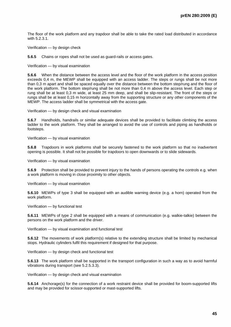
prEN 280:2009 (E)
45
The floor of the work platform and any trapdoor shall be able to take the rated load distributed in accordance with 5.2.3.1.
Verification — by design check
5.6.5 Chains or ropes shall not be used as guard-rails or access gates.
Verification — by visual examination
5.6.6 When the distance between the access level and the floor of the work platform in the access position exceeds 0,4 m, the MEWP shall be equipped with an access ladder. The steps or rungs shall be not more than 0,3 m apart and shall be spaced equally over the distance between the bottom step/rung and the floor of the work platform. The bottom step/rung shall be not more than 0,4 m above the access level. Each step or rung shall be at least 0,3 m wide, at least 25 mm deep, and shall be slip-resistant. The front of the steps or rungs shall be at least 0,15 m horizontally away from the supporting structure or any other components of the MEWP. The access ladder shall be symmetrical with the access gate.
Verification — by design check and visual examination
5.6.7 Handholds, handrails or similar adequate devices shall be provided to facilitate climbing the access ladder to the work platform. They shall be arranged to avoid the use of controls and piping as handholds or footsteps.
Verification — by visual examination
5.6.8 Trapdoors in work platforms shall be securely fastened to the work platform so that no inadvertent opening is possible. It shall not be possible for trapdoors to open downwards or to slide sidewards.
Verification — by visual examination
5.6.9 Protection shall be provided to prevent injury to the hands of persons operating the controls e.g. when a work platform is moving in close proximity to other objects.
Verification — by visual examination
5.6.10 MEWPs of type 3 shall be equipped with an audible warning device (e.g. a horn) operated from the work platform.
Verification — by functional test
5.6.11 MEWPs of type 2 shall be equipped with a means of communication (e.g. walkie-talkie) between the persons on the work platform and the driver.
Verification — by visual examination and functional test
5.6.12 The movements of work platform(s) relative to the extending structure shall be limited by mechanical stops. Hydraulic cylinders fulfil this requirement if designed for that purpose.
Verification — by design check and functional test
5.6.13 The work platform shall be supported in the transport configuration in such a way as to avoid harmful vibrations during transport (see 5.2.5.3.3).
Verification — by design check and visual examination
5.6.14 Anchorage(s) for the connection of a work restraint device shall be provided for boom-supported lifts and may be provided for scissor-supported or mast-supported lifts.

prEN 280:2009 (E)
46
The anchor device(s), anchor point(s) and mobile anchor point(s) shall be so designed as to accept the personal protective equipment and ensure that it is not possible for correctly connected personal protective equipment to become detached unintentionally.
Exposed edges or corners shall be relieved either with a radius of at least 0,5 mm or a 45° chamfer.
Each anchorage used as part of a work restraint system shall meet the following requirements:
a) For a single person rating, each anchorage shall be capable of withstanding a static force of 3 kN without reaching ultimate strength. For anchorages rated for more than one person, the strength requirement shall be multiplied by the number of persons. This strength requirement shall only apply to the anchorage and its attachment to the MEWP in all possible load directions and must not be taken into account for the stability calculation and test.
b) The number of anchorages shall equal or exceed the number of rated occupants. More than one occupant may attach to a single anchorage if the anchorage is rated for more than one person.
Verification — by design check and visual examination
5.6.15 The working positions shall be designed that the vibration dose is as low as possible. The manufacturer shall state the values for vibration at the working places.
NOTE For measurement of vibration see ISO 2631-1.
5.7 Controls
5.7.1 MEWPs shall be provided with controls such that all movements of the MEWP can only take place whilst the controls are being actuated. The controls, when released, shall automatically return to the neutral position. The travel controls in the cabs of vehicle mounted MEWPs do not need to be of this type .
All controls shall be constructed to prevent inadvertent operation. Hand controls in the platform shall be protected against sustained involuntary operation. Foot controls in the platform shall be shrouded and have slip resistant surfaces.
Controls shall be positioned to avoid danger to the operator from moving parts of the MEWP.
Verification — by functional test and visual examination
5.7.2 On MEWPs of types 2 and 3 it shall not be possible for the travelling controls to be operated simultaneously with any other controls. This does not apply to rail mounted MEWPs. This shall be achieved by a safety device in accordance with 5.11.
Verification — by design check and functional test
5.7.3 The direction of all movements of the MEWP shall be clearly indicated on or near the controls by words or symbols. All controls shall where possible be arranged for logical operation and the movement of the platform is stopped or reversed if the operator is pushed against the controls.
Verification — by visual examination and functional test
5.7.4 The control devices shall be situated on the work platform. This does not preclude the provision of duplicate controls operated from the base or ground level. Duplicate controls shall be protected against unauthorised operation and may be used to serve as the emergency device (see 5.7.8 and 5.7.9).
The duplicate and platform controls shall be interlocked so it is possible to operate the MEWP from only one control position at the same time. This position shall be set using a safety device that complies with 5.11 situated at the duplicate control position.

prEN 280:2009 (E)
47
If wireless control systems are used they shall comply with Annex F (normative). Operation of the extending structure and elevated drive functions shall only be possible when the wireless controls are located in the work platform in a position specifically designated by the manufacturer.
Verification — by functional test and visual examination
5.7.5 MEWPs shall be provided with emergency stop controls in accordance with EN ISO 13850 at each control position.
Emergency stop controls are not required on MEWPs with full-flow control valves with control handles connected mechanically to the control valve spools (manual override).
Verification — by design check and functional test
5.7.6 Pilot and solenoid operated control valves shall be so designed and installed that they stop the corresponding movement in the event of power failure.
Verification — by design check and functional test
5.7.7 On starting, or restoration of the power after failure of the power supply, no movement shall occur unless there is a deliberate action by the operator.
Verification — by functional test
5.7.8 MEWPs shall be fitted with an over-riding emergency system (e.g. a hand pump, a secondary power unit, gravity lowering valves) appropriate to ensure that, if the main power supply fails, the work platform can be returned into a position from which it is possible to leave it without danger, taking into account the need to manoeuvre the platform clear of obstructions (see 7.2.5).
The position of the controls of the emergency system shall be in a position easily accessible from the ground (see 5.7.4).
The above requirements need not apply if leaving or reaching any position of the work platform is possible in another way (e.g. by means of fixed ladders).
Verification — by design check and functional test
5.7.9 Overriding of the platform emergency stop control and the load sensing system is allowed for rescuing a trapped and/or incapacitated operator on the platform. Over-riding is permitted only by the use of a safety device that is independent from the selection control device. The safety device must be operated by hold-to-run controls and be protected against unauthorised use.
The overriding of the load sensing system shall allow motion of the platform sufficient to rescue the operator. Features shall be provided to protect against misuse of the overriding safety device and to give visible evidence that they have been used or tampered with. This evidence shall remain until the features are returned to the condition they were in prior to the safety devices being operated or accessed. Resetting the features to their original condition should require the use of a tool..
Emergency stop overriding shall not be possible on MEWPs which are equipped with a mode selection device according to the Machinery Directive Annex I, sub-clause 1.2.5, to bypass safety functions.
Verification — by design check and functional test
5.7.10 A device shall be provided to ensure that the speed of movement of the work platform is restricted to 1.4 times normal speed even under emergency operations.
Verification — by functional check

prEN 280:2009 (E)
48
5.8 Electrical equipment
5.8.1 Electrical equipment of MEWPs shall comply with the relevant CENELEC standards especially with the requirements of EN 60204-1:2006. If due to special conditions MEWPs are used outside the ranges of the following items of EN 60204-1:2006:
a) 4.3.2 d. c. supplies;
b) 4.4.2 ambient air temperature;
c) 4.4.4 altitude;
d) 15.4.3 connection to moving elements of the machine.
Deviations are necessary and manufacturer shall take the necessary safety measures and/or state any operating limitations in the instruction handbook.
The relevant electromagnetic compatibility requirements shall be observed.
Verification — by design check and visual examination
5.8.2 A main switch shall be fitted in an easily accessible position. It shall be possible to secure it in the isolated position, with the use of a padlock or equivalent, to ensure no inadvertent operation.
Verification — by design check and visual examination
5.8.3 Cables shall be multi-stranded when flexibility is necessary and, where required, shall be oil-resistant.
Verification — by design check and visual examination
5.8.4 Batteries shall be protected against damage by short circuits and against mechanical damage. The disconnection (isolation) of the battery, i.e. breaking of the electrical supply (e.g. when charging), shall be easily possible and without the use of a tool.
Verification — by visual examination
5.8.5 When necessary to prevent ingress of water the minimum degree of protection provided by enclosures shall be IP 54 in accordance with EN 60529:1991. Manufacturers shall take into account any foreseeable conditions of use (e.g. fluids other than water) necessitating higher degrees of protection.
Verification — by design check and visual examination
5.8.6 The machines shall have sufficient immunity to electromagnetic disturbances to enable them to operate safely as intended and not fail to danger when exposed to the levels and types of disturbances intended by the manufacturer. The manufacturer of the machines shall design, install and wire the equipment and sub-assemblies taking into account the recommendations of the suppliers of these sub-assemblies.
Examples of possible malfunctioning which shall not occur due to radiation in the electromagnetic environment conditions foreseen by the manufacturer of the machine include:
- unexpected start-up;
- the machine being prevented from stopping if the stop command has already been given;
- resetting of the emergency stop function;
- a reduction in fault detection capacity;

prEN 280:2009 (E)
49
- the inhibition of the operation of any safety or interlocking device;
- exceeding the safe (reduced) speed of machine parts.
5.9 Hydraulic systems
5.9.1 The hydraulic system shall include the pressure limiting device (e.g. pressure relief valve) before the first control valve. If different maximum pressures are used in the hydraulic system, more than one pressure limiting device shall device be provided.
The adjustment of pressure limiting devices shall require the use of tools and be capable of being sealed.
Verification — by design check and visual examination
5.9.2 Pipes and their connections which may be subjected to the maximum pressure permitted by any pressure limiting device shall be designed to withstand at least twice that pressure without permanent deformation (R
p0,2). If in normal operation components may be subjected to higher pressures than permitted
by the pressure limiting device, they shall be designed to withstand at least twice that higher pressure without permanent deformation (R
p0,2), but see 5.10.1.2 for failure conditions.
Verification — by design check
5.9.3 The bursting pressure of hoses, including fittings, which may be subjected to the maximum pressure permitted by any pressure limiting device shall be not less than three times that pressure.
Verification — by design check
5.9.4 All components of the hydraulic system other than those specified in 5.9.2, 5.9.3 and 5.10 shall be rated for at least the maximum pressure to which they will be subjected, including any temporary increase of pressure setting necessary for carrying out the overload test (see 6.1.4.3).
Verification — by design check
5.9.5 Each hydraulic circuit shall be provided with sufficient connections for pressure gauges to allow checking for correct operation.
Verification — by design check and visual examination
5.9.6 The design of the hydraulic system shall enable entrapped air to be vented.
Verification — by design check
5.9.7 Any fluid reservoir open to atmosphere shall be equipped with an air inlet filter.
Verification — by visual examination
5.9.8 Each fluid reservoir tank shall be equipped with easily accessible devices indicating both the permissible maximum fluid level and the necessary minimum level when the MEWP is in the transport configuration.
Verification — by visual examination and functional test
5.9.9 Each hydraulic system shall have means to ensure the fluid cleanliness level necessary for safe operation of the system and its components.
Verification — by design check

prEN 280:2009 (E)
50
5.9.10 In hydraulic systems incorporating gas-loaded accumulators means shall be provided to vent the liquid pressure automatically or to positively isolate the accumulator when the system is in the non-pressurised state.
If the gas-loaded accumulator pressure is required by design to be retained when the system is shut off, complete information for safe servicing shall be given on or near the accumulator in a visible location. Information shall include the statement "Caution – Pressurised vessel". Duplicate information shall be provided in the instruction handbook (see 7.1.1.7.a)) on the circuit diagram.
There shall be a warning label on the gas-loaded accumulator "Caution - Pressurised vessel. Discharge prior to disassembly".
Verification — by design check and visual examination
5.9.11 Hydraulic hoses shall be designed or identified or located to avoid any incorrect connection causing a hazard, e.g. to reverse the direction of movement of a hydraulic cylinder.
Verification — by visual examination
5.10 Hydraulic cylinders
5.10.1 Structural design
5.10.1.1 The design of load supporting cylinders shall be based on an analysis of the pressures, loads and forces during normal operation and failure conditions (see 5.10.1.3) taking into account whether or not they are used as end stops. Special consideration needs to be given to the rod/piston connection and end-cap design.
5.10.1.2 Normal operating conditions
5.10.1.2.1 Buckling
It is the responsibility of the manufacturer to identify the operating conditions which produce the combinations of extended length, pressure, deflections and externally applied loads and forces creating the maximum buckling conditions.

prEN 280:2009 (E)
51
Key: F load p system pressure p
FT normal pressure
Z flow restricted
Figure 11 — Cylinder pressures; normal operation (cylinder in compression)
Key: F load p system pressure p
FT normal pressure
Z flow restricted
Figure 12 — Cylinder pressures; normal operation (cylinder in tension)

prEN 280:2009 (E)
52
Key: F load X failed seal
⎯ equal pressure on top and bottom of the piston
⎯ load is supported by the area of the rod πd2/4 instead of the area of the piston πD2/4
⎯ the normal pressure pFC increases by the ratio D2/d
2
Figure 13 — Cylinder pressures; seal failure
Key F load p system pressure pFC normal pressure due to load
Z flow restricted
Figure 14 — Twin cylinders in compression; normal operation

prEN 280:2009 (E)
53
Key B buckling load F load p system pressure PFC normal pressure due to load Y line blocked Z flow restricted
Figure 15 — Twin cylinders in compression; one line blocked
5.10.1.2.2 Constructional detail
The design of welded joints shall conform to 5.2.5.2. Load-carrying threaded joints shall comply with relevant standards, and stress calculations shall take into account the reduced shear areas due to manufacturing tolerances and the elastic deformation caused by hydraulic pressures. The design of threaded joints subjected to varying tensile loads shall take into account the effects of fatigue and prevent inadvertent separation (unscrewing).
5.10.1.2.3 Conditions causing pressure above pressure limiting device pressures (see Figures 11 to 15):
a) the effect of devices which reduce the speed of cylinders below the speed which could result from the full fluid supply to the cylinders, causing internal pressure loading additional to the normal pressure due to externally applied loads. This additional pressure can be determined by the ratio
)/( 222 dDD −
where D is the diameter of the piston and d is the diameter of the piston rod, when a cylinder is in tension and the speed control device acts on the annulus. The speed control device may take the form of the control valve being partially open or closed;
b) the effect of thermal expansion of fluid confined in the cylinder when at rest.

prEN 280:2009 (E)
54
5.10.1.3 Failure conditions
5.10.1.3.1 The normal generated pressure can increase by the ratio D2/d
2 due to oil leaking past piston seals in double acting cylinders under compressive loads. This affects particularly the stresses in the cylinder tube and the head, and these shall not exceed the yield stress (R
p0,2). This ratio is the minimum safety factor for
valves, hoses and pipes which are at the same pressure as the cylinder, unless the pressure increase is limited by other hydraulic components.
5.10.1.3.1 When more than one cylinder operates the same mechanism (see Figures 14 and 15) consideration shall be given to the effect of one cylinder being blocked and taking or causing greater loads. In the case of double acting cylinders this includes the force(s) generated by the other cylinder(s) or the force required to move the other cylinder.
Under failure conditions the calculated maximum stress shall not exceed the yield stress of the material (R
p0,2).
5.10.2 Load holding cylinders shall be fitted with a safety device in accordance with 5.11 to prevent unintended movement caused by failure of an external pipe (excluding those indicated in c)). The device shall only be released by an external force or by an internal force caused by thermal expansion inside the cylinder.
They shall be either:
a. integral with the cylinder, or
b. directly and rigidly flange-mounted, or
c. placed close to the cylinder and connected to it by means of rigid pipes (as short as possible), having welded or flanged connections and being calculated in the same way as the cylinder.
Other types of fittings such as compression fittings or flared pipe fittings are not permitted between the cylinder and the lock valve.
NOTE 1 These requirements fulfil 5.5.1.6.
NOTE 2 Hose burst valves or parachute valves alone do not fulfil this requirement
Verification of the requirements of 5.10 — by design check, functional test, and visual examination.
5.11 Safety devices
5.11.1 In the standard, wherever reference is made to this clause, the performance of safety-related parts shall, in the event of faults, conform to the performance levels (taken from EN ISO 13849-1:2006) that are given in Table 4.
5.11.2 The validation of the safety functions and categories in 5.11.1 is given in EN ISO 13849-2:2003.
5.11.3 The combined effect of correct use by a trained operator, the control system, the operating system and the safety system shall be to achieve a performance level as shown in Table 4.
It shall only be possible to override a safety device listed in Table 4 in a safe manner by using a separate device of the same performance level or better.

prEN 280:2009 (E)
55
Table 5 — Performance levels for safety devices
Paragraph of standard Required performance level according to EN ISO 13849-1
5.3.1 c
5.3.2 c
5.3.8.1 c
5.3.8.2 d
5.3.10 d
5.3.16 c
5.4.1.2 d
5.4.1.3.3 d
5.4.1.4 d
5.4.3 c
5.4.4 c
5.5.1.3 c
5.5.2.7 c
5.5.3.7 c
5.5.5.2 c
5.6.1 d (c, in case of master slave systems)
5.6.3 c
5.7.2 b
5.7.4 c
5.10.2 c
For safety devices which incorporate mechanical parts only, no specific performance level is required.

prEN 280:2009 (E)
56
6 Verification of the safety requirements and/or measures
6.1 Examinations and tests
6.1.1 General
Examinations and tests to ensure that the MEWPs comply with this standard shall consist of:
a. design checks (see 6.1.2);
b. manufacturing checks (see 6.1.3);
c. tests (see 6.1.4).
The results of examinations and tests, and the name and address of person(s) making them shall be recorded in a signed report.
The range of examinations and tests for several circumstances is described in 6.1.4, 6.2, 6.3, 7.1.1.5 and 7.1.1.6.
6.1.2 Design check
The design check shall verify that the MEWP is designed in accordance with this standard. It will include the check of the following documents:
a) drawings containing the main dimensions of the MEWP;
b) description of the MEWP with necessary information about its capabilities;
c) information about the materials used;
d) diagrams of the electrical, hydraulic and pneumatic circuits;
e) instruction handbook;
f) calculations;
The documents shall give all necessary information to enable the calculations to be checked.
6.1.3 Manufacturing check
The manufacturing check shall verify that:
a) the MEWP is manufactured in accordance with the checked documents;
b) the components are in accordance with the drawings;
c) test certificates are available for each type of rope, chain and hydraulic or pneumatic hose. These certificates shall indicate the minimum breaking force or bursting pressure as appropriate;
d) the quality of welds particularly in load bearing components is ensured by use of the appropriate European Standard(s);
e) construction and installation of parts (especially safety devices) are in accordance with this standard.
prEN 280:2009 (E)
57
6.1.4 Tests
6.1.4.1 General
Tests shall be made to verify that:
a) the MEWP is stable;
b) the MEWP is structurally sound;
c) all functions work correctly and safely;
d) markings are fitted.
Special aids may be required to allow these tests to be carried out safely on MEWPs without duplicate controls in accordance with 5.7.4.
6.1.4.2 Stability tests
6.1.4.2.1 Static tests
The MEWP shall be set up on the maximum allowable inclination of the chassis defined by the manufacturer plus 0,5° with any stabilisers used as specified by the manufacturer. Test load(s) shall be applied to represent all the least favourable load and force combinations specified in 5.2.4.1, 5.2.4.2, 5.2.4.3 and 5.2.4.4. For Group A MEWPs (see 1.4) that have platform extension(s) with different rated loads from the main platform the test load, representing the rated load under 5.2.4.1, shall be as defined below:
The people and tools/materials loads shall be distributed on the extension and, if necessary, on the main deck as specified in 5.2.3.1.
The test may be carried out on level ground if the test loads are re-calculated to include the effects of the maximum allowable inclination of the chassis defined by the manufacturer plus 0,5°.
The test load(s) may be applied at any suitable strong point, if necessary, to avoid overstressing any part of the MEWP.
The test is to be repeated in all the most unfavourable extended and/or retracted positions. Examples are shown in Table 2 and Figures 5 to 8.
The MEWP is stable if it can come to a stationary condition without turning over while supporting the test load(s).
Additionally it shall be demonstrated that, following application of manual forces according to 5.2.3.4 in any position of the work platform, the work platform shows no permanent deformation.
6.1.4.2.2 Dynamic tests on MEWPs of types 2 and 3
6.1.4.2.2.1 General
MEWPs of types 2 and 3 shall be subjected to kerb tests and braking tests, with the specified rated load distributed evenly over the half of the work platform or extension to create the greatest overturning moment in the specific test case.
For MEWPs of Group A (see 1.4) types 2 and 3 that have platform extension(s) with different rated loads from the main platform the tests shall be carried out with the loads given below distributed in the same way on the main platform and extension at the same time.

prEN 280:2009 (E)
58
Tests shall also be carried out with only the extension load specified below, distributed in the same way on the extension. In addition, the main platform loads that increase the overturning moments shall be taken into account in accordance with 5.2.5.1. An example of where these loads would need to be taken into account is given below:-
Test shall be done at the most unfavorable fixed configuration of the extending structure and work platform as dictated by the design.
NOTE For different tests there may exist different most unfavorable fixed configurations.
6.1.4.2.2.2 Kerb and depression tests
The tests shall be repeated driving in both forward and reverse directions, in each extended position of the MEWP and, if different travel speeds are allowed for different heights, at each of those heights at the maximum permitted speeds for those heights. In all cases, the steering wheels shall be parallel to the length of the machine.
During these tests, it is not necessary to simulate the effect of the permissible wind speed.
For crawler-mounted MEWPs, the obstacle shall consist in a block, with a section of 0,1m x 0,1m
If the MEWP is equipped with an oscillating axle that can be locked this axle shall be blocked to the maximum oscillating position, the wheel at the opposite to the load being no more in contact with the ground.
The MEWP shall not overturn during the tests:
The tests shall be carried out as follows.
a) For tests running into a kerb, MEWPs of types 2 and 3, except rail-mounted MEWPs, shall be driven on level ground in order
⎯ to bring each leading wheel or track in turn into contact with a kerb with a height of 0,1 m at an angle of 30° from perpendicular to the kerb, and
⎯ to bring both leading wheels or tracks simultaneously into contact with the same kerb.
The drive control shall be maintained at maximum until the MEWP comes to a stop or both leading wheels or tracks climb the kerb.
b) For depression tests of MEWPs of types 2 and 3 intended for off-slab use, except rail-mounted MEWPs, the MEWP shall be driven on level ground in order
⎯ to drive each leading wheel or track in turn off a depression with a height of 0,1 m; the test machine shall approach the depression at an angle of 30° from perpendicular to the depression and be driven until both leading wheels or tracks are off of the depression, and
⎯ to drive both leading wheels or tracks simultaneously off the same depression.
The drive control shall be maintained at maximum until both leading wheels or tracks are driven into or over the depression.
c) For depression tests for MEWPs of type 2 and 3 intended for paved/slab use only, except rail-mounted MEWPs, the MEWP shall be driven on level ground in order
⎯ to drive each leading wheel or track in turn into a 600 mm square depression with a vertical drop of 100 mm with one front wheel or track aligned across (perpendicular to) the edge of the test hole. The test wheel or track shall enter the hole at all locations along the edge of the depression (only one leading wheel or track shall be driven into the depression for each approach).

prEN 280:2009 (E)
59
Speed shall be maintained at maximum until the test wheel is driven into the depression.
d) For MEWPs on crawler, the following successively tests shall be carried out: ⎯ get over the block with each crawler successively;
⎯ get over the block with both crawlers simultaneously; in case of 4 crawlers, get over the block with the front crawlers simultaneously and then the rear crawlers simultaneously.
6.1.4.2.2.3 Braking tests
MEWPs of types 2 and 3 shall be stopped as rapidly as the controls allow, in both forward and reverse directions, in each MEWP position and combination of slope, loads and forces which together create conditions of minimum stability and, if different travel speeds are allowed for different heights, at each of those heights at the maximum permitted speeds for those heights.
During these tests, it is not necessary to simulate the effect of the permissible wind speed.
The MEWP shall not overturn during the above tests and the stopping distance shall comply with 5.3.17.
6.1.4.3 Overload test
The test load shall be 125 % of the rated load for power operated MEWPs, and 150 % of the rated load for manually operated MEWPs.
For Group A MEWPs (see 1.4) that have platform extension(s) with different rated loads from the main platform the test load shall be as defined below:
The people and tools/materials loads shall be distributed on the extension and, if necessary, on the main deck as specified in 5.2.3.1.
All movements with the test loads shall be carried out at accelerations and decelerations appropriate with safe control of the load. Where several movements with the test load have to be carried out (i.e. lifting, lowering, slewing, travelling), the intended movements shall be carried out separately and with care taking into due account the least favourable positions and when vibrations associated with preceding movements have subsided.
When, due to the various combinations of loads or outreaches of a MEWP, tests with different test loads are necessary, all movements shall be carried out with all test loads except where the least favourable conditions can be sufficiently simulated by one performance test.
During the overload test the MEWP shall be on level ground and the extending structure put into each position which creates maximum stress in any load carrying part of the MEWP.
During this test it is not necessary to simulate the effect of the permissible wind speed.
During the overload test the braking systems shall be capable of stopping and sustaining the test load(s). After removing the test load(s) the MEWP shall show no permanent deformation.
6.1.4.4 Additional tests for MEWPS supported in the working position by pneumatic tyres or by non-rigid suspensions
For MEWPS supported in the working position by pneumatic tyres or by non-rigid suspensions a test with 150 % of rated load shall be performed. During this test the MEWP shall be set up on the maximum allowable inclination of the chassis defined by the manufacturer plus the inclination deriving from a deflated tyre or a failure of the non-rigid suspension.
During the above tests the MEWP shall not overturn.

prEN 280:2009 (E)
60
6.1.4.5 Functional tests
Functional tests shall demonstrate that:
a) the MEWP can operate smoothly for all motions whilst carrying 110 % of the rated load at the rated speeds;
b) all safety devices work correctly;
c) maximum permitted speeds are not exceeded;
d) maximum permitted accelerations and decelerations are not exceeded.
6.2 Type tests of MEWPs
The first MEWP made to a new design or incorporating significant changes to an existing design shall be subjected to the:
a) design check (see 6.1.2);
b) manufacturing check (see 6.1.3);
c) tests (see 6.1.4).
6.3 Tests before placing on the market
MEWPs built in accordance with a type tested model shall be subjected to the:
a) brake test (see 6.1.4.2.2.3);
b) overload test (see 6.1.4.3);
c) functional tests (see 6.1.4.4)
before they are placed on the market.
7 Information for use
7.1 Instruction handbook
7.1.1 General
7.1.1.1 The manufacturer or his authorised representative established in the Union shall draw up an instruction handbook complying with 6.5 in EN ISO12100-2:2003.
Instructions for maintenance operations which are to be carried out only by specialist maintenance personnel shall be separated from the other instructions.
The instruction handbook shall include the following information:
7.1.1.2 Operating instructions which shall give details for safe use e.g.:
a) characteristics and description of the MEWP and intended use (including the access position(s));
b) information about setting up the MEWP, e.g. maximum permitted slope(s) for operation and travelling and the necessary bearing strength of the ground;

prEN 280:2009 (E)
61
c) location, purpose and use of all normal controls, emergency lowering and any emergency stop equipment;
d) prohibition of overloading the work platform;
e) prohibition of use as a crane;
f) national traffic regulations;
g) keeping clear of live electric conductors;
h) avoidance of contact with fixed objects (buildings etc.) or moving objects (vehicles, cranes etc.);
i) prohibition of any increase in reach or working height of the MEWP by use of additional equipment, e.g. ladders;
j) prohibition of any addition that would increase the wind loading on the MEWP e.g. notice boards (for exception see 5.2.3.5);
k) environmental limitations (see 5.8.1.b) and c));
l) information on vibration;
m) important daily checks on the safe condition of the machine (oil leaks, loose electrical fittings/connections, chafed hoses/cables, condition of tyres/brakes/batteries, collision damage, obscured instruction plates, special safety devices etc.);
n) installation of removable guard-rails;
o) prohibition of getting on and off the work platform when elevated;
p) precautions for travelling with elevated work platform;
q) precautions for travelling with crawler machines;
r) approved exchangeable work platforms;
s) guidance on the use of work restraint devices;
t) the operating method to be followed in the event of accident or breakdown; if a blockage is likely to occur, the operating method to be followed so as to enable the equipment to be safely unblocked;
u) the specification of spare parts to be used, when these affect the health and safety of operators;
v) a test report detailing the static and dynamic tests carried out by the or for the manufacturer or his authorised representative;
w) the A-weighted emission sound pressure level at the specified workstation(s) when this value exceeds 70 dB. If the A-weighted emission sound pressure level does not exceed 70 dB this fact should be stated;
These values must be either those actually measured for the MEWP or those established on the basis of measurements taken for a technically comparable MEWP which is representative of the MEWP to be produced;
Where the workstation(s) are undefined or cannot be defined, A-weighted sound pressure levels must be measured at a distance of 1 metre from the surface of the machinery and at a height of 1,6 metres from the floor or access platform. The position and value of the maximum sound pressure must be indicated;

prEN 280:2009 (E)
62
Where specific Community Directives lay down other requirements for the measurement of sound pressure levels or sound power levels, those Directives must be applied and the corresponding provisions of this section shall not apply.
7.1.1.3 Transport handling and storage information e.g.:
a) any special provisions for securing parts of the MEWP for transport between places of use;
b) the method of loading onto other vehicles/vessels for transport between places of use, including lifting points, mass, centre of gravity etc. for lifting purposes;
c) precautions to be taken before periods of storage indoors or out-of-doors;
d) checks to be made prior to use after periods of storage, exposure to extremes of ambient conditions – heat, cold, moisture, dust etc.
7.1.1.4 Commissioning e.g.:
a) tests before placing on the market (see 6.3);
b) checks to be made on power supply, hydraulic oils, lubricants etc. on first use, after long periods of storage or changes in environmental conditions (winter, summer, changed geographical location etc.).
7.1.1.5 Periodical examinations and tests e.g.:
a) periodical examinations and tests to be carried out according to the operating conditions and frequency of use;
b) the content of periodical examinations and test, i.e.
1) a visual examination of the structure with special attention to corrosion and other damage of load-bearing parts and welds. This applies particularly to rotating parts e.g. pin connection of articulated booms and linkages.
2) an examination of the mechanical, hydraulic, pneumatic and electrical systems with special attention to safety devices;
3) a test to prove the effectiveness of brakes and/or overload devices;
4) functional tests (see 6.1.4.5);
c) the advice that the frequency and extent of periodical examinations and tests may also depend on national regulations.
7.1.1.6 Examinations and tests after major alterations or major repair to a MEWP already in use which shall consist of:
a) design check (see 6.1.2);
b) manufacturing check (see 6.1.3);
c) practical tests (see 6.1.4)
to an extent corresponding to the type of alterations or repair.
For the purpose of this European Standard 'major alterations' or 'major repair' are modifications of the whole or part of the MEWP which affect stability, strength or performance.

prEN 280:2009 (E)
63
7.1.1.7 Maintenance information for use by trained personnel (see introduction) e.g.:
a) technical information on the MEWP including electric/hydraulic circuit diagrams;
b) consumable items requiring regular/frequent checks for attention (lubricants, hydraulic oil level and condition, batteries etc.);
c) safety features to be checked at specified intervals including safety devices, load holding actuators, over-riding emergency device, any emergency stop equipment;
d) measures to be taken to ensure safety during maintenance;
e) checking for any dangerous deterioration (corrosion, cracking, abrasion etc.);
f) criteria for method and frequency of examination and repair/replacement of parts e.g.:
o wire rope drive systems. Single wire ropes in accordance with 5.5.2.1.a), or first and second ropes in systems according to 5.5.2.1.b).1) or b).2) or b).3) shall be replaced when the criteria of wear indicated in ISO 4309 are detected in any one of those ropes;
o chain drive systems. Single chains in accordance with 5.5.3.1.a), or pairs of chains in accordance with 5.5.3.1.b).1) or b).2) shall be replaced when the chain manufacturer's limits of wear are detected in any one of those chains;
o other components if applicable (e.g. expected life time);
g) the importance of using only manufacturer approved replacement parts, particularly for load-supporting and safety-related components;
h) the necessity of obtaining manufacturer's approval of any alteration which might affect stability, strength or performance;
i) parts requiring adjustment, including setting details;
j) any necessary tests/checks after maintenance to ensure a safe operating condition;
k) instructions for the inspection and maintenance of harness anchor points and the structure to which they attach.
7.1.1.8 Modification to the intended use
At least advice shall be given that the user shall obtain the guidance and approval of the manufacturer in the event of any special working methods or conditions which are outside those specified by the manufacturer (see 7.1.1.2 a)).
7.1.2 There shall be provisions in the instruction handbook to record:
a) the results of examinations and tests;
b) major alterations and repairs
and to keep certificates.
7.2 Marking
7.2.1 One or more durable manufacturer's plates(s) giving the following indelible information shall be permanently attached to the MEWP in an easily visible place:
prEN 280:2009 (E)
64
a) the business name and full address of the manufacturer and, where applicable, his authorised representative;;
b) country of manufacture;
c) model and designation of the machinery;
d) serial or fabrication number;
e) year of construction, that is the year in which the manufacturing process is completed;
f) non-loaded mass in kilogram;
g) rated load in kilogram;
h) rated load given as the allowable number of persons and mass of equipment in kilogram;
i) for work platforms that have different specified rated loads each rated load shall be given as the allowable number of persons and mass of equipment in kilogram;
j) maximum allowable manual force in Newton;
k) maximum allowable wind speed in meter per second;
l) allowable inclination(s) of the chassis;
m) hydraulic supply information if an external hydraulic power supply is used;
n) electrical supply information if an external electric power supply is used.
Parts of this information may be repeated at other appropriate places on the MEWP (see 7.2.2 and 7.2.7).
7.2.2 The following information shall be permanently and clearly marked on each work platform in an easily visible place:
a) the rated load in kilogram;
b) the rated load given as allowable number of persons and mass of equipment in kilogram;
c) the maximum allowable manual force in Newton;
d) maximum allowable wind speed in meter per second;
e) allowable special loads and forces, if applicable.
If more than one rated load is designated, they shall be tabulated in relation to the configuration of the MEWP.
7.2.3 Each anchorage point shall be marked with "Work restraint only" (by words or symbol) and the number of persons who, at the same time, can attach to it.
7.2.4 MEWPs with a work platform which can be extended, enlarged or moved relatively to the extending structure shall be marked with the rated load which can be carried in all positions and configurations of the work platform.
If more than one rated load is designated, the loads shall be tabulated in relation to the configuration of the work platform.
7.2.5 Instructions for use of the over-riding emergency system (see 5.7.8) shall be fitted near its controls.

prEN 280:2009 (E)
65
7.2.6 MEWPs with main and secondary work platforms shall be marked with the total rated load as well as with the rated loads of each work platform.
7.2.7 MEWPs which are designed for indoor use only (wind loads need not to be taken into consideration) shall be permanently and clearly marked in an easily visible place to that effect.
7.2.8 Points for connection of external power supplies shall be permanently and clearly marked with the essential power supply information (see 7.2.1).
7.2.9 Parts which may be detached for functional reasons (e.g. stabilisers) shall be permanently and clearly marked in an easily visible place with:
a) manufacturer's or supplier's name;
b) model designation of the MEWP;
c) serial or fabrication number of the MEWP.
7.2.10 Exchangeable work platforms shall be permanently and clearly marked in an easily visible place with:
a) manufacturer's or supplier's name;
b) part number.
7.2.11 An abridged version of the instructions for using the MEWP shall be permanently and clearly affixed in a suitable position. This abridged version shall, as a minimum, refer the operator to the instructions for use.
7.2.12 All projecting extremities of MEWPs shall be marked with hazard colours (see ISO 3864-1:2002).
7.2.13 Each stabiliser/wheel shall be permanently and clearly marked in an easily visible place with the maximum load on the ground it may be required to support during operation of the MEWP.
7.2.14 The pressure for pneumatic tyres shall be indicated on the MEWP.
7.2.15 Where safe clearances or adequate guarding are not possible warning notices shall be fitted (see 5.4.3).
7.2.16 A notice shall be fitted to a MEWP equipped with a captive chock in accordance with 5.4.4 warning persons not to enter the space beneath a raised work platform and extending structure during maintenance unless the chock is in place.
7.2.17 MEWPs in accordance with 5.3.9 requiring the use of stabilisers shall be provided with a warning notice at the operator's position to make the operator aware of the need to position the stabilisers.
7.2.18 Hydraulic systems with a gas-loaded accumulator shall have a warning label on the gas-loaded accumulator 'Caution – Pressurised vessel. Discharge prior to disassembly'.

prEN 280:2009 (E)
66
Annex A (informative)
Use of MEWPs in wind speeds greater
than 12,5 m/s (Beaufort-Scale)
The original WG 1 of CEN/TC 98 adopted Beaufort Scale 6 after discussing a number of previously existing standards and the experience of users of MEWPs. A significant reaction from users was that it represented a natural limit; at that level of wind speed operators became aware of the effects and were reluctant to use the machines.
The occasional, or locally regular, occurrence of higher wind speeds was recognised and discussed but it was considered unreasonable to expect all MEWPs to be designed for exceptional circumstances which were readily recognisable by operators.
(This took into account the fact that wind forces increase by the square of the wind speed).
It was agreed that higher wind speeds came into the category of "special loads and forces" (see 5.2.3.5) and could be dealt with
a) by the manufacturers specifying that higher wind speeds were acceptable (see 7.2.1k)) or
b) by measures such as a reduction in the number of persons allowed in the work platform in those conditions. Most manufacturers used this procedure, giving appropriate details in their operating instruction manuals. This approach is consistent with a requirement of training for operators in the Directive for Use of Work Equipment (89/655/EEC), Article 7.

prEN 280:2009 (E)
67
Annex B (informative)
Dynamic factors in stability and
structural calculations
B.1 Stability calculations
Different methods of determining stability, used in existing standards, were discussed e.g.:
a) Application of a factor to the rated load. It was eventually agreed that this was inadequate, particularly for large machines with large structural masses;
b) Application of various factors to rated load, structural masses, etc. applied vertically. These factors varied from one standard to another and in no case were they substantiated by experiments or calculations;
c) Residual load i.e. a percentage of the total weight of the MEWP to remain on the ground on the unloaded side when carrying the rated load in the work platform. This was shown to be impractical for machines with variable stabiliser widths and with several tipping lines at different distances from the slewing centre.
It was concluded that the method to be used must take into account not only structural masses, rated load, wind forces, manual forces etc. but their dynamic effects, where applicable, expressed as a percentage acting in the direction of movement. It was also agreed that the calculation method must be checked by a static stability type test representing the calculated overturning moment – something not required by other standards.
However, this still left open the percentage figure to be used for the dynamic effects, and it was agreed that this must be determined experimentally. The method chosen was to strain gauge the stabilisers, during operation of the extending structure with the rated load in the work platform, on the basis that the load on the stabilisers determines the stability.
Taking the static stresses as unity, the stress fluctuations, when reversing the controls to produce the most violent oscillations possible, varied between the minimum of 0.9 and the maximum of 1.2, over a curve similar to a sine wave. It was considered that the dynamic forces producing this result could be represented by a static test calculated using the mean value. The mean value, 1.05, was rounded up to 1.10 to give a substantial margin of safety and various manufacturers made calculations to compare the resulting test loads with their existing test methods.
Compared with existing test methods (which varied considerably) the new method showed slightly lower test loads for some smaller machines (under 10 m), similar figures for medium sized machines (up to 20 m), and substantially higher figures for the largest machines (up to 70 m) due to their higher centres of gravity.
The figure of 1.10 (1.0 vertical plus 0.10 angular) was accepted as giving a more reliable test over the whole range of machines types and sizes than previous methods. It would give type-test loads of 1.5 to 8 times the rated load, when taking into account the maximum possible combinations of loads and forces and working conditions. The increase from 1.05 to 1.10 was considered to provide an extra margin of safety, particularly when considering the improbability of all the worst conditions occurring simultaneously.
The oscillations produced during the tests were much more severe than those produced by even accidental misuse at normal maximum operating speeds, indicating that the results were related more to the energy-absorbing flexibility and natural frequency of the structure than to operating speeds.

prEN 280:2009 (E)
68
B.2 Structural calculations
Clearly, under the same type of misuse, the stress fluctuations at the upper end of the extending structure would be much greater. "Experience under known service conditions is the most valuable and reliable basis for design" (BS 2573, Part 2) but manufacturers are advised to make similar strain gauge tests to check that the peak stresses are within the maximum permissible stress limits for the particular design details. Being of a very intermittent nature they would not normally need to be taken into account in fatigue calculations.

prEN 280:2009 (E)
69
Annex C (normative)
Calculation of wire rope drive systems
C.1 General
A "wire rope drive system" comprises the wire ropes running on rope drums and on or over rope pulleys as well as any associated rope drums, rope pulleys and compensating pulleys.
Compensating pulleys are rope pulleys over which the wire rope normally runs during operation over a segment not exceeding three times the diameter of the wire rope.
Wire ropes which do not run on rope drums and/or over rope pulleys (carrying ropes and tensioning ropes) and sling ropes are not dealt with in this annex.
C.2 Calculation of wire rope drive systems
When calculating the wire rope drive systems, the following factors which influence the service life of a wire rope must be taken into consideration:
a) mode of operation (drive group);
b) wire rope diameter (coefficient c);
c) diameters of rope drums, rope pulleys and compensating pulleys [coefficient (h1 · h
2)];
d) rope grooves.
Table C.1 — Drive groups according to running time categories
Symbol V006
V012
V025
V05
V1 V
2 V
3 V
4 V
5
Running time
category Mean running time per day in h, related
to one year up to 0,125
> 0,125 up to 0,25
> 0,25 up to 0,5
> 0,5 up to
1
> 1 up to
2
> 2 up to
4
> 4 up
to 8
> 8 up to 16
> 16
No. Term Explanation Drive group
1 Light maximum load occurs only infrequently 1E
m 1E
M 1D
m 1C
m 1B
m 1A
m 2
m 3
m 4
m
2 Mediumlow, average and maxi-mum loads occur with roughly equal frequency
1Em 1D
m 1C
m 1B
m 1A
m 2
m 3
m 4
m 5
m
Load collective
3 heavy maximum loads occur almost continuously 1D
m 1C
m 1B
m 1A
m 2
m 3
m 4
m 5
m 5
m
If the duration of a load cycle is 12 min or longer, the rope drive may be graded one drive group lower than the drive group grading determined from the running time category and from the load collective.

prEN 280:2009 (E)
70
The mechanical components shall be graded according to their mode of operation into a "drive group" in accordance with Table C.1, in order to achieve an adequately long service life. The grading is made according to running time categories, which take the average running time of the wire rope drive system into account. As regards the grading into running time categories, the mean running time per day, related to one year, is the determining factor.
C.3 Calculation of rope diameters (coefficient c)
The rope diameter d (in mm) is determined in accordance with the equation below, from the calculated traction force on the rope S (in N):
Scd ⋅=min (C.1)
The values of coefficient c (in mm/ ) are given in Table C.2 for the various drive groups. These values apply equally to bright and to galvanised wire ropes.
The calculated rope traction force S is determined from the static traction force in the wire rope taking into consideration the acceleration forces and the efficiency of the wire rope drive system (see C.5).
Items which need not be taken into consideration include: Acceleration forces up to 10 % of the static traction forces.
Table C.2 — Coefficients c
c in mm/ N for wire ropes which are not non-twisting
Drive group Nominal strength of the individual wires
N/mm²
1 Em 1570 1770 1960
1 Dm – 0.0670 0.0630
1 Cm – 0.0710 0.0670
1 Bm – 0.0750 0.0710
1 Am 0.0850 0.0800 0.0750
2m 0.0900 0.0850
3m 0.095
4m 0.106
5m 0.118
1 Em 0.132
C.4 Calculation of the diameters of rope drums, rope pulleys and compensating pulleys [coefficient (h1 · h2)]
The diameter D of rope drums, rope pulleys and compensating pulleys, related to the centre of the wire rope, is calculated from the minimum rope diameter d
min determined in accordance with C.3, in accordance with the
following equation:
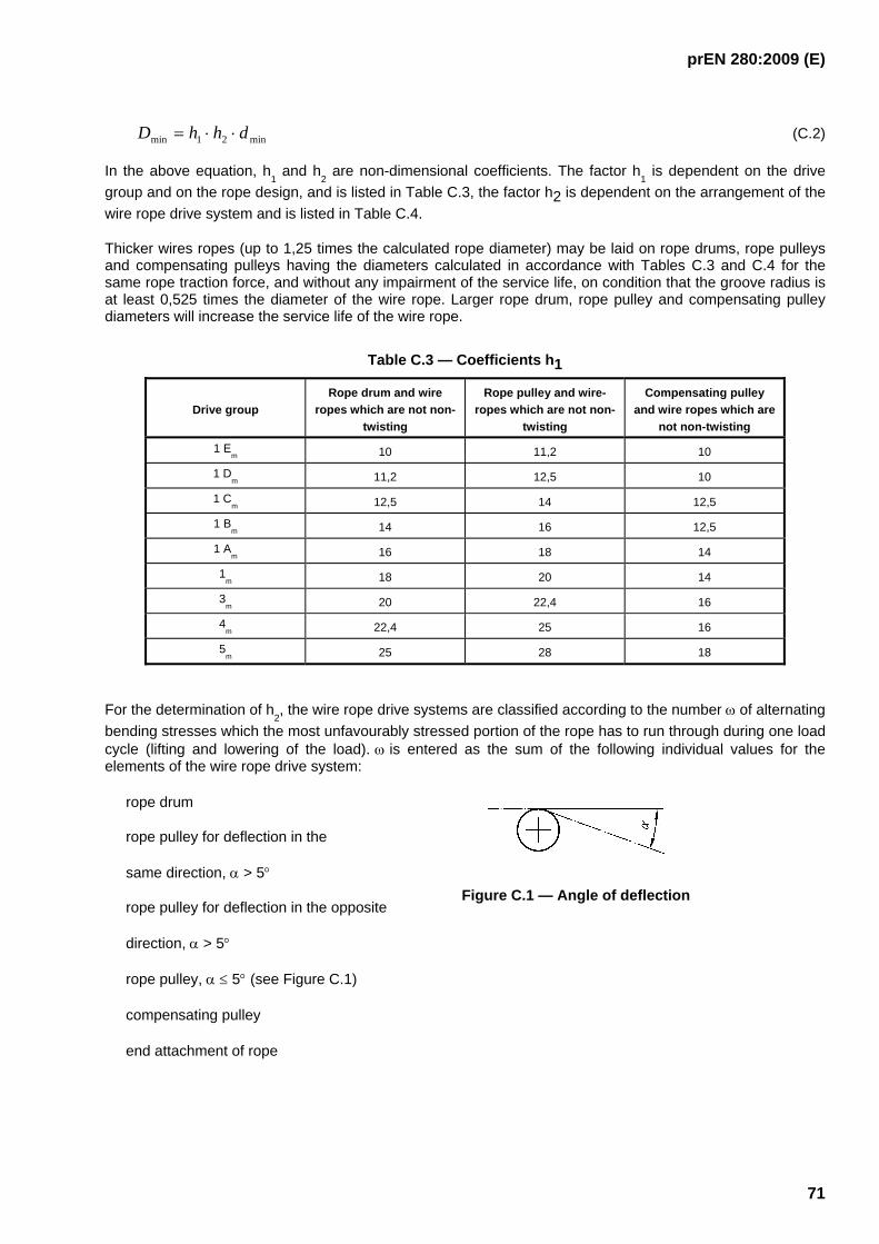
prEN 280:2009 (E)
71
min21min dhhD ⋅⋅= (C.2)
In the above equation, h1 and h
2 are non-dimensional coefficients. The factor h
1 is dependent on the drive
group and on the rope design, and is listed in Table C.3, the factor h2 is dependent on the arrangement of the wire rope drive system and is listed in Table C.4.
Thicker wires ropes (up to 1,25 times the calculated rope diameter) may be laid on rope drums, rope pulleys and compensating pulleys having the diameters calculated in accordance with Tables C.3 and C.4 for the same rope traction force, and without any impairment of the service life, on condition that the groove radius is at least 0,525 times the diameter of the wire rope. Larger rope drum, rope pulley and compensating pulley diameters will increase the service life of the wire rope.
Table C.3 — Coefficients h1
Drive group Rope drum and wire
ropes which are not non- twisting
Rope pulley and wire-ropes which are not non-
twisting
Compensating pulley and wire ropes which are
not non-twisting
1 Em 10 11,2 10
1 Dm 11,2 12,5 10
1 Cm 12,5 14 12,5
1 Bm 14 16 12,5
1 Am 16 18 14
1m 18 20 14
3m 20 22,4 16
4m 22,4 25 16
5m 25 28 18
For the determination of h2, the wire rope drive systems are classified according to the number ω of alternating
bending stresses which the most unfavourably stressed portion of the rope has to run through during one load cycle (lifting and lowering of the load). ω is entered as the sum of the following individual values for the elements of the wire rope drive system:
rope drum
rope pulley for deflection in the
same direction, α > 5°
rope pulley for deflection in the opposite
direction, α > 5°
rope pulley, α ≤ 5° (see Figure C.1)
compensating pulley
end attachment of rope
Figure C.1 — Angle of deflection

prEN 280:2009 (E)
72
Deflection in the opposite direction must be taken into consideration if the angle between the planes of two adjacent rope pulleys (traversed by the rope in succession) amounts to more than 120° (see Figure C.2).
Table C.4 — Coefficients h2
Examples for arrangements of rope drives h2
1)
for
Description Examples of application (drums illustrated in double lines)
ω rope
drums, compen-
sating pulleys
rope pulley
s
Wire rope runs on rope drum and over no more than
2 rope pulleys with deflection in the same direction, or
1 rope pulley with deflection in opposite direction
≤ 5 1 1
Wire rope runs on rope drum and over no more than
4 rope pulleys with deflection in the same direction, or
2 rope pulleys with deflection in the same direction and
1 rope pulley with deflection in the opposite direction, or
2 rope pulleys with deflection in the opposite direction
6 up to 9
1 1.12
Wire rope runs on rope drum and over at least
5 rope pulleys with deflection in the same direction, or
3 rope pulleys with deflection in the same direction plus
1 rope pulley with deflection in the opposite direction, or
1 rope pulley with deflection in the same direction plus
2 rope pulleys with deflection in the opposite direction, or
3 rope pulleys with deflection in the opposite direction
≥ 10 1 1.25
*) Compensating pulley; 1)
The correlation of ω and h2 in respect of the description and of the examples of application is only valid on

prEN 280:2009 (E)
73
condition that one segment of rope runs through the entire arrangement of the rope drive during one working stroke. For the determination of h
2, only the values of ω which occur at the most unfavourable segment of the rope need be considered.
Deflection in the same direction Deflection in the opposite direction
Figure C.2 — Deflection in the same/opposite direction
C.5 Efficiency of wire rope drive systems
The efficiency of a rope drive, for calculation of the rope traction force in accordance with Clause C.3 is determined in accordance with the following equation:
( ) ( ) ( )R
nRi
RFi
RS n ηηηηηη−−
⋅⋅=⋅=1
11 (C.3)
where
i number of fixed rope pulleys between the rope drum and the pulley block or load
n number of rope plies in one pulley bock. One pulley block consists of the sum total of all the rope plies and rope pulleys for one rope winding onto a rope drum (see Figure C.3)
ηF efficiency of the pulley block
( )R
nR
n ηηη−−
⋅1
11F (C.4)
Rη efficiency of one rope pulley
Sη efficiency of the wire rope drive system.
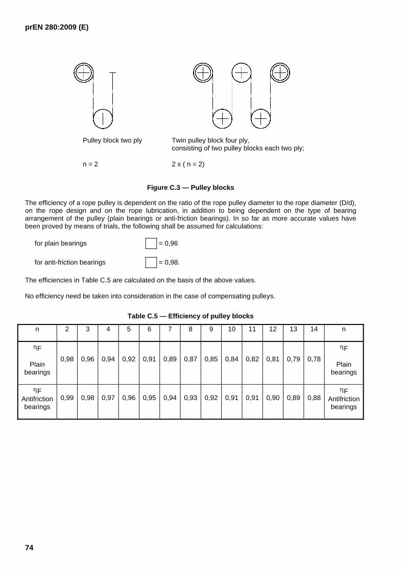
prEN 280:2009 (E)
74
Pulley block two ply Twin pulley block four ply, consisting of two pulley blocks each two ply;
n = 2 2 x ( n = 2)
Figure C.3 — Pulley blocks
The efficiency of a rope pulley is dependent on the ratio of the rope pulley diameter to the rope diameter (D/d), on the rope design and on the rope lubrication, in addition to being dependent on the type of bearing arrangement of the pulley (plain bearings or anti-friction bearings). In so far as more accurate values have been proved by means of trials, the following shall be assumed for calculations:
for plain bearings = 0,96
for anti-friction bearings = 0,98.
The efficiencies in Table C.5 are calculated on the basis of the above values.
No efficiency need be taken into consideration in the case of compensating pulleys.
Table C.5 — Efficiency of pulley blocks
n 2 3 4 5 6 7 8 9 10 11 12 13 14 n
ηF
Plain bearings
0,98 0,96 0,94 0,92 0,91 0,89 0,87 0,85 0,84 0,82 0,81 0,79 0,78
ηF
Plain bearings
ηF Antifriction bearings
0,99 0,98 0,97 0,96 0,95 0,94 0,93 0,92 0,91 0,91 0,90 0,89 0,88 ηF
Antifriction bearings

prEN 280:2009 (E)
75
Annex D (informative)
Calculation example – wire rope drive
systems
D.1 Method used to determine the coefficients and ratios used for 5.5.2 (wire rope drive systems) using the load cycle figures in 5.2.5.3 and operating speeds in 5.4.5
D.1.1 General
This method was preferred to the use of the Group Classification of Mechanisms method in ISO 4301-4 which posed problems of relating the state of loading and load spectrum factors to MEWPs, but gives results in line with the mobile crane standards ISO 4308-2 (Coefficients of Utilisation), and ISO 8087 (Drum and Sheave Sizes).
D.1.2 Notes
a)
1. "Light intermittent duty" in accordance with 5.2.5.3.3 is interpreted as large machines with large rated loads, often operating with less than the full rated load and used intermittently.
2. "Heavy duty" in accordance with 5.2.5.3.3 is interpreted as smaller machines with low rated loads, regularly carrying the full rated load, and used regularly.
3. "Medium term" (see Table C.1) is considered the most severe working case for extending structures, as the load varies during the load cycle. Heavy Term would only apply to levelling systems on machines with low rated loads e.g. one person, carried during the whole of every load cycle. This does not apply to MEWPs but would still give the same drive group used in the example.
b) The worst possible case has been taken e.g. a single rigid boom moving through an arc to reach maximum height. In practice, as this movement is achieved by the use of more than one boom, the mean running time would be divided by the number of booms and would be further reduced by the higher operating speeds of telescopic movements.
c) For the purpose of this analysis a load cycle starts when the work platform is loaded in the access position, and finishes when it is unloaded in the access position after being extended to a working position.
D.1.3 Annex C (normative) method summarised
a) Use the number of load cycles and operating speeds from this European Standard to derive the 'mean running time per day in hours, related to one year' in Table C.1 to determine the drive group.
b) Calculate the minimum theoretical rope diameter, dmin, using the coefficient c, for this drive group from Table C.2 in equation (C.1)
Scd ⋅=min
where
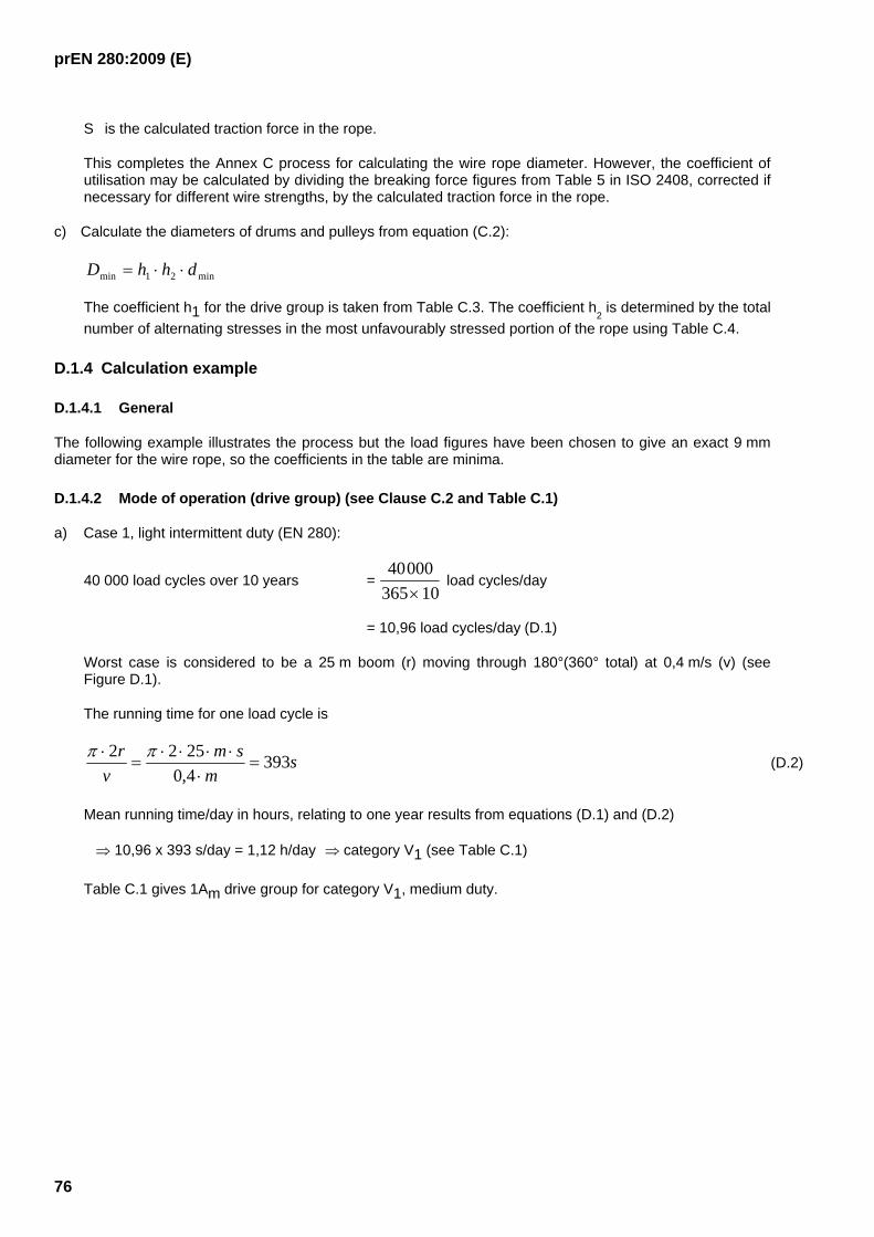
prEN 280:2009 (E)
76
S is the calculated traction force in the rope.
This completes the Annex C process for calculating the wire rope diameter. However, the coefficient of utilisation may be calculated by dividing the breaking force figures from Table 5 in ISO 2408, corrected if necessary for different wire strengths, by the calculated traction force in the rope.
c) Calculate the diameters of drums and pulleys from equation (C.2):
min21min dhhD ⋅⋅=
The coefficient h1 for the drive group is taken from Table C.3. The coefficient h2 is determined by the total
number of alternating stresses in the most unfavourably stressed portion of the rope using Table C.4.
D.1.4 Calculation example
D.1.4.1 General
The following example illustrates the process but the load figures have been chosen to give an exact 9 mm diameter for the wire rope, so the coefficients in the table are minima.
D.1.4.2 Mode of operation (drive group) (see Clause C.2 and Table C.1)
a) Case 1, light intermittent duty (EN 280):
40 000 load cycles over 10 years = 40000
365 10× load cycles/day
= 10,96 load cycles/day (D.1)
Worst case is considered to be a 25 m boom (r) moving through 180°(360° total) at 0,4 m/s (v) (see Figure D.1).
The running time for one load cycle is
sm
smv
r 3934,02522
=⋅
⋅⋅⋅⋅=
⋅ ππ (D.2)
Mean running time/day in hours, relating to one year results from equations (D.1) and (D.2)
⇒ 10,96 x 393 s/day = 1,12 h/day ⇒ category V1 (see Table C.1)
Table C.1 gives 1Am drive group for category V1, medium duty.
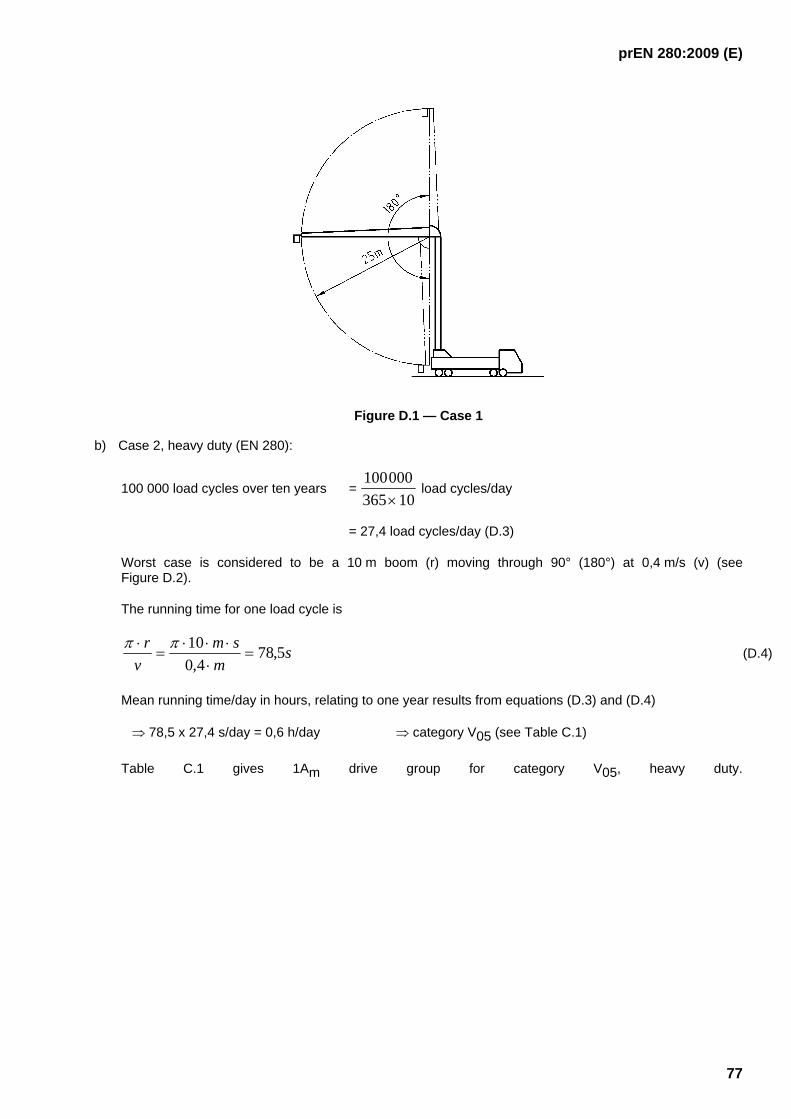
prEN 280:2009 (E)
77
Figure D.1 — Case 1
b) Case 2, heavy duty (EN 280):
100 000 load cycles over ten years = 100000365 10×
load cycles/day
= 27,4 load cycles/day (D.3)
Worst case is considered to be a 10 m boom (r) moving through 90° (180°) at 0,4 m/s (v) (see Figure D.2).
The running time for one load cycle is
sm
smv
r 5,784,0
10=
⋅⋅⋅⋅
=⋅ ππ
(D.4)
Mean running time/day in hours, relating to one year results from equations (D.3) and (D.4)
⇒ 78,5 x 27,4 s/day = 0,6 h/day ⇒ category V05 (see Table C.1)
Table C.1 gives 1Am drive group for category V05, heavy duty.

prEN 280:2009 (E)
78
Figure D.2 — Case 2
1Am drive group is adopted as appropriate for all MEWPs complying with this standard.
D.1.4.3 Calculation of minimum rope diameter (see C.3)
The minimum rope diameter is
Scd ⋅=min (D.5)
where S is the calculated load in the rope in Newton. For drives of group 1Am Table C.2 gives:
c = 0,090 for 1 570 N/mm² ropes
c = 0,085 for 1 770 N/mm² ropes
c = 0,085 for 1 960 N/mm² ropes
under not non-twisting conditions.
For S = 10 000 N and c = 0,09 resp. S = 11 211 N and c = 0,085 equation (D.5) leads to a minimum rope diameter of 9 mm.
D.1.4.4 Working coefficients
From ISO 2408, Table 5, the minimum breaking force of 9 mm diameter wire ropes is
F01 = 47 300 N (fibre core)
F02 = 51 000 N (steel core)
Based on ISO 2408, Table 5 (tensile grade 1 770 N/mm²), the following working coefficients result for 9 mm ropes (see Table D.1):
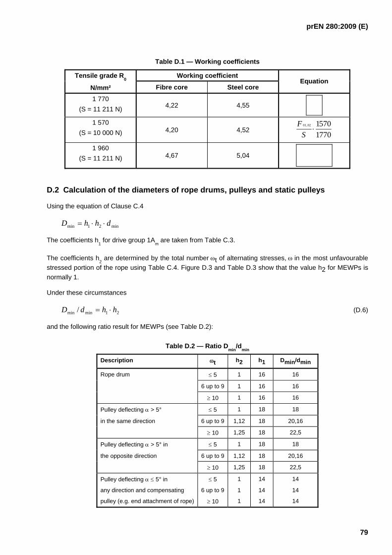
prEN 280:2009 (E)
79
Table D.1 — Working coefficients
Working coefficient Tensile grade R0
N/mm² Fibre core Steel core Equation
1 770 (S = 11 211 N) 4,22 4,55
1 570 (S = 10 000 N) 4,20 4,52 7701
570102,01⋅
SF
1 960 (S = 11 211 N) 4,67 5,04
D.2 Calculation of the diameters of rope drums, pulleys and static pulleys
Using the equation of Clause C.4
min21min dhhD ⋅⋅=
The coefficients h1 for drive group 1A
m are taken from Table C.3.
The coefficients h2 are determined by the total number ωt of alternating stresses, ω in the most unfavourable
stressed portion of the rope using Table C.4. Figure D.3 and Table D.3 show that the value h2 for MEWPs is normally 1.
Under these circumstances
21minmin / hhdD ⋅= (D.6)
and the following ratio result for MEWPs (see Table D.2):
Table D.2 — Ratio Dmin
/dmin
Description ωt h2 h1 Dmin/dmin
Rope drum ≤ 5 1 16 16
6 up to 9 1 16 16
≥ 10 1 16 16
Pulley deflecting α > 5° ≤ 5 1 18 18
in the same direction 6 up to 9 1,12 18 20,16
≥ 10 1,25 18 22,5
Pulley deflecting α > 5° in ≤ 5 1 18 18
the opposite direction 6 up to 9 1,12 18 20,16
≥ 10 1,25 18 22,5
Pulley deflecting α ≤ 5° in ≤ 5 1 14 14
any direction and compensating 6 up to 9 1 14 14
pulley (e.g. end attachment of rope) ≥ 10 1 14 14
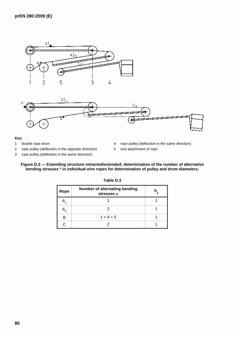
prEN 280:2009 (E)
80
Key: 1 double rope drum 2 rope pulley (deflection in the opposite direction) 3 rope pulley (deflection in the same direction)
4 rope pulley (deflection in the same direction) 5 end attachment of rope
Figure D.3 — Extending structure retracted/extended; determination of the number of alternative bending stresses * in individual wire ropes for determination of pulley and drum diameters.
Table D.3
Rope Number of alternating bending stresses ω
h2
A1 1 1
A2 2 1
B 1 + 4 = 5 1
C 2 1
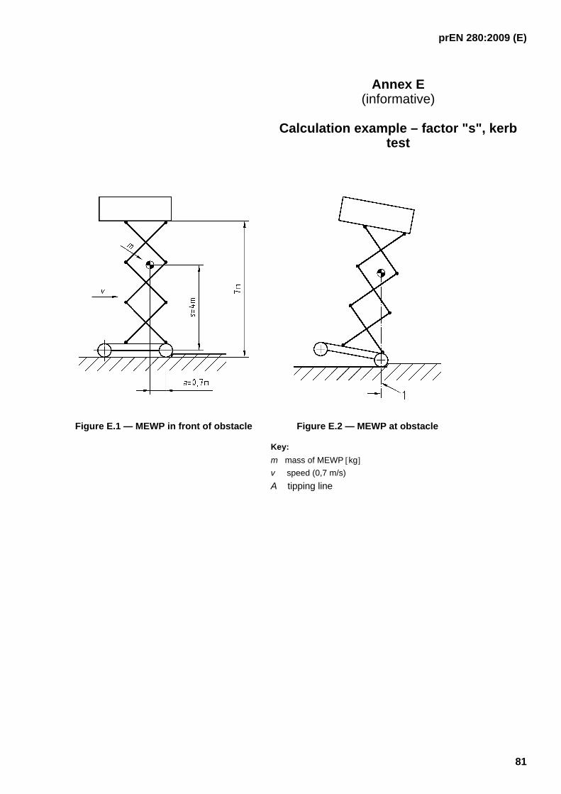
prEN 280:2009 (E)
81
Annex E (informative)
Calculation example – factor "s", kerb
test
Figure E.1 — MEWP in front of obstacle Figure E.2 — MEWP at obstacle
Key: m mass of MEWP [kg] v speed (0,7 m/s) A tipping line
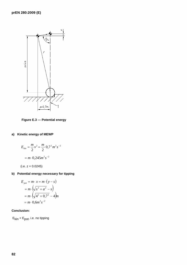
prEN 280:2009 (E)
82
Figure E.3 — Potential energy
a) Kinetic energy of MEWP
22
2222
245,0
7,022
−
−
⋅=
⋅==
smm
smmvmEkin
(i.e. z = 0.0245)
b) Potential energy necessary for tipping
( )( )( )
22
22
22
6,0
47,04−⋅=
−+⋅=
−+⋅=
−⋅=⋅=
smm
mm
sasm
symxmEpot
Conclusion:
Ekin < Epot, i.e. no tipping
prEN 280:2009 (E)
83
Annex F (normative)
Additional requirements for wireless
controls and control systems
Wireless controls shall be designed according to sub-clause 9.2.7 of EN 60204-32:1998 with the following additions:
F.1 General
The transmitter shall not transmit whilst the means to prevent unauthorised use is activated.
F.2 Control limitation
F.2.1 Activation of the transmitter shall be indicated on the transmitter and shall not initiate any movement of a MEWP.
F.2.2 The receiver shall provide output operating commands to the control system only when it is receiving frames containing the right address and correct command.
F.2.3 The main contactor shall only be energised (i.e. controlled to the “on” state) by at least one correctly received frame without any operating commands but containing a start command.
F.2.4 To avoid inadvertent movements after any situation having caused the MEWP to stop (e.g. power supply fault, battery replacement or lost signal condition), the system shall only output operating commands resulting in any MEWP movement after the MEWP driver has returned the controls to “off” position for a suitable period of time i.e. it has received at least one frame without any operating commands.
F.2.5 Whenever the MEWP switch is de-energised, all operating command outputs for MEWP movements from the receiver shall cease.
F.3 Stop
F.3.1 The part of the wireless control system to perform the stop function is a safety related part of the MEWPs control system, as defined in sub-clause 3.1 of EN ISO 13849-1:2006. This part of the wireless control system shall be designed to performance level “d” or higher for safety performance as defined in sub-clause 4.5 of EN ISO 13849-1:2006.
F.3.2 The control system shall initiate a stop of all MEWP movements when no valid frame has been correctly received within 0,5 s.
F.3.3 Unless the receiver monitors that the state of the control system corresponds with the state of the receiver outputs, the stop in F.3.2 shall also de-energise the MEWP switch. If the receiver monitors that the state of the control system corresponds with the state of the receiver outputs, the de-energising of the MEWP switch may be delayed up to a maximum of 5 minutes.
F.3.4 If emergency stop functions of category 0, as required in sub-clause 9.2.5.4.2 of EN 60204-32:2008, creates any additional risk, the stop function may be of category 1.
F.4 Serial data communication
F.4.1 The frame shall be sent repeatedly during operation.

prEN 280:2009 (E)
84
F.4.2 The system shall provide a transmission reliability to a hamming distance of the total number of bits in a frame divided by 20 and at least 4, or other means which ensure an equal level of reliability such that the probability of an erroneous frame getting through is less than 10-8.
F.5 Use of more than one operator control station
F.5.1 Transferral of control from one transmitter to another shall not be possible until the first transmitter has been de-activated by a deliberate action, specifically designed for this purpose.
F.5.2 Means shall be provided to enable several transmitter/receiver pairs to operate in the transmission range without unwanted interference with each other.
F.5.3 The means provided in F.5.2 shall be protected from accidental or unintentional change.
F.6 Battery-powered operator control stations
After the warning and the period required in 9.2.7.6 of EN 60204-32:1998 (when the transmitter battery voltage becomes so low that a reliable transmission cannot be guaranteed) the transmitter shall go automatically to the locked-off condition (i.e. the receiver stops all MEWP motions and de-energises the MEWP switch).
F.7 Receiver
The receiver shall withstand the vibration, random wide band test in EN 60068-2-64, Test Fd.
F.8 Warnings
Where persons can be expected to be in the vicinity of the MEWP or a part of the MEWP (e.g. travelling MEWP, slewing MEWP) and the risk exists of persons being trapped, run over etc. then warnings in addition to those in 7.2 shall be provided.
The MEWP shall be provided with
a) a marking on the access onto the MEWP, that states that the MEWP is provided with a wireless control system, and
b) either
⎯ a continuous visual warning while a wireless control system is engaged or
⎯ an automatic acoustic and/or visual warning prior to movements of the MEWP.
F.9 Information for use
F.9.1 The manufacturer's instructions shall include installation information to ensure that when a cable-less control system is in use, it shall not interfere with, or be interfered by, other systems in use at that location.
F.9.2 The manufacturer shall state the actual delay for the stop function in Clause F.3.2.

prEN 280:2009 (E)
85
Annex ZA (informative)
Relationship between this European Standard and the Essential
Requirements of EU Directive 2006/42/EC
This European Standard has been prepared under a mandate given to CEN by the European Commission and the European Free Trade Association to provide a means of conforming to Essential Requirements of the New Approach Directive Machinery 2006/42/EC.
Once this standard is cited in the Official Journal of the European Communities under that Directive and has been implemented as a national standard in at least one Member State, compliance with the normative clauses of this standard confers, within the limits of the scope of this standard, a presumption of conformity with the relevant Essential Requirements of that Directive and associated EFTA regulations.
WARNING — Other requirements and other EU Directives may be applicable to the product(s) falling within the scope of this standard.

prEN 280:2009 (E)
86
Bibliography
[1] EN 81-1:1998, Safety rules for the construction and installation of lifts — Part 1: Electric lifts.
[2] EN 81-2:1998, Safety rules for the construction and installation of lifts — Part 2: Hydraulic lifts.
[3] EN 528:1996, Rail dependent storage and retrieval equipment — Safety.
[4] EN 1495:1997, Lifting platforms — Mast climbing work platforms.
[5] EN 1570:1998, Safety requirements for lifting tables.
[6] prEN 1726-2:1999, Safety of industrial trucks — Self-propelled trucks up to and including 10000 kg capacity and tractors with a draw-bar pull up to and including 20000 N — Part 2: Additional requirements for trucks with elevating operator position and trucks specifically designed to travel with elevated loads.
[7] EN 1756-1+A1:2008, Tail lifts — Platform lifts for mounting on wheeled vehicles — Safety requirements — Part 1: Tail lifts for goods.
[8] EN 1756-2:2004, Tail lifts — Platform lifts for mounting on wheeled vehicles — Safety requirements — Part 2: Tail lifts for passengers.
[9] EN 1777:2004, Hydraulic platforms (HPs) for fire services — Safety requirements and testing.
[10] EN 1808:1999, Suspended access equipment.
[11] EN 1915-1:2001, Aircraft ground support equipment — General requirements — Part 1: Basic safety requirements.
[12] EN 1915-2:2001, Aircraft ground support equipment — General requirements — Part 2: Stability and strength requirements, calculations and test methods.
[13] EN 12159:2000, Builders hoists for persons and materials with vertically guided cages.
[14] ISO 2408, Steel wire ropes for general purposes — Minimum requirements.
[15] ISO 4301-4, Cranes and related equipment — Classification — Part 4: Jib cranes.
[16] ISO 4308-2, Cranes and lifting appliances — Selection of wire ropes — Part 2: Mobile cranes —Coefficient of utilisation.
[17] ISO 8087, Mobile cranes — Drum and sheave sizes.