mobile automated robotic drilling, inspection, and … · · 2013-09-25mobile automated robotic...
TRANSCRIPT
Page 1 of 7
2013-01-2338
Mobile Automated Robotic Drilling, Inspection, and Fastening
Troy Gray, Daniel Orf, Greg Adams Electroimpact Inc.
Copyright © 2012 SAE International
ABSTRACT
The versatility of the accurate robot has been increased by
coupling it with a mobile platform with vertical axis. The
automation can be presented to fixed aircraft components such
as wings, fuselage sections, flaps, or other aircraft assemblies
requiring accurate drilling, inspection, and fastening.
The platform accommodates a tool changer, ride along coupon
stand, fastener feed system, and other systems critical for
quality automated aircraft assembly. The accurate robot’s
flexibility is increased by a floor resynchronization system.
The indexing system is replaced by an automated two-camera
onboard vision system and miniature targets embedded in the
factory floor, with accuracy comparable to cup and cone
alternatives. The accurate robot can be deployed by casters,
curvilinear rail, or air bearings.
INTRODUCTION
The rapidly increasing demand for flexible automation in
aerospace assembly is realized with the introduction of the
mobile accurate robot. The mobile robot is a highly accurate
robotic system used for automated drilling, inspection, and
fastening of aircraft equipment.
The mobile robot consists of a stiff platform contacting the
foundation at 3 points, a Y-Sled for vertical positioning, and
for the mobile robot described an accurate KUKA KR500-
L340 robot with secondary feedback. These systems work in
conjunction to accurately present the end effector to a host of
aircraft assemblies. A typical end effector consists of, but is
not limited to a drill spindle, secondary drill spindle, hole
probe, fastener inserter, resynchronization camera, and an auto
normalizing nose piece. The platform of the mobile robot also
carries a coupon stand, an automatic tool changer, a fastener
feed system, and overview cameras. The mobile robot
assembly can be moved utilizing casters or air bearings; a
curvilinear rail can be utilized for guidance.
The mobile robot has an unlimited number of positions from
which its expanded volume can operate. The setup time of the
Electroimpact mobile robot has been maximized for speed.
The mobile robot can be equipped with traditional indexing
methods such as cup and cone or a floor resynchronization
indexing design that does not require anchor floor embedment.
MOBILE ROBOT SUMMARY
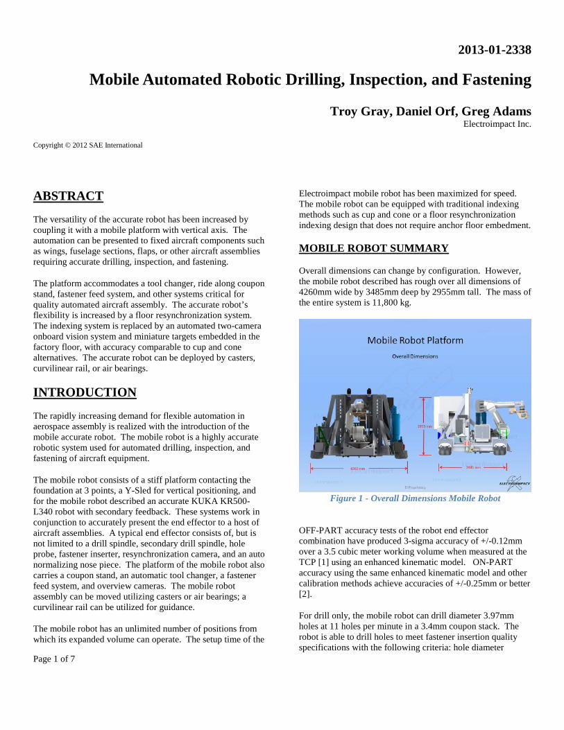
Overall dimensions can change by configuration. However,
the mobile robot described has rough over all dimensions of
4260mm wide by 3485mm deep by 2955mm tall. The mass of
the entire system is 11,800 kg.
Figure 1 - Overall Dimensions Mobile Robot
OFF-PART accuracy tests of the robot end effector
combination have produced 3-sigma accuracy of +/-0.12mm
over a 3.5 cubic meter working volume when measured at the
TCP [1] using an enhanced kinematic model. ON-PART
accuracy using the same enhanced kinematic model and other
calibration methods achieve accuracies of +/-0.25mm or better
[2].
For drill only, the mobile robot can drill diameter 3.97mm
holes at 11 holes per minute in a 3.4mm coupon stack. The
robot is able to drill holes to meet fastener insertion quality
specifications with the following criteria: hole diameter
Page 2 of 7
tolerance of +/- 25 microns, countersink depth +/- 80 microns
with an inspection method of Cpk 1.33 or better.
The following is a table of the major auxiliary systems of the
mobile robot.
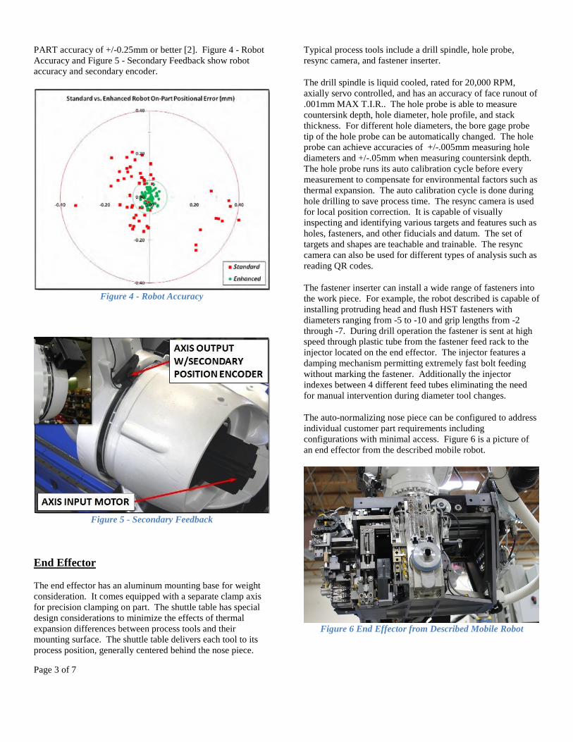
Table 1. Mobile Robot Auxiliary Systems
• Platform
• Y-Sled
• Accurate Robot with Secondary Feedback
• End Effector
• Floor Indexing Method with Camera Resync
• Coupon Stand
• Automatic Tool Changer
• Fastener Feed Systems
• Movement Methods
Figure 2 - Mobile Robot Auxiliary Systems
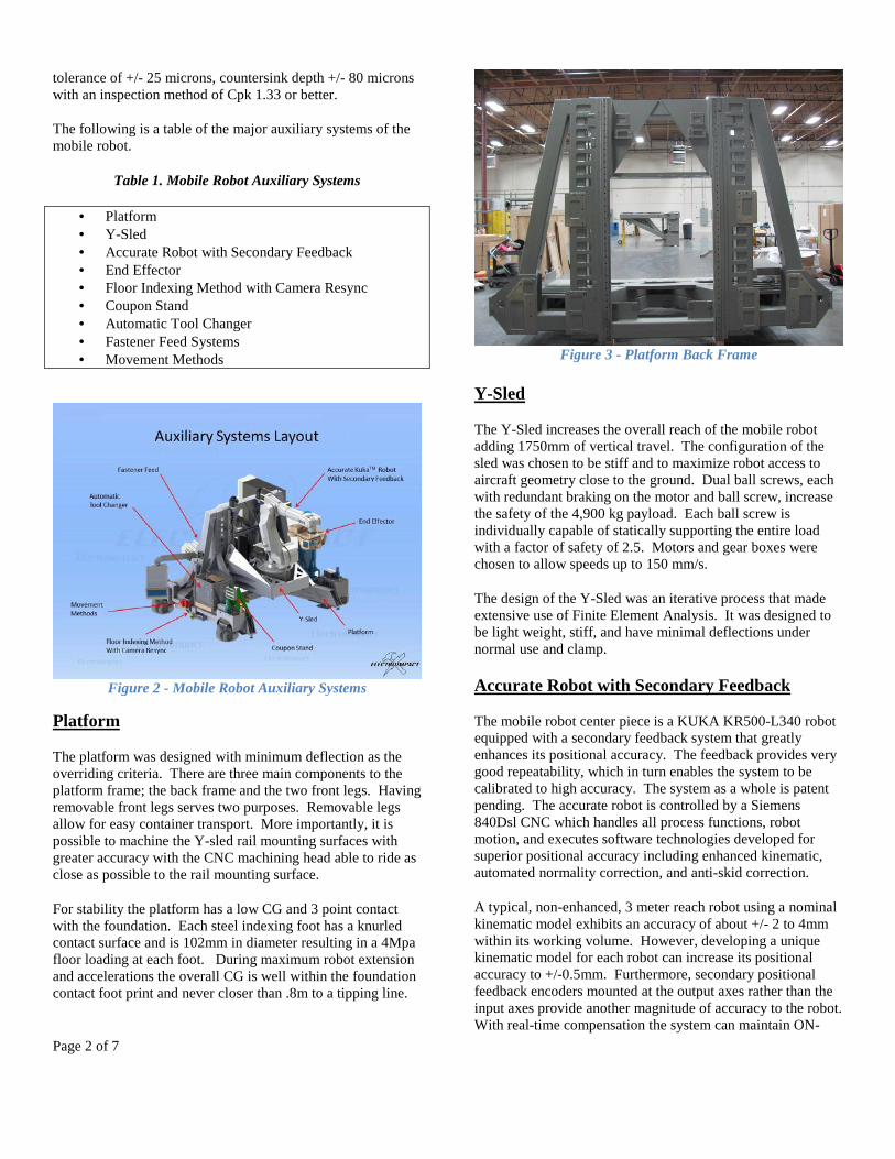
Platform
The platform was designed with minimum deflection as the
overriding criteria. There are three main components to the
platform frame; the back frame and the two front legs. Having
removable front legs serves two purposes. Removable legs
allow for easy container transport. More importantly, it is
possible to machine the Y-sled rail mounting surfaces with
greater accuracy with the CNC machining head able to ride as
close as possible to the rail mounting surface.
For stability the platform has a low CG and 3 point contact
with the foundation. Each steel indexing foot has a knurled
contact surface and is 102mm in diameter resulting in a 4Mpa
floor loading at each foot. During maximum robot extension
and accelerations the overall CG is well within the foundation
contact foot print and never closer than .8m to a tipping line.
Figure 3 - Platform Back Frame
Y-Sled
The Y-Sled increases the overall reach of the mobile robot
adding 1750mm of vertical travel. The configuration of the
sled was chosen to be stiff and to maximize robot access to
aircraft geometry close to the ground. Dual ball screws, each
with redundant braking on the motor and ball screw, increase
the safety of the 4,900 kg payload. Each ball screw is
individually capable of statically supporting the entire load
with a factor of safety of 2.5. Motors and gear boxes were
chosen to allow speeds up to 150 mm/s.
The design of the Y-Sled was an iterative process that made
extensive use of Finite Element Analysis. It was designed to
be light weight, stiff, and have minimal deflections under
normal use and clamp.
Accurate Robot with Secondary Feedback
The mobile robot center piece is a KUKA KR500-L340 robot
equipped with a secondary feedback system that greatly
enhances its positional accuracy. The feedback provides very
good repeatability, which in turn enables the system to be
calibrated to high accuracy. The system as a whole is patent
pending. The accurate robot is controlled by a Siemens
840Dsl CNC which handles all process functions, robot
motion, and executes software technologies developed for
superior positional accuracy including enhanced kinematic,
automated normality correction, and anti-skid correction.
A typical, non-enhanced, 3 meter reach robot using a nominal
kinematic model exhibits an accuracy of about +/- 2 to 4mm
within its working volume. However, developing a unique
kinematic model for each robot can increase its positional
accuracy to +/-0.5mm. Furthermore, secondary positional
feedback encoders mounted at the output axes rather than the
input axes provide another magnitude of accuracy to the robot.
With real-time compensation the system can maintain ON-
Page 3 of 7
PART accuracy of +/-0.25mm or better [2]. Figure 4 - Robot
Accuracy and Figure 5 - Secondary Feedback show robot
accuracy and secondary encoder.
Figure 4 - Robot Accuracy
Figure 5 - Secondary Feedback
End Effector
The end effector has an aluminum mounting base for weight
consideration. It comes equipped with a separate clamp axis
for precision clamping on part. The shuttle table has special
design considerations to minimize the effects of thermal
expansion differences between process tools and their
mounting surface. The shuttle table delivers each tool to its
process position, generally centered behind the nose piece.
Typical process tools include a drill spindle, hole probe,
resync camera, and fastener inserter.
The drill spindle is liquid cooled, rated for 20,000 RPM,
axially servo controlled, and has an accuracy of face runout of
.001mm MAX T.I.R.. The hole probe is able to measure
countersink depth, hole diameter, hole profile, and stack
thickness. For different hole diameters, the bore gage probe
tip of the hole probe can be automatically changed. The hole
probe can achieve accuracies of +/-.005mm measuring hole
diameters and +/-.05mm when measuring countersink depth.
The hole probe runs its auto calibration cycle before every
measurement to compensate for environmental factors such as
thermal expansion. The auto calibration cycle is done during
hole drilling to save process time. The resync camera is used
for local position correction. It is capable of visually
inspecting and identifying various targets and features such as
holes, fasteners, and other fiducials and datum. The set of
targets and shapes are teachable and trainable. The resync
camera can also be used for different types of analysis such as
reading QR codes.
The fastener inserter can install a wide range of fasteners into
the work piece. For example, the robot described is capable of
installing protruding head and flush HST fasteners with
diameters ranging from -5 to -10 and grip lengths from -2
through -7. During drill operation the fastener is sent at high
speed through plastic tube from the fastener feed rack to the
injector located on the end effector. The injector features a
damping mechanism permitting extremely fast bolt feeding
without marking the fastener. Additionally the injector
indexes between 4 different feed tubes eliminating the need
for manual intervention during diameter tool changes.
The auto-normalizing nose piece can be configured to address
individual customer part requirements including
configurations with minimal access. Figure 6 is a picture of
an end effector from the described mobile robot.
Figure 6 End Effector from Described Mobile Robot

Page 4 of 7
Floor Indexing Method with Camera Resync
The mobile robot has expanded flexibility with the
introduction of the Floor Resynchronization System. The
Floor Resynchronization System allows for the mobile robot
to be easily moved and placed in various working positions on
the factory floor without a need for beds, rails or locking cup-
and-cone interface. This system relies on miniature embedded
targets and a high resolution, two-camera, vision system to
accurately orient and locate the mobile robot on the factory
floor.
The stainless steel targets are embedded flush in the factory
foundation at nominal locations below the cameras of each
mobile robot at each operating position. Actual target
locations are valued in the FRS by laser tracker and the offsets
from nominal are noted for use in rigid body transforms later.
The targets are low cost, flexibly deployed, and simple to
expand down the road.
Figure 7 – Floor Resynchronization Target
Figure 8 – Floor Resynchronization Camera
The two vision system cameras, rigidly mounted to the mobile
robot frame, are calibrated to Robot Coordinate System (RCS)
with the help of a calibration plate and laser tracker. The
calibration plate features five fiducials which are designed to
be valued by the vision system and laser tracker. The laser
tracker values these fiducials in the RCS while the cameras
initially record values in individual camera image space with
Cognex VisionPro software. Using both sets of values (5
fiducial locations per camera, 10 total), VisionPro calculates
the 6 degree of freedom (6DOF) transformation on each
camera completing camera calibrations. All readings
performed by the vision system after calibration are in the
RCS.
Figure 9 – Floor Resynchronization Calibration
When the mobile robot is moved and placed, it must be set
down with both targets within camera fields of view (+/-
25mm). Placement is guided by downward-pointing lasers
adjacent to each camera. Once placed, the vision system
locates both targets in RCS. Since the targets are also at
known locations in the FRS, it is now possible to calculate the
mobile robot location in the FRS with a 3DOF transformation.
The jig and aircraft parts are also at known locations within
the FRS – using the new transformation, the robot can now
rapidly approach the aircraft part with its end effector. Each
time the mobile robot moves to a new location, the mobile
robot 3DOF transformation is calculated upon placement.
For robotic aerospace automation systems in which flexible
placement is paramount, the Floor Resynchronization System
enables rapid and flexible placement where machine rail beds
and cup-and-cone location are not feasible.
Automatic Tool Changer
The Automatic tool changer in the configuration shown has 24
modular pockets that can hold HSK 32 tool holders, HSK 40
tool holders, and probe tips. The tool changer has an RFID
read write head for reading tool holder information. A sensor
measures pocket occupancy.

Page 5 of 7
The tool changer has a singular axis design which is more
compact and precise than standard conveyor tool changer
designs. The enclosed design prevents accumulation of chips,
dust, and coolant. Figure 10 is a picture of the ATC from the
described mobile robot.
Figure 10 Automatic Tool Changer
Fastener Feed Systems
The mobile robot can be equipped with an Electroimpact
fastener feed system, or an original equipment manufacturer
fastener feed system. Pictured below in Figure 11 the
Electroimpact fastener feed system has 18 hoppers and 24
hangers.
Figure 11 Electroimpact Fastener Feed System
The configuration shown above can accommodate 42 different
grip lengths for fasteners sized 5/32, 3/16, 1/4, and 5/16 for
HST10 and HST11 fasteners. Other sizes can also be
accommodated. Drop tubes allow for single fastener insertion
for testing and for low quantity production runs.
Movement Methods
The mobile robot can be moved on full swiveling wheel
casters or air casters. The movement is handled with battery
powered electric tugs, or in some cases, pushed by hand. For
the mobile robot described the electric tugs used are
manufactured by MasterMover™.
Figure 12 MasterMover
Transport moves are generally handled with the wheel casters,
and two operators using a pair of electric tugs on a single
mobile robot; the electrica tugs are positioned opposite each
other on the sides of the mobile robot frame and allow
maximum freedom of movement.
In jig and precision moves are facilitated with the help of a
guide rail that is mounted in the floor. The rail used is
Strothmann™ flush floor round track. Electroimpact has
adapted the rail product to include curved sections, which
increases the scope of guided moves that can be accomplished
in sensitive and limited access areas. The Strothmann rail
guidance yields single axis precision of +/- 1mm throughout
the guided movement.
The mobile robot guided movements can be accomplished
with the mobile robot frame supported by either the wheel
casters or the air casters.
Page 6 of 7
Figure 13 Air Caster and Strothmann Rail
The wheel caster system uses one wheel caster at each corner
of the mobile robot. The wheel casters incorporate a powered
vertical axis that lifts the mobile robot frame off the floor for
movement on the wheel casters. This arrangement gives the
frame the most rigid contact with the floor during use of the
robot. Electroimpact has used two methods for actuating the
vertical axis on the wheel casters; one method employs
screws, motors, and caster frames with suspension, the other
method employs airbags as both the lifting and suspension
mechanism, with air circuitry that permits the load to be kept
level during lifting.
The air caster system uses an air caster near each corner of the
mobile robot, and two air actuated brakes. The air caster
system is arranged to facilitate short in-jig movements with
the mobile robot being pushed between positions by the
operator, without the need to use additional equipment such as
an electric tug. The air actuated brakes are deployed by
default, and must be released by the operator; this prevents
drifting of the mobile robot platform when the air casters are
energized, and reduces workload on the operator as the mobile
robot is pushed into its next position.
The mobile robot can be positioned very accurately without
mechanical guidance in areas where clearance is not a concern
using a pair of “acute angle chevrons” marked on the floor and
a pair of lasers mounted on the mobile robot frame and
powered by an on-board battery. The operator keeps the laser
dot on the floor between the two converging lines of the
chevron, and is easily able to steer the dot to the point where
the two lines converge. First time operators with no training
have routinely been able to complete a rough 10 meter course
and position both alignment laser dots in a pair of 25mm
diameter circles at the point of the chevrons in times of under
5 minutes total without the aid of chevrons.
With additional features, the mobile robot can also be
positioned in close proximity to difficult to access work pieces
by positioning the vertical axis of the mobile robot for work
piece clearance and moving the frame into position, such that
the vertical axis movement is limited, but access of the robot
is enhanced.
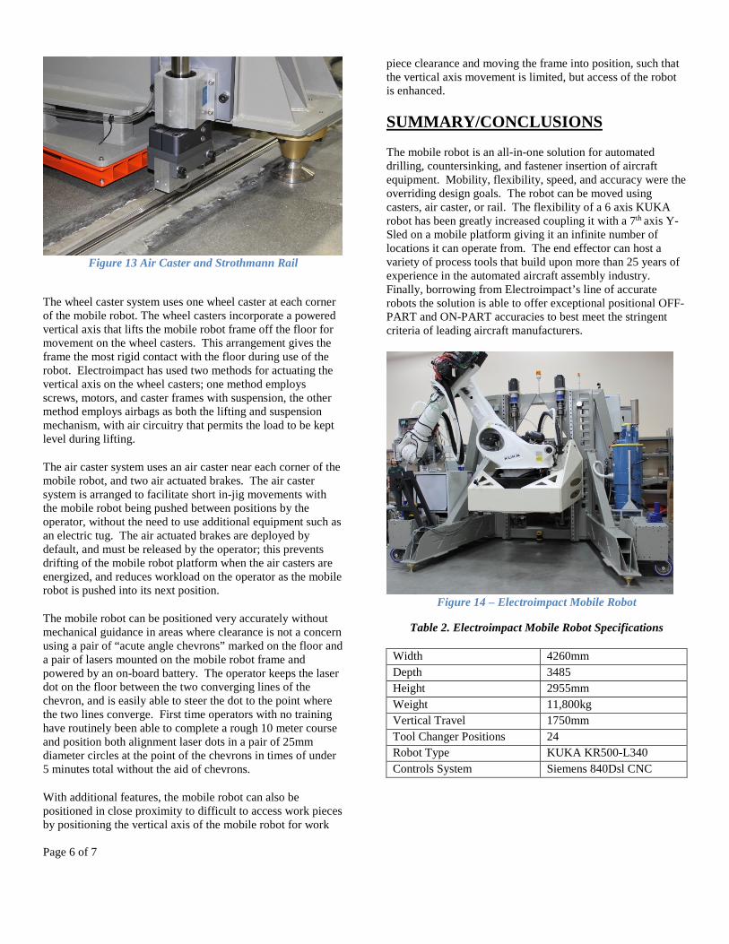
SUMMARY/CONCLUSIONS
The mobile robot is an all-in-one solution for automated
drilling, countersinking, and fastener insertion of aircraft
equipment. Mobility, flexibility, speed, and accuracy were the
overriding design goals. The robot can be moved using
casters, air caster, or rail. The flexibility of a 6 axis KUKA
robot has been greatly increased coupling it with a 7th axis Y-
Sled on a mobile platform giving it an infinite number of
locations it can operate from. The end effector can host a
variety of process tools that build upon more than 25 years of
experience in the automated aircraft assembly industry.
Finally, borrowing from Electroimpact’s line of accurate
robots the solution is able to offer exceptional positional OFF-
PART and ON-PART accuracies to best meet the stringent
criteria of leading aircraft manufacturers.
Figure 14 – Electroimpact Mobile Robot
Table 2. Electroimpact Mobile Robot Specifications
Width 4260mm
Depth 3485
Height 2955mm
Weight 11,800kg
Vertical Travel 1750mm
Tool Changer Positions 24
Robot Type KUKA KR500-L340
Controls System Siemens 840Dsl CNC
Page 7 of 7
REFERENCES
1. Russell DeVlieg, “Applied Accurate Robotic Drilling for
Aircraft Fuselage,” SAE Technical Paper 2010-01-1836,
2010.
2. Russell DeVlieg, “High-Accuracy Robotic
Drilling/Milling of 737 Inboard Flaps,” SAE Technical
Paper 2011-01-2733, 2011, doi:10.4271/2011-01-2733.
CONTACT INFORMATION
Troy Gray, Electroimpact, Mukilteo, WA 425-348-8090
Daniel Orf, Electroimpact, Mukilteo, WA 425-348-8090
Greg Adams, Electroimpact, Mukilteo, WA 425-348-8090
ACKNOWLEDGMENTS
Russell DeVlieg, Lead Robotic Engineer, Electroimpact
Siemens, www.sea.siemens.com
KUKA Robotics, www.kukarobotics.com
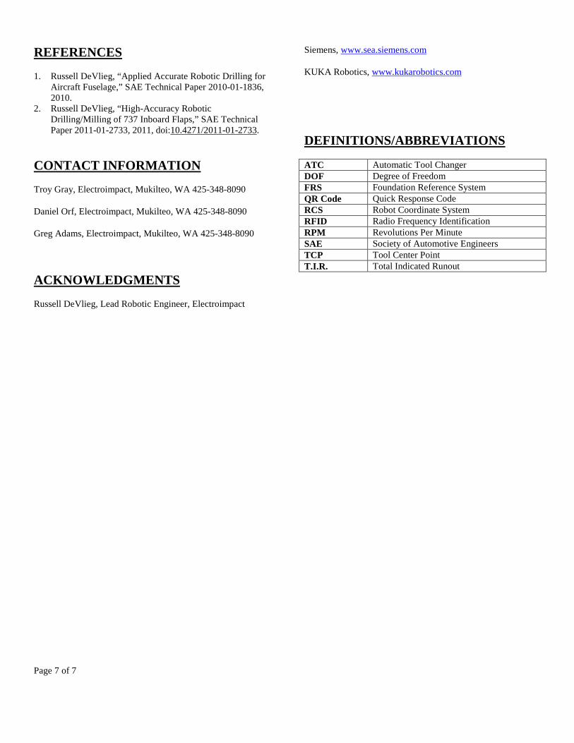
DEFINITIONS/ABBREVIATIONS
ATC Automatic Tool Changer
DOF Degree of Freedom
FRS Foundation Reference System
QR Code Quick Response Code
RCS Robot Coordinate System
RFID Radio Frequency Identification
RPM Revolutions Per Minute
SAE Society of Automotive Engineers
TCP Tool Center Point
T.I.R. Total Indicated Runout