mobile area water and sewer system
TRANSCRIPT


MOBILE AREA WATER AND SEWER SYSTEM
MOBILE, ALABAMA
BIDDING REQUIREMENTS AND
CONTRACT DOCUMENTS
for the construction of the
WRIGHT SMITH, JR. WASTEWATER TREATMENT PLANT
HEADWORKS REPLACEMENT PROJECT
Contract No. ________
****
****
JACOBS Pensacola, FL
April 2020
© JACOBS Owner Organization 2020. All rights reserved. This document and the ideas and designs incorporated herein, as an instrument of professional service, is the property of Jacobs and is not to be used in whole or part, for any other project without the written authorization of Jacobs. Any reuse, modification, or alteration of this document and the ideas and designs incorporated herein is at the sole risk of the party(ies) reusing, modifying, or altering it. All references to Jacobs and its employees and all professional seals shall be removed prior to any reuse, modification, or alteration of this document.
Project No. D3197100 Copy No.


Smith Wastewater Treatment Plant - Headworks Replacement
Pages
PW\DEN003\D3197100 TABLE OF CONTENTS APRIL 9, 2020 00 01 10 - 1 ©COPYRIGHT 2020 JACOBS
VOLUME 1
PART 1 - MAWSS STANDARD SPECIFICATIONS
Table of Contents ................................................................................................... 1- 16 Invitation for Bids .................................................................................................. 1- 1 Proposal.................................................................................................................. 1- 6 Subcontracting Plan ............................................................................................... 1- 1 Contract .................................................................................................................. 1- 4 Contract Bond ........................................................................................................ 1- 2 Labor and Material Bond ....................................................................................... 1- 3 Section 1 – Definition of Terms............................................................................. 1- 4 Section 2 – Proposal Requirements and Conditions .............................................. 1- 3 Section 3 – Award and Execution of Contract ....................................................... 1- 5 Section 4 – Scope of Work .................................................................................... 1- 3 Section 5 – Control of Work .................................................................................. 1- 6 Section 6 – Control of Material ............................................................................. 1- 2 Section 7 – Legal Relations and Responsibility to Public ..................................... 1- 5 Section 8 – Prosecution and Progress .................................................................... 1- 12 Section 9 – Testing Materials ................................................................................ 1- 3 Section 10 – Special Provisions ............................................................................. 1- 19 Special Conditions to the Standard Specifications for Water Mains, Sanitary Sewers and Sewage Pumping Stations, Board of Water and Sewer Commissioners of the City of Mobile, Alabama ................................................... 1- 3 Appendix H – Small and Small Disadvantaged Business ..................................... 1- 8 Appendix J – Irrevocable Standby Letter of Credit ............................................... 1- 1 Bid Bond ................................................................................................................ 1- 1 Information for Bidders ......................................................................................... 1- 3 Supplemental General Conditions ......................................................................... 1- 41
PART 2 - TECHNICAL SPECIFICATIONS
DIVISION 1—GENERAL REQUIREMENTS
01 11 00 Summary of Work .................................................................... 1- 2 01 26 00 Contract Modification Procedures ........................................... 1- 6 01 29 00 Payment Procedures ................................................................. 1- 3 01 31 13 Project Coordination ................................................................ 1- 7 01 31 19 Project Meetings ...................................................................... 1- 3 01 32 00 Construction Progress Documentation .................................... 1- 6 01 33 00 Submittal Procedures ............................................................... 1- 9 Supplement 1, Form: Transmittal of Contractor’s Submittal .. 1- 1

Smith Wastewater Treatment Plant - Headworks Replacement Pages
TABLE OF CONTENTS PW\DEN003\D3197100 00 01 10 - 2 APRIL 9, 2020 ©COPYRIGHT 2020 JACOBS
01 43 33 Manufacturers’ Field Services ................................................. 1- 3 Supplement 1, Manufacturer’s Certificate of Proper
Installation................................................................................ 1- 1 01 45 16.13 Contractor Quality Control ...................................................... 1- 9 01 45 33 Special Inspection Observation and Testing ............................ 1- 6 Supplement 1, Contractor’s Statement of Responsibility ........ 1- 2 Supplement 2, Fabricator’s Certificate of Compliance ............ 1- 1 01 50 00 Temporary Facilities and Controls ........................................... 1- 8 01 57 13 Temporary Erosion and Sediment Control .............................. 1- 12 01 57 28 Temporary Flow Control ......................................................... 1- 7 01 61 00 Common Product Requirements .............................................. 1- 8 Supplement 1, Form: Manufacturer’s Certificate of
Compliance .............................................................................. 1- 1 01 77 00 Closeout Procedures................................................................. 1- 4 01 78 23 Operation and Maintenance Data ............................................. 1- 6 Supplement 1, Form: Maintenance Summary Form ................ 1- 2 01 88 15 Anchorage and Bracing ............................................................ 1- 7 01 91 14 Equipment Testing and Facility Startup .................................. 1- 6 Supplement 1, Unit Process Startup Form ............................... 1- 1 Supplement 2, Facility Performance Demonstration/
Certification Form .................................................................... 1- 1 DIVISION 2—EXISTING CONDITIONS
02 41 00 Demolition ............................................................................... 1- 8 DIVISION 3—CONCRETE
03 01 32 Repair of Vertical and Overhead Concrete Surfaces ............... 1- 10 03 01 33 Repair of Horizontal Concrete Surfaces .................................. 1- 11 03 10 00 Concrete Forming and Accessories ......................................... 1- 5 03 15 00 Concrete Joints and Accessories .............................................. 1- 9 03 21 00 Steel Reinforcement ................................................................. 1- 4 03 24 00 Fibrous Reinforcing ................................................................. 1- 3 03 30 00 Cast-in-Place Concrete............................................................. 1- 28 Supplement 1, Concrete Mix Design, Class 5000F3S1P2C2 .. 1- 2 Supplement 2, Concrete Mix Design, Class 4500F1S1P1C1 .. 1- 1 Supplement 3, Concrete Mix Design, Class CF00F1S1P0C1 . 1- 2 03 39 00 Concrete Curing ....................................................................... 1- 3 03 62 00 Grouting ................................................................................... 1- 9 Supplement 1, 24-Hour Evaluation of Nonshrink Grout Test Form and Grout Testing Procedures ................................ 1- 3 03 63 00 Concrete Doweling .................................................................. 1- 4 03 64 23 Epoxy Resin Injection Grouting .............................................. 1- 11

Smith Wastewater Treatment Plant - Headworks Replacement
Pages
PW\DEN003\D3197100 TABLE OF CONTENTS APRIL 9, 2020 00 01 10 - 3 ©COPYRIGHT 2020 JACOBS
DIVISION 4—MASONRY (NOT USED)
DIVISION 5—METALS
05 05 19 Post-Installed Anchors ............................................................. 1- 8 05 50 00 Metal Fabrications ................................................................... 1- 14 05 52 16 Aluminum Railings .................................................................. 1- 8 05 53 00 Metal Gratings ......................................................................... 1- 6 DIVISION 6—WOOD, PLASTICS, AND COMPOSITES
06 82 00 Glass-Fiber-Reinforced Plastic ................................................ 1- 6 DIVISIONS 7 THROUGH 8 (NOT USED)
DIVISION 9—FINISHES
09 90 00 Painting and Coating ................................................................ 1- 23 Supplement 1, Paint System Data Sheet (PSDS) ..................... 1- 1 Supplement 2, Paint Product Data Sheet (PPDS) .................... 1- 1 DIVISION 10—SPECIALTIES
10 44 00 Fire Protection and Safety Equipment ........................................... 1-
DIVISIONS 11 THROUGH 12 (NOT USED)
DIVISION 13—SPECIAL CONSTRUCTION
13 34 23 Fabricated Structures ..................................................................... 1- 6
DIVISIONS 14 THROUGH 25 (NOT USED)
VOLUME 2
DIVISION 26—ELECTRICAL
26 05 02 Basic Electrical Requirements ................................................. 1- 6 26 05 04 Basic Electrical Materials and Methods .................................. 1- 9 26 05 05 Conductors ............................................................................... 1- 12 26 05 33 Raceway and Boxes ................................................................. 1- 29 26 08 00 Commissioning of Electrical Systems ..................................... 1- 13 26 20 00 Low-Voltage AC Induction Motors ......................................... 1- 12 26 24 19 Low-Voltage Motor Control .................................................... 1- 9 26 27 26 Wiring Devices ........................................................................ 1- 8
Smith Wastewater Treatment Plant - Headworks Replacement Pages
TABLE OF CONTENTS PW\DEN003\D3197100 00 01 10 - 4 APRIL 9, 2020 ©COPYRIGHT 2020 JACOBS
26 29 23 Low-Voltage Adjustable Frequency Drive Systems ................ 1- 13 26 41 00 Facility Lightning Protection ................................................... 1- 6 26 43 00 Surge Protective Devices ......................................................... 1- 4 26 50 00 Lighting .................................................................................... 1- 10
DIVISIONS 27 THROUGH 30 (NOT USED)
DIVISION 31—EARTHWORK
31 10 00 Site Clearing............................................................................. 1- 3 31 23 13 Subgrade Preparation ............................................................... 1- 4 31 23 16 Excavation................................................................................ 1- 5 31 23 19.01 Dewatering ............................................................................... 1- 3 31 23 23 Fill and Backfill ....................................................................... 1- 9 31 23 23.15 Trench Backfill ........................................................................ 1- 9 31 32 00 Soil Stabilization ...................................................................... 1- 5 31 32 19.16 Geotextile ................................................................................. 1- 6 31 41 00 Shoring ..................................................................................... 1- 2 DIVISION 32—EXTERIOR IMPROVEMENTS
32 11 23 Aggregate Base Courses .......................................................... 1- 4 32 12 16 Asphalt Paving ......................................................................... 1- 7 32 13 13 Concrete Paving ....................................................................... 1- 15 32 16 00 Curbs and Sidewalks ................................................................ 1- 3 32 91 13 Soil Preparation ........................................................................ 1- 3 32 92 00 Turf and Grasses ...................................................................... 1- 7 DIVISION 33—UTILITIES
33 05 13 Manholes .................................................................................. 1- 7 33 05 16.13 Precast Concrete Utility Structure ........................................... 1- 5 33 41 01 Storm Drain Piping .................................................................. 1- 2 33 41 01.05 Reinforced Concrete Data Sheet .............................................. 1- 2 33 44 13.13 Catch Basins............................................................................. 1- 2 DIVISION 34—TRANSPORTATION (NOT USED)
DIVISION 35—WATERWAY AND MARINE CONSTRUCTION
35 20 16.25 Fabricated Slide Gates and Stop Logs .................................... 1- 10 Supplement 1, Slide Gate Schedule ......................................... 1- 1 DIVISIONS 36 THROUGH 39 (NOT USED)
Smith Wastewater Treatment Plant - Headworks Replacement
Pages
PW\DEN003\D3197100 TABLE OF CONTENTS APRIL 9, 2020 00 01 10 - 5 ©COPYRIGHT 2020 JACOBS
DIVISION 40—PROCESS INTEGRATION
40 05 15 Piping Support Systems ........................................................... 1- 11 Supplement 1, Table 1: Nonchemical Areas ............................ 1- 1 40 27 00 Process Piping—General ......................................................... 1- 20 Supplement 1, Piping Schedule Legend .................................. 1- 2 Supplement 2, Piping Schedule ............................................... 1- 2 40 27 00.01 Ceramic-Epoxy-Lined Ductile Iron Pipe and Fittings DS ....... 1- 3 40 27 00.08 Stainless Steel Pipe and Fittings General-Service DS ............. 1- 2 40 27 00.10 Polyvinyl Chloride (PVC) Pipe and Fittings DS ..................... 1- 2 40 27 01 Process Piping Specialties........................................................ 1- 12 40 27 02 Process Valves and Operators .................................................. 1- 19 Supplement 1, Electric Actuated Valve Schedule ................... 1- 1 40 80 01 Process Piping Leakage Testing .............................................. 1- 6 40 90 00 Instrumentation and Control for Process Systems ................... 1- 34 Supplement 1, Loop Specifications ......................................... 1- 8 Supplement 2, Instrument List ................................................. 1- 1 Supplement 3, PLC I/O List ..................................................... 1- 2 Supplement 4, Existing RTU2 Record Drawings
(Panel Layout, Interconnection, I/O Wirings) ......................... 1- 9 Supplement 5, Existing RTU2 Panel Quick Sheet................... 1- 19 40 91 00 Instrumentation and Control Components ............................... 1- 17 40 99 90 Package Control Systems ......................................................... 1- 22 DIVISIONS 41 THROUGH 43 (NOT USED)
DIVISION 44—POLLUTION CONTROL EQUIPMENT
44 42 01 Traveling Water Screen ........................................................... 1- 7 44 42 30 Mechanically Cleaned Bar Screens ......................................... 1- 19 44 42 40 Vortex Grit Chamber Equipment ............................................. 1- 6 44 42 41 Cyclone Separator and Grit Washer ........................................ 1- 9 44 42 56.04 Submersible Pumps .................................................................. 1- 8 Supplement 1, Data Sheets: Pump and Motor ......................... 1- 2 44 42 56.09 Non-Clog Centrifugal Pumps .................................................. 1- 10 Supplement 1, Pump Data Sheet .............................................. 1- 3 DIVISION 45 THROUGH 49 (NOT USED)
VOLUME 3
PART 3 - DRAWINGS (BOUND SEPARATELY)
END OF SECTION


PART 1
MAWSS STANDARD SPECIFICATIONS


BOARD OF WATER AND SEWER COMMISSIONERS
OF THE
CITY OF MOBILE, ALABAMA
STANDARD SPECIFICATIONS
FOR
WATER MAINS, SANITARY SEWERS
AND
SEWAGE PUMPING STATIONS
APRIL 1993
UPDATED MAY 2012
TABLE OF CONTENTS
BOARD OF WATER AND SEWER COMMISSIONERS
OF THE
CITY OF MOBILE, ALABAMA
STANDARD SPECIFICATIONS
FOR
WATER MAINS, SANITARY SEWERS
AND
SEWAGE PUMPING STATIONS
I. GENERAL INFORMATION AND REQUIREMENTS, INVITATION,
PROPOSAL AND CONTRACT DOCUMENTS
GENERAL INFORMATION AND REQUIREMENTS
INVITATION FOR BIDS
PROPOSAL
CONTRACT
CONTRACT BOND
LABOR AND MATERIAL BOND
II. GENERAL CONDITIONS Paragraph
SECTION 1
DEFINITIONS OF TERMS
Definitions……………………………………………………………. 1.01
AASHTO……………………………………………….……………. 1.02
ANSI…………………………………………………………………. 1.03
Addendum……………………………………………………………. 1.04
ADEM………………………………………………………………... 1.05
Advertisement for Bids………………………………………………. 1.06
Agreement……………………………………………………………. 1.07
ASTM………………………………………………………………… 1.08
AWWA………………………………………………………………. 1.09
Bid……………………………………………………………………. 1.10
Bidder………………………………………………………………… 1.11
2

TABLE OF CONTENTS
(Continued)
Paragraph
Board……………………………………………………………………… 1.12
Contract…………………………………………………………………… 1.13
Contract Bid Price………………………………………………………… 1.14
Contract Bonds……………………………………………………………. 1.15
Contractor…………………………………………………………………. 1.16
County……………………………………………………………………. 1.17
Developer…………………………………………………………………. 1.18
Developer’s Engineer…………………………………………………….. 1.19
DIPRA……………………………………………………………………. 1.20
Engineer…………………………………………………………………… 1.21
Equipment…………………………………………………………………. 1.22
Extra Work………………………………………………………………… 1.23
Extra Work Orders………………………………………………………… 1.24
Laboratory…………………………………………………………………. 1.25
Material……………………………………………………………………. 1.26
NEMA……………………………………………………………………... 1.27
Notice to Proceed………………………………………………………….. 1.28
OSHA……………………………………………………………………… 1.29
Owner……………………………………………………………………… 1.30
Plans (Drawings)…………………………………………………………... 1.31
Product…………………………………………………………………….. 1.32
Project……………………………………………………………………... 1.33
Proposal……………………………………………………………………. 1.34
Proposal Form……………………………………………………………... 1.35
Proposal Guaranty…………………………………………………………. 1.36
Record Drawings…………………………………………………………... 1.37
Resident Project Representative…………………………………………… 1.38
SAHD……………………………………………………………………… 1.39
Shop Drawings…………………………………………………………….. 1.40
Specifications……………………………………………………………… 1.41
State………………………………………………………………………... 1.42
Subcontractor……………………………………………………………… 1.43
Superintendent…………………………………………………………….. 1.44
Supplemental Agreement………………………………………………….. 1.45
Surety……………………………………………………………………… 1.46
Work………………………………………………………………………. 1.47
3

TABLE OF CONTENTS
(Continued)
Paragraph
SECTION 2
PROPOSAL REQUIREMENTS AND CONDITIONS
Qualifications of Bidders…………………………………………… 2.01
Contents of Proposal Forms………………………………………… 2.02
Interpretation of Approximate Estimates…………………………… 2.03
Examination of Plans and Specifications…………………………… 2.04
Special Provisions and Site of Work
Preparation of Proposal……………………………………………... 2.05
Irregular Proposals………………………………………………….. 2.06
Proposal Guaranty…………………………………………………... 2.07
Delivery of Proposals………………………………………………. 2.08
Withdrawal or Revision of Proposal……………………………….. 2.09
Opening of Proposals………………………………………………. 2.10
Disqualifications of Bidders……………………………………….. 2.11
Liquidated Damages………………………………………………... 2.12
SECTION 3
AWARD AND EXECUTION OF CONTRACT
Consideration of Bids………………………………………………. 3.01
Award of Contract………………………………………………….. 3.02
Return of Proposal Guarantee……………………………………… 3.03
Execution of Contract……………………………………………… 3.04
Failure to Execute Contract………………………………………... 3.05
Requirements of Contract Bonds…………………………………... 3.06
Insurance………………………………………………………….... 3.07
Indemnity Provisions………………………………………………. 3.08
SECTION 4
SCOPE OF WORK
Intent of Plans and Specifications…………………………………. 4.01
Underground and Existing Utilities……………………………….. 4.02
Alteration of Plans or Character of Work………………………… 4.03
Extra Work………………………………………………………… 4.04
Construction and Maintenance of Detours………………………... 4.05
Removal and Disposal of Structures and Obstructions…………… 4.06
Final Clean-Up……………………………………………………. 4.07
Maintenance of the Work During Construction………………….. 4.08
Failure to Maintain Work………………………………………… 4.09
4
TABLE OF CONTENTS
(Continued)
Paragraph
SECTION 5
CONTROL OF WORK
Authority of the Engineer…………………………………………… 5.01
Plans and Shop Drawings…………………………………………… 5.02
Manufacturer’s Drawings…………………………………………… 5.03
Conformity with Plans and Allowable Deviations…………………. 5.04
Coordination of Plans, Specifications, and Special Provisions…….. 5.05
Cooperation of the Contractor……………………………………… 5.06
Construction Surveys………………………………………………. 5.07
Resident Project Representatives…………………………………... 5.08
Inspection…………………………………………………………… 5.09
Removal of Defective and Unauthorized Work……………………. 5.10
Disputed Claims……………………………………………………. 5.11
Contractor Initiated Changes……………………………………….. 5.12
Project Completion………………………………………………… 5.13
Final Construction Inspection……………………………………… 5.14
Final Acceptance…………………………………………………… 5.15
Maintenance Guarantee After Acceptance…………………………. 5.16
Contract Closeout Documents……………………………………… 5.17
SECTION 6
CONTROL OF MATERIAL
Source of Supply and Quality of Materials…………………………. 6.01
Samples and Tests…………………………………………………… 6.02
Storage of Materials…………………………………………………. 6.03
Defective Materials………………………………………………….. 6.04
Contractor’s Title to Materials………………………………………. 6.05
SECTION 7
LEGAL RELATIONS AND RESPONSIBILITY TO PUBLIC
Laws to be Observed…………………………………………………. 7.01
Permits, Taxes, Licenses, Laws and Ordinances…………………….. 7.02
Patented Devices, Materials and Processes………………………….. 7.03
Sanitary Provisions…………………………………………………… 7.04
Public Convenience and Safety………………………………………. 7.05
Crossing Railroads……………………………………………………. 7.06
Ingress and Egress……………………………………………………. 7.07
5
TABLE OF CONTENTS
(Continued)
Paragraph
Barricades, Danger, Warning and Detour Signs……………………….. 7.08
Preservation and Restoration of Property……………………………… 7.09
Trees, Monuments, Et Cetera
Responsibility for Damage Claims, Etc……………………………….. 7.10
Right-of-Way………………………………………………………….. 7.11
Interference of Contractors……………………………………………. 7.12
Contractor’s Responsibility for Work………………………………… 7.13
Contractor’s Responsibility for Completion………………………….. 7.14
Personal Liability of Public Officials…………………………………. 7.15
No Waiver of Legal Rights……………………………………………. 7.16
Use of Chemicals……………………………………………………… 7.17
Dust Control…………………………………………………………… 7.18
Safety and Health Regulations for Construction……………………… 7.19
Bracing………………………………………………………………… 7.20
Wetlands………………………………………………………………. 7.21
SECTION 8
PROSECUTION AND PROGRESS
Subletting or Assigning of Contract………………………………….. 8.01
Notice to Proceed…………………………………………………….. 8.02
Notice and Service Thereof………………………………………….. 8.03
Prosecution of Work…………………………………………………. 8.04
Construction Schedule and Periodic Estimates……………………… 8.05
Limitations of Operations…………………………………………… 8.06
Character of Workmen and Equipment……………………………… 8.07
Temporary Suspension of Work……………………………………... 8.08
Determination and Extension of Contract Time……………………… 8.09
for completion of Work
Failure or Delay in Completing Work on Time……………………… 8.10
Default of Contract…………………………………………………… 8.11
Termination for Failure of Performance……………………………… 8.12
Payments to Contractor………………………………………………. 8.13
Payment for Material Stored…………………………………………. 8.14
Payment By Contractor………………………………………………. 8.15
Furnishing of Utilities………………………………………………… 8.16
Monthly Estimates…………………………………………………… 8.17
Extra and Force Account Work……………………………………… 8.18
Acceptance of Final Payment Constitutes Release………………….. 8.19
Disturbed Areas……………………………………………………… 8.20
6
TABLE OF CONTENTS
(Continued)
Paragraph
SECTION 9
TESTING MATERIALS
Inspection and Testing of Materials………………………………………… 9.01
Portland Cement……………………………………………………………. 9.02
Aggregates for Use in Cement Concrete…………………………………… 9.03
Fine Aggregate……………………………………………………………… 9.04
Coarse Aggregate…………………………………………………………… 9.05
Slump Tests of Concrete……………………………………………………. 9.06
Advance Concrete Tests……………………………………………………. 9.07
Concrete Design Mix and Tests……………………………………………. 9.08
Concrete Control Tests (Laboratory Curing)………………………………. 9.09
Reinforcing Steel…………………………………………………………… 9.10
Structural Steel……………………………………………………………… 9.11
Steel Bar Joists……………………………………………………………… 9.12
Brick………………………………………………………………………… 9.13
Building Block and Stone…………………………………………………… 9.14
Concrete Sewer Pipe………………………………………………………… 9.15
Cast Iron, Ductile Iron Pipe and Special Castings………………………….. 9.16
Other Materials and Equipment…………………………………………….. 9.17
III. CONSTRUCTION SPECIFICATIONS
SECTION 10
SPECIAL PROVISIONS
Alabama Act No. 84-228…………………………………………………… 10.01
Small and Small Underutilized Businesses…………………………………. 10.02
State Highway or Railroad Permits…………………………………………. 10.03
Permits, Certificates, Laws and Ordinances………………………………… 10.04
Wage Rates………………………………………………………………….. 10.05
Sequence of Operations…………………………………………………….. 10.06
Project Documentation……………………………………………………… 10.07
Reports, Records and Data…………………………………………………. . 10.08
Signs………………………………………………………………………… 10.09
Construction Within State Highway Right-of-Way………………………… 10.10
Cutting of Trees Within Public Rights-of-Way…………………………….. 10.11
Dewatering………………………………………………………………….. 10.12
Weather Conditions………………………………………………………… 10.13
7
TABLE OF CONTENTS
(Continued)
Paragraph
Locks and Keys……………………………………………………… 10.14
Tightness of Water Containing Walls………………………………. 10.15
Extension of Contract Time………………………………………… 10.16
Clean-Up……………………………………………………………. 10.17
Brands of Equipment and Materials………………………………... 10.18
Affidavit of Compliance……………………………………………. 10.19
Supervision of Installation and the Guarantee……………………… 10.20
Manufacturer’s Certification……………………………………….. 10.21
Maximum Trench Width…………………………………………… 10.22
Basis of Payment and Method of Measure………………………… 10.23
Special Handling of Purchase Orders……………………………… 10.24
Bypass Pumping…………………………………………………… 10.25
SECTION 11
WATER MAINS
Scope………………………………………………………………. 11.01
Work Included……………………………………………………… 11.02
Materials……………………………………………………………. 11.03
Inspection…………………………………………………………… 11.04
Handling Pipe and Accessories…………………………………….. 11.05
Removing and Replacing Pavement……………………………….. 11.06
Alignment and Grade………………………………………………. 11.07
Excavation and Preparation of Trench……………………………… 11.08
Pipe Laying…………………………………………………………. 11.09
Jointing Pipe………………………………………………………… 11.10
Setting Valves, Valve Boxes, Fittings and Blow-Offs……………… 11.11
Setting Hydrants…………………………………………………….. 11.12
Plugging Dead Ends………………………………………………… 11.13
Anchorage of Bends, Tees and Plugs………………………………. 11.14
Chlorination of Completed Pipeline………………………………… 11.15
Hydrostatic Testing…………………………………………………. 11.16
Concrete…………………………………………………………….. 11.17
Backfilling………………………………………………………….. 11.18
Erosion Control…………………………………………………….. 11.19
Maintenance of Surfaces…………………………………………… 11.20
Clean-Up…………………………………………………………… 11.21
Pressure Tests and Chlorination Adjacent…………………………. 11.22
To Existing Water Lines
8

TABLE OF CONTENTS
(Continued)
Paragraph
Existing Water System………………………………............................ 11.23
Dust Control…………………………………………………………… 11.24
Public Safety………………………………………………………….. 11.25
Extra Depth for Water Lines………………………………………….. 11.26
Tapping of Water Mains……………………………………………… 11.27
Encasement Pipe……………………………………………………… 11.28
Backflow Prevention…………………………………………………. 11.29
SECTION 12
SANITARY SEWERS
Scope………………………………………………………………… 12.01
Work Included…………………………………….….…….……….. 12.02
Pipeline System Materials………………………………...……......... 12.03
Ductile Iron Pipe Gravity and Force Mains…………………………. 12.03A
PVC Pipe for Gravity and Force Main Pipes………………………… 12.03B
PVC for Small Diameter Force Mains (Under 4-inch Diameter…….. 12.03C
Polyethylene Plastic Pipe (HDPE pipe)……………………………… 12.03D
Small Diameter HDPE Service Lines for Low Pressure Force Mains
(Under 3-inch diameter)……………………………………… 12.03E
Encasement Pipe……………………………………………………… 12.03F
Lateral Services and Connections……………………………………. 12.03G
Sewer Cleanout Assemblies…………………………………………... 12.03H
Coupling of Dissimilar Pipes…………………………………………. 12.03I
Precast Manhole………………………………………………………. 12.04
Brick Manhole and Risers…………………………………………….. 12.05
Manhole Testing………………………………………………………. 12.06
Laboratory Testing…………………………………………………….. 12.06A
Vacuum Testing……………………………………………………… 12.06B
Corrosion Resistance/Lining for New and Existing Precast Manholes… 12.07
Urethane-Based Lining………………………………………………….. 12.07A
Manhole Frame and Cover (Castings)…………………………………… 12.08
Manhole Steps……………………………………………………………. 12.09
Drop Connections for Manholes………………………………………….. 12.10
Concrete for Miscellaneous Construction………………………………. 12.11
Brick………………………………………………………………………. 12.12
Grout for Sewer Structures……………………………………………….. 12.13
Crushed Slag or Crushed Stone Foundation……………………………… 12.14
Embedment of PVC Pipe for Gravity Sewers…………………………….. 12.15
Embedment of Polyethylene Sewer Pipe (Force Main)…………………… 12.16
9

TABLE OF CONTENTS
(Continued)
Paragraph
Excavation for Trenches………………………………………………... 12.17
Establishing Grade……………………………………………………… 12.18
Pipe Line Tolerances……………………………………………………. 12.19
Lying Gravity Sewer Pipe and Laterals………………………………… 12.20
Backfilling……………………………………………………………….. 12.21
Erosion Control………………………………………………………….. 12.22
Pumping and By-Passing………………………………………………… 12.23
Bracing…………………………………………………………………… 12.24
Creek Crossings………………………………………………………….. 12.25
Installation of Force Mains……………………………………………….. 12.26
Water Tight Testing of Sewers…………………………………………… 12.27
Deflection Testing of Sewers………………………………………........... 12.28
Removing and Replacing Pavement………………………………………. 12.29
Cleanup and Maintenance…………………………………………………. 12.30
Internal Video Inspections…………………………………………………. 12.31
Cleaning of Sewer Mains…………………………………………………… 12.32
Permanent Plugging and Abandoning Sewer Lines and Manholes………… 12.33
Pipeline Markers and Bollards for Manhole Protection……………………. 12.34
SECTION 13
SEWAGE PUMPING STATION
PART 1 - GENERAL
Scope…………………………………………………………………….. 13.1.01
Revision………………………………………………………………….. 13.1.02
Reference Standards…………………………………………………….. 13.1.03
Engineering Policy………………………………………………………. 13.1.04
Design Engineer’s Scope of Work………………………………………. 13.1.05
Design Criteria…………………………………………………………… 13.1.06
Contractor Submittals……………………………………………………. 13.1.07
Guarantee and Warranty…………………………………………………. 13.1.08
System Testing and Acceptance…………………………………………. 13.1.09
Contract Document Preparation………………………………………….. 13.1.10
10
TABLE OF CONTENTS
(Continued)
Paragraph
PART 2 – PUMPING STATION MATERIALS AND EQUIPMENT
New Wet Wells………………………………………………………. 13.2.01
Renovated Wet Wells………………………………………………… 13.2.02
Single & Multi-Speed Submersible Pump…………………………… 13.2.03
Variable Speed Submersible Pumps…………………………………. 13.2.04
Engine Driven Back-up Pumps………………………………………. 13.2.05
Piping…………………………………………………………………. 13.2.06
Valves…………………………………………………………………. 13.2.07
Flowmeter…………………………………………………………….. 13.2.08
Pipe Hangers and Supports…………………………………………… 13.2.09
Access Hatch Cover…………………………………………………... 13.2.10
Miscellaneous…………………………………………………………. 13.2.11
Grinder Pumping stations……………………………………………... 13.2.12
By-pass Pumping……………………………………………………… 13.2.13
Force Main Design…………………………………………………….. 13.2.14
PART 3 – SITE WORK
Clearing and Grubbing………………………………………………… 13.3.01
Grading and Drainage…………………………………………………. 13.3.02
Excavation and Backfill for Pumping Stations………………………… 13.3.03
Access Drive…………………………………………………………… 13.3.04
Crushed Stone and Gravel Surfacing………………………………….. 13.3.05
Fencing and Gates …………………………………………………….. 13.3.06
PART 4 – ELECTRICAL
General Electrical Design Considerations……………………………… 13.4.01
MAWSS Equipment Standards………………………………………… 13.4.02
General Electrical Design Considerations……………………………… 13.4.03
Control Philosophy …………………………………………………….. 13.4.04
Emergency Engine Operation…………………………………………... 13.4.05
Stand-by Generator Operation………………………………………….. 13.4.06
Portable Stand-by Generator Operation………………………………… 13.4.07
Wiring…………………………………………………………………… 13.4.08
Overcurrent Protection………………………………………………….. 13.4.09
11
TABLE OF CONTENTS
(Continued)
Paragraph
Motor Starters and Controllers…………………………………………….. 13.4.10
Variable Frequency Drives………………………………………………… 13.4.11
Control Components……………………………………………………….. 13.4.12
Float Switches……………………………………………………………… 13.4.13
Engraved Nameplates………………………………………………………. 13.4.14
Pump Control Panel…………………………………………………………. 13.4.15
SCADA Control Panel………………………………………………………. 13.4.16
Flow Measurement…………………………………………………………… 13.4.17
Narrative of Pump Station Operation………………………………………… 13.4.18
Telemetry System…………………………………………………………….. 13.4.19
Wooden Antenna Pole Requirements………………………………………… 13.4.20
APPENDIX D – Section 13
• Standard Forms and Specification Sheets
• Guide to MAWSS Pumping Stations
• Guide to MAWSS Piping Specifications
• Guide to MAWSS Valve Specifications
• Wet Well and Manhole Lining System Specifications
• SECTION 09745 Epoxy Wet Well and Manhole Coating Systems
• SECTION 09748 Urethane Wet Well and Manhole Lining System
• SECTION 09749 Calcium Aluminate Cementitious Wet Well and
Manhole Lining System
DRAWINGS
SECTION 14
REMOVING AND REPLACING PAVEMENT
Scope……………………………………………………………………….. 14.01
Materials……………………………………………………………………. 14.02
Removing and Replacing Pavement……………………………………….. 14.03
12
TABLE OF CONTENTS
(Continued)
Paragraph
SECTION 15
BACKFILLING
Scope………………………………………………………………………. 15.01
Materials…………………………………………………………………… 15.02
Backfilling…………………………………………………………………. 15.03
Backfilling for Sewage Pumping Stations………………………………… 15.04
SECTION 16
EROSION CONTROL
Scope………………………………………………………………………. 16.01
Erosion Control and Property Protection………………………………….. 16.02
Materials and Construction Requirements………………………………… 16.03
Method of Measurement and Basis of Payment…………………………… 16.04
Paragraph
SECTION 17
ENCASEMENT PIPE
Scope……………………………………………………………….. … 17.01
General……………………………………………………………....... 17.02
Material……………………………………………………………….. 17.03
Filling Encasement…………………………………………………… 17.04
Encasement Spacers………………………………………………….. 17.05
SECTION 18
REHABILITATION OF SANITARY SEWER MAINS BY THE
CURED-IN-PLACE (CIPP) METHOD
Scope……………………………………………………………….. 18.01
Materials……………………………………………………………. 18.02
Construction Procedures……………………………………………. 18.03
Construction Methods………………………………………………. 18.04
Post Televising of Completed Sections…………………………….. 18.05
CIPP Contractor Qualifications…………………………………….. 18.06
Warranty……………………………………………………………. 18.07
13
TABLE OF CONTENTS
(Continued)
Paragraph
SECTION 19
REHABILITATION OF MANHOLES
Scope……………………………………………………………….. 19.01
Lining of Manholes…………………………………………………. 19.02
Replacement of Manhole Frame and Cover………………………… 19.03
Salvaging Manhole Frame and Cover………………………………. 19.04
Raising of Existing Manhole Frame and Cover……………………. 19.05
Inflow Dish…………………………………………………………. 19.06
Chimney Seal………………………………………………………. 19.07
Manholes Lacking Benches and Inverts…………………………… 19.08
Manhole Rehabilitation Contractor Qualifications………………… 19.09
Vacuum Testing……………………………………………………. 19.10
Manhole Rehabilitation Warranty…………………………………. 19.11
SECTION 20
HORIZONTAL DIRECTIONAL DRILLING (HDD)/HDPE PIPE
Scope………………………………………………………………. 20.01
Materials…………………………………………………………… 20.02
Installation………………………………………………………… 20.03
Drilling Operations………………………………………………… 20.04
SECTION 21
REHABILITATION OF SANITARY SEWER MAINS BY THE PIPE
BURSTING AND TRENCHLESS PIPE REPLACEMENT METHOD
Scope………………………………………………………………. 21.01
Materials…………………………………………………………… 21.02
Construction Procedures…………………………………………… 21.03
Construction Methods……………………………………………… 21.04
Testing……………………………………………………………… 21.05
Post Televising of Completed Sections…………………………….. 21.06
SECTION 22
LIGHTNING PROTECTION SYSTEM
Scope……………………………………………………………….. 22.01
Summary……………………………………………………………. 22.02
14

TABLE OF CONTENTS
(Continued)
Paragraph
Description of Work………………………………………………… 22.03
Submittals…………………………………………………………… 22.04
Manufacturer Requirements…………………………………………. 22.05
Installer Requirements………………………………………………. 22.06
General……………………………………………………………… 22.07
Components………………………………………………………… 22.08
Lightning Rods (Air Terminals) for Buildings……………………… 22.09
SECTION 23
TRANSIENT VOLTAGE SURGE SUPPRESSORS
Description………………………………………………………….. 23.01
General Requirements………………………………………………. 23.02
Scope………………………………………………………………… 23.03
Brand Selection……………………………………………………… 23.04
Submittals…………………………………………………………… 23.05
Products…………………………………………………………….. 23.06
Secondary Service Suppressors for Distribution Panels……………. 23.07
Low Voltage Suppressors…………………………………………… 23.08
Warranty……………………………………………………………. 23.09
SECTION 24
ELECTRICAL MATERIALS AND METHODS
General………………………………………………………….. 24.01
Safety and Inspections………………………………………….. 24.02
Codes and Standards……………………………………………. 24.03
Grounding………………………………………………………. 24.04
Conduit…………………………………………………………. 24.05
Wire and Cable………………………………………………… 24.06
Cable Connectors and Supports……………………………….. 24.07
Installations……………………………………………………. 24.08
Identification and Labeling……………………………………. 24.09
Warranty………………………………………………………. 24.10
Maintenance…………………………………………………… 24.11
Final Acceptance……………………………………………… 24.12
15
TABLE OF CONTENTS
(Continued)
APPENDICES
APPENDIX A List of Acceptable products and Approved Manufacturers
APPENDIX B Water Line Construction Details (1 Sheet)
APPENDIX C Sanitary Sewer Construction Details (2 Sheets)
APPENDIX D Sewage Pumping Station Details (1 Sheet)
APPENDIX E Sewage Pumping Station Electrical Details (1 Sheet)
APPENDIX F Project Sign Detail (1 Sheet)
APPENDIX G Policy for the Control of Backflow and Cross-Connections
APPENDIX H Small and Small Disadvantaged Business
APPENDIX I Trench Widths and Paving Cut-Backs
APPENDIX J Irrevocable Standby Letter of Credit
APPENDIX K Installation Details by Lift Station
Loop Number Assignments for Duplex Pump Stations
Loop Number Assignments for Single Pump Stations
Sewage Pumping Station Wiring &Control Logic
Sewage Pumping Station Electrical Details for New Installation
RTU Details for Existing control Panel
Electrical Details for Building Revisions
APPENDIX L Sewer Cleanout Detail & Service Connection to Lined S.S. Mains
(2 Drawings)
APPENDIX M Timber Pile Supports for D. I. Sanitary Sewer Pipe (1 Drawing)
APPENDIX N Contractor SSO/Unpermitted Discharge Reporting Form-added 5/2012
16

INVITATION FOR BIDS
Sealed bids will be received by the Board of Water and Sewer Commissioners of the City of Mobile, Alabama (“Board”), at the Wesley A. James Operations Center, 4725 Moffett Road, Suite A, Mobile, AL 36618‐0249 until 12:30 p.m., Local Time, June 1, 2020, and then publicly opened and read, for furnishing all labor, materials, and performing all work for the following project: Contract No.: D3197100, Project Name: Wright Smith Jr. WWTP Headworks Replacement Project. The project is funded by the Alabama Department of Environmental Management State Revolving Fund (SRF) Loan Program. The selected bidder shall comply with all conditions and requirements of the program as they pertain to this Project. A complete set of electronic contract documents including Drawings, Specifications, referenced documents and a model bid package may be obtained via an e‐mail request to Seth Tatman at [email protected]. A CD containing the electronic files of the Documents will be mailed at the request of the prospective bidder upon receipt by Jacobs of a $50 non‐refundable payment and a valid FedEx account number to which the shipping charges may be billed. Review of a physical set of the contract documents is not available. Questions regarding the Contract Documents must be submitted electronically to JACOBS through Seth Tatman no later than 4:00 p.m. CDT, May 15, 2020 in order for responses to be provided via addendum prior to the bid date. A non‐mandatory virtual Pre‐Bid Conference will be held through a conference call on May 14, 2020 at 10:30 a.m., Local Time, to discuss bidding and project requirements. Prospective bidders and Subcontractors are encouraged to participate. Interested parties my join the virtual prebid conference by phone by dialing into the meeting at 1‐888‐796‐6828 and using the participant code 906318#. There will not be a video feed associated with this meeting. Bids must be submitted on the standard forms included with the Contract Documents in the tabbed and color‐coded format as indicated. Envelopes containing bids must be sealed and delivered to the Director, Board of Water and Sewer Commissioners of the City of Mobile, Alabama, 4725A Moffett Road, Mobile, Alabama 36618‐0249: “Bid for constructing Project # D3197100 ‐ Wright Smith Jr. WWTP Headworks Replacement Project, to be opened at 12:30 p.m., Local Time, June 1, 2020”. The Bidder's Alabama State Contractor's License Number and discipline shall be on the envelope. Hand‐delivered bid packages shall be delivered to the receptionist at the main entrance of the MAWSS office complex, 4725A Moffett Road, Mobile AL 36618. Bid guarantee in the form of certified check, bid bond, or Irrevocable Letter of Credit acceptable to the Board will be required for at least 5 percent of the bid amount, not to exceed $10,000.
The Board reserves the right to reject any and all bids and to waive any informality in bids received. THIS INVITATION FOR BIDS IS CONDENSED FOR ADVERTISING PURPOSES. ADDITIONAL
INFORMATION/REQUIREMENTS FOR BIDDERS CAN BE FOUND IN THE CONTRACT DOCUMENTS.
THE BOARD OF WATER AND SEWER COMMISSIONERS
OF THE CITY OF MOBILE, ALABAMA


PROPOSAL PAGE 1
PROPOSAL
TO: BOARDOFWATERANDSEWERCOMMISSIONERS
OFTHECITYOFMOBILE,ALABAMA Submitted: (Date) The undersigned, as Bidder, hereby declares that he has examined the site of the Work and informed himself fully in regard to all conditions pertaining to the place where the Work is to be done; that he has examined the Plans and Specifications for the Work and all Contract Documents relative thereto, and has read the Board’s Standard Specifications and all General Conditions and Special Provisions furnished; and that he has satisfied himself relative to the Work to be performed. The Bidder proposes and agrees, if this Proposal is accepted, to contract with the Board of Water and Sewer Commissioners of the City of Mobile, Alabama, in the form of contract specified to furnish all materials, equipment, machinery, tools, apparatus, means of transportation and labor necessary to complete the following Work:
WRIGHT SMITH JR. WWTP HEADWORKS REPLACEMENT PROJECT
JACOBS PROJECT NO. D3197100 in full and complete accordance with the shown, noted, described and reasonably intended requirements of the Plans, Specifications and all other Contract Documents to the full and entire satisfaction of the Board of Water and Sewer Commissioners of the City of Mobile, Alabama with a definite understanding that no money will be allowed for extra work except as set forth in the attached General Conditions and other Contract Documents for the lump sum or unit prices listed opposite each item. It is agreed that the description under each item, being briefly stated, implies, although it does not mention, all incidentals and that the prices stated are intended to cover all such work, materials and incidentals as constitute Bidder's obligations as described in the Specifications and any details not specifically mentioned, but evidently included in the Contract shall be compensated for the item in which it most logically is included. The Owner reserves the right to award the Contract to the lowest responsible and responsive Bidder. The basis of award for this project shall be based upon the Total Base Bid plus the total amount of additive alternates and less the total amount of deductive alternates that are selected by the Owner.

PROPOSAL PAGE 2
Bidder will complete the work in accordance with the Contract Documents for the following price: ____________________________________________Dollars and __________Cents (words) $____________________ (numerals) The Bidder shall include an Owner’s Allowance in the amount of $200,000.00 in the total bid price. The Base Bid Summary is as follows: Lump Sum Base Bid Price: $ _________ Owner’s Allowance: $ 200,000.00 TOTAL BASE BID (total of above and equal to total bid) $__________ Either or both of the following Additive Alternates 1 and 2 may or may not be accepted by the Owner at the time of award of the contract at the Owner’s sole discretion. Additive Alternate No 1. – Supply and Install the Traveling Water Screen (Band Screen) System
as indicated in Section 44 42 01, Traveling Water Screen
Bidder further proposes that if the Board of Water and Sewer Commissioners of the City of Mobile, Alabama elect to include the supply and installation of a travelling water screen (band screen) system inclusive of the screen basin changes from that indicated for the base bid, screen unit (SCRN-110), washwater booster pump (P-130), discharge conveyor (CONV-120 and all associated electrical and control components as indicated in the drawings along with any other miscellaneous changes as necessary to accommodate this change , the Contract Price will be increased in the amount of: ____________________________________________Dollars and __________Cents (words) $____________________ (numerals)
Additive Alternate No 2. – Plant Sewer Flow Meter (FIT/FE/FQI110)
Bidder further proposes that if the Board of Water and Sewer Commissioners of the City of Mobile, Alabama elects to include the supply and installation of a plant sewer flow meter in the band screen basin (SB-110) inclusive of all associated electrical and control components as indicated in the drawings along with any other miscellaneous changes as necessary to accommodate this change , the Contract Price will be increased in the amount of: ____________________________________________Dollars and __________Cents (words)

PROPOSAL PAGE 3
$____________________ (numerals)Either or both of the following Additive Alternates 3 and 4 may or may not be accepted by the Owner at any time at or after the award of the contract up to the initiation of the majority of the project’s required pavement operations at the Owner’s sole discretion. The quantities of either additive alternate is at the Owner’s discretion without a change in the contract time or the unit price up to a quantity to encompass all of the existing paved areas of the facility. Additive Alternate No 3. – Additional Asphalt Overlay (Unit Price Basis)
Bidder further proposes that if the Board of Water and Sewer Commissioners of the City of Mobile, Alabama elects to direct and include additional asphalt overlay of existing paved areas (concurrent with other paving operations) inclusive of all associated work as necessary to complete the overlay, the Contract Price will be increased on a unit price basis of $____________________ (numerals) per square yard in the bid quantity of 1,000 square yards for a total amount of: ________________________________________Dollars and __________Cents (words) $____________________ (numerals).
Additive Alternate No 4. – Asphalt Replacement (Unit Price Basis)
Bidder further proposes that if the Board of Water and Sewer Commissioners of the City of Mobile, Alabama elects to direct and include asphalt removal and replacement with 3” thick asphalt (concurrent with other paving operations) inclusive of all associated work as necessary to complete the replacement, the Contract Price will be increased on a unit price basis of $____________________ (numerals) per square yard in the bid quantity of 100 square yards for a total amount of: ________________________________________Dollars and __________Cents (words) $____________________ (numerals).
The Bidder further proposes and agrees hereby to commence the Work with an adequate force, plant and equipment at the time stated in the notice to the Contractor from the Engineers to proceed, and reach Substantial Completion of the work within 365 consecutive calendar days from and after the date stated in said notice and to achieve Final Completion of the work within an additional 30 days after Substantial Completion. The undersigned further agrees that, in case of failure on his part to execute the said Contract and the bond within 10 consecutive calendar days after written notice being given of the award of the Contract, the check or bid bond in the amount of 5 percent of this bid accompanying this bid, and the monies payable thereon, shall be paid into the funds of the Board of Water and Sewer Commissioners of the City of Mobile, Alabama as liquidated damages for such failure; otherwise the check or bid bond accompanying this Proposal shall be returned to the undersigned: Attached hereto is a certified check on the Bank of or a Bid Bond for the sum of Dollars ($ )
PROPOSAL PAGE 4
made payable to the Board of Water and Sewer Commissioners of the City of Mobile, Alabama. By (Legal Signature) (Printed Name and Title) Witness: (Legal Signature) Witness: (Legal Signature) ADDRESS: CONTRACTOR'S LICENSE NO: BIDDER acknowledges receipt of the following ADDENDA:
PROPOSAL PAGE 5
PROPOSED SUBCONTRACTING PLAN SUBCONTRACTORS The Bidder further proposes that the following subcontracting firms or businesses may be awarded subcontracts for the following portions of the Work in the event that the Bidder is awarded the Contract (use additional sheets, if required): Mechanical Name Street City Instrumentation and Control (Shall be Agent and/or representative of the computer system supplier, requires total system responsibility for control devices and system) Name Street City Electrical Name Street City Others (ADD SHEETS AS NEEDED) Name Street City

PROPOSAL PAGE 6
SSO AND UNPERMITTED DISCHARGE PREVENTION NOTIFICATION: Sanitary Sewer Overflows (SSOs) and unpermitted discharges of wastewater to the environment are a violation of Federal and State laws, as well as a beach of this Contract. The Contractor and associated subcontractors, vendors, and other entities and persons chosen to complete this Work shall not, through act or omission, discharge untreated wastewater to the environment or cause wastewater to back up into a building. The Contractor hereby agrees to indemnify the Owner if the Owner is assessed penalties or fines, receives regulatory actions, or has claims, actions, or suits filed against it by any person or entity as a result of SSOs or unpermitted discharges caused by act or omission of the Contractor and/or any entity or person performing Work in the Contractor’s behalf under this Contract. The Contractor shall reimburse the Owner for all damages, losses, penalties, fines, judgments, interest, costs, and expenses of every nature incurred by the Owner, including but not limited to reasonable attorney’s fees, arising from or associated with each SSO or unpermitted discharge. In addition, the Contractor shall pay the following penalties to the Owner for SSOs and unpermitted discharges caused by the Contractor or any entity or person performing Work in the Contractor’s behalf, regardless of whether such SSOs or discharges reach waters of the State.
Estimated Volume Spilled Penalty Amount
0 to 10,000 gallons $1,000 10,001 to 25,000 gallons $2,000 25,001 to 50,000 gallons $2,500 50,001 to 150,000 gallons $3,000 More than 150,000 gallons $6,000
I, having authority to execute this document, have reviewed the above Notification, therein. Contractor Name Street City Signature
Revised 6/2012

SUBCONTRACTING PLAN
In order for your proposal to be considered, you, as Bidder, must complete all blanks in this Subcontracting Plan and sign
with a handwritten signature where indicated below.
Failure to fill in the blanks on this Subcontracting Plan and/or to include a handwritten signature will be cause for
rejection of your bid.
It is MAWSS’s goal that in all contracts, contractors shall make a demonstrated good faith effort to award 15% of the
contract amount to certified Disadvantages Business Entities [DBE’s] / Diverse Suppliers as subcontractors and/or suppliers
performing commercially useful functions which are consistent with contract requirements.
Copies of MAWSS DBE Policy 16-01 [for public works projects], DBE/Supplier Diversity Policy 17-01 [for contracts for other
goods and services], MAWSS’s list of certified Disadvantaged Business Enterprises [DBE’s] / Diverse Suppliers, and lists of
organizations that have information on DBE’s / Diverse Suppliers are available from MAWSS’s Supplier Diversity Office (251-
694-3194) or from the MAWSS website, www.mawss.com.
PLEASE STATE WHAT PERCENTAGE OF THE WORK FOR THIS CONTRACT YOU PLAN TO AWARD TO DBE/DIVERSE SUPPLIER SUBCONTRACTORS AND/OR VENDORS: (Total %)_____________________________________
ESTIMATED TOTAL DOLLAR AMOUNT TO BE AWARDED TO DBE/DIVERSE SUPPLIER: (Total $)_____________________________________
AMOUNT BID FOR THIS CONTRACT:
(Total $)_____________________________________
If the above percentage is zero or is less than 15%, be sure to include your Affidavit of Contractor’s Good Faith Efforts to
Meet Subcontractor / Vendor Diversity Goals and all supporting documentation in your bid package.
Please list below all subcontractors and suppliers which you plan to use for this contract. Also indicate which of these
are DBE’s / Diverse Supplier by writing “yes” or “no” where indicated. Also list for each the percentage of the total
contract amount to be performed by each and the certification group the DBE / Diverse Supplier is certified with. Attach
additional sheets if needed. [If you are not using any subcontractors or vendors, you will need to write “zero” below and
sign the form.]
SUBCONTRACTOR/ VENDOR NAME DBE / Diverse Supplier? % OF CONTRACT AMT. CERTIFICATION GROUP Yes or No (MAWSS, ALDOT, ADECA, SRMSDC, BCIA)
____________________________________ _________ __________________ _________________
____________________________________ _________ __________________ _________________
____________________________________ _________ __________________ _________________
____________________________________ _________ __________________ _________________
____________________________________ _________ __________________ _________________
____________________________________ _________ __________________ _________________
____________________________________ _________ __________________ _________________
CAUTION: ACCURATELY COMPLETE ALL PARTS OF THIS FORM AND SIGN BELOW:
WE WILL EXERCISE GOOD FAITH TO COMPLY WITH THIS PLAN AND MAWSS’S DBE REQUIREMENTS.
_____________________________________ BIDDER By: __________________________________


CONTRACT
, by
, (Contractor)
THIS CONTRACT is made and entered into the _______ day of 20
and bet ween
hereinafter “Contractor,” and the Board of Water and Sewer Commissioners of the City of Mobile, Alabama, hereinafter “Owner.”
WITNESSETH:
The Contractor, for the consideration hereinafter fully set out hereby agrees with the Owner, as follows:
1. The Contractor shall furnish all materials and perform all Work as set forth in the following Contract Documents: Invitation for Bids, and any Addenda thereto; Proposal and all Documents submitted therewith; Standard Specifications of the Board of Water and Sewer Commissioners of the City of Mobile, Alabama; any Specifications of the Owner provide with the Invitation for Bids which are specific to this Contract; General Conditions; Special Provisions; Detailed Specifications; this Contract form; Bonds; Drawings and Addenda; all of which are attached hereto and made a part of the parties’ Contract, as if fully set forth herein:
Wright Smith Jr. WWTP Headworks Replacement ProjectProject No. D3197100
2. The Contractor shall commence performance of this Contract on a date to be specified in a written orderof the Owner, and shall fully complete all Work hereunder within 395 days from and after said date. “Work”shall include all construction, delivery of materials and items, and other obligations of the Contractor underthis Contract.
3. The Owner hereby agrees to pay to the Contractor for the faithful performance of the Contract,subject to additions and deductions as provided in the Specifications or Proposal, inlawful money of the United States as follows:
Approximately S________________________, and 00/100 Dollars ($_____________.__) in accordance with lump sum and unit prices set forth in the proposal inclusive of Additive Alternates No. 1 and No. 2. (Identify as selected by Owner)
CONTRACT PAGE 2
4. The Owner shall make monthly partial payments to the Contractor on the basis of a dulycertified and approved estimate of Work performed during the preceding calendar month by theContractor. The Owner may retain five percent (5%) of the amount of such estimate until fiftypercent (50%) of the Work has been completed. The Owner may hold this retainage until allWork has been performed strictly in accordance with this Contract and until all Work has beenaccepted by the Owner, and all obligations of the Contractor under this Contract have beensatisfied.
5. Upon submission by the Contractor of evidence satisfactory to the Owner that allpayrolls, material bills, and other costs incurred by the Contractor in connection with theperformance of this Contract have been paid in full, and upon satisfaction by the Contractor ofall other obligations under this Contract, final payment on account of this Contract shall be madewithin thirty days (30) after the completion by the Contractor of all Work covered by thisContract and the acceptance thereof by the Owner.
6. The parties hereto acknowledge and agree that time is of the essence for performance ofthis Contract. The parties agree that in the event the Work is not completed within the timeherein specified, the Owner may retain from the compensation otherwise to be paid to theContractor the sum not to exceed $1,000 per day as prescribed in the Special Conditions foreach day thereafter, Sundays and holidays included, that the Work remains uncompleted. Theparties agree that this dollar amount represents their agreed upon stipulation as to the damageswhich the Owner will have sustained per day due to the failure of the Contractor to completethe Work within the time stipulated, and that this amount is not a penalty.
7. Sanitary Sewer Overflows (SSOs) and unpermitted discharges of wastewater to theenvironment are a violation of Federal and State laws, as well as a breach of this Contract. TheContractor and associated subcontractors, vendors, and other entities and persons chosen tocomplete this Work shall not, through act or omission, discharge untreated wastewater to theenvironment or cause wastewater to back up into a building. The Contractor hereby agrees toindemnify the Owner if the Owner is assessed penalties or fines, receives regulatory actions, orhas actions, suits, or claims filed against it by any person or entity as a result of SSOs orunpermitted discharges caused by act or omission of the Contractor and/or any entity or personperforming work in the Contractor’s behalf under this Contract. The Contractor shall reimbursethe Owner for all damages, losses, penalties, fines, judgments, interest, costs, and expenses ofevery nature incurred by the Owner, including but not limited to reasonable attorney’s fees,arising from or associated with each SSO or unpermitted discharge. In addition, the Contractorshall pay the penalties identified in the Contract Documents to the Owner for SSOs andunpermitted discharges caused by the Contractor and/or any entity or person performing Work inthe Contractor’s behalf, regardless of whether such SSOs or discharges reach waters of the State.

CONTRACT PAGE 3
8. The parties hereto further agree hereto that if at any time after the execution of thisContract and the Contract Bond hereto attached for its faithful performance, the Owner shalldeem the surety or sureties upon such bond to be unsatisfactory, or if, for any reason, such bondceases to be adequate to cover the performance of the Work, the Contractor shall at its expense,within five (5) days after the receipt of notice from the Owner to do so, furnish an additionalbond or bonds in such form and amount and with such surety or sureties as shall be satisfactoryto the Owner. In such event, no further payment to the Contractor shall be due under thisContract until such new or additional security for the faithful performance of the Work shall befurnished in manner and form satisfactory to the Owner.
IN WITNESS WHEREOF the representatives of the parties hereto have executed this Contract by signing below, with full authority as the act of each party, to be effective as of the day and date first above written in two (2) counterparts, each of which shall, without proof or accounting for the other counterpart, be deemed an original Contract.
BOARD OF WATER AND SEWER COMMISSIONERS OF THE CITY OF
MOBILE, ALABAMA ATTEST
By By____________________________________ (Legal Signature) (Legal Signature)
(Printed Name and Title) (Printed Name and Title)
CONTRACTOR: _________________________
By (Legal Signature) (Legal Signature)
By (Printed Name and Title) (Printed Name and Title)
(SEAL)

CONTRACT PAGE 4
NOTARY ACKNOWLEDGEMENTS
STATE OF_____________________ COUNTY OF___________________
Before me, the undersigned Notary Public in and for the above County and State, personally appeared__________________________, whose name as _____________________ for the above Owner is signed above, and who, after being by me first duly sworn, acknowledged before me that he/she signs this Contract with full authority as the act of the Owner.
Given under my hand and seal this______ day of ______________________, 20____.
___________________________________
[Print Name]:________________________
My Commission expires:_______________
STATE OF_____________________ COUNTY OF___________________
Before me, the undersigned Notary Public in and for the above County and State, personally appeared_____________________________, whose name as ___________________ for the above Contractor is signed above, and who, after being by me first duly sworn, acknowledged before me that he/she signs this Contract with full authority as the act of the Contractor.
Given under my hand and seal this_______ day of______________________, 20______.
___________________________________
[Print Name]:________________________
My Commission expires:_______________
Revised 5/2012
CONTRACT BOND
KNOW ALL MEN BY THESE PRESENTS that we _____________________________ ______________________________________________________________________________
(hereinafter the “Principal”) and __________________________________________________________________________
(hereinafter the “Surety”)
are held and firmly bound unto the Board of Water and Sewer Commissioners of the City of Mobile, Alabama (hereinafter the “Board”) in the penal sum of ___________________________ ______________________________________________________________________________ _____________________________Dollars ($________________________________________) for the faithful performance of a certain written Contract dated the ____ day of _____________, 20_______, entered into between the Principal and the Board, for the following construction project or other work (hereinafter the “Contract”): __________________________________ __________________________________ PROJECT NO. _____________________ a copy of which said Contract is incorporated herein by reference and made a part hereof as if fully set out. NOW THEREFORE, this Bond and all obligations hereof shall remain in full force and effect until all covenants, terms, and conditions of the Contract for the work referenced above have been fully performed. The conditions of this Bond and its obligations are further described as follows: The Principal shall faithfully perform all terms and conditions of the Contract and shall fully pay all obligations incurred in connection therewith. The Principal shall honor all obligations of every nature relative to the Contract. The Principal shall save the Board harmless from any and all liability of every nature, kind, and character which may be incurred in connection with the performance or fulfillment of the Contract and from any and all other such liability resulting from negligence or otherwise on the part of the Principal and/or any entity performing work or providing materials on the Principal’s behalf for the Contract. The Principal shall further save the Board harmless from all costs and damages which may be suffered by reason of the failure to fully and completely perform said Contract. The Principal shall fully reimburse and repay the Board for all expenditures of every kind and description which may be incurred by the Board in making good any and every default which may exist on the part of the Principal in connection with the performance of said Contract. The Principal shall pay all lawful claims of persons, firms, partnerships, corporations, and other entities for all labor performed and material furnished in connection with the performance of the Contract. Failure to pay any such claims of persons, firms, partnerships, or corporations shall give them a direct right of action against the Principal and Surety under this obligation.
CONTRACT BOND
PAGE 2 Any alterations or additions which may be made under the Contract or in the Work to be done under it, or the giving by the Board of any extensions of time for the performance of the Contract, or any other forbearance on the part of either the Board or the Principal shall not, in any way, release the Principal and Surety, or either of them, their heirs, executors, administrators, successors, or assigns for their liability hereunder, notice to the Surety of any such alteration, extension, or forbearance being expressly waived. All obligations of this Bond shall remain in full force and effect until the performance of all covenants, terms, and conditions herein stipulated, and after such performance in full, it shall become null and void. IN TESTIMONY WHEREOF witness the hands and seal of the parties hereto on this _________ day of _____________________, 20________. Executed in two (2) counterparts. By ___________________________ (Principal)
Witness: ______________________________ ______________________________ (Legal Signature) (Printed Name and Title) ______________________________________ By ___________________________ (Surety) Witness: ______________________________ ______________________________ (Legal Signature) (Printed Name and Title) By ___________________________________ (Resident Agent) ______________________________________ (Printed Name and Title)
Revised 5/2012

02/03 Revised (b) 10/12
LABOR AND MATERIAL BOND KNOW ALL MEN BY THESE PRESENTS: That we ______________________________________,
as Principal, and___________________________________________________________________and
_______________________________________________, as Surety, are held and firmly bound unto
the Board of Water and Sewer Commissioners of the city of Mobile, Alabama, hereafter called the
“Obligee”, in the penal sum of _____________________________________________Dollars
($____________________), lawful money of the United States, for the payment of which sum well
and truly to be made, we bind ourselves, our heirs, personal representatives, successors, and assigns,
jointly and severally, firmly by these presents.
WHEREAS, said Principal has entered into a certain Contract with said Obligee, dated the ______, day of ________________________ 20______, (hereinafter called the “Contract) for the construction of:
_____________________________________ _____________________________________ PROJECT No._________________________ which Contract and the Specifications for said Work shall be deemed a part hereof as fully as if set out herein.
NOW, THEREFORE, THE CONDITION OF THIS OBLIGATION IS SUCH that if said Principal and all subcontractors to whom any portion of work provided for in said Contract is sublet and all assignees of said Principal and of such subcontractors, shall promptly make payments to all persons supplying him or them with labor, materials, feed-stuffs or supplies for or in the prosecution of the Work provided for in such Contract, or in any amendment or extension of or additions to said Contract, and for the payment of reasonable attorney’s fees, incurred by the claimant or claimants in suits on each bond, then the above obligations shall be void; otherwise to remain in full force and effect. PROVIDED, however that this bond is subject to the following conditions and limitations.
(a) Any person, firm or corporation that has furnished labor, materials, feed-stuffs, or supplies for or in the prosecution of the Work provided for in said Contract shall have a direct right of action against the Principal and Surety on this bond, which right of action shall be asserted in a proceeding instituted in the County in which the Work provided for in said Contract
02/03 Revised (b) 10/12
LABOR AND MATERIAL BOND PAGE 2 is to be performed or in any county in which said Principal and Surety does business. Such right of action shall be asserted in a proceeding instituted in the name of the claimant or claimants for his or their use and benefit against said Principal and Surety or either of them (but not later than one year after the final settlement, including warranties, of said Contract) in which action such claim or claims shall be adjudicated and judgment rendered thereon.
(b) The Principal and Surety hereby designate and appoint
(Chief Executive Officer of Surety Company) as the agent of each of them to receive and accept service of process or other pleading issued or filed in any proceeding instituted on this bond and hereby consent that such service shall be the same as personal service on the Principal and/or Surety.
( c ) The Surety shall not be liable hereunder for damage or compensation recoverable under any Workmen’s Compensation or Employer’s Liability Statute.
(d) In no event shall the Surety be liable for a greater sum than the obligation of this bond, or subject to any suit, action or proceeding thereon that is instituted later than one year after the final settlement, including warranties, of said Contract.
(e) This bond is given pursuant to the terms of Act No. 39, General Laws of Alabama, approved February 8, 1935, entitled “An Act to Further Provide for Bonds of Contractors on State and Other Public Works and Suits Thereon.”

02/03 Revised (b) 10/12
LABOR AND MATERIAL BOND PAGE 3 Executed in two (2) counterparts.
SIGNED, SEALED AND DELIVERED THIS _________day of ________________________, 2020.
By (Principal) (Seal)
Witness:
(Legal Signature) (Printed Name and Title)
By
(Surety) Witness:
(Legal Signature) (Printed Name and Title) By
(Resident Agent)
(Printed Name and Title)


1-1 04/93
SECTION 1
DEFINITION OF TERMS
1.01 DEFINITIONS: Whenever in these Specifications, or in any documents or instruments in construction operations where these Specifications govern, the following terms, or pronouns in the place of them, are used, the intent and meaning shall be interpreted as follows: 1.02 AASHTO: The American Association of State Highway and Transportation Officials. Any reference to AASHTO standards shall be taken to mean the most recently published revision unless otherwise specified. 1.03 ANSI: The American National Standards Institute. Any reference to ANSI standards shall be taken to mean the most recently published revision unless otherwise specified. 1.04 ADDENDUM: An Addendum is a document which is added to the original Contract Documents during the bidding period to clarify, revise, add to, or delete from the original Contract Documents or previous Addenda. 1.05 ADEM: The Alabama Department of Environmental Management. 1.06 ADVERTISEMENT FOR BIDS: A document which briefly describes to prospective Bidders the title and location of Project, location of bid opening, brief description of nature and scope of Project, identities of Owner and Engineer, how to
obtain Bid Documents, deposit requirements, statement of bid security, and method of submitting bids. 1.07 AGREEMENT: The written agreement between Owner and Contractor covering the Work to be performed; other Contract Documents are attached to the Agreement. 1.08 ASTM: The American Society for Testing Materials. Any reference to ASTM standards shall be taken to mean the most recently published revision unless otherwise specified. 1.09 AWWA: The American Water Works Association. Any reference to AWWA standards shall be taken to mean the most recently published revision unless otherwise specified. 1.10 BID: The offer or proposal of the Bidder submitted on the prescribed form setting forth the prices for the Work to be performed. 1.11 BIDDER: Any individual, firm or corporation submitting a Proposal for the Work contemplated, acting directly or through a duly authorized representative.
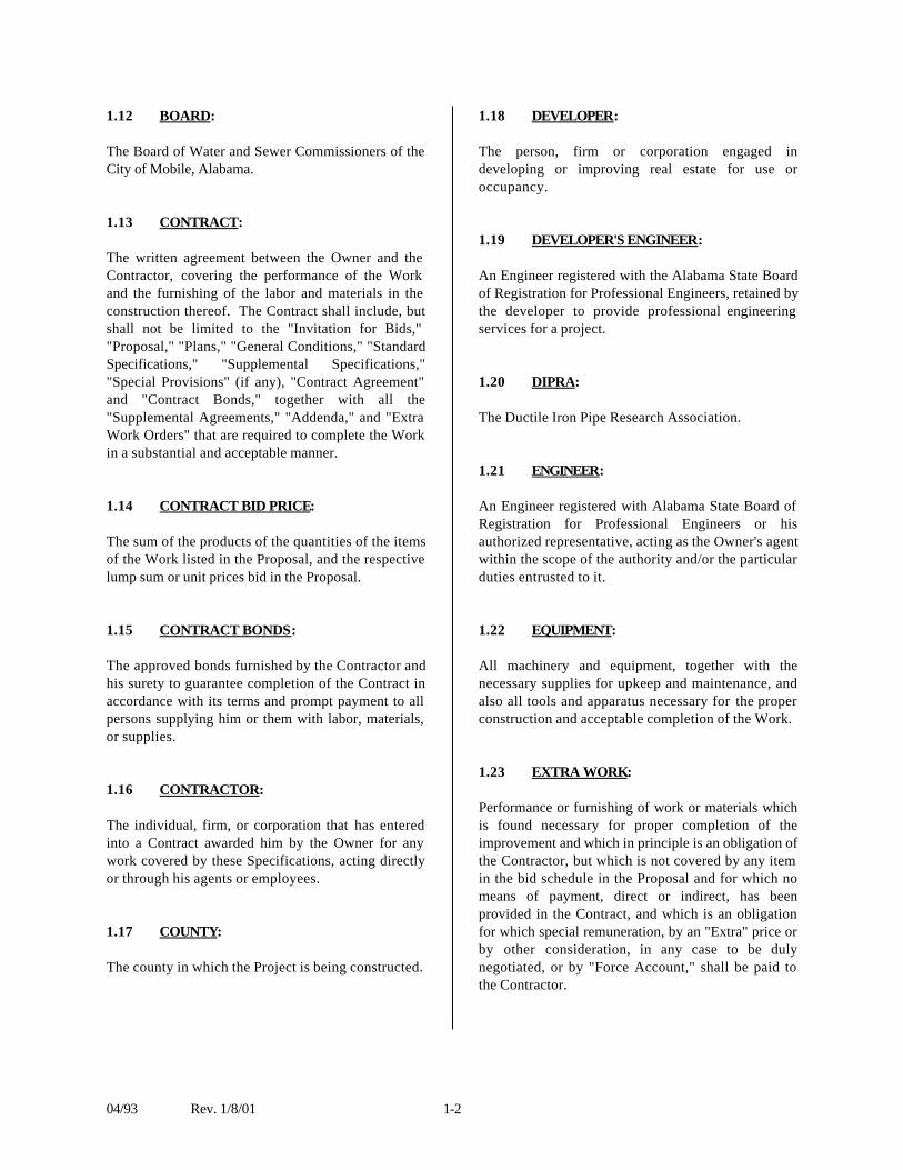
04/93 Rev. 1/8/01 1-2
1.12 BOARD: The Board of Water and Sewer Commissioners of the City of Mobile, Alabama. 1.13 CONTRACT: The written agreement between the Owner and the Contractor, covering the performance of the Work and the furnishing of the labor and materials in the construction thereof. The Contract shall include, but shall not be limited to the "Invitation for Bids," "Proposal," "Plans," "General Conditions," "Standard Specifications," "Supplemental Specifications," "Special Provisions" (if any), "Contract Agreement" and "Contract Bonds," together with all the "Supplemental Agreements," "Addenda," and "Extra Work Orders" that are required to complete the Work in a substantial and acceptable manner. 1.14 CONTRACT BID PRICE: The sum of the products of the quantities of the items of the Work listed in the Proposal, and the respective lump sum or unit prices bid in the Proposal. 1.15 CONTRACT BONDS: The approved bonds furnished by the Contractor and his surety to guarantee completion of the Contract in accordance with its terms and prompt payment to all persons supplying him or them with labor, materials, or supplies. 1.16 CONTRACTOR: The individual, firm, or corporation that has entered into a Contract awarded him by the Owner for any work covered by these Specifications, acting directly or through his agents or employees. 1.17 COUNTY: The county in which the Project is being constructed.
1.18 DEVELOPER: The person, firm or corporation engaged in developing or improving real estate for use or occupancy. 1.19 DEVELOPER'S ENGINEER: An Engineer registered with the Alabama State Board of Registration for Professional Engineers, retained by the developer to provide professional engineering services for a project. 1.20 DIPRA: The Ductile Iron Pipe Research Association. 1.21 ENGINEER: An Engineer registered with Alabama State Board of Registration for Professional Engineers or his authorized representative, acting as the Owner's agent within the scope of the authority and/or the particular duties entrusted to it. 1.22 EQUIPMENT: All machinery and equipment, together with the necessary supplies for upkeep and maintenance, and also all tools and apparatus necessary for the proper construction and acceptable completion of the Work. 1.23 EXTRA WORK: Performance or furnishing of work or materials which is found necessary for proper completion of the improvement and which in principle is an obligation of the Contractor, but which is not covered by any item in the bid schedule in the Proposal and for which no means of payment, direct or indirect, has been provided in the Contract, and which is an obligation for which special remuneration, by an "Extra" price or by other consideration, in any case to be duly negotiated, or by "Force Account," shall be paid to the Contractor.
1-3 1/01
1.24 EXTRA WORK ORDERS: Written orders approved by the Owner to the Contractor concerning the performance of work or furnishing of materials involving Extra Work as defined in these Specifications. 1.25 LABORATORY: Any laboratory authorized by the Owner to test materials and work involved in the Contract. 1.26 MATERIAL: Any substance proposed to be used in connection with the construction of any part of the Work and its appurtenances. 1.27 NEMA: The National Electrical Manufacturers Association. Any reference to NEMA standards shall be taken to mean the most recently published revision unless otherwise specified. 1.28 NOTICE TO PROCEED: Written notice from the Engineer or the equivalent thereto giving the Contractor notice of the date on which he is to begin the prosecution of the Work for which he has contracted. 1.29 OSHA: The Federal Occupational Safety and Health Administration. 1.30 OWNER: The Board of Water and Sewer Commissioners of the City of Mobile, Alabama.
1.31 PLANS (DRAWINGS): All official, approved Plans (Drawings), which are on file with the Owner, or exact reproductions thereof, showing details of the Work covered by the Contract. 1.32 PRODUCT: The term "product" as used in these Contract Documents includes materials, systems and equipment. 1.33 PROJECT: The entire Work to be performed pursuant to the Contract Documents. 1.34 PROPOSAL: The written offer for the Work contemplated, when submitted by the Bidder in the required manner on the prescribed Proposal Form, properly signed and guaranteed. 1.35 PROPOSAL FORM: The approved prepared form on which the Owner requires the formal bids to be submitted for the Work contemplated. 1.36 PROPOSAL GUARANTY: The certified check or bid bond designated in the Invitation for Bids, or in the Proposal Form, to be furnished by the Bidder to insure execution of the Contract and furnishing of the bonds for the Work contemplated, if it be awarded to him. 1.37 RECORD DRAWINGS: Drawings which show details of the Work as on the Plans but which revise the Plans to include any modifications or deviations which have been approved by the Board or the Engineer and incorporated into the Work.

04/93 Rev. 1/8/01 1-4
1.38 RESIDENT PROJECT REPRESENTATIVE: The authorized representative of the Engineer who is assigned to the Project site or any part thereof. 1.39 SAHD: The State of Alabama Highway Department. 1.40 SHOP DRAWINGS: All drawings, diagrams, illustrations, brochures, schedules and other data which are prepared by Contractor, a subcontractor, manufacturer, supplier, distributor or other person on behalf of the Contractor, and which illustrate the equipment, material or some portion of the Work. 1.41 SPECIFICATIONS: The general term comprising all the directions, provisions and requirements contained herein, together with such as may be added or adopted as General Conditions, Supplemental General Conditions, Supplemental Specifications or Special Provisions. 1.42 STATE: The state in which the Project is being constructed. 1.43 SUBCONTRACTOR: Any properly qualified individual, firm, or corporation undertaking the performance of any part of the Work under the terms of the Contract by virtue of an agreement between himself and the Contractor previously approved by the Owner. 1.44 SUPERINTENDENT: The representative for the Contractor present on the Work at all times during progress, authorized to receive and fulfill instructions from the Engineer or Owner.
1.45 SUPPLEMENTAL AGREEMENT: A written agreement executed by the Owner and the Contractor with the consent of the Surety covering major changes and/or revised or new prices and items and supplementing the original Contract. 1.46 SURETY: The corporate body, licensed under the laws of the state, bound with and for the Contractor for the acceptable performance of the Contract and also for the payment of claims recoverable under the Contract Bonds. 1.47 WORK: The entire completed construction or the various separately identifiable parts thereof required to be furnished under the Contract Documents. Work is the result of performing services, furnishing labor and furnishing and incorporating materials and equipment into the construction, all as required by the Contract Documents.
END OF SECTION

2-1 04/06
SECTION 2
PROPOSAL REQUIREMENTS AND CONDITIONS
2.01 GENERAL QUALIFICATIONS OF BIDDERS: All bidders acknowledge that a bidder’s financial stability, its ability to furnish the necessary equipment and materials throughout the project, and the knowledge, training, and experience of its employees are important to prevent interruption of service and inconvenience to Owner, to protect the environment and public health, and to ensure completion of a quality product in the allotted time. Bidders shall be licensed as Contractors when required by law, and shall have appropriate specialty designation(s) if required for the project. Each bidder must be able to submit proof that bidder as an entity[whether the bidder is a person, corporation, partnership, firm, company, or other entity] as well as bidder’s supervisory employees [including project superintendent, project manager, and forepersons] have had a minimum of two (2) years’ experience immediately preceding the submission of the bid, performing work of a similar scope and complexity. Bidder must be able to present proof that Bidder and its supervisory employees completed this similar work in a satisfactory and safe manner. Each bidder acknowledges that failure to present proof that Bidder as an entity and Bidder’s supervisory employees have satisfactorily performed similar work for at least two (2) years immediately preceding the submission of this bid shall result in rejection of bid. Each bidder must be able to furnish proof that it owns, or has in its possession and control, appropriate and sufficient equipment to properly and efficiently perform all work required under this contract. 2.02 CONTENTS OF PROPOSAL FORMS: The Owner will furnish to Bidders, Specifications containing a blank Proposal Form showing description of the Work contemplated, the approximate estimate of the various quantities of the
pay items of the Work to be performed and materials to be furnished, the amount of the Proposal Guaranty, and the date, time, and place of opening of Proposals, and the time in which the Work must be completed. All papers bound with or attached to the Proposal Form are a necessary part thereof and must not be detached or altered. Failure to submit a subcontracting plan will result in your bid being considered non-responsive. All bidders shall submit a plan for the use of small and small disadvantaged businesses as subcontractors. The form provided with the Proposal shall be used for this purpose. 2.03 INTERPRETATION OF
APPROXIMATE ESTIMATES: Although the estimate of quantities of work listed in the Proposal Form are the results of calculations made from field surveys or other available information, they are to be considered as only approximate estimates of the quantities of the different pay items and are to be used only as a basis for comparing bids for awarding the Contract. Such quantities, including the classification thereof, may or may not be representative of the actual conditions encountered during construction and the Owner does not guarantee that the approximate quantities given will hold strictly in the construction of the Work. Final payment to the Contractor will be made for only the actual quantities of the respective pay items of the Work performed, at the Contract unit prices bid in the Proposal, in accordance with the Plans and Specifications, as finally determined from actual measurements made during the progress or after completion of the Work, and if, upon completion of the Work, the actual quantities of the respective pay items performed shall be more or less than the quantities estimated in the Proposal, the Contract unit prices bid in the Proposal will still prevail, except as otherwise hereinafter provided.

04/06 2-2
2.04 EXAMINATION OF PLANS AND SPECIFICATIONS, SPECIAL PROVISIONS AND SITE OF WORK:
All Bidders are required to examine carefully the site of the proposed Work, the Proposal Form, Plans, General Conditions, Standard Specifications, Supplemental Specifications, Special Provisions, and the Contract and Bond Forms, and it is mutually agreed that the submission of a Proposal shall be
prima-facie evidence that the Bidder has made such examination and has judged for and satisfied himself as to the conditions to be encountered as to the character, quality, and quantities of work to be performed and materials to be furnished, and as to the requirements of Plans, General Conditions, Standard Specifications, Supplemental Specific-ations, Special Provisions, Contract and Bonds, and as to the contingencies. Bidders shall satisfy themselves that the Work can be completed within the time set forth in the Contract. Bidders shall also familiarize themselves with and shall comply with the requirements of all federal, state, and local laws and ordinances which may directly or indirectly affect the Work or its prosecution, persons engaged in or employed on the Work, and the materials or equipment used in the Work. No adjustments or compensations will be allowed for losses caused by failure to comply with the above requirements. 2.05 PREPARATION OF PROPOSAL: The Bidder's Proposal must be submitted on the Proposal Form furnished him by the Owner. The Bidder must specify, with figures, a unit price for each of the separate items for which a quantity is given in the Proposal Form (except when alternate bids are called for on items) and shall show the products of the respective unit prices and the estimated quantities in the columns provided for that purpose, as well as the gross sum for which he will perform all of the estimated work required by these Standard Specifications, Supplemental Specific-ations, Special Provisions, and the Plans. The Engineer will check the gross sum given in the Proposal, and in case of error or discrepancy, the gross sum obtained by adding the products of the unit prices and the various estimated quantities listed in the Proposal shall prevail and this shall be the Contract Bid Price. The Proposal shall be properly signed by the Bidder. 2.06 IRREGULAR PROPOSALS: Proposals may be rejected if they contain any omissions, alterations of form, additions not called for, conditional bids, alternate bids unless called for, incomplete bids, erasures or irregularities of any kind. Proposals in which the unit or lump sum prices bid are obviously unbalanced may be rejected.

2-3 04/06
No alteration of the terms and conditions of the sealed bid which are written upon or appended to the outside of the bid will be accepted or considered. 2.07 PROPOSAL GUARANTY: No Proposal will be considered unless accompanied by a properly certified check or bid bond made payable to the Owner in the amount indicated in the Invitation for Bids. Cashier's checks will not be accepted in lieu thereof. The full amount of the Proposal Guaranty of a Bidder whose Proposal is accepted shall be forfeited to the Owner, in liquidation of damages, in the event of failure of the Bidder to execute Contract and Contract Bonds as stipulated herein. 2.08 DELIVERY OF PROPOSALS: Each Proposal shall be placed, together with the Proposal Guaranty, in a sealed envelope, on the outside of which is written in large letters "Proposal for (Name of Project)" and so marked as to indicate the Project and the name of the Bidder, and the Bidder General Contractor's license number (where applicable). Proposals may be delivered in person or by mail. When sent by mail, preferably registered, the sealed Proposal, marked as indicated above, shall be enclosed in another envelope for mailing. Proposals will be received by the Owner until the hour of the date set in the Invitation for Bids for the opening thereof. No Proposal will be accepted or considered which has not been received prior to the hour of the opening date. 2.09 WITHDRAWAL OR REVISION OF
PROPOSAL: A Proposal may be withdrawn at any time prior to the hour fixed in the Invitation for Bids for opening of Proposals, provided a request in writing executed by the Bidder or his duly authorized representative is filed with the Owner prior to that time. When such Proposal is reached, it will be returned to the Bidder unopened. No Proposal can be withdrawn, modified or corrected after the hour set for opening such Proposals. Proposals received after the hour set for opening will be returned unopened.
2.10 OPENING OF PROPOSALS: Proposals will be opened and read publicly, except when directed otherwise by the Owner, at the time and place indicated in the Invitation for Bids. Bidders or their authorized representative are invited to be present at public opening of bids. 2.11 DISQUALIFICATION OF BIDDERS: If there is reason to believe that collusion exists among the Bidders, any or all Proposals may be rejected, and participants in such collusion may not be considered in future Proposals for the same work. 2.12 LIQUIDATED DAMAGES: Time is an essential element in the Contract. As the prosecution of the Work will inconvenience the public, obstruct traffic, and interfere with business, it is important that the Work be pressed vigorously to completion. Also, the cost to the Owner for the administration of the Contract, observation, and engineering for the Work under construction will be increased if the time occupied in the Work is lengthened. Therefore, for each day that the Work remains uncompleted after the time specified in the Contract, or additional time that may be allowed by the Owner for the completion of the Work when extra or additional work is ordered by the Owner, the amount specified in the Contract shall be paid by the Contractor to the Owner as liquidated damages for the loss sustained by the Owner because of failure of the Contractor to complete the Work within the specified time. Liquidated damages will be deducted from partial payments otherwise due the Contractor. The amount of liquidated damages shall be the amount set forth in the Contract.
END OF SECTION

3-1 07/06
SECTION 3
AWARD AND EXECUTION OF CONTRACT
3.01 CONSIDERATION OF BIDS: After the Proposals are opened and read, the approximate estimated quantity of each item multiplied by the unit price bid for that item, the products calculated, and the gross sums bid obtained in each of the acceptable Proposals, the Contract Bid Prices will be compared and the results of such comparison will be made available to each Bidder on request. Until the final award of the Contract, however, the Owner reserves the right to reject any and all Proposals, and to waive all technicalities. 3.02 AWARD OF CONTRACT: The award of the Contract, if it is to be awarded, will be by the Owner to the lowest responsible Bidder whose Proposal shall comply with all the requirements necessary to render it formal. The successful Bidder will be notified by letter, mailed to the address shown on his Proposal, that his bid has been accepted and that he has been awarded the Contract. Award will be made within 60 days after bids are received unless otherwise stated in the Special Provisions. This period may be extended if mutually agreeable to Owner and Contractor. The Owner, before awarding the Contract, may require a reviewed financial statement. If, in the opinion of the Owner, this statement does not justify the award, the Owner reserves the right to reject the low bid. The reviewed financial statement shall contain, as a minimum, a review of financial statements including performing inquiry and analytical procedures that provide the Owner with a reasonable basis for expressing limited assurance that there are not material modifications that should be made to the statements in order for them to be in conformity with generally accepted accounting principles or, if applicable, with any other comprehensive basis of accounting. The financial statement shall be submitted within 10 days of the Owner's request. Should it be necessary to eliminate part of the Work in order to award the Contract within the funds available for construction, the Owner reserves the
right to designate the portion of the Work to be omitted. The amount of deduction will be determined by multiplying the quantity of items omitted by the unit price or lump sum bid for such items, or by negotiation. 3.03 RETURN OF PROPOSAL
GUARANTEE: All Proposal Guarantees will be returned, if requested, within 30 days following the opening of Proposals; except those of the three lowest Bidders, which will be returned, if requested, after satisfactory bonds have been furnished and the Contract has been executed. The Owner reserves the right to return all Proposal Guarantees by mail and its responsibility shall end upon the mailing thereof. 3.04 EXECUTION OF CONTRACT: The Contract shall be signed by the successful Bidder and returned to the Engineer with satisfactory Contract Bonds within 10 days after the date of Notice of Award. 3.05 FAILURE TO EXECUTE CONTRACT: Failure to execute a Contract and file acceptable Contract Bonds within 10 days after the date of Notice of Award shall be just cause for the annulment of the award and the forfeiture of the Proposal Guaranty1 as liquidation of damages sustained. Award may then be made to the next lowest responsible Bidder or the Work may be readvertised or constructed by day labor, or otherwise contracted as the Owner may decide. 3.06 REQUIREMENTS OF CONTRACT
BONDS: Prior to award of the Contract, the Contractor shall submit to the Owner the name and address of the bonding company for the approval of the Owner.
1 Revised 02/03
3-2 07/06
A Contract Bond, and a Labor and Material Payment Bond, in the forms which are included in the Contract Documents, and each in the sum as herein specified, to be duly executed at the proper time sequence by the successful Bidder as Principal and by a surety company licensed to do business under the laws of the State in which the Work is located, and satisfactory to the Owner, will be required for the faithful performance of the Contract, and the payment for labor and materials. Sureties to be acceptable must be named in the current list of "Companies Holding Certificates of Authority as Acceptable Sureties” as published in Circular 570 (amended) by the Audit Staff Bureau of Accounts, U.S. Treasury Department. In addition, the surety company must have a rating of A- or better, as rated by A. M. Best Company.2 To insure the faithful performance of each and every condition, stipulation, and requirement of the Contract, and to indemnify and save harmless the Owner from any and all damages, either directly or indirectly, arising out of any failure to perform the same, the successful Bidder, to whom the Contract is awarded shall, within 10 days from the date of the award, furnish and file with the Owner an acceptable Contract Bond in the amount equal to 100 percent of the Contract Bid Price of the Contract awarded. In case of default on the part of the Contractor, all expenses incident to ascertaining and collecting losses suffered by the Owner under the bond, including both engineering and legal services, shall lie against the Contract Bond for performance of the Work. In addition thereto, the successful Bidder to whom the Contract is awarded shall, within 10 days, furnish and file with the Owner an acceptable surety bond for payment of labor, materials, feed-stuffs or supplies payable to the Owner in an amount not less than 100 percent of the Contract Price, with the obligation that the Contractor shall promptly make payment to all persons furnishing him or them with labor, materials, feed-stuffs, or supplies for or in the prosecution of the Work, and for the payment of reasonable attorney's fees incurred by successful claimants or plaintiffs in suits on said Bond. If at any time, the Owner, for justifiable cause, shall be or become dissatisfied with any surety or sureties upon the Performance or Payment Bonds, the Contractor shall, within 5 days after notice from the Owner, substitute an acceptable bond (or bonds) in 2 Revised and adopted 07/24/06
such form and sum and signed by such other surety or sureties as may be satisfactory to the Owner. The premiums on such bond shall be paid by the Contractor. No further payments to the Contractor shall be deemed due nor shall be made until the new surety or sureties shall have furnished acceptable bond to the Owner. In lieu of a Contract Bond and a Labor and Material Bond, the Contractor may submit an irrevocable letter of Credit (Appendix K). The letter must be completed and certified by a lending institution satisfactory to the Board. The letter shall be in the amount of 100% of the Contract amount. 3.07 INSURANCE:3
A. General: The Contractor shall provide
insurance in accordance with the required specifications.
B. Contractor Coverage: The Contractor shall not
commence work under this Contract until he has obtained all insurance required under the following paragraphs and until such insurance has been approved by the Owner, nor shall the Contractor allow any subcontractor to commence work on his subcontract until all similar insurance required of the subcontractor has been obtained and approved. If the subcontractor does not take out insurance in his own name, the principal contractor shall provide such insurance protection for the subcontractor and such subcontractor's employees.
C. Casualty Insurance: The following insurance
coverages (with limits not less than specified herein) shall be maintained by the Contractor for the duration of the Contract, affording coverage for any claim arising out of Contractor's operations herein, whether by the Contractor or by any subcontractor or by any Employee or Agent of either:
1. Claims of employees under Worker's
Compensation and other similar employee benefit acts, including claims because of bodily injury, occupational sickness or disease, or death.
3 Revised and adopted 07/24/06
2. Claims arising out of bodily injury, sickness, disease, or death of any person other than employee.
3. Claims for damages arising out of libel,
slander, false arrest, detention or imprisonment, malicious prosecution, defamation or violation of right of privacy, wrongful entry or eviction or other right of private occupancy, including claims as a result of an offense related to the employment of a claimant by Contractor (so-called "Personal Injury").
4. Claims arising out of damage to or
destruction of tangible property, including loss of use.
5. The Contractor shall furnish certification of
insurance and policies verifying that the above coverages are in effect before commencing any work, and that each policy is endorsed to give the Owner 30 days notice in writing in the event of cancellation or material change therein.
b. Limits of Liability: Type of Insurance Bodily Injury Worker's Compensation Statutory
Employers' Liability $500,000 Each Accident; $500,000 By Disease, Policy Lmt $500,000 Disease,Each
Employee Commercial Automobile $1,000,000 Each Accident.
Bodily Injury and Property Damage Combined
Business auto includes all
owned, leased, hired and non-owned automobiles.
Commercial General Liability:
$1,000,000 per Occurrence $1,000,000 Personal & Advertising Injury $2,000,000 General
Aggregate per project $2,000,000 Products & Completed Operations Aggregate $100,000 fire damage liability
Policies of Insurance shall state that the Owner and the Owner’s employees be named as additional insureds on the Contractor's Automobile Liability and Commercial General Liability policies.
In respect to Worker's Compensation, a
Waiver of Subrogation shall be issued in favor of the Owner. Where applicable, the U.S. Longshore and Harborworkers Compensation Act Endorsement shall be attached to the policy. Where applicable, the Maritime Coverage Endorsement (to include coverage under Jones Act) shall be attached to the policy. Both the U. S. Longshore and Harborworkers and the Maritime Coverage shall have limits equal to or greater than the employer’s liability coverage.
6. Rated by AM Best – A- or better. For non-
admitted companies, a rating of A or better by AM Best.
a. At the discretion of the Board, worker’s
compensation insurance may be placed through a qualified worker’s compensation self-insurance fund.
Umbrella Liability:
In addition to the basic limits previously set out for Commercial General Liability, Products and Completed Operations, Automobile Liability and Worker's Compensation and Employer's Liability, Contractors shall provide Umbrella Liability limits of $5,000,000 per occurrence and aggregate.
Coverage shall be issued with a "pay on behalf of" wording, including Personal Injury and other extensions, and provide coverage at least as broad as that afforded by the primary insurance policies.
Extensions:
Blanket Contractual Liability Personal Injury Blanket Collapse and Underground Coverage Broad Form Property (including Completed Operations) Employees as Additional Insureds Host Liquor Liability Non-owned Watercraft Liability Worldwide Products
3-3 07/06 C34Revised 4/4/11

3-4 07/06
Fire Legal Liability Incidental Medical Malpractice Extended Bodily Injury (Assault and Battery) Newly Acquired Organizations When and if the use of explosives for blasting purposes appears necessary or desirable, such methods shall not be undertaken without written authorization of the Owner, and then only provided that acceptable extensions of liability coverage have been obtained specifically to include the explosion ("X") hazard and the collapse ("C") hazard. The policy of general liability shall include the special underground property damage coverage (providing the so-called "U" hazard) on a blanket basis. D. Owner's Protective Liability: The Contractor shall furnish from a carrier acceptable to the Owner, a policy of liability insurance, commonly called "Owner's Protective Liability" in the name of the Board of Water and Sewer Commissioners of the City of Mobile, d/b/a MAWSS, providing "Independent Contractor's Coverage" for the operations embraced by this Contract with limits of $1,000,000 bodily injury and $1,000,000 property damage. Policy shall be endorsed that the premium is to be paid by the named Contractor
E. Property Insurance - Contractor:
1. The Contractor shall assume complete responsibility for safe-guarding all portions of the Work in progress, whether completed or not, until such work has been accepted by the Owner, and shall maintain such insurance to protect himself against perils which may cause such property to be damaged or destroyed. This coverage shall be similar to the former All Risks of Physical Loss Form, including, if available, Collapse. Title to such work in progress, whether completed or not, shall remain vested in the Contractor until finally accepted by the Owner.
2. Coverage Form - Coverage shall be
provided on an actual completed value Builder's Risk Form or, if more appropriate, an installation floater in the joint name of the Contractor and Owner for the duration of the Contract.
3. The Owner has the option of providing
Builder's Risk coverage for any projects undertaken by a Contractor. If the Owner exercises this option, the Contract Proposal will appropriately indicate this and provide for separately showing the cost of the Builder's Risk coverage in the Bid.
3.08 INDEMNITY PROVISIONS: The Contractor shall indemnify and hold harmless the Owner and the Engineer and their agents and employees from and against all claims, damages, losses, demands, payments, suits, actions, recoveries and judgments of every nature and description and expenses including attorney’s fees arising out of or resulting from the performance of the Work, provided that any such claim, damage, loss or expense: (1) is attributable to bodily injury, sickness, disease or death, or to injury to or destruction of tangible property (other than the Work itself) including the loss of use resulting therefrom; and (2) is caused in whole or in part by a negligent act or omission of the Contractor, any subcontractor, anyone directly or indirectly employed by any of them or anyone for whose acts any of them may be liable, regardless of whether or not it is caused in part by a party indemnified hereunder. The Contractor shall assume all risk and bear any loss or injury to property or persons occasioned by neglect or accident during the progress of Work until the same shall have been completed and accepted. He shall also assume all blame or loss by reason of neglect or violation of any state or federal law or municipal rule, regulation or order. The Contractor shall give to the proper authorities all required notices relating to the Work, obtain all official permits and licenses and pay all proper fees. He shall make good any injury that may have occurred to any adjoining building, structure or utility in consequence of the Work. In any and all claims against the Owner or the Engineer or any of their agents or employees by any employee of the Contractor, any subcontractor, anyone directly or indirectly employed by any of them or anyone for whose acts any of them may be liable, the indemnification obligation under the "INDEMNITY PROVISIONS" shall not be limited in any way by any limitation on the amount or types of damages, compensation or benefits payable by or for the Contractor or any subcontractor under

3-5 07/06
workmen's compensation acts, disability benefit acts or other employee benefit acts. The obligations of the Contractor under Paragraph 3.08 shall not extend to the liability of the Engineer's negligent acts, errors or omissions, or those of his employees or agents.
END OF SECTION


4-1 04/93
SECTION 4
SCOPE OF WORK
4.01 INTENT OF PLANS AND SPECIFICATIONS:
The true intent of the Plans, Specifications, and Special Provisions is to prescribe a complete Work or improvement which the Contractor undertakes to do, complete in every detail, in full compliance with the Plans, General Conditions, these Specifications, the Supplemental Specifications, the Special Provisions, Proposal, Contract and Invitation for Bids, together with all authorized alterations, Supplemental Agreements and Extra Work Orders. The Contractor shall perform all items of the Work covered and stipulated in the Contract, Specifications, and Plans, shall remove all obstructions from the right of way, and shall do such special, additional, extra, and incidental work as may be considered necessary to complete the Work and its appurtenances, or structures, to the finished lines, grades, cross sections and dimensions shown on the Plans or as modified by written orders of the Engineer, in a satisfactory and acceptable manner. The Contractor shall furnish, unless definitely and expressly provided to the contrary in the Proposal, Special Provisions or Plans, all material, implements, machinery, equipment, tools, supplies, transportation and labor necessary to the prosecution and completion of the Work. 4.02 UNDERGROUND AND EXISTING
UTILITIES: The Plans show structures, certain features of the topography, and certain underground utilities, but they do not purport to show all features, lines, or obstructions. Such topography and notes in the Plans were inserted from records available, and are for the Contractor's convenience only. The Contractor shall verify the existence and location of surface topography, underground structures, and utilities to assure conflicts will be avoided in the construction of this Work. The Contractor shall conduct prudent underground explorations in advance of his work in order to make adjustments to the Work if necessary.
The Contractor shall protect, maintain and keep in service all exiting utilities and service connections during construction operations. Any existing utility lines cut or damaged shall be repaired immediately and the service restored at the Contractor's expense. 4.03 ALTERATION OF PLANS OR
CHARACTER OF WORK: The Owner or his authorized representative may without notice to the Surety make, without change in the unit prices, alterations in the Plans or in the nature of the Work which they may consider necessary or desirable during the progress of the Work to complete fully and acceptably the proposed construction, provided that such alterations do not materially change the general features of the original Plans and Specifications. Material changes shall be understood to mean those changes in the original Plans and Specifications made necessary by the exigencies of the Work resulting in the alteration of cost to the Contractor by an amount which could not have been foreseen at the time of his bidding upon the Work. The Owner reserves the right for the Engineer to revise any part of the alignment, grades, structures, width, and other dimension on the Work, if the Engineer deems it advisable and such changes shall not be considered material changes. The Owner also reserves the right for the Engineer to increase or decrease the quantity of any or all of the items listed in the estimate of approximate quantities in the Proposal Form and such increase or decrease shall not be considered as a waiver of any of the conditions of the Contract or Contract Bonds. 4.04 EXTRA WORK: In connection with the Work covered by the Contract, the Owner or his authorized representative may at any time during its progress order other work or materials incidental thereto. If any such work and material is not listed as a pay item with a Contract Unit Bid Price or if compensation therefor is not included in the Contract unit prices bid for other pay items under the terms of the Contract, it will be

04/93 4-2
designated as Extra Work, and shall be performed by the Contractor as directed, provided, however, that before any Extra Work is started the Engineer shall furnish the Contractor a Proposal Form, stating the location, kind and estimated quantity of Extra Work to be done. The Contractor shall indicate on this Proposal Form the compensation (unit price, or lump sum) for which he will perform the Extra Work and this Proposal shall be submitted to the Owner for approval. The Owner may approve the Proposal, in which case it shall be an authorization for doing the Work and shall become a part of the Contract, but if the Owner considers the price submitted for any item of the Extra Work excessive and a satisfactory adjustment price cannot be reached for such item, it shall be optional with the Owner to terminate the Contract insofar as it applies to such item or Extra Work in question and perform such Extra Work by other agents or other means or to direct that the Contractor performs the Work on a "Force Account" basis. Claims for payment for Extra Work not so authorized may be rejected by the Owner. 4.05 CONSTRUCTION AND MAINTENANCE
OF DETOURS: No road or section of road shall be closed to traffic except with the written permission of the Engineer and the governing authority, and no construction operations that will in any way inconvenience the traveling public shall be started until adequate provisions have been made to detour or bypass traffic in safety and comfort. All detours shall be approved by the Highway Department, City Engineer or the official having jurisdiction over the roads or streets. The Contractor shall maintain all detours for traffic over the Work. Unless otherwise provided in the Special Provisions, the road, while undergoing improvement, shall be kept continuously open to public traffic and in passable and safe condition. When the Contractor hauls materials over any detour or public road, he shall so regulate his loads that the capacity of the road and its structures is not exceeded and he shall be responsible for any specific damage that may result to the road or its structures from failure to observe regulations governing traffic thereon.
4.06 REMOVAL AND DISPOSAL OF STRUCTURES AND OBSTRUCTIONS:
Unless otherwise provided, the Contractor shall remove at his expense any existing above or below-ground structure or part of structure, fence, building, or other encumbrance or obstruction upon or within the limits of the Work, which interferes in any way with the new construction. Compensation for the removal of any structure not listed as a pay item in the Proposal with a Contract Bid Price shall be included in the Contract unit prices bid for the pay items of the Work. 4.07 FINAL CLEAN-UP: Upon completion and before Work will be finally accepted and final payment made, the Contractor shall clean and remove from the Work and adjacent property, stream channels, sites of structures, and all areas occupied by him in connection with the Work, all weeds, shrubs, stumps, portions of trees, and all other forms of objectionable organic matter; all useless, surplus, excavated or discarded materials; and all loose rock, boulders, falsework, temporary structures, machinery and equipment. He shall restore in an acceptable manner all property, both public and private, which has been damaged during the prosecution of the Work, and shall leave the Work and sites of structures in a neat presentable condition throughout the Project. Depositing any material on abutting property with or without the consent of the property owner will not be considered a satisfactory method of disposal. 4.08 MAINTENANCE OF THE WORK DURING
CONSTRUCTION: The Contractor shall be required to maintain the Work from the date of the approval of his Contract until the Work is completed and shall maintain it in first-class condition for 30 days after it is completed and until the Work is finally accepted. The maintenance shall consist of continuous and effective work prosecuted day by day, with adequate equipment and forces to the end of the Project, keeping the entire work site in satisfactory and acceptable condition at all times. The Contractor shall take adequate precautions to protect trees,
4-3 04/93
shrubs, plants, and existing site improvements from injury during construction operations and shall maintain adequate drainage and utility service during his work. Compensation for maintenance work during construction and before the Work is finally accepted shall be included in the Contract unit prices bid on the pay items of the Work and the Owner will not pay additional for such work. 4.09 FAILURE TO MAINTAIN WORK: The failure of the Contractor, at any time, to comply with the above provisions for maintenance of the Work will result in the following:
First: The Owner, or his authorized representative, will immediately notify the Contractor, his superintendent or employees to comply with the required maintenance provisions. Second: In the event the Contractor fails to remedy his lack of or unsatisfactory maintenance within 24 hours after the date of issuance of this notice, the Owner may proceed immediately with adequate forces and equipment to maintain in a satisfactory and acceptable manner the Work site, and the entire cost of this maintenance will be deducted from monies due or that become due the Contractor on this Contract. Third: As an alternate to the Owner's taking over the maintenance, all the quantities of the Work performed which are not properly maintained may be deducted from the Contractor's current payment request even if such quantities have been allowed on a previous estimate.
END OF SECTION

5 - 1 05/98
SECTION 5
CONTROL OF WORK
5.01 AUTHORITY OF THE ENGINEER To prevent misunderstandings, disputes, and litigation, the Engineer shall decide any and all questions which arise concerning the quality and acceptability of materials furnished and work performed, the rate of progress of the Work, interpretation of the Plans and Specifications, and the acceptable fulfillment of the Contract on the part of the Contractor. The Engineer will determine the amount, quantity, classification, and quality of the several kinds of work performed and materials furnished which are to be paid for under the Contract and his decision and estimate shall be conclusive and binding on both parties thereto and such decision and estimate of the Engineer, in case any questions arise, shall be a condition precedent to the right of the Contractor to receive any money due him under the Contract. Explanations concerning the meaning of the Plans and Specifications and Contract, all directions necessary to complete or make definite the Plans, Special Provisions, Specifications or Contract and to give them due effect, will be given by the Engineer and his findings shall be final and binding on both parties hereto. The Engineer shall have authority to enforce and make effective decisions and orders as apply to conformance with the Contract. He shall decide disputes and mutual rights between Contractors. Notwithstanding any general clauses, wording, paragraphs, or other references contained in the Plans, Specifications, General Conditions, or elsewhere in the Special Provisions, the Engineer and his Resident Project Representative are not charged with the responsibility of directing the actual procedures and detail methods of construction to be used by the Contractor in accomplishing the Work contained in the Contract between the Owner and the Contractor; nor is the Engineer responsible to act as superintendent, foreman, or safety engineer for the Contractor, nor for the safety of the Contractor’s personnel. 5.02 PLANS AND SHOP DRAWINGS: General drawings, showing such details as are necessary to give a comprehensive idea of the construction contemplated will be included in the approved Plans. The approved Plans will be supplemented by such working drawings as are
necessary to adequately define the Work. It is mutually agreed that all authorized alterations affecting the requirements and information given on the approved Plans shall be in writing. After checking and verifying all field measurements, Contractor shall submit to Engineer for review, five copies of all Shop Drawings, plus the number of copies Contractor wishes to have returned to him after Engineer’s review, collated according to the organization of the accepted schedule of Shop Drawings, which will bear a stamp or specific written indication that Contractor has satisfied Contractor’s responsibilities under the Contract with respect to Contractor’s review of the submission. All submissions will be identified as “Shop Drawings” on the outermost enclosure and show Project name and Engineer’s Project number. The data shown on the Shop Drawings will be complete with respect to quantities, dimensions, descriptive data, diagrams specified performance, design criteria, materials, and similar data to enable Engineer to review the information as required. Contractor shall also submit to Engineer for review and approval, with such promptness as to cause no delay in Work, all samples required by the Contract. All samples will have been checked by and accompanied by a specific written indication that Contractor has satisfied Contractor’s responsibilities under the Contract with respect to the review of the submission and will be identified clearly as to material, supplier, pertinent data such as catalog numbers, and the use for which intended. Before submission of each Shop Drawing or sample, Contractor shall have determined and verified all quantities, dimensions, specified performance criteria, installation requirements, materials, catalog numbers, and similar data with respect thereto and reviewed or coordinated each Shop Drawing or sample with other Shop Drawings and samples and with the requirements of the Work and the Contract. At the time of each submission, Contractor shall give Engineer specific written notice of each variation that the Shop Drawings or samples may have from the requirements of the Contract, and, in addition, shall cause a specific notation to be made on each Shop Drawing submittal to Engineer for review and approval of each such variation. When the

5 - 2 05/98
Contractor does call such deviation to the attention of the Engineer, the Contractor shall state in his letter whether or not such deviations involve deductions or extra cost adjustment. Engineer will review with reasonable promptness Shop Drawings and samples, but Engineer’s review will be only for conformance with the design concept of the Project and for compliance with the methods, techniques, sequences, or procedures of construction (except where a specific means, method, technique, sequence, or procedure of construction is indicated in or required by the Contract Documents). The review of a separate item will not indicate approval of the assembly in which the item functions. Contractor shall make corrections required by Engineer, and shall return the required number of corrected copies of Shop Drawings and submit, as required, new samples for review. Contractor shall direct specific attention in writing to revisions other than the corrections called for by the Engineer on previous submittals. Engineer’s review of Shop Drawings or samples shall not relieve Contractor from responsibility for any variation from the requirements of the Contract unless Contractor has, in writing, called Engineer’s attention to each such variation at the time of submission, and Engineer has given written approval of each such variation by a specific written notation thereof incorporated in or accompanying the Shop Drawings or sample; nor will any review by Engineer relieve Contractor from responsibility for errors or omissions in the Shop Drawings. The Contractor shall furnish five complete sets of the corrected copies of Shop Drawings including parts list, operation and maintenance manuals, lubrication charts and descriptive literature for all equipment. No payment shall be made to the Contractor for any specialties or equipment unless Shop Drawings have been approved by the Engineer. Final payment under the Contract will not be made until all specified documents have been submitted for equipment. Compensation for furnishing all Shop Drawings and samples shall be included in the Contract Unit Prices for the pay items of the Work and such Drawings and samples shall be furnished by the Contractor without additional compensation. 5.03 MANUFACTURER’S DRAWINGS: The manufacturer’s drawings of any special materials required for the job shall be submitted to the Engineer for review prior to installation.
5.04 CONFORMITY WITH PLANS AND ALLOWABLE DEVIATIONS:
Finished work in all cases shall conform with lines, grades, sections, details and dimensions of the Work contemplated as shown on the approved Plans except as modified in writing by the Engineer. Any deviation from the approved Plans and working drawings that may be required by the exigencies of the construction, will be determined by the Engineer and authorized in writing. In cases where minor deviations within the limits shown on the Plans or contained in the Specifications will be in the best interest of the Owner or present a more finished or aesthetic appearance, then the Contractor shall notify the Engineer or his representative before the Work progresses to a point where the change cannot be effected without incurring additional expense to the Owner. 5.05 COORDINATION OF PLANS,
SPECIFICATIONS, AND SPECIAL PROVISIONS:
The Specifications, Supplemental Specifications, General Conditions, Plans, Special Provisions, and all supplementary documents are essential parts of the Contract, and a requirement occurring in one is as binding as though occurring in all. They are intended to be complementary and to describe and provide for a complete Work. In case of discrepancy, figured dimensions, unless obviously incorrect, shall govern over the scaled dimensions. Supplemental Specifications shall govern over the Standard Specifications. Plans shall govern over Specifications; Special Provisions shall govern over both Specifications, Supplemental Specifications and Plans. The Contractor shall take no advantage of, and shall promptly notify the Engineer if he discovers, any error or omission of dimensions in the Plans, or of any discrepancy between the Plans and Specifications. The Engineer will make such corrections and supply such omitted dimensions as may be necessary and his interpretation shall be final. When supplementary specifications such as Federal, ASTM, ANSI, AASHTO, AWWA, etc., are referenced in these Specifications, such references shall be the latest edition of such supplementary specifications.
5 - 3 05/98
5.06 COOPERATION OF THE CONTRACTOR:
The Contractor will be supplied with no more than four copies of the Plans, Specifications, Supplemental Specifications, and Special Provisions. If additional copies of documents are required, the Contractor shall reimburse the Engineer for the actual cost of reproduction of documents as requested. The Contractor shall have available on the Work, at all times, one copy of each of said Plans, Specifications, Supplemental Specifications, and Special Provisions. He shall give the Work the constant attention necessary to facilitate the progress thereof and shall cooperate with the Engineer, Engineer’s Resident Project Representative, and with other Contractors in every way possible. The Contractor shall at all times have a competent Superintendent on the Work, capable of reading and thoroughly understanding the Plans and Specifications, as his agent on the Work, with full authority to execute the Work without delay and to supply promptly such materials, tools, plant equipment, and labor as may be required. Such Superintendent shall be furnished irrespective of the amount of work subcontracted and shall have authority over all subcontract work. The Contractor shall schedule and conduct his work and dispose of his material so as to avoid causing unnecessary inconvenience and delay to other Contractors engaged on adjacent work and so as to join his work to that of other Contractors in a proper manner, and in accordance with the spirit of the Plans and Specifications, and so as to perform his work in the proper sequence in relation to that of other adjacent work. Each Contractor shall so conduct his operation and maintain the Work in such condition that adequate drainage shall be effected at all times. It is mutually agreed that in case of a dispute arising between two or more Contractors engaged on the same work as to the respective rights of each under these Specifications, the Engineer shall determine the matters at issue and shall define the respective rights of the various interests involved in order to secure completion of all parts of the Work in general harmony and with satis factory results, and his decision shall be final and binding on all parties concerned and shall not in any way be a cause for claims for extra compensation by any of the parties.
5.07 CONSTRUCTION SURVEYS: The Engineer will establish bench marks and horizontal control points. From these points, Contractor shall lay out the Work by establishing all lines and grades at the site necessary to control the Work, and shall be responsible for all measurements that may be required for the execution of the Work. Second order leveling shall be used by the Contractor in establishing elevations, and all levels shall be looped in or closed. All survey data shall be recorded in accordance with standard and approved methods. All field notes, sketches, and computations made by the Contractor in establishing control points for his work shall be available to the Engineer at all times. The Contactor shall furnish, at his expense, all stakes, pins, platforms, equipment and labor as may be required in laying out any part of the Work from the control points established by the Engineer. It shall be the responsibility of the Contractor to maintain and preserve all stakes and other markers established by him until authorized to remove them. If any of the control points established by the Engineer are destroyed by or through negligence of the Contractor, they may be replaced by the Engineer, and the expense of replacement will be deducted from any amount due or which may become due the Contractor. 5.08 RESIDENT PROJECT
REPRESENTATIVES: The Engineer may appoint such Representatives as he desires, and they shall be granted full access to the Work and to mills and factories in which material is being prepared for use under the Contract. They shall have authority to request compliance with terms of the Contract, to approve or reject materials, to make measurements of quantities, to keep records of costs, and otherwise represent the Engineer. The Contractor may appeal from their decisions to the Engineer, pending settlement but no work shall be done in any manner contrary to the Contract on items affected by such appeal. If the Contractor refuses to comply with instruction of the Representative to fulfill the requirements of the Contract, the Representative shall, if possible, immediately notify his immediate superior and obtain instructions. Failing in this, if the Contractor refuses to suspend operations on verbal order, he shall issue a written order suspending the Work on items affected, giving in detail the reasons for suspension. Immediately after placing the order in the hands of the person in charge for the Contractor, he shall report to his

5 - 4 05/98
immediate superior, or in his absence to the Engineer, for further instructions. Representatives shall not be authorized to revoke, alter, enlarge, relax or release any requirements of the Special Provisions, Specifications, or Contract; to approve or accept any portion of the Work; nor to issue instruction contrary to the Plans and Specifications; nor shall they act as superintendent, foreman, or safety engineer for the Contractor nor for the safety of the Contractor’s personnel; or interfere with the management of the Work. Any advice which they may give the Contractor shall not be construed as binding the Owner in any way, nor releasing the Contractor from fulfilling all the terms of the Contract. 5.09 INSPECTION: All materials and workmanship shall be subject to inspection, examination, and test by the Representatives of the Owner, or the Engineer, at any and all times. The Owner, or the Engineer, shall have the right to reject defective materials and workmanship or require correction thereof. Rejected materials shall be promptly and satisfactorily replaced with proper materials and rejected workmanship shall be promptly and satisfactorily corrected. If the Contractor fails to proceed at once with the replacement of rejected materials or the correction of rejected workmanship, the Owner may, by contract or otherwise, replace such materials or correct such workmanship and charge the cost thereof to the Contractor. Failure of Representative to find defects or to request removals shall in no way relieve the Contractor of responsibility. The Contractor shall furnish the Engineer with every reasonable facility for ascertaining whether or not the Work performed and materials used are in accordance with the requirements and intent of the Specifications and Contract. At any time before final acceptance of the Work, the Contractor shall, if the Engineer requests, remove and uncover such portions of the finished work as the Engineer may direct. After the examination, the Contractor shall restore said portions of the Work to the standard required by the Contract. If the work thus exposed or examined proves acceptable, the uncovering or removing and replacing of the covering or making good of the parts removed, shall be paid for as Extra Work, but, if the work so exposed or examined proves unacceptable, no compensation will be allowed the Contractor for the uncovering or removing and the replacing of the covering or making good of the parts removed. No
work shall be done nor material used without suitable inspection by the Engineer, or his representative. Failure to find or reject any defective work or material shall not prevent later rejection when such defect be discovered, or obligate the Owner to Final Acceptance. 5.10 REMOVAL OF DEFECTIVE AND
UNAUTHORIZED WORK: All work which has been rejected shall be remedied, or else removed and replaced in an acceptable manner by the Contractor at his own expense, and no compensation shall be allowed him for such removal or replacement. Any work done without the lines and grades shown on the Plans or as given, except as herein provided, or any Extra Work done without written authority will be considered as unauthorized and at the expense of the Contractor and will not be measured or paid for. Unauthorized work shall be removed and replaced at the Contractor’s expense. Upon failure on the part of the Contractor to immediately comply with any order of the Engineer made under the provisions of this Section, the Owner shall have authority to cause defective work to be remedied, or removed and replaced, and unauthorized work to be removed and to deduct the cost from any monies due or to become due the Contractor. In case no such monies are available, the amount shall be charged against the Contractor’s Surety. 5.11 DISPUTED CLAIMS: In any case where the Contractor wishes to make claim to the Owner for extra compensation for work or materials he deems not clearly covered in the Contract or not ordered by the Engineer as Extra Work, the Contractor shall notify the Engineer or the Owner in writing, of his intention to make claim for such extra compensation, before he begins the work on which he bases his claim. If such notice is not given, or if the notice is given and the Engineer is not afforded proper facilities for keeping strict account of the actual cost to the Contractor, then the contractor hereby agrees to waive claim for such extra compensation. Such notice by the Contractor, and the fact that the Engineer has kept account of the cost shall in no way be construed as establishing the validity of the claim. When the work has been completed, the Contractor shall immediately file his claim with the Engineer.

5 - 5 05/98
5.12 CONTRACTOR INITIATED CHANGES:
The Contractor and his subcontractor must submit in writing any requests for modifications to the Plans and Specifications. Shop Drawings that are submitted to the Engineer for his review do not constitute “in writing” unless it is brought to the attention of the Engineer that specific changes are being suggested. 5.13 PROJECT COMPLETION: The Work shall be complete when all pay items and any Extra Work to be performed under this Contact is performed in its entirety and in accordance with contractual requirements. 5.14 FINAL CONSTRUCTION
INSPECTION: Whenever the Engineer considers the Work provided and contemplated by the Contract is nearing completion, or within 10 days after being notified by the Contractor that the Work is completed, the Engineer will inspect all the Work included in the Contract. If the Engineer finds that the Work has not been satisfactorily completed at the time of such inspection, he shall advise the Contractor in writing as to the Work to be done or the particular defects to be remedied. When these defects have been remedied and the Work has been satisfactorily completed the Engineer shall make the Final Inspection, and shall notify the Contractor in writing that the Final Inspection has been made and that time charges end on the day of Final Inspection. Maintenance Period shall start on the day after this Final Inspection. 5.15 FINAL ACCEPTANCE: After the Final Inspection is made as outlined above, the Contractor shall maintain the Work for 30 days in the same manner as set forth under “Maintenance of the Work During Construction.” The Work will be finally accepted at the end of the 30 day maintenance period provided all work has been satisfactorily maintained. The Contractor, immediately after receiving the letter of Final Inspection, shall give notice of said completion of Work by an advertisement in some newspaper of general circulation published within the city or county wherein the Work has been done for a period of four successive weeks. Proof of publication of said notice shall be made by the Contractor to the
Owner, by affidavit of the publisher and a printed copy of the notice published. If no newspaper is published in the county where the Work is done, the notice may be given by posting at the Court House for 30 days and proof of same shall be made by the probate judge or sheriff and the Contractor. In no instance shall a final settlement be made upon the Contractor until the expiration of the Maintenance Period and until the Contract is completed and Project accepted by the Owner. 5.16 MAINTENANCE GUARANTEE AFTER
ACCEPTANCE: Neither the final certificate of payment nor any provisions in the Contract, nor partial or entire use or occupancy of the premises by the Owner shall constitute an acceptance of work not done in accordance with the Contract or relieve the Contractor of liability in respect to any express warranties or responsibility for faulty materials or workmanship. The Contractor shall remedy any defects in the Work and pay for any damage to other work resulting therefrom which shall appear within a period of two years from the date of final acceptance of the Work unless specified otherwise by the Owner. The Owner will give notice of observed defects with reasonable promptness and the Contractor shall repair the defects immediately. The Contractor’s Performance or Contract Bond shall remain in effect and cover this guarantee. After completion of the Project and prior to final acceptance, the Contractor shall provide a statement addressed to the Owner from his/her Surety acknowledging that the Contract Bonds will remain in effect during the two year warranty period or as otherwise required by the Owner. Final payment under the contract will not be made until this statement is received. For projects involving the lining of sewer mains and laterals, a five year warranty shall be provided in lieu of a two year warranty. The requirements stated above for a two year warranty shall also hold true for the five year warranty. 5.17 CONTRACT CLOSEOUT
DOCUMENTS; The Contractor shall complete and submit to the Engineer the following contract closeout requirements:
A. The Contractor’s advertisement of Notice of Completion.

5 - 6 05/98
B. The Contractor’s Affidavit of Payment of Claims and Debts.
C. The Contractor’s Consent of Surety
Company to Final Payment.
D. The Contractor’s letter acknowledging that acceptance of final payment constitutes a waiver of all claims, present or future, in connection with the referenced project.
E. The Contractor’s letter of guarantee that all
defects in materials and workmanship for a period of two years, or as otherwise specified by the Owner, commencing on the date of final acceptance and acknowledgment that the Contractor’s Material and Performance Bond shall remain in effect to cover this guarantee period.
F. One set of Record Drawings and video,
where required, neatly marked with all changes for quantity computation for all changes.
END OF SECTION
6 - 1 04/93
SECTION 6
CONTROL OF MATERIAL
6.01 SOURCE OF SUPPLY AND QUALITY
OF MATERIALS: All materials proposed to be used may be inspected or tested at any time during their preparation and use. Only materials conforming to the requirements of the Specifications shall be incorporated in the Work. Material which has become in any way unfit for use, shall not be used in the Work. Any material which has become mixed with or coated by dirt or other foreign substance shall not be used in the Work. The source of supply of each of the materials shall be approved by the Owner’s representative before the delivery is made to any section of the Work. When so indicated or directed, representative preliminary samples of character and quality shall be submitted for examination or test, and written approval of the quality of such samples must be received by the Contractor prior to obtaining materials from the respective sources of supply. 6.02 SAMPLES AND TESTS: Inspection and tests will be conducted promptly but the Contactor shall notify the Owner’s representative, in writing, immediately on the placing of orders for materials, giving the source and the dates when shipments are to be made. Materials to be tested will be sampled by the authorized representative, upon delivery, or at any time before use and acceptance or rejection will be based on the test of such samples. In any event, material actually incorporated in the construction must meet the requirements of the Contract. The Contractor shall afford such facilities for collecting and forwarding samples; but shall not make use of nor incorporate in the Work any material represented by the samples until the tests have been made and the materials found acceptable in accordance with the requirements of the Contract. The Contractor in all cases shall furnish the required samples without charge. When tests are made at the source of production, the producer shall furnish every reasonable facility for the performance of the tests and for the protection of testing equipment and supplies, and shall permit the Owner’s representative to have free access to all parts of the plant to enable adequate inspection and
selection of samples. Sources of supply of bituminous material shall have adequate testing facilities and satisfactory laboratory equipment, which equipment shall meet the requirements of the standard methods mentioned in the Specifications. 6.03 STORAGE OF MATERIALS: Materials shall be stored so as to insure the preservation of their quality and fitness for the Work in a manner as recommended by the manufacturer and approved by the Engineer. Materials in storage shall be so arranged as to facilitate prompt inspection. Stored materials even though approved before storage may be inspected prior to their use in the Work and shall meet the requirements of the Specifications at the time they are incorporated in the Work. Materials shall be stored only where specifically permitted. Stockpiling of construction materials shall be confined to such cleared areas as may be approved. Private property shall not be used without written permission of the property owner or lessee. 6.04 DEFECTIVE MATERIALS: All materials not conforming to the requirements of the Contract shall be considered as defective and all such materials, whether in place or not, shall be rejected and shall be removed immediately from the site of the Work. Defective materials discovered in the process of the Work will be rejected. All defective material shall be replaced by the Contractor at his expense. No rejected materials, the defects of which have been subsequently corrected, shall be used until written approval has been given by the Owner’s representative. Upon the failure of the Contractor to comply at once with any order under the provisions of this Section, the Owner shall have authority to remove and replace defective material and to deduct cost of removal and replacement from any monies due or which may become due the Contractor or his Surety. 6.05 CONTRACTOR’S TITLE TO
MATERIALS: No materials or supplies for the Work shall be purchased by the Contractor or by any subcontractor

6 - 2 04/93
subject to any chattel mortgage or order and conditional sale contract or other agreement by which an interest is retained by the seller. The Contractor warrants that he has good title to all materials and supplies used by him in the Work, free from all liens, claims or encumbrances.
END OF SECTION
7 - 1 01/95
SECTION 7
LEGAL RELATIONS AND RESPONSIBILITY TO PUBLIC
7.01 LAWS TO BE OBSERVED: The Contractor shall at all times observe and comply with all federal, state, and local laws, ordinances, orders, decrees, and regulations existing or enacted subsequently to the execution of the Contract which in any manner affect the prosecution of the Work. The Contractor and his Surety shall indemnify and save harmless the Owner and all their representatives, agents, and employees against any claim or liability arising from or based on the violation of any such law, ordinance, regulation, order, or decree, whether by himself, his employees, or his subcontractors. 7.02 PERMITS, TAXES, LICENSES, LAWS
AND ORDINANCES: The Contractor shall procure all permits, certificates, and licenses, pay all charges, royalties and fees, and give all notices necessary and incident to the due and lawful prosecution of the Work. The Contractor shall pay all applicable federal, state, and local sales, use or other category of tax that may be imposed. He shall comply with all federal, state and local laws, ordinances or rules and regulations relating to the performance of the Work. A permit must be obtained from the MAWSS engineering department prior to any construction activity taking place within easements or rights-of-way which contain water and/or sanitary sewer mains. Application for the permit must be in the form specified. A detailed set of plans and specifications must be submitted with the application. Following a review of the plans, MAWSS will issue a permit for the construction activity. The permit may be issued subject to the modification of the plans to include provisions to safeguard the sanitary sewer system from damage during construction and to minimize the possibility of future maintenance activities. 7.03 PATENTED DEVICES, MATERIALS
AND PROCESSES: If the Contractor is required or desires to use any design, device, material, or process covered by letters, patents or copyrights, he shall arrange and provide for such use by suitable agreement with the patentee or owner, and a copy of the agreement shall be filed with the Owner. Whether or not such
agreement is made or filed, the Contractor and the Surety shall indemnify and save harmless the Owner, the Engineer, and all their authorized representatives from any and all suits, costs, penalties, or claims for infringement by reason of the use of any such patented design, device, material, or process, or any trademark or copyright in connection with the Work agreed to be performed under the Contract, and shall indemnify the Owner, the Engineer and all their authorized representatives for any costs, expenses, and damages which he or they may be obligated to pay by reason of such infringement or alleged infringement at any time during the prosecution or after the completion of the Work. 7.04 SANITARY PROVISIONS: The Contractor shall provide and maintain in a neat, sanitary condition such accommodations for the use of his employees as may be necessary to comply with the rules and regulations of the State Board of Health or of other authorities having jurisdiction, and shall permit no public nuisance. 7.05 PUBLIC CONVENIENCE AND
SAFETY: No road or street shall be closed by the Contractor to the public except by written permission of the authority having jurisdiction, and except while so closed, the Contractor shall maintain traffic over, through or around the Work included in this Contract, with the maximum practical convenience, for the full 24 hours of each day of the Contract, whether or not work has ceased temporarily. The Contractor shall notify the Engineer at the earliest possible date after the Contract has been executed, and in any case before the starting of any construction that might in any way inconvenience or endanger traffic, so that the necessary arrangements may be determined. The convenience of the general public and of residents along the road shall be provided for in a reasonably adequate and satisfactory manner. Where existing roads are not available for use as detours, unless otherwise provided in the Special Provisions, all traffic shall be permitted to pass through the Work. The Contractor shall provide and maintain at his own expense such temporary roads as may be necessary to provide convenient access to driveways, houses, buildings, or other property abutting the

7 - 2 01/95
Work under construction, as well as temporary approaches to, and crossings of, intersecting roads. The Contractor shall arrange his work so that no undue and prolonged blocking of business establishments will occur. Whenever possible all materials unloaded on the job sites will be placed in an area well away from the traveling public in order to avoid hazardous conditions. Materials and equipment stored on the roads shall be so placed and the Work at all times shall be so connected as to insure minimum danger and obstruction to the traveling public. In order that all unnecessary delay to the traveling public may be avoided, the Contractor shall provide and station competent flagmen whose sole duties shall consist of directing and controlling the movement of public traffic either through or around the Work. Fire hydrants shall be accessible at all times to the Fire Department. No materials or other obstruction shall be placed closer to a fire hydrant than permitted by ordinances, rules or regulations, or within 5 feet of a fire hydrant, in the absence of such ordinances, rules, or regulations. In case of city or town work, the Contractor shall give the Chief of the Fire Department, City Engineer, and other appropriate local officials at least 24 hours notice in writing before it becomes necessary to obstruct a cross street. 7.06 CROSSING RAILROADS: No work of any character shall be commenced on the railroad right of way until the Railroad Company has been duly notified by the Contractor of the date he proposes to begin work and until an authorized representative of the Railroad Company is present, unless the Railroad Company waives such requirement. 7.07 INGRESS AND EGRESS: In areas where there is access to residences, businesses, public and private buildings, and other facilities, the Contractor shall plan his work to afford access to property abutting the Work at all times except when absolutely necessary, including providing immediate backfill of pipe, shells for temporary surfacing, and adequate signing and flagmen to control and direct traffic. The Contractor shall submit his method of operation for approval
before starting work on the Project. There will be no direct payment for this Work, with payment included in the bid for other items of work in the Contract. 7.08 BARRICADES, DANGER, WARNING
AND DETOUR SIGNS: The Contractor shall at his own expense, provide, erect, paint and maintain all necessary barricades of the material and design to meet the requirements of the State Highway Department, Public Works Department, City Engineering Department, or other officials having jurisdiction. Also, at his own expense, the Contractor shall provide suitable and sufficient red lights, torches, reflectors or other danger signals and signs, provide a sufficient number of watchmen and take all the necessary precautions for the protection of the Work and safety of the public. The Contractor shall erect warning signs beyond the limits of the Pro ject as required, but at least 300 feet beyond each end of the Project and at least 300 feet in advance of any place on the Project where operations interfere with the use of the road by traffic. Barricades shall be kept well painted, and suitable warning signs shall be placed thereon. All barricades and obstructions shall be illuminated at night and all lights or devices for this purpose shall be kept burning from sunset to sunrise. 7.09 PRESERVATION AND
RESTORATION OF PROPERTY, TREES, MONUMENTS, ETC:
The Contractor shall not enter upon private property for any purpose without first obtaining permission from the Owners and the lessees. The Contractor shall be responsible for the preservation of all public and private property, monuments, signs, telephone lines, roads, highways, streets, other utilities, etc., along and adjacent to the Project; shall use every precaution necessary to prevent damage to pipes, conduits and other underground structures; and shall protect carefully from disturbance or damage all land monuments and property marks until an authorized agent has witnessed or otherwise referenced their location and shall not remove them until directed. The Contractor must obtain all necessary information in regard to existing utilities and shall give notice in writing to the Owners or proper authorities in charge of streets, gas and water pipes, electric and other conduits, railways, poles and pole lines, manholes, catch basins, fixtures, appurtenances, and all other property that may be affected by the Contractor’s operations at least 48 hours before his operations will

7 - 3 01/95
affect such property. The Contractor shall not hinder or interfere with any person in the protection of such work, or with the operation of utilities at any time. The Contractor shall not remove, injure, cut or destroy trees, shrubs, or plants that are to remain on the streets or those which are privately owned without proper authority. When or where any direct or indirect damage or injury is done to public or private property by or as a result of any act, omission, neglect, or otherwise of the Contractor, he shall make good such damage or injury in an acceptable manner. The Contractor shall examine all bridges and culverts, on or near the Work, over which he will move his materials, implements or equipment and shall take such precautions as are necessary to properly strengthen such structures to prevent damage before he uses them. The Contractor shall be responsible for any and all damages, caused by his operation to such bridges and culverts. 7.10 RESPONSIBILITY FOR DAMAGE
CLAIMS, ETC: The Contractor and Surety shall save harmless the Owner and all his representatives from all suits, actions, or claims of any character brought on account of any injuries or damages sustained by any person or property in consequence of performing any work in connection with this Project, or of any neglect in safeguarding the Work, or of any delay in completing the Work or of the use of any unacceptable or defective materials, or of any other act or omission either similar or dissimilar to the above enumerated acts, by said Contractor or his agent by which any person or property is injured through the fault of the said Contractor or his agents. The Contractor shall report to the Owner all accidents occurring on the Work within 48 hours after their occurrence. The report shall contain complete information on the accident including names, addresses of persons involved and names and addresses of witnesses. 7.11 RIGHT-OF-WAY: All right-of-way and easements for the Work will be provided without cost to the Contractor unless otherwise specified with ingress and egress at public roads and streets. If the Contractor desires other points of entry, he shall secure the written permission
of the property owners and pay any cost relative thereto. 7.12 INTERFERENCE OF CONTRACTORS: The right is reserved by the Owner to award any work not included in the Contract to another for performance during the progress of this Contract, or to perform such work with their own forces, and the Contractor for this Contract shall so cooperate and conduct his operation as to minimize the interference therewith. Where two or more Contractors are employed on related or adjacent work, each shall conduct his operations in such a manner as not to cause any unnecessary delay or hindrance to the other. Each Contractor shall be responsible to the other for any damage, injury, loss or expense which may be suffered on account of interference of operations, neglect or failure to finish the Work at the specified time, or for any other cause. If, through acts of neglect on the part of the Contractor, any other Contractor, subcontractor or vendor shall suffer loss or damage or assert any claim on the Work, the Contractor agrees to settle with such other Contractor, subcontractor or vendor by agreement or arbitration if such other Contractor, subcontractor or vendor will so settle. If such other Contractor, subcontractor or vendor shall assert any claim against the Owner on account of any damage alleged to have been sustained, the Owner shall notify the Contractor, who shall indemnify and save harmless the Owner against any such claim. 7.13 CONTRACTOR’S RESPONSIBILITY
FOR WORK: Until the final acceptance of the Work by the Owner as evidenced in writing, it shall be in the custody and under the charge and care of the Contractor and he shall take every necessary precaution against injury or damage to any part thereof by the action of the elements or from any other cause, whether arising from the execution or from the nonexecution of the Work. The Contractor shall rebuild, repair, restore and make good at his own expense all injuries or damages to any portion of the Work occasioned by any cause before its completion and acceptance and shall bear the expenses thereof. 7.14 CONTRACTOR’S RESPONSIBILITY
FOR COMPLETION: The Contractor shall accept ultimate responsibility for completion and final acceptance of the overall Project including work done by subcontractors and
7 - 4 01/95
material and equipment provided by vendors and suppliers. The Contractor shall be responsible for coordination of Project execution in order to prevent duplication of work, omissions, and other intercontract conflicts. References to duties and responsibilities of subcontractors, vendors, suppliers, etc., within the Specifications are intended to be addressed through the general Contractor’s overall responsibility. 7.15 PERSONAL LIABILITY OF PUBLIC
OFFICIALS: In carrying out any of the provisions of the Contract or in exercising any power or authority granted thereby, there shall be no liability upon the Engineer or his representatives, either personally or as officials of the Owner, it being understood that in such matters they act as agents and representatives of the Owner. 7.16 NO WAIVER OF LEGAL RIGHTS: The Owner or the Engineer shall not be precluded or stopped by any measurement, estimate or certificate made or given by either of them before or after the completion and acceptance of the Work and payment therefore, pursuant to any measurement, estimate or certificate, from showing the true and correct amount and character of the Work performed and materials furnished by the Contractor; or from showing at any time that any such measurement, estimate or certificate is untrue or incorrectly made in any particula; or from showing at any time that the Work or materials or any part thereof, do not conform in fact to the Contract. The Engineer shall have the right to reject the whole or any part of the aforesaid work or materials should the said measurements, estimate or payment be found, or be known, to be inconsistent with the terms of the Contract, or otherwise improperly given; and the Owner shall not be precluded from demanding and recovering from the Contractor and his Surety such damages as it may sustain by reason of the Contractor’s failure to comply with the terms of the Contract. Neither the acceptance by the Engineer, or any representative, or employee; nor any certificate by the Engineer for payment of money; nor any payment for nor acceptance of the whole or any part of the Work by the Owner, or Engineer; nor any extension of time; nor any possession taken by the Owner or its employees, shall operate as a waiver of any portion of the Contract or of any power herein reserved by the Owner or of any right to damages herein provided, nor such any breach of the Contract be held to be a waiver of any other or subsequent breach.
7.17 USE OF CHEMICALS: All chemicals used during Project construction or furnished for Project operation, whether herbicide, pesticide, disinfectant, polymer, reactant or of other classification, must be clearly identified and show approval of either EPA or USDA. Use of all such chemicals and disposal of residues shall be in strict conformance with manufacturer’s instructions or government regulations as applicable. 7.18 DUST CONTROL: The Contractor shall at all times provide for the control of dust within residential areas and such other areas where dust is a nuisance to the public by sprinkling with water or by other approved dust control measures. Water shall be provided by the Contractor. No direct compensation will be made for water or other dust control measures, payment for which shall be included in the price bid for other items of work except where a specific pay item is included in the Proposal. 7.19 SAFETY AND HEALTH
REQUIREMENTS FOR CONSTRUCTION:
The Contractor shall comply with the Department of Labor Safety and Health Regulations for construction promulgated under the Occupational Safety and Health Act of 1970 (P.L. 91-596) and under Section 107 of the Contract Work Hours and Safety Standards Act (P.L. 91-54) and any amendments or additions thereto, where excavation and trenching are required the contractor shall comply with the requirements of OSHA Excavation and Trenching Safety Regulations (29 CFR Part 1926 – Excavation, Final Rule), and any amendments or additions thereto. The Contractor shall be familiar and comply with the Board’s Safety Rules Handbook in so far as it augments the specific regulation referred to in this Section. The Contractor alone shall be responsible for initiating, maintaining and supervising all safety precautions and programs in connection with the Work. The Contractor shall take all necessary precautions for the safety of, and shall provide necessary protection to prevent damage, injury or loss to:

7 - 5 01/95
A. All employees on the Work and other persons and organizations who may be affected thereby.
B. All the Work and materials and equipment
to be incorporated therein, whether in storage on or off the site; and
C. Other property at the site or adjacent thereto,
including trees, shrubs, lawns, walks, pavements, roadways, structures, utilities, and Underground Facilities not designated for removal relocation or replacement in the course of construction.
The Contractor shall comply with all applicable Laws and Regulations of any public body having jurisdiction for the safety of persons or property or to protect them from damage, injury or loss; and shall erect and maintain all necessary safeguards for such safety and protection. The Contractor shall notify owners of adjacent property and of Underground Facilities and utility owners when prosecution of the Work may affect them, and shall cooperate with them in the protection, removal, relocation and replacement of their property. All damage, injury or loss to any property referred to above in Paragraphs 2 and 3 caused, directly or indirectly, in whole or in part, by Contractor any Subcontractor, Supplier or any other person or organization directly or indirectly employed by any of them to perform or furnish any of the Work or anyone for whose acts any of them may be liable, shall be remedied by the Contractor. The Contractor’s duties and responsibilities for the safety and protection of the Work shall continue until such time as all the Work is completed and Engineer has issued a notice to Owner and Contractor that the Work is acceptable. The Contractor shall designate a responsible representative at the site whose duty shall be the prevention of accidents. This person shall be the Contractor’s superintendent unless otherwise designated in writing by the Contractor to the Owner. The Contractor shall procure the referenced safety and health regulations, shall keep them on file at the job site, and shall require all supervisory personnel to become familiar with them. 7.20 BRACING: In the event that the Contractor or his surety deems it necessary, desirable, or for other reasons to open sheet or close sheet the trenches, the sheeting shall be accomplished in such a manner that the pipe will be protected at all times. Such sheeting shall remain in
place until the backfill is carried to a point at least 2 feet above the top of the pipe. The Contractor shall exercise every precaution in removing the sheeting in order to avoid damaging the pipe. Should there be evidence that the removal of sheeting would damage the pipe, the sheeting shall be left in place. The top of sheeting left in place shall be at least 12 inches below the finished ground. There will be no payment for this item. 7.21 WETLANDS: The Contractor shall have a thorough knowledge of all wetland regulations and shall be able to determine if wetland areas are encountered during construction. If construction is determined to be in a wetland area or adjacent to a wetland area, the Contractor shall comply with all wetland regulations. END OF SECTION

Page 1 of 12 Section 8 04/18
SECTION 8
PROSECUTION AND PROGRESS
8.01 SUBLETTING OR ASSIGNING OF CONTRACT; SUBCONTRACTORS
a. Subletting or Assignment. The Contractor shall not sublet, assign, transfer, convey, sell or
otherwise dispose of any portion of the Contract, his right, title, or interest thereon or his power to
execute such Contract, to any person, firm, or corporation without written consent of the Owner, and
such written consent shall not be construed to relieve the Contractor of any responsibility for the
fulfillment of the Contract. In case the Contractor assigns all or any part of any monies due or to
become due under the Contract, the instrument of assignment shall contain a clause substantially to the
effect that it is agreed that the right of the assignee in and to any monies due or to become due to the
Contractor shall be subject to prior liens of all persons, firms, and corporations for services rendered or
materials supplied for the performance or the Work called for in the Contract.
b. Subcontractors.
The Contractor may utilize the service of Specialty Subcontractors on those parts of the work which,
under normal contracting practices, are performed by the Specialty Subcontractors.
The Contractor shall not award any Work to any subcontractor without prior written approval of the
Owner. As part of the submittals with the Contractor’s bid for award of the Contract, the Contractor
must include a Subcontracting Plan form with a brief description of the proposed award to each
subcontractor, including such information as the Owner may require. Award of the Contract by the
Board is acceptance of the submitted Subcontracting Plan unless Contractor is notified otherwise by the
Board’s authorized designated representative.
The Owner reserves the right to decline to approve a subcontractor proposed on a bidder’s
Subcontracting Plan if the Owner, in its sole discretion, has concerns as to the quality of past work
performed by the subcontractor on any job; the subcontractor’s willingness or ability to adhere to
ordinances, other laws, and/or court orders affecting the environment or other matters relative to the
Work; or any other matter which may adversely affect the Owner’s customers, the general public, or the
Owner’s systems, facilities, or property.
If the Owner, acting through its authorized designated representative, declines to approve a
subcontractor proposed in a Subcontracting Plan submitted by an otherwise responsible and responsive
bidder, the bidder will be given an opportunity as set forth herein to propose a different subcontractor
or to withdraw the bid without penalty. The Owner’s representative will provide the bidder with written
notice [via e-mail, certified mail, or hand delivery] that the proposed subcontractor is not approved, and

Page 2 of 12 Section 8 04/18
the bidder will then have five (5) business days from receipt of the notice in which to deliver to the
Owner’s representative an amended Subcontracting Plan proposing a different subcontractor. The
contractor shall not change the amount of his bid when submitting a revised Subcontracting Plan. If the
bidder delivers an amended Subcontracting Plan, the Owner’s representative will have authority to
accept the amended Subcontracting Plan and recommend award of the Contract, or to decline to accept
the substitute subcontractor and recommend award to the next lowest responsible and responsive
bidder. Or, the bidder may withdraw its bid without penalty prior to the end of this 5-day period. This
opportunity to propose a new subcontractor within the 5-day period as set forth herein is ONLY for
situations in which the Owner has rejected a proposed subcontractor for reasons stated in the preceding
paragraph. In no other circumstances will a bidder be permitted to change a proposed contractor after
bid opening but before contract award. This provision shall not be interpreted to allow a bidder to add
a DBE subcontractor to its Subcontracting Plan after bids have been opened but before contract
award.
The Contractor acknowledges the Owner’s responsibilities for providing water and sewer services to its
customers, complying with environmental and other laws, and protecting its systems, facilities and
properties. The Contractor will ensure that its contracts with all subcontractors incorporate by
reference the Standard Specifications, General Conditions, and other Contract Documents of the
contract between the Owner and the Contractor, including but not limited to this Section 8.01.
Nothing herein is intended to limit the responsibilities of the Contractor for directing the work and
performance of its subcontractors or for the quality of work, compliance with laws and court decrees,
safety, or any other responsibilities of the Contractor as reflected in the Contract and or as required by
construction industry standards.
The Contractor shall be as fully responsible to the Owner for the acts and omissions of the
subcontractors, and of personnel either directly or indirectly employed by them, as the Contractor is for
the acts and omissions of persons directly employed by Contractor.
The Contractor shall cause appropriate provisions to be inserted in all subcontracts relative to the Work
to bind subcontractors to the Contractor by the terms of the General Conditions and other Contract
Documents insofar as applicable to the Work of subcontractors and to give the Contractor the same
power as regards terminating any subcontract that the Owner may exercise of the Contractor under any
provision of the Contract Documents.
Nothing contained in this Contract shall create any contractual relation between any subcontractor and
the Owner, nor shall it create any obligation on the part of the Owner to pay or to see to the payment of
any moneys due any subcontractor, except as may be otherwise required by law.

Page 3 of 12 Section 8 04/18
8.02 NOTICE TO PROCEED:
The Owner will, after executing the Contract, issue to the Contractor in writing or by wire a Notice to
Proceed. The beginning of the time allotted for the Contract completion will be 10 days after the date
of the Notice to Proceed, or the day on which Work is actually started, whichever occurs first.
8.03 NOTICE AND SERVICE THEREOF:
Any notice to any Contractor from the Owner relative to any part of this Contract shall be in writing to
the said Contractor at his last given address, or delivered in person to said Contractor or his authorized
representative on the Work.
8.04 PROSECUTION OF WORK:
The Contractor shall begin the Work to be performed under the Contract within 10 days after issuance
of the Notice to Proceed, and he shall give the Engineer definite notice of his intention to start work at
least 72 hours in advance of beginning work. During the progress of the Work, the Contractor shall
notify the Engineer at least 24 hours before he expects to be ready to undertake any particular features
of the Work in order that proper inspection may be provided.
The Contractor must continuously and diligently prosecute the Work in such order and manner to
complete the Work in the specified time. The Contractor shall employ an ample force of men and
provide construction plant properly adapted to the Work and of sufficient capacity and efficiency to
accomplish the Work in a safe and workmanlike manner at the rate of progress deemed necessary to
insure its completion within the time set forth in the Contract. Each operation shall be begun as soon
after the Contract is awarded as conditions will permit. Each class of work will be expected to progress
from the date it is begun until completed. All plant and equipment shall be maintained in good working
order and provision shall be made for immediate emergency repairs.
Should the Contractor fail to maintain a satisfactory rate of progress, the Owner will require that
additional men and/or plant be placed on the Work, or a reorganization of plant layout be effected in
order that the Work be brought up to the required progress schedule and maintained there. Should the
Contractor fail to furnish suitable or sufficient tools, machinery, equipment or force for the proper
prosecution of the Work, the Owner may withhold all estimates which are may become due until their
orders are complied with or the Contract may be annulled as hereinafter provided.
Should the prosecution of the Work be discontinued by the Contractor, with the consent of the Owner,
the Contractor shall notify the Engineer in writing at least 24 hours before resuming operations.
8.05 CONSTRUCTION SCHEDULE AND PERIODIC ESTIMATES:
Immediately after execution and delivery of the Contract, and before the first partial payment is made,
the Contractor shall deliver to the Owner an estimated construction progress schedule in the form
satisfactory to the Owner, showing the proposed dates of commencement and completion of each of
the various subdivisions of work required under the Contract Documents and the anticipated amount of

Page 4 of 12 Section 8 04/18
each monthly payment that will become due the Contractor in accordance with the progress schedule.
The Contractor shall also furnish the Owner: (a) a detailed estimate giving a complete breakdown of
lump sum prices; (b) periodic itemized estimates of work done for the purpose of making partial
payments thereon; and (c) a schedule of Shop Drawings submissions. The cost incurred in making up
any of these schedules will be used only for determining the basis of partial payments and will not be
considered as fixing a basis for additions to or deductions from the Contract Price.
8.06 LIMITATONS OF OPERATIONS:
The Contractor shall at all times conduct the Work in such manner and in such sequence as will insure
the least practicable interference with traffic. He shall not open up work to the prejudice of work
already started. The Contractor shall furnish the section on which work is in progress before work is
started on any additional section.
Whenever work being done by other Contractors is contiguous or related to the Work included in the
Contract, the respective rights of the various interests involved shall be established by the Engineer in
order to secure the completion of the various portions of the Work in general harmony.
8.07 CHARACTER OF WORKMEN AND EQUIPMENT:
All subcontractors, superintendents, foremen, and workmen employed by the Contractor shall be
competent and reliable. All workmen must have sufficient skill and experience to properly perform the
Work assigned them. All workmen engaged on special work or skilled work, or in any trade shall have
had sufficient experience and ability in such work to properly and satisfactorily perform it and operate
the equipment involved, and shall make due and proper effort to execute the Work in the manner
prescribed in the Contract. The Owner may demand the dismissal of any person employed by the
Contractor in, about, or upon the Work who misconducts himself or is incompetent or negligent in the
due and proper performance of his duty, or who neglects or refuses to comply with the Contract; and
such person shall not again be employed thereon without the written consent of the Owner. Should the
Contractor continue to employ or re-employ any such person, the Owner may withhold all estimates,
which are or may become due or he may suspend the Work until the Contractor complies with such
orders.
The methods and appliances used, the labor employed, and the machinery and equipment used shall be
of sufficient size and in such mechanical condition as to meet the requirements and produce a
satisfactory quality and quantity of work, shall be adequate to complete the Contract within the time
specified in the Contract. No change in the machinery and equipment employed on the Work, which
shall have the effect of decreasing its capacity, shall be made. The measure of the capacity of machinery
and equipment shall be its actual performance on the Work.
In case the actual progress shall fall behind the estimated progress at any time, or should it become
apparent that the Contractor will be unable to complete the Contract at the time and in the manner
specified in the Contract, the Owner may require that additional equipment be placed on the Work.

Page 5 of 12 Section 8 04/18
Should the Contractor fail to furnish suitable or sufficient tools, machinery, equipment or force for the
proper prosecution of the Work, the Owner may withhold all estimates which are or may become due
until their orders are complied with or the Contract may be annulled as hereinafter provided.
Equipment used on any portion of the Work shall also be such that no injury to the roadway, adjacent
property, utilities, structures or other highways will result from its use.
8.08 TEMPORARY SUSPENSION OF WORK:
The Owner shall have the authority to suspend the Work wholly or in part for such period as may be
deemed necessary, due to unsuitable weather, or other essential conditions which are unfavorable for
the suitable prosecution of the Work, or for failure on the part of the Contractor to carry out
instructions, or to perform any provision of the Contract or on account of any other conditions, which
make it impracticable to secure satisfactory work. No additional compensation shall be paid the
Contractor because of such suspension. The Contractor shall immediately respect the written order of
the Owner or his authorized representative to suspend the Work, wholly or in part. Upon suspension,
the Work shall be put in proper and satisfactory condition, carefully covered and properly protected.
The Contractor shall not suspend the Work without such authority and the Work shall be resumed when
conditions are favorable and methods are corrected when instructed in writing, and the Contractor shall
notify the Engineer when he proposes to resume work, sufficiently in advance of such time, so as to
afford the Engineer opportunity to re-establish field representation.
Should the progress of the Work be stopped by a temporary injunction, court or restraining order,
process or judgment of any kind directed to either of the parties hereto, then such period of delay shall
not be charged against the Contract Time nor shall the Owner be liable to the Contractor because of
such delay or termination of Work.
If for any reason it should become necessary to stop work for an indefinite period, the Contractor shall
store all materials in such a manner that they will not obstruct or impede the traveling public or become
damaged in any way, and he shall provide suitable drainage and take every precaution to prevent
damage to or deterioration of the Work performed.
8.09 DETERMINATION AND EXTENSION OF CONTRACT TIME FOR COMPLETION OF WORK:
A. When the time for completion of the Work in the contract is based upon working days, the
number of working days will be specified in the Proposal Form.
A working day is defined as any day when, in the opinion of the Engineer, soil and weather conditions
are such as would permit effective work on any of the current major or controlling operations of the
Project with at least 80% of the labor and equipment normally engaged on such major or controlling
operations for at least 5 hours or more. If conditions are such as to stop work in less than this time, the
day will not be counted as a working day. Sundays, national holidays, and holidays legal in the State
shall be excluded from the count of working days. Contract working days shall start on the date
stipulated in the Notice to Proceed and the Engineer shall be the sole judge of working days that elapse

Page 6 of 12 Section 8 04/18
between the date stipulated in the Notice to Proceed and the actual commencing of operations by the
Contractor. In computing the time required by the Contractor in the execution of the Work, allowance
will be made for days not considered working days. However, no allowance shall be made for delays or
suspension of the Work due to fault of the Contractor. Each week the Engineer shall give written notice
to the Contractor, or to his representative in charge of the Work, of the number of working days the
Engineer has determined there were in the weekly period covered by such notices. Any objection by the
Contractor to such weekly decision shall be deemed waived, shall not thereafter be made the basis for
any claim, unless the Contractor shall within 3 days of receipt of such notice file with the Engineer
written protest setting forth his objections and specifying the reason therefore.
In case the final estimate exceeds the Contract Bid Price an extension in the work days will be granted
the Contractor. This extension shall be in direct proportion to the amount of total overrun in dollars,
that is, the percentage of overrun shall first be computed and the Working Days shall be increased by
the same percentage.
B. When time set for completion of the Work is based upon calendar days, working days are not
applicable and no extension of time beyond the calendar date will be made, except that where the final
estimate exceeds the Contract Bid Price, and extension in calendar days will be granted the Contractor.
This extension shall be in direct proportion to amount of total overrun in dollars as above provided.
Time shall not be charged for maintenance after the Final Construction Inspection in case of either A or
B.
8.10 FAILURE OR DELAY IN COMPLETING WORK ON TIME:
Time is an essential element in the Contract, as delay in the prosecution of the Work will inconvenience
the public, obstruct traffic, and interfere with business. It is important that the Work be pressed
vigorously to completion. Should the Contractor, or, in case of default, the Surety fail to complete the
Work within the time stipulated in the Contract, or within such extra time as may be allowed as herein
above provided, a deduction of the amount stipulated in the Contract for Liquidated Damages will be
made for each and every calendar day that such Contract remains uncompleted after the calendar date
specified for completion or after the expiration of the number of working days allowed for completion.
The said amount stipulated in the Contract is hereby mutually agreed upon as liquidated damages.
Permitting the Contractor to continue and finish the Work or any part of it after the calendar date
specified for completion or after the expiration of the number of Working Days allowed for completion,
after any extension of time, shall not operate as a waiver on the part of the Owner of the rights of the
Owner under this Contract.
In any suit for collection of, or involving the assessment of, liquidated damages, the reasonableness of
the amount per day stipulated in the Contract shall be presumed. The liquidated damages referred to
herein are intended to be and are cumulative, and shall be in addition to every other remedy now or
hereafter enforceable at law, in equity, by statute, or under the Contract.
Page 7 of 12 Section 8 04/18
8.11 DEFAULT OF CONTRACT:
If the Contractor fails to begin the Work under Contract within the time specified, or fails to perform the
Work with sufficient workmen, equipment, or materials, to insure its prompt completion, or performs
the Work unsuitably, or neglects or refuses to remove materials or perform anew such work as shall be
rejected as defective and unsuitable, or discontinues the prosecution of the Work, or from any other
cause whatsoever does not carry the Work in an acceptable manner, or becomes insolvent or is
adjudicated as bankrupt, or commits any act of bankruptcy or insolvency, or allows any final judgment
to stand against him unsatisfied for a period of 10 days, the Owner or his representative may give notice
in writing by registered mail to the Contractor and the Surety of such delay, neglect, or default. If within
10 days after such notice the Contractor does not proceed to remedy to the satisfaction of the Owner
the fault specified in said notice, or the Surety does not proceed to take over the Work for completion,
the Owner shall have full power and authority, without impairing the obligation of the Contract or the
Contract Bonds, to take over the completion of the Work; to appropriate or use any or all material and
equipment on the ground that may be suitable and acceptable; to enter into agreements with others for
the completion of the Contract according to the terms and provisions thereof; or to use such other
methods as in its opinion may be required for the completion of the Contract. The Contractor and his
Surety shall be liable for all costs and expenses incurred by the Owner in completing the Work, and also
for the liquidated damages in conformity with the terms of the Contract. In case the sum of such
liquidated damages and the expense so incurred by the Owner is less than the sum which would have
been payable under the Contract if it had been completed by the Contractor or his Surety, the
Contractor or his Surety shall be entitled to receive the difference; and in case the sum of such expense
and such liquidated damages exceeds the sum which would have been payable under the Contract, the
Contractor and his Surety shall be liable and shall pay to the Owner the amount of such excess. Notice
to the Contractor shall be deemed to be served when delivered to the person in charge of any office
used by the Contractor, his representative at or near the Work or by registered mail addressed to the
Contractor at his last known place of business.
8.12 TERMINATION FOR FAILURE OF PERFORMANCE:
In the event of failure by the Contractor to perform any and all of the Contractor’s obligations in a
prompt and efficient manner satisfactory to the Owner, the Owner will have the right to summarily
terminate this agreement, including all work covered hereby, by giving the Contractor written notice of
such termination, after which the Owner may employ contracting services of his choice to complete the
Work under this Contract and the Contractor and it’s Sureties will reimburse the Owner any additional
costs which may result from such termination and employment of other contracting services. Failure by
the Owner to exercise this right to so terminate this Contract for any such default by the Contractor shall
not constitute a waiver by the Owner of its right to so terminate this Contract for any subsequent
default.

Page 8 of 12 Section 8 04/18
8.13 PAYMENTS TO CONTRACTOR:
The Contractor shall submit a payment estimate on or before the 1st day of each calendar month for
work performed the preceding calendar month. Within ten (10) days of receipt of the estimate, the
Engineer will review, approve, and forward the estimate to the Owner, or return the estimate to the
Contractor for needed corrections. Upon receipt of an estimate which has been reviewed and approved
by the Engineer, the Board will consider the estimate at its next scheduled meeting, and within ten (10)
calendar days after Board approval, will make a partial payment to the Contractor on the basis of an
approved and certified estimate. To ensure the proper performance of this Contract, the Owner will
retain five (5%) percent of the amount of each estimate until fifty percent (50%) of the Contract amount
is reached and no further retainage will be withheld (unless a different amount is stipulated in the
Special Provisions) until final completion and acceptance of all Work covered by the Contract. All
material and work covered by partial payments made shall thereupon become the sole property of the
Owner, but this provision shall not be construed as relieving the Contractor from the sole responsibility
for the care and protection of materials and work upon which payments have been made or the
restoration of any damaged work, or as a waiver of the right of the Owner to require the fulfillment of
all of the terms of the Contract.
The Contractor agrees that he will indemnify and save the Owner harmless from all claims growing out
of the lawful demands of subcontractors, laborers, workmen, mechanics, materialmen, and furnishes of
machinery and parts thereof, equipment, power tools, and all supplies, including commissary, incurred
in the furtherance of the performance of this Contract. The Contractor shall furnish satisfactory
evidence that all obligations of the nature herein above designated have been paid, discharged, or
waived. If the Contractor fails so to do, then the Owner may, after having served written notice on the
said Contractor, either pay unpaid bills of which the Owner has written notice, direct, or withhold from
the Contractor’s unpaid compensation a sum of money deemed reasonably sufficient to pay any and all
such lawful claims until satisfactory evidence is furnished that all liabilities have been fully discharged,
whereupon payment to the Contractor shall be resumed, in accordance with the terms of this Contract,
but in no event shall the provisions of this sentence be construed to impose any obligations upon the
Owner to either the Contractor or his Surety. In paying any unpaid bills of the Contractor, the Owner
shall be deemed the agent of the Contractor, and any payment so made by the Owner shall be
considered as a payment made under the Contract by the Owner to the Contractor and the Owner shall
not be liable to the Contractor for any such payment made in good faith.
All material and work covered by partial payments made shall thereupon become the sole property of
the Owner, but this provision shall not be construed as relieving the Contractor from the sole
responsibility for the care and protection of materials and Work upon which payments have been made
or the restoration of any damaged Work, or as a waiver of the right of Owner to require the fulfillment
of all the terms of the Contract.
8.14 PAYMENT FOR MATERIAL STORED:

Page 9 of 12 Section 8 04/18
Material delivered to the Project site, but not incorporated in the completed work will be paid for (less
retainage) in the month following delivery when substantiated by invoices from the manufacturer. This
includes materials delivered to storage prior to issuance of Notice to Proceed. Invoices for materials
delivered during the month shall be included with the estimate on which the materials are shown. On
monthly estimates subsequent to the first estimate submitted that includes invoices for stored materials
for which payment to the Contractor has been made, there shall be a signed statement that the invoices
have been paid by the Contractor. The statement shall read as follows:
“This is to certify that payment has been made for invoiced materials included in
Previous monthly estimates No. through .
Signed “
In the event that such statement is not furnished or the manufacturer’s or material suppliers notify the
Owner in writing that they have not been paid for materials included on previous estimates, the Owner
will make payment to the manufacturers or material suppliers in accordance with the provisions of
these Specifications and the amount of such payments shall be deducted from the amount then due the
Contractor. It is the intent that payment for materials delivered to the Project are to be paid for as
promptly as possible and that the Contractor is to make remittance for such materials to the
manufacturers or materials suppliers promptly upon receipt of funds from the Owner. The Owner
reserves the right to take such steps as deemed appropriate pursuant to the provisions of these
Specifications to assure that materials are paid for promptly.
8.15 PAYMENT BY CONTRACTOR:
The Contractor shall pay: (a) for all transportation and utility services not later than the 20th day of the
calendar month following that in which services are rendered; (b) for all materials, tools, and other
expendable equipment to the extent of 90 percent of the cost thereof, not later than the 20th day of the
calendar month following that in which such materials, tools, and equipment are delivered at the site of
the Project; (c) for major items of equipment to be installed in the Work, not later than the 5th day
following each payment to the Contractor, the respective amounts allowed the Contractor on account of
the equipment furnished; and (d) to each of his subcontractors, not later than the 5th day following each
payment to the Contractor, the respective amounts allowed the Contractor on account of the work
performed by his subcontractors to the extent of each subcontractor’s interest therein.
8.16 FURNISHING OF UTILITIES:
The Contractor, at his own expense, shall provide water, sewer, gas, electricity and telephone lines for
construction. The Contractor shall provide all necessary temporary piping and wiring as required to
perform his work. After completion of the permanent utility connections, the Contractor shall be
required as a part of this Work to secure all utility services from the respective utility companies and
shall pay all monthly bills until final acceptance. The Contractor shall then have the respective utility

Page 10 of 12 Section 8 04/18
companies transfer their billing to the Owner’s name. If the Owner obtains beneficial use prior to final
acceptance, the billing may be transferred at that time. Utility services required for testing of
equipment or other use of the Contractor will be paid for by the Contractor regardless of whether
equipment has been placed in service. Unless specified elsewhere within these Specifications and/or
noted on the Plans, costs associated with the providing of permanent utilities including water and
electricity requiring work beyond the point of connection of the utility company will be considered
outside the scope of work defined for this Contract. Costs, charges, fees, etc., assessed by utility
companies for work or services beyond the point of connection shall not be the responsibility of the
Contractor unless specifically included by other portions of these Specifications and Plans. Utility
services required for testing of equipment will be paid for by the Contractor regardless of whether
equipment has been placed in service.
8.17 MONTHLY ESTIMATES:
For the purpose of making partial monthly estimates only work that has been completed will be
measured for payment. On each monthly estimate, the Contractor shall place the following
certification:
“I hereby certify that the Work covered by this estimate was performed in
accordance with the Contract, that prevailing scales of wages were paid and
that this estimate is true and that payment therefore has not been received.
Number of Days in Contract Days
Number of Days Elapsed Days
Percent of Time Elapsed %
Percent of Contract Completed %
By “
8.18 EXTRA AND FORCE ACCOUNT WORK:
Extra Work as hereinbefore defined, when authorized and accepted will be paid for in accordance with
the following:
A. The Contractor shall submit to the Owner or its authorized representative a written agreement
for the Work to be done and basis of payment (lump sum, force account or unit price), and
submit the same to the Owner for authorization to perform such Extra Work.
1. When Extra Work is authorized to be paid for on a lump sum basis, the Contractor shall
compute the percentage done each month and submit with the monthly estimate, a detail
sheet showing this percentage and the amount due.
Page 11 of 12 Section 8 04/18
2. When Extra Work is authorized to be paid for on a unit price basis, the Contractor shall
include on each monthly estimate the amount of Work done that month.
3. When Extra Work is authorized to be paid for on a Force Account basis, the Contractor shall
furnish itemized statements to the Engineer of the cost of all Force Account work, which
shall include a certified copy of the weekly payroll and original receipted bills for all
materials used and freight charges paid on same, provided that where materials used are
not specifically purchased for use on Extra Work but are taken from the Contractor’s stock,
the Contractor shall submit an affidavit of the quantity, price, and freight on such materials
in lieu of original bills and invoices, which affidavit must be approved by Engineer.
With each monthly estimate on Work paid for on a Force Account basis, the Contractor shall
submit in duplicate a detailed statement showing the following:
a. Name, class, date, number of hours worked each day, total hours, rate and extension
for each laborer and foreman engaged.
b. Designation, number of hours worked each day, total hours, rental rate and extension
for each truck, and unit of machinery engaged.
c. Quantity of materials, price and extension.
d. Freight on materials.
e. When the Extra Work is complete, the cost of Property Damages, Liability, Worker’s
Compensation and Unemployment Insurance.
B. All Extra Work done by Force Account will be paid for in the following manner:
1. For all labor, and foreman in direct charge of the specific work, the Contractor shall receive
the current local rate of wage, to be agreed upon in writing before beginning work, for each
and every hour that said labor, teams and foreman are actually engaged in such work; to
which shall be added an amount equal to 10 percent thereof. No allowance shall be made
for general superintendent and use of small tools and ordinary equipment.
2. For the cost of Property Damage, Liability, Worker’s Compensation and Unemployment
Insurance required for Force Account Work, the Contractor shall receive the actual cost to
which no percentage shall be added. The Contractor shall furnish satisfactory evidence of
the rate or rates paid for such insurance.

Page 12 of 12 Section 8 04/18
3. For materials, the Contractor shall receive the actual cost of such material delivered to the
Work, including the freight charges, as shown by original receipted bills; to which shall be
added an amount equal to 10 percent of the sum thereof.
4. For any machinery or special equipment other than small tools, including pertinent fuel and
lubricants, which it may be deemed necessary or desirable to use, the Contractor shall be
allowed a reasonable rental price to be agreed upon in writing before such work is begun,
for the time that such equipment is in use on the Work and to which sum no percentage
shall be added.
No Extra Work will be paid for unless unit prices or wages have been agreed upon in writing
before such work is started.
The compensation as above provided in 1, 2, 3, and 4 shall be accepted by the Contractor as
payment in full for Extra Work done on a Force Account basis including superintendence,
general expense, overhead, use of tools and equipment for which no rental is allowed,
Contract Bonds and profit.
8.19 ACCEPTANCE OF FINAL PAYMENT CONSTITUTES RELEASE:
The acceptance by the Contractor of final payment shall be and shall operate as a release to the Owner
of all claims and all liability to the Contractor for all things done or furnished in connection with this
Work and for every act and neglect of the Owner and other relating to or arising out of this Work. No
payment, however, final or otherwise, shall operate to release the Contractor or his Sureties from any
obligations under this Contract or the Contract Bonds.
8.20 DISTURBED AREAS:
All areas that are disturbed due to direct or indirect construction operations shall be restored by the
Contractor to a condition equal or better than the condition of the area prior to the operations.
END OF SECTION

9 - 1 04/93
SECTION 9
TESTING MATERIALS 9.01 INSPECTION AND TESTING OF
MATERIALS: The following will be the minimum test requirements. All tests are to be performed by a recognized testing laboratory subject to the approval of the Owner. Materials of construction, particularly those upon which strength and durability of the structure may depend, shall be inspected and tested to establish conformity with the Contract and suitability for uses intended. The following are differentiations of minimum service desired to protect the interest of the Owner. Other materials, not listed, shall also receive attention consistent with the importance of the use to which they are to be put. The judgment of the Engineer shall prevail where it appears advisable to deviate from the limitations set forth hereinafter because of nonavailability of the material required other than concrete materials and concrete. When so specified in the Special Provisions, the Owner will pay for testing; but when not specified, the testing shall be performed, at no cost to the Owner, by an approved independent testing laboratory. 9.02 PORTLAND CEMENT: A. Where the total Project requirement is less
than 200 barrels (one car): Cement shall have been shipped from the
mill not more than three months previous to receipt on the Work. Manufacturer’s certificate required.
B. Where the total Project is between 200
barrels and 800 barrels: Manufacturer’s test and certificate of
inspection conformance for each shipment shall be furnished except where, for special reasons, independent laboratory testing as for condition C is required.
C. Where the total Project requirement exceeds
800 barrels; also where cement other than a
standard ASTM, or a Federal Specification Portland Cement, is used:
Tests shall be made on the entire cement
requirement by an approved independent laboratory on car samples, or bin (sealed) samples, as may be required. (ASTM Specification C150)
Cement Testing shall be conducted under
ASTM Specification C150 where not in conflict with Project Specifications.
9.03 AGGREGATES FOR USE IN CEMENT
CONCRETE: A. Concrete aggregates shall conform to
“Standard Specifications for Concrete Aggregates”, ASTM Serial Designation C33.
B. In the absence of test records indicating
suitability, or of a satisfactory service record for a period of 5 or more years, the test requirements for fine and coarse aggregates shall be made.
C. The maximum size of the aggregate shall
not be larger than one-fifth of the narrowest dimension between forms of the member for which the concrete is to be used, nor larger than three-fourths of the minimum clear spacing between reinforcing bars.
9.04 FINE AGGREGATE: Conformity with ASTM C33. Tests shall be made periodically as the Work progresses to assure uniformity. 9.05 COARSE AGGREGATE: Conformity with ASTM C33. 9.06 SLUMP TESTS OF CONCRETE: Where 25 or more cubic yards of concrete are placed, also as necessary to maintain desired consistency of the concrete, a slump test shall be made per ASTM C143. Not less than one such test shall be made for each 50 cubic yards of concrete placed at one

9 - 2 04/93
operation. Such test shall also be made on each sample of concrete used in making test specimens. 9.07 ADVANCE CONCRETE TESTS: A. Where more than 50 and less than 500 cubic
yards of concrete are required: Before the start of concreting, make a single
batch of a set of four standard 6-inch cylinders per ASTM C31 and cure. Test two at 7 days and two at 28 days per ASTM C39. Report as for “Concrete Control Test (Laboratory Curing)” below.
B. Where a total of more than 500 cubic yards
of concrete is required: Advance tests of concrete shall be made in
an independent laboratory in accordance with ASTM C39. Six standard 6-inch compression cylinders, three to be tested at 7 days and three at 28 days, shall be made with the proportioning and materials, including cement, of the type, brand and mill source proposed to be used in the major part of the Project. The slump should not be less than the greatest slump expected to be used in the structure. The tests made on aggregates, as required above, may be made a part of these tests if suitably referenced on the reports which shall be issued at 7 and 28 days to interested parties. These tests shall be repeated if necessary because of changes in materials or unsatisfactory results. Strength requirements will be stated in the Contract.
9.08 CONCRETE DESIGN MIX AND
TESTS: A. The Contractor shall submit to the Owner
for approval a design concrete mix by an approved commercial testing laboratory before placing any concrete.
B. All on-site concrete testing shall be at the
Owner’s expense. 9.09 CONCRETE CONTROL TESTS
(LABORATORY CURING): Where a total of more than 500 cubic yards of concrete is required:
During the progress of the Work, and for each different mix of concrete, a set of two standard 6-inch concrete cylinders shall be made and tested, where from 25 to 100 cubic yards of concrete are placed, during each and every day’s operations. Also, an additional set of tests shall be made for each 100 cubic yards or major fractions thereof over and above the first 100 cubic yards. The cylinders of each set shall be molded from the same sample of concrete and tested at 7 days or at 28 days, as may be specifically desired. ASTM C31 shall govern. Testing shall be done per ASTM C39. 9.10 REINFORCING STEEL: A. Where less than 50 tons are required:
Field inspection for section, rust, shape and dimensions. Manufacturer’s certificate required.
B. Where 50 or more tons are required: Inspection and tests by an approved
laboratory for conformance with governing specification.
9.11 STRUCTURAL STEEL: A. Where less than 100 tons are required:
Field inspection for rust, dimensions, riveting, welding, painting, etc. Manufacturer’s certificate required.
B. Where 100 or more tons are required: Mill and shop inspection by an independent
laboratory. 9.12 STEEL BAR JOISTS: Where more than 100 joists are required: There shall be furnished the manufacturer’s test data proving the efficiency of the design of his joists for the purpose intended, and in addition there shall be furnished certificates that the joists as furnished are in accordance with Project requirements and with the Standard Specifications for Steel Joists as given in the handbook “Steel Joists Construction” published by the Steel Joists Institute. 9.13 BRICK: A. Where less than 50,000 are required:

9 - 3 04/93
Visual inspection as set forth in ASTM or other designated specification.
B. Where 50,000 or more are required: Visual inspection and tests, as set forth in
ASTM or other designated specification, by an independent laboratory.
9.14 BUILDING BLOCK AND STONE: A. Where less than 1,000 pieces are required: Visual inspection as set forth in ASTM or
other designated specification. B. Where 1,000 or more pieces are required: Visual inspection and tests, as set forth in
ASTM or other designated specification, by an independent laboratory.
9.15 CONCRETE SEWER PIPE: Inspection and testing, as set forth in ASTM or other designated specification, by an independent laboratory. Inspection shall be made at the factory and each joint of approved pipe and fitting shall be stamped by the laboratory. Except when so specified in the Special Provisions, the supplier may use his own quality control program and provide and affidavit as to conformance with Contract requirements. 9.16 CAST IRON, DUCTILE IRON PIPE
AND SPECIAL CASTINGS: Each piece of pipe shall bear the manufacturer’s serial number and shall be certified by the manufacturer to have met the requirements of the governing Standard Specifications. Also, each piece shall be visually inspected in the field for Specification conformance. 9.17 OTHER MATERIALS AND
EQUIPMENT: Materials other than the foregoing, including equipment, shall or course, also be suitably specified, and shall be inspected and tested to assure conformance with the Specifications and with manufacturer’s certificates. END OF SECTION


Page 1 of 19 Section 10 07/06 Revised 5/2012 10.02 Revised 11/13
SECTION 10
SPECIAL PROVISIONS
10.01 ALABAMA ACT NO. 84-228:
Contractors shall comply with the requirement of Act No. 84-228 of the Legislature of the State of
Alabama. Particular attention is directed to Section 2 of Act. No. 84-228 which requires submission of
certain documents with the bid documentation and failure to submit such documents may be cause for
rejection of the Contractor’s bid.
As a convenience to bidders, the law is presented below; however, it shall be the Contractor’s
responsibility to satisfy himself as to the responsibilities under the law.
ALABAMA LAW
(Regular Session, 1984)
Act No. 84-228
S. 135-Senators Foshee, and Teague
AN ACT
Relating to contracts and contractors; to give preference to resident contractors who bid on public work
projects except where federal funds are involved.
Be it Enacted by the Legislature of Alabama:
Section 1. In the letting of public contracts in which any state, county or municipal funds are utilized,
except those contracts funded in whole or in part with funds received from a federal agency, preference
shall be given to resident contractors and a nonresident bidder domiciled in a state having laws granting
preference to local contractors shall be awarded Alabama public contracts only on the same basis as the
nonresident bidder’s state awards contracts to Alabama contractors bidding under similar
circumstances; and resident contractors in Alabama as defined in Section 39-2-12, Code of Alabama
1975, be they corporate, individuals or partnerships, are to be granted preference over nonresidents in
awarding of contracts in the same manner and to the same extent as provided by the laws of the state
of domicile of the nonresident.
Section 2 Nonresident bidders must accompany any written bid documents with a written opinion of
an attorney at law licensed to practice law in such nonresident bidder’s state of domicile, as to the

Page 2 of 19 Section 10 07/06 Revised 5/2012 10.02 Revised 11/13
preferences, if any or none, granted by the law of that state to its own business entities whose principal
places of business are in that state in the letting of any or all public contracts.
Section 3. A summary of this law shall be made a part of the advertised Specifications of all projects
affected by this law.
Section 4. The provisions of this Act are severable. If any part of this Act is declared invalid or
unconstitutional, such declaration shall not affect the part which remains.
Section 5. All laws or parts of laws which conflict with this Act are hereby repealed.
Section 6. This Act shall become effective immediately upon its passage and approval by the Governor,
or upon its otherwise becoming law.
Approved April 30, 1984 Time: 4:30 P.M.
10.02 SMALL AND SMALL UNDERUTILIZED BUSINESSES:
The Board’s Small and Underutilized Business office will assist Bidders upon request in meeting the
requirements of the Contract.
10.03 STATE HIGHWAY OR RAILROAD PERMITS:
Where a pipe is to be laid along or under a State Highway or railroad, the Contractor shall furnish the
Highway Department or railroad company with bonds and insurance as required to secure a permit.
The cost of bonds and insurance will be borne by the Contractor.
10.04 PERMITS, CERTIFICATES, LAWS AND ORDINANCES:
The Contractor shall, at his own expense, procure all permits, certificates and licenses required of him by
law for the execution of his work. He shall comply with all federal, state, and local laws, ordinances and
rules and regulations relating to the performance of the Work.
The Contractor shall also comply with Ordinance 55-012 “An Ordinance Regulating All Excavation Work
of Existing Streets and Improvements Within Public Rights-of-Ways,” adopted by the Board of Water and
Sewer Commissioners of the City of Mobile, Alabama, April 3, 1970.
10.05 WAGE RATES:

Page 3 of 19 Section 10 07/06 Revised 5/2012 10.02 Revised 11/13
The construction of said Project shall in all respects conform to all applicable requirements of federal,
state and local laws and ordinances.
10.06 SEQUENCE OF OPERATIONS:
The Contractor shall start at the point or points designated by the Owner and shall proceed with the
sequence of construction as the Owner directs. The Contractor shall provide sufficient crews to lay pipe
and complete the job within the time specified. In general, each line shall be laid, tested and placed in
service before another line is started.
10.07 PROJECT DOCUMENTATION:
A. General: Prior to start of construction, the project right-of-way or easement shall be
documented by the use of photographs or videotapes. Pictures (photo or video), in color, shall
be taken at 100 feet on centers and shall be taken along the centerline of the Project looking up
station. At least one station marker shall be visible for identification purposes and station
markers shall be set up by the Contractor. During the course of documentation, any features or
items of interest or importance which may be encountered shall be photographed or
videotaped. Prints or tapes shall be delivered to the Engineer within one week after they are
made.
B. Photographs: Clear, legible photographs shall be taken by a skilled technician using a wide
angle lens. Each photograph shall be identified on the back with Project number, location, date
and time of day that photograph was taken. One color print approximately 4” x 6” and the
negative shall be delivered to the Engineer.
C. Videotapes: The purpose of the videotape recordings shall be a supply of continuous visual and
audio record of problem areas, items, and features found within any particular area. This
videotape record may be supplemented with photographs to exactly identify and locate specific
bad features or items.
The videotape recordings shall be capable of recording and reproducing a picture having not less than
500 lines of resolution. The videotape recorder shall be one on which both sound and video information
can be recorded utilizing a VHS video cassette system. The videotape recording shall be made on
magnetic tape which shall produce a visual image equal to or better than the quality of the picture on a
television monitor. The replay of the recorder video information, when reviewed on a monitor/receiver,
shall be free of electrical interference and shall produce clear, stable images. To ascertain that the
equipment to be used in this Work meets the stated minimum requirements, a videotape of a suitable
test pattern will be required prior to initiation of Work.

Page 4 of 19 Section 10 07/06 Revised 5/2012 10.02 Revised 11/13
The audio portion of the composite signal shall be sufficiently free of electrical interference and
background noise to provide an oral report that is clear and completely and easily discernible. The
audio portion of the tape report shall be recorded by the operating technician on the audio-video tapes
as they are being produced and shall include the location or identification of the section being viewed,
the station-to-station direction of travel, the distance traveled on the specific run, and any problems
encountered.
Videotape recordings shall be enclosed in a vinyl plastic container which shall clearly indicate the date
the tape was taken and the designated section(s) of the Project contained on the tape.
There shall be no separate payment for photographic and/or videotape work.
10.08 REPORTS, RECORDS AND DATE:
The Contractor and each of his subcontractors shall submit to the Owner such schedules of quantities
and costs, progress schedules, payrolls, reports, estimates, records, and other data as the Owner may
request concerning work performed or to be performed under this Contract.
10.09 SIGNS:
Before starting and during construction on any Project, the Contractor shall place at both ends of the
section signs approximately 8 feet long by 4 feet high. The signs shall be worded approximately as
shown in Appendix F.
10.10 CONSTRUCTION WITHIN STATE HIGHWAY RIGHT-OF-WAY:
The requirements of the State of Alabama Highway Department “Standards for Accommodating Utilities
on Highway Rights-of-Way” are hereby made a part of these Specifications for all utility construction
within rights-of-way for roads or highways under the jurisdiction of the State of Alabama Highway
Department.
10.11 CUTTING OF TREES WITHIN PUBLIC RIGHTS-OF-WAY:
The Contractor shall obtain a permit from the Mobile Tree Commission prior to trimming or removing
any trees located within public rights-of-way. When large tree limbs and roots are encountered, the
Contractor shall take precautions to protect by tunneling, or pushing the pipe under the roots so as not
to damage them. No additional payment shall be made for this Work, but it shall be included in the unit
price bid for related items.

Page 5 of 19 Section 10 07/06 Revised 5/2012 10.02 Revised 11/13
10.12 DEWATERING:
The Contractor shall remove any water which may be found or may accumulate in the trenches and shall
perform all work necessary to keep them clear of water while the foundations are being laid, the
masonry being constructed, or pipe laying is in progress. Such removal shall be accomplished by means
of a well point system or other approved means. Comprehensive plans for dewatering operations, if
used, shall be submitted prior to installation. No extra payment will be made for dewatering.
10.13 WEATHER CONDITIONS:
In the event of temporary suspension of work or during inclement weather, or whenever the Owner
shall direct, the Contractor will, and will cause his subcontractor to protect carefully his and their Work
and materials against damage or injury from weather. If any work or materials shall have been damaged
or injured by reason of failure on the part of the Contractor or any of his subcontractors to protect his
work, such materials shall be removed and replaced at the expense of the Contractor.
10.14 LOCKS AND KEYS:
All locks to be furnished under this Contract shall be keyed alike and 5 keys shall be delivered to the
Engineer for distribution to the Owner. Padlocks shall be furnished by the Owner except where noted
otherwise on the Plans and in these Specifications.
10.15 TIGHTNESS OF WATER CONTAINING WALLS:
All basins and tanks are hydraulic structures and shall be watertight. Each tank shall be filled with water
to full depth and kept full 24 hours for observation. The Contractor shall exercise every precaution to
secure watertightness by careful mixing and placing of the concrete so as to obtain a homogeneous
mixture at maximum density, without air pockets or voids, using the minimum practical amount of
water in the mix. Extreme care shall be used to secure continuity of water stops at expansion and
construction joints, sealing off holes from wall ties, etc., and thoroughly placing concrete about wall
sleeves, wall pipes and other obstructions. The Contractor shall fix all leaks. The Contractor shall furnish
test water at his own expense.
10.16 EXTENSION OF CONTRACT TIME:
Unless specifically waived by the Owner, when an extension of contract time is granted by the Owner to
the Contractor to complete the Work under this Contract, the Contractor shall pay any additional
engineering Cost or other Cost accrued to the Owner as a result of the extension of time granted.
Page 6 of 19 Section 10 07/06 Revised 5/2012 10.02 Revised 11/13
The requirements of Specification Paragraph 5.14, Paragraph 5.15 and Paragraph 8.10 will be strictly
adhered to upon completion of the Work.
10.17 CLEAN-UP:
The job shall be kept clean at all times. Loose dirt shall not be allowed to clog ditches or cover
sidewalks. Soft clay or other undesirable material removed from the trenches shall be removed from
the streets, sidewalks or ditches. The Owner reserves the right to demand that the Contractor’s forces
be diverted to this clean-up at any time that condition of streets, driveways, sidewalks, or private
property warrants such diversion. Such diversion of Contractor’s forces will not entitle the Contractor to
any extension of time or additional compensation.
10.18 BRANDS OF EQUIPMENT AND MATERIALS:
When referenced the name of a certain brand, make or manufacturer is to denote the quality standard
of the equipment or material, and is to convey the general style, type, character and quality. Whenever
a material or article required is specified or shown on the Plans by using the proprietary product or of a
particular manufacturer or vendor, any material or article which will meet the design criteria and is
equal in function and durability as determined by the Engineer will be considered.
10.19 AFFIDAVIT OF COMPLIANCE:
Suppliers of pipe and fittings shall furnish in triplicate to the Owner, and affidavit stating that all pipe
and fittings furnished under this Contract conform to the requirements as set forth in these
Specifications. Unless specified otherwise, all materials shall be new, unused and without defect.
10.20 SUPERVISION OF INSTALLATION AND THE GUARANTEE:
The Contractor shall employ a factory trained engineer to supervise the installation and alignment of all
items of mechanical and electrical equipment. He shall see that all items of equipment are installed,
piped, and wired, meeting the requirements of the Plans and Specifications and in accordance with the
manufacturer’s recommendations. The Contractor shall place all equipment in satisfactory operation
and demonstrate such. The Contractor shall guarantee the satisfactory operation of all apparatus and
machinery against defects in workmanship, material, and installation for a period of one year from the
date of final acceptance. The Owner will give notice of observed defects with reasonable promptness
and the Contractor shall remedy any defects in the Work and pay for any damage to other work
resulting therefrom. Neither the final certificate of payment nor any provision in the Contract
Documents nor partial or entire use or occupancy of the premises by the Owner shall constitute an
acceptance of work not done in accordance with the Contract Documents, or relieve the Contractor of
liability in respect to any express warranties or responsibility for faulty materials or workmanship.

Page 7 of 19 Section 10 07/06 Revised 5/2012 10.02 Revised 11/13
The manufacturer’s representatives shall submit to the Engineer in writing a document stating the
Contractor has installed the equipment properly and in accordance with the manufacturer’s
recommendations.
10.21 MANUFACTURER’S CERTIFICATION:
To assure that manufacturers and suppliers are aware of the use to which their equipment and products
will be subjected, the Contractor shall require the manufacturer or manufacturer’s representative to
place the following certification on submittal data transmittals:
“This is to certify that we have examined the Plans and Specifications for this
Project and have ascertained that this equipment or material is suitable for the
Purpose and use intended.
“
Authorized Signature
10.22 MAXIMUM TRENCH WIDTH:
The maximum trench widths set the limit of payment for various items listed in Paragraph 10.26, “Basis
of Payment and Method of Measure.” The maximum trench widths and typical paving cut-backs which
are applicable to these Specifications are shown in Appendix I.
10.23 BASIS OF PAYMENT AND METHOD OF MEASURE:
A. General: The unit price bid for the various items shall be compensation in full for furnishing all materials, labor, equipment, and incidentals for the item in place complete in every detail. There will be no direct payment for clearing, excavating, bracing, caulking, backfilling, clean-up, restoration of property, testing or other items of work necessary for the installation of the item, with the exception of the removal and replacement of pavement as paid for under a separate item.
B. Item Number Clarification: Bid items are numbered according to the following classifications: Sanitary Sewer Items (SS); Water Line Items (WL); Backfilling Items (BF); Pavement Items (PA); General Construction Items (GC); and Erosion Control Items (EC).
SS-1. Stacks and Laterals: The unit price bid for this item will be compensation in full for
Page 8 of 19 Section 10 07/06 Revised 5/2012 10.02 Revised 11/13
furnishing and installing 1 linear foot of the various types and sizes of pipe used for stacks and
laterals complete in place with plug or cap for each stack or lateral. Any bends required for
alignment of laterals will be paid for under this item on the linear foot basis. Where stacks or
laterals are to serve property that is lower than the street, the stacks and laterals shall be
placed at such depth as required to serve such property and no additional payment will be
made for extra depth required for stacks and laterals.
SS-2. Sewer Pipe: The unit price bid for the various sizes, types and depths of sewer pipe
shall be compensation in full for 1 linear foot of pipe complete in place, the measurement being
made parallel to and along the centerline of the installed pipe. Where pipe starts and
terminates in manholes, the measurements will be from center to center of manholes. Where
pipe starts or terminates without manholes, the measurement will be made from end of pipe to
center of next manhole. No deduction in length will be made for space in the line occupied by
manholes or fittings. The depth of cut to be paid for will be the vertical distance from the
ground surfaces on the centerline of pipe to the pipe invert. Elevated pipelines shall be paid for
at the unit price for 1 linear foot of the various size and type of elevated pipe. Retained joints in
elevated gravity sewers shall be included in price bid per linear foot of elevated sewer pipe.
Pipe in encasement or culverts shall be paid for at 0’-6’ depth.
SS-3. Wyes and Tees for Sewers: The unit price bid shall be compensation in full for
furnishing and installing 1 wye or tee complete in place, including covers or plugs if required.
SS-4. Manholes: The unit price shall be compensation in full for 1 lined manhole of the
various sizes, types, and depths complete in place. The depth of manhole shall be established as
the vertical distance from the surface of ground on centerline to the lowest pipe invert. Where
the manhole protrudes above the surface of the ground, the depth shall be established as the
vertical distance from the top of manhole cover to the lowest pipe invert. The unit price shall
include the joints of pipe and plugs used as stubouts, where shown on the Plans.
SS-5. Drop Connections at Manholes: Payment for this item will be made on the basis of the
unit price per linear foot; the measurement will be made between the invert of the incoming
sewer and the invert of the manhole. The unit price bid shall be for 1 linear foot of drop
connection complete in place including sewer pipe and fittings of the proper size, extension of
the concrete manhole base, the concrete or masonry encasement and all incidentals. This
payment is to be in addition to the payment for the standard manhole.
SS-6. Force Main: The unit price bid for the various sizes, classes, and types of pipe will be
compensation in full for furnishing all labor, material, equipment, and incidentals (including
locked mechanical joint retainer glands when set forth in the Proposal) necessary to lay and
complete 1 linear foot of the pipe regardless of depth of cover in accordance with these
Page 9 of 19 Section 10 07/06 Revised 5/2012 10.02 Revised 11/13
Specifications. Measurement for payment will be made along the centerline of installed pipe,
such measurement starting at the centerline of installed pipe and terminating at the centerline
of junctions or to the various ends. There will be no deductions in measured length for specials,
fittings, or valves installed in the line.
SS-7. Sewage Pumping Station: The lump sum bid shall be compensation in full for 1 sewage
pumping station complete within the limits shown on the Plans including, but not limited to
structures, piping, grading, topsoil, grassing, fencing, electrical work, pumps, motors and
starters, and incidentals necessary for a complete installation.
SS-8. Abandon Existing Manhole: The unit price bid for this item shall be compensation in
full for breaking and filling 1 abandoned sewer manhole complete in accordance with the Plans.
The unit price shall include furnishing, placing, and compacting sand or sand-clay backfill to the
original grade. There will be no additional payment made for sand or sand-clay backfill material
used under this item. Existing manholes to be abandoned shall be broken off to a depth of 3
feet below the ground line. Removing and cleaning the manhole frame and cover, and
transporting frame and cover to the Owner’s warehouse will be paid for separately.
SS-9. Concrete Plug for Sewer Pipe: The unit price bid for this item shall be compensation in
full for all labor, material, equipment, and incidentals necessary for 1 concrete or masonry plug
of the various sizes used to plug an abandoned sewer pipe.
SS-10. Concrete for Sewer Construction: The unit price bid shall be compensation in full for 1
cubic yard of concrete for pipe cradles, foundations, thrust blocks, or encasement for pipe.
Concrete used for manhole bottoms, concrete manholes, and for repaving will not be paid for
under this item. (No payment will be made for this item where the Contractor elects to use it
for his own convenience or to fill overcuts).
SS-11. Ductile Iron or Cast Iron Fittings for Sewers/Force Mains: The unit price bid for fittings
for sewers or force main items will be compensation in full for furnishing and installing 1 pound
of ductile iron or cast iron fittings complete in place (including locked mechanical joint retainer
glands when set forth in the Proposal). Payment will be based on catalog weight of the
manufacturer supplying fittings. Bolts and other miscellaneous items will not be included in the
weights.
SS-12. Running Board: The unit price bid for this item shall be compensation in full for
furnishing and laying 1 linear foot of the assembled running board including splices, battens, and
wedges complete in place.
Page 10 of 19 Section 10 07/06 Revised 5/2012 10.02 Revised 11/13
SS-13. Saddle Piles: The unit price bid for this item shall be compensation in full for furnishing
and driving 1 linear foot of pile to grade, ready for receiving the running board.
SS-14. Haunching for PVC Sewer Pipe: The unit price bid for this item shall be compensation in
full for 1 linear foot of haunching complete in place, measured along the centerline of the
installed pipe.
SS-15. Air and Vacuum Valve Assembly: The unit price bid for this item shall be compensation
in full for furnishing and installing 1 air and vacuum valve assembly complete in place, including
the air and vacuum valve, valve back flush system, tapping saddle or tee, washed gravel,
concrete pipe type valve pit, cast iron manhole type cover, fittings, connecting valving and
piping, and all excavations, compaction, backfilling and clean-up, and incidentals necessary for a
complete installation.
SS-16. Internal Video Inspection: The unit price bid for this item shall be compensation in full
for furnishing all labor, equipment, materials, and incidentals necessary to complete 1 linear
foot of television inspection of the new various size sewers for the purpose of documenting
lateral locations.
WL-1. Water Pipe: The unit price bid for the various sizes and types of pipe will be
compensation in full for furnishing all material, labor, equipment, and incidentals (including
locked mechanical joint retainer glands when set forth in the Proposal) necessary to lay and
complete 1 linear foot of pipe, in accordance with these Specifications. Measurement for
payment will be made along the centerline of installed pipe, such measurement starting at the
centerline of installed pipe and terminating at the centerline of junctions or to the various ends.
There will be no deductions in measured length for specials, fittings, or valves installed in the
line.
SWL-2. Ductile Iron or Cast Iron Water Fittings: The unit price bid for this item will be
compensation in full for furnishing all material, labor, equipment, and incidentals (including
locked mechanical joint retainer glands when set forth in the Proposal) necessary to install and
complete 1 pound of ductile iron or cast iron fittings in accordance with these Specifications. All
fittings including sleeves, reducers, etc., will be included under this item. Bolts and other
miscellaneous items will not be included in the weights. Payment will be based on catalog
weight of the manufacturer supplying fittings.

Page 11 of 19 Section 10 07/06 Revised 5/2012 10.02 Revised 11/13
WL-3. Gate Valves: The unit price bid for the various size and type gate valves will be
compensation in full for furnishing all material, labor, equipment, valve box, and incidentals
necessary to install and complete 1 gate valve in accordance with the Plans and Specifications.
WL-4. Butterfly Valves: The unit price bid shall be compensation in full for furnishing and
installing 1 butterfly valve of the various sizes complete in every respect including valve,
operator, valve box, and incidentals necessary for a complete installation.
WL-5. Tapping Valves and Sleeves: The unit price bid for the various size tapping valves will
be compensation in full for 1 tapping valve and sleeve with valve box complete in place in
accordance with these Specifications.
WL-6. Air Release Valve Assembly: The unit price bid for this item shall be compensation in
full for furnishing and installing 1 air release valve assembly complete in place, including the air
release valve, tapping saddle or tee, washed gavel, concrete pipe type valve pit, cast iron
manhole type cover, fittings, connecting valving and piping, and all excavation, compaction,
backfilling and clean-up, and incidentals necessary for a complete installation.
WL-7. Valve Stem Extensions: The unit price bid for the various size valve stem extensions will
be compensation in full for furnishing all material, labor, equipment, and incidentals necessary
to install and complete 1 linear foot of valve stem extension in accordance with Plans and
Specifications.
WL-8. Fire Hydrants: The unit price bid for fire hydrants will be compensation in full for
furnishing all material, labor, equipment, and incidentals necessary to install and complete 1 fire
hydrant in accordance with these Specifications. Depth of bury shall be 3’6” except where
shown otherwise on the Plans or in the Proposal.
WL-9. Fire Hydrant Extension Section: The unit price bid for this item will be compensation in
full for furnishing all material, labor, equipment, and incidentals necessary to install one, 1-foot
long fire hydrant extension section complete with bolts, gaskets, and stem extension.
WL-10. Hydrant Valve Anchoring Tee: The unit price bid for hydrant valve anchoring tees will
be compensation in full for furnishing all material, labor, equipment, and incidentals necessary
to install and complete 1 hydrant valve anchoring tee of the various sizes in place.
W-11. Concrete for Water Lines: The unit price bid shall be compensation in full for 1 cubic
yard of concrete used for foundations, anchors thrust blocks, or encasement for pipe. Concrete
used for repaving will not be paid for under this item.
Page 12 of 19 Section 10 07/06 Revised 5/2012 10.02 Revised 11/13
W-12. Salvage Existing D.I. or C.I. Water Pipe: The unit price bid for this item will be
compensation in full for furnishing all labor, equipment, and incidentals necessary to remove,
clean properly for reuse, and to transport salvaged water piping to a place of storage in the City
of Mobile, Alabama to be designated by the Board, 1 linear foot of the various size pipe. Pipe
damaged through carelessness of the Contractor will not be paid for. Measurement will be
made along the centerline of the pipe. No deduction in length will be made for valves or fittings
and the removing of these items shall be included in the unit price bid for salvage of existing
pipe. Contractor shall place an identifying mark on each piece of pipe with blue paint, “W” for
water pipe.
W-13. Lowering Existing Water Line: The unit price bid for this item will be compensation in
full for furnishing all labor, equipment, and incidentals necessary to lower 1 linear foot of
existing water lines (all sizes) at locations shown on the Plans or as designated by the Engineer,
and to a depth that will afford ample clearance below proposed street or road construction and
proposed drainage structures. Pipe damaged through carelessness of the Contractor will be
replaced with new water pipe by the Contractor, at his expense. Measurement will be made
along the centerline of the pipe. No deduction in length will be made for valves or fittings and
the lowering of these items shall be included in the unit price bid for lowering existing water
line. No extra compensation will be allowed for necessary adjustment of fire hydrants attached
to existing water lines to be lowered.
W-14. Remove and Salvage Existing Water Meters and Boxes: The unit price bid for this item
will be compensation in full for furnishing all labor, equipment, and incidentals necessary to
remove, clean, haul, and store 1 water meter and meter box from existing water lines to be
abandoned or where water service is to be discontinued. Meters and meter boxes damaged
through carelessness of the Contractor will not be paid for. The price bid for this item shall
include transporting the salvaged items to a place of storage in the City of Mobile, Alabama to
be designated by the Owner.
WL-15. Remove and Relocate Water Meter and Meter Box: The unit price bid for this item will
be compensation in full for removing, transporting, and re-installing 1 existing water meter and
meter box complete and ready for use in the new location as designated on the Plans or as
directed in the field.
WL-16. Remove and Relocate Fire Hydrant: The unit price for this item will be compensation in
full for removing, cleaning, transporting, and reinstalling 1 existing fire hydrant complete and
ready for operation in the new location as designated on the Plans or as instructed in the field.
The price shall also include repainting of the hydrant in accordance with these Specifications.
Page 13 of 19 Section 10 07/06 Revised 5/2012 10.02 Revised 11/13
WL-17. Corporation Stops: The unit price bid for the various size corporation stops will be
compensation in full for furnishing corporation stops, tapping water lines, installing, and
completing in accordance with these Specifications. Stops shall be installed where specified.
Corporation stops used for bleeding air and testing purposes will not be paid for.
WL-18. Curb Stops: The unit price bid for various size curb stops will be compensation in full
for furnishing curb stops, installed and completed in accordance with these Specifications.
Stops shall be installed where specified or instructed in the field.
WL-19. Copper Service Pipe: The unit price bid for furnishing and laying the various sizes of
service pipe will be compensation in full for furnishing all materials, labor, equipment and
incidentals necessary to lay and complete 1 linear foot of pipe in accordance with these
specifications. Measurement will be made along the center line of installed pipe, such
measurement starting at the center line of installed pipe and terminating at the center line of
junctions or to the various ends. There will be no deductions in measured lengths for specials,
fittings, or valves installed in the line. Adapters necessary to properly join the copper service
pipe to corporation stops and curb stops shall be considered incidental to the unit price bid for
this work and no separate payment shall be made for such.
BF-1. Sand or Sand-Clay Backfill: The unit price bid for this item will be compensation in full for
1 cubic yard of sand or sand-clay used for backfill, which shall include furnishing sand or sand-
clay, backfilling, compacting, and hauling away surplus material.
This item will be measured in place. The length authorized by the Engineer to be backfilled with
sand or sand-clay, multiplied by the trench width for specified pipe diameter in accordance with
Appendix I of these Specifications, multiplied by the average depth of backfill to the top of pipe
and then converted to cubic yards, will be the amount paid for, regardless of the width or length
removed, and replaced with sand or sand-clay.
BF-2. Flowable Backfill: The unit price for this item shall be compensation in full for
furnishing and spreading 1 cubic yard of flowable backfill complete in place.
PA-1. Removing and Preparation of Base for Flexible Pavement: The unit price bid for this
item shall be compensation in full for removing 1 square yard of flexible wearing surface and
base and the preparation and placement of new base complete in place. In measuring this item
for payment, the length removed multiplied by the specified trench width plus 18 inches will be
the amount paid for, regardless of the width removed and replaced. No additional allowances
will be made for bell holes or manhole.
Page 14 of 19 Section 10 07/06 Revised 5/2012 10.02 Revised 11/13
PA-2. Bituminous Wearing Surface for Patch Surfacing: The unit price for this item shall be
compensation in full for 1 square yard of bituminous concrete wearing surface placed at the rate
of 1-1/4 inch square yard (or 1-1/2 inches in state and Mobile County right-of-way), including
leveling, tack coat, pavement markings, and incidentals necessary for completion of the wearing
surface.
PA-3. Bituminous Wearing Surface for Full Width Street Surfacing: The unit price bid for this
item shall be compensation in full for 1 square yard of bituminous concrete wearing surface
placed at the rate of 1-1/4 inch per square yard, including leveling, tack coat, pavement
markings, and incidentals necessary for completion of the wearing surface.
PA-4. Removing and Replacing Concrete Pavement: The unit price bid for this item shall be
compensation in full for removing and replacing 1 square yard of concrete pavement with
Portland Cement Concrete Pavement complete in place including base course, saw cuts,
pavement markings, and incidentals necessary for a complete installation of the concrete patch.
In measuring this item for payment, the length removed multiplied by the width of pavement
between saw cuts actually removed will be the amount paid for.
PA-5. Temporary Asphalt Patch: The unit price bid shall be compensation in full for 1 square
yard of temporary asphalt patch complete in place including maintenance and removal prior to
final concrete patch.
PA-6. Replacement of Concrete Sidewalks or Ditch Paving: The unit price bid for this item
will be compensation in full for furnishing all material, labor, equipment, and incidentals to
remove and replace 1 square yard of sidewalk under which pipe is laid. In measuring this item
for payment the length removed multiplied by the trench width for the specific pipe diameter in
accordance with Appendix I of this Specification will be the amount paid for, where the line
crosses sidewalks regardless of the width removed and replaced. If the pipeline is laid under
and parallel with the sidewalk, the actual width of the sidewalk, up to a maximum of 5 feet, will
be measured for payment.
GC-1. Reef Shell Foundation: The unit price bid for this item shall be compensation in full for
furnishing, spreading, and compacting reef shell over the full width of trench to an 8 inch
thickness for 1 linear foot of trench. (No payments will be made for this item where the
Contractor elects to use it for his own convenience or to fill overcuts). At the Contractor’s
option, crushed stone, or slag may be used for foundation material in lieu of reef shell at no
change in Contract Price. Gravel, crushed stone, slag, and reef shell are specified in other
sections of the Specifications.

Page 15 of 19 Section 10 07/06 Revised 5/2012 10.02 Revised 11/13
GC-2. Crushed Slag or Crushed Stone Foundation: The unit price bid for this item shall be
compensation in full for furnishing, spreading, and compacting crushed slag, or crushed stone
over the full width of trench to an 8 inch thickness for 1 linear foot of trench. (No payments will
be made for this item where the Contractor elects to use it for his own convenience or to fill
overcuts).
GC-3. Mats: The unit price bid for this item shall be compensation in full for furnishing and
installing mats in lieu of foundation material for piping. Compensation shall be for the full width
of the trench and for 1 linear foot of trench.
GC-4. Restrained Joint Fitting: The unit price bid shall be compensation in full for 1 positive or
friction restrained joint fitting of the various sizes complete in place including tee head bolts, set
screws, and gasket.
GC-5. Rust Proof Rods for Anchorage: The unit price bid for this item will be compensation in
full for furnishing all material, labor, equipment, and incidentals necessary to install and
complete 1 linear foot of anchor rod. The price shall include threading, bolts, and coating of the
rod.
GC-6. Rust Proof Clamps for Anchorage: The unit price bid for this item will be compensation
in full for furnishing all material, labor, equipment, and incidentals necessary to install and
complete 1 clamp. The price shall include all bolts, nuts, and coating of the clamps.
GC-7. Anchoring Couplings: The unit price bid shall be compensation in full for each
anchoring coupling of the various sizes complete in place.
GC-8. Encasement Pipe: The unit price bid for furnishing and installing encasement pipe
(corrugated metal, welded steel or tunnel liner plate) will be compensation in full for furnishing
all material, labor, equipment, and incidentals necessary to install and complete 1 linear foot of
the encasement pipe of various sizes and types in accordance with the Plans and Specifications
including sand fill. Measurement will be made along the centerline of the installed encasement
pipe. The carrier pipe inside encasement pipe will not be included in the unit price bid for
encasement pipe.
GC-9. Concrete for Piers and Headwalls: The unit price bid for this item will be compensation
in full for 1 cubic yard of formed concrete used for headwalls, elevated piers, or other types of
formed concrete. The unit price bid shall include reinforcing steel, pipe straps, and anchor bolts.
Measurements will be made of the complete structures.

Page 16 of 19 Section 10 07/06 Revised 5/2012 10.02 Revised 11/13
GC-10. Remove and Replace Concrete Curb and Gutter: The unit price bid for this item shall be
compensation in full for furnishing all equipment, labor, materials, transportation, handling,
delivery and all incidentals necessary for removing and replacing 1 linear foot on concrete curb
and gutter, concrete valley gutter or concrete curb, under which pipe is laid. Curb, gutter, and
curb and gutter replaced shall be of the same type and thickness as that removed, with
concrete, 3,000 psi minimum strength. The Contractor at his option may elect to bore or push
piping liner under the existing concrete curb in lieu of removing and replacing concrete curb. If
the Contractor elects to use this method, payment shall be the unit price bid to remove and
replace concrete curb and gutter at the allowable trench widths.
GC-11. Restoration of Property: The lump sum bid shall be compensation in full for restoration
of property within the various limits complete including, but not limited to replacement of sod
in lawns and other sodded areas, replacement of ornamental shrubbery, clean-up, replacement
of lawn decoration items and all other items of work required for restoration of property, except
for removal and replacement of pavement and removal and resetting of fencing which will be
paid for separately.
GC-12. Remove and Reset Fencing: The unit price bid shall be compensation in full for
removing and resetting 1 linear foot of fence of the various types encountered. Measurement
will be made for the length authorized to be removed and reset. Posts, fencing or other
materials lost, damaged, or destroyed by the Contractor’s operations shall be replaced with new
material of the same type that existed prior to removal at the Contractor’s expense. Fences that
are removed and authorized by the Owner not to be reset will not be paid for.
GC-13. Treated Timber Bracing: The unit price bid shall be compensation in full for 1 board
foot complete in place including all timber, bolts, washers, nuts, and incidentals necessary for a
complete installation.
GC-14. Caps for Pile Bents: The unit price bid shall be compensation in full for 1 cap for pile
bents complete in place including concrete, reinforcing steel, anchor bolts, sleeve nuts, anchor
straps or cables, and coating of pipe anchorage.
GC-15. Reinforcing Steel: The unit price bid shall be compensation in full for 1 pound of
reinforcing steel complete in place. Measurement of reinforcement will be made of the length
of bars actually placed in accordance with the Plans or bar schedules approved by the Engineer,
or in accordance with the instructions of the Engineer. The measured length will be converted
to weights for the size of bars listed by use of the unit weights per linear foot stated in Federal
Specification QQ-B-71a. Steel in laps indicated on the Plans or required by the Engineer will be
paid for at the Contract Unit Price. No payment will be made for the additional steel in laps
which are authorized for the convenience of the Contractor or for reinforcing steel in pile caps.
Page 17 of 19 Section 10 07/06 Revised 5/2012 10.02 Revised 11/13
GC-16. Polyethylene Sheath: Where indicated on the Plans or where directed, the exterior of
ductile iron pipe shall be covered with a sealed polyethylene sheath in accordance with AWWS
Specification C105. The unit price for the various sizes of this item shall be compensation in full
for furnishing and installing 1 linear foot of sheath complete in place.
EC-1. Grassing for Erosion Control: The unit price bid shall be compensation in full for 1 acre
of grassing for erosion control complete in place including ground preparation, fertilizing,
seeding, and maintenance. Measurement will be made to the nearest tenth of an acre of the
area actually grassed except that grassing areas outside of the construction easements will be
considered the responsibility of the Contractor and will not be measured for payment.
EC-2. Mulching: The unit price bid shall be compensation in full for 1 acre of mulching
complete in place. Measurement will be made to the nearest tenth of an acre of the area
actually mulched except that mulching of areas outside of the construction easements will be
considered the responsibility of the Contractor and will not be measured for payment.
EC-3. Solid Sod: The unit price bid for this item shall be compensation in full for 1 square yard
of solid sod where specified.
EC-4. Riprap: The unit price shall be compensation in full for 1 square yard, 1 foot in
thickness, of riprap complete in place. Price shall include shell or gravel used for choking riprap.
Where depths greater than 1 foot are shown on the Plans or directed the quantity to be paid for
will be increased in the proportions that the thickness bears to 1 foot, i.e., if thickness is 1.5 feet
then the surface area will be multiplied by 1.5 to determine the quantity to be paid for.
EC-5. Gravel Blanket for Riprap: The unit price bid shall be compensation in full for 1 square
yard, 6 inches in thickness, of gravel blanket for riprap complete in place.
EC-6. Shell Blanket for Riprap: The unit price bid shall be compensation in full for 1 square
yard, 6 inches in thickness, of shell blanket for riprap complete in place.
EC-7. Timber Ditch Checks: The unit price for this item shall be compensation in full for 1
timber ditch check as detailed, complete in place.
EC-8. Erosion Control Netting: The unit price bid for this item will be compensation in full for
furnishing and installing 1 square yard of erosion control netting, including all materials,
equipment, tools, labor, and incidentals required to complete the item. Payment will be limited
to a 20 foot total width.

Page 18 of 19 Section 10 07/06 Revised 5/2012 10.02 Revised 11/13
EC-9. Silt Fence: The unit price bid for this item shall be compensation in full for all labor,
material, equipment, and incidentals necessary for 1 linear foot of silt fence installed for
temporary erosion control.
EC-10. Hay Bales: The unit price bid for this item shall be compensation in full for all labor,
material, equipment, and incidentals necessary for 1 hay bale installed for temporary erosion
control.
EC-11. Geotextile Filter Blanket for Riprap: The unit price bid for this item shall be
compensation in full for all labor, materials, equipment, and incidentals necessary for the
installation of 1 square yard of geotextile filter blanket, complete in place.
10.24 SPECIAL HANDLING OF PURCHASE ORDERS1
The Board of Water and Sewer Commissioners is exempt from City, County, State and Federal sales tax
for any hardware, equipment, and materials purchased for the installation of Capital projects.
Contractors shall take this into consideration when preparing bids for capital projects. To ensure there
are no taxes charged, Contractors are directed to do the following:
Contractor shall contact the Alabama Revenue Department and apply for a tax exempt certificate for the
specific project. The phone number for the Mobile office is 334-344-4737. The web site that explains
the rules and regulations for tax exemption is www.ador.state.al.us, rule number 810-6-5.02.
Contractor shall mail copies of the tax exempt certificate to all suppliers of all hardware, equipment, and
material.
Contractor shall state on each purchase order to the supplier that material, equipment, and hardware
for installation owned and operated by the Board of Water and Sewer Commissioners of the City of
Mobile are exempt from County and State sales tax as per the number on the certificate of exemption.
10.25 BYPASS PUMPING2
The Contractor shall submit three (3) copies of a Bypass Pumping Plan as required in Section 12.22 to
the Engineer for review prior to proceeding with bypassing operations. Bypassing operations shall not
commence until a Bypass Pumping Plan is reviewed by the Engineer.
The Contractor shall be responsible for and shall indemnify and hold the Owner harmless for any
sanitary sewer overflow occurring as the result of the work performed. The Contractor is responsible for
any sewer discharge to the surface due to failure in bypass hose, piping or other equipment. Any
discharge from air release valves shall be contained. The Contractor shall ensure that raw sewage will
Page 19 of 19 Section 10 07/06 Revised 5/2012 10.02 Revised 11/13
not spill on the ground or into any bodies of water, channel, or conduits of conveyance of storm water
during the performance of this work. Prior to removal of the bypass pumping pipe, the Contractor shall
empty all sewage into the sewer system. The Contractor is responsible for and shall indemnify and hold
the Owner harmless for any sanitary sewer discharge to the environment due to a failure in the
equipment and/or bypassing operation.
In the event of a sanitary sewer overflow, the Contractor shall contact the Owner’s representative
immediately and complete the Contractor Unpermitted Discharge Reporting Form provided by the
Owner. If there is a sanitary sewer discharge to the environment due to a failure in the equipment
and/or bypassing operation, the Contractor shall reimburse the Owner all costs related in any way to
compliance with laws, regulatory requirements, and/or court orders and decrees associated with the
overflow or discharge event. The costs include by not limited to water quality monitoring, signage,
cleanup, fines, legal fees, claims, and reporting. In the event that the peak flows during the bypass
pumping operation exceed the projected peak flow figures previously provided by the Owner and a
sanitary sewer overflow event occurs when the Contractor’s equipment is operating correctly, the
Contractor will not be held liable for the sanitary sewer overflow or discharge.
1Revised & adopted 1/8/01
2Section 10.25 – Added & Adopted 4/7/03
The Contractor shall be liable for and shall indemnify and hold the Owner harmless for any other claims
made as a result of the sanitary sewer discharge or sanitary sewer overflow due to a failure in the
equipment and/or bypassing operation and shall be responsible for all requirements imposed by the
regulatory agencies. In addition, the Contractor shall provide notification consisting of one (1) quarter
page advertisement published in the Mobile Register within 3 days of the sanitary sewer overflow. The
advertisement shall be written in a manner reasonably designed to inform fully the customers of the
Owner. The notice shall be conspicuous and shall not use unduly technical language, unduly small print
or other methods which would frustrate the purpose of the notice. The notice shall disclose all material
facts regarding the subject including the amount of the overflow, when the overflow occurred, any
potential adverse health effects, the population at risk, reasonably known methods of mitigation known,
and steps being taken to mitigate problems with the by-pass pumping operation. Each notice shall
contain the name, business address, and telephone number of the Contractor.
END OF SECTION


1
SPECIAL CONDITIONS TO THE STANDARD SPECIFICATIONS FOR WATER MAINS,
SANITARY SEWERS AND SEWAGE PUMPING STATIONS, BOARD OF WATER AND
SEWER COMMISSIONERS OF THE CITY OF MOBILE, ALABAMA
I CONTRACT
PARAGRAGH 6
The daily charge for Liquidated Damages shall be determined by the Engineer as the sum of
charges from the Engineer plus charges by the Owner for additional time expended by its
personnel as associated with the overrun of the contract time by the Contractor divided by the
number of days of the overrun with the resulting charge not to exceed $1,000 per day of overrun.
II GENERAL CONDITIONS
SECTION 2 – PROPOSAL REQUIREMENTS AND CONDITIONS
Paragraph 2.01 GENERAL QUALIFICATIONS OF BIDDERS, 3RD paragraph, REPLACE “…minimum of
two (2) years’ experience immediately preceding the submission of the bid, performing work of a
similar scope and complexity…” with “…minimum of five (5) years’ experience immediately
preceding the submission of the bid, performing work of a similar scope and complexity.”
SECTION 3 ‐ AWARD AND EXECUTION OF CONTRACT
Paragraph 3.01 CONSIDERATION OF BIDS, DELETE ”…the approximate estimated quantity of each item multiplied by the unit price bid for than item, the products calculated, and the gross sums bid obtained in each of the acceptable Proposals…”
Paragraph 3.07 INSURANCE, Paragraph D Owner’s Protection Liability, ADD to the coverage: JACOBS, 25 W. Cedar Street, Suite 350, Pensacola, FL 32502.
SECTION 4 – SCOPE OF WORK
Paragraph 4.06 REMOVAL AND DISPOSAL OF STRUCTURES AND OBSTRUCTIONS, DELETE last
sentence and replace with “Compensation for the removal and disposal of the structures and
obstructions shall be included in the Lump Sum Bid Price.”
Paragraph 4.02 UNDERGROUND AND EXISTING UTILITIES, ADD “Reference Drawings and reports
as directly referred to in the contract documents or as pertinent to the construction are included
in the CD of electronic files as supplied to each registered bidder. Hard copies of these documents
will not be issued with the bid documents but are hereby included by reference. Those documents
include the following which are supplied for information only and without any guaranty of
accuracy or completeness:
1. Smith Ref DWGS 1 OF 3
2. Smith Ref DWGS 2 OF 3
3. Smith Ref DWGS 3 OF 3
4. File name: Geotechnical_Reports Description: “Smith WWTP Headworks Replacement Project, Mobile AL dated June 20, 2019 by
Southern Earth Sciences, Inc.

2
SECTION 7. – LEGAL RELATIONS AND RESPONSIBILITY TO PUBLIC
Paragraph 7.19 SAFETY AND HEALTH REQUIREMENTS FOR CONSTRUCTION ‐ ADD the following:
“Contractor and Subcontractor activities and practices shall additionally include provisions for
minimization of the possibility of spread of contagions to include the following:
1. Observe CDC guidelines for social distancing to the fullest extent possible.
2. Limit workforce activities and presence to only those areas as required by the work.
3. Limit direct contact with MAWSS employees to necessary communications.
4. Conduct monthly progress meetings utilizing a virtual platform if requested by the Owner.”
SECTION 8 – PROSECUTION AND PROGRESS
Paragraph 8.04, ADD the following: ‘Contractor and Subcontractor regular working hours consist
of 7 a.m. to 6 p.m., Monday through Friday, excluding observed holidays. Work not requiring
real‐time observation by the Engineer may be allowed to be performed on weekends, observed
holidays, and outside the regular working hours but requires at least 2 days advanced notice and
approval by Owner. After‐hours work requiring real‐time Engineering observation will be allowed
on special occasions such as pipe tie‐ins upon provision of 7 days advanced notice. Overtime
work is work in excess of 40 hours per week. Contractor shall be subject to charges from the
Owner for reimbursement of Engineer’s charges associated with after‐hours or overtime work
observation.
Paragraph 8.09.B, ADD the following: “If adverse weather conditions are the basis for a claim for
additional time, such claim shall be documented by data substantiating that the weather
conditions were abnormal for the duration of the contract time, could not have been reasonably
anticipated, and had an adverse effect on the scheduled construction. The 10‐year historic
average of rainfall per month, as reported at the Mobile Airport, will be used as a basis to assess
the number of rain days allowed. No rain days will be considered when the average rainfall
amount is less than 0.1 inches in a day.”
Paragraph 8.13 PAYMENTS TO CONTRACTOR, 1st paragraph, DELETE “…will consider the estimate at its next scheduled meeting, and within ten (10) calendar days after the Board approval…”
SECTION 9 – TESTING MATERIALS
Paragraph 9.01 INSPECTION AND TESTING OF MATERIALS, 4TH paragraph, REPLACE “…in the Special Provisions…” with …” in the technical specifications or drawings…”ADD the following sentence to the paragraph: “The Contractor shall be responsible for coordinating and scheduling of the required tests. Contractor shall pay for any retesting that may be required due to failure of the initial test.”
SECTION 10 – SPECIAL PROVISIONS
Paragraph 10.06 SEQUENCE OF OPERATIONS, DELETE paragraph in its entirety.
Paragraph 10.07 PROJECT DOCUMENTATION, DELETE paragraph in its entirety.
Paragraph 10.18 BRANDS OF EQUIPMENT AND MATERIAL, ADD the following Paragraphs:
“If Contractor wishes to substitute a different manufacturer than the named manufacturer, Contractor shall propose the substitute at least 14 days prior to the bid opening along with full documentation indicating complete specification compliance of the proposed substitute or identifying any non‐compliance and the technical basis for acceptance of the non‐compliance. Substitutions after the bid and award of the contract will generally not be approved except for minor subsystems and generically named components at the sole discretion of the Owner.

3
If Contractor proposes a substitute manufacturer and/or model to the Owner and it is accepted by the Owner, the Contractor shall reimburse Owner for engineering redesign, if necessary, based on the Engineer’s salary costs times a multiplier of 3.10. Salary costs are defined as raw labor costs plus salary overheads that are defined as a percentage of wages or salaries of employees working, and premiums measured by or applicable at the time of performance to such wages or salaries such as, but not limited to, worker’s compensation, insurance, Social Security, state and federal unemployment insurance, salary continuation insurance, pension plan costs, and prorated allowances for vacation, sick pay, and holiday pay.”
Paragraph 10.19 SIGNS, REPLACE “Appendix F” with “the SRF General Conditions”
Paragraph 10.20, 4th sentence, REPLACE ‘The Contractor shall guarantee the satisfactory
operation of all apparatus and machinery against defects in workmanship, material, and
installation for a period of one year from date of final acceptance’ with ‘The Contractor shall
guarantee the satisfactory operation of all apparatus and machinery against defects in
workmanship, material, and installation for a period as stated in Section 5, CONTROL OF WORK.’
Paragraph 10.22 MAXIMUM TRENCH WIDTH, DELETE paragraph in its entirety
Paragraph 10.23 BASIS OF PAYMENT AND METHOD OF MEASURE, DELETE paragraph in its
entirety.
SECTION 11 through SECTION 24
Where MAWSS standard specification Sections 11 through 24 are in conflict with the technical
specifications as herein contained, the MAWSS technical specifications are superseded by the
project technical specifications.
APPENDIX A through APPENDIX C
Where MAWSS standard Appendix A through D are in conflict with the technical specifications as herein contained, the MAWSS technical specifications are superseded by the project technical specifications.
APPENDIX D through APPENDIX G
Delete Appendix D through Appendix G in their entirety.
APPENDIX I
Delete Appendix I in its entirety.
APPENDIX K through APPENDIX M
Delete Appendix K through Appendix M in their entirety.
END OF SECTION


APPENDIX H
SMALL AND SMALL DISADVANTAGED BUSINESS
The Board has established an office for Small and Underutilized Business Development to assist with
Bidders on Request in meeting the requirements of this contract.
The service will be provided at no cost to the Bidders.
Revised 11/13


DBE 16-01 MAWSS Disadvantage Business Enterprise Policy For Public Works Act Contracts
1
Board of Water and Sewer Commissioners Policy No.: UBE/DBE 16-01
Approved: December 5, 2016 Amended: October 2017
DISADVANTAGED BUSINESS ENTERPRISE POLICY
FOR PUBLIC WORKS ACT CONTRACTS PURPOSE: The purpose of this policy is to increase meaningful participation of Disadvantaged Business Enterprises in MAWSS contracts which are subject to the bidding requirements of the Public Works Act, to establish MAWSS’s goals for DBE participation, and to set forth requirements for the MAWSS DBE Program. SCOPE: This policy will apply to all MAWSS publicly bid contracts for public works and the consultants who manage these contracts. If a contract is to be paid all or in part with non-MAWSS funds, and a funding entity has DBE program requirements that exceed or are more stringent than those of this Policy, then the additional DBE policy provisions of the funding entity or entities will also apply as contract requirements. Contracts for public works which do not meet the dollar threshold for public advertisement for bids will be subject to MAWSS’s DBE Policy for Contracts for Goods, Services, and Small Public Works Projects. In the event that MAWSS must enter into a contract for a public works project on an emergency basis, MAWSS will still seek competitive bids for the work and will declare the nature of the emergency in writing, in accordance with the Public Works Act. MAWSS reserves the right to waive or modify the requirements of this policy if the emergency is adversely affecting or presents and immediate threat to public health, safety, or the environment. DEFINITIONS: Contractor - An individual or business entity seeking to contract with MAWSS for a public works project and which will function in the role of general contractor for the project. DBE - Disadvantaged Business Enterprise - A for profit small business concern for which socially and economically disadvantaged individuals own at least a 51 % interest and also control management and daily business operations, certified as such on one or more of the lists of DBE’s referenced in this Policy. MAWSS - Mobile Area Water and Sewer System. Public Works Project - This will be as defined in §39-2-1, Code of Alabama, (1975), as amended.
DBE 16-01 MAWSS Disadvantage Business Enterprise Policy For Public Works Act Contracts
2
Subcontractor - For purposes of this Policy, a subcontractor means an individual or business entity which subcontracts with the general contractor to perform work or services for a public works project. Supplier - For purposes of this Policy, an individual or business entity who enters into a contract with a general contractor to provide materials, equipment, or other products or items for a project. Supplies - For purposes of this Policy, this term may include materials, equipment, supplies, or other products or items for a project. Commercial Useful Function – A for profit business that is responsible for execution of the work of the contract or a distinct element of the work. A company or individual, who actually performs, manages or supervises the work involved. POLICY: It is MAWSS policy that Disadvantaged Business Enterprises (DBE’s) be given ample and fair opportunities to do business with MAWSS, either directly or indirectly, by ensuring that contractors who enter into publicly bid public works contracts with MAWSS make earnest and diligent efforts to include DBE’s as subcontractors and suppliers. Contractors who wish to bid on a MAWSS public works project shall take all necessary and reasonable steps in accordance with this Policy to ensure that DBE’s have the maximum allowable opportunity to compete for subcontracts and supplier contracts for the project. This Policy shall be race and gender-neutral. Contractors shall not discriminate in awarding subcontracts and supplier contracts on the basis of race, color, national origin, ethnicity, or sex, during the bid process as well as during performance of a MAWSS public works contract. It is MAWSS’s goal that in contracts for public works, contractors shall make a demonstrated good faith effort to award fifteen percent (15%) of the contract amount to certified Disadvantaged Business Enterprises as subcontractors and/or suppliers performing commercially useful functions which are consistent with contract requirements. This percentage shall be considered a target which is subject to modifications and may be waived or adjusted by MAWSS if the contractor, after demonstrating a good faith effort, is unable to comply with the 15% goal. However, the requirement that a contractor demonstrate a good faith effort shall not be considered informality subject to waiver, except in cases of emergency as noted above. IMPLEMENTATION - THE MAWSS DBE PROGRAM: A. Lists of Certified DBE’s: All contractors submitting bids for MAWSS public works contracts are required to utilize MAWSS’s most recent list of certified DBE’s in their efforts to meet their good faith DBE requirements. Bidders may also use the other lists specified below. If a bidder plans to use a DBE from one of the other lists, the bidder must notify MAWSS’s DBE Office so that the DBE’s certification can be verified. MAWSS’s list of certified DBE’s includes a description of the areas for which each DBE can provide services or supplies. Contractors are required to use DBE’s only in the areas for which the DBE’s are certified.

DBE 16-01 MAWSS Disadvantage Business Enterprise Policy For Public Works Act Contracts
3
DBE subcontractors and suppliers may be selected from the following lists:
MAWSS List of Certified Disadvantaged Business Enterprises - www.mawss.com Alabama Department of Transportation Certified List - www.dot.state.al.us
SRMSDC Certified List [Southern Region Minority Supplier Development Council] www.srmsdc.org
ADECA Certified List [Alabama Department of Economic and Community Affairs]
www.adeca.alabama.gov BCIA Certified List [Birmingham Construction Industry Authority] www.bcial.org
A contractor may also contact MAWSS’s DBE Office if the contractor knows of a DBE who would like to be added to the MAWSS certified list in order to qualify as a subcontractor or a supplier. The MAWSS DBE Office will work with the contractor and the DBE to determine if the DBE meets certification requirements. The current listings of DBE’s certified by MAWSS are available on MAWSS’s website: www.mawss.com or by contacting MAWSS’s DBE Office at (251) 694-3194. B. DBE Requirements: Contractors who wish to enter into a public works contract with MAWSS must make good faith efforts to comply with MAWSS’s goals for DBE participation by learning about, contacting, and negotiating with potential DBE’s who are able and available to provide work or supplies for the project. In addition to obtaining lists of certified DBE’s, Contractors will contact organizations which provide assistance to DBE’s and obtain contact information for DBE’s available to provide services and materials. A list of such organizations is available from the MAWSS DBE Office. Contractors will then contact certified DBE’s to obtain prices and other information necessary for the contractor to evaluate the possibility of participation by DBE’s. Contractors bidding on MAWSS public works projects must list all DBE subcontractors and suppliers on the Subcontracting Plan form submitted in the bid package and sign the form. When preparing a bid, the bidding contractor must obtain firm prices from all DBE’s. The bid package must include correspondence from each DBE subcontractor/supplier on the DBE’s letterhead in which the DBE confirms negotiated terms for the subcontract or supply contract, including compensation and a brief description of the scope of work or the items to be supplied. If a contractor bidding for a MAWSS contract is unable to meet the 15% goal for DBE participation for the project, the contractor must note this on the Subcontracting Plan form, state what percentage of the goal was achieved, if any, and sign the form. The contractor must also submit an Affidavit of Contractor’s Good Faith Efforts to Meet DBE Goals with the bid package setting forth the reasons the goal could not be achieved for this project. The Affidavit must include names, addresses, and contact information for each DBE contacted, a description of information provided to each, and a statement regarding each as to why an agreement for a subcontract or supply contract was not reached. The Affidavit must include description of the

DBE 16-01 MAWSS Disadvantage Business Enterprise Policy For Public Works Act Contracts
4
good faith efforts made to obtain DBE participation, referencing the factors listed below. Documentation supporting the statements in the Affidavit must be attached thereto. C. Demonstrating good faith efforts to meet MAWSS’s DBE goals for a public works contract: When bids are received for a public works contract, MAWSS’s DBE Office will review the submittals relative to DBE Program requirements. To determine if a bidder has demonstrated a good faith effort to reach MAWSS’s DBE participation goal, the MAWSS DBE Office will review and consider bidder’s submitted documentation as to the following factors:
Did the bidder obtain the MAWSS List of Certified DBE entities? What other lists of certified DBE’s did the bidder use, if any?
Did the bidder use the services of available community organizations, small and/or disadvantaged
business groups, local, state, and federal small or disadvantaged business assistance offices, and other organizations which provide assistance in recruitment and placement of DBE’s, to obtain information and contact information for DBE’s who might be able to perform work or furnish supplies for the project?
Did the bidder attend pre-bid meetings scheduled by MAWSS to which DBE’s were also invited, to
inform DBE’s of opportunities to provide services or supplies for the project?
Did the bidder advertise in general circulation media and trade association publications concerning DBE opportunities for the project and give potential subcontractors and suppliers reasonable time to respond and negotiate?
Did the bidder provide written notice to a reasonable number of DBE firms and allow them sufficient
time to respond and negotiate?
Was the information provided by the bidder to potential DBE subcontractors and suppliers adequate to apprise them of the plans, specifications, and requirements for the project?
If the bidder received initial solicitations from interested DBE’s, did the bidder follow up by contacting
the DBE’s again to determine if the DBE’s were interested in subcontracting or furnishing supplies for the project?
What efforts did the bidder make to determine whether the project specifications, drawings, and other
documents presented opportunities for participation by DBE’s? Did the bidder select certain portions of the work as suitable for performance by DBE subcontractors, or break down the work into smaller parts in order to allow participation by DBE’s?
For any DBE determined by the bidder to be unqualified or unable to participate, did the bidder offer a
reasonable justification for the bidder’s decision not to utilize that DBE?
If the bidder contacted the MAWSS DBE Office requesting that potential subcontractors or suppliers be considered for addition to the MAWSS certification list, this should also be documented and will be considered by MAWSS.
DBE 16-01 MAWSS Disadvantage Business Enterprise Policy For Public Works Act Contracts
5
The foregoing list is not exclusive. Other efforts to comply may be documented by a bidder for consideration by MAWSS. Bidders shall have until the close of business on the fourth day after the bid opening to submit complete information in compliance with the DBE Program. Additional information, such as clarifying documentation, provided after the close of business on the fourth day after the bid opening shall only be provided and/or accepted upon request of the MAWSS’ DBE Office and such information shall be submitted as expeditiously as possible so MAWSS can determine if the bid is in compliance with this policy. Contractors are hereby notified that bids which do not comply with MAWSS’s DBE Policy and Program requirements may be rejected as non-responsive. D. Continuing compliance with the MAWSS DBE Program during performance of contract: MAWSS’s DBE Office will monitor continuing compliance with the DBE Program requirements as contracts are performed. If a subcontract or supply contract with a DBE is terminated prior to its termination date, the contractor must notify MAWSS’s DBE Office. This notification must include the reasons for the early termination as well as a description of efforts made by the contractor to engage another certified DBE as a replacement subcontractor or supplier. The contractor must file a written report with MAWSS’s DBE Office once a month documenting the contractor’s continuing compliance with the DBE Program. This report will list all DBE subcontractors and suppliers currently performing work or providing supplies for the project. Information and data requested by the DBE Office regarding compliance with the DBE Program must be promptly provided by the contractor. Contractors shall make available to MAWSS’s DBE Office all records pertaining to use of DBE subcontractors and suppliers. MAWSS reserves the right to make site visits to project locations to confirm compliance with DBE Program requirements. A contractor’s failure to comply with this policy and MAWSS’s DBE program requirements during performance of a contract may be considered a breach of the contract and may result in its termination. By entering into a contract with MAWSS, a contractor acknowledges and agrees that failure to comply with MAWSS’s DBE Program requirements relative to that contract shall be grounds for its termination by MAWSS.

DBE 16-01 MAWSS Disadvantage Business Enterprise Policy For Public Works Act Contracts
6
Failure by a contractor performing a public works project for MAWSS to comply with the DBE Program requirements may result in that contractor being determined “not a responsible bidder” in bids for future MAWSS contracts. Contractors must maintain for three (3) years such records as are necessary to determine compliance with MAWSS’s DBE policy. E. MAWSS tracking of DBE Program Achievements:
MAWSS’s DBE Coordinator will report to the MAWSS Board semi-annually, in January and in July of each year, on DBE utilization and on other efforts by MAWSS’s DBE Office to enhance DBE participation in MAWSS’s public works contracts. MAWSS may also contract for Disparity Studies as determined by the Board, to provide further information to enhance MAWSS’s DBE Program.
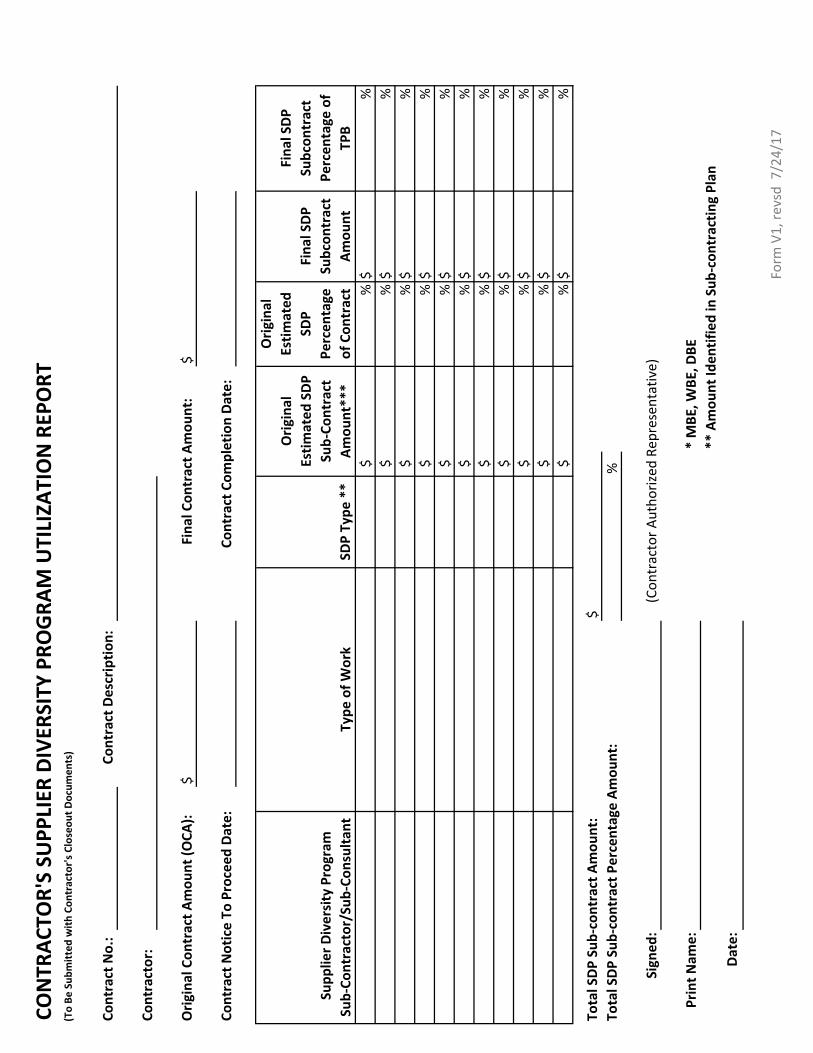
CONTR
ACTO
R'S SU
PPLIER
DIVER
SITY
PRO
GRA
M UTILIZA
TION REP
ORT
(To Be
Sub
mitted
with
Con
tractor's
Closeou
t Docum
ents)
Contract No.:
Contract Descriptio
n:
Contractor:
Orig
inal Con
tract A
mou
nt (O
CA):
$
Fina
l Con
tract A
mou
nt:
$
Contract Notice To
Proceed
Date:
Con
tract C
ompletion Date:
SDP Type
**
Orig
inal
Estim
ated
SD
P Pe
rcen
tage
of Con
tract
Fina
l SDP
Subcon
tract
Amou
nt
Fina
l SDP
Subcon
tract
Percen
tage
of
TPB
$%
$%
$%
$%
$%
$%
$%
$%
$%
$%
$%
$%
$%
$%
$%
$%
$%
$%
$%
$%
$%
$%
Total SDP Sub‐contract Amou
nt:
$To
tal SDP Sub‐contract Percentage Am
ount:
%
Signed
:(Con
tractor A
utho
rized
Rep
resentative)
Print N
ame:
* MBE
, WBE
, DBE
** Amou
nt Id
entified in Sub
‐con
tractin
g Plan
Date:
Form
V1, re
vsd 7/24/17
Orig
inal
Estim
ated
SDP
Sub‐Co
ntract
Amou
nt***
Sup
plier D
iversity Program
Sub‐Co
ntractor/Sub
‐Con
sulta
ntType
of W
ork


Change of Sub-Contractor Form
In accordance with MAWSS DBE 16‐01
JOB NAME_____________________________________Location________________________________
Name of General Contractor_____________________________________________________________
Name of Original Sub‐Contractor__________________________________________________________
Name of New Sub‐Contractor_____________________________________________________________
Reason for Change______________________________________________________________________
_____________________________________________________________________________________
_____________________________________________________________________________________
This instrument is for the purpose of advising all persons involved of a change being made on the
contract and job‐site.
_______________________________ __________________________________
General Contractor Supplier Diversity Office
_________________________________
Asst. Director


APPENDIX J
IRREVOCABLE STANDBY LETTER OF CREDIT


(BANK)
DATE: IRREVOCABLE STANDBY LETTER OF CREDIT
CREDIT NUMBER
IN FAVOR OF: Board of Water and Sewer Commissioners of the City of Mobile, Alabama
FOR ACCOUNT OF: (Contractor) (Address)
AMOUNT: Up to the aggregate amount of $
EXPIRATION DATE AT OUR COUNTERS IN MOBILE, ALABAMA
Gentlemen: We hereby establish our irrevocable standby letter of credit No. in your favor available by your draft(s) drawn on us at sight when accompanied by the following document: 1. Statement purportedly signed by an authorized representative of the Board of Water and Sewer Commissioners of the City of Mobile, Alabama certifying that (Contractor) is in default under the terms of the agreement for the Project No. Any reference to the agreement is for informational purpose only, the agreement does not represent an integral part of this letter of credit. All draft(s) drawn under this credit must be marked: Drawn under (Bank) Mobile letter of credit No. , dated . Partial drawings are permitted. THE ORIGINAL OF THIS LETTER OF CREDIT MUST BE PRESENTED WITH ANY DRAWING We hereby engage with you that drafts drawn under and in compliance with the terms of the credit will be duly honored upon presentation and delivery of the documents as specified. Except so far as otherwise expressly stated, this documentary credit is subject to the "Uniform Customs and Practice for Documentary Credits" fixed by the International Chamber of Commerce in effect as of the date of issuance hereof.
, Mobile (Bank) Authorized Signature Authorized Signature


BID BOND
KNOW ALL MEN BY THESE PRESENTS: That we,______________________________________________________________________________________ (Name of Bidder) __________________________________________________________________________________, as Principal, (Address) and _________________________________________________________________________________ (Name of Surety) of__________________________________________________________________________, as Surety, (Address) jointly and severally, hereby bind ourselves, our heirs, executors, administrators, successors, and assigns to the Board of Water and Sewer Commissioners of the City of Mobile, Alabama, as the Owner, in the PENAL SUM of five percent (5%) of the amount of the Principal's bid, but in no event more than Fifty thousand Dollars ($10,000.00). THE CONDITION OF THIS OBLIGATION is that the Principal has submitted to the Owner the attached bid, which is incorporated herein by reference, for the Project identified as: ________________________________________________________________Project No.____________________
NOW, THEREFORE, if, within the terms of the Bid Documents, the Owner accepts the Principal's bid and the Principal thereafter either:
(a) executes and delivers a Construction Contract with the required Contract and Labor and Material Bonds (each in the form contained in the Bid Documents and properly completed in accordance with the bid) and delivers evidence of insurance as prescribed in the Bid Documents, or
(b) fails to execute and deliver such Construction Contract with such Bonds and evidence of insurance, but pays the Owner the difference, not to exceed the Penal Sum of this Bond, between the amount of the Principal's Bid and the larger amount for which the Owner may award a Construction Contract for the same Work to another bidder,
then, this obligation shall be null and void, otherwise it shall remain in full force and effect.
The Surety, for value received, hereby stipulates and agrees that the obligation of the Surety under this Bond shall not in any manner be impaired or affected by any extension of the time within which the Owner may accept the Principal's bid, and the Surety does hereby waive notice of any such extension.
SIGNED AND SEALED this_________________ day of_______________________________,__________. ATTEST: PRINCIPAL: _________________________________________
_______________________________________ By___________________________________ Name and Title
ATTEST: SURETY: _________________________________________
_______________________________________ By___________________________________ Name and Title Approved 11/21/2016


Page 1 of 3 4/8/20
INFORMATION FOR BIDDERS
No bid will be accepted or read from a bidder who is not on the list of entities who have
requested the contract documents as per the Invitation to Bid.
Bids must be submitted upon the standard forms, furnished by the Board of Water & Sewer
Commissioners of the City of Mobile, Alabama, included in the Project Specifications
Bid submission must include colored and tabbed page dividers and color‐coded bid pages to
emulate the bid package as included in the contract document electronic files. Tabs shall be
typed or legibly written extending out the right edge of the paper. Bid shall include the following
items printed on the color paper as indicated as follows with all blanks filled in as required to
form a complete bid:
Item Paper Color
Invitation for Bid White
Page divider tabbed "ADDENDUMS" Yellow
All issued addendums White
Page Divider tabbed "BID TOTAL" Yellow
Proposal Page 1 White
Proposal Pages 2, 3 and 4 Yellow
Proposal Page 5 – Proposed Subcontracting Plan Yellow
Page divider tabbed " SSO NOTIFICATION " Yellow
Proposal Page 6 SSO and Unpermitted Discharge Prevention Notification
Yellow
Page divider tabbed "SUBCONTRACTING PLAN" Yellow
SUBCONTRACTING PLAN Yellow
MAWSS DBE Policy with Change of Sub‐Contractor Form (7 pages)
White
Page divider tabbed "BID BOND" Yellow
Bid Bond form Yellow
Page divider tabbed "OTHER" Yellow
Any other documents as required for a complete bid White
Guarantee will be required with each bid for at least 5% of the amount of the bid not to exceed
$10,000 filed in the form of a certified check, Bid Bond, or irrevocable Letter of Credit acceptable
to the Owner payable to the Board of Water & Sewer Commissioners of the City of Mobile,
Alabama. Bid Bonds shall include certification that the bonding company is listed in Circular 570
of the U. S. Treasury Department. The name, address, telephone number, and contact person for
the bonding company shall also be included.
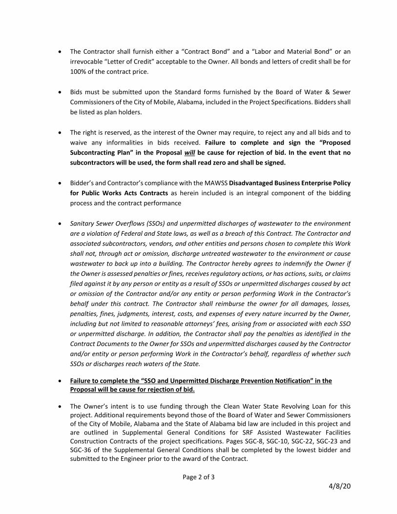
Page 2 of 3 4/8/20
The Contractor shall furnish either a “Contract Bond” and a “Labor and Material Bond” or an
irrevocable “Letter of Credit” acceptable to the Owner. All bonds and letters of credit shall be for
100% of the contract price.
Bids must be submitted upon the Standard forms furnished by the Board of Water & Sewer
Commissioners of the City of Mobile, Alabama, included in the Project Specifications. Bidders shall
be listed as plan holders.
The right is reserved, as the interest of the Owner may require, to reject any and all bids and to
waive any informalities in bids received. Failure to complete and sign the “Proposed
Subcontracting Plan” in the Proposal will be cause for rejection of bid. In the event that no
subcontractors will be used, the form shall read zero and shall be signed.
Bidder’s and Contractor’s compliance with the MAWSS Disadvantaged Business Enterprise Policy
for Public Works Acts Contracts as herein included is an integral component of the bidding
process and the contract performance
Sanitary Sewer Overflows (SSOs) and unpermitted discharges of wastewater to the environment
are a violation of Federal and State laws, as well as a breach of this Contract. The Contractor and
associated subcontractors, vendors, and other entities and persons chosen to complete this Work
shall not, through act or omission, discharge untreated wastewater to the environment or cause
wastewater to back up into a building. The Contractor hereby agrees to indemnify the Owner if
the Owner is assessed penalties or fines, receives regulatory actions, or has actions, suits, or claims
filed against it by any person or entity as a result of SSOs or unpermitted discharges caused by act
or omission of the Contractor and/or any entity or person performing Work in the Contractor’s
behalf under this contract. The Contractor shall reimburse the owner for all damages, losses,
penalties, fines, judgments, interest, costs, and expenses of every nature incurred by the Owner,
including but not limited to reasonable attorneys’ fees, arising from or associated with each SSO
or unpermitted discharge. In addition, the Contractor shall pay the penalties as identified in the
Contract Documents to the Owner for SSOs and unpermitted discharges caused by the Contractor
and/or entity or person performing Work in the Contractor’s behalf, regardless of whether such
SSOs or discharges reach waters of the State.
Failure to complete the “SSO and Unpermitted Discharge Prevention Notification” in the Proposal will be cause for rejection of bid.
The Owner’s intent is to use funding through the Clean Water State Revolving Loan for this project. Additional requirements beyond those of the Board of Water and Sewer Commissioners of the City of Mobile, Alabama and the State of Alabama bid law are included in this project and are outlined in Supplemental General Conditions for SRF Assisted Wastewater Facilities Construction Contracts of the project specifications. Pages SGC‐8, SGC‐10, SGC‐22, SGC‐23 and SGC‐36 of the Supplemental General Conditions shall be completed by the lowest bidder and submitted to the Engineer prior to the award of the Contract.

Page 3 of 3 4/8/20
For the Bidder’s satisfaction of the requirements of Section 2 of the General Conditions Paragraph 2.04 to visit the site of the work, the Owner will make available the site for inspection by official document holders during normal business hours Monday through Friday from April 27, 2020 through May 15, 2020. Such inspections must be requested by e‐mail to Gavin Butler at [email protected] at least 24 hours in advance of the intended inspection and scheduled at a mutually convenient date and time. Inspections will be unguided and plant staff will not be available for nor responsive to questions. Additionally, all visitors must strictly observe all CDC guidance for social separation as associated with COVID‐19 and must limit their inspections to areas directly involved in the work.
END OF SECTION


State of Alabama Alabama Department of Environmental Management State Revolving Fund (SRF) Loan Program SRF Section Permits and Services Division Alabama Department of Environmental Management Post Office Box 301463 Montgomery, Alabama 36130-1463
(334) 271-7796 (334) 271-7950 FAX
Supplemental General Conditions
for SRF Assisted
Public Drinking Water and Wastewater Facilities Construction Contracts
SRF Project Number: _______________

Table of Contents:
I ADEM Special Conditions…………………………………………... SGC-3
II Bonds and Insurance………………………………………...……... SGC-3
III Utilization of Disadvantaged Business Enterprises (DBEs) ……. SGC-3 IV Six Affirmative Steps for Good Faith DBE Solicitation ….………. SGC-4 V Documentation Required from Owner and Contractor …………… SGC-5 VI Resources for Identifying DBE Contractors/Subcontractors…….. SGC-7 VII DBE Compliance Form………………………………………………. SGC-8 VIII EPA Form 6100-2 DBE Subcontractor Participation Form………. SGC-10 IX EPA Form 6100-3 DBE Subcontractor Performance Form…….… SGC-12 X EPA Form 6100-4 DBE Subcontractor Utilization Form……….….. SGC-14 XI EPA Form 5700-52 A MBE/WBE Utilization Reports…………..… SGC-16 XII Changes to Approved DBE Compliance Form……………………. SGC-21 XIII Certification Regarding Equal Employment Opportunity…………. SGC-22 XIV Debarred Firms Certification………………………………………… SGC-23 XV Davis-Bacon and Related Acts…………………………………….. SGC-24
XVI American Iron and Steel……………………….………..………….. SGC-33 XVII Project Sign Detail - CWSRF………………………….….………… SGC-34 XVIII Project Sign Detail - DWSRF……………………….…….………… SGC-35 XIX Construction Contract Requirements………………..…..……….… SGC-36 XX Project Review and Cost Summary……………………................. SGC-37
SRF Supplemental General Conditions
SGC - 2

I – ADEM Special Conditions 1. Construction within State right-of-way shall be in accordance with Alabama Department of
Transportation policies and procedures. 2. Construction is to be carried out in compliance with applicable NPDES permits and in a
manner that prevents bypassing of raw wastewater flows during construction. If bypassing is anticipated, the ADEM NPDES Enforcement Branch (334-271-7975) shall be advised in advance and the contractor shall take all necessary steps to minimize the impacts of bypassing.
3. Siltation and soil erosion shall be minimized during construction. The contractor shall
obtain an NPDES storm water permit for construction if required. 4. The owner shall provide and maintain competent and adequate supervision and inspection. 5. ADEM and EPA shall have access to the site and the project work at all times. 6. These Special Conditions shall supersede any conflicting provisions of this contract. 7. A project sign is required. See Parts XVII and XVIII, pages SGC-34 – SGC-35, for more
information. II – Bonds and Insurance Bonding requirements shall comply with Alabama Act No. 97-225. Provisions of the Act are summarized below: 1. Bid Bond – Not less than 5% of either the owner’s estimated cost or of the contractor’s bid
up to a maximum $10,000. The bid guarantee shall consist of a cashier’s check drawn on an Alabama bank or a bid bond executed by a surety company duly authorized and qualified to make bonds in the State of Alabama.
2. Performance Bond – 100% of the contract price. 3. Payment Bond – Payable to the awarding authority, shall be executed in an amount not less
than 50% of the contract price. In addition to the insurance requirements elsewhere in the specifications, the owner or the contractor, as appropriate, must acquire any flood insurance made available by the Federal Emergency Management Agency as required by 40 CFR 30.600 (b), if construction will take place in a flood hazard area identified by the Federal Emergency Management Agency. III – Utilization of Disadvantaged Businesses Enterprises (DBEs) It is the policy of the State Revolving Loan Fund (SRF) to promote a “fair share” of sub-agreement awards to small, minority, and women-owned businesses for equipment, supplies, construction, and services. Compliance with these contract provisions is required in order for project costs to be eligible for SRF funding. The “fair share” objective is a goal, not a quota. Failure on the part of the apparent successful bidder to submit required information to the loan recipient (Owner) may be considered by the Owner in evaluating whether the bidder is responsive to bid requirements.
SRF Supplemental General Conditions
SGC - 3

The project objectives for utilization of Minority Business Enterprises (MBE's) and Women's Business Enterprises (WBE's) are as follows: Commodities (Supplies) MBE 4% WBE 11% Contractual (Services) MBE 8% WBE 30% Equipment MBE 5% WBE 20% Construction MBE 2.5% WBE 3% For purposes of clarification: • This objective applies to any Federally assisted procurement agreement in excess of
$10,000.
• This objective necessitates three responsibilities; separate solicitations must be made of small and minority and women's business enterprises.
• A minority business is a business, at least 51 percent of which is owned and controlled by minority group members (Black; Hispanics; Asian American; American Indian; and, any other designations approved by the Office of Management and Budget).
• A women's business is a business, at least 51 percent of which is owned and controlled by one or more women.
• The control determination will revolve around the minority or woman owner's involvement in the day-to-day management of the business enterprise.
• Solicitation should allow adequate time for price analysis; ADEM recommends that contact be made no later than 15 days before bid opening.
• Efforts taken to comply with this objective must be documented in detail; maintain records of firms contacted, including any negotiation efforts to reach competitive price levels, and awards to the designated firms.
• ADEM recommends that the prime contractor utilize the services of the Minority Business Development Service Centers. These Centers are funded by the U.S. Department of Commerce to provide technical, financial and contracting assistance to minority and women's business enterprises. These Centers are located in a number of Regional cities.
• Use of the services provided by Centers does not absolve the prime contractors from pursuing additional efforts to meet this objective.
IV – Six Affirmative Steps for Good Faith DBE Solicitation The loan recipient shall follow the six affirmative steps found in the SRF application when using loan funds to procure sources of supplies, construction and services. If the successful bidder plans to subcontract a portion of the project, the bidder must submit to the owner within 10 days after bid opening, evidence of the affirmative steps taken to utilize small, minority and women's businesses. These six affirmative steps or ‘good faith efforts’ are required methods to ensure that DBEs have the opportunity to compete for procurements funded by EPA financial assistance dollars. Such affirmative steps are described as follows: 1. Ensure DBEs are made aware of contracting opportunities to the fullest extent practicable through outreach and recruitment activities. This will include placing DBEs on solicitation lists and soliciting them whenever there are potential sources.
SRF Supplemental General Conditions
SGC - 4

2. Make information on forthcoming opportunities available to DBEs and arrange time frames for contracts and establish delivery schedules, where the requirements permit, in a way that encourages and facilitates participation by DBEs in the competitive process. This includes, whenever possible, posting solicitation for bids or proposals for a minimum of 30 calendar days before the bid or proposal closing date. 3. Consider in the contracting process whether firms competing for large contracts could subcontract with DBEs. This will include dividing total requirements when economically feasible into smaller tasks or quantities to permit maximum participation by DBEs in the competitive process. 4. Encourage contracting with a consortium of DBEs when a contract is too large for one of these firms to handle individually. 5. Use the resources, services, and assistance of the Department of Transportation (DOT), Small Business Administration (SBA), and the Minority Business Development Agency of the Department of Commerce (MBDA). 6. If the Contractor awards subcontracts, it must take the steps described in items (1) through (5) listed above. V – Documentation Required from Owner and Contractor The low, responsive, responsible bidder must forward the following items, in duplicate, to the Owner no later than 10 days after bid opening. The Owner shall transmit one (1) copy of its DBE documentation of the prime contractor solicitation and the bidder’s DBE documentation of all subcontractor solicitation to ADEM within 14 days after bid opening. 1. SRF project number and project name. 2. List of subcontractors (name, address and telephone) with dollar amount and duration for
subcontracts). If there are to be no subcontractors, please indicate as such. 3. List of any subcontract work yet to be committed with estimate of dollar amount and
duration of contract. 4. DBE Documents - See Part IV, page SGC-3. 5. Debarred Firms Certification – See Part XIV, page SGC-23. 6. Certification Regarding Equal Employment Opportunity – See Part XIII, page SGC-22. The Owner shall submit annual MBE/WBE Utilization Reports (EPA Form 5700-52A, pages SGC-16 - SGC-17) within 30 days of the end of the annual reporting period (October 30th). Submit reports directly to:
Diane Lockwood Administrative Section Fiscal Branch Alabama Department of Environmental Management Post Office Box 301463 Montgomery, Alabama 36130-1463
SRF Supplemental General Conditions
SGC - 5

The Prime Contractor must submit the following items to the Owner: 1) DBE Compliance Form. The Owner must submit this information to ADEM to demonstrate compliance with the DBE requirements. ADEM’s approval is required prior to award of the construction contract and commencement of any SRF-funded construction. (Page SGC-8) 2) Certification Regarding Equal Employment Opportunity. This form is required for the prime contractor and for all subcontractors. The prime contractor’s form should be submitted with the DBE Compliance Form and the subcontractors’ forms should be submitted as the subcontracts are executed. (Page SGC-22) 3) Debarred Firms Certification. This form is required for the prime contractor and for all subcontractors. The prime contractor’s form should be submitted with the DBE Compliance Form and the subcontractors’ forms should be submitted as the subcontracts are executed. (Page SGC-23) 4) EPA Form 6100-2 DBE Subcontractor Participation Form. This form gives a DBE subcontractor the opportunity to describe the work the DBE subcontractor received from the prime contractor, how much the DBE subcontractor was paid, and any other concerns the DBE subcontractor might have. The prime contractor must provide this form to each DBE subcontractor for the DBE subcontractor’s submittal to ADEM’s DBE Coordinator (to be forwarded to EPA’s DBE Coordinator). (Page SGC-10) 5) EPA Form 6100-3 DBE Subcontractor Performance Form. This form captures an intended DBE subcontractor’s description of work to be performed for the prime contractor and the price of the work. This form is to be provided by the prime contractor to each DBE subcontractor and submitted with the DBE Compliance Form. (Page SGC-12) 6) EPA Form 6100-4 DBE Subcontractor Utilization Form. This form captures the prime contractor’s intended use of an identified DBE subcontractor and the estimated dollar amount of the work. This form is to be completed by the prime contractor and submitted with the DBE Compliance Form. (Page SGC-14) 7) EPA Form 5700-52 A MBE/WBE Utilization Reports (DBE Annual Report). The Owner must submit this information to ADEM within 30 days of the end of the annual reporting period (October 30th). (Pages SGC-16 - SGC-17) 8) Changes to Approved DBE Compliance Form. If any changes, substitutions, or additions are proposed to the subcontractors included in previous Department approvals, the Owner must submit this information to the Department for prior approval in order for the affected subcontract work to be eligible for SRF funding. (Page SGC-21) 9) Certified Payrolls. These should be submitted to the Owner at least monthly for the prime contractor and all subcontractors. The Owner must maintain payroll records and make these available for inspection. Please note that DBEs, MBEs, and WBEs must be certified by EPA, SBA, or DOT (or by state, local, Tribal, or private entities whose certification criteria match EPA’s). DBEs must be certified in order to be counted toward the recipient’s MBE/WBE accomplishments. Depending upon the certifying agency, a DBE may be classified as a DBE, a Minority Business Enterprise (MBE), or a Women’s Business Enterprise (WBE). The documentation of these good faith solicitation efforts must be detailed in order to allow for satisfactory review. Such documentation might include fax confirmation sheets, copies of solicitation letters/emails, printouts of the online solicitations, printouts of online search results, affidavits of publication in newspapers, etc. The prime contractor is strongly encouraged to follow up each written, fax, or email solicitation with at least 1 logged phone call. The prime contractor must employ the six affirmative steps to subcontract with DBEs, even if the prime contractor has achieved its fair share objectives.
SRF Supplemental General Conditions
SGC - 6

If a DBE subcontractor fails to complete work under the subcontract for any reason, the prime contractor must notify the Owner in writing prior to any termination and must employ the six good faith efforts described above if using a replacement subcontractor. Any proposed changes from an approved DBE subcontractor must be reported to the Owner and to ADEM on the Changes to Approved Subcontractors Form prior to initiation of the action. EPA Forms Nos. 6100-3 and 6100-4 must also be submitted to ADEM for new DBE subcontracts. VI – Resources for Identifying DBE Contractors/Subcontractors The following organizations may provide assistance in soliciting DBE participation: City of Birmingham Office of Economic Development ATTN: Andrew Mayo, Economic Specialist 710 20th Street North Birmingham, Alabama 35203 205/254-2799 205/254-7741 FAX [email protected] U.S. Small Business Administration http://www.pro-net.sba.gov National Association of Minority Contractors (NAMC) http://www.namc-atl.org
Alabama Department of Transportation ATTN: John Huffman 1409 Coliseum Boulevard Montgomery, Alabama 36130 334-244-6261 http://www.dot.state.al.us U.S. Department of Commerce Minority Business Development Agency 401 West Peachtree Street NW – Suite 1715 Atlanta, Georgia 30308 404/730-3300 404/730-3313 FAX http://www.mbda.gov/
Governor’s Office of Minority and Women’s Business Enterprises 401 Adams Avenue Suite 360 Montgomery, Alabama 36130 1-800-447-4191 334/242-2220 334/242-4203 FAX Birmingham Construction Industrial Authority ATTN: Rhonsha Walker or Kimberly Bivins 3600 4th Avenue South Birmingham, Alabama 35222 205/324-6202 205/324-6210 FAX http://www.BCIA1.org
NOTES: (1) The Owner and the prime contractor shall use the necessary resources to identify and directly solicit no less than 3 certified DBE/MBE firms and 3 WBE firms to bid in each expected contract/subcontract area. If a diligent and documented search of ALDOT, SBA, and MBDA directories does not identify 3 potential certified DBE/MBE firms and 3 potential certified WBE firms, then the prime contractor shall post an advertisement in at least 1 of the other online or print resources. Whenever possible, post solicitation for bids or proposals for a minimum of 30 calendar days before the bid or proposal closing date. (2) Expenditures to a DBE that acts merely as a broker or passive conduit of funds, without performing, managing, or supervising the work of its subcontract in a manner consistent with normal business practices may not be counted. (3) The prime contractor should attempt to identify and first solicit DBEs in the geographic proximity of the project before soliciting those located farther away. (4) In addition, you may contact ADEM’s DBE Coordinator, Diane Lockwood, at (334) 271-7815 for assistance.
SRF Supplemental General Conditions
SGC - 7

VII – DBE Compliance Form PLEASE NOTE: ALL INFORMATION OUTLINED ON THIS FORM IS REQUIRED FOR DBE COMPLIANCE. THE PROPOSED PRIME CONTRACTOR AND OWNER SHOULD ENSURE THAT THIS INFORMATION IS COMPLETE PRIOR TO SUBMITTAL. Loan Recipient: __________________________ SRF Loan Number: __________________ CERTIFICATIONS: I certify that the information submitted on and with this form is true and accurate and that this firm has met and will continue to meet the conditions of this construction contract regarding DBE solicitation and utilization. I further certify that criteria used in selecting subcontractors and suppliers were applied equally to all potential participants and that EPA Forms 6100-2 and 6100-3 were distributed to all DBE subcontractors. ________________________________________ Date____________ (Prime Contractor signature) ________________________________________ (Printed name and title) I certify that I have reviewed the information submitted on and with this form and that it meets the requirements of the Owner's State Revolving Fund loan contract. ________________________________________ Date____________ (Signature of Owner or Owner's representative) ________________________________________ (Printed name and title) GENERAL INFORMATION: Owner contact: ______________________________________________________________________ Owner phone number/email: ____________________________________________________________ Consulting engineer contact: ____________________________________________________________ Consulting engineer phone number/email: _________________________________________________ Proposed prime contractor: _____________________________________________________________ Prime contractor contact: ______________________________________________________________ Prime contractor phone number/email: ____________________________________________________ Proposed prime contract amount: $ ________________ Proposed total DBE/MBE participation: $ ________________ Percentage: ____% Goal: 2.5% Proposed total WBE participation: $ ________________ Percentage: ____% Goal: 3.0%
SRF Supplemental General Conditions
SGC - 8
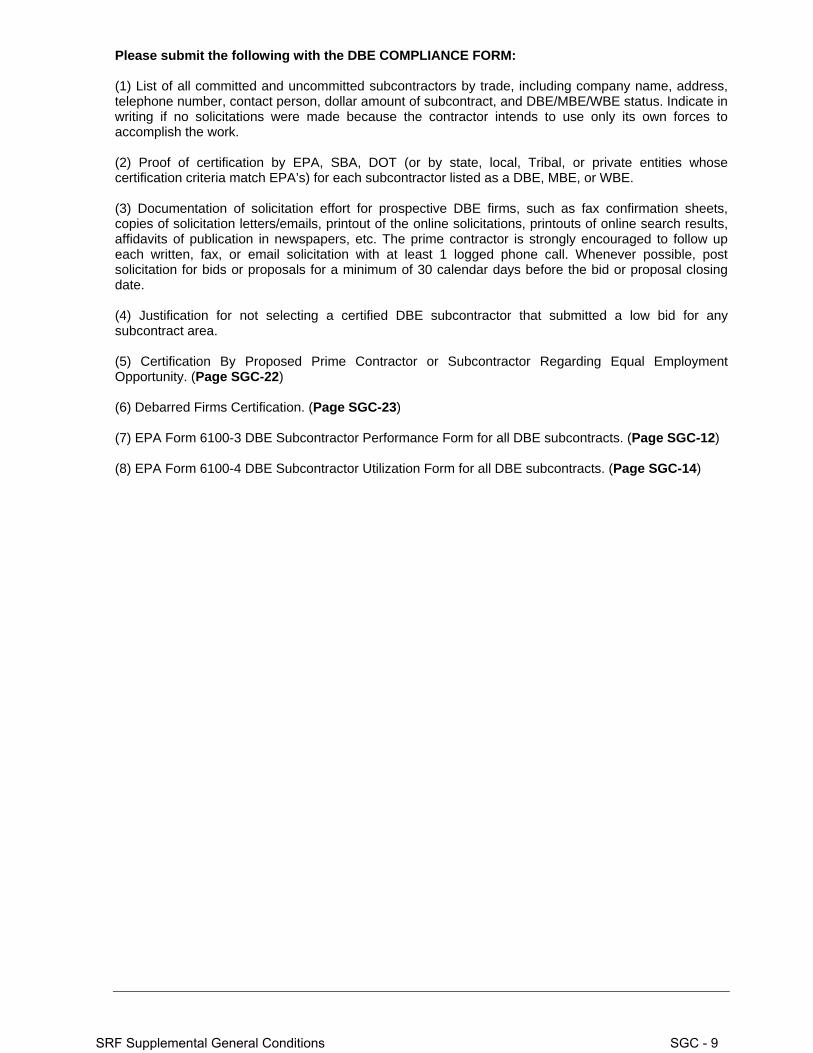
Please submit the following with the DBE COMPLIANCE FORM: (1) List of all committed and uncommitted subcontractors by trade, including company name, address, telephone number, contact person, dollar amount of subcontract, and DBE/MBE/WBE status. Indicate in writing if no solicitations were made because the contractor intends to use only its own forces to accomplish the work. (2) Proof of certification by EPA, SBA, DOT (or by state, local, Tribal, or private entities whose certification criteria match EPA’s) for each subcontractor listed as a DBE, MBE, or WBE. (3) Documentation of solicitation effort for prospective DBE firms, such as fax confirmation sheets, copies of solicitation letters/emails, printout of the online solicitations, printouts of online search results, affidavits of publication in newspapers, etc. The prime contractor is strongly encouraged to follow up each written, fax, or email solicitation with at least 1 logged phone call. Whenever possible, post solicitation for bids or proposals for a minimum of 30 calendar days before the bid or proposal closing date. (4) Justification for not selecting a certified DBE subcontractor that submitted a low bid for any subcontract area. (5) Certification By Proposed Prime Contractor or Subcontractor Regarding Equal Employment Opportunity. (Page SGC-22) (6) Debarred Firms Certification. (Page SGC-23) (7) EPA Form 6100-3 DBE Subcontractor Performance Form for all DBE subcontracts. (Page SGC-12) (8) EPA Form 6100-4 DBE Subcontractor Utilization Form for all DBE subcontracts. (Page SGC-14)
SRF Supplemental General Conditions
SGC - 9
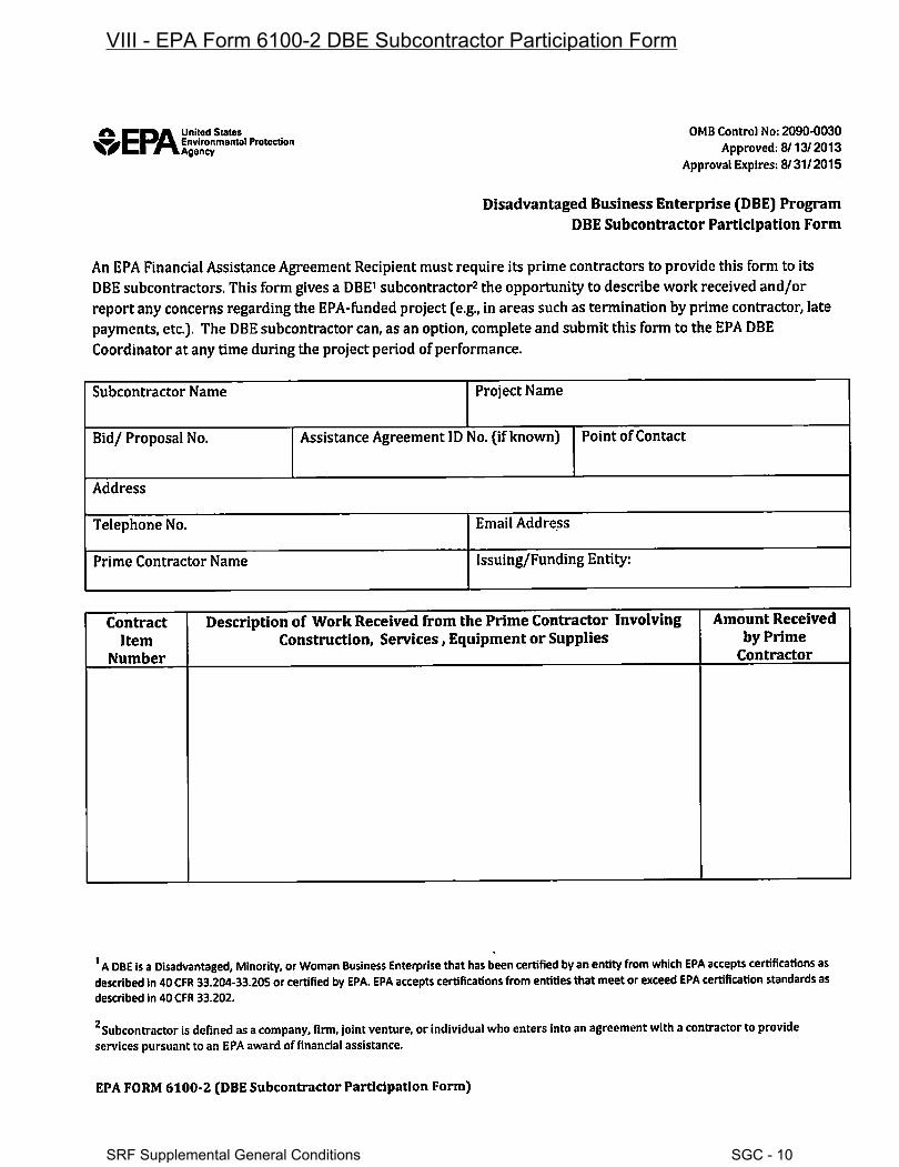
VIII - EPA Form 6100-2 DBE Subcontractor Participation Form
SRF Supplemental General Conditions
SGC - 10
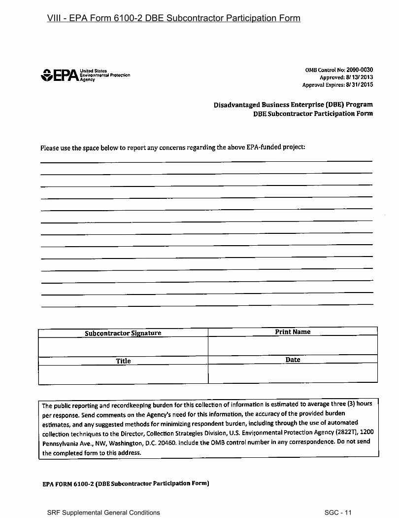
VIII - EPA Form 6100-2 DBE Subcontractor Participation Form
SRF Supplemental General Conditions
SGC - 11

IX - EPA Form 6100-3 DBE Subcontractor Performance Form
SRF Supplemental General Conditions
SGC - 12

IX - EPA Form 6100-3 DBE Subcontractor Performance Form
SRF Supplemental General Conditions
SGC - 13
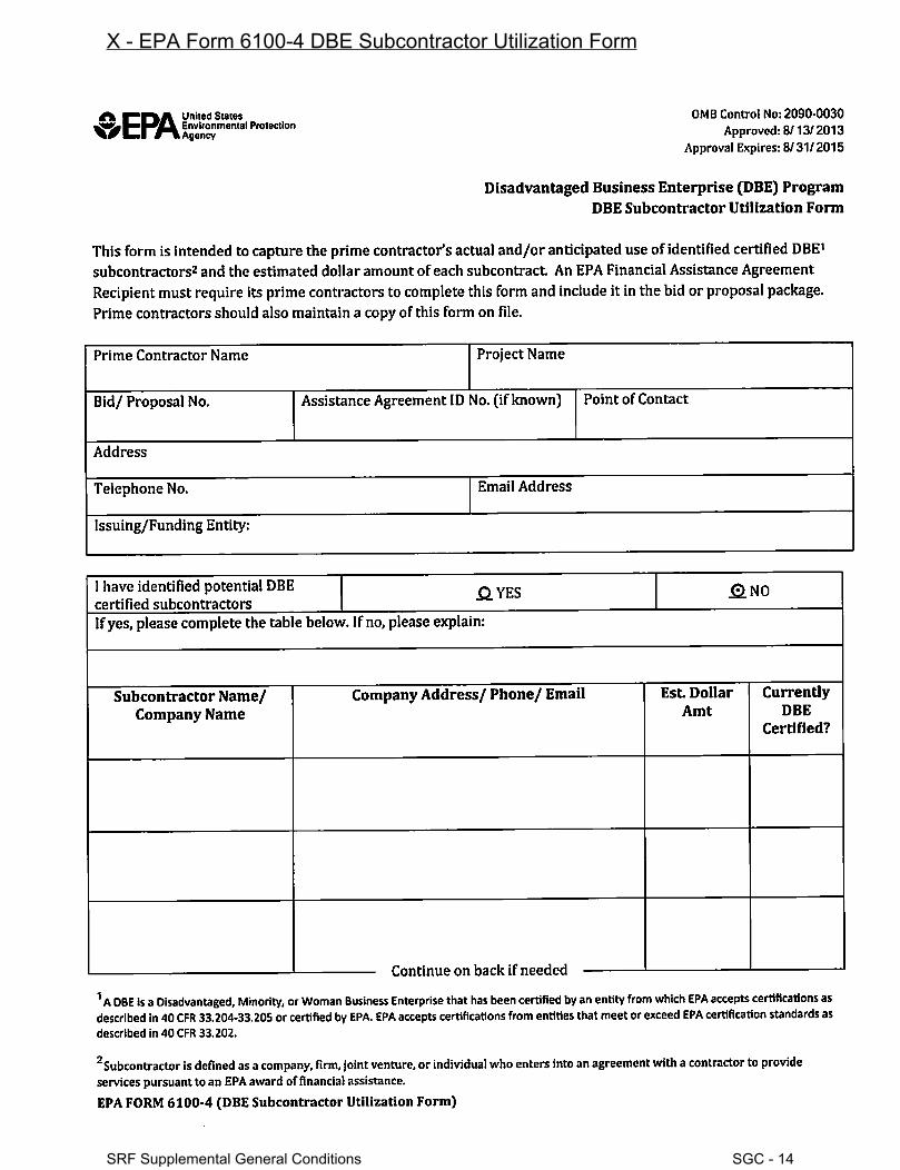
X - EPA Form 6100-4 DBE Subcontractor Utilization Form
SRF Supplemental General Conditions
SGC - 14

X - EPA Form 6100-4 DBE Subcontractor Utilization Form
SRF Supplemental General Conditions
SGC - 15

XI - EPA Form 5700-52A MBE/WBE Utilization Reports
SRF Supplemental General Conditions
SGC - 16
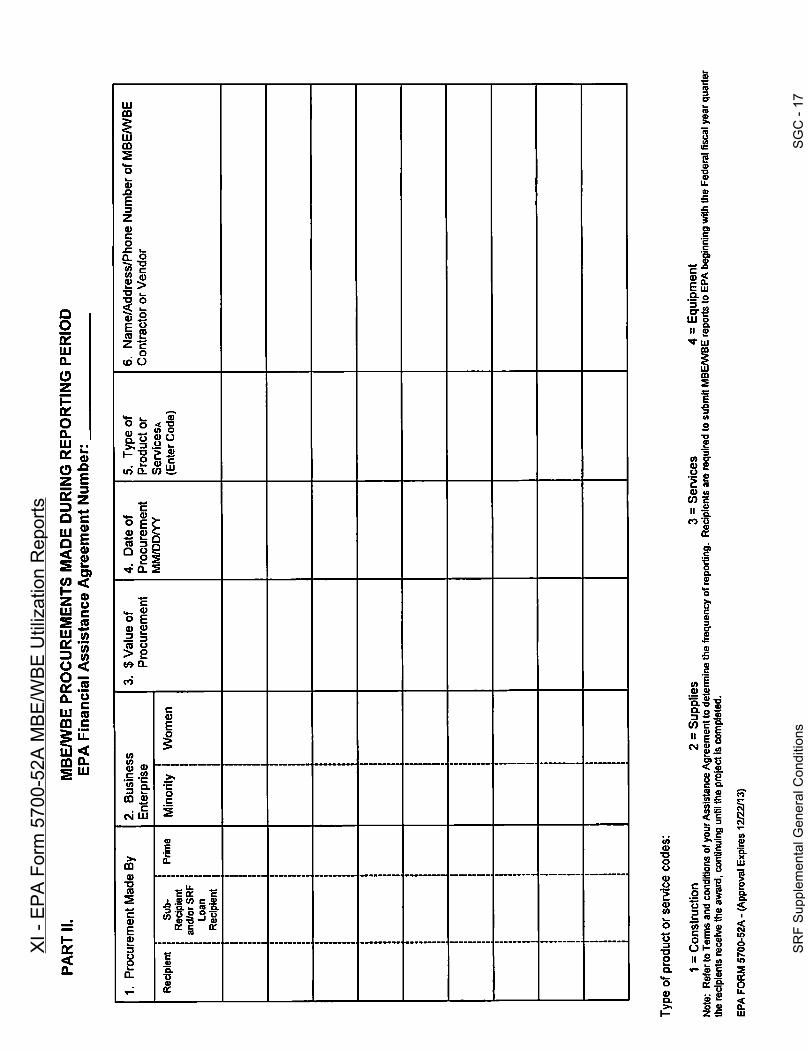
XI -
EP
A F
orm
570
0-52
A M
BE
/WB
E U
tiliz
atio
n R
epor
ts
SR
F S
uppl
emen
tal G
ener
al C
ondi
tions
SG
C -
17
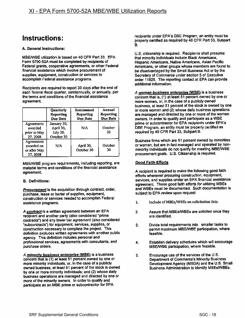
XI - EPA Form 5700-52A MBE/WBE Utilization Reports
SRF Supplemental General Conditions
SGC - 18
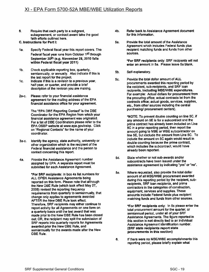
XI - EPA Form 5700-52A MBE/WBE Utilization Reports
SRF Supplemental General Conditions
SGC - 19

XI - EPA Form 5700-52A MBE/WBE Utilization Reports
SRF Supplemental General Conditions
SGC - 20

XII - Changes to Approved DBE Compliance Form
SRF Supplemental General Conditions
SGC - 21
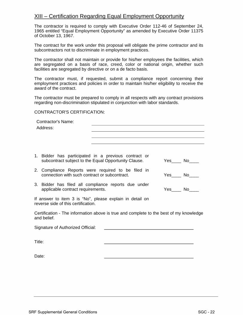
XIII – Certification Regarding Equal Employment Opportunity
The contractor is required to comply with Executive Order 112-46 of September 24, 1965 entitled “Equal Employment Opportunity” as amended by Executive Order 11375 of October 13, 1967. The contract for the work under this proposal will obligate the prime contractor and its subcontractors not to discriminate in employment practices. The contractor shall not maintain or provide for his/her employees the facilities, which are segregated on a basis of race, creed, color or national origin, whether such facilities are segregated by directive or on a de facto basis. The contractor must, if requested, submit a compliance report concerning their employment practices and policies in order to maintain his/her eligibility to receive the award of the contract. The contractor must be prepared to comply in all respects with any contract provisions regarding non-discrimination stipulated in conjunction with labor standards. CONTRACTOR'S CERTIFICATION: Contractor's Name: Address:
1. Bidder has participated in a previous contract or
subcontract subject to the Equal Opportunity Clause. 2. Compliance Reports were required to be filed in
connection with such contract or subcontract. 3. Bidder has filed all compliance reports due under
applicable contract requirements. If answer to item 3 is “No”, please explain in detail on reverse side of this certification.
Yes____ No____ Yes____ No____ Yes____ No____
Certification - The information above is true and complete to the best of my knowledge and belief. Signature of Authorized Official: Title: Date:
SRF Supplemental General Conditions
SGC - 22
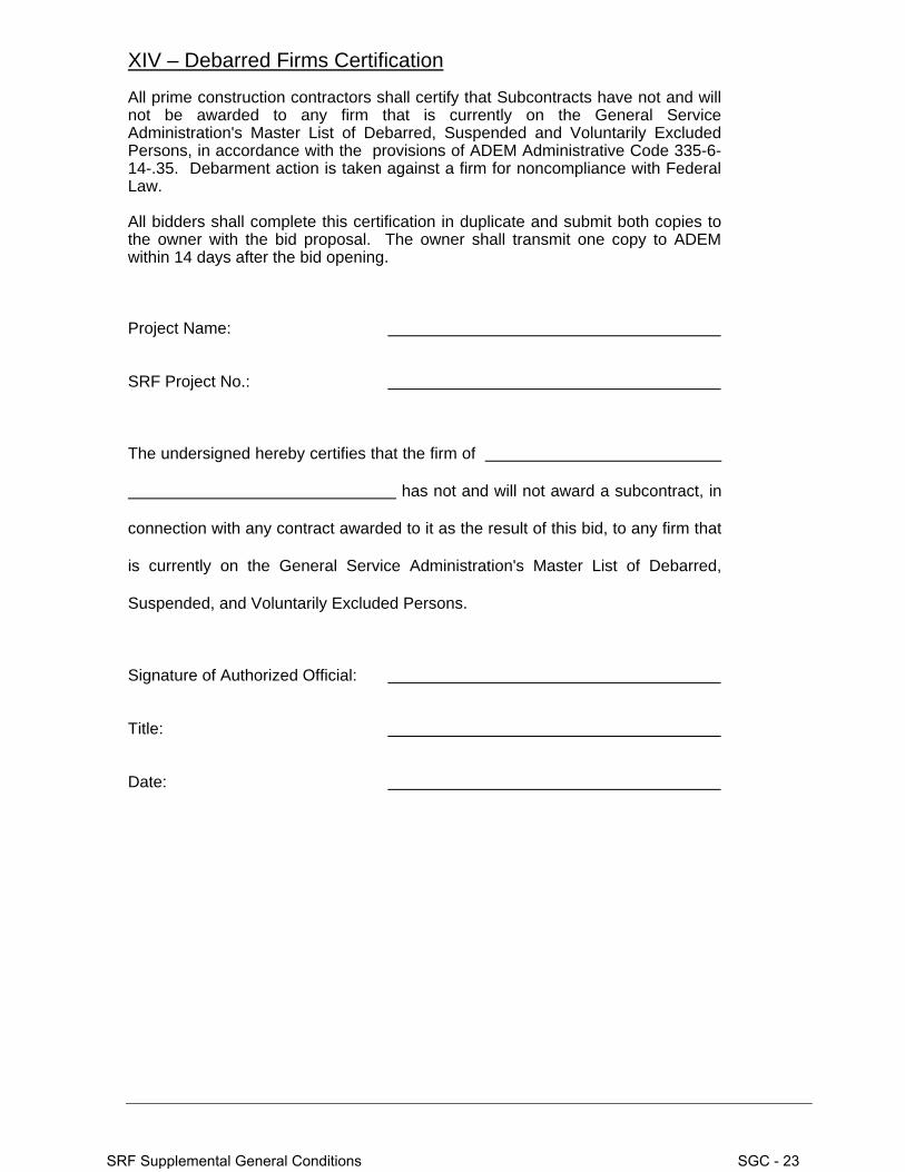
XIV – Debarred Firms Certification All prime construction contractors shall certify that Subcontracts have not and will not be awarded to any firm that is currently on the General Service Administration's Master List of Debarred, Suspended and Voluntarily Excluded Persons, in accordance with the provisions of ADEM Administrative Code 335-6-14-.35. Debarment action is taken against a firm for noncompliance with Federal Law. All bidders shall complete this certification in duplicate and submit both copies to the owner with the bid proposal. The owner shall transmit one copy to ADEM within 14 days after the bid opening. Project Name: SRF Project No.: The undersigned hereby certifies that the firm of
has not and will not award a subcontract, in
connection with any contract awarded to it as the result of this bid, to any firm that
is currently on the General Service Administration's Master List of Debarred,
Suspended, and Voluntarily Excluded Persons.
Signature of Authorized Official: Title: Date:
SRF Supplemental General Conditions
SGC - 23

XV – Davis-Bacon and Related Acts Labor Standards Provisions for Federally Assisted Contracts Wage Rate Requirements Under FY 2013 Continuing Appropriation I. Requirements under the Consolidated and Further Continuing Appropriations Act. 2013 (P.L. 113-6) For Subrecipients That Are Governmental Entities: The following terms and conditions specify how recipients will assist EPA in meeting its Davis-Bacon (DB) responsibilities when DB applies to EPA awards of financial assistance under the FY 2013 Continuing Resolution with respect to State recipients and subrecipients that are governmental entities. If a subrecipient has questions regarding when DB applies, obtaining the correct DB wage determinations, DB provisions, or compliance monitoring, it may contact the State recipient. If a State recipient needs guidance, the recipient may contact Cynthia Y. Edwards at [email protected] or at 404-562-9340 of EPA, Region 4 Grants and SRF Management Section, for guidance. The recipient or subrecipient may also obtain additional guidance from DOL's web site at http://www.dol.gov/whd/ 1. Applicability of the Davis- Bacon (DB) prevailing wage requirements. Under the FY 2013 Continuing Resolution, DB prevailing wage requirements apply to the construction, alteration, and repair of treatment works carried out in whole or in part with assistance made available by a State water pollution control revolving fund and to any construction project carried out in whole or in part by assistance made available by a drinking water treatment revolving loan fund. If a subrecipient encounters a unique situation at a site that presents uncertainties regarding DB applicability, the subrecipient must discuss the situation with the recipient State before authorizing work on that site. 2. Obtaining Wage Determinations. (a) Subrecipients shall obtain the wage determination for the locality in which a covered activity subject to DB will take place prior to issuing requests for bids, proposals, quotes or other methods for soliciting contracts (solicitation) for activities subject to DB. These wage determinations shall be incorporated into solicitations and any subsequent contracts. Prime contracts must contain a provision requiring that subcontractors follow the wage determination incorporated into the prime contract. (i) While the solicitation remains open, the subrecipient shall monitor www.wdol.gov weekly to ensure that the wage determination contained in the solicitation remains current. The subrecipients shall amend the solicitation if DOL issues a modification more than 10 days prior to the closing date (i.e. bid opening) for the solicitation. If DOL modifies or supersedes the applicable wage determination less than 10 days prior to the closing date, the subrecipients may request a finding from the State recipient that there is not a reasonable time to notify interested contractors of the modification of the wage determination. The State recipient will provide a report of its findings to the subrecipient. (ii) If the subrecipient does not award the contract within 90 days of the closure of the solicitation, any modifications or supersedes DOL makes to the wage determination contained in the solicitation shall be effective unless the State recipient, at the request of the subrecipient, obtains an extension of the 90 day period from DOL pursuant to 29 CFR 1.6(c)(3)(iv). The subrecipient shall monitor www.wdol.gov on a weekly basis if it does not award the contract within 90 days of closure of the solicitation to ensure that wage determinations contained in the solicitation remain current. (b) If the subrecipient carries out activity subject to DB by issuing a task order, work assignment or similar instrument to an existing contractor (ordering instrument) rather than by publishing a solicitation, the subrecipient shall insert the appropriate DOL wage determination from www.wdol.gov into the ordering instrument. (c) Subrecipients shall review all subcontracts subject to DB entered into by prime contractors to verify that the prime contractor has required its subcontractors to include the applicable wage determinations.
SRF Supplemental General Conditions
SGC - 24

(d) As provided in 29 CFR 1.6(f), DOL may issue a revised wage determination applicable to a subrecipient’s contract after the award of a contract or the issuance of an ordering instrument if DOL determines that the subrecipient has failed to incorporate a wage determination or has used a wage determination that clearly does not apply to the contract or ordering instrument. If this occurs, the subrecipient shall either terminate the contract or ordering instrument and issue a revised solicitation or ordering instrument or incorporate DOL’s wage determination retroactive to the beginning of the contract or ordering instrument by change order. The subrecipient’s contractor must be compensated for any increases in wages resulting from the use of DOL’s revised wage determination. 3. Contract Subcontract Provisions. (a) The Recipient shall insure that the subrecipient(s) shall insert in full in any contract in excess of $2,000 which is entered into for the actual construction, alteration and/or repair, including painting and decorating, of a treatment work under the CWSRF or a construction project under the DWSRF financed in whole or in part from Federal funds or in accordance with guarantees of a Federal agency or financed from funds obtained by pledge of any contract of a Federal agency to make a loan, grant or annual contribution (except where a different meaning is expressly indicated), and which is subject to the labor standards provisions of any of the acts listed in § 5.1 or the FY 2010 appropriation , the following clauses: (1) Minimum wages. (i) All laborers and mechanics employed or working upon the site of the work will be paid unconditionally and not less often than once a week, and without subsequent deduction or rebate on any account (except such payroll deductions as are permitted by regulations issued by the Secretary of Labor under the Copeland Act (29 CFR part 3)), the full amount of wages and bona fide fringe benefits (or cash equivalents thereof) due at time of payment computed at rates not less than those contained in the wage determination of the Secretary of Labor which is attached hereto and made a part hereof, regardless of any contractual relationship which may be alleged to exist between the contractor and such laborers and mechanics. Contributions made or costs reasonably anticipated for bona fide fringe benefits under section 1(b)(2) of the Davis-Bacon Act on behalf of laborers or mechanics are considered wages paid to such laborers or mechanics, subject to the provisions of paragraph (a)(1)(iv) of this section; also, regular contributions made or costs incurred for more than a weekly period (but not less often than quarterly) under plans, funds, or programs which cover the particular weekly period, are deemed to be constructively made or incurred during such weekly period. Such laborers and mechanics shall be paid the appropriate wage rate and fringe benefits on the wage determination for the classification of work actually performed, without regard to skill, except as provided in § 5.5(a)(4). Laborers or mechanics performing work in more than one classification may be compensated at the rate specified for each classification for the time actually worked therein: Provided, That the employer's payroll records accurately set forth the time spent in each classification in which work is performed. The wage determination (including any additional classification and wage rates conformed under paragraph (a)(1)(ii) of this section) and the Davis-Bacon poster (WH-1321) shall be posted at all times by the contractor and its subcontractors at the site of the work in a prominent and accessible place where it can be easily seen by the workers. Subrecipients may obtain wage determinations from the U.S. Department of Labor’s web site, www.dol.gov. (ii)(A) The subrecipient(s), on behalf of EPA, shall require that any class of laborers or mechanics, including helpers, which is not listed in the wage determination and which is to be employed under the contract shall be classified in conformance with the wage determination. The State award official shall approve a request for an additional classification and wage rate and fringe benefits therefore only when the following criteria have been met: (1) The work to be performed by the classification requested is not performed by a classification in the wage determination; and
SRF Supplemental General Conditions
SGC - 25

(2) The classification is utilized in the area by the construction industry; and (3) The proposed wage rate, including any bona fide fringe benefits, bears a reasonable relationship to the wage rates contained in the wage determination. (B) If the contractor and the laborers and mechanics to be employed in the classification (if known), or their representatives, and the subrecipient(s) agree on the classification and wage rate (including the amount designated for fringe benefits where appropriate), documentation of the action taken and the request, including the local wage determination shall be sent by the subrecipient (s) to the State award official. The State award official will transmit the request, to the Administrator of the Wage and Hour Division, Employment Standards Administration, U.S. Department of Labor, Washington, DC 20210 and to the EPA DB Regional Coordinator concurrently. The Administrator, or an authorized representative, will approve, modify, or disapprove every additional classification request within 30 days of receipt and so advise the State award official or will notify the State award official within the 30-day period that additional time is necessary. (C) In the event the contractor, the laborers or mechanics to be employed in the classification or their representatives, and the subrecipient(s) do not agree on the proposed classification and wage rate (including the amount designated for fringe benefits, where appropriate), the award official shall refer the request and the local wage determination, including the views of all interested parties and the recommendation of the State award official, to the Administrator for determination. The request shall be sent to the EPA DB Regional Coordinator concurrently. The Administrator, or an authorized representative, will issue a determination within 30 days of receipt of the request and so advise the contracting officer or will notify the contracting officer within the 30-day period that additional time is necessary. (D) The wage rate (including fringe benefits where appropriate) determined pursuant to paragraphs (a)(1)(ii)(B) or (C) of this section, shall be paid to all workers performing work in the classification under this contract from the first day on which work is performed in the classification. (iii) Whenever the minimum wage rate prescribed in the contract for a class of laborers or mechanics includes a fringe benefit which is not expressed as an hourly rate, the contractor shall either pay the benefit as stated in the wage determination or shall pay another bona fide fringe benefit or an hourly cash equivalent thereof. (iv) If the contractor does not make payments to a trustee or other third person, the contractor may consider as part of the wages of any laborer or mechanic the amount of any costs reasonably anticipated in providing bona fide fringe benefits under a plan or program, Provided, That the Secretary of Labor has found, upon the written request of the contractor, that the applicable standards of the Davis-Bacon Act have been met. The Secretary of Labor may require the contractor to set aside in a separate account assets for the meeting of obligations under the plan or program. (2) Withholding. The subrecipient(s), shall upon written request of the EPA Award Official or an authorized representative of the Department of Labor, withhold or cause to be withheld from the contractor under this contract or any other Federal contract with the same prime contractor, or any other federally-assisted contract subject to Davis-Bacon prevailing wage requirements, which is held by the same prime contractor, so much of the accrued payments or advances as may be considered necessary to pay laborers and mechanics, including apprentices, trainees, and helpers, employed by the contractor or any subcontractor the full amount of wages required by the contract. In the event of failure to pay any laborer or mechanic, including any apprentice, trainee, or helper, employed or working on the site of the work, all or part of the wages required by the contract, the (Agency) may, after written notice to the contractor, sponsor, applicant, or owner, take such action as may be necessary to cause the suspension of any further payment, advance, or guarantee of funds until such violations have ceased.
SRF Supplemental General Conditions
SGC - 26

(3) Payrolls and basic records. (i) Payrolls and basic records relating thereto shall be maintained by the contractor during the course of the work and preserved for a period of three years thereafter for all laborers and mechanics working at the site of the work. Such records shall contain the name, address, and social security number of each such worker, his or her correct classification, hourly rates of wages paid (including rates of contributions or costs anticipated for bona fide fringe benefits or cash equivalents thereof of the types described in section 1(b)(2)(B) of the Davis-Bacon Act), daily and weekly number of hours worked, deductions made and actual wages paid. Whenever the Secretary of Labor has found under 29 CFR 5.5(a)(1)(iv) that the wages of any laborer or mechanic include the amount of any costs reasonably anticipated in providing benefits under a plan or program described in section 1(b)(2)(B) of the Davis-Bacon Act, the contractor shall maintain records which show that the commitment to provide such benefits is enforceable, that the plan or program is financially responsible, and that the plan or program has been communicated in writing to the laborers or mechanics affected, and records which show the costs anticipated or the actual cost incurred in providing such benefits. Contractors employing apprentices or trainees under approved programs shall maintain written evidence of the registration of apprenticeship programs and certification of trainee programs, the registration of the apprentices and trainees, and the ratios and wage rates prescribed in the applicable programs. (ii)(A) The contractor shall submit weekly, for each week in which any contract work is performed, a copy of all payrolls to the subrecipient, that is, the entity that receives the sub-grant or loan from the State capitalization grant recipient. Such documentation shall be available on request of the State recipient or EPA. As to each payroll copy received, the subrecipient shall provide written confirmation in a form satisfactory to the State indicating whether or not the project is in compliance with the requirements of 29 CFR 5.5(a)(1) based on the most recent payroll copies for the specified week. The payrolls shall set out accurately and completely all of the information required to be maintained under 29 CFR 5.5(a)(3)(i), except that full social security numbers and home addresses shall not be included on the weekly payrolls. Instead the payrolls shall only need to include an individually identifying number for each employee (e.g., the last four digits of the employee's social security number). The required weekly payroll information may be submitted in any form desired. Optional Form WH-347 is available for this purpose from the Wage and Hour Division Web site at http://www.dol.gov/esa/whd/forms/wh347instr.htm or its successor site. The prime contractor is responsible for the submission of copies of payrolls by all subcontractors. Contractors and subcontractors shall maintain the full social security number and current address of each covered worker, and shall provide them upon request to the subrecipient(s) for transmission to the State or EPA if requested by EPA , the State, the contractor, or the Wage and Hour Division of the Department of Labor for purposes of an investigation or audit of compliance with prevailing wage requirements. It is not a violation of this section for a prime contractor to require a subcontractor to provide addresses and social security numbers to the prime contractor for its own records, without weekly submission to the subrecipient(s). (B) Each payroll submitted shall be accompanied by a “Statement of Compliance,” signed by the contractor or subcontractor or his or her agent who pays or supervises the payment of the persons employed under the contract and shall certify the following: (1) That the payroll for the payroll period contains the information required to be provided under § 5.5 (a)(3)(ii) of Regulations, 29 CFR part 5, the appropriate information is being maintained under § 5.5 (a)(3)(i) of Regulations, 29 CFR part 5, and that such information is correct and complete; (2) That each laborer or mechanic (including each helper, apprentice, and trainee) employed on the contract during the payroll period has been paid the full weekly wages earned, without rebate, either directly or indirectly, and that no deductions have been made either directly or indirectly from the full wages earned, other than permissible deductions as set forth in Regulations, 29 CFR part 3; (3) That each laborer or mechanic has been paid not less than the applicable wage rates and fringe benefits or cash equivalents for the classification of work performed, as specified in the applicable wage determination incorporated into the contract.
SRF Supplemental General Conditions
SGC - 27

(C) The weekly submission of a properly executed certification set forth on the reverse side of Optional Form WH-347 shall satisfy the requirement for submission of the “Statement of Compliance” required by paragraph (a)(3)(ii)(B) of this section. (D) The falsification of any of the above certifications may subject the contractor or subcontractor to civil or criminal prosecution under section 1001 of title 18 and section 231 of title 31 of the United States Code. (iii) The contractor or subcontractor shall make the records required under paragraph (a)(3)(i) of this section available for inspection, copying, or transcription by authorized representatives of the State, EPA or the Department of Labor, and shall permit such representatives to interview employees during working hours on the job. If the contractor or subcontractor fails to submit the required records or to make them available, the Federal agency or State may, after written notice to the contractor, sponsor, applicant, or owner, take such action as may be necessary to cause the suspension of any further payment, advance, or guarantee of funds. Furthermore, failure to submit the required records upon request or to make such records available may be grounds for debarment action pursuant to 29 CFR 5.12. (4) Apprentices and trainees. (i) Apprentices. Apprentices will be permitted to work at less than the predetermined rate for the work they performed when they are employed pursuant to and individually registered in a bona fide apprenticeship program registered with the U.S. Department of Labor, Employment and Training Administration, Office of Apprenticeship Training, Employer and Labor Services, or with a State Apprenticeship Agency recognized by the Office, or if a person is employed in his or her first 90 days of probationary employment as an apprentice in such an apprenticeship program, who is not individually registered in the program, but who has been certified by the Office of Apprenticeship Training, Employer and Labor Services or a State Apprenticeship Agency (where appropriate) to be eligible for probationary employment as an apprentice. The allowable ratio of apprentices to journeymen on the job site in any craft classification shall not be greater than the ratio permitted to the contractor as to the entire work force under the registered program. Any worker listed on a payroll at an apprentice wage rate, who is not registered or otherwise employed as stated above, shall be paid not less than the applicable wage rate on the wage determination for the classification of work actually performed. In addition, any apprentice performing work on the job site in excess of the ratio permitted under the registered program shall be paid not less than the applicable wage rate on the wage determination for the work actually performed. Where a contractor is performing construction on a project in a locality other than that in which its program is registered, the ratios and wage rates (expressed in percentages of the journeyman's hourly rate) specified in the contractor's or subcontractor's registered program shall be observed. Every apprentice must be paid at not less than the rate specified in the registered program for the apprentice's level of progress, expressed as a percentage of the journeymen hourly rate specified in the applicable wage determination. Apprentices shall be paid fringe benefits in accordance with the provisions of the apprenticeship program. If the apprenticeship program does not specify fringe benefits, apprentices must be paid the full amount of fringe benefits listed on the wage determination for the applicable classification. If the Administrator determines that a different practice prevails for the applicable apprentice classification, fringes shall be paid in accordance with that determination. In the event the Office of Apprenticeship Training, Employer and Labor Services, or a State Apprenticeship Agency recognized by the Office, withdraws approval of an apprenticeship program, the contractor will no longer be permitted to utilize apprentices at less than the applicable predetermined rate for the work performed until an acceptable program is approved. (ii) Trainees. Except as provided in 29 CFR 5.16, trainees will not be permitted to work at less than the predetermined rate for the work performed unless they are employed pursuant to and individually registered in a program which has received prior approval, evidenced by formal certification by the U.S. Department of Labor, Employment and Training Administration. The ratio of trainees to journeymen on the job site shall not be greater than permitted under the plan approved by the Employment and Training Administration. Every trainee must be paid at not less than the rate specified in the approved program for the trainee's level of progress, expressed as a percentage of the journeyman hourly rate specified in the applicable wage determination. Trainees shall be paid fringe benefits in accordance with the provisions of the trainee program.
SRF Supplemental General Conditions
SGC - 28
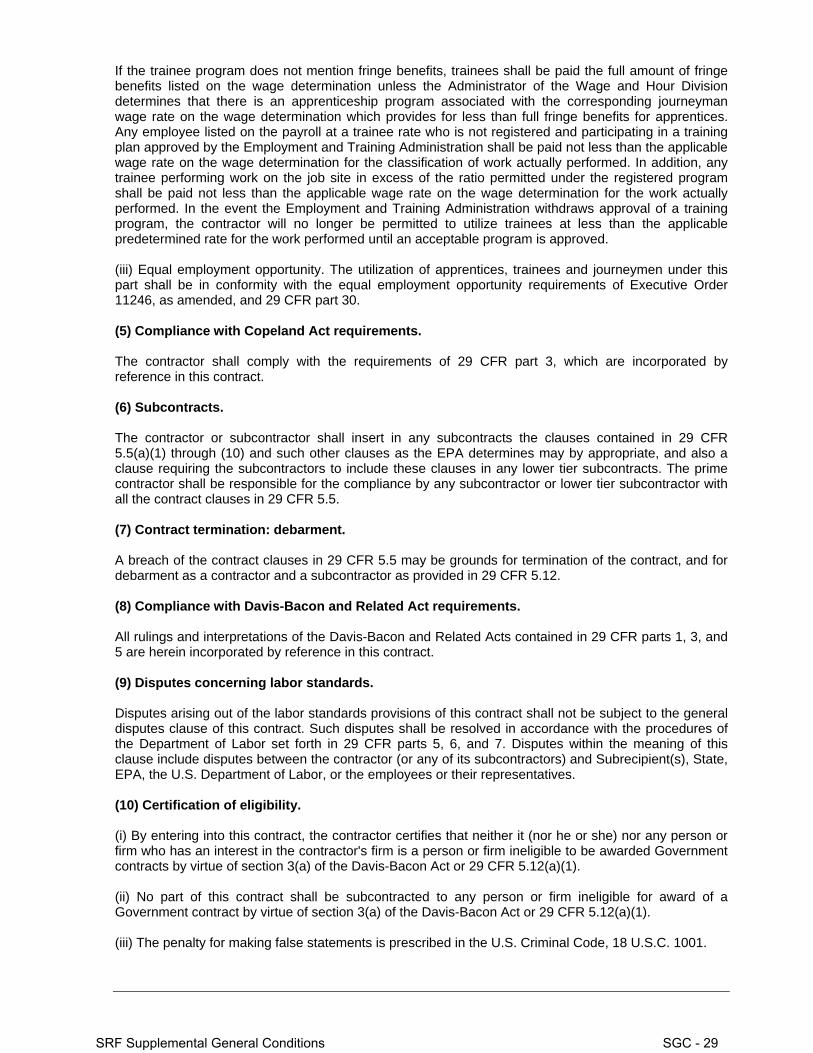
If the trainee program does not mention fringe benefits, trainees shall be paid the full amount of fringe benefits listed on the wage determination unless the Administrator of the Wage and Hour Division determines that there is an apprenticeship program associated with the corresponding journeyman wage rate on the wage determination which provides for less than full fringe benefits for apprentices. Any employee listed on the payroll at a trainee rate who is not registered and participating in a training plan approved by the Employment and Training Administration shall be paid not less than the applicable wage rate on the wage determination for the classification of work actually performed. In addition, any trainee performing work on the job site in excess of the ratio permitted under the registered program shall be paid not less than the applicable wage rate on the wage determination for the work actually performed. In the event the Employment and Training Administration withdraws approval of a training program, the contractor will no longer be permitted to utilize trainees at less than the applicable predetermined rate for the work performed until an acceptable program is approved. (iii) Equal employment opportunity. The utilization of apprentices, trainees and journeymen under this part shall be in conformity with the equal employment opportunity requirements of Executive Order 11246, as amended, and 29 CFR part 30. (5) Compliance with Copeland Act requirements. The contractor shall comply with the requirements of 29 CFR part 3, which are incorporated by reference in this contract. (6) Subcontracts. The contractor or subcontractor shall insert in any subcontracts the clauses contained in 29 CFR 5.5(a)(1) through (10) and such other clauses as the EPA determines may by appropriate, and also a clause requiring the subcontractors to include these clauses in any lower tier subcontracts. The prime contractor shall be responsible for the compliance by any subcontractor or lower tier subcontractor with all the contract clauses in 29 CFR 5.5. (7) Contract termination: debarment. A breach of the contract clauses in 29 CFR 5.5 may be grounds for termination of the contract, and for debarment as a contractor and a subcontractor as provided in 29 CFR 5.12. (8) Compliance with Davis-Bacon and Related Act requirements. All rulings and interpretations of the Davis-Bacon and Related Acts contained in 29 CFR parts 1, 3, and 5 are herein incorporated by reference in this contract. (9) Disputes concerning labor standards. Disputes arising out of the labor standards provisions of this contract shall not be subject to the general disputes clause of this contract. Such disputes shall be resolved in accordance with the procedures of the Department of Labor set forth in 29 CFR parts 5, 6, and 7. Disputes within the meaning of this clause include disputes between the contractor (or any of its subcontractors) and Subrecipient(s), State, EPA, the U.S. Department of Labor, or the employees or their representatives. (10) Certification of eligibility. (i) By entering into this contract, the contractor certifies that neither it (nor he or she) nor any person or firm who has an interest in the contractor's firm is a person or firm ineligible to be awarded Government contracts by virtue of section 3(a) of the Davis-Bacon Act or 29 CFR 5.12(a)(1). (ii) No part of this contract shall be subcontracted to any person or firm ineligible for award of a Government contract by virtue of section 3(a) of the Davis-Bacon Act or 29 CFR 5.12(a)(1). (iii) The penalty for making false statements is prescribed in the U.S. Criminal Code, 18 U.S.C. 1001.
SRF Supplemental General Conditions
SGC - 29

4. Contract Provision for Contracts in Excess of $100,000. (a) Contract Work Hours and Safety Standards Act. The subrecipient shall insert the following clauses set forth in paragraphs (a)(1), (2), (3), and (4) of this section in full in any contract in an amount in excess of $100,000 and subject to the overtime provisions of the Contract Work Hours and Safety Standards Act. These clauses shall be inserted in addition to the clauses required by Item 3, above or 29 CFR 4.6. As used in this paragraph, the terms laborers and mechanics include watchmen and guards. (1) Overtime requirements. No contractor or subcontractor contracting for any part of the contract work which may require or involve the employment of laborers or mechanics shall require or permit any such laborer or mechanic in any workweek in which he or she is employed on such work to work in excess of forty hours in such workweek unless such laborer or mechanic receives compensation at a rate not less than one and one-half times the basic rate of pay for all hours worked in excess of forty hours in such workweek. (2) Violation; liability for unpaid wages; liquidated damages. In the event of any violation of the clause set forth in paragraph (a)(1) of this section the contractor and any subcontractor responsible therefore shall be liable for the unpaid wages. In addition, such contractor and subcontractor shall be liable to the United States (in the case of work done under contract for the District of Columbia or a territory, to such District or to such territory), for liquidated damages. Such liquidated damages shall be computed with respect to each individual laborer or mechanic, including watchmen and guards, employed in violation of the clause set forth in paragraph (a)(1) of this section, in the sum of $10 for each calendar day on which such individual was required or permitted to work in excess of the standard workweek of forty hours without payment of the overtime wages required by the clause set forth in paragraph (a)(1) of this section. (3) Withholding for unpaid wages and liquidated damages. The subrecipient, upon written request of the EPA Award Official or an authorized representative of the Department of Labor, shall withhold or cause to be withheld, from any moneys payable on account of work performed by the contractor or subcontractor under any such contract or any other Federal contract with the same prime contractor, or any other federally-assisted contract subject to the Contract Work Hours and Safety Standards Act, which is held by the same prime contractor, such sums as may be determined to be necessary to satisfy any liabilities of such contractor or subcontractor for unpaid wages and liquidated damages as provided in the clause set forth in paragraph (b)(2) of this section. (4) Subcontracts. The contractor or subcontractor shall insert in any subcontracts the clauses set forth in paragraph (a)(1) through (4) of this section and also a clause requiring the subcontractors to include these clauses in any lower tier subcontracts. The prime contractor shall be responsible for compliance by any subcontractor or lower tier subcontractor with the clauses set forth in paragraphs (a)(1) through (4) of this section. (b) In addition to the clauses contained in Item 3, above, in any contract subject only to the Contract Work Hours and Safety Standards Act and not to any of the other statutes cited in 29 CFR 5.1, the Subrecipient shall insert a clause requiring that the contractor or subcontractor shall maintain payrolls and basic payroll records during the course of the work and shall preserve them for a period of three years from the completion of the contract for all laborers and mechanics, including guards and watchmen, working on the contract. Such records shall contain the name and address of each such employee, social security number, correct classifications, hourly rates of wages paid, daily and weekly number of hours worked, deductions made, and actual wages paid. Further, the Subrecipient shall insert in any such contract a clause providing hat the records to be maintained under this paragraph shall be made available by the contractor or subcontractor for inspection, copying, or transcription by authorized representatives of the (write the name of agency) and the Department of Labor, and the contractor or subcontractor will permit such representatives to interview employees during working hours on the job.
SRF Supplemental General Conditions
SGC - 30
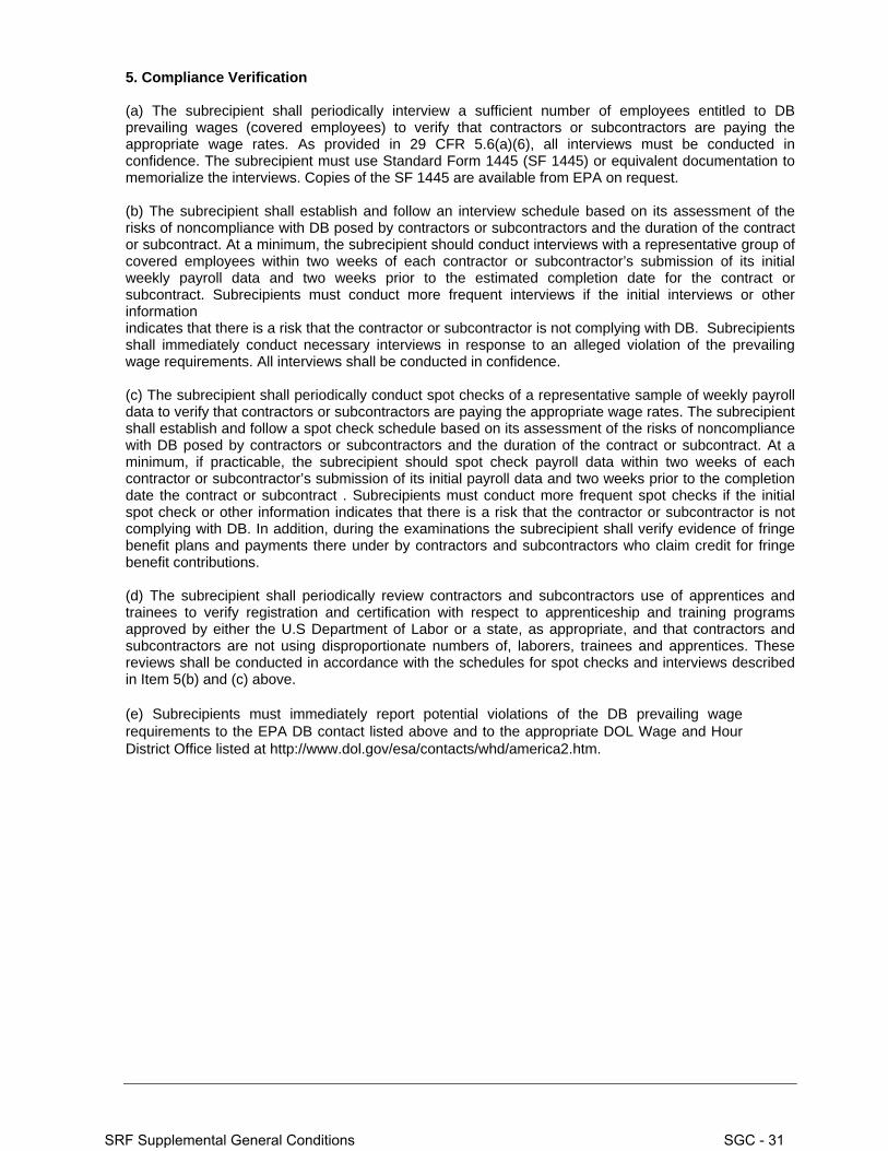
5. Compliance Verification (a) The subrecipient shall periodically interview a sufficient number of employees entitled to DB prevailing wages (covered employees) to verify that contractors or subcontractors are paying the appropriate wage rates. As provided in 29 CFR 5.6(a)(6), all interviews must be conducted in confidence. The subrecipient must use Standard Form 1445 (SF 1445) or equivalent documentation to memorialize the interviews. Copies of the SF 1445 are available from EPA on request. (b) The subrecipient shall establish and follow an interview schedule based on its assessment of the risks of noncompliance with DB posed by contractors or subcontractors and the duration of the contract or subcontract. At a minimum, the subrecipient should conduct interviews with a representative group of covered employees within two weeks of each contractor or subcontractor’s submission of its initial weekly payroll data and two weeks prior to the estimated completion date for the contract or subcontract. Subrecipients must conduct more frequent interviews if the initial interviews or other information indicates that there is a risk that the contractor or subcontractor is not complying with DB. Subrecipients shall immediately conduct necessary interviews in response to an alleged violation of the prevailing wage requirements. All interviews shall be conducted in confidence. (c) The subrecipient shall periodically conduct spot checks of a representative sample of weekly payroll data to verify that contractors or subcontractors are paying the appropriate wage rates. The subrecipient shall establish and follow a spot check schedule based on its assessment of the risks of noncompliance with DB posed by contractors or subcontractors and the duration of the contract or subcontract. At a minimum, if practicable, the subrecipient should spot check payroll data within two weeks of each contractor or subcontractor’s submission of its initial payroll data and two weeks prior to the completion date the contract or subcontract . Subrecipients must conduct more frequent spot checks if the initial spot check or other information indicates that there is a risk that the contractor or subcontractor is not complying with DB. In addition, during the examinations the subrecipient shall verify evidence of fringe benefit plans and payments there under by contractors and subcontractors who claim credit for fringe benefit contributions. (d) The subrecipient shall periodically review contractors and subcontractors use of apprentices and trainees to verify registration and certification with respect to apprenticeship and training programs approved by either the U.S Department of Labor or a state, as appropriate, and that contractors and subcontractors are not using disproportionate numbers of, laborers, trainees and apprentices. These reviews shall be conducted in accordance with the schedules for spot checks and interviews described in Item 5(b) and (c) above. (e) Subrecipients must immediately report potential violations of the DB prevailing wage requirements to the EPA DB contact listed above and to the appropriate DOL Wage and Hour District Office listed at http://www.dol.gov/esa/contacts/whd/america2.htm.
SRF Supplemental General Conditions
SGC - 31

(Insert applicable wage rate determination here.) Wage Rates are county specific for Heavy Construction and can be found at: http://www.gpo.gov/davisbacon/al.html .
SRF Supplemental General Conditions
SGC - 32

"General Decision Number: AL20200110 01/03/2020
Superseded General Decision Number: AL20190110
State: Alabama
Construction Type: Heavy
County: Mobile County in Alabama.
HEAVY CONSTRUCTION PROJECTS
Note: Under Executive Order (EO) 13658, an hourly minimum wage of $10.80 for calendar year 2020 applies to all contracts subject to the Davis-Bacon Act for which the contract is awarded (and any solicitation was issued) on or after January 1, 2015. If this contract is covered by the EO, the contractor must pay all workers in any classification listed on this wage determination at least $10.80 per hour (or the applicable wage rate listed on this wage determination, if it is higher) for all hours spent performing on the contract in calendar year 2020. If this contract is covered by the EO and a classification considered necessary for performance of work on the contract does not appear on this wage determination, the contractor must pay workers in that classification at least the wage rate determined through the conformance process set forth in 29 CFR 5.5(a)(1)(ii) (or the EO minimum wage rate, if it is higher than the conformed wage rate). The EO minimum wage rate will be adjusted annually. Please note that this EO applies to the above-mentioned types of contracts entered into by the federal government that are subject to the Davis-Bacon Act itself, but it does not apply to contracts subject only to the Davis-Bacon Related Acts, including those set forth at 29 CFR 5.1(a)(2)-(60). Additional information on contractor requirements and worker protections under the EO is available at www.dol.gov/whd/govcontracts.
Modification Number Publication Date 0 01/03/2020
ENGI0653-013 06/01/2017
Rates Fringes
POWER EQUIPMENT OPERATOR (PIPELINE) Backhoe, Excavator, Trackhoe....................$ 40.69 15.20 Bulldozer...................$ 40.69 15.20 ---------------------------------------------------------------- SUAL2015-038 08/02/2017
Rates Fringes
CARPENTER, Includes Form Work....$ 19.05 7.86
CEMENT MASON/CONCRETE
Page 1 of 4
2/14/2020https://beta.sam.gov/wage-determination/AL20200110/0?index=wd&is_active=true&date_...
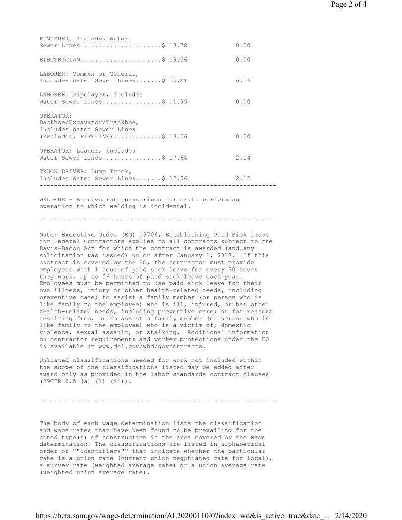
FINISHER, Includes Water Sewer Lines......................$ 13.78 0.00
ELECTRICIAN......................$ 19.56 0.00
LABORER: Common or General, Includes Water Sewer Lines.......$ 15.21 6.16
LABORER: Pipelayer, Includes Water Sewer Lines................$ 11.95 0.00
OPERATOR: Backhoe/Excavator/Trackhoe, Includes Water Sewer Lines (Excludes, PIPELINE).............$ 13.56 0.00
OPERATOR: Loader, Includes Water Sewer Lines................$ 17.64 2.14
TRUCK DRIVER: Dump Truck, Includes Water Sewer Lines.......$ 12.56 2.12 ----------------------------------------------------------------
WELDERS - Receive rate prescribed for craft performing operation to which welding is incidental.
================================================================
Note: Executive Order (EO) 13706, Establishing Paid Sick Leave for Federal Contractors applies to all contracts subject to the Davis-Bacon Act for which the contract is awarded (and any solicitation was issued) on or after January 1, 2017. If this contract is covered by the EO, the contractor must provide employees with 1 hour of paid sick leave for every 30 hours they work, up to 56 hours of paid sick leave each year. Employees must be permitted to use paid sick leave for their own illness, injury or other health-related needs, including preventive care; to assist a family member (or person who is like family to the employee) who is ill, injured, or has other health-related needs, including preventive care; or for reasons resulting from, or to assist a family member (or person who is like family to the employee) who is a victim of, domestic violence, sexual assault, or stalking. Additional information on contractor requirements and worker protections under the EO is available at www.dol.gov/whd/govcontracts.
Unlisted classifications needed for work not included within the scope of the classifications listed may be added after award only as provided in the labor standards contract clauses (29CFR 5.5 (a) (1) (ii)).
----------------------------------------------------------------
The body of each wage determination lists the classification and wage rates that have been found to be prevailing for the cited type(s) of construction in the area covered by the wage determination. The classifications are listed in alphabetical order of ""identifiers"" that indicate whether the particular rate is a union rate (current union negotiated rate for local), a survey rate (weighted average rate) or a union average rate (weighted union average rate).
Page 2 of 4
2/14/2020https://beta.sam.gov/wage-determination/AL20200110/0?index=wd&is_active=true&date_...

Union Rate Identifiers
A four letter classification abbreviation identifier enclosed in dotted lines beginning with characters other than ""SU"" or ""UAVG"" denotes that the union classification and rate were prevailing for that classification in the survey. Example: PLUM0198-005 07/01/2014. PLUM is an abbreviation identifier of the union which prevailed in the survey for this classification, which in this example would be Plumbers. 0198 indicates the local union number or district council number where applicable, i.e., Plumbers Local 0198. The next number, 005 in the example, is an internal number used in processing the wage determination. 07/01/2014 is the effective date of the most current negotiated rate, which in this example is July 1, 2014.
Union prevailing wage rates are updated to reflect all rate changes in the collective bargaining agreement (CBA) governing this classification and rate.
Survey Rate Identifiers
Classifications listed under the ""SU"" identifier indicate that no one rate prevailed for this classification in the survey and the published rate is derived by computing a weighted average rate based on all the rates reported in the survey for that classification. As this weighted average rate includes all rates reported in the survey, it may include both union and non-union rates. Example: SULA2012-007 5/13/2014. SU indicates the rates are survey rates based on a weighted average calculation of rates and are not majority rates. LA indicates the State of Louisiana. 2012 is the year of survey on which these classifications and rates are based. The next number, 007 in the example, is an internal number used in producing the wage determination. 5/13/2014 indicates the survey completion date for the classifications and rates under that identifier.
Survey wage rates are not updated and remain in effect until a new survey is conducted.
Union Average Rate Identifiers
Classification(s) listed under the UAVG identifier indicate that no single majority rate prevailed for those classifications; however, 100% of the data reported for the classifications was union data. EXAMPLE: UAVG-OH-0010 08/29/2014. UAVG indicates that the rate is a weighted union average rate. OH indicates the state. The next number, 0010 in the example, is an internal number used in producing the wage determination. 08/29/2014 indicates the survey completion date for the classifications and rates under that identifier.
A UAVG rate will be updated once a year, usually in January of each year, to reflect a weighted average of the current negotiated/CBA rate of the union locals from which the rate is based.
----------------------------------------------------------------
WAGE DETERMINATION APPEALS PROCESS
1.) Has there been an initial decision in the matter? This can
Page 3 of 4
2/14/2020https://beta.sam.gov/wage-determination/AL20200110/0?index=wd&is_active=true&date_...

be:
* an existing published wage determination * a survey underlying a wage determination * a Wage and Hour Division letter setting forth a position on a wage determination matter * a conformance (additional classification and rate) ruling
On survey related matters, initial contact, including requests for summaries of surveys, should be with the Wage and Hour Regional Office for the area in which the survey was conducted because those Regional Offices have responsibility for the Davis-Bacon survey program. If the response from this initial contact is not satisfactory, then the process described in 2.) and 3.) should be followed.
With regard to any other matter not yet ripe for the formal process described here, initial contact should be with the Branch of Construction Wage Determinations. Write to:
Branch of Construction Wage Determinations Wage and Hour Division U.S. Department of Labor 200 Constitution Avenue, N.W. Washington, DC 20210
2.) If the answer to the question in 1.) is yes, then an interested party (those affected by the action) can request review and reconsideration from the Wage and Hour Administrator (See 29 CFR Part 1.8 and 29 CFR Part 7). Write to:
Wage and Hour Administrator U.S. Department of Labor 200 Constitution Avenue, N.W. Washington, DC 20210
The request should be accompanied by a full statement of the interested party's position and by any information (wage payment data, project description, area practice material, etc.) that the requestor considers relevant to the issue.
3.) If the decision of the Administrator is not favorable, an interested party may appeal directly to the Administrative Review Board (formerly the Wage Appeals Board). Write to:
Administrative Review Board U.S. Department of Labor 200 Constitution Avenue, N.W. Washington, DC 20210
4.) All decisions by the Administrative Review Board are final.
================================================================
END OF GENERAL DECISION "
Page 4 of 4
2/14/2020https://beta.sam.gov/wage-determination/AL20200110/0?index=wd&is_active=true&date_...

XVI – American Iron and Steel Requirement Section 4.13 Compliance with 2014 Appropriations Act. (a) The Loan Recipient agrees to comply with all federal requirements applicable to the Authority Loan (including those imposed by P.L. 113-76, Consolidated Appropriations Act (the "2014 Appropriations Act") and related SRF Policy Guidelines) which the Loan Recipient understands includes, among other things, requirements that all of the iron and steel products used in the Project are to be produced in the United States ("American Iron and Steel") unless (i) the Loan Recipient has requested and obtained a waiver from the U.S. Environmental Protection Agency pertaining to the Project or (ii) the Authority has otherwise advised the Loan Recipient in writing that the Buy American Requirement is not applicable to the Project. . (b) The Loan Recipient also agrees to comply with all recordkeeping and reporting requirements under the Clean Water Act (codified generally under 33 U.S.C. §1251 et seq.) (the "Clean Water Act"), including any reports required by a federal agency or the Authority such as performance indicators of program deliverables, information on costs and Project progress. The Loan Recipient understands that (i) each contract and subcontract related to the Project is subject to audit by appropriate federal and state entities, and (ii) failure to comply with the Clean Water Act and this Agreement may be an Event of Default hereunder that results in a repayment of the Authority Loan in advance of the maturity of the Evidence of Indebtedness and/or other remedial actions. The Loan Recipient agrees to cause all contractors and subcontractors to comply with (through the inclusion of appropriate terms and conditions in all contracts, subcontracts and lower tiered transactions, such terms and conditions to be in substantially the form set forth in connection with the development and construction of the project The Contractor acknowledges to and for the benefit of the , Alabama ("Purchaser"), and the Alabama Water Pollution Control Authority or the Drinking Water Finance Authority (the "State Authority") that it understands the goods and services under this Agreement are being funded with monies made available by the Clean Water State Revolving Fund that have statutory requirements commonly known as "American Iron and Steel;" that requires all of the iron and steel products used in the project to be produced in the United States ("American Iron and Steel") including iron and steel products provided by the Contractor pursuant to this Agreement. The Contractor hereby represents and warrants to and for the benefit of the Purchaser and the State Authority that (a) the Contractor has reviewed and understands the American Iron and Steel Requirement, (b) all of the iron and steel products used in the project will be and/or have been produced in the United States in a manner that complies with the American Iron and Steel Requirement, unless a waiver of the requirement is approved, and (c) the Contractor will provide any further verified information, certification or assurance of compliance with this paragraph, or information necessary to support a waiver of the American Iron and Steel Requirement, as may be requested by the Purchaser or the State Authority. Notwithstanding any other provision of this Agreement, any failure to comply with this paragraph by the Contractor shall permit the Purchaser or State Authority to recover as damages against the Contractor any loss, expense, or cost (including without limitation attorney's fees) incurred by the Purchaser or State Authority resulting from any such failure (including without limitation any impairment or loss of funding, whether in whole or in part, from the State Authority or any damages owed to the State Authority by the Purchaser). While the Contractor has no direct contractual privity with the State Authority, as a lender to the Purchaser for the funding of its project, the Purchaser and the Contractor agree that the State Authority is a third-party beneficiary and neither this paragraph (nor any other provision of this Agreement necessary to give this paragraph force or effect) shall be amended or waived without the prior written consent of the State Authority.
SRF Supplemental General Conditions
SGC - 33
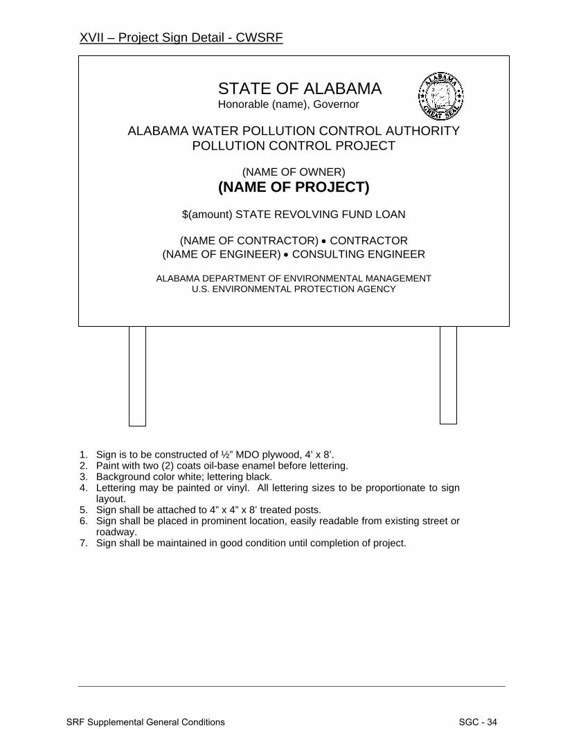
XVII – Project Sign Detail - CWSRF 1. Sign is to be constructed of ½” MDO plywood, 4’ x 8’. 2. Paint with two (2) coats oil-base enamel before lettering. 3. Background color white; lettering black. 4. Lettering may be painted or vinyl. All lettering sizes to be proportionate to sign
layout. 5. Sign shall be attached to 4” x 4” x 8’ treated posts. 6. Sign shall be placed in prominent location, easily readable from existing street or
roadway. 7. Sign shall be maintained in good condition until completion of project.
STATE OF ALABAMA Honorable (name), Governor
ALABAMA WATER POLLUTION CONTROL AUTHORITY
POLLUTION CONTROL PROJECT
(NAME OF OWNER) (NAME OF PROJECT)
$(amount) STATE REVOLVING FUND LOAN
(NAME OF CONTRACTOR) • CONTRACTOR
(NAME OF ENGINEER) • CONSULTING ENGINEER
ALABAMA DEPARTMENT OF ENVIRONMENTAL MANAGEMENT U.S. ENVIRONMENTAL PROTECTION AGENCY
SRF Supplemental General Conditions
SGC - 34

XVIII – Project Sign Detail - DWSRF 1. Sign is to be constructed of ½” MDO plywood, 4’ x 8’. 2. Paint with two (2) coats oil-base enamel before lettering. 3. Background color white; lettering black. 4. Lettering may be painted or vinyl. All lettering sizes to be proportionate to sign
layout. 5. Sign shall be attached to 4” x 4” x 8’ treated posts. 6. Sign shall be placed in prominent location, easily readable from existing street or
roadway. 7. Sign shall be maintained in good condition until completion of project.
STATE OF ALABAMA
Honorable (Name), Governor
ALABAMA DRINKING WATER FINANCE AUTHORITY INFRASTRUCTURE PROJECT
(NAME OF OWNER)
(NAME OF PROJECT)
$(amount) STATE REVOLVING FUND LOAN
(NAME OF CONTRACTOR) • CONTRACTOR (NAME OF ENGINEER) • CONSULTING ENGINEER
ALABAMA DEPARTMENT OF ENVIRONMENTAL MANAGEMENT
U.S. ENVIRONMENTAL PROTECTION AGENCY
SRF Supplemental General Conditions
SGC - 35

XIX – Construction Contract Requirements This checklist is to be completed by the Owner/Engineer when submitting plans and specifications to the SRF and Operator Certification Section for review. It affirms to the SRF reviewer that the Owner/Engineer has addressed these items (in boilerplate form) within the specifications manual. Contract Satisfied Page No. Yes/No Bid Advertisement (including date, time, and location of bid opening). Bid Bond. Performance Bond (100%). Payment Bond (Not less than 50%). Contract Length. Liquidated Damages. Liability Insurance (including workman’s comp, public liability, and builder’s risk, if applicable). Method of Award (i.e. lowest, responsive, responsible bidder). Air testing of gravity sewers (if applicable). Within 14 days after bid opening, the Owner/Engineer is to prepare the Project Review and Cost Summary (page SGC-37) and submit it to the SRF and Operator Certification Section of ADEM. Upon completion of review, an Approval to Award will be issued. Note: The Owner assumes all financial risk if the construction contract is awarded prior to the issuance of an Approval to Award by the SRF and Operator Certification Section.
SRF Supplemental General Conditions
SGC - 36

XX – Project Review and Cost Summary This form is to be completed and sent with supporting documentation to ADEM within 14 days after bid opening. Following review, an Approval to Award letter will be issued. Upon award of the contract, a complete, bound set of the contract documents should be forwarded to ADEM for review. Loan Applicant: Project Number: Contract Number/Name: 1. Date of plans and specifications concurrence letter from ADEM:
Date of construction permit issuance from ADEM: 2. Attach copies of the following documents:
a. Bid advertisement with certification by publisher and date(s) of publication.
b. Certified bid tabulation.
c. Proposal of the selected bidder.
d. Bid bond.
e. Engineer’s letter to loan applicant recommending award of the contract. If the award is made to other than the low bidder, provide justification.
f. Site certificates for the project if not previously submitted with SRF loan application.
g. Documentation from the owner and contractor. The list of required documents can be
found in Part III, page SGC-3 of the ADEM Supplemental General Conditions for SRF Assisted Public Drinking Water and Wastewater Facilities Construction Contracts (ADEM FORM 341).
h. Copy of the wage determination used in bidding.
i. Any addenda that have been issued after ADEM review of the plans and specifications.
Comments:
Form Revised 03 -10-10
Alabama Department of Environmental Management ADEM SRF Project Review and Cost Summary
SRF Supplemental General Conditions
SGC - 37


PART 2
TECHNICAL SPECIFICATIONS

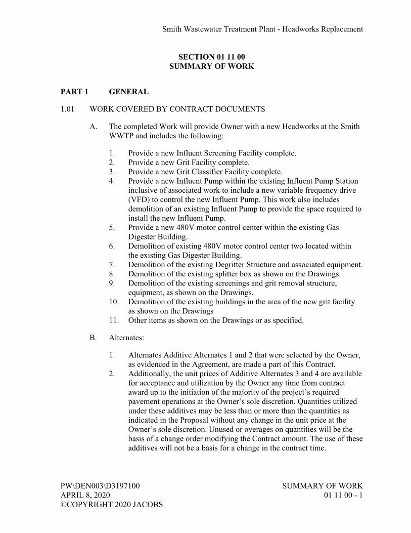
Smith Wastewater Treatment Plant - Headworks Replacement
PW\DEN003\D3197100 SUMMARY OF WORK APRIL 8, 2020 01 11 00 - 1 ©COPYRIGHT 2020 JACOBS
SECTION 01 11 00 SUMMARY OF WORK
PART 1 GENERAL
1.01 WORK COVERED BY CONTRACT DOCUMENTS
A. The completed Work will provide Owner with a new Headworks at the Smith WWTP and includes the following:
1. Provide a new Influent Screening Facility complete. 2. Provide a new Grit Facility complete. 3. Provide a new Grit Classifier Facility complete. 4. Provide a new Influent Pump within the existing Influent Pump Station
inclusive of associated work to include a new variable frequency drive (VFD) to control the new Influent Pump. This work also includes demolition of an existing Influent Pump to provide the space required to install the new Influent Pump.
5. Provide a new 480V motor control center within the existing Gas Digester Building.
6. Demolition of existing 480V motor control center two located within the existing Gas Digester Building.
7. Demolition of the existing Degritter Structure and associated equipment. 8. Demolition of the existing splitter box as shown on the Drawings. 9. Demolition of the existing screenings and grit removal structure,
equipment, as shown on the Drawings. 10. Demolition of the existing buildings in the area of the new grit facility
as shown on the Drawings 11. Other items as shown on the Drawings or as specified.
B. Alternates:
1. Alternates Additive Alternates 1 and 2 that were selected by the Owner, as evidenced in the Agreement, are made a part of this Contract.
2. Additionally, the unit prices of Additive Alternates 3 and 4 are available for acceptance and utilization by the Owner any time from contract award up to the initiation of the majority of the project’s required pavement operations at the Owner’s sole discretion. Quantities utilized under these additives may be less than or more than the quantities as indicated in the Proposal without any change in the unit price at the Owner’s sole discretion. Unused or overages on quantities will be the basis of a change order modifying the Contract amount. The use of these additives will not be a basis for a change in the contract time.

Smith Wastewater Treatment Plant - Headworks Replacement
SUMMARY OF WORK PW\DEN003\D3197100 01 11 00 - 2 APRIL 8, 2020 ©COPYRIGHT 2020 JACOBS
3. Alternates that were Bid were as described below: a. Additive Alternate No. 1: Provide a band screen upstream of the
Influent Screens Facility. b. Additive Alternate No. 2: Provide a flowmeter on the In-Plant
Return line as shown on the Drawings. c. Additive Alternate No 3: Provide additional asphalt overlay on a
unit price basis as bid. Overlay shall be of the areas as directed by the Owner and in accordance with the contract details for overlay.
d. Additive Alternate No 4: Provide asphalt replacement on a unit price basis as bid. Replacement shall be of the areas as directed by the Owner and in accordance with the specification requirements for asphalt patching.
1.02 PROVISIONS FOR MAINTENENACE OF THE EXISTING FACILITY IN OPERATION
A. An integral component of the work is the maintenance of the existing facility in operation throughout the prosecution of the work. Such work shall include sequencing of the work, bypass pumping, and temporary means as required herein and as necessary to allow the Facility to continuously accept and fully treat raw sewage. See Section 01 31 13, Project Coordination for additional requirements.
1.03 PROVISIONS FOR FUTURE WORK
A. Provisions for future construction are shown on the Drawings. The provisions for future Work includes all conduit required to power and control the components associated with the band screen and the flowmeter that are included under Additive Alternates 1 and 2.
PART 2 PRODUCTS (NOT USED)
PART 3 EXECUTION (NOT USED)
END OF SECTION
Smith Wastewater Treatment Plant - Headworks Replacement
PW\DEN003\D3197100 CONTRACT MODIFICATION MARCH 4, 2020 PROCEDURES ©COPYRIGHT 2020 JACOBS 01 26 00 - 1
SECTION 01 26 00 CONTRACT MODIFICATION PROCEDURES
PART 1 GENERAL
1.01 PROPOSAL REQUESTS
A. Owner may, in anticipation of ordering an addition, deletion, or revision to the Work, request Contractor to prepare a detailed proposal of cost and times to perform contemplated change.
B. Proposal request will include reference number for tracking purposes and detailed description of and reason for proposed change, and such additional information as appropriate and as may be required for Contractor to accurately estimate cost and time impact on Project.
C. Proposal request is for information only; Contractor is neither authorized to execute proposed change nor to stop Work in progress as result of such request.
D. Contractor’s written proposal shall be transmitted to Engineer promptly, but not later than 14 days after Contractor’s receipt of Owner’s written request. Proposal shall remain firm for a maximum period of 45 days after receipt by Engineer.
E. Owner’s request for proposal or Contractor’s failure to submit such proposal within the required time period will not justify a Claim for an adjustment in Contract Price or Contract Times (or Milestones).
1.02 CLAIMS
A. Include, at a minimum:
1. Specific references including (i) Drawing numbers, (ii) Specification section and article/paragraph number, and (iii) Submittal type, Submittal number, date reviewed, Engineer’s comment, as applicable, with appropriate attachments.
2. Stipulated facts and pertinent documents, including photographs and statements.
3. Interpretations relied upon. 4. Description of (i) nature and extent of Claim, (ii) who or what caused
the situation, (iii) impact to the Work and work of others, and (iv) discussion of claimant’s justification for requesting a change to price or times or both.
Smith Wastewater Treatment Plant - Headworks Replacement
CONTRACT MODIFICATION PW\DEN003\D3197100 PROCEDURES MARCH 4, 2020 01 26 00 - 2 ©COPYRIGHT 2020 JACOBS
5. Estimated adjustment in price claimant believes it is entitled to with full documentation and justification.
6. Requested Change in Contract Times: Include at least (i) Progress Schedule documentation showing logic diagram for request, (ii) documentation that float times available for Work have been used, and (iii) revised activity logic with durations including sub-network logic revisions, duration changes, and other interrelated schedule impacts, as appropriate.
7. Documentation as may be necessary as set forth below for Work Change Directive, and as Engineer may otherwise require.
1.03 WORK CHANGE DIRECTIVES
A. Procedures:
1. Engineer will: a. Initiate, including a description of the Work involved and any
attachments. b. Affix signature, demonstrating Engineer’s recommendation. c. Transmit five copies to Owner for authorization.
2. Owner will: a. Affix signature, demonstrating approval of the changes involved. b. Return four copies to Engineer, who will retain one copy, send
one copy to the Resident Project Representative or other field representative, and forward two copies to Contractor.
3. Upon completion of Work covered by the Work Change Directive or when final Contract Times and Contract Price are determined, Contractor shall submit documentation for inclusion in a Change Order.
4. Contractor’s documentation shall include but not be limited to: a. Appropriately detailed records of Work performed to enable
determination of value of the Work. b. Full information required to substantiate resulting change in
Contract Times and Contract Price for Work. On request of Engineer, provide additional data necessary to support documentation.
c. Support data for Work performed on a unit price or Cost of the Work basis with additional information such as: 1) Dates Work was performed, and by whom. 2) Time records, wage rates paid, and equipment rental rates. 3) Invoices and receipts for materials, equipment, and
subcontracts, all similarly documented.
B. Effective Date of Work Change Directive: Date of signature by Owner, unless otherwise indicated thereon.
Smith Wastewater Treatment Plant - Headworks Replacement
PW\DEN003\D3197100 CONTRACT MODIFICATION MARCH 4, 2020 PROCEDURES ©COPYRIGHT 2020 JACOBS 01 26 00 - 3
1.04 CHANGE ORDERS
A. Procedure:
1. Engineer will prepare six copies of proposed Change Order and transmit such with Engineer’s written recommendation and request to Contractor for signature.
2. Contractor shall, upon receipt, either: (i) promptly sign copies, retaining one for its file, and return remaining five copies to Engineer for Owner’s signature, or (ii) return unsigned five copies with written justification for not executing Change Order.
3. Engineer will, upon receipt of Contractor signed copies, promptly forward Engineer’s written recommendation and partially executed five copies for Owner’s signature, or if Contractor fails to execute the Change Order, Engineer will promptly so notify Owner and transmit Contractor’s justification to Owner.
4. Upon receipt of Contractor-executed Change Order, Owner will promptly either: a. Execute Change Order, retaining one copy for its file and
returning four copies to Engineer; or b. Return to Engineer unsigned copies with written justification for
not executing Change Order. 5. Upon receipt of Owner-executed Change Order, Engineer will transmit
two copies to Contractor, one copy to Resident Project Representative or other field representative, and retain one copy, or if Owner fails to execute the Change Order, Engineer will promptly so notify Contractor and transmit Owner’s justification to Contractor.
6. Upon receipt of Owner-executed Change Order, Contractor shall: a. Perform Work covered by Change Order. b. Revise Schedule of Values to adjust Contract Price and submit
with next Application for Payment. c. Revise Progress Schedule to reflect changes in Contract Times, if
any, and to adjust times for other items of Work affected by change.
d. Enter changes in Project record documents after completion of change related Work.
B. In signing a Change Order, Owner and Contractor acknowledge and agree that:
1. Stipulated compensation (Contract Price or Contract Times, or both) set forth includes payment for (i) the Cost of the Work covered by the Change Order, (ii) Contractor’s fee for overhead and profit, (iii) interruption of Progress Schedule, (iv) delay and impact, including

Smith Wastewater Treatment Plant - Headworks Replacement
CONTRACT MODIFICATION PW\DEN003\D3197100 PROCEDURES MARCH 4, 2020 01 26 00 - 4 ©COPYRIGHT 2020 JACOBS
cumulative impact, on other Work under the Contract Documents, and (v) extended overheads.
2. Change Order constitutes full mutual accord and satisfaction for the change to the Work.
3. Unless otherwise stated in the Change Order, all requirements of the original Contract Documents apply to the Work covered by the Change Order.
1.05 COST OF THE WORK
A. In determining the supplemental costs allowed, the following will apply.
B. Rental of construction equipment and machinery and the parts thereof having a replacement value in excess of $1,000, whether owned by Contractor or rented or leased from others, shall meet the following requirements:
1. Full rental costs for leased equipment shall not exceed rates listed in the Rental Rate Blue Book published by Equipment Watch, as adjusted to the regional area of the Project. Owned equipment costs shall not exceed the single shift rates established in the Cost Reference Guide (CRG) published by Equipment Watch. The most recent published edition in effect at commencement of actual equipment use shall be used.
2. Rates shall apply to equipment in good working condition. Equipment not in good condition, or larger than required, may be rejected by Engineer or accepted at reduced rates.
3. Leased Equipment: For equipment leased or rented in arm’s length transactions from outside vendors, maximum rates shall be determined by the following actual usage/Payment Category: a. Less than 8 hours: Hourly rate. b. 8 or more hours but less than 7 days: Daily rate. c. 7 or more days but less than 30 days: Weekly rate. d. 30 days or more: Monthly rate.
4. Arm’s length rental and lease transactions are those in which the firm involved in the rental or lease of equipment is not associated with, owned by, have common management, directorship, facilities and/or stockholders with the firm renting the equipment.
5. Financial arrangements associated with rental and lease transactions that provide Contractor remuneration or discounts not visible to the Owner must be disclosed and integrated with charged rates.
6. Leased Equipment in Use: Actual equipment use time documented by Engineer shall be the basis that equipment was on and utilized at the Project Site. In addition to the leasing rate above, equipment operational costs shall be paid at the estimated hourly operating cost rate set forth in the Rental Rate Blue Book if not already included in the lease rate. Hours
Smith Wastewater Treatment Plant - Headworks Replacement
PW\DEN003\D3197100 CONTRACT MODIFICATION MARCH 4, 2020 PROCEDURES ©COPYRIGHT 2020 JACOBS 01 26 00 - 5
of operation shall be based upon actual equipment usage to the nearest quarter hour, as recorded by Engineer.
7. Leased Equipment, When Idle (Standby): Idle or standby equipment is equipment onsite or in transit to and from the Work Site and necessary to perform the Work under the modification, but not in actual use. Idle equipment time, as documented by Engineer, shall be paid at the leasing rate determined above, excluding operational costs.
8. Owned and Other Equipment in Use: Equipment rates for owned equipment or equipment provided in other than arm’s length transaction shall not exceed the single shift total hourly costs rate developed in accordance with the CRG and as modified herein for multiple shifts. This total hourly rate will be paid for each hour the equipment actually performs work. Hours of operation shall be based upon actual equipment usage as recorded by Engineer. This rate shall represent payment in full for Contractor’s direct costs.
9. Owned and Other Equipment, When Idle (Standby): Equipment necessary to be onsite to perform the Work on single shift operations, but not utilized, shall be paid for at the ownership hourly expense rate developed in accordance with the CRG, provided its presence and necessity onsite has been documented by Engineer. Payment for idle time of portions of a normal workday, in conjunction with original contract Work, will not be allowed. In no event shall idle time claimed in a day for a particular piece of equipment exceed the normal Work or shift schedule established for the Project. It is agreed that this rate shall represent payment in full for Contractor’s direct costs. When Engineer determines that the equipment is not needed to continuously remain at the Work Site, payment will be limited to actual hours in use.
10. Owned and Other Equipment, Multiple Shifts: For multiple shift operations, the CRG single shift total hourly costs rate shall apply to the operating equipment during the first shift. For subsequent shifts, up to two in a 24-hour day, operating rate shall be the sum of the total hourly CRG operating cost and 60 percent of the CRG ownership and overhaul expense. Payment for idle or standby time for second and third shifts shall be 20 percent of the CRG ownership and overhaul expense.
11. When necessary to obtain owned equipment from sources beyond the Project limits, the actual cost to transfer equipment to the Site and return it to its original location will be allowed as an additional item of expense. Move-in and move-out allowances will not be made for equipment brought to the Project if the equipment is also used on original Contract or related Work.
12. If the move-out destination is not to the original location, payment for move-out will not exceed payment for move-in.
Smith Wastewater Treatment Plant - Headworks Replacement
CONTRACT MODIFICATION PW\DEN003\D3197100 PROCEDURES MARCH 4, 2020 01 26 00 - 6 ©COPYRIGHT 2020 JACOBS
13. If move is made by common carrier, the allowance will be the amount paid for the freight. If equipment is hauled with Contractor’s own forces, rental will be allowed for the hauling unit plus the hauling unit operator’s wage. If equipment is transferred under its own power, the rental will be 75 percent of the appropriate total hourly costs for the equipment, without attachments, plus the equipment operator’s wage.
14. Charges for time utilized in servicing equipment to ready it for use prior to moving and similar charges will not be allowed.
15. When a breakdown occurs on any piece of owned equipment, payment shall cease for that equipment and any other owned equipment idled by the breakdown.
16. If any part of the Work is shut down by Owner, standby time will be paid during nonoperating hours if diversion of equipment to other Work is not practicable. Engineer reserves the right to cease standby time payment when an extended shutdown is anticipated.
17. If a rate has not been established in the CRG for owned equipment, Contractor may: a. If approved by Engineer, use the rate of the most similar model
found, considering such characteristics as manufacturer, capacity, horsepower, age, and fuel type, or
b. Request Equipment Watch to furnish a written response for a rate on the equipment, which shall be presented to Engineer for approval; or
c. Request Engineer to establish a rate.
1.06 FIELD ORDER
A. Engineer will issue Field Orders, with three copies to Contractor.
B. Effective date of the Field Order shall be the date of signature by Engineer, unless otherwise indicated thereon.
C. Contractor shall acknowledge receipt by signing and returning one copy to Engineer.
D. Field Orders will be incorporated into subsequent Change Orders, as a no-cost change to the Contract.
PART 2 PRODUCTS (NOT USED)
PART 3 EXECUTION (NOT USED)
END OF SECTION
Smith Wastewater Treatment Plant - Headworks Replacement
PW\DEN003\D3197100 PAYMENT PROCEDURES MARCH 6, 2020 01 29 00 - 1 ©COPYRIGHT 2020 JACOBS
SECTION 01 29 00 PAYMENT PROCEDURES
PART 1 GENERAL
1.01 SUBMITTALS
A. Informational Submittals:
1. Schedule of Values: Submit on Contractor’s standard form. 2. Schedule of Estimated Progress Payments:
a. Submit with initially acceptable Schedule of Values. b. Submit adjustments thereto with Application for Payment.
3. Application for Payment. 4. Final Application for Payment.
1.02 SCHEDULE OF VALUES
A. Prepare a separate Schedule of Values for each schedule of the Work under the Agreement.
B. Upon request of Engineer, provide documentation to support the accuracy of the Schedule of Values.
C. Unit Price Work: Reflect unit price quantity and price breakdown from conformed Bid Form.
D. Lump Sum Work:
1. List bonds and insurance premiums, mobilization, demobilization, preliminary and detailed progress schedule preparation, equipment testing, facility startup, and contract closeout separately. a. Mobilization includes, at minimum, items identified in
Section 01 50 00, Temporary Facilities and Controls. b. Include item(s) for monthly progress schedule update and
maintenance of Engineer’s trailer. 2. Break down by Division 02 through 49 with appropriate subdivision of
each specification for each Project facility.
E. An unbalanced or front-end loaded schedule will not be acceptable.
F. Summation of the complete Schedule of Values representing all the Work shall equal the Contract Price.
G. Submit Schedule of Values on a CD in a spreadsheet format compatible with latest version of MSExcel.
Smith Wastewater Treatment Plant - Headworks Replacement
PAYMENT PROCEDURES PW\DEN003\D3197100 01 29 00 - 2 MARCH 6, 2020 ©COPYRIGHT 2020 JACOBS
1.03 SCHEDULE OF ESTIMATED PROGRESS PAYMENTS
A. Show estimated payment requests throughout Contract Times aggregating initial Contract Price.
B. Base estimated progress payments on initially acceptable progress schedule. Adjust to reflect subsequent adjustments in progress schedule and Contract Price as reflected by modifications to the Contract Documents.
1.04 APPLICATION FOR PAYMENT
A. Transmittal Summary Form: Attach one Summary Form with each detailed Application for Payment for each schedule and include Request for Payment of Materials and Equipment on Hand as applicable. Execute certification by authorized officer of Contractor.
B. Use detailed Application for Payment Form suitable to Owner.
C. Provide separate form for each schedule as applicable.
D. Include accepted Schedule of Values for each schedule or portion of lump sum Work.
E. Include separate line item for each Change Order and Work Change Directive executed prior to date of submission. Provide further breakdown of such as requested by Engineer.
F. Preparation:
1. Round values to nearest dollar. 2. Submit Application for Payment, including a Transmittal Summary
Form and detailed Application for Payment Form(s) for each schedule as applicable, a listing of materials on hand for each schedule as applicable, and such supporting data as may be requested by Engineer.
1.05 PAYMENT
A. Payment for all Lump Sum Work shown or specified in Contract Documents is included in the Contract Price. Payment will be based on a percentage complete basis for each line item of the accepted Schedule of Values.
B. Payment for Lump Sum Work covers all Work specified or shown within the limits or Specification sections.

Smith Wastewater Treatment Plant - Headworks Replacement
PW\DEN003\D3197100 PAYMENT PROCEDURES MARCH 6, 2020 01 29 00 - 3 ©COPYRIGHT 2020 JACOBS
1.06 NONPAYMENT FOR REJECTED OR UNUSED PRODUCTS
C. Payment will not be made for following:
1. Loading, hauling, and disposing of rejected material. 2. Quantities of material wasted or disposed of in manner not called for
under Contract Documents. 3. Rejected loads of material, including material rejected after it has been
placed by reason of failure of Contractor to conform to provisions of Contract Documents.
4. Material not unloaded from transporting vehicle. 5. Defective Work not accepted by Owner. 6. Material remaining on hand after completion of Work.
1.06 PARTIAL PAYMENT FOR STORED MATERIALS AND EQUIPMENT
A. Partial Payment: No partial payments will be made for materials and equipment delivered or stored unless Shop Drawings and preliminary operation and maintenance data is acceptable to Engineer.
B. Final Payment: Will be made only for products incorporated in Work; remaining products, for which partial payments have been made, shall revert to Contractor unless otherwise agreed, and partial payments made for those items will be deducted from final payment.
PART 2 PRODUCTS (NOT USED)
PART 3 EXECUTION (NOT USED)
END OF SECTION


Smith Wastewater Treatment Plant - Headworks Replacement
PW\DEN003\D3197100 PROJECT COORDINATION MARCH 4, 2020 01 31 13 - 1 ©COPYRIGHT 2020 JACOBS
SECTION 01 31 13 PROJECT COORDINATION
PART 1 GENERAL
1.01 SUBMITTALS
A. Informational:
1. Statement of Qualification (SOQ) for land surveyor or civil engineer. 2. Photographs:
a. Digital Images: Submit two copies of DVD disc containing images within 5 days of being taken. Each image is to have a minimum file size of 1.4 Mb (1,400 Kb) so viewed resolution is high quality. The production of larger file sizes with higher resolution is encouraged.
3. Video Recordings: Submit two copies within 5 days of being taken. 4. Construction Sequencing and Bypass Pumping. See Section 01 57 28,
Temporary Flow Control.
1.02 RELATED WORK AT SITE
A. General:
1. Other work that is either directly or indirectly related to scheduled performance of the Work under these Contract Documents, listed henceforth, is anticipated to be performed at Site by others.
2. Coordinate the Work of these Contract Documents with work of others as specified in General Conditions.
3. Include sequencing constraints specified herein as a part of Progress Schedule.
1.03 UTILITY NOTIFICATION AND COORDINATION
A. Coordinate the Work with various utilities within Project limits. Notify applicable utilities prior to commencing Work, if damage occurs, or if conflicts or emergencies arise during the Work.
1.04 PROJECT MILESTONES
A. General: Include the Milestones specified herein as a part of the Progress Schedule required under Section 01 32 00, Construction Progress Documentation.

Smith Wastewater Treatment Plant - Headworks Replacement
PROJECT COORDINATION PW\DEN003\D3197100 01 31 13 - 2 MARCH 4, 2020 ©COPYRIGHT 2020 JACOBS
1.05 WORK SEQUENCING/CONSTRAINTS
A. Include the following work sequences in the Progress Schedule:
1. Continuous unobstructed operation of the Smith WWTP is required. This shall require the addition of temporary bypass pumping as specified in Section 01 57 28, Temporary Flow Control.
2. Provide temporary plugs or caps on interconnecting piping as needed to maintain the indicated existing facilities in service and to preclude the entry of wastewater into new facilities prior to their acceptance.
1.06 FACILITY OPERATIONS
A. Continuous operation of Owner’s facilities is of critical importance. Schedule and conduct activities to enable existing facilities to operate continuously, unless otherwise specified.
B. Perform Work continuously during critical connections and changeovers, and as required to prevent interruption of Owner’s operations.
C. When necessary, plan, design, and provide various temporary services, utilities, connections, temporary piping and heating, access, and similar items to maintain continuous operations of Owner’s facility.
D. Do not close lines, open or close valves, or take other action which would affect the operation of existing systems, except as specifically required by the Contract Documents and after authorization by Owner and Engineer. Such authorization will be considered within 48 hours after receipt of Contractor’s written request.
E. Process or Facility Shutdown:
1. The existing and/or proposed facilities may only be shut down after approval, installation and activation of bypass pumping facilities such that normal flow is maintained into the Smith WWTP.
2. Provide 48 hours advance written request for approval of need to shut down a process or facility to Owner and Engineer.
3. Power outages will be considered upon 48 hours written request to Owner and Engineer. Describe the reason, anticipated length of time, and areas affected by the outage. Provide temporary provisions for continuous power supply to critical facility components.
Smith Wastewater Treatment Plant - Headworks Replacement
PW\DEN003\D3197100 PROJECT COORDINATION MARCH 4, 2020 01 31 13 - 3 ©COPYRIGHT 2020 JACOBS
F. Install and maintain bypass facilities and temporary connections required to keep Owner’s operations on line. Sequences other than those specified will be considered upon written request to Owner and Engineer, provided they afford equivalent continuity of operations.
G. Do not proceed with Work affecting a facility’s operation without obtaining Owner’s and Engineer’s advance approval of the need for and duration of such Work.
H. Relocation of Existing Facilities:
1. During construction, it is expected that minor relocations of Work will be necessary.
2. Provide complete relocation of existing structures and Underground Facilities, including piping, utilities, equipment, structures, electrical conduit wiring, electrical duct bank, and other necessary items.
3. Use only new materials for relocated facility. Match materials of existing facility, unless otherwise shown or specified.
4. Perform relocations to minimize downtime of existing facilities. 5. Install new portions of existing facilities in their relocated position prior
to removal of existing facilities, unless otherwise accepted by Engineer.
1.07 ADJACENT FACILITIES AND PROPERTIES
A. Examination:
1. After Effective Date of the Agreement and before Work at Site is started, Contractor, Engineer, and affected property owners and utility owners shall make a thorough examination of pre-existing conditions including existing buildings, structures, and other improvements in vicinity of Work, as applicable, which could be damaged by construction operations.
2. Periodic reexamination shall be jointly performed to include, but not limited to, cracks in structures, settlement, leakage, and similar conditions.
B. Documentation:
1. Record and submit documentation of observations made on examination inspections in accordance with Article Construction Photographs and Article Audio-Video Recordings.
2. Such documentation shall be used as indisputable evidence in ascertaining whether and to what extent damage occurred as a result of Contractor’s operations, and is for the protection of adjacent property owners, Contractor, and Owner.
Smith Wastewater Treatment Plant - Headworks Replacement
PROJECT COORDINATION PW\DEN003\D3197100 01 31 13 - 4 MARCH 4, 2020 ©COPYRIGHT 2020 JACOBS
1.08 CONSTRUCTION PHOTOGRAPHS
A. General:
1. Photographically document all phases of the Project including preconstruction, construction progress, and post-construction.
2. Engineer shall have right to select subject matter and vantage point from which photographs are to be taken.
3. Digital Images: No post-session electronic editing of images is allowed. Stored image shall be actual image as captured without cropping or other edits.
B. Preconstruction and Post-Construction:
1. After Effective Date of the Agreement and before Work at Site is started, and again upon issuance of Substantial Completion, take a minimum of 48 photographs of Site and property adjacent to perimeter of Site.
2. Particular emphasis shall be directed to structures both inside and outside the Site.
3. Format: Digital, minimum resolution of 1680 by 2240 pixels and 24-bit, millions of color.
C. Construction Progress Photos:
1. Photographically demonstrate progress of construction, showing every aspect of Site and adjacent properties as well as interior and exterior of new or impacted structures.
2. Weekly: Take 48 photographs using digital, minimum resolution of 1680 by 2240 pixels and 24-bit, millions of color.
3. Monthly: Take 50 photographs using digital, minimum resolution of 1680 by 2240 pixels and 24-bit, millions of color.
D. Documentation:
1. Digital Images: a. Electronic image shall have date taken embedded into image. b. Archive using a commercially available photo management
system that provides listing of photographs including date, keyword description, and direction of photograph.
c. Label each disk with Project and Owner’s name, week, month, and year images were produced.
Smith Wastewater Treatment Plant - Headworks Replacement
PW\DEN003\D3197100 PROJECT COORDINATION MARCH 4, 2020 01 31 13 - 5 ©COPYRIGHT 2020 JACOBS
1.09 AUDIO-VIDEO RECORDINGS
A. Prior to beginning the Work on Site or of a particular area of the Work, and again within 10 days following date of Substantial Completion, videograph Site and property adjacent to Site.
B. In the case of preconstruction recording, no work shall begin in the area prior to Engineer’s review and approval of content and quality of video for that area.
C. Particular emphasis shall be directed to physical condition of existing vegetation, structures, and pavements within and areas adjacent to and within the right-of-way or easement, and on Contractor storage and staging areas.
D. Engineer shall have right to select subject matter and vantage point from which videos are to be taken.
E. Video Format and Quality:
1. DVD format, with sound. 2. Video:
a. Produce bright, sharp, and clear images with accurate colors, free of distortion and other forms of picture imperfections.
b. Electronically, and accurately display the month, day, year, and time of day of the recording.
3. Audio: a. Audio documentation shall be done clearly, precisely, and at a
moderate pace. b. Indicate date, project name, and a brief description of the location
of recording, including: 1) Facility name. 2) Street names or easements. 3) Addresses of private property. 4) Direction of coverage, including engineering stationing, if
applicable.
F. Documentation:
1. DVD Label: a. DVD number (numbered sequentially, beginning with 001). b. Project name. c. Date and time of coverage.
2. Project Video Log: Maintain an ongoing log that incorporates above noted label information for DVDs on Project.
Smith Wastewater Treatment Plant - Headworks Replacement
PROJECT COORDINATION PW\DEN003\D3197100 01 31 13 - 6 MARCH 4, 2020 ©COPYRIGHT 2020 JACOBS
1.10 REFERENCE POINTS AND SURVEYS
A. Location and elevation of bench marks are shown on Drawings.
B. Contractor’s Responsibilities:
1. Provide additional survey and layout required to layout the Work. 2. Check and establish exact location of existing facilities prior to
construction of new facilities and any connections thereto. 3. In event of discrepancy in data provided by Owner, request clarification
before proceeding with Work. 4. Retain professional land surveyor or civil engineer registered in state of
Alabama who shall perform or supervise engineering surveying necessary for additional construction staking and layout.
5. Maintain complete accurate log of survey work as it progresses as a Record Document.
6. On request of Engineer, submit documentation. 7. Provide competent employee(s), tools, stakes, and other equipment and
materials as Engineer may require to check layout, survey, and measurement work performed by others.
PART 2 PRODUCTS (NOT USED)
PART 3 EXECUTION
3.01 CUTTING, FITTING, AND PATCHING
A. Cut, fit, adjust, or patch Work and work of others, including excavation and backfill as required, to make Work complete.
B. Obtain prior written authorization of Engineer and Owner before commencing Work to cut or otherwise alter:
1. Structural or reinforcing steel, structural column or beam, elevated slab, trusses, or other structural member.
2. Weather-resistant or moisture-resistant elements. 3. Efficiency, maintenance, or safety of element. 4. Work of others.
C. Refinish surfaces to provide an even finish.
1. Refinish continuous surfaces to nearest intersection. 2. Refinish entire assemblies. 3. Finish restored surfaces to such planes, shapes, and textures that no
transition between existing work and the Work is evident in finished surfaces.

Smith Wastewater Treatment Plant - Headworks Replacement
PW\DEN003\D3197100 PROJECT COORDINATION MARCH 4, 2020 01 31 13 - 7 ©COPYRIGHT 2020 JACOBS
D. Restore existing work, Underground Facilities, and surfaces that are to remain in completed Work including concrete-embedded piping, conduit, and other utilities as specified and as shown on Drawings.
E. Make restorations with new materials and appropriate methods as specified for new Work of similar nature; if not specified, use recommended practice of manufacturer or appropriate trade association.
F. Fit Work airtight to pipes, sleeves, ducts, conduit, and other penetrations through surfaces and fill voids.
G. Remove specimens of installed Work for testing when requested by Engineer.
END OF SECTION


Smith Wastewater Treatment Plant - Headworks Replacement
PW\DEN003\D3197100 PROJECT MEETINGS MARCH 6, 2020 01 31 19 - 1 ©COPYRIGHT 2020 JACOBS
SECTION 01 31 19 PROJECT MEETINGS
PART 1 GENERAL
1.01 GENERAL
A. Engineer will schedule physical arrangements for meetings throughout progress of the Work, prepare meeting agenda with regular participant input and distribute with written notice of each meeting, preside at meetings, record minutes to include significant proceedings and decisions, and reproduce and distribute copies of minutes within 5 days after each meeting to participants and parties affected by meeting decisions.
1.02 PRECONSTRUCTION CONFERENCE
A. Contractor shall be prepared to discuss the following subjects, as a minimum:
1. Required schedules. 2. Status of Bonds and insurance. 3. Sequencing of critical path work items. 4. Progress payment procedures. 5. Project changes and clarification procedures. 6. Use of Site, access, office and storage areas, security and temporary
facilities. 7. Major product delivery and priorities. 8. Contractor’s safety plan and representative.
B. Attendees will include:
1. Owner’s representatives. 2. Contractor’s office representative. 3. Contractor’s resident superintendent. 4. Contractor’s quality control representative. 5. Subcontractors’ representatives whom Contractor may desire or
Engineer may request to attend. 6. Engineer’s representatives. 7. Others as appropriate.
1.03 PRELIMINARY SCHEDULES REVIEW MEETING
A. As set forth in General Conditions and Section 01 32 00, Construction Progress Documentation.

Smith Wastewater Treatment Plant - Headworks Replacement
PROJECT MEETINGS PW\DEN003\D3197100 01 31 19 - 2 MARCH 6, 2020 ©COPYRIGHT 2020 JACOBS
1.04 PROGRESS MEETINGS
A. Engineer will schedule regular progress meetings at Site, conducted monthly to review the Work progress, Progress Schedule, Schedule of Submittals, Application for Payment, contract modifications, and other matters needing discussion and resolution.
B. Attendees will include:
1. Owner’s representative(s), as appropriate. 2. Contractor, Subcontractors, and Suppliers, as appropriate. 3. Engineer’s representative(s). 4. Others as appropriate.
1.05 QUALITY CONTROL MEETINGS
A. In accordance with Section 01 45 16.13, Contractor Quality Control.
B. Scheduled by Engineer on regular basis and as necessary to review test and inspection reports, and other matters relating to quality control of the Work and work of other Contractors.
C. Attendees will include:
1. Contractor. 2. Contractor’s designated quality control representative. 3. Subcontractors and Suppliers, as necessary. 4. Engineer’s representatives.
1.06 PROCESS INSTRUMENTATION AND CONTROL SYSTEMS (PICS) COORDINATION MEETINGS
A. Engineer will schedule up to three meetings at Site, conducted to review specific requirements of PICS work.
B. Attendees will include:
1. Contractor. 2. Owner. 3. PICS Subcontractor/Installer. 4. Engineer’s representatives.
1.07 PREINSTALLATION MEETINGS
A. When required in individual Specification sections, convene at Site prior to commencing the Work of that section.

Smith Wastewater Treatment Plant - Headworks Replacement
PW\DEN003\D3197100 PROJECT MEETINGS MARCH 6, 2020 01 31 19 - 3 ©COPYRIGHT 2020 JACOBS
B. Require attendance of entities directly affecting, or affected by, the Work of that section.
C. Notify Engineer 4 days in advance of meeting date.
D. Provide suggested agenda to Engineer to include reviewing conditions of installation, preparation and installation or application procedures, and coordination with related Work and work of others.
1.08 FACILITY STARTUP MEETINGS
A. Schedule and attend a minimum of three facility startup meetings. The first of such meetings shall be held prior to submitting Facility Startup Plan, as specified in Section 01 91 14, Equipment Testing and Facility Startup, and shall include preliminary discussions regarding such plan.
B. Agenda items shall include, but not be limited to, content of Facility Startup Plan, coordination needed between various parties in attendance, and potential problems associated with startup.
C. Attendees will include:
1. Contractor. 2. Contractor’s designated quality control representative. 3. Subcontractors and equipment manufacturer’s representatives whom
Contractor deems to be directly involved in facility startup. 4. Engineer’s representatives. 5. Owner’s operations personnel. 6. Others as required by Contract Documents or as deemed necessary by
Contractor.
1.09 OTHER MEETINGS
A. In accordance with Contract Documents and as may be required by Owner and Engineer.
PART 2 PRODUCTS (NOT USED)
PART 3 EXECUTION (NOT USED)
END OF SECTION


Smith Wastewater Treatment Plant - Headworks Replacement
PW\DEN003\D3197100 CONSTRUCTION PROGRESS DOCUMENTATION MARCH 6, 2020 01 32 00 - 1 ©COPYRIGHT 2020 JACOBS
SECTION 01 32 00 CONSTRUCTION PROGRESS DOCUMENTATION
PART 1 GENERAL
1.01 SUBMITTALS
A. Informational Submittals:
1. Preliminary Progress Schedule: Submit at least 7 days prior to preconstruction conference.
2. Detailed Progress Schedule: a. Submit initial Detailed Progress Schedule in accordance with
General Conditions. b. Submit an Updated Progress Schedule at each update, in
accordance with Article Detailed Progress Schedule. 3. Submit with Each Progress Schedule Submission:
a. Contractor’s certification that Progress Schedule submission is actual schedule being used for execution of the Work.
b. Electronic file compatible with latest version of Microsoft Project, unless otherwise approved by Engineer.
c. Progress Schedule: Four legible copies. d. Narrative Progress Report: Same number of copies as specified
for Progress Schedule.
1.02 PRELIMINARY PROGRESS SCHEDULE
A. In addition to basic requirements outlined in General Conditions, show a detailed schedule, beginning with Notice to Proceed, for minimum duration of 90 days, and a summary of balance of Project through Final Completion.
B. Show activities including, but not limited to the following:
1. Notice to Proceed. 2. Permits. 3. Submittals, with review time. Contractor may use Schedule of
Submittals specified in Section 01 33 00, Submittal Procedures. 4. Early procurement activities for long lead equipment and materials. 5. Initial Site work. 6. Earthwork. 7. Specified Work sequences and construction constraints. 8. Contract Milestone and Completion Dates. 9. Owner-furnished products delivery dates or ranges of dates. 10. Major structural, mechanical, equipment, electrical, architectural, and
instrumentation and control Work.

Smith Wastewater Treatment Plant - Headworks Replacement
CONSTRUCTION PROGRESS DOCUMENTATION PW\DEN003\D3197100 01 32 00 - 2 MARCH 6, 2020 ©COPYRIGHT 2020 JACOBS
11. System startup summary. 12. Project close-out summary. 13. Demobilization summary.
C. Update Preliminary Progress Schedule monthly as part of progress payment process. Failure to do so may result in the Owner withholding all or part of the monthly progress payment until the Preliminary Progress Schedule is updated in a manner acceptable to Engineer.
D. Format: In accordance with Article Progress Schedule—Bar Chart.
1.03 DETAILED PROGRESS SCHEDULE
A. In addition to requirements of General Conditions, submit Detailed Progress Schedule beginning with Notice to Proceed and continuing through Final Completion.
B. Show the duration and sequences of activities required for complete performance of the Work reflecting means and methods chosen by Contractor.
C. When accepted by Engineer, Detailed Progress Schedule will replace Preliminary Progress Schedule and become Baseline Schedule. Subsequent revisions will be considered as Updated Progress Schedules.
D. Format: In accordance with Article Progress Schedule—Bar Chart.
E. Update monthly to reflect actual progress and occurrences to date, including weather delays.
1.04 PROGRESS SCHEDULE—BAR CHART
A. General: Comprehensive bar chart schedule, generally as outlined in Associated General Contractors of America (AGC) 580, “Construction Project Planning and Scheduling Guidelines.” If a conflict occurs between the AGC publication and this specification, this specification shall govern.
B. Format:
1. Unless otherwise approved, white paper, 11-inch by 17-inch sheet size. 2. Title Block: Show name of Project and Owner, date submitted, revision
or update number, and name of scheduler. 3. Identify horizontally, across the top of the schedule, the time frame by
year, month, and day. 4. Identify each activity with a unique number and a brief description of
the Work associated with that activity. 5. Legend: Describe standard and special symbols used.

Smith Wastewater Treatment Plant - Headworks Replacement
PW\DEN003\D3197100 CONSTRUCTION PROGRESS DOCUMENTATION MARCH 6, 2020 01 32 00 - 3 ©COPYRIGHT 2020 JACOBS
C. Contents: Identify, in chronological order, those activities reasonably required to complete the Work, including as applicable, but not limited to:
1. Obtaining permits, submittals for early product procurement, and long lead time items.
2. Mobilization and other preliminary activities. 3. Initial Site work. 4. Specified Work sequences, constraints, and Milestones, including
Substantial Completion date(s). 5. Subcontract Work. 6. Major equipment design, fabrication, factory testing, and delivery dates. 7. Delivery dates for Owner-furnished products, as specified in
Section 01 11 00, Summary of Work. 8. Sitework. 9. Concrete Work. 10. Structural steel Work. 11. Architectural features Work. 12. Conveying systems Work. 13. Equipment Work. 14. Mechanical Work. 15. Electrical Work. 16. Instrumentation and control Work. 17. Interfaces with Owner-furnished equipment. 18. Other important Work for each major facility. 19. Equipment and system startup and test activities. 20. Project closeout and cleanup. 21. Demobilization.
1.05 PROGRESS OF THE WORK
A. Updated Progress Schedule shall reflect:
1. Progress of Work to within 5 working days prior to submission. 2. Approved changes in Work scope and activities modified since
submission. 3. Delays in Submittals or resubmittals, deliveries, or Work. 4. Adjusted or modified sequences of Work. 5. Other identifiable changes. 6. Revised projections of progress and completion. 7. Report of changed logic.
B. Produce detailed sub-schedules during Project, upon request of Owner or Engineer, to further define critical portions of the Work such as facility shutdowns.

Smith Wastewater Treatment Plant - Headworks Replacement
CONSTRUCTION PROGRESS DOCUMENTATION PW\DEN003\D3197100 01 32 00 - 4 MARCH 6, 2020 ©COPYRIGHT 2020 JACOBS
C. If an activity is not completed by its latest scheduled completion date and this failure is anticipated to extend Contract Times (or Milestones), submit, within 7 days of such failure, a written statement as to how nonperformance will be corrected to return Project to acceptable current Progress Schedule. Actions by Contractor to complete the Work within Contract Times (or Milestones) will not be justification for adjustment to Contract Price or Contract Times.
D. Owner may order Contractor to increase plant, equipment, labor force, or working hours if Contractor fails to:
1. Complete a Milestone activity by its completion date. 2. Satisfactorily execute Work as necessary to prevent delay to overall
completion of Project, at no additional cost to Owner.
1.06 SCHEDULE ACCEPTANCE
A. Engineer’s acceptance will demonstrate agreement that:
1. Proposed schedule is accepted with respect to: a. Contract Times, including Final Completion and all intermediate
Milestones, are within the specified times. b. Specified Work sequences and constraints are shown as specified. c. Specified Owner-furnished Equipment or Material arrival dates,
or range of dates, are included. d. Access restrictions are accurately reflected. e. Startup and testing times are as specified. f. Submittal review times are as specified. g. Startup testing duration is as specified and timing is acceptable.
2. In all other respects, Engineer’s acceptance of Contractor’s schedule indicates that, in Engineer’s judgment, schedule represents reasonable plan for constructing Project in accordance with the Contract Documents. Engineer’s review will not make any change in Contract requirements. Lack of comment on any aspect of schedule that is not in accordance with the Contract Documents will not thereby indicate acceptance of that change, unless Contractor has explicitly called the nonconformance to Engineer’s attention in submittal. Schedule remains Contractor’s responsibility and Contractor retains responsibility for performing all activities, for activity durations, and for activity sequences required to construct Project in accordance with the Contract Documents.
B. Unacceptable Preliminary Progress Schedule:
1. Make requested corrections; resubmit within 10 days. 2. Until acceptable to Engineer as Baseline Progress Schedule, continue
review and revision process, including updating schedule on a monthly basis to reflect actual progress and occurrences to date.

Smith Wastewater Treatment Plant - Headworks Replacement
PW\DEN003\D3197100 CONSTRUCTION PROGRESS DOCUMENTATION MARCH 6, 2020 01 32 00 - 5 ©COPYRIGHT 2020 JACOBS
C. Unacceptable Detailed Progress Schedule:
1. Make requested corrections; resubmit within 10 days. 2. Until acceptable to Engineer as Baseline Progress Schedule, continue
review and revision process.
1.07 ADJUSTMENT OF CONTRACT TIMES
A. Reference General Conditions and Section 01 26 00, Contract Modification Procedures.
B. Evaluation and reconciliation of Adjustments of Contract Times shall be based on the Updated Progress Schedule at the time of proposed adjustment or claimed delay.
C. Schedule Contingency:
1. Contingency, when used in the context of the Progress Schedule, is time between Contractor’s proposed Completion Time and Contract Completion Time.
2. Contingency included in Progress Schedule is a Project resource available to both Contractor and Owner to meet Contract Milestones and Contract Times. Use of Schedule contingency shall be shared to the proportionate benefit of both parties.
3. Use of schedule contingency suppression techniques such as preferential sequencing and extended activity times is prohibited.
4. Pursuant to Contingency sharing provisions of this specification, no time extensions will be granted, nor will delay damages be paid until a delay occurs which (i) consumes all available contingency time, and (ii) extends Work beyond the Contract Completion date.
D. Claims Based on Contract Times:
1. Where Engineer has not yet rendered formal decision on Contractor’s Claim for adjustment of Contract Times, and parties are unable to agree as to amount of adjustment to be reflected in Progress Schedule, reflect an interim adjustment in the Progress Schedule as acceptable to Engineer.
2. It is understood and agreed that such interim acceptance will not be binding on either Contractor or Owner, and will be made only for the purpose of continuing to schedule Work until such time as formal decision has been rendered as to an adjustment, if any, of the Contract Times.
3. Revise Progress Schedule prepared thereafter in accordance with Engineer’s formal decision.
Smith Wastewater Treatment Plant - Headworks Replacement
CONSTRUCTION PROGRESS DOCUMENTATION PW\DEN003\D3197100 01 32 00 - 6 MARCH 6, 2020 ©COPYRIGHT 2020 JACOBS
PART 2 PRODUCTS (NOT USED)
PART 3 EXECUTION (NOT USED)
END OF SECTION

Smith Wastewater Treatment Plant - Headworks Replacement
PW\DEN003\D3197100 SUBMITTAL PROCEDURES MARCH 6, 2020 01 33 00 - 1 ©COPYRIGHT 2020 JACOBS
SECTION 01 33 00 SUBMITTAL PROCEDURES
PART 1 GENERAL
1.01 DEFINITIONS
A. Action Submittal: Written and graphic information submitted by Contractor that requires Engineer’s approval.
B. Deferred Submittal: Information submitted by Contractor for portions of design that are to be submitted to permitting agency for approval prior to installation of that portion of the Work, along with Engineer’s review documentation that submittal has been found to be in general conformance with Project’s design.
C. Informational Submittal: Information submitted by Contractor that requires Engineer’s review and determination that submitted information is in accordance with the Conditions of the Contract.
1.02 PROCEDURES
A. Direct submittals to Engineer at the following, unless specified otherwise.
1. To be determined at preconstruction conference.
B. Electronic Submittals: Submittals shall, unless specifically accepted, be made in electronic format.
1. Each submittal shall be an electronic file in Adobe Acrobat Portable Document Format (PDF). Use the latest version available at time of execution of the Agreement.
2. Electronic files that contain more than 10 pages in PDF format shall contain internal bookmarking from an index page to major sections of the document.
3. PDF files shall be set to open “Bookmarks and Page” view. 4. Add general information to each PDF file, including title, subject,
author, and keywords. 5. PDF files shall be set up to print legibly at 8.5-inch by 11-inch, 11-inch
by 17-inch, or 22-inch by 34-inch. No other paper sizes will be accepted.
6. Submit new electronic files for each resubmittal. 7. Include a copy of the Transmittal of Contractor’s Submittal form,
located at end of section, with each electronic file.
Smith Wastewater Treatment Plant - Headworks Replacement
SUBMITTAL PROCEDURES PW\DEN003\D3197100 01 33 00 - 2 MARCH 6, 2020 ©COPYRIGHT 2020 JACOBS
8. Engineer will reject submittal that is not electronically submitted, unless specifically accepted.
9. Provide Engineer with authorization to reproduce and distribute each file as many times as necessary for Project documentation.
10. Detailed procedures for handling electronic submittals will be discussed at the preconstruction conference.
C. Transmittal of Submittal:
1. Contractor shall: a. Review each submittal and check for compliance with Contract
Documents. b. Stamp each submittal with uniform approval stamp before
submitting to Engineer. 1) Stamp to include Project name, submittal number,
Specification number, Contractor’s reviewer name, date of Contractor’s approval, and statement certifying submittal has been reviewed, checked, and approved for compliance with Contract Documents.
2) Engineer will not review submittals that do not bear Contractor’s approval stamp and will return them without action.
2. Complete, sign, and transmit with each submittal package, one Transmittal of Contractor’s Submittal form attached at end of this section.
3. Identify each submittal with the following: a. Numbering and Tracking System:
1) Sequentially number each submittal. 2) Resubmission of submittal shall have original number with
sequential alphabetic suffix. b. Specification section and paragraph to which submittal applies. c. Project title and Engineer’s project number. d. Date of transmittal. e. Names of Contractor, Subcontractor or Supplier, and
manufacturer as appropriate. 4. Identify and describe each deviation or variation from Contract
Documents.
D. Format:
1. Do not base Shop Drawings on reproductions of Contract Documents. 2. Package submittal information by individual specification section. Do
not combine different specification sections together in submittal package, unless otherwise directed in specification.

Smith Wastewater Treatment Plant - Headworks Replacement
PW\DEN003\D3197100 SUBMITTAL PROCEDURES MARCH 6, 2020 01 33 00 - 3 ©COPYRIGHT 2020 JACOBS
3. Present in a clear and thorough manner and in sufficient detail to show kind, size, arrangement, and function of components, materials, and devices, and compliance with Contract Documents.
4. Index with labeled tab dividers in orderly manner.
E. Timeliness: Schedule and submit in accordance Schedule of Submittals and requirements of individual Specification sections.
F. Processing Time:
1. Time for review shall commence on Engineer’s receipt of submittal. 2. Engineer will act upon Contractor’s submittal and transmit response to
Contractor not later than 30 days after receipt, unless otherwise specified. For submittals in excess of 50 pages, Engineer’s response will be within 45 days after receipt.
3. Resubmittals will be subject to same review time. 4. No adjustment of Contract Times or Price will be allowed as a result of
delays in progress of Work caused by rejection and subsequent resubmittals.
G. Resubmittals: Clearly identify each correction or change made.
H. Incomplete Submittals:
1. Engineer will return entire submittal for Contractor’s revision if preliminary review deems it incomplete.
2. When any of the following are missing, submittal will be deemed incomplete: a. Contractor’s review stamp; completed and signed. b. Transmittal of Contractor’s Submittal; completed and signed. c. Clear evidence that the Contractor has performed the required
review. d. Substantive components of a submittal.
I. Submittals not required by Contract Documents:
1. Will not be reviewed and will be returned stamped “Not Subject to Review.”
2. Engineer will keep one copy and return submittal to Contractor.
1.03 ACTION SUBMITTALS
A. Prepare and submit Action Submittals required by individual specification sections.

Smith Wastewater Treatment Plant - Headworks Replacement
SUBMITTAL PROCEDURES PW\DEN003\D3197100 01 33 00 - 4 MARCH 6, 2020 ©COPYRIGHT 2020 JACOBS
B. Shop Drawings:
1. Identify and Indicate: a. Applicable Contract Drawing and Detail number, products, units
and assemblies, and system or equipment identification or tag numbers.
b. Equipment and Component Title: Identical to title shown on Drawings.
c. Critical field dimensions and relationships to other critical features of Work. Note dimensions established by field measurement.
d. Project-specific information drawn accurately to scale. 2. Manufacturer’s standard schematic drawings and diagrams as follows:
a. Modify to delete information that is not applicable to the Work. b. Supplement standard information to provide information
specifically applicable to the Work. 3. Product Data: Provide as specified in individual specifications. 4. Foreign Manufacturers: When proposed, include names and addresses
of at least two companies that maintain technical service representatives close to Project.
C. Samples:
1. Copies: Two, unless otherwise specified in individual specifications. 2. Preparation: Mount, display, or package Samples in manner specified to
facilitate review of quality. Attach label on unexposed side that includes the following: a. Manufacturer name. b. Model number. c. Material. d. Sample source.
3. Manufacturer’s Color Chart: Units or sections of units showing full range of colors, textures, and patterns available.
4. Full-size Samples: a. Size as indicated in individual specification section. b. Prepared from same materials to be used for the Work. c. Cured and finished in manner specified. d. Physically identical with product proposed for use.
D. Action Submittal Dispositions: Engineer will review, comment, stamp, and distribute as noted:
1. Approved: a. Contractor may incorporate product(s) or implement Work
covered by submittal. b. Distribution: Electronic.
Smith Wastewater Treatment Plant - Headworks Replacement
PW\DEN003\D3197100 SUBMITTAL PROCEDURES MARCH 6, 2020 01 33 00 - 5 ©COPYRIGHT 2020 JACOBS
2. Approved as Noted: a. Contractor may incorporate product(s) or implement Work
covered by submittal, in accordance with Engineer’s notations. b. Distribution: Electronic.
3. Partial Approval, Resubmit as Noted: a. Make corrections or obtain missing portions, and resubmit. b. Except for portions indicated, Contractor may begin to
incorporate product(s) or implement Work covered by submittal, in accordance with Engineer’s notations.
c. Distribution: Electronic. 4. Revise and Resubmit:
a. Contractor may not incorporate product(s) or implement Work covered by submittal.
b. Distribution: Electronic. E. Backcharges for Review of Resubmittals
a. Where a resubmittal is returned as “Partially Approved, Resubmit as Noted” or “Revise and Resubmit”, Contractor shall be subject to charges from the Owner for reimbursement of Engineer’s charges associated with review of the 2nd and subsequent resubmittals at a cost of $250 each for submittal of less than 30 pages or 10 drawings, and $500 for any larger submittals.
1.04 INFORMATIONAL SUBMITTALS
A. General:
1. Copies: Submit three copies, unless otherwise indicated in individual specification section.
2. Refer to individual specification sections for specific submittal requirements.
3. Engineer will review each submittal. If submittal meets conditions of the Contract, Engineer will forward copy to appropriate parties. If Engineer determines submittal does not meet conditions of the Contract and is therefore considered unacceptable, Engineer will retain one copy and return remaining copy with review comments to Contractor, and require that submittal be corrected and resubmitted.
B. Certificates:
1. General: a. Provide notarized statement that includes signature of entity
responsible for preparing certification. b. Signed by officer or other individual authorized to sign documents
on behalf of that entity.
Smith Wastewater Treatment Plant - Headworks Replacement
SUBMITTAL PROCEDURES PW\DEN003\D3197100 01 33 00 - 6 MARCH 6, 2020 ©COPYRIGHT 2020 JACOBS
2. Welding: In accordance with individual specification sections. 3. Installer: Prepare written statements on manufacturer’s letterhead
certifying installer complies with requirements as specified in individual specification section.
4. Material Test: Prepared by qualified testing agency, on testing agency’s standard form, indicating and interpreting test results of material for compliance with requirements.
5. Certificates of Successful Testing or Inspection: Submit when testing or inspection is required by Laws and Regulations or governing agency or specified in individual specification sections.
6. Manufacturer’s Certificate of Compliance: In accordance with Section 01 61 00, Common Product Requirements.
7. Manufacturer’s Certificate of Proper Installation: In accordance with Section 01 43 33, Manufacturers’ Field Services.
C. Construction Photographs and Video: In accordance with Section 01 31 13, Project Coordination, and as may otherwise be required in Contract Documents.
D. Closeout Submittals: In accordance with Section 01 77 00, Closeout Procedures.
E. Contractor-design Data (related to temporary construction):
1. Written and graphic information. 2. List of assumptions. 3. List of performance and design criteria. 4. Summary of loads or load diagram, if applicable. 5. Calculations. 6. List of applicable codes and regulations. 7. Name and version of software. 8. Information requested in individual specification section.
F. Deferred Submittals: See Drawings for list of deferred submittals.
1. Contractor-design data related to permanent construction: a. List of assumptions. b. List of performance and design criteria. c. Summary of loads or load diagram, if applicable. d. Calculations. e. List of applicable codes and regulations. f. Name and version of design software. g. Factory test results. h. Informational submittals requested in individual specification
section.

Smith Wastewater Treatment Plant - Headworks Replacement
PW\DEN003\D3197100 SUBMITTAL PROCEDURES MARCH 6, 2020 01 33 00 - 7 ©COPYRIGHT 2020 JACOBS
2. Prior to installation of indicated structural or nonstructural element, equipment, distribution system, or component or its anchorage, submit calculations and test results of Contractor-designed components for review by Engineer.
G. Manufacturer’s Instructions: Written or published information that documents manufacturer’s recommendations, guidelines, and procedures in accordance with individual specification section.
H. Operation and Maintenance Data: As required in Section 01 78 23, Operation and Maintenance Data.
I. Payment:
1. Application for Payment: In accordance with Section 01 29 00, Payment Procedures.
2. Schedule of Values: In accordance with Section 01 29 00, Payment Procedures.
3. Schedule of Estimated Progress Payments: In accordance with Section 01 29 00, Payment Procedures.
J. Quality Control Documentation: As required in Section 01 45 16.13, Contractor Quality Control.
K. Schedules:
1. Schedule of Submittals: Prepare separately or in combination with Progress Schedule as specified in Section 01 32 00, Construction Progress Documentation. a. Show for each, at a minimum, the following:
1) Specification section number. 2) Identification by numbering and tracking system as
specified under Paragraph Transmittal of Submittal. 3) Estimated date of submission to Engineer, including
reviewing and processing time. b. On a monthly basis, submit updated Schedule of Submittals to
Engineer if changes have occurred or resubmittals are required. 2. Progress Schedules: In accordance with Section 01 32 00, Construction
Progress Documentation.
L. Special Guarantee: Supplier’s written guarantee as required in individual specification sections.

Smith Wastewater Treatment Plant - Headworks Replacement
SUBMITTAL PROCEDURES PW\DEN003\D3197100 01 33 00 - 8 MARCH 6, 2020 ©COPYRIGHT 2020 JACOBS
M. Statement of Qualification: Evidence of qualification, certification, or registration as required in Contract Documents to verify qualifications of professional land surveyor, engineer, materials testing laboratory, specialty Subcontractor, trade, Specialist, consultant, installer, and other professionals.
N. Submittals Required by Laws, Regulations, and Governing Agencies:
1. Promptly submit promptly notifications, reports, certifications, payrolls, and otherwise as may be required, directly to the applicable federal, state, or local governing agency or their representative.
2. Transmit to Engineer for Owner’s records one copy of correspondence and transmittals (to include enclosures and attachments) between Contractor and governing agency.
O. Test, Evaluation, and Inspection Reports:
1. General: Shall contain signature of person responsible for test or report. 2. Factory:
a. Identification of product and specification section, type of inspection or test with referenced standard or code.
b. Date of test, Project title and number, and name and signature of authorized person.
c. Test results. d. If test or inspection deems material or equipment not in
compliance with Contract Documents, identify corrective action necessary to bring into compliance.
e. Provide interpretation of test results, when requested by Engineer. f. Other items as identified in individual specification sections.
3. Field: a. As a minimum, include the following:
1) Project title and number. 2) Date and time. 3) Record of temperature and weather conditions. 4) Identification of product and specification section. 5) Type and location of test, Sample, or inspection, including
referenced standard or code. 6) Date issued, testing laboratory name, address, and telephone
number, and name and signature of laboratory inspector. 7) If test or inspection deems material or equipment not in
compliance with Contract Documents, identify corrective action necessary to bring into compliance.
8) Provide interpretation of test results, when requested by Engineer.
9) Other items as identified in individual specification sections.

Smith Wastewater Treatment Plant - Headworks Replacement
PW\DEN003\D3197100 SUBMITTAL PROCEDURES MARCH 6, 2020 01 33 00 - 9 ©COPYRIGHT 2020 JACOBS
P. Testing and Startup Data: In accordance with Section 01 91 14, Equipment Testing and Facility Startup.
Q. Training Data: In accordance with Section 01 43 33, Manufacturers’ Field Services.
1.05 SUPPLEMENTS
A. The supplements listed below, following “End of Section”, are part of this specification.
1. Forms: Transmittal of Contractor’s Submittal.
PART 2 PRODUCTS (NOT USED)
PART 3 EXECUTION (NOT USED)
END OF SECTION


Smith Wastewater Treatment Plant - Headworks Replacement
PW\DEN003\D3197100 SUBMITTAL PROCEDURES MARCH 6, 2020 01 33 00 SUPPLEMENT - 1 ©COPYRIGHT 2020 JACOBS
TRANSMITTAL OF CONTRACTOR’S SUBMITTAL (ATTACH TO EACH SUBMITTAL)
DATE:
TO:
FROM: Contractor
Submittal No.:
New Submittal Resubmittal
Project:
Project No.:
Specification Section No.: (Cover only one section with each transmittal)
Schedule Date of Submittal:
SUBMITTAL TYPE: Shop Drawing Sample Informational Deferred
The following items are hereby submitted:
Number of Copies
Description of Item Submitted (Type, Size, Model Number, Etc.)
Spec. and Para. No.
Drawing or Brochure Number
Contains Variation to Contract No Yes
Contractor hereby certifies that (i) Contractor has complied with the requirements of Contract Documents in preparation, review, and submission of designated Submittal and (ii) the Submittal is complete and in accordance with the Contract Documents and requirements of laws and regulations and governing agencies.
By:___________________________________ Contractor (Authorized Signature)


Smith Wastewater Treatment Plant - Headworks Replacement
PW\DEN003\D3197100 MANUFACTURERS’ FIELD SERVICES MARCH 6, 2020 01 43 33 - 1 ©COPYRIGHT 2020 JACOBS
SECTION 01 43 33 MANUFACTURERS’ FIELD SERVICES
PART 1 GENERAL
1.01 DEFINITIONS
A. Person-Day: One person for 8 hours within regular Contractor working hours.
1.02 SUBMITTALS
A. Informational Submittals:
1. Training Schedule: Submit, in accordance with requirements of this Specification, not less than 21 days prior to start of equipment installation and revise as necessary for acceptance.
1.03 QUALIFICATION OF MANUFACTURER’S REPRESENTATIVE
A. Authorized representative of the manufacturer, factory trained, and experienced in the technical applications, installation, operation, and maintenance of respective equipment, subsystem, or system, with full authority by the equipment manufacturer to issue the certifications required of the manufacturer. Additional qualifications may be specified in the individual Specification section.
B. Representative subject to acceptance by Owner and Engineer. No substitute representatives will be allowed unless prior written approval by such has been given.
PART 2 PRODUCTS (NOT USED)
PART 3 EXECUTION
3.01 FULFILLMENT OF SPECIFIED MINIMUM SERVICES
A. Furnish manufacturers’ services, when required by an individual Specification section, to meet the requirements of this section.
B. Where time is necessary in excess of that stated in the Specifications for manufacturers’ services, or when a minimum time is not specified, time required to perform specified services shall be considered incidental.
C. Schedule manufacturer’ services to avoid conflict with other onsite testing or other manufacturers’ onsite services.
Smith Wastewater Treatment Plant - Headworks Replacement
MANUFACTURERS’ FIELD SERVICES PW\DEN003\D3197100 01 43 33 - 2 MARCH 6, 2020 ©COPYRIGHT 2020 JACOBS
D. Determine, before scheduling services, that conditions necessary to allow successful testing have been met.
E. Only those days of service approved by Engineer will be credited to fulfill specified minimum services.
F. When specified in individual Specification sections, manufacturer’s onsite services shall include:
1. Assistance during product (system, subsystem, or component) installation to include observation, guidance, instruction of Contractor’s assembly, erection, installation or application procedures.
2. Inspection, checking, and adjustment as required for product (system, subsystem, or component) to function as warranted by manufacturer and necessary to furnish Manufacturer’s Certificate of Proper Installation.
3. Providing, on a daily basis, copies of manufacturers’ representatives field notes and data to Engineer.
4. Revisiting the Site as required to correct problems and until installation and operation are acceptable to Engineer.
5. Resolution of assembly or installation problems attributable to or associated with respective manufacturer’s products and systems.
6. Assistance during functional and performance testing, and facility startup and evaluation.
7. Training of Owner’s personnel in the operation and maintenance of respective product as required.
3.02 MANUFACTURER’S CERTIFICATE OF PROPER INSTALLATION
A. When so specified, a Manufacturer’s Certificate of Proper Installation form, a copy of which is attached to this section, shall be completed and signed by equipment manufacturer’s representative.
B. Such form shall certify signing party is a duly authorized representative of manufacturer, is empowered by manufacturer to inspect, approve, and operate their equipment and is authorized to make recommendations required to ensure equipment is complete and operational.
3.03 TRAINING
A. General:
1. Furnish manufacturers’ representatives for detailed classroom and hands-on training to Owner’s personnel on operation and maintenance of specified product (system, subsystem, component) and as may be required in applicable Specifications.

Smith Wastewater Treatment Plant - Headworks Replacement
PW\DEN003\D3197100 MANUFACTURERS’ FIELD SERVICES MARCH 6, 2020 01 43 33 - 3 ©COPYRIGHT 2020 JACOBS
2. Furnish trained, articulate personnel to coordinate and expedite training, to be present during training coordination meetings with Owner, and familiar with operation and maintenance manual information specified in Section 01 78 23, Operation and Maintenance Data.
3. Manufacturer’s representative shall be familiar with facility operation and maintenance requirements as well as with specified equipment.
4. Furnish complete training materials, to include operation and maintenance data, to be retained by each trainee.
B. Training Schedule:
1. List specified equipment and systems that require training services and show:
a. Respective manufacturer. b. Estimated dates for installation completion. c. Estimated training dates.
2. Allow for multiple sessions when several shifts are involved. 3. Adjust schedule to ensure training of appropriate personnel as deemed
necessary by Owner, and to allow full participation by manufacturers’ representatives. Adjust schedule for interruptions in operability of equipment.
4. Coordinate with Section 01 32 00, Construction Progress Documentation, and Section 01 91 14, Equipment Testing and Facility Startup.
C. Prestartup Training:
1. Coordinate training sessions with Owner’s operating personnel and manufacturers’ representatives, and with submission of operation and maintenance manuals in accordance with Section 01 78 23, Operation and Maintenance Data.
2. Complete at least 14 days prior to beginning of facility startup.
D. Post-startup Training: If required in Specifications, furnish and coordinate training of Owner’s operating personnel by respective manufacturer’s representatives.
3.04 SUPPLEMENTS
A. The supplement listed below, following “End of Section,” is part of this specification.
1. Manufacturer’s Certificate of Proper Installation.
END OF SECTION


Smith Wastewater Treatment Plant - Headworks Replacement
PW\DEN003\D3197100 MANUFACTURERS’ FIELD SERVICES MARCH 6, 2020 01 43 33 SUPPLEMENT - 1 ©COPYRIGHT 2020 JACOBS
MANUFACTURER’S CERTIFICATE OF PROPER INSTALLATION
OWNER EQPT SERIAL NO:
EQPT TAG NO: EQPT/SYSTEM:
PROJECT NO: SPEC. SECTION:
I hereby certify that the above-referenced equipment/system has been:
(Check Applicable)
Installed in accordance with Manufacturer’s recommendations.
Inspected, checked, and adjusted.
Serviced with proper initial lubricants.
Electrical and mechanical connections meet quality and safety standards.
All applicable safety equipment has been properly installed.
Functional tests.
System has been performance tested, and meets or exceeds specified performance requirements. (When complete system of one manufacturer)
Note: Attach any performance test documentation from manufacturer.
Comments:
I, the undersigned Manufacturer’s Representative, hereby certify that I am (i) a duly authorized representative of the manufacturer, (ii) empowered by the manufacturer to inspect, approve, and operate their equipment and (iii) authorized to make recommendations required to ensure equipment furnished by the manufacturer is complete and operational, except as may be otherwise indicated herein. I further certify that all information contained herein is true and accurate.
Date: _________________________________, 20___
Manufacturer:
By Manufacturer’s Authorized Representative: (Authorized Signature)

Smith Wastewater Treatment Plant - Headworks Replacement
PW\DEN003\D3197100 CONTRACTOR QUALITY CONTROL MARCH 6, 2020 01 45 16.13 - 1 ©COPYRIGHT 2020 JACOBS
SECTION 01 45 16.13 CONTRACTOR QUALITY CONTROL
PART 1 GENERAL
1.01 REFERENCES
A. The following is a list of standards which may be referenced in this section:
1. ASTM International (ASTM): a. D3740, Evaluation of Agencies Engaged in the Testing and/or
Inspection of Soil and Rock as Used in Engineering Design and Construction.
b. E329, Use in the Evaluation of Testing and Inspection Agencies as Used in Construction.
1.02 DEFINITIONS
A. Contractor Quality Control (CQC): The means by which Contractor ensures that the construction, to include that performed by subcontractors and suppliers, complies with the requirements of the Contract.
1.03 SUBMITTALS
A. Informational Submittals:
1. CQC Plan: Submit, not later than 30 days after receipt of Notice to Proceed.
2. CQC Report: Submit, weekly, an original and one copy in report form.
1.04 OWNER’S QUALITY ASSURANCE
A. All Work is subject to Owner’s quality assurance inspection and testing at all locations and at all reasonable times before acceptance to ensure strict compliance with the terms of the Contract Documents.
B. Owner’s quality assurance inspections and tests are for the sole benefit of Owner and do not:
1. Relieve Contractor of responsibility for providing adequate quality control measures;
2. Relieve Contractor of responsibility for damage to or loss of the material before acceptance;
3. Constitute or imply acceptance; or 4. Affect the continuing rights of Owner after acceptance of the completed
Work.

Smith Wastewater Treatment Plant - Headworks Replacement
CONTRACTOR QUALITY CONTROL PW\DEN003\D3197100 01 45 16.13 - 2 MARCH 6, 2020 ©COPYRIGHT 2020 JACOBS
C. The presence or absence of a quality assurance inspector does not relieve Contractor from any Contract requirement.
D. Promptly furnish all facilities, labor, and material reasonably needed for performing such safe and convenient inspections and tests as may be required by Engineer.
E. Owner may charge Contractor for any additional cost of inspection or test when:
1. Work is not ready at the time specified by Contractor for inspection or test.
2. when work as tested fails the required test requiring retesting. 3. when prior rejection makes re-inspection or retest necessary. 4. when Contractor’s subsequent work after testing alters previously tested
work requiring its retesting.
F. Quality assurance inspections and tests will be performed in a manner that will not unnecessarily delay the Work.
PART 2 PRODUCTS (NOT USED)
PART 3 EXECUTION
3.01 GENERAL
A. Maintain an adequate inspection system and perform such inspections as will ensure that the Work conforms to the Contract Documents.
B. Maintain complete inspection records and make them available at all times to Owner and Engineer.
C. The quality control system shall consist of plans, procedures, and organization necessary to produce an end product that complies with the Contract Documents. The system shall cover all construction and demolition operations, both onsite and offsite, including Work by subcontractors, fabricators, suppliers and purchasing agents, and shall be keyed to the proposed construction sequence.
3.02 COORDINATION MEETING
A. After the Preconstruction Conference, but before start of construction, and prior to acceptance of the CQC Plan, schedule a meeting with Engineer and Owner to discuss the quality control system.

Smith Wastewater Treatment Plant - Headworks Replacement
PW\DEN003\D3197100 CONTRACTOR QUALITY CONTROL MARCH 6, 2020 01 45 16.13 - 3 ©COPYRIGHT 2020 JACOBS
B. Develop a mutual understanding of the system details, including the forms for recording the CQC operations, control activities, testing, administration of the system for both onsite and offsite Work, and the interrelationship of Contractor’s management and control with the Owner’s Quality Assurance.
C. There may be occasions when subsequent conferences may be called by either party to reconfirm mutual understandings and/or address deficiencies in the CQC system or procedures that may require corrective action by Contractor.
3.03 QUALITY CONTROL ORGANIZATION
A. CQC System Manager:
1. Designate an individual within Contractor’s organization who will be responsible for overall management of CQC and have the authority to act in CQC matters for the Contractor.
2. CQC System Manager may perform other duties on the Project. 3. CQC System Manager shall be an experienced construction person, with
a minimum of 3-years construction experience on similar type Work. 4. CQC System Manager shall report to the Contractor’s project manager
or someone higher in the organization. Project manager in this context shall mean the individual with responsibility for the overall quality and production management of the Project.
5. CQC System Manager shall be onsite during construction; periods of absence may not exceed three contiguous working days at any one time.
6. Identify an alternate for CQC System Manager to serve with full authority during the System Manager’s absence. The requirements for the alternate will be the same as for designated CQC System Manager.
B. Organizational Changes: Obtain Engineer’s acceptance before replacing the CQC manager. Requests for changes shall include name, and qualifications of the proposed replacement.
3.04 QUALITY CONTROL PHASING
A. CQC shall include at least three phases of control to be conducted by CQC System Manager for all definable features of Work, as follows:
1. Preparatory Phase: a. Notify Owner at least 48 hours in advance of beginning any of the
required action of the preparatory phase. b. This phase shall include a meeting conducted by the CQC System
Manager and attended by the superintendent, other CQC personnel (as applicable), and the foreman responsible for the definable feature. The CQC System Manager shall instruct applicable CQC staff as to the acceptable level of workmanship required in order to meet Contract requirements.

Smith Wastewater Treatment Plant - Headworks Replacement
CONTRACTOR QUALITY CONTROL PW\DEN003\D3197100 01 45 16.13 - 4 MARCH 6, 2020 ©COPYRIGHT 2020 JACOBS
c. Document the results of the preparatory phase meeting by separate minutes prepared by the CQC System Manager and attached to the QC report.
d. Perform prior to beginning Work on each definable feature of Work: 1) Review applicable Contract Specifications. 2) Review applicable Contract Drawings. 3) Verify that all materials and/or equipment have been tested,
submitted, and approved. 4) Verify that provisions have been made to provide required
control inspection and testing. 5) Examine the Work area to verify that all required
preliminary Work has been completed and is in compliance with the Contract.
6) Perform a physical examination of required materials, equipment, and sample Work to verify that they are on hand, conform to approved Shop Drawing or submitted data, and are properly stored.
7) Review the appropriate activity hazard analysis to verify safety requirements are met.
8) Review procedures for constructing the Work, including repetitive deficiencies.
9) Document construction tolerances and workmanship standards for that phase of the Work.
10) Check to verify that the plan for the Work to be performed, if so required, has been accepted by Engineer.
2. Initial Phase: a. Accomplish at the beginning of a definable feature of Work:
1) Notify Owner at least 48 hours in advance of beginning the initial phase.
2) Perform prior to beginning Work on each definable feature of Work: a) Review minutes of the preparatory meeting. b) Check preliminary Work to verify compliance with
Contract requirements. c) Verify required control inspection and testing. d) Establish level of workmanship and verify that it
meets minimum acceptable workmanship standards. Comparison with sample panels is appropriate.
e) Resolve all differences. f) Check safety to include compliance with and
upgrading of the safety plan and activity hazard analysis. Review the activity analysis with each worker.

Smith Wastewater Treatment Plant - Headworks Replacement
PW\DEN003\D3197100 CONTRACTOR QUALITY CONTROL MARCH 6, 2020 01 45 16.13 - 5 ©COPYRIGHT 2020 JACOBS
3) Separate minutes of this phase shall be prepared by the CQC System Manager and attached to the QC report. Exact location of initial phase shall be indicated for future reference and comparison with follow-up phases.
4) The initial phase should be repeated for each new crew to work onsite, or any time acceptable specified quality standards are not being met.
3. Follow-up Phase: a. Perform daily checks to verify continuing compliance with
Contract requirements, including control testing, until completion of the particular feature of Work.
b. Daily checks shall be made a matter of record in the CQC documentation and shall document specific results of inspections for all features of Work for the day or shift.
c. Conduct final follow-up checks and correct all deficiencies prior to the start of additional features of Work that will be affected by the deficient Work. Constructing upon or concealing nonconforming Work will not be allowed.
4. Additional Preparatory and Initial Phases: Additional preparatory and initial phases may be conducted on the same definable features of Work as determined by Owner if the quality of ongoing Work is unacceptable; or if there are changes in the applicable QC staff or in the onsite production supervision or work crew; or if work on a definable feature is resumed after a substantial period of inactivity, or if other problems develop.
3.05 CONTRACTOR QUALITY CONTROL PLAN
A. General:
1. Plan shall identify personnel, procedures, control, instructions, test, records, and forms to be used.
2. An interim plan for the first 30 days of operation will be considered. 3. Construction will be permitted to begin only after acceptance of the
CQC Plan or acceptance of an interim plan applicable to the particular feature of Work to be started.
4. Work outside of the features of Work included in an accepted interim plan will not be permitted to begin until acceptance of a CQC Plan or another interim plan containing the additional features of Work to be started.

Smith Wastewater Treatment Plant - Headworks Replacement
CONTRACTOR QUALITY CONTROL PW\DEN003\D3197100 01 45 16.13 - 6 MARCH 6, 2020 ©COPYRIGHT 2020 JACOBS
B. Content:
1. Plan shall cover the intended CQC organization for the entire Contract and shall include the following, as a minimum: a. Letters of Authority: A copy of a letter to the CQC System
Manager signed by an authorized official of the firm, describing the responsibilities and delegating sufficient authorities to adequately perform the functions of the CQC System Manager, including authority to stop Work which is not in compliance with the Contract. The CQC System Manager shall issue letters of direction to all other various quality control representatives outlining duties, authorities and responsibilities. Copies of these letters will also be furnished to Owner.
b. Submittals: Procedures for scheduling, reviewing, certifying, and managing submittals, including those of subcontractors, offsite fabricators, suppliers and purchasing agents.
c. Testing: Control, verification and acceptance testing procedures for each specific test to include the test name, frequency, specification paragraph containing the test requirements, the personnel and laboratory responsible for each type of test, and an estimate of the number of tests required.
d. Procedures for tracking preparatory, initial, and follow-up control phases and control, verification, and acceptance tests, including documentation.
e. Procedures for tracking deficiencies from identification through acceptable corrective action. These procedures will establish verification that identified deficiencies have been corrected.
f. Reporting procedures, including proposed reporting formats; include a copy of the CQC report form.
C. Acceptance of Plans: Acceptance of the Contractor’s basic and addendum CQC plans is required prior to the start of construction. Acceptance is conditional and will be predicated on satisfactory performance during the construction. Owner reserves the right to require Contractor to make changes in the CQC plan and operations including removal of personnel, as necessary, to obtain the quality specified.
D. Notification of Changes: After acceptance of the CQC plan, Contractor shall notify Engineer, in writing, a minimum of 7 calendar days prior to any proposed change. Proposed changes are subject to acceptance by Engineer.
Smith Wastewater Treatment Plant - Headworks Replacement
PW\DEN003\D3197100 CONTRACTOR QUALITY CONTROL MARCH 6, 2020 01 45 16.13 - 7 ©COPYRIGHT 2020 JACOBS
3.06 CONTRACTOR QUALITY CONTROL REPORT
A. As a minimum, prepare a CQC report for every 7 calendar days. Account for all days throughout the life of the Contract. Reports shall be signed and dated by CQC System Manager. Include copies of test reports and copies of reports prepared by QC staff.
B. Maintain current records of quality control operations, activities, and tests performed, including the Work of subcontractors and suppliers.
C. Records shall be on an acceptable form and shall be a complete description of inspections, the results of inspections, daily activities, tests, and other items, including but not limited to the following:
1. Contractor/subcontractor and their areas of responsibility. 2. Operating plant/equipment with hours worked, idle, or down for repair. 3. Work performed today, giving location, description, and by whom.
When a network schedule is used, identify each phase of Work performed each day by activity number.
4. Test and/or control activities performed with results and references to specifications/plan requirements. The control phase should be identified (Preparatory, Initial, Follow-up). List deficiencies noted along with corrective action.
5. Material received with statement as to its acceptability and storage. 6. Identify submittals reviewed, with Contract reference, by whom, and
action taken. 7. Offsite surveillance activities, including actions taken. 8. Job safety evaluations stating what was checked, results, and
instructions or corrective actions. 9. List instructions given/received and conflicts in Drawings and/or
Specifications. 10. Contractor’s verification statement. 11. Indicate a description of trades working on the Project; the number of
personnel working; weather conditions encountered; and any delays encountered.
12. These records shall cover both conforming and deficient features and shall include a statement that equipment and materials incorporated in file work and workmanship comply with the Contract.
3.07 SUBMITTAL QUALITY CONTROL
A. Submittals shall be as specified in Section 01 33 00, Submittal Procedures. The CQC organization shall be responsible for certifying that all submittals are in compliance with the Contract requirements. Owner will furnish copies of test report forms upon request by Contractor. Contractor may use other forms as approved.

Smith Wastewater Treatment Plant - Headworks Replacement
CONTRACTOR QUALITY CONTROL PW\DEN003\D3197100 01 45 16.13 - 8 MARCH 6, 2020 ©COPYRIGHT 2020 JACOBS
3.08 TESTING QUALITY CONTROL
A. Testing Procedure:
1. Perform tests specified or required to verify that control measures are adequate to provide a product which conforms to Contract requirements. Perform the following activities and record the following data: a. Verify testing procedures comply with contract requirements. b. Verify facilities and testing equipment are available and comply
with testing standards. c. Check test instrument calibration data against certified standards. d. Verify recording forms and test identification control number
system, including all of the test documentation requirements, have been prepared.
e. Documentation: 1) Record results of all tests taken, both passing and failing, on
the CQC report for the date taken. 2) Include specification paragraph reference, location where
tests were taken, and the sequential control number identifying the test.
3) Actual test reports may be submitted later, if approved by Engineer, with a reference to the test number and date taken.
4) Provide directly to Engineer an information copy of tests performed by an offsite or commercial test facility. Test results shall be signed by an engineer registered in the state where the tests are performed.
5) Failure to submit timely test reports, as stated, may result in nonpayment for related Work performed and disapproval of the test facility for this Contract.
B. Testing Laboratories: Laboratory facilities, including personnel and equipment, utilized for testing soils, concrete, asphalt and steel shall meet criteria detailed in ASTM D3740 and ASTM E329, and be accredited by the American Association of Laboratory Accreditation (AALA), National Institute of Standards and Technology (NIST), National Voluntary Laboratory Accreditation Program (NVLAP), the American Association of State Highway and Transportation Officials (AASHTO), or other approved national accreditation authority. Personnel performing concrete testing shall be certified by the American Concrete Institute (ACI).
3.09 COMPLETION INSPECTION
A. CQC System Manager shall conduct an inspection of the Work at the completion of all Work or any milestone established by a completion time stated in the Contract.
Smith Wastewater Treatment Plant - Headworks Replacement
PW\DEN003\D3197100 CONTRACTOR QUALITY CONTROL MARCH 6, 2020 01 45 16.13 - 9 ©COPYRIGHT 2020 JACOBS
B. Punchlist:
1. CQC System Manager shall develop a punchlist of items which do not conform to the Contract requirements.
2. Include punchlist in the CQC report, indicating the estimated date by which the deficiencies will be corrected.
3. CQC System Manager or staff shall make a second inspection to ascertain that all deficiencies have been corrected and so notify the Owner.
4. These inspections and any deficiency corrections required will be accomplished within the time stated for completion of the entire Work or any particular increment thereof if the Project is divided into increments by separate completion dates.
END OF SECTION

Smith Wastewater Treatment Plant - Headworks Replacement
PW\DEN003\D3197100 SPECIAL INSPECTION, MARCH 5, 2020 OBSERVATION, AND TESTING ©COPYRIGHT 2020 JACOBS 01 45 33 - 1
SECTION 01 45 33 SPECIAL INSPECTION, OBSERVATION, AND TESTING
PART 1 GENERAL
1.01 SUMMARY
A. This section covers requirements for Special Inspection, Observation, and Testing required in accordance with The Building Code of the City of Mobile and with Chapter 17 of the 2012 IBC and is in addition to and supplements requirements included in Statement of Special Inspections shown on Drawings.
1.02 REFERENCES
A. The following is a list of standards which may be referenced in this section:
1. American Society of Civil Engineers (ASCE): 7, Minimum Design Loads for Buildings and Other Structures.
2. International Code Council (ICC): a. International Building Code (IBC). b. Evaluation Service (ICC-ES) Reports and Legacy Reports.
1.03 DEFINITIONS
A. Agencies and Personnel:
1. Agency Having Jurisdiction (AHJ): Permitting building agency; may be a federal, state, local, or other regional department, or individual including building official, fire chief, fire marshal, chief of a fire prevention bureau, labor department, or health department, electrical inspector; or others having statutory authority. AHJ may be Owner when authorized to be self-permitting by governmental permitting agency or when no governmental agency has authority.
2. Approved Agency: An established and recognized agency regularly engaged in conducting tests or furnishing inspection services, when such agency has been approved.
3. Registered Design Professional in Responsible Charge: An individual who is registered or licensed to practice their respective design profession as defined by statutory requirements of professional registration laws of state or jurisdiction in which Project is to be constructed.
4. Special Inspector: Qualified person employed by Owner who will demonstrate competence to the satisfaction of AHJ for inspection of a particular type of construction or operation requiring Special Inspection.

Smith Wastewater Treatment Plant - Headworks Replacement
SPECIAL INSPECTION, PW\DEN003\D3197100 OBSERVATION, AND TESTING MARCH 5, 2020 01 45 33 - 2 ©COPYRIGHT 2020 JACOBS
B. Statement of Special Inspections: Detailed written procedure contained on Drawings establishing systems and components subject to Special Inspection, Observation, and Testing during construction, type and frequency of testing, extent and duration of Special Inspection, and reports to be completed and distributed by Special Inspector.
C. Special Inspection:
1. Special Inspection: Inspection required of materials, installation, fabrication, erection, or placement of components and connections requiring special expertise to ensure compliance with approved Contract Documents and referenced standards.
2. Special Inspection, Continuous: Full-time observation of work requiring Special Inspection by an approved Special Inspector who is present in area where the Work is being performed.
3. Special Inspection, Periodic: Part-time or intermittent observation of the Work requiring Special Inspection by an approved Special Inspector who is present in area where the Work has been or is being performed, and at completion of the Work.
D. Structural Systems and Components:
1. Diaphragm: Component of structural lateral load resisting system consisting of roof, floor, or other membrane or bracing system acting to transfer lateral forces to vertical resisting elements of structure.
2. Drag Strut or Collector: Component of structural lateral load resisting system consisting of diaphragm or shear wall element that collects and transfers diaphragm shear forces to vertical force-resisting elements or distributes forces within diaphragm or shear wall.
3. Seismic-Force-Resisting System: That part of structural lateral load resisting system that has been considered in the design to provide required resistance to seismic forces identified on Drawings.
4. Shear Wall: Component of structural lateral load resisting system consisting of a wall designed to resist lateral forces parallel to plane of the wall. Unless noted otherwise on Drawings, load-bearing walls with direct in-plane connections to roof and floors shall be considered to be shear walls.
5. Wind Force Resisting System: That part of the structural system that has been considered in the design to provide required resistance to wind forces identified on Drawings.
E. Nonstructural Components:
1. Architectural Component Supports: Structural members or assemblies of members which transmit loads and forces from architectural systems or components to structure, including braces, frames, struts, and attachments.

Smith Wastewater Treatment Plant - Headworks Replacement
PW\DEN003\D3197100 SPECIAL INSPECTION, MARCH 5, 2020 OBSERVATION, AND TESTING ©COPYRIGHT 2020 JACOBS 01 45 33 - 3
2. Electrical Component Supports: Structural members or assemblies which transmit loads and forces from electrical equipment to structure, including braces, frames, legs, pedestals, and tethers, as well as elements forged or cast as part of component for anchorage.
3. Mechanical and Plumbing Component Supports: Structural members or assemblies which transmit loads and forces from mechanical or plumbing equipment to structure, including braces, frames, skirts, legs, saddles, pedestals, snubbers, and tethers, as well as elements forged or cast as part of component for anchorage.
F. Professional Observation:
1. Does not include or waive responsibility for required Special Inspection or inspections by building official.
2. Requirements are indicated on Statement of Special Inspections provided on Drawings.
3. Geotechnical Observation: Visual observation of selected subgrade bearing surfaces and installation of deep foundation elements by a registered design professional for general conformance to Contract Documents.
4. Structural Observation: Visual observation of structural system(s) by a registered design professional for general conformance to Contract Documents.
1.04 SUBMITTALS
A. Informational Submittals:
1. Contractor’s Statement of Responsibility: Form shall be completed by entity responsible for construction of main wind-force-resisting system, listed in Statement of Special Inspections. Refer to Article Supplements located at end of section.
2. Fabricator’s Certificate of Compliance: Form shall be completed by entity responsible for shop fabrication of structural load-bearing members and assemblies. Refer to Article Supplements located at end of section.
1.05 STATEMENT OF SPECIAL INSPECTIONS REQUIREMENTS
A. Designated Systems for Inspection:
1. Seismic-force resisting systems designated under IBC Section 1705 and subject to Special Inspection under Section 1705: None required.
2. Wind-force-resisting systems designated under IBC Section 1705: See Drawings for basic lateral load resisting systems for each structure and other designated wind-resisting components.

Smith Wastewater Treatment Plant - Headworks Replacement
SPECIAL INSPECTION, PW\DEN003\D3197100 OBSERVATION, AND TESTING MARCH 5, 2020 01 45 33 - 4 ©COPYRIGHT 2020 JACOBS
B. Statement of Special Inspections:
1. As included in Drawings and in support of building permit application, Project-specific requirements were prepared by Registered Design Professional in Responsible Charge. The following identifies elements of inspection, observation, and testing program to be followed in construction of the Work: a. Designated wind-force-resisting systems and components that are
subject to Special Inspection and Structural Observation for lateral load resistance.
b. Special Inspection and testing required by IBC Section 1705 and other applicable sections and referenced standards therein.
c. Type and frequency of Special Inspection required. d. Type and frequency of testing required. e. Required frequency and distribution of testing and Special
Inspection reports to be distributed by Special Inspector to Engineer, Contractor, building official, and Owner.
f. Geotechnical Observation to be Performed: Required frequency and distribution of Geotechnical Observation reports by registered design professional to Contractor, building official, and Owner.
g. Structural Observations to be Performed: Required frequency and distribution of Structural Observation reports by registered design professional to Contractor, building official, and Owner.
C. Special Inspection and associated testing of shop fabrication and field construction will be performed by an approved accredited independent agency or by Authority Having Jurisdiction’s (AHJ) approved, qualified inspection staff. Owner will secure and pay for services of agency to perform Special Inspection and associated testing.
D. Code required Special Inspection with associated testing and Professional Observation, as provided in Statement of Special Inspections in supplement located at the end of this section and further provided in this section, is for benefit of Owner and does not:
1. Relieve Contractor of responsibility for providing adequate quality control measures.
2. Relieve Contractor of responsibility for damage to or loss of material before acceptance.
3. Constitute or imply acceptance. 4. Affect continuing rights of Owner after acceptance of completed Work.
E. The presence or absence of code required Special Inspector and Professional Observer does not relieve Contractor from Contract requirements.

Smith Wastewater Treatment Plant - Headworks Replacement
PW\DEN003\D3197100 SPECIAL INSPECTION, MARCH 5, 2020 OBSERVATION, AND TESTING ©COPYRIGHT 2020 JACOBS 01 45 33 - 5
F. Contractor is responsible for additional costs associated with Special Inspection and Testing and Observation when Work is not ready at time identified by Contractor and Special Inspectors and Professional Observer are onsite, but not able to provide contracted services.
G. Contractor is responsible for associated costs for additional Special Inspection and Testing and Professional Observation by Special Inspectors and Professional Observers required because of rejection of materials of in place Work that cannot be made compliant to Contract Document without additional inspections and observation and testing.
PART 2 PRODUCTS (NOT USED)
PART 3 EXECUTION
3.01 GENERAL
A. Requirements of the Statement of Special Inspections are provided by the Owner. All other testing and inspections, unless noted otherwise, are provided by Contractor.
B. Provide access to shop or Site for Special Inspection and Testing and Professional Observation requirements.
C. Notify Engineer in advance of required Special Inspection and Professional Observation no later than 48 hours prior to date of Special Inspection and Professional Observation.
D. Provide access for Special Inspector to construction documents.
E. Retain special inspection records on-site to be readily available for review.
F. Cooperate with Special Inspector and provide safe access to the Work to be inspected.
G. Submit Fabricator's Certificates of Compliance for approved fabricators.
H. Provide reasonable auxiliary services as requested by the Special Inspector. Auxiliary services required include, but not limited to:
1. Providing access to the Work and furnishing incidental labor and facilities necessary to facilitate inspections and tests to assist the Special Inspector in performing test/inspections.
2. Providing storage space for the Special Inspector’s exclusive use, such as for storing and curing concrete test samples and delivery of samples to testing laboratories.

Smith Wastewater Treatment Plant - Headworks Replacement
SPECIAL INSPECTION, PW\DEN003\D3197100 OBSERVATION, AND TESTING MARCH 5, 2020 01 45 33 - 6 ©COPYRIGHT 2020 JACOBS
3. Providing the Special Inspector with access to all approved submittals. 4. Providing security and protection of samples and test equipment at the
Project Site. 5. Provide samples of materials to be tested in required quantities.
I. Materials and systems shall be inspected during placement where Continuous Special Inspection is required.
J. Where Periodic Special Inspection is indicated in the Statement of Special Inspections:
1. Schedule inspections for either during or at completion of their placement or a combination or both.
2. Schedule periodically inspected Work (either inspected during or after its placement) so that corrections can be completed and re-inspected before Work is inaccessible.
3. Sampling a portion of the Work is not allowed. Schedules shall provide for inspection of all Work requiring periodic inspection.
3.02 SUPPLEMENTS
A. The supplements listed below, following “End of Section,” are a part of this specification:
1. Contractor’s Statement of Responsibility. 2. Fabricator’s Certificate of Compliance.
END OF SECTION

Smith Wastewater Treatment Plant - Headworks Replacement
PW\DEN003\D3197100 SPECIAL INSPECTION, MARCH 5, 2020 OBSERVATION, AND TESTING ©COPYRIGHT 2020 JACOBS 01 45 33 SUPPLEMENT 1 - 1
CONTRACTOR’S STATEMENT OF RESPONSIBILITY
(Project)
(Name of Contracting Company)
(Business Address)
(_____) (_____) (Telephone) (Fax)
I, (We) hereby certify that I am (we are) aware of the Special Inspection and Testing and Professional Observation requirements contained in Contract Documents for this Project for wind force-resisting systems as listed in Statement of Special Inspections in supplement located at the end of this section, and that:
1. I, (We) aware of the systems and the requirements of the special inspection and acknowledge our responsibility in the implementation of the Statement of Special Inspections for the construction of the following systems:
Facility Specification Lateral Force-Resisting
System
40-Grit Classifier Steel Canopy
Ordinary steel moment frames (main frames) and ordinary steel concentrically braced frames
3. Control of this Work will be exercised to obtain conformance with Contract Documents approved by building official.
4. Procedures within the Contractor’s organization to be used for exercising control of the Work, method and frequency of reporting, and distribution of reports required under Statement of Special Inspections for Project are attached to this statement.
5. I, (We) will provide 48-hour notification to Engineer and approved inspection agency as required for structural tests and Special Inspection for Project.
Smith Wastewater Treatment Plant - Headworks Replacement
SPECIAL INSPECTION, PW\DEN003\D3197100 OBSERVATION, AND TESTING MARCH 5, 2020 01 45 33 SUPPLEMENT 1 - 2 ©COPYRIGHT 2020 JACOBS
6. The following person is hereby identified as exercising control over requirements of this section for the Work designated above:
Name:
Qualifications:
(Print name and official title of person signing this form)
Signed by:
Date:
Project Name:
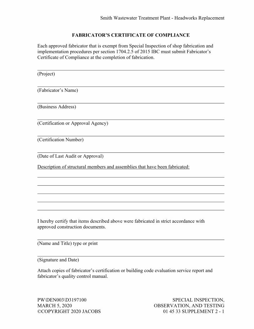
Smith Wastewater Treatment Plant - Headworks Replacement
PW\DEN003\D3197100 SPECIAL INSPECTION, MARCH 5, 2020 OBSERVATION, AND TESTING ©COPYRIGHT 2020 JACOBS 01 45 33 SUPPLEMENT 2 - 1
FABRICATOR’S CERTIFICATE OF COMPLIANCE
Each approved fabricator that is exempt from Special Inspection of shop fabrication and implementation procedures per section 1704.2.5 of 2015 IBC must submit Fabricator’s Certificate of Compliance at the completion of fabrication.
(Project)
(Fabricator’s Name)
(Business Address)
(Certification or Approval Agency)
(Certification Number)
(Date of Last Audit or Approval)
Description of structural members and assemblies that have been fabricated:
I hereby certify that items described above were fabricated in strict accordance with approved construction documents.
(Name and Title) type or print
(Signature and Date)
Attach copies of fabricator’s certification or building code evaluation service report and fabricator’s quality control manual.


Smith Wastewater Treatment Plant - Headworks Replacement
PW\DEN003\D3197100 TEMPORARY FACILITIES AND CONTROLS MARCH 5, 2020 01 50 00 - 1 ©COPYRIGHT 2020 JACOBS
SECTION 01 50 00 TEMPORARY FACILITIES AND CONTROLS
PART 1 GENERAL
1.01 REFERENCES
A. The following is a list of standards which may be referenced in this section:
1. American Nursery and Landscape Association (ANLA): American Standards for Nursery Stock.
2. Federal Emergency Management Agency (FEMA). 3. National Fire Prevention Association (NFPA): 241, Standard for
Safeguarding Construction, Alteration, and Demolition Operations. 4. Telecommunications Industry Association (TIA): 568-C, Commercial
Building Telecommunications Cabling Standard. 5. U.S. Department of Agriculture (USDA): Urban Hydrology for Small
Watersheds. 6. U.S. Weather Bureau: Rainfall-Frequency Atlas of the U.S. for
Durations from 30 Minutes to 24 Hours and Return Periods from 1 to 100 Years.
1.02 SUBMITTALS
A. Informational Submittals:
1. Copies of permits and approvals for construction as required by Laws and Regulations and governing agencies.
2. Temporary Construction Submittals: a. Contractor’s field office, storage yard, and storage building plans,
including gravel surfaced area. b. Fencing and protective barrier locations and details. c. Staging area location plan. d. Plan for maintenance of existing plant operations.
1.03 MOBILIZATION
A. Mobilization shall include, but not be limited to, these principal items:
1. Obtaining required permits. 2. Obtaining off-site parking area for Contractor’s employees 3. Moving Contractor’s field office and equipment required for first month
operations onto Site. 4. Installing temporary construction power, wiring, and lighting facilities. 5. Providing onsite Internet service

Smith Wastewater Treatment Plant - Headworks Replacement
TEMPORARY FACILITIES AND CONTROLS PW\DEN003\D3197100 01 50 00 - 2 MARCH 5, 2020 ©COPYRIGHT 2020 JACOBS
6. Providing onsite sanitary facilities and potable water facilities as specified and as required by Laws and Regulations, and governing agencies.
7. Arranging for and erection of Contractor’s work and storage yard. 8. Posting OSHA required notices and establishing safety programs and
procedures. 9. Having Contractor’s superintendent at Site full time.
B. Use area designated for Contractor’s temporary facilities as shown on Drawings.
1.04 PROTECTION OF WORK AND PROPERTY
A. Comply with Owner’s safety rules while on Owner’s property.
B. Keep Owner informed of serious onsite accidents and related claims.
C. Use of Explosives: No blasting or use of explosives will be allowed onsite.
PART 2 PRODUCTS
2.01 PROJECT SIGN
A. Refer to Project Sign Detail in ADEM Supplementary General Conditions.
PART 3 EXECUTION
3.01 TEMPORARY UTILITIES
A. Power:
1. Electric power will be available at or near Site exclusive of power as needed for temporary bypass pumping. Determine type and amount available and make arrangements for obtaining temporary electric power service.
2. Cost of electric power will be borne by Contractor. 3. Provide independent power source for bypass pumping as specified in
Section 01 57 28, Temporary Flow Control.
B. Lighting: Provide temporary lighting to meet applicable safety requirements to allow erection, application, or installation of materials and equipment, and observation or inspection of the Work.

Smith Wastewater Treatment Plant - Headworks Replacement
PW\DEN003\D3197100 TEMPORARY FACILITIES AND CONTROLS MARCH 5, 2020 01 50 00 - 3 ©COPYRIGHT 2020 JACOBS
C. Water:
1. Contractor shall make temporary connections for construction water at Site at locations as coordinated with the Owner. Provide temporary facilities and piping required to bring water to point of use and remove when no longer needed. Notify fire department before obtaining water from fire hydrants.
2. Water as reasonably necessary for the prosecution of the work shall be provided at no cost to the Contractor. If, in the opinion of the Engineer, the Contractor’s water use is excessive or wasteful, Engineer may require the Contractor to install an acceptable metering device and pay for water used at Owner’s current rate.
3. Provide means to prevent water used for testing from flowing back into source pipeline.
D. Sanitary and Personnel Facilities: Provide and maintain facilities for Contractor’s employees, Subcontractors, and other onsite employers’ employees. Service, clean, and maintain facilities and enclosures.
E. Fire Protection: Furnish and maintain on Site adequate firefighting equipment capable of extinguishing incipient fires. Comply with applicable parts of NFPA 241.
3.02 PROTECTION OF WORK AND PROPERTY
A. General:
1. Maintain in continuous service existing oil and gas pipelines, underground power, telephone or communication cable, water mains, irrigation lines, sewers, poles and overhead power, site lighting, and other utilities encountered within the Work, unless other arrangements satisfactory to owners of said utilities have been made.
2. Where completion of the Work requires temporary or permanent removal or relocation of existing utility, coordinate activities with owner of said utility and perform work to their satisfaction. See Section 01 31 13, Project Coordination for additional coordination requirements.
3. Protect, shore, brace, support, and maintain underground pipes, conduits, drains, and other underground utility construction uncovered or otherwise affected by construction operations.
4. Keep fire hydrants and water control valves free from obstruction and available for use at all times.
Smith Wastewater Treatment Plant - Headworks Replacement
TEMPORARY FACILITIES AND CONTROLS PW\DEN003\D3197100 01 50 00 - 4 MARCH 5, 2020 ©COPYRIGHT 2020 JACOBS
5. In areas where Contractor’s operations are adjacent to or near a utility, such as gas, telephone, television, electric power, water, sewer, or irrigation system, and such operations may cause damage or inconvenience, suspend operations until arrangements necessary for protection have been made by Contractor.
6. Notify property owners and utility offices that may be affected by construction operation at least 2 days in advance: Before exposing a utility, obtain utility owner’s permission. Should service of utility be interrupted due to Contractor’s operation, notify proper authority immediately. Cooperate with said authority in restoring service as promptly as possible and bear costs incurred.
7. Do not impair operation of existing sewer system. Prevent construction material, pavement, concrete, earth, volatile and corrosive wastes, and other debris from entering sewers, pump stations, or other sewer structures.
8. Maintain original Site drainage wherever possible.
B. Site Security: Provide and maintain additional temporary security fences as necessary to protect the Work and Contractor-furnished products not yet installed.
C. Trees and Plantings:
1. Protect from damage and preserve trees, shrubs, and other plants outside limits of the Work and within limits of the Work, which are designated on Drawings to remain undisturbed. a. Where practical, tunnel beneath trees when on or near line of
trench. b. Employ hand excavation as necessary to prevent tree injury. c. Do not stockpile materials or permit traffic within drip lines of
trees. d. Provide and maintain temporary barricades around trees. e. Water vegetation as necessary to maintain health. f. Cover temporarily exposed roots with wet burlap, and keep burlap
moist until soil is replaced around roots. g. No trees, except those specifically shown on Drawings to be
removed, shall be removed without written approval of Engineer. h. Dispose of removed trees in a legal manner off the Site.
2. Balling and burlapping of trees indicated for replacement shall conform to recommended specifications set forth in the American Standards for Nursery Stock, published by American Nursery and Landscape Association. Balls shall be firm and intact and made-balls will not be accepted. Handle ball and burlap trees by ball and not by top.

Smith Wastewater Treatment Plant - Headworks Replacement
PW\DEN003\D3197100 TEMPORARY FACILITIES AND CONTROLS MARCH 5, 2020 01 50 00 - 5 ©COPYRIGHT 2020 JACOBS
3. In event of damage to bark, trunks, limbs, or roots of plants that are not designated for removal, treat damage by corrective pruning, bark tracing, application of a heavy coating of tree paint, and other accepted horticultural and tree surgery practices.
4. Replace each plant that dies as a result of construction activities.
D. Existing Structures:
1. Where Contractor contemplates removal of small structures such as fences, signposts, and culverts that interfere with Contractor’s operations, obtain approval of property owner and Engineer.
2. Replace items removed in their original location and a condition equal to or better than original.
E. Dewatering: Construct, maintain, and operate cofferdams, channels, flume drains, sumps, pumps, or other temporary diversion and protection works. Furnish materials required, install, maintain, and operate necessary pumping and other equipment for the environmentally safe removal and disposal of water from the various parts of the Work. Maintain foundations and parts of the Work free from water.
F. Archaeological Finds: Should finds of an archaeological or paleontological nature be made within Site limits, immediately notify Owner and Engineer and proceed in accordance with General Conditions. Continue the Work in other areas without interruption.
G. Endangered and Threatened Species:
1. Take precautions necessary and prudent to protect native endangered and threatened flora and fauna.
2. Notify Engineer of construction activities that might threaten endangered and threatened species or their habitats.
3. Engineer will mark areas known as habitats of endangered and threatened species prior to commencement of onsite activities.
4. Additional areas will be marked by Engineer as other habitats of endangered and threatened species become known during construction.
3.03 TEMPORARY CONTROLS
A. Air Pollution Control:
1. Minimize air pollution from construction operations. 2. Burning of waste materials, rubbish, or other debris will not be
permitted on or adjacent to Site.
Smith Wastewater Treatment Plant - Headworks Replacement
TEMPORARY FACILITIES AND CONTROLS PW\DEN003\D3197100 01 50 00 - 6 MARCH 5, 2020 ©COPYRIGHT 2020 JACOBS
3. Conduct operations of dumping rock and of carrying rock away in trucks to cause a minimum of dust. Give unpaved streets, roads, detours, or haul roads used in construction area a dust-preventive treatment or periodically water to prevent dust. Strictly adhere to applicable environmental regulations for dust prevention. See Civil Drawings for additional requirements.
4. Provide and maintain temporary dust-tight partitions, bulkheads, or other protective devices during construction to permit normal operation of existing facilities. Construct partitions of plywood, insulating board, plastic sheets, or similar material. Construct partitions in such a manner that dust and dirt from demolition and cutting will not enter other parts of existing building or facilities. Remove temporary partitions as soon as need no longer exists.
B. Noise Control:
1. Provide acoustical barriers so noise emanating from tools or equipment will not exceed legal noise levels.
2. Noise Control Plan: Propose plan to mitigate construction noise and to comply with noise control ordinances, including method of construction, equipment to be used, and acoustical treatments.
C. Water Pollution Control:
1. Divert sanitary sewage and nonstorm waste flow interfering with construction and requiring diversion to sanitary sewers. Do not cause or permit action to occur which would cause an overflow to existing waterway.
2. Prior to commencing excavation and construction, obtain Engineer’s agreement with detailed plans showing procedures intended to handle and dispose of sewage, groundwater, and dewatering pump discharges.
3. Comply with Section 01 57 13, Temporary Erosion and Sedimentation Control, for stormwater flow and surface runoff.
4. Do not dispose of volatile wastes such as mineral spirits, oil, chemicals, or paint thinner in storm or sanitary drains. Disposal of wastes into streams or waterways is prohibited. Provide acceptable containers for collection and disposal of waste materials, debris, and rubbish.
D. Erosion, Sediment, and Flood Control: Provide, maintain, and operate temporary facilities as specified in Section 01 57 13, Temporary Erosion and Sedimentation Control, to control erosion and sediment releases, and to protect the Work and existing facilities from flooding during construction period.

Smith Wastewater Treatment Plant - Headworks Replacement
PW\DEN003\D3197100 TEMPORARY FACILITIES AND CONTROLS MARCH 5, 2020 01 50 00 - 7 ©COPYRIGHT 2020 JACOBS
3.04 STORAGE YARDS AND BUILDINGS
A. No area beyond that indicated by the drawings on Owner’s property may be used for temporary facilities. Provide lands and access to lands for additionally needed temporary facilities for use by Contractor for duration of Project.
B. Coordinate requirements with Section 01 61 00, Common Product Requirements.
C. Temporary Storage Yards: Construct temporary storage yards for storage of products that are not subject to damage by weather conditions.
D. Temporary Storage Buildings:
1. Provide environmental control systems that meet recommendations of manufacturers of equipment and materials stored.
2. Arrange or partition to provide security of contents and ready access for inspection and inventory.
3. Store combustible materials (paints, solvents, fuels) in a well-ventilated and remote building meeting safety standards.
3.05 ACCESS ROADS
A. Utilize existing access roads into the site and within the site. Provide additional access routes within the site as required by the work.
B. Maintain drainage ways. Install and maintain culverts to allow water to flow beneath access roads. Provide corrosion-resistant culvert pipe of adequate strength to resist construction loads.
C. Provide gravel, crushed rock, or other stabilization material to permit access by all motor vehicles at all times.
D. Maintain road grade and crown to eliminate potholes, rutting, and other irregularities that restrict access.
E. Upon completion of construction, restore ground surface disturbed by access road construction to original grade.
3.06 PARKING AREAS
A. Contractor may park up to two vehicles at the construction trailer. All other vehicle parking shall be off-site. Provide lands and access to lands for parking for use by Contractor for duration of Project. Mules used to transport employees from offsite parking may be parked within the designated temporary facilities areas.

Smith Wastewater Treatment Plant - Headworks Replacement
TEMPORARY FACILITIES AND CONTROLS PW\DEN003\D3197100 01 50 00 - 8 MARCH 5, 2020 ©COPYRIGHT 2020 JACOBS
B. Control vehicular parking to preclude interference with public traffic or parking, or access by emergency vehicles.
3.07 VEHICULAR TRAFFIC
A. Comply with Laws and Regulations regarding closing or restricting use of public streets or highways. No public or private road shall be closed, except by written permission of proper authority. Ensure the least possible obstruction to traffic and normal commercial pursuits.
B. Conduct the Work to interfere as little as possible with public travel, whether vehicular or pedestrian.
C. Whenever it is necessary to cross, close, or obstruct roads, driveways, and walks, whether public or private, provide and maintain suitable and safe bridges, detours, or other temporary expedients for accommodation of public and private travel.
3.08 CLEANING DURING CONSTRUCTION
A. In accordance with MAWSS’s Standard Specifications, as may be specified in other Specification sections, and as required herein.
B. Wet down exterior surfaces prior to sweeping to prevent blowing of dust and debris. At least weekly, sweep floors (basins, tunnels, platforms, walkways, roof surfaces), and pick up and dispose of debris.
C. Provide approved containers for collection and disposal of waste materials, debris, and rubbish. At least weekly, dispose of such waste materials, debris, and rubbish offsite.
D. Unless indicated otherwise at least weekly, brush sweep entry drive, roadways, and other streets and walkways affected by the Work and where adjacent to the Work.
END OF SECTION
Smith Wastewater Treatment Plant - Headworks Replacement
PW\DEN003\D3197100 TEMPORARY EROSION AND MARCH 5, 2020 SEDIMENT CONTROL ©COPYRIGHT 2020 JACOBS 01 57 13 - 1
SECTION 01 57 13 TEMPORARY EROSION AND SEDIMENT CONTROL
PART 1 GENERAL
1.01 SUMMARY OF WORK
A. This section covers Work necessary for stabilization of soil to prevent erosion and sedimentation during construction and land disturbing activities. The Work shall include the furnishing of all labor, materials, tools, and equipment to perform the Work and services necessary as herein specified and as indicated on the Drawings. This shall include installation, maintenance, and final removal of all temporary soil erosion and sediment control measures and installation of permanent soil erosion control practices.
B. The minimum areas requiring soil erosion and sediment control measures are indicated on the Drawings. The right is reserved to modify the use, location, and quantities of soil erosion and sediment control measures based on activities of Contractor and as the Engineer considers to be to the best interest of the Owner.
C. See additional information show on the Drawings.
D. Erosion and sediment control practices shall comply with the “Alabama Handbook for Erosion Control, Sediment Control and Stormwater Management on Construction Sites and Urban Areas,” latest edition.
E. Erosion and sediment control practices shall also comply with the “City of Mobile, Alabama Flood Plain Management Plan,” latest edition.
1.02 DEFINITIONS
A. BMP: Best management practice, means schedule of activities, prohibitions of practices, maintenance procedures, and other management practices to prevent or reduce the pollution of waters of the United States. BMPs also include treatment requirements, operating procedures, and practices to control site runoff, spillage or leaks, and waste disposal.
B. CBMPP: Construction Best Management Practice Plan prepared by the Contractor, as described and required by Alabama NPDES Permit ALR100000.
C. Certified Contractor: A person who has received training and is a certified professional to install/construct, inspect and maintain erosion and sediment control practices.

Smith Wastewater Treatment Plant - Headworks Replacement
TEMPORARY EROSION AND PW\DEN003\D3197100 SEDIMENT CONTROL MARCH 5, 2020 01 57 13 - 2 ©COPYRIGHT 2020 JACOBS
D. City: City of Mobile.
E. Clearing: Removal of interfering or objectionable material lying on or protruding above ground surface.
F. Construction Exit: A stone stabilized pad located at any point where traffic will be leaving a construction site to a public right-of-way, street, alley, sidewalk, or parking area or any other area where there is a transition from bare soil to a paved area.
G. ESC: Erosion and sediment control. Any temporary or permanent measures that prevent or reduce erosion, control sedimentation, and ensure that sediment does not leave a site.
H. Land Disturbing Activity: Any activity that results in a change in the existing soil cover (both vegetative and non-vegetative) and/or the existing soil topography. Land disturbing activities include, but are not limited to demolition, construction, clearing, grading, excavation and filling.
I. Maintenance Period: Maintenance period begins immediately after each area is planted and shall continue for a period of 8 weeks after all seeding, sodding, and planting are completed.
J. Project Limits: Areas, as shown or specified, within which Work is to be performed.
K. Sediments: Soil, sand, and minerals washed from land into water, usually after a rain event.
L. Standard Specifications: When referenced in this section, shall mean the current edition of the Alabama Department of Transportation Standard Specifications for Highway Construction.
1.03 GENERAL
A. All activities shall conform to the Alabama Handbook and the City of Mobile (City) requirements. In the event of a conflict, the more stringent requirement shall apply.
B. Contractor must obtain a copy of the approved Tier 1 Land Disturbance permit prior to Construction.
C. Contractor shall apply and comply with the following permits before construction begins:
1. Alabama Department of Environmental Management: National Pollutant Discharge Elimination System (NPDES) General Permit Number ALR10000.

Smith Wastewater Treatment Plant - Headworks Replacement
PW\DEN003\D3197100 TEMPORARY EROSION AND MARCH 5, 2020 SEDIMENT CONTROL ©COPYRIGHT 2020 JACOBS 01 57 13 - 3
D. Contractor shall implement and comply with the CBMPP specific for the Project.
E. The site is within an Alabama Priority Watershed and as such, the Contractor shall comply with the associated special requirements for erosion and sedimentation control.
F. Land disturbance activities shall not commence until the all permits listed above have been issue.
G. Erosion and sediment control practices shall be installed prior to commencement of land disturbance activities.
H. Prior to commencing land disturbance activities, the Contractor shall clearly and accurately demarcate the limits of land disturbance with clearing fence or other appropriate means, for the entire duration of the Project.
I. No land disturbance shall occur outside the limits indicated in the Drawings, unless approved by the Engineer.
J. After installation of the erosion and sediment control BMP’s, the Contractor must contact the City and request a field inspection before proceeding with clearing, grading, utility installation, and Work.
K. The location of some erosion and sediment control measures may have to be altered from those shown on the Drawings if drainage patterns during construction differ from the ones shown on the Drawings. Contractor is responsible to accomplish erosion and sediment control for all drainage patterns created during various stages of construction. Contractor shall report to the Engineer any difficulty in controlling erosion during any phase of construction.
L. Soil erosion stabilization and sedimentation control consist of, but not limited to, the following elements:
1. Conducting earthwork and excavation activities in such a manner to fit the topography soil type and condition.
2. Implementation and continuous maintenance of BMP’s. 3. Minimize disturbed area and duration of exposure to erosion elements. 4. Stabilize disturbed areas immediately:
a. Topsoil and seeding: 1) Placement and maintenance of Temporary Seeding on all
areas disturbed by construction. 2) Placement of permanent topsoil, fertilizer, and seed, etc., in
all areas not occupied by structures or pavement, unless shown otherwise.

Smith Wastewater Treatment Plant - Headworks Replacement
TEMPORARY EROSION AND PW\DEN003\D3197100 SEDIMENT CONTROL MARCH 5, 2020 01 57 13 - 4 ©COPYRIGHT 2020 JACOBS
b. Soil Stabilization Seeding: Placement of fertilizer and seed, etc., in areas as specified hereinafter.
c. Plastic sheeting to protect slopes as indicated on the Drawings. 5. Construction or installation of temporary erosion control facilities such
as, silt fences, check dams, diversion dikes, etc. 6. Construction or installation of permanent erosion control facilities such
as, spreader swales, stormwater swales, rip-rap, permanent vegetation, etc.
M. Contractor shall install and add to the erosion control measures during construction as determined by the Engineer or the Public Works Department.
N. The Contractor shall be responsible for phasing Work in areas allocated for his exclusive use during this Project, including any proposed stockpile areas, to restrict sediment transport. This will include installation of any temporary erosion control devices, ditches, or other facilities.
O. The areas set aside for the Contractor’s use during the Project may be temporarily developed to provide satisfactory working, staging, and administrative areas for his exclusive use. Preparation of these areas shall be in accordance with other requirements contained within these Specifications and shall be done in a manner to both control all sediment transport away from the area.
P. Contractor is responsible for maintaining all erosion control measures installed for the full duration of this Contract.
Q. Contractor shall observe the approved Project sequence as indicated on the Drawings. The Contractor shall maintain careful scheduling and performance to ensure that the exposure of land area stripped of its natural cover is kept to a minimum.
R. Mulch or temporary seeding or plastic sheeting over slopes shall be applied to all disturbed areas within 5 days of clearing. All disturbed areas that are stabilized with mulch shall be stabilized with temporary seeding after 14 days.
S. Areas opened by construction operations and that are not anticipated to be re-excavated or dressed and received final grassing treatment within 14 days shall be temporary seeded with a quick growing grass species which will provide an early cover during the season in which it is planted and will not compete with the permanent grassing.
T. Earthwork operations in the vicinity of water buffers and the lake shall be carefully controlled to avoid dumping or sloughing into the buffer or water.
U. The Contractor shall maintain all elements, systems, and facilities of the Soil Erosion Stabilization and Sedimentation Control during this Project for the duration of his activities on this Project until permanent stabilization of the Site is achieved.
Smith Wastewater Treatment Plant - Headworks Replacement
PW\DEN003\D3197100 TEMPORARY EROSION AND MARCH 5, 2020 SEDIMENT CONTROL ©COPYRIGHT 2020 JACOBS 01 57 13 - 5
V. Upon completion of construction, and after the site is stabilized, the Contractor shall remove all temporary erosion control measures and dispose of them, unless noted on the Drawings. Permanent sod shall be applied to the entire Site for all remaining area.
W. Contractor shall inspect erosion and sediment control measures each day to ensure that they are working properly. Formal inspections made jointly by the Contractor and the Engineer or the Owner shall be conducted, at a minimum, every 2 weeks to evaluate the Contractor’s conformance to the requirements of these Specifications and the Permit.
X. All silt traps and spreader swales shall be cleaned of collected sediment after every storm event, and shall be immediately repaired or replaced if found to be defective. Cleaning shall be done in a manner that will not direct the sediment into the storm drain piping system. Removed sediment shall be taken to an area selected by the Engineer where it can be cleaned of sticks and debris, then allowed to dry. Final sediment and debris disposal shall be onsite as designated by Engineer.
Y. Silt fence shall be inspected for depth of sediment, tears, to see if fabric is securely attached to the fence posts, and to see that the fence posts are firmly in the ground. Built up sediment shall be removed from silt fence when it has reached one-half the height of the fence.
Z. Temporary and permanent seeding and planting shall be inspected for bare spots, washouts, and healthy growth. All the permanent seeded grass cover areas shall be reworked and reseeded if 75 percent grass cover is not achieved within 14 days.
AA. If full implementation of the approved Drawings does not provide for effective erosion and sediment control, additional measures shall be implemented as directed by the Engineer or the Owner.
BB. Contractor’s failure to install, operate and maintain all erosion and sediment control measures, to the satisfaction of the Engineer and the Owner, will result in all construction being stopped on the job until such measures are installed or returned to their proper functional condition.
CC. A maintenance inspection report shall be made after each inspection by the Contractor. The reports will be kept onsite during construction and available upon request by the Owner, the Engineer, the County, or any Federal or Local Agency approving erosion and sediment control plans. This report shall be made and retained as part of the CBMPP for at least 3 years from the date that the site is finally stabilized and the Notice of Termination is submitted. The report shall identify any incidents of non-compliance.

Smith Wastewater Treatment Plant - Headworks Replacement
TEMPORARY EROSION AND PW\DEN003\D3197100 SEDIMENT CONTROL MARCH 5, 2020 01 57 13 - 6 ©COPYRIGHT 2020 JACOBS
1.04 SUBMITTALS
A. Submittals shall be made in accordance with Section 01 33 00, Submittal Procedures:
1. Shop Drawings. 2. Product Data.
B. In addition, the Contractor shall provide the following specific information:
1. Copy of CBMPP. 2. Erosion and Sediment Control Plans identifying any field changes. 3. Supporting calculations from any deviation from the approved ESC
plans. 4. Sequence and schedule of activities; such as ESC installation, ESC
maintenance, site clearing, grading, construction activities, construction of utilities, infrastructure and buildings, final grading, and temporary and final stabilization and removal of all ESC measures. Schedule shall identify the expected date and duration of each activity.
PART 2 PRODUCTS
2.01 SILT FENCE
A. See Drawings.
2.02 PERMANENT SEED
A. As specified in Section 32 92 00, Turf and Grasses.
2.03 TEMPORARY SEED
A. As specified in Section 32 92 00, Turf and Grasses.
2.04 TOPSOIL
A. Topsoil shall be as specified under Section 32 91 13, Soil Preparation.
2.05 FERTILIZER
A. As specified in Section 32 92 00, Turf and Grasses.
2.06 LIME
A. As specified in Section 32 91 13, Soil Preparation.

Smith Wastewater Treatment Plant - Headworks Replacement
PW\DEN003\D3197100 TEMPORARY EROSION AND MARCH 5, 2020 SEDIMENT CONTROL ©COPYRIGHT 2020 JACOBS 01 57 13 - 7
2.07 MULCH
A. As specified in Section 31 32 00, Soil Stabilization.
2.08 EROSION CONTROL MATTING
A. As specified in Section 31 32 00, Soil Stabilization.
2.09 WATER FOR DUST CONTROL
A. Free of hazardous or toxic contaminates.
2.10 STONE FOR ENTRANCE DRIVE TO SITE
A. See Drawings.
PART 3 EXECUTION
3.01 GENERAL
A. The Contractor shall install erosion and sediment control measures and maintain in accordance with the Drawings.
B. The Contractor shall provide and maintain soil stabilization at all times.
C. After installation of the initial erosion and sediment control measures, the Contractor shall schedule an inspection with the Engineer and the City’s site inspector. No other construction activities shall occur until the Engineer approves the installation of the initial erosion and sediment control measures. If unforeseen conditions exist in the field that warrants the installation of additional erosion and sediment control measures, the Contractor must install any additional measures deemed necessary by the Engineer.
D. Contractor shall observe the approved Project sequence. The Contractor shall maintain careful scheduling and performance to ensure that the exposure of land area stripped of its natural cover is kept to a minimum.
E. Contractor shall be responsible for phasing Work in areas allocated for their exclusive use during Project, including proposed stockpile areas and installation of temporary erosion control devices, ditches, or other facilities.
F. Engineer’s acceptance of CBMPP required prior to starting earth disturbing activities.

Smith Wastewater Treatment Plant - Headworks Replacement
TEMPORARY EROSION AND PW\DEN003\D3197100 SEDIMENT CONTROL MARCH 5, 2020 01 57 13 - 8 ©COPYRIGHT 2020 JACOBS
3.02 SILT FENCE
A. The Contractor shall construct silt fence in accordance with the “Alabama Handbook” and the City of Mobile where shown and at locations determined by the Engineer or the City.
3.03 SEEDING
A. General:
1. The Contractor shall give at least 3 days notice to the Engineer prior to seeding to allow for inspection of the areas. The Contractor shall rework any areas not approved for seeding to the Engineer’s satisfaction.
2. The Contractor shall keep the Engineer advised of schedule of operations.
3. Seed shall be clean, delivered in original unopened packages and bearing an analysis of the contents, guaranteed 95 percent pure with minimum germination rate of 85 percent.
B. Schedules: Seeding shall be performed in accordance with the schedules shown on the approved Drawings.
C. Soil Stabilization and Temporary Seeding:
1. Soil stabilization seeding shall consist of the application of the following materials in quantities as further described herein for stockpiles and disturbed areas left inactive for more than 14 days. a. Lime. b. Fertilizer. c. Seed. d. Mulch. e. Maintenance.
2. Hydroseeding will be permitted as an alternative method of applying seed and associated soil conditioning agents described above. Should the Contractor elect to apply soil stabilization seeding by hydroseeding methods, he shall submit his operational plan and methods to the Engineer.
3. Temporary Seeding is to be placed and maintained over all disturbed areas prior to Permanent Seeding. Maintain Temporary Seeding until such time as areas are approved for Permanent Seeding. As a minimum, maintenance shall include the following: a. Fix-up and reseeding of bare areas or redisturbed areas. b. Mowing for stands of grass or weeds exceeding 6 inches in height.

Smith Wastewater Treatment Plant - Headworks Replacement
PW\DEN003\D3197100 TEMPORARY EROSION AND MARCH 5, 2020 SEDIMENT CONTROL ©COPYRIGHT 2020 JACOBS 01 57 13 - 9
D. Topsoil and Permanent Seeding and Sod:
1. Topsoil and Permanent Seeding shall consist of the application of the following materials in quantities as further described herein: a. 6-inch depth of topsoil. b. Lime. c. Fertilizer. d. Permanent seed mix. e. Mulch.
2. Topsoil is to be placed over all disturbed areas that are not surfaced with concrete, asphalt, or pavers.
3. Preparation: a. After rough grading is completed and reviewed by the Engineer,
Contractor shall spread topsoil as hereinbefore specified over all areas to receive Permanent Seeding to a minimum compacted depth of 6 inches with surface elevations as shown. Loosen the finished surface to a depth of 2 inches and leave in smooth condition, free from depressions or humps, ready for seeding.
b. Finish Grading: 1) Contractor shall rake the topsoiled area to a uniform grade,
so that all areas drain as indicated on the grading plan. 2) Contractor shall remove all trash and stones exceeding
1 inch in diameter from area to a depth of 2 inches. 4. Permanent Sod: After soil has been scarified, apply sod and other
products as specified in the Section 32 92 00, Turf and Grasses. 5. Maintenance:
a. Maintenance Period: Contractor shall begin maintenance immediately after each portion of permanent grass is planted and continue for 8 weeks after all planting is completed.
b. Maintenance Operations: Contractor shall water to keep surface soil moist. Repair washed out areas by filling with topsoil, liming, fertilizing, and seeding. Replace mulch on banks when washed or blown away. Mow to 2 inches after grass reaches 3 inches in height, and mow frequently enough to keep grass from exceeding 3-1/2 inches. Weed by local spot application of selective herbicide only after first planting season when grass is established.
6. Guarantee: a. If, at the end of the 8-week maintenance period, a satisfactory
stand of grass has not been produced, the Contractor shall renovate and reseed the grass or unsatisfactory portions thereof immediately, or, if after October 15 during the next planting season. If a satisfactory stand of grass develops by July 1 of the following year, it will be accepted. If it is not accepted, a complete replanting will be required during the planting season meeting all of the requirements specified under paragraph Permanent Seed.
Smith Wastewater Treatment Plant - Headworks Replacement
TEMPORARY EROSION AND PW\DEN003\D3197100 SEDIMENT CONTROL MARCH 5, 2020 01 57 13 - 10 ©COPYRIGHT 2020 JACOBS
b. A satisfactory stand is defined as grass or section of grass that has a substantial establishment of new grass, strongly rooted, and uniformly green in appearance from a distance of 50 feet and which covers 75 percent or more of the grassed area. No noticeable thin or bare areas as determined by the Engineer.
3.04 CLEARING LIMIT
A. Before beginning clearing and grubbing operations, install silt fence at limits of clearing.
B. Drive posts a minimum of 18 inches into ground at maximum spacing of 6 feet.
C. Remove after permanent stabilization is complete and accepted by Engineer.
3.05 SOIL STOCKPILES
A. Protect from erosion with silt fence.
B. Seed stockpile, not active for 14 days, with soil stabilization seed, surrounded by silt fence and a permanent 2-foot minimum depth perimeter ditch located within 10 feet of the toe of stockpile slope.
C. Sediment transport and erosion from working stockpiles shall be controlled and restricted from moving beyond immediate stockpile area by construction of temporary toe-of-slope ditches and accompanying silt fences, as necessary. Keep these temporary facilities in operational condition by regular cleaning, regrading, and maintenance.
3.06 EROSION CONTROL MAT
A. Provide and install as specified in Section 31 32 00, Soil Stabilization.
3.07 DUST CONTROL
A. Contractor shall control, at all times, surface and air movement of dust.
B. Sprinkler site with water until the surface is wet. Repeat as needed.
3.08 FIELD QUALITY
A. Conduct inspections jointly with Engineer and/or the City every 2 weeks to evaluate conformance to requirements of Specifications, the Drawings, and the CBMPP.
Smith Wastewater Treatment Plant - Headworks Replacement
PW\DEN003\D3197100 TEMPORARY EROSION AND MARCH 5, 2020 SEDIMENT CONTROL ©COPYRIGHT 2020 JACOBS 01 57 13 - 11
B. Replace or repair failed or overloaded silt fences, check dams, or other temporary erosion control devices within 2 days after receiving written notice from Engineer and/or City.
3.09 MAINTENANCE OF EROSION AND SEDIMENT CONTROL MEASURES
A. Erosion and sediment control measures shall be maintained at all times until permanent stabilization of the site is achieved.
B. Erosion and sediment control measures shall be checked after each rain event, and shall be immediately repaired or replaced if found to be defective. A record shall be maintained of all inspections, repairs and replacement.
C. Contractor shall inspect erosion and sediment control measures each day to ensure that they are working properly.
D. Construction exit shall be top dressed with additional material periodically to maintain minimum depth of 6 inches. All materials spilled, dropped, washed, or tracked from vehicles or site onto roadways or into storm drains must be removed immediately.
E. Silt fence shall be inspected for depth of sediment, tears, to see if the fabric is securely attached to the fence posts, and to see that the fence posts are firmly in the ground. Build up sediment shall be removed from silt fence when it has reached one-half the height of the fence.
F. Each BMP is to be maintained or replaced if the accumulated sediment depth is equal to or greater than one-half of the capacity of the device. Reference marks denoting the elevation at which each device is to be maintained shall be placed on all devices.
G. Temporary and permanent seeding, sodding, and planting shall be inspected for bare spots, washouts, and healthy growth. All the permanent seeded grass cover areas shall be reworked and reseeded if 75 percent grass cover is not achieved within 14 days.
H. If full implementation of the approved Drawings does not provide for effective erosion and sediment control, additional ESC measures shall be implemented as directed by the Engineer or the City.
I. A maintenance inspection report shall be made after each inspection by the Contractor. The reports will be kept onsite during construction and available upon request by the Engineer, Owner, or any Federal, State, or Local Agency. The report shall identify any incidents of non-compliance.

Smith Wastewater Treatment Plant - Headworks Replacement
TEMPORARY EROSION AND PW\DEN003\D3197100 SEDIMENT CONTROL MARCH 5, 2020 01 57 13 - 12 ©COPYRIGHT 2020 JACOBS
J. Contractor shall installed and add to erosion control measures as determined by the Engineer or the Owner.
K. The Contractor shall maintain all elements of the ESC measures and facilities to be constructed during this Project for the duration of his activities on this Project. Formal inspections made jointly by the Contractor and the Engineer shall be conducted every 2 weeks to evaluate the Contractor’s conformance to the Approved Drawings and this Specification.
L. All silt traps shall be cleaned of collected sediment after every storm or as determined from the biweekly inspections. Cleaning shall be done in a manner that will not direct the sediment into the storm drain piping system. Removed sediment shall be taken to an area selected by the Engineer where it can be cleaned of sticks and debris, then allowed to dry. Final sediment and debris disposal shall be onsite as designated by Engineer.
M. Replacement or repair of failed or overloaded silt fences, check dams, or other temporary erosion control devices shall be accomplished by the Contractor within 2 days after receiving written notice from the Engineer.
N. Unpaved earth drainage ditches shall be regraded as needed to maintain original grade and remove sediment buildup. If a ditch becomes difficult to maintain, the Contractor shall cooperate with the Engineer and install additional erosion control devices such as check dams, temporary paving, or silt fences as directed by the Engineer.
O. If the Contractor has not complied with any of the above maintenance efforts to the satisfaction of the Engineer within 2 working days after receiving written notification from the Engineer, the Owner shall have the prerogative of engaging others to perform any needed maintenance or cleanup, including removal of accumulated sediment at constructed erosion control facilities, at Contractor’s expense.
3.10 CLEANING
A. Dress sediment deposits remaining after fence has been removed to conform to existing grade. Prepare and seed graded area.
END OF SECTION

Smith Wastewater Treatment Plant - Headworks Replacement
PW\DEN003\D3197100 TEMPORARY FLOW CONTROL APRIL 8, 2020 01 57 28 - 1 ©COPYRIGHT 2020 JACOBS
SECTION 01 57 28 TEMPORARY FLOW CONTROL
PART 1 GENERAL
1.01 REFERENCES
A. The following is a list of standards which may be referenced in this section:
1. Institute of Inspection, Cleaning, and Restoration Certification (IICRC): S500, Standard and Reference Guide for Professional Water Damage Restoration.
1.02 DEFINITIONS
A. Bypass Pumping: Temporary flow control accomplished by diverting flow away from the Work area using one or more pumps.
B. Temporary Flow Control: Reducing, limiting, or excluding flow in or to a sanitary sewer, storm sewer, pump station, force main, or other facility as required for performing the Work under the Contract. Draining, handling, and disposal of sanitary sewage, process flows and stormwater from pipelines and other facilities as required for performing the Work under the Contract is also part of temporary flow control.
C. Temporary Flow Control Plan: Plan prepared by Contractor containing complete information on how Contractor proposes to perform temporary flow control in accordance with specified requirements.
1.03 SYSTEM DESCRIPTION
A. Provide facilities and controls required to intercept, convey, and discharge flow to be controlled; include standby and emergency equipment.
B. Conform to regulatory requirements.
C. Protect water resources, wetlands, and other natural resources.
D. Temporary flow control shall be done in a manner that will not damage private or public property, or create a nuisance or public menace. Flow shall be conveyed in enclosed pipes that are adequately protected from traffic or other hazards.
E. Discharge:
1. To sanitary sewer system or process basin receiving the flows prior to the diversion.
Smith Wastewater Treatment Plant - Headworks Replacement
TEMPORARY FLOW CONTROL PW\DEN003\D3197100 01 57 28 - 2 APRIL 8, 2020
©COPYRIGHT 2020 JACOBS
2. Dumping or free flow on private or public property, gutters, streets, or sidewalks is prohibited.
3. Discharge of sanitary sewage to storm sewers, to surface waters or wetlands, or into the ground, is prohibited.
1.04 SITE CONDITIONS
A. Existing facilities in vicinity of bypass area are shown on Drawings or included in referenced documents.
B. Minimize impact to site and process component accessibility required by bypass pumping system installation and operation.
1.05 SUBMITTALS
A. Informational Submittals:
1. Temporary Flow Control Plan. 2. Emergency Cleanup Plan. 3. Special permits required for temporary flow control. 4. Names and qualifications of industrial hygienist and standby cleanup
Subcontractor, including but not limited to, certification by IICRC. 5. Information describing equipment and materials to be used and showing
conformance with specified requirements.
1.06 QUALITY ASSURANCE
A. Qualifications:
1. Industrial Hygienist and Cleanup Subcontractor: Certified by IICRC. 2. Temporary Flow Control System Designer: Professional engineer who
has at least 5 years’ experience in design of such systems and who is registered in the State of Alabama.
B. Regulatory Requirements: Comply with any applicable ADEM and City of Mobile requirements.
1.07 PERFORMANCE REQUIREMENTS
A. General:
1. It is essential to operate the existing treatment facility without interruption of service throughout the project duration.

Smith Wastewater Treatment Plant - Headworks Replacement
PW\DEN003\D3197100 TEMPORARY FLOW CONTROL APRIL 8, 2020 01 57 28 - 3 ©COPYRIGHT 2020 JACOBS
2. During modification of the existing facility that interrupt normal flow patterns; provide, operate, and maintain temporary facilities such as dams, plugs, pumping equipment, piping and necessary power to intercept all sewage and/or process flows before it reaches a point where it would interfere with the work.
3. Maintain flows around the work area in such a manner that will not cause surcharging of sewers, damage to sewers, and that will prevent public and private property from damage.
4. Where bypassing of the influent sewer or the influent pumping station is required, provide pumping capacity of at least 30 MGD exclusive of spare pumps.
5. Where bypassing of the plant sewer is required, provide pumping capacity of at least 6 MGD exclusive of spare pumps.
6. Where bypassing of the eastern influent sewer is required, provide pumping capacity of at least 10 MGD exclusive of spare pumps.
7. Where bypassing of process flows using bypass pumping is required, provide pumping capacity (exclusive of spare bypass pumps) of at least equal to the combined capacity of the pumps contributing to the flow in the main being interrupted exclusive of spare process pumps. Where the interrupted main is a gravity-fed force main, provide bypass pumping equal to the flow rate of the main flowing full at 6 feet per second velocity.
B. Anticipated Bypass Requirements:
1. Bypass pumping is required as generally indicated by the Sequence of Construction as contained in the Contract Drawings which will generally include at some point the influent pumping station, plant sewer, the influent 54-inch sewer and the eastern influent sewer.
2. Bypass pumping may be required depending upon the Contractor’s sequence of operations to include the process piping associated with the utility relocations associated with the
1.08 SEQUENCING AND SCHEDULING
A. Schedule and sequence bypass operations to coordinate with the other work to minimize the duration of bypass operations.
B. Where practical, limit bypass operations to daytime hours.
C. Bypass operations must be continuously monitored exclusive of off-site electronic monitoring.
PART 2 PRODUCTS (NOT USED)

Smith Wastewater Treatment Plant - Headworks Replacement
TEMPORARY FLOW CONTROL PW\DEN003\D3197100 01 57 28 - 4 APRIL 8, 2020
©COPYRIGHT 2020 JACOBS
PART 3 EXECUTION
3.01 GENERAL REQUIREMENTS
A. Install temporary flow control facilities only within Owner’s property.
B. Operate and maintain temporary flow control 24 hours per day, 7 days per week, including without limitation, holidays, as required to control flows.
C. Promptly remove temporary flow control facilities as soon as they are no longer needed.
3.02 REQUIRED TEMPORARY FLOW CONTROL
A. Eliminate flow from sewer manhole to manhole segments during manhole construction or modification and connection of new branch piping within that segment.
3.03 EQUIPMENT AND MATERIALS
A. General:
1. Provide materials and equipment that will ensure continuous and successful operation of temporary flow control systems.
2. Repair or modify systems as necessary. 3. Unless otherwise shown or specified, materials and equipment may be
new or used at Contractor’s option.
B. Plugs:
1. Provide with taps for connection of pressure gauges and air hoses, and flow-through capability.
2. Pipe Diameters 24 Inches and Smaller: Use mechanical plugs with rubber gaskets or pneumatic plugs with rubber boots.
3. Pipe Diameters Larger than 24 Inches: a. Use inflatable bag stoppers made in two or more pieces. b. Manufacturers:
1) Lansas. 2) Cherne Industries.
C. Pumps:
1. Fully automatic, self-priming units that do not require use of foot valves or vacuum pumps in priming system.
2. Solids handling design with ability to pump minimum 3-inch diameter sphere.

Smith Wastewater Treatment Plant - Headworks Replacement
PW\DEN003\D3197100 TEMPORARY FLOW CONTROL APRIL 8, 2020 01 57 28 - 5 ©COPYRIGHT 2020 JACOBS
3. Able to run dry for long periods of time to accommodate cyclical nature of flows.
4. Engine: Equipped to minimize noise. Noise levels shall not exceed 86 dBA at a distance of 50 feet from source.
D. Electric Power Generators:
1. Be able to simultaneously start and run electric powered pumps required for flow to be controlled.
2. Equipped to minimize noise. Noise levels shall not exceed 86 dBA at a distance of 50 feet from source.
3. Include automatic transfer switch if flow control system is to operate unattended.
E. Standby Equipment:
1. Standby Pump: One of each size to be available onsite. 2. Electric Power Generators: Minimum of one if temporary flow control
system contains electric powered pump. Able to simultaneously start and run electric powered pumps required for flow to be controlled.
3.04 TEMPORARY FLOW CONTROL PLAN
A. Prepare and submit Temporary Flow Control Plan at least 60 days before starting the Work requiring temporary flow control; include following information:
1. Drawings indicating location of temporary sewer plugs and bypass discharge lines.
2. Traffic Control Plan specifically applicable to temporary flow control adhering to requirements of applicable agencies and as may be specified in Contract Documents.
3. Locations where flow will be intercepted and discharged. 4. If trucks are to be employed include the following:
a. Numbers and sizes of trucks. b. Configuration of facilities to be used to load trucks at each
interception location. c. Locations where trucks will unload. d. Time for loading, unloading, and travel.
5. Complete descriptions and performance characteristics of pumps, electric power generators, and standby equipment.
6. Acoustical information for equipment to be used showing compliance with noise control requirements of Section 01 50 00, Temporary Facilities and Control.
Smith Wastewater Treatment Plant - Headworks Replacement
TEMPORARY FLOW CONTROL PW\DEN003\D3197100 01 57 28 - 6 APRIL 8, 2020
©COPYRIGHT 2020 JACOBS
7. Details of temporary force mains, including horizontal and vertical alignments, pipe materials, protection of existing buried and aboveground facilities and improvements, maintenance of traffic and access to properties.
8. Design calculations proving adequacy of temporary system and selected equipment to convey all flows.
9. Drawings showing layouts and configurations of temporary flow control facilities and also showing locations relative to right-of-way easement, and property boundaries.
10. Drawings and design calculations of temporary bulkheads and plugs. 11. Drawings and design calculations for thrust restraint of temporary
piping. 12. Details of system controls and control logic; include diagrams and
narrative. 13. Anticipated schedule for the Work. 14. Other information to completely describe temporary flow control
facilities and conformance to specified requirements. 15. Anticipate coordination needs with Owner’s staff.
3.05 EMERGENCY CLEANUP PLAN
A. Prepare and submit not less than 60 days before scheduled date of temporary flow control activities. As a minimum plan shall include the following:
1. Procedures for removal of water. 2. Procedures for determining nature and extent of damage and required
restoration where restoration is possible. 3. Provide for industrial hygienist and standby Subcontractor for cleanup
of exterior and building interior spaces that might be affected by a spill, backup, or overflow. Industrial hygienist and cleanup Subcontractor shall be certified by IICRC and follow IICRC S500 for cleanup of Category 3 water.
B. Implement for Full Scale Test and during temporary flow control.
3.06 TEMPORARY SANITARY SEWAGE FLOW REDUCTION
A. Contractor shall be responsible for control of flows and under no circumstances be entitled to rely on flow reduction or curtailment by Owner.
3.07 DRAINING EXISTING PIPELINE
A. Before initiating shutdown, ensure required materials, equipment, and labor are available onsite. Excavate and expose portions of existing pipeline to be removed.

Smith Wastewater Treatment Plant - Headworks Replacement
PW\DEN003\D3197100 TEMPORARY FLOW CONTROL APRIL 8, 2020 01 57 28 - 7 ©COPYRIGHT 2020 JACOBS
B. Provide tap and piping in place to drain sewage/process flows from existing pipeline before it is cut and to capture contents that may drain out when pipe is cut or capture flows at the downstream end of the isolated section.
C. Sewage/process flows drained from sewer/process mains shall be conveyed and discharged to downstream sewer or process main or basin.
3.08 FIELD QUALITY CONTROL
A. Hydrostatic Pressure Test for Pump Bypass Systems:
1. Prior to operation, test each section of discharge piping with maximum pressure equal to 1.5 times maximum operating pressure of system.
2. Notify Engineer 24 hours prior to testing.
B. Full Scale Test:
1. At least 4 days prior to test, notify Engineer of date and time of test. 2. Do not begin temporary flow control activities until successful test has
been completed. 3. Conduct on proposed temporary flow control at least 4 days before
scheduled date of actual proposed temporary flow control. 4. Purpose of test is to demonstrate capability, function, and reliability of
Contractor’s proposed method of temporary flow control. 5. Duration: Minimum of 3 hours. 6. Conduct between 8:00 a.m. and 4:00 p.m. Do not conduct test on
Saturday, Sunday, or holiday. 7. If electric pumps are being used, provide standby generators to ensure
continuity of pumping operation in event of power failure. 8. Demonstrate system controls and operation, reliability, and transfer to
standby equipment during test. 9. Conduct until flow is accommodated for minimum specified test
duration. 10. Failure:
a. Test shall be deemed to have failed if during test flows are not accommodated for whatever reason and for whatever length of time.
b. If test fails, determine and correct deficiencies that caused test to fail and conduct another Full Scale Test.
11. Determination by Engineer of a successful test, permission by Engineer to proceed with the Work requiring temporary flow control, or anything else shall not relieve Contractor from responsibility to provide temporary flow control.
END OF SECTION

Smith Wastewater Treatment Plant - Headworks Replacement
PW\DEN003\D3197100 COMMON PRODUCT REQUIREMENTS MARCH 6, 2020 01 61 00 - 1 ©COPYRIGHT 2020 JACOBS
SECTION 01 61 00 COMMON PRODUCT REQUIREMENTS
PART 1 GENERAL
1.01 DEFINITIONS
A. Products:
1. New items for incorporation in the Work, whether purchased by Contractor or Owner for the Project, or taken from previously purchased stock, and may also include existing materials or components required for reuse.
2. Includes the terms material, equipment, machinery, components, subsystem, system, hardware, software, and terms of similar intent and is not intended to change meaning of such other terms used in Contract Documents, as those terms are self-explanatory and have well recognized meanings in construction industry.
3. Items identified by manufacturer’s product name, including make or model designation, indicated in manufacturer’s published product literature, that is current as of the date of the Contract Documents.
1.02 DESIGN REQUIREMENTS
A. Where Contractor design is specified, design of installation, systems, equipment, and components, including supports and anchorage, shall be in accordance with provisions as indicated in the Drawings, with the Building Code of the City of Mobile, with the Occupational Safety and Health Administration and with all other applicable state and local agency requirements.
B. Where Contractor design is specified; installation, systems, equipment, and components shall be designed by a qualified professional Engineer registered in the State of Alabama.
1.03 ENVIRONMENTAL REQUIREMENTS
A. Altitude: Provide materials and equipment suitable for installation and operation under rated conditions at 50 feet above sea level.
B. Provide equipment and devices installed outdoors or in unheated enclosures capable of continuous operation within an ambient temperature range of 10 degrees F to 105 degrees F.

Smith Wastewater Treatment Plant - Headworks Replacement
COMMON PRODUCT REQUIREMENTS PW\DEN003\D3197100 01 61 00 - 2 MARCH 6, 2020 ©COPYRIGHT 2020 JACOBS
1.04 PREPARATION FOR SHIPMENT
A. When practical, factory assemble products. Mark or tag separate parts and assemblies to facilitate field assembly. Cover machined and unpainted parts that may be damaged by the elements with strippable protective coating.
B. Package products to facilitate handling and protect from damage during shipping, handling, and storage. Mark or tag outside of each package or crate to indicate its purchase order number, bill of lading number, contents by name, name of Project and Contractor, equipment number, and approximate weight. Include complete packing list and bill of materials with each shipment.
C. Extra Materials, Special Tools, Test Equipment, and Expendables:
1. Furnish as required by individual Specifications. 2. Schedule:
a. Ensure that shipment and delivery occurs concurrent with shipment of associated equipment.
b. Transfer to Owner shall occur immediately subsequent to Contractor’s acceptance of equipment from Supplier.
3. Packaging and Shipment: a. Package and ship extra materials and special tools to avoid
damage during long term storage in original cartons insofar as possible, or in appropriately sized, hinged-cover, wood, plastic, or metal box.
b. Prominently displayed on each package, the following: 1) Manufacturer’s part nomenclature and number, consistent
with Operation and Maintenance Manual identification system.
2) Applicable equipment description. 3) Quantity of parts in package. 4) Equipment manufacturer.
4. Deliver materials to site or other area as designated by the Contractor. 5. Notify Engineer, Owner, and Construction Manager upon arrival for
transfer of materials. 6. Replace extra materials and special tools found to be damaged or
otherwise inoperable at time of transfer to Owner.
D. Request a minimum 7-day advance notice of shipment from manufacturer. Upon receipt of manufacturer’s advance notice of shipment, promptly notify Engineer of anticipated date and place of delivery.
E. Factory Test Results: Reviewed and accepted by Engineer before product shipment as required in individual Specification sections.

Smith Wastewater Treatment Plant - Headworks Replacement
PW\DEN003\D3197100 COMMON PRODUCT REQUIREMENTS MARCH 6, 2020 01 61 00 - 3 ©COPYRIGHT 2020 JACOBS
1.05 DELIVERY AND INSPECTION
A. Deliver products in accordance with accepted current Progress Schedule and coordinate to avoid conflict with the Work and conditions at Site. Deliver anchor bolts and templates sufficiently early to permit setting prior to placement of structural concrete.
B. Deliver products in undamaged condition, in manufacturer’s original container or packaging, with identifying labels intact and legible. Include on label, date of manufacture and shelf life, where applicable.
C. Unload products in accordance with manufacturer’s instructions for unloading or as specified. Record receipt of products at Site. Promptly inspect for completeness and evidence of damage during shipment.
D. Remove damaged products from Site and expedite delivery of identical new undamaged products, and remedy incomplete or lost products to provide that specified, so as not to delay progress of the Work.
1.06 HANDLING, STORAGE, AND PROTECTION
A. Handle and store products in accordance with manufacturer’s written instructions and in a manner to prevent damage. Store in approved storage yards or sheds provided in accordance with Section 01 50 00, Temporary Facilities and Controls. Provide manufacturer’s recommended maintenance during storage, installation, and until products are accepted for use by Owner.
B. Manufacturer’s instructions for material requiring special handling, storage, or protection shall be provided prior to delivery of material.
C. Arrange storage in a manner to provide easy access for inspection. Make periodic inspections of stored products to ensure that products are maintained under specified conditions, and free from damage or deterioration. Keep running account of products in storage to facilitate inspection and to estimate progress payments for products delivered, but not installed in the Work.
D. Store electrical, instrumentation, and control products, and equipment with bearings in weather-tight structures maintained above 60 degrees F. Protect electrical, instrumentation, and control products, and insulate against moisture, water, and dust damage. Connect and operate continuously space heaters furnished in electrical equipment.
E. Store fabricated products above ground on blocking or skids, and prevent soiling or staining. Store loose granular materials in well-drained area on solid surface to prevent mixing with foreign matter. Cover products that are subject to deterioration with impervious sheet coverings; provide adequate ventilation to avoid condensation.
Smith Wastewater Treatment Plant - Headworks Replacement
COMMON PRODUCT REQUIREMENTS PW\DEN003\D3197100 01 61 00 - 4 MARCH 6, 2020 ©COPYRIGHT 2020 JACOBS
F. Store finished products that are ready for installation in dry and well-ventilated areas. Do not subject to extreme changes in temperature or humidity.
G. After installation, provide coverings to protect products from damage due to traffic and construction operations. Remove coverings when no longer needed.
H. Hazardous Materials: Prevent contamination of personnel, storage area, and Site. Meet requirements of product specification, codes, and manufacturer’s instructions.
PART 2 PRODUCTS
2.01 GENERAL
A. Provide manufacturer’s standard materials suitable for service conditions, unless otherwise specified in the individual Specifications.
B. Where product specifications include a named manufacturer, with or without model number, and also include performance requirements, named manufacturer’s products must meet the performance specifications.
C. Like items of products furnished and installed in the Work shall be end products of one manufacturer and of the same series or family of models to achieve standardization for appearance, operation and maintenance, spare parts and replacement, manufacturer’s services, and implement same or similar process instrumentation and control functions in same or similar manner.
D. Do not use materials and equipment removed from existing premises, except as specifically permitted by Contract Documents.
E. Provide interchangeable components of the same manufacturer, for similar components, unless otherwise specified.
F. Equipment, Components, Systems, and Subsystems: Design and manufacture with due regard for health and safety of operation, maintenance, and accessibility, durability of parts, and shall comply with applicable OSHA, state, and local health and safety regulations.
G. Regulatory Requirement: Coating materials shall meet federal, state, and local requirements limiting the emission of volatile organic compounds and for worker exposure.

Smith Wastewater Treatment Plant - Headworks Replacement
PW\DEN003\D3197100 COMMON PRODUCT REQUIREMENTS MARCH 6, 2020 01 61 00 - 5 ©COPYRIGHT 2020 JACOBS
H. Safety Guards: Provide for all belt or chain drives, fan blades, couplings, or other moving or rotary parts. Cover rotating part on all sides. Design for easy installation and removal. Use 16-gauge or heavier; galvanized steel, aluminum coated steel, or galvanized or aluminum coated 1/2-inch mesh expanded steel. Provide galvanized steel accessories and supports, including bolts. For outdoors application, prevent entrance of rain and dripping water.
I. Authority Having Jurisdiction (AHJ):
1. Provide the Work in accordance with NFPA 70, National Electrical Code (NEC). Where required by the AHJ, material and equipment shall be labeled or listed by a nationally recognized testing laboratory or other organization acceptable to the AHJ in order to provide a basis for approval under NEC.
2. Materials and equipment manufactured within the scope of standards published by Underwriters Laboratories, Inc. shall conform to those standards and shall have an applied UL listing mark.
J. Equipment Finish:
1. Provide manufacturer’s standard finish and color, except where specific color is indicated.
2. If manufacturer has no standard color, provide equipment with finish as approved by Owner.
K. Special Tools and Accessories: Furnish to Owner, upon acceptance of equipment, all accessories required to place each item of equipment in full operation. These accessory items include, but are not limited to, adequate oil and grease (as required for first lubrication of equipment after field testing), light bulbs, fuses, hydrant wrenches, valve keys, handwheels, chain operators, special tools, and other spare parts as required for maintenance.
L. Lubricant: Provide initial lubricant recommended by equipment manufacturer in sufficient quantity to fill lubricant reservoirs and to replace consumption during testing, startup, and operation until final acceptance by Owner.
M. Components and Materials in Contact with Water for Human Consumption: Comply with the requirements of the Safe Drinking Water Act and other applicable federal, state, and local requirements. Provide certification by manufacturer or an accredited certification organization recognized by the Authority Having Jurisdiction that components and materials comply with the maximum lead content standard in accordance with NSF/ANSI 61 and NSF/ANSI 372.
1. Use or reuse of components and materials without a traceable certification is prohibited.

Smith Wastewater Treatment Plant - Headworks Replacement
COMMON PRODUCT REQUIREMENTS PW\DEN003\D3197100 01 61 00 - 6 MARCH 6, 2020 ©COPYRIGHT 2020 JACOBS
2.02 FABRICATION AND MANUFACTURE
A. General:
1. Manufacture parts to U.S.A. standard sizes and gauges. 2. Two or more items of the same type shall be identical, by the same
manufacturer, and interchangeable. 3. Design structural members for anticipated shock and vibratory loads. 4. Use 1/4-inch minimum thickness for steel that will be submerged,
wholly or partially, during normal operation. 5. Modify standard products as necessary to meet performance
Specifications.
B. Lubrication System:
1. Require no more than weekly attention during continuous operation. 2. Convenient and accessible; oil drains with bronze or stainless steel
valves and fill-plugs easily accessible from the normal operating area or platform. Locate drains to allow convenient collection of oil during oil changes without removing equipment from its installed position.
3. Provide constant-level oilers or oil level indicators for oil lubrication systems.
4. For grease type bearings, which are not easily accessible, provide and install stainless steel tubing; protect and extend tubing to convenient location with suitable grease fitting.
2.03 SOURCE QUALITY CONTROL
A. Where Specifications call for factory testing to be witnessed by Engineer, notify Engineer not less than 14 days prior to scheduled test date, unless otherwise specified.
B. Calibration Instruments: Bear the seal of a reputable laboratory certifying instrument has been calibrated within the previous 12 months to a standard endorsed by the National Institute of Standards and Technology (NIST).
C. Factory Tests: Perform in accordance with accepted test procedures and document successful completion.
Smith Wastewater Treatment Plant - Headworks Replacement
PW\DEN003\D3197100 COMMON PRODUCT REQUIREMENTS MARCH 6, 2020 01 61 00 - 7 ©COPYRIGHT 2020 JACOBS
PART 3 EXECUTION
3.01 INSPECTION
A. Inspect materials and equipment for signs of pitting, rust decay, or other deleterious effects of storage. Do not install material or equipment showing such effects. Remove damaged material or equipment from the Site and expedite delivery of identical new material or equipment. Delays to the Work resulting from material or equipment damage that necessitates procurement of new products will be considered delays within Contractor’s control.
3.02 MANUFACTURER’S CERTIFICATE OF COMPLIANCE
A. With all manufactured components, a Manufacturer’s Certificate of Compliance, a copy of which is attached to this section, shall be completed in full, signed by entity supplying the product, material, or service, and submitted prior to shipment of product or material or execution of the services.
B. Engineer may permit use of certain materials or assemblies prior to sampling and testing if accompanied by accepted certification of compliance.
C. Such form shall certify proposed product, material, or service complies with that specified. Attach supporting reference data, affidavits, and certifications as appropriate.
D. May reflect recent or previous test results on material or product, if acceptable to Engineer.
3.03 INSTALLATION
A. Equipment Drawings show general locations of equipment, devices, and raceway, unless specifically dimensioned.
B. No shimming between machined surfaces is allowed.
C. Install the Work in accordance with NECA Standard of Installation, unless otherwise specified.
D. Repaint painted surfaces that are damaged prior to equipment acceptance.
E. Do not cut or notch any structural member or building surface without specific approval of Engineer.

Smith Wastewater Treatment Plant - Headworks Replacement
COMMON PRODUCT REQUIREMENTS PW\DEN003\D3197100 01 61 00 - 8 MARCH 6, 2020 ©COPYRIGHT 2020 JACOBS
F. Handle, install, connect, clean, condition, and adjust products in accordance with manufacturer’s instructions, and as may be specified. Retain a copy of manufacturers’ instruction at Site, available for review at all times.
G. For material and equipment specifically indicated or specified to be reused in the Work:
1. Use special care in removal, handling, storage, and reinstallation to assure proper function in the completed Work.
2. Arrange for transportation, storage, and handling of products that require offsite storage, restoration, or renovation. Include costs for such Work in the Contract Price.
3.04 FIELD FINISHING
A. In accordance with Section 09 90 00, Painting and Coating, and individual Specification sections.
3.05 ADJUSTMENT AND CLEANING
A. Perform required adjustments, tests, operation checks, and other startup activities.
3.06 LUBRICANTS
A. Fill lubricant reservoirs and replace consumption during testing, startup, and operation prior to acceptance of equipment by Owner.
3.07 SUPPLEMENTS
A. The supplement listed below, following “End of Section”, is part of this specification.
1. Form: Manufacturer’s Certificate of Compliance.
END OF SECTION

Smith Wastewater Treatment Plant - Headworks Replacement
PW\DEN003\D3197100 COMMON PRODUCT REQUIREMENTS MARCH 6, 2020 01 61 00 SUPPLEMENT - 1 ©COPYRIGHT 2020 JACOBS
MANUFACTURER’S CERTIFICATE OF COMPLIANCE
OWNER: PRODUCT, MATERIAL, OR SERVICE SUBMITTED: PROJECT NAME:
PROJECT NO:
Comments:
I hereby certify that the above-referenced product, material, or service called for by the Contract for the named Project will be furnished in accordance with all applicable requirements. I further certify that the product, material, or service are of the quality specified and conform in all respects with the Contract requirements, and are in the quantity shown. I further certify that we have examined the Plans and Specifications for this Project and have ascertained that this equipment or material is suitable for the purpose and use intended.
Date of Execution: ________________________________________, 20___
Manufacturer:
Manufacturer’s Authorized Representative (print):
(Authorized Signature)

Smith Wastewater Treatment Plant - Headworks Replacement
PW\DEN003\D3197100 CLOSEOUT PROCEDURES MARCH 6, 2020 01 77 00 - 1 ©COPYRIGHT 2020 JACOBS
SECTION 01 77 00 CLOSEOUT PROCEDURES
PART 1 GENERAL
1.01 SUBMITTALS
A. Informational Submittals:
1. Submit prior to application for final payment. a. Record Documents: As required in General Conditions. b. Special bonds, Special Guarantees, and Service Agreements. c. Consent of Surety to Final Payment: As required in General
Conditions. d. Releases or Waivers of Liens and Claims: As required in General
Conditions. e. Releases from Agreements. f. Final Application for Payment: Submit in accordance with
procedures and requirements stated in Section 01 29 00, Payment Procedures.
g. Extra Materials: As required by individual Specification sections.
1.02 RECORD DOCUMENTS
A. Quality Assurance:
1. Furnish qualified and experienced person, whose duty and responsibility shall be to maintain record documents.
2. Accuracy of Records: a. Coordinate changes within record documents, making legible and
accurate entries on each sheet of Drawings and other documents where such entry is required to show change.
b. Purpose of Project record documents is to document factual information regarding aspects of the Work, both concealed and visible, to enable future modification of the Work to proceed without lengthy and expensive Site measurement, investigation, and examination.
3. Make entries within 24 hours after receipt of information that a change in the Work has occurred.
4. Prior to submitting each request for progress payment, request Engineer’s review and approval of current status of record documents. Failure to properly maintain, update, and submit record documents may result in a deferral by Engineer to recommend whole or any part of Contractor’s Application for Payment, either partial or final.

Smith Wastewater Treatment Plant - Headworks Replacement
CLOSEOUT PROCEDURES PW\DEN003\D3197100 01 77 00 - 2 MARCH 6, 2020 ©COPYRIGHT 2020 JACOBS
PART 2 PRODUCTS (NOT USED)
PART 3 EXECUTION
3.01 MAINTENANCE OF RECORD DOCUMENTS
A. General:
1. Promptly following commencement of Contract Times, secure from Engineer at no cost to Contractor, one complete set of Contract Documents In electronic format for Contractor’s printing and use.
2. Print one full size set of contract drawings for “Record Drawing” markup.
3. Label or stamp each record document with title, “RECORD DOCUMENTS,” in neat large printed letters.
4. Record information concurrently with construction progress and within 24 hours after receipt of information that change has occurred. Do not cover or conceal Work until required information is recorded.
B. Preservation:
1. Maintain documents in a clean, dry, legible condition and in good order. Do not use record documents for construction purposes.
2. Make documents and Samples available at all times for observation by Engineer.
C. Making Entries on Drawings:
1. Using an erasable colored pencil (not ink or indelible pencil), clearly describe change by graphic line and note as required. a. Color Coding:
1) Green when showing information deleted from Drawings. 2) Red when showing information added to Drawings. 3) Blue and circled in blue to show notes.
2. Date entries. 3. Call attention to entry by “cloud” drawn around area or areas affected. 4. Legibly mark to record actual changes made during construction,
including, but not limited to: a. Depths of various elements of foundation in relation to finished
first floor data if not shown or where depth differs from that shown.
b. Horizontal and vertical locations of existing and new Underground Facilities and appurtenances, and other underground structures, equipment, or Work. Reference to at least two measurements to permanent surface improvements.

Smith Wastewater Treatment Plant - Headworks Replacement
PW\DEN003\D3197100 CLOSEOUT PROCEDURES MARCH 6, 2020 01 77 00 - 3 ©COPYRIGHT 2020 JACOBS
c. Location of internal utilities and appurtenances concealed in the construction referenced to visible and accessible features of the structure.
d. Locate existing facilities, piping, equipment, and items critical to the interface between existing physical conditions or construction and new construction.
e. Changes made by Addenda and Field Orders, Work Change Directive, Change Order, and Engineer’s written interpretation and clarification using consistent symbols for each and showing appropriate document tracking number.
5. Dimensions on Schematic Layouts: Show on record drawings, by dimension, the centerline of each run of items such as are described in previous subparagraph above. a. Clearly identify the item by accurate note such as “cast iron
drain,” “galv. water,” and the like. b. Show, by symbol or note, vertical location of item (“under slab,”
“in ceiling plenum,” “exposed,” and the like). c. Make identification so descriptive that it may be related reliably
to Specifications.
3.02 FINAL CLEANING
A. At completion of the Work or of a part thereof and immediately prior to Contractor’s request for certificate of Substantial Completion; or if no certificate is issued, immediately prior to Contractor’s notice of completion, clean entire Site or parts thereof, as applicable.
1. Leave the Work and adjacent areas affected in a cleaned condition satisfactory to Owner and Engineer.
2. Remove grease, dirt, dust, paint or plaster splatter, stains, labels, fingerprints, and other foreign materials from exposed surfaces.
3. Repair, patch, and touch up marred surfaces to specified finish and match adjacent surfaces.
4. Clean all windows. 5. Clean and wax wood, vinyl, or painted floors. 6. Broom clean exterior paved driveways and parking areas. 7. Hose clean sidewalks, loading areas, and others contiguous with
principal structures. 8. Rake clean all other surfaces. 9. Remove snow and ice from access to buildings. 10. Replace air-handling filters and clean ducts, blowers, and coils of
ventilation units operated during construction. 11. Leave water courses, gutters, and ditches open and clean.

Smith Wastewater Treatment Plant - Headworks Replacement
CLOSEOUT PROCEDURES PW\DEN003\D3197100 01 77 00 - 4 MARCH 6, 2020 ©COPYRIGHT 2020 JACOBS
B. Use only cleaning materials recommended by manufacturer of surfaces to be cleaned.
END OF SECTION

Smith Wastewater Treatment Plant - Headworks Replacement
PW\DEN003\D3197100 OPERATION AND MAINTENANCE DATA MARCH 6, 2020 01 78 23 - 1 ©COPYRIGHT 2020 JACOBS
SECTION 01 78 23 OPERATION AND MAINTENANCE DATA
PART 1 GENERAL
1.01 SECTION INCLUDES
A. Detailed information for the preparation, submission, and Engineer’s review of Operations and Maintenance (O&M) Data, as required by individual Specification sections.
1.02 DEFINITIONS
A. Preliminary Data: Initial and subsequent submissions for Engineer’s review.
B. Final Data: Engineer-accepted data, submitted as specified herein.
C. Maintenance Operation: As used on Maintenance Summary Form is defined to mean any routine operation required to ensure satisfactory performance and longevity of equipment. Examples of typical maintenance operations are lubrication, belt tensioning, adjustment of pump packing glands, and routine adjustments.
1.03 SEQUENCING AND SCHEDULING
A. Equipment and System Data:
1. Preliminary Data: a. Do not submit until Shop Drawing for equipment or system has
been reviewed and approved by Engineer. b. Submit prior to shipment date.
2. Final Data: Submit Instructional Manual Formatted data not less than 30 days prior to installation of equipment or system. Submit Compilation Formatted and Electronic Media Formatted data prior to Substantial Completion of Project.
B. Materials and Finishes Data:
1. Preliminary Data: Submit at least 15 days prior to request for final inspection.
2. Final Data: Submit within 10 days after final inspection.
1.04 DATA FORMAT
A. Prepare preliminary and final data in the form of an instructional manual. Prepare final data on electronic media.
Smith Wastewater Treatment Plant - Headworks Replacement
OPERATION AND MAINTENANCE DATA PW\DEN003\D3197100 01 78 23 - 2 MARCH 6, 2020 ©COPYRIGHT 2020 JACOBS
B. Instructional Manual Format:
1. Binder: Commercial quality, permanent, three-ring or three-post binders with durable plastic cover.
2. Size: 8-1/2 inches by 11 inches, minimum. 3. Cover: Identify manual with typed or printed title “OPERATION AND
MAINTENANCE DATA” and list: a. Project title. b. Designate applicable system, equipment, material, or finish. c. Identity of separate structure as applicable. d. Identify volume number if more than one volume. e. Identity of equipment number and Specification section.
4. Spine: a. Project title. b. Identify volume number if more than one volume.
5. Title Page: a. Contractor name, address, and telephone number. b. Subcontractor, Supplier, installer, or maintenance contractor’s
name, address, and telephone number, as appropriate. 1) Identify area of responsibility of each. 2) Provide name and telephone number of local source of
supply for parts and replacement. 6. Table of Contents:
a. Neatly typewritten and arranged in systematic order with consecutive page numbers.
b. Identify each product by product name and other identifying numbers or symbols as set forth in Contract Documents.
7. Paper: 20-pound minimum, white for typed pages. 8. Text: Manufacturer’s printed data, or neatly typewritten. 9. Three-hole punch data for binding and composition; arrange printing so
that punched holes do not obliterate data. 10. Material shall be suitable for reproduction, with quality equal to
original. Photocopying of material will be acceptable, except for material containing photographs.
C. Electronic Media Format:
1. Portable Document Format (PDF): a. After all preliminary data has been found to be acceptable to
Engineer, submit Operation and Maintenance data in PDF format on CD.
b. Files to be exact duplicates of Engineer-accepted preliminary data. Arrange by specification number and name.
c. Files to be fully functional and viewable in most recent version of Adobe Acrobat.

Smith Wastewater Treatment Plant - Headworks Replacement
PW\DEN003\D3197100 OPERATION AND MAINTENANCE DATA MARCH 6, 2020 01 78 23 - 3 ©COPYRIGHT 2020 JACOBS
1.05 SUBMITTALS
A. Informational:
1. Data Outline: Submit two copies of a detailed outline of proposed organization and contents of Final Data prior to preparation of Preliminary Data.
2. Preliminary Data: a. Submit three copies for Engineer’s review. b. If data meets conditions of the Contract:
1) One copy will be returned to Contractor. 2) One copy will be forwarded to Resident Project
Representative. 3) One copy will be retained in Engineer’s file.
c. If data does not meet conditions of the Contract: 1) All copies will be returned to Contractor with Engineer’s
comments (on separate document) for revision. 2) Engineer’s comments will be retained in Engineer’s file. 3) Resubmit two copies revised in accordance with Engineer’s
comments. 3. Final Data: Submit two copies in format specified herein.
1.06 DATA FOR EQUIPMENT AND SYSTEMS
A. Content for Each Unit (or Common Units) and System:
1. Product Data: a. Include only those sheets that are pertinent to specific product. b. Clearly annotate each sheet to:
1) Identify specific product or part installed. 2) Identify data applicable to installation. 3) Delete references to inapplicable information.
c. Function, normal operating characteristics, and limiting conditions.
d. Performance curves, engineering data, nameplate data, and tests. e. Complete nomenclature and commercial number of replaceable
parts. f. Original manufacturer’s parts list, illustrations, detailed assembly
drawings showing each part with part numbers and sequentially numbered parts list, and diagrams required for maintenance.
g. Spare parts ordering instructions. h. Where applicable, identify installed spares and other provisions
for future work (e.g., reserved panel space, unused components, wiring, terminals).
2. As-installed, color-coded piping diagrams.

Smith Wastewater Treatment Plant - Headworks Replacement
OPERATION AND MAINTENANCE DATA PW\DEN003\D3197100 01 78 23 - 4 MARCH 6, 2020 ©COPYRIGHT 2020 JACOBS
3. Charts of valve tag numbers, with the location and function of each valve.
4. Drawings: Supplement product data with Drawings as necessary to clearly illustrate: a. Format:
1) Provide reinforced, punched, binder tab; bind in with text. 2) Reduced to 8-1/2 inches by 11 inches, or 11 inches by
17 inches folded to 8-1/2 inches by 11 inches. 3) Where reduction is impractical, fold and place in 8-1/2-inch
by 11-inch envelopes bound in text. 4) Identify Specification section and product on Drawings and
envelopes. b. Relations of component parts of equipment and systems. c. Control and flow diagrams. d. Coordinate drawings with Project record documents to assure
correct illustration of completed installation. 5. Instructions and Procedures: Within text, as required to supplement
product data. a. Format:
1) Organize in consistent format under separate heading for each different procedure.
2) Provide logical sequence of instructions for each procedure. 3) Provide information sheet for Owner’s personnel, including:
a) Proper procedures in event of failure. b) Instances that might affect validity of guarantee or
Bond. b. Installation Instructions: Including alignment, adjusting,
calibrating, and checking. c. Operating Procedures:
1) Startup, break-in, routine, and normal operating instructions. 2) Test procedures and results of factory tests where required. 3) Regulation, control, stopping, and emergency instructions. 4) Description of operation sequence by control manufacturer. 5) Shutdown instructions for both short and extended duration. 6) Summer and winter operating instructions, as applicable. 7) Safety precautions. 8) Special operating instructions.
d. Maintenance and Overhaul Procedures: 1) Routine maintenance. 2) Guide to troubleshooting. 3) Disassembly, removal, repair, reinstallation, and re-
assembly. 6. Guarantee, Bond, and Service Agreement: In accordance with
Section 01 77 00, Closeout Procedures.
Smith Wastewater Treatment Plant - Headworks Replacement
PW\DEN003\D3197100 OPERATION AND MAINTENANCE DATA MARCH 6, 2020 01 78 23 - 5 ©COPYRIGHT 2020 JACOBS
B. Content for Each Electric or Electronic Item or System:
1. Description of Unit and Component Parts: a. Function, normal operating characteristics, and limiting
conditions. b. Performance curves, engineering data, nameplate data, and tests. c. Complete nomenclature and commercial number of replaceable
parts. d. Interconnection wiring diagrams, including control and lighting
systems. 2. Circuit Directories of Panelboards: 3. Electrical service. 4. Control requirements and interfaces. 5. Communication requirements and interfaces. 6. List of electrical relay settings, and control and alarm contact settings. 7. Electrical interconnection wiring diagram, including as applicable,
single-line, three-line, schematic and internal wiring, and external interconnection wiring.
8. As-installed control diagrams by control manufacturer. 9. Operating Procedures:
a. Routine and normal operating instructions. b. Startup and shutdown sequences, normal and emergency. c. Safety precautions. d. Special operating instructions.
10. Maintenance Procedures: a. Routine maintenance. b. Guide to troubleshooting. c. Adjustment and checking. d. List of relay settings, control and alarm contact settings.
11. Manufacturer’s printed operating and maintenance instructions. 12. List of original manufacturer’s spare parts, manufacturer’s current
prices, and recommended quantities to be maintained in storage.
C. Maintenance Summary:
1. Compile individual Maintenance Summary for each applicable equipment item, respective unit or system, and for components or sub-units.
2. Format: a. Use Maintenance Summary Form bound with this section or
electronic facsimile of such. b. Each Maintenance Summary may take as many pages as required. c. Use only 8-1/2-inch by 11-inch size paper. d. Complete using typewriter or electronic printing.

Smith Wastewater Treatment Plant - Headworks Replacement
OPERATION AND MAINTENANCE DATA PW\DEN003\D3197100 01 78 23 - 6 MARCH 6, 2020 ©COPYRIGHT 2020 JACOBS
3. Include detailed lubrication instructions and diagrams showing points to be greased or oiled; recommend type, grade, and temperature range of lubricants and frequency of lubrication.
4. Recommended Spare Parts: a. Data to be consistent with manufacturer’s Bill of Materials/Parts
List furnished in O&M manuals. b. “Unit” is the unit of measure for ordering the part. c. “Quantity” is the number of units recommended. d. “Unit Cost” is the current purchase price.
1.07 DATA FOR MATERIALS AND FINISHES
A. Content for Architectural Products, Applied Materials, and Finishes:
1. Manufacturer’s data, giving full information on products: a. Catalog number, size, and composition. b. Color and texture designations. c. Information required for reordering special-manufactured
products. 2. Instructions for Care and Maintenance:
a. Manufacturer’s recommendation for types of cleaning agents and methods.
b. Cautions against cleaning agents and methods that are detrimental to product.
c. Recommended schedule for cleaning and maintenance.
B. Content for Moisture Protection and Weather Exposed Products:
1. Manufacturer’s data, giving full information on products: a. Applicable standards. b. Chemical composition. c. Details of installation.
2. Instructions for inspection, maintenance, and repair.
1.08 SUPPLEMENTS
A. The supplement listed below, following “End of Section”, is part of this Specification.
1. Form: Maintenance Summary Form.
PART 2 PRODUCTS (NOT USED)
PART 3 EXECUTION (NOT USED)
END OF SECTION

Smith Wastewater Treatment Plant - Headworks Replacement
PW\DEN003\D3197100 OPERATION AND MAINTENANCE DATA MARCH 6, 2020 01 78 23 SUPPLEMENT 1 - 1 ©COPYRIGHT 2020 JACOBS
MAINTENANCE SUMMARY FORM
PROJECT: CONTRACT NO.:
1. EQUIPMENT ITEM
2. MANUFACTURER
3. EQUIPMENT/TAG NUMBER(S)
4. WEIGHT OF INDIVIDUAL COMPONENTS (OVER 100 POUNDS)
5. NAMEPLATE DATA (hp, voltage, speed, etc.)
6. MANUFACTURER’S LOCAL REPRESENTATIVE
a. Name Telephone No.
b. Address
7. MAINTENANCE REQUIREMENTS
Maintenance Operation Comments Frequency
Lubricant (If Applicable)
List briefly each maintenance operation required and refer to specific information in manufacturer’s standard maintenance manual, if applicable. (Reference to manufacturer’s catalog or sales literature is not acceptable.)
List required frequency of each maintenance operation.
Refer by symbol to lubricant required.
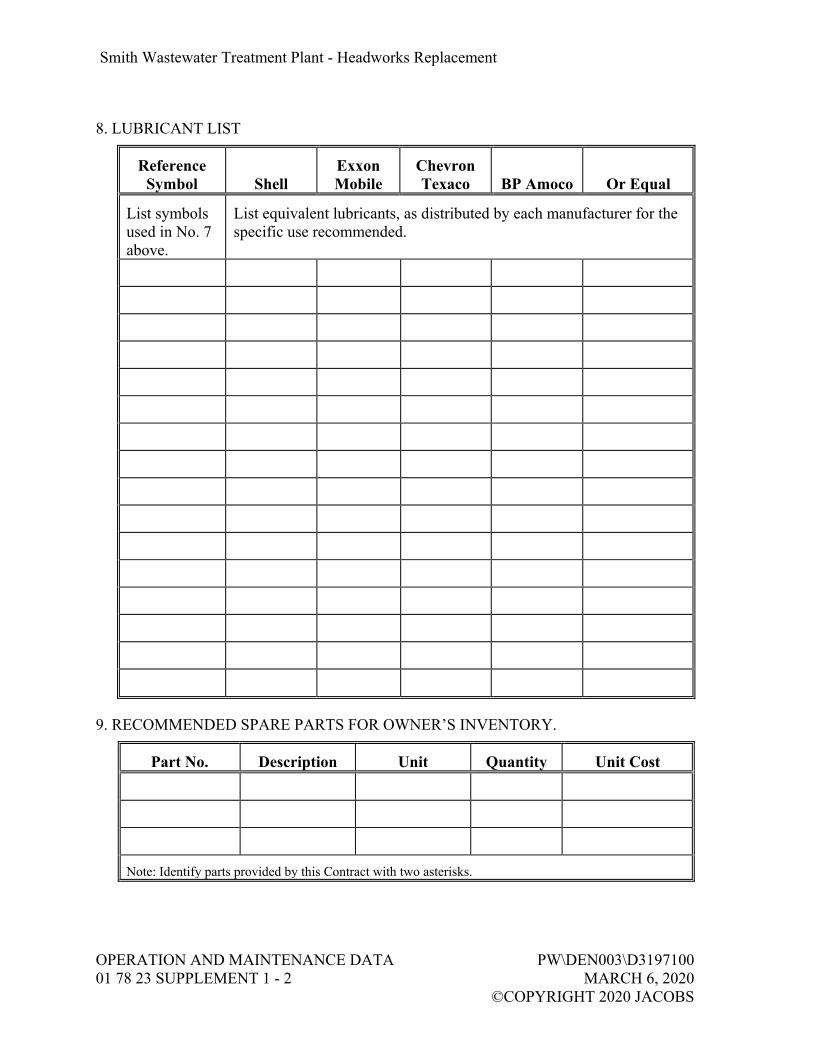
Smith Wastewater Treatment Plant - Headworks Replacement
OPERATION AND MAINTENANCE DATA PW\DEN003\D3197100 01 78 23 SUPPLEMENT 1 - 2 MARCH 6, 2020 ©COPYRIGHT 2020 JACOBS
8. LUBRICANT LIST
Reference Symbol Shell
Exxon Mobile
Chevron Texaco BP Amoco Or Equal
List symbols used in No. 7 above.
List equivalent lubricants, as distributed by each manufacturer for the specific use recommended.
9. RECOMMENDED SPARE PARTS FOR OWNER’S INVENTORY.
Part No. Description Unit Quantity Unit Cost
Note: Identify parts provided by this Contract with two asterisks.

Smith Wastewater Treatment Plant - Headworks Replacement
PW\DEN003\D3197100 ANCHORAGE AND BRACING APRIL 8, 2020 01 88 15 - 1 ©COPYRIGHT 2020 JACOBS
SECTION 01 88 15 ANCHORAGE AND BRACING
PART 1 GENERAL
1.01 SUMMARY
A. This section covers requirements for anchorage and bracing of equipment, distribution systems, and other nonstructural components required in accordance with the ICC 2012 International Building Code (IBC), for seismic, wind, gravity, soil, and operational loads.
1.02 REFERENCES
A. The following is a list of standards which may be referenced in this section:
1. American Institute of Steel Construction (AISC) 360, Specification for Structural Steel Buildings.
2. American Society of Civil Engineers (ASCE): ASCE 7, Minimum Design Loads for Buildings and Other Structures.
3. International Code Council (ICC): International Building Code (IBC). 4. State of Alabama.
1.03 DEFINITIONS
A. Authority Having Jurisdiction (AHJ): Permitting building agency; may be a federal, state, local, or other regional department, or individual including building official, fire chief, fire marshal, chief of a fire prevention bureau, labor department, or health department, electrical inspector; or others having statutory authority. AHJ may be Owner when authorized to be self-permitting by governmental permitting agency or when no governmental agency has authority.
B. Designated Seismic System: Architectural, electrical, and mechanical system or their components for which component importance factor is greater than 1.0.
1.04 DESIGN AND PERFORMANCE REQUIREMENTS
A. General:
1. Anchorage and bracing systems shall be designed by a qualified professional engineer registered in the State of Alabama.
2. Design anchorage into concrete including embedment in accordance with ACI 318-11, Appendix D (or other industry standard approved by Engineer), and Project Specifications. a. Unless otherwise noted, design for cracked concrete condition.

Smith Wastewater Treatment Plant - Headworks Replacement
ANCHORAGE AND BRACING PW\DEN003\D3197100 01 88 15 - 2 APRIL 8, 2020 ©COPYRIGHT 2020 JACOBS
3. Design anchorage and bracing of architectural, mechanical, and electrical components and systems in accordance with this section, unless a design is specifically provided within Contract Documents or where exempted hereinafter.
4. Design attachments, braces, and anchors for equipment, components, and distribution systems to structure for gravity, seismic, wind, and operational loading.
5. Anchor and brace piping and ductwork, whether exempt or not exempt for this section, so that lateral or vertical displacement does not result in damage or failure to essential architectural, mechanical, or electrical equipment.
6. Architectural Components: Includes, but are not limited to, nonstructural walls and elements, partitions, cladding and veneer, access flooring, signs, cabinets, suspended ceilings, and glass in glazed curtain walls and partitions.
7. Provide supplementary framing where required to transfer anchorage and bracing loads to structure.
8. Adjust equipment pad sizes or provide additional anchorage confinement reinforcing to provide required anchorage capacities.
9. Design anchorage and bracing for: a. Equipment and components that weigh more than 400 pounds and
have center of mass located 4 feet or less above adjacent finished floor.
b. Equipment weighing more than 20 pounds that has center of mass located more than 4 feet above adjacent finished floor.
c. Mechanical and electrical components that are not provided with flexible connections between components and associated ductwork, piping, or conduit.
d. Distribution systems that weigh more than 5 pounds per foot that have center of mass located more than 4 feet above adjacent finished floor.
10. Design seismic anchorage and bracing for Designated Seismic Systems regardless of weight or mounting height. a. Component Important Factor:
1) Ip = 1.0, unless noted otherwise. 2) Ip shall be taken as 1.5 if any of the following conditions
apply: a) Component is required to function for life-safety
purposes after an earthquake, including fire protection sprinkler systems and egress stairways.
b) Component contains hazardous materials. 11. For components exempted from design requirements of this section,
provide bolted, welded, or otherwise positively fastened attachments to supporting structure.

Smith Wastewater Treatment Plant - Headworks Replacement
PW\DEN003\D3197100 ANCHORAGE AND BRACING APRIL 8, 2020 01 88 15 - 3 ©COPYRIGHT 2020 JACOBS
B. Design Loads:
1. Gravity: Design anchorage and bracing for self-weight and superimposed loads on components and equipment.
2. Wind: Design anchorage and bracing for wind criteria provided on Structural Notes on Drawings for exposed architectural components and exterior and wind-exposed mechanical and electrical equipment. Alternately, manufacturer certification may be provided for components such as roofing and flashing to verify attachments meet Project-specific design criteria.
3. Operational: a. For loading supplied by equipment manufacturer for IBC required
load cases. b. Loads may include equipment vibration, torque, thermal effects,
effects of internal contents (weight and sloshing), water hammer, and other load-inducing conditions.
c. Locate braces to minimize vibration to or movement of structure. d. For vibrating loads, use anchors meeting requirements of
Section 05 50 00, Metal Fabrications or Section 05 05 19, Post-Installed Anchors, for anchors with designated capacities for vibratory loading per manufacturer’s ICC-ES report.
4. Hydraulic: Design of anchorage for submerged gates and other mechanical equipment shall include hydrostatic and hydrodynamic loads determined in accordance with Section 15.7 of ASCE 7-10.
5. Seismic: a. In accordance with 2012 IBC, Section 1613, and Chapter 13 of
ASCE 7. b. Design anchorage and bracing for design criteria listed on General
Structural Notes on Drawings. c. Design forces for anchors in concrete shall be in accordance with
ASCE 7, Section 13.4.2, or IBC Section 1905.1.9 as applicable for Project Seismic Design Category.
C. Seismic Design Requirements:
1. Analyze local region of body of nonstructural component for load transfer of anchorage attachment if component Ip = 1.5.
2. The following are exempt from requirements for provision of seismic anchorages and bracing, in addition to those items specifically exempted in ASCE 7, Part 13.5 for architectural components and Part 13.6 for electrical and mechanical equipment: a. Furniture, except storage cabinets and bookshelves over 6 feet tall. b. Temporary or movable equipment.

Smith Wastewater Treatment Plant - Headworks Replacement
ANCHORAGE AND BRACING PW\DEN003\D3197100 01 88 15 - 4 APRIL 8, 2020 ©COPYRIGHT 2020 JACOBS
3. Provide support drawings and calculations for electrical distribution components if any of the following conditions apply: a. Conduit diameter is greater than 2.5-inch trade size. b. Total weight of bus duct, cable tray, or conduit supported by
trapeze assemblies exceeds 10 pounds per foot. 4. Existing components, systems, and equipment in their final condition
that are modified by Project requirements and are not exempted by above paragraph require the same anchorage and bracing drawing and calculation submittals as new equipment. Field verify existing conditions.
5. Other seismic design and detailing information identified in ASCE 7, Chapter 13, is required to be provided for new architectural, mechanical and electrical components, systems, or equipment.
1.05 SUBMITTALS
A. Action Submittals:
1. Shop Drawings: a. List of architectural, mechanical, and electrical equipment
requiring Contractor-designed anchorage and bracing, unless specifically exempted.
b. Manufacturers’ engineered seismic and non-seismic hardware product data.
c. Attachment assemblies’ drawings including seismic attachments; include connection hardware, braces, and anchors or anchor bolts for nonexempt components, equipment, and systems.
d. Drawings for seismic attachment assemblies include connection hardware, braces, and anchors (or anchor bolts) for modified, nonexempt existing components, equipment, and systems where a combination of new and existing systems or components’ final condition would require anchorage or bracing under this specification for new equipment.
e. Submittal will be rejected if proposed anchorage method would create excessive stress to supporting member. Revise anchorages and strengthen structural support to eliminate overstressed condition.
B. Informational Submittals:
1. Anchorage and Bracing Calculations: For attachments, braces, and anchorages, include IBC and Project-specific criteria as noted on General Structural Notes on Drawings, in addition to manufacturer’s specific criteria used for design; sealed by a civil engineer registered in the State of Alabama.
2. Manufacturer’s hardware installation requirements.
Smith Wastewater Treatment Plant - Headworks Replacement
PW\DEN003\D3197100 ANCHORAGE AND BRACING APRIL 8, 2020 01 88 15 - 5 ©COPYRIGHT 2020 JACOBS
1.06 SOURCE QUALITY CONTROL
A. Contractor and supplier responsibilities to accommodate Owner-furnished shop fabrication related special inspections and testing are provided in Project’s Statement of Special Inspections on Drawings, and Section 01 45 33, Special Inspection, Observation, and Testing.
B. Provide all other specified, regulatory required, or required repair verification inspection and testing that is not listed in Statement of Special Inspections in accordance with Section 01 45 16.13, Contractor Quality Control.
C. Provide Source Quality Control for welding and hot-dip galvanizing of anchors in accordance with Section 05 50 00, Metal Fabrications.
PART 2 PRODUCTS
2.01 GENERAL
A. Design and construct attachments and supports transferring seismic and non-seismic loads to structure of materials and products suitable for application and in accordance with design criteria shown on Drawings and nationally recognized standards.
B. Provide anchor bolts for anchorage of equipment to concrete or masonry in accordance with Section 05 50 00, Metal Fabrications. Provide anchor bolts of the size, minimum embedment, and spacing designated in calculations submitted by Contractor and accepted by Engineer.
C. Provide post-installed concrete and masonry anchors for anchorage of equipment to concrete or masonry in accordance with Section 05 05 19, Post-Installed Anchors. Provide post-installed anchors of the size, minimum embedment, and spacing designated in calculations submitted by Contractor and accepted by Engineer.
D. Do not use powder-actuated fasteners or sleeve anchors for seismic attachments and anchorage where resistance to tension loads is required. Do not use expansion anchors, other than undercut anchors, for nonvibration isolated mechanical equipment rated over 10 horsepower.
PART 3 EXECUTION
3.01 GENERAL
A. Make attachments, bracing, and anchorage in such a manner that component lateral force is transferred to lateral force resisting system of structure through a complete load path.

Smith Wastewater Treatment Plant - Headworks Replacement
ANCHORAGE AND BRACING PW\DEN003\D3197100 01 88 15 - 6 APRIL 8, 2020 ©COPYRIGHT 2020 JACOBS
B. Design, provide, and install overall seismic anchorage system to provide restraint in all directions, including vertical, for each component or system so anchored.
C. Provide snubbers in each horizontal direction and vertical restraints for components mounted on vibration isolation systems where required to resist overturning.
D. Provide piping anchorage that maintains design flexibility and expansion capabilities at flexible connections and expansion joints.
1. Piping and ductwork suspended more than 12 inches below supporting structure shall be braced for seismic effects to avoid significant bending of hangers and their attachments , unless high-deformability piping is used per ASCE 7, Section 13.6.8 or HVAC ducts have a cross-sectional area of less than 6 square feet and or weigh 17 pounds per foot or less.
E. Anchor tall and narrow equipment such as motor control centers and telemetry equipment at base and within 12 inches from top of equipment, unless approved otherwise by Engineer.
F. Do not attach architectural, mechanical, or electrical components to more than one element of a building structure at a single restraint location where such elements may respond differently during a seismic event. Do not make such attachments across building expansion and contraction joints.
3.02 INSTALLATION
A. Do not install components or their anchorages or restraints prior to review and acceptance by Engineer and AHJ.
B. Notify Engineer upon completion of installation of seismic restraints in accordance with Section 01 45 33, Special Inspection, Observation, and Testing.
3.03 FIELD QUALITY ASSURANCE AND QUALITY CONTROL
A. In accordance with Section 05 50 00, Metal Fabrications and Section 05 05 19, Post-Installed Anchors.
B. Owner-Furnished Quality Assurance, in accordance with IBC Chapter 17 requirements, is provided in Statement of Special Inspections Plan on Drawings. Contractor responsibilities and related information are included in Section 01 45 33, Special Inspection, Observation, and Testing.

Smith Wastewater Treatment Plant - Headworks Replacement
PW\DEN003\D3197100 ANCHORAGE AND BRACING APRIL 8, 2020 01 88 15 - 7 ©COPYRIGHT 2020 JACOBS
C. Provide any other specified, regulatory required, or required repair verification inspection and testing that is not listed in Statement of Special Inspections in accordance with Section 01 45 16.13, Contractor Quality Control.
END OF SECTION

Smith Wastewater Treatment Plant - Headworks Replacement
PW\DEN003\D3197100 EQUIPMENT TESTING AND MARCH 6, 2020 FACILITY STARTUP ©COPYRIGHT 2020 JACOBS 01 91 14 - 1
SECTION 01 91 14 EQUIPMENT TESTING AND FACILITY STARTUP
PART 1 GENERAL
1.01 DEFINITIONS
A. Facility: Entire Project, or an agreed-upon portion, including all of its unit processes.
B. Functional Test: Test or tests in presence of Engineer and Owner to demonstrate that installed equipment meets manufacturer’s installation, calibration, and adjustment requirements and other requirements as specified.
C. Performance Test: Test or tests performed after any required functional test in presence of Engineer and Owner to demonstrate and confirm individual equipment meets performance requirements specified in individual sections.
D. Unit Process: As used in this section, a unit process is a portion of the facility that performs a specific process function, such as a pumping station.
E. Facility Performance Demonstration:
1. A demonstration, conducted by Contractor, with assistance of Owner, to demonstrate and document the performance of the entire operating facility, both manually and automatically (if required), based on criteria developed in conjunction with Owner and as accepted by Engineer.
2. Such demonstration is for the purposes of (i) verifying to Owner entire facility performs as a whole, and (ii) documenting performance characteristics of completed facility for Owner’s records. Neither the demonstration nor the evaluation is intended in any way to make performance of a unit process or entire facility the responsibility of Contractor, unless such performance is otherwise specified.
1.02 SUBMITTALS
A. Informational Submittals:
1. Facility Startup and Performance Demonstration Plan. 2. Functional and performance test results. 3. Completed Unit Process Startup Form for each unit process. 4. Completed Facility Performance Demonstration/Certification Form.

Smith Wastewater Treatment Plant - Headworks Replacement
EQUIPMENT TESTING AND PW\DEN003\D3197100 FACILITY STARTUP MARCH 6, 2020 01 91 14 - 2 ©COPYRIGHT 2020 JACOBS
1.03 FACILITY STARTUP AND PERFORMANCE DEMONSTRATION PLAN
A. Develop a written plan, in conjunction with Owner’s operations personnel; to include the following:
1. Step-by-step instructions for startup of each unit process and the complete facility.
2. Unit Process Startup Form (sample attached), to minimally include the following: a. Description of the unit process, including equipment
numbers/nomenclature of each item of equipment and all included devices.
b. Detailed procedure for startup of the unit process, including valves to be opened/closed, order of equipment startup, etc.
c. Startup requirements for each unit process, including water, power, chemicals, etc.
d. Space for evaluation comments. 3. Facility Performance Demonstration/Certification Form (sample
attached), to minimally include the following: a. Description of unit processes included in the facility startup. b. Sequence of unit process startup to achieve facility startup. c. Description of computerized operations, if any, included in the
facility. d. Contractor certification facility is capable of performing its
intended function(s), including fully automatic operation. e. Signature spaces for Contractor and Engineer.
PART 2 PRODUCTS (NOT USED)
PART 3 EXECUTION
3.01 GENERAL
A. Facility Startup Meetings: Schedule, in accordance with requirements of Section 01 31 19, Project Meetings, to discuss test schedule, test methods, materials, chemicals and liquids required, facilities operations interface, and Owner involvement.
B. Contractor’s Testing and Startup Representative:
1. Designate and furnish one or more personnel to coordinate and expedite testing and facility startup.
2. Representative(s) shall be present during startup meetings and shall be available at all times during testing and startup.

Smith Wastewater Treatment Plant - Headworks Replacement
PW\DEN003\D3197100 EQUIPMENT TESTING AND MARCH 6, 2020 FACILITY STARTUP ©COPYRIGHT 2020 JACOBS 01 91 14 - 3
C. Provide temporary valves, gauges, piping, test equipment and other materials and equipment required for testing and startup.
D. Provide Subcontractor and equipment manufacturers’ staff adequate to prevent delays. Schedule ongoing work so as not to interfere with or delay testing and startup.
E. Owner will:
1. Provide water, power, chemicals, and other items as required for startup, unless otherwise indicated.
2. Operate process units and facility with support of Contractor.
3.02 EQUIPMENT TESTING
A. Preparation:
1. Complete installation before testing. 2. Furnish qualified manufacturers’ representatives, when required by
individual Specification sections. 3. Obtain and submit from equipment manufacturer’s representative
Manufacturer’s Certificate of Proper Installation Form, in accordance with Section 01 43 33, Manufacturers’ Field Services, when required by individual Specification sections.
4. Equipment Test Report Form: Provide written test report for each item of equipment to be tested, to include the minimum information: a. Owner/Project Name. b. Equipment or item tested. c. Date and time of test. d. Type of test performed (Functional or Performance). e. Test method. f. Test conditions. g. Test results. h. Signature spaces for Contractor and Engineer as witness.
5. Cleaning and Checking: Prior to beginning functional testing: a. Calibrate testing equipment in accordance with manufacturer’s
instructions. b. Inspect and clean equipment, devices, connected piping, and
structures to ensure they are free of foreign material. c. Lubricate equipment in accordance with manufacturer’s
instructions. d. Turn rotating equipment by hand when possible to confirm that
equipment is not bound. e. Open and close valves by hand and operate other devices to check
for binding, interference, or improper functioning.
Smith Wastewater Treatment Plant - Headworks Replacement
EQUIPMENT TESTING AND PW\DEN003\D3197100 FACILITY STARTUP MARCH 6, 2020 01 91 14 - 4 ©COPYRIGHT 2020 JACOBS
f. Check power supply to electric-powered equipment for correct voltage.
g. Adjust clearances and torque. h. Test piping for leaks.
6. Ready-to-test determination will be by Engineer based at least on the following: a. Acceptable Operation and Maintenance Data. b. Notification by Contractor of equipment readiness for testing. c. Receipt of Manufacturer’s Certificate of Proper Installation, if so
specified. d. Adequate completion of work adjacent to, or interfacing with,
equipment to be tested. e. Availability and acceptability of manufacturer’s representative,
when specified, to assist in testing of respective equipment. f. Satisfactory fulfillment of other specified manufacturer’s
responsibilities. g. Equipment and electrical tagging complete. h. Delivery of all spare parts and special tools.
B. Functional Testing:
1. Conduct as specified in individual Specification sections. 2. Notify Owner and Engineer in writing at least 10 days prior to
scheduled date of testing. 3. Prepare Equipment Test Report summarizing test method and results. 4. When, in Engineer’s opinion, equipment meets functional requirements
specified, such equipment will be accepted for purposes of advancing to performance testing phase, if so required by individual Specification sections. Such acceptance will be evidenced by Engineer/Owner’s signature as witness on Equipment Test Report.
C. Performance Testing:
1. Conduct as specified in individual Specification sections. 2. Notify Engineer and Owner in writing at least 10 days prior to
scheduled date of test. 3. Performance testing shall not commence until equipment has been
accepted by Engineer as having satisfied functional test requirements specified.
4. Type of fluid, gas, or solid for testing shall be as specified. 5. Unless otherwise indicated, furnish labor, materials, and supplies for
conducting the test and taking samples and performance measurements. 6. Prepare Equipment Test Report summarizing test method and results.
Smith Wastewater Treatment Plant - Headworks Replacement
PW\DEN003\D3197100 EQUIPMENT TESTING AND MARCH 6, 2020 FACILITY STARTUP ©COPYRIGHT 2020 JACOBS 01 91 14 - 5
7. When, in Engineer’s opinion, equipment meets performance requirements specified, such equipment will be accepted as to conforming to Contract requirements. Such acceptance will be evidenced by Engineer’s signature on Equipment Test Report.
3.03 STARTUP OF UNIT PROCESSES
A. Prior to unit process startup, equipment within unit process shall be accepted by Engineer as having met functional and performance testing requirements specified.
B. Make adjustments, repairs, and corrections necessary to complete unit process startup.
C. Startup shall be considered complete when, in opinion of Engineer, unit process has operated in manner intended for 5 continuous days without significant interruption. This period is in addition to functional or performance test periods specified elsewhere.
D. Significant Interruption: May include any of the following events:
1. Failure of Contractor to provide and maintain qualified onsite startup personnel as scheduled.
2. Failure to meet specified functional operation. 3. Failure of any critical equipment or unit process that is not satisfactorily
corrected within 5 hours after failure. 4. Failure of any noncritical equipment or unit process that is not
satisfactorily corrected within 8 hours after failure. 5. As determined by Engineer.
E. A significant interruption will require startup then in progress to be stopped. After corrections are made, startup test period to start from beginning again.
3.04 FACILITY PERFORMANCE DEMONSTRATION
A. When, in the opinion of Engineer, startup of all unit processes has been achieved, sequence each unit process to the point that facility is operational.
B. Demonstrate proper operation of required interfaces within and between individual unit processes.
C. After facility is operating, complete performance testing of equipment and systems not previously tested.

Smith Wastewater Treatment Plant - Headworks Replacement
EQUIPMENT TESTING AND PW\DEN003\D3197100 FACILITY STARTUP MARCH 6, 2020 01 91 14 - 6 ©COPYRIGHT 2020 JACOBS
D. Document, as defined in Facility Startup and Performance Demonstration Plan, the performance of the facility including its computer system, until all unit processes are operable and under control of computer system.
E. Certify, on the Facility Performance Demonstration/Certification Form, that facility is capable of performing its intended function(s), including fully automatic and computerized operation.
3.05 SUPPLEMENTS
A. Supplements listed below, following “End of Section,” are a part of this Specification:
1. Unit Process Startup Form. 2. Facility Performance Demonstration/Certification Form.
END OF SECTION

Smith Wastewater Treatment Plant - Headworks Replacement
PW\DEN003\D3197100 EQUIPMENT TESTING AND MARCH 6, 2020 FACILITY STARTUP ©COPYRIGHT 2020 JACOBS 01 91 14 SUPPLEMENT 1 - 1
UNIT PROCESS STARTUP FORM
OWNER: PROJECT:
Unit Process Description: (Include description and equipment number of all equipment and devices):
Startup Procedure (Describe procedure for sequential startup and evaluation, including valves to be opened/closed, order of equipment startup, etc.):
Startup Requirements (Water, power, chemicals, etc.):
Evaluation Comments:


Smith Wastewater Treatment Plant - Headworks Replacement
PW\DEN003\D3197100 EQUIPMENT TESTING AND MARCH 6, 2020 FACILITY STARTUP ©COPYRIGHT 2020 JACOBS 01 91 14 SUPPLEMENT 2 - 1
FACILITY PERFORMANCE DEMONSTRATION/CERTIFICATION FORM
OWNER: PROJECT:
Unit Processes Description (List unit processes involved in facility startup):
Unit Processes Startup Sequence (Describe sequence for startup, including computerized operations, if any):
Contractor Certification that Facility is capable of performing its intended function(s), including fully automatic operation:
Contractor: Date: _________________________, 20____
Engineer: (Authorized Signature)
Date: _________________________, 20____

Smith Wastewater Treatment Plant - Headworks Replacement
PW\DEN003\D3197100 DEMOLITION MARCH 4, 2020 02 41 00 - 1 ©COPYRIGHT 2020 JACOBS
SECTION 02 41 00 DEMOLITION
PART 1 GENERAL
1.01 REFERENCES
A. The following is a list of standards which may be referenced in this section:
1. Air-Conditioning, Heating, and Refrigeration Institute (AHRI): Guideline K, Containers for Recovered Non-flammable Fluorocarbon Refrigerants.
2. American National Standards Institute (ANSI): A10.6, Safety Requirements for Demolition Operations.
3. Occupational Safety and Health Administration (OSHA), U.S. Code of Federal Regulations (CFR) Title 29 Part 1926—Occupational Safety and Health Regulations for Construction.
4. Environmental Protection Agency (EPA), U.S. Code of Federal Regulations (CFR), Title 40: a. Part 61—National Emission Standards for Hazardous Air
Pollutants. b. Part 82—Protection of Stratospheric Ozone. c. Part 273—Standards for Universal Waste Management.
1.02 DEFINITIONS
A. ACM: Asbestos-containing material.
B. Demolition: Dismantling, razing, destroying, or wrecking of any fixed building or structure or any part thereof. Demolition also includes removal of pipes, manholes tanks, conduit, and other underground facilities, whether as a separate activity or in conjunction with construction of new facilities.
C. Modify: Provide all necessary material and labor to modify an existing item to the condition indicated or specified.
D. Relocate: Remove, protect, clean and reinstall equipment, including electrical, instrumentation, and all ancillary components required to make the equipment fully functional, to the new location identified on the Drawings.
E. Renovation: Altering a facility or one or more facility components in any way.
F. Salvage/Salvageable: Remove and deliver, to the specified location(s), the equipment, building materials, or other items so identified to be saved from destruction, damage, or waste; such property to remain that of Owner. Unless otherwise specified, title to items identified for demolition shall revert to Contractor.
Smith Wastewater Treatment Plant - Headworks Replacement
DEMOLITION PW\DEN003\D3197100 02 41 00 - 2 MARCH 4, 2020 ©COPYRIGHT 2020 JACOBS
G. Universal Waste Lamp: In accordance with 40 CFR 273, the bulb or tube portion of an electric lighting device, examples of which include, but are not limited to, fluorescent, high-intensity discharge, neon, mercury vapor, high-pressure sodium, and metal halide lamps.
H. Universal Waste Thermostat: A temperature control device that contains metallic mercury in an ampule attached to a bimetal sensing element, and mercury-containing ampules that have been removed from these temperature control devices in compliance with the requirements of 40 CFR 273.
1.03 SUBMITTALS
A. Informational Submittals:
1. Submit proposed Demolition/Renovation Plan, in accordance with requirements specified herein, for approval before such Work is started.
2. Submit copies of any notifications, authorizations and permits required to perform the Work.
3. Copies of reports and other documentation required for abandoning wells.
1.04 REGULATORY AND SAFETY REQUIREMENTS
A. When applicable, demolition Work shall be accomplished in strict accordance with 29 CFR 1926-Subpart T.
B. Comply with federal, state, and local hauling and disposal regulations. In addition to the requirements of the General Conditions, Contractor’s safety requirements shall conform to ANSI A10.6.
C. Furnish timely notification of this demolition project to applicable federal, state, regional, and local authorities in accordance with 40 CFR 61-Subpart M.
1.05 DEMOLITION/RENOVATION PLAN
A. Demolition/Renovation Plan shall provide for safe conduct of the Work and shall include:
1. Detailed description of methods and equipment to be used for each operation.
2. The Contractor’s planned sequence of operations, including coordination with other work in progress.
3. Procedures for removal and disposition of materials specified to be salvaged.

Smith Wastewater Treatment Plant - Headworks Replacement
PW\DEN003\D3197100 DEMOLITION MARCH 4, 2020 02 41 00 - 3 ©COPYRIGHT 2020 JACOBS
1.06 SEQUENCING AND SCHEDULING
A. The Work of this Specification shall not commence until Contractor’s Demolition/Renovation Plan has been approved by Engineer.
B. Include the Work of this Specification in the progress schedule, as specified in Section 01 32 00, Construction Progress Documentation.
PART 2 PRODUCTS (NOT USED)
PART 3 EXECUTION
3.01 EXISTING FACILITIES TO BE DEMOLISHED OR RENOVATED
A. Facilities:
1. Facilities scheduled for complete demolition are as shown on the Drawings.
2. Portions of buildings and other areas scheduled for selective demolition, partial demolition, and renovation Work are as shown on the Drawings.
B. Structures:
1. Existing structures shown to be demolished shall be removed in their entirety.
2. Sidewalks, curbs, gutters and street light bases shall be removed as indicated.
C. Utilities and Related Equipment:
1. Notify Engineer or appropriate utilities to turn off affected services at least 48 hours before starting demolition activities.
2. Remove existing utilities as indicated and terminate in a manner conforming to the nationally recognized code covering the specific utility and approved by Engineer.
3. When utility lines are encountered that are not indicated on the Drawings, notify Engineer prior to further work in that area.
4. Remove meters and related equipment and deliver to a location as determined by the Owner.
5. Excavate and remove utility lines serving buildings to be demolished to a distance of 5 feet beyond the outside perimeter of the demolition.
6. Provide a permanent leak-proof closure for water and gas lines. 7. Plug sewer lines with concrete to a minimum plug length of 10 feet to
prevent groundwater infiltration.
Smith Wastewater Treatment Plant - Headworks Replacement
DEMOLITION PW\DEN003\D3197100 02 41 00 - 4 MARCH 4, 2020 ©COPYRIGHT 2020 JACOBS
D. Groundwater Observation Wells: Abandon the groundwater observation wells in accordance with City of Mobile requirements. Submit copies of all reports and other documentation required to be submitted to City. Abandon wells that will be within the limits of an excavation before excavation begins.
E. Paving and Slabs:
1. Sawcut concrete and asphaltic concrete paving and slabs to full depth. 2. Provide neat sawcuts at limits of pavement removal as indicated.
F. Concrete:
1. Core drill corners of new opening to avoid overcutting adjacent reinforcing in existing concrete to remain. Saw concrete along straight lines to a depth of not less than 2 inches. Make each cut in walls perpendicular to the face and in alignment with the cut in the opposite face. Break out the remainder of the concrete provided that the broken area is concealed in the finished Work, and the remaining concrete is sound.
2. At locations where the broken face cannot be concealed, grind smooth or saw cut entirely through the concrete. Repair exposed rebar ends and embeds as shown on Drawings.
3. Where new concrete adjoins existing concrete, thoroughly clean and mechanically roughen existing concrete surfaces to roughness profile of 3/16 inch. Rebar and small embeds at existing concrete may be required to be left to engage new concrete. Saturate surface with water for 24 hours prior to placing new concrete. The new Work shall tie into the existing construction as shown on Drawings.
4. At submerged locations not to receive new concrete, paint exposed rebar or metal embed ends with System No. 19a at wastewater surfaces per Section 09 90 00, Painting and Coating.
G. Patching:
1. Where removals leave holes and damaged surfaces exposed in the finished Work, patch and repair to match adjacent finished surfaces as to texture and finish.
2. Where new Work is to be applied to existing surfaces, perform removals and patching in a manner to produce surfaces suitable for receiving new Work.
3. Patching shall be as specified and indicated, and shall include: a. Fill holes and depressions caused by previous physical damage or
left as a result of removals in existing concrete walls with an approved patching material, applied in accordance with the manufacturer’s printed instructions.
Smith Wastewater Treatment Plant - Headworks Replacement
PW\DEN003\D3197100 DEMOLITION MARCH 4, 2020 02 41 00 - 5 ©COPYRIGHT 2020 JACOBS
H. Air-Conditioning Equipment:
1. Remove air-conditioning equipment without releasing chlorofluorocarbon refrigerants to the atmosphere in accordance with the Clean Air Act Amendment of 1990.
I. Cylinders and Canisters: Remove all fire suppression system cylinders and canisters and dispose as specified in Paragraph Ozone Depleting Substances (ODS).
J. Electrical:
1. Cut off concealed or embedded conduit, boxes, or other materials a minimum of 3/4 inch below final finished surface.
2. When removing designated equipment, conduit and wiring may require rework to maintain service to other equipment.
3. Rework existing circuits, or provide temporary circuits as necessary during renovation to maintain service to existing lighting and equipment not scheduled to be renovated. Existing equipment and circuiting shown are based upon limited field surveys. Verify existing conditions, make all necessary adjustments, and record the Work on the Record Drawings. This shall include, but is not limited to, swapping and other adjustments to branch circuits and relocation of branch circuit breakers within panelboards as required to accomplish the finished work.
4. Reuse of existing luminaires, devices, conduits, boxes, or equipment will be permitted only where specifically indicated.
5. Raceways and cabling not scheduled for reuse. a. Inaccessibly Concealed: Cut off and abandon in place. b. Exposed or Concealed above Accessible Ceilings: Remove.
6. Raceways and Cabling Scheduled for Future Use: Cap/seal and tag. 7. Relocating Equipment: Extend existing wiring or run new wiring from
the source. 8. Where the existing raceway is concealed, the outlet box shall be
cleaned, and a blank cover plate installed. 9. Where the concealed raceway is uncovered remove raceway (or
extended to new location if appropriate). 10. Provide new typewritten panelboard circuit directory cards.
K. Universal Waste Lamps and Thermostats: Manage, contain, package, and label in strict accordance with 40 CFR 273.

Smith Wastewater Treatment Plant - Headworks Replacement
DEMOLITION PW\DEN003\D3197100 02 41 00 - 6 MARCH 4, 2020 ©COPYRIGHT 2020 JACOBS
3.02 PROTECTION
A. Dust and Debris Control:
1. Prevent the spread of dust and debris to occupied portions of the building and avoid the creation of a nuisance in the surrounding area. Do not use water if it results in hazardous or objectionable conditions such as, but not limited to, ice, flooding, or pollution.
2. Sweep pavements as often as necessary to control the spread of debris that may result in foreign object damage potential to vehicular traffic.
B. Existing Work:
1. Survey the site and examine the Drawings and Specifications to determine the extent of the Work before beginning any demolition or renovation.
2. Take necessary precautions to avoid damage to existing items scheduled to remain in place, to be reused, or to remain the property of Owner; any Contractor-damaged items shall be repaired or replaced as directed by Engineer.
3. Provide temporary weather protection during interval between removal of existing exterior surfaces and installation of new to ensure that no water leakage or damage occurs to structure or interior areas of existing building.
4. Ensure that structural elements are not overloaded as a result of or during performance of the Work. Responsibility for additional structural elements or increasing the strength of existing structural elements as may be required as a result of any Work performed under this Contract shall be that of the Contractor. Repairs, reinforcement, or structural replacement must have Engineer approval.
5. Do not overload pavements to remain.
C. Trees: Protect trees within the Site that might be damaged during demolition and are indicated to be left in place, by a 6-foot high fence. The fence shall be securely erected a minimum of 5 feet from the trunk of individual trees or follow the outer perimeter of branches or clumps of trees. Any tree designated to remain that is damaged during the Work shall be replaced in kind, as approved by the Engineer.
D. Facilities:
1. Protect electrical and mechanical services and utilities. Where removal of existing utilities and pavement is specified or indicated, provide approved barricades, temporary covering of exposed areas, and temporary services or connections for electrical and mechanical utilities.

Smith Wastewater Treatment Plant - Headworks Replacement
PW\DEN003\D3197100 DEMOLITION MARCH 4, 2020 02 41 00 - 7 ©COPYRIGHT 2020 JACOBS
2. Protect all facility elements not scheduled for demolition. 3. Provide interior shoring, bracing, or support to prevent movement,
settlement, or collapse of structure or element to be demolished and adjacent facilities.
E. Protection of Personnel:
1. During demolition, continuously evaluate the condition of the structure being demolished and take immediate action to protect all personnel working in and around the demolition site.
2. Provide temporary barricades and other forms of protection to protect Owner’s personnel and the general public from injury due to demolition Work.
3. Provide protective measures as required to provide free and safe passage of Owner’s personnel and the general public to occupied portions of the structure.
3.03 BURNING
A. The use of burning at the Site for the disposal of refuse and debris will not be permitted.
3.04 RELOCATIONS
A. Perform the removal and reinstallation of relocated items as indicated with workmen skilled in the trades involved. Clean all items to be relocated prior to reinstallation, to the satisfaction of Engineer. Repair items to be relocated which are damaged or replace damaged items with new undamaged items as approved by Engineer.
3.05 BACKFILL
A. Do not use demolition debris as backfill material.
B. Fill excavations, open basements and other hazardous openings to existing ground level or foundation level of new construction in accordance with Section 31 23 23, Fill and Backfill.
3.06 TITLE TO MATERIALS
A. All items designated to be removed shall become the property of the Contractor.
Smith Wastewater Treatment Plant - Headworks Replacement
DEMOLITION PW\DEN003\D3197100 02 41 00 - 8 MARCH 4, 2020 ©COPYRIGHT 2020 JACOBS
B. Title to equipment and materials resulting from demolition is vested in the Contractor upon approval by the Engineer of Contractor’s Demolition / Renovation Plan, and the resulting authorization by Engineer to begin demolition.
3.07 REUSE OF MATERIALS AND EQUIPMENT
A. Remove and store materials and equipment listed in Article Title To Materials to be reused or relocated to prevent damage, and reinstall as the Work progresses.
B. Properly store and maintain equipment and materials in same condition as when removed.
C. Store equipment and material designated to be reused in a location designated by Owner.
D. Equipment and material designated to be reused shall be cleaned, serviced and checked for proper operability before being put back into service.
E. Engineer will determine condition of equipment and materials prior to removal.
3.08 UNSALVAGEABLE MATERIAL
A. Concrete, masonry, and other noncombustible material, except concrete permitted to remain in place, shall be disposed of offsite.
B. Combustible material shall be disposed of off the Site.
C. Universal Waste Lamps and Thermostats: Dispose of in strict accordance with 40 CFR 273.
3.09 CLEANUP
A. Debris and rubbish shall be removed from basement and similar excavations. Debris and rubbish shall be removed and transported in a manner that prevents spillage on streets or adjacent areas. Local regulations regarding hauling and disposal shall apply.
END OF SECTION
Smith Wastewater Treatment Plant - Headworks Replacement
PW\DEN003\D3197100 REPAIR OF VERTICAL AND OVERHEAD MARCH 5, 2020 CONCRETE SURFACES ©COPYRIGHT 2020 JACOBS 03 01 32 - 1
SECTION 03 01 32 REPAIR OF VERTICAL AND OVERHEAD CONCRETE SURFACES
PART 1 GENERAL
1.01 REFERENCES
A. The following is a list of standards which may be referenced in this section:
1. American Concrete Institute (ACI): a. 301, Specifications for Structural Concrete. b. 506.2, Specification for Shotcrete.
2. ASTM International (ASTM): a. A82/A82M, Standard Specification for Steel Wire, Plain, for
Concrete Reinforcement. b. A185/A185M, Standard Specification for Steel Welded Wire
Reinforcement, Plain, for Concrete. c. A615/A615M, Standard Specification for Deformed and Plain
Carbon-Steel Bars for Concrete Reinforcement. d. A706/A706M, Standard Specification for Low-Alloy Steel
Deformed and Plain Bars for Concrete Reinforcement. e. C42/C42M, Standard Test Method for Obtaining and Testing
Drilled Cores and Sawed Beams of Concrete. f. C78/C78M, Standard Test Method for Flexural Strength of
Concrete (Using Simple Beam with Third-Point Loading). g. C109/C109M, Standard Test Method for Compressive Strength of
Hydraulic Cement Mortars (Using 2-in. or Cube Specimens). h. C157/C157M, Standard Test Method for Length Change of
Hardened Hydraulic-Cement Mortar and Concrete. i. C348, Standard Test Method for Flexural Strength of Hydraulic-
Cement Mortars. j. C496/C496M, Standard Test Method for Splitting Tensile
Strength of Cylindrical Concrete Specimens. k. C531, Standard Test Method for Linear Shrinkage and Coefficient
of Thermal Expansion of Chemical-Resistant Mortars, Grouts, Monolithic Surfacings, and Polymer Concretes.
l. C596, Standard Test Method for Drying Shrinkage of Mortar Containing Hydraulic Cement.
m. C666/C666M, Standard Test Method for Resistance of Concrete to Rapid Freezing and Thawing.
n. C882/C882M, Standard Test Method for Bond Strength of Epoxy-Resin Systems Used with Concrete by Slant Shear.
o. C1202, Standard Test Method for Electrical Indication of Concrete’s Ability to Resist Chloride Ion Penetration.
Smith Wastewater Treatment Plant - Headworks Replacement
REPAIR OF VERTICAL AND OVERHEAD PW\DEN003\D3197100 CONCRETE SURFACES MARCH 5, 2020 03 01 32 - 2 ©COPYRIGHT 2020 JACOBS
p. C1583/C1583M, Standard Test Method for Tensile Strength of Concrete Surfaces and the Bond Strength or Tensile Strength of Concrete Repair and Overlay Materials by Direct Tension (Pull-off Method).
q. D4258, Standard Practice for Surface Cleaning Concrete for Coating.
r. D4259, Standard Practice for Abrading Concrete. s. E699, Standard Practice for Evaluation of Agencies Involved in
Testing, Quality Assurance, and Evaluating of Building Components.
1.02 DEFINITIONS
A. Abrasive Blasting: Surface preparation method that uses compressed air intermixed with an abrasive medium to clean surface of substrate concrete, exposed steel, and steel reinforcement. Compressed air and abrasive medium is projected at high speed through a nozzle directly at the surface. Method is used to remove corrosion by-products, laitance, or other materials that may inhibit bond of repair concrete.
B. Defective Area: As defined in Section 03 30 00, Cast-in-Place Concrete.
C. High-Pressure Water Blasting: Sometimes referred to as hydro-demolition. Uses water that may contain an abrasive medium, projected under high pressure and high velocity. Used for demolition, cutting, partial or full depth removal, cleaning, scarifying, or roughening of concrete surfaces, or removing existing coatings, for preparation of substrate concrete surfaces.
D. New Concrete: As defined in Section 03 30 00, Cast-in-Place Concrete.
1.03 SUBMITTALS
A. Action Submittals:
1. Product data sheets for each material supplied. 2. Drawings supplemented by photographs indicating location, size,
estimated quantity, and proposed repair mortar for each repair location in existing concrete.
3. Drawings indicating results of sounding for hollow areas including location, size, and estimated quantity of hollow-sounding areas for each repair location.
B. Informational Submittals:
1. Repair Mortar System: Manufacturer’s preparation and installation instructions.

Smith Wastewater Treatment Plant - Headworks Replacement
PW\DEN003\D3197100 REPAIR OF VERTICAL AND OVERHEAD MARCH 5, 2020 CONCRETE SURFACES ©COPYRIGHT 2020 JACOBS 03 01 32 - 3
2. Written description of equipment proposed for concrete removal and surface preparation.
3. Certificates: a. Manufacturer’s Certificate of Compliance, in accordance with
Section 01 61 00, Common Product Requirements, that proposed repair mortar systems are prepackaged, shrinkage compensated, specially designed for use on vertical and overhead surfaces that are exposed to weather.
b. Mortar Manufacturer’s Certificate of Proper Installation. 4. Statements of Qualification:
a. Repair mortar system applicator. b. Independent Testing Laboratory.
5. Repair mortar system manufacturer’s proposed modified test procedures for ASTM C109/C109M, ASTM C882/C882M, and ASTM C157/C157M test methods.
6. Field and laboratory test reports.
1.04 QUALITY ASSURANCE
A. Qualifications:
1. Repair Mortar System Applicator: 2. Repair Mortar System Manufacturer’s Representative: Knowledgeable
and experienced on technical data and application requirements for specified products.
B. Independent Testing Laboratory: Meet criteria stated in ASTM E699.
C. Pre-repair Conference:
1. Required Meeting Attendees: a. Contractor. b. Repair Subcontractor. c. Technical representative for repair material manufacturer if
required by Engineer. d. Engineer.
2. Schedule and conduct prior incorporation of respective products into Project. Notify Engineer of location and time.
3. Agenda shall include, but not limited to: a. Review of field conditions. Conduct field observations of Work to
be performed. b. Based on above observations, repair material manufacturer’s
technical representative shall confirm material selection and make Project-specific repair method recommendations.
Smith Wastewater Treatment Plant - Headworks Replacement
REPAIR OF VERTICAL AND OVERHEAD PW\DEN003\D3197100 CONCRETE SURFACES MARCH 5, 2020 03 01 32 - 4 ©COPYRIGHT 2020 JACOBS
c. Review proposed surface preparation, material application, consolidation, finishing, curing, and protection of repair material from weather conditions.
d. Other specified requirements requiring coordination.
1.05 DELIVERY, STORAGE, AND HANDLING
A. Package repair mortar system products in moisture-resistant bags, pails, or moisture-resistant bulk bags.
B. Deliver, store, and handle repair materials in accordance with manufacturer’s printed instructions.
PART 2 PRODUCTS
2.01 REPAIR SYSTEM C – POLYMER-MODIFIED REPAIR MORTAR
A. Polymer-modified, one- or two-component, cementitious based, chloride resistant, flowable, gray in color, working time of 20 minutes minimum, surface renovation mortar.
B. Cured Mortar Properties:
1. Compressive Strength, ASTM C109/C109M at 28 Days: 7,000 psi minimum.
2. Flexural Strength, ASTM C348 at 28 Days: 1,200 psi minimum. 3. Slant Shear Bond Strength, ASTM C882/C882M Test Method Modified
with No Bonding Agent at 28 Days: 2,000 psi minimum. 4. Splitting Tensile Strength, ASTM C496/C496M at 28 Days: 500 psi
minimum. 5. Drying Shrinkage, ASTM C596 at 28 Days: 0.12 percent maximum.
Not required for small repair areas approximately 1 square foot in area or less.
6. Freeze Thaw Resistance, ASTM C666/C666M, at 300 Cycles: 90 percent RDM.
7. Chloride Ion Permeability Based on Charge Passed, ASTM C1202: 800 coulombs maximum for liquid holding and below grade repairs.
C. Manufacturers and Products:
1. Sika Corp., Lyndhurst, NJ; SikaTop 123 PLUS. 2. Euclid Chemical Co., Cleveland, OH; DuralTop Gel.

Smith Wastewater Treatment Plant - Headworks Replacement
PW\DEN003\D3197100 REPAIR OF VERTICAL AND OVERHEAD MARCH 5, 2020 CONCRETE SURFACES ©COPYRIGHT 2020 JACOBS 03 01 32 - 5
2.02 WATER
A. Clean and free from oil, acid, alkali, organic matter, or other deleterious substances, meeting federal drinking water standards, as specified in Section 03 30 00, Cast-in-Place Concrete.
2.03 REINFORCEMENT
A. Deformed Steel Reinforcement: Per Section 03 21 00, Steel Reinforcement.
B. Tie Wire: 16-gauge, galvanized.
2.04 CEMENTITIOUS BONDING AGENT AND REINFORCEMENT COATING
A. Cementitious adhesive, specifically formulated for bonding plastic portland cement concrete or mortar to hardened portland cement concrete.
1. Mixed Bonding Agent Properties: a. Pot Life: 75 minutes to 105 minutes. b. Contact Time: 24 hours.
2. Cured Cementitious Adhesive Properties: a. Splitting Tensile Strength, ASTM C496/C496M at 28 Days:
500 psi minimum. b. Flexural Strength, ASTM C348: 1,000 psi minimum. c. Slant Shear Bond Strength, ASTM C882/C882M at 14 Days:
1) 2-Hour Open Time: 2,500 psi minimum. 2) 24-Hour Open Time: 2,000 psi minimum.
3. Bonding agent shall not produce a vapor barrier. 4. Compatible with and from same manufacturer as the repair system used.
B. Manufacturers and Products:
1. BASF Construction Chemicals, LLC - Building Systems, Shakopee, MN; MasterEmaco P 124.
2. Sika Corp., Lyndhurst, NJ; Sika Armatec 110 EpoCem. 3. Euclid Chemical Co., Cleveland, OH: Dural Prep AC.
2.05 EVAPORATION RETARDANT
A. As specified in Section 03 39 00, Concrete Curing.
2.06 CURING COMPOUND
A. As specified in Section 03 39 00, Concrete Curing.
Smith Wastewater Treatment Plant - Headworks Replacement
REPAIR OF VERTICAL AND OVERHEAD PW\DEN003\D3197100 CONCRETE SURFACES MARCH 5, 2020 03 01 32 - 6 ©COPYRIGHT 2020 JACOBS
PART 3 EXECUTION
3.01 GENERAL
A. New Concrete Work: Repair deficiencies in new concrete structures constructed under this Contract with applicable repair system. Refer to Section 03 30 00, Cast-in-Place Concrete.
3.02 PREPARATION
A. Identify unsound and deteriorated concrete by sounding techniques, or as directed by Engineer, and review proposed extent of repair with Engineer.
B. Remove unsound, honeycombed, deteriorated, or otherwise defective areas of concrete from work areas.
1. Use 8,000 psi minimum high-pressure water blasting machine as required for Site conditions.
2. Remove concrete to abrade substrate concrete surfaces to a minimum amplitude roughness of 3/16 inch measured between high and low points with a 3-foot-long straightedge, in accordance with ASTM D4259.
3. Where final surface is required to be flush with existing adjacent surface remove existing concrete depth as required for application of minimum thickness of repair mortar.
C. Do not use power-driven jackhammers, chipping hammers, or scabblers unless water blasting is not permitted or practical because of Site conditions, or may cause other damage to equipment or facilities. In such cases where chipping hammers are required, limit size of chipping hammer to 16 pounds or lighter, or use small electric hammer, to reduce formation of micro-fractures in substrate concrete surface.
D. Following removal of unsound or deteriorated concrete, check substrate concrete surface by sounding techniques to identify unsound concrete remaining or resulting from use of chipping hammer.
E. Remove unsound concrete to satisfaction of Engineer.
F. Square edges of patch areas by sawing or chipping to avoid tapered shoulders or featheredges. Avoid cutting embedded steel reinforcement. Roughen polished saw-cut edge by high-pressure water blasting.

Smith Wastewater Treatment Plant - Headworks Replacement
PW\DEN003\D3197100 REPAIR OF VERTICAL AND OVERHEAD MARCH 5, 2020 CONCRETE SURFACES ©COPYRIGHT 2020 JACOBS 03 01 32 - 7
G. Remove concrete adjacent to steel reinforcement to a minimum of 1-inch clearance around steel reinforcement for application and bonding of new repair mortar to circumference of exposed steel reinforcement if one or more of the following surface conditions exist:
1. 50 percent or more of circumference around steel reinforcement is exposed during concrete removal.
2. 25 percent or more of circumference around steel reinforcement is exposed during concrete removal and corrosion is present to extent that more than 25 percent loss of section has occurred.
3. Otherwise evident that bond between existing concrete and steel reinforcement has been destroyed or has deteriorated as determined by Engineer.
H. Clean exposed steel reinforcement of loose rust and concrete splatter per recommendations of repair material manufacturer and in accordance with ASTM D4258.
I. Keep areas from which concrete has been removed free of dirt, dust, and water blasting waste slurry. Remove laitance and other bond inhibiting contaminates from prepared areas.
J. Dampen repair areas at least 6 inches beyond area to receive repair mortar for at least 24 hours to provide saturated surface dry (SSD) condition without standing water at time of application of mortar as required by and in accordance with repair mortar manufacturer’s printed instructions.
K. Collect and dispose of spent water and concrete debris from removal operations offsite in manner and location acceptable to Owner.
3.03 REINFORCEMENT INSTALLATION
A. Replace deteriorated steel reinforcement with new steel reinforcement equivalent in cross-sectional area to original steel reinforcement.
3.04 PROTECTION
A. If cementitious coating or bonding agent is used, protect adjacent surfaces from over application. Promptly remove bonding agent applied beyond repair area.
3.05 REPAIR SYSTEM C – POLYMER-MODIFIED REPAIR MORTAR PLACEMENT
A. Mix mortar in accordance with manufacturer’s printed instructions.

Smith Wastewater Treatment Plant - Headworks Replacement
REPAIR OF VERTICAL AND OVERHEAD PW\DEN003\D3197100 CONCRETE SURFACES MARCH 5, 2020 03 01 32 - 8 ©COPYRIGHT 2020 JACOBS
B. Bond Coat: Apply to prepared substrate concrete surface before application of mortar in accordance with repair mortar manufacturer’s printed instructions. Do not apply more bond coat than can be covered with mortar before bond coat dries. Do not retemper bond coat.
C. Place mortar by hand or low-pressure spray and trowel to specified surface finish, in accordance with requirements of repair material’s printed instructions.
D. Finish repair mortar to smooth even surface to match adjacent concrete surface.
E. Cure as specified in Article Curing, and in accordance with manufacturer’s printed instructions.
3.06 CURING
A. Prior to curing, apply water fog to repair mortar system in accordance with repair mortar system manufacturer’s printed instructions.
B. Cure in accordance with repair mortar manufacturer’s printed instructions.
C. Where permitted by repair mortar manufacturer’s printed instructions, commence water curing after repair mortar system application and when curing will not cause erosion of mortar.
D. Continuously water fog cure repair mortar system for a period of 7 days.
E. Do not cure using curing compound or membrane, unless method is part of repair mortar system manufacturer’s printed instructions and approval is obtained from Engineer.
F. Cure intermediate layers of repair mortar in accordance with repair mortar manufacturer’s printed instructions.
G. Where curing compound is permitted by repair mortar system manufacturer, apply curing compound in accordance with Section 03 39 00, Concrete Curing.
3.07 FIELD QUALITY CONTROL
A. Sounding for Hollow Areas:
1. Light hammer tap repaired areas listening for hollow sound to determine areas that have not properly bonded to substrate concrete.
2. Mark hollow areas for removal and replacement.
Smith Wastewater Treatment Plant - Headworks Replacement
PW\DEN003\D3197100 REPAIR OF VERTICAL AND OVERHEAD MARCH 5, 2020 CONCRETE SURFACES ©COPYRIGHT 2020 JACOBS 03 01 32 - 9
B. Compression Strength Test:
1. Test in accordance with ASTM C109/C109M, except modified by making samples using repair mortar.
2. Obtain production samples of mixed wet mortar materials from nozzle, or mixer, during construction for compliance with Specifications for testing at 7 days, and 28 days.
3. Provide a minimum of three samples for each 200 square feet of mortar repair, and a minimum of three samples in total, whichever is greater, for testing.
4. Record location where repair mortar is being applied at time production samples are obtained.
C. Direct Tension Bond Test:
1. In Situ Bond Testing: Perform tension bond test in accordance with ASTM C1583/C1583M.
2. Record locations on in situ bond tests on each type of applied repair mortar.
D. Testing laboratory retained by Contractor will provide the following:
1. Compression Strength Test: a. Testing will follow a “modified” ASTM C109/C109M. b. A minimum of three production samples of mixed material will be
obtained from each 200 square feet of mortar repair, and a minimum of three samples in total, whichever is greater, for testing at 7 days, and 28 days.
c. Record location where repair mortar is being applied at time production samples are obtained.
2. Direct Tension Bond Test: a. Two core samples will be obtained and tested for each
2,000 square feet of repair work. b. Cores will be 2-1/2-inch or 3-inch diameter to a total depth equal
to at least 2.5 times repair mortar thickness. c. Bond Strength of Repair Mortar to Substrate Concrete: 300 psi
minimum in direct tension without failure or movement. d. Record locations of Bond Tests on each type of applied repair
mortar tested.
E. Retest mortar repairs that do not meet test requirements.
F. Repair and fill holes using same repair mortar where core samples have been removed.
Smith Wastewater Treatment Plant - Headworks Replacement
REPAIR OF VERTICAL AND OVERHEAD PW\DEN003\D3197100 CONCRETE SURFACES MARCH 5, 2020 03 01 32 - 10 ©COPYRIGHT 2020 JACOBS
3.08 MORTAR REPAIR FAILED TEST
A. Remove and replace unacceptable Work.
B. Hollow Sounding Areas: Saw cut hollow sounding areas to a new square edge. Remove unsound mortar repair. Prepare substrate surface and reapply repair mortar as specified herein above.
C. Failed Compression Strength Test: Remove affected areas of repair mortar represented by failed compression strength test results. Prepare substrate surface and reapply repair mortar as specified herein above.
D. Failed Bond Tests: Remove affected areas of repair mortar represented by failed bond test results. Prepare substrate surface and reapply repair mortar as specified herein above.
E. Retest areas where repair mortar was removed and replaced, in accordance with test requirements specified herein above.
3.09 MANUFACTURER’S SERVICES
A. Provide repair mortar system manufacturer’s representative at Site to review acceptability of surface preparation, mixing and installation assistance, inspection, and Certification of Proper Installation.
3.10 CLEANING
A. Remove waste materials, unsound material from concrete surfaces, material chipped from structure, and water used in preparation of or repair areas, finishing, and curing, and dispose offsite at an approved disposal site.
END OF SECTION

Smith Wastewater Treatment Plant - Headworks Replacement
PW\DEN003\D3197100 REPAIR OF HORIZONTAL APRIL 8, 2020 CONCRETE SURFACES ©COPYRIGHT 2020 JACOBS 03 01 33 - 1
SECTION 03 01 33 REPAIR OF HORIZONTAL CONCRETE SURFACES
PART 1 GENERAL
1.01 REFERENCES
A. The following is a list of standards which may be referenced in this section:
1. American Association of State Highway and Transportation Officials (AASHTO): T277, Standard Method of Test for Electrical Indication of Concrete’s Ability to Resist Chloride Ion Penetration.
2. ASTM International (ASTM): a. A82/A82M, Standard Specification for Steel Wire, Plain, for
Concrete Reinforcement. b. A1064/A1064M, Standard Specification for Steel Welded Wire
Reinforcement, Plain, for Concrete. c. A615/A615M, Standard Specification for Deformed and Plain
Carbon-Steel Bars for Concrete Reinforcement. d. A706/A706M, Standard Specification for Low-Alloy Steel
Deformed and Plain Bars for Concrete Reinforcement. e. C42/C42M, Standard Test Method for Obtaining and Testing
Drilled Cores and Sawed Beams of Concrete. f. C78/C78M, Standard Test Method for Flexural Strength of
Concrete (Using Simple Beam with Third-Point Loading). g. C109/C109M, Standard Test Method for Compressive Strength of
Hydraulic Cement Mortars (Using 2-in. or Cube Specimens). h. C157/C157M, Standard Test Method for Length Change of
Hardened Hydraulic-Cement Mortar and Concrete. i. C348, Standard Test Method for Flexural Strength of Hydraulic-
Cement Mortars. j. C469, Standard Test Method for Static Modulus of Elasticity and
Poisson’s Ratio of Concrete in Compression. k. C496/C496M, Standard Test Method for Splitting Tensile
Strength of Cylindrical Concrete Specimens. l. C666/C666M, Standard Test Method for Resistance of Concrete
to Rapid Freezing and Thawing. m. C779/C779M, Standard Test Method for Abrasion Resistance of
Horizontal Concrete Surfaces. n. C882/C882M, Standard Test Method for Bond Strength of Epoxy-
Resin Systems Used with Concrete by Slant Shear. o. C928/C928M, Standard Specification for Packaged, Dry, Rapid-
Hardening Cementitious Materials for Concrete Repairs.

Smith Wastewater Treatment Plant - Headworks Replacement
REPAIR OF HORIZONTAL PW\DEN003\D3197100 CONCRETE SURFACES APRIL 8, 2020 03 01 33 - 2 ©COPYRIGHT 2020 JACOBS
p. C1012/C1012M, Standard Test Method for Length Change of Hydraulic-Cement Mortars Exposed to a Sulfate Solution.
q. C1202, Standard Test Method for Electrical Indication of Concrete’s Ability to Resist Chloride Ion Penetration.
r. C1583/C1583M, Standard Test Method for Tensile Strength of Concrete Surfaces and the Bond Strength or Tensile Strength of Concrete Repair and Overlay Materials by Direct Tension (Pull-off Method).
s. D638, Standard Test Method for Tensile Properties of Plastics. t. D695, Standard Test Method for Compressive Properties of Rigid
Plastics. u. D4258, Standard Practice for Surface Cleaning Concrete for
Coating. v. D4259, Standard Practice for Abrading Concrete. w. E699, Standard Practice for Evaluation of Agencies Involved in
Testing, Quality Assurance, and Evaluating of Building Components.
1.02 DEFINITIONS
A. Abrasive Blasting: Surface preparation method that uses compressed air intermixed with an abrasive medium to clean surface of substrate concrete, exposed steel, and steel reinforcement. Compressed air and abrasive medium is projected at high speed through a nozzle directly at the surface. Method is used to remove corrosion by-products, laitance, or other materials that may inhibit bond of repair concrete.
B. Defective Area: As defined in Section 03 30 00, Cast-in-Place Concrete.
C. High-Pressure Water Blasting (sometimes referred to as hydro-demolition): Uses water that may contain an abrasive medium, projected under high pressure and high velocity. Used for demolition, cutting, partial or full depth removal, cleaning, scarifying, or roughening of concrete surfaces, or removing existing coatings, for preparation of substrate concrete surfaces.
D. New Concrete: As defined in Section 03 30 00, Cast-in-Place Concrete.
1.03 SUBMITTALS
A. Action Submittals:
1. Product data sheets for each material supplied. 2. Drawings supplemented by photographs indicating location, size,
estimated quantity, and proposed repair mortar system for each repair location in existing concrete.
Smith Wastewater Treatment Plant - Headworks Replacement
PW\DEN003\D3197100 REPAIR OF HORIZONTAL APRIL 8, 2020 CONCRETE SURFACES ©COPYRIGHT 2020 JACOBS 03 01 33 - 3
B. Informational Submittals:
1. Repair Mortar System: Manufacturer’s preparation and installation instructions.
2. Written description of equipment proposed for concrete removal and surface preparation.
3. Certificates: a. Manufacturer’s Certificate of Compliance in accordance with
Section 01 61 00, Common Product Requirements, that proposed repair mortar systems meet requirements of ASTM C928/C928M.
b. Manufacturer’s Certificate of Compliance, in accordance with Section 01 61 00, Common Product Requirements, that repair mortar systems are prepackaged, shrinkage compensated, specially designed for use on horizontal surfaces that are exposed to weather.
c. Mortar Manufacturer’s Certificate of Proper Installation. 4. Statements of Qualification: Repair mortar system applicator. 5. Field and laboratory test results.
1.04 QUALITY ASSURANCE
A. Qualifications: Repair Mortar System Applicator: Trained and experienced applicator endorsed by repair mortar system manufacturer.
B. Independent Testing Laboratory: Meet criteria stated in ASTM E699.
C. Pre-repair Conference:
1. Required Meeting Attendees: a. Contractor. b. Repair Subcontractor. c. Technical representative for repair material manufacturer. d. Engineer.
2. Schedule and conduct prior to incorporation of respective products into Project. Notify Engineer of location and time.
3. Agenda shall include, but not limited to: a. Review of field conditions. Conduct field observations of the
Work to be performed. b. Based on above observations, repair material manufacturer’s
technical representative shall confirm material selection and make Project specific repair method recommendations.
c. Technical representative for repair material manufacturer shall review proposed surface preparation, material application, consolidation, finishing, curing, and protection of repair material from weather conditions.
d. Other specified requirements requiring coordination.

Smith Wastewater Treatment Plant - Headworks Replacement
REPAIR OF HORIZONTAL PW\DEN003\D3197100 CONCRETE SURFACES APRIL 8, 2020 03 01 33 - 4 ©COPYRIGHT 2020 JACOBS
1.05 DELIVERY, STORAGE, AND HANDLING
A. Package repair mortar system products in moisture-resistant bags, pails, or moisture-resistant bulk bags.
B. Deliver, store, and handle repair materials in accordance with manufacturer’s printed instructions.
PART 2 PRODUCTS
2.01 REPAIR MORTAR SYSTEM NO. 5—POLYMER MODIFIED REPAIR MORTAR
A. One or two-component, fast-setting, polymer modified cementitious based repair mortar system.
B. Compressive Strength, ASTM C109/C109M:
1. 1 Day: 2,500 psi minimum. 2. 7 Days: 5,000 psi minimum. 3. 28 Days: 7,000 psi minimum.
C. Flexural Strength, ASTM C348 at 28 Days: 1,500 psi minimum.
D. Slant Shear Bond Strength, ASTM C882/C882M Modified at 28 Days: 2,000 psi minimum.
E. Splitting Tensile Strength, ASTM C496/C496M at 28 Days: 600 psi minimum.
F. Abrasion Resistance Depth of Wear, ASTM C779/C779M, Procedure A, at 60 Minutes: 0.033 inch maximum.
G. Drying Shrinkage, ASTM C157/C157M Modified, at 28 Days: 0.09 percent maximum.
H. Rapid Chloride Ion Permeability Based on Charge Passed, ASTM C1202: 28 Days: Under 850 coulombs maximum.
I. Manufacturers and Products:
1. Sika Corporation - Lyndhurst NJ; SikaTop – 122 PLUS. 2. Euclid Chemical Co., Cleveland, OH; Duraltop Flowable Mortar.

Smith Wastewater Treatment Plant - Headworks Replacement
PW\DEN003\D3197100 REPAIR OF HORIZONTAL APRIL 8, 2020 CONCRETE SURFACES ©COPYRIGHT 2020 JACOBS 03 01 33 - 5
2.02 WATER
A. Clean and free from oil, acid, alkali, organic matter, or other deleterious substances, meeting federal drinking water standards, as specified in Section 03 30 00, Cast-in-Place Concrete.
2.03 REINFORCEMENT
A. Deformed Steel reinforcement: ASTM A615/A615M, Grade 60, where welding is not required.
B. Mesh Reinforcement: Welded wire fabric flat sheets with spacing of wires and wire size in accordance with ASTM A1064/A1064M, wire 75 ksi minimum tensile strength per ASTM A82/A82M, and repair mortar system manufacturer’s recommendations.
C. Tie Wire: 16-gauge, galvanized.
D. Mesh Anchors:
1. Manufacturers and Products: a. Powers Fastening, Inc., Brewster, NY; Tie Wire Version of
Power-Stud. b. Hilti Fastener Systems, Tulsa, OK; Kwik Bolt II HHDCA,
1/4-inch ceiling hanger.
2.04 CEMENTITIOUS BONDING AGENT AND REINFORCEMENT COATING
A. Cementitious adhesive, specifically formulated for bonding plastic portland cement concrete or mortar to hardened portland cement concrete.
1. Mixed Bonding Agent Properties: a. Pot Life: 75 minutes to 105 minutes. b. Contact Time: 24 hours.
2. Cured Cementitious Adhesive Properties: a. Splitting Tensile Strength, ASTM C496/C496M at 28 Days:
600 psi minimum. b. Flexural Strength, ASTM C348: 1,000 psi minimum. c. Slant Shear Bond Strength, ASTM C882/C882M:
1) 2-Hour Open Time: 2,500 psi minimum. 2) 24-Hour Open Time: 2,000 psi minimum.
3. Bonding agent shall not produce a vapor barrier. 4. Compatible with, and from same manufacturer as the, repair mortar
system used.

Smith Wastewater Treatment Plant - Headworks Replacement
REPAIR OF HORIZONTAL PW\DEN003\D3197100 CONCRETE SURFACES APRIL 8, 2020 03 01 33 - 6 ©COPYRIGHT 2020 JACOBS
B. Manufacturers and Products:
1. BASF Construction Chemicals, LLC - Building Systems, Shakopee, MN; MasterEmaco P 124.
2. Sika Corp., Lyndhurst, NJ; Sika Armatec 110 EpoCem. 3. Euclid Chemical Co., Cleveland, OH; Dural Prep AC.
2.05 EPOXY BONDING AGENT
A. Two-component, moisture insensitive, 100 percent solids epoxy resin.
B. Tensile Strength, ASTM D638, at 14 Days: 4,400 psi minimum.
C. Elongation at Break, ASTM D638: 1.49 percent minimum.
D. Compressive Strength, ASTM D695, at 28 Days for Application Temperature of 73 Degrees F to 77 Degrees F: 8,000 psi minimum.
E. Bond Strength, ASTM C882/C882M, at 14 Days: 1,800 psi minimum.
F. Pot Life, at 73 Degrees F to 77 Degrees F: 75 minutes minimum.
G. Manufacturers and Products: BASF Construction Chemicals, LLC - Building Systems, Shakopee, MN; MasterEmaco ADH 326 when ambient temperature is 73 degrees F or higher.
2.06 EVAPORATION RETARDANT
A. As specified in Section 03 39 00, Concrete Curing.
2.07 CURING COMPOUND
A. As specified in Section 03 39 00, Concrete Curing.
PART 3 EXECUTION
3.01 GENERAL
A. New Concrete Work: Repair deficiencies in new concrete structures constructed under this Contract with applicable repair system.
3.02 APPLICATION
A. General:
1. Repair Mortar System No. 5: a. Patches and Overlays: 1/4 inch to 3 inches thick. b. Return to service for foot traffic in 4 hours; wheel traffic in
7 days.

Smith Wastewater Treatment Plant - Headworks Replacement
PW\DEN003\D3197100 REPAIR OF HORIZONTAL APRIL 8, 2020 CONCRETE SURFACES ©COPYRIGHT 2020 JACOBS 03 01 33 - 7
c. Working Time: 30 minutes at 70 degrees F. d. Application Temperature Range: 45 degrees F to 90 degrees F.
3.03 PREPARATION
A. Identify unsound and deteriorated concrete by sounding techniques, or as directed by Engineer. Review proposed extent of repair with Engineer.
B. Remove unsound, deteriorated, or otherwise defective areas of concrete from Work areas.
1. Use 8,000 psi minimum high-pressure water blasting machine, as appropriate to suit Site conditions.
2. Remove concrete to abrade substrate concrete surface to a minimum amplitude roughness of 3/16 inch measured between high and low points with a 3-foot long straightedge, in accordance with ASTM D4259.
3. Where final surface is required to be flush with existing adjacent surface, remove existing concrete depth as required for application of minimum thickness of repair mortar.
C. Do not use power-driven jackhammers, chipping hammers, scabblers, or scarifiers unless water blasting is not permitted or practical because of Site conditions, or may cause other damage to equipment or facilities. In such cases where chipping hammers are required, limit size of chipping hammer to 16 pounds or lighter, or use small electric chipping hammer, to reduce formation of micro-fractures in substrate concrete surface.
D. Following removal of unsound or deteriorated concrete, check substrate concrete surface by sounding techniques to identify unsound concrete remaining or resulting from use of chipping hammer.
E. Remove unsound concrete to satisfaction of Engineer.
F. Square edges of patch areas by sawing or chipping to avoid tapered shoulders or featheredges. Avoid cutting embedded steel reinforcement. Roughen polished saw-cut edge by high-pressure water blasting.
G. Remove concrete adjacent to steel reinforcement to a minimum of 1-inch clearance around steel reinforcement for application and bonding of new repair mortar to entire circumference of exposed steel reinforcement if one or more of the following surface conditions exist:
1. 50 percent or more of circumference around steel reinforcement is exposed during concrete removal.
Smith Wastewater Treatment Plant - Headworks Replacement
REPAIR OF HORIZONTAL PW\DEN003\D3197100 CONCRETE SURFACES APRIL 8, 2020 03 01 33 - 8 ©COPYRIGHT 2020 JACOBS
2. 25 percent or more of circumference around steel reinforcement is exposed during concrete removal and corrosion is present to extent that more than 25 percent loss of section has occurred.
3. Otherwise evident that bond between existing concrete and steel reinforcement has been destroyed or has deteriorated as determined by Engineer.
H. Clean exposed steel reinforcement of loose rust and concrete splatter per recommendations of repair material manufacturer and in accordance with ASTM D4258.
I. Keep areas from which concrete has been removed free of dirt, dust, and water blasting waste slurry. Remove laitance and other bond inhibiting contaminates from prepared areas.
J. Preparation of Substrate Concrete Surface in Areas to Receive Repair Mortar System No. 5: Dampen repair areas at least 6 inches beyond area to receive repair mortar for at least 24 hours to provide saturated surface dry (SSD) condition without standing water at time of application of mortar, as required by and in accordance with repair mortar manufacturer’s printed instructions.
K. Collect and dispose of spent water and concrete debris from removal operations offsite in manner and location acceptable to Owner.
3.04 REINFORCEMENT INSTALLATION
A. Provide steel reinforcement when existing steel reinforcement is not exposed and when mortar application is more than 4 inches deep, unless otherwise shown on Drawings.
B. Replace deteriorated steel reinforcement with new steel reinforcement equivalent in cross-sectional area to original steel reinforcement.
C. Install mesh anchors in accordance with mesh manufacturer’s instructions.
D. Fasten steel reinforcement to chairs with tie wire to prevent from moving during placement of repair mortar.
E. Lap reinforcement mesh a minimum of one mesh spacing and securely fasten mesh to mesh anchors, or to steel reinforcement fastened to mesh anchors, with tie wire at intervals no more than 12 inches to prevent movement during application of repair mortar.
F. Coat exposed new and existing steel reinforcement with cementitious reinforcement coating at the same time as substrate concrete is coated, as specified below, per repair mortar and cementitious reinforcement coating manufacturers’ printed instructions.

Smith Wastewater Treatment Plant - Headworks Replacement
PW\DEN003\D3197100 REPAIR OF HORIZONTAL APRIL 8, 2020 CONCRETE SURFACES ©COPYRIGHT 2020 JACOBS 03 01 33 - 9
3.05 PROTECTION
A. If cementitious coating or bonding agent is used, protect adjacent surfaces from over application. Promptly remove bonding agent applied beyond repair area.
B. Protect adjacent surfaces, and equipment from spillage of repair mortar and dust, as applicable for repair mortar system used.
3.06 PLACEMENT
A. Repair Mortar System No. 5:
1. Remove standing and free water from prepared area. 2. Apply bond scrub coat of mortar to prepared surface in accordance with
manufacturer’s instructions. Do not apply more scrub coat of mortar than can be covered with repair mortar before scrub coat begins drying.
3. Immediately place mixed repair mortar into prepared area from one side to the other side.
4. Work material firmly into bottom and sides of patch to ensure a good continuous bond.
5. Level repair mortar and screed to elevation of existing concrete. 6. Finish to same texture as existing concrete around patch. 7. Repair Mortar System No. 5 screed or use self-leveling mixture to
obtain a uniform and plane surface.
3.07 CURING
A. Repair Mortar System No. 5: Apply curing compound in accordance with Section 03 39 00, Concrete Curing.
3.08 FIELD QUALITY CONTROL
A. Sounding for Hollow Areas:
1. Chain drag or light hammer tap repaired areas listening for hollow sound to determine areas that have not properly bonded to substrate concrete.
2. Mark hollow areas for removal and replacement.
B. Compression Strength Test:
1. Test in accordance with ASTM C109/C109M, except modified by making samples using repair mortar.
2. Obtain production samples of mixed materials from mixer during construction for compliance with Specifications.

Smith Wastewater Treatment Plant - Headworks Replacement
REPAIR OF HORIZONTAL PW\DEN003\D3197100 CONCRETE SURFACES APRIL 8, 2020 03 01 33 - 10 ©COPYRIGHT 2020 JACOBS
3. Provide minimum of three samples for each 200 square feet of mortar repair, and a minimum of three samples in total, whichever is greater for testing.
4. Record location where repair mortar is being applied at time production samples are obtained.
C. Direct Tension Bond Test:
1. In Situ Bond Testing: Perform tension bond test in accordance with ASTM C1583/C1583M.
2. Record locations on in situ bond tests on each type of applied repair mortar.
D. Testing laboratory retained by Contractor will provide the following:
1. Compression Strength Test: a. Testing will follow a “modified” ASTM C109/C109M. b. A minimum of three production samples of mixed material will be
obtained from each 200 square feet of mortar repair, and a minimum of three samples in total, whichever is greater, for testing at 7 days, and 28 days.
c. Record location where repair mortar is being applied at time production samples are obtained.
2. Direct Tension Bond Test: a. Two core samples will be obtained and tested for each
2,000 square feet of repair work. b. Cores will be 2-1/2-inch or 3-inch diameter to a total depth equal
to at least 2.5 times repair mortar thickness. c. Bond Strength of Repair Mortar to Substrate Concrete: 300 psi
minimum in direct tension without failure or movement. d. Record locations of bond tests on each type of applied repair
mortar tested.
E. Retest mortar repairs that do not meet test requirements.
F. Repair and fill holes using same repair mortar where core samples have been removed.
3.09 MORTAR REPAIR FAILED TEST
A. Remove and replace unacceptable Work.
B. Hollow Sounding Areas: Saw cut hollow sounding areas to a new square edge, remove unsound mortar repair. Prepare substrate surface and reapply repair mortar as specified herein above.
Smith Wastewater Treatment Plant - Headworks Replacement
PW\DEN003\D3197100 REPAIR OF HORIZONTAL APRIL 8, 2020 CONCRETE SURFACES ©COPYRIGHT 2020 JACOBS 03 01 33 - 11
C. Failed Compression Strength Test: Remove affected areas of repair mortar represented by failed compression strength test results. Prepare substrate surface and reapply repair mortar as specified herein above.
D. Failed Bond Tests: Remove affected areas of repair mortar represented by failed bond test results. Prepare substrate surface and reapply repair mortar as specified herein above.
E. Retest areas where repair mortar was removed and replaced, in accordance with test requirements specified herein above.
3.10 MANUFACTURERS’ SERVICES
A. Provide mortar manufacturer’s representative at Site to advice on product selection, review acceptability of surface preparation, mixing and installation assistance, inspection, and Certification of Proper Installation.
3.11 CLEANING
A. Remove excess repair mortar materials as the Work proceeds. Remove waste materials, unsound material from concrete surfaces, material chipped from structure, and water used in preparation of repair areas, finishing, and curing, and dispose offsite at approved disposal site.
END OF SECTION


Smith Wastewater Treatment Plant - Headworks Replacement
PW\DEN003\D3197100 CONCRETE FORMING AND ACCESSORIES MARCH 5, 2020 03 10 00 - 1 ©COPYRIGHT 2020 JACOBS
SECTION 03 10 00 CONCRETE FORMING AND ACCESSORIES
PART 1 GENERAL
1.01 REFERENCES
A. The following is a list of standards which may be referenced in this section:
1. American Concrete Institute (ACI): 301, Specifications for Structural Concrete.
1.02 DEFINITIONS
A. Defective Areas: See definition in Section 03 30 00, Cast-in-Place Concrete.
B. Exposed Concrete: See definition in Section 03 30 00, Cast-in-Place Concrete.
1.03 DESIGN REQUIREMENTS
A. Design formwork in accordance with ACI 301 to provide concrete finishes specified in Section 03 30 00, Cast-in-Place Concrete.
B. Unless otherwise specified, limit deflection of facing materials for concrete surfaces to comply with ACI 117 and ACI 301. Limit deflection of facing materials to comply with tolerance limits established by Contract Documents and with tolerances required by equipment manufacturers. Coordinate tolerance requirements with equipment manufacturers.
1.04 SUBMITTALS
A. Action Submittals:
1. Shop Drawings: Formwork drawings signed and sealed by a licensed professional engineer in the state of the Project.
2. Product Data: a. Form release agent. b. Form ties. c. Products to be used for sealing tie holes.
B. Informational Submittals: Statement of qualifications for formwork designer.

Smith Wastewater Treatment Plant - Headworks Replacement
CONCRETE FORMING AND ACCESSORIES PW\DEN003\D3197100 03 10 00 - 2 MARCH 5, 2020 ©COPYRIGHT 2020 JACOBS
1.05 QUALITY ASSURANCE
A. Qualifications:
1. Formwork Designer: Formwork, falsework, and shoring design shall be designed by an engineer licensed in the State of Alabama.
PART 2 PRODUCTS
2.01 FORM MATERIALS
A. Wall Forms and Underside of Slabs and Beams:
1. Materials: Plywood, hard plastic finished plywood, overlaid waterproof particle board, or steel in “new and undamaged” condition, of sufficient strength and surface smoothness to produce specified finish.
2. Where steel forms are used, treat steel surfaces to prevent rusting using products approved for use on steel forms.
B. Column Forms:
1. Rectangular Columns: As specified for walls.
2.02 ACCESSORIES
A. Form Release Agent:
1. Material: a. Shall not bond with, stain, or adversely affect concrete surfaces. b. Shall not impair subsequent treatments of concrete surfaces when
applied to forms c. Ready-to-use water based material formulated to reduce or
eliminate surface imperfections. d. Contain no mineral oil or organic solvents.
2. Manufacturers and Products: Not for surfaces exposed to potable water. a. BASF, Shakopee, MN; MBT MasterFinish RL 211. b. Cresset Chemical Company; Crete-Lease 20-VOC-Xtra.
B. Rustication Grooves and Beveled Edge Corner Strips: Nonabsorbent material, compatible with form surface, fully sealed on all sides prohibiting loss of paste or water between the two surfaces.
C. Form Snap-Ties:
1. Material: Steel. 2. Spreader Inserts:
a. Conical or spherical type.

Smith Wastewater Treatment Plant - Headworks Replacement
PW\DEN003\D3197100 CONCRETE FORMING AND ACCESSORIES MARCH 5, 2020 03 10 00 - 3 ©COPYRIGHT 2020 JACOBS
b. Design to maintain positive contact with forming material. c. Furnish units that will leave no metal closer than 1.5 inches to
concrete surface when forms, inserts, and tie ends are removed. 3. Wire ties not permitted.
D. Form Snap-Ties with Water Stop:
1. For hydraulic structures, basements, pipe galleries, and accessible spaces below finish grade, furnish one of the following: a. Integral steel water stop 0.103-inch thick and 0.625-inch diameter
tightly and continuously welded to tie. b. Neoprene water stop 3/16-inch thick and 15/16-inch diameter
whose center hole is one-half diameter of tie, or molded plastic water stop of comparable size.
c. Orient water stop perpendicular to tie and symmetrical about center of tie.
d. Design ties to prevent rotation or disturbance of center portion of tie during removal of ends and to prevent water leaking along tie.
E. Through-Bolts:
1. At Contractor’s option, may be used as alternate to form snap-tie or form snap-tie with water stop.
2. Tapered minimum 1-inch diameter at smallest end. 3. Elastic Vinyl Plug for Through-Bolt Tie Holes:
a. Design and size of plug to allow insertion with tool to enable plug to elongate and return to original length and diameter upon removal; forms watertight seal.
b. Manufacturers and Products: Greenstreak Group, Inc., St Louis, MO; X-Plug.
PART 3 EXECUTION
3.01 FORM SURFACE PREPARATION
A. Prior to coating surface, thoroughly clean form surfaces that will be in contact with concrete or that have been in contact with previously cast concrete, dirt, and other surface contaminants.
B. Exposed Wood Forms in Contact with Concrete: Apply form release agent as recommended by manufacturer.
C. Steel Forms: Apply form release agent as soon as they are cleaned to prevent discoloration of concrete from rust.
Smith Wastewater Treatment Plant - Headworks Replacement
CONCRETE FORMING AND ACCESSORIES PW\DEN003\D3197100 03 10 00 - 4 MARCH 5, 2020 ©COPYRIGHT 2020 JACOBS
3.02 ERECTION
A. General: In accordance with ACI 301, unless otherwise specified.
B. Beveled Edges (Chamfer):
1. Form 3/4-inch bevels at concrete edges, unless otherwise shown. 2. Where beveled edges on existing adjacent structures are other than
3/4 inch, obtain Engineer’s approval of size prior to placement of beveled edge.
C. Wall Forms:
1. Do not reuse forms with damaged surfaces. 2. Locate form ties and joints in uninterrupted uniform pattern. 3. Inspect form surfaces prior to installation to ensure conformance with
specified tolerances.
D. Form Tolerances:
1. Provide forms in accordance with ACI 117 and ACI 318, and the following tolerances for finishes specified: a. See the Schedule of Concrete Finishes in Section 03 30 00,
Cast-in-Place Concrete, for beam, column, and wall types related to required form tolerances.
b. Wall Tolerances: 1) Straight Vertical or Horizontal Wall Surface: Flat planes
within tolerance specified. 2) Wall Type W-A:
a) Plumb within 1/4 inch in 10 feet or within 1 inch from top to bottom for walls over 40 feet high.
b) Depressions in Wall Surface: Maximum 5/16 inch when 10-foot straightedge is placed on high points in all directions.
3) Wall Type W-B: a) Plumb within 1/8 inch in 10 feet or within 1/2 inch
from top to bottom for walls over 40 feet high. b) Depressions in Wall Surface: Maximum 1/8 inch
when 10-foot straightedge is placed on high points in all directions.
4) Thickness: Maximum 1/4-inch minus or 1/2 inch plus from dimension shown.
5) Form Offset: Between adjacent pieces of formwork, facing material shall not exceed 1/4 inch.

Smith Wastewater Treatment Plant - Headworks Replacement
PW\DEN003\D3197100 CONCRETE FORMING AND ACCESSORIES MARCH 5, 2020 03 10 00 - 5 ©COPYRIGHT 2020 JACOBS
c. Beams and Columns Tolerances: 1) Exposed Straight Horizontal and Vertical Surfaces: Flat
planes within tolerances specified. 2) Lateral Alignment:
a) Centerlines shall be within plus or minus 1/2 inch from dimensions shown.
b) At intersections, centerlines shall intersect within plus or minus 1/2 inch of dimensions shown.
3) Beam Type B-A: a) Physical Dimensions: Maximum 1/4-inch minus or
1/2 inch plus from dimension shown. b) Elevations: Within plus or minus 1/2 inch, except
where tops of beams become part of finished slab. In this case refer to slab tolerances.
3.03 FORM REMOVAL
A. Nonsupporting forms, sides of beams, walls, columns, and similar parts of Work, may be removed after cumulatively curing at not less than 50 degrees F for 24 hours from time of concrete placement if:
1. Concrete is sufficiently hard so as not to sustain damage by form removal operations.
2. Curing and protection operations are maintained.
B. Elevated Structural Slabs or Beams: In accordance with ACI 318, Chapter 6, and at such time as concrete has reached compressive strength equal to 80 percent of specified 28-day compressive strength as determined by test cylinders.
C. Form Ties: Remove conical inserts or through bolts and plug holes as specified in Section 03 30 00, Cast-in-Place Concrete.
3.04 FIELD QUALITY ASSURANCE AND QUALITY CONTROL
A. Owner-Furnished Quality Assurance, in accordance with IBC Chapter 17 requirements, is provided in Statement of Special Inspections Plan on Drawings Contractor responsibilities and related information are included in Section 01 45 33, Special Inspection, Observation, and Testing.
B. Contractor-Furnished Quality Control: Inspection and testing as required in Section 01 45 16.13, Contractor Quality Control.
END OF SECTION


Smith Wastewater Treatment Plant - Headworks Replacement
PW\DEN003\D3197100 CONCRETE JOINTS AND ACCESSORIES APRIL 8, 2020 03 15 00 - 1 ©COPYRIGHT 2020 JACOBS
SECTION 03 15 00 CONCRETE JOINTS AND ACCESSORIES
PART 1 GENERAL
1.01 REFERENCES
A. The following is a list of standards which may be referenced in this section:
1. ASTM International (ASTM): a. A36/A36M, Specification for Carbon Structural Steel. b. A615/A615M, Specification for Deformed and Plain Carbon-Steel
Bars for Concrete Reinforcement. c. A653/A653M, Standard Specification for Steel Sheet, Zinc-
Coated (Galvanized) or Zinc-Iron Alloy-Coated (Galvannealed) by the Hot-Dip Process.
d. A767/A767M, Specification for Zinc-Coated (Galvanized) Steel Bars for Concrete Reinforcement.
e. C920, Specification for Elastomeric Joint Sealants. f. D226, Specification for Asphalt-Saturated Organic Felt Used in
Roofing and Waterproofing. g. D227, Specification for Coal-Tar Saturated Organic Felt Used in
Roofing and Waterproofing. h. D994, Specification for Preformed Expansion Joint Filler for
Concrete (Bituminous Type). i. D1056, Specification for Flexible Cellular Materials—Sponge or
Expanded Rubber. j. D1171, Standard Guide for Evaluating Nonwoven Fabrics. k. D1751, Specification for Preformed Expansion Joint Filler for
Concrete Paving and Structural Construction (Nonextruding and Resilient Bituminous Types).
l. D1752, Specification for Preformed Sponge Rubber and Cork Expansion Joint Fillers for Concrete Paving and Structural Construction.
m. D2240, Standard Test Method for Rubber Property – Durometer Hardness.
2. Corps of Engineers (COE): CRD-C-572, Corps of Engineers Specifications for Polyvinylchloride Waterstop.
Smith Wastewater Treatment Plant - Headworks Replacement
CONCRETE JOINTS AND ACCESSORIES PW\DEN003\D3197100 03 15 00 - 2 APRIL 8, 2020 ©COPYRIGHT 2020 JACOBS
1.02 SUBMITTALS
A. Action Submittals:
1. Shop Drawings: a. Waterstop: Details of splices, method of securing and supporting
waterstop in forms to maintain proper orientation and location during concrete placement.
b. Construction Joints, Expansion Joints and Control Joints: Layout and location for each type. Include joints locations shown on Drawings, additional required joint locations and any proposed alternate locations.
2. Product Data: a. Waterstops. b. Bond breaker. c. Premolded joint fillers. d. Roofing felt. e. Accessories not specified in other sections.
3. Samples: PVC waterstop splice, joint, and fabricated cross of each size, shape, and fitting of waterstop.
B. Informational Submittals:
1. Certification: a. Letter stating compatibility between liquids being contained and
materials used for: 1) Waterstops. 2) Joint fillers.
b. Manufacturer’s application instructions for: 1) Bonding agent. 2) Bond breaker.
2. Manufacturer’s written instructions for product shipment, storage, handling, installation/application, and repair for: a. Waterstops. b. Bond breaker. c. Bonding agent. d. Premolded joint fillers.
1.03 DELIVERY, STORAGE, AND HANDLING
A. Acceptance at Site: Verify delivered materials are in accordance with Specifications, regulatory agencies, and Manufacturer’s product data sheets prior to unloading and storing onsite.
B. Storage: Store materials under tarps to protect from oil, dirt, and sunlight or as required by Manufacturer.

Smith Wastewater Treatment Plant - Headworks Replacement
PW\DEN003\D3197100 CONCRETE JOINTS AND ACCESSORIES APRIL 8, 2020 03 15 00 - 3 ©COPYRIGHT 2020 JACOBS
PART 2 PRODUCTS
2.01 PLASTIC WATERSTOP
A. Extruded from elastomeric plastic compound of which basic resin shall be prime virgin polyvinyl chloride (PVC). Compound shall not contain scrapped material, reclaimed material, or pigment.
B. Specific Gravity: Approximately 1.37.
C. Shore Durometer Type A Hardness: Approximately 80.
D. Performance Requirements: COE Specification CRD-C-572.
E. Type Required in All Expansion, Contraction, and Control Joints: 6 inches wide or 9 inches wide with center bulb and parallel longitudinal ribs or protrusions on each side of strip center, as indicated on Drawings.
F. Type Required in Construction Joints: Flat ribbed, 6 inches wide or 9 inches wide with parallel longitudinal ribs or protrusions on each side of strip center. Center bulb is optional. Corrugated or tapered type waterstops are not acceptable.
G. Thickness: Constant from bulb edge (or center of waterstop) to outside stop edge.
H. Minimum Weight per Foot of Waterstop:
1. 1.60 pounds for 3/8 inch by 6 inches. 2. 2.30 pounds for 3/8 inch by 9 inches.
I. Factory Fabrications: Use only factory fabrications for intersections, transitions, and changes of direction.
J. Manufacturers and Products for Center Bulb Type:
1. Use same manufacturers for flat ribbed profile: a. Vinylex Corp., St Louis, MO.; No. RB638H (6 inches by
3/8 inch) and No. RB938H (9 inches by 3/8 inch). b. Greenstreak, St. Louis, MO; Style No. 702, (4 inches by
3/16 inch), Style 732 (6 inches by 3/8 inch) and Style 735 (9 inches by 3/8 inch).
c. Durajoint, Garrettsville, OH.; Type 3, (4 inches by 3/16 inch), Type 9 (6 inches by 3/8 inch), and Type 10 (9 inches by 3/8 inch).
d. BoMetals, Carrollton, GA.: No. RCB-4316LB (4 inches by 3/16 inch), No. RCB-638LB (6 inches by 3/8 inch) and No. RCB-938NT (9 inches by 3/8 inch).
Smith Wastewater Treatment Plant - Headworks Replacement
CONCRETE JOINTS AND ACCESSORIES PW\DEN003\D3197100 03 15 00 - 4 APRIL 8, 2020 ©COPYRIGHT 2020 JACOBS
e. Dacon Plastics LLC, Jacksonville, TX; No. RCB11, (4 inches by 3/16 inch), No. RCB17 (6 inches by 3/8 inch) and No. RCB18 (9 inches by 3/8 inch).
2.02 WIRE LOOPED PLASTIC WATERSTOP
A. Furnish as alternative to plastic waterstops.
B. Same material and geometry as plastic waterstops.
C. Furnish with continuous galvanized wire looping at edge for convenience in positioning and securing stop in place in forms.
D. Manufacturer and Product: Paul Murphy Plastics, Roseville, MI; “Wire Stop Waterstop”; geometry numbers ACR 6380, ACR 9380, as shown on Paul Murphy Plastics Co. Drawing No. CCP-120-12M.
2.03 HYDROPHILIC WATERSTOP
A. For use at construction joints only, where new concrete is placed against existing concrete and as shown on Drawings.
B. Material shall be a nonbentonite hydrophilic rubber compound.
C. Manufacturers and Products:
1. Greenstreak Plastic Products, St. Louis, MO; Hydrotite CJ-1020-2K with Leakmaster LV-1 adhesive and sealant.
2. Adeka Ultra Seal, JLM Associates, Spearfish, SD; MC-2010M with 3M-2141 adhesive and P-201 sealant.
3. BoMetals, Carrollton, GA; No. RF-912 (9 inches by 1/2 inch).
2.04 BOND BREAKER
A. Tape for Joints: Adhesive-backed glazed butyl or polyethylene tape. Same width as joint that will adhere to premolded joint material or concrete surface.
B. Use bond prevention material as specified in Section 03 30 00, Cast-in-Place Concrete, except where bond breaker tape is specifically called for on Drawings.
2.05 PREMOLDED JOINT FILLER
A. Bituminous Type: ASTM D994 or ASTM D1751.

Smith Wastewater Treatment Plant - Headworks Replacement
PW\DEN003\D3197100 CONCRETE JOINTS AND ACCESSORIES APRIL 8, 2020 03 15 00 - 5 ©COPYRIGHT 2020 JACOBS
B. Sponge Rubber:
1. Neoprene, closed-cell, expanded; ASTM D1056, Type 2C5, with compression deflection, 25 percent deflection (limits), 119 kPa to 168 kPa (17 psi to 24 psi) minimum. Use in joints for hydraulic structures.
2. Manufacturer and Product: Monmouth Rubber and Plastics, Corp, Long Branch, NJ; Durafoam DK5151.
2.06 ACCESSORIES
A. Joint Sealant.
B. One-Part Polyurethane, Immersible:
1. Polyurethane base, single-component, moisture curing; ASTM C920, Type S, Grade NS or P, Class 25.
2. Capable of being continuously immersed in water. 3. Manufacturers and Products for Nonsag:
a. Sika Chemical Corp.; Sikaflex-1a. b. Tremco; Vulkem 116.
4. Manufacturers and Products for Self-leveling: a. BASF; Sonneborn, SL-1. b. Tremco; Vulkem 45. c. Sika Chemical Corp.; Sikaflex 1c SL.
C. Roofing Felt: ASTM D226, Type II, 30-pound asphalt-saturated or equal weight of ASTM D227 coal-tar saturated felt.
D. Steel Reinforcement: As specified in Section 03 21 00, Steel Reinforcement.
E. Nails: Galvanized, as required for securing premolded joint filler.
F. Ties for PVC Waterstop: “Hog Rings” or grommets for each edge at 12-inch maximum spacing.
PART 3 EXECUTION
3.01 GENERAL
A. Commence concrete placement after joint preparation is complete.
B. Time Between Concrete Pours: As specified in Section 03 30 00, Cast-in-Place Concrete.
Smith Wastewater Treatment Plant - Headworks Replacement
CONCRETE JOINTS AND ACCESSORIES PW\DEN003\D3197100 03 15 00 - 6 APRIL 8, 2020 ©COPYRIGHT 2020 JACOBS
3.02 SURFACE PREPARATION
A. Construction Joints: Prior to placement of abutting concrete, clean contact surface.
1. Remove laitance and spillage from steel reinforcement and dowels. 2. Roughen surface to minimum of 1/4-inch amplitude:
a. Sandblast after concrete has fully cured. b. Water blast after concrete has partially cured. c. Green cut fresh concrete with high-pressure water and hand tools.
3. Perform cleaning so as not to damage waterstop, if one is present.
B. Expansion Joint:
1. Use wire brush or motorized device to mechanically roughen and thoroughly clean concrete surfaces on each side of joint from plastic waterstop to top of joint.
2. Use dry, high-pressure air to remove dust and foreign material, and dry joint.
3. Prime surfaces as required before placing joint filler. 4. Avoid damage to waterstop.
C. Contraction Joint and Control Joint:
1. Coat concrete surfaces above and below plastic waterstop with bond breaker.
2. Do not damage or coat waterstop.
D. Construction Joint with Hydrophilic Waterstop:
1. Follow hydrophilic waterstop manufacturer’s written instructions. 2. Clean debris, dirt, dust, and foreign material from concrete surface.
Concrete surface must be smooth, clean, and dry. Grind concrete as required.
3.03 INSTALLATION OF WATERSTOPS
A. General:
1. Continuous waterstop shall be installed in all construction joints in walls and slabs of water holding basins and channels and in walls of belowgrade structures, unless specifically noted otherwise.
2. Join waterstop at intersections to provide continuous seal. 3. Center waterstop on joint. 4. Secure waterstop in correct position. Tie waterstop to steel
reinforcement using grommets, “Hog Rings,” or tiewire at maximum spacing of 12 inches. Do not displace waterstop during concrete placement.

Smith Wastewater Treatment Plant - Headworks Replacement
PW\DEN003\D3197100 CONCRETE JOINTS AND ACCESSORIES APRIL 8, 2020 03 15 00 - 7 ©COPYRIGHT 2020 JACOBS
5. Repair or replace damaged waterstop. 6. Place concrete and vibrate to obtain impervious concrete in vicinity of
joints. 7. Joints in Footings and Slabs:
a. Ensure that space beneath horizontal waterstop is completely filled with concrete.
b. During concrete placement, make visual inspection of waterstop area.
c. Limit concrete placement to elevation of waterstop in first pass, vibrate concrete under waterstop, lift ribbed waterstop to confirm full consolidation without voids, then place remaining concrete to full height of slab.
B. Plastic Waterstops:
1. Install in accordance with manufacturer’s written instructions. 2. Splice in accordance with waterstop manufacturer’s written instructions
using Teflon-coated thermostatically controlled heating iron at approximately 380 degrees F. a. Allow at least 10 minutes before new splice is pulled or strained
in any way. b. Finished splices shall provide cross section that is dense and free
of porosity with tensile strength of not less than 80 percent of unspliced materials.
c. Use only factory made waterstop fabrications for all intersections, changes of directions and transitions.
d. Field splice permitted only for straight butt welds. 3. Wire looped plastic waterstop may be substituted for plastic waterstop.
C. Hydrophilic Waterstop:
1. Install in accordance with manufacturer’s written instructions. 2. Provide minimum of 2-1/2 inches of concrete cover over waterstop.
When structure has two layers of steel reinforcement, locate centered between layers of steel or as shown.
3. Apply adhesive to concrete surface and allow to dry for specified time before applying waterstop strip.
4. Lap ends of waterstop strip together at splices and corners and join with sealant.
5. Verify that waterstop is anchored firmly in place before placing concrete. Do not allow vibrator to come into contact with waterstop.
6. Lap hydrophilic waterstop 2 feet minimum with intersecting plastic waterstops.

Smith Wastewater Treatment Plant - Headworks Replacement
CONCRETE JOINTS AND ACCESSORIES PW\DEN003\D3197100 03 15 00 - 8 APRIL 8, 2020 ©COPYRIGHT 2020 JACOBS
3.04 EXPANSION JOINT INSTALLATION
A. Premolded Joint Filler:
1. Sufficient in width to completely fill joint space where shown. 2. Install per manufacturer’s written instructions. 3. If waterstop is in joint, cut premolded joint filler to butt tightly against
waterstop and concrete face. 4. Precut premolded joint filler to required depth at locations where joint
filler or sealant is to be applied. 5. Form cavities for joint filler with either precut, premolded joint filler, or
smooth removable accurately shaped material. Entire joint above waterstop, in slabs, shall be formed and removed so that entire space down to waterstop can be filled with the pourable joint filler.
6. Vibrate concrete thoroughly along joint form to produce dense, smooth surface.
B. Bituminous Type Premolded Joint Filler:
1. Drive nails approximately 1 foot 6 inches on center through filler, prior to installing, to provide anchorage embedment into concrete during concrete placement.
2. Secure premolded joint filler in forms before concrete is placed.
C. Sponge Rubber Joint Filler: Install per manufacturer’s written instructions.
3.05 CONTRACTION JOINT INSTALLATION
A. Place bond breaker above and below waterstop.
B. Vibrate concrete thoroughly along the joint form to produce a dense, smooth surface. Do not roughen surface.
3.06 CONTROL JOINT INSTALLATION
A. Locate steel reinforcement as shown.
B. Install waterstop.
C. Vibrate concrete thoroughly along the joint form to produce a dense, smooth surface. Do not roughen surface.
D. Install bond breaker to concrete surfaces above and below waterstop.

Smith Wastewater Treatment Plant - Headworks Replacement
PW\DEN003\D3197100 CONCRETE JOINTS AND ACCESSORIES APRIL 8, 2020 03 15 00 - 9 ©COPYRIGHT 2020 JACOBS
3.07 PREFORMED CONTROL JOINTS
A. Use only where specifically shown; do not use in hydraulic basins.
B. Locate slightly below top of slab.
C. Install in accordance with manufacturer’s written instructions in straight, full-length pieces.
D. Steel Strip Type with Preformed Groove: Brace to withstand pressure of concrete during and after placement using only approved stakes and other secondary installation materials.
3.08 FIELD QUALITY ASSURANCE AND QUALITY CONTROL
A. Owner-Furnished Quality Assurance, in accordance with IBC Chapter 17 requirements, is provided in the Statement of Special Inspections Plan on Drawings. Contractor responsibilities and related information are included in Section 01 45 33, Special Inspection, Observation, and Testing.
B. Contractor-Furnished Quality Control: Inspection and testing as required in Section 01 45 16.13, Contractor Quality Control.
END OF SECTION


Smith Wastewater Treatment Plant - Headworks Replacement
PW\DEN003\D3197100 STEEL REINFORCEMENT MARCH 5, 2020 03 21 00 - 1 ©COPYRIGHT 2020 JACOBS
SECTION 03 21 00 STEEL REINFORCEMENT
PART 1 GENERAL
1.01 GENERAL
A. Steel reinforcement shall comply with ACI 301 and as modified in the following.
1.02 REFERENCES
A. The following is a list of standards which may be referenced in this section:
1. American Concrete Institute (ACI): a. 117, Specification for Tolerances for Concrete Construction and
Materials. b. 301, Specifications for Structural Concrete. c. SP-66, Detailing Manual.
2. American Welding Society (AWS): D1.4/D1.4M, Structural Welding Code - Reinforcing Steel.
3. ASTM International (ASTM): a. A615/A615M, Standard Specification for Deformed and Plain
Carbon-Steel Bars for Concrete Reinforcement. b. A706/A706M, Standard Specification for Low-Alloy Steel
Deformed and Plain Bars for Concrete Reinforcement. c. A1064/A1064M, Standard Specification for Carbon Steel Wire
and Welded Wire Reinforcement, Plain and Deformed, for Concrete.
4. Concrete Reinforcing Steel Institute (CRSI): a. Placing Reinforcing Bars. b. Manual of Standard Practice.
5. International Code Council (ICC): Evaluation Services Report.
1.03 SUBMITTALS
A. Action Submittals:
1. Shop Drawings prepared in accordance with ACI 301 and ACI SP-66: a. Bending lists. b. Placing drawings.
2. Welded, metallic sleeve splice, and mechanical threaded connection.
B. Informational Submittals: Lab test reports for steel reinforcement showing stress-strain curves and ultimate strengths.

Smith Wastewater Treatment Plant - Headworks Replacement
STEEL REINFORCEMENT PW\DEN003\D3197100 03 21 00 - 2 MARCH 5, 2020 ©COPYRIGHT 2020 JACOBS
1.04 DELIVERY, STORAGE, AND HANDLING
A. In accordance with ACI 301 and recommendations of CRSI Placing Reinforcing Bars.
PART 2 PRODUCTS
2.01 MATERIALS
A. Reinforcing Bars:
1. Includes stirrups, ties, and spirals. 2. ASTM A615/A615M, Grade 60, where welding is not required.
B. Welded Wire Fabric:
1. ASTM A1064, using wire of 75 ksi minimum tensile strength. 2. Furnish flat sheets only, rolled sheets not permitted.
2.02 ACCESSORIES
A. Tie Wire:
1. Black, soft-annealed 16-gauge wire. 2. Nylon-, epoxy-, or plastic-coated wire.
B. Bar Supports and Spacers:
1. Plastic Protected Wire Bar Supports: In compliance with ANSI/CRSI – RB 4.1 Class 1 Reinforcement Supports.
2. Stainless Steel Protected Wire Bar Supports: In compliance with ANSI/CRSI – RB 4.1 Class 2 Reinforcement Supports, except legs shall be made wholly from stainless steel wire.
3. Precast Concrete Bar Supports: In compliance with ANSI/CRSI – RB 4.1 Cementitious (Precast) Reinforcement Supports. a. Precast concrete bar supports shall have equal or greater strength
than the surrounding concrete. b. Precast concrete bar supports shall be four square inches
minimum, in plan. c. Precast concrete bar supports shall have tie wires.
Smith Wastewater Treatment Plant - Headworks Replacement
PW\DEN003\D3197100 STEEL REINFORCEMENT MARCH 5, 2020 03 21 00 - 3 ©COPYRIGHT 2020 JACOBS
PART 3 EXECUTION
3.01 PREPARATION
A. Notify Engineer when reinforcing is ready for inspection and allow sufficient time for inspection prior to placing concrete.
B. Clean reinforcing bars of loose mill scale, oil, earth, and other contaminants.
3.02 INSTALLATION
A. Bundle or space bars, instead of field bending where construction access through reinforcing is necessary.
B. Splicing:
1. Minimum length of lap splices shall comply with table in Contract Documents.
2. Use lap splices, unless otherwise shown or permitted in writing by Engineer.
3. Stagger splices in adjacent bars where indicated.
C. Tying Reinforcing Bars:
1. Tie every other intersection on mats made up of Nos. 3, 4, 5, and 6 bars to hold them firmly at required spacing.
2. Bend tie wire away from concrete surface to provide clearance of 1 inch from surface of concrete to tie wire.
D. Reinforcement Around Openings: On each side and above and below pipe or opening, place an equivalent area of steel bars to replace steel bars cut for opening. Extend steel reinforcing a standard lap length beyond opening at each end.
E. Welding of reinforcement is not permitted.
F. Straightening and Rebending: Field bending of steel reinforcement bars is not permitted.
G. Unless permitted by Engineer, do not cut reinforcing bars in field.
3.03 WELDED WIRE FABRIC INSTALLATION
A. Use only where specifically shown.
B. Extend fabric to within 2 inches of edges of slab and lap splices at least 1-1/2 courses of fabric or minimum 8 inches.
Smith Wastewater Treatment Plant - Headworks Replacement
STEEL REINFORCEMENT PW\DEN003\D3197100 03 21 00 - 4 MARCH 5, 2020 ©COPYRIGHT 2020 JACOBS
C. Tie laps and splices securely at ends and at least every 24 inches with tie wire.
D. Place welded wire fabric on concrete blocks and rigidly support equal to that provided for reinforced bars. Do not use broken concrete, brick, or stone.
E. Do not use fabric that has been rolled. Install flat sheets only.
3.04 FIELD QUALITY ASSURANCE AND QUALITY CONTROL
A. Owner-Furnished Quality Assurance, in accordance with IBC Chapter 17 requirements, is provided in the Statement of Special Inspections Plan on Drawings. Contractor responsibilities and related information are included in Section 01 45 33, Special Inspection, Observation, and Testing.
B. Contractor-Furnished Quality Control: Inspection and testing as required in Section 01 45 16.13, Contractor Quality Control.
END OF SECTION

Smith Wastewater Treatment Plant - Headworks Replacement
PW\DEN003\D3197100 FIBROUS REINFORCING MARCH 6, 2020 03 24 00 - 1 ©COPYRIGHT 2020 JACOBS
SECTION 03 24 00 FIBROUS REINFORCING
PART 1 GENERAL
1.01 REFERENCES
A. The following is a list of standards which may be referenced in this section:
1. ASTM International (ASTM): a. C78, Standard Test Method for Flexural Strength of Concrete
(Using Simple Beam with Third-Point Loading). b. C1116, Standard Specification for Fiber-Reinforced Concrete and
Shotcrete. c. E119, Standard Test Methods for Fire Tests of Building
Construction and Materials.
1.02 DEFINITIONS
A. Aspect Ratio: The ratio of length to diameter of the fiber.
B. Fibrillated Fibers: Fibers in bundles that, when added to concrete during mixing, separate into uniformly distributed angular fibrils (fiber strands) which act as secondary concrete reinforcement.
C. Macro-Fibers: Longer length, higher volume, typically 0.4 percent to 0.7 percent by volume fiber, sometimes referred to as structural fibers.
D. Monofilament Fiber: Single filament fiber.
1.03 SYSTEM DESCRIPTION
A. Performance Requirements:
1. Minimum residual strength index of 50 psi. 2. 2-hour fire resistance rating when tested under ASTM E119 on
Series 700, Series 800, and Series 900 composite metal deck assemblies.
1.04 SUBMITTALS
A. Action Submittals:
1. Product data for fibrillated fibers. 2. Fiber reinforced concrete mix design.

Smith Wastewater Treatment Plant - Headworks Replacement
FIBROUS REINFORCING PW\DEN003\D3197100 03 24 00 - 2 MARCH 6, 2020 ©COPYRIGHT 2020 JACOBS
B. Informational Submittals:
1. Manufacturer’s written instructions for mixing and batching of fibrillated fibers.
2. Fiber manufacturer’s Certificate of Compliance. 3. Manufacturer’s written instruction for mixing and batching of fibrillated
fibers with Microban “B”. 4. Manufacturer’s written test procedure for the residual strength index of
fiber reinforced concrete. 5. Certificate of Compliance from concrete supplier as to type, brand
name, and amount of fibers added to mix. 6. Fiber manufacturer’s certification of registration as proof of ISO 9002
Fiber Manufacturing Facility Certification.
PART 2 PRODUCTS
2.01 MATERIALS
A. Macro-Fibers:
1. Polypropylene/polyethylene monofilament. 2. Specific Gravity: 0.92. 3. Tensile Strength: 85 ksi minimum. 4. Type III fibers conforming to ASTM C1116. 5. Aspect Ratio: 70 minimum. 6. Fiber Length: 1.50 inch to 2.0 inch. 7. Manufacturer:
a. Euclid Chemical Company, Cleveland, OH; Tuf-Strand SF. b. W. R. Grace & Company, Cambridge, MA; Strux 90/40. c. Propex Concrete Systems Corporation, Chattanooga, TN;
Fibermesh 650.
B. Concrete: Components shall conform to Section 03 30 00, Cast-in-Place Concrete.
2.02 CONCRETE MIX DESIGN AND CONCRETE MIXING
A. In accordance with Section 03 30 00, Cast-in-Place Concrete.
B. Add 3 pounds minimum per cubic yard at the time concrete is batched.
C. Mix fibers into concrete in accordance with fiber manufacturer’s instructions.

Smith Wastewater Treatment Plant - Headworks Replacement
PW\DEN003\D3197100 FIBROUS REINFORCING MARCH 6, 2020 03 24 00 - 3 ©COPYRIGHT 2020 JACOBS
PART 3 EXECUTION
3.01 PLACING, PROTECTING, CURING, AND FINISHING
A. In accordance with Section 03 30 00, Cast-in-Place Concrete.
3.02 FIELD QUALITY CONTROL
A. Test as specified in Section 03 30 00, Cast-in-Place Concrete.
B. Test fiber reinforced concrete with a modified version of ASTM C78 test using the printed test procedure provided by Fibermesh.
3.03 MANUFACTURER’S SERVICE
A. Provide the services of a technical representative to instruct the concrete supplier in proper batching and mixing of materials.
END OF SECTION

Smith Wastewater Treatment Plant - Headworks Replacement
PW\DEN003\D3197100 CAST-IN-PLACE CONCRETE APRIL 8, 2020 03 30 00 - 1 ©COPYRIGHT 2020 JACOBS
SECTION 03 30 00 CAST-IN-PLACE CONCRETE
PART 1 GENERAL
1.01 REFERENCES
A. The following is a list of standards that may be referenced in this Section:
1. American Concrete Institute (ACI): a. 117, Specification for Tolerances for Concrete Construction and
Materials. b. 301, Specifications for Structural Concrete. c. 305.1, Specification for Hot Weather Concreting. d. 306.1, Standard Specification for Cold Weather Concreting. e. 350.1, Specification for Tightness Testing of Environmental
Engineering Concrete Containment Structures. f. CP-1, Technical Workbook for ACI Certification of Concrete
Field Testing Technician – Grade 1. 2. ASTM International (ASTM):
a. C31/C31M, Standard Practice for Making and Curing Concrete Test Specimens in the Field.
b. C33/C33M, Standard Specification for Concrete Aggregates. c. C39/C39M, Standard Test Method for Compressive Strength of
Cylindrical Concrete Specimens. d. C94/C94M, Standard Specification for Ready-Mixed Concrete. e. C109/C109M, Standard Test Method for Compressive Strength of
Hydraulic Cement Mortars (Using 2-in. or [50-mm] Cube Specimens).
f. C143/C143M, Standard Test Method for Slump of Hydraulic-Cement Concrete.
g. C150/C150M, Standard Specification for Portland Cement. h. C157/C157M, Standard Test Method for Length Change of
Hardened Hydraulic-Cement Mortar and Concrete. i. C227, Standard Test Method for Potential Alkali Reactivity of
Cement-Aggregate Combinations (Mortar-Bar Method). j. C231/C231M, Standard Test Method for Air Content of Freshly
Mixed Concrete by the Pressure Method. k. C260/C260M, Standard Specification for Air-Entraining
Admixtures for Concrete. l. C494/C494M, Standard Specification for Chemical Admixtures
for Concrete.

Smith Wastewater Treatment Plant - Headworks Replacement
CAST-IN-PLACE CONCRETE PW\DEN003\D3197100 03 30 00 - 2 APRIL 8, 2020 ©COPYRIGHT 2020 JACOBS
m. C595/C595M, Standard Specification for Blended Hydraulic Cements.
n. C618, Standard Specification for Coal Fly Ash and Raw or Calcined Natural Pozzolan for Use in Concrete.
o. C881/C881M, Standard Specification for Epoxy-Resin-Base Bonding Systems for Concrete.
p. C979/C979M, Standard Specification for Pigments for Integrally Colored Concrete.
q. C989, Standard Specification for Slag Cement for Use in Concrete and Mortars.
r. C1012/C1012M, Standard Test Method for Length Change of Hydraulic-Cement Mortars Exposed to a Sulfate Solution.
s. C1017/C1017M, Standard Specification for Chemical Admixtures for Use in Producing Flowing Concrete.
t. C1074, Standard Practice for Estimating Concrete Strength by the Maturity Method.
u. C1077, Standard Practice for Agencies Testing Concrete and Concrete Aggregates for Use in Construction and Criteria for Testing Agency Evaluation.
v. C1218/C1218M, Standard Test Method for Water-Soluble Chloride in Mortar and Concrete.
w. C1240, Standard Specification for Silica Fume Used in Cementitious Mixtures.
x. C1260, Standard Test Method for Potential Alkali Reactivity of Aggregates (Mortar-Bar Method).
y. C1293, Standard Test Method for Determination of Length Change of Concrete Due to Alkali-Silica Reaction.
z. C1567, Standard Test Method for Determining the Potential Alkali-Silica Reactivity of Combinations of Cementitious Materials and Aggregate (Accelerated Mortar-Bar Method).
aa. C1582/C1582M, Standard Specification for Admixtures to Inhibit Chloride-Induced Corrosion of Reinforcing Steel in Concrete.
bb. C1602/C1602M, Standard Specification for Mixing Water Used in the Production of Hydraulic Cement Concrete.
cc. D4580, Standard Practice for Measuring Delaminations in Concrete Bridge Decks by Sounding.
dd. E329, Standard Specification for Agencies Engaged in Construction Inspection, Special Inspection, or Testing Materials Used in Construction.
ee. E1155, Standard Test Method for Determining FF Floor Flatness and FL Floor Levelness Numbers.
3. National Ready Mixed Concrete Association (NRMCA).
Smith Wastewater Treatment Plant - Headworks Replacement
PW\DEN003\D3197100 CAST-IN-PLACE CONCRETE APRIL 8, 2020 03 30 00 - 3 ©COPYRIGHT 2020 JACOBS
1.02 DEFINITIONS
A. Basin Train: Series of interconnected basins that operate as a unit with same water level.
B. Cold Weather: When ambient temperature is below 40 degrees F or is approaching 40 degrees F and falling.
C. Contractor’s Licensed Design Engineer: Individual representing Contractor who is licensed to practice engineering as defined by statutory requirements of professional licensing laws in state or jurisdiction in which Project is to be constructed.
D. Defective Area: Surface defects that include honeycomb, rock pockets, indentations, and surface voids greater than 3/16-inch deep, surface voids greater than 3/4 inch in diameter, cracks in liquid containment structures and below grade habitable spaces that are 0.005-inch wide and wider, and cracks in other structures with visible leakage or that are 0.010-inch wide and wider, spalls, chips, embedded debris, sand streaks, mortar leakage from form joints, deviations in formed surface that exceed specified tolerances and include but are not limited to fins, form pop-outs, and other projections. At exposed concrete, defective areas also include texture irregularities, stains, and other color variations that cannot be removed by cleaning.
E. Exposed Concrete: Concrete surface that can be seen inside or outside of structure regardless of whether concrete is above water, dry at all times, or can be seen when structure is drained.
F. Hot Weather: As defined in ACI 305.1.
G. Hydraulic Structure: Liquid containment structure.
H. New Concrete: Less than 60 days old.
I. Slurry Mixture: Mixture of sand, 3/8-inch maximum nominal aggregate size, cement, and water for wall construction joints with waterstop.
1.03 SUBMITTALS
A. Action Submittals:
1. Mix Designs: a. Contain proportions of materials and admixtures to be used on
Project, signed by mix designer. b. Documentation of average strength for each proposed mix design
in accordance with ACI 301.

Smith Wastewater Treatment Plant - Headworks Replacement
CAST-IN-PLACE CONCRETE PW\DEN003\D3197100 03 30 00 - 4 APRIL 8, 2020 ©COPYRIGHT 2020 JACOBS
c. Manufacturer’s Certificate of Compliance, in accordance with Section 01 43 33, Manufacturers’ Field Services, for the following: 1) Portland cement. 2) Fly ash. 3) Aggregates, including specified class designation for coarse
aggregate. 4) Admixtures. 5) Concrete producer has verified compatibility of constituent
materials in design mix. d. Test Reports:
1) Cement: Chemical analysis report. 2) Supplementary Cementitious Materials: Chemical analysis
report and report of other specified test analyses. 3) Water-Soluble Chloride-Ion Content in Hardened Concrete:
Unless otherwise permitted, in accordance with ASTM C1218/C1218M at an age between 28 days and 42 days.
4) Shrinkage Test Results: In accordance with ASTM C157/C157M as modified herein.
e. Aggregates: 1) Coarse Aggregate Gradation: List gradings and percent
passing through each sieve. 2) Fine Aggregate Gradation: List gradings and percent
passing through each sieve. 3) Percent of fine aggregate weight to total aggregate weight. 4) Deleterious substances in fine aggregate per
ASTM C33/C33M, Table 2. 5) Deleterious substances in coarse aggregate per
ASTM C33/C33M, Table 4. 6) Test Reports:
a) Alkali Aggregate Reactivity: Aggregate shall be classified as nonpotentially reactive in accordance with Article Concrete Mix Design. Include documentation of test results per applicable standards.
f. Admixtures: Manufacturer’s catalog cut sheets and product data sheets for each admixture used in proposed mix designs.
2. Product Data: Specified ancillary materials. 3. Detailed plan for curing and protection of concrete placed and cured in
cold weather. Details shall include, but not be limited to, the following: a. Procedures for protecting subgrade from frost and accumulation
of ice or snow on reinforcement, other metallic embeds, and forms prior to placement.

Smith Wastewater Treatment Plant - Headworks Replacement
PW\DEN003\D3197100 CAST-IN-PLACE CONCRETE APRIL 8, 2020 03 30 00 - 5 ©COPYRIGHT 2020 JACOBS
b. Procedures for measuring and recording temperatures of reinforcement and other embedded items prior to concrete placement.
c. Methods for temperature protection during placement. d. Types of covering, insulation, housing, or heating to be provided. e. Curing methods to be used during and following protection
period. f. Use of strength accelerating admixtures. g. Methods for verification of in-place strength. h. Procedures for measuring and recording concrete temperatures. i. Procedures for preventing drying during dry, windy conditions.
4. Detailed plan for hot weather placements including curing and protection for concrete placed in ambient temperatures over 80 degrees F. Plan shall include, but not be limited to, the following: a. Procedures for measuring, and recording temperatures of
reinforcement and other embedded items prior to concrete placement.
b. Use of retarding admixture. c. Methods for controlling temperature of reinforcement and other
embedded items and concrete materials before and during placement.
d. Types of shading and wind protection to be provided. e. Curing methods, including use of evaporation retardant. f. Procedures for measuring and recording concrete temperatures. g. Procedures for preventing drying during dry, windy conditions.
5. Thermal Control Plan: For concrete sections with a minimum specified dimension that is greater than 2 feet – 6 inches.
B. Informational Submittals:
1. Preinstallation Conference minutes. 2. Manufacturer’s application instructions for bonding agent and bond
breaker. 3. Manufacturer’s Certificate of Compliance to specified standards:
a. Bonding agent. b. Bond breaker.
4. Statement of Qualification: a. Batch Plant: Certification as specified herein. b. Mix designer. c. Installer. d. Testing agency.
5. Field test reports. 6. Liquid tightness test results. 7. When required, documentation that maximum concrete temperature and
gradient concrete temperatures complied with Contract Documents for the duration of curing period.
Smith Wastewater Treatment Plant - Headworks Replacement
CAST-IN-PLACE CONCRETE PW\DEN003\D3197100 03 30 00 - 6 APRIL 8, 2020 ©COPYRIGHT 2020 JACOBS
8. Concrete Delivery Tickets: a. For each batch of concrete before unloading at Site. b. In accordance with ASTM C94/C94M, including requirements
14.2.1. through 14.2.10. c. Indicate amount of mixing water withheld and maximum amount
that may be permitted to be added at Site.
1.04 QUALITY ASSURANCE
A. Concrete construction shall conform to requirements of ACI 117 and ACI 301, except as modified herein.
B. Qualifications:
1. Batch Plant: NRMCA Program for Certification of Ready-Mixed Concrete Production Facilities or approved equivalent program.
2. Mix Designer: Person responsible for developing concrete mixture proportions certified as NRMCA Concrete Technologist Level 2 or DOT certified mix designer in jurisdiction of the Work. Requirement may be waived if individual is Contractor’s Licensed Design Engineer.
3. Flatwork Finisher: Unless otherwise permitted, at least one person on finishing crew shall be certified as an ACI Flatwork Finisher.
4. Testing Agency: Unless otherwise permitted, an independent agency, qualified according to ASTM C1077 and ASTM E329 for testing indicated. a. Where field testing is required of Contractor, personnel
conducting field tests shall be qualified as ACI Concrete Field Testing Technician, Grade 1, according to ACI CP-1 or an equivalent certification program.
b. Personnel performing laboratory tests shall be ACI-certified Concrete Strength Testing Technician and Concrete Laboratory Testing Technician - Grade I. Testing Agency laboratory supervisor shall be an ACI-certified Concrete Laboratory Testing Technician - Grade II.
C. Thermal Control Plan: When required, shall include the following minimum requirements:
1. Calculated or measured adiabatic temperature rise of concrete. 2. Upper limit for concrete temperature at time of placement. 3. Description of specific measures and equipment that will be used to
ensure maximum temperature in placement will not exceed specified maximum temperature limit.
4. Calculated maximum temperature in placement based on expected conditions at time of placement and use of proposed measures to control temperatures.

Smith Wastewater Treatment Plant - Headworks Replacement
PW\DEN003\D3197100 CAST-IN-PLACE CONCRETE APRIL 8, 2020 03 30 00 - 7 ©COPYRIGHT 2020 JACOBS
5. Description of specific measures and equipment that will be used to ensure temperature difference will not exceed specified temperature difference limit.
6. Calculated maximum temperature difference in placement based on expected conditions at time of placement and use of proposed measures to control temperature differences.
7. Description of equipment and procedures that will be used to monitor and log temperatures and temperature differences.
8. Drawing showing locations for temperature sensors in placement. 9. Description of format and frequency of providing temperature data to
Engineer. 10. Description of measures to address and reduce excessive temperatures
and temperature differences, if they occur. 11. Description of curing procedures, including materials and methods, and
curing duration. 12. Description of formwork removal procedures to ensure temperature
difference at temporarily exposed surface will not exceed temperature difference limit, and how curing will be maintained.
13. Alternate temperature limits when permitted by Engineer. a. Determination of alternate temperature limits shall be based on
detailed thermal and crack analyses. b. Analyses shall be stamped by Contractor’s Licensed Design
Engineer. 14. If concrete design mixture is changed, thermal control plan must be updated.
D. Preinstallation Conference:
1. Required Meeting Attendees: a. Contractor, including pumping, placing and finishing, and curing
subcontractors. b. Ready-mix producer. c. Admixture representative. d. Testing and sampling personnel. e. Engineer who authored Statement of Special Inspection Plan or
Engineer’s designee. 2. Schedule and conduct prior to incorporation of respective products into
Project. Notify Engineer of location and time. 3. Agenda shall include:
a. Admixture types, dosage, performance, and redosing at Site. b. Mix designs, test of mixes, and Submittals. c. Placement methods, techniques, equipment, consolidation, and
form pressures. d. Slump and placement time to maintain slump. e. Finish, curing, and water retention. f. Protection procedures for weather conditions.
Smith Wastewater Treatment Plant - Headworks Replacement
CAST-IN-PLACE CONCRETE PW\DEN003\D3197100 03 30 00 - 8 APRIL 8, 2020 ©COPYRIGHT 2020 JACOBS
g. Thermal plan. h. Other specified requirements requiring coordination.
4. Conference minutes as specified in Section 01 31 19, Project Meetings.
PART 2 PRODUCTS
2.01 MATERIALS
A. Cementitious Materials:
1. Cement: a. Portland Cement: Unless otherwise specified, conform to
requirements of ASTM C150/C150M. b. Blended Hydraulic Cement:
1) Unless otherwise specified, conform to requirements of ASTM C595/C595M.
2) Portland cement used in blended hydraulic cement, conform to requirements of ASTM C150/C150M.
c. Furnish from one source. 2. Supplementary Cementitious Materials (SCM):
a. Fly Ash (Pozzolan): Class F fly ash in accordance with ASTM C618, except as modified herein: 1) Shall not be produced from process that has utilized
hazardous or potentially hazardous materials. 2) ASTM C618, Table 1, Loss on Ignition: Unless permitted
otherwise, maximum 3 percent. b. Slag Cement: In accordance with ASTM C989, Grade 100 or
Grade 120, except as modified herein: 1) Shall not be produced from process that has utilized
hazardous or potentially hazardous materials. c. Silica Fume: ASTM C1240.
B. Aggregates: Unless otherwise permitted, furnish from one source for each aggregate type used in a mix design.
1. Aggregates: a. In accordance with ASTM C33/C33M, except as modified herein.
1) Class Designation: 4S unless otherwise specified. b. Free of materials and aggregate types causing popouts,
discoloration, staining, or other defects on surface of concrete. c. Alkali Silica Reactivity: See Article, Concrete Mix Design.
2. Fine Aggregates: a. Clean, sharp, natural sand, or manufactured sand from the same
source as the coarse aggregate. b. ASTM C33/C33M.

Smith Wastewater Treatment Plant - Headworks Replacement
PW\DEN003\D3197100 CAST-IN-PLACE CONCRETE APRIL 8, 2020 03 30 00 - 9 ©COPYRIGHT 2020 JACOBS
c. Limit deleterious substances in accordance with ASTM C33/C33M, Table 2 and as follows: 1) Limit material finer than 75-μm (No. 200) sieve to 5 percent
mass of total sample. 2) Limit coal and lignite to 1.0 percent.
3. Coarse Aggregate: a. Crushed gravels, crushed stone, or combination of these materials
containing no more than 15 percent flat or elongated particles (long dimension more than five times the short dimension).
b. Limit deleterious substances in accordance with ASTM C33/C33M, Table 4 for specified class designation.
C. Admixtures: Unless otherwise permitted, furnish from one manufacturer.
1. Characteristics: a. Compatible with other constituents in mix. b. Contain at most, only trace amount chlorides in solution. c. Do not use admixtures known to be toxic after concrete is
30 days. d. Furnish type of admixture as recommended by manufacturer for
anticipated temperature ranges. 2. Shrinkage Reducing Admixture:
a. Manufacturers and Products: 1) BASF Admixtures Inc., Shakopee, MN; Tetraguard AS20. 2) Euclid Chemical Co., Cleveland, OH; Eucon SRA Series. 3) W. R. Grace & Co., Cambridge, MA; Eclipse Series.
3. Do not use calcium chloride as an admixture. 4. Admixtures with no standard, ASTM or other, designation may be used
where permitted.
D. Water and Ice: Mixing water for concrete and water used to make ice shall be potable water, unless alternative sources of water are permitted.
1. Water from alternative sources shall comply with requirements of ASTM C1602/C1602M, and concentration of chemicals in combined mixing water shall be less than: a. Chloride Content: 1,000 ppm. b. Sulfate Content as SO4: 3000 ppm. c. Alkalis as (Na2O + 0.658 K2O): 600 ppm. d. Total Solids by Mass: Less than 50,000 ppm.
2.02 ANCILLARY MATERIALS
A. Bonding Agent: Unless otherwise specified, in accordance with the following:
1. ASTM C881/C881M, Type V. 2. Two-component, moisture insensitive, 100 percent solids epoxy.

Smith Wastewater Treatment Plant - Headworks Replacement
CAST-IN-PLACE CONCRETE PW\DEN003\D3197100 03 30 00 - 10 APRIL 8, 2020 ©COPYRIGHT 2020 JACOBS
3. Consult manufacturer for surface finish, pot life, set time, vertical or horizontal application, and forming restrictions.
4. Manufacturers and Products: a. BASF Building Systems Inc., Shakopee, MN; Concresive
Standard LVI. b. Euclid Chemical Co., Cleveland, OH; Euco # 352 Epoxy System
LV. c. Prime Resins, Conyers, GA; Prime Bond 3000 to 3900 Series. d. Sika Chemical Corp., Lyndhurst, NJ; Sikadur 32 Hi-Mod.
B. Bond Breaker:
1. Nonstaining type, providing positive bond prevention. 2. Manufacturers and Products:
a. Dayton Superior Corporation, Kansas City, KS; EDOCO Clean Lift Bond Breaker.
b. Nox-Crete Products Group, Omaha, NE; Silcoseal Select.
C. Repair Material:
1. In accordance with requirements of Section 03 01 32, Repair of Vertical and Overhead Concrete Surfaces.
2. In accordance with requirements of Section 03 01 33, Repair of Horizontal Concrete Surfaces.
D. Crack Repair: In accordance with requirements of Section 03 64 23, Epoxy Resin Injection Grouting.
2.03 CONCRETE MIX DESIGN
A. General:
1. See Supplement at the end of this section for mix design requirements for each class of concrete used on Project.
2. Prepare design mixtures for each type and strength of concrete, selecting and proportioning ingredients in accordance with requirements of ACI 301, unless otherwise specified.
3. Selection of constituent materials and products in mix design are optional, unless specified otherwise.
4. Unless otherwise permitted, use water-reducing admixture or water-reducing admixture and high-range water-reducing admixture, or plasticizing admixture in pumped concrete, in concrete with a water-cementitious materials ratio below 0.50, and in concrete that is part of a liquid-containment structure.
5. Unless otherwise permitted, use water-reducing admixture and high-range water-reducing admixture, or plasticizing admixture in columns, piers, pilasters, and walls.
Smith Wastewater Treatment Plant - Headworks Replacement
PW\DEN003\D3197100 CAST-IN-PLACE CONCRETE APRIL 8, 2020 03 30 00 - 11 ©COPYRIGHT 2020 JACOBS
6. Use water-reducing admixture or high-range water-reducing admixture, or plasticizing admixture to achieve fresh properties that facilitate handling, placing, and consolidating of concrete, and specified hardened properties.
7. Use water-reducing and retarding admixture when anticipated high temperatures, low humidity, or other adverse placement conditions can adversely affect fresh properties of concrete.
8. Unless otherwise specified, desired fresh properties of concrete shall be determined by Contractor, and coordinated with concrete producer. Fresh properties of concrete shall remain stable to satisfaction of Contractor, for duration of placement and consolidation, and shall remain in conformance with requirements of Contract Documents.
B. Potential alkali-aggregate reactivity of concrete:
1. Do not use aggregates susceptible to alkali-carbonate reaction (ACR). 2. Unless otherwise specified, or unless members are assigned to Exposure
Class C0, use one of the three options below for qualifying concrete mixtures to reduce the potential of alkali-silica reaction. Option c. shall not be used with natural pozzolans, or fly ash that has a CaO content more than 18 percent, or for aggregates with expansions greater than or equal to 0.24 percent when tested in accordance with ASTM C1293. Fly ash with an alkali content greater than 4.0 percent shall not be used in options b. or c. a. For each aggregate used in concrete, the expansion result
determined in accordance with ASTM C1293 shall not exceed 0.04 percent at 1 year.
b. For each aggregate used in concrete, the expansion result of the aggregate and cementitious materials combination determined in accordance with ASTM C1567 shall not exceed 0.10 percent at an age of 16 days. Submit supporting data for each aggregate showing expansion in excess of 0.10 percent at 16 days when tested in accordance with ASTM C1260.
c. Alkali content in concrete (LBA), excluding that from supplementary cementitious materials and the pozzolans and slags in blended cements, shall not exceed 4 lb/yd3 for aggregates with expansions more than or equal to 0.04 percent and less than 0.12 percent or 3 lb/yd3 for aggregates with expansions greater than or equal to 0.12 percent and less than 0.24 percent. Reactivity shall be determined by testing in accordance with ASTM C1293. Alkali content shall be calculated as follows: 1) LBA = (cement content, lb/yd3) by (equivalent alkali
content of portland cement in percent/100 percent).

Smith Wastewater Treatment Plant - Headworks Replacement
CAST-IN-PLACE CONCRETE PW\DEN003\D3197100 03 30 00 - 12 APRIL 8, 2020 ©COPYRIGHT 2020 JACOBS
C. Proportions:
1. Design mix to meet aesthetic, durability, and strength requirements. 2. Where fly ash is included in mix, minimum fly ash content shall be a
minimum of 15 percent of weight of total cementitious materials.
D. Concrete Shrinkage Limits: Where shrinkage limits are specified, design mix for following shrinkage limits and test in accordance with ASTM C157/C157M, with the following modifications:
1. Prisms shall be moist cured for 7 days prior to 28-day drying period. 2. Comparator reading at end of 7-day moist cure shall be used as initial
length in length change calculation. 3. Reported results shall be average of three prisms. 4. If shrinkage of a specimen departs from average of that test age by more
than 0.004 percent, disregard results obtained from that specimen. 5. Unless otherwise specified, results at end of 28-day drying period shall
not exceed 0.040 percent if 3-inch prisms are used, or exceed 0.038 percent if 4-inch prisms are used. Aggregate will be rejected if test values exceed these limits.
E. Slump Range at Site:
1. Prior to submitting mix design, consult with concrete producer and select a target slump value at point of delivery, for each application of each design mix. Unless otherwise permitted, target slump value will then be enforced for duration of Project. Unless otherwise permitted, target slump value is 4 inches at point of delivery, for concrete without high range water reducing admixture.
2. Design mixes that include a high-range water-reducing or a plasticizing admixture shall have a minimum slump of 2 inches prior to addition of admixture. Unless otherwise permitted, slump shall be 8 inches maximum at point of delivery, for concrete with a high range water reducing admixture.
3. Slump tolerance shall meet requirements of ACI 117.
F. Combined Aggregate Gradation:
1. Combined Gradation Limits: Fine aggregate shall be in range of 36 percent to 40 percent of total aggregate weight.
2.04 CONCRETE MIXING
A. General: In accordance with ACI 301, except as modified herein.

Smith Wastewater Treatment Plant - Headworks Replacement
PW\DEN003\D3197100 CAST-IN-PLACE CONCRETE APRIL 8, 2020 03 30 00 - 13 ©COPYRIGHT 2020 JACOBS
B. Truck Mixed Concrete:
1. For every truck, test slump of samples taken per ASTM C94/C94M, paragraph 12.5.1.
2. Where specified slump is more than 4 inches, and if slump tests differ by more than 2 inches, discontinue use of truck mixer, unless causing condition is corrected and satisfactory performance is verified by additional slump tests.
2.05 TEMPERATURE LIMITS
A. For concrete sections with a minimum specified dimension that is greater than 2 feet 6 inches, and unless otherwise permitted:
1. Provide documentation that maximum concrete temperature in structure will not exceed 160 degrees Fahrenheit, and maximum temperature differential between center of section and external surfaces of concrete will not exceed 35 degrees Fahrenheit.
2.06 SOURCE QUALITY CONTROL
A. Source Quality Control Inspection: Engineer shall have access to and have right to inspect batch plants, cement mills, and supply facilities of suppliers, manufacturers, and Subcontractors, providing products included in this section.
PART 3 EXECUTION
3.01 PLACING CONCRETE
A. Preparation: Meet requirements ACI 301, except as modified herein.
B. Inspection: Notify Engineer and Special Inspector at least 1 full working day in advance before starting to place concrete.
C. Placement into Formwork:
1. Where vapor retarder or barrier is required, coordinate subgrade preparation with requirements in Division 7 of Specifications.
2. Reinforcement: Secure in position before placing concrete. 3. Place concrete as soon as possible after leaving mixer, without
segregation or loss of ingredients, without splashing forms or steel above, and in layers not over 1.5 feet deep, except for slabs which shall be placed full depth. Place and consolidate successive layers prior to initial set of first layer to prevent cold joints.

Smith Wastewater Treatment Plant - Headworks Replacement
CAST-IN-PLACE CONCRETE PW\DEN003\D3197100 03 30 00 - 14 APRIL 8, 2020 ©COPYRIGHT 2020 JACOBS
4. Placement frequency shall be such that lift lines will not be visible in exposed and architectural concrete finishes.
5. Use placement devices, for example chutes, pouring spouts, and pumps as required to prevent segregation.
6. Vertical Free Fall Drop to Final Placement: a. Forms 8 Inches or Less Wide: 5 feet. b. Forms Wider than 8 Inches: 8 feet, except as specified.
7. For placements where drops are greater than specified, use placement device such that free fall below placement device conforms to required value. a. Limit free fall to prevent segregation caused by aggregates hitting
steel reinforcement. 8. Do not use aluminum conveying devices. 9. Provide sufficient illumination in the interior of forms so concrete
deposition is visible, permitting confirmation of consolidation quality. 10. Joints in Footings and Slabs:
a. Ensure space beneath plastic waterstop completely fills with concrete.
b. During concrete placement, make visual inspection of entire waterstop area.
c. Limit concrete placement to elevation of waterstop in first pass, vibrate concrete under waterstop, lift waterstop to confirm full consolidation without voids, and place remaining concrete to full height of slab.
d. Apply procedure to full length of waterstop. 11. Trowel and round off top exposed edges of walls with 1/4-inch radius
steel edging tool. 12. Cure concrete as specified in Section 03 39 00, Concrete Curing.
D. Conveyor Belts and Chutes:
1. Design and arrange ends of chutes, hopper gates, and other points of concrete discharge throughout conveying, hoisting, and placing system for concrete to pass without becoming segregated.
2. Do not use chutes longer than 50 feet. 3. Minimum Slopes of Chutes: Angled to allow concrete to readily flow
without segregation. 4. Conveyor Belts:
a. Approved by Engineer. b. Wipe clean with device that does not allow mortar to adhere to
belt. c. Cover conveyor belts and chutes.
E. Retempering: Not permitted for concrete where cement has partially hydrated.

Smith Wastewater Treatment Plant - Headworks Replacement
PW\DEN003\D3197100 CAST-IN-PLACE CONCRETE APRIL 8, 2020 03 30 00 - 15 ©COPYRIGHT 2020 JACOBS
F. Pumping of Concrete:
1. Provide standby pump, conveyor system, crane and concrete bucket, or other system onsite during pumping, for adequate redundancy to ensure completion of concrete placement without cold joints in case of primary placing equipment breakdown.
2. Minimum Pump Hose (Conduit) Diameter: 4 inches. 3. Replace pumping equipment and hoses (conduits) that are not
functioning properly.
G. Concrete sections with a minimum specified dimension that is greater than 2 feet 6 inches:
1. Cure and protect concrete in accordance with accepted thermal control plan and as follow: a. Minimum curing period shall be 14 days. b. Unless otherwise permitted, preserve moisture by maintaining
forms in place. 2. Strength measurement shall be representative of in-place concrete
within 2 inches of concrete surface. 3. Concrete strength shall be verified through correlation of concrete
temperature and compressive strengths established by cylinder compressive tests and in accordance with ASTM C1074.
4. Unless otherwise specified, control concrete temperatures to within specified limits from time concrete is placed until time internal temperature has cooled from its maximum, such that difference between average daily ambient and maximum internal concrete temperature at time of protection removal, is less than specified temperature difference limit.
5. Unless otherwise specified, place one temperature sensor at center of mass of placement and one temperature sensor at a depth 2 inches from center of nearest exterior surface. Place additional sensor at each location to serve as a backup in event that other temperature sensor fails. In addition, provide temperature sensor in shaded location for monitoring ambient onsite temperature. a. Unless otherwise specified, monitor temperatures hourly using
electronic sensors capable of measuring temperature from 32 degrees F to 212 degrees F to an accuracy of 2 degrees F.
b. Ensure temperature sensors are operational before placing concrete.
c. Unless otherwise specified, provide data from sensors to Engineer on a daily basis, until requirements are met.

Smith Wastewater Treatment Plant - Headworks Replacement
CAST-IN-PLACE CONCRETE PW\DEN003\D3197100 03 30 00 - 16 APRIL 8, 2020 ©COPYRIGHT 2020 JACOBS
6. Compare temperatures and temperature differences with maximum limits specified in Article, Temperature Limits every 12 hours, unless otherwise permitted. If either exceeds specified limits, take immediate action as described in accepted thermal control plan to remedy situation. Do not place additional mass concrete until cause of excessive temperature or temperature difference has been identified and corrections are accepted.
H. Maximum Size of Concrete Placements:
1. Limit size of each placement to allow for strength gain and volume change as a result of shrinkage.
2. Locate expansion, control, and contraction joints where shown on Drawings.
3. Construction Joints: Unless otherwise shown or permitted, locate construction joints as follows: a. Locate construction joints as shown on Drawings or where
approved in joint location submittal required in Section 03 15 00, Concrete Joints and Accessories.
b. Provide vertical construction joints in walls and slabs at maximum spacing of 40 feet, unless shown or approved otherwise.
c. When vertical expansion, contraction, or control joint spacing does not exceed 60 feet, intermediate construction joints are not required.
d. Uniformly space vertical construction joints within straight sections of walls and slabs, avoiding penetrations.
4. Consider beams, girders, brackets, column capitals, and haunches as part of floor or roof system and place monolithically with floor or roof system.
5. Should placement sequence result in cold joint located below finished water surface, install waterstop in joint.
I. Minimum Time between Adjacent Placements:
1. Construction or Control Joints: 7 days unless otherwise specified. 2. Construction joint between top of footing or slab, and column or wall:
As soon as can safely be done without damaging previously cast concrete or interrupting curing thereof, but not less than 24 hours.
3. Expansion or Contraction Joints: 1 day. 4. For columns and walls with a height in excess of 10 feet, wait at least
2 hours before depositing concrete in beams, girders, or slabs supported thereon.
5. For columns and walls 10 feet in height or less, wait at least 1 hour prior to depositing concrete in beams, girders, brackets, column capitals, or slabs supported thereon.

Smith Wastewater Treatment Plant - Headworks Replacement
PW\DEN003\D3197100 CAST-IN-PLACE CONCRETE APRIL 8, 2020 03 30 00 - 17 ©COPYRIGHT 2020 JACOBS
J. Consolidation and Visual Observation:
1. Consolidation Equipment and Methods: ACI 301. 2. Provide at least one standby vibrator in operable condition at Site prior
to placing concrete. 3. Provide sufficient windows in forms or limit form height to allow for
concrete placement through windows and for visual observation of concrete.
4. Vibrate concrete in vicinity of joints to obtain impervious concrete.
K. Hot Weather:
1. Prepare ingredients, mix, place, cure, and protect in accordance with ACI 301, ACI 305.1, and as follows: a. Maintain concrete temperature below 90 degrees F at time of
placement, or furnish test data or other proof that admixtures and mix ingredients do not produce flash set plastic shrinkage, or cracking as a result of heat of hydration. Cool ingredients before mixing to maintain fresh concrete temperatures as specified or less.
b. Provide for windbreaks, shading, fog spraying, sprinkling, ice, wet cover, or other means as necessary to maintain concrete at or below specified temperature.
2. Concrete Curing: As specified in Section 03 39 00, Concrete Curing.
L. Cold Weather Placement:
1. Unless otherwise permitted, shall be in accordance with requirements of ACI 306.1 and as follows: a. Cold weather requirements shall apply when ambient temperature
is below 40 degrees F or approaching 40 degrees F and falling. b. Do not place concrete over frozen earth or against surfaces with
frost or ice present. Frozen earth shall be thawed to acceptance of Engineer.
c. Unless otherwise permitted, do not place concrete in contact with surfaces less than 35 degrees F; requirement is applicable to all surfaces including reinforcement and other embedded items.
d. Provide supplemental external heat as needed when other means of thermal protection are unable to maintain minimum surface temperature of concrete as specified in ACI 306.1.
e. Maintain minimum surface temperature of concrete as specified in ACI 306.1 for no less than 3 days during cold weather conditions.

Smith Wastewater Treatment Plant - Headworks Replacement
CAST-IN-PLACE CONCRETE PW\DEN003\D3197100 03 30 00 - 18 APRIL 8, 2020 ©COPYRIGHT 2020 JACOBS
f. Cure concrete as specified in Section 03 39 00, Concrete Curing. 1) Protect concrete from freezing until end of curing period
and until concrete has attained a compressive strength of 3500 psi or design compressive strength if less than 3500 psi.
2. Provide maximum and minimum temperature sensors placed on concrete surfaces spaced throughout Work to allow monitoring of concrete surface temperatures representative of Work. Unless otherwise permitted, record surface temperature of concrete at least once every 12 hours during specified curing period.
3. External Heating Units: Do not exhaust heater flue gases directly into enclosed area as it causes concrete carbonation as a result of concentrated carbon dioxide.
4. Maintain curing conditions as specified in Section 03 39 00, Concrete Curing.
3.02 PLACING TREMIE CONCRETE SEALS
A. Place concrete when water level inside area to be filled with concrete is equal to groundwater elevation outside.
B. Maintain relation of water levels until concrete design strength is obtained.
3.03 CONCRETE BONDING
A. Construction Joints in New Concrete Members: Prepare surface of construction joint as specified in Section 03 15 00, Concrete Joints and Accessories.
B. Construction Joints at Existing Concrete:
1. Thoroughly clean and mechanically roughen existing concrete surfaces to roughness profile of 1/4 inch.
2. Saturate surface with water for 24 hours prior to placing new concrete.
3.04 REPAIRING CONCRETE
A. General:
1. Inject cracks that leak with crack repair epoxy as specified in Section 03 64 23, Epoxy Resin Injection Grouting.
2. Repair defective areas of concrete. 3. Repair horizontal concrete surfaces in accordance with
Section 03 01 33, Repair of Horizontal Concrete Surfaces.

Smith Wastewater Treatment Plant - Headworks Replacement
PW\DEN003\D3197100 CAST-IN-PLACE CONCRETE APRIL 8, 2020 03 30 00 - 19 ©COPYRIGHT 2020 JACOBS
4. Repair vertical and overhead concrete surfaces in accordance with Section 03 01 32, Repair of Vertical and Overhead Concrete Surfaces.
B. Tie Holes:
1. Unless otherwise specified, fill with specified repair material. a. Prepare substrate and mix, place, and cure repair material per
manufacturer’s written recommendations.
C. Alternate Form Ties, Through-Bolts:
1. Mechanically roughen entire interior surface of through hole. 2. Apply bonding agent to roughened surface and drive elastic vinyl plug
to half depth. 3. Dry pack entire hole from both sides of plug with non-shrink grout, as
specified in Section 03 62 00, Grouting. 4. Use only enough water to dry pack grout. 5. Dry pack while bonding agent is still tacky. 6. If bonding agent has dried, remove bonding agent by mechanical means
and reapply new coat of bonding agent. 7. Compact grout using steel hammer and steel tool to drive grout to high
density. 8. Cure grout with water.
D. Exposed Metal Objects:
1. Remove metal objects not intended to be exposed in as-built condition of structure including wire, nails, and bolts, by chipping back concrete to depth of 1 inch and then cutting or removing metal object.
2. Repair area of chipped-out concrete as specified for defective areas.
E. Blockouts at Pipes or Other Penetrations: Where shown install in accordance with requirements of Drawings.
3.05 CONCRETE WALL FINISHES
A. Type W-1 (Ordinary Wall Finish):
1. Patch tie holes. 2. Knock off projections. 3. Repair defective areas. 4. Inject cracks in accordance with requirements of Section 03 64 23,
Epoxy Resin Injection Grouting.
Smith Wastewater Treatment Plant - Headworks Replacement
CAST-IN-PLACE CONCRETE PW\DEN003\D3197100 03 30 00 - 20 APRIL 8, 2020 ©COPYRIGHT 2020 JACOBS
B. Type W-2 (Smooth Wall Finish):
1. Patch tie holes. 2. Grind off fins and other projections. 3. Repair defective areas to provide smooth uniform appearance. 4. Inject cracks in accordance with requirements of Section 03 64 23,
Epoxy Resin Injection Grouting.
3.06 CONCRETE SLAB FINISHES
A. General:
1. Use manual screeds, vibrating screeds, or roller compacting screeds to place concrete level and smooth.
2. Do not use “jitterbugs” or other special tools designed for purpose of forcing coarse aggregate away from surface and allowing layer of mortar, which will be weak and cause surface cracks or delamination, to accumulate.
3. Finish slab in accordance with specified slab finish. 4. Do not dust surfaces with dry materials nor add water to surfaces. 5. Cure concrete as specified in Section 03 39 00, Concrete Curing.
B. Type S-1 (Steel Troweled Finish):
1. Finish by screeding and floating with straightedges to bring surfaces to required finish elevation.
2. Wood float to true, even plane with no coarse aggregate visible. 3. Use sufficient pressure on wood floats to bring moisture to surface. 4. After surface moisture has disappeared, hand steel trowel concrete to
produce smooth, smooth dense surface, free from trowel marks. 5. Provide light steel-troweled finish (two trowelings) at air-entrained
slabs. Provide hard steel-troweled finish (ringing sound from the trowel) for nonair-entrained slabs.
6. Do not use dry cement or additional water during troweling, nor will excessive troweling be permitted.
7. Power Finishing: a. Approved power machine may be used in lieu of or in addition to
hand finishing in accordance with directions of machine manufacturer.
b. Do not use power machine when concrete has not attained necessary set to allow finishing without introducing high and low spots in slab.
c. Do first steel troweling for slab S-1 finish by hand.

Smith Wastewater Treatment Plant - Headworks Replacement
PW\DEN003\D3197100 CAST-IN-PLACE CONCRETE APRIL 8, 2020 03 30 00 - 21 ©COPYRIGHT 2020 JACOBS
C. Type S-2 (Wood Float Finish):
1. Finish slab to receive fill and mortar setting bed by screeding with straightedges to bring surface to required finish plane.
2. Wood float finish to compact and seal surface. 3. Remove laitance and leave surface clean. 4. Coordinate with other finish procedures.
D. Type S-3 (Underside Elevated Slab Finish): When forming is removed, grind
off projections on underside of slab and repair defective areas, including small shallow air pockets where schedule of concrete finishes requires:
1. Prepare surfaces to match Type W-2 (Smooth Wall Finish). 2. Prepare surfaces to match Type W-7 (Smooth Rubbed Wall Finish). 3. Prepare surfaces to match Type W-4 (Finish for Cementitious
Coatings). 4. Prepare surfaces to match Type W-5 (Finish for Painting).
E. Type S-5 (Broomed Finish):
1. Finish as specified for Type S-1 floor finish, except use only a light-steel troweled finish, and then finish surface by drawing fine-hair broom lightly across surface.
2. Broom in same direction and parallel to expansion joints, or, in case of inclined slabs, perpendicular to slope, except for round roof slab, broom surface in radial direction.
F. Type S-6 (Sidewalk Finish):
1. Slope walks down 1/4 inch per foot away from structures, unless otherwise shown.
2. Strike off surface by means of strike board and float with wood or cork float to true plane, then flat steel trowel before brooming.
3. Broom surface at right angles to direction of traffic or as shown. 4. Lay out sidewalk surfaces in blocks, as shown or as directed by
Engineer, with grooving tool.
G. Concrete Curbs:
1. Float top surface of curb smooth, and finish all discontinuous edges with steel edger.
2. After concrete has taken its initial set, remove front form and give exposed vertical surface an ordinary wall finish, Type W-1.
Smith Wastewater Treatment Plant - Headworks Replacement
CAST-IN-PLACE CONCRETE PW\DEN003\D3197100 03 30 00 - 22 APRIL 8, 2020 ©COPYRIGHT 2020 JACOBS
3.07 CONCRETE SLAB TOLERANCES
A. Slab Tolerances:
1. Exposed Slab Surfaces: Comprise of flat planes as required within tolerances specified.
2. Slab Finish Tolerances and Slope Tolerances: Crowns on floor surface not too high as to prevent 10-foot straightedge from resting on end blocks, nor low spots that allow block of twice the tolerance in thickness to pass under supported 10-foot straightedge.
3. Slab Type S-A: Steel gauge block 5/16 inch thick. 4. Slab Type S-B: Steel gauge block 1/8 inch thick. 5. Slab Type S-A and S-B: Finish Slab Elevation: Slope slabs to floor
drain and gutter, and shall adequately drain regardless of tolerances. 6. Thickness: Maximum 1/4 inch minus or 1/2 inch plus from thickness
shown. Where thickness tolerance will not affect slope, drainage, or slab elevation, thickness tolerance may exceed 1/2 inch plus.
7. Coordinate slab tolerance with equipment vendors. Slab tolerances shall comply with specified tolerances and equipment vendor's requirements, whichever is more restrictive.
B. Slab Elevation and Thickness:
1. Finish Slab Elevation: Slope slabs to floor drains and gutter. Slabs shall adequately drain regardless of tolerances.
2. Thickness: Maximum 1/4 inch minus or 1/2 inch plus from thickness shown. Where thickness tolerance will not affect slope, drainage, or slab elevation, thickness tolerance may exceed 1/2 inch plus.
3.08 BEAM AND COLUMN FINISHES
A. Type B-1: Match wall Type W-1.
B. Type B-2: Match wall Type W-2.
C. Type C-1: Match wall Type W-1.
D. Type C-2: Match wall Type W-2.
3.09 BACKFILL AGAINST STRUCTURES
A. Do not backfill against walls until concrete has obtained specified 28-day compressive strength.
Smith Wastewater Treatment Plant - Headworks Replacement
PW\DEN003\D3197100 CAST-IN-PLACE CONCRETE APRIL 8, 2020 03 30 00 - 23 ©COPYRIGHT 2020 JACOBS
B. Refer to General Structural Notes on the Drawings for additional requirements, including elevated slab and diaphragm completion prior to backfill.
C. Unless otherwise permitted, place backfill simultaneously on both sides of structure, where such fill is required, to prevent differential pressures.
3.10 FIELD QUALITY CONTROL
A. General:
1. Provide adequate facilities for safe storage and proper curing of concrete test specimens onsite for first 24 hours, and for additional time as may be required before transporting to test lab.
2. Unless otherwise specified, sample concrete for testing for making test specimens, from point of delivery.
3. When concrete is pumped, sample and test air content at point of delivery and at point of placement. a. For Each Concrete Mixture: Provided results of air content tests
for first load of the day are within specified limits, testing need only be performed at point of delivery for subsequent loads of that concrete mixture except that testing should be performed at point of placement every 4 hours.
4. Evaluation will be in accordance with ACI 301 and Specifications. 5. Test specimens shall be made, cured, and tested in accordance with
ASTM C31/C31M and ASTM C39/C39M. 6. Frequency of testing may be changed at discretion of Engineer. 7. Pumped Concrete: Take concrete samples for slump,
ASTM C143/C143M, and test specimens, ASTM C31/C31M and ASTM C39/C39M, and shrinkage specimens (ASTM C157/C157M) at placement (discharge) end of line.
8. If measured air content at delivery is greater than specified limit, check test of air content will be performed immediately on a new sample from delivery unit. If check test fails, concrete has failed to meet requirements of Contract Documents. If measured air content is less than lower specified limit, adjustments will be permitted in accordance with ASTM C94/C94M, unless otherwise specified. If check test of adjusted mixture fails, concrete has failed to meet requirements of Contract Documents. Concrete that has failed to meet requirements of Contract Documents shall be rejected.
9. Contractor will coordinate slab tolerance with equipment vendors. Slab tolerances shall comply with specified tolerances and equipment vendor's requirements, whichever is more restrictive
Smith Wastewater Treatment Plant - Headworks Replacement
CAST-IN-PLACE CONCRETE PW\DEN003\D3197100 03 30 00 - 24 APRIL 8, 2020 ©COPYRIGHT 2020 JACOBS
B. Concrete Strength Test:
1. Unless otherwise specified, one specimen at age of 7 days for information, and two 6-inch diameter or when permitted three 4-inch diameter test specimens at age of 28 days for acceptance.
2. If result of 7-day concrete strength test is less than 50 percent of specified 28-day strength, extend period of moist curing specified in Section 03 39 00, Concrete Curing, by seven additional days.
3. Provide a minimum of one spare test specimen per sample. Test spare cylinder as directed by Engineer.
C. Cold Weather Placement Tests:
1. During cold weather concreting, cast cylinders for field curing as follows. Use method that will produce greater number of specimens: a. Six extra test cylinders from last 100 cubic yards of concrete. b. Minimum three specimens for each 2 hours of placing time or for
each 100 cubic yards. 2. These specimens shall be in addition to those cast for lab testing. 3. Protect test cylinders from weather until they can be placed under same
protection provided for concrete of structure that they represent. 4. Keep field test cylinders in same protective environment as parts of
structure they represent to determine if specified strength has been obtained.
5. Test cylinders in accordance with applicable sections of ASTM C31/C31M and ASTM C39/C39M.
6. Use test results to determine specified strength gain prior to falsework removal or for prestressing.
D. Tolerances:
1. Walls: Measure and inspect walls for compliance with tolerances specified in Section 03 10 00, Concrete Forming and Accessories.
2. Slab Finish Tolerances and Slope Tolerances: a. Make floor flatness measurements day after floor is finished and
before shoring is removed to eliminate effects of shrinkage, curing, and deflection.
b. Support 10-foot long straightedge at each end with steel gauge blocks of thicknesses equal to specified tolerance.
c. Compliance with designated limits in four of five consecutive measurements is satisfactory, unless defective conditions are observed.
Smith Wastewater Treatment Plant - Headworks Replacement
PW\DEN003\D3197100 CAST-IN-PLACE CONCRETE APRIL 8, 2020 03 30 00 - 25 ©COPYRIGHT 2020 JACOBS
E. Liquid Tightness Tests:
1. Purpose: To determine integrity and liquid-tightness of finished exterior and interior concrete surfaces of liquid containment structures.
2. Test the following structures for liquid-tightness: a. 10 – Influent Screens. b. 30 – Grit Facility.
3. Potable water for initial tightness test will be provided by Owner. a. Provide means to transport water to structure to be tested. b. If additional tightness tests are required due to failure to meet
criteria, provide water for subsequent tests. 4. After testing has been completed, dispose of test water in a manner
approved by Owner. Liquid-Tightness Test Requirement: a. Perform tightness tests in accordance with ACI 350.1 and as
specified herein. b. Do not place backfill or install facing, fiber-reinforced concrete
fill, coatings, or other work that will cover concrete surfaces until tightness testing has been completed and approved.
c. Measure evaporation, precipitation, and temperature as specified. 5. Measure water surface at two points 180 degrees apart when possible
where attachments, such as ladders exist, at 24-hour intervals. 6. Acceptance Criteria:
a. Acceptance of the containment structure shall be based on criteria for both Part 1 and Part 2. Containment structures shall be retested until they meet the required Part 1 and Part 2 criteria.
b. Part 1, Qualitative: If any water is observed on the containment structure surfaces, exterior to the contained liquid, where moisture can be picked up on a dry hand, the containment structure shall be considered to have failed Part 1 of the test.
c. Part 2, Quantitative: 1) Volume loss shall not exceed 0.050 percent of contained
liquid volume per 24-hour period, adjusted for evaporation, precipitation, and temperature
2) Acceptance that structure has passed Part 2 of the tightness test shall be based on total volume loss at end of specified test period.
7. Repairs When Test Fails: a. Dewater structure; fill leaking cracks with crack repair epoxy as
specified in Section 03 64 23, Epoxy Resin Injection Grouting. b. Patch areas of damp spots previously recorded, and repeat water
leakage test in its entirety until structure successfully passes test.
Smith Wastewater Treatment Plant - Headworks Replacement
CAST-IN-PLACE CONCRETE PW\DEN003\D3197100 03 30 00 - 26 APRIL 8, 2020 ©COPYRIGHT 2020 JACOBS
3.11 MANUFACTURER’S SERVICES
A. Provide representative at Site in accordance with Section 01 43 33, Manufacturers’ Field Services, for installation assistance, inspection, and certification of proper installation for concrete ingredients, mix design, mixing, and placement.
1. Concrete Producer Representative: a. Be present during first placement of each type of concrete mix. b. Assist with concrete mix design, performance, placement, weather
problems, and problems as may occur with concrete mix throughout Project, including instructions for redosing.
c. Establish control limits on concrete mix designs. d. Provide equipment for control of concrete redosing for air
entrainment or high range water reducing admixture, superplasticizers, at Site to maintain proper slump and air content if needed.
2. Admixture Manufacturer’s Representative: Available for consultations as required to ensure proper installation and performance of specified products.
3. Bonding Agent Manufacturer’s Representative: Available for consultations as required to ensure proper installation and performance of specified products.
3.12 PROTECTION OF INSTALLED WORK
A. After curing as specified in Section 03 39 00, Concrete Curing, and after applying final floor finish, cover slabs with plywood or particle board or plastic sheeting or other material to keep floor clean and protect it from material and damage as a result of other construction work.
B. Repair areas damaged by construction, using specified repair materials and approved repair methods.
3.13 SCHEDULE OF CONCRETE FINISHES
A. Form Tolerances: As specified in Section 03 10 00, Concrete Forming and Accessories.

Smith Wastewater Treatment Plant - Headworks Replacement
PW\DEN003\D3197100 CAST-IN-PLACE CONCRETE APRIL 8, 2020 03 30 00 - 27 ©COPYRIGHT 2020 JACOBS
B. Provide concrete finishes as scheduled:
Area Type of Finish
Required Form Tolerances
Exterior Wall Surfaces
Abovegrade/exposed (above point 6" below finish grade)
W-2 W-B
Abovegrade/covered with brick veneer or other finish material
W-1 W-A
Backfilled/waterproofed (below point 6" below finish grade)
W-1 W-A
Backfilled/not waterproofed (below point 6" below final grade)
W-1 W-A
Walls to receive cementitious coatings W-4 W-B
Interior Wall Surfaces
Open top liquid-holding tanks and basins/not painted or coated
W-2 W-A
Covered liquid-holding tanks and basins/not painted or coated
W-1 W-A
Water-holding tanks, channels, and basins/painted or coated
W-5 W-A
Buildings, pipe galleries, and other dry areas/not painted or coated
W-2 W-A
Buildings, pipe galleries, and other dry areas/painted or coated
W-5 W-A
Exterior Slabs
Roof slab/exposed S-5 S-B
Roof slab/covered with roofing material S-1 S-A
Water-holding tanks and basins/top of wall S-5 S-B
Top of footing S-2 S-A
Clarifier slabs S-2, S-7 S-A
Other liquid-holding tanks and basins S-1 S-A
Stairs and landings S-5 S-B
Sidewalks S-6 S-B
Other exterior slabs S-5 S-A

Smith Wastewater Treatment Plant - Headworks Replacement
CAST-IN-PLACE CONCRETE PW\DEN003\D3197100 03 30 00 - 28 APRIL 8, 2020 ©COPYRIGHT 2020 JACOBS
Area Type of Finish
Required Form Tolerances
Interior Slabs
Pipe galleries, and other dry areas S-1 S-B
Slabs to receive mortar setting bed for tile S-2 S-A
Slabs to receive resilient flooring or carpet S-1 S-A
Hydraulic channels S-1 S-A
Underside of elevated slabs S-3 S-A
Beams and Columns
Beams/coated B-3 B-A
Beams/not coated B-2 B-A
Columns/coated C-3 C-A
Columns/not coated C-2 C-A
3.14 SUPPLEMENT
A. Requirements of concrete mix designs following “End of Section,” are a part of this Specification and supplement requirements of Parts 1 through 3 of this Section:
1. Concrete Mix Design, Class 5000F0S1P2C2. 2. Concrete Mix Design, Class 3500F0S1P1C1. 3. Concrete Mix Design, Class CF00F0S1P0C1.
END OF SECTION
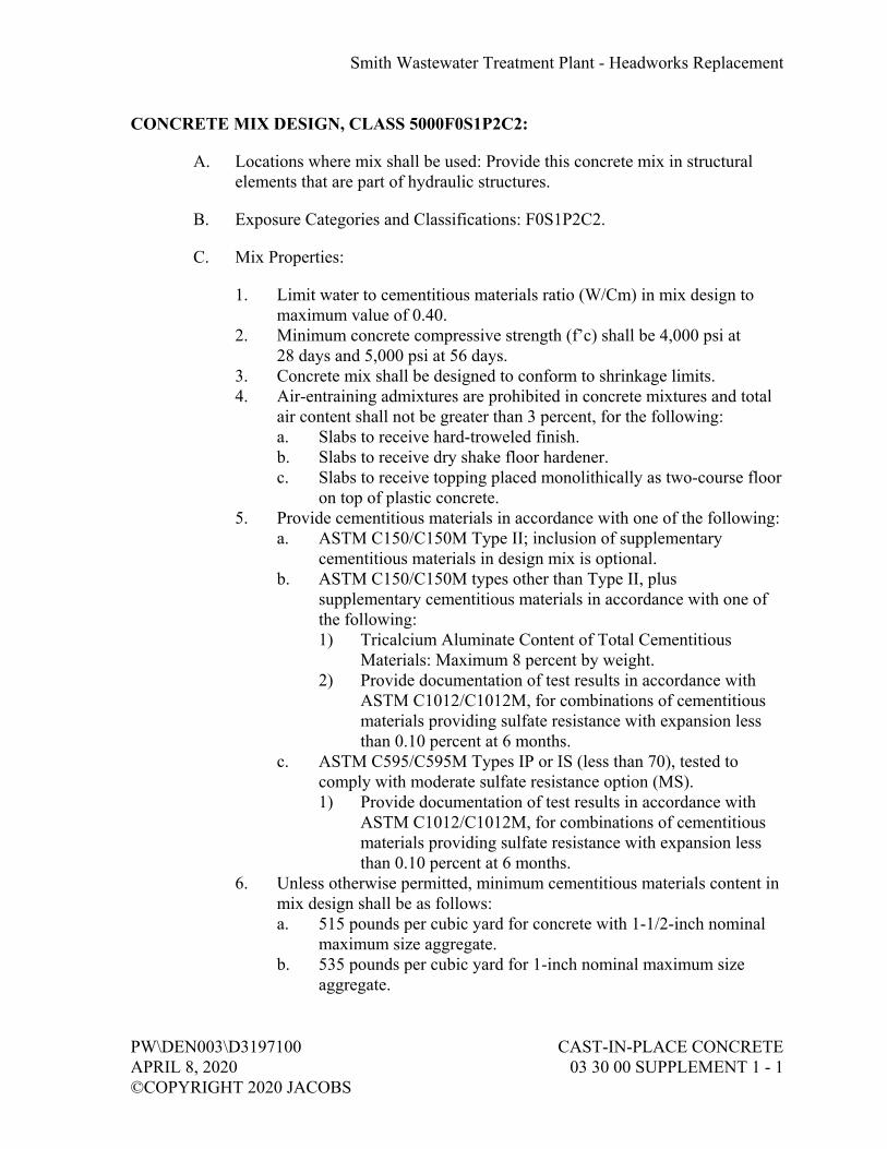
Smith Wastewater Treatment Plant - Headworks Replacement
PW\DEN003\D3197100 CAST-IN-PLACE CONCRETE APRIL 8, 2020 03 30 00 SUPPLEMENT 1 - 1 ©COPYRIGHT 2020 JACOBS
CONCRETE MIX DESIGN, CLASS 5000F0S1P2C2:
A. Locations where mix shall be used: Provide this concrete mix in structural elements that are part of hydraulic structures.
B. Exposure Categories and Classifications: F0S1P2C2.
C. Mix Properties:
1. Limit water to cementitious materials ratio (W/Cm) in mix design to maximum value of 0.40.
2. Minimum concrete compressive strength (f’c) shall be 4,000 psi at 28 days and 5,000 psi at 56 days.
3. Concrete mix shall be designed to conform to shrinkage limits. 4. Air-entraining admixtures are prohibited in concrete mixtures and total
air content shall not be greater than 3 percent, for the following: a. Slabs to receive hard-troweled finish. b. Slabs to receive dry shake floor hardener. c. Slabs to receive topping placed monolithically as two-course floor
on top of plastic concrete. 5. Provide cementitious materials in accordance with one of the following:
a. ASTM C150/C150M Type II; inclusion of supplementary cementitious materials in design mix is optional.
b. ASTM C150/C150M types other than Type II, plus supplementary cementitious materials in accordance with one of the following: 1) Tricalcium Aluminate Content of Total Cementitious
Materials: Maximum 8 percent by weight. 2) Provide documentation of test results in accordance with
ASTM C1012/C1012M, for combinations of cementitious materials providing sulfate resistance with expansion less than 0.10 percent at 6 months.
c. ASTM C595/C595M Types IP or IS (less than 70), tested to comply with moderate sulfate resistance option (MS). 1) Provide documentation of test results in accordance with
ASTM C1012/C1012M, for combinations of cementitious materials providing sulfate resistance with expansion less than 0.10 percent at 6 months.
6. Unless otherwise permitted, minimum cementitious materials content in mix design shall be as follows: a. 515 pounds per cubic yard for concrete with 1-1/2-inch nominal
maximum size aggregate. b. 535 pounds per cubic yard for 1-inch nominal maximum size
aggregate.

Smith Wastewater Treatment Plant - Headworks Replacement
CAST-IN-PLACE CONCRETE PW\DEN003\D3197100 03 30 00 SUPPLEMENT 1 - 2 APRIL 8, 2020 ©COPYRIGHT 2020 JACOBS
c. 560 pounds per cubic yard for 3/4-inch nominal maximum size aggregate.
d. 580 pounds per cubic yard for 1/2-inch nominal maximum size aggregate.
e. 600 pounds per cubic yard for 3/8-inch nominal maximum size aggregate.
f. Unless otherwise permitted, limit cementitious materials content to 100 pounds per cubic yard greater than specified minimum cementitious materials content in mix design.
7. Limit water-soluble, chloride-ion content in hardened concrete to 0.10 percent, unless otherwise specified. a. Limits are stated in terms of chloride ions in percent by weight of
cement. b. Unless otherwise permitted, provide documentation from concrete
tested in accordance with ASTM C1218/C1218M at an age between 28 days and 42 days.
D. Refer to PART 1 through PART 3 of this Section for additional requirements.
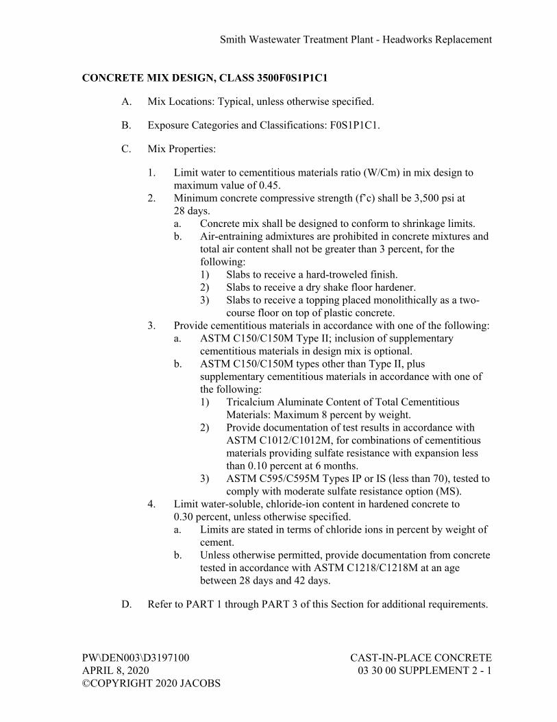
Smith Wastewater Treatment Plant - Headworks Replacement
PW\DEN003\D3197100 CAST-IN-PLACE CONCRETE APRIL 8, 2020 03 30 00 SUPPLEMENT 2 - 1 ©COPYRIGHT 2020 JACOBS
CONCRETE MIX DESIGN, CLASS 3500F0S1P1C1
A. Mix Locations: Typical, unless otherwise specified.
B. Exposure Categories and Classifications: F0S1P1C1.
C. Mix Properties:
1. Limit water to cementitious materials ratio (W/Cm) in mix design to maximum value of 0.45.
2. Minimum concrete compressive strength (f’c) shall be 3,500 psi at 28 days. a. Concrete mix shall be designed to conform to shrinkage limits. b. Air-entraining admixtures are prohibited in concrete mixtures and
total air content shall not be greater than 3 percent, for the following: 1) Slabs to receive a hard-troweled finish. 2) Slabs to receive a dry shake floor hardener. 3) Slabs to receive a topping placed monolithically as a two-
course floor on top of plastic concrete. 3. Provide cementitious materials in accordance with one of the following:
a. ASTM C150/C150M Type II; inclusion of supplementary cementitious materials in design mix is optional.
b. ASTM C150/C150M types other than Type II, plus supplementary cementitious materials in accordance with one of the following: 1) Tricalcium Aluminate Content of Total Cementitious
Materials: Maximum 8 percent by weight. 2) Provide documentation of test results in accordance with
ASTM C1012/C1012M, for combinations of cementitious materials providing sulfate resistance with expansion less than 0.10 percent at 6 months.
3) ASTM C595/C595M Types IP or IS (less than 70), tested to comply with moderate sulfate resistance option (MS).
4. Limit water-soluble, chloride-ion content in hardened concrete to 0.30 percent, unless otherwise specified. a. Limits are stated in terms of chloride ions in percent by weight of
cement. b. Unless otherwise permitted, provide documentation from concrete
tested in accordance with ASTM C1218/C1218M at an age between 28 days and 42 days.
D. Refer to PART 1 through PART 3 of this Section for additional requirements.

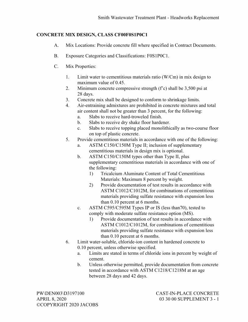
Smith Wastewater Treatment Plant - Headworks Replacement
PW\DEN003\D3197100 CAST-IN-PLACE CONCRETE APRIL 8, 2020 03 30 00 SUPPLEMENT 3 - 1 ©COPYRIGHT 2020 JACOBS
CONCRETE MIX DESIGN, CLASS CF00F0S1P0C1
A. Mix Locations: Provide concrete fill where specified in Contract Documents.
B. Exposure Categories and Classifications: F0S1P0C1.
C. Mix Properties:
1. Limit water to cementitious materials ratio (W/Cm) in mix design to maximum value of 0.45.
2. Minimum concrete compressive strength (f’c) shall be 3,500 psi at 28 days.
3. Concrete mix shall be designed to conform to shrinkage limits. 4. Air-entraining admixtures are prohibited in concrete mixtures and total
air content shall not be greater than 3 percent, for the following: a. Slabs to receive hard-troweled finish. b. Slabs to receive dry shake floor hardener. c. Slabs to receive topping placed monolithically as two-course floor
on top of plastic concrete. 5. Provide cementitious materials in accordance with one of the following:
a. ASTM C150/C150M Type II; inclusion of supplementary cementitious materials in design mix is optional.
b. ASTM C150/C150M types other than Type II, plus supplementary cementitious materials in accordance with one of the following: 1) Tricalcium Aluminate Content of Total Cementitious
Materials: Maximum 8 percent by weight. 2) Provide documentation of test results in accordance with
ASTM C1012/C1012M, for combinations of cementitious materials providing sulfate resistance with expansion less than 0.10 percent at 6 months.
c. ASTM C595/C595M Types IP or IS (less than70), tested to comply with moderate sulfate resistance option (MS). 1) Provide documentation of test results in accordance with
ASTM C1012/C1012M, for combinations of cementitious materials providing sulfate resistance with expansion less than 0.10 percent at 6 months.
6. Limit water-soluble, chloride-ion content in hardened concrete to 0.10 percent, unless otherwise specified. a. Limits are stated in terms of chloride ions in percent by weight of
cement. b. Unless otherwise permitted, provide documentation from concrete
tested in accordance with ASTM C1218/C1218M at an age between 28 days and 42 days.

Smith Wastewater Treatment Plant - Headworks Replacement
CAST-IN-PLACE CONCRETE PW\DEN003\D3197100 03 30 00 SUPPLEMENT 3 - 2 APRIL 8, 2020 ©COPYRIGHT 2020 JACOBS
7. Fiber Reinforcement: a. Where required, provide polypropylene micro-fibers in design
mix in accordance with Section 03 24 00, Fibrous Reinforcing. b. Add fiber-reinforcement to mix in concrete plant.
D. Refer to PART 1 through PART 3 of this Section for additional requirements.
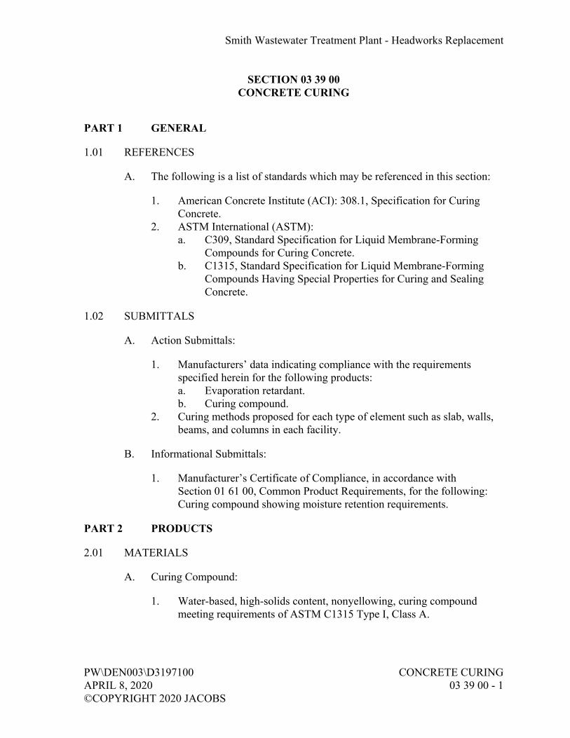
Smith Wastewater Treatment Plant - Headworks Replacement
PW\DEN003\D3197100 CONCRETE CURING APRIL 8, 2020 03 39 00 - 1 ©COPYRIGHT 2020 JACOBS
SECTION 03 39 00 CONCRETE CURING
PART 1 GENERAL
1.01 REFERENCES
A. The following is a list of standards which may be referenced in this section:
1. American Concrete Institute (ACI): 308.1, Specification for Curing Concrete.
2. ASTM International (ASTM): a. C309, Standard Specification for Liquid Membrane-Forming
Compounds for Curing Concrete. b. C1315, Standard Specification for Liquid Membrane-Forming
Compounds Having Special Properties for Curing and Sealing Concrete.
1.02 SUBMITTALS
A. Action Submittals:
1. Manufacturers’ data indicating compliance with the requirements specified herein for the following products: a. Evaporation retardant. b. Curing compound.
2. Curing methods proposed for each type of element such as slab, walls, beams, and columns in each facility.
B. Informational Submittals:
1. Manufacturer’s Certificate of Compliance, in accordance with Section 01 61 00, Common Product Requirements, for the following: Curing compound showing moisture retention requirements.
PART 2 PRODUCTS
2.01 MATERIALS
A. Curing Compound:
1. Water-based, high-solids content, nonyellowing, curing compound meeting requirements of ASTM C1315 Type I, Class A.

Smith Wastewater Treatment Plant - Headworks Replacement
CONCRETE CURING PW\DEN003\D3197100 03 39 00 - 2 APRIL 8, 2020 ©COPYRIGHT 2020 JACOBS
2. Manufacturers and Products: a. Euclid Chemical Co., Cleveland, OH; Super Diamond
Clear VOX. b. WR Meadows, Inc., Hampshire, IL; VOCOMP-30. c. Vexcon Chemical, Inc.; Philadelphia, PA; Starseal 1315. d. Dayton Superior; Safe Cure and Seal 1315 EF.
B. Evaporation Retardant:
1. Optional: Fluorescent fugitive dye color tint that disappears completely upon drying.
2. Manufacturers and Products: a. BASF Construction Chemicals, Shakopee, MN;
MasterKure ER 50. b. Euclid Chemical Co., Cleveland, OH; Eucobar.
C. Water: Clean and potable, containing less than 500 ppm of chlorides.
PART 3 EXECUTION
3.01 CONCRETE CURING
A. General:
1. Cure all concrete in accordance with project specifications and ACI 308.1.
2. Where surfaces are to receive coatings, painting, cementitious material, or other similar finishes, use only water curing procedures. Refer to Interior Finish Schedule for surfaces to receive coatings.
3. Use only water curing on hydraulic structures. 4. Where curing compound cannot be used, water curing as described
below or special methods using moisture shall be agreed upon by Engineer prior to placing concrete.
5. As required in Section 03 30 00, Cast-in-Place Concrete, if result of 7-day concrete strength test is less than 50 percent of specified 28-day strength, extend period of moist curing specified below, by 7 additional days.
B. Use one of the following methods as approved by Engineer:
1. Vertical Surfaces a. Method 1: Leave concrete forms in place and keep surfaces of
forms and concrete moist for 7 days unless otherwise specified. b. Method 2: Continuously sprinkle with water 100 percent of
exposed surfaces for 7 days unless otherwise specified, starting immediately after removal of forms.

Smith Wastewater Treatment Plant - Headworks Replacement
PW\DEN003\D3197100 CONCRETE CURING APRIL 8, 2020 03 39 00 - 3 ©COPYRIGHT 2020 JACOBS
2. Horizontal Surfaces: a. Method 1: Protect surface by water ponding for 7 days unless
otherwise specified. b. Method 2: Cover with burlap or cotton mats and keep
continuously moist for 7 days unless otherwise specified. c. Method 3: Cover with 1-inch layer of wet sand, earth, or sawdust,
and keep continuously moist for 7 days unless otherwise specified.
d. Method 4: Continuously sprinkle exposed surface for 7 days unless otherwise specified.
3.02 EVAPORATION RETARDANT APPLICATION
A. Use on flatwork when environmental conditions are anticipated to cause rapid drying of the concrete surface.
B. Spray onto surface of fresh flatwork concrete immediately after screeding to react with surface moisture.
C. Reapply as needed to ensure a continuous moist surface until final finishing is completed.
END OF SECTION


Smith Wastewater Treatment Plant - Headworks Replacement
PW\DEN003\D3197100 GROUTING MARCH 6, 2020 03 62 00 - 1 ©COPYRIGHT 2020 JACOBS
SECTION 03 62 00 GROUTING
PART 1 GENERAL
1.01 REFERENCES
A. The following is a list of standards which may be referenced in this section:
1. ASTM International (ASTM): a. C230, Standard Specification for Flow Table for Use in Tests of
Hydraulic Cement. b. C307, Standard Test Method for Tensile Strength of Chemical-
Resistant Mortar, Grouts, and Monolithic Surfacings. c. C531, Standard Test Method for Linear Shrinkage and Coefficient
of Thermal Expansion of Chemical-Resistant Mortars, Grouts, Monolithic Surfacings, and Polymer Concretes.
d. C579, Standard Test Methods for Compressive Grout Strength of Chemical-Resistant Mortars, Grouts, Monolithic Surfacings, and Polymer Concretes.
e. C882, Standard Test Method for Bond Strength of Epoxy-Resin Systems Used With Concrete By Slant Shear.
f. C939, Standard Test Method for Flow of Grout for Preplaced-Aggregate Concrete (Flow Cone Method).
g. C940, Standard Test Method for Expansion and Bleeding of Freshly Mixed Grouts for Preplaced-Aggregate Concrete in the Laboratory.
h. C1107/C1107M, Standard Specification for Packaged Dry, Hydraulic-Cement Grout (Nonshrink).
i. C1181, Standard Test Methods for Compressive Creep of Chemical-Resistant Polymer Machinery Grouts.
j. D4263, Standard Test Method for Indicating Moisture in Concrete by the Plastic Sheet Method.
1.02 SUBMITTALS
A. Action Submittals:
1. Product data of grouts. 2. Proposed method for keeping existing concrete surfaces wet prior to
placing nonshrink grout. 3. Forming method for fluid grout placements. 4. Curing method for grout.
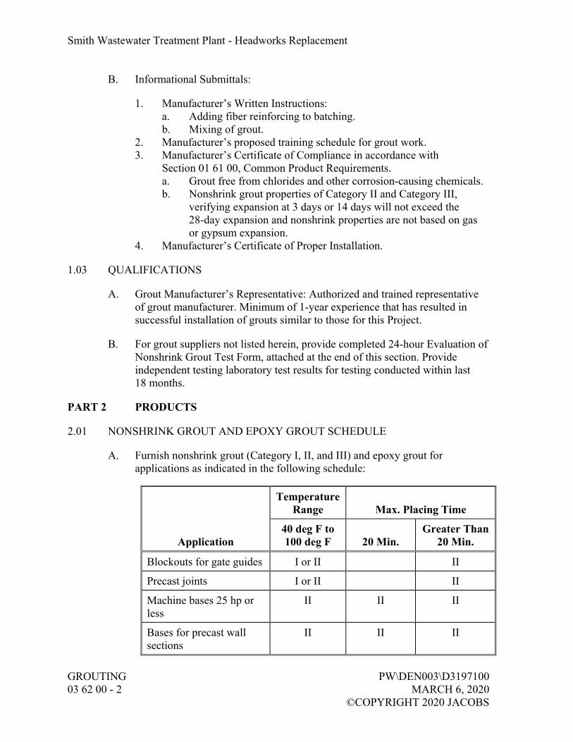
Smith Wastewater Treatment Plant - Headworks Replacement
GROUTING PW\DEN003\D3197100 03 62 00 - 2 MARCH 6, 2020 ©COPYRIGHT 2020 JACOBS
B. Informational Submittals:
1. Manufacturer’s Written Instructions: a. Adding fiber reinforcing to batching. b. Mixing of grout.
2. Manufacturer’s proposed training schedule for grout work. 3. Manufacturer’s Certificate of Compliance in accordance with
Section 01 61 00, Common Product Requirements. a. Grout free from chlorides and other corrosion-causing chemicals. b. Nonshrink grout properties of Category II and Category III,
verifying expansion at 3 days or 14 days will not exceed the 28-day expansion and nonshrink properties are not based on gas or gypsum expansion.
4. Manufacturer’s Certificate of Proper Installation.
1.03 QUALIFICATIONS
A. Grout Manufacturer’s Representative: Authorized and trained representative of grout manufacturer. Minimum of 1-year experience that has resulted in successful installation of grouts similar to those for this Project.
B. For grout suppliers not listed herein, provide completed 24-hour Evaluation of Nonshrink Grout Test Form, attached at the end of this section. Provide independent testing laboratory test results for testing conducted within last 18 months.
PART 2 PRODUCTS
2.01 NONSHRINK GROUT AND EPOXY GROUT SCHEDULE
A. Furnish nonshrink grout (Category I, II, and III) and epoxy grout for applications as indicated in the following schedule:
Application
Temperature Range Max. Placing Time
40 deg F to 100 deg F 20 Min.
Greater Than 20 Min.
Blockouts for gate guides I or II II
Precast joints I or II II
Machine bases 25 hp or less
II II II
Bases for precast wall sections
II II II

Smith Wastewater Treatment Plant - Headworks Replacement
PW\DEN003\D3197100 GROUTING MARCH 6, 2020 03 62 00 - 3 ©COPYRIGHT 2020 JACOBS
Application
Temperature Range Max. Placing Time
40 deg F to 100 deg F 20 Min.
Greater Than 20 Min.
Form Tie-Through bolt openings
II II II
Machine bases 26 hp and up
III or Epoxy Grout
III or Epoxy Grout
III or Epoxy Grout
Baseplates and/or soleplates with vibration, thermal movement, etc.
III or Epoxy Grout
III or Epoxy Grout
III or Epoxy Grout
2.02 NONSHRINK GROUT
A. Category I:
1. Nonmetallic and nongas-liberating. 2. Prepackaged natural aggregate grout requiring only the addition of
water. 3. Test in accordance with ASTM C1107/C1107M:
a. Grout shall have flowable consistency. b. Flowable for 15 minutes.
4. Grout shall not bleed at maximum allowed water. 5. Minimum strength of flowable grout, 3,000 psi at 3 days, 5,000 psi at
7 days, and 7,000 psi at 28 days. 6. Manufacturers and Products:
a. BASF Building System, Inc., Shakopee, MN; MasterFlow 100. b. Euclid Chemical Co., Cleveland, OH; NS Grout. c. Dayton Superior Corp., Miamisburg, OH; 1107 Advantage Grout. d. US MIX Co., Denver, CO; US SPEC GP Grout. e. Five Star Products Inc., Fairfield, CT; Five Star Grout.
B. Category II:
1. Nonmetallic, nongas-liberating. 2. Prepackaged natural aggregate grout requiring only the addition of
water. 3. Aggregate shall show no segregation or settlement at fluid consistency
at specified times or temperatures. 4. Test in accordance with ASTM C1107/C1107M:
a. Fluid consistency 20 seconds to 30 seconds in accordance with ASTM C939.
b. Temperatures of 40 degrees F, 80 degrees F, and 90 degrees F.

Smith Wastewater Treatment Plant - Headworks Replacement
GROUTING PW\DEN003\D3197100 03 62 00 - 4 MARCH 6, 2020 ©COPYRIGHT 2020 JACOBS
5. 1 hour after mixing, pass fluid grout through flow cone with continuous flow.
6. Minimum strength of fluid grout, 3,500 psi at 1 day, 4,500 psi at 3 days, and 7,500 psi at 28 days.
7. Maintain fluid consistency when mixed in 1-yard to 9-yard loads in ready-mix truck.
8. Manufacturers and Products: a. BASF Building Systems, Inc., Shakopee, MN; MasterFlow 928. b. Five Star Products Inc., Fairfield, CT; Five Star Fluid Grout 100. c. Euclid Chemical Co., Cleveland, OH; Hi Flow Grout. d. Dayton Superior Corp., Miamisburg, OH; Sure Grip High
Performance Grout. e. US MIX Co., Denver, CO; US SPEC MP Grout.
C. Category III:
1. Metallic and nongas-liberating. 2. Prepackaged aggregate grout requiring only the addition of water. 3. Aggregate shall show no segregation or settlement at fluid consistency
at specified times or temperatures. 4. Test in accordance with ASTM C1107/C1107M:
a. Fluid consistency 20 seconds to 30 seconds in accordance with ASTM C939.
b. Temperatures of 40 degrees F and 100 degrees F. 5. 1 hour after mixing, pass fluid grout through flow cone with continuous
flow. 6. Minimum strength of fluid grout, 4,000 psi at 1 day, 5,000 psi at 3 days,
and 9,000 psi at 28 days. 7. Maintain fluid consistency when mixed in 1-yard to 9-yard loads in
ready-mix truck. 8. Manufacturer and Product:
a. BASF Building Systems, Inc., Shakopee, MN; MasterFlow 885. b. Euclid Chemical Co, Cleveland, OH; Hi-Flow Metallic Grout.
2.03 EPOXY GROUT
A. High-strength, nonshrink, high-temperature epoxy grouting material developed for the support of heavy equipment with vibratory loads.
B. Three-component mixture of a two-component epoxy resin system (100 percent solids) with a graded, precision aggregate blend.
C. Premeasured, prepackaged system.
D. Flowable.
Smith Wastewater Treatment Plant - Headworks Replacement
PW\DEN003\D3197100 GROUTING MARCH 6, 2020 03 62 00 - 5 ©COPYRIGHT 2020 JACOBS
E. Minimum compressive strength in accordance with ASTM C579 Method B, 9,500 psi at 75 degrees F at 7 days, 11,000 psi at post cure.
F. Maximum creep resistance in accordance with ASTM C1181 at 600 psi, 140 degrees F; 6.0 by 10-3 in/in.
G. Minimum bond strength in accordance with ASTM C882, 2,000 psi.
H. Minimum tensile strength in accordance with ASTM C307, 2,000 psi.
I. Maximum coefficient of thermal expansion in accordance with ASTM C531 at 73 degrees F to 210 degrees F, 23.0 by 10-6 in/in/degrees F.
J. Working Time: Minimum 2 hours at 50 degrees F; 1.5 hours at 70 degrees F; 50 minutes at 90 degrees F.
K. Good chemical resistance.
L. Good effective bearing area.
M. Noncorrosive.
N. Moisture insensitive.
O. Modify resin and aggregate content where recommended by epoxy grout manufacturer to provide desired epoxy grout flow properties.
P. Manufacturer and Product:
1. BASF Building System, Inc., Shakopee MN; MasterFlow 648. 2. Euclid Chemical Co., Cleveland, OH; E3-G. 3. Dayton Superior Corp., Miamisburg, OH; Pro-Poxy 2000 Normal Set. 4. Five Star Products Inc., Fairfield, CT; DP Epoxy Grout.
PART 3 EXECUTION
3.01 GROUT
A. General: Mix, place, and cure grout in accordance with grout manufacturer’s representative’s training instructions.
B. Epoxy Grout: Concrete slab shall be fully cured for 28 days to ensure excess water has evaporated. Test concrete surface for moisture in accordance with ASTM D4263 before epoxy grout is placed.
Smith Wastewater Treatment Plant - Headworks Replacement
GROUTING PW\DEN003\D3197100 03 62 00 - 6 MARCH 6, 2020 ©COPYRIGHT 2020 JACOBS
C. Form Tie-Through Bolt Holes: Provide nonshrink grout, Category II, fill space with dry pack dense grout hammered in with steel tool and hammer. Through-bolt holes; coordinate dry pack dense grout application with vinyl plug in Section 03 10 00, Concrete Forming and Accessories, and bonding agent in Section 03 30 00, Cast-in-Place Concrete.
D. Form Snap-Tie Hole: Fill tie hole in accordance with requirements of Section 03 30 00, Cast-in-Place Concrete.
3.02 GROUTING MACHINERY FOUNDATIONS
A. Block out original concrete or finish off at distance shown below bottom of machinery base with grout. Prepare concrete surface by sandblasting, chipping, or by mechanical means to remove any soft material. Surface roughness in accordance with manufacturer’s written instructions.
B. Clean metal surfaces of all paint, oil, grease, loose rust, and other foreign material that will be in contact with grout.
C. Sandblast to bright metal all metal surfaces in contact with epoxy grout in accordance with manufacturer’s written instructions.
D. Set machinery in position and wedge to elevation with steel wedges, or use cast-in leveling bolts. Remove wedges after grout is set and pack void with grout.
E. Form with watertight forms at least 2 inches higher than bottom of plate.
F. Fill space between bottom of machinery base and original concrete in accordance with manufacturer’s representative’s training instructions.
G. If grout cannot be placed from one edge and flowed to the opposite edge, air vents shall be provided through the plate to prevent air entrapment.
H. Radius all corners of grout pad.
I. Install expansion joints for epoxy grout placement in accordance with manufacturer’s written instructions.
3.03 TANK FOUNDATIONS
A. Prepare concrete surface by sandblasting, chipping, or by mechanical means to remove any soft material. Surface roughness in accordance with manufacturer’s written instructions.
B. Clean metal surfaces of all paint, oil, grease, loose rust and other foreign material that will be in contact with grout.

Smith Wastewater Treatment Plant - Headworks Replacement
PW\DEN003\D3197100 GROUTING MARCH 6, 2020 03 62 00 - 7 ©COPYRIGHT 2020 JACOBS
C. Set tank in position and wedge to elevation with steel wedges, or use cast-in leveling bolts. Remove wedges after grout is set and pack void with grout.
D. Form with watertight forms at least 2 inches higher than bottom of plate.
E. Fill space between bottom of tank base and original concrete in accordance with manufacturer’s representative’s training instructions.
3.04 FIELD QUALITY CONTROL
A. General:
1. Performed by Project representative’s inspection staff. 2. Perform the following quality control inspections. The grout
manufacturer’s representative shall accompany the Project representative’s inspection staff on the first installation of each size and type of equipment.
B. Evaluation and Acceptance of Nonshrink Grout:
1. Inspect the surface preparation of concrete substrates onto which nonshrink grout materials are to be applied, for conformance to the specified application criteria including, but not limited to, substrate profile, degree of cleanliness, and moisture.
2. Inspect preparation and application of nonshrink grout form work for conformance to the manufacturer’s recommendations.
3. Conduct a final review of completed nonshrink grout installation for conformance to these Specifications.
4. Provide a flow cone and cube molds with restraining plates onsite. Continue tests during Project as demonstrated by grout manufacturer’s representative.
5. Perform flow cone and bleed tests, and make three 2-inch by 2-inch cubes for each 25 cubic feet of each type of nonshrink grout used. Use restraining caps for cube molds in accordance with ASTM C1107 / C1107M.
6. For large grout applications, make three additional cubes and one more flow cone test. Include bleed test for each additional 25 cubic feet of nonshrink grout placed.
7. Consistency: As specified in Article Nonshrink Grout. Flow cone test in accordance with ASTM C939. Grout with consistencies outside range requirements shall be rejected.
8. Segregation: As specified in Article Nonshrink Grout. Grout when aggregate separates shall be rejected.
9. Nonshrink grout cubes shall test equal to or greater than minimum strength specified.
Smith Wastewater Treatment Plant - Headworks Replacement
GROUTING PW\DEN003\D3197100 03 62 00 - 8 MARCH 6, 2020 ©COPYRIGHT 2020 JACOBS
10. Strength Test Failures: Nonshrink grout work failing strength tests shall be removed and replaced.
11. Store cubes at 70 degrees F. 12. Independent testing laboratory shall prepare, store, cure, and test cubes
in accordance with ASTM C1107/C1107M. 13. All grout, already placed, which fails to meet the requirements of these
Specifications, is subject to removal and replacement at no additional cost to the Owner.
C. Evaluation and Acceptance of Epoxy Grout:
1. Inspect ambient conditions during various phases of epoxy grouting installation for conformance with the epoxy grout manufacturer’s requirements.
2. Inspect the surface preparation of concrete substrates onto which epoxy grout materials are to be applied, for conformance to the specified application criteria including, but not limited to, substrate profile, degree of cleanliness, and moisture.
3. Inspect the surface preparation of the metallic substrates onto which the epoxy primer is to be applied.
4. Inspect the epoxy-primed metallic substrate for coverage and adhesion. 5. Inspect preparation and application of epoxy grout form work for
conformance to the manufacturer’s recommendation. 6. Verify consistency obtained is sufficient for the proper field placement
at the installed temperatures. 7. Inspect and record that the “pot life” of epoxy grout materials is not
exceeded during the installation. 8. Inspect epoxy grout for cure. 9. Inspect and record that localized repairs made to grout voids are in
conformance with the specification requirements. 10. Conduct a final review of completed epoxy grout installation for
conformance to these Specifications. 11. Compression tests and fabrication of specimens for epoxy grout shall be
made in accordance to ASTM C579, Method B, at intervals during construction as selected by the Project representative. A set of three specimens shall be made for testing at 7 days, and each earlier time period as appropriate.
12. Independent testing laboratory shall prepare, store, cure, and test cubes in accordance with ASTM C579.
13. All grout, already placed, which fails to meet the requirements of these Specifications, is subject to removal and replacement at no additional cost to the Owner.
Smith Wastewater Treatment Plant - Headworks Replacement
PW\DEN003\D3197100 GROUTING MARCH 6, 2020 03 62 00 - 9 ©COPYRIGHT 2020 JACOBS
3.05 MANUFACTURER’S SERVICES
A. General:
1. Coordinate demonstrations, training sessions, and applicable Site visits with grout manufacturer’s representative. Allow 2-week notice to grout manufacturer’s representative for scheduling purposes.
2. Provide and conduct onsite, demonstration and training sessions for bleed tests, mixing, flow cone measurement, cube testing, application, and curing for each category and type of grout.
3. Necessary equipment and materials shall be available for demonstration. 4. Conduct training prior to equipment mount installation work on
equipment pads. 5. Training for each type of grout shall be not less than 4 hours’ duration.
B. Epoxy Grout Training:
1. Provide epoxy grout installation training by the qualified epoxy grout manufacturer’s representative for Contractor’s workers that will be installing epoxy grout for equipment mounts. Schedule training to allow Engineer’s attendance.
2. Include training in: a. Performance testing such as compressive strength testing of the
epoxy grout. b. All aspects of using the products, from mixing to application.
3. Transport test cubes to independent test laboratory and obtain test reports.
4. Training by manufacturer’s representative does not relieve Contractor of overall responsibility for this portion of the work.
5. Submit a list of attendees that have been satisfactorily trained to perform epoxy grout installation for equipment mounting.
3.06 SUPPLEMENTS
A. The supplement listed below, following “End of Section,” is part of this Specification.
1. 24-hour Evaluation of Nonshrink Grout Test Form and Grout Testing Procedures.
END OF SECTION


Smith Wastewater Treatment Plant - Headworks Replacement
PW\DEN003\D3197100 GROUTING MARCH 6, 2020 03 62 00 SUPPLEMENT 1 - 1 ©COPYRIGHT 2020 JACOBS
SUPPLEMENT 1
(Test Lab Name)
(Address)
(Phone No.)
24-HOUR EVALUATION OF NONSHRINK GROUT TEST FORM
OBJECTIVE: Define standard set of test procedures for an independent testing laboratory to perform and complete within a 24-hour period.
SCOPE: Utilize test procedures providing 24-hour results to duplicate field grouting demands. Intent of evaluation is to establish grout manufacturer’s qualifications.
PRIOR TO TEST: Obtain three bags of each type of grout.
1. From intended grout supplier for Project. 2. Three bags of grout shall be of same lot number.
ANSWER THE FOLLOWING QUESTIONS FOR GROUT BEING TESTED FROM LITERATURE, DATA, AND PRINTING ON BAG:
A. Product data and warranty information contained in company literature and data? Yes_____ No_____
B. Literature and bag information meet specified requirements? Yes_____ No_____
C. Manufacturer guarantees grout as specified in Article Guarantee? Yes_____ No_____
D. Guarantee extends beyond grout replacement value and allows participation with Contractor in replacing and repairing defective areas? Yes_____ No_____
E. Water demands and limits printed on bag? Yes_____ No_____
F. Mixing information printed on the bag? Yes_____ No_____
G. Temperature restrictions printed on bag? Yes_____ No_____
*Rejection of a grout will occur if one or more answers are noted NO.
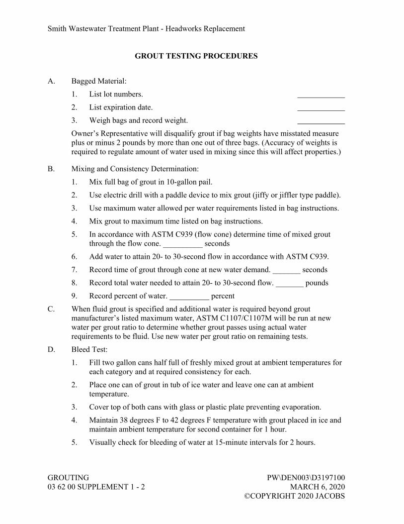
Smith Wastewater Treatment Plant - Headworks Replacement
GROUTING PW\DEN003\D3197100 03 62 00 SUPPLEMENT 1 - 2 MARCH 6, 2020 ©COPYRIGHT 2020 JACOBS
GROUT TESTING PROCEDURES
A. Bagged Material:
1. List lot numbers.
2. List expiration date.
3. Weigh bags and record weight.
Owner’s Representative will disqualify grout if bag weights have misstated measure plus or minus 2 pounds by more than one out of three bags. (Accuracy of weights is required to regulate amount of water used in mixing since this will affect properties.)
B. Mixing and Consistency Determination:
1. Mix full bag of grout in 10-gallon pail.
2. Use electric drill with a paddle device to mix grout (jiffy or jiffler type paddle).
3. Use maximum water allowed per water requirements listed in bag instructions.
4. Mix grout to maximum time listed on bag instructions.
5. In accordance with ASTM C939 (flow cone) determine time of mixed grout through the flow cone. __________ seconds
6. Add water to attain 20- to 30-second flow in accordance with ASTM C939.
7. Record time of grout through cone at new water demand. _______ seconds
8. Record total water needed to attain 20- to 30-second flow. _______ pounds
9. Record percent of water. __________ percent
C. When fluid grout is specified and additional water is required beyond grout manufacturer’s listed maximum water, ASTM C1107/C1107M will be run at new water per grout ratio to determine whether grout passes using actual water requirements to be fluid. Use new water per grout ratio on remaining tests.
D. Bleed Test:
1. Fill two gallon cans half full of freshly mixed grout at ambient temperatures for each category and at required consistency for each.
2. Place one can of grout in tub of ice water and leave one can at ambient temperature.
3. Cover top of both cans with glass or plastic plate preventing evaporation.
4. Maintain 38 degrees F to 42 degrees F temperature with grout placed in ice and maintain ambient temperature for second container for 1 hour.
5. Visually check for bleeding of water at 15-minute intervals for 2 hours.

Smith Wastewater Treatment Plant - Headworks Replacement
PW\DEN003\D3197100 GROUTING MARCH 6, 2020 03 62 00 SUPPLEMENT 1 - 3 ©COPYRIGHT 2020 JACOBS
6. Perform final observation at 24 hours.
If grout bleeds a small amount at temperatures specified, grout will be rejected.
E. Extended Flow Time and Segregation Test (for Category II and Category III):
1. Divide the remaining grout into two 3-gallon cans. Place the cans into the 40-degree F and 90-degree F containers and leave for 20, 40, and 60 minutes. Every 20 minutes remove and check for segregation or settlement of aggregate. Use a gloved hand to reach to the bottom of the can, if more than 1/4 inch of aggregate has settled to the bottom or aggregate has segregated into clumps reject the grout.
2. Right after the settlement test mix the grout with the drill mixer for 10 seconds. Take a ASTM C939 flow cone test of grout and record flow time. Maintain this process for 1 hour at ambient temperatures of 40 degrees F and 90 degrees F.
a. 20 min _____, sec. @ 40 degrees F.
b. 40 min _____, sec. @ 40 degrees F.
c. 60 min _____, sec. @ 40 degrees F.
d. 20 min _____, sec. @ 90 degrees F.
e. 40 min _____, sec. @ 90 degrees F.
f. 60 min _____, sec. @ 90 degrees F.
All Category II and Category III grout that will not go through the flow cone with continuous flow after 60 minutes will be disqualified.
____________ ____________
Qualified Disqualified
F. 24-hour Strength Test:
1. Using grout left in mixing cans in accordance with ASTM C1107/C1107M for mixing and consistency determination test and for extended time flow test, make minimum of nine cube samples.
2. Store cubes at 70 degrees F for 24 hours.
3. Record average compressive strength of nine cubes at 24 hours.
Grout will be disqualified if 24-hour compressive strengths are less than 2,500 psi for grouts claiming fluid placement capabilities.
Grouts that have not been disqualified after these tests are qualified for use on the Project for the application indicated in Nonshrink Grout Schedule.
Signature of Independent Testing Laboratory Date Test Conducted

Smith Wastewater Treatment Plant - Headworks Replacement
PW\DEN003\D3197100 CONCRETE DOWELING MARCH 5, 2020 03 63 00 - 1 ©COPYRIGHT 2020 JACOBS
SECTION 03 63 00 CONCRETE DOWELING
PART 1 GENERAL
1.01 REFERENCES
A. The following is a list of standards that may be referenced in this section:
1. American National Standards Institute (ANSI). 2. ASTM International (ASTM):
a. C881/C881M, Standard Specification for Epoxy-Resin-Base Bonding Systems for Concrete.
b. E488, Standard Test Methods for Strength of Anchors in Concrete and Masonry Elements.
3. International Code Council (ICC): a. 2015 International Building Code (IBC). b. Evaluation Services Reports.
1.02 DEFINITIONS
A. ICC Evaluation Services Report: Published by ICC for products provided by concrete adhesive anchor manufacturers.
B. Special Inspection: As defined in the ICC IBC and indicated on the Statement of Special Inspection (Plan) on the Drawings.
1.03 SUBMITTALS
A. Action Submittals:
1. Product Data: Manufacturer’s catalog information.
B. Informational Submittals:
1. Manufacturer’s instructions for preparation, placement, drilling of holes, installation of anchors and adhesive, and handling of cartridges, nozzles, and equipment.
2. Manufacturer’s written letter of certification identifying installer’s qualifications to install products.
3. ICC Evaluation Services Report: Specific to proposed doweling system manufacturer.
1.04 QUALITY ASSURANCE
A. Qualifications:
1. Installer: Trained and certified by manufacturer.

Smith Wastewater Treatment Plant - Headworks Replacement
CONCRETE DOWELING PW\DEN003\D3197100 03 63 00 - 2 MARCH 5, 2020 ©COPYRIGHT 2020 JACOBS
1.05 DELIVERY, STORAGE, AND HANDLING
A. Container Markings: Include manufacturer’s name, product name, batch number, product expiration date, ANSI hazard classification, and appropriate ANSI handling precautions.
B. Store adhesive components in accordance with manufacturer’s written instructions.
C. Dispose of when:
1. Shelf life has expired. 2. Stored other than per manufacturer’s instructions.
PART 2 PRODUCTS
2.01 MATERIALS
A. Adhesive:
1. Approved by an ICC Evaluation Services Report for conformance to 2015 IBC requirements for doweling of steel reinforcing bars in cracked concrete.
2. Suitable for long-term loads as well as for wind and seismic loads. 3. Meet requirements of ASTM C881/C881M. 4. Two-component, insensitive to moisture, designed to be used in adverse
freeze/thaw environments. 5. Disposable, Self-Contained Cartridge System:
a. Capable of dispensing both components in proper mixing ratio. b. Fit into manually or pneumatically operated caulking gun.
6. Mixed Adhesive: Nonsag, light paste consistency with ability to remain in a 1-inch diameter overhead drilled hole without runout.
7. Cure Temperature, Pot Life, and Workability: Compatible for intended use and anticipated environmental conditions.
8. Manufacturers and Products: a. Hilti, Inc., Tulsa, OK; HIT-RE 500-V3 (ESR-3814) Adhesive
Anchors. b. Simpson Strong-Tie Co., Inc., Pleasanton, CA; SET-3G Epoxy
Adhesive Anchors (ESR-4057).
B. Mixing Nozzles: Disposable, manufactured in several sizes to accommodate size of reinforcing dowels.
C. Reinforcing Dowels: As specified in Section 03 21 00, Steel Reinforcement.

Smith Wastewater Treatment Plant - Headworks Replacement
PW\DEN003\D3197100 CONCRETE DOWELING MARCH 5, 2020 03 63 00 - 3 ©COPYRIGHT 2020 JACOBS
PART 3 EXECUTION
3.01 INSTALLATION
A. Drilling Equipment:
1. Drilling Hammers for Dowel Holes: a. Electric or pneumatic rotary type with medium or light impact. b. Hollow drills with flushing air systems are preferred.
2. Where edge distances are less than 2 inches, use lighter impact equipment to prevent microcracking and concrete spalling during drilling process.
B. Hole Diameter: Use drill bit diameter meeting ICC Evaluation Services Report requirements and as recommended by manufacturer.
C. Obstructions in Drill Path: When existing steel reinforcement is encountered during drilling, obtain Engineer approval for proposed fix.
D. Doweling:
1. Install per details shown on Drawings and in accordance with adhesive manufacturer’s instructions.
2. When using epoxy anchors, dowels may be prebent prior to installation to 15 degrees to align with other bars. Do not heat dowels to bend.
3. Bent Bar Dowels: Where edge distances are critical, and intersection with steel reinforcement is likely, drill hole at 10-degree angle or less and use prebent reinforcing bars.
E. Adhesive:
1. Install in accordance with written manufacturer’s instructions. 2. Dispense components through specially designed static mixing nozzle
that thoroughly mixes components and places mixed adhesive at base of predrilled hole.
3.02 FIELD QUALITY ASSURANCE AND QUALITY CONTROL
A. Owner-Furnished Quality Assurance, in accordance with IBC Chapter 17 requirements, is provided in the Statement of Special Inspection (Plan) on Drawings. Contractor responsibilities and related information on special inspection and testing are included in Section 01 45 33, Special Inspection, Observation, and Testing.
1. Special inspection will be performed by the Special Inspector in accordance with ICC ESR requirements and as specified in Section 01 45 33, Special Inspection, Observation, and Testing.

Smith Wastewater Treatment Plant - Headworks Replacement
CONCRETE DOWELING PW\DEN003\D3197100 03 63 00 - 4 MARCH 5, 2020 ©COPYRIGHT 2020 JACOBS
2. Continuous inspection required where noted on Drawings and where concrete dowels are installed in overhead applications.
3. Periodic inspection required where continuous inspection is not specified.
4. Special Inspector will observe installation in accordance with requirements of the ICC Evaluation Services Report and will submit report including the following: a. Product Description: Product name, rod diameter, and length. b. Drill bit compliance. c. Hole diameter, diameter, and depth and cleanliness. d. Adhesive expiration date.
5. Verification of dowel installation in accordance with manufacturer’s published instructions
B. Contractor-Furnished Quality Control: Inspection and testing as required in Section 01 45 16.13, Contractor Quality Control.
END OF SECTION

Smith Wastewater Treatment Plant - Headworks Replacement
PW\DEN003\D3197100 EPOXY RESIN INJECTION GROUTING MARCH 6, 2020 03 64 23 - 1 ©COPYRIGHT 2020 JACOBS
SECTION 03 64 23 EPOXY RESIN INJECTION GROUTING
PART 1 GENERAL
1.01 REFERENCES
A. The following is a list of standards which may be referenced in this section:
1. ASTM International (ASTM): a. C882, Standard Specification for Test Method for Bond Strength
of Epoxy Resin System Used with Concrete by Slant Shear. b. D570, Standard Test Method for Water Absorption of Plastics. c. D638, Standard Test Method for Tensile Properties of Plastics. d. D648, Standard Test Method for Deflection Temperature of
Plastics under Flexural Load in the Edgewise Position. e. D695, Standard Test Method for Compressive Properties of Rigid
Plastics. f. D790, Standard Test Methods for Flexural Properties of
Unreinforced and Reinforced Plastics and Electrical Insulating Materials.
1.02 DEFINITIONS
A. Crack: Complete or incomplete separation of concrete into two or more parts produced by breaking or fracturing.
B. Defective Area: As defined in Section 03 30 00, Cast-in-Place Concrete.
C. Hydraulic Structure: Liquid containment structure and/or structure designed to mitigate liquid infiltration.
D. Injection: Method of bonding together, addressing or eliminating leakage through cracks or joints by installing resin under pressure to fill the void in crack or joint.
E. Joint: A planned and formed discontinuity in concrete structure at junction of adjacent and sequential concrete placements and may contain embedded waterstops.
F. Leak or Leakage: Crack or joint exhibiting presence of moisture, sign of efflorescence, intermittently wet to touch, or continuous flow of liquid.
G. Narrow Cracks: Width equal to or less than 0.015 inch.
H. Wide Cracks: Wider than 0.015 inch.
Smith Wastewater Treatment Plant - Headworks Replacement
EPOXY RESIN INJECTION GROUTING PW\DEN003\D3197100 03 64 23 - 2 MARCH 6, 2020 ©COPYRIGHT 2020 JACOBS
1.03 SUBMITTALS
A. Action Submittals:
1. Physical and chemical properties for epoxy resin. 2. Technical data for metering, mixing, and injection equipment. 3. Depth of penetration, length, material used, and procedures where
epoxy is approved for use. 4. Marked up drawings of proposed epoxy injection repair crack locations,
widths, and lengths and direction on structure. 5. Sample bottle. 6. Pot Life Test. 7. Slant Shear Test (Bond Strength).
B. Informational Submittals:
1. Manufacturer’s recommended surface preparation procedures and application instructions for epoxy resins.
2. Manufacturer’s Certificate of Compliance in accordance with Section 01 61 00, Common Product Requirements. Certified test results for each batch of epoxy resin.
3. Statements of Qualification for Epoxy Resin: a. Manufacturer’s Site representative. b. Injection applicator. c. Injection pump operating technician.
4. Sample of epoxy resin two component ratio and injection pressure test records for concrete crack repair work.
5. Installation instructions for repairing core holes with repair mortar. 6. Health and Safety Plans for confined space entry acid flushing work.
Test results of epoxy resin bond tests. 7. Epoxy resin two component ratio and injection pressure test records for
concrete crack repair work.
1.04 QUALITY ASSURANCE
A. Qualifications for Injection Staffs:
1. Manufacturer’s Site Representative: a. Capable of instructing successful methods of epoxy injection
process for concrete structure. b. Understands and is capable of explaining technical aspects of
correct material selection and use. c. Experienced in operation, maintenance, and troubleshooting of
application equipment.
Smith Wastewater Treatment Plant - Headworks Replacement
PW\DEN003\D3197100 EPOXY RESIN INJECTION GROUTING MARCH 6, 2020 03 64 23 - 3 ©COPYRIGHT 2020 JACOBS
2. Injection Crew and Job Foreman: a. Provide written and verifiable evidence showing compliance with
the following requirements: 1) Licensed or certified by epoxy resin material manufacturer. 2) Minimum 3 years’ experience in successful epoxy injection
for at least 10,000 linear feet of successful crack injection, including 2,000 linear feet of wet crack injection to stop water leakage.
B. Injected Epoxy Resin: Fill cracks and joints with minimum resin depth penetration no less than 90 percent of:
1. Full thickness of concrete section for cracks or joints. 2. Depth between waterstop and inside face of structure for joints with an
embedded waterstop.
C. Injected cracks and joints which leak shall be considered deficient work irrespective of depth of penetration. Reinjection of deficient work or, with approval of Engineer, provide other repairs to eliminate leakage.
D. Bond Strength Test for Epoxy Resin:
1. Concrete failure before resin failure. 2. 1,500 psi minimum bond strength per ASTM C882 test requirements
with no failure of either concrete or epoxy resin.
1.05 DELIVERY, STORAGE, AND HANDLING
A. Packing and Shipping:
1. Package resin material in new sealed containers and label with following information: a. Manufacturer’s name. b. Product name and lot number. c. ANSI Hazard Classification. d. ANSI recommended precautions for handling. e. Mix ratio by volume for components.
B. Storage and Protection: Store epoxy resin material containers in accordance with manufacturer’s printed instructions and at ambient temperatures below 110 degrees F and above 45 degrees F.

Smith Wastewater Treatment Plant - Headworks Replacement
EPOXY RESIN INJECTION GROUTING PW\DEN003\D3197100 03 64 23 - 4 MARCH 6, 2020 ©COPYRIGHT 2020 JACOBS
PART 2 PRODUCTS
2.01 MANUFACTURERS
A. Materials and accessories specified in this section shall be products of:
1. BASF Construction Chemicals, LLC-Building Systems, Shakopee, MN; SCB Concresive Series products that meet properties indicated in sub-section 2.2.B.
2. Sika Corp., Lyndhurst, NJ; Sikadur Series products that meet properties below.
3. Euclid Chemical Co., Cleveland, OH; Euco Series (#452) products that meet properties below.
2.02 EPOXY INJECTION RESIN
A. Two-component A and B structural epoxy resin for injection into cracks or joints or other voids in concrete structures for bonding or grouting.
B. Uncured Resin Properties:
1. When mixed in ratio specified on resin container label:
Test Method
Wide Cracks or
Joints
Narrow Cracks or
Joints
Pot Life (60-gram mass) @ 77, plus or minus 4 deg F
As specified in Article Source Quality Control
13 to 25 minutes
15 to 30 minutes
Pot Life (60-gram mass) @ 100, plus or minus 4 deg F
As specified in Article Source Quality Control
3 to 10 minutes
10 to 20 minutes
Viscosity @ 40, plus or minus 3 deg F
Brookfield RVT Spindle No. 4 @ 20 rpm
4,400 cps 600 cps
Viscosity @ 75 to 77 deg F
Brookfield RVT Spindle No. 2 @ 20 rpm
375 to 350 cps
175 to 140 cps

Smith Wastewater Treatment Plant - Headworks Replacement
PW\DEN003\D3197100 EPOXY RESIN INJECTION GROUTING MARCH 6, 2020 03 64 23 - 5 ©COPYRIGHT 2020 JACOBS
C. Epoxy Resin Properties: When cured for 7 days at 77 degree F, plus or minus 3 degrees F and conditioned at test temperature 12 hours prior to test, unless otherwise specified.
Test Method Wide Cracks or
Joints Narrow Cracks
or Joints
Ultimate Tensile Strength, psi
ASTM D368 8,000 min. 5,000 min.
Tensile Elongation @ Break, percent
ASTM D638 4.2 max. 3.0 max.
Flexural Strength, psi
ASTM D790 10,000 min. 10,000 min.
Flexural Modulus, psi
ASTM D790 5.5 x 10⁵ min. 4.5x10⁵ min.
Compressive Yield Strength, psi
ASTM D695* 15,000 min. 12,000 min.
Compressive Modulus, psi
ASTM D695* 4.0x105 min. 4.0x10⁵ min.
Heat Deflection Temperature
ASTM D648* 130 deg F min. 140 deg F min.
Cured 3 days @ 40 deg F – Wet Concrete 3,500 psi min. 3,500 psi min.
Cured 1 day @ 77 deg F – Dry Concrete 5,000 psi min. 5,000 psi min.
Cured 3 days @ 77 deg plus or minus 3 deg F
5,000 psi min. 5,000 psi min.
*Cure test specimens so that peak exothermic temperature of resin does not exceed 100 degrees F.
Note: See referenced specifications for preparation method of test specimens.
2.03 SURFACE SEAL
A. Sufficient strength and adhesion for holding injection fittings firmly in place and to resist pressures preventing leakage during injection.
B. Capable of removal after injection resin has cured.
2.04 WATER
A. Clean and free from oil, acid, alkali, organic matter, or other deleterious substances, meeting federal drinking water standards.
Smith Wastewater Treatment Plant - Headworks Replacement
EPOXY RESIN INJECTION GROUTING PW\DEN003\D3197100 03 64 23 - 6 MARCH 6, 2020 ©COPYRIGHT 2020 JACOBS
2.05 SOURCE QUALITY CONTROL
A. Test Requirements: Perform tests for each batch of epoxy resin.
B. Pot Life Test:
1. Condition Component A and Component B to required temperature. 2. Measure components in ratio of Component B as stated on
manufacturer’s label into an 8-fluid ounce paper cup. 3. Mix components for 60 seconds using non-metallic stirring instrument.
Scrape sides and bottom of cup periodically. 4. Probe mixture once with non-metallic stirring instrument every
30 seconds, starting 2 minutes prior to minimum specified pot life. 5. Pot Life Definition: Time at which a soft stringy mass forms in center of
cup.
C. Slant Shear Test: Prepare specimens and perform tests in accordance with ASTM C882.
PART 3 EXECUTION
3.01 GENERAL
A. Unless permitted otherwise, structurally repair cracks or joints listed below:
1. Cracks considered to be defective as defined in Section 03 30 00, Cast-in-Place Concrete.
B. Do not proceed with injection work until submittals have been reviewed and approved by Engineer.
C. Perform cracks or joints injection work after removing defective surface materials and after performing surface preparation, but prior to applying surface repair material unless otherwise noted. See Section 03 01 32, Repair of Vertical and Overhead Concrete Surfaces, Section 03 01 33, Repair of Horizontal Concrete Surfaces, for concrete surface repair system.
D. Width of cracks may vary along length and through thickness of concrete section.
E. Remove all excess, unused epoxy resin materials on concrete surfaces exposed to view prior to end of Work.
3.02 EQUIPMENT
A. Portable, positive displacement type pumps with in-line metering to meter and mix two epoxy resin components and inject mixture into cracks or joints.
Smith Wastewater Treatment Plant - Headworks Replacement
PW\DEN003\D3197100 EPOXY RESIN INJECTION GROUTING MARCH 6, 2020 03 64 23 - 7 ©COPYRIGHT 2020 JACOBS
B. Pumps:
1. Electric or air powered with interlocks providing positive ratio control of proportions for the two components at nozzle.
2. Primary injection pumps for each material of different mix ratio, including a standby backup pump of similar ratio.
3. Capable of immediate compensation for changes in resins. 4. Do not use batch mix pumps.
C. Discharge Pressure: Automatic pressure controls capable of discharging mixed epoxy resin at pressures in accordance with epoxy resin manufacturer’s printed instruction and able to maintain pressure.
D. Automatic Shutoff Control: Provide sensors on both Component A and Component B reservoirs for stopping machine automatically when only one component is being pumped to mixing head.
E. Proportioning Ratio Tolerance: Maintain epoxy resin manufacturer’s prescribed mix ratio within a tolerance of plus or minus 5 percent by volume at discharge pressure up to 160 psi.
F. Ratio/Pressure Check Device:
1. Two independent valve nozzles capable of controlling flow rate and pressure by opening or closing valve to restrict material flow.
2. Pressure gauge capable of sensing pressure behind each valve.
3.03 PREPARATION
A. Free cracks or joints from loose matter, dirt, laitance, oil, grease, efflorescence, salt, and other contaminants.
B. Clean cracks or joints in accordance with epoxy resin manufacturer’s instructions.
C. Clean surfaces adjacent to cracks or joints from dirt, dust, grease, oil, efflorescence, and other foreign matter detrimental to bond of surface seal system and to expose the full extent of cracks and joints in accordance with manufacturer’s printed instruction by low pressure water cleaning using a pressure of 1,000 psi to 3,000 psi.
D. Do not use acids and corrosives for cleaning, other than those specified herein unless neutralized prior to injecting epoxy resin.
Smith Wastewater Treatment Plant - Headworks Replacement
EPOXY RESIN INJECTION GROUTING PW\DEN003\D3197100 03 64 23 - 8 MARCH 6, 2020 ©COPYRIGHT 2020 JACOBS
E. During installation and curing of materials, if ambient temperature is expected to drop below manufacturer’s recommended minimum temperature, provide enclosures and heat as required.
F. Provide work platforms as required.
G. Dry out cracks or joints if required by manufacturer’s instructions.
3.04 APPLICATION
A. All liquid is to be removed from hydraulic structure prior to commencing with epoxy injection, unless approved otherwise.
B. Entry Ports:
1. Establish openings for epoxy resin entry in surface seal along crack. 2. Determine space between entry ports equal to thickness of concrete
member to allow epoxy resin to penetrate to the full thickness of the member.
3. Drill injection holes at an angle between 45 degrees and 60 degrees from surface of concrete and perpendicular to alignment of cracks or joints, to intersect crack or joint at midpoint of concrete section, and intersect joints at midpoint between waterstop and interior concrete surface, except as noted otherwise.
4. Locate drill holes on alternate sides of crack or joint where possible, unless orientation of crack or joint is known or has been verified by non-destructive testing techniques or core drilling.
5. Drill Hole Spacing: Do not to exceed concrete thicknesses or 12 inches maximum, except as noted otherwise.
6. Adjust location and angle of drill holes to suit orientation of crack or joint and at commencement of drilling holes for injection.
7. Take measures to prevent drilling holes for injection too shallow or too deep, or damaging existing waterstop in joints.
8. Remove dust and debris in drill holes and on surface of structure resulting from drilling operation, by flushing with water prior to installing the injection packers or ports.
9. Space entry ports closer together to allow adjustment of injection pressure to obtain minimum loss of epoxy to soil at locations where: a. Cracks or joints extend entirely through concrete element. b. Backfill of walls on one side. c. Slab-on-grade. d. Difficult to excavate behind wall to seal both surfaces of crack.
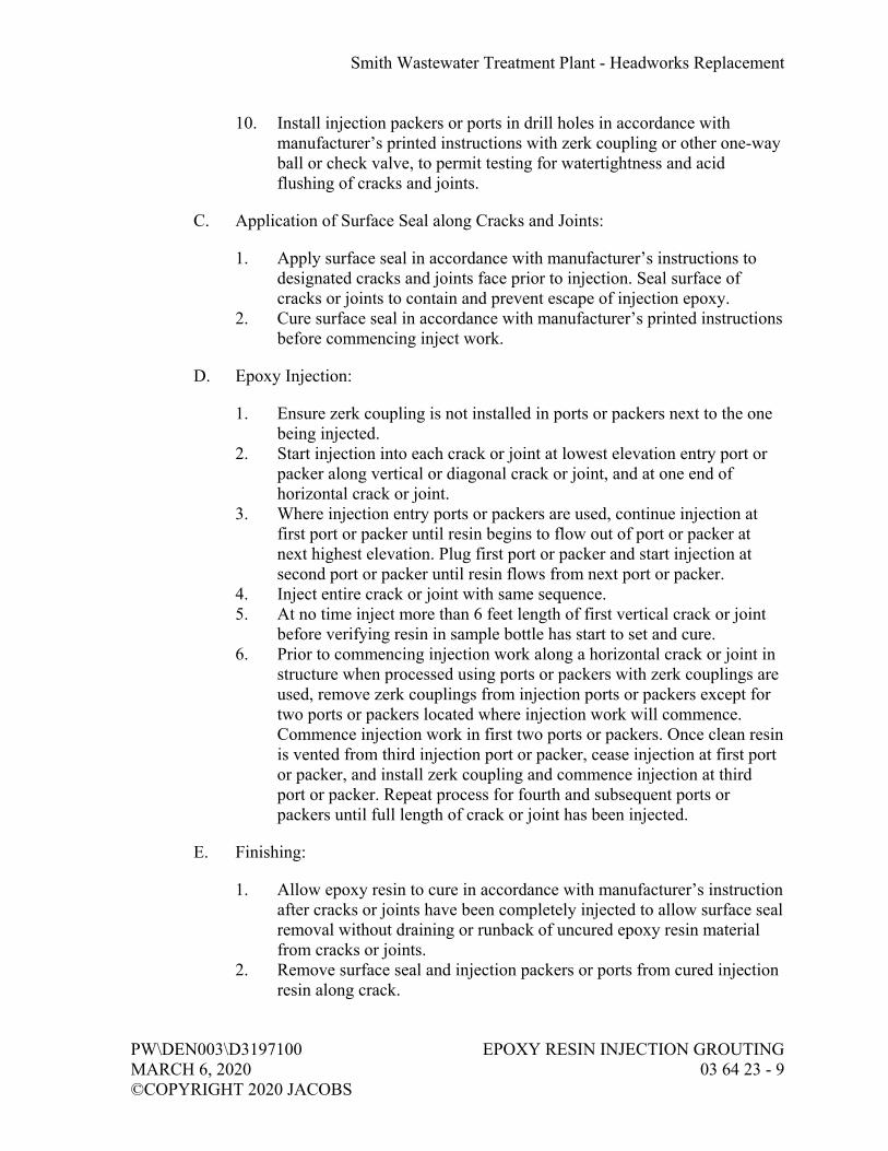
Smith Wastewater Treatment Plant - Headworks Replacement
PW\DEN003\D3197100 EPOXY RESIN INJECTION GROUTING MARCH 6, 2020 03 64 23 - 9 ©COPYRIGHT 2020 JACOBS
10. Install injection packers or ports in drill holes in accordance with manufacturer’s printed instructions with zerk coupling or other one-way ball or check valve, to permit testing for watertightness and acid flushing of cracks and joints.
C. Application of Surface Seal along Cracks and Joints:
1. Apply surface seal in accordance with manufacturer’s instructions to designated cracks and joints face prior to injection. Seal surface of cracks or joints to contain and prevent escape of injection epoxy.
2. Cure surface seal in accordance with manufacturer’s printed instructions before commencing inject work.
D. Epoxy Injection:
1. Ensure zerk coupling is not installed in ports or packers next to the one being injected.
2. Start injection into each crack or joint at lowest elevation entry port or packer along vertical or diagonal crack or joint, and at one end of horizontal crack or joint.
3. Where injection entry ports or packers are used, continue injection at first port or packer until resin begins to flow out of port or packer at next highest elevation. Plug first port or packer and start injection at second port or packer until resin flows from next port or packer.
4. Inject entire crack or joint with same sequence. 5. At no time inject more than 6 feet length of first vertical crack or joint
before verifying resin in sample bottle has start to set and cure. 6. Prior to commencing injection work along a horizontal crack or joint in
structure when processed using ports or packers with zerk couplings are used, remove zerk couplings from injection ports or packers except for two ports or packers located where injection work will commence. Commence injection work in first two ports or packers. Once clean resin is vented from third injection port or packer, cease injection at first port or packer, and install zerk coupling and commence injection at third port or packer. Repeat process for fourth and subsequent ports or packers until full length of crack or joint has been injected.
E. Finishing:
1. Allow epoxy resin to cure in accordance with manufacturer’s instruction after cracks or joints have been completely injected to allow surface seal removal without draining or runback of uncured epoxy resin material from cracks or joints.
2. Remove surface seal and injection packers or ports from cured injection resin along crack.

Smith Wastewater Treatment Plant - Headworks Replacement
EPOXY RESIN INJECTION GROUTING PW\DEN003\D3197100 03 64 23 - 10 MARCH 6, 2020 ©COPYRIGHT 2020 JACOBS
3. Finish crack or joint faces flush with adjacent concrete. 4. Indentations or protrusions caused by placement of entry ports, packers,
drill holes, or damage from removal of surface seal is not acceptable. 5. Grind off protrusions and patch indentations and holes from injection
packers and entry ports with a suitable patch material to satisfaction of Engineer.
6. Remove surplus surface seal material splatters and injection resin material runs and spills from concrete surfaces.
3.05 FIELD QUALITY CONTROL
A. Epoxy Resin Two Component Ratio Tests:
1. Disconnect mixing head and pump two resin components simultaneously through ratio check device.
2. Adjust discharge pressure to 160 psi for both resin components. 3. Simultaneously discharge both resin components into separate
calibrated containers. 4. Compare amounts simultaneously discharged into calibrated containers
during same time period to determine mix ratio. 5. Complete test at 160 psi discharge pressure and repeat procedure for
0 psi discharge pressure. 6. Run ratio test for each injection unit at beginning and end of each
injection work day, and when injection work has stopped for more than 1 hour.
7. Document and maintain complete accurate records of ratios and pressure checks.
B. Injection Pressure Test:
1. Disconnect mixing head of injection equipment and connect two resin component delivery lines to pressure check device.
2. Pressure Check Device: a. Two independent valved nozzles capable of controlling flow rate
and pressure by opening or closing of valve. b. Pressure gauge capable of sensing pressure buildup behind each
valve. 3. Close valves on pressure check device and operate equipment until
gauge pressure on each line reads 160 psi. 4. Stop pumps and observe pressure; do not allow pressure gauge to drop
below 150 psi within 3 minutes. 5. Run pressure test for each injection equipment unit:
a. Beginning and end of each injection work day. b. When injection work stop for more than 45 minutes.
Smith Wastewater Treatment Plant - Headworks Replacement
PW\DEN003\D3197100 EPOXY RESIN INJECTION GROUTING MARCH 6, 2020 03 64 23 - 11 ©COPYRIGHT 2020 JACOBS
6. Check tolerance to verify equipment capable of meeting specified ratio tolerance.
END OF SECTION

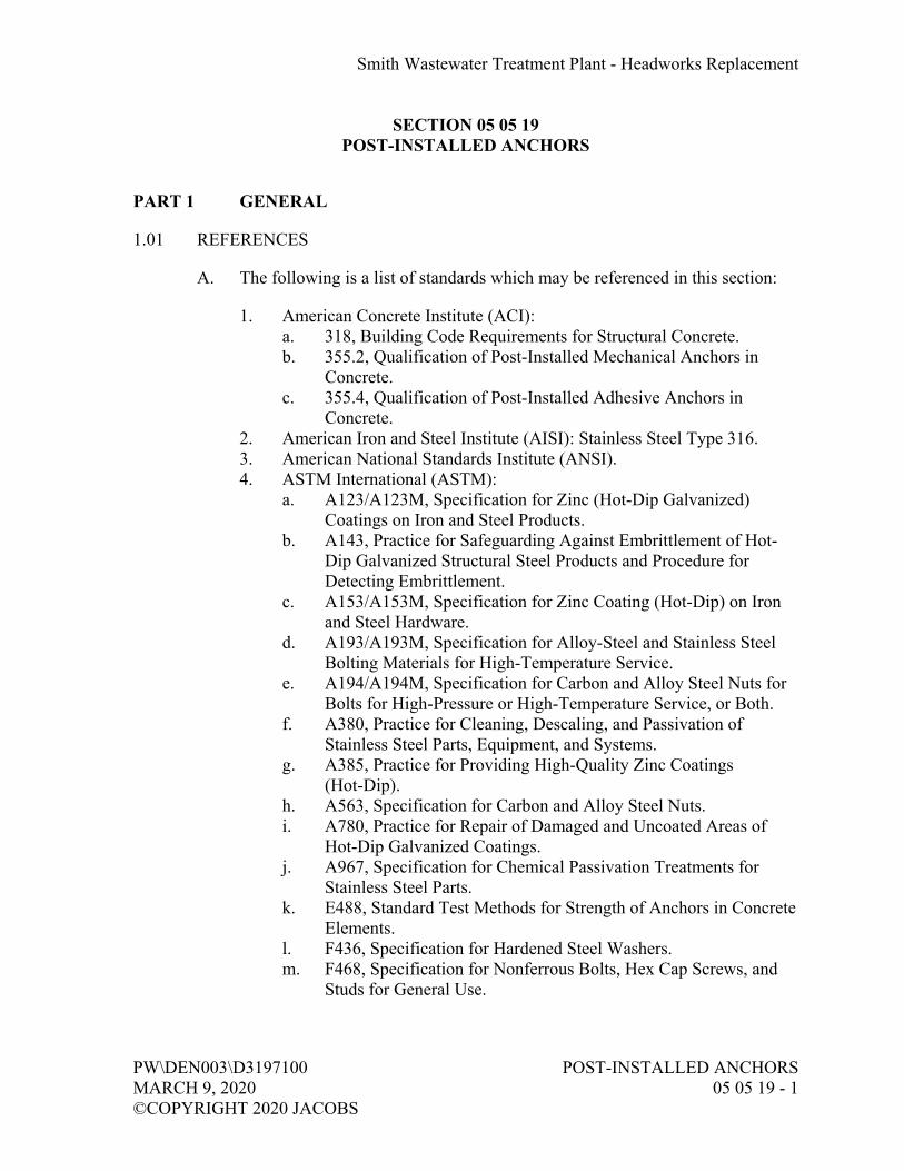
Smith Wastewater Treatment Plant - Headworks Replacement
PW\DEN003\D3197100 POST-INSTALLED ANCHORS MARCH 9, 2020 05 05 19 - 1 ©COPYRIGHT 2020 JACOBS
SECTION 05 05 19 POST-INSTALLED ANCHORS
PART 1 GENERAL
1.01 REFERENCES
A. The following is a list of standards which may be referenced in this section:
1. American Concrete Institute (ACI): a. 318, Building Code Requirements for Structural Concrete. b. 355.2, Qualification of Post-Installed Mechanical Anchors in
Concrete. c. 355.4, Qualification of Post-Installed Adhesive Anchors in
Concrete. 2. American Iron and Steel Institute (AISI): Stainless Steel Type 316. 3. American National Standards Institute (ANSI). 4. ASTM International (ASTM):
a. A123/A123M, Specification for Zinc (Hot-Dip Galvanized) Coatings on Iron and Steel Products.
b. A143, Practice for Safeguarding Against Embrittlement of Hot-Dip Galvanized Structural Steel Products and Procedure for Detecting Embrittlement.
c. A153/A153M, Specification for Zinc Coating (Hot-Dip) on Iron and Steel Hardware.
d. A193/A193M, Specification for Alloy-Steel and Stainless Steel Bolting Materials for High-Temperature Service.
e. A194/A194M, Specification for Carbon and Alloy Steel Nuts for Bolts for High-Pressure or High-Temperature Service, or Both.
f. A380, Practice for Cleaning, Descaling, and Passivation of Stainless Steel Parts, Equipment, and Systems.
g. A385, Practice for Providing High-Quality Zinc Coatings (Hot-Dip).
h. A563, Specification for Carbon and Alloy Steel Nuts. i. A780, Practice for Repair of Damaged and Uncoated Areas of
Hot-Dip Galvanized Coatings. j. A967, Specification for Chemical Passivation Treatments for
Stainless Steel Parts. k. E488, Standard Test Methods for Strength of Anchors in Concrete
Elements. l. F436, Specification for Hardened Steel Washers. m. F468, Specification for Nonferrous Bolts, Hex Cap Screws, and
Studs for General Use.

Smith Wastewater Treatment Plant - Headworks Replacement
POST-INSTALLED ANCHORS PW\DEN003\D3197100 05 05 19 - 2 MARCH 9, 2020 ©COPYRIGHT 2020 JACOBS
n. F568M, Specification for Carbon and Alloy Steel Externally Threaded Metric Fasteners.
o. F593, Specification for Stainless Steel Bolts, Hex Cap Screws, and Studs.
p. F594, Specification for Stainless Steel Nuts. q. F1554, Specification for Anchor Bolts, Steel, 36, 55, and 105-ksi
Yield Strength. 5. International Association of Plumbing and Mechanical Officials
Uniform ES (IAPMO-UES): Evaluation Reports for Concrete and Masonry Anchors.
6. International Code Council Evaluation Service (ICC-ES): a. Evaluation Reports for Concrete and Masonry Anchors. b. AC01, Acceptance Criteria for Expansion Anchors in Masonry
Elements. c. AC70, Acceptance Criteria for Fasteners Power-driven into
Concrete, Steel and Masonry Elements. d. AC106, Acceptance Criteria for Predrilled Fasteners (Screw
Anchors) in Masonry Elements. e. AC193, Acceptance Criteria for Mechanical Anchors in Concrete
Elements. f. AC308, Acceptance Criteria for Post-Installed Adhesive Anchors in
Concrete Elements. Evaluation Reports for Concrete and Masonry Anchors.
7. Specialty Steel Industry of North America (SSINA): a. Specifications for Stainless Steel. b. Design Guidelines for the Selection and Use of Stainless Steel. c. Stainless Steel Fabrication. d. Stainless Steel Fasteners.
1.02 DEFINITIONS
A. Corrosive Area: Containment area or area exposed to delivery, storage, transfer, or use of chemicals.
B. Exterior Area: Location not protected from weather by a building or other enclosed structure to include buried roof structures.
C. Interior Dry Area: Location inside building or structure where floor is not subject to liquid spills or wash down, and where wall or roof slab is not common to a hydraulic or earth-retaining structure.
D. Interior Wet Area: Location inside building or structure where floor is sloped to floor drains or gutters and is subject to liquid spills or wash down, or where wall, floor, or roof slab is common to a hydraulic or earth-retaining structure.

Smith Wastewater Treatment Plant - Headworks Replacement
PW\DEN003\D3197100 POST-INSTALLED ANCHORS MARCH 9, 2020 05 05 19 - 3 ©COPYRIGHT 2020 JACOBS
E. Submerged: Location at or below top of wall of open hydraulic structure, such as a basin or channel, or wall, ceiling, or floor surface inside a covered hydraulic structure, or exterior belowgrade wall or roof surface of hydraulic structure, open or covered.
1.03 SUBMITTALS
A. Action Submittals:
1. Shop Drawings: Specific instructions for concrete anchor installation, including drilled hole size and depth, preparation, placement, procedures, and instructions for safe handling of anchoring systems.
B. Informational Submittals:
1. Concrete Anchors: a. Manufacturer’s product description and installation instructions. b. Current ICC-ES or IAPMO-UES Report for each type of post-
installed anchor to be used. c. Adhesive Anchor Installer Certification.
2. Passivation method for stainless steel members.
1.04 QUALITY ASSURANCE
A. Qualifications:
1. Installers of adhesive anchors horizontally or upwardly inclined to support sustained tension loads shall be certified by an applicable certification program. Certification shall include written and performance tests in accordance with the ACI/CRSI Adhesive Installer Certification Program or equivalent.
2. Galvanized Coating Applicator: Company specializing in hot-dip galvanizing after fabrication and following procedures of Quality Assurance Manual of the American Galvanizers Association.
1.05 DELIVERY, STORAGE, AND HANDLING
A. Package stainless steel items in a manner to provide protection from carbon impregnation.
B. Protect hot-dip galvanized finishes from damage as a result of metal banding and rough handling.
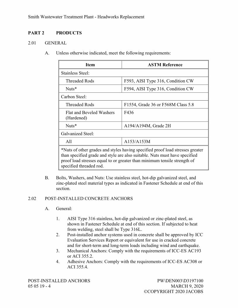
Smith Wastewater Treatment Plant - Headworks Replacement
POST-INSTALLED ANCHORS PW\DEN003\D3197100 05 05 19 - 4 MARCH 9, 2020 ©COPYRIGHT 2020 JACOBS
PART 2 PRODUCTS
2.01 GENERAL
A. Unless otherwise indicated, meet the following requirements:
Item ASTM Reference
Stainless Steel:
Threaded Rods F593, AISI Type 316, Condition CW
Nuts* F594, AISI Type 316, Condition CW
Carbon Steel:
Threaded Rods F1554, Grade 36 or F568M Class 5.8
Flat and Beveled Washers (Hardened)
F436
Nuts* A194/A194M, Grade 2H
Galvanized Steel:
All A153/A153M
*Nuts of other grades and styles having specified proof load stresses greater than specified grade and style are also suitable. Nuts must have specified proof load stresses equal to or greater than minimum tensile strength of specified threaded rod.
B. Bolts, Washers, and Nuts: Use stainless steel, hot-dip galvanized steel, and zinc-plated steel material types as indicated in Fastener Schedule at end of this section.
2.02 POST-INSTALLED CONCRETE ANCHORS
A. General:
1. AISI Type 316 stainless, hot-dip galvanized or zinc-plated steel, as shown in Fastener Schedule at end of this section. If subjected to heat from welding, steel shall be Type 316L.
2. Post-installed anchor systems used in concrete shall be approved by ICC Evaluation Services Report or equivalent for use in cracked concrete and for short-term and long-term loads including wind and earthquake.
3. Mechanical Anchors: Comply with the requirements of ICC-ES AC193 or ACI 355.2.
4. Adhesive Anchors: Comply with the requirements of ICC-ES AC308 or ACI 355.4.

Smith Wastewater Treatment Plant - Headworks Replacement
PW\DEN003\D3197100 POST-INSTALLED ANCHORS MARCH 9, 2020 05 05 19 - 5 ©COPYRIGHT 2020 JACOBS
B. Torque-Controlled Expansion Anchors (Wedge Anchors):
1. Manufacturers and Products: a. Hilti, Inc., Tulsa, OK; Kwik-Bolt –TZ (KB-TZ) Anchors
(ESR-1917). b. DeWalt/Powers Fasteners, Brewster, NY; Power-Stud +SD1,
+SD2, +SD4, or +SD6 Anchors (ESR-2502 and ESR-2818). c. Simpson Strong-Tie Co., Inc., Pleasanton, CA; Strong-Bolt 2
Anchors (ESR-1771 and ESR-3037).
C. Self-Tapping Concrete Screw Anchors:
1. Manufacturers and Products: a. DeWalt/Powers Fasteners, Brewster, NY; Wedge-Bolt+
(ESR-2526). b. DeWalt/Powers Fasteners, Brewster, NY; Vertigo+ Rod Hanger
Screw Anchor (ESR-2989). c. DeWalt/Powers Fasteners, Brewster, NY; Snake+ Flush Mount
Screw Anchor (ESR-2272). d. Hilti, Inc., Tulsa, OK; HUS-EZ Screw Anchor (ESR-3027). e. Simpson Strong-Tie Co., Inc., Pleasanton, CA; Titen HD Screw
Anchor (ESR-2713).
D. Adhesive Anchors:
1. Threaded Rod: a. Diameter as shown on Drawings. b. Length as required to provide minimum depth of embedment
indicated and thread projection required. c. Clean and free of grease, oil, or other deleterious material.
2. Adhesive: a. Two-component, insensitive to moisture, designed to be used in
adverse freeze/thaw environments. b. Cure Temperature, Pot Life, and Workability: Compatible for
intended use and anticipated environmental conditions. 3. Packaging and Storage:
a. Disposable, self-contained system capable of dispensing both components in proper mixing ratio and fitting into a manually or pneumatically operated caulking gun.
b. Store adhesive on pallets or shelving in a covered storage area. c. Package Markings: Include manufacturer’s name, product name,
batch number, product expiration date, ANSI hazard classification, and appropriate ANSI handling precautions.
d. Dispose of when: 1) Shelf life has expired. 2) Stored other than in accordance with manufacturer’s
instructions.
Smith Wastewater Treatment Plant - Headworks Replacement
POST-INSTALLED ANCHORS PW\DEN003\D3197100 05 05 19 - 6 MARCH 9, 2020 ©COPYRIGHT 2020 JACOBS
4. Manufacturers and Products: a. Hilti, Inc., Tulsa, OK; HIT-RE 500-V3 (ESR-3814) Adhesive
Anchors. b. Simpson Strong-Tie Co., Inc., Pleasanton, CA; SET-3G Epoxy
Adhesive Anchors (ESR-4057)
E. Adhesive Threaded Inserts:
1. Type 316 stainless steel, internally threaded inserts. If subjected to heat from welding, steel shall be Type 316L.
2. Manufacturer and Product: Hilti, Inc., Tulsa, OK; HIS-RN Insert with HIT-RE 500-V3 adhesive.
PART 3 EXECUTION
3.01 CONCRETE ANCHORS
A. Begin installation only after concrete to receive anchors has attained design strength.
B. Locate existing reinforcing with Ground Penetrating Radar or other method approved by Engineer prior to drilling. Coordinate with Engineer to adjust anchor locations where installation would result in hitting reinforcing.
C. Install in accordance with written manufacturer’s instructions.
D. Provide minimum embedment, edge distance, and spacing as indicated on Drawings.
E. Use only drill type and bit type and diameter recommended by anchor manufacturer.
F. Clean hole of debris and dust per manufacturer’s requirements.
G. When unidentified embedded steel, rebar, or other obstruction is encountered in drill path, slant drill to clear obstruction. If drill must be slanted more than indicated in manufacturer’s installation instructions to clear obstruction, notify Engineer for direction on how to proceed.
H. Adhesive Anchors:
1. Unless otherwise approved by Engineer and adhesive manufacturer: a. Do not install adhesive anchors when temperature of concrete is
below 40 degrees F or above 100 degrees F. b. Do not install prior to concrete attaining an age of 21 days.

Smith Wastewater Treatment Plant - Headworks Replacement
PW\DEN003\D3197100 POST-INSTALLED ANCHORS MARCH 9, 2020 05 05 19 - 7 ©COPYRIGHT 2020 JACOBS
c. Remove any standing water from hole with oil-free compressed air. Inside surface of hole shall be dry.
d. Do not disturb anchor during recommended curing time. e. Do not exceed maximum torque as specified in manufacturer’s
instructions.
I. Prestressed Concrete: Do not use drilled-in anchors in prestressed or post-tensioned concrete members without Engineer’s prior approval unless specifically shown on Drawings.
3.02 FIELD QUALITY ASSURANCE AND QUALITY CONTROL
A. Owner-Furnished Quality Assurance, in accordance with IBC Chapter 17 requirements, is provided in the Statement of Special Inspections Plan on Drawings. Contractor responsibilities and related information are included in Section 01 45 33, Special Inspection, Observation, and Testing.
B. Contractor-Furnished Quality Control: Inspection and testing as required in Section 01 45 16.13, Contractor Quality Control.
3.03 FASTENER SCHEDULE
A. Unless indicated otherwise on Drawings, provide fasteners as follows:
Service Use and Location Product Remarks
1. Post-Installed Anchors for Metal Components to Cast-in-Place Concrete (such as, Ladders, Handrail Posts, Electrical Panels, Platforms, and Equipment)
Interior Dry Areas Anchor material type to match material being anchored (for example, stainless steel anchors to anchor stainless steel equipment, zinc-plated anchors to anchor painted equipment, galvanized anchors to anchor galvanized equipment).
Verify product acceptability and manufacturer’s requirements if anchor installation will occur in an overhead application
Submerged, Exterior, Interior Wet, and Corrosive Areas
Stainless steel adhesive anchors Verify product acceptability and manufacturer’s requirements if anchor installation will occur in an overhead application
2. All Others
All service uses and locations Stainless steel fasteners

Smith Wastewater Treatment Plant - Headworks Replacement
POST-INSTALLED ANCHORS PW\DEN003\D3197100 05 05 19 - 8 MARCH 9, 2020 ©COPYRIGHT 2020 JACOBS
B. Antiseizing Lubricant: Use on all stainless steel threads.
C. Do not use adhesive anchors to support fire-resistive construction or where ambient temperature will exceed 120 degrees F.
END OF SECTION

Smith Wastewater Treatment Plant - Headworks Replacement
PW\DEN003\D3197100 METAL FABRICATIONS APRIL 8, 2020 05 50 00 - 1 ©COPYRIGHT 2020 JACOBS
SECTION 05 50 00 METAL FABRICATIONS
PART 1 GENERAL
1.01 REFERENCES
A. The following is a list of standards which may be referenced in this section:
1. The Aluminum Association, Inc. (AA): The Aluminum Design Manual. 2. American Galvanizers Association (AGA):
a. Inspection of Hot-Dip Galvanized Steel Products. b. Quality Assurance Manual.
3. American Iron and Steel Institute (AISI): Stainless Steel Types. 4. American Ladder Institute (ALI): A14.3, Ladders - Fixed - Safety
Requirements. 5. American National Standards Institute (ANSI). 6. American Society of Safety Engineers (ASSE): A10.11, Safety
Requirements for Personnel and Debris Nets. 7. American Welding Society (AWS):
a. D1.1/D1.1M, Structural Welding Code - Steel. b. D1.2/D1.2M, Structural Welding Code - Aluminum. c. D1.6/D1.6M, Structural Welding Code - Stainless Steel.
8. ASTM International (ASTM): a. A36/A36M, Standard Specification for Carbon Structural Steel. b. A48/A48M, Specification for Gray Iron Castings. c. A53/A53M, Standard Specification for Pipe, Steel, Black and
Hot-Dipped, Zinc-Coated, Welded and Seamless. d. A108, Standard Specification for Steel Bar, Carbon and Alloy,
Cold-Finished. e. A123/A123M, Standard Specification for Zinc (Hot-Dip
Galvanized) Coatings on Iron and Steel Products. f. A143/A143M, Standard for Safeguarding Against Embrittlement
of Hot-Dip Galvanized Structural Steel Products and Procedure for Detecting Embrittlement.
g. A153/A153M, Standard Specification for Zinc Coating (Hot-Dip) on Iron and Steel Hardware.
h. A193/A193M, Standard Specification for Alloy-Steel and Stainless Steel Bolting for High Temperature or High Pressure Service and Other Special Purpose Applications.
i. A194/A194M, Standard Specification for Carbon and Alloy Steel Nuts for Bolts for High Pressure or High Temperature Service, or Both.

Smith Wastewater Treatment Plant - Headworks Replacement
METAL FABRICATIONS PW\DEN003\D3197100 05 50 00 - 2 APRIL 8, 2020 ©COPYRIGHT 2020 JACOBS
j. A240/A240M, Standard Specification for Chromium and Chromium-Nickel Stainless Steel Plate, Sheet, and Strip for Pressure Vessels and for General Applications.
k. A276, Standard Specification for Stainless Steel Bars and Shapes. l. A283/A283M, Standard Specification for Low and Intermediate
Tensile Strength Carbon Steel Plates. m. A307, Standard Specification for Carbon Steel Bolts and Studs,
60,000 PSI Tensile Strength. n. A325, Standard Specification for Structural Bolts, Steel, Heat
Treated 120/105 ksi Minimum Tensile Strength. o. A380, Standard Practice for Cleaning, Descaling, and Passivation
of Stainless Steel Parts, Equipment, and Systems. p. A384/A384M, Standard Practice for Safeguarding Against
Warpage and Distortion During Hot-Dip Galvanizing of Steel Assemblies.
q. A385/A385M, Standard Practice for Providing High-Quality Zinc Coatings (Hot-Dip).
r. A489, Standard Specification for Carbon Steel Lifting Eyes. s. A500/A500M, Standard Specification for Cold-Formed Welded
and Seamless Carbon Steel Structural Tubing in Rounds and Shapes.
t. A501, Standard Specification for Hot-Formed Welded and Seamless Carbon Steel Structural Tubing.
u. A563, Standard Specification for Carbon and Alloy Steel Nuts. v. A653/A653M, Standard Specification for Steel Sheet, Zinc-
Coated (Galvanized) or Zinc-Iron Alloy-Coated (Galvannealed) by the Hot-Dip Process.
w. A780/A780, Standard Practice for Repair of Damaged and Uncoated Areas of Hot-Dip Galvanized Coatings.
x. A786/A786M, Standard Specification for Hot-Rolled Carbon, Low-Alloy, High-Strength Low-Alloy, and Alloy Steel Floor Plates.
y. A793, Standard Specification for Rolled Floor Plate, Stainless Steel.
z. A967, Standard Specification for Chemical Passivation Treatments for Stainless Steel Parts.
aa. A992/A992M, Standard Specification for Structural Steel Shapes. bb. A1085, Standard Specification for Cold-Formed Welded Carbon
Steel Hollow Structural Sections (HSS). cc. B209, Standard Specification for Aluminum and Aluminum-Alloy
Sheet and Plate. dd. B308/B308M, Standard Specification for Aluminum-
Alloy 6061-T6 Standard Structural Profiles. ee. B429/B429M, Standard Specification for Aluminum-Alloy
Extruded Structural Pipe and Tube.
Smith Wastewater Treatment Plant - Headworks Replacement
PW\DEN003\D3197100 METAL FABRICATIONS APRIL 8, 2020 05 50 00 - 3 ©COPYRIGHT 2020 JACOBS
ff. B632/B632M, Standard Specification for Aluminum-Alloy Rolled Tread Plate.
gg. C881/C881M, Standard Specification for Epoxy-Resin-Base Bonding Systems for Concrete.
hh. D1056, Standard Specification for Flexible Cellular Materials - Sponge or Expanded Rubber.
ii. F436, Standard Specification for Hardened Steel Washers. jj. F468, Standard Specification for Nonferrous Bolts, Hex Cap
Screws, and Studs for General Use. kk. F593, Standard Specification for Stainless Steel Bolts, Hex Cap
Screws, and Studs. ll. F594, Standard Specification for Stainless Steel Nuts. mm. F844, Standard Specification for Washers, Steel, Plain (Flat),
Unhardened for General Use. nn. F1554, Standard Specification for Anchor Bolts, Steel, 36, 55, and
105-ksi Yield Strength. 9. Occupational Safety and Health Administration (OSHA):
a. 29 CFR 1910.27, Fixed Ladders. b. 29 CFR 1926.105, Safety Nets. c. 29 CFR 1926.502, Fall Protection Systems Criteria and Practices.
10. Specialty Steel Industry of North America (SSINA): a. Specifications for Stainless Steel. b. Design Guidelines for the Selection and Use of Stainless Steel. c. Stainless Steel Fabrication. d. Stainless Steel Fasteners.
1.02 DEFINITIONS
A. Anchor Bolt: Cast-in-place anchor; concrete or masonry.
B. Corrosive Area: Containment area or area exposed to delivery, storage, transfer, or use of chemicals. Corrosive area includes areas exposed to corrosive atmosphere such as hydrogen sulfide from wastewater.
C. Exterior Area: Location not protected from weather by building or other enclosed structure.
D. Interior Dry Area: Location inside building or structure where floor is not subject to liquid spills or washdown, nor where wall or roof slab is common to a hydraulic or earth-retaining structure.
E. Interior Wet Area: Location inside building or structure where floor is sloped to floor drains or gutters and is subject to liquid spills or washdown, or where wall, floor, or roof slab is common to a hydraulic or earth-retaining structure.

Smith Wastewater Treatment Plant - Headworks Replacement
METAL FABRICATIONS PW\DEN003\D3197100 05 50 00 - 4 APRIL 8, 2020 ©COPYRIGHT 2020 JACOBS
F. Submerged: Location at or below top of wall of open hydraulic structure, such as basin or channel, or wall, ceiling or floor surface inside a covered hydraulic structure, or exterior belowgrade wall or roof surface of hydraulic structure, open or covered.
1.03 SUBMITTALS
A. Action Submittals:
1. Shop Drawings: Metal fabrications, including welding and fastener information.
B. Informational Submittals:
1. U-Channel Concrete Inserts: a. Manufacturer’s product description. b. Allowable load tables.
2. Pre-engineered Ladders: Letter of certification that ladder meets OSHA 29 CFR 1910.27 requirements.
3. Passivation method for stainless steel members.
1.04 QUALITY ASSURANCE
A. Qualifications:
1. Galvanized Coating Applicator: Company specializing in hot-dip galvanizing after fabrication and following procedures of Quality Assurance Manual of the American Galvanizers Association.
1.05 DELIVERY, STORAGE, AND HANDLING
A. Insofar as practical, factory assemble specified items. Package assemblies, which have to be shipped unassembled to protect materials from damage and tag to facilitate identification and field assembly.
B. Package stainless steel items to provide protection from carbon impregnation.
C. Protect painted coatings and hot-dip galvanized finishes from damage as a result of metal banding and rough handling. Use padded slings and straps.
D. Store fabricated items in dry area, not in direct contact with ground.

Smith Wastewater Treatment Plant - Headworks Replacement
PW\DEN003\D3197100 METAL FABRICATIONS APRIL 8, 2020 05 50 00 - 5 ©COPYRIGHT 2020 JACOBS
1.06 SPECIAL GUARANTEE
A. Manufacturer’s extended guarantee or warranty, with Owner named as beneficiary, in writing, as special guarantee. Special guarantee shall provide for correction, or at option of Owner, removal and replacement of sidewalk doors found defective during a period of 5 years after date of Substantial Completion. Duties and obligations for correction or removal and replacement of defective Work as specified in General Conditions.
PART 2 PRODUCTS
2.01 GENERAL
A. For hot-dip galvanized steel that is exposed to view and does not receive paint, limit the combined phosphorus and silicon content to 0.04 percent. For steels that require a minimum of 0.15 percent silicon (such as plates over 1.5 inches thick for ASTM A36/A36M steel), limit maximum silicon content to 0.21 percent and phosphorous content to 0.03 percent.
B. Unless otherwise indicated, meet the following requirements:
Item ASTM Reference
Steel Wide Flange Shapes A992/992M
Other Steel Shapes and Plates A36/A36M or A572/A572M, Grade 50 or A992/A992M for other steel shapes
Steel Pipe A500, Grade B
Hollow Structural Sections (HSS) A500/A500M, Grade C
Aluminum:
Aluminum Plates B209, Alloy y6061-T6
Aluminum Structural Shapes B308/B308M, Alloy 6061-T6
Stainless Steel:
Bars and Angles A276, AISI Type 316 (316L for welded connections)
Shapes A276, AISI Type 304 (304L for welded connections)
Steel Plate, Sheet, and Strip A240/A240M, AISI Type 316 (316L for welded connections)
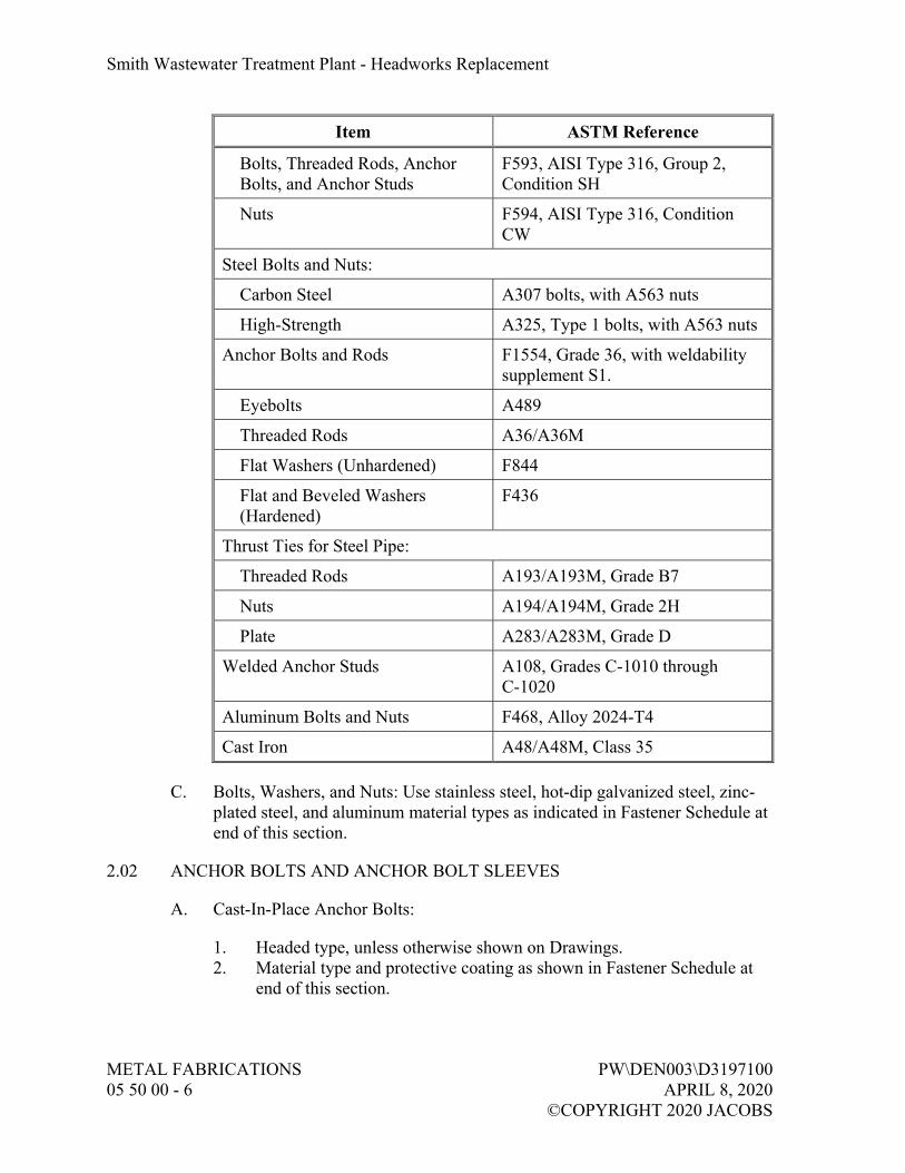
Smith Wastewater Treatment Plant - Headworks Replacement
METAL FABRICATIONS PW\DEN003\D3197100 05 50 00 - 6 APRIL 8, 2020 ©COPYRIGHT 2020 JACOBS
Item ASTM Reference
Bolts, Threaded Rods, Anchor Bolts, and Anchor Studs
F593, AISI Type 316, Group 2, Condition SH
Nuts F594, AISI Type 316, Condition CW
Steel Bolts and Nuts:
Carbon Steel A307 bolts, with A563 nuts
High-Strength A325, Type 1 bolts, with A563 nuts
Anchor Bolts and Rods F1554, Grade 36, with weldability supplement S1.
Eyebolts A489
Threaded Rods A36/A36M
Flat Washers (Unhardened) F844
Flat and Beveled Washers (Hardened)
F436
Thrust Ties for Steel Pipe:
Threaded Rods A193/A193M, Grade B7
Nuts A194/A194M, Grade 2H
Plate A283/A283M, Grade D
Welded Anchor Studs A108, Grades C-1010 through C-1020
Aluminum Bolts and Nuts F468, Alloy 2024-T4
Cast Iron A48/A48M, Class 35
C. Bolts, Washers, and Nuts: Use stainless steel, hot-dip galvanized steel, zinc-plated steel, and aluminum material types as indicated in Fastener Schedule at end of this section.
2.02 ANCHOR BOLTS AND ANCHOR BOLT SLEEVES
A. Cast-In-Place Anchor Bolts:
1. Headed type, unless otherwise shown on Drawings. 2. Material type and protective coating as shown in Fastener Schedule at
end of this section.

Smith Wastewater Treatment Plant - Headworks Replacement
PW\DEN003\D3197100 METAL FABRICATIONS APRIL 8, 2020 05 50 00 - 7 ©COPYRIGHT 2020 JACOBS
B. Anchor Bolt Sleeves:
1. Plastic: a. Single unit construction with corrugated sleeve. b. Top of sleeve shall be self-threading to provide adjustment of
threaded anchor bolt projection. c. Material: High-density polyethylene.
2. Fabricated Steel: ASTM A36/A36M.
2.03 POST-INSTALLED CONCRETE
A. See Section 05 05 19, Post-Installed Anchors.
2.04 STUD SHEAR CONNECTORS
A. Headed anchor studs (HAS), or threaded anchor studs (TAS), or stud shear connectors, as indicated on Drawings.
1. Carbon Steel: ASTM A108, Standard Quality Grades 1010 through 1020, inclusive either semikilled or killed aluminum or silicon dioxidation, unless indicated otherwise.
2. Stainless Steel: ASTM F593, AISI Type 316, Condition CW, where indicated.
B. Manufacturers:
1. Nelson Stud Welding, FabriSteel Co., Elyria, OH. 2. Stud Welding Associates, Inc., Elyria, OH.
2.05 PIPE SLEEVES
A. As specified in Section 40 27 01, Process Piping Specialties.
2.06 ACCESSORIES
A. Antiseizing Lubricant for Stainless Steel Threaded Connections:
1. Suitable for potable water supply. 2. Resists washout. 3. Manufacturers and Products:
a. Bostik, Middleton, MA; Neverseez. b. Saf-T-Eze Div., STL Corp., Lombard, IL; Anti-Seize.

Smith Wastewater Treatment Plant - Headworks Replacement
METAL FABRICATIONS PW\DEN003\D3197100 05 50 00 - 8 APRIL 8, 2020 ©COPYRIGHT 2020 JACOBS
B. Neoprene Gasket:
1. ASTM D1056, 2C1, soft, closed-cell neoprene gasket material, suitable for exposure to sewage and sewage gases, unless otherwise shown on Drawings.
2. Thickness: Minimum 1/4 inch. 3. Furnish without skin coat. 4. Manufacturer and Product: Monmouth Rubber and Plastics Corporation,
Long Branch, NJ; Durafoam DK1111LD.
2.07 FLOOR PLATE
A. Material:
1. Aluminum: ASTM B632/B632M, Alloy 6061-T6.
B. Minimum Thickness:
1. Steel: 1/4 inch, unless shown otherwise on Drawings. 2. Aluminum: 3/8 inch, unless shown otherwise on Drawings.
C. Surface: Raised-lug pattern or diamond tread, unless shown otherwise on Drawings.
D. Slip-Resistant Surface:
1. Provide where indicated on Drawings. 2. Manufacturers and Products:
a. IKG/Borden, Clark, NJ; MEBAC 2. b. W.S. Molnar Co., Detroit, MI; SLIPNOT Grade 2–Medium.
2.08 FABRICATION
A. General:
1. Finish exposed surfaces smooth, sharp, and to well-defined lines. 2. Furnish necessary rabbets, lugs, and brackets so work can be assembled
in neat, substantial manner. 3. Conceal fastenings where practical; where exposed, flush countersink. 4. Drill metalwork and countersink holes as required for attaching
hardware or other materials. 5. Grind cut edges smooth and straight. Round sharp edges to small
uniform radius. Grind burrs, jagged edges, and surface defects smooth. 6. Fit and assemble in largest practical sections for delivery to Site.

Smith Wastewater Treatment Plant - Headworks Replacement
PW\DEN003\D3197100 METAL FABRICATIONS APRIL 8, 2020 05 50 00 - 9 ©COPYRIGHT 2020 JACOBS
B. Materials:
1. Use steel shapes, unless otherwise noted. 2. Steel to be hot-dip galvanized: Limit silicon content to less than
0.04 percent or to between 0.15 percent and 0.25 percent. 3. Fabricate aluminum in accordance with AA Specifications for
Aluminum Structures–Allowable Stress Design.
C. Welding:
1. Weld connections and grind exposed welds smooth. When required to be watertight, make welds continuous.
2. Welded fabrications shall be free from twisting or distortion caused by improper welding techniques.
3. Steel: Meet fabrication requirements of AWS D1.1/D1.1M, Section 5. 4. Aluminum: Meet requirements of AWS D1.2/D1.2M. 5. Stainless Steel: Meet requirements of AWS D1.6/D1.6M. 6. Welded Anchor Studs: Prepare surface to be welded and weld with stud
welding gun in accordance with AWS D1.1/D1.1M, Section 7, and manufacturer’s instructions.
7. Complete welding before applying finish.
D. Painting:
1. Shop prime with rust-inhibitive primer as specified in Section 09 90 00, Painting and Coating, unless otherwise indicated.
2. Coat surfaces of galvanized steel and aluminum fabricated items to be in direct contact with concrete, grout, masonry, or dissimilar metals, as specified in Section 09 90 00, Painting and Coating, unless indicated otherwise.
3. Do not apply protective coating to galvanized steel anchor bolts or galvanized steel welded anchor studs, unless indicated otherwise.
E. Galvanizing:
1. Fabricate steel to be galvanized in accordance with ASTM A143/A143M, ASTM A384/A384M, and ASTM A385/A385M. Avoid fabrication techniques that could cause distortion or embrittlement of the steel.
2. Provide venting and drain holes for tubular members and fabricated assemblies in accordance with ASTM A385/A385M.
3. Remove welding slag, splatter, burrs, grease, oil, paint, lacquer, and other deleterious material prior to delivery for galvanizing.
4. Remove by blast cleaning or other methods surface contaminants and coatings not removable by normal chemical cleaning process in the galvanizing operation.
Smith Wastewater Treatment Plant - Headworks Replacement
METAL FABRICATIONS PW\DEN003\D3197100 05 50 00 - 10 APRIL 8, 2020 ©COPYRIGHT 2020 JACOBS
5. Hot-dip galvanize steel members, fabrications, and assemblies after fabrication in accordance with ASTM A123/A123M.
6. Hot-dip galvanize bolts, nuts, washers, and hardware components in accordance with ASTM A153/A153M. Oversize holes to allow for zinc alloy growth. Shop assemble bolts and nuts.
7. Galvanized steel sheets in accordance with ASTM A653/A653M. 8. Galvanize components of bolted assemblies separately before assembly.
Galvanizing of tapped holes is not required.
F. Electrolytic Protection: Coat surfaces of galvanized steel and aluminum fabricated items to be in direct contact with concrete, grout, masonry, or dissimilar metals, as specified in Section 09 90 00, Painting and Coating, unless indicated otherwise.
G. Fitting: Where movement of fabrications is required or shown, cut, fit, and align items for smooth operation. Make corners square and opposite sides parallel.
H. Accessories: Furnish as required for a complete installation. Fasten by welding or with stainless steel bolts or screws.
2.09 SOURCE QUALITY CONTROL
A. Visually inspect all fabrication welds and correct deficiencies.
1. Steel: AWS D1.1/D1.1M, Section 6 and Table 6.1, Visual Inspection Acceptance Criteria.
2. Aluminum: AWS D1.2/D1.2M. 3. Stainless Steel: AWS D1.6/D1.6M.
PART 3 EXECUTION
3.01 INSTALLATION OF METAL FABRICATIONS
A. General:
1. Install metal fabrications plumb and level, accurately fitted, free from distortion or defects.
2. Install rigid, substantial, and neat in appearance. 3. Install manufactured products in accordance with manufacturer’s
recommendations. 4. Obtain Engineer approval prior to field cutting steel members or making
adjustments not scheduled.

Smith Wastewater Treatment Plant - Headworks Replacement
PW\DEN003\D3197100 METAL FABRICATIONS APRIL 8, 2020 05 50 00 - 11 ©COPYRIGHT 2020 JACOBS
B. Aluminum:
1. Do not remove mill markings from concealed surfaces. 2. Remove inked or painted identification marks on exposed surfaces not
otherwise coated after installed material has been inspected and approved.
3. Fabrication, mechanical connections, and welded construction shall be in accordance with the AA Aluminum Design Manual.
C. Pipe Sleeves:
1. Provide where pipes pass through concrete. 2. Holes drilled with a rotary drill may be provided in lieu of sleeves in
existing walls. 3. Provide center flange for water stoppage on sleeves in exterior or water-
bearing walls. 4. Provide rubber caulking sealant or a modular mechanical unit to form
watertight seal in annular space between pipes and sleeves.
3.02 CAST-IN-PLACE ANCHOR BOLTS
A. Locate and hold anchor bolts in place with templates at time concrete is placed.
B. Use anchor bolt sleeves for location adjustment and provide two nuts and one washer per bolt of same material as bolt.
C. Minimum Bolt Size: 1/2-inch diameter by 12 inches long, unless otherwise shown.
3.03 ACCESS COVERS
A. Install access covers, including sidewalk doors in accordance with manufacturer’s instructions.
B. Accurately position prior to placing concrete, such that covers are flush with floor surface.
C. Protect from damage resulting from concrete placement. Thoroughly clean exposed surfaces of concrete spillage to obtain a clean, uniform appearance.
D. Route drain pipe to exterior face of concrete or as shown on Drawings.
Smith Wastewater Treatment Plant - Headworks Replacement
METAL FABRICATIONS PW\DEN003\D3197100 05 50 00 - 12 APRIL 8, 2020 ©COPYRIGHT 2020 JACOBS
3.04 ELECTROLYTIC PROTECTION
A. Aluminum and Galvanized Steel:
1. Coat surfaces of galvanized steel and aluminum fabricated items to be in direct contact with concrete, grout, masonry, or dissimilar metals, as specified in Section 09 90 00, Painting and Coating, unless indicated otherwise.
2. Do not apply protective coating to galvanized steel anchor bolts or galvanized steel welded anchor studs, unless indicated otherwise.
3. Allow coating to dry before installation of the material. 4. Protect coated surfaces during installation. 5. Should coating become marred, prepare and touch up in accordance
with paint manufacturer’s written instructions.
B. Titanium: Where titanium equipment is in contact with concrete or dissimilar metal, provide full-face neoprene insulation gasket, 3/32-inch minimum thickness and 70-durometer hardness.
C. Stainless Steel:
1. During handling and installation, take necessary precautions to prevent carbon impregnation of stainless steel members.
2. After installation, visually inspect stainless steel surfaces for evidence of iron rust, oil, paint, and other forms of contamination.
3. Remove contamination using cleaning and passivation methods in accordance with requirements of ASTM A380 and ASTM A967.
4. Brushes used to remove foreign substances shall utilize only stainless steel or nonmetallic bristles.
5. After treatment, visually inspect surfaces for compliance.
3.05 PAINTING
A. Painted Galvanized Surfaces: Prepare as specified in Section 09 90 00, Painting and Coating.
B. Repair of Damaged Hot-Dip Galvanized Coating:
1. Conform to ASTM A780/A780M. 2. For minor repairs at abraded areas, use sprayed zinc conforming to
ASTM A780/A780M. 3. For flame cut or welded areas, use zinc-based solder, or zinc sticks,
conforming to ASTM A780/A780M. 4. Use magnetic gauge to determine thickness is equal to or greater than
base galvanized coating.
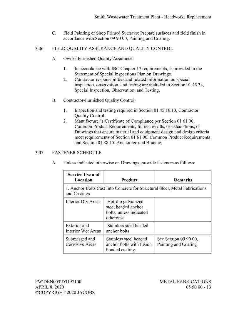
Smith Wastewater Treatment Plant - Headworks Replacement
PW\DEN003\D3197100 METAL FABRICATIONS APRIL 8, 2020 05 50 00 - 13 ©COPYRIGHT 2020 JACOBS
C. Field Painting of Shop Primed Surfaces: Prepare surfaces and field finish in accordance with Section 09 90 00, Painting and Coating.
3.06 FIELD QUALITY ASSURANCE AND QUALITY CONTROL
A. Owner-Furnished Quality Assurance:
1. In accordance with IBC Chapter 17 requirements, is provided in the Statement of Special Inspections Plan on Drawings.
2. Contractor responsibilities and related information on special inspection, observation, and testing are included in Section 01 45 33, Special Inspection, Observation, and Testing.
B. Contractor-Furnished Quality Control:
1. Inspection and testing required in Section 01 45 16.13, Contractor Quality Control.
2. Manufacturer’s Certificate of Compliance per Section 01 61 00, Common Product Requirements, for test results, or calculations, or Drawings that ensure material and equipment design and design criteria meet requirements of Section 01 61 00, Common Product Requirements and Section 01 88 15, Anchorage and Bracing.
3.07 FASTENER SCHEDULE
A. Unless indicated otherwise on Drawings, provide fasteners as follows:
Service Use and Location Product Remarks
1. Anchor Bolts Cast Into Concrete for Structural Steel, Metal Fabrications and Castings
Interior Dry Areas Hot-dip galvanized steel headed anchor bolts, unless indicated otherwise
Exterior and Interior Wet Areas
Stainless steel headed anchor bolts
Submerged and Corrosive Areas
Stainless steel headed anchor bolts with fusion bonded coating
See Section 09 90 00, Painting and Coating

Smith Wastewater Treatment Plant - Headworks Replacement
METAL FABRICATIONS PW\DEN003\D3197100 05 50 00 - 14 APRIL 8, 2020 ©COPYRIGHT 2020 JACOBS
Service Use and Location Product Remarks
2. Anchor Bolts Cast Into Concrete for Equipment Bases
Interior Dry Areas Stainless steel headed anchor bolts, unless otherwise specified with equipment
Submerged, Exterior, Interior Wet, and Corrosive Areas
Stainless steel headed anchor bolts with fusion bonded coating, unless otherwise specified with equipment
See Section 09 90 00, Painting and Coating
3. Post-Installed Anchors: See Section 05 05 19, Post-Installed Anchors
4. Connections for Structural Steel Framing
Exterior and Interior Wet and Dry Areas
High-strength steel bolted connections
Use hot-dipped galvanized high-strength bolted connections for galvanized steel framing members.
5. Connections of Aluminum Components
Submerged, Exterior and Interior Wet and Dry Areas
Stainless steel bolted connections, unless otherwise specified with equipment
8. All Others
Exterior and Interior Wet and Dry Areas
Stainless steel fasteners
B. Antiseizing Lubricant: Use on stainless steel threads.
END OF SECTION

Smith Wastewater Treatment Plant - Headworks Replacement
PW\DEN003\D3197100 ALUMINUM RAILINGS MARCH 5, 2020 05 52 16 - 1 ©COPYRIGHT 2020 JACOBS
SECTION 05 52 16 ALUMINUM RAILINGS
PART 1 GENERAL
1.01 REFERENCES
A. The following is a list of standards which may be referenced in this section:
1. Aluminum Association, Incorporated (AA): DAF45, Designation System for Aluminum Finishes.
2. American Concrete Institute (ACI) 318, Building Code Requirements for Structural Concrete.
3. American Iron and Steel Institute (AISI). 4. ASTM International (ASTM):
a. A193/A193M, Standard Specification for Alloy-Steel and Stainless Steel Bolting for High Temperature or High Pressure Service and Other Special Purpose Applications.
b. A194/A194M, Standard Specification for Carbon and Alloy Steel Nuts for Bolts for High Pressure or High Temperature Service, or Both.
c. E894, Standard Test Method for Anchorage of Permanent Metal Railing Systems and Rails for Buildings.
d. E935, Standard Test Methods for Performance of Permanent Metal Railing Systems and Rails for Buildings.
e. E985, Standard Specification for Permanent Metal Railing Systems and Rails for Buildings.
5. International Code Council (ICC): International Building Code (IBC). 6. Occupational Safety and Health Act (OSHA): 29 CFR 1910, Code of
Federal Regulations.
1.02 DEFINITIONS
A. ICC Evaluation Services Report: ICC report on evaluation of manufactured concrete anchor systems.
B. Railings: This term includes guardrail systems, handrail systems, platform railing systems, ramp-rail systems, and stair-rail systems. Railings may be comprised of a framework of vertical, horizontal, or inclined members, grillwork or panels, accessories, or combination thereof.
C. Special Inspection: As defined by the ICC IBC.
D. Toeboards: Vertical barrier at floor level usually erected on railings along exposed edges of floor or wall openings, platforms, or ramps to prevent miscellaneous items from falling through.
Smith Wastewater Treatment Plant - Headworks Replacement
ALUMINUM RAILINGS PW\DEN003\D3197100 05 52 16 - 2 MARCH 5, 2020 ©COPYRIGHT 2020 JACOBS
1.03 DESIGN REQUIREMENTS
A. Structural Performance of Railing Systems: Design, test, fabricate, and install railings to withstand the following structural loads without exceeding allowable design working stress or allowable deflection. Apply each load to produce maximum stress and deflection in railing system components.
1. Top Rail: Capable of withstanding the following load cases applied: a. Concentrated load of 200 pounds applied at any point and in any
direction in accordance with ICC IBC and OSHA. b. Uniform load of 50 pounds per linear foot applied in any direction
in accordance with ICC IBC. c. Concentrated load need not be assumed to act concurrently with
uniform loads in accordance with ICC IBC. 2. In-Fill Area of Railing Systems:
a. Capable of withstanding a horizontally applied normal load of 50 pounds applied to 1 square foot at any point in system including panels, intermediate rails, balusters, and openings and space between railings.
b. Horizontal concentrated load need not be assumed to act concurrently with loads on top rails of railings.
1.04 SUBMITTALS
A. Action Submittals:
1. Shop Drawings: a. Project-specific scaled plans and elevations of railings and detail
drawings. Include railing profiles, sizes, connections, anchorage, size and type of fasteners, and accessories.
b. Manufacturer’s literature and catalog data of railing and components.
c. Design Data: Calculations or test data using specified design performance loads and including the following: 1) Bending stress in, and deflection of, posts in accordance
with ASTM E985 as modified herein. 2) Design of post base connection. 3) Documentation that concrete anchors have been designed in
accordance with one of the following: a) ACI 318, Appendix D. b) ICC Evaluation Services Report for selected anchor.
2. Samples: a. Rail sections, 6 inches long showing each type of proposed
connection, proposed finish, and workmanship. b. Each fitting including wall brackets, castings, toeboard, and rail
expansion joints.

Smith Wastewater Treatment Plant - Headworks Replacement
PW\DEN003\D3197100 ALUMINUM RAILINGS MARCH 5, 2020 05 52 16 - 3 ©COPYRIGHT 2020 JACOBS
B. Informational Submittals:
1. Manufacturer’s assembly and installation instructions. 2. Special Inspection: Manufacturer’s instructions for Special Inspection of
post-installed anchors. 3. Test Reports: Test data may supplement load calculations providing
data covers complete railing system, including anchorage: a. Test data for railing and components showing load and deflection
as a result of load, in enough detail to prove railing is strong enough and satisfies national, state, local standards, regulations, code requirements, and OSHA 29 CFR 1910, using design loads specified. Include test data for the following: 1) Railing and post connections. 2) Railing wall connections. 3) Railing expansion joint connections. 4) Railing system gate assembly, including latch, gate stop,
and hinges. Both gate latch and stop to support required loads applied independent of each other.
b. Testing of anchorages shall be in accordance with ASTM E894 and ASTM E935 using applied loads in accordance with ICC IBC.
c. Deflection Criteria: In accordance with ASTM E985 and design loads specified, except as follows: maximum calculated lateral deflection at top of posts shall not exceed 1 inch.
d. Aluminum Rail Piping: Test data showing yield strength of pipe as delivered equals or exceeds specified values.
4. Manufacturer’s written recommendations describing procedures for maintaining railings including cleaning materials, application methods, and precautions to be taken in use of cleaning materials.
1.05 QUALITY ASSURANCE
A. Qualifications: Calculations required for design data shall be stamped by a registered civil or structural engineer licensed in state where Project will be constructed.
1.06 DELIVERY, STORAGE, AND HANDLING
A. Package and wrap railings to prevent scratching and denting during shipment, storage, and installation. Maintain protective wrapping to the extent possible until railing is completely installed.
B. Delivery:
1. Shop assemble into practical modules of lengths not exceeding 24 feet for shipment.
2. Deliver toeboards loose for field assembly.

Smith Wastewater Treatment Plant - Headworks Replacement
ALUMINUM RAILINGS PW\DEN003\D3197100 05 52 16 - 4 MARCH 5, 2020 ©COPYRIGHT 2020 JACOBS
3. Deliver clear anodized railing pipe and posts with protective plastic wrap.
1.07 ENVIRONMENTAL REQUIREMENTS
A. Thermal Movements: Allow for thermal movement resulting from the following maximum range in ambient temperature in design, fabrication, and installation of railings to prevent buckling, opening up of joints, over stressing of components, connections and other detrimental effects. Base design calculation on actual surface temperature of material as a result of both solar heat gain and night time sky heat loss. Temperature change is difference between high or low temperature and installation temperature.
1. Temperature Change Range: 70 degrees F, ambient; 100 degrees F, material surfaces.
PART 2 PRODUCTS
2.01 ALUMINUM RAILINGS
A. General:
1. Furnish pre-engineered and prefabricated railing systems as shown on Drawings.
2. Railing systems using pop rivets or glued railing construction are not permitted.
3. Sand cast accessories and components are not permitted. 4. Fasteners shall be AISI Type 316 stainless steel, unless otherwise noted.
B. Rails, Posts, and Formed Elbows:
1. Extruded Alloy 6105-T5, 6061-T6, or equivalent. 2. Tensile Strength: 38,000 psi, minimum. 3. Yield Strength: 35,000 psi, minimum. 4. Wall Thickness: 0.145 inch, minimum. 5. Posts and railings shall be nominal 1-1/2-inch diameter (1.90-inch
outside diameter).
C. Accessories:
1. Fittings and Accessories: a. Extruded, machined bar stock, permanent mold castings, or die
castings of sufficient strength to meet load requirements. b. Gauge metal components are not acceptable for load-resisting
components. c. Fittings shall match color of pipe in railings.
Smith Wastewater Treatment Plant - Headworks Replacement
PW\DEN003\D3197100 ALUMINUM RAILINGS MARCH 5, 2020 05 52 16 - 5 ©COPYRIGHT 2020 JACOBS
2. Miscellaneous Extruded Aluminum Parts: Alloys 6063-T6, 6061-T6, or 6105 T5 aluminum, or equivalent, and of adequate strength for all loads.
3. Castings for Railings: a. Cast Al-mag with sufficient strength to meet load and test
requirements. b. Anodizable grade finish with excellent resistance to corrosion
when subjected to exposure of sodium chloride solution intermittent spray and immersion.
4. Post Anchorages: a. Refer to standard details for types of post anchorages and
minimum requirements. b. Bolts at anchorages shall be minimum 1/2-inch diameter.
5. Wall Brackets: Adjustable wall fitting, with provision for minimum three 3/8-inch diameter AISI Type 316 stainless steel bolts or concrete anchors. If subjected to heat from welding, steel shall be Type 316L
6. Rail Terminals (including Wall Returns): Aluminum wall fitting with provision for three 3/8-inch Type 304 fasteners.
7. Railing System Gate: a. Extruded aluminum rail components. b. Hardware Manufacturers and Products:
1) Julius Blum & Co., Inc., Carlstadt, NJ; No. 782/3 gate hinges with springs, and No. 784 gate latch and stop.
2) CraneVeyor Corp., South El Monte, CA; No. C4370b gate hinges with spring, No. C4369 gate latch, and No. C4368 gate stop.
3) Moultrie Manufacturing Co., Moultrie, GA; Part No. W60006.
8. Toeboards: a. Molded or extruded Alloy 6063-T6 or 6061-T6 aluminum. b. Provide slotted holes for expansion and contraction where
required. 9. Fasteners: Stainless steel.
D. Finishes:
1. Pipe and Post: In accordance with AA DAF45, designation AA-M32-C22-A41.
2. Cast Fittings and Toeboards: In accordance with AA DAF45, designation AA-M10-C22-A41.
2.02 ANCHOR BOLTS, FASTENERS, AND CONCRETE ANCHORS
A. Locknuts, Washers, and Screws:
1. Elastic Locknuts, Steel Flat Washers, Round Head Machine Screws (RHMS): AISI Type 316 stainless steel.
2. Flat Washers: Molded nylon.
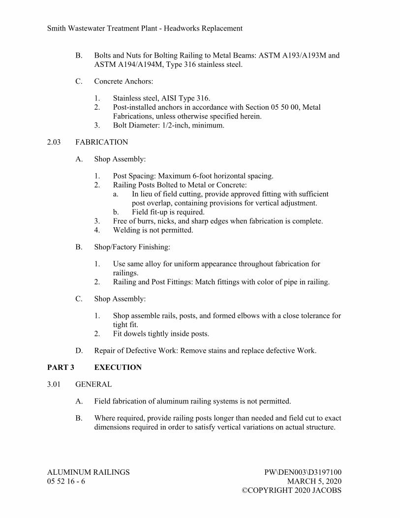
Smith Wastewater Treatment Plant - Headworks Replacement
ALUMINUM RAILINGS PW\DEN003\D3197100 05 52 16 - 6 MARCH 5, 2020 ©COPYRIGHT 2020 JACOBS
B. Bolts and Nuts for Bolting Railing to Metal Beams: ASTM A193/A193M and ASTM A194/A194M, Type 316 stainless steel.
C. Concrete Anchors:
1. Stainless steel, AISI Type 316. 2. Post-installed anchors in accordance with Section 05 50 00, Metal
Fabrications, unless otherwise specified herein. 3. Bolt Diameter: 1/2-inch, minimum.
2.03 FABRICATION
A. Shop Assembly:
1. Post Spacing: Maximum 6-foot horizontal spacing. 2. Railing Posts Bolted to Metal or Concrete:
a. In lieu of field cutting, provide approved fitting with sufficient post overlap, containing provisions for vertical adjustment.
b. Field fit-up is required. 3. Free of burrs, nicks, and sharp edges when fabrication is complete. 4. Welding is not permitted.
B. Shop/Factory Finishing:
1. Use same alloy for uniform appearance throughout fabrication for railings.
2. Railing and Post Fittings: Match fittings with color of pipe in railing.
C. Shop Assembly:
1. Shop assemble rails, posts, and formed elbows with a close tolerance for tight fit.
2. Fit dowels tightly inside posts.
D. Repair of Defective Work: Remove stains and replace defective Work.
PART 3 EXECUTION
3.01 GENERAL
A. Field fabrication of aluminum railing systems is not permitted.
B. Where required, provide railing posts longer than needed and field cut to exact dimensions required in order to satisfy vertical variations on actual structure.

Smith Wastewater Treatment Plant - Headworks Replacement
PW\DEN003\D3197100 ALUMINUM RAILINGS MARCH 5, 2020 05 52 16 - 7 ©COPYRIGHT 2020 JACOBS
C. Install railing with base that provides plus or minus 1/4-inch vertical adjustment inside base fitting. If adjustment is required in field and exceeds plus or minus 1/4-inch, reduce post length not to exceed beyond bottom of lowest set-screw or bolt in base fitting.
D. Modification to supporting structure is not permitted where railing is to be attached.
E. Mount railings only on completed walls. Do not support railings temporarily by means not satisfying structural performance requirements.
F. Protection from Entrapped Water:
1. Make provisions in exterior and interior installations subject to high humidity to drain water from railing system.
2. For posts mounted in concrete, bends, and elbows occurring at low points, drill weep holes of 1/4-inch diameter at lowest possible elevations, one hole per post or rail. Drill hole in plane of rail.
3.02 RAILING INSTALLATION
A. Assembly and Installation: Perform in accordance with manufacturer’s written recommendations for installation.
B. Expansion Joints:
1. Maximum intervals of 54 feet on center and at structural joints. 2. Slip joint with internal sleeve extending 2 inches beyond each side of
joint. Provide 1/2-inch slip joint gap to allow for expansion. 3. Fasten to one side using 3/8-inch diameter set-screw. Place set-screw at
bottom of pipe. 4. Locate joints within 12 inches of posts. Locate expansion joints in rails
that span expansion joints in structural walls and floors supporting the posts.
C. Posts and Rails:
1. Surface Mounted Posts: a. Bolt post baseplate connectors firmly in place. b. Shims, wedges, grout, and similar devices for railing post
alignment not permitted. 2. Set posts plumb and aligned to within 1/8 inch in 12 feet. 3. Set rails horizontal or parallel to slope of steps to within 1/8 inch in
12 feet. 4. Install posts and rails in same plane. 5. Remove projections or irregularities and provide a smooth surface for
sliding hands continuously along top rail.

Smith Wastewater Treatment Plant - Headworks Replacement
ALUMINUM RAILINGS PW\DEN003\D3197100 05 52 16 - 8 MARCH 5, 2020 ©COPYRIGHT 2020 JACOBS
6. Use offset rail for use on stairs and platforms if post is attached to web of stringers or structural platform supports.
7. Support 1-1/2-inch rails directly above stairway stringers with offset fittings.
D. Toeboard:
1. Provide at railings, except where 4-inch or higher concrete curbs are installed, at gates, or at stairways unless shown otherwise.
2. Accurately measure in field for correct length; after railing post installation cut and secure to posts.
3. Dimension between bottom of toeboard and walking surface not to exceed 1/4 inch.
4. Install plumb and aligned to within 1/8 inch in 12 feet.
E. Railing System Gate: Install in accordance with manufacturer’s installation instructions.
3.03 FIELD FINISHING
A. Corrosion Protection: Prevent galvanic action and other forms of corrosion caused from direct contact with concrete and dissimilar metals by coating metal surfaces as specified in Section 09 90 00, Painting and Coating.
3.04 FIELD QUALITY CONTROL
A. Post-installed anchors supporting railing systems require special inspection.
B. Owner-Furnished Quality Assurance, in accordance with ICC IBC Chapter 17 requirements, is provided in the Statement of Special Inspections Plan on Drawings. Contractor responsibilities and related information are included in Section 01 45 33, Special Inspection and Testing.
C. Contractor-Furnished Quality Control: Inspection and testing as required in Section 01 45 16.13, Contractor Quality Control.
3.05 CLEANING
A. Wash railing system thoroughly using clean water and soap. Rinse with clean water.
B. Do not use acid solution, steel wool, or other harsh abrasive.
C. If stain remains after washing, restore in accordance with railing manufacturer’s recommendations or replace stained railings.
END OF SECTION

Smith Wastewater Treatment Plant - Headworks Replacement
PW\DEN003\D3197100 METAL GRATINGS MARCH 5, 2020 05 53 00 - 1 ©COPYRIGHT 2020 JACOBS
SECTION 05 53 00 METAL GRATINGS
PART 1 GENERAL
1.01 REFERENCES
A. The following is a list of standards which may be referenced in this section:
1. ASTM International (ASTM): B221, Standard Specification for Aluminum and Aluminum-Alloy Extruded Bars, Rods, Wire, Profiles, and Tubes.
2. National Association of Architectural Metal Manufacturers (NAAMM): a. MBG 531, Metal Bar Grating Manual. b. MBG 532, Heavy-Duty Metal Bar Grating Manual.
1.02 SUBMITTALS
A. Action Submittals:
1. Shop Drawings: a. Grating: Show dimensions, weight, size, and location of
connections to adjacent grating, supports, and other Work. b. Grating Anchorage: Show details of anchorage to supports to
prevent displacement from traffic impact. c. Product data for grating, grating clips, anchors, accessories, and
other manufactured products specified herein. d. Manufacturer’s specifications, including coatings, surface
treatment, and finishes.
B. Informational Submittals:
1. Special handling and storage requirements. 2. Installation instructions.
1.03 DELIVERY, STORAGE, AND HANDLING
A. Insofar as is practical, factory assemble items.
B. Package and clearly tag parts and assemblies that are, due to necessity, shipped unassembled.

Smith Wastewater Treatment Plant - Headworks Replacement
METAL GRATINGS PW\DEN003\D3197100 05 53 00 - 2 MARCH 5, 2020 ©COPYRIGHT 2020 JACOBS
PART 2 PRODUCTS
2.01 MANUFACTURERS
A. Materials, equipment, and accessories specified in this section shall be products of:
1. Alabama Metal Industries Corporation (AMICO), Birmingham, AL. 2. HARSCO Industrial IKG, Houston, TX. 3. Ohio Gratings, Inc., Canton, OH.
2.02 GRATING MATERIALS
A. Aluminum: Provide alloy and temper as designated below.
1. Bearing Bars and Banding: ASTM B221 alloy 6061-T6 or 6063-T6. 2. Swaged Crossbar Rods: ASTM B221 alloy 6061 or 6063, or
ASTM B210 alloy 3003. 3. Finish: Mill.
2.03 METAL BAR GRATING
A. General Requirements:
1. Maximum Service Load: a. Light Duty (Type A): 100 psf uniformly distributed load. b. Medium Duty (Type B): 500 psf uniformly distributed load.
2. Maximum Deflection: Span/240 or 1/4 inch, whichever is less. 3. Bearing Bar Spacing:
a. Light Duty: 1-3/16-inch maximum, center-to-center. 4. Cross Bar Spacing: 4 inches maximum, center-to-center. 5. Bearing Bars, Cross Bars and Banding: Minimum thickness as specified
in NAAMM MBG 531 or as shown on Drawings.
B. Grating Materials: I-bar grating fabricated by swaging crossbars between extruded I-shaped bearing bars.
C. Surface: Striated.
D. Stair Treads:
1. Material and Type: Same as grating material and grating type as furnished for connecting walkway or work surface.
2. Nosings: Integral ribbing and serrated edge on one long axis of tread, or nonslip abrasive on each tread along one long edge.
3. Carrier Plate or Angle: Furnish at each end for connection to stair stringers.
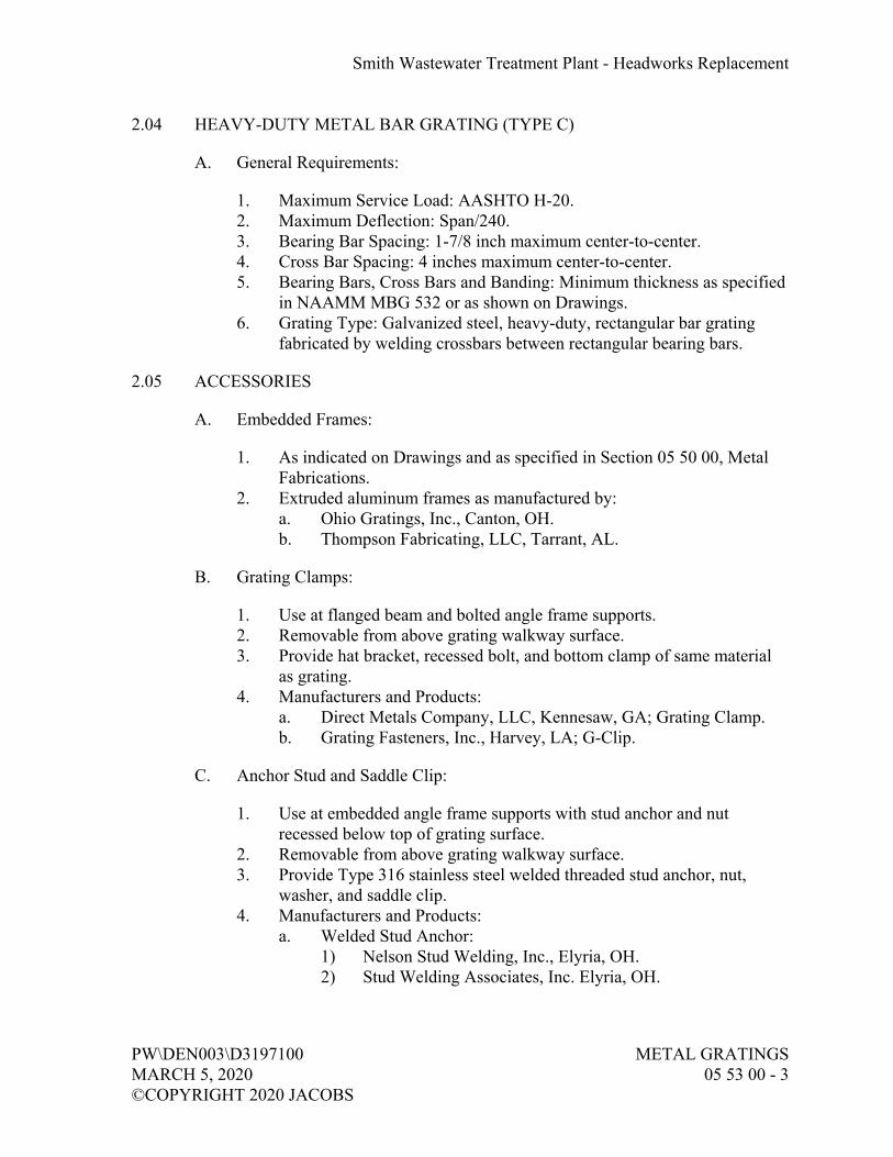
Smith Wastewater Treatment Plant - Headworks Replacement
PW\DEN003\D3197100 METAL GRATINGS MARCH 5, 2020 05 53 00 - 3 ©COPYRIGHT 2020 JACOBS
2.04 HEAVY-DUTY METAL BAR GRATING (TYPE C)
A. General Requirements:
1. Maximum Service Load: AASHTO H-20. 2. Maximum Deflection: Span/240. 3. Bearing Bar Spacing: 1-7/8 inch maximum center-to-center. 4. Cross Bar Spacing: 4 inches maximum center-to-center. 5. Bearing Bars, Cross Bars and Banding: Minimum thickness as specified
in NAAMM MBG 532 or as shown on Drawings. 6. Grating Type: Galvanized steel, heavy-duty, rectangular bar grating
fabricated by welding crossbars between rectangular bearing bars.
2.05 ACCESSORIES
A. Embedded Frames:
1. As indicated on Drawings and as specified in Section 05 50 00, Metal Fabrications.
2. Extruded aluminum frames as manufactured by: a. Ohio Gratings, Inc., Canton, OH. b. Thompson Fabricating, LLC, Tarrant, AL.
B. Grating Clamps:
1. Use at flanged beam and bolted angle frame supports. 2. Removable from above grating walkway surface. 3. Provide hat bracket, recessed bolt, and bottom clamp of same material
as grating. 4. Manufacturers and Products:
a. Direct Metals Company, LLC, Kennesaw, GA; Grating Clamp. b. Grating Fasteners, Inc., Harvey, LA; G-Clip.
C. Anchor Stud and Saddle Clip:
1. Use at embedded angle frame supports with stud anchor and nut recessed below top of grating surface.
2. Removable from above grating walkway surface. 3. Provide Type 316 stainless steel welded threaded stud anchor, nut,
washer, and saddle clip. 4. Manufacturers and Products:
a. Welded Stud Anchor: 1) Nelson Stud Welding, Inc., Elyria, OH. 2) Stud Welding Associates, Inc. Elyria, OH.

Smith Wastewater Treatment Plant - Headworks Replacement
METAL GRATINGS PW\DEN003\D3197100 05 53 00 - 4 MARCH 5, 2020 ©COPYRIGHT 2020 JACOBS
b. Saddle Clip: 1) Direct Metals Company, LLC, Kennesaw, GA; Saddle Clip. 2) Grating Fasteners, Inc., Harvey, LA; Saddle Clip. 3) Struct-Fast, Inc., Baltimore, MD; Gratefast.
5. At Embedded Extruded Aluminum: a. Provide aluminum clip, bolt, nut, and washer, with clip engaging
bottom flange of I-bar. b. Manufacturers and Products:
1) Direct Metals Company, LLC, Kennesaw, GA; Plank Clip. 2) Thompson Fabricating Company, Inc., Birmingham, AL;
TFCO Standard Hold Down Clip.
2.06 FABRICATION
A. General:
1. In accordance with NAAMM MBG 531 or NAAMM MBG 532. 2. Do not weld aluminum grating. 3. Stainless steel Type 304 and Type 316 subjected to heat from welding,
shall be Type 304L and Type 316L respectively. 4. Conceal fastenings where practical. 5. Drill metalwork and countersink holes as required for attaching
hardware or other materials. 6. Cutouts:
a. Fabricate in grating sections for penetrations indicated. b. Arrange to permit grating removal without disturbing items
penetrating grating. c. Edge band openings in grating that interrupt four or more bearing
bars with bars of same size and material as bearing bars. 7. Do not notch bearing bars at supports to maintain elevation. 8. Field measure areas to receive grating. Verify dimensions of new
fabricated supports, and fabricate to dimension required for specified clearances.
9. Section Length: Sufficient to prevent section from falling through clear opening when oriented in the span direction and one end is touching either the concrete or the vertical leg of grating support.
10. Minimum Bearing: 1 inch for grating depth up to 2-1/4 inches and 2 inches for grating depth greater than 2-1/4 inches.
11. Banding and Toe Plates: Same material as grating and welded to bearing bars in accordance with requirements of NAAMM MBG 531 and NAAMM MBG 532.
B. Metal Bar Grating: A single grating section shall be not less than 1.5 feet or greater than 3 feet in width, or weigh more than 150 pounds.

Smith Wastewater Treatment Plant - Headworks Replacement
PW\DEN003\D3197100 METAL GRATINGS MARCH 5, 2020 05 53 00 - 5 ©COPYRIGHT 2020 JACOBS
C. Supports:
1. Same material as grating, except that supports which are to be embedded in concrete shall be Type 316 stainless steel, unless part of an extruded aluminum system.
2. Coordinate dimensions and fabrication with grating to be supported. 3. Coordinate dimensions with increased depth due to serrations.
PART 3 EXECUTION
3.01 PREPARATION
A. Electrolytic Protection:
1. Protect aluminum surfaces in contact with dissimilar metals, or embedded or in contact with masonry, grout, or concrete as specified in Section 09 90 00, Painting and Coating.
2. Allow paint to dry before installation of material.
3.02 INSTALLATION
A. Until grating sections are securely fastened in place, area shall be appropriately barricaded or flagged to alert people working in the area of potential fall hazard.
B. Install manufactured products in accordance with manufacturer’s recommendations.
C. Install supports such that grating sections have a solid bearing on both ends, and that grating sections will not rock or wobble under design loads.
D. Install grating supports plumb and level as applicable.
E. Install sections of welded frames with anchors to straight plane without offsets.
F. Field locate and install fasteners to fit grating layout.
G. Anchor grating securely to supports using minimum of four fastener clips and bolts per grating section.
H. Each grating or plank section shall be easily removable and replaceable.
I. Completed installation shall be rigid and neat in appearance.

Smith Wastewater Treatment Plant - Headworks Replacement
METAL GRATINGS PW\DEN003\D3197100 05 53 00 - 6 MARCH 5, 2020 ©COPYRIGHT 2020 JACOBS
J. Protect painted and galvanized surfaces during installation.
K. Repair damaged coatings as specified in Section 09 90 00, Painting and Coating.
END OF SECTION

Smith Wastewater Treatment Plant - Headworks Replacement
PW\DEN003\D3197100 GLASS-FIBER-REINFORCED PLASTIC MARCH 5, 2020 06 82 00 - 1 ©COPYRIGHT 2020 JACOBS
SECTION 06 82 00 GLASS-FIBER-REINFORCED PLASTIC
PART 1 GENERAL
1.01 REFERENCES
A. The following is a list of standards which may be referenced in this section:
1. ASTM International (ASTM): a. C177, Standard Test Method for Steady-State Heat Flux
Measurements and Thermal Transmission Properties by Means of the Guarded Hot-Plate Apparatus.
b. D570, Standard Test Method for Water Absorption of Plastics. c. D635, Standard Test Method for Rate of Burning and/or Extent
and Time of Burning Plastics in a Horizontal Position. d. D638, Standard Test Method for Tensile Properties of Plastics. e. D695, Standard Test Method for Compressive Properties of Rigid
Plastics. f. D696, Standard Test Method for Coefficient of Linear Thermal
Expansion of Plastics Between -30 Degrees C and 30 Degrees C. g. D790, Standard Test Methods for Flexural Properties of
Unreinforced and Reinforced Plastics and Electrical Insulating Materials.
h. D792, Standard Test Methods for Density and Specific Gravity (Relative Density) by Plastics Displacement.
i. D2344, Standard Test Method for Apparent Interlaminar Shear Strength of Parallel Fiber Composites by Short-Beam Method.
j. D2583, Standard Test Method for Indentation Hardness of Rigid Plastics by Means of a Barcol Impressor.
k. E84, Standard Test Method for Surface Burning Characteristics of Building Materials.
2. International Code Council (ICC): International Building Code (IBC). 3. Occupational Safety and Health Act (OSHA): 29 CFR 19.10, Code of
Federal Regulations. 4. Underwriters’ Laboratories, Inc. (UL): 94, UL Standard for Safety Test
for Flammability of Plastic Materials for Parts in Devices and Appliances.
1.02 DEFINITIONS
A. ICC Evaluation Services Report: ICC report on evaluation of manufactured concrete anchor systems.
B. Special Inspection: As defined by the ICC IBC.

Smith Wastewater Treatment Plant - Headworks Replacement
GLASS-FIBER-REINFORCED PLASTIC PPW\DEN003\D3197100 06 82 00 - 2 MARCH 5, 2020 ©COPYRIGHT 2020 JACOBS
1.03 DESIGN REQUIREMENTS
A. This section contains components and connectors that require Contractor design.
1.04 SUBMITTALS
A. Action Submittals:
1. Shop Drawings: a. Product Data: Indicate design load parameters, dimensions,
adjacent construction, materials, thicknesses, fabrication details, required clearances, field jointing, tolerances, colors, finishes, methods of support, and anchorages..
2. Samples: Submit two samples, 24 by 24 inch in size, illustrating color, texture, and finish.
B. Informational Submittals:
1. Handling and storage requirements. 2. Manufacturer’s installation instructions. 3. Factory test reports for physical properties of product.
a. Test data for supports may supplement load calculations providing data covers the complete system, including anchorage.
4. Manufacturer’s Certification of Compliance for specified products. 5. Fabricator’s qualification experience. 6. Manufacturer’s qualification experience.
1.05 QUALIFICATIONS
A. Designer: Calculations required for Contractor design shall be stamped by a registered engineer, licensed in state where Project will be constructed.
B. Fabricator: Minimum of 5 years’ experience.
C. Manufacturer: Minimum of 5 years’ experience in manufacturing products meeting these specifications.
1.06 DELIVERY, STORAGE, AND HANDLING
A. Preparation for Shipment:
1. Insofar as is practical, factory assemble items provided hereunder. 2. Package and clearly tag parts and assemblies that are of necessity
shipped unassembled in a manner that will protect materials from damage, and facilitate identification and final assembly in field.

Smith Wastewater Treatment Plant - Headworks Replacement
PW\DEN003\D3197100 GLASS-FIBER-REINFORCED PLASTIC MARCH 5, 2020 06 82 00 - 3 ©COPYRIGHT 2020 JACOBS
B. Storage and Handling: In accordance with manufacturer’s recommendations and in such a manner as to prevent damage of any kind, including overexposure to sunlight.
PART 2 PRODUCTS
2.01 GENERAL
A. Like Items of Materials: Where possible, provide end products of one manufacturer to achieve standardization for appearance, maintenance, and replacement.
B. Unless otherwise specified, manufacture products by a pultruded process using vinyl ester resin with ultra-violet (UV) inhibitor additives.
C. Provide a synthetic surface veil covering on exterior surfaces.
D. Molded products may be furnished as an option where included in Specifications below.
E. Provide color pigment dispersed in resin system.
F. Fabricate FRP products exposed to outdoor conditions with an additional 1-mil thick UV coating to shield product from UV light.
G. Seal all cut ends, holes, and abrasions of FRP shapes with resin to prevent moisture intrusion.
2.02 GLASS FIBER AND RESIN FABRICATIONS
A. Deflection and Safety Factors for structural support members:
1. Deflection Criteria: Not to exceed L/360 due to live load. 2. Safety Factors: Minimum ratios of ultimate stress to allowable static
service stress: a. Flexural Members: 2.5. b. Compression Members: 3.0. c. Shear: 3.0. d. Connections: 4.0.
3. Minimum design safety factors for dynamic or impact loads: twice the values for static service loads.
B. Loads:
1. 100 psf uniform live load over platform. 2. Static and dynamic loads for equipment shown.

Smith Wastewater Treatment Plant - Headworks Replacement
GLASS-FIBER-REINFORCED PLASTIC PPW\DEN003\D3197100 06 82 00 - 4 MARCH 5, 2020 ©COPYRIGHT 2020 JACOBS
C. Glass fiber reinforced polyester or vinyl ester resin matrix, approximately 50 percent resin-to-glass ratio.
D. Provide internal continuous glass strand rovings and continuous strand glass mats for longitudinal and transverse strength.
E. Material Properties:
Minimum Ultimate Coupon Properties (UN)
Material Properties Test Method Units
Pultruded Fiberglass Structural Shapes
Ultimate tensile stress in longitudinal direction, psi (MPa)
ASTM D638 30,000 (207)
Ultimate compressive stress in longitudinal direction, psi (MPa)
ASTM D695 30,000 (207)
Ultimate flexural stress in longitudinal direction, psi (MPa)
ASTM D790 30,000 (207)
Ultimate short beam shear in longitudinal direction, psi (MPa)
ASTM D2344 4,500 (31)
Ultimate tensile stress in transverse direction, psi (MPa)
ASTM D638 7,000 (48)
Ultimate compressive stress in transverse direction, psi (MPa)
ASTM D695 15,000 (103)
Ultimate flexural stress in transverse direction, psi (MPa)
ASTM D790 10,000 (69)
Density (lb/in.3) (kg/mm3) ASTM D792 0.060-0.070 (0.00166-00194)
Water absorption (25-hr immersion)
ASTM D570 0.60 max, % by weight
Barcol hardness ASTM D2583 45
Coefficient of thermal expansion 10-6 in./in./º C
ASTM D696
Expansion, LW10-6 in./in./º F 4.4
Thermal conductivity, Btu-in./ft2/hr/º F
ASTM C177
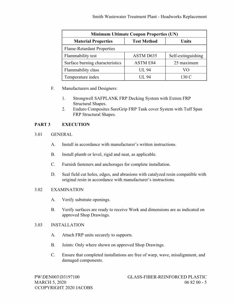
Smith Wastewater Treatment Plant - Headworks Replacement
PW\DEN003\D3197100 GLASS-FIBER-REINFORCED PLASTIC MARCH 5, 2020 06 82 00 - 5 ©COPYRIGHT 2020 JACOBS
Minimum Ultimate Coupon Properties (UN)
Material Properties Test Method Units
Flame-Retardant Properties
Flammability test ASTM D635 Self-extinguishing
Surface burning characteristics ASTM E84 25 maximum
Flammability class UL 94 VO
Temperature index UL 94 130 C
F. Manufacturers and Designers:
1. Strongwell SAFPLANK FRP Decking System with Extren FRP Structural Shapes.
2. Enduro Composites SureGrip FRP Tank cover System with Tuff Span FRP Structural Shapes.
PART 3 EXECUTION
3.01 GENERAL
A. Install in accordance with manufacturer’s written instructions.
B. Install plumb or level, rigid and neat, as applicable.
C. Furnish fasteners and anchorages for complete installation.
D. Seal field cut holes, edges, and abrasions with catalyzed resin compatible with original resin in accordance with manufacturer’s instructions.
3.02 EXAMINATION
A. Verify substrate openings.
B. Verify surfaces are ready to receive Work and dimensions are as indicated on approved Shop Drawings.
3.03 INSTALLATION
A. Attach FRP units securely to supports.
B. Joints: Only where shown on approved Shop Drawings.
C. Ensure that completed installations are free of warp, wave, misalignment, and damaged components.

Smith Wastewater Treatment Plant - Headworks Replacement
GLASS-FIBER-REINFORCED PLASTIC PPW\DEN003\D3197100 06 82 00 - 6 MARCH 5, 2020 ©COPYRIGHT 2020 JACOBS
D. Seal joints in FRP components and between FRP components and adjacent construction, as required for a weathertight installation.
3.04 ERECTION TOLERANCES
A. Section 01 45 16.13, Contractor Quality Control: Requirements for tolerances.
B. Maximum Variation from Indicated Position: 1/8 inch.
C. Maximum Offset from Alignment Adjacent Components: 1/8 inch.
3.05 CLEANING
A. Section 01 77 00, Closeout Procedures: Requirements for cleaning.
B. Clean components of foreign material without damaging finished surface.
C. Clean fabrications.
END OF SECTION

Smith Wastewater Treatment Plant - Headworks Replacement
PW\DEN003\D3197100 PAINTING AND COATING MARCH 6, 2020 09 90 00 - 1 ©COPYRIGHT 2020 JACOBS
SECTION 09 90 00 PAINTING AND COATING
PART 1 GENERAL
1.01 REFERENCES
A. The following is a list of standards which may be referenced in this section:
1. American Water Works Association (AWWA): a. C203, Coal-Tar Protective Coatings and Linings for Steel Water
Pipelines—Enamel and Tape—Hot-Applied. b. C209, Cold-Applied Tape Coatings for the Exterior of Special
Sections, Connections, and Fittings for Steel Water Pipelines. c. C213, Fusion-Bonded Epoxy Coating for the Interior and Exterior
of Steel Water Pipelines. d. C214, Tape Coating Systems for the Exterior of Steel Water
Pipelines. 2. Environmental Protection Agency (EPA). 3. NACE International (NACE): SP0188, Discontinuity (Holiday) Testing
of New Protective Coatings on Conductive Substrates. 4. NSF International (NSF): 61, Drinking Water System Components -
Health Effects. 5. Occupational Safety and Health Act (OSHA). 6. Research Council on Structural Connections (RCSC): Specification for
Structural Joints using High-Strength Bolts. 7. The Society for Protective Coatings (SSPC):
a. PA 2, Procedure for Determining Conformance to Dry Coating Thickness Requirements.
b. PA 10, Guide to Safety and Health Requirements for Industrial Painting Projects.
c. SP 1, Solvent Cleaning. d. SP 2, Hand Tool Cleaning. e. SP 3, Power Tool Cleaning. f. SP 5, White Metal Blast Cleaning. g. SP 6, Commercial Blast Cleaning. h. SP 7, Joint Surface Preparation Standard Brush-Off Blast
Cleaning. i. SP 10, Near-White Blast Cleaning. j. SP 11, Power Tool Cleaning to Bare Metal. k. SP 16, Brush-Off Blast Cleaning of Coated and Uncoated
Galvanized Steel, Stainless Steels, and Non-Ferrous Metals. l. SP 13, Surface Preparation of Concrete. m. Guide 15, Field Methods for Retrieval and Analysis of Soluble
Salts on Steel and Other Nonporous Substrates.
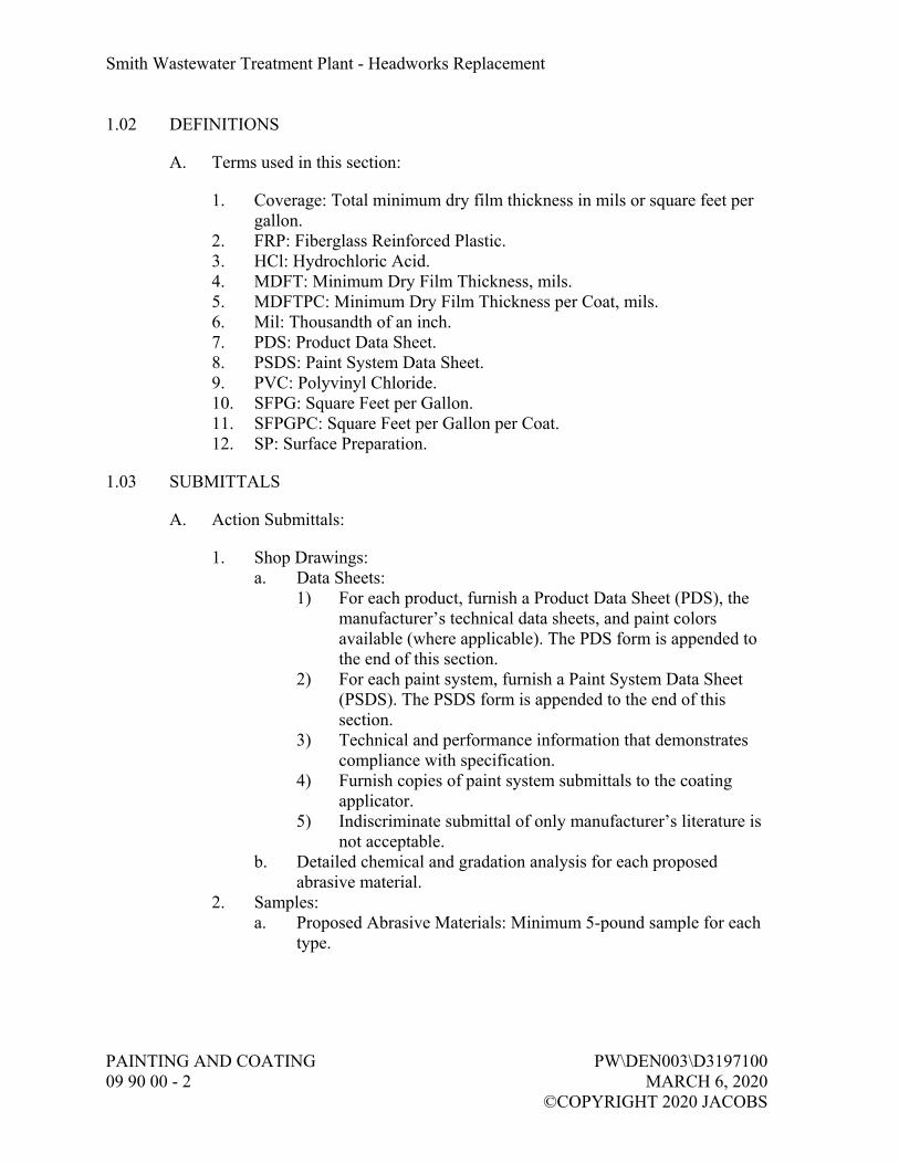
Smith Wastewater Treatment Plant - Headworks Replacement
PAINTING AND COATING PW\DEN003\D3197100 09 90 00 - 2 MARCH 6, 2020 ©COPYRIGHT 2020 JACOBS
1.02 DEFINITIONS
A. Terms used in this section:
1. Coverage: Total minimum dry film thickness in mils or square feet per gallon.
2. FRP: Fiberglass Reinforced Plastic. 3. HCl: Hydrochloric Acid. 4. MDFT: Minimum Dry Film Thickness, mils. 5. MDFTPC: Minimum Dry Film Thickness per Coat, mils. 6. Mil: Thousandth of an inch. 7. PDS: Product Data Sheet. 8. PSDS: Paint System Data Sheet. 9. PVC: Polyvinyl Chloride. 10. SFPG: Square Feet per Gallon. 11. SFPGPC: Square Feet per Gallon per Coat. 12. SP: Surface Preparation.
1.03 SUBMITTALS
A. Action Submittals:
1. Shop Drawings: a. Data Sheets:
1) For each product, furnish a Product Data Sheet (PDS), the manufacturer’s technical data sheets, and paint colors available (where applicable). The PDS form is appended to the end of this section.
2) For each paint system, furnish a Paint System Data Sheet (PSDS). The PSDS form is appended to the end of this section.
3) Technical and performance information that demonstrates compliance with specification.
4) Furnish copies of paint system submittals to the coating applicator.
5) Indiscriminate submittal of only manufacturer’s literature is not acceptable.
b. Detailed chemical and gradation analysis for each proposed abrasive material.
2. Samples: a. Proposed Abrasive Materials: Minimum 5-pound sample for each
type.
Smith Wastewater Treatment Plant - Headworks Replacement
PW\DEN003\D3197100 PAINTING AND COATING MARCH 6, 2020 09 90 00 - 3 ©COPYRIGHT 2020 JACOBS
b. Reference Panel: 1) Surface Preparation:
a) Prior to start of surface preparation, furnish a 4-inch by 4-inch steel panel for each grade of sandblast specified herein, prepared to specified requirements.
b) Provide panel representative of the steel used; prevent deterioration of surface quality.
c) Panel to be reference source for inspection upon approval by Engineer.
2) Paint: a) Unless otherwise specified, before painting work is
started, prepare minimum 8-inch by 10-inch sample with type of paint and application specified on similar substrate to which paint is to be applied.
b) Furnish additional samples as required until colors, finishes, and textures are approved.
c) Approved samples to be the quality standard for final finishes.
B. Informational Submittals:
1. Applicator’s Qualification: List of references substantiating experience. 2. Coating manufacturer’s Certificate of Compliance, in accordance with
Section 01 43 33, Manufacturers’ Field Services. 3. Factory Applied Coatings: Manufacturer’s certification stating factory
applied coating system meets or exceeds requirements specified. 4. Manufacturer’s written verification that submitted material is suitable
for the intended use. 5. Coating for Faying Surfaces: Manufacturer’s test results that show the
proposed coating meets the slip resistance requirements of the AISC Specification for Structural Joints using ASTM A325 or ASTM A490 bolts.
6. If the manufacturer of finish coating differs from that of shop primer, provide finish coating manufacturer’s written confirmation that materials are compatible.
7. Manufacturer’s written instructions and special details for applying each type of paint.
1.04 QUALITY ASSURANCE
A. Applicator Qualifications: Minimum 5 years’ experience in application of specified products.
Smith Wastewater Treatment Plant - Headworks Replacement
PAINTING AND COATING PW\DEN003\D3197100 09 90 00 - 4 MARCH 6, 2020 ©COPYRIGHT 2020 JACOBS
B. Regulatory Requirements:
1. Meet federal, state, and local requirements limiting the emission of volatile organic compounds.
2. Perform surface preparation and painting in accordance with recommendations of the following: a. Paint manufacturer’s instructions. b. SSPC PA 10. c. Federal, state, and local agencies having jurisdiction.
C. Mockup:
1. Before proceeding with Work under this section, finish one complete space or item of each color scheme required showing selected colors, finish texture, materials, quality of work, and special details.
2. After Engineer approval, sample spaces or items shall serve as a standard for similar work throughout the Project.
1.05 DELIVERY, STORAGE, AND HANDLING
A. Shipping:
1. Where precoated items are to be shipped to the Site, protect coating from damage. Batten coated items to prevent abrasion.
2. Protect shop painted surfaces during shipment and handling by suitable provisions including padding, blocking, and use of canvas or nylon slings.
B. Storage:
1. Store products in a protected area that is heated or cooled to maintain temperatures within the range recommended by paint manufacturer.
2. Primed surfaces shall not be exposed to weather for more than 2 months before being topcoated, or less time if recommended by coating manufacturer.
1.06 PROJECT CONDITIONS
A. Environmental Requirements:
1. Do not apply paint in temperatures or moisture conditions outside of manufacturer’s recommended maximum or minimum allowable.
2. Do not perform final abrasive blast cleaning whenever relative humidity exceeds 85 percent, or whenever surface temperature is less than 5 degrees F above dew point of ambient air.

Smith Wastewater Treatment Plant - Headworks Replacement
PW\DEN003\D3197100 PAINTING AND COATING MARCH 6, 2020 09 90 00 - 5 ©COPYRIGHT 2020 JACOBS
B. Status of Existing Coatings:
1. The following information on existing coatings or substrate conditions is provided for information only, and is generally believed to be accurate, but is not guaranteed. Perform tests as required to verify applicability of this information to the Work.
PART 2 PRODUCTS
2.01 MANUFACTURERS
A. Nationally recognized manufacturers of paints and protective coatings who are regularly engaged in the production of such materials for essentially identical service conditions.
B. Minimum of 5 years’ verifiable experience in manufacture of specified product.
C. Each of the following manufacturers is capable of supplying most of the products specified herein:
1. Tnemec. 2. Carboline.
2.02 ABRASIVE MATERIALS
A. Select abrasive type and size to produce surface profile that meets coating manufacturer’s recommendations for specific primer and coating system to be applied.
2.03 PAINT MATERIALS
A. General:
1. Manufacturer’s highest quality products suitable for intended service. 2. Compatibility: Only compatible materials from a single manufacturer
shall be used in the Work. Particular attention shall be directed to compatibility of primers and finish coats.
3. Thinners, Cleaners, Driers, and Other Additives: As recommended by coating manufacturer.
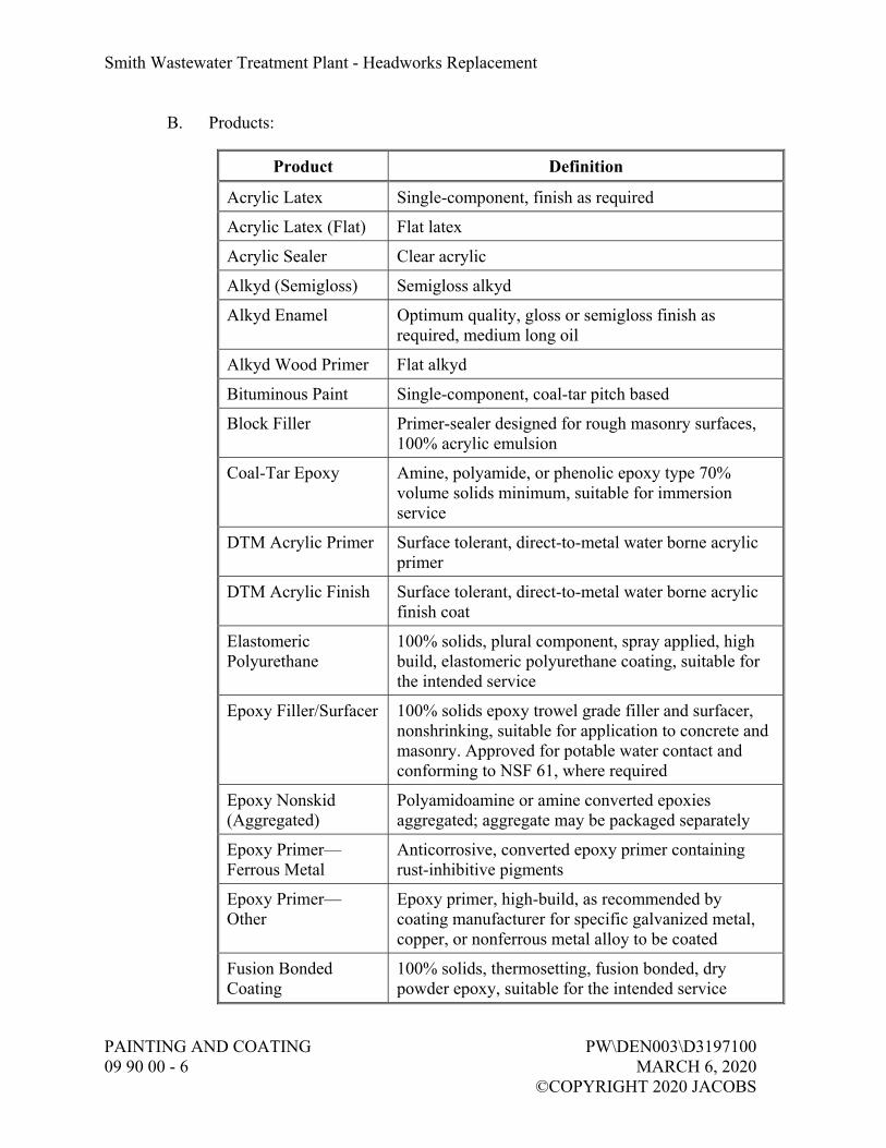
Smith Wastewater Treatment Plant - Headworks Replacement
PAINTING AND COATING PW\DEN003\D3197100 09 90 00 - 6 MARCH 6, 2020 ©COPYRIGHT 2020 JACOBS
B. Products:
Product Definition
Acrylic Latex Single-component, finish as required
Acrylic Latex (Flat) Flat latex
Acrylic Sealer Clear acrylic
Alkyd (Semigloss) Semigloss alkyd
Alkyd Enamel Optimum quality, gloss or semigloss finish as required, medium long oil
Alkyd Wood Primer Flat alkyd
Bituminous Paint Single-component, coal-tar pitch based
Block Filler Primer-sealer designed for rough masonry surfaces, 100% acrylic emulsion
Coal-Tar Epoxy Amine, polyamide, or phenolic epoxy type 70% volume solids minimum, suitable for immersion service
DTM Acrylic Primer Surface tolerant, direct-to-metal water borne acrylic primer
DTM Acrylic Finish Surface tolerant, direct-to-metal water borne acrylic finish coat
Elastomeric Polyurethane
100% solids, plural component, spray applied, high build, elastomeric polyurethane coating, suitable for the intended service
Epoxy Filler/Surfacer 100% solids epoxy trowel grade filler and surfacer, nonshrinking, suitable for application to concrete and masonry. Approved for potable water contact and conforming to NSF 61, where required
Epoxy Nonskid (Aggregated)
Polyamidoamine or amine converted epoxies aggregated; aggregate may be packaged separately
Epoxy Primer—Ferrous Metal
Anticorrosive, converted epoxy primer containing rust-inhibitive pigments
Epoxy Primer—Other
Epoxy primer, high-build, as recommended by coating manufacturer for specific galvanized metal, copper, or nonferrous metal alloy to be coated
Fusion Bonded Coating
100% solids, thermosetting, fusion bonded, dry powder epoxy, suitable for the intended service

Smith Wastewater Treatment Plant - Headworks Replacement
PW\DEN003\D3197100 PAINTING AND COATING MARCH 6, 2020 09 90 00 - 7 ©COPYRIGHT 2020 JACOBS
Product Definition
TFE Lube or Grease Lube
Tetrafluoroethylene, liquid coating, or open gear grease as supplied by McMaster-Carr Supply Corporation, Elmhurst, IL
High Build Epoxy Polyamidoamine epoxy, minimum 69% volume solids, capability of 4 to 8 MDFT per coat
Inorganic Zinc Primer
Solvent or water based, having 85% metallic zinc content in the dry film; follow manufacturer’s recommendation for topcoating
Latex Primer Sealer Waterborne vinyl acrylic primer/sealer for interior gypsum board and plaster. Capable of providing uniform seal and suitable for use with specified finish coats
NSF Epoxy Polyamidoamine epoxy, approved for potable water contact and conforming to NSF 61
Epoxy, High Solids Polyamidoamine epoxy, 80% volume solids, minimum, suitable for immersion service
Polyurethane Enamel Two-component, aliphatic or acrylic based polyurethane; high gloss finish
Organic Zinc Rich Primer
Epoxy or moisture cured urethane with 85-percent zinc content in the dry film, meeting the requirements of RCSC Specification for Structural Joints using High Strength Bolts, Class A or Class B, as required.
Rust-Inhibitive Primer
Single-package steel primers with anticorrosive pigment loading
Sanding Sealer Co-polymer oil, clear, dull luster
Silicone/Silicone Acrylic
Elevated temperature silicone or silicone/acrylic based
Stain, Concrete Acrylic, water repellant, penetrating stain
Stain, Wood Satin luster, linseed oil, solid or transparent as required
Varnish Nonpigmented vehicle based on a variety of resins (alkyd, phenolic, urethane) in gloss, semigloss, or flat finishes, as required
Water Base Epoxy Two-component, polyamide epoxy emulsion, finish as required

Smith Wastewater Treatment Plant - Headworks Replacement
PAINTING AND COATING PW\DEN003\D3197100 09 90 00 - 8 MARCH 6, 2020 ©COPYRIGHT 2020 JACOBS
2.04 MIXING
A. Multiple-Component Coatings:
1. Prepare using each component as packaged by paint manufacturer. 2. No partial batches will be permitted. 3. Do not use multiple-component coatings that have been mixed beyond
their pot life. 4. Furnish small quantity kits for touchup painting and for painting other
small areas. 5. Mix only components specified and furnished by paint manufacturer. 6. Do not intermix additional components for reasons of color or
otherwise, even within the same generic type of coating.
B. Colors: Formulate paints with colorants free of lead, lead compounds, or other materials that might be affected by presence of hydrogen sulfide or other gas likely to be present at Site.
2.05 SHOP FINISHES
A. Shop Blast Cleaning: Reference Paragraph, Shop Coating Requirements.
B. Surface Preparation: Provide Engineer minimum 7 days’ advance notice to start of shop surface preparation work and coating application work.
C. Shop Coating Requirements:
1. When required by equipment specifications, such equipment shall be primed and finish coated in shop by manufacturer and touched up in field with identical material after installation.
2. Where manufacturer’s standard coating is not suitable for intended service condition, Engineer may approve use of a tie-coat to be used between manufacturer’s standard coating and specified field finish. In such cases, tie-coat shall be surface tolerant epoxy as recommended by manufacturer of specified field finish coat. Coordinate details of equipment manufacturer’s standard coating with field coating manufacturer.
D. Pipe:
1. Ductile Iron Pipe: a. Use SSPC standards as a guide for desired prepared surface.
Follow recommendations of pipe and coating manufacturers for means and methods to achieve SSPC-equivalent surface.
b. The surface preparation and application of the primer and finish coats shall be performed by pipe manufacturer.

Smith Wastewater Treatment Plant - Headworks Replacement
PW\DEN003\D3197100 PAINTING AND COATING MARCH 6, 2020 09 90 00 - 9 ©COPYRIGHT 2020 JACOBS
c. For high performance (epoxy) coatings, follow additional recommendations of pipe and coating manufacturers.
d. Prior to blast cleaning, grind smooth surface imperfections, including, but not limited to delaminating metal or oxide layers.
e. For conventional (alkyd) coatings, clean asphalt varnish supplied on pipe and apply one full coat of a tar stop before two full coats of the color coats specified.
2. Steel Pipe: a. Surface preparation and application of primer and finish coats
shall be performed by pipe manufacturer. b. For pipe with epoxy lining, do not place end cap seals until pipe
lining material has sufficiently dried.
PART 3 EXECUTION
3.01 GENERAL
A. Provide Engineer minimum 7 days’ advance notice to start of field surface preparation work and coating application work.
B. Perform the Work only in presence of Engineer, unless Engineer grants prior approval to perform the Work in Engineer’s absence.
C. Schedule inspection of cleaned surfaces and all coats prior to succeeding coat in advance with Engineer.
3.02 EXAMINATION
A. Factory Finished Items:
1. Schedule inspection with Engineer before repairing damaged factory-finished items delivered to Site.
2. Repair abraded or otherwise damaged areas on factory-finished items as recommended by coating manufacturer. Carefully blend repaired areas into original finish. If required to match colors, provide full finish coat in field.
B. Surface Preparation Verification: Inspect and provide substrate surfaces prepared in accordance with these Specifications and printed directions and recommendations of paint manufacturer whose product is to be applied. The more stringent requirements shall apply.

Smith Wastewater Treatment Plant - Headworks Replacement
PAINTING AND COATING PW\DEN003\D3197100 09 90 00 - 10 MARCH 6, 2020 ©COPYRIGHT 2020 JACOBS
3.03 PROTECTION OF ITEMS NOT TO BE PAINTED
A. Remove, mask, or otherwise protect hardware, lighting fixtures, switchplates, aluminum surfaces, machined surfaces, couplings, shafts, bearings, nameplates on machinery, and other surfaces not specified elsewhere to be painted.
B. Provide drop cloths to prevent paint materials from falling on or marring adjacent surfaces.
C. Protect working parts of mechanical and electrical equipment from damage during surface preparation and painting process.
D. Mask openings in motors to prevent paint and other materials from entering.
E. Protect surfaces adjacent to or downwind of Work area from overspray.
3.04 SURFACE PREPARATION
A. Field Abrasive Blasting:
1. Perform blasting for items and equipment where specified and as required to restore damaged surfaces previously shop or field blasted and primed or coated.
2. Refer to coating systems for degree of abrasive blasting required. 3. Where the specified degree of surface preparation differs from
manufacturer’s recommendations, the more stringent shall apply.
B. Metal Surface Preparation:
1. Where indicated, meet requirements of SSPC Specifications summarized below: a. SP 1, Solvent Cleaning: Removal of visible oil, grease, soil,
drawing and cutting compounds, and other soluble contaminants by cleaning with solvent.
b. SP 2, Hand Tool Cleaning: Removal of loose rust, loose mill scale, loose paint, and other loose detrimental foreign matter, using nonpower hand tools.
c. SP 3, Power Tool Cleaning: Removal of loose rust, loose mill scale, loose paint, and other loose detrimental foreign matter, using power-assisted hand tools.
d. SP 5, White Metal Blast Cleaning: Removal of visible oil, grease, dust, dirt, mill scale, rust, coatings, oxides, corrosion products, and other foreign matter by blast cleaning.

Smith Wastewater Treatment Plant - Headworks Replacement
PW\DEN003\D3197100 PAINTING AND COATING MARCH 6, 2020 09 90 00 - 11 ©COPYRIGHT 2020 JACOBS
e. SP 6, Commercial Blast Cleaning: Removal of visible oil, grease, dust, dirt, mill scale, rust, coatings, oxides, corrosion products, and other foreign matter, except for random staining limited to no more than 33 percent of each unit area of surface which may consist of light shadows, slight streaks, or minor discolorations caused by stains of rust, stains of mill scale, or stains of previously applied coatings.
f. SP 7, Brush-Off Blast Cleaning: Removal of visible rust, oil, grease, soil, dust, loose mill scale, loose rust, and loose coatings. Tightly adherent mill scale, rust, and coating may remain on surface.
g. SP 10, Near-White Blast Cleaning: Removal of visible oil, grease, dust, dirt, mill scale, rust, coatings, oxides, corrosion products, and other foreign matter, except for random staining limited to no more than 5 percent of each unit area of surface which may consist of light shadows, slight streaks, or minor discolorations caused by stains of rust, stains of mill scale, or stains of previously applied coatings.
h. SP 11, Power Tool Cleaning to Bare Metal: Removal of visible oil, grease, dirt, dust, mill scale, rust, paint, oxide, corrosion products, and other foreign matter using power-assisted hand tools capable of producing suitable surface profile. Slight residues of rust and paint may be left in lower portion of pits if original surface is pitted.
i. SP-16, Brush Blasting of Non-Ferrous Metals: A brush-off blast cleaned non-ferrous metal surface, when viewed without magnification, shall be free of all visible oil, grease, dirt, dust, metal oxides (corrosion products), and other foreign matter. Intact, tightly adherent coating is permitted to remain. A coating is considered tightly adherent if it cannot be removed by lifting with a dull putty knife. Bare metal substrates shall have a minimum profile of 19 micrometers (0.75 mil).
2. The words “solvent cleaning”, “hand tool cleaning”, “wire brushing”, and “blast cleaning”, or similar words of equal intent in these Specifications or in paint manufacturer’s specification refer to the applicable SSPC Specification.
3. Where OSHA or EPA regulations preclude standard abrasive blast cleaning, wet or vacu-blast methods may be required. Coating manufacturers’ recommendations for wet blast additives and first coat application shall apply.
4. Ductile Iron Pipe Supplied with Asphaltic Varnish Finish: Remove asphaltic varnish finish prior to performing specified surface preparation.
5. Hand tool clean areas that cannot be cleaned by power tool cleaning.

Smith Wastewater Treatment Plant - Headworks Replacement
PAINTING AND COATING PW\DEN003\D3197100 09 90 00 - 12 MARCH 6, 2020 ©COPYRIGHT 2020 JACOBS
6. Round or chamfer sharp edges and grind smooth burrs, jagged edges, and surface defects.
7. Welds and Adjacent Areas: a. Prepare such that there is:
1) No undercutting or reverse ridges on weld bead. 2) No weld spatter on or adjacent to weld or any area to be
painted. 3) No sharp peaks or ridges along weld bead.
b. Grind embedded pieces of electrode or wire flush with adjacent surface of weld bead.
8. Preblast Cleaning Requirements: a. Remove oil, grease, welding fluxes, and other surface
contaminants prior to blast cleaning. b. Cleaning Methods: Steam, open flame, hot water, or cold water
with appropriate detergent additives followed with clean water rinsing.
c. Clean small isolated areas as above or solvent clean with suitable solvent and clean cloth.
9. Blast Cleaning Requirements: a. Type of Equipment and Speed of Travel: Design to obtain
specified degree of cleanliness. Minimum surface preparation is as specified herein and takes precedence over coating manufacturer’s recommendations.
b. Select type and size of abrasive to produce surface profile that meets coating manufacturer’s recommendations for particular primer to be used.
c. Use only dry blast cleaning methods. d. Do not reuse abrasive, except for designed recyclable systems. e. Meet applicable federal, state, and local air pollution and
environmental control regulations for blast cleaning, confined space entry (if required), and disposition of spent aggregate and debris.
10. Post-Blast Cleaning and Other Cleaning Requirements: a. Clean surfaces of dust and residual particles from cleaning
operations by dry (no oil or water vapor) air blast cleaning or other method prior to painting. Vacuum clean enclosed areas and other areas where dust settling is a problem and wipe with a tack cloth.
b. Paint surfaces the same day they are blasted. Reblast surfaces that have started to rust before they are painted.
C. Galvanized Metal, Copper, and Nonferrous Metal Alloy Surface Preparation:
1. Remove soil, cement spatter, and other surface dirt with appropriate hand or power tools.
Smith Wastewater Treatment Plant - Headworks Replacement
PW\DEN003\D3197100 PAINTING AND COATING MARCH 6, 2020 09 90 00 - 13 ©COPYRIGHT 2020 JACOBS
2. Brush blast in accordance with SSPC SP 16. 3. Obtain and follow coating manufacturer’s recommendations for
additional preparation that may be required.
D. Concrete Surface Preparation:
1. Do not begin until 30 days after concrete has been placed. 2. Meet requirements of SSPC SP 13. 3. Remove grease, oil, dirt, salts or other chemicals, loose materials, or
other foreign matter by solvent, detergent, or other suitable cleaning methods.
4. Brush-off blast clean to remove loose concrete and laitance, and provide a tooth for binding. Upon approval by Engineer, surface may be cleaned by acid etching method. Approval is subject to producing desired profile equivalent to No. 80 grit flint sandpaper. Acid etching of vertical or overhead surfaces shall not be allowed.
5. Secure coating manufacturer’s recommendations for additional preparation, if required, for excessive bug holes exposed after blasting.
6. Unless otherwise required for proper adhesion, ensure surfaces are dry prior to painting.
E. Plastic and FRP Surface Preparation:
1. Hand sand plastic surfaces to be coated with medium grit sandpaper to provide tooth for coating system.
2. Large areas may be power sanded or brush-off blasted, provided sufficient controls are employed so surface is roughened without removing excess material.
F. Existing Painted Surfaces to be Repainted Surface Preparation:
1. Detergent wash and freshwater rinse. 2. Clean loose, abraded, or damaged coatings to substrate by hand or
power tool, SP 2 or SP 3. 3. Feather surrounding intact coating. 4. Apply one spot coat of specified primer to bare areas, overlapping
prepared existing coating. 5. Apply one full finish coat of specified primer to entire surface. 6. If an aged, plural-component material is to be topcoated, contact coating
manufacturer for additional surface preparation requirements. 7. Application of Cosmetic Coat:
a. It is assumed that existing coatings have oxidized sufficiently to prevent lifting or peeling when overcoated with paints specified.
b. Check compatibility by application to a small area prior to starting painting.

Smith Wastewater Treatment Plant - Headworks Replacement
PAINTING AND COATING PW\DEN003\D3197100 09 90 00 - 14 MARCH 6, 2020 ©COPYRIGHT 2020 JACOBS
c. If lifting or other problems occur, request disposition from Engineer.
8. Perform blasting as required to restore damaged surfaces. Materials, equipment, procedures shall meet requirements of SSPC.
3.05 SURFACE CLEANING
A. Brush-off Blast Cleaning:
1. Equipment, procedure, and degree of cleaning shall meet requirements of SSPC SP 7.
2. Abrasive: Either wet or dry blasting sand, grit, or nutshell. 3. Select various surface preparation parameters, such as size and hardness
of abrasive, nozzle size, air pressure, and nozzle distance from surface such that surface is cleaned without pitting, chipping, or other damage.
4. Verify parameter selection by blast cleaning a trial area that will not be exposed to view.
5. Engineer will review acceptable trial blast cleaned area and use area as a representative sample of surface preparation.
6. Repair or replace surface damaged by blast cleaning.
B. Acid Etching:
1. After precleaning, spread the following solution by brush or plastic sprinkling can: One part commercial muriatic acid reduced by two parts water by volume. Adding acid to water in these proportions gives an approximate 10 percent solution of HCl.
2. Application: a. Rate: Approximately 2 gallons per 100 square feet. b. Work acid solution into surface by hard-bristled brushes or
brooms until complete wetting and coverage is obtained. c. Acid will react vigorously for a few minutes, during which time
brushing shall be continued. d. After bubbling subsides (10 minutes), hose down remaining slurry
with high pressure clean water. e. Rinse immediately to avoid formation on the surface of salts that
are difficult to remove. f. Thoroughly rinse to remove any residual acid surface condition
that may impair adhesion. 3. Ensure surface is completely dry before application of coating. 4. Apply acid etching to obtain a “grit sandpaper” surface profile. If not,
repeat treatment.

Smith Wastewater Treatment Plant - Headworks Replacement
PW\DEN003\D3197100 PAINTING AND COATING MARCH 6, 2020 09 90 00 - 15 ©COPYRIGHT 2020 JACOBS
C. Solvent Cleaning:
1. Consists of removal of foreign matter such as oil, grease, soil, drawing and cutting compounds, and any other surface contaminants by using solvents, emulsions, cleaning compounds, steam cleaning, or similar materials and methods that involve a solvent or cleaning action.
2. Meet requirements of SSPC SP 1.
3.06 APPLICATION
A. General:
1. The intention of these Specifications is for existing and new, interior and exterior concrete, and metal, and submerged metal surfaces to be painted, whether specifically mentioned or not, except as specified otherwise. Do not paint exterior concrete surfaces, unless specifically indicated.
2. Extent of Coating (Immersion): Coatings shall be applied to internal vessel and pipe surfaces, nozzle bores, flange gasket sealing surfaces, carbon steel internals, and stainless steel internals, unless otherwise specified.
3. For coatings subject to immersion, obtain full cure for completed system. Consult coatings manufacturer’s written instructions for these requirements. Do not immerse coating until completion of curing cycle.
4. Apply coatings in accordance with these Specifications and paint manufacturers’ printed recommendations and special details. The more stringent requirements shall apply. Allow sufficient time between coats to assure thorough drying of previously applied paint.
5. Sand wood lightly between coats to achieve required finish. 6. Vacuum clean surfaces free of loose particles. Use tack cloth just prior
to applying next coat. 7. Fusion Bonded Coatings Method Application: Electrostatic, fluidized
bed, or flocking. 8. Coat units or surfaces to be bolted together or joined closely to
structures or to one another prior to assembly or installation. 9. Water-Resistant Gypsum Board: Use only solvent type paints and
coatings. 10. On pipelines, terminate coatings along pipe runs to 1 inch inside pipe
penetrations. 11. Keep paint materials sealed when not in use. 12. Where more than one coat is applied within a given system, alternate
colors to provide a visual reference showing required number of coats have been applied.

Smith Wastewater Treatment Plant - Headworks Replacement
PAINTING AND COATING PW\DEN003\D3197100 09 90 00 - 16 MARCH 6, 2020 ©COPYRIGHT 2020 JACOBS
B. Galvanized Metal, Copper, and Nonferrous Metal Alloys:
1. Concealed galvanized, copper, and nonferrous metal alloy surfaces (behind building panels or walls) do not require painting, unless specifically indicated herein.
2. Prepare surface and apply primer in accordance with System No. 10 specification.
3. Apply intermediate and finish coats of the coating system appropriate for the exposure.
C. Porous Surfaces, Such As Concrete and Masonry:
1. Filler/Surfacer: Use coating manufacturer’s recommended product to fill air holes, bug holes, and other surface voids or defects.
2. Prime Coat: May be thinned to provide maximum penetration and adhesion. a. Type and Amount of Thinning: Determined by paint manufacturer
and dependent on surface density and type of coating. 3. Surface Specified to Receive Water Base Coating: Damp, but free of
running water, just prior to application of coating.
D. Film Thickness and Coverage:
1. Number of Coats: a. Minimum required without regard to coating thickness. b. Additional coats may be required to obtain minimum required
paint thickness, depending on method of application, differences in manufacturers’ products, and atmospheric conditions.
2. Application Thickness: a. Do not exceed coating manufacturer’s recommendations. b. Measure using a wet film thickness gauge to ensure proper
coating thickness during application. 3. Film Thickness Measurements and Electrical Inspection of Coated
Surfaces: a. Perform with properly calibrated instruments. b. Recoat and repair as necessary for compliance with specification. c. Coats are subject to inspection by Engineer and coating
manufacturer’s representative. 4. Visually inspect concrete, masonry, nonferrous metal, plastic, and wood
surfaces to ensure proper and complete coverage has been attained. 5. Give particular attention to edges, angles, flanges, and other similar
areas, where insufficient film thicknesses are likely to be present, and ensure proper millage in these areas.
6. Apply additional coats as required to achieve complete hiding of underlying coats. Hiding shall be so complete that additional coats would not increase the hiding.

Smith Wastewater Treatment Plant - Headworks Replacement
PW\DEN003\D3197100 PAINTING AND COATING MARCH 6, 2020 09 90 00 - 17 ©COPYRIGHT 2020 JACOBS
3.07 PROTECTIVE COATINGS SYSTEMS AND APPLICATION SCHEDULE
A. Unless otherwise shown or specified, paint surfaces in accordance with the following application schedule. In the event of discrepancies or omissions in the following, request clarification from Engineer before starting work in question.
B. System No. 2 Submerged Metal—Domestic Sewage:
Surface Prep. Paint Material Min. Coats, Cover
SP 5, White Metal Blast Cleaning
Prime in accordance with manufacturer’s recommendations
Coal-Tar Epoxy -OR- High Build Epoxy
2 coats, 16 MDFT 2 coats, 16 MDFT
1. Use on the following items or areas: a. Metal surfaces new and existing below a plane 1 foot above
maximum liquid surface, metal surfaces above maximum liquid surface that are a part of immersed equipment, concrete embedded surfaces of metallic items, such as wall pipes, pipes, pipe sleeves, access manholes, gate guides and thimbles, and structural steel, and the following specific surfaces: 1) Interior surfaces of steel piping noted in the Piping
Schedule.
C. System No. 4 Exposed Metal—Highly Corrosive:
Surface Prep. Paint Material Min. Coats, Cover
SP 10, Near-White Blast Cleaning
Epoxy Primer—Ferrous Metal
1 coat, 2.5 MDFT
High Build Epoxy 1 coat, 4 MDFT
Polyurethane Enamel 1 coat, 3 MDFT
1. Use on the following items or areas: a. Exposed metal surfaces, new and existing located inside or
outside of structures and exposed to weather, and the following specific surfaces: 1) Submersible pumps and piping within dry well. 2) Above grade or exposed piping 3) Valves and other related accessories associated with piping
system.

Smith Wastewater Treatment Plant - Headworks Replacement
PAINTING AND COATING PW\DEN003\D3197100 09 90 00 - 18 MARCH 6, 2020 ©COPYRIGHT 2020 JACOBS
D. System No. 5 Exposed Metal—Mildly Corrosive:
Surface Prep. Paint Material Min. Coats, Cover
SP 10, Near-White Blast Cleaning
Epoxy Primer—Ferrous Metal
1 coat, 2.5 MDFT
Polyurethane Enamel 1 coat, 3 MDFT
1. Use on the following items or areas: a. Exposed metal surfaces, new and existing located inside or
outside of structures and exposed to weather or in a highly humid atmosphere, such as pipe galleries and similar areas, and the following specific surfaces: 1) Equipment pumps, motors, and related accessories.
E. System No. 6 Exposed Metal—Atmospheric:
Surface Prep. Paint Material Min. Coats, Cover
SP 6, Commercial Blast Cleaning
Rust-Inhibitive Primer 1 coat, 2 MDFT
Alkyd Enamel 2 coats, 4 MDFT
1. Use on the following items or areas: a. Exposed metal surfaces, new and existing located inside or
outside of structures or exposed to weather, including: metal doors and frames, vents, louvers, exterior metal ductwork, flashing, sheet metalwork and miscellaneous architectural metal trim, and the following specific surfaces: 1) Inside duct stack heads behind diffusers, registers, and
grilles with flat black. 2) Instrumentation and control systems exposed enclosures for
process. b. Apply surface preparation and primer to surfaces prior to
installation. Finish coats need only be applied to surfaces exposed after completion of construction.

Smith Wastewater Treatment Plant - Headworks Replacement
PW\DEN003\D3197100 PAINTING AND COATING MARCH 6, 2020 09 90 00 - 19 ©COPYRIGHT 2020 JACOBS
F. System No. 7 Concrete Encased Metal:
Surface Prep. Paint Material Min. Coats, Cover
SP 6, Commercial Blast Cleaning
Coal-Tar Epoxy 2 coats, 16 MDFT
High Build Epoxy
1. Use on the following items or areas: a. Use on concrete encased ferrous metals including wall pipes, pipe
sleeves, access manholes, gate guides, and thimbles; and the following specific surfaces:
G. System No. 8 Buried Metal—General:
Surface Prep. Paint Material Min. Coats, Cover
SP 10, Near-White Blast Cleaning
Standard Hot Coal-Tar Enamel -OR- Coal-Tar Epoxy
AWWA C203 2 coats, 16 MDFT
For Highly Abrasive Soil, Brackish Water: Tape Coat System
AWWA C214 with Double Outer Wrap
1. For steel pipe and fittings, follow AWWA C209 and AWWA C214 with double outer wrap.
2. Use on the following items or areas: a. Buried, belowgrade portions of steel items, except buried stainless
steel or ductile iron
H. System No. 10 Galvanized Metal, Copper, and Nonferrous Metal Alloy Conditioning:
Surface Prep. Paint Material Min. Coats, Cover
In accordance with Paragraph Galvanized Metal, Copper, and Nonferrous Metal Alloy Surface Preparation
Epoxy Primer—Other As recommended by coating manufacturer Remaining coats as required for exposure
1. Use on the following items or areas: a. Galvanized surfaces requiring painting b. After application of System No. 10, apply finish coats as required
for exposure.
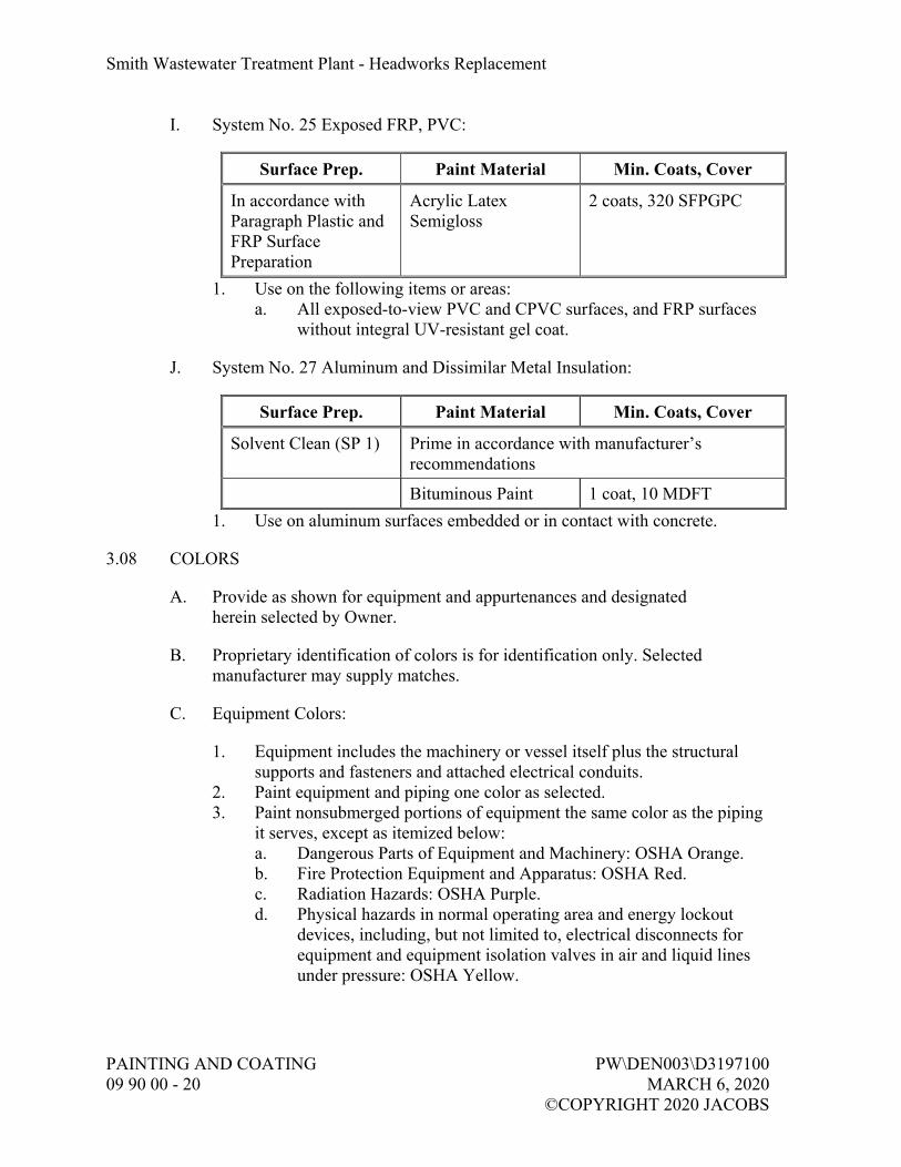
Smith Wastewater Treatment Plant - Headworks Replacement
PAINTING AND COATING PW\DEN003\D3197100 09 90 00 - 20 MARCH 6, 2020 ©COPYRIGHT 2020 JACOBS
I. System No. 25 Exposed FRP, PVC:
Surface Prep. Paint Material Min. Coats, Cover
In accordance with Paragraph Plastic and FRP Surface Preparation
Acrylic Latex Semigloss
2 coats, 320 SFPGPC
1. Use on the following items or areas: a. All exposed-to-view PVC and CPVC surfaces, and FRP surfaces
without integral UV-resistant gel coat.
J. System No. 27 Aluminum and Dissimilar Metal Insulation:
Surface Prep. Paint Material Min. Coats, Cover
Solvent Clean (SP 1) Prime in accordance with manufacturer’s recommendations
Bituminous Paint 1 coat, 10 MDFT
1. Use on aluminum surfaces embedded or in contact with concrete.
3.08 COLORS
A. Provide as shown for equipment and appurtenances and designated herein selected by Owner.
B. Proprietary identification of colors is for identification only. Selected manufacturer may supply matches.
C. Equipment Colors:
1. Equipment includes the machinery or vessel itself plus the structural supports and fasteners and attached electrical conduits.
2. Paint equipment and piping one color as selected. 3. Paint nonsubmerged portions of equipment the same color as the piping
it serves, except as itemized below: a. Dangerous Parts of Equipment and Machinery: OSHA Orange. b. Fire Protection Equipment and Apparatus: OSHA Red. c. Radiation Hazards: OSHA Purple. d. Physical hazards in normal operating area and energy lockout
devices, including, but not limited to, electrical disconnects for equipment and equipment isolation valves in air and liquid lines under pressure: OSHA Yellow.

Smith Wastewater Treatment Plant - Headworks Replacement
PW\DEN003\D3197100 PAINTING AND COATING MARCH 6, 2020 09 90 00 - 21 ©COPYRIGHT 2020 JACOBS
D. Pipe Identification Painting:
1. Color code nonsubmerged metal piping, except electrical conduit. Paint fittings and valves the same color as pipe, except equipment isolation valves.
2. Pipe Color Coding: As shown in table below. 3. On exposed stainless steel piping, apply color 24 inches in length along
pipe axis at connections to equipment, valves, or branch fittings, at wall boundaries, and at intervals along piping not greater than 9 feet on center.
4. Pipe Supports: Painted light gray, as approved by Owner.
E. Pipe System Color Code:
Pipe System Color
Drains and Sludge Light Brown
Drains Black
Effluent, Primary Silver/Gray
Filter Backwash Supply Medium Blue
Filter Surface Wash Supply Medium Blue
Headworks Buff
Plant Service Water Medium Blue
Raw Sewage Dark Gray
3.09 FIELD QUALITY CONTROL
A. Testing Equipment:
1. Provide calibrated electronic type dry film thickness gauge to test coating thickness specified in mils.
2. Provide low-voltage wet sponge electrical holiday detector to test completed coating systems, 20 mils dry film thickness or less, except zinc primer, high-build elastomeric coatings, and galvanizing, for pinholes, holidays, and discontinuities, as manufactured by Tinker and Rasor, San Gabriel, CA, Model M-1.
3. Provide high-voltage spark tester to test completed coating systems in excess of 20 mils dry film thickness. Unit as recommended by coating manufacturer.

Smith Wastewater Treatment Plant - Headworks Replacement
PAINTING AND COATING PW\DEN003\D3197100 09 90 00 - 22 MARCH 6, 2020 ©COPYRIGHT 2020 JACOBS
B. Testing:
1. Thickness and Continuity Testing: a. Measure coating thickness specified in mils with a magnetic type,
dry film thickness gauge, in accordance with SSPC PA 2. Check each coat for correct millage. Do not make measurement before a minimum of 8 hours after application of coating.
b. Holiday detect coatings 20 mils thick or less, except zinc primer and galvanizing, with low voltage wet sponge electrical holiday detector in accordance with NACE SP0188.
c. Holiday detect coatings in excess of 20 mils dry with high voltage spark tester as recommended by coating manufacturer and in accordance with NACE SP0188.
d. After repaired and recoated areas have dried sufficiently, retest each repaired area. Final tests may also be conducted by Engineer.
C. Inspection: Leave staging and lighting in place until Engineer has inspected surface or coating. Replace staging removed prior to approval by Engineer. Provide additional staging and lighting as requested by Engineer.
D. Unsatisfactory Application:
1. If item has an improper finish color or insufficient film thickness, clean surface and topcoat with specified paint material to obtain specified color and coverage. Obtain specific surface preparation information from coating manufacturer.
2. Evidence of runs, bridges, shiners, laps, or other imperfections is cause for rejection.
3. Repair defects in accordance with written recommendations of coating manufacturer.
E. Damaged Coatings, Pinholes, and Holidays:
1. Hand or power sand visible areas of chipped, peeled, or abraded paint, and feather edges. Follow with primer and finish coat. Depending on extent of repair and appearance, a finish sanding and topcoat may be required.
2. Remove rust and contaminants from metal surface. Provide surface cleanliness and profile in accordance with surface preparation requirements for specified paint system.
3. Feather edges and repair in accordance with recommendations of paint manufacturer.
4. Apply finish coats, including touchup and damage-repair coats in a manner that will present a uniform texture and color-matched appearance.

Smith Wastewater Treatment Plant - Headworks Replacement
PW\DEN003\D3197100 PAINTING AND COATING MARCH 6, 2020 09 90 00 - 23 ©COPYRIGHT 2020 JACOBS
3.10 MANUFACTURER’S SERVICES
A. In accordance with Section 01 43 33, Manufacturers’ Field Services, coating manufacturer’s representative shall be present at Site as follows:
1. On first day of application of any coating system. 2. A minimum of two additional Site inspection visits, each for a minimum
of 4 hours, in order to provide Manufacturer’s Certificate of Proper Installation.
3. As required to resolve field problems attributable to or associated with manufacturer’s product.
4. To verify full cure of coating prior to coated surfaces being placed into immersion service.
3.11 CLEANUP
A. Place cloths and waste that might constitute a fire hazard in closed metal containers or destroy at end of each day.
B. Upon completion of the Work, remove staging, scaffolding, and containers from Site or destroy in a legal manner.
C. Remove paint spots, oil, or stains upon adjacent surfaces and floors and leave entire job clean.
3.12 SUPPLEMENTS
A. The supplements listed below, following “End of Section,” are a part of this specification:
1. Paint System Data Sheet (PSDS). 2. Paint Product Data Sheet (PPDS).
END OF SECTION

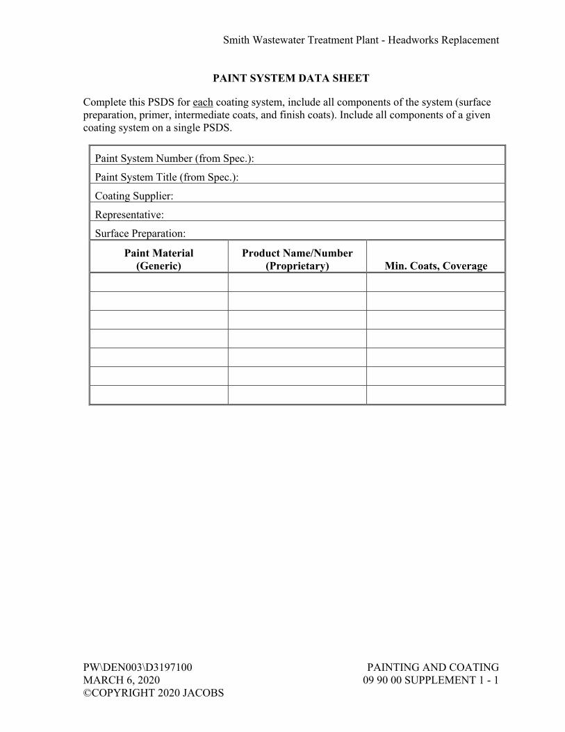
Smith Wastewater Treatment Plant - Headworks Replacement
PW\DEN003\D3197100 PAINTING AND COATING MARCH 6, 2020 09 90 00 SUPPLEMENT 1 - 1 ©COPYRIGHT 2020 JACOBS
PAINT SYSTEM DATA SHEET
Complete this PSDS for each coating system, include all components of the system (surface preparation, primer, intermediate coats, and finish coats). Include all components of a given coating system on a single PSDS.
Paint System Number (from Spec.):
Paint System Title (from Spec.):
Coating Supplier:
Representative:
Surface Preparation:
Paint Material (Generic)
Product Name/Number (Proprietary) Min. Coats, Coverage

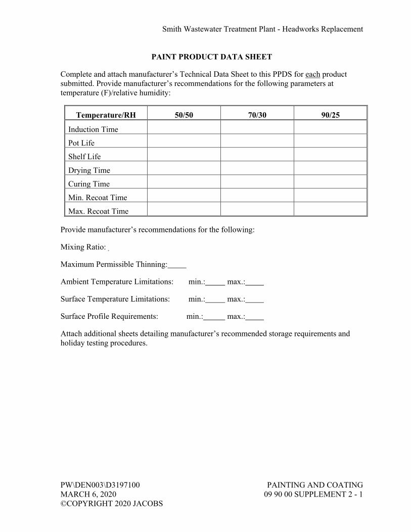
Smith Wastewater Treatment Plant - Headworks Replacement
PW\DEN003\D3197100 PAINTING AND COATING MARCH 6, 2020 09 90 00 SUPPLEMENT 2 - 1 ©COPYRIGHT 2020 JACOBS
PAINT PRODUCT DATA SHEET
Complete and attach manufacturer’s Technical Data Sheet to this PPDS for each product submitted. Provide manufacturer’s recommendations for the following parameters at temperature (F)/relative humidity:
Temperature/RH 50/50 70/30 90/25
Induction Time
Pot Life
Shelf Life
Drying Time
Curing Time
Min. Recoat Time
Max. Recoat Time
Provide manufacturer’s recommendations for the following:
Mixing Ratio:
Maximum Permissible Thinning:
Ambient Temperature Limitations: min.: max.:
Surface Temperature Limitations: min.: max.:
Surface Profile Requirements: min.: max.:
Attach additional sheets detailing manufacturer’s recommended storage requirements and holiday testing procedures.


Smith Wastewater Treatment Plant - Headworks Replacement
PW\DEN003\D3197100 FABRICATED STRUCTURES APRIL 8, 2020 13 34 23 - 1 ©COPYRIGHT 2020 JACOBS
SECTION 13 34 23 FABRICATED STRUCTURES
PART 1 GENERAL
1.01 REFERENCES
A. The following is a list of standards which may be referenced in this section:
1. American Architectural Manufacturers Association (AAMA): 101, and General Finishing Documents.
2. American Society of Civil Engineers (ASCE): 7, Minimum Design Loads for Buildings and Other Structures.
3. ASTM International (ASTM): a. C920, Standard Specification for Elastomeric Joint Sealants. b. E84, Standard Test Method for Surface Burning Characteristics of
Building Materials.
1.02 SYSTEM DESCRIPTION
A. Design, furnish, and install complete building package using manufacturer’s standard components.
B. Building Name: Grit Classifier.
1. Size: a. Exterior, Maximum: 26 feet – 6 inches wide by 34 feet – 8 inches
long by 16 feet – 0 inches high. b. Interior, Minimum: 25 feet – 0 inches by 34 feet – 6 inches. c. Clear Ceiling Height: 15 feet – 2 inches. d. Bay Spacing: 8 feet – 0 inches.
2. Roof Slope: 1 inch(es) vertical to 12 inches horizontal.
C. Structure: All-metal, prefabricated structure of steel frame design, fabricated from hot-dip galvanized sheet steel.
D. Design: Coordinate enclosure design with process equipment.
1.03 SUBMITTALS
A. Action Submittals:
1. Shop Drawings: a. Manufacturer’s Literature and Technical Data: Drawings and
Specifications for proposed building system.

Smith Wastewater Treatment Plant - Headworks Replacement
FABRICATED STRUCTURES PW\DEN003\D3197100 13 34 23 - 2 APRIL 8, 2020 ©COPYRIGHT 2020 JACOBS
b. Manufacturer’s Standard Details: Clearly mark those portions that apply to specific Project and those parts that do not apply.
c. Anchorage and bracing drawings and/or catalog information, as required by Section 01 88 15, Anchorage and Bracing, for loads provided in Section 01 61 00, Common Product Requirements.
d. Painting Systems: Specifications; include paint manufacturer’s name, product trade name, and preparation for shop and field coats.
2. Samples: Colors of metal siding and interiors available.
B. Informational Submittals:
1. Drawings stamped by Contractor’s engineer, licensed in the project state, and prepared specifically for this Project: a. Materials and Details: Show materials, details of components
(including doors and other accessories), finishes, fastenings, methods of joining, sealants, anchor bolt, shear angle, and baseplate details including sizes and dimensions, size and location of structural members and bracing, wall structural members, bracing, openings, and structural wind columns as required.
2. Calculations Stamped by Contractor’s Engineer: a. Complete structural stress and deflection analysis of structural
components and connections; for bolted moment-resistant connections in main frames consider prying action of bolts.
b. Heat loss calculations showing conformance with applicable code. 3. Anchorage and bracing calculations as required by Section 01 88 15,
Anchorage and Bracing, for loads provided in Section 01 61 00, Common Product Requirements. Submit with Action Submittal for the same item.
4. Experience records of manufacturer and installer. 5. Approval of installer by manufacturer of structure components. 6. Certification that codes and referenced standards have been met. 7. Description and details of electrical continuity and grounding methods. 8. Test reports.
1.04 QUALITY ASSURANCE
A. Qualifications:
1. Designers: Engineer registered in state where building is to be erected. 2. Manufacturer:
a. At least 5 years’ experience in work of type required in this section.
b. Production capacity to provide work required for this Project without delay.

Smith Wastewater Treatment Plant - Headworks Replacement
PW\DEN003\D3197100 FABRICATED STRUCTURES APRIL 8, 2020 13 34 23 - 3 ©COPYRIGHT 2020 JACOBS
3. Erector/Installer: a. Not less than 5 years’ experience in erection of prefabricated
structures similar to this Project, documented with references and contact information.
b. Approved by manufacturer of building components.
B. Regulatory Requirements: Design building system to meet requirements of building codes specified in Section 01 61 00, Common Product Requirements.
1.05 DELIVERY, STORAGE, AND HANDLING
A. Deliver building components in undamaged condition to Site when ready for installation.
B. Protect products from damage and deterioration.
C. Handle products in accordance with manufacturers’ instructions.
1.06 EXTRA MATERIALS
A. Delivery: In accordance with Section 01 61 00, Common Product Requirements.
1.07 SPECIAL GUARANTEE
A. Provide manufacturer’s extended guarantee or warranty, with Owner named as beneficiary, in writing, as special guarantee. Special guarantee shall provide for correction, or at the option of the Owner, removal and replacement of Work specified in this Specification section found defective during a minimum period of 5 years and as stated below after the date of Substantial Completion. Duties and obligations for correction or removal and replacement of defective Work as specified in the General Conditions.
B. Conditions:
1. Panel Performance: Finish on metal roof panels, flashing, and trim will not chalk, crack, check blister, peel, flake, chip, or lose adhesion for 5 years. Envelope Performance: Roofing assemblies will remain weathertight for 20 years.

Smith Wastewater Treatment Plant - Headworks Replacement
FABRICATED STRUCTURES PW\DEN003\D3197100 13 34 23 - 4 APRIL 8, 2020 ©COPYRIGHT 2020 JACOBS
PART 2 PRODUCTS
2.01 MANUFACTURERS
A. Materials, equipment, and accessories specified in this section shall be products of:
1. Butler Manufacturing Co. 2. Varco-Pruden Metal Building Systems.
2.02 SYSTEM PERFORMANCE
A. Structural Loading: Design structure in accordance with ASCE 7, local building codes, and the following:
1. Building: Own dead load. 2. Special Equipment: As located on Drawings. 3. Design Wind Loads: In accordance with applicable building code in the
Project area. 4. Earthquake Load: In accordance with applicable building code for
Seismic Zone B in the Project area. 5. Ceiling Supporting Cable Tray System: 100 pounds per lineal foot.
B. Environmental Design Conditions:
1. Design Temperature: Winter DB, 40 degrees; summer DB, 90 degrees. 2. Prevailing Wind Direction: South from January to February, East from
August to October and North from October to February.
2.03 COMPONENTS
A. Substructure: Cast-in-place concrete foundation.
B. Interior:
1. Floor: Level, easy to clean, nonslip to wet smooth rubber-sole shoes.
2.04 MATERIALS
A. Roofing and Siding: Standing seam metal, with gutters and downspouts.
B. Sealant: Single part polyurethane or silicone meeting ASTM C920, Type S, Grade NS, Class 25.
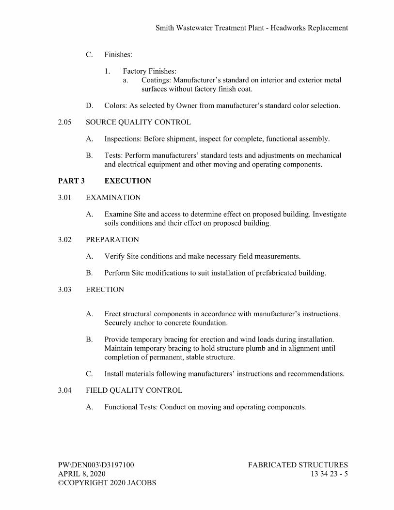
Smith Wastewater Treatment Plant - Headworks Replacement
PW\DEN003\D3197100 FABRICATED STRUCTURES APRIL 8, 2020 13 34 23 - 5 ©COPYRIGHT 2020 JACOBS
C. Finishes:
1. Factory Finishes: a. Coatings: Manufacturer’s standard on interior and exterior metal
surfaces without factory finish coat.
D. Colors: As selected by Owner from manufacturer’s standard color selection.
2.05 SOURCE QUALITY CONTROL
A. Inspections: Before shipment, inspect for complete, functional assembly.
B. Tests: Perform manufacturers’ standard tests and adjustments on mechanical and electrical equipment and other moving and operating components.
PART 3 EXECUTION
3.01 EXAMINATION
A. Examine Site and access to determine effect on proposed building. Investigate soils conditions and their effect on proposed building.
3.02 PREPARATION
A. Verify Site conditions and make necessary field measurements.
B. Perform Site modifications to suit installation of prefabricated building.
3.03 ERECTION
A. Erect structural components in accordance with manufacturer’s instructions. Securely anchor to concrete foundation.
B. Provide temporary bracing for erection and wind loads during installation. Maintain temporary bracing to hold structure plumb and in alignment until completion of permanent, stable structure.
C. Install materials following manufacturers’ instructions and recommendations.
3.04 FIELD QUALITY CONTROL
A. Functional Tests: Conduct on moving and operating components.

Smith Wastewater Treatment Plant - Headworks Replacement
FABRICATED STRUCTURES PW\DEN003\D3197100 13 34 23 - 6 APRIL 8, 2020 ©COPYRIGHT 2020 JACOBS
3.05 MANUFACTURER’S SERVICES
A. Provide manufacturers’ representatives at Site in accordance with Section 01 43 33, Manufacturers’ Field Services, for installation assistance, inspection and certification of proper installation, equipment testing, startup assistance, and training of Owner’s personnel for specified component, subsystem, equipment, or system.
3.06 CLEANING
A. Thoroughly clean interior and exterior of building and leave weathertight and ready for use.
END OF SECTION