mns is motor control center interface manual redundancy … · 2018-05-10 · redundancy...
TRANSCRIPT

MNS iS Motor Control Center Interface Manual Redundancy System Release V5.4/0
MNS is a registered trademark.
Other trademarks and trade names reside with their respective owners.
This document relates to the MNS iS System Release 5.4/0.
The information in this document is subject to change without notice and should not be construed as a commitment by ABB. ABB assumes no responsibility for any errors that may appear in this document.
In no event shall ABB be liable for direct, indirect, special, incidental, or consequential damages of any nature or kind arising from the use of this document, nor shall ABB be liable for incidental or consequential damages arising from use of any software or hardware described in this document.
This document and parts thereof must not be reproduced or copied without ABB's written permission, and the contents thereof must not be imparted to a third party nor be used for any unauthorized purpose. The software described in this document is furnished under a license and may be used, copied, or disclosed only in accordance with the terms of such license.
All rights reserved.
Copyright © 2009 ABB Automation Products GmbH, Ladenburg, Germany

MNS iS Interface Manual Redundancy Content
1TGC910177M0201 – Release V5.4 3
Table of content
General ........................................................................................................................... 5 Target Group ..........................................................................................................................5 Use of Warning, Caution, Information and Tip icon ................................................................5 Terminology ............................................................................................................................6 Related Documentation ........................................................................................................10 Related System Version .......................................................................................................10 Document Revision History ..................................................................................................10
Introduction.................................................................................................................. 11 Redundancy..........................................................................................................................11
Line Redundancy .........................................................................................................................11 Slave Redundancy .......................................................................................................................11
MNS iS Hardware Requirements..........................................................................................12 MNS iS Software Requirements ...........................................................................................12
Basics........................................................................................................................... 13 Redundancy Requirements ..................................................................................................13 Fault detection and change over ..........................................................................................14 Redundancy Configuration ...................................................................................................15 Primary and Backup MLink...................................................................................................17
Interfaces...................................................................................................................... 18 MLink connectors..................................................................................................................18 Redundancy MLink connection.............................................................................................18 Switchgear Bus connection ..................................................................................................19 Ethernet network connections ..............................................................................................21
Redundancy Setup ...................................................................................................... 22 Hardware Setup....................................................................................................................22 Parameter Setup...................................................................................................................22 Initial Values .........................................................................................................................23
Redundancy Functions............................................................................................... 24 Handled faults.......................................................................................................................24 Failsafe .................................................................................................................................24 PLC / PCS Data Communication..........................................................................................25
MODBUS RTU and TCP..............................................................................................................25 PROFIBUS DP and DP-V1 ..........................................................................................................25
Content MNS iS Interface Manual Redundancy
4 1TGC910177M0201 – Release V5.4
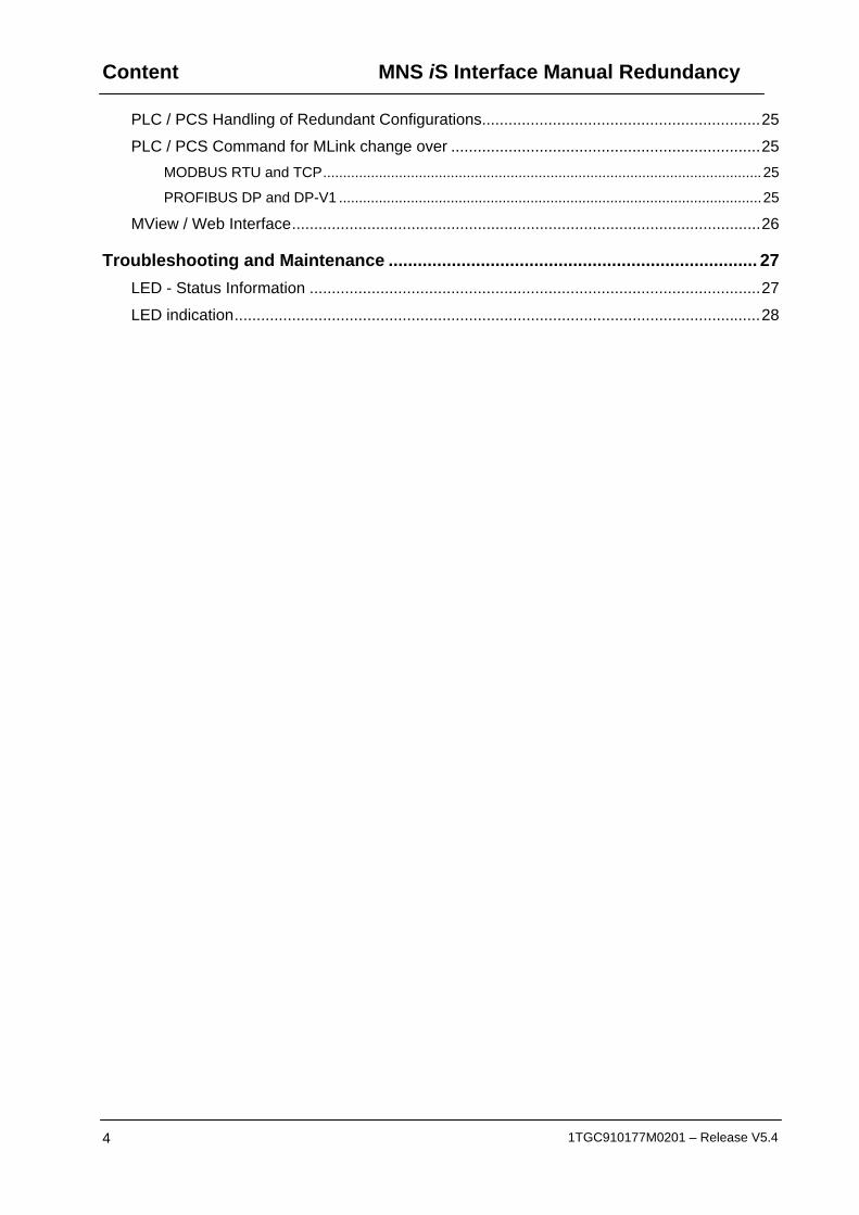
PLC / PCS Handling of Redundant Configurations...............................................................25 PLC / PCS Command for MLink change over ......................................................................25
MODBUS RTU and TCP..............................................................................................................25 PROFIBUS DP and DP-V1 ..........................................................................................................25
MView / Web Interface..........................................................................................................26
Troubleshooting and Maintenance ............................................................................ 27 LED - Status Information ......................................................................................................27 LED indication.......................................................................................................................28
MNS iS Interface Manual Redundancy General
1TGC910177M0201 – Release V5.4 5
General
Target Group This document describes communication and control interfaces used in MNS iS. The manual is primarily intended for those requiring information on accessing information and data provided from MNS iS. Furthermore the document provides information for integration of MNS iS as fieldbus component into PLC or higher level Process Control Systems to control system and application engineers.
It is assumed that the reader of this manual is familiar with basic terms of fieldbus and control communication (e.g. basic knowledge about PROFIBUS, Modbus etc.).
Use of Warning, Caution, Information and Tip icon

General MNS iS Interface Manual Redundancy
6 1TGC910177M0201 – Release V5.4
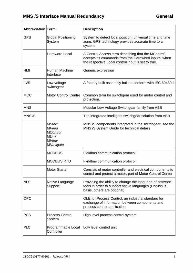
Terminology List of the terms, acronyms, abbreviations and definitions that the document uses.
Abbreviation Term Description
Aspect Object ABB technology. An Aspect Object is a computer representation of a real object such as a pump, a valve, an order or a virtual object such as a service or an object type. An Aspect Object is described by its aspects and is organized in structures.
Alarm Alarm is defined as status transition from any state to abnormal state. Status transition to abnormal state can be data crossing over the pre-defined alarm limit.
Bus Local A Control Access term describing that the MControl accepts its commands from a device on the switchgear control network, e.g. the Web Interface, MView.
COTS Commercial off the shelf
Commercial off the shelf product, term to describe products available on the market, ready to use
DCS Distributed Control System
See also PCS
DTM Device Type Manager Software module used to manage devices via fieldbus (e.g. PROFIBUS) using frame application environment (e.g. PactWare, ABB Fieldbus Builder etc.)
Eth. Ethernet Ethernet is a local area network (LAN) technology. The Ethernet standard specifies the physical medium, access control rules and the message frames.
Event An event is a status transition from one state to another. It can be defined as alarm, if the state is defined as abnormal or as warning as a pre-alarm state.
FD Field Device Term for devices connected to the fieldbus (e.g. motor control units or circuit breaker protection)
GSD file Geräte Stamm Datei (German abbreviation)
A hardware description file for a PROFIBUS-DP or PROFIBUS-DP/V1 slave type
MNS iS Interface Manual Redundancy General
1TGC910177M0201 – Release V5.4 7
Abbreviation Term Description
GPS Global Positioning System
System to detect local position, universal time and time zone, GPS technology provides accurate time to a system
Hardware Local A Control Access term describing that the MControl accepts its commands from the Hardwired inputs, when the respective Local control input is set to true.
HMI Human Machine Interface
Generic expression
LVS Low voltage switchgear
A factory built assembly built to conform with IEC 60439-1
MCC Motor Control Centre Common term for switchgear used for motor control and protection.
MNS Modular Low Voltage Switchgear family from ABB
MNS iS The integrated intelligent switchgear solution from ABB
MStart MFeed MControl MLink MView MNavigate
MNS iS components integrated in the switchgear, see the MNS iS System Guide for technical details
MODBUS Fieldbus communication protocol
MODBUS RTU Fieldbus communication protocol
Motor Starter Consists of motor controller and electrical components to control and protect a motor, part of Motor Control Center
NLS Native Language Support
Providing the ability to change the language of software tools in order to support native languages (English is basis, others are optional)
OPC OLE for Process Control, an industrial standard for exchange of information between components and process control application
PCS Process Control System
High level process control system
PLC Programmable Local Controller
Low level control unit

General MNS iS Interface Manual Redundancy
8 1TGC910177M0201 – Release V5.4
Abbreviation Term Description
PROFIBUS-DP Fieldbus communication protocol with cyclic data transfer (V0).
PROFIBUS-DP/V1 Fieldbus communication protocol, extension of PROFIBUS- DP allowing acyclic data transfer and multi master (V1).
PROFIBUS-DP/V2 Fieldbus communication protocol, extension of PROFIBUS- DP allowing time stamp and communication between master and slave (V2).
RCU Remote Control Unit Local control unit with pushbutton and indicator to operate a device (e.g. motor) from field level.
RS232 Standard No. 232 for PC communication, established by EIA (Electronics Industries Association, USA)
RS485 Communication interface standard from EIA (Electronics Industries Association, USA), operating on voltages between 0V and +5V. RS-485 is more noise resistant than RS-232C, handles data transmission over longer distances, and can drive more receivers.
RTC Real Time Clock Integrated clock function in devices used to generate time and date information if a remote clock system is not present
Software Local A Control Access term describing that the MControl accepts its commands from the hardwired inputs as a result of either the PCS or MView passing the Control Access Authority to Soft-Local.
Note: Does not require the hardwired local input to be set to true.
SNTP Simple Network Time Protocol
a protocol used for time synchronization in Control Network through Ethernet
Switchgear Bus Network
Term used to describe the internal switchgear communication network, between MLink and MControl.
TCP/IP Transmission Control Protocol / Internet Protocol
TCP/IP is a high-level connection oriented, reliable, full duplex communication protocol developed for integration of the heterogenous systems.
Trip A consequence of an alarm activated or an external trip command from another device to stop the motor or trip the circuit breaker.
MNS iS Interface Manual Redundancy General
1TGC910177M0201 – Release V5.4 9
Abbreviation Term Description
UTC Coordinated Universal Time
Coordinated Universal Time is the international time standard. It is the current term for what was commonly referred to as Greenwich Meridian Time (GMT). Zero (0) hours UTC is midnight in Greenwich England, which lies on the zero longitudinal meridian. Universal time is based on a 24 hour clock.
Warning A warning is defined as status transition from any state to pre-alarm state to inform in advance before an alarm level is reached.

General MNS iS Interface Manual Redundancy
10 1TGC910177M0201 – Release V5.4
Related Documentation MNS iS 1TGC910127 M0201 MNS iS Interface Manual MLink, Release 5.4
1TGC910137M0201 MNS iS Interface Manual Web Interface, Release 5.4
1TGC910157 M0201 MNS iS Interface Manual Profibus, Release 5.4
1TGC910167 M0201 MNS iS Interface Manual Modbus, Release 5.4
1TGC910187 M0201 MNS iS MControl Interface Manual Profibus Direct, Release 5.4
1TGC910001 B0204 MNS iS System Guide
1TGC910609 M0201 MNS iS Quick Guide Installation and System Setup, Release 5.4
1TGC910069 M0201 MNavigate Help file V5.4
1TGC910018 M0202 MNS iS ATEX – Enhancements for Safety
PROFIBUS [1] Profibus Specification Slave Redundancy TC4-04-0001
Related System Version The content of this document is related to MNS iS System Release 5.4/0.
The described functions are designed but may not be fully implemented in all details. Please refer to the current system guides and release notes regarding possible restrictions.
Document Revision History

MNS iS Interface Manual Redundancy Introduction
1TGC910177M0201 – Release V5.4 11
Introduction
Redundancy Redundancy in communication systems and fieldbus technology allows data communication between a PLC or PCS master to slave devices on two independent communication links. This may be required if a higher availability of the communication link is required. The MLink device in MNS iS is a slave device on the fieldbus (PROFIBUS or MODBUS), to which the following types of redundancy are applicable:
Line Redundancy
In this case, the cable connection between a fieldbus master and slave devices is doubled. Two independent cables are used and routed through the plant on different cable ways. This redundancy requires third party hardware. No additional components and configuration is required in MNS iS.
Slave Redundancy
In slave redundancy, two slave devices are used on separate cable connections to the fieldbus master. MNS iS allows redundancy incorporated in a fieldbus system as Slave Redundancy by using two MLink modules.
Fig. 1 MNS iS Redundancy
Redundant OPC Servers are not supported.

Introduction MNS iS Interface Manual Redundancy
12 1TGC910177M0201 – Release V5.4
MNS iS Hardware Requirements The redundancy is available for MLink Types:
Profibus DP and DP-V1: 1TGE102019R1001
Modbus RS232 and TCP: 1TGE102019R2300
Modbus RS422 and TCP: 1TGE102019R4200
Modbus RS485 and TCP: 1TGE102019R4800
Redundant Link cable 1TGE120109R0002 2m
Redundant Link cable 1TGE120109R0003 3m
Redundant Link cable 1TGE120109R0005 5m
Redundant Link cable 1TGE120109R0010 10m
Ferrite Core 1TGB000197P0001 Required for redundant link cables.
MNS iS Software Requirements Redundancy requires MNS iS Release 2.0 or higher.
MNS iS Interface Manual Redundancy Basics
1TGC910177M0201 – Release V5.4 13
Basics
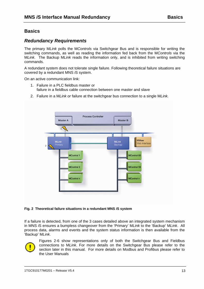
Redundancy Requirements The primary MLink polls the MControls via Switchgear Bus and is responsible for writing the switching commands, as well as reading the information fed back from the MControls via the MLink. The Backup MLink reads the information only, and is inhibited from writing switching commands.
A redundant system does not tolerate single failure. Following theoretical failure situations are covered by a redundant MNS iS system.
On an active communication link:
1. Failure in a PLC fieldbus master or failure in a fieldbus cable connection between one master and slave
2. Failure in a MLink or failure at the switchgear bus connection to a single MLink.
Fig. 2 Theoretical failure situations in a redundant MNS iS system
If a failure is detected, from one of the 3 cases detailed above an integrated system mechanism in MNS iS ensures a bumpless changeover from the ‘Primary’ MLink to the ‘Backup’ MLink. All process data, alarms and events and the system status information is then available from the ‘Backup’ MLink.
Figures 2-6 show representations only of both the Switchgear Bus and Fieldbus connections to MLink. For more details on the Switchgear Bus please refer to the section later in this manual. For more details on Modbus and Profibus please refer to the User Manuals
1
2

Basics MNS iS Interface Manual Redundancy
14 1TGC910177M0201 – Release V5.4
Fault detection and change over If the fieldbus communication between Primary MLink and Process Controller fails and fieldbus connection between the Backup MLink and Process Controller is healthy, then the Primary MLink and the Backup MLink execute a ‘Bumpless’ changeover.
The primary MLink polls the MControls via Switchgear Bus and is responsible for writing the switching commands, as well as reading the information fed back from the MControls via the MLink. The Backup MLink reads the information only, and is inhibited from writing switching commands.
If we take fig 2 as an example, and the communication is lost between the ‘Master A’ controller and the ‘MLink Primary’, (case 1), and the communication between the ‘Master B’ controller and the ‘MLink Backup’ is healthy. Then the system will initialize the changeover, resulting in;
Process Controller ‘Master B’ now having read / write access.
What was the ‘MLink Backup’ now becomes the active MLink, responsible for sending Control commands.
Fault indication that there is a redundancy problem, is then given by the serial link, to the ‘Master B’ controller, it is also displayed via the Web Interface, and LED indication is given by the Backup MLink.
The same handling also applies for cases 2 and 3 previously detailed.
The fieldbus data values sent from the Backup MLink are frozen at the time of the change over. This is to ensure that the fieldbus communication is available at any time for another change over.
When the communication is then restored between ‘Master A’ and the Primary MLink, the redundancy fault indication will then be cleared. The system is then again running in the redundant mode, with the ‘Master B’ Process Controller having read / write access, and ‘Master A’ having read access only.
It is possible to initiate a changeover of the Master Controllers, providing all communication links are healthy, for more details please refer to the Modbus and Profibus User Manuals.

MNS iS Interface Manual Redundancy Basics
1TGC910177M0201 – Release V5.4 15
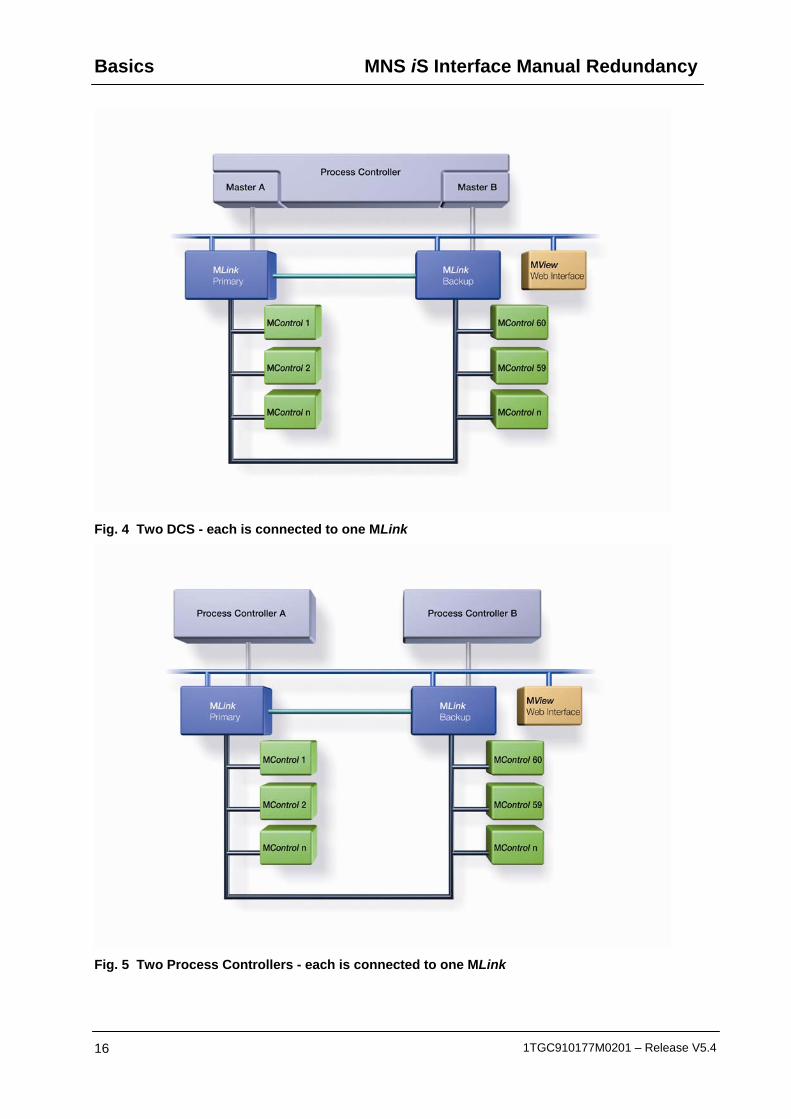
Redundancy Configuration There are three options available to connect PLC or PCS to both MLink
• One PLC / PCS connected to both MLink, as described in [1]
• One PLC / PCS with at least redundant (two) master interfaces
• Redundant (two) PLC / PCS (redundancy handled in PLC or PCS only)
Fig. 3 One PCS is connected to both MLinks (Modbus RTU or Profibus DP)
This redundancy is described in [1]. The PLC / PCS master device is capable of communication to two slave devices with different fieldbus addresses.
Basics MNS iS Interface Manual Redundancy
16 1TGC910177M0201 – Release V5.4
Fig. 4 Two DCS - each is connected to one MLink
Fig. 5 Two Process Controllers - each is connected to one MLink
MNS iS Interface Manual Redundancy Basics
1TGC910177M0201 – Release V5.4 17
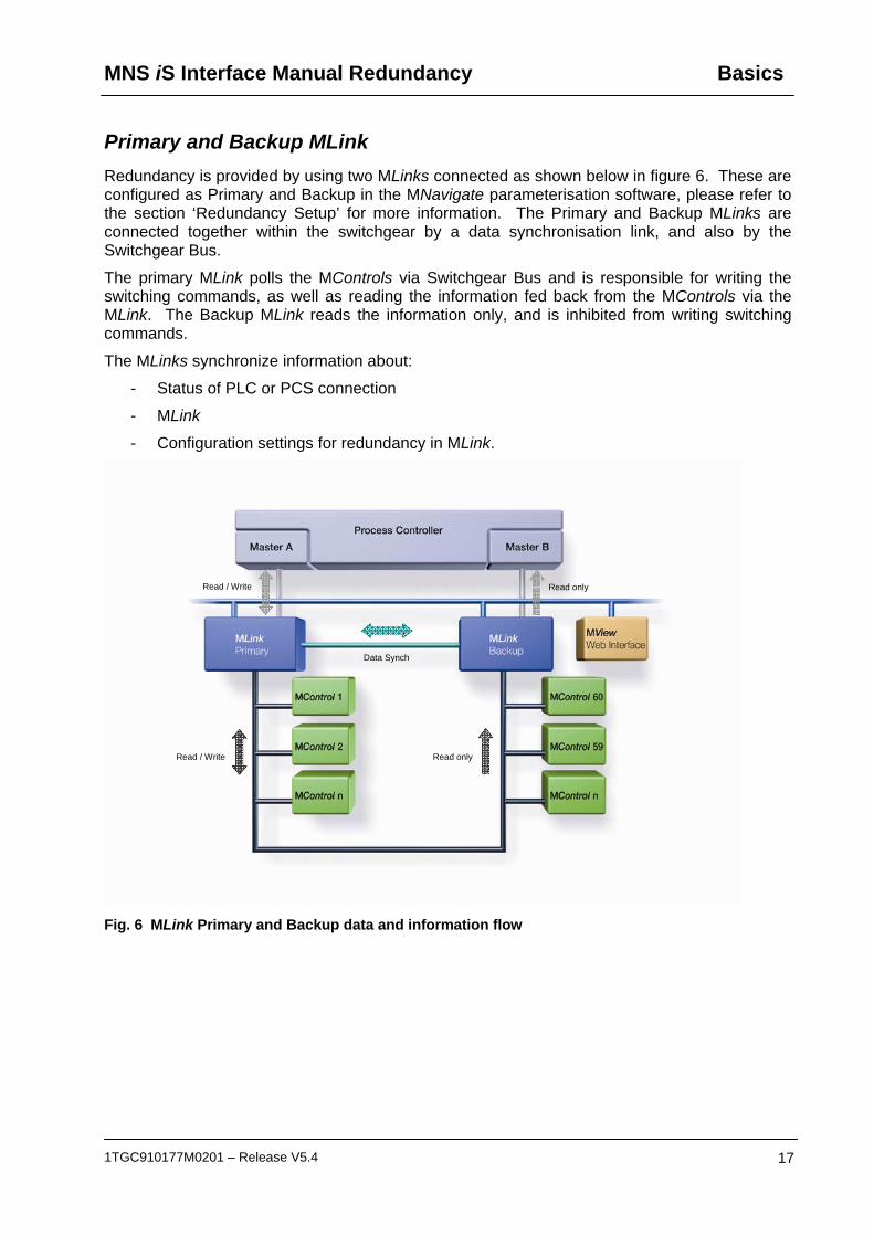
Primary and Backup MLink Redundancy is provided by using two MLinks connected as shown below in figure 6. These are configured as Primary and Backup in the MNavigate parameterisation software, please refer to the section ‘Redundancy Setup’ for more information. The Primary and Backup MLinks are connected together within the switchgear by a data synchronisation link, and also by the Switchgear Bus.
The primary MLink polls the MControls via Switchgear Bus and is responsible for writing the switching commands, as well as reading the information fed back from the MControls via the MLink. The Backup MLink reads the information only, and is inhibited from writing switching commands.
The MLinks synchronize information about:
- Status of PLC or PCS connection
- MLink
- Configuration settings for redundancy in MLink.
Fig. 6 MLink Primary and Backup data and information flow
Read / Write
Read / Write
Data Synch
Read only
Read only

Interfaces MNS iS Interface Manual Redundancy
18 1TGC910177M0201 – Release V5.4
Interfaces
MLink connectors MLinks that are used in redundant configuration, differ from those in non redundant configurations, where an additional connector (Serial 1) is utilized.
Fig. 7 MLink front view with redundancy link connector
The LED indication on the front side of MLink has been extended with following functions to indicate the redundancy status:
LED Number Description
7 Redundancy Error
8 MLink running as Primary
Table 1 LEDs for Redundancy Indication (Only valid if LED 10 is on)
Redundancy MLink connection Both MLinks must be connected together to enable data synchronization via a RS232 Null Modem cable from serial port 1 to serial port 1 to ensure correct operation. ABB part numbers for these cables and the associated ferrite core are given in the section ‘MNS iS Hardware Requirements’
Fig. 8 Serial 1 to serial 1 Redundant link connections with ferrite core.
The length of this cable should not exceed 10 meters
LED indicators
Redundant MLink Connector (Serial1)

MNS iS Interface Manual Redundancy Interfaces
1TGC910177M0201 – Release V5.4 19
Switchgear Bus connection In a dual redundant configuration both MLinks are connected to the Switchgear Bus for communication to MControl devices. The maximum numbers of MControls connected to both MLinks is 60, the maximum allowable number of panels is 7, and the maximum switchgear bus cable length is 30m, not including backplanes.
The Switchgear Bus must be terminated at both ends of the line, with the active bus termination resistors. This differs from non redundant systems where only one terminating resistor is required.
Approved redundant topologies.
Fig. 9 Redundant MLinks sample topology example 1
Interfaces MNS iS Interface Manual Redundancy
20 1TGC910177M0201 – Release V5.4
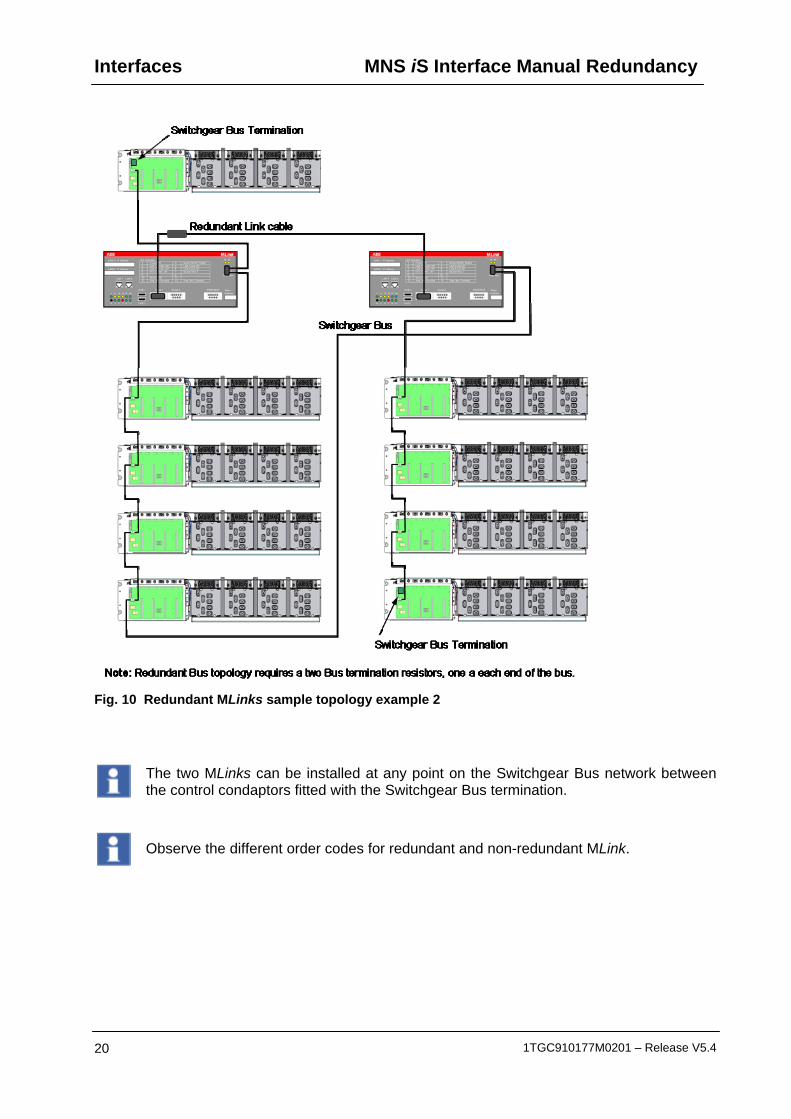
Fig. 10 Redundant MLinks sample topology example 2
The two MLinks can be installed at any point on the Switchgear Bus network between the control condaptors fitted with the Switchgear Bus termination.
Observe the different order codes for redundant and non-redundant MLink.

MNS iS Interface Manual Redundancy Interfaces
1TGC910177M0201 – Release V5.4 21
Ethernet network connections The Ethernet network used in MNS iS (Switchgear Control Network) connects all MLink to MView and MNavigate and the OPC Server. It is connected to LAN 2 port on the MLink. In a redundant configuration the pair of Primary and Backup MLinks must be connected to the same network (via managed switches) in order that the redundancy handling for the MView functions correctly.
Fig. 11 Switchgear Control Network
Switchgear Control Network Restrictions
In order to achieve maximum performance from the interfaces on the Ethernet Switchgear Control Network it is not recommended to exceed the following
2 x Web Interfaces (MView)
1 x MNavigate client
1 x OPC DA Server
1 x OPC AE Server

Redundancy Setup MNS iS Interface Manual Redundancy
22 1TGC910177M0201 – Release V5.4
Redundancy Setup MNS iS dual redundancy requires following hardware setup and configuration parameters.
Hardware Setup 1. Connect both MLinks by redundancy link (RS232 Null Modem cable). 2. Connect Switchgear Bus to both MLinks, Control Condaptors and terminate Switchgear Bus
at both ends of the line. 3. Connect MView and MNavigate via Ethernet using network switches. 4. Connect PLC or PCS as required in the project.
Parameter Setup Configuration of parameters is handled via MNavigate. These parameters must then be downloaded to both the Primary and Backup MLinks for the settings to take effect. The majority of these parameters for the MLink are identical; address settings could differ depending on project requirements.
1. Set the Ethernet IP address of LAN1 and LAN2 for Primary and Backup MLink.
Fig. 12 IP address of Primary and Backup
It is essential that the IP address setting for LAN 2 (IPAddressEth0) of Primary and Backup MLinks is different. The same subnet mask is used because both Ethernet ports are connected to the same Ethernet network for MView and MNavigate communication.
2. Set the slave address for PROFIBUS, ModbusRTU or ModbusTCP.
Fig. 13 Configure field bus address of Primary and Backup

MNS iS Interface Manual Redundancy Redundancy Setup
1TGC910177M0201 – Release V5.4 23
Initial Values
Fig. 14 MLink Configuration Initial Values
Variable Name Default Parameter Remarks
IP Address Eth1
(LAN 1)
192.168.100.100 Primary
IP Address Eth1
(LAN 1)
192.168.100.100 Backup
IP Address Eth0
(LAN 2)
192.168.200.100 Primary
IP Address Eth0
(LAN 2)
192.168.200.101 Backup
MODBUS RTU / TCP Slave address 1 Primary and Backup
PROFIBUS Slave address 3 Primary and Backup
Table 2 Initial values (fieldbus addresses are applicable for the selected protocol only)
The settings must be adjusted to the project requirements and may be different from above initial values.
Both MLinks require a correct IP address setting. If IP address LAN 1 (IPAddressEth1) is used for Modbus TCP, then this LAN address must also be different from that of the settings for LAN 2 (IPAddressEth0).
Redundancy Functions MNS iS Interface Manual Redundancy
24 1TGC910177M0201 – Release V5.4
Redundancy Functions
Handled faults Both MLink supervise at all times the redundancy conditions, detecting faults and problems according following table.
Event Action
PLC or PCS connection interrupted for more than 1 second to Primary MLink
Note : For Profibus the additional time of Profibus watchdog is set by the DCS
Redundancy change over if backup MLink has a active PLC or PCS connection
Power loss or internal error of Primary MLink Redundancy change over, Redundancy error indicated
Power loss of backup MLink No change over, Redundancy error indicated
Redundancy link cable broken Redundancy error indicated
Problems in redundancy setup No change over possible, Redundancy error indicated
Switchgear Bus at Primary MLink disconnected (e.g. plug removed)
Redundancy change over
Table 3 Handled faults
A change over from Primary to Backup MLink will only be performed if there is no redundancy error.
Failsafe The MControls can be configured to switch into a safe state (failsafe parameter) if both PLC / PCS connections are disturbed longer than the parameterized PLC Time Out. See the respective MNS iS Interface Manuals Modbus and Profibus as well as the MNavigate help files for further failsafe details.
MNS iS Interface Manual Redundancy Redundancy Functions
1TGC910177M0201 – Release V5.4 25
PLC / PCS Data Communication Both Primary and Backup MLinks are communicating to the PLC or DCS. The Primary MLink sends and receives data from PLC while the Backup MLink sends only data to the PLC. The PLC must interpret the data registers to detect which is the Primary and which is the Backup MLink.
MODBUS RTU and TCP Default data mapping uses following registers: Register Number: 12001 – If register is set MLink is Primary Register Number: 12002 – If register is set MLink has redundancy error
PROFIBUS DP and DP-V1 Default data image uses the following bytes/bits: Byte number 243, Bit 0: If bit is set MLink is Primary Byte number 243, Bit 1: If bit is set MLink has Redundancy Error
See the respective MNS iS Interface Manuals Modbus and Profibus manuals for further details.
If user data mapping is used, it is a basic requirement that this data is provided.
PLC / PCS Handling of Redundant Configurations The PLC or PCS must interpret the MLink redundancy status registers to determine which MLink is the Primary MLink, and in the event of a changeover being initiated by the MLinks the PLC or DCS should react accordingly.
PLC / PCS Command for MLink change over The PLC application can also force the Primary MLink in a redundant system to change over to the Backup MLink.
MODBUS RTU and TCP Default data mapping uses the register 44001 for change over commands from PLC: A value 0x0001 must be sent to that register to force the PLC MODBUS master to change over to the slave in order to communicate with the new Primary MLink.
PROFIBUS DP and DP-V1 Default data image uses following bytes/bits to change over: Byte 124, Bit 0 – Setting to 1 initiates a redundancy change over
If user data mapping is used, it is a basic requirement that this data is provided.
Redundancy Functions MNS iS Interface Manual Redundancy
26 1TGC910177M0201 – Release V5.4
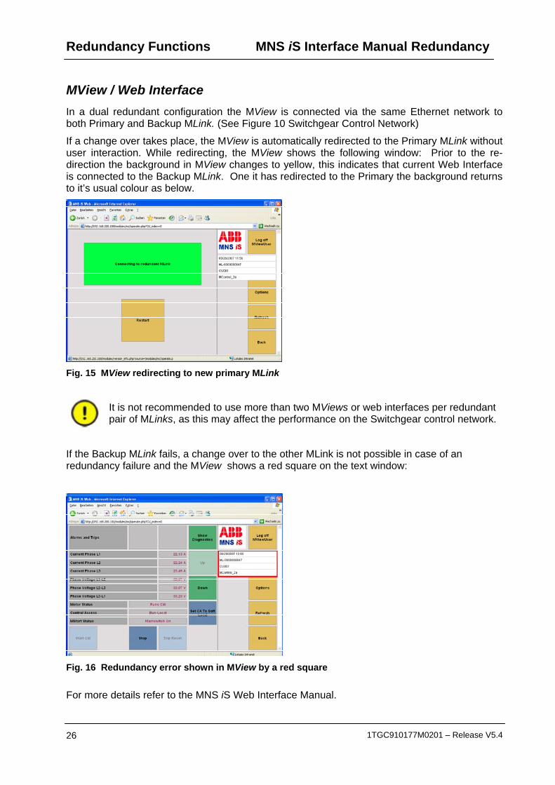
MView / Web Interface In a dual redundant configuration the MView is connected via the same Ethernet network to both Primary and Backup MLink. (See Figure 10 Switchgear Control Network)
If a change over takes place, the MView is automatically redirected to the Primary MLink without user interaction. While redirecting, the MView shows the following window: Prior to the re-direction the background in MView changes to yellow, this indicates that current Web Interface is connected to the Backup MLink. One it has redirected to the Primary the background returns to it’s usual colour as below.
Fig. 15 MView redirecting to new primary MLink
It is not recommended to use more than two MViews or web interfaces per redundant pair of MLinks, as this may affect the performance on the Switchgear control network.
If the Backup MLink fails, a change over to the other MLink is not possible in case of an redundancy failure and the MView shows a red square on the text window:
Fig. 16 Redundancy error shown in MView by a red square
For more details refer to the MNS iS Web Interface Manual.

MNS iS Interface Manual Redundancy Troubleshooting and Maintenance
1TGC910177M0201 – Release V5.4 27
Troubleshooting and Maintenance
MView or MNavigate can not communicate with both MLinks: - Check Ethernet cabling, IP address settings and network switch functionality
Redundancy Difference Report MNavigate has the functionality to generate a report listing differences between primary and backup MLinks any difference between the two can result LED 7 indication. These differences should be rectified before proceeding with other trouble shooting.
MView redundancy Status
It is possible to further review the redundancy status, this can be found utilizing MView. Please refer to the MNS iS Web Interface Manual for how to find the following information.
Fig. 17 Redundancy status displayed by MView
LED - Status Information The MLink redundancy is monitored by the status LED 8 and 7 on the front of the MLink. For more detailed information on LED status please refer to the MNS iS Interface Manual MLink.
If LEDs 7 and 11 are on: Please check the redundancy report in MNavigate and that:
- Both MLinks are powered on and running.
- Null Modem cable connection - redundancy link between both MLinks.
- Switchgear Bus connector and cable attached in a proper way to both MLinks.
Following a re-boot it could take up to 5 minutes depending on numbers of MControl and size of user data mapping table until the MLink PLC application is running and LED 7 is off.
In case LED 8 is flashing on both MLinks: - The MLinks are continuously monitoring the MControl connection. If no MControl is
connected to the MLink, a change over between both MLink is executed every 2 seconds, because neither MLink receives responses from a single MControl.
- Also occurs if only one MControl is connected and an application download is currently in progress (when booting after download, the connection to MLink is reset).
- Also occurs if multiple MControl are connected and a multiple download is currently in progress.
(cont)
Troubleshooting and Maintenance
MNS iS Interface Manual Redundancy
28 1TGC910177M0201 – Release V5.4
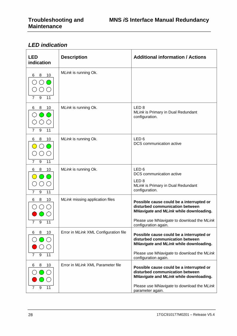
LED indication
LED indication
Description Additional information / Actions
6 8 10
7 9 11
MLink is running Ok.
6 8 10
7 9 11
MLink is running Ok.
LED 8 MLink is Primary in Dual Redundant configuration.
6 8 10
7 9 11
MLink is running Ok.
LED 6 DCS communication active
6 8 10
7 9 11
MLink is running Ok.
LED 6 DCS communication active
LED 8 MLink is Primary in Dual Redundant configuration.
6 8 10
7 9 11
MLink missing application files Possible cause could be a interrupted or disturbed communication between MNavigate and MLink while downloading.
Please use MNavigate to download the MLink configuration again.
6 8 10
7 9 11
Error in MLink XML Configuration file Possible cause could be a interrupted or disturbed communication between MNavigate and MLink while downloading.
Please use MNavigate to download the MLink configuration again.
6 8 10
7 9 11
Error in MLink XML Parameter file Possible cause could be a interrupted or disturbed communication between MNavigate and MLink while downloading.
Please use MNavigate to download the MLink parameter again.

MNS iS Interface Manual Redundancy Troubleshooting and Maintenance
1TGC910177M0201 – Release V5.4 29
6 8 10
7 9 11
Internal MLink error MLink is not able to create internal database.
Please reboot the MLink. If that doesn’t resolve the problem use MNavigate to download the MLink configuration again.
6 8 10
7 9 11
Xml file missing During startup MLink is checking if all required xml files are available. In case of a missing file that error is indicated.
Please use MNavigate to download the MLink configuration again.
6 8 10
7 9 11
Network configuration error MLink is not able to configure the IP settings as mentioned in configuration file e.g. due to wrong setting of Default Gateway parameter for that Ethernet Interface.
Please use MNavigate to check the settings and download the MLink configuration again. If a download is not possible please use a flash card reader (ref. to MNavigate Help or MNavigate Manual).
6 8 10
7 9 11
General DCS fault (only available if configured)
Please check if MLink hardware (the identity number) matches to the project specification (e.g. Profibus MLink <-> Profibus project). Furthermore the DataMapping should be checked.
Please use MNavigate to download the MLink configuration or download Mapping file again (ref. to MNavigate Help or MNavigate Manual).
6 8 10
7 9 11
General DCS fault (only available if configured)
See above LED 8 MLink is Primary in Dual Redundant configuration.
6 8 10
7 9 11
General redundancy fault (only available if configured)
Please use MNavigate to check the redundancy status (Redundancy Report) . If a mismatch was found please download the regarding file.
For details please refer to MNavigate Help or MNavigate Manual.
6 8 10
7 9 11
General redundancy fault (only available if configured)
See above LED 6
DCS communication active
Table 4 LED error indication

Contact us ABB Low Voltage Systems Publication Editor: ABB Automation Products GmbH Ladenburg, Germany Local Contacts on www.abb.com/mns
Copyright© 2009 ABB All rights reserved. Publication No. 1TGC910177M0201