mmwave radar in adas applications - ti.com · pdf file– imaging radar sensor • 2x...
TRANSCRIPT
mmWave Radar – ADAS Applications
Chethan Kumar Y.B Abdulraheem Killedar Embedded Processing ���� Radar, Analytics & Processors
1

Chethan Kumar Y. BHardware Applications Manager (SMTS) & Radar & Analytics Processors
• Career
– Masters degree in Electronics Design and Technology from Indian Institute of Science
– Joined TI as NCG and that was in the year 2000.
• Expertise
– Started career as an Analog Design Engineer and held various
positions with multiple groups within High Performance/High Volume
Analog, Wireless and Embedded Processing organizations.
– Rich experience on Analog and Mixed Signal Products in silicon,
systems and applications functions.
– Published multiple papers including best papers awards in various
internal and external conferences.
– Has two granted patents and is pursuing a few more
– Currently leads the Hardware applications team for the Auto Radar
Product line
2
Likes adventure sports and is an avid badminton player

• Career
– Masters Degree in Digital Electronics
– Over a decade of experience in Semiconductor industry
across TI, Marvel and ST Micro. Joined TI in 2011. Prior to
joining the Radar team, managed Application, Verification &
Validation teams in Processor BU for SoCs like AM335x/437x
and TDA2/3
• Expertise
– Comprehensive knowledge of “SoC Design cycle” spanning
across IP/SoC-RTL Design, Design Verification, Emulation and
Prototyping
– Pre/Post Silicon AV&V of Digital, Mixed Signal SoCs and
Applications Engineering
– Proudly ramping (finding my way) on mmWave Sensing
Applications3
Abdulraheem KilledarHardware Applications Engineer- Radar and Analytics Processors
Likes Travelling to far away corners
and spending time with his adorable
daughter

Outline � What is RADAR??
� Introduction
� Automotive RADAR applications and Challenges
� Why mmWave?
� Brief introduction to Frequency Modulated Continuous Wave RADAR(FMCW)
� System Block diagram
� TI’s mmWave RADAR solutions
� TI mmWave Journey
� Device Portfolio
� Device Architecture
� Sensor configuration with TI mmWave solutions
� Applications
�How to get started
� Introduction to EVMs
� 3rd Party Sensor modules
4

What is RADAR??
5

Yah we remember… seeing this in School ☺☺☺☺
Applications: Military,Inductrial,Automotive-ADAS …….many more!!
� Range,
� Angle (Azimuth, Elevation)
� Velocity
� Size
Observables
Types
Courtesy: Google

7

8
Types of Radar Sensing-mmWave Radars
Long-Range Radar (LRR)
76-78 GHz
1 m – 250 m
MRR & IR
26 GHz77-81 GHz
0.2 m – 160 m
Video
0 m – 80 m
Short-Range Radar (SRR)24-26 GHz and
77-81GHz
0.2 m – 80 m
Ultrasonic (US)48 kHz
0.2 m – 3 m
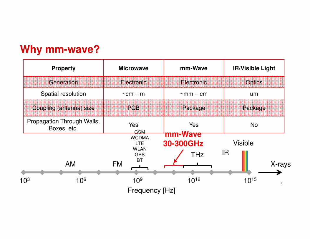
Why mm-wave?
9
Property Microwave mm-Wave IR/Visible Light
Generation Electronic Electronic Optics
Spatial resolution ~cm – m ~mm – cm um
Coupling (antenna) size PCB Package Package
Propagation Through Walls,
Boxes, etc.Yes Yes No
Frequency [Hz]
X-rays
103 106 109 1012 1015
AM FM
GSM
WCDMA
LTE
WLAN
GPS
BT
Visible
IRTHz
mm-Wave30-300GHz

Frequency Modulated Continuous Wave FMCW Radar
10
fTx(t)
fRx(t)
fIF
(few MHz)
c
Rtd
2=
Tchirp
t
B (in 100’s of
MHz or few
GHz)
FMCW – Freq vs. Time �Ability to sweep wide RF bandwidth (GHz) while keeping IF bandwidth small (MHz)
� Better range resolution. RF sweepbandwidth of 2 GHz can achieve7.5cm range resolution, while IFbandwidth can still be <15MHz
� Lower peak power requirement
Key Features
� Range precision ∝ RF (sweep) Bandwidth
� Velocity precision ∝ Dwell (frame) time� Angle precision ∝ Number of Tx,Rx
Performance

System Block Diagram
11
Ramp waveform gen.
chirp
b
chirp
cT
chirp
cT
cT
RBf
tT
Btft
tT
Bftf
2
2)(
)(
2
=
+=
+=
ππφ
f T(t
)
Beat freq = Round-trip delay * Slope
� LO is ramped linearly to produce L-FMCW transmit signal
� Received signal (from object reflections) is mixed with the same ramping LO
� Baseband ADC output is post processed in DSP
� Beat frequency (fb)-Range
� Phase shift between successive chirps -Doppler (relative velocity)
� Angle of arrival is obtained using beamforming (multiple Tx, Rx)
How does it work?

Journey & the Offering !!
12
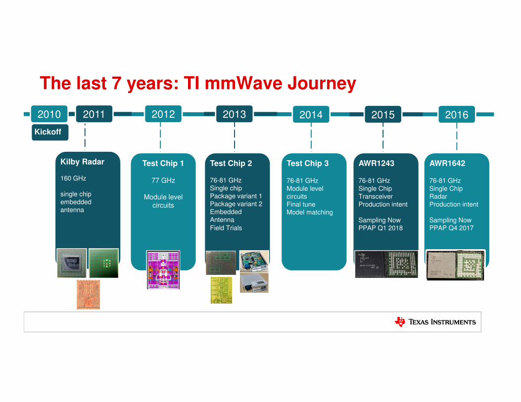
The last 7 years: TI mmWave Journey
Kilby Radar
160 GHz
single chip
embedded
antenna
Kickoff
2010 2011 2012 2013 2014 2015
Test Chip 2
76-81 GHz
Single chip
Package variant 1
Package variant 2
Embedded
Antenna
Field Trials
Test Chip 3
76-81 GHz
Module level
circuits
Final tune
Model matching
AWR1243
76-81 GHz
Single Chip
Transceiver
Production intent
Sampling Now
PPAP Q1 2018
Test Chip 1
77 GHz
Module level circuits
2016
AWR1642
76-81 GHz
Single Chip
Radar
Production intent
Sampling Now
PPAP Q4 2017

• 5cm resolution• 1° angular accuracy• Ability to distinguish two
closely placed objects• 300km/h max relative
velocity detection• Jammer avoidance from
other radars• Intelligent self monitoring
Smart, accurate radar sensors enable autonomous driving
14
CMOSmm-wave
76 – 81 GHz
Ultra high resolution
Multi-mode
Scalable
Global coverage
Robust
Single chip

76 – 81 GHz mmWave SoCs (Sampling)
Radar Sensor
• Use Cases– Imaging Radar Sensor
• 2x AR12 + External DSP
• 4x AR12 + External DSP
15
Radar Sensor + HW Accelerator
• Use Cases
– Entry-level Single-chip Radar
• Proximity warning, Blind spot
Single Chip Radar
• Use Cases– USRR Single Chip Radar
• 160 Degree, 40m
– SRR Single chip Radar
• 120m Cross traffic Alert
AW R 1 2 4 3
4RXCalibration, Monitoring
Engine
3TX Synth SPI
CSI2
AW R 1 4 4 3
4RXCalibration, Monitoring
Engine
3TX Synth
R4F
Radar Acc
576KB
SPI
CAN
AW R 1 6 4 2
4RXCalibration, Monitoring
Engine
2TX Synth
R4F
C674x
1.5MB SPI
CAN
CANFD

Scaling from front-end only to full radar integration
Received Signal
Pre-conditioning
Object detection
Range,
Doppler,
angle
estimation
Object Classification,
Tracking
DSP Cortex R4FAnalog + DFERF
•Antenna
•LNA•Mixer
•HP/LPF
•AGC/DC
•ADC
•Re-sampling
•Range FFT
•Doppler FFT
•Angle Estimation
•Object detection
•Kalman Filtering
•Object Classification
•Car network communication
AWR12x
AWR14x
AWR16x

Architecture: AWR1243 Single Chip FMCW Transceiver
17
� Highly integrated 76-81GHz front-end� 3 TX, 4 RX channels� LVDS/CSI2 interface for ADC data
output� Multi-chip cascading support� Built-in Radio (BIST) processor for RF
calibration and safety monitoring� Closed loop PLL for precise and linear
chirp synthesis� Complex baseband architecture for
improved noise figure and interference tolerance
� Flexible Ramp Generator and Digital front-end supporting multiple chirp profiles
� Wide IF bandwidth (15MHz) and reconfigurable output sampling rates
Overview

Architecture: AWR1443 Single Chip Proximity Sensor
18
� Single chip proximity Sensor
� IF bandwidth – 5MHz
� Highly integrated 76-81GHz radar
frontend
� 3 TX, 4RX channels
� Multiple automotive interfaces
� Built-in Radio (BIST) processor for RF
calibration and monitoring
� Programmable lock step R4F MCU
� Integrated hardware accelerators
Overview

Architecture: AWR1642 Single Chip RADAR Sensor
19
� Highly integrated 76-81 GHz radar
frontend
� 2 TX, 4RX channels
� Multiple automotive interfaces
� Built-in Radio (BIST) processor for RF
calibration and monitoring
� Programmable lock step R4F MCU
� High performance C67 DSP
� ASIL B capable
Overview

20
Comparison: AWR1642/AWR1443/AWR1243
LNA
LNA
LNA
LNA
PA
ADC
ADC
ADC
ADC Decim
ation F
ilters
chain
AGC/DC est.
Cleanup
PLL
Synthᶲ Chirp Gen
Oscillator
Crystal
TX x2
RX x4
PA ᶲ
X4
GPADC Buf Cortex
R4F
PRAMD
R
A
MDMA
Ramp gen RTI/WD, TIMER
C674x
L1P
UMC
L1D
EMC
L2 RAM
EDMAx4
Handshake RAM1
Handshake RAM2
ADC buffersADC buffers
LVDS
CRC
DMM
MDO
Cortex 4F
DRAM PRAM
DMAx2
ECU
Interface
Boot ROM
STC
MailBox
IOs
JTAG/TracenReset
Test/Debug VMON
L3 RAM
HIL
SPI/I2C
CANFD
QSPI
Safety MCU/PMIC
Flash Interface
nError
RTI/WD, TIMER
DCAN
SPI
CSI2
Safety MCU
Sync
ESM
Uart1,2,3
Temp
Cryptography
Development
Interfaces
Uart4
Development Interface
Ctl Registers
DFE
FFT Engine
RTI/WD, TIMER
GPADC
CRC High speed raw data
PA ᶲ

Software Offering - High Performance RADAR Front end
21
AWR1243External
Processor
Control Interface(SPI and GPIOs)
Data InterfaceLVDS or CSI2
ECU Interface
Firmware is Embedded Platform Software (SDK)
• Control is via messages over SPI• mmWaveLink: TI offers driver with
APIs that abstract these messages
Software Offering mmWave Device Firmware Package
(DFP)
TI TDAx
Radar
SDK

Software Offering - Single Chip RADAR Sensor
22
AWR1443
AWR1642
ECU Interface
Software Offering mmWave Software Development Kit
ECU InterfaceMCU
HWA - FFT
MCU
DSP
SFLASH
SFLASH
Platform Software
• RTOS
• Device Drivers
• Tools (Image Creation, Flashing etc..)
• Sample Applications
• APIs and Processing Libraries

TI Confidential – NDA Restrictions
Satellite
Configuration
Sensor configuration with TI mmWave solutions
23
SRR
AWR1642
CORNER/MRR
AWR1243
Processor
AWR1243
USRR
AWR1642
Proximity
AWR1443
IMAGING
AWR1243 AWR1243 AWR1243 AWR1243
Processor
LRR
AWR1243
Processor
AWR1642
Processor
AWR1642
CANFD
AWR1642AWR1642

TI Confidential – NDA Restrictions
Applications
24
•Adaptive Cruise Control
•Automated Highway Driving
150 m +
RCS: 10 – 50sqm
•Automated Emergency Braking
•Automated Urban Driving
100 m – 150 m
RCS: 1 – 10sqm
•Pedestrian Detection
•Bicyclist Detection
•BSD, RCA, LCA
20 m – 100 m
RCS: 0.1 – 1sqm
•Proximity warning
•Parking
•Stop and Go Traffic
5 m – 20 m
RCS: 0.1sqm
•Proximity warning
•Chassis sensors
•Gesture detection
•Driver monitoring
•Occupant detection
2 cm – 5 m
RCS: micro sqm
Single chip
solution
Works with
external
MCU/DSP
AWR1243
AWR1443 AWR1642
AWR1443 AWR1642
AWR1642
AWR1243

Trend in Radar sensors
25
77 GHZ LRR
Micro + MMIC
77 GHZ MRR
Micro + MMIC
24 GHz SRR
Micro + MMICSingle Chip 76-81 GHz
4RX 3TX
Cascaded 77 GHz
(8+)RX (6+)TX
Signal Processor
Today 2021
+ NCAP, Surround
Radar, Park Assist
+ Highly Automated
Driving

TI Confidential – NDA Restrictions
26
SILICON
TOOLS
& KITS
SUPPORT
TI DESIGNSTRAINING
ECOSYSTEM
PARTNERS
I N D U S T R I A L A U TO M O T I V E
A N A LYT I C S M A C H I N E V I S I O N
Delivering mmWave sensing solutions
mmWaveStudio
mmWave
SOC
mmWaveSDK
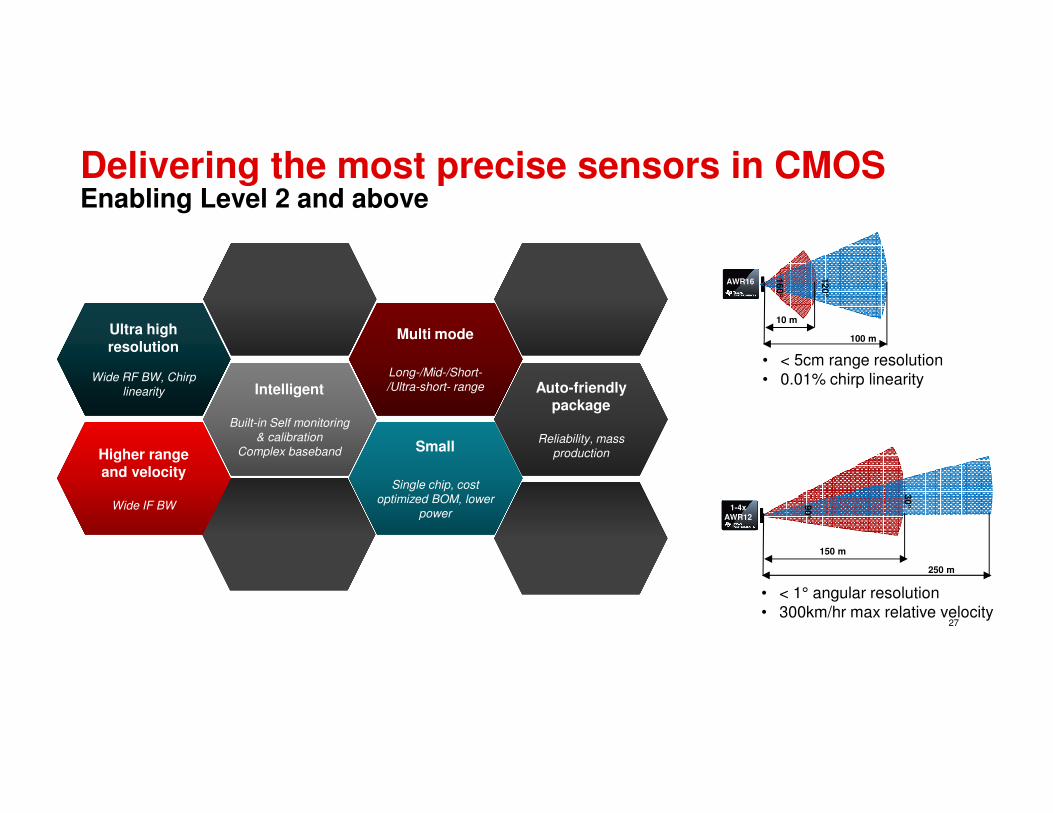
Delivering the most precise sensors in CMOSEnabling Level 2 and above
27
AWR16
10 m
100 m
120°
160°
1-4xAWR12
150 m
250 m
30°9
0°
• < 5cm range resolution
• 0.01% chirp linearity
• < 1° angular resolution
• 300km/hr max relative velocity
Ultra high resolution
Wide RF BW, Chirp
linearity
Ultra high resolution
Wide RF BW, Chirp
linearity Intelligent
Built-in Self monitoring
& calibration
Complex baseband
Intelligent
Built-in Self monitoring
& calibration
Complex baseband
Auto-friendly package
Reliability, mass
production
Auto-friendly package
Reliability, mass
production
Multi mode
Long-/Mid-/Short-
/Ultra-short- range
Multi mode
Long-/Mid-/Short-
/Ultra-short- range
Higher range and velocity
Wide IF BW
Higher range and velocity
Wide IF BW
Small
Single chip, cost
optimized BOM, lower
power
Small
Single chip, cost
optimized BOM, lower
power

Competing Technologies!
28

29
Adapted from Kunert, MOSARIM W23 at EuMW 2012
24G
Hz
NB
Rad
ar
24G
Hz
UW
B
Rad
ar
76-
81G
Hz
Rad
ar
Mo
no
Vid
eo
Ste
reo
Vid
eo
Far/
Nea
r IR
Sen
so
r
Laser
Scan
ner
Ult
raso
nic
Range < 2m
Range > 100m
Angular resolution
Object separation/discrimination
Object classification
Direct velocity measurement
Operation in dust/fog/snow
Dazzling sunlight
Day and night
Sensor blockage due to dirt
Mounting/surface coverconstraints
Regulatory constraints
Effect on vehicle aesthetics
Sensor data fusion capability
Competing Technologies
� Object Classification� Better Angular resolution� High Processing bandwidth
Stereo Camera
� Best in class angular resolution� Slower scan ~20Hz� Expensive
Lidar
� Cost Effective� Large sensors, � Can’t be placed under bumper
Ultrasonic
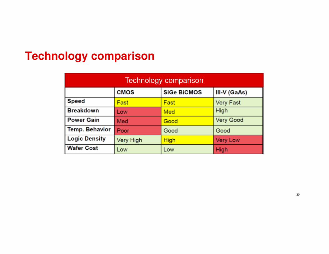
Technology comparison
30
Technology comparison

Basic Transistor Comparison
31

Lets get started & WIN….
32

TI Confidential – NDA Restrictions
Hardware Platforms
33
• Enables evaluation of single chip radar
• Proximity sensor demo on AWR1443 EVM
• SRR demo on AWR1642 EVM
AW R 1 2 4 3 + T D A3 xAW R 1 2 4 3 + T S W 1 4 0 0AW R 1 4 4 3 / AW R 1 6 4 2 E V M
AW R 1 4 4 3 / AW R 1 6 4 2 S e n s o r m o d u l e
• Enables RF performance evaluation
• Raw ADC capture into PC and then post process
• mmWave Studio to visualize object range/velocity/angle
• Enables radar algorithm and MRR/LRR application development on TDA3x
• Enables vehicle validation/demonstration
• Enables radar algorithm and proximity/SRR application development on AWR1443/ AWR1642
• Enables vehicle validation/demonstration

EVMs-AWR1243/AWR1443/AWR1642
34
� The Booster Pack� Rogers RO4835 material� Antenna on board � XDS110 based JTAG emulation � On board QSPI flash for application code
storage.� UART through USB to PC for debug logging.� On-board CAN transceiver for AWR1443 &
CAN/CANFD for AWR1642.� Provision for ADC raw data transfer over
LVDS/CSI.� leverages the Launchpad ecosystem� 5V power jack to power the board
Key Features
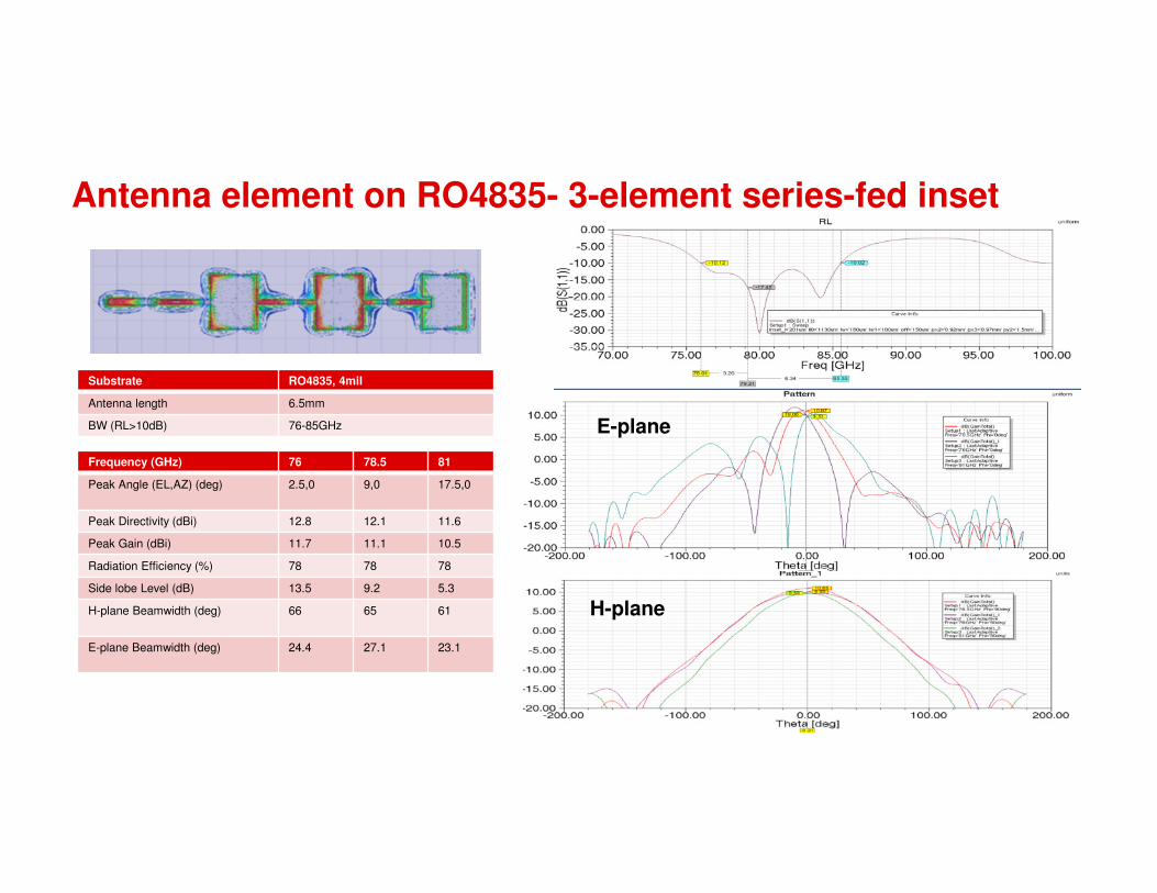
Antenna element on RO4835- 3-element series-fed inset
35
Frequency (GHz) 76 78.5 81
Peak Angle (EL,AZ) (deg) 2.5,0 9,0 17.5,0
Peak Directivity (dBi) 12.8 12.1 11.6
Peak Gain (dBi) 11.7 11.1 10.5
Radiation Efficiency (%) 78 78 78
Side lobe Level (dB) 13.5 9.2 5.3
H-plane Beamwidth (deg) 66 65 61
E-plane Beamwidth (deg) 24.4 27.1 23.1
Substrate RO4835, 4mil
Antenna length 6.5mm
BW (RL>10dB) 76-85GHz E-plane
H-plane

Debug Devpack
36
Key Features
� Micro USB Powered.� PC interface through on board FTDI for SPI,
GPIO controls & UART loggers� 120pin connector to interface with TDA3 EVM
(via DIB and VAB boards) and the TSW1400� 20 pin LaunchPad connectors for Control
signals to/from the AWR1443 EVM� 60 pin high density (HD) connector to get the
high speed ADC data over CSI or LVDS interface from the Booster-Pack..
� 60pin MIPI connector for JTAG trace (for AWR1642 ONLY)
� Header for DMM interface (for AWR16XX device ONLY).
� Second CAN connector (for AWR1642 device ONLY).

ADC data capture solution: TSW1400
37
TSW1400
�Altera Stratix IV based FPGA generic ADC data capture board.
�Supports 900MBPS Serial LVDS capture on 7 Pairs of LVDS pins.
�512MB of on board storage space�Supports capture and post processing in RT3 directly.�Supports single-tone, multi-tone signal performance
analysis�Supports up to 16 converter channels simultaneously �Capability to feed CMOS parallel data using DAC
interface.
Key Features
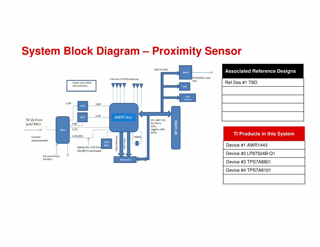
System Block Diagram – Proximity Sensor
Associated Reference Designs
Ref Des #1 TBD
TI Products in this System
Device #1 AWR1443
Device #2 LP87524B-Q1
Device #3 TPS7A8801
Device #4 TPS7A8101
AWR14xx

System Block Diagram – Short Range Sensor
Associated Reference Designs
Ref Des #1 TIDEP0092
TI Products in this System
Device #1 AWR1642
Device #2 LP87524B-Q1
Device #3 TPS7A8801
Device #4 TPS7A8101
AWR16xx
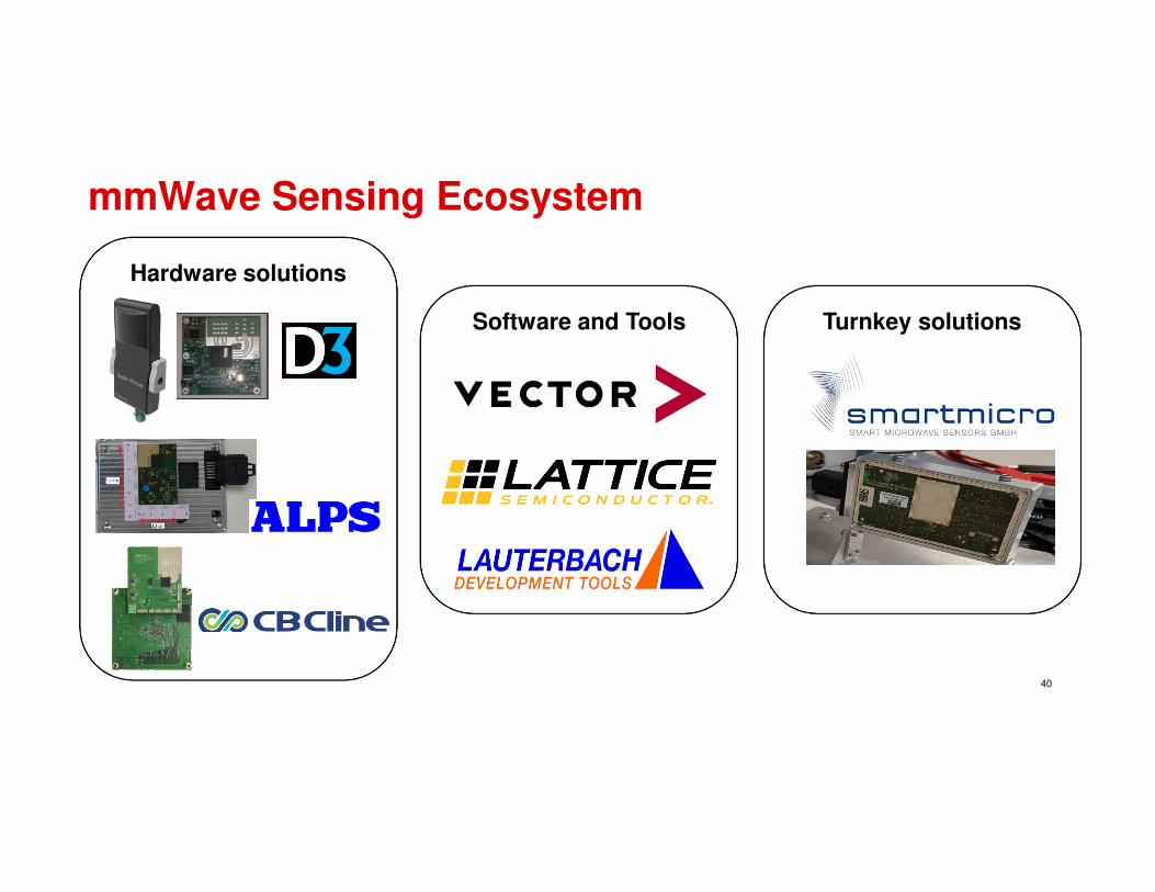
mmWave Sensing Ecosystem
40
Hardware solutions
Software and Tools Turnkey solutions
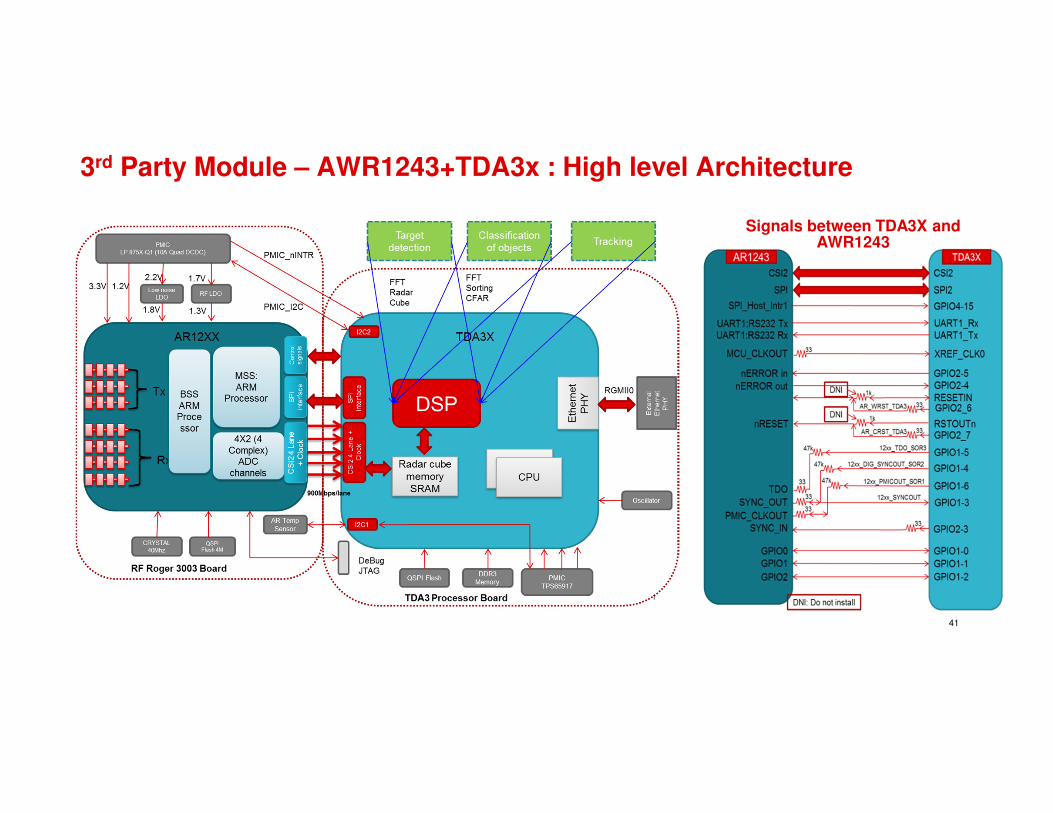
3rd Party Module – AWR1243+TDA3x : High level Architecture
41
Signals between TDA3X and AWR1243

3rd Party Modules ALPS : Sensor Module
42
Simplified block diagram
� Supports Radar system development on TDA3X + AWR1243 Platform
� Supports Multiple antenna configuration: 2 Flavors of RF Boards
� RJ45 Connector based Ethernet support
� 60 pin MIPI connector with Trace debug capability
� Single Power supply Module with Aluminum casing acting as heatsink
Key Features

Design kit availability
43
Silicon
EVM
• TI(Ecosystem partner) built reference HW
RF tool
• Signal Path analysis, Radiative measurements
HDK
• Reference Schematic/Layout, BOM, RF Model, Thermal Model
SDK
• Firmware, Device drivers, Operating system, Development environment
√(PPAP)June 2018
√(PPAP)June 2018
√(PPAP)Jan 2018
√ √ √
√ √ √
√ √ √
√ √ √
AWR1443 AWR1642AWR1243

Thank you

Back up