mmics for multi pixel receivers a. cremonini · mmics for multi pixel receivers a. cremonini i n a...
TRANSCRIPT

Workshop on Receivers & Arrays 2010 -19,20 September 2010, MPIfR/Bonn
INSTITUTE of RADIOASTRONOMY
I N A F
MMICs for multi pixel receivers
A. Cremonini
I N A F

Workshop on Receivers & Arrays 2010 -19,20 September 2010, MPIfR/Bonn
INSTITUTE of RADIOASTRONOMY
I N A F
Outline
o Introduction
o MMICs
o Semiconductor technology
o Scenario
o Examples of MMICs used in array receivers for radioastronomy
o Projects in progress
o Remarks on MMIC based devices
o Conclusions

Workshop on Receivers & Arrays 2010 -19,20 September 2010, MPIfR/Bonn
INSTITUTE of RADIOASTRONOMY
I N A F
The evolution of instruments for radioastronomical observation is nowadays strongly
oriented on developing and exploiting the array concept.
Array of antennas
Introduction
VLA ATCA ALMA SKA
Array of receivers
C-band Ka-Band K-band
Workshop on Receivers & Arrays 2010 -19,20 September 2010, MPIfR/Bonn
INSTITUTE of RADIOASTRONOMY
I N A F
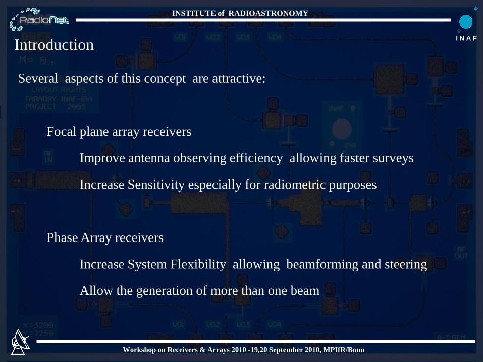
Several aspects of this concept are attractive:
Focal plane array receivers
Improve antenna observing efficiency allowing faster surveys
Increase Sensitivity especially for radiometric purposes
Phase Array receivers
Increase System Flexibility allowing beamforming and steering
Allow the generation of more than one beam
Introduction

Workshop on Receivers & Arrays 2010 -19,20 September 2010, MPIfR/Bonn
INSTITUTE of RADIOASTRONOMY
I N A F
In the technologies applied to radioastronomy interest in MMICs
grows as the needs of low cost, small scale production,
high integrated solution.
Hybrid devices, created with discrete components provide paramount
performances, but the realisation on large scale has high
cost, assembling time, reliability strictly related on
manufacturing.
MMICs

Workshop on Receivers & Arrays 2010 -19,20 September 2010, MPIfR/Bonn
INSTITUTE of RADIOASTRONOMY
I N A F
MMICs performances are less human skills dependant
MMICs developing cost is higher
MMICs is less expensive for small mass production
MIC vs MMIC
Active devices are manufactured using the same process
Active device
selection is possible
MMICs selection is
possible
Passive Catalog is the
entire market
Passive Catalog is
limited by foundry
process
MMIC is a MUST for mass
production
And
MIC “fine Art” Skills are a MUST in
order to maximize MMICs
performances exploitation

Workshop on Receivers & Arrays 2010 -19,20 September 2010, MPIfR/Bonn
INSTITUTE of RADIOASTRONOMY
I N A F
MMIC technology allows to include in a single chip several active
and passive components in order to realise a function or a
set of functions.
Fundamental requirements are:
Low power consumption
Low noise
An asset for radioastronomical application : CryoREL
Assets:
Lower cost
Fast production
Higher repeatability and reliability

Workshop on Receivers & Arrays 2010 -19,20 September 2010, MPIfR/Bonn
INSTITUTE of RADIOASTRONOMY
I N A F
Semiconductor technology
InP HEMT
o Best consolidated process for noise and cryo applications
o State of the art at 35nm with applications up to 350 GHz
InP mHEMT
o InP on GaAs : one more degree of freedom in the process
o EU foundries, no ITAR , no geopolitical availability dependency
o Preliminary cryo results in Q and W band
InSb HEMT Extremely Low power consumption .
Could be the future for Large arrays cryogenic applications

Workshop on Receivers & Arrays 2010 -19,20 September 2010, MPIfR/Bonn
INSTITUTE of RADIOASTRONOMY
I N A FScenario
InP HEMT
NCG
HRL
InP mHEMT
IAF (D)
OMMIC (F)
InP , InSb HEMT
Chalmers Univ. (S)
OPTEL (I)
UMAN (UK)
ETH (CH)

Workshop on Receivers & Arrays 2010 -19,20 September 2010, MPIfR/Bonn
INSTITUTE of RADIOASTRONOMY
I N A F
Some examples of MMICs
used on Array receivers for
radioastronomy

Workshop on Receivers & Arrays 2010 -19,20 September 2010, MPIfR/Bonn
INSTITUTE of RADIOASTRONOMY
I N A F
Medicina
VLBI 32m
Designed By INAF-IRA
Tested on 32 mt Medicina radiotelescope
Final Destination 64mt SRT
FARADAY
• Multifeed Focal Plane Array
• 7 Horns - 14 Channels
• Working from 18-26 GHz
• For Secondary Focus
• Heterodyne architecture
• Cryogenically cooled

Workshop on Receivers & Arrays 2010 -19,20 September 2010, MPIfR/Bonn
INSTITUTE of RADIOASTRONOMY
I N A FMMICs application :LNAs
NGC 0.1 InP HEMT
14 Cryo LNAs
14 “warm” LNAs
Noise Performances 4245-020 22LNA_07A
60
100
140
180
220
260
300
340
15,5
16,5
17,5
18,5
19,5
20,5
21,5
22,5
23,5
24,5
25,5
26,5
Frequency [GHz]T
e [
K]
020201 020201 High Accuracy Simulated
5 7 9 11 13 15 17 19 21 23 25 27 29 31 33 35
Frequency (GHz)
Spar 22LNA07A 020201
-60
-40
-20
0
20
-30
-15
0
15
30
DB(|S[1,1]|) (R)
020101 1V35-18mA
DB(|S[2,1]|) (L)
020101 1V35-18mA
DB(|S[2,2]|) (R)
020101 1V35-18mA
Cryo LNA
“Warm” LNA

Workshop on Receivers & Arrays 2010 -19,20 September 2010, MPIfR/Bonn
INSTITUTE of RADIOASTRONOMY
I N A F
MMICs Extra results
NGC 0.1 InP HEMT
7 Cryo LNAs Designs between 4 to 120 GHz
4-8 Ghz
8 - 12 Ghz
26 - 40 Ghz
33-50 Ghz
70 - 100 Ghz60-85 Ghz

Workshop on Receivers & Arrays 2010 -19,20 September 2010, MPIfR/Bonn
INSTITUTE of RADIOASTRONOMY
I N A FOCRA-F
• Multifeed Focal Plane Array receiver
• 8 (later 16) Beams
• Working from 26-36 GHz
• Pseudo correlation Direct Detection Architecture
• Cryogenically cooled
Designed By JBO (UK)
Final Destination Torun (PL)

Workshop on Receivers & Arrays 2010 -19,20 September 2010, MPIfR/Bonn
INSTITUTE of RADIOASTRONOMY
I N A F
MMICs application :LNAs, Phase switches
NGC 0.1 InP HEMT
8 Cryo LNAs
8 Cryo phase switches
FARADAY MMIC LNA #1. Noise temperature and gain
measurements Tlna = 15 K 27.08.04
0
20
40
60
80
100
26 28 30 32 34 36
Frequency GHz
Te K
Te K
MMIC Phase switch #2 @ 18 K. phase shift between states.
08.10.04
0
20
40
60
80
100
120
140
160
180
26 28 30 32 34 36
Frequency GHz
deg
s
-45
-35
-25
-15
-5
5
15
25
35
45
dB
phase diff
magnitude diff
average across
10Ghz BW =
170degs

Workshop on Receivers & Arrays 2010 -19,20 September 2010, MPIfR/Bonn
INSTITUTE of RADIOASTRONOMY
I N A F
Facilities : JBO
Design :Pharos Consortioum leaded by ASTRON
Pharos
• Vivaldi Dense Phased Array
• 4 beams electronically formed and steered
• Single polarisation
• Working from 4 to 8 GHz
• For Primary Focus
• Cryogenically cooled
Workshop on Receivers & Arrays 2010 -19,20 September 2010, MPIfR/Bonn
INSTITUTE of RADIOASTRONOMY
I N A F
Facilities : JBO
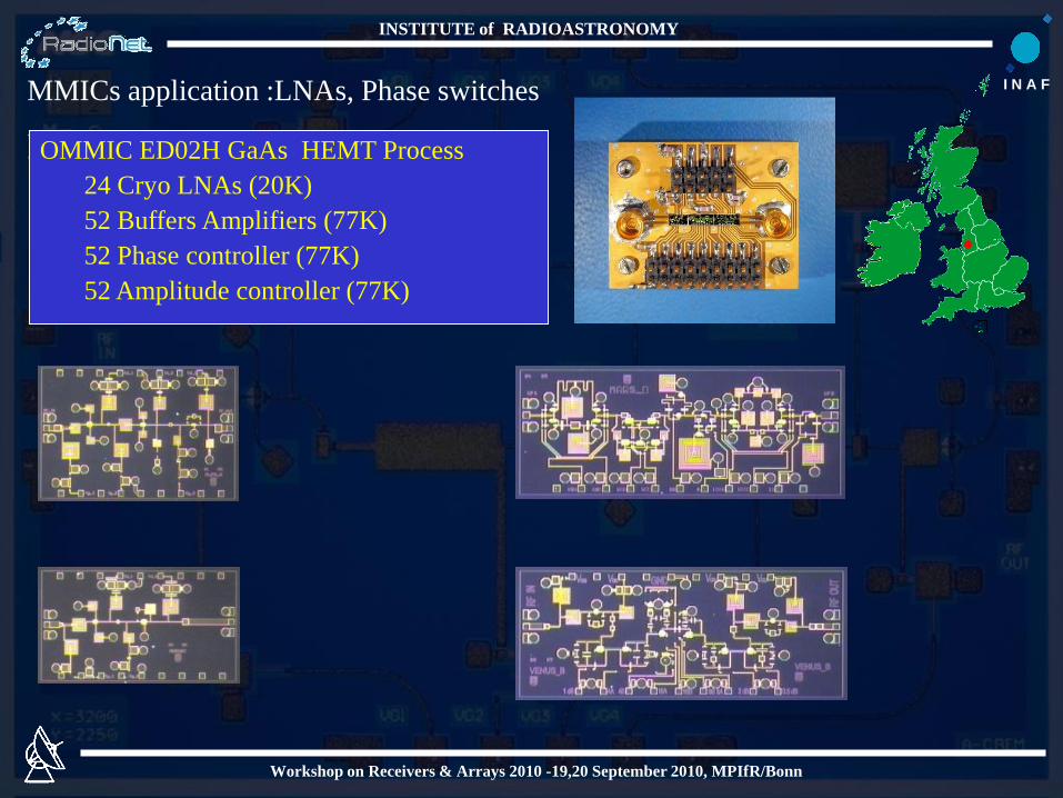
MMICs application :LNAs, Phase switches
OMMIC ED02H GaAs HEMT Process
24 Cryo LNAs (20K)
52 Buffers Amplifiers (77K)
52 Phase controller (77K)
52 Amplitude controller (77K)

Workshop on Receivers & Arrays 2010 -19,20 September 2010, MPIfR/Bonn
INSTITUTE of RADIOASTRONOMY
I N A FPharos MMICs Extra results
OMMIC D007IH 70 nm InP on GaAs mHEMT Process
Q-band LNA
W-band LNA
30 35 40 4525 50
5
10
15
20
25
30
35
0
40
freq, GHz
|S2
1| (d
B)
30 35 40 4525 50
-15
-10
-5
0
5
-20
10
freq, GHz
|S1
1| (d
B)
-20
-10
0
10
20
30
40
75 85 95 105
[dB
]
freq. [GHz]
GaAs 70nm LNA, Flanged, 300KIRL
ORL
Gins

Workshop on Receivers & Arrays 2010 -19,20 September 2010, MPIfR/Bonn
INSTITUTE of RADIOASTRONOMY
I N A F
Projects in Progress

Workshop on Receivers & Arrays 2010 -19,20 September 2010, MPIfR/Bonn
INSTITUTE of RADIOASTRONOMY
I N A F
Apricot (All Purpose Radio Imaging Cameras on Telescopes)
Design a MMIC Q band heterodyne receiver chipset using mHEMT
foundry process available at OMMIC and IAF
LNA
Mixing
Multiplier
FP7 Project funded within Radionet
Partners: UMAN, MPfIR,IRA,UTV, CAY, TCfA, FG-IGN
Aim : Define architecture and validate technologies for multi
purposes large format focal plane “radio camera”
Frequency range : 33-50 GHz (Q-Band).

Workshop on Receivers & Arrays 2010 -19,20 September 2010, MPIfR/Bonn
INSTITUTE of RADIOASTRONOMY
I N A F
ASImm
Design W-band devices radiometric purposes using OMMIC MMIC
mHEMT foundry process and IAF mHEMT foundry process
Improve Packaging and Assembling Techniques
Project funded by ASI (Italian Space Agency)
Partners: Thales (as prime contractor), Officine Pasquali
INAF, UNI-MI, UNI-GE, UNIROMA1,CNR
Aim : Validate technologies for future space experiments
Frequency range : W-band

Workshop on Receivers & Arrays 2010 -19,20 September 2010, MPIfR/Bonn
INSTITUTE of RADIOASTRONOMY
I N A F
Remarks on MMIC based
devices

Workshop on Receivers & Arrays 2010 -19,20 September 2010, MPIfR/Bonn
INSTITUTE of RADIOASTRONOMY
I N A F
MMIC Design
MMIC is a ensemble of active
and passive elements
MMIC is NOT a receiver
COMPONENT but a PART OF
IT
This could be a MMIC designer
trap
Noise Performances 4245-020 22LNA_05A
60
100
140
180
220
260
15,5
16,5
17,5
18,5
19,5
20,5
21,5
22,5
23,5
24,5
25,5
26,5
Frequency [GHz]
Te [
K]
050201 050201 High Accuracy Simulated

Workshop on Receivers & Arrays 2010 -19,20 September 2010, MPIfR/Bonn
INSTITUTE of RADIOASTRONOMY
I N A F
Wiring
100 Dual Polarization channels at WR-22
200 four stages LNAs
1800 Wires
Separate stage biasing is
important in order to compensate
the temperature effect and find
the best trade off between noise,
gain , match and... Oscillations100 Dual Polarisation channels at WR-10
200 + 200 five stages LNAs
4400 Wires
Embed a cryogenic bias supply
“remotely controlled”
Improve cryomodels and
Foundry process
Release flexibility specifications

Workshop on Receivers & Arrays 2010 -19,20 September 2010, MPIfR/Bonn
INSTITUTE of RADIOASTRONOMY
I N A F
MMIC Packaging
Housing could waste most of efforts devoted in MMIC design in order to obtain
state of the art results
Housing has influence on
Self resonances
Matching (Gain and Noise)
Reliability
For Cryogenic MMICs devices,
Differential CTE between all the
joined elements MUST be
carefully taken into account ,
because STRESS between
components can DAMAGE them
Crucial Aspects are:
Housing Alloys
Attaching method
The choice is not unique BUT is
APPLICATION DEPENDANT

Workshop on Receivers & Arrays 2010 -19,20 September 2010, MPIfR/Bonn
INSTITUTE of RADIOASTRONOMY
I N A F
Conclusion
o Array receiver architecture make the MMIC opportunity more than
attractive. Several examples of array receivers already prove it.
o Semiconductor scenario give several opportunity to exploit MMIC
potentiality
o Excellent MMIC design is a necessary starting point but it is not
SUFFICIENT
o MIC designers experiences and manufacturer skillness are
NECESSARY in order to realise the devices
o Radioastronomy can get many advantages by MMICs
o Developing an MMIC foundry process oriented to cryogenic
radioastronomical applications is NOT a foundry mainstream
o MMICs R&D on foundry process and on devices is EXPENSIVE
o Radioastronomical community MUST SYNERGICALLY INVEST on it

Workshop on Receivers & Arrays 2010 -19,20 September 2010, MPIfR/Bonn
INSTITUTE of RADIOASTRONOMY
I N A F
Research Groups involved in the described activities
I N A F
PHAR S
Workshop on Receivers & Arrays 2010 -19,20 September 2010, MPIfR/Bonn
INSTITUTE of RADIOASTRONOMY
I N A F
Thanks
For your attention
A. Cremonini