mmaaiinn rreeppoorrtt && aannnneexxuurree · email : [email protected] website : ....
TRANSCRIPT
Improving & Revamping the Existing / Proposed
Water Supply Distribution System with Continuous
Pressurized Supply to Coimbatore Corporation
MMaaiinn RReeppoorrtt && AAnnnneexxuurree
VVoolluummee –– II ((aa))
JUNE 2013 APRIL 2017
FICHTNER Consulting Engineers India Pvt. Ltd.
Menon Eternity, 9th Floor, No, 165, St.Marys Road
Alwarpet, Chennai - 600018
Tel : +91 – 044 – 45932600, Fax : + 91 – 044 - 45932809
Email : [email protected]
Website : www.fichtner.co.in

Coimbatore Water Supply System Detailed Project Report - Revision I
Improving & Revamping the Existing / Proposed WSS JNNURM
i
List of Contents
Chapters and Appendices
LIST OF ANNEXURES
LIST OF DRAWINGS v
LIST OF TABLES xv
LIST OF FIGURES xviii
PROJECT SUMMARY 21
1 Sector Background, Context & Broad Project Rationale 25
1.1 Project Site Appreciation 25
1.1.1 Physical & Geographical Characteristics 25
1.1.2 Topography 26
1.1.3 Geology 26
1.1.4 Soil 26
1.1.5 Structure & Tectonics 26
1.1.6 Weathering 26
1.1.7 Alluvium & Kankar 26
1.1.8 Climate and Rainfall 26
1.1.9 Industrial Activities 27
1.1.10 Existing Status of Physical Infrastructure 27
(i) Status of Water Supply Infrastructure 27
(ii) Source - Pillur (Bhavani River) source 28
(iii) Source - Siruvani River Source 30
(iv) Present Water Distribution Zones 30
(v) Master Service Reservoirs 31
(vi) Service Reservoirs 31
(vii) Existing Water Distribution System 34
1.1.11 Seismicity 40
1.1.12 Groundwater Quality and Quantity 41
1.1.13 Financial Status of the Local Body 41
1.1.14 Sewerage Infrastructure 41
1.1.15 Sewage Farms 42
1.1.16 Storm Water Drains 42
1.1.17 Solid Waste Management 43
1.1.18 E-Governance 43
1.1.19 Web site 43
1.2 Existing Tariff and Cost Recovery 44
2 Project Definition, Concept and Scope 45
2.1 Project Area 45
Coimbatore Water Supply System Detailed Project Report - Revision I
Improving & Revamping the Existing / Proposed WSS JNNURM
ii
2.2 Scope of Work 45
2.3 Objectives 45
2.3.1 Objective: A 45
2.3.2 Objective: B 46
2.4 Selection of Design Basis 47
2.4.1 Flow Reliability Analysis on Pillur Source 47
2.5 Deficiencies of the Existing Water Supply System 51
2.6 Project Benchmarks 52
2.7 Need for the Project 52
2.8 Technical Solutions towards Project Benchmarks 55
2.8.1 Methodology for 24 X 7 WSS 55
(i) Back drop drawing 55
(ii) Operational Zones 55
(iii) District Metering Areas 56
(iv) Hydraulic Model 56
(v) Simulation of DMAS 56
(vi) Bulk Water Meters and Consumer Water Meters 57
2.8.2 Instrumentation for 24 X 7 WSS 57
2.8.3 Disinfection Process for 24 X 7 WSS 61
2.8.4 24 X 7 Customer Care Centre 61
2.8.5 Introduction of Volumetric Rational Tariff 61
2.9 Physical Infrastructure Components 61
2.9.1 Formulation of Design Basis 61
(i) Design Parameters 61
(ii) Population Projection 62
(iii) CDP Observations for Demand Projection 63
(iv) Topographical Survey 81
(v) Soil Investigation 81
(vi) Zoning of Distribution System 84
(vii) Distribution System Network 84
(viii) Consumption Peak Factor 84
(ix) Minimum Residual Head 85
(x) Utility of Existing Pipes 85
(xi) Network Analysis for Looped Distribution System 85
(xii) Elimination of Public Fountains 86
(xiii) Pipe Material 86
(xiv) Trench Size for Pipe Laying 87
(xv) Service Reservoirs 87
(xvi) House Service Connections 87
2.9.2 Field Investigations Done 88
2.9.3 Detailed Engineering Design - Feeder Main System 92
(i) Existing Feeder Main System 93
(ii) Existing Problems in Feeder Main Systems 95

Coimbatore Water Supply System Detailed Project Report - Revision I
Improving & Revamping the Existing / Proposed WSS JNNURM
iii
(iii) Proposed Feeder Main System 96
(iv) Proposed Feeder Main Alignment 97
(v) Appurtenances Proposed 113
1. Sluice Valve 113
2. Scour Valve 113
3. Air Valve 113
4. Flow Regulating Valves 114
5. Bulk Water Meters and Data Loggers 114
(vi) Observations on Hydraulic Design of Feeder Mains 115
2.9.4 Interlinking of Pillur MSR and Siruvani MSR 117
(i) Appurtenances Proposed 118
1. Sluice Valve 118
1. Scour Valve 118
2. Air Valve 118
2.9.5 Detailed Engineerign Design – Distribution System 119
(i) Zoning of the Project Area 119
1. North Zone 119
2. West Zone 120
3. South Zone 120
4. East Zone or Demo Zone I & II 120
(ii) Rezoned Boundaries 121
(iii) Propsoed Pipe Materials & Sizes 121
(iv) Service Reservoirs 140
(v) Abandoned Sumps & SRs 157
(vi) Appurtenances Proposed 157
1. Sluice Valve 157
2. Scour Valve 158
3. Air Valve 158
4. Pressure Control Valves and Bulk Water Meter 158
2.9.6 Automation of Distribution System – SCADA 159
(i) Introduction 159
(ii) Scope of work 159
(iii) System Design 160
(iv) Proposed System 160
1. SRs / GLSRs in Distribution Network 160
2. Central SCADA Station at MSRs 161
2.9.7 Clearances Required From Other Agencies 162
2.10 Environmental Impact Assessment 162
2.10.1 Objective of EIA 162
2.10.2 Legal and Policy Framework 163
2.10.3 Environmental Assessment and Review Process 163
2.10.4 National Regulations 163
2.10.5 Necessity for this EIA Study 166
2.10.6 Broad Paradigms for Mitigation Plan 167
2.10.7 Resettlement and Rehabilitation Issues 168
Coimbatore Water Supply System Detailed Project Report - Revision I
Improving & Revamping the Existing / Proposed WSS JNNURM
iv
2.10.8 Management of Noise Impacts 168
2.10.9 Managing Impacts due to Construction Machinery 168
2.10.10 Managing Impact of Air Pollution 169
2.10.11 Environmental Monitoring 176
2.10.12 Impact during Design Phase 178
2.10.13 Impact during Construction Phase 179
2.10.14 Impact during Operation Phase 181
2.10.15 Impact Identification Matrix 181
2.10.16 Environmental and Social Classification 183
2.10.17 Specialized Services for PMC and Quality Assurance 183
3 Project Cost 184
3.1 Basis of Costing 184
3.2 Land acquisition / Site Development 184
3.3 Physical Infrastructure Component Cost 184
3.4 Rehabilitation & Resettlement Cost 187
3.5 Project Costing 187
3.6 Annual Operation and Maintenance Costs 187
3.7 Institutional Strengthening 189
3.7.1 Training to be imparted 189
4 Project Institution Framework 191
4.1 Roles of Different Institutions 191
4.2 Roles and Responsibility Matrix 192
4.2.1 Role of the Government of Tamilnadu (GoTN) 192
4.2.2 Role of the Coimbatore Water Supply Sector 192
4.2.3 Role of the Coimbatore City Corporation (CCC) 193
4.3 Overall Financial Structuring of the Project 193
5 Project O&M Planning 195
5.1 Institution Framework (Organization & Operations) Strategy 195
5.2 Selection of O&M Operator 195
5.2.1 Preventive Maintenance 195
5.2.2 Quality of Materials 197
5.2.3 Maintenance of Service Reservoirs 197
5.2.4 Maintenance of Water Distribution System 197
5.2.5 Duration and quantity of supply 198
5.2.6 Quality of water received by household 198
Coimbatore Water Supply System Detailed Project Report - Revision I
Improving & Revamping the Existing / Proposed WSS JNNURM
v
LIST OF DRAWINGS
S.NO DESCRIPTION DWG NO
1 Index & Key Plan 10/1811150/WSS/WIN/001
2 Contour Plan 10/1811150/WSS/WIN/002
3 Ward Plan 10/1811150/WSS/WIN/003
4 Existing water supply system 10/1811150/WSS/WIN/004
5 Existing Feeder Main System 10/1811150/WSS/WIN/005
6 Existing Distribution System 10/1811150/WSS/WIN/006
Feeder Main Drawings
7 Proposed Feeder Main System - Pillur, Siruvani &
MSR Interlinking 10/1811150/WSS/WIN/007
8
Plan showing Pillur MSR Outlet Interconnections
& MSR SR interconnections at Bharathi Park &
Ramakrishnapuram
10/1811150/WSS/WIN/008
9
Plan Showing the Alignment of Pillur Feeder Main
- I (From Proposed MSR at Ramakrishnapuram to
Proposed SR at Bharathi Nagar - By Gravity)
10/1811150/WSS/WIN/009
10 Flow Diagram for Pillur Feeder Main - I 10/1811150/WSS/WIN/010
(sheet 1 to 2)
11 Longitudinal Section for Pillur Feeder Main - I &
Branches
10/1811150/WSS/WIN/011
(sheet 1 to 8)
12
Plan Showing the Alignment of Pillur Feeder Main
- II (From Existing MSR at Ramakrishnapuram to
Proposed SR at Lakshmi Nagar Mill Colony - By
Gravity)
10/1811150/WSS/WIN/012
13 Flow Diagram for Pillur Feeder Main - II 10/1811150/WSS/WIN/013
(sheet 1 to 2)
14 Longitudinal Section for Pillur Feeder Main - II &
Branches
10/1811150/WSS/WIN/014
(sheet 1 to 6)
15
Plan Showing the Alignment of Pillur Feeder Main
- III (From Existing MSR at Ramakrishnapuram to
Proposed Sump at Rakatchi Garden - By Gravity)
10/1811150/WSS/WIN/015
16 Flow Diagram for Pillur Feeder Main - III 10/1811150/WSS/WIN/016
17 Longitudinal Section for Pillur Feeder Main - III &
Branches 10/1811150/WSS/WIN/017
18
Plan Showing the Alignment of Pillur Feeder Main
- IV (From Proposed Sump at Rakatchi Garden to
Proposed SR at Jai Nagar - By Pumping )
10/1811150/WSS/WIN/018
19 Flow Diagram for Pillur Feeder Main - IV 10/1811150/WSS/WIN/019

Coimbatore Water Supply System Detailed Project Report - Revision I
Improving & Revamping the Existing / Proposed WSS JNNURM
vi
S.NO DESCRIPTION DWG NO
20 Longitudinal Section for Pillur Feeder Main - IV &
Branches
10/1811150/WSS/WIN/020
(sheet 1 to 4)
21
Plan Showing the Alignment of Siruvani Feeder
Main - I (From Existing MSR at Bharathi Park to
Proposed SR at Housing Unit - By Gravity)
10/1811150/WSS/WIN/021
22 Flow Diagram for Siruvani Feeder Main - I 10/1811150/WSS/WIN/022
(sheet 1 to 2)
23 Longitudinal Section for Siruvani Feeder Main - I
& Branches
10/1811150/WSS/WIN/023
(sheet 1 to 4)
24
Plan Showing the Alignment of Siruvani Feeder
Main - II (From Existing MSR at Bharathi Park to
Proposed Sump at Sanganur Chinthamani - By
Gravity)
10/1811150/WSS/WIN/024
25 Flow Diagram for Siruvani Feeder Main - II 10/1811150/WSS/WIN/025
26 Longitudinal Section for Siruvani Feeder Main - II
& Branches 10/1811150/WSS/WIN/026
27
Plan Showing the Alignment of Siruvani Feeder
Main - III (From Proposed Sump at Sanganur
Chinthamani to Revathy Layout SR & Direct
Feeding SR's - By Pumping)
10/1811150/WSS/WIN/027
28 Flow Diagram for Siruvani Feeder Main - III 10/1811150/WSS/WIN/028
29 Longitudinal Section for Siruvani Feeder Main - III
& Branches
10/1811150/WSS/WIN/029
(sheet 1 to 2)
30
Plan Showing the Alignment of Pillur Siruvani
MSR Interlinking Main (From Existing MSR at
Ramakrishnapuram to Proposed GLSR at Bharathi
Park - By Gravity)
10/1811150/WSS/WIN/030
31 Flow Diagram for MSR Interlinking Feeder Main 10/1811150/WSS/WIN/031
32 Longitudinal Section for MSR Interlinking Main 10/1811150/WSS/WIN/032
(sheet 1 to 2)
Distribution System Drawings
33 Proposed Zonal Boundaries for Distribution
System 10/1811150/WSS/WIN/033
34 Plan Showing the Boundary of North Zone -
Distribution System 10/1811150/WSS/WIN/034
35 WS Distribution System Layout Plan - North Zone
- Avarampalayam SR (Existing) 10/1811150/WSS/WIN/035
36 WS Distribution System Layout Plan - North Zone
- PRP Garden SR (Proposed) 10/1811150/WSS/WIN/036
37 WS Distribution System Layout Plan - North Zone
- Jai Nagar SR - Zone A (Proposed) 10/1811150/WSS/WIN/037

Coimbatore Water Supply System Detailed Project Report - Revision I
Improving & Revamping the Existing / Proposed WSS JNNURM
vii
S.NO DESCRIPTION DWG NO
38 WS Distribution System Layout Plan - North Zone
- Jai Nagar SR - Zone B (Proposed) 10/1811150/WSS/WIN/038
39 WS Distribution System Layout Plan - North Zone
- Kamadhenu Nagar SR (Existing) 10/1811150/WSS/WIN/039
40 WS Distribution System Layout Plan - North Zone
- Kamarajapuram SR (Existing) 10/1811150/WSS/WIN/040
41 WS Distribution System Layout Plan - North Zone
- Karupayya Gounder SR - Zone A (Proposed) 10/1811150/WSS/WIN/041
42 WS Distribution System Layout Plan - North Zone
- Karupayya Gounder SR - Zone B (Proposed) 10/1811150/WSS/WIN/042
43 WS Distribution System Layout Plan - North Zone
- Nehru Street SR - Zone A (Proposed) 10/1811150/WSS/WIN/043
44 WS Distribution System Layout Plan - North Zone
- Nehru Street SR - Zone B (Proposed) 10/1811150/WSS/WIN/044
45 WS Distribution System Layout Plan - North Zone
- Peelamedu SR - Zone A (Existing) 10/1811150/WSS/WIN/045
46 WS Distribution System Layout Plan - North Zone
- Peelamedu SR - Zone B (Existing) 10/1811150/WSS/WIN/046
47 WS Distribution System Layout Plan - North Zone
- Ponni Nagar SR - Zone A (Proposed) 10/1811150/WSS/WIN/047
48 WS Distribution System Layout Plan - North Zone
- Ponni Nagar SR - Zone B (Proposed) 10/1811150/WSS/WIN/048
49 WS Distribution System Layout Plan - North Zone
- Gandhi Ma Nagar SR (Existing) 10/1811150/WSS/WIN/049
50 WS Distribution System Layout Plan - North Zone
- Rakatchi Garden SR - Zone A (Proposed) 10/1811150/WSS/WIN/050
51 WS Distribution System Layout Plan - North Zone
- Rakatchi Garden SR - Zone B (Proposed) 10/1811150/WSS/WIN/051
52 WS Distribution System Layout Plan - North Zone
- Ramakrishnapuram SR - Zone A (Proposed)
10/1811150/WSS/WIN/052
(sheet 1 to 2)
53 WS Distribution System Layout Plan - North Zone
- Ramakrishnapuram SR - Zone B (Proposed) 10/1811150/WSS/WIN/053
54 WS Distribution System Layout Plan - North Zone
- Rathinapuri SR (Existing) 10/1811150/WSS/WIN/054
55 WS Distribution System Layout Plan - North Zone
- Rayyapa Nagar SR - Zone A (Existing) 10/1811150/WSS/WIN/055
56 WS Distribution System Layout Plan - North Zone
- Rayyapa Nagar SR - Zone B (Existing) 10/1811150/WSS/WIN/056
57 WS Distribution System Layout Plan - North Zone
- RG Nagar SR (Existing) 10/1811150/WSS/WIN/057
Coimbatore Water Supply System Detailed Project Report - Revision I
Improving & Revamping the Existing / Proposed WSS JNNURM
viii
S.NO DESCRIPTION DWG NO
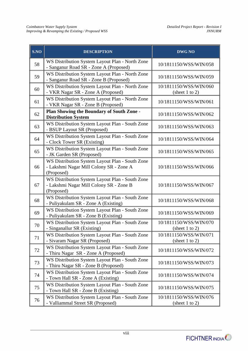
58 WS Distribution System Layout Plan - North Zone
- Sanganur Road SR - Zone A (Proposed) 10/1811150/WSS/WIN/058
59 WS Distribution System Layout Plan - North Zone
- Sanganur Road SR - Zone B (Proposed) 10/1811150/WSS/WIN/059
60 WS Distribution System Layout Plan - North Zone
- VKR Nagar SR - Zone A (Proposed)
10/1811150/WSS/WIN/060
(sheet 1 to 2)
61 WS Distribution System Layout Plan - North Zone
- VKR Nagar SR - Zone B (Proposed) 10/1811150/WSS/WIN/061
62 Plan Showing the Boundary of South Zone -
Distribution System 10/1811150/WSS/WIN/062
63 WS Distribution System Layout Plan - South Zone
- BSUP Layout SR (Proposed) 10/1811150/WSS/WIN/063
64 WS Distribution System Layout Plan - South Zone
- Clock Tower SR (Existing) 10/1811150/WSS/WIN/064
65 WS Distribution System Layout Plan - South Zone
- JK Garden SR (Proposed) 10/1811150/WSS/WIN/065
66
WS Distribution System Layout Plan - South Zone
- Lakshmi Nagar Mill Colony SR - Zone A
(Proposed)
10/1811150/WSS/WIN/066
67
WS Distribution System Layout Plan - South Zone
- Lakshmi Nagar Mill Colony SR - Zone B
(Proposed)
10/1811150/WSS/WIN/067
68 WS Distribution System Layout Plan - South Zone
- Puliyakulam SR - Zone A (Existing) 10/1811150/WSS/WIN/068
69 WS Distribution System Layout Plan - South Zone
- Puliyakulam SR - Zone B (Existing) 10/1811150/WSS/WIN/069
70 WS Distribution System Layout Plan - South Zone
- Singanallur SR (Existing)
10/1811150/WSS/WIN/070
(sheet 1 to 2)
71 WS Distribution System Layout Plan - South Zone
- Sivaram Nagar SR (Proposed)
10/1811150/WSS/WIN/071
(sheet 1 to 2)
72 WS Distribution System Layout Plan - South Zone
- Thiru Nagar SR - Zone A (Proposed) 10/1811150/WSS/WIN/072
73 WS Distribution System Layout Plan - South Zone
- Thiru Nagar SR - Zone B (Proposed) 10/1811150/WSS/WIN/073
74 WS Distribution System Layout Plan - South Zone
- Town Hall SR - Zone A (Existing) 10/1811150/WSS/WIN/074
75 WS Distribution System Layout Plan - South Zone
- Town Hall SR - Zone B (Existing) 10/1811150/WSS/WIN/075
76 WS Distribution System Layout Plan - South Zone
- Valliammal Street SR (Proposed)
10/1811150/WSS/WIN/076
(sheet 1 to 2)

Coimbatore Water Supply System Detailed Project Report - Revision I
Improving & Revamping the Existing / Proposed WSS JNNURM
ix
S.NO DESCRIPTION DWG NO
77 WS Distribution System Layout Plan - South Zone
- Vysial Street SR (Proposed) 10/1811150/WSS/WIN/077
78 Plan Showing the Boundary of East / Demo
Zone - I - Distribution System 10/1811150/WSS/WIN/078
79 WS Distribution System Layout Plan - East / Demo
Zone I - Siddhaphudhur SR - Zone A (Existing) 10/1811150/WSS/WIN/079
80 WS Distribution System Layout Plan - East / Demo
Zone I - Siddhaphudhur SR - Zone B (Existing) 10/1811150/WSS/WIN/080
81 WS Distribution System Layout Plan - East / Demo
Zone I - Tatabad SR - Zone A (Existing) 10/1811150/WSS/WIN/081
82 WS Distribution System Layout Plan - East / Demo
Zone I - Tatabad SR - Zone B (Existing) 10/1811150/WSS/WIN/082
83 WS Distribution System Layout Plan - East / Demo
Zone I - VOC Park SR - Zone A (Existing) 10/1811150/WSS/WIN/083
84 WS Distribution System Layout Plan - East / Demo
Zone I - VOC Park SR - Zone B (Existing)
10/1811150/WSS/WIN/084
(sheet 1 to 2)
85 WS Distribution System Layout Plan - East / Demo
Zone I - VOC Park SR - Zone A (Proposed) 10/1811150/WSS/WIN/085
86 WS Distribution System Layout Plan - East / Demo
Zone I - VOC Park SR - Zone B (Proposed) 10/1811150/WSS/WIN/086
87 Plan Showing the Boundary of East / Demo
Zone - II - Distribution System 10/1811150/WSS/WIN/087
88 WS Distribution System Layout Plan - East / Demo
Zone II - Anna Nagar SR - Zone A (Existing) 10/1811150/WSS/WIN/088
89 WS Distribution System Layout Plan - East / Demo
Zone II - Anna Nagar SR - Zone B (Existing) 10/1811150/WSS/WIN/089
90
WS Distribution System Layout Plan - East / Demo
Zone II - Annai Velankanni Nagar SR - Zone A
(Proposed)
10/1811150/WSS/WIN/090
91
WS Distribution System Layout Plan - East / Demo
Zone II - Annai Velankanni Nagar SR - Zone B
(Proposed)
10/1811150/WSS/WIN/091
92 WS Distribution System Layout Plan - East / Demo
Zone II - Bharathi Nagar SR - Zone A (Proposed)
10/1811150/WSS/WIN/092
Sheet 1 to 2
93 WS Distribution System Layout Plan - East / Demo
Zone II - Bharathi Nagar SR - Zone B (Proposed) 10/1811150/WSS/WIN/093
94 WS Distribution System Layout Plan - East / Demo
Zone II - DJ Nagar SR - Zone A (Existing) 10/1811150/WSS/WIN/094
95 WS Distribution System Layout Plan - East / Demo
Zone II - DJ Nagar SR - Zone B (Existing) 10/1811150/WSS/WIN/095

Coimbatore Water Supply System Detailed Project Report - Revision I
Improving & Revamping the Existing / Proposed WSS JNNURM
x
S.NO DESCRIPTION DWG NO
96 WS Distribution System Layout Plan - East / Demo
Zone II - GV Residency SR (Existing) 10/1811150/WSS/WIN/096
97 WS Distribution System Layout Plan - East / Demo
Zone II - Hudco Colony SR (Proposed) 10/1811150/WSS/WIN/097
98 WS Distribution System Layout Plan - East / Demo
Zone II - KK Nagar SR - Zone A (Existing) 10/1811150/WSS/WIN/098
99 WS Distribution System Layout Plan - East / Demo
Zone II - KK Nagar SR - Zone B (Existing) 10/1811150/WSS/WIN/099
100 WS Distribution System Layout Plan - East / Demo
Zone II - Kothari Nagar SR (Proposed) 10/1811150/WSS/WIN/100
101 WS Distribution System Layout Plan - East / Demo
Zone II - Nethajipuram SR - Zone A (Existing) 10/1811150/WSS/WIN/101
102 WS Distribution System Layout Plan - East / Demo
Zone II - Nethajipuram SR - Zone B (Existing) 10/1811150/WSS/WIN/102
103
WS Distribution System Layout Plan - East / Demo
Zone II - Rajalakshmi Nagar SR - Zone A
(Proposed)
10/1811150/WSS/WIN/103
104
WS Distribution System Layout Plan - East / Demo
Zone II - Rajalakshmi Nagar SR - Zone B
(Proposed)
10/1811150/WSS/WIN/104
105 WS Distribution System Layout Plan - East / Demo
Zone II - SIHS Colony SR (Existing) 10/1811150/WSS/WIN/105
106
WS Distribution System Layout Plan - East / Demo
Zone II - Sri Lakshmi Nagar SR - Zone A
(Proposed)
10/1811150/WSS/WIN/106
107
WS Distribution System Layout Plan - East / Demo
Zone II - Sri Lakshmi Nagar SR - Zone B
(Proposed)
10/1811150/WSS/WIN/107
108 WS Distribution System Layout Plan - East / Demo
Zone II - Tagore Nagar SR - Zone A (Proposed) 10/1811150/WSS/WIN/108
109 WS Distribution System Layout Plan - East / Demo
Zone II - Tagore Nagar SR - Zone B (Proposed) 10/1811150/WSS/WIN/109
110 WS Distribution System Layout Plan - East / Demo
Zone II - Uppilipalayam SR (Proposed) 10/1811150/WSS/WIN/110
111 Plan Showing the Boundary of West Zone -
Distribution System 10/1811150/WSS/WIN/111
112 WS Distribution System Layout Plan - West Zone -
AKS Nagar SR - Zone A (Proposed) 10/1811150/WSS/WIN/112
113 WS Distribution System Layout Plan - West Zone -
AKS Nagar SR - Zone B (Proposed) 10/1811150/WSS/WIN/113

Coimbatore Water Supply System Detailed Project Report - Revision I
Improving & Revamping the Existing / Proposed WSS JNNURM
xi
S.NO DESCRIPTION DWG NO
114 WS Distribution System Layout Plan - West Zone -
AKS Nagar SR - Zone C (Proposed) 10/1811150/WSS/WIN/114
115 WS Distribution System Layout Plan - West Zone -
Bharathi Park SR - Zone A (Proposed) 10/1811150/WSS/WIN/115
116 WS Distribution System Layout Plan - West Zone -
Bharathi Park SR - Zone B (Proposed) 10/1811150/WSS/WIN/116
117 WS Distribution System Layout Plan - West Zone -
Boopathy Layout SR - Zone A (Existing) 10/1811150/WSS/WIN/117
118 WS Distribution System Layout Plan - West Zone -
Boopathy Layout SR - Zone B (Existing) 10/1811150/WSS/WIN/118
119 WS Distribution System Layout Plan - West Zone -
Cheran Nagar SR (Existing) 10/1811150/WSS/WIN/119
120 WS Distribution System Layout Plan - West Zone -
Chinthamani Nagar SR - Zone A (Proposed) 10/1811150/WSS/WIN/120
121 WS Distribution System Layout Plan - West Zone -
Chinthamani Nagar SR - Zone B (Proposed) 10/1811150/WSS/WIN/121
122 WS Distribution System Layout Plan - West Zone -
DB Road SR - Zone A (Existing) 10/1811150/WSS/WIN/122
123 WS Distribution System Layout Plan - West Zone -
DB Road SR - Zone B (Existing) 10/1811150/WSS/WIN/123
124 WS Distribution System Layout Plan - West Zone -
Gandhi Park SR (Existing) 10/1811150/WSS/WIN/124
125 WS Distribution System Layout Plan - West Zone -
Housing Unit SR - Zone A (Proposed) 10/1811150/WSS/WIN/125
126 WS Distribution System Layout Plan - West Zone -
Housing Unit SR - Zone B (Proposed)
10/1811150/WSS/WIN/126
(sheet 1 to 2)
127 WS Distribution System Layout Plan - West Zone -
Iswarya Nagar SR - Zone A (Existing) 10/1811150/WSS/WIN/127
128 WS Distribution System Layout Plan - West Zone -
Iswarya Nagar SR - Zone B (Existing) 10/1811150/WSS/WIN/128
129 WS Distribution System Layout Plan - West Zone -
Jayaram Nagar SR - Zone A (Existing) 10/1811150/WSS/WIN/129
130 WS Distribution System Layout Plan - West Zone -
Jayaram Nagar SR - Zone B (Existing) 10/1811150/WSS/WIN/130
131 WS Distribution System Layout Plan - West Zone -
Koilmedu SR (Existing) 10/1811150/WSS/WIN/131
132 WS Distribution System Layout Plan - West Zone -
Kurunji Garden SR - Zone A (Proposed) 10/1811150/WSS/WIN/132
133 WS Distribution System Layout Plan - West Zone -
Kurunji Garden SR - Zone B (Proposed)
10/1811150/WSS/WIN/133
(sheet 1 to 2)
134 WS Distribution System Layout Plan - West Zone - 10/1811150/WSS/WIN/134
Coimbatore Water Supply System Detailed Project Report - Revision I
Improving & Revamping the Existing / Proposed WSS JNNURM
xii
S.NO DESCRIPTION DWG NO
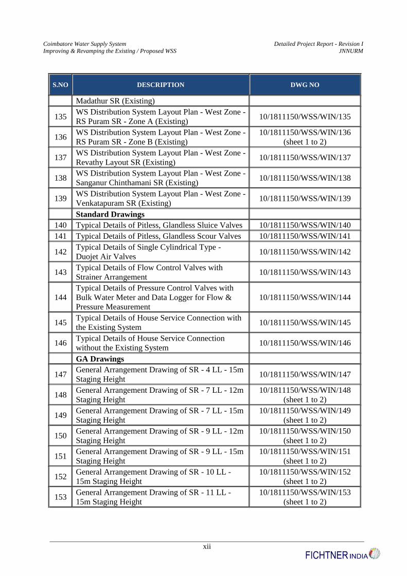
Madathur SR (Existing)
135 WS Distribution System Layout Plan - West Zone -
RS Puram SR - Zone A (Existing) 10/1811150/WSS/WIN/135
136 WS Distribution System Layout Plan - West Zone -
RS Puram SR - Zone B (Existing)
10/1811150/WSS/WIN/136
(sheet 1 to 2)
137 WS Distribution System Layout Plan - West Zone -
Revathy Layout SR (Existing) 10/1811150/WSS/WIN/137
138 WS Distribution System Layout Plan - West Zone -
Sanganur Chinthamani SR (Existing) 10/1811150/WSS/WIN/138
139 WS Distribution System Layout Plan - West Zone -
Venkatapuram SR (Existing) 10/1811150/WSS/WIN/139
Standard Drawings
140 Typical Details of Pitless, Glandless Sluice Valves 10/1811150/WSS/WIN/140
141 Typical Details of Pitless, Glandless Scour Valves 10/1811150/WSS/WIN/141
142 Typical Details of Single Cylindrical Type -
Duojet Air Valves 10/1811150/WSS/WIN/142
143 Typical Details of Flow Control Valves with
Strainer Arrangement 10/1811150/WSS/WIN/143
144
Typical Details of Pressure Control Valves with
Bulk Water Meter and Data Logger for Flow &
Pressure Measurement
10/1811150/WSS/WIN/144
145 Typical Details of House Service Connection with
the Existing System 10/1811150/WSS/WIN/145
146 Typical Details of House Service Connection
without the Existing System 10/1811150/WSS/WIN/146
GA Drawings
147 General Arrangement Drawing of SR - 4 LL - 15m
Staging Height 10/1811150/WSS/WIN/147
148 General Arrangement Drawing of SR - 7 LL - 12m
Staging Height
10/1811150/WSS/WIN/148
(sheet 1 to 2)
149 General Arrangement Drawing of SR - 7 LL - 15m
Staging Height
10/1811150/WSS/WIN/149
(sheet 1 to 2)
150 General Arrangement Drawing of SR - 9 LL - 12m
Staging Height
10/1811150/WSS/WIN/150
(sheet 1 to 2)
151 General Arrangement Drawing of SR - 9 LL - 15m
Staging Height
10/1811150/WSS/WIN/151
(sheet 1 to 2)
152 General Arrangement Drawing of SR - 10 LL -
15m Staging Height
10/1811150/WSS/WIN/152
(sheet 1 to 2)
153 General Arrangement Drawing of SR - 11 LL -
15m Staging Height
10/1811150/WSS/WIN/153
(sheet 1 to 2)
Coimbatore Water Supply System Detailed Project Report - Revision I
Improving & Revamping the Existing / Proposed WSS JNNURM
xiii
S.NO DESCRIPTION DWG NO
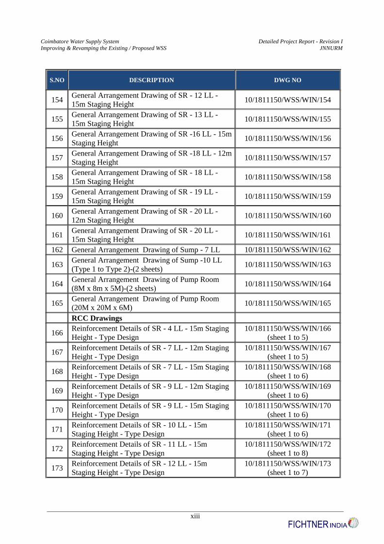
154 General Arrangement Drawing of SR - 12 LL -
15m Staging Height 10/1811150/WSS/WIN/154
155 General Arrangement Drawing of SR - 13 LL -
15m Staging Height 10/1811150/WSS/WIN/155
156 General Arrangement Drawing of SR -16 LL - 15m
Staging Height 10/1811150/WSS/WIN/156
157 General Arrangement Drawing of SR -18 LL - 12m
Staging Height 10/1811150/WSS/WIN/157
158 General Arrangement Drawing of SR - 18 LL -
15m Staging Height 10/1811150/WSS/WIN/158
159 General Arrangement Drawing of SR - 19 LL -
15m Staging Height 10/1811150/WSS/WIN/159
160 General Arrangement Drawing of SR - 20 LL -
12m Staging Height 10/1811150/WSS/WIN/160
161 General Arrangement Drawing of SR - 20 LL -
15m Staging Height 10/1811150/WSS/WIN/161
162 General Arrangement Drawing of Sump - 7 LL 10/1811150/WSS/WIN/162
163 General Arrangement Drawing of Sump -10 LL
(Type 1 to Type 2)-(2 sheets) 10/1811150/WSS/WIN/163
164 General Arrangement Drawing of Pump Room
(8M x 8m x 5M)-(2 sheets) 10/1811150/WSS/WIN/164
165 General Arrangement Drawing of Pump Room
(20M x 20M x 6M) 10/1811150/WSS/WIN/165
RCC Drawings
166 Reinforcement Details of SR - 4 LL - 15m Staging
Height - Type Design
10/1811150/WSS/WIN/166
(sheet 1 to 5)
167 Reinforcement Details of SR - 7 LL - 12m Staging
Height - Type Design
10/1811150/WSS/WIN/167
(sheet 1 to 5)
168 Reinforcement Details of SR - 7 LL - 15m Staging
Height - Type Design
10/1811150/WSS/WIN/168
(sheet 1 to 6)
169 Reinforcement Details of SR - 9 LL - 12m Staging
Height - Type Design
10/1811150/WSS/WIN/169
(sheet 1 to 6)
170 Reinforcement Details of SR - 9 LL - 15m Staging
Height - Type Design
10/1811150/WSS/WIN/170
(sheet 1 to 6)
171 Reinforcement Details of SR - 10 LL - 15m
Staging Height - Type Design
10/1811150/WSS/WIN/171
(sheet 1 to 6)
172 Reinforcement Details of SR - 11 LL - 15m
Staging Height - Type Design
10/1811150/WSS/WIN/172
(sheet 1 to 8)
173 Reinforcement Details of SR - 12 LL - 15m
Staging Height - Type Design
10/1811150/WSS/WIN/173
(sheet 1 to 7)

Coimbatore Water Supply System Detailed Project Report - Revision I
Improving & Revamping the Existing / Proposed WSS JNNURM
xiv
S.NO DESCRIPTION DWG NO
174 Reinforcement Details of SR - 13 LL - 15m
Staging Height - Type Design
10/1811150/WSS/WIN/174
(sheet 1 to 7)
175 Reinforcement Details of SR - 16 LL - 15m
Staging Height - Type Design
10/1811150/WSS/WIN/175
(sheet 1 to 8)
176 Reinforcement Details of SR - 18 LL - 12m
Staging Height - Type Design
10/1811150/WSS/WIN/176
(sheet 1 to 8)
177 Reinforcement Details of SR - 18 LL - 15m
Staging Height - Type Design
10/1811150/WSS/WIN/177
(sheet 1 to 8)
178 Reinforcement Details of SR - 19 LL - 15m
Staging Height - Type Design
10/1811150/WSS/WIN/178
(sheet 1 to 8)
179 Reinforcement Details of SR - 20 LL - 12m
Staging Height - Type Design
10/1811150/WSS/WIN/179
(sheet 1 to 8)
180 Reinforcement Details of SR - 20 LL - 15m
Staging Height - Type Design
10/1811150/WSS/WIN/180
(sheet 1 to 8)
181 Reinforcement Details of Sump - 7 LL - Type
Design
10/1811150/WSS/WIN/181
(sheet 1 to 2)
182 Reinforcement Details of Sump - 10 LL - Type
Design 10/1811150/WSS/WIN/182
183 Reinforcement Details of Pump Room - 8m x 8m x
5m - Type Design 10/1811150/WSS/WIN/183
184 Reinforcement Details of Pump Room - 20m x
10m x 6m - Type Design 10/1811150/WSS/WIN/184
Coimbatore Water Supply System Detailed Project Report - Revision I
Improving & Revamping the Existing / Proposed WSS JNNURM
xv
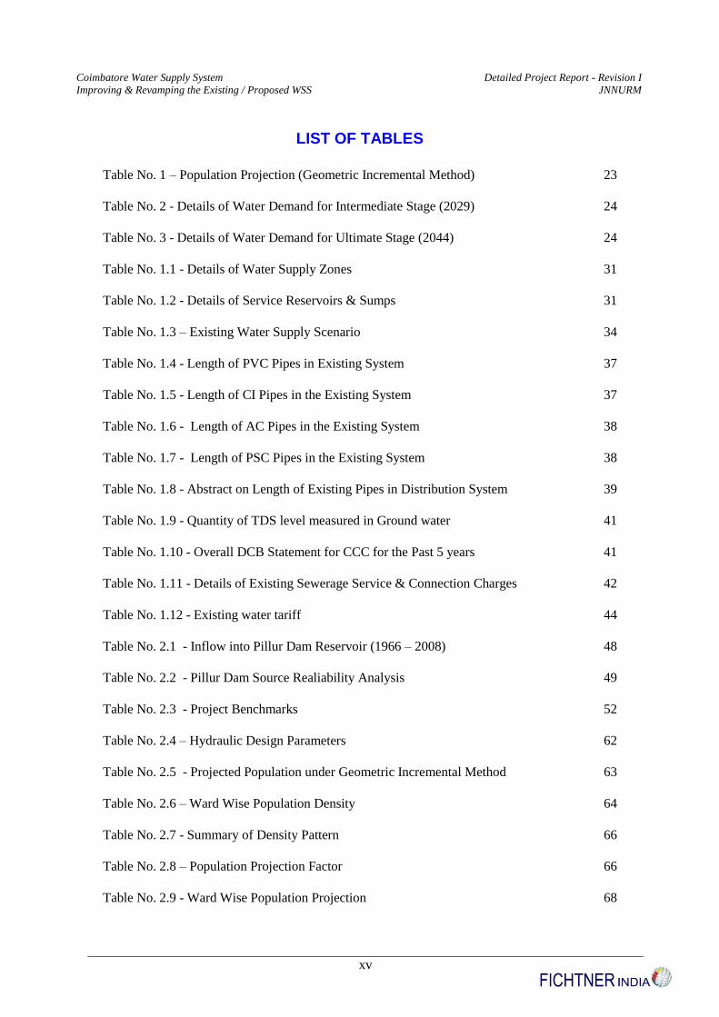
LIST OF TABLES
Table No. 1 – Population Projection (Geometric Incremental Method) 23
Table No. 2 - Details of Water Demand for Intermediate Stage (2029) 24
Table No. 3 - Details of Water Demand for Ultimate Stage (2044) 24
Table No. 1.1 - Details of Water Supply Zones 31
Table No. 1.2 - Details of Service Reservoirs & Sumps 31
Table No. 1.3 – Existing Water Supply Scenario 34
Table No. 1.4 - Length of PVC Pipes in Existing System 37
Table No. 1.5 - Length of CI Pipes in the Existing System 37
Table No. 1.6 - Length of AC Pipes in the Existing System 38
Table No. 1.7 - Length of PSC Pipes in the Existing System 38
Table No. 1.8 - Abstract on Length of Existing Pipes in Distribution System 39
Table No. 1.9 - Quantity of TDS level measured in Ground water 41
Table No. 1.10 - Overall DCB Statement for CCC for the Past 5 years 41
Table No. 1.11 - Details of Existing Sewerage Service & Connection Charges 42
Table No. 1.12 - Existing water tariff 44
Table No. 2.1 - Inflow into Pillur Dam Reservoir (1966 – 2008) 48
Table No. 2.2 - Pillur Dam Source Realiability Analysis 49
Table No. 2.3 - Project Benchmarks 52
Table No. 2.4 – Hydraulic Design Parameters 62
Table No. 2.5 - Projected Population under Geometric Incremental Method 63
Table No. 2.6 – Ward Wise Population Density 64
Table No. 2.7 - Summary of Density Pattern 66
Table No. 2.8 – Population Projection Factor 66
Table No. 2.9 - Ward Wise Population Projection 68
Coimbatore Water Supply System Detailed Project Report - Revision I
Improving & Revamping the Existing / Proposed WSS JNNURM
xvi
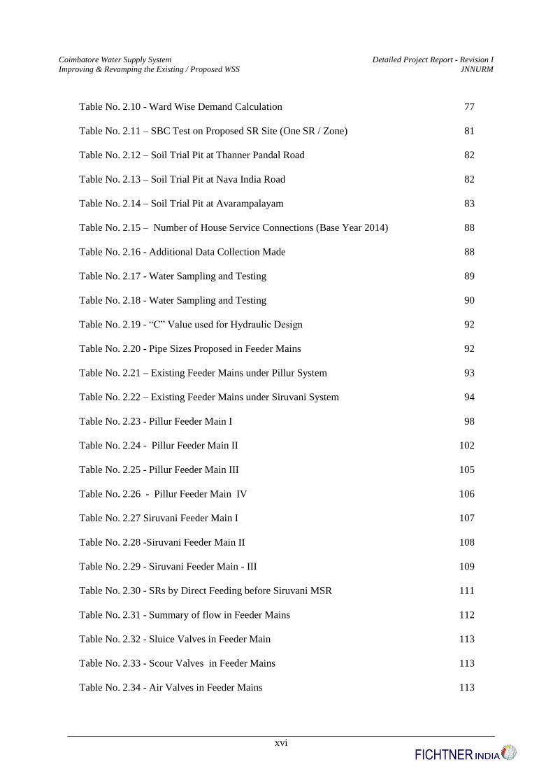
Table No. 2.10 - Ward Wise Demand Calculation 77
Table No. 2.11 – SBC Test on Proposed SR Site (One SR / Zone) 81
Table No. 2.12 – Soil Trial Pit at Thanner Pandal Road 82
Table No. 2.13 – Soil Trial Pit at Nava India Road 82
Table No. 2.14 – Soil Trial Pit at Avarampalayam 83
Table No. 2.15 – Number of House Service Connections (Base Year 2014) 88
Table No. 2.16 - Additional Data Collection Made 88
Table No. 2.17 - Water Sampling and Testing 89
Table No. 2.18 - Water Sampling and Testing 90
Table No. 2.19 - “C” Value used for Hydraulic Design 92
Table No. 2.20 - Pipe Sizes Proposed in Feeder Mains 92
Table No. 2.21 – Existing Feeder Mains under Pillur System 93
Table No. 2.22 – Existing Feeder Mains under Siruvani System 94
Table No. 2.23 - Pillur Feeder Main I 98
Table No. 2.24 - Pillur Feeder Main II 102
Table No. 2.25 - Pillur Feeder Main III 105
Table No. 2.26 - Pillur Feeder Main IV 106
Table No. 2.27 Siruvani Feeder Main I 107
Table No. 2.28 -Siruvani Feeder Main II 108
Table No. 2.29 - Siruvani Feeder Main - III 109
Table No. 2.30 - SRs by Direct Feeding before Siruvani MSR 111
Table No. 2.31 - Summary of flow in Feeder Mains 112
Table No. 2.32 - Sluice Valves in Feeder Main 113
Table No. 2.33 - Scour Valves in Feeder Mains 113
Table No. 2.34 - Air Valves in Feeder Mains 113
Coimbatore Water Supply System Detailed Project Report - Revision I
Improving & Revamping the Existing / Proposed WSS JNNURM
xvii
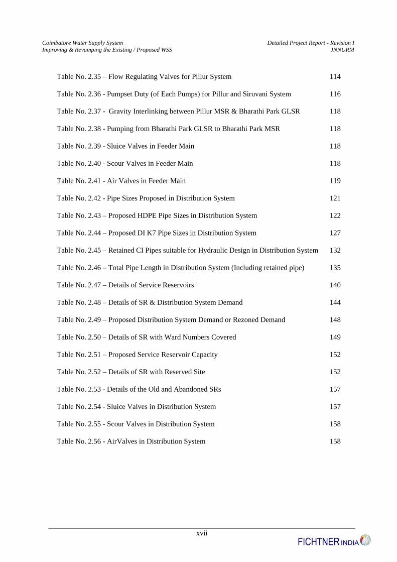
Table No. 2.35 – Flow Regulating Valves for Pillur System 114
Table No. 2.36 - Pumpset Duty (of Each Pumps) for Pillur and Siruvani System 116
Table No. 2.37 - Gravity Interlinking between Pillur MSR & Bharathi Park GLSR 118
Table No. 2.38 - Pumping from Bharathi Park GLSR to Bharathi Park MSR 118
Table No. 2.39 - Sluice Valves in Feeder Main 118
Table No. 2.40 - Scour Valves in Feeder Main 118
Table No. 2.41 - Air Valves in Feeder Main 119
Table No. 2.42 - Pipe Sizes Proposed in Distribution System 121
Table No. 2.43 – Proposed HDPE Pipe Sizes in Distribution System 122
Table No. 2.44 – Proposed DI K7 Pipe Sizes in Distribution System 127
Table No. 2.45 – Retained CI Pipes suitable for Hydraulic Design in Distribution System 132
Table No. 2.46 – Total Pipe Length in Distribution System (Including retained pipe) 135
Table No. 2.47 – Details of Service Reservoirs 140
Table No. 2.48 – Details of SR & Distribution System Demand 144
Table No. 2.49 – Proposed Distribution System Demand or Rezoned Demand 148
Table No. 2.50 – Details of SR with Ward Numbers Covered 149
Table No. 2.51 – Proposed Service Reservoir Capacity 152
Table No. 2.52 – Details of SR with Reserved Site 152
Table No. 2.53 - Details of the Old and Abandoned SRs 157
Table No. 2.54 - Sluice Valves in Distribution System 157
Table No. 2.55 - Scour Valves in Distribution System 158
Table No. 2.56 - AirValves in Distribution System 158
Coimbatore Water Supply System Detailed Project Report - Revision I
Improving & Revamping the Existing / Proposed WSS JNNURM
xviii
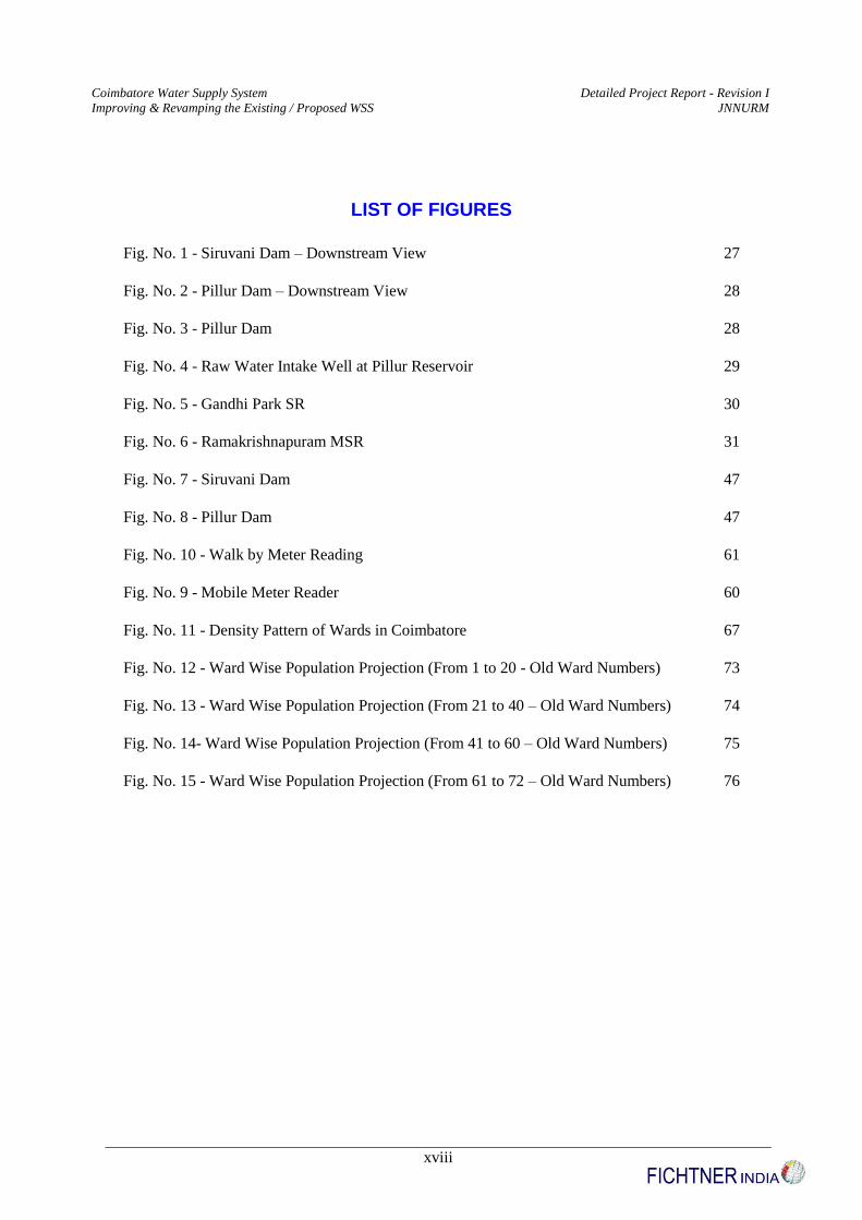
LIST OF FIGURES
Fig. No. 1 - Siruvani Dam – Downstream View 27
Fig. No. 2 - Pillur Dam – Downstream View 28
Fig. No. 3 - Pillur Dam 28
Fig. No. 4 - Raw Water Intake Well at Pillur Reservoir 29
Fig. No. 5 - Gandhi Park SR 30
Fig. No. 6 - Ramakrishnapuram MSR 31
Fig. No. 7 - Siruvani Dam 47
Fig. No. 8 - Pillur Dam 47
Fig. No. 10 - Walk by Meter Reading 61
Fig. No. 9 - Mobile Meter Reader 60
Fig. No. 11 - Density Pattern of Wards in Coimbatore 67
Fig. No. 12 - Ward Wise Population Projection (From 1 to 20 - Old Ward Numbers) 73
Fig. No. 13 - Ward Wise Population Projection (From 21 to 40 – Old Ward Numbers) 74
Fig. No. 14- Ward Wise Population Projection (From 41 to 60 – Old Ward Numbers) 75
Fig. No. 15 - Ward Wise Population Projection (From 61 to 72 – Old Ward Numbers) 76
Coimbatore Water Supply System Detailed Project Report - Revision I
Improving & Revamping the Existing / Proposed WSS JNNURM
19
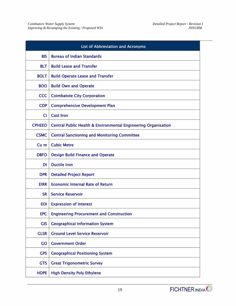
List of Abbreviation and Acronyms
BIS Bureau of Indian Standards
BLT Build Lease and Transfer
BOLT Build Operate Lease and Transfer
BOO Build Own and Operate
CCC Coimbatote City Corporation
CDP Comprehensive Development Plan
CI Cast Iron
CPHEEO Central Public Health & Environmental Engineering Organisation
CSMC Central Sanctioning and Monitoring Committee
Cu m Cubic Metre
DBFO Design Build Finance and Operate
DI Ductile Iron
DPR Detailed Project Report
EIRR Economic Internal Rate of Return
SR Service Reservoir
EOI Expression of Interest
EPC Engineering Procurement and Construction
GIS Geographical Information System
GLSR Ground Level Service Reservoir
GO Government Order
GPS Geographical Positioning System
GTS Great Trigonometric Survey
HDPE High Density Poly Ethylene
Coimbatore Water Supply System Detailed Project Report - Revision I
Improving & Revamping the Existing / Proposed WSS JNNURM
20
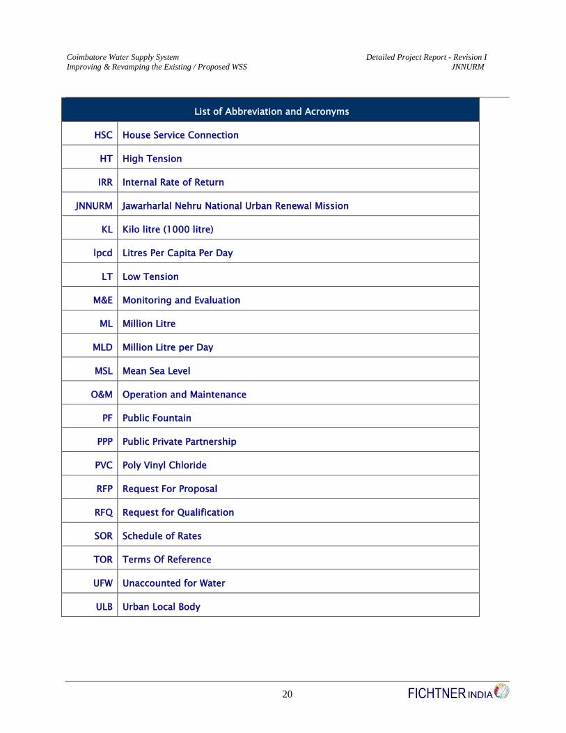
List of Abbreviation and Acronyms
HSC House Service Connection
HT High Tension
IRR Internal Rate of Return
JNNURM Jawarharlal Nehru National Urban Renewal Mission
KL Kilo litre (1000 litre)
lpcd Litres Per Capita Per Day
LT Low Tension
M&E Monitoring and Evaluation
ML Million Litre
MLD Million Litre per Day
MSL Mean Sea Level
O&M Operation and Maintenance
PF Public Fountain
PPP Public Private Partnership
PVC Poly Vinyl Chloride
RFP Request For Proposal
RFQ Request for Qualification
SOR Schedule of Rates
TOR Terms Of Reference
UFW Unaccounted for Water
ULB Urban Local Body

Coimbatore Water Supply System Detailed Project Report - Revision I
Improving & Revamping the Existing / Proposed WSS JNNURM
21
PROJECT SUMMARY
Preamble
As a part of the Jawaharlal Nehru National Urban Renewal Mission (JNNURM) initiated by Government
of India, Ministry of Urban Development and Ministry of Housing and Urban Poverty Alleviation, 63 cities
have been selected all over India. The aim of the mission is to encourage various cities to initiate steps to
bring about improvement in the existing service levels in an efficient, equitable and financially sustainable
manner. Water Supply has been identified as one of the major sector eligible for assistance under the
submission directorate for Basic Services to the Urban Poor. Coimbatore is one of the selected cities under
this mission.
Background
Coimbatore City Corporation is located in the western part of Tamilnadu and is the third largest city in
Tamilnadu after Chennai and Madurai and one of the fastest growing cities in India. This city serves as the
District Headquarters for Coimbatore District and is situated at 495 kms South West of Chennai City in
Tamilnadu. It is well connected with major cities and towns of India by Highways, Railways and Airways
and also abroad. Coimbatore City is a major industrial and textile centre and is now emerging as a major
hub for Information Technology in Tamilnadu. Many National and Multinational companies are planning to
start their software parks in Coimbatore. Thereby, job opportunities and population are expected to increase
in multifold. There are more than one lakh small, medium and large scale industries of Textile, Automobile
spares, Foundry, Pumps, Motors, Electronics, Steel and Aluminium are existing. Coimbatore City is
popularly known as the Textile Capital or Manchester of South India.
The Commissioner of City Corporation, Coimbatore had invited proposal for the preparation of Detailed
Project Report for Improving and revamping the Existing/Proposed Water Supply Scheme with 24x7 in
Coimbatore Municipal Corporation. The LOI was issued to M/s Fichtner India vide ROC No.
29760/2006/WSI dated 8.09.2008 by the Commissioner of Municipal Corporation, Coimbatore. The first
stage of this assignment, the Inception Report was submitted to the Coimbatore Corporation during
November 2008 followed by Interim report during March 2009, Draft Final Report during July 2009 and

Coimbatore Water Supply System Detailed Project Report - Revision I
Improving & Revamping the Existing / Proposed WSS JNNURM
22
the final DPR was submitted during March 2010 in accordance with the suggestions of the State Level
Technical Standing Committee constituted by Directorate of Municipal Adminsitration, Government of
Tamilnadu, Chennai, City Technical Advisory Group (CTAG) / City Voluntary Technical Committee
(CVTV), Elected Representatives of Coimbatore Corporation. Further to the submission of the DPR, M/s
Fichtner India has revised the DPR as per Minutes of Principal Secretary, MA&WS as requested by
Coimbatore corporation vide corporation letter Roc.No.2896/08/JN-5 dated 16.12.2011.In addition to the
above, the Technical suggestions received from TNUIFSL, Chennai has been incorporated and submitted as
requested by the Coimbatore corporation vide corporation letter Roc.No.2896/08/JN-5 dated 15.02.2012.
Subsequently, M/s Fichtner India has made a power point presentation to Commissioner, Coimbatore
Corporation and further to Commissionarate of Municipal Adminsitration, Chennai, Government of
Tamilnadu along with special invitee of Water Supply and Sanitation Specialist of World Bank for onward
forwarding of the DPR to the State Level Nodal Agency as requested by the Coimbatore Corporation vide
corporation letter Roc.No.2896/08/JN-5 dated 07.02.2013. The Technical suggestions received from CMA,
Chennai has also been incorporated and submitted as Revision Number I of the DPR. The same DPR has
been appraised to SLTSC (State Level Technical Steering Committee of Tamil Nadu). The appraised DPR
has been forwarded to Ministry of Urban Development, Government of India through Tamil Nadu Nodal
agency, TUFIDCO for funding under JNNURM – II Section via official letter
no.TUFIDCO/JnNURM/GoTN/M(Mu)/501/2013 dated 23.08.2013. The same DPR has been technically
appraised by CPHEEO, MoUD, GOI and their suggestions and commnets has been incorporated and
submitted herewith as final DPR.
Project Site Appreciation & Rationale for Water Supply Improvements
The population has grown from 0.47 lakhs in 1911 to 9.30 lakhs in the year 2001 with an average annual
growth rate of 2.7 % and an average decadal growth rate of 27.34%. The population of the Local Planning
Authority is 16.40 lakhs covering an area of 105.60 Sq.km. The availability of power, clubbed with raw
material availability for textile processing, from 1935, has led to the establishment of many industries
resulted in a nearly 52% increase in population during 1941-1951. The city has registered the decadal
growth rate of 49.20 % during the period 1971- 1981. This is attributed to the up gradation of Municipality
to the status of Corporation, whereby additional areas were included in its jurisdiction.The geographical
location details of Coimbatore Corporation as per Survey of India topographical map are Latitude: 10o
58’00” N & Longitude: 76o 58’ 00”E. The present water supply to Coimbatore Corporation is 137 mld for
a population of 1.10 million at the pro rata supply of 125 lpcd, from two water supply schemes, namely,

Coimbatore Water Supply System Detailed Project Report - Revision I
Improving & Revamping the Existing / Proposed WSS JNNURM
23
Siruvani & Pillur.
a) Siruvani Water Supply System: At present, 75 Mld of treated drinking water from the existing
Siruvani Water Supply Scheme is being supplied to the Coimbatore Corporation with head works
(Siruvani Reservoir) at Attapady Valley in Palakkad District of Kerala State, at a distance of 40 km
from Coimbatore. The raw water is conveyed through a tunnel to the treatment plant at Siruvani
Adivaram. After full scale treatment, clear water is conveyed by gravity through 1000 mm PSC pipes
to the Master Service Reservoir at Bharathi Park from where it is fed to the Service Reservoirs in
Western Zone of the town and distributed through the network of distribution system. The scheme is in
operation since 1982.
b) Pillur Water Supply System: Another scheme with the Pillur Reservoir situated at the foothills of
Nilgiris in Western Ghats as source was implemented in the year 1995 for Coimbatore Corporation, 22
Towns and 523 Rural Habitations. The total installed capacity is 125 Mld and Coimbatore corporation
gets 62 Mld from this scheme. Raw water is drawn through intake well cum pump house located in
Pillur Reservoir and conveyed through 1500 mm dia. MS pipes and tunnel of length 3.850 km at
Periakombai hills to the treatment plant at Velliangadu. The treated water is pumped from WTP
through the clear water tunnel of 0.9 Km long at Kattan hills. The water is gravitated from the tunnel
to the Master Service Reservoir at Ramakrishnapuram from where it is fed to the Service Reservoirs in
Eastern Zone of the town and distributed through the network of distribution system. The requirements
of other beneficiaries are tapped at suitable locations.
Population and Demand Forecast
Population projection is done as per Geometric Incremental Method as this method is mostly applicable for
growing towns and cities having vast scope of expansion as described in CPHEEO, under Clause 2.2.7 on
Population Projection. The same method has also been approved or followed under JNNURM Project for
Pillur II Scheme, which is the Terms of Reference for this project.
Table No. 1 – Population Projection (Geometric Incremental Method)
Sl No Year Project Stage Population (Nos)
1 2011 Census Population 10,61,447
2 2014 Base Year 11,10,933
3 2029 Intermediate Stage 13,95,199
4 2044 Ultimate Stage 17,52,203
Coimbatore Water Supply System Detailed Project Report - Revision I
Improving & Revamping the Existing / Proposed WSS JNNURM
24
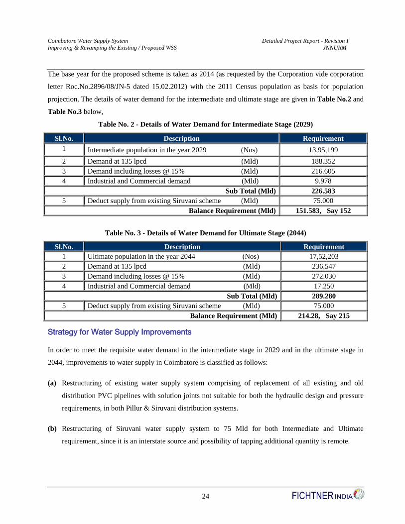
The base year for the proposed scheme is taken as 2014 (as requested by the Corporation vide corporation
letter Roc.No.2896/08/JN-5 dated 15.02.2012) with the 2011 Census population as basis for population
projection. The details of water demand for the intermediate and ultimate stage are given in Table No.2 and
Table No.3 below,
Table No. 2 - Details of Water Demand for Intermediate Stage (2029)
Sl.No. Description Requirement
1 Intermediate population in the year 2029 (Nos) 13,95,199
2 Demand at 135 lpcd (Mld) 188.352
3 Demand including losses @ 15% (Mld) 216.605
4 Industrial and Commercial demand (Mld) 9.978
Sub Total (Mld) 226.583
5 Deduct supply from existing Siruvani scheme (Mld) 75.000
Balance Requirement (Mld) 151.583, Say 152
Table No. 3 - Details of Water Demand for Ultimate Stage (2044)
Sl.No. Description Requirement
1 Ultimate population in the year 2044 (Nos) 17,52,203
2 Demand at 135 lpcd (Mld) 236.547
3 Demand including losses @ 15% (Mld) 272.030
4 Industrial and Commercial demand (Mld) 17.250
Sub Total (Mld) 289.280
5 Deduct supply from existing Siruvani scheme (Mld) 75.000
Balance Requirement (Mld) 214.28, Say 215
Strategy for Water Supply Improvements
In order to meet the requisite water demand in the intermediate stage in 2029 and in the ultimate stage in
2044, improvements to water supply in Coimbatore is classified as follows:
(a) Restructuring of existing water supply system comprising of replacement of all existing and old
distribution PVC pipelines with solution joints not suitable for both the hydraulic design and pressure
requirements, in both Pillur & Siruvani distribution systems.
(b) Restructuring of Siruvani water supply system to 75 Mld for both Intermediate and Ultimate
requirement, since it is an interstate source and possibility of tapping additional quantity is remote.
Coimbatore Water Supply System Detailed Project Report - Revision I
Improving & Revamping the Existing / Proposed WSS JNNURM
25
(c) Augmentation of water supply from Pillur reservoir to meet the balance ultimate demand of 214.280
Mld for the entire corporation.
(d) Augmentation of additional Storate tanks for the intermediate demand.
(e) Provision of special components / control and instrumentaions for a pressured continous water supply
system from the present intermittent supply.
Cost of the Project
The total cost of the project is estimated as Rs556.57 Crores (As per Schedule of Rates 2016–2017)
1 Sector Background, Context & Broad Project Rationale
1.1 Project Site Appreciation
Coimbatore is the district head - quarters of Coimbatore district located at 495 Km south west of Chennai.
This is the third largest city in Tamilnadu and has numerous textile mills and small scale engineering units.
Historical reference of Coimbatore city dates back to 1200 AD. Ruled by Cheran rulers, the city was
developed as strategic town during the Nayakas rule of Madurai. Tippu Sultan conceded the town to British
colonialists in 1799, who subsequently promoted Coimbatore as the military transit town between Palghat
in the west and Gazal Hatty in the north. Beginning 1879, the city has started to emerge as an administrative
and industrial town in its own merit. In the year 1866, Coimbatore was constituted as a Coimbatore
Municipal Town with an area of 10.88 sq. km. The Madras- Podanur rail link passing through Erode was
opened in the same year and thus its connectivity to the other region was improved. The Coimbatore
Municipality was upgraded to Municipal Corporation during May 1981 and spreads over an area of 105.60
sq. km.
1.1.1 Physical & Geographical Characteristics
The city is traversed, in the middle, by the river Noyyal rising from the Vellingiri hills on the West. It is
surrounded by the Nilgiris, a rich tea producing hinterland in the North, Pollachi, the receiving center for
forest production in the South and the Cochin Harbor in the South West. The towns of Mettupalayam,
Pollachi and Tirupur are within a radius of 40 Km. from Coimbatore. The Regional setting of Coimbatore
is explicated in Dwg No: 10/1811150/WSS/WIN/001, Volume VI part of this DPR.
Coimbatore Water Supply System Detailed Project Report - Revision I
Improving & Revamping the Existing / Proposed WSS JNNURM
26
1.1.2 Topography
Coimbatore Corporation is having a gradual slope from the West to East and north to south except some
pockets like Race Course and Ram Nagar. The ground level varies generally from + 440.00 to + 390.00 mm
from MSL.
1.1.3 Geology
The area is underlined by high grade of metamorphic rock of peninsular gneissic complex. These rocks are
moderately weathered. The major rock types occurring in the area are Biotitic gneiss and Charnockite. The
permeability rate varies from medium to poor, depending upon the soil texture. It was reported that the
over-exploitation of ground water has caused heavy decline in ground water level in the Corporation area.
1.1.4 Soil
The soil in most of the areas is black cotton soil.
1.1.5 Structure & Tectonics
The crystalline rocks of Achaean Age are the primary rocks which have undergone varied degree of
metamorphism, exhibit secondary structural features like joints and fractures or lineaments.
1.1.6 Weathering
The crystalline rocks of the Coimbatore area are highly variable depending upon the structure, mineral and
chemical composition of the rocks. Gneiss in general is less resistant to weathering than charnockite and
granite due to highly foliated and fissile nature. The average depth of weathering in this block is 15 m and
the maximum is about 30 m from G.L.
1.1.7 Alluvium & Kankar
Occurrences of alluvium are seen whereas extensive surface cover of Kankar is noticed. Kankar, which is a
product of chemical weathering of the country rocks, is a hard, indurated, white to buff coloured material
composed of calcium carbonate. Precipitation is the main source of recharge. There are no perennial rivers
or noticeable canal command system to promote recharging.
1.1.8 Climate and Rainfall
The mean daily temperature during summer varies from 36° C to 41° C and during winter varies from 14° C

Coimbatore Water Supply System Detailed Project Report - Revision I
Improving & Revamping the Existing / Proposed WSS JNNURM
27
Fig. No. 1 - Siruvani Dam – Downstream
View
to 31°C. The influence of the western ghat is predominant in this region. The area receives rainfall mainly
from North East monsoon and the contribution from South west is marginal. The average annual rainfall of
Coimbatore city is 623 mm where as it is 714.00 mm for Coimbatore district.
1.1.9 Industrial Activities
There are a number of textile mills in and around the city run by Government and by private companies.
Well established handloom textile manufacturing units, big and small foundries engaged in the
manufacturing of deep well motors and pump sets for agricultural and domestic purposes, a famous cement
manufacturing unit in Madukkarai at 10 kms from the city and 3 big textile machinery manufacturing units,
etc provide employment to thousands of people and contribute to the industrial growth of the region and the
state. Coimbatore has also attracted investment in hi-tech industries in the recent years, especially in the
field of solar energy and computer software.
1.1.10 Existing Status of Physical Infrastructure
(i) Status of Water Supply Infrastructure
The City Engineer and his team of Engineers and Staff are
responsible for ensuring protected drinking water supply in
the city. The city requires 165 Million litres of water daily
at present. On an average, the per capita supply is
maintained at about 125 lpcd (litres per capita per day) by
supplying 137 Mld.
Protected water supply for Coimbatore town is provided
through two major water supply schemes.
1. Siruvani Water Supply Scheme - 75 Mld
2. Pillur Water Supply Scheme I - 62 Mld
Total present supply - 137 Mld

Coimbatore Water Supply System Detailed Project Report - Revision I
Improving & Revamping the Existing / Proposed WSS JNNURM
28
Fig. No. 2 - Pillur Dam – Downstream
View
The head works of both water supply schemes are operated
and maintained by Tamil Nadu Water Supply and Drainage
Board and they supply bulk water to two different Master
Service Reservoirs maintained by Coimbatore Corporation.
From these two separate Master Service Reservoirs, water
supply is being distributed through 49 elevated service
reservoirs and sumps about 640 km of existing distribution
network.
The water level of Siruvani dam touched the dead storage level during 2004 due to monsoon failure and the
supply level was reduced to 25 Mld against normal supply of 75 Mld. As a temporary solution the needs of
the Siruvani fed area is met with by interconnecting Pillur water supply and Siruvani water supply networks
wherever possible.
Services / Functions
Operation and Maintenance of headworks for water supply and distribution of drinking water to
house holds and public fountains.
Sanctioning new house service connections
Conveyance and distribution of water for private and public uses
Billing and collection of water charges
Creating awareness among people to conserve water and construct Rain Water Harvesting
structures
(ii) Source - Pillur (Bhavani River) source
Pillur Dam was constructed in Bhavani River, a tributary
of Cauvery. The Dam is located in the downstream of the
confluence point of its main tributary Kundha River
which originates in the Nilgiris hills of Western Ghats.
The average rainfall of the basin is ranging from 1000
mm to 4000 mm. The catchment of the river lies in both
Fig. No. 3 - Pillur Dam

Coimbatore Water Supply System Detailed Project Report - Revision I
Improving & Revamping the Existing / Proposed WSS JNNURM
29
Tamil Nadu and Kerala states and forms part of the Western Ghats.
There are three hydel power projects in the upstream of
Pillur Dam. The major tributaries are Siruvani, Kodingiyar
& Varahapallam Rivers. Kunda River is confluencing in
river Bhavani in the upstream of Pillur Dam. The total
storage capacity of Pillur Dam is 1566 Mcft and FRL is
426.72 m and Dead Storage level is 356.60 m. The
minimum inflow into the Dam is 600 cusecs. About 53.65
cusecs (131.25 Mld) is already tapped for Pillur Scheme I.
Hence another 53.65 cusecs (131.25 Mld) of water may be
safely tapped from the Dam for Pillur Scheme II.
Existing Pillur Scheme I - Salient details
Source : Pillur Reservoir across River Bhavani.
Head works : Collection well - 21 m dia
Raw water pumpsets : 6 x 442 HP (2 Nos. standbye) Vertical
Turbine pumpsets of duty
91200 lpm x 61.99 m
Raw water pumping main : 1500 mm dia MS pipe - 482 m
Raw water Tunnel
at Periyakombai Hill : 3850 m long, 2.20 m size D’ shaped tunnel
Raw water Gravity main : 1500 mm dia PSC pipe 1050 m
Water Treatment Plant at Velliyankadu: 131.25 mld consists of pre-sedimentation
Tank, Aerator, Clariflocculator, Filter house,
Clear water reservoir and Sump-cum-pump
house etc.
Fig. No. 4 - Raw Water Intake Well at
Pillur Reservoir

Coimbatore Water Supply System Detailed Project Report - Revision I
Improving & Revamping the Existing / Proposed WSS JNNURM
30
Clear water pumping main : 1500 mm dia PSC / MS pipe - 10870 m
Clear water tunnel at Katten Hill : 800 m long, 2.20 m size D’ shaped tunnel
Clear water Gravity main upto MSR : 1500 & 1000 mm dia PSC pipe - 23700 m
Master Service Reservoir (MSR)
at Ramakrishnapuram : 30 Lakh litres
Feeder mains : 43 km
Service Reservoirs & Sumps : 23 Nos.
(iii) Source - Siruvani River Source
Source : Siruvani Dam
Head works at Attapady valley
in Palghat district,Kerala : Intake tower 6 m dia
Raw water Tunnel : 1550 m length, 1.80 x 2.10 m
Pick up weir & Raw water Gravity main : The water from the dam let out in the
Anayar stream at tunnel exit is picked up at
Adivaram by a pick up weir, after its travel
through a length of 1.6 km in the Anayar stream.
The water heading up at the pick up weir is let
into a Collection well and conveyed to the
Treatment works through 1000 mm dia PSC
pipes.
Treatment Plant at Siruvani Dam
Adivaram : 106.50 mld consists of Aerator,
Clariflocculator, Filter house and
Clear water reservoir
Clear water Gravity main upto MSR : 1000 mm dia PSC pipe 31330 m
Master Service Reservoir at Bharathi Park : 38.00 Lakh litres
Service Reservoirs & Sumps : 26
Nos.
(iv) Present Water Distribution Zones
Initially there were 25 service reservoirs (226.39 LL) in the city.

Coimbatore Water Supply System Detailed Project Report - Revision I
Improving & Revamping the Existing / Proposed WSS JNNURM
31
After commissioning of Pillur Scheme-I, the city is served by 46 service reservoirs. Further 3 SRs located at
Vysial Street under Siruvani Scheme & Rathinapuri and Maniakarampalayam under Pillur Scheme-I are not
in use. The balance service reservoirs of 236.50 LL capacities get water from Pillur Source. The total area
has been divided into 5 water supply zones and 43 sub-zones for effective operation and maintenance.
Details of existing five water distribution zones are given in Table No. 1.1
Table No. 1.1 - Details of Water Supply Zones
Zone No. Zone
No. of
SRs &
Sump
Population Base
year (2006) No. of HSC Source
I HLR-Bharathi Park 11 164064 18429 Siruvani
II LLR-Gandhi Park 10 254706 21387 Siruvani
III MSR-
Ramakrishnapuram
13 169592 22467 Pillur & Siruvani
IV Singanallur 10 226756 26456 Pillur
V Sungam 5 210157 17382 Pillur & Siruvani
Total 49 1025275 106121
(v) Master Service Reservoirs
Water is supplied to the city through the Master Service
Reservoirs at Barathi Park & Ramakrishnapuram. These
two master service reservoirs are supplying water to other
service reservoirs. These two MSRs also supply water to
their command area. The MSR at Ramakrishnapuram is
fed by the gravity main from clear water tunnel at Katten
hill under Pillur Scheme I. The MSR at Bharathi Park is
fed by the gravity main of Siruvani Scheme.
(vi) Service Reservoirs
Table No. 1.2 - Details of Service Reservoirs & Sumps
Sl. No. Zone Location of SR No. Capacity
(LL) GL (m)
LWL
(m)
MWL
(m) Source
1 I Dewan Baghadur Road 1 28.00 426.80 440.80 445.00 S I R U V A N I
Fig. No. 6 - Ramakrishnapuram MSR

Coimbatore Water Supply System Detailed Project Report - Revision I
Improving & Revamping the Existing / Proposed WSS JNNURM
32
Sl. No. Zone Location of SR No. Capacity
(LL) GL (m)
LWL
(m)
MWL
(m) Source
2 Koilmedu 1 2.00 440.00 453.00 456.00
3 Nataraj layout (Boopathy
layout) 1 20.00 439.00 452.10 456.70
4 Venkatapuram 1 2.00 440.00 453.00 456.00
5 Bharathi Park MSR 5 38.87 432.00 443.00 447.00
6 Chinthamani Nagar
(Sanganur Part A) 1 5.00 439.00 450.00 453.00
7 Tatabad 1 11.00 426.00 434.80 438.00
8
II
Gandhi Park OHT 2 19.80 427.75 424.30 421.25
SIR
UV
AN
I
9 Gandhi Park 2 22.72 427.75 434.95 431.30
10 D.B.Road Near 3 Post 1 20.00 427.75 434.95 431.30
11 Jeyaram Nagar 1 10.00 414.00 431.44 428.44
12 Madathur (P.N.Pudur) 1 5.00 439.00 446.00 443.00
13 Iswarya Nagar
(Seeranaicken Palayam) 1 10.00 424.00 434.43 440.43
14 Revathi Nagar (Linamar) 1 3.00 422.70 434.00 431.00
15 Vysial Street 1 9.00 409.00 422.60 426.80
16
III
Jai Nagar,
Goundampalayam 1 10.00 427.43 451.14 455.14
SIR
UV
AN
I
17 R.G.Nagar (Kannappa
Nagar) 1 6.00 438.29 432.14 465.14
18 Kamarajapuram 1 6.00 426.74 429.50 432.50
19 Rathinapuri (Not in use) 1 6.00 426.00 432.00 435.00
PIL
LU
R
20 Ramakrishnapuram
(Ganapathy MSR) 1 30.00 428.86 443.86 447.86
21 Ganapathy Ma Nagar
(7.00-Sump) 1 3.00 428.86 443.86 446.50
22 TNUDP Colony Gandhi
Ma Nagar (11.00-Sump) 1 6.00 428.86 443.86 446.50
23 Krishnarayapuram Zone I
Avarampalayam 1 2.50 409.22 424.63 427.63
24 Krishnarayapuram Zone II
Kamadenu Nagar 1 3.00 409.49 422.44 425.44

Coimbatore Water Supply System Detailed Project Report - Revision I
Improving & Revamping the Existing / Proposed WSS JNNURM
33
Sl. No. Zone Location of SR No. Capacity
(LL) GL (m)
LWL
(m)
MWL
(m) Source
25 Rayappa Nagar 1 15.00 423.63 434.07 437.07
26 Maniakarampalayam Zone-
I (Not in use) 1 1.00 410.00 416.00 419.00
27 V V Nagar 1 0.50 429.00 435.00 439.00
28 Police Quarters 1 0.50 429.00 435.00 439.00
29
IV
Peelamedu Zone I 1 15.00 414.50 425.50 429.00
PIL
LU
R
30
Peelamedu Zone II
Uppilipalayam Zone III
Part D.J.Nagar
1 10.00 406.29 420.29 423.79
31 Karunanidhi Nagar
(2 tier) 1
4.00 397.66 410.66 412.66
6.00 397.66 417.66 420.66
32
Sowripalayam Zone I
Udayampalayam (Meena
Estate)
1 5.00 401.00 409.00 412.58
33 Sowripalayam Zone II G.V
Residency 1 6.00 394.65 409.65 412.65
34 Uppilipalayam Zone I
VRP 1 10.00 403.00 411.00 414.11
35 Anna Nagar
Neelikonampalayam 1 16.00 389.11 404.11 407.61
36 Singanallur 1 7.00 396.00 398.00 401.00
37 Nethaji puram 1 12.00 387.491 399.491 403.141
38 SIHS Colony (7.00-Sump) 1 3.00 400.00 412.00 415.65
39
V
District IV -B
Sidhapudur 1 20.00 423.50 429.10 433.30
PIL
LU
R
40 District IX -B
Puliakulam 1 24.00 405.00 415.80 420.00
41 District IX -A
Townhall 1 16.00 409.00 422.60 426.80
42 V.O.C Park 1 27.00 423.00 435.80 440.00
SIR
U
VA
NI

Coimbatore Water Supply System Detailed Project Report - Revision I
Improving & Revamping the Existing / Proposed WSS JNNURM
34
Sl. No. Zone Location of SR No. Capacity
(LL) GL (m)
LWL
(m)
MWL
(m) Source
43 Nanjundapuram 1 2.00 390.80 403.80 407.00
Grand Total 49 478.89
(vii) Existing Water Distribution System
Table No. 1.3 – Existing Water Supply Scenario
S.No Description Details
1 City Coimbatore
2 Status Corporation
3 Area 105.6 Sq.Km
4 Topography Elevation varies from 390m to 440 m
5 Wards 72 (New) 60 (Old)
6 Water Supply Zones 5
7 SRs & Sumps 49 Nos (41 SR’s & 8 Sumps)
8 Distribution Pipes 1122 Km
9 HSCs 106121
10 Present Service Level Intermittent Supply - 125 Lpcd (As per ToR)
(Once in 2/3 days for 2 to 3 Hours)
11 Proposed Service Level 135 Lpcd
12 Population 11,10,933 (As per 2011 Census Population)
The total length of the existing distribution network in Coimbatore Corporation is around 1122 km. Size of
pipes in the distribution system ranges from 45 mm dia to 237.8mm dia PVC, 80 mm to 600 mm dia CI, 80
to 450 dia AC and 300 and 1000 mm dia PSC pipes. The length of PVC, CI, AC and PSC pipes in the
existing system is given in Table No. 1.4, Table No. 1.5, Table No. 1.6, Table No. 1.7 and Table No. 1.8
respectively.
Pipe networks are not laid for some stretches of roads within Corporation boundary. So, there are many
uncovered areas in the town and these areas are dependent on water supply through tankers. The total length
of roads not covered by existing water distribution system is about 253 km. The new distribution network

Coimbatore Water Supply System Detailed Project Report - Revision I
Improving & Revamping the Existing / Proposed WSS JNNURM
35
provided is 1377 km and along with rider mains (a secondary line of 100 mm Diameter proposed parallel to
primary mains on the same road to avoid direct tapping from primary mains for House Service
Connections).
In each zone, it is noticed that the allotted quantity for that specific zone is distributed to a significantly
higher number of water supply service connections than originally stipulated without requisite technical
assessment, resulting in low pressure conditions in most of the areas. This results in residents not receiving
sufficient quantity of water at minimum residual pressure even during normal season, when adequate
supply is distributed to the town. This is primarily due to the indiscriminate extension of pipelines that have
been originally designed to serve only a specified number of service connections and distribution zone. In
order to eliminate this problem, the entire system has been redesigned with new distribution network
covering the entire Corporation area.
The prevailing problems in the distribution network, ward wise was listed down by the Councillors and the
remedial nmeasures for the same was listed down and enclosed in Volume I (b), Annexure Number – A2,
part of this DPR.


37
Table No. 1.4 - Length of PVC Pipes in Existing System
S.NO ZONE PVC ID Size in mm
45 59.60 71 85.3 118.7 152 170.9 190.1 213.8 237.8 Total
1 North Zone 0 865 105685 0 114516 1912 0 0 0 0
Total Length of Pipes
2 South Zone 0 865 14949 18489 32065 0 4378 2040 558 0
3 West Zone 0 1556 43880 0 90557 802 594 1202 0 257
4 Demo Zone-1 0 0 4792 5183 6422 751 542 0 0 0
5 Demo Zone-2 0 0 21135 183423 77016 4121 0 0 0
TOTAL 0 3286 190440 207095 320575 7586 5513 3242 558 257 739 Km
NOTE : The PVC pipes are jointed using solvent cement.
Table No. 1.5 - Length of CI Pipes in the Existing System
NOTE : The CI pipes laid in 1976 under Siruvani project for 34 km and the balance 160 km CI pipes laid under Pillur project in 1998.
S.NO ZONE CI Pipe Size in mm
80 100 125 150 200 250 300 350 400 450 500 600 700 Total
1 North Zone 0 0 0 156 0 0 0 0 0 0 0 0 0
Total Length of Pipes
2 South Zone 4946 11143 7905 3223 1932 746 1788 0 158 0 0 0 0
3 West Zone 3688 14968 5023 2529 1017 1112 1982 315 0 2531 533 0 0
4 Demo Zone – I 16384 54060 2438 8638 4581 1501 3457 0 0 850 0 0 0
5 Demo Zone - II 21615 1129 0 1237 6298 857 3232 739 0 1179 29 0 100
TOTAL 46633 81300 15367 15783 13828 4216 10459 1054 158 4560 561 0 100 194 Km

38
Table No. 1.6 - Length of AC Pipes in the Existing System
S.NO ZONE AC Pipe Size in mm
80 100 125 150 200 250 300 350 400 450 Total
1 North Zone - 3317 3660 1534 6059 1970 1348 1643 - -
Total Length of Pipes
2 South Zone 9059 10127 2408 2764 2212 2386 - - -
3 West Zone 1759 7719 2571 5445 4429 1466 1221 - - -
4 Demo Zone – I - - - - - - - - - -
5 Demo Zone - II - - - - - - - - - -
TOTAL 15808 21163 8639 9743 12700 5822 2569 1643 - - 78 Km
NOTE : The AC pipes joints are observed to be with frequent leaks and burst in the system.
Table No. 1.7 - Length of PSC Pipes in the Existing System
S. NO ZONE PSC Pipe Size in mm
Total 1000 1100 1200
1 North Zone - - -
Total Length of Pipes
2 South Zone - - -
3 West Zone 62 - -
4 Demo Zone – I - - -
5 Demo Zone - II - 1374 3166
TOTAL 62 1374 3166 5 Km

39
Table No. 1.8 - Abstract on Length of Existing Pipes in Distribution System
S.No. Material Abstract Length (Km)
1 PVC 785
2 AC 166
3 CI 169
4 PSC 2
TOTAL 1122 Km
Coimbatore Water Supply System Detailed Project Report - Revision I
Improving & Revamping the Existing / Proposed WSS JNNURM
40
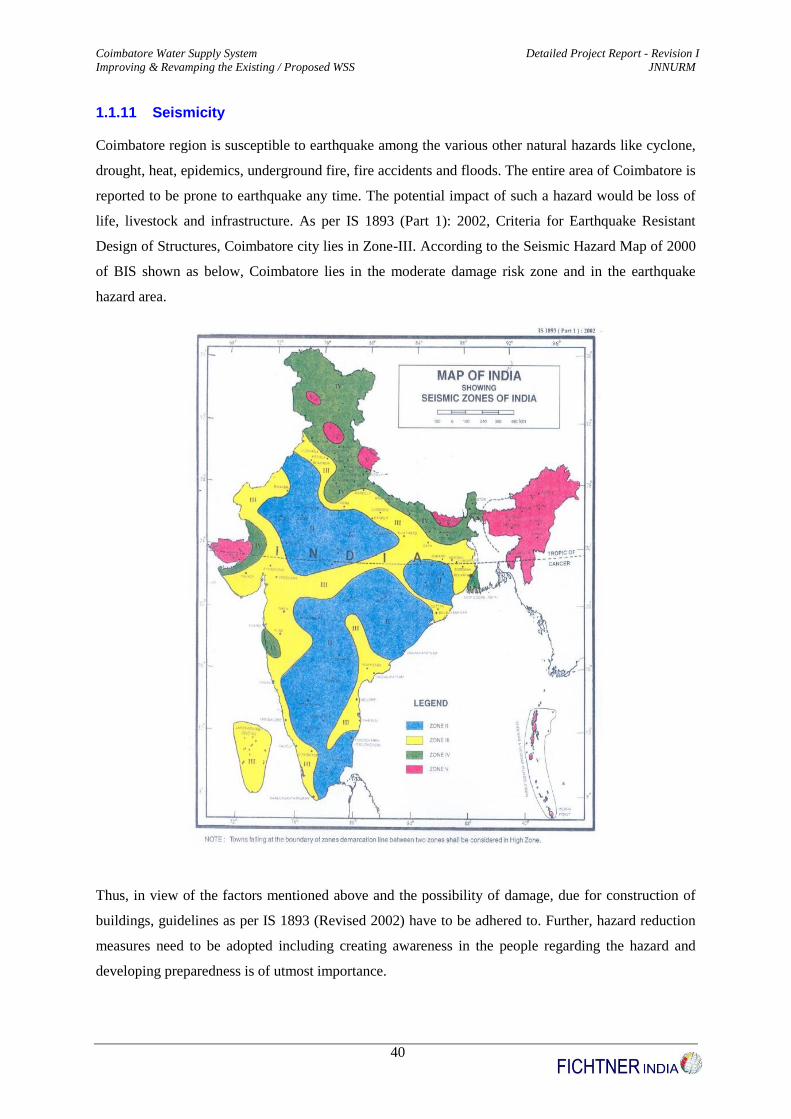
1.1.11 Seismicity
Coimbatore region is susceptible to earthquake among the various other natural hazards like cyclone,
drought, heat, epidemics, underground fire, fire accidents and floods. The entire area of Coimbatore is
reported to be prone to earthquake any time. The potential impact of such a hazard would be loss of
life, livestock and infrastructure. As per IS 1893 (Part 1): 2002, Criteria for Earthquake Resistant
Design of Structures, Coimbatore city lies in Zone-III. According to the Seismic Hazard Map of 2000
of BIS shown as below, Coimbatore lies in the moderate damage risk zone and in the earthquake
hazard area.
Thus, in view of the factors mentioned above and the possibility of damage, due for construction of
buildings, guidelines as per IS 1893 (Revised 2002) have to be adhered to. Further, hazard reduction
measures need to be adopted including creating awareness in the people regarding the hazard and
developing preparedness is of utmost importance.
Coimbatore Water Supply System Detailed Project Report - Revision I
Improving & Revamping the Existing / Proposed WSS JNNURM
41
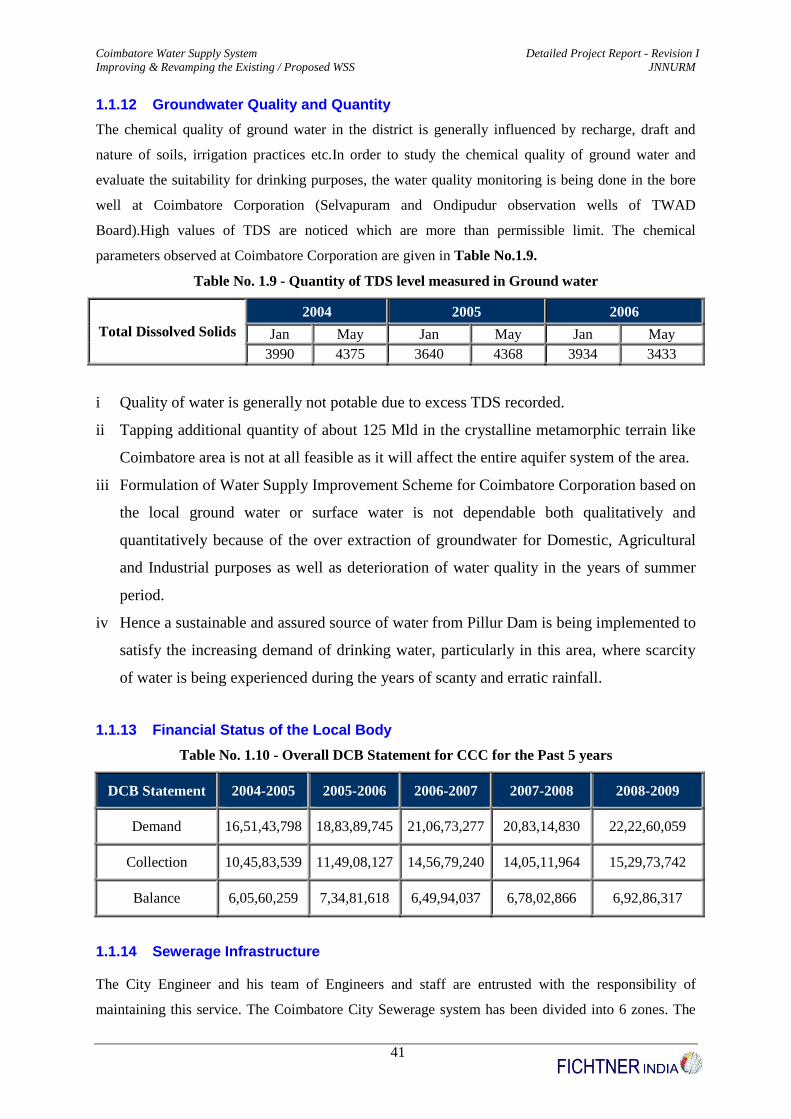
1.1.12 Groundwater Quality and Quantity
The chemical quality of ground water in the district is generally influenced by recharge, draft and
nature of soils, irrigation practices etc.In order to study the chemical quality of ground water and
evaluate the suitability for drinking purposes, the water quality monitoring is being done in the bore
well at Coimbatore Corporation (Selvapuram and Ondipudur observation wells of TWAD
Board).High values of TDS are noticed which are more than permissible limit. The chemical
parameters observed at Coimbatore Corporation are given in Table No.1.9.
Table No. 1.9 - Quantity of TDS level measured in Ground water
Total Dissolved Solids
2004 2005 2006
Jan May Jan May Jan May
3990 4375 3640 4368 3934 3433
i Quality of water is generally not potable due to excess TDS recorded.
ii Tapping additional quantity of about 125 Mld in the crystalline metamorphic terrain like
Coimbatore area is not at all feasible as it will affect the entire aquifer system of the area.
iii Formulation of Water Supply Improvement Scheme for Coimbatore Corporation based on
the local ground water or surface water is not dependable both qualitatively and
quantitatively because of the over extraction of groundwater for Domestic, Agricultural
and Industrial purposes as well as deterioration of water quality in the years of summer
period.
iv Hence a sustainable and assured source of water from Pillur Dam is being implemented to
satisfy the increasing demand of drinking water, particularly in this area, where scarcity
of water is being experienced during the years of scanty and erratic rainfall.
1.1.13 Financial Status of the Local Body
Table No. 1.10 - Overall DCB Statement for CCC for the Past 5 years
DCB Statement 2004-2005 2005-2006 2006-2007 2007-2008 2008-2009
Demand 16,51,43,798 18,83,89,745 21,06,73,277 20,83,14,830 22,22,60,059
Collection 10,45,83,539 11,49,08,127 14,56,79,240 14,05,11,964 15,29,73,742
Balance 6,05,60,259 7,34,81,618 6,49,94,037 6,78,02,866 6,92,86,317
1.1.14 Sewerage Infrastructure
The City Engineer and his team of Engineers and staff are entrusted with the responsibility of
maintaining this service. The Coimbatore City Sewerage system has been divided into 6 zones. The

Coimbatore Water Supply System Detailed Project Report - Revision I
Improving & Revamping the Existing / Proposed WSS JNNURM
42
UGD system has been functioning in old developed areas from 1983 in zone 1 and 2 and from 1994 in
zone 3 to a total length of 52.30 km. Nearly 19000 Residential and Non residential buildings have
been provided with service connections. There are two pumping stations at Ukkadam and at
Nanjundapuram to pump sewage to the STP at Vellalore. Treated effluent is being used for
Horticulture and Golf ground maintenance purposes. The estimates for providing UGD in zones 4, 5
and 6 have been prepared. The Government has accorded Administration Sanction for the project and
the same is being under implementation.There are 19,897 house sewer connections. It is proposed to
extend underground drainage system to the added areas at a cost of Rs.250 Crores by identifying
funding agency for the project.
1.1.15 Sewage Farms
The Corporation has two sewage farms covering an extent of 815 acres: Ukkadam (115 acres) and
Vellalore (700 acres). The Corporation has undertaken an ambitious programme of tree plantation in
an area of about 150 acres in the Vellalore sewage farm with the help of the state forest department.
Around 55,000 saplings have already been planted. The details of the existing sewerage service and
connection charges are given in Table No. 1.11.
Table No. 1.11 - Details of Existing Sewerage Service & Connection Charges
Based on
Property tax
Avg. annual sewerage service
charges for new & existing
connections
One time sewerage connection
charges at the time of new
connections
Domestic (Rs) Commercial (Rs) Domestic (Rs) Commercial (Rs)
Upto Rs.300 200 500 1250 2400
Rs.300 - 1000 1450 3200 4500 10000
Rs.1000-5000 4700 8500 9000 17500
Above Rs.5000 7750 16500 14500 24000
Source: UGSS Report for Coimbatore City
1.1.16 Storm Water Drains
The Corporation maintains 603.50 kms of storm water drains. About 40 kms of new storm water
drains are being constructed and added every year. At present, there is a full fledged storm water
drainage facility in most part of the Corporation. The storm water finds its way towards the nearby
Sanganur Pallam Odai and ultimately joins with the Noyyal River at Singanallur area. Besides, during
the heavy rainfall time and frequent flash flood situations in the corporation area, the storm water

Coimbatore Water Supply System Detailed Project Report - Revision I
Improving & Revamping the Existing / Proposed WSS JNNURM
43
system should be capable of quick disposal of the rain water and also it should prevent any damage to
life, properties, business and transportation etc. The sullage and part of sewage are collected through
the storm water drains and finally finds its way towards the nearby Noyyal River through its canal
system.
1.1.17 Solid Waste Management
Solid waste management in the city is entrusted with the Health Department and Engineering
Department. The aim of the City Municipal Corporation is 100% collection of garbage generated in
the city daily. The area of the city is 105.60 Sq.km. This is divided in to 72 wards (Old) and 60
wards (New). The entire streets in the above 72 wards (Old) are put into blocks for the purpose of
sweeping. Waste generated in the city is about 500 tonnes per day.
The waste generated is swept and collected in 700 dustbins and 201 containers which are distributed
in various street corners and dumper boxes. 2457 Sanitary Workers are employed by this Corporation.
The collected garbage is transported to dust bins by hand-drawn push carts.All the streets in 72 wards
(Old) are divided in day blocks and there are 2457 scavengers in this Corporation. All the garbage
collected is removed through tractors engaged on hire by the Corporation to the compost yard at
Vellalore.
1.1.18 E-Governance
In this Corporation, data relating to property tax, water charges and non-tax items have been
computerized and are collected through computerised service centres / selected banks. Computerised
Service Centres are functioning on all working days from 10.00 A.M. to 5.P.M. so as to enable the
public to remit the tax directly. Public can ascertain the details of property tax dues etc., from the
Computerised service centres during the working hours. Birth and death certificates are issued
through computer service centres and there is also facility to register the complaints of the public
through phone.
1.1.19 Web site
Public can get general information of the Corporation.
Public can have the details of all activities of Corporation through the WEBSITE.
WEBSITE: www.coimbatore-corporation.com
E-Mail ID : [email protected]

Coimbatore Water Supply System Detailed Project Report - Revision I
Improving & Revamping the Existing / Proposed WSS JNNURM
44
1.2 Existing Tariff and Cost Recovery
The levy of water charges is under stepped tariff system from 01.04.2003. The corporation is
collecting the following service connection charges. The existing water tariff is detailed in Table
No.1.12. New Water Supply connection charge is Rs.2000.
Table No. 1.12 - Existing water tariff
Rs. per 1000 litres/month Domestic (Rs.) Non-domestic (Rs.)
Upto 50,000 3.50 7.00
50,001 to 100,000 4.00 9.00
100,001 to 150,000 5.00 12.00
Above 150,000 6.50 15.00
METERED CONNECTIONS
S.No Consumption (m3) Domestic Non Domestic Bulk Domestic Bulk Non domestic
1 1 - 50 m3 3.50 7.00 3.50 7.00
2 50 - 100 4.00 9.00 4.00 9.00
3 100 - 150 5.00 12.00 5.00 12.00
4 Above 150 6.50 15.00 6.50 15.00
5 Bi-Monthly
Minimum 80.00 600.00 350.00 900.00
Domestic users are allowed a free allowance of 100 litres per day
Supply on a per tap basis is allowed at Rs. 50.00 per tap connection per month
Note :
1. All connections are metered and consumers are billed every 2 months
2. Water bills are paid at the water utility office at banks, through bill collectors and at CCMC
3. There were 3240 new connections in 2005-06. The price of a new domestic connection is
Rs.3000 payable prior to connection

Coimbatore Water Supply System Detailed Project Report - Revision I
Improving & Revamping the Existing / Proposed WSS JNNURM
45
2 Project Definition, Concept and Scope
2.1 Project Area
The project area is the Coimbatore City Corporation area, having 72 wards (Old) , covering
105.6 sq km area.
2.2 Scope of Work
Preparation of DPR
Part I
(i) For improving and revamping the existing water supply distribution net work with
assured storage facilities for uninterrupted 24 X 7 water supply facility to the entire
Corporation area
Part II
(ii) For design, operation, maintenance of uninterrupted 24 X 7 water supply facility to
demo zones I & II in Coimbatore Corporation
Part III
(i) Design of TwoTunnels having capacity of 265 Mld for Raw Water and 250 Mld for
Clear Water
(Aready submitted separately to Coimbatore Corporation vide FI/letter no
3350810001/018 dated 25/01/10)
2.3 Objectives
2.3.1 Objective: A
Objectives of implementation of un-interrupted Water Supply to the entire city:
1. Implementing good engineering practices to upgrade existing network including replacement of
old worn out pipes.
2. Studying in detail the existing distribution network, zones, sub zones and revamping the existing
water supply network and providing the additional storage reservoirs wherever necessary for 24 X
7 un-interrupted water supply including disinfection methods.
3. Increasing the zones and sub zones with assured storage facilities for entire city.
4. Providing consumers with an 24 X 7 un-interrupted water supply at desired pressure
5. Reduction of Un-account for Water (UFW) to within 15% by reducing leakages and unmeasured

Coimbatore Water Supply System Detailed Project Report - Revision I
Improving & Revamping the Existing / Proposed WSS JNNURM
46
supply.
6. 100% metering with good quality meters having long life spans.
7. Improving billing mechanism (Reading, bills generation & distribution) to reduce time & cost per
bill including spot billing system etc.
8. Better services to urban poor by implementation of slum policy of Government of Tamilnadu.
9. Attending consumer complaints within short time.
10. Improving the satisfaction of stake holders.
11. Accountability on design, implementation, and O&M with single agency through performance
based contract and bench marking of services.
12. Implementing the lessons learnt from pilot zones to other parts of city.
13. Digital map of each rezoning distribution network to the entire city.
14. Preparation of detailed project report and Bid Document including the plan polio.
2.3.2 Objective: B
1. To introduce continuous, pressurized and improved water supply services in the Demonstration
Zones for a period of 5 years.
2. To undertake a structured prudent rehabilitation program of optimizing the performance of
existing infrastructure assets to improve the efficiency of the water supply service in the
Demonstration Zones.
3. To establish, within the chosen Demonstration Zone, an efficient and effective customer contact
centre offering billing, collection and complaint redressal support services.
4. To operate, maintain and manage the water supply services at the specified performance levels or
higher in the Demonstration Zone.
5. To provide efficient and effective metered, measured and monitored water services ensuring
equity and cost recovery at the tariff levels fixed by Coimbatore City Municipal Corporation from
time to time.
6. Preparation of DPR as per TOR including bid documents.
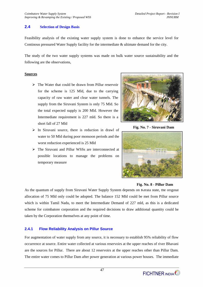
Coimbatore Water Supply System Detailed Project Report - Revision I
Improving & Revamping the Existing / Proposed WSS JNNURM
47
2.4 Selection of Design Basis
Feasibility analysis of the existing water supply system is done to enhance the service level for
Continous pressured Water Supply facility for the intermediate & ultimate demand for the city.
The study of the two water supply systems was made on bulk water source sustainability and the
following are the observations,
Sources
The Water that could be drawn from Pillur reservoir
for the scheme is 125 Mld, due to the carrying
capacity of raw water and clear water tunnels. The
supply from the Siruvani System is only 75 Mld. So
the total expected supply is 200 Mld. However the
Intermediate requirement is 227 mld. So there is a
short fall of 27 Mld
In Siruvani source, there is reduction in drawl of
water to 50 Mld during poor monsoon periods and the
worst reduction experienced is 25 Mld
The Siruvani and Pillur WSSs are interconnected at
possible locations to manage the problems on
temporary measure
As the quantum of supply from Siruvani Water Supply System depends on Kerala state, the original
allocation of 75 Mld only could be adopted. The balance 152 Mld could be met from Pillur source
which is within Tamil Nadu, to meet the Intermediate Demand of 227 mld, as this is a dedicated
scheme for coimbatore corporation and the required decisions to draw additional quantity could be
taken by the Corporation themselves at any point of time.
2.4.1 Flow Reliability Analysis on Pillur Source
For augmentation of water supply from any source, it is necessary to establish 95% reliability of flow
occurrence at source. Entire water collected at various reservoirs at the upper reaches of river Bhavani
are the sources for Pillur. There are about 12 reservoirs at the upper reaches other than Pillur Dam.
The entire water comes to Pillur Dam after power generation at various power houses. The immediate
Fig. No. 7 - Siruvani Dam
Fig. No. 8 - Pillur Dam

Coimbatore Water Supply System Detailed Project Report - Revision I
Improving & Revamping the Existing / Proposed WSS JNNURM
48
power station above Pillur Dam is Kundah Power House III which has an installed capacity of 3 x 60
MW = 180 MW with a maximum discharge of 1800 cusecs. So, there is enough water available after
power generation to meet the Intermediate & Ultimate requirement.
A Statement showing the year wise inflow into Pillur Dam Reservoir from 1966 to October 2008,
collected from TNEB is furnished below in Table No. 2.1
Table No. 2.1 - Inflow into Pillur Dam Reservoir (1966 – 2008)
Year Inflow in
mcft Year
Inflow in
mcft Year
Inflow in
mcft Year
Inflow in
mcft
1966 24112 1976 19378 1986 22072 1997 30806
1967 27459 1977 32105 1987 11943 1998 32951
1968 26153 1978 30545 1988 21900 1999 28009
1969 22489 1979 50467 1989 21694 2000 22918
1970 24665 1980 40546 1990 16995 2001 21277
1971 28356 1981 38400 1991 27913 2002 13075
1972 25523 1982 21268 1992 49432 2003 6897
1973 33062 1983 22256 1993 22524 2004 30001
1974 28655 1984 27459 1994 34148 2005 36992
1975 30952 1985 18595 1995 21820 2006 34497
1996 28470 2007 42358
Upto
10/2008 18892
A flow duration analysis is arrived in order to establish the 95% reliability of flow in the river. It was
found that the source reliability for Pillur reservoir is more than 100 %.The details of the calculation
was listed in Table No. 2.2.

49
Table No. 2.2 - Pillur Dam Source Realiability Analysis
Year Yearly Inflow to Pillur
Reservoir (mcft) Yearly Inflow (Mm3) Inflow (Mld) Requirement (Mld) Excess (Mld) % Excess
1966 24112 682775887 1870618868 215 1870618653 > 100 %
1967 27459 777552384 2130280504 215 2130280289 > 100 %
1968 26153 740570578 2028960488 215 2028960273 > 100 %
1969 22489 636817640 1744705863 215 1744705648 > 100 %
1970 24665 698435105 1913520836 215 1913520621 > 100 %
1971 28356 802952599 2199870134 215 2199869919 > 100 %
1972 25523 722730963 1980084830 215 1980084615 > 100 %
1973 33062 936211695 2564963548 215 2564963333 > 100 %
1974 28655 811419337 2223066677 215 2223066462 > 100 %
1975 30952 876463141 2401268879 215 2401268664 > 100 %
1976 19378 548723919 1503353203 215 1503352988 > 100 %
1977 32105 909112469 2490719093 215 2490718878 > 100 %
1978 30545 864938183 2369693652 215 2369693437 > 100 %
1979 50467 1429066469 3915250600 215 3915250385 > 100 %
1980 40546 1148135000 3145575342 215 3145575127 > 100 %
1981 38400 1087367040 2979087781 215 2979087566 > 100 %
1982 21268 602242766 1649980181 215 1649979966 > 100 %
1983 22256 630219814 1726629627 215 1726629412 > 100 %
1984 27459 777552384 2130280504 215 2130280289 > 100 %
1985 18595 526551826 1442607742 215 1442607527 > 100 %
1986 22072 625009513 1712354830 215 1712354615 > 100 %
1987 11943 338188140 926542849 215 926542634 > 100 %
1988 21900 620139015 1699011000 215 1699010785 > 100 %
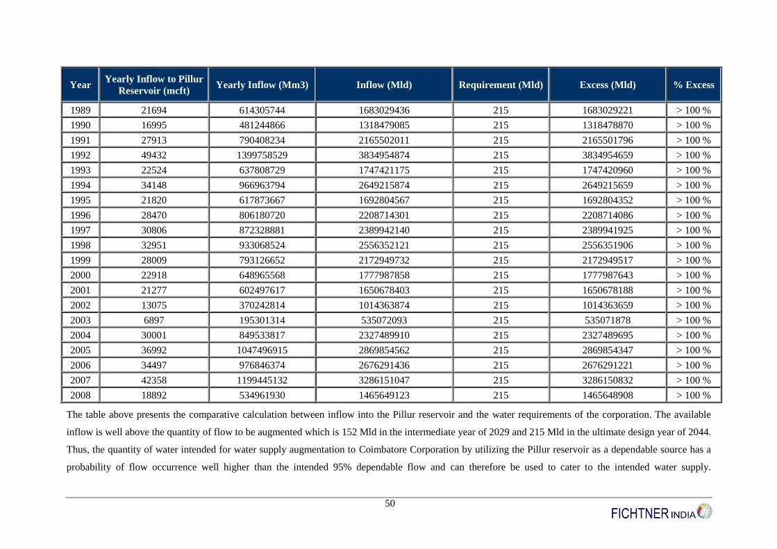
50
Year Yearly Inflow to Pillur
Reservoir (mcft) Yearly Inflow (Mm3) Inflow (Mld) Requirement (Mld) Excess (Mld) % Excess
1989 21694 614305744 1683029436 215 1683029221 > 100 %
1990 16995 481244866 1318479085 215 1318478870 > 100 %
1991 27913 790408234 2165502011 215 2165501796 > 100 %
1992 49432 1399758529 3834954874 215 3834954659 > 100 %
1993 22524 637808729 1747421175 215 1747420960 > 100 %
1994 34148 966963794 2649215874 215 2649215659 > 100 %
1995 21820 617873667 1692804567 215 1692804352 > 100 %
1996 28470 806180720 2208714301 215 2208714086 > 100 %
1997 30806 872328881 2389942140 215 2389941925 > 100 %
1998 32951 933068524 2556352121 215 2556351906 > 100 %
1999 28009 793126652 2172949732 215 2172949517 > 100 %
2000 22918 648965568 1777987858 215 1777987643 > 100 %
2001 21277 602497617 1650678403 215 1650678188 > 100 %
2002 13075 370242814 1014363874 215 1014363659 > 100 %
2003 6897 195301314 535072093 215 535071878 > 100 %
2004 30001 849533817 2327489910 215 2327489695 > 100 %
2005 36992 1047496915 2869854562 215 2869854347 > 100 %
2006 34497 976846374 2676291436 215 2676291221 > 100 %
2007 42358 1199445132 3286151047 215 3286150832 > 100 %
2008 18892 534961930 1465649123 215 1465648908 > 100 %
The table above presents the comparative calculation between inflow into the Pillur reservoir and the water requirements of the corporation. The available
inflow is well above the quantity of flow to be augmented which is 152 Mld in the intermediate year of 2029 and 215 Mld in the ultimate design year of 2044.
Thus, the quantity of water intended for water supply augmentation to Coimbatore Corporation by utilizing the Pillur reservoir as a dependable source has a
probability of flow occurrence well higher than the intended 95% dependable flow and can therefore be used to cater to the intended water supply.

Coimbatore Water Supply System Detailed Project Report - Revision I
Improving & Revamping the Existing / Proposed WSS JNNURM
51
2.5 Deficiencies of the Existing Water Supply System
It is evidenced from the above Source Reliability Analysis, that the Pillur source is more than
adequate to meet the project requirement. The water quantity is much excess that it can cater to more
than multiple times the requirement of the Coimbatore corporation. It is also evidenced that the
prevailing Tunnels can carry more water as compared to the intermediate and ultimate requirement of
the corporation, if the depth of water flow in the tunnel is increased. So as far as the Bulk water /
source of water, Coimbatore corporation possess excess quantity of water and also adequate
infrastructure to bring until the Master Service Reservoirs at Ramakrishnapuram. Since Siruvanui
being the interstate source, source augmentation / source improvement shall not be possible.
Subsequently Pillur being allocated as reliable / perennial source for the corporation, restricting
Siruvani to 75 Mld until the ultimate stage of the project.
Under the present scenario, the water supply infrastructure from Master Service Reservoirs to End
Consumers namely prevailing service reservoirs, feeder mains, pumpsets, sumps, distribution system
pipelines, water meters has been analysed in detail with data collected through field visits, data
available from the corporation, etc., After detailed investigation, it is understood that the present
service level of the Coimbatore Corporation ranges from 75 lpcd to 125 lpcd (Based on sample
studies made) that too with the intermittent supply of 3 to 4 hours a day, once in a 3 to 4 days a week
(Under worst case scenario) with residual pressure ranging from 0.1 m to 2 m (Based on sample
studies made) at the house service connections.
There was also list of frequent compliant on the present water supply system, exspecially the
Distribution System by various Councillors / elected representatives in Councillors Grievances in
Zonal meeting. The salient complaint list were as follows,
1. Inadequate Water Supply & inadequate pressure
2. Frequent burst & breakdowns in pipes
3. Contamination due to mixing of sewage
4. Blockage of pipes
5. Water received only when pumped by hand pumps from the HSC
6. Presence of Old pipes with frequent leaks
7. Limited hours of supply
The above such complaints were collected by the consultant from the ward wise councillors in the
Grievance meeting and the cause for such defeciences, remedial measures was elaobarated to all the
councillors attended the meeting. The details of the same was enclosed Volume I (b) Annexure
Number – A2 part of this DPR.

Coimbatore Water Supply System Detailed Project Report - Revision I
Improving & Revamping the Existing / Proposed WSS JNNURM
52
2.6 Project Benchmarks
As Coimbatore, one of the major and fast growing industrial hub of Tamil Nadu next to Chennai, the
infrastructure should meet the requirements of the growing population. As water supply is one of the
basic essential amenities, coimbatore corporation planned to revamp the present intermittent water
supply to a 24x7 type of water supply with the salient bench marks envisaged as per the CPHEEO
norms. The following Table No. 2.3 illustrates the project bench mark after the implementation of the
project.
Table No. 2.3 - Project Benchmarks
S.No Propsoed Indicator After Implementation
1 Coverage of Water Supply Connection 100 %
2 Per capita availability of Water at consumer end 135 lpcd
3 Extent of metering of water connections 100 %
4 Extent of Non – revenue water 15 %
5 Continuity of water supply 24 X 7
6 Efficiency in redressal of customer complaints 80 %
7 Adequacy of treatment & disinfection and quality of
water supplied 100 %
8 Cost recovery in water supply services 100 %
9 Efficiency in collection of water supply related charges 90 %
10 Number of persons receiving less than 70 lpcd 0 %
2.7 Need for the Project
In order for the corporation to meet the project benchmarks, the prevailing system components were
analysed with respect to the objective and are presented in synopsis as below. The detailed
calculations, analysis made were presented in Annexure part of this DPR and the proposed system
were elaborated in respective portion of the DPR.
1. Existing Feeder Mains
Mainly of AC, PSC & CI Pipes with frequent Leaks with 78 Kms pipe length
No Bulk water meters to quantum of water / Inflow or Outflow in the feeder mains
UFW in Pillur Feeder Main is 23.55 % and in Siruvani Feeder Main is 22.37 % as
compared to permissible limit of 5 %. The details of the same are enclosed in
Volume I (b) Annexure Number – A4 part of this DPR.
Direct tapping to Distribution System before Service Reservoirs
Separate bulk water supply line is observed to Jail area, Railways, etc.,

Coimbatore Water Supply System Detailed Project Report - Revision I
Improving & Revamping the Existing / Proposed WSS JNNURM
53
2. Existing Service Reservoirs & Storage Sumps
The following gives the list of Service Reservoirs in Dilapted condition and also
with less staghing height not suitable for a 24x7 type of water supply system
Sl.No. SR Location Ward Number
(Old) Capacity (LL)
1 Maniyakaram Palayam SR 72 1.00
2 Police Quarters SR 72 0.50
3 V.V.Nagar SR 72 0.50
4 V.O.C Nagar Sump 72 0.50
5 Ganapathy Ma Nagar Sump 72 3.00
6 Gandhi Ma Nagar Sump 72 6.00
7 Housing Unit Sump 3 0.50
8 Nanjundapuram SR 12 2.00
9 Sowripalayam SR 14 5.00 (Staghing Height – 8m)
10 Varadharajapuram SR 11 10.00 (Staghing Height – 8m)
11 Uppilipalayam SR 11 10.00 (Dilapted Condition)
12 Bharathi Park GLSR 34 10.00
13 Bharathi Park GLSR 34 10.00 (Dilapted Condition)
14 Gandhi Park GLSR 51 10.00
15 SIHS Colony Sump 4 3.00
3. Distribution System
Mainly of PVC, PSC & CI pipes with 1122 Kms pipe length
Many new layouts and uncovered areas without water supply is about 253 Kms
Major portion of corporation (namely North, East, South & Central) are Panchayats
earlier except that of the West Zones served by Siruvani which was the old town. The
water supplied at the rate of 70 lpcd earlier as per the norms of Town Panchayats. So,
the pipe sizes are capable of supplying 70 lpcd only as compared to the required rate
of 135 lpcd
Many D’System are supplied by more than one or two service reservoirs
simulatneosuly due to inadequate pressure, if supplied via single service reservoir
Almost all the wards faces Inadequate Water Supply & inadequate pressure, Frequent
burst & breakdowns in pipes, Contamination due to mixing of sewage, Blockage of
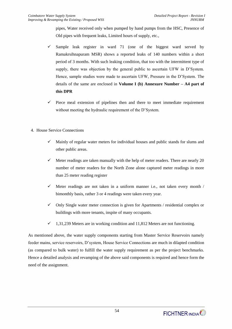
Coimbatore Water Supply System Detailed Project Report - Revision I
Improving & Revamping the Existing / Proposed WSS JNNURM
54
pipes, Water received only when pumped by hand pumps from the HSC, Presence of
Old pipes with frequent leaks, Limited hours of supply, etc.,
Sample leak register in ward 71 (one of the biggest ward served by
Ramakrsihnapuram MSR) shows a reported leaks of 140 numbers within a short
period of 3 months. With such leaking condition, that too with the intermittent type of
supply, there was objection by the general public to ascertain UFW in D’System.
Hence, sample studies were made to ascertain UFW, Pressure in the D’System. The
details of the same are enclosed in Volume I (b) Annexure Number – A4 part of
this DPR
Piece meal extension of pipelines then and there to meet immediate requirement
without meeting the hydraulic requirement of the D’System.
4. House Service Connections
Mainly of regular water meters for individual houses and public stands for slums and
other public areas.
Meter readings are taken manually with the help of meter readers. There are nearly 20
number of meter readers for the North Zone alone captured meter readings in more
than 25 meter reading register
Meter readings are not taken in a uniform manner i.e., not taken every month /
bimonthly basis, rather 3 or 4 readings were taken every year.
Only Single water meter connection is given for Apartments / residential complex or
buildings with more tenants, inspite of many occupants.
1,31,239 Meters are in working condition and 11,812 Meters are not functioning.
As mentioned above, the water supply components starting from Master Service Reservoirs namely
feeder mains, service reservoirs, D’system, House Service Connections are much in dilapted condition
(as compared to bulk water) to fulfill the water supply requirement as per the project benchmarks.
Hence a detailed analysis and revamping of the above said components is required and hence form the
need of the assignment.

Coimbatore Water Supply System Detailed Project Report - Revision I
Improving & Revamping the Existing / Proposed WSS JNNURM
55
S.No Propsoed Indicator Before
Implementation
After
Implementation
1 Coverage of Water Supply Connection 95.37 % 100 %
2 Per capita availability of Water at
consumer end
70 – 125 lpcd
(Once in 4 to 5 Days)
135 lpcd
(Daily)
3 Extent of metering of water connections 87.49 % 100 %
4 Extent of Non – revenue water 23 % 15 %
5 Continuity of water supply
Intermittent (Once in 2 to
3 Days a week , 2 to 3
Hours a Day)
24 X 7
6 Efficiency in redressal of customer
complaints 80 % 80 %
7 Adequacy of treatment & disinfection
and quality of water supplied Nil 100 %
8 Cost recovery in water supply services 89 % 100 %
9 Efficiency in collection of water supply
related charges 70 – 80 % 90 %
10 Number of persons receiving less than 70
lpcd Nil 0 %
2.8 Technical Solutions towards Project Benchmarks
2.8.1 Methodology for 24 X 7 WSS
The prerequisites for the design and monitoring of 24 X 7 system are discussed below
(i) Back drop drawing
The satellite pan sharpened digitized image of 0.6 resolutions for the city can be digitized to a vector
image in a DXF format and this image could be used as a backdrop drawing for hydraulic model, but
the same is not available with the Coimbatore Corporation. Hence the survey drawing obtained from
Corporation dually vetted is used as the base drawing for the preparation of existing network.
(ii) Operational Zones
The town has to be rezoned into various operational zones for designing of 24 X 7 WSS. The existing
storage and the additional storage systems for the design demand are worked out and rezoning was
done, identifying new reservoirs required in additional to the existing reservoirs. Each SR with its
serving area will form an operational zone and the water from the MSR is gravitated to each SR. The
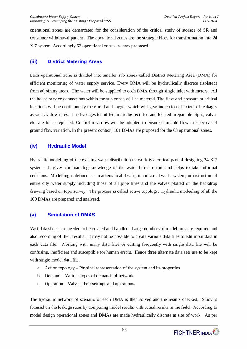
Coimbatore Water Supply System Detailed Project Report - Revision I
Improving & Revamping the Existing / Proposed WSS JNNURM
56
operational zones are demarcated for the consideration of the critical study of storage of SR and
consumer withdrawal pattern. The operational zones are the strategic blocs for transformation into 24
X 7 system. Accordingly 63 operational zones are now proposed.
(iii) District Metering Areas
Each operational zone is divided into smaller sub zones called District Metering Area (DMA) for
efficient monitoring of water supply service. Every DMA will be hydraulically discrete (isolated)
from adjoining areas. The water will be supplied to each DMA through single inlet with meters. All
the house service connections within the sub zones will be metered. The flow and pressure at critical
locations will be continuously measured and logged which will give indication of extent of leakages
as well as flow rates. The leakages identified are to be rectified and located irreparable pipes, valves
etc. are to be replaced. Control measures will be adopted to ensure equitable flow irrespective of
ground flow variation. In the present context, 101 DMAs are proposed for the 63 operational zones.
(iv) Hydraulic Model
Hydraulic modelling of the existing water distribution network is a critical part of designing 24 X 7
system. It gives commanding knowledge of the water infrastructure and helps to take informal
decisions. Modelling is defined as a mathematical description of a real world system, infrastructure of
entire city water supply including those of all pipe lines and the valves plotted on the backdrop
drawing based on topo survey. The process is called active topology. Hydraulic modeeling of all the
100 DMAs are prepared and analysed.
(v) Simulation of DMAS
Vast data sheets are needed to be created and handled. Large numbers of model runs are required and
also recording of their results. It may not be possible to create various data files to edit input data in
each data file. Working with many data files or editing frequently with single data file will be
confusing, inefficient and susceptible for human errors. Hence three alternate data sets are to be kept
with single model data file.
a. Action topology – Physical representation of the system and its properties
b. Demand – Various types of demands of network
c. Operation – Valves, their settings and operations.
The hydraulic network of scenario of each DMA is then solved and the results checked. Study is
focused on the leakage rates by comparing model results with actual results in the field. According to
model design operational zones and DMAs are made hydraulically discrete at site of work. As per

Coimbatore Water Supply System Detailed Project Report - Revision I
Improving & Revamping the Existing / Proposed WSS JNNURM
57
hydraulic analysis carried out by the hydraulic model, new pipe lines will be laid replacing inadequate
size or defective old pipes will be replaced. Using DMA, NRW for each DMA will be worked out
and could be tackled, one by one based on priority.
(vi) Bulk Water Meters and Consumer Water Meters
Bulk water meters will be installed to measure the quantum of water that is entered into a DMA and
100 % HSCs are proposed to be installed with consumer water meters to measure the quantity of
water consumed as aforesaid.
2.8.2 Instrumentation for 24 X 7 WSS
Sluice / Scour Valves
Sluice valve is used for flow control, isolation of sub zones and for
carrying out O & M works. There are DI sluice valves of class PN-
10 which are available in market with resilient seated, without valve
pits, buried underground with telescopic extension rod with soft
sealing without gland, flat gate bottom with lining conformed to IS
14846/BS 5163/DIN 3202. These hi-tech valves are more suitable to
places where very high traffic load is experienced and carrying out
O & M practise will be cause for disturbance to the traffic, these
buried type application are suitable. These type of valves are
proposed for the entire Coimbatore corporation.
Importance of Air Management in 24/7 Water Supply Distribution Systems
The first step towards 24 X 7 water supply is strengthening of existing distribution system both in
terms of flow capacity as well as minimizing the leakage potential. One of the main reasons for
excessive leakage in 24 X 7 water supply system is the uncontrolled entry and exit of air into the
distribution system that damages the pipe joints.
Most water distribution systems in the country are old and are in bad shape in terms of leak
prevention. A major portion of the leakage in distribution systems occurs at pipe joints when the pipe
systems are prone to excessive leakage. Therefore understanding the air-water interaction and proper
management of air in distribution systems is at most important for minimizing the leakage in water

Coimbatore Water Supply System Detailed Project Report - Revision I
Improving & Revamping the Existing / Proposed WSS JNNURM
58
supply systems.
Air may enter the pipe distribution network from supply source even in continuous water supply
systems. If the treated water enters the clear water tank in the form of a plunging jet the resulting
turbulence can entrain air that gets transported into the distribution system. Dissolved air present in
high pressure water may be released when the water passes through low pressure regions. Air enters
the distribution network from the delivery points (typically connections to underground sumps or
elevated household storage tanks) if the pipelines gets drained partially or completely. Air may also
enter through the leaky joints at high elevation points along the pipelines.
Air that has entered the distribution system gets vented out during the subsequent filling cycle of
supply of water to consumers. If the flow velocity is not sufficient, air bubbles get accumulated at the
pipe crown, horizontal bends, and/or high elevation points. This may get compressed when the water
pressure reaches those locations. Pockets of compressed air may choke the flow reducing the delivery
efficiency of pipelines. Sudden movement of choked air may generate undue stresses on pipe joints
which in turn may create or exacerbate the existing leaks.
Proper venting of entrained air is very important for efficient operation and longer life of water supply
systems. Appropriately sized and judicially placed good quality air valves will vent the air out of the
system without creating choking conditions and the associated pipe joint problems. Air may continue
to create choking conditions while larger orifice sizes than the desired values may lead to air valve
slam and associated surge pressure which may damage the pipe joints eventually leading to leaky
joints. Inefficient air valves may lead to more problems than not having them. For example improper
float design may lead to premature closure of the air valve resulting in small but potentially dangerous
(elsewhere in the distribution system) pressure surges. The use of larger air valve may lead to
frequent pipe breaks from the location of the improperly sized air valve. Premature closure also
results in trapping of compressed air which leads to choking of water flow. Proper venting of air from
the distribution system especially near the consumer meter is essential to avoid over charging the
consumer. Compressed air pocket passing through a water meter makes the meter record much higher
flow quantities than water. Such overcharging may eventually lead to mistrust and eventual misuse of
water meters. While proper venting of air is important during the filling and delivery cycle of water to
the consumers, letting air into the system during the draining cycle (after the flow has ceased entering
the distribution system) is also very important to prevent low pressures in the system which can
potentially be more detrimental on the pipe joints. Most pipe joints can withstand fairly positive
pressures but may not be able to withstand negative pressures. Such joints are highly susceptible for
leakage when they are subject to high negative pressures. In continuous water supply systems, low
pressures in the distribution system occur only during abnormal operation such as power failure
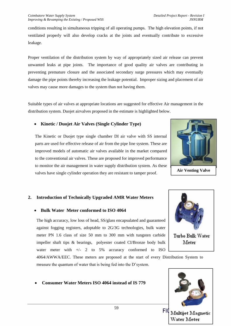
Coimbatore Water Supply System Detailed Project Report - Revision I
Improving & Revamping the Existing / Proposed WSS JNNURM
59
Air Venting Valve
conditions resulting in simultaneous tripping of all operating pumps. The high elevation points, if not
ventilated properly will also develop cracks at the joints and eventually contribute to excessive
leakage.
Proper ventilation of the distribution system by way of appropriately sized air release can prevent
unwanted leaks at pipe joints. The importance of good quality air valves are contributing in
preventing premature closure and the associated secondary surge pressures which may eventually
damage the pipe points thereby increasing the leakage potential. Improper sizing and placement of air
valves may cause more damages to the system than not having them.
Suitable types of air valves at appropriate locations are suggested for effective Air management in the
distribution system. Duojet airvalves proposed in the estimate is highlighted below.
Kinetic / Duojet Air Valves (Single Cylinder Type)
The Kinetic or Duojet type single chamber DI air valve with SS internal
parts are used for effective release of air from the pipe line system. These are
improved models of automatic air valves available in the market compared
to the conventional air valves. These are proposed for improved performance
to monitor the air management in water supply distribution system. As these
valves have single cylinder operation they are resistant to tamper proof.
2. Introduction of Technically Upgraded AMR Water Meters
Bulk Water Meter conformed to ISO 4064
The high accuracy, low loss of head, SS/glass encapsulated and guaranteed
against fogging registers, adoptable to 2G/3G technologies, bulk water
meter PN 1.6 class of size 50 mm to 300 mm with tungsten carbide
impeller shaft tips & bearings, polyester coated CI/Bronze body bulk
water meter with +/- 2 to 5% accuracy conformed to ISO
4064/AWWA/EEC. These meters are proposed at the start of every Distribution System to
measure the quantum of water that is being fed into the D’system.
Consumer Water Meters ISO 4064 instead of IS 779
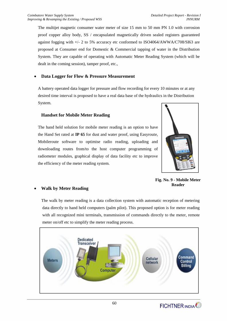
Coimbatore Water Supply System Detailed Project Report - Revision I
Improving & Revamping the Existing / Proposed WSS JNNURM
60
Fig. No. 9 - Mobile Meter
Reader
The multijet magnetic consumer water meter of size 15 mm to 50 mm PN 1.0 with corrosion
proof copper alloy body, SS / encapsulated magnetically driven sealed registers guaranteed
against fogging with +/- 2 to 5% accuracy etc conformed to ISO4064/AWWA/C708/SI63 are
proposed at Consumer end for Domestic & Commercial tapping of water in the Distribution
System. They are capable of operating with Automatic Meter Reading System (which will be
dealt in the coming session), tamper proof, etc.,
Data Logger for Flow & Pressure Measurement
A battery operated data logger for pressure and flow recording for every 10 minutes or at any
desired time interval is proposed to have a real data base of the hydraulics in the Distribution
System.
Handset for Mobile Meter Reading
The hand held solution for mobile meter reading is an option to have
the Hand Set rated at IP 65 for dust and water proof, using Easyroute,
Mobileroute software to optimise radio reading, uploading and
downloading routes from/to the host computer programming of
radiometer modules, graphical display of data facility etc to improve
the efficiency of the meter reading system.
Walk by Meter Reading
The walk by meter reading is a data collection system with automatic reception of metering
data directly to hand held computers (palm pilot). This proposed option is for meter reading
with all recognized mini terminals, transmission of commands directly to the meter, remote
meter on/off etc to simplify the meter reading process.

Coimbatore Water Supply System Detailed Project Report - Revision I
Improving & Revamping the Existing / Proposed WSS JNNURM
61
Fig. No. 10 - Walk by Meter Reading
Radio Module for Remote Water Reader
The proposed Radio Module for Remote Water Reader
is another technology option available in the market
compatible with water meters from DN 15 to 500 mm to
store records spanning 13 months, even work in
congested areas.
2.8.3 Disinfection Process for 24 X 7 WSS
The disinfection proposed is Gas Chlorination system at MSR.
2.8.4 24 X 7 Customer Care Centre
The 24 X 7 customer care centre with billing and collection software including complaints redressal
module and monitoring is proposed.
2.8.5 Introduction of Volumetric Rational Tariff
The tariff plays a vital role in revenue generation of any water supply system to make it self
sustainable. A suitable methodology for designing volumetric tariff will be proposed after approval of
the final cost estimate considering subsidiary for poor category.
2.9 Physical Infrastructure Components
2.9.1 Formulation of Design Basis
(i) Design Parameters
The design parameters for designing water supply systems was adopted as per CPHEEO manual on
Water Supply and also considering TWAD (Tamil Nadu Water Supply & Drainage Board) norms as
mentioned in the given Table No. 2.4

Coimbatore Water Supply System Detailed Project Report - Revision I
Improving & Revamping the Existing / Proposed WSS JNNURM
62
Table No. 2.4 – Hydraulic Design Parameters
Sl.No Parameters Data
1 Ultimate Design period (Approved) 30 yrs (2014 to 2044)
2 Intermediate period (Approved) 15 yrs (2014 to 2029)
3 Pumping hours for intermediate and
ultimate demand 22 hours
4 Per capita supply 135 lpcd
5 Intermediate Commercial & Industrial
demand 9.98 mld
6 Ultimate Industrial and Commercial
demand 17.25 mld
7
UFW in the system (Maximum) 15%
a) Feeder or Conveying Mains 5 %
b) Distribution System 10 %
8 Materials for pipes for Distribution
System
90 to 315mm – HDPE PN6 PE100
> 350 mm – DI S/S K7 pipes
9
Materials for pipes for Feeder Mains
(As per TWAD Norms)
< 200 mm – HDPE
200 – 600 mm – DI S/S K7 Pipes
> 600 mm – MS Pipes
a) Class of Pipes
HDPE –PN 6-PE 100 for Gravity Mains
HDPE – PN 8- PE 100 for Pumping Mains
DI K7 S/S for Gravity & Pumping Mains
MS (With minimum of 8mm thickness for
Gravity Mains)
10 Hazer William’s factor “C” for pipes
Proposed Pipes 140 for DI & MS Pipes and
145 for HDPE Pipes
Existing Pipes 100 for CI Pipes
11
Service Reservoirs
a) Storage Capacity 1/3 rd of Intermediate Demand
b) Capacities Rounded Off to nearest One Lakh Litres as per
TWAD Norms for Urban water supply schemes
c) No. of Compartments Generally 2 for more than 10 LL
d) Staghing Height 12 to 15 m
e) Shape Circular
12
Distribution System
a) Minimum Residual Head at Ferrule
Point
12 m for Proposed SR’s (and also for existing
SR’s wherever possible) and
7 m for Existing SR’s
b) Pressure Variation within the Zones Within 5 m
c) Peak Factor
3.00 for Population < 50,000
2.5 for Population from 50,000 – 2,00,000
2 for Population > 2,00,000
13 Underground Sumps Detention Time of 30 & 60 minutes as per
TWAD Norms
(ii) Population Projection
The population projection was done by the following methods namely,
1. Arithmetical Increase Method
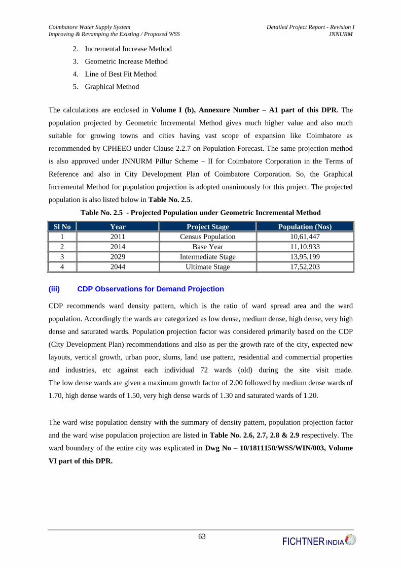
Coimbatore Water Supply System Detailed Project Report - Revision I
Improving & Revamping the Existing / Proposed WSS JNNURM
63
2. Incremental Increase Method
3. Geometric Increase Method
4. Line of Best Fit Method
5. Graphical Method
The calculations are enclosed in Volume I (b), Annexure Number – A1 part of this DPR. The
population projected by Geometric Incremental Method gives much higher value and also much
suitable for growing towns and cities having vast scope of expansion like Coimbatore as
recommended by CPHEEO under Clause 2.2.7 on Population Forecast. The same projection method
is also approved under JNNURM Pillur Scheme – II for Coimbatore Corporation in the Terms of
Reference and also in City Development Plan of Coimbatore Corporation. So, the Graphical
Incremental Method for population projection is adopted unanimously for this project. The projected
population is also listed below in Table No. 2.5.
Table No. 2.5 - Projected Population under Geometric Incremental Method
Sl No Year Project Stage Population (Nos)
1 2011 Census Population 10,61,447
2 2014 Base Year 11,10,933
3 2029 Intermediate Stage 13,95,199
4 2044 Ultimate Stage 17,52,203
(iii) CDP Observations for Demand Projection
CDP recommends ward density pattern, which is the ratio of ward spread area and the ward
population. Accordingly the wards are categorized as low dense, medium dense, high dense, very high
dense and saturated wards. Population projection factor was considered primarily based on the CDP
(City Development Plan) recommendations and also as per the growth rate of the city, expected new
layouts, vertical growth, urban poor, slums, land use pattern, residential and commercial properties
and industries, etc against each individual 72 wards (old) during the site visit made.
The low dense wards are given a maximum growth factor of 2.00 followed by medium dense wards of
1.70, high dense wards of 1.50, very high dense wards of 1.30 and saturated wards of 1.20.
The ward wise population density with the summary of density pattern, population projection factor
and the ward wise population projection are listed in Table No. 2.6, 2.7, 2.8 & 2.9 respectively. The
ward boundary of the entire city was explicated in Dwg No – 10/1811150/WSS/WIN/003, Volume
VI part of this DPR.
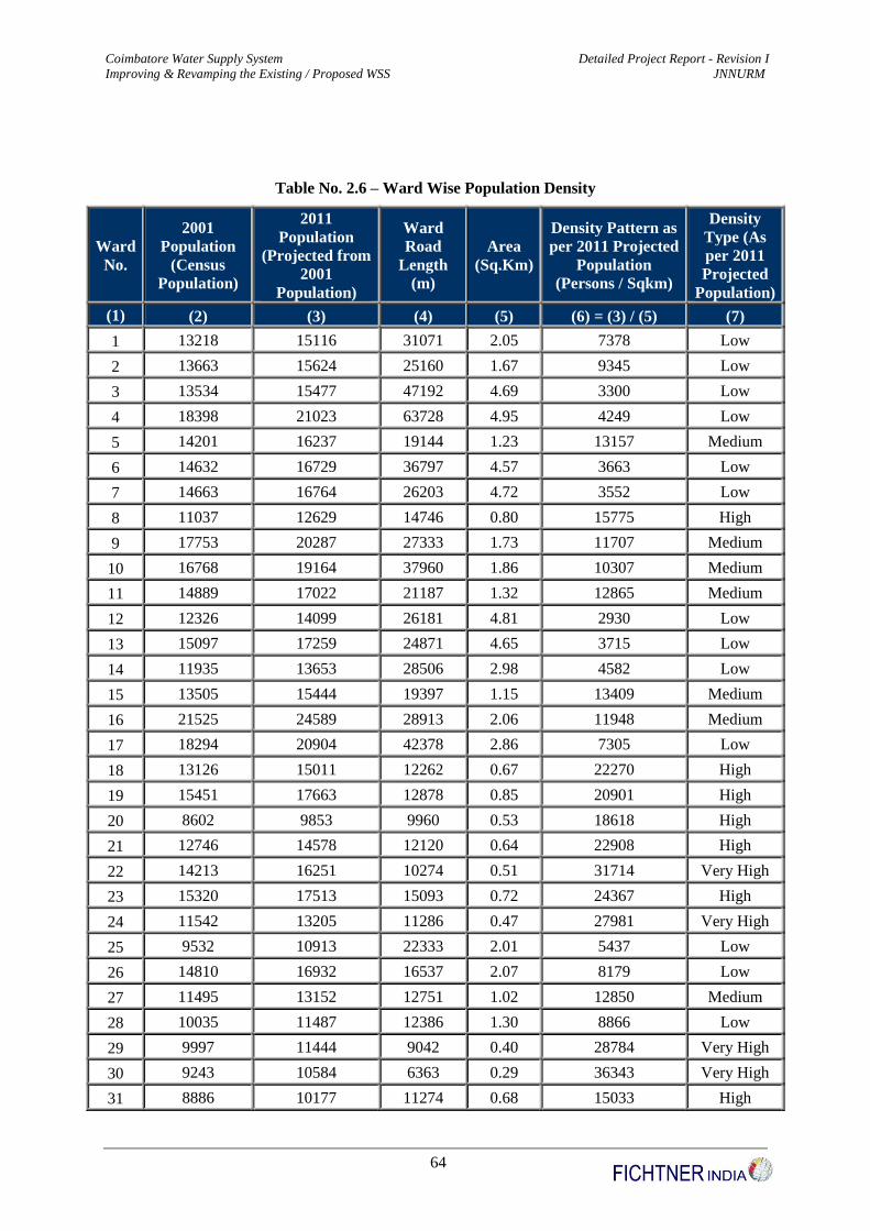
Coimbatore Water Supply System Detailed Project Report - Revision I
Improving & Revamping the Existing / Proposed WSS JNNURM
64
Table No. 2.6 – Ward Wise Population Density
Ward
No.
2001
Population
(Census
Population)
2011
Population
(Projected from
2001
Population)
Ward
Road
Length
(m)
Area
(Sq.Km)
Density Pattern as
per 2011 Projected
Population
(Persons / Sqkm)
Density
Type (As
per 2011
Projected
Population)
(1) (2) (3) (4) (5) (6) = (3) / (5) (7)
1 13218 15116 31071 2.05 7378 Low
2 13663 15624 25160 1.67 9345 Low
3 13534 15477 47192 4.69 3300 Low
4 18398 21023 63728 4.95 4249 Low
5 14201 16237 19144 1.23 13157 Medium
6 14632 16729 36797 4.57 3663 Low
7 14663 16764 26203 4.72 3552 Low
8 11037 12629 14746 0.80 15775 High
9 17753 20287 27333 1.73 11707 Medium
10 16768 19164 37960 1.86 10307 Medium
11 14889 17022 21187 1.32 12865 Medium
12 12326 14099 26181 4.81 2930 Low
13 15097 17259 24871 4.65 3715 Low
14 11935 13653 28506 2.98 4582 Low
15 13505 15444 19397 1.15 13409 Medium
16 21525 24589 28913 2.06 11948 Medium
17 18294 20904 42378 2.86 7305 Low
18 13126 15011 12262 0.67 22270 High
19 15451 17663 12878 0.85 20901 High
20 8602 9853 9960 0.53 18618 High
21 12746 14578 12120 0.64 22908 High
22 14213 16251 10274 0.51 31714 Very High
23 15320 17513 15093 0.72 24367 High
24 11542 13205 11286 0.47 27981 Very High
25 9532 10913 22333 2.01 5437 Low
26 14810 16932 16537 2.07 8179 Low
27 11495 13152 12751 1.02 12850 Medium
28 10035 11487 12386 1.30 8866 Low
29 9997 11444 9042 0.40 28784 Very High
30 9243 10584 6363 0.29 36343 Very High
31 8886 10177 11274 0.68 15033 High

Coimbatore Water Supply System Detailed Project Report - Revision I
Improving & Revamping the Existing / Proposed WSS JNNURM
65
Ward
No.
2001
Population
(Census
Population)
2011
Population
(Projected from
2001
Population)
Ward
Road
Length
(m)
Area
(Sq.Km)
Density Pattern as
per 2011 Projected
Population
(Persons / Sqkm)
Density
Type (As
per 2011
Projected
Population)
32 9290 10637 6246 0.36 29452 Very High
33 11825 13528 8056 0.77 17525 High
34 15954 18236 21154 1.49 12206 Medium
35 6155 7063 4229 0.36 19634 High
36 11022 12612 5178 0.51 24830 High
37 7081 8119 5526 0.24 34304 Very High
38 6781 7777 5922 0.34 22591 High
39 6349 7284 3258 0.34 21297 High
40 10911 12486 2205 0.14 88072 Saturated
41 8072 9249 4214 0.16 57452 Saturated
42 12336 14111 13185 1.28 11066 Medium
43 12086 13826 5375 0.22 61669 Saturated
44 14057 16073 6212 0.34 47303 Saturated
45 8724 9992 6199 0.27 36860 Very High
46 10019 11469 2096 0.10 118448 Saturated
47 10042 11495 5038 0.17 66171 Saturated
48 9771 11186 2817 0.12 90986 Saturated
49 10613 12146 14821 1.01 12079 Medium
50 5677 6518 8452 0.47 13824 Medium
51 9156 10485 8069 0.60 17363 High
52 12451 14242 11055 0.63 22614 High
53 13461 15393 7262 0.33 47041 Saturated
54 26056 29755 28722 4.09 7270 Low
55 12901 14755 31946 4.42 3338 Low
56 15425 17633 19776 1.02 17221 High
57 14466 16539 17709 4.38 3778 Low
58 11146 12754 17025 2.22 5740 Low
59 13868 15858 22564 1.71 9295 Low
60 13282 15189 11891 1.25 12132 Medium
61 15085 17245 16473 1.01 17127 High
62 10821 12383 18470 0.78 15910 High
63 10490 12006 8185 0.41 28983 Very High
64 9810 11230 9158 0.53 20991 High
65 11640 13317 39126 2.57 5185 Low
66 21799 24901 26543 1.47 16914 High
67 12863 14712 8370 0.31 48134 Saturated

Coimbatore Water Supply System Detailed Project Report - Revision I
Improving & Revamping the Existing / Proposed WSS JNNURM
66
Ward
No.
2001
Population
(Census
Population)
2011
Population
(Projected from
2001
Population)
Ward
Road
Length
(m)
Area
(Sq.Km)
Density Pattern as
per 2011 Projected
Population
(Persons / Sqkm)
Density
Type (As
per 2011
Projected
Population)
68 5668 6507 4193 0.17 37448 Very High
69 20917 23895 17470 0.83 28707 Very High
70 16153 18463 28603 1.70 10873 Medium
71 11058 12653 10826 0.57 22073 High
72 32360 36943 105300 5.65 6542 Low
Total 930822 1061447 1294245 105.62
Table No. 2.7 - Summary of Density Pattern
S.No Density Pattern Range (Persons / Sq.km) No. of wards
1 Low Dense Wards 0 - 10000 20
2 Medium Dense Wards 10000 - 15000 13
3 High Dense Wards 15000 - 25000 20
4 Very High Dense Wards 25000 - 45000 10
5 Saturated Wards > 45000 9
Total 72
Table No. 2.8 – Population Projection Factor
No of Wards Density Type Projection Factor
23 Low Dense Wards 2.00
15 Medium Dense Wards 1.70
16 High Dense Wards 1.50
12 Very High Dense Wards 1.30
6 Saturated Wards 1.20

Coimbatore Water Supply System Detailed Project Report - Revision I
Improving & Revamping the Existing / Proposed WSS JNNURM
67
Density Pattern in Coimbatore
Saturated Wards
9 NosVery High Dense
Wards
10 Nos
High Dense
Wards
20 NosMedium Dense
Wards
13 Nos
Low Dense
Wards
20 Nos
Fig. No. 11 - Density Pattern of Wards in Coimbatore
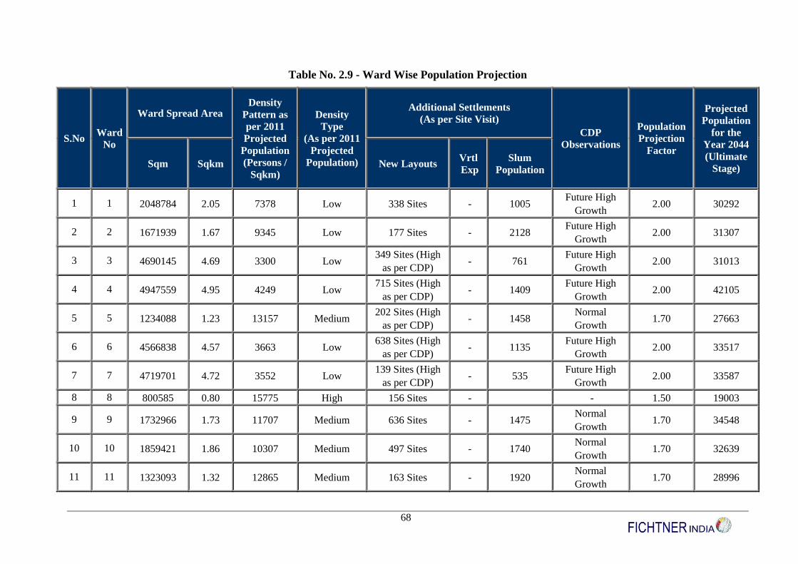
68
Table No. 2.9 - Ward Wise Population Projection
S.No Ward
No
Ward Spread Area Density
Pattern as
per 2011
Projected
Population
(Persons /
Sqkm)
Density
Type
(As per 2011
Projected
Population)
Additional Settlements
(As per Site Visit)
CDP
Observations
Population
Projection
Factor
Projected
Population
for the
Year 2044
(Ultimate
Stage) Sqm Sqkm New Layouts
Vrtl
Exp
Slum
Population
1 1 2048784 2.05 7378 Low 338 Sites - 1005 Future High
Growth 2.00 30292
2 2 1671939 1.67 9345 Low 177 Sites - 2128 Future High
Growth 2.00 31307
3 3 4690145 4.69 3300 Low 349 Sites (High
as per CDP) - 761
Future High
Growth 2.00 31013
4 4 4947559 4.95 4249 Low 715 Sites (High
as per CDP) - 1409
Future High
Growth 2.00 42105
5 5 1234088 1.23 13157 Medium 202 Sites (High
as per CDP) - 1458
Normal
Growth 1.70 27663
6 6 4566838 4.57 3663 Low 638 Sites (High
as per CDP) - 1135
Future High
Growth 2.00 33517
7 7 4719701 4.72 3552 Low 139 Sites (High
as per CDP) - 535
Future High
Growth 2.00 33587
8 8 800585 0.80 15775 High 156 Sites - - 1.50 19003
9 9 1732966 1.73 11707 Medium 636 Sites - 1475 Normal
Growth 1.70 34548
10 10 1859421 1.86 10307 Medium 497 Sites - 1740 Normal
Growth 1.70 32639
11 11 1323093 1.32 12865 Medium 163 Sites - 1920 Normal
Growth 1.70 28996
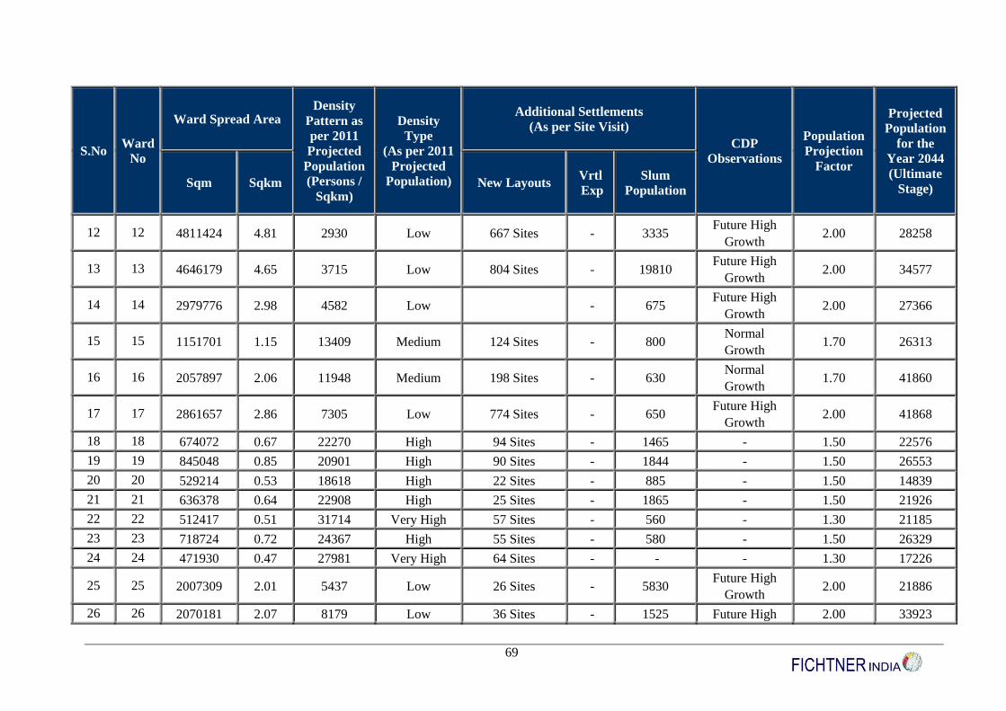
69
S.No Ward
No
Ward Spread Area Density
Pattern as
per 2011
Projected
Population
(Persons /
Sqkm)
Density
Type
(As per 2011
Projected
Population)
Additional Settlements
(As per Site Visit)
CDP
Observations
Population
Projection
Factor
Projected
Population
for the
Year 2044
(Ultimate
Stage) Sqm Sqkm New Layouts
Vrtl
Exp
Slum
Population
12 12 4811424 4.81 2930 Low 667 Sites - 3335 Future High
Growth 2.00 28258
13 13 4646179 4.65 3715 Low 804 Sites - 19810 Future High
Growth 2.00 34577
14 14 2979776 2.98 4582 Low - 675 Future High
Growth 2.00 27366
15 15 1151701 1.15 13409 Medium 124 Sites - 800 Normal
Growth 1.70 26313
16 16 2057897 2.06 11948 Medium 198 Sites - 630 Normal
Growth 1.70 41860
17 17 2861657 2.86 7305 Low 774 Sites - 650 Future High
Growth 2.00 41868
18 18 674072 0.67 22270 High 94 Sites - 1465 - 1.50 22576
19 19 845048 0.85 20901 High 90 Sites - 1844 - 1.50 26553
20 20 529214 0.53 18618 High 22 Sites - 885 - 1.50 14839
21 21 636378 0.64 22908 High 25 Sites - 1865 - 1.50 21926
22 22 512417 0.51 31714 Very High 57 Sites - 560 - 1.30 21185
23 23 718724 0.72 24367 High 55 Sites - 580 - 1.50 26329
24 24 471930 0.47 27981 Very High 64 Sites - - - 1.30 17226
25 25 2007309 2.01 5437 Low 26 Sites - 5830 Future High
Growth 2.00 21886
26 26 2070181 2.07 8179 Low 36 Sites - 1525 Future High 2.00 33923

70
S.No Ward
No
Ward Spread Area Density
Pattern as
per 2011
Projected
Population
(Persons /
Sqkm)
Density
Type
(As per 2011
Projected
Population)
Additional Settlements
(As per Site Visit)
CDP
Observations
Population
Projection
Factor
Projected
Population
for the
Year 2044
(Ultimate
Stage) Sqm Sqkm New Layouts
Vrtl
Exp
Slum
Population
Growth
27 27 1023494 1.02 12850 Medium 53 Sites - 160 Normal
Growth 1.70 22417
28 28 1295593 1.30 8866 Low 16 Sites High - Future High -
Growth 2.00 23033
29 29 397572 0.40 28784 Very High 8 Sites - 1000 - 1.30 14936
30 30 291218 0.29 36343 Very High 6 Sites High 1850 - 1.30 13818
31 31 676948 0.68 15033 High 12 Sites High - - 1.50 15324
32 32 361180 0.36 29452 Very High 21 Sites High 600 - 1.30 13888
33 33 771938 0.77 17525 High 33 Sites High 2142 - 1.50 20351
34 34 1494050 1.49 12206 Medium 38 Sites - 575 Normal
Growth 1.70 31061
35 35 359715 0.36 19634 High 11 Sites - 3693 - 1.50 10653
36 36 507942 0.51 24830 High 7 Sites - - - 1.50 18978
37 37 236663 0.24 34304 Very High 11 Sites - 2000 - 1.30 10613
38 38 344228 0.34 22591 High 4 Sites - 75 - 1.50 11724
39 39 342012 0.34 21297 High - - - 1.50 10985
40 40 141768 0.14 88072 Saturated 3 Sites - - - 1.20 15042
41 41 160978 0.16 57452 Saturated 4 Sites - - - 1.20 11158
42 42 1275092 1.28 11066 Medium 380 Sites - 400 Normal
Growth 1.70 24047

71
S.No Ward
No
Ward Spread Area Density
Pattern as
per 2011
Projected
Population
(Persons /
Sqkm)
Density
Type
(As per 2011
Projected
Population)
Additional Settlements
(As per Site Visit)
CDP
Observations
Population
Projection
Factor
Projected
Population
for the
Year 2044
(Ultimate
Stage) Sqm Sqkm New Layouts
Vrtl
Exp
Slum
Population
43 43 224191 0.22 61669 Saturated 26 Sites - 4505 - 1.20 16650
44 44 339790 0.34 47303 Saturated 4 Sites - - - 1.20 19347
45 45 271080 0.27 36860 Very High 8 Sites - - - 1.30 13049
46 46 96825 0.10 118448 Saturated 3 Sites - - - 1.20 13822
47 47 173715 0.17 66171 Saturated 5 Sites - - - 1.20 13853
48 48 122941 0.12 90986 Saturated 2 Sites - - - 1.20 13482
49 49 1005588 1.01 12079 Medium 39 Sites - - Normal
Growth 1.70 20707
50 50 471471 0.47 13824 Medium 26 Sites - - Normal
Growth 1.70 11139
51 51 603842 0.60 17363 High 24 Sites - 315 - 1.50 15786
52 52 629791 0.63 22614 High 82 Sites - 885 - 1.50 21422
53 53 327236 0.33 47041 Saturated 16 Sites - - - 1.20 18531
54 54 4093116 4.09 7270 Low 696 Sites High 14160 Future High
Growth 2.00 59569
55 55 4420063 4.42 3338 Low 658 Sites (High
as per CDP) - 3775
Future High
Growth 2.00 29569
56 56 1023920 1.02 17221 High 354 Sites - 795 1.50 26509
57 57 4378226 4.38 3778 Low 40 Sites - 2675 Future High
Growth 2.00 33138
58 58 2222099 2.22 5740 Low 184 Sites (High - 1285 Future High 2.00 25567

72
S.No Ward
No
Ward Spread Area Density
Pattern as
per 2011
Projected
Population
(Persons /
Sqkm)
Density
Type
(As per 2011
Projected
Population)
Additional Settlements
(As per Site Visit)
CDP
Observations
Population
Projection
Factor
Projected
Population
for the
Year 2044
(Ultimate
Stage) Sqm Sqkm New Layouts
Vrtl
Exp
Slum
Population
as per CDP) Growth
59 59 1706017 1.71 9295 Low 566 Sites (High
as per CDP) - 605
Future High
Growth 2.00 31774
60 60 1251960 1.25 12132 Medium 87 Sites High 1000 Normal
Growth 1.70 25881
61 61 1006906 1.01 17127 High 118 Sites High 1250 - 1.50 25927
62 62 778318 0.78 15910 High 221 Sites High 1750 - 1.50 18634
63 63 414240 0.41 28983 Very High 110 Sites High 1000 - 1.30 15667
64 64 534997 0.53 20991 High 14 Sites High 7100 - 1.50 16905
65 65 2568525 2.57 5185 Low 522 Sites High 710 Future High
Growth 2.00 26693
66 66 1472190 1.47 16914 High 750 Sites - 4225 - 1.50 37411
67 67 305637 0.31 48134 Saturated 99 Sites - - - 1.20 17713
68 68 173771 0.17 37448 Very High 26 Sites - - - 1.30 8519
69 69 832388 0.83 28707 Very High 159 Sites - - - 1.30 31123
70 70 1698114 1.70 10873 Medium 249 Sites - - Normal
Growth 1.70 31446
71 71 573249 0.57 22073 High 87 Sites - 440 1.50 19039
72 72 5646754 5.65 6542 Low 2454 Sites High 1510 Future High
Growth 2.00 73946
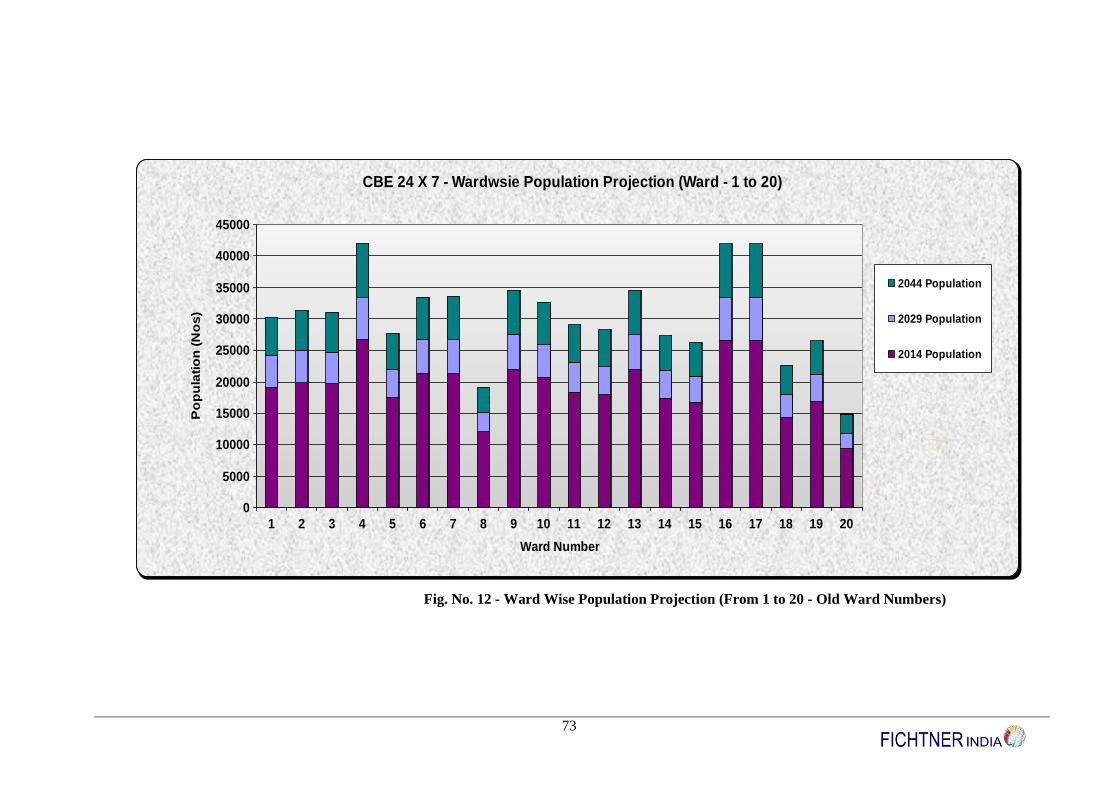
73
0
5000
10000
15000
20000
25000
30000
35000
40000
45000
Po
pu
lati
on
(N
os
)
1 2 3 4 5 6 7 8 9 10 11 12 13 14 15 16 17 18 19 20
Ward Number
CBE 24 X 7 - Wardwsie Population Projection (Ward - 1 to 20)
2044 Population
2029 Population
2014 Population
Fig. No. 12 - Ward Wise Population Projection (From 1 to 20 - Old Ward Numbers)

74
0
5000
10000
15000
20000
25000
30000
35000
Po
pu
lati
on
(N
os
)
21 22 23 24 25 26 27 28 29 30 31 32 33 34 35 36 37 38 39 40
Ward Number
CBE 24 X 7 - Wardwsie Population Projection (Ward - 21 to 40)
2044 Population
2029 Population
2014 Population
Fig. No. 13 - Ward Wise Population Projection (From 21 to 40 – Old Ward Numbers)
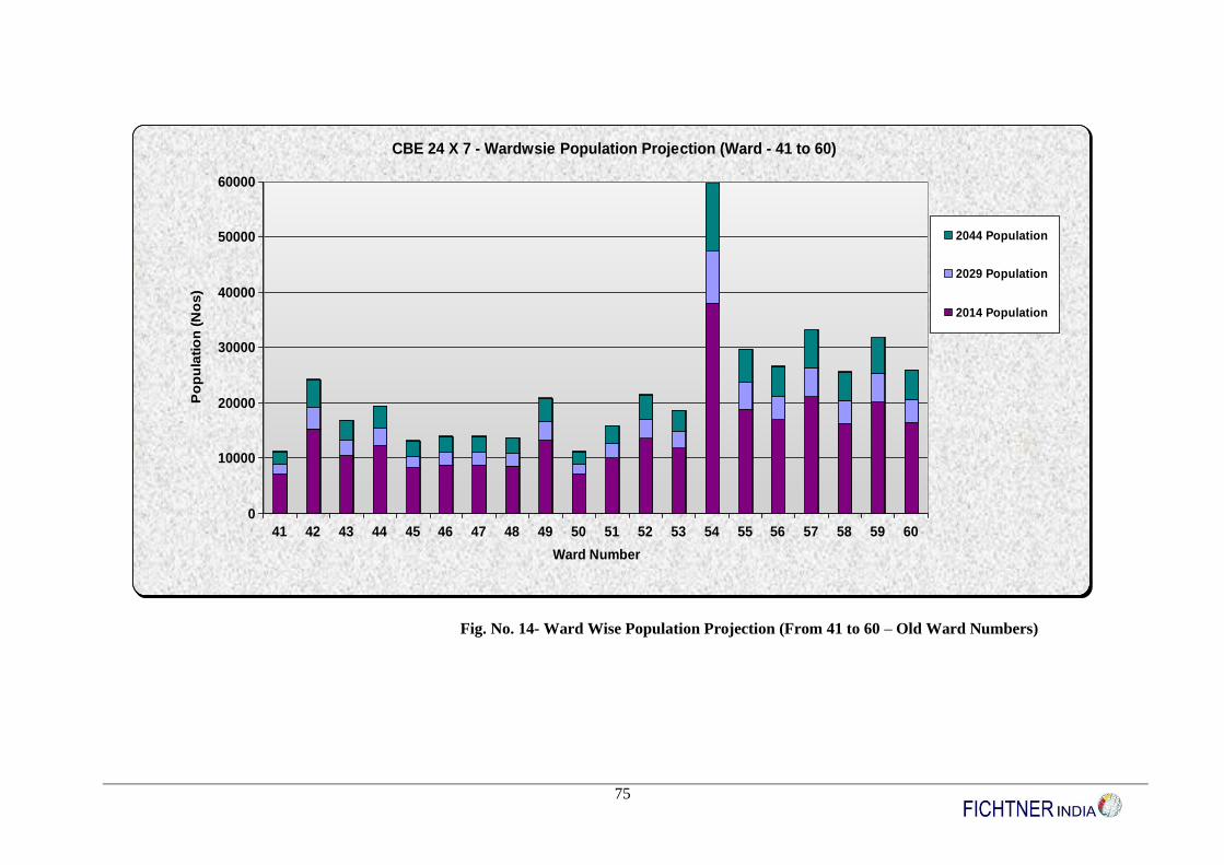
75
0
10000
20000
30000
40000
50000
60000P
op
ula
tio
n (
No
s)
41 42 43 44 45 46 47 48 49 50 51 52 53 54 55 56 57 58 59 60
Ward Number
CBE 24 X 7 - Wardwsie Population Projection (Ward - 41 to 60)
2044 Population
2029 Population
2014 Population
Fig. No. 14- Ward Wise Population Projection (From 41 to 60 – Old Ward Numbers)
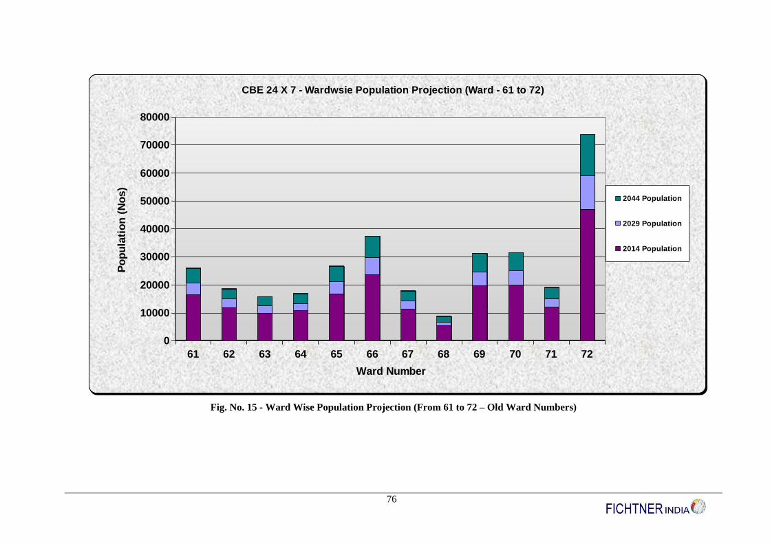
76
0
10000
20000
30000
40000
50000
60000
70000
80000P
op
ula
tio
n (
No
s)
61 62 63 64 65 66 67 68 69 70 71 72
Ward Number
CBE 24 X 7 - Wardwsie Population Projection (Ward - 61 to 72)
2044 Population
2029 Population
2014 Population
Fig. No. 15 - Ward Wise Population Projection (From 61 to 72 – Old Ward Numbers)
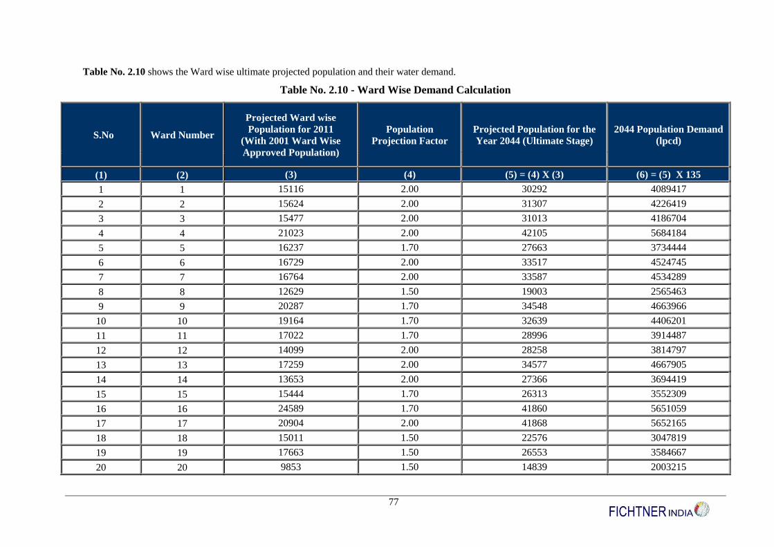
77
Table No. 2.10 shows the Ward wise ultimate projected population and their water demand.
Table No. 2.10 - Ward Wise Demand Calculation
S.No Ward Number
Projected Ward wise
Population for 2011
(With 2001 Ward Wise
Approved Population)
Population
Projection Factor
Projected Population for the
Year 2044 (Ultimate Stage)
2044 Population Demand
(lpcd)
(1) (2) (3) (4) (5) = (4) X (3) (6) = (5) X 135
1 1 15116 2.00 30292 4089417
2 2 15624 2.00 31307 4226419
3 3 15477 2.00 31013 4186704
4 4 21023 2.00 42105 5684184
5 5 16237 1.70 27663 3734444
6 6 16729 2.00 33517 4524745
7 7 16764 2.00 33587 4534289
8 8 12629 1.50 19003 2565463
9 9 20287 1.70 34548 4663966
10 10 19164 1.70 32639 4406201
11 11 17022 1.70 28996 3914487
12 12 14099 2.00 28258 3814797
13 13 17259 2.00 34577 4667905
14 14 13653 2.00 27366 3694419
15 15 15444 1.70 26313 3552309
16 16 24589 1.70 41860 5651059
17 17 20904 2.00 41868 5652165
18 18 15011 1.50 22576 3047819
19 19 17663 1.50 26553 3584667
20 20 9853 1.50 14839 2003215

78
S.No Ward Number
Projected Ward wise
Population for 2011
(With 2001 Ward Wise
Approved Population)
Population
Projection Factor
Projected Population for the
Year 2044 (Ultimate Stage)
2044 Population Demand
(lpcd)
21 21 14578 1.50 21926 2960076
22 22 16251 1.30 21185 2860034
23 23 17513 1.50 26329 3554419
24 24 13205 1.30 17226 2325526
25 25 10913 2.00 21886 2954608
26 26 16932 2.00 33923 4579546
27 27 13152 1.70 22417 3026313
28 28 11487 2.00 23033 3109466
29 29 11444 1.30 14936 2016347
30 30 10584 1.30 13818 1865460
31 31 10177 1.50 15324 2068792
32 32 10637 1.30 13888 1874866
33 33 13528 1.50 20351 2747414
34 34 18236 1.70 31061 4193186
35 35 7063 1.50 10653 1438197
36 36 12612 1.50 18978 2562000
37 37 8119 1.30 10613 1432810
38 38 7777 1.50 11724 1582742
39 39 7284 1.50 10985 1482992
40 40 12486 1.20 15042 2030695
41 41 9249 1.20 11158 1506269
42 42 14111 1.70 24047 3246393
43 43 13826 1.20 16650 2247743
44 44 16073 1.20 19347 2611830
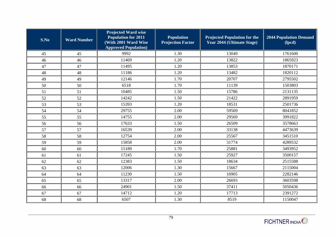
79
S.No Ward Number
Projected Ward wise
Population for 2011
(With 2001 Ward Wise
Approved Population)
Population
Projection Factor
Projected Population for the
Year 2044 (Ultimate Stage)
2044 Population Demand
(lpcd)
45 45 9992 1.30 13049 1761600
46 46 11469 1.20 13822 1865923
47 47 11495 1.20 13853 1870171
48 48 11186 1.20 13482 1820112
49 49 12146 1.70 20707 2795502
50 50 6518 1.70 11139 1503803
51 51 10485 1.50 15786 2131135
52 52 14242 1.50 21422 2891959
53 53 15393 1.20 18531 2501736
54 54 29755 2.00 59569 8041852
55 55 14755 2.00 29569 3991822
56 56 17633 1.50 26509 3578663
57 57 16539 2.00 33138 4473639
58 58 12754 2.00 25567 3451510
59 59 15858 2.00 31774 4289532
60 60 15189 1.70 25881 3493952
61 61 17245 1.50 25927 3500157
62 62 12383 1.50 18634 2515588
63 63 12006 1.30 15667 2115004
64 64 11230 1.50 16905 2282146
65 65 13317 2.00 26693 3603598
66 66 24901 1.50 37411 5050436
67 67 14712 1.20 17713 2391272
68 68 6507 1.30 8519 1150047
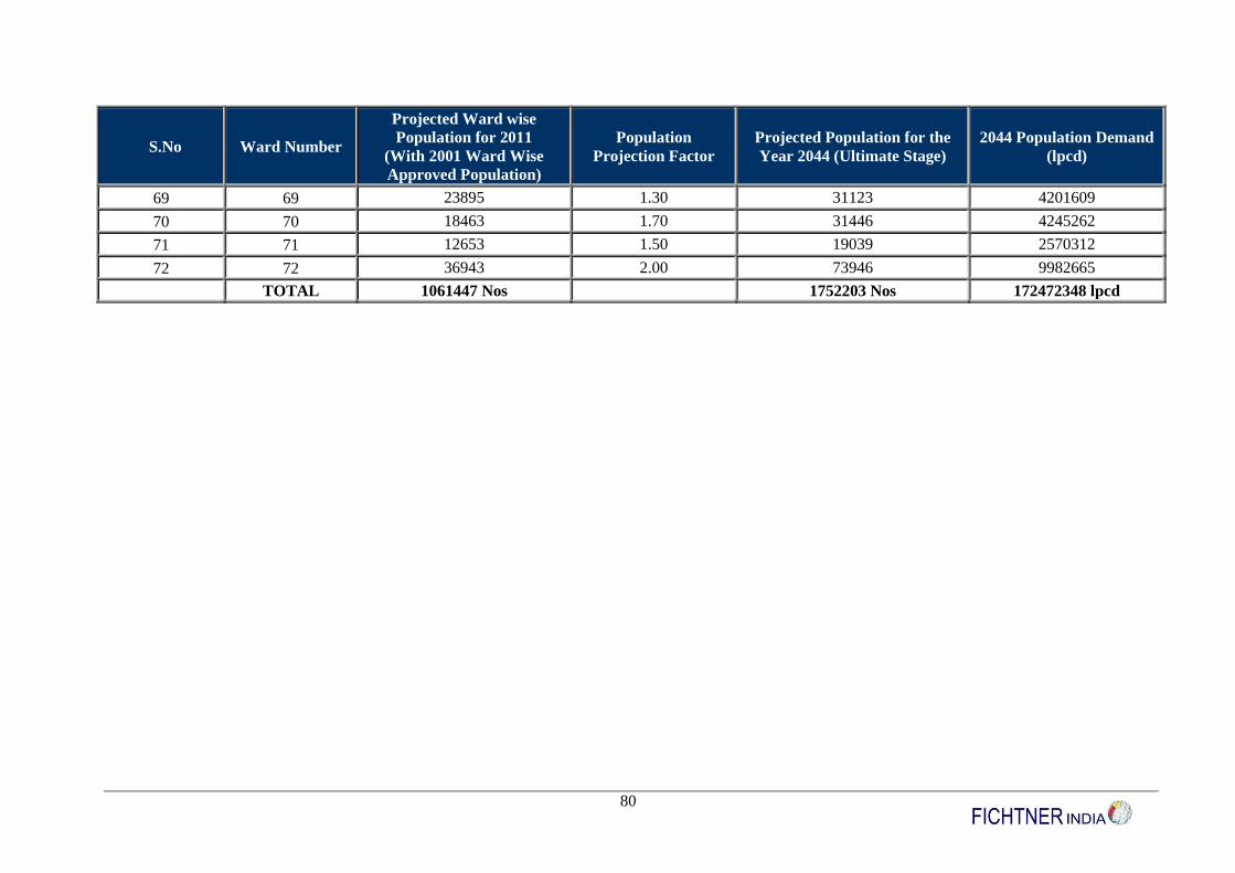
80
S.No Ward Number
Projected Ward wise
Population for 2011
(With 2001 Ward Wise
Approved Population)
Population
Projection Factor
Projected Population for the
Year 2044 (Ultimate Stage)
2044 Population Demand
(lpcd)
69 69 23895 1.30 31123 4201609
70 70 18463 1.70 31446 4245262
71 71 12653 1.50 19039 2570312
72 72 36943 2.00 73946 9982665
TOTAL 1061447 Nos 1752203 Nos 172472348 lpcd
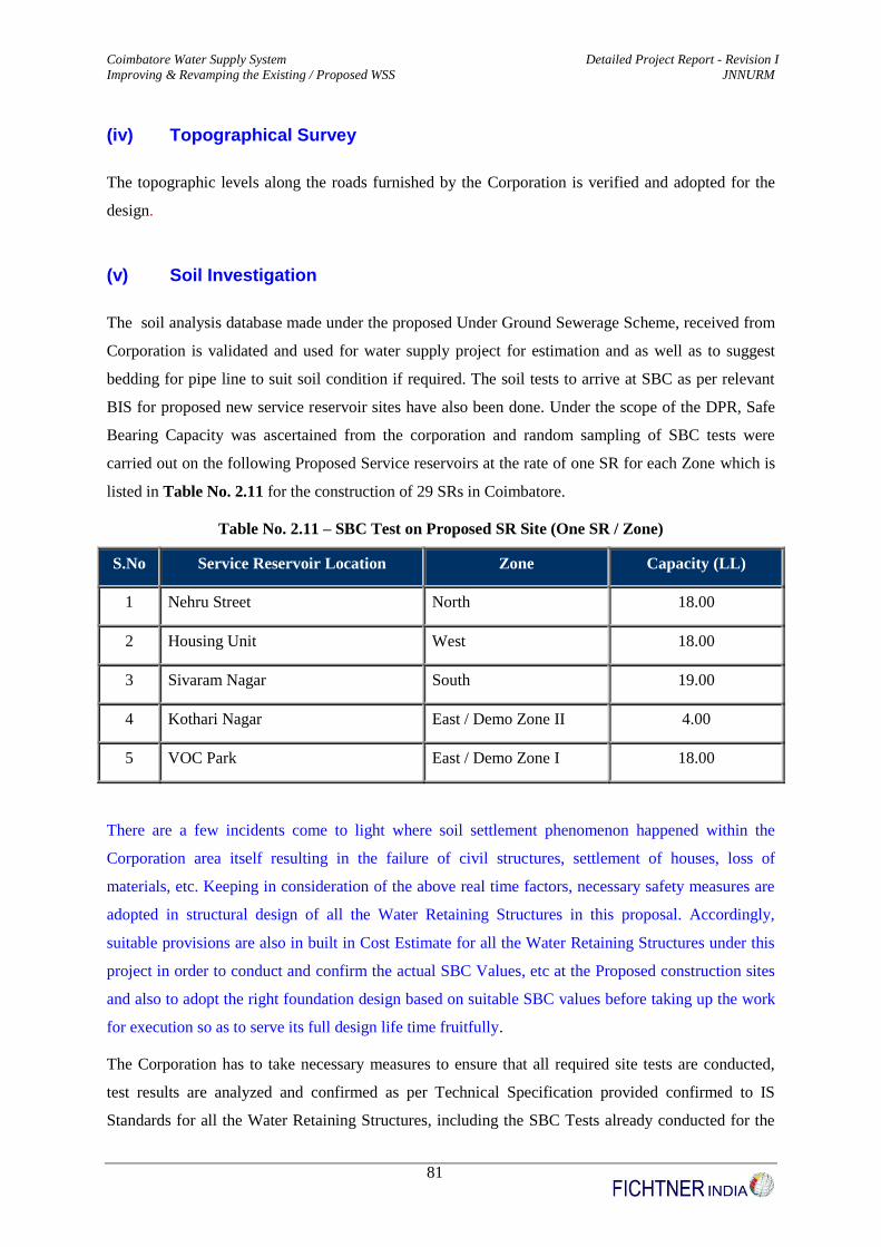
Coimbatore Water Supply System Detailed Project Report - Revision I
Improving & Revamping the Existing / Proposed WSS JNNURM
81
(iv) Topographical Survey
The topographic levels along the roads furnished by the Corporation is verified and adopted for the
design.
(v) Soil Investigation
The soil analysis database made under the proposed Under Ground Sewerage Scheme, received from
Corporation is validated and used for water supply project for estimation and as well as to suggest
bedding for pipe line to suit soil condition if required. The soil tests to arrive at SBC as per relevant
BIS for proposed new service reservoir sites have also been done. Under the scope of the DPR, Safe
Bearing Capacity was ascertained from the corporation and random sampling of SBC tests were
carried out on the following Proposed Service reservoirs at the rate of one SR for each Zone which is
listed in Table No. 2.11 for the construction of 29 SRs in Coimbatore.
Table No. 2.11 – SBC Test on Proposed SR Site (One SR / Zone)
S.No Service Reservoir Location Zone Capacity (LL)
1 Nehru Street North 18.00
2 Housing Unit West 18.00
3 Sivaram Nagar South 19.00
4 Kothari Nagar East / Demo Zone II 4.00
5 VOC Park East / Demo Zone I 18.00
There are a few incidents come to light where soil settlement phenomenon happened within the
Corporation area itself resulting in the failure of civil structures, settlement of houses, loss of
materials, etc. Keeping in consideration of the above real time factors, necessary safety measures are
adopted in structural design of all the Water Retaining Structures in this proposal. Accordingly,
suitable provisions are also in built in Cost Estimate for all the Water Retaining Structures under this
project in order to conduct and confirm the actual SBC Values, etc at the Proposed construction sites
and also to adopt the right foundation design based on suitable SBC values before taking up the work
for execution so as to serve its full design life time fruitfully.
The Corporation has to take necessary measures to ensure that all required site tests are conducted,
test results are analyzed and confirmed as per Technical Specification provided confirmed to IS
Standards for all the Water Retaining Structures, including the SBC Tests already conducted for the

Coimbatore Water Supply System Detailed Project Report - Revision I
Improving & Revamping the Existing / Proposed WSS JNNURM
82
above said Service Reservoirs before execution of the project. However, for the ease implementation
of the project, foundation is designed for the above said Service Reservoirs with the ascertained SBC
value from the field tests conducted which is annexed in Volume I (b), Annexure Number – A9
part of this DPR.
The details of site selected for validation are listed in Table No. 2.12, 2.13 & 2.14 repectively.
Location : Trial pit at Thanner pandal road
Ward No : 3
Date : 24.02.09
Table No. 2.12 – Soil Trial Pit at Thanner Pandal Road
Details received from Corporation Validation by Fichtner
Sl.No. Depth Soil Specimen Nature
1 0 to 1.00 mtr Clay soil Verified
2 1.00 to 2.00 mtr Loose Clay soil Verified
Location : Trial pit at Nava India Road (Avinasi road junction)
Ward No : 14
Date : 25.02.09
Table No. 2.13 – Soil Trial Pit at Nava India Road
Details received from Corporation Validation by Fichtner
Sl.No. Depth Soil Specimen Nature
1 0 to 1.00 mtr Red soil Hard soil
2 1.00 to 2.00 mtr Red soil Verified
3 2.00 to 3.00 mtr Red soil Verified

Coimbatore Water Supply System Detailed Project Report - Revision I
Improving & Revamping the Existing / Proposed WSS JNNURM
83
Location : Trial pit at South Street, Avarampalayam
Ward No : 17
Date : 25.02.09
Table No. 2.14 – Soil Trial Pit at Avarampalayam
Details received from Corporation Validation by Fichtner
Sl.No. Depth Soil Specimen Nature
1 0 to 1.00 mtr Clay soil Verified
2 1.00 to 2.00 mtr Clay soil Verified
Additionally the SBC value of the soil was determined by drilling 100mm diameter bore hole using
Rotary Calyx Mechanically Operated Drilling Equipment, to a depth of 10m below the local ground
level or upto the hard stratum with the “N” value over 100 or 34 blows for 10 cm penetration

Coimbatore Water Supply System Detailed Project Report - Revision I
Improving & Revamping the Existing / Proposed WSS JNNURM
84
whichever is encountered earlier. Additionally SPT test, laboratory test on soil samples collected
classification of soil, type and depth of foundation, etc., was deteremined.
(vi) Zoning of Distribution System
The capacity and serving area of a reservoir is primarily based on the population and its demand. The
contour of the area to be served is one of the prime considerations for demarcation of SR zones in the
project area. The contour plan prepared is considered for rezoning, which depends on the capacity of
the existing & proposed service reservoirs, terrain of the area, distance, location, vertical expansion,
new layouts, cluster to be served, etc. and the most economical design is arrived at. While rezoning,
necessity for providing additional service reservoir to meet additional requirement is analyzed and
provided. Zoning of the area in the proposed project area under jurisdiction of CCC, is carried out.
This has been performed based on the ultimate stage (year 2044) population. Each zone is provided
with an SR and further divided into multiple District Metering Areas (DMAs) for SRs of capacity
more than 10 LL. Following are the important criteria adopted in zoning of the project area for the
design of the distribution system.
(a) In any classified zone, the difference in the maximum and minimum elevations shall
not be more than 10m.
(b) The minimum residual head available shall be atleast 12 m (as specified in the Manual
on Water Supply of CPHEEO) for all proposed service reservoirs and a minimum of
7 m based on the constraints imposed by the staging height of existing SRs.
(c) Zone boundaries have been demarcated along the Contour lines of the project area.
(vii) Distribution System Network
Distribution System Network for each service reservoir is prepared taking into account of the factors
like length of distribution system, maximum serving area and physical constraints. Further, suitable
coverage of Slum settlements, spatial distribution of the settlements, type of service, etc., are also
considered for suitable rezoning.
(viii) Consumption Peak Factor
There is variation in water consumption during the day and the night and also varies with seasons.
There is no clearly defined relationship between average and peak flow currently applied to all towns.
Coimbatore Water Supply System Detailed Project Report - Revision I
Improving & Revamping the Existing / Proposed WSS JNNURM
85
The CPHEEO Manual on Water Supply and Treatment recommends the following peak factors for
various design population.
Population less than 50000 : 3.0
Population range of 50000 to 200,000 : 2.5
Population above 200,000 : 2.0
Hence, the relevant peak factor is adopted accordingly for each zone.
(ix) Minimum Residual Head
The CPHEEO Manual prescribes a minimum residual head of 12 m at ferrule points for two storey
building and the same is adopted for this project. However, as most of the existing SRs are old, based
on the existing staging height, a minimum residual head of 7 m is maintained for such zones
(x) Utility of Existing Pipes
The pressure distribution system with minimum 12 m pressure is proposed. The existing PVC Pipes
may not be suitable due to the factors of susceptibility to impact loading, vulnerable for damages by
other service agencies, temperature & non resistivity. The use of AC Pipes is also not in practice due
to heavy weight and hence the existing AC pipes also require replacement. The CI pipe laid long ago
served out their life and requires replacement. The piece meal extensions made using pipes less than
100 mm dia to meet immediate requirement temporarily also requires replacement.
(xi) Network Analysis for Looped Distribution System
Network mapping and modelling for detailed engineering design is the core activity that determines
the realisation of desired objectives under this assignment. A basic hydraulic model of the network
comprising of primary, secondary and tertiary mains is analysed, using an internationally recognized
network modelling software package, namely WATERGEMS & LOOP. Based on the model
simulations, the capacity of the network, identified engineering requirements for hydraulic zoning,
district metering, improving the flow characteristics, rehabilitation, replacement and expansion to
meet the demand projections so as to ensure a continuous pressurized water supply service is carried
out. Network drawings analysis results will be given to Coimbatore Corporation for its usage and
validation in future.

Coimbatore Water Supply System Detailed Project Report - Revision I
Improving & Revamping the Existing / Proposed WSS JNNURM
86
(xii) Elimination of Public Fountains
There is a percentage share of distribution of water through public fountains to serve the consumers
who are not having House Service Connections in their property. As 24 X 7 continuous water supply
system is proposed, the possibility of meeting each and every household property owner to avail HSC
will be emphasised by convincing the consumers with rational tariff structure and implementing slum
policy of government for urban poor. At present, there are 3412 nos of public fountains in the
Coimbatore Corporation area and suggestions will be made to reduce / eliminate the public fountains
to the extent possible through suitable IEC activities by the Corporation
(xiii) Pipe Material
Selection of Pipe Material
CPHEEO has laid down guidelines on the techno-economic comparison and selection the pipeline
material. The present selection is made based on these guidelines. Hazen William’s C value of 100 for
Existing CI pipes, 140 for DI and MS Pipes considered for design. DI pipes have an inherent high
tensile strength. Thus, high factor of safety to the pipeline against accidental waterhammer/ impact /
traffic loading on pipeline, accidental drop at site during laying / loading / unloading, etc. DI pipes
have a distinct advantage, namely, they come with internal cement mortar lining that is done at
factory, along with the external bitumen painting over a zinc coat. In an area like Coimbatore, which
is in the vicinity for high traffic, congestion, high rainfall, high temperature, etc it is better to provide
a pipeline which has inherent corrosion resistant and other featured properties. DI pipes protected
internally with centrifugally applied cement mortar lining are best suited to resist against corrosion.
Considering these factors, spigot and socket spun DI pipes lined internally with cement mortar and
externally with bitumen painting over zinc coat of Class K7 is selected as the pipe material for feeder
mains. The pipes shall be HDPE PN6-PE100 for size less than 200 mm for Gravity mains and
HDPEPN8-PE100 for pumping mains, DI K7 for pipes ranging from 200 – 600 mm and MS
(Minimum of 8 mm thickness) for pipes greater than 600 mm are considered.
Hazen William’s Roughness Coefficient
Hazen William’s Roughness Coefficient ‘C’ for transmission / feeder mains in the system is adopted
as per CPHEEO norms. Adequacy of the existing mains was verified by proper selection of C value
based on the pipe material and age as specified in the CPHEEO manual.
Coimbatore Water Supply System Detailed Project Report - Revision I
Improving & Revamping the Existing / Proposed WSS JNNURM
87
(xiv) Trench Size for Pipe Laying
Trenches for laying feeder mains and distribution mains in the system have been estimated based on
the standard guidelines specified in the CPHEEO Manual. A minimum pipe cover of 1.0 m from the
ground to the pipe crown shall be maintained for proper load distribution and pipeline safety
considerations. A minimum working space of 300 mm on either side of the pipe is considered as
working space for proper excavation.
(xv) Service Reservoirs
Based on the zoning of the distribution system, CCC is divided into four parts namely East, West,
North and South with a total number of 63 service reservoirs having 101 Sub Zones. The storage
capacity of each SR has been worked out for the intermediate stage based on 24 hours pumping and
24 hours supply, as per the CPHEEO guidelines. The capacities of SRs proposed are as follows:
4 Lakh Litres with 15 metres of Staging Height
7 Lakh Litres with 12 & 15 metres of Staging Height
9 Lakh Litres with 12 & 15 metres of Staging Height
10 Lakh Litres with 15 metres of Staging Height
11 Lakh Litres with 15 metres of Staging Height
12 Lakh Litres with 15 metres of Staging Height
13 Lakh Litres with 12 metres of Staging Height
16 Lakh Litres with 15 metres of Staging Height
18 Lakh Litres with 12 & 15 metres of Staging Height
19 Lakh Litres with 15 metres of Staging Height
20 Lakh Litres with 12 & 15 metres of Staging Height
The details of the proposed SRs – 29 Nos in the 101 Sub Zones with improratnt land marks covered
under each SR are presented in Volume – I (b), Annexure Number – A11 part of this DPR.
(xvi) House Service Connections
In order to cater to the population in the intermediate stage viz., for the project area where
augmentation proposals are made, the total number of HSCs are worked out for the Base year 2014
population and comes around 2.00 Lakhs Connections (Approximately). The present (2010) House
Service Connections are procured from the corporation and found to be 1,43,051 Nos. The same has
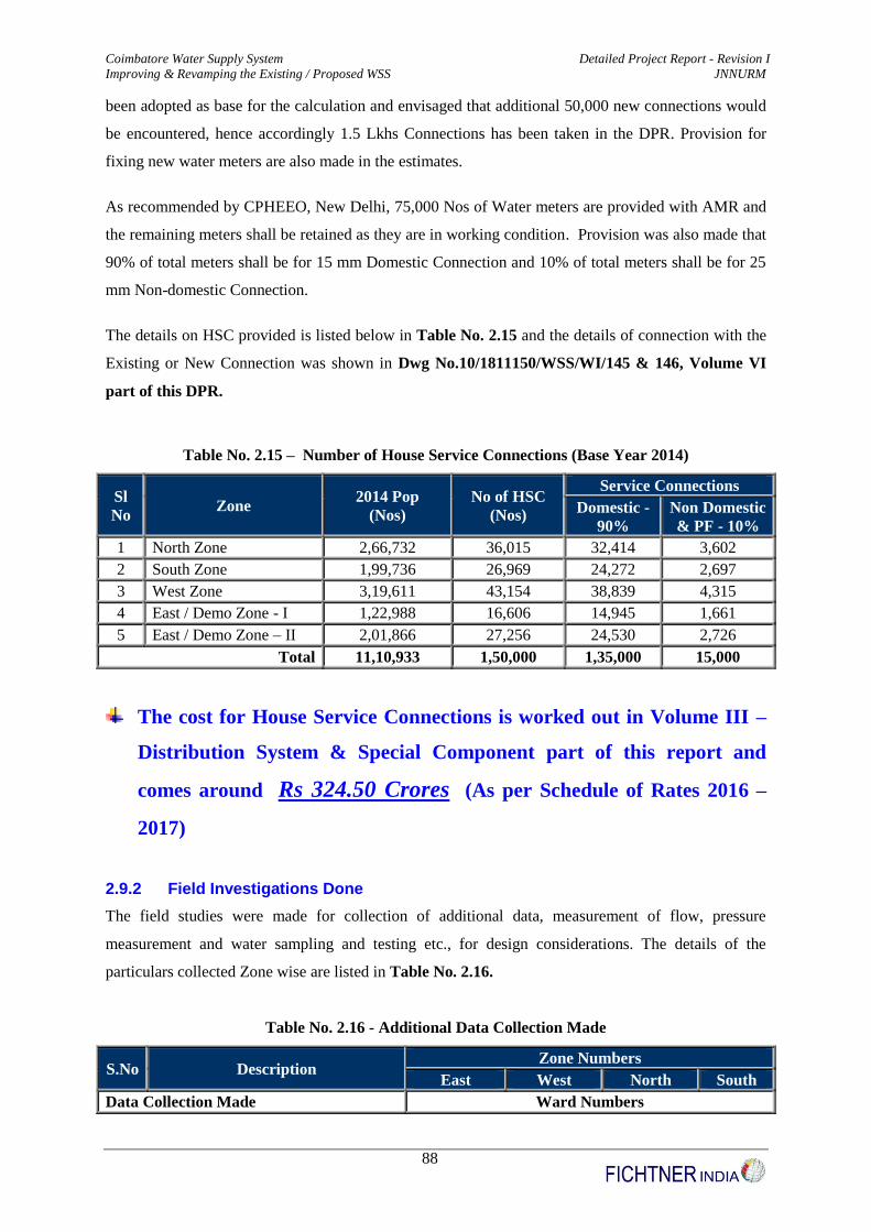
Coimbatore Water Supply System Detailed Project Report - Revision I
Improving & Revamping the Existing / Proposed WSS JNNURM
88
been adopted as base for the calculation and envisaged that additional 50,000 new connections would
be encountered, hence accordingly 1.5 Lkhs Connections has been taken in the DPR. Provision for
fixing new water meters are also made in the estimates.
As recommended by CPHEEO, New Delhi, 75,000 Nos of Water meters are provided with AMR and
the remaining meters shall be retained as they are in working condition. Provision was also made that
90% of total meters shall be for 15 mm Domestic Connection and 10% of total meters shall be for 25
mm Non-domestic Connection.
The details on HSC provided is listed below in Table No. 2.15 and the details of connection with the
Existing or New Connection was shown in Dwg No.10/1811150/WSS/WI/145 & 146, Volume VI
part of this DPR.
Table No. 2.15 – Number of House Service Connections (Base Year 2014)
Sl
No
Zone
2014 Pop
(Nos)
No of HSC
(Nos)
Service Connections
Domestic -
90%
Non Domestic
& PF - 10%
1 North Zone 2,66,732 36,015 32,414 3,602
2 South Zone 1,99,736 26,969 24,272 2,697
3 West Zone 3,19,611 43,154 38,839 4,315
4 East / Demo Zone - I 1,22,988 16,606 14,945 1,661
5 East / Demo Zone – II 2,01,866 27,256 24,530 2,726
Total 11,10,933 1,50,000 1,35,000 15,000
The cost for House Service Connections is worked out in Volume III –
Distribution System & Special Component part of this report and
comes around Rs 324.50 Crores (As per Schedule of Rates 2016 –
2017)
2.9.2 Field Investigations Done
The field studies were made for collection of additional data, measurement of flow, pressure
measurement and water sampling and testing etc., for design considerations. The details of the
particulars collected Zone wise are listed in Table No. 2.16.
Table No. 2.16 - Additional Data Collection Made
S.No Description Zone Numbers
East West North South
Data Collection Made Ward Numbers
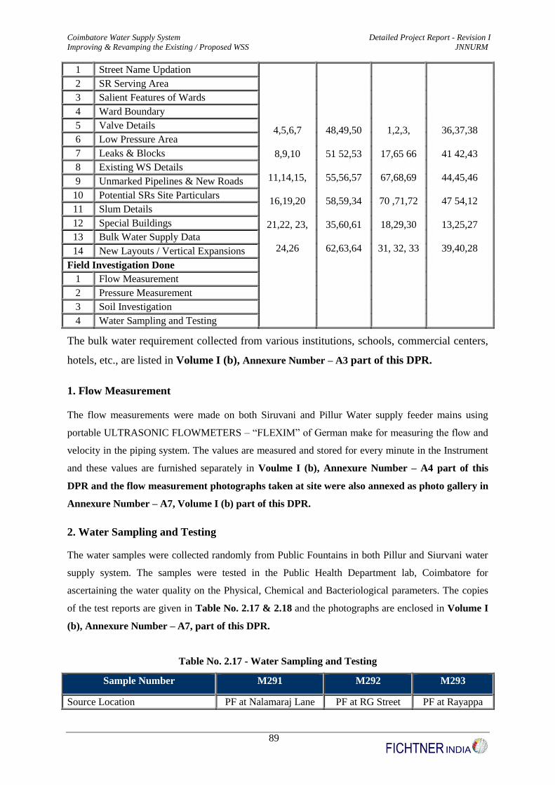
Coimbatore Water Supply System Detailed Project Report - Revision I
Improving & Revamping the Existing / Proposed WSS JNNURM
89
1 Street Name Updation
4,5,6,7
8,9,10
11,14,15,
16,19,20
21,22, 23,
24,26
48,49,50
51 52,53
55,56,57
58,59,34
35,60,61
62,63,64
1,2,3,
17,65 66
67,68,69
70 ,71,72
18,29,30
31, 32, 33
36,37,38
41 42,43
44,45,46
47 54,12
13,25,27
39,40,28
2 SR Serving Area
3 Salient Features of Wards
4 Ward Boundary
5 Valve Details
6 Low Pressure Area
7 Leaks & Blocks
8 Existing WS Details
9 Unmarked Pipelines & New Roads
10 Potential SRs Site Particulars
11 Slum Details
12 Special Buildings
13 Bulk Water Supply Data
14 New Layouts / Vertical Expansions
Field Investigation Done
1 Flow Measurement
2 Pressure Measurement
3 Soil Investigation
4 Water Sampling and Testing
The bulk water requirement collected from various institutions, schools, commercial centers,
hotels, etc., are listed in Volume I (b), Annexure Number – A3 part of this DPR.
1. Flow Measurement
The flow measurements were made on both Siruvani and Pillur Water supply feeder mains using
portable ULTRASONIC FLOWMETERS – “FLEXIM” of German make for measuring the flow and
velocity in the piping system. The values are measured and stored for every minute in the Instrument
and these values are furnished separately in Voulme I (b), Annexure Number – A4 part of this
DPR and the flow measurement photographs taken at site were also annexed as photo gallery in
Annexure Number – A7, Volume I (b) part of this DPR.
2. Water Sampling and Testing
The water samples were collected randomly from Public Fountains in both Pillur and Siurvani water
supply system. The samples were tested in the Public Health Department lab, Coimbatore for
ascertaining the water quality on the Physical, Chemical and Bacteriological parameters. The copies
of the test reports are given in Table No. 2.17 & 2.18 and the photographs are enclosed in Volume I
(b), Annexure Number – A7, part of this DPR.
Table No. 2.17 - Water Sampling and Testing
Sample Number M291 M292 M293
Source Location PF at Nalamaraj Lane PF at RG Street PF at Rayappa

Coimbatore Water Supply System Detailed Project Report - Revision I
Improving & Revamping the Existing / Proposed WSS JNNURM
90
Sample Number M291 M292 M293
Nagar
Ward Number 38 41 18
Source Siruvani Supply Siruvani Supply Pillur Supply
Date of sampling 24.02.2009 24.02.2009 24.02.2009
PARAMETERS
PHYSICAL EXAMINATION
Appearance Slight Yellow (SP) Slight Yellow (SP) Colourless (SP)
Odour None None None
Turbidity NTU 3 2 2
CHEMICAL EXAMINATION
Total Dissolved Solids 40 85 120
Carbonate Hardness (As Caco3) 16 17 50
Non Carbonate Hardness (As
Caco3) 4 2 0
Total Hardness (Caco3) 20 19 50
Calcium Hardness (As Caco3) 11 7 32
Magnesium Hardness (As Caco3) 9 12 18
Chloride (As Cl) 7 7 28
Ammonium Nitrogen (as N) 0.01 0.02 0
Albuminoid Nitrogen (As N) - - -
Oxygen absorbed (Tidys test in 4
hrs) 0.12 0.16 0.08
Nitrate Nitrogen (As No2 mg/l) 0.2 0.2 0.2
Phenolpthalin Alkalinity (As
Caco3) 0 0 0
Methly Orange Alkalinity (As
Caco3) 16 17 50
Fluoride (as F) 0.1 0.1 0.1
pH value 7.1 6.8 7.2
Total Iron (As Fe) 0.5 0.4 0.1
Manganese (As Mn) 0 0 0
QUALITATIVE TESTS
Nitrite Nitrogen NIL NIL NIL
Sulphate Trace Trace Trace
Phosphate Trace Trace Trace
Toxic Substance - - -
Electrical Conductivity
(Reciprocal megohms per Cm at
20 C)
53 46 215
Microscopical Examination Amorphous Matter Amorphous Matter Amorphous
Matter
Table No. 2.18 - Water Sampling and Testing

Coimbatore Water Supply System Detailed Project Report - Revision I
Improving & Revamping the Existing / Proposed WSS JNNURM
91
Sample Number M294 M295
Source Location PF at Jothi Nagar PF at Rajiv Nagar
Ward Number 19 21
Source Pillur Pillur
Date of sampling 25.02.2009 25.02.2009
PARAMETERS
PHYSICAL EXAMINATION
Appearance Colourless (SP) Slight Yellow
Odour None None
Turbidity NTU 1 2
CHEMICAL EXAMINATION
Total Dissolved solids 65 30
Carbonate Hardness (As Caco3) 33 14
Non Carbonate Hardness (As Caco3) 1 5
Total Hardness (As Caco3) 34 19
Calcium Hardness (As Caco3) 20 7
Magnesium Hardness (As Caco3) 14 12
Chloride (As Cl) 6 6
Ammonium Nitrogen (as N) 0 0.01
Albuminoid Nitrogen (As N) - -
Oxygen absorbed (Tidys test in 4 hrs) 0.04 0.12
Nitrate Nitrogen (As No2 mg/l) 0.2 0.2
Phenolpthalin Alkalinity (As Caco3) 0 0
Methly Orange Alkalinity (As Caco3) 33 14
Fluoride (as F) 0.1 0.1
pH value 6.9 6.9
Total Iron (As Fe) 0.05 0.2
Manganese (As Mn) 0 0
QUALITATIVE TESTS
Nitrite Nitrogen NIL NIL
Sulphate Trace Trace
Phosphate Trace Trace
Toxic Substance - -
Electrical Conductivity (Reciprocal megohms per Cm
at 20 C) 93 50
Microscopical Examination Amorphous Matter Amorphous Matter
BACTERIOLOGICAL EXAMINATION
Plate Count per ml on agar at 37 deg C – 24 Hrs 70 0
MPN of Coliform bacteria / 100 ml 240 0
Nature of Coliform bacteria isolated Irregular VI -
The result of the sample collected from the Pit Tap at Jothi Nagar (Sample Number - M294),
Jayasimmapuram of Ward No 19 is not satisfactory for bacteriological quality. The pit taps will be
eliminated on providing continuous pressured system with a minimum residual head of 12m / 7m in
respective zones.

Coimbatore Water Supply System Detailed Project Report - Revision I
Improving & Revamping the Existing / Proposed WSS JNNURM
92
2.9.3 Detailed Engineering Design - Feeder Main System
As the entire distribution system and corresponding SRs are designed to meet the ultimate demand in
the year 2044, it is imperative that the feeder main system connecting all the SRs with the master
service reservoir (MSR) is also designed to cater to the ultimate demand. Design parameters
considered in the design of feeder mains is narrated below:
Design Parameters: The coefficient of roughness ‘C’ adopted in the design of feeder mains for the
existing pipes and proposed new pipes are listed in Table No. 2.19.
Table No. 2.19 - “C” Value used for Hydraulic Design
S.No Pipe Type System "C" Value for Pipes in Feeder Mains
Existing System Proposed System
1 PVC Siruvani - -
2 HDPE Siruvani - 145
3 DI & MS Siruvani - 140
4 CI Siruvani 100 -
5 AC Siruvani - -
6 PSC Siruvani - -
7 PVC Pillur - -
8 HDPE Pillur - 145
9 DI & MS Pillur - 140
10 CI Pillur 100 -
11 AC Pillur - -
12 PSC Pillur - -
The feeder / gravity mains are designed with 22 hours of flow.
With a view to minimize the cost for pipe material, old CI pipes satisfying the hydraulic
criteria are proposed for retention, removing all AC,PSC and PVC pipes. The details of pipe
sizes adopted are listed below in Table No. 2.20
Table No. 2.20 - Pipe Sizes Proposed in Feeder Mains
S.No. Pipe material &
Pressure Rating
Diameter in mm
(ID – for DI & MS
and OD for HDPE)
Type
1 HDPE – PE 100 PN 6 < 200 Gravity System
2 HDPE – PE 100 PN 8 < 200 Pumping System
3 DI-K7 S/S 200 - 600 Gravity / Pumping System
4 MS PIPES > 600 Gravity / Pumping System
.

Coimbatore Water Supply System Detailed Project Report - Revision I
Improving & Revamping the Existing / Proposed WSS JNNURM
93
In order to ensure designed flow to all SRs simultaneously, flow control valves are
proposed at the inlet of some SRs where the residual head available is extremely high
(Say > 7m pressure) and to stablize a uniform flow within the feeder mains.
As some SRs cannot be fed under gravity from MSR due to prevailing higher
elevations, ground level sumps are proposed nearby with required pumpsets, for
feeding them.
Ground level sumps proposed are designed for a retention time of 30 minutes (of the
intermediate stage requirement) for system which operates only during emergency
contingencies and for a retention time of 60 minutes (of the intermediate stage
requirement) for system which operates under routine / normal operation.
(i) Existing Feeder Main System
Details of existing feeder main arrangement and the Service reservoirs being fed under both Pillur and
Siruvani schemes are given below in Table No. 2.21 & Table No.2.22
Table No. 2.21 – Existing Feeder Mains under Pillur System
S.No From To Diameter Material Length Feeding Reservoir
1 NP-1 NP-2 1000 PSC 835 -
2 NP-2 NP-3 1000 PSC 1753 -
3 NP-3 NP-4 1000 PSC 178 -
4 NP-4 NP-5 1000 PSC 638 -
5 NP-5 NP-6 800 PSC 1543 -
6 NP-6 NP-7 800 PSC 932 -
7 NP-7 NP-8 750 AC 689 -
8 NP-8 NP-9 500 AC 296 -
9 NP-9 NP-10 450 AC 954 -
10 NP-10 NP-11 450 CI 1545 -
11 NP-11 NP-12 400 CI 1063 Puliyakulam
12 NP-12 NP-13 900 PVC 459 -
13 NP-10 NP-14 450 CI 1145 Town Hall
14 NP-2 NP-15 350 CI 1462 VV Nagar
15 NP-15 NP-16 450 CI 1581 Police Quarters
16 NP-16 NP-17 450 CI 921 Gandhi Ma Nagar
17 NP-2 NP-17 200 AC 5671 -
18 NP-17 NP-18 450 CI 5096 -
19 NP-18 NP-19 350 CI 948 -
20 NP-19 NP-20 350 CI 1240 -
21 NP-20 NP-21 350 CI 326 Singanallur
22 NP-21 - 200 AC - -
23 NP-22 NP-23 350 CI 1404 Anna Nagar

Coimbatore Water Supply System Detailed Project Report - Revision I
Improving & Revamping the Existing / Proposed WSS JNNURM
94
S.No From To Diameter Material Length Feeding Reservoir
24 NP-23 NP-24 300 CI 1509 -
25 NP-24 NP-25 150 AC 771 SIHS Colony
26 NP-24 NP-26 300 CI 366 Nethajipuram
27 NP-18 NP-27 300 CI 2146 KK Nagar
28 NP-4 NP-28 500 CI 1507 Avarampalayam
29 NP-28 NP-29 500 CI 320 -
30 NP-28 NP-30 500 CI 144 -
31 NP-30 NP-31 500 CI 101 Kamadehnu Nagar
32 NP-31 NP-32 500 CI 512 -
33 NP-32 NP-33 250 AC 1655 Peelamedu
34 NP-33 NP-34 450 AC 1185 -
35 NP-34 NP-35 450 PSC 1356 Sowripalayam
36 NP-35 NP-36 350 PSC 2251 -
37 NP-36 NP-37 350 PSC 419 GV Residency
38 NP-36 NP-19 250 CI 1298 Varadarajapuram
39 NP-6 NP-38 750 CI 666 Siddhapudur
40 NP-39 NP-40 200 AC 2829 Maniyakarampalayam
41 NP-40 NP-41 450 CI 1620 -
42 NP-41 NP-42 450 CI 220 Kamarajapuram
43 NP-41 NP-43 450 CI 60 -
44 NP-43 NP-44 450 CI 209 -
45 NP-44 NP-3 450 CI 530 -
Table No. 2.22 – Existing Feeder Mains under Siruvani System
S.No From To Diameter Material Length Feeding Reservoir
1 NS-1 NS-2 500 CI 1119
2 NS-2 NS-3 450 CI 1668
3 NS-3 NS-4 600 CI 1210
4 NS-4 NS-5 250 CI 1083 Cheran Nagar
5 NS-4 NS-6 600 CI 2233 Jayaram Nagar
6 NS-3 NS-7 450 CI 1216 Gandhi Park, DB Road
7 NS-7 NS-8 600 CI 1432 Vysia Street
8 NS-1 NS-9 450 CI 1548 RS Puram,
9 NS-1 NS-10 600 CI 1366 Sanganur Chinthamani
10 NS-1 NS-11 600 CI 1183
11 NS-11 NS-12 500 CI 1426
12 NS-12 NS-13 500 CI 234
13 NS-13 NS-14 500 CI 290 RG Nagar
14 NS-13 NS-15 500 CI 1966 Rayappa Nagar
15 NS-12 NS-16 250 AC 1554 Jai Nagar
16 NS-1 NS-17 250 CI 554

Coimbatore Water Supply System Detailed Project Report - Revision I
Improving & Revamping the Existing / Proposed WSS JNNURM
95
S.No From To Diameter Material Length Feeding Reservoir
17 NS-1 NS-18 500 CI 1651
18 NS-18 NS-19 250 CI 522 Tatabad
19 NS-18 NS-20 500 CI 1998 VOC Park
20 NS-20 NS-21 150 CI 2560
The details of the existing feeder main system are presented in Dwg No. 10/1811150/WSS/WIN/005,
Volume VI part of this DPR.
(ii) Existing Problems in Feeder Main Systems
1. No Bulk water meter is installed either in MSRs or in SRs. This resulted in ineffective
monitoring of flow among MSRs to SRs and designed quantity is not received at various SRs.
2. Direct tapping in Feeder Mains between MSR to SRs was observed. This resulted in reduction
of residual pressure available at the feeder mains to feed the SR’s due to which SRs are not
receiving designed flow. Many SRs like Jai Nagar SR, Sanganur Chintamani SR, etc., are not
used due to insufficient flow in the reservoir.
3. Interlinking of Distribution System under both schemes like Pillur and Siruvani was observed
near the Sungam areas, to overcome the shortage problem occurring during the Siruvani
schemes.
4. Also distribution network were linked with two SRs at a time to feed remote areas, the area of
higher elevation as observed in the Southern Part of Coimbatore in Ward 54, which is
supplied by both Gandhi Park SR and also by Bharathi Park GLSR. This will greatly affect
the network hydraulics by causing higher flow than the designed quantity into the system and
affects the efficiency of the system like the pipe joints getting weaker (cement solvent as in
the present case), prone to more leakage, etc.,
5. Direct Feeding arrangement to SRs from rising mains namely in Revathi Layout SR,
Venkatapuram SR, Madatur SR, Ishwarya Nagar SR, etc in West Zone was also observed in
between Siruvani WTP to Siruvani MSR. These arrangements affect the regular water supply
schedule of Siruvani fed areas, especially during the shortage period.
6. There is no proper feeder main arrangement with the dependable source in the existing system
to overcome the shortage in Siruvani Supply.
7. Due to insuffiecient pressure in the feeder main to feed the SR’s, many places pumpsets are
used to directly pump into the Distribution system. Also due to frequent power failure or
power shutdown, pumps are operated using Diesel or in case of non availability of such
arrangments, the supply to the zone is affected considerably.

Coimbatore Water Supply System Detailed Project Report - Revision I
Improving & Revamping the Existing / Proposed WSS JNNURM
96
(iii) Proposed Feeder Main System
1. The existing feeder main alignment was retained as such, so as to avoid any additional / New
Railway Crossings, National Highway Crossings, Nallas, Water Streams etc., which may
delay the laying of pipes during execution time. The entire alignment was revamped for the
ultimate demand in 2044 and the existing CI pipes suitable for hydraulic designs are retained.
Additionally new feeder mains are proposed to the newly proposed SRs in both the systems.
2. Isolation of Pillur and Siruvani System are made separately, with Pillur System having it
supply from Pillur MSR and Siruvani system from Siruvani MSR respectively. The railway
line running parallel to the Mettupalayam Highway starting from ward 64 at Northern end and
ending at Ward 13 near Trichy Pallaghat road forms the boundary for Siruvani and Pillur
Systems
3. The Pillur feeder main was further sub divided into two primary stretches, linking a group of
Service reservoirs from Existing and Proposed MSR at Ramakrishnapuram separately.
4. In the proposed Feeder mains system, both Pillur & Siruvani MSRs are used only as
balancing reservoirs and the existing distribution system are delinked from the system.
5. Special apputenences like Sluice Valves with actuators connected to SCADA system are
proposed at the Inlet of each SR, Pitless sluice valves along the branch mains for flow
regulation and control during O & M. DI Scour Valves are proposed closure to Nallah or
water stream along the alignment for scouring. Duojet cylindrical air valves are proposed in
the higher / elevated gorund levels in between each stretches. Flow regulating valves are
proposed where the residual head at the SR Inlet was very high (> 7 m). Bulk water meters
with flow measurement are proposed at the outlet of each SR connecting to each District
Metering Area (DMA’s), to quantify the flow to distribution system.
6. In case of Direct Feeding SR’s – As an emergency contingency for the Direct Feeding SRs
under Siruvani system during drought periods, a separate pumping arrangement has been
made from the proposed sump of 10 LL capacity with the retention time of 60 minutes at the
existing Sanganur Chinthamani SR area, extending upto Revathy Layout along the pheriperal
boundary of Coimbatore Corporation connecting the other 5 direct feeding SRs. The size of
the pumping mains is arrived based on the economical analysis taking in to account the cost
of pipes, pumpsets and energy charges.
Alternate options like
Connecting Six SRs from Siruvani MSR separately by laying a
separate line was also considered. But due to high elevation difference
Coimbatore Water Supply System Detailed Project Report - Revision I
Improving & Revamping the Existing / Proposed WSS JNNURM
97
(ie) the SRs being located in the higher elevation it cannot be fed by
gravity system.
Connecting Six SRs to a proposed single Service Reservoir, acting like
a balancing reservoir at higher elevation (Probably in Ward 61) to
feed the six reservoirs is also considered. But due to the
nonavailability of apt site and also additional cost is incurred for
construction of balancing reservoir, so this alternative is also ruled
out
Details of the propsed feeder main system and their longitudinal section for a chainage of every 30 m
is shown in Dwg No. 10/1811150/WSS/WIN/007, Volume VI part of this DPR.
(iv) Proposed Feeder Main Alignment
The total length of feeder mains coming under Pillur, Siruvani & Pillur Siruvani MSR comes around
105 Kms. Pillur comprises of 64 Kms of main under Gravity and 10 Kms of main under Pumping.
Siruvani comprises of 15 Kms of main under Gravity and 7.50 Kms of main under Pumping. Pillur
Siruvani MSR Interlinking comprises of 8.50 kms of main under gravity.
Details of Service Reservoirs under each system and also the proposed feeder main system being fed
under Pillur and Siruvani system are listed in Table No. 2.23 to 2.29 and shown in Dwg No.
10/1811150/WSS/WIN/ 007 to 032, Volume VI part of this DPR.

98
Table No. 2.23 - Pillur Feeder Main I
From Proposed MSR at Ramakrishnapuram to Proposed SR at Bharathi Nagar (By Gravity) S
tretc
h
Len
gth
(m)
Inte
rmed
i
ate
Flo
w
(m)
Ult
ima
te
Flo
w (
m)
Dia
met
er
(mm
)
Pip
e
Ma
teria
l
Rem
ark
s
No
de
No
G.L
(m
)
Sta
gin
g
Hei
gh
t
(M)
LW
L
(m)
Dep
th O
f
Wa
ter (
m)
MW
L (
m)
Pip
e
Ou
tlet
Lev
el (
m)
Ca
pa
city
(LL
)
SR
Na
me
1 - 2 1500 742.91 948.17 1250 MS
(10mm THK) - 2 428.13 - - - - - - -
2 - 3 1000 733.45 936.3 1250 MS
(10mm THK) - 3 422.5 - - - - - - -
3 - 4 700 665.12 850.48 1200 MS
(10mm THK) - 4 417.86 - - - - - - -
4 - 5 2300 632.81 809.9 900 MS
(8mm THK) - 5 411.41 - - - - - - -
5 - IT 1000 34.72 34.72 - - - - - - - - - - Tapping for
ITPark
5 - 6 500 598.09 775.18 700 MS
(7mm THK) - 6 410.51 - - - - - - -
6 - 7 275 560.72 724.55 700 MS
(7mm THK) - 7 407.33 - - - - - - -
7 - 8 123 523.88 678.29 700 MS
(7mm THK) - 8 406.47 - - - - - - -
8 - 9 1423 474.43 616.19 700 MS
(7mm THK) - 9 396.07 - - - - - - -
9 - 10 564 441.52 574.86 700 MS
(7mm THK) - 10 393.99 - - - - - - -
10 - 11 1377 136.33 177.46 500 DI K7 S/S - 11 388.41 - - - - - - -
11 - 12 1532 85.36 113.45 500 DI K7 S/S - 12 387.38 - - - - - - -
12 - 13 956 47.8 66.28 400 DI K7 S/S - 13 399.33 - - - - - - -
13 - 14 225 39.81 56.26 400 DI K7 S/S - 14 400.61 15.00 415.61 3.50 419.11 421.61 11.00
Bharathi
Nagar SR
(Proposed)
PILLUR - BRANCHES FOR FEEDER MAIN-I

99
Table No. 2.23 - Pillur Feeder Main I
From Proposed MSR at Ramakrishnapuram to Proposed SR at Bharathi Nagar (By Gravity) S
tretc
h
Len
gth
(m)
Inte
rmed
i
ate
Flo
w
(m)
Ult
ima
te
Flo
w (
m)
Dia
met
er
(mm
)
Pip
e
Ma
teria
l
Rem
ark
s
No
de
No
G.L
(m
)
Sta
gin
g
Hei
gh
t
(M)
LW
L
(m)
Dep
th O
f
Wa
ter (
m)
MW
L (
m)
Pip
e
Ou
tlet
Lev
el (
m)
Ca
pa
city
(LL
)
SR
Na
me
2 - 15 100 9.46 11.88 200 DI K7 S/S - 15 428.13 10.60 438.73 3.00 441.73 442.73 3.00
Gandhi
Managar SR
(Exting)
3 - 16 947 68.33 85.82 500 DI K7 S/S - 16 422.50 15.00 437.50 3.70 441.00 442.20 8.00
VKR Nagar
SR
(Proposed)
4 - 17 370 32.31 40.58 350 DI K7 S/S - 17 417.70 15.00 432.70 3.10 435.80 438.30 10.00
Karuppiya
Goundar SR
(Proposed)
6 - 18 1116 37.37 50.83 400 CI EXIST
ING 18 405.80 - - - - - - -
18 - 19 853 37.37 50.63 250 DI K7 S/S - 19 401.42 15.00 416.42 3.50 419.92 422.42 10
Hudco
Colony SR
(Proposed)
7 - 20 51 36.84 46.26 200 DI K7 S/S - 20 406.29 14.00 420.29 3.50 423.79 426.29 10.00 DJ Nagar SR
(Existing)
8 - 21 276 49.45 62.10 250 DI K7 S/S - 21 406.26 12.00 418.26 3.20 421.462 423.962 13.00
Rajalakshmi
Nagar SR
(Proposed)
9 - 22 1330 32.91 41.33 300 DI K7 S/S - 22 396.28 - - - - - - -
22 - 23 955 32.91 41.33 300 DI K7 S/S - 23 399.03 13.00 412.03 3.50 415.53 418.03 10.00 KK Nagar SR
(Existing)
10 - 24 378 305.19 397.39 700 MS
(7mm THK) - 24 390.87 - - - - - - -
24 - 25 507 173.89 232.5 500 MS
(7mm THK) - 25 388.07 - - - - - - -
25 - 26 236 173.89 232.5 400 MS
(7mm THK) - 26 387.32 - - - - - - -
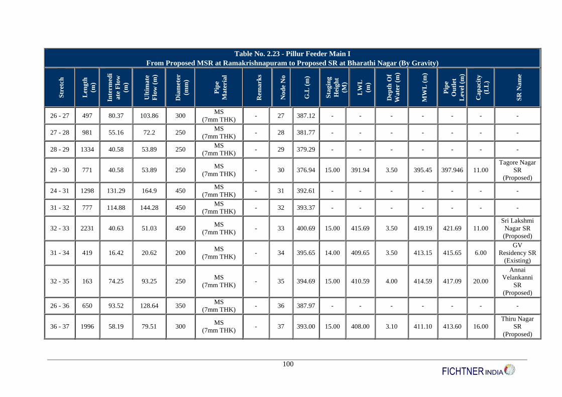
100
Table No. 2.23 - Pillur Feeder Main I
From Proposed MSR at Ramakrishnapuram to Proposed SR at Bharathi Nagar (By Gravity) S
tretc
h
Len
gth
(m)
Inte
rmed
i
ate
Flo
w
(m)
Ult
ima
te
Flo
w (
m)
Dia
met
er
(mm
)
Pip
e
Ma
teria
l
Rem
ark
s
No
de
No
G.L
(m
)
Sta
gin
g
Hei
gh
t
(M)
LW
L
(m)
Dep
th O
f
Wa
ter (
m)
MW
L (
m)
Pip
e
Ou
tlet
Lev
el (
m)
Ca
pa
city
(LL
)
SR
Na
me
26 - 27 497 80.37 103.86 300 MS
(7mm THK) - 27 387.12 - - - - - - -
27 - 28 981 55.16 72.2 250 MS
(7mm THK) - 28 381.77 - - - - - - -
28 - 29 1334 40.58 53.89 250 MS
(7mm THK) - 29 379.29 - - - - - - -
29 - 30 771 40.58 53.89 250 MS
(7mm THK) - 30 376.94 15.00 391.94 3.50 395.45 397.946 11.00
Tagore Nagar
SR
(Proposed)
24 - 31 1298 131.29 164.9 450 MS
(7mm THK) - 31 392.61 - - - - - - -
31 - 32 777 114.88 144.28 450 MS
(7mm THK) - 32 393.37 - - - - - - -
32 - 33 2231 40.63 51.03 450 MS
(7mm THK) - 33 400.69 15.00 415.69 3.50 419.19 421.69 11.00
Sri Lakshmi
Nagar SR
(Proposed)
31 - 34 419 16.42 20.62 200 MS
(7mm THK) - 34 395.65 14.00 409.65 3.50 413.15 415.65 6.00
GV
Residency SR
(Existing)
32 - 35 163 74.25 93.25 250 MS
(7mm THK) - 35 394.69 15.00 410.59 4.00 414.59 417.09 20.00
Annai
Velankanni
SR
(Proposed)
26 - 36 650 93.52 128.64 350 MS
(7mm THK) - 36 387.97 - - - - - - -
36 - 37 1996 58.19 79.51 300 MS
(7mm THK) - 37 393.00 15.00 408.00 3.10 411.10 413.60 16.00
Thiru Nagar
SR
(Proposed)

101
Table No. 2.23 - Pillur Feeder Main I
From Proposed MSR at Ramakrishnapuram to Proposed SR at Bharathi Nagar (By Gravity) S
tretc
h
Len
gth
(m)
Inte
rmed
i
ate
Flo
w
(m)
Ult
ima
te
Flo
w (
m)
Dia
met
er
(mm
)
Pip
e
Ma
teria
l
Rem
ark
s
No
de
No
G.L
(m
)
Sta
gin
g
Hei
gh
t
(M)
LW
L
(m)
Dep
th O
f
Wa
ter (
m)
MW
L (
m)
Pip
e
Ou
tlet
Lev
el (
m)
Ca
pa
city
(LL
)
SR
Na
me
36 - 38 255 35.33 49.13 200 MS
(7mm THK) - 38 388.19 15.00 403.19 3.50 406.69 409.19 10.00
Uppilipalaya
m
SR ( Existing)
27 - 39 326 25.21 31.66 200 MS
(7mm THK) - 39 388.90 8.35 397.25 3.00 400.25 402.75 7.00
Singanallur
SR (Existing)
28 - 40 375 14.58 18.31 200 MS
(7mm THK) - 40 380.69 15.00 395.69 3.50 399.19 401.69 4.00
Kothari Nagar
SR
(Proposed)
11 - 41 35 50.97 64.01 250 CI EXIST
ING 41 389.11 15.00 404.11 3.50 407.61 410.11 16.00
Anna Nagar
SR (Existing)
12 - 42 185 37.56 47.17 200 DI K7 S/S - 42 387.49 12.00 399.491 3.65 403.141 405.641 12.00 Nethajipuram
SR (Existing)
13 - 43 313 7.98 10.03 200 DI K7 S/S - 43 399.44 12.00 411.44 4.21 415.65 418.15 3.00 SIHS Colony
(Existing)

102
Table No. 2.24 - Pillur Feeder Main II
(From Existing MSR at Ramakrishnapuram to Proposed SR at Lakshmi Nagar Mill Colony (By Gravity)
Str
etch
Len
gth
(m
)
Inte
rmed
ia
te F
low
(Lp
s)
Ult
ima
te
Flo
w (
Lp
s)
Dia
met
er
(mm
)
Pip
e
Ma
teria
l
Pip
e
Rem
ark
s
No
de
Nu
mb
er
Gl
(m)
Sta
gin
g
Hei
gh
t (m
)
LW
L (
m)
Dep
th O
f
Wa
ter (
m)
MW
L (
m)
Pip
e O
utl
et
Lev
el (
m)
Ca
pa
city
(LL
)
SR
Na
me
(Ex
t/P
ro
)
1 - 2 901 922.94 1174.89 1400 MS
(12 mm THICK) - 2 421.05 - - - - - - -
2 - 3 1749 922.94 1174.89 1400 MS
(12 mm THICK) - 3 416.88 - - - - - - -
3 - 4 182 865.88 1098.97 1400 MS
(12 mm THICK) - 4 415.93 - - - - - - -
4 - 5 459 777.82 982.55 1400 MS
(12 mm THICK) - 5 415.18 - - - - - - -
5 - 6 1172 777.82 982.55 1400 MS
(12 mm THICK) - 6 417.52 - - - - - - -
6 - 7 524 705.48 891.7 1400 MS
(12 mm THICK) - 7 424.67 - - - - - - -
7 - 8 22 615.28 778.42 1400 MS
(12 mm THICK) - 8 424.65 - - - - - - -
8 - 9 330 560.07 706.92 1400 MS
(12 mm THICK) - 9 427.53 - - - - - - -
9 - 10 429 560.07 706.92 1400 MS
(12 mm THICK) - 10 423.97 - - - - - - -
10 - 11 1383 402.59 505.62 700 MS (7 mm
THICKNESS) - 11 414.33 - - - - - - -
11 - 12 740 402.59 505.62 700 MS (7 mm
THICKNESS) - 12 407.48 - - - - - - -
12 - 14 1165 201.87 253.53 500 DI K7 S/S - 14 407.55 - - - - - - -
14 - 15 730 131.8 165.52 500 DI K7 S/S - 15 407.09 - - - - - - -
15 - 16 1005 108.49 136.25 400 DI K7 S/S - 16 405.43 - - - - - - -
16 - 17 897 30.92 38.83 300 DI K7 S/S - 17 405.43 - - - - - - -
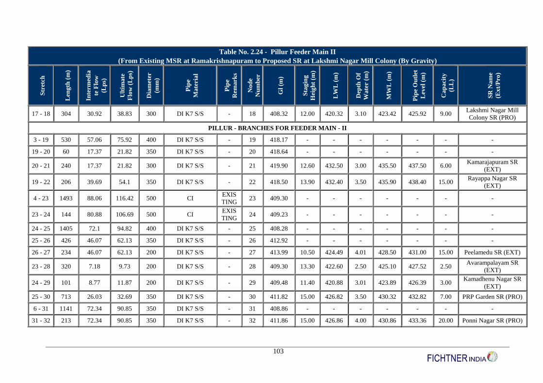
103
Table No. 2.24 - Pillur Feeder Main II
(From Existing MSR at Ramakrishnapuram to Proposed SR at Lakshmi Nagar Mill Colony (By Gravity)
Str
etch
Len
gth
(m
)
Inte
rmed
ia
te F
low
(Lp
s)
Ult
ima
te
Flo
w (
Lp
s)
Dia
met
er
(mm
)
Pip
e
Ma
teria
l
Pip
e
Rem
ark
s
No
de
Nu
mb
er
Gl
(m)
Sta
gin
g
Hei
gh
t (m
)
LW
L (
m)
Dep
th O
f
Wa
ter (
m)
MW
L (
m)
Pip
e O
utl
et
Lev
el (
m)
Ca
pa
city
(LL
)
SR
Na
me
(Ex
t/P
ro
)
17 - 18 304 30.92 38.83 300 DI K7 S/S - 18 408.32 12.00 420.32 3.10 423.42 425.92 9.00 Lakshmi Nagar Mill
Colony SR (PRO)
PILLUR - BRANCHES FOR FEEDER MAIN - II
3 - 19 530 57.06 75.92 400 DI K7 S/S - 19 418.17 - - - - - - -
19 - 20 60 17.37 21.82 350 DI K7 S/S - 20 418.64 - - - - - - -
20 - 21 240 17.37 21.82 300 DI K7 S/S - 21 419.90 12.60 432.50 3.00 435.50 437.50 6.00 Kamarajapuram SR
(EXT)
19 - 22 206 39.69 54.1 350 DI K7 S/S - 22 418.50 13.90 432.40 3.50 435.90 438.40 15.00 Rayappa Nagar SR
(EXT)
4 - 23 1493 88.06 116.42 500 CI EXIS
TING 23 409.30 - - - - - - -
23 - 24 144 80.88 106.69 500 CI EXIS
TING 24 409.23 - - - - - - -
24 - 25 1405 72.1 94.82 400 DI K7 S/S - 25 408.28 - - - - - - -
25 - 26 426 46.07 62.13 350 DI K7 S/S - 26 412.92 - - - - - - -
26 - 27 234 46.07 62.13 200 DI K7 S/S - 27 413.99 10.50 424.49 4.01 428.50 431.00 15.00 Peelamedu SR (EXT)
23 - 28 320 7.18 9.73 200 DI K7 S/S - 28 409.30 13.30 422.60 2.50 425.10 427.52 2.50 Avarampalayam SR
(EXT)
24 - 29 101 8.77 11.87 200 DI K7 S/S - 29 409.48 11.40 420.88 3.01 423.89 426.39 3.00 Kamadhenu Nagar SR
(EXT)
25 - 30 713 26.03 32.69 350 DI K7 S/S - 30 411.82 15.00 426.82 3.50 430.32 432.82 7.00 PRP Garden SR (PRO)
6 - 31 1141 72.34 90.85 350 DI K7 S/S - 31 408.86 - - - - - - -
31 - 32 213 72.34 90.85 350 DI K7 S/S - 32 411.86 15.00 426.86 4.00 430.86 433.36 20.00 Ponni Nagar SR (PRO)
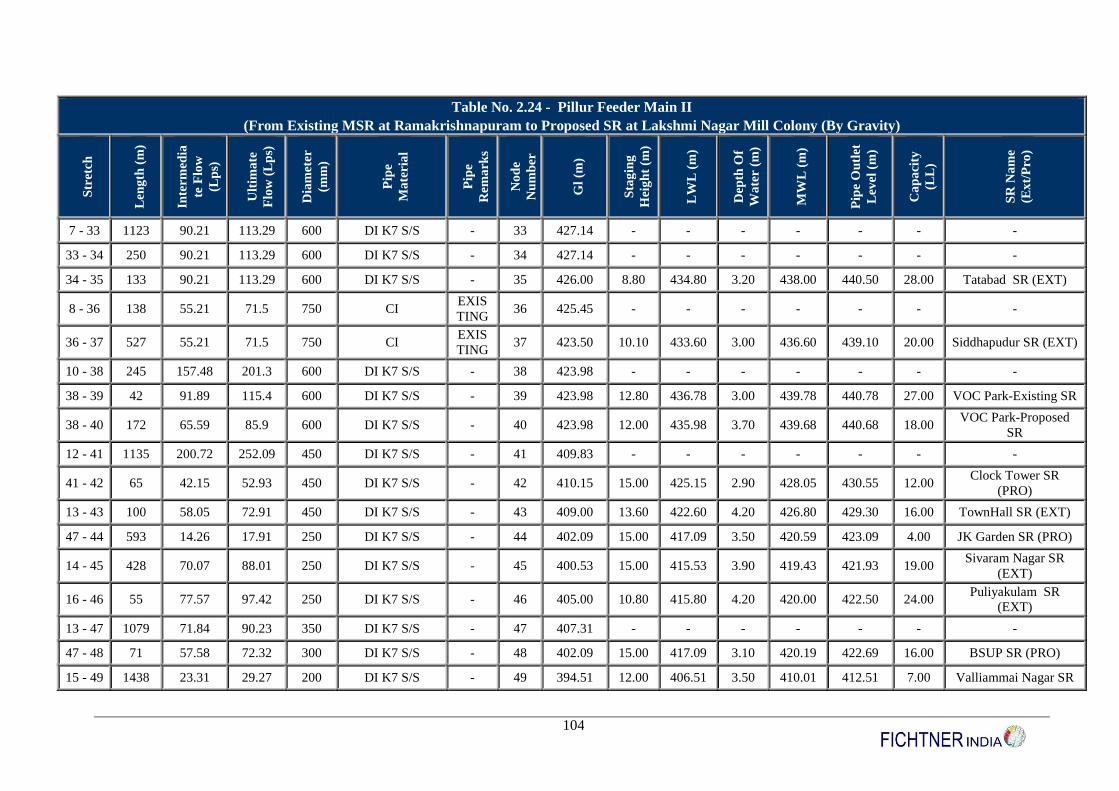
104
Table No. 2.24 - Pillur Feeder Main II
(From Existing MSR at Ramakrishnapuram to Proposed SR at Lakshmi Nagar Mill Colony (By Gravity)
Str
etch
Len
gth
(m
)
Inte
rmed
ia
te F
low
(Lp
s)
Ult
ima
te
Flo
w (
Lp
s)
Dia
met
er
(mm
)
Pip
e
Ma
teria
l
Pip
e
Rem
ark
s
No
de
Nu
mb
er
Gl
(m)
Sta
gin
g
Hei
gh
t (m
)
LW
L (
m)
Dep
th O
f
Wa
ter (
m)
MW
L (
m)
Pip
e O
utl
et
Lev
el (
m)
Ca
pa
city
(LL
)
SR
Na
me
(Ex
t/P
ro
)
7 - 33 1123 90.21 113.29 600 DI K7 S/S - 33 427.14 - - - - - - -
33 - 34 250 90.21 113.29 600 DI K7 S/S - 34 427.14 - - - - - - -
34 - 35 133 90.21 113.29 600 DI K7 S/S - 35 426.00 8.80 434.80 3.20 438.00 440.50 28.00 Tatabad SR (EXT)
8 - 36 138 55.21 71.5 750 CI EXIS
TING 36 425.45 - - - - - - -
36 - 37 527 55.21 71.5 750 CI EXIS
TING 37 423.50 10.10 433.60 3.00 436.60 439.10 20.00 Siddhapudur SR (EXT)
10 - 38 245 157.48 201.3 600 DI K7 S/S - 38 423.98 - - - - - - -
38 - 39 42 91.89 115.4 600 DI K7 S/S - 39 423.98 12.80 436.78 3.00 439.78 440.78 27.00 VOC Park-Existing SR
38 - 40 172 65.59 85.9 600 DI K7 S/S - 40 423.98 12.00 435.98 3.70 439.68 440.68 18.00 VOC Park-Proposed
SR
12 - 41 1135 200.72 252.09 450 DI K7 S/S - 41 409.83 - - - - - - -
41 - 42 65 42.15 52.93 450 DI K7 S/S - 42 410.15 15.00 425.15 2.90 428.05 430.55 12.00 Clock Tower SR
(PRO)
13 - 43 100 58.05 72.91 450 DI K7 S/S - 43 409.00 13.60 422.60 4.20 426.80 429.30 16.00 TownHall SR (EXT)
47 - 44 593 14.26 17.91 250 DI K7 S/S - 44 402.09 15.00 417.09 3.50 420.59 423.09 4.00 JK Garden SR (PRO)
14 - 45 428 70.07 88.01 250 DI K7 S/S - 45 400.53 15.00 415.53 3.90 419.43 421.93 19.00 Sivaram Nagar SR
(EXT)
16 - 46 55 77.57 97.42 250 DI K7 S/S - 46 405.00 10.80 415.80 4.20 420.00 422.50 24.00 Puliyakulam SR
(EXT)
13 - 47 1079 71.84 90.23 350 DI K7 S/S - 47 407.31 - - - - - - -
47 - 48 71 57.58 72.32 300 DI K7 S/S - 48 402.09 15.00 417.09 3.10 420.19 422.69 16.00 BSUP SR (PRO)
15 - 49 1438 23.31 29.27 200 DI K7 S/S - 49 394.51 12.00 406.51 3.50 410.01 412.51 7.00 Valliammai Nagar SR
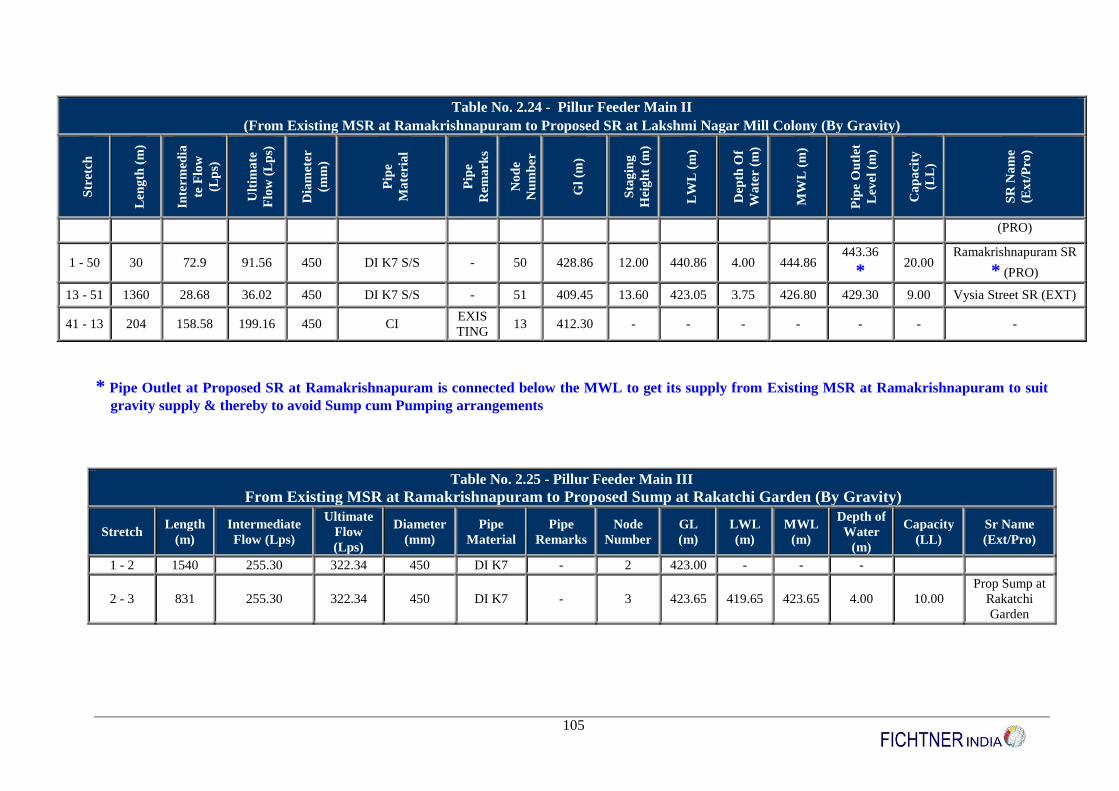
105
Table No. 2.24 - Pillur Feeder Main II
(From Existing MSR at Ramakrishnapuram to Proposed SR at Lakshmi Nagar Mill Colony (By Gravity)
Str
etch
Len
gth
(m
)
Inte
rmed
ia
te F
low
(Lp
s)
Ult
ima
te
Flo
w (
Lp
s)
Dia
met
er
(mm
)
Pip
e
Ma
teria
l
Pip
e
Rem
ark
s
No
de
Nu
mb
er
Gl
(m)
Sta
gin
g
Hei
gh
t (m
)
LW
L (
m)
Dep
th O
f
Wa
ter (
m)
MW
L (
m)
Pip
e O
utl
et
Lev
el (
m)
Ca
pa
city
(LL
)
SR
Na
me
(Ex
t/P
ro
)
(PRO)
1 - 50 30 72.9 91.56 450 DI K7 S/S - 50 428.86 12.00 440.86 4.00 444.86 443.36
* 20.00
Ramakrishnapuram SR
* (PRO)
13 - 51 1360 28.68 36.02 450 DI K7 S/S - 51 409.45 13.60 423.05 3.75 426.80 429.30 9.00 Vysia Street SR (EXT)
41 - 13 204 158.58 199.16 450 CI EXIS
TING 13 412.30 - - - - - - -
* Pipe Outlet at Proposed SR at Ramakrishnapuram is connected below the MWL to get its supply from Existing MSR at Ramakrishnapuram to suit
gravity supply & thereby to avoid Sump cum Pumping arrangements
2.28 - Pillur Feeder Main III istirishnapuram to Proposed Sump at Rakatchi Garden (By Gravity)ble No 2.28 - Pillur Feeder Main III - From Existing MSR at
Ramakrishnapuram to Proposed Sump at Rakatchi Garden (By Gravity)
Table No. 2.25 - Pillur Feeder Main III
From Existing MSR at Ramakrishnapuram to Proposed Sump at Rakatchi Garden (By Gravity)
Stretch Length
(m)
Intermediate
Flow (Lps)
Ultimate
Flow
(Lps)
Diameter
(mm)
Pipe
Material
Pipe
Remarks
Node
Number
GL
(m)
LWL
(m)
MWL
(m)
Depth of
Water
(m)
Capacity
(LL)
Sr Name
(Ext/Pro)
1 - 2 1540 255.30 322.34 450 DI K7 - 2 423.00 - - -
2 - 3 831 255.30 322.34 450 DI K7 - 3 423.65 419.65 423.65 4.00 10.00
Prop Sump at
Rakatchi
Garden

106
Table No. 2.26 - Pillur Feeder Main IV
Pumping from Proposed Sump at Rakatchi Garden to Existing SR at Jai Nagar (By Pumping) S
tret
ch
Len
gth
(M
)
Inte
rmed
iate
Flo
w (
Lp
s)
Ult
ima
te
Flo
w (
Lp
s)
Dia
met
er
(Mm
)
Pip
e
Ma
teria
l
Pip
e
Rem
ark
s
No
de
Nu
mb
er
GL
(M
)
Sta
gin
g
Hei
gh
t (M
)
LW
L (
M)
Dep
th O
f
Wa
ter
(M)
MW
L (
M)
Pip
e O
utl
et
Lev
el (
M)
Sta
gin
g
Hei
gh
t (M
)
Ca
pa
city
(LL
)
SR
Na
me
(Ex
t/P
ro
)
1 - 2 1673 180.56 228.47 500 DI K7 S/S - 2 428.79 - - - - - - - -
2 - 3 1083 64.24 80.67 400 DI K7 S/S - 3 435.89 - - - - - - - -
3 - 4 143 48.05 60.34 350 DI K7 S/S - 4 434.87 - - - - - - - -
4 - 5 80 48.05 60.34 350 DI K7 S/S - 5 436.30 19.90 456.20 4.00 460.20 462.70 19.90 10.00 Jai Nagar
SR (Ext)
PILLUR - BRANCHES FOR FEEDERMAIN - IV
2 - 6 610 116.32 147.8 350 DI K7 S/S - 6 427.23 - - - - - - - -
6 - 7 1717 83.74 106.88 300 DI K7 S/S - 7 421.39 - - - - - - - -
7 - 8 645 66.96 84.1 250 DI K7 S/S - 8 421.16 15.00 436.16 3.70 439.857 442.36 15.00 20.00 Nehru Street
SR (Pro)
3 - 11 1950 16.19 20.33 180 HDPE PN
8 - 11 428.34 15.3 443.64 3.00 446.64 449.14 15.30 6.00
RG Nagar
SR (Ext)
PILLUR - SUB BRANCHES FOR FEEDERMAIN – IV
6 - 10 1570 32.58 40.92 200 DI K7 S/S - 10 423.54 15.00 438.54 3.10 441.64 44.14 15.00 9.00
Sanganur
Road SR
(Prop)
7 - 9 480 16.78 22.78 180 HDPE PN
8 - 9 423.52 13.70 437.22 3.00 440.02 445.2 13.70 6.00
Rathinapuri
SR (Ext)
* Pipe Outlet at Proposed SR at Bharathi Park is connected below the MWL to get its supply from Bharathi Park MSR to suit gravity supply &
thereby to avoid Sump cum Pumping arrangements
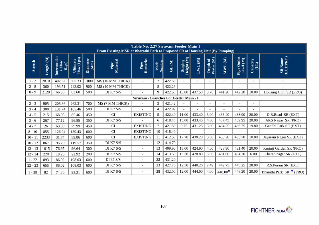
107
Table No. 2.27 Siruvani Feeder Main I From Existing MSR at Bharathi Park to Proposed SR at Housing Unit (By Pumping)
Str
etch
Len
gth
(M
)
Inte
rmed
iat
e F
low
(Lp
s)
Ult
ima
te
Flo
w (
Lp
s)
Dia
met
er
(Mm
)
Pip
e
Ma
teria
l
Pip
e
Rem
ark
s
No
de
Nu
mb
er
GL
(M
)
Sta
gin
g
Hei
gh
t (M
)
LW
L (
M)
Dep
th o
f
Wa
ter (
M)
MW
L (
M)
Pip
e O
utl
et
Lev
el (
M)
Ca
pa
city
(LL
)
SR
Na
me
(EX
T/P
RO
)
1 - 2 2810 402.37 505.33 1000 MS (10 MM THICK) - 2 422.55 - - - - - - -
2 - 8 360 193.51 243.02 900 MS (10 MM THICK) - 8 422.23 - - - - - - -
8 - 9 2120 66.56 83.60 500 DI K7 S/S - 9 422.50 15.00 437.50 3.70 441.20 442.20 18.00 Housing Unit SR (PRO)
Siruvani - Branches For Feeder Main - I
2 - 3 905 208.86 262.31 700 MS (7 MM THICK) - 3 421.42 - - - - - -
3 - 4 300 131.74 165.46 500 DI K7 S/S - 4 422.02 - - - - - -
4 - 5 215 68.05 85.46 450 CI EXISTING 5 422.40 11.00 433.40 3.00 436.40 438.90 20.00 D.B.Road SR (EXT)
3 - 6 267 77.12 96.85 350 DI K7 S/S - 6 418.45 15.00 433.45 4.00 437.45 439.95 20.00 AKS Nagar SR (PRO)
4 - 7 26 63.69 79.99 450 CI EXISTING 7 421.50 9.75 431.25 3.00 434.25 436.75 19.80 Gandhi Park SR (EXT)
8 - 10 855 126.94 159.43 600 CI EXISTING 10 418.40 - - - - - -
10 - 11 2233 31.74 39.86 600 CI EXISTING 11 412.50 17.70 430.20 3.00 433.20 435.70 10.00 Jayaram Nagar SR (EXT)
10 - 12 867 95.20 119.57 350 DI K7 S/S - 12 414.70 - - - - - -
12 - 13 1015 76.95 96.64 300 DI K7 S/S - 13 409.90 15.00 424.90 4.00 428.90 431.40 20.00 Kurinji Garden SR (PRO)
12 - 14 220 18.25 22.92 200 DI K7 S/S - 14 413.50 15.30 428.80 3.00 431.80 434.30 6.00 Cheran nagar SR (EXT)
1 - 22 893 86.02 108.03 600 DI k7 S/S - 22 431.20 - - - - - -
22 - 23 655 86.02 108.03 600 DI K7 S/S - 23 427.76 12.50 440.26 2.49 442.75 445.25 28.00 R.S.Puram SR (EXT)
1 - 28 82 74.30 93.31 600 DI K7 S/S - 28 432.00 12.00 444.00 4.00 448.00* 446.20 20.00 Bharathi Park SR * (PRO)
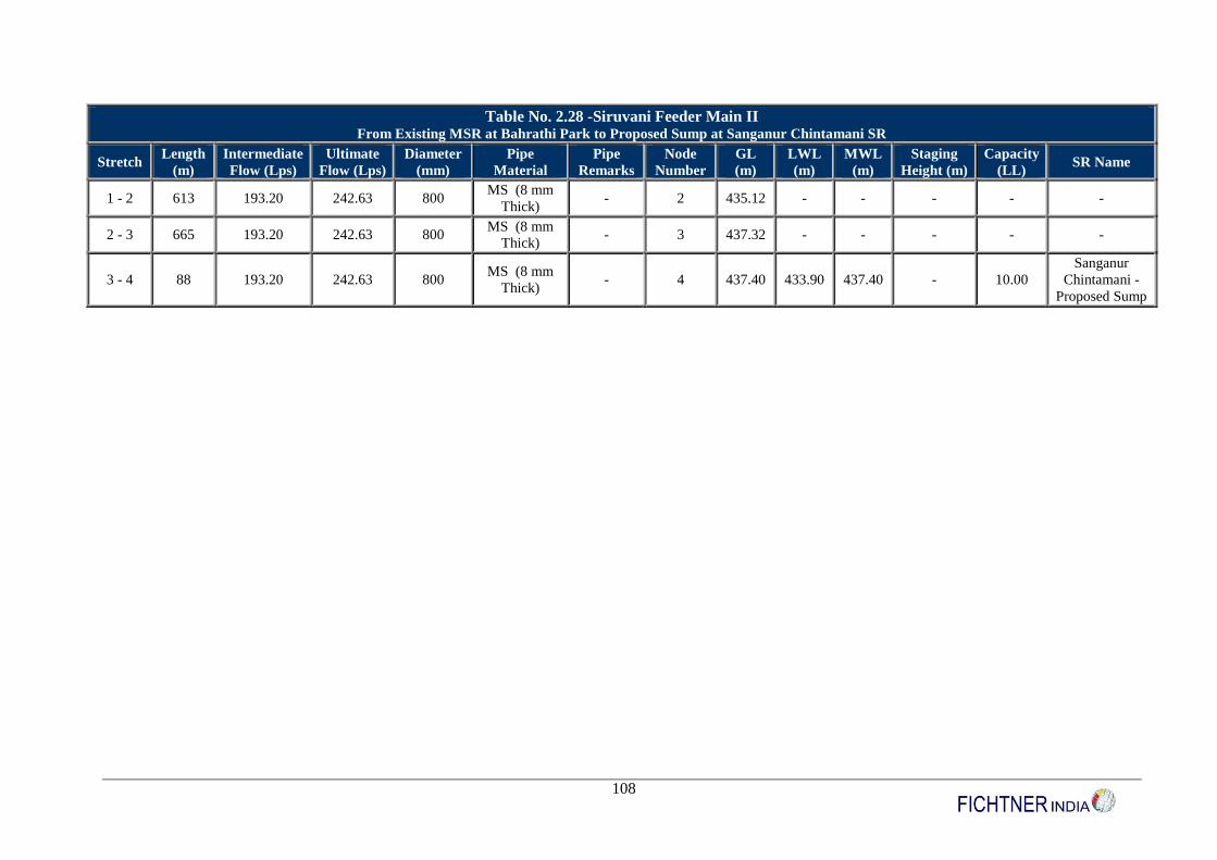
108
Table No. 2.28 -Siruvani Feeder Main II From Existing MSR at Bahrathi Park to Proposed Sump at Sanganur Chintamani SR
Stretch Length
(m)
Intermediate
Flow (Lps)
Ultimate
Flow (Lps)
Diameter
(mm)
Pipe
Material
Pipe
Remarks
Node
Number
GL
(m)
LWL
(m)
MWL
(m)
Staging
Height (m)
Capacity
(LL) SR Name
1 - 2 613 193.20 242.63 800 MS (8 mm
Thick) - 2 435.12 - - - - -
2 - 3 665 193.20 242.63 800 MS (8 mm
Thick) - 3 437.32 - - - - -
3 - 4 88 193.20 242.63 800 MS (8 mm
Thick) - 4 437.40 433.90 437.40 - 10.00
Sanganur
Chintamani -
Proposed Sump
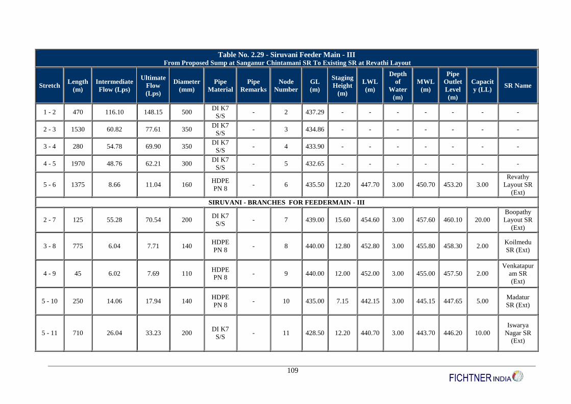
109
Table No. 2.29 - Siruvani Feeder Main - III From Proposed Sump at Sanganur Chintamani SR To Existing SR at Revathi Layout
Stretch Length
(m)
Intermediate
Flow (Lps)
Ultimate
Flow
(Lps)
Diameter
(mm)
Pipe
Material
Pipe
Remarks
Node
Number
GL
(m)
Staging
Height
(m)
LWL
(m)
Depth
of
Water
(m)
MWL
(m)
Pipe
Outlet
Level
(m)
Capacit
y (LL) SR Name
1 - 2 470 116.10 148.15 500 DI K7
S/S - 2 437.29 - - - - - - -
2 - 3 1530 60.82 77.61 350 DI K7
S/S - 3 434.86 - - - - - - -
3 - 4 280 54.78 69.90 350 DI K7
S/S - 4 433.90 - - - - - - -
4 - 5 1970 48.76 62.21 300 DI K7
S/S - 5 432.65 - - - - - - -
5 - 6 1375 8.66 11.04 160 HDPE
PN 8 - 6 435.50 12.20 447.70 3.00 450.70 453.20 3.00
Revathy
Layout SR
(Ext)
SIRUVANI - BRANCHES FOR FEEDERMAIN - III
2 - 7 125 55.28 70.54 200 DI K7
S/S - 7 439.00 15.60 454.60 3.00 457.60 460.10 20.00
Boopathy
Layout SR
(Ext)
3 - 8 775 6.04 7.71 140 HDPE
PN 8 - 8 440.00 12.80 452.80 3.00 455.80 458.30 2.00
Koilmedu
SR (Ext)
4 - 9 45 6.02 7.69 110 HDPE
PN 8 - 9 440.00 12.00 452.00 3.00 455.00 457.50 2.00
Venkatapur
am SR
(Ext)
5 - 10 250 14.06 17.94 140 HDPE
PN 8 - 10 435.00 7.15 442.15 3.00 445.15 447.65 5.00
Madatur
SR (Ext)
5 - 11 710 26.04 33.23 200 DI K7
S/S - 11 428.50 12.20 440.70 3.00 443.70 446.20 10.00
Iswarya
Nagar SR
(Ext)

110
Table No. 2.29 - Siruvani Feeder Main - III From Proposed Sump at Sanganur Chintamani SR To Existing SR at Revathi Layout
Stretch Length
(m)
Intermediate
Flow (Lps)
Ultimate
Flow
(Lps)
Diameter
(mm)
Pipe
Material
Pipe
Remarks
Node
Number
GL
(m)
Staging
Height
(m)
LWL
(m)
Depth
of
Water
(m)
MWL
(m)
Pipe
Outlet
Level
(m)
Capacit
y (LL) SR Name
1 - 12 176 39.85 50.85 250 DI K7
S/S - 12 437.32 15.00 452.52 2.90 455.32 457.72 12.00
Chintamani
SR (Prop)

Coimbatore Water Supply System Detailed Project Report - Revision I
Improving & Revamping the Existing / Proposed WSS JNNURM
111
Table No. 2.30 - SRs by Direct Feeding before Siruvani MSR
S.No Service Reservoir
Name
Capacity
(LL)
Remarks on
Alignment Remarks on Tapping
1 Koilmedu 2.00 Existing Before Bharathi Park MSR
2 Boopathy Layout 20.00 Existing Before Bharathi Park MSR
3 Venkatapuram 2.00 Existing Before Bharathi Park MSR
4 Revathi Layout 3.00 Existing Before Bharathi Park MSR
5 Madathur 5.00 Existing Before Bharathi Park MSR
6 Iswarya Nagar 10.00 Existing Before Bharathi Park MSR
Total Requirement 47.00 LL (Say 4 MLD)
NOTE : Since the SRs are currently tapped by gravity before the Bharathi Park MSR, the same
system is retained, however during Drought period a separate pumping arrangements are provided to
the above said Direct Feeding SR’s from Baharathi Park MSR.
The summary of the feeder main arrangement for both Pillur and Siruvani Scheme and its SR
arrangement is listed below
1. The requirement by SRs coming under Proposed MSR at Ramakrishnapuram (ie) Pillur
Feeder Main I will be 833 Lps (ie) 72 Mld for the Ultimate Stage and 646 Lps (ie) 56 Mld
for the Intermediate Stage. Since the SR’s are designed for 1/3rd of Intermediate
Requirement, the capacity of SR capacity designed is for 20 Mld approximately.
2. The requirement by SRs coming under Existing MSR at Ramakrishnapuram (ie) for Pillur
Feeder Main II, III & IV will be 1450 Lps (ie) 125 Mld for the Ultimate Stage and 1142
Lps (ie) 99 Mld for the Intermediate Stage. Since the SR’s are designed for 1/3rd of
Intermediate Requirement, the capacity of SR capacity designed is 36 Mld approximately.
3. The requirement by SRs coming under Existing MSR at Baharthi Park (ie) for Siruvani
Main I, II, III (Including the Direct Feeding SRs) will be 867 Lps (ie) 75 Mld for both
Ultimate & Intermediate Stage. Since the SR’s are designed for 1/3rd of Intermediate
Requirement, the capacity of SR capacity designed is 22 Mld approximately.
Since the quantum of supply from Siruvani is fixed as 75 mld during the entire design period of 30
years, SRs coming under Siruvani system are carefully delineated such that the total requirement lies
well within the 75 Mld ((22 x 3 = 66 Mld) for SR’s coming under Existing MSR at Siruvani + 12 Mld
for Direct feeding SR’s fed before Siruvani MSR = 75 Mld as discussed above) and can be fed from
Siruvani MSR. Vysial Street SR & Town Hall SR currently fed under Siruvani System was
reallocated to Pillur system. The balance ultimate requirement of 215 mld (ie) 289.280 – 75 = 214.28,
say 215 mld is reallocated to Pillur MSR.

Coimbatore Water Supply System Detailed Project Report - Revision I
Improving & Revamping the Existing / Proposed WSS JNNURM
112
Interconnnecting Pillur MSR Outlets for Balance Reservoir Action
The summary of the feeder main arrangement for both Pillur and Siruvani Scheme and the
importance of Interconnecting Pillur MSR outlets arrangements is justifified below.
1. The requirement by Pillur Feeder Main I served by Proposed MSR at Ramakrishnapuram
for the ultimate stage is calculated to be 876 Lps (ie) 76 Mld approximately.
2. The requirement by Pillur Feeder Main II, III & IV served by Existing MSR at
Ramakrishnapuram for the ultimate stage is calculated to be 1523 Lps (ie) 134 Mld
approximately with a Bulk Water Storage of 5 Mld totaling to 139 Mld approximately.
3. The requirement by Siruvani Feeder Mains served by Existing MSR at Bharathi Park for
the ultimate stage is calculated to be 867 Lps (ie) 75 Mld approximately.
Table No. 2.31 - Summary of flow in Feeder Mains
S.No Description Inflow to MSR
(MLD)
Requirement by
ELSRs (Approx
Mld)
Remarks
1 Pillur – New MSR System 62.50 76 All MSR at
Pilllur Scheme
to be
Interlinked and
should act as
Balancing
Reservoir
2 Pillur - Old MSR System 62.50 139
3 Pillur - New MSR after
Intermediate Stage 89 -
4 Siruvani MSR System 63 63
5 Siruvani Direct Feeding System 12 12
TOTAL 290 Mld
(Approx)
290 Mld
(Approx)
It is observed that asthe requirement of ELSRs connected to Old MSR and New MSR are
higher than the total storage capacity of MSR, an additional of 89 Mld storage capacity is to
be constructed after the Intermediate Stage (year) and all the three MSRs should be
interconnected and act as collective balancing reservoir for the entire Pillur system and to
over come the individual shortage of each MSRs.
The Pillur feeder main outlets say Pillur Feeder Main I (From Proposed MSR at
Ramakrishnapuram to Bharthi Nagar), Pillur Feeder Main II (From Existing MSR at
Ramakrishnapuram to Lakshmi Mill Colony), Pillur Feeder Main III (From Existing
MSR at Ramakrishnapuram to Rakatchi Garden Sump) to be tapped only from the
Interconnected pipe outlet of Old & New MSR at Ramakrishnapuram. This will avoid
any surplus (Resulting in MSR Overflow) or deficit condition (Resulting in Drying of
MSR) that may occur in any of the system due to excess requirement or less
requirement by the Distribution System compared to inflow to any of the MSR and

Coimbatore Water Supply System Detailed Project Report - Revision I
Improving & Revamping the Existing / Proposed WSS JNNURM
113
both MSR’s thereby will act as a balancing reservoir during such circumstances. The hydraulic designs of all the Feeder mains are listed in Volume II, Feeder Main part of this
report.
(v) Appurtenances Proposed
1. Sluice Valve
Details of sluice valves proposed with sizes and numbers in both the system are listed below in Table
No.2.32
Table No. 2.32 - Sluice Valves in Feeder Main
Feeder Mains 100 125 150 200 250 300 350 400 500 600 700
Pillur Main I - - - 8 2 6 2 - 2 - 2
Pillur Main II - - - 3 1 8 2 3 1 - -
Pillur Main III - - - - - 1 - - - - -
Pillur Main IV - - 1 - - 1 - - - - -
Siruvani Main I - - - 1 - 4 1 2 - 1 -
Siruvani Main II - - - - - - - - - 1 -
Siruvani Main III - 2 - 2 - - 1 - - - -
TOTAL 0 2 1 14 3 20 6 5 3 2 2
2. Scour Valve
Details of scour valves proposed with sizes are listed below in Table No. 2.33
Table No. 2.33 - Scour Valves in Feeder Mains
Feeder Mains 100 125 150 200 250 300 350 400 450 500 700 800
Pillur Main I
- 4 2 4 1 - 1 - 1 - -
Pillur Main II
- - 1 2 1 1 3 - - - 4
Pillur Main III
- - - 2 - - - - - - -
Pillur Main IV 1 - 2 - 1 1 - - - - - -
Siruvani Main I
- - 1 - 2 3 1 - - - -
Siruvani Main II
- - - - - - - 1 - - -
Siruvani Main III 1 1 - 2 - - - - - - - -
TOTAL 2 1 6 6 9 5 4 5 1 1 0 4
3. Air Valve
Details of Air valves proposed with sizes are listed below in Table No. 2.34
Table No. 2.34 - Air Valves in Feeder Mains
Feeder Mains 50 80 100 150 200
Pillur Main I - 7 6 3 1
Pillur Main II 0 3 4 2 3

Coimbatore Water Supply System Detailed Project Report - Revision I
Improving & Revamping the Existing / Proposed WSS JNNURM
114
Feeder Mains 50 80 100 150 200
Pillur Main III - - 2 - -
Pillur Main IV 2 3 1 - -
Siruvani Main I - 1 2 3 1
Siruvani Main II - - - 1 -
Siruvani Main III 1 1 - - -
TOTAL 3 15 15 9 5
4. Flow Regulating Valves
Flow regulating valves are proposed at the Inlet of SRs coming under each feeder main system listed
below where residual pressure is very high when compared to other SRs. This will help to regularize
the flow within the system and for equal distribution at the same time for all the SRs. The details of
Flow Regulating valves are listed in Table No.2.35
Table No. 2.35 – Flow Regulating Valves for Pillur System
Feeder Mains 50 65 80 100 125 150 200
Pillur Main I - 1 2 2 5 2 1
Pillur Main II - 2 - 1 - 1 2
Pillur Main III - - - - - - -
Pillur Main IV - - - - - - -
Siruvani Main I - - - - 1 - 1
Siruvani Main II - - - - - - -
Siruvani Main III - - - - - - -
TOTAL 0 3 2 3 6 3 4
The typical details of Sluice Valves, Scour Valves & Air valves and other Standard Drawings are
shown in Dwg No. 10/1811150/WSS/WIN/140 to 142, Volume VI part of this DPR.
5. Bulk Water Meters and Data Loggers
Bulk water meters are proposed at the outlet of each SR and MSR for each DMAs. This will meet the
requirement of determining the transmission losses at feeder mains and also to ascertain distribution
system losses. Number of bulk water meters proposed are 101 out of which 101 numbers are used in
Distribution Sytem Zones and 4 numbers for MSRs.
Outlet at MSR – Sum of outlet at SRs = Transmission Losses in Feeder Mains
Outlet at Each SR - Sum of Consumption = Distribution Losses in the Network
The typical details of Bulk Water Meter with Data Logger for Flow & Pressure Measurement and
other Standard Drawings are shown in Dwg No.10/1811150/WSS/WIN/144, Volume VI part of this
DPR.
Coimbatore Water Supply System Detailed Project Report - Revision I
Improving & Revamping the Existing / Proposed WSS JNNURM
115
(vi) Observations on Hydraulic Design of Feeder Mains
The following are the observations made from the hydraulic design of the Feeder Main System
1. Pillur System
Three existing SRs - Jai Nagar, RG Nagar and Rathinapuri SR and three proposed SRs
namely Nehru Street SR, Ramasamy Nagar SR, Sanganur road SR in North Zone are in
higher elevation with the level difference of 2 to 3 m higher than the exisitng MSR at
Ramakrishnapuram. So it is not being fed by the feeder mains under gravity system.
Hence ground level sump of 10 LL capacity with the retention time of 60 minutes is
proposed at Rakatchi Garden and pumping arrangements is proposed for the above 6 SRs.
Pipe Outlet of Proposed SR near to Ramakrishnapuram MSR is connected below the
Maximum Water Level of the reservoir to get its supply from Existing MSR at Pillur (to
suit gravity supply) and thereby to avoid sump cum pump arrangements
2. Siruvani System
Bharathi Park MSR consists of two tiers with 17 LL & 10 LL capacities. Top tier is
utilised for serving the SRs and the bottom tier is utilised for serving the proposed sump
at Sanganur Chintamani SR by gravity and thereby to 6 other direct feeding SRs by
pumping.
Local pumping arrangement has been proposed from the proposed sump at Sanaganur
Chinthamani SR to existing Sanganur Chinthamani SR and proposed Chinthamani SR
Presently Sanganur Chintamani SR is fed by gravity by the available head from Siruvani
MSR with the maximum water level condition. But since hydraulic designs are carried for
the Lowest Water Level condition and not for maximum water level, a sump has been
proposed at Sanganur Chintamani SR and a local pumping arrangement is now proposed.
Pipe Outlet of Proposed SR near to Bharathi Park MSR is connected below the Maximum
Water Level of the reservoir to get its supply from Existing MSR at Bharathi Park (to suit
gravity supply) and thereby to avoid sump cum pump arrangements
The details of proposed pumpsets are listed below in Table No. 2.36
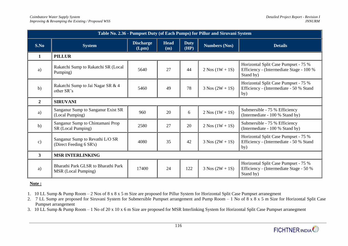
Coimbatore Water Supply System Detailed Project Report - Revision I
Improving & Revamping the Existing / Proposed WSS JNNURM
116
Table No. 2.36 - Pumpset Duty (of Each Pumps) for Pillur and Siruvani System
S.No System Discharge
(Lpm)
Head
(m)
Duty
(HP) Numbers (Nos) Details
1 PILLUR
a) Rakatchi Sump to Rakatchi SR (Local
Pumping) 5640 27 44 2 Nos (1W + 1S)
Horizontal Split Case Pumpset - 75 %
Efficiency - (Intermediate Stage - 100 %
Stand by)
b) Rakatchi Sump to Jai Nagar SR & 4
other SR’s 5460 49 78 3 Nos (2W + 1S)
Horizontal Split Case Pumpset - 75 %
Efficiency - (Intermediate - 50 % Stand
by)
2 SIRUVANI
a) Sanganur Sump to Sanganur Exist SR
(Local Pumping) 960 20 6 2 Nos (1W + 1S)
Submersible - 75 % Efficiency
(Intermediate - 100 % Stand by)
b) Sanganur Sump to Chintamani Prop
SR (Local Pumping) 2580 27 20 2 Nos (1W + 1S)
Submersible - 75 % Efficiency
(Intermediate - 100 % Stand by)
c) Sanganur Sump to Revathi L/O SR
(Direct Feeding 6 SR's) 4080 35 42 3 Nos (2W + 1S)
Horizontal Split Case Pumpset - 75 %
Efficiency - (Intermediate - 50 % Stand
by)
3 MSR INTERLINKING
a) Bharathi Park GLSR to Bharathi Park
MSR (Local Pumping) 17400 24 122 3 Nos (2W + 1S)
Horizontal Split Case Pumpset - 75 %
Efficiency - (Intermediate Stage - 50 %
Stand by)
Note :
1. 10 LL Sump & Pump Room – 2 Nos of 8 x 8 x 5 m Size are proposed for Pillur System for Horizontal Split Case Pumpset arranegment
2. 7 LL Sump are proposed for Siruvani System for Submersible Pumpset arrangement and Pump Room – 1 No of 8 x 8 x 5 m Size for Horizontal Split Case
Pumpset arrangement
3. 10 LL Sump & Pump Room – 1 No of 20 x 10 x 6 m Size are proposed for MSR Interlinking System for Horizontal Split Case Pumpset arranegment
Coimbatore Water Supply System Detailed Project Report - Revision I
Improving & Revamping the Existing / Proposed WSS JNNURM
117
The cost of Feeder Mains for Pillur & Siruvani system (Excluding
Pillur Siruvani MSR Interlinking) with all appurtennces is worked out
in Volume II – Feeder Main, Sumps & Pumpsets part of this DPR and
comes around Rs. 87.23 Crores (As per Schedule of Rates 2016 –
2017)
The cost of Pumpsets, Sump cum Pumps, pump room arrangements,
generators with all appurtennces is worked out in Volume II – Feeder
Main, Sumps & Pumpsets part of this DPR and comes around
Rs. 7.19 Crores (As per Schedule of Rates 2016 – 2017)
2.9.4 Interlinking of Pillur MSR and Siruvani MSR
A separate feeder main system is proposed from the Newly Proposed MSR at Ramakrishnapuram to
the Siruvani MSR to overcome the fluctuations at Siruvani supply during the drought conditions.
Since the level difference (Lowest Water Level) between both the MSR’s is only 0.86 m
(Ramakrishnapuram MSR – Siruvani MSR = 443.86 – 443.00 = 0.86 m) interconnecting both the
MSR’s by gravity s is not feasible. So Gravity cum pumping arrangement was made.
1. Gravity System – From Existing MSR at Ramakrishnapuram to Propsoed GLSR at Bharathi Park
2. Pumping System – From Proposed GLSR at Bharathi Partk to Existing MSR at Bharathi Park
A new proposed GLSR at Bharathi Park are used to store water from Pillur MSR and tackle
the fluctuations in Siruvani supply. The existing GLSR at Bharathi Park was found to be a
very old system, served its life time and also in dilapted condition, so a new GLSR at Bharathi
Park was proposed.
The Interlinking of gravity main from Pillur MSR to Bharathi Park GLSR is designed for 50
mld transmission capacity. The local pumping arrangement from Bharathi Park GLSR to
Bharathi Park MSR is designed with 5 Nos of Horizontal Split Case pumpsets, each pumpset
capable of discharging 10 Mld for 23 hours. So any fluctuations is Siruvani supply can be met
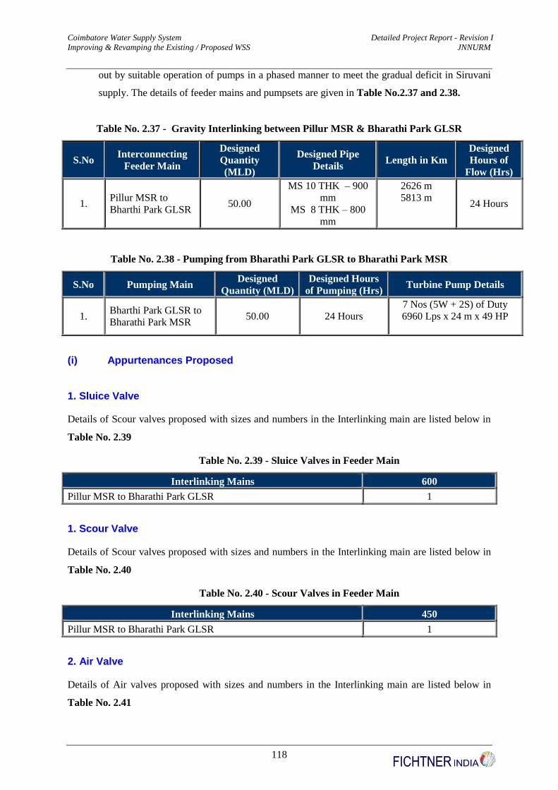
Coimbatore Water Supply System Detailed Project Report - Revision I
Improving & Revamping the Existing / Proposed WSS JNNURM
118
out by suitable operation of pumps in a phased manner to meet the gradual deficit in Siruvani
supply. The details of feeder mains and pumpsets are given in Table No.2.37 and 2.38.
Table No. 2.37 - Gravity Interlinking between Pillur MSR & Bharathi Park GLSR
S.No Interconnecting
Feeder Main
Designed
Quantity
(MLD)
Designed Pipe
Details Length in Km
Designed
Hours of
Flow (Hrs)
1. Pillur MSR to
Bharthi Park GLSR 50.00
MS 10 THK – 900
mm
MS 8 THK – 800
mm
2626 m
5813 m 24 Hours
Table No. 2.38 - Pumping from Bharathi Park GLSR to Bharathi Park MSR
S.No Pumping Main Designed
Quantity (MLD)
Designed Hours
of Pumping (Hrs) Turbine Pump Details
1. Bharthi Park GLSR to
Bharathi Park MSR 50.00 24 Hours
7 Nos (5W + 2S) of Duty
6960 Lps x 24 m x 49 HP
(i) Appurtenances Proposed
1. Sluice Valve
Details of Scour valves proposed with sizes and numbers in the Interlinking main are listed below in
Table No. 2.39
Table No. 2.39 - Sluice Valves in Feeder Main
Interlinking Mains 600
Pillur MSR to Bharathi Park GLSR 1
1. Scour Valve
Details of Scour valves proposed with sizes and numbers in the Interlinking main are listed below in
Table No. 2.40
Table No. 2.40 - Scour Valves in Feeder Main
Interlinking Mains 450
Pillur MSR to Bharathi Park GLSR 1
2. Air Valve
Details of Air valves proposed with sizes and numbers in the Interlinking main are listed below in
Table No. 2.41

Coimbatore Water Supply System Detailed Project Report - Revision I
Improving & Revamping the Existing / Proposed WSS JNNURM
119
Table No. 2.41 - Air Valves in Feeder Main
Interlinking Mains 150
Pillur MSR to Bharathi Park GLSR 2
The cost for interlinking of Pillur Siruvani MSR by Feeder Main
System is worked out in Volume II – Feeder Mains, Sumps & Pumpsets
part of this DPR and comes around Rs 12.55 Crores (As per Schedule
of Rates 2016 – 2017)
2.9.5 Detailed Engineerign Design – Distribution System
The factors namely Population, Water Demand, Existing SR Capacity, Site Availability for new
proposal, Feeder Main routing and Alignments are considered while designing the 24 X 7 water
supply system in all zones and all for demo zones
(i) Zoning of the Project Area
The existing 5 water supply zones is rezoned into 4 water supply zones into North Zone, West Zone,
East Demo Zone I & East Demo Zone II for effective management of water supply system, by
delineating Demo Zone Areas, isolation of Siruvani and Pillur Systems, introducing Billing and
Collection Software System, Customer Care Software System, monitoring of Pressure Management
Network Systems and easy O & M system, etc., The design of proposed water supply zones is
described below.
1. North Zone
This zone covers the northern part of Coimbatore City Corporation with an area of 25.33 Sq.Km.
Wards covered under this zone are 1, 2(part), 3(part), 14(p), 17, 18, 19(p), 20(p), 33(p), 65, 66, 67, 68,
69, 70, 71&72 and the density of population is 9200 Persons per Sq.Km. This zone is the gateway to
the major hubs such as Mettupalayam, Sathyamangalam and Avinashi and is well connected with
National Highways. There are two railway lines; the first one is to Mettupalayam dividing this zone as
North West and North East parts and the second one is to Chennai dividing this zone as North and
South parts. As a harbinger for the major industries such as textile, foundry and pump etc., there is a
scope for rapid development in this zone. The difference in ground level within the zone is 33 m and
20 m respectively and ground level varies from 441.51 m in North West to 408.63 m in North East
and 424.34 m in North to 403.62 m in South. In addition, an IT Park Bulk Water Demand of 3 Mld

Coimbatore Water Supply System Detailed Project Report - Revision I
Improving & Revamping the Existing / Proposed WSS JNNURM
120
was also provided with North Zone as requested by Coimbatore Corporation.
2. West Zone
West Zone covers the Western part of Coimbatore City Corporation with an area of 25.64 Sq.Km.
Wards covered by the zone are 34,37,38,44 to 53 & 55 to 64 and covers partly by wards 27, 33, 35,
36, 42 & 54. The density of population is 9383 Persons per Sq.Km. This zone is the gateway to the
holy place Marudamalai and university. Coimbatore city is connected with important places like
Palakkad and Thadagam by the roads running through this zone. The contours of this zone fall from
North-West to South-East and the difference in levels is 35m. The Ground level varies from 442 m in
the North-West to 407 m in South-East.
3. South Zone
South Zone covers the southern part of Coimbatore City Corporation and with an area of 23.60
Sq.Km. This Zone covers the wards 6(p), 7(p), 12, 13, 14, 19(p), 21(p), 22, 23, 24, 25(p), 26(p), 39,
40, 41, 42, 43, 54(p). Density of population is 9383 Persons per Sq.Km. This zone is become the
gateway to the places such as Palani. Trichy and Palakad and is well connected with National
Highways. The railway line to Trichy and Palani are passing through this zone. The Ground level
varies from 401.66 m in North West to 389.63 m in North East and 400.86 m in North to 396.89 m in
South.
4. East Zone or Demo Zone I & II
East Zone covers the Eastern Part of Coimbatore City Corporation with an area of 31.05 (8.93 Sq.Km
for Demo Zone I + 22.12 Sq.Km for Demo Zone II) Sq.Km. Wards covered are 2, 3, 4, 5, 6, 7, 8, 9,
10, 11, 14, 15,16, 20, 21, 25, 26, 27, 28, 29, 30, 31, 32, 33, 35, 36, 26 etc. Density of population is
14180 Persons per Sq.Km. This zone is the gateway to major hub such as Mettupalayam,
Sathyamangalam, Trichy and Avinashi and is well connected with National Highways. There are
three natural water streams or nallas crossings this zone. There are two railway lines. The first one is
running to Mettupalayam dividing this zone along the Western Border and the second one is running
to Chennai along the Eastern Part. As there is a wide spread of vacant lands available in this zone,
there is a possibility for rapid development for residential, apartments, multiple complexes, etc.,
This zone is divided into two parts as Demo Zone I covering Race Course, Ram Nagar & Gandhi
Puram areas and as Demo Zone II covering Peelamedu, Peelamedu Pudur, Sowripalayam,
Masakalipalayam, Neelikonampalayam and Ondipudur areas. The difference in ground level within

Coimbatore Water Supply System Detailed Project Report - Revision I
Improving & Revamping the Existing / Proposed WSS JNNURM
121
the Demo Zone I is 25.57 m with levels varying from 429.07 m to 403.50 m and 45.05 m in Demo
Zone II with levels varying from 417.21 m to 372.16 m.
(ii) Rezoned Boundaries
The rezoned outer boundaries of the above Zones are mentioned in Dwg No –
10/1811150/WSS/WIN/033, Volume VI part of this DPR.The rezoned or proposed water supply
system in each zone for the horizon year demand is shown in Dwg No – 10/1811150/WSS/WIN/034
to 061 for North Zone, Dwg No – 10/1811150/WSS/WIN/062 to 077 for South Zone , Dwg No –
10/1811150/WSS/WIN/078 to 086 for Demo Zone I and in Dwg No – 10/1811150/WSS/WIN/087
to 110 for Demo Zone II and in Dwg No – 10/1811150/WSS/WIN/111 to 139 for West Zone in
Volume VI, Drawing Part of this DPR.
(iii) Propsoed Pipe Materials & Sizes
With a view to minimize the cost for pipe material, old CI pipes satisfying the hydraulic criteria are
proposed for retention, removing all AC,PSC and PVC pipes. In the case of new pipes HDPE PN6 PE
100 pipes are proposed for diameters ranging from 90 mm Diameter to 315 mm Diameter and more
than 350 mm Diameter pipes shall be of DI K7 pipes.The details of pipe sizes adopted are listed
below in Table No. 2.42
Table No. 2.42 - Pipe Sizes Proposed in Distribution System
S.No. Pipe material & Pressure Rating Diameter in mm
1 HDPE PN6 PE100 90 to 315 mm
2 DI K7 Above 350 mm
The following details gives the break up of pipe materials that was proposed in hydraulic design of
distribution system and also the break up of pipe materials that was retained. The details are given in
Table No.2.43 to 2.46

Coimbatore Water Supply System Detailed Project Report - Revision I
Improving & Revamping the Existing / Proposed WSS JNNURM
122
Table No. 2.43 – Proposed HDPE Pipe Sizes in Distribution System
ZONE S.No SUB ZONE PROPOSED PIPE LENGTH in Meters (HDPE PIPE)
90 mm 140 mm 200 mm 250 mm 315 mm
EAST I
1 SIDDHAPHUDHUR A 9807 138 - 1136 464
2 SIDDHAPHUDHUR B 9402 40 2626 - 1147
3 TATABAD A 6466 1710 1603 - 589
4 TATABAD B 7635 - 960 892 513
5 VOC EX - A 10148 - 2744 3282 -
6 VOC EX - B 14558 - - 3804 1793
7 VOC PROPOSED - A 6095 3983 36 - 2687
8 VOC PROPOSED - B 3480 684 220 - 783
EAST II
9 ANNA NAGAR A 11087 3879 3110 - -
10 ANNA NAGAR B 11266 2732 3762 - -
11 ANNAI VELANKANNI A 13637 3513 1203 - 4726
12 ANNAI VELANKANNI B 13637 3513 1203 - 4726
13 BHARATHI NAGAR A 10933 889 - 881 -
14 BHARATHI NAGAR B 11456 - - 3787 434
15 DJ NAGAR A 10792 372 - - 2940
16 DJ NAGAR B 9295 - 1271 1753 -
17 GV RESIDENCY 9200 474 - - 3698
18 HUDCO COLONY 12891 794 867 2133 -
19 KK NAGAR A 2728 2040 - 2110 -
20 KK NAGAR B 5906 927 - 1380 -
21 KOTHARI NAGAR 8526 - - - 3540

Coimbatore Water Supply System Detailed Project Report - Revision I
Improving & Revamping the Existing / Proposed WSS JNNURM
123
ZONE S.No SUB ZONE PROPOSED PIPE LENGTH in Meters (HDPE PIPE)
90 mm 140 mm 200 mm 250 mm 315 mm
22 NETHAJI NAGAR A 8442 2655 - 464 -
23 NETHAJI NAGAR B 7449 1725 - - 2116
24 RAJALAKSHMI NAGAR A 10166 58 2741 1007 -
25 RAJALAKSHMI NAGAR B 11886 1143 624 - 1892
26 SIHS COLONY 6808 697 - - -
27 SRI LAKSHMI NAGAR A 5634 - - 2899 -
28 SRI LAKSHMI NAGAR B 12212 - - - 2112
29 TAGORE NAGAR A 3275 375 - 3096 -
30 TAGORE NAGAR B 11994 - - - 3138
31 UPPILIPALAYAM 10013 - - 2687 -
NORTH
32 AVARAMPALAYAM 3249 493 132 - 226
33 GANDHINAGAR 7523 483 - 685 136
34 JAI NAGAR A 11421 3937 - - 287
35 JAI NAGAR B 25840 - 6050 - 522
36 KAMADHENU NAGAR 2738 924 - 542 373
37 KAMARAJAPURAM 5717 165 1054 999 1160
38 KARUPAYYA GOWNDER A 7640 - 2338 - 421
39 KARUPAYYA GOWNDER B 5816 928 2034 - 828
40 NEHRU STREET A 5149 - 1000 - -
41 NEHRU STREET B 7579 4980 570 - -
42 PEELAMEDU A 10091 401 2197 - 1250
43 PEELAMEDU B 5084 2157 - - -
44 PONNI NAGAR A 8433 - - 1679 1003
45 PONNI NAGAR B 11013 1580 - 721 -
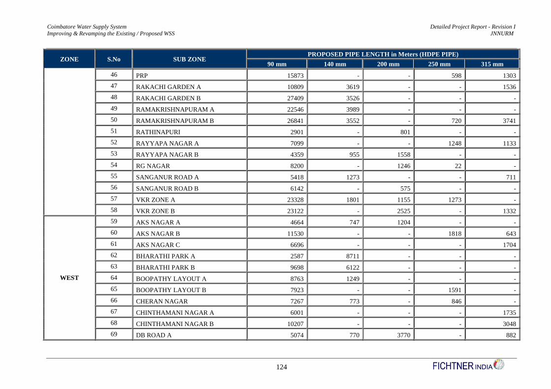
Coimbatore Water Supply System Detailed Project Report - Revision I
Improving & Revamping the Existing / Proposed WSS JNNURM
124
ZONE S.No SUB ZONE PROPOSED PIPE LENGTH in Meters (HDPE PIPE)
90 mm 140 mm 200 mm 250 mm 315 mm
46 PRP 15873 - - 598 1303
47 RAKACHI GARDEN A 10809 3619 - - 1536
48 RAKACHI GARDEN B 27409 3526 - - -
49 RAMAKRISHNAPURAM A 22546 3989 - - -
50 RAMAKRISHNAPURAM B 26841 3552 - 720 3741
51 RATHINAPURI 2901 - 801 - -
52 RAYYAPA NAGAR A 7099 - - 1248 1133
53 RAYYAPA NAGAR B 4359 955 1558 - -
54 RG NAGAR 8200 - 1246 22 -
55 SANGANUR ROAD A 5418 1273 - - 711
56 SANGANUR ROAD B 6142 - 575 - -
57 VKR ZONE A 23328 1801 1155 1273 -
58 VKR ZONE B 23122 - 2525 - 1332
WEST
59 AKS NAGAR A 4664 747 1204 - -
60 AKS NAGAR B 11530 - - 1818 643
61 AKS NAGAR C 6696 - - - 1704
62 BHARATHI PARK A 2587 8711 - - -
63 BHARATHI PARK B 9698 6122 - - -
64 BOOPATHY LAYOUT A 8763 1249 - - -
65 BOOPATHY LAYOUT B 7923 - - 1591 -
66 CHERAN NAGAR 7267 773 - 846 -
67 CHINTHAMANI NAGAR A 6001 - - - 1735
68 CHINTHAMANI NAGAR B 10207 - - - 3048
69 DB ROAD A 5074 770 3770 - 882

Coimbatore Water Supply System Detailed Project Report - Revision I
Improving & Revamping the Existing / Proposed WSS JNNURM
125
ZONE S.No SUB ZONE PROPOSED PIPE LENGTH in Meters (HDPE PIPE)
90 mm 140 mm 200 mm 250 mm 315 mm
70 DB ROAD B 5257 - - - -
71 GANDHI PARK 6343 - 4271 - 2025
72 HOUSING UNIT A 9206 - - 1428 -
73 HOUSING UNIT B 5347 - - 5036 -
74 ISWARYA NAGAR A 5380 1579 1319 - -
75 ISWARYA NAGAR B 4212 - - 133 2150
76 JAYARAM NAGAR A 7872 402 - - 2257
77 JAYARAM NAGAR B 9459 315 - 2861 620
78 KOILMEDU 1109 - - - 1028
79 KURUNJI GARDEN A 11397 - - - 2380
80 KURUNJI GARDEN B 8094 1494 - 2641 -
81 MADATHUR 5252 965 508 - 1431
82 REVATHY LAYOUT 3163 1476 - 1287 247
83 RS PURAM A 7791 2963 3592 - 1418
84 RS PURAM B 12188 3915 - - -
85 SANGANUR CHINTHAMANI 3795 - - 2211 -
86 VENKATAPURAM 1019 - 765 - -
SOUTH
87 VYSIAL STREET 2132 2208 - - -
88 BSUP 13048 19 1368 - -
89 CLOCK TOWER 5440 2221 - 2210 -
90 JK GARDEN 26379 - 2874 - -
91 LAKSHMI MILL COLONY A 2666 381 - - 781
92 LAKSHMI MILL COLONY B 3775 - 963 1634 -
93 PULIYAKULAM A 10566 - 3416 - 613

Coimbatore Water Supply System Detailed Project Report - Revision I
Improving & Revamping the Existing / Proposed WSS JNNURM
126
ZONE S.No SUB ZONE PROPOSED PIPE LENGTH in Meters (HDPE PIPE)
90 mm 140 mm 200 mm 250 mm 315 mm
94 PULIYAKULAM B 10883 - - 3054 -
95 SINGANALLUR 8560 1820 2721 - -
96 SIVARAM NAGAR 23317 1352 1188 - 3730
97 THIRU NAGAR A 3794 1156 2763 - 50
98 THIRU NAGAR B 7345 - - 4043 -
99 TOWN HALL A 3495 6 - - 692
100 TOWN HALL B 3995 - 1894 - -
101 VALLIAMMAL STREET 9239 362 - 2275 -
Total Length in Meters 910092 108110 78821 72866 80693
Total Length in Kilometers 910.09 108.11 78.82 72.87 80.69
Total length of Proposed HDPE Pipes in Distribution System is about 1251 Kms which is 90.85 % of the total D’System length .

Coimbatore Water Supply System Detailed Project Report - Revision I
Improving & Revamping the Existing / Proposed WSS JNNURM
127
Table No. 2.44 – Proposed DI K7 Pipe Sizes in Distribution System
ZONE S.No SUB ZONE PROPOSED PIPE LENGTH in Meters (DI PIPE)
350 mm 400 mm 450 mm 500 mm 600 mm 700 mm
EAST I
1 SIDDHAPHUDHUR A 100 223 - - - -
2 SIDDHAPHUDHUR B - 1012 - - - -
3 TATABAD A - - 315 394 - -
4 TATABAD B - - - - - 1194
5 VOC EX - A 572 140 - - - -
6 VOC EX - B - - 225 2487 - -
7 VOC PROPOSED - A - - - - - 920
8 VOC PROPOSED - B - 370 - - - -
EAST II
9 ANNA NAGAR A - - - - 536 -
10 ANNA NAGAR B - - - 355 - -
11 ANNAI VELANKANNI A - - - - - -
12 ANNAI VELANKANNI B - - - - - -
13 BHARATHI NAGAR A - 256 - - - -
14 BHARATHI NAGAR B - - - - - -
15 DJ NAGAR A - 212 - - - -
16 DJ NAGAR B - - - - 1080 -
17 GV RESIDENCY - - - - - -
18 HUDCO COLONY - 1057 - - - 1056
19 KK NAGAR A 20 - - - - -
20 KK NAGAR B 277 - - - - -
21 KOTHARI NAGAR - - - 20 - -
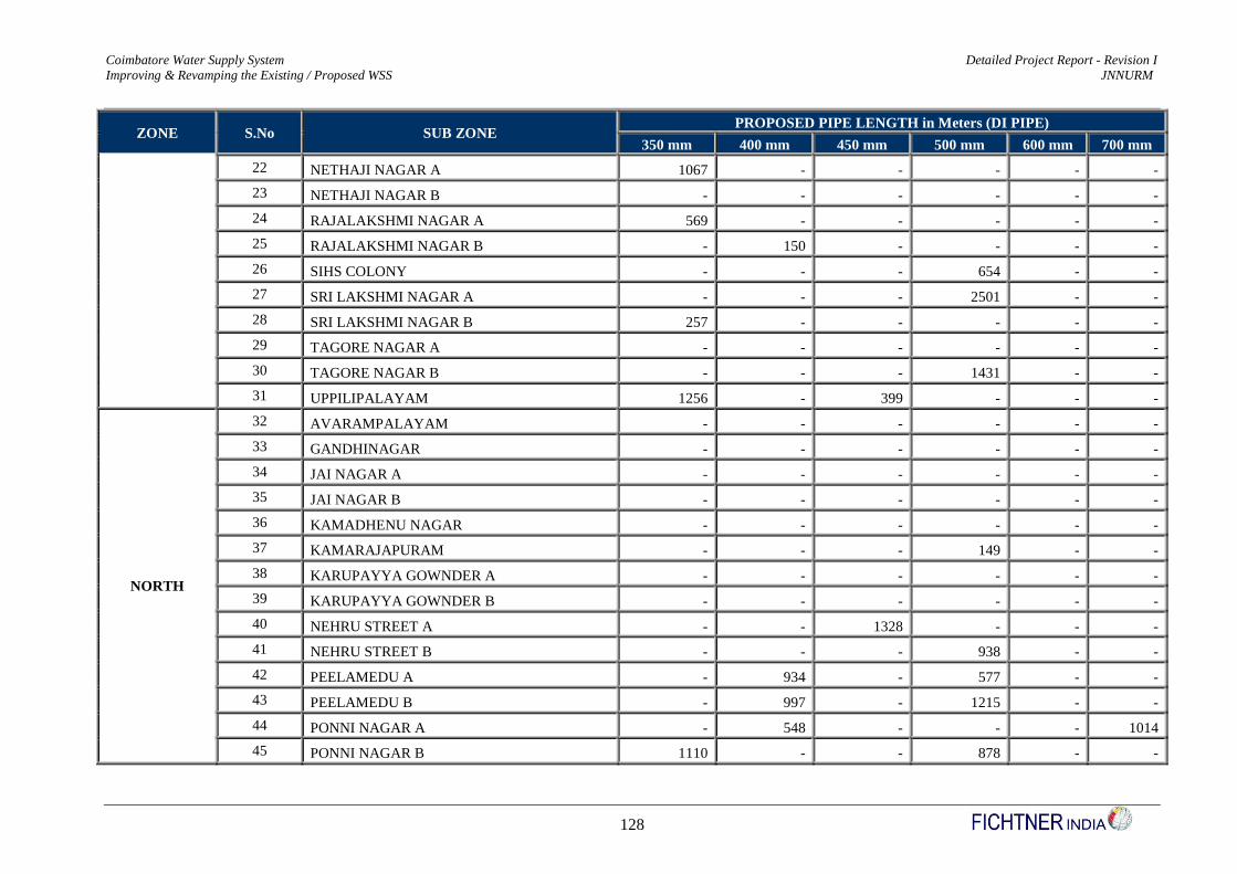
Coimbatore Water Supply System Detailed Project Report - Revision I
Improving & Revamping the Existing / Proposed WSS JNNURM
128
ZONE S.No SUB ZONE PROPOSED PIPE LENGTH in Meters (DI PIPE)
350 mm 400 mm 450 mm 500 mm 600 mm 700 mm
22 NETHAJI NAGAR A 1067 - - - - -
23 NETHAJI NAGAR B - - - - - -
24 RAJALAKSHMI NAGAR A 569 - - - - -
25 RAJALAKSHMI NAGAR B - 150 - - - -
26 SIHS COLONY - - - 654 - -
27 SRI LAKSHMI NAGAR A - - - 2501 - -
28 SRI LAKSHMI NAGAR B 257 - - - - -
29 TAGORE NAGAR A - - - - - -
30 TAGORE NAGAR B - - - 1431 - -
31 UPPILIPALAYAM 1256 - 399 - - -
NORTH
32 AVARAMPALAYAM - - - - - -
33 GANDHINAGAR - - - - - -
34 JAI NAGAR A - - - - - -
35 JAI NAGAR B - - - - - -
36 KAMADHENU NAGAR - - - - - -
37 KAMARAJAPURAM - - - 149 - -
38 KARUPAYYA GOWNDER A - - - - - -
39 KARUPAYYA GOWNDER B - - - - - -
40 NEHRU STREET A - - 1328 - - -
41 NEHRU STREET B - - - 938 - -
42 PEELAMEDU A - 934 - 577 - -
43 PEELAMEDU B - 997 - 1215 - -
44 PONNI NAGAR A - 548 - - - 1014
45 PONNI NAGAR B 1110 - - 878 - -
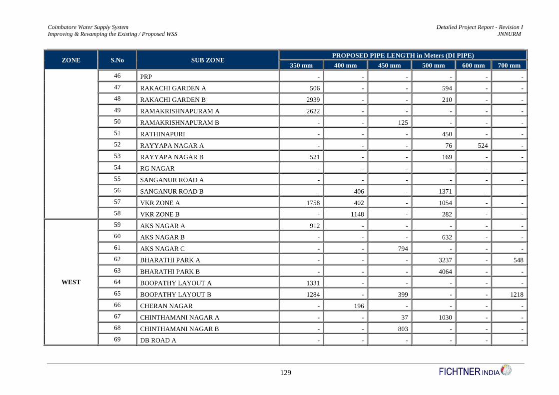
Coimbatore Water Supply System Detailed Project Report - Revision I
Improving & Revamping the Existing / Proposed WSS JNNURM
129
ZONE S.No SUB ZONE PROPOSED PIPE LENGTH in Meters (DI PIPE)
350 mm 400 mm 450 mm 500 mm 600 mm 700 mm
46 PRP - - - - - -
47 RAKACHI GARDEN A 506 - - 594 - -
48 RAKACHI GARDEN B 2939 - - 210 - -
49 RAMAKRISHNAPURAM A 2622 - - - - -
50 RAMAKRISHNAPURAM B - - 125 - - -
51 RATHINAPURI - - - 450 - -
52 RAYYAPA NAGAR A - - - 76 524 -
53 RAYYAPA NAGAR B 521 - - 169 - -
54 RG NAGAR - - - - - -
55 SANGANUR ROAD A - - - - - -
56 SANGANUR ROAD B - 406 - 1371 - -
57 VKR ZONE A 1758 402 - 1054 - -
58 VKR ZONE B - 1148 - 282 - -
WEST
59 AKS NAGAR A 912 - - - - -
60 AKS NAGAR B - - - 632 - -
61 AKS NAGAR C - - 794 - - -
62 BHARATHI PARK A - - - 3237 - 548
63 BHARATHI PARK B - - - 4064 - -
64 BOOPATHY LAYOUT A 1331 - - - - -
65 BOOPATHY LAYOUT B 1284 - 399 - - 1218
66 CHERAN NAGAR - 196 - - - -
67 CHINTHAMANI NAGAR A - - 37 1030 - -
68 CHINTHAMANI NAGAR B - - 803 - - -
69 DB ROAD A - - - - - -

Coimbatore Water Supply System Detailed Project Report - Revision I
Improving & Revamping the Existing / Proposed WSS JNNURM
130
ZONE S.No SUB ZONE PROPOSED PIPE LENGTH in Meters (DI PIPE)
350 mm 400 mm 450 mm 500 mm 600 mm 700 mm
70 DB ROAD B 1665 - - 217 - -
71 GANDHI PARK - - - 1070 - 273
72 HOUSING UNIT A 2974 - - - 839 -
73 HOUSING UNIT B 250 - - 681 - 1156
74 ISWARYA NAGAR A 1085 - - - - -
75 ISWARYA NAGAR B - - 322 - - -
76 JAYARAM NAGAR A - - - 50 - -
77 JAYARAM NAGAR B - - - - - -
78 KOILMEDU - - - - - -
79 KURUNJI GARDEN A - - 853 - - -
80 KURUNJI GARDEN B 1929 - - - - -
81 MADATHUR - - - - - -
82 REVATHY LAYOUT - - - - - -
83 RS PURAM A - 164 - - - -
84 RS PURAM B - - 1872 49 - -
85 SANGANUR CHINTHAMANI 307 - - - - -
86 VENKATAPURAM - - - - - -
SOUTH
87 VYSIAL STREET - 574 - - - -
88 BSUP - - - 992 99 -
89 CLOCK TOWER - 446 - 162 - -
90 JK GARDEN - - 687 - - -
91 LAKSHMI MILL COLONY A - - - - - -
92 LAKSHMI MILL COLONY B 150 - - - - -
93 PULIYAKULAM A - 351 - 122 - -

Coimbatore Water Supply System Detailed Project Report - Revision I
Improving & Revamping the Existing / Proposed WSS JNNURM
131
ZONE S.No SUB ZONE PROPOSED PIPE LENGTH in Meters (DI PIPE)
350 mm 400 mm 450 mm 500 mm 600 mm 700 mm
94 PULIYAKULAM B - 879 - - - -
95 SINGANALLUR - 637 - - - -
96 SIVARAM NAGAR 413 - 1108 - 890 -
97 THIRU NAGAR A - - - 1026 1208 -
98 THIRU NAGAR B - - 178 - - -
99 TOWN HALL A - - 634 - - -
100 TOWN HALL B - 1001 - - - -
101 VALLIAMMAL STREET 1863 - - - 998 -
Total Length in Meters 27737 12103 10079 29137 6174 7379
Total Length in Kilometers 27.74 12.10 10.08 29.14 6.17 7.38
Total length of Proposed DI Pipes in Distribution System is about 93 Kms which is 6.75 % of the total D’System length.
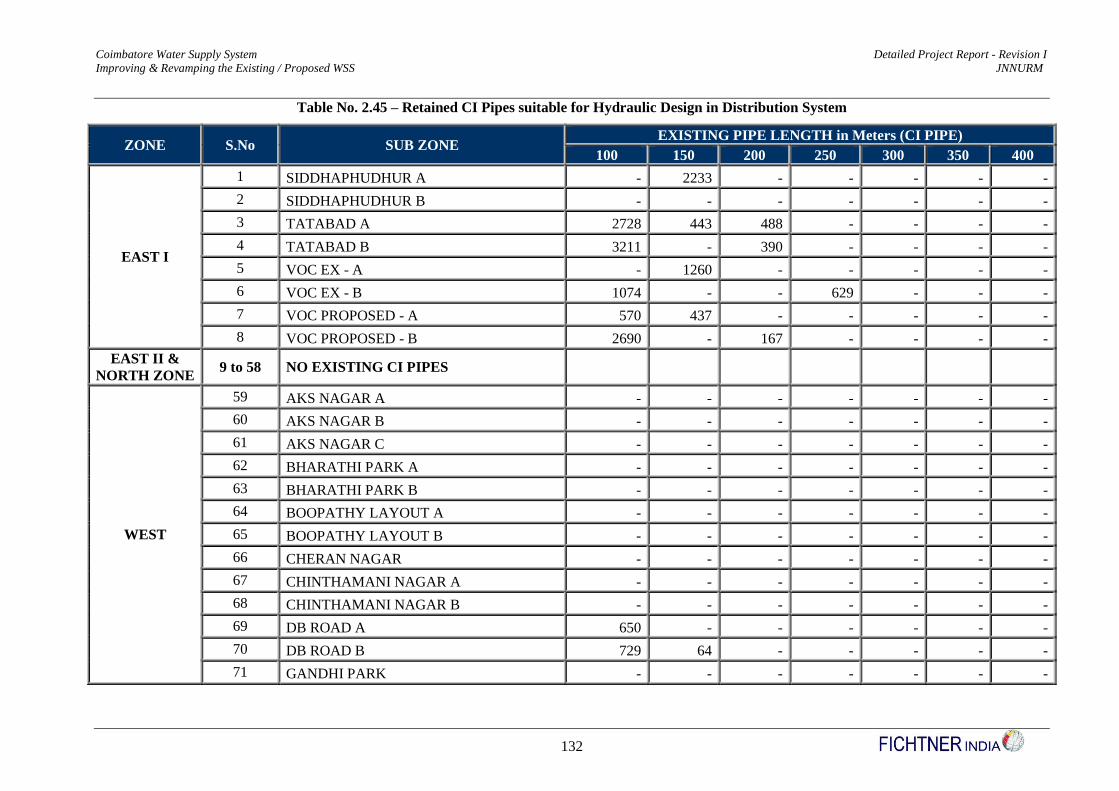
Coimbatore Water Supply System Detailed Project Report - Revision I
Improving & Revamping the Existing / Proposed WSS JNNURM
132
Table No. 2.45 – Retained CI Pipes suitable for Hydraulic Design in Distribution System
ZONE S.No SUB ZONE EXISTING PIPE LENGTH in Meters (CI PIPE)
100 150 200 250 300 350 400
EAST I
1 SIDDHAPHUDHUR A - 2233 - - - - -
2 SIDDHAPHUDHUR B - - - - - - -
3 TATABAD A 2728 443 488 - - - -
4 TATABAD B 3211 - 390 - - - -
5 VOC EX - A - 1260 - - - - -
6 VOC EX - B 1074 - - 629 - - -
7 VOC PROPOSED - A 570 437 - - - - -
8 VOC PROPOSED - B 2690 - 167 - - - -
EAST II &
NORTH ZONE 9 to 58 NO EXISTING CI PIPES
WEST
59 AKS NAGAR A - - - - - - -
60 AKS NAGAR B - - - - - - -
61 AKS NAGAR C - - - - - - -
62 BHARATHI PARK A - - - - - - -
63 BHARATHI PARK B - - - - - - -
64 BOOPATHY LAYOUT A - - - - - - -
65 BOOPATHY LAYOUT B - - - - - - -
66 CHERAN NAGAR - - - - - - -
67 CHINTHAMANI NAGAR A - - - - - - -
68 CHINTHAMANI NAGAR B - - - - - - -
69 DB ROAD A 650 - - - - - -
70 DB ROAD B 729 64 - - - - -
71 GANDHI PARK - - - - - - -
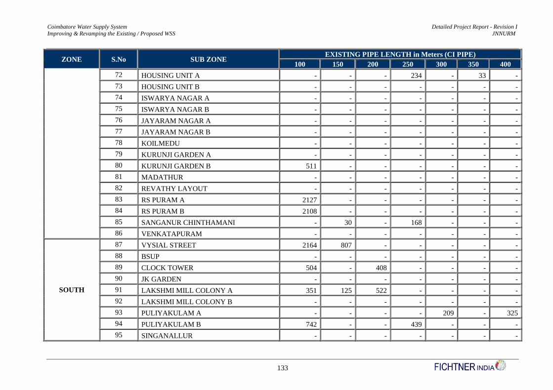
Coimbatore Water Supply System Detailed Project Report - Revision I
Improving & Revamping the Existing / Proposed WSS JNNURM
133
ZONE S.No SUB ZONE EXISTING PIPE LENGTH in Meters (CI PIPE)
100 150 200 250 300 350 400
72 HOUSING UNIT A - - - 234 - 33 -
73 HOUSING UNIT B - - - - - - -
74 ISWARYA NAGAR A - - - - - - -
75 ISWARYA NAGAR B - - - - - - -
76 JAYARAM NAGAR A - - - - - - -
77 JAYARAM NAGAR B - - - - - - -
78 KOILMEDU - - - - - - -
79 KURUNJI GARDEN A - - - - - - -
80 KURUNJI GARDEN B 511 - - - - - -
81 MADATHUR - - - - - - -
82 REVATHY LAYOUT - - - - - - -
83 RS PURAM A 2127 - - - - - -
84 RS PURAM B 2108 - - - - - -
85 SANGANUR CHINTHAMANI - 30 - 168 - - -
86 VENKATAPURAM - - - - - - -
SOUTH
87 VYSIAL STREET 2164 807 - - - - -
88 BSUP - - - - - - -
89 CLOCK TOWER 504 - 408 - - - -
90 JK GARDEN - - - - - - -
91 LAKSHMI MILL COLONY A 351 125 522 - - - -
92 LAKSHMI MILL COLONY B - - - - - - -
93 PULIYAKULAM A - - - - 209 - 325
94 PULIYAKULAM B 742 - - 439 - - -
95 SINGANALLUR - - - - - - -

Coimbatore Water Supply System Detailed Project Report - Revision I
Improving & Revamping the Existing / Proposed WSS JNNURM
134
ZONE S.No SUB ZONE EXISTING PIPE LENGTH in Meters (CI PIPE)
100 150 200 250 300 350 400
96 SIVARAM NAGAR 416 - - - - - -
97 THIRU NAGAR A - - - - - - -
98 THIRU NAGAR B - - - - - - -
99 TOWN HALL A 2005 883 - 450 - - -
100 TOWN HALL B - - - - - - -
101 VALLIAMMAL STREET - - - - - - -
Total Length in Meters 22580 6282 1975 1920 209 33 325
Total Length in Kilometers 22.58 6.28 1.98 1.92 0.21 0.03 0.33
Total length of Retained CI Pipes in Distribution System is about 33 Kms which is 2.40 % of the total D’System length.
Total length of Ratined CI Pipes in Distribution System is about 33 Kms which is 19.53 % of the total Existing CI pipes in D’System length.
Total length of Ratined CI Pipes in Distribution System is about 33 Kms which is 2.94 % of the total Existing D’System length.
However, as per Technical suggestions of CPHEEO, other than retained CI pipes, the existing pipes, say PVC Pipes – 785 Kms, AC Pipes – 166 Kms, PSC – 2
Kms, out of the above, say 10 % of PVC pipes in every zone, totalling about 79 Kms of PVC Pipelines shall be reused for other schemes and accordingly 10 % of
pipe cost has been deducted in cost estimate portion of Distribution System from each zone. The other pipes namey AC / PSC shall not be used for Distribution
System
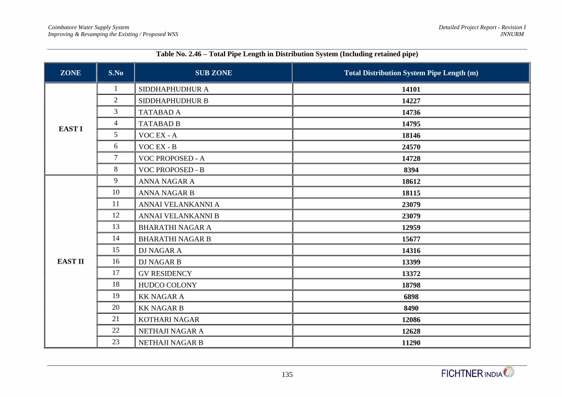
Coimbatore Water Supply System Detailed Project Report - Revision I
Improving & Revamping the Existing / Proposed WSS JNNURM
135
Table No. 2.46 – Total Pipe Length in Distribution System (Including retained pipe)
ZONE S.No SUB ZONE Total Distribution System Pipe Length (m)
EAST I
1 SIDDHAPHUDHUR A 14101
2 SIDDHAPHUDHUR B 14227
3 TATABAD A 14736
4 TATABAD B 14795
5 VOC EX - A 18146
6 VOC EX - B 24570
7 VOC PROPOSED - A 14728
8 VOC PROPOSED - B 8394
EAST II
9 ANNA NAGAR A 18612
10 ANNA NAGAR B 18115
11 ANNAI VELANKANNI A 23079
12 ANNAI VELANKANNI B 23079
13 BHARATHI NAGAR A 12959
14 BHARATHI NAGAR B 15677
15 DJ NAGAR A 14316
16 DJ NAGAR B 13399
17 GV RESIDENCY 13372
18 HUDCO COLONY 18798
19 KK NAGAR A 6898
20 KK NAGAR B 8490
21 KOTHARI NAGAR 12086
22 NETHAJI NAGAR A 12628
23 NETHAJI NAGAR B 11290

Coimbatore Water Supply System Detailed Project Report - Revision I
Improving & Revamping the Existing / Proposed WSS JNNURM
136
ZONE S.No SUB ZONE Total Distribution System Pipe Length (m)
24 RAJALAKSHMI NAGAR A 14541
25 RAJALAKSHMI NAGAR B 15695
26 SIHS COLONY 8159
27 SRI LAKSHMI NAGAR A 11034
28 SRI LAKSHMI NAGAR B 14581
29 TAGORE NAGAR A 6746
30 TAGORE NAGAR B 16563
31 UPPILIPALAYAM 14355
NORTH
32 AVARAMPALAYAM 4100
33 GANDHINAGAR 8827
34 JAI NAGAR A 15645
35 JAI NAGAR B 32412
36 KAMADHENU NAGAR 4577
37 KAMARAJAPURAM 9244
38 KARUPAYYA GOWNDER A 10399
39 KARUPAYYA GOWNDER B 9606
40 NEHRU STREET A 7477
41 NEHRU STREET B 14067
42 PEELAMEDU A 15450
43 PEELAMEDU B 9453
44 PONNI NAGAR A 12677
45 PONNI NAGAR B 15302
46 PRP 17774
47 RAKACHI GARDEN A 17064
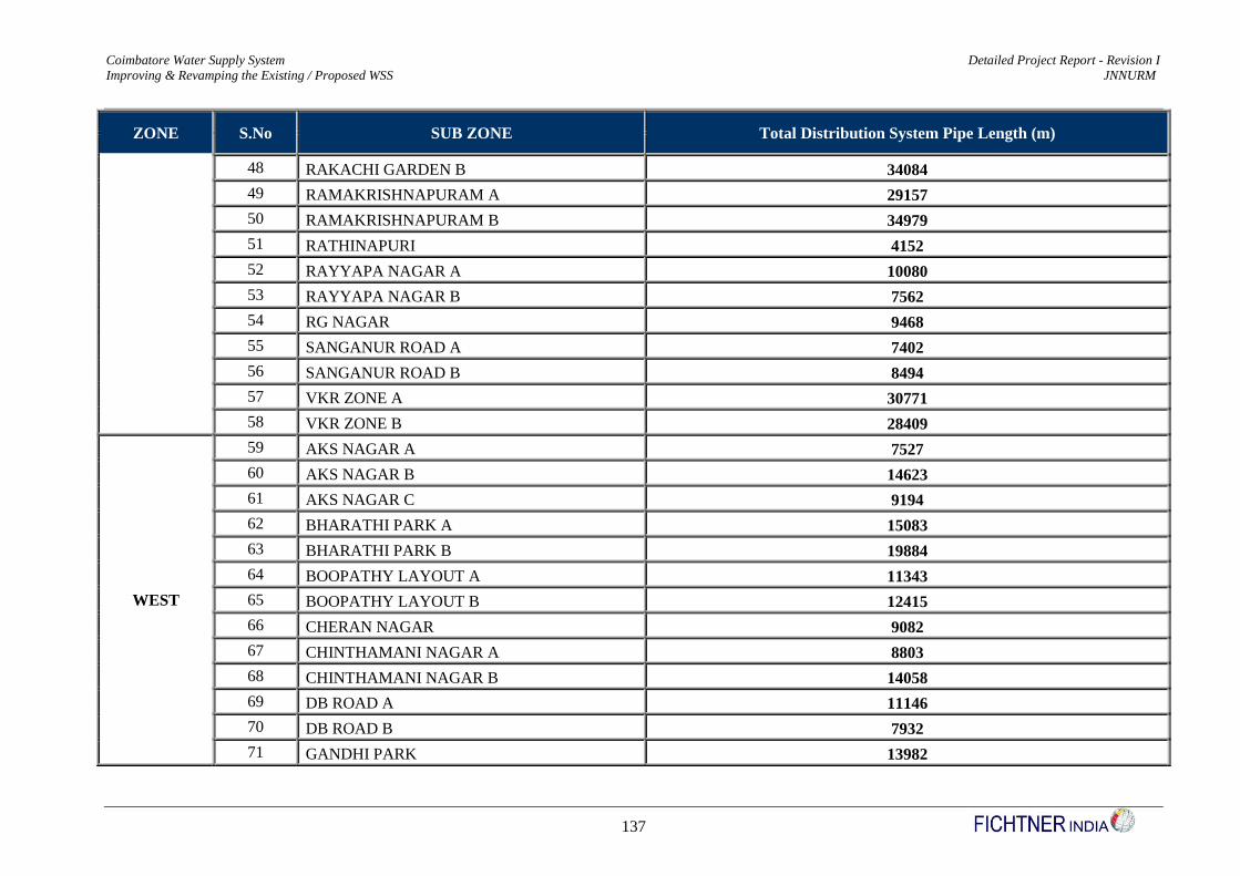
Coimbatore Water Supply System Detailed Project Report - Revision I
Improving & Revamping the Existing / Proposed WSS JNNURM
137
ZONE S.No SUB ZONE Total Distribution System Pipe Length (m)
48 RAKACHI GARDEN B 34084
49 RAMAKRISHNAPURAM A 29157
50 RAMAKRISHNAPURAM B 34979
51 RATHINAPURI 4152
52 RAYYAPA NAGAR A 10080
53 RAYYAPA NAGAR B 7562
54 RG NAGAR 9468
55 SANGANUR ROAD A 7402
56 SANGANUR ROAD B 8494
57 VKR ZONE A 30771
58 VKR ZONE B 28409
WEST
59 AKS NAGAR A 7527
60 AKS NAGAR B 14623
61 AKS NAGAR C 9194
62 BHARATHI PARK A 15083
63 BHARATHI PARK B 19884
64 BOOPATHY LAYOUT A 11343
65 BOOPATHY LAYOUT B 12415
66 CHERAN NAGAR 9082
67 CHINTHAMANI NAGAR A 8803
68 CHINTHAMANI NAGAR B 14058
69 DB ROAD A 11146
70 DB ROAD B 7932
71 GANDHI PARK 13982
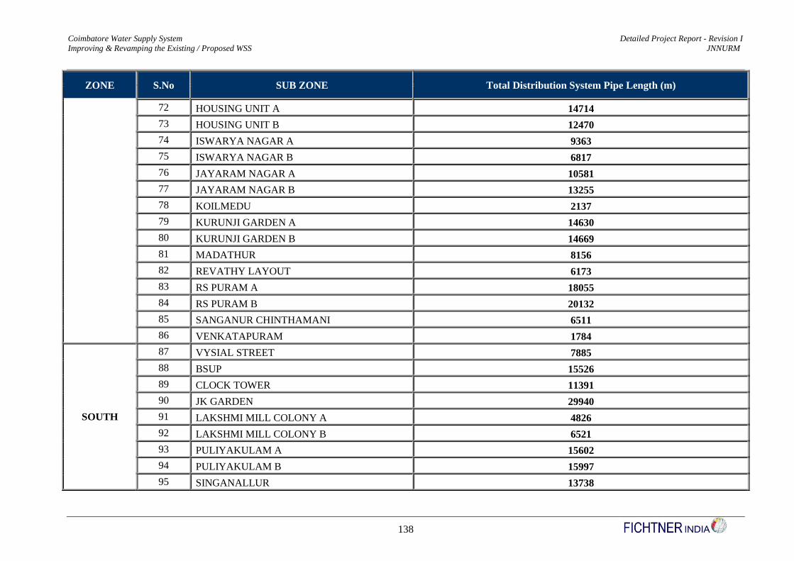
Coimbatore Water Supply System Detailed Project Report - Revision I
Improving & Revamping the Existing / Proposed WSS JNNURM
138
ZONE S.No SUB ZONE Total Distribution System Pipe Length (m)
72 HOUSING UNIT A 14714
73 HOUSING UNIT B 12470
74 ISWARYA NAGAR A 9363
75 ISWARYA NAGAR B 6817
76 JAYARAM NAGAR A 10581
77 JAYARAM NAGAR B 13255
78 KOILMEDU 2137
79 KURUNJI GARDEN A 14630
80 KURUNJI GARDEN B 14669
81 MADATHUR 8156
82 REVATHY LAYOUT 6173
83 RS PURAM A 18055
84 RS PURAM B 20132
85 SANGANUR CHINTHAMANI 6511
86 VENKATAPURAM 1784
SOUTH
87 VYSIAL STREET 7885
88 BSUP 15526
89 CLOCK TOWER 11391
90 JK GARDEN 29940
91 LAKSHMI MILL COLONY A 4826
92 LAKSHMI MILL COLONY B 6521
93 PULIYAKULAM A 15602
94 PULIYAKULAM B 15997
95 SINGANALLUR 13738
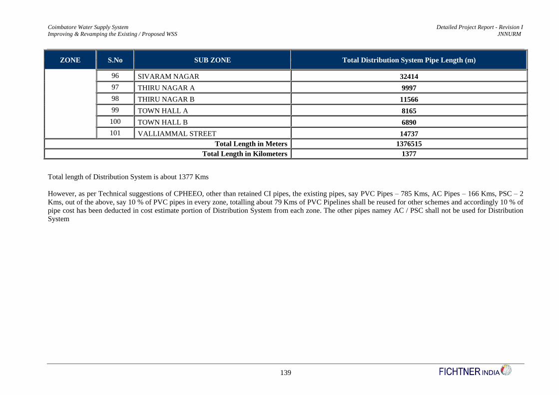
Coimbatore Water Supply System Detailed Project Report - Revision I
Improving & Revamping the Existing / Proposed WSS JNNURM
139
ZONE S.No SUB ZONE Total Distribution System Pipe Length (m)
96 SIVARAM NAGAR 32414
97 THIRU NAGAR A 9997
98 THIRU NAGAR B 11566
99 TOWN HALL A 8165
100 TOWN HALL B 6890
101 VALLIAMMAL STREET 14737
Total Length in Meters 1376515
Total Length in Kilometers 1377
Total length of Distribution System is about 1377 Kms
However, as per Technical suggestions of CPHEEO, other than retained CI pipes, the existing pipes, say PVC Pipes – 785 Kms, AC Pipes – 166 Kms, PSC – 2
Kms, out of the above, say 10 % of PVC pipes in every zone, totalling about 79 Kms of PVC Pipelines shall be reused for other schemes and accordingly 10 % of
pipe cost has been deducted in cost estimate portion of Distribution System from each zone. The other pipes namey AC / PSC shall not be used for Distribution
System

Coimbatore Water Supply System Detailed Project Report - Revision I
Improving & Revamping the Existing / Proposed WSS JNNURM
140
(iv) Service Reservoirs
The details of proposed SRs are given in Table No. 2.47 to 2.52
Table No. 2.47 – Details of Service Reservoirs
Sl.No Reservoir Name Zone SR Type SR Capacity
(LL)
Staging
Height (m) GL (m) LWL (m) MWL (m)
Depth of Water
Storage (m)
Pipe Outlet
Level (m)
1 Ramakrishna Puram SR * N Proposed 20.00 12.00 428.860 440.860 444.860 4.000 443.360 *
2 V.K.R Nagar SR N Proposed 18.00 15.00 422.500 437.500 441.200 3.700 442.200
3 Gandhi Ma Nagar SR N Existing 3.00 10.60 428.130 438.730 441.730 3.000 442.730
4 Karuippya Gounder SR N Proposed 9.00 15.00 417.700 432.700 435.800 3.100 438.300
5 Peelamedu SR N Existing 15.00 10.50 413.990 424.490 428.500 4.010 431.000
6 Kamadhenu Nagar SR N Existing 3.00 11.40 409.480 420.880 423.890 3.010 426.390
7 Avarampalayam SR N Existing 2.50 13.30 409.300 422.600 425.100 2.500 427.520
8 PRP Garden SR SR N Proposed 7.00 15.00 411.820 426.820 430.320 3.500 432.820
9 Rathinapuri SR N Existing 6.00 13.70 423.520 437.220 440.220 3.000 445.200
10 Rayappa Nagar SR N Existing 15.00 13.90 418.500 432.400 435.900 3.500 438.400
11 Kamarajapuram SR N Existing 6.00 12.60 419.900 432.500 435.500 3.000 437.500
12 Sanganur Road SR N Proposed 9.00 15.00 423.540 438.540 441.640 3.100 444.140
13 Nehru Street SR N Proposed 18.00 15.00 421.157 436.157 439.857 3.700 442.357
14 Ponni Nagar SR N Proposed 20.00 15.00 411.860 426.860 430.860 4.000 433.360
15 Jai Nagar SR N Existing 10.00 19.90 436.300 456.200 460.200 4.000 462.700
16 RG Nagar SR N Existing 6.00 15.30 428.340 443.640 446.640 3.000 449.140
17 Rakatchi Garden SR N Proposed 20.00 15.00 423.650 438.650 442.650 4.000 445.150
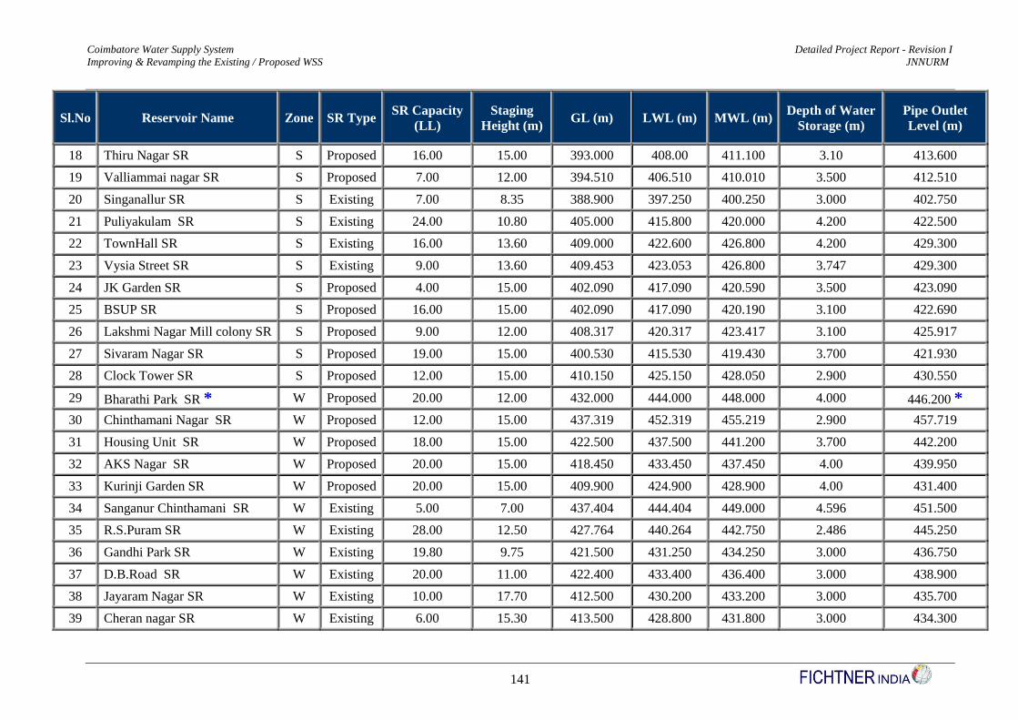
Coimbatore Water Supply System Detailed Project Report - Revision I
Improving & Revamping the Existing / Proposed WSS JNNURM
141
Sl.No Reservoir Name Zone SR Type SR Capacity
(LL)
Staging
Height (m) GL (m) LWL (m) MWL (m)
Depth of Water
Storage (m)
Pipe Outlet
Level (m)
18 Thiru Nagar SR S Proposed 16.00 15.00 393.000 408.00 411.100 3.10 413.600
19 Valliammai nagar SR S Proposed 7.00 12.00 394.510 406.510 410.010 3.500 412.510
20 Singanallur SR S Existing 7.00 8.35 388.900 397.250 400.250 3.000 402.750
21 Puliyakulam SR S Existing 24.00 10.80 405.000 415.800 420.000 4.200 422.500
22 TownHall SR S Existing 16.00 13.60 409.000 422.600 426.800 4.200 429.300
23 Vysia Street SR S Existing 9.00 13.60 409.453 423.053 426.800 3.747 429.300
24 JK Garden SR S Proposed 4.00 15.00 402.090 417.090 420.590 3.500 423.090
25 BSUP SR S Proposed 16.00 15.00 402.090 417.090 420.190 3.100 422.690
26 Lakshmi Nagar Mill colony SR S Proposed 9.00 12.00 408.317 420.317 423.417 3.100 425.917
27 Sivaram Nagar SR S Proposed 19.00 15.00 400.530 415.530 419.430 3.700 421.930
28 Clock Tower SR S Proposed 12.00 15.00 410.150 425.150 428.050 2.900 430.550
29 Bharathi Park SR * W Proposed 20.00 12.00 432.000 444.000 448.000 4.000 446.200 *
30 Chinthamani Nagar SR W Proposed 12.00 15.00 437.319 452.319 455.219 2.900 457.719
31 Housing Unit SR W Proposed 18.00 15.00 422.500 437.500 441.200 3.700 442.200
32 AKS Nagar SR W Proposed 20.00 15.00 418.450 433.450 437.450 4.00 439.950
33 Kurinji Garden SR W Proposed 20.00 15.00 409.900 424.900 428.900 4.00 431.400
34 Sanganur Chinthamani SR W Existing 5.00 7.00 437.404 444.404 449.000 4.596 451.500
35 R.S.Puram SR W Existing 28.00 12.50 427.764 440.264 442.750 2.486 445.250
36 Gandhi Park SR W Existing 19.80 9.75 421.500 431.250 434.250 3.000 436.750
37 D.B.Road SR W Existing 20.00 11.00 422.400 433.400 436.400 3.000 438.900
38 Jayaram Nagar SR W Existing 10.00 17.70 412.500 430.200 433.200 3.000 435.700
39 Cheran nagar SR W Existing 6.00 15.30 413.500 428.800 431.800 3.000 434.300
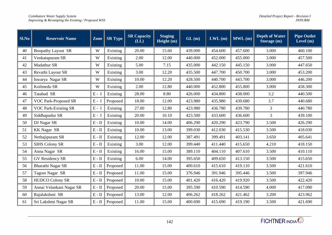
Coimbatore Water Supply System Detailed Project Report - Revision I
Improving & Revamping the Existing / Proposed WSS JNNURM
142
Sl.No Reservoir Name Zone SR Type SR Capacity
(LL)
Staging
Height (m) GL (m) LWL (m) MWL (m)
Depth of Water
Storage (m)
Pipe Outlet
Level (m)
40 Boopathy Layout SR W Existing 20.00 15.60 439.000 454.600 457.600 3.000 460.100
41 Venkatapuram SR W Existing 2.00 12.00 440.000 452.000 455.000 3.000 457.500
42 Madathur SR W Existing 5.00 7.15 435.000 442.150 445.150 3.000 447.650
43 Revathi Layout SR W Existing 3.00 12.20 435.500 447.700 450.700 3.000 453.200
44 Iswarya Nagar SR W Existing 10.00 12.20 428.500 440.700 443.700 3.000 446.200
45 Koilmedu SR W Existing 2.00 12.80 440.000 452.800 455.800 3.000 458.300
46 Tatabad SR E - I Existing 28.00 8.80 426.000 434.800 438.000 3.2 440.500
47 VOC Park-Proposed SR E - I Proposed 18.00 12.00 423.980 435.980 439.680 3.7 440.680
48 VOC Park-Existing SR E - I Existing 27.00 12.80 423.980 436.780 439.780 3 440.780
49 Siddhapudur SR E - I Existing 20.00 10.10 423.500 433.600 436.600 3 439.100
50 DJ Nagar SR E - II Existing 10.00 14.00 406.290 420.290 423.790 3.500 426.290
51 KK Nagar SR E - II Existing 10.00 13.00 399.030 412.030 415.530 3.500 418.030
52 Nethajipuram SR E - II Existing 12.00 12.00 387.491 399.491 403.141 3.650 405.641
53 SIHS Colony SR E - II Existing 3.00 12.00 399.440 411.440 415.650 4.210 418.150
54 Anna Nagar SR E - II Existing 16.00 15.00 389.110 404.110 407.610 3.500 410.110
55 GV Residency SR E - II Existing 6.00 14.00 395.650 409.650 413.150 3.500 415.650
56 Bharathi Nagar SR E - II Proposed 11.00 15.00 400.610 415.610 419.110 3.500 421.610
57 Tagore Nagar SR E - II Proposed 11.00 15.00 376.946 391.946 395.446 3.500 397.946
58 HUDCO Colony SR E - II Proposed 10.00 15.00 401.420 416.420 419.920 3.500 422.420
59 Annai Velankani Nagar SR E - II Proposed 20.00 15.00 395.590 410.590 414.590 4.000 417.090
60 Rajalakshmi SR E - II Proposed 13.00 12.00 406.262 418.262 421.462 3.200 423.962
61 Sri Lakshmi Nagar SR E - II Proposed 11.00 15.00 400.690 415.690 419.190 3.500 421.690
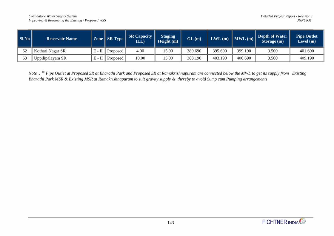
Coimbatore Water Supply System Detailed Project Report - Revision I
Improving & Revamping the Existing / Proposed WSS JNNURM
143
Sl.No Reservoir Name Zone SR Type SR Capacity
(LL)
Staging
Height (m) GL (m) LWL (m) MWL (m)
Depth of Water
Storage (m)
Pipe Outlet
Level (m)
62 Kothari Nagar SR E - II Proposed 4.00 15.00 380.690 395.690 399.190 3.500 401.690
63 Uppilipalayam SR E - II Proposed 10.00 15.00 388.190 403.190 406.690 3.500 409.190
Note : * Pipe Outlet at Proposed SR at Bharathi Park and Proposed SR at Ramakrishnapuram are connected below the MWL to get its supply from Existing
Bharathi Park MSR & Existing MSR at Ramakrishnapuram to suit gravity supply & thereby to avoid Sump cum Pumping arrangements

Coimbatore Water Supply System Detailed Project Report - Revision I
Improving & Revamping the Existing / Proposed WSS JNNURM
144
Table No. 2.48 – Details of SR & Distribution System Demand
Sl.
No Reservoir Zone SR Type
2029
Intermedia
te
Population
(Nos)
Int
Demand
with 10 %
Loss
(LPS)
Int
Industri
al
Demand
(LPS)
Int Total
Flow - 24
hrs (Lps)
2044
Ultimate
Population
(Nos)
Ult
Demand
with 10 %
Loss (LPS)
Ult
Industrial
Demand
(LPS)
Ult Total
Flow - 24
hrs (Lps)
Distribution
System
Length
1 Ramakrishna Puram-A N Proposed 17599 30.25 - 30.248 22102 37.99 - 37.988 29157
2 Ramakrishna Puram-B N Proposed 21113 36.29 - 36.289 26516 45.57 - 45.574 34979
3 V.K.R Nagar-A N Proposed 18867 32.43 - 32.428 23695 40.73 - 40.726 30771
4 V.K.R Nagar-B N Proposed 17419 29.94 - 29.939 21876 37.60 - 37.600 28409
5 Karuippya - Zone A N Proposed 9026 15.51 - 15.514 11336 19.48 - 19.484 10399
6 Karuippya - Zone B N Proposed 8134 13.98 - 13.980 10215 17.56 - 17.557 9606
7 Peelamedu-A N Existing 12210 20.99 4.11 25.099 15334 26.36 7.110 33.466 15450
8 Peelamedu-B N Existing 7471 12.84 4.11 16.953 9382 16.13 7.110 23.236 9453
9 Kamadhenu Nagar N Existing 3700 6.36 1.65 8.008 4647 7.99 2.850 10.837 4577
10 Avarampalayam N Existing 3015 5.18 1.37 6.552 3786 6.51 2.370 8.877 4100
11 PRP Garden SR N Proposed 13823 23.76 - 23.758 17360 29.84 - 29.838 17774
12 Rathinapuri N Existing 6997 12.03 3.29 15.317 8787 15.10 5.690 20.793 4152
13 Rayappa Nagar-A N Existing 9307 16.00 4.11 20.109 11689 20.09 7.110 27.200 10080
14 Rayappa Nagar-B N Existing 6982 12.00 4.11 16.113 8769 15.07 7.110 22.181 7562
15 Kamarajapuram N Existing 9224 15.85 - 15.854 11584 19.91 - 19.911 9244
16 Sanganur Road - A N Proposed 8057 13.85 - 13.848 10118 17.39 - 17.391 7402
17 Sanganur Road - B N Proposed 9246 15.89 - 15.892 11612 19.96 - 19.958 8494
18 Nehru Street-A N Proposed 12342 21.21 - 21.212 15500 26.64 - 26.640 7477
19 Nehru Street-B N Proposed 23218 39.91 - 39.907 29160 50.12 - 50.118 14067
20 Ponni Nagar-A N Proposed 17404 29.91 - 29.913 21857 37.57 - 37.567 12675
21 Ponni Nagar-B N Proposed 21011 36.11 - 36.112 26387 45.35 - 45.352 15302
22 Jai Nagar-A N Existing 8305 14.27 - 14.275 10431 17.93 - 17.928 15643
23 Jai Nagar-B N Existing 17209 29.58 - 29.578 21612 37.15 - 37.146 32412
24 RG Nagar N Existing 8596 14.77 - 14.774 10795 18.55 - 18.555 7715
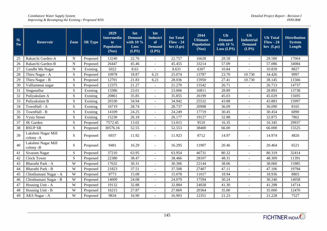
Coimbatore Water Supply System Detailed Project Report - Revision I
Improving & Revamping the Existing / Proposed WSS JNNURM
145
Sl.
No Reservoir Zone SR Type
2029
Intermedia
te
Population
(Nos)
Int
Demand
with 10 %
Loss
(LPS)
Int
Industri
al
Demand
(LPS)
Int Total
Flow - 24
hrs (Lps)
2044
Ultimate
Population
(Nos)
Ult
Demand
with 10 %
Loss (LPS)
Ult
Industrial
Demand
(LPS)
Ult Total
Flow - 24
hrs (Lps)
Distribution
System
Length
25 Rakatchi Garden-A N Proposed 13240 22.76 - 22.757 16628 28.58 - 28.580 17064
26 Rakatchi Garden-B N Proposed 26447 45.46 - 45.455 33214 57.09 - 57.086 34084
27 Gandhi Ma Nagar N Existing 5022 8.63 - 8.631 6307 10.84 - 10.839 8827
28 Thiru Nagar - A S Proposed 10978 18.87 6.21 25.074 13787 23.70 10.730 34.426 9997
29 Thiru Nagar - B S Proposed 12701 21.83 6.21 28.036 15950 27.41 10.730 38.145 11566
30 Valliammai nagar S Proposed 12375 21.27 - 21.270 15542 26.71 - 26.713 14737
31 Singanallur S Existing 13386 23.01 - 23.006 16811 28.89 - 28.893 13738
32 Puliyakulam A S Existing 20861 35.85 - 35.855 26199 45.03 - 45.029 15695
33 Puliyakulam B S Existing 20330 34.94 - 34.942 25532 43.88 - 43.883 15997
34 TownHall - A S Existing 16719 28.74 - 28.737 20998 36.09 - 36.090 8165
35 TownHall - B S Existing 14109 24.25 - 24.249 17719 30.45 - 30.454 6890
36 Vysia Street S Existing 15230 26.18 - 26.177 19127 32.88 - 32.875 7862
37 JK Garden S Proposed 7572.45 13.02 - 13.015 9510 16.35 - 16.345 29937
38 BSUP SR S Proposed 30576.16 52.55 - 52.553 38400 66.00 - 66.000 15525
39 Lakshmi Nagar Mill
colony -A S Proposed 6937 11.92 - 11.923 8712 14.97 - 14.974 4826
40 Lakshmi Nagar Mill
colony -B S Proposed 9481 16.29 - 16.295 11907 20.46 - 20.464 6521
41 Sivaram Nagar S Proposed 37210 63.95 - 63.954 46731 80.32 - 80.319 32414
42 Clock Tower S Proposed 22380 38.47 - 38.466 28107 48.31 - 48.309 11391
43 Bharathi Park - A W Proposed 17632 30.31 - 30.306 22144 38.06 - 38.060 15985
44 Bharathi Park - B W Proposed 21823 37.51 - 37.508 27407 47.11 - 47.106 19784
45 Chinthamani Nagar - A W Proposed 8773 15.08 - 15.078 11017 18.94 - 18.936 8803
46 Chinthamani Nagar - B W Proposed 14009 24.08 - 24.079 17594 30.24 - 30.240 14058
47 Housing Unit - A W Proposed 19132 32.88 - 32.884 24028 41.30 - 41.298 14714
48 Housing Unit - B W Proposed 16215 27.87 - 27.869 20364 35.00 - 35.000 12470
49 AKS Nagar - A W Proposed 9834 16.90 - 16.903 12351 21.23 - 21.228 7527

Coimbatore Water Supply System Detailed Project Report - Revision I
Improving & Revamping the Existing / Proposed WSS JNNURM
146
Sl.
No Reservoir Zone SR Type
2029
Intermedia
te
Population
(Nos)
Int
Demand
with 10 %
Loss
(LPS)
Int
Industri
al
Demand
(LPS)
Int Total
Flow - 24
hrs (Lps)
2044
Ultimate
Population
(Nos)
Ult
Demand
with 10 %
Loss (LPS)
Ult
Industrial
Demand
(LPS)
Ult Total
Flow - 24
hrs (Lps)
Distribution
System
Length
50 AKS Nagar - B W Proposed 19106 32.84 - 32.838 23995 41.24 - 41.241 14623
51 AKS Nagar - C W Proposed 12012 20.65 - 20.646 15086 25.93 - 25.929 9194
52 Kurinji Garden A W Proposed 20398 35.06 - 35.059 25618 44.03 - 44.030 14630
53 Kurinji Garden B W Proposed 20465 35.17 - 35.175 25702 44.17 - 44.175 14669
54 Sanganur Chinthamani W Existing 8326 14.31 - 14.310 10456 17.97 - 17.972 6511
55 R.S.Puram - A W Existing 21515 36.98 - 36.979 27020 46.44 - 46.441 17923
56 R.S.Puram - B W Existing 24162 41.53 - 41.528 30344 52.15 - 52.155 20129
57 Gandhi Park W Existing 33824 58.13 - 58.134 42478 73.01 - 73.010 13982
58 D.B.Road - A W Existing 21114 36.29 - 36.290 26517 45.58 - 45.576 11147
59 D.B.Road - B W Existing 15022 25.82 - 25.819 18866 32.43 - 32.425 7930
60 Jayaram Nagar - A W Existing 7489 12.87 - 12.873 9406 16.17 - 16.166 10581
61 Jayaram Nagar - B W Existing 9365 16.10 - 16.096 11762 20.22 - 20.215 13231
62 Cheran nagar W Existing 9693 16.66 - 16.660 12173 20.92 - 20.923 9082
63 Boopathy Layout - A W Existing 14869 25.56 - 25.556 18674 32.10 - 32.096 11343
64 Boopathy Layout - B W Existing 16274 27.97 - 27.972 20439 35.13 - 35.129 12415
65 Venkatapuram W Existing 3673 6.31 - 6.313 4613 7.93 - 7.928 1784
66 Madathur W Existing 9518 16.36 - 16.359 11953 20.54 - 20.545 8156
67 Revathi Layout W Existing 5859 10.07 - 10.070 7358 12.65 - 12.647 6173
68 Iswarya - A W Existing 9750 16.76 - 16.758 12245 21.05 - 21.046 9361
69 Iswarya - B W Existing 7877 13.54 - 13.538 9892 17.00 - 17.003 6819
70 Koilmedu W Existing 3663 6.30 - 6.296 4600 7.91 - 7.906 2137
71 Tatabad - A E - I Existing 23807 40.92 - 40.919 29899 51.39 - 51.3890 14736
72 Tatabad - B E - I Existing 24094 41.41 - 41.411 30259 52.01 - 52.0073 14795
73 VOC Park-Proposed -A E - I Proposed 19669 33.81 3.40 37.203 24702 42.46 5.87 48.3285 14728
74 VOC Park - Proposed-B E - I Proposed 11210 19.27 3.40 22.664 14078 24.20 5.87 30.0696 8394
75 VOC Park-Existing - A E - I Existing 20262 34.83 - 34.826 25447 43.74 - 43.7368 18146
76 VOC Park - Existing - B E - I Existing 28533 49.04 - 49.041 35834 61.59 - 61.5894 24570

Coimbatore Water Supply System Detailed Project Report - Revision I
Improving & Revamping the Existing / Proposed WSS JNNURM
147
Sl.
No Reservoir Zone SR Type
2029
Intermedia
te
Population
(Nos)
Int
Demand
with 10 %
Loss
(LPS)
Int
Industri
al
Demand
(LPS)
Int Total
Flow - 24
hrs (Lps)
2044
Ultimate
Population
(Nos)
Ult
Demand
with 10 %
Loss (LPS)
Ult
Industrial
Demand
(LPS)
Ult Total
Flow - 24
hrs (Lps)
Distribution
System
Length
77 Siddhapudur - Zone A E - I Existing 13318 22.89 2.09 24.980 16726 28.75 3.61 32.3597 14104
78 Siddhapudur - Zone B E - I Existing 13566 23.32 2.09 25.406 17037 29.28 3.61 32.8952 14227
79 DJ Nagar - Zone A E - II Existing 8754 15.05 - 15.046 10994 18.90 - 18.8955 14313
80 DJ Nagar - Zone B E - II Existing 10808 18.58 - 18.576 13574 23.33 - 23.3296 13396
81 KK Nagar - A E - II Existing 7784 13.38 - 13.379 9776 16.80 - 16.8025 6898
82 KK Nagar - B E - II Existing 9692 16.66 - 16.658 12172 20.92 - 20.9209 8589
83 Nethajipuram - A E - II Existing 10531 18.10 - 18.100 13225 22.73 - 22.7312 12629
84 Nethajipuram - B E - II Existing 9414 16.18 - 16.180 11823 20.32 - 20.3206 11290
85 SIHS Colony E - II Existing 4240 7.29 - 7.288 5325 9.15 - 9.1523 8159
86 Anna Nagar A E - II Existing 13727 23.59 - 23.594 17240 29.63 - 29.6314 18639
87 Anna Nagar B E - II Existing 13337 22.92 - 22.922 16749 28.79 - 28.7877 18115
88 GV Residency E - II Existing 8717 14.98 - 14.982 10948 18.82 - 18.8161 13363
89 Bharathi Nagar - A E - II Proposed 6390 10.98 6.03 17.016 8026 13.79 10.430 24.2239 12959
90 Bharathi Nagar - B E - II Proposed 7732 13.29 6.03 19.323 9711 16.69 10.430 27.1205 15680
91 Tagore Nagar A E - II Proposed 5288 9.09 2.82 11.908 6641 11.41 4.875 16.2888 6746
92 Tagore Nagar B E - II Proposed 12983 22.31 2.82 25.134 16305 28.02 4.875 32.8984 16563
93 HUDCO Colony E - II Proposed 15692 26.97 7.14 34.108 19707 33.87 12.340 46.2108 18931
94 Annai Velankani Nagar
- A E - II Proposed 19286 33.15 - 33.148 24221 41.63 - 41.6303 22098
95 Annai Velankani Nagar
- B E - II Proposed 20142 34.62 - 34.620 25297 43.48 - 43.4784 23079
96 Rajalakshmi A E - II Proposed 13954 23.98 - 23.983 17525 30.12 - 30.1204 14537
97 Rajalakshmi B E - II Proposed 12305 21.15 - 21.148 15453 26.56 - 26.5600 15700
98 Sri Lakshmi Nagar A E - II Proposed 10733 18.45 - 18.447 13479 23.17 - 23.1667 11034
99 Sri Lakshmi Nagar B E - II Proposed 10844 18.64 - 18.638 13619 23.41 - 23.4074 14581
100 Kothari Nagar E - II Proposed 7741 13.31 - 13.306 9722 16.71 - 16.7103 12086
101 Uppilipalayam E - II Proposed 13425 23.07 9.17 32.248 16860 28.98 15.860 44.8387 14355

Coimbatore Water Supply System Detailed Project Report - Revision I
Improving & Revamping the Existing / Proposed WSS JNNURM
148
Sl.
No Reservoir Zone SR Type
2029
Intermedia
te
Population
(Nos)
Int
Demand
with 10 %
Loss
(LPS)
Int
Industri
al
Demand
(LPS)
Int Total
Flow - 24
hrs (Lps)
2044
Ultimate
Population
(Nos)
Ult
Demand
with 10 %
Loss (LPS)
Ult
Industrial
Demand
(LPS)
Ult Total
Flow - 24
hrs (Lps)
Distribution
System
Length
TOTAL
1395199
Nos
2398 Lps 80 Lps 2478 Lps 1752203 Nos
3012 Lps 139 Lps 3150 Lps 1374734 m
2072LL 69 LL 2141 LL 2602 LL 120 LL 2722 LL 1375 Km
Table No. 2.49 – Proposed Distribution System Demand or Rezoned Demand
Propsoed D’Syetm Demand for Intermediate Stage Requirement
D’System Requirement (From Table 2.48 above ) 214.113 Mld
Industrial Demand retained at Existing MSR at Pillur for Intermediate Stage 3.052 MLD
Sub Total 217.165 MLD
5 % Transmission Loss 9.42 MLD
Distribution System Designed for Intermediate Stage 226.583 MLD (Which is the Project Intermediate requirement)
Propsoed D’Syetm Demand for Ultimate Stage Requirement
D’System Requirement (From Table 2.48 above ) 272.176 Mld
Industrial Demand retained at Existing MSR at Pillur for Ultimate Stage 5.276 MLD
Sub Total 277.452 MLD
5 % Transmission Loss 11.83 MLD
Distribution System Designed for Ultimate Stage 289.280 MLD (Which is the Project Ultimate requirement)
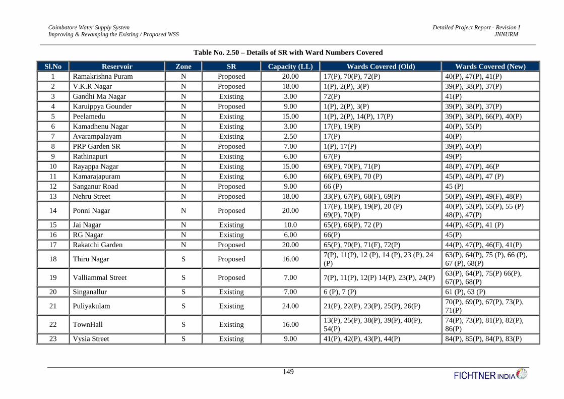
Coimbatore Water Supply System Detailed Project Report - Revision I
Improving & Revamping the Existing / Proposed WSS JNNURM
149
Table No. 2.50 – Details of SR with Ward Numbers Covered
Sl.No Reservoir Zone SR Capacity (LL) Wards Covered (Old) Wards Covered (New)
1 Ramakrishna Puram N Proposed 20.00 17(P), 70(P), 72(P) 40(P), 47(P), 41(P)
2 V.K.R Nagar N Proposed 18.00 1(P), 2(P), 3(P) 39(P), 38(P), 37(P)
3 Gandhi Ma Nagar N Existing 3.00 72(P) 41(P)
4 Karuippya Gounder N Proposed 9.00 1(P), 2(P), 3(P) 39(P), 38(P), 37(P)
5 Peelamedu N Existing 15.00 1(P), 2(P), 14(P), 17(P) 39(P), 38(P), 66(P), 40(P)
6 Kamadhenu Nagar N Existing 3.00 17(P), 19(P) 40(P), 55(P)
7 Avarampalayam N Existing 2.50 17(P) 40(P)
8 PRP Garden SR N Proposed 7.00 1(P), 17(P) 39(P), 40(P)
9 Rathinapuri N Existing 6.00 67(P) 49(P)
10 Rayappa Nagar N Existing 15.00 69(P), 70(P), 71(P) 48(P), 47(P), 46(P
11 Kamarajapuram N Existing 6.00 66(P), 69(P), 70 (P) 45(P), 48(P), 47 (P)
12 Sanganur Road N Proposed 9.00 66 (P) 45 (P)
13 Nehru Street N Proposed 18.00 33(P), 67(P), 68(F), 69(P) 50(P), 49(P), 49(F), 48(P)
14 Ponni Nagar N Proposed 20.00 17(P), 18(P), 19(P), 20 (P)
69(P), 70(P)
40(P), 53(P), 55(P), 55 (P)
48(P), 47(P)
15 Jai Nagar N Existing 10.0 65(P), 66(P), 72 (P) 44(P), 45(P), 41 (P)
16 RG Nagar N Existing 6.00 66(P) 45(P)
17 Rakatchi Garden N Proposed 20.00 65(P), 70(P), 71(F), 72(P) 44(P), 47(P), 46(F), 41(P)
18 Thiru Nagar S Proposed 16.00 7(P), 11(P), 12 (P), 14 (P), 23 (P), 24
(P)
63(P), 64(P), 75 (P), 66 (P),
67 (P), 68(P)
19 Valliammal Street S Proposed 7.00 7(P), 11(P), 12(P) 14(P), 23(P), 24(P) 63(P), 64(P), 75(P) 66(P),
67(P), 68(P)
20 Singanallur S Existing 7.00 6 (P), 7 (P) 61 (P), 63 (P)
21 Puliyakulam S Existing 24.00 21(P), 22(P), 23(P), 25(P), 26(P) 70(P), 69(P), 67(P), 73(P),
71(P)
22 TownHall S Existing 16.00 13(P), 25(P), 38(P), 39(P), 40(P),
54(P)
74(P), 73(P), 81(P), 82(P),
86(P)
23 Vysia Street S Existing 9.00 41(P), 42(P), 43(P), 44(P) 84(P), 85(P), 84(P), 83(P)
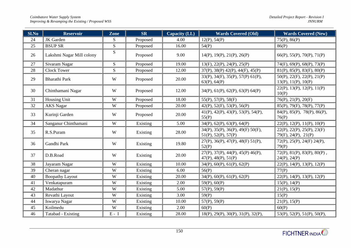
Coimbatore Water Supply System Detailed Project Report - Revision I
Improving & Revamping the Existing / Proposed WSS JNNURM
150
Sl.No Reservoir Zone SR Capacity (LL) Wards Covered (Old) Wards Covered (New)
24 JK Garden S Proposed 4.00 12(P), 54(P) 75(P), 86(P)
25 BSUP SR S Proposed 16.00 54(P) 86(P)
26 Lakshmi Nagar Mill colony S
Proposed 9.00 14(P), 19(P), 21(P), 26(P) 66(P), 55(P), 70(P), 71(P)
27 Sivaram Nagar S Proposed 19.00 13(F), 22(P), 24(P), 25(P) 74(F), 69(P), 68(P), 73(P)
28 Clock Tower S Proposed 12.00 37(P), 38(P) 42(P), 44(F), 45(P) 81(P), 85(P), 83(F), 80(P)
29 Bharathi Park W Proposed 20.00 33(P), 34(F), 35(P), 57(P) 61(P),
63(P), 64(P)
50(P), 22(F), 22(P), 21(P)
13(P), 11(P), 10(P)
30 Chinthamani Nagar W Proposed 12.00 34(P), 61(P), 62(P), 63(P) 64(P) 22(P), 13(P), 12(P), 11(P)
10(P)
31 Housing Unit W Proposed 18.00 55(P), 57(P), 58(F) 76(P), 21(P), 20(F)
32 AKS Nagar W Proposed 20.00 42(P), 52(F), 53(P), 56(P) 85(P), 79(F), 78(P), 77(P)
33 Kurinji Garden W Proposed 20.00 41(P), 42(P), 43(P), 53(P), 54(P),
55(P)
84(P), 85(P), 78(P), 86(P),
76(P)
34 Sanganur Chinthamani W Existing 5.00 34(P), 62(P), 63(P), 64(P) 22(P), 12(P), 11(P), 10(P)
35 R.S.Puram W Existing 28.00 34(P), 35(P), 36(P), 49(F) 50(F),
51(P), 52(P), 57(P)
22(P), 22(P), 25(P), 23(F)
79(F), 24(P), 21(P)
36 Gandhi Park W Existing 19.80 27(P), 36(P), 47(P), 48(F) 51(P),
52(P)
72(P), 25(P), 24(F) 24(P),
79(P)
37 D.B.Road W Existing 20.00 27(P), 37(P), 44(P), 45(P) 46(P),
47(P), 48(P), 51(P)
72(P), 81(P), 83(P), 80(P) ,
24(P), 24(P)
38 Jayaram Nagar W Existing 10.00 34(P), 60(P), 61(P), 62(P) 22(P), 14(P), 13(P), 12(P)
39 Cheran nagar W Existing 6.00 56(P) 77(P)
40 Boopathy Layout W Existing 20.00 34(P), 60(P), 61(P), 62(P) 22(P), 14(P), 13(P), 12(P)
41 Venkatapuram W Existing 2.00 59(P), 60(P) 15(P), 14(P)
42 Madathur W Existing 5.00 57(P), 59(P) 21(P), 15(P)
43 Revathi Layout W Existing 3.00 59(P) 15(P)
44 Iswarya Nagar W Existing 10.00 57(P), 59(P) 21(P), 15(P)
45 Koilmedu W Existing 2.00 60(P) 60(P)
46 Tatabad - Existing E - I Existing 28.00 18(P), 29(P), 30(P), 31(P), 32(P), 53(P), 52(P), 51(P), 50(P),

Coimbatore Water Supply System Detailed Project Report - Revision I
Improving & Revamping the Existing / Proposed WSS JNNURM
151
Sl.No Reservoir Zone SR Capacity (LL) Wards Covered (Old) Wards Covered (New)
33(P), 35(P) 67(P), 69(P) 22(P) 49(P), 48(P)
47 VOC Park-Proposed E - I Proposed 18.00 20(P), 25(P), 26(P), 27(P) 28(P),
30(P) 31(P), 35(P), 36(P)
55(P), 73(P), 71(P), 72(P)
54(P), 52(P) 51(P), 22(P),
25(P) 48 VOC Park-Existing E - I Existing 27.00
49 Siddhapudur E - I Existing 20.00 20(P), 26(P), 28(P), 29(P) 55(P), 71(P), 54(P), 52(P)
50 DJ Nagar E - II Existing 10.00 2(P), 3(P), 4(P), 9(P), 10(P), 16(P) 38(P), 37(P), 59(P), 58(P),
57(P), 56(P)
51 KK Nagar E - II Existing 10.00 15(P), 16 (P) 65(P), 56 (P)
52 Nethajipuram E - II Existing 12.00 4(P), 5(P), 6 (P) 59(P), 60(P), 61 (P)
53 SIHS Colony E - II Existing 3.00 4 (P) 59 (P)
54 Anna Nagar E - II Existing 16.00 4(P), 6(P), 8(P), 9 (P) 59(P), 61(P), 62(P), 58(P)
55 GV Residency E - II Existing 6.00 9(P), 10(P) 58(P), 57(P)
56 Bharathi Nagar E - II Proposed 11.00 4(P) 59(P)
57 Tagore Nagar E - II Proposed 11.00 5(P), 6 (P) 60(P), 61 (P)
58 HUDCO Colony E - II Proposed 10.00 10(P), 16(P) 57(P), 56(P)
59 Annai Velankani Nagar E - II Proposed 20.00 7(P), 10(P), 14(P), 15(P) 63(P), 57(P), 66(P), 65(P)
60 Rajalakshmi Nagar E - II Proposed 13.00 8(P), 9(P), 10(P), 11(P) 62(P), 58(P), 57(P), 64(P)
61 Sri Lakshmi Nagar E - II Proposed 11.00 2(P), 14(P), 16P) 38(P), 66(P), 56(P)
62 Kothari Nagar E - II Proposed 4.00 6(P), 7(P) 61(P), 63(P)
63 Uppilipalayam E - II Proposed 10.00 6(P), 7(P), 8(P), 11(P) 61(P), 63(P), 62(P), 64(P)
Note : All SRs with Importtant Landmarks are annexed in Annexure Number – A11, Volume I (a) Part of this Report
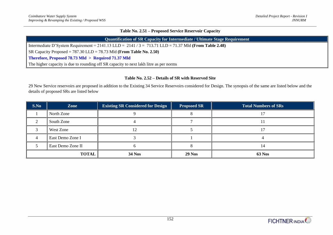
Coimbatore Water Supply System Detailed Project Report - Revision I
Improving & Revamping the Existing / Proposed WSS JNNURM
152
Table No. 2.51 – Proposed Service Reservoir Capacity
Quantification of SR Capacity for Intermediate / Ultimate Stage Requirement
Intermediate D’System Requirement = 2141.13 LLD = 2141 / 3 = 713.71 LLD = 71.37 Mld (From Table 2.48)
SR Capacity Proposed = 787.30 LLD = 78.73 Mld (From Table No. 2.50)
Therefore, Proposed 78.73 Mld > Required 71.37 Mld
The higher capacity is due to rounding off SR capacity to next lakh litre as per norms
Table No. 2.52 – Details of SR with Reserved Site
29 New Service reservoirs are proposed in addition to the Existing 34 Service Reservoirs considered for Design. The synopsis of the same are listed below and the
details of proposed SRs are listed below
S.No Zone Existing SR Considered for Design Propsoed SR Total Numbers of SRs
1 North Zone 9 8 17
2 South Zone 4 7 11
3 West Zone 12 5 17
4 East Demo Zone I 3 1 4
5 East Demo Zone II 6 8 14
TOTAL 34 Nos 29 Nos 63 Nos
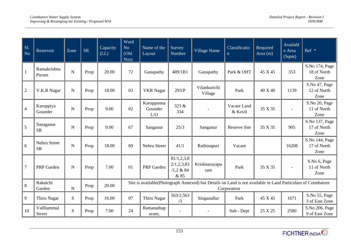
Coimbatore Water Supply System Detailed Project Report - Revision I
Improving & Revamping the Existing / Proposed WSS JNNURM
153
Sl.
No Reservoir Zone SR
Capacity
(LL)
Ward
No
(Old
Nos)
Name of the
Layout
Survey
Number Village Name
Classificatio
n
Required
Area (m)
Availabl
e Area
(Sqmt)
Ref *
1 Ramakrishna
Puram N Prop 20.00 72 Ganapathy 489/1B1 Ganapathy Park & OHT 45 X 45 353
S.No 174, Page
18 of North
Zone
2 V.K.R Nagar N Prop 18.00 03 VKR Nagar 293/P Vilankurichi
Village Park 40 X 40 1139
S.No 47, Page
12 of North
Zone
4 Karuppiya
Gounder N Prop 9.00 02
Karuppanna
Gounder
L/O
323 &
334 -
Vacant Land
& Kovil 35 X 35 -
S.No 20, Page
11 of North
Zone
5 Sanaganur
SR N Prop 9.00 67 Sanganur 25/3 Sanganur Reserve Site 35 X 35 905
S.No 137, Page
17 of North
Zone
6 Nehru Street
SR N Prop 18.00 69 Nehru Street 41/1 Rathinapuri Vacant 16208
S.No 144, Page
17 of North
Zone
7 PRP Garden N Prop 7.00 01 PRP Garden
81/1,2,3,8
2/1,2,3,83
/1,2 & 84
& 85
Krishnarayapu
ram Park 35 X 35 -
S.No 6, Page
11 of North
Zone
8 Rakatchi
Garden
N Prop 20.00
Site is available(Photograph Annexed) but Details on Land is not available in Land Particulars of Coimbatore
Corporation
9 Thiru Nagar S Prop 16.00 07 Thiru Nagar 563/2,563
/3 Singanallur Park 45 X 45 1671
S.No 55, Page
3 of East Zone
10 Vallliammal
Street S Prop 7.00 24
Ramanathap
uram, - - Sub - Dept 25 X 25 2580
S.No 206, Page
9 of East Zone
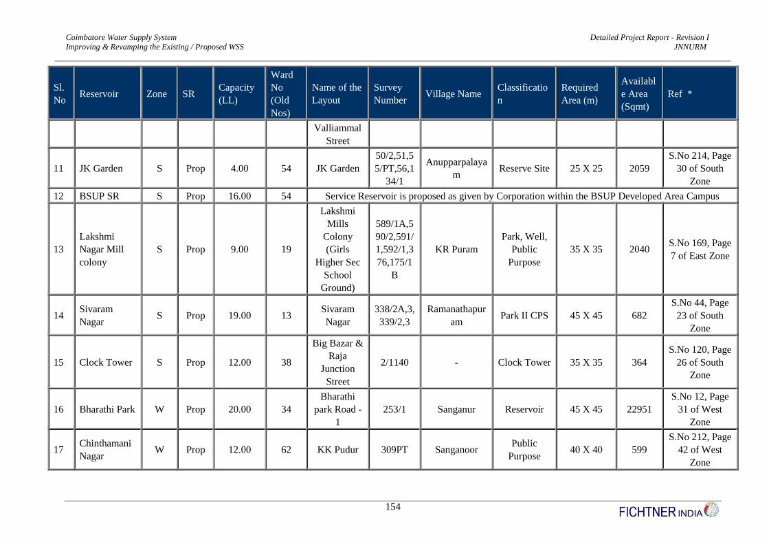
Coimbatore Water Supply System Detailed Project Report - Revision I
Improving & Revamping the Existing / Proposed WSS JNNURM
154
Sl.
No Reservoir Zone SR
Capacity
(LL)
Ward
No
(Old
Nos)
Name of the
Layout
Survey
Number Village Name
Classificatio
n
Required
Area (m)
Availabl
e Area
(Sqmt)
Ref *
Valliammal
Street
11 JK Garden S Prop 4.00 54 JK Garden
50/2,51,5
5/PT,56,1
34/1
Anupparpalaya
m Reserve Site 25 X 25 2059
S.No 214, Page
30 of South
Zone
12 BSUP SR S Prop 16.00 54 Service Reservoir is proposed as given by Corporation within the BSUP Developed Area Campus
13
Lakshmi
Nagar Mill
colony
S Prop 9.00 19
Lakshmi
Mills
Colony
(Girls
Higher Sec
School
Ground)
589/1A,5
90/2,591/
1,592/1,3
76,175/1
B
KR Puram
Park, Well,
Public
Purpose
35 X 35 2040 S.No 169, Page
7 of East Zone
14 Sivaram
Nagar S Prop 19.00 13
Sivaram
Nagar
338/2A,3,
339/2,3
Ramanathapur
am Park II CPS 45 X 45 682
S.No 44, Page
23 of South
Zone
15 Clock Tower S Prop 12.00 38
Big Bazar &
Raja
Junction
Street
2/1140 - Clock Tower 35 X 35 364
S.No 120, Page
26 of South
Zone
16 Bharathi Park W Prop 20.00 34
Bharathi
park Road -
1
253/1 Sanganur Reservoir 45 X 45 22951
S.No 12, Page
31 of West
Zone
17 Chinthamani
Nagar W Prop 12.00 62 KK Pudur 309PT Sanganoor
Public
Purpose 40 X 40 599
S.No 212, Page
42 of West
Zone

Coimbatore Water Supply System Detailed Project Report - Revision I
Improving & Revamping the Existing / Proposed WSS JNNURM
155
Sl.
No Reservoir Zone SR
Capacity
(LL)
Ward
No
(Old
Nos)
Name of the
Layout
Survey
Number Village Name
Classificatio
n
Required
Area (m)
Availabl
e Area
(Sqmt)
Ref *
18 Housing Unit W Prop 18.00 58
Housing
Unit, SN
Palayam
238/2,237
/A1,3,296
/1,236PT,
297/A12
A1
SN Palayam Play Space,
Open 40 X 40 2260
S.No 158, Page
40 of West
Zone
19 AKS Nagar W Prop 20.00 52 AKS Nagar 115/3,114
/1 TS Ward No 7 Open A 45 X 45 2974
S.No 113, Page
38 of West
Zone
20 Kurinji
Garden W Prop 20.00 42
Kurinji
Garden
479/29PT
,480/2PT
Kumarapalaya
m Park 35 X 35 2467
S.No 152, Page
27 of South
Zone
21 VOC Park-
Proposed E - I Prop 18.00 27 VOC Park 1/924 PT CBE Town Park 40 X 40 36280
S.No 83, Page
24 of South
Zone
22 Bharathi
Nagar E - II Prop 11.00 04
Bharathi
Nagar 332/2 - Vacant 35 X 35 1549
S.No 6, Page 1
of East Zone
23 Tagore Nagar E - II Prop 11.00 05 Tagore
Nagar
229/2PT,
229/3,230
,235,236,
237
Singanallur Park 35 X 35 4103 S.No 21, Page
1 of East Zone
24 HUDCO
Colony E - II Prop 10.00 16
Hudco
Colony
(Near PSG)
495/1,2A,
3A,503/1
B,2,504/1
B
Sowripalayam Park 35 X 35 8772 S.No 151, Page
7 of East Zone
25 Annai
Velankani E - II Prop 20.00 15
Annai
Velanganni
208, 209,
201 Sowripalayam
Public
Purpose 45 X 45 3683
S.No 134, Page
6 of East Zone

Coimbatore Water Supply System Detailed Project Report - Revision I
Improving & Revamping the Existing / Proposed WSS JNNURM
156
Sl.
No Reservoir Zone SR
Capacity
(LL)
Ward
No
(Old
Nos)
Name of the
Layout
Survey
Number Village Name
Classificatio
n
Required
Area (m)
Availabl
e Area
(Sqmt)
Ref *
Nagar Nagar
26 Rajalakshmi
Nagar E - II Prop 13.00 10
Rajalakshmi
Nagar 56
Lakshmi
Puram Vacant Land 40 X 40 2959
S.No 80, Page
4 of East Zone
of CCC
27 Sri Lakshmi
Nagar E - II Prop 11.00 14
Sri Lakshmi
Nagar
549/1B,5
55/1B,55
2/2 Part
Sowripalayam Park 35 X 35 2286
S.No 111, Page
5 of East Zone
of CCC
28 Kothari
Nagar E - II Prop 4.00 06
Kothari
Nagar
279,283,2
88,289/4,
294/2,297
,298PT,2
99,509,54
4/1
Singanallur Play Ground 25 X 25 8125
S.No 32, Page
2 of East Zone
of CC
29 Uppilipalaya
m E - II Prop 10.00 11
Uppilipalay
m Park 218 Uppilipalayam Park / OHT 35 X 35 3003
S.No 99, Page
4 of East Zone
of CCC
Note : Photograph for Each Site is taken seperately and annexed in Annexure Number – A7, Volume I(b) part of this DPR.
* - Reference on avialble land are taken from Coimbatore Municipal Corporation Land Particulars from Town Planning Section

Coimbatore Water Supply System Detailed Project Report - Revision I
Improving & Revamping the Existing / Proposed WSS JNNURM
157
(v) Abandoned Sumps & SRs
The existing sumps and the old, abandoned SRs less than 1 lakh capacity are eliminated and not
considered for rehabilitation are listed in Table No. 2.53
Table No. 2.53 - Details of the Old and Abandoned SRs
Sl.No. SR Location Ward Number
(Old) Capacity (LL)
1 Maniyakaram Palayam SR 72 1.00
2 Police Quarters SR 72 0.50
3 V.V.Nagar SR 72 0.50
4 V.O.C Nagar Sump 72 0.50
5 Ganapathy Ma Nagar Sump 72 3.00
6 Gandhi Ma Nagar Sump 72 6.00
7 Housing Unit Sump 3 0.50
8 Nanjundapuram SR 12 2.00
9 Sowripalayam SR 14 5.00 (Staghing Height – 8m)
10 Varadharajapuram SR 11 10.00 (Staghing Height – 8m)
11 Uppilipalayam SR 11 10.00 (Dilapted Condition)
12 Bharathi Park GLSR 34 10.00
13 Bharathi Park GLSR 34 10.00 (Dilapted Condition)
14 Gandhi Park GLSR 51 10.00
15 SIHS Colony Sump 4 3.00
The cost for construction of additional service reservoirs for the
Intermediate Stage is worked out in Volume V – Structural Design &
Estimates part of this report and comes around Rs. 55.66 Crores (As
per Schedule of Rates 2016 – 2017)
(vi) Appurtenances Proposed
1. Sluice Valve
Details of sluice valves proposed with sizes in the respective zones are listed below in Table No.2.54
Table No. 2.54 - Sluice Valves in Distribution System
Zone 65 80 100 125 150 200 250 300 350 400 500
East Demo Zone I - 14 - - 3 10 1 13 1 - 3
East Demo Zone II - 29 - - 13 8 19 28 2 3 3
North - 43 - - 18 25 11 34 4 - 1
South -- 17 1 - 6 15 10 20 3 3 -
West - 24 1 - 10 9 23 36 4 1 1
TOTAL 0 127 2 0 50 67 64 131 14 7 8
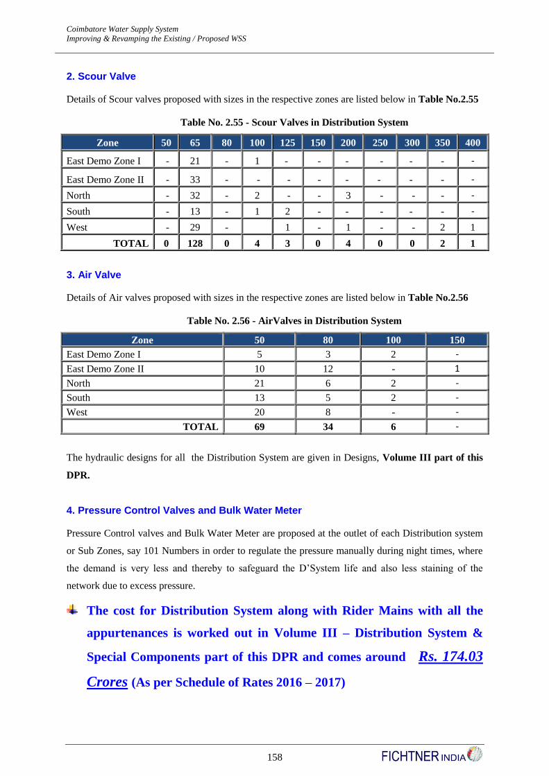
Coimbatore Water Supply System Detailed Project Report - Revision I
Improving & Revamping the Existing / Proposed WSS JNNURM
158
2. Scour Valve
Details of Scour valves proposed with sizes in the respective zones are listed below in Table No.2.55
Table No. 2.55 - Scour Valves in Distribution System
Zone 50 65 80 100 125 150 200 250 300 350 400
East Demo Zone I - 21 - 1 - - - - - - -
East Demo Zone II - 33 - - - - - - - - -
North - 32 - 2 - - 3 - - - -
South - 13 - 1 2 - - - - - -
West - 29 - 1 - 1 - - 2 1
TOTAL 0 128 0 4 3 0 4 0 0 2 1
3. Air Valve
Details of Air valves proposed with sizes in the respective zones are listed below in Table No.2.56
Table No. 2.56 - AirValves in Distribution System
Zone 50 80 100 150
East Demo Zone I 5 3 2 -
East Demo Zone II 10 12 - 1
North 21 6 2 -
South 13 5 2 -
West 20 8 - -
TOTAL 69 34 6 -
The hydraulic designs for all the Distribution System are given in Designs, Volume III part of this
DPR.
4. Pressure Control Valves and Bulk Water Meter
Pressure Control valves and Bulk Water Meter are proposed at the outlet of each Distribution system
or Sub Zones, say 101 Numbers in order to regulate the pressure manually during night times, where
the demand is very less and thereby to safeguard the D’System life and also less staining of the
network due to excess pressure.
The cost for Distribution System along with Rider Mains with all the
appurtenances is worked out in Volume III – Distribution System &
Special Components part of this DPR and comes around Rs. 174.03
Crores (As per Schedule of Rates 2016 – 2017)
Coimbatore Water Supply System Detailed Project Report - Revision I
Improving & Revamping the Existing / Proposed WSS JNNURM
159
2.9.6 Automation of Distribution System – SCADA
(i) Introduction
For Coimbatore Corporation, it is proposed to have a well planned infrastructure for water supply
distribution system, which covers an area of 105.6 sq.km
The infrastructure includes,
Internal Feeder / Transmission mains – 96.50 kms
Interlinking of Pillur & Siruvani MSR systems – 8.5 Kms
Distribution System – 1375 Kms
Overhead Service Reservoirs – 63 Nos
Ground level Sumps – 3 Nos
As a part of total integrated monitoring and data acquisition system, it is proposed to install one
integrated system which will primarily controlled by PLC locally, networked through GPRS and will
have central monitoring, data acquisition and no controls. The proposed system will cover automation
and online data acquisition for Pillur system at the master control facility at the MSR site at
Ramakrishnapuram, covering feeder mains, SRs and sumps and another one for Siruvani system at the
MSR site at Bharathi Park, covering feeder mains, SRs and sumps, and a display facility at
Corporation office complex at Townhall. The purpose of integrated automation system is to have the
following for effective utilization of resources and handling emergencies centrally and to stop
pilferages and distribution losses.
Online data collection of water quality parameters and flow at MSR sites
Monitoring of water level at each SR/ GLSR
Monitoring of discharge from each SR
Online metering of water discharge from each MSRs / SRs / GLSRs
Monitoring operation of pumping machinery in pumping mains
Automatic generation of real time MIS reports without intervention of operator and
user defined graphics and reports.
(ii) Scope of work
The scope of the work of establishment of SCADA shall include design, manufacture, testing at
works, supply at site, storage at site, installation/erection, testing, commissioning, integrating with the
existing system, proving, field testing and handing over the integrated automation system. The scope
shall also include total operation and maintenance of the automation system for the period of five
years after two years of free operation and maintenance. The payment against AMC for 5 years at the
agreed rates shall be made by CCC from its own funds. The AMC shall include free up gradation of

Coimbatore Water Supply System Detailed Project Report - Revision I
Improving & Revamping the Existing / Proposed WSS JNNURM
160
SCADA software and all consumables that will be required for smooth running of the system.
(iii) System Design
Basically the system is divided in to three sections for each of the two systems namely Pillur and
Siruvani systems:
Remote monitoring of SRs / GLSRs in the distribution network
Monitroing of pumping at pumping stations
Centralized monitoring station at respective MSR site
The automation system will be designed in three layers.
Field instruments like level transmitters, pressure transmitters, motorized actuators, analyzers
etc.
PLC/RTU based control system with local HMI and facility to network with SCADA at
remote places through GPRS/GSM/RF
Centralized monitoring stations at each MSR site and both shall be connected to CCC head
office through wireless /GPRS/ Broad Band
The central monitoring station is proposed to have SCADA software, which will carryout real time
data collection and will have facility of report generation and monitoring. The networking of different
sections and SRs with central SCADA system shall be such that instantaneous status of the sections
shall be available on web through web browsers. In addition to the centralized data collection, the
system shall also generate SMS alerts from the point of generation.
(iv) Proposed System
1. SRs / GLSRs in Distribution Network
There are 63 SRs and 3 GLSRs spread all over the territory of CCC operated by manually operated
valves. It is proposed to monitor the levels and flow through each SRs on real time basis and to have
monitor over the discharge of each SRs through actuated valves from central SCADA of respective
system. Each SR site, it is proposed to install one ultrasonic level transmitter, one pressure transmitter,
and one flow transmitter, and one electrically actuated valve. All these equipments are proposed to be
connected to one PLC / RTU and it will be connected on wireless network to the central SCADA
station of the respective system.
Each PLC / RTU at SR shall have one 6” touch screen HMI for the operator to monitor the valves.
The PLC/RTU of each SR shall collect the input data and transmit the same to central SCADA at an
interval of not more than 5 min. The operation of discharge valve shall be possible from central
SCADA also. The maximum time delay form the command to initiation of valve shall not exceed 10
Coimbatore Water Supply System Detailed Project Report - Revision I
Improving & Revamping the Existing / Proposed WSS JNNURM
161
sec. The network shall be such that update time or remote operation shall not be affected by traffic on
wireless network. Each SR site shall also be provided with a UPS of suitable rating so that in the case
of power failure the flow data is not lost and the monitoring system will still keep working. The
connectivity of individual PLC at each SR site will be either through GPRS or through broadband
connection of service providers without fixed IP.
2. Central SCADA Station at MSRs
SCADA stations is proposed at Ramakrishnapuram MSR site for Pillur system and at Bharathi Park
MSR site for Siruvani system: These stations shall be acting as a master control stations as well as
MIS centers. The system shall be capable of generating various user defined reports. One of the
computer stations shall act as a history server. SCADA shall be provided with unlimited tags with run
time and also of development version.The monitor room will have two servers and two operator
terminals all connected on LAN. One operator terminal will have minimum 42” LCD monitor which
will display current status of total water system in graphical form. The servers shall work in
redundancy mode so that failure of one of the server will not result in to loss of data or monitoring.
The monitoring room shall be provided with online 10 KVA UPS capacity with the backup time of 4
hrs. The monitoring station shall be provided with broadband connection with fixed IP.At the head
office of the CCC at TownHall, one operator terminal with a minimum 42” LCD monitor displaying
the current status of both the water supply systems will be installed and this will be connected
The cost for Special Components like Automatic Meter Reading (AMR)
System, Disinfection Units, Any Time Payment Machine (ATP), Bulk
Water Meter with Data Logger for Flow & Pressure Measurement and
room for Data Logger, Gas Chlorination Disinfection is worked out in
Volume III – Distribution System & Special Component part of this
report and comes around Rs. 150.47 Crores (As per Schedule of
Rates 2016 – 2017)
The cost for Common Components like SCADA and Water Quality
Test Laboratory is worked out in Volume IV – Common Components
& Data Bank part of this DPR and comes around Rs. 8.10 Crores (As
per Schedule of Rates 2016 – 2017)
Coimbatore Water Supply System Detailed Project Report - Revision I
Improving & Revamping the Existing / Proposed WSS JNNURM
162
2.9.7 Clearances Required From Other Agencies
For this project, clearances required from other agencies such as land acquisition, road crossing,
railway crossing, etc., are listed down in Volume I (b), Annexure Number – A12 part of this DPR
2.10 Environmental Impact Assessment
This section identifies and assesses the probable impacts on different environmental parameters due to
planning, construction and the operation of the proposed development in the CCC area. After studying
the existing baseline environmental scenario, initial field surveys, reviewing the process and related
statutory norms, the major impacts have been identified and assessed during the design, construction
and the operation phases.
2.10.1 Objective of EIA
Water Supply, Drainage and Sewerage Systems, Roads and Electricity form significant infrastructure
components of any urban area. Since the city’s cleanliness to a great extent, depends on the Water
Supply, Drainage and Sewerage, Roads and Electricity systems, efficient and effective planning,
design, implementation and operation of these systems warrant importance.
Though the very purpose of the water supply, drainage and sewerage, roads and electricity systems is
to enhance the quality of urban life, there are certain adverse impacts attached to them. These impacts
are usually due to ill-planning of the systems and selection of inappropriate technologies for the
treatment and disposal of the wastes. Therefore, the negative impacts of these projects can be easily
addressed through both proactive and reactive measures.
Any development project therefore has a potential to cause Environmental and Social impacts. These
impacts are in the form of displacement of people from the project area or causing impairment of the
ambient environment of the people living in or near the project area. By taking into account the
location aspects of the project and through proper rehabilitation and replacement plans and
environment management plan, these impacts can be mitigated.
The following items form part of the Environment and Social Impact:
Legal and Policy Framework;
The proposed project;
The existing environment; and
Environmental Management Plan

Coimbatore Water Supply System Detailed Project Report - Revision I
Improving & Revamping the Existing / Proposed WSS JNNURM
163
2.10.2 Legal and Policy Framework
Major development projects are governed by international, national and local rules and regulations
pertaining to various aspects of project development viz., engineering, safety, environment, etc., the
frame work and standards related to this are described in the following paragraphs.
2.10.3 Environmental Assessment and Review Process
GOI policies and guidelines exist on the following environmental components:
Environmental and Occupational health and safety
Forest
Air Quality
Water and Effluent Quality
Social and Cultural Issues
Community Involvement
2.10.4 National Regulations
India is the first country which has made provisions for protection and improvement of the
environment in the Constitution. This was done in 1976 during the 42nd Amendment to the
Constitution. These provisions were incorporated in the Constitution of India with effect from January
1977. Article 51(g) of the Constitution states that “It should be the duty of every citizen of India to
protect and improve the natural environment including forest, lakes, rivers and wild life, and to have
compassion for living creatures”.
In India, as far as policy, legal and administrative framework with regard to the environment are
concerned, there are numerous acts formed over time, applicable to enacted at the National level
barring one or two pertaining to a particular region or State.
Provisions exist in various acts to tackle environment pollution. However, with the country’s
emerging environment scenario due to industrialization in the post independence era, these were
found either inadequate or being not effectively applicable to prevent degradation of the environment.
After the Stockholm Conference on human and air pollution, it was considered appropriate to have
uniform laws across the country for broad environmental problems endangering the health and safety
of people as well as the flora and fauna. The Water (Prevention and Control of Pollution) Act 1974
was the first enactment by the Parliament in this direction, and the pollution control boards at the
Centre and in the States came into being. Another piece of legislation enacted was the Water
(Prevention and Control of Pollution) Cess Act 1977 in order to conserve water and to augment the
finances of the regulatory agencies. Thereafter, the Air (Control and Pollution Prevention) was
enacted in 1981 and the task of implementation of the legislation was entrusted to the same regulatory
agencies created under the Water (Prevention and Control of Pollution) Act, 1974 as the Water
(Prevention and Control of Pollution) Act were designed to deal with only water and air pollution

Coimbatore Water Supply System Detailed Project Report - Revision I
Improving & Revamping the Existing / Proposed WSS JNNURM
164
problems respectively. It was in 1986 that the Parliament enacted a comprehensive or umbrella
legislation for the protection of the environment in its entirety. This was the Environment (Protection)
Act 1986. Over the years, several amendments have been made to the various existing statutes and
several notifications have been issued to address the environmental issues.
Project related impacts occur at three stages of the project:
1) Planning and Design
2) Construction
3) Operation
Planning and Design stage incorporates the location of the water intake point, location of the new
water treatment facilities, water treatment steps, laying of the pipeline and construction details,
materials of construction etc. which ultimately decide the impact during construction and operation
phase. While some of the construction phase impacts are temporary, some are permanent. The
Operation phase impacts are generally continuous in nature. To identify these impacts broadly on
physical and ecological environment, Impact Identification Matrix has been developed in the later part
of this chapter. The various Acts and Notifications on Enviromental issues have been presented in the
following table:
Summary of Indian Environment Acts
Acts / Rules /
Notifications Brief Description Remarks
The Wild Life
Protection Act, 1972
Management of forest areas as
national parks, Sanctuaries,
Game Reserves and Closed
Areas
All due care has to be taken to protect
the wild life habitats, particularly the
rare and endangered species, while
conducting the construction and
operation activities
The Forest
(Conservation) Act,
1980
Restriction on the de-
reservation of forests, clearing
of forests, cultivation of tea,
coffee, spices, etc., conversion
of land for non-forest uses, etc.
Forest clearance to be obtained in order
to clear the construction Right of Way
(RoW)
The Water
(Prevention and
Control of Pollution)
Act, 1974
Provides for the prevention and
control of water pollution as
well as restoration of water
quality
Indirect impact associated during the
construction phase with wastewater
generation
The Water
(Prevention and
Control of Pollution)
Cess Act, 1974
Provides for the levy and
collection of cess on water
consumed by persons of certain
industries and by local
authorities
For use of water in labour / staff
colonies and other installations
The Air (Prevention
and Control of
Pollution) Act, 1981
Objective is to prevent, control
and reduce air pollution
including noise pollution
Proponent will have to control
emissions of dust and noise during the
construction phase as well as exhausts
of machinery / vehicles
The Environment
(Protection) Act,
An umbrella legislation which
takes in to account all the
Environmental standards for discharge
and emissions are also promulgated
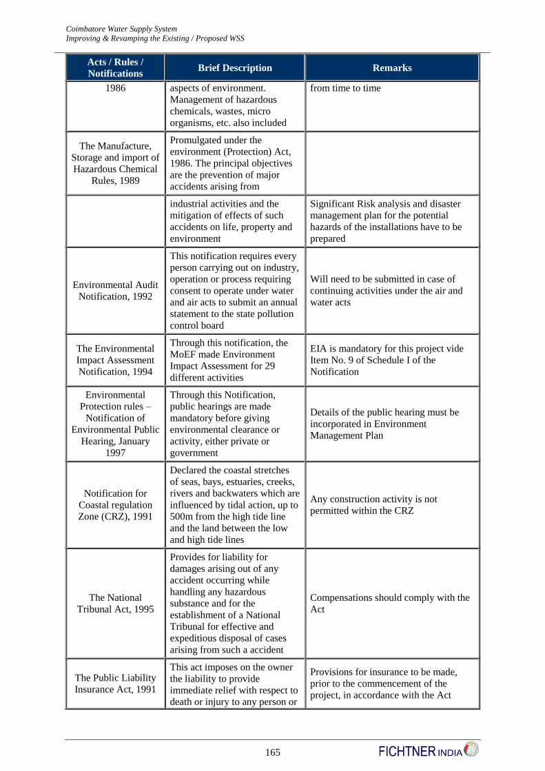
Coimbatore Water Supply System Detailed Project Report - Revision I
Improving & Revamping the Existing / Proposed WSS JNNURM
165
Acts / Rules /
Notifications Brief Description Remarks
1986 aspects of environment.
Management of hazardous
chemicals, wastes, micro
organisms, etc. also included
from time to time
The Manufacture,
Storage and import of
Hazardous Chemical
Rules, 1989
Promulgated under the
environment (Protection) Act,
1986. The principal objectives
are the prevention of major
accidents arising from
industrial activities and the
mitigation of effects of such
accidents on life, property and
environment
Significant Risk analysis and disaster
management plan for the potential
hazards of the installations have to be
prepared
Environmental Audit
Notification, 1992
This notification requires every
person carrying out on industry,
operation or process requiring
consent to operate under water
and air acts to submit an annual
statement to the state pollution
control board
Will need to be submitted in case of
continuing activities under the air and
water acts
The Environmental
Impact Assessment
Notification, 1994
Through this notification, the
MoEF made Environment
Impact Assessment for 29
different activities
EIA is mandatory for this project vide
Item No. 9 of Schedule I of the
Notification
Environmental
Protection rules –
Notification of
Environmental Public
Hearing, January
1997
Through this Notification,
public hearings are made
mandatory before giving
environmental clearance or
activity, either private or
government
Details of the public hearing must be
incorporated in Environment
Management Plan
Notification for
Coastal regulation
Zone (CRZ), 1991
Declared the coastal stretches
of seas, bays, estuaries, creeks,
rivers and backwaters which are
influenced by tidal action, up to
500m from the high tide line
and the land between the low
and high tide lines
Any construction activity is not
permitted within the CRZ
The National
Tribunal Act, 1995
Provides for liability for
damages arising out of any
accident occurring while
handling any hazardous
substance and for the
establishment of a National
Tribunal for effective and
expeditious disposal of cases
arising from such a accident
Compensations should comply with the
Act
The Public Liability
Insurance Act, 1991
This act imposes on the owner
the liability to provide
immediate relief with respect to
death or injury to any person or
Provisions for insurance to be made,
prior to the commencement of the
project, in accordance with the Act

Coimbatore Water Supply System Detailed Project Report - Revision I
Improving & Revamping the Existing / Proposed WSS JNNURM
166
Acts / Rules /
Notifications Brief Description Remarks
damage to any property
resulting from an accident
while handling any of the
notified hazardous chemicals
The Hazardous Waste
(Management and
handling) rules, 1989
Prescribe guidelines for
handling hazardous wastes
Must comply with the rules, in case of
generation of hazardous wastes during
the construction and operation phases of
the project.
2.10.5 Necessity for this EIA Study
It is necessary to study the environmental impact of the project so that necessary preventive and
corrective measures can be suggested to minimise the potential negative impacts of this project and
thereby secure maximum benefits to the people and the environment. This study involves the
following:
(a) Identification and assessment of all the likely environmental and social impacts of the
project components
(b) Development of an environmental management plan for making the project environmentally
sound and socially acceptable
(c) Recommendation of an appropriate monitoring mechanism for environmental management.
(d) Overall aim is to maximize the benefits of the project and minimize/mitigate environmental
and social risks due to the proposed project.
Environmental Impacts
Positive Impacts
Following are the positive environmental impacts of the project:
1. Social Impact due to provision of protected water supply.
2. The town is benefited with water supply.
3. Health of the community would be improved.
4. Improved community hygiene.
5. Local employment due to additional investment. Thereby local economy improves.
6. Improvement in social and economic status.
7. Additional water provided will help in fire safety.
8. Living conditions improves.
9. Decrease in water borne diseases
Coimbatore Water Supply System Detailed Project Report - Revision I
Improving & Revamping the Existing / Proposed WSS JNNURM
167
10. Women can utilize time spent for fetching water from long distances to other beneficial
purpose.
11. Noise and nuisance created by water tankers and lorries are avoided.
Negative Impacts
Following are the negative environmental impacts of the project:
1. Traffic is disturbed during laying water mains.
2. Dust problem during construction.
3. Communication facilities may get affected.
4. Noise near pumping station sites.
5. Disposition of water tanker owners.
6. Property & Economical assets are created which have to be maintained.
7. Health hazard in handling chemicals like chlorine.
8. Possibility of chlorine leakage.
2.10.6 Broad Paradigms for Mitigation Plan
1. Adequate safety signals to be provided like “Men at work”, “Take Diversion”, etc and
traffic to be effectively diverted.
2. Sprinkling of water can reduce dust.
3. Adequate care to be taken not to disturb the communication systems by identifying the
locations in consultation with the respective departments.
4. Noise can be reduced by proper design and maintenance and planting of trees around
sump cum pump houses. If required, glass partitions can be provided as sound barriers.
5. Carry out repairs wherever possible when traffic is minimum. Ensure good house
keeping.
6. Action would be taken for installation of sewerage system and storm water drainage
system and avoid stagnation of water.
7. Backwash water should be properly disposed of
8. All precautions would be taken to avoid leakage of chemicals during post chlorination.
The operators would be instructed regarding handling of chemicals, action to be taken in
case of emergency, etc.,

Coimbatore Water Supply System Detailed Project Report - Revision I
Improving & Revamping the Existing / Proposed WSS JNNURM
168
2.10.7 Resettlement and Rehabilitation Issues
As all the sites proposed for construction of new service reservoirs, ground level sumps etc., are
owned by Coimbatore Corporation, there will be no resettlement or rehabilitation issues to be
confronted during the implementation of this project.
2.10.8 Management of Noise Impacts
Following precautionary measures are recommended for the management of noise impacts.
1. To minimise the impact, construction operations in residential and sensitive areas should
be restricted to between 7.30 a.m. and 6.00 p.m.
2. Prior information should be provided if the blasting is significant.
3. Noise level should be reduced by provision of enclosures to generator sets and concrete
mixers at the sites.
4. Noise Level of Construction Machinery should not exceed the following limits
Construction Machinery dBA at 2 m Distance
Truck 85
Generator 96
Concrete Mixer 89
Flitting Mixer 85
Vibrator 86
Batching Plant 86
Crane 85
Permissible level 55 d BA
2.10.9 Managing Impacts due to Construction Machinery
Precautionary measures in order to avoid adverse impacts due to traffic congestion are as follows:
1. The most suitable route should be selected for delivery and haul equipment with due
consideration for load limits, traffic pattern and the character of the area traversed.
2. Traffic controls and diversions, marked with signs, lights and other measures (flags)
should be provided. This is necessary to minimise confusion and ensure public safety.
Police and fire departments should be informed before any route is closed. Also, routes
should not be closed until an alternative road is identified.
3. Prospective contractor should follow the prescribed safe, legal laid limits of all bridges
and surface roads that may be traversed by the heavy equipment used at the project sites.

Coimbatore Water Supply System Detailed Project Report - Revision I
Improving & Revamping the Existing / Proposed WSS JNNURM
169
2.10.10 Managing Impact of Air Pollution
Construction activities and the consequent transportation activities add to the air pollution in the
region. Impact of the air pollution will be moderate and short term while laying distribution lines.
Precautionary Measures
1. It is recommended that the construction equipment, machinery and diesel engines be
maintained in good condition so as to reduce emissions.
2. Dust should be controlled by sweeping and sprinkling with water. Mud should be washed
from all construction equipment and vehicles prior to hauling on roads.
3. Trucks carrying dust and sand to and from the construction site should be covered or
wetted in accordance with the construction specifications prescribed by the Coimbatore
City Corporation to minimise release of dust.
Potential Air Quality and Noise Impact Issues
Activity Location Impact
Pipeline laying Roadside areas Dust problem for Commuters and road users
Construction of Proposed
Service Reservoirs Reserved Site areas Dust problem for near by living habitants
Construction of Proposed
Sump cum Pumping
arranegments
Reserved Site areas Dust problem for near by living habitants
Pipeline laying
For laying of pipelines, the impacts on air quality during construction are due to generation of dust for
excavation and handling of construction materials. Dust generation during pipeline laying is important
because it passes by roadside which is used by commuters and local people.
After pipelines are laid underground and the trench is filled with soil, the topsoil is not often properly
compacted and the debris is left behind. This causes dust pollution for quite some period until the top
cover stabilizes. Dust pollution may therefore have a significant impact if not properly mitigated.
Short-term exposure to particulates can aggravate lung diseases, causing asthma attacks and acute
bronchitis and may also increase susceptibility to respiratory infections.
Construction of Service Reservoirs & Sump cum Pumps
Construction work for these infrastructures can be divided into three groups – excavation work,
foundation work and superstructure work. Certain foundation work may involve development of pile
driving rigs etc. These activities may generate noise pollution. Besides foundation work will involve
trench cutting, digging and concreting work. The work will involve steel and concrete work, masonry
work etc and will involve use of equipment like hoists, cranes, mixers, welding sets etc. There will be

Coimbatore Water Supply System Detailed Project Report - Revision I
Improving & Revamping the Existing / Proposed WSS JNNURM
170
dust, noise and gaseous pollution due to these works. The mechanical erection works involve
extensive use of mechanical equipment for storage, retrieval and erection, site fabrication etc leading
to some noise and air pollution. Since the construction of Service Reservoirs and Sump cum Pumps
are going to be in the reserved site areas of Coimbatore Corporation, only the habitants surrounding
the reserved site areas will be affected.
Environmental Management Plan - Construction Phase Impacts
Sl.
No. Issues Action to be taken
Responsible
Agencies
Time Frame
For
Implementation
Pre-
construction
Impacts
1.
Site clearance,
Flora and fauna
Impact on
vegetation
a. Adequate precaution
against damage to existing
structures, electricity and
telephone lines and other
infrastructure services
b. Site clearance will be
done only in the area
required for the project.
c. A minimum level of tree
plantation will be ensured.
No important species are
present in the area.
Prospective
Contractor
Prospective
Contractor
CCC
As per
Implementation
Schedule
As per
Implementation
Schedule
During the
period of
Construction of
Project
2. Storage of
Materials
a. Site for storage of pipes,
construction materials
and disposal of debris,
refuse, etc. to be
identified.
CCC
Before
Commencement
of the Project
Construction
Phase Impacts
3. Air Pollution
and Vibrations
a. Noisy construction
operations in residential
and sensitive areas should
be restricted between
7.30am to 6.00pm.
b. Provision of ear plugs to
operators of heavy
machinery and workers in
near vicinity
c. Preventive maintenance of
construction equipment
and vehicles to meet
emission standards and to
keep them with low
noise.
d. Provision for enclosing
Prospective
Contractor
-----do-----
-----do-----
-----do----
During the
period
of Project
execution
--------do--------
--------do--------
--------do--------
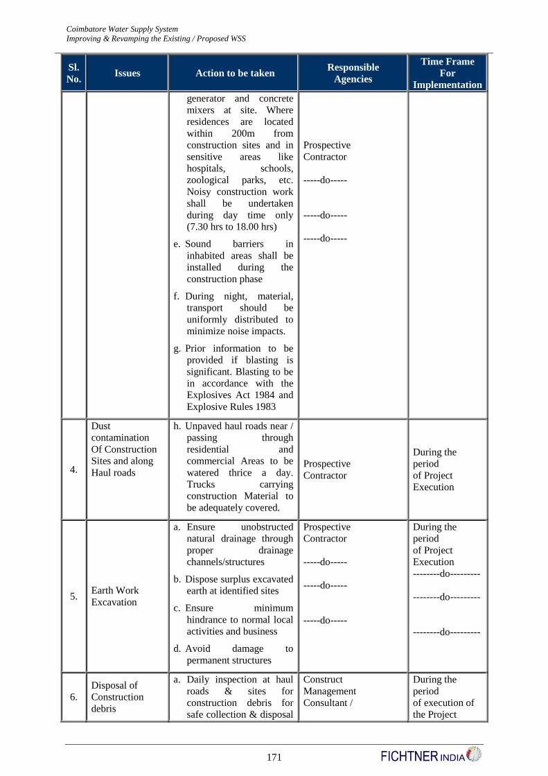
Coimbatore Water Supply System Detailed Project Report - Revision I
Improving & Revamping the Existing / Proposed WSS JNNURM
171
Sl.
No. Issues Action to be taken
Responsible
Agencies
Time Frame
For
Implementation
generator and concrete
mixers at site. Where
residences are located
within 200m from
construction sites and in
sensitive areas like
hospitals, schools,
zoological parks, etc.
Noisy construction work
shall be undertaken
during day time only
(7.30 hrs to 18.00 hrs)
e. Sound barriers in
inhabited areas shall be
installed during the
construction phase
f. During night, material,
transport should be
uniformly distributed to
minimize noise impacts.
g. Prior information to be
provided if blasting is
significant. Blasting to be
in accordance with the
Explosives Act 1984 and
Explosive Rules 1983
Prospective
Contractor
-----do-----
-----do-----
-----do-----
4.
Dust
contamination
Of Construction
Sites and along
Haul roads
h. Unpaved haul roads near /
passing through
residential and
commercial Areas to be
watered thrice a day.
Trucks carrying
construction Material to
be adequately covered.
Prospective
Contractor
During the
period
of Project
Execution
5. Earth Work
Excavation
a. Ensure unobstructed
natural drainage through
proper drainage
channels/structures
b. Dispose surplus excavated
earth at identified sites
c. Ensure minimum
hindrance to normal local
activities and business
d. Avoid damage to
permanent structures
Prospective
Contractor
-----do-----
-----do-----
-----do-----
During the
period
of Project
Execution
--------do---------
--------do---------
--------do---------
6.
Disposal of
Construction
debris
a. Daily inspection at haul
roads & sites for
construction debris for
safe collection & disposal
Construct
Management
Consultant /
During the
period
of execution of
the Project
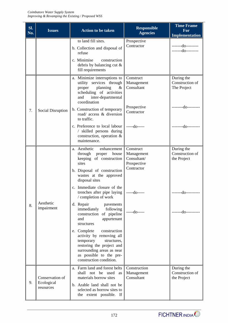
Coimbatore Water Supply System Detailed Project Report - Revision I
Improving & Revamping the Existing / Proposed WSS JNNURM
172
Sl.
No. Issues Action to be taken
Responsible
Agencies
Time Frame
For
Implementation
to land fill sites.
b. Collection and disposal of
refuse
c. Minimise construction
debris by balancing cut &
fill requirements
Prospective
Contractor
-------do---------
-------do---------
7. Social Disruption
a. Minimize interruptions to
utility services through
proper planning &
scheduling of activities
and inter-departmental
coordination
b. Construction of temporary
road/ access & diversion
to traffic.
c. Preference to local labour
/ skilled persons during
construction, operation &
maintenance.
Construct
Management
Consultant
Prospective
Contractor
-----do-----
During the
Construction of
The Project
--------do---------
--------do---------
8. Aesthetic
impairment
a. Aesthetic enhancement
through proper house
keeping of construction
sites
b. Disposal of construction
wastes at the approved
disposal sites
c. Immediate closure of the
trenches after pipe laying
/ completion of work
d. Repair pavements
immediately following
construction of pipeline
and appurtenant
structures
e. Complete construction
activity by removing all
temporary structures,
restoring the project and
surrounding areas as near
as possible to the pre-
construction condition.
Construct
Management
Consultant/
Prospective
Contractor
-----do-----
-----do-----
During the
Construction of
the Project
-------do----------
-------do----------
9.
Conservation of
Ecological
resources
a. Farm land and forest belts
shall not be used as
materials borrow sites
b. Arable land shall not be
selected as borrow sites to
the extent possible. If
Construction
Management
Consultant
During the
Construction of
the Project
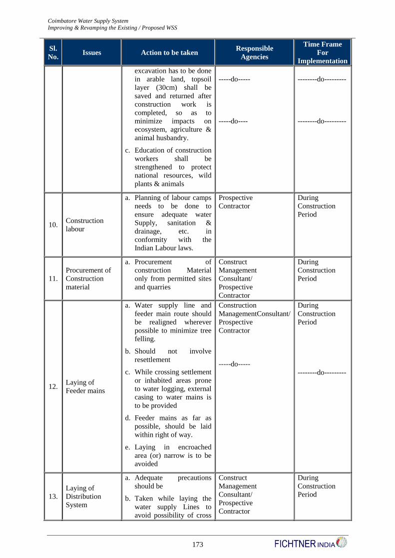
Coimbatore Water Supply System Detailed Project Report - Revision I
Improving & Revamping the Existing / Proposed WSS JNNURM
173
Sl.
No. Issues Action to be taken
Responsible
Agencies
Time Frame
For
Implementation
excavation has to be done
in arable land, topsoil
layer (30cm) shall be
saved and returned after
construction work is
completed, so as to
minimize impacts on
ecosystem, agriculture &
animal husbandry.
c. Education of construction
workers shall be
strengthened to protect
national resources, wild
plants & animals
-----do-----
-----do----
--------do---------
--------do---------
10. Construction
labour
a. Planning of labour camps
needs to be done to
ensure adequate water
Supply, sanitation &
drainage, etc. in
conformity with the
Indian Labour laws.
Prospective
Contractor
During
Construction
Period
11.
Procurement of
Construction
material
a. Procurement of
construction Material
only from permitted sites
and quarries
Construct
Management
Consultant/
Prospective
Contractor
During
Construction
Period
12. Laying of
Feeder mains
a. Water supply line and
feeder main route should
be realigned wherever
possible to minimize tree
felling.
b. Should not involve
resettlement
c. While crossing settlement
or inhabited areas prone
to water logging, external
casing to water mains is
to be provided
d. Feeder mains as far as
possible, should be laid
within right of way.
e. Laying in encroached
area (or) narrow is to be
avoided
Construction
ManagementConsultant/
Prospective
Contractor
-----do-----
During
Construction
Period
--------do---------
13.
Laying of
Distribution
System
a. Adequate precautions
should be
b. Taken while laying the
water supply Lines to
avoid possibility of cross
Construct
Management
Consultant/
Prospective
Contractor
During
Construction
Period
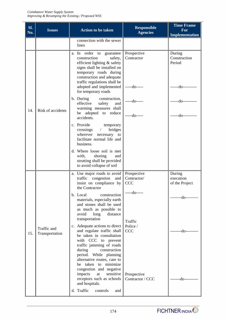
Coimbatore Water Supply System Detailed Project Report - Revision I
Improving & Revamping the Existing / Proposed WSS JNNURM
174
Sl.
No. Issues Action to be taken
Responsible
Agencies
Time Frame
For
Implementation
connection with the sewer
lines
14. Risk of accidents
a. In order to guarantee
construction safety,
efficient lighting & safety
signs shall be installed on
temporary roads during
construction and adequate
traffic regulations shall be
adopted and implemented
for temporary roads
b. During construction,
effective safety and
warming measures shall
be adopted to reduce
accidents.
c. Provide temporary
crossings / bridges
wherever necessary to
facilitate normal life and
business.
d. Where loose soil is met
with, shoring and
strutting shall be provided
to avoid collapse of soil
Prospective
Contractor
-----do-----
-----do-----
-----do-----
During
Construction
Period
------do----------
------do----------
------do----------
15.
Traffic and
Transportation
a. Use major roads to avoid
traffic congestion and
insist on compliance by
the Contractor
b. Local construction
materials, especially earth
and stones shall be used
as much as possible to
avoid long distance
transportation
c. Adequate actions to direct
and regulate traffic shall
be taken in consultation
with CCC to prevent
traffic jamming of roads
during construction
period. While planning
alternative routes, care to
be taken to minimize
congestion and negative
impacts at sensitive
receptors such as schools
and hospitals.
d. Traffic controls and
Prospective
Contractor/
CCC
-----do-----
Traffic
Police /
CCC
Prospective
Contractor / CCC
During
execution
of the Project
--------do---------
--------do---------
-------do----------
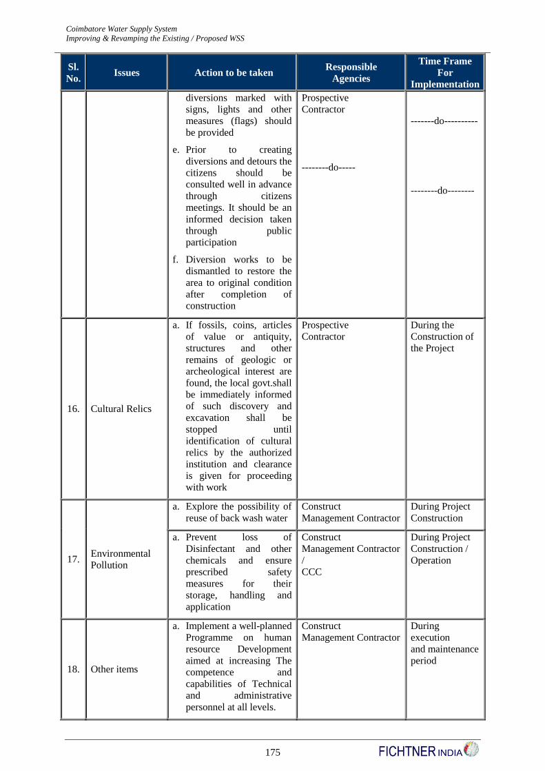
Coimbatore Water Supply System Detailed Project Report - Revision I
Improving & Revamping the Existing / Proposed WSS JNNURM
175
Sl.
No. Issues Action to be taken
Responsible
Agencies
Time Frame
For
Implementation
diversions marked with
signs, lights and other
measures (flags) should
be provided
e. Prior to creating
diversions and detours the
citizens should be
consulted well in advance
through citizens
meetings. It should be an
informed decision taken
through public
participation
f. Diversion works to be
dismantled to restore the
area to original condition
after completion of
construction
Prospective
Contractor
--------do-----
-------do----------
--------do--------
16. Cultural Relics
a. If fossils, coins, articles
of value or antiquity,
structures and other
remains of geologic or
archeological interest are
found, the local govt.shall
be immediately informed
of such discovery and
excavation shall be
stopped until
identification of cultural
relics by the authorized
institution and clearance
is given for proceeding
with work
Prospective
Contractor
During the
Construction of
the Project
17. Environmental
Pollution
a. Explore the possibility of
reuse of back wash water
Construct
Management Contractor
During Project
Construction
a. Prevent loss of
Disinfectant and other
chemicals and ensure
prescribed safety
measures for their
storage, handling and
application
Construct
Management Contractor
/
CCC
During Project
Construction /
Operation
18. Other items
a. Implement a well-planned
Programme on human
resource Development
aimed at increasing The
competence and
capabilities of Technical
and administrative
personnel at all levels.
Construct
Management Contractor
During
execution
and maintenance
period
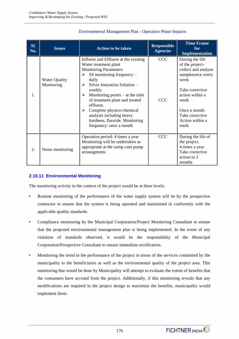
Coimbatore Water Supply System Detailed Project Report - Revision I
Improving & Revamping the Existing / Proposed WSS JNNURM
176
Environmental Management Plan - Operation Phase Impacts
Sl.
No. Issues Action to be taken
Responsible
Agencies
Time Frame
for
Implementation
1.
Water Quality
Monitoring
Influent and Effluent at the existing
Water treatment plant
Monitoring Parameters
SS monitoring frequency –
daily
Silver Ionisation Solution –
weekly
Monitoring points – at the inlet
of treatment plant and treated
effluent.
Complete physico-chemical
analysis including heavy
hardness, fluoride. Monitoring
frequency: once a month
CCC
CCC
During the life
of the project-
collect and analyze
samplesonce every
week
Take corrective
action within a
week
Once a month.
Take corrective
Action within a
week
2. Noise monitoring
Operation period: 4 times a year
Monitoring will be undertaken as
appropriate at the sump cum pump
arranegments
CCC During the life of
the project.
4 times a year.
Take corrective
action in 3
months
2.10.11 Environmental Monitoring
The monitoring activity in the context of the project would be at three levels:
Routine monitoring of the performance of the water supply system will be by the prospective
contractor to ensure that the system is being operated and maintained in conformity with the
applicable quality standards.
Compliance monitoring by the Municipal Corporation/Project Monitoring Consultant to ensure
that the proposed environmental management plan is being implemented. In the event of any
violation of standards observed, it would be the responsibility of the Municipal
Corporation/Prospective Consultant to ensure immediate rectification.
Monitoring the trend in the performance of the project in terms of the services committed by the
municipality to the beneficiaries as well as the environmental quality of the project area. This
monitoring that would be done by Municipality will attempt to evaluate the extent of benefits that
the consumers have accrued from the project. Additionally, if this monitoring reveals that any
modifications are required in the project design to maximize the benefits, municipality would
implement them.

Coimbatore Water Supply System Detailed Project Report - Revision I
Improving & Revamping the Existing / Proposed WSS JNNURM
177
Institutional Arrangements required
Having a Monitoring Agency to monitor environmental quality.
Review of outputs of the monitoring agency
Rationalise the environmental monitoring process.
Prepare Annual Environmental & Social Audit Report & Environmental Compliance Report.
Monitoring at this level would also be a form of disclosure monitoring used to keep the beneficiaries
of the project informed about its progress.
Implementation of mitigation measures may also sometimes give rise to impacts, which will be
recognized early if rigorous monitoring is ensured. The monitoring plan should also provide for
periodic revision of the measures. The plan is described in following Table covers the monitoring
requirements at all levels during operation phase. It provides the monitoring requirement for each
impact/issue identified earlier and the responsible agencies.
Environmental Management Plan - Construction Phase Impacts
Sl.
No. Monitoring Requirement Specifications
Responsible
Agency
1. a. Ambient air quality at six fixed
stations to understand the
impact of change in traffic
pattern due to the project
b. Moving Station (1 no.) at the
construction site (only during
construction period) to
understand the impact of
construction operations.
SPM, Oxides of Nitrogen, CO,
Co2
SPM, Oxides of
Nitrogen, CO, Co2
Coimbatore City
Corporation
Coimbatore City
Corporation
2.
Noise levels at the construction
sites (only during construction
period)
Fortnightly monitoring at 2
locations, hourly basis for 24
hour period.
Coimbatore City
Corporation
3. Disposal of Construction Debris
Periodic inspection at
2 locations on hourly basis for
24 hour period.
Coimbatore City
Corporation
4. Traffic and Transportation
Measures for diverting the traffic
during construction across
district roads and roads within
the Municipal Corporation
Coimbatore City
Corporation (once
a week)
5.
Domestic Sewage and refuse
management at the labour camps
and construction sites
Check for adequacy of sanitation
arrangements at the labour
camps
Coimbatore City
Corporation (once a
week)
6. Water Pollution
Check for
a. blockage of flowing water
which may lead to stagnation
of water
Coimbatore City
Corporation (once
in 15 days)

Coimbatore Water Supply System Detailed Project Report - Revision I
Improving & Revamping the Existing / Proposed WSS JNNURM
178
Sl.
No. Monitoring Requirement Specifications
Responsible
Agency
b. soil erosion due to
construction activities leading
to contamination and siltation
of water bodies
c. water contamination due to
use of fuel and lubricants at
the construction sites
7. Procurement of construction
material
Procurement from be only
permitted sites
Project
Management
Consultant
Environmental Management Plan - Operation Phase Impacts
Sl.
No. Monitoring Requirement Specifications Responsible Agency
1. Water Quality at Service
reservoir
a. Monitoring parameter: Chemical
Quality: Monitoring point - At
outlet of MSR, SRs
b. Monitoring Frequency: 2
locations & 3 samples per
location
Coimbatore City
Corporation
2. Water Quality at Consumer
end
a. Monitoring Parameter:
Bacteriological quality &
Residual Chlorine - Monitoring
point: At receiving point of the
consumer
b. Monitoring frequency: Weekly
Coimbatore City
Corporation (once a
week)
2.10.12 Impact during Design Phase
The major impact associated with Design or Pre-construction phase deals with loss of land, loss of
natural habitat, loss of properties and livelihood due to acquisition of properties. The design of
alignment also decides the acquiring or impacting water-bodies, forest, cultural sites etc. The Design
phase takes into account these issues along with environmental and social specialists to minimize the
impact. Besides the impact on environment and social factors, other issues were also considered like
legal issues and compliance norms, to facilitate the implementation process.
For the present project there will be no new requirement of land to be procured, as new service
reservoirs, underground sumps etc., will be accommodated in the corporation land already available.
New main pipeline will be in the same alignment as that of the existing ones, however the additional
line for the distribution will be along the road where there is enough apron land. Desilting wastes will
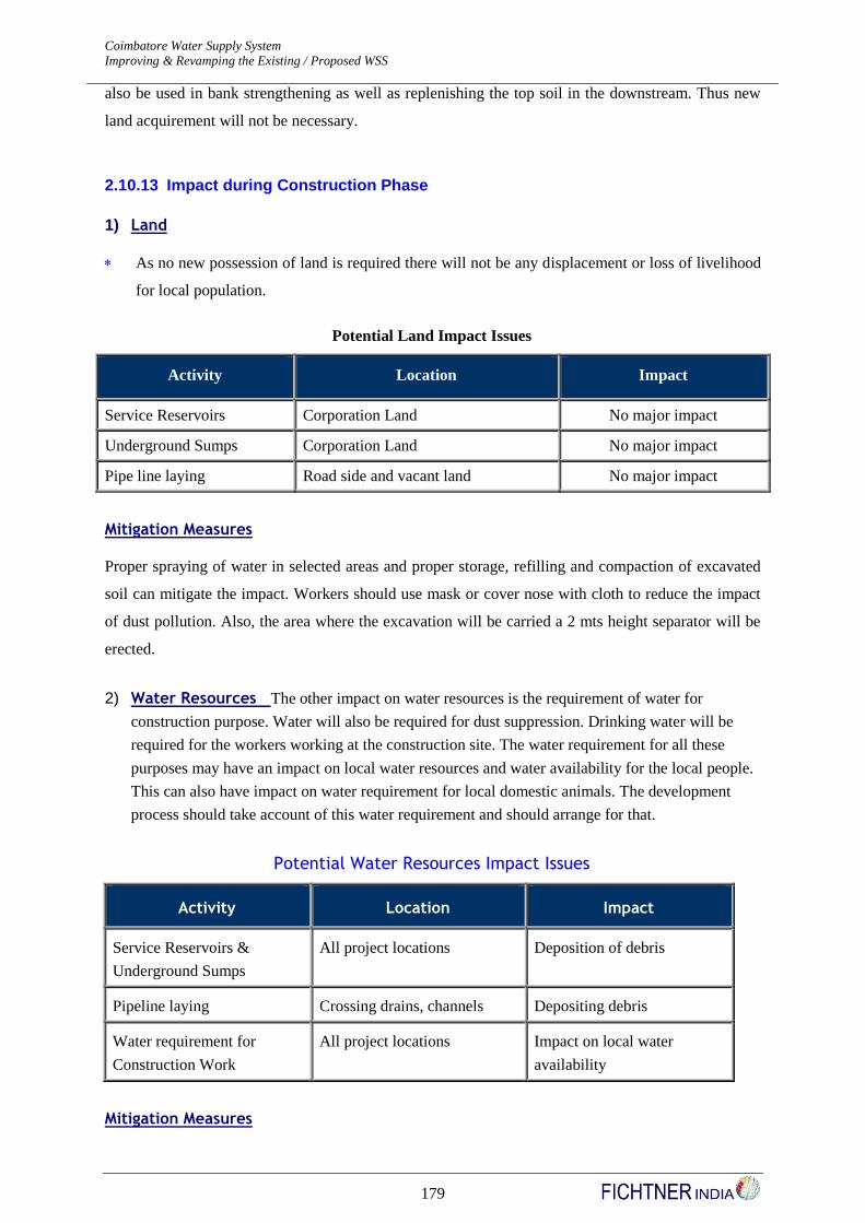
Coimbatore Water Supply System Detailed Project Report - Revision I
Improving & Revamping the Existing / Proposed WSS JNNURM
179
also be used in bank strengthening as well as replenishing the top soil in the downstream. Thus new
land acquirement will not be necessary.
2.10.13 Impact during Construction Phase
1) Land
As no new possession of land is required there will not be any displacement or loss of livelihood
for local population.
Potential Land Impact Issues
Activity Location Impact
Service Reservoirs Corporation Land No major impact
Underground Sumps Corporation Land No major impact
Pipe line laying Road side and vacant land No major impact
Mitigation Measures
Proper spraying of water in selected areas and proper storage, refilling and compaction of excavated
soil can mitigate the impact. Workers should use mask or cover nose with cloth to reduce the impact
of dust pollution. Also, the area where the excavation will be carried a 2 mts height separator will be
erected.
2) Water Resources The other impact on water resources is the requirement of water for
construction purpose. Water will also be required for dust suppression. Drinking water will be
required for the workers working at the construction site. The water requirement for all these
purposes may have an impact on local water resources and water availability for the local people.
This can also have impact on water requirement for local domestic animals. The development
process should take account of this water requirement and should arrange for that.
Potential Water Resources Impact Issues
Activity Location Impact
Service Reservoirs &
Underground Sumps
All project locations Deposition of debris
Pipeline laying Crossing drains, channels Depositing debris
Water requirement for
Construction Work
All project locations Impact on local water
availability
Mitigation Measures
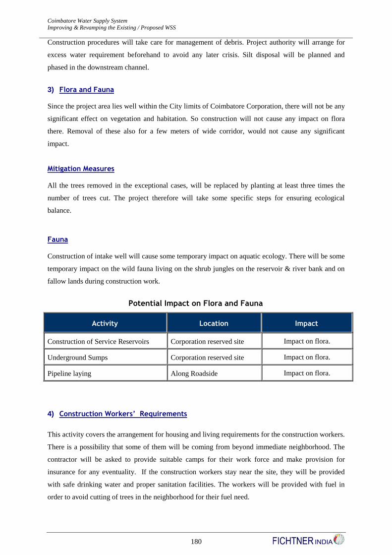
Coimbatore Water Supply System Detailed Project Report - Revision I
Improving & Revamping the Existing / Proposed WSS JNNURM
180
Construction procedures will take care for management of debris. Project authority will arrange for
excess water requirement beforehand to avoid any later crisis. Silt disposal will be planned and
phased in the downstream channel.
3) Flora and Fauna
Since the project area lies well within the City limits of Coimbatore Corporation, there will not be any
significant effect on vegetation and habitation. So construction will not cause any impact on flora
there. Removal of these also for a few meters of wide corridor, would not cause any significant
impact.
Mitigation Measures
All the trees removed in the exceptional cases, will be replaced by planting at least three times the
number of trees cut. The project therefore will take some specific steps for ensuring ecological
balance.
Fauna
Construction of intake well will cause some temporary impact on aquatic ecology. There will be some
temporary impact on the wild fauna living on the shrub jungles on the reservoir & river bank and on
fallow lands during construction work.
Potential Impact on Flora and Fauna
Activity Location Impact
Construction of Service Reservoirs Corporation reserved site Impact on flora.
Underground Sumps Corporation reserved site Impact on flora.
Pipeline laying Along Roadside Impact on flora.
4) Construction Workers’ Requirements
This activity covers the arrangement for housing and living requirements for the construction workers.
There is a possibility that some of them will be coming from beyond immediate neighborhood. The
contractor will be asked to provide suitable camps for their work force and make provision for
insurance for any eventuality. If the construction workers stay near the site, they will be provided
with safe drinking water and proper sanitation facilities. The workers will be provided with fuel in
order to avoid cutting of trees in the neighborhood for their fuel need.

Coimbatore Water Supply System Detailed Project Report - Revision I
Improving & Revamping the Existing / Proposed WSS JNNURM
181
2.10.14 Impact during Operation Phase
Operation of water collection, storage and supply will generate solid, liquid and gaseous effluents.
Their impacts are discussed below.
1) Air Quality
During normal operation of water supply scheme, there will be no generation of gaseous effluents and
thus no impact on air quality.
However if DG sets are used for emergency activities during power cut, then the impact on air quality
should be considered. In that case proper height of exhaust, acoustic cover etc. as per acts will be
followed.
2) Noise
Generally there will be no noise pollution during the water supply for the people outside. The DG set
used for the emergency operation will be silent eco-generator sets.
3) Effluent generated from additional water supplied (Sewage contribution)
Under the scope of this project, there is expected to be an impact on the volume of waste water
generated after implementation of the water supply augmentation works. The additional quantity of
water to be supplied in future will trigger an additional load on the sewerage system and hence this
will have to be factored in the proposed sewerage project.
Therefore, the sewerage infrastructure of the CCC has to be improved to meet the impact of the
project water supply augmentation. A Sewerage project has been proposed which includes laying of
sewer network, intermediate pumping stations and road restoration works. In addition to the above
proposal, it is proposed to construct 100 Nos of Public toilets across various locations in the city units
for enhancing the sanitation facilities.
Reuse of treated sewage effluent for irrigation purpose, financial resource generation from sewage by
selling the sludge to farmers as manure, private sector participation in monitoring the sewage &
effluent treatment units has been listed in the City Development Plan for Coimbatore.
2.10.15 Impact Identification Matrix
Relevant components of environment, which are likely to experience some impacts due to the project
activities, have been identified above. Environmental parameters are broadly classified under two
groups:

Coimbatore Water Supply System Detailed Project Report - Revision I
Improving & Revamping the Existing / Proposed WSS JNNURM
182
1) Physical Environment
2) Biological Environment
The parameter selected for impact identification is site and project specific. Different parameters
considered under the said groups are as follows:
Topography
Hydrology
Water Quality PHYSICAL ENVIRONMENT
Air Quality
Noise and
Flora
Fauna BIOLOGICAL ENVIRONMENT
Aquatic Life
The interaction between project activities (construction and operation phase) and environmental
parameters described above are shown in the following table depicting Identification matrix. The
matrix points out each activity and its impact on specific environmental parameters. This is a
qualitative work and does not indicate quantitative impact. Some of the impacts are temporary and
localized and some impacts have permanent effect.
Environmental Impact Matrix
ACTIVITY
PHYSICAL ENVIRONMENT
ECOLOGICAL ENVIRONMEN
T
Topo graphy Hydro logy Water Quality
Air Qualit
y
Noise
Flora Fauna Aquatic Ecology
Construction Phase
Construction of Service Reservoirs
X X X X
Construction of Underground Sumps
X X X X X
Pipeline laying X X
Construction Workers’ Requirement
X X
Operation- Phase
Gaseous Effluent from DG Set
X
Coimbatore Water Supply System Detailed Project Report - Revision I
Improving & Revamping the Existing / Proposed WSS JNNURM
183
2.10.16 Environmental and Social Classification
As per environmental and social screening, this project is classified under S-3 category. The
implication is that there are no households involved and the number of project affected persons (PAP)
is nil. As per environmental categorization of urban infrastructure projects, water supply project fall
under E-3 category.
2.10.17 Specialized Services for PMC and Quality Assurance
Typically, it is envisaged that the PMC works and associated components namely Capacity Building,
Institutional Strengthening, IEC activities, Transaction costs will approximately work out to 5% of the
total Project Cost. However on the ground level the project “may” require some further investigation
on technical and institutional part during implementation phase. A special fund provision for this will
be made in the budget.

Coimbatore Water Supply System Detailed Project Report - Revision I
Improving & Revamping the Existing / Proposed WSS JNNURM
184
3 Project Cost
3.1 Basis of Costing
The cost estimate for the water supply improvement is prepared based on the following references:
TWAD Schedule of Rates for the year 2014-2015
Lead Statement and Rate Analysis of Coimbatore Corporation
3.2 Land acquisition / Site Development
Based on the data provided by the Coimbatore City Corporation, land availability for all the
components are investigated and identified for availability. The land details such as survey number,
extent of land available are furnished in Table No.2.51 Volume I (a), Report part of this DPR.
3.3 Physical Infrastructure Component Cost
A summary of the physical infrastructure component costs estimated for the proposed improvements
is presented in Table No. 3.1 as below.
GENERAL COST ABSTRACT
Coimbatore Water Supply System - Revised Final DPR (Schedule of Rates 2016-2017)
Sl
No Description
Base Cost of the
Project
Base Cost of the
Project (Rs in
Lakhs)
I Feeder Mains, Sumps & Pump Room, Pumpsets &
Generators
A. Feeder Mains
1 Pillur System
a) Feeder Main I from Proposed MSR at Ramakrishnapuram to
Proposed SR at Bharathi Nagar (Gravity) – 33.20 Kms 26,57,43,583 2657.44
b)
Feeder Main II from Existing MSR at Ramakrsihnapuram to
Proposed SR at Lakshmi Nagar Mill Colony (Gravity) –
28.41 Kms 34,03,22,554 3403.23
c) Feeder Main III from Existing MSR at Ramakrishnapuram to
Proposed sump at Rakkatchi Garden (Gravity) – 2.37 Kms 1,53,97,395 153.95
d) Feeder Main IV from Proposed Sump at Rakkatchi Garden to
Existing SR at Jai Nagar (Pumping) – 9.98 Kms 4,05,24,788 405.25
2 Siruvani System
a) Feeder Main I - From Existing MSR at Bharathi Park to
Proposed SR at Housing Unit (By Gravity) – 13.82 Kms 12,50,49,275 1250.49
b)
Feeder Main II - From Existing MSR at Bharathi Park to
Proposed Sump at Sanganur Chinthamani (By Gravity) –
1.36 Kms 2,06,33,654 206.34
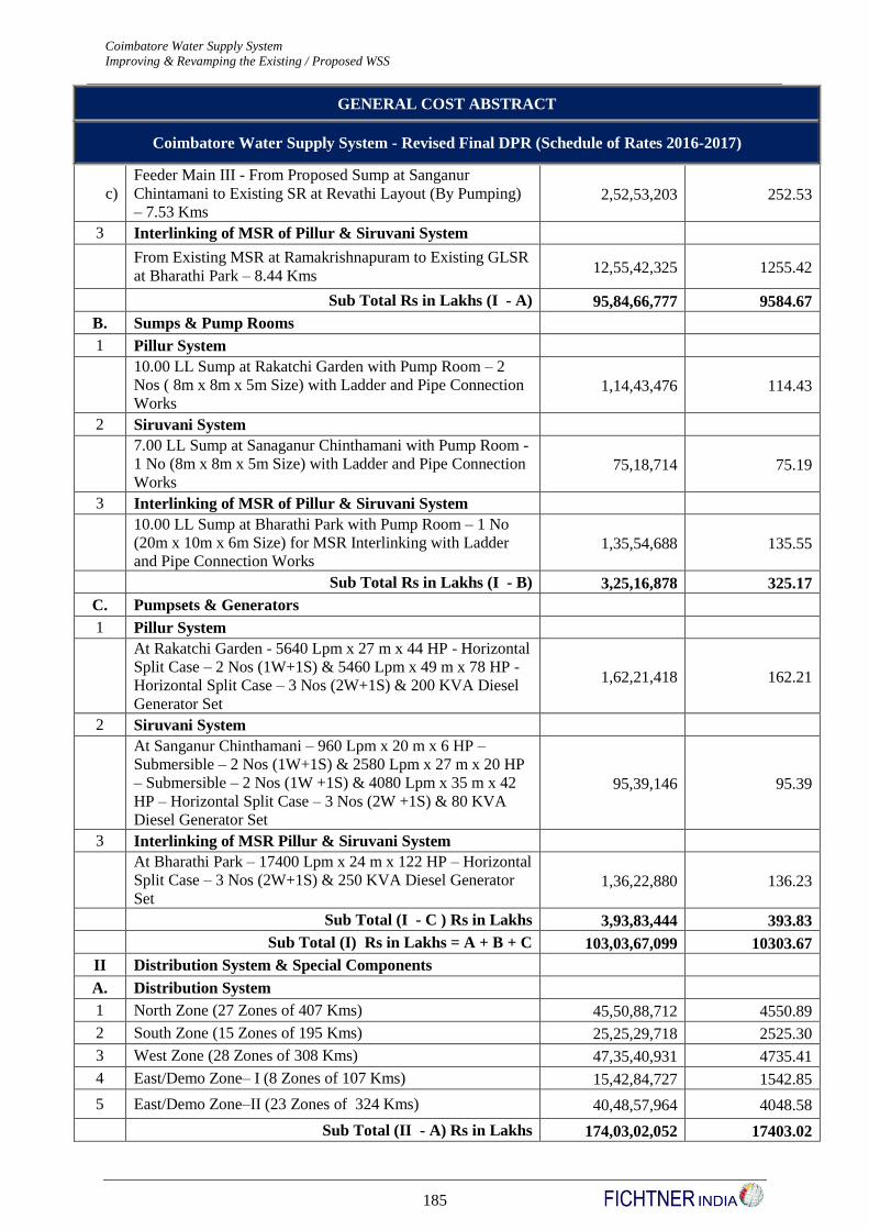
Coimbatore Water Supply System Detailed Project Report - Revision I
Improving & Revamping the Existing / Proposed WSS JNNURM
185
GENERAL COST ABSTRACT
Coimbatore Water Supply System - Revised Final DPR (Schedule of Rates 2016-2017)
c)
Feeder Main III - From Proposed Sump at Sanganur
Chintamani to Existing SR at Revathi Layout (By Pumping)
– 7.53 Kms 2,52,53,203 252.53
3 Interlinking of MSR of Pillur & Siruvani System
From Existing MSR at Ramakrishnapuram to Existing GLSR
at Bharathi Park – 8.44 Kms 12,55,42,325 1255.42
Sub Total Rs in Lakhs (I - A) 95,84,66,777 9584.67
B. Sumps & Pump Rooms
1 Pillur System
10.00 LL Sump at Rakatchi Garden with Pump Room – 2
Nos ( 8m x 8m x 5m Size) with Ladder and Pipe Connection
Works 1,14,43,476 114.43
2 Siruvani System
7.00 LL Sump at Sanaganur Chinthamani with Pump Room -
1 No (8m x 8m x 5m Size) with Ladder and Pipe Connection
Works 75,18,714 75.19
3 Interlinking of MSR of Pillur & Siruvani System
10.00 LL Sump at Bharathi Park with Pump Room – 1 No
(20m x 10m x 6m Size) for MSR Interlinking with Ladder
and Pipe Connection Works 1,35,54,688 135.55
Sub Total Rs in Lakhs (I - B) 3,25,16,878 325.17
C. Pumpsets & Generators
1 Pillur System
At Rakatchi Garden - 5640 Lpm x 27 m x 44 HP - Horizontal
Split Case – 2 Nos (1W+1S) & 5460 Lpm x 49 m x 78 HP -
Horizontal Split Case – 3 Nos (2W+1S) & 200 KVA Diesel
Generator Set
1,62,21,418 162.21
2 Siruvani System
At Sanganur Chinthamani – 960 Lpm x 20 m x 6 HP –
Submersible – 2 Nos (1W+1S) & 2580 Lpm x 27 m x 20 HP
– Submersible – 2 Nos (1W +1S) & 4080 Lpm x 35 m x 42
HP – Horizontal Split Case – 3 Nos (2W +1S) & 80 KVA
Diesel Generator Set
95,39,146 95.39
3 Interlinking of MSR Pillur & Siruvani System
At Bharathi Park – 17400 Lpm x 24 m x 122 HP – Horizontal
Split Case – 3 Nos (2W+1S) & 250 KVA Diesel Generator
Set 1,36,22,880 136.23
Sub Total (I - C ) Rs in Lakhs 3,93,83,444 393.83
Sub Total (I) Rs in Lakhs = A + B + C 103,03,67,099 10303.67
II Distribution System & Special Components
A. Distribution System
1 North Zone (27 Zones of 407 Kms) 45,50,88,712 4550.89
2 South Zone (15 Zones of 195 Kms) 25,25,29,718 2525.30
3 West Zone (28 Zones of 308 Kms) 47,35,40,931 4735.41
4 East/Demo Zone– I (8 Zones of 107 Kms) 15,42,84,727 1542.85
5 East/Demo Zone–II (23 Zones of 324 Kms) 40,48,57,964 4048.58
Sub Total (II - A) Rs in Lakhs 174,03,02,052 17403.02

Coimbatore Water Supply System Detailed Project Report - Revision I
Improving & Revamping the Existing / Proposed WSS JNNURM
186
GENERAL COST ABSTRACT
Coimbatore Water Supply System - Revised Final DPR (Schedule of Rates 2016-2017)
B. Special Components
1
Automatic Hand Held Meter Reading System (5 Nos – 1 No
for each Zone) & Data Collection Software (5 Nos – 1 No for
each Zone ) 1,28,00,000 128.00
2 Any Time Payment Machine (5 Nos – 1 No for each Zone) 25,87,500 25.88
3
Bulk Water Meter with Data Logger for Flow & Pressure
Measurment & Pressure Control Valve & Data Logger Room
(101 Nos – 1 No for each D’System Sub Zone) 27,10,52,694 2710.53
4 Gas Chlorination Disinfection (2 Sets – 1 No for each MSR) 1,08,32,756 108.33
5 House Service Connection Meters (75,000 Nos as AMR
Meters) 117,81,97,500 117,81.98
6
Rider Mains of 90 Kms Length in all 5 Zones (23 Kms in
North Zone, 11 Kms in South, 30 Kms in West, 9 Kms in
East Zone I & 17 Kms in East Zone II) 2,92,61,141 292.61
Sub Total (II - B) Rs in Lakhs 1504731591 15047.32
Sub Total (II) Rs in Lakhs = A + B 324,50,33,643 32450.34
III Service Reservoirs & Pipe Connections
A. North Zone
20 LL – 15 m Staging Height – 2 Nos 5,54,64,208 554.64
20 LL – 12 m Staging Height – 1 No 2,36,00,026 236.00
18 LL – 15 m Staging Height – 2 Nos 5,39,58,926 539.59
9 LL – 15 m Staging Height – 2 Nos 2,56,77,792 256.78
7 LL – 15 m Staging Height – 1 No 1,03,07,351 103.07
Sub Total (IV - A) Rs in Lakhs 16,90,08,303 1690.08
B. South Zone
19 LL – 15 m Staging Height – 1 No 25,849,737 258.50
16 LL – 15m Staging Height – 2 Nos 51,613,019 516.13
12 LL – 15m Staging Height – 1 No 18,077,404 180.77
9 LL – 12 m Staging Height – 1 No 11,514,534 115.15
7 LL – 12 m Staging Height – 1 No 9,091,952 90.92
4 LL – 15 m Staging Height – 1 No 5,994,454 59.94
Sub Total (IV - B) Rs in Lakhs 122,141,100 1221.41
C. West Zone
20 LL – 15 m Staging Height – 2 Nos 5,36,91,137 536.91
20 LL – 12 m Staging Height – 1 No 2,53,36,645 253.37
18 LL – 15 m Staging Height – 1 No 2,77,71,681 277.72
12 LL – 15 m Staging Height – 1 No 17,771,613 177.72
Sub Total (IV - C) Rs in Lakhs 12,45,71,076 1245.71
D. East / Demo Zone I
18 LL – 12 m Staging Height – 1 No 2,48,52,448 248.52
Sub Total (IV - D) Rs in Lakhs 2,48,52,448 248.52
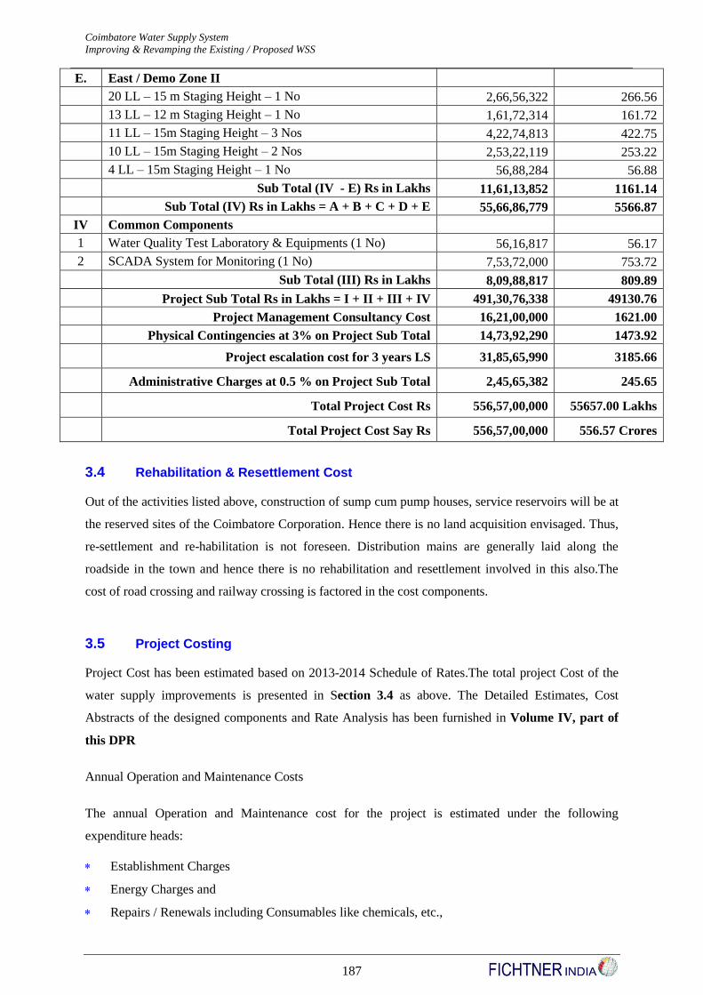
Coimbatore Water Supply System Detailed Project Report - Revision I
Improving & Revamping the Existing / Proposed WSS JNNURM
187
E. East / Demo Zone II
20 LL – 15 m Staging Height – 1 No 2,66,56,322 266.56
13 LL – 12 m Staging Height – 1 No 1,61,72,314 161.72
11 LL – 15m Staging Height – 3 Nos 4,22,74,813 422.75
10 LL – 15m Staging Height – 2 Nos 2,53,22,119 253.22
4 LL – 15m Staging Height – 1 No 56,88,284 56.88
Sub Total (IV - E) Rs in Lakhs 11,61,13,852 1161.14
Sub Total (IV) Rs in Lakhs = A + B + C + D + E 55,66,86,779 5566.87
IV Common Components
1 Water Quality Test Laboratory & Equipments (1 No) 56,16,817 56.17
2 SCADA System for Monitoring (1 No) 7,53,72,000 753.72
Sub Total (III) Rs in Lakhs 8,09,88,817 809.89
Project Sub Total Rs in Lakhs = I + II + III + IV 491,30,76,338 49130.76
Project Management Consultancy Cost 16,21,00,000 1621.00
Physical Contingencies at 3% on Project Sub Total 14,73,92,290 1473.92
Project escalation cost for 3 years LS 31,85,65,990 3185.66
Administrative Charges at 0.5 % on Project Sub Total 2,45,65,382 245.65
Total Project Cost Rs 556,57,00,000 55657.00 Lakhs
Total Project Cost Say Rs 556,57,00,000 556.57 Crores
3.4 Rehabilitation & Resettlement Cost
Out of the activities listed above, construction of sump cum pump houses, service reservoirs will be at
the reserved sites of the Coimbatore Corporation. Hence there is no land acquisition envisaged. Thus,
re-settlement and re-habilitation is not foreseen. Distribution mains are generally laid along the
roadside in the town and hence there is no rehabilitation and resettlement involved in this also.The
cost of road crossing and railway crossing is factored in the cost components.
3.5 Project Costing
Project Cost has been estimated based on 2013-2014 Schedule of Rates.The total project Cost of the
water supply improvements is presented in Section 3.4 as above. The Detailed Estimates, Cost
Abstracts of the designed components and Rate Analysis has been furnished in Volume IV, part of
this DPR
Annual Operation and Maintenance Costs
The annual Operation and Maintenance cost for the project is estimated under the following
expenditure heads:
Establishment Charges
Energy Charges and
Repairs / Renewals including Consumables like chemicals, etc.,

Coimbatore Water Supply System Detailed Project Report - Revision I
Improving & Revamping the Existing / Proposed WSS JNNURM
188
Maintenance expenses incurred by components like ATP Machine, etc.,
Establishment charges are calculated based on the staff strength required as per the norms stipulated
in the CPHEEO manual for water supply and furnished as below in Table No. 3.2
Staff Pattern (as per CPHEEO Norms) (Only for Distribution System)
Sl
No Category of Staff
Num
bers CPHEEO Norms
1 Valve Operator for 2 MSR (2 Nos) 4 Nos 2 x 2 shift
2
Supervisor / Asst Manager - Pillur
Mains I, II,III & IV and Siruvani
Mains I, II, III
7 Nos 1 No for each network
3
Fitters for Pumping main
Pillur - 9.98 Km & Siruvani - 7.53
Km
6 Nos 2 nos for every 6 km
Fitters for Gravity main
Pillur - 63.98 Km & Siruvani - 15.19
Km
MSR Interlinking - 8.44 Km
29
Nos 2 nos for every 6 km
Fitters for MSR & Sump cum
pumping arrangements 8 Nos 4 x 2 shift
4
Electrician / Mechanic (2 MSR + 2
Pump cum sumping - 1 for MSR + 1
for PS)
4 Nos 2 x 2 shift
5 Helpers (Mazdoor category grade I)
for Distribution system (101 zones)
101
Nos 1 no for each zone
6 Watchman for Service reservoir (63
Nos)
126
Nos 1 no x 2 shift
Watchman for MSR (2 MSR - 12 hr
shift - 2 shifts/day) 4 Nos 1 no x 2 shift
7
Billing & Collection of water charges
a) Water Meter Reader to read 1.5
Lakhs Connection
300
Nos
One for every 500 connection to be read
monthly or a minimum of one if less than
500 connection (includes leave reserve / shift
duty also)
8 c) Water rate collectors to collect
rates for 1.5 Lakhs Connection
100
Nos
One for every 1500 monthly billed
connections
9 d) Water rate superintendent for 1.5
Lakhs Connection
25
Nos
One for every 6000 billed connection
monthly
10
e) Meter repairer (assuming 5% of
meters fails per month = 150000 x
0.05 = 7500 nos)
94
Nos
One for every 80 meters per month to be
repaired
11 f) Assistant meter repairer 94
Nos
One for every 80 meters per month to be
repaired
12 Water Analyst (Chemical) 1 Nos
13 Water Analyst (Bacteriological) 1 Nos
14 Laboratory Technician 3 Nos
15 Typist cum Clerk 1 Nos
16 Water Sample Takers 3 Nos
17 Laboratory Cleaners 3 Nos
18 SCADA Operators (Techncial) for
entire Scheme at Central Control 3 Nos 1 x 3 shifts
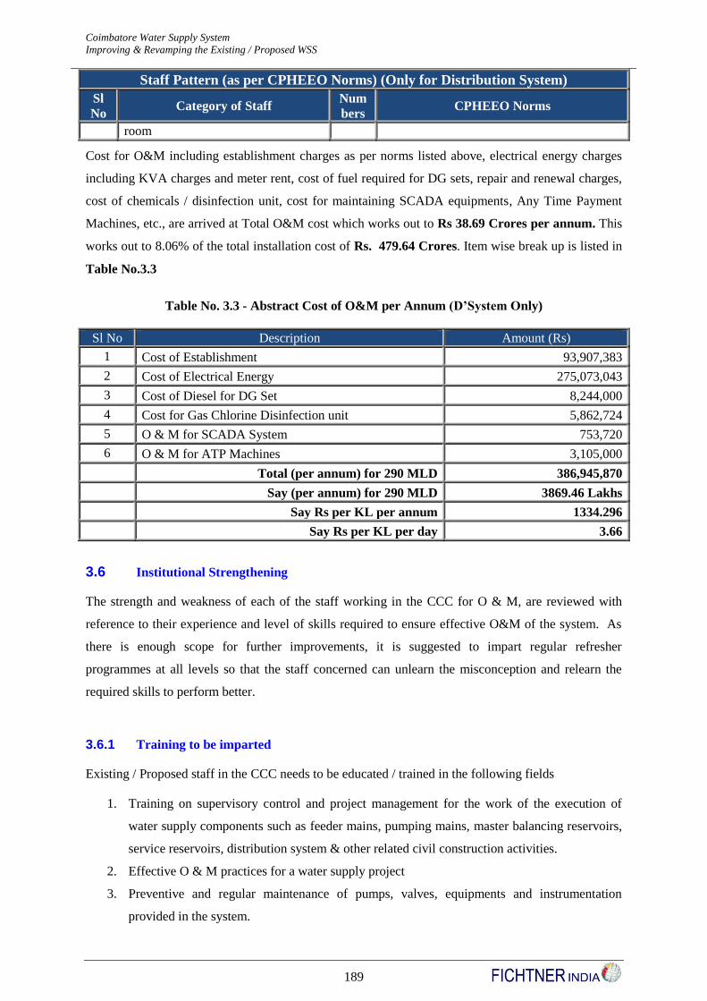
Coimbatore Water Supply System Detailed Project Report - Revision I
Improving & Revamping the Existing / Proposed WSS JNNURM
189
Staff Pattern (as per CPHEEO Norms) (Only for Distribution System)
Sl
No Category of Staff
Num
bers CPHEEO Norms
room
Cost for O&M including establishment charges as per norms listed above, electrical energy charges
including KVA charges and meter rent, cost of fuel required for DG sets, repair and renewal charges,
cost of chemicals / disinfection unit, cost for maintaining SCADA equipments, Any Time Payment
Machines, etc., are arrived at Total O&M cost which works out to Rs 38.69 Crores per annum. This
works out to 8.06% of the total installation cost of Rs. 479.64 Crores. Item wise break up is listed in
Table No.3.3
Table No. 3.3 - Abstract Cost of O&M per Annum (D’System Only)
Sl No Description Amount (Rs)
1 Cost of Establishment 93,907,383
2 Cost of Electrical Energy 275,073,043
3 Cost of Diesel for DG Set 8,244,000
4 Cost for Gas Chlorine Disinfection unit 5,862,724
5 O & M for SCADA System 753,720
6 O & M for ATP Machines 3,105,000
Total (per annum) for 290 MLD 386,945,870
Say (per annum) for 290 MLD 3869.46 Lakhs
Say Rs per KL per annum 1334.296
Say Rs per KL per day 3.66
3.6 Institutional Strengthening
The strength and weakness of each of the staff working in the CCC for O & M, are reviewed with
reference to their experience and level of skills required to ensure effective O&M of the system. As
there is enough scope for further improvements, it is suggested to impart regular refresher
programmes at all levels so that the staff concerned can unlearn the misconception and relearn the
required skills to perform better.
3.6.1 Training to be imparted
Existing / Proposed staff in the CCC needs to be educated / trained in the following fields
1. Training on supervisory control and project management for the work of the execution of
water supply components such as feeder mains, pumping mains, master balancing reservoirs,
service reservoirs, distribution system & other related civil construction activities.
2. Effective O & M practices for a water supply project
3. Preventive and regular maintenance of pumps, valves, equipments and instrumentation
provided in the system.

Coimbatore Water Supply System Detailed Project Report - Revision I
Improving & Revamping the Existing / Proposed WSS JNNURM
190
4. Preventive measures for corrosion related issues of water mains.
5. Communication & Public relations.
6. Training to handle field kits for testing of water quality.
7. Training for Fitters / field workers to provide new house service connections with MDPE
pipes and electro fusion saddle pieces.
8. Training for field staff in maintenance of the water supply distribution net works with
equitable pressures and design concepts for extension of distribution networks.
9. Training for handling leak detection equipments and SCADA.
10. Training for handling special equipments like Automatic Meter Reading (AMR) system, Any
Time Payment (ATP) machine, Water meter test bench, Automatic Pressure Management
System (PMS), Billing & Collection software systems, etc.,

Coimbatore Water Supply System Detailed Project Report - Revision I
Improving & Revamping the Existing / Proposed WSS JNNURM
191
4 Project Institution Framework
4.1 Roles of Different Institutions
Fulfillment of the objective of increased hours of water supply with high level of consumer
satisfaction calls for substantial capital investment with legal covenants on the rehabilitation of
distribution system including service lines and consumer metering, preparation of accurate network
maps and data bases, installation of state of the art computer hardware and software etc. (to integrate
water demand assessment, asset management, consumer billing, day to day O&M, Costumer Relation
Management etc.) It also calls for highly efficient and focused management of complete water supply
distribution system that would ensure non-revenue water to be within desired limits and delivery of
water to consumers at the lowest unit cost. With the present organizational set up and skill levels
available with the O&M staff, managing an efficient service delivery for the water supply system
departmentally and to achieve the target of continuous water supply within specified time frame and
at lowest costs will be difficult.
Therefore, the private sector’s involvement in Water Supply service delivery system is imperative to
create a synergistic situation with the objective to provide better service to the consumer and cover all
section of the society, by rational tariff structure. We propose Private Sector involvement to seek
investment in
Refurbishment / Management of the Distribution Network for improved system performance.
Within the provisions of public-private-partnership mechanisms, it becomes imperative to identify the
roles of various stakeholders in the development particularly with respect to design, construction,
development, financing and maintenance of the project.
The Project construction is envisaged to be carried out on Public-Private Partnership model both by
being tendered out under the supervision/management of the ULB and also through a separately
established legal entity/project implementation company such as an SPV (Special Purpose Vehicle) if
required.
This project implementation is envisaged to be governed through specific transaction framework,
which shall involve:
(a) Devolution of responsibility to the relevant entity in order to engineer, detail design,
construct, implement, operate & maintain the project in the holistic way.
1. Ensure contractors capability to deliver in terms of construction & operations management
Coimbatore Water Supply System Detailed Project Report - Revision I
Improving & Revamping the Existing / Proposed WSS JNNURM
192
2. Setting up of framework to ensure that contractor functions as per committed performance
requirements for the project within the legal system.
3. Balancing public and private interests for infrastructure provision, fund availability and project
implementation to bring capital efficiency.
4.2 Roles and Responsibility Matrix
4.2.1 Role of the Government of Tamilnadu (GoTN)
The main role envisaged for Government of Tamil Nadu would be to provide financial assistance of
20% for the project implementation, inter-alia, other necessary facilitation from other relevant Central
and State agencies such as the Railways, Roads, Water resource development authority etc. Thus, the
State government is expected to act as an enabler to this project development and having supervising
authority being stakeholder.
4.2.2 Role of the Coimbatore Water Supply Sector
The role of water sector is to act as an enabler in bringing different agencies involved in the service
delivery to a common platform and ensure efficiency and financial viability of the agencies in the
water supply system. Also, delegating to the private sector the responsibility for time-bound,
qualitative and efficient project implementation. They would also be the prime body dealing in
necessary co-ordination/ facilitation as required between various departments such as numerous
utilities that co-exist in the project influence area etc.
The water sector is envisaged to operationalize the Special Purpose Vehicle (SPV) and will have full
control over the functioning of the SPV including the operationalization of the Escrow Account.
The key functions of the water sector in the corporation can be broadly categorized into two, namely,
1) Strategic Functions
2) Operational Functions
1. Strategic Functions
To set tariffs according to general policy rules and contractual terms;
Environment regulation for the Integrated management of water resources in the
Corporation Area;

Coimbatore Water Supply System Detailed Project Report - Revision I
Improving & Revamping the Existing / Proposed WSS JNNURM
193
Finalization of the terms and conditions of the different contractual arrangements for service
delivery of Water;
To enter into Contractual/Concession Agreements with SPV;
Formulation of the SPV’s and decide on their Equity Holding Patterns;
Activation of the Escrow Account if necessary;
To regulate all investment Decisions;
Operational Functions
To set and enforce service quality standards;
To monitor and enforce drinking water standards;
To deal with customer complaints;
To regulate bulk supply agreements, if they exist;
4.2.3 Role of the Coimbatore City Corporation (CCC)
The Coimbatore City Corporation (CCC) is envisaged with the role of the “Owner” of the project,
with 30% of the Financing to be sourced from and private sector involvement through BLT
mechanism under PPP. It will be the responsibility of the Private operator for the efficient project
implementation as well as meeting different performance indicators e.g Quality, Delivery,
Productivity etc. CCC is also expected to put in place necessary processes required for public
awareness and participation in order to ensure minimum disruption of normal life of the public while
the water supply augmentation activities are being carried out including setting up of help desks etc. A
program related to IEC will be initiated for generation of public awareness.
Here it is pertinent to note that the project will be implemnted by the PMC company which will
ensure the qulity and timely implementation of the project. After the completion of the project the
Management Contractor will take over the project for the day today operation of the Water
Distribution System.
4.3 Overall Financial Structuring of the Project
As per the guidelines of JNNURM, cities having population between 1 - 4 Million would get 50%
grant from Central Government. 20% grant from the State Government and the rest 30% have to
arranged by ULBs through various sources as Devolved Funds, surplus resources, Debt/ Term Loan
or Private Equity/ Community Funding etc.
Accordingly for the Coimbatore City Corporation with more than 1 Million Population, the City is
eligible for receiving 50% of project implementation cost as grant from the Central Government

Coimbatore Water Supply System Detailed Project Report - Revision I
Improving & Revamping the Existing / Proposed WSS JNNURM
194
Funds. Further, the State Government of TamilNadu shall ensure 20% of funds towards its
contribution. Coimbatore City Corporation shall arrange the rest 30% of funds through PPP by
strategically entering into agreement with the private player.
Cost estimates for Re-structuring of existing water supply system comprising replacement of existing
distribution mains and replacement of pumps and accessories and Augmentation works for the water
supply reveal that the project requires an investment of 479.64 Crores during the two subsequent
financial years. It includes the cost of construction, consultancy services during design and quality
assurance/ supervision charges during construction period, cost of civil works and the cost of
shifting/crossing the utilities.
Based on the availability of funds from various sources for implementing the proposed Coimbatore
Water Supply Scheme, following financial structuring is evolved for the project.
Overall Financial Structuring of the Project
SN Govt.
Project
Contribution
Source
Amount
(in Rs.
Crores)
% share
by
specific
source
%
share
by
govt.
entity
Remarks on when
and how state and
ULB shares would be
arranged
1. Central ACA Grant 278.29 50% 50% Not Applicable
2.
State
Grant towards its
share in the project
111.31 20% 20%
After the approval of
the Project the Govt. of
Tamil Nadu will take
expeditious action for
allocating the
necessary funds
3.
Loan taken by state
Govt. towards its
share in project
4. ULB
Private equity/
community resource
funding; others
166.97 30% -
If necessary loan will
be taken from
government financial
institutions
Total Project 556.57 100%
Coimbatore Water Supply System Detailed Project Report - Revision I
Improving & Revamping the Existing / Proposed WSS JNNURM
195
5 Project O&M Planning
5.1 Institution Framework (Organization & Operations) Strategy
In the CCC administered area, it is proposed that the different type of PPP framework will be used for
bridging the financing gap as well as managerial skill. The detail of the institutional framework as
well as the operational module has been discussed in detail in chapter 5. The further refinement of the
O&M process will be developed during the implementation phase but the basic feature will remain the
same and will follow the roadmap illustrated as per CPHEEO norms. However for clarity the O&M
Plan is discussed in detail, which is as follows.
5.2 Selection of O&M Operator
It is diligent to deploy a Management Contract Operator to maintain the assets related to Water
Supply more fully discussed in Chapter-5 of this DPR. It will be responsibility of the Operator to
design an efficient operation and maintenance mechanism to achieve the desired level of efficiency
and service delivery during the contract period. In the context of this project, the ambit of O&M
framework commences from the time the Project is commissioned. Besides a responsibility of an
Operator who will have a dedicated O&M load, there are as set of responsibilities vested on the part
of the CCC on preventive and regular maintenance aspects which will have an impact on the service
delivery levels.
5.2.1 Preventive Maintenance
Preventive maintenance of a water supply system is a set of activities that are to be performed on a
regular basis. This has a marginal bearing on the initial project cost, but will result in economical
maintenance of the system over the project life. In the water distribution network for CCC area,
proper maintenance will enhance the serviceability of the life of water mains and appurtenances
which in turn will assure regular and uninterrupted water supply to consumers. The capital cost to be
incurred in this proposed project for both rehabilitation works and augmentation of new system
should have an appropriate O&M framework in place including both capacity and institutional related
issues.
Maintenance issues in pipelines differ from place to place depending on the conditions encountered.
Selection of suitable pipe material and periodical maintenance is essential to ensure that the public
receives protected water supply at the most economical rate with minimum breakdowns. This shall
ultimately manifest itself as consumer satisfaction. Following are some of the important points to be
considered while planning based on the CPHEEO guidelines:

Coimbatore Water Supply System Detailed Project Report - Revision I
Improving & Revamping the Existing / Proposed WSS JNNURM
196
Annual Periodic inspection of mechanical / electrical equipment such as pumps, valves,
capacitors, voltage stabilizers for trouble-free operation and optimum performance.
Materials of superior quality shall be examined and implemented accordingly – A log of such
reports has to be documented and archived for evolving a proper Database Management
Mechanism.
Newly laid mains shall be regularly tested (The period and interval of testing has to be evolved in
consultation with the Operator to be hired)
Corrosion control measures shall be deployed at periodic intervals and the equipments and
appurtenances shall be inspected and coated with Anti-corrosive paints/chemicals.
A leak detection survey shall be performed at periodic intervals.
Ducts shall be provided across streets to permit laying of additional mains, if required
Provisions of stubs (short length mains) to accommodate a group of ferrule connections
Use of equipment like submersible dewatering pumps, cutting machines, pressure cutting
machines, pipe detectors, leak detectors, lighting sets, butterfly valves etc.
Preparation of manuals' with details of mains, valves, hydrants, etc. within a ward/ zone
Maintaining emergency labour teams to work on Sundays and holidays
Liaison with other utilities for proper work co-ordination and reduced interference
Adequate staff training
System of information dissemination to consumers on possible disruption in supply
Breakdown / Emergency Maintenance
In case of a damage (pipe burst) resulting on a branch main, the following operational sequence
shall be adopted:
Labour workforce (skilled & unskilled) shall be mobilised and required materials shall be
assimilated and the team shall be directed to the breakdown site.
Main control stations, senior officers concerned with maintenance and distribution shall be
informed of the situation and kept updated on progress.
The concerned control office shall be intimated to isolate the damaged main and alternative
supply arrangements (if possible tankers) shall be deployed into action.
Utilities such as Gas, Electricity and Telephones shall be informed on the breakdown and request
them to be present at site to ensure contractor co-ordination.
Coimbatore Water Supply System Detailed Project Report - Revision I
Improving & Revamping the Existing / Proposed WSS JNNURM
197
Isolation of the water main by closing sluice values on both the sides. This will have to be done if
the pipe is damaged severely (pipeline burst).
5.2.2 Quality of Materials
The water supply system will work without (or with very minimal) interruption if procured materials
such as pipes and appurtenances are of good and standard quality. It is therefore necessary to use
standard materials of approved make and establish procedures right from procurement of materials to
installation, testing and commissioning.
Pipes procured shall be subjected to hydraulic pressure tests as specified in IS:1536. If the testing
facility does not exist, a manufacturer's test certificate shall be insisted obtained and filed for
reference. Manufacturers shall test pipes in the presence of the representative of CCC and submit a
test certificate while delivering the pipes. Valves, hydrants and other appurtenances shall be tested
prior to installation. It is recommended to invest more in procuring good quality materials rather than
purchasing inferior materials and then incur high maintenance expenditure.
5.2.3 Maintenance of Service Reservoirs
Important aspects to be considered in the maintenance of service reservoir are:
Measurement of inflows / outflows: Supply and Discharge flows shall be measured to ensure that
they tally. Level and flow indicators/ recorders shall be functional
Structural leakage: All structural damages and leak shall be promptly repaired
External Pollution: Manhole openings, ventilation shafts and overflow pipes shall be adequately
protected and checked periodically to prevent any contaminant infiltration
General cleanliness in and around the service reservoirs should be maintained
A garden around the service reservoir may be provided for aesthetic reasons
A program to clean the service reservoir at least twice in a year shall be undertaken during non-
supply times or a facility to by-pass the water supply shall be in place
Appropriate safety measures to prevent entry of unauthorized persons shall be provided
All guide and handrails shall be maintained in a safe and firm condition
5.2.4 Maintenance of Water Distribution System
Conveyance and water distribution are items that involve substantial expenditure in a large water
supply scheme. For effective maintenance, the entire water distribution system shall be divided into
sub-zones served preferably from one elevated service reservoir. Operation and Maintenance of the
Coimbatore Water Supply System Detailed Project Report - Revision I
Improving & Revamping the Existing / Proposed WSS JNNURM
198
water distribution system should be entrusted to at least a Junior Engineer who shall be the authorised
official of the controlling authority to receive and deal with complaints. Appropriate registers shall be
maintained to record complaints and track follow up action to ensure that the complaint is addressed.
If the complaint is such that it cannot be dealt with at his level, the Junior Engineer shall promptly
refer the matter to a higher authority and also intimate the action taken to the complaint. Frequent
vigilance checks in areas receiving maximum complaints shall be made an essential part of the
supervisory staff’s daily schedule of duties.
5.2.5 Duration and quantity of supply
Duration of the supply is 24 hours and the quantity proposed is 135 lpcd.
5.2.6 Quality of water received by household
Quality of water will be satisfying the water quality specified as per IS with proper disinfection.