mlj1000 instruction booklet - ge digital...
TRANSCRIPT

GGEEKK--105560 105560
�GE Power Management
����“We bring good things to life”
MLJ
MLJ1000DIGITAL SYNCHRONISM
CHECK RELAY
GEK - 105560
1
TABLE OF CONTENTS
1. DESCRIPTION .................................................................................................................... 4
2. APPLICATION .................................................................................................................... 5
2.1 DESIGN CHARACTERISTICS .......................................................................................... 52.2 APPLICATIONS.................................................................................................................. 7
3. OPERATION PRINCIPLES............................................................................................. 11
3.1 CONFIGURATION UNIT ................................................................................................. 113.1.1 GENERAL Settings....................................................................................................... 11
3.2 SYNCHRONISM CHECK UNIT ...................................................................................... 113.2.1 Mode of Operation ....................................................................................................... 123.2.2 Settings ......................................................................................................................... 133.2.3 Failure of Closure Conditions ..................................................................................... 13
3.3 UNDERVOLTAGE UNIT ................................................................................................. 143.3.1 Mode of Operation ....................................................................................................... 143.3.2 Settings ......................................................................................................................... 14
3.4 INPUT UNITS.................................................................................................................... 153.5 SELF-CHECK UNIT.......................................................................................................... 15
3.5.1 Mode of Operation ....................................................................................................... 153.6 OUTPUT UNITS................................................................................................................ 16
3.6.1 Mode of Operation ....................................................................................................... 163.6.2 Settings ......................................................................................................................... 16
3.7 POWER SUPPLY .............................................................................................................. 17
4. TECHNICAL CHARACTERISTICS.............................................................................. 18
4.1 MODEL LIST..................................................................................................................... 184.2 TECHNICAL CHARACTERISTICS ................................................................................ 184.3 INSULATION .................................................................................................................... 194.4 TYPE TESTS ..................................................................................................................... 20
5. DESCRIPTION OF HARDWARE................................................................................... 21
5.1 CASE.................................................................................................................................. 215.2 INTERNAL CONNECTIONS ........................................................................................... 215.3 IDENTIFICATION.............................................................................................................215.4 MLJ FRONT DEVICES..................................................................................................... 21
6. OPERATION OF MLJ (KEYPAD AND DISPLAY) ..................................................... 23
6.1 READOUT SEQUENCE ................................................................................................... 246.1.1 F0: State of relay, error codes ..................................................................................... 256.1.2 F1, F2: VL, VB, Voltage in line and buses................................................................... 256.1.3 F3:∆V Voltage difference module ................................................................................ 25
GEK - 105560
2
6.1.4 F4: ∆θ Phase angle...................................................................................................... 256.1.5 F5: ∆f Frequency Slip .................................................................................................. 256.1.6 F6, F7, F8, F9, and F10 Magnitudes recorded ........................................................... 266.1.7 F11: TEST Display and inputs test .............................................................................. 266.1.8 F12: VL VB State of Line and buses ............................................................................ 26
6.2 SEQUENCE OF SETTINGS ............................................................................................. 266.3 CALIBRATION SEQUENCE............................................................................................ 286.4 SUMMARY OF SETTINGS.............................................................................................. 29
7. ACCEPTANCE TESTS..................................................................................................... 31
7.1 INTRODUCTION .............................................................................................................. 317.2 VISUAL INSPECTION...................................................................................................... 317.3 INSULATION .................................................................................................................... 317.4 SYNCHRONISM UNIT..................................................................................................... 31
7.4.1 Voltage unit test............................................................................................................ 327.4.2 Angle unit test............................................................................................................... 32
7.5 UNDERVOLTAGE UNIT ................................................................................................. 327.6 CONTINUOUS AND MANUAL MODE TESTS............................................................. 337.7 CALIBRATION ................................................................................................................. 337.8 GROUNDING .................................................................................................................... 33

GEK - 105560
3
List of Figures
FIGURE 1 LOGICAL DIAGRAM OF OPERATION (226B2202H2) ..............................35FIGURE 2 NAMEPLATE (226B1276H1).................................................................36FIGURE 3 OUTLINE AND PANEL DRILLING (226B6086H1) ....................................37FIGURE 4 REAR TERMINAL PLATE (226B3205H1)................................................38FIGURE 5 EXTERNAL CONNECTIONS (226B6265H1) ............................................39FIGURE 6 INTERNAL SETTINGS (301A7408H1) ....................................................40FIGURE 7 BLOCK DIAGRAM (226B2201H1).........................................................41
The information provided herein does not intend to cover all details of variations of thedescribed equipment nor does it take into account the circumstances that may be present inyour installation, operating or maintenance activities.
Should you wish to receive additional information, or for any particular problem which cannotbe solved by referring to the information contained herein, please write to:
GENERAL ELECTRIC (USA) POWER MANAGEMENT, S.A.

GEK - 105560
4
1. DESCRIPTION
The main applications of the MLJ are:
• Connecting a generator to the system.• Reestablishing the connection between two parts of the system.• Manual closing of circuit breakers• Automatic reclosing of a breaker after a relay trip.
The MLJ is a digital synchronism-checking relay that measures bus and line voltages. It tests:
• Voltage difference• Frequency slip• The phase angle between both voltages
The equipment provides an output to enable to close the circuit breaker when all of the values fallwithin the set limits and remain there for the duration of time chosen for the setting. In the event that allthe conditions have not been met, after one minute the equipment gives off a signal showing a failureof closing conditions.
The relay functions in two modes:
• Continuous mode: In this mode synchronism is checked continuously.• Manual mode: This is activated when voltage is applied through a manually activated input, thus
beginning synchronism control when voltage applied through another digital input for initialchecking.
The function of synchronism (with voltage in the line and bus) can be controlled by two undervoltageunits, which allow the synchronism operation when both voltages are higher than the set value.
Additionally, it is equipped with DLDB dead line-dead bus, DLLB dead line-live bus, and LLDB live line-dead bus, making it possible to select any combination thereof through independent settings.
The basic MLJ1000 equipment and the equipment linkable via RS-485 is mounted in a 2-inch module,compatible with industrial MID systems, or in a 1/8 rack as an individual relay.
The equipment with communications added to the RS-485, through RS-232 and plastic or glass fiberoptics, models MLJ1006 MLJ1007, come with an additional 2-inch wide card, and is mounted in a 4-inch module (also compatible with MID systems), or on a 1/4 rack as an individual relay.

GEK - 105560
5
2. APPLICATION
2.1 DESIGN CHARACTERISTICS
Measurement accuracy
The differential angle measurement of the MLJ is high precision and is limited solely by errors inavailable voltage transformers .
The measurement of the angle is practically independent of the voltage.
In the MLJ the measurement is obtained via a numerical calculation done on digital voltage samples,thus achieving high precision. This allows for a rating of 2º, which is clearly better than the possiblerating using other technologies.
Influence of harmonics
The pillar of the MLJ measurement calculation is the discrete Fourier transform, which is in essence aharmonics filter. For this reason the voltage and line measurements are not affected by frequenciesother than the fundamental.
The rejection of harmonics is added to the independence of measurements, both magnitude andphase, relative to frequency signal variations, which is very important in a synchronism checking relaywhich, by its own nature, works in variable frequencies.
Given that in power systems, synchronization or synchronism checking is carried out in a steady state,that is with voltage magnitudes near or equal to the rated value, close enable is not emitted for very lowvoltages. Therefore, for voltage of less than 9 volts, the relay stops measuring phase and frequency,not giving permission to close under such conditions.
The MLJ also offers additional insensitivity to frequency measurement concerning harmonics, sincethis is done via a hardware circuit, a zero-cross detector, with an intrinsic harmonics filter. Furthermore,it has a software filter which operates by double-period measurement, both between the rising andfalling edges, averaging them out and allowing for better performance of algorithm frequency(improving security and response).
Closing time delay
The minimum closing time, set at 100 ms, is actually 160 ms, as it is necessary to add the timerequired by the measurement units and the operation of the output relays to the set 100 ms. It shouldbe kept in mind that during the first cycles, from the time of a closure, the voltage is stabilizing both inthe line as well as in the buses and it is no desirable to allow a closure under these conditions. What ismore, it is necessary to take into consideration the response of both the high voltage transformers andthe internal transformers of the relay.

GEK - 105560
6
There is also a time for sustaining the permission signal, which always has a fixed value of some 130ms., being the result of a prefixed delay of 100 ms. added to the dropout time of the measurementunits (one cycle = 20 ms. at 50 Hz.) and the deactivation of the output relay (10 ms.).
Minimum settings
Barring any special requirements, it is not recommended to use settings that near the minimum limitsfor the relays, (2 V for the voltage difference, 2º for the angle difference), so as to avoid being toorestrictive in close enabling, given the real characteristics of accuracy in the installations, measurementtransformers, etc.
Close enable
Close enable is defined by three conditions in the system:
• The difference in amplitude of the two voltage signals to be synchronized defines a circle shiftedfrom the axis of abscissa a distance equal to the magnitude of the minimum vector and having amaximum radius equal to the difference ∆V.
• The angular difference, allowed either in positive or negative, between the two approaching vectors,
forms a cone on which the close enable takes place. • The frequency slip, ∆f = f1 - f2, which has to be less than that specified, configures a third and
basic condition of closure, optimum for carrying out closure procedures in ideal conditions, withsimilarity between signals.
∆V
V1
V2
θ1 θ2
CLOSE ENABLE
∆f = f1 - f2

GEK - 105560
7
2.2 APPLICATIONS
Synchronism
In general, synchronism check is intended primly for application where the two parts of a system to bejoined by the closure of a circuit breaker are interconnected at other points throughout the system.Usually, performing synchronism check measurements is done with relatively long times in order tomake sure the voltages are synchronized. Nevertheless, this long timer, which can be on the order of10 to 20 seconds, is not appropriate when both ends of the line are to be reclosed at high speed. If themeasurement time is lower, then the synchronism check can be done faster, although this means thatthe reclosing could be done under no-synchronism conditions, with greater frequency slip than for idealcondition.
It is essential to point out the intrinsic relation that invariably exists between time, frequency slip andangle of closure, in such a way that, for constant slip, the following expression is carried out:
SD
T= *
*
1000
180
Where: D = angle of closure in degreesS = Frequency slip in mHzT = Total time in seconds
For applications where a preferred value for frequency slip does not exist, it is recommended to usethe maximum. This way the behavior of other synchronism relays which do not have this feature canbe reproduced.
If a preferred value for the voltage difference does not exist, it is recommended to use the maximumrating; in doing so closure is permitted monitoring only conditions of phase, slip and time.
If the time of the circuit breaker closure is known, the maximum angle difference can be estimated byapplying the above expression; it will be obtained during closure of the circuit breaker.
For example, let us take: a setting of 30º for the angle, a setting of 167 ms for the time,and that the time of operation of the circuit breaker to be 83 ms.
From the above equation we obtain the value of 1 Hz (360º/s) for frequency slip S. If wehad frequency slip greater than 1 Hz, we would not have close enable.
If we adjust the maximum frequency slip to 330 mHz, then:
330 mHz ≅ 120º/s ⇒ 120º/s * 167 ms = 20º
and the movement in the difference of the angle during the circuit breaker closure will be:
83 ms * 120º/s = 10º
20º+10º=30º, which is the fixed phase setting, and therefore the closure occurs at theoptimum moment, when the voltages in the line and bus are completely in phase.

GEK - 105560
8
In a large majority of cases, the typical slip can be set at around 20 to 40 mHz. This is the situation forshort lines.
In lines with short “dead times”, that is, immediate reclosing in the remote end, with very similaroperation in case of internal faults in both circuit breakers and channel transmission times less than 25ms, the slip setting may be set at 200 to 250 mHz.
In any case, the order and operating times of the different elements involved should be observed;these are the elements with which the synchronism check relay must be coordinated, and whosetypical magnitudes are shown on the following page.

GEK - 105560
9
t1 t2 t3 t4 t5 t6 t7 t8 t9 t10 t11 t12
t1 = Moment of detection of the fault in protections A and B.
t2 = Tripping order of circuit breakers A and B (it may not happen at the same time).
t3 = Opening of circuit breakers A and B (it may not happen at the same time).
t4 = Spark quenching of the arcs in circuit breakers A and B.
t5 = End of safety waiting period, in order to compensate error clear up discrepancies between circuitbreakers A and B, and order reclosing of circuit breaker B.
t6 = Closure of circuit breaker B and initiation of stabilization of relay signals of synchronism relay A.
t7 = Initiation of the set time in synchronism relay A.
t8 = End of synchronism relay time delay and internal output of synchronization enable.
t9 = Reclose order of circuit breaker A.
t10 = Closure of circuit breaker A.
t11 = Resetting of synchronism relay A.
t12 = End of output enable of synchronism relay A.
∆1 = Opening time of circuit breakers = 60 ms.
∆2 = Spark quenching time = 20 ms.
∆3 = Additional waiting time for discrepancies in opening of circuit breakers A and B.
∆4 = Closure time of circuit breaker B = 80 ms.
∆5 = Stabilization time of synchronism relay signals = 30 ms.
∆6 = Time set in the synchronism relay for voltage checking (setting).
∆7 = Time for action of output unit of the synchronism relay = 30 ms.
∆8 = Closure time of circuit breaker A = 80 ms.
∆9 = Reset time of the synchronism relay = 130 ms.
∆10 = Sustained time of synchronism enable = 130 ms.
Λ3Λ1 Λ2 Λ4 Λ6Λ5 Λ7 Λ8 Λ9 Λ10
A B

GEK - 105560
10
Application of voltage
As the MLJ is equipped with instantaneous undervoltage monitoring in two inputs (line and bus), andwith undervoltage and overvoltage levels (live and dead), it can be used as a relay in a large number ofapplications such as:
• Undervoltage• Overvoltage• Voltage within the limits• Voltage outside of limits• Instantaneous or time delayed
In order to do so, the following should be set:
1. The desired settings for the presence or absence of voltage in line and bus (3-1 to 3-4).2. The enable settings of the undervoltage unit (4-2 to 4-4).3. The control setting for voltage in line and bus (2-2).4. The enables for the synchronism unit and synchronism control (4-2 and 2-1).5. The configured function for auxiliary relays (5-1 and 5-2).6. The output contact jumpers (normally open or closed).

GEK - 105560
11
3. OPERATION PRINCIPLES
The MLJ can be described as the function of a group of different units, each being responsible for onepart of the overall operation.
3.1 CONFIGURATION UNIT
The configuration unit allows us to select and change the following parameters:
• Frequency (50 or 60 Hz).• Unit number.• Communication speed.
3.1.1 GENERAL Settings
The configuration unit has the following settings:
0-1: fOperation frequencyRange: 50 or 60Units: HzDefault value: 50
6-1: COM. IDUnit number (relay identifier)Range: 1-255Default value: 1
6-2: COM. kbaudsSerial port baud rateRange: 0.3, 0.6, 1.2, 2.4, 4.8, 9.6, 14.4, 19.2, 38.4Units: kilobaudsDefault value: 9.6
NOTE: Settings 6-1 and 6-2 are the only ones that do no restart the protection since they only affectcommunications. The rest of the protection settings restart the protection.
3.2 SYNCHRONISM CHECK UNIT
The main function of the MLJ is that of providing synchronism conditions for circuit breaker closures.The synchronism check unit analyzes the voltage magnitudes at both side of the circuit breaker, andthe status of inputs and the settings, giving a synchronism signal if the conditions are met.
Depending on the status of the Manual input, this unit has two modes of operation: Manual mode andContinuous mode. They are both described below.
GEK - 105560
12
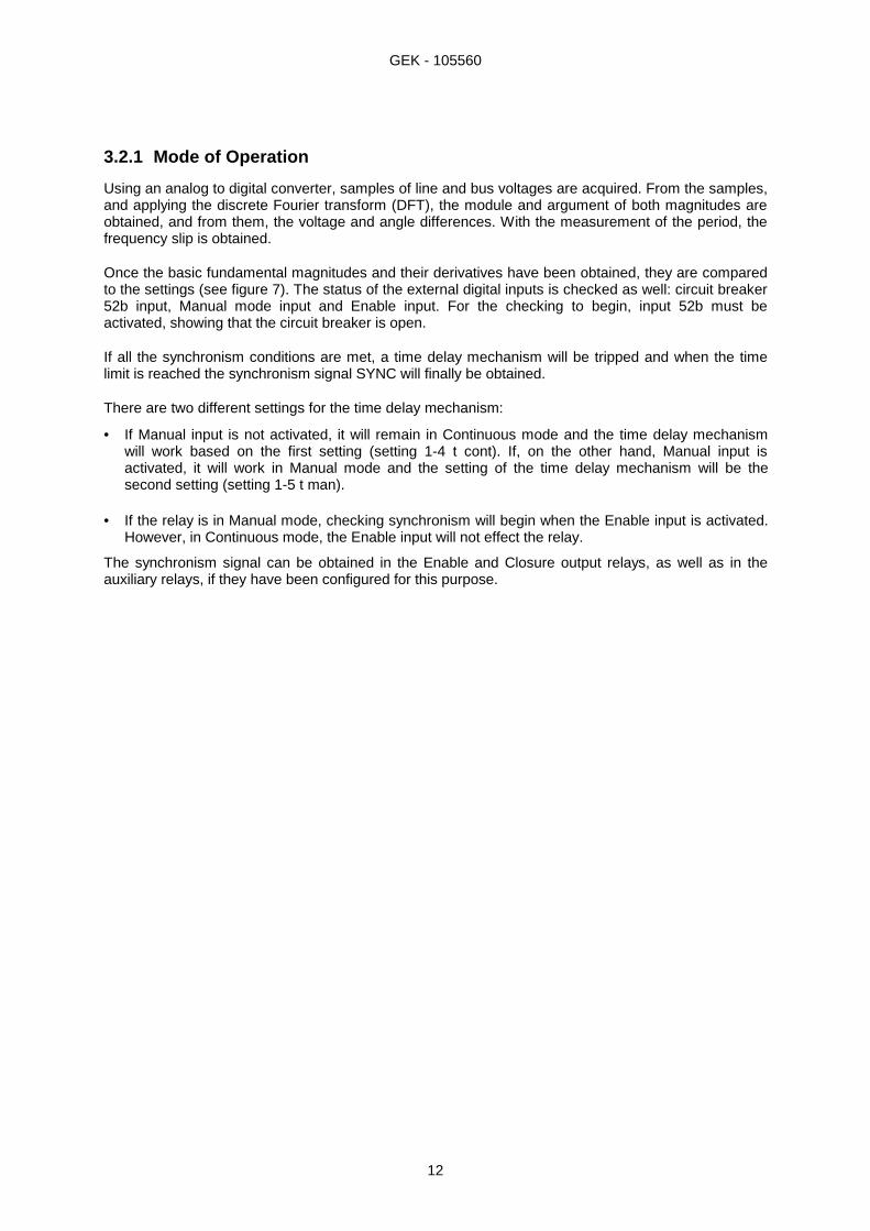
3.2.1 Mode of Operation
Using an analog to digital converter, samples of line and bus voltages are acquired. From the samples,and applying the discrete Fourier transform (DFT), the module and argument of both magnitudes areobtained, and from them, the voltage and angle differences. With the measurement of the period, thefrequency slip is obtained.
Once the basic fundamental magnitudes and their derivatives have been obtained, they are comparedto the settings (see figure 7). The status of the external digital inputs is checked as well: circuit breaker52b input, Manual mode input and Enable input. For the checking to begin, input 52b must beactivated, showing that the circuit breaker is open.
If all the synchronism conditions are met, a time delay mechanism will be tripped and when the timelimit is reached the synchronism signal SYNC will finally be obtained.
There are two different settings for the time delay mechanism:
• If Manual input is not activated, it will remain in Continuous mode and the time delay mechanismwill work based on the first setting (setting 1-4 t cont). If, on the other hand, Manual input isactivated, it will work in Manual mode and the setting of the time delay mechanism will be thesecond setting (setting 1-5 t man).
• If the relay is in Manual mode, checking synchronism will begin when the Enable input is activated.
However, in Continuous mode, the Enable input will not effect the relay.
The synchronism signal can be obtained in the Enable and Closure output relays, as well as in theauxiliary relays, if they have been configured for this purpose.
GEK - 105560
13
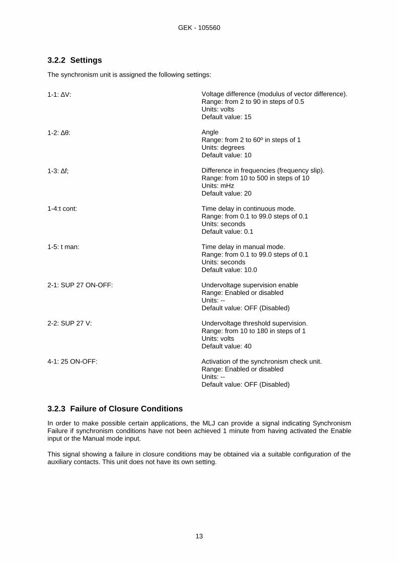
3.2.2 Settings
The synchronism unit is assigned the following settings:
1-1: ∆V: Voltage difference (modulus of vector difference).Range: from 2 to 90 in steps of 0.5Units: voltsDefault value: 15
1-2: ∆θ: AngleRange: from 2 to 60º in steps of 1Units: degreesDefault value: 10
1-3: ∆f; Difference in frequencies (frequency slip).Range: from 10 to 500 in steps of 10Units: mHzDefault value: 20
1-4:t cont: Time delay in continuous mode.Range: from 0.1 to 99.0 steps of 0.1Units: secondsDefault value: 0.1
1-5: t man: Time delay in manual mode.Range: from 0.1 to 99.0 steps of 0.1Units: secondsDefault value: 10.0
2-1: SUP 27 ON-OFF: Undervoltage supervision enableRange: Enabled or disabledUnits: --Default value: OFF (Disabled)
2-2: SUP 27 V: Undervoltage threshold supervision.Range: from 10 to 180 in steps of 1Units: voltsDefault value: 40
4-1: 25 ON-OFF: Activation of the synchronism check unit.Range: Enabled or disabledUnits: --Default value: OFF (Disabled)
3.2.3 Failure of Closure Conditions
In order to make possible certain applications, the MLJ can provide a signal indicating SynchronismFailure if synchronism conditions have not been achieved 1 minute from having activated the Enableinput or the Manual mode input.
This signal showing a failure in closure conditions may be obtained via a suitable configuration of theauxiliary contacts. This unit does not have its own setting.

GEK - 105560
14
3.3 UNDERVOLTAGE UNIT
Besides the undervoltage described in and linked with the synchronism unit, there is an independentunit which has various undervoltage and overvoltage functions to allow for the closure of the circuitbreaker in dead lines and/or bus situations (see figure 1).
3.3.1 Mode of Operation
The modulus are calculated from the line and bus voltage phasors and then compared with thesettings. For each voltage two different levels can be set.
If the voltage is below the set undervoltage level, the corresponding line or bus is said to be dead. If thevoltage is above the set overvoltage level, the line or bus is said to be live.
There can be three different situations of undervoltage: live line and bus (LLLB), dead line and live bus(DLLB), or dead bus and live line (LLDB). By choosing settings we are able to make the undervoltageunit operate in any of these situations.
Similar to what has been stated in the case of the synchronism unit, if the Manual input is activated, inorder for the undervoltage units to operate, it is necessary to also activate the Enable input. However,as opposed to the synchronism check unit, this undervoltage unit has no time delay whatsoever.
3.3.2 Settings
The undervoltage unit has the following assigned settings:
3-1: VL↑: Level of voltage present in line (live line: LL).Range: from 40 to 245 in steps of 1.Units: voltsDefault value: 50
3-2: VL↓: Level of voltage absent in line (dead line: DL).Range: from 10 to 180 in steps of 1.Units: voltsDefault value: 30
3-3: VB↑: Level of voltage present in bus (live bus: LB).Range: from 40 to 245 in steps of 1.Units: voltsDefault value: 50
3-4: VB↓: Level of voltage absent in bus (dead bus: DB).Range: from 10 to 180 in steps of 1.Units: voltsDefault value: 30
4-2: DLDB ON-OFF: Activation condition: dead line and bus (DLDB).Range: Enabled or disabled.Units: --Default value: OFF (Disabled)
4-3: DLLB ON-OFF: Activation condition: dead line with live bus(DLLB).Range: Enabled or disabled.Units: --Default value: OFF (Disabled)

GEK - 105560
15
4-4: LLDB ON-OFF: Activation condition: live line with dead bus(LLDB).Range: Enabled or disabled.Units: --Default value: OFF (Disabled)
NOTE: The relay does not check to see if the live line setting (3-1) is greater than the dead line setting(3-2). This is also applied to the bus settings (3-3 and 3-4). This allows for protection schemesfor under or overvoltage, as well as inhibiting close enable in overvoltage situations.
3.4 INPUT UNITS
The three digital inputs are activated with D.C. voltages and with the same range of values as those ofthe auxiliary voltage.
The input unit not only reads the state of the inputs, but also filters the possible bounce or noise whichmay be present.
Input 52b indicates the state of the circuit breaker. If it is active it means that the circuit breaker isopen. In this case the synchronism unit can give synchronism if the rest of the set conditions are met. Ifit is not used, voltage must be applied to this input in order to enable the synchronism unit.
The Manual mode input changes the time of the delay mechanism of the synchronism unit and givesway to the Enable input; if that input is not active, neither the synchronism nor the undervoltage will beactivated.
When Manual mode is not desired, simply disconnect the Manual and Enable inputs, leaving theterminals corresponding to these two inputs free.
3.5 SELF-CHECK UNIT
While operating the synchronism and undervoltage units, the MLJ continuously carries out internalchecks to verify the integrity of its components.
3.5.1 Mode of Operation
During startups and regular operation, the MLJ monitors the following parameters without interferingwith normal operation:
• Program memory (ROM).• Work memory (RAM).• Non-volatile setting memory (EEPROM).• Setting validity.• Analog measurement circuits.
A WATCHDOG internal system diagnosis the program sequences using task chaining - which providesa high level of security of the internal operation.
During startup, a thorough check is carried out, during which the message “tSt” appears on the relaydisplay.
This unit indicates possible failures detected using codes on the display. It also generates an Alarmsignal, which can be obtained on an alarm contact (programmable) as well as an auxiliary contact..
Upon detection of a system failure, the outputs are deactivated in order to avoid misoperation of therelay.

GEK - 105560
16
The codes for failures are:
0.0. No defects8.0. ROM failure. The program memory has failed.8.1. Writing failure to EEPROM8.2. RAM program failure0.1. Setting failure. The settings stored are incorrect. This error is also shown when the
EEPROM memory is new (in which case the settings are stored by default).0.4. Measurement error (defect in the analog circuits).
If there are multiple failures, only the one with top priority is shown. The above is listed from most toleast important.
3.6 OUTPUT UNITS
The MLJ has 5 outputs which are relay contacts. The contacts can be configured as normally opened(N.O.) or normally closed (N.C.), by means of internal jumpers (solded in the printed circuit board). Thecontacts included are:
2 close enable contacts. Set in the factory as normally opened (N.O.) (non-configurable).1 alarm contact. Set in the factory as normally closed (N.C.) (non-configurable).1 auxiliary contact. Set in the factory as normally opened (N.O.) and configured in factory as function25.1 auxiliary contact. Set in the factory as normally opened (N.O.) and configured in factory as function27.
3.6.1 Mode of Operation
Internally, the MLJ reads the signals sent from the following units: the synchronism and synchronismfailure signals supplied by the synchronism unit; the undervoltage, dead bus and line signals suppliedby the undervoltage unit; and, finally, the alarm signal given by the self-check unit.
If there is a synchronism or undervoltage signal, this unit will activate the Close enable relays.
If there is an Alarm signal, or if the power fails, the Alarm relay will be deactivated. For this reason thiscontact is always configured as normally closed (N.C.) contact.
The auxiliary relays are activated depending on how they have previously been configured. Theconfiguration is individual for each of them, and is done by selection using the following menu:
− Close enable (PEr)− Synchronism (25)− Undervoltage (27)− Dead line (_dL)− Dead bus (db_)− Failure of closure conditions (F25)− Alarm (ALA)
NOTE: the message that appears on the screen is shown in parenthesis.
The selection of the outputs as normally opened (N.O.) or normally closed (N.C.) can be donewithdrawing the MLJ from its case and changing the jumpers to C for closed and A for opened,respectively (a solder gun is required for this operation).
3.6.2 Settings
There are two settings, one for each of the auxiliary outputs:
5-1 �� 1:Configuration: first auxiliary outputRange: PEr, 25, 27, _dL, db_, F25, ALAUnits: --

GEK - 105560
17
Default value: 25 (synchronism)
5-2 �� 2:Configuration: second auxiliary outputRange: PEr, 25, 27, _dL, db_, F25, ALAUnits: --Default value: 27 (undervoltage)
3.7 POWER SUPPLY
The power supply circuit of the MLJ generates, from the auxiliary voltage, the internal voltagesnecessary for the operation of the relay.
The power supply isolates the internal circuitry from external perturbations, for both industrial and highfrequencies.
The power supply is effective over a wide range and is a switching type power supply.

GEK - 105560
18
4. TECHNICAL CHARACTERISTICS
4.1 MODEL LIST
Here is the information required to completely define the MLJ models. (See chart below):
MLJ 100 _ A010 _ 00 _
Communications Auxiliary and inputs voltage Case
0 - No communications F - 24/ 48 Vdc C - In individual case5 - RS-485 H - 110/ 250 Vdc S - In MID system6 - RS-485, 232, plastic optic fiber7 - RS-485, 232, glass optic fiber
4.2 TECHNICAL CHARACTERISTICS
• FREQUENCY
50 and 60 Hz, programmable by user.
• NOMINAL VOLTAGE
63 to 220 Vac.
• AUXILIARY POWER
24 - 28 Vdc ± 20%
110 - 250 Vdc ± 20%
• MAXIMUM VOLTAGE ALLOWABLE
Continuous: 440 Vac.
• TEMPERATURE RANGES
Operating: -25ºC to +55ºC
Storage: -40ºC to +65ºC
Comply with IEC standard 255-6 (for the -25º to +55ºC interval) and ANSI C37.90 (specifying the -25º to +55ºC interval).
• AMBIENT HUMIDITY
Up to 95% without condensation.
• CLOSURE ENABLE CONTACTS
Break capacity: 4000 VA
Maximum continuous voltage: 300 Vdc
Maximum alternating voltage: 440 Vac
Carry continuously: 16 A
Make and carry: 30 A

GEK - 105560
19
• ALARM AND AUXILIARY CONTACTS
Break: 1760 VA
Maximum continuous voltage: 250 Vdc
Maximum alternating voltage: 380 Vac
Make and carry: 8 A
Carry continuously: 8 A
• ACCURACY
Voltage: 2% or 0.5 V
Voltage difference: 3% or 1 V
Angle difference: 1º (voltages between 20 and 220 Vac)
2.5º (voltages between 10 and 20 Vac and between 220 and 300 Vac)
Frequency slip: 5 mHz (range of 45 to 65 Hz)
Time: 1% or 30 ms (*)
The slip measurement unit may require up to 60 ms, which will be added to the time delayintroduced by setting; this is typical behavior.
• VOLTAGE CIRCUIT BURDEN
Less than 0.15 VA at 110 V and 50 Hz or at 120 V and 60 Hz.
• DIGITAL INPUTS BURDEN
24 to 48 Vdc model: 30 kOhm
110 to 220 Vdc model: 136 kOhm
• AUXILIARY POWER SUPPLY BURDEN
Idle: 3W (NC alarm relay activated only)
Tripped: 6W (all relays activated)
• WEIGHTS
Net: 3 kg.
Shipping: 4 kg.
4.3 INSULATION
According to IEC 255-5.
Between each terminal and ground: 2000 Vac for 1 minute at industrial frequency.
Between independent circuits: 2000 Vac for 1 minute at industrial frequency.

GEK - 105560
20
4.4 TYPE TESTS
1 Mhz noise test
2.5 kV, 1 kV peak, class III according to IEC 255-4.
Impulse test
5 kV peak, 1.2/50 µs, 0.5 J according to IEC 255-4.
Electrostatic discharge
According to IEC 1000-1-2, IEC 255-22-2 class IV.
Radio interference
According to IEC 1000-1-3, IEC 255-22-3 class III.
Fast transients
According to IEC 1000-1-4, IEC 255-22-4 class IV.
Radiofrequency emission (radiated interference)
According to EN 55022, class B.
Magnetic fields
According to IEC 100-4-8, class V.
Sinusoidal vibrations
According to IEC 255-21-1, class II.
Shock test
According to IEC 255-21-2, class II.
The MLJ relay complies with these regulations, which include the GE standard of insulation andelectromagnetic compatibility and the standards required for the Community Standard 89/336 for theEuropean Community CE label, under the harmonized European regulations. It also complies with theEuropean directive requirements for low voltage, and the environmental and operative requirementsestablished in regulations ANSI C37.90, IEC 255-5, IEC 255-6 and IEC 68.

GEK - 105560
21
5. DESCRIPTION OF HARDWARE
5.1 CASE
The case of the MLJ is made of steel plate, with an anti-corrosion treatment and painted with epoxypowder paint. The standard dimensions are shown in figure 3.
The front cover is made of a transparent plastic material fitted tightly to the case, forming a seal thatprevents dust from entering and protects it from any accidental tampering. Included is a switch whichallows access to the ENTER button without having to remove the cover. With this button the readoutmenu can be accessed allowing visualization of all the parameters indicated on the characteristic plateunder the title DISPLAY.
The relay can be withdrawn completely from its case without having to disconnect any wires.Nevertheless, it is advisable to disconnect the voltage of the auxiliary feed before removing the relay,though it is not mandatory.
5.2 INTERNAL CONNECTIONS
External wiring is carried out in the two terminal blocks mounted in the rear part of the case. Eachterminal block contains 12 terminals with screws M3 (metric 3 mm diameter) (see figure 4).
There is no internal wiring, given that the relay is made up of a removable card with a connectordesigned for directed insertion into the terminal blocks.
5.3 IDENTIFICATION
The complete relay model is indicated on the nameplate. (See figure 2).
The terminal blocks are identified by a letter located on the back plate, just above the left edge (lookingat the relay from the back) of each block. There are two terminal blocks in each case, each identifiedby a letter: A or B.
In each terminal block, the terminals are labeled from 1 to 12.
5.4 MLJ FRONT DEVICES
On the front of the MLJ on the nameplate are the following setting and signaling elements:
Control pushbuttons
The MLJ comes with three push buttons to control all of the relay operations.
ENTER ↵
PLUS +
MINUS –

GEK - 105560
22
Displays
Three red seven segment displays (LED type) are used to supply information to the user and to make iteasier to set the relay.
LEDs
In addition to the displays described above, there are three LEDs which provide the followinginformation:
• READY: green LED. Relay available and protection enabled.• 52: Red LED indicating close enable condition.• 27: Red LED indicating undervoltage condition.

GEK - 105560
23
6. OPERATION OF MLJ (KEYPAD AND DISPLAY)
The MLJ is operated by means of three push-buttons located on the front. These buttons are lined upvertically and, from top to bottom; they are “ENTER”, “+”, and “–”.
The first button is indicated with an arrow (see figure 2), although throughout this manual it is referredto as ENTER. With the cover on, only this button can be accessed using a push button.
The relay supplies information by means of three displays of seven segments and using three LEDs,all of which are located on the front. The LEDs are lined up vertically and are marked, from top tobottom: “READY”, “52”, and “27”.
The MLJ can be set in one of the three following conditions:
• Readout Sequence: supplies information about the state of the relay, voltage values, frequencyslip, registers of the last close enable, etc. To operate, simply push the ENTER button.
• Setting Sequence: allows consulting and changing of the operation settings of the MLJ. All three
buttons are used for this operation. • Calibration Sequence: this function gives the average of the line and bus voltages, to assist in
calibration.
Immediately after connecting the relay, it carries out a self-check test and the letters tSt appear. Uponcompletion of the self-check test, the relay becomes operative, in Readout Sequence, with the state ofthe line and bus shown on the display (live or dead).
CALIBRATIONS READINGS SETTINGS
Going from one sequence to another isdone by pressing either one button orsimultaneously pressing a combinationof buttons. As can be seen in thediagram, if no button is pressed for twominutes while in Setting Sequence, itwill return automatically to ReadoutSequence.minutes
GEK - 105560
24
6.1 READOUT SEQUENCE
This is the typical sequence for the MLJ as well as the power-up sequence. It is divided into a series of“Functions”, each corresponding to different types of information. These functions are numbered from1 to 12 and are identified by the letter F followed by the number of the function.
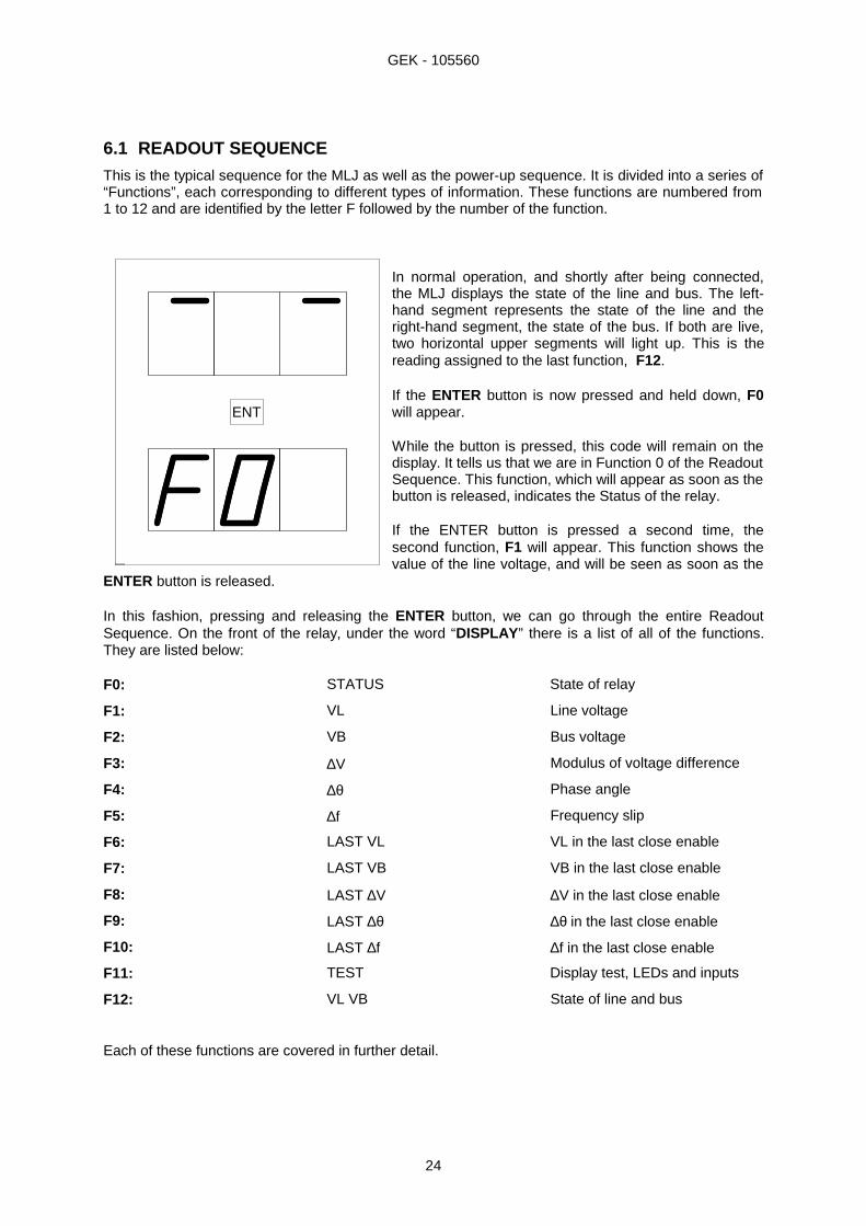
In normal operation, and shortly after being connected,the MLJ displays the state of the line and bus. The left-hand segment represents the state of the line and theright-hand segment, the state of the bus. If both are live,two horizontal upper segments will light up. This is thereading assigned to the last function, F12.
If the ENTER button is now pressed and held down, F0will appear.
While the button is pressed, this code will remain on thedisplay. It tells us that we are in Function 0 of the ReadoutSequence. This function, which will appear as soon as thebutton is released, indicates the Status of the relay.
If the ENTER button is pressed a second time, thesecond function, F1 will appear. This function shows thevalue of the line voltage, and will be seen as soon as the
ENTER button is released.
In this fashion, pressing and releasing the ENTER button, we can go through the entire ReadoutSequence. On the front of the relay, under the word “DISPLAY ” there is a list of all of the functions.They are listed below:
F0: STATUS State of relay
F1: VL Line voltage
F2: VB Bus voltage
F3: ∆V Modulus of voltage difference
F4: ∆θ Phase angle
F5: ∆f Frequency slip
F6: LAST VL VL in the last close enable
F7: LAST VB VB in the last close enable
F8: LAST ∆V ∆V in the last close enable
F9: LAST ∆θ ∆θ in the last close enable
F10: LAST ∆f ∆f in the last close enable
F11: TEST Display test, LEDs and inputs
F12: VL VB State of line and bus
Each of these functions are covered in further detail.
ENT

GEK - 105560
25
6.1.1 F0: State of relay, error codes
The state of the MLJ presented by a two-digit code. The decimal points remain lit so as to distinguishthe code from other readings. A 00 code (everything correct) would be represented as follows:
The state codes for the MLJ, in order of priority, are:
0.0. No defects8.0. ROM failure. The program memory has failed.8.1. Failure in writing to EEPROM8.2. RAM program failure0.1. Setting failure. The settings stored are incorrect. This error is also produced when the
EEPROM memory is new (in which case the default settings are stored).0.4. Measurement error (defect in the analog circuits).
The error 0.1. can be corrected by the user by simply modifying the value of any of the settings.
The rest of the errors indicate an electronic failure; if such errors are persistent, maintenance will berequired. If the error is transitory and disappears, the MLJ will reset and start up in the normal fashion.
6.1.2 F1, F2: VL, VB, Voltage in line and buses
These readings supply the RMS values of voltages in real time.
6.1.3 F3:∆V Voltage difference module
The relay vectorially subtracts the line and bus voltages; the modulus of the subtraction is what isrepresented in this reading. See the graphic of phasors in the APPLICATION section.
6.1.4 F4: ∆θ Phase angle
The phase angle is always given in absolute values which fall between 0 and 180º. The anglemeasurement is not influenced significantly by variations in voltage.
If the line or bus voltage is less than 9 volts, since the relay does not consider the angle measurementsprecise enough in such conditions, three horizontal lines will appear on the screen(overflow indicator).
6.1.5 F5: ∆f Frequency Slip
This reading supplies the frequency slip in mHz, calculated based on the difference in frequencies.
For the same reason mentioned in the previous section, if voltage is less than 9 volts, three horizontallines will appear on the screen.

GEK - 105560
26
6.1.6 F6, F7, F8, F9, and F10 Magnitudes recorded
When close enable is given, whether by synchronism or undervoltage, the relay registers of certainmeasured magnitudes at that moment. Later, when so desired, in the Reading Sequence they can beviewed with the following functions:
F6: LAST VLF7: LAST VBF8: LAST ∆VF9: LAST ∆θF10:LAST ∆f
6.1.7 F11: TEST Display and inputs test
In this reading, all the segments of the displays will light up and blink in order to make sure there thatnone is defective.
The three LEDs will also light up, indicating they are not defective.
Additionally, the LEDs act as a control for the digital inputs. If these are active the LEDs will blink onand off; if they are not active, they will light up continuously. The are assigned the follows codes:
• MANUAL input → LED READY• ENABLE input → LED 52• INPUT 52b → LED 27
6.1.8 F12: VL VB State of Line and buses
Through the horizontal segments of the display, the MLJ relay gives an indication as to whether the line(left-hand display) or the bus (right-hand display) are live or dead.
The upper segments indicate live; the lower, dead, and the middle segments show that the value of thevoltage falls between the live and dead values. These limits are determined by the settings in 3-1 to 3-4.
The MLJ admits the live limit to be inferior to the dead limit. In these cases both the upper as well asthe lower segments can be lit up.
6.2 SEQUENCE OF SETTINGS
In order to introduce or modify the settings it is necessary for the relay to be in the Setting Sequence.To do this the protective cover must be removed as the three buttons will be used.
Supposing we are in the Readout Sequence. In order to enter in the Setting Sequence, the ENTERbutton must be pressed and, without releasing it, press the “-” button. After this operation has beendone, (the buttons may be released), 1-1 will appear on the screen. This means that the 1-1 setting(voltage difference) can be changed.
Inversely, if you want to go back to the Readout Sequence from the Setting Sequence, both the “+”and the “-” buttons must be pressed simultaneously. In any case, if two minutes were to pass withoutany button being pressed, the MLJ will go automatically back to the Readout Sequence.
Let us suppose we are in the Setting Sequence. In this case the following can be done:
• Go to the next setting (1-2). Press the “+” button.• Go to the previous setting (0-1). Press the “-” button.• See or change the current setting (1-2). Press ENTER.

GEK - 105560
27
In the first two situations we can go forward or backward throughout the entire list of settings by simplypressing the “+” or the “-” button. On the nameplate, under the word “SETTINGS” a complete list canbe found.
If on the other hand, ENTER is pressed, the value of the setting will be seen blinking; if Enter ispressed again the setting will be left as it was and on the screen the name of the current setting willappear, for example 1-1.
If instead of having pressed the last ENTER, the “+” or the “-” button had been pressed, the settingwould have been modified, either increasing or decreasing it by one step. This modification does nottake place until it has been confirmed with an ENTER. At that moment the setting is stored in the non-volatile memory and protection with the new functioning parameters is started up.
In the BEGINNING OPERATION chapter of this book all of the operation units, settings, ranges,stages and units are described.
Here is an example:
Let us suppose that in setting 1-3 (frequency slip) we have 20 mHz and we wish to change it to 70mHz.
• We begin with the Readout Sequence display, which gives us the line and bus activity, and go tothe Setting Sequence:
Display: - -Press: ENTER (F0) appears on the display. Without releasing it press
“-”)Display: 1-1 (the buttons can now be released)
• We now go to the setting 1-3:Press: “+”Display: 1-2Press: “+”Display: 1-3 (we have achieved the desired setting)
• Now we will modify it:Press: ENTERDisplay: 20 - blinking (these are the current 20 mHz)Press: “+” (press 5 times since the pitch is 10)Display: 70 - blinking (we now have the desires setting)Press: ENTER (the change has been carried out)Display: 1-3
In brief, the process is the same for any desired setting modification: select the code for the desiredsetting modification, press ENTER, change it by pressing either “+” or “-” , and confirm the changewith ENTER.
If when the setting is being changed, the “+” or “-” button is held constantly, acceleration will occur,speeding up the change in setting.
If the maximum allowed value for the setting appears on the display, pressing “+” will have no effect.The same will happen if the minimum allowed value appears on the display and “-” is pressed.
NOTE: a change in settings causes all the units to restart; if there is an output activated, is will bedeactivated until the corresponding unit renews the activation.

GEK - 105560
28
6.3 CALIBRATION SEQUENCE
Under normal conditions, the relay will not need to be calibrated.
The calibration of this protection is done in the factory in a controlled environment with high precisionequipment. Therefore, not only is it unnecessary to recalibrate the relay, but also not recommended.
The relay has a single gain calibration by means of a potentiometer (see figure 6).

GEK - 105560
29
6.4 SUMMARY OF SETTINGS
Following, is a table containing a summary of all the settings of the MLJ relay. In addition to thedescription and the setting code, the allowable values, step and default value (the value the relaycomes with from the factory) are indicated. In the right-hand column, SETTING, a blank space is left sothat the user may note the value the relay has been set at.
TABLE 1 MLJ SETTINGS
SETTING NAME RANGE STEP DEFAULT SETTING
GENERAL
0-1 Frequency 50/60 Hz N.A. 50 Hz
PROTECTION
1-1 Voltage difference 2-90 V 0.5 V 15 V1-2 Angle 2-60º 1º 10º1-3 Frequency slip 10-500
mHz10 mHz 20 mHz
1-4 Continuous mode timing 0.1-99-0 s 0.1 s 0.1 s1-5 Manual mode timing 0.1-99-0 s 0.1 s 10.1 s2-1 Voltage supervision enable OFF-ON N.A. OFF2-2 Voltage supervision threshold 10-180 V 1 V 40 V3-1 Level present of voltage in line (VL↑) 40-245 V 1 V 50 V
3-2 Level absent of voltage in line (VL↓) 10-180 V 1 V 30 V
3-3 Level present of voltage in bus (VB↑) 40-245 V 1 V 50 V
3-4 Level present of voltage in bus (VB↓) 10-180 V 1 V 30 V4-1 Synchronism unit enable OFF-ON N.A. OFF4-2 (DLDB) dead line and bus enable OFF-ON N.A. OFF4-3 (DLLB) dead line live bus enable OFF-ON N.A. OFF4-4 (LLDB) live line dead bus enable OFF-ON N.A.. OFF5-1 Configuration 1st auxiliary output see table 2 N.A. 255-2 Configuration 2nd auxiliary output see table 2 N.A. 27
COMMUNICATIONS
6-1 Unit number 1-255 1 16-2 Serial port baud-rate (kilobauds) 0.3-38.4 N.A. 9.6

GEK - 105560
30
Going to settings sequence Going to readout sequence
Note: N.A. Not applicable
TABLE 2 CONFIGURATION OF OUTPUTS
FUNCTION NAME FUNCTION OPERATION
PEr Close enable25 Synchronism27 Undervoltage_dL Dead linedb_ Dead busF25 Fail to closeALA Alarm
If while in Readout Sequence, the ENTER and “+” buttons, are pressed simultaneously, the word CALwill appear briefly on the screen, followed immediately by the average value of the line and busvoltages.
By applying a known voltage, for example 60 RMS, to both the line and bus inputs, the trimmer isadjusted (see figure 5) until a reading of 60.0 on the display is obtained.
If we now press the ENTER button for a moment, we return to Readout Sequence.

GEK - 105560
31
7. ACCEPTANCE TESTS
7.1 INTRODUCTION
Given the digital nature of this relay, in most occasions making sure that the relay measures correctlywill guarantee proper performance, since all of the logic of measurement and protection isimplemented by means of programming. In order to do this, the voltages in the line and bus need onlyto be measured with a multimeter and make sure they coincide, within the specified accuracy, with thereading indicated on the screen.
A phasemeter should be used in order to check the correct measurement of the voltage and phasedifference (since the voltage difference is measured vectorially) if angle and voltage is required to betested.
Finally, with an accurate and stable frequency meter the line and bus voltage frequency can bemeasured the difference between them calculated, which should coincide with the measurement thatappears on the relay screen.
7.2 VISUAL INSPECTION
Check the nameplate stamping to ensure that the model number and rating of the relay agree with therequisition. The relay should also be checked for scratches, dents, or loose components that may havebeen caused from negligent transport.
7.3 INSULATION
Due to the presence of capacitors for immunizing the relay from external interference, during theinsulation test, approximately 7 mA for each capacitor is consumed. In the event that the apparatusused to carry out the insulation test does not permit such a consumption, the test will be done bygrouping less terminals.
These tests are only carried out on new relays. A new relay means one that has not been in service,whose expedition date is not more than a year old, and one which has been stored in suitableconditions so as to prevent any deterioration.
NOTE: It is very important that the strip connected to the ground terminal on the back of the relay istightened at all time. If this strip is loose, harmful transients could occur when the insulationtest voltages are performed.
Short-circuit all the terminals except A11, A12, B11 and B12. Slowly apply 2000 V of alternating currentto the chassis and then slowly reduce it back down to 0 V.
7.4 SYNCHRONISM UNIT
For these tests, two independent voltage generators, adjustable in amplitude and phase, should beavailable.
In order to carry out these tests the synchronism unit should be activated and the undervoltage unitdeactivated. This is done by putting the 4-1 setting on ON and settings 4-2, 4-3 and 4-4 on OFF.
Due to the complexity of the necessary equipment, it is not recommended to carry out the frequencydifference test. To check that the measurement is correct, the slip on the readout menu (readout F5) is

GEK - 105560
32
visualized by applying a voltage greater than 10 V to the line and the buses. The readout should be 0mHz.
7.4.1 Voltage unit test
The setting by defect is used for the voltage difference; In this case 15 V.
Apply continuous voltage to input 52b (simulates open circuit breaker).
The Close enable contact should be closed and the red LED 52 lit up.
Reduce the voltage in the buses until the relay drops. At 44 V this drop should clearly occur, at whichtime the voltage difference is 16 V (60 V - 44 V = 16 V), which is greater than the 15V of the setting.
When two independent supplies are not available, it is recommended to use a variable autotransformerin order to be able to charge the bus voltage when so desired. If only voltages other than 60 V (63.5 Vor 110 V for example) are available, the test can also be done although keeping in mind that the relaywill trip when the voltage difference is less than the set value.
If a variable autotransformer is not available this unit can be tested by applying, for instance, 220 V tothe line and 127 V to the bus by means of a simple 220/127 V transformer. In this case, Close enablewill not be given, given that the voltage difference is very large. In order to generate Close enable, thesame voltage (220 V for example) is simply applied to the line and bus inputs.
7.4.2 Angle unit test
For the angle difference, the default setting of 15º should be kept.
Apply continuous voltage to input 52b (simulates open circuit breaker).
Apply 60 V to the line and bus inputs (these should be in phase).
The Close enable contacts should be closed and the red LED 52 (Close enable) lit up.
Lag the bus voltage until the relay drops. This drop should clearly occur at 17º, greater than the set15º.
When two independent supplies are not available, the test is done by reversing the polarity of the busvoltages, which means lagging it to 180º, and in which case the relay will not trip.
7.5 UNDERVOLTAGE UNIT
In order to carry out these tests the undervoltage unit should be enabled and the synchronism unitdisabled. This is done by putting setting 4-1 on OFF, setting 4-2 on ON and settings 4-3 and 4-4 onOFF.
Apply 40 V both to line and bus. The middle segments corresponding to the line and bars will light upon the relay screen when the relay is in readout in the idle position.
The relay should not trip.
Reduce the voltage to 20 V. The lower segments on the screen will be activated. The relay shouldoperate and the red LEDs 52 (Close enable) and 27 (undervoltage) lit up.
If there is no variable power supply available, the test can be done by applying and removing a knownvoltage (for example 63 V).

GEK - 105560
33
7.6 CONTINUOUS AND MANUAL MODE TESTS
With the default settings, the delay in continuous mode is 0.1 s and in manual mode it is 10 s. Thishelps to know when the relay acts in one mode or the other.
Manual mode
Apply continuous voltage to inputs MANUAL, ENABLE and 52b.
Apply 60 V in parallel to line and buses.
When approximately 10 seconds are up (plus some delay with the measurement units and outputrelays, which in any case, is less than 100 ms) the relay should function.
Remove the voltage to the ENABLE or 52b input. The relay should drop.
Continuous mode
Apply continuous voltage to input 52b .
Apply 60 V in parallel to line and buses.
When approximately 100 milliseconds are up (plus some delay with the measurement units and outputrelays, less than 80 ms in any case) the relay should operate.
Remove the voltage to input 52b (simulates closure of the circuit breaker). The relay should drop.
7.7 CALIBRATION
The MLJ relay is based on a microprocessor and performs numerical processing of alternatingvoltages, with high resolution and accuracy. It uses an algorithm that is highly unaffected by distortionto measure the RMS value. Due to minimal usage of components and the reliability of themeasurement, it not considered necessary to recalibrate the relay.
Nevertheless, and simply for information purposes, see section 6.3, CALIBRATION SEQUENCE.
7.8 GROUNDING
The MLJ has a terminal (B12) for grounding. Connected to this terminal there is also a strip thatconnects the terminal to the relay case. This strip improves the discharge path of interference andmust always be connected ; it must not be disconnected even when an insulation test is beingperformed.
Grounding is done with a cable that leads directly to ground of the panel or the cabinet; it should nevergo through disconnecting terminals (that might become disconnected), nor should grounding betweenequipment be linked. Each one or each case must have its own cable which is directly connected.
In relays with communications or if a cable with a shield is used, the shield should be connected to theterminal intended for this purpose (B11), without interrupting continuity, and not connecting to theground. However, for personal safety, and in order to divert interference to ground, it must always beconnected to the ground in at least one point. Generally the most convenient place is on the side of thecommunications controller. By doing this, grounding the cable is achieved as well as avoidingcirculation of currents through the cable which could affect the correct operation of communications.
There are several reasons for grounding a relay such as the MLJ:
• Personal safety. A defect in insulation could allow the relay case to come in contact withconductors that may deliver dangerous ground voltages. The differences in voltage to ground are

GEK - 105560
34
the dangerous ones since people are touching the ground, normally through their footwear and thefloor of the installation.
• Protection of the relay’s internal circuits against overvoltage. Overvoltage which can reach therelay by connections (power supply circuit, output contacts, etc.) tend to be the so-called commonor longitudinal mode; that is, they are overvoltages that try to make the circuit to ground. The filtersin the inside of the relay short-circuit these overvoltages, directing them to ground through the filtersthemselves and through grounding.
• Protection of the relay against electrostatic discharge. When a person moves towards a relay,it is possible that he or she is charged in respect to the ground (this is highly improbably in asubstation, but is more likely in an office environment) Upon touching any part of the relay, theperson will produce a discharge to the relay which will make a circuit to the ground until it reachesthe person’s feet. The grounding of the relay will make the discharge travel through the person andthus avoid its leaving through the interior of the equipment, which could interfere with its normaloperation.
• Deviation of leakage currents. In the wiring of any electrical equipment to its case, if the case ismetallic, there is always a capacity, which is the sum of the interference capacity and the capacitiesrequired for filtering. Although the currents that can circulate through these capacities may not bedangerous for people, they are always startling and annoying, and made worse when the ground iswet or when lightweight footwear is used.
• Avoiding spurious measures. If there are sensitive, high impedance input circuits which are leftdisconnected, the leakage currents mentioned in the previous paragraph can make their owncircuits, giving out “ghost” measurements. Grounding keeps the measurement circuits from floatingand the leakage currents from making their own circuits.
A similar case might arise in which the ground, from the perspective of the relay, is more harmful thanbeneficial, since the equipment with the better ground will be the one that offers a better path for anyovervoltage produced in the substation. The disturbance could even come from the very ground cableand make a circuit to a ground with less potential, through the interference capacities with the panels.In any case, for personal safety the equipment cases must always be grounded.
Doubts about the grounding of equipment often arise; not grounding can in some cases be the sourceof problems while on the other hand, in other circumstances, unnecessary grounding can also lead toproblems.
When dealing with grounding problems, it is not wise to have set ideas which reduce problems to onlya few possibilities; one must be aware of what problems can arise and why they have come about. Theonly set rule, for safety’s sake, should be that all equipment that is meant to be grounded should havea ground connection.
One of the main reasons for the difficulty in achieving proper grounding is that the equivalent electriccircuit, which is generally a cable, is different according to the frequency of the voltages applied to theground. At industrial frequency (50 or 60 Hz), a cable functions as a very low impedance, and thereforethe voltage at the ends will never reach higher values. But as the voltage is increased, the cable will bemore like an inductance, with more impedance, and at higher frequencies the cable functions as atransmission line. For determined lengths of cable, the situation might arise in which one of the endsfinishes in a short-circuit (which is exactly the goal in grounding), while the same circuit on the otherend is exactly the opposite, that is, an open circuit.
It is helpful to remember that an industrial frequency that undergoes a significant variation in maximumvalue, typical in installations in failure circumstances, generates a large amount of high frequencyharmonics.
At industrial frequency it has been seen that the cable presents low impedance, limiting overvoltages inits ends, but this is at the cost of leading high intensities, which can cause problems in induction orradiation, to the equipment or to adjacent equipment. This is one of the reasons why loops in thegrounding wires must be avoided.
In conclusion, it is necessary to always keep the recommendations of the manufacturers in mind as faras safety measures are concerned.

GEK - 105560
35
Figure 1 Logical diagram of Operation (226B2202H2)

GEK - 105560
36
Figure 2 Nameplate (226B1276H1)

GEK - 105560
37
Figure 3 Outline and panel drilling (226B6086H1)

GEK - 105560
38
Figure 4 Rear terminal plate (226B3205H1)

GEK - 105560
39
Figure 5 External connections (226B6265H1)
Note: The transformers can be connected to single or compound voltage.

GEK - 105560
40
Figure 6 Internal settings (301A7408H1)

GEK - 105560
41
Figure 7 Block Diagram (226B2201H1)