mld theory
DESCRIPTION
short notes for mold makingTRANSCRIPT

SSB – GTTC – MYS
Reference books for further reading: Injection molds by R.G.W pye, injection molding handbook, 108 proven designs,
SUBJECT: MOULD THEORY
page 1 of 96
DIPLOMA IN TOOL AND DIE MAKING
MOULD THEORY
Introduction:
The mould is an assembly of parts containing with in it an impression
into which hot plasticized material is injected, and then maintained at certain temperature and
pressure, then cooled to get a commercially acceptable shape. The impression may therefore as
that part of the mould, which imparts shape to the moulding.
There are different types of molding process depending on the requirement
i) Injection molding
ii) Compression & transfer molding
iii) Extrusion
iv) Blow molding
v) Thermoforming
vi) Vacuum forming
vii) Calendaring
In Tool & die making more emphasis is placed on injection molds as the design & fabrication of
injection molds requires more skill & comprehension.
Working principle:
The impression of a mould is formed by two mould members, namely:
The cavity portion of the mould, forms the external shape of the moulding
The core portion of the mould, forms the internal form of the moulding
Classification of injection molds
Injection molds can be classified according to their construction
A) Two plate mould B) Three plate mould C) Runner less moulds
Two plate mould

SSB – GTTC – MYS
Reference books for further reading: Injection molds by R.G.W pye, injection molding handbook, 108 proven designs,
SUBJECT: MOULD THEORY
page 2 of 96
DIPLOMA IN TOOL AND DIE MAKING
Working principle:
Two mould members form the impression of a mould, namely:
1. The cavity portion of the mould, which forms the external shape
of the molding
2. The core portion of the mould, it forms the internal form of the
Molding
It consists of a core plate and a cavity plate; the temperature control channels are present in both
of the back up plates, core plates and cavity plate. It also consist of support pillars ejectors, sprue
bush, sprue pulled, and a gate.
Injection Moulding
Parts of a conventional injection mould:
An injection mould mainly consists of,
1. Cavity and core plate
2. Sprue bush
3. Runner and gate system
4. Register ring
5. Guide pillar and bushes
6. Top plate
7. Bottom plate
8. Ejection system
1. Cavity and core plate: The basic mould in this case consists of two plates. Into one plate is
sunk the cavity, which shapes the outside form of the mounting and is therefore known as cavity
plate. The core which projects from the core plate forms the core plate forms the inside shape of
the molding
2. Sprue bush: During the injection process plastic material is delivered to the nozzle of the
machine as a melt. The material in this passage is termed as the sprue and the bush as the sprue
bush
3. Runner and gate: The material may be directly injected into the impression through,
i. Sprue bush
SSB – GTTC – MYS
Reference books for further reading: Injection molds by R.G.W pye, injection molding handbook, 108 proven designs,
SUBJECT: MOULD THEORY
page 3 of 96
DIPLOMA IN TOOL AND DIE MAKING
ii. Runner and gate
This is a channel machined into mould plate to connect the sprue with the entrance to the impression.
The gate is a channel connecting the runner with the impression
4. Register ring: The alignment between the nozzle and the sprue should be corrected for the easy
flow of material. To ensure this the mould must be center to the machine and this can be achieved by
providing a register ring.
5. Guide pillar and bushes: To mould an even walled component it is necessary to ensure that
the cavity and core should be kept in proper alignment. This is achieved by providing guide
pillars and bushes on the mould plates. The guide pillar has its working diameter smaller than the
fitting diameter; if the working diameter is bent it can be easily removed without damaging the
fitting hole.
6. Top plate: The top plate houses the register ring, anchor bush, guide bush. The top plate is a bit
wider than the other plates so as to serve the purpose of clamping the mould to the platen of the
injection-molding machine. Top plate holds the fixed half of the mould together.
7. Bottom plate: The bottom plate houses the clamping screw. The main purpose of the bottom
plate is to clamp the moveable half of the mould together i.e. the core plate, core back plate,
spacers guide pillar, and ejector plate.
8. Ejector unit:
Ejector unit consists of ejector plate and ejector back plate. Ejector plate houses
the ejector pins & return pins where as ejector back plate as a backing plate to
ejector plate.
9. Ejector guide pillars & bush Ejector guide pillar and bush is for guiding the ejector unit
10. Spacer Spacer is for maintaining the gap between bottom plate & core back plate & also it helps in maintaining
the required mold height.
Description of some of the commonly used parts in injection mould
Bolsters (Top & Bottom Plates)
The fundamental requirements of a bolster can be summed up as follows:
SSB – GTTC – MYS
Reference books for further reading: Injection molds by R.G.W pye, injection molding handbook, 108 proven designs,
SUBJECT: MOULD THEORY
page 4 of 96
DIPLOMA IN TOOL AND DIE MAKING
i) It must provide a suitable pocket into which the insert can be fitted.
ii) It must provide some means for securing the inset after it is fitted in position.
iii) It must have sufficient strength to with stand the applied moulding forces.
Bolster material The bolster normally is made from MILD STEEL PLATE to BS 970-040 A15
specification. How ever in some areas a MEDIUM CARBON STEEL (BS 970-080 M40) is
preferred.
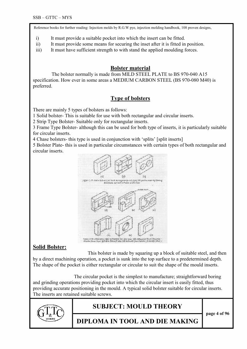
Type of bolsters
There are mainly 5 types of bolsters as follows:
1 Solid bolster- This is suitable for use with both rectangular and circular inserts.
2 Strip Type Bolster- Suitable only for rectangular inserts.
3 Frame Type Bolster- although this can be used for both type of inserts, it is particularly suitable
for circular inserts.
4 Chase bolsters- this type is used in conjunction with ‘splits’ [split inserts]
5 Bolster Plate- this is used in particular circumstances with certain types of both rectangular and
circular inserts.
Solid Bolster: This bolster is made by squaring up a block of suitable steel, and then
by a direct machining operation, a pocket is sunk into the top surface to a predetermined depth.
The shape of the pocket is either rectangular or circular to suit the shape of the mould inserts.
The circular pocket is the simplest to manufacture; straightforward boring
and grinding operations providing pocket into which the circular insert is easily fitted, thus
providing accurate positioning in the mould. A typical solid bolster suitable for circular inserts.
The inserts are retained suitable screws.

SSB – GTTC – MYS
Reference books for further reading: Injection molds by R.G.W pye, injection molding handbook, 108 proven designs,
SUBJECT: MOULD THEORY
page 5 of 96
DIPLOMA IN TOOL AND DIE MAKING
Stripper Type Bolster: This is an alternative method of making a bolster to suit rectangular inserts.
The pocket is made by machining a slot completely through the bolster block. Steel strips are
then fitted at either end of the slot to complete a frame for the inserts.
Advantage: Both the sides and base of the pocket can be ground and also the inner edge of the
strip. So all-important surfaces are ground and the fitting of rectangular inserts is simplified.
Chase Bolster: When splits [split inserts] are to be incorporated in the mould design it is necessary
for one of the bolster to lock the splits in their closed position. There are two types as follows.
1. THE OPEN CHANNEL - which is used for shallow rectangular splits.
2. ENCLOSED CHASE TYPE BOLSTER-, which is used for deep splits and is normally of
closed type.
Frame Type Bolster: This mainly consists of 1. FRAME
2. BACKING PLATE
The frame is made by machining an aperture of the required shape completely through the bolster
plate. The bottom of the insert is supported by a backing plate secured to the frame by a number
of socket headed screws. This type of bolster is particularly useful with small inserts where there
is often insufficient room to position the screws.
Guide pillars:
Function of guide pillars: Guide pillars are usually necessary to ensure that both halves of the moulds
are kept in alignment while the mould is closing. The pillars have also the subsidiary functions of
protecting the core and acting as locating pins when the mould is being assembled.
On the two plate moulds the
guide pillars are normally fitted on the moving half so that they provide some protection for the
core when the mould is off the machine. The design of the length of the guide pillar should be
such that both moulds are positively aligned before the core enters the cavity, without this
precaution any slight misalignment perhaps due to wear of the platen bushes, may cause the core
to strike the cavity wall with the disastrous results. To safeguard against this possibility the guide
pillar should be sufficient length to enter the guide bush before it enters the cavity
They are basically five types they are
1. Leader pins
2. Standard
3. Spigot
SSB – GTTC – MYS
Reference books for further reading: Injection molds by R.G.W pye, injection molding handbook, 108 proven designs,
SUBJECT: MOULD THEORY
page 6 of 96
DIPLOMA IN TOOL AND DIE MAKING
4. Surface fitting
5. Pull back
The guide pillars are made up of mild steel, hardened & ground to 58-60 HRC
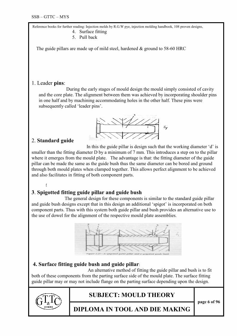
1. Leader pins: During the early stages of mould design the mould simply consisted of cavity
and the core plate. The alignment between them was achieved by incorporating shoulder pins
in one half and by machining accommodating holes in the other half. These pins were
subsequently called ‘leader pins’.
2. Standard guide In this the guide pillar is design such that the working diameter ‘d’ is
smaller than the fitting diameter D by a minimum of 7 mm. This introduces a step on to the pillar
where it emerges from the mould plate. The advantage is that: the fitting diameter of the guide
pillar can be made the same as the guide bush thus the same diameter can be bored and ground
through both mould plates when clamped together. This allows perfect alignment to be achieved
and also facilitates in fitting of both component parts.
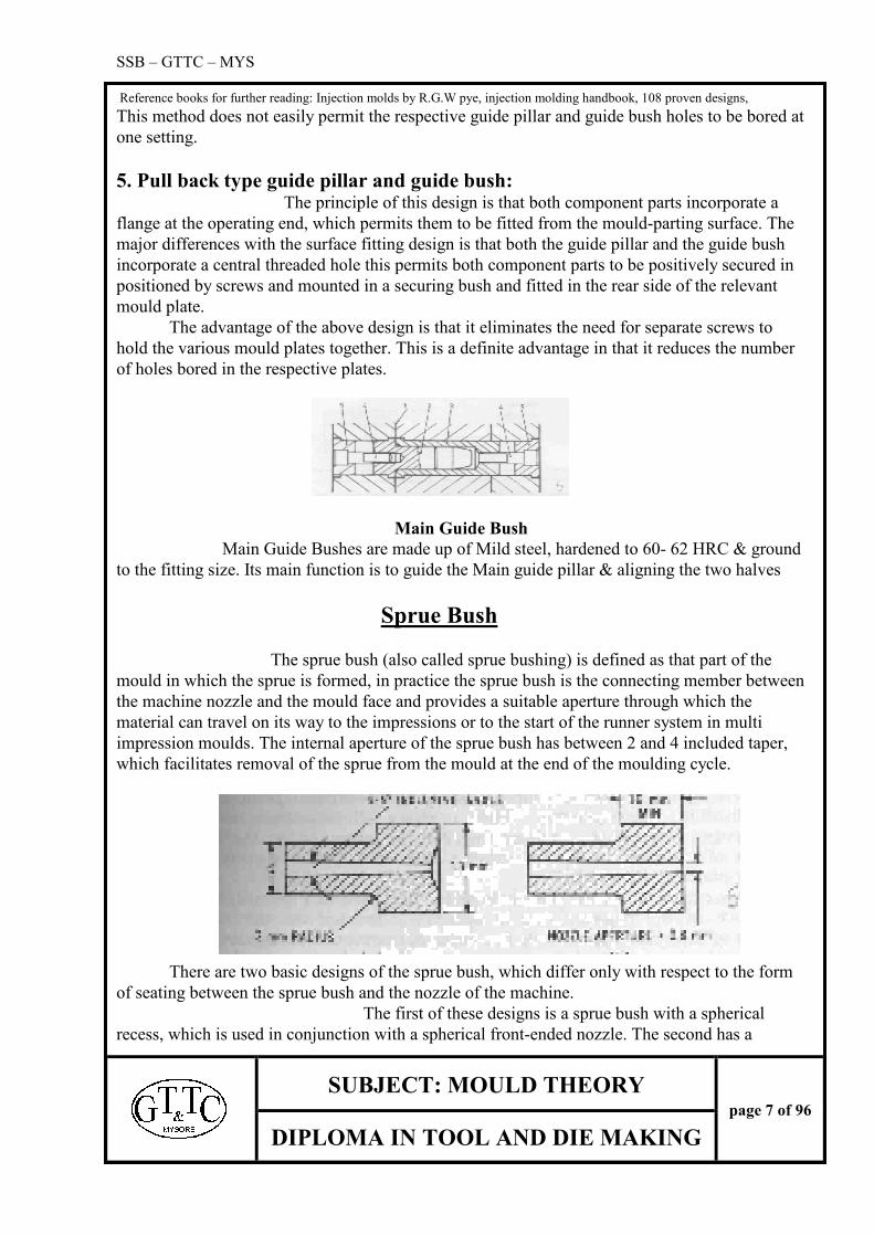
3. Spigotted fitting guide pillar and guide bush The general design for these components is similar to the standard guide pillar
and guide bush designs except that in this design an additional ‘spigot’ is incorporated on both
component parts. Thus with this system both guide pillar and bush provides an alternative use to
the use of dowel for the alignment of the respective mould plate assemblies.
4. Surface fitting guide bush and guide pillar: An alternative method of fitting the guide pillar and bush is to fit
both of these components from the parting surface side of the mould plate. The surface fitting
guide pillar may or may not include flange on the parting surface depending upon the design.
SSB – GTTC – MYS
Reference books for further reading: Injection molds by R.G.W pye, injection molding handbook, 108 proven designs,
SUBJECT: MOULD THEORY
page 7 of 96
DIPLOMA IN TOOL AND DIE MAKING
This method does not easily permit the respective guide pillar and guide bush holes to be bored at
one setting.
5. Pull back type guide pillar and guide bush: The principle of this design is that both component parts incorporate a
flange at the operating end, which permits them to be fitted from the mould-parting surface. The
major differences with the surface fitting design is that both the guide pillar and the guide bush
incorporate a central threaded hole this permits both component parts to be positively secured in
positioned by screws and mounted in a securing bush and fitted in the rear side of the relevant
mould plate.
The advantage of the above design is that it eliminates the need for separate screws to
hold the various mould plates together. This is a definite advantage in that it reduces the number
of holes bored in the respective plates.
Main Guide Bush
Main Guide Bushes are made up of Mild steel, hardened to 60- 62 HRC & ground
to the fitting size. Its main function is to guide the Main guide pillar & aligning the two halves
Sprue Bush
The sprue bush (also called sprue bushing) is defined as that part of the
mould in which the sprue is formed, in practice the sprue bush is the connecting member between
the machine nozzle and the mould face and provides a suitable aperture through which the
material can travel on its way to the impressions or to the start of the runner system in multi
impression moulds. The internal aperture of the sprue bush has between 2 and 4 included taper,
which facilitates removal of the sprue from the mould at the end of the moulding cycle.
There are two basic designs of the sprue bush, which differ only with respect to the form
of seating between the sprue bush and the nozzle of the machine.
The first of these designs is a sprue bush with a spherical
recess, which is used in conjunction with a spherical front-ended nozzle. The second has a

SSB – GTTC – MYS
Reference books for further reading: Injection molds by R.G.W pye, injection molding handbook, 108 proven designs,
SUBJECT: MOULD THEORY
page 8 of 96
DIPLOMA IN TOOL AND DIE MAKING
perfectly flat rear face, i.e. the seating between it and its corresponding nozzle.
Providing a alignment between the nozzle and the bush aperture
MATERIAL OF SPRUE BUSH: Nickel chrome steel (BS 970-817 M40) and should be always
hardened.
The taper of the sprue in the sprue bush is 2º-4º or in the ratio of 1:25. The minimum diameter of
the sprue is around 3 mm .The sprue area is drilled, sparked & finally finely finished using
polishing techniques. It is hardened to 42-44 HRC
Locating Ring It is the part used in the injection mould to locate the mold to the injection-molding
machine. It is fixed on the top plate or top bolster. It is made up of mild steel
It is also called as register ring.
Ejector Pins Function of ejector pin is to eject the component after it is formed. Ejector pins are fixed
in ejector grid. Usually they are made of T35Cr5MoV1 (HDS) or T110W2Cr1 (OHNS).
Ejector Grid Ejector grid consists of ejector pins, ejector plate, ejector back plate, ejector guide pillars
& ejector guide bush. Ejector plate & ejector back plate is made up of mild steel while ejector
guide pillar & ejector guide bush is made up of OHNS material.
Sprue Puller Pin Sprue puller pulls the runner & sprue from the fixed half to moving half so that feed system
& the component can easily be ejected. It is fixed on the moving side opposite Sprue Bush. It is
also made up of HDS or OHNS material. It is hardened
to 52-54 HRC
Sprue Puller Bush Sprue puller bush guide the sprue puller pin in the moving half. It is also made up of
HDSW or OHNS material. It is hardened to 52-54 HRC
Stop Pins Stop pins are fixed in the fixed half to resist the impact of the return pin when it hits the
cavity plate It is also made up of OHNS material & hardened to 52-54 HRC
Return pins Return pins are fixed in ejector grid. The function of return pin is to move the ejector grid
back once it has ejected the component. It is made up of OHNS material & hardened to 52 – 54
SSB – GTTC – MYS
Reference books for further reading: Injection molds by R.G.W pye, injection molding handbook, 108 proven designs,
SUBJECT: MOULD THEORY
page 9 of 96
DIPLOMA IN TOOL AND DIE MAKING
HRC.
Ejector Guide Pillar & Bush This is fixed in the core back plate. Main function of the ejector guide pillar is to guide
the ejector grid when it is ejecting the components and when it is moving back. It is made up of
Mild steel & case hardened to 58-60 HRC. The ejector guide bush is fixed in ejector grid & also
is made up of mild steel case hardened & ground. Its hardness is 60-62 HRC
Filling Mechanism The material has to be conveyed from the nozzle of the injection moulding machine to the
impressions or cavities to make a component. The flow way or the path through which the
material travels is called the feed system. Feed system is an important element of the mould. It
has to be properly designed to get a good quality component.
FEED SYSTEM
The feed system can be broadly classified in to three parts that is sprue, runner & gate
Sprue: A sprue is a path, which connects the flow way from nozzle to the runners. It is machined
in the sprue bush. The general taper of the sprue is around 2º - 4º or in the ratio of 1:25.
Minimum diameter of the hole is around 3 mm. The radius at the top is to suit the radius of the
nozzle. The hole is machined first using drills & later by using taper reamer or spark erosion
machine. Finally it is highly polished to finish. It is better to keep the sprue as short as possible to
reduce the heat loss.
Runner: The runner is a channel machined into the mould plate to connect the sprue with the
entrance or gate to the impression. In the basic two-plate mould the runner is positioned on the
parting surface while on more complex designs the runner is positioned below the parting
surface.
The wall of the runner channel must be smooth to prevent any restriction to flow.
There must be no machine marks which would tend to retain In the runner in the mould plate, To
ensure this it is desirable for the mould design to specify that the runner is polished “in line of
draw”.
There are some other considerations for determining the runner.
i) The shape of the cross section the runner
ii) The size of the runner
iii) The runner lay out
Runner cross-section shape:

SSB – GTTC – MYS
Reference books for further reading: Injection molds by R.G.W pye, injection molding handbook, 108 proven designs,
SUBJECT: MOULD THEORY
page 10 of 96
DIPLOMA IN TOOL AND DIE MAKING
The cross sectional shape of the runner used in a mould is usually one of the four forms
namely
i) Trapezoidal
ii) Modified trapezoidal
iii) Hexagonal
iv) Fully round
The criterion of the efficient runner is that the runner should provide a maximum cross-
sectional area from the standpoint of pressure transfer and a maximum contact on the
periphery from the standup point of the heat transfer. The round and the square are the two
most commonly used in moulds but the semicircular and rectangular types are generally not
used in mould system. But the square runner is also not satisfactory for the reason as it is
difficult to eject. Because of this in practice an angle of 10° is provided on the runner wall.
This modifies the square to the trapezoidal cross-section. The volume of this runner is
approximately 25% greater than the round runner of the same dimension.
The hexagonal runner is basically a double trapezoidal runner, where the two
halves of the trapezium meet at parting surface. It is easier to match the two halves of the hexagonal
runner compared to that of a round runner. This point applies particularly to runners, which are less
than 3mm in width.
The round runner:

SSB – GTTC – MYS
Reference books for further reading: Injection molds by R.G.W pye, injection molding handbook, 108 proven designs,
SUBJECT: MOULD THEORY
page 11 of 96
DIPLOMA IN TOOL AND DIE MAKING
The main draw back of the round runner is that it is formed by two
semicircular channels machined one in of the mould plates. It is essential that these channels
be accurately matched to prevent an undesirable and inefficient runner system being made.
The choice of the runner section is also influenced by the question whether
positive ejection of the runner system is possible or not. For a two-plate mould it is possible
but for a multi plate mould it is not practicable. Here a basic trapezoidal-type runner is always
specified, the runner channel being machined into the injection half from which it is pulled as
the mould opens. In this way the runner is free to fall under the gravity between mould plates.
But if a circular runner had been specified, the runner system could well adhere to its channel
making it difficult to remove it.
Runner size: When deciding the size of the runner the following must be considered
i) The wall section and the volume of the moulding
ii) Distance of the impression from the main runner or sprue
iii) Runner cooling type used
iv) The range of cutters available
v) Plastic material that is being used
i) The cross sectional area of the runner must be sufficient to permit the melt to pass
through and fill the impression before the runner freeze and for packing pressure to be
applied for shrinkage compensation if required.
ii) Further the plastic melt has to travel along the runner the greater is the resistance to
flow. Hence the distance the impression is from the sprue has a direct bearing on the
cross-sectional size of the runner.
The cross-sectional area of runner should not be such that it controls the injection system. The
larger the cross-sectional area of the runner the greater is the material it contains and it longer
time to cool sufficiently enable the mould to be opened and the moldings ejected.
Calculation of runner size:
D = vW x ªvL
3.7 Where a=4
D=runner diameter
W=weight of moulding
L=height/length of runner)
Theoretically the cross-sectional area of main runner should be equal to/in excess of
the combined cross-sectional areas of the branch runners that is feeding the material.
Runner layout:

SSB – GTTC – MYS
Reference books for further reading: Injection molds by R.G.W pye, injection molding handbook, 108 proven designs,
SUBJECT: MOULD THEORY
page 12 of 96
DIPLOMA IN TOOL AND DIE MAKING
The layout of the runner system will depend upon the following,
i) The number of impressions
ii) The shape of the component
iii) The type of mould, either two or multi plate
iv) Type of gate
Note that the runner length should always be kept to a minimum to reduce
pressure losses and the runner system should be balanced i.e. the distance the
plastic material from sprue to the gate should be same for each moulding. This
ensures uniformity in filling with out interruption.
Runner should also be kept as short as possible to reduce heat &
Pressure loss, it also should be highly polished to avoid turbulence
While material is flowing
GATES
The gate is a channel connecting the runner with the impression. It has small cross-
sectional area when compared with the rest of feed system. This cross-sectional area
is necessary so that:
i) The gates freezes soon after the impression is filled so that the injection
plunger can be with drawn with out the probability of void being created in
the moulding by suck back.
ii) It allows for simple degating and in some moulds this de-gating can be
automatic.
iii) After de-gating only a small witness mark remains.
iv) Better control of the filling of multi impressions can be achieved.
v) Packing the impression with material in excess of that required to compensate
for shrinkage is minimized.
The size of the gate can be considered in terms of gate cross-sectional area and gate
length. The optimum size for a gate will depend on,
i) Flow characteristics of the material to be moulded
ii) The wall section of the moulding
iii) The volume of material to be injected into the impression
iv) The temperature of the melt
v) Temperature of the mould
Positioning of the gate:

SSB – GTTC – MYS
Reference books for further reading: Injection molds by R.G.W pye, injection molding handbook, 108 proven designs,
SUBJECT: MOULD THEORY
page 13 of 96
DIPLOMA IN TOOL AND DIE MAKING
Ideally the position of the gate should that there is an even flow of melt in the
impression so that it fills uniformly and the advancing melt spreads and reaches out to
various extremities of the impression at the same time. Such an ideal position for the
gate is possible in moldings such as those with circular cross-section (cup or a cone),
which will be at the center.
Balanced Gating: It is often necessary to balance the gates of multi impression moulds to
ensure that the impressions fill simultaneously this method is adopted when preferred
balanced runner system cannot be used.
The melt will take the easiest path hence once the runner system is filled, the
impressions closest to the sprue will tend to fill first and those at greater distance will
fill last. As a result some impressions may get over packed while others may be
starved of material. To achieve balanced filling in impressions it is necessary to cause
the greater restriction to flow of the melt to those impressions closer to the sprue and
to progressively reduce the restriction as the distance from the sprue increases.
Types of gate:
There are different types of gates namely:
i) Sprue Gate: When the moulding is directly fed from a sprue bush or secondary sprue, the feed
section is termed as sprue gate. The main disadvantage of this gate is it leaves a large gate mark on the
moulding
i) Rectangular Edge Gate:
This is a general purpose gate and in its simplest form
is merely a rectangular channel machined in one mould plate to connect the runner to
the impression. This gate offers certain advantages over many other forms of gate
namely
a) The cross-sectional form is simple and, therefore, cheap to machine.
b) Close accuracy in the gate dimensions can be achieved.
c) The gate dimensions can be easily and quickly modified.
d) The filling rate of the impression can be controlled relatively independent
SSB – GTTC – MYS
Reference books for further reading: Injection molds by R.G.W pye, injection molding handbook, 108 proven designs,
SUBJECT: MOULD THEORY
page 14 of 96
DIPLOMA IN TOOL AND DIE MAKING
of the gate seal time.
e) All common moulding materials can be moulded through this type of gate.
The major disadvantage of this type is that after removal a witness mark is left on
a visible surface of the moulding
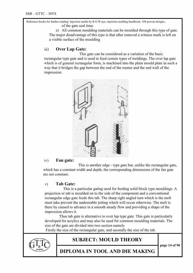
iii) Over Lap Gate: This gate can be considered as a variation of the basic
rectangular type gate and is used to feed certain types of moldings. The over lap gate
which is of general rectangular form, is machined into the plain mould plate in such a
way that it bridges the gap between the end of the runner and the end wall of the
impression.
iv) Fan gate:
This is another edge - type gate but, unlike the rectangular gate,
which has a constant width and depth, the corresponding dimensions of the fan gate
are not constant.
v) Tab Gate: This is a particular gating used for feeding solid block type mouldings. A
projection or tab is moulded on to the side of the component and a conventional
rectangular edge gate feeds this tab. The sharp right angled turn which is the melt
must take prevent the undesirable jetting which will occur otherwise. The melt is
there by caused to advance in a smooth steady flow and providing a shape of the
impression allows it.
Thus tab gate is alternative to over lap type gate. This gate is particularly
developed for acrylics and may also be used for common moulding materials. The
size of the gate are divided into two section namely
Firstly the size of the rectangular gate, and secondly the size of the tab.

SSB – GTTC – MYS
Reference books for further reading: Injection molds by R.G.W pye, injection molding handbook, 108 proven designs,
SUBJECT: MOULD THEORY
page 15 of 96
DIPLOMA IN TOOL AND DIE MAKING
i) Diaphragm Gate: This gate is used for single impression tabular shape
moldings on two plate moulds. It may also be used for multi impression of tubular
shape moldings on runner less and under feed moulds.
The sprue leads into a circular recess, which is slightly
smaller than the diameter of the tube. This recess forms a disk of material and acts as
a runner, which allows material to flow radically from the sprue to the gate. The gate
may either be cut on the core or on the cavity inserts. In both the cases it connects the
disk runner with the impression.
Winkle Gate

SSB – GTTC – MYS
Reference books for further reading: Injection molds by R.G.W pye, injection molding handbook, 108 proven designs,
SUBJECT: MOULD THEORY
page 16 of 96
DIPLOMA IN TOOL AND DIE MAKING
MOULD COOLING METHODS:
After moulding a part it is necessary to cool the component before its ejection.
The mould is cooled using the coolant and system used to supply the coolant into the mould is known
as Mould Cooling System.
There are several methods for cooling the component; some of them are discussed
below.
In a case where the cavity is small and shallow:
To this case the best approach is to drill two flow ways, one either side of the cavity and
to connect these at one end by the means of a flexible hose. Adapters are fitted into the ends of
the flow way.
The two flow ways can be inter-connected internally by the means of an internal
drilling. This forms the u-circuit and it is useful in cooling long narrow cavity.
The other method is similar to the previous type except that the connecting channel
is machined into the connecting plate and the latter is not sunk into the sidewall.
In case where the cavity has larger area and shallow cavity, the mould plate is drilled,
plugged and baffled. This forms a flow path of a Z-configuration through which the coolant is
circulated. Here the cooling effect is going to be more on the left side than the right side.
In circuit type all the inlet and outlet parts are arranged on the same side to facilitate
the mould setting. In a balanced Z-circuit, baffles are necessary to block certain flow ways to
provide a continues circuit with out allowing sections to be by passed and to become dead waters.
The baffles should be incorporated in such a manner that they are readily accessible if leakage
occurs in them
There are different types of cooling system namely
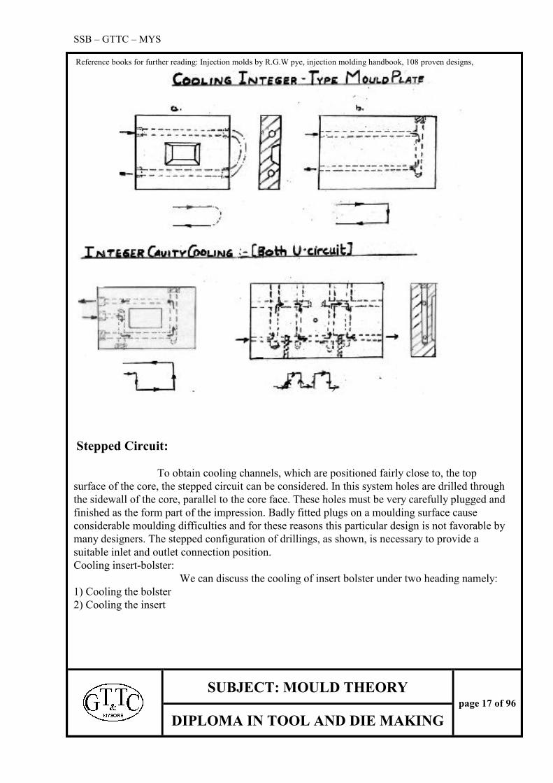
Cooling integer-type core plate:
Providing the depth of the core is fairly shallow (under 25mm (1in)) the Z-type
single -level system can be adopted, the waterways being situated beneath the core in a manner
similar to that for integer cavities discussed in the preceding section. For deeper cores, however,
the single-level circuit is not sufficient to permit the coolant to transfer heat away from the core
surface fast enough. Some arrangement must, therefore, be made to permit the circulation of
coolant inside the core. There are several alternative ways of doing this and the method adopted
will be determined to some extent by the actual shape of the core.
SSB – GTTC – MYS
Reference books for further reading: Injection molds by R.G.W pye, injection molding handbook, 108 proven designs,
SUBJECT: MOULD THEORY
page 17 of 96
DIPLOMA IN TOOL AND DIE MAKING
Stepped Circuit:
To obtain cooling channels, which are positioned fairly close to, the top
surface of the core, the stepped circuit can be considered. In this system holes are drilled through
the sidewall of the core, parallel to the core face. These holes must be very carefully plugged and
finished as the form part of the impression. Badly fitted plugs on a moulding surface cause
considerable moulding difficulties and for these reasons this particular design is not favorable by
many designers. The stepped configuration of drillings, as shown, is necessary to provide a
suitable inlet and outlet connection position.
Cooling insert-bolster:
We can discuss the cooling of insert bolster under two heading namely:
1) Cooling the bolster
2) Cooling the insert

SSB – GTTC – MYS
Reference books for further reading: Injection molds by R.G.W pye, injection molding handbook, 108 proven designs,
SUBJECT: MOULD THEORY
page 18 of 96
DIPLOMA IN TOOL AND DIE MAKING
Cooling the bolster:
In moulds, constructed on the insert-bolster principle, where the depth of the
impression is relatively small, the circulation of the coolant is often confined to the bolster. This
relies on the reasonably good thermal conductivity of steel to allow the heat to be rapidly
transferred from the impression as required. Even better results can be achieved using a material
with a higher thermal conductivity, such as beryllium-copper for the insert
The method adopted for cooling the bolster is, the holes are drilled through
the bolster and are interconnected, either externally or internally to permit the circulation of
coolant
It is desirable that these flow ways are positioned as close to the insert6 as practicable. For a
shallow depth of insert the holes may be situated directly below the insert. A Z-type layout is
normally adopted. The alternative method is to arrange holes close to the sides of the inserts. This
case the rectangular type of circuit is used. For deeper inserts, a multi level system is desirable.
This is simply a combination of both the above layouts.
Cooling cavity inserts:
The method adopted for cooling cavity inserts depends, to some extent, upon
the shape of the insert this can broadly be classified as either rectangular or circular. The
circulation of fluid with in the insert is easily achieved, but a complication exists in that the flow-
way cannot be drilled into the insert from the bolster with out incorporating some from of seal to
prevent leakage.
Cooling rectangular inserts:
The shape and the depth of the cavity determine a typical rectangular
insert. All drillings with in the cavity insert should be inter-connected, plugged, and baffled, so as

SSB – GTTC – MYS
Reference books for further reading: Injection molds by R.G.W pye, injection molding handbook, 108 proven designs,
SUBJECT: MOULD THEORY
page 19 of 96
DIPLOMA IN TOOL AND DIE MAKING
to necessitate the minimum of external couplings. The design should aim to have only one inlet
and one outlet per insert.
The mould setup can more quickly setup moulds for production if the supply and return lines
can be attached directly to adapters, which project from the sidewalls of the mould.
Cooling circular inserts:
The drilling methods discussed for rectangular inserts cannot normally adopted
for cooling circular inserts due to space limitations. However, because the insert has the circular
form, an annular grove can be incorporated quite simply, the circular cavity insert is fitted in a
standard type of frame type of bolster a coolant annulus is machined on the periphery of the insert
and additional groves provided above and below the coolant annulus to accommodate `O` rings.
Then fitted to the bolster, this O rings prevents leakage of fluid between the insert and bolster.
Some care must be taken to prevent the O-ring be damaged when the insert is fitted. A lead-in
over the bolster hole at Z facilitates this operation.
The annulus is connected to the supply and return line via drillings to the bolster. For the
multi impression moulds the inserts can be positioned in lines so that a vertical drilling inter
connects each annulus to form a continuous circuit.
The relevant equations for determining the pitch circle diameter (P C D) and the pitch for the
inserts are given below:
P=D+(3/2) m equation (1)
PCD= P+ (X/n) equation (2)
Sin (180/n) Where P= pitch
D=diameter of inserts
m=depth of grove
n=number of impressions
X=space required between the grooves

SSB – GTTC – MYS
Reference books for further reading: Injection molds by R.G.W pye, injection molding handbook, 108 proven designs,
SUBJECT: MOULD THEORY
page 20 of 96
DIPLOMA IN TOOL AND DIE MAKING
Worked example:
Determine the pitch and pitch circle diameter for the interconnecting grooves design,
given the following information:
Diameter of insert, D=25mm (1”)
Gap between inlet and outlet grooves, X=3mm
Number of impressions, n=6
Depth of groove, m=3mm
Solution: Use equation (1) and (2)
SI units
P=25+ (3x3)
2
=29.5mm
PCD= 29.5+(3/6) =60mm
Sin (180/6)
Baffled Hole System: This design utilizes a system of baffled holes (U). The holes, drilled into the
rare face of the insert may either be at right angles to the base or to be parallel to the outside wall
of the core the diameter of the hole is normally in the range 13mm to 25mm, depending on the
size of the insert. To provide a flow path for the coolant the individual holes are interconnected
by annulus (V), which is machined into the base of the insert. A baffle is fitted into an end-milled
slot, which is machined at right angle to the annulus. The inlet (W) and outlet (X) drillings
through the bolster are situated on either side of the baffle. To ensure that the coolant circulates
down each individual hole, baffles must be fitted in to each. The baffle, the top end of which is
usually made up of brass. The core insert is fitted into a bolster of solid type and an O-ring
incorporated to prevent leakage each baffle must be flushed with rear face of the insert, to prevent
the hole being bypassed.

SSB – GTTC – MYS
Reference books for further reading: Injection molds by R.G.W pye, injection molding handbook, 108 proven designs,
SUBJECT: MOULD THEORY
page 21 of 96
DIPLOMA IN TOOL AND DIE MAKING
Baffled Hole System for Small Inserts:
In the designs the impressions are arranged in line, and the inserts being circular,
fitted into a frame type of bolster. Each inserts incorporates a chamber, which is in alignment
with a drilling in the bolster. To prevent leakage of coolant a small O-ring is fitted in a recess
below each insert. The individual drillings are interconnected by a hole drilled completely
through the mould. The lower end of this hole is the inlet, and the top end becomes the outlet. To
ensure the coolant passes down each chamber, baffles are necessary. The baffles are mounted in
each insert chamber at right angles to the main drilling. Note that the lower end of the baffle
incorporates a radius to match that of the main drilling. As the coolant progressively gains heat as
it passes through the mould, this type is not efficient for cooling more than 3or4 impressions
The Bubbler System:
This type is basically the same as the deep chamber type, suitable adopted
for the small inserts a relatively small diameter hole is machined in to the rare face of the insert.
A bubbler pipe is fitted in the backing plate and protrudes into this hole, there by forming an
annulus. Suitable inlet and outlet holes are drilled in the backing plate.
One type of circuit for which this system can be used is illustrated. The coolant passes
from the inlet hole `U` up the inside of the bubbler pipe, and then down the out side, into the out
let hole, `V`. Note that the temperature of the coolant is approximately the same in each insert as
they are all connected in the same way.
SSB – GTTC – MYS
Reference books for further reading: Injection molds by R.G.W pye, injection molding handbook, 108 proven designs,
SUBJECT: MOULD THEORY
page 22 of 96
DIPLOMA IN TOOL AND DIE MAKING
The Spiral Plug System: This method of cooling small core inserts is an alternative to the bubbler
system. The only basic difference between the two types is that a spiral plug replaces the central
pipe. The spiral plug is essentially a hollow cylinder, the external surface of which is machined to
form a single-start constants-depth thread. This plug is fitted in to a close fitting-accommodating
hole in both the core insert and in the backing plate.
The inlet hole bored in the backing plate is suitably coupled to the spiral plug’s
central drilling, while the adjacent outlet port is aligned with the start of the spiral groove. Thus
the incoming coolant is directed through the center of the assembly after which it passes down the
spiral groove to the outlet port. Note that a dowel pin should be incorporated to ensure that
misalignment between the respective holes dose not occur due to the possible twisting of the
spiral plug production.
Heat Rods: This system is normally adopted for situations in which it is impracticable to
incorporate an internal fluid circulating system within a core insert because of size limitation. A
heat rod basically a cylindrical metal rod, which is inserted into an accommodating hole,
machined in the core insert. Its purpose is to facilitate the conduction of heat away from the
impression.
Note that good surface-to-surface contact between the heat rod and the core insert bore is an
essential requirement for this type.
As the system is used where it is impracticable to adopt other methods such as the bubbler or
baffle system it follows that the diameter of the heat-rods are likely to be relatively small. An
indication of the heat transfer capabilities of a heat-rod can be obtained by using Fourier’s heat
conduction equation. Note that this equation is based upon the assumption that the flow of heat is
unidirectional and that steady state condition applies.
Fourier’s equation:
Q= kA x ?T
X
Where Q=the rate of heat transfer (W)
K=the coefficient of heat transfer (W/mº c)
A=the area at right angles to heat flow (m²)
?T=the temperature differential (ºc)
X=the length of the heat rod (m)
Two points should be noted from the above equation
i) The heat flow rate (Q) is directly proportional to the thermal conductivity value (K),
for e.g., copper has a thermal conductivity 6 times that of mild steel.
Heat flow rate (Q) is proportional to the square of the diameter (i.e. the area A = pD²/4), thus if
the diameter of the heat-rod is reduced by say 50% then the heat flow rate is reduced by ¼.
Cooling shallow core inserts: Once it is decided, that not to rely on conducting the melt heat, away from the

SSB – GTTC – MYS
Reference books for further reading: Injection molds by R.G.W pye, injection molding handbook, 108 proven designs,
SUBJECT: MOULD THEORY
page 23 of 96
DIPLOMA IN TOOL AND DIE MAKING
core to the rather remote holes drilled, in the bolster, then the other alternative to be considered is
incorporating the holes or channels directly into the core insert .One method for doing this was
under the heading “cooling cavity inserts”. The method involved drilling holes using a basic ‘U’
circuit configuration. Useful variations on this approach use either the ‘Z’ or ‘balanced Z’
designs.
An alternative design, which can be adopted for cooling shallow core inserts, is the ‘spiral
circuit’. This design basically consists of a channel machined into the rear face of the core insert
in the form of a spiral. Unfortunately in practice the spiral form is both difficult and expensive to
produce, therefore compromise ‘spirals’ are normally adopted for cooling a large round insert and
for cooling a large rectangular insert respectively.
Deep chamber design: The rear face of the core insert recessed to form a deep chamber (U). This
chamber is normally circular for ease of machining. The insert is firmly held down onto a flat
face at the base of a pocket machined in the bolster by screws. An O-ring fitted into a groove
prevents leakage between the two surfaces. In operation the chamber is completely full of water.
The incoming coolant passes from the inlet, through the internal drillings and pipe to impinge on
the center of the chamber Single impression moulds this is likely to be the hottest part of the core
insert as it is directly opposite the sprue.

SSB – GTTC – MYS
Reference books for further reading: Injection molds by R.G.W pye, injection molding handbook, 108 proven designs,
SUBJECT: MOULD THEORY
page 24 of 96
DIPLOMA IN TOOL AND DIE MAKING
While being the cheapest of the deep cooling methods to incorporate, the deep chamber design
suffers from two major disadvantages:
1. The flow rate of the coolant drops markedly as it enters the chamber. This means that the
required turbulent flow is not achieved in this region and that the transfer of heat to the
coolant is less effective
2. It is possible by incorrect design or incorrect tool making for an air pocket to be formed at
the top of the chamber as shown. An uneven temperature profile with associated
moulding problem will result. The air pocket is created by the incorrect positioning of the
outlet port (Z) in relation to the chamber. It is essential that this port be always situated at
the highest point of the chamber when the mould is mounted on the injection machine. It
is for this reason that moulds incorporating the deep chamber design should be engraved
with information as to which way the mould should be mounted on the machine
The deep chamber design with central support: In this system, the support feature is provided by a central column, which can be
integral with the bolster, or be a separate member. Obviously if the depth of the chamber
necessitates a column which is relatively long, it is preferable to use the latter type
.
The design has 2 primary objectives
1. To support the central region of the core against possible deflections.
2. To have the central region solid to permit a wall type ejector element to be incorporated.

SSB – GTTC – MYS
Reference books for further reading: Injection molds by R.G.W pye, injection molding handbook, 108 proven designs,
SUBJECT: MOULD THEORY
page 25 of 96
DIPLOMA IN TOOL AND DIE MAKING
Note that if the latter design is used in conjunction with a separate central column then an
additional O-ring must be incorporated to avoid fluid leakage past the stem of the valve.
The disadvantages, which apply to the deep chamber type, apply to this type as well.
That is, the flow rate drops as it enters the annulus, and air pockets may be formed. If a large
diameter ejector valve is incorporated, with its own coolant system, then the results of the above
disadvantages are lessened. This is because an efficient coolant circulation system is incorporated
at the point where it is required, that is, at the hottest part of the core, namely the front surface.
Cooling other mould parts:
Other mould plates: On multi-plate moulds it is necessary to consider the cooling of other mould plates in
addition to that of the primary cavity and core plate. In particular, the stripper plate in a stripper
plate mould, and the feed plate in a mould of the underfeed type. Separate control of the
temperature of these plates is necessary to achieve the optimum production cycle.
Cooling valve-type ejectors: The valve type of ejector normally forms a relatively large part of the surface of the
impression. It is desirable, therefore, to provide facilities for the dissipation of heat from this
component. In the first a bubbler system is adopted. The stem of the valve ejector is bored to
accommodate a water junction unit. The connectors are coupled to the supply and return lines via
flexible hoses to allow for the ejector valve movement. The coolant passes via the inlet down the
center of the pipe, and back to the outlet via the outside of the pipe. This is the simplest method
of cooling the valve-type ejector.
Cooling the sprue bush: A relatively large bulk of plastic material is contained in the sprue, which must be
cooled during each cycle to a temperature at which it is sufficiently solid to allow for its removal
from the mould. It is therefore desirable to incorporate a separate sprue bush cooling circuit so
that heat can be transferred from this member as efficiently as possible.
Water connections and seals:
Expansion pressure plug: This standard component part consists of six parts. A tapered cap, which is
connected to a base via a counter sink, headed screw. An olive is in an intermediate position
between the gap and the base. A metal C-ring and a rubber O-ring complete the assembly. The
assembly of the expansion pressure plug into the mould plate is a simple operation as follows:
The plug is inserted into the flow-way aperture to the required depth using a suitably graduated

SSB – GTTC – MYS
Reference books for further reading: Injection molds by R.G.W pye, injection molding handbook, 108 proven designs,
SUBJECT: MOULD THEORY
page 26 of 96
DIPLOMA IN TOOL AND DIE MAKING
push-rod. The screw is then rotated to pull the cap and vase closer together. This operation causes
the metal C-ring to expand and thereby grip the inner bore of the flow way drilling. The rubber
O-ring is also expanded during this operation and thereby cerates a leak free join. A working
pressure of up to 10 bar (1 MN/m²) (145 Ibf/in²) is recommended. Water temperature range of
upto 100ºC (212ºF), together with an oil temperature range of between -15ºC and 150ºC (5-
300ºF) is also specified. An expansion pressure plug is available to suit the following flow-way
diameters: 8 mm, 10 mm, 12 mm, 14 mm and 16 mm.
The pressure plug may also be used to seal ends of drilled flow-way holes there by replacing the
conventional taper pressure plugs. This eliminates the necessity for the normal tapping operation.
Sealing plugs: This standard component part consists of two-part assembly, an outer ring and a
taper plug. The outer ring, which incorporates four projecting beads on its surface, has an internal
tapered bore to accommodate the complimentary shaped tapered plug. The complete assembly is
mounted in the required position within the mould plate by means of a assembly set.
The assembly operations are as follows: The tapered plug is screwed on to the pulling bar
of the assembly until it contacts the face of a graduated tube. The sealing plug assembly is then
inserted into the flow-way aperture, via the tube, its depth being controlled by a preset stop. The
pulling bar is then withdrawn through the graduated tube by means of a pair of assembly pliers.
This later action causes the tapered plug to be drawn into the outer ring, causing it to expand and
thereby impinging its external beads against the surface on the flow -way. This action creates an
effective seal and effectively provides a fixed baffle in the required position.
The manufacturer recommends a maximum permissible pressure of fourtys (40) bar
(4MN/m²) (580 lbf/in²). Naturally the effectiveness of the fit is controlled by the tolerance
accuracy of the flow-way bore operation. The range of available diameter pressure plugs is
6,8,10,12, and 16.
Adaptors: The majority of moulds are drilled to provide a flow path through which the
coolant can be circulated. These drillings are connected to the supply and return lines via
adaptors. The adaptor is a standard mould pipefitting, which can be obtained in a number of
alternative designs and sizes.
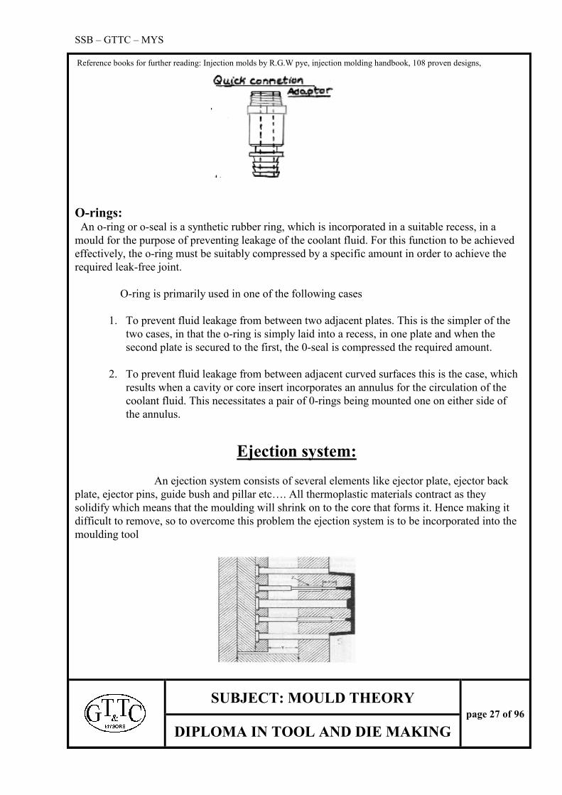
Quick connection adaptors:
The disadvantage of the fixed adaptor design is:
1. The rubber hose must be connected and disconnected each time the mould is set on the
machine.
i) The adaptor projects a considerable distance from the side of the mould.
SSB – GTTC – MYS
Reference books for further reading: Injection molds by R.G.W pye, injection molding handbook, 108 proven designs,
SUBJECT: MOULD THEORY
page 27 of 96
DIPLOMA IN TOOL AND DIE MAKING
O-rings: An o-ring or o-seal is a synthetic rubber ring, which is incorporated in a suitable recess, in a
mould for the purpose of preventing leakage of the coolant fluid. For this function to be achieved
effectively, the o-ring must be suitably compressed by a specific amount in order to achieve the
required leak-free joint.
O-ring is primarily used in one of the following cases
1. To prevent fluid leakage from between two adjacent plates. This is the simpler of the
two cases, in that the o-ring is simply laid into a recess, in one plate and when the
second plate is secured to the first, the 0-seal is compressed the required amount.
2. To prevent fluid leakage from between adjacent curved surfaces this is the case, which
results when a cavity or core insert incorporates an annulus for the circulation of the
coolant fluid. This necessitates a pair of 0-rings being mounted one on either side of
the annulus.
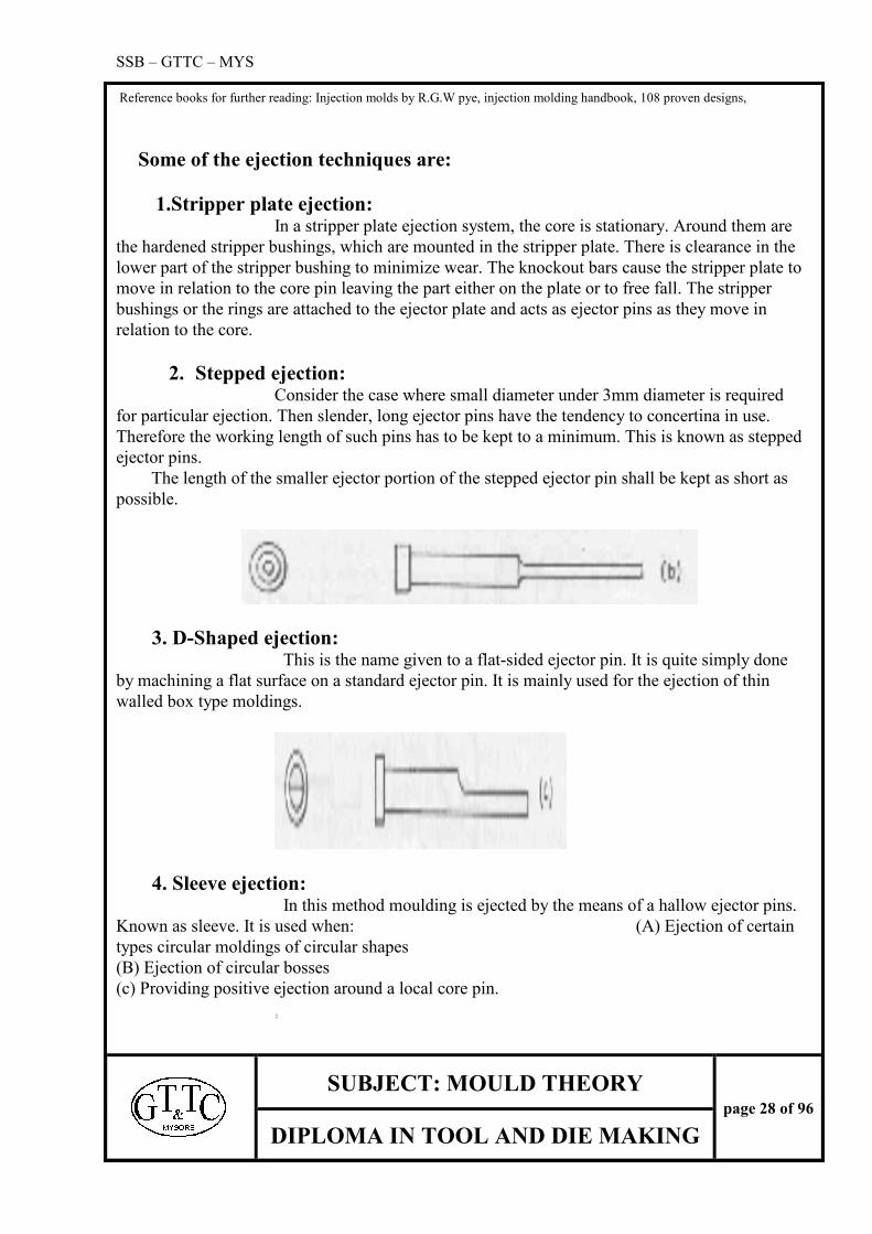
Ejection system:
An ejection system consists of several elements like ejector plate, ejector back
plate, ejector pins, guide bush and pillar etc…. All thermoplastic materials contract as they
solidify which means that the moulding will shrink on to the core that forms it. Hence making it
difficult to remove, so to overcome this problem the ejection system is to be incorporated into the
moulding tool
SSB – GTTC – MYS
Reference books for further reading: Injection molds by R.G.W pye, injection molding handbook, 108 proven designs,
SUBJECT: MOULD THEORY
page 28 of 96
DIPLOMA IN TOOL AND DIE MAKING
Some of the ejection techniques are:
1.Stripper plate ejection: In a stripper plate ejection system, the core is stationary. Around them are
the hardened stripper bushings, which are mounted in the stripper plate. There is clearance in the
lower part of the stripper bushing to minimize wear. The knockout bars cause the stripper plate to
move in relation to the core pin leaving the part either on the plate or to free fall. The stripper
bushings or the rings are attached to the ejector plate and acts as ejector pins as they move in
relation to the core.
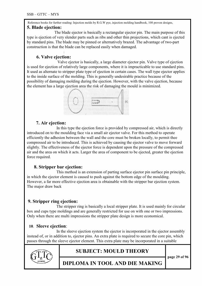
2. Stepped ejection: Consider the case where small diameter under 3mm diameter is required
for particular ejection. Then slender, long ejector pins have the tendency to concertina in use.
Therefore the working length of such pins has to be kept to a minimum. This is known as stepped
ejector pins.
The length of the smaller ejector portion of the stepped ejector pin shall be kept as short as
possible.
3. D-Shaped ejection: This is the name given to a flat-sided ejector pin. It is quite simply done
by machining a flat surface on a standard ejector pin. It is mainly used for the ejection of thin
walled box type moldings.
4. Sleeve ejection: In this method moulding is ejected by the means of a hallow ejector pins.
Known as sleeve. It is used when: (A) Ejection of certain
types circular moldings of circular shapes
(B) Ejection of circular bosses
(c) Providing positive ejection around a local core pin.
SSB – GTTC – MYS
Reference books for further reading: Injection molds by R.G.W pye, injection molding handbook, 108 proven designs,
SUBJECT: MOULD THEORY
page 29 of 96
DIPLOMA IN TOOL AND DIE MAKING
5. Blade ejection: The blade ejector is basically a rectangular ejector pin. The main purpose of this
type is ejection of very slender parts such as ribs and other thin projections, which cant is ejected
by standard pins. The blade may be pinned or alternatively brazed. The advantage of two-part
construction is that the blade can be replaced easily when damaged.
6. Valve ejection: Valve ejector is basically, a large diameter ejector pin. Valve type of ejection
is used for ejection of relatively large components, where it is impracticable to use standard pins.
It used as alternate to stripper plate type of ejection in certain cases. The wall type ejector applies
to the inside surface of the molding. This is generally undesirable practice because of the
possibility of damaging molding during the ejection. However, with the valve ejection, because
the element has a large ejection area the risk of damaging the mould is minimized.
7. Air ejection: In this type the ejection force is provided by compressed air, which is directly
introduced on to the moulding face via a small air ejector valve. For this method to operate
efficiently the adhesion between the wall and the core must be broken locally, to permit thee
compressed air to be introduced. This is achieved by causing the ejector valve to move forward
slightly. The effectiveness of the ejector force is dependent upon the pressure of the compressed
air and the area on which it acts. Larger the area of component to be ejected, greater the ejection
force required.
8. Stripper bar ejection: This method is an extension of parting surface ejector pin surface pin principle,
in which the ejector element is caused to push against the bottom edge of the moulding.
However, a far more effective ejection area is obtainable with the stripper bar ejection system.
The major draw back
9. Stripper ring ejection: The stripper ring is basically a local stripper plate. It is used mainly for circular
box and cups type moldings and are generally restricted for use on with one or two impressions.
Only when there are multi impressions the stripper plate design is more economical.
10. Sleeve ejection: In the sleeve ejection system the ejector is incorporated in the ejector assembly
instead of, or in addition to, ejector pins. An extra plate is required to secure the core pin, which
passes through the sleeve ejector element. This extra plate may be incorporated in a suitable

SSB – GTTC – MYS
Reference books for further reading: Injection molds by R.G.W pye, injection molding handbook, 108 proven designs,
SUBJECT: MOULD THEORY
page 30 of 96
DIPLOMA IN TOOL AND DIE MAKING
recess in the back plate of the SMS (standard mould system). Alternatively, an additional plate,
the core-retaining plate (CRP), may be added between the ejector assembly and the back plate, as
the width of this plate can be the same as that of the ejector plate assembly.
Stripper plate assembly: There basically two types of stripper plate assemblies, which may be classified as
the standard and the basic type system. In the standard type, the stripper plate is incorporated
between the fixed and the moving halves of the mould.
Standard stripper assembly: This assembly system is achieved, quite simply, by adding an extra plate (stripper
plate) between the two primary plates (cavity and core plates). The stripper plate may be
positively coupled to the ejector plate assembly by the means of tie-rods, or operating pins may
be incorporated in the ejector plate assembly.
Basic stripper plate assembly: The directly operated stripper plate assembly of a standard mould is theoretically
achieved by removing the ejector plate assembly and the ejector grid
Fitting an extra plate (stripper plate) between the core and the cavity plates. Actuation of the
stripper plate may be either by the means of the injection machine actuator rods or by some
other means, such as length bolts, chains etc…
Ejector plate assembly: The ejector plate assembly is that part of the mould to which the ejector element
is attached. The assembly is contained in a pocket, formed by the ejector grid, directly
behind the mould plate. The assembly consists of an ejector plate, a retaining plate and an
ejector rod. One end of this latter member threaded and it is screwed into the ejector plate.
Ejector plate: The purpose of this member is to transmit the ejector force from the actuating
system of the injection machine to the moulding via an ejector element. The force required
to eject a moulding is appreciable, particular with those moldings which are deep and
which incorporate little drift.
Retaining plate: This member is securely attached to the ejector plate by screws. Its purpose is to
retain the ejector element/elements. The depth of the head of the ejector element it retains
governs the thickness of the plate. But in general, the retaining plates are within the range
of 7mm to 13mm thickness
Note that for small moulds the retaining plate is made to the same general
dimensions as the ejector plate. These plates are usually made up of mild steel (BS 970-
040A15) material.

SSB – GTTC – MYS
Reference books for further reading: Injection molds by R.G.W pye, injection molding handbook, 108 proven designs,
SUBJECT: MOULD THEORY
page 31 of 96
DIPLOMA IN TOOL AND DIE MAKING
Guiding and supporting of ejector plate assembly:
This assembly must be guided and supported if there is any possibility of undue
strain being applied to any ejector element.
For the smaller type of mould, the ejector plate incorporates an ejector rod, which
slides within an ejector rod bush, which, in turn, is securely fitted, into the back plate of
the mould. This system very conveniently maintains alignment and provides support for
the ejector plate assembly. In the alternative method the bushes are incorporated within the
ejector assembly and these slide on hardened steel columns attached to the back plate.
These columns are normally used as support pillars.
For heavy types of ejector plate or bar assemblies, the plate or the bars may be
supported on its bottom edge. Support strips are attached to the lower support block. The
support strips are of either hardened steel or phosphor bronze. An alignment feature may

SSB – GTTC – MYS
Reference books for further reading: Injection molds by R.G.W pye, injection molding handbook, 108 proven designs,
SUBJECT: MOULD THEORY
page 32 of 96
DIPLOMA IN TOOL AND DIE MAKING
be incorporated if desired in which case T-section support strips are used. The projecting
portion is a slide fit in a mating recess in the ejector plate assembly. It is common practice,
however, on heavy moulds to use hardened steel columns for the main alignment, and
incorporate strips purely for the purpose of supporting the member.
Ejector rod and ejector rod bush: There are two types of ejector rod and ejector rod bush assembly namely.
Conventional type: Here the ejector rod is attached to the ejector plate by the means of a thread. To
ensure concentricity a small parallel length larger diameter is provided on both ejector rod and
ejector plate. The threaded hole may either extend completely through the ejector plate or it may
be blind. This type is particularly desirable when a central sprue puller is used.
Standard part type: This type of assembly consists of plain diameter ejector rod, to which an ejector rod
cap is attached by a means of socket headed cap screw. The attachment of the ejector rod to the
ejector plate is either by means of a projecting integral threaded member or by fitting a suitable
diameter grub screw into the front end of the ejector rod to produce the same result.
Ejector plate assembly return system: This deals with the mechanism of returning the ejector plate assembly to its rear
position in preparation for the next shot, when the mould closes.
Certain ejection system provides positive return of the ejector assembly by virtue of the
mould geometry. The stripper plate mould is an example for that type.
The two common system used are,
The push back return system
The spring return system
The push back returns system: This basically is a large diameter ejector pin fitted close to the Four Corners of the
ejector plate back pin. In the moulding position at the push back pins are plush with the mould
plate surface. In the ejected position the push back protrudes beyond the mould plate surface.
Thus, when the mould is in the process of being closed, the push back pins strike the mould plate
and progressively return the ejector plate assembly to the rear position.
Spring return system: For small moulds, where the ejector assembly is of light construction, a spring or
stacks of Belleville washers can be used to return the ejector plate assembly. Here the spring is
fitted on the ejector rod. A cap is attached to the end of the ejector rod to hold the spring in
position under slight compression.
In operation, when the ejector assembly is actuated, the spring compressed even more.

SSB – GTTC – MYS
Reference books for further reading: Injection molds by R.G.W pye, injection molding handbook, 108 proven designs,
SUBJECT: MOULD THEORY
page 33 of 96
DIPLOMA IN TOOL AND DIE MAKING
Immediately the mould-closing stroke commences, however, the spring applies a force to return
the ejector assembly to its rear position.
Ejector grid: The ejector grid is that part of the mould, which supports the mould plate and provides
a space into the ejector plate assembly, can be fitted and operated. The grid normally
consists of a back plate (clamp plate) on to which a number of conveniently shaped
`support blocks` are mounted.
Tie rod actuation: Method1
A conventional ejector plate and ejector grid system is adopted in this design
but with the retaining plate removed. The stripper plate is coupled with to the ejector plate
by three or four tie rods. The operation of the stripper plate may be either via the injection
machines fixed actuator rod, or alternatively by direct action by the machines hydraulic
ejector system. In the first case as the mould moving half moves rearwards, the ejector rod
straight the actuating rod of the machine. Stripping the moulding from the core arrests the
movement of the ejector and stripper plate, there.
In alternative case the ram of the machines hydraulic ejection actuator is
programmed to function at a specific point in the opening stroke and thereby operate the
stripper plate via the ejector rod and ejector assembly.
Method2
This type is very similar to the first type; the only difference is that the ejector grid system
is dispensed with. In this method the aperture in the moving platen of machine must be
large enough to accommodate the ejector plate and the tie rods.
Length bolt actuation: In this type length bolts suitably situated with in the mould arrest the ejector
plate. The fixed mould plate is recessed to accommodate the head of the length bolt and a
clearance hole in the moving mould plate to accommodate the nut and the lock nut. The
amount by which the stripper plate is allowed for free movement is the sum of the distance
between them
Chain actuation: This type is similar to the length bolt type except that chains are used to arrest
the motion of the stripper plate instead of length bolts. One end of the chain is connected
to the stripper plate and the other is fixed to the mould plate via adapter blocks. When
mould is in closed position the chain hangs down in a loop on either side of the mould. As
the mould opens the chains are progressively straightened until, finally they arrest the
movement of the stripper plate.
SSB – GTTC – MYS
Reference books for further reading: Injection molds by R.G.W pye, injection molding handbook, 108 proven designs,
SUBJECT: MOULD THEORY
page 34 of 96
DIPLOMA IN TOOL AND DIE MAKING
Direct actuation: On medium and large size injection machines actuator rods are incorporated for
ejection purpose. These actuators are positioned symmetric above the centerline of the
moving platen they can be used to actuate the stripper plate directly. When the mould is
open the stripper plate moves back along with the moving half until the stripper plate is
arrested by the actuator rods. Further movement of the moving half causes the core to be
withdrawn through the stripper bush and the required moulding to be ejected.
SPRUE PULLERS
When the mould opens it is essential that the sprue be pulled positively from
the spure bush. With single impression moulds the sprue feeds directly into the base of the
component and the sprue is pulled at the same time as the mould is pulled from the cavity.
For multi impression moulds using a feed back system the sprue would
probably be left in the spure bush each time the mould was opened. This would require a manual
operation to remove the unwanted sprue.
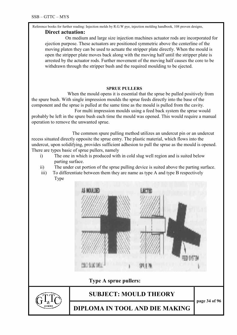
The common spure pulling method utilizes an undercut pin or an undercut
recess situated directly opposite the sprue entry. The plastic material, which flows into the
undercut, upon solidifying, provides sufficient adhesion to pull the sprue as the mould is opened.
There are types basic of sprue pullers, namely
i) The one in which is produced with in cold slug well region and is suited below
parting surface.
ii) The under cut portion of the sprue pulling device is suited above the parting surface.
iii) To differentiate between them they are name as type A and type B respectively
Type
Type A sprue pullers:

SSB – GTTC – MYS
Reference books for further reading: Injection molds by R.G.W pye, injection molding handbook, 108 proven designs,
SUBJECT: MOULD THEORY
page 35 of 96
DIPLOMA IN TOOL AND DIE MAKING
The simplest type is the reverse taper cold slug well type. The cold slug well wall are
tapered inwards creating an under cut in the line of drawn direction. The sprue pin, which is
identical to an ejector pin, is positioned behind the cold slug well such that when the ejection
occurs the slug is ejected with the feed system. The sprue pin is again used to extract the slug
but here it shears through the plastic material leaving the solidified material in the grooves.
Type B sprue pullers:
This type works on the principle of withdrawing the sprue puller through a plate such
as the stripper plate in order to eject the feed system. One common type is the mushroom-
headed sprue puller; the grooved head of the sprue puller creates an affective under cut,
which is used to pull the sprue. During the mould opening the sprue puller is effectively with
drawn with respect to the adjacent plate causing the feed system to sheared from the sprue
puller.
3. Z type sprue puller
SSB – GTTC – MYS
Reference books for further reading: Injection molds by R.G.W pye, injection molding handbook, 108 proven designs,
SUBJECT: MOULD THEORY
page 36 of 96
DIPLOMA IN TOOL AND DIE MAKING
Sprue puller bushes:
The under cut form of the previously discussed under cut sprue pullers will
create machining problems particularly with respect to large mould plates. So it is normal
practice to machine the under form into a separate bush and mount this bush into the mould
plate in a similar manner to that of the circular core insert.
Parting Surfaces:
General: The parting surfaces of a mould are those portions, which are adjacent to the
impressions of both mould plates, which butt together to form a seal and prevent the loss of the
plastics material from the impressions. The parting surfaces are the simplest to manufacture and
maintain. Parting surfaces can be classified as either flat or non-flat.
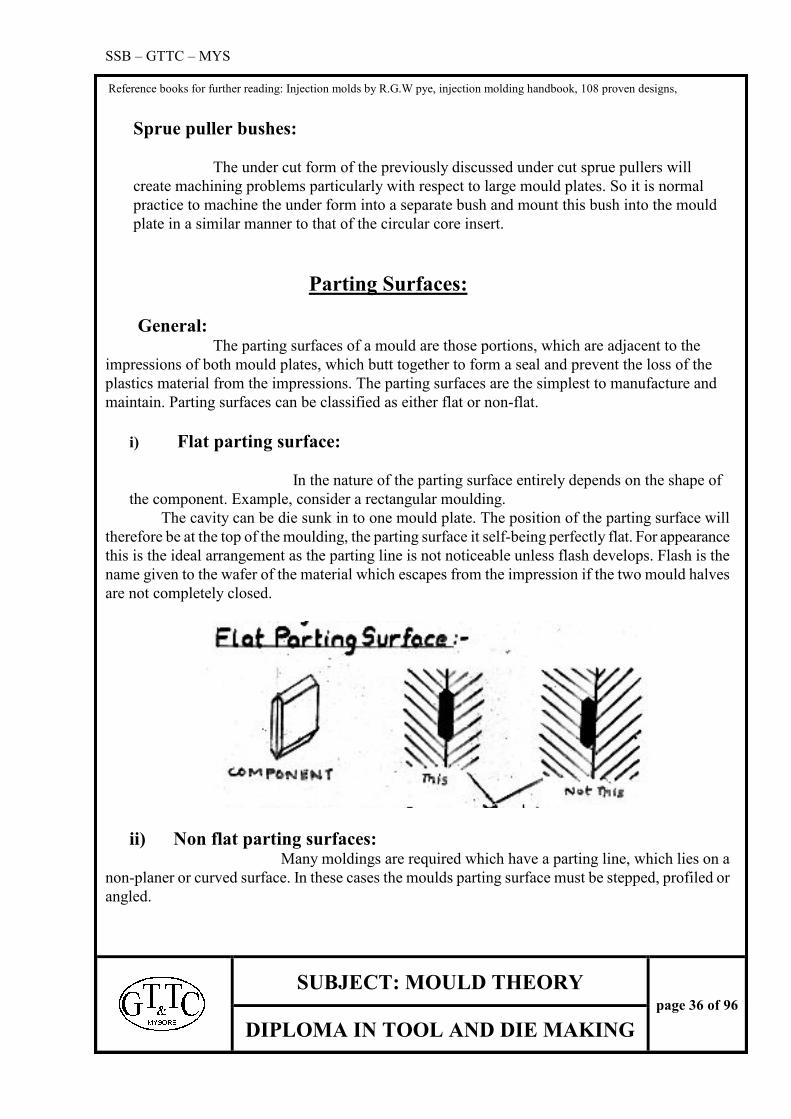
i) Flat parting surface:
In the nature of the parting surface entirely depends on the shape of
the component. Example, consider a rectangular moulding.
The cavity can be die sunk in to one mould plate. The position of the parting surface will
therefore be at the top of the moulding, the parting surface it self-being perfectly flat. For appearance
this is the ideal arrangement as the parting line is not noticeable unless flash develops. Flash is the
name given to the wafer of the material which escapes from the impression if the two mould halves
are not completely closed.
ii) Non flat parting surfaces: Many moldings are required which have a parting line, which lies on a
non-planer or curved surface. In these cases the moulds parting surface must be stepped, profiled or
angled.
SSB – GTTC – MYS
Reference books for further reading: Injection molds by R.G.W pye, injection molding handbook, 108 proven designs,
SUBJECT: MOULD THEORY
page 37 of 96
DIPLOMA IN TOOL AND DIE MAKING
iii) Stepped parting surface: Consider a Z plate component, as this form is stepped, the mould’s parting
surface must likewise be stepped. Note that, as the edge of the component is square with the
face (apart from moulding draft), the entire moulding form can be accommodated in one
mould half. However if the edge had incorporated a radius, then in addition to the mould
having a stepped parting surface the required edge form would have to be die sunk in to each
of the two mould halves.
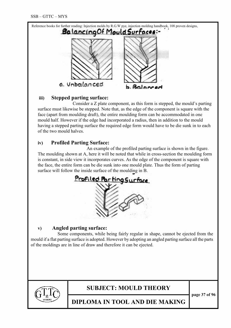
iv) Profiled Parting Surface: An example of the profiled parting surface is shown in the figure.
The moulding shown at A, here it will be noted that while in cross-section the moulding form
is constant, in side view it incorporates curves. As the edge of the component is square with
the face, the entire form can be die sunk into one mould plate. Thus the form of parting
surface will follow the inside surface of the moulding in B.
v) Angled parting surface: Some components, while being fairly regular in shape, cannot be ejected from the
mould if a flat parting surface is adopted. However by adopting an angled parting surface all the parts
of the moldings are in line of draw and therefore it can be ejected.

SSB – GTTC – MYS
Reference books for further reading: Injection molds by R.G.W pye, injection molding handbook, 108 proven designs,
SUBJECT: MOULD THEORY
page 38 of 96
DIPLOMA IN TOOL AND DIE MAKING
vi) Complex edge forms: Until now, we had seen components, which have a constant edge form i.e. either
square, double beveled or radius edges. Now consider components where the edge form is not
constant. This often leads to complex parting surfaces. Consider the given figure, here the
component is a flat rectangular block whose sides have a double beveled edge, but whose
ends are square with top surface. For this there are two alternative designs. The simplest is the
flat parting surface in which the half of the components form will be die sunk into each of the
two moulds. The parting line of the component will therefore occur down the middle of the
double bevel and also across the middle of the ends. This parting line (witness mark) across
the ends may not be acceptable to the costumer, in case the slightly more complete stepped
parting surface must be adopted.
To obviate the parting line passing across the middle of the moulding, it is
necessary to raise the level of the mould surface at either end on one mould plate. To
accommodate these raised portions the complementary form must be machined into the other
mould plate. As the raised portions follow the profile of the top of the component,. The
projecting male form must be carefully bedded down into the complementary female form,
which other wise will result in flash.
Therefore it can be concluded that flat parting surface is simplest and therefore cheapest to
produce. The stepped parting surface will allow the parting line to be positioned in the most
in conspicuous place. Another reason is that stepped parting line will allow for slight
longitudinal difference the two mould halves.

SSB – GTTC – MYS
Reference books for further reading: Injection molds by R.G.W pye, injection molding handbook, 108 proven designs,
SUBJECT: MOULD THEORY
page 39 of 96
DIPLOMA IN TOOL AND DIE MAKING
SPLITS:
General:
A moulding, which has a recess or projection, is termed as an undercut moulding.
The mould design for this type of component is inevitably more complex than for the
inline of draw component, as it necessitates the removal of that part of the impression,
which forms the undercut prior to ejection
Sliding Splits: In this case the splits are mounted in guides on a flat mould plate and are actuated
in one plane by mechanical or hydraulic means. The splits are positively locked in their
closed position by heels, which project from the other mould half
Guiding and retention of splits: There are 3 main factors of guiding and retention system for a sliding split type
moulds.
1) Slide movements must be prevented to ensure that the split halves always come
together in the same place.
ii) All parts of the guiding system must be of adequate strength to support the weight of
the splits and to with stand the force applied to the splits.
iii) Two split halves must have a smooth, unimpeded movement.

SSB – GTTC – MYS
Reference books for further reading: Injection molds by R.G.W pye, injection molding handbook, 108 proven designs,
SUBJECT: MOULD THEORY
page 40 of 96
DIPLOMA IN TOOL AND DIE MAKING
Mould plate for splits: There are several ways of producing a t-shaped slot in the mould plate:
They are,
i) The form may be machined from solid steel plate using a t-type milling cutter. This
is seldom used, as it is difficult to grind the t-form to accurate dimension
ii) Separate guide strips may be attached to a flat mould plate. The strips must be
screwed and doweled to mould plate to ensure rigidity
iii) Machining a u shaped slot across the face of the mould plate produces the required
form and then two flat steel strips are securely attached to the top surface.
Methods of operation: The most used type of operation are based on various types of cam. Like, finger
cam, dogleg cam and cam track actuation type.
I) Finger cam operation: in this system, hardened, circular steel pins, termed finger cams,
are mounted at an angle in the fixed mould plate. The splits, mounted in the guides on the

SSB – GTTC – MYS
Reference books for further reading: Injection molds by R.G.W pye, injection molding handbook, 108 proven designs,
SUBJECT: MOULD THEORY
page 41 of 96
DIPLOMA IN TOOL AND DIE MAKING
moving mould plate, having corresponding angled circular holes to accommodate finger
cams.
A typical design given in the figure which is a spool mould component, the splits are
being shown in closed position at a. as the mould opens the finger cam forces the split to
move outwards sliding on the mould plate b.
Once the contact with the finger cam is lost it ceases the splits movement
immediately. Continued movement of the moving half causes the ejector system to operate
and the moulding to be ejected. on closing the reverse action occurs, i.e. the finger cam re-
enters the hole in the split and forces the split to move inwards. the final closing of the
split is achieved by the locking heels and not by the finger cam.
The distance traveled by each split across the mould plate is determined by
length and the angle of finger cam. The movement can be calculated using
M= (L sinθ)- (c / cos θ)
To determine the length of the finger cam
Where
L=(M/sinθ) + (2c/sin2θ)
M= splits movements
θ = angle of finger cam
L = working length of finger cam
C = clearance

SSB – GTTC – MYS
Reference books for further reading: Injection molds by R.G.W pye, injection molding handbook, 108 proven designs,
SUBJECT: MOULD THEORY
page 42 of 96
DIPLOMA IN TOOL AND DIE MAKING
Spring actuation: This obviates the use of cams altogether in corporate compression springs to force the
splits apart and utilizes the angled face of the bolster to close them. The outward
movement must therefore be limited so that they will re-enter the bolster as the mould is
closed. This type is limited to the moldings, which incorporate relatively shallow
undercuts.

SSB – GTTC – MYS
Reference books for further reading: Injection molds by R.G.W pye, injection molding handbook, 108 proven designs,
SUBJECT: MOULD THEORY
page 43 of 96
DIPLOMA IN TOOL AND DIE MAKING
Dogleg cam actuation: This type of actuation is used where a greater split delay is required than which can be
achieved by the finger cam. Dogleg cam, which is of a rectangular section, is mounted on
to fixed mould plate. Each split incorporates a rectangular hole, the operating face of
which has a corresponding angle to that of the cam.
Sequence of operation: at the mould is closed and splits are locked together by
locking heels of a mould plate. The splits do not immediately open and the mould halves
are parted at b, because of the straight portion of the dig leg cam. The mould, which is
encased with in the splits, will thus be pulled from stationary core. Further movement of
the core will cause the splits to actuate by the dog leg cams. This thereby causes the
moulding to be released. The reverse action occurs when the mould is closed.

SSB – GTTC – MYS
Reference books for further reading: Injection molds by R.G.W pye, injection molding handbook, 108 proven designs,
SUBJECT: MOULD THEORY
page 44 of 96
DIPLOMA IN TOOL AND DIE MAKING
Cam track actuation: This type utilizes a cam track machine din to a steel plate attached to the fixed half of the
moulding. A boss is fitted to both side of the split will run on this track. The movement of
the splits therefore can be accurately controlled by the specific cam track design.
Hydraulic actuation: in this type splits are actuated hydraulically and are not dependent on the opening movement of the mould. The splits can be operated
automatically at any specific time. Operating program on the machine does this. Machines,
which do not have programming, for cylinder controls it, is necessary to add separate
hydraulic operating circuit.

SSB – GTTC – MYS
Reference books for further reading: Injection molds by R.G.W pye, injection molding handbook, 108 proven designs,
SUBJECT: MOULD THEORY
page 45 of 96
DIPLOMA IN TOOL AND DIE MAKING
Splits locking method: It is essential that splits are held rigidly during injection, as high pressures develops with
in the impression will tend to force them apart. to resist these pressures the splits are being
conveniently locked in their positions by the use of a chase bolster. When the mould is
closed the chase bolster encloses and clamps the splits. Each split will have sloping or
angled face accurately machining the respective angled face of the chase bolster. When
this type is adopted the locking angle must be at least 5 degrees greater than the cam-
operating angle.
Angled lift splits: In this type the splits are mounted in a chase bolster, which forms part of the moving half
of the mould. The splits are caused to move out with an angular motion, the outward
component that relieves the undercut portion of the moulding. The splits are normally
actuated by ejector system. In a spool mould it should be noted that the guiding of the
angled lift is not as critical as for the guiding the sliding splits. The alignment of splits is
achieved by seating them in chase bolster.
Side cores and side cavities:
A side core is a local core, which is normally mounted at right angle to the
mould axis for forming a hole or a recess in the side face of the moulding. In this side core
will prevent the in line removal of the moulding and some means being provided for
withdrawing the side core before the ejection.
The side cavity performs similar function to the side core, in that it permits the
moulding of components, which are not in the line of draw. This element caters for
components with projection/s on one or more of their side faces. The side cavity is a
segment of a solid cavity insert or plate which can be withdrawn to permit the moulding to
be ejected in line.
Internal Undercuts
1. Form pin angled ejection
form pin is used to mould internal undercut as well as the same thing is used for ejection.
2. Collapsible core method
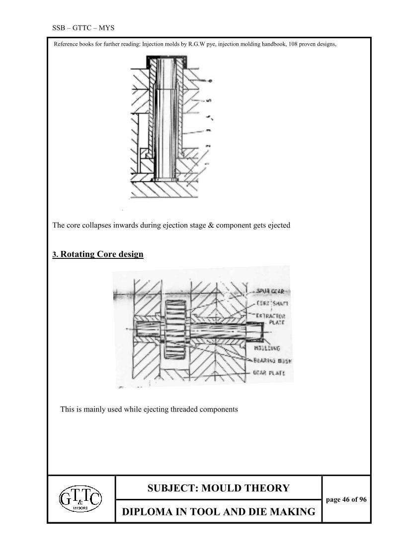
SSB – GTTC – MYS
Reference books for further reading: Injection molds by R.G.W pye, injection molding handbook, 108 proven designs,
SUBJECT: MOULD THEORY
page 46 of 96
DIPLOMA IN TOOL AND DIE MAKING
The core collapses inwards during ejection stage & component gets ejected
3. Rotating Core design
This is mainly used while ejecting threaded components
SSB – GTTC – MYS
Reference books for further reading: Injection molds by R.G.W pye, injection molding handbook, 108 proven designs,
SUBJECT: MOULD THEORY
page 47 of 96
DIPLOMA IN TOOL AND DIE MAKING
4. Loose insert Design
Loose inserts are used when it is not possible to eject the component by ordinary method. There
should be second insert ready to load in as soon as the first insert is removed out.
Runner less moulds (hot runner):
The term runner less mould may be applied any mould in which a conventional runner
system is not present. For the mould system, which incorporates a direct feed form the
nozzle, comes under the above classification.
Nozzles: The purpose of the nozzle is to provide the flow path for the plastic melt
from the machine cylinder to the mould. The simplest type is which the nozzle butts on the
sprue bush of the mould. There are two standard designs
i) First type in corporate a hemispheric end
ii) Second type is flat ended
The small length of reverse taper in the bore at the front of the nozzle is such that the
sprue is just broken in side the nozzle. This helps to keep the nozzle face clean and also
helps in maintaining leak free sealing face. Special nozzles are required for certain free
flowing materials like nylon etc.
Extended nozzle: We learnt the advantage of keeping the length of sprue gate as short as possible to
minimize pressure drop and also to blemish left on the moulding when the sprue gate is
removed. With the standard extended nozzle type the length of the sprue gate is controlled
by depth of mould plate. The special design in this are termed as long reach nozzle or
extended nozzle. Some means of heating the nozzle must be provided in order to prevent
the cooling of plastic material. One method is to fit a resistant type band heater on the
parallel length of nozzle and to control its temperature.
Barb nozzle: The conventional sprue gate results in sizable blemish being left at the
injection point. To reduce it to a minimum some form of pin gate is necessary. one method
of achieving this form of gate is by using a special nozzle. this nozzle is termed as barb
nozzle or Italian nozzle.
This is similar to the standard nozzle except that a projection at the front incorporates
barbs. it is this portion of the nozzle which is accommodate in reverse taper sprue.

SSB – GTTC – MYS
Reference books for further reading: Injection molds by R.G.W pye, injection molding handbook, 108 proven designs,
SUBJECT: MOULD THEORY
page 48 of 96
DIPLOMA IN TOOL AND DIE MAKING
Heated sprue system: there are two heated sprue system which can be used for
feeding directly into the impression they are,
i) The conventional sprue bush is replaced by an internal heated sprue bush
ii) The sprue bush is replaced with an internally extension nozzle.
Internally heated sprue bush: the principle of this type is that a heating element is
in corporate at the centerline of sprue bush in the flow way between the injection machine
nozzle and the gate entry into the impression. by this the polymer material which is heated
may be held at a elevated controlled temperature.
Internally extended nozzle: this type consists of 5 major parts
i) Outer body
ii) Inner body
iii) Torpedo
iv) Torpedo tip
v) Cartridge heater
Hot runner unit moulds:
This is the name given to the moulds, which contain a heated runner with in its
structure. The block suitable insulated from the mould is maintained at controlled
temperature to keep the runner permanently as a melt. The plastic material can be directed
into the mould extremities with out the loss of heat and pressure. this unit is mounted
adjacent to the cavity plate. The plastic material enters via centrally positioned sprue

SSB – GTTC – MYS
Reference books for further reading: Injection molds by R.G.W pye, injection molding handbook, 108 proven designs,
SUBJECT: MOULD THEORY
page 49 of 96
DIPLOMA IN TOOL AND DIE MAKING
bush, passes through a flow way and leaves the unit via secondary nozzle in line with the
impression. When the mould is opened the moulding is pulled from the cavity and sprue
is broken at the smaller diameter d
.
Advantages of hot runner unit mould: i) There is no feed system for the operator to remove from the mould
ii) On manually controlled injection machines the mould open time is reduced
iii) The cost of separating, storing and regrinding scrap feed system is there by saved
iv) As no scrap material is produced it cannot be contaminated
v) The moulding is automatically debated on direct feed system
vi) All of the impressions practically fill at the same time
vii) Moldings are produced with less strain because of lower pressure
viii) Thin walled section moldings fill relatively easily because the melt is at a higher
Temperature close to the impression.
Injection moulding machines
Various types and functions Injection component or end classifies the injection moulding machines
An injection machine basically consists of a clamping portion that consists of mould and
the injection, which, feeds, melts, and meters the plastic.
Injection moulding machines can be classified according to their construction as
1. Hand injection moulding machines
2. Semi automatic moulding machines
3. Fully automatic injection moulding machines

SSB – GTTC – MYS
Reference books for further reading: Injection molds by R.G.W pye, injection molding handbook, 108 proven designs,
SUBJECT: MOULD THEORY
page 50 of 96
DIPLOMA IN TOOL AND DIE MAKING
Hand injection moulding machines
This is a basic type of injection moulding machine. it is mainly used where the component
precision is not high, for average surface finish , production rate is low & is limited by size.
Machine consists of a vertical barrel, which has a plunger on it & a clamping unit. The material is
fed in the barrel & the external band surrounding it heats it. A thermostat controls the
temperature. When the material is sufficiently melted for the feed, it is pushed by the plunger,
which is manually powered. Hand molding machines doesn’t have any cooling attachments or
ejection facilities. The mold has to be physically opened by hand & component knocked out.
Semi automatic moulding machines
Semi automatic machines are of two types they are vertical & horizontal. In vertical
feeding direction is perpendicular to clamping direction where as in horizontal
It is in line with the mold. In this kind of machines injection is automatic & cycle can be set for
injection & the amount of material fed can be controlled as well as pressure.
Ejection is manual. Moderate quality of component can be achieved.
Fully automatic injection moulding machines Fully automatic machines provides fully automated injection, clamping, opening & ejection,
preheater with hydraulic facilities for side cores or splits. Latest machines consist of
microprocessor controller, which scan store the parameters set for the each mold & later can be
recalled. This is for high precision component with optimized cycle time. Large volumes of
production can be handled & the machine ranges from as low as 10 tons to 1200 tons.
Again fully automated machines can be classified on the specifications like distance between the
tie bars, injection pressure, shot capacity, plasticizing capacity, maximum clamping tonnage &
also on the type of injection mechanism.
Injection mechanism can be basically classified in to two types. They are
1. Torpedo type (plunger type)
2. Screw plunger type
There are double cylinder, indexing type injection moulding machines for specific components
like double color moldings

SSB – GTTC – MYS
Reference books for further reading: Injection molds by R.G.W pye, injection molding handbook, 108 proven designs,
SUBJECT: MOULD THEORY
page 51 of 96
DIPLOMA IN TOOL AND DIE MAKING
Torpedo type (Plunger type)
The single stage plunger uses a plunger to force material over a spreader to torpedo. Resistance
heaters supply the heat.
Conduction and convection heat the material.
The two-stage plunger- type machine uses a single stage plunger to plasticizing the material and
force it into a second cylinder shoots. The material into the mould.
The two-stage screw plunger is essentially similar to the plunger -plunger machine except that a
fixed screw is used for plastic zing instead of plunger.
Screw plunger Type
A reciprocating screw uses a rotating screw to plasticize the material. As the screw turns, the
plasticized material is forced in front of it, pushing the screw back. The material is injected by
bringing the screw forward, which then acts as a plunger
Mould Setting Mould is hoisted from the crane & is loaded in the suitable machine from the top in tie
bar machines. Then the platens are closed on the machine & clamped. Opening
Stroke, ejection stroke, clamping tonnage & injection pressure is set. Cooling circuits are
connected. Mould is preheated by hot oil circulation if necessary & thus the mould is ready for
taking component
Moulding process First the material is loaded in the hopper where it is preheated to the required temperature.
Pre heating is done to remove moisture content in the material which otherwise will produce a
defective component. The material, which is in the granular form, may be mixed with pigments &
dies for coloring also. A built in magnet separates the ferrous particles from the plastic material.
Next the material flows from the hopper to the barrel. Barrel is heated by 4 stage
heating process. The barrel heats the material. Materials get plasticzed by the rotating screw & by
the action of the heat. The rotating screw & the reciprocating mechanism pushes the material
forward.

SSB – GTTC – MYS
Reference books for further reading: Injection molds by R.G.W pye, injection molding handbook, 108 proven designs,
SUBJECT: MOULD THEORY
page 52 of 96
DIPLOMA IN TOOL AND DIE MAKING
At the end of the barrel there is a nozzle with the valve. The material is injected through the
nozzle in to the mould.
Moulding cycle
3. Closing
4. Injection of material
5. Curing the component
6. Opening of the mould
7. Ejection
There are three ways of filling the mould,
The first is by having a screw in full forward position. The screw starts to rotate after the
mould is closed and fills the mould; the pressure is to the injection ram to apply the final injection
pressure.
Secondly is to fill the previously plasticized material. The screw acting as a ram comes
forward slowly and when it reaches its full forward position it starts to turn until the mould is
filled. Then a small cushion is maintained and hydraulic pressure is applied to complete the cycle
Lastly, is to start with a full barrel and continue until the point where the screw comes
forward and a small cushion is left behind. This method allows for a rapid filling cycle.
METHODS AND REMIDES FOR RECTIFICATION OF
COMPONENT DEFECTS:
Injection moulding faults may appear during starting a new model, when
changing to a new material, or during the regular operation of mould. Major moulding faults are
short shot, parts flashing, brittleness, and discolourisation, degrading and burning of material
etc…
Let’s discuss some them
1. Short shot: A short shot is the case where, usually the material solidifies before it
is completely fills the cavity and also due to insufficient effective pressure on the material in the
cavity.
The short shots can be over come by increasing the temperature and pressure of the material
and also by increasing the nozzle-sprue-runner gate system to the required effectiveness. Other
times it may require improvements in the mould and part design.
Apart from these short shot can be rectified by,

SSB – GTTC – MYS
Reference books for further reading: Injection molds by R.G.W pye, injection molding handbook, 108 proven designs,
SUBJECT: MOULD THEORY
page 53 of 96
DIPLOMA IN TOOL AND DIE MAKING
Checking the material in the hopper.
Checking for blockages in the hopper’s throat.
Increase feed if it low
Increasing the plasticizing capacity of the machine.
Check for loss of injection pressure during cycle
Providing uninterrupted flow of material in the cavity/s
2.Parts flashing: When the parting surface in the mould is not flat, there is an
unbalanced force at certain instances. The plastic material when, under pressure with in the
impression will exert a force which tends to open the mould in the lateral direction. If this
happens some flashings may appear on the angled face.
Parts flashings may be over come by
Increasing the gate system if required.
Equalizing the filling rate.
Increasing the wall thickness. Thin walls may cause premature freezing.
Check for loss of pressure in cylinder.
Uninterrupted filling.
3.Brittlens: Due to degradation of the material during moulding the component may
loose its property of with standing external force and impact. This disorder is known as
brittleness.
Brittleness can be over come by,
If the material is thermally degrading then lower cylinder and nozzle temperature.
Increase injection speed, pressure, and forward time.
Increase mould temperature if low.
Reduce the screw speed.
4. Material discolourisation: Material in the mould often looses its original colour
due to burning and degradation that is caused by excessive temperatures, material hang-ups in the
system. The discolourisation of component be solved by,
Providing a clean nozzle.
Checking for colorant and additives degrading
Proper functioning of thermo couple
Proper working of temperature control

SSB – GTTC – MYS
Reference books for further reading: Injection molds by R.G.W pye, injection molding handbook, 108 proven designs,
SUBJECT: MOULD THEORY
page 54 of 96
DIPLOMA IN TOOL AND DIE MAKING
Proper removal of lubricant and unwanted oil from mould
Providing better mould lubricants.
5. Surface defects: Surface defects are faults like splay marks caused by wetness of
hygroscopic materials and water condensed on no hydroscopic pellets, contamination etc…
Splay marks and surface disturbance at the gate are probably the hardest moulding
faults to over come. Some of the remedies are,
I) If the moulding condition do not help it is usually necessary to change the gating system
and mould temperature control.
Heating at the gates with a propane torch will determine the advisability of adding a heat
sink or a heating cartridge in the gating area.
Localizing gate heating.
5. Wrapage and Excessive Shrinkage: Wrapage and excessive shrinkage are the
faults caused by the faulty design of the part, misallocation of the gate, irregular-moulding
conditions. These problems could de over come by
Increasing the cycle time.
Increasing the pressure without excessive packing.
Increasing the injection boost without excessive packing.
Keeping the packing to the minimum for wrapage
Keeping the packing to the maximum for shrinkage.
Increasing the wall thickness.
Providing sufficient venting.
Adding ribs and fillets.
6. Poor welds (flow marks): Flow marks the results of welding cooling material
around the projection, such as pins, which show up as broken parts, and their visibility depends
upon the material, colour and surface. Poor welds may be prevented by venting at the weld,
adding a run-off from the weld section, increasing the wall thickness of the part at the weld,
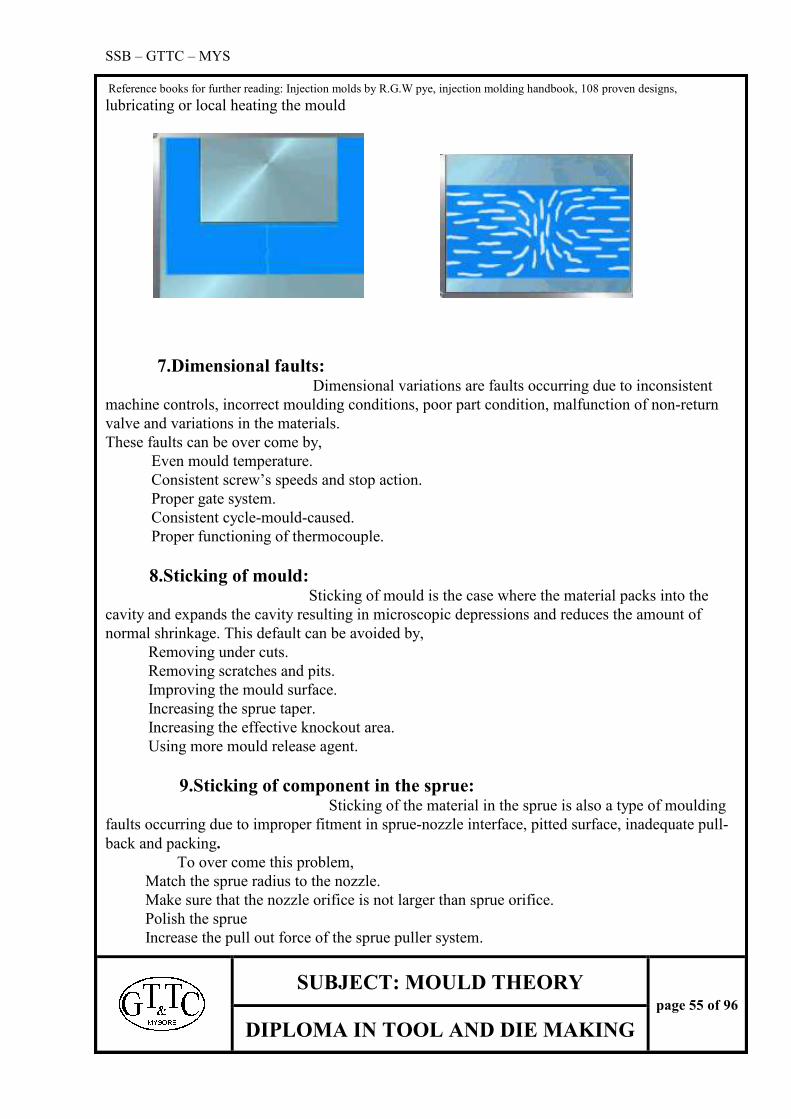
SSB – GTTC – MYS
Reference books for further reading: Injection molds by R.G.W pye, injection molding handbook, 108 proven designs,
SUBJECT: MOULD THEORY
page 55 of 96
DIPLOMA IN TOOL AND DIE MAKING
lubricating or local heating the mould
7.Dimensional faults: Dimensional variations are faults occurring due to inconsistent
machine controls, incorrect moulding conditions, poor part condition, malfunction of non-return
valve and variations in the materials.
These faults can be over come by,
Even mould temperature.
Consistent screw’s speeds and stop action.
Proper gate system.
Consistent cycle-mould-caused.
Proper functioning of thermocouple.
8.Sticking of mould: Sticking of mould is the case where the material packs into the
cavity and expands the cavity resulting in microscopic depressions and reduces the amount of
normal shrinkage. This default can be avoided by,
Removing under cuts.
Removing scratches and pits.
Improving the mould surface.
Increasing the sprue taper.
Increasing the effective knockout area.
Using more mould release agent.
9.Sticking of component in the sprue: Sticking of the material in the sprue is also a type of moulding
faults occurring due to improper fitment in sprue-nozzle interface, pitted surface, inadequate pull-
back and packing.
To over come this problem,
Match the sprue radius to the nozzle.
Make sure that the nozzle orifice is not larger than sprue orifice.
Polish the sprue
Increase the pull out force of the sprue puller system.

SSB – GTTC – MYS
Reference books for further reading: Injection molds by R.G.W pye, injection molding handbook, 108 proven designs,
SUBJECT: MOULD THEORY
page 56 of 96
DIPLOMA IN TOOL AND DIE MAKING
Reduce feed.
Reduce ram forward time.
Reduce material temperature.
10. Sticking of component in the mould: After the moulding process components tend to stick to the core part mainly due to
insufficient knockout, packing of material into the mould or due to incorrect mould design. If
parts stick in the mould, it almost impossible to get the right the component.
Sticking of components can be rectified by,
Checking for the cause of sticking that is it due to short shots or due to incorrect engaging
of knockout system.
Removing under cuts, burrs, nicks and similar irregularities.
Restore and re-polishing.
Increasing the taper.
Increasing the effective knockout area.
Other type of moulding process
Extrusion:
Introduction:
One of the common methods of processing plastics is EXTRUTION, using a
screw (known as extruder screw) inside a barrel. The plastic (usually in the form of granules or
powder) is fed from a hopper on the screw. It is then conveyed along the barrel where it is heated
by conduction from the barrel heaters and due to its movements along the screw flights. The
depth of the screw channel is reduced along the length of the screw so as to compact the material.
At the end of the extruder the melt passes through a die to produce an extrusion of the desired
shape.
Examples of extrusion

SSB – GTTC – MYS
Reference books for further reading: Injection molds by R.G.W pye, injection molding handbook, 108 proven designs,
SUBJECT: MOULD THEORY
page 57 of 96
DIPLOMA IN TOOL AND DIE MAKING
Basically an extruder screw has three stage or zone namely:
Feed zone
Compression zone
Metering zone
Feed zone:
The function of this zone is to pre heat the plastic and convey it to the subsequent zone. The
design of this section is important since the constant screw depth must supply sufficient material
to the metering zone so as not to starve it.
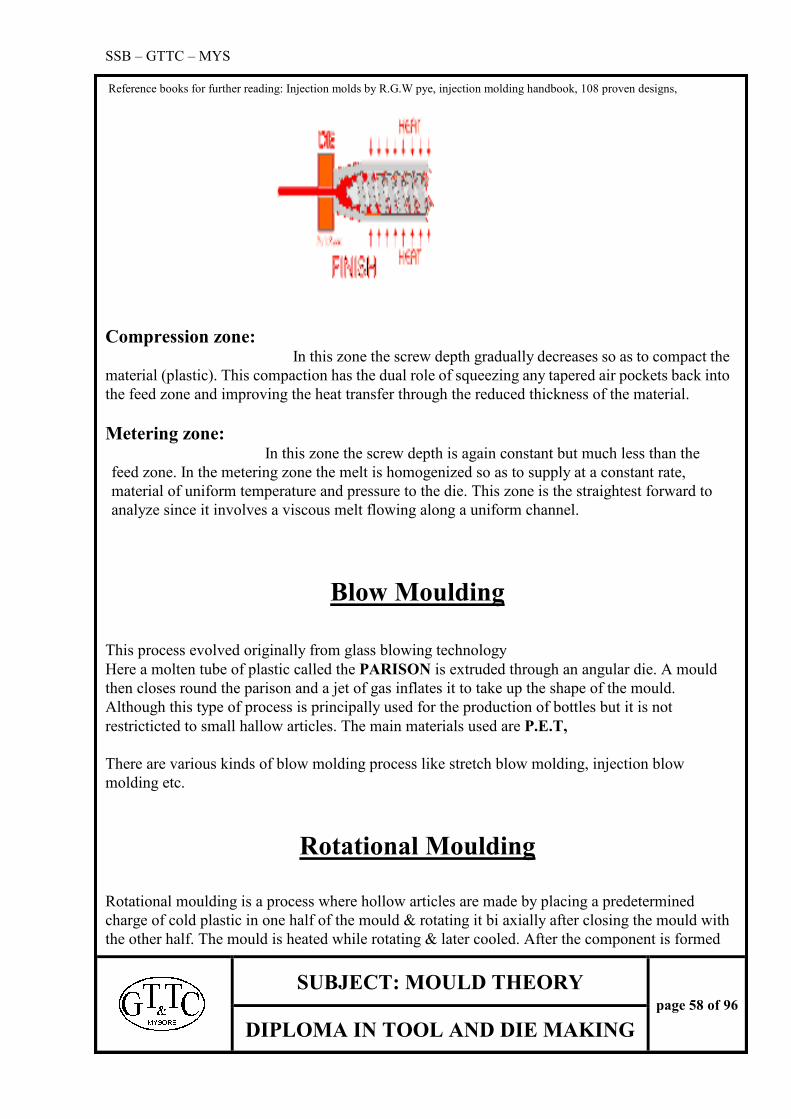
SSB – GTTC – MYS
Reference books for further reading: Injection molds by R.G.W pye, injection molding handbook, 108 proven designs,
SUBJECT: MOULD THEORY
page 58 of 96
DIPLOMA IN TOOL AND DIE MAKING
Compression zone: In this zone the screw depth gradually decreases so as to compact the
material (plastic). This compaction has the dual role of squeezing any tapered air pockets back into
the feed zone and improving the heat transfer through the reduced thickness of the material.
Metering zone: In this zone the screw depth is again constant but much less than the
feed zone. In the metering zone the melt is homogenized so as to supply at a constant rate,
material of uniform temperature and pressure to the die. This zone is the straightest forward to
analyze since it involves a viscous melt flowing along a uniform channel.
Blow Moulding
This process evolved originally from glass blowing technology
Here a molten tube of plastic called the PARISON is extruded through an angular die. A mould
then closes round the parison and a jet of gas inflates it to take up the shape of the mould.
Although this type of process is principally used for the production of bottles but it is not
restricticted to small hallow articles. The main materials used are P.E.T,
There are various kinds of blow molding process like stretch blow molding, injection blow
molding etc.
Rotational Moulding
Rotational moulding is a process where hollow articles are made by placing a predetermined
charge of cold plastic in one half of the mould & rotating it bi axially after closing the mould with
the other half. The mould is heated while rotating & later cooled. After the component is formed

SSB – GTTC – MYS
Reference books for further reading: Injection molds by R.G.W pye, injection molding handbook, 108 proven designs,
SUBJECT: MOULD THEORY
page 59 of 96
DIPLOMA IN TOOL AND DIE MAKING
it is removed from the mould.
Mostly hollow articles are done by this method. It ranges from toys to water drums. The process
is little slow but it is cost effective & component is stress free.
Thermo Forming
Thermo forming is a process where a plastic sheets are moulded using a process called
thermoforming. Here the sheet is laid on a die & buy using a vacuum section & heat the
components are formed in to desired shape. Later the extra material is trimmed off.
SSB – GTTC – MYS
Reference books for further reading: Injection molds by R.G.W pye, injection molding handbook, 108 proven designs,
SUBJECT: MOULD THEORY
page 60 of 96
DIPLOMA IN TOOL AND DIE MAKING
COMPRESSION MOULDS
INTRODUCTIONS
The basic principle of compression moulding is that the plastic material becomes fluid under the
influence of heat and pressure and the material is forced into any opening in the mould to obtain the
desired shape.
WORKING PROCESS
Compression moulds are made out of steel. The moulding sections of the mould are hardened and
are highly polished.
Two halves of the moulds are mounted in between the platens of the hydraulic press. The material
is placed in the cavity of the heated mould in the form of powder or preformed pellets. As the press
closes the two halves of the mould, the plunger causes the material to flow through the mould. As the
material is compressed into shape, the heat and pressure causes a chemical reaction in the material,
which set or cured into the shape of required piece part.
WORKING PRINCIPLE OF COMPRESSION MOULD
Figure1 show the cross section of a compression mould in the open position with the powder
placed in the cavity for moulding.
Figure 2 shows the mould in closed condition after the material has been moulded into shape.
The bottom half of the mould remains stationary in the press.
The arrow in figure1 shows the movement of the press to close the mould. The
arrow in figure 2 indicates the movement of the press to open the mould and to remove the moulding
article.
A TYPICAL COMPRESSION MOULDING CYCLE
LOADING OF MOULD
First the mould is prepared and set between platens in a press. The mould is heated by using
cartridges. The preform (material) is then placed in the loading well of the mould after preheating.
CLOSING OF MOULD
Once the material (powder) is placed in the loading well, the mould is made to close until the
plunger butts to the cavity top surface (closing land ones).
PRESSING Once the mould is closed, pressure is applied in order to make the material to flow into the

SSB – GTTC – MYS
Reference books for further reading: Injection molds by R.G.W pye, injection molding handbook, 108 proven designs,
SUBJECT: MOULD THEORY
page 61 of 96
DIPLOMA IN TOOL AND DIE MAKING
extremities of the impression and to compact the material.
CURING TIME
It is the time elapsed when the movement of the presses cases and the pressure is retained until
the pieces part is certified.
OPENING OF THE MOULD
After the piece part is completely cured, mould is open at the parting surface, thereby making
the provision for removal of the moulded article.
EJECTION The component is then ejected by means of ejector pins or knobs or knockouts i.e., the
components is lifted from the impression up to the parting surface or above and then manually
removed.
CLEANING OF MOULD The mould is cleaned for flash and left out material by compressed air and the mould is ready for the next
cycle.
FUNDAMENTALS OF MOULDING
In order to understand the fundamental of moulding and mould construction, the following definitions are
given.
1.PLATEN
It is the flat surface of the moulding press. in which the two halves of the mould are mounted. It
generally positions horizontally on compression presses and vertically on Injection moulding machines.
2.DIE OR CAVITY
It is the female section of the mould, which generally gives the external shape for the part to be
moulded.
3.CORE OR PLUNGER
It is the main portion of the mould in a compression mould. The plunger pushes or forces the
material into any opening of the cavity. It gives the internal profiles for the component during
moulding.
4.CHASE OR HOUSING
These are steel plates used to hold the cavities and the plunger.
5.MOULD
SSB – GTTC – MYS
Reference books for further reading: Injection molds by R.G.W pye, injection molding handbook, 108 proven designs,
SUBJECT: MOULD THEORY
page 62 of 96
DIPLOMA IN TOOL AND DIE MAKING
a) To shape or form an article
b) It is an entire assembly of cavities, housings, Plunger, ejector unit & etc, which are necessary to
mould plastic articles.
6) MOULDING
It is the article or part to be moulded.
7) STOPPER
It is horizontal surface used to limit the stroke of the press
8)PARTING LINE
It is the line or surface at which the two halves of the mould i.e., the plunger and the cavity meet and
forms a seal, which prevents the plastic material from escaping.
9) FLASH
It is a thin unwanted section or a film or moulding material that forms at the parting surface.
10) TABLET OR PREFORM
It is the moulding material that has been pressed in to some desired shape for efficient loading of
the moulding material .The tablet can have a form, which is nearer to the finished moulding article e.g.:
Round ob-round, square
ADVANTAGES
I) Eliminates larger area of filing room
ii) Correct quantity of powder is maintained
iii) For multi-cavity mould, loading is easier
iv) More effective in preheating, because they are more homogenous.
A PARTS OF MOULDING TOOL
A general compression mould consists of different parts. Each part is important in its own respect
and has a different function to perform. The following are the list of parts with their basic functions.
1) TOP PLATE
This is the top most plate. The top position of the mould parts are clamped by means of
screws and is also used for clamping the top assembly on to the machine platen. This plate supports
the core inserts and prevents it from coming back.

SSB – GTTC – MYS
Reference books for further reading: Injection molds by R.G.W pye, injection molding handbook, 108 proven designs,
SUBJECT: MOULD THEORY
page 63 of 96
DIPLOMA IN TOOL AND DIE MAKING
2) CORE PLATE
This is a plate where the core or plunger is fixed in position and in alignment with the cavity.
3) CORE This is used in the mould to give the inside profile of a component. it is the male part of the
complete tool.
4) CAVITY
Cavity is the hollow shape of the mould, It is the main part of the mould to get the outside profile
of the component. It is the female part of the complete tool.
5) CAVITY PLATE
A plate or block of steel, which contains the cavity in position, used for fixing the cavity in position.
With the help of guide bushes, it aligns the core plate in its axis.
6) SPACERS OR DISTANCE BARS
These are parallels to be used in moulds to facilitate the seating of ejector assembly, which is used
for the removal of the component.
7) BOTTOM PLATE
It is the bottom most part of the mould assembly. It is used for clamping the bottom assembly of
the mould on to the machine platens.
8)BACK PLATE
It is fixed behind the cavity plate .it supports the cavity inserts and prevents the inserts from
moving down.
8) EJECTOR BACK PLATE
This houses the ejector pins and push back pins & together with the ejector plate, ejector guides &
forms an ejector assembly.
9) EJECTOR PINS
It is a moving pin used for removal of components, which are fitted in ejector assembly.
10) PUSH BACK PINS (RETAINER PINS)
SSB – GTTC – MYS
Reference books for further reading: Injection molds by R.G.W pye, injection molding handbook, 108 proven designs,
SUBJECT: MOULD THEORY
page 64 of 96
DIPLOMA IN TOOL AND DIE MAKING
These pins are fitted in the ejector plate and ends up on the mould parting line. This is to retain
the ejector plate assembly to its original position.
****************************************************************************************
***************
2) TYPES OF COMPRESSION MOULDS
Compression moulds are classified into the main categories:
* HAND MOULDS
*SEMI-AUTOMATIC
*FULLY AUTOMATIC MOULDS
HAND MOULDS
These are usually smaller in size and not weigh more than 12 kg for easy to handle.
WORKING
The material is put into the cavities and the 2 halves of the mould are closed .It is then placed
between the platens of the press. After the press has been closed the parts are moulded, the mould is
opened & removed from the press & the parts are ejected from the mould on a conveniently located
place or bench. The process is done repeatedly. Hand mould production is limited to small parts, short
runs and proto type work.
SEMI- AUTOMATIC MOULDS
The term semi automatic is used to cover the moulds from which the moulded articles are ejected
by movements of mould parts actuated by the press. After ejection, the press operator then places the
mould parts in a suitable containers or on a bench for flash removal .The operator cleans the mould of
excess material and the process is repeated.
There are different types of semi Automatic moulds in us they are
1) SEMI- AUTOMATIC OPEN FLASH MOULD
2) SEMI -AUTOMATIC FULLY POSITIVE MOULD
3) SEMI -AUTOMATIC LANDED POSITIVE MOULD
4) SEMI -AUTOMATIC SEMI POSITIVE MOULD

SSB – GTTC – MYS
Reference books for further reading: Injection molds by R.G.W pye, injection molding handbook, 108 proven designs,
SUBJECT: MOULD THEORY
page 65 of 96
DIPLOMA IN TOOL AND DIE MAKING
1) SEMI-AUTOMATIC OPEN FLASH MOULD
The first moulds constructed were of the type. This type of moulds may be used to produce large
parts from BMC (bulk moulding compound) or SMC (Sheet moulding compounds). In this type of
mould, loading well is not constructed. The cavity is filled with material and the excess material is
squeezed over the lands. The plastic materials fed are in the form of pallets. Here less pressure is exerted
on the plastic than in any other type of the mould. Thus a less dense moulding results. The flash type of
mould is not generally used with cores filled material and for articles, which require high density. It is
used for manufacture of buttons, Dinnerware, plates, & saucers, and in the manufacture of similar
shallow depth articles.
DISADVANTAGES
There is no positive location between the mould halves.
2) SEMI AUTOMATIC FULLY POSITIVE MOULD
The direct or fully positive mould is primarily used with materials containing cores fillers. The
amount of materials placed into the mould must be measured accurately as there is very less means of
excess material to escape.
In a positive mould, almost all the pressure is exerted on to the material and very little material is
allowed to escape. The clearance between the plunger& the cavity varies between 0.05mm to 0.13mm
per side depending on the size of the moulding and the material to be moulded. This type of mould is
used for deep draw parts where maximum density is required.
These moulds are usually limited to single cavity productions where each charge materials must be
weighed to assure depth of travel and density.

SSB – GTTC – MYS
Reference books for further reading: Injection molds by R.G.W pye, injection molding handbook, 108 proven designs,
SUBJECT: MOULD THEORY
page 66 of 96
DIPLOMA IN TOOL AND DIE MAKING
3) SEMI AUTOMATIC LANDED POSITIVE MOULD
In this type of mould, multy cavity moulds can be done. A bead around the top edge of the mould shape
necessitates the change in the mould shape construction. The mould is landed in positive type in order to
facilitate escape of gases.
This type of mould may opt to cause some trouble, if care is taken at al times to remove the flash
from the landed area. Contained operation with flash left on the land surface will probably result in
damage or brake down of lands.
4) SEMI AUTOMATIC SEMI POSITIVE MOULD
In this type of mould, loading well is positively located above the cavity surface. The difference in the
semi positive type, there is a taper of 2 degree to 3degree on the walls of the loading well, As the 2 halves
of the mould begins to close the mould, acts much like a flash mould and the excess material is allowed
to escape. As the plunger proceeds further inside the cavity, full pressure is exerted on the material and
produces a moulding of maximum density& the mould becomes positive

SSB – GTTC – MYS
Reference books for further reading: Injection molds by R.G.W pye, injection molding handbook, 108 proven designs,
SUBJECT: MOULD THEORY
page 67 of 96
DIPLOMA IN TOOL AND DIE MAKING
FULLY AUTOMATIC MOULDS
It has the basic construction of a semi automatic mould but has provision for series of other
mechanisms. Fully automatic moulds comprise of ejector mechanism, auto-feeding mechanism, and
series of controls for component removal, transportation, cleaning mechanism & host of other controls.
Once the machine is set the operator’s presence is not required near the machine. This type of mould set
is generally for large p[production work.
Automatic moulds are similar to semi automatic moulds but do not need on operator once the mould
has been set up for production these moulds through the use of combination of loading devices, timing
devices, ejector systems, sweeps, micro-switches safety devices and cleaning apparatus fend for
themselves in moulding different articles.
****************************************************************************************
*************
The purpose of each type of mould and factors such as size of the articles, production requirements,
etc, determine which of the 3 moulds to be used
SPLIT CAVITY MOULDS
These moulds are used for components having undercuts or external threads. The cavity is split into 2
halves to enables the components to be removed from the cavity. The split cavity is placed in a
corresponding taper housing, which gives the 2 halves locking when the pressure is applied. When
component is ejected, the halves move apart & release the component from the cavity.
GANG MOULDS
These moulds are used where placing the moulding powder in a single loading well can mould number
of small components & then the plasticised material flows into the individual cavities, because of the
lands in between the cavities, flash results about 0.1mm t0 0.5mm thickness. This flash interconnects the
components, which facilitates the ejection, for subsequent unloading.

SSB – GTTC – MYS
Reference books for further reading: Injection molds by R.G.W pye, injection molding handbook, 108 proven designs,
SUBJECT: MOULD THEORY
page 68 of 96
DIPLOMA IN TOOL AND DIE MAKING
REENTRY MOULD
These are also known as Inverse moulds .In this type of mould, the moulding material in plastic plate is
made to rise into the cavity under pressure. This type of mould is used for long components requiring a
high finish.
3) FACTORS EFFECTING LOADING WELL HEIGHT.
There are 3 basic factors to be remembered while calculating mould loading well size.
1) BULK FACTOR
2) SHRINKAGE ALLOWANCE
3) FLASH THICKNESS ALLOWANCE
4) CALCULATION OF LOADING WELL HEIGHT.
1) BULK FACTOR
It is the ratio of the volume of the loose uncompacted moulding powder to the solid volume of the
component .It is also known as the filling material.
If a loose volume of 4cubic centimeter is required shape of a solid moulding of 1 cubic cm, then the
bulk factor is 3:1 or 4.
2) SHRINKAGE ALLOWANCE
All thermo set moulding compounds shrink as they come out of the mould & cool off. This shrinkage
factor is considered by adding on based dimensions of the part (core & cavity). By which the dimensions
decrease when the part cools down. Shrinkage is a variable factor depends on type of material.
The mould dimensions are increased by this allowance .As the dimensions decrease when the parts
cool down after ejection this allowance is necessary. this shrinkage is different for different materials.
3) FLASH THICKNESS ALLOWANCE
In a mould, which gives horizontal flash to the cavity, depth has to be increased by the amount of
thickness of flash. The flash thickness adds to the total thickness of the part & this thickness must be
subtracts from the basic cavity depth in order to finish piece part with desired thickness.
4) CALCULATION OF LOADING WELL HEIGHT.
The loading well height can be determined as per the dimensions mentioned in the drawing.
1) Bulk factor of moulding material
2) Percentage of wastage of moulding material
3) Height of loading well=Volume of loading well/ area of loading well.
4) Find out bulk volume of moulding powder (cavity volume x bulk factor)

SSB – GTTC – MYS
Reference books for further reading: Injection molds by R.G.W pye, injection molding handbook, 108 proven designs,
SUBJECT: MOULD THEORY
page 69 of 96
DIPLOMA IN TOOL AND DIE MAKING
Data to calculate height of loading well & locking tonnage.
a) Piece part dimension = 10x20x30 mm
b) Component material = melamine formaldehyde
c) Bulk factor of material = 2.5
d) Closing land length = 3mm
e) Corner radius = R 3mm
f) Powder wastage = 10 %
g) Specific compressive pressure: 250 kg/cm
1) CALCULATE THE AREA OF CAVITY WELL AT PARTING LINE
Cross sectional area = 30 x20 = 600
Dimension of filling room
Loading well length = 30+3+3+3+3 = 42mm
Loading well width = 20+3+3+3+3= 32 mm
Area = length x width
= 42x 32
Volume = 42x32x H
2) FIND OUT THE VOLUME OF MOULDING POWDER
Volume of cavity = L x w X H
= 30 X 20 X10= 6000 MM
BULK VOLUME OF MOULDING POWDER = VOLUME OF MOULDING POWDER X BULK
FACTOR = 6000 X 2.5 = 15000
Add 10% wastage to powder volume= 15000 mm + 10 %= 16500 mm
Remaining volume = total volume – cavity volume = 16500- 6000= 10500mm
3) CALCULATE THE HEIGHT OF LOADING WELL
HEIGHT = V – V V= TOTAL VOLUME OF MATERIAL
A V= VOLUME OF ACTUAL CAVITY SPACE
A= AREA OF LOADING WELL
LXWXH= 10500 mm
42 x 32 x H = 10500 mm]
H= 10500
42 x 32.
= 7.8 mm = (approx =8 mm)
LOADING WELL HEIGHT = 8 MM
LOCKING TONNAGE
SSB – GTTC – MYS
Reference books for further reading: Injection molds by R.G.W pye, injection molding handbook, 108 proven designs,
SUBJECT: MOULD THEORY
page 70 of 96
DIPLOMA IN TOOL AND DIE MAKING
=SPECIFIC COMPRESSIVE PRESSURE x AREA OF CAVITY
=250 Kg/cm x 3x2 cm
=250 Kg/cm x 6
=1500 kg
=1.5 Tones
*******************************************************************************
4) FACTORS THAT INFLUENCE COMPRESSION MOULDING The three important factors that must be considered in compression moulding are Temperature,
Pressure, Cure time & Venting.
TEMPERATURE
The majority of thermosetting compounds must be heated to approximately 150 degree centigrade
for optimum cure. Temperature for moulding various materials, can be determined by experimentation
or by getting the information from the manufacturer of the particular material.
Higher temperature may degrade some of the physical properties or electrical characteristic of the
material to set before the cavity is completely filled. The high temperature causes blister and burnt
marks on the component.
Temperatures, which are too low, do not allow the material to flow properly and results in
incompletely cured piece parts of poor consistency, thus reduces the productivity of the cycle. There is
generally an optimum temperature, which produces the best flow characteristics for the particular
material and cavity.
Generally compression and transfer moulds are heated to approximately 150 degree centigrade. The
exact temperature not only vary with the material used and the type of mould, but it also vary with the
geometry of the moulded articles, and whether loose powder or preheated performs are used.
Because plastics are generally good heat insulating material preheating of the charge used is often used
to shorten the time in the moulding. Pre heating temperature is commonly between 65 degree centigrade
to 150 degree centigrade. 150 degree centigrade higher temperatures are possible when heat is more
rapidly transferred to the material.
Pre heated material generally flows more rapidly during actual moulding process & because the
material starts at an elevated temperature the time to complete to cure in the mould cavity is shorten,
generally yielding a more economical overall cycle.
PRESSURE
The pressure needed to mould a particular article depends, on the flow characteristics of the
material, cavity depth and projected area of the piece part. Moulding with thermosetting plastics
require great pressure for 2 basic reasons. To ensure that plastic fills all of the cavity and as a relatively
uniform density through out. To ensure better heat transfer to the material. It is recommended or found
most suitable that pressure of 211Kg/cm is sufficient, for moulding Phenolics. For deeper moulding
exceeding 25mm.It is desired to add 19.3 Kg/cm of depth. For Urea and Melamine formaldehyde double
the amount of pressure is required. For Transfer moulding, Generally pressure of three times the
magnitude of compression moulding is required.

SSB – GTTC – MYS
Reference books for further reading: Injection molds by R.G.W pye, injection molding handbook, 108 proven designs,
SUBJECT: MOULD THEORY
page 71 of 96
DIPLOMA IN TOOL AND DIE MAKING
HEIGHT OF
PIECE
PHENOL MELAMINE DEPTH
01 VERY LOW 200 Kg/ cm 250kg/cm UP TO 15mm
02 LOW 250Kg/cm 300Kg/cm 15-40 mm
03 AVERAGE 300kg/cm 400Kg/cm 40-60 mm
04 HIGH 400Kg/cm 500Kg/cm 60-80 mm
05 VERY HIGH 500Kg/cm 800Kg/cm ABOVE 80mm
CURE TIME
The period required to harden thermo set material partial or complete polymerization is called
Cure time. Many compounds produce parts that are
Hard enough blister free and apparently cured. But a free or dwell time is required to completely
transform the plastic material.
Cure time is the time elapsed when the movement of the press stops until the pressure on the moulded
part is released.
For small and thin walled pieces, cure time will be only a minute or two, and for larger pieces, the cure
time will be as high as 30 minutes.
VENTING
Another factor, which should be considered for compression moulding, is venting. During a process
of compression moulding, gases are formed as the chemical reaction takes place in the material. Some
provision must be made to get rid of these gases. Gas pockets can cause incomplete shots or blistered
piece parts. The method of getting rid of these gases is to allow the mould to breathe i.e., the mould is
closed and then opened again for about 3mm to get rid of gases and then closed again.
Other methods are by making a small flat on the periphery of the plunger or by making small grooves
on the cavity top surface. The air can be let to escape through the ejector pin holes also.
HEATING OF MOULDS
Heating of moulds parts takes place by the resistance heating elements in the mould. The
advantage of heater elements is that it is very easy to control the temperature. The thermo set or
metallic strip is fixed in the mould part and set on to the required temperature range. When an electric
current is passed through a resistance wire, heat is produced. The mould parts are heated by way of
conduction.
For small moulds, heating is done with heater element belt placed around the mould. It gives
sufficiently uniform temperatures.
For bigger moulds several heating cartridges have to be placed in channels in such a way that the
uniform heating of the mould is done. All these heating cartridges are connected to a one common plug.
Now a day’s heavy moulds are heated by induction heating. The heated mould has to be insulated

SSB – GTTC – MYS
Reference books for further reading: Injection molds by R.G.W pye, injection molding handbook, 108 proven designs,
SUBJECT: MOULD THEORY
page 72 of 96
DIPLOMA IN TOOL AND DIE MAKING
with material like asbestos .The temperatures of the mould depends on the plastic material to be
processed.
****************************************************************************************
************************
5) PRE HEATING
In order to reduce the setting time and in order to reduce the moulding cycle the thermo set
material should be pre heated .the moisture content of the material is also removed in the process.
Preheating can be done in different ways. Preheating with infrared bulbs. Preheating in gas or electrical
heated furnace & preheating in high frequency fields.
PREHEATING IN FURNACES
It is not so much used because the preheating time is very long .Heating to 100 degree centigrade
takes approximately 30 minutes.
PREHEATING WITH INFRARED LAMPS
This method can reduce the above-mentioned time by approximately 50%. A dull light source in a
furnace with a reflective inside is used. Infrared heating has more heat penetration than pre heating in a
conventional furnace, to obtain good results, the thickness of the tablet should not go beyond 12mm.
PREHEATING IN HIGH FREQUENCY FIELDS
This method reduces the preheating time still further. it makes effective heating possible. It takes one
minute to preheat 500 grams of charge to 110 degree centigrade .The high frequency preheating
equipment consist of two metal plates placed parallel to each other and is connected to high frequency
AC circuit. When an insulating material is placed in between the plates and the current is switched on
the electrical energy will be transmitted to the thermo set material where it is converted into heat
energy. This method is very much used and the tablets are more homogeneous resulting in a good
preheats.
Preheating of thermo set with high frequency gives the following advantages.
1) Heat is directly induced within the material
2) Uniform heating of charge is present.
3) No heat loss
4) Faster heating cycle
5) Clean, convenient and easy handling of the charge.
6) Efficient heat plasticisation in one minute that gives a faster and immediate flow
****************************************************************************************
************************
6) TRANSFER MOULDS
Transfer moulding is a method of moulding thermo set material. In transfer moulding, the
material is not placed in the cavity as in compression mould, but is placed in a loading chamber outside
the cavity where the material is subjected to heat and pressure, in order to liquidify it. When the liquid
starts flowing, the material by plunger either through a system of runners & gate into the cavity.

SSB – GTTC – MYS
Reference books for further reading: Injection molds by R.G.W pye, injection molding handbook, 108 proven designs,
SUBJECT: MOULD THEORY
page 73 of 96
DIPLOMA IN TOOL AND DIE MAKING
Transfer moulding is necessary where
* Thick ness of moulding is critical and has closed tolerance.
* Shape of moulding necessitates the use of thin weak section of metal, thin and small
diameter pins, which could be easily damaged by initial force created by compression mould.
Transfer moulding has various advantages.
1) Tolerances over flash line may be held to a minimum.
2) Reduced cure time as compared to compression mould.
3) Small diameter holes can be moulded and through holes may be moulded flash free.
4) Parts having side cores are easily moulded
5) Moulded in inserts is more easily done?
DISADVANTAGES 1. Gate or Sprue removal becomes necessary.
2. Gates must be properly selected to avoid weld lines
3. Large flat parts are subjected to flow lines
4. Material scrap loss is higher
5. Mould venting is necessary.
6. Higher moulding pressures are required
7. Mould cost is higher than that of Compression moulds.
TYPES OF TRANSFER MOULDS There are two types of transfer moulds
1.POT TRANSFER
2.PLUNGER TRANSFER
1) POT TRANSFER
It is used in a conventional moulding press. Material is placed in the pot provided on top of the
mould. The mould material gets heated by the hot mould. Combining with the pressure of the plunger
the material becomes fluid and is forced into the sprue, runner and gates and in to the cavity. The
pressure is kept until the piece part is solidified. Excess material forms a cull at the bottom of the pot
and also forms a dovetail shape in the plunger called as the Cull pick up. After the parts have been
cured the mould opens near the pot. As the plunger comes out of the pot the sprue is broken at the small
diameter of the taper. The cull pick up on the plunger carries the cull out of the pot and the sprue.
While the mould continues to move, the parting line surface of the mould is open and the component is
ejected.

SSB – GTTC – MYS
Reference books for further reading: Injection molds by R.G.W pye, injection molding handbook, 108 proven designs,
SUBJECT: MOULD THEORY
page 74 of 96
DIPLOMA IN TOOL AND DIE MAKING
Loading position Closed Position
Partially open position Ejection position
2) PLUNGER TRANSFER
In plunger type transfer moulds, the combination of heat of the mould and the pressure of the
plunger on the preform causes the material to become fluid and flow through the runners, and gates
into the cavities.
The plunger transfer defers from the pot transfer in that the plunger is part of the moulding press and
not a part of the mould. By the use of this plunger, the sprue is eliminated and a very thin cull of the
small area is formed above the target area thus reducing the loss of material.
SSB – GTTC – MYS
Reference books for further reading: Injection molds by R.G.W pye, injection molding handbook, 108 proven designs,
SUBJECT: MOULD THEORY
page 75 of 96
DIPLOMA IN TOOL AND DIE MAKING
A TYPICAL TRANSFER MOULDING CYCLE
LOADING
The mould is set between the platens and is adjusted for stroke of opening and the mould is
heated .The preform is preheated and placed in the loading well.
CLOSING OF MOULD
The mould closes, as the press is actuated. the plunger then starts to close and begins to build up
pressure on the material.
TRANSFER INJECTION
As the pressure continues the material becomes fluid and starts to flow through the sprue into the
impression or through the system of runner and gates into the impression.
COOLING
Pressure is retained as the material starts to cure and becomes solid.
OPENING OF MOULD
First the mould starts to open and the plunger comes out of the well carrying the waste cull and the
sprue along with it. Further continuation of the press actuates the latch and the mould is opened at
the parting surface thereby.
****************************************************************
7) DEFECTS AND REMEDIES IN COMPRESSION MOULDS.
A) BLISTERING (swollen areas on a moulding surface)
1. Increase cure time.
2. Close mould slowly on the low pressure, then apply high pressure
3. Breathe mould as soon as possible
4. Increase pressure
5. Lower mould temperature
6. Check mould temperature for uniformity.
7. Vent mould at dead ends with vents pins
8. Use stiffer material;
9. Pre heat material to eliminate moisture
10. Increase preheat temperature

SSB – GTTC – MYS
Reference books for further reading: Injection molds by R.G.W pye, injection molding handbook, 108 proven designs,
SUBJECT: MOULD THEORY
page 76 of 96
DIPLOMA IN TOOL AND DIE MAKING
B) SHORT SHOT 1.Adjust charge weight
2.Try, a range of plastics for best grades
3. Increase pressure
4. Lower mould temperatures
5. Pre heat material
6.Try with higher density material to obtain greater back up pressure
in the mould.
7. Breathe mould easier
8. Use semi positive mould
C) DULL SURFACE / POOR GLOSS 1. Adjust mould temperatures – usually reduce
2. Insufficient cure
3. Increase pressure
4. Polish the mould
5. Chrome plate the mould
D) INTERNAL VOIDS 1. Breathe the mould
2. Lower mould temperature
3. Increase pressure
4. Preheat material
5. Close mould slowly and apply lower pressure for longer time
E) MOULD STICKING] 1. Clean moulds surfaces
2. Provide sufficient draft angles
3. Remove dents and undercuts from moulding surfaces.
4. Polish mould surface
5. Adjust ejector pins
6. Increase cure
7. Raise mould temperature
8. Pre heat material
F) ORANGE PEEL 1. Use finer ground material
2. Use lower mould temperature
3. Preheat material by di-electric heating
4. Use stiffer material
5. Close mould slowly on low pressure
G) CLOUDED OR SEGREGATED SURFACE 1. Use lower mould temperature
2. Use pre heat material
3. Check mould temperature for its uniformity
4. Adjust plasticity
5. Adjust pressure and closing speed
SSB – GTTC – MYS
Reference books for further reading: Injection molds by R.G.W pye, injection molding handbook, 108 proven designs,
SUBJECT: MOULD THEORY
page 77 of 96
DIPLOMA IN TOOL AND DIE MAKING
H) DIMPLED SURFACE 1.Use stiffer material
2. Use lower mould temperature
3. Increase charge weight
4. Increase pressure
5.Shape preform more closely to piece
I) WARPED PIECE 1. Increase cure
2. Heat mould more uniformly
3. Redesign ejector pin position for even ejection force
4. Use stiffer material
5. Provide sufficient draft angle
6.Use lower shrinkage material.
7.Use shrink fixture.
J) CRACKING AFTER MOULDINGS 1. Redesign ejector pins positions for even ejection force
2. Use correct size of shrink force
3. Increase wall thickness around insert
4. Increase ribs
5. Use even annealing
6. Increase cure
7. Reduce ejection rate
K) BURNED MARKS /SCORCHED MARKS
1.Reduce preheat temperature
2. Reduce mould temperature
3. Breathing is required
M) THICK FLASH 1.Reduce charge weight
2. Sufficient means of escape
3. Increase pressure
4. Increase mould temperatures
*************************************************************************************
**************************

SSB – GTTC – MYS
Reference books for further reading: Injection molds by R.G.W pye, injection molding handbook, 108 proven designs,
SUBJECT: MOULD THEORY
page 78 of 96
DIPLOMA IN TOOL AND DIE MAKING
DIE-CASTING THEORY
1) INTRODUCTION
Casting is one of the oldest methods of obtaining parts of required form. It consists of feeding
liquid metal to the shaped cavity and allowing it to cool and till the liquid metal solidifies.
Casting is the method of producing metallic parts. Metal casting are majority classified as:
_______________________________________________________________________
Sand casting metal mould casting plaster mould casting investment casting
1) Green sand moulding 1) gravity die casting
2) Dry sand moulding 2) pressure die casting
3) Shell moulding 3) centrifugal casting
4) High pressure moulding
In metal mould casting process, the mould will be metal and hence it will be of permanent
character. Where as in other process the mould will be destroyed for each casting produced.
Die Casting differs from other casting process. In the other casting process the mould is destroyed to
take the component. In other words only one component is produced per mould.
Die-casting is produced by forcing molten metal under pressure into metal moulds called dies
(pressure is not encountered in case of gravity castings).
Die-casting dies are made of metal and are permanent nature, that is mould (or dies) is not destroyed
to take out the component. Any number of components can be produced from a single die.
METAL MOULD CASTING ARE CLASSIFIED AS
1.Gravity Die Casting
2. Pressure Die Casting
3) Centrifugal casting
GRAVITY DIE CASTING
Incase of gravity Die casting the molten metal fills the cavity under gravity. in this process the
liquid metal is poured into the metal die (made of cast iron or steel) and is allowed to cool under the
action of gravity. Cavity in the die is the replica of the component and is designed for easy assembly
and disassembly of dies, pouring and extraction.
PRESSURE DIECASTING
Incase of pressure Die Casting the molten metal is forced under pressure to fill the cavity. In this
process the liquid metal is injected into the cavity under external pressure and this pressure is
SSB – GTTC – MYS
Reference books for further reading: Injection molds by R.G.W pye, injection molding handbook, 108 proven designs,
SUBJECT: MOULD THEORY
page 79 of 96
DIPLOMA IN TOOL AND DIE MAKING
maintained until the liquid metal cools and then the solid casting is ejected out of the cavity.
Hence the pressure casted parts are stronger and accurate then other casted parts.
ADVANTAGES OF PRESSURE DIE CASTING
1.Thin walled castings can be produced.
2. Mass production on fast running machines reduces the manufacturing cost.
3.Intricate castings can be produced with high dimensional accuracy and consequently reduce and
some time eliminate machining and assembly time of the components.
4.Pressure die cast parts can be obtained with smooth and clean surface finish and are suitable for
painting, chromium plating and amodifizing etc.
5.Rate of production is high.
6. Since the castings are produced under high pressure, thin walled casting casting with greater
strength to weigh ratio and greater dimensional stability can be produced.
7. Higher production rates up to 400-shots/ hour are possible.
8. Repeatability that is thousands of castings can be produced without significant change in
dimensions.
9. Pressure die-casting involves less finishing cost or requires no finishing all.
10. Casting of complex shapes can be produced.
11. Since strength to weight ratio is more, the cast of production is cheaper.
12. Pressure die-castings can be plated with minimum surface preparation.
DISADVANTAGES
a) Initial investment is high because of expensive die and machine.
b) Not economical for small volume of production.
c) Heavy Casting cannot be Casted because it is limited by shot capacity of
machine.
d) Limited to Non Ferrous metals having melting point below 900 degree
centigrade.
e) Commercial use of process is limited to copper base alloys, aluminum alloys,
magnesium alloys and zinc alloys.
f) Weight of the casting is limited to 25 kg of Aluminum and generally less than
10 kg of all.
g) If the casting that is complicated shape, the die construction operation and
maintenance becomes complicated.
h) The pressure die casting machine and related equipment and dies are
expensive, unless the required quantities are large, the process will not be
economical.
*************************************************************************************
*************************
2) DIE CASTING ALLOYS
SSB – GTTC – MYS
Reference books for further reading: Injection molds by R.G.W pye, injection molding handbook, 108 proven designs,
SUBJECT: MOULD THEORY
page 80 of 96
DIPLOMA IN TOOL AND DIE MAKING
Pressure die-casting cannot be use for casting ferrous metals this is because the machine parts and
die casting die parts are themselves made of ferrous metals. These cannot withstand the temperature of
molten ferrous metals being injected, that is why the application of pressure die casting is limited only to
non ferrous metals having melting point less than 900 degree centigrade. There are mainly six alloys,
which are pressure die Casted. They are Zinc, Aluminum, Magnesium, Copper, Lead and Tin alloys.
These alloys are again classified as high fusion and low fusion alloys. The alloys are based on their
melting temperature.
Since die-casting is a process of producing metallic parts, apart from mechanical aspects,
metallurgy also plays an important part in obtaining bound die-castings. Mechanical engineering has
been responsible for the physical development of the process as related to casting mechanisms and the
design and constructions of dies and other equipment. Metallurgy helps in the formulation of suitable
die casting alloys to suit the varying demands of the product, preparation and control of alloys
compositions, developing methods of finishing die casting parts solving heat treatment problems of
alloys and tool materials.
With the proper blend of these two disciplines we will be able to produce sound die-casting.
TYPES OF ALLOYS
The main problem of product designer is to select the most suitable alloy taking into account, the
function, cost and quality of the parts. Following factors are considered while choosing an alloy.
The die casting alloys should have following properties:
i. It should have good mechanical properties i.e., tensile strength, ductility and
hardness.
ii. It should be dimensionally stable.
iii. It should have good machinability.
iv. Its adaptability to die casting process i.e., its castability and fluidity.
v. It should have less and even shrinkage.
vi. It should have good corrosion and acid resistance.
vii. It should have low melting point.
viii. It should have less weight and low in cost.
ix. It should be able to intake finishing operations such as polishing and plating.
All the above properties cannot be found in a single alloy, selection of any
particular alloy depends on it suitability for the operation it has to perform.
Mainly there are six main groups of alloys namely zinc, aluminum, magnesium, copper,
lead, tin.
a) HIGH FUSION ALLOYS:
The alloys with melting point more than 500 degree centigrade fall into group. They are Aluminum,
magnesium and copper alloys.
B) LOW FUSION ALLOYS

SSB – GTTC – MYS
Reference books for further reading: Injection molds by R.G.W pye, injection molding handbook, 108 proven designs,
SUBJECT: MOULD THEORY
page 81 of 96
DIPLOMA IN TOOL AND DIE MAKING
Zinc, Lead and Tin Alloys which have melting temperature less than 500 degree centigrade fall into
these groups.
ZINC ALLOYS
Zinc alloys are used for the majority of the die cast components. Its plus point is ease and speed with
which it can be die cast. Apart from high production rate, low fusion die cast and low die maintenance
cast are the advantage. They have good mechanical properties easily machinable and can be finished
economically.
Zinc Alloy: Zamak 3, Zamak 5, Density –7.13,
Melting point –420 degree centigrade, shrinkage-0.5%
ALUMINIUM ALLOY
Aluminum alloys are used for Die casting for the reasons,
1) Excellent creep resistance and thermal conductivity
2) Lower density
3) Good strength to weight
4) Can be finished economically, employed in the electrical industry
5) Adaptability to die-casting.
2. Aluminum Alloys: LM2, LM4, LM6, LM24.
Density-2.7, Melting point –660 degree centigrade, Shrinkage –0.6%
MAGNESIUM ALLOYS
Magnesium alloys are employed where weight is the main criteria because of its extreme lightness it
sis employed in the manufacture of the part of portable tools/ machine, typewriter camera.
3.Magnesium Alloys: Mg, Alg1, Mg Alg1, Density-1.74,
Melting point- 650 degree centigrade, Shrinkage-0.7%
COPPER ALLOYS
Main advantage of these alloys are high strength, high conductivity, corrosions resistance,
especially brass die casting because of their dimensional stability and accuracy and economy are
employed in the manufacture of automotive gears, levers transmission parts, electrical machine valves
bearing and general engineering.
Copper Alloys: Density-8.5, Melting point-900 degree centigrade, Shrinkage- 0.8 to 1%
TIN ALLOYS
Bearing properties corrosion resistance are the main features. Extensively employed in parts of syrup
SSB – GTTC – MYS
Reference books for further reading: Injection molds by R.G.W pye, injection molding handbook, 108 proven designs,
SUBJECT: MOULD THEORY
page 82 of 96
DIPLOMA IN TOOL AND DIE MAKING
pump, food processing machines, and dental and surgical appliances.
Tin Alloys: Density-7.3, Melting point –232 degree centigrade, Shrinkage-0.2 to 0.4 %
LEAD ALLOYS
Lead alloys are cheaper in cost, incorrodable, and have resistance to the passage of excellence and have
acid resistance. They are employed in where strength and hardness are not important. They are
employed for fire extinguisher parts. Batteries, chemical apparatus and parts used in x- ray equipments,
for governor weights and similar devices.
Lead Alloys: Density -11.35, Melting point- 327 degree centigrade, Shrinkage-0.3 to 0.5 %
3) CLASSIFICATION OF DIE CASTING MACHINE
REQUIREMENTS OF DIE CASTING MACHINE:
1) To hold the Die Casting Die.
2) To inject the molten metal under pressure into die.
3) To close Die with required locking force against the applied injection pressure.
4) To open the Die Casting die and eject the component.
CLASSIFICATION OF DIE CASTING MACHINES
Hot chamber Machines
Die-casting { Cold chamber machines (Horizontal / Vertical M/c)
________________________________________________________________
HOT CHAMBER COLD CHAMBER I
________________________________________________________________
1.Die casting alloy is a 1. Die casting alloy is melted in
Furnace, which is, situated furnace, which is situated out
With in machine. side the machine.
2. Used for only low fusion 2. Used mainly for high fusion
Alloys. alloy. Low fusion alloys can
also be cast.
_______________________________________________________________
A) HOT CHAMBER MACHINES

SSB – GTTC – MYS
Reference books for further reading: Injection molds by R.G.W pye, injection molding handbook, 108 proven designs,
SUBJECT: MOULD THEORY
page 83 of 96
DIPLOMA IN TOOL AND DIE MAKING
These machines are also known as Gooseneck machines because of the shape of its injection
chamber & it is also called as submerged chamber machine, because it is injection chamber is
submersed into molten metal.
Hot chamber machines can handle only low fusion alloys, because the metal melting furnace is
situated with in the machine. This means the injection unit is always in the hot condition. The High
Fusion Alloys require high temperatures to melt because of their high melting point. This high
temperature raises the temperature of injection chamber parts. These over heated parts may
contaminate the alloy being casted. This situation does not occur in case of cold chamber machine. Here
the furnace is situated out side the machine. The molten metal from the furnace is then transferred into
the machines injection chamber by ladle. It is then forced into the die under high pressure. So here the
molten metal is in contact with machine parts for very less time. Hence the temperatures of the machine
parts are not underly raised. This makes the cold chamber machine suitable for even high fusion alloys.
The general arrangement of the machine is as shown. It essentially consists of three units injection unit,
die locking unit and ejection unit.
INJECTION UNIT
The injection unit along with furnace is situated with in the machine. It is of the gooseneck shape
and is submersed in the molten metal bath. The main parts of injection unit are Furnace, pot, Hydraulic
shot cylinder, Plunger, Gooseneck and Nozzle.
The furnace is made of the firebricks and it provides for combustion area. The pot holds the molten
metal. The molten metal in take parts is provided in the gooseneck. The hydraulic shot cylinder actuates
the plunger, which forces the molten metal into the die through the gooseneck and nozzle. Nozzle
connects the gooseneck with the die-casting die.
OPERATION OF THE HOT CHAMBER MACHINE:
The operation is as follows:
When the plunger is in up position the molten metal flows from pot into the pressure cylinder
through the insert parts when the die is closed and locked in its position, the hydraulic shot cylinder
actuates the plunger to move downwards, the plunger in its down stroke first seals the inlet post and
there by stopping the further entry of molten metal into pressure cylinder, further downward
movement of the plunger forces the molten metal to flow into the die under pressure through the
gooseneck and nozzle. After the metal is solidified in the die, the shot cylinder actuates the plunger to
move upwards. This uncovers the inlet part and forces the molten metal to flow into the pressure
cylinder. Now the machine is ready for the next cycle as soon as the two die halves are closed and locked
again.
Here the metal is injected into the die with in very minimum amount of time and with very minimum
loss of temperature. This gives very faster production rates compared to cold chamber machines.
B) COLD CHAMBER DIE CASTING MACHINES

SSB – GTTC – MYS
Reference books for further reading: Injection molds by R.G.W pye, injection molding handbook, 108 proven designs,
SUBJECT: MOULD THEORY
page 84 of 96
DIPLOMA IN TOOL AND DIE MAKING
In case of cold chamber die casting machines the metal is melted in a furnance, which is situated out
side the machine. The molten metal from the furnance is then loaded into the injection chamber. Cold
chamber die casting machine is classified as horizontal machines and vertical machines.
HORIZONTAL COLD CHAMBER MACHINES
The general arrangement of the machines is as shown. The injection unit consists of a shot or injection
cylinder, plunger and shot chamber, shot chamber is mounted horizontally. A pouring hole is provided
on the top of the shot chamber for pouring the molten metal.
The operation of the horizontal cold chamber machines is as follow. The operating cycle starts with
die closed and locked and the plunger in a back position. The molten metal is ladded into the shot
chamber through the pouring hole. Then the injection cylinder is actuated and moves the plunger
forward. The plunger first closes the pouring hole there by cutting off.
The molten metal coming into the shot chamber. The forward moving plunger then forces the molten
metal to flow into the die. After the metal solidifies in the cavities, the die opens. Again the plunger
moves in the forward direction to eject the remaining material in the shot chamber. Then plunger
retracts uncovering the pouring hole. Now the machine is ready for the next shot as the die is closed.
In these type machines the injection chamber is situated below the centerline of the machine. The
cavity is machined in the die above the injection line, this is because if the cavity is situated below the
injection line then the metal may fill the cavity under gravitation instead of under pressure, which may
lead to several casting defects. One disadvantage of placing the cavity above the injection chamber is
that the component cannot be centre fed. This disadvantage is over come in case of vertical cold
chamber machines.
VERTICAL COLD CHAMBER DIE CASTING
In these types of machines the shot chamber is placed vertically and is connected to the casting by
means of sprue bushings. The general arrangement of the machine is as shown. The injection system
consists of a vertical shot chamber, sprue bushing, upper and lower plungers, the cycle starts with the
die closed and locked and the upper plunger in its top position. The lower plunger covers the bushing
hole so that the metal entry is blocked now the molten metal from the external furnace is loaded into the
shot chamber from top. This metal seats on lower plunger. After the metal being ladled the upper
plunger is actuated and it moves down. This downward moving upper plunger exerts pressure on lower
plunger. As the pressure builds up, the lower plunger moves down, uncovering the sprue bush hole. This
allows the molten metal to flow into the die cavity through sprue bushing. Now the plunger movement is
stopped and the molten metal is allowed to solidify.
After this dwell period while the mould is being opened, the upper plunger is moved back to its
original position at top. The lower plunger moves up and shears off the remaining metal in the shot
chamber and ejects it. Now the machine is ready for next cycle as soon as the two mould halves are
closed.
One disadvantages of this machine is that since the lower plunger acts as trimmer also, wear on it
more.
Vertical cold chamber machines aids in centre gating the component. Also in the vertical chamber, the
molten metal moves in a compact mass as the plunger advances. This minimizes metal turbulence and
ensures low porosity in the casting produced. The material is also more density packed in the
component.
In practice the use of vertical machine is restricted to the casting that cannot be done on horizontal
machine as the speed of vertical machine less. It is mainly used when the casting is to be centre gated or

SSB – GTTC – MYS
Reference books for further reading: Injection molds by R.G.W pye, injection molding handbook, 108 proven designs,
SUBJECT: MOULD THEORY
page 85 of 96
DIPLOMA IN TOOL AND DIE MAKING
when less porosity components are needed.
DISADVANTAGES OF COLD CHAMBER DIE CASTING
1) The need for an auxiliary method of feeding metal into shot chamber.
2) Longer cycle time then is needed for hot chamber operations
3) The possibility of metal defects doe to loss of super heat.
4) In vertical chamber machine, which has two operating plungers, the bottom works as a
trimmer for the metal in the machine sprue, needs frequent maintenance.
5) The rate of production of vertical chamber process are generally slower than horizontal
casting process
MACHINE SPECIFICATIONS
The following machine specifications are to be considered while designing any die casting dies.
a) Locking force
b) Shot weight: Kg of zinc for hot chamber
c) Injection pressure: Kg /cm sq
d) Distance between tie bars.
e) Maximum and minimum shot height.
f) Maximum ejection stroke
g) Distance between injection point centre line and machine
centerline in case of horizontal cold chamber machines.
****************************************************************************************
************************
4) DIE LOCKING MECHANISMS & EJECTION SYSTEM
A) DIE LOCKING MECHANISM
THERE ARE MAINLY TWO TYPES OF DIE LOCKING MECHANISMS
a) Hydraulic and toggle die locking
b) Straight hydraulic locking
a) HYDRUALIC AND TOGGLE LOCKING
This is the most common type of die locking the die-casting machine consists of fixed plate on injection
side and a moving plate on ejection side. These plates are mounted on machine tie bars. The moving plate,
cross head, and fixed platen behind moving platen are connected together through the links.
These links provide for the locking of the die. The hydraulic cylinder provided actuates the toggle
mechanisms.
b) STRAIGHT HYDRUALIC LOCKING SYSTEM

SSB – GTTC – MYS
Reference books for further reading: Injection molds by R.G.W pye, injection molding handbook, 108 proven designs,
SUBJECT: MOULD THEORY
page 86 of 96
DIPLOMA IN TOOL AND DIE MAKING
Here the die locking is effected by a straight acting hydraulic cylinder, which is directly fastened to
moving platen.
B) EJECTOR SYSTEMS
On a die casting die, the casting is ejected out by means of ejector plate. To eject the component out
this ejector plate has to be actuated. This is accomplished on die casting machine in two ways
1) Mechanical actuations (knock out pins and knock out plate)
2) Rack and pinion
3) Hydraulic actuations
1) MECHANICAL ACTUATION
This has a heavy steel plate secured to the toggle carrier of the die casting machine, knock out pins
that are in contact with the ejector pin plate pass through the holes in ejector platen. As the die opens
the ejector plate approaches the knock out plate. The knock out pins then contact the knockout plate
and pushes the ejector plate of the die forward and the continuing travel of the ejection system pushes
the casting and the sprue from the die. When the die closes the ejector pin are retracted by the die
return pins.
Some die casting machines have adjustable knockout pins on either side or passing through the
moving platen which could be made to contact the extended knock out plate of the ejector system of the
die to actuate the ejection of the casting.
2) RACK AND PINION EJECTION SYSTEM
The ejector mechanism with rack and pinion is fastened to the ejector (movable) die half. Guide
pins with rack teeth are attached to the ejector pin plate. a pinion engages the rack teeth on the
machine to eject the casting. Standard ejector boxes with rack and pinion assemble could be used. this
system is rather obsolete.
3) HYDRUALIC ACTUATIONS
This system includes a hydraulic cylinder mounted on the back of the ejector platen. The cylinder rod
protrudes through the platen to the eject pin plate. When the ejector (movable) platen moves efficiently
to allow removal of the casting from the limit switch causes the cylinder rod to advance, forcing the
casting out of the ejector half of the die. The advantage of this system over the mechanical system is that
the ejector pins can be retracted with the die in the open position. In this position the die can be easily
cleaned and inspected with the pins retracted.
The hydraulic retraction of ejectors avoids the interruption of side cores with the ejector pins by
withdrawing the ejector pins before the side cores are moved in by finger cams in the die closed position.
This system allows the loading of inserts in the moving half when ejector pins are located under the
inserts.
****************************************************************************************
***********************

SSB – GTTC – MYS
Reference books for further reading: Injection molds by R.G.W pye, injection molding handbook, 108 proven designs,
SUBJECT: MOULD THEORY
page 87 of 96
DIPLOMA IN TOOL AND DIE MAKING
5) FEED SYSTEM
Feed system is the flow way, which connects nozzle to each impression.
Metal biscuit is the amount of material left in the sprue brush after the cavity is filled. It is required
to transmit the injection pressure developed by plunger into the molten metal, which fills the cavities.
Biscuit thickness is to be kept to a minimum, as this does not form a part of the component. It is
thickness is governed by the amount of metal ladled into the shot chamber. The normal thickness is 10-
15mm.The biscuit is ejected from the sprue bush by the forward movement of the plunger, after the
casting has been solidified.
A) RUNNER
Runner is a channel, which leads the metal from the sprue bush into gate. Whether runners are to be
provided in the fixed or moving plate of the die depends on the final direction of gating. If no particular
reason necessitates to machine runner in either plate, then the side should be selected where water-
cooling can be provided conveniently.
Curved runners are likely to trap air in the metal instead of pushing if forward through cavity. Hence
it is preferable to choose straight runners.
The following considerations are to be taken while designing runner
1. Heat loss should be minimum:
To minimize heat loss, the cross section area of runner should be minimum for the given perimeter.
Also the length of runner should be as short as permissible to minimize heat loss.
2. Heat balance
Die casting dies acts like a heat exchanger, absorbing heat from the liquid metal and releasing it to
the dies. During die casting the parts of the cavity away from the gate receives less heat than those,
which are near the gate. This is because the metal has to travel along distance to reach the extremities of
cavities. In this process the molten metal should have lost much of heat.
Runner should be designed in such a way that the distance, the molten metal has to travel in the die
cavity should be minimum. A proper heat balance should be there to obtain good quality of casting.
3. Area of runner
Area of runner should be sufficient to feed the required amount of liquid metal with in the given fill
time chosen.
4. Turbulence should be minimum.
Runner should be as straight as possible minimizing turbulence. Abrupt changes in direction increase
turbulences. Runner surface should have good surface finish to minimize turbulence and also from
removing purpose it should be polished in line of draw.

SSB – GTTC – MYS
Reference books for further reading: Injection molds by R.G.W pye, injection molding handbook, 108 proven designs,
SUBJECT: MOULD THEORY
page 88 of 96
DIPLOMA IN TOOL AND DIE MAKING
CROSS SECTION OF RUNNER
In practice the cross section of the runner chosen is modified trapezoidal form. This runner cross section is
most preferable then others by considering the efficiency of runner, easy to manufacture and easy to eject the
casting.
Sidewalls of runner are machined to an angle of 10 degree to facilitate ejection.
The cross sectional area of main runner should be equal to the sum of cross section areas of all the
branch runners.
W=2D, R=1 to 3mm also area of runner =W X D
Area of runner= 1.6 to 2 times the area of gate.
Runner layout depends on:
1. Number of impression.
2. Type of die
3. Shape of component.
4. Type of gate.
RUNNER BALANCING
Distance of metal travel from sprue to gate is same for each impression.
B) GATE CONSTRUCTION
Gate is construction through which molten metal is injected into the cavity.
Gate is that part of the feed system which connects runner with cavity.
The following points should be considered while designing gate system.
1) Gate should be of such cross section that it supplies required volume of liquid metal into the
cavity and over flows with in fill time.
2) Gate should be also being thin as possible so that it can be trimmed easily.
3) Gate thickness should not exceed the minimum wall thickness of the casting.
4) The position of the gate with respect to the cavity should be such that turbulence in the cavity is
reduced to minimize that is the liquid metal should be directed along the path of least resistance.
5) Gate position should also facilitate easy trimming.
6) Gate should be placed in such a way that the molten metal entering the cavity should not block the
air vents instead if should force the air into the air vents.
7) The gate has to be placed in such a way that it should feed the thick sections first.
8)Melting points of individual streams should be preferable on thick section where the die
temperature can be maintained hot.
9) Also desirable that melting points are close on area, where over flows can be provided. This way it
can be avoided that trapped air prevents the joining.
10) The travel of small individual streams should be as short as possible on long travel; the alloy may
cool on the die wall to an extent that fusing at the meeting point is hardly possible
SSB – GTTC – MYS
Reference books for further reading: Injection molds by R.G.W pye, injection molding handbook, 108 proven designs,
SUBJECT: MOULD THEORY
page 89 of 96
DIPLOMA IN TOOL AND DIE MAKING
C) TYPES OF GATES
1) THICK GATING Advantages
Sound castings, Pressure tight casting more die life
Disadvantages
Trimming is difficult; more flow marks are formed especially on thin walled casting.
2) THIN GATING Advantages
1.Better surface finish on casting
2.Trimming is simple
3. Reduces the flow marks
4. Better control for direction of flow
Disadvantages
1) More holdering
2) Short die life
2) Results jet or turbulent fill
By considering the above advantages and disadvantages of thick and thin gates. Compromised
condition should be considered depends on how best the component or casting is needed.
Gate should be placed in such a way that the molten metal entering the cavity should not block air
vents; instead it should force the air in to the air vents.
The gate has to be placed in such a way that it should feed the thick sessions first.
Normally rectangular cross section is used for gates
GATE ARE CLASSIFIED AS FOLLOWS
1) FAN GATE
This type of gate is normally employed for flat castings where there is not much obstruction to the
metal flow. Fan type gate is employed for flat castings where there are not much obstructions to the
metal flow and where length to breadth ratio is small (2:1).
2) T- SHAPED GATES
This is most universary-employed gate. This gating is one extensively employed since it can be
adopted for awkward shaped castings with cores and castings having varying sections, depressions,
bosses fins ate. Because of the forerunner, the back flow is avoided and metal shoots into the cavity as a
compact stream.
3) END GATE
This type of gate is used when length to breadth ratio is very small. In such cases this type of gate is
preferred over fan gate because in this type the metal enters the cavity as a compact stream and does not
caused much turbulence. When the length to breadth ratio is small end gating is employed. Compared

SSB – GTTC – MYS
Reference books for further reading: Injection molds by R.G.W pye, injection molding handbook, 108 proven designs,
SUBJECT: MOULD THEORY
page 90 of 96
DIPLOMA IN TOOL AND DIE MAKING
to fan gating the metal enters the cavity as a compact stream and does not cause much turbulence.
4) COMB GATE
This type of gate is employed where direct hitting of the molten metal on the cores is to be avoided.
It is possible to obtain good casting finish and the air may get entrapped due to counter flowing stream.
GATING CIRCULAR CASTINGS
For circular castings central gating is ideal. If hence a side gating as shown in figure is used. Gates are arranged in such a way that the liquid metal does not directly hit the core but flows
tangential to the core.
GATING TUBULAR COMPONENTS
For tubular parts if side gating is adopted the liquid metals strikes the central core and after some
shots the core surface may become scored and cause ejection problems. But fettling is much easier. Ring
gating vites the difficulty of damaging the central core and hence does not cause ejection problems. The
types of runners and gates so far discussed are applicable wit some modification to most of the die-
castings.
POSITION OF GATES
The location of the gate in relation to the cavity very important from the point of reproduction and
subsequent finishing. Generally the gate is placed along an edge from can be easily sheared and where the
traces of trimming if any or not harmful to the function of the component. Thus to important aspects
considered while disposing the gate are quality of the casting (with regard to internal defects and surface
finish) and ease of finishing.
To obtain a sound casting the turbulence in the cavity should be minimum that is the liquid metal should be
directed along the path of least resistance. Determining this path of least resistance for particular casting
depends upon the ingenuity of the die designer. Gating should be placed in such way that vents should not
be blocked during the begi9ning part of the injection phase and the metal that enters through the gate first
contains more slush and should be made to flow over to the overflows. If it is difficult to fill the cavities of
larger narrow casting by a single gate, multiple gates are employed. the last portion to be filled in a casting
is that near the gate , the gate has to be placed to feed the thick section first.
D) CALCULATION TO FIND SIZE OF RUNNER AND GATES
DESIGN OF GATES
Gate should be of such cross section that it supplies required volume of liquid metal into the cavity
and overflows with in the full time. It should also be as thin as possible so that it can be trimmed or
fettled easily. In case gate thickness should except the minimum wall thickness of casting. Generally the
gate thickness to casting wall thickness ratio of 1:4 is adopted. Gate thickness should be equal to or
greater than 0.8mm.
With thin gates solid front fill cannot be obtained. With thick gates it is possible to achieve the solid

SSB – GTTC – MYS
Reference books for further reading: Injection molds by R.G.W pye, injection molding handbook, 108 proven designs,
SUBJECT: MOULD THEORY
page 91 of 96
DIPLOMA IN TOOL AND DIE MAKING
front fill, but pinholes porosity and trimming problem does exists.
Gate area= Ag = Q
(100Vg) in cm
Where Q is fill rate in cubic cm / sec
Velocity at gate in m/ sec
Gate thickness
Thickness of wall Gate thickness in mm
0.75 – 1.5 mm Aluminum Zinc
1.5- 2.5mm 0.5- 0.8 0.5- 0.6
2.5 – 4mm 0.8- 1.25 0.6- 0.85
4- 6mm 1. 25- 1.6 0.85- 1.35
1.6- 2 1.35- 1.65
**********************************************************************
******************
6) OVER FLOWS
Over flows are small depression connected to the casting cavities. Over flows are normally
connected to the casting cavities by means of over flow gates.
Over flows serve the following purposes;
1) Over flows serves as metal receivers for the first metal entering the cavity during each shoat.
Normally this metal will be cooler and is oxidized metal to overflows avoids cold shuts and traps
2) The molten metal forces the air through overflows and vents.
3) Overflows helps in thermal balancing overflows increase the temperature of castings in the vicinity of
their location. This increased temperature helps in improving the joining of two metal streams. This
improves the surface finish a hence the quality of castings.
4) Overflows act as ejector pads.
5) Incase of family dies of non-uniform weight of castings more overflows are provided to the lesser
weight castings. In order to balance the weight.
6) Over flows provide additional mass to the small casting and thin wall casting in order to maintain
satisfactory and stable die temperature.
Overflows gate thickness is usually less than main gate thickness; overflow should never be gated to
their full length because metal may flow back from overflows into cavity.
Instead of giving one long overflow number of shorter overflows are given. Normally one gate is
provided per overflow. It is preferable not to inter connect the overflows.
Over flows should be short. Two or more overflows should not be interconnected. In some family dies
more overflows are added to the smallest casting than are required for filling in order to bring the
weight nearer to that of the larger castings.
SSB – GTTC – MYS
Reference books for further reading: Injection molds by R.G.W pye, injection molding handbook, 108 proven designs,
SUBJECT: MOULD THEORY
page 92 of 96
DIPLOMA IN TOOL AND DIE MAKING
****************************************************************************************
***************
7) AIR VENTS & COOLING SYSTEM
AIR VENTS
Air vents serves as outlets through which air can escape from the cavity. Air vents normally lead out
of overflows. It can also be provided by machining small grooves on the parting surface of the die. The
depth of the air vents is normally 0.1 to 0.2mm width is 15 to 25mm and should taper off to 0.05 to
0.15mm towards the edge of the die block. If the air vent provided proves insufficient then the width
should be increased but not the depth. Alternatively more air vents can be provided.
Vents or air escapes passages normally lead out of overflows in certain castings or directly from the
edge of the cavity. The metal flow pattern should be in such a way that vents should be the last area to
be filled with molten metal during full time. Vents should not get blocked during initial portion of fill
time. Total cross section of vents should be at least 50% of the gate area. The depth of vents at the cavity
should be between 0.2 to 0.3mm
Ejector pins can be also act as air vents for this purpose, small slots are sometimes grinded on its
sides, and flat depth is normally 0.05mm.
COOLING SYSTEM
During die-casting process the molten metal is injected on to the die at very high temperature, this raises
temperature of the die to a great extent.the die temperature has to be maintained at certain value to get
optimum production. This is done by drilling cooling channels on the die and circulating water thought them,
the temperature at which a die has to be maintained depends on, the type of material being cast, shot weight,
cycle speed, surface area of the cavity.
TYPE OF ALLOY DIE TEMPERATURE METAL TEMPERATURE D.C
______________________________________________
Aluminum 200 to 250 660 to 700
Zinc 180 to 200 300 to 400
Magnesium 200 to 250 660 to 700
Brass 250 to 300 850 to 900
_______________________________________________
If the temperature of the die exceeds the working temperature range, than it results in heat
checking may occur, Results is longer cycle time. Sliding parts may jam due to expansion by over
heating, if the temperature of die falls below the working temperature range, then results on short fills
and cold shots. It leads to poor surface finish. Weld lines may be formed, may results in more ejection
force.
The die parts, which need cooling, are inserts, spreader, and space bush, bubbler system, sometimes
plate also cooled.
One important thing to be noted with respect to die cooling is that in case die-casting. O-Rings cannot be
SSB – GTTC – MYS
Reference books for further reading: Injection molds by R.G.W pye, injection molding handbook, 108 proven designs,
SUBJECT: MOULD THEORY
page 93 of 96
DIPLOMA IN TOOL AND DIE MAKING
used as they cannot withstand the high temperature be directly threaded onto the part being cooled.
TYPES OF COOLING METHODS.
SPREADER COOLING
Spreader is cooled either by baffle or bubbler system. Baffled is thin brass sheet normally 2To 3mm
thickness. This is bronzed to M.S. adopter. adopter having B.S.P a thread is threaded to spreader. Inlet
and outlet holes are provided.
BUBBLER SYSTEM.
Consists of a thin copper or brass tube fitted tightly in to the adapter. Adaptor having BSP threads is
threaded into spreaders cooling water enter, through inner diameter of the tube and flows out into the
space between outer diameter of tube and the hole drilled on the spreader. Inlet and out let holes are
provided.
SPACE BUSH COOLING
In order to cool space bush a MS sleeve in shank fit in space bush inlet and outlet nozzles are provided
in the sleeve. Angular grooves are made in the space bush for water circulating.
INSERT COOLING
For rectangular inserts nozzles are directly threaded in to the insert, for circular inserts, a MS sleeve
is shrink fitted on the insert, similar to space bush cooling.
DRAFT ON INSERTS:
Draft for zinc alloys is 15 or 1/9 degree. Drafter for aluminum is 30 or ½ degree.
****************************************************************************************
***************
8)DIE CASTING FAULTS AND REMEDIES
A brief procedure intended for shop floor use is given below.
A) SURFACE FINISH
1) COLD SHUTS, MISRUNS OR INCOMPLETE FILLING OF THE CAVITY
2) HEAT WAVES
3) BLISTERS
4) SINKS
5) LAMINATION
6) SOLDERING
7) DRAGGING
8) DIE EROSION
SSB – GTTC – MYS
Reference books for further reading: Injection molds by R.G.W pye, injection molding handbook, 108 proven designs,
SUBJECT: MOULD THEORY
page 94 of 96
DIPLOMA IN TOOL AND DIE MAKING
B) SOUNDNESS
C) DIMENSIONAL REPRODUCIBILITY
D) METAL DRIBBLE FROM SPRUE HOLE
A) SURFACE FINISH
1) COLD SHUTS, MISRUNS OR INCOMPLETE FLLING OF THE CAVITY
a] Increase dies surface temperature at injection.
- Increase shot rate
-Reduce cooling in the die
-Insulate insert from the bolster
-Introduce heating in the die
b] Increase rate of filling cavity
- Open up speed control valve
- Increase injection pressure
-Increase gate size
c] Increase temperature of metal entering the die
- Reduce or eliminate the first stage
-Increase metal pouring temperatures
-Increase percentage fill of shot sleeve
2) HEAT WAVES
A] Reduce injection speed
B] Reduce die temperature
i. Increase local cooling in the die
ii. Reduce casting rate
iii. Check condition of cooling water channels and inlet temperature of water.
3) BLISTERS
A] Reduce the temperature of casting at die open
1] Increase die closed time
2] Use DT/CT Controller to open die when casting is at the correct temperature
B] Reduce entrapped gases
1] Reduce injection speed
2] Use two-stage injection
3] Use minimum die lubricant
4] Reconsider type of die lubricant

SSB – GTTC – MYS
Reference books for further reading: Injection molds by R.G.W pye, injection molding handbook, 108 proven designs,
SUBJECT: MOULD THEORY
page 95 of 96
DIPLOMA IN TOOL AND DIE MAKING
5] Improve venting in the die
4) SINKS
1] Increase injection speed. 2] Increase local cooling
5) LAMINATION
1] Arrange for injection change over to occur before metal reaches the gates. 2] Eliminate jerky injection check
a] Accumulator pressure
b] Conditions of sleeve and plunger
3] Increase die temp at injection
6) SOLDERING
1] Reduce injection speed
2] Reduce die temperature
a] Increase local cooling
b] Reduce casting rate
c] Check condition of cooling water channels and inlet temperature of water.
3] Increase gate size
7) DRAGGING
1] Open die at optimum temperature-use the DT/CT controller
2] Reconsider type and quantity of die lubricant used.
3] Improve lubrication
4] Check die alignment and whether die drops as it opens.
5] Check surface finish and hardness of the die
6] Increase draft.
8) DIE EROSION
1] Reduce injection speed
2] Check hardness of die
3] Nitride cavity surface.
-------------------------------------------------------------------------------------------------------
B )SOUNDNESS

SSB – GTTC – MYS
Reference books for further reading: Injection molds by R.G.W pye, injection molding handbook, 108 proven designs,
SUBJECT: MOULD THEORY
page 96 of 96
DIPLOMA IN TOOL AND DIE MAKING
1) INCREASE PRESSURE TRANSMITTED DURING SOLIDIFICATION
a] Increase pressure in the injection cylinder
b] Reduce size of plunger
c] Increase cooling on heavy sections if problem in this region
d] Reduce heavy flashing
e] Increase slug length
f] Increase gate thickness if small in relation to casting size.
2] REDUCE THE ENTRAPPED GATES
a] Reduce filing speed
b] Use two-stage injection
c] Use the minimum die and shot sleeve lubricant and lubricate every shot
d] Reconsider type of lubricant
e] Improve venting
-------------------------------------------------------------------------------------------------------
C) DIMENSIONSAL REPRODUCIBILITY
Improve consistency of casting operation running machine and automatically and /or use
DT/ CT controller
If casting dimensions is
a) Too big
-Reduce die closed time or increase temperature setting on the cycle / time temperature setting on the
cycle / time controller.
b) Too small
-Increase die closed time or reduce temperature setting on the cycle / time controller
-------------------------------------------------------------------------------------------------------
D) METAL DRIBBLE FROM SPRUE HOLE
a) Use plunger overlaps
b) Check metal level in holding pot
c) Increase cooling around sprue.
************************************************************
****************