mks type 146c cluster gauge vacuum gauge measurement …120598-p1 rev b, 3/99 instruction manual mks...
TRANSCRIPT

120598-P1Rev B, 3/99
Instruction Manual
MKS Type 146C Cluster GaugeVacuum Gauge Measurement
and Control System
Six Shattuck RoadAndover, MA 01810-2449(800) 227-8766 or (978) 975-2350
Fax: (978) 975-0093E-mail: [email protected]
Web site: http://www.mksinst.com

WARRANTYType 146C Equipment
MKS Instruments, Inc. (MKS) warrants that the equipment described above (the
“equipment”) manufactured by MKS shall be free from defects in materials and
workmanship for a period of one year from date of shipment and will for a period of two
years from the date of shipment, correctly perform all date-related operations, including
without limitation accepting data entry, sequencing, sorting, comparing, and reporting,
regardless of the date the operation is performed or the date involved in the operation,
provided that, if the equipment exchanges data or is otherwise used with equipment,
software, or other products of others, such products of others themselves correctly
perform all date-related operations and store and transmit dates and date-related data
in a format compatible with MKS equipment. THIS WARRANTY IS MKS’ SOLE
WARRANTY CONCERNING DATE-RELATED OPERATIONS.
For the period commencing with the date of shipment of this equipment and ending one
year later in the case of defects in materials and workmanship, but two years later in the
case of failure to comply with the date-related operations warranty, MKS will, at its
option, either repair or replace any part which is defective in materials or workmanship
or with respect to the date-related operations warranty without charge to the purchaser.
The foregoing shall constitute the exclusive and sole remedy of the purchaser for any
breach by MKS of this warranty.
The purchaser, before returning any equipment covered by this warranty, which is
asserted to be defective by the purchaser, shall make specific written arrangements
with respect to the responsibility for shipping the equipment and handling any other
incidental charges with the MKS sales representative or distributor from which the
equipment was purchased or, in the case of a direct purchase from MKS, with the MKShome office in Andover, Massachusetts, USA.
This warranty does not apply to any equipment which has not been installed and used
in accordance with the specifications recommended by MKS for the proper and normal
use of the equipment. MKS shall not be liable under any circumstances for indirect,
special, consequential, or incidental damages in connection with, or arising out of, the
sale, performance, or use of the equipment covered by this warranty.
MKS recommends that all MKS pressure and flow products be calibrated periodically
(typically every 6 to 12 months) to ensure accurate readings. When a product is
returned to MKS for this periodic re-calibration it is considered normal preventative
maintenance not covered by any warranty.
THIS WARRANTY IS IN LIEU OF ALL OTHER RELEVANT WARRANTIES,
EXPRESSED OR IMPLIED, INCLUDING THE IMPLIED WARRANTY OF
MERCHANTABILITY AND THE IMPLIED WARRANTY OF FITNESS FOR A
PARTICULAR PURPOSE, AND ANY WARRANTY AGAINST INFRINGEMENT OF
ANY PATENT.
11-98 120598-P1

120598-P1Rev B, 3/99
MKS Type 146C Cluster GaugeVacuum Gauge Measurement
and Control System
0
1

Copyright © 1999 by MKS Instruments, Inc.
All rights reserved. No part of this work may be reproduced or transmitted in any form or byany means, electronic or mechanical, including photocopying and recording, or by anyinformation storage or retrieval system, except as may be expressly permitted in writing by MKSInstruments, Inc.
Printed in the United States of America
Baratron is a registered trademark and Cluster Gauge is a trademark of MKS Instruments,Inc., Andover, MA
Swagelok , VCR®, and VCO® are registered trademarks of Swagelok Marketing Co., Solon,OH
Convectron is a registered trademark of Granville-Phillips Company, Boulder, CO
IBM , XT , and AT are registered trademarks of International Business Machines Corp.,Armonk, NY
Firmware version 4.0x

Table of Contents
iii
Table of Contents
Safety Information.................................................................................................................. 1
Symbols Used in This Instruction Manual.................................................................. 1
Symbols Found on the Unit ....................................................................................... 2
Safety Procedures and Precautions ............................................................................. 3
Sicherheitshinweise................................................................................................................ 5
In dieser Betriebsanleitung vorkommende Symbole ................................................... 5
Am Gerät angebrachte Symbole................................................................................. 6
Sicherheitsvorschriften und Vorsichtsmaßnahmen...................................................... 7
Informations relatives à la sécurité.......................................................................................... 9
Symboles utilisés dans ce manuel d'utilisation ........................................................... 9
Symboles apparaissant sur l'appareil .......................................................................... 10
Mesures de sécurité et mises en garde ........................................................................ 11
Información sobre seguridad................................................................................................... 13
Símbolos usados en el manual de instrucciones.......................................................... 13
Símbolos que aparecen en la unidad........................................................................... 14
Procedimientos y precauciones de seguridad .............................................................. 15
Chapter One: General Information......................................................................................... 17
Introduction ............................................................................................................... 17
How this Manual is Organized ................................................................................... 18
Format of Instructions ................................................................................... 19
Conventions Used in this Manual .................................................................. 19
Terminology Used in this Manual ................................................................. 20
Customer Support ...................................................................................................... 22
Chapter Two: Installation ...................................................................................................... 23
How To Unpack the 146 Instrument........................................................................... 23
Unpacking Checklist ..................................................................................... 23
Boards........................................................................................................... 24
Optional Accessories ..................................................................................... 24

Table of Contents
iv
Interface Cables .............................................................................................25
Generic Shielded Cable Description...............................................................25
Model Code Explanation ...............................................................................28
Product Location and Requirements ...........................................................................29
Operating Environmental Requirements.........................................................29
Safety Conditions ..........................................................................................29
Mounting Instructions....................................................................................29
Electrical Requirements .................................................................................29
System Requirements .................................................................................................30
Pressure Transducer Selection........................................................................30
Valve Selection..............................................................................................30
Mass Flow Controller Selection .....................................................................30
Dimensions ................................................................................................................31
146 Set Up .................................................................................................................32
General ..........................................................................................................32
Checking the Fuses and AC line Voltage Select Switch .................................33
Transducer/Mass Flow Controller Connections ..............................................33
Communication and Power Connections........................................................33
Installing Boards in the 146 Unit ...................................................................34
New Configuration Warning Code (C11) .......................................................37
146 Start Up...............................................................................................................38
Chapter Three: Overview .......................................................................................................39
The Front Panel..........................................................................................................39
The Power Switch..........................................................................................39
Overview of Keys and Their Functions.......................................................................40
What Happens when a Key is Pressed ............................................................40
Specific Keys and Their Functions.................................................................41
The Front Panel Window............................................................................................43
Initial View Upon Power Up..........................................................................43
What to Look For ..........................................................................................44
Labels on the 146 Unit ...............................................................................................46
Inside the Type 146 Unit ............................................................................................47
General Information.......................................................................................47
Table of Contents
v
Capacitance Manometer Board ...................................................................... 48
Pirani/Convection.......................................................................................... 50
Configuring the Dual Channel Pirani/Convection Board as SingleChannel Board .............................................................................................. 51
Cold Cathode ................................................................................................ 54
Hot Cathode .................................................................................................. 55
Thermocouple Board ..................................................................................... 59
Configuring the Dual Thermocouple Board as Single Channel Board ............ 60
Mass Flow Controller Board ......................................................................... 63
General I/O Connector................................................................................... 65
Auxiliary Output Board................................................................................. 67
Auxiliary Output Board - Fail-Safe Feature ................................................... 68
Control Board ............................................................................................... 69
How To Configure the Control Board to Drive Different Valves ................... 72
The Displayless Front Panel Connector Pinout .............................................. 74
The Binary Coded Decimal (BCD) Board...................................................... 76
The RS-232 Connector .................................................................................. 77
Overview of Modes ................................................................................................... 79
How To Tell which Mode You Are In ........................................................... 79
How To Change from One Mode to Another ................................................. 79
Overview of the Five Modes ......................................................................... 80
Operational Diagram.................................................................................................. 82
Effects of Channel Changes ....................................................................................... 84
When a Channel’s Condition Changes from Measuring To . . ....................... 84
When a Channel’s Condition Changes to Measuring/Initializing From . . ...... 85
Overview of Alarms................................................................................................... 86
Alarm Conditions.......................................................................................... 88
System Design Elements............................................................................................ 90
General Control Theory................................................................................. 90
Pressure Control ............................................................................................ 92
Mass Flow Control........................................................................................ 93
Memory Storage in the 146 Instrument.......................................................... 95
Ion Gauge High Pressure Protection/Disconnect Detection ............................ 97

Table of Contents
vi
Displayless 146 Unit ..................................................................................................98
Connecting to the Displayless 146 Unit .........................................................98
The LED........................................................................................................99
How To Establish RS-232 Communications ..................................................100
Chapter Four: Operation in Normal Mode..............................................................................101
General Information ...................................................................................................101
Normal Mode is Used when Performing the Following Procedures ................102
How To Display the Software Version .......................................................................103
How To Switch Channels in the Main Display ...........................................................104
How To Turn a Channel ON or OFF ..........................................................................106
How To Turn an Alarm ON or OFF ...........................................................................107
How To Zero a Sensor/MFC ......................................................................................108
How To Toggle the Zero On and Off..........................................................................112
How To Span a Pirani Type Sensor to Atmosphere ....................................................113
How To Span a Sensor with a Reference ....................................................................115
How To Toggle the Span On and Off .........................................................................117
How To Calculate the Analog Set Point .....................................................................118
How To Command an MFC Open Override ...............................................................120
How To Command an MFC Close Override...............................................................121
How To Cancel an MFC Open/Close Override...........................................................121
How To Start Hot Cathode Low Power Degassing .....................................................122
How To Start Hot Cathode High Power Degassing.....................................................123
How To Stop Hot Cathode Degassing ........................................................................124
Chapter Five: Operation in Leakage Mode .............................................................................125
General Information ...................................................................................................125
Leakage Mode is Used when Performing the Following Procedures...............127
How To Display the Software Version .......................................................................128
How To Switch Channels in the Main Display ...........................................................129
How To Turn a Channel ON or OFF ..........................................................................131
How To Turn an Alarm ON or OFF ...........................................................................132
How To Zero a Sensor/MFC ......................................................................................133
How To Toggle the Zero On and Off..........................................................................137

Table of Contents
vii
How To Span a Pirani Type Sensor to Atmosphere.................................................... 138
How To Span a Sensor with a Reference.................................................................... 140
How To Toggle the Span On and Off......................................................................... 142
How To Calculate the Analog Set Point ..................................................................... 143
How To Command an MFC Open Override............................................................... 146
How To Command an MFC Close Override .............................................................. 146
How To Cancel an MFC Open/Close Override .......................................................... 147
How To Start Hot Cathode Low Power Degassing ..................................................... 148
How To Start Hot Cathode High Power Degassing .................................................... 149
How To Stop Hot Cathode Degassing........................................................................ 150
Chapter Six: Operation in Tuning Mode................................................................................ 151
General Information................................................................................................... 151
The Front Panel Window............................................................................... 152
The Various Displays in Tuning Mode .......................................................... 154
Tuning Mode is Used when Performing the Following Procedures ................ 156
The Two Levels within Tuning Mode............................................................ 157
Keys.............................................................................................................. 159
The Deviation Indicator................................................................................. 160
How To Change the Valve Position ........................................................................... 162
How To Adjust Base.................................................................................................. 164
How To Adjust Start .................................................................................................. 166
How To Adjust Integral ............................................................................................. 168
How To Adjust Preset................................................................................................ 170
How To Edit Recipes (Gain, Lead, and Set Point)...................................................... 172
How To Adjust Gain.................................................................................................. 174
How To Adjust Lead.................................................................................................. 176
How To Adjust Set Point ........................................................................................... 178
Chapter Seven: Operation in Setup Mode .............................................................................. 181
General Information................................................................................................... 181
The Various Displays in Setup Mode ............................................................ 182
How To Set Alarm Trip Points .................................................................................. 188
How To Perform Sensor Calibration/MFC Setup ....................................................... 190

Table of Contents
viii
Capacitance Manometer.................................................................................192
Pirani and Convection Gauges .......................................................................194
Cold Cathode.................................................................................................196
Hot Cathode...................................................................................................198
Mass Flow Controller ....................................................................................200
Thermocouple................................................................................................202
How To Set Up a Dual Channel Display.....................................................................204
Two Types of Dual Channel Operation - Continuous and Discontinuous .......206
How To Configure an Analog Output.........................................................................208
Linear Scaling................................................................................................209
Logarithmic Scaling.......................................................................................209
Set Point ........................................................................................................209
How To Adjust Miscellaneous Codes .........................................................................211
Code 1: How To Select Pressure/Volt/Current...........................................................212
Code 2: How To Select Pressure Units ......................................................................215
Code 3: How To Adjust Audio Alarms......................................................................216
Code 4: How To Adjust Alpha (PID Control)............................................................218
Code 5: How To Configure the RS-232 Port .............................................................220
Code 7: How To Set the Display for Leakage Mode ..................................................222
Code 8: How To Edit the Data Logger Interval..........................................................224
Code 10x: How To Adjust the Display Lag ...............................................................226
Code 11x: How To Turn Auto Zeroing ON or OFF ...................................................228
Code 12x: How To Adjust the Auto Power Control ...................................................230
Code 13x: How To Adjust Softstart for Control.........................................................232
Code 14x: How To Select Control Settings ...............................................................234
Code 15x: How To Set Up the Analog Set Point .......................................................236
Code 16x: How To Set the HC Shutoff Features........................................................239
Code 17x: How To Set Up the MFC..........................................................................241
Set Point Mode of Operation..........................................................................242
Totaling Mode of Operation...........................................................................242
Ratio Mode of Operation ...............................................................................242
Code 18x: How To Select the Convection Gauge ......................................................245
Chapter Eight: Operation in Control Mode.............................................................................247

Table of Contents
ix
General Information................................................................................................... 247
Control Mode is Used when Performing the Following Procedures ............... 247
The Deviation Indicator................................................................................. 249
The Rear Panel Override Indicator................................................................. 250
How To Select the Active Recipe............................................................................... 251
How To Set the Valve to OPEN Position ................................................................... 251
How To Set the Valve to AUTO Position .................................................................. 252
How To Set the Valve to CLOSE Position................................................................. 252
How To Set the Valve to HOLD Position .................................................................. 253
How To Set the Valve to MANUAL Position ............................................................ 253
Chapter Nine: RS-232 Communications ................................................................................ 255
General Information................................................................................................... 255
How To Establish RS-232 Communications.................................................. 255
MKS RS-232 Protocol .................................................................................. 256
Channel Numbering ...................................................................................... 256
General Guidelines for RS-232 Messages ...................................................... 258
Command Messages .................................................................................................. 259
Power Control Messages ............................................................................... 260
Calibration Messages .................................................................................... 261
Sensor Configuration Messages..................................................................... 263
Mass Flow Controller Messages .................................................................... 265
Dual Channel Setup Messages....................................................................... 266
Alarm Trip Point Messages ........................................................................... 267
Analog Output Messages............................................................................... 269
Control Messages .......................................................................................... 270
Miscellaneous Messages................................................................................ 273
Read Only Messages ..................................................................................... 276
Error Messages .......................................................................................................... 287
Chapter Ten: Maintenance..................................................................................................... 289
General Information................................................................................................... 289
How To Clean the Front Panel ................................................................................... 289
How To Replace the Fuses......................................................................................... 290

Table of Contents
x
Chapter Eleven: Troubleshooting ...........................................................................................291
The Diagnostics Feature .............................................................................................291
Starting the Diagnostics Feature.....................................................................291
Performing 146 Instrument Self Tests ............................................................291
Code 1: RAM Test........................................................................................292
Code 2: PROM Test .....................................................................................293
Code 3: Display Test ....................................................................................293
Code 4: Check all Keys.................................................................................294
Code 5: Beeper Test......................................................................................295
Code 5x: Relay Test......................................................................................296
Code 6: Rear Panel Status.............................................................................297
Code 6x: Analog Outputs Check...................................................................298
Code 7x: Response Time for Fail-Safe Feature .............................................299
Code 9999: Factory Calibration ....................................................................300
Appendix A: Product Specifications.......................................................................................301
Physical Specifications...............................................................................................301
Electrical Specifications .............................................................................................302
Appendix B: Parts List/Accessories .......................................................................................303
Appendix C: RS-232 Error Codes ..........................................................................................305
Error Code Summary..................................................................................................305
Appendix D: Front Panel Error/Status Messages ....................................................................307
Appendix E: Instrument Default Values .................................................................................309
Appendix F: Underrange and Overrange Values.....................................................................313
Appendix G: Board Specific Commands................................................................................315
General Information ...................................................................................................315
Capacitance Manometer Messages..............................................................................316
Pirani/Convection Messages.......................................................................................318
Cold Cathode Messages .............................................................................................320
Hot Cathode Messages ...............................................................................................322
Mass Flow Controller Messages .................................................................................324
Thermocouple Messages ............................................................................................326

Table of Contents
xi
Auxiliary Output Messages........................................................................................ 327
Control Messages ...................................................................................................... 329
Index...................................................................................................................................... 331

Table of Contents
xii

List of Figures
xiii
List of Figures
Figure 1: The Front Panel of the 146 Instrument.................................................................... 21
Figure 2: Preferred Method.................................................................................................... 26
Figure 3: Alternate Method To Use When Cable Clamp is Not Available.............................. 26
Figure 4: Rear Panel of the 146 Unit ..................................................................................... 27
Figure 5: Model Code ........................................................................................................... 28
Figure 6: Front Panel Dimensions ......................................................................................... 31
Figure 7: Top Dimensions ..................................................................................................... 31
Figure 8: Side Dimensions .................................................................................................... 32
Figure 9: Opening the Type 146 Unit .................................................................................... 34
Figure 10: Fastening Screw Positions .................................................................................... 35
Figure 11: Front Panel of the Type 146 Instrument................................................................ 39
Figure 12: Full LCD Display................................................................................................. 43
Figure 13: Explanation of the Front Panel Display................................................................. 44
Figure 14: Labels on the 146 Unit ......................................................................................... 46
Figure 15: Dual Pirani Board Connectors .............................................................................. 52
Figure 16: Jumper Placement on the Pirani/Convection Board............................................... 52
Figure 17: Jumper Placement on the Hot Cathode Board ....................................................... 58
Figure 18: Top Fastening Screw on the Dual Thermocouple Board........................................ 61
Figure 19: Jumper Placement on the Thermocouple Board .................................................... 61
Figure 20: Jumper Placement on the Control Board............................................................... 72
Figure 21: Sample Display for Each Mode ............................................................................ 78
Figure 22: Relay B during an Alarm Condition, when configured as a Deactuated Relay....... 86
Figure 23: Relay B during an Alarm Condition, when configured as an Actuated Relay ........ 87
Figure 24: The Front of a Displayless 146 Unit ..................................................................... 98
Figure 25: Normal Mode Display .......................................................................................... 101
Figure 26: Software Version Number in Normal Mode.......................................................... 103
Figure 27: Dual Channel Display in Normal Mode................................................................ 105
Figure 28: Zeroing a Sensor .................................................................................................. 108
Figure 29: Spanning a Pirani-Type Sensor............................................................................. 113
Figure 30: Spanning a Sensor with a Reference ..................................................................... 115

List of Figures
xiv
Figure 31: Graph Showing Analog Set Point Defaults............................................................118
Figure 32: Adjusting Lower and Upper Points for Analog Set Point Calculations ..................119
Figure 33: Leakage Mode ......................................................................................................125
Figure 34: Software Version Number in Leakage Mode .........................................................128
Figure 35: Dual Channel Display in Leakage Mode ...............................................................130
Figure 36: Zeroing a Sensor ...................................................................................................133
Figure 37: Spanning a Sensor.................................................................................................138
Figure 38: Spanning a Sensor with a Reference......................................................................140
Figure 39: Graph Showing Analog Set Point Defaults............................................................143
Figure 40: Adjusting the Lower and Upper Points for the Analog Set Point Calculations .......144
Figure 41: Tuning Mode - Original Display ...........................................................................152
Figure 42: The SET POINT legend displayed in Tuning Mode..............................................153
Figure 43: The Two Levels within Tuning Mode ...................................................................158
Figure 44: Deviation Indicator ...............................................................................................160
Figure 45: Tuning Mode Display when Adjusting the Valve Position ....................................162
Figure 46: Adjusting the Base Valve Position ........................................................................164
Figure 47: Adjusting the Start Valve Position ........................................................................166
Figure 48: Adjusting the Integral Value .................................................................................168
Figure 49: Adjusting the Preset Valve Position ......................................................................170
Figure 50: Adjusting the Gain Value......................................................................................174
Figure 51: Adjusting the Lead Value......................................................................................176
Figure 52: Adjusting the Set Point Value ...............................................................................178
Figure 53: Setup Mode ..........................................................................................................181
Figure 54: Display for Setting Alarm Trip Points...................................................................188
Figure 55: Sensor Codes for Sensor Calibration .....................................................................191
Figure 56: Sensor Calibration for Capacitance Manometers ...................................................192
Figure 57: Calibration for Pirani and Convection Gauges.......................................................194
Figure 58: Sensor Calibration for Cold Cathode Gauges ........................................................196
Figure 59: Sensor Calibration for Hot Cathode Gauges ..........................................................198
Figure 60: Sensor Calibration for Mass Flow Controllers.......................................................200
Figure 61: Sensor Calibration for Thermocouples ..................................................................202
Figure 62: Setting Up Dual Channel Displays ........................................................................204
Figure 63: Display for Configuring an Analog Output............................................................208

List of Figures
xv
Figure 64: Linear: Voltage versus Pressure............................................................................ 209
Figure 65: Linear and Logarithmic: Voltage versus Pressure ................................................. 209
Figure 66: Code 1 Display..................................................................................................... 212
Figure 67: Code 2 Display..................................................................................................... 215
Figure 68: Code 3 Display..................................................................................................... 216
Figure 69: Code 4 Display..................................................................................................... 218
Figure 70: Code 5 Display..................................................................................................... 220
Figure 71: Code 7 Display..................................................................................................... 222
Figure 72: Code 8 Display..................................................................................................... 224
Figure 73: Code 10x Display................................................................................................. 226
Figure 74: Code 11x Display................................................................................................. 228
Figure 75: Code 12x Display................................................................................................. 230
Figure 76: Code 13x Display................................................................................................. 232
Figure 77: Code 14x Display................................................................................................. 234
Figure 78: Code 15x Display................................................................................................. 236
Figure 79: Graph Showing Analog Set Point Defaults ........................................................... 237
Figure 80: Code 16x Display................................................................................................. 239
Figure 81: Code 17x Display................................................................................................. 241
Figure 82: Code 18x Display................................................................................................. 245
Figure 83: Control Mode Screen............................................................................................ 248
Figure 84: Deviation Indicator............................................................................................... 249
Figure 85: Initial Diagnostics Screen Display ........................................................................ 291
Figure 86: PASS Test Result Display from RAM Self-Test ................................................... 292
Figure 87: The Keypad Test Result for the [+/-] Key ......................................................... 295
Figure 88: The Keypad Test Result for the [QUIET/CANCEL] Key....................................... 295
Figure 89: Rear Panel Output Test Display When all Bits are High ....................................... 296
Figure 90: Analog Output Test Display ................................................................................. 298

List of Figures
xvi

List of Tables
xvii
List of Tables
Table 1: Definition of Symbols Found on the Unit .....................................................................2
Tabelle 2: Definitionen der am Gerät angebrachten Symbole......................................................6
Tableau 3: Définition des symboles apparaissant sur l'appareil .................................................10
Tabla 4: Definición de los símbolos que aparecen en la unidad.................................................14
Table 5: Key Color Codes ........................................................................................................40
Table 6: Description of the Front Panel Keys............................................................................41
Table 7: Standard Front Panel Messages...................................................................................45
Table 8: Capacitance Manometer Pinout...................................................................................48
Table 9: MKS Capacitance Manometers and Cables .................................................................49
Table 10: Pirani/Convection Connector Pinout .........................................................................50
Table 11: Pirani Sensors and Cables .........................................................................................50
Table 12: Cold Cathode Connector Pinout................................................................................54
Table 13: Cold Cathode Sensors and Cables.............................................................................54
Table 14: Hot Cathode Coaxial Connector Pinout.....................................................................55
Table 15: Hot Cathode Sensors and Cables...............................................................................55
Table 16: Hot Cathode Type “D” Connector Pinout..................................................................56
Table 17: Thermocouple Connector Pinout...............................................................................59
Table 18: Cabling Information for the Thermocouple Board.....................................................59
Table 19: Mass Flow Controller Connector Pinout ...................................................................63
Table 20: Mass Flow Controllers and Cables............................................................................64
Table 21: General I/O Connector Pinout ...................................................................................65
Table 22: Relay Output (Top) Connector Pinout.......................................................................67
Table 23: Status/Analog Output (Bottom) Connector Pinout ....................................................67
Table 24: Control Valve (Top) Connector Pinout .....................................................................69
Table 25: Control Interface (Bottom) Connector Pinout............................................................70
Table 26: Control Board Pin Jumpers .......................................................................................70
Table 27: Control Valves and Cables........................................................................................71
Table 28: Flow Controllers and Cables.....................................................................................71
Table 29: Remote Front Panel Cables.......................................................................................74
Table 30: Front Panel Connector Pinout on the Displayless 146 Unit .......................................75
List of Tables
xviii
Table 31: BCD Board Pinout ................................................................................................... 76
Table 32: RS-232 Connector Pinout and Cables....................................................................... 77
Table 33: Normal and Leakage Mode Status Codes.................................................................. 80
Table 34: When a Channel’s Condition Changes from Measuring To ...................................... 84
Table 35: When a Channel’s Condition Changes To Measuring/Initializing From ................... 85
Table 36: Default Settings of the Trip Point Alarms................................................................. 87
Table 37: Data Stored in EEPROM During a Power Loss ........................................................ 95
Table 38: Normal Mode Functions......................................................................................... 102
Table 39: Ranges for Zeroing a Sensor................................................................................... 111
Table 40: Leakage Mode Functions........................................................................................ 127
Table 41: Ranges for Zeroing a Sensor................................................................................... 136
Table 42: Summary of Tuning Mode Displays ....................................................................... 155
Table 43: Tuning Mode Functions ......................................................................................... 156
Table 44: Special Key Functions in Tuning Mode.................................................................. 159
Table 45: Summary of Setup Mode Displays ......................................................................... 183
Table 46: Summary of Setup Mode Codes ............................................................................. 184
Table 47: Setup Mode Procedures.......................................................................................... 185
Table 48: Setup Mode Functions............................................................................................ 186
Table 49: Sensor Calibration Parameters for Each Channel Type ........................................... 190
Table 50: Default Values for Dual Channel Displays ............................................................. 205
Table 51: How To Adjust Miscellaneous Codes..................................................................... 211
Table 52: Control Mode Functions......................................................................................... 247
Table 53: RS-232 Communication Parameters ....................................................................... 255
Table 54: RS-232 Command Message Format ....................................................................... 257
Table 55: Power Control Messages ........................................................................................ 260
Table 56: Chapter References for Power Control Messages.................................................... 260
Table 57: Calibration Messages ............................................................................................. 261
Table 58: Chapter References for the Power Control Messages .............................................. 262
Table 59: Sensor Configuration Messages.............................................................................. 263
Table 60: Sensor Configuration Parameters for Each Gauge Type.......................................... 264
Table 61: Chapter References for Sensor Configuration Messages ......................................... 264
Table 62: Mass Flow Controller Messages............................................................................. 265
Table 63: Chapter References for Mass Flow Controller Messages......................................... 265

List of Tables
xix
Table 64: Dual Channel Setup Messages ................................................................................266
Table 65: Chapter References for Dual Channel Setup Messages............................................266
Table 66: Alarm Messages .....................................................................................................267
Table 67: Chapter References for Alarm Messages .................................................................267
Table 68: Analog Output Messages ........................................................................................269
Table 69: Chapter References for Analog Output Messages....................................................269
Table 70: General Control Messages ......................................................................................270
Table 71: Chapter References for General Control Messages ..................................................270
Table 72: Control Adjust Messages ........................................................................................271
Table 73: Chapter References for Control Adjust Messages....................................................271
Table 74: Recipe Specific Messages .......................................................................................272
Table 75: Chapter References for Recipe Specific Messages...................................................272
Table 76: Miscellaneous Messages .........................................................................................273
Table 77: Chapter References for Miscellaneous Messages.....................................................274
Table 78: Read Only Data Messages ......................................................................................276
Table 79: Response Format for Read Only Data Messages .....................................................277
Table 80: Chapter References for Read Only Data Messages ..................................................278
Table 81: Response to a Power Up Status Message ................................................................282
Table 82: Read Only Status Messages ....................................................................................283
Table 83: Response Format for the Read Only Status Messages .............................................283
Table 84: Chapter References for Read Only Status Messages................................................286
Table 85: Error Code Summary..............................................................................................287
Table 86: Voltage Range and Fuse Selection ..........................................................................290
Table 87: Diagnostics Code 4 Key Press Results ....................................................................294
Table 88: Hexadecimal Values Assigned to General I/O Connector Input Bits........................297
Table 89: RS-232 Error Code Summary .................................................................................305
Table 90: Description of Front Panel Error/Status Messages...................................................307

List of Tables
xx

Safety Information Symbols Used in This Instruction Manual
1
Safety Information
Symbols Used in This Instruction Manual
Definitions of WARNING, CAUTION, and NOTE messages used throughout the manual.
Warning The WARNING sign denotes a hazard. It calls attention to aprocedure, practice, condition, or the like, which, if notcorrectly performed or adhered to, could result in injury topersonnel.
Caution The CAUTION sign denotes a hazard. It calls attention to anoperating procedure, practice, or the like, which, if not correctlyperformed or adhered to, could result in damage to or destruction ofall or part of the product.
Note The NOTE sign denotes important information. It calls attention to aprocedure, practice, condition, or the like, which is essential to highlight.

Symbols Found on the Unit Safety Information
2
Symbols Found on the Unit
The following table describes symbols that may be found on the unit.
Definition of Symbols Found on the Unit
|
On (Supply) IEC 417, No.5007
Off (Supply)IEC 417, No.5008
Earth (ground) IEC 417, No.5017
Protective earth (ground)
IEC 417, No.5019
Frame or chassis IEC 417, No.5020
Equipotentiality IEC 417, No.5021
Direct current IEC 417, No.5031
Alternating currentIEC 417, No.5032
Both direct andalternating current
IEC 417, No.5033-aClass ll equipment
IEC 417, No.5172-a
Three phasealternating current
IEC 617-2 No.020206
Caution, refer toaccompanying
documentsISO 3864, No.B.3.1
Caution, risk ofelectric shock
ISO 3864, No.B.3.6Caution, hot surfaceIEC 417, No.5041
Table 1: Definition of Symbols Found on the Unit

Safety Information Safety Procedures and Precautions
3
Safety Procedures and Precautions
The following general safety precautions must be observed during all phases of operation of thisinstrument. Failure to comply with these precautions or with specific warnings elsewhere inthis manual violates safety standards of intended use of the instrument and may impair theprotection provided by the equipment. MKS Instruments, Inc. assumes no liability for thecustomer’s failure to comply with these requirements.
DO NOT SUBSTITUTE PARTS OR MODIFY INSTRUMENT
Do not install substitute parts or perform any unauthorized modification to the instrument.Return the instrument to an MKS Calibration and Service Center for service and repair to ensurethat all safety features are maintained.
SERVICE BY QUALIFIED PERSONNEL ONLY
Operating personnel must not remove instrument covers. Component replacement and internaladjustments must be made by qualified service personnel only.
GROUNDING THE PRODUCT
This product is grounded through the grounding conductor of the power cord. To avoid electricalshock, plug the power cord into a properly wired receptacle before connecting it to the productinput or output terminals. A protective ground connection by way of the grounding conductor inthe power cord is essential for safe operation.
DANGER ARISING FROM LOSS OF GROUND
Upon loss of the protective-ground connection, all accessible conductive parts (including knobsand controls that may appear to be insulating) can render an electrical shock.
GROUND AND USE PROPER ELECTRICAL FITTINGS
Dangerous voltages are contained within this instrument. All electrical fittings and cables mustbe of the type specified, and in good condition. All electrical fittings must be properly connectedand grounded.
USE THE PROPER POWER CORD
Use only a power cord that is in good condition and which meets the input power requirementsspecified in the manual.
Use only a detachable cord set with conductors that have a cross-sectional area equal to or greaterthan 0.75 mm2. The power cable should be approved by a qualified agency such as VDE,Semko, or SEV.

Safety Procedures and Precautions Safety Information
4
USE THE PROPER POWER SOURCE
This product is intended to operate from a power source that does not apply more voltagebetween the supply conductors, or between either of the supply conductors and ground, than thatspecified in the manual.
USE THE PROPER FUSE
Use only a fuse of the correct type, voltage rating, and current rating, as specified for yourproduct.
DO NOT OPERATE IN EXPLOSIVE ATMOSPHERES
To avoid explosion, do not operate this product in an explosive environment unless it has beenspecifically certified for such operation.
HIGH VOLTAGE DANGER
High voltage is present in the cable, and in the sensor when the controller is turned on.

Sicherheitshinweise In dieser Betriebsanleitung vorkommende Symbole
5
Sicherheitshinweise
In dieser Betriebsanleitung vorkommende Symbole
Definition der mit WARNUNG!, VORSICHT! und HINWEIS überschriebenen Abschnitte indieser Betriebsanleitung.
Warnung! &CU 5[ODQN 9#4070)� YGKUV CWH GKPG )GHCJTGPSWGNNG JKP� 'U
OCEJV CWH GKPGP #TDGKVUCDNCWH� GKPG #TDGKVUYGKUG� GKPGP
<WUVCPF QFGT GKPG UQPUVKIG )GIGDGPJGKV CWHOGTMUCO� FGTGP
WPUCEJIGO·G #WUHÒJTWPI D\Y� WPIGPÒIGPFG
$GTÒEMUKEJVKIWPI \W -ÌTRGTXGTNGV\WPI HÒJTGP MCPP�
8QTUKEJV� Das Symbol VORSICHT! weist auf eine Gefahrenquelle hin. Esmacht auf einen Bedienungsablauf, eine Arbeitsweise oder einesonstige Gegebenheit aufmerksam, deren unsachgemäße Ausführungbzw. Ungenügende Berücksichtigung zu einer Beschädigung oderZerstörung des Produkts oder von Teilen des Produkts führen kann.
*KPYGKU Das Symbol HINWEIS weist auf eine wichtige Mitteilung hin, die aufeinen Arbeitsablauf, eine Arbeitsweise, einen Zustand oder eine sonstigeGegebenheit von besonderer Wichtigkeit aufmerksam macht.

Am Gerät angebrachte Symbole Sicherheitshinweise
6
Am Gerät angebrachte Symbole
Der untenstehenden Tabelle sind die Bedeutungen der Symbole zu entnehmen, die an dem Gerätangebracht sind.
Definitionen der am Gerät angebrachten Symbole
|Ein (Netz)
IEC 417, Nr. 5007
Aus (Netz)
IEC 417, Nr. 5008
Erde
IEC 417, Nr. 5017
Schutzleiter
IEC 417, Nr. 5019
Rahmen oder Chassis
IEC 417, Nr. 5020
Äquipotentialanschluß
IEC 417, Nr. 5021
Gleichstrom
IEC 417, Nr. 5031
Wechselstrom
IEC 417, Nr. 5032
Wechselstrom und
Gleichstrom
IEC 417, Nr. 5033-a
Geräteklasse II
IEC 417, Nr. 5172-a
Drehstrom
IEC 617-2 Nr. 020206
Vorsicht! Bitte
Begleitdokumente
lesen!
ISO 3864, Nr. B.3.1
Vorsicht!
Stromschlaggefahr!
ISO 3864, Nr. B.3.6
Vorsicht!
Heiße Fläche!
IEC 417, Nr. 5041
Tabelle 2: Definitionen der am Gerät angebrachten Symbole

Sicherheitshinweise Sicherheitsvorschriften und Vorsichtsmaßnahmen
7
Sicherheitsvorschriften und Vorsichtsmaßnahmen
Die untenstehenden allgemeinen Sicherheitsvorschriften sind bei allen Betriebs-phasendieses Instruments zu befolgen. Jede Mißachtung dieser Sicherheits-vorschriften odersonstiger spezifischer Warnhinweise in dieser Betriebsanleitung stellt eineZuwiderhandlung der für dieses Instrument geltenden Sicherheits-standards dar und kanndie an diesem Instrument vorgesehenen Schutzvor-richtungen unwirksam machen. MKSInstruments, Inc. haftet nicht für eine Mißachtung dieser Sicherheitsvorschriften seitensdes Kunden.
Keine Teile austauschen und keine Veränderungen vornehmen!
Bauen Sie in das Instrument keine Ersatzteile ein, und nehmen Sie keine eigenmächtigenÄnderungen am Gerät vor! Schicken Sie das Instrument zu Wartungs- und Reparatur-zwecken aneinen MKS-Kalibrierungs- und -Kundendienst ein! Dadurch wird sicher-gestellt, daß alleSicherheitseinrichtungen voll funktionsfähig bleiben.
Wartung nur durch qualifizierte Fachleute!
Das Gehäuse des Instruments darf vom Bedienpersonal nicht geöffnet werden. Das Auswechselnvon Bauteilen und das Vornehmen von internen Einstellungen ist nur von qualifiziertenFachleuten durchzuführen.
Produkt erden!
Dieses Produkt ist mit einer Erdleitung und einem Schutzkontakt am Netzstecker versehen. Umder Gefahr eines elektrischen Schlages vorzubeugen, ist das Netzkabel an einer vorschriftsmäßiggeerdeten Schutzkontaktsteckdose anzuschließen, bevor es an den Eingangs- bzw.Ausgangsklemmen des Produkts angeschlossen wird. Das Instrument kann nur sicher betriebenwerden, wenn es über den Erdleiter des Netzkabels und einen Schutzkontakt geerdet wird.
Gefährdung durch Verlust der Schutzerdung!
Geht die Verbindung zum Schutzleiter verloren, besteht an sämtlichen zugänglichen Teilen ausstromleitendem Material die Gefahr eines elektrischen Schlages. Dies gilt auch für Knöpfe undandere Bedienelemente, die dem Anschein nach isoliert sind.

Sicherheitsvorschriften und Vorsichtsmaßnahmen Sicherheitshinweise
8
Erdung und Verwendung geeigneter elektrischer Armaturen!
In diesem Instrument liegen gefährliche Spannungen an. Alle verwendeten elektrischenArmaturen und Kabel müssen dem angegebenen Typ entsprechen und sich in einwand-freiemZustand befinden. Alle elektrischen Armaturen sind vorschriftsmäßig anzubringen und zu erden.
Richtiges Netzkabel verwenden!
Das verwendete Netzkabel muß sich in einwandfreiem Zustand befinden und den in derBetriebsanleitung enthaltenen Anschlußwerten entsprechen.
Das Netzkabel muß abnehmbar sein. Der Querschnitt der einzelnen Leiter darf nicht weniger als0,75 mm2 betragen. Das Netzkabel sollte einen Prüfvermerk einer zuständigen Prüfstelle tragen,z.B. VDE, Semko oder SEV.
Richtige Stromquelle verwenden!
Dieses Produkt ist für eine Stromquelle vorgesehen, bei der die zwischen den Leitern bzw.zwischen jedem der Leiter und dem Masseleiter anliegende Spannung den in dieserBetriebsanleitung angegebenen Wert nicht überschreitet.
Richtige Sicherung benutzen!
Es ist eine Sicherung zu verwenden, deren Typ, Nennspannung und Nennstromstärke denAngaben für dieses Produkt entsprechen.
Gerät nicht in explosiver Atmosphäre benutzen!
Um der Gefahr einer Explosion vorzubeugen, darf dieses Gerät nicht in der Nähe explosiverStoffe eingesetzt werden, sofern es nicht ausdrücklich für diesen Zweck zertifiziert worden ist.
Hochspannungsgefahr!
Bei eingeschaltetem Steuerteil liegt im Kabel und im Sensor Hochspannung an.

Informations relatives à la sécurité Symboles utilisés dans ce manuel d'utilisation
9
Informations relatives à la sécurité
Symboles utilisés dans ce manuel d'utilisation
Définition des indications AVERTISSEMENT, ATTENTION et REMARQUE utilisées dans cemanuel.
#XGTVKUUGOGPV .KPFKECVKQP #8'46+55'/'06 UKIPCNG WP FCPIGT RQVGPVKGN� 'NNG GUV
FGUVKP¾G ¯ CVVKTGT NCVVGPVKQP UWT WPG RTQE¾FWTG� WPG WVKNKUCVKQP� WPG
UKVWCVKQP QW VQWVG CWVTG EJQUG RT¾UGPVCPV WP TKUSWG FG DNGUUWTG GP
ECU FGZ¾EWVKQP KPEQTTGEVG QW FG PQP�TGURGEV FGU EQPUKIPGU�
#VVGPVKQP L'indication ATTENTION signale un danger potentiel. Elle est destinéeà attirer l'attention sur une procédure, une utilisation, une situation outoute autre chose présentant un risque d'endommagement ou de dégâtd'une partie ou de la totalité de l'appareil en cas d'exécution incorrecteou de non-respect des consignes.
4GOCTSWG L'indication REMARQUE signale des informations importantes. Elle estdestinée à attirer l'attention sur une procédure, une utilisation, une situation outoute autre chose présentant un intérêt particulier.
Symboles apparaissant sur l'appareil Informations relatives à la sécurité
10
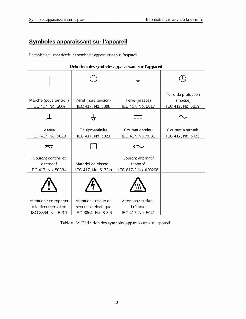
Symboles apparaissant sur l'appareil
Le tableau suivant décrit les symboles apparaissant sur l'appareil.
Définition des symboles apparaissant sur l'appareil
|
Marche (sous tension)
IEC 417, No. 5007
Arrêt (hors tension)
IEC 417, No. 5008
Terre (masse)
IEC 417, No. 5017
Terre de protection
(masse)
IEC 417, No. 5019
Masse
IEC 417, No. 5020
Equipotentialité
IEC 417, No. 5021
Courant continu
IEC 417, No. 5031
Courant alternatif
IEC 417, No. 5032
Courant continu et
alternatif
IEC 417, No. 5033-a
Matériel de classe II
IEC 417, No. 5172-a
Courant alternatif
triphasé
IEC 617-2 No. 020206
Attention : se reporter
à la documentation
ISO 3864, No. B.3.1
Attention : risque de
secousse électrique
ISO 3864, No. B.3.6
Attention : surface
brûlante
IEC 417, No. 5041
Tableau 3: Définition des symboles apparaissant sur l'appareil

Informations relatives à la sécurité Mesures de sécurité et mises en garde
11
Mesures de sécurité et mises en garde
Prendre toutes les précautions générales suivantes pendant toutes les phases d'utilisation de cetappareil. Le non-respect de ces précautions ou des avertissements contenus dans ce manuelentraîne une violation des normes de sécurité relatives à l'utilisation de l'appareil et le risque deréduire le niveau de protection fourni par l'appareil. MKS Instruments, Inc. ne prend aucuneresponsabilité pour les conséquences de tout non-respect des consignes de la part de ses clients.
NE PAS SUBSTITUER DES PIÈCES OU MODIFIER L'APPAREIL
Ne pas utiliser de pièces détachées autres que celles vendues par MKS Instruments, Inc. oumodifier l'appareil sans l'autorisation préalable de MKS Instruments, Inc. Renvoyer l'appareil àun centre d'étalonnage et de dépannage MKS pour tout dépannage ou réparation afin de s'assurerque tous les dispositifs de sécurité sont maintenus.
DÉPANNAGE EFFECTUÉ UNIQUEMENT PAR UN PERSONNEL QUALIFIÉ
L'opérateur de l'appareil ne doit pas enlever le capot de l'appareil. Le remplacement descomposants et les réglages internes doivent être effectués uniquement par un personneld'entretien qualifié.
MISE À LA TERRE DE L'APPAREIL
Cet appareil est mis à la terre à l'aide du fil de terre du cordon d'alimentation. Pour éviter toutrisque de secousse électrique, brancher le cordon d'alimentation sur une prise de courantcorrectement câblée avant de le brancher sur les bornes d'entrée ou de sortie de l'appareil. Unemise à la terre de protection à l'aide du fil de terre du cordon d'alimentation est indispensablepour une utilisation sans danger de l'appareil.
DANGER LIÉ À UN DÉFAUT DE TERRE
En cas de défaut de terre, toutes les pièces conductrices accessibles (y compris les boutons decommande ou de réglage qui semblent être isolés) peuvent être source d'une secousse électrique.
MISE À LA TERRE ET UTILISATION CORRECTE D'ACCESSOIRES ÉLECTRIQUES
Des tensions dangereuses existent à l'intérieur de l'appareil. Tous les accessoires et les câblesélectriques doivent être conformes au type spécifié et être en bon état. Tous les accessoiresélectriques doivent être correctement connectés et mis à la terre.

Mesures de sécurité et mises en garde Informations relatives à la sécurité
12
UTILISATION D'UN CORDON D'ALIMENTATION APPROPRIÉ
Utiliser uniquement un cordon d'alimentation en bon état et conforme aux exigences de puissanced'entrée spécifiées dans le manuel.
Utiliser uniquement un cordon d'alimentation amovible avec des conducteurs dont la section estégale ou supérieure à 0,75 mm2. Le cordon d'alimentation doit être approuvé par un organismecompétent tel que VDE, Semko ou SEV.
UTILISATION D'UNE ALIMENTATION APPROPRIÉE
Cet appareil est conçu pour fonctionner en s'alimentant sur une source de courant électriquen'appliquant pas une tension entre les conducteurs d'alimentation, ou entre les conducteursd'alimentation et le conducteur de terre, supérieure à celle spécifiée dans le manuel.
UTILISATION D'UN FUSIBLE APPROPRIÉ
Utiliser uniquement un fusible conforme au type, à la tension nominale et au courant nominalspécifiés pour l'appareil.
NE PAS UTILISER DANS UNE ATMOSPHÈRE EXPLOSIVE
Pour éviter tout risque d'explosion, ne pas utiliser l'appareil dans une atmosphère explosive àmoins qu'il n'ait été approuvé pour une telle utilisation.
DANGER DE HAUTE TENSION
Une haute tension est présente dans le câble et dans le capteur lorsque le contrôleur est soustension.

Información sobre seguridad Símbolos usados en el manual de instrucciones
13
Información sobre seguridad
Símbolos usados en el manual de instrucciones
Definiciones de los mensajes de ADVERTENCIA, PRECAUCIÓN Y OBSERVACIÓN usadosen el manual.
#FXGTVGPEKC 'N UÃODQNQ FG #&8'46'0%+# KPFKEC WP TKGUIQ� 2QPG FG TGNKGXG
WP RTQEGFKOKGPVQ� RT±EVKEC� EQPFKEKÉP� GVE�� SWG� FG PQ
TGCNK\CTUG W QDUGTXCTUG EQTTGEVCOGPVG� RQFTÃC ECWUCT NGUKQPGU C
NQU GORNGCFQU�
2TGECWEKÉP El símbolo de PRECAUCIÓN indica un riesgo. Pone de relieve unprocedimiento, práctica, etc., de tipo operativo que, de no realizarseu observarse correctamente, podría causar desperfectos alinstrumento, o llegar incluso a causar su destrucción total o parcial.
1DUGTXCEKÉP El símbolo de OBSERVACIÓN indica información de importancia. Ponede relieve un procedimiento, práctica, condición, etc., cuyo conocimientoresulta esencial.

Símbolos que aparecen en la unidad Información sobre seguridad
14
Símbolos que aparecen en la unidad
En la tabla que figura a continuación se indican los símbolos que aparecen en la unidad.
Definición de los símbolos que aparecen en la unidad
|Encendido
(alimentación eléctrica)
IEC 417, N.° 5007
Apagado
(alimentación eléctrica)
IEC 417, N.° 5008
Puesta a tierra
IEC 417, N.° 5017
Protección a tierra
IEC 417, N.° 5019
Caja o chasis
IEC 417, N.° 5020
Equipotencialidad
IEC 417, N.° 5021
Corriente continua
IEC 417, N.° 5031
Corriente alterna
IEC 417, N.° 5032
Corriente continua y
alterna
IEC 417, N.° 5033-a
Equipo de clase II
IEC 417, N.° 5172-a
Corriente alterna
trifásica
IEC 617-2 N.° 020206
Precaución. Consultar
los documentos
adjuntos
ISO 3864, N.° B.3.1
Precaución. Riesgo
de descarga eléctrica
ISO 3864, N.° B.3.6
Precaución.Superficie
caliente
IEC 417, N.° 5041
Tabla 4: Definición de los símbolos que aparecen en la unidad

Información sobre seguridad Procedimientos y precauciones de seguridad
15
Procedimientos y precauciones de seguridad
Las precauciones generales de seguridad que figuran a continuación deben observarsedurante todas las fases de funcionamiento del presente instrumento. La no observancia dedichas precauciones, o de las advertencias específicas a las que se hace referencia en elmanual, contraviene las normas de seguridad referentes al uso previsto del instrumento ypodría impedir la protección que proporciona el instrumento. MKS Instruments, Inc., noasume responsabilidad alguna en caso de que el cliente haga caso omiso de estosrequerimientos.
NO UTILIZAR PIEZAS NO ORIGINALES NI MODIFICAR EL INSTRUMENTO
No se debe instalar piezas que no sean originales ni modificar el instrumento sin autorización.Para garantizar que las prestaciones de seguridad se observen en todo momento, enviar elinstrumento al Centro de servicio y calibración de MKS cuando sea necesaria su reparación yservicio de mantenimiento.
REPARACIONES EFECTUADAS ÚNICAMENTE POR TÉCNICOS ESPECIALIZADOS
Los operarios no deben retirar las cubiertas del instrumento. El cambio de piezas y los reajustesinternos deben efectuarlos únicamente técnicos especializados.
PUESTA A TIERRA DEL INSTRUMENTO
Este instrumento está puesto a tierra por medio del conductor de tierra del cable eléctrico. Paraevitar descargas eléctricas, enchufar el cable eléctrico en una toma debidamente instalada, antesde conectarlo a las terminales de entrada o salida del instrumento. Para garantizar el uso sinriesgos del instrumento resulta esencial que se encuentre puesto a tierra por medio del conductorde tierra del cable eléctrico.
PELIGRO POR PÉRDIDA DE LA PUESTA A TIERRA
Si se pierde la conexión protectora de puesta a tierra, todas las piezas conductoras a las que setiene acceso (incluidos los botones y mandos que pudieran parecer estar aislados) podríanproducir descargar eléctricas.
PUESTA A TIERRA Y USO DE ACCESORIOS ELÉCTRICOS ADECUADOS
Este instrumento funciona con voltajes peligrosos. Todos los accesorios y cables eléctricos debenser del tipo especificado y mantenerse en buenas condiciones. Todos los accesorios eléctricosdeben estar conectados y puestos a tierra del modo adecuado.

Procedimientos y precauciones de seguridad Información sobre seguridad
16
USAR EL CABLE ELÉCTRICO ADECUADO
Usar únicamente un cable eléctrico que se encuentre en buenas condiciones y que cumpla losrequisitos de alimentación de entrada indicados en el manual.
Usar únicamente un cable desmontable instalado con conductores que tengan un área de seccióntransversal equivalente o superior a 0,75mm². El cable eléctrico debe estar aprobado por unaentidad autorizada como, por ejemplo, VDE, Semko o SEV.
USAR LA FUENTE DE ALIMENTACIÓN ELÉCTRICA ADECUADA
Este instrumento debe funcionar a partir de una fuente de alimentación eléctrica que no apliquemás voltaje entre los conductores de suministro, o entre uno de los conductores de suministro yla puesta a tierra, que el que se especifica en el manual.
USAR EL FUSIBLE ADECUADO
Usar únicamente un fusible del tipo, clase de voltaje y de corriente adecuados, según lo que seespecifica para el instrumento.
EVITAR SU USO EN ENTORNOS EXPLOSIVOS
Para evitar el riesgo de explosión, no usar este instrumento o en un entorno explosivo, a no serque haya sido certificado para tal uso.
PELIGRO POR ALTO VOLTAJE
Cuando el controlador está encendido, se registra alto voltaje en el cable y en el sensor.

Chapter One: General Information Introduction
17
Chapter One: General Information
Introduction
The Type 146C Cluster Gauge Vacuum Gauge Measurement and Control System is a versatile,½ rack instrument which can power and provide concurrent readouts for up to four differentvacuum gauges, or a combination of gauges and flow controllers. The instrument can supportcapacitance manometers (4, 5, or 6 decade), Pirani, and ion gauges. A Dual Channel featureautomatically switches from one gauge to another, thus providing the potential for a continuouspressure reading display from 10-10 to 103 Torr. The channel in the main display canautomatically switch from a rough vacuum gauge to a high vacuum gauge during pumpdown orbackfill. The 146 unit can accept a user-defined set point to operate a flow controller. If morethan one flow controller is used, a Totaling feature allows one controller to control the total flowof all the controllers combined. With the optional Control board installed, the 146 unit cangovern an upstream solenoid valve, a downstream throttle valve, or one or more ratio controllersin a closed-loop pressure control system.
The 146 unit arrives from the factory with four default recipes, each with an individual set point,phase lead, and gain setting. The recipes can easily be customized to meet the needs of differentapplications. By using the keyboard on the front panel, operators can: set alarm relay parameters,display pressure or leakage readings, choose display units (Torr, Pascal, mbar), and configurecommunication data. Control parameters such as base, lead, gain, integral, softstart, and start canalso be adjusted through the front panel. Gauges can be zeroed and spanned individually, orcross-calibrated for span. There is an automatic ion gauge powerdown at high pressures, and asensor powerdown for cryo-pump regeneration. The non-volatile memory stores all parameterentry values as well as sensor data such as capacitance manometer zero correction, and HPSPirani spans. Diagnostic tests are included for basic troubleshooting.
The 146 instrument has a front panel window with a 4½ digit main display, and three 2½ digitdisplays. The LCD window is backlit with an electro-luminescent lamp, and has an automaticone-hour timeout. Although the LCD is readable without backlighting, any keystroke re-illuminates the backlight in addition to performing its usual function. All commands can beactivated through the front panel, or the unit can be controlled via an interface with a computerthrough an RS-232 serial communication link. A front panel lockout feature disables commandcontrol through the front panel (except for the [QUIET/CANCEL] key). The 146 unit front panellockout commands are entered through the available digital control lines or RS-232 messages.
Another option is the displayless unit. Here, 146 units have their normal front panel replacedwith a panel that has only a power switch, LED, and 25-pin Type “D” connector. One or more ofthese displayless units can be placed in remote locations and controlled through a portable frontpanel which has the normal display, or through RS-232 communications. The panel can beconnected to each remote unit in turn with a ribbon cable. In summary, the 146 instrument isdesigned to allow operators the ability to calibrate gauges; control and fine tune their pressuresystem, and still provide flexibility for system upgrades.

How this Manual is Organized Chapter One: General Information
18
How this Manual is Organized
This manual is designed to provide detailed, step by step instructions for all the functions theType 146 unit can perform. It also supplies overview and background information to help youacquire a general understanding of the 146 instrument, and how to use it. A color-codedoperational diagram offers a pictorial representation of the modes, functions, and appropriatekeys that are used to operate the 146 unit. The operational diagram and quick reference guides(on yellow paper) may be all you need to operate the 146 unit once you have familiarizedyourself with its functions.
Before installing the Type 146 unit in your system and/or operating it, carefully read andfamiliarize yourself with all precautionary notes in Safety Procedures and Precautions at thefront of this manual. In addition, observe and obey all WARNING and CAUTION notesprovided throughout the manual.
Chapter One, General Information, (this chapter) introduces the product and describes theorganization of the manual.
Chapter Two, Installation, explains the environmental requirements and describes how to mountthe instrument in your system.
Chapter Three, Overview, gives a brief description of the instrument and its functionality.
Chapter Four, Operation in Normal Mode, describes how to use the instrument and explains allthe functions and features.
Chapter Five, Operation in Leakage Mode, describes the use of the leakage mode.
Chapter Six, Operation in Tuning Mode, explains when to use the tuning mode.
Chapter Seven, Operation in Setup Mode, defines the use of the setup mode.
Chapter Eight, Operation in Control Mode, explains how to configure a Control board to controlyour process.
Chapter Nine, RS-232 Communications, describes how to communicate with the 146 unitthrough RS-232 communications.
Chapter Ten, Maintenance, lists maintenance tips for your 146 unit.
Chapter Eleven, Troubleshooting, describes the diagnostic commands supported by the frontpanel.
Appendix A, Product Specifications, lists the specifications of the instrument.
Appendix B, Parts List/Accessories, lists all the accessories supported by the 146 unit.
Appendix C, RS-232 Error Codes, explains RS-232 error messages.
Appendix D, Front Panel Error/StatusMessages, explains the front panel messages.
Appendix E, Instrument Default Values, lists the default value for all operating parameters.
Appendix F, Underrange and Overrange Values, lists the out-of-range pressures for differentgauges.
Appendix G, Board Specific Commands, lists the commands that apply to each board type.

Chapter One: General Information How this Manual is Organized
19
Format of Instructions
Each set of directions contained in this manual includes all the steps necessary to perform aparticular task. Even though some steps are identical for several operations, they are repeated ineach set of instructions. This means you do not have to read preceding chapters, but may godirectly to a description of a function, and you will be provided with all the steps necessary toperform that task.
Although detailed instructions are provided, it is very useful to read the overview sections at thebeginning of the manual. A better understanding of the 146 unit will make operation of it moreintuitive. The displayless option is discussed in a separate section at the end of Chapter Three:Overview.
This manual follows the functional design of the 146 instrument. That is, after the introductoryand overview sections, each of the five modes in which the 146 unit can operate, is discussed in aseparate chapter.
Conventions Used in this Manual
Keys: All the keys mentioned in this manual are displayed on the front panel of the 146unit. In this manual, the keys are referred to by the names (functions) printed onthem. The key names (functions) are written with the key name inside straightbrackets. For example, [ENTER].
Most keys on the keyboard have more than one function printed on them. In thismanual, both functions are shown, separated by a slash, even though only one ofthe functions may be applicable to a set of instructions. For example, [ON/LEAD]is a key with two functions printed on it.
When two keys must be pressed simultaneously, this is shown by presenting thekeys side by side. The instructions explicitly describe what you are to do. Forexample, to indicate that the up and down arrow keys must be pressedsimultaneously, the keys are presented as shown:
[ ] and [ ]
and the instructions might read ...
Press the Up and Down arrow keys simultaneously.
If there is a shortcut key, or shortcut key sequence, the instructions are written touse the shortcut sequence. Instructions are written with the fewest steps possible.
Legends: Legends or any messages displayed on the front panel window, are written withthree blank spaces before and after the legend/message, and written in capitalletters. For example, the legend No Sensor is written as NO SENSOR .
Italics: Italics are used to stress a word or concept. For example, instructions may read:
Do not discard any packing material, until the 146 unit has been inspected.

How this Manual is Organized Chapter One: General Information
20
Modes: Modes are always written in proper format (the first letter is capitalized). Forexample, the three standard modes available with the 146 unit are Normal Mode,Leakage Mode, and Setup Mode.
Boards: The names for the boards are always written in proper format (the first letter iscapitalized). For example, the two optional modes for the 146 unit are availableonly if the optional Control board is installed.
Terminology Used in this Manual
The definitions supplied below are not standardized definitions, but are definitions specific to the146 unit and this manual.
Front Panel The front panel of the 146 unit is shown in Figure 1, page 21. It includes thefront panel window, the alarm and channel label areas, the keypad, and thepower switch.
Front PanelWindow
The front panel window is also referred to as simply the window, or the LCDscreen. All pressure readings, legends, system messages, alarm and channelinformation, and user-defined parameters, are displayed in the window.
WindowDisplays
Within the front panel window are four areas where pressure readings andparameter fields are displayed. The locations of the four areas remain fixed inthe window, although the information displayed in them changes. The fourdisplays are referred to as the left, center, right, and main displays.
The left display is located in the upper left area of the front panel window.
The center display is located in the upper middle area of the front panelwindow.
The right display is located in the upper right area of the front panel window.
The main display is the largest display, and is located in the bottom centerarea of the front panel window. The pressure readings for channels 1, 2, and3, are shown in the left, center, and right displays respectively. Any channelcan be selected for display in the main display area. The default is for thechannel 1 pressure reading to appear in the main display. The exception tothis is when all four channels are used, whereupon the pressure reading forchannel 4 appears in the main display. Channel 4 can only be monitored inthe main display.
Alarm LabelArea
The alarm label area is an etched rectangle on the left side of the front panel.Use this area to affix custom labels referring to alarms A through D.
Channel LabelArea
The channel label area is an etched rectangle on the right side of the frontpanel. Use this area to affix custom labels referring to channels 1 through 4.

Chapter One: General Information How this Manual is Organized
21
Mode The 146 instrument is designed to operate in five different modes. Theassociated parameters and functions of each mode are viewed in the frontpanel window, and operable through the front panel keypad (and the RS-232serial port). The three standard modes of the Type 146 instrument are NormalMode (the default mode), Leakage Mode, and Setup Mode. Two other modes,Tuning Mode and Control Mode are available when the optional Controlboard is installed in the 146 unit.
Function A function is a task the 146 unit can perform. For example, spanning a sensorwith a reference is a task the 146 unit can perform. Other tasks includeswitching channels in the main display, and adjusting set point values. Eachfunction is given a separate How To... section within this manual. Refer tothe Table of Contents for a complete list of all functions the 146 unit canperform.
Parameter A parameter is a value or option you add or alter when you give a command orexecute a function. The result is that the command or function accomplishesits task in the way that you want. If you do not enter a parameter, the 146 unitoperates according to default values. For example, the default baud rate forRS-232 communications is 9600. Unless you enter a different baud rate, thisis the value the 146 instrument uses.
} } }
}Alarm
Label Area
Front Panel Window
Channel Label Area
Power Switch
Keypad
A
B
C
D
1
2
3
4
ALARMS CHANNELS
ALARMCHANNELTUNINGCOMMON
POINT
1 2 3 4 5 6 7 8 92
03 4 A B CDUAL
+/-EXP
ZERO DEGAS ON
LEAD
OFF
GAIN
QUIETENTER
DISPLAYMODE
CONTROLMODE
D
CANCEL
SPAN
1
POWER
ON
OFF
VACUUM GAUGE MEASUREMENT AND CONTROL SYSTEM TYPE 146
SET
0
1
Figure 1: The Front Panel of the 146 Instrument

Customer Support Chapter One: General Information
22
Customer Support
Standard maintenance and repair services are available at all of our regional MKS Calibrationand Service Centers, listed on the back cover. In addition, MKS accepts the instruments of othermanufacturers for recalibration using the Primary and Transfer Standard calibration equipmentlocated at all of our regional service centers. Should any difficulties arise in the use of your Type146 instrument, or to obtain information about companion products MKS offers, contact anyauthorized MKS Calibration and Service Center. If it is necessary to return the instrument toMKS, please obtain an ERA Number (Equipment Return Authorization Number) from the MKSCalibration and Service Center before shipping. The ERA Number expedites handling andensures proper servicing of your instrument.
Please refer to the inside of the back cover of this manual for a list of MKS Calibration andService Centers.
Warning All returns to MKS Instruments must be free of harmful,corrosive, radioactive, or toxic materials.

Chapter Two: Installation How To Unpack the 146 Instrument
23
Chapter Two: Installation
How To Unpack the 146 Instrument
MKS has carefully packed the 146 unit so that it will reach you in perfect operating order. Uponreceiving the unit, however, you should check for defects, cracks, broken connectors, etc., to becertain that damage has not occurred during shipment.
Note Do not discard any packing materials until you have completed yourinspection and are sure the unit arrived safely.
If you find any damage, notify your carrier and MKS immediately. If it is necessary to return theunit to MKS, obtain an ERA Number (Equipment Return Authorization Number) from the MKSService Center before shipping. Please refer to the inside of the back cover of this manual for alist of MKS Calibration and Service Centers.
Caution Only qualified individuals should perform the installation and anyuser adjustments. They must comply with all the necessary ESD andhandling precautions while installing and adjusting the instrument.Proper handling is essential when working with all highly sensitiveprecision electronic instruments.
Unpacking Checklist
Standard Equipment
• The 146 Vacuum Gauge Measurement and Control System
• Power cord (If you choose to supply your own power cord you must ensure that itcomplies with the applicable national regulatory requirements, such as UL or CSA.)
• A set of self-adhesive labels for Alarm and Channel identification on the front panel ofthe 146 unit
• Instruction Manual (this manual)
Optional Equipment
• Electrical Connector Accessories Kit, 146C-K1, (includes mating connectors for all theconnectors and two screwlock assemblies for each connector cover supplied)
• Rack Mounting Kit
• Interface Cables

How To Unpack the 146 Instrument Chapter Two: Installation
24
Boards
All or some of the following boards may have been ordered with your basic 146 unit. Examinethe rear panel of the 146 unit to make sure your unit conforms to your order code. Refer toFigure 4, page 27, to see how to identify these boards by their connectors on the rear panel.Also, refer to the explanation of an order form code in Figure 5, page 28. The boards should beplaced within the 146 unit in the same order as they are listed on your order form.
Also on the order form configuration sheet, are specific configuration instructions. For example,the unit can be set up for a single channel Pirani board (the default is a dual channel board), orfor a low power HPS hot cathode (the default is for a high power gauge).
Labels are placed at each occupied board slot on the rear panel of the 146 unit. The labelsidentify the channel number(s) and type of board installed in the slot.
• Capacitance Manometer Board
• Dual Pirani/Convection Board
• Cold Cathode Board
• Hot Cathode Board
• Mass Flow Controller Board
• Auxiliary Output Board
• Control Board
• Binary Coded Decimal (BCD) Board
• Dual Thermocouple Board
Optional Accessories
Refer to Appendix B: Parts List/Accessories, page 303
• Gauges
• Valves
• Mass Flow Controllers
• Cables for Gauges/Valves/Mass Flow Controllers
• Remote Front Panel with cable
• Displayless Type 146 Units (indicated as such in the order code)
• RM-6 Rack Mount (MKS p/n RM6)
• RS-232 Cable for Displayless Units (MKS p/n CB146-21)
• Labels for rear panel board identification (MKS p/n LB-1141011)

Chapter Two: Installation How To Unpack the 146 Instrument
25
Interface Cables
As of January 1, 1996, most products shipped to the European Community must comply with theEMC Directive 89/336/EEC, which covers radio frequency emissions and immunity tests. Inaddition, as of January 1, 1997, some products shipped to the European Community must alsocomply with the Product Safety Directive 92/59/EEC and Low-Voltage Directive 73/23/EEC,which cover general safety practices for design and workmanship. MKS products that meetthese requirements are identified by application of the CE mark.
To ensure compliance with EMC Directive 89/336/EEC, an overall metal braided shielded cable,properly grounded at both ends, is required during use. No additional installation requirementsare necessary to ensure compliance with Directives 92/59/EEC and 73/23/EEC.
Refer to Appendix B: Parts List/Accessories, page 303, for a complete list of interface cablesavailable.
Generic Shielded Cable Description
MKS offers a full line of cables for all MKS equipment. Should you choose to manufacture yourown cables, follow the guidelines listed below:
1. The cable must have an overall metal braided shield, covering all wires. Neitheraluminum foil nor spiral shielding will be as effective; using either may nullifyregulatory compliance.
2. The connectors must have a metal case which has direct contact to the cable’s shield onthe whole circumference of the cable. The inductance of a flying lead or wire from theshield to the connector will seriously degrade the shield’s effectiveness. The shieldshould be grounded to the connector before its internal wires exit.
3. With very few exceptions, the connector(s) must make good contact to the device’s case(ground). “Good contact” is about 0.01 ohms; and the ground should surround all wires.Contact to ground at just one point may not suffice.
4. For shielded cables with flying leads at one or both ends; it is important at each such end,to ground the shield before the wires exit. Make this ground with absolute minimumlength. Refer to Figures 2 and 3, page 26. (A ¼ inch piece of #22 wire may beundesirably long since it has approximately 5 nH of inductance, equivalent to 31 ohms at1000 MHz). After picking up the braid’s ground, keep wires and braid flat against thecase. With very few exceptions, grounded metal covers are not required over terminalstrips. If one is required, it will be stated in the Declaration of Conformity or in theinstruction manual.
5. In selecting the appropriate type and wire size for cables, consider:
A. The voltage ratings;
B. The cumulative I2R heating of all the conductors (keep them safely cool);
C. The IR drop of the conductors, so that adequate power or signal voltage gets to thedevice;

How To Unpack the 146 Instrument Chapter Two: Installation
26
D. The capacitance and inductance of cables which are handling fast signals, (such asdata lines or stepper motor drive cables); and
E. That some cables may need internal shielding from specific wires to others; pleasesee the instruction manual for details regarding this matter.
Example 1: Preferred Method To Connect Cable
(shown on a transducer)
Transducer
Overall Insulation(if present)
Bare Metal Cable ClampMaking Firm Contact To Braid
Braid Here Is Desirable(but not usually necessary)
Keep Wires and BraidFlat Against Case
Metal Cable Clamp
Screw
Split Lock Washer
External Tooth Lock Washer
Transducer Housing
Optional Plastic or Metal CableClamp (For Physical Strain Relief)
Figure 2: Preferred Method
Example 2: Alternate Method To Connect Cable
(shown on a transducer)
Transducer
Overall Insulation(if present)
Braid Strands TwistedUnder Washer
Keep Wires Flat Against Case
Optional Plastic or Metal CableClamp (For Physical Strain Relief)
ScrewSplit Lock Washer
Flat WashersExternal Tooth Lock Washer
Transducer Housing
Figure 3: Alternate Method To Use When Cable Clamp is Not Available

Chapter Two: Installation How To Unpack the 146 Instrument
27
Card Slot 1
MaleConnector(Pins black)
FemaleConnector
(Insulator black)
RS-232Interface
Line VoltageSwitch
ACPower
Fuse
GeneralInterface
(I/O Board)
230V 1.0A (T)115V 1.6A (T)
Fuses 250V IEC
50/60 Hz150 VAMax
Fuses
Line
RS
232
COLD CATHODEBOARD
DUAL PIRANI/CONVECTIONBOARD
CAPACITANCEMANOMETER
MASS FLOWCONTROLLERBOARD
HOT CATHODEBOARD
B.C.DBOARD
AUXILIARYOUTPUTBOARD
CONTROLBOARD
ANALOGBOARD
Channel 1
Channel 2
C.M. Interface
High Voltage
Current Input
M.F.CInterface
Current Input
H.C.Interface
B.C.D.Interface
RelayInterface
AnalogOutputs
ValveOutput
ControlInterface
BlankCoverPlate
DUAL THERMOCOUPLEBOARD
Channel 1
Channel 2
Figure 4: Rear Panel of the 146 Unit

How To Unpack the 146 Instrument Chapter Two: Installation
28
Order Code
Type Number
Card Slot 1
Card Slot 2
Card Slot 3
Card Slot 4
Card Slot 5
Display option
146C B A C N M - X
Figure 5: Model Code
Model Code Explanation
Available Boards
Channel Boards Function Boards
A= Capacitance Manometer M = Control
B = Dual Pirani/Convection N = Auxiliary Output
C = Cold Cathode S = Binary Coded Decimal
D= Hot Cathode O = No board installed (covered slot)
E = Dual Thermocouple
F = Mass Flow Controller
O= No board installed (covered slot)
Display Option
1 = 146 unit with a front panel display
2 = 146 displayless unit (without front panel display)
Notes
1. Four is the maximum number of channels for the instrument.
2. Channel numbers are determined by the sequence of channel boards. For example, a singleboard installed in slot 1 becomes channel 1. If a dual channel board is installed in slot 2, itoccupies channels 2 and 3.
3. Only one Control board and one Auxiliary Output board can be installed in the instrument.
4. All unused slots must be specified as O (no board) within the model code.
5. If two Hot Cathode (HC) boards are installed into one unit, both HC boards MUST be set tolow power configuration. Otherwise, the 146 unit may exceed its temperature rating.

Chapter Two: Installation Product Location and Requirements
29
Product Location and Requirements
The Type 146 unit meets the following criteria:
• POLLUTION DEGREE 2 in accordance with IEC 664
• Transient overvoltages according to INSTALLATION CATEGORY II
Operating Environmental Requirements
• Ambient Operating Temperature: 15° to 40° C (59° to 104° F)
• Storage humidity range: 0 to 95%, non-condensing
• Main supply voltage fluctuations must not exceed ±10% of the nominal voltage
• Ventilation requirements include sufficient air circulation
• Connect the power cord into a grounded outlet
Note If you choose to supply your own power cord you must ensure that itcomplies with the applicable national regulatory requirements, such asUL or CSA.
Safety Conditions
The 146 unit poses no safety risk under the following environmental conditions.
• Altitude: up to 2000 m
• Maximum relative humidity: 80% for temperatures up to 31 °C, decreasing linearly to50% at 40 °C
Mounting Instructions
• The 146 unit can be mounted in a panel cutout or in a 19 inch rack when supplied withthe RM-6 Rack Mount option
• If a throttle valve is used, the maximum pressure in the gas system in which the 146 unitis installed must not exceed atmospheric pressure due to the requirements of the valve
Electrical Requirements
• Input Power requirements are 100 to 120 VAC, nominal, or 220 to 240 VAC, nominal,50/60 Hz
• Power consumption is 150 VA, maximum
• Maintain a solid system ground for proper operation and safety to personnel

System Requirements Chapter Two: Installation
30
System Requirements
Pressure Transducer Selection
Refer to the description of each transducer board in Inside the Type 146 Unit, page 47, such asconnector pinouts.
Any capacitance manometer that delivers up to ±10 Volts full scale can be used with the146 unit. However, be aware that if a capacitance manometer which delivers less than±10 Volts full scale is used, some sensor conditions such as overrange and underrange will notbe detected.
The Pirani-type gauges that are compatible with the 146 unit are the HPS Pirani gauge, HPSConvection Enhanced Pirani (CEP) gauge, and the Granville Phillips Convectron® gauge.
The HPS inverted magnetron cold cathode gauge is compatible.
All Bayard-Alpert hot cathode gauges are supported. This includes both the thoriated iridiumand tungsten filament gauges in nude or glass envelope configuration (where available), and theHPS low power, nude, Bayard-Alpert hot cathode.
Note Use of a hot cathode gauge with a glass tube (or envelope) voids the CEcompliance. Only hot cathode gauges with nude tubes pass CE testing.
Valve Selection
The control valve may be either a proportional current driven valve, or a voltage driven throttlevalve. Many valve types may be used as long as proper cabling is employed.
Mass Flow Controller Selection
All MKS mass flow controllers, and equivalent controllers, are supported.
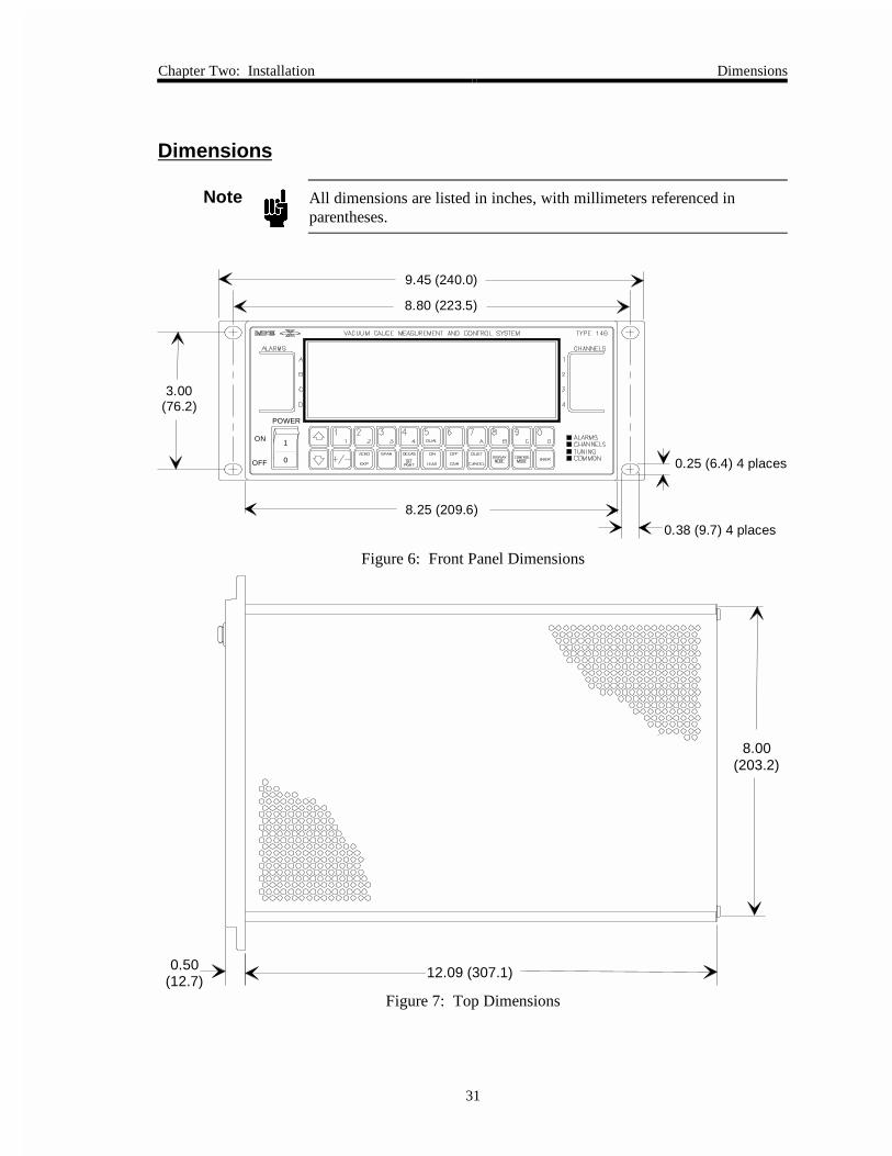
Chapter Two: Installation Dimensions
31
Dimensions
Note All dimensions are listed in inches, with millimeters referenced inparentheses.
3.00(76.2)
9.45 (240.0)
8.25 (209.6)
8.80 (223.5)
0.38 (9.7) 4 places
0.25 (6.4) 4 places
POWER
ON
OFF 0
1
Figure 6: Front Panel Dimensions
0.50(12.7)
12.09 (307.1)
8.00(203.2)
Figure 7: Top Dimensions

146 Set Up Chapter Two: Installation
32
3.47(88.1)
3.38(85.7)
Figure 8: Side Dimensions
146 Set Up
Caution Provide proper clearance so that the 146 unit operates withinproduct environmental specifications (refer to Appendix A: ProductSpecifications, page 301).
General
1. Employ proper grounding.
Power, analog and digital commons are all tied together in the 146 power supply. Thetransducer signal common and power common are usually tied together internally at thesensor. Although these commons are connected together internally, it is important thateach ground be used only for its stated purpose to minimize ground noise and ground-loop errors.
2. Plug the power cord into a properly grounded electrical outlet to ensure protectiveearthing.
Note If you choose to supply your own power cord you must ensure that itcomplies with the applicable national regulatory requirements, such asUL or CSA.
3. Use a voltmeter to check that the maximum potential difference between the chassiscommon and each of the internal grounds is no more than 3.5 Volts.
The chassis common is connected to the 146 internal grounds through severalmicrofarads of capacitance distributed throughout the unit. It is also clamped with3.3 Volt, back-to-back, zener diodes shunted by several 0.1 uF capacitors in the powersupply. This arrangement allows some flexibility in configuring an optimum earth-grounding scheme that is especially important when several transducers are connected tothe 146 unit. The maximum potential difference between these grounds must be limitedto 3.5 Volts to prevent the introduction of noise.

Chapter Two: Installation 146 Set Up
33
Checking the Fuses and AC line Voltage Select Switch
Note If the 146 unit is ordered with a full configuration form filled out, it willarrive with the correct fuse(s) and have the voltage switch set for properAC voltage. There are no other adjustments needed for set up.
If a full configuration form was not filled out, or to confirm the set up of the 146 unit, check thetype of fuses installed in the unit. Refer to How To Replace the Fuses, page 290.
Transducer/Mass Flow Controller Connections
Please refer to the installation instructions that came with your particular transducers or massflow controllers.
• Connect the gauge/MFC interface cable to the appropriate 146 connector.
Refer to Figure 4, page 27, to identify the appropriate connector.
Communication and Power Connections
Refer to Figure 4, page 27, for the location of all communication and power connections.
1. Connect the proper interface cable to the General I/O connector.
2. Connect the IBM PC® (XT®, AT®, or compatible) computer cable to the standard9-pin female RS-232 connector.
3. If an Auxiliary Output board is installed, use a cable to connect the 146 unit to a devicewhich can be activated through the relays on the top connector (the relay interface), andanother cable to connect an analog output device to the bottom connector (the analogoutput interface) on the Auxiliary Output board.
4. If a Control board is installed, use a cable to connect an appropriate valve or controller tothe top connector (the valve output interface) on the Control board. Table 27, page 71,lists appropriate valves and controllers. The bottom connector (the control interface)provides remote function control. Connect a PC or other remote equipment to thisconnector with the appropriate cable.
5. If a Control board is installed, the proper pin jumpers must be selected.
Refer to Table 26, page 70, for details.

146 Set Up Chapter Two: Installation
34
Installing Boards in the 146 Unit
This section describes how to install boards that have been ordered after the 146 unit has arrived.
Warning The 146 unit has lethal voltages inside. To avoid the dangerof electrical shock, the power line must be disconnectedbefore opening the unit.
1. Be sure the power cord is disconnected.
2. Remove the four (4) Phillips screws on the outside corners of the rear panel and theseven (7) screws from the top cover.
Refer to Figure 9 for an illustration of how to open the 146 unit.
1. Disconnect the power cord.
2. Remove the four (4) Phillips screws on the outside corners.
3. Remove the seven (7) screws from the top cover.
4. Remove the cover by firmly pulling it towards the back of the unit.
Figure 9: Opening the Type 146 Unit
3. Remove the top cover by firmly pulling it towards the back of the unit. Note theorientation of the cover since the center hole is slightly off center to accommodate aconnector if a board is positioned in slot 5.
4. Carefully turn the unit over so that it is bottom-side up and remove the seven (7) screws.
5. Remove the bottom cover by firmly pulling it towards the back of the unit. Note theorientation of the cover since the center hole is slightly off center to accommodate aconnector if a board is positioned in slot 5.

Chapter Two: Installation 146 Set Up
35
6. Place the unit on a flat surface in its normal orientation, with the rear panel facing you.
7. Decide where the board will go.
We recommend that you do not move any boards already installed in the 146 unit.Instead, install a new board in an unused slot. This avoids the situation where the146 unit changes user-defined parameters to default parameters. Refer to NewConfiguration Warning Code, on page 37, for more information concerning aconfiguration change in the 146 instrument.
A. It is best to install all transducer boards in slots 1, 2, 3, or 4, whichever is thelowest numbered slot available.
B. It is best to install the Control board in slot 5.
C. It is best to install the Auxiliary Output board in slot 4 or 5 if no Control board ispresent. If a Control board is present, it is best to install the Auxiliary Outputboard in slot 4.
8. Unscrew the two small screws holding the slot cover that corresponds to the board slotyou intend to use.
9. If your board has two Type “D” connectors (Dual Pirani, Dual Thermocouple, Control,or Auxiliary Output boards), remove the top connector’s fastening screw.
Refer to Figure 10, page 35, for placement of the top connector’s fastening screw.
Dual Pirani or Dual ThermocoupleBoard
ControlBoard
Auxiliary OutputBoard
Top Fastening Screws
Figure 10: Fastening Screw Positions
10. Slide the board inside the unit so that the connector(s) protrude through the opening inthe rear panel.
11. Line the board up so that the female connector on the board is directly over the maleconnector on the mother board.

146 Set Up Chapter Two: Installation
36
12. Gently push the board onto the male connector.
13. If your board has two Type “D” connectors (Dual Pirani, Dual Thermocouple, Control,or Auxiliary Output boards), replace the top connector’s fastening screw.
14. Turn the unit over so that it is bottom-side up.
15. Take the screw that came with the board, and use it to fasten the board to the bottom ofthe unit.
16. Replace the bottom cover by inserting it into the grooves provided, and firmly sliding ittowards the front of the unit. Replace the seven (7) screws that fasten the bottom cover.
The center screw on the bottom cover is slightly off center to avoid interfering with aconnector if a board is positioned in slot 5. Therefore, the cover must be in the correctorientation for the screw holes to line up properly.
17. Carefully turn the unit right-side up.
18. Replace the top cover by inserting it into the grooves provided, and firmly sliding ittowards the front of the unit. Replace the seven (7) screws that fasten the top cover.
The center screw on the top cover is slightly off center to avoid interfering with aconnector if a board is positioned in slot 5. Therefore, the cover must be in the correctorientation for the screw holes to line up properly.
19. Replace the four (4) Phillips screws on the outside corners of the rear panel.
20. Plug in the power cord.

Chapter Two: Installation 146 Set Up
37
New Configuration Warning Code (C11)
Under most circumstances, when there is a configuration change in the 146 unit, a warning code(C11) is displayed and an alarm audio tone goes off when the unit is powered up again. Thealarm sound is silenced by pressing the [QUIET / CANCEL] key. This also deletes the C11 codefrom the front panel window. The purpose of the warning code and alarm sound is to remindyou that there may be parameter changes within the unit caused by the configuration change. Ifthere is a change, it will involve resetting of parameters to their default values for one or morechannels.
Note The beginning of this section describes what happens in most instanceswhen there is a configuration change in the 146 instrument. Theexceptions to this general description are discussed at the end of thissection under the title Exceptions.
The recommended procedure for installing boards, explained in the previous section, avoidsaltering any user-defined parameters. The C11 warning code and alarm are still activated,however, when a new board is added because this still entails a configuration change. Allparameters associated with the new board are set at default values.
If a board is removed from the unit, and not replaced with the same type board, the code andalarm are activated upon power up. Also, the user-defined parameters in any transducer boardsinstalled in higher numbered slots, go to default values. The channel numbers associated withthose boards are also changed if a transducer board (of any type), is not installed to replace theremoved board.
For example, assume the 146 unit has three transducer boards installed. There are CapacitanceManometer boards in slots one and two (corresponding to channels 1 and 2), and a Cold Cathodeboard in slot three (channel 3). If a Capacitance Manometer board is removed from slot two, theCold Cathode board (previously channel 3) becomes channel 2, and all user-defined parametersfor the cold cathode change to default values. The parameters associated with channel 1 remainunchanged because the channel number for that board has remained unchanged.
If a board is not changed, but the gauge attached to the board is replaced, the C11 code and alarmare not activated, however, there still may be parameter changes within the unit. Whether or notthere are parameter changes depends upon if the gauge is being replaced with another gauge ofthe same type (no parameter changes), or if the user-defined parameters are valid and appropriatefor the new type of gauge. For example, replacing a 120 capacitance manometer with a 107capacitance manometer might entail parameter changes. If the user-defined sensor range enteredfor the Type 120 gauge is valid for the Type 107 gauge, then it is preserved. If the user-definedsensor range is not valid, however, the sensor range changes to the Type 107 default value.

146 Start Up Chapter Two: Installation
38
Exceptions
If the configuration change in the 146 unit is extensive or involves global parameters, all user-defined parameters are reset to factory defaults. As in the previous discussion, the C11 warningcode is displayed at the next power up. In addition, the E4 error code is displayed after the unitits turned off and then on again. Therefore, if the C11 warning code is displayed on power up, itis a good idea to cycle the power again to determine the full extent of the configuration changeon user-defined parameters.
An optional displayless 146 unit cannot display any error codes unless a remote front panel isconnected to it. The presence of error conditions (such as C11 or E4) is indicated when the LEDon the displayless unit remains red instead of turning to green a few seconds after power up. Formore information about the displayless unit and remote front panel option, refer to Displayless146 Unit, page 98.
146 Start Up
1. Be sure the AC power cord is disconnected.
2. Push the power switch to the OFF position.
3. Plug in the power cord.
4. Push the power switch to the ON position.
The 146 unit responds by activating the front panel window, and testing all LCDsegments. Within 5 seconds the screen changes and the 146 unit defaults to NormalMode. The pressure readings for all attached, active gauges are displayed.
5. Allow the system to warm up.
For rated accuracy, the 146 unit should be allowed to warm up for 5 minutes. Refer tothe start up instructions that came with your particular transducers for additional start upprocedures and warm up times. A cold or hot cathode gauge must be turned on since itis off when the 146 unit powers up.
6. Initiate gas flow in a manner appropriate to your system.
The system is now operational. If a Control board is installed, the 146 unit can controlthe system according to default settings, or according to the settings specified in yourconfiguration sheet.

Chapter Three: Overview The Front Panel
39
Chapter Three: Overview
The Front Panel
A
B
C
D
1
2
3
4
ALARMS CHANNELS
ALARMCHANNELTUNINGCOMMON
POINT
1 2 3 4 5 6 7 8 92
03 4 A B CDUAL
+/- EXP
ZERO DEGAS ON
LEAD
OFF
GAIN
QUIETENTER
DISPLAYMODE
CONTROLMODE
D
CANCEL
SPAN
1
POWER
ON
OFF
VACUUM GAUGE MEASUREMENT AND CONTROL SYSTEM TYPE 146
SET
0
1
Figure 11: Front Panel of the Type 146 Instrument
The front panel includes the power switch, the alarm and channel label areas, the keys, and thefront panel window. All modes can be accessed through the front panel and from the RS-232serial port. All commands can be activated through the front panel (and most can be activatedthrough the RS-232 serial port).
The keys on the front panel are color coded to group them according to their functions.
The Power Switch
The Power switch controls the electrical power to the 146 unit. The 146 unit uses the universalsymbols for power on (1) and power off (0).

Overview of Keys and Their Functions Chapter Three: Overview
40
Overview of Keys and Their Functions
This overview explains the way keys function in general. Any exceptions to the general rules arenoted within each appropriate chapter.
What Happens when a Key is Pressed
With each valid key press, a soft beep is sounded. An invalid key press does not evoke anysound, but causes the INVALID legend to temporarily appear on the far right side of the frontpanel window. An inappropriate key sequence, such as trying to zero a channel that has beenturned off, evokes a single loud beep. An incomplete key sequence times out after 3 seconds,and evokes two loud beeps.
Key Color Codes
Red Keys Relates to Alarms
[7/A], [8/B], [9/C], and [0/D] Used to select one of the four alarms (A through D).
[QUIET/CANCEL] Silences any alarm as its first function.
Yellow Keys Relates to Channels
[11], [22], [33], [44], and[5DUAL]
Used to select one of the four channels (1 through 4)or the dual channel display function.
[ZERO/EXP] & [SPAN/.] Used to zero, or span channels.
[DEGAS/SET POINT] Used to degas hot cathode gauges.
[ON/LEAD] & [OFF/GAIN] Used to turn channels and sensors on or off.
Green Keys Used in Tuning Mode
[DEGAS/SET POINT] Used to select control parameter Set Point.
[ON/LEAD] Used to select control parameter Lead
[OFF/GAIN] Used to select control parameter Gain
Blue Keys Common to all modes
[11], [22], [33], [44],[5DUAL], [6], [7A], [8B],
[9C], [0D], , ,[ENTER], [+/-,],
[QUIET/CANCEL],[ZERO/EXP],
[DISPLAY MODE],[CONTROL MODE]
For mode/ function selection, and parameter entry.
Table 5: Key Color Codes

Chapter Three: Overview Overview of Keys and Their Functions
41
Specific Keys and Their Functions
Some keys have more than one function printed on them, but only one of the functions is enabledat any given time. Table 6 describes the function of each key on the front panel. If a function isrestricted to a certain mode or modes, the table lists the applicable mode(s) within parentheses.
Description of the Front Panel Keys
Key Description
and 1. Scrolls through lists of functions.
2. Increments or decrements an active parameter by the smallestunit available (Tuning Mode).
3. Activates the Open/Close Override functions for MFCs (Normaland Leakage Modes).
[+/-] 1. Adds a positive or negative sign to an active parameter, or to theexponent of the active parameter.
2. Toggles between the first and second part of an active, two-partparameter setting up Dual Channels. The first part is the channelnumber, and the second part is a High or Low setting. The [+/-]key toggles between the first and second part of this parameter.
[ZERO/EXP] 1. Zeros a sensor, or zeroes a sensor to a reference.
2. Creates an exponent when entering a value in scientific notation.
3. Toggles between mTorr and scientific notation for some numericparameters.
[SPAN/.] 1. Spans a sensor, or spans a sensor to a reference.
2. Enters a decimal in numeric parameters.
[DEGAS/SET POINT] 1. Makes the SET POINT parameter the active parameter. (TuningMode only).
2. Turns the degas function on for hot cathode gauges (Normal andLeakage Modes).
Table 6: Description of the Front Panel Keys(Continued on next page)
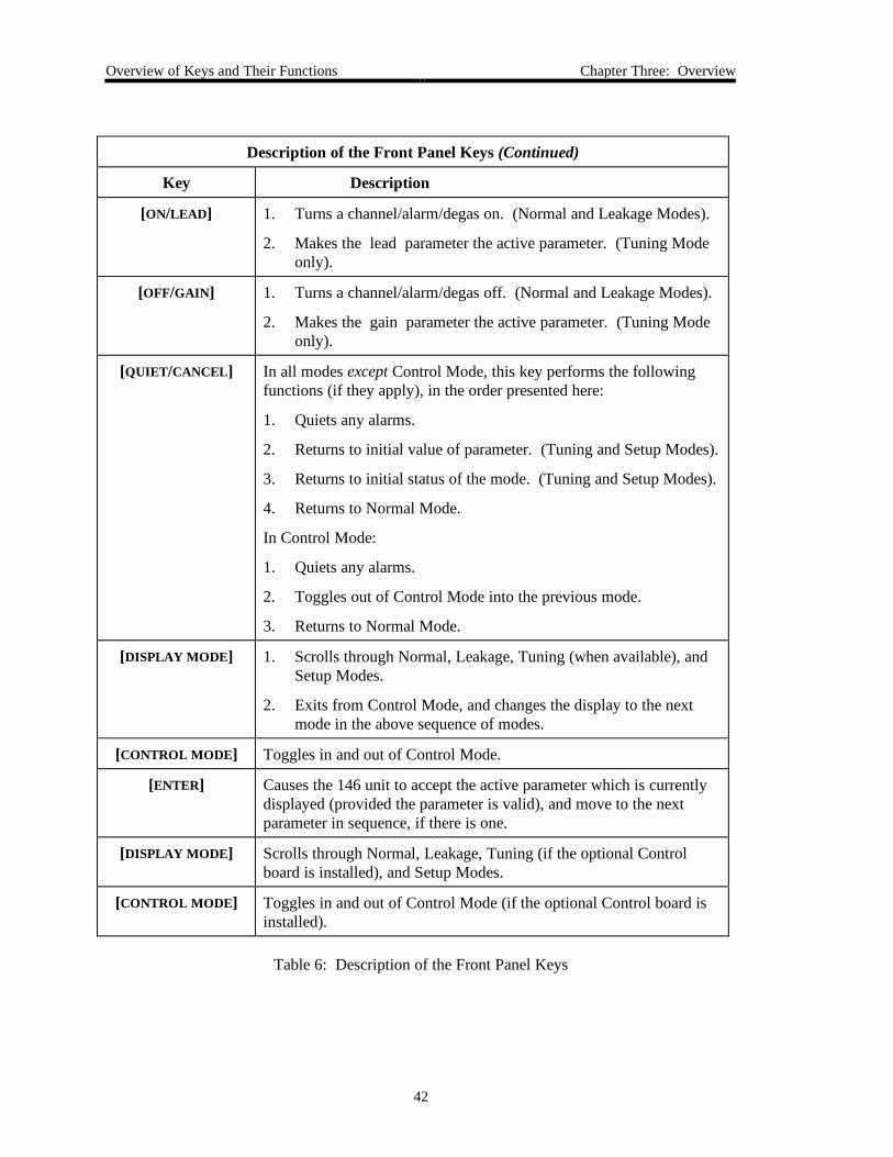
Overview of Keys and Their Functions Chapter Three: Overview
42
Description of the Front Panel Keys (Continued)
Key Description
[ON/LEAD] 1. Turns a channel/alarm/degas on. (Normal and Leakage Modes).
2. Makes the lead parameter the active parameter. (Tuning Modeonly).
[OFF/GAIN] 1. Turns a channel/alarm/degas off. (Normal and Leakage Modes).
2. Makes the gain parameter the active parameter. (Tuning Modeonly).
[QUIET/CANCEL] In all modes except Control Mode, this key performs the followingfunctions (if they apply), in the order presented here:
1. Quiets any alarms.
2. Returns to initial value of parameter. (Tuning and Setup Modes).
3. Returns to initial status of the mode. (Tuning and Setup Modes).
4. Returns to Normal Mode.
In Control Mode:
1. Quiets any alarms.
2. Toggles out of Control Mode into the previous mode.
3. Returns to Normal Mode.
[DISPLAY MODE] 1. Scrolls through Normal, Leakage, Tuning (when available), andSetup Modes.
2. Exits from Control Mode, and changes the display to the nextmode in the above sequence of modes.
[CONTROL MODE] Toggles in and out of Control Mode.
[ENTER] Causes the 146 unit to accept the active parameter which is currentlydisplayed (provided the parameter is valid), and move to the nextparameter in sequence, if there is one.
[DISPLAY MODE] Scrolls through Normal, Leakage, Tuning (if the optional Controlboard is installed), and Setup Modes.
[CONTROL MODE] Toggles in and out of Control Mode (if the optional Control board isinstalled).
Table 6: Description of the Front Panel Keys

Chapter Three: Overview The Front Panel Window
43
The Front Panel Window
Initial View Upon Power Up
On power up, the 146 unit goes through its normal initialization and provides a full LCD testdisplay in the front panel window, shown in Figure 12.
mBAR CmTORR FPASCALVOLTS K1 2 3 4
o
o
o
PaTorr
Ko
oCo
mBAR PamTorr F
oCo
mBAR Ko
Pam oC
oBAR K
o
TUNING LEAKAGE SETUP
SELFOPENAUTOCLOSEHOLDMANUAL
LATCHED
LATCHED
LATCHED
LATCHED
SET POINT LEAD GAIN
OVERRANGEUNDERRANGENO SENSOR CAN'T ZEROOVERRIDE INVALID
PRESET DUAL CHANNEL INTEGRAL THRESHOLDSTART SENSOR CALBASE CODE TRIP POINTANALOG END POINT
Figure 12: Full LCD Display
When initialization is complete, the 146 unit defaults to Normal Mode operation. The frontpanel back-light has an automatic timed turn off. If no keys are pressed, the back-light shuts offafter one hour. The window is reactivated by pressing any key (the key also executes anycommand associated with it).

The Front Panel Window Chapter Three: Overview
44
What to Look For
TUNING GAIN
TORR
HOLD
1
INVALID
This is a legendindicating the activemode
This is a TuningMode Parameter
BlinkingDisplay
This is a ControlMode Parameter
Channel Number
An ErrorMessage
Figure 13: Explanation of the Front Panel Display
A Blinking Display: A blinking parameter in the window indicates that this parameter is theactive entry—its value can be confirmed or edited. You may edit the blinking parameter, orpress the [ENTER] key to move to the next editable parameter (if there is one).
Legends: The 146 unit displays many different legends. Some legends indicate which mode the146 unit is operating in, some provide a choice of parameters (for example OPEN, AUTO, CLOSE ,HOLD, or MANUAL), and some show which parameter is currently available for editing (forexample SET POINT, LEAD, or GAIN).
Channel Number: The small number to the bottom right of the main display, indicates thechannel whose pressure reading is currently being shown in the main display. The left, center,and right displays do not need to have a channel number because they always display channels 1,2, and 3 respectively, when in Normal or Leakage Modes.
Error Codes: The 146 unit is able to determine several different error conditions (such as adisconnected sensor). Refer to Appendices C and D for a list of error codes and what they mean.
IMPORTANT
It is important to be familiar with the various legends, error messages, and parameters which canbe displayed in the front panel window. These messages convey valuable information aboutwhich mode the 146 unit is operating in, the status of the 146 unit and the sensors connected toit, the currently editable parameter, and more.
Take the time to look at Figure 12, page 43, to see all the standard legends, error messages, andparameters of the 146 unit, and where they are displayed in the window. Refer to Table 7, page45, for a summary of the standard messages. In addition to these standard messages, error codes(see Appendix D: Front Panel Error/Status Messages, page 307), can also be displayed. Errorcodes appear in the main, left, center, or right displays, whichever display is most appropriate.

Chapter Three: Overview The Front Panel Window
45
Note The front panel also displays status information and error codes. Refer toAppendix D: Front Panel Error/Status Messages, page 307, for moreinformation.
Standard Front Panel Messages
Category Messages and their Meaning
ModeIdentification
TUNING: The 146 unit is in Tuning Mode.
LEAKAGE: The 146 unit is in Leakage Mode.
SETUP: The 146 unit is in Setup Mode.
Alarm/RelayStatus
A diamond: A diamond indicates an alarm condition.
LATCHED: This message indicates the status of an alarm relay.
Tuning ModeParameters
BASE: The BASE parameter is currently editable.
START: The START parameter is currently editable.
INTEGRAL: The INTEGRAL parameter is currently editable.
PRESET: The PRESET parameter is currently editable.
SET POINT: The SET POINT parameter is currently editable.
LEAD: The LEAD parameter is currently editable.
GAIN: The GAIN parameter is currently editable.
No parameter is displayed: When in Tuning Mode, if:
1. None of the above parameters is displayed and
2. The HOLD or MANUAL Control Mode legend is displayed and
3. The [ENTER] key is pressed, thenthe VALVE POSITION parameter is currently editable.
Control ModeValvePositions
OPEN: The valve output signal is set to 100%.
AUTO: The valve is controlled according to a selected recipe.
CLOSE: The valve output signal is set to zero.
HOLD: The valve is held at its current position.
MANUAL: The valve output signal is changed to a preset value.
Table 7: Standard Front Panel Messages(Continued on next page)

Labels on the 146 Unit Chapter Three: Overview
46
Standard Front Panel Messages (Continued)
Category Messages and their Meaning
Setup ModeFunctions
DUAL CHANNEL THRESHOLD: This parameter is currently editable.
SENSOR CAL: Perform sensor calibration/MFC setup
TRIP POINT: The alarm trip point parameter is currently editable.
CODE: This indicates that a miscellaneous code can be selected.
ANALOG ENDPOINT: Parameters for the Analog Output can be edited.
Sensor Status OVERRANGE: The system pressure has gone above a sensor’s range.
UNDERRANGE: The system pressure has gone below a sensor’s range.
NO SENSOR: No sensor is connected to an active channel.
CAN'T ZERO: The 146 unit cannot zero a sensor because the sensor isoutside of its acceptable zeroing range.
Other INVALID: An invalid keystroke has been used.
Table 7: Standard Front Panel Messages
Labels on the 146 Unit
The 146 unit has a serial number label and an informational label on the side of the unit. Theinformational label states that the CE compliance applies to the model code configuration set atthe factory only. If you modify the unit in any way, such as adding a board, check with thefactory to determine whether the new configuration is CE compliant.
146CAAFFM1
Serial #:
Model #:
MKS Instruments, Inc. Made in the USA
0000410922 CE mark compliance only valid for the specific model configuration
shown on the serial number tag.
Figure 14: Labels on the 146 Unit
Note Not all configurations of the 146 unit are CE compliant. Units that arenot CE compliant cannot display the “CE” symbol on the serial numberlabel. Consult the factory to determine whether a specific configurationis CE compliant.

Chapter Three: Overview Inside the Type 146 Unit
47
Inside the Type 146 Unit
General Information
There are six board slots inside the 146 unit. The sixth slot is for the Analog board, which comesstandard with the 146 unit, and must be installed in slot 6. Transducer and MFC boards shouldbe installed in slots 1, 2, 3, or 4; whichever is the lowest numbered slot available. The 146 unitcan only support one Control board, and one Auxiliary Output board.
Labels are placed on the rear panel to mark the channel number and board type of each boardinstalled in the unit when it leaves the factory. A complete set of labels is supplied if anunconfigured base unit is ordered. Additional labels are available (MKS p/n LB-1141011).
Note Use overall metal braided shielded cables, properly grounded at bothends, for all connections to ensure CE compliance. Refer to InterfaceCables, page 25, for additional information.

Inside the Type 146 Unit Chapter Three: Overview
48
Capacitance Manometer Board
The Capacitance Manometer board has one 15-pin female Type “D” connector. Table 8 showsthe connector pinout. Refer to Table 9, page 49, for a list of MKS capacitance manometerssupported, along with their cables.
Capacitance Manometer Pinout
Pin Number Assignment
1 +15 Volts
2 Signal +
3 Remote Zero *
4 x0.1 Range Select * or
PROM Clock**
5 Power Ground
6 -15 Volts
7 +15 Volts
8 Remote Zero Out-of-Range *
9 -15 Volts
10 PROM Write**
11 Digital Ground
12 Signal -
13 Range Identification * or
PROM Read**
14 Bypass Remote Zero *
15 Chassis Ground
* Feature on the 120 transducer only
** Feature on the 107 transducer only
Table 8: Capacitance Manometer Pinout
Note If a pin has a function that is not supported by your transducer, do notconnect a signal to it. Circuitry on the Capacitance Manometer boardmay be damaged if an inappropriate signal is connected.

Chapter Three: Overview Inside the Type 146 Unit
49
MKS Capacitance Manometers and Cables
Type Description Cable Number
107B 6 Decade Sensor CB107-1-10, CB107S-1-10
120 Highest Accuracy Standalone CB120-1-10, CB120S-1-10
122A General Purpose CB112-2-10, CB112S-2-10
127A Heated General Purpose CB259-5-10, CB259S-5-10
128 High Temperature General Purpose CB259-5-10, CB259S-5-10
220 NEMA Case CB112-10-10, CB112S-10-10
221 Remote Sensor CB112-14-10, CB112S-14-10
223 Differential Sensor CB112-2-10, CB112S-2-10
124, 224, 225 General Purpose with Alarms CB112-2-10, CB112S-2-10
390 or 690with a 270
Highest Accuracy CB112-6, CB112S-6
622 Absolute Transducer CB112-2-10, CB112S-2-10
623 Absolute Transducer CB112-2-10, CB112S-2-10
624 Absolute Transducer (heated) CB112-2-10, CB112S-2-10
625 Absolute Transducer (heated) CB112-2-10, CB112S-2-10
626 Absolute Transducer CB259-5-10, CB259S-5-10
627 Absolute Transducer (heated) CB259-5-10, CB259S-5-10
628 Absolute Transducer (heated) CB259-5-10, CB259S-5-10
700 Series Mini-Baratron® Absolute and GagePressure Transducers
consult factory
800 Series Ultraclean Mini-Baratron Absoluteand Gage Pressure Transducers
consult factory
Table 9: MKS Capacitance Manometers and Cables

Inside the Type 146 Unit Chapter Three: Overview
50
Pirani/Convection
On the end of the Pirani/Convection board are two 9-pin female Type “D” connectors, since theboard can support up to two gauges. Table 10 shows the connector pinout. The top connector isthe lower numbered channel, and the bottom connector is the higher numbered channel. Forexample, if this board is installed in slot 1, the top connector is channel 1, and the bottomconnector is channel 2.
Pirani/Convection Connector Pinout
Pin Number Assignment
1 Drive +
2 Chassis Ground
3 Signal +
4 Signal -
5 Power Ground
6 Drive +
7 Bridge Delta +
8 Bridge Delta -
9 Power Ground
Table 10: Pirani/Convection Connector Pinout
Pirani Sensors and Cables
Sensor Type Part Number
Pirani Tube with KF-16 103150010
Pirani Tube with ¹/8” NPT 103150011
Pirani Tube with ½” VCR 103150012
Pirani Tube with 11/3” CF 103150013
Pirani Tube with 2¾” CF 103150014
Cable Type Part Number
10 foot cable for all HPS Pirani sensors CB146-15, CB146S-15
146 to HPS CEP gauge CB146-37, CB146S-37
146 to G.P. Convectron® CB146-14, CB146S-14
146 cable adapter for G.P. Convectron cable CB146-1, CB146S-1
Table 11: Pirani Sensors and Cables

Chapter Three: Overview Inside the Type 146 Unit
51
Configuring the Dual Channel Pirani/Convection Board as Single Channel Board
The Pirani/Convection board can function as a single channel board. MKS will have configuredthe board as a single channel board, if you requested it when you placed the order. The boardwill be configured for dual channel operation if you did not specify single channel operation. Ifyou did not request the single channel configuration, but wish to configure the board for singlechannel operation, follow these instructions.
Warning The 146 unit has lethal voltages inside. To avoid the dangerof electrical shock, disconnect the power line before openingthe unit.
1. Be sure the power cord is disconnected.
2. Disconnect all cables from the 146 unit.
3. Remove the four (4) Phillips screws on the outside corners of the rear panel and theseven (7) screws from the top cover.
4. Remove the top cover by firmly pulling it towards the back of the unit. Note theorientation of the cover since the center hole is slightly off center to accommodate aconnector if a board is positioned in slot 5.
5. Carefully turn the unit over so that it is bottom-side up and remove the seven (7) screws.
6. Remove the bottom cover by firmly pulling it towards the back of the unit. Note theorientation of the cover since the center hole is slightly off center to accommodate aconnector if a board is positioned in slot 5.
7. Remove the Phillips screw that is securing the Pirani/Convection board to the bottom ofthe 146 unit.
8. Carefully turn the unit right-side up.
9. Unscrew the two small screws holding the slot cover on the Pirani/Convection board.

Inside the Type 146 Unit Chapter Three: Overview
52
10. Remove the top fastening screw that is above the upper connector.
Top fastening screw
Figure 15: Dual Pirani Board Connectors
11. Carefully but firmly pull the Pirani/Convection board out of the 146 unit.
12. Remove the jumper that is currently on any jumper pack numbered JP2 through JP8(typically the jumper is stored on JP2).
Place the jumper on JP1 forsingle channel configuration
Place the jumper on JP2 fordual channel configuration
Figure 16: Jumper Placement on the Pirani/Convection Board
13. Place the jumper on JP1.
The board is now configured as a single channel Pirani/Convection board. The topconnector becomes the only active channel.
Note Only the top connector is active when the Pirani/Convection board isconfigured for single channel operation.

Chapter Three: Overview Inside the Type 146 Unit
53
14. Slide the board back inside the unit so that the connectors protrude through the openingin the rear panel.
15. Line the board up so that the female connector on the board is directly over the maleconnector on the mother board.
16. Gently push the board onto the male connector.
17. Replace the top connector’s fastening screw.
18. Turn the unit over so that it is bottom-side up.
19. Replace the Phillips screw that fastens the board to the 146 unit.
20. Replace the bottom cover by inserting it into the grooves provided, and firmly sliding ittowards the front of the unit. Replace the seven (7) screws that fasten the bottom cover.
The center screw on the bottom cover is slightly off center to avoid interfering with aconnector if a board is positioned in slot 5. Therefore, the cover must be in the correctorientation for the screw holes to line up properly.
21. Carefully turn the unit right-side up.
22. Replace the top cover by inserting it into the grooves provided, and firmly sliding ittowards the front of the unit. Replace the seven (7) screws that fasten the top cover.
The center screw on the top cover is slightly off center to avoid interfering with aconnector if a board is positioned in slot 5. Therefore, the cover must be in the correctorientation for the screw holes to line up properly.
23. Replace the four (4) Phillips screws on the outside corners of the rear panel.
24. Plug in the power cord.

Inside the Type 146 Unit Chapter Three: Overview
54
Cold Cathode
Located on the end of the Cold Cathode board are two coaxial connectors. Table 12 shows theconnector pinout. A list of MKS sensors, along with their cables, is shown in Table 13.
Cold Cathode Connector Pinout
High Voltage High Voltage BNC
High Voltage Center
Chassis Ground Shield
Ion Current SMA
Ion Current Center
Chassis Ground Shield
Table 12: Cold Cathode Connector Pinout
Cold Cathode Sensors And Cables
Sensor and Cable Type Part Number
Cold Cathode with NW-40-KF 104210001
Cold Cathode with 2¾” CF 104210002
Cold Cathode with 1” tube 104210003
Cold Cathode with NW-25-KF 104210004
Cold Cathode Cable (10 ft.) 100006171
Table 13: Cold Cathode Sensors and Cables
Note One characteristic common to all ion gauges is an inability to establish anion current at high pressures. The gauge may, therefore, respond as if thepressure is extremely low. Keep this characteristic in mind when settinga disconnect threshold, alarm trip points, or if you designate an ion gaugeas a reference channel.

Chapter Three: Overview Inside the Type 146 Unit
55
Hot Cathode
Located on the end of the Hot Cathode board is one coaxial connector and one 15-pin femaleType “D” connector. Table 14 shows the connector pinout of the coaxial connector and Table 16shows the Type “D” connector pinout. A list of MKS hot cathode gauges, along with theircables, is shown in Table 15.
Note Only hot cathode gauges with nude tubes are CE compliant. Hot cathodegauges with glass tubes are not CE compliant. If your 146 unit is CEcompliant, you must use a hot cathode gauge with a nude tube for the unitto remain CE compliant.
The 146 unit offers several power control features designed for use with hot cathode gauges. Ifthe 146 unit detects a disconnected hot cathode, a tube short, or an open filament in the HCgauge, it automatically turns off power to the gauge. To restore power to the gauge, toggle theHC channel off and on again. This feature is always enabled.
Hot Cathode Coaxial Connector Pinout
Ion Current SMA
Ion Current Center
Chassis Ground Shield
Table 14: Hot Cathode Coaxial Connector Pinout
Hot Cathode Sensors and Cables
Sensor Type Part Number
All MKS Hot Cathode Gauges Types IG-xx, RG75, and NRC563 consult factory
HPS low power, nude, Bayard-Alpert (B/A) hot cathode KF-40 100005987
HPS low power, nude, Bayard-Alpert (B/A) hot cathode 2¾ CF 100005980
Other nude or B/A tubes - thoriated iridium or tungsten filament Consult factory
Cable Description Part Number
Cable for glass envelope tubes CB146-13, CB146S-13
Cable for glass envelope tubes and external power CB146-16, CB146S-16
Cable for nude hot cathode tube CB146-19, CB146S-19
Table 15: Hot Cathode Sensors and Cables

Inside the Type 146 Unit Chapter Three: Overview
56
Hot Cathode Type “D” Connector Pinout
Pin Number Assignment
1 Filament +
2 Chassis Ground
3 Filament -
4 +15 Volt Output
5 115 Volt Output
6 Grid/Degas -
7 External -15 Volts (high power)
8 Grid/Degas +
9 Filament +
10 External +15 Volts
11 Filament -
12 Power Ground
13 Grid/Degas -
14 External -15 Volts (Current limited)
15 Grid/Degas +
Table 16: Hot Cathode Type “D” Connector Pinout
Note All ion gauges show an inability to establish an ion current at highpressures. The gauge may respond as if the pressure is extremely low.Keep this characteristic in mind when setting a disconnect threshold,alarm trip points, or if you designate an ion gauge as a reference channel.
Provision for External Power to a Hot Cathode
The 146 unit can supply a maximum of 45 watts to a hot cathode. If the hot cathode isundergoing a high power degas, all of the 45 watts is used for the degassing process. If the hotcathode is undergoing a low power degas, the filament is powered for measurement, and theremaining power is used for the degassing function.
Power from the internal power supply is supplied to the hot cathode board via looping the supplyin the rear panel connector. If preferred, a cable can be supplied which does not loop the powerinto the hot cathode board. The optional cable provides a line that can be connected to anexternal power source. The external power source would then power the hot cathode board. A90 watt, ± 15 Volt, external power supply can provide 60 watts for degassing in the high or lowpower degas mode.

Chapter Three: Overview Inside the Type 146 Unit
57
Configuring the Hot Cathode Board for a Low Power Hot Cathode
The Hot Cathode board can be configured for a low power hot cathode (the default is for a highpower gauge). MKS will configure the board at the factory, if specified on the order. If you didnot request the low power configuration, but wish to use the board with a low power hot cathode,follow these instructions.
Caution 1. Be sure to have the correct setting for your hot cathode. Damagemay occur to a low power hot cathode gauge if you operate it withthe high power gauge configuration because excessive powerwould be applied to the grid during degas.
2. If two Hot Cathode (HC) boards are installed in one unit, the HCboards MUST be set to low power configuration. Otherwise, the146 unit may exceed its temperature rating.
Warning The 146 unit has lethal voltages inside. To avoid the dangerof electrical shock, disconnect the power line before openingthe unit.
1. Be sure the power cord is disconnected.
2. Disconnect all cables from the 146 unit.
3. Remove the four (4) Phillips screws on the outside corners of the rear panel and theseven (7) screws from the top cover.
4. Remove the top cover by firmly pulling it towards the back of the unit. Note theorientation of the cover since the center hole is slightly off center to accommodate aconnector if a board is positioned in slot 5.
5. Carefully turn the unit over so that it is bottom-side up and remove the seven (7) screws.
6. Remove the bottom cover by firmly pulling it towards the back of the unit. Note theorientation of the cover since the center hole is slightly off center to accommodate aconnector if a board is positioned in slot 5.
7. Remove the Phillips screw that is securing the Hot Cathode board to the bottom of the146 unit.
8. Carefully turn the unit right-side up.
9. Unscrew the two small screws holding the slot cover on the Hot Cathode board.
10 Carefully but firmly pull the Hot Cathode board out of the unit.
11. Remove one of the shorting jumpers which is currently stored on JP4.

Inside the Type 146 Unit Chapter Three: Overview
58
The HC High Power configurationis with no jumper on JP3.Shorting jumpers are stored on JP4.
The HC Low Power configuration is with a shorting jumper on JP3.
Figure 17: Jumper Placement on the Hot Cathode Board
12. Place the shorting jumper on JP3 to configure the board for a low power hot cathode.
13. Slide the board back inside the unit so that the connectors protrude through the openingin the rear panel.
14. Line the board up so that the female connector on the board is directly over the maleconnector on the mother board.
15. Gently push the board onto the male connector.
16. Turn the unit over so that it is bottom-side up.
17. Replace the Phillips screw that fastens the board to the 146 unit.
16. Replace the bottom cover by inserting it into the grooves provided, and firmly sliding ittowards the front of the unit. Replace the seven (7) screws that fasten the bottom cover.
The center screw on the bottom cover is slightly off center to avoid interfering with aconnector if a board is positioned in slot 5. Be sure to align the cover correctly.
17. Carefully turn the unit right-side up.
18. Replace the top cover by inserting it into the grooves provided, and firmly sliding ittowards the front of the unit. Replace the seven (7) screws that fasten the top cover.
The center screw on the top cover is slightly off center to avoid interfering with aconnector if a board is positioned in slot 5. Be sure to align the cover correctly.
19. Replace the four (4) Phillips screws on the outside corners of the rear panel.
20. Plug in the power cord.

Chapter Three: Overview Inside the Type 146 Unit
59
Thermocouple Board
The Thermocouple board has two 9-pin female Type “D” connectors since the board can supportup to two thermocouple gauges. Table 17 shows the connector pinout. The top connector is thelower numbered channel, and the bottom connector is the higher numbered channel. Forexample, if this board is installed in slot 1, the top connector is channel 1, and the bottomconnector is channel 2.
The 146 instrument supports the following thermocouples:
• MKS TC-1A
• Hastings DV-6M
Note Units equipped with a Thermocouple board cannot carry a CE mark sincethere are no CE compliant thermocouple gauges available.
Thermocouple Connector Pinout
Pin Number Assignment
1 Drive +
2 Drive -
3 Signal +
4 Drive -
5 Drive +
6 Gauge ID
7 Digital Ground
8 Keyed Position
9 Chassis Ground
Table 17: Thermocouple Connector Pinout
Cabling Information for the Thermocouple Board
Cable Part Number Available Lengths
146 to TC-1A CB146-6-XX, CB146S-6-XX 10 ft to 25 ft
146 to DV-6M CB146-8-XX, CB146S-8-XX 10 ft to 100 ft
Extension cable, 146 to TC-1A CB146-7-XX, CB146S-7-XX 26 ft to 100 ft
where XX indicates the length
Table 18: Cabling Information for the Thermocouple Board

Inside the Type 146 Unit Chapter Three: Overview
60
Configuring the Dual Thermocouple Board as Single Channel Board
The Thermocouple board can function as a single channel board. MKS will have configured theboard as a single channel board, if you requested it when you placed the order. The board will beconfigured for dual channel operation if you did not specify single channel operation. If you didnot request the single channel configuration, but wish to configure the board for single channeloperation, follow these instructions.
Warning The 146 unit has lethal voltages inside. To avoid the dangerof electrical shock, disconnect the power line before openingthe unit.
1. Be sure the power cord is disconnected.
2. Disconnect all cables from the 146 unit.
3. Remove the four (4) Phillips screws on the outside corners of the rear panel and theseven (7) screws from the top cover.
4. Remove the top cover by firmly pulling it towards the back of the unit. Note theorientation of the cover since the center hole is slightly off center to accommodate aconnector if a board is positioned in slot 5.
5. Carefully turn the unit over so that it is bottom-side up and remove the seven (7) screws.
6. Remove the bottom cover by firmly pulling it towards the back of the unit. Note theorientation of the cover since the center hole is slightly off center to accommodate aconnector if a board is positioned in slot 5.
7. Remove the Phillips screw that is securing the Thermocouple board to the bottom of the146 unit.
8. Carefully turn the unit right-side up.
9. Unscrew the two small screws holding the slot cover on the Thermocouple board.

Chapter Three: Overview Inside the Type 146 Unit
61
10. Remove the top fastening screw that is above the upper connector.
Top fastening screw
Figure 18: Top Fastening Screw on the Dual Thermocouple Board
11. Carefully but firmly pull the Thermocouple board out of the 146 unit.
12. Locate jumper JP1, as shown in Figure 19.
There should be a jumper on pin 1.
Jumper JP1
Figure 19: Jumper Placement on the Thermocouple Board
13. Move the jumper to short pins 1 and 2.
The board is now configured as a single channel Thermocouple board. The topconnector becomes the only active channel.
Note Only the top connector is active when the Thermocouple board isconfigured for single channel operation.
14. Slide the board back inside the unit so that the connectors protrude through the openingin the rear panel.
15. Line the board up so that the female connector on the board is directly over the maleconnector on the mother board.

Inside the Type 146 Unit Chapter Three: Overview
62
16. Gently push the board onto the male connector.
17. Replace the top connector’s fastening screw.
18. Turn the unit over so that it is bottom-side up.
19. Replace the Phillips screw that fastens the board to the 146 unit.
20. Replace the bottom cover by inserting it into the grooves provided, and firmly sliding ittowards the front of the unit. Replace the seven (7) screws that fasten the bottom cover.
The center screw on the bottom cover is slightly off center to avoid interfering with aconnector if a board is positioned in slot 5. Therefore, the cover must be in the correctorientation for the screw holes to line up properly.
21. Carefully turn the unit right-side up.
22. Replace the top cover by inserting it into the grooves provided, and firmly sliding ittowards the front of the unit. Replace the seven (7) screws that fasten the top cover.
The center screw on the top cover is slightly off center to avoid interfering with aconnector if a board is positioned in slot 5. Therefore, the cover must be in the correctorientation for the screw holes to line up properly.
23. Replace the four (4) Phillips screws on the outside corners of the rear panel.
24. Plug in the power cord.

Chapter Three: Overview Inside the Type 146 Unit
63
Mass Flow Controller Board
On the end of the Mass Flow Controller (MFC) board is a 15-pin female Type “D” connector.The table below shows the connector pinout. A list of MKS mass flow controllers, along withtheir cables, is shown in Table 20, page 64.
Mass Flow Controller Connector Pinout
Pin Number Assignment
1 No Connection
2 Signal In +
3 Valve Close output (active low open collector)
4 Valve Open output (active low open collector)
5 Power Ground
6 -15 Volts
7 +15 Volts
8 Set Point Signal Output
9 Fault Input (active low TTL): Reserved
10 Open
11 Set Point Remote Sense
12 Signal Common
13 No Connection
14 No Connection
15 Chassis Ground
Table 19: Mass Flow Controller Connector Pinout
Note A “No Connection” assignment indicates that the pin has no internalconnection.

Inside the Type 146 Unit Chapter Three: Overview
64
Mass Flow Controllers And Cables
MFC And Cable Type Part Number
All MKS Mass Flow Controllers except Types1749/1759
Consult the factory for a complete list ofMFC types, ranges, and part numbers
Cable for MFCs w/ Edge Card connector CB147-7
Cable for MFCs w/ 15-pin Type “D” connector CB147-1, CB147S-1
Cable for MFCs w/ 9-pin Type “D” connector CB147-12, CB147S-12
Table 20: Mass Flow Controllers and Cables
Note You must use the appropriate CB147-X cable to enable the MFC overridecommands. The CB259-5 and CB259-10 cables do not support the openand close override commands. However, using these cables will notdamage either unit.

Chapter Three: Overview Inside the Type 146 Unit
65
General I/O Connector
The General I/O connector is a 25-pin male Type “D” connector. This connector brings out theanalog output 1 signal, Relay A and B contacts, and remote zero, alarm latch, and front-panel-lockout digital control lines. The front panel lockout feature provides a security measure toprevent inadvertent command entry through the front panel. The front panel can also be lockedor unlocked via RS-232 communications. The Relay A and B contacts can handle up to 1A at30 VDC. Table 21 lists the pinout functions of the General I/O connector.
General I/O Connector Pinout
Pin Number Assignment
1 Chassis
2 Remote Zero Channel 3
3 Remote Zero Channel 4
4 Latch Relay B
5 Latch Relay D
6 Digital Ground
7 Reserved
8 Reserved
9 Analog Output 1
10 Front Panel Lockout
11 Relay B Normally Open
12 Relay B Common
13 Relay B Normally Closed
14 Remote Zero Channel 1
15 Remote Zero Channel 2
16 Latch Relay A
17 Latch Relay C
18 Digital Ground
19 Reserved
Table 21: General I/O Connector Pinout(Continued on next page)

Inside the Type 146 Unit Chapter Three: Overview
66
General I/O Connector Pinout (Continued)
Pin Number Assignment
20 Reserved
21 Reserved
22 Analog 1 Common (Single Ground)
23 Relay A Normally Open
24 Relay A Common
25 Relay A Normally Closed
Table 21: General I/O Connector Pinout
Remote Zero Line Function with Ion Gauges
The Remote Zero lines on the General I/O connector act as an On/Off toggle switch for iongauges. A high to low transition on the Remote Zero line turns the ion gauge off. A low to hightransition turns the ion gauge on. This feature is supported for both hot cathode and cold cathodegauges.

Chapter Three: Overview Inside the Type 146 Unit
67
Auxiliary Output Board
The Auxiliary Output board contains relays C and D (which supplement relays A and B), andanalog outputs 2 and 3. The modified, male 9-pin Type “D” connector at the top of the boardallows operation of 120 VAC devices. The 9-pin female Type “D” connector at the bottom ofthe board carries relay status, analog output signals 2 and 3, and their return lines. Table 22 liststhe pin functions of the relay connections and Table 23 lists the functions for the analog outputs.
Relay Output (Top) Connector Pinout
Pin Number Assignment
1, 6, 2 Relay C (NO, C, NC)*
4, 9, 5 Relay D (NO, C, NC)*
* NO = Normally Open, NC = Normally Closed, C = Common to both
Table 22: Relay Output (Top) Connector Pinout
Status/Analog Output (Bottom) Connector Pinout
Pin Number Assignment
1 Relay C Status (high = energized)
2 Relay D Status (high = energized)
3 Reserved
4 Reserved
5 Analog 2 Common (Signal Ground)
6 Analog 3 Out
7 Analog 3 Common (Signal Ground)
8 Analog 2 Out
9 Digital Ground
Table 23: Status/Analog Output (Bottom) Connector Pinout

Inside the Type 146 Unit Chapter Three: Overview
68
Auxiliary Output Board - Fail-Safe Feature
Relays C and D on the Auxiliary Output board are associated with the 146 instrument’s Fail-Safefeature. When the 146 unit is powered on, this feature is activated. The processor waits untilpressure readings are stable before activating any of the relays in the 146 unit.
The Fail-Safe feature includes a timed hardware reset that causes relays C and D to go to defaultpositions. The processor in the 146 unit prevents the timed hardware reset from executing bysending out an interrupt pulse every 10 milliseconds. If the 146 unit’s software crashes, theinterrupt pulse stops and the timed hardware reset executes, causing relays C and D to go todefault positions.
Code 7x in the 146 diagnostics feature, is used to determine if the Fail-Safe system is operating,and its response time. When Code 7x is used, the processor sends a relay setup command torelays C and D, and then checks to see if the relays have responded. If the relays do not respond,the abbreviation Err (for Error), appears in the main display. If the relays do respond, theFail-Safe test continues; the Code 7x function determines the Fail-Safe system response time,and displays it in the main display (in milliseconds). The response time is the elapsed timebetween when an interrupt pulse is received by the hardware reset, and when relays C and D goto the default position (de-energized state).
To confirm that the Fail-Safe feature is operating properly, refer to Code 7x: Response Time forFail-Safe Feature, page 299.

Chapter Three: Overview Inside the Type 146 Unit
69
Control Board
The Control board has two 9-pin Type “D” connectors (one female, one male). The femaleconnector is located at the top of the board. It carries the valve drive lines, and the PCS (pressurecontrol signal) output used for throttle valves or ratio controllers. Table 24 shows the pinout forthis connector. Table 27, page 71, shows some of the valves that interface to the 146 unit.
Control Valve (Top) Connector Pinout
Pin Number Assignment
1 Power Ground
2 + 15 Volts
3 Analog Set Point +
4 Analog Set Point -
5 PCS Signal
6 Valve Drive +
7 Valve Drive -
8 PCS Common (Signal Ground)
9 Chassis Ground
Table 24: Control Valve (Top) Connector Pinout
When using the Valve Drive + and - outputs (pins 6 and 7 in Table 24), the full scale valve drivecurrent (140 or 200 mA), and the compliance voltage (14 or 26 Volts), must be selected via theproper pin jumpers. For the Type 146 unit, compliance voltage is the voltage needed to sustain agiven constant current throughout a range of valve types. Unless otherwise specified in yoursystem configuration sheet, the default jumper packs are JP3 and JP5. This default enables the146 unit to drive a Type 148 or 248 Valve. Refer to Table 26, page 70, for a complete jumperpack description. Refer to the following instructions to configure the 146 instrument to drivedifferent valves.

Inside the Type 146 Unit Chapter Three: Overview
70
The male connector carries open, close, manual, and set point recipe select digital control lines.It also carries the analog set point input. Table 25, page 70, lists the pinout of this connector.Table 28, page 71, lists MKS flow controllers that interface to the 146 unit.
Control Interface (Bottom) Connector Pinout
Pin Number Assignment
1 Analog Set Point + (signal)
2 Set Point B
3 Set Point C
4 Set Point D
5 Digital Ground
6 Analog Set Point - (return)
7 Open
8 Manual
9 Close
Table 25: Control Interface (Bottom) Connector Pinout
Control Board Pin Jumpers
Jumper Pack Voltage/Current Jumpered For. . .
JP1 200 mA 154 valve
JP2 reserved
JP3 140 mA 148, 153, and 248 valves
JP4 26 Volts 154 valve
JP5 14 Volts 148, 153, and 248 valves
Table 26: Control Board Pin Jumpers

Chapter Three: Overview Inside the Type 146 Unit
71
Control Valves and Cables
Valve Type MKS Valve Part Number for Cable
Solenoid 148, 248 CB251-2-10, CB251S-2-10
Smart Throttle (not powered by the 146) 153 CB153-4-10, CB153S-4-10
Smart Throttle (powered by the 146) 153 CB153-13-10, CB153S-13-10
High Flow Solenoid 154 CB251-2-10 w/ CB-248-1 adapterCB251S-2-10 w/ CB-248-1 adapter
Table 27: Control Valves and Cables
Flow Controllers and Cables
Equipment Description MKS Product Cable Number
4 Channel flow, with CRT 147 CB146-3, CB146S-3
1 Channel Flow 246 CB246-3, CB246S-3
4 Channel Flow 247 CB247-9, CB247S-9
Table 28: Flow Controllers and Cables

Inside the Type 146 Unit Chapter Three: Overview
72
How To Configure the Control Board to Drive Different Valves
1. Be sure the power cord is disconnected.
Warning The 146 unit has lethal voltages inside. To avoid the dangerof electrical shock, disconnect the power line before openingthe unit.
2. Disconnect all cables from the 146 unit.
3. Remove the four (4) Phillips screws on the outside corners of the rear panel and theseven (7) screws from the top cover.
4. Remove the top cover by firmly pulling it towards the back of the unit. Note theorientation of the cover since the center hole is slightly off center to accommodate aconnector on a board positioned in slot 5.
5. Carefully turn the unit over so that it is bottom-side up and remove the seven (7) screws.
6. Remove the bottom cover by firmly pulling it towards the back of the unit. Note theorientation of the cover since the center hole is slightly off center to accommodate aconnector on a board positioned in slot 5.
7. Remove the shorting jumpers that are currently placed on and jumper packs numberedJP1 through JP5.
Short jumper packs JP1 and JP4for 154 valve configuration
Short jumper packs JP3and JP5 for 148 and 248valve configuration
Figure 20: Jumper Placement on the Control Board
8. Place the shorting jumpers on JP1 and JP4 (for a Type 154 valve) or place the jumperson JP3 and JP5 (for Type 148 or 248 valves).

Chapter Three: Overview Inside the Type 146 Unit
73
9. Replace the bottom cover by inserting it into the grooves provided, and firmly sliding ittowards the front of the unit. Replace the seven (7) screws that fasten the bottom cover.
The center screw on the bottom cover is slightly off center to avoid interfering with aconnector on a board in slot 5. Therefore, the cover must be in the correct orientation forthe screw holes to line up properly.
10. Carefully turn the unit right-side up.
11. Replace the top cover by inserting it into the grooves provided, and firmly sliding ittowards the front of the unit. Replace the seven (7) screws that fasten the top cover.
The center screw on the bottom cover is slightly off center to avoid interfering with aconnector on a board in slot 5. Therefore, the cover must be in the correct orientation forthe screw holes to line up properly.
12. Replace the four (4) Phillips screws on the outside corners of the rear panel and the seven(7) screws on the top cover.
13. Replace the four (4) screws on the rear panel.
14. Plug in the power cord.

Inside the Type 146 Unit Chapter Three: Overview
74
The Displayless Front Panel Connector Pinout
When ordered as an optional displayless unit, the 146 instrument arrives with a front panel thatonly contains a power switch, LED, and a 25-pin female Type “D” Interface connector. Thisconnector allows an RS-232 communications source to be connected to the front of thedisplayless unit. The pinout of the connector is listed in Table 30, page 75. The RS-232 cableused on the front panel connector (MKS p/n CB146-21) is not the same as the RS-232 cable usedfor rear panel communications (refer to Table 32, page 77, for the proper MKS part number).
Both the Interface connector, located on the front panel, and an RS-232 connector, located on therear panel, support RS-232 communication between the 146 unit and a computer. However, the146 unit only accepts command messages through one port at a time, though it can report statusinformation on both ports simultaneously. The 146 unit determines which port takes precedencebased on the state of pin 4 of the Interface connector.
Pin 4 left open: The rear panel connector (RS-232) is active; the front panel connector(Interface) is passive. The RS-232 connector takes precedence. It will accept commandmessages and respond to query messages. The device connected to the Interface connector canonly receive RS-232 communications that are currently being issued from the 146 unit, throughthe rear panel.
Pin 4 grounded: The front panel connector (Interface) is active; the rear panel connector(RS-232) is passive. The Interface connector takes precedence so that the device connected tothe front panel can communicate fully with the 146 unit. Any device connected to the rear panelRS-232 connector can only receive messages that are currently being issued from the 146 unit,through the front panel.
For regular operation, use the RS-232 connector on the rear panel to connect the 146 unit to yoursystem. The Interface connector provides a convenient port to connect a portable computer to the146 unit should you need to troubleshoot the unit.
Pin 8 can supply a +5V signal, which can be used to power one of several types of remoteterminals.
The functions on pins 5 and 20 are special options that must be specifically requested from thefactory.
Remote Front Panel Cable
RS-232 Cable to Remote Front Panel CB146-21, CB146S-21
Table 29: Remote Front Panel Cables

Chapter Three: Overview Inside the Type 146 Unit
75
Front Panel Connector Pinout on the Displayless 146 Unit
Pin Number Assignment
1 Chassis Ground
2 RS-232 Transmit
3 RS-232 Receive
4 RS-232 Receive Enable (connect to digital ground to
override rear connector RS-232)
5 RS-232 CTS (special option)
6 Spare
7 Digital Ground
8 Filtered +5 Volts
9 Keyboard P4
10 Keyboard P5
11 Keyboard P6
12 Keyboard P7
13 Keyboard P8
14 Display Backlight Enable
15 Display Data U2
16 Display Data U3
17 Display Data U4
18 Display Data Clock
19 Keyboard P3
20 RS-232 RTS (special option)
21 Keyboard P2
22 Keyboard P1
23 Keyboard P11
24 Keyboard P10
25 Keyboard P9
Table 30: Front Panel Connector Pinout on the Displayless 146 Unit

Inside the Type 146 Unit Chapter Three: Overview
76
The Binary Coded Decimal (BCD) Board
The BCD board has an unwired, 25-pin female Type “D” connector. This board providesinput/output signals for hot cathode gauges.
The first four signals listed are inputs. The active low for the inputs requires about a 1 mA sink,0.8 Volts maximum. The data inputs are read every 100 ms and require the recognition of atransition. A minimum pulse width of 100 ms must be observed for the inputs to be activated.
The remaining signals are outputs. The open collector is tied to +5 Volts with 5.6K ohms. Datachanges after the falling edge of a strobe, and is valid on the strobe’s rising edge. The strobepulse is approximately 5 microseconds, and the BCD data is updated at a rate of 100 ms.
BCD Connector Pinout
Pin Number Assignment
3 Remote Off
4 Remote Degas
16 Reserved
17 Reserved
18 Least significant digit 1
19 Least significant digit 2
6 Least significant digit 4
5 Least significant digit 8
20 Most significant digit 1
21 Most significant digit 2
8 Most significant digit 4
7 Most significant digit 8
22 Exponent digit 1
23 Exponent digit 2
10 Exponent digit 4
9 Exponent digit 8
11 Exponent digit 10
24 Strobe
25 Status
Table 31: BCD Board Pinout(Continued on next page)

Chapter Three: Overview Inside the Type 146 Unit
77
BCD Connector Pinout (Continued)
Pin Number Assignment
12 Inverse of Status
2, 14 External Digital Ground
13 Digital Ground (Reserve)
1 and shell Chassis Ground
15 Digital +5 Volts (Reserved)
Table 31: BCD Board Pinout
The RS-232 Connector
Located on the rear panel is the standard, 9-pin male Type “D” connector that is used for serialcommunications. Table 32 lists the pin functions employed by this interface. The RS-232Communications chapter describes the RS-232 protocol used in the 146 unit.
RS-232 Connector Pinout and Cables
Pin Number Assignment
2 TXD*
3 RXD*
5 Digital Ground
7 CTS*
Cable for AT® or compatible CB-146-2, CB-146S-2
Cable for XT® or compatible CB-146-4, CB-146S-4
* TXD =Transmit Data, RXD =Receive Data, CTS =Clear To Send
Table 32: RS-232 Connector Pinout and Cables

Inside the Type 146 Unit Chapter Three: Overview
78
Torr mTorr Torr
HOLD
4
mTORR
Normal Mode
Torr mTorr Torr
LEAKAGE
HOLD
TORR
4
Leakage Mode
TUNING HOLD
2
TORR
Tuning Mode
CLOSE
TORR
SETUP
TRIP POINT
Setup Mode
TorrOPENAUTOCLOSEHOLDMANUAL
TORR
4
Control Mode(requires the Control Board)
(requires the Control Board)
Figure 21: Sample Display for Each Mode

Chapter Three: Overview Overview of Modes
79
Overview of Modes
There are three standard modes for the 146 unit: Normal, Leakage, and Setup. Two additionalmodes are available if the optional Control board is installed: Control and Tuning. Allcommands for all modes are accessible with the front panel keypad. Most commands areaccessible through the RS-232 communications port. Some operating conditions (such as valvecontrol functions), are also operable through hardwired connections on the rear panel.
When the 146 unit is powered up, it goes through a full screen LCD test, and all displays in thefront panel window light up. After roughly five seconds, the screen changes and the unit defaultsto Normal Mode.
How To Tell which Mode You Are In
Refer to Figure 21, page 78, for a sample figure of each mode. Each mode provides a maindisplay and three upper displays.
Normal Mode The screen is not labeled.
Leakage Mode Displays the LEAKAGE legend.
Setup Mode Displays the SETUP legend.
Tuning Mode Displays the TUNING legend.
Control Mode Displays the five valve positions (OPEN, AUTO, CLOSE, HOLD, and MANUAL). Whenentering Control Mode from Leakage, Tuning, or Setup Modes, the legends for thosemodes continue to be displayed. It is the presence or absence of the complete valveposition list that indicates whether or not the 146 unit is in Control Mode.
How To Change from One Mode to Another
Use the [DISPLAY MODE] key to scroll through Normal, Leakage, Tuning, and Setup Modes.
Use the [CONTROL MODE] key to toggle in and out of Control Mode.

Overview of Modes Chapter Three: Overview
80
Overview of the Five Modes
Normal
Normal Mode is the default mode, and is a general system status mode. When in this mode, thedefault is for the channel 1 pressure reading to appear in the main display. The exception to thisis if all four channels are used, whereupon the pressure reading for channel 4 appears in the maindisplay. Channel 4 can only be monitored in the main display.
Leakage
Leakage Mode is indicated by the legend LEAKAGE . Leakage Mode is similar to NormalMode because the same functions can be performed in both modes. The major difference is whatis shown in the Main display. Instantaneous leakage, or leakage rate is shown in the maindisplay when the unit is in Leakage Mode.
Leakage Rate is the rate of pressure change over a user-defined time period. Instantaneousleakage is the difference between base pressure and the current sensor reading. Base pressuresimply means the initial pressure recorded when Leakage Mode is first entered. Base pressuresare stored for each channel.
Leakage Mode can be used as a general system status mode, or for maintenance. If a systemdoes not maintain its pressure, this mode can be used to show how fast the system is leaking.
Normal and Leakage Mode Sensor Status Messages
In addition to a normal display of pressure, the 146 unit provides important sensor statusinformation in the channel displays. When appropriate, this information replaces the display ofpressure. The status information is presented as follows:
Normal and Leakage Mode Status Codes
A blank display No channel installed.
E0 Disconnected sensor.
If any sensor becomes disconnected from a powered channel, theNO SENSOR legend appears on the right side of the window, and thechannel’s pressure reading is replaced with E0.
E1 Bad sensor.
A sensor is considered bad if it is unable to provide pressureinformation. This determination is sensor dependent. The badsensor’s pressure reading is replaced with E1.
" - - - - " Underrange sensor (lower segments of the display are turned on)
When a sensor’s input goes under range, the UNDERRANGE legendappears on the right side of the window.
Table 33: Normal and Leakage Mode Status Codes(Continued on next page)

Chapter Three: Overview Overview of Modes
81
Normal and Leakage Mode Status Codes (Continued)
" - - - - " Overrange sensor (upper segments of the display are turned on)
When a sensor’s input goes over range, the OVERRANGE legendappears on the right side of the window.
" .. " or " .... " Channel turned off (decimal points in the display are turned on)
" . " Channel auto-powered off.
A single decimal point is displayed for any ion gauge channel that isturned off with the Auto Power feature. This distinguishes it from auser commanded turn off condition.
Table 33: Normal and Leakage Mode Status Codes
Setup
Setup Mode is indicated by the SETUP legend. Setup Mode is used to set up the 146 unit tooperate according to the needs of a particular control system. For example, alarm trip points areentered in Setup Mode, and the 146 instrument can be set up to read pressure over a range that isspanned by two sensors. All miscellaneous codes for the 146 unit are contained within SetupMode.
Tuning
Available only if the Control board is installed
This mode is indicated by the TUNING legend. In Tuning Mode, specific control parameterscan be adjusted to help fine tune the 146 unit for optimum control performance. Theseparameters can be changed individually as the need arises, or changed as part of an associatedcollection of control parameters, called a recipe. In either case, the best lead and gain parameterscan be matched with different set points, and associated with a different control channel.
In Tuning Mode there is a deviation indicator which indicates where the controlling sensor’spressure reading is relative to set point.
Control
Available only if the Control board is installed
The Control Mode is used to control a valve in one of five ways. The five valve controlpositions are OPEN, AUTO, CLOSE, HOLD, and MANUAL. In addition, one of the four recipes(edited in Tuning Mode), can be selected as the active recipe. When the 146 unit is set to operatein AUTO mode, it uses the parameters associated with the active recipe to operate the controlvalve.
In Control Mode there is a deviation indicator which indicates where the controlling sensor’spressure reading is relative to set point.

Operational Diagram Chapter Three: Overview
82
Operational Diagram
Included with this manual is an operational diagram depicting the procedures used to performtasks with the 146 unit. The purpose of the diagram is to provide a pictorial quick referenceguide to the different modes of the 146 unit, the functions (tasks) contained within each mode,and instructions needed to perform those functions. The instructions included in the diagram arecomplete, but terse. Once you are familiar with the 146 instrument, however, this diagram maybe all you need to refresh your memory on how to perform the functions shown.
The black text in the diagram represents keys on the front panel of the 146 unit. For example,the word [ENTER] is written in black text and it represents the [ENTER] key on the 146 frontpanel. Blue text is used for instructions and general information. For example, the instruction1. Enter sensor range is written in blue text. Red text designates the five modes of the 146 unit(Normal, Leakage, Setup, Tuning, and Control), and the functions the instrument can perform(smaller red text). For example, the function Set Alarm Trip Points is written in red text.Heavy black lines separate the modes.
The different colors of the wedges in the chart indicate the flow of instructions. Starting at thecenter of the diagram, you may enter any of the black wedges containing a mode name (large, redtext), by pressing the key indicated. For example, use [CONTROL MODE] to enter Control Mode,and use [DISPLAY MODE] to scroll through the other modes. Once in the correct black wedge, theflow of instructions always proceeds to a new colored wedge that is touching whatever wedgeyou are in. The sequence is always black to blue, blue to red, and red to green.
Example 1:
SELECT A MODE
Starting at the center of the diagram, the 146 unit defaults to Normal Mode (this isindicated by the dotted line arrow). Use the [DISPLAY MODE] key to scroll to LeakageMode.
PROCEED TO A BLUE COLORED WEDGE
There is only one new colored wedge touching the Leakage Mode wedge. This is theblue colored wedge that Leakage Mode shares with Normal Mode. The wedge containsgeneral information.
PROCEED TO A RED COLORED WEDGE
There are 10 red colored wedges touching the blue wedge you are in. You may performany of the functions described in those wedges. For example, one function listed is Turna Channel On or Off. To accomplish this, follow the directions inside the function’s redcolored wedge.

Chapter Three: Overview Operational Diagram
83
Example 2:
SELECT A MODE
Starting at the center of the diagram, the 146 unit defaults to Normal Mode. Use the[DISPLAY MODE] key to scroll to Tuning Mode.
PROCEED TO A BLUE COLORED WEDGE
There are two blue colored wedges touching the Tuning Mode wedge. Choose the onethat reads To edit recipes:. Contained in this blue wedge are instructions. When youcomplete the instructions you may move on to the next new colored wedge.
PROCEED TO A RED COLORED WEDGE
There is only one red colored wedge into which you may move. The wedge containsgeneral information.
PROCEED TO A GREEN COLORED WEDGE
There are three green colored wedges touching the red wedge you are in. You mayperform any of the functions described in those wedges. For example, one functionlisted is Adjust Set Point. To accomplish this, follow the directions inside the function’sgreen colored wedge.
Example 3:
SELECT A MODE
Starting at the center of the diagram, the 146 unit defaults to Normal Mode. Use the[DISPLAY MODE] key to scroll to Tuning Mode (the same mode as in example 2).
PROCEED TO A BLUE COLORED WEDGE
There are two blue colored wedges touching the Tuning Mode wedge. This time, choose theone that reads To adjust parameters:. Contained in this blue wedge are instructions.When you complete the instructions you may move on to the next new colored wedge.
PROCEED TO A RED COLORED WEDGE
There are 6 red colored wedges touching the blue wedge you are in. One of these wedges isthe same red wedge we moved into in example 2. This means that there are two avenuesthat you may follow to reach the same three functions (Adjust Set Point, Gain, andLead). In this example, however, choose the red wedge which contains the functionAdjust Start. Follow the instructions written in this red wedge to adjust the value forStart.

Effects of Channel Changes Chapter Three: Overview
84
Effects of Channel Changes
When a Channel’s Condition Changes from Measuring To . . .
SourceChannel goes
fromMeasuring to:
PCS Outputcurrently inAuto Mode
Analog Output(see note #1)
RelayOperation
Auto PowerReferenceChannel
DualChannel
Operation
Manual off Normaloperation, use
defaultoverrangepressure.
Output goes to10.5 VDC.
Deactuatedand Alarmturns off
(see note #2)
Disabled. Ifsource channel is
Auto Off, itbecomes
Manually Off.
Normaloperation butManually Offin continuous
range.
Auto off Normaloperation, use
defaultoverrangepressure.
Output goes to10.5 VDC.
Deactuatedand Alarmturns off
(see note #2)
Disabled. Ifsource channel is
Auto Off, itbecomes
Manually Off.
Normaloperation butAuto Off incontinuous
range.
Disconnected Normaloperation, use
defaultoverrangepressure.
Output goes to10.5 VDC.
Deactuatedand Alarmturns off
(see note #2)
Disabled. Ifsource channel is
Auto Off, itbecomes
Manually Off.
Normaloperation butDisconnectedin continuous
range.
Underranged Normaloperation, use
defaultunderrangepressure.
Normaloperation, use
defaultunderrangepressure.
Normaloperation, use
defaultunderrangepressure.
Normaloperation, use
defaultunderrangepressure.
Normaloperation butunderrange in
continuousrange.
Overranged Normaloperation, use
defaultoverrangepressure.
Normaloperation, use
defaultoverrangepressure.
Normaloperation, use
defaultoverrangepressure.
Normaloperation, use
default overrangepressure.
Normaloperation butoverranged in
continuousrange.
Failed Normaloperation, use
defaultoverrangepressure.
Output goes to10.5 VDC.
Deactuated.(see note #2)
Disabled. Ifsource channel is
Auto Off, itbecomes
Manually Off.
Normaloperation but
Failed incontinuous
range.
Zeroing Normaloperation
Normaloperation
Normaloperation
Normaloperation
Normaloperation
Table 34: When a Channel’s Condition Changes from Measuring To ...

Chapter Three: Overview Effects of Channel Changes
85
When a Channel’s Condition Changes to Measuring/Initializing From . .
Source channel goesto Measuring orInitializing from:
PCS Outputcurrently inAuto Mode
AnalogOutput
(see note #1)
RelayOperation
Auto PowerReferenceChannel
DualChannel
Operation
Manual off Normaloperation
Normaloperation
Normaloperation
Re-enabled if it wasenabled before
being turned off,and the source
channel remainsManually Off.
Normaloperation
Auto off Normaloperation
Normaloperation
Normaloperation
Re-enabled if it wasenabled before
being turned off,and the source
channel remainsManually Off.
Normaloperation
Disconnected Normaloperation
Normaloperation
Normaloperation
Re-enabled if it wasenabled before
being disconnected,and the source
channel remainsManually Off.
Normaloperation
Underranged Normaloperation
Normaloperation
Normaloperation
Normal operation,use defaultunderrangepressure.
Normaloperation
Overranged Normaloperation
Normaloperation
Normaloperation
Normal operation,use default
overrange pressure.
Normaloperation
Zeroing Normaloperation
Normaloperation
Normaloperation
Normal operation Normaloperation
Table 35: When a Channel’s Condition Changes To Measuring/Initializing From ...
Notes
Note 1: The information in this column applies to all analog outputs except for set points. Setpoint type analog outputs continue to output the specified set point voltage regardless ofthe source channel’s condition.
Note 2: The stated result will not occur if the relay is currently tripped or latched. If the latchedcondition is removed, the relay will respond as stated. Additionally, if the alarm is on, itwill turn off.

Overview of Alarms Chapter Three: Overview
86
Overview of Alarms
From a design viewpoint, the alarm system in the 146 unit consists of several, single pole, doublethrow relays. Two alarms (A and B) come standard with the 146 unit and are available on theGeneral I/O connector. The optional Auxiliary Output board provides two additional alarms (Cand D).
From an operational viewpoint, the alarm system consists of user-defined alarm trip points,user-defined relay untripped states, a user-defined relay latching state, and front panel windowdisplays. Also, users can turn individual alarms, or the entire alarm audio system, on or off.
Individual alarms can be turned on/off in Normal or Leakage Modes (refer to How To Turn anAlarm On or Off, in either the Operation in Normal Mode or Operation in Leakage Modechapter). When an individual alarm is turned off, the alarm’s relay will be in its deactuated state,and nothing associated with that alarm (alarm audio tone, alarm diamond display, or alarm relayactivity) will change regardless of the pressure.
Alarm trip points are entered, and individual alarms can be turned on/off (enabled/disabled) inSetup Mode (refer to How To Set Alarm Trip Points, in the Operation in Setup Mode chapter).The alarm audio tone (a continuous high tone) can be permanently turned on/off in Setup Mode(refer to How to Adjust Alarms, in the Operation in Setup Mode chapter).
To understand how to configure the alarm relay system in the 146 unit, it is necessary tounderstand what an alarm condition means. In the 146 instrument, an alarm condition existswhen pressure rises above the alarm trip point pressure. The alarm condition is indicated bya diamond on the left side of the front panel, and an alarm audio tone. In addition, if the alarm isset to remain latched after an alarm condition ceases (the pressure drops below the alarm trippoint), then a LATCHED legend also appears on the front panel.
The first alarm relay parameter to set up is the relay untripped state. Actuation and deactuationsimply refer to how an alarm relay is configured during a non-alarm condition. The relayuntripped state is adjusted in Setup Mode. Individual alarms can be assigned an actuated ordeactuated state.
When a relay is set up as actuated, the letter A appears in the center display when adjusting thealarm trip point in Setup Mode. When a relay is set up as deactuated, the letter d appears in thecenter display. Refer to How To Set Alarm Trip Points in the Operation in Setup Mode chapter,for instructions on how to change the actuation state of an alarm. If a relay is set up as adeactuated relay and an alarm condition arises, the relay will respond as shown in Figure 22.(The signals are available on the General I/O connector.)
Normally Open (Pin 11)
Normally Closed (Pin 13)
Relay B Common(Pin 12)
Figure 22: Relay B during an Alarm Condition, when configured as a Deactuated Relay
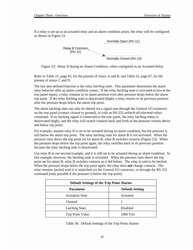
Chapter Three: Overview Overview of Alarms
87
If a relay is set up as an actuated relay and an alarm condition arises, the relay will be configuredas shown in Figure 23.
Normally Open (Pin 11)
Normally Closed (Pin 13)
Relay B Common(Pin 12)
Figure 23: Relay B during an Alarm Condition, when configured as an Actuated Relay
Refer to Table 21, page 65, for the pinouts of relays A and B, and Table 22, page 67, for thepinouts of relays C and D.
The last user-defined function is the relay latching state. This parameter determines the alarmrelay behavior after an alarm condition ceases. If the relay latching state is activated (a low at therear panel input), a relay remains in its alarm position even after pressure drops below the alarmtrip point. If the relay latching state is deactivated (high), a relay returns to its previous positionafter the pressure drops below the alarm trip point.
The alarm latching state can only be altered via a signal sent through the General I/O connectoron the rear panel (contact closure to ground), or with an RS-232 unlatch-all-alarmed-relayscommand. If no latching signal is connected to the rear panel, the relay latching status isdeactivated (high), and the relay will switch contacts back and forth as the pressure crosses aboveand below trip point.
For example, assume relay B is set to be actuated during an alarm condition, but the pressure isstill below the alarm trip point. The relay latching state for alarm B is not activated. When thepressure rises above the trip point set for alarm B, relay B switches contacts (Figure 23). Whenthe pressure drops below the trip point again, the relay switches back to its previous positionbecause the relay latching state is deactivated.
Use relay B as our second example, and it is still set to be actuated during an alarm condition. Inthis example, however, the latching state is activated. When the pressure rises above the trippoint set for alarm B, relay B switches contacts as it did before. The relay is said to be latched.When the pressure drops below the trip point again, the relay does not change contacts. Therelay remains latched until it is unlatched via the General I/O connector, or through the RS-232command (only possible if the pressure is below the trip point).
Default Settings of the Trip Point Alarms
Parameter Default Setting
Actuation State Actuated
Channel 1
Latching State Disabled
Trip Point Value 1000 Torr
Table 36: Default Settings of the Trip Point Alarms

Overview of Alarms Chapter Three: Overview
88
Alarm Conditions
An alarm condition occurs when a channel’s pressure reading goes over the alarm trip point.When an alarm condition arises, the 146 responds in four ways. In this example, the latchingstate is enabled, but the relay is initially unlatched.
1. The alarm audio tone starts. This can be quieted with the [QUIET/CANCEL] key.
2. A diamond is displayed on the left side of the front panel window, and corresponds toone of the four red alarm letters beside it on the front panel. A diamond indicates analarm condition, and not the status of the alarm relays.
3. The alarm relay condition switches. That is, if a relay contact was open, it becomesclosed.
4. If the latching state for the alarm is enabled, a LATCHED legend appears on the left sideof the front panel window. The latched legend indicates the state of the alarm relay afteran alarm condition, not the state of the alarm condition itself. If the latching state for thealarm is disabled, no LATCHED legend appears.
Note An alarm audio tone goes off if a gauge becomes disconnected. This isnot a trip point alarm condition, and no relays are altered. To remedy thesituation, reconnect the sensor and press the [QUIET/CANCEL] key.
Here are two scenarios to further illustrate what happens in an alarm condition, and what happenswhen a sensor (on an active channel) is disconnected.
Scenario 1: A Trip Point Alarm Condition
In this situation, all the relays are unlatched, and no alarm conditions are present. The alarmlatching state is enabled.
1. The pressure reading on a channel goes above the alarm trip point for that channel.
A. The alarm audio tone goes off.
B. A diamond appears in the front panel window, corresponding to a red alarmletter on the front panel.
C. An alarm relay switches contacts (and becomes latched because of the latchingstate).
D. A LATCHED legend appears in the front panel window.
2. Quiet the alarm audio tone by pressing the [QUIET/CANCEL] key.
A. The alarm audio tone is quieted, but the relay remains latched.
B. An alarm audio tone will go off again during the next alarm condition, regardlessof the relay latching state.

Chapter Three: Overview Overview of Alarms
89
3. The channel’s pressure reading drops below the alarm trip point.
A. The diamond in the window disappears, but the relay remains latched.
4. Unlatch the alarm relay via the connector on the General I/O connector.
A. The alarm relay becomes unlatched.
B. The LATCHED legend in the window disappears.
Scenario 2: A Disconnected Sensor
In this situation, the alarm relay status is irrelevant, as is the latching state.
1. A sensor becomes disconnected.
A. The alarm audio tone goes off.
B. An UNDERRANGE legend temporarily appears in the upper right section of thefront panel window.
C. A NO SENSOR legend is displayed in the window, corresponding to one of thefour yellow channel numbers on the right side of the front panel.
D. The code E0 replaces the pressure reading in the sensor’s channel display.
2. Quiet the alarm audio tone with the [QUIET/CANCEL] key.
A. The alarm audio tone is quieted.
B. An alarm audio tone will go off again during an alarm condition, or if anothersensor becomes disconnected.
3. Reconnect the sensor.
A. The NO SENSOR legend in the window disappears.
B. The sensor’s pressure reading replaces the E0 code in the appropriate display.

System Design Elements Chapter Three: Overview
90
System Design Elements
This section discusses, in a general way, how the 146 instrument can be used to control apressure/vacuum system. A Control board must be installed in the 146 instrument for thecontrol capabilities to function. The 146 instrument utilizes three parameters of control (gain,lead, and integral), and these are discussed in some detail. This section also provides basicinformation about pressure control, and explains how to recognize and correct pump choking.
General Control Theory
The 146 instrument can control a gas system via mass flow control with an MFC. The moretypical source of control is with pressure sensors. Only one sensor can control the gas system atany one time. That is, the pressure reading from only one sensor is compared to a set point andused to create a valve drive signal. To change which sensor is being used to control the system,you change the channel designated as the control channel. The control parameters for eachControl board can be stored in a “control recipe.” The 146 instrument supports up to four controlrecipes. These recipes can be edited in Tuning Mode. Each control recipe can be associated witha different channel by selecting a different control channel in Setup Mode.
The control system for a 146 instrument typically consists of six parts:
• the sensor(s)
• a gas supply
• a control valve (gas inlet or exhaust throttle valve)
• a process chamber
• a pumping system
• the 146 instrument
The system may also include one or more ratio flow controllers, or mass flow controllers ifcontrolling via mass flow.
Normally, gas pressure is controlled by altering the pumping speed of a pump that removes gasfrom the system (less frequently, it is regulated by controlling gas flow into the system via acontrol valve). The 146 instrument can regulate the control valve, be it a downstream throttlevalve or an upstream solenoid valve, or control one or more ratio flow controllers. If a Controlboard is not installed in the 146 instrument, a separate controller must be used to control gaspressure.
When controlling gas pressure, the 146 unit obtains a pressure reading from a sensor operating onthe control channel, and compares the reading with a set point. It then sends an external controlsignal to position a downstream throttle valve, an upstream solenoid valve, or to regulate one ormore ratio flow controllers. The gas system is continuously regulated to ensure that the actualpressure reaches, and is maintained at, the set point pressure.

Chapter Three: Overview System Design Elements
91
The 146 instrument utilizes Proportional-Integral-Derivative (PID) control found in mostindustrial controllers today. The P-I-D parameters operate according to an equation. Theseparameters are:
1. Proportional control action (Gain) is used as a constant to create a valve drive signal thatis proportional to the error signal, (the error signal is the result of comparing actualpressure with the set point). The error signal is then multiplied by a gain setting, thuscreating a proportional valve drive signal. The higher the gain, the greater the change inthe valve drive signal. Thus, the response is proportional to the gain.
Provided that the gain is not set too high, adjusting it allows the system to approach setpoint more quickly than if a lower gain setting is used. The best tuned gain ismaximized without promoting overshoot.
Valve Drive Signal = K1 x Error Signal
(K1 is adjusted by changing the gain setting)
2. Integral control action creates a valve drive signal that is proportional to the magnitudeand sign of the area under the error signal curve (error signal with respect to time).
Valve Drive Signal = K2 x ∫(Error Signal)dt
As time passes the valve position is changed. Due to integration (and good control), theerror signal approaches and is reduced to zero. An increase in the integral valueincreases the period of time over which the error signal is generated, and system responsegets slower. This helps offset potential oscillation caused by a high gain setting.
3. Derivative control action (Phase Lead) creates a valve drive signal that is proportional tothe rate of change of the sensor pressure reading. Derivative is the lead, or anticipationfactor.
Valve Drive Signal = K3 x d(pressure) dt
(K3 is adjusted by changing the lead setting)
Part of the lag in a control system is caused by the fact that the current pressure readingis no longer accurate by the time it is used in the PID calculations. To overcome this, thecurrent reading is compared with a previous reading, and then the rate of change isextrapolated to arrive at a new pressure reading. The new reading more accuratelyrepresents the true pressure. The new pressure reading is substituted for the currentreading in PID calculations. Thus, the derivative control mode provides an anticipationelement. The valve drive signal then causes the control valve to approach its steady stateposition sooner than it would if there was no derivative in the above equation.
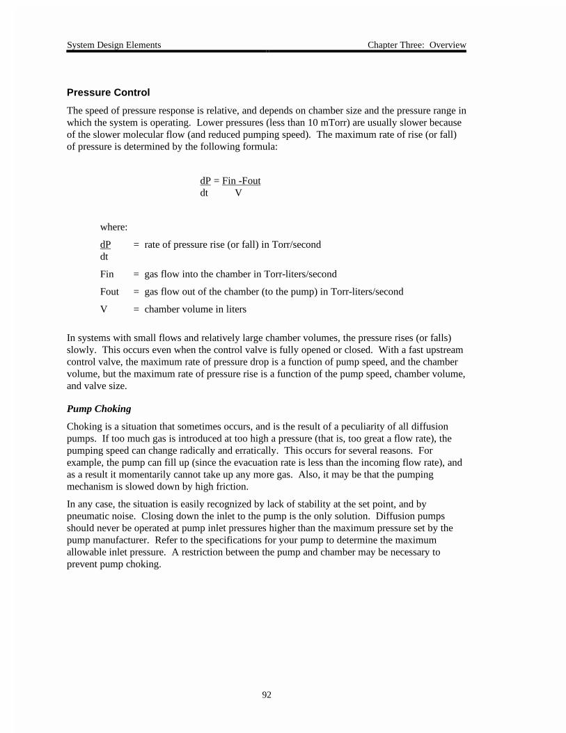
System Design Elements Chapter Three: Overview
92
Pressure Control
The speed of pressure response is relative, and depends on chamber size and the pressure range inwhich the system is operating. Lower pressures (less than 10 mTorr) are usually slower becauseof the slower molecular flow (and reduced pumping speed). The maximum rate of rise (or fall)of pressure is determined by the following formula:
dP = Fin -Foutdt V
where:
dP = rate of pressure rise (or fall) in Torr/seconddt
Fin = gas flow into the chamber in Torr-liters/second
Fout = gas flow out of the chamber (to the pump) in Torr-liters/second
V = chamber volume in liters
In systems with small flows and relatively large chamber volumes, the pressure rises (or falls)slowly. This occurs even when the control valve is fully opened or closed. With a fast upstreamcontrol valve, the maximum rate of pressure drop is a function of pump speed, and the chambervolume, but the maximum rate of pressure rise is a function of the pump speed, chamber volume,and valve size.
Pump Choking
Choking is a situation that sometimes occurs, and is the result of a peculiarity of all diffusionpumps. If too much gas is introduced at too high a pressure (that is, too great a flow rate), thepumping speed can change radically and erratically. This occurs for several reasons. Forexample, the pump can fill up (since the evacuation rate is less than the incoming flow rate), andas a result it momentarily cannot take up any more gas. Also, it may be that the pumpingmechanism is slowed down by high friction.
In any case, the situation is easily recognized by lack of stability at the set point, and bypneumatic noise. Closing down the inlet to the pump is the only solution. Diffusion pumpsshould never be operated at pump inlet pressures higher than the maximum pressure set by thepump manufacturer. Refer to the specifications for your pump to determine the maximumallowable inlet pressure. A restriction between the pump and chamber may be necessary toprevent pump choking.

Chapter Three: Overview System Design Elements
93
Mass Flow Control
The MFC board allows the 146 instrument to communicate with mass flow controllers (MFCs)to regulate the flow of gas into a system. The 146 instrument can operate in either set point,totaling, or ratio flow control mode. To select which parameter to use for control, refer to Code17x: Adjust MFC Set Point, Mode, and Co-channel in the Operation in Setup Mode chapter. Toselect the MFC as the controlling channel, refer to Code 14x: How To Select Polarity and theControl Channel also in the Operation in Setup Mode chapter.
Set Point Mode of Operation
When using the Set Point mode of operation, the 146 instrument sends out a voltagecorresponding to a user-defined set point (in sccm). The set point voltage takes into account anyzero offset which may have resulted from zeroing the MFC, to ensure that the MFC controls tothe desired flow rate. The 146 instrument can operate up to four MFCs. Each MFC operating inSet Point mode has a set point value assigned to it.
Totaling Mode of Operation
When using the Totaling mode of operation, two MFCs operate in conjunction with each other.One MFC (defined as the co-channel), operates according to a fixed set point. The other MFC,defined as the totaling MFC, adjusts its output voltage to maintain a user-defined total flow rate(set point) for the system. For example, you want to maintain a flow rate of 100 sccm. Enter aset point of 100 sccm and set the co-channel to a fixed flow rate of 20 sccm. The totaling MFCwill subtract 20 (flow rate of the co-channel) from 100 (the set point) and adjust its voltage toproduce a flow rate of 80 sccm. Therefore, the total flow rate will be 100 (20 + 80). As with theSet Point mode of operation, the 146 instrument accounts for any zero offset.
Ratio Flow Control Mode of Operation
In a Ratio control mode, the 146 instrument is capable of controlling up to four MFCs. The 146uses a pressure control signal (PCS), or a total flow signal, as feedback. The Ratio mode uses alogical control channel to execute the PID control algorithm and achieve the desired gas ratio.The logical control channel (control channel 0) is present even if no Control board is installed.The 146 instrument calculates the control signal to correct the gas ratio and sends the signal to allMFCs configured for Ratio control.
Two possible control methods exist within Ratio mode: control with a pressure measuringcontrol channel, and control with a flow measuring (MFC) control channel.
The ratio controllers maintain the gas ratio, and the 146 instrument maintains the absolutepressure by controlling the total flow.
Essentially, the Ratio mode of operation scales and proportions the 0 to 10 Volt control signalamong the MFCs configured for Ratio mode, based on their chosen ratio set points. The setpoints can range from 0 to 200%. Since most MFCs accept a 0 to 5 Volt signal, the controlsignal for a given MFC is always scaled by ½, then multiplied by the ratio set point percent:
MFC control signal = ½ (control signal)(ratio set point %/100)

System Design Elements Chapter Three: Overview
94
Example 1: Assume you have two MFCs configured for ratio control and you change thecontrol set point to 100%. Each MFC has a set point of 50%. The PID control algorithmdetermines that full scale flow is required to meet the new set point, so the equation becomes:
MFC control signal = ½ (10 Volts)(50%/100) = 2.5 Volts
Each MFC would receive a 2.5 Volt control signal.
Example 2: If the control algorithm determined that the change necessitates a 60% flow rate, theequation becomes:
MFC control signal = ½ (6 Volts)(50%) = 1.5 Volts
Each MFC would receive a 1.5 Volt control signal.
Example 3: Assume that you have three MFCs with ratio set points of 10%, 30%, and 60%.The PID algorithm determines that a 75% control signal is required to meet the control set point.The 146 instrument calculates the control signal for each MFC:
MFC 1 = ½ (7.5 Volts)(10%) = 0.375 Volts
MFC 2 = ½ (7.5 Volts)(30%) = 1.125 Volts
MFC 1= ½ (7.5 Volts)(60%) = 2.25 Volts
The total control signal is 3.75 Volts (75% of 5 Volts).
Pressure Measuring Control
When using a pressure measuring control channel, up to three MFCs can be configured tofunction in a pressure control loop. In this case, the total flow of the three MFCs determines thepressure, however, the percent of gas through each MFC remains constant. For example, if theratio set points for the three MFCs are 30%, 30%, and 40% and pressure rises in the system, thegas flow through each MFC decreases but the 30%, 30%, 40% relationship remains intact.
Flow Measuring Control
When using a flow measuring control channel, an MFC channel is selected as the control inputchannel. The Ratio mode MFCs follow the controlling MFC with their respective proportions offlow as set by their Ratio mode set points.

Chapter Three: Overview System Design Elements
95
Memory Storage in the 146 Instrument
The operational parameters of the 146 unit are stored in non-volatile memory as parameters arechanged. The 146 unit is designed to store most user-defined, and 146-determined data inEEPROM. A front-panel lockout command, however, is not stored. The following is a list ofwhat is preserved in EEPROM.
Data Stored in EEPROM During Power Loss
Power Down Status Data Alarm Data (for all alarms)
Alarm informationState (enabled or disabled)RecipeControl mode
Channel state (on/off)
Trip point value
Associated channel number
Untripped state (actuated or deactuated)
Control Data Recipe Data (for each recipe)
Softstart value Base value
Alpha value Start value
Polarity setting Preset value
Integral value
Set point value Softstart state (enabled or disabled
Gain Input Channel number
Lead
Analog set point range
Analog set point state (enabled or disabled)
Channel-Sensor Data (for all channels)
Linear Capacitance Manometer:
Zero
Pirani-type:
Gas type
Zero (if enabled)
MFC:
Co-channel
Mode
Hot Cathode:
Ion gauge factor
Disconnect threshold
High pressure shutoff
Fast Rate-of-Rise state (enabled or disabled)
Sensitivity
Cold Cathode:
Disconnect threshold
Combined gauge and GCF
Table 37: Data Stored in EEPROM During a Power Loss(Continued on next page)

System Design Elements Chapter Three: Overview
96
Data Stored in EEPROM During Power Loss (Continued)
Ion Gauge Auto-Power -Off Feature Analog Output Data (for all 3 outputs)
Auto-off trip point value
Auto-off status (enabled or disabled)
Reference channel number
Analog output type
Channel number
Endpoint
Configuration Data Analog Set Point Data
Sensor board type (each channel)
Leakage rate time base
Analog set point zero voltage
Analog set point full scale voltage
Channel number
Analog set point full scale pressure
Communications Data Dual Channel Data for Displays
Data logger interval
Baud rate
Communications mode (parity, data bits, stopbits)
Protocol (MKS 146 or data logger)
Upper threshold
Lower threshold
Continuity type
Associated channels in dual 1 and dual 2
General Settings
Audio alarm state (enabled or disabled)
Measurement units
Auto zero state (enabled or disabled)
Auto zero reference
Auto power state (enabled or disabled)
Auto power trip point
Channel range
Channel sensitivity
Span settings
Span enable
Display settings
Table 37: Data Stored in EEPROM During a Power Loss

Chapter Three: Overview System Design Elements
97
Ion Gauge High Pressure Protection/Disconnect Detection
A characteristic of either hot or cold cathode gauges is that they may provide invalid pressurereadings when the pressure is above 1 x 10⁻² Torr. In addition, hot cathode tubes may bedamaged at high pressures. To address these gauge limitations, the 146 unit has some highpressure, and pressure rate-of-rise protection built into its hardware, and provides user-editableprotection parameters as well.
Ion Gauge Auto Power Control (Setup Mode Code 12x) CC and HC
When the pressure reading of an ion gauge exceeds a user-defined pressure limit, the gauge ispowered off. When the pressure drops below the preset limit, the 146 unit restores power to theion gauge. If a hot cathode gauge had been degassing when it was powered off, the degasfunction will not turn back on when the 146 unit restores power to the hot cathode gauge.
HC High Pressure Shutoff (Setup Mode Code 16x) HC only
When the pressure reading of a hot cathode gauge exceeds a user-defined pressure limit, thegauge is powered off. The gauge will not auto power on again even if the pressure drops belowthe shutoff pressure. To power the gauge again, the pressure must be below the shutoff limit,and the HC channel must be turned off and then on again. The high pressure shutoff is alwaysactive and it is intended to function as a fail-safe feature. The pressure limit should be sethigher than the auto power pressure threshold.
Ion Gauge Disconnect Threshold (Setup Mode Sensor Calibration screen) CC and HC
The ion gauge disconnect threshold feature sounds an alarm and changes the gauge’s reading toE0 when the channel’s pressure drops below the threshold pressure. Set the disconnectthreshold to a value one decade below the system base pressure for a reliable disconnect alarm.You can also set the threshold pressure to the highest pressure reading the ion gauge canreliably measure. The factory configuration has this feature disabled (disconnect threshold is-1.0).
Features Built Into the 146 Hardware
Internal Fast Rate-of-Rise Shutoff (Setup Mode Code 16x) HC only
If pressure rises rapidly to a level that potentially could harm a hot cathode’s filament, thegauge is turned off and the E1 error code appears in the display. The exact pressure rate ofrise is dependent upon the type of gauge, but for most Bayard-Alpert tubes it is around 3Torr/sec. To power the gauge again, the hot cathode channel must be turned off and then onagain. The factory configuration has this feature disabled. This shutoff feature is accessedthrough the right hand entry of the Code 16x display. Press the ON button to enable this fastpressure rate of rise shutoff feature; press the OFF button to disable it.
Internal Sensing of HC disconnect/tube shorts/open filament HC only
If the 146 unit detects a disconnected hot cathode gauge, or a tube short or open filament in thehot cathode, the gauge is immediately turned off. To restore power to the gauge, the HCchannel must be turned off and then on again.

Displayless 146 Unit Chapter Three: Overview
98
Displayless 146 Unit
A displayless 146 unit is controlled by remote RS-232 communications through the RS-232connector on the rear panel. An additional Interface connector on the front panel provides aconvenient serial communications port so you can use a portable computer to communicate withthe unit while it is installed in your system.
The displayless 146 unit has only a power switch, LED, and the Interface connector. TheInterface connector is a 25-pin female Type “D” connector. Refer to Table 30, page 75, for apinout of the connector on the displayless 146 unit.
Interface ConnectorLEDPower Switch
0
1
VACUUM GAUGE MEASUREMENT AND CONTROL SYSTEM
TYPE 146
POWER
ON
OFF
INTERFACE
Figure 24: The Front of a Displayless 146 Unit
Connecting to the Displayless 146 Unit
The displayless 146 unit has an Interface connector, located on the front panel, and an RS-232connector, located on the rear panel. Both connectors support RS-232 communication betweenthe 146 unit and a computer. However, the 146 unit only accepts command messages throughone port at a time, though it can report status information on both ports simultaneously. The 146unit determines which port takes precedence based on the state of pin 4 of the Interfaceconnector. When pin 4 is left open, the device connected to the Interface connector can onlyreceive RS-232 communications that are currently being issued from the 146 unit, through therear panel. Therefore, the RS-232 connector takes precedence. If pin 4 is grounded, the deviceconnected to the Interface connector overrides the rear panel communication link and it cancommunicate fully with the 146 unit.
Use the RS-232 connector on the rear panel to connect the 146 unit to your system. TheInterface connector provides a convenient port to connect a portable computer to the 146 unitshould you need to troubleshoot the unit.

Chapter Three: Overview Displayless 146 Unit
99
The LED
The LED on a displayless 146 unit indicates the status of the unit. When a displayless 146 unitis powered on, the LED condition is as follows:
1. The LED turns red, then changes to green within a few seconds.
This indicates that all systems are operating properly.
2. The LED turns red and stays red.
This indicates a power up problem is detected. The error code can be displayed orqueried through RS-232 communications.
A. Turn power to the displayless unit off and then on again.
If only one non-fatal error condition was detected, the LED turns red andchanges to green within a few seconds.
If more than one non-fatal error condition was detected (such as codes C11, E4,or E10), the LED remains lit. The error code can be displayed or queriedthrough RS-232 communications.
B. Cycle the power a few more times to allow the unit to cycle through the non-fatal error conditions.
3. After cycling power to the 146 unit several times, the LED still remains red.
This indicates a fatal error condition (such as E2, E3, E12) is detected. The error codecan be displayed or queried through RS-232 communications (if it is still operating).
Note If querying the error code through RS-232 communications, use thepower up status command, described in the RS-232 Communicationschapter.

Displayless 146 Unit Chapter Three: Overview
100
How To Establish RS-232 Communications
Connect the RS-232 source to a displayless 146 unit with the correct RS-232 cable. Install the146 unit into your system using the rear panel connector. Note that the RS-232 cable used forrear panel communications (refer to Table 32, page 77, for the proper MKS part number) differsfrom the RS-232 cable for front panel communications (MKS p/n CB146-21). All RS-232commands are supported through either connector. Refer to Chapter Nine: RS-232Communications, page 255, for a complete list of RS-232 commands/requests and the properprotocol for communications.
Refer to Table 32, page 77, for a pinout of the rear panel RS-232 connector. Table 30, page 75,lists the pinout of the front panel Interface connector.
Pins 1 through 5, 7, 8, and 20 on a displayless unit’s front panel are involved with RS-232communications. Pins 4 and 8 are especially worth noting. If pin 4 is left open, the deviceconnected to the 146 unit can only receive RS-232 communications that are currently beingissued from the 146 unit, through the rear panel. For example, if a status query is sent to the 146displayless unit, the reply (which includes the header identifying the query), is received. If pin 4is grounded, the device connected to the 146 instrument overrides the rear panel communicationlink and it can communicate fully with the 146 unit (that is, it can initiate queries).
Pin 8 can supply a +5V signal, which can be used to power one of several types of remoteterminals.
The functions on pins 5 and 20 are special options that must be specifically requested from thefactory.

Chapter Four: Operation in Normal Mode General Information
101
Chapter Four: Operation in Normal Mode
General Information
Figure 25 shows a sample window for Normal Mode. In Normal Mode, all displays show apressure reading, provided the displays are connected to active sensors and the sensors arereading within their range. If the Control board is installed, the valve control state is displayed(OPEN, AUTO, CLOSE, HOLD, or MANUAL) as well. In our example, the valve control state is setto HOLD.
Torr m
HOLD
4
mTORR
LEFT DISPLAY CENTER DISPLAY RIGHT DISPLAY
The pressure readingfrom the gauge onchannel 1 is shownhere.
The pressure readingfrom the gauge onchannel 2 is shownhere.
The pressure readingfrom the gauge onchannel 3 is shownhere.
The pressure reading from the gauge on channel 4 is shown here.
Note: It is possible to display the pressure reading froma gauge on any channel in the Main Display.
MAIN DISPLAY
Figure 25: Normal Mode Display

General Information Chapter Four: Operation in Normal Mode
102
Normal Mode is Used when Performing the Following Procedures
Normal Mode Functions
Function Comments
View most System StatusInformation
Displays the pressure readings from up to four differentsensors.
Display software version Lists the software version number.
Switch Channel in the MainDisplay
Selects what to show in the main display. The choices arechannel 1, 2, 3, 4, or dual channel display function 1 or 2.
Turn a Channel ON/OFF Turns power to a sensor on or off, and turns the sensor’schannel on or off. Only the channel (not the sensor power) isturned off for capacitance manometers and mass flowcontrollers.
Turn an Alarm ON/OFF Enables/disables standard alarms A and B, and optionalalarms C and D.
Zero a Sensor/MFC Sets the zero pressure point for a sensor.
Toggle the Zero-of-a-Sensor/MFC On and Off
Toggles between undoing the zero, and then re-instating thezero, once a sensor has been zeroed.
Span a Pirani Sensor toAtmosphere
Sets the upper pressure reading of a Pirani sensor equal to 760Torr or Atmosphere (Atm), whichever is applicable.
Span a Sensor with aReference
Spans the sensor of a selected channel to the reading ofanother sensor.
Toggle the Span-of-a -SensorOn and Off
Toggles between undoing the span, and then re-instating thespan, once a sensor has been spanned.
Set Lower and Upper Pointsfor Analog Set PointCalculations
Changes the analog set point by adjusting the analog set pointinput voltage.
Command MFC Open/CloseOverrides
Moves an MFC to full open or full close within two secondswhen commanded with one of these overrides.
Cancel MFC Open/CloseOverrides
Cancels an override that is in effect.
Start Hot Cathode Low/HighPower Degassing
Starts low power or high power degassing for a hot cathodewhich is currently powered on.
Stop HC Degassing Ends the degassing (low power or high power) functioncurrently underway.
Table 38: Normal Mode Functions

Chapter Four: Operation in Normal Mode How To Display the Software Version
103
How To Display the Software Version
1. Repeatedly press the [DISPLAY MODE] key until the 146 unit is in Normal Mode.
The system responds by scrolling through modes.
2. Press the [9/C][0/D] keys simultaneously.
The system responds by displaying the software version number in the main display(refer to Figure 26).
Torr mTorr Torr
HOLD
4
LEFT DISPLAY CENTER DISPLAY RIGHT DISPLAY
MAIN DISPLAY
The pressure readingfrom the gauge onchannel 1 is shown here.
The pressure readingfrom the gauge onchannel 2 is shown here.
The pressure readingfrom the gauge onchannel 3 is shown here.
Software version numberis shown here.
Figure 26: Software Version Number in Normal Mode
3. Press the [QUIET/CANCEL] key.
The system responds by returning to the previous Normal Mode display.
Note Any key can be pressed to return the window to Normal Mode.However, the 146 unit also executes any command associated with thekey.

How To Switch Channels in the Main Display Chapter Four: Operation in Normal Mode
104
How To Switch Channels in the Main Display
The system defaults to showing the pressure reading for channel 1 in the main display. Theexception to this is if all four channels are used, whereupon the pressure reading for channel 4appears in the main display. Channel 4 can only be monitored in the main display.
By following the procedure explained below, the pressure reading from any of the four channelscan be shown in the main display. Alternately, the main display can be configured for a dualchannel display.
The dual channel display feature of the 146 unit automatically switches between two user-selected channels to provide a pressure readout in the main display. The dual channel displaycan only be viewed in the main display. The channel numbers of the two user-selected channelsthat make up the dual channel display are shown to the right of the main display. Whenconfigured for dual channel display, the 146 unit can provide a pressure readout that showspressure readings over a larger dynamic range than when the main display shows only a singlechannel’s pressure readout.
Two dual channel setups can be configured (Dual Channel 1, and Dual Channel 2). The samechannel can be used in both setups. For example, if Dual Channel 1 switches the main displaybetween channels 1 and 4, Dual Channel 2 can still be setup to switch between channels 3 and 4.It does not matter that channel 4 is used in both setups, because only one setup can be used atime.
Note The Dual Channel feature only effects what is shown in the main display.System control cannot be governed with two channels.
One of the two channels used in a Dual Channel display can be used forcontrol. Control does not switch to the other user-selected channel,however, when the main display readout switches to the other channel.
1. Repeatedly press the [DISPLAY MODE] key until the 146 unit is in Normal Mode.
The system responds by scrolling through modes.
2. Press [1], [2], [3], or [4], (to select a channel), or press [DUAL][1] or [DUAL][2], (to selectdual channel display feature 1 or 2).
The system responds by showing the selected channel’s pressure reading, or changing todual channel display, in the main display.
For example, in Figure 25, page 101, channel 4 is shown in the main display. Anexample of a dual channel display is shown in Figure 27, page 105.

Chapter Four: Operation in Normal Mode How To Switch Channels in the Main Display
105
LEFT DISPLAY CENTER DISPLAY RIGHT DISPLAY
The pressure readingfrom the gauge onchannel 1 is shown here.
The pressure readingfrom the gauge onchannel 2 is shown here.
The pressure readingfrom the gauge onchannel 3 is shown here.
Torr mTorr
HOLD
1 4
mTORR
MAIN DISPLAY
The pressure reading from one of the two gauges (discontinuous/continuous operation), or a combined reading from both gauges(only possible with continuous operation), is shown here.
Note: In this example, the gauges on channels 1 and 4 make up the dual channel display.
Figure 27: Dual Channel Display in Normal Mode
In a dual channel display, pressure information is shown for a single channel, or for bothchannels combined. The display is determined by whether the dual channel feature isconfigured for continuous or discontinuous operation, and whether the pressure is beingtaken from the upper or lower channel, or the overlapping region between the channels.Refer to How To Set Up a Dual Channel Readout, in the Operation in Setup Modechapter, to learn how to select continuous or discontinuous operation in the dual channeldisplay feature.

How To Turn a Channel ON or OFF Chapter Four: Operation in Normal Mode
106
How To Turn a Channel ON or OFF
The ability to turn off power to sensors is a useful function in several situations. For example, itis a safety procedure against explosion during cryo-pump regeneration with all sensors exceptcapacitance manometers (the danger of explosion does not exist with capacitance manometers).A cold cathode should be powered off above 1 x 10⁻² Torr otherwise false readings may occur.Generally this is also true for hot cathodes. In addition, a hot cathode gauge may experiencedamage to its filament at high pressures. Pirani type gauges may need to be powered off if thereis a chance their filaments may ignite, or induce a reaction in backfilled gases.
Warning Turn off all gauges (except capacitance manometers), whichare in contact with a cryo-pump, during regenerationprocedures. The gauges may cause an explosion if they arenot powered down.
Turning a capacitance manometer or mass flow controller (MFC) on or off is done following theexact same procedure as turning a sensor on or off except that power is still supplied to the MFCor capacitance manometer.
1. Repeatedly press the [DISPLAY MODE] key until the 146 unit is in Normal Mode.
The system responds by scrolling through modes.
2. Press the [ON/LEAD] or [OFF/GAIN] key, followed by [1], [2], [3], or [4].
The system responds by turning power to the sensor or MFC of the selected channel on(press [ON/LEAD]), or off (press [OFF/GAIN]). If power to a channel is turned off, thedisplay for that channel changes to decimal points to indicate the channel is turned off.
Note One exception: Power to capacitance manometers and MFCs cannot beturned off this way, although their displays can be.

Chapter Four: Operation in Normal Mode How To Turn an Alarm ON or OFF
107
How To Turn an Alarm ON or OFF
1. Repeatedly press the [DISPLAY MODE] key until the 146 unit is in Normal Mode.
The system responds by scrolling through modes.
2. Press the [ON/LEAD] or [OFF/GAIN] key, followed by [A], [B], [C], or [D].
The system responds by enabling (press [ON/LEAD]) or disabling (press [OFF/GAIN]), theselected alarm.
Note Alarms A and B are standard with the 146 unit, but alarms C and D areonly available if the Auxiliary Output board is installed.

How To Zero a Sensor/MFC Chapter Four: Operation in Normal Mode
108
How To Zero a Sensor/MFC
For pressure sensors, zeroing means adjusting the readout for the sensor. The zero point is thepressure at which the instrument displays zero pressure. For capacitance manometers and Piranitype gauges, the zero point is the output voltage at which zero pressure is referenced.
A TC gauge, unlike a capacitance manometer or Pirani type gauge, produces its maximum outputat zero pressure. The zero is adjusted by varying the power until a standard output voltage isachieved.
Actual Pressure (or other measured parameter)0
+
-
Zero should be lowered
Zero should be raised
Good Zero adjustment
Zero adjustment is an additive/subtractiveprocess which moves a gauge's range upor down on the pressure axis.
Pressure
Readout
Figure 28: Zeroing a Sensor
For mass flow controllers (MFC), the zero offset is subtracted from the MFC reading and addedto the set point output voltage. This is done to accommodate the internal PID control loop in anMFC.

Chapter Four: Operation in Normal Mode How To Zero a Sensor/MFC
109
Note 1. Before zeroing an MFC, verify that there is no gas flow through theunit. Two ways to accomplish this involve an upstream valve, orwith a digital override (refer to How To Command an MFC CloseOverride, page 121).
2. To zero an MFC, the MFC reading must be close to 0.0. The 146unit will not perform the zero function if the reading deviates from0.0 by more than ±10% of the full scale range of the MFC. Forexample, to zero a 10 sccm unit, the reading must be 0.0 ±1.0 sccm.
1. Pump the gauge down to a pressure below the resolution of the gauge (<0.5 mTorr for aTC gauge). For an MFC, ensure that no gas is flowing through the unit.
2. Repeatedly press the [DISPLAY MODE] key until the 146 unit is in Normal Mode.
The system responds by scrolling through modes.
3. Press the [ZERO/EXP] key, followed by [1], [2], [3], or [4].
The system responds by zeroing the sensor/MFC of the channel number pressed. Thereading in the selected channel’s display goes to zero.

How To Zero a Sensor/MFC Chapter Four: Operation in Normal Mode
110
Note 1. Zeroing a Pirani sensor preempts the factory set zero. To return tothe factory set zero, refer to How To Perform SensorCalibration/MFC Setup, page 190.
2. If there is no sensor for the channel number selected, the systemresponds by beeping and displaying the CAN’T ZERO errormessage.
3. If a sensor’s zero goes out of its normal range, the 146 unit respondswith the CAN’T ZERO error message.
4. Ion gauges cannot be zeroed since they are high vacuum gauges.
5. For the MKS Type 120 gauge, the zeroing occurs in both the sensorand in the 146 unit. If the Type 120 gauge cannot complete thezeroing itself, a CAN’T ZERO message is momentarily displayedand the 146 unit completes the zeroing, provided the 120 gauge iswithin ±0.8 V of zero.
6. TC gauges must be zeroed when used for the first time or whenreplacing the current gauge with a new one.
7. The zero reading for a TC gauge can be toggled on or off. When on,the 146 unit uses the stored zero power level. When off, the storedzero power level is replaced with the factory default power level.Refer to How To Toggle the Zero On and Off, page 112, for moreinformation.
8. When replacing a TC-1A gauge with a DV-6M gauge, the systemmay require two zero commands to achieve a stable zero. This is dueto the difference in power levels and thermal response between thetwo gauges.

Chapter Four: Operation in Normal Mode How To Zero a Sensor/MFC
111
Ranges for Zeroing a Sensor
Sensor Type Zero Range
Type 107 Capacitance Manometer -0.2 Volts to +0.2 Volts
Type 120 Capacitance Manometer -0.8 Volts to +0.8 Volts
Linear Capacitance Manometer -0.3 Volts to +0.3 Volts
Pirani Type Gauges Gauges can always be zeroed
Cold Cathode Gauges Gauges cannot be zeroed
Hot Cathode Gauges Gauges cannot be zeroed
Mass Flow Controller ±0.5 Volts
Table 39: Ranges for Zeroing a Sensor

How To Toggle the Zero On and Off Chapter Four: Operation in Normal Mode
112
How To Toggle the Zero On and Off
Once a sensor or MFC has been zeroed, use this procedure to toggle between undoing the zero,and then re-instating the zero again. When the zero is toggled off, the original, unzeroedsensor/MFC reading is displayed. Toggling a sensor’s zero on and off is useful as a diagnosticaid or for a transducer calibration check.
1. Repeatedly press the [DISPLAY MODE] key until the 146 unit is in Normal Mode.
The system responds by scrolling through modes.
2. Press the [ZERO/EXP] key, then the [OFF/GAIN] key, followed by [1], [2], [3], or [4].
The system responds by bypassing the user-defined zero of the sensor/MFC on theselected channel.
Note 1. For the MKS Type 120 capacitance manometer, the zero is bypassedboth in the sensor and in the 146 unit.
2. For Pirani gauges, the factory-set zero becomes effective.
3. For TC gauges, the factory default power level is used. The gaugewill not yield accurate pressure measurements when the zero istoggled off!
3. Press the [ZERO/EXP] key, then the [ON/LEAD] key, followed by [1], [2], [3], or [4].
The system responds by undoing the previous command, and restoring the channel’suser-defined zero.
Note 1. For the MKS Type 120 capacitance manometer, the zero is restored inboth the sensor and in the 146 unit.
2. For Pirani gauges, the user-defined zero is restored.
3. For TC gauges, the stored zero power level is restored.

Chapter Four: Operation in Normal Mode How To Span a Pirani Type Sensor to Atmosphere
113
How To Span a Pirani Type Sensor to Atmosphere
Spanning a Pirani type sensor should only be done at atmosphere. Spanning is done to adjust theupper range of the gauge which may have drifted due to contamination or aging of the sensor.The span adjustment assumes a pressure of 760 Torr (atmospheric pressure), as its reference.Convection gauges display 760 Torr when spanned, and an HPS Pirani gauge displays Atm.This spanning method is usually sufficient to bring the spanned gauge’s readings within its statedmeasurement accuracy. If this is not the case, span the gauge with a reference (refer to How ToHow To Span a Sensor with a Reference, page 115).
Actual Pressure (or other measured parameter)
Spanning adjusts the slope of a gauge'sPressure versus Actual Pressure (or othermeasured parameter) line.
Original slope of Channelto be Spanned
Pressure
Reading
New slope
Figure 29: Spanning a Pirani-Type Sensor
Note 1. Spanning a Pirani sensor preempts the factory set span. To return tothe factory set span, refer to How To Perform SensorCalibration/MFC Setup, page 190.
2. Because of the high accuracy of capacitance manometers, they arenot spanned to atmosphere (which may not be exactly 760 Torr).
3. Ion gauges cannot measure at atmosphere, so they are spanned to areference within their range.
4. A Pirani sensor cannot be spanned if helium (He) or argon (Ar) isthe gas type chosen. The gas must be nitrogen (N2).

How To Span a Pirani Type Sensor to Atmosphere Chapter Four: Operation in Normal Mode
114
1. Repeatedly press the [DISPLAY MODE] key until the 146 unit is in Normal Mode.
The system responds by scrolling through modes.
2. Press the [SPAN/.] key, followed by [1], [2], [3], or [4].
The system responds by spanning the sensor on the selected channel number.

Chapter Four: Operation in Normal Mode How To Span a Sensor with a Reference
115
How To Span a Sensor with a Reference
This procedure stores a span constant for a spanned gauge. This makes the upper pressurereading of the spanned gauge agree with the pressure reading of the referenced gauge. Spanningis done with two sensors that are well within their measurement ranges.
Note This procedure does not apply to capacitance manometers.
Spanning adjusts the slope of a gauge'sPressure versus Actual Pressure (or othermeasured parameter) line.
Pressure
Reading
Reference Point
New slope
Original slope
Actual Pressure (or other measured parameter)
Figure 30: Spanning a Sensor with a Reference
Note 1. Pirani gauges must be reading above 100 Torr, and the referencechannel must be within a decade of the Pirani channel for a valid span.
2. When spanning a Pirani gauge, the reference sensor can be anythingexcept an ion gauge. This includes another Pirani.
3. For a successful span of an ion gauge, the reference must be acapacitance manometer. The capacitance manometer must be at leasta decade above its zero, reading within one decade (±) of theunspanned ion gauge, and reading at or below 10 mTorr.

How To Span a Sensor with a Reference Chapter Four: Operation in Normal Mode
116
1. Repeatedly press the [DISPLAY MODE] key until the 146 unit is in Normal Mode.
The system responds by scrolling through modes.
2. Press [SPAN/.], followed by [5/DUAL], followed by [1], [2], [3], or [4] (lower rangesensor), followed by [1], [2], [3], or [4] again (upper range sensor).
The system responds by spanning the sensor on the first channel, to the reading of thesensor on the second channel.

Chapter Four: Operation in Normal Mode How To Toggle the Span On and Off
117
How To Toggle the Span On and Off
Once a sensor has been spanned, use this procedure to toggle between undoing the span, and thenre-instating the span. This procedure does not apply to capacitance manometers. When the spanis toggled off, the factory-defined span is used for the display of pressure. Refer to How ToPerform Sensor Calibration/MFC Setup, page 190, to view whether the factory-defined or user-defined span is in effect.
1. Repeatedly press the [DISPLAY MODE] key until the 146 unit is in Normal Mode.
The system responds by scrolling through modes.
2. Press the [SPAN/.] key, then the [OFF/GAIN] key, followed by [1], [2], [3], or [4].
The system responds by bypassing the user-defined span for the sensor on the channelnumber selected.
3. Press the [SPAN/.] key, then the [ON/LEAD] key, followed by [1], [2], [3], or [4].
The system responds by undoing the previous command, and restoring the channel’suser-defined span.

How To Calculate the Analog Set Point Chapter Four: Operation in Normal Mode
118
How To Calculate the Analog Set Point
The analog set point input is a linear input sent through the lower connector on the Controlboard. The input corresponds to an analog set point value (refer to Figure 31). By adjusting theanalog set point input voltage, the analog set point is changed. The default settings are for ananalog input of 0.0 Volts to correspond to a zero set point, and for a 5 Volt input to define a 1000Torr set point. The acceptable analog input voltage range is 0 to 10 Volts, with the default fullscale voltage set at 5 Volts. The ability to define the set point through an analog input isdisabled by default. Refer to Code 15x: How To Set Up Analog Set Point, in the Operation inSetup Mode chapter for instructions on how to enable the analog set point feature.
Analog set point is a voltage input thatdetermines the analog set point.
Analog Set Point (Torr)
Input
Voltage
0
0 500 1000
2.5
5
Figure 31: Graph Showing Analog Set Point Defaults
The lower and upper points of the analog input voltage range can be altered (refer to Figure 32,page 119) in Normal and Leakage Modes. By changing either one, or both of these points, theslope of the analog input voltage versus analog set point line is changed. As a result of thechange in slope, a fixed input voltage defines a different analog set point. To adjust the lowerand upper points in Normal and Leakage Modes, the current analog input voltage must bealtered. To change the upper point (not the lower point), independent of the current analog input,refer to Code 15x: How To Set Up Analog Set Point, in the Operation in Setup Mode chapter.

Chapter Four: Operation in Normal Mode How To Calculate the Analog Set Point
119
When adjusting the lower point,the upper point remains fixed,and the slope changes.
Original slope
When adjusting the upper point,the lower point remains fixed,and the slope changes.
Input
Voltage
0
0 Analog Set Point (Torr) 1000
5
Figure 32: Adjusting Lower and Upper Points for Analog Set Point Calculations
Adjusting the Lower Point of the Analog Set Point Input Voltage Range
The analog set point feature does not need to be enabled to allow a change in the lower point ofthe analog input voltage range. However, the feature must be enabled to allow the 146 unit tocontrol with an analog set point (refer to Code 15x: How To Set Up Analog Set Point in theOperation in Setup Mode chapter).
1. Repeatedly press the [DISPLAY MODE] key until the 146 unit is in Normal mode.
The system responds by scrolling through modes.
2. Provide an analog input equal to the desired low point on the input voltage scale.
3. Press the [ZERO/EXP] key, followed by the [DEGAS/SET POINT] key.
The system responds by setting the lower point of the analog set point input range equalto the current analog input. The upper point of the input range remains fixed. The slopeof the analog input voltage versus analog set point line changes.

How To Command an MFC Open Override Chapter Four: Operation in Normal Mode
120
Adjusting the Upper Point of The Analog Set Point Input Voltage Range
The analog set point feature does not need to be enabled to allow a change in the upper point ofthe analog input voltage range. However, the feature must be enabled to allow the 146 unit tocontrol with an analog set point (refer to Code 15x: How To Set Up Analog Set Point in theOperation in Setup Mode chapter).
1. Repeatedly press the [DISPLAY MODE] key until the 146 unit is in Normal Mode.
The system responds by scrolling through modes.
2. Provide an analog input equal to the desired full scale voltage input.
3. Press the [SPAN/.] key, followed by the [DEGAS/SET POINT] key.
The system responds by setting the full scale voltage (the upper point of the analog setpoint input range), equal to the current analog input. The lower point of the input rangeremains fixed. The slope of the analog input voltage versus analog set point linechanges.
How To Command an MFC Open Override
A mass flow controller (MFC) moves to full open from any position within two seconds whencommanded with an open override.
1. Repeatedly press the [DISPLAY MODE] key until the 146 unit is in Normal Mode.
The system responds by scrolling through modes.
2. Press the key, followed by [1], [2], [3], or [4].
The system responds by moving the MFC on the selected channel to full open within 2seconds.
Note You must use the appropriate CB147-X cable, listed in Table 20, page64, to enable the MFC override commands. The CB259-5 and CB259-10 cables do not support the open and close override commands.However, using these cables will not damage either unit.

Chapter Four: Operation in Normal Mode How To Command an MFC Close Override
121
How To Command an MFC Close Override
A mass flow controller (MFC) moves to full close from any position within two seconds whencommanded with a close override.
1. Repeatedly press the [DISPLAY MODE] key until the 146 unit is in Normal Mode.
The system responds by scrolling through modes.
2. Press the key, followed by [1], [2], [3], or [4].
The system responds by moving the MFC on the selected channel to full close within 2seconds.
Note 1. The close override provides a fully closed condition, and in mostcases can be used to zero the MFC (zero flow).
2. You must use the appropriate CB147-X cable, listed in Table 20,page 64, to enable the MFC override commands. The CB259-5 andCB259-10 cables do not support the open and close overridecommands. However, using these cables will not damage either unit.
How To Cancel an MFC Open/Close Override
An open or close override is canceled with the same sequence of steps.
1. Repeatedly press the [DISPLAY MODE] key until the 146 unit is in Normal Mode.
The system responds by scrolling through modes.
2. Press either the or key, followed by [OFF/GAIN], then [1], [2], [3], or [4].
The system responds by removing the open or close override for the MFC on the selectedchannel. The MFC then performs as if no override had been given.

How To Start Hot Cathode Low Power Degassing Chapter Four: Operation in Normal Mode
122
How To Start Hot Cathode Low Power Degassing
During a low power degas, the filament inside the hot cathode stays on, and valid pressurereadings continue to be obtained. During low power degas (I2R resistance heating), all the powerremaining (after powering the filament) is delivered to the grid inside the tube. The front paneldisplay for the degassing hot cathode continuously toggles between a pressure reading and dG(the degas code).
Note 1. The 146 unit can only perform the degassing procedure on one hotcathode gauge at a time. All other channels will continue to functionduring the degassing procedure.
2. A hot cathode must be on (channel on) in order to degas it.
1. Repeatedly press the [DISPLAY MODE] key until the 146 unit is in Normal Mode.
The system responds by scrolling through modes.
2. Press the [DEGAS/SET POINT] key, then the [ON/LEAD] key, followed by [1], [2], [3], or[4].
The system responds by turning on the low power degas of the hot cathode on theselected channel, and causing that channel’s display to toggle between a pressure readingand dG .
Caution Damage to a hot cathode gauge can occur if pressure is allowed to gettoo high. Monitor the pressure, and control it within thespecifications stated for the hot cathode gauge.
Degas is only effective if the pressure remains less than 1 x 10⁻⁵ Torr.

Chapter Four: Operation in Normal Mode How To Start Hot Cathode High Power Degassing
123
How To Start Hot Cathode High Power Degassing
During a high power degas, the filament inside the hot cathode is turned off, and all power isdelivered to the grid inside the tube. Pressure readings are not obtained during a high powerdegas.
Caution Only perform a high power degas procedure on a high power hotcathode gauge. Performing a high power degas procedure on a lowpower gauge may damage the grid within the gauge.
Note 1. The 146 unit can only perform the degassing procedure on one hotcathode gauge at a time. All other channels will continue to functionduring the degassing procedure.
2. A hot cathode must be on (channel on) in order to degas it.
The front panel display for the degassing hot cathode displays dG (the degas code)continuously for a high power degas. A hot cathode must be on (channel on) in order to degas it.
1. Repeatedly press the [DISPLAY MODE] key until the 146 unit is in Normal Mode.
The system responds by scrolling through modes.
2. Press the [DEGAS/SET POINT] key, followed by [1], [2], [3], or [4].
The system responds by turning on the high power degas of the hot cathode on theselected channel, and causing that channel’s display to change to dG .
Caution Damage to a hot cathode gauge can occur if pressure is allowed to gettoo high. Monitor the pressure, and control it within thespecifications stated for the hot cathode gauge.
Degas is only effective if the pressure remains less than 1 x 10⁻⁵ Torr.

How To Stop Hot Cathode Degassing Chapter Four: Operation in Normal Mode
124
How To Stop Hot Cathode Degassing
When a low power degas is turned off, power to the grid inside the tube is discontinued. Thefilament remains on and the front panel display shows the pressure reading.
When a high power degas is turned off, power to the grid inside the tube is discontinued (as witha low power degas). The channel re-initializes and the hot cathode filament turns on. The frontpanel display shows a pressure reading during initialization but this reading should not beconsidered valid until the display stops flashing (within 1 to 2 seconds).
1. Repeatedly press the [DISPLAY MODE] key until the 146 unit is in Normal Mode.
The system responds by scrolling through modes.
2. Press the [DEGAS/SET POINT] key, then the [OFF/GAIN] key, followed by [1], [2], [3], or[4].
The system responds by turning off the degas of the hot cathode on the selected channel.
A. If the hot cathode had been undergoing a low power degas, its display shows acontinuous, valid, pressure reading.
B. If the hot cathode had been undergoing a high power degas, the gauge re-initializes and its display flashes until initialization is complete (within 2seconds). The display then shows a continuous, valid, pressure reading.

Chapter Five: Operation in Leakage Mode General Information
125
Chapter Five: Operation in Leakage Mode
General Information
Press the [DISPLAY MODE] key once from Normal Mode to get to Leakage Mode. The wordLEAKAGE appears in small letters above the main display.
Torr m
LEAKAGE
HOLD
TORR
4
LEFT DISPLAY CENTER DISPLAY RIGHT DISPLAY
The pressure reading fromthe gauge on channel 1 is shown here.
The pressure reading fromthe gauge on channel 3 is shown here.
The pressure reading fromthe gauge on channel 2 is shown here.
MAIN DISPLAY
This is the leakage rate measured from the gauge on channel 4.
Note: The main display may show the Leakage Rate (as in this example) or instantaneous Leakage.
Figure 33: Leakage Mode
Figure 33 shows a sample window for Leakage Mode. In Leakage Mode, all upper displaysshow a pressure reading, provided the displays are hooked up to active sensors and the sensorsare reading within their range. The main display shows either leakage rate, or instantaneousleakage.
Leakage rate is the leakage over a user-defined time base. The leakage rate display shows therate in pressure units/second. For example, the leakage rate may be 3 Torr per 30 seconds, whereTorr is the pressure unit, and 30 seconds is the user-defined time base. The display shows therate as .1 Torr because a rate of 3 Torr/30 seconds equals a rate of 0.1 Torr/second. Refer to

General Information Chapter Five: Operation in Leakage Mode
126
Code 7: How To Set the Display for Leakage Mode, page 222, to learn how to define the timebase.
Instantaneous leakage is the difference between the current pressure reading, and the basepressure. The base pressure is the pressure reading on a channel when Leakage Mode was firstentered. For example, if the pressure reading on channel 4 was 900 Torr when Leakage modewas first entered (the base pressure), and the current pressure reading is 905 Torr, theinstantaneous leakage value is 5 Torr. The base pressure is taken for all channels (not just theone in the main display) when Leakage Mode is entered. As a result, leakage can be viewed forany channel by bringing that channel into the main display.

Chapter Five: Operation in Leakage Mode General Information
127
Leakage Mode is Used when Performing the Following Procedures
Leakage Mode Functions
Function Comments
View most System Status Information Displays the pressure readings from up to fourdifferent sensors.
Display software version Lists the software version number.
Switch Channel in the Main Display Selects what to show in the main display. Thechoices are channel 1, 2, 3, 4, or dual channeldisplay function 1 or 2.
Turn a Channel ON/OFF Turns power to a sensor on or off, and turns thesensor’s channel on or off. Only the channel(not the sensor power) is turned off forcapacitance manometers.
Turn an Alarm ON/OFF Enables/disables standard alarms A and B, andoptional alarms C and D.
Zero a Sensor/MFC Sets the zero pressure point for a sensor.
Toggle the Zero-of-a-Sensor/MFC On andOff
Toggles between undoing the zero, and then re-instating the zero, once a sensor has been zeroed.
Span a Pirani Sensor to Atmosphere Sets the upper pressure reading of a Pirani sensorequal to 760 Torr or Atmosphere (Atm),whichever is applicable.
Span a Sensor with a Reference Spans the sensor of a selected channel to thereading of another sensor.
Toggle the Span-of-a -Sensor On and Off Toggles between undoing the span, and then re-instating the span, once a sensor has beenspanned.
Set Lower and Upper Points for AnalogSet Point Calculations
Changes the analog set point by adjusting theanalog set point input voltage.
Command MFC Open/Close Overrides Moves an MFC to full open or full close withintwo seconds.
Cancel MFC Open/Close Overrides Cancels an override that is in effect.
Start Hot Cathode Low/High PowerDegassing
Starts low power or high power degassing for ahot cathode which is currently powered on.
Stop HC Degassing Ends the degassing (low power or high power)function currently underway.
Table 40: Leakage Mode Functions

How To Display the Software Version Chapter Five: Operation in Leakage Mode
128
How To Display the Software Version
1. Repeatedly press the [DISPLAY MODE] key until the 146 unit is in Leakage Mode.
The system responds by scrolling through modes.
2. Press [9/C][0/D] keys simultaneously.
The system responds by displaying the software version number in the main display(refer to Figure 34).
Torr mTorr Torr
HOLD
4
LEFT DISPLAY CENTER DISPLAY RIGHT DISPLAY
MAIN DISPLAY
The pressure readingfrom the gauge onchannel 1 is shown here.
The pressure readingfrom the gauge onchannel 2 is shown here.
The pressure readingfrom the gauge onchannel 3 is shown here.
Software version numberis shown here.
Figure 34: Software Version Number in Leakage Mode
3. Press the [QUIET/CANCEL] key.
The system responds by returning to Leakage Mode, and displaying the appropriatechannel’s leakage rate or instantaneous leakage in the main display.
Note Any key can be pressed to return the window to Leakage Mode.However, the 146 unit also executes any command associated with thekey.

Chapter Five: Operation in Leakage Mode How To Switch Channels in the Main Display
129
How To Switch Channels in the Main Display
The system defaults to showing the leakage rate or instantaneous leakage for channel 1 in themain display. The exception to this is if all four channels are used, whereupon the sameinformation for channel 4 appears in the main display. Channel 4 can only be monitored in themain display.
By following the procedure explained below, leakage information from any of the four channelscan be shown in the main display. Alternately, the main display can be configured for a dualchannel display.
The dual channel display feature of the 146 unit automatically switches between two user-selected channels that show leakage information in the main display. The dual channel displaycan only be viewed in the main display. The channel numbers of the two user-selected channels,which make up the dual channel display, are shown to the right of the main display.
Two dual channel setups can be configured (Dual Channel 1, and Dual Channel 2). The samechannel can be used in both setups. For example, if Dual Channel 1 switches the main displaybetween channels 1 and 4, Dual Channel 2 can still be setup to switch between channels 3 and 4.It does not matter that channel 4 is used in both setups, because only one setup can be used atime.
Note The Dual Channel feature only effects what is shown in the main display.System control cannot be governed with two channels.
One of the two channels used in a Dual Channel display can be used forcontrol. Control does not switch to the other user-selected channel,however, when the main display readout switches to the other channel.
1. Repeatedly press the [DISPLAY MODE] key until the 146 unit is in Leakage Mode.
The system responds by scrolling through modes.
2. Press [1], [2], [3], or [4], (to select a channel), or press [DUAL][1] or [DUAL][2], (to selectdual channel display feature 1 or 2).
The system responds by showing leakage rate or instantaneous leakage in the maindisplay. This is true whether just a single channel is selected for the main display, or ifthe dual channel display function is selected. Refer to Code 7: How To Set Up the MainDisplay for Leakage Mode, in the Operation in Setup Mode chapter, to learn how toselect either leakage rate or instantaneous leakage.
For example, in Figure 33, page 125, the leakage rate for channel 4 is shown in the maindisplay. An example of a dual channel display is shown in Figure 35, page 130. In thisexample, the leakage rate for channel 1 or channel 4, or a leakage rate from the twochannels combined, is shown in the main display.

How To Switch Channels in the Main Display Chapter Five: Operation in Leakage Mode
130
Torr mTorr
LEAKAGE
HOLD
TORR
1 4
LEFT DISPLAY CENTER DISPLAY RIGHT DISPLAY
The pressure reading fromthe gauge on channel 1 is shown here.
The pressure reading fromthe gauge on channel 3 is shown here.
The pressure reading fromthe gauge on channel 2 is shown here.
MAIN DISPLAY
This display shows either Instantaneous Leakage (current pressure minus base pressure) or Leakage Rate expressed in units/second (leakage is measured over a user-defined time base.
Base pressure is the pressure reading on a channel when Leakage Mode is first entered. Base pressure is obtained and stored for all active channels.
Note: In this example, the gauges on channels 1 and 4 make up the dual channel display.
Figure 35: Dual Channel Display in Leakage Mode
In a dual channel display function, leakage information is shown for a single channel, orfor both channels combined. The display is determined by whether the dual channeldisplay feature is configured for continuous or discontinuous operation, and whetherinstantaneous pressure is being taken from the upper or lower channel, or the overlappingregion between the channels. Refer to How To Set Up a Dual Channel Readout, in theOperation in Setup Mode chapter, to learn how to select continuous or discontinuousoperation in the dual channel feature.

Chapter Five: Operation in Leakage Mode How To Turn a Channel ON or OFF
131
How To Turn a Channel ON or OFF
The ability to turn off power to sensors is a useful function in several situations. For example, itis a safety procedure against explosion during cryo-pump regeneration with all sensors exceptcapacitance manometers (the danger of explosion does not exist with capacitance manometers).A cold cathode should be powered off above 1 x 10⁻² Torr, otherwise false readings may occur.Generally this is also true for hot cathodes. In addition, a hot cathode gauge may experiencedamage to its filament at high pressures. Pirani type gauges may need to be powered off if thereis a chance their filaments may ignite, or induce a reaction in backfilled gases.
Warning Turn off all gauges (except capacitance manometers), whichare in contact with a cryo-pump, during regenerationprocedures. The gauges may cause an explosion if they arenot powered down.
Turning a capacitance manometer or mass flow controller (MFC) on or off is done following theexact same procedure as turning a sensor on or off except that power is still supplied to thecapacitance manometer or MFC.
1. Repeatedly press the [DISPLAY MODE] key until the 146 unit is in Leakage Mode.
The system responds by scrolling through modes.
2. Press the [ON/LEAD] or [OFF/GAIN] key, followed by [1], [2], [3], or [4].
The system responds by turning power to the sensor or MFC of the selected channel on(press [ON/LEAD]), or off (press [OFF/GAIN]). If power to a channel is turned off, thedisplay for that channel changes to decimal points to indicate the channel is turned off.
Note One exception: Power to capacitance manometers and MFCs cannot beturned off this way, although their displays can be.

How To Turn an Alarm ON or OFF Chapter Five: Operation in Leakage Mode
132
How To Turn an Alarm ON or OFF
1. Repeatedly press the [DISPLAY MODE] key until the 146 unit is in Leakage Mode.
The system responds by scrolling through modes.
2. Press the [ON/LEAD] or [OFF/GAIN] key, followed by [A], [B], [C], or [D].
The system responds by enabling (press [ON/LEAD]), or disabling (press [OFF/GAIN]), theselected alarm.
Note Alarms A and B are standard with the 146 unit, but alarms C and D areonly available if the Auxiliary Output board is installed.

Chapter Five: Operation in Leakage Mode How To Zero a Sensor/MFC
133
How To Zero a Sensor/MFC
For pressure sensors, zeroing means adjusting the readout for the sensor. The zero point is thepressure at which the instrument displays zero pressure. For capacitance manometers and Piranitype gauges, the zero point is the output voltage at which zero pressure is referenced.
A TC gauge, unlike a capacitance manometer or Pirani type gauge, produces its maximum outputat zero pressure. The zero is adjusted by varying the power until a standard output voltage isachieved.
Actual Pressure (or other measured parameter)0
+
-
Zero should be lowered
Zero should be raised
Good Zero adjustment
Zero adjustment is an additive/subtractiveprocess which moves a gauge's range upor down on the pressure axis.
Pressure
Readout
Figure 36: Zeroing a Sensor
For mass flow controllers (MFC), the zero offset is subtracted from the MFC reading and addedto the set point output voltage. This is done to accommodate the internal PID control loop in anMFC.

How To Zero a Sensor/MFC Chapter Five: Operation in Leakage Mode
134
Note 1. Before zeroing an MFC, verify that there is no gas flow through theunit. Two ways to accomplish this involve an upstream valve, orwith a digital override (refer to How To Command an MFC CloseOverride, page 146).
2. To zero an MFC, the MFC reading must be close to 0.0. The 146unit will not perform the zero function if the reading deviates from0.0 by more than ±10% of the full scale range of the MFC. Forexample, to zero a 10 sccm unit, the reading must be 0.0 ±1.0 sccm.
1. Repeatedly press the [DISPLAY MODE] key until the 146 unit is in Leakage Mode.
The system responds by scrolling through modes.
2. Press the [ZERO/EXP] key, followed by [1], [2], [3], or [4].
The system responds by zeroing the sensor/MFC of the channel number pressed. Thereading in the selected channel’s display goes to zero.

Chapter Five: Operation in Leakage Mode How To Zero a Sensor/MFC
135
Note 1. Zeroing a Pirani sensor preempts the factory set zero. To return tothe factory set zero, refer to How To Perform SensorCalibration/MFC Setup, page 190.
2. If there is no sensor for the channel number selected, the systemresponds by beeping and displaying the CAN’T ZERO errormessage.
3. If a sensor’s zero goes out of its normal range, the 146 unit respondswith the CAN’T ZERO error message.
4. Ion gauges cannot be zeroed since they are high vacuum gauges.
5. For the MKS Type 120 gauge, the zeroing occurs in both the sensorand in the 146 unit. If the Type 120 gauge cannot complete thezeroing itself, a CAN’T ZERO message is momentarily displayedand the 146 unit completes the zeroing, provided the 120 gauge iswithin ±0.8 V of zero.
6. TC gauges must be zeroed when used for the first time or whenreplacing the current gauge with a new one.
7. The zero reading for a TC gauge can be toggled on or off. When on,the 146 unit uses the stored zero power level. When off, the storedzero power level is replaced with the factory default power level.Refer to How To Toggle the Zero On and Off, page 137, for moreinformation.
8. When replacing a TC-1A gauge with a DV-6M gauge, the systemmay require two zero commands to achieve a stable zero. This is dueto the difference in power levels and thermal response between thetwo gauges.

How To Zero a Sensor/MFC Chapter Five: Operation in Leakage Mode
136
Ranges For Zeroing A Sensor
Sensor Type Zero Range
Type 107 Capacitance Manometer -0.2 Volts to +0.2 Volts
Type 120 Capacitance Manometer -0.8 Volts to +0.8 Volts
Linear Capacitance Manometer -0.3 Volts to +0.3 Volts
Pirani Type Gauges Gauges can always be zeroed
Cold Cathode Gauges Gauges cannot be zeroed
Hot Cathode Gauges Gauges cannot be zeroed
Mass Flow Controller ±0.5 Volts
Table 41: Ranges for Zeroing a Sensor

Chapter Five: Operation in Leakage Mode How To Toggle the Zero On and Off
137
How To Toggle the Zero On and Off
Once a sensor or MFC has been zeroed, use this procedure to toggle between undoing the zero,and then re-instating the zero again. When the zero is toggled off, the original, unzeroedsensor/MFC reading is displayed. Toggling a sensor’s zero on and off is useful as a diagnosticaid or for a transducer calibration check.
1. Repeatedly press the [DISPLAY MODE] key until the 146 unit is in Leakage Mode.
The system responds by scrolling through modes.
2. Press the [ZERO/EXP] key, then the [OFF/GAIN] key, followed by [1], [2], [3], or [4].
The system responds by bypassing the user-defined zero of the sensor/MFC on theselected channel.
Note 1. For the MKS Type 120 capacitance manometer, the zero is bypassedboth in the sensor and in the 146 unit.
2. For Pirani gauges, the factory-set zero becomes effective.
3. For TC gauges, the factory default power level is used. The gaugewill not yield accurate pressure measurements when the zero istoggled off!
3. Press the [ZERO/EXP] key, then the [ON/LEAD] key, followed by [1], [2], [3], or [4].
The system responds by undoing the previous command, and restoring the channel’suser-defined zero.
Note 1. For the MKS Type 120 capacitance manometer, the zero is restored inboth the sensor and in the 146 unit.
2. For Pirani gauges, the user-defined zero is restored.
3. For TC gauges, the stored zero power level is restored.

How To Span a Pirani Type Sensor to Atmosphere Chapter Five: Operation in Leakage Mode
138
How To Span a Pirani Type Sensor to Atmosphere
Spanning a Pirani type sensor should only be done at atmosphere. Spanning is done to adjust theupper range of the gauge which may have drifted due to contamination or aging of the sensor.The span adjustment assumes a pressure of 760 Torr (atmospheric pressure), as its reference.Convection gauges display 760 Torr when spanned, and an HPS Pirani gauge displays Atm.This spanning method is usually sufficient to bring the spanned gauge’s readings within its statedmeasurement accuracy. If this is not the case, span the gauge with a reference (refer to How ToSpan a Sensor with a Reference, page 140).
Actual Pressure (or other measured parameter)
Spanning adjusts the slope of a gauge'sPressure versus Actual Pressure (or othermeasured parameter) line.
Original slope of Channelto be Spanned
Pressure
Reading
New slope
Figure 37: Spanning a Sensor
Note 1. Spanning a Pirani sensor preempts the factory set span. To return tothe factory set span, refer to How To Perform SensorCalibration/MFC Setup, page 190.
2. Because of the high accuracy of capacitance manometers, they arenot spanned to atmosphere (which may not be exactly 760 Torr).
3. Ion gauges cannot measure at atmosphere, so they are spanned to areference within their range.
4. A Pirani sensor cannot be spanned if helium (He) is the gas typechosen.

Chapter Five: Operation in Leakage Mode How To Span a Pirani Type Sensor to Atmosphere
139
1. Repeatedly press the [DISPLAY MODE] key until the 146 unit is in Leakage Mode.
The system responds by scrolling through modes.
2. Press the [SPAN/.] key, followed by [1], [2], [3], or [4].
The system responds by spanning the sensor on the selected channel number.

How To Span a Sensor with a Reference Chapter Five: Operation in Leakage Mode
140
How To Span a Sensor with a Reference
This procedure stores a span constant for a spanned gauge. This makes the upper pressurereading of the spanned gauge agree with the pressure reading of the referenced gauge. Spanningis done with two sensors that are well within their measurement ranges.
Note This procedure does not apply to capacitance manometers.
Spanning adjusts the slope of a gauge'sPressure versus Actual Pressure (or othermeasured parameter) line.
Pressure
Reading
Reference Point
New slope
Original slope
Actual Pressure (or other measured parameter)
Figure 38: Spanning a Sensor with a Reference

Chapter Five: Operation in Leakage Mode How To Span a Sensor with a Reference
141
Note 1. Pirani gauges must be reading above 100 Torr, and the referencechannel must be within a decade of the Pirani channel for a valid span.
2. When spanning a Pirani gauge, the reference sensor can be anythingexcept an ion gauge. This includes another Pirani.
3. For a successful span of an ion gauge, the reference must be acapacitance manometer. The capacitance manometer must be at leasta decade above its zero, reading within one decade (±) of theunspanned ion gauge, and reading at or below 10 mTorr.
1. Repeatedly press the [DISPLAY MODE] key until the 146 unit is in Leakage Mode.
The system responds by scrolling through modes.
2. Press [SPAN/.], followed by [5/DUAL], followed by [1], [2], [3], or [4] (lower rangesensor), followed by [1], [2], [3], or [4] again (upper range sensor).
The system responds by spanning the sensor on the first channel to the reading of thesensor on the second channel.

How To Toggle the Span On and Off Chapter Five: Operation in Leakage Mode
142
How To Toggle the Span On and Off
Once a sensor has been spanned, use this procedure to toggle between undoing the span, and thenre-instating the span. This procedure does not apply to capacitance manometers. When the spanis toggled off, the factory-defined span is used for the display of pressure. Refer to How ToPerform Sensor Calibration/MFC Setup, page 190, to view whether the factory-defined or user-defined span is in effect.
1. Repeatedly press the [DISPLAY MODE] key until the 146 unit is in Leakage Mode.
The system responds by scrolling through modes.
2. Press the [SPAN/.] key, then the [OFF/GAIN] key, followed by [1], [2], [3], or [4].
The system responds by bypassing the user-defined span for the sensor on the channelnumber selected.
3. Press the [SPAN/.] key, then the [ON/LEAD] key, followed by [1], [2], [3], or [4].
The system responds by undoing the previous command, and restoring the channel’suser-defined span.

Chapter Five: Operation in Leakage Mode How To Calculate the Analog Set Point
143
How To Calculate the Analog Set Point
The analog set point input is a linear input sent through the lower connector on the optionalControl board. The input corresponds to an analog set point value (refer to Figure 39). Byadjusting the analog set point input voltage, the analog set point is changed. The default settingsare for an analog input of 0.0 Volts to correspond to a zero set point, and for a 5 Volt input todefine a 1000 Torr set point. The acceptable analog input voltage range is 0 to 10 Volts, with thedefault full scale voltage set at 5 Volts. The ability to define the set point through an analoginput is disabled by default. Refer to Code 15x: How To Set Up Analog Set Point, in theOperation in Setup Mode chapter for instructions on how to enable the analog set point feature.
Analog set point is a voltage input thatdetermines the analog set point.
Analog Set Point (Torr)
Input
Voltage
0
0 500 1000
2.5
5
Figure 39: Graph Showing Analog Set Point Defaults
The lower and upper points of the analog input voltage range can be altered (refer to Figure 40,page 144) in Normal and Leakage Modes. By changing either one, or both of these points, theslope of the analog input voltage versus analog set point line is changed. As a result of thechange in slope, a fixed input voltage defines a different analog set point. To adjust the lowerand upper points in Normal and Leakage Modes, the current analog input voltage must bealtered. To change the upper point (not the lower point), independent of the current analog input,refer to Code 15x: How To Set Up Analog Set Point, in the Operation in Setup Mode chapter.

How To Calculate the Analog Set Point Chapter Five: Operation in Leakage Mode
144
When adjusting the lower point,the upper point remains fixed,and the slope changes.
Original slope
When adjusting the upper point,the lower point remains fixed,and the slope changes.
Input
Voltage
0
0 Analog Set Point (Torr) 1000
5
Figure 40: Adjusting the Lower and Upper Points for the Analog Set Point Calculations
Adjusting the Lower Point of the Analog Set Point Input Voltage Range
The analog set point feature does not need to be enabled to allow a change in the lower point ofthe analog input voltage range. However, the feature must be enabled to allow the 146 unit tocontrol with an analog set point (refer to Code 15x: How To Set Up Analog Set Point in theOperation in Setup Mode chapter).
1. Repeatedly press the [DISPLAY MODE] key until the 146 unit is in Leakage Mode.
The system responds by scrolling through modes.
2. Provide an analog input equal to the desired low point on the input voltage scale.
3. Press the [ZERO/EXP] key, followed by the [DEGAS/SET POINT] key.
The system responds by setting the lower point of the analog set point input range equalto the current analog input. The upper point of the input range remains fixed. The slopeof the analog input voltage versus analog set point line changes.

Chapter Five: Operation in Leakage Mode How To Calculate the Analog Set Point
145
Adjusting the Upper Point of The Analog Set Point Input Voltage Range
The analog set point feature does not need to be enabled to allow a change in the upper point ofthe analog input voltage range. However, the feature must be enabled to allow the 146 unit tocontrol with an analog set point (refer to Code 15x: How To Set Up Analog Set Point in theOperation in Setup Mode chapter).
1. Repeatedly press the [DISPLAY MODE] key until the 146 unit is in Leakage mode.
The system responds by scrolling through modes.
2. Provide an analog input equal to the desired full scale voltage input.
3. Press the [SPAN/.] key, followed by the [DEGAS/SET POINT] key.
The system responds by setting the full scale voltage (the upper point of the analog setpoint input range), equal to the current analog input. The lower point of the input rangeremains fixed. The slope of the analog input voltage versus analog set point linechanges.
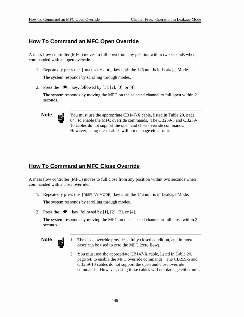
How To Command an MFC Open Override Chapter Five: Operation in Leakage Mode
146
How To Command an MFC Open Override
A mass flow controller (MFC) moves to full open from any position within two seconds whencommanded with an open override.
1. Repeatedly press the [DISPLAY MODE] key until the 146 unit is in Leakage Mode.
The system responds by scrolling through modes.
2. Press the key, followed by [1], [2], [3], or [4].
The system responds by moving the MFC on the selected channel to full open within 2seconds.
Note You must use the appropriate CB147-X cable, listed in Table 20, page64, to enable the MFC override commands. The CB259-5 and CB259-10 cables do not support the open and close override commands.However, using these cables will not damage either unit.
How To Command an MFC Close Override
A mass flow controller (MFC) moves to full close from any position within two seconds whencommanded with a close override.
1. Repeatedly press the [DISPLAY MODE] key until the 146 unit is in Leakage Mode.
The system responds by scrolling through modes.
2. Press the key, followed by [1], [2], [3], or [4].
The system responds by moving the MFC on the selected channel to full close within 2seconds.
Note 1. The close override provides a fully closed condition, and in mostcases can be used to zero the MFC (zero flow).
2. You must use the appropriate CB147-X cable, listed in Table 20,page 64, to enable the MFC override commands. The CB259-5 andCB259-10 cables do not support the open and close overridecommands. However, using these cables will not damage either unit.

Chapter Five: Operation in Leakage Mode How To Cancel an MFC Open/Close Override
147
How To Cancel an MFC Open/Close Override
An open or close override is canceled with the same sequence of steps.
1. Repeatedly press the [DISPLAY MODE] key until the 146 unit is in Leakage Mode.
The system responds by scrolling through modes.
2. Press either the or key, followed by [OFF/GAIN], then [1], [2], [3], or [4].
The system responds by removing the open or close override for the MFC on the selectedchannel. The MFC then performs as if no override had been given.

How To Start Hot Cathode Low Power Degassing Chapter Five: Operation in Leakage Mode
148
How To Start Hot Cathode Low Power Degassing
During a low power degas, the filament inside the hot cathode stays on, and valid pressurereadings continue to be obtained. During low power degas (I2R), all the power remaining (afterpowering the filament) is delivered to the grid inside the tube. The front panel display for thedegassing hot cathode continuously toggles between a pressure reading and dG (the degascode).
Note 1. The 146 unit can only perform the degassing procedure on one hotcathode gauge at a time. All other channels will continue to functionduring the degassing procedure.
2. A hot cathode must be on (channel on) in order to degas it.
1. Repeatedly press the [DISPLAY MODE] key until the 146 unit is in Leakage Mode.
The system responds by scrolling through modes.
2. Press the [DEGAS/SET POINT] key, then the [ON/LEAD] key, followed by [1], [2], [3], or[4].
The system responds by turning on the low power degas of the hot cathode on theselected channel, and causing that channel’s display to toggle between a pressure readingand dG .
Caution Damage to a hot cathode gauge can occur if pressure is allowed to gettoo high. Monitor the pressure, and control it within thespecifications stated for the hot cathode gauge.
Degas is only effective if the pressure remains less than 1 x 10⁻⁵ Torr.

Chapter Five: Operation in Leakage Mode How To Start Hot Cathode High Power Degassing
149
How To Start Hot Cathode High Power Degassing
During a high power degas, the filament inside the hot cathode is turned off, and all power isdelivered to the grid inside the tube. Pressure readings are not obtained during a high powerdegas.
Caution Only perform a high power degas procedure on a high power hotcathode gauge. Performing a high power degas procedure on a lowpower gauge may damage the grid within the gauge.
Note 1. The 146 unit can only perform the degassing procedure on one hotcathode gauge at a time. All other channels will continue to functionduring the degassing procedure.
2. A hot cathode must be on (channel on) in order to degas it.
The front panel display for the degassing hot cathode displays dG (the degas code)continuously for a high power degas.
1. Repeatedly press the [DISPLAY MODE] key until the 146 unit is in Leakage Mode.
The system responds by scrolling through modes.
2. Press the [DEGAS/SET POINT] key, followed by [1], [2], [3], or [4].
The system responds by turning on the high power degas of the hot cathode on theselected channel, and causing that channel’s display to change to dG .
Caution Damage to a hot cathode gauge can occur if pressure is allowed to gettoo high. Monitor the pressure, and control it within thespecifications stated for the hot cathode gauge.
Degas is only effective if the pressure remains less than 1 x 10⁻⁵ Torr.

How To Stop Hot Cathode Degassing Chapter Five: Operation in Leakage Mode
150
How To Stop Hot Cathode Degassing
When a low power degas is turned off, power to the grid inside the tube is discontinued. Thefilament remains on and the front panel display shows the pressure reading.
When a high power degas is turned off, power to the grid inside the tube is discontinued (as witha low power degas). The channel re-initializes and the hot cathode filament turns on. The frontpanel display shows a pressure reading during initialization but this reading should not beconsidered valid until the display stops flashing (within 1 to 2 seconds).
1. Repeatedly press the [DISPLAY MODE] key until the 146 unit is in Leakage Mode.
The system responds by scrolling through modes.
2. Press the [DEGAS/SET POINT] key, then the [OFF/GAIN] key, followed by [1], [2], [3], or[4].
The system responds by turning off the degas of the hot cathode on the selected channel.
A. If the hot cathode had been undergoing a low power degas, its display shows acontinuous, valid, pressure reading.
B. If the hot cathode had been undergoing a high power degas, the gauge re-initializes and its display flashes until initialization is complete (within 2seconds). The display then shows a continuous, valid, pressure reading.

Chapter Six: Operation in Tuning Mode General Information
151
Chapter Six: Operation in Tuning Mode
General Information
Tuning Mode is available only if a Control board is installed (in which case, a valve controllegend such as HOLD, is displayed). Press the [DISPLAY MODE] key twice from Normal Modeto scroll to Tuning Mode. The word TUNING appears in small letters above the main display.
Figure 41: Tuning Mode - Original Display, page 152, shows a sample window for TuningMode. Tuning Mode allows for fine tuning of seven valve control parameters. Of these sevenparameters, three are included in recipes ( GAIN, LEAD, and SET POINT), and four areindependent valve control parameters (BASE, START, INTEGRAL, and PRESET).
The three control parameters GAIN, LEAD, and SET POINT are associated in a recipe. Thedefault values in these recipes are:
GAIN 10
LEAD 1.5 seconds
SET POINT 0
By changing these default values, you can match the best lead and gain parameters with differentset points. In addition, you can associate each recipe with a different control channel (refer toCode 14x: How To select Polarity and the Control Channel, in the Operation in Setup Modechapter). In this way, a multi-stepped process can be easily implemented with a predefinedrecipe (refer to How To Select the Active Recipe in the Operation in Control Mode chapter).
In addition to these seven valve control parameters, there are several more are accessible fromSetup Mode. Refer to Code 4 (Alpha), Code 13x (Softstart), Code14x (Polarity and ControlChannel), and Code 15x (Analog Set Point), in the Operation in Setup Mode chapter for moreinformation about these additional valve control parameters.

General Information Chapter Six: Operation in Tuning Mode
152
The Front Panel Window
TUNING HOLD
2
TORR
LEFT DISPLAY CENTER DISPLAY RIGHT DISPLAY
This is the current valveposition expressed as a percent of the valvecontrol signal output.
This example shows a setting of 20.1% of the valve control signal output.
This indicates which of the four possible recipes is theactive recipe (in this case,it is recipe 1).
Refer to Control Mode toselect which recipe is theactive recipe.
This indicates which of thefour possible recipes isselected for editing (in thiscase, it is recipe 1).
MAIN DISPLAYThe pressure reading from the gaugeon the control channel (in this case, channel 2) is shown here.
Note: The control channel determineswhich gauge's pressure reading is compared to set point.
Note: This parameter must beHOLD (as in this example), orMANUAL, in order to adjustthe valve position shown in the left display.
Figure 41: Tuning Mode - Original Display
Note The first time you enter the Tuning Mode, the window looks like theexample above. After activating any of the Tuning parameters, however,the window may appear with a parameter legend displayed when TuningMode is entered again. An example of this is shown in Figure 42,page 153. To return to the original Tuning Mode display, press[QUIET/CANCEL].
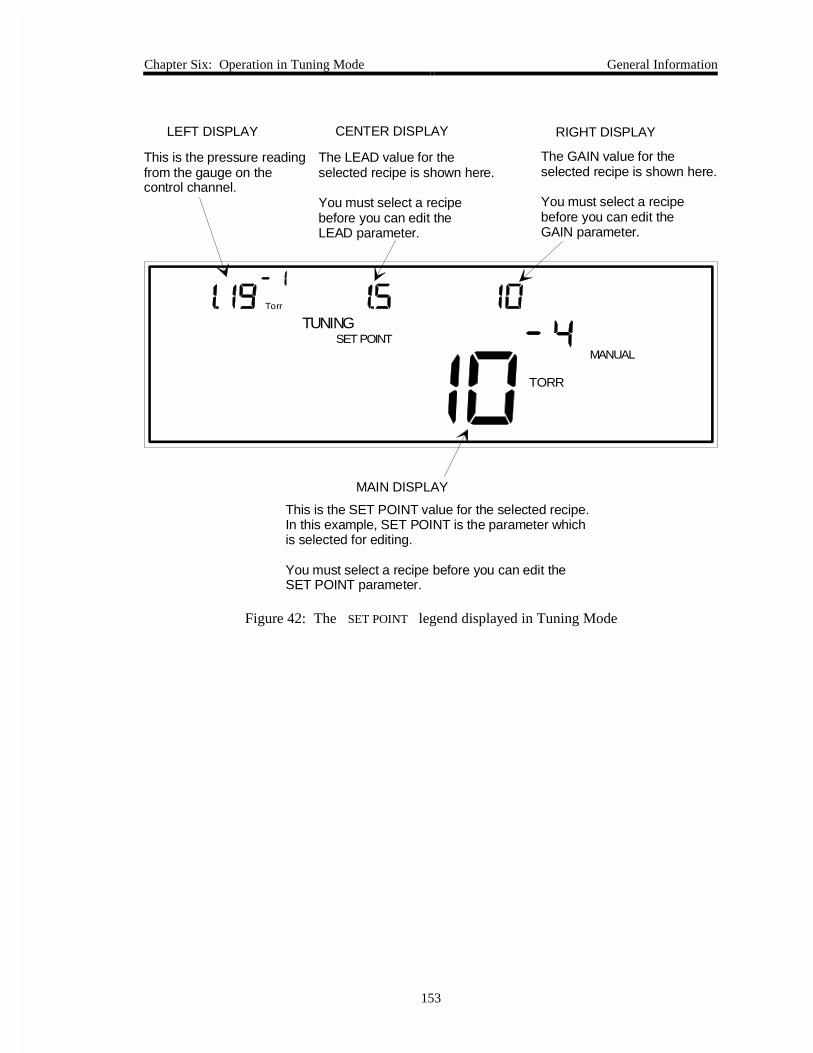
Chapter Six: Operation in Tuning Mode General Information
153
TUNING
MANUAL
TORR
SET POINT
Torr
LEFT DISPLAY CENTER DISPLAY RIGHT DISPLAY
This is the pressure readingfrom the gauge on the control channel.
The LEAD value for theselected recipe is shown here. You must select a recipebefore you can edit the LEAD parameter.
The GAIN value for the selected recipe is shown here.
You must select a recipe before you can edit the GAIN parameter.
MAIN DISPLAY
This is the SET POINT value for the selected recipe. In this example, SET POINT is the parameter whichis selected for editing.
You must select a recipe before you can edit the SET POINT parameter.
Figure 42: The SET POINT legend displayed in Tuning Mode

General Information Chapter Six: Operation in Tuning Mode
154
The Various Displays in Tuning Mode
In Tuning Mode, the content of the different displays varies depending upon which function youare currently performing. Table 42, page 155, summarizes what is in each display whenperforming Tuning Mode functions. Italics are used to indicate which displays have editableparameters.
For all parameters except Valve Position, the parameter name is displayed when the parameter iseditable. For example, the Base parameter is editable when the word BASE is displayed, andthe Set Point parameter is editable when the words SET POINT are displayed. Refer toFigure 1, page 21, to refresh your memory of exactly where the parameter names appear in thefront panel window.
The Valve Position parameter is only editable when no other Tuning Mode parameter (BASE,START, INTEGRAL, PRESET, GAIN, LEAD, or SET POINT), is displayed, and when the Control Modeparameter MANUAL or HOLD is displayed.

Chapter Six: Operation in Tuning Mode General Information
155
Summary of Tuning Mode Displays
Adjust theseParameters
Left Display Center Display Right Display Main Display
ValvePosition
* (Noparameter isdisplayed)
Current valveposition
* MANUAL/ HOLD
must be displayed
Indicates activerecipe
Indicateseditable recipe
Pressure readingfrom gauge oncontrol channel
Base Current valveposition
The BASE
position for theselected recipe
" "
Start " The START
position for theselected recipe
" "
Integral " The INTEGRAL
value for theselected recipe
" "
Preset " The PRESET
position for theselected recipe
" "
Gain " The LEAD
value for theselected recipe
The GAIN
value for theselected recipe
"
Lead " The LEAD
value for theselected recipe
The GAIN
value for theselected recipe
"
Set Point Pressure readingfrom gauge on thecontrol channel
" " The SET POINT
value for theselected recipe
Note: Italics are used to indicate displays with editable parameters.
Table 42: Summary of Tuning Mode Displays

General Information Chapter Six: Operation in Tuning Mode
156
Tuning Mode is Used when Performing the Following Procedures
Tuning Mode Functions
Change the valve position This feature is only functional if the [MANUAL] or
[HOLD] legend is displayed. The current valve positionbecomes editable.
Adjust the Base parameter Base is defined as the smallest user-defined value for thevalve control signal output. In effect, this limits howclosed the valve can become. Note: The Base parametercan override the Softstart parameter.
Adjust the Start parameter The Start value is used to set the initial position of thevalve when the AUTO feature is evoked in ControlMode. The Start value only applies if the valve was atfull open or full close just prior to evoking the AUTO
feature. Note: If Softstart is enabled, it can override theStart parameter.
Adjust the Integral parameter The Integral parameter selects the time constant used forthe integral term of the PID control.
Adjust the Preset parameter The Preset value is used to set the position of the valvewhen the MANUAL feature is evoked in Control Mode.
Adjust the Gain parameter Gain can be adjusted, and is associated with the selectedrecipe.
Adjust the Lead parameter Lead can be adjusted, and is associated with the selectedrecipe.
Adjust the Set Point parameter Set Point can be adjusted, and is associated with theselected recipe.
Edit Control Recipes There can be up to four recipes, each with its own SetPoint, Gain, and Lead parameters. By switching theactive recipe (in Control Mode), and selecting the AUTO
feature (also in Control Mode), one of these four multi-parameter recipes can be used to position the valve.
Table 43: Tuning Mode Functions

Chapter Six: Operation in Tuning Mode General Information
157
The Two Levels within Tuning Mode
Figure 43, page 158, depicts the differences in functionality and in key operation between thetwo levels of Tuning Mode.
The Upper Level of Tuning Mode
When Tuning Mode is first entered, it is always operating at the upper level. This is trueregardless of whether or not any Tuning Mode parameters (BASE, START, INTEGRAL, PRESET,GAIN, LEAD, or SET POINT), are currently displayed. This level is used to scroll among theparameters and observe their current values, but no parameter editing can be done at this level.
It is important to understand that the Valve Position parameter does not have a specific legend asdo all other Tuning Mode parameters. In order to select the Valve Position parameter, theControl Mode parameter HOLD or MANUAL must be displayed. Additionally, you mustmove through the Tuning Mode parameters until none of the other Tuning Mode parameters aredisplayed. There are two ways to move to the Valve Position parameter.
One press of the [QUIET/CANCEL] key selects the Valve Position parameter (no Tuning Modeparameters are displayed). Alternately, the Valve Position parameter can be selected by scrollingto it with the arrow keys. As Figure 43, page 158, shows, the Valve Position parameter ispositioned between the BASE parameter and the SET POINT parameter. If the BASE parameter legend is displayed, one press of the selects the Valve Position parameter. If theSET POINT parameter legend is currently displayed, one press of the selects the ValvePosition parameter.
The and keys the [QUIET/CANCEL] key, and the [ENTER] key function differently in thetwo levels of Tuning Mode. On the upper level, the arrow keys scroll through the Tuning Modeparameters BASE, START, INTEGRAL, PRESET, GAIN, LEAD, SET POINT, and Valve Position(remember, there is no Valve Position parameter legend). The [QUIET/CANCEL] key first selectsthe Valve Position parameter, and if pressed again, returns the 146 unit to Normal Mode. The[ENTER] key selects a parameter for editing and moves to the lower level of Tuning Mode.
The Lower Level of Tuning Mode
The lower level of Tuning Mode is used for parameter editing. To move from the upper level tothe lower level, move to the parameter to be edited, then press the [ENTER] key.
On the lower level, the arrow keys increment and decrement the value of the selected parameter.For example, if the GAIN parameter is selected for editing, then the increases thedisplayed value for GAIN , and the decreases it.
On the lower level the [QUIET/CANCEL] key has an additional function. When first pressed, thekey returns the editable parameter to its pre-edited value. For example, if GAIN is the editableparameter, and its initial value is 5, the key increases the value to 6. If the [QUIET/CANCEL]key is pressed, the value for GAIN returns to 5. After this initial operation, the[QUIET/CANCEL] key returns to the upper level.
When still on the lower level, the [ENTER] key causes the 146 unit to accept the value for thecurrently editable parameter, and returns the unit to the upper level of Tuning Mode.

General Information Chapter Six: Operation in Tuning Mode
158
Upper Level of Tuning Mode
Lower Level of Tuning Mode
Base
Integral
Preset Gain
Lead
Set Point
[DEGAS/SETPOINT]
[ON/LEAD]
Valve Position
[OFF/GAIN]
Start
Parameter
Functionality returns to theUpper Level of Tuning Mode
Functionality begins on theUpper Level of Tuning Mode
Upper Level of Tuning Mode
Shortcut Keys go directlyto a parameter and selectit for editing.
and scroll through these parameters
[ENTER] selects parameter for editing
To select Valve Position:1. No other Tuning Mode parameters can be displayed.2. Control Mode parameter HOLD or MANUAL must be displayed.
[QUIET/CANCEL] 1. Goes directly to Valve Position parameter2. Returns to Normal Mode
Once selected with [ENTER]the parameter is editable [ENTER] ends editing
and adjust parameter value
1. Returns a parameter to its pre-edited value2. Returns to the Upper Level3. Goes directly to Valve Position parameter4. Returns to Normal Mode
[QUIET/CANCEL]
Figure 43: The Two Levels within Tuning Mode

Chapter Six: Operation in Tuning Mode General Information
159
Keys
Table 44 explains the variations in how keys work in Tuning Mode. The Shortcut keys are quickways of selecting certain parameters. The arrow keys can also be used.
Special Key Functions in Tuning Mode
Keys Key Function
[+/-] The [+/-] key moves edit capability one digit to the left in a parameterfield. For example, if the value in a parameter field is 123 , and youare using the arrow keys to adjust the 3 digit, the [+/-] key moves theedit capability to the 2 digit. Now, the arrow keys adjust the 2digit. If the [+/-] key is pressed again, the adjustment control moves tothe 1 digit.
[EXP/.] The [EXP/.] key moves edit capability one digit to the right in aparameter field. For example, if the value in a parameter field is 123, and the arrow keys are adjusting the 1 digit, the [EXP/.] key movesthe edit capability to the 2 digit. Now, the arrow keys adjust the 2digit. If the [EXP/.] key is pressed again, adjustment control moves tothe 3 digit.
[QUIET/CANCEL] 1. Returns a parameter to its pre-edited value (Lower Level only).
2. Selects the Valve Position parameter (Both Levels).
3. Returns the 146 unit to Normal Mode.
and 1. Scroll through Tuning Mode parameters (Upper Level).
2. Increase/decrease the value of the editable parameter (Lower Level).
Shortcut Keys Key Function
[QUIET/CANCEL] Selects the Valve Position parameter, On the Upper level of TuningMode. On the Lower level, this key selects the Valve Positionparameter after it returns any currently editable parameter to its pre-edited value.
[DEGAS/SET POINT] Selects the SET POINT parameter for updating, and causes it to blinkin the main display. The SET POINT legend appears above the maindisplay.
[ON/LEAD] Selects the LEAD parameter for updating, and causes it to blink in thecenter display. The LEAD legend appears above the main display.
[OFF/GAIN] Selects the GAIN parameter for updating, and causes it to blink in theright display. The GAIN legend appears above the main display.
Table 44: Special Key Functions in Tuning Mode

General Information Chapter Six: Operation in Tuning Mode
160
The Deviation Indicator
In Tuning Mode there is a deviation indicator which indicates the deviation of the systempressure from set point. The deviation from set point is displayed approximately every one-thirdsecond (this is how often the LCD screen is refreshed). The deviation indicator is enabled only ifthe 146 unit is operating with the AUTO feature turned on (refer to How To Set the Valve to AUTO
Position, in the Operation in Control Mode chapter).
There are ten deviation indicator segments. The five upper segments represent pressure deviationover set point and the five lower segments represent pressure deviation under set point. The 146unit determines the segment(s) to illuminate according to the following formula:
Deviation = Psp
Where: P = pressuresp = set point
Each segment represents a different percent of deviation as shown in Figure 44.
Deviation Percent Error
Segments
1.2 to < 1.95
1.05 to < 1.2
1.01 to <1.05
1.002 to < 1.01
None = 0.998 to <1.002
0.99 to < 0.998
0.95 to < 0.99
0.80 to <0.95
0.05 to < 0.80
<0.05
> +95%
+20 to 95%
+5 to 20%
+1 to 5%
+0.2 to 1%
0.2%
-0.2 to 1%
-1 to -5%
-5 to -20%
-20 to -95%
> -95%
±
1.95≥
Figure 44: Deviation Indicator

Chapter Six: Operation in Tuning Mode General Information
161
If the system is operating far below set point, there will be a large change in pressure betweenscreen refreshing because the system will be quickly moving towards set point. Within theone-third second time frame, the deviation could range from - 22% (at the beginning of the timeframe), to - 4% (at the end of the time frame). In this case, the middle three segments in thelower half of the deviation indicator light up (refer Figure 44, page 160).
As another example, assume there is pressure oscillation above and below set point. Upper andlower deviation indicator segments light up to indicate over and under pressure readings. Ineffect, the deviation indicator provides similar information to that provided by an oscilloscope.If the oscillation continues, it is possible that reducing the Gain setting may improve systemstability. When the system does stabilize, none of the deviation indicators are lit.
When the Set Point is 0:
If the set point is 0 and the pressure reading is 0, no segments light up.
If the set point is 0 and the pressure is above 0, the uppermost segment lights up.
If the set point is 0 and the pressure is below 0, the lowermost segment lights up.

How To Change the Valve Position Chapter Six: Operation in Tuning Mode
162
How To Change the Valve Position
TUNING HOLD
2
TORR
LEFT DISPLAY CENTER DISPLAY RIGHT DISPLAY
This is the current valveposition expressed as a percent of the valvecontrol signal output.
This example shows a setting of 20.1% of thevalve control signal output.
This indicates which of the four possible recipes is theactive recipe (in this case,it is recipe 1).
This indicates which of thefour possible recipes isselected for editing (in thiscase, it is recipe 1).
MAIN DISPLAY
The pressure reading from the gauge on the control channel (in this case, channel 2) is shown here.
Note: The control channel determines which gauge's pressure reading is compared with set point.
This parameter must be HOLD(as in this example), or MANUALin order to adjust the valve positionshown in the left display.
Figure 45: Tuning Mode Display when Adjusting the Valve Position
The Valve Position can only be changed if the MANUAL or HOLD legend is displayed.
The Valve Position is expressed as a percent of the valve control signal output. If the valve iscurrently in a HOLD position (selected in Control Mode) the HOLD feature is overriddenwhile the Valve Position is changed. After adjusting the Valve Position, the new position ismaintained in a HOLD status.
Valve Position is a real-time parameter. The new valve position goes into effect as soon as it isadjusted with this procedure.

Chapter Six: Operation in Tuning Mode How To Change the Valve Position
163
1. Repeatedly press the [DISPLAY MODE] key until the 146 unit is in Tuning Mode.
The system responds by scrolling through modes.
2. Be sure the correct Tuning Mode window is displayed.
If any of the Tuning Mode legends is displayed (BASE, START, INTEGRAL, PRESET,GAIN, LEAD, or SET POINT), press the [QUIET/CANCEL] key until the legend is gone.
3. Press the [ENTER] key.
The system responds by causing the left display to blink.
4. Enter a Valve Position (expressed as a percent of the valve control signal output).
A new Valve Position may be entered using the number keys. The Valve Position,which is currently displayed, can be adjusted using the arrow keys and the [+/-] key.
A. If the display is correct, press the [ENTER] key.
B. If the display is not correct, enter the correct valve position, then press the[ENTER] key.
The system responds by accepting the valve position. The valve’s position changesaccording to the valve control signal entered here, and is then maintained at this position.

How To Adjust Base Chapter Six: Operation in Tuning Mode
164
How To Adjust Base
MANUAL
TORR
TUNING
BASE
LEFT DISPLAY CENTER DISPLAY RIGHT DISPLAY
This is the current valveposition expressed as apercent of the valvecontrol signal output.
This example shows a setting of 20.1% of the valve control signal output.
The BASE valve positionis expressed as a percentof the valve control signaloutput.
In this example, BASE isthe parameter which is selected for editing, andis currently set at 15.5%.
This indicates which of thefour possible recipes isselected for editing (in thiscase, it is recipe 2).
MAIN DISPLAY
This is the pressure reading from the gauge on the control channel.
Figure 46: Adjusting the Base Valve Position
Base is a valve control parameter that is expressed as a percent of the valve control signal output.A Base setting of 20 means the valve control signal output should not go below 20% of the fullopen output. In effect, this means the valve should remain at least 20% open.
For solenoid valves, the Base parameter is frequently adjusted to the point just below where thevalve begins to open.
Note The Base parameter can override the Softstart parameter (Code 13x in theOperation in Setup Mode chapter).
1. Repeatedly press the [DISPLAY MODE] key until the 146 unit is in Tuning Mode.
The system responds by scrolling through modes.

Chapter Six: Operation in Tuning Mode How To Adjust Base
165
2. Select the BASE parameter by scrolling through the parameters with the arrow keys.
The system responds by displaying each of the Tuning parameters as they are scrolledthrough.
3. Press the [ENTER] key.
The system responds by causing the center display to blink.
4. Enter the Base value. The range is from 0 to 103% of full open, and the default is 0.
A. If the center display shows the correct base value, press the [ENTER] key.
B. If the center display is not correct, use the numeral keys and the arrow keys (fortenths of a percent) to enter the correct Base value, then press the [ENTER] key.
The system responds by accepting the Base value.

How To Adjust Start Chapter Six: Operation in Tuning Mode
166
How To Adjust Start
MANUAL
TORR
TUNING
START
LEFT DISPLAY CENTER DISPLAY RIGHT DISPLAY
This is the current valveposition expressed as apercent of the valvecontrol signal output.
This example shows a setting of 20.1% of the valve control signal output.
The START valve positionis expressed as a percentof the valve control signaloutput.
In this example, START isthe parameter which is selected for editing, andis currently set at 25.5%.
This indicates which of thefour possible recipes isselected for editing (in thiscase, it is recipe 2).
MAIN DISPLAY
This is the pressure reading from the gauge on the control channel.
Figure 47: Adjusting the Start Valve Position
Start is a valve position, expressed as a percent of the valve control signal output. The Startvalue is used to set the initial position of the valve when the AUTO feature is evoked in ControlMode. The Start value only applies if the valve was at full open or full close just prior toevoking the AUTO feature.
Note If the Softstart parameter (Code 13x in the Operation in Setup Modechapter), is enabled, it can override the Start parameter.
1. Repeatedly press the [DISPLAY MODE] key until the 146 unit is in Tuning Mode.
The system responds by scrolling through modes.

Chapter Six: Operation in Tuning Mode How To Adjust Start
167
2. Select the START parameter by scrolling through the parameters with the arrow keys.
The system responds by displaying each of the Tuning parameters as they are scrolledthrough.
3. Press the [ENTER] key.
The system responds by causing the center display to blink.
4. Enter the Start value. The range is from 0 to 103% of full open, and the default is 0.
A. If the center display shows the correct Start value, press the [ENTER] key.
B. If the center display is not correct, use the numeral keys and arrow keys to enterthe correct Start value, then press the [ENTER] key.
The system responds by accepting the Start value.

How To Adjust Integral Chapter Six: Operation in Tuning Mode
168
How To Adjust Integral
LEFT DISPLAY CENTER DISPLAY RIGHT DISPLAY
This is the current valveposition expressed as apercent of the valvecontrol signal output.
This example shows a setting of 20.1% of the valve control signal output.
The INTEGRAL parameterselects the time constant forPID calculations.
In this example, INTEGRALis the parameter which is selected for editing, andis currently set at 10.0.
This indicates which of thefour possible recipes isselected for editing (in thiscase, it is recipe 2).
MAIN DISPLAY
This is the pressure reading from the gauge on the control channel.
MANUAL
TORR
TUNING
INTEGRAL
Figure 48: Adjusting the Integral Value
The Integral parameter selects the time constant used for PID calculations.
1. Repeatedly press the [DISPLAY MODE] key until the 146 unit is in Tuning Mode.
The system responds by scrolling through modes.
2. Select the INTEGRAL parameter by scrolling through the parameters with the arrowkeys.
The system responds by displaying each of the Tuning parameters as they are scrolledthrough.
3. Press the [ENTER] key.
The system responds by causing the center display to blink.

Chapter Six: Operation in Tuning Mode How To Adjust Integral
169
4. Enter the Integral value. The value must be between 0.02 and 100 (inclusive) seconds,and the default is 0.3 seconds.
A. If the center display shows the correct Integral value, press the [ENTER] key.
B. If the center display is not correct, use the numeral keys and arrow keys to enterthe correct Integral value, then press the [ENTER] key.
The system responds by accepting the Integral value.

How To Adjust Preset Chapter Six: Operation in Tuning Mode
170
How To Adjust Preset
MANUAL
TORR
TUNING
PRESET
LEFT DISPLAY CENTER DISPLAY RIGHT DISPLAY
This is the current valveposition expressed as apercent of the valvecontrol signal output.
This example shows a setting of 20.1% of the valve control signal output.
The PRESET valve positionis expressed as a percentof the valve control signaloutput.
In this example, PRESET isthe parameter which is selected for editing, andis currently set at 50.0%.
This indicates which of thefour possible recipes isselected for editing (in thiscase, it is recipe 2).
MAIN DISPLAY
This is the pressure reading from the gauge on the control channel.
Figure 49: Adjusting the Preset Valve Position
Preset is a valve position, expressed as a percent of the valve control signal output. The Presetvalue is used to set the position of the valve when the MANUAL feature is evoked in ControlMode.
1. Repeatedly press the [DISPLAY MODE] key until the 146 unit is in Tuning Mode.
The system responds by scrolling through modes.
2. Select the PRESET parameter by scrolling through the parameters with the arrow keys.
The system responds by displaying each of the Tuning parameters as they are scrolledthrough.
3. Press the [ENTER] key.
The system responds by causing the center display to blink.

Chapter Six: Operation in Tuning Mode How To Adjust Preset
171
4. Enter the Preset value. The range is from 0 to 103% of full open, and the default is99.8%.
A. If the center display shows the correct Preset value, press the [ENTER] key.
B. If the center display is not correct, use the numeral keys and arrow keys to enterthe correct Preset value, then press the [ENTER] key.
The system responds by accepting the Preset value.

How To Edit Recipes (Gain, Lead, and Set Point) Chapter Six: Operation in Tuning Mode
172
How To Edit Recipes (Gain, Lead, and Set Point)
Editing a recipe follows the same procedure as editing the gain, lead, and set point parametersseparately. It is mentioned here in a separate How To section so that you do not have to readthe following three How To sections to know how to edit a recipe. The instructions can bepresented in a more efficient manner than when they are presented as three separate instructionsets.
The 146 unit can store four different recipes. Each recipe contains a gain, lead, and set pointvalue, and an associated control channel (refer to Code 14x: Select Polarity and ControlChannel, in the Operation in Setup Mode chapter to select the control channel). The 146 unitcomes with four identical recipes. The default values in these recipes are:
GAIN 10
LEAD 1.5 seconds
SET POINT 0
Channel 1 is the default control channel for all recipes. When the 146 unit is set to control withthe AUTO feature (refer to How To Set the Valve to AUTO position, in the Operation in ControlMode chapter), it controls according to the parameter values of the active recipe (refer to How ToSelect the Active Recipe, also in the Operation in Control Mode chapter).
Note It is not necessary to follow this exact sequence of steps. The gain, lead,and set point values can be entered in any order.
Recipe parameters (GAIN, LEAD, and SET POINT) are real-time parameters. The new parametervalues go into effect as soon as they are adjusted with this procedure.
1. Repeatedly press the [DISPLAY MODE] key until the 146 unit is in Tuning Mode.
The system responds by scrolling through modes.
2. Enter the number of the recipe to be created or edited.
The system responds by accepting the recipe number.
Note If the MANUAL or HOLD legend is displayed, and the right displayshows the Edit Recipe parameter (E1, E2, E3, or E4), the left display willblink. The left display is flashing the current control valve position.Since we want to edit the recipe, you may ignore the blinking left displayand proceed to the next step.

Chapter Six: Operation in Tuning Mode How To Edit Recipes (Gain, Lead, and Set Point)
173
3. Press the [OFF/GAIN] key.
The system responds by changing the window parameters, and causing the right displayto blink. The GAIN legend is displayed. Refer to Figure 50, page 174, for an exampleof the front panel window with the GAIN legend displayed.
4. Enter a value for Gain between 0.002 and 10,000 (the default is 10).
A. If the Gain value is already correct, press the [ENTER] key.
B. If the Gain value is incorrect, use the [ZERO/EXP] , [+/-] , and numeral keys toenter the correct Gain value, then press the [ENTER] key.
The system responds by accepting the Gain value.
5. Press the [ON/LEAD] key.
The system responds by causing the center display to blink. The LEAD legend isdisplayed. Refer to Figure 51, page 176, for an example of the front panel window withthe LEAD legend displayed.
6. Enter a value for Lead between 0.001 and 1000 seconds (the default is 1.5 seconds).
A. If the Lead value is already correct, press the [ENTER] key.
B. If the Lead value is incorrect, use the [ZERO/EXP] , [+/-] , and numeral keys toenter the correct Lead value, then press the [ENTER] key.
The system responds by accepting the Lead value.
7. Press the [DEGAS/SET POINT] key.
The system responds by moving the pressure reading of the controlling channel from themain display to the left display, and presenting the current Set Point value in the maindisplay. The SET POINT legend is displayed, and the main display blinks. Refer toFigure 52, page 178, for an example of the front panel window with the SET POINT legend displayed.
8. Enter a Set Point value between ± 100,000 (the default is 0).
A. If the Set Point is already correct, press the [ENTER] key.
B. If the Set Point is incorrect, use the [ZERO/EXP] , [+/-], and numeral keys toenter the correct Set Point, then press the [ENTER] key.
The system responds by accepting the Set Point value.

How To Adjust Gain Chapter Six: Operation in Tuning Mode
174
How To Adjust Gain
MANUAL
TORR
TUNING GAIN
LEFT DISPLAY CENTER DISPLAY RIGHT DISPLAY
This is the current valveposition expressed as apercent of the valvecontrol signal output.
This example shows a setting of 20.1% of the valve control signal output.
The LEAD value for the selected recipe is shownhere.
You must select a recipebefore you can edit the LEAD parameter.
The GAIN value for theselected recipe is shownhere. In this example, GAINis the parameter which isselected for editing.
You must select a recipe before you can edit theGAIN parameter.
MAIN DISPLAY
This is the pressure reading from the gauge on the control channel.
Figure 50: Adjusting the Gain Value
Gain is a control parameter. When installed in a control loop, the 146 unit calculates an errorsignal. The error signal is multiplied by the Gain setting. Thus, when the 146 unit sends out avalve drive signal (based upon the error signal which it received), the valve drive signal isproportional to the Gain setting and the error signal.
Gain is a real-time parameter. The new Gain value goes into effect as soon as it is adjusted withthis procedure.
1. Repeatedly press the [DISPLAY MODE] key until the 146 unit is in Tuning Mode.
The system responds by scrolling through modes.

Chapter Six: Operation in Tuning Mode How To Adjust Gain
175
2. Enter the number of the recipe (1 through 4), which is to have the Gain setting adjusted.
The system responds by accepting the recipe number.
Note If the MANUAL or HOLD legend is displayed, and the right displayshows the Edit Recipe parameter (E1, E2, E3, or E4), the left display willblink. The left display is flashing the current control valve position.Since we want to edit a recipe, you may ignore the blinking left displayand proceed to the next step.
3. Press the [OFF/GAIN] key, OR scroll through the Tuning Mode parameters with thearrow keys until the GAIN legend is displayed, then press the [ENTER] key.
The system responds by changing the window parameters, and causing the right displayto blink.
4. Enter a value for Gain between 0.002 and 10,000 (the default is 10).
A. If the Gain value is already correct, press the [ENTER] key.
B. If the Gain value is incorrect, use the [ZERO/EXP] , [+/-] , and numeral keys toenter the correct Gain value, then press the [ENTER] key.
The system responds by accepting the Gain value.

How To Adjust Lead Chapter Six: Operation in Tuning Mode
176
How To Adjust Lead
MAIN DISPLAY
This is the pressure reading from the gauge on the control channel.
MANUAL
TORR
TUNING LEAD
LEFT DISPLAY CENTER DISPLAY RIGHT DISPLAY
This is the current valveposition expressed as apercent of the valvecontrol signal output.
This example shows a setting of 20.1% of the valve control signal output.
The LEAD value for theselected recipe is shownhere. In this example,LEAD is the parameterwhich is selected for editing.
You must select a recipebefore you can edit theLEAD parameter.
The GAIN value for the selected recipe is shownhere.
You must select a recipebefore you can edit theGAIN parameter.
Figure 51: Adjusting the Lead Value
The Lead parameter creates a valve drive signal that is proportional to the rate of change of thecontrolling sensor’s pressure reading. That is, the Lead value provides anticipation in thesystem, allowing set point to be reached more quickly.
Lead is a real-time parameter. The new Lead value goes into effect as soon as it is adjusted withthis procedure.
1. Repeatedly press the [DISPLAY MODE] key until the 146 unit is in Tuning Mode.
The system responds by scrolling through modes.

Chapter Six: Operation in Tuning Mode How To Adjust Lead
177
2. Enter the number of the recipe (1 through 4), that needs to have the Lead settingadjusted.
The system responds by accepting the recipe number.
Note If the MANUAL or HOLD legend is displayed, and the right displayshows the Edit Recipe parameter (E1, E2, E3, or E4), the left display willblink. The left display is flashing the current control valve position.Since we want to edit a recipe, you may ignore the blinking left displayand proceed to the next step.
3. Press the [ON/LEAD] key, OR scroll through the Tuning Mode parameters with thearrow keys until the LEAD legend is displayed, then press the [ENTER] key.
The system responds by changing the window parameters, and causing the center displayto blink.
4. Enter a value for Lead between 0.001 and 1000 seconds (the default is 1.5 seconds).
A. If the Lead value is already correct, press the [ENTER] key.
B. If the Lead value is incorrect, use the [ZERO/EXP] , [+/-] , and numeral keys toenter the correct Lead value, then press the [ENTER] key.
The system responds by accepting the Lead value.

How To Adjust Set Point Chapter Six: Operation in Tuning Mode
178
How To Adjust Set Point
TUNING
MANUAL
TORR
SET POINT
Torr
LEFT DISPLAY CENTER DISPLAY RIGHT DISPLAY
This is the pressurereading from the gaugeon the control channel.
The LEAD value for theselected recipe is shownhere.
You must select a recipebefore you can edit theLEAD parameter.
The GAIN value for theselect recipe is shownhere.
You must select a recipebefore you can edit theGAIN parameter.
MAIN DISPLAYThis is the SET POINT value for the selected recipe. In this example, SET POINT is the parameter which is selected for editing.
You must select a recipe before you can edit the SET POINT parameter.
Figure 52: Adjusting the Set Point Value
Set Point is a real-time parameter. The new Set Point value goes into effect as soon as it isadjusted with this procedure.
1. Repeatedly press the [DISPLAY MODE] key until the 146 unit is in Tuning Mode.
The system responds by scrolling through modes.
2. Enter the number of the recipe (1 through 4) which needs to have the Set Point edited.
The system responds by accepting the recipe number.

Chapter Six: Operation in Tuning Mode How To Adjust Set Point
179
Note If the MANUAL or HOLD legend is displayed, and the right displayshows the Edit Recipe parameter (E1, E2, E3, or E4), the left display willblink. The left display is flashing the current control valve position.Since we want to edit a recipe, you may ignore the blinking left displayand proceed to the next step.
3. Press the [DEGAS/SET POINT] key, or scroll through the Tuning Mode parameterswith the arrow keys until the SET POINT legend is displayed, then press the [ENTER]key.
The system responds by changing the window parameters, and causing the left display toblink.
4. Enter a Set Point value between ±100,000 Torr (the default is 0).
A. If the Set Point is already correct, press the [ENTER] key.
B. If the Set Point is incorrect, use the [ZERO/EXP] , [+/-] , and numeral keys toenter the correct Set Point value, then press the [ENTER] key.
The system responds by accepting the Set Point.

How To Adjust Set Point Chapter Six: Operation in Tuning Mode
180
This page intentionally left blank.

Chapter Seven: Operation in Setup Mode General Information
181
Chapter Seven: Operation in Setup Mode
General Information
Press the [DISPLAY MODE] key three times from Normal Mode to get to Setup Mode. The wordSETUP appears in small letters above the main display.
Figure 53 shows a sample window for Setup Mode. Setup Mode is used to set up the 146 unit tooperate according to the needs of a specific control system. For example, in Setup Mode, alarmtrip points are entered, and the 146 unit can be set up to read pressure over a range that isspanned by two gauges. All the miscellaneous codes for the 146 instrument are contained withinSetup Mode.
CLOSE
TORR
SETUP
TRIP POINT
CENTER DISPLAY RIGHT DISPLAYLEFT DISPLAY
MAIN DISPLAY
This indicates if the selectedalarm is ON (enabled) orOFF (disabled) as in thisexample.
The trip point for the selectedalarm is shown in this display.
The letter of the alarm which is selected for editing (A through D)is shown here.
This is the channel numberfor the gauge which isassociated with the selectedalarm. The uppercase A indicates normally actuated.
Figure 53: Setup Mode

General Information Chapter Seven: Operation in Setup Mode
182
The Various Displays in Setup Mode
In Setup Mode, the content of the different displays varies depending upon which function youare currently performing. Table 45, page 183, summarizes what is in each display whenperforming the Setup Mode functions. Table 46, page 184, summarizes the information in themiscellaneous code screens.
For all parameters except individual miscellaneous codes, the parameter name is displayed whenthe parameter is editable. For example, the Alarm Trip Points parameter is editable when thewords TRIP POINT are displayed, and the Sensor Calibration parameter is editable when thewords SENSOR CAL are displayed. Refer to Figure 1, page 21, to refresh your memory ofexactly where the parameter names appear in the front panel window.
Individual miscellaneous codes are indicated by the code number in the left display, and theparameter name CODE at the bottom right area of the front panel window.
In the Sensor Calibration function, if a hot cathode is on the selected channel, the letters Hcappear in the right display. Above and to the right of the letters Hc is either the letter H orthe letter l . The letter H is used to indicate a high power hot cathode and it is the defaultsetting. The letter l is used to indicate a low power hot cathode (HPS low power, Bayard-Alpert, nude, hot cathode). Refer to Hot Cathode, page 55, for instructions on how to change thedefault setting and accommodate a low power hot cathode.

Chapter Seven: Operation in Setup Mode General Information
183
Summary of Setup Mode Displays
Function Left Display Center Display Right Display Main Display
Set Alarm TripPoints
Alarm letter Channel numberfor alarm
On/Off Alarm Alarm trip point
Set Up DualChannels
Dual channelnumber andHigh/Lowswitchpoint
Control channelnumber
Continuous (ct) ordiscontinuous (dt) orOff, dual channeldisplay
Dual channelswitchpoint
Set Up AnalogOutputs
AnalogOutput #
Input channel # Output scalingmethod
Pressure = Fullscale output orset point
SensorCalibration
Input channelnumber
CM: sensorresolution
Type of gauge CM: sensor range
P: factory oruser-definedzero/ span
P: gas type
CC: ion gaugedisconnectthreshold value
CC: combinedgauge & GCF
HC: ion gaugedisconnectthreshold value
The letter H or labove Hc, indicateshigh or low poweredhot cathode. Noteditable here
HC: sensitivity
FC: MFC modeof operation -either (SP) or(to). Noteditable here
FC: MFC range
Table 45: Summary of Setup Mode Displays

General Information Chapter Seven: Operation in Setup Mode
184
Summary of Setup Mode Codes
Function Left Display Center Display Right Display Main Display
1 Select Volt/Pressure/ orCurrent
Code number - HU (high voltage),EC (emissioncurrent), or IC (ioncurrent)
*Main display mustbe Volt, or this isunused
Selects Volt orPrES (pressure)
2 SelectPressure Units
Code number - - Selects pressureunit
3 Edit AudioAlarms
Code number - - On or Off audioalarm
4 Adjust Alpha Code number - - Alpha value
5 Set upRS-232 Port
Code number Data bits andparity
Data logger orMKS protocol
Baud rate
7 Set up MainDisplay inLeakage Mode
Code number - - DetermineLeakage Modemain display
8 Edit DataLogger Interval
Code number - - Data loggerinterval value
10x AdjustDisplay Lag
Code number - - Display lagpercent
11x Auto Zero Code number - On/Off Auto Zero Reference channelnumber
12x Adjust IonGauge AutoPower Control
Code number& channelnumber for iongauge
Referencechannel number
On/Off auto powercontrol
Trip point for autopower control
13x AdjustSoftstart
Code numberand recipenumber
- On/Off softstartspeed function
Softstart speed
14x SetPolarity &ControlChannel
Code numberand recipenumber
- Control channelnumber recipedependent
Select dir (direct)or rEV (reversepolarity
Table 46: Summary of Setup Mode Codes(Continued on next page)

Chapter Seven: Operation in Setup Mode General Information
185
Summary of Setup Mode Codes (Continued)
Function Left Display Center Display Right Display Main Display
15x Set upAnalog SetPoint
Code numberand recipenumber
Voltage to spananalog input
On/Off analog setpoint
Full scale inputvoltage
16x Adjust HCHigh PressureShutoff
Code numberand channelnumber
- Internal fast rate-of-rise shutoff value
High pressureshutoff value
17x AdjustMFC Set Point,Mode, and Co-channel
Code numberand channelnumber
Co-channel, forTotaling only
Set Point, Totaling,or Ratio parameterselection
Set Point
18x Select theType ofConvectionGauge
Code numberand channelnumber
- - Convection gaugetype; Cn forConvectron,CP for CEP
Table 46: Summary of Setup Mode Codes
Setup Mode is Used when Performing the Following Procedures
Setup Mode Procedures
Action Description
Setting Alarm TripPoints
The trip point is the pressure at which an alarm is tripped. Alarms A and Bare standard. Alarms C and D are only available with the Auxiliary Outputboard.
Sensor Calibration Sensor calibration is used to customize parameters for different sensor types.For capacitance manometers it allows the sensor range and resolution to beentered (except for Type 107 transducers). For Pirani or convection gauges,it selects the gas type, and is used to determine if the zero and span valuesare Factory or User defined. For cold cathode gauges, the Gas CorrectionFactor and disconnect threshold are entered. For hot cathode gauges,sensitivity and the disconnect threshold for sensor reading are entered. ForMFCs, the range is entered.
Setting up DualChannel Display
The 146 unit is set up to display over a range that is spanned by twodifferent sensors.
Setting an AnalogEndpoint
This function programs each of the three analog outputs as either linearlyscaled (Ln), logarithmically scaled (lo1 - lo9), or as a fixed voltage (SP).
Table 47: Setup Mode Procedures

General Information Chapter Seven: Operation in Setup Mode
186
Setup Mode Functions
Miscellaneous Codes Code Functions
Code 1:
Pressure/Volt/CurrentSelect
Selects pressure, voltage, or current for the main display in Normaland Leakage Modes.
Code 2:
Pressure Units
Selects Torr, mbar, or Pascal.
Code 3:
Audio Sound
Turns all audio sounds, except the key-press click, On or Off.
Code 4:
Alpha (PID Control)
Edits the alpha value (default value is 20).
Code 5:
RS-232 PortConfiguration
Adjusts RS-232 parameters such as baud rate, protocol, parity, anddata bits.
Code 7:
Leakage Display Setup
Selects either instantaneous leakage, or leakage rate for the maindisplay in Leakage Mode.
Code 8:
Data Logger Interval
Edits the data logger interval.
Code 10x:
Adjust Display Lag
Where x is a channel number.
Selects a display sensitivity to accommodate the level of noise indifferent gas systems.
Code 11x:
Auto Zeroing
Where x is a channel number.
Auto zeros one channel with a selected reference channel.Enables/disables the Auto Zero feature.
Code 12x:
Adjust Ion GaugeAuto Power Control
Where x is a channel number.
Adjusts the auto power shutoff pressure and the reference channel forthe Ion Gauge Auto Power feature, and enables/disables the feature.
Code 13x:
Softstart for Control(PID Control)
Where x is a recipe number.
Edits the softstart speed.
Table 48: Setup Mode Functions(Continued on next page)

Chapter Seven: Operation in Setup Mode General Information
187
Setup Mode Functions (Continued)
Miscellaneous Codes Code Functions
Code 14x:
Select Polarity andControl Channel
Where x is a channel number.
Selects polarity for upstream or downstream control, and selects thecontrol channel.
Code 15x:
Analog Set PointSetup (PID Control)
Where x is a recipe number.
Sets the full scale set point, and the full scale voltage to span for theanalog input, and enables/disables the analog set point feature.
Code 16x:
Adjust HC HighPressure Shutoff
Where x is a channel number.
Edits the high pressure shutoff value and the internal fast rate-of-riseshutoff value.
Code 17x:
Adjust MFC Set Point,Mode, and Co-channel
Where x is a channel number.
Selects either the Set Point, Totaling, or Ratio mode of operation, andsets the mass flow set point. When operating in the Totaling mode,you must also choose the co-channel.
Code 18x:
Select the Type ofConvection Gauge
Selects the type of convection gauge, either Cn for Convectron, orCP for CEP. The Convectron is selected as the initial gauge. Thisentry is unnecessary for a Pirani gauge.
Table 48: Setup Mode Functions

How To Set Alarm Trip Points Chapter Seven: Operation in Setup Mode
188
How To Set Alarm Trip Points
MAIN DISPLAY
The trip point value for the selected alarm is shown in this display.
CLOSE
TORR
SETUP
TRIP POINT
LEFT DISPLAY CENTER DISPLAY RIGHT DISPLAY
The letter of the alarmwhich is selected for editing (A through D)is shown here.
In this example, alarmB is selected.
This is the channel numberfor the gauge which is associated with the selectedalarm. The uppercase A indicates the untripped state of the relay is actuated.
This indicates whether the selected alarm is ON (enabled) or OFF (disabled) as shown in this example.
Figure 54: Display for Setting Alarm Trip Points
The trip point is the pressure at which an alarm is tripped. Alarms A and B are standard, butalarms C and D are available only if the optional Auxiliary Output board is installed.
Note Be sure the input channel to the alarm is powered on. You will not beable to configure the alarm unless the input channel is powered on.
1. Repeatedly press the [DISPLAY MODE] key until the 146 unit is in Setup Mode.
The system responds by scrolling through modes.
2. Use the arrow keys to scroll to the TRIP POINT legend.
The system responds by scrolling through legends.

Chapter Seven: Operation in Setup Mode How To Set Alarm Trip Points
189
3. Enter the correct alarm letter in the left display.
A. If the display is correct, press the [ENTER] key.
B. If the display is incorrect, press one of the alarm keys ([A], [B], [C], or [D]), thenpress the [ENTER] key.
The system responds by accepting the alarm letter entry, and causing the main display toblink.
4. Enter the trip point value in the main display (the default is 1000 Torr).
A. If the display is correct, press the [ENTER] key.
B. If the display is incorrect, enter the correct trip point, then press the [ENTER] key.
The system responds by accepting the trip point, and causing the right display to blink.
5. Turn the alarm On or Off (enable or disable). The default is Off (disable).
A. If the alarm is set correctly, press the [ENTER] key.
B. If the alarm is not set correctly, press either the [ON/LEAD] key (to enable) or the[OFF/GAIN] key (to disable), then press the [ENTER] key.
The system responds by accepting the alarm status, and causing the center display toblink.
6. Enter the channel number to associate with the chosen alarm, and select the relayuntripped state. The default channel is channel 1, and the default relay untripped state isactuated.
Notice, next to the channel number is the letter A, or d. The letter A means the relayuntripped state of the alarm relay is actuated, and the letter d means the untripped stateof the alarm relay is de-actuated. Refer to Overview of Alarms, in the Overview chapterfor more information about relay actuation states.
A. If the display is correct, press the [ENTER] key.
B. If the display is not correct, press the correct channel key, (1 through 4) , then use thearrow keys to toggle the relay actuation state between actuated (A), and deactuated(d), then press the [ENTER] key.
The system responds by accepting the channel number and relay untripped state, andcausing the left display to blink. The system is ready to accept a new alarm letter.

How To Perform Sensor Calibration/MFC Setup Chapter Seven: Operation in Setup Mode
190
How To Perform Sensor Calibration/MFC Setup
Sensor calibration is used to adjust parameters that are specific to different gauge types or to amass flow controller (MFC). The 146 unit determines which type of sensor is connected to theselected channel, however, the sensor must be powered on for the determination to be accurate.If the sensor is off, the 146 unit reports the last type of sensor connected and powered by thatchannel.
Sensor calibration allows you to adjust parameters specific to each channel type, as listed inTable 49.
Sensor Configuration Parameters
Type Adjustable Parameters
Pirani or Convection Gauge Gas Type
Gauge Calibration Parameters:Zero* - factory or user definedSpan* - factory or user defined
Hot Cathode Gauge Sensitivity
High Pressure Shutoff
Disconnect Threshold
Cold Cathode Gauge Gauge Correction Factor
Disconnect Threshold
Capacitance Manometer Sensor Range
Resolution (except Type 107 transducer)
Mass Flow Controller Range (entered and displayed in sccm)
Thermocouple Gauge Gas Type
Table 49: Sensor Calibration Parameters for Each Channel Type
1. Repeatedly press the [DISPLAY MODE] key until the 146 unit is in Setup Mode.
The system responds by scrolling through modes.
2. Use the arrow keys to scroll to the SENSOR CAL legend.
The system responds by scrolling through legends.

Chapter Seven: Operation in Setup Mode How To Perform Sensor Calibration/MFC Setup
191
3. Enter a channel number in the left display.
A. If the display is correct, press the [ENTER] key.
B. If the display is not correct, press the correct channel number, (1 through 4), thenpress the [ENTER] key.
The system responds by accepting the channel number input, changing all the otherparameters on the screen to what is appropriate for the selected channel, and causing themain display to blink. Depending upon what kind of sensor is associated with theselected channel, one of three windows is possible.
In the right display there is a code for the input channel sensor type. Refer to Figure 55for a list of codes and sensor types.
Linear 107
PiraniConvection
Cold CathodeMass Flow Controller
HPS CEP
Capacitance Manometer
Code Sensor/MFC
Capacitance ManometerCapacitance Manometer120
Hot Cathode (high power)Hot Cathode (low power)
MKS TC-1A ThermocoupleHastings DV-6M Thermocouple
Figure 55: Sensor Codes for Sensor Calibration
This chapter reviews the sensor calibration for each sensor category separately, and then coversthe MFCs and thermocouples.
Note All the instructions in How To Perform Sensor Calibration assume thatsteps 1 through 3 on the previous page have been performed.

How To Perform Sensor Calibration/MFC Setup Chapter Seven: Operation in Setup Mode
192
Capacitance Manometer
Torr
CLOSE SETUP
TORR
SENSOR CAL
The number for the inputchannel is entered here.
In this example, channel 2is selected as the inputchannel.
This display shows thesensor resolution.
This indicates the type ofgauge associated with theselected input channel.
Capacitance manometersmay be indicated by 107,120, or ln (as in this case).
This is the sensor range for the capacitancemanometer on the selected input channel.
LEFT DISPLAY CENTER DISPLAY RIGHT DISPLAY
MAIN DISPLAY
Figure 56: Sensor Calibration for Capacitance Manometers
Refer to How To Perform Sensor Calibration/MFC Setup, page 190, for steps 1 through 3.
Capacitance manometers may be listed as 107, 120 or ln in the right display.
4. Enter the span for the sensor in the main display.
The span range is
Type 107: 940 to 1060 Torr.
Type 120 or linear capacitance manometer: 0.0009 to 100,000 Torr.
The default span for all capacitance manometers is 1000 Torr.
A. If the main display is correct, press the [ENTER] key.
B. If the display is incorrect, enter the correct sensor span, then press the [ENTER] key.
The system responds by accepting the span value, and blinking the center display.
Note For a 6 decade MKS Type 107 gauge, the range is adjustable ± 6% only.

Chapter Seven: Operation in Setup Mode How To Perform Sensor Calibration/MFC Setup
193
5. Enter the sensor resolution in the center display.
Sensor resolution is the smallest pressure that can be displayed above or below zero. Thesensor resolution range for a Type 120 gauge or linear capacitance manometer is±7 decades.
The default resolution for all capacitance manometers is 10-1.
A. If the display is correct, then press the [ENTER] key.
B. If the display is incorrect, enter the correct sensor resolution, then press the [ENTER]key.
The system responds by accepting the sensor resolution.

How To Perform Sensor Calibration/MFC Setup Chapter Seven: Operation in Setup Mode
194
Pirani and Convection Gauges
CENTER DISPLAY RIGHT DISPLAYLEFT DISPLAY
CLOSE SETUP
SENSOR CAL
The number for the inputchannel is entered here.
In this example, channel 2is selected as the inputchannel.
This indicates the type ofgauge associated with theselected input channel.
The codes are P forPirani (shown in thisexample) Cn for Convectron,and CP for HPS CEP.
This indicates either aFactory (F), or User (U)defined ZERO (leftcharacter) and SPAN(right character).
In this case, the ZEROis User-defined, and theSPAN is Factory-defined.
There are three gas types which may be selected:n2 (nitrogen, as in this case), HE (helium), and Ar (argon).
MAIN DISPLAY
Figure 57: Calibration for Pirani and Convection Gauges
The sensor type codes are P for Pirani, Cn for Convectron, and CP for HPS CEP (ConvectionEnhanced Pirani). Sensor type, whether Pirani or convection, is automatically determined whena channel is initialized. However, the 146 unit cannot distinguish between the two convectiongauges: Convectron and CEP. The default convection gauge selection is the Convectron gauge.If you are using a CEP gauge, you must change the convection gauge type to CEP. Noadditional commands are required if you are using either a Convectron gauge or a standard Piranigauge.
The display also lists the type of gas selected, either n2 (nitrogen), HE (helium), or Ar (argon).

Chapter Seven: Operation in Setup Mode How To Perform Sensor Calibration/MFC Setup
195
Refer to How To Perform Sensor Calibration/MFC Setup, page 190, for steps 1 through 3.
4. Verify that the 146 unit has correctly determined the sensor type. If the sensor type isincorrect, use the arrow keys to change the sensor type entry. If you have a convectiongauge, use Code 18x to verify the type of gauge.
The 146 unit cannot distinguish between a Convectron gauge and an HPS CEP gauge. Ifyou are using an HPS CEP gauge you must select it using Code 18x, as described inCode 18x: How To Select the Convection Gauge, page 245.
Note Turn the channel off before you attempt to change the convection gaugetype. The command will not be accepted if the channel is on.
A. If the display is correct, then press the [ENTER] key.
B. If the display is incorrect, scroll to the correct sensor type, then press the [ENTER]key.
The system responds by accepting the sensor type, and blinking the right display.
5. Use the arrow keys to select the gas type (n2 for nitrogen, HE for helium, and Ar forargon). The default gas type is nitrogen.
A. If the display is correct, then press the [ENTER] key.
B. If the display is incorrect, scroll to the correct gas type, then press the [ENTER] key.
The system responds by accepting the gas type, and blinking the center display.
6. Confirm if the zero (left) and span (right) parameters are correctly listed as Factory-defined or User-defined. The default is Factory-defined zero and span.
A. If the display is correct, then press the [ENTER] key.
B. If the display is incorrect, press the [ZERO/EXP] or [SPAN/.] keys to toggle the leftand right parameters (respectively), between F (Factory-defined) and U (User-defined) zero and span values, then press the [ENTER] key.
The system responds by accepting the zero and span parameter definitions.
Note Zeroing or spanning a Pirani or convection gauge in Normal or LeakageMode, switches the center display to U (User defined).

How To Perform Sensor Calibration/MFC Setup Chapter Seven: Operation in Setup Mode
196
Cold Cathode
CLOSE SETUP
SENSOR CAL
Torr
LEFT DISPLAY CENTER DISPLAY RIGHT DISPLAY
The input channelnumber is enteredhere.
This is the disconnect threshold pressure for the sensor reading.
This indicates a coldcathode gauge.
MAIN DISPLAY
This is the combined gauge and gas correction factor. This example shows the default value of 1.00 (one).
Figure 58: Sensor Calibration for Cold Cathode Gauges
Refer to How To Perform Sensor Calibration/MFC Setup, page 190, for steps 1 through 3.
A cold cathode sensor is indicated by the code cc.
4. Enter a combined gauge and gas correction factor (GCF).
A. If the display is correct, press the [ENTER] key.
B. If the display is incorrect, enter another value, then press the [ENTER] key.
The exact value for the combined gauge and GCF depends upon the type of gas used,and it must also allow for some variability in the gauge itself.
The system responds by accepting the entered value, and causing the center display toblink.
Note 1. The default value for the gauge/gas correction factor is 1.00.
2. In the 146 unit, the combined gauge/GCF value (between 0 and 10,excluding 0), is used as a multiplier. Therefore, it functions as aspan adjustment factor.

Chapter Seven: Operation in Setup Mode How To Perform Sensor Calibration/MFC Setup
197
5. Enter a disconnect threshold for the sensor in the center display.
A. If the display is correct, press the [ENTER] key.
B. If the display is incorrect, enter the correct disconnect threshold, then press the[ENTER] key.
The system responds by accepting the new disconnect threshold.
Note When this feature is enabled, and the sensor pressure reading drops belowthe disconnect threshold value entered here, an alarm sounds. The factoryconfiguration value for the sensor disconnect threshold is -1.0, to disablethe feature.
Do not enable this feature if your pressure signal is noisy in its low range.The noise may cause the pressure reading to drop below the disconnectpressure momentarily; the 146 unit will power down the sensor and reporta disconnected sensor status for the channel.

How To Perform Sensor Calibration/MFC Setup Chapter Seven: Operation in Setup Mode
198
Hot Cathode
LEFT DISPLAY CENTER DISPLAY RIGHT DISPLAY
Torr
SETUP
SENSOR CAL
The number for the inputchannel is entered here.
This is the lower cutoffpressure for the sensorreading.
This stands for hotcathode. The uppercase H indicates high power, a lowercase l indicates low power.
MAIN DISPLAY
This is the sensitivity value for the hot cathode gauge.
Figure 59: Sensor Calibration for Hot Cathode Gauges
A hot cathode sensor is indicated by the code Hc. In addition, above and to the right of the Hccode, is either the letter H or the letter l . The letter H is used to indicate a high powerhot cathode and it is the default setting. The letter l is used to indicate a low power hotcathode (HPS low power, Bayard-Alpert, nude, hot cathode). Refer to Configuring the HotCathode Board for a Low Power Hot Cathode, page 57, for instructions on how to change thedefault setting and accommodate a low power hot cathode.
Refer to How To Perform Sensor Calibration/MFC Setup, page 190, for steps 1 through 3.
4. Enter a sensitivity value.
A. If the display is correct, press the [ENTER] key.
B. If the display is incorrect, enter another value, then press the [ENTER] key.
The system responds by accepting the entered value, and causing the center display toblink.
Note 1. The default value for sensitivity is 10.
2. The sensitivity value must be in the range of 0.011 to 100.

Chapter Seven: Operation in Setup Mode How To Perform Sensor Calibration/MFC Setup
199
5. Enter a disconnect threshold for the sensor in the center display.
A. If the display is correct, press the [ENTER] key.
B. If the display is incorrect, enter the correct disconnect threshold, then press the[ENTER] key.
The system responds by accepting the new disconnect threshold. The factoryconfiguration has this feature disabled (the disconnect threshold is set to -1.0).
Note When this feature is enabled, and the sensor pressure reading drops belowthe disconnect threshold value entered here, an alarm sounds. The factoryconfiguration value for the sensor disconnect threshold is -1.0, to disablethe feature.
Do not enable this feature if your pressure signal is noisy in its low range.The noise may cause the pressure reading to drop below the disconnectpressure momentarily; the 146 unit will power down the sensor and reporta disconnected sensor status for the channel.

How To Perform Sensor Calibration/MFC Setup Chapter Seven: Operation in Setup Mode
200
Mass Flow Controller
LEFT DISPLAY CENTER DISPLAY RIGHT DISPLAY
MAIN DISPLAY
This is the range of the mass flow controller (in sccm).
SETUP
SENSOR CAL
The number for the inputchannel is entered here.
In this example, channel 4is selected as the inputchannel.
This displays the mode of operation, SP for Set Point(as here), to for Totaling, rA for Ratio. The mode of operation is editable with code 17x.
The FC indicatesFlow Controller.
Figure 60: Sensor Calibration for Mass Flow Controllers
An MFC is indicated by the code FC in the right display. The three modes of operation for anMFC are Set Point, Totaling and Ratio. The different modes are indicated by codes in the centerdisplay: SP for the Set Point mode; to for the Totaling mode; and rA for the Ratio mode.To change the mode of operation, refer to Code 17x: How To Set Up the MFC, page 241.
The only editable parameter in the MFC sensor calibration display is the range of the MFC.
Note 1. The range of the mass flow controller must be entered in sccm(standard cubic centimeters per minute). You cannot change the unitsto slm (standard liters per minute).
2. The mode of operation, displayed in the center display, cannot bechanged through this screen. Refer to Code 17x: How To Set Up theMFC, page 241, to change the operating mode.

Chapter Seven: Operation in Setup Mode How To Perform Sensor Calibration/MFC Setup
201
Refer to How To Perform Sensor Calibration/MFC Setup, page 190, for steps 1 through 3.
4. Enter the range of the MFC, in sccm.
The default is 1000 sccm. The range is 0.0002 sccm to 1 x 10⁵ sccm.
A. If the display is correct, press the [ENTER] key.
B. If the display is incorrect, enter the correct range, then press the [ENTER] key.
The system responds by accepting the new value.

How To Perform Sensor Calibration/MFC Setup Chapter Seven: Operation in Setup Mode
202
Thermocouple
RIGHT DISPLAYLEFT DISPLAY
SETUP
SENSOR CAL
The number for the inputchannel is entered here.
In this example, channel 2is selected as the inputchannel.
This indicates the type ofgauge associated with theselected input channel.
The codes are 1A for an MKS TC-1A gauge, d6 fora Hastings DV-6M gauge.
There are three gas types which may be selected:n2 (nitrogen, as in this case), HE (helium), and Ar (argon).
MAIN DISPLAY
Figure 61: Sensor Calibration for Thermocouples
The thermocouple gauge codes are 1A for the MKS TC-1A, and d6 for the Hastings DV-6Mgauge. The gauge type is automatically determined when a channel is initialized.
Note The thermocouple type, displayed in the right hand display, cannot bechanged through this screen. The 146 unit determines the thermocoupletype when the channel is powered on.
The display also lists the type of gas selected, either n2 (nitrogen), HE (helium), or Ar (argon).
Refer to How To Perform Sensor Calibration/MFC Setup, page 190, for steps 1 through 3.
4. Verify that the 146 unit has correctly determined the gauge type. The gauge type isdisplayed in the right display.

Chapter Seven: Operation in Setup Mode How To Perform Sensor Calibration/MFC Setup
203
5. Use the arrow keys to select the gas type (n2 for nitrogen, HE for helium, and Ar forargon), listed in the main display. The default gas type is nitrogen.
A. If the display is correct, then press the [ENTER] key.
B. If the display is incorrect, scroll to the correct gas type, then press the [ENTER] key.
The system responds by accepting the gas type, and blinking the center display.

How To Set Up a Dual Channel Display Chapter Seven: Operation in Setup Mode
204
How To Set Up a Dual Channel Display
MAIN DISPLAY
CLOSE
TORR
SETUP
DUAL CHANNEL THRESHOLD
This indicates the channelnumber associated with the control gauge.
This indicates the dualchannel setup number(1 or 2), and the switch-point (High or Low).
In this example, the Highswitchpoint for dualchannel setup number 2is selected for editing.
The switchpoint value for the selected dual channel setup is shown here. In this example, the value shown is the high switchpoint for dual channel 2.
This display indicates if theselected dual channel setup isset to continuous operation (ct),discontinuous operation (dc), or disabled (OFF).
In this example, the dual channelfeature is set up for continuous operation.
LEFT DISPLAY CENTER DISPLAY RIGHT DISPLAY
Figure 62: Setting Up Dual Channel Displays
The dual channel display function can be activated in Normal and Leakage Modes (refer to HowTo Switch Channels in the Main Display, in either the Operation in Normal Mode, or LeakageMode chapters). The dual channel function allows the 146 unit to display pressure readings fromone of two associated sensors. One sensor controls over a low range, and the other sensorcontrols over the high range.
There are two switchpoints associated with the dual channel threshold function (high and low).A switchpoint is the pressure at which the pressure reading display switches from one sensor toanother. When the pressure is above the high switchpoint, the upper channel is used for display.When the pressure is below the low switchpoint, the lower channel is used for display. Thepressure range between the switchpoints provides hysteresis, and is used to create a singlepressure display.
Use the [+/-] key to toggle between the two switchpoints in the left display. The 146instrument has default high and low switchpoint values which are different for different sensortypes. Enter a 0 in the switchpoint field (center display), to enable the default values. Table 50,page 205, summarizes the default values.

Chapter Seven: Operation in Setup Mode How To Set Up a Dual Channel Display
205
Note There are no default values supplied for a hot cathode gauge. If 0 isentered for a switchpoint, the system accepts the value of 0. The defaultvalues for a cold cathode gauge are good values to reference whendetermining the best switchpoint values for a hot cathode gauge.
Default Values For Dual Channel Displays
The default value is enabled when 0 is entered except where indicated by an X .The X indicates where the system accepts a value of 0 for the switchpoint.
The upper number is the high switchpoint
The lower number is the low switchpoint
Hi Dual Channel Sensor
(min. resolution for CM)
Lo Dual Channel Sensor
(max. range for CM)
ColdCathode
HotCathode
0.1 TorrCM
1 TorrCM
10 TorrCM
100 TorrCM
HPS
Pirani
9 mT
1 mT
X 100 mT
10 mT
1 T
100 mT
10 T
1 T
X
G.P. Convectron
HPS CEP
9 mT
1 mT
X 100 mT
10 mT
1 T
100 mT
10 T
1 T
100 T
10 T
0.001 mT Linear CM 1 mT
0.1 mT
X X X 10 T
1 T
X
0.01 mT Linear CM 1 mT
0.1 mT
X 100 mT
50 mT
X X X
0.1 mT Linear CM 3 mT
0.3 mT
X 100 mT
50 mT
1 T
0.5 T
X X
1 mT Linear CM 9 mT
1 mT
X 100 mT
50 mT
1 T
0.5 T
10 T
5 T
X
10 mT Linear CM X X 100 mT
50 mT
1 T
0.5 T
10 T
5 T
100 T
50 T
100 mT Linear CM X X 100 mT
50 mT
1 T
0.5 T
10 T
5 T
100 T
50 T
107 CM 9 mT
1 mT
X 100 mT
50 mT
1 T
0.5 T
10 T
5 T
100 T
50 T
Table 50: Default Values for Dual Channel Displays

How To Set Up a Dual Channel Display Chapter Seven: Operation in Setup Mode
206
Two Types of Dual Channel Operation - Continuous and Discontinuous
Continuous operation means the 146 unit smoothly transitions the pressure readout (in the maindisplay), from one sensor to another over the pressure range where they overlap. This is done bycreating a percent gradient which gives the lower range sensor’s reading a greater weight incalculations at the lower end of the overlapping range, and the upper sensor’s reading a greaterweight at the higher end of the overlapping range. The range is delimited by user-definedswitchpoints.
Discontinuous operation means the 146 instrument switches the pressure readout from one sensorto the other at the user-defined high and low switchpoints. The readout shows output from onlyone sensor at a time. The sensor outputs are not combined over the area where the sensors’ranges overlap.
The dual channel display function can be enabled or disabled.
Note The following instruction sequence is the same for setting either the lowor high switchpoint setting.
1. Repeatedly press the [DISPLAY MODE] key until the 146 unit is in Setup Mode.
The system responds by scrolling through modes.
2. Use the arrow keys to scroll to the DUAL CHANNEL THRESHOLD legend.
The system responds by displaying dual channel parameters.
3. Select either H(high) or L(low) switchpoint in the left display, with the [+/-] key.
The system responds by toggling between the high and low switchpoints.
4. Enter the dual channel number (1 or 2), which is also in the left display, then press the[ENTER] key.
The system responds by accepting the channel number, and causing the main display toblink.
5. Enter the switchpoint value. The range for both the upper and lower switchpoints is afloating point value between 0 and 25,000 inclusive. The default is 0.
Note A general rule of thumb is that the high and low switchpoints shoulddiffer by at least a factor of ten. It is possible to enter values with less ofa difference, but then there is a risk of getting a negative slope when theunit is set for continuous operation. If the difference is too large, the datadisplayed may be unreliable. What is considered “too large” dependsupon the type of gauges used.

Chapter Seven: Operation in Setup Mode How To Set Up a Dual Channel Display
207
A. If the main display is correct, press the [ENTER] key.
B. If the main display is not correct, enter the correct switchpoint value, then press the[ENTER] key.
The system responds by accepting the switchpoint value, and causing the right display toblink.
6. Select a type of dual channel operation, (ct for continuous, dt for discontinuous, and OFFto disable the function). The default is off (disabled).
A. If the right display is correct, press the [ENTER] key.
B. If the right display is not correct, use the arrow keys to scroll through the threeselections of dual channel operation.
The system responds by accepting the type of dual channel operation, and causing thecenter display to blink.
7. Enter the channel number associated with the control sensor. The default is channel 1 forboth the upper and lower sensors.
A. If the center display is correct, press the [ENTER] key.
B. If the center display is not correct, enter the correct channel number (1 through 4),then press the [ENTER] key.
The system responds by accepting the channel number entered.
Note If you are setting the low switchpoint, the controlling sensor is the onethat controls at the lower range. If you are setting the high switchpoint,the controlling sensor is the one that controls at the higher range.

How To Configure an Analog Output Chapter Seven: Operation in Setup Mode
208
How To Configure an Analog Output
CLOSE
VOLTS
SETUP
ANALOG END POINT
This indicates whichanalog output (1 through 3)is selected for editing.
In this example, analog output number 3 is readyfor editing.
This display lists theinput channel (1 through 4)whcih supplies the input signal for scaling.
The output scaling methodis selected in this display.
The three output scaling methods are: Linear (Ln),Logarithmic (lo1 through lo9),and set point (SP).
This display currently shows an output voltage of 8 Volts because the output scalingmethod selected in the right display is SP (set point). If either Ln or lo0 through lo9 (logarithmic) is selected as the output scaling method, the main display is used to enter the pressure value corresponding to the full scale output.
Note: The 146 unit defaults to 5 Volts if a value over 10 is entered in the main displayAND the output scaling method is set to SP (set point).
LEFT DISPLAY CENTER DISPLAY RIGHT DISPLAY
MAIN DISPLAY
Figure 63: Display for Configuring an Analog Output
The 146 unit supports up to three analog outputs: one on the CPU board; and two on theAuxiliary Output board. Each of these outputs may be programmed as either linearly scaled(Ln), logarithmically scaled (lo1 - lo9), or as a set point (SP). In the case of linear or logarithmicscaling, the full scale output of 10 V is made to correspond to a pressure.

Chapter Seven: Operation in Setup Mode How To Configure an Analog Output
209
Linear Scaling
In linear scaling, the voltage versus pressure curve is linear over its entire length. Refer toFigure 64 for a scalar representation of voltage versus pressure.
Volts
Torr
0 1 2 3 4 5 6 7 8 9 10
600 700 800 900 10000 100 200 300 400 500
Figure 64: Linear: Voltage versus Pressure
Logarithmic Scaling
In logarithmic scaling, the voltage versus pressure curve is logarithmic over its upper portion,and linear over its lower portion. The boundary between linear and logarithmic scaling isdetermined by the selection of LO1 through LO9. The numerals 1 through 9 represent thenumber of logarithmic decades in the output. Each logarithmic decade is equal to 1 Volt. As anexample, you want the full scale voltage of 10 Volts to correspond to 20 Torr, and you want threedecades of logarithmic output. To accomplish this, select LO3. Refer to Figure 65 for a scalarrepresentation of voltage versus pressure with three decades of logarithmic output.
0
Volts
Torr
linear logarithmicScaling
0 1 2 3 4 5 6 7 8 9 10
0.01 0.02 0.2 2 20
Figure 65: Linear and Logarithmic: Voltage versus Pressure
Set Point
In the case of a set point (select SP in the right display), a fixed voltage is sent from the 146 unit,regardless of the pressure readings received.
1. Repeatedly press the [DISPLAY MODE] key until the 146 unit is in Setup Mode.
The system responds by scrolling through modes.
2. Use the arrow keys to scroll to the ANALOG END POINT legend.

How To Configure an Analog Output Chapter Seven: Operation in Setup Mode
210
3. Enter the number for the analog output to be modified.
A. If the left display is correct, press the [ENTER] key.
B. If the left display is not correct, enter the correct analog output number (1 through 3),then press the [ENTER] key.
The system responds by accepting the analog output number, and causing the maindisplay to blink.
4. Enter the pressure value corresponding to full scale voltage OR the voltage for set point(0 to 10 Volts), if that is the input method to be used.
A. If the main display is correct, press the [ENTER] key.
B. If the main display is not correct, enter the correct pressure value, then press the[ENTER] key.
Note The pressure units remain the same, even if the value entered is intendedto be a fixed set point voltage.
5. Select the output scaling method to be used.
A. If the right display is correct, press the [ENTER] key.
B. If the right display is not correct, use the arrow keys to select the output scalingmethod, then press the [ENTER] key.
If ln or lo1-lo9 is selected, the system responds by accepting the output scaling method,and causing the center display to blink.
If SP is selected, the center display goes blank, the units in the main display change toVOLTS , and the left display blinks. If the value entered in the main display is greaterthan 10, the system defaults to 5 Volts.
6. Select the input channel (1 through 4, 5 for dual channel 1, or 6 for dual channel 2)which supplies the input signal for scaling.
A. If the center display is correct, press the [ENTER] key.
B. If the center display is not correct, enter the correct input channel (1 through 4, 5 fordual channel 1, or 6 for dual channel 2), then press the [ENTER] key.
The system responds by accepting the input channel number.
Note The same channel may be used for more than one analog output.
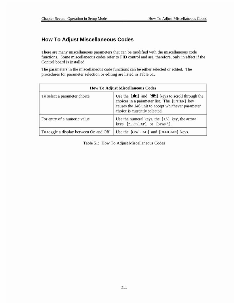
Chapter Seven: Operation in Setup Mode How To Adjust Miscellaneous Codes
211
How To Adjust Miscellaneous Codes
There are many miscellaneous parameters that can be modified with the miscellaneous codefunctions. Some miscellaneous codes refer to PID control and are, therefore, only in effect if theControl board is installed.
The parameters in the miscellaneous code functions can be either selected or edited. Theprocedures for parameter selection or editing are listed in Table 51.
How To Adjust Miscellaneous Codes
To select a parameter choice Use the [ ] and [ ] keys to scroll through thechoices in a parameter list. The [ENTER] keycauses the 146 unit to accept whichever parameterchoice is currently selected.
For entry of a numeric value Use the numeral keys, the [+/-] key, the arrowkeys, [ZERO/EXP], or [SPAN/.].
To toggle a display between On and Off Use the [ON/LEAD] and [OFF/GAIN] keys.
Table 51: How To Adjust Miscellaneous Codes

Code 1: How To Select Pressure/Volt/Current Chapter Seven: Operation in Setup Mode
212
Code 1: How To Select Pressure/Volt/Current
RIGHT DISPLAYLEFT DISPLAY
CLOSE SETUP
CODE
The code number isdisplayed and edited here.
In this example, the code number is 1.
MAIN DISPLAY
This display toggles between PrES (pressure) and Volt as in this example.
Note: If PrES is selected, the right display is blank.
When "Volt" is selected in the main display, this displayscrolls through HU (high voltage for cold cathodes), EC (emission current for hot cathodes), and IC, as in this example, (ion current for cold or hot cathodes).
Although this display can scroll through the three choices whenever Volt is selected in the main display, these choices are only relevant for an ion gauge.
Figure 66: Code 1 Display
This function determines whether pressure (PrES), or voltage (Volt), is shown in the maindisplay in Normal and Leakage Modes. The other three displays in Normal and Leakage Modescontinue to show pressure readings. The selections made in this function only effect the channelshown in the main display in Normal or Leakage Modes, and do not effect RS-232 functions.
If pressure (PrES) is selected in the main display in the Code 1 function, there are no parametersto edit. The pressure selection (PrES) is available for all gauge types.
The voltage (Volt) selection is also available for any gauge type, but the editable parameter in theCode 1 right display only applies to ion gauges. If voltage (Volt) is selected, the right displayflashes and there is an additional choice to make if an ion gauge is on the channel shown in themain display in Normal or Leakage Modes. If any other gauge type is on the main displaychannel (in Normal or Leakage modes), the choices available in the flashing right display areirrelevant. The right display scrolls through the following choices: high voltage (HU), ioncurrent (IC), and emission current (EC).

Chapter Seven: Operation in Setup Mode Code 1: How To Select Pressure/Volt/Current
213
The high voltage (HU) selection only applies to cold cathodes (CC). The high voltage, which isbeing applied to the cold cathode, is shown in the main display in Normal and Leakage Modes.This display can be used for several purposes, such as a diagnostic aid. For example, if the coldcathode is shorted, a very low voltage is displayed. If the pressure is very high (above 1 Torr),there may be enough gas available to prevent any high voltage conduction, therefore a full highvoltage is applied to the cold cathode (and shown in the main display).
Note If the HU (high voltage) selection is chosen for a hot cathode, then 0(zero) is shown in the main display in Normal and Leakage Modes.
The Ion Current (IC) selection applies to both hot and cold cathodes. Ion current is sometimesreferred to as the collector current. This display shows the current that is present at the collectorinside an ion gauge.
The Emission Current (EC) selection only applies to hot cathodes (HC). The emission current ismaintained at 1 milliampere when the pressure is below 1 x 10⁻⁴ Torr. At pressures higher than1 x 10-4 Torr, the emission current is maintained at 100 microamperes. This reduced emissioncurrent level helps to extend the life of a hot cathode gauge.
Note If the EC (Emission Current) selection is chosen for a cold cathode, a0 (zero) is shown in the main display in Normal and Leakage Modes.
1. Repeatedly press the [DISPLAY MODE] key until the 146 unit is in Setup Mode.
The system responds by scrolling through modes.
2. Use the arrow keys to scroll to the CODE legend.
The system responds by causing the left display to blink.
3. Enter the number 1 and press the [ENTER] key.
The system responds by displaying the appropriate parameters for code 1, and causingthe main display to blink.
4. Select PrES or Volt in the main display (the default is pressure).
A. If the display is correct, then press the [ENTER] key.
B. If the display is not correct, press one of the arrow keys, then press the [ENTER]key.
The system responds by accepting the parameter value.
Note If PrES is selected, the right window becomes blank and the Code 1function is finished.

Code 1: How To Select Pressure/Volt/Current Chapter Seven: Operation in Setup Mode
214
5. If Volt is selected, the right display blinks. Select HU (high voltage for cold cathodes),IC (ion current for ion gauges), or EC (emission current for hot cathodes).
Note This parameter is irrelevant if a gauge other than an ion gauge is selectedas the main display channel in Normal or Leakage Modes. Press the[ENTER] key.
A. If the display is correct for an ion gauge, press the [ENTER] key.
B. If the display is not correct for an ion gauge, use the [ ] and [ ] (arrow keys)to scroll to the correct selection, then press the [ENTER] key.
The system responds by accepting the configuration choice for the main display inNormal or Leakage Modes.

Chapter Seven: Operation in Setup Mode Code 2: How To Select Pressure Units
215
Code 2: How To Select Pressure Units
LEFT DISPLAY
CLOSE SETUP
TORR
CODE
The code number is displayed and edited here.In this example, the code number is 2.
MAIN DISPLAY
The arrow keys are used to scroll among the three choices for pressure units. The choices are: PASCAL, mBAR, and TORR (as in this example).
Figure 67: Code 2 Display
This function selects the units for pressure readings shown in all displays, and for all parameterentries. The choices are: Torr, Pascal, and millibar (mbar).
1. Repeatedly press the [DISPLAY MODE] key until the 146 unit is in Setup Mode.
The system responds by scrolling through modes.
2. Use the arrow keys to scroll to the CODE legend.
The system responds by causing the left display to blink.
3. Enter the number 2 and press the [ENTER] key.
The system responds by displaying the appropriate parameters for code 2. One of thethree pressure units available for the main display (Torr, Pascal, or mbar), blinks.
4. Use the arrow keys to select a pressure unit. The default is Torr.
A. If the display is correct, press the [ENTER] key.
B. If the display is not correct, scroll to the correct pressure unit (mBAR, TORR, orPASCAL) with an arrow key, then press the [ENTER] key.
The system responds by accepting the pressure unit.
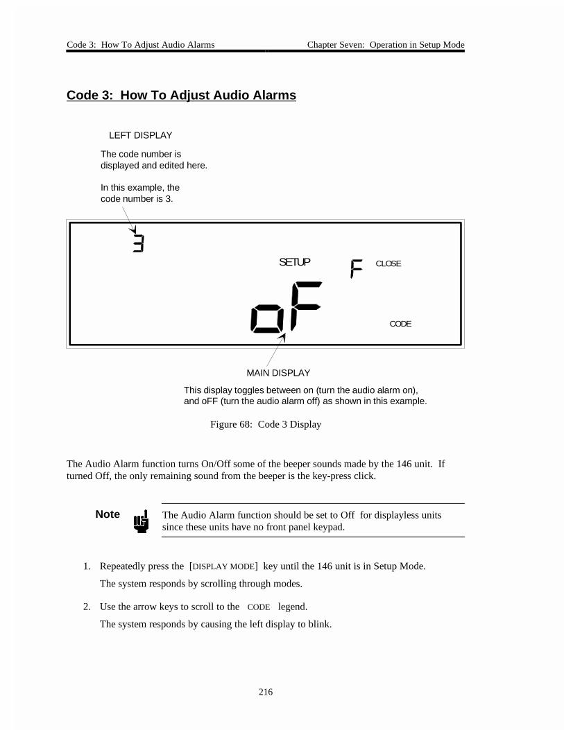
Code 3: How To Adjust Audio Alarms Chapter Seven: Operation in Setup Mode
216
Code 3: How To Adjust Audio Alarms
LEFT DISPLAY
CLOSE SETUP
CODE
The code number isdisplayed and edited here.
In this example, thecode number is 3.
MAIN DISPLAY
This display toggles between on (turn the audio alarm on),and oFF (turn the audio alarm off) as shown in this example.
Figure 68: Code 3 Display
The Audio Alarm function turns On/Off some of the beeper sounds made by the 146 unit. Ifturned Off, the only remaining sound from the beeper is the key-press click.
Note The Audio Alarm function should be set to Off for displayless unitssince these units have no front panel keypad.
1. Repeatedly press the [DISPLAY MODE] key until the 146 unit is in Setup Mode.
The system responds by scrolling through modes.
2. Use the arrow keys to scroll to the CODE legend.
The system responds by causing the left display to blink.

Chapter Seven: Operation in Setup Mode Code 3: How To Adjust Audio Alarms
217
3. Enter the number 3 and press the [ENTER] key.
The system responds by displaying the appropriate parameters for code 3, and causingthe main display to blink.
4. Select On or Off in the main display (the default is On).
A. If the display is correct, press the [ENTER] key.
B. If the display is not correct, press either the [ON/LEAD] (to turn sounds On), or[OFF/GAIN] (to turn sounds Off), then press the [ENTER] key.
The system responds by turning the alarm audio tone on or off.

Code 4: How To Adjust Alpha (PID Control) Chapter Seven: Operation in Setup Mode
218
Code 4: How To Adjust Alpha (PID Control)
LEFT DISPLAY
CLOSE SETUP
CODE
The code number isdisplayed and edited here.
In this example, the code number is 4.
MAIN DISPLAY
This display is used to edit thealpha value (for PID control).
Figure 69: Code 4 Display
This function requires the Control board.
Alpha is a control parameter that helps reduce the amplification of noise, which is an inherentproblem in PID control algorithm calculations. The noise itself is inherent in control systems.With a low Alpha value, the lead’s response time is slower. With a higher Alpha value, the leadmay be overly sensitive to noise. Unless there is a well understood reason for changing theAlpha value, it should remain at its default value of 20.
1. Repeatedly press the [DISPLAY MODE] key until the 146 unit is in Setup Mode.
The system responds by scrolling through modes.
2. Use the arrow keys to scroll to the CODE legend.
The system responds by causing the left display to blink.

Chapter Seven: Operation in Setup Mode Code 4: How To Adjust Alpha (PID Control)
219
3. Enter the number 4 and press the [ENTER] key.
The system responds by displaying the appropriate parameters for code 4, and causingthe main display to blink.
4. Enter an appropriate Alpha value, between 5 and 99 (the default is 20).
A. If the display is correct, press the [ENTER] key.
B. If the display is not correct, enter the correct value, then press the [ENTER] key.
The system responds by accepting the Alpha value.
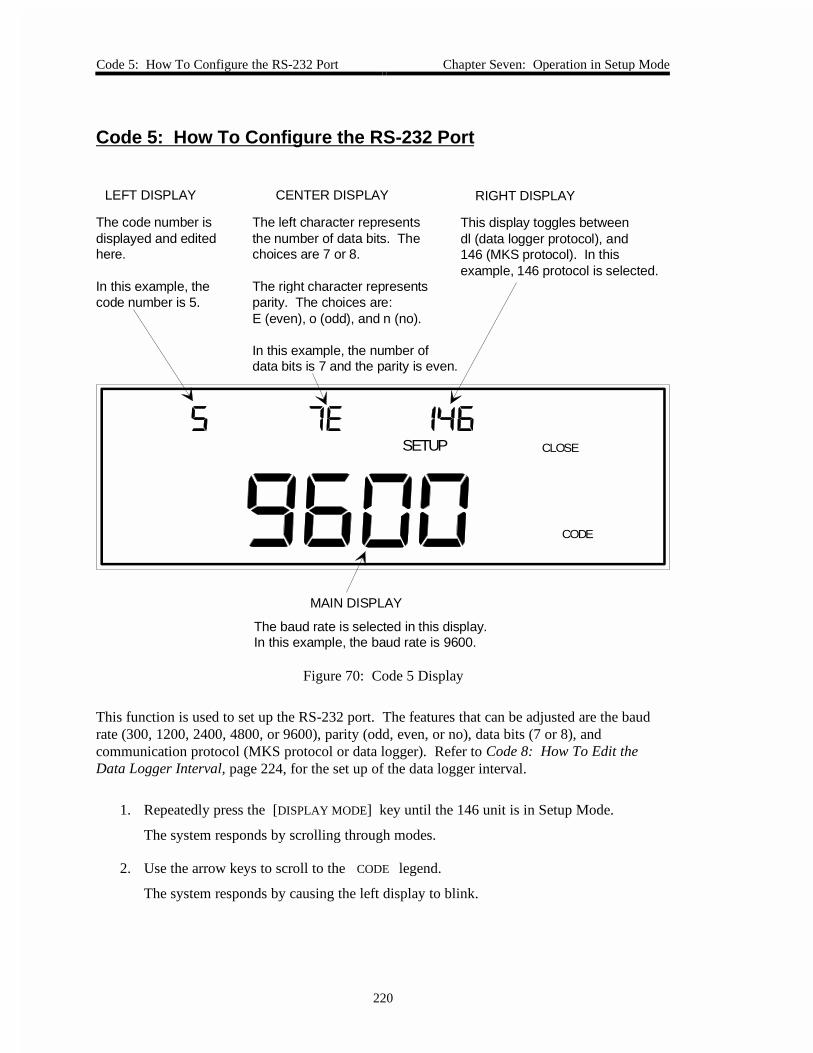
Code 5: How To Configure the RS-232 Port Chapter Seven: Operation in Setup Mode
220
Code 5: How To Configure the RS-232 Port
CENTER DISPLAY RIGHT DISPLAYLEFT DISPLAY
CLOSE SETUP
CODE
The code number isdisplayed and editedhere.
In this example, thecode number is 5.
The left character representsthe number of data bits. Thechoices are 7 or 8.
The right character representsparity. The choices are: E (even), o (odd), and n (no).
In this example, the number ofdata bits is 7 and the parity is even.
This display toggles betweendl (data logger protocol), and146 (MKS protocol). In this example, 146 protocol is selected.
MAIN DISPLAY
The baud rate is selected in this display.In this example, the baud rate is 9600.
Figure 70: Code 5 Display
This function is used to set up the RS-232 port. The features that can be adjusted are the baudrate (300, 1200, 2400, 4800, or 9600), parity (odd, even, or no), data bits (7 or 8), andcommunication protocol (MKS protocol or data logger). Refer to Code 8: How To Edit theData Logger Interval, page 224, for the set up of the data logger interval.
1. Repeatedly press the [DISPLAY MODE] key until the 146 unit is in Setup Mode.
The system responds by scrolling through modes.
2. Use the arrow keys to scroll to the CODE legend.
The system responds by causing the left display to blink.

Chapter Seven: Operation in Setup Mode Code 5: How To Configure the RS-232 Port
221
3. Enter the number 5 and press the [ENTER] key.
The system responds by displaying the appropriate parameters for code 5, and causingthe main display to blink.
4. Use the [ ] or [ ] key to select the correct baud rate (the default is 9600).
A. If the display is correct, press the [ENTER] key.
B. If the display is not correct, use the arrow keys to scroll to the correct baud rate, thenpress the [ENTER] key.
The system responds by accepting the baud rate, and causing the right parameter to blink.
5. Select the correct protocol (the default is MKS protocol).
A. If the display is correct, press the [ENTER] key.
B. If the display is not correct, use the arrow keys to select the correct protocol, thenpress the [ENTER] key. The choices for protocol are 146 (MKS Protocol) and dl(data logger).
The system responds by accepting the protocol, and causing the center display to blink.
6. Enter the number of data bits (7 or 8), and parity (even, odd, or no). The defaults are 7data bits, and even parity.
A. If the display is correct, press the [ENTER] key.
B. If the display is not correct, press the [7] or [8] key to enter the number of databits, then use the arrow keys to scroll through the three parity choices. Press the[ENTER] key.
The system responds by accepting the number of data bits and parity choices.

Code 7: How To Set the Display for Leakage Mode Chapter Seven: Operation in Setup Mode
222
Code 7: How To Set the Display for Leakage Mode
LEFT DISPLAY
CLOSE SETUP
CODE
The code number isdisplayed and edited here.
In this example, the code number is 7.
MAIN DISPLAY
Code 7 is used to determine what is shown in the main display when the 146 unit isin the Leakage Mode.
If a number between 1 and 60 is entered here, the main display in Leakage Mode willshow a leakage rate value. The number entered here represents the time base for the leakage rate calculations.
If a 0 is entered here, as in this example, the main display in Leakage Mode will showinstantaneous leakage. Instantaneous leakage is the difference between the current pressure reading and what the pressure reading was when Leakage Mode was entered.
Figure 71: Code 7 Display
This function determines what is shown in the main display in Leakage Mode. The two choicesare instantaneous leakage (enter 0 in this function), and leakage rate (enter a number between 1and 60 in this function). Instantaneous leakage is the pressure change since entering LeakageMode, and leakage rate is the actual rate of change of the pressure.
Chapter Seven: Operation in Setup Mode Code 7: How To Set the Display for Leakage Mode
223
1. Repeatedly press the [DISPLAY MODE] key until the 146 unit is in Setup Mode.
The system responds by scrolling through modes.
2. Use the arrow keys to scroll to the CODE legend.
The system responds by causing the left display to blink.
3. Enter the number 7 and press the [ENTER] key.
The system responds by displaying the appropriate parameters for code 7, and causingthe main display to blink.
4. Enter the leakage rate time base OR 0 for instantaneous leakage. The default value of 0configures the 146 unit for instantaneous leakage display.
A. If the display is correct, press the [ENTER] key.
B. If the display is not correct, enter 0 for instantaneous leakage, or a number from 1 to60 (seconds) to define the time base for leakage rate calculations, then press the[ENTER] key.
The system responds by accepting the value entered.

Code 8: How To Edit the Data Logger Interval Chapter Seven: Operation in Setup Mode
224
Code 8: How To Edit the Data Logger Interval
LEFT DISPLAY
CLOSE SETUP
CODE
The code number isdisplayed and edited here.
In this example, thecode number is 8.
MAIN DISPLAY
The data logger interval value is shown here. The value can range from 1 to 3600.
Figure 72: Code 8 Display
The data logger interval is the time period (from 1 to 3600 seconds), for the periodic output ofpressure readings. The default is 60 seconds. The pressure reading outputs are for all fourchannels, and are sent via the RS-232 port. The data logger interval may be selected at any time,regardless of the currently selected protocol. Refer to Code 5: How To Configure the RS-232Port, page 220, to select a protocol.
1. Repeatedly press the [DISPLAY MODE] key until the 146 unit is in Setup Mode.
The system responds by scrolling through modes.
2. Use the arrow keys to scroll to the CODE legend.
The system responds by causing the left display to blink.

Chapter Seven: Operation in Setup Mode Code 8: How To Edit the Data Logger Interval
225
3. Enter the number 8 and press the [ENTER] key.
The system responds by displaying the appropriate parameters for code 8, and causingthe main display to blink.
4. Enter the value for the data logger interval (1 through 3600 seconds, inclusive).
A. If the display is correct, press the [ENTER] key.
B. If the display is not correct, use the numeral keys to enter a value between 1 and3600, then press the [ENTER] key.
The system responds by accepting the data logger interval value.
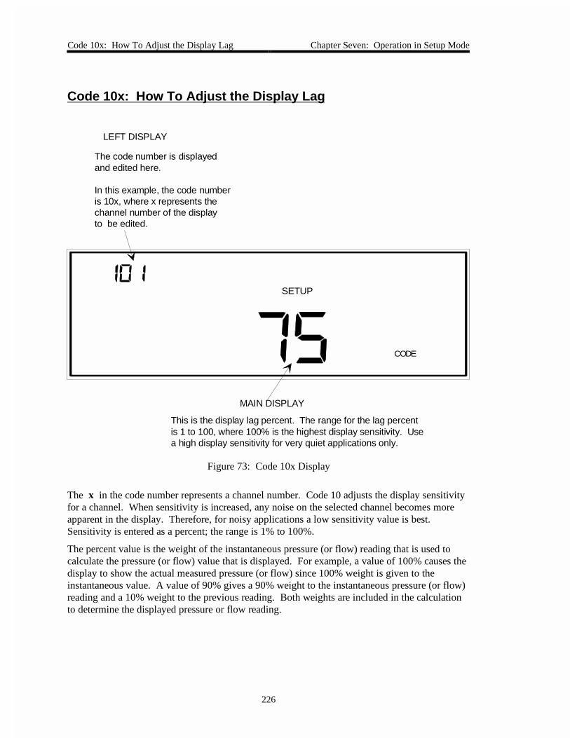
Code 10x: How To Adjust the Display Lag Chapter Seven: Operation in Setup Mode
226
Code 10x: How To Adjust the Display Lag
SETUP
CODE
LEFT DISPLAY
The code number is displayedand edited here.
In this example, the code numberis 10x, where x represents thechannel number of the displayto be edited.
MAIN DISPLAY
This is the display lag percent. The range for the lag percentis 1 to 100, where 100% is the highest display sensitivity. Usea high display sensitivity for very quiet applications only.
Figure 73: Code 10x Display
The x in the code number represents a channel number. Code 10 adjusts the display sensitivityfor a channel. When sensitivity is increased, any noise on the selected channel becomes moreapparent in the display. Therefore, for noisy applications a low sensitivity value is best.Sensitivity is entered as a percent; the range is 1% to 100%.
The percent value is the weight of the instantaneous pressure (or flow) reading that is used tocalculate the pressure (or flow) value that is displayed. For example, a value of 100% causes thedisplay to show the actual measured pressure (or flow) since 100% weight is given to theinstantaneous value. A value of 90% gives a 90% weight to the instantaneous pressure (or flow)reading and a 10% weight to the previous reading. Both weights are included in the calculationto determine the displayed pressure or flow reading.

Chapter Seven: Operation in Setup Mode Code 10x: How To Adjust the Display Lag
227
1. Repeatedly press the [DISPLAY MODE] key until the 146 unit is in Setup Mode.
The system responds by scrolling through modes.
2. Use the arrow keys to scroll to the CODE legend.
The system responds by causing the left display to blink.
3. Enter the number 10x (where x represents a channel number), and press the [ENTER]key.
The system responds by displaying the appropriate parameters for code 10x, and causingthe main display to blink.
4. Enter the sensitivity percent (the default is 100% for all sensors, and 25% for an MFC).
A. If the display is correct, press the [ENTER] key.
B. If the display is not correct, enter the correct sensitivity percent (1 through 100%),and then press the [ENTER] key.
The system responds by immediately adjusting the sensitivity for the selected channel.
Note 1. A 100% setting results in an instantaneous display of pressure orflow changes. Lower settings cause the displayed reading to lag theinstantaneous reading.
2. The lag is for display purposes and RS-232 pressure queries only.Real-time data is used for all other internal functions (such as relays,analog output, and control).

Code 11x: How To Turn Auto Zeroing ON or OFF Chapter Seven: Operation in Setup Mode
228
Code 11x: How To Turn Auto Zeroing ON or OFF
SETUP
CODE
RIGHT DISPLAYLEFT DISPLAY
The code number is displayedand edited here.
In this example, thecode number is 11x, where x represents the channel number forthe gauge to be zeroed.
This display toggles betweenon (enable the auto zero feature), andoFF (disable the auto zero feature), asin this example.
MAIN DISPLAY
This is the channel number of the reference channel,by which the selected channel (left display) is zeroed.
Figure 74: Code 11x Display
The x in the code number represents a channel number. When the Auto Zero feature is set upand enabled, one channel (defined as the reference channel) automatically zeros a second channel(defined as the selected channel). The selected channel is continually zeroed as long as thereference channel’s pressure is below the selected channel’s minimum resolution. The zeroingoperation is suspended whenever the reference channel’s condition is not measuring, and duringthe first 10 seconds after the reference channel is turned on.
The Auto Zero function overrides any user-defined zero previously set. If a new user-definedzero is then implemented, it overrides the effects of the Auto Zero function. If the Auto Zerofeature is disabled, the 146 unit uses the last zero defined (by Auto Zero or user-defined, and viathe front panel, RS-232, or rear panel remote zero).

Chapter Seven: Operation in Setup Mode Code 11x: How To Turn Auto Zeroing ON or OFF
229
1. Repeatedly press the [DISPLAY MODE] key until the 146 unit is in Setup Mode.
The system responds by scrolling through modes.
2. Use the arrow keys to scroll to the CODE legend.
The system responds by causing the left display to blink.
3. Enter the number 11x (where x represents the channel number of the gauge to bezeroed), and press the [ENTER] key.
The system responds by showing code 11x in the left display, and causing the maindisplay to blink.
4. Enter the reference channel number (the default is channel 1).
A. If the display is correct, press the [ENTER] key.
B. If the display is not correct, enter the correct reference channel number (1 through 4),and press the [ENTER] key.
The system responds by accepting the reference channel number and causing the rightdisplay to blink.
5. Select On or Off to Enable or Disable the Auto Zero function.
A. If the display is correct, press the [ENTER] key.
B. If the display is not correct, use the [ON/LEAD] or [OFF/GAIN] key to enable ordisable the Auto Zero function, then press the [ENTER] key.
The system responds by enabling or disabling the Auto Zero function for the specifiedreference and selected channels.

Code 12x: How To Adjust the Auto Power Control Chapter Seven: Operation in Setup Mode
230
Code 12x: How To Adjust the Auto Power Control
CENTER DISPLAY RIGHT DISPLAYLEFT DISPLAY
CLOSE SETUP
TORR
CODE
The code number isdisplayed and edited here.
In this example, thecode number is 12x, where x represents the channel numberof an ion gauge.
This is the number for thereference channel.
This display toggles betweenoFF (disable the auto power control)and on (enable the auto powercontrol). The auto power controlis enabled in this example.
MAIN DISPLAY
This is the shutoff pressure for the auto power control.
Figure 75: Code 12x Display
This function applies to ion gauges only.
The x in the code number represents the channel number associated with the ion gauge. Thisfunction is used to turn the power to an ion gauge on or off automatically with respect to apressure reading from a reference channel. The parameters which can be adjusted with thisfunction are the switchpoint (the pressure at which the gauge is powered off), selection of thereference channel, and enabling/disabling (turning on or off) the Automatic Power On/Off featureitself.

Chapter Seven: Operation in Setup Mode Code 12x: How To Adjust the Auto Power Control
231
1. Repeatedly press the [DISPLAY MODE] key until the 146 unit is in Setup Mode.
The system responds by scrolling through modes.
2. Use the arrow keys to scroll to the CODE legend.
The system responds by causing the left display to blink.
3. Enter the number 12x (where x represents the channel number for the ion gauge), andpress the [ENTER] key.
The system responds by displaying the appropriate parameters for code 12x, and causingthe main display to blink.
4. Enter the switchpoint pressure (the default is 0.001 Torr).
A. If the display is correct, press the [ENTER] key.
B. If the display is not correct, enter the correct switchpoint (0 through 35,000 Torr),and press the [ENTER] key.
The system responds by accepting the switchpoint value, and causing the right display toblink.
5. Select on or off in the right display (the default is off).
When this function is enabled (on), a channel can still be turned off manually. If turnedoff manually, a channel must be manually turned back on again before it can beautopowered.
A. If the display is correct, press the [ENTER] key.
B. If the display is not correct, use the [ON/LEAD] or [OFF/GAIN] key to enable ordisable the Automatic Power On/Off feature. Press the [ENTER] key to select theaction.
The system responds by enabling or disabling the Automatic Power On/Off feature forthe selected ion gauge channel, and causing the center display to blink.
6. Enter the reference channel number (the default is channel 1).
A. If the display is correct, press the [ENTER] key.
B. If the display is not correct, enter the correct reference channel number (1 through 4),then press the [ENTER] key.
The system responds by accepting the reference channel number.

Code 13x: How To Adjust Softstart for Control Chapter Seven: Operation in Setup Mode
232
Code 13x: How To Adjust Softstart for Control
RIGHT DISPLAYLEFT DISPLAY
CLOSE SETUP
CODE
The code number isdisplayed and edited here.
In this example, the codenumber is 13x, where x represents the number ofthe recipe whose softstartvalue is listed in the main display. In this example, the recipe number is 2.
This display toggles betweenoFF (disable the softstart speedfeature for the selected recipe),and on (enable the softstart speedfeature). This example shows the softstart speed enabled.
The status of the softstart feature,either enabled or disabled, applies to all recipes.
MAIN DISPLAY
The softstart speed value is edited here. The value entered here only effects the selected recipe.
Figure 76: Code 13x Display
This function requires the Control board.
The x in the code number represents a recipe number. The softstart speed is used whenadjusting the control valve, and is the time period for which the valve drive signal (and thus thevalve position) can go from 0 to 100%. Each recipe can have a different softstart speed thevalue shown in the main display applies to the selected recipe only. The right display indicatesthe status of the softstart function; whether it is enabled or disabled. The softstart status appliesto all recipes.

Chapter Seven: Operation in Setup Mode Code 13x: How To Adjust Softstart for Control
233
1. Repeatedly press the [DISPLAY MODE] key until the 146 unit is in Setup Mode.
The system responds by scrolling through modes.
2. Use the arrow keys to scroll to the CODE legend.
The system responds by causing the left display to blink.
3. Enter the number 13x (where x represents a recipe number), and press the [ENTER]key.
The system responds by displaying the appropriate parameters for code 13x, and causingthe main display to blink.
4. Enter the softstart speed value. The range is 1 to 99 seconds, and the default is 10seconds.
A. If the display is correct, press the [ENTER] key.
B. If the display is not correct, enter the correct softstart speed value (1 to 99), thenpress the [ENTER] key.
The system responds by accepting the softstart speed value, and causing the right displayto blink.
Note The softstart speed is common to all recipes.
5. Select On or Off in the right display (the default is Off).
A. If the display is correct, press the [ENTER] key.
B. If the display is not correct, use the [ON/LEAD] or [OFF/GAIN] key to enable ordisable the Softstart Control feature for the selected recipe, then press the [ENTER]key.
The system responds by enabling or disabling the Softstart Control feature for theselected recipe.

Code 14x: How To Select Control Settings Chapter Seven: Operation in Setup Mode
234
Code 14x: How To Select Control Settings
RIGHT DISPLAYLEFT DISPLAY
CLOSE SETUP
CODE
The code number isdisplayed and editedhere.
This number represents the code number and the number for the recipe which you want to edit. In this example, recipe 2 is selected for editing.
MAIN DISPLAY
This display toggles between rEV (reverse) anddir (direct) polarity.
Note: The polarity applies to all recipes, regardlessof which recipe is selected in the left display.
The input channel number for the controlloop of the selected recipe is entered here.
In this example, input channel 1provides the input in recipe 2.
Figure 77: Code 14x Display
This function requires the Control board.
The x in the code number represents a recipe number. This function selects the polarity (director reverse), and the input channel used for control. By changing the input channel and thenediting a recipe (refer to How To Edit Recipes, in the Operation in Tuning Mode chapter), adifferent input channel can be associated with each recipe.
Note The polarity feature applies to all recipes, not just the selected recipe.

Chapter Seven: Operation in Setup Mode Code 14x: How To Select Control Settings
235
1. Repeatedly press the [DISPLAY MODE] key until the 146 unit is in Setup Mode.
The system responds by scrolling through modes.
2. Use the arrow keys to scroll to the CODE legend.
The system responds by causing the left display to blink.
3. Enter the number 14x (where x represents a recipe number, the default recipe is 1),and press the [ENTER] key.
The system responds by displaying the appropriate parameters for code 14x, and causingthe main display to blink.
4. Select dir (direct) or rEV (reverse) polarity. The default is direct polarity.
For upstream control, the rEV (reverse) polarity is used to decrease the upstream valve’soutput as pressure rises in the process chamber. For downstream control, the dir (direct)polarity is used to increase the downstream valve’s output as pressure rises in the processchamber. This polarity setting applies to all recipes.
A. If the display is correct, press the [ENTER] key.
B. If the display is not correct, use the arrow keys to select the correct polarity direction,then press the [ENTER] key.
The system responds by accepting the polarity direction, and causing the right display toblink.
Note Although the polarity can be modified within any recipe, only the lastentered polarity is saved and used for all recipes.
5. Enter the input channel number (the default is input channel 1).
The input channel provides the signal that is fed into the control loop. The channelchosen becomes associated with the selected recipe. The default entry for all recipes isinput channel 1.
Note The two Dual Channels cannot be used as input channels.
Either one of the two channels used in Dual Channel display, however,can be used as an input channel.
A. If the display is correct, press the [ENTER] key.
B. If the display is not correct, enter the correct channel number (1 through 4), thenpress the [ENTER] key.
The system responds by accepting the input channel.

Code 15x: How To Set Up the Analog Set Point Chapter Seven: Operation in Setup Mode
236
Code 15x: How To Set Up the Analog Set Point
CENTER DISPLAYLEFT DISPLAY
CLOSE SETUP
TORR
CODE
The code number isdisplayed and editedhere.
This number representsthe code number and the recipe number to be modified. In this example, the code number is 15 and recipe number 3 is selected for editing.
MAIN DISPLAY
This is the full scalevoltage used to set the upper limit of the analoginput voltage range. This value is used forall recipes.
This is where the full scale set point pressure is edited. The value entered here only effectsthe selected recipe.
RIGHT DISPLAY
This display toggles betweenon (enable the analog set pointfeature), and oFF (disable thefeature). This example shows theanalog set point disabled.
If the analog set point feature isturned off, the 146 unit defaults to a digital set point input.
Figure 78: Code 15x Display
This function requires the Control board.
The x in the code number represents a recipe number. Each recipe can be configured with adifferent full scale set point pressure value, set in the main display. The set point signal input isconfigured as an analog or digital input in the right display of this function. All parametersadjusted in this function except the parameter edited in the center display (full scale voltage to setthe upper limit of the analog input voltage range), are specific to each recipe. The full scalevoltage for analog input is common to all recipes.
The analog set point input is a linear input sent through the lower connector on the Controlboard. The input corresponds to an analog set point value (refer to Figure 79, page 237). Byadjusting the analog set point input voltage, the analog set point is changed. The default settingsare for an analog input of 0 Volts to correspond to a 0 set point, and for a 5 Volt input to define a

Chapter Seven: Operation in Setup Mode Code 15x: How To Set Up the Analog Set Point
237
1000 Torr set point. The acceptable analog input voltage range is 0 to 10 Volts, with the defaultfull scale voltage set at 5 Volts. The full scale set point pressure can range from 0 to 100,00Torr; 1000 Torr is the default. The ability to define the set point through an analog input isdisabled by default.
5
Analog Set Point (Torr)
Analog set point is a voltage input thatdetermines the analog set point.
Input
Voltage
2.5
0
0 500 1000
Figure 79: Graph Showing Analog Set Point Defaults
The lower and upper points of the analog input voltage range can be altered in Normal andLeakage Modes, however to do so the current analog input voltage must be altered. To changethe upper point (not the lower point), independent of the current analog input, use Code 15x.
1. Repeatedly press the [DISPLAY MODE] key until the 146 unit is in Setup Mode.
The system responds by scrolling through modes.
2. Use the arrow keys to scroll to the CODE legend.
The system responds by causing the left display to blink.
3. Enter the number 15x (where x represents the recipe number), and press the[ENTER] key.
The system responds by displaying the appropriate parameters for code 15x, and causingthe main display to blink.
4. Enter the full scale set point pressure value from 0 to 100,000 Torr (the default is 1000Torr).
A. If the display is correct, press the [ENTER] key.

Code 15x: How To Set Up the Analog Set Point Chapter Seven: Operation in Setup Mode
238
B. If the display is not correct, enter the correct full scale set point, then press the[ENTER] key.
The system responds by accepting the full scale pressure value, associating it withthe selected recipe, and causing the right display to blink.
5. Select On or Off in the right display (the default is Off) to enable/disable the Analog SetPoint feature.
A. If the display is correct, press the [ENTER] key.
B. If the display is not correct, use the [ON/LEAD] (to enable), or [OFF/GAIN](to disable) key, the analog set point feature for the selected recipe, then press the[ENTER] key.
The system responds by enabling or disabling the analog set point feature for the selectedrecipe, and causing the center display to blink.
Note If the analog set point feature is turned off in a recipe, the system defaultsto a digital set point input for that recipe. The digital set point can beentered via the front panel or RS-232 communications.
6. Enter the full scale voltage to set the upper limit of the analog input voltage range (thedefault is 5 Volts).
A. If the display is correct, press the [ENTER] key.
B. If the display is not correct, enter the correct full scale voltage (up to 10 Volts), andpress the [ENTER] key.
The system responds by accepting the full scale voltage value and using it to set theupper point on the analog set point slope.
The slope of the line in the analog voltage input versus analog set point graph determinesthe value of the analog set point. Changing the value of the upper point on the linechanges the slope of the line. Figure 39, page 143, illustrates how the Analog Set Pointfeature determines set point, and Refer to Figure 40, page 144, shows how adjusting thelower or upper points of the analog input voltage range effect the set point value.
Note 1. The full scale voltage can also be modified in Normal and LeakageModes. Refer to How To Set Lower and Upper Points for Analog SetPoint Calculations in Normal and Leakage Modes.
2. Although the full scale voltage can be modified within any recipe,only the last entered voltage is saved and used for all recipes.

Chapter Seven: Operation in Setup Mode Code 16x: How To Set the HC Shutoff Features
239
Code 16x: How To Set the HC Shutoff Features
RIGHT DISPLAY
This display shows the state of the internal fast rate-of-rise shutoff feature. This feature is built into your 146 hardware.
The screen lists off for disabled or on for enabled.
TORR
SETUP
CODE
LEFT DISPLAY
The code number is displayedand edited here.
In this example, the codenumber is 16x, where x represents the channelnumber of the hot cathode.
MAIN DISPLAY
This is the hot cathode high pressure shutoff limit.
Figure 80: Code 16x Display
This function applies to hot cathode gauges only.
The x in the code number represents the channel number for the hot cathode. The user-definedhigh pressure shutoff value is used to protect a hot cathode from potential damage if the pressurerises too high. When the gauge is turned off with this function, three dots ( . . . ) appear in thehot cathode channel display. The gauge must be turned back on manually.
The internal fast rate-of-rise shutoff feature is built into the hardware of the 146 unit. It monitorsthe pressure signal for a rapid increase. Most gauges are shut down around 10 to 100 mT in theevent of a rapid pressure rise, and the error code E1 appears in the hot cathode channel display.To turn the hot cathode back on, the channel must first be turned off. When turned off, three dots( . . . ) appear in the hot cathode channel display. The channel can then be turned back on.

Code 16x: How To Set the HC Shutoff Features Chapter Seven: Operation in Setup Mode
240
1. Repeatedly press the [DISPLAY MODE] key until the 146 unit is in Setup Mode.
The system responds by scrolling through modes.
2. Use the arrow keys to scroll to the CODE legend.
The system responds by causing the left display to blink.
3. Enter the number 16x (where x represents the hot cathode channel number), andpress the [ENTER] key.
The system responds by displaying the appropriate parameters for code 16x, and causingthe main display to blink.
4. Enter the hot cathode high pressure shutoff value.
The default value is 1 x 10⁻³ Torr and the range is 1.001 x 10⁻⁵ Torr to 1 Torr.
A. If the display is correct, press the [ENTER] key.
B. If the display is not correct, enter the correct high pressure shutoff value, then pressthe [ENTER] key.
The system responds by accepting the high pressure shutoff value.
5. Set the internal fast rate-of-rise shutoff feature. The factory configuration has this featuredisabled. To enable the feature, press the [ON/LEAD] key.
Note Only enable the internal fast rate-of-rise shutoff feature if your pressuresignal is stable. A noisy pressure signal may exceed the rate-of rise-valuemomentarily causing the 146 unit to turn off the hot cathode gauge
Caution Enabling the internal fast rate-of-rise shutoff feature will make the146 unit more sensitive to electrostatic discharge (ESD). Transientsignals may be interpreted as a fast pressure change that would causethe 146 unit to turn off power to the hot cathode gauge. When thisfeature is enabled, the 146 unit DOES NOT COMPLY with theLow-Voltage Directive (EN61010-1: 1993) requirement for CEcertification.
The 146 unit is configured at the factory with this feature disabled.
A. If the display is correct, press the [ENTER] key.
B. If the display is not correct, press the [ON/LEAD] key to enable or the [OFF/GAIN]key to disable the feature.
The system responds by enabling or disabling the internal fast rate-of-rise shutoff feature.

Chapter Seven: Operation in Setup Mode Code 17x: How To Set Up the MFC
241
Code 17x: How To Set Up the MFC
SETUP
CODE
CENTER DISPLAY RIGHT DISPLAYLEFT DISPLAY
The code number isdisplayed and editedhere.
In this example, the code number is 17x,where x representsthe channel numberof a mass flow controller.
This is the number for theco-channel (only usedwhen the MFC is set upin the Totaling modeof operation).
This display selects the mode ofoperation, either set point (SP),totaling (to), or ratio (rA).
MAIN DISPLAY
This is the MFC set point for use in either theset point or totaling modes of operation. For theratio mode, this entry is the ratio parameter.
Note: The unit for the set point entry is sccm.
Figure 81: Code 17x Display
The x in the code number represents the channel number for the mass flow controller (MFC).The three modes of operation for an MFC are Set Point, Totaling, and Ratio. The differentmodes are indicated by codes in the right display: SP for Set Point; to for Totaling; and rAfor Ratio.

Code 17x: How To Set Up the MFC Chapter Seven: Operation in Setup Mode
242
Set Point Mode of Operation
When using the Set Point mode of operation, the 146 unit sends out a voltage corresponding to auser-defined set point (in sccm). The set point voltage takes into account any zero offset whichmay have resulted from zeroing the MFC, to ensure that the MFC controls to the desired flowrate. The 146 unit can operate up to four MFCs. Each MFC operating in Set Point mode has aset point value assigned to it.
Totaling Mode of Operation
When using the Totaling mode of operation, two MFCs operate in conjunction with each other.One MFC (defined as the co-channel), operates according to a fixed set point. The other MFC,defined as the totaling MFC, adjusts its output voltage to maintain a user-defined total flow rate(set point) for the system. For example, you want to maintain a flow rate of 100 sccm. Enter aset point of 100 sccm and set the co-channel to a fixed flow rate of 20 sccm. The totaling MFCwill subtract 20 (flow rate of the co-channel) from 100 (the set point) and adjust its voltage toproduce a flow rate of 80 sccm. Therefore, the total flow rate will be 100 (20 + 80). As with theSet Point mode of operation, the 146 accounts for any zero offset.
Ratio Mode of Operation
In the Ratio mode of operation, the 146 instrument is capable of controlling up to four MFCssimultaneously. The 146 uses a pressure control signal (PCS), or a total flow signal, as feedback.The Ratio mode uses a logical control channel to execute the PID control algorithm and achievethe desired gas ratio. The logical control channel (control channel 0) is present even if noControl board is installed. The 146 unit calculates the control signal to correct the gas ratio andsends the signal to all MFCs configured for Ratio control.
Two possible control methods exist within Ratio mode: control with a pressure measuringcontrol channel, and control with a flow measuring (MFC) control channel.
The ratio controllers maintain the gas ratio, and the 146 instrument maintains the absolutepressure by controlling the total flow.
Essentially, the Ratio mode of operation scales and proportions the 0 to 10 Volt control signalamong the MFCs configured for Ratio mode, based on their chosen ratio set points. The setpoints can range from 0 to 200%. Since most MFCs accept a 0 to 5 Volt signal, the controlsignal for a given MFC is always scaled by ½, then multiplied by the ratio set point percent:
MFC control signal = ½ (control signal)(ratio set point %/100)
Example 1: Assume you have two MFCs configured for ratio control and you change thecontrol set point to 100%. Each MFC has a set point of 50%. The PID control algorithmdetermines that full scale flow is required to meet the new set point, so the equation becomes:
MFC control signal = ½ (10 Volts)(50%/100) = 2.5 Volts
Each MFC would receive a 2.5 Volt control signal.

Chapter Seven: Operation in Setup Mode Code 17x: How To Set Up the MFC
243
Example 2: If the control algorithm determined that the change necessitates a 60% flow rate, theequation becomes:
MFC control signal = ½ (6 Volts)(50%) = 1.5 Volts
Each MFC would receive a 1.5 Volt control signal.
Example 3: Assume that you have three MFCs with ratio set points of 10%, 30%, and 60%.The PID algorithm determines that a 75% control signal is required to meet the control set point.The 146 instrument calculates the control signal for each MFC:
MFC 1 = ½ (7.5 Volts)(10%) = 0.375 Volts
MFC 2 = ½ (7.5 Volts)(30%) = 1.125 Volts
MFC 3 = ½ (7.5 Volts)(60%) = 2.25 Volts
The total control signal is 3.75 Volts (75% of 5 Volts).
Pressure Measuring Control
When using a pressure measuring control channel, up to three MFCs can be configured tofunction in a pressure control loop. In this case, the total flow of the three MFCs determines thepressure, however, the percent of gas through each MFC remains constant. For example, if theratio set points for the three MFCs are 30%, 30%, and 40% and pressure rises in the system, thegas flow through each MFC decreases but the 30%, 30%, 40% relationship remains intact.
Flow Measuring Control
When using a flow measuring control channel, an MFC channel is selected as the control inputchannel. The Ratio mode MFCs follow the controlling MFC with their respective proportions offlow as set by their Ratio mode set points.

Code 17x: How To Set Up the MFC Chapter Seven: Operation in Setup Mode
244
1. Repeatedly press the [DISPLAY MODE] key until the 146 unit is in Setup Mode.
The system responds by scrolling through modes.
2. Use the arrow keys to scroll to the CODE legend.
The system responds by causing the left display to blink.
3. Enter the number 17x (where x represents an MFC channel number), and press the[ENTER] key.
The system responds by displaying the appropriate parameters for code 17x, and causingthe main display to blink.
4. Enter the set point flow rate (the range is ± 10% of the MFC range) if using Set Point orTotaling mode, or enter the ratio set point percent (0 to 200%) if using Ratio mode.
A. If the display is correct, press the [ENTER] key.
B. If the display is not correct, enter the correct set point, then press the [ENTER] key.
The system responds by accepting the set point value and causing the right display toblink.
5. Use the arrow keys to scroll through the modes of operation ( SP for Set Point, to forTotaling, and rA for Ratio)
A. If the display is correct, press the [ENTER] key.
B. If the display is not correct, press an arrow key and then press the [ENTER] key.
If Set Point (SP) is selected, no more input is required for code 17x. When the selectedMFC is controlling, it controls according to the new set point.
If Totaling (to) is selected, the system responds by displaying a blinking channel numberin the center display.
If Ratio (rA) is selected, no additional input is required. The MFC will control to a flowrate equal to the PID output signal times the ratio selected the main display.
6. If Totaling mode (to) was selected, enter the channel number for the co-channel (it mustbe an MFC).
A. If the display is correct, press the [ENTER] key.
B. If the display is not correct, enter the correct co-channel number, and press the[ENTER] key.
The system responds by accepting the co-channel number. When the totaling MFCis controlling, its output voltage is adjusted in order to accommodate the output ofthe co-channel MFC, and to control with a total flow rate equal to the user-definedset point.

Chapter Seven: Operation in Setup Mode Code 18x: How To Select the Convection Gauge
245
Code 18x: How To Select the Convection Gauge
LEFT DISPLAY
The code number is displayed and edited here.
In this example, the code number is 18x,where x representsthe channel numberof a convection gauge.
MAIN DISPLAY
This displays toggles between Cn for a Convectron and CP for a CEP gauge.
SETUP
CODE
Figure 82: Code 18x Display
The 146 instrument now supports the HPS Convection Enhanced Pirani (CEP) gauge. Thisgauge replaces the Alcatel PI 3C gauge.
When the 146 instrument detects the type of gauge attached to each channel, it can distinguishbetween a Pirani and convection gauge. However, it cannot distinguish between the twoconvection gauges: the Granville-Phillips Convectron® gauge and the HPS CEP gauge. Thedefault convection gauge selection is the Convectron gauge. If you are using a CEP gauge, youmust change the convection gauge type to CEP. No additional commands are required if you areusing either a Convectron gauge or a standard Pirani gauge.
Note Turn the channel off before you attempt to change the convection gaugetype. The command will not be accepted if the channel is on.

Code 18x: How To Select the Convection Gauge Chapter Seven: Operation in Setup Mode
246
1. Repeatedly press the [DISPLAY MODE] key until the 146 unit is in the Setup Mode.
The system responds by scrolling through the modes.
2. Use the arrow keys to scroll to the CODE legend.
The system responds by causing the left display to blink.
3. Enter the number 18x (where x represents the convection gauge channel number), andpress the [ENTER] key.
The system responds by displaying the abbreviation for the type of convection gaugeinstalled and blinking the main display entry.
4. Use the arrow keys to toggle between the convection gauge abbreviations:
Cn for a Convectron gauge
CP for a CEP gauge
A. If the display is correct, press the [ENTER] key.
B. If the display is not correct, press an arrow key to toggle to the correct gauge typeand then press the [ENTER] key.
The system responds by accepting the new convection gauge type.

Chapter Eight: Operation in Control Mode General Information
247
Chapter Eight: Operation in Control Mode
General Information
Toggle in and out of this mode by pressing the [CONTROL MODE] key.
Note The Control Mode functions only if a Control board is installed.
Figure 83, page 248, shows an example of the Control Mode window. Control Mode functionsare used to operate a valve in one of several ways:
Manual
Open
Close
Hold
Auto
The HOLD selection halts the valve in its current position. The AUTO selectionautomatically controls the position of the valve according to one of four user-defined recipes.
Control Mode is Used when Performing the Following Procedures
Control Mode Functions
Select an Active Recipe The active recipe is used to control the valvewhen the AUTO feature is selected.
Valve Positions
Move the valve to open (OPEN) The valve output signal is set to 100%.
Control the valve automatically (AUTO) The valve is controlled according to aselected recipe.
Move the valve to closed (CLOSE) The valve output signal is set to zero.
Hold the valve in its current position (HOLD) This feature freezes the valve in its currentposition.
Move the valve to a preset position (MANUAL) The valve is moved to a preset position. Thepreset position is entered in Tuning Mode.
Table 52: Control Mode Functions

General Information Chapter Eight: Operation in Control Mode
248
TorrOPENAUTOCLOSEHOLDMANUAL
TORR
4
This is the current valve position, expressed asa percent of the valvecontrol signal output.
This example shows asetting of 20.1% of thevalve control signal output.
The active recipe isselected in this display.
In this example, recipe4 is the active recipe.
The set point for the activerecipe is entered here. OR,if an analog set point is beingused, the analog set point valueis displayed here.
LEFT DISPLAY CENTER DISPLAY RIGHT DISPLAY
The current pressure reading from the control channel is displayed here.
MAIN DISPLAYThis is a list of valve control positions. The arrow keys on the keyboard scroll the selecting arrow through the list of valve positions.
In this example, AUTO is selected, so the 146 unit will control according to the control parameters in the active recipe (recipe 4 in this example).
Figure 83: Control Mode Screen

Chapter Eight: Operation in Control Mode General Information
249
The Deviation Indicator
In Control Mode there is a deviation indicator which indicates the deviation of the systempressure from set point. The deviation from set point is displayed approximately every one-thirdsecond (this is how often the LCD screen is refreshed). The deviation indicator is enabled only ifthe 146 unit is operating with the Auto feature turned on (refer to How To Set the Valve to AUTOPosition, page 252).
There are ten deviation indicator segments on the front panel (refer to Figure 12, page 43). Fivesegments represent pressure over set point and five represent pressure under set point. The 146unit determines the segment(s) to illuminate according to the following formula:
Deviation = Psp
where: P = pressuresp = set point
Each segment represents a different percent of deviation as shown in Figure 84.
Deviation Percent Error
Segments
1.2 to < 1.95
1.05 to < 1.2
1.01 to <1.05
1.002 to < 1.01
None = 0.998 to <1.002
0.99 to < 0.998
0.95 to < 0.99
0.80 to <0.95
0.05 to < 0.80
<0.05
> +95%
+20 to 95%
+5 to 20%
+1 to 5%
+0.2 to 1%
0.2%
-0.2 to 1%
-1 to -5%
-5 to -20%
-20 to -95%
> -95%
±
1.95≥
Figure 84: Deviation Indicator

General Information Chapter Eight: Operation in Control Mode
250
If the system is operating far below set point, there will be a large change in pressure betweenscreen refreshing because the system will be quickly moving towards set point. Within theone-third second time frame, the deviation could range from -22% (at the beginning of the timeframe), to -4% (at the end of the time frame). In this case, the middle three segments in thelower half of the deviation indicator light up (refer to Figure 84, page 249).
Another example is when the pressure oscillates above and below set point. Upper and lowerdeviation indicator segments light up to indicate over and under pressure readings. In effect, thedeviation indicator provides similar information to that provided by an oscilloscope. If theoscillation continues, it is possible that reducing the Gain setting may improve system stability.When the system does stabilize, none of the deviation indicators are lit.
When the Set Point is 0:
If the set point is 0 and the pressure reading is 0, no segments light up.
If the set point is 0 and the pressure is above 0, the uppermost segment lights up.
If the set point is 0 and the pressure is below 0, the lowermost segment lights up.
The Rear Panel Override Indicator
The Valve Position parameters (Open, Auto, Close, Hold, and Manual), and the Active Recipeparameter can be selected through the front panel keyboard. The Open, Close, Manual, andActive Recipe parameters can also be selected through the bottom connector on the Controlboard (digital control lines). A front panel selection can be overridden by a rear panel digitalinput. A small arrow appears to the left of the parameter when a rear panel override occurs.Refer to Figure 12, page 43, to see where the Control Mode parameters and their associatedoverride arrows are located.
For example, if the Valve Position parameter AUTO is selected with the front panel keypad, theAUTO legend is displayed in the front panel window. If the Valve Position parameter CLOSE
is selected through the rear panel, this selection overrides the front panel keypad selection. TheAUTO legend continues to be displayed, but the CLOSE legend is also displayed.Additionally, a small arrow is shown to the left of the CLOSE legend, to indicate a rear paneloverride is in effect.
An Active Recipe override is indicated by displaying a small arrow next to the AUTO legend.For example, if the 146 unit is currently operating with the AUTO parameter selected, and theactive recipe is recipe 1, the AUTO legend is displayed. If the active recipe is changed to recipe2 through the rear panel, the AUTO legend remains lit, but a small arrow now appears to theleft of it.

Chapter Eight: Operation in Control Mode How To Select the Active Recipe
251
How To Select the Active Recipe
Up to four user-defined recipes, each containing gain, lead, and set point values, can be edited inTuning Mode. This function determines which of the four recipes is the active recipe. Theactive recipe is the recipe that regulates the control valve when the AUTO feature is selected inControl Mode.
1. Press the [CONTROL MODE] key.
The system responds by entering Control Mode.
2. Press the [1], [2], [3], or [4] key to select a recipe (the default is recipe 1).
The system responds by making the selected recipe the active recipe. The selected recipenumber appears next to the letter A (for Active) in the center display.
How To Set the Valve to OPEN Position
This command sequence adjusts the valve control signal output to full output. Generally, thismeans the valve goes to a full open position.
1. Press the [CONTROL MODE] key.
The system responds by entering Control Mode.
2. Scroll to the OPEN legend with the arrow keys.
The system responds by scrolling the small arrow in the window display.
3. Press the [ENTER] key.
The system responds by changing the valve control signal output to 100 %. As a result,the valve’s position generally goes to full open.

How To Set the Valve to AUTO Position Chapter Eight: Operation in Control Mode
252
How To Set the Valve to AUTO Position
This feature operates the valve according to the control parameters in the active recipe. Thecontrol parameters include gain, lead, and set point.
1. Press the [CONTROL MODE] key.
The system responds by entering Control Mode.
2. Scroll to the AUTO legend with the arrow keys.
The system responds by scrolling the small arrow in the window display.
3. Press the [ENTER] key.
The system responds by operating the valve according to the control parameters of theactive recipe.
How To Set the Valve to CLOSE Position
This command sequence adjusts the valve control signal output to 0. Generally, this means thevalve goes to a fully closed position.
1. Press the [CONTROL MODE] key.
The system responds by entering Control Mode.
2. Scroll to the CLOSE legend with the arrow keys.
The system responds by scrolling the small arrow in the window display.
3. Press the [ENTER] key.
The system responds by setting the valve control signal output to 0. As a result, thevalve’s position generally goes to full close.

Chapter Eight: Operation in Control Mode How To Set the Valve to HOLD Position
253
How To Set the Valve to HOLD Position
This function is used to hold the valve control signal output at its current value. This has theeffect of holding the control valve in its current position. The valve position can then bemodified in Tuning Mode by changing the valve control signal output. Once changed, the newvalve position is maintained as a fixed position.
1. Press the [CONTROL MODE] key.
The system responds by entering Control Mode.
2. Scroll to the HOLD legend with the arrow keys.
The system responds by scrolling the small arrow in the window display.
3. Press the [ENTER] key.
The system responds by holding the valve control signal output at its current value.
How To Set the Valve to MANUAL Position
When this feature is evoked, the valve control signal output immediately changes to the valueselected in the How To Adjust Preset, in the Operation in Tuning Mode chapter. This has theeffect of altering the valve position until it is held at the position dictated by the preset value.
Note The rate at which the valve changes position is a function of the valvedynamics. The valve control signal output, and the 146 window displays,however, are changed immediately when the MANUAL feature isevoked.
1. Press the [CONTROL MODE] key.
The system responds by entering Control Mode.
2. Scroll to the MANUAL legend with the arrow keys.
The system responds by scrolling the small arrow in the window display.
3. Press the [ENTER] key.
The system responds by immediately changing the valve control signal output to the valueentered in the preset function (refer to How To Adjust Preset, in the Operation in Tuning Modechapter).

How To Set the Valve to MANUAL Position Chapter Eight: Operation in Control Mode
254
This page intentionally left blank.

Chapter Nine: RS-232 Communications General Information
255
Chapter Nine: RS-232 Communications
General Information
The 146 unit is programmed to communicate with any host computer equipped with an RS-232serial port, and an RS-232 cable. The 146 instrument is configured as a DTE (Data TerminalEquipment) device, and uses a 9-pin male Type “D” IBM AT® configuration connector. Allstandard baud rates are accepted up to a baud rate of 9600. The 146 unit supports 7 or 8 bit dataformat, and any parity option (even, odd, or no). Commands sent via the RS-232 port allow fullcontrol of all 146 functions remotely. The parameters, and inquiries of parameters and readings,are both changeable.
RS-232 Communication Parameters
Parameter Initial Setting Options
Baud Rate 9600 300, 1200, 2400, 4800
Parity Even Odd, No
Number of Data Bits 7 8
Number of Stop Bits 1 Cannot be changed
End-of-Line Delimiter CR Cannot be changed
Protocol MKS Data Logger
Table 53: RS-232 Communication Parameters
Refer to Code 5: How To Configure the RS-232 Port, in Chapter Seven: Operation in SetupMode, for instructions on changing the communication parameters.
Note The communication parameters cannot be changed on a displayless 146unit.
How To Establish RS-232 Communications
Use the RS-232 connector on the rear panel to connect the 146 unit to your computer. Be sure touse the correct RS-232 cable.
Displayless units have an RS-232 connector on both the front and rear panels. Note that theRS-232 cable used for rear panel communications (refer to Table 32, page 77, for the properMKS part number) is not the same as the RS-232 cable used for the front panel (MKS p/nCB146-21).

General Information Chapter Nine: RS-232 Communications
256
MKS RS-232 Protocol
Command formats sent by the Host computer
Messages sent by the host computer to the 146 unit are either commands that instruct theinstrument to change an operating parameter, or requests that prompt the instrument to reportstatus information. The following table shows the format of RS-232 command messages that aresent from the host computer to the 146 unit. Specific commands are described in CommandMessages, page 259.
Note Use UPPERCASE letters for all messages. Messages entered inlowercase will generate an “invalid command” error.
Channel Numbering
The 146 unit can hold up to five plug-in boards and supports up to four input channels and oneprocess control channel. The input channels include capacitance manometers, Pirani gauges,convection gauges, hot cathode gauges (maximum of two), cold cathode gauges, thermocouplegauges, and mass flow controllers. The unit supports one process control channel. The analogoutput(s) does not require channel space. The channel numbering sequence depends on theposition of the plug-in board in the 146 unit. The input and output channels are numberedseparately.
The 146 unit assigns the channel numbers upon power up. For example, using the boardconfiguration shown in Figure 4, page 27, the Pirani board in slot 1 would be assigned inputchannel 1 (upper connector) and input channel 2 (lower connector). The Capacitance Manometerboard in the adjacent slot would use input channel 3. The Cold Cathode board in slot 3 would beassigned input channel 4. The Auxiliary Output board in slot 4 provides two additional relaysand two additional analog outputs. Neither relays nor analog outputs are allocated channelnumbers. The Control board in slot 5 would use the one process control channel.
If the Capacitance Manometer board is removed from slot 2, the Cold Cathode board (previouslyinput channel 4) would become input channel 3, and all user defined parameters for the coldcathode would change to default values. The parameters associated with input channels 1 and 2remain unchanged because the channel numbers assigned to the Pirani board would haveremained unchanged.
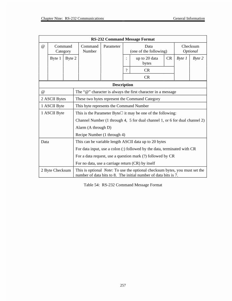
Chapter Nine: RS-232 Communications General Information
257
RS-232 Command Message Format
@ CommandCategory
CommandNumber
Parameter Data(one of the following)
ChecksumOptional
Byte 1 Byte 2 : up to 20 databytes
CR Byte 1 Byte 2
? CR
CR
Description
@ The “@” character is always the first character in a message
2 ASCII Bytes These two bytes represent the Command Category
1 ASCII Byte This byte represents the Command Number
1 ASCII Byte This is the Parameter Byte it may be one of the following:
Channel Number (1 through 4, 5 for dual channel 1, or 6 for dual channel 2)
Alarm (A through D)
Recipe Number (1 through 4)
Data This can be variable length ASCII data up to 20 bytes
For data input, use a colon (:) followed by the data, terminated with CR
For a data request, use a question mark (?) followed by CR
For no data, use a carriage return (CR) by itself
2 Byte Checksum This is optional Note: To use the optional checksum bytes, you must set thenumber of data bits to 8. The initial number of data bits is 7.
Table 54: RS-232 Command Message Format

General Information Chapter Nine: RS-232 Communications
258
General Guidelines for RS-232 Messages
• All commands are sent and received as ASCII strings except for the checksum, which isbinary.
• All commands must include a parameter byte, even if it has no significance. Anycharacter, including a space, can be supplied in its place.
• The checksum bytes are ignored, unless the checksum mode is enabled.
The checksum is the sum of all the ASCII values in the message. It includes everythingpreceding it, beginning with the “at” character (@), and ending with the carriage return(CR). The checksum command needs no checksum value of its own. If the checksum isenabled, the 146 unit expects a checksum for all commands and returns a properchecksum. The checksum is sent with the low byte first. The number of data bits must beset to 8 when the checksum is enabled. The 146 unit is initially configured with thechecksum disabled. Refer to Miscellaneous Messages, page 273, to enable the checksum.
• UPPERCASE letters must be used in all command messages.
• Floating point data fields may be entered in either scientific notation or fixed notation.
For example, to set the disconnect threshold to 1 x 10⁻¹⁰ on channel 1, the 146 instrumentaccepts either of the following commands:
a) @0651:.0000000001<CR>
b) @0651:1E-10<CR>
where:
<CR> is a carriage return
Also, it is possible to specify the form that all RS-232 responses (from the 146 unit) are in, bysending the following command:
@508x:<option><CR>
where:
x is anything
<option> is E (for scientific notation) or D (for fixed notation)
<CR> is a carriage return
Note This command is not saved at power down and must be re-initializedafter each power up.

Chapter Nine: RS-232 Communications Command Messages
259
Command Messages
This section describes all of the RS-232 commands that can be received by the 146 unit. Thecommands in this section are grouped by function. Refer to Appendix G: Board SpecificCommands, page 315, for a list of commands organized by plug-in board type.
Should an incorrect command message be sent, the 146 unit will return an error message. Theerror messages, and their causes, are discussed in Error Messages, page 287.

Command Messages Chapter Nine: RS-232 Communications
260
Power Control Messages
The power control messages enable you to turn the power to a channel on or off; to activate theAuto Power feature; and to perform a hot cathode degas procedure.
Power Control Messages
Message Description Message Format
@ commandcategory
commandnumber
Parameter Data Optionalchecksum
Channel Power @ 0 8 1 1, 2, 3, or 4(channel #)
: ON = on
OFF = off
CR c1 c2
Channel Auto Control(ion gauges only)
@ 0 8 2 1, 2, 3, or 4(channel #)
: E = Enable
D = Disable
CR c1 c2
Auto Power ReferenceChannel
@ 0 8 3 1, 2, 3, or 4(channel #)
: Referencechannel #
CR c1 c2
Auto Power ShutoffPressure
@ 0 8 4 1, 2, 3, or 4(channel #)
: ASCII value(-1 to 1 Torr)
CR c1 c2
Hot Cathode Degas @ 0 8 5 1, 2, 3, or 4(channel #)
: L = Lo power
H = Hi power
O = Off
CR c1 c2
Table 55: Power Control Messages
Table 58 lists the chapter that explains the function performed by each message.
Chapter References for Power Control Messages
Function Chapter
Channel Power Chapter Four: Operation in Normal Mode
Channel Auto Control (ion gauges only) Chapter Seven: Operation in Setup Mode
Auto Power Reference Channel Chapter Seven: Operation in Setup Mode
Auto Power Shutoff Pressure Chapter Seven: Operation in Setup Mode
Hot Cathode Degas Chapter Four: Operation in Normal Mode
Table 56: Chapter References for Power Control Messages

Chapter Nine: RS-232 Communications Command Messages
261
Calibration Messages
Depending upon the type of sensor, calibration may involve adjusting the zero, the span, or boththe zero and span.
Calibration Messages
Message Description Message Format
@ commandcategory
commandnumber
Parameter Data Optionalchecksum
Zero Channel @ 0 5 1 1, 2, 3, or 4(channel #) orS (set point)
CR c1 c2
Define Lower AnalogSet Point Input
@ 0 5 2 Any character : Min. Voltagein ASCII
CR c1 c2
Span Channel @ 0 5 3 1, 2, 3, or 4(channel #) orS (set point)
CR c1 c2
Define Upper AnalogSet Point Input
@ 0 5 4 Any character : Max Voltagein ASCII
CR c1 c2
Span Channel withreference
@ 0 5 5 1, 2, 3, or 4(channel #)
: 1, 2, 3, or 4
(channel #)
CR c1 c2
Zero On/Off @ 0 5 6 1, 2, 3, or 4(channel #) orS (set point)
: ON = On
OFF = Off
CR c1 c2
Span On/Off @ 0 5 7 1, 2, 3, or 4(channel #) orS (set point)
: ON = On
OFF = Off
CR c1 c2
Enable Auto Zero @ 0 5 8 1, 2, 3, or 4(channel #)
: E = Enable
D = Disable
CR c1 c2
Select Auto ZeroReference Channel
@ 0 5 9 1, 2, 3, or 4(channel #)
: 1, 2, 3, or 4 CR c1 c2
Table 57: Calibration Messages

Command Messages Chapter Nine: RS-232 Communications
262
Table 58 lists the chapter that explains the function performed by each message.
Chapter References for Calibration Messages
Function Chapter
Zero Channel Chapter Four: Operation in Normal Mode
Define Lower Analog Set Point Input Chapter Five: Operation in Leakage Mode
Span Channel Chapter Four: Operation in Normal Mode
Define Upper Analog Set Point Input Chapter Five: Operation in Leakage Mode
Span Channel with reference Chapter Four: Operation in Normal Mode
Zero On/Off Chapter Four: Operation in Normal Mode
Span On/Off Chapter Four: Operation in Normal Mode
Enable Auto Zero Chapter Seven: Operation in Setup Mode
Select Auto Zero Reference Channel Chapter Seven: Operation in Setup Mode
Table 58: Chapter References for the Power Control Messages

Chapter Nine: RS-232 Communications Command Messages
263
Sensor Configuration Messages
The sensor configuration messages set the parameters specific to each type of channel. Forexample, you must set the gas type for a Pirani or convection gauge. Table 60, page 264, liststhe parameters for each gauge type.
Sensor Configuration Messages
Message Description Message Format
@ commandcategory
commandnumber
Parameter Data Optionalchecksum
Channel Range @ 0 6 1 1, 2, 3, or 4(channel #)
: ASCII value CR c1 c2
Channel Resolution @ 0 6 2 1, 2, 3, or 4(channel #)
: ASCII valuethat representsthe resolutionas a power of10
CR c1 c2
Channel Gas Type @ 0 6 3 1, 2, 3, or 4(channel #)
: N = Nitrogen
A = Argon
H = Helium
CR c1 c2
Channel GaugeFactor/Sensitivity
@ 0 6 4 1, 2, 3, or 4(channel #)
: ASCII value CR c1 c2
Ion Gauge DisconnectThreshold
@ 0 6 5 1, 2, 3, or 4(channel #)
: ASCII value CR c1 c2
Hot Cathode HighPressure Shutoff
@ 0 6 6 1, 2, 3, or 4(channel #)
: ASCII value CR c1 c2
Hot Cathode FastPressure Rate of RiseShutoff
@ 0 6 7 1, 2, 3, or 4(channel #)
: E = Enabled
D = Disabled
CR c1 c2
Convection GaugeType
@ 0 6 8 1, 2, 3, or 4(channel #)
: 4 = GP
Convectron
5 = HPS Convection
CR c1 c2
Table 59: Sensor Configuration Messages
Table 61, page 264, lists the chapter that explains the function performed by each message.

Command Messages Chapter Nine: RS-232 Communications
264
Sensor Configuration Parameters for Each Gauge Type
Gauge Type Configuration Parameter
Pirani or Convection Gas Type
Convection Gauge Type (convection gauges only)
Hot Cathode Sensitivity
High Pressure Shutoff
Disconnect Threshold
Cold Cathode Gauge Correction Factor
Disconnect Threshold
Capacitance Manometer Sensor Range
Resolution (except Type 107 unit)
Mass Flow Controller Range
Thermocouple Thermocouple Type (detected at power up)
Gas Type
Table 60: Sensor Configuration Parameters for Each Gauge Type
Chapter References for Sensor Configuration Messages
Function Chapter
Channel Range Chapter Seven: Operation in Setup Mode
Channel Resolution Chapter Seven: Operation in Setup Mode
Channel Gas Type Chapter Seven: Operation in Setup Mode
Channel Gauge Factor/Sensitivity Chapter Seven: Operation in Setup Mode
Ion Gauge Disconnect Threshold Chapter Seven: Operation in Setup Mode
Hot Cathode High Pressure Shutoff Chapter Seven: Operation in Setup Mode
Hot Cathode Fast Pressure Rate of Rise Shutoff Chapter Seven: Operation in Setup Mode
Table 61: Chapter References for Sensor Configuration Messages

Chapter Nine: RS-232 Communications Command Messages
265
Mass Flow Controller Messages
The Mass Flow Controller board enables the 146 unit to communicate with mass flow controllersto regulate the flow of gas into a system.
Mass Flow Controller Messages
Message Description Message Format
@ commandcategory
commandnumber
Parameter Data Optionalchecksum
Mode of Operation @ 1 0 1 1, 2, 3, or 4(channel #)
: R = Ratio
S = Set Point
T = Totaling
CR c1 c2
Adjust Set Point @ 1 0 2 1, 2, 3, or 4(channel #)
: 0.0002 to1 x 105 sccm
CR c1 c2
Totaling Co-channel @ 1 0 3 1, 2, 3, or 4(channel #)
: 1, 2, 3, or 4(co-channel #)
CR c1 c2
Open/Close/CancelOverride
@ 1 0 4 1, 2, 3, or 4(channel #)
: O = Open
C = Close
N = Cancel
CR c1 c2
Table 62: Mass Flow Controller Messages
Table 63 lists the chapter that explains the function performed by each message.
Chapter References for Mass Flow Controller Messages
Function Chapter
Mode of Operation Chapter Seven: Operation in Setup Mode
Adjust Set Point Chapter Seven: Operation in Setup Mode
Totaling Co-channel Chapter Seven: Operation in Setup Mode
Open/Close/Cancel Override Chapter Seven: Operation in Setup Mode
Table 63: Chapter References for Mass Flow Controller Messages
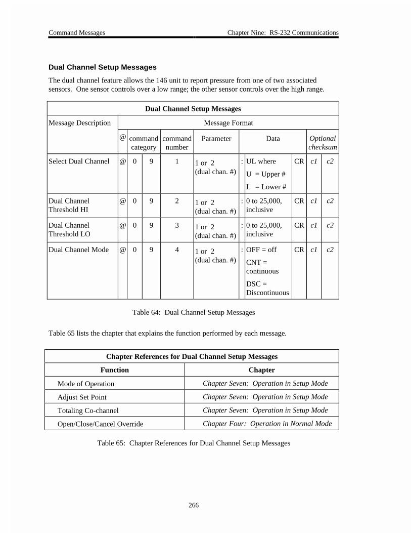
Command Messages Chapter Nine: RS-232 Communications
266
Dual Channel Setup Messages
The dual channel feature allows the 146 unit to report pressure from one of two associatedsensors. One sensor controls over a low range; the other sensor controls over the high range.
Dual Channel Setup Messages
Message Description Message Format
@ commandcategory
commandnumber
Parameter Data Optionalchecksum
Select Dual Channel @ 0 9 1 1 or 2(dual chan. #)
: UL where
U = Upper #
L = Lower #
CR c1 c2
Dual ChannelThreshold HI
@ 0 9 2 1 or 2(dual chan. #)
: 0 to 25,000,inclusive
CR c1 c2
Dual ChannelThreshold LO
@ 0 9 3 1 or 2(dual chan. #)
: 0 to 25,000,inclusive
CR c1 c2
Dual Channel Mode @ 0 9 4 1 or 2(dual chan. #)
: OFF = off
CNT =continuous
DSC =Discontinuous
CR c1 c2
Table 64: Dual Channel Setup Messages
Table 65 lists the chapter that explains the function performed by each message.
Chapter References for Dual Channel Setup Messages
Function Chapter
Mode of Operation Chapter Seven: Operation in Setup Mode
Adjust Set Point Chapter Seven: Operation in Setup Mode
Totaling Co-channel Chapter Seven: Operation in Setup Mode
Open/Close/Cancel Override Chapter Four: Operation in Normal Mode
Table 65: Chapter References for Dual Channel Setup Messages

Chapter Nine: RS-232 Communications Command Messages
267
Alarm Trip Point Messages
The trip point defines the pressure at which an alarm is tripped. Trip Point A and B are standard;Trip Point C and D are available on the Auxiliary Output board.
Alarm Messages
Message Description Message Format
@ commandcategory
commandnumber
Parameter Data Optionalchecksum
Alarm Enable @ 0 1 1 A, B, C, orD
: E = Enable
D = Disable
CR c1 c2
Trip Point Value @ 0 1 2 A, B, C, orD
: ±100,000 Torr CR c1 c2
Alarm Association @ 0 1 3 A, B, C, orD
: 1, 2, 3, or 4
(channel #)
CR c1 c2
Unlatch CurrentlyAlarmed Relays
@ 0 1 4 Anycharacter
CR c1 c2
Status Alert @ 0 1 5 Anycharacter
: E = Enable
D = Disable
CR c1 c2
Untripped State ofUnlatched Relay
@ 0 1 6 A, B, C, orD
: A = Actuated
D = Deactuated
CR c1 c2
Table 66: Alarm Messages
Table 67 lists the chapter that explains the function performed by each message.
Chapter References for Alarm Messages
Function Chapter
Alarm Enable Chapter Seven: Operation in Setup Mode
Alarm Trip Point Chapter Seven: Operation in Setup Mode
Alarm Association Chapter Seven: Operation in Setup Mode
Unlatch Currently Alarmed Relays Applies to RS-232 messages only see below
Status Alert Applies to RS-232 messages only see below
Untripped State of Unlatched Relay Chapter Seven: Operation in Setup Mode
Table 67: Chapter References for Alarm Messages

Command Messages Chapter Nine: RS-232 Communications
268
Unlatch Currently Alarmed Relays
Refer to Chapter Three: Overview, for a description of the latching state. There are two ways tounlatch currently alarmed relays; either send the RS-232 command, or set a TTL signal high (thelatch pins are located on the General I/O connector). This action releases the latch on the alarmso the relay can resume normal operation. If the pressure is within the defined operating range,the alarm will resume its untripped state. If the pressure is outside of the defined operatingrange, the alarm will resume its tripped state. The state of the relay latching pin (high or low)determines whether the alarm will become latched. If the pin is high the latching state isdeactivated; if the pin is low the latching state is activated.
Status Alert
When the status alert function is enabled, the 146 unit automatically sends a message to the hostcomputer whenever an alarm is tripped.

Chapter Nine: RS-232 Communications Command Messages
269
Analog Output Messages
The 146 unit supports one analog output on the CPU board and two additional analog outputsprovided by the Auxiliary Output board.
Analog Output Messages
Message Description Message Format
@ commandcategory
commandnumber
Parameter Data Optionalchecksum
Channel Output Type @ 0 7 1 1, 2, or 3(analogoutput #)
: LN = Linear
LO1 - LO9 =
Log 1 - Log 9
SP = Set Point
CR c1 c2
Input ChannelSelection
@ 0 7 2 1, 2, or 3(analogoutput #)
: channel # 1, 2, 3,4, 5 (dual 1), or 6(dual 2)
CR c1 c2
Full Scale Pressure(for 10 V output)
@ 0 7 3 1, 2, or 3(analogoutput #)
: Value in ASCII CR c1 c2
Table 68: Analog Output Messages
Table 69 lists the chapter that explains the function performed by each message.
Chapter References for Analog Output Messages
Function Chapter
Channel Output Type Chapter Seven: Operation in Setup Mode
Input Channel Selection Chapter Seven: Operation in Setup Mode
Full Scale Pressure (for 10 V output) Chapter Seven: Operation in Setup Mode
Table 69: Chapter References for Analog Output Messages

Command Messages Chapter Nine: RS-232 Communications
270
Control Messages
The control messages are separated into three categories: General; Control Adjust; and RecipeSpecific messages.
Note The General and Control Adjust messages support Control Channel 0,which is a virtual control channel used by the MFC board for Ratio flowcontrol. A “virtual” channel exists in software only; it does not require aphysical board to function. Refer to Mass Flow Control, page 93, forinformation on Ratio control for flow controllers.
General Control Messages
Message Description Message Format
@ commandcategory
commandnumber
Parameter(Controlchannel)
Data Optionalchecksum
Select Control Mode @ 0 2 1 0,* 1 : A = Auto
O = Open
C = Close
H = Hold
M = Manual
CR c1 c2
Select Active Recipe @ 0 2 2 0,* 1 : 1, 2, 3, or 4
(recipe #)
CR c1 c2
Select ControllerPolarity
@ 0 2 3 0,* 1 : D = Direct
R = Reverse
CR c1 c2
*Control channel 0 is a virtual control channel used in conjunction with Mass Flow Controllers
Table 70: General Control Messages
Table 71 lists the chapter that explains the function performed by each message.
Chapter References for General Control Messages
Function Chapter
Select Control Mode Chapter Eight: Operation in Control Mode
Select Active Recipe Chapter Eight: Operation in Control Mode
Select Controller Polarity Chapter Seven: Operation in Setup Mode
Table 71: Chapter References for General Control Messages

Chapter Nine: RS-232 Communications Command Messages
271
Control Adjust Messages
Message Description Message Format
@ commandcategory
commandnumber
Parameter(Controlchannel)
Data Optionalchecksum
Adjust Integral @ 0 3 1 0,* 1 : 0.01 to 100 seconds CR c1 c2
Adjust Base @ 0 3 2 0,* 1 : 0 to 103(% of full open)
CR c1 c2
Adjust Start @ 0 3 3 0,* 1 : 0 to 103(% of full open)
CR c1 c2
Adjust Alpha @ 0 3 4 0,* 1 : 5 to 99, inclusive CR c1 c2
Adjust Preset @ 0 3 5 0,* 1 : 0 to 103(% of full open)
CR c1 c2
Adjust Output @ 0 3 6 0,* 1 : 0 to 100% inclusive CR c1 c2
Adjust Softstart Speed @ 0 3 7 0,* 1 : 1.0 to 990 seconds CR c1 c2
Analog Set Point F.S. @ 0 3 8 0,* 1 : 0 to 10 Volts CR c1 c2
* Control channel 0 is a virtual control channel used in conjunction with Mass Flow Controllers
Table 72: Control Adjust Messages
Table 73 lists the chapter that explains the function performed by each message.
Chapter References for Control Adjust Messages
Function Chapter
Adjust Integral Chapter Six: Operation in Tuning Mode
Adjust Base Chapter Six: Operation in Tuning Mode
Adjust Start Chapter Six: Operation in Tuning Mode
Adjust Alpha Chapter Seven: Operation in Setup Mode
Adjust Preset Chapter Six: Operation in Tuning Mode
Adjust Output Chapter Seven: Operation in Setup Mode
Adjust Softstart Speed Chapter Seven: Operation in Setup Mode
Analog Set Point F.S. Chapter Seven: Operation in Setup Mode
Table 73: Chapter References for Control Adjust Messages

Command Messages Chapter Nine: RS-232 Communications
272
Recipe Specific Messages
Message Description Message Format
@ commandcategory
commandnumber
Parameter Data Optionalchecksum
Adjust Set Point @ 0 4 1 1, 2, 3, or 4(recipe #)
: ±100,000 Torr CR c1 c2
Adjust Lead @ 0 4 2 1, 2, 3, or 4(recipe #)
: 0.001 to 1000 CR c1 c2
Adjust Gain @ 0 4 3 1, 2, 3, or 4(recipe #)
: 0.001 to10,000
CR c1 c2
Select Softstart @ 0 4 4 1, 2, 3, or 4(recipe #)
: E = Enable
D = Disable
CR c1 c2
Select Analog SetPoint
@ 0 4 5 1, 2, 3, or 4(recipe #)
: D = Digital
A = Analog
CR c1 c2
Adjust Analog SetPoint Range
@ 0 4 6 1, 2, 3, or 4(recipe #)
: 0 to 100,000Torr
CR c1 c2
Select ControlChannel
@ 0 4 7 1, 2, 3, or 4(recipe #)
: 1, 2, 3, or 4(channel #)
CR c1 c2
Table 74: Recipe Specific Messages
Table 75 lists the chapter that explains the function performed by each message.
Chapter References for Recipe Specific Messages
Function Chapter
Adjust Set Point Chapter Six: Operation in Tuning Mode
Adjust Lead Chapter Six: Operation in Tuning Mode
Adjust Gain Chapter Six: Operation in Tuning Mode
Adjust Softstart Chapter Seven: Operation in Setup Mode
Adjust Analog Set Point Chapter Seven: Operation in Setup Mode
Adjust Analog Set Point Range Chapter Seven: Operation in Setup Mode
Select Control Channel Chapter Seven: Operation in Setup Mode
Table 75: Chapter References for Recipe Specific Messages
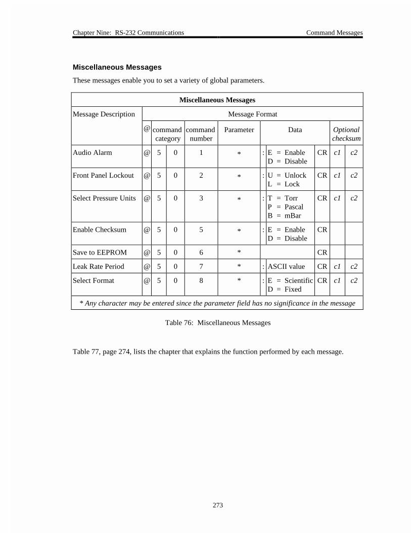
Chapter Nine: RS-232 Communications Command Messages
273
Miscellaneous Messages
These messages enable you to set a variety of global parameters.
Miscellaneous Messages
Message Description Message Format
@ commandcategory
commandnumber
Parameter Data Optionalchecksum
Audio Alarm @ 5 0 1 * : E = EnableD = Disable
CR c1 c2
Front Panel Lockout @ 5 0 2 * : U = UnlockL = Lock
CR c1 c2
Select Pressure Units @ 5 0 3 * : T = TorrP = PascalB = mBar
CR c1 c2
Enable Checksum @ 5 0 5 * : E = EnableD = Disable
CR
Save to EEPROM @ 5 0 6 * CR
Leak Rate Period @ 5 0 7 * : ASCII value CR c1 c2
Select Format @ 5 0 8 * : E = ScientificD = Fixed
CR c1 c2
* Any character may be entered since the parameter field has no significance in the message
Table 76: Miscellaneous Messages
Table 77, page 274, lists the chapter that explains the function performed by each message.

Command Messages Chapter Nine: RS-232 Communications
274
Chapter References for Miscellaneous Messages
Function Chapter
Audio Alarm Chapter Seven: Operation in Setup Mode
Front Panel Lockout Chapter Three: Operation in Overview Mode
Select Pressure Units Chapter Seven: Operation in Setup Mode
Optional Checksum Applies to RS-232 messages only see below
Save to EEPROM Applies to RS-232 messages only see below
Leak Rate Period Refer to How To Determine the Leak Rate, page 280
Select Format Applies to RS-232 messages only see below
Table 77: Chapter References for Miscellaneous Messages
Optional Checksum
The 146 unit can communicate with a host computer with or without using checksum bytes. Thechecksum is the sum of all the ASCII values in the message. It includes all characters in themessage; from the “at” character (@) through the carriage return (CR). The checksum itself isnot calculated into the checksum value.
When the checksum is enabled, the 146 unit expects to receive a checksum for all incomingmessages. In return it sends a checksum value with each response. The checksum is sent withthe low byte first. The 146 unit is shipped with the checksum feature disabled.
Note The number of data bits must be set to 8 when the checksum is enabled.Refer to How To Configure the RS-232 Port, in Chapter Seven:Operation in Setup Mode, for information on changing thecommunication parameters.
The communication parameters on a displayless 146 unit cannot bechanged. Refer to Table 53, page 255, for a listing of the defaultcommunication parameters.
Save To EEPROM Command
The 146 unit saves information to its EEPROM immediately upon receiving this command.During front panel operation, the 146 unit saves the information when you exit either the Setupor Tuning modes.

Chapter Nine: RS-232 Communications Command Messages
275
How To Select the Response Format
You can specify whether the response sent by the 146 unit is in scientific notation or fixedformat. The initial configuration is fixed. The 146 unit will accept messages in either format,regardless of the format selected for its response messages. To configure the 146 unit to respondin scientific notation, issue the command:
@508•:E<CR>
where • = represents a blank spaceE = for scientific notation (D selects fixed notation)
Note You must re-issue this command after each power up since it is not storedat power down.

Command Messages Chapter Nine: RS-232 Communications
276
Read Only Messages
The read only messages prompt the 146 unit to return information. You cannot change the valueor setting of any read only parameter. The read only messages are divided into read only datamessages and read only status messages.
Read Only Data Messages
Message Description Message Format
@ commandcategory
commandnumber
Parameter Data Optionalchecksum
Channel Pressure @ 6 0 1 channel # 1, 2,3, 4, 5 (dual 1),or 6 (dual 2)
? CR c1 c2
Channel Pressure withTime Stamp
@ 6 0 2 channel # 1, 2,3, 4, 5 (dual 1),or 6 (dual 2)
? CR c1 c2
Channel Voltage @ 6 0 3 channel # 1, 2,3, 4, 5 (dual 1),or 6 (dual 2)
? CR c1 c2
Ion Current @ 6 0 4 channel # 1, 2,3, 4, 5 (dual 1),or 6 (dual 2)
? CR c1 c2
Emission Current @ 6 0 5 channel # 1, 2,3, 4, 5 (dual 1),or 6 (dual 2)
? CR c1 c2
Pressure Leak Rate @ 6 0 6 channel # 1, 2,3, 4, 5 (dual 1),or 6 (dual 2)
? CR c1 c2
Analog Set Point @ 6 0 7 Any character ? CR c1 c2
Channel Condition
This is the bestmessage to use whenchecking the pressurereading
@ 6 0 8 channel # 1, 2,3, 4, 5 (dual 1),or 6 (dual 2)
? CR c1 c2
Power Up Status @ 6 0 9 Any character ? CR c1 c2
Table 78: Read Only Data Messages(Continued on next page)

Chapter Nine: RS-232 Communications Command Messages
277
Read Only Data Messages (Continued)
Message Description Message Format
@ commandcategory
commandnumber
Parameter Data Optionalchecksum
Relay Status @ 6 0 A A, B, C, or D ? CR c1 c2
Alarm Status @ 6 0 B A, B, C, or D ? CR c1 c2
Current Control Mode @ 6 0 C Any character ? CR c1 c2
Current Recipe @ 6 0 D Any character ? CR c1 c2
Current PID Set Point @ 6 0 E Any character ? CR c1 c2
PCS Output @ 6 0 F Any character ? CR c1 c2
Table 78: Read Only Data Messages
Response Format for Read Only Data Messages
Message Response* Description
Channel Condition @608X:<status><pres> where x is 1 through 6
<pres> is an empty field unless <status> is A orB, then <pres> is an ASCII string
<status> is:
A = On
B = low power degas
C = Underranged
D = Overranged
E = Manually off
F = Auto off
G = High power degas
H = Initializing
I = Zeroing
J = Bad sensor
K = Disconnected
L = Channel notinstalled
Relay Status @60A:<para><status> where <para> A, B, C, or D
<status> is E = Enabled
D = Disabled
T = Tripped
Table 79: Response Format for Read Only Data Messages(Continued on next page)

Command Messages Chapter Nine: RS-232 Communications
278
Response Format for Read Only Data Messages (Continued)
Message Response* Description
Alarm Status @60B:<para><status> where <para> A, B, C, or D
<status> is E = Enabled
D = Disabled
T = Tripped
Control Mode @60C:<over><mode> where <over> is: 0 = No override
1 = Override enabled
<mode> is:
A = Auto
O = Open
C = Close
M = Manual
H = Hold
Current Recipe @60D:<over><recipe> where <over> is: 0 = No override
1 = Override enabled
<recipe> is: An ASCII string, from 1 to 4
PID Set Point @60E:<type><sp> where <type> is: analog set point
digital set point
<sp> is: An ASCII string
* All response messages terminate in a CR as the end-of-line delimiter
Table 79: Response Format for Read Only Data Messages
Chapter References for Read Only Data Messages
Function Chapter
Channel Pressure Chapter Four: Operation in Normal Mode
Channel Pressure with Time Stamp Applies to RS-232 messages only see below
Channel Voltage Chapter Seven: Operation in Setup Mode
Ion Current Chapter Seven: Operation in Setup Mode
Emission Current Chapter Seven: Operation in Setup Mode
Pressure Leak Rate Chapter Seven: Operation in Setup Mode
Table 80: Chapter References for Read Only Data Messages

Chapter Nine: RS-232 Communications Command Messages
279
Chapter References for Read Only Data Messages
Function Chapter
Analog Set Point Chapter Seven: Operation in Setup Mode
Channel Status Applies to RS-232 messages only see below
Power Up Status Chapter Four: Operation in Normal Mode
Relay Status Chapter Three: Overview
Alarm Status Chapter Seven: Operation in Setup Mode
Current Control Mode Chapter Eight: Operation in Control Mode
Current Recipe Chapter Eight: Operation in Control Mode
Current PID Set Point Chapter Eight: Operation in Control Mode
PCS Output Chapter Three: Overview
Table 80: Chapter References for Read Only Data Messages
How To Report the Channel Reading with Time Stamp
The 146 instrument can report the channel’s reading with the time difference between readings.A 16-bit counter tracks the elapsed time in 10 millisecond increments. The counter incrementsby one count every 10 milliseconds, until it reaches a count of 65535 (approximately 65seconds). The counter then wraps around and begins counting from 0 again. To calculate theelapsed time between readings, subtract the time stamp of the first reading from the time stampof the second reading.
For example, you query the channel reading on channel 3, and the 146 responds with:
@6023:133 4261 <CR>
to indicate a pressure of 133 at the time equivalent to 4261 counts.
The next time you check the reading with time stamp, the 146 instrument responds with:
@6023:129 18784 <CR>
The time between the readings is:
18784 - 4261 = 14523 counts
Therefore, the time elapsed between readings is approximately 14.5 seconds.

Command Messages Chapter Nine: RS-232 Communications
280
How To Check the Status of an Alarm or a Relay
There are separate read only messages to report the status of an alarm and the status of a relay.The status message reports whether the alarm or relay is enabled, disabled, or tripped.
To determine the status of an alarm or a relay, send the message:
@60#X?<CR>
where # = is A for a relay or B for an alarm
where X = is the alarm letter (A, B, C, or D)
The 146 responds with:
@60#X:S <CR>
where S = is relay or alarm state: E = Enabled; D = Disabled; T = Tripped
How To Determine the Leak Rate
The 146 instrument can calculate the leak rate of a sensor. The leak rate reflects the amount ofleakage over a user-defined time period, expressed as pressure units per second. For example, ifthe pressure is measured in Torr and you have selected a time base of 30 seconds, the leak ratewill be reported as Torr per 30 seconds. The leak rate period entry is global and applies to allchannels.
The leak rate is calculated as a moving average using the most recent measurements. The 146instrument continually replaces the oldest value with the latest value and recalculates the newleak rate. Initially, when you enter the leak rate period, you must wait until the time period haselapsed before querying the 146 instrument to report the leak rate.
The range is from 1 to 60 seconds; the default value is 1.
To determine the leak rate, you must first specify the time period, for example, 30 seconds:
@507•:30 <CR>
where • = represents a blank space
To request the leak rate on channel 5, enter:
@6065? <CR>
Following the example above, the 146 instrument responds with:
@6065:2 <CR>
This response indicates that a 2 Torr difference in pressure has occurred over 30 seconds.

Chapter Nine: RS-232 Communications Command Messages
281
How To Check the Channel Status
The channel status message reports the channel’s pressure if the channel is currently on orcurrently performing a low power degas. Otherwise, the response will indicate the condition ofthe channel initializing, zeroing, underranged, overranged, off (either manual or auto), highpower degas, disconnected, sensor problem, or not installed. Since the channel status messagereports complete information on the channel’s condition, it is the best command to use when youquery the pressure reading.
To check the channel pressure, enter:
@608C?<CR>
where C = is the channel number 1, 2, 3, 4, 5 (dual 1), or 6 (dual 2)
The 146 instrument responds with:
@608C:<status><reading> <CR>
where <status> is: = A for On
B for low power degas
C for underranged
D for overranged
E for manually off
F for auto off
G for high power degas
H for initializing
I for zeroing
J for bad sensor
K for disconnected
L for channel not installed
<reading > is: = an empty field unless <status> is A (on) or B (low power degas),then this field contains an ASCII string representing the channel’sreading
For example, the following response indicates a disconnected sensor on channel 2:
@6082:K <CR>
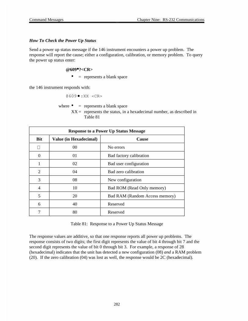
Command Messages Chapter Nine: RS-232 Communications
282
How To Check the Power Up Status
Send a power up status message if the 146 instrument encounters a power up problem. Theresponse will report the cause; either a configuration, calibration, or memory problem. To querythe power up status enter:
@609•?<CR>
• = represents a blank space
the 146 instrument responds with:
@609•:XX <CR>
where • = represents a blank spaceXX = represents the status, in a hexadecimal number, as described in
Table 81
Response to a Power Up Status Message
Bit Value (in Hexadecimal) Cause
00 No errors
0 01 Bad factory calibration
1 02 Bad user configuration
2 04 Bad zero calibration
3 08 New configuration
4 10 Bad ROM (Read Only memory)
5 20 Bad RAM (Random Access memory)
6 40 Reserved
7 80 Reserved
Table 81: Response to a Power Up Status Message
The response values are additive, so that one response reports all power up problems. Theresponse consists of two digits; the first digit represents the value of bit 4 through bit 7 and thesecond digit represents the value of bit 0 through bit 3. For example, a response of 28(hexadecimal) indicates that the unit has detected a new configuration (08) and a RAM problem(20). If the zero calibration (04) was lost as well, the response would be 2C (hexadecimal).

Chapter Nine: RS-232 Communications Command Messages
283
Read Only Status Messages
Message Description Message Format
@ commandcategory
commandnumber
Parameter Data Optionalchecksum
Software Version @ 7 0 1 * ? CR c1 c2
Channel Status @ 7 0 2 * ? CR c1 c2
Alarm Status @ 7 0 3 * ? CR c1 c2
Configuration Setup @ 7 0 4 * ? CR c1 c2
Rear Panel Status @ 7 0 5 * ? CR c1 c2
Reference Voltage @ 7 0 6 * ? CR c1 c2
* Any character may be entered since the parameter field has no significance in the message
Table 82: Read Only Status Messages
Response Format for the Read Only Status Messages
Message Response Description
Software Version <version> CR where <version> represents the software versionnumber
Channel Status C1:<text>LF CR
C2:<text> LF CR
C3:<text> LF CR
C4:<text> LF CR
where <text> is:
ON = Sensor normal
OFF = Manual off
AOFF = Auto off
DCNT = Disconnected
OVER = Overranged
UNDR = Underranged
INIT = Initializing
ZERO = Zeroing
E1 = Channel error #
- - - - = Channel notinstalled
Alarm Status AA:<text>LF CR
AB:<text> LF CR
AC:<text> LF CR
AD:<text> LF CR
where <text> is:
ENAB = AlarmEnabled
ENAL = In alarmedstate
ENLT = Just latchedDSBL = Alarm disabled
- - - - = Channel notinstalled
Table 83: Response Format for the Read Only Status Messages(Continued on next page)

Command Messages Chapter Nine: RS-232 Communications
284
Response Format for the Read Only Status Messages (Continued)
Message Response Description
Configuration (slot status atpower up)
Sx<text> LF CR where x is 1 through 5
<text> is:
CC-- = Cold Cathode
CLN = Linear Cap. Man.
C107 = Type 107 Cap. Man.
C120 = Type 120 Cap. Man.
CNCN = Convection, dual channel
PRCN = Pirani/Convection
C- - - = Cap. Man. board, no sensor
CN - - = Convection, single channel
CNPR = Convection/Pirani
CNTL = Control board
AUXO = Auxiliary Output board
- - - - = Empty slot
PR - - = Pirani, single channel
PRPR = Pirani, dual channel
MFC - Mass Flow Controller
HCL - = Hot Cathode, low power
HCH - = Hot Cathode, high power
1A - - = Thermocouple board
Table 83: Response Format for the Read Only Status Messages

Chapter Nine: RS-232 Communications Command Messages
285
Response Format for the Read Only Status Messages (Continued)
Message Response Description
Rear Panel Status
Remote zero channel 1
Remote zero channel 2
Remote zero channel 3
Remote zero channel 4
Latch relay A
Latch relay B
Latch relay C
Latch relay D
Front panel lockout
Open valve
Manual valve control
Close valve
Set point B
Set point C
Set point D
RZ1:<text> LF CR
RZ2:<text> LF CR
RZ3:<text> LF CR
RZ4:<text> LF CR
LTA:<text> LF CR
LTB:<text> LF CR
LTC:<text> LF CR
LTD:<text> LF CR
FPL:<text> LF CR
OM:<text> LF CR
MM:<text> LF CR
CM:<text> LF CR
SPB:<text> LF CR
SPC:<text> LF CR
SPD:<text> LF CR
where <text> is L for low (Ground)
H for high (5 Volts)
Calibration Data (ASCII) <text> LF CR
<text> LF CR
<text> LF CR
<text> LF CR
<text> LF CR
where <text> is a six character value forthe voltage in standard fixed pointformat. The second character from theleft is the decimal point.
* All response messages terminate in a CR as the end-of-line delimiter
Table 83: Response Format for the Read Only Status Messages

Command Messages Chapter Nine: RS-232 Communications
286
Table 84 lists the chapter that explains the function performed by each message.
Chapter References for Read Only Status Messages
Function Chapter
Software Version Chapter Four: Operation in Normal Mode
Channel Status Chapter Four: Operation in Normal Mode
Alarm Status Chapter Three: Overview
Configuration Setup Chapter Three: Overview
Rear Panel Status Chapter Three: Overview
Calibration Data Chapter Seven: Operation in Setup Mode
Table 84: Chapter References for Read Only Status Messages
How To Determine The Software Version
To request the software version, enter:
@701•?<CR>
• = represents a blank space
the 146 instrument responds with:
@701•:XX <CR>
where • = represents the software version, for example, 4.0

Chapter Nine: RS-232 Communications Error Messages
287
Error Messages
If the 146 instrument cannot execute a command, it will respond with an error message.
Error Code Summary
Error Code Description
E111 Unrecognized command
E112 Inappropriate command
E122 Invalid data field
E131 Bad checksum
Table 85: Error Code Summary
E111: Unrecognized Command
An “unrecognized command” error message will occur if the command syntax is incorrect. The146 instrument cannot interpret the command string. The syntax error is located in the first fourbytes of the command.
E112: Inappropriate Command
The 146 instrument will return an “inappropriate command” error message if the commandcannot be executed on the selected channel or at this time. Examples of inappropriate commandsinclude attempting to:
• Read a channel that is turned off
• Zero an ion gauge (Ion gauges cannot be zeroed)
• Read a channel that is out-of-range
• Read a hot cathode gauge that is performing a high power degas
• Perform a degas procedure on a channel that is not connected to a hot cathode gauge
• Span a Pirani gauge that has the gas type set to argon or helium (A Pirani can only bespanned if the gas type is set to nitrogen.)
• Enter the Auto (or PID) control mode with the recipe select command set to “none”
E122: Invalid Data Field
An “invalid data field” error message indicates a problem with the data field of the commandstring. The data field can contain a maximum of 26 characters. If your data field exceeds 26characters, the 146 instrument will return an invalid command error message. Other possiblecauses of an invalid command error message include an invalid data range, or a data field thatcontains numbers instead of letters, or vice versa.

Error Messages Chapter Nine: RS-232 Communications
288
This page intentionally left blank.
How To Determine The Software Version How To Determine The Software Version
289
Chapter Ten: Maintenance
General Information
The Type 146 instrument is virtually maintenance free, however, a few common sense notes areincluded here.
• Periodically check for wear on the cables and inspect the enclosure for visible signs ofdamage.
• The 146 unit’s environment should be kept dust free.
• If a substantial change is made to the gas system, verify that the maximum potentialdifference between grounds is limited to 3.5 Volts to prevent noise.
How To Clean the Front Panel
• The front panel may be washed with mild soap and water, and a non-abrasive cloth.

How To Determine The Software Version How To Determine The Software Version
290
How To Replace the Fuses
Warning Be sure the power cord is DISCONNECTED before proceedingwith the next step.
1. Select the proper fuses.
All units should have two fuses installed to fuse both sides of the line.
A. Refer to Figure 4, page 27, for the location of the fuses.
B. Refer to Table 86 for proper fuse selection.
Voltage Range and Fuse Selection
Setting Nominal Voltage Range Fuses (250V IEC)
115 VAC 100 to 120 VAC 1.6A(T)
230 VAC 220 to 240 VAC 1.0A (T)
Table 86: Voltage Range and Fuse Selection
2. Check the setting of the AC line voltage select switch.
A. Refer to Figure 4, page 27, for the location of the switch.
B. Use a small straight screwdriver to set the switch to the left position foroperation in the 115V range, or to the right position for operation in the 230Vrange.

Chapter Eleven: Troubleshooting The Diagnostics Feature
291
Chapter Eleven: Troubleshooting
The Diagnostics Feature
The 146 unit comes with a basic diagnostics feature. This feature is used to command the 146unit to perform specific self-tests and display the test results in the front panel window.
Starting the Diagnostics Feature
1. Press and hold both arrow keys [ ] and [ ] together, for about 3 seconds whenpowering up the 146 unit. When the arrow keys are released, the display changes to theinitial diagnostics screen display.
The system responds by performing its normal initialization procedure and providing afull LCD test display in the front panel window.
Figure 85: Initial Diagnostics Screen Display
Performing 146 Instrument Self Tests
All tests except Codes 5x, 6x, and 7x, are initiated by entering a code number and pressing the[ENTER] key. The 146 unit responds by performing the selected self-test.
If the self-test for any code except Codes 1 and 2 fails, the display remains as it was before theself-test was initiated. For example, if the display currently is showing the word PASS (as inFigure 86, page 292), and a Code 6 test is done, the display continues to show the word PASSif the Code 6 self-test failed. Codes 1 and 2 test the 146 unit RAM and PROM respectively.These tests should always come up with a PASS test result because if either the RAM or PROMis bad, the 146 unit displays error codes upon power up, and will not initiate the diagnosticsfeature at all.

The Diagnostics Feature Chapter Eleven: Troubleshooting
292
There are three general message codes that may appear in the main display. One general messagecode is nA for non-applicable. This appears when a test is being run inappropriately. Thegeneral message code ni stands for not installed. For example, if the Code 6x test is being runto test one of the analog outputs on the Analog Output board, and the Analog Output board is notinstalled in the 146 unit, then the ni general message code is displayed. General message codeErr is displayed for an inappropriate key sequence. When this message is displayed, press the[QUIET/CANCEL] key to return to the initial diagnostics screen display.
To Exit the Diagnostics screens:
1. Press [1/1] , then [0/D] , and then the [ENTER] key.
The system responds by exiting the Diagnostics screens.
Code 1: RAM Test
1. Press the [1/1] key and then the [ENTER] key.
The system should respond by performing a RAM test and displaying PASS. Anexample of the PASS display shown in Figure 86.
Figure 86: PASS Test Result Display from RAM Self-Test

Chapter Eleven: Troubleshooting The Diagnostics Feature
293
Code 2: PROM Test
1. Press the [2/2] key and then the [ENTER] key.
The system should respond by performing a checksum verification and displaying PASS.The display is the same as shown in Figure 86, page 292.
Note Codes 1 and 2 are the same tests the 146 unit performs as part of thenormal power up procedure. If either of the tests fails at power up, anerror code is displayed (E2 for PROM failure, and E3 for RAM failure).
Code 3: Display Test
1. Press the [3/3] key and then the [ENTER] key.
The system should respond by providing a full LCD test display. This is the samedisplay that appears during a normal power up. Refer to Figure 12, page 43, to see whatthe full display looks like.
The full LCD display is shown for less than 3 seconds, and then the unit returns to theinitial diagnostics screen display.
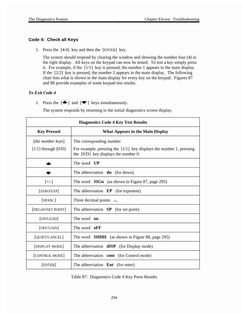
The Diagnostics Feature Chapter Eleven: Troubleshooting
294
Code 4: Check all Keys
1. Press the [4/4] key and then the [ENTER] key.
The system should respond by clearing the window and showing the number four (4) inthe right display. All keys on the keypad can now be tested. To test a key simply pressit. For example, if the [1/1] key is pressed, the number 1 appears in the main display.If the [2/2] key is pressed, the number 2 appears in the main display. The followingchart lists what is shown in the main display for every key on the keypad. Figures 87and 88 provide examples of some keypad test results.
To Exit Code 4
1. Press the [ ] and [ ] keys simultaneously.
The system responds by returning to the initial diagnostics screen display.
Diagnostics Code 4 Key Test Results
Key Pressed What Appears in the Main Display
[the number keys]
[1/1] through [0/D]
The corresponding number
For example, pressing the [1/1] key displays the number 1, pressingthe [0/D] key displays the number 0.
The word UP
The abbreviation dn (for down)
[+/-] The word SIGn (as shown in Figure 87, page 295)
[ZERO/EXP] The abbreviation EP (for exponent)
[SPAN/.] Three decimal points ...
[DEGAS/SET POINT] The abbreviation SP (for set point)
[ON/LEAD] The word on
[OFF/GAIN] The word oFF
[QUIET/CANCEL] The word SHHH (as shown in Figure 88, page 295)
[DISPLAY MODE] The abbreviation dISP (for Display mode)
[CONTROL MODE] The abbreviation cont (for Control mode)
[ENTER] The abbreviation Ent (for enter)
Table 87: Diagnostics Code 4 Key Press Results

Chapter Eleven: Troubleshooting The Diagnostics Feature
295
Figure 87: The Keypad Test Result for the [+/-] Key
Figure 88: The Keypad Test Result for the [QUIET/CANCEL] Key
Code 5: Beeper Test
1. Press the [5/DUAL] key and then the [ENTER] key.
The system should respond by sounding one beep, and placing the number 5 in the rightdisplay.

The Diagnostics Feature Chapter Eleven: Troubleshooting
296
Code 5x: Relay Test
The x in the code represents the relay letter A through D. To perform a relay test on relay A,press the [5/DUAL] key, followed by the [7/A] key.
Figure 89: Rear Panel Output Test Display When all Bits are High
Steps 2 and 3 in this instruction set, can be performed in reverse order.
1. Press the [5/DUAL] key, followed by a number key (A through D).
The system should respond by displaying the number 5 followed by the letter keyselected. For example, if the letter key [7/A] is selected, the center display shows 5A .
2. Press the [ON/LEAD] key.
The system should respond by turning the selected relay on and displaying the word on .
When turned on, a normally open contact is closed (energized). A normally closedcontact is opened (energized).
3. Press the [OFF/GAIN] key.
The system should respond by turning the selected relay off and displaying the wordoFF . A small “click” sound can be heard as the relay switches from on to off.
When turned off, a normally open contact is opened (de-energized). A normally closedcontact is closed (de-energized).
To Exit Code 5x
1. Press the [QUIET/CANCEL] key.
The system responds by returning to the initial diagnostics screen display.

Chapter Eleven: Troubleshooting The Diagnostics Feature
297
Code 6: Rear Panel Status
1. Press the [6] key and then the [ENTER] key.
The 146 unit’s processor should respond by reading the inputs for 8 bits (remote zero 1through 4, and latches A through D) on the General I/O connector, and displaying thesum of the hexadecimal values which are assigned to each bit when the bit is high. Referto Table 88 for a listing of the hexadecimal values assigned to each bit when it is high(when low, the bits are assigned a value of 0).
The sum of the hexadecimal values is shown in the main display. For example, ifRemote Zero 1 and Latch A are low, they are assigned a value of 0. The other inputs areassigned the hexadecimal values shown. The 146 unit totals all values. The sum is EE(hexadecimal for 238). If all bits are high, the sum is FF (hexadecimal for 255), asshown in Figure 89, page 296.
Hexadecimal Values Assigned to the General I/O Connector Input Bits
Bit Definition Hexadecimal Value if Bit is High
Remote Zero 1 01
Remote Zero 2 02
Remote Zero 3 04
Remote Zero 4 08
Latch A 10
Latch B 20
Latch C 40
Latch D 80
Table 88: Hexadecimal Values Assigned to General I/O Connector Input Bits

The Diagnostics Feature Chapter Eleven: Troubleshooting
298
Code 6x: Analog Outputs Check
The x in the code represents the analog output number (1 through 3).
1. Press the [6] key, followed by an analog output number (1 through 3).
The system should respond by placing the analog output number (1 through 3) in thecenter display, and the analog output abbreviation AnAl in the main display.
The analog output is normally proportional to pressure. The 146 unit sends a squarewave to make the output go back and forth between 0 and 10 Volts. An output detectiondevice must be used to detect if the analog output is indeed fluctuating between 0 and 10Volts.
Figure 90: Analog Output Test Display

Chapter Eleven: Troubleshooting The Diagnostics Feature
299
Code 7x: Response Time for Fail-Safe Feature
The x in the code represents the Auxiliary Output board relay letter (C or D).
Relays C and D on the Auxiliary Output board are associated with the 146 instrument’s Fail-Safefeature. When the 146 unit is powered on, the Fail-Safe feature is activated. When Code 7x isused, the processor sends a relay setup command to relays C, D, and then checks to see if therelays have responded. If the relays do not respond, the abbreviation Err (for Error), appearsin the main display. If the relays do respond, the Fail-Safe feature continues, and the Code 7xfunction determines the Fail-Safe system response time.
The Fail-Safe feature includes a timed hardware reset. The hardware reset causes relays C and Dto go to default positions. During normal operation of the 146 unit, the processor prevents thetimed hardware reset from executing by sending out an interrupt pulse every 10 milliseconds. Ifthe 146 unit’s software crashes, the interrupt pulse stops and the timed hardware reset executes,causing relays C and D to go to default positions.
Code 7x is used to determine if the Fail-Safe system is operating, and its response time. Theresponse time is the amount of time which passes between when an interrupt pulse is received bythe hardware reset, and when relays C and D can be set to default. The response time should beabout 12 msec. ± 1 msec.
1. Press the [7/a] key, followed by either [9/C] (for Relay C), or [0/D] (for Relay D).
The system responds by displaying the Fail-Safe feature response time in milliseconds.

The Diagnostics Feature Chapter Eleven: Troubleshooting
300
Code 9999: Factory Calibration
MKS Instruments performs factory calibration procedures on the 146 instrument. Part of thecalibration procedure involves entering Code 9999 while the 146 unit is attached to otherinstrumentation. When 9999 is entered, the abbreviation CAL appears in the main display.Nothing further can be done with this code because the 146 unit is not attached to the appropriatecalibration instrumentation. The 146 unit must be powered off to exit Code 9999.
Caution 1. If the code 9999 is shown in the main display, the Fail-Safefeature has failed its self-test. Return the 146 unit to MKS forrepair.
2. If the number 26 appears in the main display, the relays did notgo to their default values within 26 milliseconds (the maximumtime on the counter). Return the 146 unit to MKS for repair.

Appendix A: Product Specifications Physical Specifications
301
Appendix A: Product Specifications
Physical SpecificationsAnalog Output Standard: 0 to 10 VDC on single channel, linear or log
Optional: 0 to 10 VDC on 2 additional channels, linear or log
Closed-Loop PressureControl (optional)
One channel (selectable) PID control for use with MKS Type 248Proportioning Valve or MKS Type 153 Exhaust Throttle Valve
Compatible Instruments Capacitance Manometers
Any capacitance manometer providing 0 to ± 10 VDC output;MKS Types 107, 120, 122, 124, 127, 128, 220, 221, 223, 224,225, 390 or 690 with 270, 622, 623, 624, 625, 626, 627, 628, 700Series or 800 Series.
Cold Cathode Gauge Tubes
HPS Division Cold Cathode Gauge Tubes
Convection Gauge Tubes
HPS Division Convection Enhanced PiraniGranville-Phillips Convectron
Hot Cathode Gauge Tubes1
HPS Division Hot Cathode Gauge Tubes including thoriatediridium and tungsten filament gauges in nude or glass envelopeconfiguration, and the HPS low power, nude, Bayard-Alpert Tube
Mass Flow Controllers
MKS MFCs except for Types 1749 and 1759
Pirani gauge tubes
HPS Division Pirani gauge tubes
Thermocouple Gauges2
MKS TC-1AHastings DV-6M
(Continued on next page)
1 Only hot cathode gauges with nude tubes are CE compliant. Hot cathode gauges with glass tubes donot pass CE testing.
2 Units equipped with a Dual Thermocouple board will not carry the CE mark since there are no CEcompliant thermocouple gauges to connect to the board.

Electrical Specifications Appendix A: Product Specifications
302
Physical Specifications (Continued)Digital Output RS-232
Input Power Required 100 to 120 VAC or 220 to 240 VAC, 50/60 Hz
Mounting ½ rack; 9” W x 3½” H x 12” D (24.1 cm x 8.9 cm x 30.5 cm)
Power Supply Output ± 15 VDC @ 2 Amps
Simultaneous Display 1 channel with 4½ place LCD readout (with exponent)
3 channels with 2½ place LCD readouts (with exponents)
Trip Point Relays Standard: 2 alarm relay outputs (28 Volts max.)
Optional: 2 additional alarm relay outputs (120 VAC max.)
Electrical SpecificationsCE Mark Compliance3
Electromagnetic Compatibility4
Low-Voltage Requirements
Installation Category
Pollution Degree
Product Safety and Liability
EMC Directive 89/336/EEC
Low-Voltage Directive 73/23/EEC
II, according to EN 61010-1
2, according to IEC 664
Product Safety Directive 92/59/EEC
Power Requirement
115 VAC setting
230 VAC setting
100 to 120 VAC, nominal
220 to 240 VAC, nominal
Power Consumption 150 VA, maximum
Fuse Ratings
115 V
230 V
1.6A(T)
1.0A(T)
Due to continuing research and development activities, these product specifications are subject to change without notice.
3 CE compliance depends on the actual configuration of your 146 unit. Some configurations are not CEcompliant.
4 An overall metal braided shielded cable, properly grounded at both ends, is required during use.

Appendix B: Parts List/Accessories Gauge Cables
303
Appendix B: Parts List/Accessories
Gauge CablesGauge Cables
Gauge Type Cable
Capacitance Manometer:
107B
120
122A/124/223/224/225/622/623/624/625
127A/128/626/627/628
220
221
390 or 690 with a 270
700 Series
800 Series
CB107-1-10
CB120-1-10
CB112-2-10
CB259-5-10
CB112-10-10
CB112-14-10
CB112-6-10
Consult factory
Consult factory
Cold Cathode: 10421000x (where x = fittingtype)
100006171 for all types
Convection:
HPS Convection Enhanced Pirani (CEP)
Granville-Phillips Convectron
Adapter cable for G.P. Convectron cable
CB146-37
CB146-14
CB146-1
Hot Cathode:
HPS low power, nude, Bayard-Alpert (B/A)KF40 or 2¾ CF
MKS Hot Cathode Gauges nude or B/A,thoriated iridium or tungsten filament,Types IG-xx, RG75, & NRC563
For glass envelope tubes CB146-13
For glass envelope tubes CB146-16& external power
For nude hot cathode tube CB146-19
Pirani: 10315001x (where x = fitting type) CB146-15 for all types
Thermocouple:
TC-1A
Extension cable (26 to 100 ft)
DV-6M
CB146-6-10
CB146-7-XX
CB146-8-10

Mass Flow Controller Cables Appendix B: Parts List/Accessories
304
Mass Flow Controller CablesMass Flow Controller Cables
Mass Flow Controllers Cable
All MKS MFCs exceptTypes 1749 and 1759
Cable for MFCs w/ Edge Card connector CB147-7
Cable for MFCs w/ 15-pin Type “D” connector CB147-1
Cable for MFCs w/ 9-pin Type “D” connector CB147-12
Control Valve CablesControl Valve Cables
Control Valves Cable
Type 148, 248
Type 153 (not powered by the 146 unit)
Type 153 (not powered by the 146 unit)
Type 154
CB251-2-10
CB153-4-10
CB153-13-10
CB251-2-10 (with CB248-1-5 adapter)
Power Supply/Readout CablesPower Supply/Readout Cables
Power Supply/Readout Cable
Type 147 Four Channel Flow, with CRT
Type 246 Single Channel Flow
Type 247 Four Channel Flow
CB147-3
CB246-3
CB247-9
AccessoriesAccessories
Item Part Number
Rack Mounting Kit
RS-232 cable for displayless units
114090
CB146-21

Appendix C: RS-232 Error Codes Error Code Summary
305
Appendix C: RS-232 Error Codes
Error Code Summary
If the 146 instrument cannot execute a command, it will respond with an error message. Theerror codes are summarized in Refer to Table 89.
RS-232 Error Code Summary
Error Code Description
E111 Unrecognized command
E112 Inappropriate command
E122 Invalid data field
E131 Bad checksum
Table 89: RS-232 Error Code Summary
E111: Unrecognized Command
An “unrecognized command” error message will occur if the command syntax is incorrect. The146 instrument cannot interpret the command string. The syntax error is located in the first fourbytes of the command.
E112: Inappropriate Command
The 146 instrument will return an “inappropriate command” error message if the commandcannot be executed on the selected channel or at this time. Examples of inappropriate commandsinclude attempting to:
• Read a channel that is turned off
• Zero an ion gauge (Ion gauges cannot be zeroed)
• Read a channel that is out-of-range
• Read a hot cathode gauge that is performing a high power degas
• Perform a degas procedure on a channel that is not connected to a hot cathode gauge
• Span a Pirani gauge that has the gas type set to argon or helium (A Pirani can only bespanned if the gas type is set to nitrogen.)
• Enter the Auto (or PID) control mode with the recipe select command set to “none”

Error Code Summary Appendix C: RS-232 Error Codes
306
E122: Invalid Data Field
An “invalid data field” error message indicates a problem with the data field of the commandstring. The data field can contain a maximum of 26 characters. If your data field exceeds 26characters, the 146 instrument will return an invalid command error message. Other possiblecauses of an invalid command error message include an invalid data range, or a data field thatcontains numbers instead of letters, or vice versa.

Appendix D: Front Panel Error/Status Messages Description
307
Appendix D: Front Panel Error/Status Messages
Description
1. E stands for Error.
2. C stands for Caution, or a non-vital problem.
3. Input channel errors appear in their respective displays.
4. Output channel and system errors appear in the main display.
Description of Front Panel Error/Status Messages
Display/Error Code Error
A blank display No channel/board installed
A blinking display Calibration error
INVALID legend Invalid keystroke
1 long beep Invalid command
2 short beeps Keypad timeout
“ . ” Channel auto-powered offA single decimal point is displayed for any cold cathode channel thatis turned off with the Ion Gauge Auto Power feature. Thisdistinguishes it from a user-commanded turn off condition.
“ - - - - ” Underrange sensor (lower segments of display are turned on)Underrange conditions depend upon which sensor is associated withthe channel. A differential capacitance manometer goes underrangewhen the reference port pressure exceeds the measurement portpressure by the full scale of the sensor. For Pirani gauges, zeroing thesensor can bring the instrument within range.
“ - - - - ” Overrange sensor (upper segments of display are turned on)Overrange conditions depend upon which sensor is associated with thechannel. Generally, a sensor goes overrange when the pressureexceeds the measurement range of the sensor.
“ .. ” or “ .... ” Channel turned off (all decimal points in the display are turned on)If any channels were off when the 146 unit was powered down, theyremain off when the unit is powered up. The channel must be turnedon to resume pressure measurement.
Table 90: Description of Front Panel Error/Status Messages(Continued on next page)

Description Appendix D: Front Panel Error/Status Messages
308
Description of Front Panel Error/Status Messages (Continued)
Display/Error Code Error
E0 Disconnected sensor
If any sensor becomes disconnected from a powered channel, theNO SENSOR legend appears on the right side of the window, and thechannel’s pressure reading is replaced with E0.
E1 Bad sensor
A sensor is considered bad if it is unable to provide pressureinformation. This determination is sensor dependent. A Pirani typegauge with an open filament, an MKS Type 120 sensor which cannotrange switch or which has a non-verified change in gain, and MKSType 107 six decade transducer with corrupted EEPROM data, are thedetectable bad sensors.
E2 PROM checksum error
E3 RAM failure
E4 User EEPROM checksum failure
E8 EEPROM Cal reference failure (non-recoverable)
E9 Set point input out of range
E10 Wrong EEPROM format
E12 System recovery failure
C5 Cannot turn off channel with associated alarms enabled
C6 Cannot turn off channel with associated control channel in AUTO
C7 Cannot shut off reference channel of an auto powered ion gauge
C11 New hardware configuration detected
Table 90: Description of Front Panel Error/Status Messages
To Override C Error Codes (C5, C6, C7, and C11):
All of the C error codes are overridden by pressing the [ENTER] key.
Codes Displayed at Power Up:
If there has been a configuration change in the 146 unit (C11), or an E4 or E10 condition ispresent, the 146 instrument displays an error code upon power up. When power is recycled(turned off and then on again), the unit clears the non-fatal error code. If there is only one non-fatal error, the unit powers up and initializes normally. If however, a second error conditionexists, then the error code for the second error condition is displayed. By cycling the power afew times, all non-fatal error codes are displayed and then cleared.

Appendix E: Instrument Default Values Default Values
309
Appendix E: Instrument Default Values
Default Values
Active recipe 1
Alarm Relays
Untripped alarm state
Channel assignment (all alarms)
Trip point default
Alarm status
Latch state
Actuated
1
1000 Torr (range ± 105,000 Torr)
Disabled
Off
Alarms - Audio On
Alpha 20
Analog Output End Point
Value
Type
Channel association
1000 Torr
Linear
1
Analog Set Point
Zero voltage
Full scale voltage
Setting
Status
Overrange
Underrange
0.0 Volts
5 Volts
1000 Torr (range 0 to 100,000 Torr)
Disabled
Input > 10.3 Volts
Input < -10.3 Volts
Base 0 (range 0 to 103% of full open)
Baud Rate 9600

Default Values Appendix E: Instrument Default Values
310
Capacitance Manometer
Span
Resolution
1000 Torr
10-1
Cold Cathode
Gauge & GCF
Disconnect Threshold
1
1.0-10 Torr
Control Channel 1
Control Valve Position CLOSE
Data Bits 7 bit
Data Logger Interval 60 seconds
Dual Channel
Continuity status
Upper channel number
Lower channel number
Upper threshold value
Lower threshold value
Off
1
1
0 (range 0 and 25,000 inclusive)
0 (range 0 and 25,000 inclusive)
Gain 10 (range 0.001 to 10,000)
Hot Cathode
Disconnect Threshold
Internal High Pressure Fast Shutoff
Sensitivity
1.0-10 Torr
Disabled
10
Integral 0.3 (range 0.01 to 100 seconds)
Lead 1.5 seconds (range 0.001 to 1000 seconds)
Leakage Time Base 0 (= instantaneous leakage)
Mass Flow Controller Range 1000 sccm
Parity Even
Pirani
ZERO and SPAN
Gas type
Factory-defined
Nitrogen

Appendix E: Instrument Default Values Default Values
311
Polarity Direct
Preset 99.8% (range 0 to 103% of full open)
Protocol MKS Protocol
Set Point 0 (range ± 100,000 Torr)
Softstart
Speed value
Status
10 (range 1.0 to 990 seconds)
Disabled
SPAN (for all recipes) 1
Start 0 (range 0 to 103% of full open)
Unit Torr

Default Values Appendix E: Instrument Default Values
312
This page intentionally left blank.
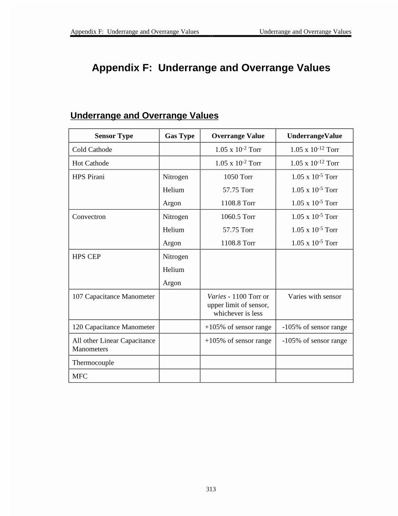
Appendix F: Underrange and Overrange Values Underrange and Overrange Values
313
Appendix F: Underrange and Overrange Values
Underrange and Overrange Values
Sensor Type Gas Type Overrange Value UnderrangeValue
Cold Cathode 1.05 x 10⁻² Torr 1.05 x 10⁻¹² Torr
Hot Cathode 1.05 x 10⁻² Torr 1.05 x 10⁻¹² Torr
HPS Pirani Nitrogen 1050 Torr 1.05 x 10⁻⁵ Torr
Helium 57.75 Torr 1.05 x 10⁻⁵ Torr
Argon 1108.8 Torr 1.05 x 10⁻⁵ Torr
Convectron Nitrogen 1060.5 Torr 1.05 x 10⁻⁵ Torr
Helium 57.75 Torr 1.05 x 10⁻⁵ Torr
Argon 1108.8 Torr 1.05 x 10⁻⁵ Torr
HPS CEP Nitrogen
Helium
Argon
107 Capacitance Manometer Varies - 1100 Torr orupper limit of sensor,
whichever is less
Varies with sensor
120 Capacitance Manometer +105% of sensor range -105% of sensor range
All other Linear CapacitanceManometers
+105% of sensor range -105% of sensor range
Thermocouple
MFC

Underrange and Overrange Values Appendix F: Underrange and Overrange Values
314
This page intentionally left blank.

Appendix G: Board Specific Commands General Information
315
Appendix G: Board Specific Commands
General Information
This appendix organizes the 146 commands by plug-in board type. It lists all the commandsnecessary to operate each type of sensor. The plug-in boards covered include:
• Capacitance Manometer
• Pirani/Convection
• Cold Cathode
• Hot Cathode
• Mass Flow Controller
• Thermocouple
• Auxiliary Output
• Control
The commands are arranged in four groups: power, configuration, calibration, and status. Referto the body of the manual for an explanation of each command. Although this appendix lists theRS-232 commands, the information applies to commands that are entered through both RS-232and front panel operations.

Capacitance Manometer Messages Appendix G: Board Specific Commands
316
Capacitance Manometer Messages
The 146 supports a wide variety of MKS capacitance manometers. Refer to Table 9, page 49, fora complete list of transducers.
Capacitance Manometer Messages
Function Description Command Range and Restrictions
Power Channelpower
@081<para>:<state> <para> is the channel number 1, 2, 3, or 4
<state> is ON for on; OFF for off
Sensor must be installed
Configuration Sensor fullscale
@061<para>:<fs> <para> is the channel number 1, 2, 3, or 4
<fs> 0.001 to 100,000 Torr equivalent
Sensor must be installed
Sensor type must be linear or Type 120
Sensorresolution
@062<para>:<res> <para> is the channel number 1, 2, 3, or 4
<res> is an ASCII value that represents theresolution as a power of 10, from +7 to -7.
Sensor type must be linear or Type 120
Calibration Zerofunction
@056<para>:<state> <para> is the channel number 1, 2, 3, or 4
<state> is ON for on; OFF for off
Sensor must be installed
Zerochannel
@051<para> <para> is the channel number 1, 2, 3, or 4
Command only
Zero function must be on
Auto zerofunction
@058<para>:<state> <para> is the channel number 1, 2, 3, or 4
<state> is E for enabled; D for disabled
Select autozeroreferencesensor
@059<para>:<ref> <para> is the channel number 1, 2, 3, or 4
<ref> is the reference channel number
Both sensors must be installed
(Continued on next page)

Appendix G: Board Specific Commands Capacitance Manometer Messages
317
Capacitance Manometer Messages (Continued)
Function Description Command Range and Restrictions
Status Reportchannelreading
@601<para>? <para> is the channel number 1, 2, 3, or 4
Request only - Sensor must be installed
Report readingwith timestamp
@602<para>? <para> is the channel number 1, 2, 3, or 4
Request only - Sensor must be installed
Report sensorvoltage
@603<para>? <para> is the channel number 1, 2, 3, or 4
Request only - Sensor must be installed
Reportchannelcondition
@608<para>? <para> is the channel number 1, 2, 3, or 4
Request only - Sensor must be installed

Pirani/Convection Messages Appendix G: Board Specific Commands
318
Pirani/Convection Messages
The 146 unit can identify the gauge as a Pirani or convection gauge. If the gauge is identified asa convection gauge, you must further identify the gauge as either a Granville-Phillips Convectrongauge or an HPS Convection Enhanced Pirani (CEP) gauge.
Pirani/Convection Messages
Function Description Command Range and Restrictions
Power Channelpower
@081<para>:<state> <para> is the channel number 1, 2, 3, or 4
<state> is ON for on; OFF for off
Sensor must be installed
Configuration Gas type @063<para>:<gas> <para> is the channel number 1, 2, 3, or 4
<gas> is N for nitrogenH for heliumA for argon
Convectiongauge type
@068<para>:<type> <para> is the channel number 1, 2, 3, or 4
<type> 4 for GP Convectron5 for HPS convection
(Continued on next page)
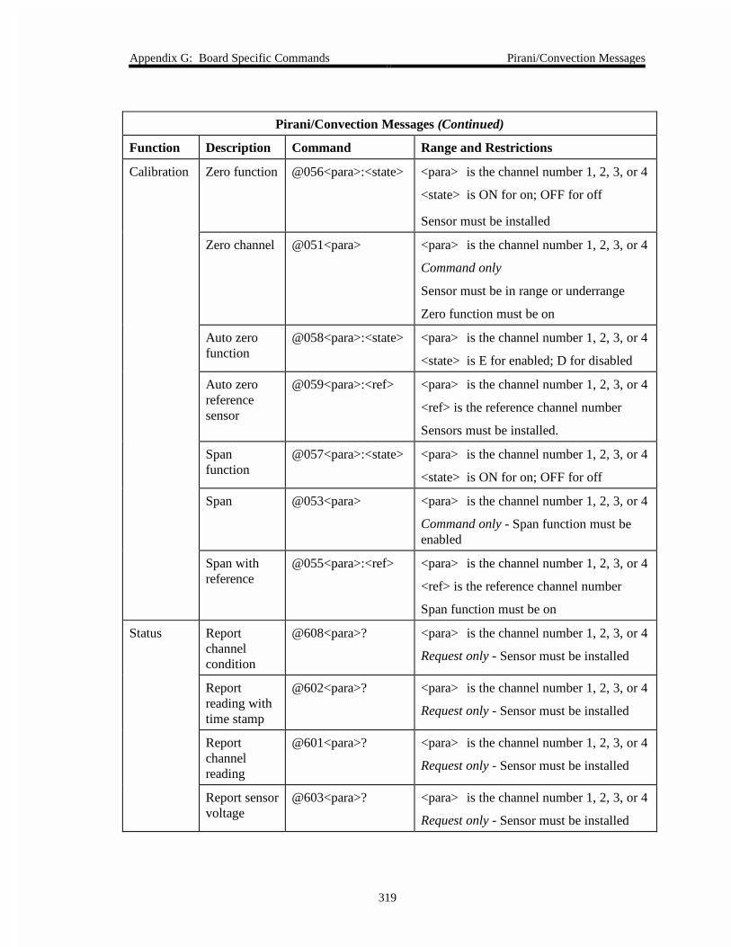
Appendix G: Board Specific Commands Pirani/Convection Messages
319
Pirani/Convection Messages (Continued)
Function Description Command Range and Restrictions
Calibration Zero function @056<para>:<state> <para> is the channel number 1, 2, 3, or 4
<state> is ON for on; OFF for off
Sensor must be installed
Zero channel @051<para> <para> is the channel number 1, 2, 3, or 4
Command only
Sensor must be in range or underrange
Zero function must be on
Auto zerofunction
@058<para>:<state> <para> is the channel number 1, 2, 3, or 4
<state> is E for enabled; D for disabled
Auto zeroreferencesensor
@059<para>:<ref> <para> is the channel number 1, 2, 3, or 4
<ref> is the reference channel number
Sensors must be installed.
Spanfunction
@057<para>:<state> <para> is the channel number 1, 2, 3, or 4
<state> is ON for on; OFF for off
Span @053<para> <para> is the channel number 1, 2, 3, or 4
Command only - Span function must beenabled
Span withreference
@055<para>:<ref> <para> is the channel number 1, 2, 3, or 4
<ref> is the reference channel number
Span function must be on
Status Reportchannelcondition
@608<para>? <para> is the channel number 1, 2, 3, or 4
Request only - Sensor must be installed
Reportreading withtime stamp
@602<para>? <para> is the channel number 1, 2, 3, or 4
Request only - Sensor must be installed
Reportchannelreading
@601<para>? <para> is the channel number 1, 2, 3, or 4
Request only - Sensor must be installed
Report sensorvoltage
@603<para>? <para> is the channel number 1, 2, 3, or 4
Request only - Sensor must be installed

Cold Cathode Messages Appendix G: Board Specific Commands
320
Cold Cathode Messages
The 146 unit supports up to four cold cathode gauges.
Cold Cathode Messages
Function Description Command Range and Restrictions
Power Channelpower
@081<para>:<state> <para> is the channel number 1, 2, 3, or 4
<state> is ON for on; OFF for off
Sensor must be installed
Auto powerfunction
@082<para>:<state> <para> is the channel number 1, 2, 3, or 4
<state> is E for enabled; D for disabled
Auto powerreference
@083<para>:<ref> <para> is the channel number 1, 2, 3, or 4
<ref> is the reference channel ID
Auto powershutoffpressure
@084<para>:<pres> <para> is the channel number 1, 2, 3, or 4
<pres> is the shutoff pressure, in ASCII
Configuration Gaugefactor
@064<para>:<fact> <para> is the channel number 1, 2, 3, or 4
<fact> is a numeric ASCII string
Disconnectpressure
@065<para>:<pres> <para> is the channel number 1, 2, 3, or 4
<pres> is the disconnect pressure, inASCII
Calibration Spanfunction
@057<para>:<state> <para> is the channel number 1, 2, 3, or 4
<state> ON for on; OFF for off
Sensor must be installed
Span withreference
@055<para>:<ref> <para> is the channel number 1, 2, 3, or 4
<ref> is the reference channel number
Span function must be on
Span @053<para> <para> is the channel number 1, 2, 3, or 4
Command only - Span function must be on
(Continued on next page)

Appendix G: Board Specific Commands Cold Cathode Messages
321
Cold Cathode Messages (Continued)
Function Description Command Range and Restrictions
Status Report channelcondition
@608<para>? <para> is the channel number 1, 2, 3, or 4
Request only - Sensor must be installed
Report readingwith time stamp
@602<para>? <para> is the channel number 1, 2, 3, or 4
Request only - Sensor must be installed
Report channelreading
@601<para>? <para> is the channel number 1, 2, 3, or 4
Request only - Sensor must be installed
Report sensorvoltage
@603<para>? <para> is the channel number 1, 2, 3, or 4
Request only - Sensor must be installed
Report sensor ioncurrent
@604<para>? <para> is the channel number 1, 2, 3, or 4
Request only - Sensor must be installed

Hot Cathode Messages Appendix G: Board Specific Commands
322
Hot Cathode Messages
The 146 unit supports up to four hot cathode gauges.
Hot Cathode Messages
Function Description Command Range and Restrictions
Power Channelpower
@081<para>:<state> <para> is the channel number 1, 2, 3, or 4
<state> is ON for on; OFF for off
Sensor must be installed
Auto powerfunction
@082<para>:<state> <para> is the channel number 1, 2, 3, or 4
<state> is E for enabled; D for disabled
Auto powerreference
@083<para>:<ref> <para> is the channel number 1, 2, 3, or 4
<ref> is the reference channel number
Auto powershutoffpressure
@084<para>:<pres> <para> is the channel number 1, 2, 3, or 4
<pres> is the shutoff pressure, in ASCII
Degas @085<para>:<dgas> <para> is the channel number 1, 2, 3, or 4
<dgas> is: H for high power degasL for low power degasO for degas function off
Configuration Select gaugefactor
@064<para>:<fact > <para> is the channel number 1, 2, 3, or 4
<fact> is a numeric ASCII string
Disconnectpressure
@065<para>:<pres> <para> is the channel number 1, 2, 3, or 4
<pres> is the disconnect pressure, in ASCII
High pressureshutoff
@066<para>:<pres> <para> is the channel number 1, 2, 3, or 4
<pres> is the shutoff pressure, in ASCII
Fail-Safefunction
@067<para>:<state> <para> is the channel number 1, 2, 3, or 4
<state> is E for enabled; D for disabled
(Continued on next page)

Appendix G: Board Specific Commands Hot Cathode Messages
323
Hot Cathode Messages (Continued)
Function Description Command Range and Restrictions
Calibration Span function @057<para>:<state> <para> is the channel number 1, 2, 3, or 4
<state> is ON for on; OFF for off
Sensor must be installed
Span withreference
@055<para>:<ref> <para> is the channel number 1, 2, 3, or 4
<ref> is the reference channel number
Span function must be on
Span @053<para> <para> is the channel number 1, 2, 3, or 4
Command only - Span function must be on
Status Report channelcondition
@608<para>? <para> is the channel number 1, 2, 3, or 4
Request only - Sensor must be installed
Report readingwith timestamp
@602<para>? <para> is the channel number 1, 2, 3, or 4
Request only - Sensor must be installed
Report channelreading
@601<para>? <para> is the channel number 1, 2, 3, or 4
Request only - Sensor must be installed
Report sensorion current
@604<para>? <para> is the channel number 1, 2, 3, or 4
Request only - Sensor must be installed
Report sensoremissioncurrent
@605<para>? <para> is the channel number 1, 2, 3, or 4
Request only - Sensor must be installed

Mass Flow Controller Messages Appendix G: Board Specific Commands
324
Mass Flow Controller Messages
The 146 instrument supports all MKS mass flow controllers, and equivalent flow controllers.
Mass Flow Controller Messages
Function Description Command Range and Restrictions
Power Channelpower
@081<para>:<state> <para> is the channel number 1, 2, 3, or 4
<state> is ON for on; OFF for off
MFC must be installed
Configuration MFC range @061<para>:<rng> <para> is the channel number 1, 2, 3, or 4
<rng> is a number between 0.0002 sccmto 1 x 10⁵ sccm
Operatingmode
@101<para>:<mode> <para> is the channel number 1, 2, 3, or 4
<mode> is R for RatioS for Set PointT for Totaling
Set Pointvalue
@102<para>:<value> <para> is the channel number 1, 2, 3, or 4
<value> is from ±105% MFC F.S. range
Totaling co-channel
@103<para>:<chan> <para> is the channel number 1, 2, 3, or 4
<chan> is the co-channel number
Override @104<para>:<cmd> <para> is the channel number 1, 2, 3, or 4
<cmd> is O for OpenC for CloseN for Cancel
Calibration Zerofunction
@056<para>:<state> <para> is the channel number 1, 2, 3, or 4
<state> is ON for on; OFF for off
Sensor must be installed
Zerochannel
@051<para> <para> is the channel number 1, 2, 3, or 4
Command only
Sensor must be in range or underrange
Zero function must be on
(Continued on next page)

Appendix G: Board Specific Commands Mass Flow Controller Messages
325
Mass Flow Controller Messages
Function Description Command Range and Restrictions
Status Report MFCstatus
@608<para>? <para> is the channel number 1, 2, 3, or 4
Request only - MFC must be installed
Report MFCflow rate
@601<para>? <para> is the channel number 1, 2, 3, or 4
Request only - MFC must be installed
Report MFCflow ratewith timestamp
@602<para>? <para> is the channel number 1, 2, 3, or 4
Request only - MFC must be installed
Report MFCvoltage
@603<para>? <para> is the channel number 1, 2, 3, or 4
Request only - MFC must be installed

Thermocouple Messages Appendix G: Board Specific Commands
326
Thermocouple Messages
The 146 instrument supports the MKS TC-1A and the Hastings DV-6M thermocouples.
Thermocouple Messages
Function Description Command Range and Restrictions
Power Channel power @081<para>:<state> <para> is the channel number 1, 2, 3, or 4
<state> is ON for on; OFF for off
Sensor must be installed
Configuration Gas Type @063<para>:<gas> <para> is the channel number 1, 2, 3, or 4
<gas> is N for nitrogen; H for helium; A for argon
Calibration Zero function @056<para>:<state> <para> is the channel number 1, 2, 3, or 4
<state> is ON for on; OFF for off
Sensor must be installed
Zero channel @051<para> <para> is the channel number 1, 2, 3, or 4
Command only
Sensor must be in range or underrange
Zero function must be on
Auto zerofunction
@058<para>:<state> <para> is the channel number 1, 2, 3, or 4
<state> is E for enabled; D for disabled
Auto zeroreference sensor
@059<para>:<ref> <para> is the channel number 1, 2, 3, or 4
<ref> is the ref. channel number
Sensors must be installed
Status Report sensorstatus
@608<para>? <para> is the channel number 1, 2, 3, or 4
Request only - Sensor must be installed
Report sensorreading
@601<para>? <para> is the channel number 1, 2, 3, or 4
Request only - Sensor must be installed
Report readingwith time stamp
@602<para>? <para> is the channel number 1, 2, 3, or 4
Request only - Sensor must be installed
Report sensorvoltage
@603<para>? <para> is the channel number 1, 2, 3, or 4
Request only - Sensor must be installed
Report channelcondition
@608<para>? <para> is the channel number 1, 2, 3, or 4
Request only - Sensor must be installed

Appendix G: Board Specific Commands Auxiliary Output Messages
327
Auxiliary Output Messages
The Auxiliary Output board provides two relays (in addition to relays A and B, available on theGeneral I/O connector), and two analog outputs (in addition to the single analog output providedby the General I/O connector).
Auxiliary Output Messages
Function Description Command Range and Restrictions
Alarms Alarm enable @011<para>:<data> <para> is the alarm letter (A through D)
<data> is E for enabled; D for disabled
Trip pointvalue
@012<para>:<data> <para> is the alarm letter (A through D)
<data> is the trip point pressure, from-100000 to 100000 Torr, inclusive
Alarmassociation
@013<para>:<chan> <para> is any character (no significance)
<chan> is the input channel (1, 2, 3, or 4)
Unlatch cur-rently alarmedrelays
@014<para> <para> is any character (no significance)
Status alert @015<para>:<state> <para> is any character (no significance)
<state> is E for enabled; D for disabled
Untripped stateof unlatchedrelay
@016<chan>:<state> <chan> is the alarm letter (A through D)
<state> is A for actuated; D for deactuated
Relay Status @60A<alarm>? <alarm> is the alarm letter
Request only
Response: E = Enabled, D = Disabled,T = Tripped
Alarm Status @60B<alarm>? <alarm> is the alarm letter
Request only
Response: E = Enabled, D = Disabled,T = Tripped
(Continued on next page)

Auxiliary Output Messages Appendix G: Board Specific Commands
328
Auxiliary Output Messages (Continued)
Function Description Command Range and Restrictions
AnalogOutputs
ChannelOutput Type
@071<para>:<type> <para> is the analog output (1, 2, or 3)
<type> is LN for linearLO1 to LO9 for log 1 to log 9SP for set point
Input ChannelSelection
@072<para>:<chan> <para> is the analog output (1, 2, or 3)
<chan> is the input channel (1, 2, 3, 4, 5(dual 1), or 6 (dual 2))
FS Pressure(10 V output)
@073<para>:<pres> <para> is the analog output (1, 2, or 3)
<pres> is the full scale pressure

Appendix G: Board Specific Commands Control Messages
329
Control Messages
The Control board allows you to use the 146 as a closed-loop controller. The control messagesare separated into three categories: General; Control Adjust; and Recipe Specific messages.
Control Messages
Function Description Command Range and Restrictions
GeneralControl
Control mode @021<para>:<mode> <para> is channel number (0*, 1)
<mode> is A for autoO for openC for closeH for holdM for manual
Active recipe @022<para>:<data> <para> is control channel number (0*, 1)
<data> is the recipe number 1, 2, 3, or 4
ControllerPolarity
@023<para>:<data> <para> is control channel number (0*, 1)
<data> is D for direct; R for reverse
CurrentSetting
ControlMode
@60C<para>? <para> is control channel number (0*, 1)
CurrentRecipe
@60D<para>? <para> is control channel number (0*, 1)
Current PIDSet Point
@60E<para>? <para> is control channel number (0*, 1)
PCS Output @60F<para>? <para> is control channel number (0*, 1)
* Control channel 0 is a virtual control channel used in conjunction with Mass Flow Controllers
(Continued on next page)

Control Messages Appendix G: Board Specific Commands
330
Control Messages (Continued)
Function Description Command Range and Restrictions
ControlAdjust
Integral @031<para>:<data> <para> is control channel number (0*, 1)
<data> is from 0.01 to 100 seconds
Base @032<para>:<data> <para> is control channel number (0*, 1)
<data> is from 0 to 103 (% of full open)
Start @033<para>:<data> <para> is control channel number (0*, 1)
<data> is from 0 to 103 (% of full open)
Alpha @034<para>:<data> <para> is control channel number (0*, 1)
<data> is from 5 to 99, inclusive
Preset @035<para>:<data> <para> is control channel number (0*, 1)
<data> is from 0 to 103 (% of full open)
Output @036<para>:<data> <para> is control channel number (0*, 1)
<data> is from 0 to 100% inclusive
Softstart speed @037<para>:<data> <para> is control channel number (0*, 1)
<data> is from 1.0 to 990 seconds
Set point F.S. @038<para>:<data> <para> is control channel number (0*, 1)
<data> is from 0 to 10 Volts
RecipeSpecific
Set point value @041<para>:<pres> <para> is the recipe number, 1, 2, 3, or 4
<pres> is from ±100,000 Torr
Lead @042<para>:<lead> <para> is the recipe number, 1, 2, 3, or 4
<lead> is from 0.001 to 1000 seconds
Gain @043<para>:<gain> <para> is the recipe number, 1, 2, 3, or 4
<gain> is from 0.001 to 10,000
Softstart @044<para>:<pres> <para> is the recipe number, 1, 2, 3, or 4
<pres> is from 1.0 to 990 seconds
Select analogset point
@045<para>:<state> <para> is the recipe number, 1, 2, 3, or 4
<state> is E for enabled; D for disabled
Analog setpoint range
@046<para>:<rng> <para> is the recipe number, 1, 2, 3, or 4
<rng> is 0 to 100,000 Torr
ControlChannel
@047<para>:<chan> <para> is the recipe number, 1, 2, 3, or 4
<chan> is the input channel, 1, 2, 3, or 4
* Control channel 0 is a virtual control channel used in conjunction with Mass Flow Controllers
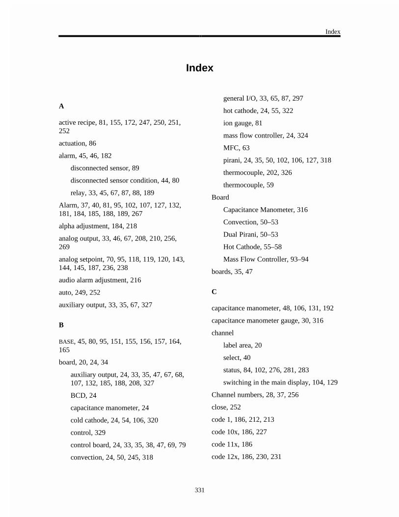
Index
331
Index
A
active recipe, 81, 155, 172, 247, 250, 251,252
actuation, 86
alarm, 45, 46, 182
disconnected sensor, 89
disconnected sensor condition, 44, 80
relay, 33, 45, 67, 87, 88, 189
Alarm, 37, 40, 81, 95, 102, 107, 127, 132,181, 184, 185, 188, 189, 267
alpha adjustment, 184, 218
analog output, 33, 46, 67, 208, 210, 256,269
analog setpoint, 70, 95, 118, 119, 120, 143,144, 145, 187, 236, 238
audio alarm adjustment, 216
auto, 249, 252
auxiliary output, 33, 35, 67, 327
B
BASE, 45, 80, 95, 151, 155, 156, 157, 164,165
board, 20, 24, 34
auxiliary output, 24, 33, 35, 47, 67, 68,107, 132, 185, 188, 208, 327
BCD, 24
capacitance manometer, 24
cold cathode, 24, 54, 106, 320
control, 329
control board, 24, 33, 35, 38, 47, 69, 79
convection, 24, 50, 245, 318
general I/O, 33, 65, 87, 297
hot cathode, 24, 55, 322
ion gauge, 81
mass flow controller, 24, 324
MFC, 63
pirani, 24, 35, 50, 102, 106, 127, 318
thermocouple, 202, 326
thermocouple, 59
Board
Capacitance Manometer, 316
Convection, 50–53
Dual Pirani, 50–53
Hot Cathode, 55–58
Mass Flow Controller, 93–94
boards, 35, 47
C
capacitance manometer, 48, 106, 131, 192
capacitance manometer gauge, 30, 316
channel
label area, 20
select, 40
status, 84, 102, 276, 281, 283
switching in the main display, 104, 129
Channel numbers, 28, 37, 256
close, 252
code 1, 186, 212, 213
code 10x, 186, 227
code 11x, 186
code 12x, 186, 230, 231

Index
332
code 13x, 186, 232, 233
code 14x, 187, 234, 235
code 15x, 187, 236
code 16x, 187, 239
code 17x, 187, 200, 241
code 18x, 187, 195, 245
code 2, 186, 215
code 3, 186, 216, 217
code 4, 186, 218, 219
code 5, 186, 220, 221, 224
code 7, 125, 186, 222, 223
code 8, 186, 220, 224, 225
cold cathode gauge, 30, 320
control board, 33, 35, 38, 47, 69, 79, 90, 92,101, 118, 143, 151, 211, 218, 230, 232, 234,236, 239, 250, 329
control theory, 90
convection gauge, 318
D
data logger interval, 96, 184, 186, 220, 224,225
deviation indicator, 81, 160, 249, 250
diagnostics feature, 291
dual channel, 17, 40, 46, 96, 102, 104, 105,127, 129, 185, 204, 206, 235
Dual Pirani board, 50–53
single channel, 51, 60
E
Errors, 287, 305
F
failsafe, 68
front panel, 17, 20, 39, 43, 152, 289
function, 21
fuses, 33, 290
G
GAIN, 40, 42, 45, 81, 95, 151, 155, 156,157, 159, 161, 172, 173, 174, 175, 250, 251,252
gain, 90, 91
H
hold, 253
Hot Cathode board, 55–58
low power configuration, 57
hot cathode gauge, 30, 322
I
input channels, 256
installation
communication and power connections,33
MFC connections, 33
new configuration warning code, 37
product location and requirements, 29
setup, 32
start up, 38
transducer connections, 33
Installation, 23
unpack, 23
Installation Category, 29
INTEGRAL, 45, 95, 151, 155, 156, 157, 168,169
Integral, 90, 91
Ion gauges, 55

Index
333
K
keys, 19, 40, 41, 159
L
latchability state, 88
LCD, 17, 20, 43, 293
LEAD, 40, 42, 45, 81, 90, 91, 95, 151, 155,156, 157, 159, 172, 173, 176, 177, 218, 251,252
Leak rate, 280
leakage mode, 127
M
maintenance, 22
Maintenance, 289
mass flow controller, 30, 63, 324
mass flow controller, 93–94
memory storage, 95
miscellaneous codes, 81, 181, 182, 186,187, 211
mode, 21, 42, 45, 79, 247
N
new configuration warning code, 37
normal mode
software version display, 102, 103, 127
O
open, 251
operational diagram, 18, 82
output channels, 256
overrange, 307, 313
P
parameter, 21, 154, 258
parameter data, 95
PCS, 69, 93, 242
pirani gauge, 30, 318
Pollution Degree, 29
PRESET, 45, 95, 151, 155, 156, 157, 170,171, 247
pressure control, 69, 90, 92
pump choking, 90, 92
R
recipes, 17, 81, 151, 172, 235, 236, 247,251
RS-232
configure port, 220
RS-232 communications, 79, 255
RS-232 connector, 33, 77
S
safety procedures, 29, 106, 131
sensor
calibration, 46, 112, 137, 182, 185, 190,263
turn on/off, 106
set point, 92
set point, 90
SETPOINT, 41, 95, 118, 143, 144, 145, 151,153, 155, 156, 157, 159, 161, 172, 173, 178,179, 187, 208, 210, 236, 237, 249, 250, 251,252
Setup mode, 181–246
edit data logger interval, 220, 224
softstart
adjustment, 232

Index
334
software version, 102, 127
software version display, 103, 128
SPAN, 40, 41, 102, 113, 115, 117, 127, 138,140, 142, 185, 192, 195, 261
start, 38, 45, 95, 151, 155, 156, 157, 166,167
status, channel, 281, 283
status, 102, 276
status, channel, 84
system design elements, 90
system requirements, 30
pressure transducer selection, 30
valve selection, 30
T
temperature, 29
thermocouple, 59, 202, 326
TRIP POINT, 46, 86, 87, 88, 95, 184, 185,188, 189
troubleshooting, 291
diagnostics feature, 291
U
underrange, 307, 313
V
valve position
changing, 156, 162
Z
zero
a sensor, 133
MFC, 108
sensor, 108
zero-of-a-sensor
toggling on/off, 102, 127