mixing box - schako.com
TRANSCRIPT

Ferdinand Schad KGSteigstraße 25-27
D-78600 KolbingenTelephone +49 (0) 74 63 - 980 - 0
Fax +49 (0) 74 63 - 980 - [email protected]
Mixing BoxMBE / MBP

Contents
Construction subject to change. No return possible!
Mixing Box Model MBE / MBP
08/20 - 2 26.08.2016Version:
Description ........................................................................................................................................3Installation ................................................................................................................................................................................. 5Construction .............................................................................................................................................................................. 5Model ......................................................................................................................................................................................... 5Accessories ................................................................................................................................................................................ 5
Models and dimensions .........................................................................................................................6Dimensions ................................................................................................................................................................................ 6Dimensions of accessories ........................................................................................................................................................ 7
Technical data ....................................................................................................................................8Volumetric flow range ................................................................................................................................................................ 8Sound values ............................................................................................................................................................................. 9Flow generated noise ............................................................................................................................................................... 10Radiated noise ......................................................................................................................................................................... 11Technical data of the control components ............................................................................................................................... 12Circuit diagrams ....................................................................................................................................................................... 13Setting the operating potentiometers / calculation formulae .................................................................................................... 18Technical data of controllers and motors ................................................................................................................................. 20Functional check ...................................................................................................................................................................... 22Startup using PC-Tool .............................................................................................................................................................. 23Startup using the setting and diagnostic device ZTH EU (Belimo) ........................................................................................... 24Controller selection .................................................................................................................................................................. 25Maintenance and service .......................................................................................................................................................... 25
Legend ........................................................................................................................................... 26Order details .................................................................................................................................... 26Specification texts .............................................................................................................................. 27

Mixing Box Model MBE / MBP
DescriptionThe mixing box type MBE/MBP consists of a housing with tworound connection pipes and an integrated silencer unit for re-ducing flow generated noise. Two volumetric flow controllersare integrated, in order to allow the volumetric flow in ducts tobe kept constant or variable or to be regulated using positivecontrol Vmin, Vmax or "CLOSED". It is used in two-duct air-con-ditioning systems, in which control and mixing can be carriedout electrically or pneumatically, as desired. The measuringsensor used in the cold-air connection pipe and in the silencerunit is a flow-resistant measuring cross on which 12 measuringpoints have been distributed by the median line method, to allowa precise air flow measurement. A control flap is integrated inthe round connection spigot to dampen and shut off. The firstsetting of values is done in-factory. With this factory setting, allmixing boxes are checked for correct functioning. The maxi-mum deviation of the volumetric flows is +/- 5%, relative to thenominal volumetric flow Vnenn, based on a calibration curve of12 m/sec. At lower flow rates, the deviation in percent may in-crease.For the calibration of the controllers, a curve with a flow rate of12 m/sec. is available. For constant-volume volumetric flowcontrollers, the Vmin value will be set to the desired constant-volume value. If the calibration curve must be changed on site, the controllersmust either be recalibrated in-factory or the calibration curvemust be changed on site by the customer service of Schako.
For the measurement of the effective pressure, Schako is usingits measuring principle by means of a double measuring crossmade of extruded aluminium profile, to which 12 measuringpoints have been attached on the pressure and suction side, re-spectively, by the median line method, in order to determine av-erage values. In comparison with measuring rods or measuringorifices having fewer measuring points, this gives higher accu-racy, allowing the inflow area required in front of the volumetricflow controller to be minimised (see page 5 - Installation Infor-mation).
When using the controllers in systems with heavy dust contam-ination, suitable filters must be connected upstream. For pollut-ed air, use static membrane pressure sensors as transmitters.In this case, it is imperative to observe the notice sign regardingthe mounting position. The mixing boxes are not suitable for aircontaining sticky and oily particles.
In all controller brands, the direction of rotation for opening is clockwise.
For maintenance, service, retrofitting, etc., inspection openings in sufficient number and size must be provided on site.
Field of application
Attention:The cold air connection piece must be insulated on site if there is a risk of condensate formation.
- for supply air systems- for constant or variable volumetric flows- Positive control Vmin, Vmax, or "CLOSED"- Differential pressure range 250 - 1000 Pa- for duct velocities:
- MBE (electric) = 4 - 12 m/s- MBP (pneumatic) = 4 - 12 m/s
- for ambient temperatures of 0 - 50°C- Measuring air condition 0 - 50°C- 5 - 95% r.h., non-condensing
- Supply voltage for MBE (electric):24 V AC (19.2...28.8V) or 24 V DC (21.6...28.8V)
- Feed pressure for MBP (pneumatic): 1.2 ± 0.1 bar- Design for spiral duct connection to DIN 24145- With integrated silencer to reduce flow generated noise- Additional acoustic cladding to reduce radiated noise availa-
ble at an extra charge- Additional silencer for further reduction of the flow generated
noise available at an extra charge. Only possible in connection with a connection frame (-AR)
08/20 - 3
Construction subject to change. No return possible!
26.08.2016Version:

Mixing Box Model MBE / MBP
RegulationMixing boxes are used in twin-duct air-conditioning systems.The unit mixes cold and hot air in such a way that the differencebetween the highest and the lowest temperature at the outlet ofthe device (low-pressure side) is less than 10%. Two controlcircuits independent of one another are formed, which allow thesupply air to be controlled at a constant or variable flow rate.The differential pressure sensor for the cold air, with a measur-ing cross in the connection pipe (1), together with the cold aircontroller (2), forms a control circuit which is managed by theroom temperature control (8) via a 0(2) - 10 V DC signal. Thehot air control circuit comprising a differential pressure sensor,measuring cross (3) in the rectangular silencer unit (7) and hotair controller (4) is set to "constant" as standard and controls thetotal air volume by admixing the amount of hot air necessary forthe sum of cold air and hot air to reach the total air volume. Ifthe cold air volume exceeds the total air volume, the hot air con-trol damper (5) will be completely closed. When cooling air de-mand decreases, the cold air control damper (6) is closed. Theactual throughput of the air volume can be measured and eval-uated via the U5 signal of the controllers (in the case of electricmixing boxes). Pneumatic mixing box MBP: Unlike the electronic mixing boxMBE, this mixing box does not require a measuring cross (1)mounted in the round cold air connection pipe. A volumetricflow controller (PI or I controller) for activating the pneumaticactuators is adequate for control.Cold air either left or right as desired (shown on the left)
W = Hot airK = Cold air
W
W
K
08/20 - 4
Construction subject to change. No return possible!
26.08.2016Version:

Mixing Box Model MBE / MBP
InstallationInstallation informationTo avoid unnecessary controller errors, the min. distances ac-cording to the following table / drawings must be observed. Forcombinations of several connection pieces or pieces with firedampers or silencers, the larger minimum distances must beobserved.
Distance to:
Distance to a bent connection piece
Distance to other connection pieces(e.g. branching piece, reduction piece, T-junction, etc.)
Distance to a fire damper
Distance to a silencer
Construction
Model
Accessories
Connection piece with bend: 1 x DOther connection pieces:(e.g. T-junction, branching piece, reduction piece, etc.)
2 x D
Fire dampers: 2 x DSilencers: 2 x D
Housing
- Galvanised sheet steel
- abrasion-resistant up to a duct velocity of 20 m/s
- Lined with mineral wool, perforated sheet cover.
Damper leaf seal
- made of PUR, silicone-free
- for airtight design to DIN EN 1751 Class 2 (NW100 only), Class 3 (NW125 - 400 only).
Guide baffle
- Galvanised sheet steel, perforated
Measuring cross
- Blades made of extruded aluminium profile
- Blade mount made of plastic (PA 6).
Silencer unit
- Lined with mineral wool, perforated sheet cover.
Hot and cold air control damper
- galvanised sheet steel
MBE - With electric controlMBP - With pneumatic control...-KR - Cold air right in air flow direction...-KL - Cold air left in air flow direction (standard)
Connection frame (-AR)- Galvanised sheet steel
Acoustic cladding (-DS)- Galvanised sheet steel, with mineral wool lining
Rubber lip seal (-GD)- Special rubber
Additional silencer (-ZS)- Galvanised sheet steel, baffle with mineral wool lining
(MWK) and optionally with perforated sheet cover (MLK).
08/20 - 5
Construction subject to change. No return possible!
26.08.2016Version:

Mixing Box Model MBE / MBP
Models and dimensionsDimensionsMBE MBP
View A View C
View B View D
Available sizes
For sizes 315 and 400, the housing consists of two parts mounted ex works.
Inspection opening
Rivet nut M8 Through-hole ø10
Inspection opening
Rivet nut M8 Through-hole ø10
NW B B1 BK H HK L øD a b c100 360 400 250 220 160 1100 98 194 286 178125 480 520 370 230 170 1100 123 204 399 238160 580 620 470 260 200 1400 158 234 504 288200 700 740 590 290 230 1500 198 259 624 348250 880 920 770 340 280 1500 248 309 804 438315 1000 1040 890 440 385 1835 313 409 924 498400 1400 1440 1290 490 430 1835 398 459 1324 698
08/20 - 6
Construction subject to change. No return possible!
26.08.2016Version:

Mixing Box Model MBE / MBP
Dimensions of accessoriesAcoustic cladding (-DS) and additional silencer (-ZS)
Available sizes
For sizes 315 and 400, the housing consists of two parts mounted ex works.
NW B B1 DB DB1 BK H DH HK AH AB L SL øD a b= = =
SB SB1 SH100 360 400 440 480 250 220 300 160 209 352 1100
1000
98 194 286125 480 520 560 600 370 230 310 170 219 465 1100 123 204 399160 580 620 660 700 470 260 340 200 249 570 1400 158 234 504200 700 740 780 820 590 290 370 230 274 690 1500 198 259 624250 880 920 960 1000 770 340 420 280 324 870 1500
1500248 309 804
315 1000 1040 1080 1120 890 440 520 385 424 990 1835 313 409 924400 1400 1440 1480 1520 1290 490 570 430 474 1390 1835 398 459 1324
Acoustic claddingAdditional silencer
View X Section A-Ashown without connection frame
Section C-Cshown without connection frame
Connection frame (-AR) Rubber lip seal (-GD)Detail X
08/20 - 7
Construction subject to change. No return possible!
26.08.2016Version:

Mixing Box Model MBE / MBP
Technical data
Volumetric flow rangefor MBE (constant or min/max)
for MBP (constant or min/max)
Attention, the following specifications are important for pro-gramming the volumetric flow controllers:
NW V Hot air controlTotal air volume
Cold air control variable
ø electrical electrical
(mm)vmin
(4m/s)vmax
(12m/s)vmin
(2 m/s)vmax
(12 m/s)
100m3/h 106 319 53 319
l/s 30 89 15 89
125m3/h 168 505 84 505
l/s 47 140 23 140
160m3/h 279 836 139 836
l/s 77 232 37 232
200m3/h 439 1317 219 1317
l/s 122 366 61 366
250m3/h 690 2070 345 2070
l/s 192 575 96 575
315m3/h 1101 3303 550 3303
l/s 306 918 153 918
400m3/h 1783 5348 891 5348
l/s 495 1486 248 1486
NW V Hot air control Cold air control variableø pneumatic pneumatic
(mm)vmin
(4m/s)vmax
(12m/s)vmin
(4 m/s)vmax
(12 m/s)
100m3/h 106 319 106 319
l/s 30 89 30 89
125m3/h 168 505 168 505
l/s 47 140 47 140
160m3/h 279 836 279 836
l/s 77 232 77 232
200m3/h 439 1317 439 1317
l/s 122 366 122 366
250m3/h 690 2070 690 2070
l/s 192 575 192 575
315m3/h 1101 3303 1101 3303
l/s 306 918 306 918
400m3/h 1783 5348 1783 5348
l/s 495 1486 495 1486
- This table merely specifies the complete measuring range ofthe controller (volumetric flow range)
- If the customer wants a calibration curve different from 12 m/s, it must be specified!
- When the air volume drops below the Vmin shown in the ta-bles, the correct functioning of the volumetric flow controlleris no longer guaranteed!
- If only one air volume is specified in the order (as Vmax value),the volumetric flow controller will be delivered as variable vol-umetric flow controller. The Vmin value will be set to the valuespecified in the catalogue.
- If only one air volume is specified in the order (as Vmin orVkonstant value or without specifying a value), then the volu-metric flow controller will be delivered as a constant volumet-ric flow controller. The volume specified in the order is set tothe Vmin value, and the Vmax value is set to 100%.
- The air volumes can be changed using setting devices specif-ic of the controller make, depending on the calibration curveset ex works.
- For the parameter setting of the control components (all con-trollers), an air density of 1.2 kg/m³ has been taken into ac-count.
- Belimo compact controllers are elevation-compensated. Theyare calibrated ex works to the specific system elevation of thespecified installation site.
- If no system elevation is given in the order, the controllers willbe calibrated to the elevation of the delivery address.
08/20 - 8
Construction subject to change. No return possible!
26.08.2016Version:

Mixing Box Model MBE / MBP
Sound valuesMBE / MBP, without acoustic cladding MBE / MBP - DS, with acoustic cladding (-DS)
MBE / MBP-ZS, with additional silencer (-ZS)
Insertion loss MBE / MBP
Insertion loss as the difference of the sound power levels meas-ured with and without the mixing box.
NW De (dB/oct)
fm (Hz)
125
250
500
100
0
200
0
400
0
800
0
with
out a
dditi
onal
sile
ncer 100
17 24 34 38 36 28 21125
160
200
22 28 40 41 40 34 28250
315
400
with
add
ition
al s
ilenc
er 100
23 30 43 44 42 33 27125
160
200
29 33 48 49 47 42 35250
315
400
Z Supply airA Return air1 Supply air flow generated noise without silencer2 Supply air flow generated noise with silencer
3 Radiated noise of supply air without acoustic clad-ding
4 Radiated noise of supply air with acoustic cladding5 Flow generated noise in round duct for supply air
08/20 - 9
Construction subject to change. No return possible!
26.08.2016Version:

Mixing Box Model MBE / MBP
Flow generated noisewith / without additional silencer (-ZS)
NW vk V Static pressure difference(m/s) (m3/h) [l/s] 250 Pa 500 Pa 1000 Pa
LWA [dB(A)] LWA [dB(A)] LWA [dB(A)]without additional
silencerwith additional
silencerwithout additional
silencerwith additional
silencerwithout additional
silencerwith additional
silencer
100
3 80 22 26 19 30 23 34 276 160 44 29 22 33 26 37 309 239 66 32 24 36 28 40 3212 319 89 38 30 42 34 46 38
125
3 126 35 32 24 36 28 40 326 253 70 34 26 38 30 42 349 379 105 37 31 41 35 45 3912 505 140 41 33 45 37 49 41
160
3 209 58 34 27 38 31 42 356 418 116 38 30 42 34 46 389 627 174 42 34 46 38 50 4212 836 232 44 36 48 40 52 44
200
3 329 91 35 26 39 30 43 346 658 183 38 29 42 33 46 379 988 274 43 34 47 38 51 4212 1317 366 47 38 51 42 55 46
250
3 517 144 36 26 40 30 44 346 1035 288 39 29 43 33 47 379 1552 431 44 33 48 37 52 4112 2070 575 49 38 53 42 57 46
315
3 826 229 37 26 41 30 45 346 1651 459 40 29 44 33 48 379 2477 688 45 34 49 38 53 4212 3303 918 50 39 54 43 58 47
400
3 1337 371 39 28 43 32 47 366 2674 743 42 30 46 34 50 389 4011 1114 46 34 50 38 54 4212 5348 1486 52 40 56 44 60 48
08/20 - 10
Construction subject to change. No return possible!
26.08.2016Version:

Mixing Box Model MBE / MBP
Radiated noisewith / without acoustic cladding (-DS)
NW vk V Static pressure difference(m/s) (m3/h) [l/s] 250 Pa 500 Pa 1000 Pa
LWA [dB(A)] LWA [dB(A)] LWA [dB(A)]without acoustic cladding 40 mm
with acousticcladding 40 mm
without acoustic cladding 40 mm
with acousticcladding 40 mm
without acoustic cladding 40 mm
with acousticcladding 40 mm
100
3 80 22 35 26 40 31 45 366 160 44 39 30 44 35 49 409 239 66 41 32 46 37 51 42
12 319 89 43 34 48 39 53 44
125
3 126 35 36 26 41 31 46 366 253 70 40 30 45 35 50 409 379 105 44 34 49 39 54 44
12 505 140 46 36 51 41 56 46
160
3 209 58 38 30 43 35 48 406 418 116 41 32 46 37 51 429 627 174 45 36 50 41 55 46
12 836 232 49 39 54 44 59 49
200
3 329 91 38 29 43 34 48 396 658 183 42 33 47 38 52 439 988 274 46 37 51 42 56 47
12 1317 366 47 39 52 44 57 49
250
3 517 144 39 30 44 35 49 406 1035 288 42 33 47 38 52 439 1552 431 46 37 51 42 56 47
12 2070 575 48 39 53 44 58 49
315
3 826 229 40 31 45 36 50 416 1651 459 44 35 49 40 54 459 2477 688 47 38 52 43 57 48
12 3303 918 49 40 54 45 59 50
400
3 1337 371 41 32 46 37 51 426 2674 743 45 36 50 41 55 469 4011 1114 48 39 53 44 58 49
12 5348 1486 50 41 55 46 60 51
08/20 - 11
Construction subject to change. No return possible!
26.08.2016Version:

Mixing Box Model MBE / MBP
Technical data of the control components
Measured value collection and control functionThe measured value collection is carried out via a flow-favouringdouble measuring cross. The measuring openings are distribut-ed over the measuring cross according to the median line meth-od. The pressure differential formed on the measuring cross isdetermined by means of a dynamic or static measuring sensor.The measured values are averaged to give an average valuewhich represents a measuring quantity for the volumetric flow.The controller compares the actual value signal with the setpointvalue and sends an output signal to the electric actuator whichadjusts the controller deviation independent of pressure chang-es in the duct network.
The volumetric flow controllers of the Belimo make, types LMV-D3-MP Compact, VRD3-SO and VRP-VFP are delivered bySCHAKO as standard with the operating mode (Y signal, U5 sig-nal) 2-10 V DC. When activated by 2 V DC, the Vmin volume iscontrolled, the smallest possible Vmin volume that can be con-trolled can be seen from the "Volumetric Flow Range" tables.When the air volume drops below the Vmin shown in the ta-bles, the correct functioning of the volumetric flow controlleris no longer guaranteed!
Positive control damper "CLOSED"Airtight sealing is achieved on site either via a positive control"CLOSED" by means of a switch or a relay, or via an actuator sig-nal of 0 V DC applied to the input Y (all compact controllersequipped with the operating mode 2-10V DC). Accordingly, thedrive will likewise close the flap in operating range 2 - 10 V DC(however, this does not apply to the operating range 0-10 V DC),and the VAV control will be inactive. To do so, it must be en-sured that the actuator signal is < 0.1 V DC. This is why in roomswhere defined pressures are active (e.g. laboratories), the flapshould be closed via a digital on site switching contact.
If the Compact controllers of the Belimo make must be deliveredwith the operating mode 0-10V DC on customer request, pleasenote that a positive control "CLOSED" can only be effected via aswitching contact with diode.
If the compact controllers of the Belimo make are used togetherwith the type VRP-VFP-300 in the master/slave mode or in par-allel mode, then only the 2-10 V DC operating mode is usuallypossible.
Positive control damper "OPEN"Supports smoke extraction or is used as a safety position. Thevolumetric flow controller is in this case inactive, and the damp-er is driven to the mechanical open position. In this case, it isrecommended using an actuator with spring return function(e.g. Belimo make, type VRD3, actuator type LF24-V). This en-sures that the actuator flap will be driven into the defined "OPEN"end position also via an digital contact or in case of power fail-ure.
Vmin control to a minimum volumetric flowDepending on requirement or by not assigning them, individualareas can be set to stand-by operation. In this way, minimumroom flushing with greatly reduced energy expenditure isachieved.
Vmax control to a max. volumetric flowIndividual or several rooms are supplied for a short period witha maximum volumetric flow. This allows, for example, a roomthrough-ventilation or efficient heating to be effected.
Continuous operationAs a function of the continuous driving signal and the pro-grammed operating range (0-10 V DC or 2-10 V DC), the volu-metric flow controller will regulate the volumetric flow linearlybetween the setpoint values of Vmin and Vmax.
Constant operationIf terminal 3 (Y driving signal) has not been assigned, the airvolume set on the Vmin potentiometer will be set to a constantvolume.
08/20 - 12
Construction subject to change. No return possible!
26.08.2016Version:

Mixing Box Model MBE / MBP
Circuit diagramsCircuit diagram standard controllerCompact controller Belimo make LMV-D3-MPVAV with analogue command signal
MP / actual value signal
PC-Tool
VAV command signal
on site
...MV-D3-MP
VAV with lock (CLOSED)Mode 2-10V DC
PC-Tool
VAV command signal
MP / actual value sig-
Switchover CLOSED /VAV operation
CLO
SED
VAV
on site
...MV-D3-MP
MP bus activation with integrated switch
Lock mode (CLOSED)In the 2 - 10 V mode, the following function can be carried with a 0 - 10 V signal:
**Attention: Controller/DDC must be able topull the command signal to 0 V.
Com-mand sig-nal Y
Volumetric flow
Function
< 0.1 V ** 0 Damper CLOSED, VAV control inac-tive
0.2...2 V Vmin Vmin operating stage active
2...10 V Vmin ... Vmax Continuous opera-tion Vmin ... Vmax
PC-Tool
e.g.windowcontact
MP address:1...8
on site
...MV-D3-MP
No. Designation Wire colour Function
1 - ⊥ black ⊥ - Feed AC/DC 24 V2 + ∼ red ∼ +
3 Y white VAV / CAV command signal5 U orange - Actual value signal
- MP bus connection
}
Cable designations
08/20 - 13
Construction subject to change. No return possible!
26.08.2016Version:
Mixing Box Model MBE / MBP
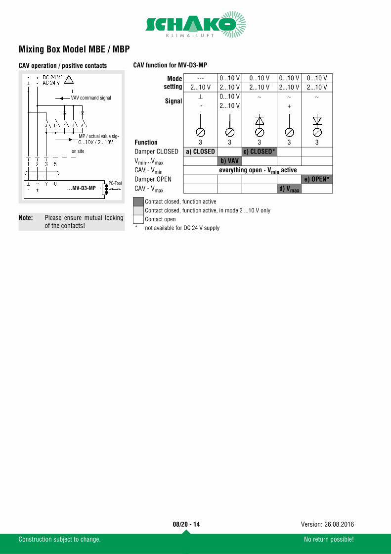
CAV operation / positive contacts
Note: Please ensure mutual lockingof the contacts!
PC-Tool
VAV command signal
MP / actual value sig-
on site
...MV-D3-MP
CAV function for MV-D3-MP
Modesetting
--- 0...10 V 0...10 V 0...10 V 0...10 V2...10 V 2...10 V 2...10 V 2...10 V 2...10 V
Signal⊥ 0...10 V ∼ ∼ ∼ - 2...10 V +
Function 3 3 3 3 3Damper CLOSED a) CLOSED c) CLOSED*Vmin...Vmax b) VAV CAV - Vmin everything open - Vmin activeDamper OPEN e) OPEN*CAV - Vmax d) Vmax
Contact closed, function activeContact closed, function active, in mode 2 ...10 V onlyContact open
* not available for DC 24 V supply
08/20 - 14
Construction subject to change. No return possible!
26.08.2016Version:

Mixing Box Model MBE / MBP
LED table of functions for LMV-D3-MP1.) Synch time2.) Adaptation time
Application Function Description / actionLED pat-tern
Adapta-tion
Address
⊕⊕
LED 1 power
LED 2 status
N1 operation Status display - 24V power supply o.k.- VAV-Compact ready for operation
S1 service function Synchronisation Synchronisation started by:a) Operating / service unitb) Manual trigger device at the VAV-Compactc) Power ON behaviour
S2 service function Adaptation Adaptation started by:a) Operating / service unitb) Key on the VAV-Compact
V1 VAV service VAV serviceactive
a) Press both keys «Adaptation» & «Address» simultaneouslyb) VAV service will be activated: - until 24V supply is switched off - until both keys are pressed again - after 2 hours have passed
Lack of air Damper opens as actual volume is too low
Target volumereached
Control circuit balanced
Air excess Damper closes as actual volume is too high
B1 bus operation Addressing via MP master(Acknowledge-ment at the VAV-Compact)
a) Addressing has been triggered at the MP master
b) Press addressing keyLED will switch to the communication display as soon as the addressing process is complete.
B2 bus operation Addressing via MP master (with serial number)
Addressing at the MP master was triggered, LED will switch to the communication display as soon as the addressing process is complete.
B3 bus operation communication
MP-PP displayCommunication
Communication display via MP master or oper-ating / service unit
LED 1
LED 2
LED 1
LED 2Start 1.) →
LED 1
LED 2Start 2.) →
LED 1
LED 2
LED 1
LED 2
LED 1
LED 2
LED 1
LED 2
LED 1
LED 2
LED 1
LED 2On event MP communication
LED 1
LED 2Not address. MP communication
LED 1
LED 2MP communication
green LED (power) is lit
yellow LED (status) is lit
yellow LED (status) is flashing
08/20 - 15
Construction subject to change. No return possible!
26.08.2016Version:

Mixing Box Model MBE / MBP
Wiring diagram of alternative controllerConnection diagram VRP
* Phase crossover
connection via safety trans-former
*
on site
Two-stage volumetric flow rate controlVRP
Function a b cVminVmaxVmaxVmax
connection via safety trans-former
on site
Positive control VRP
Function a b c dCLOSED
VminVmaxOPEN
connection via safety trans-former
on site
Universal controller Belimo make VRP-VFP300
Connection diagram VRD3-SO
Drive ...-V
Drive input w
PP connection ZTH-EUVolumetric flow actual value U5
Control input Z1 / Z2
ZTH-EU
AC 24 VDC 24 V
VRD3
on site
Positive control VRD3-SO
Drive ...-VZTH-EU
AC 24 V
VRD3
OPEN
CLOSED2.)
3.)
1.)
4.)
on site
Two-stage volumetric flow rate controlVRD3-SO
Drive ...-VZTH-EU
AC 24 V
JumperVRD3
OPEN
CLOSED5.)
7.)
9.)
8.)
6.)
VRD3
on site
Universal controller Belimo make VRD3-SO
Overview control signals / functions
*) requires AC 24 V power supply
Signal terminal / Function Priority GND pos HW neg HW 24 VAC openForced contact Z1 - Terminal 6 1 - OPEN 1.) - OPEN 1.) -Forced contact Z2 - Terminal 7 2 CLOSED 2.) Vmin 3.) - Vmax 4.) - Tool (PP-Cmd) -> ZTH-EU 3 CAV stages (Auto, OPEN, CLOSED, Vmin, Vmax, Stop)
Command signal w - Terminal 3 Jumper: VRD3
4 CLOSED 5.) Mode: 2 ... 10 V
OPEN 6.) CLOSED 7.) Mode: 0 ... 10 V
Vmax 8.) Vmin 9.)
08/20 - 16
Construction subject to change. No return possible!
26.08.2016Version:

Mixing Box Model MBE / MBP
Setting Vmin and VmaxThe Vmax value must always be set higher than the Vmin; other-wise the VRD3 controller will run in the CAV mode with the Vmin volume as setpoint.
The Vmin and Vmax operating volumetric flow settings can be made at the VRD3 in one of two ways.a) directly on the setting potentiometer (as with the VRD2)
Vmin 0 … 100 % of VnennVmax 30 … 100 % of Vnenn
b) by means of the VAV setting device ZTH EU (PP Command)To write a value to the VRD3 by PP Command, both Vmin undVmax potentiometers must be in the Tool position. When thepotentiometer(s) are set to «Tool», with the ZTH EU connected,it may be necessary to refresh the menu by pressing the keys. The function can be seen from the following figure:
w
45 %
45 %
r = readw= write
r
effective value
w
(PP)0...100% Tool
ZTH EU
Tool
Automatic switchovervia potentiometer positionPotentiometer:- Tool ZTH value- 0 ... 100%: potentiometer
VRD3
programmedvalue
08/20 - 17
Construction subject to change. No return possible!
26.08.2016Version:

Mixing Box Model MBE / MBP
Setting the operating potentiometers / calculation formulae
Set value for Vmax
The required volumetric flow that is to flow at the 10 V DC com-mand signal at terminal 3 (w/Y) or with positive control Vmax isset in % at the Vmax potentiometer of the controller, the ZTH-EUdevice or PC-Tool. This value refers to the set Vnenn nominal vol-umetric flow.
Set value for Vmin
The required volumetric flow that is to flow at the 0 V DC com-mand signal (operating mode 0-10 V DC) or at the 2 V DC com-mand signal (operating mode 2 - 10 V DC) at terminal 3 (wY) orwith positive control Vmin is set in % at the Vmin potentiometerof the controller, the ZTH-EU device or PC-Tool. This value re-fers to the set Vnenn or Vmax volumetric flow (depending on con-troller type).
Information regarding the set value VminIn the following controllers, Vmin refers to Vmax:
in the following controllers, Vmin refers to Vnenn:
Calculation of the U5 voltage value
Operating mode: 2 - 10 V DC:Vmax values
Vmin values
Operating mode: 0 - 10 V DC:Vmax values
Vmin values
Calculation of the Vnenn volumetric flow
Attention:The Vnenn value changes as a function of the set calibrationcurve.
Depending on the required Vmax volumetric flow, the calibrationcurve will be selected specifically by Schako during program-ming. This guarantees maximum accuracy of the actual value ofthe volumetric flow.
Make TypeBelimo VRP-VFP
Make TypeBelimo LMV-D3-MP, VRD3
EWVmax
VmaxVnenn---------------- 100%×=
EWVmin
VminVnenn oder Vmax--------------------------------------------- 100%×=
EW (%) = Set valueEK (m/s) = Calibration curveU5 (V DC) = U5 signalF (m²) = Area
U5 VmaxVnenn---------------- 8V 2V+×=
U5 Vmin
Vnenn---------------- 8V 2V+×=
U5 VmaxVnenn---------------- 10V×=
U5 Vmin
Vnenn---------------- 10V×=
Vnenn EK F 3600××=
08/20 - 18
Construction subject to change. No return possible!
26.08.2016Version:

Mixing Box Model MBE / MBP
Actual value measurement via feedback signal U5 using a voltmeter or PC-ToolTerminal assignmentVRD3-SO / VRP-VFP
LMV-D3-MP
Supply voltage: 24 V AC/DC (terminals 1+2)Measurement output 2 - 10 V DC (terminals 1+5)Measurement output 0 - 10 V DC (terminals 1+5)
The actual value signal U5 is a real feedback of the volumetricflow actual value for monitoring and controlling the air through-put volume.
U5 signal 0-10 V DC
Example
U5 signal 2-10 V DC
Example
Assume: Measurement output signal U5 = 6.3 V DCCalibration value VRA-E = 12 m/sec
Measured value: Duct velocity = 7.6 m/s
Air volume: Duct velocity x area m² x 3600 = m³/h
Assume: Measurement output signal U5 = 6.3 V DCCalibration value VRA-E = 12 m/sec
Measured value: Duct velocity = 6.3 m/s
Air volume: Duct velocity x area m² x 3600 = m³/h
08/20 - 19
Construction subject to change. No return possible!
26.08.2016Version:

Mixing Box Model MBE / MBP
Technical data of controllers and motorsController standard
LMV-D3-MP (make Belimo)Dynamic pressure sensor, digital VAV controller and damperdrive as communication-capable VAV-Compact solution
Controller alternatively
VRP-VFP (make Belimo)For static differential pressure control with separately availablesensors VFP-100, 300 or 600
VRD3-SO (make Belimo)with integrated dynamic differential pressure sensor
Measuring principle: Pressure reading with through-flowMeasuring range of thesensor :
2... ~ 450 Pa
Supply voltage: AC 24 V 50/60 Hz; DC 24 VFunctional range: AC 19.2...28.8 V; DC 21.6...28.8VPower consumption: 2 WDimensioning: 3.5 VATorque: min. 5 Nm at the rated voltageControl function : VAV/CAV/Open-Loop;
Supply/return air or stand-alone operation;master/slave parallel circuit;Mixing box control
Setting rangeVmin/Vmax :
Vmin = 0...100 % of set Vnenn volumetricflowVmax = 20...100 % of set Vnenn volumetricflow
Command variable w/Y:(Input resistance min.100 kΩ)
DC 2-10 V (4...20 mA with 500 Ω input re-sistance)DC 0-10 V (0...20 mA with 500 Ω input re-sistance)adjustable DC 0...10 V
Setting range actual val-ue signal U5 :
DC 2...10 VDC 0...10V
MP bus function Address in bus mode: MP 1 ... 8 (traditional operation: PP)LONWORKS® /Konnex EIB:
with BELIMO interface UK24LON /UK24EIB, 1 ... 8 BELIMO MP devices (VAV /flap drive/ valve)
DDC controller: DDC controller / PLC from different manu-facturers, with integrated MP interface
Fan Optimiser: with BELIMO Optimiser COU24-A-MPSensor connection: Passive (Pt1000, Ni1000, etc.) and active
sensors (0...10 V), for example tempera-ture, humidity, 2-point signal (switchingpower 16 mA @ 24 V), for example switch,presence detector
Protection class: III (safety extra low voltage)Protection type: IP 54 (hose-connected)EMC: CE according to 39/336/EECMeasuring air and ambi-ent temperatures :
0° C...+50° C, 5...95% rH, non-condensing
Storage temperature: -20° C...+80° CSound power level: max. 35 dB (A)Operation and service: plug-in via service socket / PC-Tool (from
V3.1) / ZTH-EUCommunication: PP/MP bus, max. DC 15V, 1200 baudConnection : Cable, 4 x 0.75mm², terminalsWeight: approx. 500 g
Measuring principle: Pressure measurement with metal mem-brane
Measuring range of the sensor :
0...100 Pa, 0...300 Pa or 0...600 Pa
Supply voltage: AC 24 V 50/60 Hz;Power consumption: 1.3 W (incl. sensor VFP-..., without actua-
tor)Dimensioning: 2.6 VA (incl. sensor VFP-..., without actua-
tor)Command variable w: -Command variable w1: DC 2-10 V (input resistance 100 kΩ)Command variable w2: 0-20 V phase crossover (input resistance 8
kΩ)Operating range: DC 2-10 VVolumetric flow: DC 2-10 VActual value signal U5: -Torque: -Sound power level: -
Measuring principle: Pressure reading with through-flowMeasuring range of the sensor :
2... ~ 300 Pa
Supply voltage: AC 24 V 50/60 Hz; DC 24 VPower consumption: 2 WDimensioning: 3.5 VA (without damper drive)Command variable w: -Command variable w1: DC 0-10 V (input resistance 100 kΩ)Command variable w2: -Operating range: DC 2-10 V (0-10V switch over via ZEV)Volumetric flow: DC 0-10 V (for operating mode 0-10)Actual value signal U5: DC 2-10 V (for operating mode 2-10)Torque: -Sound power level: -
08/20 - 20
Construction subject to change. No return possible!
26.08.2016Version:

Mixing Box Model MBE / MBP
Damper drives...24-for VRP-VFP, VRD3-SO, VRP-STP, VRP-MNM24A-V
SM 24A-V
LF24-V
Supply voltage: AC 24V 50/50 Hz / DC 24V of VR..., ready to plug in
Power consumption/Dimensioning: 3.5 W / 5.5 VAActuator signal: DC 6.0 V± 4V (of VR...)Torque at therated voltage: Min. 10 NmRunning time for 90° (or 95°): 150 s.Protection type: IP 54Protection class: III (safety extra low voltage)Sound power level: max. 35 dB (A)
Supply voltage: AC 24V 50/50 Hz / DC 24V of VR..., ready to plug in
Power consumption/Dimensioning: 4 W / 6 VAActuator signal: DC 6.0 V± 4V (of VR...)Torque at the rated voltage: 20 NmRunning time for 90°(or 95°): 150 s.Protection type: IP 54Protection class: III (safety extra low voltage)Sound power level: max. 45 dB (A)
Supply voltage: AC 24V 50/50 Hz / DC 24V of VR..., ready to plug in
Power consumption/Dimensioning: 6 W / 10 VAActuator signal: DC 6.0 V± 4V (of VR...)Torque at the rated voltage: Min. 15 NmRunning time for 90°(or 95°): Drive 150 s, spring return =16 sProtection type: IP 54Protection class: III (safety extra low voltage)Sound power level: Drive max. 45 dB(A) / Spring max. 62 dB(A)
08/20 - 21
Construction subject to change. No return possible!
26.08.2016Version:

Mixing Box Model MBE / MBP
Functional check
VRD3-SO, VRP-VFP functional checkElectric connection :Apply supply voltage 24 V AC (±10%) to terminals 1 + 2.Is the polarity of the system neutral conductor correct?
VR.. / drive ...24-V:Connect terminals 1+7. Does the drive move to the "CLOSED"position?
Vmax:Connect terminals 2+7. Does VR.. control to Vmax?
Vmin :Interrupt the terminal 3 and/or 4 command variable. Does VR..control to Vmin?
Functional check during startup and serviceIf required, easily accessible setting potentiometers and con-nections allow set values and the correct operation of the mixingbox to be reliably and quickly checked on site.
LMV-D3-MP: Functional checkElectrical connectionApply supply voltage 24 V AC (±10%) to terminals 1 + 2.Is the polarity of system neutral conductor correct?
LMV-D3-MP / ZTH-EU :Has the LMV-D3-MP been set to the correct operating mode?(Check using the connected ZTH-EU!)
Drive:Use the ZTH-EU to set operating mode 2-10 V and connect ter-minals 1+3 of the LMV-D3-MP.Does the drive move to the "CLOSED" position?
Vmax:Connect terminals 2+3 of the LMV-D3-MP and disconnect U5connection to the ZTH-EU.If the LMV-D3-MP controls to Vmax - Check actual value signalU5.
Functional check during startup and serviceIf required, easily accessible setting potentiometers and con-nections allow set values and the correct operation of the mixingbox to be reliably and quickly checked on site.
No: Check the wiring according to the diagram. Checktransformer power.
→ Example: VRD3-SO (2.9 VA), VRP-VFP (2.6 VA),NM24-V (4.0 VA)
Yes: VR.. / drive ...24-V
No: Check the direction of rotation switch of the drive.
→ Switch on drive is marked L/R or A/B.
Yes: Vmax
No: Check and compare the setting of the Vmax potenti-ometer with the technical data on the VAV machine.
→ If the drive moves to the "OPEN" position, andthe maximum volume is not reached, then theduct pressure is too low.
Yes: Vmin
No: Check and compare the setting of the Vmin potenti-ometer with the technical data on the VAV machine.
Yes: If required, restore interrupted connections (termi-nals 3+4).
No: Check the wiring according to the diagram. Checktransformer power.
→ LMV-D3-MP 5 VA
Yes: LMV-D3-MP / ZTH-EU
No: Set operating mode on the selector switch of theZTH-EU and save it in the LMV-D3-MP by pressingthe Set key.
→ Operating modes: 0-10 V, 2-10 V
Yes: Drive
No: Contact VRA manufacturer.
Yes: Vmax
No: Check the Vmax potentiometer on the ZTH-EU andcompare the settings with the technical data on theVAV device.
→ If the drive moves to the "OPEN" position, andthe maximum volume is not reached, then theduct pressure is too low.
Yes: Set system-specific operating mode using the ZTH-EU.
08/20 - 22
Construction subject to change. No return possible!
26.08.2016Version:

Mixing Box Model MBE / MBP
Startup using PC-ToolDirect connection in the switch cabinet or socket(traditional application)
ZTH EU as MP level converter
DescriptionThe ZTH EU is also a potential-free interface between the USBport of a PC and the Belimo MP bus. It is used to connect theBelimo PC-Tool directly to the MP bus or directly to a program-mable MFT drive.
Power supplyThe ZTH EU is supplied with power by the USB port. The MP busvoltage is obtained internally by means of DC/DC converter. Thisis why no external power supply is necessary.
DriverTo be able to work with the ZTH EU, a suitable driver must beinstalled on the PC. The driver can be downloaded from the Be-limo website (download section). After installation of the driver,the ZTH EU device will log in to the PC as a virtual COM interface.
NoteFor connection to USB ports of PCs and BELIMO 24 V drivesonly (to safety extra low voltage SELV or US class 2 feeds).
Connection diagram 1
Local connection via a service socket of the MF/MP or LON driveusing a ZK1-GEN cable.
Connection diagram 2
Local connection via a connecting cable of the MF/MP or LONdrive using a ZK2-GEN cable.
1.) white = GND
green = MP
blue = not connected
...A-MF
...A-MP
...D3-MP
...ALON
...D3LON
1.)
...LON
...ALON
...D3LON
...MFT(2) A-AF...A-MP...D3-MP
08/20 - 23
Construction subject to change. No return possible!
26.08.2016Version:

Mixing Box Model MBE / MBP
Startup using the setting and diagnostic device ZTHEU (Belimo)
Short descriptionThe VAV setting device ZTH EU allows efficient testing of VAVand CAV installations. Installations fitted with the Belimo VAVcontroller can be simply adapted to the room and user require-ments.The VAV setting device ZTH EU replaces the previous setting de-vice ZTH-GEN (2007-2014).All standard Belimo VAV controllers with integrated PP commu-nication (from 1992) that are sold in the EU can be set using the ZTH EU.
Specifications:easy, quick setting of the VAV boxes parametersdiagnostic functionone tool for all VAV unitsvoltage supplied by VAV controllers - no batteries required!service socket VAV / CR24 controller, PP connectionincludes connecting cable RJ12 6/4, 6-pin plugNew generation, MP bus tester for functional test of MP busbackward compatible with all Belimo PP / MP units from 1992efficient handling, can be operated with one handSelection of stages for test (OPEN/CLOSE/MIN/MAX/STOP)Damper position indicator for diagnosticsDisplay of the setpoint / actual volume and Vmin/max setting in m³/s (l/s).
Keys / Display:
2 x 16-digit LCD with background lighting
Connection:Locally via service socket
Dimensions:85x65x23 (WxHxD)
Connection and supplyStand-alone operation:Connection including supply takes place via the service socketat the VAV controller or via the terminals.Bus operation:The ZTH EU can be used in the following units while the bus isrunning if it is connected via the local service socket: VAV-Com-pact L/N/SMV-D3-MP, NMVAX-D3-MP, L/NMV-D3LON.With the VRP-M, L/NMV-D3-M and NMVAX-D3-MP, the MP-Bus must be disconnected when the service socket is used.
Restriction:Direct connection in an MP network or via an MP-Bus master isnot possible.
The ZTH EU comes with a quick start guide de/en to be affixedto the back of the unit.
Forwards / BackwardsChange value / status
OK Confirm inputESC Cancel input/
Leave submenu/ Discard changesi shows additional information if available
08/20 - 24
Construction subject to change. No return possible!
26.08.2016Version:

Mixing Box Model MBE / MBP
Smartphone - Belimo Assistant AppThe NFC antenna area of the VAV Compact is located betweenthe Belimo or OEM logo and the NFC label. Align NFC-capable android smartphone with loaded Assistantapp on the VAV-Compact such that the two antennae are aboveone another.
The Belimo Assistant app can be downloaded from the GooglePlay Store.
Controller selection
Accessories:S1A/S2A, limit switch make Belimo, to fit all new compact controllersand actuators of make Belimo.integrated potentiometer Belimo P1000 AZTH-EU for Belimo ...MV-D3-MP / PC-Tool for Belimo ...MV-D3-MP
Maintenance and serviceAssembly and maintenance instructions
Zero adjustment of the static pressure sensors VFP-...The pressure probe is based on a static pressure meter. Greatcare must be taken to ensure correct transport and correct as-sembly. The mixing box has been adjusted in-factory by theOEM manufacturer according to their mounting position. If thecontrollers are installed in a different position, the sensors canbe adjusted as follows.
NFC-capable devices:- LMV-D3-MP, NMV-D3-MP, SMV-D3-MP and LHV-D3-MP with
printed NFC label.Non-NFC-capable devices:- All devices without NFC label- LMV-D3-MF- LMV-D3LON and NMV-D3LON
Electric controller: Actuator:- 2x Belimo :
- LMV-D3-MP Compact (Standard)- VRD3-SO 2x NM24A-V- VRD3-SO 2x LF24-V- VRP/VFP 2x NM24A-V- VRP/VFP 2x LF24-V
The selection of each actuator (torque) depends on the housing di-mensions.
Pneumatic controllers: Servo cylinder:- 1x Sauter :
- RLP100 F916 1x AK 31 P2 F001 and 1x AK 31 P3 F001 - RLP100 F918 2x AK 31 P1 F001
1. When the device is delivered, check whether the controllersare complete and delivered without damage. Complaintshave to be communicated immediately and directly to thetransporter and SCHAKO.
2. The mixing boxes must not be fastened to the regulationcomponents, measuring crosses or the control dampers,but only to the housing.
3. The units must be carefully stored on site. They must beprotected from dust, dirt and from direct weather effects.
4. The units must be assembled in a way in to allow inspec-tion, meaning that the maintenance cover in the silencerpart is freely accessible.
5. Assembly must be carried out by expert personnel, observ-ing recognised technical rules and regulations.
6. For polluted air, the mixing boxes must be used with anintegrated controller with static membrane pressure sen-sors. In this case, it is imperative to observe the noticesign regarding the mounting position. The mixing boxesare not suitable for air with greasy and sticky compo-nents.
1. Sensor VFP-... must be installed.2. Connect VFP-... to VRP and supply VRP with 24 V AC mains
voltage.3. Remove lid from VFP... .4. Move damper to the "OPEN" position.5. Pull damper drive plug from the VRP.6. Remove the pressure hoses from the connection pipes.
Attention! Make a note of the (+) and (-) assignments.7. The membrane position is considered balanced when both
LEDs are dark (OFF). If the meter position is not balanced,one of the two LEDs will light up, and the position must beadjusted on the potentiometer in the VFP-...
8. Slowly turn the zero point adjustment of the potentiometer(non-painted potentiometer), until both LEDs are dark(OFF).
9. Assemble lid of VFP....10. Reconnect pressure pipes as before (+) and (-).11. Reconnect the plug of the damper drive.
08/20 - 25
Construction subject to change. No return possible!
26.08.2016Version:

Mixing Box Model MBE / MBP
Cleaning of the dynamic differential pressure sensorThe dynamic differential pressure sensor integrated into theLMV-D3-MP and VRD3-SO requires little maintenance. Howev-er, if, depending on the degree of pollution of the air, unexpectedvolumetric flow deviations occur, then the following procedureis recommended.Legend
Order details
1. Pull off the pressure hoses from the sensor connection pipeof the LMV-D3-MP or the VRD3.Attention! Make a note of the (+) and (-) assignments.
2. Using a suitable hand pump, blow air into the (-) connectionpiece of the sensor (this will blow any dirt deposited insidethe sensor out of the (+) connection piece).
3. Remove any dirt that may have formed from the connectingpieces and hose ends.
4. Reconnect pressure hoses, (+) and (-) as before.5. Carry out a functional check of the controller.
fm (Hz) = Octave centre frequencyDe [dB/Oct] = Insertion lossLWA [dB(A)] = A-weighted sound power levelNW (mm) = Nominal width
U5 (V) DC = Measurement output (electric volt-age)
vK (m/s) = Duct velocityV (m³/h) = Air volumeV [l/s] = Air volumeRE (m/s) = Controller calibration value
Operating mode
0 - 10 V
With electric control-MBE
With pneumatic control-MBP
Operating mode
2 - 10 V
Cold air right(in air flow direction)
-KR
Cold air left(in air flow direction)
-KL
with acoustic cladding-DS
without acoustic cladding-
with connection frame-AR
without connection frame-
with additional silencer-ZS
without additional silencer-
with rubber lip seal-GD
without rubber lip seal-
Order example:MBE-Vmin-Vmax-KL-200-LMV-D3-MP
Unless stated otherwise, the thick-frame model will be delivered!
Mixing box
Variablevolumetric flow rate control
......... - .........(Vmin - Vmax)
Constantvolumetric flow rate control
.........(Vkons)
08/20 - 26
Construction subject to change. No return possible!
26.08.2016Version:

Mixing Box Model MBE / MBP
Specification textsMixing box for use in twin-duct air-conditioning systems, forspiral duct connection to DIN 24 145 with integrated volumetricflow controller for use in constant and variable volumetric flow,room and duct pressure regulation. With positive control Vmin,Vmax or "CLOSED". Consisting of a housing made of galvanised sheet steel linedwith mineral wool, with a guide baffle made of perforated galva-nised sheet steel. Housing containing two volumetric flow con-trollers, consisting of a round connection piece made ofgalvanised sheet steel with damper leaf made of galvanisedsheet steel and silicone-free damper leaf seal for airtight designto DIN EN 1751, Class 2 (NW100 only), Class 3 (NW125 - 400only), with measuring cross blades made of extruded alumini-um profile, blade mount made of plastic (PA6). A special meas-uring cross allows position-independent mounting. With electric control, control voltage 24 V AC, 50 / 60 Hz, tem-perature compensation of 10-40°C, wired and adjusted in-facto-ry.Product: SCHAKO type MBE
Model
Accessories (at an extra charge):
- With pneumatic control
Feed pressure 1.2 ± 0.1 bar- Depressurised "CLOSED"- Depressurised "OPEN"Temperature compensation of 0 - 50° CProduct: SCHAKO type MBP
- Cold air right (-KR), in air flow direction- Cold air left (-KL) in air flow direction (standard)
- Acoustic cladding (-DS) for reducing the radiated noise madeof insulating material with sheet metal casing made of galva-nised sheet steel.
- Galvanised sheet steel connection frame (-AR).- Additional silencer (-ZS) made of galvanised sheet steel and
baffle with mineral wool lining (MWK) and optionally withperforated sheet cover (MLK).
- Rubber lip seal (-GD), made of special rubber.
08/20 - 27
Construction subject to change. No return possible!
26.08.2016Version: