mitsubishi electric industrial robot - allied … · the following precautions are taken from the...
TRANSCRIPT

Mitsubishi Electric Industrial Robot
CR750/CR751 Controller Instruction Manual Force Sense Function
BFP-A8947


Teaching work should only be performed by those individuals who have undergone special training. (The same applies to maintenance work with the robot power ON.)
Conduct safety education.
Prepare work regulations indicating robot operation methods and procedures, and measures to be taken when errors occur or when rebooting robots, and observe these rules at all times. (The same applies to maintenance work with the robot power ON.)
Prepare work regulations.
Only perform teaching work after first equipping the controller with a device capable of stopping operation immediately. (The same applies to maintenance work with the robot power ON.)
Equip with an EMERGENCY STOP button.
Notify others when teaching work is being performed by affixing a sign to the START switch, etc. (The same applies to maintenance work with the robot power ON.)
Indicate that teaching work is being performed.
Install fences or enclosures around robots to prevent contact between robots and workers during operation.
Install safety fences.
Stipulate a specific signaling method to be used among related workers when starting operation.
Operation start signal
As a rule, maintenance work should be performed only after turning OFF the power, and other workers should be notified that maintenance is being performed by affixing a sign to the START switch, etc.
Indicate that maintenance work is being performed.
Before starting operation, conduct an inspection of robots, EMERGENCY STOP buttons, and any other related devices to ensure that there are no abnormalities.
Inspection before starting operation
Safety Precautions Always read the following precautions and separate "Safety Manual"
carefully before using robots, and take appropriate action when
required.
Caution
Caution
Caution
Caution
Caution
Caution
Warning
Warning

The following precautions are taken from the separate "Safety Manual". Refer to the "Safety Manual" for further details.
Use robots in an environment stipulated in the specifications. Failure to observe this may result in decreased reliability or breakdown. (Temperature, humidity, atmosphere, noise environment, etc.)
Only transport robots in the manner stipulated. Failure to observe this may result in bodily injury or breakdown if the robot is dropped.
Install and use the robot on a secure and stable platform. Positional displacement or vibrations may occur if the robot is unstable.
Ensure that cables are kept as far apart from noise sources as possible. Positional displacement or malfunction may occur if in close contact with one another.
Do not apply too much force to connectors, or bend cables too much. Failure to observe this may result in contact defects or wire damage.
Ensure that the weight of the workpiece, including the hand, does not exceed the rated load or allowable torque. Failure to observe this may result in alarms or breakdown.
Attach hands and tools, and grip workpieces securely. Failure to observe this may result in bodily injury or property damage if objects are sent flying or released during operation.
Ground the robot and controller properly. Failure to observe this may result in malfunction due to noise, or even electric shock.
Always indicate the robot operating status during movement. If there is no indication, operators may approach the robot, potentially leading to incorrect operation.
If performing teaching work inside the robot movement range, always ensure complete control over the robot beforehand. Failure to observe this may result in bodily injury or property damage if able to start the robot with external commands.
Jog the robot with the speed set as low as possible, and never take your eyes off the robot. Failure to observe this may result in collision with workpieces or surrounding equipment.
Always check robot movement in step operation before commencing auto operation following program editing. Failure to observe this may result in collision with surrounding equipment due to programming mistakes, etc.
If attempting to open the safety fence door during auto operation, ensure that the door is locked, or that the robot stops automatically. Failure to observe this may result in bodily injury.
Caution
Caution
Caution
Caution
Caution
Caution
Caution
Caution
Caution
Caution
Warning
Warning
Warning

Do not perform unauthorized modifications or use maintenance parts other than those stipulated. Failure to observe this may result in breakdown or malfunction. If moving the robot arm by hand from outside the enclosure, never insert hands or fingers in openings. Depending on the robot posture, hands or fingers may become jammed. Do not stop the robot or engage the emergency stop by turning OFF the robot controller main power. Robot accuracy may be adversely affected if the robot controller main power is turned OFF during auto operation. Furthermore, the robot arm may collide with surrounding equipment if it falls or moves under its own inertia. When rewriting internal robot controller information such as programs or parameters, do not turn OFF the robot controller main power. If the robot controller main power is turned OFF while rewriting programs or parameters during auto operation, the internal robot controller information may be destroyed. Horizontal multi-joint robots The hand may drop under its own weight while the robot brake release switch is pressed, and therefore due care should be taken. Failure to observe this may result in collision between the hand and surrounding equipment, or hands or fingers becoming jammed if the hand falls. Attach the cap to the SSCNET III connector after disconnecting the SSCNET III cable. If the cap is not attached, dirt or dust may adhere to the connector pins, resulting in deterioration connector properties, leading to malfunction. Do not look directly at light emitted from the tip of SSCNET III connectors or SSCNET III cables. Eye discomfort may be felt if exposed to the light. (SSCNET III employs a Class 1 or equivalent light source as specified in JISC6802 and IEC60825-1.)
Caution
Caution
Warning
Caution
Caution
Warning
Caution
■ Revision History
Print Date Instruction Manual No.
Revision content
2012-10-03 BFP-A8947 � First print

■ Introduction
Thank you for purchasing a Mitsubishi Electric industrial robot. The "force sense function" uses force sensor
information with 6 degrees of freedom to provide the robot with a sense of its own force. Using dedicated
commands and status variables compatible with the robot program language (MELFA-BASICV) facilitates
work requiring minute power adjustments and power detection that was not possible on past robots.
Always read over this manual to gain a sufficient understanding of its content before using the "force sense
function".
Please note that this instruction manual assumes that operators have an understanding of basic Mitsubishi
Electric industrial robot operation and functionality. Refer to the separate "Instruction Manual, Detailed
Explanations of Functions and Operations" for information on basic operation.
■ Notation used in this manual
Notice *ONLY QUALIFIED SERVICE PERSONNEL MAY INSTALL OR SERVICE THE ROBOT SYSTEM. *ANY PERSON WHO PROGRAM, TEACHES, OPERATE, MAINTENANCE OR REPAIRS THE ROBOT SYSTEM IS TRAINED AND DEMONSTRATES COMPETENCE TO SAFELY PERFORM THE ASSIGNED TASK. *ENSURE COMPLIANCE WITH ALL LOCAL AND NATIONAL SAFETY AND ELECTRICAL CODES FOR THE INSTALLATION AND OPERATION OF THE ROBOT SYSTEM.
No part of this manual may be reproduced by any means or in any form, without prior consent from Mitsubishi.
The details of this manual are subject to change without notice. An effort has been made to make full descriptions in this manual. However, if any discrepancies or unclear
points are found, please contact your dealer. The information contained in this document has been written to be accurate as much as possible.
Please interpret that items not described in this document "cannot be performed." or "alarm may occur". Please contact your nearest dealer if you find any doubtful, wrong or skipped point.
This specifications is original.
Copyright(C) 2012 MITSUBISHI ELECTRIC CORPORATION
Caution
Warning
Danger
Incorrect handling may result in imminent danger, leading to death or serious injury. Incorrect handling may lead to death or serious injury. Incorrect handling may result in property damage, or danger leading to impairment of the user.
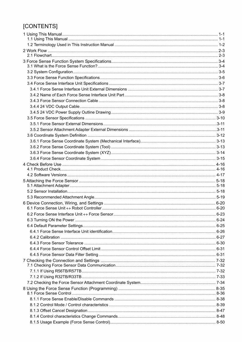
[CONTENTS]
1 Using This Manual.................................................................................................................................. 1-1
1.1 Using This Manual ..................................................................................................................................... 1-1
1.2 Terminology Used in This Instruction Manual ............................................................................................ 1-2
2 Work Flow .............................................................................................................................................. 2-3
2.1 Flowchart.................................................................................................................................................... 2-3
3 Force Sense Function System Specifications......................................................................................... 3-4
3.1 What is the Force Sense Function?........................................................................................................... 3-4
3.2 System Configuration................................................................................................................................. 3-5
3.3 Force Sense Function Specifications......................................................................................................... 3-6
3.4 Force Sense Interface Unit Specifications ................................................................................................. 3-7
3.4.1 Force Sense Interface Unit External Dimensions ................................................................................ 3-7
3.4.2 Name of Each Force Sense Interface Unit Part ................................................................................... 3-8
3.4.3 Force Sensor Connection Cable .......................................................................................................... 3-8
3.4.4 24 VDC Output Cable........................................................................................................................... 3-8
3.4.5 24 VDC Power Supply Outline Drawing............................................................................................... 3-9
3.5 Force Sensor Specifications .................................................................................................................... 3-10
3.5.1 Force Sensor External Dimensions.....................................................................................................3-11
3.5.2 Sensor Attachment Adapter External Dimensions ..............................................................................3-11
3.6 Coordinate System Definition .................................................................................................................. 3-12
3.6.1 Force Sense Coordinate System (Mechanical Interface)................................................................... 3-13
3.6.2 Force Sense Coordinate System (Tool) ............................................................................................. 3-13
3.6.3 Force Sense Coordinate System (XYZ) ............................................................................................. 3-14
3.6.4 Force Sensor Coordinate System ...................................................................................................... 3-15
4 Check Before Use ................................................................................................................................ 4-16
4.1 Product Check.......................................................................................................................................... 4-16
4.2 Software Versions .................................................................................................................................... 4-17
5 Attaching the Force Sensor .................................................................................................................. 5-18
5.1 Attachment Adapter.................................................................................................................................. 5-18
5.2 Sensor Installation.................................................................................................................................... 5-18
5.3 Recommended Attachment Angle............................................................................................................ 5-19
6 Device Connection, Wiring, and Settings ............................................................................................. 6-20
6.1 Force Sense Unit Robot Controller ..................................................................................................... 6-20
6.2 Force Sense Interface Unit Force Sensor........................................................................................... 6-23
6.3 Turning ON the Power ............................................................................................................................. 6-24
6.4 Default Parameter Settings...................................................................................................................... 6-25
6.4.1 Force Sense Interface Unit identification............................................................................................ 6-26
6.4.2 Calibration .......................................................................................................................................... 6-27
6.4.3 Force Sensor Tolerance ..................................................................................................................... 6-30
6.4.4 Force Sensor Control Offset Limit ...................................................................................................... 6-31
6.4.5 Force Sensor Data Filter Setting ........................................................................................................ 6-31
7 Checking the Connection and Settings ................................................................................................ 7-32
7.1 Checking Force Sensor Data Communication......................................................................................... 7-32
7.1.1 If Using R56TB/R57TB....................................................................................................................... 7-32
7.1.2 If Using R32TB/R33TB....................................................................................................................... 7-33
7.2 Checking the Force Sensor Attachment Coordinate System................................................................... 7-34
8 Using the Force Sense Function (Programming) ................................................................................. 8-35
8.1 Force Sense Control ................................................................................................................................ 8-36
8.1.1 Force Sense Enable/Disable Commands .......................................................................................... 8-38
8.1.2 Control Mode / Control characteristics ............................................................................................... 8-39
8.1.3 Offset Cancel Designation.................................................................................................................. 8-47
8.1.4 Control characteristics Change Commands....................................................................................... 8-48
8.1.5 Usage Example (Force Sense Control).............................................................................................. 8-50

8.2 Force Sense Detection ............................................................................................................................ 8-59
8.2.1 Mo Trigger .......................................................................................................................................... 8-60
8.2.2 Force Detection Status ....................................................................................................................... 8-63
8.2.3 Data Latch .......................................................................................................................................... 8-63
8.2.4 Data Referencing................................................................................................................................ 8-63
8.2.5 Usage Example (Force Sense Detection) .......................................................................................... 8-65
8.3 Force Sense log....................................................................................................................................... 8-70
8.3.1 Force Sense Log Function Specifications .......................................................................................... 8-70
8.3.2 Parameter Settings............................................................................................................................. 8-72
8.3.3 Force Sense Log Data Acquisition ..................................................................................................... 8-73
8.3.4 Force Sense Log Data Display (RT ToolBox2)................................................................................... 8-74
8.3.5 Force Sense Log File FTP Transfer ................................................................................................... 8-79
8.3.6 Usage Example (Force Sense Log) ................................................................................................... 8-80
9 Using the Force Sense Function (Teaching)......................................................................................... 9-83
9.1 Force Sense T/B ...................................................................................................................................... 9-84
9.1.1 Force Sense Control (T/B) ................................................................................................................. 9-84
9.1.2 Force Sense Monitor .......................................................................................................................... 9-88
9.1.3 Contact Detection ............................................................................................................................... 9-89
9.1.4 Usage Example (Force Sense Function T/B)..................................................................................... 9-90
9.2 Teaching Operation .................................................................................................................................. 9-95
9.2.1 Teaching Position Precautions ........................................................................................................... 9-95
9.2.2 Usage Example (Teaching Operation) ............................................................................................... 9-98
9.3 Force Sense Function Screen ............................................................................................................... 9-102
9.3.1 R56TB/R57TB .................................................................................................................................. 9-102
9.3.2 R32TB/R33TB .................................................................................................................................. 9-105
10 Application Examples ..................................................................................................................... 10-109
11 Language Specifications..................................................................................................................11-113
11.1 Commands Relating to Force Sense Control Function.......................................................................11-113
11.2 Status Variables Relating to Force Sense Control Function ...............................................................11-121
11.3 Commands Relating to Force Sense Detection Function ...................................................................11-131
11.4 Status Variables Relating Force Sense Detection Function................................................................11-134
11.5 Commands Relating to Force Sense Log Function ............................................................................11-145
11.6 Other Related Commands ..................................................................................................................11-148
11.7 Examples.............................................................................................................................................11-152
12 Parameter Specifications................................................................................................................ 12-157
12.1 Force Sense Function Related Parameter List.................................................................................. 12-157
12.2 RT ToolBox2 Force Sense Function Parameter Setting Screen........................................................ 12-160
12.3 R56TB/R57TB Force Sense Function Parameter Setting Screen..................................................... 12-163
13 Troubleshooting.............................................................................................................................. 13-166
13.1 Behavior when Force Sense Control Errors Occur............................................................................ 13-166
13.2 Force Sense Fuction Related Error List............................................................................................. 13-166
13.3 Force Control Function Related Error Details.................................................................................... 13-168
14 Appendix......................................................................................................................................... 14-173
14.1 Control Status Transition.................................................................................................................... 14-173


1 Using This Manual
Using This Manual 1-1
1 Using This Manual
1.1 Using This Manual
This manual is divided up in to the following sections, and describes how to use the force sense function, which
employs a force sense interface and force sense sensor. Refer to the "Instruction Manual" provided with the
robot controller for details on functionality and the operation methods for the standard robot controller.
Table 1-1: Instruction Manual content
Chapter Title Content
1 Using This Manual Describes the makeup of this manual.
2 Work Flow Describes the work required to construct a system employing a force sensor. Carry out the work as described.
3 Force Sense Function System Specifications
Describes the force sense function system specifications.
4 Check Before Use
Describes the product configuration and devices to be prepared. Check whether all the required products are present, and check the controller, T/B, and RT-ToolBox2 versions.
5 Force Sensor Attachment
Describes how to attach the force sensor to the robot. Pay heed to the precautions when using the robot with sensor attached.
6 Device Connection, Wiring, and Settings
Describes how to connect the respective devices.
7 Checking the Connection and Settings
Describes how to check that the sensor has been properly attached, that devices have been properly connected, and that all settings have been specified correctly. Always check these items before using the force sense function.
8 Using the Force Sense Function (Programming)
Describes how to use (programming method) the force sense function.
9 Using the Force Sense Function (Teaching)
Describes how to use (teaching method) the force sense function.
10 Application Examples Describes application examples using the force sense function.
11 Language Specifications Describes detailed MELFA-BASIC language specifications relating to the force sense function.
12 Parameter Specifications
Describes detailed parameter specifications relating to the force sense function.
13 Troubleshooting Describes the details of and remedies for errors relating to the force sense function.
1 Using This Manual
1-2 Terminology Used in This Instruction Manual
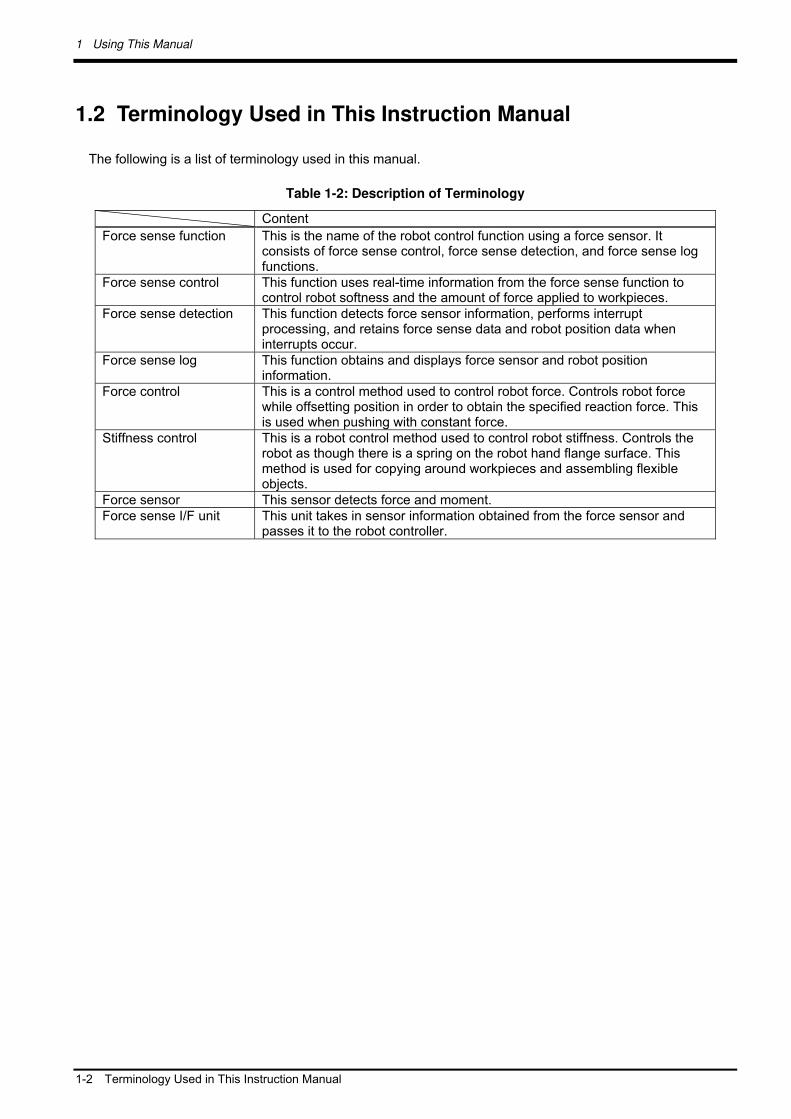
1.2 Terminology Used in This Instruction Manual
The following is a list of terminology used in this manual.
Table 1-2: Description of Terminology
Content
Force sense function This is the name of the robot control function using a force sensor. It consists of force sense control, force sense detection, and force sense log functions.
Force sense control This function uses real-time information from the force sense function to control robot softness and the amount of force applied to workpieces.
Force sense detection This function detects force sensor information, performs interrupt processing, and retains force sense data and robot position data when interrupts occur.
Force sense log This function obtains and displays force sensor and robot position information.
Force control This is a control method used to control robot force. Controls robot force while offsetting position in order to obtain the specified reaction force. This is used when pushing with constant force.
Stiffness control This is a robot control method used to control robot stiffness. Controls the robot as though there is a spring on the robot hand flange surface. This method is used for copying around workpieces and assembling flexible objects.
Force sensor This sensor detects force and moment. Force sense I/F unit This unit takes in sensor information obtained from the force sensor and
passes it to the robot controller.

2 Work Flow
Flowchart 2-3
2 Work Flow
The work required to construct a system employing a force sensor is shown below. Refer to the following work
flow and carry out the work as described.
2.1 Flowchart
1. Force sense function system specifications...."See Chapter 3 of this manual."
Check the force sense function system configuration and function specifications before carrying out the
following work.
2. Product check..."See Chapter 4 of this manual."
Check the purchased product and prepare the required parts.
3. Force sensor attachment method..."See Chapter 5 of this manual."
Attach the force sensor to the robot.
4. Device connection, wiring, setting methods..."See Chapter 6 of this manual."
Connect the force sense interface unit and force sensor, and set the required default parameter settings.
5. Connection and setting check method..."See Chapter 7 of this manual."
Check whether the connections and settings are correct. Always check connections and settings before using
the force sense function.
6. Using the force sense function..."See Chapters 8 , 9 , and 10 of this manual."
Describes how to use the force sense function. Use the force sense function while referring to the detailed
descriptions in Chapters 11 and 12 .

3 Force Sense Function System Specifications
3-4 What is the Force Sense Function?
3 Force Sense Function System Specifications
3.1 What is the Force Sense Function?
The "force sense function" uses force sensor information with 6 degrees of freedom to provide the robot with a
sense of its own force. Using dedicated commands and status variables compatible with the robot program
language (MELFA-BASIC V) facilitates work requiring minute power adjustments and power detection that was
not possible on past robots.
<Main features>
(1) Robots can be controlled softly and operated while copying applicable workpieces. (2) Robots can be operated while pushing in the desired direction with a fixed amount of force. (3) Robot softness and contact detection conditions can be changed during movement. (4) Contact status can be detected and interrupt processing performed. (5) Position information and force information at the time of contact can be performed. (6) Force data synchronized with position data can be saved as log data. (7) Log data can be displayed in a graph using RT ToolBox2. (8) Log data files can be transferred to an FTP server.

3 Force Sense Function System Specifications
System Configuration 3-5
3.2 System Configuration
The device configuration required to use the force sense function is shown below.
Fig. 3-1: Force sense function system configuration drawing
Force sense interface unit
(2F-TZ561)
Computer
Cable between
devices
Robot controller
Teaching pendant
(R56/57TB or
R32/33TB) RT ToolBox2 3D-11C-WINJ 3D-12C-WINJ
24 VDC power
supply
(2F-PWR-01)
24 VDC output cable
(2F-PWRCBL-01)
(Force sensor
attachment
example) Robot
Force sensor
(1F-FS001-W200)
Serial cable between unit and sensor
(2F-FSCBL1-05)
LAN, USB
24 VDC input power
supply cable
(2F-PWRCBL-02)

3 Force Sense Function System Specifications
3-6 Force Sense Function Specifications
3.3 Force Sense Function Specifications
The force sense function specifications are as follows.
Table 3-1: Force sense function specifications
Item Function Details
Applicable robot RV-F Series / RH-F Series Robot program language MELFA-BASIC V (with dedicated force sense function commands)
Stiffness control Function used to control robot softly (Sets stiffness coefficients, damping coefficients.)
Force control This function controls the robot while pushing with specified force.
Force sense control
Control characteristics change
This function changes the control characteristics of force control and stiffness control during robot movement.
Interrupt execution Interrupt processing can be performed using the status at the point the specified force and moment are exceeded.
Data latch This function obtains the force sensor and robot position at the time of contact.
Force sense detection
Data referencing This function displays force sensor data and retains maximum values. Synchronization data This function obtains force sensor information synchronized with
position information as log data. Start/end triggers Logging start and end commands can be specified in the robot
program.
Co
ntro
ller
Force sense log
FTP transfer This function transfers obtained log files to an FTP server. Force sense control (TB)
Enables/disables force sensor control and sets control conditions while jogging.
Force sense monitor Displays sensor data and the force sense control setting status.
R32TB/R33TB
Teaching position search
This function searches for the contact position.
Force sense control (TB)
Enables/disables force sense control and sets control conditions while jogging.
Force sense monitor Displays sensor data and the force sense control setting status. Teaching position search
This function searches for the contact position.
R56TB/R57TB
Parameter setting screen
Dedicated force sense function parameter setting screen
Waveform data display
Displays force sensor and position data.
RT ToolBox2
Parameter setting screen
Dedicated force sense function parameter setting screen

3 Force Sense Function System Specifications
Force Sense Interface Unit Specifications 3-7
3.4 Force Sense Interface Unit Specifications
The force sense interface unit specifications are as follows.
Table 3-2: Force sense interface unit specifications
Item Unit Specification Value Remarks
Model - 2F-TZ561 Force sensor
No. of connected sensors
sensors 1
RS-422 ch 1
For sensor connection Interface
SSCNET III ch 2 For robot controller and additional axis amp connection
Input voltage range
VDC 24 5% There should be no momentary power interruptions or momentary voltage drops.
Power supply
Power consumption
W 25 Includes power supply capacity for force sensor unit.
External dimensions mm 225(W) x 111(D) x 48(H) Does not include protrusions. Weight kg Approx. 0.8 Construction
Panel installation, open
type IP20
Operating temperature range °C 0 to 40 Relative humidity %RH 45 to 85 There should be no dew condensation.Paint color Dark gray Munsell No.: 3.5PB3.2/0.8
3.4.1 Force Sense Interface Unit External Dimensions
Outline drawings of the force sense interface unit are shown below.
Fig. 3-2: Force sense interface unit outline drawings
4 - 4.5 hole FG (M3 screw)

3 Force Sense Function System Specifications
3-8 Force Sense Interface Unit Specifications
3.4.2 Name of Each Force Sense Interface Unit Part
The name of each force sense interface unit part is as follows.
3.4.3 Force Sensor Connection Cable
3.4.4 24 VDC Output Cable
CN1B
(for additional axis amp
connection)
CN4 connector
(not used)
CN9 connector
(not used)
DC24 connector
(for power supply)
CN1A
(for robot controller
connection) CN422
(for force sensor
connection)
5000 mm
Connection diagram
(Pin assignment)
1: +24 V
2: 0 V
3: GND

3 Force Sense Function System Specifications
Force Sense Interface Unit Specifications 3-9
3.4.5 24 VDC Power Supply Outline Drawing
Fig. 3-3: 24 VDC power supply outline drawing

3 Force Sense Function System Specifications
3-10 Force Sensor Specifications
3.5 Force Sensor Specifications
The force sensor specifications are as follows.
Table 3-3: Force sensor specifications
Item Unit Specification Value Remarks
Model - 1F-FS001-W200
Fx, Fy, Fz N 200 Rated load Mx, My,
Mz Nm 4
Fx, Fy, Fz N 1000 Max. static load *1 Mx, My,
Mz Nm 6
Fx, Fy, Fz N 10000 Breaking load *2 Mx, My,
Mz Nm 300
Fx, Fy, Fz N Approx. 0.03 Resolution Mx, My,
Mz Nm Approx. 0.0006
Linearity %FS 3
Hysteresis %FS 5
Other axis sensitivity %FS ±5
Fx, Fy, Fz %FS/°C ±0.2 Zero temperature properties
Mx, My, Mz
%FS/°C ±0.2
Consumption current mA 200
Output form - RS422
Weight (sensor unit) g 360
External dimensions mm 80 x 32.5 See outline drawing.
Material - Aluminum alloy
Color - Black
Temperature °C 0 to 45 Operating environment Humidity %RH 95 or less *1: Stopper function operating load *2: Permanent deformation load
The breaking load is not the load which guarantees sensor operation. If operated up to
even one degree of the breaking load, distortion will occur inside the sensor, and it may
not be possible to detect load properly. Please use within the rate load.
Caution

3 Force Sense Function System Specifications
Force Sensor Specifications 3-11
3.5.1 Force Sensor External Dimensions
Outline drawings of the force sensor are shown below.
Fig. 3-4: Force sensor outline drawing
3.5.2 Sensor Attachment Adapter External Dimensions
Outline drawings of the sensor attachment adapter are shown below.
Fig. 3-5: Sensor attachment adapter outline drawings
(Detection axis Y) (Y-)
Positioning pin hole
2 -3 H7, depth 4 Positioning pin hole
2 -3 H7, depth 4
H7, effective depth 4
H7, effective depth 4
(Detection
axis X)
(Detection axis Z) (Z+)
Sensor attachment tapping hole 4 – M6 x 1.0
Sensor detection center
Low-head bolt for sensor attachment 4 – M6 x 1.0
(P.C.D 63)
(Cable: MISUMI NA20276RSB-26-5P)
(P.C.D 63)
Cross-section AA
depth 6
R0.4 or less
4 – M6 screw through-hole, bottom hole 4.9
(at equidistant points on circumference)
depth 5
(sensor positioning pin hole)
4 – 5.5 cut, 10 through-hole
(at equidistant points on circumference)
A
(Y-)
(Y+)
depth 10

3 Force Sense Function System Specifications
3-12 Coordinate System Definition
3.6 Coordinate System Definition
The force and moment coordinate systems used with the force sense function are summarized in "Table 3-4".
Table 3-4: Force sense coordinate system list
Coordinate System Name Description
Force sense coordinate system (mechanical interface)
Coordinate system that forms reference for calibration (See section 6.4.2 for details on calibration.)
Force sense coordinate system (tool)
Coordinate system for force sense function (when tool selected)
Force sense coordinate system (XYZ) Coordinate system for force sense function (when XYZ selected)
Force sensor coordinate system Coordinate system for force sensor
A definition of each coordinate system is described below.

3 Force Sense Function System Specifications
Coordinate System Definition 3-13
3.6.1 Force Sense Coordinate System (Mechanical Interface)
The force sense coordinate system (mechanical interface) is defined as follows.
3.6.2 Force Sense Coordinate System (Tool)
If the tool coordinate system is set, the force sense coordinate system (tool) is defined as follows based on the
set tool coordinate system.
The force sense coordinate system (mechanical interface) is the plus direction coordinate system for the direction receiving the reaction force when the robot is moved in the mechanical interface coordinate system plus direction. The coordinate system origin point overlaps with that of the mechanical interface coordinate system. (In this coordinate system, the mechanical interface coordinate system symbols are reversed.)
+Xm
+Zm
+Ym
Force sense coordinate
system
(mechanical interface)
Mechanical interface coordinate
system
* Refer to the separate "Detailed Explanations of Functions and Operations (BFP-A8586)" for details on the definition of the mechanical interface coordinate system.
+FXm
+FZm
+FYm
+MZm +MXm
+MYm
+Xt
The force sense coordinate system (tool) is the plus direction coordinate system for the direction receiving the reaction force when the robot is moved in the tool coordinate system plus direction. The coordinate system origin point overlaps with that of the tool coordinate system. (In this coordinate system, the tool coordinate system symbols are reversed.)
+MZt
+MXt
+MYt
Mechanical interface coordinate system
Force sense coordinate system
(tool)
Tool coordinate system
+Yt
+Zt
* Refer to the separate "Detailed Explanations of Functions and Operations (BFP-A8586)" for details on the definition of the tool coordinate system.
+FXt
+FZt
+FYt

3 Force Sense Function System Specifications
3-14 Coordinate System Definition
3.6.3 Force Sense Coordinate System (XYZ)
The assumed force sense coordinate system (XYZ) used in force sense function processing is defined as
follows.
The force sense coordinate system (XYZ) is the plus direction coordinate system for the
direction receiving the reaction force when the robot is moved in the XYZ coordinate
system plus direction. The coordinate system origin point overlaps with that of the
mechanical interface coordinate system.
+MZ
+MY
+MX
Force sense coordinate
system (XYZ)
XYZ coordinate system (direction only)
+X
+FZ
+Z
+Y
+FY
+FX
* Refer to the separate "Detailed Explanations of Functions and Operations (BFP-A8586)" for details on the definition of the XYZ coordinate system.
+MZ
+MY
+MX

3 Force Sense Function System Specifications
Coordinate System Definition 3-15
3.6.4 Force Sensor Coordinate System
The force sensor coordinate system is defined as follows.
+FZs
+FXs
Tool side
+FYs
The origin point of the force sensor coordinate system is the position 18 mm away from the robot side surface.
18 mm
Robot side
Coordinate system origin point
Left-hand system
+MYs
+MZs
+MXs

4 Check Before Use
4-16 Product Check
4 Check Before Use
4.1 Product Check
The standard configuration of this product is as follows. Please check.
Table 4-1: Force sensor set product configuration list
No. Part Name Model Quantity
(1) Force sensor 1F-FS001-W200 1 (2) Force sense interface unit 2F-TZ561 1 (3) Sensor attachment adapter (RV-2/4/7F) 1F-FSFLG-01 1 (4) Adapter cable 1F-ADCBL-01 1 (5) 24 VDC power supply 2F-PWR-01 1 (6) 24 VDC power supply output cable 2F-PWRCBL-01 1 m (7) 24 VDC power supply input cable 2F-PWRCBL-02 1 m (8) Serial cable between unit and sensor 2F-FSCBL1-05 5 m (9) SSCNET III cable MR-J3BUS10M 10 m (10) CD-ROM
4F-FS001-W200 (force sensor set)
BFP-A8946 1
Note) The numbers in the above table correspond to the numbers below.
(1) Force sensor (2) Force sense interface unit (3) Sensor attachment adapter
(8) Serial cable between unit and sensor (5 m) (9) SSCNET III cable (10 m)
(5) 24 VDC power supply (7) 24 VDC power supply
input cable (4) Adapter cable
(6) 24 VDC power supply
output cable
(10)CD-ROM
・Instruction Manual
・Sample Program
4 Check Before Use
Software Versions 4-17
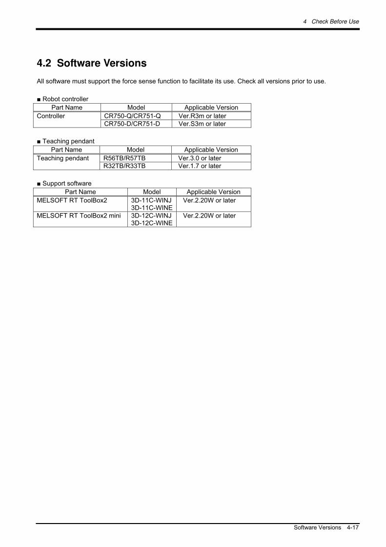
4.2 Software Versions
All software must support the force sense function to facilitate its use. Check all versions prior to use.
■ Robot controller
Part Name Model Applicable Version
CR750-Q/CR751-Q Ver.R3m or later Controller CR750-D/CR751-D Ver.S3m or later
■ Teaching pendant
Part Name Model Applicable Version
R56TB/R57TB Ver.3.0 or later Teaching pendant R32TB/R33TB Ver.1.7 or later
■ Support software
Part Name Model Applicable Version
MELSOFT RT ToolBox2 3D-11C-WINJ3D-11C-WINE
Ver.2.20W or later
MELSOFT RT ToolBox2 mini 3D-12C-WINJ3D-12C-WINE
Ver.2.20W or later
5 Attaching the Force Sensor
5-18 Attachment Adapter
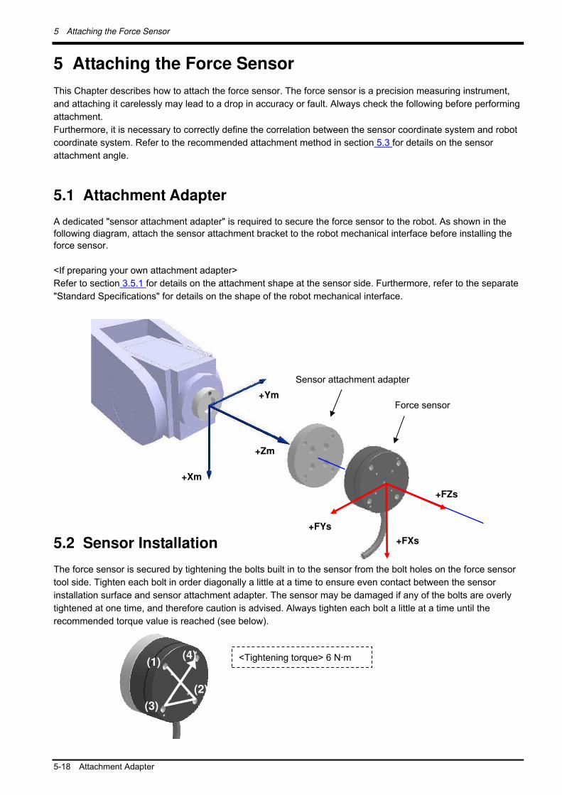
5 Attaching the Force Sensor
This Chapter describes how to attach the force sensor. The force sensor is a precision measuring instrument,
and attaching it carelessly may lead to a drop in accuracy or fault. Always check the following before performing
attachment.
Furthermore, it is necessary to correctly define the correlation between the sensor coordinate system and robot
coordinate system. Refer to the recommended attachment method in section 5.3 for details on the sensor
attachment angle.
5.1 Attachment Adapter
A dedicated "sensor attachment adapter" is required to secure the force sensor to the robot. As shown in the
following diagram, attach the sensor attachment bracket to the robot mechanical interface before installing the
force sensor.
<If preparing your own attachment adapter>
Refer to section 3.5.1 for details on the attachment shape at the sensor side. Furthermore, refer to the separate
"Standard Specifications" for details on the shape of the robot mechanical interface.
5.2 Sensor Installation
The force sensor is secured by tightening the bolts built in to the sensor from the bolt holes on the force sensor
tool side. Tighten each bolt in order diagonally a little at a time to ensure even contact between the sensor
installation surface and sensor attachment adapter. The sensor may be damaged if any of the bolts are overly
tightened at one time, and therefore caution is advised. Always tighten each bolt a little at a time until the
recommended torque value is reached (see below).
+Xm
+Ym
+Zm
+FZs
+FXs
+FYs
Sensor attachment adapter
Force sensor
(1)
(2)
(3)
(4) <Tightening torque> 6 N·m

5 Attaching the Force Sensor
Recommended Attachment Angle 5-19
The bolts should also be tightened a little at a time to ensure an even attachment surface when attaching a
hand to the force sensor tool side (Tightening torque: 6 N·m).
Care should also be taken with regard to the following points. If not attached properly, it will not be possible to
obtain force data accurately, leading to a drop in force sense control performance.
Ensure that the hand attachment surface is as flat as possible, and ensure sufficient stiffness to avoid any
loss in force or moment.
Do not attach in such a way as to prevent movement of moveable parts of the force sensor (cable routing
etc.)
5.3 Recommended Attachment Angle
The following attachment method is recommended to ensure easy calibration with the force sensor coordinate
system and force sense coordinate system (mechanical interface) that forms the reference for the force sense
function.
[Recommended attachment angle]
Attach so that the sensor coordinate system +FXs direction is parallel with the mechanical interface
coordinate system +Xm direction.
<Calibration>
To ensure proper functioning of the force sense function, it is necessary to correctly set the correlation between
the force sensor coordinate system and force sense coordinate system (mechanical interface).
* Refer to section 6.4.2 for details on the calibration method.
* Refer to section 3.5 for details on the coordinate system definition.
+Xm
+Ym
+Zm
+FZs
+FXs
+FYs
Sensor attachment adapter
Force sensor
6 Device Connection, Wiring, and Settings
6-20 Force Sense Unit ( Robot Controller
6 Device Connection, Wiring, and Settings
This Chapter describes "force sensor", "force sense interface unit", and "robot controller" connection, as well as
default parameter settings.
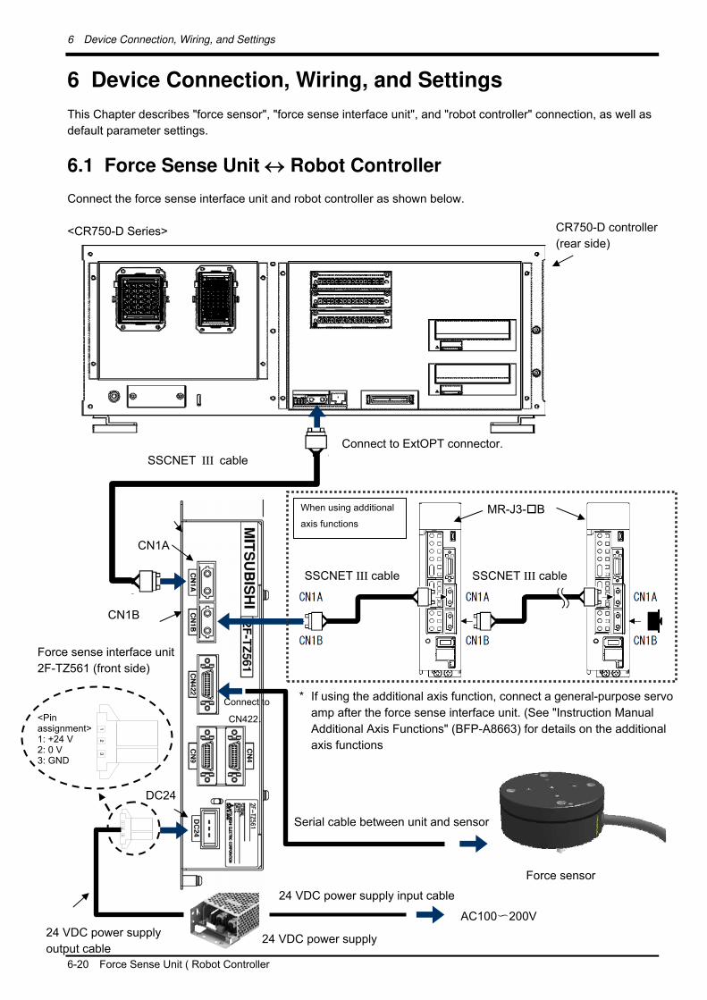
6.1 Force Sense Unit Robot Controller
Connect the force sense interface unit and robot controller as shown below.
<CR750-D Series>
Connect to ExtOPT connector.
Force sense interface unit
2F-TZ561 (front side)
When using additional
axis functions
MR-J3-B
<Pin assignment> 1: +24 V 2: 0 V 3: GND
CN1B
SSCNET III cable
* If using the additional axis function, connect a general-purpose servo
amp after the force sense interface unit. (See "Instruction Manual
Additional Axis Functions" (BFP-A8663) for details on the additional
axis functions
CR750-D controller
(rear side)
CN1A
DC24
24 VDC power supply
output cable
Force sensor
Connect to
CN422.
Serial cable between unit and sensor
SSCNET III cable SSCNET III cable
24 VDC power supply
24 VDC power supply input cable
AC100〜200V

6 Device Connection, Wiring, and Settings
Force Sense Unit ( Robot Controller 6-21
<CR751-D Series>
CR751-D controller
(front side)
Connect to ExtOPT connector.
Force sense interface unit
2F-TZ561 (front side)
When using additional
axis functions MR-J3-B
<Pin assignment> 1: +24 V 2: 0 V 3: GND
CN1B
SSCNET III cable
* If using the additional axis function, connect a general-purpose servo
amp after the force sense interface unit. (See "Instruction Manual
Additional Axis Functions" (BFP-A8663) for details on the additional
axis functions
CN1A
DC24
24 VDC power supply
output cable
Force sensor
Connect to
CN422.
Serial cable between unit and sensor
SSCNET III cable SSCNET III cable
24 VDC power supply
24 VDC power supply input cable
AC100〜200V
6 Device Connection, Wiring, and Settings
6-22 Force Sense Unit ( Robot Controller
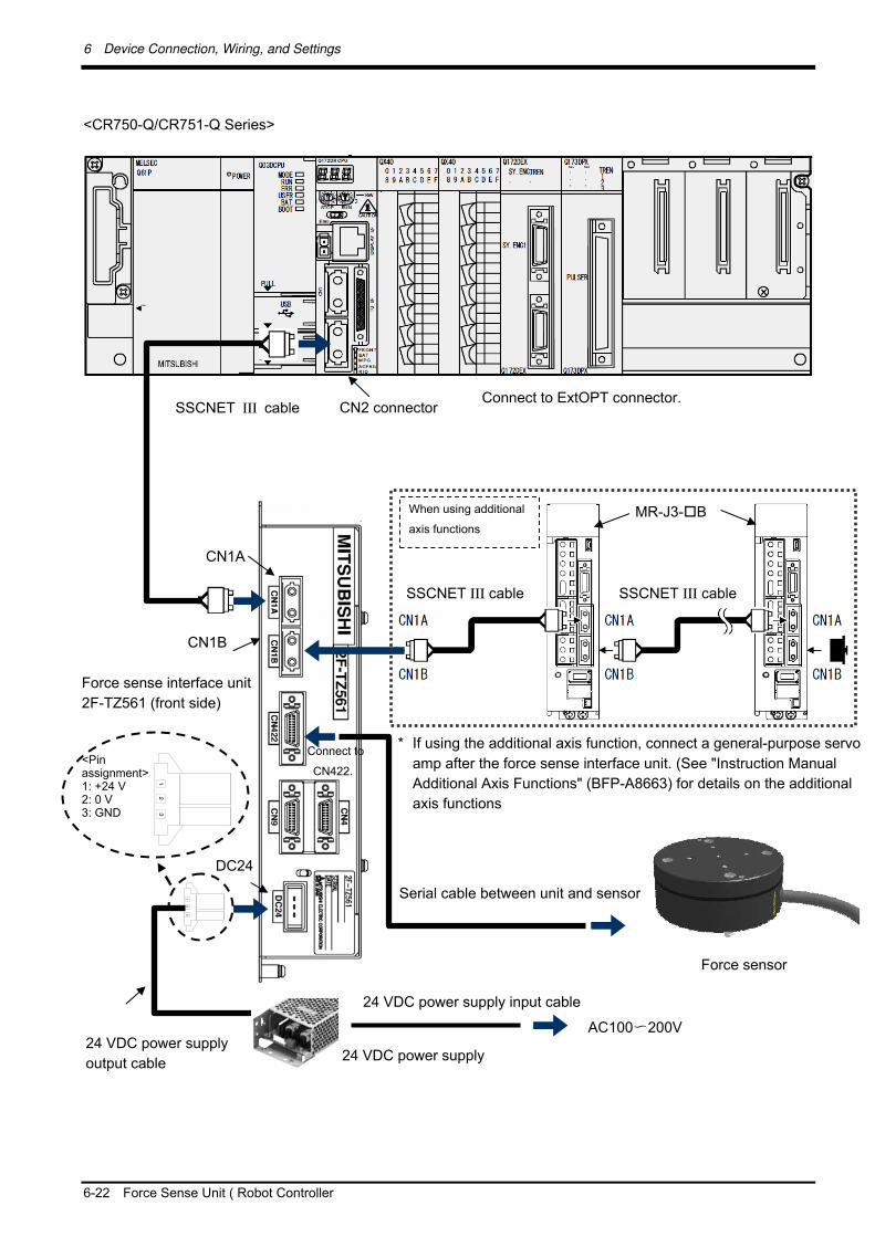
<CR750-Q/CR751-Q Series>
Connect to ExtOPT connector.
Force sense interface unit
2F-TZ561 (front side)
When using additional
axis functions MR-J3-B
<Pin assignment> 1: +24 V 2: 0 V 3: GND
CN1B
SSCNET III cable
* If using the additional axis function, connect a general-purpose servo
amp after the force sense interface unit. (See "Instruction Manual
Additional Axis Functions" (BFP-A8663) for details on the additional
axis functions
CN1A
DC24
24 VDC power supply
output cable
Force sensor
Connect to
CN422.
Serial cable between unit and sensor
CN2 connector
SSCNET III cable SSCNET III cable
24 VDC power supply
24 VDC power supply input cable
AC100〜200V

6 Device Connection, Wiring, and Settings
Force Sense Interface Unit ( Force Sensor 6-23
6.2 Force Sense Interface Unit Force Sensor
Connect the force sense interface unit and force sensor as shown below.
<Robot with internal wiring>
<Standard robot>
Built-in cable
Force sensor
Force sense I/F
unit
Serial cable between unit and
sensor
Adapter cable
Connect to CN422
connector.
(2) Force sense I/F unit
Connect to CN422
connector.
Force sensor
Serial cable between unit and
sensor
The adapter cable is not used for
the standard robot.
6 Device Connection, Wiring, and Settings
6-24 Turning ON the Power
6.3 Turning ON the Power
Turn ON the power only after checking that the force sense interface unit, robot controller, and force sensor
have been properly connected. Turn the power ON and OFF in the following order.
<When turning the power ON>
Turn ON the power to the force sense interface unit followed by the robot controller (or simultaneously).
<When turning the power OFF>
Turn OFF the power to the robot controller followed by the force sense interface unit (or simultaneously).
(There is no need to turn OFF the force sense interface unit power if only the controller is ON.)
Do not disconnect the SSCNET III cable after turning ON the power. Furthermore, do not look directly at the light from the end of the SSCNET III connector or SSCNET III cable. Some discomfort may be experienced with direct exposure. (The SSCNET III light source is equivalent to the Class 1 source specified in JISC6802, IEC60825-1.)
Caution
6 Device Connection, Wiring, and Settings
Default Parameter Settings 6-25
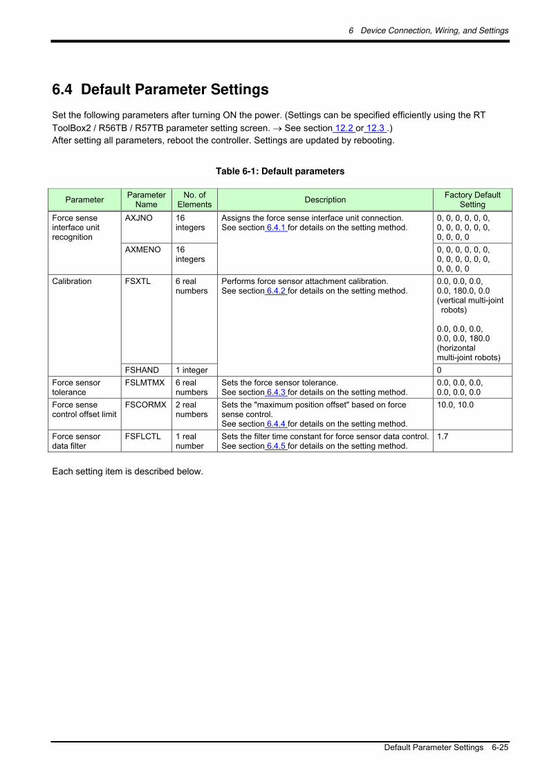
6.4 Default Parameter Settings
Set the following parameters after turning ON the power. (Settings can be specified efficiently using the RT
ToolBox2 / R56TB / R57TB parameter setting screen. See section 12.2 or 12.3 .)
After setting all parameters, reboot the controller. Settings are updated by rebooting.
Table 6-1: Default parameters
Parameter Parameter
Name No. of
Elements Description
Factory Default Setting
Force sense interface unit recognition
AXJNO 16 integers
Assigns the force sense interface unit connection. See section 6.4.1 for details on the setting method.
0, 0, 0, 0, 0, 0, 0, 0, 0, 0, 0, 0, 0, 0, 0, 0
AXMENO 16 integers
0, 0, 0, 0, 0, 0, 0, 0, 0, 0, 0, 0, 0, 0, 0, 0
Calibration FSXTL 6 real numbers
Performs force sensor attachment calibration. See section 6.4.2 for details on the setting method.
0.0, 0.0, 0.0, 0.0, 180.0, 0.0 (vertical multi-joint robots)
0.0, 0.0, 0.0, 0.0, 0.0, 180.0 (horizontal multi-joint robots)
FSHAND 1 integer 0
Force sensor tolerance
FSLMTMX 6 real numbers
Sets the force sensor tolerance. See section 6.4.3 for details on the setting method.
0.0, 0.0, 0.0, 0.0, 0.0, 0.0
Force sense control offset limit
FSCORMX 2 real numbers
Sets the "maximum position offset" based on force sense control. See section 6.4.4 for details on the setting method.
10.0, 10.0
Force sensor data filter
FSFLCTL 1 real number
Sets the filter time constant for force sensor data control. See section 6.4.5 for details on the setting method.
1.7
Each setting item is described below.
6 Device Connection, Wiring, and Settings
6-26 Default Parameter Settings
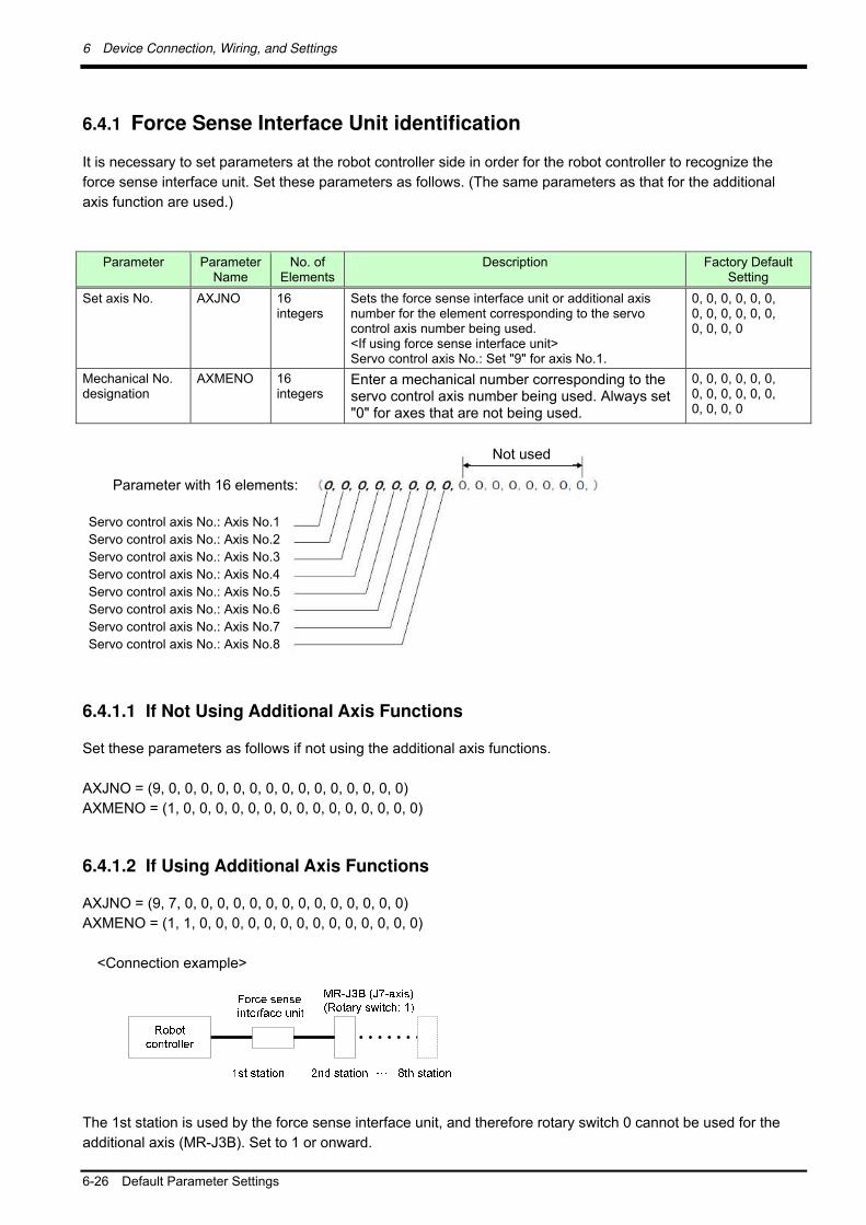
6.4.1 Force Sense Interface Unit identification
It is necessary to set parameters at the robot controller side in order for the robot controller to recognize the
force sense interface unit. Set these parameters as follows. (The same parameters as that for the additional
axis function are used.)
Parameter Parameter Name
No. of Elements
Description Factory Default Setting
Set axis No.
AXJNO 16 integers
Sets the force sense interface unit or additional axis number for the element corresponding to the servo control axis number being used. <If using force sense interface unit> Servo control axis No.: Set "9" for axis No.1.
0, 0, 0, 0, 0, 0, 0, 0, 0, 0, 0, 0, 0, 0, 0, 0
Mechanical No. designation
AXMENO 16 integers
Enter a mechanical number corresponding to the servo control axis number being used. Always set "0" for axes that are not being used.
0, 0, 0, 0, 0, 0, 0, 0, 0, 0, 0, 0, 0, 0, 0, 0
6.4.1.1 If Not Using Additional Axis Functions
Set these parameters as follows if not using the additional axis functions.
AXJNO = (9, 0, 0, 0, 0, 0, 0, 0, 0, 0, 0, 0, 0, 0, 0, 0)
AXMENO = (1, 0, 0, 0, 0, 0, 0, 0, 0, 0, 0, 0, 0, 0, 0, 0)
6.4.1.2 If Using Additional Axis Functions
AXJNO = (9, 7, 0, 0, 0, 0, 0, 0, 0, 0, 0, 0, 0, 0, 0, 0)
AXMENO = (1, 1, 0, 0, 0, 0, 0, 0, 0, 0, 0, 0, 0, 0, 0, 0)
<Connection example>
The 1st station is used by the force sense interface unit, and therefore rotary switch 0 cannot be used for the
additional axis (MR-J3B). Set to 1 or onward.
Parameter with 16 elements:
Not used
Servo control axis No.: Axis No.1
Servo control axis No.: Axis No.2
Servo control axis No.: Axis No.3
Servo control axis No.: Axis No.4
Servo control axis No.: Axis No.5
Servo control axis No.: Axis No.6
Servo control axis No.: Axis No.7
Servo control axis No.: Axis No.8

6 Device Connection, Wiring, and Settings
Default Parameter Settings 6-27
6.4.2 Calibration
To use the force sense function, it is necessary to define (calibrate) the correlation between the force sensor
coordinate system and force sense coordinate system (mechanical interface). Calibration is performed with the
following parameter settings.
There is a danger that the robot may move in an unintended direction if the calibration settings are incorrect. After setting the parameters, always check that they have been set correctly by following the procedure in "Chapter 5
Table 6-2 Details of parameters FSHAND and FSXTL
Parameter Parameter
Name No. of
Elements Description
Factory Default Setting
Force sensor coordinate system selection
FSHAND 1 integer Selects the force sensor coordinate system hand system (left-hand system/right-hand system). The force sensor coordinate system hand system differs depending on the sensor attachment direction, and therefore it is necessary to change the setting based on the attachment direction. Set the left-hand system for recommended attachment.
0: Force sensor coordinate system left-hand system 1: Force sensor coordinate system right-hand system
<Left-hand system> <Right-hand system>
0
Force sensor attachment position
FSXTL 6 real numbers
Sets the positional relationship for the mechanical interface coordinate system and force sensor coordinate system.
1st element: X-axis direction coordinate system origin offset [mm] 2nd element: Y-axis direction coordinate system origin offset [mm] 3rd element: Z-axis direction coordinate system origin offset [mm] 4th element: Coordinate axis rotation angle around X-axis [deg] 5th element: Coordinate axis rotation angle around Y-axis [deg] 6th element: Coordinate axis rotation angle around Z-axis [deg]
0.0, 0.0, 0.0, 0.0, 180.0, 0.0 (vertical multi-joint robots) 0.0, 0.0, 0.0, 0.0, 0.0, 180.0 (horizontal multi-joint robots)
* Refer to the next sub-section for more specific details on the setting method.
Caution
Force sense
coordinate system
(mechanical
interface)
Mechanical interface coordinate
system
+Xm
+FZm
+Zm
+Ym
+FYm
+FXm
+FZs
+FXs
Force sensor coordinate
system
+FYs [Calibration]
Sets the correlation between the force sensor
coordinate system and force sense coordinate
system (mechanical interface).

6 Device Connection, Wiring, and Settings
6-28 Default Parameter Settings
6.4.2.1 Parameter Setting Example 1 (for Recommended Attachment)
When the force sensor attachment is the recommended attachment (described in section 5.3 the parameter
settings for elements 1 to 4 for FSHAND and FSXTL will be the default factory settings. Change only elements 1
to 3 for FSXTL.
[Coordinate system hand system]
The force sensor coordinate system will be the left-hand system, and should therefore be set as follows.
FSHAND = 0 (default)
[Parallel transfer]
The force sensor coordinate system origin position as viewed from the mechanical interface coordinate system
is (0, 0, 32), and therefore the FSXTL settings are as follows.
FSXTL 1st element = 0
FSXTL 2nd element = 0
FSXTL 3rd element = +32
[Rotational transfer]
To align the posture of the force sense coordinate system (mechanical interface) and force sensor coordinate
system, it is sufficient to rotate +180 degrees around the Ym-axis, and therefore the FSXTL settings are as
follows.
FSXTL 4th element = 0 (default)
FSXTL 5th element = +180 (default)
FSXTL 6th element = 0 (default)
+Xm
+FZm
+Zm
+Ym
+FYm
+FXm
Force sense coordinate
system
(mechanical interface)
Left-hand system
Mechanical interface coordinate system
+FZs
+FXs
Robot view side
Force sensor coordinate
system
Left-hand system
+FYs
32 mm (sensor attachment adapter thickness + distance to sensor center)
[Recommended attachment]
Attach the sensor so that the
+FXs and +Xm directions match.

6 Device Connection, Wiring, and Settings
Default Parameter Settings 6-29
6.4.2.2 Parameter Setting Example 2
If, as shown below, the force sensor coordinate system origin is offset 50 mm in the +Zm direction and rotated
30 degrees around the Zm-axis as viewed from the mechanical interface coordinate system, set the parameters
as follows.
[Coordinate system hand system]
The force sensor coordinate system will be the left-hand system, and should therefore be set as follows.
FSHAND = 0
[Parallel transfer]
The force sensor coordinate system origin position as viewed from the mechanical interface coordinate system
is (0, 0, 50), and therefore the FSXTL settings are as follows.
FSXTL 1st element = 0
FSXTL 2nd element = 0
FSXTL 3rd element = +50
[Rotational transfer]
To align the posture of the force sense coordinate system (mechanical interface) and force sensor coordinate
system, it is sufficient to rotate +180 degrees around the Ym-axis after rotating +30 degrees around the
Zm-axis, and therefore the FSXTL settings are as follows.
FSXTL 4th element = 0
FSXTL 5th element = +180
FSXTL 6th element = +30
+Xm
+FZm
+Zm
+Ym
+FYm
+FXm
Force sense coordinate
system
(mechanical interface)
Left-hand system
Mechanical interface coordinate system
+FZs
+FXs
Robot view side
Force sensor coordinate system
Left-hand system
+FYs
50 mm
+30º
6 Device Connection, Wiring, and Settings
6-30 Default Parameter Settings
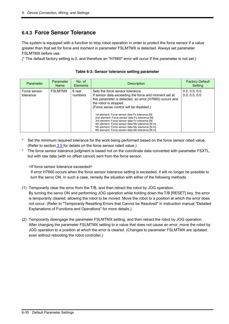
6.4.3 Force Sensor Tolerance
The system is equipped with a function to stop robot operation in order to protect the force sensor if a value
greater than that set for force and moment in parameter FSLMTMX is detected. Always set parameter
FSLMTMX before use.
(* The default factory setting is 0, and therefore an "H7660" error will occur if this parameter is not set.)
Table 6-3: Sensor tolerance setting parameter
Parameter Parameter
Name No. of
Elements Description
Factory Default Setting
Force sensor tolerance
FSLMTMX 6 real numbers
Sets the force sensor tolerance. If sensor data exceeding the force and moment set at this parameter is detected, an error (H7660) occurs and the robot is stopped. (Force sense control will be disabled.)
1st element: Force sensor data Fx tolerance [N] 2nd element: Force sensor data Fy tolerance [N] 3rd element: Force sensor data Fz tolerance [N] 4th element: Force sensor data Mx tolerance [N·m] 5th element: Force sensor data My tolerance [N·m] 6th element: Force sensor data Mz tolerance [N·m]
0.0, 0.0, 0.0, 0.0, 0.0, 0.0
* Set the minimum required tolerance for the work being performed based on the force sensor rated value.
(Refer to section 3.5 for details on the force sensor rated value.)
* The force sensor tolerance judgment is based not on the coordinate data converted with parameter FSXTL,
but with raw data (with no offset cancel) sent from the force sensor.
<If force sensor tolerance exceeded>
If error H7660 occurs when the force sensor tolerance setting is exceeded, it will no longer be possible to
turn the servo ON. In such a case, remedy the situation with either of the following methods.
(1) Temporarily clear the error from the T/B, and then retract the robot by JOG operation.
By turning the servo ON and performing JOG operation while holding down the T/B [RESET] key, the error
is temporarily cleared, allowing the robot to be moved. Move the robot to a position at which the error does
not occur. (Refer to "Temporarily Resetting Errors that Cannot be Resolved" in instruction manual "Detailed
Explanations of Functions and Operations" for more details.)
(2) Temporarily disengage the parameter FSLMTMX setting, and then retract the robot by JOG operation.
After changing the parameter FSLMTMX setting to a value that does not cause an error, move the robot by
JOG operation to a position at which the error is cleared. (Changes to parameter FSLMTMX are updated
even without rebooting the robot controller.)

6 Device Connection, Wiring, and Settings
Default Parameter Settings 6-31
6.4.4 Force Sensor Control Offset Limit
This parameter sets the position command offset upper limit for force sense control. If the offset exceeds this
upper limit, an error (H2760) occurs. This acts as a protection function for inadequate operation or setting, and
therefore the required minimum value should be set.
Table 6-4: Force sense control offset limit setting parameter
Parameter Parameter
Name No. of
Elements Description
Factory Default Setting
Force sense control offset limit
FSCORMX 2 real numbers
Sets the maximum position offset for force sense control. 1st element: Position maximum offset [mm] 2nd element: Posture maximum offset [deg.] [Setting range] 1st element: 0 to +200.0 2nd element: 0 to +150.0
10.0, 10.0
6.4.5 Force Sensor Data Filter Setting
The force sensor data filter time constant can be changed. Sensor data that does not stabilize can be improved
by increasing the time constant, however, as this affects force sense control characteristics, the default value
should generally be used.
Table 6-5: Force sensor data filter parameter
Parameter Parameter
Name No. of
Elements Description
Factory Default Setting
Force sensor data filter
FSFLCTL 1 real number
Sets the force sensor data filter time constant. [Unit]: ms [Setting range]: 0 to +1000.0
1.7

7 Checking the Connection and Settings
7-32 Checking Force Sensor Data Communication
7 Checking the Connection and Settings
Before using the force sense function, ensure that force sensor data is being sent to the robot controller in the
correct coordinate system.
7.1 Checking Force Sensor Data Communication
Display the teaching pendant force sense control screen with the following operation, and ensure that the force
sensor data is displayed correctly. If data does not show any change even when force is applied to the force
sensor, there is a possibility that there is a problem with the device connection or parameter settings. If so, refer
to "Chapter 6 ".
7.1.1 If Using R56TB/R57TB
If using the force sensor, an [F] button appears at the bottom of the JOG screen. By pressing this button, a force
sense control screen appears on the left of the JOG screen. (If the [F] button does not appear, check the
parameter settings in " section 6.4.1 ".)
Fig. 7-1: F button display
Fig. 7-2: Force sense control extension screen
Ensure that the
force sensor
data changes.
Press the [F] button.

7 Checking the Connection and Settings
Checking Force Sensor Data Communication 7-33
7.1.2 If Using R32TB/R33TB
Monitor mode
Ensure that the force sensor
data changes.
Menu screen
Extension function menu screen

7 Checking the Connection and Settings
7-34 Checking the Force Sensor Attachment Coordinate System
7.2 Checking the Force Sensor Attachment Coordinate System
Check force data when external force is applied by hand to the force sensor tool side. If set correctly, the
correlation between the direction in which force is applied and the changed direction in the force data will be as
shown in "Table 7-1". If the force data direction is different, check the calibration parameter settings in " section
6.4.2 ".
In the interest of safety, always perform this check with the servo power OFF.
If tool coordinates are set, perform this check after disabling the tool designation. (Check after setting all parameter MEXTL setting values to 0.)
Table 7-1: Force direction check
Direction in which Force Applied
Force Data Change
(1) -Xm direction Fx value changes to + direction. (2) -Ym direction Fy value changes to + direction. (3) -Zm direction Fz value changes to + direction.
+Xm
+FZm
+Zm
+Ym
+FYm
+FXm
Force sense coordinate
system
(mechanical interface)
Mechanical interface coordinate system
Check the force data displayed at
the teaching pendant while
pushing by hand.
Force sensor
Caution
Caution

8 Using the Force Sense Function (Programming)
Checking the Force Sensor Attachment Coordinate System 8-35
8 Using the Force Sense Function (Programming)
This Chapter describes robot programming using the force sense function.
The force sense function consists of "force sense control", "force sense detection", and "force sense log"
functions. Refer to the section numbers and pages under "Reference" in the following table for a "description"
and "sample program" for each function.
Table 8-1: Force sense function usage method reference list (programming)
Reference Function Class Function Overview
Description Sample
Controls push force. Page 8-51 Force control
Controls force and speed. Page 8-52 Stiffness control Controls softness. Page 8-54
Changes control characteristics during robot movement.
Page 8-55
Force sense control Control characteristics
change Changes control characteristics in the trigger conditions.
Section 8.1
Page 8-57
Detects contact status and performs interrupt processing.
Page 8-65
Interrupt execution Defines interrupt conditions and uses the conditions in the program.
Page 8-66 Force sense detection
Data latch / referencing Latches forse sense data and uses the data in the program.
Section 8.2
Page 8-68
Log data acquisition Acquires time series data during work. Log data display Displays log data in a graph.
Page 8-80 Force sense log
Log data transfer Transfers log data to the FTP server.
Section 8.3
Page 8-82

8 Using the Force Sense Function (Programming)
8-36 Force Sense Control
8.1 Force Sense Control
The force sense control function is used to control robot softness and push force. Depending on the application,
this function switches between "force control" and "stiffness control". The characteristics of each type of control
are described below.
(1) Force control
This control mode controls the robot while pushing with a specified force. The robot moves automatically to the
position at which the specified reaction force can be obtained.
The robot can be moved while pushing the workpiece with constant force and maintaining the contact status.
Force control has the following 2 modes.
<Speed priority mode>
If no contact has been made with the target object, the robot switches to speed control mode and moves at the
specified speed toward the object.
<Force priority mode>
If contact has been made with the target object, the robot switches to force control mode and the robot is
controlled in order that the specified reaction force can be obtained.
(2) Stiffness control
This control mode is used to control the robot softly like a spring. By applying external force, the robot moves
automatically in the direction that allows it to escape the external force.
This type of control can be used to suppress the force acting on the workpiece when performing insertion work.
Furthermore, the robot position is offset while following the assembly part shape, allowing teaching position
displacements to be absorbed
(3) Position control
This control mode is used to control the robot position. Position control is applied to axes for which neither force
control nor stiffness control are specified.
Table 8-2: Offset restrictions
X,Y,Z A,B,C Remarks
Positional offset restriction
10 [mm] 10 [deg] Can be changed in FSCORMX.
Speed offset restriction (Automatic)
80 [mm/s] 80 [deg/s]
Speed offset restriction (Manual)
Approx.8 [mm/s] Approx 8 [deg/s]
Offset and offset speed restrictions
The restrictions shown in "Table 8-2" are applied to positional offset and offset speed for force sense
control. The positional offset restriciton can be changed in parameter FSCORMX.
8 Using the Force Sense Function (Programming)
Force Sense Control 8-37
By enabling force sense control, the robot moves automatically based on the external force acting on the sensor. Even if it seems that the robot has stopped at first glance, it may be moving at a very slow speed, and therefore attention should be paid to robot behavior while this function is enabled.
Even if program operation is interrupted with an HLT command while force sense control is enabled, the force sense control enabled status is maintained, and therefore the robot may move. To stop the robot, it is necessary to perform the stop entry operation or disable force sense control.
Always check "Chapter 5 before enabling force sense control. If there is a mistake with the connection or settings, the robot may move in an unintended direction.
If resuming operation after an emergency stop condition or after interrupting program operation, a command to return the robot from its stationary position to the position when the program was interrupted is generated automatically. When force sense control is enabled, the difference between the position at which the program was interrupted and the actual stoppage position will be greater than that when force sense control is disabled, and therefore the robot may move significantly when operation is resumed. * It is also possible to stop generation of the command to return the robot from to the position
when the program was interrupted by changing the parameter RETPATH (setting for auto recovery after JOG feed when program interrupted), setting to "0". Refer to "Setting for Auto Recovery After JOG Feed when Program Interrupted" in instruction manual "Detailed Explanations of Functions and Operations" for details on the parameter RETPATH.
Caution
注意
Caution
Caution
Singular point adjacent operation restrictions
Singular point adjacent operation cannot be performed while force sense control is enabled,
regardless of interpolation or JOG operation. If the robot approaches a point adjacent to a singular
point during operation, an error (L3986) occurs. Use force sense control at a position that will avoid a
singular point adjacent condition.
If necessary to move the robot adjacent to a singular point, or if wishing to pass through the singular
point using the singular point pass function, disable the force sense function.
Caution
8 Using the Force Sense Function (Programming)
8-38 Force Sense Control
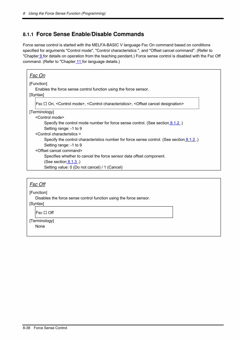
8.1.1 Force Sense Enable/Disable Commands
Force sense control is started with the MELFA-BASIC V language Fsc On command based on conditions
specified for arguments "Control mode", "Control characteristics ", and "Offset cancel command". (Refer to
"Chapter 9 for details on operation from the teaching pendant.) Force sense control is disabled with the Fsc Off
command. (Refer to "Chapter 11 for language details.)
Fsc On
[Function]
Enables the force sense control function using the force sensor.
[Syntax]
Fsc On, <Control mode>, <Control characteristics>, <Offset cancel designation>
[Terminology]
<Control mode>
Specify the control mode number for force sense control. (See section 8.1.2 .)
Setting range: -1 to 9
<Control characteristics >
Specify the control characteristics number for force sense control. (See section 8.1.2 .)
Setting range: -1 to 9
<Offset cancel command>
Specifies whether to cancel the force sensor data offset component.
(See section 8.1.3 .)
Setting value: 0 (Do not cancel) / 1 (Cancel)
Fsc Off
[Function]
Disables the force sense control function using the force sensor.
[Syntax]
Fsc Off
[Terminology]
None
8 Using the Force Sense Function (Programming)
Force Sense Control 8-39
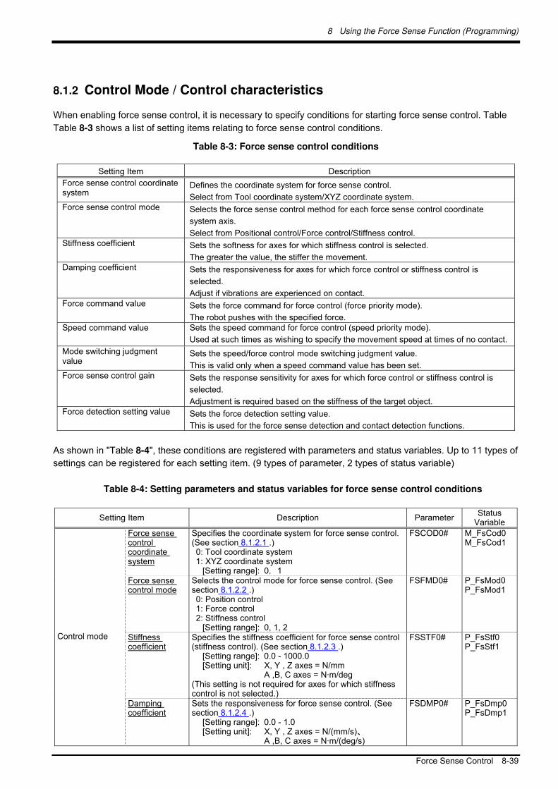
8.1.2 Control Mode / Control characteristics
When enabling force sense control, it is necessary to specify conditions for starting force sense control. Table
Table 8-3 shows a list of setting items relating to force sense control conditions.
Table 8-3: Force sense control conditions
Setting Item Description
Force sense control coordinate system
Defines the coordinate system for force sense control.
Select from Tool coordinate system/XYZ coordinate system. Force sense control mode Selects the force sense control method for each force sense control coordinate
system axis.
Select from Positional control/Force control/Stiffness control. Stiffness coefficient Sets the softness for axes for which stiffness control is selected.
The greater the value, the stiffer the movement. Damping coefficient Sets the responsiveness for axes for which force control or stiffness control is
selected.
Adjust if vibrations are experienced on contact. Force command value Sets the force command for force control (force priority mode).
The robot pushes with the specified force. Speed command value Sets the speed command for force control (speed priority mode).
Used at such times as wishing to specify the movement speed at times of no contact.
Mode switching judgment value
Sets the speed/force control mode switching judgment value.
This is valid only when a speed command value has been set. Force sense control gain Sets the response sensitivity for axes for which force control or stiffness control is
selected.
Adjustment is required based on the stiffness of the target object. Force detection setting value Sets the force detection setting value.
This is used for the force sense detection and contact detection functions.
As shown in "Table 8-4", these conditions are registered with parameters and status variables. Up to 11 types of
settings can be registered for each setting item. (9 types of parameter, 2 types of status variable)
Table 8-4: Setting parameters and status variables for force sense control conditions
Setting Item Description Parameter Status
Variable
Force sense control coordinate system
Specifies the coordinate system for force sense control. (See section 8.1.2.1 .) 0: Tool coordinate system 1: XYZ coordinate system
[Setting range]: 0,1
FSCOD0# M_FsCod0 M_FsCod1
Force sense control mode
Selects the control mode for force sense control. (See section 8.1.2.2 .) 0: Position control 1: Force control 2: Stiffness control
[Setting range]: 0, 1, 2
FSFMD0# P_FsMod0 P_FsMod1
Stiffness coefficient
Specifies the stiffness coefficient for force sense control (stiffness control). (See section 8.1.2.3 .)
[Setting range]: 0.0 - 1000.0 [Setting unit]: X, Y , Z axes = N/mm A ,B, C axes = N·m/deg
(This setting is not required for axes for which stiffness control is not selected.)
FSSTF0# P_FsStf0 P_FsStf1
Control mode
Damping coefficient
Sets the responsiveness for force sense control. (See section 8.1.2.4 .)
[Setting range]: 0.0 - 1.0 [Setting unit]: X, Y , Z axes = N/(mm/s)、 A ,B, C axes = N·m/(deg/s)
FSDMP0# P_FsDmp0 P_FsDmp1

8 Using the Force Sense Function (Programming)
8-40 Force Sense Control
Force command value
Sets the force command for force sense control. (See section 8.1.2.5 .)
[Setting range]: - force sensor tolerance value to + force sensor tolerance value
[Setting unit]: X, Y, Z component = N A, B, C component = N·m
(This setting is not required for axes for which force control is not selected.)
FSFCMD0# P_FsFCd0 P_FsFCd1
Speed command value
Sets the offset speed used in force sense control (force control) speed priority mode. (See section 8.1.2.6 .)
[Setting range]: 0.0 - 50.0 (0.0 only for 7th and 8th elements)
[Setting unit]: X, Y, Z component = mm/s A, B, C component = deg/s
If set to 0.0, force control for that axis will always be in force priority mode. (This setting is not required for axes for which force control is not selected.)
FSSPD0# P_FsSpd0 P_FsSpd1
Mode switching judgment value
Sets the judgment value for switching between the force sense control (force control) speed priority and force priority modes. (See section 8.1.2.7 .)
[Setting range]: - force sensor tolerance value to + force sensor tolerance value
[Setting unit]: X, Y, Z component = N A, B, C component = N·m
If the setting is the same as the force command value (parameter FSFCMD0 1 – 09), the mode for force control will always be force priority for that axis.)
(This setting is not required for axes for which force control is not selected.)
FSSWF0#
P_FsSwF0 P_FsSwF1
Force sense control gain
Sets the response sensitivity for force sense control. (See section 8.1.2.8 .)
[Setting range]: 0.0 - 300.0 [Setting unit]: X, Y, Z axis component = 10
-3 mm/N
A, B, C axis component = 10-3
deg/(N·m)
FSFGN0# P_FsGn0 P_FsGn1
Control characteristics
Force detection setting value
Sets the force detection setting for interrupt signals and data retention trigger for each coordinate axis. (See section 8.1.2.9 .)
[Setting range]: 0.0 - force sensor tolerance value [Setting unit]: X, Y, Z axis component = N A, B, C axis component = N·m
FSFLMT0# P_FsFLm0 P_FsFLm1
(# corresponds to group Nos. 1 to 9.)
For those settings items that are underlined, setting is required for each coordinate axis of the force
sense coordinate system. This corresponds to X, Y, Z, A, B, and C in this order from the 1st element of
parameters and status variables. (Coordinate system definition is based on the "force sense control
coordinate system".)
There is no need to reboot the controller after writing parameters relating to control mode/control
characteristics. (Settings are immediately updated.)
Settings can be specified efficiently using the RT ToolBox2/R56TB/R57TB force sense function
parameter setting screen. (See section 12.2 or 12.3 .)

8 Using the Force Sense Function (Programming)
Force Sense Control 8-41
All parameter settings are classified by "condition groups" consisting of the control mode and control
characteristics, and "condition Nos." constituting numbers -1 to 9. When specifying conditions with the Fsc On
command, they are specified with a combination of these "condition groups" and "condition Nos."
Statement structure:FscOn, <Control mode>, <Control characteristics >, <Offset cancel designation>
If, for example, using the condition settings highlighted by the red boxes in Table 8-5 to start force sense control,
set "1" for the "Control mode" argument and "-1" for the <Control characteristics > argument. (See section 8.1.3
for detail on <Offset cancel designation".)
Table 8-5: Condition groups and condition Nos.
Condition No. Setting Item
-1 0 1 2 to 8 9
Force sense control coordinate system
M_FsCod1 M_FsCod0 FSCOD01 FSCOD0# FSCOD09
Force sense control mode
P_FsMod1 P_FsMod0 FSFMD01 FSFMD0# FSFMD09
Stiffness coefficient P_FsStf1 P_FsStf0 FSSTF01 FSSTF0# FSSTF09
Control mode
Damping coefficient P_FsDmp1 P_FsDmp0 FSDMP01 FSDMP0# FSDMP09
Force command value
P_FsFCd1 P_FsFCd0 FSFCMD01 FSFCMD0# FSFCMD09
Speed command value
P_FsSpd1 P_FsSpd0 FSSPD01 FSSPD0# FSSPD09
Mode switching judgment value
P_FsSwF1 P_FsSwF0 FSSWF01 FSSWF0# FSSWF09
Force sense control gain
P_FsGn1 P_FsGn0 FSFGN01 FSFGN0# FSFGN09
Co
nd
ition
gro
up
Control characteristics
Force detection setting value
P_FsFLm1 P_FsFLm0 FSFLMT01 FSFLMT0# FSFLMT09
(# corresponds to group Nos. 2 to 8.)

8 Using the Force Sense Function (Programming)
8-42 Force Sense Control
8.1.2.1 Force Sense Control Coordinate System
The coordinate systems used with force sense control are specified from the following.
Tool coordinate system XYZ coordinate system
Force sense coordinate system (tool) Force sense coordinate system (XYZ)
8.1.2.2 Force Sense Control Mode
The force sense control mode is set for each axis. The characteristics of each mode are as follows.
Table 8-6: Force sense control mode characteristics
Position Control Mode Force Control Mode Stiffness Control Mode
Control
method
As with normal robot control, the robot is controlled with position commands.
The robot is controlled while pushing with a specified force. The force size and direction are set with the "Force command value".
Controls the robot softly. Softness is set with the "Stiffness coefficient".
Application This is used in combination with force control and stiffness control.
Work involving pushing Grinding work
Fitting/insertion work
Copying/teaching work
+Yt
+Xt
+Zt
+FZt
+FXt
+FYt
+X
+FZ
+Z
+Y
+FY
+FX
The coordinate system direction is the direction in which
the XYZ coordinate system symbol is reversed, and the
origin is the mechanical interface coordinate system
origin.
The coordinate system direction is the direction in
which the tool coordinate system symbol is reversed,
and the origin is the tool coordinate system origin.

8 Using the Force Sense Function (Programming)
Force Sense Control 8-43
8.1.2.3 Stiffness Coefficient
Stiffness control softness is specified with the stiffness coefficient. The stiffness coefficient is the equivalent of
spring constant, and the greater the value, the harder the control.
<Correlation between teaching position and reaction force>
If stiffness control mode is selected, when an external force acts on the arm tip, resulting in displacement
between the teach position and actual position, the robot moves to a position at which the reaction force
corresponding to the "displacement" and "stiffness coefficient" can be obtained.
In the following image, stiffness control is performed only for the tool Z-axis. By setting 0.5 [N/mm] for the
Z-direction stiffness coefficient, and the teaching position at 5 mm below the contact surface, force F produced
on the contact surface is calculated as follows.
F = 0.5 [N/mm] × 5 [mm] = 2.5 [N]
The smaller the stiffness coefficient, the smaller the reaction force, helping to deal with greater displacements.
8.1.2.4 Damping Coefficient
Vibrations that occur when applying positional offsets with force sense control (stiffness control or force control)
are adjusted with the damping coefficient. The greater the value, the greater the effect in suppressing vibrations,
however, positional offsetting is delayed with sudden changes in force, resulting in a greater force applied the
moment contact is made with the workpiece.
If required, damping coefficient adjustments should be made after force sense control gain adjustment is
complete. (Vibrations also occur if the force sense control gain is too great.)
Position command
(teaching position)
Actual position
(contact position)
5 mm

8 Using the Force Sense Function (Programming)
8-44 Force Sense Control
8.1.2.5 Force Command Value
Sets the force command value for force control (force priority mode). When force control is enabled, the robot
moves so that the reaction force specified with the force command value can be obtained.
If no external force acts on the robot (if no contact is made), the robot moves in the force command value
direction and reaction force direction (direction in which the specified force is produced when contact is made.)
<Example> The movement when force control mode is specified only for the FZt direction and the force
command value is FZt = +5 N is as follows.
Table 8-7: Behavior corresponding to force command
Robot Behavior
If contact made (if external force acting)
The robot is moved while offsetting its position until FZt = 5 N.
If no contact made (if no external force acting)
The robot moves in the +Zt direction so that external force is produced in the force command direction when contact is made. The movement speed is proportional to the force sense control gain x force command.
The movement speed when no external force is acting is dependent on the force sense control gain and force
command. (The greater the force sense control gain and force command, the faster the movement.) If
specifying the speed at this point, set the "Speed command value".
8.1.2.6 Speed Command Value
Specifies the movement speed for force control (speed priority mode) when no contact is made with the target
object. Use if performing work while automatically switching between speed control and force control, or to
minimize impact by restricting the approach speed to the target object.
Set the switching condition for "speed priority mode" and "force priority mode" with the "Mode switching
judgment value". If the speed command value is 0.0, priority mode switching is not performed. Force priority
mode is always performed.
+Yt
+Xt
+Zt
+FZt
+FXt
+FYt
Foce priority mode Speed priority mode
Speed constant
Force constant
The priority mode is switched automatically based on the sensor
data value. (The threshold value is set with the "Mode switching
judgment value".)

8 Using the Force Sense Function (Programming)
Force Sense Control 8-45
The speed specified with the speed command value is the force sense control offset speed, and not the actual robot movement speed. If the robot is not moving in other than in force sense control, such as when performing interpolation commands or JOG operation, but moving only in speed priority mode, the "specified offset speed = robot movement speed". If interpolation commands or JOG operation are being performed in speed priority mode, the "(specified offset speed + speed specified for interpolation, JOG operation) = robot movement speed".
8.1.2.7 Mode Switching Judgment Value
Sets the threshold used for switching between "speed priority mode" and "force priority mode" when the speed
command value is set for force sense control (force control).
The speed priority mode and force priority mode switch as follows based on the force command value and
switching judgment value, and force sensor data magnitude correlation.
Table 8-8 Priority mode switching
Data Magnitude Correlation
Force Command Value and
Switching Judgment Value
Sensor Data and Switching
Judgment Value
Priority
Mode
Applicable Area for Each Priority
Mode
Sensor data switching
judgment value
Force
priority
mode
Force command value >
switching judgment value
Sensor data < switching
judgment value
Speed
priority
mode
力覚センタ
力指令値
切 替え判定値
力制御モ
速度制御モ
Sensor data switching
judgment value
Force
priority
mode
Force command value <
switching judgment value
Sensor data > switching
judgment value
Speed
priority
mode
力覚センタ
力指令値
切 替え判定値
力制御モ
速度制御モ
Force command value =
switching judgment value-
Force
priority
mode
力覚センタ
力指令値
切 替え判定値
力制御モ
Caution
Force sensor data
Force
command
value
Switching
judgment
value
Force control
mode
Speed control
mode
Force sensor data
Force
command
value
Switching
judgment
value
Force control
mode
Speed control
mode
Force sensor data
Force
command
value
Switching
judgment
value
Force control
mode

8 Using the Force Sense Function (Programming)
8-46 Force Sense Control
<Force priority mode> Data from the force sensor is used to control the robot until the force specified with the force specification
value is reached. The robot moves in the direction which satisfies the force specification value by following the axis direction
for which force control is specified. The offset speed for force control is restricted to the speed command value or below.
<Speed priority mode> The robot is controlled so that the speed specified with the speed command value is reached. The robot moves in the direction which satisfies the force specification value by following the axis direction
for which force control is specified.
Example: If the robot is moved toward the target object at 1.0 [mm/s] in the -Z direction with a force of 0.5 [N]
until contact is made, and then 1.0 [N] is applied following contact:
Force command value : (0.0, 0.0, 1.0, 0.0, 0.0, 0.0)
Speed command value : (0.0, 0.0, 1.0, 0.0, 0.0, 0.0)
Switching judgment value : (0.0, 0.0, 0.5, 0.0, 0.0, 0.0)
8.1.2.8 Force Sense Control Gain
Force sense control gain is a parameter used to adjust the force sense control responsiveness. The higher the
setting, the higher the force sense control responsiveness, however, increasing the value too much will result in
an ultrasensitive response when contact is made, resulting in unstable operation.
Force sense control gain is affected by the stiffness of the target object, and therefore it is necessary to change
the gain setting value based on the object. Adjust the gain setting valueusing the following method.
<Adjustment method>
1) Move the robot at low speed by JOG operation in the axis direction for which force sense control (force
control/stiffness control) is enabled until contact is made with the target object. (speed override: approx.
5%)
2) If the robot rebounds in the opposite direction from the movement direction when contact is made, it is
necessary to lower the gain setting value. (The gain setting value can be increased if the robot does not
rebound.)
<Setting guide>
Target Object stiffness Force Sense Control Gain
1.0 N/mm 50.0
10.0 N/mm 8.0
100.0 N/mm 1.0
If the force sense control gain setting is 0.0, offsetting withy force sense control will not be performed. Control
will be the same as normal position control (normal control). Control can be changed from position control to
force control/stiffness control or vice versa by changing the gain setting value during robot movement. (Use the
FsGChg command or the FsCTrg command.)
Mode switching judgment value setting
If the "force command value" and "mode switching judgment value" are near one another, sensor
noise or vibrations may be generated while pushing with force control at a specified force, resulting
in the possibility that switching between force priroty mode or speed priority mode may occur
unexpectedly. Adjust the judgment threshold to avoid sensor noise or vibrations while referring to
the log data. Alternatively, use the FsGChg command or the FsCTrg command to change the control
features.

8 Using the Force Sense Function (Programming)
Force Sense Control 8-47
8.1.2.9 Force Detection Setting Value
The force detection setting value is used with the following functions. Refer to the respective items.
Function Class Description Reference
Interrupt execution
Monitors the status with regard to the force detection setting value. (The start-up and shut-down status with regard to the force detection setting value can be obtained.)
Force sense detection
Data latch Sensor data and position data at the moment the force detection setting value is exceeded is retained.
See section 8.2 .
Force sense control (T/B)
Contact detection
JOG operation is stopped the moment the specified force (moment) is exceeded.
See section 9.1 .
8.1.3 Offset Cancel Designation
To operate the force sense control function properly, it is necessary to perform a force/moment offset cancel
(error component elimination) for each axis with no external force (robot stopped or with no contact made) other
than gravity acting on the sensor.
The following two offset cancel methods are available.
Offset Cancel Method Details
1 Method using Fsc On command Set "1" for the Fsc On command argument <Offset cancel designation>.
2 Offset cancel operation from T/B See section 9.1.1.1 .
<Offset cancel conditions>
If performing offset cancel, always do so with the following conditions satisfied.
Robot at complete stop No contact with hand/workpiece, etc. (no external force acting)
By performing an offset cancel with contact made (with external force other than gravity acting on sensor), the force balance will be upset, and force control/stiffness control will not function properly. Always perform the offset cancel with no contact made with the sensor. If executing the Fsc On command when contact is made, disable the offset cancel designation. In a case such as this, it is necessary to perform the offset cancel at a position of no contact beforehand.
<Force sensor temperature drift>
If using the force sensor for long periods of time, sensor output values may fluctuate due the influence of
temperature drift. Create a program to periodically perform offset cancel.
<Influence of gravity>
If changing the robot posture significantly, the force component applied to the sensor by gravity will change,
resulting in the need to perform offset cancel again. If the posture changes significantly with each job, it is
necessary to perform offset cancel again after the posture changes.
Caution
Caution

8 Using the Force Sense Function (Programming)
8-48 Force Sense Control
8.1.4 Control characteristics Change Commands
The "control characteristics " (force sense control gain, force specification value, speed command value, mode
switching judgment value, force detection setting value) settings can be changed while force sense control is
enabled using the MELFA-BASIC V language FsGChg and FsCTrg commands.
Changing the "control characteristics " during movement facilitates work with a great degree of freedom. (The
"control mode" cannot be changed until the Fsc Off command has been executed.)
Refer to "Chapter 11 Language Specifications" for details on each command.
FsGChg (Fs gain change)
[Function]
Changes the control features of force sense control during movement.
[Syntax]
FsGChg <Change start position>, <Change time>, <Control features No. after change>
[Terminology] <Change start position>
Specifies the position at which the change to the control features setting is started. Specify with a percentage for the next interpolation start point end point. Setting range: 0 to 100 [%]
<Change time>
Specifies the time taken to change the control features setting. The mode switching judgment value and force detection setting value changes immediately, regardless of this setting. Setting range: 1 to 1000 [ms]
<Control features No. after change>
Specifies the control features value for which the force control gain, force command value, and force detection setting value, speed command value and mode switching judgment value are set after the change. Setting range: -1 to 9
始点 終点
%
力制御 イン切替開始
力検知設定値 即時切替
例:切替開始位置が 30%の場合
Force control gain change start Start point End point
Force detection setting value changes immediately.
Example) in case of the change start position set at 30%
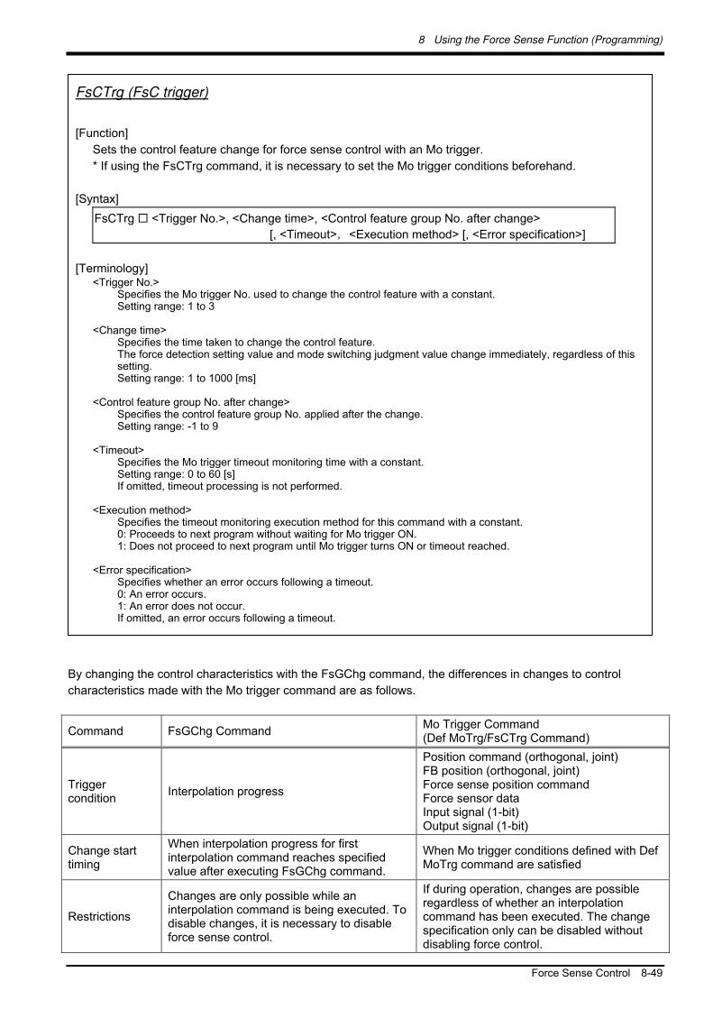
8 Using the Force Sense Function (Programming)
Force Sense Control 8-49
By changing the control characteristics with the FsGChg command, the differences in changes to control
characteristics made with the Mo trigger command are as follows.
Command FsGChg Command Mo Trigger Command (Def MoTrg/FsCTrg Command)
Trigger condition
Interpolation progress
Position command (orthogonal, joint) FB position (orthogonal, joint) Force sense position command Force sensor data Input signal (1-bit) Output signal (1-bit)
Change start timing
When interpolation progress for first interpolation command reaches specified value after executing FsGChg command.
When Mo trigger conditions defined with Def MoTrg command are satisfied
Restrictions
Changes are only possible while an interpolation command is being executed. To disable changes, it is necessary to disable force sense control.
If during operation, changes are possible regardless of whether an interpolation command has been executed. The change specification only can be disabled without disabling force control.
FsCTrg (FsC trigger)
[Function]
Sets the control feature change for force sense control with an Mo trigger.
* If using the FsCTrg command, it is necessary to set the Mo trigger conditions beforehand.
[Syntax]
FsCTrg <Trigger No.>, <Change time>, <Control feature group No. after change>
[, <Timeout>,<Execution method> [, <Error specification>]
[Terminology] <Trigger No.>
Specifies the Mo trigger No. used to change the control feature with a constant. Setting range: 1 to 3
<Change time>
Specifies the time taken to change the control feature. The force detection setting value and mode switching judgment value change immediately, regardless of this setting. Setting range: 1 to 1000 [ms]
<Control feature group No. after change>
Specifies the control feature group No. applied after the change. Setting range: -1 to 9
<Timeout>
Specifies the Mo trigger timeout monitoring time with a constant. Setting range: 0 to 60 [s] If omitted, timeout processing is not performed.
<Execution method>
Specifies the timeout monitoring execution method for this command with a constant. 0: Proceeds to next program without waiting for Mo trigger ON. 1: Does not proceed to next program until Mo trigger turns ON or timeout reached.
<Error specification>
Specifies whether an error occurs following a timeout. 0: An error occurs. 1: An error does not occur. If omitted, an error occurs following a timeout.

8 Using the Force Sense Function (Programming)
8-50 Force Sense Control
8.1.5 Usage Example (Force Sense Control)
This section describes the specific usage method for each function using sample programs.
<Control mode / control characteristics settings>
The sample programs described below set the "control mode" and "control characteristics " using status
variables. The same settings are also possible using parameters and should be substituted as appropriate. (See
following compatibility table.)
Force Sense Control Mode
Setting Item Status Variable (*=0, 1)
Parameter (#=1 to 9)
Po
sitio
n C
on
trol
Fo
rce
Co
ntro
l
Stiffn
ess
Co
ntro
l
Force sense control coordinate system
M_FsCod* FSCOD0#
Force sense control mode
P_FsMod* FSFMD0#
Stiffness coefficient P_FsStf* FSSTF0# × ×
Control mode
Damping coefficient P_FsDmp* FSDMP0# × △ △
Force command value
P_FsFCd* FSFCMD0# × ×
Speed command value
P_FsSpd* FSSPD0# × ×
Mode switching judgment value
P_FsSwF* FSSWF0# × ×
Force sense control gain
P_FsGn* FSFGN0# ×
Control characteristics
Force detection setting value
P_FsFLm* FSFLMT0# △ △ △
( : Setting required, △ : Set as required, × : No setting required)
The sample programs contained in this manual have been prepared for the purpose of understanding force sense functionality, and operation stability cannot be guaranteed. If using a sample contained in this manual on an actual system, please use with a sufficient understanding of the program content. Furthermore, the appropriate values for force sense control gain and damping coefficient, etc will vary greatly depending on the working environment, and therefore adjustments should be made with care.
Caution

8 Using the Force Sense Function (Programming)
Force Sense Control 8-51
Force Control 1
■ Operation details
The robot is pushed in the Z-direction with a force of 10 N.
Force control is started from the PStart position.
The robot is moved in the force sense control coordinate system (tool) +FZt direction until a reaction force
of 10 N can be obtained.
■ Program example <Sample program F801.prg>
‘[Control mode (0)]
P_FsStf0 = (+0.00,+0.00,+0.00,+0.00,+0.00,+0.00)(0,0) 'Stiffness coefficient [N/mm] No setting required
P_FsDmp0 = (+0.00,+0.00,+0.00,+0.00,+0.00,+0.00)(0,0) 'Damping coefficient
P_FsMod0 = (+0.00,+0.00,+1.00,+0.00,+0.00,+0.00)(0,0) 'Force sense control mode (Z-axis force control)
M_FsCod0 = 0 'Force sense control coordinate system (tool)
‘[Control characteristics (0)]
P_FsGn0 = (+0.00,+0.00,+30.00,+0.00,+0.00,+0.00)(0,0) 'Force control gain [µm/N] Adjustment required
P_FsFLm0 = (+0.00,+0.00,+0.00,+0.00,+0.00,+0.00)(0,0) 'Force detection setting value [N]
P_FsFCd0 = (+0.00,+0.00,+10.00,+0.00,+0.00,+0.00)(0,0) 'Force command (10 N in FZt direction)
P_FsSpd0 = (+0.00,+0.00,+0.00,+0.00,+0.00,+0.00)(0,0) 'Sets speed control mode speed.
P_FsSwF0 = (+0.00,+0.00,+0.00,+0.00,+0.00,+0.00)(0,0) 'Sets force/speed judgment value.
'*** <Force control (Z-axis)> ***
Servo On
Mov PStart 'Move to start point.
Dly 1
Fsc On,0,0,1 'Force sense control enabled (drop start with force control)
Dly 10
Fsc Off
End
■ Description
1) The "control mode" and "control characteristics " are set at the beginning of the program. (In this
example they are set with status variables, however, they can also be set with parameters.)
2) Force sense control is started with the Fsc On command based on the conditions set for "Control
mode (0)" and "Control characteristics (0)". "Offset cancel" is performed to offset the sensor zero point.
* Adjust the force control gain based on the target object. The higher the setting, the higher the response
sensitivity to the force command value, however, increasing the value too much may result in vibrations. (See
section 8.1.2.8 .)
PStart
10 N
FYt FZt
FXt
Force sense control
coordinate system
(tool)

8 Using the Force Sense Function (Programming)
8-52 Force Sense Control
Force Control 2 (Force-Speed Priority Mode Switching)
■ Operation details
The robot is moved at a speed of 5 mm/s in the tool Z-direction and pushed with a force of 10 N the moment it
collides.
Force control is started from the PStart position, and the robot is moved in speed priority mode at a speed
of 5 mm/s in the tool Z-direction.
The system detects when the force applies in the force sense coordinate system (tool) +FZt direction
reaches 2.5 N or greater, switches to force priority mode, and pushes with a force of 10 N.
■ Program example <Sample program F802.prg>
‘[Control mode (0)]
P_FsStf0 = (+0.00,+0.00,+0.00,+0.00,+0.00,+0.00)(0,0) 'Stiffness coefficient [N/mm] No setting required
P_FsDmp0 = (+0.00,+0.00,+0.00,+0.00,+0.00,+0.00)(0,0) 'Damping coefficient
P_FsMod0 = (+0.00,+0.00,+1.00,+0.00,+0.00,+0.00)(0,0) 'Force sense control mode (Z-axis force control)
M_FsCod0 = 0 'Force sense control coordinate system (tool)
‘[Control characteristics (0)]
P_FsGn0 = (+0.00,+0.00,+30.00,+0.00,+0.00,+0.00)(0,0) 'Force control gain [µm/N]
P_FsFLm0 = (+0.00,+0.00,+0.00,+0.00,+0.00,+0.00)(0,0) 'Force detection setting value [N] No setting required
P_FsFCd0 = (+0.00,+0.00,+10.00,+0.00,+0.00,+0.00)(0,0) 'Force command
P_FsSpd0 = (+0.00,+0.00,+5.00,+0.00,+0.00,+0.00)(0,0) 'Sets speed control mode speed.
P_FsSwF0 = (+0.00,+0.00,+2.50,+0.00,+0.00,+0.00)(0,0) 'Mode switching judgment value
(switch threshold FZt=2.5N)
'*** <Force control (force-speed hybrid)> ***
Servo On
Mov PStart 'Move to start point.
Dly 1
Fsc On,0,0,1 'Force sense control enabled (drop start with force control)
Dly 10
Fsc Off
End
Robot moves at speed of 5 mm/s in the tool Z-direction (direction in which +FZr direction force acts when contact is made) until it collides.
PStart
5mm/s 10 N
FYt FZt
FXt
Force priority
mode
Contact (reaction force of 2.5 N or greater) is made, mode switches to force priority mode, and robot pushes with force of 10 N.
Force sense control
coordinate system
(tool)
Speed priority
mode

8 Using the Force Sense Function (Programming)
Force Sense Control 8-53
■ Description
1) Force sense control is started with the Fsc On command based on the conditions set for "Control
mode (0)" and "Control characteristics (0)".
2) If the external force is less than the "mode switching judgment value (FZt=2.5N)" specified with the
status variable P_FsSwF0, "speed priority mode" is applied and the robot moves at the speed
specified with the status variable P_FsSpd0. The movement direction is the direction in which the
reaction force specified with P_FsFCd0 can be obtained when contact is made.
3) If the external force is equal to or greater than the "mode switching judgment value (FZt=2.5N)", "force
priority mode" is applied, and the robot pushes with the force specified with P_FsFCd0.

8 Using the Force Sense Function (Programming)
8-54 Force Sense Control
Stiffness Control
■ Operation details
Controls the robot softly like a spring with respect to external force applied in the force sense coordinate system
(tool) ±FXt and ±FYt directions.
Stiffness control is specified only for the FXt and Fyt axes. (Position control is specified for all other axes.)
The robot moves in the direction in which external force is received only on the X and Y planes. The robot
moves to its original position when the external force is removed.
■ Program example <Sample program F803.prg>
‘[Control mode (0)]
P_FsStf0 = (+0.10,+0.10,+0.00,+0.00,+0.00,+0.00)(0,0) 'Stiffness coefficient [N/mm]
P_FsDmp0 = (+0.00,+0.00,+0.00,+0.00,+0.00,+0.00)(0,0) 'Damping coefficient
P_FsMod0 = (+2.00,+2.00,+0.00,+0.00,+0.00,+0.00)(0,0) 'Force control mode (X, Y-axis stiffness control)
M_FsCod0 = 0 'Force sense control coordinate system (tool)
‘[Control characteristics (0)]
P_FsGn0 = (+20.00,+20.00,+0.00,+0.00,+0.00,+0.00)(0,0) 'Force control gain [µm/N]
P_FsFLm0 = (+0.00,+0.00,+0.00,+0.00,+0.00,+0.00)(0,0) 'Force detection setting value [N]
P_FsFCd0 = (+0.00,+0.00,+0.00,+0.00,+0.00,+0.00)(0,0) 'Force command
P_FsSpd0 = (+0.00,+0.00,+0.00,+0.00,+0.00,+0.00)(0,0) 'Sets speed control mode speed.
P_FsSwF0 = (+0.00,+0.00,+0.00,+0.00,+0.00,+0.00)(0,0) 'Sets force/speed judgment value.
'*** <Stiffness control (X, Y-axes)> ***
Servo On
Mov PStart
Dly 1
Fsc On, 0, 0, 1 'Force sense enable
Hlt
Fsc Off 'Force sense disable
End
■ Description
1) Sets the robot softness with the status variable P_FsStf0. The smaller the value, the softer (spring
constant is small) the movement.
2) Force sense control is started with the Fsc On command based on the conditions set for "Control
mode (0)" and "Control characteristics (0)". ("Offset cancel" is performed using the Fsc On command
to offset the sensor zero point.)
3) The robot is controlled softly while the operation is interrupted by the Hlt command. When the
operation is resumed, force sense control is then disabled and normal control mode is applied.
+FYt +FZ
t
+FXt
Force sense
control coordinate
system (tool)
-FXt
-FZt
-FYt
By controlling softly like a
spring, the robot can be moved
freely on the X-Y plane based on
the external force.
(stiffness control)
Z-direction is controlled stiffly.
(position control)

8 Using the Force Sense Function (Programming)
Force Sense Control 8-55
Control control characteristics Change 1
■ Operation details
The push force (control characteristics) is changed during robot movement.
The robot starts moving from P1 to P2 while pushing with a force of 5.0 N in the Z-direction.
The push force is increased gradually from areas with operating rate exceeding 50% until a final force of
12.0 N is reached.
50%
■ Program example <Sample program F804.prg>
‘[Control mode (0)]
P_FsStf0 = (+0.00,+0.00,+0.00,+0.00,+0.00,+0.00)(0,0) 'Stiffness coefficient [N/mm]
P_FsDmp0 = (+0.00,+0.00,+0.00,+0.00,+0.00,+0.00)(0,0) 'Damping coefficient
P_FsMod0 = (+0.00,+0.00,+1.00,+0.00,+0.00,+0.00)(0,0) 'Force sense control mode (Z-axis force control)
M_FsCod0 = 0 'Force sense control coordinate system (tool)
‘[Control characteristics (0)]
P_FsGn0 = (+0.00,+0.00,+4.00,+0.00,+0.00,+0.00)(0,0) 'Force control gain [µm/N]
P_FsFLm0 = (+0.00,+0.00,+0.00,+0.00,+0.00,+0.00)(0,0) 'Force detection setting value [N]
P_FsFCd0 = (+0.00,+0.00,+5.00,+0.00,+0.00,+0.00)(0,0) 'Force command
P_FsSpd0 = (+0.00,+0.00,+0.00,+0.00,+0.00,+0.00)(0,0) 'Sets speed control mode speed.
P_FsSwF0 = (+0.00,+0.00,+0.00,+0.00,+0.00,+0.00)(0,0) 'Sets force/speed judgment value.
‘[Control characteristics (-1)]
P_FsGn1 = (+0.00,+0.00,+4.00,+0.00,+0.00,+0.00)(0,0) 'Force control gain [µm/N]
P_FsFLm1 = (+0.00,+0.00,+0.00,+0.00,+0.00,+0.00)(0,0) 'Force detection setting value [N]
P_FsFCd1 = (+0.00,+0.00,+12.00,+0.00,+0.00,+0.00)(0,0) 'Force command
P_FsSpd1 = (+0.00,+0.00,+0.00,+0.00,+0.00,+0.00)(0,0) 'Sets speed control mode speed.
P_FsSwF1 = (+0.00,+0.00,+0.00,+0.00,+0.00,+0.00)(0,0) 'Sets force/speed judgment value.
'*** <Force control (control characteristics change)> ***
Spd 10
Servo On
Mvs P1, -3 ‘Moves to position 3 mm over contact position.
Dly 1
Fsc On, 0, 0, 1 'Force sense control enable
Dly 3
FsGChg 50,500, -1 'Set so that control characteristics changes to -1 at 50% position. (Change time: 500 ms)
Mvs P2
Fsc Off 'Force sense disable
End
P1 P2
5.0 N
12.0 N
Force

8 Using the Force Sense Function (Programming)
8-56 Force Sense Control
■ Description
1) After the robot moves to the position 3 mm over the contact position, wait for 1 s until the robot comes
to a complete stop.
2) Force sense control (force control) is started with the Fsc On command.
3) The control characteristics change conditions are specified with the FsGChg command. In this sample
program, the control characteristics setting is changed gradually from "0" to "-1" over a period of 500
ms when the movement command position reaches the point between the movement start position
and movement end position.
4) The control characteristics change starts at the midpoint (50% position) while moving to P2, and the
force command value is increased gradually.

8 Using the Force Sense Function (Programming)
Force Sense Control 8-57
Control characteristics Change 2 (Mo Trigger)
■ Operation details
The robot moves while following a guide gauge.
Movement is started in the +Y-direction at a speed of 10 mm/s while pushing in the –X direction with a
force of 5 N.
Contact with the +Y-direction wall surface is detected at position A, and robot movement changes to the
+X-direction at a speed of 10 mm/s while pushing in the +Y direction with a force of 5 N.
Movement stop when contact with the +X-direction wall surface is detected at position B.
■ Program example <Sample program F805.prg>
‘[Control mode (0)]
P_FsStf0 = (+0.00,+0.10,+0.00,+0.00,+0.00,+0.00)(0,0) 'Stiffness coefficient [N/mm]
P_FsDmp0 = (+0.00,+0.00,+0.00,+0.00,+0.00,+0.00)(0,0) 'Damping coefficient
P_FsMod0 = (+1.00,+1.00,+0.00,+0.00,+0.00,+0.00)(0,0) 'Force sense control mode (X, Y-axis force control)
M_FsCod0 = 1 'Force sense control coordinate system (XYZ)
‘[Control characteristics (0)]
P_FsGn0 = (+2.00,+2.00,+0.00,+0.00,+0.00,+0.00)(0,0) 'Force control gain [µm/N]
P_FsFLm0 = (+0.00,+0.00,+0.00,+0.00,+0.00,+0.00)(0,0) 'Force detection setting value [N]
P_FsFCd0 = (-5.00,+5.00,+0.00,+0.00,+0.00,+0.00)(0,0) 'Force command
P_FsSpd0 = (+0.00,+10.00,+0.00,+0.00,+0.00,+0.00)(0,0) 'Sets speed control mode speed.
P_FsSwF0 = (+0.00,+3.00,+0.00,+0.00,+0.00,+0.00)(0,0) 'Sets force/speed judgment value.
‘[Control characteristics (-1)]
P_FsGn1 = (+2.00,+2.00,+0.00,+0.00,+0.00,+0.00)(0,0) 'Force control gain [µm/N]
P_FsFLm1 = (+0.00,+0.00,+0.00,+0.00,+0.00,+0.00)(0,0) 'Force detection setting value [N]
P_FsFCd1 = (+5.00,+5.00,+0.00,+0.00,+0.00,+0.00)(0,0) 'Force command
P_FsSpd1 = (+10.00,+0.00,+0.00,+0.00,+0.00,+0.00)(0,0) 'Sets speed control mode speed.
P_FsSwF1 = (+3.00,+0.00,+0.00,+0.00,+0.00,+0.00)(0,0) 'Sets force/speed judgment value.
'*** <Force control-force direction change> ***
Def MoTrg 1, P_FsCurD.Y>4.5 ‘Mo trigger 1 definition: Force sensor data Fy>4.5N
Mvs PStart ‘Moves to start position.
Dly 1 ‘Wait until robot completely stopped.
Fsc On, 0, 0, 1 'Force sense enable
FsCTrg 1, 100, -1, 30, 0, 1 ‘Specify control characteristics change with Mo trigger.
*LBL1: If P_FsCurD.X < 4.5 Then GoTo *LBL1
Fsc Off 'Force sense disable
End
Cartesian coordinate system
+FY
+FZ
+FX
+X
+Z
+Y
Force sense coordinate
system (Cartesian)
Position A
Position B PStart

8 Using the Force Sense Function (Programming)
8-58 Force Sense Control
■ Description
1) Changes the control characteristics (force command direction, speed command when in speed
priority mode) when the conditions specified for the Mo trigger are established using the FsCTrg
command. (See section 8.2.1 for details on the Mo trigger.)
2) The Mo trigger is defined with the Def MoTrg command. In this example, Mo trigger condition 1 is
established when Fy > 4.5 N is satisfied.
3) After moving to PStart, force control is started with the < Control characteristics (0)> conditions
using the Fsc On command. The force direction and movement direction at this time are as follows.
Axis Direction
Movement Direction
X Moves to the position where reaction force of Fx=-5N can be obtained.
Y Moves to the position where reaction force of Fy=+5N can be obtained. However, if the reaction force is less than 3 N, the robot moves in speed priority mode to achieve a speed of 10 mm/s.
Z No movement
4) When Mo trigger condition 1 is established (when position A is reached) with the FsCtrg command,
the control characteristics is changed from "0" to "-1". The movement direction at this time is as
follows. (The FsCtrg command has a timeout function, allowing an error to be generated if
conditions are not established within the specified time.)
Axis Direction
Movement Direction
X Moves to the position where reaction force of Fx=+5N can be obtained. However, if the reaction force is less than 3 N, the robot moves in speed priority mode to achieve a speed of 10 mm/s.
Y Moves to the position where reaction force of Fy=+5N can be obtained.
Z No movement
5) The system waits until position B is reached (Fx>=4.5N) using the If command, and force sense
control is then stopped.

8 Using the Force Sense Function (Programming)
Force Sense Detection 8-59
8.2 Force Sense Detection
The force sense detection function detects the robot contact status using force sensor information. By using this
function, applications with high degree of freedom can be constructed in MELFA-BASIC V to detect contact
during movement, change the movement direction, detect work failures, and perform retry operation or error
processing and so on.
<Features>
1) Trigger conditions combining force data and position data can be set. (Mo trigger)
2) Interrupt processing for start-up and shut-down conditions can be performed for force sensor data
force detection setting values (set with Fsc On command conditions group (control characteristics).
3) Sensor data and position data obtained when the force detection setting value is exceeded can be
retained as status variables.
4) Current and maximum force sensor data values can be referenced.
Status variables for the force sense detection function are as follows.
Table 8-9: Force detection related status variables
Class Status
Variable Function Overview
Mo trigger M_MoTrg Checks the Mo trigger status. M_FsLmtS Checks whether the force sensor data force detection setting value has been
exceeded. Force detection status P_FsLmtR Checks the status of the current force sensor data with respect to the force
sensor data force detection setting value. P_FsLmtX Checks/resets axes for which the force sensor data force detection setting
value is exceeded. P_FsLmtP Checks/resets the robot FB position when the force sensor data force detection
setting value is exceeded.
Data latch
P_FsLmtD Checks/resets the force sensor data when the force sensor data force detection setting value is exceeded.
P_FsMaxD Checks/resets the force sensor maximum data value during force sense control.
P_FsCurD Checks the current force sensor data. P_FsCurP Checks the current position command offset with force sense control.
Data referencing
M_FsCSts Checks the force sense control enabled/disabled status.
Refer to section 8.1.2 for details on force setting values.
Refer to section 11.3 for details on status variables.
8 Using the Force Sense Function (Programming)
8-60 Force Sense Detection
8.2.1 Mo Trigger
The Mo trigger function is used to issue trigger signals when conditions are established based on conditions
defined by combining the following data with a comparison operation. The Mo trigger status is output to status
variable M_MoTrg.
Data Description
Each P_Curr component Robot current position (linear data) Each P_Fbc component Robot FB position (linear data) Each J_Curr component Robot current position (joint data) Each J_Fbc component Robot FB position (joint data) Each P_FsCurP component Position command after offsetting with force control Each P_FsCurD component Force sensor data (values after updating offset cancel, converting tool/XYZ
coordinates) M_In Input signal ON/OFF status M_Out Output signal ON/OFF status
By using this function, complicated trigger conditions can be specified for use with work completion
judgment/interrupt processing when abnormal work is performed (DEF ACT command), and for changing force
sense control characteristics (FsCTrg command), and so on.
To use the Mo trigger, define trigger conditions with the following procedure, and then start condition monitoring.
<Mo trigger setting procedure flow>
(1) Define trigger conditions with the Def MoTrg command. Up to three types of conditions can be set.
(2) Enable the Mo trigger with the SetMoTrg command.
(3) Perform condition branching and interrupt processing using values output to status variable M_MoTrg.
* Procedures (2) and (3) are unnecessary if using FsCTrg command.
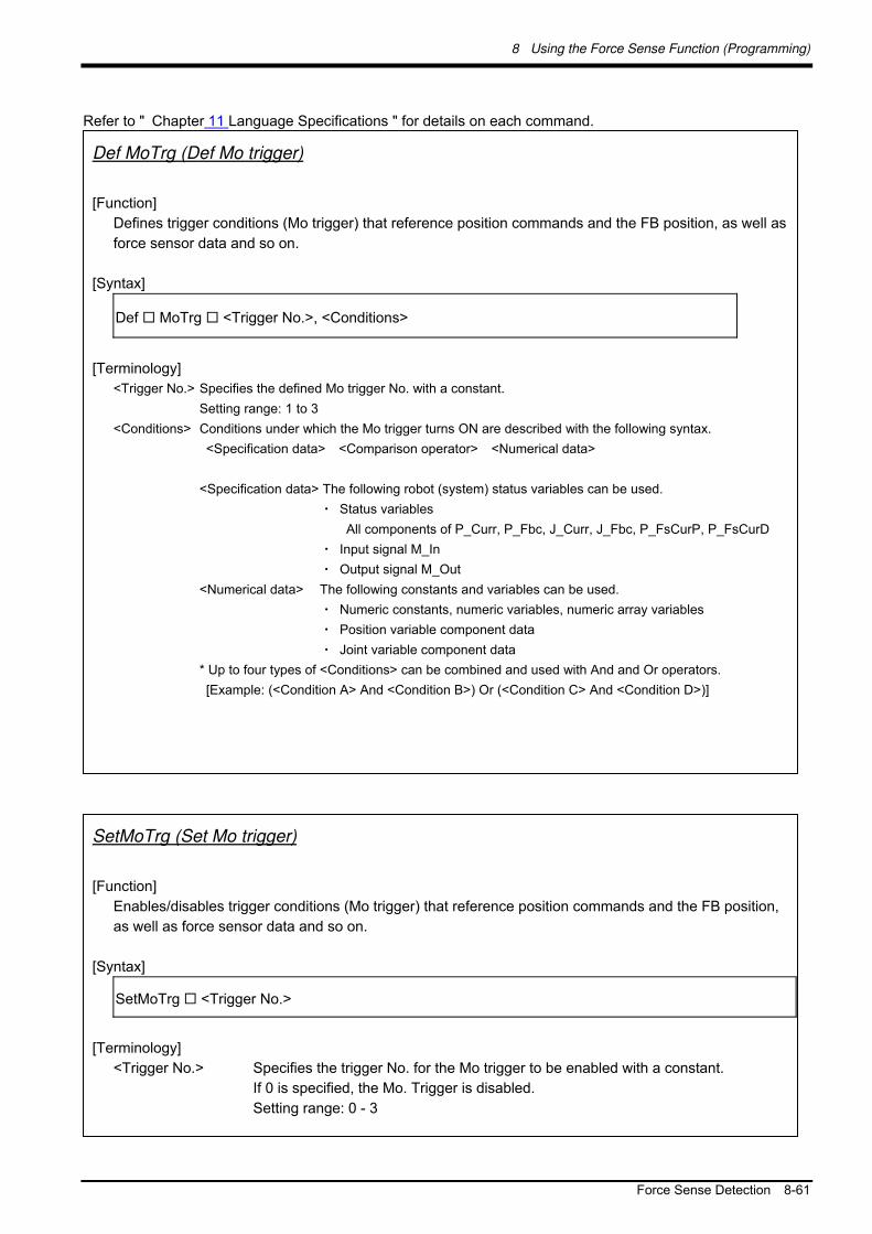
8 Using the Force Sense Function (Programming)
Force Sense Detection 8-61
Refer to " Chapter 11 Language Specifications " for details on each command.
SetMoTrg (Set Mo trigger)
[Function]
Enables/disables trigger conditions (Mo trigger) that reference position commands and the FB position,
as well as force sensor data and so on.
[Syntax]
SetMoTrg <Trigger No.>
[Terminology]
<Trigger No.> Specifies the trigger No. for the Mo trigger to be enabled with a constant.
If 0 is specified, the Mo. Trigger is disabled.
Setting range: 0 - 3
Def MoTrg (Def Mo trigger)
[Function]
Defines trigger conditions (Mo trigger) that reference position commands and the FB position, as well as
force sensor data and so on.
[Syntax]
Def MoTrg <Trigger No.>, <Conditions>
[Terminology]
<Trigger No.> Specifies the defined Mo trigger No. with a constant.
Setting range: 1 to 3
<Conditions> Conditions under which the Mo trigger turns ON are described with the following syntax.
<Specification data> <Comparison operator> <Numerical data>
<Specification data> The following robot (system) status variables can be used.
・ Status variables
All components of P_Curr, P_Fbc, J_Curr, J_Fbc, P_FsCurP, P_FsCurD
・ Input signal M_In
・ Output signal M_Out
<Numerical data> The following constants and variables can be used.
・ Numeric constants, numeric variables, numeric array variables
・ Position variable component data
・ Joint variable component data
* Up to four types of <Conditions> can be combined and used with And and Or operators.
[Example: (<Condition A> And <Condition B>) Or (<Condition C> And <Condition D>)]

8 Using the Force Sense Function (Programming)
8-62 Force Sense Detection
M_MoTrg
[Function]
References the Mo trigger enabled/disabled status, and the enabled trigger ON/OFF status.
[Syntax]
Example) <Numerical variable> = M_MoTrg (<Trigger No.>)
Details Value Defined/Undefined
Status Enabled/Disabled
Status Trigger ON/OFF
Status
+1 Defined Enabled ON 0 Defined Enabled OFF -1 Defined Disabled ―― -2 Undefined ―― ――

8 Using the Force Sense Function (Programming)
Force Sense Detection 8-63
8.2.2 Force Detection Status
8.2.2.1 M_FsLmtS
Status variable M_FsLmtSw checks whether the force detection setting value specified with the " control
characteristics " group has been exceeded. It can be used for interrupt processing and so on when a collision
occurs.
(Refer to section 11.3 for details on status variables.)
8.2.2.2 P_FsLmtR
Status variable P_FsLmtR outputs the status for each axis based on the force detection setting value specified
with the " control characteristics " group.
(Refer to section 11.3 for details on status variables.)
<Example 1>:
When the force in the X-direction exceeds the force detection setting value, the next command is skipped with
an interrupt.
Mvs P2 Wthif P_FsLmtR . X = 1, Skip
< Example 2>:
When the force in the Z-direction becomes smaller than the force detection setting value, this status variable
defines that interrupt processing is executed.
M1=-1
Def Act 1, P_FsLmtR.Z=M1 GoTo *PCEN, S
8.2.3 Data Latch
P_FsLmtX / P_FsLmtP / P_FsLmtD
Axis data, position data, and force sense data at the point the force sensor "force detection setting value" is
exceed is latched in status variables P_FsLmtX( ), P_FsLmtP( ), and P_FsLmtD( ).
(Refer to section 11.3 for details on status variables.)
8.2.4 Data Referencing
P_FsMaxD / P_FsCurD
The force sense data maximum and current values are stored in status variables P_FsMaxD( ) and P_FsCurD(
).

8 Using the Force Sense Function (Programming)
8-64 Force Sense Detection
(Refer to section 11.3 for details on status variables.)
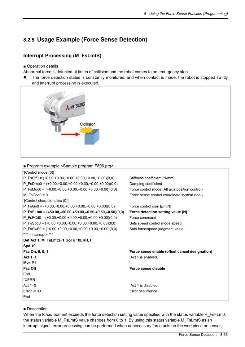
8 Using the Force Sense Function (Programming)
Force Sense Detection 8-65
8.2.5 Usage Example (Force Sense Detection)
Interrupt Processing (M_FsLmtS)
■ Operation details
Abnormal force is detected at times of collision and the robot comes to an emergency stop.
The force detection status is constantly monitored, and when contact is made, the robot is stopped swiftly
and interrupt processing is executed.
■ Program example <Sample program F806.prg>
‘[Control mode (0)]
P_FsStf0 = (+0.00,+0.00,+0.00,+0.00,+0.00,+0.00)(0,0) 'Stiffness coefficient [N/mm]
P_FsDmp0 = (+0.00,+0.00,+0.00,+0.00,+0.00,+0.00)(0,0) 'Damping coefficient
P_FsMod0 = (+0.00,+0.00,+0.00,+0.00,+0.00,+0.00)(0,0) 'Force control mode (All axis position control)
M_FsCod0 = 0 'Force sense control coordinate system (tool)
‘[Control characteristics (0)]
P_FsGn0 = (+0.00,+0.00,+0.00,+0.00,+0.00,+0.00)(0,0) 'Force control gain [µm/N]
P_FsFLm0 = (+50.00,+50.00,+50.00,+0.50,+0.50,+0.50)(0,0) 'Force detection setting value [N]
P_FsFCd0 = (+0.00,+0.00,+0.00,+0.00,+0.00,+0.00)(0,0) 'Force command
P_FsSpd0 = (+0.00,+0.00,+0.00,+0.00,+0.00,+0.00)(0,0) 'Sets speed control mode speed.
P_FsSwF0 = (+0.00,+0.00,+0.00,+0.00,+0.00,+0.00)(0,0) 'Sets force/speed judgment value.
'*** <Interrupt> ***
Def Act 1, M_FsLmtS=1 GoTo *XERR, F
Spd 10
Fsc On, 0, 0, 1 'Force sense enable (offset cancel designation)
Act 1=1 ' Act 1 is enabled.
Mvs P1 ‘
Fsc Off 'Force sense disable
End
*XERR
Act 1=0 ' Act 1 is disabled.
Error 9100 ‘Error occurrence
End
■ Description
When the force/moment exceeds the force detection setting value specified with the status variable P_FsFLm0,
the status variable M_FsLmtS value changes from 0 to 1. By using this status variable M_FsLmtS as an
interrupt signal, error processing can be performed when unnecessary force acts on the workpiece or sensor,
Collision

8 Using the Force Sense Function (Programming)
8-66 Force Sense Detection
and interrupt processing can be performed when a contact judgment/work failure occurs.
Interrupt Processing (Mo Trigger)
■ Operation details
The push force and position are inspected simultaneously, and the quality of the work is judged.
Work is judged as being successful if the Z coordinate is less than 5 mm, and a reaction force greater than
18 N is detected in the FZt direction.
If the above conditions are not satisfied within 5 seconds of assembly, assembly is judged as having failed,
and an error is output.
■ Program example <Sample program F807.prg>
‘[Control mode (0)]
P_FsStf0 = (+0.00,+0.00,+0.00,+0.00,+0.00,+0.00)(0,0) 'Stiffness coefficient [N/mm]
P_FsDmp0 = (+0.00,+0.00,+0.00,+0.00,+0.00,+0.00)(0,0) 'Damping coefficient
P_FsMod0 = (+2.00,+2.00,+1.00,+0.00,+0.00,+0.00)(0,0) 'Force control mode (X,Y: stiffness control, Z: force control)
M_FsCod0 = 0 'Force sense control coordinate system (tool)
‘[Control characteristics (0)]
P_FsGn0 = (+2.00,+2.00,+2.00,+0.00,+0.00,+0.00)(0,0) 'Force control gain [µm/N]
P_FsFLm0 = (+0.00,+0.00,+0.00,+0.0,+0.0,+0.0)(0,0) 'Force detection setting value [N]
P_FsFCd0 = (+0.00,+0.00,+20.00,+0.00,+0.00,+0.00)(0,0) 'Force command
P_FsSpd0 = (+0.00,+0.00,+0.00,+0.00,+0.00,+0.00)(0,0) 'Sets speed control mode speed.
P_FsSwF0 = (+0.00,+0.00,+0.00,+0.00,+0.00,+0.00)(0,0) 'Sets force/speed judgment value.
'*** <Interrupt> ***
Def MoTrg 1, ((P_Fbc.Z <= 5) AND (P_FsCurD.Z > 18)) 'Work complete conditions defined for Mo trigger 1.
Def Act 1,M_MoTrg(1)=1 GoTo *XOK,F 'Mo trigger 1 defined as interrupt condition.
Mvs PStart 'Robot moves over insertion position.
SetMoTrg 1 'Mo trigger 1 is enabled.
Fsc On,0,0,1 'Force sense control is enabled. (Insertion started with force control.)
Act 1=1 'Interrupt processing 1 is enabled.
M_Timer(1)=0 'Timer clear
*LBL1: If M_Timer (1) < 5000 Then GoTo *LBL1 'Waits for timeout time of 5 seconds.
Fsc Off 'Force sense control is disabled.
Error 9100 'Error occurs if insertion work not complete within 5 seconds.
End
*XOK 'Insertion work complete interrupt processing
Act 1=0
SetMoTrg 0 'Mo trigger is enabled.
Fsc Off 'Force sense control is disabled.
HOpen 1
P2=P_Fbc 'Feedback position acquisition
Success Failure
Z=10 mm Z=0 mm
Collision

8 Using the Force Sense Function (Programming)
Force Sense Detection 8-67
P2.Z=P2.Z+100 'Target position determined as position +100 mm in Z-direction
from current position
Mvs P2
End
■ Description
1) Work complete conditions are defined for Mo trigger 1 with the Def MoTrg command.
2) Force sense control is enabled after enabling Mo trigger 1, and insertion work is started.
3) If insertion work is not complete within 5 seconds of work starting, a 9100 error is output, and insertion
work is stopped.
4) If insertion work is successfully completed, M_MoTrg(1)=1, and interrupt processing (label: *XOK) is
performed.
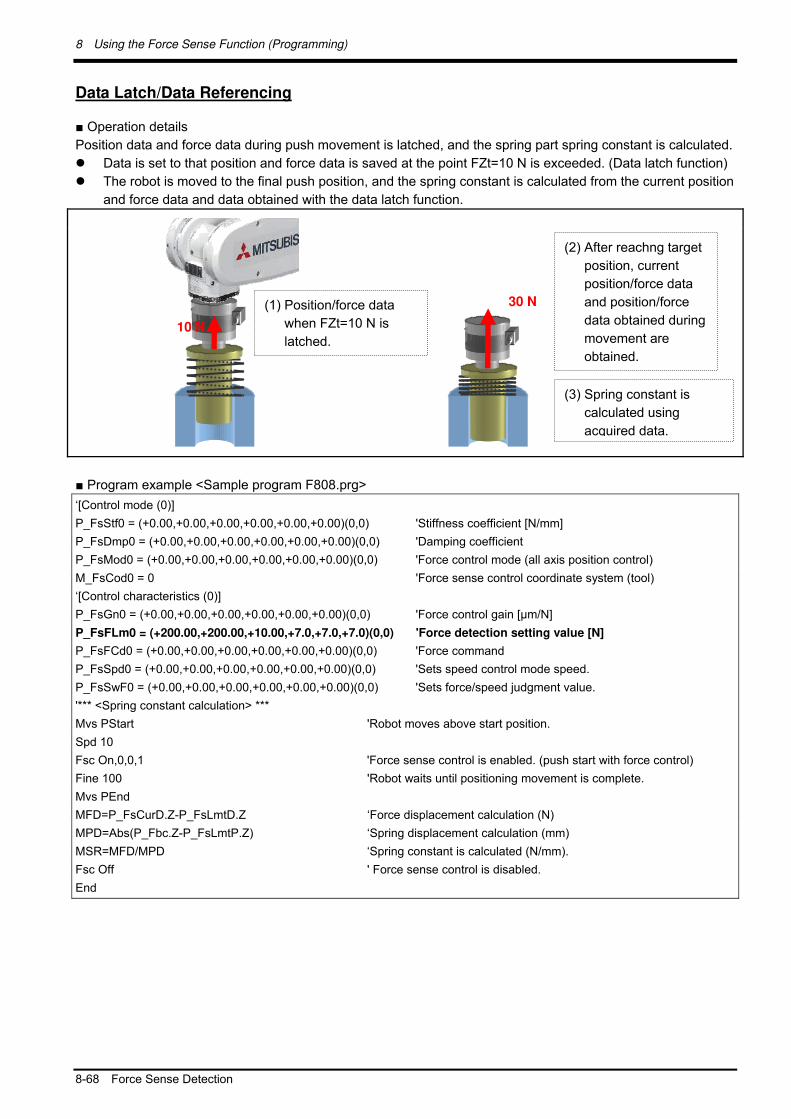
8 Using the Force Sense Function (Programming)
8-68 Force Sense Detection
Data Latch/Data Referencing
■ Operation details
Position data and force data during push movement is latched, and the spring part spring constant is calculated.
Data is set to that position and force data is saved at the point FZt=10 N is exceeded. (Data latch function)
The robot is moved to the final push position, and the spring constant is calculated from the current position
and force data and data obtained with the data latch function.
■ Program example <Sample program F808.prg>
‘[Control mode (0)]
P_FsStf0 = (+0.00,+0.00,+0.00,+0.00,+0.00,+0.00)(0,0) 'Stiffness coefficient [N/mm]
P_FsDmp0 = (+0.00,+0.00,+0.00,+0.00,+0.00,+0.00)(0,0) 'Damping coefficient
P_FsMod0 = (+0.00,+0.00,+0.00,+0.00,+0.00,+0.00)(0,0) 'Force control mode (all axis position control)
M_FsCod0 = 0 'Force sense control coordinate system (tool)
‘[Control characteristics (0)]
P_FsGn0 = (+0.00,+0.00,+0.00,+0.00,+0.00,+0.00)(0,0) 'Force control gain [µm/N]
P_FsFLm0 = (+200.00,+200.00,+10.00,+7.0,+7.0,+7.0)(0,0) 'Force detection setting value [N]
P_FsFCd0 = (+0.00,+0.00,+0.00,+0.00,+0.00,+0.00)(0,0) 'Force command
P_FsSpd0 = (+0.00,+0.00,+0.00,+0.00,+0.00,+0.00)(0,0) 'Sets speed control mode speed.
P_FsSwF0 = (+0.00,+0.00,+0.00,+0.00,+0.00,+0.00)(0,0) 'Sets force/speed judgment value.
'*** <Spring constant calculation> ***
Mvs PStart 'Robot moves above start position.
Spd 10
Fsc On,0,0,1 'Force sense control is enabled. (push start with force control)
Fine 100 'Robot waits until positioning movement is complete.
Mvs PEnd
MFD=P_FsCurD.Z-P_FsLmtD.Z ‘Force displacement calculation (N)
MPD=Abs(P_Fbc.Z-P_FsLmtP.Z) ‘Spring displacement calculation (mm)
MSR=MFD/MPD ‘Spring constant is calculated (N/mm).
Fsc Off ' Force sense control is disabled.
End
(1) Position/force data
when FZt=10 N is
latched.
30 N
(2) After reachng target
position, current
position/force data
and position/force
data obtained during
movement are
obtained.
(3) Spring constant is
calculated using
acquired data.
10 N

8 Using the Force Sense Function (Programming)
Force Sense Detection 8-69
■ Description
1) The force detection setting value is set and force control is enabled so that the position/force data are
latched when FZt=10 N.
2) The robot is moved slowly to position PEnd at the speed of 10 mm/s and the spring is pushed.
3) Each of the position/force data at the moment the spring reaction force at the spring push process
exceeds 10 N is saved to status variables P_FsLmtP and P_FsLmtD.
4) The current position/force data (P_Fbc, P_FsCurD) when the target position is reached is read, the
amount of change from data saved during the movement is calculated, the spring constant is
calculated, and then saved to variable MSR. (In this example, calculation is performed based on the
assumption that the reaction force at the target position is sufficiently greater than 10 N.)

8 Using the Force Sense Function (Programming)
8-70 Force Sense log
8.3 Force Sense log
The force sense log function is used to obtain and display log data such as force sensor data and position data.
Log data can be viewed in a graph using the RT ToolBox2 force sense control log file viewer. This function can
be used for such tasks as force sense control related parameter adjustments and checking the work status.
Furthermore, this function is equipped with a feature to transfer force sense log files to the computer by FTP,
facilitating robot quality control during operation by checking work quality and analyzing data when errors occur.
8.3.1 Force Sense Log Function Specifications
Table 8-10: Force sense log function specifications
Function Item Description
Force sense log
data acquisition
Acquirable data See Table 8-11
Sample time 7.111 ms cycles
Max. data acquisition time
45 sec.*1
Data acquisition trigger Log data is acquired from the time the FsLog On command is executed until the FsLog Off command is executed.
Data file format CSV format (See Table Table 8-12.)
No. of saved data files 2 *2
(Saved data is lost when the controller power is turned OFF.)
Force sense log
data display
(RT ToolBox2)
Graph
display
Graph format Scatter diagram format <Horizontal axis> Select from time, position commands, position FB, movement ratio. <Display data> Select from force sensor data, position commands, position FB, current FB.
Display data qty Vertical axis: 6, horizontal axis: 1
Data processing Filter processing (Filter processing is only possible for force sensor data.)
Data operation Force sense control log file reading from R/C
Graph image backup
Force sense log file
FTP transfer
Data transfer Log files are saved to computer using FTP.
*1: If the Max. data acquisition time (45 s) is reached before the FsLog Off command is executed, data
collection is automatically stopped.
*2: If the number of files stored in the controller exceeds 2, the file with oldest creation data is deleted.

8 Using the Force Sense Function (Programming)
Force Sense log 8-71
Table 8-11: Collected data
Collected Data Unit Supplementary Information
Force sensor
data [N] or [Nm]
Set with parameter FSLOGFN from the following:
Force sensor raw data (with offset cancel)
Force sensor raw data (without offset cancel)
Data after coordinate conversion (with offset cancel)
Fx, Fy, Fz, Mx, My, Mz
Position
command [mm] or [deg]
Command position
Cmd-X, Cmd-Y, Cmd-Z, Cmd-A, Cmd-B, Cmd-C, Cmd-L1, Cmd-L2,
Cmd-FL1, Cmd-FL2
Position FB [mm] or [deg] Feedback position
FB-X, FB-Y, FB-Z, FB-A, FB-B, FB-C, FB-L1, FB-L2, FB-FL1, FB-FL2
Current FB 0.1%(Rated
current ratio)
Motor current for each axis
iFB-J1, iFB-J2, iFB-J3, iFB-J4, iFB-J5, iFB-J6, iFB-J7, iFB-J8
Table 8-12: Log file format (CSV)
Log File Version,1.0 Time Stamp,YYYY.MM.DD HH:MM:SS Mecha No.,1 Robot Name,******** Data Sampling,7.111ms Sensor Data Type,2 Offset Cancel,-18.319,3.110,97.473,0.230,1.834,-0.787 Tool Data,0.000,0.000,0.000,0.000,0.000,0.000 Base Data,0.000,0.000,0.000,0.000,0.000,0.000 No.,Fx,Fy,…,Mz,Cmd-X,Cmd-Y,…,Cmd-FL2,FB-X,FB-Y,…,FB-FL2,iFB-J1,iFB-J2,…,iFB-J8 0,0.000,0.000,…,0.000,0.000,0.000,…,0,0.000,0.000,…,0,0.000,0.000,…,0.000 1,0.000,0.000,…,0.000,0.000,0.000,…,0,0.000,0.000,…,0,0.000,0.000,…,0.000 2,0.000,0.000,…,0.000,0.000,0.000,…,0,0.000,0.000,…,0,0.000,0.000,…,0.000
: :
Base/tool conversion
"Position commands" and "position FB" data are output in a coordinate system based on the
tool/base conversion data specified when executing the PsLog Off command. (The applied
tool/base conversion data is described at the beginning of the log file.)
If the data is switched between tool and base or vice versa during log data collection, the
position command/position FB before the change is not saved as a log file.

8 Using the Force Sense Function (Programming)
8-72 Force Sense log
8.3.2 Parameter Settings
Parameter settings relating to the force sense log function are as follows.
It is necessary to set parameter FSLOGFN in order to use the force sense log function.
(Settings can be specified efficiently using the parameter editing screen discussed in sections 12.2 or 12.3 .)
Table 8-13: Force sense log related parameter list
Parameter Parameter
Name No. of
Elements Description
Default Factory Setting
Log function FSLOGFN 3 integers Specifies settings for the force sense log function. 1st element: Enables/disabled the log function. [Setting range] 0 (disable), 1 (enable) 2nd element: Selects the collected force sensor data type. [Setting range] 0: Raw data (with offset cancel) 1: Raw data (without offset cancel) 2: Data after coordinate conversion (offset cancel
designation updated) 3rd element: Specifies whether to use/not use FTP. [Setting range] 0 (Do not use), 1 (Use)
0, 2, 0
Log data transfer
FTPID 1 character string
Sets the user ID used with FsOutLog command FTP communication. 1st element: user ID Setting rang: Up to 8 single-byte alphanumeric characters (upper/lower case)
ftpuser
FTPPASS 1 character string
Sets the password used with FsOutLog command FTP communication. 1st element: password [Setting range] Up to 16 single-byte alphanumeric characters (upper/lower case), or single-byte symbols (! # $ % & = - @ . ? _ )
ftppassword
FTPSVRIP 1 character string
Sets the FTP server IP address used with FsOutLog command FTP communication. 1st element: IP address [Setting range] "0.0.0.0" to "255.255.255.255"
192.168.0.99

8 Using the Force Sense Function (Programming)
Force Sense log 8-73
8.3.3 Force Sense Log Data Acquisition
Robot language MELFA-BASIC V FsLog On and FsLog Off commands are used to specify the start and end of
log data acquisition. When the FsLog Off command is executed, a log file with specified file No. name is
generated.
(Refer to section " 11.5 " for details on language specifications.)
FsLog Off
[Function]
Ends force sensor data and position command, position FB, and current FB value logging.
[Syntax]
FsLog Off <Log File No.>
[Terminology]
<Log File No.> Specifies the log file No. containing collected data.
Setting range: 1 to 999999999
FsLog On
[Function]
Starts force sensor data and position command, position FB, and current FB value logging.
[Syntax]
FsLog On
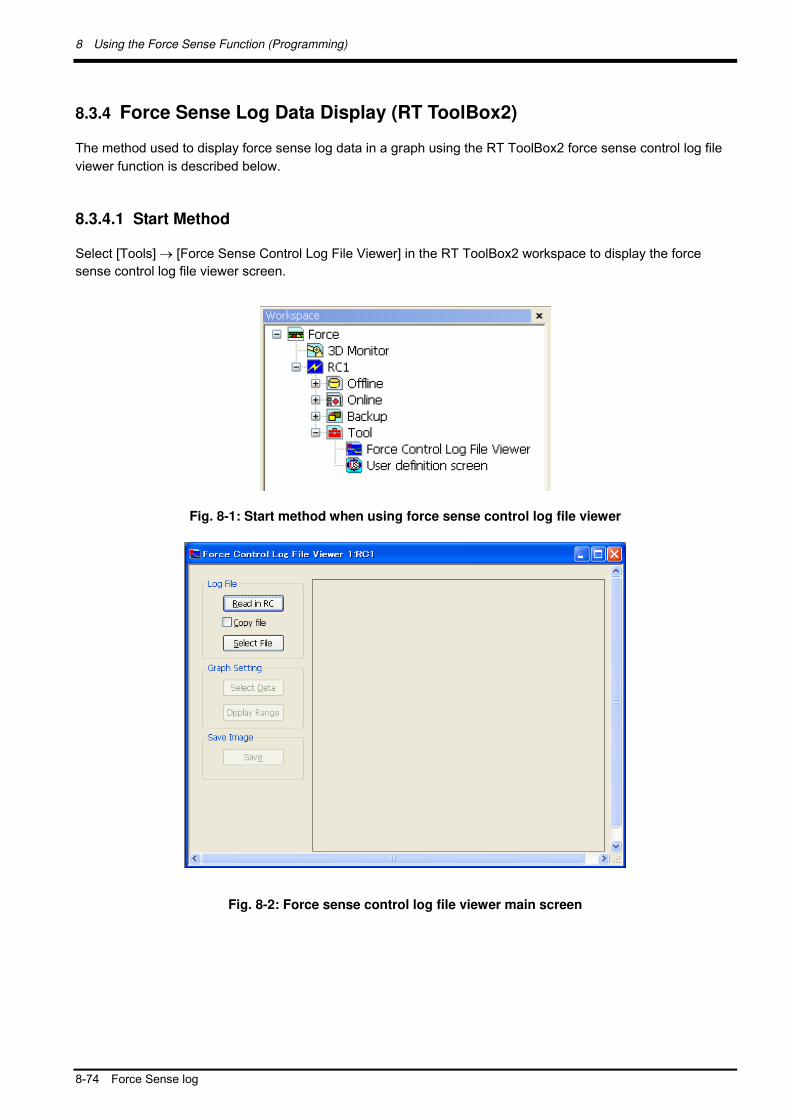
8 Using the Force Sense Function (Programming)
8-74 Force Sense log
8.3.4 Force Sense Log Data Display (RT ToolBox2)
The method used to display force sense log data in a graph using the RT ToolBox2 force sense control log file
viewer function is described below.
8.3.4.1 Start Method
Select [Tools] [Force Sense Control Log File Viewer] in the RT ToolBox2 workspace to display the force
sense control log file viewer screen.
Fig. 8-1: Start method when using force sense control log file viewer
Fig. 8-2: Force sense control log file viewer main screen

8 Using the Force Sense Function (Programming)
Force Sense log 8-75
8.3.4.2 Main Screen
Log files are imported and displayed in a graph using the buttons on the force sense control log file viewer main
screen. A description of each button is given below.
Fig. 8-3: Image of force sense control log file viewer main screen
Table 8-14: Main screen description
No. Item Description
(1) [Read RC]
button
By pressing this button when the R/C (robot controller) is connected online, the
following screen appears, allowing the user to read log files selected from a log file
list to the computer.
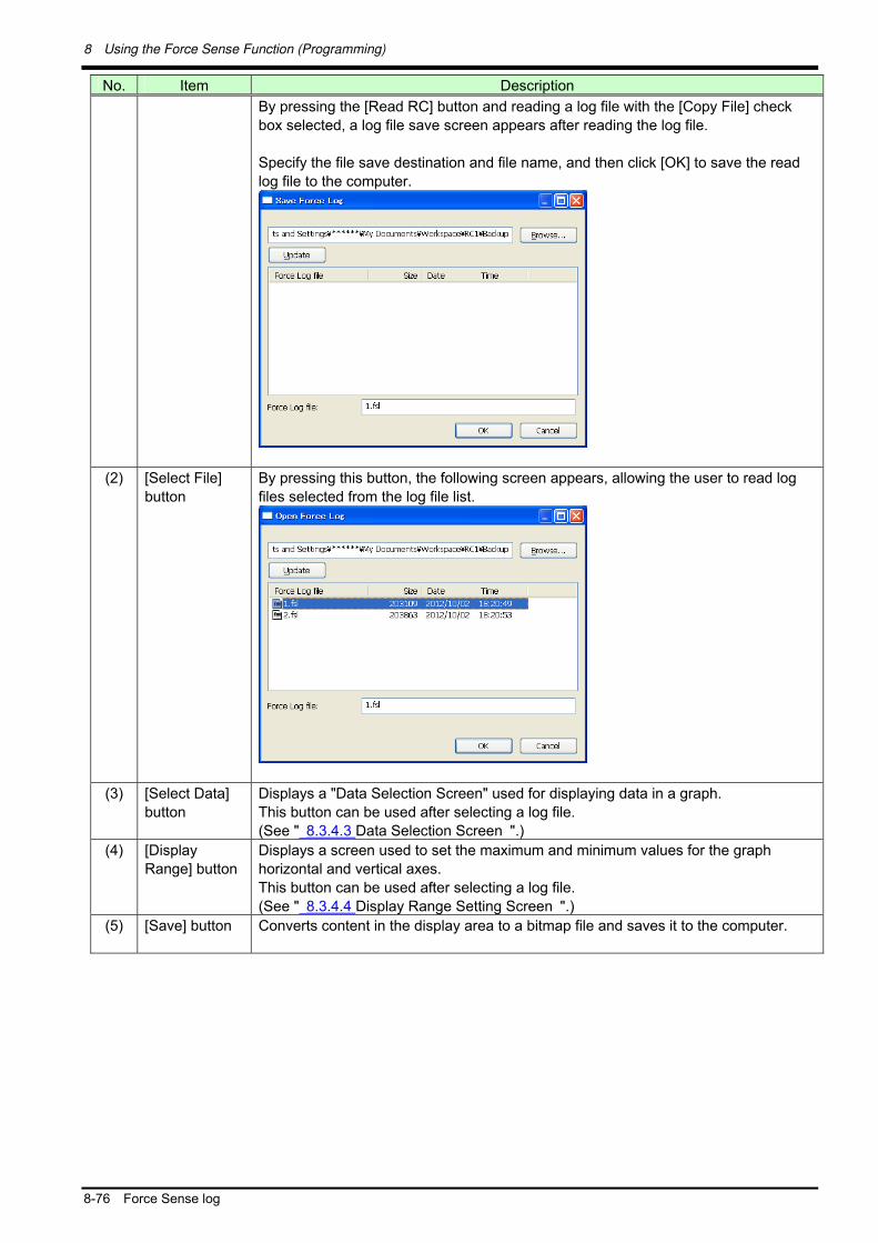
8 Using the Force Sense Function (Programming)
8-76 Force Sense log
No. Item Description
By pressing the [Read RC] button and reading a log file with the [Copy File] check
box selected, a log file save screen appears after reading the log file.
Specify the file save destination and file name, and then click [OK] to save the read
log file to the computer.
(2) [Select File]
button
By pressing this button, the following screen appears, allowing the user to read log
files selected from the log file list.
(3) [Select Data]
button
Displays a "Data Selection Screen" used for displaying data in a graph.
This button can be used after selecting a log file.
(See " 8.3.4.3 Data Selection Screen ".)
(4) [Display
Range] button
Displays a screen used to set the maximum and minimum values for the graph
horizontal and vertical axes.
This button can be used after selecting a log file.
(See " 8.3.4.4 Display Range Setting Screen ".)
(5) [Save] button Converts content in the display area to a bitmap file and saves it to the computer.
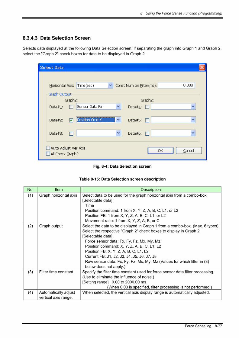
8 Using the Force Sense Function (Programming)
Force Sense log 8-77
8.3.4.3 Data Selection Screen
Selects data displayed at the following Data Selection screen. If separating the graph into Graph 1 and Graph 2,
select the "Graph 2" check boxes for data to be displayed in Graph 2.
Fig. 8-4: Data Selection screen
Table 8-15: Data Selection screen description
No. Item Description
(1) Graph horizontal axis Select data to be used for the graph horizontal axis from a combo-box.
[Selectable data]
Time
Position command: 1 from X, Y, Z, A, B, C, L1, or L2
Position FB: 1 from X, Y, Z, A, B, C, L1, or L2
Movement ratio: 1 from X, Y, Z, A, B, or C
(2) Graph output Select the data to be displayed in Graph 1 from a combo-box. (Max. 6 types)
Select the respective "Graph 2" check boxes to display in Graph 2.
[Selectable data]
Force sensor data: Fx, Fy, Fz, Mx, My, Mz
Position command: X, Y, Z, A, B, C, L1, L2
Position FB: X, Y, Z, A, B, C, L1, L2
Current FB: J1, J2, J3, J4, J5, J6, J7, J8
Raw sensor data: Fx, Fy, Fz, Mx, My, Mz (Values for which filter in (3)
below does not apply.)
(3) Filter time constant Specify the filter time constant used for force sensor data filter processing.
(Use to eliminate the influence of noise.)
[Setting range] 0.00 to 2000.00 ms
(When 0.00 is specified, filter processing is not performed.)
(4) Automatically adjust
vertical axis range.
When selected, the vertical axis display range is automatically adjusted.

8 Using the Force Sense Function (Programming)
8-78 Force Sense log
8.3.4.4 Display Range Setting Screen
Sets the range for the displayed waveform data from the [Display Range] screen.
Fig. 8-5 Image of Display Range setting screen
Table 8-16 Display Range setting screen description
No. Item Description
(1) Vertical axis display
range setting
Specifies the maximum and minimum values for the Graph 1 horizontal axis.
If adjusting the Graph 2 display range, select the "Adjust Graph 2" check box.
By pressing the [Reset] button, the horizontal axis maximum and minimum
values return to their default settings.
(2) Horizontal axis
display range setting
Specifies the maximum and minimum values for the Graph 1 vertical axis. If
adjusting the Graph 2 display range, select the "Adjust Graph 2" check box.
By pressing the [Reset] button, the vertical axis maximum and minimum
values return to their default settings
(3) Automatically adjust
vertical axis range.
When selected, the vertical axis display range is automatically adjusted.

8 Using the Force Sense Function (Programming)
Force Sense log 8-79
8.3.5 Force Sense Log File FTP Transfer
Force sense log files created in the robot controller can be transferred to an FTP server using the robot
language MELFA-BASIC V FsOutLog command.
The following preparations are required before the FsOutLog command can be executed.
(1) Network connection with Ethernet
Connect the robot controller and FTP server computer over the network with an Ethernet cable.
<CR750-Q Series connection example>
With the CR750-Q Series robot controller, FTP communication uses the robot CPU unit "DISPLAY I/F". Prepare
a hub and Ethernet cable and connect to the network as shown below.
ブF P
ボッ P ユニッボッ ン ラ
ライブユニッボッ ン ラ
E he e ブ ス をブ 接続
ボッ P ユニッI PLA I F 接続
(2) FTP related parameter settings
Sets parameters FTPID, FTPPASS, FTPSVRIP, and FSLOGFN.
(Refer to section 8.3.2 for details on parameters.)
(3) FTP server preparation
Start up the FTP server on the target computer.
FsOutLog
[Function]
Transfers logged data to the FTP server.
[Syntax]
FsOutLog <Log File No.>
[Terminology]
<Log File No.> Specifies the No. of the log file from which collected data is to be read.
Setting range: 1 to 999999999
Connect to robot CPU unit DISPLAY I/F.
Connect Ethernet cable (straight) to hub.
Drive unit
(robot controller)
Robot CPU unit
(robot controller)
FTP
server Hub

8 Using the Force Sense Function (Programming)
8-80 Force Sense log
8.3.6 Usage Example (Force Sense Log)
Force Sense Log Data Acquisition and Display
■ Operation details
Acquires data for the force acting on the workpiece when performing assembly work and displays it in a graph.
Pin insertion work is performed after starting force sense log data acquisition.
After work is complete, force sense log data acquisition is terminated and log data acquired during work is
saved.
Acquired log data is displayed in a graph using the RT ToolBox2 force sense control log viewer function.
■ Program example <Sample program F809.prg>
‘[Control mode (0)]
P_FsStf0 = (+0.00,+0.00,+0.00,+0.00,+0.00,+0.00)(0,0) 'Stiffness coefficient [N/mm]
P_FsDmp0 = (+0.00,+0.00,+0.00,+0.00,+0.00,+0.00)(0,0) 'Damping coefficient
P_FsMod0 = (+2.00,+2.00,+2.00,+0.00,+0.00,+0.00)(0,0) 'Force control mode (X,Y,Z-axis force control)
M_FsCod0 = 0 'Force sense control coordinate system (tool)
‘[Control characteristics (0)]
P_FsGn0 = (+5.00,+5.00,+5.00,+0.00,+0.00,+0.00)(0,0) 'Force control gain [µm/N]
P_FsFLm0 = (+0.00,+0.00,+0.00,+0.00,+0.00,+0.00)(0,0) 'Force detection setting value [N]
P_FsFCd0 = (+0.00,+0.00,+5.00,+0.00,+0.00,+0.00)(0,0) 'Force command (X,Y-axes: 0.0 N, Z-axis: 5.0 N)
P_FsSpd0 = (+0.00,+0.00,+0.00,+0.00,+0.00,+0.00)(0,0) 'Sets speed control mode speed.
P_FsSwF0 = (+0.00,+0.00,+0.00,+0.00,+0.00,+0.00)(0,0) 'Sets force/speed judgment value.
'*** <Log data acquisition> ***
Mov PStart
Dly 1
FsLog On 'Force sense log data acquisition start
Fsc On, 0, 0, 1 'Force sense control enable (offset cancel designation)
*LBL1: If P_FsCurD.Z < 4.5 Then Goto *LBL1
Fsc Off 'Force sense control enable
FsLog Off ,999 'Log file creation (File name: 999.fsl)
End '
Force sense log data displayed in graph in RT ToolBox2.

8 Using the Force Sense Function (Programming)
Force Sense log 8-81
■ Description
1) Specifies settings to push the robot with a force of 0.0 N in the X- and Y-directions, and 5.0 N in the
Z-direction with force control.
2) The FsLog On command is executed to start log data acquisition.
3) Insertion work is started with the Fsc On command, and the robot pushes until a reaction force of 4.5
N or greater acts in the Z-direction.
4) The FsLog Off command is executed to end log data acquisition. (The log data file name is set for the
argument.)
5) Measurement data is displayed in a graph using the RT-ToolBox2 "force sense control log file viewer"
to check the force acting on the workpiece. (See section 8.3.4 for details on how to use the force
sense control log file viewer.)

8 Using the Force Sense Function (Programming)
8-82 Force Sense log
Force Sense Log Data Transfer
■ Operation details
Transfers acquired log data files to the computer (FTP server).
Force sense log data is collected during force sense control.
Force sense log data is saved and saved log files are transferred to the computer.
■ Program example <Sample program F810.prg>
‘[Control mode (0)]
P_FsStf0 = (+0.00,+0.00,+0.00,+0.00,+0.00,+0.00)(0,0) 'Stiffness coefficient [N/mm]
P_FsDmp0 = (+0.00,+0.00,+0.00,+0.00,+0.00,+0.00)(0,0) 'Damping coefficient
P_FsMod0 = (+2.00,+2.00,+2.00,+0.00,+0.00,+0.00)(0,0) 'Force control mode (X,Y,Z-axis force control)
M_FsCod0 = 0 'Force sense control coordinate system (tool)
‘[Control characteristics (0)]
P_FsGn0 = (+0.00,+0.00,+5.00,+0.00,+0.00,+0.00)(0,0) 'Force control gain [µm/N]
P_FsFLm0 = (+0.00,+0.00,+0.00,+0.00,+0.00,+0.00)(0,0) 'Force detection setting value [N]
P_FsFCd0 = (+0.00,+0.00,+5.00,+0.00,+0.00,+0.00)(0,0) 'Force command (X,Y-axes: 0.0 N, Z-axis: 5.0 N
P_FsSpd0 = (+0.00,+0.00,+0.00,+0.00,+0.00,+0.00)(0,0) 'Sets speed control mode speed.
P_FsSwF0 = (+0.00,+0.00,+0.00,+0.00,+0.00,+0.00)(0,0) 'Sets force/speed judgment value.
'*** < Log data acquisition > ***
Mov PStart
Dly 1
FsLog On
Fsc On, 0, 0, 1 'Force sense control enable (offset cancel designation)
Dly 10 '
Fsc Off 'Force sense control enable
M1=Val(Left$(C_Time,2 ) + Mid$(C_Time,4,2 )+Right$(C_Time,2 )) 'Converts current time to numerical variable.
FsLog Off, M1 'Log file creation (File name: HHMMSS.fsl)
FsOutLog M1 'Log file transfer
End '
■ Description
1) Starts log data acquisition by executing the FsLog On command.
2) Ends log data acquisition by executing the FsLog Off command. (The log data file name is set for the
argument. In this example, the current time is used to create the file name.)
3) The acquired log file is transferred to the computer by executing the FsOutLog command. (See section
8.3.4 .)
og File Version,1.0
Time Stamp,YYYY.MM.DD HH:MM:SS
Mecha No.,1
Robot Name,********
Data Sampling,7.111ms
Sensor Data Type,2
Offset Cancel,-18.319,3.110,97.473,0.230,1.834,-0.787
Tool Data,0.000,0.000,0.000,0.000,0.000,0.000
Base Data,0.000,0.000,0.000,0.000,0.000,0.000
No.,Fx,Fy,…,Mz,Cmd-X,Cmd-Y,…,Cmd-FL2,FB-X,FB-Y,…,FB-FL2,iFB-J1,iFB-J2,…,iFB-J8
0,0.000,0.000,…,0.000,0.000,0.000,…,0,0.000,0.000,…,0,0.000,0.000,…,0.000
1,0.000,0.000,…,0.000,0.000,0.000,…,0,0.000,0.000,…,0,0.000,0.000,…,0.000
Force sense log file [1.fsl]
Computer (FTP server)
Ethernet
Robot controller

9 Using the Force Sense Function (Teaching)
Force Sense log 9-83
9 Using the Force Sense Function (Teaching)
This Chapter describes how to use the force sense function (force sense T/B) using the teaching pendant, and
how to perform teaching using the force sense function.
Refer to the section numbers and pages under "Reference" in the following table for a "description" and "usage
example" for each function.
Table 9-1: Force sense function usage method reference list (teaching)
Reference Function Class Function Overview
DescriptionUsage
Example
Force sense control (T/B) Controls push force and softness. Section
9.1.1 Page 9-90
Force sense monitor Checks force sense data. Section
9.1.2
Force sense T/B
Contact detection Checks the contact position. Section
9.1.3
Page 9-93
Teaches the push position. Page 9-98 Teaches the insertion position (using force control).
Page 9-100Teaching
Teaches the insertion position (using stiffness control).
Section 9.1.4
Page 9-101

9 Using the Force Sense Function (Teaching)
9-84 Force Sense T/B
9.1 Force Sense T/B
The force sense functions that can be used from R56TB/R57TB/R32TB/R33TB are summarized in "Table 9-2".
Table 9-2: Force sense functions that can be used from teaching pendant
Force Item Function Overview
Force control Pushes with the specified force using force control. Force sense
control (T/B) Stiffness control Controls the robot softly like a spring.
Force sense data
display
Displays the force sensor data current value on the
T/B.
Force sense monitor
Max. value
retention
Retains the force sensor data maximum value.
(Resetting is possible.)
Automatic stop Stops the robot automatically when contact is
detected during JOG operation.
Force sense monitor
Buzzer sound Sounds the buzzer when the contact detection
threshold is exceeded.
Each function is described below.
9.1.1 Force Sense Control (T/B)
JOG operation using force sense control can be performed from the teaching pendant. Force sense control
facilitates more precise teaching operations such as controlling the robot softly to the assembly position while
escaping external force, and teaching positions pushed with a fixed force. (See section 8.1 for details on force
sense control.)
If performing JOG operation while using force sense control, use the following procedure to sufficiently check
the setting status before turning the servo ON.
[Turning the servo ON when force sense control is enabled]
Step 1: Offset cancel operation (See section 9.1.1.1 .)
…Ensure that the force sensor offset component has been cancelled.
Step 2: Control mode/control characteristics selection (See section 9.1.1.2 .)
…Ensure that the used control mode/ control characteristics have been set correctly.
Step 3: Force sense control enabled/disabled selection (See section 9.1.1.3 .)
…Check the force sense control enabled/disabled status.
Servo ON

9 Using the Force Sense Function (Teaching)
Force Sense T/B 9-85
9.1.1.1 Offset Cancel Operation
If the force sensor data zero point is offset, force sense control will not function properly. Always perform the
offset cancel operation (sensor zero point offset) before use. The offset cancel operation can only be
performed when force sense control is disabled.
[Offset cancel operation]
Move the robot to a position at which no external force acts on the sensor (position at which no contact is made with hand, etc.)
Ensure that the robot is stationary and then perform the offset cancel operation. (See diagram below).
Offset cancel operation precautions
The offset cancel status is reset by rebooting the controller. If the controller is rebooted, perform
the offset cancel operation again.
The effects of gravity are contained in the sensor offset component, and therefore if the robot
arm posture is changed significantly, it is necessary to perform the offset cancel operation again.
The offset amount may change if used for long periods of time due to changes in sensor
temperature (temperature drift). In such a case, perform the offset cancel operation again.
[FUNCTION] key
[JOG] key
JOG operation screen
[F3] key: Force sense
R56TB/R57TB R32TB/R33TB
Sensor zero point offsetting is performed by
pressing the [Offset Cancel] button. By pressing the [F] key, a force sense control screen appears.

9 Using the Force Sense Function (Teaching)
9-86 Force Sense T/B
9.1.1.2 Selecting the Control Mode/Control characteristics
Before enabling force sense control, it is necessary to set the force sense control "control mode" and "control
characteristics " (parameters/status variables shown in Table 9-3) beforehand. (See section 8.1.2 for details.)
Table 9-3: Control mode/Control characteristics settings
Setting Item Status Variable (*=0, 1)
Parameter (#=1 - 9)
Default Factory Setting
Control mode
Force sense control coordinate system
M_FsCod* FSCOD0# 0
Force control mode P_FsMod* FSFMD0# 0.00, 0.00, 0.00, 0.00, 0.00, 0.00
Stiffness coefficient P_FsStf* FSSTF0# 0.00, 0.00, 0.00, 0.00, 0.00, 0.00
Damping coefficient P_FsDmp* FSDMP0# 0.00, 0.00, 0.00, 0.00, 0.00, 0.00
Control charact-eristics
Force command value P_FsFCd* FSFCMD0# 0.00, 0.00, 0.00, 0.00, 0.00, 0.00
Speed command value P_FsSpd* FSSPD0# 0.00, 0.00, 0.00, 0.00, 0.00, 0.00
Mode switching judgment value
P_FsSwF* FSSWF0# 0.00, 0.00, 0.00, 0.00, 0.00, 0.00
Force sense control gain P_FsGn* FSFGN0# 0.00, 0.00, 0.00, 0.00, 0.00, 0.00
Force detection setting value
P_FsFLm* FSFLMT0# 0.00, 0.00, 0.00, 0.00, 0.00, 0.00
[Control mode/ Control characteristics selection operation]
Specify the used "control mode" and " control characteristics " number. Ensure that the numbers used have been set correctly before enabling force sense control.
Condition settings screen
[FUNCTION] key
JOG operation screen
[F3] key: Force sense
R32TB/R33TB
[F2] key: Conditions
R56TB/R57TB
By pressing the [F] key, a force sense control screen appears.
Specify the "control mode"
and "control features" number.

9 Using the Force Sense Function (Teaching)
Force Sense T/B 9-87
9.1.1.3 Force Sense Control Enable/Disable Selection
Enable or disable force sense control. If performing JOG operation using force sense control, select "Enable",
and if performing normal JOG operation, select "Disable".
The enable/disable selection is common to both automatic operation and JOG operation. The enable/disable
status is retained even if the controller key switch is changed to and from MANUAL and AUTOMATIC.
<Example 1>
Force sense control enabled in automatic operation operation interrupted Operation key switch
changed to MANUAL T/B enabled force sense control enabled status retained.
< Example 2>
Force sense control enabled with T/B T/B disabled Operation key switch changed to AUTOMATIC
force sense control enabled status retained.
However, if the enabled/disabled status differs when interrupting and resuming robot program automatic
operation, error L3986 occurs when resuming operation.
The force sense control enable/disable status is retained even when automatic operation is stopped and the operation mode changed to MANUAL mode. Perform teaching after checking the force sense control enable/disable status, and control mode/ control characteristics settings sufficiently.
[Force sense control enable/disable operation]
Enable/disable force sense control with the ON/OFF button. (See below.) The enabled/disabled status is displayed on the T/B screen. (See below.)
Caution
[FUNCTION] key
JOG operation screen
[F3] key:
Force sense
R32TB/R33TB R56TB/R57TB
By pressing the [F] key, a force sense control screen appears.
Enable/disable force sense
control with ON/OFF button.
[F1] key: Enables/disable force sense
control with ON/OFF button.
Displays enabled/disabled status.

9 Using the Force Sense Function (Teaching)
9-88 Force Sense T/B
9.1.2 Force Sense Monitor
Displays the force sensor current and maximum values. Retained maximum values can also be cleared.
[Checking the force sensor data current/maximum values]
The force sensor data current and maximum values are shown below. The coordinate system for the displayed sensor data is based on the force sensor coordinate system
set for the "control mode".
[FUNCTION] key
JOG operation screen
[F3] key: Force sense
R32TB/R33TB R56TB/R57TB
By pressing the [F] key, a force sense control screen appears.
Displays the force sensor data current value.
Displays the force sensor data maximum value.
[FUNCTION] key
[F2] key: Max. value
[F1] key: Clears the force sensor maximum retained value by resetting.
The force sensor maximum retained value is cleared with the [Reset Max.] button.

9 Using the Force Sense Function (Teaching)
Force Sense T/B 9-89
9.1.3 Contact Detection
If the force sense data exceeds the selected "control characteristics” force detection setting value while force
sense control is enabled, JOG operation is automatically stopped. Furthermore, the buzzer sounds and the
force sensor data display field on the teaching pendant changes color to notify the user that the force detection
setting value has been exceeded.
[Contact detection operation]
Set the threshold value used to detect the contact status for the "control characteristics” force detection setting value. (See section 9.1.1.2 .)
Enable force sense control. (See section 9.1.1 .) If the force sensor data exceeds the force detection setting value during JOG operation, operation is
stopped and the buzzer sounds. The currently selected force detection setting value appears on the teaching pendant. (See below.)
[FUNCTION] key
JOG operation screen
[F3] key: Force sense
R32TB/R33TB R56TB/R57TB
By pressing the [F] key, a
force sense control screen
appears.
Displays the currently selected
detection setting value.
[FUNCTION] key
[F2] key: Max. value

9 Using the Force Sense Function (Teaching)
9-90 Force Sense T/B
9.1.4 Usage Example (Force Sense Function T/B)
Force Sense Control T/B (Force Control)
Operation details
The robot is pushed with a force of 20 N in the Z-direction (tool coordinates) with the teaching pendant.
Operation procedure
(1) Parameter settings
Set the "control mode" and " control characteristics " so that the robot is pushed with a force of 20 N in the
tool Z-direction. (See table below.)
Settings are easy using the dedicated screen at the RT ToolBox2 (or R56TB/R57TB). Furthermore,
parameters relating to the control mode/control characteristics are updated immediately, and therefore
there is no need to reboot the controller. (See section 12.2 .)
Control mode
Force sense control coordinate system
FSCOD01 0
Force control mode FSFMD01 +0.00, +0.00, +1.00, +0.00, +0.00, +0.00
Stiffness coefficient FSSTF01 +0.00, +0.00, +0.00, +0.00, +0.00, +0.00
Damping coefficient FSDMP01 +0.00, +0.00, +0.00, +0.00, +0.00, +0.00
Control characteristics
Force command value
FSFCMD01 +0.00, +0.00, +20.00, +0.00, +0.00, +0.00
Speed command value
FSSPD01 +0.00, +0.00, +0.00, +0.00, +0.00, +0.00
Mode switching judgment value
FSSWF01 +0.00, +0.00, +0.00, +0.00, +0.00, +0.00
Force sense control FSFGN01 +0.00, +0.00 ,+5.00, +0.00, +0.00, +0.00
FYt FZt
FXt
Force sense
coordinate system
(tool)
Contact detection precautions
When the robot is stopped by contact detection, the robot moves from the point the force is
detected until the robot stops, and therefore a larger force than the force detection setting value
may act.
If JOG operation is stopped when the force detection setting value is exceeded, check the force
sensor data value and then move the robot in the direction that the acting force becomes
smaller.
If the force detection setting value is greatly exceeded while force sense control is enabled, it will
not longer be able to perform JOG operation. (Slight movement is possible.) In such a case,
disable force sense control, and then move the robot by JOG operation. When doing so, take
caution not to move in a direction in which a large force acts.
FZt = 20 N

9 Using the Force Sense Function (Teaching)
Force Sense T/B 9-91
gain
Force detection setting value
FSFLMT01 +0.00, +0.00, +0.00, +0.00, +0.00, +0.00
(* In this example, settings are specified with parameters, however, setting is also possible with status
variables.)
(2) Offset cancel operation (See section 9.1.1.1 .)
Perform force sensor zero point offset.
* Perform offset cancel with no external forces acting other than gravity.

9 Using the Force Sense Function (Teaching)
9-92 Force Sense T/B
(3) Control mode/control characteristics selection (See section 9.1.1.2 .)
Set the "control mode" and "control characteristics” numbers. In this example, control mode 1 and control
characteristics 1 are used, and therefore the settings are as follows.
(4) Force sense control enable operation (See section 9.1.1.3 .)
Turn the servo ON after enabling force sense control.
Force sense control is enabled and the robot moves automatically to the position at which a reaction force of
20 N can be obtained. Movement is also possible with normal JOG operation while force sense control is
enabled.
[R32TB/R33TB]

9 Using the Force Sense Function (Teaching)
Force Sense T/B 9-93
Contact Detection/Force Sense Monitor
■ Operation details
JOG operation is stopped automatically if unnecessary force acts on the workpiece. Check the maximum value
for force applied to the workpiece.
■ Operation procedure
(1) Parameter settings
When inserting, stiffness control (stiffness coefficient = 0) is specified only in the X- and Y-directions to
ensure that the robot can move freely in response to the reaction force.
Set the "force detection setting value" so that the robot stops following contact detection when a force of 5
N or more acts in the FXt, Fyt, or FZt directions, and a moment of 0.05 N·m or more acts in the MXt, MYt,
or MZt directions. (See table below.)
Control mode
Force sense control coordinate system
FSCOD01 0
Force control mode FSFMD01 +2.00, +2.00, +0.00, +0.00, +0.00, +0.00
Stiffness coefficient FSSTF01 +0.00, +0.00, +0.00, +0.00, +0.00, +0.00
Damping coefficient FSDMP01 +0.00, +0.00, +0.00, +0.00, +0.00, +0.00
Control characteristics
Force command value
FSFCMD01 +0.00, +0.00, +0.00, +0.00, +0.00, +0.00
Speed command value
FSSPD01 +0.00, +0.00, +0.00, +0.00, +0.00, +0.00
Mode switching judgment value
FSSWF01 +0.00, +0.00, +0.00, +0.00, +0.00, +0.00
Force sense control gain
FSFGN01 +1.50, +1.50, +0.00, +0.00, +0.00, +0.00
Force detection setting value
FSFLMT01 +5.00, +5.00, +5.00, +0.05, +0.05, +0.05
(* In this example, settings are specified with parameters, however, setting is also possible with
status variables.)
(2) Offset cancel operation (See section 9.1.1.1 .)
Perform force sensor zero point offset.
* Perform offset cancel with no external forces acting other than gravity.
(3) Control mode/control characteristics selection (See section 9.1.1.2 .)
Set the "control mode" and "control characteristics” numbers. In this example, control mode 1 and control
characteristics 1 are used, and therefore the settings are as follows.
[R32TB/R33TB]
JOG operation is
stopped if unnecessary
force is applied.

9 Using the Force Sense Function (Teaching)
9-94 Force Sense T/B
(4) Force sense control enable operation (See section 9.1.1.3 .)
Turn the servo ON after enabling force sense control, and then use JOG operation to move the robot to the
insertion complete position.
JOG operation is stopped automatically if unnecessary force acts on the workpiece. (The buzzer also
sounds.)
(5) Force sense monitor (See section 9.1.2 .)
Check the force sense data maximum value with the force sense monitor.

9 Using the Force Sense Function (Teaching)
Teaching Operation 9-95
9.2 Teaching Operation
This Chapter describe teaching operation using force sense control.
9.2.1 Teaching Position Precautions
When using force sense control, the robot control controls the following two types of position.
Position
Command Type
Description
(1) Position
command
This is a movement command generated by the robot program and JOG
operation. It is referenced by the current position display and teaching
operations. (Position displayed on T/B)
(2) Force sense
position
command
Position command offset by force sense control.
When force sense control is enabled, the robot moves based on this
command.
By performing teaching operation (teaching operation from T/B or current position reading from RT ToolBox2)
from the teaching pendant or RT ToolBox2 while force control is enabled, the position command (1) is taught,
and a position different from the actual robot position (2) is taught.
[Example]…If the force control/stiffness control is enabled for the Z-axis
Fig. 9-1: Teaching position precautions
If teaching the actual position, perform teaching operation after changing the position command (position
command displayed on T/B, etc.) to the force sense position command (actual position) with the following
methods.
(1) Position command (position taught with T/B, etc.)
(2) Force sense position command (current position)
Automatically offset with force sense control.
* The command position (1) will change by performing
JOG operation, however, the actual position (2) is
offset with force sense control.
By performng teaching operation from the T/B or current position reading from the RT TooBox2 while force sense control is enabled, position command (1) is taught. The force sense command position (2) is not taught, and the taught position and actual position will differ.
Teaching operation precautions
If using force sense control, the position displayed on the teaching pendant and the actual robot
position will differ. This will affect teaching operation, and thefore it is necessary to have a proper
understanding of the information in section 9.2.1 before performing teaching operation. Refer to
seciton 9.2.2 for specific details on the operaiton method.

9 Using the Force Sense Function (Teaching)
9-96 Teaching Operation
<Method 1>…Perform teaching operation after disabling force sense control.
By disabling force sense control, the "command position" changes to the "force sense position command".
<Method 2>…Perform teaching operation after pressing the "Teach pos. search" [Execute] button.
By pressing the "Teach pos. search" [Execute] button while force sense control is enabled, the "command
position" is changed to the "force sense position command" while retaining the force sense control status. If
performing teaching with force sense control enabled, use this method. (See section 9.2.1.1 for details on
searching for the teaching position.)
9.2.1.1 Teaching Position Search
The "teaching position search" function is used to assist position teaching when force sense control is enabled.
While force control is enabled, a position offset with force sense control is added to the normal position
command (position taught with T/B), resulting in a difference between the actual robot position and position
displayed on the teaching pendant. By performing the teaching operation, the position displayed on the teaching
pendant is registered, and so it is necessary to eliminate this difference before performing the teaching
operation. (See section 9.2.1 .)
By executing this function, the "position displayed on the teaching pendant" can be replaced with the "actual
position" with force sense control still enabled.
[Using teaching position search]
<Precautions when using stiffness control>
The spring center position when using stiffness control is the position displayed on the teaching pendant. The
spring center position also moves when performing "teaching position search", and so if a stiffness coefficient of
other than 0.0 is set, the robot moves a little. Utilizing this characteristic, a position on which no external force
acts can be taught when using stiffness control as shown in the following example.
[FUNCTION] key
JOG操作画面
[F3] key: Force sense
R32TB/R33TB R56TB/R57TB
By pressing the [F] key, a force sense control screen appears.
The "teaching position search" function is
performed by presing this button. (A
confirmation screen appears.)
[FUNCTION] key
[F3] key: Search
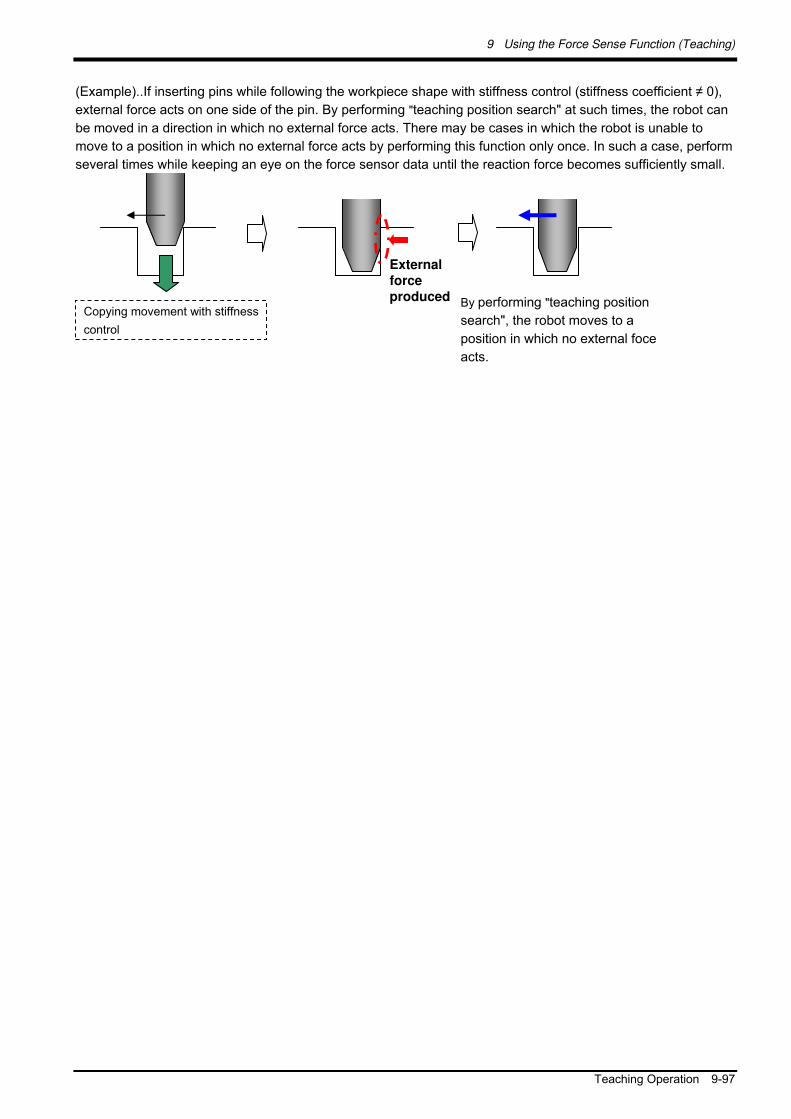
9 Using the Force Sense Function (Teaching)
Teaching Operation 9-97
(Example)..If inserting pins while following the workpiece shape with stiffness control (stiffness coefficient ≠ 0),
external force acts on one side of the pin. By performing "teaching position search" at such times, the robot can
be moved in a direction in which no external force acts. There may be cases in which the robot is unable to
move to a position in which no external force acts by performing this function only once. In such a case, perform
several times while keeping an eye on the force sensor data until the reaction force becomes sufficiently small.
External force produced
Copying movement with stiffness
control
By performing "teaching position
search", the robot moves to a
position in which no external foce
acts.

9 Using the Force Sense Function (Teaching)
9-98 Teaching Operation
9.2.2 Usage Example (Teaching Operation)
Teaching a Position Pushed with Fixed Force
■ Teaching details
Teach the position at which the spring reaction force becomes 25 N.
■ Operation procedure
(1) Parameter settings
Select force control for the Z-axis only, and set so that the robot is pushed with a force of 25 N in the tool
coordinate system +Z-direction. (See table below.)
Control mode
Force sense control coordinate system
FSCOD01 0
Force control mode FSFMD01 +0.00, +0.00, +1.00, +0.00, +0.00, +0.00
Stiffness coefficient FSSTF01 +0.00, +0.00, +0.00, +0.00, +0.00, +0.00
Damping coefficient FSDMP01 +0.00, +0.00, +0.00, +0.00, +0.00, +0.00
Control characteristics
Force command value
FSFCMD01 +0.00, +0.00, +25.00, +0.00, +0.00, +0.00
Speed command value
FSSPD01 +0.00, +0.00, +0.00, +0.00, +0.00, +0.00
Mode switching judgment value
FSSWF01 +0.00, +0.00, +0.00, +0.00, +0.00, +0.00
Force sense control gain
FSFGN01 +0.00, +0.00, +5.00, +0.00, +0.00, +0.00
Force detection setting value
FSFLMT01 +0.00, +0.00, +0.00, +0.00, +0.00, +0.00
(* In this example, settings are specified with parameters, however, setting is also possible with
status variables.)
(2) Offset cancel operation (See section 9.1.1.1 .)
Offset the force sensor zero point after first moving to the push start position (posture) by JOG operation.
* Perform offset cancel with no external forces acting other than gravity.
(3) Control mode/control characteristics selection (See section 9.1.1.2 .)
Set the "control mode" and "control characteristics " numbers.
(4) Force sense control enable operation (See section 9.1.1.3 .)
Turn the servo ON after enabling force sense control.
The robot automatically moves to the position in the tool coordinate system +Z-direction at which a reaction
force of 25 N can be obtained.
25 N
Teach this position.
Spring

9 Using the Force Sense Function (Teaching)
Teaching Operation 9-99
(5) Teaching (The following two teaching methods are available.)
<Method 1>
Ensure that the force sensor data is Fz=25 N, and then disable force sense control with the servo ON.
(By disabling force sense control, the current position data appears on the teaching pendant.)
Teach the current position.
<Method 2>
Ensure that the force sensor data is Fz=25 N, and then perform "teaching position search" with the servo
ON. By performing "teaching position search", the current position data appears on the teaching pendant.
(See section 9.2.1.1 .)
Teach the current position.

9 Using the Force Sense Function (Teaching)
9-100 Teaching Operation
Teaching the Insertion Position (Using Force Control)
■ Teaching details
Teach the ideal insertion position on which no external force acts.
Operation procedure
(1) Parameter settings
Select all axes and force control, and set the force command so that the robot is pushed with a force of 5 N
in the FZt direction, and external force is eliminated for all other axes. (FXt=FYt=0N, MXt=MYt=MZt=0 N·m)
Force sense control coordinate system
FSCOD01 0
Force control mode FSFMD01 +1.00,+1.00,+1.00,+1.00,+1.00,+1.00
Stiffness coefficient FSSTF01 +0.00,+0.00,+0.00,+0.00,+0.00,+0.00
Control mode
Damping coefficient FSDMP01 +0.00,+0.00,+0.00,+0.00,+0.00,+0.00
Force command value
FSFCMD01 +0.00,+0.00,+5.00,+0.00,+0.00,+0.00
Speed command value
FSSPD01 +0.00,+0.00,+0.00,+0.00,+0.00,+0.00
Mode switching judgment value
FSSWF01 +0.00,+0.00,+0.00,+0.00,+0.00,+0.00
Force sense control gain
FSFGN01 +0.50,+0.50,+0.50,+0.10,+0.10,+0.10
Control characteristics
Force detection setting value
FSFLMT01 +0.00,+0.00,+0.00,+0.00,+0.00,+0.00
(* In this example, settings are specified with parameters, however, setting is also possible with status
variables.)
(2) Offset cancel operation (See section 9.1.1.1 .)
Offset the force sensor zero point after first moving to the insertion start position (posture) by JOG operation.
* Perform offset cancel with no external forces acting other than gravity.
(3) Control mode/control characteristics selection (See section 9.1.1.2 .)
Set the "control mode" and "control characteristics" numbers.
(4) Force sense control enable operation (See section 9.1.1.3 .)
Turn the servo ON after enabling force sense control (stiffness control).
The robot automatically moves to the insertion complete position with force control. (The robot moves slowly
to the extent that the force sense control gain is lowered.)
* Adjust the force command or force sense control gain if required.
(5) Teaching (There are two teaching methods.)
<Method 1>
Ensure that the force sensor data is Fz=5N and that other axis components are 0 N / 0 N·m, and then
disable force sense control with the servo ON.
<Method 2>
Ensure that the force sensor data is Fz=5N and that other axis components are 0 N / 0 N·m, and then
perform "teaching position search" with the servo ON. (See section 9.2.1.1 .)
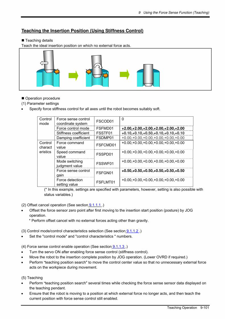
9 Using the Force Sense Function (Teaching)
Teaching Operation 9-101
Teaching the Insertion Position (Using Stiffness Control)
Teaching details
Teach the ideal insertion position on which no external force acts.
Operation procedure
(1) Parameter settings
Specify force stiffness control for all axes until the robot becomes suitably soft.
Force sense control coordinate system
FSCOD01 0
Force control mode FSFMD01 +2.00,+2.00,+2.00,+2.00,+2.00,+2.00
Stiffness coefficient FSSTF01 +0.10,+0.10,+0.50,+0.10,+0.10,+0.10
Control mode
Damping coefficient FSDMP01 +0.00,+0.00,+0.00,+0.00,+0.00,+0.00
Force command value
FSFCMD01+0.00,+0.00,+0.00,+0.00,+0.00,+0.00
Speed command value
FSSPD01 +0.00,+0.00,+0.00,+0.00,+0.00,+0.00
Mode switching judgment value
FSSWF01 +0.00,+0.00,+0.00,+0.00,+0.00,+0.00
Force sense control gain
FSFGN01 +0.50,+0.50,+0.50,+0.50,+0.50,+0.50
Control characteristics
Force detection setting value
FSFLMT01 +0.00,+0.00,+0.00,+0.00,+0.00,+0.00
(* In this example, settings are specified with parameters, however, setting is also possible with
status variables.)
(2) Offset cancel operation (See section 9.1.1.1 .)
Offset the force sensor zero point after first moving to the insertion start position (posture) by JOG
operation.
* Perform offset cancel with no external forces acting other than gravity.
(3) Control mode/control characteristics selection (See section 9.1.1.2 .)
Set the "control mode" and "control characteristics " numbers.
(4) Force sense control enable operation (See section 9.1.1.3 .)
Turn the servo ON after enabling force sense control (stiffness control).
Move the robot to the insertion complete position by JOG operation. (Lower OVRD if required.)
Perform "teaching position search" to move the control center value so that no unnecessary external force
acts on the workpiece during movement.
(5) Teaching
Perform "teaching position search" several times while checking the force sense sensor data displayed on
the teaching pendant.
Ensure that the robot is moving to a position at which external force no longer acts, and then teach the
current position with force sense control still enabled.

9 Using the Force Sense Function (Teaching)
9-102 Force Sense Function Screen
9.3 Force Sense Function Screen
9.3.1 R56TB/R57TB
If using the force sensor, an [F] button appears in the bottom of the JOG screen. By pressing this button, a force
sense control screen appears on the left of the JOG screen.
Fig. 9-2 [F] button display
Fig. 9-3: Force sense control extension screen

9 Using the Force Sense Function (Teaching)
Force Sense Function Screen 9-103
Table 9-4: Screen overview
No. Screen Control Overview
1 [F] button Displays/hides a screen (surrounded by red box in Fig. 9-3) relating to force
sense control.
(Does not appear if the force sensor interface unit is not connected.)
2 Enable/Disable
(ON/OFF)
Displays the current force sense control function enabled (ON)/disabled (OFF) status.
By pressing the [ON/OFF] button when the force sense control function is disabled, force sense control is enabled with the specified control mode/control characteristics. (Corresponds to the Fsc On command.)
By pressing the [ON/OFF] button when the force sense control function is enabled, force sense control is disabled. (Corresponds to the Fsc Off command.)
3 Control Mode
/Control Feature
Displays the currently specified control mode/control characteristics. The used control mode/control characteristics can be specified only
when the force sense control function is disabled. [Setting range -1 to 9]
The control mode/control characteristics cannot be specified when the force sense control function is enabled. (Appears gray.)
4 Teach Pos. Search By pressing the [Execute] button the system performs teaching position search. This is used to perform accurate contact position teaching.
<When function enabled> <When function disabled>
<When function enabled>
<Setting range>

9 Using the Force Sense Function (Teaching)
9-104 Force Sense Function Screen
5 Force Monitor Displays the force detection setting value (corresponds to parameters FSFLMT01 to 09 and status variables P_FsFLm0 and P_FsFlm1) specified at "Control characteristics "
No. Screen Control Overview
6 Current Displays the current force sensor data (corresponds to status variable P_FsCurD.) * Displays the value converted to the force sense coordinate system
(Tool/XYZ). Displays the current value when the force sense control function is
disabled . If the force sensor data exceeds the detected setting value during JOG
operation, the background color of the applicable data changes, and the buzzer sounds.
7 Maximum Displays the force sensor data maximum value (corresponds to status
variable P_FsMaxD) during force sense control. * The maximum value is reset with the maximum value reset operation or
offset cancel operation.
8 Offset Cancel Cancels the force sensor offset component (zero point offset). If sensor data is not 0 with no external force acting on the sensor, it is necessary to perform offset cancel.
Offsets cannot be cancelled when the force sense control function is disabled. (Appears gray.)
9 Reset Max. Resets the force sense data maximum value.
<When detection setting value over>
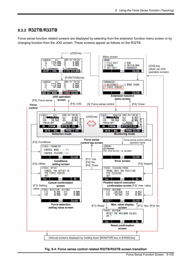
9 Using the Force Sense Function (Teaching)
Force Sense Function Screen 9-105
9.3.2 R32TB/R33TB
Force sense function related screens are displayed by selecting from the extension function menu screen or by
changing function from the JOG screen. These screens appear as follows on the R32TB.
[F2]: max. value
[FUNCTION] key
[JOG] key
Menu screen
Conditions
setting screen[F3]: Offset
[F1]: ResetForce detection
setting value screen
Reset confirmation screen
Error screen
[F4]: Close[F4]: JOG
[JOG] key(when via JOG operation screen)
Detection mode
Force
control
Force sense
control top screen
Monitoring mode
Max. value display screen
JOG operation
screen
Extension function
menu screen
Cancel confirmation
screen
Position search execution
confirmation screen
Interrupt screens displayed by holding down [MONITOR] key or [HAND] key
[F3]: Search
[3]: Force sense control
[F3]: Force sense
[JOG] key
[F1]: Yes[F4]: No[F4]: Close
[F2]: Conditions
[F1]: Yes / [F2]: No
Force sense control without operation rights
[F1]: Setting value
Fig. 9-4: Force sense control related R32TB/R33TB screen transition

9 Using the Force Sense Function (Teaching)
9-106 Force Sense Function Screen
Table 9-5: Screen overview
Screen Name Overview
Force sense control top screen
<Detection mode>
Detection mode is enabled when changing from the JOG operation screen. By operating the [-X] [+X] [-Y] [+Y] [-Z] [+Z] [-A] [+A] [-B] [+B] [-C] [+C] keys in
detection mode, JOG operation can be performed. (* Operation rights required.) JOG operation types correspond to the JOG operation screen immediately before
changing to the force sense control top screen. (The selected JOG operation type appears in the center of the screen.)
<Monitoring mode>
Monitoring mode is enabled when changing from the extension function menu
screen. JOG operation is not possible in monitoring mode. "Monitor" appears in the top center of the screen.
Screen Display
Meaning
"Fx" - "Mz"
Displays the current force sensor data (corresponding to status variable P_FsCurD.) * Displays values converted to the force sense coordinate system (Tool/XYZ). If the force sensor data exceeds the detection setting value during JOG operation, the background color of the exceeded data changes and the buzzer sounds.
"Force Sense"
Displays the current force sense control function enabled (ON)/disabled (OFF) status.
"Mode No." Displays the currently specified control mode No.
"Feature No." Displays the currently displayed control characteristics No.
Function Description
ON/OFF
Changes the force sense control function enabled/disabled status. (* Operation rights required.) The "Mode No." and "Feature No." values are used for the control mode and control characteristics. Offset cancel is not performed.
[F1]
Setting Changes to the force detection setting value screen.
Condition Changes to the conditions setting screen if force sense control is disabled. [F2] Max.
Value Changes to the maximum value display screen.
Offset Changes to the cancel confirmation screen. [F3]
Search Changes to the position search execution confirmation screen.
JOG Changes to the JOG operation screen. [F4]
Close Changes to the extension function menu screen.
The screen changes by pressing
the [FUNCTION] key.
The screen changes by pressing
the [FUNCTION] key.
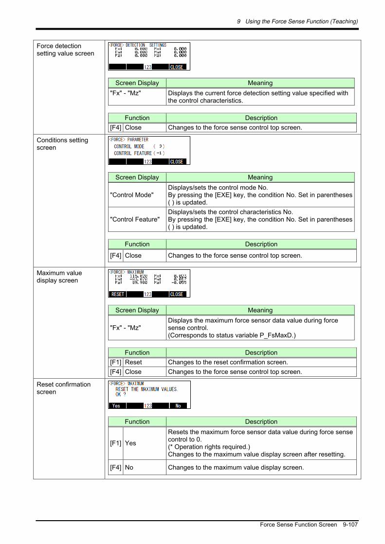
9 Using the Force Sense Function (Teaching)
Force Sense Function Screen 9-107
Force detection setting value screen
Screen Display Meaning
"Fx" - "Mz" Displays the current force detection setting value specified with the control characteristics.
Function Description
[F4] Close Changes to the force sense control top screen.
Conditions setting screen
Screen Display Meaning
"Control Mode" Displays/sets the control mode No. By pressing the [EXE] key, the condition No. Set in parentheses ( ) is updated.
"Control Feature" Displays/sets the control characteristics No. By pressing the [EXE] key, the condition No. Set in parentheses ( ) is updated.
Function Description
[F4] Close Changes to the force sense control top screen.
Maximum value display screen
Screen Display Meaning
"Fx" - "Mz" Displays the maximum force sensor data value during force sense control. (Corresponds to status variable P_FsMaxD.)
Function Description
[F1] Reset Changes to the reset confirmation screen.
[F4] Close Changes to the force sense control top screen.
Reset confirmation screen
Function Description
[F1] Yes
Resets the maximum force sensor data value during force sense control to 0. (* Operation rights required.) Changes to the maximum value display screen after resetting.
[F4] No Changes to the maximum value display screen.

9 Using the Force Sense Function (Teaching)
9-108 Force Sense Function Screen
Cancel confirmation screen
Function Description
[F1] Yes
Cancels the force sensor offset component. If the sensor data is not 0 with no external force acting on the sensor, it is necessary to perform offset cancel. (* Operation rights required.) An error occurs when force sense control is enabled and the servo is ON. Changes to the force sense control top screen after canceling.
[F4] No Changes to the force sense control top screen.
Position search execution confirmation screen
Function Description
[F1] Yes
Performs the teaching position search function. This is used when teaching the contact position. (* Operation rights required.) Changes to the force sense control top screen after processing.
[F4] No Changes to the force sense control top screen.
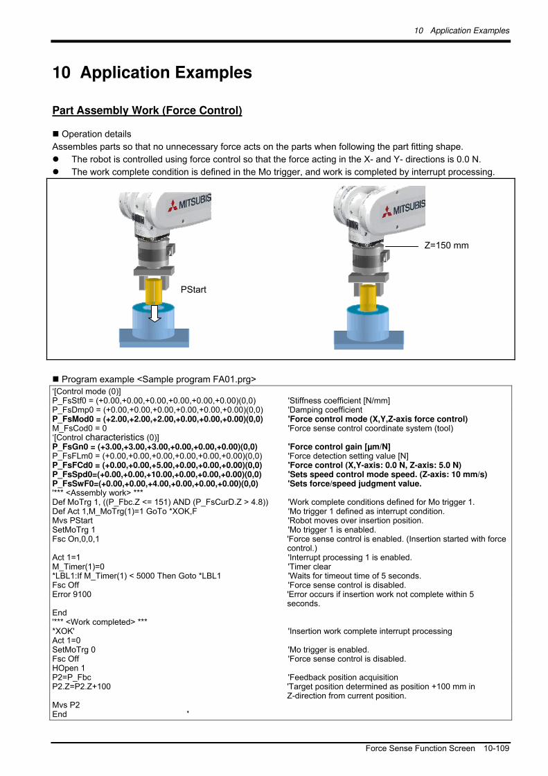
10 Application Examples
Force Sense Function Screen 10-109
10 Application Examples
Part Assembly Work (Force Control)
Operation details
Assembles parts so that no unnecessary force acts on the parts when following the part fitting shape.
The robot is controlled using force control so that the force acting in the X- and Y- directions is 0.0 N.
The work complete condition is defined in the Mo trigger, and work is completed by interrupt processing.
Program example <Sample program FA01.prg>
‘[Control mode (0)] P_FsStf0 = (+0.00,+0.00,+0.00,+0.00,+0.00,+0.00)(0,0) 'Stiffness coefficient [N/mm] P_FsDmp0 = (+0.00,+0.00,+0.00,+0.00,+0.00,+0.00)(0,0) 'Damping coefficient P_FsMod0 = (+2.00,+2.00,+2.00,+0.00,+0.00,+0.00)(0,0) 'Force control mode (X,Y,Z-axis force control) M_FsCod0 = 0 'Force sense control coordinate system (tool) ‘[Control characteristics (0)] P_FsGn0 = (+3.00,+3.00,+3.00,+0.00,+0.00,+0.00)(0,0) 'Force control gain [µm/N] P_FsFLm0 = (+0.00,+0.00,+0.00,+0.00,+0.00,+0.00)(0,0) 'Force detection setting value [N] P_FsFCd0 = (+0.00,+0.00,+5.00,+0.00,+0.00,+0.00)(0,0) 'Force control (X,Y-axis: 0.0 N, Z-axis: 5.0 N) P_FsSpd0=(+0.00,+0.00,+10.00,+0.00,+0.00,+0.00)(0,0) 'Sets speed control mode speed. (Z-axis: 10 mm/s) P_FsSwF0=(+0.00,+0.00,+4.00,+0.00,+0.00,+0.00)(0,0) 'Sets force/speed judgment value. '*** <Assembly work> *** Def MoTrg 1, ((P_Fbc.Z <= 151) AND (P_FsCurD.Z > 4.8)) 'Work complete conditions defined for Mo trigger 1. Def Act 1,M_MoTrg(1)=1 GoTo *XOK,F 'Mo trigger 1 defined as interrupt condition. Mvs PStart 'Robot moves over insertion position. SetMoTrg 1 'Mo trigger 1 is enabled. Fsc On,0,0,1 'Force sense control is enabled. (Insertion started with force
control.) Act 1=1 'Interrupt processing 1 is enabled. M_Timer(1)=0 'Timer clear *LBL1:If M_Timer(1) < 5000 Then Goto *LBL1 'Waits for timeout time of 5 seconds. Fsc Off 'Force sense control is disabled. Error 9100 'Error occurs if insertion work not complete within 5
seconds. End '*** <Work completed> *** *XOK' 'Insertion work complete interrupt processing Act 1=0 SetMoTrg 0 'Mo trigger is enabled. Fsc Off 'Force sense control is disabled. HOpen 1 P2=P_Fbc 'Feedback position acquisition P2.Z=P2.Z+100 'Target position determined as position +100 mm in
Z-direction from current position. Mvs P2 End '
PStart
Z=150 mm

10 Application Examples
10-110 Force Sense Function Screen
■Description
1) With force control, the robot is set to push with a force of 0.0 N in the X- and Y-directions, and 5.0 N in
the Z-direction. Furthermore, if the reaction force in the Z-direction is less than 4 N, the robot moves at
a speed of 10 mm/s in speed priority mode.
2) Work complete conditions are defined for Mo trigger 1 with the Def MoTrg command. (In this example,
when Z 151 mm and Fzt > 4.8 N, it is judged that insertion work is complete.)
3) After moving to the assembly start position, by enabling Mo trigger 1 followed by force sense control,
insertion work is started automatically.
4) If insertion work is not completed within 5 seconds of work starting, a 9100 error is output and insertion
work is stopped.
5) If insertion work is completed successfully, M_MoTrg(1)=1 and interrupt processing (label: *XOK) is
performed.
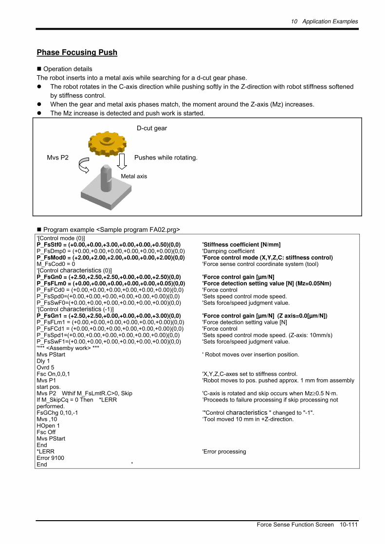
10 Application Examples
Force Sense Function Screen 10-111
Phase Focusing Push
Operation details
The robot inserts into a metal axis while searching for a d-cut gear phase.
The robot rotates in the C-axis direction while pushing softly in the Z-direction with robot stiffness softened
by stiffness control.
When the gear and metal axis phases match, the moment around the Z-axis (Mz) increases.
The Mz increase is detected and push work is started.
Program example <Sample program FA02.prg>
‘[Control mode (0)] P_FsStf0 = (+0.00,+0.00,+3.00,+0.00,+0.00,+0.50)(0,0) 'Stiffness coefficient [N/mm] P_FsDmp0 = (+0.00,+0.00,+0.00,+0.00,+0.00,+0.00)(0,0) 'Damping coefficient P_FsMod0 = (+2.00,+2.00,+2.00,+0.00,+0.00,+2.00)(0,0) 'Force control mode (X,Y,Z,C: stiffness control) M_FsCod0 = 0 'Force sense control coordinate system (tool) ‘[Control characteristics (0)] P_FsGn0 = (+2.50,+2.50,+2.50,+0.00,+0.00,+2.50)(0,0) 'Force control gain [µm/N] P_FsFLm0 = (+0.00,+0.00,+0.00,+0.00,+0.00,+0.05)(0,0) 'Force detection setting value [N] (Mz=0.05Nm) P_FsFCd0 = (+0.00,+0.00,+0.00,+0.00,+0.00,+0.00)(0,0) 'Force control P_FsSpd0=(+0.00,+0.00,+0.00,+0.00,+0.00,+0.00)(0,0) 'Sets speed control mode speed. P_FsSwF0=(+0.00,+0.00,+0.00,+0.00,+0.00,+0.00)(0,0) 'Sets force/speed judgment value. ‘[Control characteristics (-1)] P_FsGn1 = (+2.50,+2.50,+0.00,+0.00,+0.00,+3.00)(0,0) 'Force control gain [µm/N] (Z axis=0.0[µm/N]) P_FsFLm1 = (+0.00,+0.00,+0.00,+0.00,+0.00,+0.00)(0,0) 'Force detection setting value [N] P_FsFCd1 = (+0.00,+0.00,+0.00,+0.00,+0.00,+0.00)(0,0) 'Force control P_FsSpd1=(+0.00,+0.00,+0.00,+0.00,+0.00,+0.00)(0,0) 'Sets speed control mode speed. (Z-axis: 10mm/s) P_FsSwF1=(+0.00,+0.00,+0.00,+0.00,+0.00,+0.00)(0,0) 'Sets force/speed judgment value. '*** <Assemby work> *** Mvs PStart ' Robot moves over insertion position. Dly 1 Ovrd 5 Fsc On,0,0,1 'X,Y,Z,C-axes set to stiffness control. Mvs P1 'Robot moves to pos. pushed approx. 1 mm from assembly start pos. Mvs P2 Wthif M_FsLmtR.C>0, Skip 'C-axis is rotated and skip occurs when Mz0.5 N·m. If M_SkipCq = 0 Then *LERR ’Proceeds to failure processing if skip processing not performed. FsGChg 0,10,-1 ’"Control characteristics " changed to "-1". Mvs ,10 ‘Tool moved 10 mm in +Z-direction. HOpen 1 Fsc Off Mvs PStart End *LERR 'Error processing Error 9100 End '
Metal axis
D-cut gear
Pushes while rotating. Mvs P2

10 Application Examples
10-112 Force Sense Function Screen
Description
1) The robot is set to control the X-, Y-, Z-, and C-axes softly with stiffness control. The force detection
setting value is Mz = 0.05 N·m.
2) Force control is enabled, and the robot moves to a position approximately 1 mm below of the insertion
start position. (MvsP1)
3) The C-axis is rotated with the Mvs command. If a moment of Mz 0.05 N·m is detected during
operation using a Wthif sub-clause, operation is stopped and skip processing is performed at the next
step.
4) The gear is twisted in the C-axis direction while pushing in the Z-direction, and therefore when the
D-cut gear and metal axis phases match, Mz increases. Wthif sub-clause conditions are established,
and therefore rotation is stopped and skip processing is performed for the next command. (If skip
processing is not performed, the system determines that phase detection has failed and error
processing is performed.)
5) Control characteristics "0" is changed to "-1" using the FsGChg command so that the Z-axis control
gain becomes 0.0. (If the control gain is 0, the robot is not controlled softly even if stiffness control is
selected. Control will be the equivalent of position control.)
6) The robot moves 10 mm in the tool coordinate system Z-direction and assembly work is completed.

11 Language Specifications
Commands Relating to Force Sense Control Function 11-113
11 Language Specifications
This Chapter describes specifications for force sense control function related to MELFA-BASIC V commands
and status variables.
<Example>
By replacing P_FsLmtR = (0, 0, 1, 2, 0, 0, 0, 0) A-axis component data for M1 such as M1 = P_FsLmtR.A, M1 is
replaced not by 2, but by 0.034906 (=2×180). To replace M1 with 2, use the Deg function.
M1% = Deg(P_FsLmtR.A)
By changing parameter PRGMDEG setting to 1, the unit system when the P variable rotational axis component
data is referenced is deg, and therefore there is no need to use the Deg function. (Refer to instruction manual
"Detailed Description of Functions and Operation" for details on the Deg function and parameter PRGMDEG.)
11.1 Commands Relating to Force Sense Control Function
MELFA-BASIC V commands relating to the force sense control function are described below.
Table 11-1: Force sense control commands
No. Command Function Overview
1 Fsc On Enables the force sense control function using force sensor. 2 Fsc Off Disables the force sense control function using force sensor. 3 FsGChg Changes control characteristics for force sense control during operation. 4 FsCTrg Sets force sense control characteristics switching with the Mo trigger.
Precautions when using status variables
By directly referencing P variable A-, B-, and C-axis values as component data, they are read as
radian unit values. If reading values for each component and creating a program, unit conversion is
required. (See following example.)

11 Language Specifications
11-114 Commands Relating to Force Sense Control Function
Fsc On
[Function]
Enables the force sense control function using force sensor.
[Syntax]
FscOn <Control mode>, <Control characteristics >, <Offset cancel designation>
[Terminology]
<Control mode> Specifies the force sense control mode No. (See section 8.1.2 .)
Setting range: -1 - 9
Table 11-2 Control mode setting items and corresponding values
Control Mode Setting Item
-1 0 1 2 - 9
Force sense control
coordinate system
M_FsCod1 M_FsCod0 FSCOD01 FSCOD02 - FSCOD09
Force control mode P_FsMod1 P_FsMod0 FSFMD01 FSFMD02 - FSFMD09
Stiffness coefficient P_FsStf1 P_FsStf0 FSSTF01 FSSTF02 - FSSTF09
Damping coefficient P_FsDmp1 P_FsDmp0 FSDMP01 FSDMP02 - FSDMP09
<Control characteristics > Specifies the force sense control characteristics No. (See section 8.1.2 .)
Setting range: -1 - 9
Table 11-3 Control characteristics setting items and corresponding values
Control characteristics Setting Item
-1 0 1 2 - 9
Force command
value
P_FsFCd1 P_FsFCd0 FSFCMD01 FSFCMD02 - FSFCMD09
Speed command
value
P_FsSpd1 P_FsSpd0 FSSPD01 FSSPD02 - FSSPD09
Mode switching
judgment value
P_FsSwF1 P_FsSwF0 FSSWF01 FSSWF02 - FSSWF09
Force sense control
gain
P_FsGn1 P_FsGn0 FSFGN01 FSFGN02 - FSFGN09
Force detection
setting value
P_FsFLm1 P_FsFLm0 FSFLMT01 FSFLMT02 - FSFLMT09
<Offset cancel designation> Specifies whether to cancel the force sensor data offset component.
(zero point offset)
Setting value: 0 (Do not cancel)/1 (Cancel)
(For details, see section 8.1.3 .)
[Example]
Refer to examples in section 11.7 .

11 Language Specifications
Commands Relating to Force Sense Control Function 11-115
[Description]
(1) Enables the force sense control function using force sensor. (Default: Disabled)
(2) The force sense control content is specified with the "control mode" and "control characteristics " condition
Nos. set beforehand.
(3) If the force sensor is not connected and this command is executed, error L3986 occurs.
(4) This command cannot be executed when the force sense control function is enabled (error L3987 occurs.) If
changing the "control mode" or "control characteristics ", execute the Fsc Off command to disable the force
sense control function, and then execute the Fsc On command again. However, the "control characteristics
" can be changed during operation using the FsGChg command or FsCTrg command.
(5) "Control mode" and "control characteristics " 1 to 9 use setting values for each corresponding parameter.
(Refer to Table 11-2 for details of setting items contained in control mode and control characteristics.)
(6) If the "control mode" or "control characteristics " is 0 or -1, conditions set with dedicated status variables are
used. The default status is the same setting as if "control mode" and "control characteristics " 1 is specified.
(Refer to Table 11-2 for details of setting items contained in control mode and control characteristics.)
(7) If the offset cancel designation is 1, force sensor data becomes 0 for all axes when this command is
executed, and the senor offset component is offset (zero point offset). No offset is made if the offset cancel
designation is 0.
(8) If the offset cancel designation is 1, execute this command after the robot stops completely. If the command
is executed immediately after the movement, the zero point offset may not be performed properly due to an
inertial force.
(9) The force sense control enabled/disabled status and "control mode"/"control characteristics" settings are
common to both AUTOMATIC and MANUAL modes.
(10) Even if an interpolation continuous command is specified with the Cnt command, the command is executed
after waiting for the robot movement to be completed.
(11) Force sense control is disabled by performing a program reset or executing an End command. (See Fig.
11-1.)
(12) Force sense control processing functions only when the servo is ON. Even if force sense control is enabled,
force sense control processing is not performed while the servo is OFF. If the servo is turned OFF while
performing force sense control processing, processing is stopped. Force sense control processing is then
resumed by turning the servo ON again. (See Fig. 11-1.)
Force sense control disabled
Force sense control enabled
Force sense control
execution
Power ON
Fsc On commandEnable operation with T/B
Fsc Off commandDisable operation with T/BEnd commandProgram reset operation
Servo ON
Servo OFF
Fsc Off commandTDisable operation with T/BEnd commandProgram reset operationForce sense control error occurrence
If program selectable when changed to AUTOMATIC mode
Fig. 11-1: Force sense control function status transition
(13) When force sense control is not being performed, force sensor data checks using the force detection setting
value are not performed.
(14) The force sense control function and functions listed in Table 11-4 cannot be used at the same time.

11 Language Specifications
11-116 Commands Relating to Force Sense Control Function
Table 11-4 Behavior with simultaneous used with force sense control function
Function Behavior with Simultaneous Use Error
Compliance control (Cmp command)
Priority is given to the function enabled first. L3986
Collision detection (ColChk command)
Priority is given to the force sense control function. If force sense control function is enabled while collision detection is enabled, collision detection is disabled. If force sense control function is then disabled, collision detection returns to the status specified at that time.
L3986 *1
Tool/base coordinate system conversion (Base/Tool command, etc.)
Tool/base conversion data is not changed while force sense control is enabled.
L3986
Jrc command The Jrc command cannot be executed while force sense control is enabled.
L3986
Continue function The force sense control function is not compatible with the continue function.
-
* 1: An error occurs if collision detection is enabled with the ColChk command during automatic operation
and when the force sense control function is enabled.
(15) If positioning complete is executed with the Fine J command (joint)/Fine P command (linear) while force
sense control is enabled, there may be times when the robot is unable to arrive at its target destination due
to the external force acting on the force sensor, preventing positioning from being completed. If executing
positioning complete, use the Fine command (pulse).
(16) If changing both the force sense control and tracking functions from an enabled status to disabled status
when performing automatic operation, first execute the Trk Off command to disable the tracking function,
and then disable force sense control with the Fsc Off command. If the Fsc Off command is executed first, an
L2750 error occurs.
(17) Even if force sense control is enabled, a user defined area and free plane limit check are performed by
referencing the position command. The force sense position command is not referenced.

11 Language Specifications
Commands Relating to Force Sense Control Function 11-117
Fsc Off
[Function]
Disables the force sense control function using force sensor.
[Syntax]
FscOff
[Example]
Refer to examples in section 11.7 .
[Description]
(1) Disables the force sense control function using force sensor.
(2) If the force sensor is not connected, no processing is performed when this command is executed.
(3) Similarly, no processing is performed when this command is executed while the force sense control function
is disabled.
(4) The "position command" changes to the "force sense position command" when force sense control
becomes disabled.

11 Language Specifications
11-118 Commands Relating to Force Sense Control Function
FsGChg (Fs gain change)
[Function]
Changes control characteristics for force sense control during operation.
[Syntax]
FsGChg <Change start time>, <Change time>, <Control characteristics group No. after change>
[Terminology]
<Change start time> Specifies the position at which the control characteristics setting change is started.
This is specified with an interrupt during the next interpolation command start point and
end point.
Setting range: 0 - 100 [%]
<Change time> Specifies the time taken to change the control characteristics setting.
The force detection setting value and mode switching judgment value change
immediately, regardless of this specification.
Setting range: 1 - 1000 [ms]
<Control characteristics group No. after change>
Specifies the control characteristics group No. applied after the change.
Setting range: -1 to 9
[Example]
Refer to examples in section 11.7 .
[Description]
(1) Changes the force sense control function control characteristics from the current setting to the specified
control characteristics.
(2) After executing this command, when the command position reaches the specified change start position, the
control characteristics change is started for the first interpolation command. (The force detection setting
value changes immediately when this position is reached.)
(3) The force sense control gain and force command are changed to the setting values specified with "Control
characteristics " over the time set in <Change time>.
Example 1: If change start position is 30%
(4) If the force sensor is not connected, no processing is performed when this command is executed.
(5) This command cannot be executed when the force sense control gain and force command are being
changed (when the change time has not elapsed). (Error L3987)
(6) If the force sense control function is disabled without executing the interpolation command, this command
will be disabled.
(7) The "Control characteristics " change specification can only be executed during automatic operation. If
operation is interrupted before starting the change and the mode key is switched from AUTOMATIC to
MANUAL, change processing becomes invalid at that point.
(8) When the force sense control gain and force command are being changed (when the change time has not
elapsed), processing of these changes is continued until completion, even if the force sense control function
is disabled.
(9) After executing this command, the command specification also becomes invalid when the force sense
control function is disabled, without executing the interpolation command.

11 Language Specifications
Commands Relating to Force Sense Control Function 11-119
FcCTrg (FsC trigger)
[Function]
Sets force sense control characteristics switching with the Mo trigger.
[Syntax]
FsCtrg <Trigger No.>, <Change time>, <Control characteristics group No. after change>
[, <Timeout>,<Execution method> [, <Error specification>]]
[Terminology]
<Trigger No.> Specifies the Mo trigger No. used to change the control characteristics with a constant.
Setting range: 1 - 3
<Change time> Specifies the time taken to change the control characteristics.
The force detection setting value and mode switching judgment value change
immediately, regardless of this setting.
Setting range: 1 – 1000 [ms]
<Control characteristics group No. after change>
Specifies the control characteristics group No. applied after the change.
Setting range: -1 to 9
<Timeout> Specifies the Mo trigger timeout monitoring time with a constant.
Setting range: 0 – 60 [s]
If omitted, timeout processing is not performed.
<Execution method> Specifies the timeout monitoring execution method for this command with a constant.
0: Proceeds to next program without waiting for Mo trigger ON.
1: Does not proceed to next program until Mo trigger turns ON or timeout reached.
<Error specification> Specifies whether an error occurs following a timeout.
0: Error occurs.
1: Error does not occur.
An error occurs following a timeout if omitted.
[Example]
1 Def MoTrg 3, (P_Fbc.Z < 100) 'Defines Mo trigger No.3.
2 Fsc On, 1, 1, 1 'Enables force sense control.
3 FsCTrg 3, 100, 2 'Enables Mo trigger No.3 and changes the control characteristics from 1 to 2 when the trigger turns ON.
4 Mvs P1
[Description]
(1) Sets force sense control characteristics switching with the Mo trigger.
(2) By executing this command, the Mo trigger for the specified trigger No. is enabled, and the control
characteristics is changed when the trigger turns ON. When the control characteristics change is complete,
the change setting with this command will become unset.
(3) If this command is executed when the Mo trigger is disabled, the Mo trigger for the specified trigger No. is
enabled.
(4) If the Mo trigger for the specified trigger No. is undefined, an error occurs when the program is run. (Error
L.3770)
(5) If an Mo trigger for a different No. than that specified for <Trigger No.> is currently enabled, the enabled
trigger is disabled, and the Mo trigger specified for <Trigger No.> is enabled.
(6) After starting the change, the control characteristics "force sense control gain" and "force specification
value", and "speed command value" are changed to linear values toward the <Control characteristics group
No. after change> control characteristics setting, over the time set in <Change time>.
The "force detection setting value" and "mode switching judgment value" change immediately, regardless of
this setting.
(7) If a <Timeout> is specified, an error occurs after executing this command if the Mo trigger turns ON and

11 Language Specifications
11-120 Commands Relating to Force Sense Control Function
control characteristics change is not completed within the specified time. (Error L.3987)
(8) If program execution is interrupted, the timeout processing count up is also interrupted. If program execution
is resumed, the timeout processing count up is also resumed.
(9) If program execution is interrupted, the timeout processing count up is also interrupted. If program execution
is resumed, the timeout processing count up is also resumed.
(10) If a timeout occurs, the change setting with this command becomes unset, regardless of the error
specification.
(11) After executing this command, if the force sense control function is disabled before the Mo trigger turns ON,
the change setting with this command becomes unset.
(12) After executing this command, if the Mo trigger is disabled with the SetMoTrg command before the Mo
trigger turns ON, the change setting with this command becomes unset.
(13) After executing this command, if operation is interrupted and the operation panel mode key is changed from
"AUTOMATIC" to "MANUAL" before the Mo trigger turns ON, the change setting with this command
becomes unset.
(14) Even if the force sense control function is disabled while processing the control characteristics change,
processing continues until the change is complete. (Only the setting is changed. No control is performed.)
(15) An error occurs if this command is executed while processing the control characteristics change. (Error
L.3987)
(16) An error occurs if this command is executed when the force sense control function is disabled. (Error
L.3987)
(17) An error occurs if this command is executed when the control characteristics change is set with the FsGChg
command. (Error L.3987)
(18) After executing this command, an error occurs when this command is executed again before the control
characteristics changes. (Error L.3987)
If changing the change setting, disable the Mo trigger with the SetMoTrg command, and then execute this
function.
(19) After executing this command, an error occurs if the FsGChg command is executed before the control
characteristics changes. (Error L.3987)
(20) If an End command is executed for the slot for which this command is executed, or if the program reset
operation is performed, the change setting with this command becomes unset. (21) This command setting is defined with respect to the robot. Unlike the Def Act command, if a sub-program is
called with the CallP command, or if mechanical control rights are moved to another slot with the GetM or RelM commands, this command setting is continued.
(22) If the force sensor is not connected, no processing is performed even when this command is executed. No
error in particular occurs.
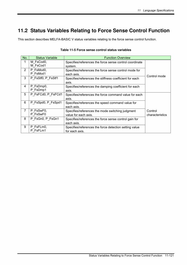
11 Language Specifications
Status Variables Relating to Force Sense Control Function 11-121
11.2 Status Variables Relating to Force Sense Control Function
This section describes MELFA-BASIC V status variables relating to the force sense control function.
Table 11-5 Force sense control status variables
No. Status Variable Function Overview
1 M_FsCod0, M_FsCod1
Specifies/references the force sense control coordinate
system. 2 P_FsMod0,
P_FsMod1 Specifies/references the force sense control mode for
each axis. 3 P_FsStf0, P_FsStf1 Specifies/references the stiffness coefficient for each
axis. 4 P_FsDmp0,
P_FsDmp1 Specifies/references the damping coefficient for each
axis.
Control mode
5 P_FsFCd0, P_FsFCd1 Specifies/references the force command value for each
axis. 6 P_FsSpd0, P_FsSpd1 Specifies/references the speed command value for
each axis. 7 P_FsSwF0,
P_FsSwF0 Specifies/references the mode switching judgment
value for each axis. 8 P_FsGn0, P_FsGn1 Specifies/references the force sense control gain for
each axis. 9 P_FsFLm0,
P_FsFLm1 Specifies/references the force detection setting value
for each axis.
Control
characteristics

11 Language Specifications
11-122 Status Variables Relating to Force Sense Control Function
M_FsCod0, M_FsCod1
[Function]
Specifies/references the force sense control coordinate system.
[Syntax]
Example) M_FsCod0=<Numeric variable 1>
Example) <Numeric variable 2>=M_FsCod1
[Terminology]
<Numeric variable 1> Specifies the force sense control coordinate system.
Setting Mode
0 Coordinate system (Tool)
1 Coordinate system (XYZ)
<Numeric variable 2> Specifies the save destination for the read control coordinate information.
[Example]
Refer to examples in section 11.7 .
[Description]
(1) Specifies/references the coordinate system for which force control is performed contained in the condition
group (control mode).
(2) The specified value is used if the Fsc On command <control mode> is set to "-1" or "0".
(3) Default status: The parameter FSCOD01 setting value is updated.
(4) The value substituted for the status variable is retained until the power is turned OFF.
(5) When force sense control is enabled with <control mode> = "0", it is not possible to write M_FsCod0. (Error
L3987 occurs.)
(6) When force sense control is enabled with <control mode> = "-1", it is not possible to write M_FsCod1. (Error
L3987 occurs.)
(7) When no force sensor is connected, the value is not applied even if it is written. Also if the setting value is
read, always 0 is output.

11 Language Specifications
Status Variables Relating to Force Sense Control Function 11-123
P_FsMod0, P_FsMod1
[Function]
Specifies/references the force sense control mode for each axis.
[Syntax]
Example) P_FsMod0=<Position variable 1>
Example) <Position variable 2>=P_FsMod1
[Terminology]
<Position variable 1> Specifies the force sense control mode for each axis.
Setting Mode
0 Position control
1 Force control
2 Stiffness control
<Position variable 2> Specifies the save destination for the read control coordinate information.
[Example]
Refer to examples in section 11.7 .
[Description]
(1) Specifies/references the force sense control mode for each axis contained in the condition group (control
mode).
(2) The specified value is used if the Fsc On command <control mode> is set to "-1" or "0".
(3) Default status: The parameter FSFMD01 setting value is updated.
(4) The value substituted for the status variable is retained until the power is turned OFF.
(5) When force sense control is enabled with <control mode> = "0", it is not possible to write P_FsMod0. (Error
L3987 occurs.)
(6) When force sense control is enabled with <control mode> = "-1", it is not possible to write P_FsMod1. (Error
L3987 occurs.)
(7) When no force sensor is connected, the value is not applied even if it is written. Also if the setting value is
read, always 0.0 is output for all elements.

11 Language Specifications
11-124 Status Variables Relating to Force Sense Control Function
P_FsStf0, P_FsStf1
[Function]
Specifies/references the stiffness coefficient for force sense control (stiffness control).
[Syntax]
Example) P_FsStf0=<Position variable 1>
Example) <Position variable 2>=P_FsStf1
[Terminology]
<Position variable 1> Specifies the stiffness coefficient for force sense control (stiffness control).
(The L1- and L2-axis components do not use this variable.)
Component Setting Range Unit
X, Y, Z 0.0 - 1000.0 N/mm
A, B, C 0.0 - 1000.0 N·m/deg
L1, L2 0.0 -
<Position variable 2> Specifies the save destination for the read stiffness coefficient.
[Example]
Refer to examples in section 11.7 .
[Description]
(1) Specifies/references the stiffness coefficient for stiffness control contained in the condition group (control
mode).
(2) The specified value is used if the Fsc On command <control mode> is set to "-1" or "0".
(3) Default status: The parameter FSSTF01 setting value is updated.
(4) The value substituted for the status variable is retained until the power is turned OFF.
(5) When force sense control is enabled with <control mode> ="0", it is not possible to write P_FsStf0. (Error
L3987 occurs.)
(6) When force sense control is enabled with <control mode> = "-1", it is not possible to write P_FsStf1. (Error
L3987 occurs.)
(7) When no force sensor is connected, the value is not applied even if it is written. Also if the setting value is
read, always 0.0 is output for all elements.

11 Language Specifications
Status Variables Relating to Force Sense Control Function 11-125
P_FsDmp0, P_FsDmp1
[Function]
Specifies/references the damping coefficient (responsiveness) for force sense control (stiffness control/force
control).
[Syntax]
Example) P_FsDmp0=<Position variable 1>
Example) <Position variable 2>=P_FsDmp1
[Terminology]
<Position variable 1> Specifies the damping coefficient for force sense control.
(The L1- and L2-axis components do not use this variable.)
Component Setting Range Unit
X, Y, Z 0.0 - 1.0 N/(mm/s)
A, B, C 0.0 - 1.0 N·m/(deg/s)
L1, L2 0.0 -
<Position variable 2> Specifies the save destination for the read damping coefficient.
[Example]
Refer to examples in section 11.7 .
[Description]
(1) Specifies/references the damping coefficient contained in the condition group (control mode).
(2) The specified value is used if the Fsc On command <control mode> is set to "-1" or "0".
(3) Default status: The parameter FSDMP01 setting value is updated.
(4) The value substituted for the status variable is retained until the power is turned OFF.
(5) When force sense control is enabled with <control mode> = "0", it is not possible to write P_FsDmp0. (Error
L3987 occurs.)
(6) When force sense control is enabled with <control mode> ="-1", it is not possible to write P_FsDmp1. (Error
L3987 occurs.)
(7) When no force sensor is connected, the value is not applied even if it is written. Also if the setting value is
read, always 0.0 is output for all elements.

11 Language Specifications
11-126 Status Variables Relating to Force Sense Control Function
P_FsFCd0, P_FsFCd1
[Function]
Specifies/references the force command value for force sense control (force control).
[Syntax]
Example) P_FsFCd0=<Position variable 1>
Example) <Position variable 2>=P_FsFCd1
[Terminology]
<Position variable 1> Specifies the force command value for force sense control (force control).
(The L1- and L2-axis components do not use this variable.)
Component Setting Range Unit
X, Y, Z - force sense tolerance value to
+ force sense tolerance value
N
A, B, C - force sense tolerance value to
+ force sense tolerance value
N·m
L1, L2 0.0 -
<Position variable 2> Specifies the save destination for the read force command value.
[Example]
Refer to examples in section 11.7 .
[Description]
(1) Specifies/references the force command value contained in the condition group (control characteristics).
(2) The specified value is used if the Fsc On command <control characteristics > is set to "-1" or "0".
(3) Default status: The parameter FSFCMD01 setting value is updated.
(4) The value substituted for the status variable is retained until the power is turned OFF.
(5) When force sense control is enabled with <control characteristics > = "0", it is not possible to write
P_FsFCd0. (Error L3987 occurs.)
(6) When force sense control is enabled with <control characteristics > = "-1", it is not possible to write
P_FsFCd1. (Error L3987 occurs.)
(7) When no force sensor is connected, the value is not applied even if it is written. Also if the setting value is
read, always 0.0 is output for all elements.

11 Language Specifications
Status Variables Relating to Force Sense Control Function 11-127
P_FsSpd0, P_FsSpd1
[Function]
Specifies/references the speed command value for force sense control (force control).
[Syntax]
Example) P_FsSpd0=<Position variable 1>
Example) <Position variable 2>=P_FsSpd1
[Terminology]
<Position variable 1> Specifies the speed command value for force sense control (force control).
(The L1- and L2-axis components do not use this variable.)
Component Setting Range Unit
X, Y, Z 0.0 - 50.0 mm/s
A, B, C 0.0 - 50.0 deg/s
L1, L2 0.0 -
The speed restriction defined by the above setting range does not guarantee that the sensor will not malfunction as a result of collision on contact. When adjusting, move the robot at a low speed to begin with, and then increase the speed if required. When doing so, check the force sensor data at the point of contact at the teaching pendant maximum value monitor, and set the speed to avoid too much force being applied.
<Position variable 2> Specifies the save destination for the read speed command value.
[Example]
Refer to examples in section 11.7 .
[Description]
(1) Specifies/references the speed command value contained in the condition group (control characteristics).
(2) The specified value is used if the Fsc On command <control characteristics > is set to "-1" or "0".
(3) Default status: The parameter FSSPD01 setting value is updated.
(4) The value substituted for the status variable is retained until the power is turned OFF.
(5) If the specified value is 0.0, speed priority mode does not function, and the robot moves in force priority
mode at all times.
(6) When force sense control is enabled with <control characteristics > = "0", it is not possible to write
P_FsSpd0. (Error L3987 occurs.)
(7) When force sense control is enabled with <control characteristics > = "-1", it is not possible to write
P_FsSpd1. (Error L3987 occurs.)
(8) If the force sensor is not connected, the value is not updated even if written. Furthermore, even if the setting
value is read, 0.0 is always output for all elements.
(9) If multiple axes are moved simultaneously in speed control mode, the actual robot movement speed is a
synthesized speed for all axes.
Caution

11 Language Specifications
11-128 Status Variables Relating to Force Sense Control Function
P_FsSwF0, P_FsSwF1
[Function]
Specifies/references the force priority mode/speed priority mode switching judgment value for the force
sense function (force control).
[Syntax]
Example) P_FsSwF0=<Position variable 1>
Example) <Position variable 2>=P_FsSwF0
[Terminology]
<Position variable 1>
Specifies the force control mode/speed control mode switching judgment value for
force sense control (force control).
(The L1- and L2-axis components do not use this variable.)
Component Setting Range Unit
X, Y, Z - N
A, B, C - N·m
L1, L2 0.0 -
<Position variable 2> Specifies the save destination for the read mode switching judgment value.
[Example]
Refer to examples in section 11.7 .
[Description]
(1) Specifies/references the mode switching judgment value contained in the condition group (control
characteristics).
(2) The specified value is used if the Fsc On command <control characteristics > is set to "-1" or "0".
(3) Default status: The parameter FSSWF01 setting value is updated.
(4) The value substituted for the status variable is retained until the power is turned OFF.
(5) When force sense control is enabled with <control characteristics > = "0", it is not possible to write
P_FsSwF0. (Error L3987 occurs.)
(6) If a value same as the force command is specified, the speed priority mode is disabled, and the robot
always operates in the force priority mode.
(7) When force sense control is enabled with <control characteristics > = "-1", it is not possible to write
P_FsSwF1. (Error L3987 occurs.)
(8) If the force sensor is not connected, the value is not updated even if written. Furthermore, even if the setting
value is read, 0.0 is always output for all elements.

11 Language Specifications
Status Variables Relating to Force Sense Control Function 11-129
P_FsGn0, P_FsGn1
[Function]
Specifies/references the force sense control gain (responsiveness) for the force sense function.
[Syntax]
Example) P_FsGn0=<Position variable 1>
Example) <Position variable 2>=P_FsGn1
[Terminology]
<Position variable 1> Specifies the force sense control gain for force sense control.
(The L1- and L2-axis components do not use this variable.)
Component Setting Range Unit
X, Y, Z 0.0 - 300.0 10-3
mm/N
A, B, C 0.0 - 300.0 10-3
deg/(N·m)
L1, L2 0.0 -
<Position variable 2> Specifies the save destination for the read force sense control gain.
[Example]
Refer to examples in section 11.7 .
[Description]
(1) Specifies/references the force sense control gain for each axis contained in the condition group (control
characteristics).
(2) The specified value is used if the Fsc On command <control characteristics > is set to "-1" or "0".
(3) Default status: The parameter FSFGN01 setting value is updated.
(4) The value substituted for the status variable is retained until the power is turned OFF.
(5) When force sense control is enabled with <control characteristics > = "0", it is not possible to write P_FsGn0.
(Error L3987 occurs.)
(6) When force sense control is enabled with <control characteristics > = "-1", it is not possible to write
P_FsGn1. (Error L3987 occurs.)
(7) When no force sensor is connected, the value is not applied even if it is written. Also if the setting value is
read, always 0.0 is output for all elements.

11 Language Specifications
11-130 Status Variables Relating to Force Sense Control Function
P_FsFLm0, P_FsFLm1
[Function]
Specifies/references the force sensor force detection setting value for the force sense function.
[Syntax]
Example) P_FsFLm0=<Position variable 1>
Example) <Position variable 2>=P_FsFLm1
[Terminology]
<Position variable 1> Specifies the force sensor force detection setting value.
(The L1- and L2-axis components do not use this variable.)
Component Setting Range Unit
X, Y, Z 0.0 - force sensor tolerance value N
A, B, C 0.0 - force sensor tolerance value N·m
L1, L2 0.0 -
<Position variable 2> Specifies the save destination for the read force detection setting value.
[Example]
Refer to examples in section 11.7 .
[Description]
(1) Specifies/references the force sensor force detection setting value contained in the condition group (control
characteristics).
(2) The specified value is used if the Fsc On command <control characteristics > is set to "-1" or "0".
(3) Default status: The parameter FSFLMT01 setting value is updated.
(4) The value substituted for the status variable is retained until the power is turned OFF.
(5) When force sense control is enabled with <control characteristics > = "0", it is not possible to write
P_FsFLm0. (Error L3987 occurs.)
(6) When force sense control is enabled with <control characteristics > = "-1", it is not possible to write
P_FsFLm1. (Error L3987 occurs.)
(7) When no force sensor is connected, the value is not applied even if it is written. Also if the setting value is
read, always 0.0 is output for all elements

11 Language Specifications
Commands Relating to Force Sense Detection Function 11-131
11.3 Commands Relating to Force Sense Detection Function
This section describes MELFA-BASIC V commands relating to the force sense detection function (Mo trigger
function).
Table 11-6 Mo trigger commands
No. Command Function Overview
1 Def MoTrg Defines trigger conditions (Mo trigger) that reference position commands and the FB position, as well as force sensor data and so on.
2 SetMoTrg Enables/disables trigger conditions (Mo trigger) that reference position commands and the FB position, as well as force sensor data and so on.
Def MoTrg (Def Mo trigger)
[Function]
Defines trigger conditions (Mo trigger) that reference position commands and the FB position, as well as
force sensor data and so on.
[Syntax]
Def MoTrg <Trigger No.>, <Conditions>
[Terminology]
<Trigger No.> Specifies the defined Mo trigger No. with a constant.
Setting range: 1 - 3
<Conditions> Conditions under which the Mo trigger turns ON are described with the following
syntax.
<Specification data> <Comparison operator> <Numerical data>
<Specification data> The following robot (system) status variables can be used.
Status variables
All components of P_Curr, P_Fbc, J_Curr, J_Fbc, P_FsCurP,
P_FsCurD
Input signal M_In
Output signal M_Out
<Numerical data> The following constants and variables can be used.
Numeric constants, numeric variables, numeric array variables
Position variable component data
Joint variable component data
* If a variable is set, the variable when executing this command is
used for trigger condition judgment.
(Even if a variable is changed after executing this command, it is
not updated to the judgment.)
* Up to 4 types of <Conditions> can be combined and used with And and Or operators.
[Example: (<Condition A> And <Condition B>) Or (<Condition C> And <Condition D>)]
* If rotational axis component data is specified for <Specification data>, the unit for the data used for
conditions judgment will be radians. If using a numeric constant for <Numerical data>, use radian
values, or append "DEG" such as in "45DEG", and then convert to radians.
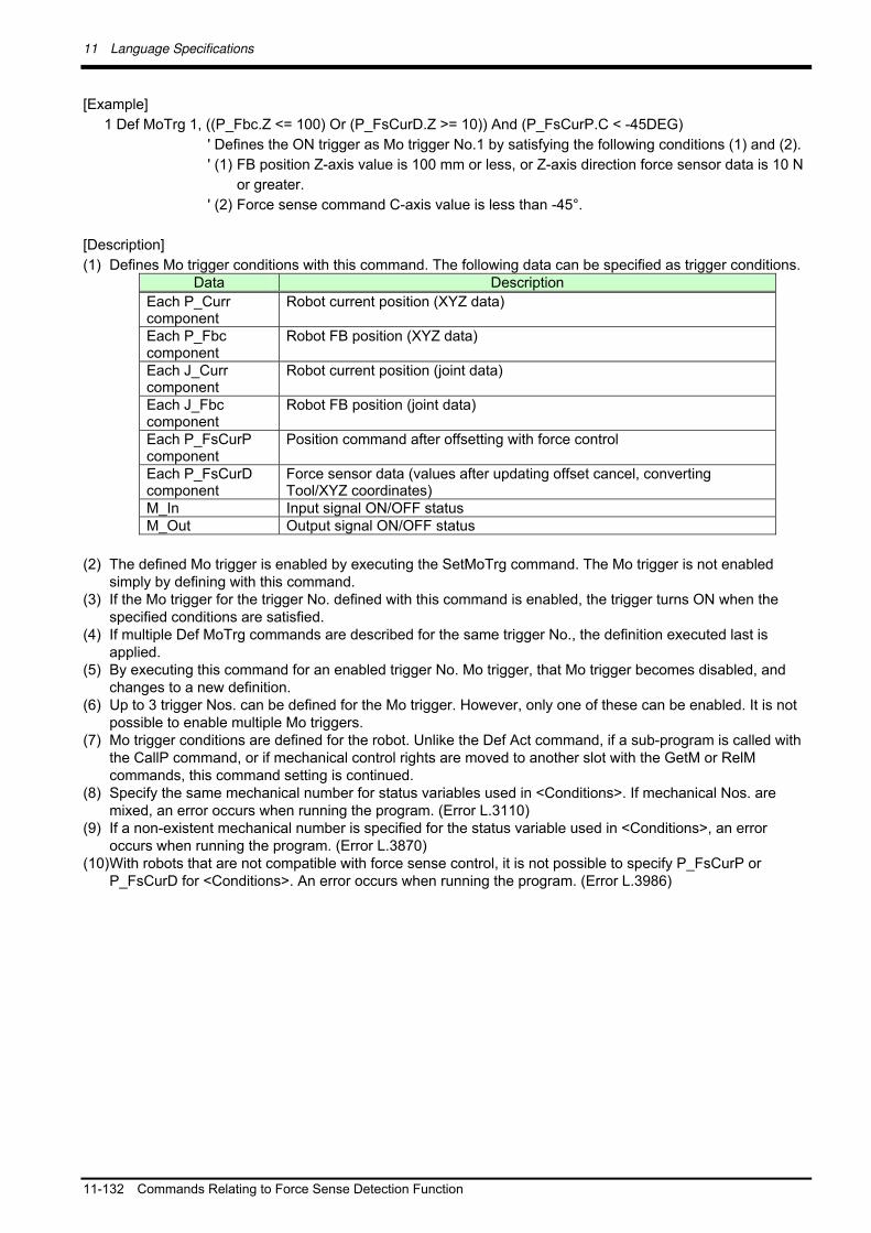
11 Language Specifications
11-132 Commands Relating to Force Sense Detection Function
[Example]
1 Def MoTrg 1, ((P_Fbc.Z <= 100) Or (P_FsCurD.Z >= 10)) And (P_FsCurP.C < -45DEG)
' Defines the ON trigger as Mo trigger No.1 by satisfying the following conditions (1) and (2).
' (1) FB position Z-axis value is 100 mm or less, or Z-axis direction force sensor data is 10 N
or greater.
' (2) Force sense command C-axis value is less than -45°.
[Description]
(1) Defines Mo trigger conditions with this command. The following data can be specified as trigger conditions. Data Description
Each P_Curr component
Robot current position (XYZ data)
Each P_Fbc component
Robot FB position (XYZ data)
Each J_Curr component
Robot current position (joint data)
Each J_Fbc component
Robot FB position (joint data)
Each P_FsCurP component
Position command after offsetting with force control
Each P_FsCurD component
Force sensor data (values after updating offset cancel, converting Tool/XYZ coordinates)
M_In Input signal ON/OFF status M_Out Output signal ON/OFF status
(2) The defined Mo trigger is enabled by executing the SetMoTrg command. The Mo trigger is not enabled simply by defining with this command.
(3) If the Mo trigger for the trigger No. defined with this command is enabled, the trigger turns ON when the specified conditions are satisfied.
(4) If multiple Def MoTrg commands are described for the same trigger No., the definition executed last is applied.
(5) By executing this command for an enabled trigger No. Mo trigger, that Mo trigger becomes disabled, and changes to a new definition.
(6) Up to 3 trigger Nos. can be defined for the Mo trigger. However, only one of these can be enabled. It is not possible to enable multiple Mo triggers.
(7) Mo trigger conditions are defined for the robot. Unlike the Def Act command, if a sub-program is called with the CallP command, or if mechanical control rights are moved to another slot with the GetM or RelM commands, this command setting is continued.
(8) Specify the same mechanical number for status variables used in <Conditions>. If mechanical Nos. are mixed, an error occurs when running the program. (Error L.3110)
(9) If a non-existent mechanical number is specified for the status variable used in <Conditions>, an error occurs when running the program. (Error L.3870)
(10) With robots that are not compatible with force sense control, it is not possible to specify P_FsCurP or P_FsCurD for <Conditions>. An error occurs when running the program. (Error L.3986)

11 Language Specifications
Commands Relating to Force Sense Detection Function 11-133
SetMoTrg (Set Mo trigger)
[Function]
Enables/disables trigger conditions (Mo trigger) that reference position commands and the FB position, as
well as force sensor data and so on.
[Syntax]
SetMoTrg <Trigger No.>
[Terminology]
<Trigger No.> Specifies the trigger No. for the Mo trigger to be enabled with a constant.
If 0 is specified, the Mo. Trigger is disabled.
Setting range: 0 - 3
[Example]
1 Def MoTrg 1, ((P_Fbc.Z <= 100) Or (P_FsCurD.Z >= 10)) And (P_FsCurP.C < -45DEG)
2 SetMoTrg 1 ' Enables Mo trigger No.1.
:
:
100 SetMoTrg 0 ' Disables the Mo trigger.
[Description]
(1) The Mo trigger is enabled/disabled with this command. (2) It is not possible to enable multiple Mo triggers simultaneously. If this command is executed consecutively,
the Mo trigger enabled last is applied. (3) When performing force sense control characteristics change processing (FsCTrg command) using an Mo
trigger, it is not possible to enable the Mo trigger with this command. An error occurs when running the program. (Error L.3987) The Mo trigger can be disabled.
(4) If the specified Mo trigger No. has not been defined, an error occurs when running the program. (Error L3770)
(5) If an End command is executed for the slot for which the trigger is enabled with this command, or if the program reset operation is performed, the Mo trigger will be disabled.
(6) Mo trigger conditions are defined for the robot. Unlike the Def Act command, if a sub-program is called with the CallP command, or if mechanical control rights are moved to another slot with the GetM or RelM commands, the Mo trigger conditions continue to apply.
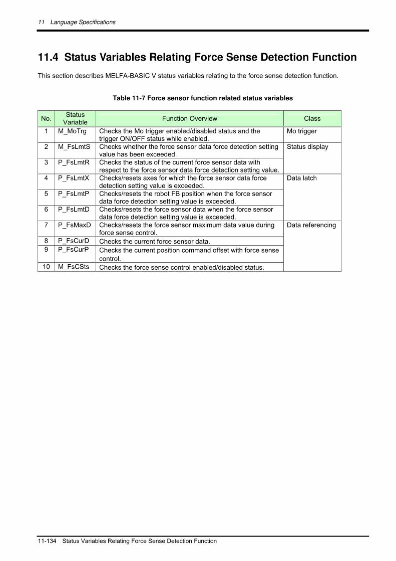
11 Language Specifications
11-134 Status Variables Relating Force Sense Detection Function
11.4 Status Variables Relating Force Sense Detection Function
This section describes MELFA-BASIC V status variables relating to the force sense detection function.
Table 11-7 Force sensor function related status variables
No. Status
Variable Function Overview Class
1 M_MoTrg Checks the Mo trigger enabled/disabled status and the trigger ON/OFF status while enabled.
Mo trigger
2 M_FsLmtS Checks whether the force sensor data force detection setting value has been exceeded.
3 P_FsLmtR Checks the status of the current force sensor data with respect to the force sensor data force detection setting value.
Status display
4 P_FsLmtX Checks/resets axes for which the force sensor data force detection setting value is exceeded.
5 P_FsLmtP Checks/resets the robot FB position when the force sensor data force detection setting value is exceeded.
6 P_FsLmtD Checks/resets the force sensor data when the force sensor data force detection setting value is exceeded.
Data latch
7 P_FsMaxD Checks/resets the force sensor maximum data value during force sense control.
8 P_FsCurD Checks the current force sensor data. 9 P_FsCurP Checks the current position command offset with force sense
control. 10 M_FsCSts Checks the force sense control enabled/disabled status.
Data referencing

11 Language Specifications
Status Variables Relating Force Sense Detection Function 11-135
M_MoTrg
[Function]
Checks the Mo trigger enabled/disabled status and the trigger ON/OFF status while enabled.
[Syntax]
Example) <Numerical variable>= M_MoTrg (<Trigger No.>)
[Terminology]
<Trigger No.> Specifies the Mo trigger No. being checked with a constant.
Setting range: 1 - 3
<Numerical variable>
Reads the Mo trigger defined/undefined status, enabled/disabled status, and trigger
ON/OFF status while enabled, and specifies the save destination.
[Example]
100 If M_MoTrg(2) = -2 Then 'If Mo trigger No.2 undefined:
101 Def MoTrg 2, P_Fbc.X > 500 ' Defines Mo trigger No.2,
102 SetMoTrg 2 ' Enables Mo trigger No.2.
103 EndIf
[Description]
(1) Checks the MO trigger defined/undefined status, enabled/disabled status, and trigger ON/OFF status while
enabled.
(2) If the Mo trigger is enabled and the defined conditions are satisfied, "+1" is returned, and if not satisfied, "0"
is returned.
(3) If the Mo trigger is disabled, "-1" is returned.
(4) If the Mo trigger is undefined, "-2" is returned.
(5) Immediately after turning ON the power, "-2" (undefined) is returned.
Details Value Defined/Undefined
Status Enabled/Disabled
Status Trigger ON/OFF
Status
+1 Defined Enabled ON 0 Defined Enabled OFF -1 Defined Disabled ―― -2 Undefined ―― ――

11 Language Specifications
11-136 Status Variables Relating Force Sense Detection Function
M_FsLmtS
[Function]
Checks whether the force sensor data force detection setting value has been exceeded.
[Syntax]
Example) <Numerical variable>= M_FsLmtS
[Terminology]
<Numerical variable>
Specifies the read numerical variable for determining whether the force detection setting value has been
exceeded.
(1: Force detection setting value exceeded, 0: Force detection setting value not exceeded)
[Example]
Refer to examples in section 11.7
[Description]
(1) Displays whether the absolute value of the force sensor data has exceeded the force detection setting
value. Displays 1 if exceeded, and 0 if not exceeded.
(2) If there is more than one axis for which the force detection setting value has been exceeded, 1 is output.
(3) The default status (when power ON) is 0. The value changes to 1 when the force detection setting value is
exceeded while the force sense control function is enabled, and returns to 0 when no axes exceed the force
detection setting value, or when force sense control is disabled.
(4) The value is always 0 if the force sensor is not connected.
(5) If movement is stopped when the force detection setting value is exceeded during automatic operation, it
can be used as the interrupt processing condition to stop the movement.
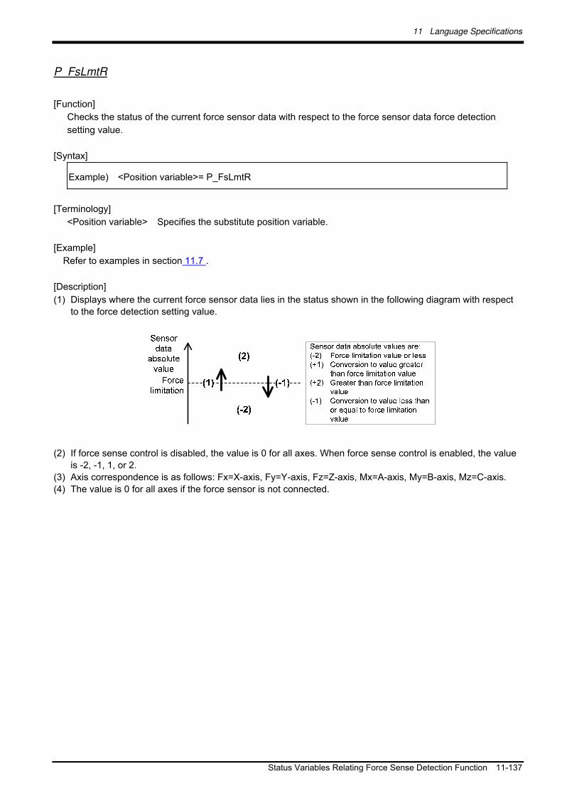
11 Language Specifications
Status Variables Relating Force Sense Detection Function 11-137
P_FsLmtR
[Function]
Checks the status of the current force sensor data with respect to the force sensor data force detection
setting value.
[Syntax]
Example) <Position variable>= P_FsLmtR
[Terminology]
<Position variable> Specifies the substitute position variable.
[Example]
Refer to examples in section 11.7 .
[Description]
(1) Displays where the current force sensor data lies in the status shown in the following diagram with respect
to the force detection setting value.
(2) If force sense control is disabled, the value is 0 for all axes. When force sense control is enabled, the value
is -2, -1, 1, or 2.
(3) Axis correspondence is as follows: Fx=X-axis, Fy=Y-axis, Fz=Z-axis, Mx=A-axis, My=B-axis, Mz=C-axis.
(4) The value is 0 for all axes if the force sensor is not connected.

11 Language Specifications
11-138 Status Variables Relating Force Sense Detection Function
P_FsLmtX
[Function]
Checks/resets axes for which the force sensor data force detection setting value is exceeded.
[Syntax]
Example) <Position variable>= P_FsLmtX
Example) P_FsLmtX =<Position variable>
[Terminology]
<Position variable> Specifies the substitute position variable.
[Example]
Refer to examples in section 11.7 .
[Description]
(1) Displays whether the force sensor data's absolute value has exceeded the force detection setting value.
Displays 1 if exceeded, and 0 if not exceeded. If any axes exist for which the value has been exceeded
even once, 1 is set for the corresponding axis element. 0 is set for axes for which the value has not been
exceeded. The value is retained until reset.
(2) Axis correspondence is as follows: Fx=X-axis, Fy=Y-axis, Fz=Z-axis, Mx=A-axis, My=B-axis, Mz=C-axis.
(3) The default status (when power ON) is 0 for all axes. A value is set when the force detection setting value is
exceeded while the force sense control function is enabled, and that value is then reset to 0 for all axes in
the following cases.
When force sense control is enabled. (Execute the Fsc On command and enable force sense control
with the teaching pendant.)
When the robot servo is turned from OFF to ON while force sense control is enabled.
When operation (4) below is performed.
(4) By substituting a position variable (any position variable value is okay) for P_FsLmtX, the value can be
reset. By resetting, the P_FsLmtP and P_FsLmtD values are reset simultaneously.
(5) The value is 0 for all axes if the force sensor is not connected.

11 Language Specifications
Status Variables Relating Force Sense Detection Function 11-139
P_FsLmtP
[Function]
Checks/resets the robot FB position when the force sensor data force detection setting value is exceeded.
[Syntax]
Example) <Position variable>= P_FsLmtP
Example) P_FsLmtP =<Position variable>
[Terminology]
<Position variable> Specifies the substitute position variable.
[Example]
Refer to examples in section 11.7 .
[Description]
(1) Checks robot position feedback when the force sensor data's absolute value exceeds the force detection
setting value for the first time.
(2) The default status (when power ON) is 0 for all axes. A value is set when the force detection setting value is
exceeded while the force sense control function is enabled, and that value is then reset to 0 for all axes in
the following cases.
When force sense control is enabled. (Execute the Fsc On command and enable force sense control
with the teaching pendant.)
When the robot servo is turned from OFF to ON while force sense control is enabled.
When operation (3) below is performed.
(3) By substituting a position variable (any position variable value is okay) for P_FsLmtP, the value can be
reset. By resetting, the P_FsLmtX and P_FsLmtD values are reset simultaneously.
(4) The value is 0 for all axes if the force sensor is not connected.

11 Language Specifications
11-140 Status Variables Relating Force Sense Detection Function
P_FsLmtD
[Function]
Checks/resets the force sensor data when the force sensor data force detection setting value is exceeded.
[Syntax]
Example) <Position variable>= P_FsLmtD
Example) P_FsLmtD =<Position variable>
[Terminology]
<Position variable> Specifies the substitute position variable.
[Example]
300 If P_FsLmtX.X=1 Then P_FsFLmt.X=P_FsLmtD.X * 0.8 'If X-direction sensor data exceeds the force
detection setting value:
'80% of the exceeded value is set as the new force detection setting value.
[Description]
(1) Checks force sensor data when the force sensor data's absolute value exceeds the force detection setting
value for the first time.
(2) The default status (when power ON) is 0 for all axes. A value is set when the force detection setting value is
exceeded while the force sense control function is enabled, and that value is then reset to 0 for all axes in
the following cases.
When force sense control is enabled. (Execute the Fsc On command and enable force sense control
with the teaching pendant.)
When the robot servo is turned from OFF to ON while force sense control is enabled.
When operation (3) below is performed.
(3) By substituting (any position variable value is okay) a position variable for P_FsLmtD, the value can be
reset. By resetting, the P_FsLmtX and P_FsLmtP values are reset simultaneously.
(4) The value is 0 for all axes if the force sensor is not connected.

11 Language Specifications
Status Variables Relating Force Sense Detection Function 11-141
P_FsMaxD
[Function]
Checks/resets the force sensor maximum data value during force sense control.
[Syntax]
Example) <Position variable>= P_FsMaxD
Example) P_FsMaxD =<Position variable>
[Terminology]
<Position variable> Specifies the substitute position variable.
[Example]
1000 P1=P_FsMaxD 'In P1, retains maximum force sensor data value up to this point.
1010 P_FsMaxD=P1 'Resets the maximum value.
[Description]
(1) Displays the force sensor data maximum value (maximum absolute value). (Maximum value of each axis is
retained.)
(2) The default status (when power OFF) is 0 for all axes. A value is set regardless of the force sense control
function enabled/disabled status, and that value is retained when a value (any position variable value is
okay) is substituted for P_FsMaxD and offset cancel is performed, or until the maximum value is reset with
the T/B.
(3) The value is always 0 for all axes if the force sensor is not connected.

11 Language Specifications
11-142 Status Variables Relating Force Sense Detection Function
P_FsCurD
[Function]
Checks the current force sensor data.
[Syntax]
Example) <Position variable>= P_FsCurD
[Terminology]
<Position variable> Specifies the substitute position variable.
[Example]
100 Def Act 1, P_FsCurD.Z > 10 GoTo *INTR1, S
'If the Z-direction sensor data exceeds 10 N, an interrupt used to perform interrupt processing
*INTR1 is defined.
200 M_DOut(6000)=P_FsCurD.X * 100
'Multiplies the X-axis sensor data value by 100 (converts unit to 0.01 N).
'Writes to CC-Link output register 6000.
[Description]
(1) Displays the current force sensor data.
(2) Force sensor data converted to the tool coordinate direction is normally displayed; however, if force sense
control is enabled in XYZ coordinate mode, force sensor data converted to the XYZ coordinate direction is
displayed. Furthermore, the offset cancel (zero point offset) result is updated.
(3) The current force sensor data can be checked even if the force sense control function is disabled.
(4) The value is always 0 for all axes if the force sensor is not connected.

11 Language Specifications
Status Variables Relating Force Sense Detection Function 11-143
P_FsCurP
[Function]
Checks the position (force sense position command) offset with force sense control.
(Force sense position command = Position command calculated with movement command, etc. + position
offset with force sense control)
[Syntax]
Example) <Position variable>= P_FsCurP
[Terminology]
<Position variable> Specifies the substitute position variable.
[Example]
2000 PD=P_Curr – P_FsCurP
'Outputs the difference between the position command and force sense position command.
2010 MD=Sqr(PD.X*PD.X + PD.Y*PD.Y + PD.Z*PD.Z)
'Outputs the interpolation distance.
[Description]
(1) Checks the position offset with force sense control.
(2) If the force sense control function is disabled, the same value as P_Curr (position command) is output if the
force sensor is not connected.

11 Language Specifications
11-144 Status Variables Relating Force Sense Detection Function
M_FsCSts
[Function]
Checks the force sense control enabled/disabled status.
[Syntax]
Example) <Numerical variable>= M_FsCSts
[Terminology]
<Numerical variable> Specifies the substitute numerical variable.
(1: Force sense control enabled, 0: Force sense control disabled)
[Example]
2000 If M_FsCSts=1 Then Fsc Off 'Disables force sense control if enabled.
[Description]
(1) Checks the force sense control enabled/disabled status.
(2) The value is 1 if force sense control is enabled, and 0 if disabled.
(3) If force sense control is enabled, the status will be enabled (1) even if the servo is OFF.

11 Language Specifications
Commands Relating to Force Sense Log Function 11-145
11.5 Commands Relating to Force Sense Log Function
This section describes MELFA-BASIC V status variables relating to the log function.
Table 11-8: Log function commands
No. Command Function Overview
1 FsLog On Starts force sensor data and position command, position FB, and current FB value logging.
2 FsLog Off Ends force sensor data and position command, position FB, and current FB value logging.
3 FsOutLog Reads logged data using FTP.
FsLog On
[Function]
Starts force sensor data and position command, position FB, and current FB value logging.
[Syntax]
FsLogOn
[Example]
Refer to examples in section 11.7 .
[Description]
(1) Collects the force sensor data and position command, position FB, and current FB value.
(2) Data collection is ended 45s after the completion of this command, or when the FsLog Off command is
executed.
(3) This command cannot be executed again during data collection. (Error L3987 occurs.)
(4) If the force sensor is not connected, no processing is performed when this command is executed.
(5) If the log function is disabled (parameter FSLOGFN 1st element is 0), no processing is performed when this
command is executed.
11 Language Specifications
11-146 Commands Relating to Force Sense Log Function
FsLog Off
[Function]
Ends force sensor data and position command, position FB, and current FB value logging.
[Syntax]
FsLogOff <Log File No.>
[Terminology]
<Log File No.> Specifies the log file No. containing collected data.
Setting range: 1 to 999999999
[Example]
Refer to examples in section 11.7 .
[Description]
(1) Ends collection of the force sensor data and position command, the position FB, and the current FB value,
and creates a log file with the name specified for the log file No.
(2) If the force sensor is not connected, no processing is performed when this command is executed.
(3) No processing is performed if this command is executed without executing the FsLog On command.
(4) If the log function is disabled (parameter FSLOGFN 1st element is 0), no processing is performed when this
command is executed.
(5) If 45s elapses after the execution of FsLog On command before executing this command, data collection
stops automatically. However, log files are not created without executing this command.
(6) Up to 2 log files can be stored in the controller. If the number of files stored exceeds 2, the file with oldest
creation data is deleted.
(7) If a log file No. the same as an existing log file is specified, the existing file is overwritten with the new file
and saved.
(8) If the log file size becomes larger than the file creation area during creation, data toward the end may be cut
off.
11 Language Specifications
Commands Relating to Force Sense Log Function 11-147
FsOutLog
[Function]
Transfers logged data to the FTP server.
[Syntax]
FsOutLog <Log File No.>
[Terminology]
<<Log File No.> Specifies the No. of the log file from which collected data is to be read.
Setting range: 1 to 999999999
[Example]
Refer to examples in section 11.7 .
[Description]
(1) Outputs CSV format log files created with the FsLog Off command to the FTP server.
(2) The file name of the file output to the FTP server is "f<log file No.>.fsl".
(3) Log files successfully transferred to the FTP server are deleted from the robot controller.
If FTP transfer fails, error L3987 occurs and the log file is not deleted.
(4) Error L3987 occurs if the log file for the specified No. does not exist.
(5) If the force sensor is not connected, no processing is performed when this command is executed.
(6) If the log function is disabled (parameter FSLOGFN 1st element is 0), or FTP is not used (parameter
FSLOGFN 3rd element is 0), no processing is performed when this command is executed.
(7) If the log file size becomes larger than the file creation area during creation, data toward the end may be cut
off.
(8) The maximum log file size is approximately 1.8 MB. Depending on the file size, FTP communication may
take several tens of seconds.
(9) If FTP communication fails, error L3987 (failed to output log file) occurs maximum of approximately 75
seconds after executing the FsOutLog command. In such a case, check the following again and reboot the
robot controller.
Parameter (FTPID, FTPPASS, FTPSVRIP) settings relating to FTP communication
Condition of network between robot controller and FTP server
Settings and startup status at FTP server

11 Language Specifications
11-148 Other Related Commands
11.6 Other Related Commands
Def Act
[Function]
Defines the interrupt conditions and processing for interrupt processing. Interrupts are used when input
signals and so on are monitored while running programs to prioritize certain processing when the specified
conditions are reached
* "F" (force sense stop) has been added to the argument <Type> for force sense control.
[Syntax]
DefAct <Priority No.>, <Format>, <Processing> [, <Type>]
[Terminology]
<Priority No.> This is the interrupt priority No. and sets Nos. 1 to 8 with a constant.
<Format> This function is described with the following formats as the interrupt conditions.
<Numerical data> <Comparison operator> <Numerical data> or,
<Numerical data> <Logic operator> <Numerical data>
* <Numerical data> refers to the following:
<Numeric constant>│<Numeric variable>│<Numeric array constant>│<Component data>
<Processing> Describes the GoTo or GoSub statement required for processing when an interrupt
occurs.
<Type> Omission: Stop type 1
Stops at the stop position assuming an external override of 100%.
It takes longer to stop if the external override is small, and so the robot always
stops at the same position.
S: Stop type 2
Not dependent on the external override, and the robot decelerates to a stop
over the minimum time and distance.
L: Execution complete stop
Performs interrupt processing after the robot has moved (1 line is completed
during execution) to its target position.
F: Force sense stop
Not dependent on the external override, and the robot decelerates to a stop
over the minimum time and distance.
If force sense control is enabled, the robot stops immediately when the robot
movement speed linear component is 50 [mm/s] or less, and the rotational
component is 50 [deg/s] or less.
If force sense control is disabled, the robot decelerates to a stop in the same manner as
that for Stop type 2 (S).

11 Language Specifications
Other Related Commands 11-149
* Additional axes decelerate to a stop in the same manner as that for Stop type 2 (S),
regardless of whether force sense control is enabled or disabled.
* If stopped with a Force sense stop (F), force sense control is disabled (including servo
OFF), or position offset with force sense control is fixed at the stopped status until the
interrupt is prohibited with "Act <Priority No.>=0".
* Use upper case alphabet characters for the <Type>.
If lower case alphabet characters are used, an error occurs when registering. (Error
L.4220)
[Example]
1 Def Act 1,M_In(17)=1 GoSub *L100 ' When the input signal for general purpose input signal No. 17
turns ON,
' this defines that the *L100 (step No. 10) sub-routine
' is called.
2 Def Act 2,MFG1 And MFG2 GoTo *L200 ' If logical products MFG1 and MFG2 become true,
' this defines a jump to *L200 (step No. 20).
3 Def Act 3,M_Timer(1)>10500 GoSub *LBL ' Jumps to *LBL (step No. 30) sub-routine after 10.5 seconds
' has elapsed.
:
10 *L100:M_Timer(1)=0 ' Sets the timer to zero.
11 Act 3=1 ' Enables Act 3.
12 Return 0
:
20 *L200:Mov P_Safe
21 End
:
30 *LBL
31 M_Timer(1)=0 ' Returns the timer to zero.
32 Act 3=0 ' Disables Act 3.
32 Return 0
[Description]
(1) Describes a Return command at the end of the jump destination processing called with the interrupt.
(2) If returned to the next step from interrupt processing with Return 1, prohibit interrupts in the interrupt
processing. If interrupts are not prohibited and interrupt conditions are left established, interrupt processing
is performed again before returning to the next step, and therefore there are times when steps are skipped
without being executed.
(3) The interrupt priority sequence is fixed with the <Priority No.>, and the priority rises in the order 1 to 8 as the
number increases.
(4) Up to 8 interrupts can be set simultaneously, and are distinguished by <Priority No.>.
(5) Only a simple <Logic operator> or <Comparison operator> can be used for <Format>. Parentheses
(operator) cannot be used either.
(6) If a Def Act command for the same priority No. is described, the latter defined command is enabled.
(7) The Def Act command is used only to define interrupts, and therefore interrupt permission/prohibition should
be specified with the Act command.
(8) Priority for communication interrupts (Com) is even higher than for interrupts defined with the Def Act
command.
(9) The Def Act command is only valid within the defined program. If using interrupt processing in programs
(sub-programs) called with the CallP command (call between programs), it is necessary to redefine
processing at the sub-program.
(10) If an interrupt occurs when a GoTo command is specified in <Processing> with the Def Act command,
interrupts being processed while executing subsequent programs are left as is, and only interrupts with high
priority are received. Processing of interrupts with the GoTo command is cancelled by executing the End

11 Language Specifications
11-150 Other Related Commands
command.
(11) It is not possible to describe a condition format combined with a log operator such as in (M1 And &H001) =
1.
(12) If an interrupt is entered while performing perfect circle interpolation or circular interpolation (Mvc, Mvr,
Mvr2, Mvr3) and control is returned to the original step with Return 0, the robot returns to the perfect circle
or circular interpolation start point before once again performing circular or arc interpolation.
(13) If an interrupt is entered while performing arch interpolation and control is returned to the original step with
Return 0, the robot performs arch interpolation from the position at that time.
[Related commands]
Act
Set the interrupt stop type correctly based on the application.
If wishing to stop the robot with an interrupt over the minimum time and distance
when executing a movement command, specify "S" for the Stop type.
Caution
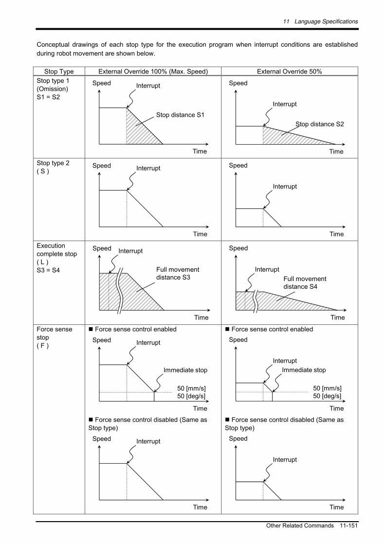
11 Language Specifications
Other Related Commands 11-151
Conceptual drawings of each stop type for the execution program when interrupt conditions are established
during robot movement are shown below.
Stop Type External Override 100% (Max. Speed) External Override 50%
Stop type 1
(Omission)
S1 = S2
Speed
Time
Interrupt
Stop distance S1
Speed
Time
Interrupt
Stop distance S2
Stop type 2
( S ) Speed
Time
Interrupt
Speed
Time
Interrupt
Execution
complete stop
( L )
S3 = S4
Speed
Time
Interrupt
Full movement distance S3
Speed
Time
Interrupt
Full movement distance S4
Force sense
stop
( F )
Force sense control enabled
Speed
Time
Interrupt
50 [mm/s]50 [deg/s]
Immediate stop
Force sense control disabled (Same as
Stop type)
Speed
Time
Interrupt
Force sense control enabled
Speed
Time
Interrupt
50 [mm/s]50 [deg/s]
Immediate stop
Force sense control disabled (Same as
Stop type)
Speed
Time
Interrupt

11 Language Specifications
11-152 Examples
11.7 Examples
Several force sense control program examples are shown below.
Example 1 Sample Program FB01.prg
The robot searches for the target object while moving in the Y-axis direction. When the object is found, the robot
moves in the X-axis direction while applying a constant force in the target object Y-direction.
対象物を検知
N 押し 動作
'Control mode ( 0 ) setting
P_FsStf0=(+0.00,+0.01,+0.00,+0.00,+0.00,+0.00)(0,0) 'Stiffness coefficient (Specifies Y-axis component as 0.01 [N/mm])
P_FsDmp0=(+0.00,+0.00,+0.00,+0.00,+0.00,+0.00)(0,0) 'Damping coefficient (no specification)
P_FsMod0=(+0.00,+1.00,+0.00,+0.00,+0.00,+0.00)(0,0) 'Force sense control type (Specifies force control in Y-axis direction.)
M_FsCod0=1 'Force sense coordinate system (Specifies XYZ coordinate system.)
'
'Control characteristics ( 0 ) setting
P_FsGn0=(+0.00,+1.00,+0.00,+0.00,+0.00,+0.00)(0,0) 'Gain (Specifies Y-direction as 1.0 [10-3
mm/N].)
P_FsFLm0=(+20.00,+0.50,+20.00,+5.00,+5.00,+5.00)(0,0) 'Force detection setting value (Specifies Y-axis direction as 0.5 [N].)
P_FsFCd0=(+0.00,+2.00,+0.00,+0.00,+0.00,+0.00)(0,0) 'Force control (Specifies Y-axis direction as 2.0 [N].)
'
Def Act 1,M_FsLmtS=1 GoTo *XMOV,S 'Defines so that interrupt processing performed if force detection setting value exceeded.
FsLog On 'Starts collecting force sense log.
Fsc On,0,0,1 'Enables force sense control with control mode=0, control characteristics =0, and offset cancel enabled.
P1=P_Curr
P1.Y=P1.Y+200
Spd 5
Act 1=1
Mvs P1 'Performs interrupt processing if contact with the target object is made during movement.
Fsc Off 'Disables force sense control.
FsLog Off,7 'Ends force sense log collection and creates log file No.7.
Act 1=0
End
'
'Interrupt processing
*XMOV
P2=P_FsCurPr
P2.X=P2.X+100 'Sets position +100 mm in X-axis direction from current position as target position.
FsGChg 5,100,2 'Changes the gain to the control characteristics 2 (parameter) setting value over 100 ms from the interpolation progress
'rate 5% position.
Mvs P2 'Moves in the X-axis direction while applying 2.0 [N] of force in the Y-axis direction.
Fsc Off 'Disables force sense control.
FsLog Off,7 ' Ends force sense log collection and creates log file No.7.
FsOutLog 7 'Transfers log file No.7 to the computer by FTP.
End
Detects target object.
Moves while pushing with 2 N.
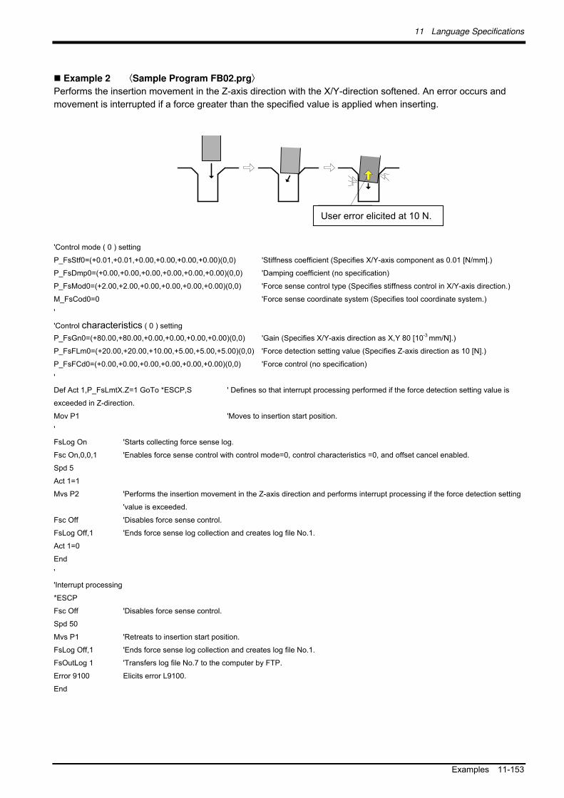
11 Language Specifications
Examples 11-153
Example 2 Sample Program FB02.prg
Performs the insertion movement in the Z-axis direction with the X/Y-direction softened. An error occurs and
movement is interrupted if a force greater than the specified value is applied when inserting.
N ユエラ を発生
'Control mode ( 0 ) setting
P_FsStf0=(+0.01,+0.01,+0.00,+0.00,+0.00,+0.00)(0,0) 'Stiffness coefficient (Specifies X/Y-axis component as 0.01 [N/mm].)
P_FsDmp0=(+0.00,+0.00,+0.00,+0.00,+0.00,+0.00)(0,0) 'Damping coefficient (no specification)
P_FsMod0=(+2.00,+2.00,+0.00,+0.00,+0.00,+0.00)(0,0) 'Force sense control type (Specifies stiffness control in X/Y-axis direction.)
M_FsCod0=0 'Force sense coordinate system (Specifies tool coordinate system.)
'
'Control characteristics ( 0 ) setting
P_FsGn0=(+80.00,+80.00,+0.00,+0.00,+0.00,+0.00)(0,0) 'Gain (Specifies X/Y-axis direction as X,Y 80 [10-3
mm/N].)
P_FsFLm0=(+20.00,+20.00,+10.00,+5.00,+5.00,+5.00)(0,0) 'Force detection setting value (Specifies Z-axis direction as 10 [N].)
P_FsFCd0=(+0.00,+0.00,+0.00,+0.00,+0.00,+0.00)(0,0) 'Force control (no specification)
'
Def Act 1,P_FsLmtX.Z=1 GoTo *ESCP,S ' Defines so that interrupt processing performed if the force detection setting value is
exceeded in Z-direction.
Mov P1 'Moves to insertion start position.
'
FsLog On 'Starts collecting force sense log.
Fsc On,0,0,1 'Enables force sense control with control mode=0, control characteristics =0, and offset cancel enabled.
Spd 5
Act 1=1
Mvs P2 'Performs the insertion movement in the Z-axis direction and performs interrupt processing if the force detection setting
'value is exceeded.
Fsc Off 'Disables force sense control.
FsLog Off,1 'Ends force sense log collection and creates log file No.1.
Act 1=0
End
'
'Interrupt processing
*ESCP
Fsc Off 'Disables force sense control.
Spd 50
Mvs P1 'Retreats to insertion start position.
FsLog Off,1 'Ends force sense log collection and creates log file No.1.
FsOutLog 1 'Transfers log file No.7 to the computer by FTP.
Error 9100 Elicits error L9100.
End
User error elicited at 10 N.

11 Language Specifications
11-154 Examples
Example 3 Sample Program FB03.prg
Searches for open holes on the XY plane. If a hole is found, the XY coordinates for the holes center position are
calculated.
穴を探索
方向 動作し接触位置
中心位置を算出
*071
'Control mode ( 0 ) setting
P_FsStf0=(+0.00,+0.00,+1.00,+0.00,+0.00,+0.00)(0,0) 'Stiffness coefficient (Specifies Z-axis component as 1 [N/mm].)
P_FsDmp0=(+0.00,+0.00,+0.00,+0.00,+0.00,+0.00)(0,0) 'Damping coefficient (no specification)
P_FsMod0=(+0.00,+0.00,+2.00,+0.00,+0.00,+0.00)(0,0) 'Force sense control type (Specifies stiffness control in Z-axis direction.)
M_FsCod0=1 'Force sense coordinate system (Specifies XYZ coordinate system.)
'
'Control characteristics ( 0 ) setting
P_FsGn0=(+0.00,+0.00,+40.00,+0.00,+0.00,+0.00)(0,0) 'Gain (Specifies Z-axis direction as 40 [10-3
mm/N].)
P_FsFLm0=(+20.00,+20.00,+5.00,+5.00,+5.00,+5.00)(0,0) 'Force detection setting value (Specifies Z-axis direction as 5 [N].)
P_FsFCd0=(+0.00,+0.00,+0.00,+0.00,+0.00,+0.00)(0,0) 'Force control (no specification)
'
Def Act 1,P_FsLmtR.Z=1 GoTo *PCEN,S 'Defines so that interrupt processing is performed if the Z-axis direction
becomes smaller than force detection setting value.
P2=P1
P2.X=P2.X+100 'Searches for width of 100 mm in X-direction.
Fsc On,0,0,1 'Enables force sense control with control mode=0, control characteristics =0, and offset cancel enabled.
Mvs P1 'Moves to search start position (Moves approximately -10 mm in the Z-axis direction from the search plane to
a low position, and then pushes in the Z-direction.)
'
Spd 5
Act 1=1
For M1=1 To 10 'Searches in 5 mm intervals in the Y-direction. Force is lost in the Z-axis direction if the robot axis drops into
a hole, and therefore an interrupt is entered.
Mvs P1
Mvs P2
P1.Y=P1.Y+5
P2.Y=P1.Y
Mvs P2
Mvs P1
P1.Y=P1.Y+5
P2.Y=P1.Y
Next M1
Act 1=0
Fsc Off
End
'
'Interrupt processing
*PCEN
Dim PX(2),PY(2)
P0=P_Curr 'The position at which the robot axis falls into the hole and stops is used as a reference.
PX(1)=P0
Robot moves in XY-direction and calculates center position from contact position.
Searches for open holes

11 Language Specifications
Examples 11-155
PX(2)=P0
PY(1)=P0
PY(2)=P0
PX(1).X=P0.X+10 'The position ±10 mm in the XY-direction from the reference position is calculated.
PX(2).X=P0.X-10
PY(1).Y=P0.Y+10
PY(2).Y=P0.Y-10
'
Fsc Off
P_FsFLm0=(+2.00,+2.00,+5.00,+5.00,+5.00,+5.00)(0,0) 'Changes the X,Y-axis direction force detection setting value to 2 [N].
Fsc On,0,0,1
MFLG=0
'
For M1=1 To 2
Mvs PX(M1) WthIf P_FsLmtR.X=1,Skip 'Moves ±10 mm in the X-axis direction and skips if the force detection setting is exceeded.
If M_SkipCq=1 Then
PX(M1)=P_FsLmtP 'If skipped, the position at which the force detection setting value is exceeded is retained.
MFLG=MFLG+1
EndIf
Mvs P0
Fsc Off 'Force sense control is temporarily enabled to reset P_FsLmtP.
Fsc On,0,0,1
Next M1
'
For M1=1 To 2
Mvs PY(M1) WthIf P_FsLmtR.Y=1,Skip ' Moves ±10 mm in the Y-axis direction and skips if the force detection setting is exceeded.
If M_SkipCq=1 Then
PY(M1)=P_FsLmtP 'If skipped, the position at which the force detection setting value is exceeded is retained.
MFLG=MFLG+1
EndIf
Mvs P0
Fsc Off ' Force sense control is temporarily enabled to reset P_FsLmtP.
Fsc On,0,0,1
Next M1
'
If MFLG=4 Then '4 points are found.
PTMP=(PX(1)+PX(2))/2
P0.X=PTMP.X 'The X-axis direction center position is set for P0.
PTMP=(PY(1)+PY(2))/2
P0.Y=PTMP.Y ' The Y-axis direction center position is set for P0.
Else '4 points are not found.
Error 9100 'Elicits error L9100.
EndIf
End
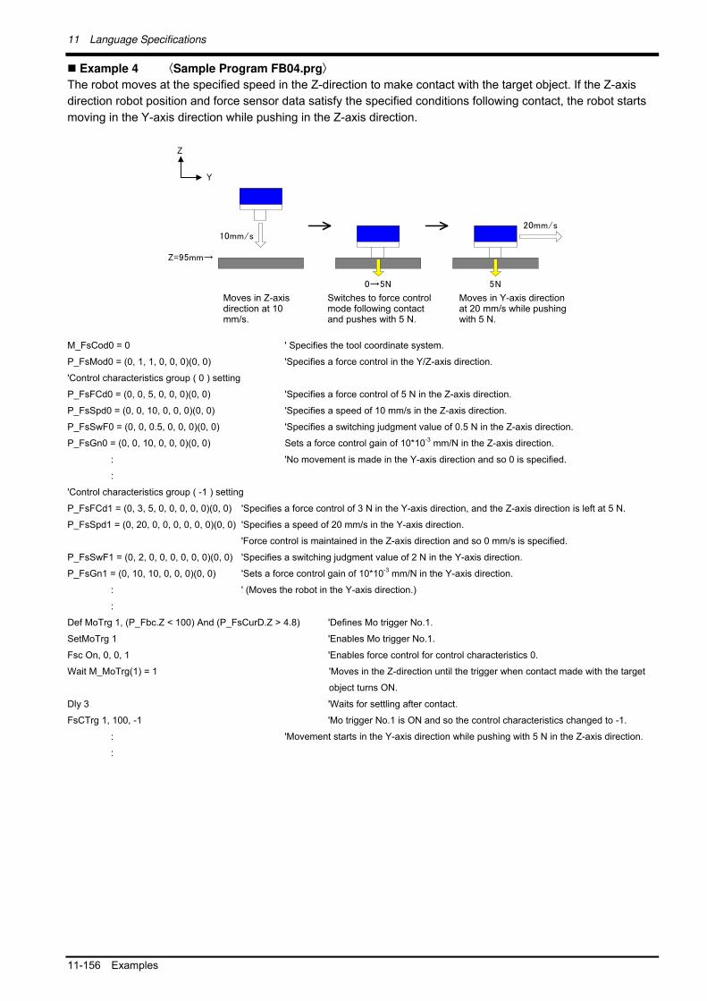
11 Language Specifications
11-156 Examples
Example 4 Sample Program FB04.prg
The robot moves at the specified speed in the Z-direction to make contact with the target object. If the Z-axis
direction robot position and force sensor data satisfy the specified conditions following contact, the robot starts
moving in the Y-axis direction while pushing in the Z-axis direction.
→5N
軸方向 動作接触 力制御モ
、5N 押し付け
=95 →
5N
5N 押し付けつつ、軸方向 動作
M_FsCod0 = 0 ' Specifies the tool coordinate system.
P_FsMod0 = (0, 1, 1, 0, 0, 0)(0, 0) 'Specifies a force control in the Y/Z-axis direction.
'Control characteristics group ( 0 ) setting
P_FsFCd0 = (0, 0, 5, 0, 0, 0)(0, 0) 'Specifies a force control of 5 N in the Z-axis direction.
P_FsSpd0 = (0, 0, 10, 0, 0, 0)(0, 0) 'Specifies a speed of 10 mm/s in the Z-axis direction.
P_FsSwF0 = (0, 0, 0.5, 0, 0, 0)(0, 0) 'Specifies a switching judgment value of 0.5 N in the Z-axis direction.
P_FsGn0 = (0, 0, 10, 0, 0, 0)(0, 0) Sets a force control gain of 10*10-3
mm/N in the Z-axis direction.
: 'No movement is made in the Y-axis direction and so 0 is specified.
:
'Control characteristics group ( -1 ) setting
P_FsFCd1 = (0, 3, 5, 0, 0, 0, 0, 0)(0, 0) 'Specifies a force control of 3 N in the Y-axis direction, and the Z-axis direction is left at 5 N.
P_FsSpd1 = (0, 20, 0, 0, 0, 0, 0, 0)(0, 0) 'Specifies a speed of 20 mm/s in the Y-axis direction.
'Force control is maintained in the Z-axis direction and so 0 mm/s is specified.
P_FsSwF1 = (0, 2, 0, 0, 0, 0, 0, 0)(0, 0) 'Specifies a switching judgment value of 2 N in the Y-axis direction.
P_FsGn1 = (0, 10, 10, 0, 0, 0)(0, 0) 'Sets a force control gain of 10*10-3
mm/N in the Y-axis direction.
: ' (Moves the robot in the Y-axis direction.)
:
Def MoTrg 1, (P_Fbc.Z < 100) And (P_FsCurD.Z > 4.8) 'Defines Mo trigger No.1.
SetMoTrg 1 'Enables Mo trigger No.1.
Fsc On, 0, 0, 1 'Enables force control for control characteristics 0.
Wait M_MoTrg(1) = 1 'Moves in the Z-direction until the trigger when contact made with the target
object turns ON.
Dly 3 'Waits for settling after contact.
FsCTrg 1, 100, -1 'Mo trigger No.1 is ON and so the control characteristics changed to -1.
: 'Movement starts in the Y-axis direction while pushing with 5 N in the Z-axis direction.
:
Moves in Z-axis direction at 10 mm/s.
Switches to force control mode following contact and pushes with 5 N.
Moves in Y-axis direction at 20 mm/s while pushing with 5 N.

12 Parameter Specifications
Force Sense Function Related Parameter List 12-157
12 Parameter Specifications
This Chapter describes parameters relating to the force sense function.
12.1 Force Sense Function Related Parameter List
Table 12-1 Force sense control related parameters
Parameter Parameter
Name No. of
Elements Description
Factory Default Setting
Force sense interface unit recognition
AXJNO 16 integers Sets the force sense interface unit or additional axis number for the element corresponding to the servo control axis number being used. <If using force sense interface unit> Servo control axis No.: Set "9" for axis No.1.
0, 0, 0, 0, 0, 0, 0, 0, 0, 0, 0, 0, 0, 0, 0, 0
AXMENO 16 integers Enter a mechanical number corresponding to the servo control axis number being used. Always set "0" for axes that are not being used.
0, 0, 0, 0, 0, 0, 0, 0, 0, 0, 0, 0, 0, 0, 0, 0
Calibration FSHAND 1 integer Selects the force sensor coordinate system hand system (left-hand system/right-hand system). The force sensor coordinate system hand system differs depending on the sensor attachment direction, and therefore it is necessary to change the setting based on the attachment direction. Set the left-hand system for recommended attachment.
0: Force sensor coordinate system left-hand system 1: Force sensor coordinate system right-hand system
<Left-hand system> <Right-hand system>
0
FSXTL 6 real numbers
Sets the positional relationship for the mechanical interface coordinate system and force sensor coordinate system.
1st element: X-axis direction coordinate system origin offset [mm] 2nd element: Y-axis direction coordinate system origin offset [mm] 3rd element: Z-axis direction coordinate system origin offset [mm] 4th element: Coordinate axis rotation angle around X-axis [deg] 5th element: Coordinate axis rotation angle around Y-axis [deg] 6th element: Coordinate axis rotation angle around Z-axis [deg]
0.0, 0.0, 0.0, 0.0, 180.0, 0.0 (vertical multi-joint robots) 0.0, 0.0, 0.0, 0.0, 0.0, 180.0 (horizontal multi-joint robots)
Force sensor tolerance
FSLMTMX 6 real numbers
Sets the force sensor tolerance. If sensor data exceeding the force and moment set at this parameter is detected, an error (H7660) occurs and the robot is stopped. (Force sense control will be disabled.)
1st element: Force sensor data Fx tolerance [N] 2nd element: Force sensor data Fy tolerance [N] 3rd element: Force sensor data Fz tolerance [N] 4th element: Force sensor data Mx tolerance [N·m] 5th element: Force sensor data My tolerance [N·m] 6th element: Force sensor data Mz tolerance [N·m]
0.0, 0.0, 0.0, 0.0, 0.0, 0.0, 0.0, 0.0

12 Parameter Specifications
12-158 Force Sense Function Related Parameter List
Parameter Parameter
Name No. of
Elements Description
Factory Default Setting
Force sense control offset limit
FSCORMX
2 real numbers
Sets the maximum position offset for force sense control. 1st element: Position maximum offset [mm] 2nd element: Posture maximum offset [deg.] [Setting range] 1st element: 0 to +200.0 2nd element: 0 to +150.0
10.0, 10.0
Force sensor data filter
FSFLCTL 1 real number
Sets the force sensor data filter time constant. [Unit]: ms
[Setting range]: 0 to +1000.0
1.7
Control mode FSCOD01 - 09
1 integer Specifies the force sense coordinate system. (See
section 8.1.2.1 .)
0: Tool coordinate system
1: XYZ coordinate system
[Setting range]: 0, 1
0
FSFMD01 - 09
8 integers Selects the force sense control mode for each
coordinate system axis. (See section 8.1.2.2 .)
0: Position control
1: Force control
2: Stiffness control
[Setting range]: 0, 1, 2
0, 0, 0, 0, 0, 0, 0, 0
FSSTF01 - 09
8 integers Sets the stiffness coefficient for force sense control
(stiffness control). (See section 8.1.2.3 .)
[Setting range]: 0.0 - 1000.0
[Setting unit]: X, Y , Z axes = N/mm
A ,B, C axes = N·m/deg
(This setting is not required for axes for which stiffness
control is not selected.)
0.0, 0.0, 0.0, 0.0, 0.0, 0.0, 0.0, 0.0
FSDMP01 - 09
8 real numbers
Sets the damping coefficient (responsiveness) for force
sense control. (See section 8.1.2.4 .)
[Setting range]: 0.0 - 1.0
[Setting unit]: X, Y , Z axes = N/(mm/s),
A ,B, C axes = N·m/(deg/s)
0.0, 0.0, 0.0, 0.0, 0.0, 0.0, 0.0, 0.0
Control characteristics
FSFCMD01 - 09
8 real numbers
Sets the force command for force sense control (force
control). (See section 8.1.2.5 .)
[Setting range]: - force sensor tolerance value to +
force sensor tolerance value
[Setting unit]: X, Y, Z component = N
A, B, C component = N·m (This setting is not required for axes for which force control is not selected.)
0.0, 0.0, 0.0, 0.0, 0.0, 0.0, 0.0, 0.0
FSSPD01 - 09
8 real numbers
Sets the speed command value for force sense control (force control). (See section 8.1.2.6 .)
[Setting range]: 0.0 - 50.0
[Setting unit]: X, Y, Z component = mm/s
A, B, C component = deg/s (This setting is not required for axes for which force control is not selected.)
0.0, 0.0, 0.0, 0.0, 0.0, 0.0, 0.0, 0.0
FSSWF01 - 09
8 real numbers
Sets the mode switching judgment value for force sense control (force control). (See section 8.1.2.7 .)
[Setting range]: - force sensor tolerance value to +
force sensor tolerance value
[Setting unit]: X, Y, Z component = N
A, B, C component = N·m (This setting is not required for axes for which force control is not selected.)
0.0, 0.0, 0.0, 0.0, 0.0, 0.0, 0.0, 0.0

12 Parameter Specifications
Force Sense Function Related Parameter List 12-159
Parameter Parameter
Name No. of
Elements Description
Factory Default Setting
Control characteristics
FSFGN01 - 09
8 real numbers
Sets the force sense control gain (response sensitivity)
for force sense control. (See section 8.1.2.8 .)
[Setting range]: 0.0 - 300.0
[Setting range]: X, Y, Z axis component = 10-3
mm/N
A, B, C axis component = 10-3
deg/(N·m)
0.0, 0.0, 0.0, 0.0, 0.0, 0.0, 0.0, 0.0
FSFLMT01 - 09
6 real numbers
Sets the force detection setting for interrupt signals and
data retention trigger for each coordinate axis. (See
section 8.1.2.9 .)
[Setting range]: 0.0 - force sensor tolerance value
[Setting range]: X, Y, Z axis component = N
A, B, C axis component = N·m
2000.0, 2000.0, 2000.0, 200.0, 200.0, 200.0
Log function FSLOGFN 3 integers Specifies settings for the force sense log function. 1st element: Enables/disabled the log function. [Setting range] 0 (disable), 1 (enable) 2nd element: Selects the collected force sensor data type. [Setting range] 0: Raw data (with offset cancel) 1: Raw data (without offset cancel) 2: Data after coordinate conversion (offset cancel
designation updated) 3rd element: Specifies whether to use/not use FTP. [Setting range] 0 (Do not use), 1 (Use)
0, 2, 0
FTPID 1 character string
Sets the user ID used with FsOutLog command FTP communication. 1st element: user ID
[Setting range]: Up to 8 single-byte alphanumeric
characters (upper/lower case)
ftpuser
FTPPASS 1 character string
Sets the password used with FsOutLog command FTP communication. 1st element: password [Setting range] Up to 16 single-byte alphanumeric characters (upper/lower case), or single-byte symbols (! # $ % & = - @ . ? _ )
ftppassword
FTPSVRIP
1 character string
Sets the FTP server IP address used with FsOutLog command FTP communication. 1st element: IP address [Setting range] "0.0.0.0" - "255.255.255.255"
192.168.0.99
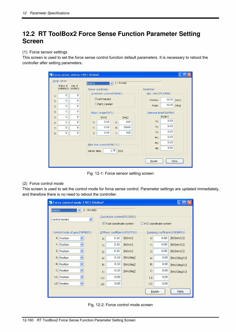
12 Parameter Specifications
12-160 RT ToolBox2 Force Sense Function Parameter Setting Screen
12.2 RT ToolBox2 Force Sense Function Parameter Setting Screen
(1) Force sensor settings
This screen is used to set the force sense control function default parameters. It is necessary to reboot the
controller after setting parameters.
Fig. 12-1: Force sensor setting screen
(2) Force control mode
This screen is used to set the control mode for force sense control. Parameter settings are updated immediately,
and therefore there is no need to reboot the controller.
Fig. 12-2: Force control mode screen

12 Parameter Specifications
RT ToolBox2 Force Sense Function Parameter Setting Screen 12-161
(3) Force control characteristics
This screen is used to set the control characteristics for force sense control. Parameter settings are updated
immediately, and therefore there is no need to reboot the controller.
Fig. 12-3: Force control characteristics screen
[Speed condition] tab [Force condition] tab

12 Parameter Specifications
12-162 RT ToolBox2 Force Sense Function Parameter Setting Screen
(4) Force log setting
This screen is used to set parameters for the force sense log function. It is necessary to reboot the controller
after writing parameters.
Fig. 12-4: Force log setting screen

12 Parameter Specifications
R56TB/R57TB Force Sense Function Parameter Setting Screen 12-163
12.3 R56TB/R57TB Force Sense Function Parameter Setting Screen
(1) Initial settings
This screen is used to set the force sense control function default parameters. It is necessary to reboot the
controller after setting parameters.
Fig. 12-5: Force sense control Initial setting screen
(2) Force control mode
This screen is used to set the control mode for force sense control. Parameter settings are updated immediately,
and therefore there is no need to reboot the controller.
Fig. 12-6: Force control mode screen

12 Parameter Specifications
12-164 R56TB/R57TB Force Sense Function Parameter Setting Screen
(3) Force control characteristics
This screen is used to set the control characteristics for force sense control. Parameter settings are updated
immediately, and therefore there is no need to reboot the controller.
Fig. 12-7: Force control feature screen
[Mode switch judgment/Speed reference] button [Gain/Instruction/Detection] button
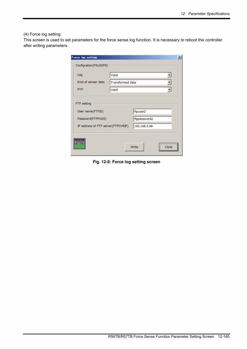
12 Parameter Specifications
R56TB/R57TB Force Sense Function Parameter Setting Screen 12-165
(4) Force log setting
This screen is used to set parameters for the force sense log function. It is necessary to reboot the controller
after writing parameters.
Fig. 12-8: Force log setting screen

13 Troubleshooting
13-166 Behavior when Force Sense Control Errors Occur
13 Troubleshooting
13.1 Behavior when Force Sense Control Errors Occur
If any of the following types of error occurs, force sense control is disabled and the servo turns OFF.
Table 13-1: Behavior when force sense control error occurs
Type Error
No. Error Details
H2760 Offset limit over
H3988 Force sense position command calculation not possible
H2770 Outside joint movement range
Force sense
position command
H2780 Speed over
Force sense I/F
unit
H8920 Force sense interface unit error
Force sensor data H7660 Sensor tolerance over
13.2 Force Sense Fuction Related Error List
The following error numbers consist of 4 digits + 5 digits. The first 4 digits appear on the operation panel and
teaching pendant. The last 5 digits can be checked at the RT ToolBox2 error details display. (See below.)
○○○○□□□□□
Error details No.
Error mechanical No.
Error No.
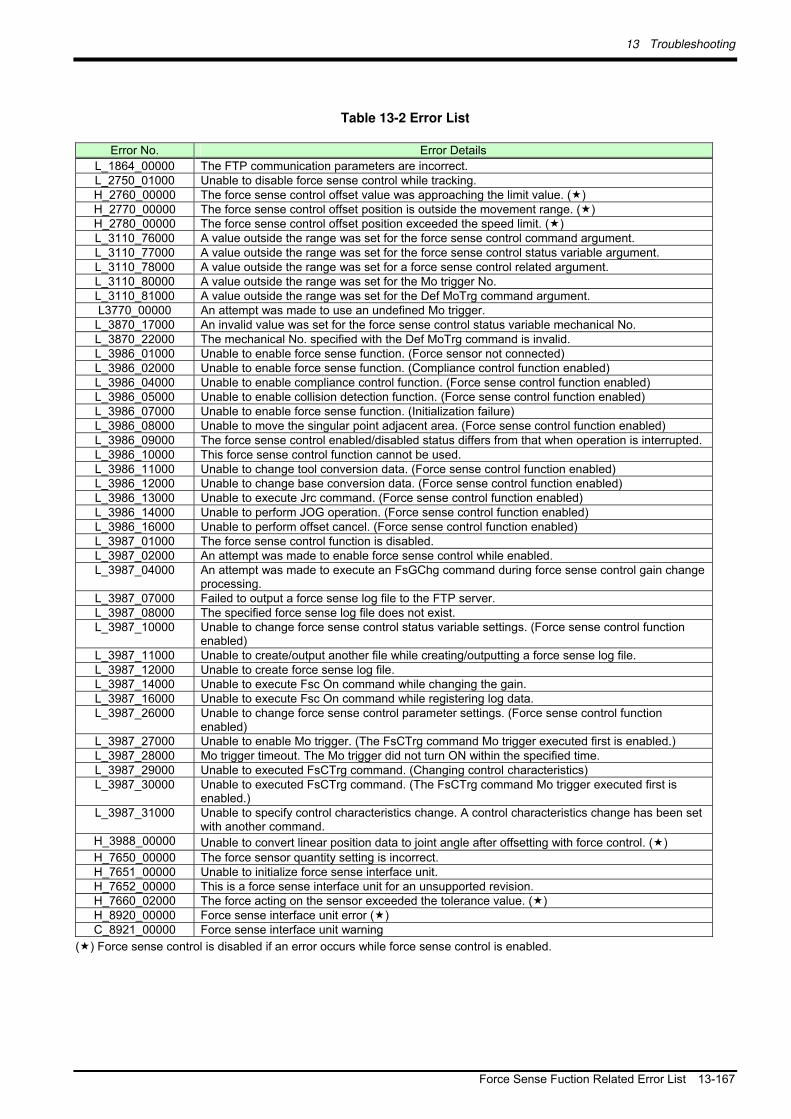
13 Troubleshooting
Force Sense Fuction Related Error List 13-167
Table 13-2 Error List
Error No. Error Details
L_1864_00000 The FTP communication parameters are incorrect. L_2750_01000 Unable to disable force sense control while tracking. H_2760_00000 The force sense control offset value was approaching the limit value. () H_2770_00000 The force sense control offset position is outside the movement range. () H_2780_00000 The force sense control offset position exceeded the speed limit. () L_3110_76000 A value outside the range was set for the force sense control command argument. L_3110_77000 A value outside the range was set for the force sense control status variable argument. L_3110_78000 A value outside the range was set for a force sense control related argument. L_3110_80000 A value outside the range was set for the Mo trigger No. L_3110_81000 A value outside the range was set for the Def MoTrg command argument. L3770_00000 An attempt was made to use an undefined Mo trigger.
L_3870_17000 An invalid value was set for the force sense control status variable mechanical No. L_3870_22000 The mechanical No. specified with the Def MoTrg command is invalid. L_3986_01000 Unable to enable force sense function. (Force sensor not connected) L_3986_02000 Unable to enable force sense function. (Compliance control function enabled) L_3986_04000 Unable to enable compliance control function. (Force sense control function enabled) L_3986_05000 Unable to enable collision detection function. (Force sense control function enabled) L_3986_07000 Unable to enable force sense function. (Initialization failure) L_3986_08000 Unable to move the singular point adjacent area. (Force sense control function enabled) L_3986_09000 The force sense control enabled/disabled status differs from that when operation is interrupted.L_3986_10000 This force sense control function cannot be used. L_3986_11000 Unable to change tool conversion data. (Force sense control function enabled) L_3986_12000 Unable to change base conversion data. (Force sense control function enabled) L_3986_13000 Unable to execute Jrc command. (Force sense control function enabled) L_3986_14000 Unable to perform JOG operation. (Force sense control function enabled) L_3986_16000 Unable to perform offset cancel. (Force sense control function enabled) L_3987_01000 The force sense control function is disabled. L_3987_02000 An attempt was made to enable force sense control while enabled. L_3987_04000 An attempt was made to execute an FsGChg command during force sense control gain change
processing. L_3987_07000 Failed to output a force sense log file to the FTP server. L_3987_08000 The specified force sense log file does not exist. L_3987_10000 Unable to change force sense control status variable settings. (Force sense control function
enabled) L_3987_11000 Unable to create/output another file while creating/outputting a force sense log file. L_3987_12000 Unable to create force sense log file. L_3987_14000 Unable to execute Fsc On command while changing the gain. L_3987_16000 Unable to execute Fsc On command while registering log data. L_3987_26000 Unable to change force sense control parameter settings. (Force sense control function
enabled) L_3987_27000 Unable to enable Mo trigger. (The FsCTrg command Mo trigger executed first is enabled.) L_3987_28000 Mo trigger timeout. The Mo trigger did not turn ON within the specified time. L_3987_29000 Unable to executed FsCTrg command. (Changing control characteristics) L_3987_30000 Unable to executed FsCTrg command. (The FsCTrg command Mo trigger executed first is
enabled.) L_3987_31000 Unable to specify control characteristics change. A control characteristics change has been set
with another command. H_3988_00000 Unable to convert linear position data to joint angle after offsetting with force control. ()
H_7650_00000 The force sensor quantity setting is incorrect. H_7651_00000 Unable to initialize force sense interface unit. H_7652_00000 This is a force sense interface unit for an unsupported revision. H_7660_02000 The force acting on the sensor exceeded the tolerance value. () H_8920_00000 Force sense interface unit error () C_8921_00000 Force sense interface unit warning
() Force sense control is disabled if an error occurs while force sense control is enabled.

13 Troubleshooting
13-168 Force Control Function Related Error Details
13.3 Force Control Function Related Error Details
(The power must be reset for errors with * in the Error No. "First 4 Digits" field.)
Error No.
First 4
Digits
Last 5
Digits
Error Cause and Remedy
Err. message FTP parameter setting error (**)
*) "**" is substituted with the "parameter name".
Cause The FTP communication parameter setting lies outside the range.
L1864 00000
Remedy Check the setting and correct.
Err. message Unable to disable force sense control. (Tracking being performed)
Cause Unable to disable force sense control while tracking function being executed.
L2750 01n00
n=Mech.
No. Remedy Try again after disabling the tracking function.
Err. message The force sense control offset limit was reached.
Cause The robot attempted to move beyond the force sense control offset limit.
H.2760 00n00
n=Mech.
No. Remedy Check whether there is a problem with robot movement while force sense
control is enabled.
(The offset limit is the value set in parameter FSCORMX.)
Err. message Outside offset position movement range (**)
*) "**" is substituted with "±Jn" (n is axis No.)
Cause The position after force sense control offset lies outside the range.
The robot may have been moved near the movement range limit.
H.2770 xxn00
xx=Axis
No.
n=Mech.
No. Remedy Review the movement position or force sense control settings, and ensure that
the offset position does not exceed the movement range.
Err. message Offset position speed over (**)
*) "**" is substituted with "Jn" (n is axis No.)
Cause The speed of movement to the position after offsetting with force sense control
exceeded the speed limit.
The movement speed may be too fast, or the robot may have been moved at
the singular point adjacent.
H.2780 0xn00
x=Axis No.
n=Mech.
No.
Remedy Review the movement speed and movement position, or the force sense
control settings.
Err. message The force sense control command argument lies outside the range.
Cause A value outside the range was set for the force sense control command
argument.
L.3110 76n00
n=Mech.
No.
Remedy Check the argument range and set a correct value.
Err. message The force sense control status variable argument lies outside the range.
Cause A value outside the range was set for the force sense control status variable
argument.
L.3110 77n00
n=Mech.
No.
Remedy Check the argument range and set a correct value.
Err. message The force sense control related argument lies outside the range.
Cause A value outside the range was set for the force sense control related
argument.
L.3110 78n00
n=Mech.
No.
Remedy Check the argument range and set a correct value.
Err. message The Mo trigger No. lies outside the range.
Cause A value outside the range was set for the Mo trigger No.
L.3110 80n00
n=Mech.
No. Remedy Check the setting range and set a correct value.
Err. message Def MoTrg command argument error
Cause An unusable variable or different mechanical No. was set.
L.3110 81n00
n=Mech.
No. Remedy Set a usable variable or same mechanical No.
Err. message This is an undefined Mo trigger.
Cause An attempt was made to use an undefined Mo trigger.
L.3770 00n00
n=Mech.
No. Remedy Define the specified Mo trigger before use.
Err. message The force sense control status variable mechanical No. is an invalid value.
Cause An invalid variable was set for the force sense control status variable
mechanical No.
L.3870 17000
Remedy Set a correct mechanical No.

13 Troubleshooting
Force Control Function Related Error Details 13-169
Err. message The mechanical No. specified with the Def MoTrg command is an invalid
value.
Cause The mechanical No. specified with the Def MoTrg command is an invalid
value.
L.3870 22000
Remedy Set a correct mechanical No.
Err. message Unable to enable force sense control. (Sensor)
Cause Unable to execute because the force sensor is not connected.
L.3986 01n00
n=Mech.
No. Remedy Connect the force sensor, or delete the command that cause the error.
Err. message Unable to enable force sense control. (Cmp command)
Cause It is not possible to enable force sense control function while the compliance
control function is enabled.
L.3986 02n00
n=Mech.
No.
Remedy The force sense control function and compliance control function cannot be
enabled simultaneously. If using the force sense control function, disable the
compliance control function.
Err. message Unable to execute the Cmp command. (Force sense control)
Cause It is not possible to enable the compliance control function while the force
sense control function is enabled.
L.3986 04n00
n=Mech.
No.
Remedy The force sense control function and compliance control function cannot be
enabled simultaneously. If using the compliance control function, disable the
force sense control function.
Err. message Unable to enable the collision detection function. (Force sense control)
Cause It is not possible to enable the collision detection function while force sense
control function is enabled.
L.3986 05n00
n=Mech.
No.
Remedy The force sense control function and collision detection function cannot be
enabled simultaneously. If using the collision detection function, disable the
force sense control function.
Err. message Unable to enable force sense control. (Initialization)
Cause It is not possible to perform initialization when starting force sense control.
L.3986 07n00
n=Mech.
No. Remedy Check the parameter settings.
Err. message This is the singular point adjacent area. (Force sense control)
Cause It is not possible to move the singular point adjacent area while the force sense
control function is enabled.
L.3986 08n00
n=Mech.
No.
Remedy If moving the singular point adjacent area, disable the force sense control
function.
Err. message The force sense control status is different.
Cause The force sense control enabled/disabled status when resuming program
operation differs from that during program operation.
L.3986 09n00
n=Mech.
No.
Remedy Set the force sense control enabled/disabled status to the correct status. (This
occurs only once when resuming program operation.)
Err. message This function cannot be used.
Cause This model is not compatible with the executed force sense control function.
L.3986 10n00
n=Mech.
No. Remedy Do not use this force sense control function.
Contact the maker for details on the latest compatibility status.
Err. message Unable to change tool conversion data. (Force sense control)
Cause It is not possible to change tool conversion data while the force sense control
function is enabled.
L.3986 11n00
n=Mech.
No.
Remedy If changing tool conversion data, disable the force sense control function.
Err. message Unable to change base conversion data. (Force sense control)
Cause It is not possible to change base conversion data while the force sense control
function is enabled.
L.3986 12n00
n=Mech.
No.
Remedy If changing base conversion data, disable the force sense control function.
Err. message Unable to execute the Jrc command. (Force sense control)
Cause It is not possible to execute the Jrc command while the force sense control
function is enabled.
L.3986 13n00
n=Mech.
No.
Remedy To execute the Jrc command, disable the force sense control function.
Err. message Disable force sense control.
Cause JOG operation cannot be performed on your model while the force sense
control function is enabled.
L.3986 14n00
n=Mech.
No.
Remedy Disable the force sense control function.

13 Troubleshooting
13-170 Force Control Function Related Error Details
Error No.
First 4
Digits
Last 5
Digits
Error Cause and Remedy
Err. message Unable to perform offset cancel. (Force sense control)
Cause It is not possible to perform offset cancel while the force sense control function
is enabled.
L.3986 16n00
n=Mech.
No.
Remedy If performing offset cancel, disable the force sense control function.
Err. message Force sense control is disabled.
Cause Force sense control is disabled, and so unable to execute the command.
L.3987 01n00
n=Mech.
No. Remedy Enable the force sense control function.
Err. message Force sense control is enabled.
Cause It is not possible to enable force sense control again while already enabled.
L.3987 02n00
n=Mech.
No. Remedy First disable the force sense control function, and then enable again.
Err. message Unable to execute the FsGChg command.
Cause It is not possible to execute the FsGChg command when force control gain
change is not complete.
L.3987 04n00
n=Mech.
No.
Remedy Review the program so that the FsGChg command is executed after force
control gain change is complete.
Err. message Unable to output log file.
Cause FTP processing was not properly performed.
L.3987 07n00
n=Mech.
No. Remedy Check the FTP related parameter setting.
Check the Ethernet cable connection.
Check the FTP server settings at the computer.
Err. message The specified log file does not exist.
Cause The log file for the No. specified with the FsOutLog command does not exist.
L.3987 08n00
n=Mech.
No. Remedy Check whether the log file No. is incorrect.
Err. message Unable to change the force sense status variable.
Cause The status variable setting is currently being used by the force sense control
function and so cannot be changed.
L.3987 10n00
n=Mech.
No.
Remedy If changing the setting, disable the force sense control function.
Err. message Force sense log commands executed simultaneously.
Cause It is not possible to create/output another file while creating (FsLog Off
command) or outputting (FsOutLog command) a force sense log file.
L.3987 11n00
n=Mech.
No.
Remedy Process after force sense log file creation/output is complete.
Err. message Unable to create log file.
Cause Unable to create a force sense log file.
L.3987 12n00
n=Mech.
No. Remedy Check the amount of available record space in the robot controller.
Err. message Unable to execute the Fsc ON command.
Cause It is not possible to execute the Fsc On command while changing the force
control gain.
L.3987 14n00
n=Mech.
No.
Remedy Execute the Fsc On command after force control gain change is complete.
Err. message Unable to perform log data related processing.
Cause It is not possible to execute FsLog On command file while recording force
sense control log data.
L.3987 16n00
n=Mech.
No.
Remedy Execute the FsLog On command after log data recording is complete.
Err. message Force sense control is enabled.
Cause The parameter setting is currently being used by the force sense control
function and so cannot be changed.
L.3987 26n00
n=Mech.
No.
Remedy If changing the parameter, disable the force sense control function once..
Err. message Unable to enable the Mo trigger.
Cause The Mo trigger for the FsCtrg command executed first is enabled.
L.3987 27n00
n=Mech.
No. Remedy Execute after changing the control characteristics.
Err. message Mo trigger timeout
Cause The Mo trigger did not turn ON within the specified time.
L.3987 28n00
n=Mech.
No. Remedy Review the Mo trigger conditions and robot program.
Err. message Unable to execute the FsCTrg command.
Cause The control characteristics is currently being changed.
L.3987 29n00
n=Mech.
No. Remedy Execute after changing the control characteristics.
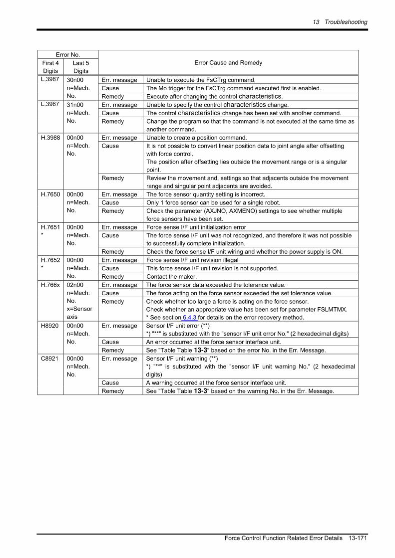
13 Troubleshooting
Force Control Function Related Error Details 13-171
Error No.
First 4
Digits
Last 5
Digits
Error Cause and Remedy
Err. message Unable to execute the FsCTrg command.
Cause The Mo trigger for the FsCTrg command executed first is enabled.
L.3987 30n00
n=Mech.
No. Remedy Execute after changing the control characteristics.
Err. message Unable to specify the control characteristics change.
Cause The control characteristics change has been set with another command.
L.3987 31n00
n=Mech.
No. Remedy Change the program so that the command is not executed at the same time as
another command.
Err. message Unable to create a position command.
Cause It is not possible to convert linear position data to joint angle after offsetting
with force control.
The position after offsetting lies outside the movement range or is a singular
point.
H.3988 00n00
n=Mech.
No.
Remedy Review the movement and, settings so that adjacents outside the movement
range and singular point adjacents are avoided.
Err. message The force sensor quantity setting is incorrect.
Cause Only 1 force sensor can be used for a single robot.
H.7650 00n00
n=Mech.
No. Remedy Check the parameter (AXJNO, AXMENO) settings to see whether multiple
force sensors have been set.
Err. message Force sense I/F unit initialization error
Cause The force sense I/F unit was not recognized, and therefore it was not possible
to successfully complete initialization.
H.7651
*
00n00
n=Mech.
No.
Remedy Check the force sense I/F unit wiring and whether the power supply is ON.
Err. message Force sense I/F unit revision illegal
Cause This force sense I/F unit revision is not supported.
H.7652
*
00n00
n=Mech.
No. Remedy Contact the maker.
Err. message The force sensor data exceeded the tolerance value.
Cause The force acting on the force sensor exceeded the set tolerance value.
H.766x 02n00
n=Mech.
No.
x=Sensor
axis
Remedy Check whether too large a force is acting on the force sensor.
Check whether an appropriate value has been set for parameter FSLMTMX.
* See section 6.4.3 for details on the error recovery method.
Err. message Sensor I/F unit error (**)
*) "**" is substituted with the "sensor I/F unit error No." (2 hexadecimal digits)
Cause An error occurred at the force sensor interface unit.
H8920 00n00
n=Mech.
No.
Remedy See "Table Table 13-3" based on the error No. in the Err. Message.
Err. message Sensor I/F unit warning (**)
*) "**" is substituted with the "sensor I/F unit warning No." (2 hexadecimal
digits)
Cause A warning occurred at the force sensor interface unit.
C8921 00n00
n=Mech.
No.
Remedy See "Table Table 13-3" based on the warning No. in the Err. Message.

13 Troubleshooting
13-172 Force Control Function Related Error Details
Table 13-3: Force sense interface unit errors
Error No. (Name) Cause Remedy
12 (memory error)
13 (S/W processing error)
Force sense interface unit internal part fault Replace the unit.
21 (sensor initial communication error)
25 (sensor communication error)
(1) The force sensor connection cable is disconnected.
(2) The force sensor connection cable is damaged.
(3) Noise contamination occurred.
(1) Connect the cable. (2) Replace the cable. (3) Perform noise countermeasures.
34 (communication data error)
36 (communication error)
37 (parameter error)
38 (communication frame error)
39 (communication axis information error)
(1) The SSCNET III cable is disconnected.
(2) The SSCNET III cable end face is dirty.
(3) The SSCNET III cable is damaged. (4) Noise contamination occurred.
(1) Connect after turning OFF the power.
(2) Wipe any dirt from the end face. (3) Replace the cable. (4) Perform noise countermeasures.

14 Appendix
Control Status Transition 14-173
14 Appendix
14.1 Control Status Transition
Force sense control has the following 4 statuses. Status Description
Force sense status disabled
This is the force sense control disabled status. This is the status when the power is turned ON.
Offsetting In this status, force sense control is enabled and the robot position is being offset based on the "control mode" and "control characteristics " settings.
Offsetting stopped
Force sense control is enabled; however, robot position offset processing has been stopped with a stop input or due to an error. (This status is possible only when the key switch is set to "AUTOMATIC".)
Processing stopped
Force sense control is enabled; however, as the servo power is OFF, robot position offset processing is not being performed.
The transition for each status by executing dedicated commands or by turning the servo ON and OFF is as
follows.

14 Appendix
14-174 Control Status Transition
Force sense control disabled
Processing stopped
Offsetting stopped
Offsetting
Stop input/emergency stop input Error (H level/L level) Operation interrupted
Power ON
Start point input Step operation Jog operation
Servo OFF Servo ON
Fsc ON command Enabling of force sense with T/B
Fsc Off command Disabling of force sense with T/B End Command Program reset Force sense control related error Program selection possible
Force sense control disabled
Processing stopped
Offsetting
Power ON
Servo OFF Servo ON
Fsc ON command Enabling of force sense with T/B
Fsc Off command Disabling of force sense with T/B Enc Command Program reset Force sense control related error
[AUTOMATIC mode]
[Manual mode]
Force sense control enabled
Force sense control enabled
Key switch change Key switch change
Stop input in the above diagram refers to a stop input from the operation panel, teaching pendant, I/O, or RT ToolBox2. However, stoppages with the Hlt command and stop inputs by releasing the key during step or JOG operation are not included.
If a stop is input and the offset amount becomes fixed while pushing with force sense controller the moment contact is made with the target object, error H.094n (servo amplifier overload) or H.096n (servo amplifier error excessive) may occur. (n is axis No.)
If the operation key switch is set to "MANUAL", robot movement by force sense control will not stop even if a stop is entered. To stop robot movement by force sense control, release the teaching pendant enable switch and turn OFF the servo power.
Caution
Caution
Caution


Oct . .2012 MEE Pr in ted in Japan on recyc led paper . Spec i f i ca t ions a re sub jec t to change w i thout no t i ce .