missouri one callmissouri one call 1-800-dig rite...
TRANSCRIPT

Missouri One CallMissouri One Call 1-800-DIG RITE(800-344-7483) or 811 or mo1call.com
Missouri One CallMissouri One Call 1-800-DIG RITE(800-344-7483) or 811 or mo1call.com
Missouri One CallMissouri One Call 1-800-DIG RITE(800-344-7483) or 811 or mo1call.com
MLICA 5-1

Missouri One CallMissouri One Call 1-800-DIG RITE(800-344-7483) or 811 or mo1call.com
Missouri One CallMissouri One Call 1-800-DIG RITE(800-344-7483) or 811 or mo1call.com
Missouri One CallMissouri One Call 1-800-DIG RITE(800-344-7483) or 811 or mo1call.com
MLICA 5-2

Missouri One CallMissouri One Call 1-800-DIG RITE(800-344-7483) or 811 or mo1call.com
Missouri One CallMissouri One Call 1-800-DIG RITE(800-344-7483) or 811 or mo1call.com
MLICA 5-3

Missouri One CallMissouri One Call 1-800-DIG RITE(800-344-7483) or 811 or mo1call.com
Missouri One CallMissouri One Call 1-800-DIG RITE(800-344-7483) or 811 or mo1call.comWait time exception if the utility fails to complete the locate: Excavator must make a second “NO RESPONSE”
ticket request.
Utility will have 2 hours to respond if Excavator calls by 2 pm.
OR
Utility will have until 10 am the following day if Excavator calls after 2 pm.
MLICA 5-4

Missouri One CallMissouri One Call 1-800-DIG RITE(800-344-7483) or 811 or mo1call.com
17 18 19 20 21 22CALL
23Wait
24 25 26 27 28 N 29 3024
Wait
25X-MAS
Wait
26
Wait(1)
27
Wait(2)
28 No LocateCall after 2 pm
29Wait until 10 am
30Start WorkMaybe?
31 1NewYearsDay
2 3 4 5 6
Missouri One CallMissouri One Call 1-800-DIG RITE(800-344-7483) or 811 or mo1call.com
MLICA 5-5

MLICA 5-6

Planning a Subsurface Drainage System
Marty Comstock, P.E.Agricultural Engineer
Drainage System Layout
In this presentation, we’ll look at:
Factors affecting the layout
Layout alternatives
Selecting the lateral drain spacing
Drainage System Layout
Factors affecting layout
Operator’s goals
Field topography• Low spots• High spots• Slope
Outlet location & depth
MLICA 5-7

Drainage System Layout
Possible Operator Goals:
Removing water from an isolated problem area
Improving drainage in an entire field
Water table management (Controlled drainage)
Sub irrigation
Economics $ $ $ $ $ $ $ $
Increase yields & profits
Layout Alternatives
Source: Illinois Drainage Guide, University of Illinois
• Interceptor Drainused to drain hillside seeps.
• Drain is installed parallel to slope above seepage area.
Layout Alternatives
• Random Systems are used to drain isolated wet depressional areas.
MLICA 5-8

Layout Alternatives
• Herringbone Systems are used to drain wet swale areas with land sloping to it from both sides.
• It provides “double drainage” along the main.
• Also used to optimize lateral line grades.
Layout Alternatives
• Parallel Systems are used to drain entire field areas.
• Can also provide controlled drainage and sub irrigation.
Pattern Drainage Components
• Main Lines
• Lateral Lines
• Surface Inlets
• Water Control Structures
• Junction Boxes
• Outlets Photo Credit: www.gpsdrainage.com
MLICA 5-9

Layout Alternatives• Elements of Parallel
systems can be incorporated into the Random (Targeted) and Herringbone systems.
• In general, the more lateral connections, the higher the cost.
Topography ConsiderationsPattern System Layout
Laterals should be oriented with the field's contours as much as possible
Advantages:
• Laterals will intercept more down slope seepage.
• Usually results in more grade on mains.
• Will be easier to “zone” for drainage management.
Topography ConsiderationsPattern System Layout
Long Laterals and Short Mains(Minimize connections)
MLICA 5-10

Drainage Water Management
Source: Extension Bulletin 871-98, The Ohio State University
DWM Structures
Source: Agri Drain
Drainage Water Management
Field must be managed in zones where the water table has less than 2 feet of variation.
Works best on flat uniform fields(slope less than 0.5 %)
Can work on steeper fields if the laterals are located with the contour of the land.
MLICA 5-11

Drainage Water Management
Drainage water management can be added to existing drainage systems.
Requires a map of the drainage system layout.
Requires knowing the sizes and grades of mains and laterals.
Topography ConsiderationsPattern System Layout
Source: Illinois Drainage Guide, University of Illinois
Which would work best for Drainage Water Management?
22 4
MLICA 5-12

QUESTIONS
Drain Outlets
MLICA 5-13

Drain OutletsProvide a “free” (not restricted) outlet
with adequate capacity.
Discharge flow without erosion damage.
Have adequate depth of cover(frost action and traffic loads).
Protected from rodents and animals.
Structurally sound.
Prevent back flooding.
Drain Outlets
Source: Illinois Drainage Guide, University of Illinois
Free Outlet without Erosion:
Drain Outlets
MLICA 5-14

Drain Outlets
Source: Illinois Drainage Guide, University of Illinois
Adequate Cover Depth:
A. Add more fill.
B. Use stronger outlet pipe.
C. Recess outlet in bank.
Drain Outlets
Floodwater Levee
Flap Gate
SeepWater
Preventing Back Flooding:
Drain Outlets
Animal Guards:
MLICA 5-15

Drain Outlets
ANY CONCERNS ??
QUESTIONS
Water Movement to Drains
MLICA 5-16

Ellipse Equation
Ellipse Equation Variables q, Required drainage rate (in/hr), Drainage Coefficient
Based on climate, crop, soils, drainable soil water volume . . .
K, Hydraulic conductivity (in/hr) Field investigation Soil survey Predict from other properties, such as soil texture
d, Drain tile depth (ft) Minimum cover requirements Restrictive layer
b, Vertical distance of water table above drain at midpoint (ft) Typical design value to meet goals for crop growth
a, Depth of impermeable layer (ft) Soil Survey verified with field investigation
Soil WaterSoil Water
Saturation Wilting PointField Capacity
Drainable Water
Available Water
AirSoil Water
MLICA 5-17

DRAINABLE WATER 3‐11%
PLANT AVAILABLE WATER(Weak Capillary Forces)
13‐21%
UNAVALABLE WATER(Strong Adsorptive Forces) 15‐24%
SOIL SOLIDS 45‐65%
← Field Capacity
← Completely Dry
← Wilting Point
← Saturation
Pore Volume
(Air and W
ater)
Solids Volume
(Mineral and Organic M
ater)
Soil Water Relationships
(Typical for Clay, Clay Loam and Silty Clay)
Soil Water Relationships
(Typical for Clay, Clay Loam and Silty Clay)
Typical Soil Water RelationshipsTypical Soil Water Relationships
Soil Texture Wilting Point(% by vol.)
Available Water
(% by vol.)
Drainable Water(% by vol.)
clays, clay loams, silty clays
15‐24 15‐26 3‐11
well structured loams 8‐17 12‐22 10‐15
sandy 3‐10 6‐15 18‐35
Source: University of Minnesota BU‐07644‐S, Soil Water Concepts, Gary Sands
DRAINABLE WATER 5%
PLANT AVAILABLE WATER(Weak Capillary Forces)
20%
SOIL SOLIDS 55%
← Field Capacity
← Completely Dry
← Wilting Point
←Saturation
Pore Volume
(Air and W
ater)
Solids Volume
(Mineral and Organic M
ater)
UNAVALABLE WATER(Strong Adsorptive Forces) 20%
Soil Water Relationships(Example Silty Clay)
Soil Water Relationships(Example Silty Clay)
MLICA 5-18

How much water do I need to remove?How much water do I need to remove?
Given a soil (silty clay) with a drainable porosity of 5% with the goal of draining the top 12 inch layer in 48 hours.
Volume of drainable water = 5% x 12 inch depth = 0.6 inches
Rate of removal = 0.6 inch ÷ 2 day
= 0.3 inch/day
How much water do I need to remove?How much water do I need to remove?
Given a soil (loam) with a drainable porosity of 12% with the goal of draining the top 12 inch layer in 48 hours.
Volume of drainable water = 12% x 12 inch depth = 1.4 inches
Rate of removal = 1.4 inch ÷ 2 day
= 0.7 inch/day
Selecting a Drainage Coefficient (D.C.)
D.C. is the depth of water to be removed from the drained area in 24 hours.
D.C. is a function of: Organic vs. mineral soils
Soil texture and drainable water
Sensitivity of crop to high water table
Topography and surface drainage
Presence of surface inlets
Reference NRCS Practice Standard 606 for Missouri
MLICA 5-19

Drainage CoefficientRef: Missouri NRCS Subsurface Drain Standard 606
Converting the D.C. to cfs
D.C. units are inch / day
Pipe flow rates are cfs (cubic feet per second)
To convert in/day to cfs:
Q = 0.042 x DC x DA
Example: DC= 3/8 in/day, DA = 1 acre
Q = 0.042 x 0.375 in/day x 1 ac
Q = 0.0158 cfs
Your TurnConverting the D.C. to cfs
Given: DC= 1/2 in/day, DA = 80 acres
What is the total drainage rate, Q, needed?
Q = 0.042 x DC x DA
Q = 0.042 x 0.5 in/day x 80 ac
Q = 1.68 cfs
MLICA 5-20

Soils Investigation
Field Investigation:
•Water table depth
•Soil texture profile
•Saturated Hydraulic Conductivity, Ksat
•Restrictive layer
K, Hydraulic conductivity
Soil Variability
Soil Survey only provides typical values for predominate soils mapped.
Point measurements don’t necessarily represent field well
Installing test drain can provide information about “effective” field hydraulic conductivity
MLICA 5-21
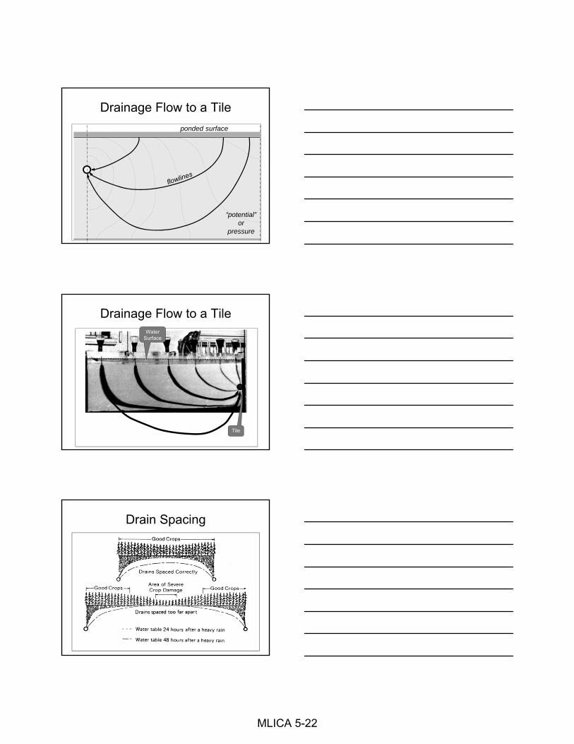
Drainage Flow to a Tile
ponded surface
“potential”or
pressure
Drainage Flow to a TileWater
Surface
Tile
Drain Spacing
MLICA 5-22

Drain Depth
Depth does influence drain capacity.
Minimum and maximum ranges. Pipe material (minimum is 2’ for CPT) Pipe size Bedding and backfill conditions Traffic loading
Installing machine capabilities.
Drain Depth
Source: Agricultural Drainage Series, University of Minnesota
Drain Spacing and Depth For a given Tile Depth, decreasing the Tile
Spacing will result in an increased rate of drainage.
MLICA 5-23

Depth vs. Spacing
For a uniform soil profile, if Tile Depth is increased then the spacing can be increased to provide same drainage rate.
Drained Water TableHigh Point
Depth vs. Spacing
BUT,if the Tile Depth is increased beyond the depth of an impermeable layer, then the drainage rate will be decreased.
Drained Water TableHigh Point
Impermeable Layer
Drain Spacing Economics
Optimum yieldor
MUDS ResearchPlot, 2005
Subirrigation, 20’ drain spacing
Optimum return on investment
MLICA 5-24

Drain Spacing Economics
$/Acre
Economic Profit Range
High $
Low $
Spacing WideNarrow
Profit Increase
System Cost
Drain Spacing Economics
B:C=1
Economic Profit Range
B:C>1
B:C<1
Spacing WideNarrow
Drain Spacing Economics
MLICA 5-25

Drain Spacing Extras
Systems that include Drainage Water Management require a higher level of design thought.
Sub Irrigation systems require even more design with care and detail.
Site specific soils investigation
Detailed topographic surveys
Crop water requirements
Drain Spacing
In practice, most drainage only system designs are based on:
A constant drain spacing for an area
or
General soil characteristics with a recommended drain spacing for each soil series
Wayne Skaggs, North Carolina, 1987
Drain Spacing Values for Blount Series
Silt Loam, poorly drained with clay layer 12” to 24”
MLICA 5-26

Drain Spacing Values (ft) for Brookston Series
Loam, poorly drained with clay loam layer 23” to 41”
Drain Spacing Values (ft) for Crosby Series
Silt Loam, poorly drained with silt clay loam layer 36” to 56”
Why use standard spacing?
Farmers and contractors are comfortable with rules of thumb for their area.
Soil inputs can be difficult to determineand
Soil properties vary across a field.
Expertise to do a site-specific design is not readily available or cost “too much”.
MLICA 5-27

Ellipse Equation
Ksat, Hydraulic Conductivity
8 in/hr ►
0.08 in/hr ►
0.8 in/hr ►
Spacing EquationsHigh Hydraulic Conductivity (Ksat) 8 in/hr = 16 ft/day
←175’ Spacing→
MLICA 5-28

Spacing EquationsModerately High Hydraulic Conductivity (Ksat) 0.8 in/hr = 1.6 ft/day
←53’ Spacing→
Spacing EquationsModerately Low Hydraulic Conductivity (Ksat) 0.08 in/hr = 0.16 ft/day
←15’ Spacing→
Spacing Summary
8 in/hr ►
0.08 in/hr ►
0.8 in/hr ►
◄ 175 ft
◄ 50 ft
◄ 15 ft
MLICA 5-29

Spacing Charts
52’
8
0.5in/day
Can you see a pattern developing?
Planning a Drainage System
The End (aka the outlet)
MLICA 5-30

The U.S. Department of Agriculture (USDA) prohibits discrimination in all its programs and activities on the basis of race, color, national origin, age, disability, and where applicable, sex, marital status, familial status, parental status, religion,
sexual orientation, genetic information, political beliefs, reprisal, or because all or a part of an individual's income is derived from any public assistance program. (Not all
prohibited bases apply to all programs.) Persons with disabilities who require alternative means for communication of program information (Braille, large print,
audiotape, etc.) should contact USDA's TARGET Center at (202) 720-2600 (voice and TDD). To file a complaint of discrimination write to USDA, Director, Office of Civil Rights, 1400 Independence Avenue, S.W., Washington, D.C. 20250-9410 or
call (800) 795-3272 (voice) or (202) 720-6382 (TDD). USDA is an equal opportunity provider and employer."
MLICA 5-31

MLICA 5-32

MLICA 5-33

MLICA 5-34

MLICA 5-35

MLICA 5-36

MLICA 5-37

MLICA 5-38

MLICA 5-39

MLICA 5-40

SUBSURFACE DRAIN DESIGN PROCEDURE
1. Complete initial planning for system
o Adequate outlet?
o Wetland determination requested
o Utilities located
o Neighboring landowners
2. Complete topographic survey
3. Create contour map
4. Determine soil properties (county soil survey and on-site investigation)
5. Determine drainage coefficient to use (in/day)
6. Select drain spacing
7. Analyze contour map for drain layout alternatives then lay out and station mains and laterals on map
8. Plot profile of existing ground along main
9. Plot control points for main on profile
o Low points of existing ground (use approx. 3’ min. depth)
o High points of existing ground (use approx 6’max. depth)
o Outlet (need 1’ freeboard)
o Lateral depth, min. grade and cover (may need to plot a profile of key laterals to ensure adequate depth of cover)
o Obstructions: buildings, utilities, bedrock, poor soils
o Wetlands
10. Plot grade lines and calculate grades for mains
o Round grades where possible
o On profile sheet, note station and elevation of all final design grade changes
MLICA 5-41
11. Determine main sizes and lengths starting at upstream end of main
a) Determine beginning main size (often start with 6”).
b) Determine capacity of this pipe.
c) Determine flow area (in acres) of each lateral (lateral length x spacing).
d) Determine flow contribution of each lateral.
e) Accumulate flow contributions of each lateral until they exceed the capacity of the main. The area above this point is called a reach.
f) Note accumulated flow and drainage area for this reach on the design chart.
g) Note upstream and downstream stations of the reach on design chart.
h) Select the main size for the next reach.
i) Determine main capacity for this reach.
j) Determine available capacity for main (main capacity less accumulated flow of upstream reaches).
k) Continue the process with step 11c until the outlet is reached.
Note: If a grade change occurs, consider this a reach change. Accumulate the flow at that station, perform step 11f and continue the process with step 11h.
12. Check to ensure outlet capacity is adequate to handle the total drainage system discharge.
*Modified document prepared by Bruce Atherton, Agricultural Engineer, USDA-NRCS Ankeny, Iowa Adapted from material prepared by Paul W. Chester, Area Engineer, Findlay, Ohio
MLICA 5-42

Drainage Design Reference
Area
1 acre = 43,560 square feet
Saturated Hydraulic Conductivity
1 micrometer per second = 1 μm/sec
1 μm/sec = 0.2834 feet per day
1 μm/sec = 0.1417 inch per hour
1 inch per hour = 7.0572 μm/sec
1 inch per hour = 2 feet per day
Pipe Flow
Q = V x A and V = Q ÷ A
Where: Q = Flow discharge rate, cubic feet per second
V = Flow velocity, feet per second
A = Cross Sectional Area, square feet
Required Drainage Capacity
Q = 0.042 x DC x DA
Where Q = Flow discharge rate, cubic feet per second
DC = Drainage Coefficient, inch/day
DA = Drained Area, acres
MLICA 5-43

2030
4050
6070
8090
100
3/8
1.75
3,81
0
2,54
0
1,90
0
1,52
0
1,27
0
1,08
0
950
840
760
1/2
1.30
2,83
0
1,88
0
1,41
0
1,13
0
940
800
700
620
560
3/8
2.20
4,79
0
3,19
0
2,39
0
1,91
0
1,59
0
1,36
0
1,19
0
1,06
0
950
1/2
1.65
3,59
0
2,39
0
1,79
0
1,43
0
1,19
0
1,02
0
890
790
710
3/8
2.70
5,88
0
3,92
0
2,94
0
2,35
0
1,96
0
1,68
0
1,47
0
1,30
0
1,17
0
1/2
2.00
4,35
0
2,90
0
2,17
0
1,74
0
1,45
0
1,24
0
1,08
0
960
870
3/8
3.10
6,75
0
4,50
0
3,37
0
2,70
0
2,25
0
1,92
0
1,68
0
1,50
0
1,35
0
1/2
2.30
5,00
0
3,33
0
2,50
0
2,00
0
1,66
0
1,43
0
1,25
0
1,11
0
1,00
0
3/8
3.45
7,51
0
5,00
0
3,75
0
3,00
0
2,50
0
2,14
0
1,87
0
1,66
0
1,50
0
1/2
2.60
5,66
0
3,77
0
2,83
0
2,26
0
1,88
0
1,61
0
1,41
0
1,25
0
1,13
0
3/8
3.80
8,27
0
5,51
0
4,13
0
3,31
0
2,75
0
2,36
0
2,06
0
1,83
0
1,65
0
1/2
2.85
6,20
0
4,13
0
3,10
0
2,48
0
2,06
0
1,77
0
1,55
0
1,37
0
1,24
0
2030
4050
6070
8090
100
3/8
2.35
5,11
0
3,41
0
2,55
0
2,04
0
1,70
0
1,46
0
1,27
0
1,13
0
1,02
0
1/2
1.75
3,81
0
2,54
0
1,90
0
1,52
0
1,27
0
1,08
0
950
840
760
3/8
3.35
7,29
0
4,86
0
3,64
0
2,91
0
2,43
0
2,08
0
1,82
0
1,62
0
1,45
0
1/2
2.50
5,44
0
3,63
0
2,72
0
2,17
0
1,81
0
1,55
0
1,36
0
1,21
0
1,08
0
3/8
4.75
10,3
40
6,
890
5,
170
4,
130
3,
440
2,
950
2,
580
2,
290
2,
060
1/
23.
557,
730
5,
150
3,
860
3,
090
2,
570
2,
200
1,
930
1,
710
1,
540
3/
85.
8012
,630
8,42
0
6,31
0
5,05
0
4,21
0
3,60
0
3,15
0
2,80
0
2,52
0
1/2
4.35
9,47
0
6,31
0
4,73
0
3,78
0
3,15
0
2,70
0
2,36
0
2,10
0
1,89
0
3/8
6.65
14,4
80
9,
650
7,
240
5,
790
4,
820
4,
130
3,
620
3,
210
2,
890
1/
25.
0010
,890
7,26
0
5,44
0
4,35
0
3,63
0
3,11
0
2,72
0
2,42
0
2,17
0
3/8
7.50
16,3
30
10
,890
8,16
0
6,53
0
5,44
0
4,66
0
4,08
0
3,63
0
3,26
0
1/2
5.60
12,1
90
8,
130
6,
090
4,
870
4,
060
3,
480
3,
040
2,
710
2,
430
3/
88.
1017
,640
11,7
60
8,
820
7,
050
5,
880
5,
040
4,
410
3,
920
3,
520
1/
26.
1013
,280
8,85
0
6,64
0
5,31
0
4,42
0
3,79
0
3,32
0
2,95
0
2,65
0
0.5
0.5
0.6
MA
XIU
M L
ATE
RAL
LEN
GTH
USI
NG
4"
DIA
MET
ER C
ORR
AG
ATE
D P
LAST
IC T
ILE
MA
XIU
M L
ATE
RAL
LEN
GTH
USI
NG
3"
DIA
MET
ER C
ORR
AG
ATE
D P
LAST
IC T
ILE
% G
rade
(3"
CPT)
DC
("/d
ay)
ARE
A(a
cre)
LATE
RAL
SPA
CIN
G (f
eet)
% G
rade
(3"
CPT)
0.6
LATE
RAL
SPA
CIN
G (f
eet)
DC
("/d
ay)
ARE
A(a
cre)
% G
rade
(4"
CPT)
% G
rade
(4"
CPT)
0.05
0.1
0.1
0.2
0.2
0.4
0.1
0.2
0.3
0.05 0.1
0.2
0.3
0.4
0.6
0.6
0.3
0.3
0.4
0.4
0.5
0.5
MLICA 5-44

20
25
30
35
40
45
Ksat, μm/secDRAIN SPA
CING, Stead
y State Hoogh
oudt Ellip
se Equation
DC 0.25 in/day
DC 0.375 in/day
DC 0.5 in/day
DC 0.75 in/day
Drain Depth = 2.5 feet
Imperm
eable Layer Depth = 2.5 feet
Midpoint Drawdown Depth = 1
05
10
15
010
20
30
40
50
60
70
80
K
Lateral Spacing, feet
μm/sec x 0.1417 = in/hr
in/hr x 7.0572 =μm/sec
MLICA 5-45

45
DRAIN SPA
CING, Stead
y State Hooghoudt Ellip
se Equation
Drain Dep
th = 3 feet
ImpermeableLayerDep
th3feet
35
40
DC 0.25 in/day
Impermeable Layer Dep
th = 3 feet
Midpoint Drawdown Dep
th = 1
30
sec
DC 0.375 in/day
DC 0.5 in/day
DC 0.75 in/day
20
25
Ksat, μm/s 10
15
K
5
10 0
010
20
30
40
50
60
70
80
90
100
Lateral Spacing, feet
μm
/sec x 0.1417 = in/hr
in/hr x 7.0572 =μm/sec
MLICA 5-46

45
DRAIN SPA
CING, Stead
y State Hooghoudt Ellip
se Equation
Drain Dep
th = 4 feet
ImpermeableLayerDep
th4feet
35
40
DC 0.25 in/day
Impermeable Layer Dep
th = 4 feet
Midpoint Drawdown Dep
th = 1
30
sec
DC 0.375 in/day
DC 0.5 in/day
DC 0.75 in/day
20
25
Ksat, μm/s 10
15
K
5
10 0
020
40
60
80
100
120
140
160
Lateral Spacing, feet
μm
/sec x 0.1417 = in/hr
in/hr x 7.0572 =μm/sec
MLICA 5-47

45
DRAIN SPA
CING, Stead
y State Hooghoudt Ellip
se Equation
Drain Dep
th = 2.5 feet
ImpermeableLayerDep
th45feet
35
40
DC 0.25 in/day
DC0375in/day
Impermeable Layer Dep
th = 4.5feet
Midpoint Drawdown Dep
th = 1
30
sec
DC 0.375 in/day
DC 0.5 in/day
DC 0.75 in/day
20
25
Ksat, μm/s 10
15
K
5
10 0
020
40
60
80
100
120
140
160
Lateral Spacing, feet
μm
/sec x 0.1417 = in/hr
in/hr x 7.0572 =μm/sec
MLICA 5-48

45
DRAIN SPA
CING, Stead
y State Hooghoudt Ellip
se Equation
Drain Dep
th = 3 feet
ImpermeableLayerDep
th5feet
35
40
DC 0.25 in/day
Impermeable Layer Dep
th = 5 feet
Midpoint Drawdown Dep
th = 1
30
sec
DC 0.375 in/day
DC 0.5 in/day
DC 0.75 in/day
20
25
Ksat, μm/s 10
15
K
5
10 0
020
40
60
80
100
120
140
160
180
Lateral Spacing, feet
μm
/sec x 0.1417 = in/hr
in/hr x 7.0572 =μm/sec
MLICA 5-49

45
DRAIN SPA
CING, Stead
y State Hooghoudt Ellip
se Equation
Drain Dep
th = 4 feet
ImpermeableLayerDep
th6feet
35
40
DC 0.25 in/day
Impermeable Layer Dep
th = 6 feet
Midpoint Drawdown Dep
th = 1
30
sec
DC 0.375 in/day
DC 0.5 in/day
DC 0.75 in/day
20
25
Ksat, μm/s 10
15
K
5
10 0
050
100
150
200
250
Lateral Spacing, feet
μm
/sec x 0.1417 = in/hr
in/hr x 7.0572 =μm/sec
MLICA 5-50