mise en page 1 - product.networkpdf.datasheet.live/datasheets-1/souriau/8533-3rs20-16pn.pdf · 8533...
TRANSCRIPT

8533 Series
239
ApplicationsEngine area/sensors in harsh environ-ments, railways (brake system), for allpurposes in severe climatical environ-ment and high temperature.
Description• Screw coupling• Interchangeable and intermateable with
MIL-C 83723 Series III T type• Plug with self locking system• High temperature connector• High level shock and vibration• Thermocouple contacts available except
hermetic connectors.StandardsNFL 54143 - EN 2997
Characteristics Mechanical• Shell : aluminum alloy (class R-W-A)
stainless steel (class K, E, Y and YE)• Plating : nickel (class R)
olive green cadmium (class W)black anodized (class A)passivated (class K, E, Y and YE)
• Insulator : thermoset• Grommet and seal : silicone elastomer• Contact : copper alloy
ferrous alloy (class Y and YE)• Plating : gold over nickel• Mechanical endurance :
250 operations (class R and W)500 operations (class K, E, Y and YE)
• Shock : 300 g during 3 ms• Vibration : random 5 Hz to 2000 Hz -
1 G2/Hz (2x8 hours)• Contact retention :
size 20 : 090 Nsize 16 : 111 Nsize 12 : 133 N
Electrical• Dielectric withstanding
Altitude Service
At ground 1500 Vrms15 000 m 600 Vrms21 000 m 400 Vrms33 000 m 200 Vrms
• Contact resistance : as per NFL 54143 andEN 2997
• Insulation resistance : > 5000 MΩ at 500 Vdc
• Max current rating per contact : size 20 : 7.5 A size 20 : 05 A class Ysize 16 : 13,0 A size 16 : 10 A }size 12 : 23,0 A size 12 : 17 A and YE
• Electrical continuity : - 5 mΩ with RFI shielded- 60 mΩ without RFI shielded
• Shielding : to 100 MHz at 1 GHzattenuation > 65 dB
Climatic• Working temperature :
- 65°C to 175°C (class W)- 65°C to 200°C (class R, A, K and Y)- 65°C to 260°C cyclic (class E and YE)
• Leakage : low pressure immersion -L54001 and interfacial sealing : pressure 2kPa
• Hermeticity : differential pressure of 1 bar(air helium) leakage is ≤ 0,36 mm3/hr
• Damp heat : as per NFL 54143 and EN 2997 10 cycles of 24 hours
• Salt spray : 48 hours (class R-K-E-Y and YE)500 hours (class W)
• Fire resistance : as per NFL 54143 andEN 2997 (class K and E)
Resistance to fluidsMIL-H 5606 - SKYDROL 500 B4 - LD4JP5 - MIL-L 7870 A - MIL-L 23699MIL-L 7808 - MIL-C 25769 - MIL-A 8243
specification without specification - connector supplied with standard contacts
08 - connector supplied with large barrel contactsL - connector supplied without contacts
polarization - N-6-7-8-9-Y - see p 244
contact type P - male S - female
contact layouts - see table p 243
shell size - 08-10-12-14-16-18-20-22-24-26-28
S - with 360° teeth
class W - 175°C (aluminum version with olive green cadmium plating)R - 200°C (aluminum version with nickel plating)A - 200°C (aluminum version with black anodized plating)K - 200°C (stainless steel version)E - 260°C (stainless steel version)
shell type 0 - square flange receptacle7 - jam nut receptacle3 - plug with self locking and RFI shielding4 - plug with self locking
basic series 8533 - 0 R S 14- 15 P N •
Ordering informationEnvironmental connectors
8533 Series 239-250_mod:Mise en page 1 24/02/2009 11:15 Page 239
1

8533 Series
240
polarization see table p 244
contact type P - male only
contact layouts see table p 243
shell size - 08-10-12-14-16-18-20-22-24
plating N - nickelA - black anodizedW - olive green cadmium
backshell type 31 - backnut52 - straight cable clamp51 - elbow cable clamp
basic series 852 - 31 N 14
Backshells aluminum version
specification A - obligatory suffix for backshell type 02 only
shell size - 08-10-12-14-16-18-20-22-24
backshell type 01 - backnut02 - straight cable clamp
basic series 8527- 01 14 •
Backshellsstainless steel version
shell size - 08-10-12-14-16-18-20*-22-24*
class Y - 200°YE - 260°
shell type 1 - solder fixing receptacle2 - square flange receptacle7 - jam nut receptacle
basic series 8533 - 1 Y 10- 05 P N
Hermetic connectors
NOTE : for others types and sizes backshells - See catalogue M 85049
* Consult us
shell size - 08-10-12-14-16-18-20-22
plating R - nickelW - olive green cadmiumA - black anodized
cap type 21 - cap for receptacle22 - cap for plug
basic series 83723- 21 R 14
Protective capsaluminum version
8533 Series 239-250_mod:Mise en page 1 24/02/2009 11:15 Page 240
2

8533 Series
241
Souriau EN 2997 AEROSPATIALE ROLLS ROYCE DescriptionNFL 54143 (1)
Cross reference list
Con
tact
Cla
ss 2
60°
CC
lass
175
° C
and
200
° C
Fem
ale
Mal
e
F
emal
e M
ale
Stai
nles
sst
eel
vers
ion
Alu
min
um
vers
ion
Stai
nles
sst
eel
vers
ion
852-31 •• - ASN-E0455-01 •• N - Backnut
852-52N •• - ASN-E0455-02 •• N - Straight cable clamp
852-51N •• - ASN-E0455-03 •• N - Elbow cable clamp
8527-01 •• - ASN-E0199-01 •• K - Backnut
8527-02 •• A - ASN-E0199-02 •• K - Straight cable clamp
8526-1348 EN 3155-018 M 2020 - - Standard size 20
8526-1349 EN 3155-018 M 1616 NSA 938 151 PA 1600 - Standard size 16
8526-1350 EN 3155-018 M 1212 NSA 938 151 PA 1200 - Standard size 12
8522-2349A EN 3155-018 M 2018 NSA 938 151 PA 2000 - Large barrel size 20
8522-6179A EN 3155-018 M 1614 NSA 938 151 PA 1601 - Large barrel size 16
8526-4175 EN 3155-018 M 1618 NSA 938 151 PA 1602 - Small barrel size 16
8526-5041 EN 3155-018 M 1218 NSA 938 151 PA 1202 - Small barrel size 12
8526-1344 EN 3155-019 F 2020 - - Standard size 20
8526-1346 EN 3155-019 F 1616 NSA 938 152 SA 1600 - Standard size 16
8526-1347 EN 3155-019 F 1212 NSA 938 152 SA 1200 - Standard size 12
8520-292 EN 3155-019 F 2018 NSA 938 152 SA 2000 - Large barrel size 20
8522-6180A EN 3155-019 F 1614 NSA 938 152 SA 1601 - Large barrel size 16
8526-4176 EN 3155-019 F 1618 NSA 938 152 SA 1602 - Small barrel size 16
8526-5591 EN 3155-019 F 1218 NSA 938 152 SA 1202 - Small barrel size 12
8533-1000 EN 3155-004 M 2020 - ESC30 P20 BC Standard size 20
8533-1004 EN 3155-004 M 1616 ASN-E 0445 FW 1600 ESC30 P16 BC Standard size 16
8533-1002 EN 3155-004 M 2018 ASN-E 0445 FW 2001 - Large barrel size 20
8533-1006 EN 3155-004 M 1614 ASN-E 0445 FW 1601 - Large barrel size 16
8533-1008 EN 3155-004 M 1618 ASN-E 0445 FW 1602 - Small barrel size 16
8533-1035 EN 3155-004 M 1212 ASN-E 0445 FW 1200 ESC30 P12 BC Small barrel size 1
8533-1019 EN 3155-044 M 2022 - - Double crimping size 20
8533-1011 900 EN 3155-005 F 2020 - ESC30 S20 BC Standard size 20
8533-1012 900 EN 3155-005 F 1616 ASN-E 0446 DW 1600 ESC30 S16 BC Standard size 16
8533-1003 EN 3155-005 F 2018 ASN-E 0446 DW 2001 - Large barrel size 20
8533-1007 EN 3155-005 F 1614 ASN-E 0446 DW 1601 - Large barrel size 16
8533-1009 EN 3155-005 F 1618 ASN-E 0446 DW 1602 - Small barrel size 16
8533-1036 EN 3155-005 F 1212 ASN-E 0446 DW 1200 ESC30 S12 BC Standard size 12
8533-1018 EN 3155-045 F 2022 - - Double crimping size 20
8533KE3C•• EN2997KE3C•• - - Projective caps receptable
8533 Series 239-250_mod:Mise en page 1 24/02/2009 11:15 Page 241
3

8533 Series
242
Souriau EN 2997 AEROSPATIALE BOEING BOEING ROLLS ROYCE DescriptionNFL 54143 (1) BACC 63 CN/CM BACC 63 BR/BT(2)
8533-0RS ••-•• PS 08(3) - ASN-E0454RS ••-•• PS - - - Square flange receptacle
8533-0WS ••-•• PS 08(3) - - - - -
8533-0RS ••-•• PS EN2997-RS0 ••-•• MF - - - -
8533-0WS ••-•• PS EN2997-WS0 ••-•• MF - - - -
8533-0RS ••-•• PS L EN2997-RS0 ••-•• AB ASN-E0454RS ••-•• PS A - - -
8533-0WS ••-•• PS L EN2997-WS0 ••-•• AB - - - -
8533-3RS ••-•• PS 08(3) - ASN-E0452RS ••-•• PS - - - Plug with self locking
8533-3WS ••-•• PS 08(3) - - - - - and RFI shielded
8533-3RS ••-•• PS EN2997-RS6 ••-•• MF - - - -
8533-3WS ••-•• PS EN2997-WS6 ••-•• AB - - - -
8533-3RS ••-•• PS L EN2997-RS6 ••-•• AB ASN-E0452RS ••-•• PS A - - -
8533-3WS ••-•• PS L EN2997-WS6 ••-•• AB - - - -
8533-4RS ••-•• PS 08(3) - ASN-E0451R ••-•• PS - - - plug with self locking
8533-4WS ••-•• PS 08(3 - - - - -
8533-4RS ••-•• PS EN2997-R6 ••-•• MF - - - -
8533-4WS ••-•• PS EN2997-W6 ••-•• MF - - - -
8533-4RS ••-•• PS L EN2997-R6 ••-•• AB ASN-E0451R ••-•• P
S A - - -
8533-4WS ••-•• PS L EN2997-W6 ••-•• AB - - - -
8533-0KS ••-•• PS 08(3 - - - - - square flange receptacle
8533-0KS ••-•• PS EN2997-S0 ••-•• MF - - - -
8533-0KS ••-•• PS L EN2997-S0 ••-•• AB - - - -
8533-3KS ••-•• PS 08(3 - - - - - plug with self locking
8533-3KS ••-•• PS EN2997-S6 ••-•• MF - - - - and RFI shielded
8533-3KS ••-•• PS L EN2997-S6 ••-•• AB - - - -
8533-4KS ••-•• PS 08(3) - - - - - plug with self locking
8533-4KS ••-•• PS EN2997-K6 ••-•• MF - - - -
8533-4KS ••-•• PS L EN2997-K6 ••-•• AB - - - -
8533-1Y ••-•• P EN2997-Y1 ••-•• M - - - - solder fixing receptacle
8533-2Y ••-•• P EN2997-Y0 ••-•• M - - - - square flange hermetic receptacle
8533-7Y ••-•• P EN2997-Y7 ••-•• M - - - - jam nut hermetic receptacle
8533-0ES ••-•• PS 08(3 - ASN-E0444SE ••-•• PS - - - square flange receptacle
8533-0ES ••-•• PS EN2997-SE0 ••-•• MF - BACC63BT ••B•• PS A -
8533-0ES ••-•• PS L EN2997-SE0 ••-•• AB ASN-E0444SE ••-•• P
S A BACC63CN••-•• PS BACC63BT ••B•• PS ESC10KE0 ••-•• PS
8533-3ES ••-•• PS 08(3) - ASN-E0442SE ••-•• PS - - - plug with self locking
8533-3ES ••-•• PS EN2997-SE6 ••-•• MF - BACC63BR ••B•• P
S A - and RFI shielded
8533-3ES ••-•• PS L EN2997-SE6 ••-•• AB ASN-E0442SE••-•• PS A BACC63CM••-•• PS BACC63BR ••B•• P
S ESC10SE6 ••-•• PS
8533-4ES ••-•• PS 08(3) - ASN-E0441KE••-•• PS - - - plug with self locking
8533-4ES ••-•• PS EN2997-KE6 ••-•• MF - - - -
8533-4ES ••-•• PS L EN2997-KE6 ••-•• AB ASN-E0441KE••-•• PS A - - ESC10KE6 ••-•• PS
8533-KE5 •• EN2997-KE5 •• - - - - dummy receptacle
8533-1YE ••-•• P EN2997-YE1 ••-•• M - - - ESC10YE1 ••-•• P solder fixing receptacle
8533-2YE ••-•• P EN2997-YE0 ••-•• M - - - ESC10YE2 ••-•• P square flange hermetic receptacle
8533-7YE ••-•• P EN2997-YE7 ••-•• M - - jam nut hermetic receptacle
Cross reference list
Stai
nles
s st
eel v
ersi
onA
lum
inum
ver
sion
Cla
ss 2
60°
CC
lass
175
° C
and
200
° C
(1) : Part numbers in specification NLF 54143. Replace EN 2997 by 3.(2) : Superseded by BACC 63 CN/CM
(3) : 08 for #20 contacts layouts
8533 Series 239-250_mod:Mise en page 1 24/02/2009 11:15 Page 242
4

8533 Series
243
Contact layoutsviewed from front face of male insulator ▲ class 200°C ■ class 260°C ● hermetic
▲ ■ ● ▲ ■
08
08-03 3#20 08-98 3#20
▲ ■ ● ▲ ■ ●
10
10-05 5#20 10-06 6#20
▲ ■ ● ▲ ■ ●
12
12-03 3#16 12-12 12#20
▲ ■ ▲ ■
24
24-61 61#20 24-30 30#16
▲ ■
28
28-42 42#16
1
2
3 4
5
Consult us - Special product.
For other contacts layout please consult us.
27#20
9#20
▲ ■ ▲ ■ ▲ ■ ▲ ■ ●
22
22-12 12#12 22-19 19#16 22-39 12#16 22-55 55#20
▲ ■ ▲ ■ ● ▲
16
44 Coax 50 Ω16-10 10#16 16-24 24#20 SN393 1#16
▲ ■ ▲ ■ ● ▲ ■
18
18-14 14#16 18-31 31#20 18-08 8#12
▲ ■ ▲ ■ ▲ ■
20
37#2020-39 2#16 20-41 41#20 20-16 16#16
▲ ■ ● ▲ ■ ● ▲ ▲ ■ ●
14
14-04 4#12 14-07 7#16 14-12 3#16 14-15 15#20
8533 Series 239-250_mod:Mise en page 1 24/02/2009 11:16 Page 243
5

8533 Series
244
alternative shell key and insert positions (MIL STD 1554)positions shell 20 shell 22 shell 24 shell 28
key e°insert a° b° c° d° a° b° c° d° a° b° c° d° a° b° c° d°N 0 105 140 215 265 105 140 215 265 105 140 215 265 105 140 215 2656 0 18 149 192 259 18 149 192 259 18 149 192 259 18 149 192 2597 0 92 152 222 342 92 152 222 342 92 152 222 342 92 152 222 3428 0 84 152 204 3349 0 24 135 199 240Y 0 98 152 268 338
alternative shell key and insert positions (MIL STD 1554)positions shell 08 shell 10 shell 12 shell 14 shell 16 shell 18
key e°insert a° b° c° d° a° b° c° d° a° b° c° d° a° b° c° d° a° b° c° d° a° b° c° d°N 0 105 140 215 265 105 140 215 265 105 140 215 265 105 140 215 265 105 140 215 265 105 140 215 2656 0 102 132 248 320 102 132 248 320 18 149 192 259 18 149 192 259 18 149 192 259 18 149 192 2597 0 80 118 230 312 80 118 230 312 92 152 222 342 92 152 222 342 92 152 222 342 92 152 222 3428 0 35 140 205 275 35 140 205 275 84 152 204 334 84 152 204 334 84 152 204 334 84 152 204 3349 0 24 135 199 240 24 135 199 240 24 135 199 240Y 0 98 152 268 338 98 152 268 338
Polarization
Crimp contactscontact type part numbers code by colour bands admissible wire section external ø over insulator
size male contact female contact AWG mm2 min. Max.
20standard 8526-1348 8526-1344 red - red 24-20 0.21-0.60 0.85 2.10
large barrel 8522-2349A 8520-292 red - violet 24-18 0.21-0.93 0.85 2.10
standard 8526-1349 8526-1346 blue - blue 20-16 0.60-1.34 1.20 2.7016 large barrel 8522-6179A 8522-6180A blue - orange 18-14 0.93-1.91 1.20 2.70
small barrel 8526-4175 8526-4176 blue - orange 22-18 0.38-0.93 1.20 2.70
12standard 8526-1350 8526-1347 yellow - yellow 14-12 1.91-3.18 1.90 4.01
large barrel 8526-5041 8526-5591 yellow - violet 22-18 0.38-0.93 1.90 4.01
20standard 8533-1000 8533-1001 red - red + 1 white dot 24-20 0.25-0.60 0.85 2.10
large barrel 8533-1002 8533-1003 red - violet + 1 white dot 22-18 0.38-0.93 0.85 2.10
20 double crimping 8533-1019 8533-1018 red - green + 1 white dot 22 0.4 - 1.25
standard 8533-1004 8533-1005 blue - blue + 1 white dot 20-16 0.60-1.34 1.20 2.7016 large barrel 8533-1006 8533-1007 blue - orange + 1 white dot 18-14 0.93-1.91 1.20 2.70
small barrel 8533-1008 8533-1009 blue - violet + 1 white dot 22-18 0.38-0.93 1.20 2.70
12 standard 8533-1035 8533-1036 yellow - yellow + 1 white dot 14-12 1.91-3.18 1.90 4.01
class
175°
C an
d 20
0°C
clas
s 26
0°C
view of front face of plug
Thermocouple contacts
contacttype male contact female contact admissible wire section external ø over insulator
size C : chromel part code by colour part code by colourA : alumel numbers bands numbers bands AWG mm2 min. Max.
standardC 8522-875A brown-orange-green 8522-877A brown-yel.-brown
24-20 0.21-0.60 0.85 2.10
20A 8522-876A brown-orange-yel. 8522-878A brown-yel.-black
large barrelC 8522-3761 yellow 2 dots 8522-3770 yellow 2 dots
22-18 0.38-0.93 0.85 2.10A 8522-3760 black 2 dots 8522-3771 black 2 dots
16 standardC 8522-881 yellow 1 dot 8522-883 yellow 1 dot
20-16 0.60-1.34 1.20 2.70A 8522-882 black 1 dot 8522-884 black 1 dot
12 standardC 8522-887 yellow 1 dot 8522-889 yellow 1 dot
14-12 1.91-3.18 1.90 4.01A 8522-888 black 1 dot 8522-890 black 1 dot
clas
s 17
5°C
and
200°
C
8533 Series 239-250_mod:Mise en page 1 24/02/2009 11:16 Page 244
6

8533 Series
245
DimensionsPlug type 3 classes WS - RS - KS - ES and type 4 classes WS - AS - KS - ES with backshellsAluminum backshells
Stainless steel backshells
shell 08 10 12 14 16 18 20 22 24 28sizeA Max 21.30 24.90 29.60 31.25 34.42 37.34 41.91 44.07 47.24 52.00
.839 .980 1.165 1.230 1.355 1.470 1.650 1.735 1.860 2.047
B 1/2”-20 5/8”-24 3/4”-20 7/8”-20 1”-20 1-1/16”-18 1-3/16”-18 1-5/16”-18 1-7/16”-18 1-3/4”-18UNEF UNEF UNEF UNEF UNEF UNEF UNEF UNEF UNEF UNEFThread
2A 2A 2A 2A 2A 2A 2A 2A 2A 2A
C Max 34.50 34.50 34.50 34.50 34.50 34.50 34.50 34.50 34.50 34.501.358 1.358 1.358 1.358 1.358 1.358 1.358 1.358 1.358 1.358
D Max 15.65 18.60 21.75 24.95 28.20 30.90 34.15 37.25 40.45 -.616 .732 .856 .982 1.110 1.217 1.344 1.467 1.593 -
E 6.75 9.40 12.80 14.75 17.93 19.94 23.11 26.29 29.20 -.266 .370 .504 .581 .706 .785 .910 1.035 1.150 -
F Max 12.85 12.85 12.85 12.85 12.85 12.85 12.85 12.85 12.85 -.506 .506 .506 .506 .506 .506 .506 . 506 .506 -
L1 Max 36.00 36.00 36.00 36.00 36.00 36.00 36.00 36.00 36.00 -1.417 1.417 1.417 1.417 1.417 1.417 1.417 1.417 1.417 -
Gmin 3.20 4.75 7.40 8.90 12.75 13.45 14.75 16.35 17.95 -
.126 .187 .291 .350 .502 .530 .581 .644 .707 -
Max 5.20 7.25 10.60 12.10 15.90 17.90 21.10 24.30 27.50 -.205 .285 .417 .476 .626 .705 .831 .957 1.083 -
H Max 19.10 21.10 25.10 26.60 33.50 36.90 39.50 42.00 45.10 -.752 .831 .988 1.047 1.319 1.453 1.555 1.654 1.776 -
J Max 22.65 24.45 27.85 27.85 30.85 37.85 40.45 44.35 46.75 -.892 .963 1.096 1.096 1.215 1.490 1.593 1.746 1.841 -
L2 Max 45.80 47.60 51.00 51.00 54.00 61.00 63.60 67.50 69.90 -1.803 1.874 2.008 2.008 2.126 2.402 2.504 2.657 2.752 -
N Max 20.50 22.00 23.60 25.20 26.80 31.30 32.90 34.50 36.10 -.807 .866 .929 .992 1.055 1.232 1.295 1.358 1.421 -
Lmin 3.20 4.75 7.40 8.90 12.75 13.15 14.75 16.35 17.95 -
.126 .187 .291 .350 .502 .518 .581 .644 .707 -
Max 5.20 7.25 10.60 12.10 15.90 17.90 21.10 24.30 27.50 -.205 .285 .417 .476 .626 .705 .831 .957 1.083 -
M Max 27.60 29.30 31.90 33.40 37.30 38.70 40.25 41.90 43.50 -1.087 1.154 1.256 1.315 1.469 1.524 1.585 1.650 1.713 -
L3 Max 50.75 52.45 55.05 56.55 60.45 61.85 63.40 65.05 66.65 -1.998 2.065 2.167 2.226 2.380 2.435 2.496 2.561 2.624 -
P Max 15.20 18.30 21.50 24.70 28.70 29.60 32.90 36.00 39.50 -.598 .720 .846 .972 1.130 1.165 1.295 1.417 1.555 -
Q Max 7.50 9.70 12.90 14.90 18.05 20.05 23.40 26.40 29.50 -.295 .382 .508 .587 .711 .789 .921 1.039 1.161 -
R Max 12.70 12.70 12.70 12.70 12.70 12.70 12.70 12.70 12.70 -.500 .500 .500 .500 .500 .500 .500 .500 .500 -
L4 Max 36.00 36.00 36.00 36.00 36.00 36.00 36.00 36.00 36.00 -1.417 1.417 1.417 1.417 1.417 1.417 1.417 1.417 1.417 -
Smin 3.18 4.75 7.40 8.91 12.72 13.16 14.76 16.36 17.93 -
.125 .187 .291 .351 .501 .518 .581 .644 .706 -
Max 5.18 7.26 10.57 12.10 15.88 17.93 21.11 24.28 27.46 -.204 .286 .416 .476 .623 .706 .831 .956 1.081 -
T Max 19.10 21.15 25.10 26.60 33.50 36.90 39.60 42.00 45.10 -.752 .833 .988 1.047 1.319 1.453 1.559 1.654 1.776 -
U Max 22.50 25.35 28.50 28.50 31.70 38.05 41.50 44.40 47.60 -.886 .998 1.122 1.122 1.248 1.498 1.634 1.748 1.874 -
L5 Max 45.80 48.65 51.80 51.80 55.00 61.35 64.80 67.70 70.90 -1.803 1.915 2.039 2.039 2.165 2.415 2.551 2.665 2.791 -
Ø for flange
Ø fo
r fla
nge
Ø fo
r fla
nge
Backnut 31
Straightcable clamp52
Elbowcable clamp51
Backnut 01
Straightcable clamp02
8533 Series 239-250_mod:Mise en page 1 24/02/2009 11:16 Page 245
7

8533 Series
246
shell 08 10 12 14 16 18 20 22 24 28size A Max 14.27 17.48 22.22 23.83 26.97 30.18 33.32 36.53 39.67 45.99
.562 .688 .875 .938 1.062 1.188 1.312 1.438 1.562 1.811
B Max 18.35 18.35 18.35 18.35 18.35 18.35 18.35 18.35 18.35 18.35.722 .722 .722 .722 .722 .722 .722 .722 .722 .722
CMin 1.32 1.32 1.32 1.32 1.32 1.32 1.32 1.32 1.32 1.32
.052 .052 .052 .052 .052 .052 .052 .052 .052 .052
Max 1.82 1.82 1.82 1.82 1.82 1.82 1.82 1.82 1.82 1.82.072 .072 .072 .072 .072 .072 .072 .072 .072 .072
D Max 12.66 15.84 19.02 22.19 25.36 26.95 30.12 33.30 36.47 44.41.498 .624 .749 .874 .998 1.061 1.186 1.311 1.436 1.748
E Max 36.00 36.00 36.00 36.00 36.00 36.00 36.00 36.00 36.00 36.001.417 1.417 1.417 1.417 1.417 1.417 1.417 1.417 1.417 1.417
F Max 20.75 23.95 26.31 28.69 31.88 34.24 36.63 39.80 43.38 50.83.817 .943 1.036 1.130 1.255 1.348 1.442 1.567 1.708 2.001
G 15.09 18.26 20.62 23.01 24.61 26.97 29.36 31.75 34.92 39.67.594 .719 .812 .906 .969 1.062 1.156 1.250 1.375 1.562
H Max 3.10 3.10 3.10 3.10 3.10 3.10 3.10 3.10 3.90 3.90.122 .122 .122 .122 .122 .122 .122 .122 .154 .154
J Max 15.65 18.60 21.75 24.95 28.20 30.90 34.15 37.25 40.45 -.616 .732 .856 .982 1.110 1.217 1.344 1.467 1.593 -
K 6.75 9.40 12.80 14.75 17.95 19.95 23.10 26.30 40.45 -.266 .370 .504 .581 .707 .785 .909 1.035 1.593 -
L Max 12.85 12.85 12.85 12.85 12.85 12.85 12.85 12.85 12.85 -.506 .506 .506 .506 .506 .506 .506 .506 .506 -
L1 Max 37.60 37.60 37.60 37.60 37.60 37.60 37.60 37.60 37.60 -1.480 1.480 1.480 1.480 1.480 1.480 1.480 1.480 1.480 -
MMin 3.20 4.75 7.40 8.90 12.75 13.15 14.75 16.35 17.95 -
.126 .187 .291 .350 .502 .518 .581 .644 .707 -
Max 5.20 7.25 10.60 12.10 15.90 17.90 21.10 24.30 27.50 -.205 .285 .417 .476 .626 .705 .831 .957 1.083 -
N Max 19.10 21.10 25.10 26.60 33.50 36.90 39.50 42.00 45.10 -.752 .831 .988 1.047 1.319 1.453 1.555 1.654 1.776 -
P Max 22.65 24.45 27.85 27.85 30.85 37.85 40.45 44.35 46.75 -.892 .963 1.096 1.096 1.215 1.490 1.593 1.746 1.841 -
L2 Max 47.40 49.20 52.60 52.60 55.60 62.60 65.20 69.10 71.50 -1.866 1.937 2.071 2.071 2.189 2.465 2.567 2.720 2.815 -
Q Max 20.50 22.00 23.60 25.20 26.80 31.30 32.90 34.50 36.10 -.807 .866 .929 .992 1.055 1.232 1.295 1.358 1.421 -
RMin 3.20 4.75 7.40 8.90 12.75 13.15 14.75 16.35 17.95 -
.126 .187 .291 .350 .502 .518 .581 .644 .707 -
Max 5.20 7.25 10.60 12.10 15.90 17.90 21.10 24.30 27.50 -.205 .285 .417 .476 .626 .705 .831 .957 1.083 -
S Max 27.60 29.30 31.90 33.40 37.30 38.70 40.25 41.90 43.50 -1.087 1.154 1.256 1.315 1.469 1.524 1.585 1.650 1.713 -
L3 Max 52.35 54.05 56.65 58.15 62.05 63.45 65.00 66.65 68.25 -2.061 2.128 2.230 2.289 2.443 2.498 2.559 2.624 2.687 -
T Max 15.20 18.30 21.50 24.70 28.10 29.60 32.90 36.00 39.50 -.598 .720 .846 .972 1.106 1.165 1.295 1.417 1.555 -
U Max 7.50 9.70 12.90 14.90 18.05 20.05 23.40 26.40 29.50 -.295 .382 .508 .587 .711 .789 .921 1.039 1.161 -
V Max 12.70 12.70 12.70 12.70 12.70 12.70 12.70 12.70 12.70 -.500 .500 .500 .500 .500 .500 .500 .500 .500 -
L4 Max 37.60 37.60 37.60 37.60 37.60 37.60 37.60 37.60 37.60 -1.480 1.480 1.480 1.480 1.480 1.480 1.480 1.480 1.480 -
WMin 3.18 4.75 7.40 8.91 12.72 13.16 14.76 16.36 17.93 -
.125 .187 .291 .351 .501 .518 .581 .644 .706 -
Max 5.18 7.26 10.57 12.10 15.88 17.93 21.11 24.28 27.46 -.204 .286 .416 .476 .625 .706 .831 .956 1.081 -
X Max 19.10 21.15 25.10 26.60 33.50 36.90 39.60 42.00 45.10 -.752 .833 .988 1.047 1.319 1.453 1.559 1.654 1.776 -
Y Max 22.50 25.35 28.50 28.50 31.70 38.05 41.50 44.40 47.60 -.886 .998 1.122 1.122 1.248 1.498 1.634 1.748 1.874 -
L5 Max 47.40 50.25 53.40 53.40 56.60 62.95 66.40 69.30 72.60 -1.866 1.978 2.102 2.102 2.228 2.478 2.614 2.728 2.858 -
Square flange receptacle type 0 classes WS - RS - AS - KS - ES with backshells
Aluminum backshells
Stainless steel backshells
Thread as plug (DIM.B)
Ø fo
r fla
nge
Ø for flange
Ø fo
r fla
nge
Backnut 31
Straightcable clamp52
Elbowcable clamp51
Backnut 01
Straightcable clamp02
8533 Series 239-250_mod:Mise en page 1 24/02/2009 11:16 Page 246
8

8533 Series
247
Jam nut receptacle type 7 classes WS - RS - AS - KS - ES with backshells
Aluminum backshells
Stainless steel backshells
shell 08 10 12 14 16 18 20 22 24sizeA Max 14.27 17.47 22.22 23.82 26.97 30.18 33.32 36.53 39.67
.562 .688 .875 .938 1.062 1.188 1.312 1.438 1.562
B Max 19.84 19.84 19.84 19.84 19.84 19.84 19.84 19.84 19.84.781 .781 .781 .781 .781 .781 .781 .781 .781
Dmin 3.18 3.18 3.18 3.18 3.18 3.18 3.18 3.18 3.18
.125 .125 .125 .125 .125 .125 .125 .125 .125
Max 1.57 1.57 1.57 1.57 1.57 1.57 1.57 1.57 1.57.062 .062 .062 .062 .062 .062 .062 .062 .062
E Max 36.00 36.00 36.00 36.00 36.00 36.00 36.00 36.00 36.001.417 1.417 1.417 1.417 1.417 1.417 1.417 1.417 1.417
F Max 27.38 30.28 35.05 38.51 41.68 44.86 49.63 52.78 55.421.078 1.192 1.380 1.516 1.641 1.766 1.954 2.078 2.182
G Max 24.89 28.04 32.79 35.33 38.51 41.68 44.86 49.63 52.81.980 1.104 1.291 1.391 1.516 1.641 1.766 1.954 2.079
H Max 21.06 24.23 29.01 30.61 33.76 36.96 40.11 43.31 46.46.829 .954 1.142 1.205 1.329 1.455 1.579 1.705 1.829
J Max 15.65 18.60 21.75 24.95 28.20 30.90 34.15 37.25 40.45.616 .732 .856 .982 1.110 1.217 1.344 1.467 1.593
K 6.75 9.40 12.80 14.75 17.95 19.95 23.10 26.30 40.45.266 .370 .504 .581 .707 .785 .909 1.035 1.593
L Max 12.85 12.85 12.85 12.85 12.85 12.85 12.85 12.85 12.85.506 .506 .506 .506 .506 .506 .506 .506 .506
L1 Max 37.60 37.60 37.60 37.60 37.60 37.60 37.60 37.60 37.601.480 1.480 1.480 1.480 1.480 1.480 1.480 1.480 1.480
Mmin 3.20 4.75 7.40 8.90 12.75 13.15 14.75 16.35 17.95
.126 .187 .291 .350 .502 .518 .581 .644 .707Max 5.20 7.25 10.60 12.10 15.90 17.90 21.10 24.30 27.50
.205 .285 .417 .476 .626 .705 .831 .957 1.083
N Max 19.10 21.10 25.10 26.60 33.50 36.90 39.50 42.00 45.10.752 .831 .988 1.047 1.319 1.453 1.555 1.654 1.776
P Max 22.65 24.45 27.85 27.85 30.85 37.85 40.45 44.35 46.75.892 .963 1.096 1.096 1.215 1.490 1.593 1.746 1.841
L2 Max 47.40 49.20 52.60 52.60 55.60 62.60 65.20 69.10 71.501.866 1.937 2.071 2.071 2.189 2.465 2.567 2.720 2.815
O Max 20.50 22.00 23.60 25.20 26.80 31.30 32.90 34.50 36.10.807 .866 .929 .992 1.055 1.232 1.295 1.358 1.421
Rmin 3.20 4.75 7.40 8.90 12.75 13.15 14.75 16.35 17.95
.126 .187 .291 .350 .502 .518 .581 .644 .707
Max 5.20 7.25 10.60 12.10 15.90 17.90 21.10 24.30 27.50.205 .285 .417 .476 .626 .705 .831 .957 1.083
S Max 27.60 29.30 31.90 33.40 37.30 38.70 40.25 41.90 43.501.087 1.154 1.256 1.315 1.469 1.524 1.585 1.650 1.713
L3 Max 52.35 54.05 56.65 58.15 62.05 63.45 65.00 66.65 68.252.061 2.128 2.230 2.289 2.443 2.498 2.559 2.624 2.687
T Max 15.20 18.30 21.50 24.70 28.10 29.60 32.90 36.00 39.50.598 .720 .846 .972 1.106 1.165 1.295 1.417 1.555
U Max 7.50 9.70 12.90 14.90 18.05 20.05 23.40 26.40 29.50.295 .382 .508 .587 .711 .789 .921 1.039 1.161
V Max 12.70 12.70 12.70 12.70 12.70 12.70 12.70 12.70 12.70.500 .500 .500 .500 .500 .500 .500 .500 .500
L4 Max 37.60 37.60 37.60 37.60 37.60 37.60 37.60 37.60 37.601.480 1.480 1.480 1.480 1.480 1.480 1.480 1.480 1.480
Wmin 3.18 4.75 7.40 8.91 12.72 13.16 14.76 16.36 17.93
.125 .187 .291 .351 .501 .354 .581 .644 .706
Max 5.18 7.26 10.57 12.10 15.88 17.93 21.11 24.28 27.46.204 .286 .416 .476 .625 .706 .831 .956 1.081
X Max 19.10 21.15 25.10 26.60 33.50 36.90 39.60 42.00 45.10.752 .833 .988 1.047 1.319 1.453 1.559 1.654 1.776
Y Max 22.50 25.35 28.50 28.50 31.70 38.05 41.50 44.40 47.60.886 .998 1.122 1.122 1.248 1.498 1.634 1.748 1.874
L5 Max 47.40 50.25 53.40 53.40 56.60 62.95 66.40 69.30 72.601.866 1.978 2.102 2.102 2.228 2.478 2.614 2.728 2.858
Thread as plug (DIM.B)Ø
for f
lang
e
Ø for flange
Ø fo
r fla
nge
Backnut 31
Straightcable clamp52
Elbowcable clamp51
Backnut 01
Straightcable clamp02
8533 Series 239-250_mod:Mise en page 1 24/02/2009 11:16 Page 247
9

8533 Series
248
Panel cut-out Type 0
Panel cut-out Type 7
DimensionsHermetic receptacle Type 1Y/1YE
shell 08 10 12 14 16 18 20 22 24 28size
A min 15.80 18.70 23.40 24.90 28.30 31.10 34.50 37.50 40.60 48.00.622 .736 .921 .980 1.114 1.224 1.358 1.476 1.598 1.890
E 15.09 18.26 20.62 23.01 24.61 26.97 29.36 31.75 34.92 39.67.594 .719 .812 .906 .969 1.062 1.156 1.250 1.375 1.562
J 3.20 3.20 3.20 3.20 3.20 3.20 3.20 3.20 3.80 3.80.126 .126 .126 .126 .126 .126 .126 .126 .150 .150
C Max 3.18 3.18 3.18 3.18 3.18 3.18 3.18 3.18 3.18 3.18.125 .125 .125 .125 .125 .125 .125 .125 .125 .125
D Max 3.18 3.18 3.18 3.18 3.18 3.18 3.18 3.18 3.18 3.18.125 .125 .125 .125 .125 .125 .125 .125 .125 .125
shell 08 10 12 14 16 18 20 22 24size
J 16.00 19.17 23.92 25.52 28.70 31.87 35.05 38.22 41.40.630 .755 .942 1.005 1.130 1.255 1.380 1.505 1.630
H 15.24 18.41 23.16 24.76 27.94 30.99 34.16 37.33 40.51.600 .725 .912 .975 1.100 1.220 1.345 1.470 1.595
K Max 3.18 3.18 3.18 3.18 3.18 3.18 3.18 3.18 3.18.125 .125 .125 .125 .125 .125 .125 .125 .125
Panel cut-out
shell A B C D E F G ØJsize Max Max Max Max Max Max Max min
08 1.45 22.05 18.45 14.29 18.12 12.70 26.50 12.96.057 .868 .726 .563 .713 .500 1.043 .510
10 1.45 22.05 18.45 17.46 21.52 14.25 26.50 14.53.057 .868 .726 .687 .847 .561 1.043 .572
12 1.45 22.05 18.45 22.22 26.57 19.05 26.50 19.30.057 .868 .726 .875 1.046 .750 1.043 .760
14 1.45 22.05 18.45 23.81 27.82 20.60 26.50 20.88.057 .868 .726 .937 1.095 .811 1.043 .822
16 1.45 22.05 18.45 26.99 30.92 23.79 26.50 24.05.057 .868 .726 1.063 1.217 .937 1.043 .947
18 1.45 22.05 18.45 30.16 34.22 26.95 26.50 27.23.057 .868 .726 1.187 1.347 1.061 1.043 1.072
20* 1.45 22.05 18.45 33.34 37.22 30.12 26.50 30.40.057 .868 .726 1.313 1.465 1.186 1.043 1.097
22 1.45 22.05 18.45 36.51 40.62 33.30 26.50 23.58.057 .868 .726 1.437 1.599 1.311 1.043 .928
24* 1.45 22.05 18.45 39.69 43.62 36.47 26.50 36.70.057 .868 .726 1.563 1.717 1.436 1.043 1.445
* Consult us
8533 Series 239-250_mod:Mise en page 1 24/02/2009 11:16 Page 248
10

8533 Series
249
Hermetic receptacle type 2Y/2YE Panel cut-out
Hermetic receptacle type 7Y/7YE Panel cut-out
shell A B C D E F G H Jsize Max Max Max Max Max Max Max Max Max08 1.45 18.35 22.05 14.29 12.70 26.50 3.00 20.75 15.09
.057 .722 .868 .563 .500 1.043 .118 .817 .594
10 1.45 18.35 22.05 17.46 14.25 26.50 3.00 23.95 18.26.057 .722 .868 .687 .561 1.043 .118 .943 .719
12 1.45 18.35 22.05 22.22 19.05 26.50 3.00 26.31 20.62.057 .722 .868 .875 .750 1.043 .118 1.036 .812
14 1.45 18.35 22.05 23.81 20.60 26.50 3.00 28.69 23.01.057 .722 .868 .937 .811 1.043 .118 1.130 .906
16 1.45 18.35 22.05 26.99 23.79 26.50 3.00 31.88 24.61.057 .722 .868 1.063 .937 1.043 .118 1.255 .969
18 1.45 18.35 22.05 30.16 26.95 26.50 3.00 34.24 26.97.057 .722 .868 1.187 1.061 1.043 .118 1.348 1.062
20* 1.45 18.35 22.05 33.34 30.12 26.50 3.00 36.63 29.36.057 .722 .868 1.313 1.186 1.043 .118 1.442 1.156
22 1.45 18.35 22.05 36.51 33.30 26.50 3.00 39.80 31.75.057 .722 .868 1.437 1.311 1.043 .118 1.567 1.250
24* 1.45 18.35 22.05 39.69 36.47 26.50 3.80 43.38 34.92.057 .722 .868 1.563 1.436 1.043 .150 1.708 1.375
K L M N PMax min
15.09 3.20 3.18 3.18 15.70.594 .126 .125 .125 .618
18.26 3.20 3.18 3.18 18.90.719 .126 .125 .125 .744
20.62 3.20 3.18 3.18 23.50.812 .126 .125 .125 .925
23.01 3.20 3.18 3.18 25.10.906 .126 .125 .125 .988
24.61 3.20 3.18 3.18 28.30.969 .126 .125 .125 1.114
26.97 3.20 3.18 3.18 31.401.062 .126 .125 .125 1.236
29.36 3.20 3.18 3.18 34.601.156 .126 .125 .125 1.362
31.75 3.20 3.18 3.18 37.801.250 .126 .125 .125 1.488
34.92 4.00 3.18 3.18 40.901.375 .157 .125 .125 1.610
shell A B C D E F Gsize Max Max Max Max Max Max Max08 2.60 26.50 19.52 14.29 27.35 24.85 20.12
.102 1.043 .769 .563 1.077 .978 .792
10 2.60 26.50 19.52 17.46 30.24 28.00 24.20.102 1.043 .769 .687 1.191 1.102 .953
12 2.60 26.50 19.52 22.22 35.01 32.75 28.95.102 1.043 .769 .875 1.378 1.289 1.140
14 2.60 26.50 19.52 23.81 38.46 35.29 30.30.102 1.043 .769 .937 1.514 1.389 1.193
16 2.60 26.50 19.52 26.99 41.64 38.46 33.45.102 1.043 .769 1.063 1.639 1.514 1.317
18 2.60 26.50 19.52 30.16 44.81 41.64 34.64.102 1.043 .769 1.187 1.764 1.639 1.364
20* 3.35 26.50 19.52 33.34 49.60 44.86 39.80.132 1.043 .769 1.313 1.953 1.766 1.567
22 3.35 26.50 19.52 36.51 52.74 49.59 43.00.132 1.043 .769 1.437 2.076 1.952 1.693
24* 3.35 26.50 19.52 39.69 55.40 52.81 46.15.132 1.043 .769 1.563 2.181 2.079 1.817
H J KMax
15.24 16.00 3.17.600 .630 .125
18.41 19.17 3.17.725 .755 .125
23.16 23.92 3.17.912 .942 .125
24.76 25.52 3.17.975 1.005 .125
27.94 28.70 3.171.100 1.130 .125
30.99 31.87 3.171.220 1.255 .125
34.16 35.05 3.171.345 1.380 .125
37.33 38.22 3.171.470 1.505 .125
40.51 41.40 3.171.595 1.630 .125
* Not industrialized
* Not industrialized
4 holes ØG
8533 Series 239-250_mod:Mise en page 1 24/02/2009 11:16 Page 249
11

8533 Series
250
Toolingcrimping
cap for plug cap for receptacle
shells A BMax Max
08 3.20 134.00.126 5.276
10 3.20 134.00.126 5.276
12 3.20 134.00.126 5.276
14 3.20 134.00.126 5.276
16 3.20 134.00 .126 5.276
18 3.20 134.00.126 5.276
22 3.20 134.00.126 5.276
contact wires part numberssizes mm2 AWG crimping pliers locator
0.93 18 8365 (M 22520 / 1-01) 8365-02 (M22520 / 1-02)20 0.60 20 or or0.38 22 8476-01 (M 22520 / 2-01) 8476-02 (M22520 / 2-02)0.21 24
1.91 141.34 16
16 0.93 18 8365 (M 22520 / 1-01) 8365-02 (M 22520 / 1-02)0.60 200.38 22
12 3.18 12 8365 (M 22520 / 1-01) 8365-02 (M 22520 / 1-02)1.91 14
Insertion and extraction of wired contactsdisposable plastic tool : • colored tip for insertion• white tip for extraction
Extraction of unwired contacts
Filler plugthese filler plugs are installed at the rear of unwired contacts to maintain connectorsealing
Reusable fixing plateTwo, three or four holes self locking fixing plates, see page 759.
contact sizes part numbers colour20 (M 81969-14-11) 8522-20 red16 (M 81969-14-03) 8522-16 blue12 (M 81969-14-04) 8522-12 yellow
contact sizes part numbers20 8522-5616 8522-5712 8522-58
contact sizes part numbers colour20 8522-389 A*/MS 27488-20 red16 8522-390 A/MS 27488-16 blue12 8522-391 A/MS 27488-12 yellow
* for class 200°C only
Protective caps Aluminum version
cap for receptacle
Protective caps Stainless steel version
8533 Series 239-250_mod:Mise en page 1 24/02/2009 11:16 Page 250
12

251
8533 - ABS Power Series
A unique contact design with a braid socket
Technical Features And Benefits
• Enabling 20 contact points for a size 4 contact vs 2 or 3 for a standard socket,
• Allowing 20 % more intensity as compared to standard socket,
• Excellent vibration withstanding,
• Insure excellent crimping (crimping bucket can be heat treated to insure good plasticity without affecting the active part elasticity insuredby the braid – added after heat treatment).
Active part
20 contact points on the pin for a #4 contact
CrimpingBucket
Braid : active part of the socket.
Cut of a contact mated pair
• Up to 260°C service temperature,
• Up to 43G vibration withstanding.
A versatile individual sealing on the cable
• Sealing on the cable done thanks to a sealing boot,
• Same connector can accomodate a wild range of cable diameter.
A contact technology integrated in well proven standard aeromil connectors
Grommet
Sealing boot Thermo plastic insert
Cable
Longitudinal cut of a connector
ABS Power Series 251 à 262_typo mod:Mise en page 1 24/02/2009 11:26 Page 251
13

252
Description
• Range extension of the EN2997-ESC 10standards for High Power Supply- Screw coupling.- Removable crimp contacts for up to 80 Amps (#4).
- High vibrations resistant.- High temperature resistant(up to 260°C for some layouts).
• ABS compliant(ABS 1340-1343, 1426-1427)
• Versatile individual sealing on the cable:- Sealing through a sealing boot.- Various range of cable diameter accomodated by the same connector.
• Fluid resistant providing maximum protection against fuel, oils, etc.
• Hermetic and quadrax version available.
• Titanium version available for light and ro-bust solutions.
Applications
• Electro mechanical actuator power supply,alternator, starter applications.
Technical Features
Mechanical
• Shell: Aluminum alloy (class R-W), Stain-less steel (class E-K), Titanium (Class TT or TF).
• Plating: Nickel, black anodized, olive greencadmium, passivated, without plating.
• Grommet and seal: silicon elastomer.
• Insulator: Thermoplastic.
• Contact body: Copper Alloy.
• Contact plating: Gold Over Nickel.
• Contact retention:#• 4 : 200N, # 6 :156 N
• Endurance: 500 mating / unmating operation.
• Vibration & shock: according to EN 2997.
Electrical
• Dielectric withstanding:
• Insulation Resistance:5000 Mh under 500 Vdc.
• Max current rating per contact:# 4 : 80 A.# 6 : 60 A.
• Contact resistance: 1 mh.
• Electrical continuity:5mh with RFI shielding.
• Shielding: to 100 MHz at 1 GHzAttenuation >= 65dB.
Environmental
• Temperature range:- 60°C+175°C class W,- 60°C +200°C class R, A and K and TF, - 60°C +260°C class E and TT.
• Leakage: low pressure immersion.L 54001 and interfacial sealing: pressure 2 kpa.
• Damp Heat: as per EN2997 10 cycles of 24 hours.
• Salt Spray: 48 hours (class A-R-K-E), 500 hours (class W).
• Fire resistance: as per EN 2997 (Class E, K).
Resistance to fluid
MIL-H 5606 – SKYDROL 500 B4-LD4 JP5-MIL-L7870A – MIL L 23699MIL –L 7808 –MIL C 25769 –MIL- A 8243.
Altitude Service
Alt ground 1500 Vrms
15 000 m 600 Vrms
21 000 m 400 Vrms
33 000 m 200 Vrms
8533 - ABS Power Series
ABS Power Series 251 à 262_typo mod:Mise en page 1 24/02/2009 11:26 Page 252
14

253
8533 - ABS Power Series
Backshell
Grommet
Insert
Plug body
Sealing boot
Male contact
Interfacial Seal
Female receptacle with backshell
Male Plug with backshell
Backshell
Grommet
Receptacle body
Sealing boot
Female contact
Insert
3D view
ABS Power Series 251 à 262_typo mod:Mise en page 1 24/02/2009 11:26 Page 253
15

8533 - ABS Power Series
254
Ordering information
Racine / Basic Series 8533 0 R S 24 04 P N L
Shell type: 0: Square flange receptacle
3: Plug with RFI shielding
7: Jam nut receptacle
Plating (according shell material - see below):
Aluminum shell: W: Olive green cadmium 175°C R: Nickel 200°C
A: Black anodized 200°C
Stainless steel shell: K: Corrosion resistant 200°C E: Nickel 260°C
Titanium shell: TT: Without plating 260°C TF: Nickel 200°C
Hermetics: Y: Shell 20 & 24
S: with 360° teeth
Shell size: 18 - 20 - 24 - 28
Contact layout: see table below.
Contact type:
P: Pin S: Socket
Orientation: N - 6 - 7 - 8 - 9 - Y
Specification:
109: with contact #4 for cable #6 + sealing boot (layout 24-04)
115: with contact #4 for cable #8 + sealing boot (layout 24-04)
126: with backshell, without contact and sealing boot (layouts 18-02, 20-04, 24-04, 28-06)
136: with contact #6 for cable #6 + sealing boot (layouts 18-02, 20-04, 28-06)
138: with contact #6 for cable #8 + sealing boot (layouts 18-02, 20-04, 28-06)
143: with contact #6 for cable #10/12 + sealing boot (layouts 18-02, 20-04, 28-06)
L: without contact and sealing boot
ABS Power Series 251 à 262_typo mod:Mise en page 1 24/02/2009 11:26 Page 254
16

8533 - ABS Power Series
255
ABS Cross Reference
Layouts
18-02 20-04 24-04 24-03 28-06
* Quadrax version available.
2 contacts size 8 4 contacts size 6* 4 contacts size 4 3 contacts size 6* 6 contacts size 6*Quadrax version only Power version only
Alu
min
ium
Ve
rsio
nS
tain
less
Ste
el
Circular plug Receptacle square Flange
SOURIAU Reference ABS Reference SOURIAU Reference ABS Reference
8533 3RS2004PNL ABS1343 C-2004 NF 8533 ORS2004PNL ABS 1426 C-2004 NF
8533 3RS2004PN126 ABS1343 P-2004 NF 8533 ORS2004PN126 ABS 1426 P-2004 NF
8533 3RS2004SNL ABS1343 D-2004 NF 8533 ORS2004SNL ABS 1426 D-2004 NF
8533 3RS2004SN126 ABS1343 S-2004 NF 8533 ORS2004SN126 ABS 1426 S-2004 NF
8533 3RS2404PNL ABS1343 C-2404 NF 8533 ORS2404PNL ABS 1426 C-2404 NF
8533 3RS2404PN126 ABS1343 P-2404 NF 8533 ORS2404PN126 ABS 1426 P-2404 NF
8533 3RS2404SNL ABS1343 D-2404 NF 8533 ORS2404SNL ABS 1426 D-2404 NF
8533 3RS2404SN126 ABS1343 S-2404 NF 8533 ORS2404SN126 ABS 1426 S-2404 NF
8533 3RS2806PNL ABS1343 C-2806 NF 8533 ORS2806PNL ABS 1426 C-2806 NF
8533 3RS2806PN126 ABS1343 P-2806 NF 8533 ORS2806PN126 ABS 1426 P-2806 NF
8533 3RS2806SNL ABS1343 D-2806 NF 8533 ORS2806SNL ABS 1426 D-2806 NF
8533 3RS2806SN126 ABS1343 S-2806 NF 8533 ORS2806SN126 ABS 1426 S-2806 NF
8533 3ES2004PNL ABS1340 C-2004 NF 8533 OES2004PNL ABS 1427 C-2004 NF
8533 3ES2004PN126 ABS1340 P-2004 NF 8533 OES2004PN126 ABS 1427 P-2004 NF
8533 3ES2004SNL ABS1340 D-2004 NF 8533 OES2004SNL ABS 1427 D-2004 NF
8533 3ES2004SN126 ABS1340 S-2004 NF 8533 OES2004SN126 ABS 1427 S-2004 NF
8533 3ES2806PNL ABS1340 C-2806 NF 8533 OES2806PNL ABS 1427 C-2806 NF
8533 3ES2806PN126 ABS1340 P-2806 NF 8533 OES2806PN126 ABS 1427 P-2806 NF
8533 ERS2806SNL ABS1340 D-2806 NF 8533 OES2806SNL ABS 1427 D-2806 NF
8533 3ES2806SN126 ABS1340 S-2806 NF 8533 OES2806SN126 ABS 1427 S-2806 NF
ABS Power Series 251 à 262_typo mod:Mise en page 1 24/02/2009 11:26 Page 255
17

256
8533 Series
Dimensions Plug Type 3 ABS 1340 - 1343
Shell size 20 24 28
A max 41,91 47,24 52,00
B (thread) 1-3/16 18 1- 7/16 18 1-3/4 18UNEF 2A UNEF 2A UNEF 2A
C max 34,50 34,50 34,50
Shell size 20 24 28
A max 33,32 39,67 45,99
B max 18,35 18,35 18,35
C max 1,45 1,45 1,45
D max 30,12 36,47 44,41
E max 36,00 36,00 36,00
F max 36,63 43,88 50,83
G 29,36 34,92 39,67
H max 3,10 3,90 3,90
Dimensions Receptacle Type 7
Shell size 20 24
A max 33,32 39,67
B max 19,84 19,84
D min 3,18 3,18
D max 1,57 1,57
E max 36,00 36,00
F max 49,63 55,42
G max 44,86 52,81
Dimensions Receptacle Type 0 ABS 1426 - 1427
ABS Power Series 251 à 262_typo mod:Mise en page 1 24/02/2009 11:26 Page 256
18

257
8533 Series
Technical Features
Mechanical
• Shell: Stainless steel.
• Plating: Passivated.
• Interfacial seal: silicon elastomer.
• Insulator: Glass.
• Contact body: Gold Plated steel.
Electrical
• Max current rating: 46 A.
Environmental
• Temperature range: -65 °C + 200 °C.
• Leakage rate: 1.10-9.
• Salt Spray: 48 h.
Hermetic Jam Nut Receptacle shell size 20
P/N 8533 7Y 20-04 PN 112
ABS Power Series 251 à 262_typo mod:Mise en page 1 24/02/2009 11:26 Page 257
19

258
8533 Series
Technical Features
Mechanical
• Shell: Stainless steel.
• Plating: Passivated.
• Interfacial seal: silicon elastomer.
• Insulator: Glass.
• Contact body: Gold Plated steel.
Electrical
• Max current rating: 46 A.
Environmental
• Temperature range: -65 °C + 200 °C.
• Leakage rate: 1.10-9.
• Salt Spray: 48 h.
Hermetic Jam Nut Receptacle shell size 24
P/N 8533 7Y 24-03 PN 112
ABS Power Series 251 à 262_typo mod:Mise en page 1 24/02/2009 11:26 Page 258
20

259
8533 Series
Strain relief Backshell ABS 1452
Layout Souriau ABS Ref. ØA ØB ØC ØL ØL1 ØL2 W Number Thread Masscode Ref. ± 0.05 ± 0.1 Max ± 0.05 ± 1.20 ± 1 ± 0.12 of holes Class 2B (g)
20-04 8533ABS 1452 A 2004
Alu 825022.94 27.72 30.12 24.1 41.78 38.28 33.21 4 1.1875-18 73
20-04 8533- UNEFStainless 8281 ABS 1452 C 2004
Steel
24-04 8533ABS 1452 A 2404
Alu 822329.8 33.71 38 31.2 48.8 46.28 45 4 1.7/16/18 95
24-04Consult UNEF
Stainlessus
ABS 1452 C 2404Steel
28-06 8533ABS 1452 A 2806
Alu 824534.74 39.7 44.4 37.7 41.78 38.28 47.49 6 1.7500- 116
28-06 8533- 18UNSStainless 8288 ABS 1452 C 2806
Steel
ABS Power Series 251 à 262_typo mod:Mise en page 1 24/02/2009 11:27 Page 259
21
8533 Series
260
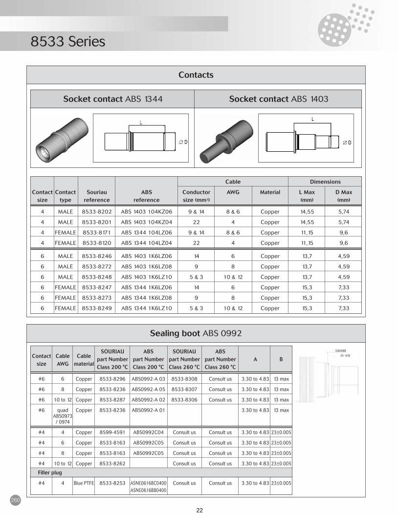
Socket contact ABS 1344 Socket contact ABS 1403
Contacts
Cable Dimensions
Contact Contact Souriau ABS Conductor AWG Material L Max D Maxsize type reference reference size (mm2) (mm) (mm)
4 MALE 8533-8202 ABS 1403 104KZ06 9 & 14 8 & 6 Copper 14,55 5,74
4 MALE 8533-8201 ABS 1403 104KZ04 22 4 Copper 14,55 5,74
4 FEMALE 8533-8171 ABS 1344 104LZ06 9 & 14 8 & 6 Copper 11,15 9,6
4 FEMALE 8533-8120 ABS 1344 104LZ04 22 4 Copper 11,15 9,6
6 MALE 8533-8246 ABS 1403 1K6LZ06 14 6 Copper 13,7 4,59
6 MALE 8533-8272 ABS 1403 1K6LZ08 9 8 Copper 13,7 4,59
6 MALE 8533-8248 ABS 1403 1K6LZ10 5 & 3 10 & 12 Copper 13,7 4,59
6 FEMALE 8533-8247 ABS 1344 1K6LZ06 14 6 Copper 15,3 7,33
6 FEMALE 8533-8273 ABS 1344 1K6LZ08 9 8 Copper 15,3 7,33
6 FEMALE 8533-8249 ABS 1344 1K6LZ10 5 & 3 10 & 12 Copper 15,3 7,33
Sealing boot ABS 0992
SOURIAU ABS SOURIAU ABS Contact Cable Cable
part Number part Number part Number part Number A Bsize AWG material
Class 200 °C Class 200 °C Class 260 °C Class 260 °C
#6 6 Copper 8533-8296 ABS0992-A 03 8533-8308 Consult us 3.30 to 4.83 13 max
#6 8 Copper 8533-8236 ABS0992-A 05 8533-8307 Consult us 3.30 to 4.83 13 max
#6 10 to 12 Copper 8533-8287 ABS0992-A 02 8533-8306 Consult us 3.30 to 4.83 13 max
#6 quad Copper 8533-8236 ABS0992-A 01 3.30 to 4.83 13 maxABS0973
/ 0974
#4 4 Copper 8599-4591 ABS0992C04 Consult us Consult us 3.30 to 4.83 23±0.005
#4 6 Copper 8533-8163 ABS0992C05 Consult us Consult us 3.30 to 4.83 23±0.005
#4 8 Copper 8533-8163 ABS0992C05 Consult us Consult us 3.30 to 4.83 23±0.005
#4 10 to 12 Copper 8533-8262 Consult us Consult us 3.30 to 4.83 23±0.005
Filler plug
#4 4 Blue PTFE 8533-8253 ASNE0616BC0400 Consult us Consult us 3.30 to 4.83 23±0.005ASNE0616BB0400
ABS Power Series 251 à 262_typo mod:Mise en page 1 24/02/2009 11:27 Page 260
22

261
8533 Series
Tooling
Crimping tool (M 22520/23-01)
Pneumatic tool
Die Set (M 22520/23-02) Locator (M 22520/23-11)
Cable Crimping tool Sealing boot
Contact Contact Contact ConductorAWG
Cable Die•set Locator extraction
size type reference size (mm2) material Pneumatic tool
4 MALE 8533-8202 9 & 14 8 & 6 Copper M22520/23-01 M22520/23-02 8533-8193
4 MALE 8533-8201 22 4 Copper M22520/23-01 M22520/23-04 8533-8141 8533-8193
4 FEMALE 8533-8171 9 & 14 8 & 6 Copper M22520/23-01 M22520/23-02 8533-8193
4 FEMALE 8533-8120 22 4 Copper M22520/23-01 M22520/23-04 8533-8141 8533-8193
6 MALE 8533-8246 14 6 Copper M22520/23-01 M22520/23-03 8530-1603
6 MALE 8533-8272 9 8 Copper M22520/23-01 M22520/23-02 8530-1603
6 MALE 8533-8248 5 & 3 10 & 12 Copper M22520/23-01 WA23-112DA 8530-1603
6 FEMALE 8533-8247 14 6 Copper M22520/23-01 M22520/23-03 8530-1603
6 FEMALE 8533-8273 9 8 Copper M22520/23-01 M22520/23-02 8530-1603
6 FEMALE 8533-8249 5 & 3 10 & 12 Copper M22520/23-01 WA23-112DA 8530-1603
Plastic extraction toolMetallic extraction tool
Extraction tool
Contact Material Part numberSize
06Plastic M 811969/14-06 (red)
Metallic 860-197
04Plastic M 811969/14-07 (blue)
Metallic 8533-8175
ABS Power Series 251 à 262_typo mod:Mise en page 1 24/02/2009 11:27 Page 261
23

270
891/2 Series
ElectricalMaximum current rating per contact :
Dielectric withstanding voltage :
Insulation resistance (at 500 Vdc) :at normal temperature . . . . . . . . . . . . . . . 5000 MΩ
Description• Screw coupling• High temperature connector for severe
environment• Fire resistant and fire wall• High level of shock and vibration• Thermocouple contacts available except
hermetic class• Stainless steel shells• Hermetic version available with male
contacts only
Characteristics MechanicalAll 89 series connectors listed below are interchangeable and intermateable with other connectors conformingto MIL-C-5015G, class K.
* Only available on special request
Firewall and fireproof tests891, 892 and 892.04 (ESC.004) series, comply with the following specifications :NF 54140, AIR 8467, test 14MIL-C 5015G class K - 4.3.20 - 4.6.16ESC 00015 and ESC 00024
ApplicationsAircraft enginesHigh temperature applications
StandardsMIL-C 5015 G, class KNFL 54140
inst 1000 Vrms 260 VrmsA 2000 Vrms 360 VrmsD 2800 Vrms 400 VrmsE 3500 Vrms 440 Vrms
service at ground level at 21,000 meters(approx. 69.000 feet)
16 020 10 007.512 035 19 1304 110 55 39
contact temperature (Max.)size 20°C 175°C 260°C
L - connector without contacts
polarizationN (normal), W, X, Y, Z - see table p 275
contacts P - maleS - female
contact layouts - see table p 274shell size - 10SL, 12S, 14S, 16S, 16, 18, 20, 22, 24 or 28
class K - fire resistant (standard)H - hermetic
shell style — - standard connector00 - square flange receptacle with thread for backfittings02 - square flange receptacle without thread for backfittings07 - jam nut receptacle (on request)06 - plug without self-locking26 - plug with self-locking— - hermetic connectors01 - solder fixing receptacle02 - square flange receptacle05 - large flange, solder fixing receptacle
sub series 1 - 200°C2 - 260°C
basic series 89 1 - 00 K -16S- 8 - S - N - L
Ordering information :891/2 connectors without backfittings891/2 hermetic connectors
standard 891 -55° +200°C yes yes 500 on plug yesstandard 892 -55° +260°C yes yes 500 on plug yes
892-04 -55° +260°C yes yes 500 on plug no(ESC.004)
special 891* -55° +200°C yes no 3000 plug and yesreceptacle
special 892* -55° +260°C yes no 3000 plug and yesreceptacle
connector temperature with number of thread interfacialseries range fire-proof self-locking operations plating sealing
891-2 Series 270-280_typo_mod:Mise en page 1 24/02/2009 11:42 Page 270
24

271
891/2 Series
- connectors supplied without contacts (compulsory)
L connectors without contacts
polarization N (normal), W, X, Y, Z - see table p 275
contacts P - male S - female
contact layouts - see table p 274
shell size - 10SL, 12S, 14S, 16S, 16, 18, 20, 22, 24 or 28
type of backfitting A - straight adapter (8590AXX type)C - elbow adapter (on request) (ESC 87 type)E - simple backnut (may be fitted onto A or C)*(8950 EXX type)F - cable clamp (may be fitted onto A or C)*(ESC 86 XX)
shell style 00 - square flange receptacle 07 - jam nut receptacle (on request)26 - plug with self-locking06 - plug without self-locking
sub series 1 - 200°C 2 - 260°C
basic series 89 1 - 26 F - 22 - 14 - P - N - L891/2 connectors with backfittings
04 - compulsory digits - ESC.004 specification
polarization N (normal), W, X, Y, Z - see table p 275
contacts P - male S - female
contact layouts - see table p 274(note : some arrangements are not included in Rolls-Royce JDS 1371 spec.)
shell size - 10SL, 12S, 14S, 16S, 16, 18, 20, 22, 24 or 28
type of backfitting K - no backfittingA - with straight adapter (8590AXX type)C - with elbow adapter (on request) (ESC 87 type)E - with simple backnut (8950 EXX type)F - with cable clamp (ESC 86 XX)
shell style 00 - square flange receptacle 26 - self-locking plug
sub series 2 - 260°C
basic series 89 2 - 26 - E - 24 - 28 - P - N - 04 L
892 suffix 04 connectors with backfittings(including types corresponding to ESC & PAN nos.)
polarization N (normal), W, X, Y, Z - see table p 275
contacts P - male S - female
contact layouts - see table p 274(note : some arrangements are not included in Rolls-Royce JDS 1371 spec.)
shell size - 10SL, 12S, 14S, 16S, 16, 18, 20, 22, 24 or 28
type of backfitting O - no backfitting
shell style A - square flange receptacle K - self-locking plug
specification numberRolls-Royce connector specifications ESC. 004- K - O - 24 - 28 - P - N
As above but Rolls-Royce ESC part nos.
Note : contacts are not supplied with these connectors
891-2 Series 270-280_typo_mod:Mise en page 1 24/02/2009 11:42 Page 271
25

891/2 Series
272
square flange receptacle 891.00K............ P MS3450 KS............. P891.00K............ S MS3450 KS............. S
plug without self locking 891.06K............ P MS3456 KS............. P891.06K............ S MS3456 KS............. S
plug with self locking 891.26K............ P MS3459 KS............. P891.26K............ S MS3459 KS............. S
jam nut receptacle 891.07K............ P891.07K............ S
square flange receptacle 891.02K............ P891.02K............ S
Part number cross reference tablesSouriau 891 (200°C) series/MIL-C 5015G classes KS & HS
MIL-C 83723 Series II
Plugs/receptacles with contacts
Souriau 892 (260°C) series / MIL-C 5015G classes KS & HSPlugs/receptacles with contacts
description Souriau part number MIL-C 5015G class KS
pin. 16.16 8950.4100Bpin. 12.12 8950.4107Bpin. 4.4 8950.4112Bsocket 16S.16 short 8950.4101Csocket 16.16 long 8950.4105Csocket 12.12 8950.4108Bsocket 4.4 8950.4113B
Contactsdescription Souriau part number
solder mounting 891.01H............... Psquare flange receptacle 891.02H............... P MS 3142 HS....C ....Psolder mounting 891.05H............... P MS 3143 HS....C ....P
Hermetic receptaclesdescription Souriau part number MIL-C 5015G class HS
solder mounting 892.01 H................ Psquare flange receptacle 892.02 H................ P MS 3142 HS ...C ...Psolder mounting 892.05 H................ P MS 3143 HS ...C ...P
Hermetic receptaclesdescription Souriau part number MIL-C-5015G class HS
size 16 sealing plugs 8522.390A MS 3187.16.2size 12 sealing plugs 8522.391A MS 3187.12.2size 4 sealing plugs 8950.4152 MS 3187.4.2size 16 insertion/extraction tool 8522.16 MS 3447.16size 12 insertion/extraction tool 8522.12 MS 3447.12size 4 extraction tool 8950.4004 MS 3165.4
Accessoriesdescription Souriau part number MIL-C-5015G
square flange receptacle 892.00 K .......... P MS 3450 KS ...... P892.00 K .......... S MS 3450 KS ...... S
plug without self locking 892.06 K .......... P MS 3456 KS ...... P892.06 K .......... S MS 3456 KS ...... S
plug with self locking 892.26 K .......... P MS 3459 KS ...... P892.26 K .......... S MS 3459 KS ...... S
jam nut receptacle 892.07 K .......... P892.07 K .......... S
square flange receptacle 892.02 K .......... P892.02 K .......... S
description Souriau part number MIL-C 5015G class KS
891-2 Series 270-280_typo_mod:Mise en page 1 24/02/2009 11:42 Page 272
26

891/2 Series
273
Souriau 891 (200°C) series / NFL 54140 class 1 (France)892 (260°C) series / NFL 54140 class 2 (France)
Plugs/receptacles with contacts
square flange receptacle 891 00 .................. 2 91 00 ................. 2892 00 .................. 2 92 00 ................. 2
plug without self locking 891 06 .................. 2 91 06 ................. 2892 06 .................. 2 92 06 ................. 2
jam nut receptacle 891 07 .................. 2 91 07 ................. 2892 07 .................. 2 92 07 ................. 2
description Souriau part number NFL 54140
Backfittings
back nut 8950 E ............ 9R ..............straight adapter 8950 A ............ 9RA ............cable clamp 8950 F ............ 9RC ............
description Souriau part number NFL 54140
square flange receptacle 892.00K ........... 04L ESC.004 AO ...........plug with self locking 892.26K ........... 04L ESC.004 KO ...........hermetic receptacle/solder flange 892.05H ........... 04* ESC.004 CO ...........
Souriau 892 suffix 04(260°C) series / ESC.004 (Rolls-Royce)PAN 6434 (Panavia)
Plugs/receptacles without contactsdescription Souriau part number PAN 6434 ESC.004
back nut 8950.E ................ ESC.004 OA ..................cable clamp 8950.F ................ ESC.004 OB ..................straight adapter 8950.A ................ ESC.004 OD ..................elbow adapter 8950.C ................* ESC.004 OE ..................
Backfittingsdescription Souriau part number PAN 6434 ESC.004
pin, standard, 16.16 8950-5049A 900 PAN 6434 PA ESC.007 PB 16pin, standard, 16.24 8950-5048A 900 PAN 6434 PB ESC.007 PA 16pin, alumel, 16.16 8950-5149 ESC.007 PB 16Apin, chromel,16.16 8950-5143 ESC.007 PB 16Csocket, standard, short 16.16 8950-5052A 900 PAN 6434 SD ESC.007 SB 16Ssocket, standard, short 16.24 8950-5050A 900 PAN 6434 SE ESC.007 SA 16Ssocket, standard, long 16.16 8950-5053A 900 PAN 6434 SF ESC.007 SB 16Lsocket, standard, long 16.24 8950-5051A 900 PAN 6434 SG ESC.007 SA 16Lsocket, alumel, short, 16.16 8950-5151 ESC.007 SB 16SAsocket, alumel, long, 16.16 8950-5153 ESC.007 SB 16LAsocket, chromel, short 16.16 8950-5145 ESC.007 SB 16SCsocket, chromel, long 16.16 8950-5147 900 ESC.007 SB 16LC
Contactsdescription Souriau part number PAN 6434 ESC.004
square flange receptacle with backnut 892.00E ........... 04L PAN 6434 CG ........... ESC.004 AA ........... square flange receptacle with cable clamp 892.00F ........... 04L PAN 6434 CA ........... ESC.004 AB ........... square flange receptacle with straight adapter 892.00A ........... 04L PAN 6434 CB ........... ESC.004 AD ........... plug with straight adapter 892.26A ........... 04L PAN 6434 DB ........... ESC.004 KD ........... plug with cable clamp 892.26F ........... 04L PAN 6434 DA ........... ESC.004 KB ........... plug with elbow adapter 892.26C ........... 04L* PAN 6434 DE ........... ESC.004 KE ...........
Receptacles/plugs with end fittings, without contactsdescription Souriau part number PAN 6434 ESC.004
*on request
*on request
*on request
891-2 Series 270-280_typo_mod:Mise en page 1 24/02/2009 11:42 Page 273
27

274
891/2 Series
Contact layouts10SL 12S 14S 16S 16 18
10SL.3 3#16
10SL.4* 2#16
12S.3 2#16 14S.2 4#16
14S.5 5#16
14S.6 6#16
14S.7 3#16
16.S1 7#16
16.S8* 5#16
16.11 2#12 18.1 10#16
1#1618.5* 2#12
18.11 5#12
20 22 24 28
6#1620.18* 3#12
20.27 14#16
20.29 17#16
22.14 19#16 24.28 24#16 28.12* 26#16
28.21 37#16
3#1628.22 3#40
* these arrangements not available with ESC.004 (FCI Souriau 892 suffix 04)part numbers
these arrangements are available in hermetic receptacles
891-2 Series 270-280_typo_mod:Mise en page 1 24/02/2009 11:42 Page 274
28
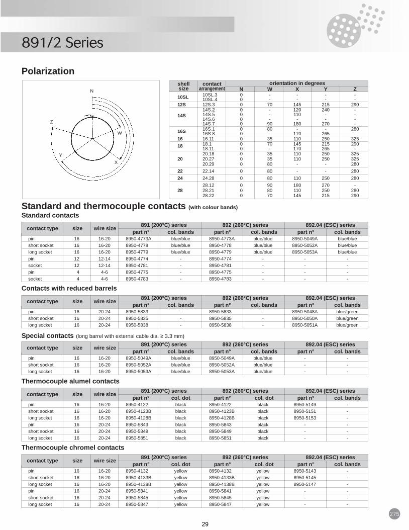
275
891/2 Series
pin 16 16-20 8950-4773A blue/blue 8950-4773A blue/blue 8950-5049A blue/blueshort socket 16 16-20 8950-4778 blue/blue 8950-4778 blue/blue 8950-5052A blue/bluelong socket 16 16-20 8950-4779 blue/blue 8950-4779 blue/blue 8950-5053A blue/bluepin 12 12-14 8950-4774 - 8950-4774 - - -socket 12 12-14 8950-4781 - 8950-4781 - - -pin 4 4-6 8950-4775 - 8950-4775 - - -socket 4 4-6 8950-4783 - 8950-4783 - - -
10SL 10SL.3 0 - - - -10SL.4 0 - - - -
12S 12S.3 0 70 145 215 290
14S14S.2 0 - 120 240 -14S.5 0 - 110 - -14S.6 0 - - - -14S.7 0 90 180 270 -
16S 16S.1 0 80 - - 28016S.8 0 - 170 265 -
16 16.11 0 35 110 250 32518 18.1 0 70 145 215 290
18.11 0 - 170 265 -20.18 0 35 110 250 325
20 20.27 0 35 110 250 32520.29 0 80 - - 280
22 22.14 0 80 - - 28024 24.28 0 80 110 250 280
28.12 0 90 180 270 -28 28.21 0 80 110 250 280
28.22 0 70 145 215 290
Polarization
Standard and thermocouple contacts (with colour bands)Standard contacts
shell contact orientation in degreessize arrangement N W X Y Z
891 (200°C) series 892 (260°C) series 892.04 (ESC) seriescontact type size wire size part n° col. bands part n° col. bands part n° col. bands
pin 16 16-20 8950-4122 black 8950-4122 black 8950-5149 -short socket 16 16-20 8950-4123B black 8950-4123B black 8950-5151 -long socket 16 16-20 8950-4128B black 8950-4128B black 8950-5153 -pin 16 20-24 8950-5843 black 8950-5843 black - -short socket 16 20-24 8950-5849 black 8950-5849 black - -long socket 16 20-24 8950-5851 black 8950-5851 black - -
891 (200°C) series 892 (260°C) series 892.04 (ESC) seriescontact type size wire size part n° col. dot part n° col. dot part n° col. bands
pin 16 16-20 8950-4132 yellow 8950-4132 yellow 8950-5143 -short socket 16 16-20 8950-4133B yellow 8950-4133B yellow 8950-5145 -long socket 16 16-20 8950-4138B yellow 8950-4138B yellow 8950-5147 -pin 16 20-24 8950-5841 yellow 8950-5841 yellow - -short socket 16 20-24 8950-5845 yellow 8950-5845 yellow - -long socket 16 20-24 8950-5847 yellow 8950-5847 yellow - -
891 (200°C) series 892 (260°C) series 892.04 (ESC) seriescontact type size wire size part n° col. dot part n° col. dot part n° col. bands
pin 16 20-24 8950-5833 - 8950-5833 - 8950-5048A blue/greenshort socket 16 20-24 8950-5835 - 8950-5835 - 8950-5050A blue/greenlong socket 16 20-24 8950-5838 - 8950-5838 - 8950-5051A blue/green
891 (200°C) series 892 (260°C) series 892.04 (ESC) seriescontact type size wire size part n° col. bands part n° col. bands part n° col. bands
pin 16 16-20 8950-5049A blue/blue 8950-5049A blue/blue - -short socket 16 16-20 8950-5052A blue/blue 8950-5052A blue/blue - -long socket 16 16-20 8950-5053A blue/blue 8950-5053A blue/blue - -
891 (200°C) series 892 (260°C) series 892.04 (ESC) seriescontact type size wire size part n° col. bands part n° col. bands part n° col. bands
Thermocouple alumel contacts
Thermocouple chromel contacts
Contacts with reduced barrels
Special contacts (long barrel with external cable dia. ≥ 3.3 mm)
N
Z
W
YX
891-2 Series 270-280_typo_mod:Mise en page 1 24/02/2009 11:42 Page 275
29

891/2 Series
276
DimensionsPlugs - type 06 and type 26
10SL 39.65 23.50 5/8”-24 1.56 0.93 UNEF.2A
12S 39.65 25.50 †1.56 1.00
14S 39.65 28.00 3/4”-20 1.56 1.10 UNEF.2A
16S 39.65 31.90 7/8”-20 1.56 1.26 UNEF.2A
16 44.15 31.90 7/8”-20 1.74 1.26 UNEF.2A
18 44.15 34.00 1”-20 1.74 1.34 UNEF.2A
20 44.15 37.50 13/16”-18 1.74 1.48 UNEF.2A
22 44.15 40.60 11/4”-18 1.74 1.60 UNEF.2A
24 44.15 43.80 17/16”-18 1.74 1.72 UNEF.2A
28 44.15 50.00 15/8”-18 1.74 1.97 UNEF.2A
shell L M Vsize
Square flange receptacles - type 00
Panel cut-out
10SL 1.60 39.65 14.90 15.84 18.25 25.25 3.80 5/8”-24 .06 1.56 .59 .62 .72 .99 .15 UNEF.2A
12S 1.60 39.65 14.90 19.02 20.60 27.60 3.80 †.06 1.56 .59 .75 .81 1.09 .15
14S 1.60 39.65 14.90 22.19 23.00 30.00 3.80 3/4”-20 .06 1.56 .59 .87 .91 1.18 .15 UNEF.2A
16S 1.60 39.65 14.90 25.40 24.60 32.62 3.80 7/8”-20 .06 1.56 .59 1.00 .97 1.28 .15 UNEF.2A
16 1.60 44.15 19.65 25.40 24.60 32.62 3.80 7/8” -20 .06 1.74 .77 1.00 .97 1.28 .15 UNEF.2A
18 1.60 44.15 19.65 28.50 26.97 35.00 4.60 1”-20 .06 1.74 .77 1.12 1.06 1.38 .18 UNEF.2A
20 2.00 44.15 19.65 31.70 29.40 37.40 4.60 13/16”-18 .08 1.74 .77 1.25 1.16 1.47 .18 UNEF.2A
22 2.00 44.15 19.65 34.88 31.75 40.80 4.60 11/4”-18 .08 1.74 .77 1.37 1.25 1.61 .18 UNEF.2A
24 2.00 44.15 20.65 38.05 34.90 43.90 4.60 17/16”-18 .08 1.74 .81 1.50 1.37 1.73 .18 UNEF.2A
28 2.00 44.15 20.65 44.40 39.65 50.65 4.60 15/8” -18 .08 1.74 .81 1.75 1.56 1.99 .18 UNEF.2A
shell K L M N R S T Vsize
10SL 20.50 18.25 3.80 10.00 17.00 18.25 3.80 6.0.81 .72 .15 .39 .67 .72 .15 .24
12S 20.50 20.60 3.80 10.00 20.20 20.60 3.80 6.0.81 .81 .15 .39 .79 .81 .15 .24
14S 23.50 23.00 3.80 10.00 23.40 23.00 3.80 6.0.93 .91 .15 .39 .92 .91 .15 .24
16S 26.50 24.60 3.80 10.00 26.60 24.60 3.80 6.01.04 .97 .15 .39 1.05 .97 .15 .24
16 26.50 24.60 3.80 10.00 26.60 24.60 3.80 5.301.04 .97 .15 .39 1.05 .97 .15 .21
18 29.80 27.00 4.60 10.00 29.70 27.00 4.60 5.301.17 1.06 .18 .39 1.17 1.06 .18 .21
20 34.60 29.40 4.60 10.00 32.90 29.40 4.60 5.301.36 1.16 .18 .39 1.29 1.16 .18 .21
22 36.20 31.75 4.60 10.00 36.10 31.75 4.60 5.301.43 1.25 .18 .39 1.42 1.25 .18 .21
24 41.10 34.90 4.60 10.00 39.30 34.90 4.60 5.301.62 1.37 .18 .39 1.55 1.37 .18 .21
28 46.30 39.65 4.60 10.00 45.60 39.65 4.60 5.301.82 1.56 .18 .39 1.79 1.56 .18 .21
shell front of panel rear of panelsize A B C D Max A B C E Max
† : 5/8” - 24 UNEF.2A for all types exceptRolls-Royce ESC.004 connectorswhich have an 11/16” - 24 UNEF.2Athread
† : 5/8” - 24 NEF.2A for all types except Rolls-Royce ESC.004 connectors whichhave an 11/16” - 24 NEF.2A thread
M
L
M
ØN S
L
B
B ØA
D
panel
4 holes ØC
E
RThread V
K 4 holes ØT
thread V
891-2 Series 270-280_typo_mod:Mise en page 1 24/02/2009 11:42 Page 276
30

277
891/2 Series
10SL 2.00 32.00 22.30 15.84 26.00 20.00 5/8”-24.08 1.26 .88 .62 1.02 .79 UNEF.2A
12S 2.00 3200 22.30 19.02 29.00 23.00 †.08 1.26 .88 .75 1.14 .91
14S 2.00 32.00 22.30 22.19 32.50 26.97 3/4”-20.08 1.26 .88 .87 1.28 1.06 UNEF.2A
16S 2.00 32.00 22.30 25.40 36.50 30.17 7/8”-24.08 1.26 .88 1.00 1.44 1.19 UNEF.2A
16 2.00 36.50 26.60 25.40 36.50 30.17 7/8”-20.08 1.44 1.05 1.00 1.44 1.19 UNEF.2A
18 2.20 36.50 26.60 28.50 39.00 33.32 1”-20.09 1.44 1.05 1.12 1.54 1.31 UNEF.2A
20 2.20 36.50 26.60 31.70 44.00 36.52 13/16”-18.09 1.44 1.05 1.25 1.73 1.44 UNEF.2A
22 2.20 36.50 26.60 34.88 47.20 39.67 11/4”-18.09 1.44 1.05 1.37 1.86 1.56 UNEF.2A
24 2.20 36.50 26.60 38.05 50.50 42.87 17/16”-18.09 1.44 1.05 1.50 1.99 1.69 UNEF.2A
28 2.20 36.50 26.60 44.40 57.00 50.00 15/8”-18.09 1.44 1.05 1.75 2.24 1.97 UNEF.2A
Jam nut receptacles - type 07shell K L M N S T Vsize
10SL 1.60 32.00 14.90 15.84 18.25 25.25 3.80 14.50.06 1.26 .59 .62 .72 .99 .15 .57
12S 1.60 32.00 14.90 19.02 20.60 27.60 3.80 14.50.06 1.26 .59 .75 .81 1.09 .15 .57
14S 1.60 32.00 14.90 22.19 23.00 30.00 3.80 17.40.06 1.26 .59 .87 .91 1.18 .15 .69
16S 1.60 32.00 14.90 25.40 24.60 32.62 3.80 20.65.06 1.26 .59 1.00 .97 1.28 .15 .81
16 1.60 36.50 19.65 25.40 24.60 32.62 3.80 20.65.06 1.44 .77 1.00 .97 1.28 .15 .81
18 1.60 36.50 19.65 28.50 26.97 35.00 4.60 23.70.06 1.44 .77 1.12 1.06 1.38 .18 .93
20 2.00 36.50 19.65 31.70 29.40 37.40 4.60 28.15.08 1.44 .77 1.25 1.16 1.47 .18 1.11
22 2.00 36.50 19.65 34.88 31.75 40.80 4.60 29.95.08 1.44 .77 1.37 1.25 1.61 .18 1.18
24 2.00 36.50 20.65 38.05 34.90 43.90 4.60 33.25.08 1.44 .81 1.50 1.37 1.73 .18 1.31
28 2.00 36.50 20.65 44.40 39.65 50.65 4.60 39.40.08 1.44 .81 1.75 1.56 1.99 .18 1.55
Square flange receptacles - type 02shell K L M N R S T Wsize
10SL 20.50 18.25 3.80 10.00 17.00 18.25 3.80 6.0.81 .72 .15 .39 .67 .72 .15 .24
12S 20.50 20.60 3.80 10.00 20.20 20.60 3.80 6.0.81 .81 .15 .39 .79 .81 .15 .24
14S 23.50 23.00 3.80 10.00 23.40 23.00 3.80 6.0.93 .91 .15 .39 .92 .91 .15 .24
16S 26.50 24.60 3.80 10.00 26.60 24.60 3.80 6.01.04 .97 .15 .39 1.05 .97 .15 .24
16 26.50 24.60 3.80 10.00 26.60 24.60 3.80 5.301.04 .97 .15 .39 1.05 .97 .15 .21
18 29.80 27.00 4.60 10.00 29.70 27.00 4.60 5.301.17 1.06 .18 .39 1.17 1.06 .18 .21
20 34.60 29.40 4.60 10.00 32.90 29.40 4.60 5.301.36 1.16 .18 .39 1.29 1.16 .18 .21
22 36.20 31.75 4.60 10.00 36.10 31.75 4.60 5.301.43 1.25 .18 .39 1.42 1.25 .18 .21
24 41.10 34.90 4.60 10.00 39.30 34.90 4.60 5.301.62 1.37 .18 .39 1.55 1.37 .18 .21
28 46.30 39.65 4.60 10.00 45.60 39.65 4.60 5.301.82 1.56 .18 .39 1.79 1.56 .18 .21
shell front of panel rear of panelsize A B C D Max A B C E Max
10SL 17.00 19.00 1.80 10.50 1.50.67 .75 .07 .41 .06
12S 20.20 22.20 1.80 10.50 1.50.79 .87 .07 .41 .06
14S 23.40 25.40 1.80 10.50 1.50.92 1.00 .07 .41 .06
16S 26.60 28.60 1.80 10.50 1.501.05 1.13 .07 .41 .06
16 26.60 28.60 1.80 9.30 1.501.05 1.13 .07 .37 .06
18 29.70 31.70 1.80 9.30 1.501.17 1.25 .07 .37 .06
20 32.90 34.90 1.80 9.30 1.501.29 1.37 .07 .37 .06
22 36.10 38.10 1.80 9.30 1.501.42 1.50 .07 .37 .06
24 39.30 40.30 1.80 9.30 1.501.55 1.59 .07 .37 .06
28 45.60 47.60 1.80 9.30 1.501.79 1.87 .07 .37 .06
shell A B C D Max D minsize
† : 5/8” - 24 UNEF.2Afor all typesexceptRolls-RoyceESC.004connectors whichhave an 11/16” - 24UNEF.2A thread
Panel cut-out
Panel cut-out
L
ØSØT
DC
B
M K
RL
B
4 holes ØC
ØAB
D E
panel
ØN
W S
R
4 holes ØT
ØA
ØN
Thread V
M K
891-2 Series 270-280_typo_mod:Mise en page 1 24/02/2009 11:42 Page 277
31

891/2 Series
278
10SL 1.60 20.40 16.55 15.84 15.84 12.70 29.20.06 .80 .65 .62 .62 .50 1.15
12S 1.60 20.40 16.55 19.02 19.02 16.70 29.20.06 .80 .65 .75 .75 .66 1.15
14S 1.60 20.40 16.55 22.19 22.19 18.30 29.20.06 .80 .65 .87 .87 .72 1.15
16S 1.60 20.40 16.55 25.40 25.40 21.40 29.20.06 .80 .65 1.00 1.0 .84 1.15
18 2.00 25.15 20.65 28.50 28.50 24.70 33.70.08 .99 .81 1.12 1.12 0.97 1.32
20 2.00 25.15 21.05 31.70 32.50 29.40 33.70.08 .99 .83 1.25 1.25 1.15 1.32
28 2.00 25.15 21.05 44.40 44.40 41.30 33.70.08 .99 .83 1.74 1.74 1.62 1.32
Hermetic solder fixing recep. type 01Hshell K L M N Q R Ssize
10SL 1.60 20.40 16.55 15.84 25.25 12.70 18.25 29.20.06 .80 .65 .62 .99 .50 .72 1.15
12S 1.60 20.40 16.55 19.02 27.60 16.70 20.60 29.20.06 .80 .65 .75 1.08 .66 .81 1.15
14S 1.60 20.40 16.55 22.19 30.00 18.30 23.00 29.20.06 .80 .65 .87 1.18 .72 .91 1.15
16S 1.60 20.40 16.55 25.40 32.60 21.40 24.60 29.20.06 .80 .65 1.00 1.28 .84 .97 1.15
18 2.00 25.15 20.65 28.50 35.00 24.70 26.97 33.70.08 .99 .81 1.12 1.38 .97 1.06 1.32
20 2.00 25.15 21.05 31.70 37.40 29.40 29.40 33.70.08 .99 .83 1.25 1.47 1.15 1.16 1.35
28 2.00 25.15 21.05 44.40 50.65 41.30 39.65 33.70.08 .99 .83 1.74 1.99 1.62 1.56 1.32
shell K L M N Q R S Vsize
10SL 13.20 18.25 3.80 17.00 18.25 3.80 6.00.52 .72 .15 .67 .72 .15 .24
12S 17.20 20.60 3.80 20.20 20.60 3.80 6.00.68 .81 .15 .79 .81 .15 .24
14S 18.80 23.00 3.80 23.40 23.00 3.80 6.00.74 .91 .15 .92 .91 .15 .24
16S 21.90 24.60 3.80 26.60 24.60 3.80 6.00.86 .97 .15 1.05 .97 .15 .24
18 25.20 27.00 4.60 29.70 27.00 4.60 5.30.99 1.06 .18 1.17 1.06 .18 .21
20 29.90 29.40 4.60 32.90 29.40 4.60 5.301.18 1.16 .18 1.29 1.16 .18 .21
28 41.80 39.65 4.60 45.60 39.65 4.60 5.301.65 1.56 .18 1.79 1.56 .18 .21
shell front of panel rear of panelsize A B C A B C D Max
10SL 13.20.52
12S 17.20.68
14S 18.80.74
16S 21.90.86
18 25.20.99
20 29.901.18
28 41.801.65
shell Asize
Hermetic square flange recep. type 02H
Panel cut-out
Panel cut-out
Ø A
M K
LS
solder
M
LV
B
D
B ØA
panel
ØC
4 holes
ØRØ
N
S Q
K 4 holes ØT (see table page 251)
ØN ØR
ØQ
S
891-2 Series 270-280_typo_mod:Mise en page 1 24/02/2009 11:42 Page 278
32

279
891/2 Series
10SL 1.60 20.40 16.55 15.84 22.00 12.70 29.20.06 .80 .65 .62 .86 .50 1.15
12S 1.60 20.40 16.55 19.02 25.15 16.70 29.20.06 .80 .65 .75 .99 .66 1.15
14S 1.60 20.40 16.55 22.19 28.35 18.30 29.20.06 .80 .65 .87 1.11 .72 1.15
16S 1.60 20.40 16.55 25.40 31.50 21.40 29.20.06 .80 .65 1.00 1.24 .84 1.15
18 2.00 25.15 20.65 28.50 34.65 24.70 33.70.08 .99 .81 1.12 1.36 .97 1.32
20 2.00 25.15 21.05 31.70 37.85 29.40 33.70.08 .99 .83 1.25 1.49 1.15 1.32
28 2.00 25.15 21.05 44.40 50.55 41.30 33.70.08 .99 .83 1.74 1.99 1.62 1.32
Hermetic solder fixing recep. type 05Hshell K L M N Q R Ssize
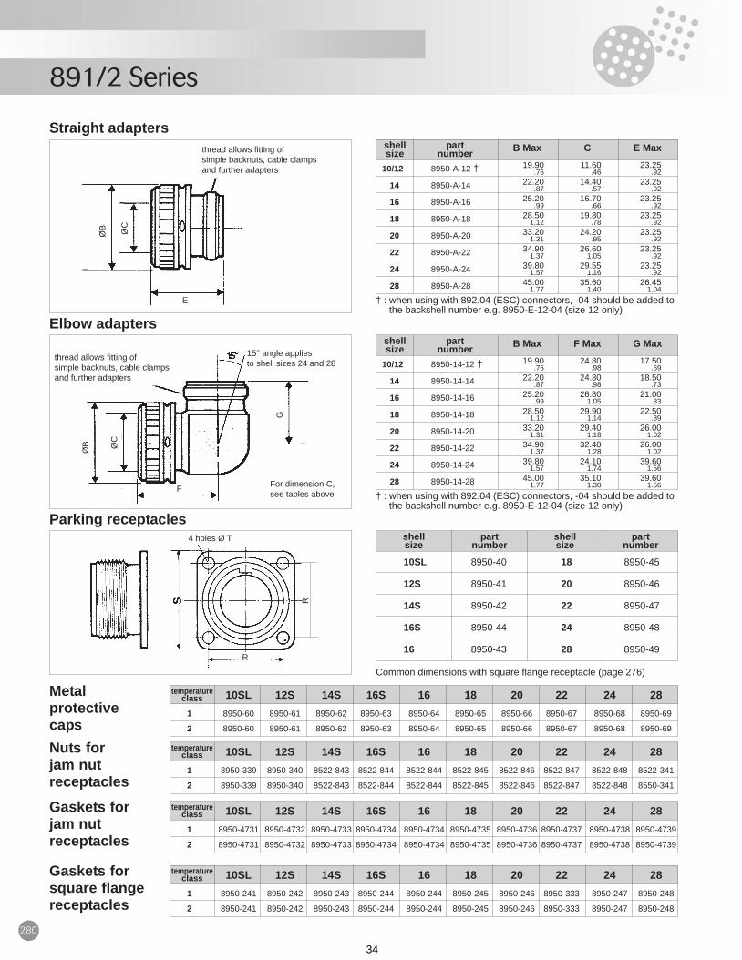
10/12 8950-E-12 † 13.00 19.20 11.60.52 .76 .46
14 8950-E-14 13.00 22.20 14.40.52 .87 .57
16 8950-E-16 13.00 25.20 16.70.52 .99 .66
18 8950-E-18 13.00 28.50 19.80.52 1.12 .78
20 8950-E-20 13.00 33.30 24.20.52 1.31 .95
22 8950-E-22 13.00 34.90 26.60.52 1.37 1.05
24 8950-E-24 13.00 39.80 29.55.52 1.57 1.16
28 8950-E-28 13.00 45.00 35.60.52 1.77 1.40
shell part A B Max Csize number
Simple backnuts
10SL 13.20.52
12S 17.20.68
14S 18.20.74
16S 21.90.86
18 25.20.99
20 29.901.18
28 41.801.65
shell Asize
† : when using with 892.04 (ESC) connectors, -04 should be added tothe backshell number e.g. 8950-E-12-04 (size 12 only)
10/12 8950-F-12 †
14 8950-F-14
16 8950-F-16
18 8950-F-18
20 8950-F-20
22 8950-F-22
24 8950-F-24
28 8950-F-28
shell partsize number
Straight cable clamps
Panel cut-out
M K
LS
Solder
ØA
ØB
ØC
A
ØN
ØR
ØQ
† : when using with 892.04 (ESC)connectors, -04 should be added tothe backshell number e.g.8950-F-12-04 (size 12 only)
891-2 Series 270-280_typo_mod:Mise en page 1 24/02/2009 11:42 Page 279
33
891/2 Series
280
1 8950-60 8950-61 8950-62 8950-63 8950-64 8950-65 8950-66 8950-67 8950-68 8950-69
2 8950-60 8950-61 8950-62 8950-63 8950-64 8950-65 8950-66 8950-67 8950-68 8950-69
10/12 8950-A-12 † 19.90 11.60 23.25.76 .46 .92
14 8950-A-14 22.20 14.40 23.25.87 .57 .92
16 8950-A-16 25.20 16.70 23.25.99 .66 .92
18 8950-A-18 28.50 19.80 23.251.12 .78 .92
20 8950-A-20 33.20 24.20 23.251.31 .95 .92
22 8950-A-22 34.90 26.60 23.251.37 1.05 .92
24 8950-A-24 39.80 29.55 23.251.57 1.16 .92
28 8950-A-28 45.00 35.60 26.451.77 1.40 1.04
shell part B Max C E Maxsize number
Straight adapters
† : when using with 892.04 (ESC) connectors, -04 should be added tothe backshell number e.g. 8950-E-12-04 (size 12 only)
10/12 8950-14-12 † 19.90 24.80 17.50.76 .98 .69
14 8950-14-14 22.20 24.80 18.50.87 .98 .73
16 8950-14-16 25.20 26.80 21.00.99 1.05 .83
18 8950-14-18 28.50 29.90 22.501.12 1.14 .89
20 8950-14-20 33.20 29.40 26.001.31 1.18 1.02
22 8950-14-22 34.90 32.40 26.001.37 1.28 1.02
24 8950-14-24 39.80 24.10 39.601.57 1.74 1.56
28 8950-14-28 45.00 35.10 39.601.77 1.30 1.56
shell part B Max F Max G Maxsize number
Elbow adapters
† : when using with 892.04 (ESC) connectors, -04 should be added tothe backshell number e.g. 8950-E-12-04 (size 12 only)
Common dimensions with square flange receptacle (page 276)
10SL 8950-40 18 8950-45
12S 8950-41 20 8950-46
14S 8950-42 22 8950-47
16S 8950-44 24 8950-48
16 8950-43 28 8950-49
shell part shell partsize number size number
Parking receptacles
temperature 10SL 12S 14S 16S 16 18 20 22 24 28classMetal protective caps
1 8950-339 8950-340 8522-843 8522-844 8522-844 8522-845 8522-846 8522-847 8522-848 8522-341
2 8950-339 8950-340 8522-843 8522-844 8522-844 8522-845 8522-846 8522-847 8522-848 8550-341
temperature 10SL 12S 14S 16S 16 18 20 22 24 28classNuts for jam nutreceptacles
1 8950-4731 8950-4732 8950-4733 8950-4734 8950-4734 8950-4735 8950-4736 8950-4737 8950-4738 8950-4739
2 8950-4731 8950-4732 8950-4733 8950-4734 8950-4734 8950-4735 8950-4736 8950-4737 8950-4738 8950-4739
temperature 10SL 12S 14S 16S 16 18 20 22 24 28classGaskets for jam nutreceptacles
1 8950-241 8950-242 8950-243 8950-244 8950-244 8950-245 8950-246 8950-333 8950-247 8950-248
2 8950-241 8950-242 8950-243 8950-244 8950-244 8950-245 8950-246 8950-333 8950-247 8950-248
temperature 10SL 12S 14S 16S 16 18 20 22 24 28classGaskets forsquare flangereceptacles
E
F
4 holes Ø T
R
R
thread allows fitting ofsimple backnuts, cable clampsand further adapters
thread allows fitting ofsimple backnuts, cable clampsand further adapters
15° angle appliesto shell sizes 24 and 28
For dimension C,see tables above
ØB
ØB
ØC
ØC
G
891-2 Series 270-280_typo_mod:Mise en page 1 24/02/2009 11:42 Page 280
34