miro: multi path interdomain routing - princeton university
TRANSCRIPT

MIRO: MULTI -PATH INTERDOMAIN ROUTING
WEN XU
A D ISSERTATION
PRESENTED TO THEFACULTY
OF PRINCETON UNIVERSITY
IN CANDIDACY FOR THE DEGREE
OF DOCTOR OFPHILOSOPHY
RECOMMENDED FORACCEPTANCE
BY THE DEPARTMENT OF
COMPUTER SCIENCE
ADVISOR: PROFESSORJENNIFER REXFORD
SEPTEMBER 2009

c© Copyright by Wen Xu, 2009. All rights reserved.

Abstract
The Internet consists of thousands of independent domains with different, and sometimes
competing, business interests. However, the current interdomain routing protocol (BGP)
limits each router to using a single route for each destination prefix, which may not sat-
isfy the diverse requirements of end users. Recent proposals for source routing offer an
alternative where end hosts or edge routers select the end-to-end paths. However, source
routing leaves transit domains with very little control andintroduces difficult scalability
and security challenges. In this dissertation, a multi-path interdomain routing protocol
called MIRO is presented, it offers substantial flexibilitywhile giving transit domains
control over the flow of traffic through their infrastructureand avoiding state explosion
in disseminating reachability information. In MIRO, routers learn default routes through
the existing BGP protocol, and arbitrary pairs of domains can negotiate the use of addi-
tional paths (bound to tunnels in the data plane) tailored totheir special needs. It retains
the simplicity of the BGP protocol for most traffic, and remains backward compatible
with BGP to allow for incremental deployability. Experiments with Internet topology
and routing data illustrate that MIRO offers tremendous flexibility for path selection with
reasonable overhead.
iii

Acknowledgments
First I would like to thank my advisor Jennifer Rexford, I cannever finish this thesis
without her encouragement and support. I can still rememberhow we developed MIRO
from the initial ideas to the final publication. I am very lucky to have an advisor who is
so open-minded, inspriational, and supportive.
I also would like to thank Kai Li and Larry Peterson for their guidance during my
earlier years in Princeton. I consider myself extremely lucky to be able to work with so
many wise people, and I want to thank all of them for not givingup on me when I got
stuck on research.
Other members in my thesis committee gave me lots of help as well. A special thank
you to Vivek Pai and Andrea LaPaugh for their valuable feedback on the thesis and on
the work itself.
I want to thank Ming Zhang for his valuable comments on the early draft of this
work, and Ioannis Avramopoulos, Elliott Karpilovsky, Dan Wendlandt, Yaping Zhu, and
the anonymous reviewers for their suggestions. I also need to express my gratefulness
to other friends and colleagues: Zhifeng Chen, Zhining Huang, Sanjeev Kumar, Limin
Jia, Junwen Lai, Jie Luo, Qin Lv, Xinming Ou, Ruoming Pang, Yaoping Ruan, Tammo
Spalink, Fei Sun, Gang Tan, Grant Wallace, Yong Wang, Zhe Wang, Dinghao Wu, Chi
Zhang, Fengzhou Zheng. Also, I owe a special thanks to Melissa Lawson for all the help
she gave me during my Princeton years.
My research was supported by DOE grant, NSF grant, HSARPA grant, a URP grant
from Cisco, and a grant from the Intel Research Council. These kind support made my
research possible.
Finally, I want to thank my parents, Bangji Xu and Liyu Wen, and my husband, Hai
Fang, for encouraging me to join the PhD program and finally tofinish the thesis.
iv

Contents
Abstract . . . . . . . . . . . . . . . . . . . . . . . . . . . . . . . . . . . . . . iii
1 Introduction 1
1.1 Interdomain Routing in Today’s Internet . . . . . . . . . . . . .. . . . . 3
1.2 Our Proposal for Multi-path Interdomain Routing . . . . . .. . . . . . . 5
2 Background and Related Work 9
2.1 The Three Routing Architectures . . . . . . . . . . . . . . . . . . . .. . 10
2.1.1 BGP . . . . . . . . . . . . . . . . . . . . . . . . . . . . . . . . . 10
2.1.2 Source Routing . . . . . . . . . . . . . . . . . . . . . . . . . . . 13
2.1.3 Overlay Networks . . . . . . . . . . . . . . . . . . . . . . . . . 15
2.2 Interdomain Routing in Today’s Internet . . . . . . . . . . . . .. . . . . 17
2.2.1 The Prevalent Interdomain Business Relationships . .. . . . . . 18
2.2.2 The BGP Protocol . . . . . . . . . . . . . . . . . . . . . . . . . 19
2.2.3 Routing Convergence . . . . . . . . . . . . . . . . . . . . . . . . 22
2.3 Related Work . . . . . . . . . . . . . . . . . . . . . . . . . . . . . . . . 23
3 MIRO Protocol Design 30
3.1 AS-Level Path-Vector Protocol . . . . . . . . . . . . . . . . . . . . .. . 31
3.2 Pull-based Supplemental Route Retrieval . . . . . . . . . . . .. . . . . 33
v

3.3 Bilateral Negotiation Between ASes . . . . . . . . . . . . . . . . .. . . 35
3.4 Selective Export of Extra Routes . . . . . . . . . . . . . . . . . . . .. . 37
3.5 Tunnels for Forwarding Data Packets . . . . . . . . . . . . . . . . .. . . 38
3.6 Summary of MIRO Protocol . . . . . . . . . . . . . . . . . . . . . . . . 39
4 MIRO Implementation 40
4.1 Intra-AS Architecture . . . . . . . . . . . . . . . . . . . . . . . . . . . .41
4.2 Data Plane Packet Encapsulation . . . . . . . . . . . . . . . . . . . .. . 44
4.3 Control Plane Tunnel Management . . . . . . . . . . . . . . . . . . . .. 46
4.4 Summary . . . . . . . . . . . . . . . . . . . . . . . . . . . . . . . . . . 48
5 Performance Evaluation 50
5.1 Evaluation Methodology . . . . . . . . . . . . . . . . . . . . . . . . . . 51
5.2 Exposing the Underlying Path Diversity . . . . . . . . . . . . . .. . . . 53
5.3 Avoiding an AS in Default Path . . . . . . . . . . . . . . . . . . . . . . .56
5.3.1 Success Rate of Different Policies . . . . . . . . . . . . . . . .. 57
5.3.2 Avoiding State Explosions . . . . . . . . . . . . . . . . . . . . . 58
5.3.3 Incremental Deployment . . . . . . . . . . . . . . . . . . . . . . 60
5.4 Controlling Incoming Traffic . . . . . . . . . . . . . . . . . . . . . . .. 63
5.5 Summary . . . . . . . . . . . . . . . . . . . . . . . . . . . . . . . . . . 67
6 Routing Policies 68
6.1 Policy Configuration in Current Internet . . . . . . . . . . . . .. . . . . 68
6.2 Multi-path Routing Policies . . . . . . . . . . . . . . . . . . . . . . .. . 70
6.2.1 Negotiation Related Rules . . . . . . . . . . . . . . . . . . . . . 70
6.2.2 Route Selection Rules . . . . . . . . . . . . . . . . . . . . . . . 71
vi
6.3 Multi-path Policy Specification Example . . . . . . . . . . . . .. . . . . 72
7 Convergence Proof 75
7.1 Abstract Models . . . . . . . . . . . . . . . . . . . . . . . . . . . . . . . 76
7.1.1 BGP with Routing Tunnels . . . . . . . . . . . . . . . . . . . . . 76
7.1.2 The Distributed Path Selection . . . . . . . . . . . . . . . . . . .78
7.1.3 Hierarchical AS Graph . . . . . . . . . . . . . . . . . . . . . . . 81
7.2 BGP Policy Guidelines that Guarantees Convergence . . . .. . . . . . . 82
7.3 MIRO Guidelines that Guarantee Convergence . . . . . . . . . .. . . . 86
7.3.1 Adding Tunnels as a Higher Level Layer . . . . . . . . . . . . . 87
7.3.2 Advertising Tunnels Only to Leaf Nodes . . . . . . . . . . . . .91
7.3.3 Using Same-class Routes for Tunnels . . . . . . . . . . . . . . .94
7.4 Mixing and Matching the Above Guidelines . . . . . . . . . . . . .. . . 108
7.4.1 Practical Implications and Summary . . . . . . . . . . . . . . .. 110
8 Conclusions 113
vii

List of Figures
1.1 Single-path Routing to AS F . . . . . . . . . . . . . . . . . . . . . . . . 4
2.1 The Formation of BGP Routing Table . . . . . . . . . . . . . . . . . . .11
2.2 Source Routing . . . . . . . . . . . . . . . . . . . . . . . . . . . . . . . 14
2.3 Overlay Networks . . . . . . . . . . . . . . . . . . . . . . . . . . . . . . 16
3.1 Multi-path Routing Example . . . . . . . . . . . . . . . . . . . . . . . .34
4.1 Intra-AS Routing Architecture . . . . . . . . . . . . . . . . . . . . .. . 43
4.2 Control Plane Negotiation Example . . . . . . . . . . . . . . . . . .. . 47
5.1 Node Distribution . . . . . . . . . . . . . . . . . . . . . . . . . . . . . . 52
5.2 Number of Available Routes . . . . . . . . . . . . . . . . . . . . . . . . 54
5.3 Number of Available Routes (Cont.) . . . . . . . . . . . . . . . . . .. . 55
5.4 Incremental Deployment . . . . . . . . . . . . . . . . . . . . . . . . . . 61
5.5 Incremental Deployment(Cont.) . . . . . . . . . . . . . . . . . . . .. . 62
5.6 Multi-homed Stub ASes with Power Nodes . . . . . . . . . . . . . . .. 65
5.7 Multi-homed Stub ASes with Power Nodes(Cont.) . . . . . . . .. . . . . 66
7.1 An Example where MIRO Does Not Converge . . . . . . . . . . . . . . .87
7.2 An Example where MIRO Does Not Converge under Strict Policy . . . . 95
viii

Chapter 1
Introduction
As of January 2009, the Internet Systems Consortium estimates that there are around 625
million individual hosts in the Internet [19]. It would be extremely difficult for a single
authority to effectively manage the communications among such a gigantic body of inde-
pendent hosts; therefore, the current Internet is structured more like a loose federation of
Autonomous Systems (AS). Each AS is independently administered by a single authority,
such as a university, a company, or a government agency. Accordingly, the routing in the
Internet can be divided into two parts: intradomain routing, which deals with the routing
inside one AS; and interdomain routing, which deals with therouting among different
ASes.
Each AS is assigned a unique AS number ranging from 0 to 65535.Then an AS
path is described using a sequence of AS numbers. Each AS alsoowns a range of IP
addresses; it could decide to further split its IP addressesinto smaller groups with each
group containing some contiguous IP addresses called an IP prefix. Interdomain routing
paths are calculated for each IP prefix; therefore, different IP prefixes originating from
the same AS can take different AS paths simultaneously. ManyASes advertise more than
1

one IP prefix, either because the IP addresses they own are notcontiguous or because
the ASes want more flexible route selections. In fact, because of the prevalence of multi-
homing, in which an AS is connected to more than one neighbor,the number of prefixes
grows more rapidly than AS numbers in today’s Internet.
Interdomain routing is an important component of Internet routing, as a great deal
of traffic traverses more than one AS. Moreover, the fact thateach AS is managed by a
different authority makes the situation more complicated compared to intradomain rout-
ing. In intradomain routing, all resources are administered by the same authority. This
authority can use all the resources inside the AS, and its ultimate goal is routing pack-
ets in the most effective way. But in interdomain routing, different authorities may have
different and sometimes competing business interests, which have a profound impact on
interdomain routing practices. For example, ASes generally are not willing to reveal their
internal network topologies or routing policies, and they usually choose the routing poli-
cies which benefit themselves the most. As a result, interdomain routing is complicated,
because it should have the following characteristics:
• Each AS should be able to express local policies that reflect its business interests.
• The protocol needs to be scalable. In terms of scalability, the protocol should
consider the large number of ASes, IP prefixes, and potentialpaths present in the
Internet. First, the number of unique ASes advertised in theInternet is around
31,000 and it is still growing. Second, each AS may advertisemultiple prefixes, and
the number of prefixes recently has been growing more rapidlythan the number of
ASes. Lastly, each AS may learn more than one path to each prefix, so the number
of paths in the Internet grows even larger.
• The privacy of each AS should be respected. In the current Internet, the routing is
2

IP Prefix Next Hop AS Path* 128.112.0.0/16 198.32.8.196 11537 10466 88* 144.228.241.81 1239 7018 88 88 88*> 205.189.32.44 6509 11537 10466 88*> 128.113.11.0/24 205.189.32.44 6509 3754 91
Table 1.1: Part of a BGP table
divided into intradomain and interdomain routing, so that an AS can avoid sharing
internal details with outsiders. This separation not only improves security, but also
helps to confine the effect of internal failures.
In the following sections, this dissertation will briefly introduce how today’s inter-
domain routing protocol works, then motivate the design of anew interdomain routing
protocol called MIRO (Multi-path Interdomain ROuting).
1.1 Interdomain Routing in Today’s Internet
In today’s Internet, a unique 16-bit or 32-bit AS number is assigned to each AS. In April
2009, around 31,000 active ASes were detected by RouteView’s observation points [30].
Border Gateway Protocol (BGP) is the current interdomain routing protocol used in the
Internet [29]. Section 2.2.2 will describe the BGP protocolin more detail, only a brief
overview is presented here.
BGP is a path-vector protocol, in which each router only advertises its own paths to
its immediate neighbors. Table 1.1 shows part of a real BGP table in a router. Each
BGP entry is associated with a certain IP prefix that is a rangeof IP addresses. For
example, 128.112.0.0/16 means matching the first 16 bits of 128.112.0.0, which stands for
IP address range 128.112.0.0 to 128.112.255.255. There maybe more than one candidate
entry associated with each IP prefix, the table shows three candidate entries for IP prefix
3

D
B C
E
FA
ABEF*ADEF
BEF*BCF
DEF*DABEF
CBEFCEFCF*
EF*ECF
F*
Figure 1.1: Single-path Routing to AS F
128.112.0.0/16. Each candidate entry carries with it a NextHop IP address and an AS
path. Taking the first entry as an example, to reach the IP addresses in 128.112.0.0/16,
this router can send packets to the router interface with IP address 198.32.8.196. When
the packets reach that router, they will go through AS 11537,then traverse AS 10466,
and finally reach the destination in AS 88.
In many cases, there will be more than one candidate entry to choose from. The BGP
limits that only a single “best” route be selected for each router. In Table 1.1, the entries
selected are represented by the “>” symbol. In the table, the router chose the AS path
“6509 11537 10466 88” at 205.189.32.44 for prefix 128.112.0.0/16, and it picked the AS
path “6509 3754 91” also at 205.189.32.44 for prefix 128.113.11.0/24. After picking a
single route for each prefix, this route will be used in transmitting all traffic destined to
this prefix, and all other candidate routes will not be used.
Figure 1.1 shows a simple AS topology. Each AS is representedby a single node, and
the connections between ASes are represented by the edges. The candidate routes are
shown for each AS, and the route with a * represents the singlechosen route. The thick
4

lines represent the links in use by one of the chosen routes destined to AS F. The routes
available to one AS are listed in decreasing preference order, for example, AS A prefers
route ABEF over ADEF. In this graph, each AS selected its mostpreferred path, because
the most preferred path is among available candidates. In reality, this may not always be
the case.
From the graph, it can be seen that the single path restriction has a profound impact
on the available flexibility. Many ASes have very little control over the paths their traffic
takes through the Internet. For example, an AS might want to avoid paths traversing an
AS known to have bad performance or filter data packets based on their contents. This
is the situation in Figure 1.1, where AS A does not want AS E to carry its traffic, but it
has no choice because both B and D have selected paths throughE. Simply asking B to
switch to the route BCF is not an attractive solution, because this would force B and all of
its neighbors to use BCF. Instead, this dissertation arguesthat the Internet’s interdomain
routing protocol should support multiple paths.
1.2 Our Proposal for Multi-path Interdomain Routing
Recent research has considered several alternatives to today’s single-path routing proto-
col, including source routing and overlay networks [17]. Insource routing, an end user
or edge AS picks the entire path the packets traverse [4, 22, 28, 42, 44]. In overlay net-
works, packets can travel through intermediate hosts to avoid performance or reliability
problems on the direct path [3]. However, these techniques do not give transit ASes,
such as Internet Service Providers (ISPs), much control over the traffic traversing their
networks. This control is important for ASes to engineer their networks to run efficiently,
and to maximize revenue based on business relationships with other ASes. The lack of
5

control for ISPs is a significant impediment to the eventual adoption of source routing. In
addition, source routing and overlay networks may not scaleeffectively enough to drive
path selection for a network as big as the Internet. Instead,this dissertation explores an
alternative, in which the interdomain routing protocol supports multi-path routing, while
providing flexible control for transit ASes and avoiding state explosion in disseminating
routing information.
Our solution is motivated by several observations about today’s interdomain-routing:
• Having each router select and advertise a single route for each prefix is not flexible
enough to satisfy diverse performance and security requirements. In Figure 1.1,
today’s routing system does not enable AS A to circumvent AS Ein sending traffic
to AS F.
• The existing routes chosen by today’s BGP-speaking routersare sufficient for a
large portion of the traffic. In Figure 1.1, AS B and its other customers may be
perfectly happy with the path BEF.
• End users need control over the properties of the end-to-endpath, rather than com-
plete control over which path is taken. In Figure 1.1, AS A only wants to avoid AS
E and does not care about the rest of the path.
• The existing BGP protocol already provides many candidate routes, although the
alternate routes are not disseminated. In Figure 1.1, AS B has learned the route
BCF but simply has not announced it to AS A.
• An AS selects routes based on business relationships with neighboring domains,
but it may be willing to direct a portion of the traffic to otherpaths for additional
6

cost. In Figure 1.1, AS B prefers BEF for financial reasons, but it may be willing
to send AS A’s traffic over BCF.
• Today’s Internet provides limited methods for one AS to influence another AS’s
choice. For example, if AS F is a multi-homed stub AS which wants to control how
much incoming traffic traverses link CF and EF respectively,it can only advertise
a smaller prefix or manipulate the AS paths [27]. However those methods may be
easily nullified by other ASes’ local policy, so AS F may not beable to achieve its
desired goals.
Inspired by these observations, this dissertation proposes a new multi-path interdo-
main routing protocol, MIRO, with the following features:
• AS-level path selection:An AS represents an institution, such as a university or
company, and business relationships are easily defined at the AS level. Selecting
path at the AS level is simpler and more scalable than giving each end user fine-
grain control over path selection.
• Negotiation for alternate routes: An AS learns a single route from each neighbor
and negotiates to learn alternate routes as needed. This leads to a scalable solution
that is backward compatible with BGP, and it also allows policy interaction between
two arbitrary ASes that may not be adjacent.
• Policy-driven export of alternate routes: The responding AS in the negotiation
has control over which alternate paths, if any, it announcesin each step of the
negotiation. This gives transit ASes control over the traffic entering their networks.
• Tunnels to direct traffic on alternate paths: After a successful negotiation, the
two ASes establish the state needed to forward data traffic onthe alternate route.
7

The remaining traffic traverses the default route installedin the forwarding tables.
With the additional flexibility, ASes can choose paths that satisfy their special needs,
for example:
• Avoiding a specific AS on the path for security or performancereasons:An AS
can avoid sending sensitive data through a hostile country or avoid an AS that often
drops packets [39].
• Achieving higher performance:An AS can send traffic through more expensive
inter-AS links that are normally not available, to achieve lower latency or higher
bandwidth.
• Load balancing for incoming traffic:A multi-homed AS trying to balance load
over multiple incoming links can request that some upstreamASes use special AS
paths to direct traffic over a different incoming link1.
In designing MIRO, policy and mechanism are separated wherever possible, to sup-
port a wide range of policies for interdomain routing. Still, this dissertation presents
example policies and useful policy guidelines to illustrate the benefits of adopting this
protocol. In the next section, background material and related work is presented. Then,
Chapter 3 gives an overview of the main design decisions. This dissertation describes
MIRO in greater detail in Chapter 4 and demonstrate the effectiveness and efficiency of
MIRO in Chapter 5 using measurement data from RouteViews [30]. Chapter 6 discusses
how ASes can configure flexible routing policies. Then, Chapter 7 proves that MIRO will
not lead to system oscillation when adopted routing policies satisfy certain constraints.
Chapter 8 discusses additional technical issues and concludes the dissertation.1Analysis of RouteView’s data [30] shows that 60% of the 31,000 ASes are multi-homed and more than
4900 are announcing smaller subnets into BGP to exert control over incoming traffic. However, announcingsmall subnets increases routing-table size without providing precise control.
8

Chapter 2
Background and Related Work
Throughout this dissertation, MIRO will be compared to two other routing architectures:
BGP and source routing. BGP is the current interdomain protocol, and uses path-vector
routing to limit the amount of information propagated. At the other extreme, source
routing propagates a huge amount of information by revealing the entire Internet topology
to each source entity. Therefore, it is interesting to compare these protocols to MIRO.
Also, many approaches used are currently adopted in virtualrouting networks called
overlay networks, so this dissertation will also discuss the difference between MIRO and
overlay networks.
This chapter starts with a brief comparison of BGP, source routing, and overlay net-
works. After that, there are more details about today’s Internet and the current BGP
protocol. Finally, there is a discussion of related literatures.
9

2.1 The Three Routing Architectures
BGP limits the amount of information propagated by hiding the internal topology of each
AS, advertising incremental results only to immediate neighbors, and limiting that a sin-
gle path be selected for each prefix. However, these restrictions also limit the number of
available paths to each AS. In recent interdomain routing proposals, source routing is the
most radically different approach in terms of the amount of information distributed. The
entire router-level or AS-level Internet topology is disclosed to each end host, and then the
packet sources dictate the entire path each packet will traverse. The end hosts in source
routing can pick any routes they want while the intermediaterouters have to blindly obey
the selections. It is also questionable whether source routing protocols are scalable when
numerous end hosts are simultaneously picking routes. Overlay networks are not used
in interdomain routing, but their member hosts can affect routing by redirecting packets
upon request.
2.1.1 BGP
Without getting into the details of BGP protocol, this section illustrates how it works by
showing the formation of the routing tables in Figure 2.1. Interested readers should refer
to Section 2.2.2 for details. In step 1, AS F knows that prefix 12.34.0.0/16 belongs to
F, therefore F adds the NULL AS path F to its routing table, andadvertises that to its
immediate neighbors C and E. In step 2, C and E accept CF and EF,respectively, as the
path to reach 12.34.0.0/16, and then they advertise the pathto their immediate neighbors.
Even though F might also receive CF and EF, it will find that itself is already included in
the path, and accordingly discard those updates to prevent routing loops. In step 3, AS
B gets two candidate routes BCF and BEF, and it selects one of the paths, BEF, as the
10

Figure 2.1: The Formation of BGP Routing Table* represents chosen route.
11

best route, and only advertises BEF to all its immediate neighbors. Finally in step 4, AS
A receives both ABEF and ADEF, picks ABEF as the best path, andadvertises that to
immediate neighbors B and D. After that, D adds the new path toits routing table, but
because the best path at D is still DEF, AS D will keep the candidate route DABEF, but
will not send new BGP updates.
From the above description, it can be seen that BGP has several salient features that
limit flexibility in path selection:
• Destination-based forwarding: BGP distributes reachability information about IP
prefixes, and each IP router forwards a packet by performing alongest-prefix match
on the destination IP address. For example, 12.34.0.0/16 isassociated with all paths
in Figure 2.1. If a packet with destination IP 12.34.56.78 has no better matches
(e.g., another entry 12.34.56.0/24 which can match the first24 bits of 12.34.56.78),
it will go through the best AS path designated in the 12.34.0.0/16 entry. Because
the next hop is determined solely based on the IP destinationaddress, all packets
with the same IP destination will follow the same downstreampath if they arrive at
the same router.
• Single-path routing: For each prefix, a router learns at most one route from each
neighbor, and it can only select or advertise a single “best”route. In Figure 2.1,
only the paths with a “*” are selected and advertised to neighbors. This limits the
number of paths advertised, and imposes severe restrictions on flexibility.
• Path-vector protocol: The BGP is a path-vector protocol where routers learn only
the AS paths advertised by their neighbors. There is anotherfamily of routing pro-
tocols, which are called link-state protocols. In link-state protocols, every node
floods the status of its links to every other node in the network. If a link-state pro-
12

tocol is applied to the topology in Figure 2.1, F will advertise the link CF and EF
to all other nodes; while C will advertise BC, CE, and CF to allothers, etc. There-
fore, all nodes have the complete topology and they can compute the shortest paths
simultaneously. Compared to link-state protocols, a path-vector protocol improves
scalability at the expense of visibility into the possible paths.
• Local-policy based: The BGP gives each AS significant flexibility in deciding
which routes to select and export. As in Figure 2.1, each nodeindependently de-
cides which path should be selected as the best path, and because only best path
is advertised, the local decision of each node will impact the final choices. As a
result, the available routes in BGP depend on the composition of the local policies
in the downstream ASes, limiting the control each AS has overpath selection.
Another problem in current BGP is that it is hard for one AS to influence another AS’s
local policy effectively. Inside each AS, paths are selected based on local parameters;
sometimes one AS can make local decisions based on parameters attached to announce
BGP paths from another AS. However, compared to a bidirectional negotiation, this kind
of one-way request does not give the requesting AS any feedback. Moreover, these meth-
ods are often used only between adjacent ASes that unconditionally trust each other, e.g.,
an AS belonging to end-customers and its ISP.
2.1.2 Source Routing
In the past few years, several researchers have proposed source routing as a way to pro-
vide greater flexibility in path selection [4, 14, 22, 25, 28,42, 44]. In contrast to a path-
vector protocol like BGP, source routing is more like a link-state protocol, all links inside
the network are advertised via flooding to each end AS or end host. Then the end hosts or
13

D
B C
E
FA
ABCF
ABEF
ADECF
Figure 2.2: Source Routing
edge routers can select the hop-by-hop path from the source to the destinations for each
of their packets. The entire hop-by-hop path or a flow identifier that corresponds to the
path is encoded in each data packet. As in Figure 2.2, AS A can choose any loop-free
path, including ABCF, ABEF, and ADECF. Although source routing maximizes flexibil-
ity, several difficult challenges remain:
• Limited control for intermediate ASes:Under source routing, intermediate ASes
have very little control over how traffic enters or leaves their networks. In Fig-
ure 2.2, ASes B, C, D, and E have to unconditionally obey the path selections made
by A. This makes it difficult for intermediate ASes to engineer their networks based
on their own business goals, which is a barrier to the deployment of source-routing
schemes.
• Scalability: The sources need to know the entire network topology, at somelevel
of detail, to compute the paths. The volume of topology data and the overhead of
path computation would be high, unless the data are aggregated; including load or
performance metrics, if necessary, would further increasethe overhead. In addition,
the sources must receive new topology information quickly when link or router
14

failures make the old paths invalid.
• Efficiency and stability:In source routing, end hosts or edge routers adapt path
selection based on application requirements and feedback about the state of the
network. Although source routing can generate good solutions in certain cases [26],
a large number of selfish sources selecting paths at the same time may lead to
suboptimal outcomes, or even instability.
• Security: Currently, authentication of a host is based on its IP address. Source
routing will break this kind of authentication, because both the forward and the
reverse default paths are overridden, and an attacker can easily inject packets with
a false source address without being caught. For that reason, many organizations
disable source routing at their border routers [5].
Even if these challenges prove to be surmountable in practice, it is valuable to con-
sider other approaches that make different trade-offs between flexibility for the sources,
control for the intermediate ASes, and scalability of the overall system.
2.1.3 Overlay Networks
In overlay networks, several end hosts form a virtual topology on top of the existing In-
ternet [3]. When the direct path through the underlying network has performance or relia-
bility problems, the sending node can direct traffic throughan intermediate overlay node.
Then, the traffic travels on the path from the source to the intermediate node, followed by
the path from the intermediate node to the destination. Overlay nodes are normally placed
on end hosts rather than intermediate routers, so they can use more CPU-intensive and
flexible high-level routing algorithms. The packets in overlay networks are normally for-
warded via encapsulation, wrapping a new IP header outside the original packet, so over-
15

Figure 2.3: Overlay Networks
lay networks require no cooperation from underlying networks while forwarding packets,
and different overlay networks can use different routing protocols simultaneously.
In Figure 2.3, there are three overlay nodes, placed at ASes A, C, and F respectively.
If the current BGP path from A to C is ABC as in case a), AS A can route its packets
through the path ABCF by sending packets to C, and asking C to forward them to F.
However, an overlay network is a virtual network built on topof the physical network.
Therefore, the overlay network has no control over the physical routes, and can only adapt
to physical route changes by forwarding packets through another overlay node. Suppose
that the BGP path from A to C suddenly changes from ABC to ADEC as in case b), then
AS A has no way to circumvent AS E in this overlay.
Although overlay networks are useful for circumventing problems on the direct path,
they are not a panacea for supporting flexible path selectionat scale, for several reasons:
16

• Data-plane overhead:Sending traffic through intermediate hosts requires tunnel-
ing, which adds overhead for encapsulating and decapsulating the data packets.
The packets must traverse the intermediate host’s edge linktwice, incurring both
delay and cost.
• Limited control: Overlay networks have no control over the paths between the
nodes, and they have limited visibility into the propertiesof the paths. The paths
depend on the underlying network topology, as well as the policies of the various
ASes in the network.
• Probing overhead:To compensate for poor visibility into the underlying network,
overlay networks normally rely on aggressive probing to infer properties of the
paths between nodes. Probing has inherent inaccuracies anddoes not scale well to
large deployments.
In contrast to source routing, overlay networks do not require support from the routers
or consent from the ASes in the underlying network. Althoughoverlays undoubtedly have
an important role to play in enabling new services and adapting to application require-
ments, the underlying network should have native support for more flexible path selection
to support diverse performance and security requirements efficiently, and at scale.
2.2 Interdomain Routing in Today’s Internet
Having seen the advantages and disadvantages of the three routing architectures, this
dissertation proposes the design of a new interdomain routing protocol that can address
most of the concerns. Interdomain routing policies are driven by various business rela-
tionships between different ASes. This section will first look at several prevalent business
17

relationships in today’s Internet, and then describe the BGP protocol in more detail.
2.2.1 The Prevalent Interdomain Business Relationships
Today’s Internet is a loose federation of ASes, and each AS employs local BGP policies
that fit its own business interests the best. Therefore, understanding these business re-
lationships can help us understand the policies the ASes arelikely to apply. Although
it is theoretically possible to sign any kind of business contracts between two ASes, in
today’s Internet there are several prevalent business relationships, all of them established
between neighboring ASes.
The most common relationships are: customer-provider, peer, and sibling [12, 18,
32]. The routes learned from a customer AS are calledcustomer routes, similarly those
from a peer, sibling, or provider are calledpeer routes, sibling routes, or provider routes,
respectively.
In a customer-provider relationship, the customer normally pays the provider for tran-
sit service; as such, the provider announces the routes learned from any customer to all
neighboring ASes, but the customer normally only advertises the routes learned from its
provider to its own customers. In a peer-peer relationship,two ASes find it mutually
beneficial to carry traffic between each other’s customers, often free of charge. Peering
agreements normally indicate that the routes learned from apeer can only be advertised
to customers. Sibling ASes typically belong to the same institution, such as a large ISP,
and siblings provide transit service to each other. Upon learning routes for a destination
prefix from multiple neighbors, an AS typically prefers to use customer-learned routes,
then siblings, then peers, and finally providers, to maximize revenue. At times, though,
providers deviate from these policy conventions upon customer request, e.g., to provide
backup connectivity for customers. This dissertation’s author believes that business in-
18

centives can also motivate an AS to make alternate routes available to neighbors who
have special performance or security requirements.
In summary, the interdomain routing policies can be placed into two groups: the ex-
port rules and the preference rules. The export rules dictate whether a locally selected
path should be advertised to an immediate neighbor, and the preference rules arbitrate
whether certain routes should be preferred over others in a local best-path selection pro-
cess. The interdomain routing policies described above canbe summarized as:
• Export Rules
– Customer routes are advertised to every neighbor
– Provider or peer routes are advertised to customers only
• Preference Rules: customer routes are preferred the most, followed by peer routes,
then by provider routes.
The routing policies between siblings are more complicated. In our experiment, the
sibling policies are approximated like this: first, the sibling routes are examined to find
the first non-sibling link, then the sibling routes are categorized accordingly (e.g., if the
sibling route has several sibling links followed by a peering link, it is treated as a peer
route). When such a link can not be found, the route is treatedas a customer route.
Then the normal export and preference rules above are followed, while adding an entry
in export rules which says that all routes are advertised to siblings.
2.2.2 The BGP Protocol
The current BGP protocol used in today’s Internet is BGPv4 [29]. The BGP protocol
is normally implemented on routers, and the BGP messages areexchanged through a
19

1 Favor the route with higher local preference2 Favor the route with lower AS length3 Favor the route with lower origin type4 Favor the route with lower Multiple-Exit Discriminator within same next-hop AS5 Favor the route learned through eBGP session over that from iBGP session6 Favor the route with lower IGP distance to egress point7 Favor the route advertised by a router with lower router-id8 Favor the route advertised by an interface with smaller IP address
Table 2.1: The BGP selection process
persistent TCP connection between two routers. If the two routers belong to different
ASes, the session is called an external BGP (eBGP) session, otherwise it is called an
internal BGP (iBGP) session. The eBGP sessions exchange routing information between
neighboring ASes, while the iBGP sessions distribute thoserouting information from
neighboring ASes to other routers inside the same AS.
The BGP is an incremental protocol. When a router first connects to a neighbor, the
entire BGP routing table is transmitted. After that route updates and withdrawals are sent
only when the route changes. No regular routing updates are sent; therefore, each router
must remember all received routes.
Within each router, the processing on AS paths can be dividedinto three parts: import
processing, path selection, and export processing. When a new update is received via a
BGP session, the router first goes through the import processing process which blocks
certain routes and sets certain parameters (e.g., local preference value). Then, the result-
ing candidate paths are fed into the path selection process to pick a single best route for
each prefix. Finally, the selected routes are passed to export processing, which will filter
and modify those routes and forward the results to other routers that established BGP
sessions with this router.
The path selection process picks just one best candidate as the forwarding path, and
20

does this by comparing the attributes of candidate paths step by step, until only one path is
left. The process is illustrated in Table 2.1. In certain implementations, limited multipath
support can be provided in this process. For example, in someCisco routers [6], if certain
routes are nearly identical to the selected best path (e.g.,they are equal up to step 6 and
the AS path is identical), then they are used with the best path simultaneously to forward
traffic. Still, only the best path is advertised to the neighboring routers.
The AS relationships described in Section 2.2.1 are usuallyexpressed using the local
preference value, e.g., all customer routes are assigned a local preference value higher
than that of any peer or provider routes. During import processing, different local prefer-
ence values are assigned to incoming paths based on the different business relationships.
For example, all paths from customer ASes may be assigned a local preference value of
400 to 500, all paths from peer ASes may be assigned a local preference of 200 to 300,
and all paths from provider ASes may be assigned a local preference of 50 to 100. Then,
the export processing filters certain routes, depending on to whom the routes are adver-
tised. For example, only paths with a local preference of 400to 500 (customer routes)
are advertised to the providers of this AS. If the best path for a certain prefix happens to
be a peer route, then no paths associated with this prefix willbe advertised to the peers or
providers of this AS.
Although BGP is an interdomain routing protocol, intradomain considerations will
also affect BGP’s route selection process. Big networks usually contain more than one
BGP-speaking router. The edge routers normally establish eBGP sessions with adjacent
routers in other ASes, and then distribute the routes from external sources to others in this
AS using iBGP sessions. Different routers may select different AS paths for the same IP
prefix. For example, in step 5 of the BGP selection process, routes learned from eBGP
sessions are preferred to those from iBGP sessions. If two edge routers connected to
21

different next-hop ASes can reach the same IP prefix, and the two routes are equal in the
first four steps, step 5 dictates that they will each prefer going through the immediately
connected next-hop AS, so they will select different AS paths simultaneously. When this
happens, each AS can no longer be modeled using only one node.In Section 4.1, these
issues are addressed.
2.2.3 Routing Convergence
BGP is simultaneously executed on the routers deployed in different ASes, in other words,
the route selection process in the Internet is completed in adistributed fashion. The result
of a distributed algorithm may depend on the initial state ofthe system and the execution
order during the process. In some cases, a distributed algorithm may not reach a stable
state, although stable states are reachable if another initial state or execution order has
been picked. When a router switches its best route, temporary loops may be formed, and
packets may be lost. If the route selection process in BGP does not converge, certain
routers may keep switching best routes forever, which can have a disastrous impact on
the Internet traffic. Therefore, protocol convergence is animportant concern in designing
interdomain routing protocols.
Tim Griffin and others proved that the BGP protocol itself does not guarantee conver-
gence [15]. However, Lixin Gao and Jennifer Rexford later proved that the BGP protocol
will converge if certain policy guidelines are obeyed and the Internet topology exhibits
certain characteristics [13], and they found that those assumptions are generally true in
today’s Internet.
In MIRO, each router can select more than one path. With more routes and more
complicated routing policies, the original convergence proof for BGP needs to be re-
examined. Some policies which can guarantee the convergence of MIRO are described
22

in Chapter 7.
Recent work [38] proved that when using route selection policy specific to each edge,
the previous policy guidelines can actually be relaxed, while still guaranteeing conver-
gence. The more flexible default path selection provided by NS-BGP can definitely ben-
efit MIRO.
2.3 Related Work
Section 2.1 compared BGP, source routing, and overlay networks. This section is a brief
summary of individual work in source routing [4, 14, 22, 25, 28, 42, 44] and overlay net-
works [3]. Most source-routing proposals [4,14,22,28,42,44] can provide multiple routes
for every source-destination pair, and several of them [42,44] explicitly suggest routing
at the AS level rather than at the router level, as done in MIRO.
The Feedback Based Routing work [44] suggests separating the discovery of links in
Internet from inferring availability of these links. Each router on the edge maintains a full
topology of the Internet and selects routes for all packets originated from end hosts in the
local edge AS, while each router in the core announces the existence of its attached links
and forwards the packets as instructed. The availability oflinks is not announced in the
system; instead, edge routers try to avoid failed links by pre-calculating multiple inde-
pendent routes and sending probes to determine the availability of pre-calculated routes.
The dissertation argues that the amount of routing messagesin Feedback Based Rout-
ing is reduced significantly compared with BGP, since routers only propagate structural
information. However, it remains to be seen whether Feedback Based Routing is func-
tionally equivalent to BGP on achieving all traffic engineering goals. Also, Feedback
Based Routing assumes packets using the same AS path see similar latency, which may
23

not be true in reality.
The Platypus work [28] points out that there is no way to guarantee that the routes
selected by end hosts satisfy traffic policies set by intermediate ASes in previous source
routing works. The authors propose using network capabilities to achieve authenticated
source routing, and to satisfy traffic policies set by other ASes. Network capabilities are
cryptical tokens issued by ASes, only packets with the appropriate network capabilities
are allowed to use the routers. In the platypus system, each packet contains a list of
waypoints and accompanying network capabilities issued bythose waypoints. When
one packet reaches a waypoint, the corresponding capability is verified, and then the
packet is forwarded to the next waypoint denoted in the packet. Platypus presents an
interesting way for end hosts to select routes while respecting the traffic policies set by
intermediate ASes, but it is not clear whether all traffic policies can be expressed using
pre-assigned capabilities. Platypus is different from other source routing systems in that
an intermediate AS may or may not pass on the capabilities it obtained from another AS,
therefore not all links are available to an end-host. The decisions made by intermediate
ASes on capabilities may have unexpected interactions withthe feedback mechanisms
used by end-hosts to select routes.
The Loose Source Routing work [4] proposes using Wide-Area Relay Addressing
Protocol(WARP) over IP, and the header in the WARP protocol contains hop-by-hop
forward path and reverse path. The source calculates and specifies the entire paths in
the header, and then routers just forward them as instructed. The paper suggests that the
path encoded in the packet can be used to implement both transmit policies and receive
polices. When used to enforce receive policies, the receiving host can inspect the path in
the packet and ask routers near the source to filter certain malicious traffic. However, the
type of receive policies this system can enforce is limited,because the receiving host can
24

not really change the path selected by the sending host.
The Nira work [42] argues that every user or user applicationshould be able to select
routes based on the contracts signed by the user and any provider. Since every user may
sign multiple service contracts with remote providers, it is impossible for edge routers to
make route selections, as this is too much state to keep. On the other hand, end users must
keep track of the Internet topology, since they need to select the entire route. To solve
these problems, Nira proposes encoding the Internet topology and AS relationships in the
source and destination addresses. It assumes that most routes are “valley-free” as defined
by Lixin Gao and Jennifer Rexford in [12]; therefore, a hierarchical addressing scheme is
proposed where any address of an AS contains a prefix representing the provider of that
AS. When an AS is connected to more than one provider, it advertises multiple addresses
to its customers. In this system, an address uniquely identifies a provider-customer AS
chain. End users pick their routes by putting a specific source and destination address in
the packet header, and then the intermediate routers inspect both addresses to infer the
next AS on the path. One problem of Nira is that its infrastructure is tightly coupled with
“valley-free” routes, and representing other types of routes or exposing other types of
AS relationships is not entirely impossible but very complicated. Another problem is its
route availability discovery; generally speaking, a user is only notified of the changes on
the path to his tier-1 provider, and it is very possible that the user chooses a destination
address that uses an unavailable path, and the packets get dropped.
The BANANAS work [22] argues that previous source routing work specifying hop-
by-hop path in packets is hard to incrementally deploy in today’s Internet, and it proposes
the use of PathID to solve this problem. The PathID is a short hash of a sequence of
globally known identifiers describing the path. When an upgraded node in BANANAS
calculates a path, it knows not only the topology, but also which other nodes are upgraded
25

in the graph. Also, every upgraded node knows the path calculation algorithm adopted by
every other node, so it can compute the complete forwarding table used by every node,
if needed. At an upgraded source node, the PathID, which represents the entire path, is
put in each packet; at the next upgraded node, the PathID is replaced with a new PathID,
which represents the part of path that has not been traveled.One problem of BANANAS
is that each upgraded node needs to know the route selection algorithm used by every
other node, because it needs to validate the feasibility of the path it selected. As a result,
it is hard to use more advanced or dynamic route selection algorithms and to keep the
computation cost low at upgraded nodes. Also, it is questionable how much flexibility
can be gained in BANANAS if intermediate ASes are only willing to advertise a subset
of paths.
Recent work on Pathlet [14] suggests achieving scalabilityand flexibility by exporting
routes at the level of virtual nodes. A virtual node can be a router, a subnet inside one
AS, or an entire AS. This method can be used to achieve a middleground between AS-
level path vector routing and router-level link state routing. However, the Pathlet system
still assumes that path selection is done by the end hosts. For an intermediate AS, once
a pathlet is advertised to its neighbor, the pathlet can be used by any downstream end
host. The intermediate AS has little control over how much traffic will be directed to its
pathlets.
The Path Splicing work [25] suggests constructing source routes by combining mul-
tiple routing trees built on top of the physical network. Given the links in the physical
network, a set of path slices are generated, and each path slice is a routing tree towards
the given destination. The paper gives an algorithm which can calculate slices with very
few overlapping links without significantly increasing path length. When a link fails,
packets can be forwarded from one slice to another to guarantee reliability. In the inter-
26

AS domain, each AS can select more than one candidate path, create multiple forwarding
tables, then use the splice number encoded in the packet to select the appropriate for-
warding table. The concept of path splicing can be applied inMIRO as well; instead
of creating multiple forwarding tables, the additional routes introduced by MIRO can be
used to build path splices.
Generally speaking, all of the previous source routing worksuggests giving control to
end hosts or the edge routers; therefore, they do not give intermediate ASes much control
over path selection, as discussed earlier in Section 2.1.2.
Some work considers how receivers can control the paths taken by incoming pack-
ets [4], but the purpose there is mainly the filtering of malicious traffic. In contrast, MIRO
suggests new methods which can be used to control how incoming packets are routed.
Bearing some similarities to overlay networks, MIRO establishes tunnels that encap-
sulate and decapsulate packets. However, MIRO selects paths on the underlay with the
cooperation of the routers in intermediate ASes, rather than directing packets over virtual
links to intermediate hosts.
Several papers propose new routing architectures that refactor how reachability infor-
mation is disseminated. Nimrod [9] uses clusters to hide theinternal topology of a net-
work, revealing additional details only upon request. However, the members of a Nimrod
cluster must be contiguous, while the negotiations in MIRO can happen between arbitrary
pairs of ASes. Also, the Nimrod work does not present the technical details of how clus-
ters and the request-response protocol should be implemented. The HLP [33] work uses
a hybrid of link-state and path-vector protocol. It dividesASes into groups, and each
group contains multiple ASes with provider-customer relationships. Within a group, a
link-state protocol is used to compute paths; between different groups, a path-vector pro-
tocol is used. Compared to HLP, MIRO does not require that a different protocol be used
27

when the AS relationship is different; therefore, MIRO can support more flexible routing
policies.
Other routing architectures consider the role of cost and incentives in making inter-
domain routing decisions. Nexit [23] enables cooperation between neighboring ASes
in selecting egress points. Nexit uses negotiation to avoidthe inherent inefficiency of
hot-potato routing and conventional traffic engineering practices [20]. Compared to
MIRO, the negotiation in Nexit focuses specifically on selecting among the existing BGP-
learned routes at multiple egress points rather than discovering new interdomain routes.
In that sense, the two proposals are complementary and couldconceivably be part of a
larger framework for using negotiation to improve interdomain routing. Another recent
study [1] proposes a routing system that advertises multiple AS paths, with pricing infor-
mation attached to each announcement. However, the paper does not present a concrete
design and evaluation of the protocol, making it difficult tocompare to MIRO directly.
Some other work [31,34] shows how the economic framework canbe established to allow
more flexible path selection while rewarding participated parties economically. Similar
economic frameworks can be used in MIRO to stimulate the needof routing tunnels.
Multi-path routing has been explored in the context of intradomain routing. Equal
Cost Multi-Path (ECMP) allows routers to split traffic over multiple shortest paths in
intradomain routing protocols, such as OSPF and IS-IS. Someproposals have consid-
ered ways to relax the requirement in ECMP that all candidatepaths must have the same
cost [10]. Recent work on TeXCP [21] has also explored how to split traffic over multiple
intradomain paths for more effective traffic engineering. In TeXCP, ingress nodes dynam-
ically adapt the splitting of traffic over multiple pre-computed paths. It appears TeXCP
and MIRO are complementary, in that MIRO focuses on identifying and selecting paths,
whereas TeXCP focuses on how to adjust the proportion of traffic on each path.
28

Techniques for selecting multiple paths within an AS do not extend directly to in-
terdomain routing. The routers within an AS can share topology information, and they
are controlled by the same authority. In contrast, in interdomain routing, ASes have lim-
ited information about the network topology and may have different (or even conflicting)
path-selection goals. Some recent work has proposed extensions to BGP to propagate
QoS metrics [40]. However, this approach is problematic in practice, because it requires
extensive deployment and cooperation among ASes, and it mayintroduce scalability chal-
lenges if the QoS information changes frequently.
29

Chapter 3
MIRO Protocol Design
In designing a new interdomain protocol, the aim is to achieve the following goals:
• Flexibility: The protocol should not be restricted to single-path routing. Packets
going through the same router or the same AS should be able to follow different
paths.
• Scalability: The new protocol should keep the distributed information toa mini-
mum, preferably close to the amount transferred in current BGP protocol.
• Control for intermediate ASes:Both the intermediate ASes and the end hosts
should be able to affect the selected paths. Because conflicting business interests
exist, it is not always possible for every AS to get its most desired path simulta-
neously. The goal is to allow selecting better paths if all involved parties will be
rewarded for using the new paths. Originally, those paths could not be selected
because of the single-path restriction.
• Backward compatibility:Even if some ASes are still using the current BGP proto-
col, MIRO should work.
30

• Early adoption benefits:If the ASes who have adopted MIRO can gain greater
benefit than those who have not, it will be a nice incentive forevery AS to adopt
MIRO eventually.
To achieve these goals, this dissertation proposes using the current BGP protocol to
constructdefault paths, while adding multiplesupplemental pathsto the default path
through interdomain negotiations. This section presents the key features of MIRO: AS-
level path-vector routing for scalability, pull-based route retrieval for backward compati-
bility and scalability, bilateral negotiation between ASes to contain complexity, selective
export of extra routes for scalability and to give control tointermediate ASes, and tun-
neling in the data plane to direct packets along the chosen routes. For simplicity, each
AS is treated like a single node for now, and the implementation details inside an AS are
deferred until Chapter 4.
3.1 AS-Level Path-Vector Protocol
At the AS level, MIRO represents both the default paths and the supplemental paths as a
sequence of AS numbers. It also employs a path-vector protocol for distributing default
paths. As in today’s BGP, each AS adds its own AS number to the AS-path attribute
before propagating the route announcement to a neighboringAS.
Although AS-level path selection seems natural for an interdomain routing protocol,
other options exist. Some protocols propose finer-grained path selection. For example,
some source-routing proposals suggest that all links in theInternet be exposed to allow
link-level path selection. However, this dissertation argues that link-level path selection
exposes too much internal information of intermediate ASes, and also limits the control
intermediate ASes can have over the flow of traffic. In addition, supporting link-level path
31

selection requires the protocol to propagate a large amountof state, and updates to this
state when internal topology changes. In contrast, some other protocols [33, 44] divide
ASes into AS groups, and the routing protocol used between ASgroups is different from
the protocol used inside each group. The general concern with this kind of protocol is that
AS relationships are directly built into the routing protocol, because ASes inside a group
and those in different groups exchange different kinds of messages. In these systems,
adjusting AS relationships would require reconfiguration at all related sites, and the types
of relationship that are not built into the protocol would behard to implement.
This dissertation argues that routing at the AS level is the right choice. First, each
AS is owned and managed by a single authority, making the AS a natural entity of trust
and policy specification. Second, routing at the AS level is more scalable than at the
link level; each AS can keep its internal structure to itself, and traffic flow inside an
AS can be adjusted without affecting the AS path. Third, because business contracts
are often signed by authorities, rather than individual users, it is easier to verify that the
performance and reliability of a route conforms to an AS-level contract. In MIRO, groups
of related ASes can cooperate by exporting extra paths for more flexible path selection.
In other words, the ASes in MIRO implement AS-group relationships by adopting more
benign policies toward ASes inside the same group, rather than by speaking different
routing protocols inside group members. As a result, ASes inMIRO can belong to more
than one group simultaneously, but speak only one routing protocol, and non-traditional
AS-group relationships can be implemented simply by configuring new routing policies.
32

3.2 Pull-based Supplemental Route Retrieval
Routing protocols are designed to direct the packets in the correct directions so that the
packets can reach desired destinations. To do that, routingprotocols need to propagate
available links or routes in the system. Both BGP and source routing use push-based route
advertisement: the receiver of a candidate route or a candidate link does not explicitly ask
for any routes, it just accepts whatever the neighbors send.
In MIRO, the traditional push-based route advertisement isstill used for default paths,
but pull-based route retrieval is used for supplement routeadvertisements, instead. The
propagation of unnecessary information is avoided, by providing candidate routes pas-
sively, and only when someone asks for them. Because it has been observed that most
ASes and end users are satisfied with the default routes provided by BGP in the Inter-
net, this dissertation believes only a few ASes need the extra routes propagated. If more
people prefer a certain route than the default route, the underlying default routes protocol
should switch to the new route instead. The expectation is that the default paths should
satisfy most of the ASes, while the rest of the ASes can be satisfied without leading to
significant information propagation cost. For example, in Figure 3.1, AS A is the only AS
that is unsatisfied with its default route (ABEF). As a result, AS A asks AS B to advertise
alternative routes, possibly including a routing policy (e.g., “avoid routes traversing AS
E”) in the request. All other ASes simply use their default routes and incur no additional
overhead.
Another benefit with pull-based route retrieval is backwardcompatibility: the ASes
that have not deployed our multi-path extensions to BGP can continue to use today’s
push-based BGP protocol. For example, even if ASes C and F do not use the enhanced
protocol, AS A can still contact AS B for extra route candidates. Each AS can decide
33

D
B C
E
FA
DEF*
CF*
EF*DABEF ECF
CBEFCEF
BEF*BCF
ABEF*ADEF
Any route to Favoiding E?
BCF
BCF is OK
(a) route negotiation
D
B C
E
FA
DEF*
CF*
EF*DABEF ECF
CBEFCEF
ABEF*ADEF
B’s incomingtunnel table
BEF*BCF
......
tunnel tableA’s outgoing
7
......F BCFB,7
confirmed
tunnel id = 7(A −> BCF)
A−>F BCF
(b) routing tunnel establishment
Figure 3.1: Multi-path Routing Example
34

on its own whether to deploy the enhanced protocol and to offer a value-added service
to others. The evaluation section shows that even a modest deployment of MIRO by a
few tier-1 and tier-2 ISPs is sufficient to expose much of the underlying path diversity in
today’s AS-level topology, making it possible for early adopters to enjoy significant gains.
This can encourage other ISPs to deploy the protocol in orderto compete effectively with
the early adopters in providing value-added services to their customers.
3.3 Bilateral Negotiation Between ASes
When referring to supplemental paths that are constructed “as needed”, the next natural
question is, how does one define the need of individual ASes? Some of the early routing
protocol proposals include a few common path attributes, such as latency or bandwidth
in path advertisements. The author of this dissertation believes that different ASes have
different definitions of “need,” and using several common path attributes may not be
enough for everyone. Also, adding new path attributes in path announcements means that
the protocol implementation on every related router needs to be updated. In MIRO, it
is proposed that ASes use private negotiations to express their needs and path attributes,
instead of including standard measures in the public announcements.
Moreover, MIRO uses bilateral negotiation between ASes, where one AS asks an-
other to advertise alternate routes. Bilateral negotiation simplifies the protocol, and it
reflects the fact that AS business relationships are often bilateral anyway. In Figure 3.1,
negotiating with AS B is sufficient for AS A to learn a path to ASF that circumvents
AS E. In bilateral negotiations, the AS initiating the negotiation is referred to as there-
questing AS, and the other AS as theresponding AS. The AS closer to the packet source
is theupstream AS, and the one closer to packet destination is thedownstream AS. In
35

Figure 3.1, AS A is the requesting AS and the upstream AS, and AS B is the responding
AS and the downstream AS.
Although this focuses on bilateral negotiations, an AS can easily approximate multi-
party negotiation by making requests to two ASes. In Figure 3.1, AS A may ask both B
and D to advertise additional paths, with the goal of discovering paths that avoid travers-
ing AS E. In responding to a request, an AS may also contact oneor more downstream
ASes to provide additional paths. For example, AS B may ask ASC to advertise alternate
paths as part of satisfying the request from AS A, if C is not already announcing a path
that avoids AS E. Still, it is not envisioned that multi-hop negotiation needs to happen
very often, because most paths in today’s Internet are short, typically traversing four AS
hops or less.
In the simplest case, an AS negotiates with an immediate neighbor, as in Figure 3.1,
where AS A negotiates with AS B or AS D. Allowing negotiation with non-adjacent ASes
provides greater flexibility, especially when the adjacentASes have not deployed the new
multi-path routing protocol. For example, suppose ASes B and D have not deployed the
new protocol; AS A could conceivably negotiate with AS C to learn the path CF, using the
path ABC through AS B to direct packets to AS C, which then directs the packets onward
toward AS F. In directing traffic through an intermediate AS,MIRO is similar to overlay
networks, though it is envisioned that the routers in the intermediate ASes can support
this functionality directly, rather than requiring data packets to go through intermediate
hosts.
Although Figure 3.1 shows an example where the requesting ASis the upstream AS,
downstream ASes may also initiate requests. For example, suppose the link EF in Fig-
ure 3.1(a) is overloaded with traffic sent by ASes A, B, D, and Eto AS F. To reduce the
load on link EF, AS F can request one of more of the source ASes to divert traffic to the
36

link CF. For example, AS F can negotiate with AS B to switch to an alternate path that
traverses CF. Then, AS B can respond by agreeing to select thepath BCF instead of BEF,
and AS B will advertise the path BCF to its customers.
3.4 Selective Export of Extra Routes
Both the requesting AS and the responding AS can affect the result in the negotiation.
The requesting AS controls the result by selecting who it negotiates with, and which
path it picks among the choices; while the responding AS controls the result by selecting
which paths are shown to each requesting AS.
Upon receiving a request, the responding AS could conceivably propagate all known
alternate routes to the requesting AS. However, announcingall of the routes may incur
significant overhead. In addition, the responding AS may notview all routes as equally
appealing. As such, it is envisioned that the responding AS can apply routing policies
that control which alternate routes are announced, and potentially tag these routes with
preference or pricing information to influence the routing decisions of the requesting AS.
For example, suppose AS C has a customer (not shown) that wants to avoid the link CF.
Rather than offering both CEF and CBEF as alternate routes, AS C may announce only
CEF, if sending traffic via AS B incurs a significant financial cost; if AS C wants to
announce both, it can also tag the CBEF route with a higher price.
It is envisioned that the policies for exporting alternate routes will depend on the
business relationships between the two ASes. For example, suppose an AS has selected
a route learned from one customer AS, but it has also learned another route from a dif-
ferent customer AS; the AS may be willing to advertise all customer-learned routes but
not routes learned from peers or providers. Alternatively,the AS may be willing to ad-
37

vertise all routes with the same (highest) local-preference value, or advertise other (less
preferred) routes only to neighbors that subscribe to a premium service. These kinds
of policies are readily expressed using the same kinds of “route map” constructs com-
monly used in BGP import and export policies today [7], and discussed in more detail in
Chapter 6.
3.5 Tunnels for Forwarding Data Packets
Under multi-path routing, the routers cannot forward packets based on the destination IP
address alone. Instead, routers must be able to forward the packets along the paths chosen
by the upstream ASes. In MIRO, the two negotiating ASes establish atunnelto carry the
data packets. The downstream AS provides a tunnel identifierto the upstream AS; this
identifier does not need to be globally unique, it only has to be unique in the downstream
AS. In Figure 3.1(b), when AS A and AS B agree on the alternate route BCF, AS B
assigns a tunnel id of 7 and sends the id to AS A. In the data plane, AS A directs the
packets into the tunnel, and AS B removes the packets from thetunnel and forwards
them across the link BC. Then, AS C forwards the packets basedon the destination IP
address along the default path to AS F. Section 4.2 shows several ways to encapsulate the
data packets as they enter the tunnel.
The upstream AS does not need to direct all packets into tunnels. Rather, the AS
may apply local policies to direct some traffic along tunnels, and send the remaining
packets via the default path. In Figure 3.1, suppose BCF has lower latency then BEF;
then AS A may want to direct its real-time traffic via BCF, while sending best-effort
traffic along BEF, especially if AS B charges for using alternate routes. The upstream AS
can implement these traffic-splitting policies by installing classifiers that match packets
38

based on header fields (e.g., IP addresses, port numbers, andtype-of-service bits). The
upstream AS can also split the traffic to balance load across multiple paths; it can direct
a fraction of the traffic along each of the paths by applying a hash function that maps a
traffic flow (e.g., packets with the same addresses and port numbers) to a path, as in prior
work on multi-path forwarding within an AS [21].
3.6 Summary of MIRO Protocol
In this chapter, the design of MIRO was introduced. It tries to achieve flexibility and scal-
ability by adapting the current AS-level path-vector protocol. The interdomain routing
is divided into two levels, single-path path protocol (BGP)for default path propagation,
and pull-based route retrievals for additional paths when necessary. When ASes decide
that the default paths propagated via the single-path protocol do not suffice, they use bi-
lateral negotiations to discover alternatives. Using negotiations, each party can control
the outcome by filtering the paths it is willing to provide or accept. After negotiations,
they establish tunnels in the data plane to utilize the new paths they just negotiated. The
next chapter illustrates the implementation details of theMIRO protocol.
39

Chapter 4
MIRO Implementation
The previous chapter gives the high level design of MIRO, andthis chapter will describe
some implementation details for MIRO to be practical. For example, up to now the sim-
plification was made that interdomain and intradomain routing can be cleanly separated;
therefore each AS can be treated like a single node in interdomain routing protocols, ig-
noring its internal topology. However, in reality ASes often have multiple routers that
participate in the interdomain routing protocol, and the choices made in intra-domain
routing may affect the paths advertised in the inter-domainrouting protocol. Therefore,
intra-AS architecture needs to be included in the implementation of MIRO.
In addition, MIRO uses negotiations to discover additionalroutes and tunnels. There-
fore, it is important to clarify how negotiations in the control plane and tunnels in the data
plane will be achieved.
This chapter first describes how to implement MIRO across a collection of routers
inside an AS. Then, several practical methods are presentedfor encapsulating packets
and identifying the end-points of tunnels in the data plane.Finally, the control plane
design is presented.
40

4.1 Intra-AS Architecture
A large AS typically has multiple routers. Some of those routers are connected with
routers in neighboring domains, they are called edge routers. Other routers are called in-
ternal routers, and they are only connected to the routers inside the same domain. Routers
inside a domain typically exchange routing information viathe iBGP protocol, and each
router independently picks the best route and propagates the results to other routers. As
the decision process is independent, different routers maypick and advertise different AS
paths simultaneously for the same destination prefix. In this case, modeling each AS like
one node is obviously not enough.
For example, as illustrated in Figure 4.1, routers R1, R2, and R3 are edge routers.
Router R2 gets AS path VU from AS V, and AS path WU from AS W, while R3 gets WU
from AS W. Assume that the path VU and WU have equal local preference and MED
value on all routers, when the best path is being picked in theBGP selection process
as illustrated in Table 2.1, VU and WU are equally preferablein steps 1 to 6. Assume
that R2 picks VU over WU in step 7, it will then label itself as the egress point for path
BD, and announce (VU, R2) to all other routers inside the domain. Although R3 gets
(VU, R2), it prefers path WU learned via AS W in step 5 and picksWU instead, then
it announces (WU, R3) to other routers. Even if R2 gets (WU, R3), it will decide (VU,
R2) is more preferable in step 5 and stick to its choice. Therefore, R1 will get both (VU,
R2) and (WU, R3) in the steady state, they are equally preferable to R1 in steps 1 to 5, so
the IGP distance could decide which path R1 chooses in step 6.If R2 is closer, R1 will
choose (VU, R2) instead of (WU, R3).
From the above example, it can be seen that different routersinside one AS may
choose different AS paths for the same prefix. The BGP is a single-path protocol, in that
41

each router picks only one path for each prefix, though it doesallow different routers
inside one AS to pick different paths. However, the path diversity achieved under this
situation is still too restrictive, it assumes that many attributes of the paths are equal, and
the final choices depend heavily on the internal network topology. In MIRO, a higher
level of flexibility may be achieved by allowing multi-path selections, even on the same
router, and by allowing routers like R1 to select paths basedon criteria other than IGP
distances.
In MIRO, an AS is allowed to advertise any valid AS paths on anyof its edge routers
(note that including internal routers will not introduce additional valid AS paths). For
example, in Figure 4.1, R2 will announce both (VU, R2) and (WU, R2) to all other
routers although it will only label (VU, R2) as the default route. Also, R1 may announce
both VU and WU as candidate paths although it will mark VU as the default route. In
MIRO, AS X can provide WU as an extra route even if neither AS V nor AS W runs
MIRO.
To achieve that goal, two issues in MIRO need to be addressed:how do the routers
calculate and advertise these additional paths, and how arethe packets transmitted inside
the domain to traverse the non-default paths? This dissertation will look at the second
question next, and return to the first question after that.
In MIRO, the upstream AS forwards packets into a tunnel. The downstream AS takes
packets out of the tunnel and continues forwarding them. When the downstream AS is
also the responding AS, packets will be forwarded alone negotiated paths; otherwise, they
are sent using the default paths.
If each AS is abstracted to be one node, then “continue forwarding packets” means
forwarding the packets to the corresponding exit link. However, when different routers in
one AS are linked with different neighboring domains and they pick different AS paths,
42

R3(12.34.56.3)
R1(12.34.56.1)
R2(12.34.56.2)
distribute routesUse IBGP to
Egress routers(12.34.56.0/24)
AS X
Ingress routersAS Y
AS U
AS WAS V
12.34.56.10112.34.56.102
12.34.56.103
Figure 4.1: Intra-AS Routing Architecture
the packets must be sent to the correct edge router first, thenthat edge router should also
pick the correct exit link. For example, assume that both R2 and R3 choose WU as default
routes, and that AS X agrees to provide path VU to AS Y. Then thetunnel between AS X
and AS Y should end at router R2, and R2 should know that the packets in that particular
tunnel should be forwarded via link XV, rather than the default link XW. That is, R2 needs
to decapsulate the packet and to forward the packet based on the tunnel identifier1. Then
AS Y, in turn, must install the necessary state to ensure thatpackets entering the network
are diverted to the appropriate tunnels. This may require ASY to install data-plane state
at multiple ingress routers where the data packets may arrive.
Providing alternate routes to the customer requires coordination amongst the routers
in AS X. Assume again that both R2 and R3 choose WU as the default path. By default,
1This functionality, known as “directed forwarding,” is already implemented in some routers.
43

R2 does not announce the alternate route (learned from AS V) to R1 via iBGP. There
could be two main ways to implement the control protocol. First, the customer may
request alternate routes from R1, which in turn requests alternate routes from its iBGP
neighbors R2 and R3. If the client selects the alternate route, R1 propagates the tunnel
identifier and instructs R2 to install the necessary data-plane state for decapsulating and
forwarding the packets as they leave the tunnel on their way to AS V. Second, a separate
service, such as the Routing Control Platform (RCP) [8], theMorpheus platform [36], or
the VROOM architecture [37], can manage the interdomain routing information on behalf
of the routers. In this approach, the routing platform exchanges interdomain routing
information with neighboring domains, and computes BGP paths on behalf of the routers.
The routing control platform in AS X handles the requests from the customer’s routing
control platform for alternate routes to reach the destination. The routing control platform
can also install the data-plane state, such as tunneling tables or packet classifiers, in the
routers to direct traffic along the chosen paths. The recently proposed BGP ADD-PATH
capability can also be used to expose the additional paths toanother BGP speaker [35].
4.2 Data Plane Packet Encapsulation
The tunnels and the tunnel identifiers described in Section 3.5 are abstract concepts, any
technique that can forward packets on existing networks according to attached tunnel
identifiers will work. In today’s Internet, people often useIP-in-IP encapsulation for
tunneling, so the following discussion will focus on on thisspecific tunneling technique.
In this approach, the original data packet is wrapped in a newIP header when it enters a
tunnel, after which the intermediate routers forward the new packet according to the new
IP address, and finally, the new IP header is stripped away at the other end of the tunnel
44

to reveal the original data packet. A data packet can be encapsulated in several layers of
IP headers, resulting in a “tunnel inside another tunnel.”
If this approach is used in MIRO, the response from the downstream AS will include
an IP address corresponding to the egress point of the tunnel. To divert a packet into the
tunnel, the upstream AS encapsulates the original packet using this IP address. Therefore,
MIRO must ensure that the upstream AS knows how to reach this IP address, even if the
downstream AS is several AS hops away. In addition, it will need to be determined
which IP address MIRO should use, and ensured that the egressrouter is equipped to
decapsulate the packets and to direct them to the next AS in the path. There are two
main options for which IP address the downstream AS should provide, with different
advantages and disadvantages:
IP Address of the Egress Routers or Exit Links:When IP address of the exit links
are used, the downstream AS first labels each exit link with a different reserved IP ad-
dress, then advertises those addresses to the upstream AS. For example, in Figure 4.1, link
R2→AS V, R2→AS W, and R3→AS W are given IP addresses 12.34.56.101, 12.34.56.102,
and 12.34.56.103 respectively, then 12.34.56.102 and 12.34.56.103 are advertised to the
upstream AS if AS W is the selected next hop AS. This way the exit link is directly en-
coded in IP destination. Alternatively, the downstream AS can advertise the IP address
of egress routers. Because there are fewer egress routers than exit links, this will con-
sume fewer IP addresses, but the tunnel id needs to be encodedso that the egress router
knows which exit link to pick. For example, AS X in Figure 4.1 can advertise 12.34.56.2
and 12.34.56.3 if AS W is the next hop AS, and advertise 12.34.56.3 if AS V is selected
instead. R2 checks the tunnel id to see if link to AS V or that toAS W should be picked.
One Reserved IP Address for All Tunnels:The downstream AS reserves one special
IP address for all tunnels. At each ingress router, the packet destined to this special
45

IP address is replaced with the correct egress router IP address. For example, AS X
in Figure 4.1 chooses 12.34.56.100 as the special IP address, and that IP address is the
destination for any packets belonging to any tunnel in X. Also, each ingress router grabs
a mapping table of (tunnelid, set of egress router IP addresses), for example, (tunnel7,
{12.34.56.2, 12.34.56.3}) will be installed on R1 if tunnel 7 uses the AS X→AS W→AS
U route. Then, R1 learns from intra-domain routing protocolthat R2 is the closest one
in the set, therefore R1 sets 12.34.56.2 as the chosen IP address. When R1 sees a packet
destined to 12.34.56.100, it checks the tunnel id in the packet, finds that the id is 7, and
then retrieves 12.34.56.2 from its lookup table. Finally R1replaces 12.34.56.100 with
12.34.56.2 and forwards the packet to R2.
By using one IP address for all tunnels, the downstream AS does not reveal any inter-
nal topology to the upstream AS. Therefore, the downstream AS can freely adjust which
exit router and exit link to pick at its ingress routers. However, this method requires
packet rewriting, and therefore data-plane modifications at all ingress routers. On the
contrary, by exposing IP addresses corresponding to egressrouters or exit links, the in-
ternal topology is partially exposed to the upstream AS, so changes in internal topology
may lead to tunnel destruction or packets traveling longer distance. Moreover, it poses
security challenges as anyone can send packets to these addresses and issue a DoS attack.
Advanced packet filters or network capabilities [43] can be used to prevent this problem.
4.3 Control Plane Tunnel Management
The control plane manages the creation and destruction of tunnels, based on negotiations
between pairs of ASes. Section 4.1 described how routers cancoordinate inside one
AS. This section discusses how two ASes interact to establish and tear down tunnels.
46

AS A AS B
initial route to reach F:BEF
initial route to reach F:EF(chosen)CF
init negotiation(dest=F, cond=avoid E)
-
match conditionto local routes
and get CFadvertisecandidate(candidates={CF})
�
check that CFsatisfies
local policyacceptcandidate(CF)
-
insert tunnel intotunnel lookup table,assign tunnel id 7
establishtunnel(CF, id=7)�
add(AS B,7)to tunnel table
Figure 4.2: Control Plane Negotiation Example
Imagined that each AS defines a set of local policies regarding tunnel management, and
then some software on the routers or end hosts can automatically monitor current routing
situations and conduct the negotiations. This is similar tothe current BGP protocol, where
BGP policies are defined by human operators and actual path selections are performed
by programs on routers.
Figure 4.2 presents an example in which AS A launches a request to AS B, specify-
ing the destination prefix and (optionally) the desired properties of the alternate routes.
Upon receiving the request, AS B advertises the subset of candidate routes that are con-
sistent with its own local policy. Then, AS A selects one candidate route and performs a
handshake with AS B to trigger creation of the tunnel. Then, AS B replies with a tunnel
47

identifier (represented by the number “7” in the figure), or the IP address of the tunnel
end-point, and the ASes update tunnel tables accordingly.
A tunnel remains active until one AS tears it down, either actively or passively. For
example, AS A will tear down the tunnel if the path AB changes (e.g., if the path to B
now traverses through E) or fails, and AS B will tear down the tunnel if the path BCF
to the destination prefix fails. The ASes can observe these changes in the BGP update
messages or session failures. However, when A can no longer reach B, the “active tunnel
tear-down” message itself may not be able to reach AS B. To avoid leaving idle tunnels
in the downstream ASes, AS A and B should adopt a soft-state protocol, where they
exchange “keep-alive” messages in the MIRO control plane, and destroy tunnels when
the heartbeat timer expires. These “keep-alive” messages can be directed to a specialized
central server (such as the RCP) in each AS; that server will monitor the health for all
tunnels and actively tear down unused ones.
4.4 Summary
This chapter addressed several implementation issues of MIRO. First, the intra-AS im-
plementation was described. Different routers in each AS may be connected to different
neighboring ASes and they pick default BGP routes independently; MIRO tries to achieve
flexibility by allowing an AS to advertise any valid AS paths on any of its edge routers. To
do that, MIRO assumes that routers inside the domain exchange non-default paths with
each other or that a separate service like RCP exists to manage that information. Tunnels
inside MIRO end at the edge routers, therefore intermediaterouters can just forward the
packets inside a tunnel along the default path, and then the edge routers use “directed
forwarding” to send them to the correct exit links.
48

After that, the data-plane implementation was described. The discussion focused on
IP-in-IP encapsulation; the upstream AS will use the IP address it obtained from the
downstream AS to encapsulate packets. The downstream AS hasseveral choices in cal-
culating that IP address, each with its own advantages and disadvantages.
Finally, this dissertation presented a brief description of how tunnels can be managed
in the control plane. The tunnels in MIRO are established through dynamic negotiations,
which are controlled by predefined policies. Then, each AS monitors the changes in the
BGP protocol and tears down tunnels if needed.
Other than the issues already addressed, it is imagined thatmore details will be needed
when MIRO is deployed in practice. However, that is outside the scope of this disserta-
tion. This dissertation just illustrates the high level design and show the benefit of MIRO.
In the next chapter, MIRO will be evaluated using an AS-leveltopology and some sample
applications.
49

Chapter 5
Performance Evaluation
In this section, the effectiveness of MIRO is evaluated based on an AS-level topology
which is annotated with the business relationships betweenneighboring ASes. After de-
scribing the evaluation methodology, this dissertation shows that MIRO can expose much
of the path diversity on this AS-level topology. Demonstrating whether MIRO provides
enoughflexibility requires evaluating the protocol with a particular policy objective in
mind. Most of the evaluation focuses on the scenario in whichthe source AS wishes
to avoid a particular intermediate AS for security or performance reasons. These ex-
periments are used to demonstrate that MIRO is flexible and efficient, and that it offers
substantial benefits to early adopters. A second application is also briefly considered, in
which a multi-homed stub AS needs to negotiate with upstreamASes to balance load
across multiple incoming links.
50

Name Date # of Nodes # of Edges P/C Peering Siblinglinks links links
Gao 2000 10/1/2000 8829 17793 16531 1031 231Gao 2003 10/8/2003 16130 34231 30649 3062 520Gao 2005 10/8/2005 20930 44998 40558 3753 687
Agarwal 2004 2/10/2004 16921 38282 34552 3553 177
Table 5.1: Attributes of the data sets
5.1 Evaluation Methodology
Ideally, MIRO should be evaluated by deploying the new protocol in the Internet and
measuring the results. As this is not possible, MIRO is evaluated in an environment as
close to the current Internet as possible. Evaluating on streams of BGP update messages
is not sufficient, both because of the limited number of data feeds available and of the
need to know what routing policies to model. Instead, MIRO isevaluated on the AS-level
topology, assuming that each AS selects and exports routes based on the business rela-
tionships with its neighbors [13]. This dissertation drawson the results of previous work
on inferring AS relationships [12, 32], applied to the BGP tables provided by Route-
Views [30]. Invariably, RouteViews does not provide a complete view of the AS-level
topology, and even the best inference algorithms are imperfect, but it is believed that this
is the most appropriate way to evaluate the effectiveness ofMIRO under realistic con-
figurations. The main results depend primarily on the typical AS-path lengths and the
small number of high-degree nodes, which are viewed as fundamental properties of the
AS-level topology. As such, it is believed our main conclusions still hold, despite the
imperfections in the measurement data.
To infer the relationships between ASes, the algorithms presented by Gao [12] and
Agarwal [32] are applied. The results using those two algorithms are different, but the
main conclusion still holds. A previous study suggested that the Gao algorithm produces
51

0.0001
0.0010
0.0100
0.1000
1.0000
1 10 100 1000
Node Degree
Gao 2000Gao 2003Gao 2005
Agarwal 2004
Figure 5.1: Node Distribution
more accurate inference results [24], so this evaluation concentrates on the topology ob-
tained using the Gao algorithm and uses that inferred via theAgarwal algorithm just as a
reference. Using the Gao algorithm, MIRO is evaluated underthree instances of the AS-
level topology, from 2000, 2003, and 2005, to study the effects of the increasing size and
connectivity of the Internet on multi-path routing. The result using the Agarwal algorithm
on 2004 data are provided as a reference. The key characteristics of the AS topology and
business relationships are summarized in Table 5.1. Figure5.1 plots the distribution of
node degrees for the topology data evaluated in the dissertation. The graph is consistent
with previous studies that show a wide variance in node degrees, where a small number
of nodes have a large number of neighbors; these nodes correspond to the tier-1 ASes that
form the core of the Internet.
After inferring AS relationships, conventional policies are applied for selecting and
52

exporting routes to construct routing tables, where each ASoriginates a single destination
prefix. This represents the base scenario of single-path routing based on the existing
BGP protocol. To evaluate MIRO, this dissertation considers three variations on how a
responding AS decides which alternate routes to announce upon request:
• Strict Policy (/s): The responding AS only announces alternate routes with the
same local preference as the original default route. For example, if an AS origi-
nally advertises a peer-learned route to its neighbors, theAS does not announce any
alternate routes learned from a provider. It is assumed thatthe ASes follow con-
ventional export policies. For example, an AS does not announce a route learned
from one peer to another peer.
• Respect Export Policy (/e): The responding AS announces all alternate routes that
are consistent with the export policy. For example, an AS announces all alternate
routes to its customers, and all customer-learned routes toits peers and providers.
This is more relaxed than the Strict Policy, since an AS originally announcing cus-
tomer routes to its customers can now announce peer or provider routes as well.
• Most Flexible Policy (/a): The responding AS announces all alternate routes to any
neighbor, independent of the business relationships.
The last scenario, though arguably unreasonable in practice, provides a basis for evaluat-
ing how well MIRO can expose the underlying path diversity inthe Internet.
5.2 Exposing the Underlying Path Diversity
The first experiment measures the path diversity under the three policies, and compares
MIRO with conventional BGP and source routing. First, the numbers of candidate routes
53

1
10
100
1000
10000
0 20 40 60 80 100
Larg
est N
umbe
r of
Pat
hs P
er P
air
Percentage of Node Pairs
2000 1 hop respecting strict2000 1 hop respecting export
2000 1 hop violating export2000 path respecting strict
2000 path respecting export2000 path violating export
1
10
100
1000
10000
0 20 40 60 80 100
Larg
est N
umbe
r of
Pat
hs P
er P
air
Percentage of Node Pairs
2003 1 hop respecting strict2003 1 hop respecting export
2003 1 hop violating export2003 path respecting strict
2003 path respecting export2003 path violating export
Figure 5.2: Number of Available Routes
54

1
10
100
1000
10000
0 20 40 60 80 100
Larg
est N
umbe
r of
Pat
hs P
er P
air
Percentage of Node Pairs
2005 1 hop respecting strict2005 1 hop respecting export
2005 1 hop violating export2005 path respecting strict
2005 path respecting export2005 path violating export
1
10
100
1000
10000
0 20 40 60 80 100
Larg
est N
umbe
r of
Pat
hs P
er P
air
Percentage of Node Pairs
2004 1 hop respecting strict2004 1 hop respecting export
2004 1 hop violating export2004 path respecting strict
2004 path respecting export2004 path violating export
Figure 5.3: Number of Available Routes (Cont.)
55

between each (source, destination) AS pair are compared, and then the totals are sorted
and the distribution is plotted in Figure 5.2 and Figure 5.3.The graph shows the results
for two scenarios: (i) each source AS negotiates with any of its immediate neighbors
(labeled with “1-hop”) and (ii) each source AS negotiates with any ASes on the default
BGP path to destination (labeled with “path”).
In the Gao 2005 data, of the 300 million (source, destination) AS pairs analyzed,
only 5% have no alternate paths in the worst case (i.e., the (5%, 1) plot on the “1-hop
strict policy” line). The number of paths grows exponentially in the “path” curves, while
it increases pretty quickly and stays relatively flat in the “1-hop” curves. For both sets
of data, more than half of the AS pairs can find at least tens of alternate paths, and a
quarter of the AS pairs have at least one hundred alternate paths. Moreover, the “respect
export policy” and the “most flexible policy” curves are similar for both sets of data,
meaning that most of the benefits of multipath routing can be reaped without violating
the export policy. The “strict policy” line is a bit more restrictive, but still performs quite
well. Interestingly, the shapes of the curves are pretty similar over different years of
data, although the absolute numbers grow over time. For comparison, in the Agarwal
data, around 13% have no alternate paths in the worst case, and there is little difference
between the “1-hop”curve and the “path”curve. Therefore, different topology inference
algorithms have some impact on the degree of flexibility, butin all cases, MIRO can
expose a lot of underlying paths even under the strictest policy.
5.3 Avoiding an AS in Default Path
Counting the number of paths is not sufficient to evaluate theeffectiveness of MIRO,
as many of the paths may share some nodes or edges in common. Next, it is evaluated
56

Name Single Multi/s Multi/e Multi/a SourceGao 2000 27.8% 65.4% 72.9% 75.3% 89.5%Gao 2003 31.2% 67.0% 74.6% 76.6% 90.4%Gao 2005 29.5% 67.8% 73.7% 76.0% 91.1%
Sharad 2004 34.6% 56.7% 62.0% 68.1% 86.3%
Table 5.2: Comparing the routing policies
how well MIRO can satisfy a specific policy objective: avoiding an intermediate AS
known to have security or performance problems. The successrate is calculated for
every (source AS, destination AS, and AS-to-avoid) triple.Cases where the AS-to-avoid
is an immediate neighbor of the source AS are deliberately excluded. In these cases,
avoiding the AS requires the source to select a path from another immediate AS anyway.
In addition, an AS is not likely to distrust one of its own immediate neighbors.
5.3.1 Success Rate of Different Policies
Table 5.2 presents the cumulative percentage of the successrate for each policy. As
expected, the table shows that single-path, multi-path, and source routing policies provide
increasing degrees of flexibility. In the single-path case,the source AS can only satisfy
its policy objective by selecting a route announced by another immediate neighbor. In
the multi-path case, the source AS is allowed to use the routes announced by BGP, or
establish a routing tunnel with another AS. Although sourcerouting can select any path,
the source AS cannot always find a path that avoids the offending AS. If the AS-to-avoid
lies on every path to the destination, then no policy can successfully circumvent the AS.
A depth-first search algorithm is run on the graph to identifythose nodes.
Multi-path routing performs very well for this application. In the Gao data, using
the strictest multi-path policy, the success rate increases from around 30% in the single-
57

path routing case to around 65%. Relaxing the policy boosts that number further to
around 72%. If the tunnels are allowed to traverse paths thatviolate conventional export
policies, the success rate can be increased to around 76%. This is not all that far from the
source-routing policy’s success rate of 90%. Source routing achieves most of this gain
by selecting paths that conflict with the business objectives for intermediate ASes. For
example, source routing allows two ISPs to communicate by directing traffic through a
stub AS, which is not desirable. In the Agarwal data, the difference between different
policies are smaller, and multi-path policy has smaller gain, but still, MIRO increases the
success rate from around 34% to 68%.
5.3.2 Avoiding State Explosions
The next experiment quantifies the amount of state that MIRO must handle to negotiate a
routing tunnel. This analysis was conducted by counting thenumber of ASes the source
must contact, as well as the number of candidate paths received before a successful alter-
native is identified. For this test, the cases where today’s single-path routing can succeed
were eliminated, because MIRO does not need to establish tunnels on alternate paths in
these cases. Table 5.3 lists the success rate of multi-path routing, the average number of
AS queries per (source, avoid, target) tuple, and the average number of paths obtained in
each case.
For the 2005 data, when the flexible policy is used instead of the strict policy, the
average number of ASes contacted decreases to 2.43 from 3.30, which seems to suggest
that the source AS initiates fewer negotiations. However, by switching to flexible policy
from the strict one, the average number of paths increases from 43.1 to 164, so there is
a need to check more paths, although there are fewer negotiations. Similar trends can
be seen in other years, because the more flexible policy tendsto allow more candidate
58

Policy Success Rate AS#/tuple Path#/tuplestrict/s 65.4% 2.55 15.9
export/e 72.9% 2.18 27.3flexible/a 75.3% 2.00 71.5
a) Gao 2000 data
Policy Success Rate AS#/tuple Path#/tuplestrict/s 67.0% 2.83 28.7
export/e 74.6% 2.38 44.3flexible/a 76.6% 2.22 106.8
b) Gao 2003 data
Policy Success Rate AS#/tuple Path#/tuplestrict/s 67.8% 2.80 36.6
export/e 73.7% 2.53 58.9flexible/a 76.0% 2.38 139.0
c) Gao 2005 data
Policy Success Rate AS#/tuple Path#/tuplestrict/s 56.7% 1.99 4.62
export/e 62.0% 1.90 8.30flexible/a 68.1% 1.66 71.1
d) Sharad 2004 data
Table 5.3: Comparing the intermediate states
59

routes in the responding AS. Comparing across the years, thenumber of paths per tuple
increases with time because the AS topology becomes better connected. As expected, the
higher path diversity increases the success rate as well. InSharad data, fewer ASes and
paths are explored, but the success rate is also a little bit lower.
5.3.3 Incremental Deployment
The next experiment shows that MIRO is effective even when only a few ASes adopt
the enhanced protocol. The tests show that a handful of highly connected tier-1 ASes
contribute to most of the path alternatives, if export policies are respected. Referring
back to Figure 5.1, only 0.2% of the ASes has more than 200 neighbors, and less than 1%
has more than 40. However, these ASes play an important role in MIRO. In Figure 5.4
and Figure 5.5, the x-axis is the percentage of nodes that have adopted MIRO, plotted on
a logarithmic scale. It is assumed that the source AS can onlyestablish tunnels with one
of these nodes, in order of decreasing node degree to capturethe likely scenario where
the nodes with higher degree adopt MIRO first. The y-axis plots the ratio of success in
finding a path that avoids the offending AS, using as base the numbers for ubiquitous
deployment and the most flexible policy.
The curves in Figure 5.4 and Figure 5.5 confirm that the most connected nodes con-
tribute most of the benefit. In the 2005 data, if only the 0.2% most-connected nodes
(i.e., nodes with more than 200 neighbors) adopt MIRO, the system can already have
around 40% to 50% of the total gain. If the 1% most-connected nodes (i.e., with degree
greater than 40) adopt MIRO, the system can get around 50% to 75% of the benefit; these
nodes include many of the tier-1 and tier-2 ISPs. Inspectingthe result on other years, the
numbers in Sharad data are a bit lower, and can only achieve 25% to 46% of the total
gain when the top 0.2% nodes adopt MIRO, and can only get 40% to68% gain with top
60

0.05
0.08
0.14
0.23
0.39
0.64
0.01 0.1 1 10 100
Suc
cess
Rat
e F
indi
ng A
ltern
ativ
e P
ath
Percentage of Most Connected Nodes Adopting the New Policy
2000 respecting strict2000 respecting export
2000 violating export
0.05
0.08
0.14
0.23
0.39
0.64
0.01 0.1 1 10 100
Suc
cess
Rat
e F
indi
ng A
ltern
ativ
e P
ath
Percentage of Most Connected Nodes Adopting the New Policy
2003 respecting strict2003 respecting export
2003 violating export
Figure 5.4: Incremental Deployment
61

0.05
0.08
0.14
0.23
0.39
0.64
0.01 0.1 1 10 100
Suc
cess
Rat
e F
indi
ng A
ltern
ativ
e P
ath
Percentage of Most Connected Nodes Adopting the New Policy
2005 respecting strict2005 respecting export
2005 violating export
0.05
0.08
0.14
0.23
0.39
0.64
0.01 0.1 1 10 100
Suc
cess
Rat
e F
indi
ng A
ltern
ativ
e P
ath
Percentage of Most Connected Nodes Adopting the New Policy
sharad 2004 respecting strictsharad 2004 respecting export
sharad 2004 violating export
Figure 5.5: Incremental Deployment(Cont.)
62

1% nodes converted to MIRO. Still, the data in different years show similar trends, and
the numbers are quite impressive. For the sake of comparison, the effects of low-degree
nodes adopting the protocol first are also evaluated. Analyzing the 2005 data, success
rates were less than 10% until 95% of the nodes adopted MIRO. Therefore, it is not very
effective to deploy the new protocol at the edge first. Fortunately, it is much more likely
that a small number of large ASes will adopt MIRO than a large number of small ASes.
5.4 Controlling Incoming Traffic
Next, brief evaluation is presented of a second applicationof multi-path routing. This
example focuses on multi-homed stub ASes that want to exert control over inbound traffic
to balance load over multiple incoming links. Evaluating a traffic-engineering application
is difficult without a global view of the offered traffic, so the results should be viewed
as a back-of-the-envelope analysis to demonstrate the rolethat MIRO can play in this
application. In the absence of traffic measurements, it is assumed that each source AS
generates equal amounts of traffic. This allows an estimation of the total traffic on each
incoming link simply by counting the number of source ASes using this link.
Another question that needs an answer is what will happen when the default path
changes. In the original evaluation of MIRO [41], it was assumed that all the ASes that
transit through an intermediate AS always use this intermediate AS to send traffic. It was
also assumed the ASes originally using other paths would notbe affected to simplify the
calculation. This dissertation also evaluates the case where each AS independently rese-
lects its own path when an intermediate AS changes its selection; therefore, some ASes
may not select the incoming link as expected. In reality, it is possible the intermediate
AS forces its clients to prefer a longer path over a shorter path using BGP community
63

values. Therefore, the former method gives the upper bound,while the latter gives the
lower bound, and this dissertation calls the two methods “convert all” and “indepen-
dentselection”, and label them “convert” and “independent” respectively in the graph.
This dissertation calls a node a “power node” if it lies on theAS path to the destination
AS for many source ASes, and evaluates the benefits of the destination AS requesting the
power node to switch to an alternate path that traverses a different incoming link. If that
power node advertises the new default path to all its neighbors, hopefully many neighbors
will also switch to the new path. This application is evaluated by showing how many stub
ASes can find at least one “power node” that can potentially move designated amount of
traffic using this method.
In Figure 5.6 and 5.7, both the flexible policy and the strict policy are examined on
the data. For example, in the 2005 data, 10,383 multi-homed stub ASes were tested,
in total. The figure shows that under strict policy and “convert all” model, around 83%
of the stubs have at least one power node that can move more than 10% of the incoming
traffic, and around half of them have one power node that can move at least 25% of traffic.
If flexible policy is used in the “convertall” model, 98% of the stubs have at least one
power node that can move more than 10% of the traffic, and around half have one power
node that can move 35% of traffic. Under strict policy and the “independentselection”
model, around 64% of the stubs can find at least one power node which can move more
than 10% of the traffic, half of them have one power node that can move at least 15% of
traffic; under flexible policy in this model, 77% of the stubs have at least one power node
that can move more than 10% of the traffic, and half of them haveone power node that
can move at least 20% of traffic. There is a gap between the two models, but a big portion
of traffic can be moved even under the “independentselection” model. Interestingly, in
some cases, more power nodes can be found under the “convertall” model. The reason
64

10
100
1000
10 20 30 40 50 60 70 80 90
Num
ber
of m
ulti-
hom
ed s
tubs
Percentage of traffic that can be moved
2000 independent flexible policy2000 convert flexible policy
2000 independent strict policy2000 convert strict policy
100
1000
10000
10 20 30 40 50 60 70 80 90
Num
ber
of m
ulti-
hom
ed s
tubs
Percentage of traffic that can be moved
2003 independent flexible policy2003 convert flexible policy
2003 independent strict policy2003 convert strict policy
Figure 5.6: Multi-homed Stub ASes with Power Nodes
65

100
1000
10000
10 20 30 40 50 60 70 80 90
Num
ber
of m
ulti-
hom
ed s
tubs
Percentage of traffic that can be moved
2005 independent flexible policy2005 convert flexible policy
2005 independent strict policy2005 convert strict policy
100
1000
10000
10 20 30 40 50 60 70 80 90
Num
ber
of m
ulti-
hom
ed s
tubs
Percentage of traffic that can be moved
2004 independent flexible policy2004 convert flexible policy
2004 independent strict policy2004 convert strict policy
Figure 5.7: Multi-homed Stub ASes with Power Nodes(Cont.)
66

is that some stub ASes originally not using the converting transit AS prefer the new path
and switch over.
Further analysis on the power nodes in the 2005 data and finds that more than 90%
are nodes with more than 200 neighbors—most likely tier-1 ISPs. Immediate neighbors
of the destination AS constitute only 9% of the power nodes; around 68% of the power
nodes are two hops away from the destination AS. Therefore, MIRO’s ability to send
requests to non-immediate neighbors offers a significant gain, and being able to negotiate
with tier-1 ISPs, in particular, is especially useful.
5.5 Summary
The experiments show that MIRO is very effective in helping ASes achieve their policy
objectives. In the avoid-an-AS application, MIRO helps increase the success rate from
30% to 76% by establishing only one tunnel for a (source, destination) pair. Although
source routing can push the success rate to 90%, it requires huge changes to the routing
framework, and must exploit unusual paths that traverse stub ASes. In the incoming-
traffic-control application, more than 64% of the stub ASes can move around 10% of
traffic, and half of them can move at least 15% of the traffic by negotiating with a single
intermediate AS.
This also shows that most of the alternate routes are provided by the most-connected
nodes. This conclusion may lead people to conclude that MIRObenefits the big ISPs
most. Yet, MIRO is designed to expose the existing candidatepaths in the Internet, so
it is not surprising that the participation of the well-connected ASes provide the most
benefit. Yet, these results are quite dramatic, suggesting that even early adopters can
achieve a significant gain, especially if ASes can negotiatewith the non-adjacent ASes.
67

Chapter 6
Routing Policies
The policy specification language is intentionally excluded in this design, because the
underlying mechanisms should give users maximum flexibility in picking and expressing
their own policies. However, to give the readers a concrete picture, this dissertation will
present some sample policies and describe how they can be configured. This chapter first
describes how policy configuration is done in current Internet, then compares that to the
multi-path case.
6.1 Policy Configuration in Current Internet
The current BGP specification (RFC 4271) describes how two BGP neighbors exchange
information and the decision process, without defining routing policy specification [29].
Various vendors have come up with their own policy specification language and tools,
and this dissertation will describe how MIRO can be configured by extending one current
policy specification language. Similar extensions to the Routing Policy Specification
Language (RPSL) [2] should be easy to make.
68

The BGP policies can be divided into import policies and export policies. Import
policies define which unwanted paths should be filtered, and how various attributes (e.g.,
local preference value) should be set on the received paths.Export policies filter the paths
advertised to each neighbor, and adjust various attributesof the paths. The BGP route
decision process tries to pick the route with the highest local preference. If several routes
are equal on local preference, a set of steps are applied to break ties, like comparing path
length, path origin, MED value, internal path cost, and nexthop router id, in that order.
Cisco designed route-map command which can be used to configure policy routing.
The user can specify the actions to be taken when the matchingcondition is satisfied. The
syntax is as follows:
route-map map-tag [permit | deny] [sequence-number]
Wheremap-tagis a name for this rule,permitor denygives the action to be taken, and
sequence-numbergives the position of the rule in all route maps.
For example, the following route-map command specifies thatany route received
from 12.34.56.1 that matches the filter parameters set in AS access list 200 (routes that
never go through AS 312) will have its local preference set to250 and will be accepted.
Cisco route-map example
router bgp 100
!
neighbor 12.34.56.1 route-map FIX-LOCALPREF in
neighbor 12.34.56.1 remote-as 1
!
route-map FIX-LOCALPREF permit
match as-path 200
69

set local-preference 250
!
ip as-path access-list 200 deny _312_
6.2 Multi-path Routing Policies
In the multi-path case, aside from defining which route updates to match and then what
actions to take, it is necessary to define how negotiations should be conducted. The
policies are divided into two parts: negotiation related rules and route selection rules.
The negotiation rules specify how to establish and manage negotiations, while the route
selection rules filter the available candidates.
6.2.1 Negotiation Related Rules
In the requesting AS, the rules should specify when to trigger negotiation and with whom
to negotiate. In the responding AS, the rules should describe when and from whom new
negotiations will be allowed.
• Requesting AS–when to trigger negotiation:Negotiations should only be triggered
if none of the current routes satisfy the desired property. Whenever the routes or
the policies change, the router should check the triggeringconditions, then initiate
a negotiation when the conditions are satisfied.
• Requesting AS–whom to negotiate with:The requesting AS has to guess which
ASes may have appropriate candidate routes, good guesses can greatly shorten the
negotiation process. For security policy like “avoiding AS312”, some possible
candidates are the ASes on the default path between the requesting AS and the
70

AS 312 that understand the new protocol. This can be done via regular expression
matching on the default route.
• Responding AS–whether to allow negotiations:The responding AS can specify a
limit for the total number of tunnels, a rate limit for establishing new tunnels, or a
firewall where only negotiation requests from trusted peersare accepted.
6.2.2 Route Selection Rules
The responding AS can specify filter rules to selectively export its candidate routes. The
requesting AS should also set evaluation rules to determinewhich candidates to pick.
Those rules may evaluate several factors in the decision process, like the cost or the
quality of different routes.
• Route filtering:Many existing metrics can be utilized in specifying filtering rules,
e.g., only advertise routes with a local preference value ofmore than 100. In prac-
tice, it is often the case that all customer routes are assigned the same preference
value, all peer routes with a lower value, and all provider routes with the smallest lo-
cal preference value. Therefore, the selective export rules described in Section 3.4
can be easily specified by reasoning with specific local preference values.
Optionally, the requesting ASes can specify simple requirements to avoid getting
useless candidate routes. For example, the requesting AS can explicitly request
“only give me paths without AS 312.” The responding AS adds the requirement to
candidate filtering before responding with final answers.
• Route preference and cost:The routes preferred by the requesting AS may be those
less desired to the responding AS. For example, the requesting AS wants to select a
71

low latency route in the responding AS which goes through an expensive provider
link. In this case, a price system can be introduced so that the responding AS gets
compensated accordingly. Any notion of price would work as long as both parties
agree on it. With a price tag attached to each route, innovative business models
can be enabled. For example, the responding AS can sell all customer routes for a
lower price and all peer routes for a higher price. The requesting AS then picks a
candidate based on both local preference and cost.
How to build the economic framework is an interesting topic in itself, but it is
outside the scope of this dissertation. In the following examples, it is assumed that
ASes use integers to specify a fixed price for a route in each negotiation. When a
negotiation succeeds, the requesting AS agrees to pay the price for the route, and
the responding AS agrees to provide transit service. Whenever one of the parties is
no longer satisfied with the price, the tunnel will be terminated, then the requesting
AS will re-negotiate a new tunnel using a new price if needed.
6.3 Multi-path Policy Specification Example
Next, this dissertation shows how to specify the policies described above using a simple
example. In this example, the administrator specifies a simple security policy “always
try to avoid AS 312,” similar to what was done in the route-mapexample. However,
previously that AS is stuck if all of its candidate routes go through AS 312. With MIRO,
negotiations can be initiated to explore other options.
The following specification is written in this dissertation’s imaginary “extended”
route-map command. It says that the requesting AS (AS 100) will initiate a negotia-
tion if the “deny AS 312” rule results in an empty candidate set. It will try to initiate
72

negotiations with each AS that sits between itself and AS 312on any of the current can-
didate paths. The maximum price to pay for this tunnel is 250.The responding AS (AS
150) specifies that it will accept negotiations from anybodyas long as the number of ac-
tive tunnels is less than 1000. It is willing to provide all customer routes (localpref >
200) with a cost of 120 and sell all peer routes (localpref > 100) with a higher cost of
180.
Imaginary extended route-map example
The Requesting AS
router bgp 100
!
route-map AVOID_AS permit 10
match empty path 200
try negotiation NEG-312
!
ip as-path access-list 200 deny _312_
!
negotiation NEG-312
match all path #1312_
start negotiation #1 with maximum cost 250
The Responding AS
router bgp 150
!
accept negotiation from any
when tunnel_number < 1000
73

!
negotiation filter FILTER-1
filter permit local_pref > 200
set tunnel_cost 120
filter permit local_pref > 100
set tunnel_cost 180
74

Chapter 7
Convergence Proof
As described in Section 2.2.3, in a distributed route selection algorithm, it is very im-
portant to guarantee that the algorithm converges to a stable state. For the current BGP
protocol, previous work [13, 15] showed that routing instability may happen in BGP;
however, if certain policy guidelines are obeyed, and the Internet topology exhibits cer-
tain characteristics, the algorithm is guaranteed to converge.
Under MIRO, ASes can establish new tunnels through negotiations, therefore the
proof in [13] cannot be trivially applied here. This dissertation will show that, in addi-
tion to the assumptions made in [13], if ASes follow some additional guidelines in route
negotiations, the algorithm used by MIRO is still guaranteed to converge.
This chapter will first introduce an abstract model on which the whole convergence
proof is based, then briefly summarize the convergence proofin [13]. After that, this
chapter shows why the previous convergence proof cannot be trivially applied in MIRO,
and gives out three new guidelines which can guarantee convergence. Finally, the effect
of mixing and matching the three guidelines in practice is discussed.
75

7.1 Abstract Models
This section first presents an abstract model for MIRO. The model and proof are an
extension to the work in [13], therefore, the original notations are kept whenever possible.
7.1.1 BGP with Routing Tunnels
As in [13], the topology of the BGP system is modeled as a clustered graph. But in
MIRO, there are two kinds of paths, rather than just one kind in the original model: the
default paths provided by the BGP system, and the special routing tunnels established
between AS pairs. The routers speaking MIRO are a subset of BGP speakers. Therefore,
the topology of MIRO is modeled as a clustered graphG = (N, V, E, E’), where the
setN consists of ASes, the vertex setV consists of all routers speaking BGP protocol,
the default edge setE consists of all eBGP peering sessions, and the tunnel edge set E’
consists of all routing tunnel sessions. In MIRO,E’ reflects all pairs of BGP speakers
that can possibly establish a tunnel, there can be an edge between two BGP speakers
even though the tunnel is not eventually established. Each router belongs to only one AS,
but each AS may have more than one router. This dissertation usesa(i)∈N to denote the
AS to which a BGP speakeri belongs.
A BGP route updater includes destination prefix (r.prefix), next-hop interface address
(r.next hop), AS path (r.as path), and local preference(r.local pref). As in [15], it is as-
sumed that each AS uses its own ranking functionf(r.next hop, r.localpref, r.aspath)to
pick the best path among all available candidates. Each BGP speaker advertises updates
for one or more prefixes, and the updates can be selectively sent to adjacent routers via
an iBGP or eBGP session.
Although MIRO uses a pull model instead of a push one, its convergence can still
76

be proved by calculating routing updates. In MIRO, the requesting AS first sends out a
request asking for suitable candidates. Upon request, a responding AS selects a subset
from its available paths, and returns them back to the requesting AS. Finally the request-
ing AS picks the most preferred candidate and establishes the tunnel, or gives up if no
routes are suitable. When convergence is proven in MIRO, there is the assumption that
when the requesting AS first asks for candidates, it does not attach any restrictions in the
request. Instead, it filters all inappropriate paths after the responding AS sends back the
candidates. While the responding AS will send more candidates than necessary in this
model, it does not change the result of route negotiations ifthe filtering function of the
responding AS does not depend on the restrictions the requesting AS sent out. In this
model, it is assumed that every responding AS has a filtering function to prune its avail-
able paths, and every requesting AS has a separate ranking function which returns the
best route for the tunnel or empty set if no paths qualify. Thecandidate paths returned by
the responding AS are called a tunnel update.
This dissertation usesR to denote BGP route updates,T for tunnel updates, andU for
the union of two sets. That is,U = R∪ T. The symbolu denotes a MIRO update, which
can either be a BGP update or a tunnel update, each MIRO updatecontains at least the
destination prefix (u.prefix), and the AS path selected (u.aspath).
In modifying BGP routes, each router applies an implicit import policy defined by
the protocol specification and an explicit import policy configured by the network op-
erator. Letb im import(l, v)[U] denote the set of updates after applying the implicit
import policy of v on edgel. The implicit import policyb im import says that a loop
can never be introduced in the AS path: ifa(v)∈r.as path, thenb im import(l, v)[{r}]
= {} removes the path, otherwiseb im import(l, v)[{r}] = {r} keeps the path. The
explicit import policy b ex import then applies further updates to the incoming path
77

set. Therefore, the import policy transforms the set of updates U as b import(l,v)[U]
= b ex import(l,v)[b im import(l, v)[U]].
After applying the import policies, each BGP speaker follows a route selection pro-
cessBSelect(S)to pick the best route for each prefix. Also, each BGP speaker uses export
policies to determine which updates it should broadcast further to its neighbors and how
to modify those updates in advertisements. During the selection process, the BGP speaker
picks the route with the highestr.local pref , then breaks ties by considering the length
of r.as path and other metrics.
As explained above, in the convergence proof, this dissertation assumes that each
requesting AS has a ranking function to evaluate routes and each responding AS has a
filtering function to prune possible candidates; this dissertation calls the former select
policy of the requesting AS, and the latter export policy of the responding AS. In MIRO,
it is unnecessary for either the requesting AS or the reporting AS to explicitly check
for cycles in AS paths, as packets in tunnels are transferredusing special methods. For
example, if IP-in-IP encapsulation is used, packets in tunnels will have their destination IP
addresses temporarily rewritten, so paths like ABC(BD) where A and C establish tunnel
ABC to reach D is perfectly legal. Although in practice, paths with too many redundant
ASes are unlikely to be selected by the requesting AS becauseof latency.
Therefore, in MIRO, there are no import rules. The effectivefiltering rule is the
intersection of all export policies. The tunnel route finally selected by requesting ASw
and responding ASv can be represented asTSelect(w, v)t export(w, v)[U]
7.1.2 The Distributed Path Selection
As in the BGP protocol, MIRO route selection process is done in a distributed and asyn-
chronous fashion, triggered by advertisements and withdrawals of routes and tunnels. In
78

proving the convergence property of the protocol, the exacttiming of message transmis-
sions can be ignored, and the model can just contain the orderin which events occur. In
the BGP protocol, route aggregation does not affect convergence, so this proof can just
concentrate on a single destination prefixd that originates fromASd. In MIRO, depend-
ing on how routing policy is set up, the convergence of routesto one prefix may or may
not be affected by the convergence of other prefixes. This will show how convergence of
one prefix may be affected that of another in Section 7.3.
The system state is defined as a vectors = (s1, s2, ..., sn), in whichsi denotes (R, T,
T’) chosen by speakeri(1 ≤ i ≤ n), R is the chosen BGP route or empty set if no path is
chosen,T is a set of routing tunnels, andT’ is a set of candidate paths for tunnels still in
negotiation.Activatinga BGP speakeri means thati will first apply export policies to the
advertised routes, then it will apply the import policies and selection process to pick the
best routes if available. When a MIRO speakeri is activated, for each incoming tunnel
request, in addition to the above actions, it will apply export policy to its own routes
and send back candidate routes; for each response from its own tunnel request,i will
use selection process to pick a candidate and establish the tunnel. In the BGP protocol,
selected routes in an AS are only advertised to its neighbors.
For the BGP speaker inASd, the BGP route tod is the null AS path denoted asr0,
and the MIRO tunnels tod is the empty set assuming intra AS paths will be preferred
over inter-AS tunnels. For any BGP speakeri not inASd, the selection of BGP routes in
si may be affected by the choice of any speakerj that has a BGP session withk ∈ a(i),
wherej may or may not be in the same AS asi. The path chosen byi depends on the route
sj, the export policies ofj, and the import policies ofk. If i is a MIRO speaker, it can
use negotiated tunnels in addition to the BGP routes, it can also redistribute negotiated
tunnels and BGP routes to other neighbors. Specific export and selection policies control
79

the establishment of these tunnels. Therefore, the candidate routes ofi in MIRO can be
expressed as follows:
Candidates(i, s) =
(r0, r0), if a(i) = (ASd, {})
(Candidatesb(i, s), Candidatest(i, s)), otherwise
where
Candidatesb(i, s) =⋃
l=(k,j)∈E∧k∈a(i) b import(l, k)[b export(l, j)(sj)]
Candidatest(i, s) =⋃
l=(k,j)∈E′∧k∈a(i)[t export(l, j)(sj)]
After that i selects the best routes:
BestRoute(i, s) = Select(Candidates(i, s)).
As in the original model, the routers speaking BGP or MIRO protocol operate inde-
pendently, therefore only a subsetA⊆V of speakers are activated at a time, the remaining
speakers do not use the path-selection process and therefore do not change their BGP
paths or routing tunnels. Thus the next states’ = (s′1, s′
2, ..., s′
n) hass′i = BestRoute(i, s)
for i∈A, ands′i = si for i /∈A. As in [13],sA→ s′ is used to denote the transition from state
s to s’ given the activation setA. A states is stableif and only if sA→ s for any activation
setA. For the convergence proof, anactivation sequenceis defined as a (possibly infinite)
sequence of activations. As in the original model,σ is used to denote the activation se-
quence andσ(j) ⊆ V to denote thej th activation inσ. A fair activation sequenceσ is
an infinite sequence that has an infinite sub-sequence ofi for each BGP speakeri∈V. A
systemconvergesfor a particular activation sequence and initial state if itis stable after
the activation sequence.
80

7.1.3 Hierarchical AS Graph
The convergence proof in [13] depends on the fact that the Internet topology forms a
hierarchical graph; the proof in this dissertation also depends on this. Therefore, this
section will briefly reiterate the AS relationship assumptions in [13].
AS relationships are defined by the contracts that describe their cost and traffic poli-
cies. Incustomer-providerrelationship, the customer pays for its traffic sent from and
to the provider. Inpeer-peeror sibling-sibling relationship, both parties act as transit
for free. Two siblings usually belong to the same organization, while two peers are
normally managed by different organizations. As in [13],first(r.as path) denotes the
next-hop AS inr.as path, andcrop first(r.as path) denotes the remaining AS path af-
ter taking out the next-hop AS inr.as path. A route r is called a customer route if
first(r.as path) ∈ customer(a), a peer route iffirst(r.as path) ∈ peer(a), or a
provider route if
first(r.as path) ∈ provider(a). The relationships typically lead to the following BGP
export policies:
• An AS exports any route to its customer.
• An AS normally exports its customer routes only to its peers or providers.
It is assumed here that there is a hierarchical customer-provider relationship among
ASes, as in [13]. In practice the provider is often larger in size than its customers; there-
fore, the topology considering only customer-provider relationships is a directed acyclic
graph.
81

7.2 BGP Policy Guidelines that Guarantees Convergence
The convergence proof for MIRO is built upon the proof in [13], so this section will briefly
reiterate the original proof for completeness. In [13], it is shown that certain policy con-
figuration guidelines can provably guarantee the convergence of the BGP protocol. The
guidelines cover the scenarios where ASes may establishbackup links, which normally
carry no traffic unless there is a link failure in the system; the backup links are given
the lowest local preference to indicate they should only be used under emergency. The
guidelines are:
1. BGP systems with no backup links
It assumes that any customer route is preferred over any peeror provider route.
2. BGP systems with no backup links and constrained peer-to-peer agreements
In the previous guideline, it is assumed that any customer route is more preferable
than any peer or provider routes. In practice, it is possibleto have more relaxed
peering agreements. This guideline assumes that it is possible that peer routes
sometimes are equally preferable as customer routes.
3. BGP Systems with backup links
Three guidelines are given in [13], but this dissertation will only summarize and extend
the first guideline. For the other two guidelines, the proof is similar, so the full proof is
omitted for brevity.
The first guideline assumes that there are no backup links in the system, and any cus-
tomer route is preferred over any peer or provider route. Theguideline can be formalized
as:
82
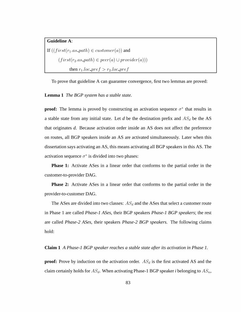
Guideline A:
If ((first(r1.as path) ∈ customer(a)) and
(first(r2.as path) ∈ peer(a) ∪ provider(a)))
thenr1.loc pref > r2.loc pref
To prove that guideline A can guarantee convergence, first two lemmas are proved:
Lemma 1 The BGP system has a stable state.
proof: The lemma is proved by constructing an activation sequenceσ∗ that results in
a stable state from any initial state. Letd be the destination prefix andASd be the AS
that originatesd. Because activation order inside an AS does not affect the preference
on routes, all BGP speakers inside an AS are activated simultaneously. Later when this
dissertation says activating an AS, this means activating all BGP speakers in this AS. The
activation sequenceσ∗ is divided into two phases:
Phase 1: Activate ASes in a linear order that conforms to the partial order in the
customer-to-provider DAG.
Phase 2: Activate ASes in a linear order that conforms to the partial order in the
provider-to-customer DAG.
The ASes are divided into two classes:ASd and the ASes that select a customer route
in Phase 1 are calledPhase-1 ASes, their BGP speakersPhase-1 BGP speakers; the rest
are calledPhase-2 ASes, their speakersPhase-2 BGP speakers. The following claims
hold:
Claim 1 A Phase-1 BGP speaker reaches a stable state after its activation in Phase 1.
proof: Prove by induction on the activation order.ASd is the first activated AS and the
claim certainly holds forASd. When activating Phase-1 BGP speakeri belonging toASn,
83

suppose all Phase-1 BGP speakers in an AS precedingASn are activated and stable,i will
select the best route among its customer routes. All customers of ASn precedeASn in
the activation sequence for Phase 1, therefore, each customer either is stable beforeASn
in Phase 1, or it does not get a customer route in Phase 1. When the latter holds, that
customer will not export its non-customer route toi according to the export rule, so that
customer’s choice will not affect the choice ofi. Thereforei is stable after its activation
in Phase 1.�
Claim 2 Any AS that selects a customer route is a Phase-1 AS.
proof: This proof is implied in the proof of the two original claims in [13], it is explic-
itly listed here to help the readers understand the proof. This is proven by contradiction.
Suppose there is a group of ASesA′ that ultimately select customer routes, but belong
to Phase-2 ASes. The symbolAS1 is used to denote the first activated AS inA′ during
Phase 1 andr for the route it picks, andAS2 is used to denotefirst(r.as path), asr
is a customer route,AS2 is a customer ofAS1. If AS2 is a Phase-1 AS, then it must be
stable after its activation in Phase 1. AsAS1 is activated afterAS2 in phase 1,AS1 must
have learned the router when it is activated in Phase 1. IfAS1 did not pickr in Phase-1,
preference rule tells us that it is only possible if a more preferable customer router′ is
picked. Following the same argument as above, the customer providing r′ is also stable
after Phase 1, sor′ should also be available thereafter, and always preferableoverr, con-
tradicting our assumption thatr is picked in the end. IfAS2 is not a Phase-1 AS, it does
not belong toA′, because it is activated beforeAS1. Therefore,AS2 must have picked a
provider or peer route, by export rule the route picked byAS2 should not be advertised
to AS1, contradicting the assumption thatr exists.�
84

Claim 3 A Phase-2 BGP speaker reaches a stable state after its activation in Phase 2.
proof: Again, this claim is proved by induction on the activation order. LetAS0 be the
first Phase-2 AS activated in Phase 2,AS0 cannot have any Phase-2 providers. Because
AS0 is a Phase-2 AS, its speakers can only get routes fromAS0’s peers and providers.
AS0’s providers must be Phase-1 ASes, so their routes are already stable. By Claim 2,
any ofAS0’s peers either (a) gets a customer route so it is a Phase-1 AS and is stable in
Phase 1, or (b) does not get a customer route so the provider orpeer route it picked will
not be advertised toAS0 and will not affectAS0’s choice. Therefore, all ofAS0’s BGP
speakers will get stable routes after the activation.
When activating Phase-2 BGP speakeri belonging toASn, suppose all Phase-2 BGP
speakers in an AS precedingASn are activated and stable. Becausei is a Phase-2 speaker,
by Claim 2 it can only select a provider or peer route.ASn’s providers are either Phase-1
ASes or activated beforeASn in Phase 2, in either case they are already stable. Simi-
larly, every peer ofASn should either be a Phase-1 AS or a Phase-2 AS. In the former
case it is already stable, in the latter case it selects a provider or peer route according to
Claim 2, and the provider or peer route it picked will not be advertised toASn so will not
affectASn’s choice. Therefore,i already have all its possible candidate paths stable, so it
reaches a stable state after being activated.�
With the above claims, the activation sequenceσ∗ will lead the system to a stable state
no matter what the initial state is.�
Lemma 2 The BGP system converges to the stable state for any initial state and any fair
activation sequence.
85

proof: Given the activation sequenceσ∗ constructed above, for any fair activation se-
quenceσ, the lemma is proven by induction on the activation order used in σ∗. Clearly
ASd is stable once activated. Assume that all BGP speakers in theASes that precedeASn
are stable after activationσ(t), andσ(t′) is the first activation set such that every BGP
speaker inASn is at least activated once betweenσ(t) andσ(t′). Similar to how the sta-
bility for ASn is proven above, it can be proved that every speaker inASn will be stable
afterσ(t′). Also, removing any node or edge from the BGP system does not change the
proof of the above lemmas, so the BGP system is inherently safe. �
Theorem 1 For a BGP system that has only customer-provider and peer-peer relation-
ships, if all ASes follow guideline A, then the BGP system is inherently safe.
proof: Using the two lemmas above, any initial state and fair activation sequence will
lead to a stable state in the BGP system, and removing nodes oredges does not affect the
proof, so the BGP system is inherently safe.�
7.3 MIRO Guidelines that Guarantee Convergence
Obviously, as MIRO is built on top of BGP, if the BGP routes do not converge, then
the MIRO routes can never converge. In addition, as MIRO routing tunnels introduce
additional dependencies, there is a need to introduce additional guidelines and pair them
with the above BGP guidelines, to guarantee the convergenceof the protocol. To illustrate
additional guidelines are needed to guarantee convergence, a simple counter-example is
given below. In this counter-example, the MIRO tunnels do not converge, even though
BGP routes converge.
86

A
B
C
D
BGP: BDMIRO tunnel: BAD
BGP: ADMIRO tunnel: ACD
BGP: CDMIRO tunnel: CBD
Figure 7.1: An Example where MIRO Does Not Converge
Figure 7.1 shows a case where MIRO tunnels do not converge, and it is similar to
the counter-example in [16]. Assume that ASes A, B, and C are all customers of D, and
they establish peering links with each other, since customer-provider routes will never be
exported to peers, ASes A, B, and C can use only the direct customer-provider routes to
reach D, so the BGP routes will converge to the routes shown inbold fonts. However,
if there are no restrictions on MIRO tunnels, tunnels can be used to violate the BGP
export policy and break the convergence. In the graph, if A, B, and C can each establish
the tunnel shown in italic fonts, and they can prefer the tunnel over BGP route, then the
situation is exactly the same as in [16], ASes A, B, and C will oscillate between the BGP
route and the MIRO tunnel, so the system can never converge.
As shown above, there is a need to use additional guidelines on MIRO tunnels so that
the system converges. The following sections will prove that the following guidelines can
guarantee convergence when paired with the BGP guidelines.
7.3.1 Adding Tunnels as a Higher Level Layer
In this section, a very simple model is studied that guarantees the convergence of the pro-
tocol. In this model, the routing tunnels can be deemed as a separate layer of routes above
the BGP paths. The established tunnels are built using only “pure” BGP routes, which do
87

not contain any tunnels, and the resulting tunnels are not advertised as BGP paths. Intu-
itively, routing tunnels built using this principle will not affect the convergence of BGP
protocol, and the tunnels do not depend on each other, so MIROconvergences whenever
BGP converges. The proof is shown below, the part identical to the BGP convergence
proof is omitted.
In addition to the guidelines above, Guideline B is given:
Guideline B:
eb(l, j)(r, T ) =
b export(l, j)(r) if l ∈ E
{} otherwise
et(l, j)(r, T ) =
t export(l, j)(r) if l ∈ E ′
{} otherwise
export(l, j)(sj) = (eb(l, j)(sj), et(l, j)(sj))
ib(l, j)(r, T ) =
b import(l, j)(r) if l ∈ E
{} otherwise
it(l, j)(r, T ) =
t import(l, j)(T ) if l ∈ E ′
{} otherwise
import(l, j)(r, T ) = (ib(l, j)(r, T ), it(l, j)(r, T ))
The guideline says that only BGP routes containing no tunnels (r) can be used to
construct new routing tunnels (et), and that routing tunnels are not used in BGP route
88

advertisement (eb), while tunnels (t) are not in use at all in export decisions. Therefore,
the established MIRO tunnels will never be used to constructanother tunnel or a new
BGP path. Next, it will be proven that this MIRO system converges when Guideline A
and Guideline B are combined.
Lemma 3 The MIRO system has a stable state.
proof: The proof is constructed by activating the MIRO system in three phases.
Phase 1: Activate ASes in a linear order that conforms to the partial order in the
customer-to-provider DAG.
Phase 2: Activate ASes in a linear order that conforms to the partial order in the
provider-to-customer DAG.
Phase 3:Activate ASes in an arbitrary linear order.
Phase 1 and Phase 2 activations are done in the same way as in Lemma 1; note that
while the proof is done for one prefix, in reality the routes for all prefixes are updated
simultaneously.
As in the proof of Guideline A, this dissertation will prove that any activation se-
quence leads to this stable state, therefore this is both a stable and unique state.
Claim 4 A Phase-1 BGP speaker reaches a stable state on BGP routes after its activation
in Phase 1.
Claim 5 A Phase-2 BGP speaker reaches a stable state on BGP routes after its activation
in Phase 2.
The proof for Claim 4 and Claim 5 are the same as in Claim 1 and Claim 2. Because
tunnels can not be used to construct BGP paths, the resultingBGP routes will always be
the same as when no routing tunnels are constructed. Therefore the proof in Lemma 1
89

still holds. Even though a certain BGP speaker might be Phase-1 BGP speaker for one
prefix while being Phase-2 speaker for another prefix, it doesnot hurt the correctness of
the original proof. After the two phases, the BGP routes for all prefixes are stable.
Claim 6 A Phase-3 MIRO speaker reaches a stable state after its activation in Phase 3.
proof: First, the BGP paths for every BGP speaker are stable after Phase 2. Therefore,
for each MIRO speakeri, when it is activated in Phase 3, the candidate paths advertised
by all possible responding ASes are already stable. Also, the intermediate path from the
upstream AS to the downstream AS is stable because it is a BGP path. Therefore, the
routing tunnels formed ati are stable. Considering the fact thati already has a stable
BGP path, the state ofi is stable after activation.�
With Claim 4, 5, and 6, the activation sequenceσ∗ leads to a stable state starting from
any initial state.�
Lemma 4 The MIRO system converges to the stable state for any initialstate and any
fair activation sequence.
proof: Given the activation sequenceσ∗ constructed above, for any fair activation se-
quenceσ, the lemma is proven by induction on the activation order used in σ∗. The proof
is similar to that in Lemma 2.�
Theorem 2 For a MIRO system built on top of a BGP system that has only customer-
provider and peer-peer relationships, if all ASes follow Guideline A and B, then the MIRO
system is inherently safe.
90

proof: According to the lemmas above, any initial state and fair activation sequence will
lead to a stable state in the MIRO system, and removing nodes or edges does not affect
the proof, so the system is inherently safe.�
7.3.2 Advertising Tunnels Only to Leaf Nodes
In some cases, Guideline B may be too restrictive, because itdoes not allow the routing
tunnels to be advertised to other ASes. In Chapter 1, load balancing is used for incoming
traffic as one of the motivations. Use Figure 1.1 for example,F may convince B to switch
to BCF instead of BEF so that more traffic come in through the link CF. In addition to
that, it can convince B to advertise BCF to all its customers,so more traffic will switch
away from the EF link, this requires that the tunnel BCF can beadvertised as candidate
BGP routes. However, the new requirement will complicate the convergence proof of the
MIRO protocol.
Luckily, as shown in Figure 5.1, today’s Internet is relatively flat, and many of the
nodes are actually only connected to one or two other ASes. Further study suggests that
most of the ASes are leaf nodes, that is, they only act as customers in any of their inter-AS
agreements. This section proves that MIRO is guaranteed to converge, if (i) tunnels can
only be advertised to leaf nodes as BGP routes, and (ii) leaf nodes will not advertise routes
to anyone else. Because there are so many leaf nodes in today’s Internet, this relaxation
will probably allow enough flexibility to achieve the load balancing of incoming traffic.
The proof is mostly the same as before: in a leaf node, all its routes are provider
routes, and those provider routes will not be advertised to another provider, therefore a
leaf node will never advertise any BGP routes to its neighbors. Because of that, using
tunnels as BGP routes in a leaf node should have no effect on the convergence of BGP.
91

Instead of Guideline B, now there is Guideline C.
Guideline C:
eb(l, j)(r, T ) =
b export(l, j)(r) if l ∈ E ∧ (l /∈ E ′ ∨ l.dst /∈ leaf nodes)
b export(l, j)(r ∪ T ) if l ∈ E ′ ∧ l.dst ∈ leaf nodes
{} otherwise
et(l, j)(r, T ) =
t export(l, j)(r) if l ∈ E ′
{} otherwise
export(l, j)(sj) = (eb(l, j)(sj), et(l, j)(sj))
ib(l, j)(r, T ) =
b import(l, j)(r) if l ∈ E
{} otherwise
it(l, j)(r, T ) =
t import(l, j)(T ) if l ∈ E ′
{} otherwise
import(l, j)(r, T ) = (ib(l, j)(r, T ), it(l, j)(r, T ))
Lemma 5 The MIRO system conforming to Guideline A and Guideline C hasa stable
state.
proof: The MIRO system is activated in four phases:
Phase 1: Activate ASes in a linear order that conforms to the partial order in the
customer-to-provider DAG.
Phase 2: Activate ASes in a linear order that conforms to the partial order in the
provider-to-customer DAG.
Phase 3:Activate non-leaf ASes in an arbitrary linear order.
92

Phase 4:Activate leaf ASes in an arbitrary linear order.
Claim 7 Any non-leaf AS reaches a stable state after its activation in Phase 3.
Since only leaf nodes can use routing tunnels to construct BGP routes, all other ASes
have exactly the same BGP route candidates as before, so theywill choose the same BGP
path after Phase 1 and 2.
Because any non-leaf AS can never use a BGP route containing any routing tunnel,
it should have all tunnel candidates stable after Phase 2, soit will pick a tunnel which is
stable after Phase 3.
Claim 8 Any leaf AS reaches a stable state after its activation in Phase 4.
Since a leaf AS is a customer to all its neighbors, any of its neighbors must be a non-leaf
AS, so that neighbor should have reached a stable state afterPhase 3. Therefore, in Phase
4, a leaf AS has all BGP routes and tunnels from all its neighbors, after its activation, and
it will stick with the BGP route and tunnels it has chosen.�
Lemma 6 The MIRO system converges to the stable state for any initialstate and any
fair activation sequence.
Given the activation sequenceσ∗ constructed above, for any fair activation sequenceσ,
the lemma is proven by induction on the activation order usedin σ∗. The proof is similar
to that in Lemma 2.�
Theorem 3 For a MIRO system built on top of a BGP system that has only customer-
provider and peer-peer relationships, if all ASes follow Guideline A and C, then the MIRO
system is inherently safe.
93

proof: According to the lemmas above, any initial state and fair activation sequence will
lead to a stable state in the MIRO system, and removing nodes or edges does not affect
the proof, so the system is inherently safe.�
7.3.3 Using Same-class Routes for Tunnels
This section studies the convergence of an alternate policy: the requirements that tunnels
cannot be used in BGP updates is relaxed; however, the type ofadvertised candidate
routes are more restricted, and now the responding AS can only advertise the routes that
both obey export policies and are in the same class as the current advertised BGP routes.
For example, if the responding AS is advertising a customer route as the chosen BGP
path, it will only advertise its customer routes to the requesting AS, hiding all peer or
provider routes. This policy is called “strict policy” in [41].
However, the strict policy alone can not guarantee the convergence of MIRO, as
shown in the following counter-example. In Figure 7.2, D is trying to decide which
route it should use to reach A, B, and C, respectively. D has direct BGP routes DA, DB,
and DC available, but those are all provider routes. D can also establish tunnels with A,
B, or C, as those three ASes agree to export all of their BGP routes to D. So to reach AS
A, D can either use the provider route DA, or establish a tunnel with B to use the route
DBA; to make it obvious DBA uses a tunnel established betweenD and B, the route is
written as D(BA). Assume that AB, BC, and CA are peering links, these tunnels will not
violate the strict policy, because B is advertising a peer route to its customer. Similarly,
D can also establish D(CB) and D(AC) to reach B and C respectively. Assume that D
always pays less using the tunnel route over direct route, therefore, it will prefer D(BA)
over DA, D(CB) over DB, and D(AC) over DC. As shown in Figure 7.2, D can never
94

CustomerProvider
Peer Peer
D to C: DC
A
B
C
D
D to A: DA
D to B: DB
D to A: D(BA)
D to B: DB
D to C: DC
D to A: D(BA)
D to B: D(CB)
D to C: DC
D to A: DA
D to B: D(CB)
D to C: DC
D to A: DA
D to B: D(CB)
D to C: D(AC)
D to A: DA
D to B: DB
D to C: D(AC)
D to A: D(BA)
D to B: DB
D to C: D(AC)
D to A: prefers D(BA) over DAD to B: prefers D(CB) over DBD to C: prefers D(AC) over DC
Figure 7.2: An Example where MIRO Does Not Converge under Strict Policy
reach a stable state. It first switches to D(BA) instead of DA to reach A, then replaces the
route DB with D(CB) to reach B, at this point D finds out the tunnel D(BA) is no longer
available since the BGP route DB has been replaced with D(CB), so it withdraws D(BA)
in its routing table and falls back to DA to reach A. Assume that D does the same thing
with the routes to B and C, then the routes of D will potentially oscillate as shown in the
graph.
This counter example shows that the convergence of MIRO is more complex than that
in the BGP world, since a path containing a tunnel now dependson the path to reach the
downstream AS. For example, route D(AC) can only exist if D chooses path DA to reach
A. If D switches to another route to reach A, this tunnel no longer exists; while in BGP,
95

the routes to different prefixes are independent of each other. Because the convergence
of one prefix can now depend on that of another prefix, additional rules are needed to
guarantee that each AS chooses routes deterministically.
Intuitively, the oscillation above can be eliminated by introducing some order between
the routes to A, B, and C inside D. Some new notations will be introduced as follows:
for an AS pathr, if the source AS obtained the path through tunnel negotiation with
another AS, thenfirst downstream(r) denotes the first downstream AS on the path, and
crop first downstream(r) is the path the first downstream AS picked. For example, in
Figure 7.2,first downstream(D(BA)) = B, crop first downstream(D(BA)) =
A, first downstream(D(AC)) = A, andcrop first downstream(D(AC)) = C. If
the source AS got the path through BGP advertisement, thenfirst downstream(r) =
a(r.prefix) is the destination AS, andcrop first downstream(r) is the empty path.
Instead of Guideline C, now there is Guideline D. Guideline Dsays that a tunnelt is
exported only when it is in the same class as the advertised BGP route. For example, if
the first AS on the advertised AS path is a customer of the current AS, thent can only
be advertised if the first AS ont is also a customer of the current AS. If a tunnel satisfies
this constraint, then it can either be advertised as a BGP path or a tunnel to other ASes.
In addition to that, there must exist a strict partial order≺x in each ASX, such thatX
will only prefer tunnel routet over BGP routes if the first downstream ASY of t and
the destination ASZ of t have the relationshipY ≺x Z. This partial order guarantees
that any pair of tunnels within an AS will not indirectly depend on each other and cause
divergence.
96

Guideline D:
e(r)(t) =
{t}
(first(t.as path) ∈ customer(a)
and first(r.as path ∈ customer(a)))
or (first(t.as path) ∈ peer(a)
and first(r.as path ∈ peer(a)))
or (first(t.as path) ∈ provider(a)
and first(r.as path ∈ provider(a)))
{} otherwise
e′(r)(T ) = ∪t∈T e(r)(t)
eb(l, j)(r, T ) =
b export(l, j)(r ∪ e′(r)(T )) if l ∈ E
{} otherwise
et(l, j)(r, T ) =
t export(l, j)(r ∪ e′(r)(T )) if l ∈ E ′
{} otherwise
export(l, j)(sj) = (eb(l, j)(sj), et(l, j)(sj))
ib(l, j)(r, T ) =
b import(l, j)(r) if l ∈ E
{} otherwise
it(l, j)(r, T ) =
t import(l, j)(T ) if l ∈ E ′
{} otherwise
import(l, j)(r, T ) = (ib(l, j)(r, T ), it(l, j)(r, T ))
For each ASx, there exists a strict partial order≺x such that:
x prefers a tunnel router over all BGP routes only iffirst downstream(r) ≺x
a(r.prefix).
97
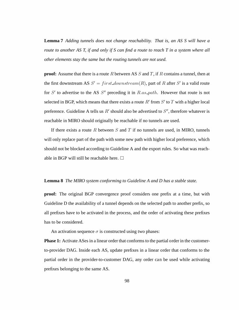
Lemma 7 Adding tunnels does not change reachability. That is, an AS Swill have a
route to another AS T, if and only if S can find a route to reach T in a system where all
other elements stay the same but the routing tunnels are not used.
proof: Assume that there is a routeR between ASS andT , if R contains a tunnel, then at
the first downstream ASS ′ = first downstream(R), part ofR afterS ′ is a valid route
for S ′ to advertise to the ASS ′′ preceding it inR.as path. However that route is not
selected in BGP, which means that there exists a routeR′ from S ′ to T with a higher local
preference. Guideline A tells usR′ should also be advertised toS ′′, therefore whatever is
reachable in MIRO should originally be reachable if no tunnels are used.
If there exists a routeR betweenS andT if no tunnels are used, in MIRO, tunnels
will only replace part of the path with some new path with higher local preference, which
should not be blocked according to Guideline A and the exportrules. So what was reach-
able in BGP will still be reachable here.�
Lemma 8 The MIRO system conforming to Guideline A and D has a stable state.
proof: The original BGP convergence proof considers one prefix at a time, but with
Guideline D the availability of a tunnel depends on the selected path to another prefix, so
all prefixes have to be activated in the process, and the orderof activating these prefixes
has to be considered.
An activation sequenceσ is constructed using two phases:
Phase 1:Activate ASes in a linear order that conforms to the partial order in the customer-
to-provider DAG. Inside each AS, update prefixes in a linear order that conforms to the
partial order in the provider-to-customer DAG, any order can be used while activating
prefixes belonging to the same AS.
98

Phase 2:Activate ASes in a linear order that conforms to the partial order in the provider-
to-customer DAG. Inside each AS, prefixes are updated in a linear order that conforms to
the partial order required by Guideline D.
The definitions of Phase-1 ASes and Phase-2 ASes must be modified slightly in this
proof; now, if an AS selects a customer route to prefixd as its BGP path, this dissertation
calls itd’s Phase-1 AS, its BGP speakersd’s Phase-1 BGP speakers; the rest of ASes are
calledd’s Phase-2 ASes, their BGP speakersd’s Phase-2 BGP speakers.
In the following proof, this dissertation takes advantage of the fact that the export
policies lead to “valley-free” AS paths [12]. That is, each valid path is in a (customer-
to-provider)*(peer-peer)?(provider-to-customer)* format, including the paths constructed
using routing tunnels. This means that a customer route consists of (provider-to-customer)
links only.
Claim 9 When a BGP speaker i is activated in Phase 1, any BGP route or tunnel route
to a prefix picked by i is stable after activation if it is a customer route.
proof: This claim is proven by induction on the activation order.
For the first BGP speakeri0 the AS has no customers, the set of customer routes is
empty, so it is stable.
Assume that all previously activated BGP speakers have stable customer routes, when
BGP speakeri is activated, this dissertation again proves by induction on the activation
order of the prefixes.
For the first prefixd0 that gets a customer route ini, the route must be the direct link
from i to d0 and it is the only customer route tod0 in i, otherwise the ASes on the path
betweeni andd0 gets a customer route and those prefixes are activated befored0 in i.
Because this is the only customer route tod0, it will stay stable after activation.
99

Assume that for a prefixdj, any preceding prefixd′ which gets a customer route is
stable, this dissertation now proves ifdj will eventually get a customer route, it will pick
that route after this activation.
Assume thati eventually selects customer BGP router′ to reachdj, then
i′ = first(r′.as path) is a customer ofi, so it should have been activated beforei and
crop first(r′.as path) should be available whendj is activated ini. If i eventually se-
lects customer tunnel router′ to reachdj, theni′ = first downstream(r′) is a descen-
dant ofi on the provider-to-customer DAG, and it should have been activated already, so
the customer routes ini′ are all stable upon activation. Alsoi′ is an ancestor ofAS(dj)
on the provider-to-customer DAG, so any prefixes toAS(i′) should be activated before
dj, their customer routes should also be stable beforedj is activated. Thereforer′ should
also be available upon activation.
Since the best routesi can pick are available upon activation, it should stick withthese
routes in future activations.
Therefore, by induction, wheni is activated in Phase 1, any route to a prefix selected
by i is stable after activation if it is a customer route.�
The above claim also means that if a BGP speakeri eventually chooses a customer
router to reach prefixd, it will choose this route in Phase 1, otherwiser is not stable and
contradicts the claim.
Claim 10 The Phase-1 BGP speaker i for a prefixd reaches a stable state on its BGP
path tod after its activation in Phase 1.
proof: Guideline A saysi prefers any customer route over peer or provider routes, so if i
has a customer route available, it will only pick customer routes, by claim 9, the customer
100

routei picks is stable after activation in Phase 1, so it will stick to this customer route it
picked.�
Claim 11 For any BGP speakeri activated in Phase 2, if all BGP routes ini are stable
upon activation, theni is stable after activation.
proof: This claim is proven by induction on the order of the prefix activated. For the first
prefix d0 updated ini, according to Guideline D,i will prefer a tunnel router over all
BGP routes only iffirst downstream(r) ≺x a(r.prefix). Becaused0 is the first prefix
activated, there can never be anyfirst downstream(r) ≺x a(r.prefix), so a tunnel
route will be chosen only if no BGP routes are available. By Lemma 7, if there exists
a tunnel route to reachd0, then there must exist at least one BGP route, thereforei will
never choose a tunnel route over a BGP route. Since it is assumed that BGP routes are
stable upon activation, the routes tod0 will also be stable upon activation.
For prefixd, by induction all routes to previous prefixes are stable. Ifi establishes
a tunnel with downstream ASi′ for d, sincei already has all its BGP routes stable and
routing tunnels do not change reachability, this tunnel canonly affect the choices ofi if
it is preferred over all BGP routes. By Guideline D, in that casei′ ≺x a(d). Since the
prefixes are activated according to the order, all prefixes ini′ must have been activated
already and the routes are stable, therefore the tunnel throughi′ is available upon activa-
tion and stable. In summary,i has all BGP routes and the routing tunnels which it may
prefer over BGP routes available and stable upon activation, so the routes tod will also
be stable after activation.
Therefore, after activation,i is stable.�
101

Claim 12 Assume thati0 is the first activated BGP speaker in Phase 2, theni0 is stable
after activation.
proof: Becausei0 is the first activated BGP speaker in Phase 2, it does not have any
providers, therefore, all its routes are either customer routes or peer routes.
By Claim 9 all customer routes are stable, sincei0 only has customer routes or peer
routes,i0 and all its peers should have all customer routes stable at this point, therefore
all BGP routesi0 can choose are stable upon activation, by Claim 11i0 is stable after
activation.�
Claim 13 When updating BGP speakeri in Phase 2, assume that all preceding speakers
are stable, theni is also stable after activation.
proof: When any prefixd is activated insidei, if i has a customer route to reachd, by
Claim 9 the route is stable. Ifi has a peer or provider router to reachd andi did not
establish a tunnel with another speaker for this route, thenthis route is propagated via the
normal BGP protocol from a neighboring speakeri′. If i′ is a peer ofi, crop first(r) is
a customer route and it should be stable ati′ after Phase 1. Ifi′ is a provider ofi, it is ac-
tivated beforei in Phase 2 and by assumption all of the routes ini′ are stable. Therefore,
i has all BGP routes available and stable upon activation, by Claim 11 i is stable after
activation.�
Claim 14 For any prefixd, a BGP speakeri reaches a stable state after Phase 2.
proof: The claim is proven by induction on the activation order in Phase 2. With Claim 12
the initial condition is proven, and Claim 13 proves the induction step.�
102

By Claim 10 and Claim 14, the described activation sequence leads to a stable state.�
Lemma 9 The MIRO system converges to the stable state for any initialstate and any
fair activation sequence.
proof: Given the activation sequenceσ∗ constructed above, for any fair activation se-
quenceσ, this lemma is proven by induction on the activation order ofall (AS, prefix)
pair used inσ∗. The proof is similar to that in Lemma 2.�
Theorem 4 For a MIRO system built on top of a BGP system that has only customer-
provider and peer-peer relationships, if all ASes follow Guideline A, Guideline C, and
Guideline B, then the MIRO system is inherently safe.
proof: Using the two lemmas above, any initial state and fair activation sequence will
lead to a stable state in the MIRO system, and removing nodes or edges does not affect
the proof, so the system is inherently safe.�
Guideline D provides one way to break the loop in Figure 7.2, it requires that each
BGP speaker imposes an order among all prefixes and uses that order to determine which
tunnels are valid. Since it is an order local to each BGP speaker, this should not be too
difficult to implement. There is another way to break the loopin the counter example,
which is to forbid the use of tunnels to establish tunnel routes inside each BGP speaker,
as expressed by Guideline E.
103

Guideline E:
e(r)(t) =
{t}
(first(t.as path) ∈ customer(a)
and first(r.as path ∈ customer(a)))
or (first(t.as path) ∈ peer(a)
and first(r.as path ∈ peer(a)))
or (first(t.as path) ∈ provider(a)
and first(r.as path ∈ provider(a)))
{} otherwise
e′(r)(T ) = ∪t∈T e(r)(t)
eb(l, j)(r, T ) =
b export(l, j)(r ∪ e′(r)(T )) if l ∈ E
{} otherwise
et(l, j)(r, T ) =
t export(l, j)(r ∪ e′(r)(T )) if l ∈ E ′
{} otherwise
export(l, j)(sj) = (eb(l, j)(sj), et(l, j)(sj))
ib(l, j)(r, T ) =
b import(l, j)(r) if l ∈ E
{} otherwise
it(l, j)(r, T ) =
t import(l, j)(T ) if l ∈ E ′
{} otherwise
import(l, j)(r, T ) = (ib(l, j)(r, T ), it(l, j)(r, T ))
In each BGP speakeri, a tunnel router is allowed only if the path fromi to
first downstream(r) does not contain another tunnel established byi.
104

As in Guideline D, Guideline E requires that a tunnelt is exported only when it is in
the same class as the advertised BGP route. But instead of a strict partial order in each
AS, it requires that each BGP speakeri invalidates a tunnelr if r depends on another
tunnel established ini. Sincei has knowledge of all its tunnels, it can easily use local
information to validate each new tunnel.
Lemma 10 The MIRO system conforming to Guideline A and E has a stable state.
proof: The MIRO system is activated in two phases:
Phase 1: Activate ASes in a linear order that conforms to the partial order in the
customer-to-provider DAG. Within each AS, activate prefix in a linear order that con-
forms to the partial order in the provider-to-customer DAG.
Phase 2: Activate ASes in a linear order that conforms to the partial order in the
provider-to-customer DAG. Within each AS, first activate all prefixes in any order, and
then activate all prefixes in any order for another time.
Claim 15 When a BGP speaker i is activated in Phase 1, any BGP route or tunnel route
to a prefix picked by i is stable after activation if it is a customer route.
proof: This claim is proven by induction on the activation order, and the proof is very
similar to that in Lemma 9, except that inside each AS, the tunnel to one prefix will not
depend on the tunnel from the same AS to another prefix, so the proof is actually simpler.
For the first BGP speakeri0, the AS has no customers, the set of customer routes is
empty, so it is stable.
Assume that all previously activated BGP speakers have stable customer routes, when
the first prefixd0 in i is activated, ifi has a customer router to reachd0, then i′ =
first(r) must be an ancestor ofA(d0) on the provider-to-customer DAG. Since prefixes
105

are activated according to the provider-to-customer DAG order andd0 is the first activated
prefix, there can be no suchi′, so the set of customer routes fromi to d0 is an empty set,
the customer routes fromi to d0 are stable upon activation.
Assume that for a prefixdj, any preceding prefixd′ which gets a customer route is
stable, it will be proven that ifdj will eventually get a customer route, it will pick that
route after this activation.
If the final customer route picked byi to reachdj is a BGP route, that meansi′ =
first(r.as path) advertised the routecrop first(r.as path) to i. Sincei′ is a customer
of i, it must be activated beforei in Phase 1, so all its customer routes are stable. Therefore
i has all its BGP customer routes available and stable upon activation.
If the final customer route picked byi to reachdj is a tunnel, theni′ = first downstream(r)
is a descendant ofi on the provider-to-customer DAG, it must be activated before i in
Phase 1, by induction assumption the routes ofi′ are stable if they are customer routes,
since only customer routes can be advertised to providers, this means all candidate routes
i′ can advertise toi are stable wheni is activated. Also,i′ is an ancestor ofa(dj) on
the provider-to-customer DAG, so the prefixes belonging toi′ are activated beforedj, by
induction assumption the customer routes fromi to i′ are all stable, therefore all customer
routesi can establish through tunneling to reachdj are available and stable upon activa-
tion. Since the BGP routes to reachdj are also available upon activation, this means the
customer routes fromi to dj are stable after activation.
By induction, any customer route picked byi is stable after activation.�
Claim 16 For any prefixd, a BGP speakeri reaches a stable state after Phase 2.
proof: Again, this is proven by induction.
106

For the first BGP speakeri0 activated in Phase 2, it has no providers, so it can only
have peer routes or customer routes. According to Claim 15, all customer routes are stable
after Phase 1, so upon activation ofi0, the customer routes ini0 and all its peers are stable,
so all BGP routes ofi0 are stable after activation. Ifi0 eventually picks a BGP route, then
that route should be stable and available after the first round of activation. On the other
hand, ifi0 eventually picks a tunnel router, according to Guideline E, the path fromi to
first downstream(r) must not be a tunnel established byi, so this part of the path must
be stable after the first round of activation. Moreover, since all routes ofi0 are either peer
routes or customer routes,crop first downstream(r) must be a customer route, so it is
stable after Phase 1. Therefore,r must be available and stable upon the second round of
activation in Phase 2, the routes ofi0 are stable after two rounds of activation in Phase 2.
Assume that all previously activated BGP speakers have stable routes, when BGP
speakeri is activated, next it will be proven that its routes are also stable after activation.
For any prefixd, if i eventually picks a BGP router, r is either a customer route,
a peer route, or a provider route. After Phase 1, all customerroutes are stable, so the
customer routes ofi and all its peers are stable,r must be available and stable upon first
round of activation in Phase 2 ifr is a customer route or peer route. Ifr is a provider
route,first(r.as path) must be the provider ofi, so it should have been activated in
Phase 2 already and all of its path should be stable. Therefore,r should also be available
and stable upon first round of activation in Phase 2 if it is a provider route.
On the other hand, ifi eventually picks a tunnel router, according to Guideline E, the
path fromi to first downstream(r) must not be a tunnel established byi, so this part of
the path must be a BGP route ofi and it should be stable after the first round of activation.
Forr′ = crop first downstream(r), if r′ is a customer route, it should already be stable
after Phase 1. Ifr′ is a peer or provider route, since any valid AS path is “valley-free”,
107

first downstream(r) must be an ancestor ofi in the provider-to-customer DAG, so it
must be activated beforei in Phase 2 and all of its routes must be stable upon activation
of i. Therefore,r should also be stable upon the second round of activation in Phase 2.
By induction, the route to any prefixd in any BGP speaker are stable after Phase 2.�
Lemma 11 The MIRO system converges to the stable state for any initialstate and any
fair activation sequence.
proof: Given the activation sequenceσ∗ constructed above, for any fair activation se-
quenceσ, the lemma is proven by induction on the activation order of all (AS, prefix)
pair used inσ∗. The proof is similar to that in Lemma 2.�
7.4 Mixing and Matching the Above Guidelines
Four guidelines which can guarantee convergence in the MIROprotocol were discussed,
and they cover some common use cases that were envisioned. Guideline B models the
case where ASes establish routing tunnels to occasionally bypass the BGP routes, but do
not expect them to be suitable for traffic originated from allsources. Guideline C models
the case where tunnels are used to give leaf nodes more flexible choices. As shown in
Figure 5.1, many of the nodes in today’s Internet topology are leaf nodes, and they can
greatly benefit from the tunnels allowed by Guideline C. Guidelines D and E model the
cases where tunnels can be freely utilized to transfer the traffic that originally would go
through BGP paths, in these guidelines it is assumed the economics incentive that defined
Guideline A is still in effect. Moreover, Guideline D requires that each AS arranges its
108

own tunnels so that it does not introduce a loop between its prefixes, while in Guideline
E tunnel routes should not be established using tunnels initiated from the same AS.
Guideline D requires that each AS imposes a strict partial order among all prefixes.
It might seem difficult to achieve, but this dissertation argues that it is not impractical.
This guideline only requires that some partial order existsif tunnels are favored over
direct paths for provider routes, and all those are local policies confined within the same
AS. Therefore, it is imagined that an AS can build the partialorder on-the-fly when it
negotiates tunnels. The only restriction is that if a new negotiation attempt may violate
the existing partial order, then the old tunnels should be torn down or the new tunnels
should be forbidden. This is actually similar to the Banker’s algorithm [11] in deadlock
checking, whenever a possible loop is found, correspondingmeasures are taken. So this
dissertation argues it is doable in practice.
In Guideline E, each AS simply labels the routes which do not use a tunnel initiated
from itself, and only uses these routes to construct tunnelswith downstream ASes. Since
each AS only needs information about the tunnels established by itself, this policy should
be easy to enforce.
It is also possible to mix and match the above guidelines as follows:
1. This dissertation proves that MIRO converges when it satisfies Guideline A and an
additional guideline, the proof is also true for other BGP guidelines presented by
Lixin Gao and Jennifer Rexford in [13].
2. It can also be requires that each AS conforms to either Guidelines A and C, or
Guidelines A and D, convergence is still guaranteed. Similarly, if each AS con-
forms to either Guidelines A and C, or Guidelines A and E, convergence is also
guaranteed.
109

For brevity the detailed proof is omitted, and an outline is given here. For any leaf
node, if it conforms to Guideline C, it will not export any tunnel routes as BGP
paths; if it conforms to Guideline D, all its BGP paths are provider routes. So those
tunnels of the leaf node can never be exported to its neighbors; therefore, a leaf
node will never export any BGP paths or tunnels to its neighbors in both cases.
For any node connected to a leaf node, if it conforms to Guideline C, it can only
export tunnels to a leaf node, so those tunnels will never be propagated further.
Therefore, the existence of Guideline C nodes will not change the convergence
proof for Guideline D. Same goes for Guideline E.
3. Guideline B can be extended so that Guideline-B tunnels can be built on top of ei-
ther BGP paths, Guideline-C tunnels, Guideline-D tunnels,or Guideline-E tunnels.
If these Guideline-B tunnels can not be used to advertise as BGP paths or to build
other types of tunnels, convergence is still guaranteed.
To prove the resulting system converges, an additional round of activation needs
to be added at the end. When the previous rounds of activationfinish, all BGP
paths, Guideline-C, Guideline-D, or Guideline-E tunnels are stable, so the resulting
Guideline-B tunnels are also stable.
7.4.1 Practical Implications and Summary
The previous sections prove that four new guidelines can guarantee the convergence of
MIRO protocol when paired with the original BGP guidelines.The four guidelines can
roughly be described as:
1. Build tunnels on top of BGP paths
2. Only advertise tunnels as BGP paths to leaf nodes
110

3. Conform to “strict policy” and maintain a partial order inside each AS
4. Conform to “strict policy” and avoid using tunnels insidethe same AS to reach the
first downstream AS
As explained above, the four guidelines can be mixed and matched together; the first
guideline can be extended to build arbitrary tunnels on top of BGP paths or other type of
tunnels. In reality, the above guidelines probably cover most use cases, because of the
following observations:
First, a requesting AS often needs just one tunnel to satisfyits path-selection goals.
• Most of the ASes are stub ASes. In the April 2009 topology generated by the Gao
algorithm, 12,468 out of 31,311 ASes are stubs.
• The observed average AS path length is only 4, therefore tunnel concatenations are
likely to be very rare—so rare they can be precluded.
• Negotiations are allowed between non-adjacent ASes, so instead of establishing a
chain of tunnels, the source AS can directly contact the other end of the chain.
As such, this dissertation envisions that an end-to-end path typically includes at most
one tunnel. The first guideline above says that MIRO is guaranteed to converge in this
case.
Second, as shown in Figure 5.1, in today’s Internet, very fewASes have a large num-
ber of neighbors, while most ASes are stub ASes. The second guideline guarantees that
an AS can freely advertise the tunnels to any stub ASes, whichmeans that many stub
ASes can have pretty flexible path choices.
Third, it is expected that economic incentives explained byLixin Gao and Jennifer
Rexford in [13] will still affect routing policies. Therefore, “strict policy” describes
111

a very practical tunnel export strategy. The third and fourth guidelines say that under
“strict policy” and some easily implementable intra-AS guideline, MIRO is guaranteed
to converge.
As explained above, this dissertation believes the four guidelines proven to guarantee
convergence in MIRO are practical and cover most use cases that interest people.
112

Chapter 8
Conclusions
This dissertation presents a multi-path interdomain routing protocol, called MIRO. It
defaults to the single-path routing provided by conventional BGP, but it also allows ASes
to negotiate alternate paths as needed. This provides flexibility where needed, while
remaining backward compatible with BGP. Compared to sourcerouting, MIRO gives
intermediate ASes more control over the flow of traffic in their networks. It does not
attempt to define global metrics for price or quality; two negotiating parties can agree to
tag route announcements in any meaningful way. Multiple policy specification languages
may coexist; new metrics or path-selection methods can be added over time.
The evaluation on realistic AS-level topologies shows thatMIRO exposes much of the
underlying path diversity in the Internet, even when only the major ISPs have deployed
the enhanced protocol. This study also finds that significantpath diversity is available,
even if ASes adhere to conventional practices for exportingroutes based on their business
relationships with their neighbors. Guaranteeing convergence is an important part in any
routing framework. This dissertation presents a formal model for MIRO and proves that
it converges under four guidelines. As explained in the dissertation, it is believed that
113

those guidelines cover most use cases in practice. Flexiblesupport for negotiation of al-
ternate routes opens up many interesting research problemsregarding how to incorporate
information about pricing, traffic load, and performance directly into the path-selection
process. These are exciting areas for future work.
114

Bibliography
[1] Mike Afergan and John Wroclawski. On the benefits and feasibility of incentive
based routing infrastructure. InPINS ’04, pages 197–204, 2004.
[2] C. Alaettinoglu, C. Villamizar, E. Gerich, D. Kessens, D. Meyer, T. Bates, D. Kar-
renberg, and M. Terpstra. Routing Policy Specification Language (RPSL). RFC
2622, June 1999.
[3] David Andersen, Hari Balakrishnan, Frans Kaashoek, andRobert Morris. Resilient
overlay networks. InProc. SOSP, pages 131–145, 2001.
[4] Katerina Argyraki and David R. Cheriton. Loose source routing as a mechanism for
traffic policies. InProc. Workshop on Future Directions in Network Architecture,
pages 57–64, 2004.
[5] Steven M. Bellovin. Security concerns for IPng. RFC 1675, August 1994.
[6] BGP best path selection algorithm. http://www.cisco.com/warp/public/459/25.shtml.
[7] Matt Caesar and Jennifer Rexford. BGP policies in ISP networks. IEEE Network
Magazine, October 2005.
115

[8] Matthew Caesar, Donald Caldwell, Nick Feamster, Jennifer Rexford, Aman Shaikh,
and Jacobus van der Merwe. Design and implementation of a routing control plat-
form. In Proc. NSDI, May 2005.
[9] I. Castineyra, N. Chiappa, and M. Steenstrup. The Nimrodrouting architecture.
RFC 1992, August 1996.
[10] J. Chen, P. Druschel, and D. Subramanian. An efficient multipath forwarding
method. InProc. IEEE INFOCOM, pages 1418–1425, March 1998.
[11] Edsger W. Dijkstra. Cooperating sequential processes. In F. Genuys, editor,Pro-
gramming Languages: NATO Advanced Study Institute, pages 43–112. Academic
Press, 1968.
[12] Lixin Gao. On inferring Autonomous System relationships in the Internet.
IEEE/ACM Trans. Networking, 9(6):733–745, 2001.
[13] Lixin Gao and Jennifer Rexford. Stable Internet routing without global coordina-
tion. IEEE/ACM Trans. Networking, 9(6):681–692, 2001.
[14] P. Brighten Godfrey, Scott Shenker, and Ion Stoica. Pathlet routing. InProc. SIG-
COMM Workshop on Hot Topics in Networking, October 2008.
[15] Timothy G. Griffin, F. Bruce Shepherd, and Gordon Wilfong. The stable paths
problem and interdomain routing.IEEE/ACM Trans. Networking, 10(2):232–243,
2002.
[16] Timothy G. Griffin and Gordon T. Wilfong. An analysis of BGP convergence prop-
erties. InProc. ACM SIGCOMM, pages 277–288, Cambridge, MA, August 1999.
116

[17] Jiayue He and Jennifer Rexford. Toward Internet-wide multipath routing. IEEE
Network, 22(2):16–21, 2008.
[18] Geoff Huston. Interconnection, peering, and settlements. InProc. INET, June 1999.
[19] Internet systems consortium Internet domain survey.
http://www.isc.org/solutions/survey.
[20] R. Johari and J.N. Tsitsiklis. Routing and peering in a competitive Internet. InProc.
IEEE Conference on Decision and Control, pages 1556–1561, December 2004.
[21] Srikanth Kandula, Dina Katabi, Bruce Davie, and Anna Charny. Walking the
tightrope: Responsive yet stable traffic engineering.Proc. ACM SIGCOMM,
35(4):253–264, 2005.
[22] H. Tahilramani Kaur, S. Kalyanaraman, A. Weiss, S. Kanwar, and A. Gandhi. BA-
NANAS: An evolutionary framework for explicit and multipath routing in the In-
ternet. InProc. Workshop on Future Directions in Network Architecture, pages
277–288, 2003.
[23] R. Mahajan, D. Wetherall, and T. Anderson. Negotiation-based routing between
neighboring ISPs. InProc. NSDI, 2005.
[24] Z. Morley Mao, Lili Qiu, Jia Wang, and Yin Zhang. On AS-level path inference. In
Proc. ACM SIGMETRICS, pages 339–349. ACM Press, 2005.
[25] Murtaza Motiwala, Megan Elmore, Nick Feamster, and Santosh Vempala. Path
splicing. Proc. ACM SIGCOMM, 38(4):27–38, 2008.
[26] Lili Qiu, Yang Richard Yang, Yin Zhang, and Scott Shenker. On selfish routing in
Internet-like environments. InProc. ACM SIGCOMM, pages 151–162, 2003.
117

[27] Bruno Quoitin, Steve Uhlig, Cristel Pelsser, Louis Swinnen, and Olivier Bonaven-
ture. Interdomain traffic engineering with BGP.IEEE Communication Magazine,
2003.
[28] Barath Raghavan and Alex C. Snoeren. A system for authenticated policy-compliant
routing. InProc. ACM SIGCOMM, pages 167–178, 2004.
[29] Y. Rekhter, T. Li, and S. Hares. A Border Gateway Protocol 4 (BGP-4). RFC 4271,
January 2006.
[30] University of Oregon Route Views Project. http://www.routeviews.org.
[31] Gireesh Shrimali, Aditya Akella, and Almir Mutapcic. Cooperative inter-domain
traffic engineering using Nash bargaining and decomposition. InProc. IEEE INFO-
COM, pages 330–338, 2007.
[32] Lakshminarayanan Subramanian, Sharad Agarwal, Jennifer Rexford, and Randy H.
Katz. Characterizing the Internet hierarchy from multiplevantage points. InProc.
IEEE INFOCOM, June 2002.
[33] Lakshminarayanan Subramanian, Matthew Caesar, ChengTien Ee, Mark Handley,
Morley Mao, Scott Shenker, and Ion Stoica. HLP: A next generation inter-domain
routing protocol. InProc. ACM SIGCOMM, pages 13–24, 2005.
[34] Vytautas Valancius, Nick Feamster, Ramesh Johari, andVijay Vazirani. MINT:
A Market for INterdomain Transit. InReArch’08 - Re-Architecting the Internet,
December 2008.
[35] D. Walton, A. Retana, , E.Chen, and J. Scudder. Advertisement of multiple paths in
BGP. Internet Draft draft-ietf-idr-add-paths-00, December 2008.
118

[36] Yi Wang, Ioannis Avramopoulos, and Jennifer Rexford. Design for configurability:
Rethinking interdomain routing policies from the ground up. In IEEE J. Selected
Areas in Communications, volume 27, pages 336–348, April 2009.
[37] Yi Wang, Eric Keller, Brian Biskeborn, Jacobus van der Merwe, and Jennifer Rex-
ford. Virtual routers on the move: live router migration as anetwork-management
primitive. InSIGCOMM ’08: Proceedings of the ACM SIGCOMM 2008 conference
on Data communication, pages 231–242, New York, NY, USA, 2008. ACM.
[38] Yi Wang, Michael Schapira, and Jennifer Rexford. Neighbor-specific BGP: More
flexible routing policies while improving global stability. In Proc. ACM SIGMET-
RICS. ACM Press, 2009.
[39] Dan Wendlandt, Ioannis Avramopoulos, David G. Andersen, and Jennifer Rexford.
Don’t secure routing protocols, secure data delivery. InProc. SIGCOMM Workshop
on Hot Topics in Networking, 2006.
[40] L. Xiao, K. Lui, J. Wang, and K. Nahrstedt. QoS extensionto BGP. InProc.
International Conference on Network Protocols, 2002.
[41] Wen Xu and Jennifer Rexford. MIRO: multi-path interdomain routing. InProc.
ACM SIGCOMM, pages 171–182, Pisa, Italy, 2006.
[42] Xiaowei Yang. NIRA: A new Internet routing architecture. In Proc. Workshop on
Future Directions in Network Architecture, pages 301–312, 2003.
[43] Xiaowei Yang, David Wetherall, and Thomas Anderson. A DoS-limiting network
architecture.ACM SIGCOMM Computer Communication Review, 35(4):241–252,
2005.
119

[44] Dapeng Zhu, Mark Gritter, and David Cheriton. Feedbackbased routing. InProc.
SIGCOMM Workshop on Hot Topics in Networking, October 2002.
120