mips pipeline in detail
DESCRIPTION
This document helps you about MIPS Pipeline Stages and pipeline cycle time also include harvard architecture and explanation of every stage of MIPS Pipeline with some exercises.Feel free to ask about Parallel ProcessingTRANSCRIPT
CS-421 Parallel Processing BE (CIS) Batch 2004-05 Handout_5.1
Page - 1 - of 3
MIPS Pipeline 1. Instruction Fetch (IF) Stage
a. Instruction Fetch
Instruction’s address in PC is applied to instruction memory that causes the addressed
instruction to become available at the output lines of instruction memory.
b. Updating PC
The address in PC is incremented by 4 but what is written in PC is determined by the
control signal PCSrc. Depending upon the status of control signal PCSrc, PC is either
written by the branch target address (BTA) or the sequential address (PC + 4).
2. Instruction Decode (ID) Stage
a. Instruction is decoded by the control unit that takes 6-bit opcode and generates control
signals.
b. The control signals are buffered in the pipeline registers until they are used in the
concerned stage by the corresponding instruction.
c. Registers are also read in this stage. Note that the first source register’s identifier in every
instruction is at bit positions [25:21] and second source register’s identifier (if any) is at
bit positions [20:16].
d. The destination register’s identifier is either at bit positions [15:11] (for R-type) or at
[20:16] (for lw and addi). The correct destination register’s identifier is selected via
multiplexer controlled by the control signal RegDst. However, this multiplexer is placed
in the EX stage because the instruction decoding is not finished until the second stage is
complete. But this identifier is buffered until the WB stage because an instruction writes
a register in the WB stage.
3. Execution (EX) Stage
a. This stage is marked by the use of ALU that performs the desired operation on registers
(R-type), calculates address (memory reference instructions), or compares registers
(branch).
b. An ALU control accepts 6-bit funct field and 2-bit control signal ALUOp to generate
the required control signal for the ALU.
c. BTA is also calculated in the EX stage by a separate adder.
4. Memory (M) Stage
a. Data memory is read (lw) or written (sw) using the address calculated by the ALU in EX
stage.
b. ZERO output of ALU and BRANCH signal generated by the control unit are ANDed
to determine the fate of branch (taken or not taken).

CS-421 Parallel Processing BE (CIS) Batch 2004-05 Handout_5.1
Page - 2 - of 3
5. Write Back (WB) Stage
a. Result produced by ALU in EX stage (R-type) or data read from data memory in M stage
(lw) is written in destination register. The data to be written in destination register is
selected via multiplexer controlled by the control signal MemToReg.
Harvard Architecture
Separate memory units for instructions and data (Harvard Architecture) are required because in a
given pipeline cycle two instructions may need to use memory (one for instruction fetch and
another for data read/write) as shown below.
WB I1 I2 I3 I4 I5 I6 M I1 I2 I3 I4 I5 I6 I7 EX I1 I2 I3 I4 I5 I6 I7 I8 ID I1 I2 I3 I4 I5 I6 I7 I8 I9 IF I1 I2 I3 I4 I5 I6 I7 I8 I9 I10
cycles 1 2 3 4 5 6 7 8 9 10 As indicated, in cycle 4 I1 accesses memory for data read/write and I4 is being fetched
accessing instruction memory. Harvard Architecture averts this problem.
Exercise 1. What are the sizes of pipeline registers IF/ID, ID/EX, EX/M and M/WB?
2. Why there is no pipeline register needed after WB stage?
Graphical Representation of MIPS Pipeline
Consider pipelined execution of following MIPS instructions:
lw $1, 0($2) add $3, $4, $5
The lw instruction uses all stages in the pipeline but add (like any other R-type instruction)
doesn’t access data memory i.e. it doesn’t use M stage. Thus the progress of above instructions
through the MIPS pipeline is illustrated below: CC1 CC2 CC3 CC4 CC5
lw IF ID EX M WB add IF ID EX WB
Did you notice any problem? In CC5 a resource conflict is observed. That is, two different
instructions attempt to use the same hardware in the same cycle. This can be averted by ensuring
uniformity: make all instructions pass through all the stages in the same order.
CS-421 Parallel Processing BE (CIS) Batch 2004-05 Handout_5.1
Page - 3 - of 3
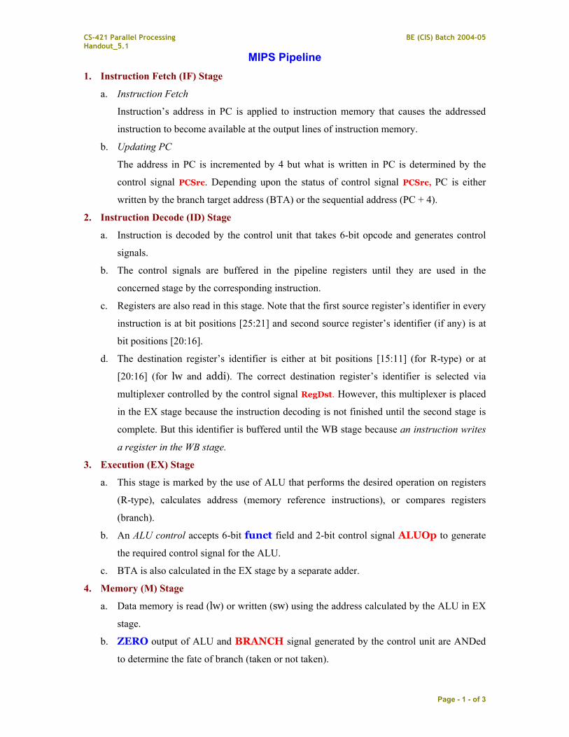
As a consequence, some instructions will do nothing (accomplished through disabling
corresponding control signals) in some stages.
R-Type IF ID EX M WB
sw IF ID EX M WB
beq IF ID EX M WB
Where shaded boxes represent pipeline stages in which given instruction does nothing.
Only lw uses all five stages.
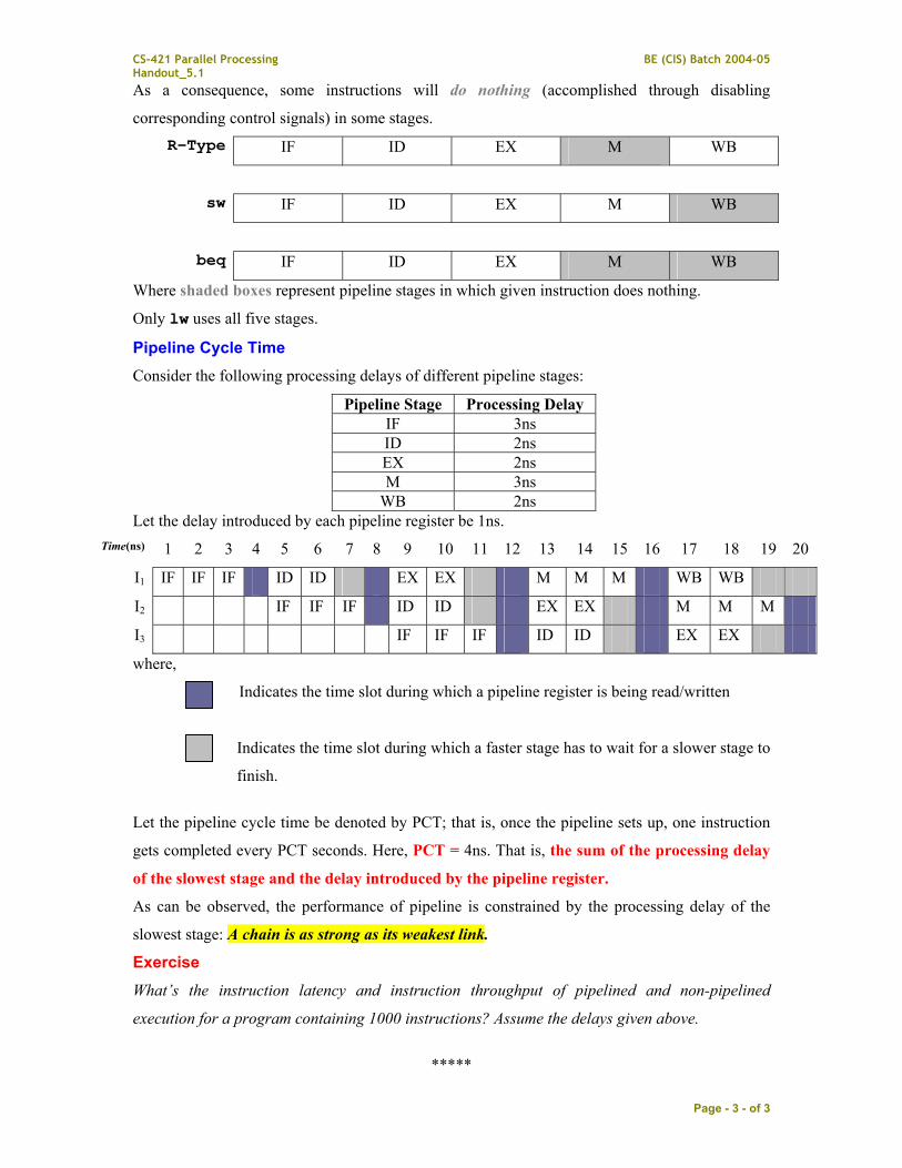
Pipeline Cycle Time Consider the following processing delays of different pipeline stages:
Pipeline Stage Processing Delay IF 3ns ID 2ns EX 2ns M 3ns
WB 2ns Let the delay introduced by each pipeline register be 1ns.
Time(ns) 1 2 3 4 5 6 7 8 9 10 11 12 13 14 15 16 17 18 19 20
I1 IF IF IF ID ID EX EX M M M WB WB
I2 IF IF IF ID ID EX EX M M M
I3 IF IF IF ID ID EX EX
where,
Indicates the time slot during which a pipeline register is being read/written
Indicates the time slot during which a faster stage has to wait for a slower stage to
finish.
Let the pipeline cycle time be denoted by PCT; that is, once the pipeline sets up, one instruction
gets completed every PCT seconds. Here, PCT = 4ns. That is, the sum of the processing delay
of the slowest stage and the delay introduced by the pipeline register.
As can be observed, the performance of pipeline is constrained by the processing delay of the
slowest stage: A chain is as strong as its weakest link.
Exercise What’s the instruction latency and instruction throughput of pipelined and non-pipelined
execution for a program containing 1000 instructions? Assume the delays given above.
*****