minutes - - get a free blog here
TRANSCRIPT

9/24/13 Introduction to Multisim: Learn to Capture and Simulate in Less Than 30 Minutes - National Instruments
www.ni.com/white-paper/10710/en 1/10
Introduction to Multisim: Learn to Capture and Simulate in Less Than 30MinutesPublish Date: Nov 17, 2010 | 110 Ratings | 3.90 out of 5
OverviewNI Multisim is an easytouse schematic capture and simulation environment that engineers, students, and professors can use to defineand simulate circuits. This article shows you how to capture and simulate a simple circuit in Multisim.
This tutorial takes less than 30 minutes to complete and consists of 50 short steps.
The example circuit in the article is an amplifier circuit. This noninverting operational amplifier configuration consists of one activecomponent (the operational amplifier) and two passive resistor components that will be used to complete the feedback network to providegain in this circuit.
Table of Contents1. Example Circuit
2. Step 1: Open Multisim
3. Step 2: Place Components
4. Step 3: Wire Components
5. Step 4: Place a Simulation Source
6. Step 5: Place Measurement Instruments
7. Step 6: Run a Simulation
1. Example CircuitFor this introductory example, simulate a standard noninverting operational amplifier circuit (pictured in Figure 1).
The gain of this noninverting amplifier is calculated simply with Gain = 1 + R1/R2.
Therefore if R1 = R2 then the gain is equal to 2, which you can verify when you run an interactive simulation in NI Multisim software.
Figure 1. Example Circuit
9/24/13 Introduction to Multisim: Learn to Capture and Simulate in Less Than 30 Minutes - National Instruments
www.ni.com/white-paper/10710/en 2/10
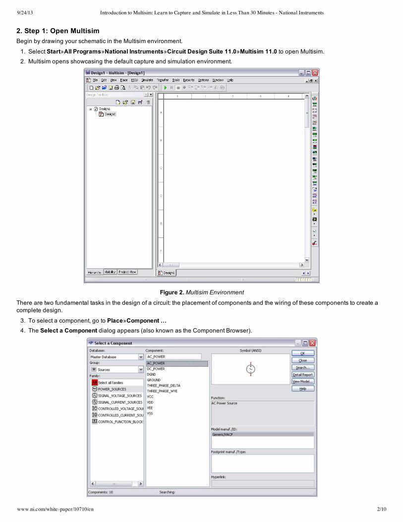
2. Step 1: Open MultisimBegin by drawing your schematic in the Multisim environment.
1. Select Start»All Programs»National Instruments»Circuit Design Suite 11.0»Multisim 11.0 to open Multisim.2. Multisim opens showcasing the default capture and simulation environment.
Figure 2. Multisim Environment
There are two fundamental tasks in the design of a circuit: the placement of components and the wiring of these components to create acomplete design.
3. To select a component, go to Place»Component …4. The Select a Component dialog appears (also known as the Component Browser).

9/24/13 Introduction to Multisim: Learn to Capture and Simulate in Less Than 30 Minutes - National Instruments
www.ni.com/white-paper/10710/en 3/10
Figure 3. Select a Component Dialog
The component browser organizes the database components into three logical levels. The Master Database contains all shippingcomponents in a readonly format. The Corporate Database is where to save custom components to be shared with colleagues (via anetwork collection and so on). Finally, the User Database is where custom components are saved that can be used only by the specificdesigner.
Additional Points
The components (or parts) are organized into Groups and Families to intuitively and logically group common parts together andmake searching easier and more effective.
The component selection box shows the Component name, Symbol, the functional description, Model, and Footprint all in asingle popup.
3. Step 2: Place ComponentsTo invoke simulation, you need a power source and a ground somewhere in your circuit to correctly reference voltages and currents inyour circuit simulation.
5. To place a Ground, go to the Sources group and highlight the POWER_SOURCES family. 6. Highlight the GROUND component (as shown in Figure 4).
7. Click OK.8. The component selection window temporarily closes and the ground symbol is "ghosted" to the mouse pointer.
9. Move the mouse to the appropriate place on the schematic and leftclick once to place the component.
Figure 4. Placing a Ground Symbol
To place a DC power supply:
10. Go to the Sources group again and highlight the POWER_SOURCES family (if not already highlighted from the previous selection).
11. Select is called DC_POWER symbol.
12. Place the DC Power source on the schematic.
13. Repeat steps 10, 11, and 12 to place a second DC_POWER symbol.Additional Points
Without a power and ground your simulation cannot run.
If you need multiple components you can repeat the placement steps as shown or place one component and use copy (CtrlC)and paste (CtrlV) to place additional components as needed.By default, the component selection box keeps returning as a popup until you have completed placing your components. Closethe window to return to the schematic entry window (Close button). You can change this in the global preferences dialog box.
Now place the remaining circuit components using the techniques discussed in the previous steps.
14. Select Place»Component.

9/24/13 Introduction to Multisim: Learn to Capture and Simulate in Less Than 30 Minutes - National Instruments
www.ni.com/white-paper/10710/en 4/10
15. To place the AD712 opamp, select the Analog group and OPAMP family.16. In the Component dialog box (circled in Figure 5), select type AD712 to filter the list of components in the family view.
17. Select any AD712KR component. The difference in the various opamps is due to the difference in associated land pattern (or footprint), which is an important considerationwhen physically implementing the design in the PCB layout environment of NI Ultiboard software.
18. Note that this component is a multisection component, as shown by the A and B tabs. This is indicative of the fact that in the singlephysical IC package. For this demo, it does not matter which one you select.
19. There are several SPICE models available for this component (these come from multiple vendors and highlight varying degrees ofcomplexity when simulating the device performance).
20. Select the second model, the AD712_2 model. This model is a more advanced model that takes into account all five terminals of theopamp.
21. Place the component.
Figure 5. Place an OpAmp
Now place the resistors in the design.
22. Select the Basic group and the Resistor family.
23. In the Component field, type 1k to select a 1 kΩ resistor.
24. You can rotate a part before placement by using the <CtrlR> shortcut on the keyboard when the component is ghosted to the mouse.Once rotated, place the component.
25. Place another 1k resistor.
At this point, your schematic should look something like Figure 6:

9/24/13 Introduction to Multisim: Learn to Capture and Simulate in Less Than 30 Minutes - National Instruments
www.ni.com/white-paper/10710/en 5/10
Figure 6. Design So Far
4. Step 3: Wire ComponentsMultisim is a modeless wiring environment. This means that Multisim determines the functionality of the mouse tool by the position of themouse. You do not have to return to the menu to select between placement, wiring, and editing tools.
26. To begin wiring, move the mouse close to a pin of a component.
27. The mouse appears as a crosshair rather than the default Windows mouse.
28. Place an initial wire junction by clicking on the pin/terminal of the part (in this case, the output pin of the AD712KR).
Figure 7. Wire an OpAmp
29. Complete the wire by moving the mouse to another terminal or just doubleclick to anchor the termination point of the wire to a floatinglocation somewhere in the schematic window.
30. Copy the existing ground. Select the ground symbol and press <CtrlC> on your keyboard. To paste the ground, press <CtrlV> belowthe R2 resistor (as seen in Figure 8).
31. Complete the wiring as shown in Figure 8. Do not worry about the labeled numbers on the wires (also called nets).

9/24/13 Introduction to Multisim: Learn to Capture and Simulate in Less Than 30 Minutes - National Instruments
www.ni.com/white-paper/10710/en 6/10
Figure 8. Wire the Components
32. The last key step is to connect the wires (nets) for power supply terminals to the positive and negative power rails (DC Power Sources)via a virtual connection.
33. Select Place»Connectors»OnPage Connector and place at the first net originating from the first DC power source.34. In the dialog box, enter the name V_POS.35. Select Place»Connectors»OnPage Connector and place at Pin 8 of the opamp.36. In the dialog box, select the V_POS connector name. The virtual connection is made.37. Repeat steps 33 to 34 for the net originating from the second DC power supply and name it V_NEG.38. Repeat steps 35 to 36 for Pin 4 on the opamp.
The circuit looks like Figure 9.

9/24/13 Introduction to Multisim: Learn to Capture and Simulate in Less Than 30 Minutes - National Instruments
www.ni.com/white-paper/10710/en 7/10
Figure 9. Complete the Schematic
5. Step 4: Place a Simulation SourceTo use simulation in a Multisim schematic, you need to place and wire a signal source to the circuit to act as a stimulus.
You can choose from several signal sources including an LVM source based on LabVIEW. Place a basic AC voltage source for thisdemonstration.
39. To place an AC signal source, go to the Sources group and highlight the SIGNAL_VOLTAGE_SOURCES family. 40. Select the AC_VOLTAGE component.41. Place and wire the AC voltage source as shown in Figure 10.
42. Place and wire a Ground component to the AC source as shown in Figure 10.

9/24/13 Introduction to Multisim: Learn to Capture and Simulate in Less Than 30 Minutes - National Instruments
www.ni.com/white-paper/10710/en 8/10
Figure 10. Place a Simulation Source
6. Step 5: Place Measurement Instruments You are now ready to run an interactive Multisim simulation; however, you need a way to visualize the data. Multisim provides instrumentsto visualize the simulated measurements.
Instruments can be found on the right menu bar and are indicated by the following icons.
Figure 11. Instrument Toolbar
43. Select the oscilloscope instrument from the menu (fourth icon from the left) and place this onto the schematic as you would any otherMultisim component.
44. Wire the Channel A and Channel B terminals of the oscilloscope to both the input and output of the amplifier circuit (as shown inFigure 12).
45. Change the color of the input channel net (connected to channel A) by rightclicking on the wire.46. Select the Color Segment option.47. Select a shade of blue and click on the OK button.
9/24/13 Introduction to Multisim: Learn to Capture and Simulate in Less Than 30 Minutes - National Instruments
www.ni.com/white-paper/10710/en 9/10
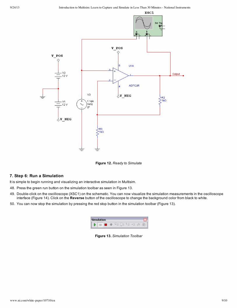
Figure 12. Ready to Simulate
7. Step 6: Run a Simulation It is simple to begin running and visualizing an interactive simulation in Multisim.
48. Press the green run button on the simulation toolbar as seen in Figure 13.
49. Doubleclick on the oscilloscope (XSC1) on the schematic. You can now visualize the simulation measurements in the oscilloscopeinterface (Figure 14). Click on the Reverse button of the oscilloscope to change the background color from black to white.
50. You can now stop the simulation by pressing the red stop button in the simulation toolbar (Figure 13).
Figure 13. Simulation Toolbar

9/24/13 Introduction to Multisim: Learn to Capture and Simulate in Less Than 30 Minutes - National Instruments
www.ni.com/white-paper/10710/en 10/10
Figure 14. Visualizing Simulation in the Oscilloscope
You have just successfully built, simulated, and analyzed a circuit using Multisim.