mint™ version 4ucc.colorado.edu/baldor-reliance/1262-202.pdfmint™ version 4 programming guide vi...
TRANSCRIPT

MN1262 02.2002
Mint™ version 4 Programming Guide
MN1262

ii MN1262 02.2002
.
Copyright
MN1262 02.2002 iii
Copyright Baldor UK Ltd © 2002. All rights reserved. This manual is copyrighted and all rights are reserved. This document or attached software may not, in whole or in part, be copied or reproduced in any form without the prior written consent of Baldor UK. Baldor UK makes no representations or warranties with respect to the contents hereof and specifically disclaims any implied warranties of fitness for any particular purpose. The information in this document is subject to change without notice. Baldor UK assumes no responsibility for any errors that may appear in this document. MINT™ is a registered trademark of Baldor UK Ltd. Windows 95, Windows 98, Windows NT, Windows 2000, Windows ME and Windows XP are registered trademarks of the Microsoft Corporation. Baldor UK Ltd Mint Motion Centre 6 Bristol Distribution Park Hawkley Drive Bristol BS32 0BF U.K. Telephone: +44 (0) 1454 850 000 Fax: +44 (0) 1454 859 001 Web site: www.baldor.co.uk Sales email: [email protected] Support email: [email protected] Baldor Electric Company Telephone: +1 501 646 4711 Fax: +1 501 648 5792 email: [email protected] web site: www.baldor.com
Baldor ASR GmbH Telephone: +49 (0) 89 90508-0 Fax: +49 (0) 89 90508-492 Baldor ASR AG Telephone: +41 (0) 52 647 4700 Fax: +41 (0) 52 659 2394 Australian Baldor Pty Ltd Telephone: +61 2 9674 5455 Fax: +61 2 9674 2495 Baldor Electric (F.E.) Pte Ltd Telephone: +65 744 2572 Fax: +65 747 1708

Mint™ version 4 Programming Guide
iv MN1262 02.2002
Safety Information
MN1262 02.2002 v
SAFETY NOTICE: Only qualified personnel should attempt the start-up procedure or troubleshoot this equipment. This equipment may be connected to other machines that have rotating parts or parts that are controlled by this equipment. Improper use can cause serious or fatal injury. Only qualified personnel should attempt to start-up, program or troubleshoot this equipment.
Precautions:
WARNING: Be sure that you are completely familiar with the safe operation of this equipment. This equipment may be connected to other machines that have rotating parts or parts that are controlled by this equipment. Improper use can cause serious or fatal injury. Only qualified personnel should attempt to program, start-up or troubleshoot this equipment.
WARNING: Be sure that you are completely familiar with the safe programming of this equipment. This equipment may be connected to other machines that have rotating parts or parts that are controlled by this equipment. Improper programming of this equipment can cause serious or fatal injury. Only qualified personnel should attempt to program, start-up or troubleshoot this equipment.
WARNING: The stop input to this equipment should not be used as the single means of achieving a safety critical stop. Drive disable, motor disconnect, motor brake and other means should be used as appropriate. Only qualified personnel should attempt to program, start-up or troubleshoot this equipment.

Mint™ version 4 Programming Guide
vi MN1262 02.2002
WARNING: Improper operation or programming of the control may cause violent motion of the motor shaft and driven equipment. Be certain that unexpected motor shaft movement will not cause injury to personnel or damage to equipment. Peak torque of several times the rated motor torque can occur during control failure.
WARNING: The motor shaft will rotate during the homing procedure. Be certain that unexpected motor shaft movement will not cause injury to personnel or damage to equipment.
CAUTION: To prevent equipment damage, be certain that input and output signals are powered and referenced correctly.
Manual Revision History
MN1262 02.2002 vii
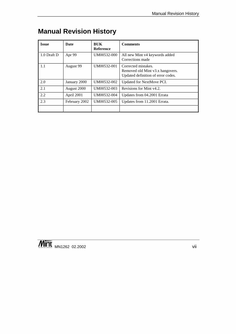
Manual Revision History Issue Date BUK
Reference Comments
1.0 Draft D Apr 99 UM00532-000 All new Mint v4 keywords added Corrections made
1.1 August 99 UM00532-001 Corrected mistakes. Removed old Mint v3.x hangovers. Updated definition of error codes.
2.0 January 2000 UM00532-002 Updated for NextMove PCI.
2.1 August 2000 UM00532-003 Revisions for Mint v4.2.
2.2 April 2001 UM00532-004 Updates from 04.2001 Errata
2.3 February 2002 UM00532-005 Updates from 11.2001 Errata.

Mint™ version 4 Programming Guide
viii MN1262 02.2002
Contents
MN1262 02.2002 ix
Introduction................................................................................ 1 1.1 Introducing Mint version 4.........................................................................2 1.2 Introduction to Mint ...................................................................................3 1.3 Program Structure ....................................................................................6
The Servo Loop.......................................................................... 9 2.1 Controller Types .....................................................................................10
2.1.1 NextMove Controller...........................................................................10 2.1.2 MME Controller ..................................................................................10
2.2 The Servo Loop ......................................................................................11 2.3 Selecting Servo Loop Gains ...................................................................17 2.4 Dual Encoder Feedback .........................................................................17
Mint™ Language ...................................................................... 19 3.1.1 Multi-Axis and Channel Syntax...........................................................20 3.1.2 Single Axis or Channel References using Dot ....................................23
3.2 Mint Numbers and Variables...................................................................24 3.2.1 Numbers ............................................................................................24 3.2.2 Binary and HEX Notation ...................................................................24 3.2.3 Constants...........................................................................................25 3.2.4 Pre-defined Constants .......................................................................26 3.2.5 Variables ............................................................................................27 3.2.6 Delimiters ...........................................................................................30
3.3 Arrays .....................................................................................................30 3.3.1 Advanced use of Arrays .....................................................................32 3.3.2 Array Data File Format .......................................................................33
3.4 Relational and Mathematical Operators ..................................................34
Mint™ version 4 Programming Guide
x MN1262 02.2002
3.4.1 Relational Operators ..........................................................................34 3.4.2 Mathematical Operators .....................................................................35 3.4.3 Bitwise Operators...............................................................................35 3.4.4 Logical Operators...............................................................................36 3.4.5 Trigonometric Functions.....................................................................37 3.4.6 General Functions..............................................................................38 3.4.7 Operator Precedence.........................................................................38
3.5 Macros....................................................................................................39 3.6 Conditional Statements...........................................................................41
3.6.1 IF .. THEN statement .........................................................................41 3.6.2 IF block structure ...............................................................................41 3.6.3 PAUSE statement ..............................................................................42
3.7 Loops......................................................................................................43 3.7.1 FOR .. NEXT loop ..............................................................................43 3.7.2 REPEAT .. UNTIL loop.......................................................................44 3.7.3 WHILE .. ENDW loop.........................................................................45 3.7.4 LOOP .. ENDL loop............................................................................45 3.7.5 EXIT statement ..................................................................................46
3.8 Subroutines ............................................................................................46 3.8.1 Reserved Labels ................................................................................47
3.9 Mint Interpreter Limitations .....................................................................47
Terminal Input/Output.............................................................. 51 4.1 RS232 Communication...........................................................................54 4.2 The RS485 Channel ...............................................................................54
4.2.1 Multi-Drop RS485...............................................................................54 4.2.2 Using a Controller as a Master ...........................................................56 4.2.3 Using a PC as a Master .....................................................................56 4.2.4 Using the RS485 Port as a Normal Serial Port. ..................................57

Contents
MN1262 02.2002 xi
4.3 Dual Port RAM Communication ..............................................................58 4.4 CAN Communication ..............................................................................58
Mint Comms Communications................................................ 59 5.1 Activating the Comms Protocol...............................................................60 5.2 Controller to Controller Master/Slave Comms.........................................61 5.3 Use of the Comms Array in Mint .............................................................62 5.4 Comms Data Format ..............................................................................63
5.4.1 Writing Data .......................................................................................63 5.4.2 Reading Data .....................................................................................64
5.5 Comms over a CANopen Network...........................................................65 5.6 Extended Comms Array..........................................................................65
Creating Motion........................................................................ 69 6.1 Enabling Axes.........................................................................................70 6.2 Open Loop Servo Control .......................................................................70
6.2.1 Torque Control ...................................................................................70 6.2.2 Servo Off............................................................................................71
6.3 Scale Factor ...........................................................................................72 6.4 Motion Profiles........................................................................................72 6.5 Stopping Motion......................................................................................73 6.6 Move Buffer and GO...............................................................................74 6.7 AXISMODE and IDLE.............................................................................77 6.8 Controlled Motion....................................................................................78 6.9 Speed Control.........................................................................................78 6.10 Linear Positional Control.........................................................................79 6.11 Incremental Moves .................................................................................80 6.12 Interpolated Moves .................................................................................81
6.12.1 Linear Interpolation ............................................................................81 6.12.2 Circular Interpolation ..........................................................................82

Mint™ version 4 Programming Guide
xii MN1262 02.2002
6.12.3 Contoured Moves...............................................................................83 6.13 Establishing a Datum..............................................................................84
6.13.1 Datum Profiles ...................................................................................85 6.13.2 Order of Datuming .............................................................................87 6.13.3 Defining a New Position .....................................................................87
6.14 Encoder Following and Software Gearboxes ..........................................87 6.14.1 Position Locked..................................................................................90 6.14.2 Velocity Locked..................................................................................90 6.14.3 Clutch Mode.......................................................................................91 6.14.4 Extended Clutch Mode .......................................................................92 6.14.5 Gearing Compensation ......................................................................94
6.15 Flying Shears..........................................................................................94 6.16 Cam Profiling ..........................................................................................96
6.16.1 Cam Tables........................................................................................97 6.17 Spline and P.V.T.....................................................................................99 6.18 Hold To Analog.......................................................................................99 6.19 Blending ...............................................................................................100 6.20 Compensation Modes...........................................................................100 6.21 Virtual Axes ..........................................................................................100
Input/Output Handling Using Mint ....................................... 101 7.1 Mint Control of I/O Functions ................................................................102 7.2 Digital Inputs.........................................................................................103 7.3 Digital Outputs ......................................................................................104 7.4 I/O Banks..............................................................................................105 7.5 Analog Inputs........................................................................................105 7.6 Analog Outputs.....................................................................................106 7.7 Stepper I/O ...........................................................................................106 7.8 Input/Output ‘On the Fly' .......................................................................107
Contents
MN1262 02.2002 xiii
Event and Error Handling...................................................... 109 8.1 NextMove .............................................................................................110 8.2 ServoNode 51.......................................................................................112 8.3 MintDrive ..............................................................................................114 8.4 Error Event: #ONERROR .....................................................................115
8.4.1 Synchronous Errors .........................................................................116 8.4.2 Asynchronous Errors........................................................................117 8.4.3 #ONERROR.....................................................................................119 8.4.4 Global Error Output ..........................................................................121
8.5 CAN Event: #CANx...............................................................................121 8.6 Stop Input Event: #STOP .....................................................................123 8.7 Fast Position Latch Event: #FASTIN[input] ...........................................123 8.8 Timer Event: #TIMER ...........................................................................124 8.9 Digital Input Events: #IN[input]..............................................................125 8.10 Comms Event: #COMMS[location] .......................................................126
Program Buffers..................................................................... 127 9.1 Memory Maps.......................................................................................128
9.1.1 MintDrive and ServoNode 51 Memory Map......................................129 9.1.2 NextMove Memory Map ...................................................................131
9.2 Using the Buffers ..................................................................................131 9.3 PROTECT ............................................................................................132
9.3.1 Enable/Disable of Password Checking.............................................134 9.3.2 Mint Program Upload/Download.......................................................134 Editor Commands........................................................................................135
Keyword Reference Guide..................................................... 139 10.1 Mint Keyword Syntax ............................................................................140 10.2 Mint Keyword Definitions ......................................................................140 10.3 Mint Keywords ......................................................................................143
Mint™ version 4 Programming Guide
xiv MN1262 02.2002
Quick Reference..................................................................... 393 11.1 Program Constructs..............................................................................394 11.2 Subroutines ..........................................................................................394 11.3 Conditional Statements.........................................................................394 11.4 Loops....................................................................................................394 11.5 Program Flow .......................................................................................395 11.6 Motion Keywords ..................................................................................395 11.7 System Keywords .................................................................................398 11.8 Event and Error Keywords ....................................................................400 11.9 Input/Output Keywords .........................................................................401 11.10 Terminal Input / Output .........................................................................402 11.11 Network Control....................................................................................402 11.12 Other Functions ....................................................................................403 11.13 Line Editor Commands .........................................................................404 11.14 Relational and Mathematical Operators ................................................404 11.15 ASCII Character Codes ........................................................................405
Troubleshooting..................................................................... 407 12.1 Troubleshooting Common Problems.....................................................408 12.2 MML Error Codes and Messages .........................................................410 12.3 Mint Workbench Error Codes and Messages .......................................417 12.4 Mint Error Codes and Messages...........................................................417
Bibliography........................................................................... 423

Introduction
MN1262 02.2002 1
1. Introduction
1 Mint™ is a flexible Basic like programming language designed for high speed motion control applications. This chapter covers:
◊ A list of platforms served by this guide. ◊ An introduction to the Mint programming language.
Mint™ version 4 Programming Guide
2 MN1262 02.2002
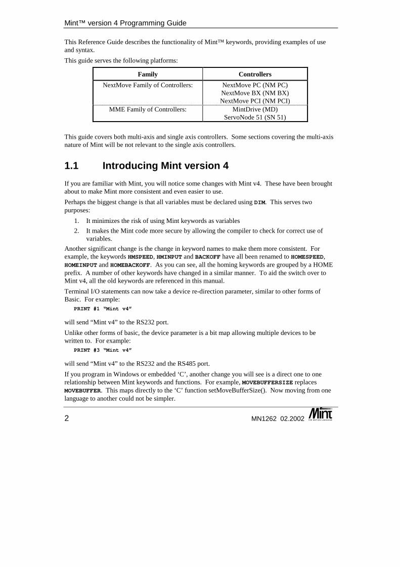
This Reference Guide describes the functionality of Mint™ keywords, providing examples of use and syntax. This guide serves the following platforms:
Family Controllers NextMove Family of Controllers: NextMove PC (NM PC)
NextMove BX (NM BX) NextMove PCI (NM PCI)
MME Family of Controllers: MintDrive (MD) ServoNode 51 (SN 51)
This guide covers both multi-axis and single axis controllers. Some sections covering the multi-axis nature of Mint will be not relevant to the single axis controllers.
1.1 Introducing Mint version 4 If you are familiar with Mint, you will notice some changes with Mint v4. These have been brought about to make Mint more consistent and even easier to use. Perhaps the biggest change is that all variables must be declared using DIM. This serves two purposes:
1. It minimizes the risk of using Mint keywords as variables 2. It makes the Mint code more secure by allowing the compiler to check for correct use of
variables. Another significant change is the change in keyword names to make them more consistent. For example, the keywords HMSPEED, HMINPUT and BACKOFF have all been renamed to HOMESPEED, HOMEINPUT and HOMEBACKOFF. As you can see, all the homing keywords are grouped by a HOME prefix. A number of other keywords have changed in a similar manner. To aid the switch over to Mint v4, all the old keywords are referenced in this manual. Terminal I/O statements can now take a device re-direction parameter, similar to other forms of Basic. For example:
PRINT #1 “Mint v4”
will send “Mint v4” to the RS232 port. Unlike other forms of basic, the device parameter is a bit map allowing multiple devices to be written to. For example:
PRINT #3 “Mint v4”
will send “Mint v4” to the RS232 and the RS485 port. If you program in Windows or embedded ‘C’, another change you will see is a direct one to one relationship between Mint keywords and functions. For example, MOVEBUFFERSIZE replaces MOVEBUFFER. This maps directly to the ‘C’ function setMoveBufferSize(). Now moving from one language to another could not be simpler.
Introduction
MN1262 02.2002 3
Errors are now handled in a more consistent manner, again with a one to one relationship between Mint and embedded ‘C’. Within Mint, errors are reported with their error number:
R0003: PROGRAM Data specified out of range [axis/channel 0] [line 20]
More errors are now reported at compile time, including mismatched block constructs such as WHILE..ENDW and IF..ENDIF. With Mint v4 comes the new Mint WorkBench. This replaces the NextMove WorkBench and cTERM for Windows providing a common front end across all Mint v4 controllers. Further details of the Mint WorkBench can be found in the appropriate Installation Guides.
1.2 Introduction to Mint Mint™ is a structured form of Basic, custom designed for motion control applications, either stepper or servo. It was devised to allow users to quickly get up and running with simple motion control programs. In addition, Mint includes a wide range of powerful commands for complex applications. Supporting a Basic-like structure, Mint has a number of motion-specific keywords built in. These keywords allow control of motor position, speed, torque, interpolation and synchronization of multiple axes. Full software control over fundamental motor control parameters, is also provided through the language, for example, servo loop gains. Applications can vary from simple single axis positional control, to complex multi-axis systems. Between these two extremes, Mint's flexible and powerful command set provides a solution to the vast majority of industrial motion control applications. To begin with a short example of Mint code, the following program can be used to demonstrate an XY table application that moves to a series of positions and sets an output. For example, the output could be used to move a tool head.
REM Program: XY exampleREM Define axes in useAXES[0,1]
REM Define 10 XY positionsDIM xpos(10) = 10,10,10,20,30,40,40,40,30,20DIM ypos(10) = 10,20,30,30,30,30,20,10,10,10
GOSUB initGOSUB mainEND
#initHOME[0,1] = 0,0 : REM Home axes 0 and 1PAUSE IDLE[0,1] : REM Wait for axes to stop
RETURN
#mainDIM a
REM Repeat foreverLOOPREM Move to the 10 points
Mint™ version 4 Programming Guide
4 MN1262 02.2002
FOR a = 1 to 10REM Move to the absolute positionMOVEA[0,1] = xpos(a),ypos(a) : GO[0,1]PAUSE IDLE[0,1]: REM Wait for axes to stopOUT.0 = 1 : REM Set an output (head down)PAUSE IN.0 : REM Wait for head to be downOUT.0 = 0 : REM Move the head upPAUSE !IN.0 : REM Wait for head to be up
NEXTGOSUB init : REM Home the axes againPAUSE IN.1 : REM Wait for input to start again
ENDLRETURN
The above example assumes that all servo loop gains, speeds, accelerations etc. have been set-up. Mint uses 2 file buffers: the first designated as the configuration file - used to store such information as the servo loop gains and speeds etc. The second buffer, the program file, stores this actual application. It should therefore be possible to write an application that is common amongst different types of motors and to only change the configuration file when the motor is changed. In fact the two files can accept the same instructions. On program execution, the configuration file is first executed, followed by the program file. You will note in the example, keywords such as MOVEA, IDLE, and HOME etc. These are motion specific keywords and are used to access motion control and input/output features of the system. All motion keywords, unlike the Basic type keywords (for example: FOR, PRINT, WHILE), can be abbreviated to two or three letters. For instance, SPEED is abbreviated to SP which is useful for saving memory space. To access a particular axis, square brackets are used next to the motion keyword. For example:
SPEED[1] = 10
or a dot as shown: SPEED.1 = 10
will set the speed of axis 1 to 10 units. ACCEL[0,1] = 600,800
will set the acceleration of axis 0 to 600 units and axis 1 to 800 units. a = POS.2
will assign the position of axis 2 to the user variable a. In most cases the square brackets are optional.
SPEED[0,1] = 10,20SPEED = 10,20
are the same depending on the value of the default axes string as defined by the AXES keyword. The AXES keyword as seen previous example, AXES[0,1] tells Mint that all motion keywords relate to 2 axes, i.e. 0 and 1 unless explicitly indicated by enclosing the axes in square brackets after the keyword. For example:
RESET[0,1,2]
Introduction
MN1262 02.2002 5
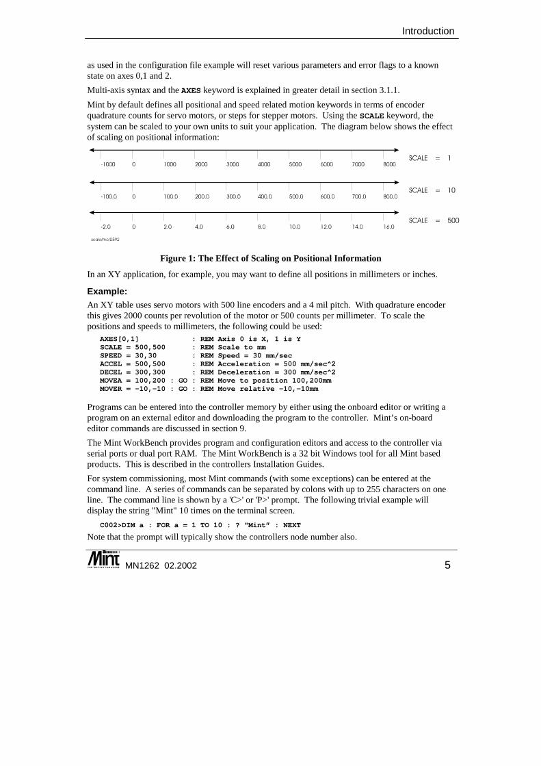
as used in the configuration file example will reset various parameters and error flags to a known state on axes 0,1 and 2. Multi-axis syntax and the AXES keyword is explained in greater detail in section 3.1.1. Mint by default defines all positional and speed related motion keywords in terms of encoder quadrature counts for servo motors, or steps for stepper motors. Using the SCALE keyword, the system can be scaled to your own units to suit your application. The diagram below shows the effect of scaling on positional information:
Figure 1: The Effect of Scaling on Positional Information
In an XY application, for example, you may want to define all positions in millimeters or inches.
Example: An XY table uses servo motors with 500 line encoders and a 4 mil pitch. With quadrature encoder this gives 2000 counts per revolution of the motor or 500 counts per millimeter. To scale the positions and speeds to millimeters, the following could be used:
AXES[0,1] : REM Axis 0 is X, 1 is YSCALE = 500,500 : REM Scale to mmSPEED = 30,30 : REM Speed = 30 mm/secACCEL = 500,500 : REM Acceleration = 500 mm/sec^2DECEL = 300,300 : REM Deceleration = 300 mm/sec^2MOVEA = 100,200 : GO : REM Move to position 100,200mmMOVER = -10,-10 : GO : REM Move relative -10,-10mm
Programs can be entered into the controller memory by either using the onboard editor or writing a program on an external editor and downloading the program to the controller. Mint’s on-board editor commands are discussed in section 9. The Mint WorkBench provides program and configuration editors and access to the controller via serial ports or dual port RAM. The Mint WorkBench is a 32 bit Windows tool for all Mint based products. This is described in the controllers Installation Guides. For system commissioning, most Mint commands (with some exceptions) can be entered at the command line. A series of commands can be separated by colons with up to 255 characters on one line. The command line is shown by a 'C>' or 'P>' prompt. The following trivial example will display the string "Mint" 10 times on the terminal screen.
C002>DIM a : FOR a = 1 TO 10 : ? "Mint” : NEXT
Note that the prompt will typically show the controllers node number also.
Mint™ version 4 Programming Guide
6 MN1262 02.2002
1.3 Program Structure Programs in Mint are made up of a configuration file and a program file. The configuration file should store all the set up and initialization information such as system gains and I/O settings. The program file stores the actual application program. Once program and configuration files have been written, they must be downloaded to the controller. The Mint WorkBench provides editor and file download facilities. The RUN command is used at the command line to execute the configuration and program files. When the RUN command is received, Mint compiles the configuration file and executes it. When the end of the configuration file is reached, Mint will compile and execute the program file. The compilation may take a few seconds, depending on the program size. To halt a program, <CTRL><E> is pressed which sends ASCII code 5 to the controller. This will break the executing program and return to the command line. An abort error will be generated on all axes which by default causes the drives to be disabled and DAC outputs to be zeroed. It is also possible to run and stop Mint programs using toolbar buttons in the Mint WorkBench. A typical program file would be modular in construction, with subroutines being used wherever possible.
REM Program fileREM Project ..REM Author ...REM Date .....
GOSUB initGOSUB mainEND
REM Setup all global variables here#initDIM my_var1 = 1DIM newPos = 1000
RETURN
REM Main loop here#mainLOOPREM Place main code here
ENDLRETURN
REM Define rest of subroutines here
The subroutine init is used to define all global variables used within the system. This must be placed at the beginning of the program since variables are defined at compile time and not run time. There are no restrictions on which parameters can be set up in the configuration file. The following is a list of parameters that are commonly set up in the configuration file:
• Input / Output configuration commands to assign limit, stop and other I/O as required for the application and to determine the active state for these channels.
Introduction
MN1262 02.2002 7
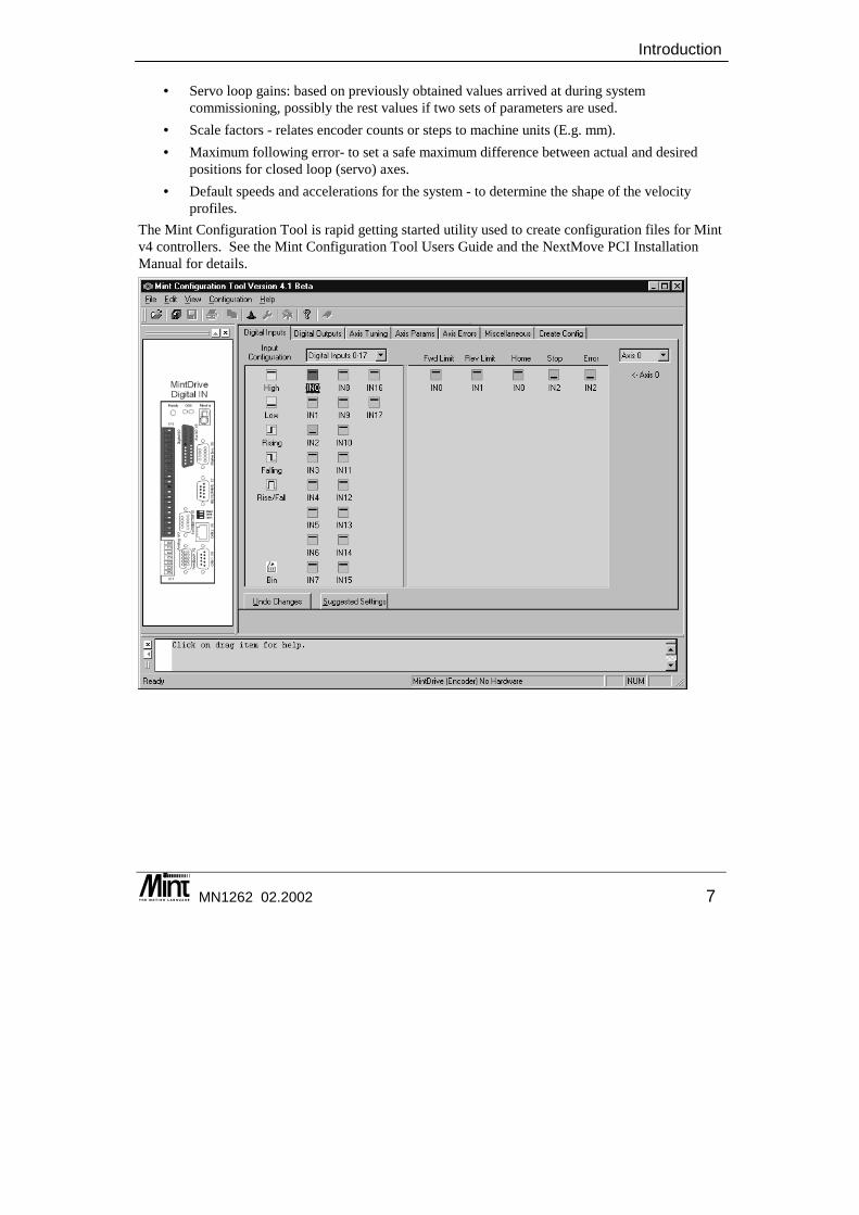
• Servo loop gains: based on previously obtained values arrived at during system commissioning, possibly the rest values if two sets of parameters are used.
• Scale factors - relates encoder counts or steps to machine units (E.g. mm). • Maximum following error- to set a safe maximum difference between actual and desired
positions for closed loop (servo) axes. • Default speeds and accelerations for the system - to determine the shape of the velocity
profiles. The Mint Configuration Tool is rapid getting started utility used to create configuration files for Mint v4 controllers. See the Mint Configuration Tool Users Guide and the NextMove PCI Installation Manual for details.

Mint™ version 4 Programming Guide
8 MN1262 02.2002

The Servo Loop
MN1262 02.2002 9
2. The Servo Loop
2 Mint supports a 5 term servo loop. This chapter covers the fundamentals of the servo loop on the Mint controllers.
◊ Fundamentals of closed loop control ◊ The servo loop terms in detail
Mint™ version 4 Programming Guide
10 MN1262 02.2002
2.1 Controller Types
2.1.1 NextMove Controller The NextMove controller differs fundamentally from other motion controllers due to its high speed floating point Digital Signal Processor core. Since the controller can process floating point numbers efficiently, most of the operating firmware, including the servo loop closure algorithms use floating point numbers. This is a major advantage for generation of motion profiles etc. since all calculations can be performed in meaningful units before conversion to machine units (encoder quadrature counts or steps) within the loop closure algorithm. The real time portion of the code consists of two basic interrupt driven routines:
• Every 2ms+ (500Hz), the profiling algorithm generates set point data for all axes of motion and control the stepper axes.
• Every 1000µs* (1KHz) the controller samples the axes positions, calculates the instantaneous axis demand on the basis of linear interpolation of the profiler output and generates a new servo demand by running the PIDVFA loop. This is referred to as the servo loop.
In addition, there is a 2ms interrupt routine which performs house keeping tasks and updates Dual Port RAM.
2.1.2 MME Controller The MME controllers have integer based processors, and so cannot process floating-point numbers as efficiently as NextMove. Instead floating-point numbers are processed using scaled integer arithmetic. The real time portion of the code consists of one basic interrupt driven routine:
• Every servo tick the controller samples the axes positions, calculates the instantaneous axis demand on the basis of linear interpolation of the profiler output and generates a new servo demand by running the PIDVF loop. This is referred to as the servo loop.
The servo tick, by default, is 1ms on MintDrive.
+ Software selectable for 1 or 2 milli-seconds depending on controller. 2ms is the default setting. * Software selectable for 200, 250, 500 or 1000 micro-seconds depending on controller. 1000µs is the default setting.
The Servo Loop
MN1262 02.2002 11
2.2 The Servo Loop At the lowest level of control software, instantaneous axis position demands produced by the controller software must be translated into motor demands. This is achieved by closed loop control of the motor. The motor is controlled to minimize the error between demand and actual position measured with an incremental encoder. Every servo tick the controller compares desired and actual positions and calculates the correct demand for the motor. Torque is calculated by a PIDVFA (Proportional, Integral, Derivative, Velocity Feedback, Velocity Feed Forward and Acceleration Feed Forward) algorithm. Control could be achieved by applying a torque proportional to the error alone, but this is a rather simplistic approach. Imagine that there is a small error between demanded and actual position. A proportional controller will simply multiply the error by some constant, the Proportional gain, and apply the resultant to the motor via an amplifier. If the gain is too high this may cause overshoot, which will result in the motor vibrating back and forth around the desired position. As the gain is increased, the controller will present more resistance to positional error, but oscillations will increase in magnitude until the system becomes unstable. To reduce the onset of instability a damping term is incorporated in the servo loop algorithm, called Velocity feedback gain. Velocity feedback acts to resist rapid movement of the motor and hence allows the proportional gain to be set higher before vibration sets in. (In some applications, the velocity feedback is handled by the amplifier, called a velocity servo). The effect of too high proportional gain, or too low velocity feedback gain is illustrated by the "Under damped" line in figure 2. An alternative damping method is provided in the form of the Derivative of the error signal. Derivative action has the same effect as velocity feedback if the velocity feedback and feedforward terms are equal. In torque controlled systems, Derivative action is generally the preferred term. With Proportional and Derivative action it is possible for a motor at a point to exhibit a small positional error (called following error). The controller multiplies the error by the proportional term to produce an applied corrective torque (in current control), but for very small errors the torque may not be large enough to overcome static friction. This error can be overcome by incorporating an integral term in the loop calculations. Integral action involves summing the error over time, so that motor torque is gradually increased until the positional error falls to zero.
Mint™ version 4 Programming Guide
12 MN1262 02.2002
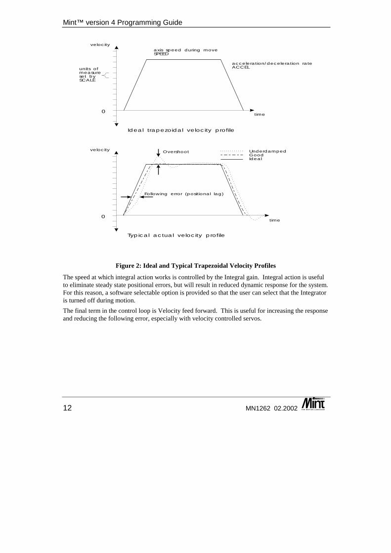
Figure 2: Ideal and Typical Trapezoidal Velocity Profiles
The speed at which integral action works is controlled by the Integral gain. Integral action is useful to eliminate steady state positional errors, but will result in reduced dynamic response for the system. For this reason, a software selectable option is provided so that the user can select that the Integrator is turned off during motion. The final term in the control loop is Velocity feed forward. This is useful for increasing the response and reducing the following error, especially with velocity controlled servos.
time
velocity
acceleration/deceleration rateACCEL
0
axis speed during moveSPEED
units ofmeasureset bySCALE
Ideal trapezoidal velocity profile
time
velocity
0
Typical actual velocity profile
Overshoot
Following error (positional lag)
UnderdampedGoodIdeal
The Servo Loop
MN1262 02.2002 13
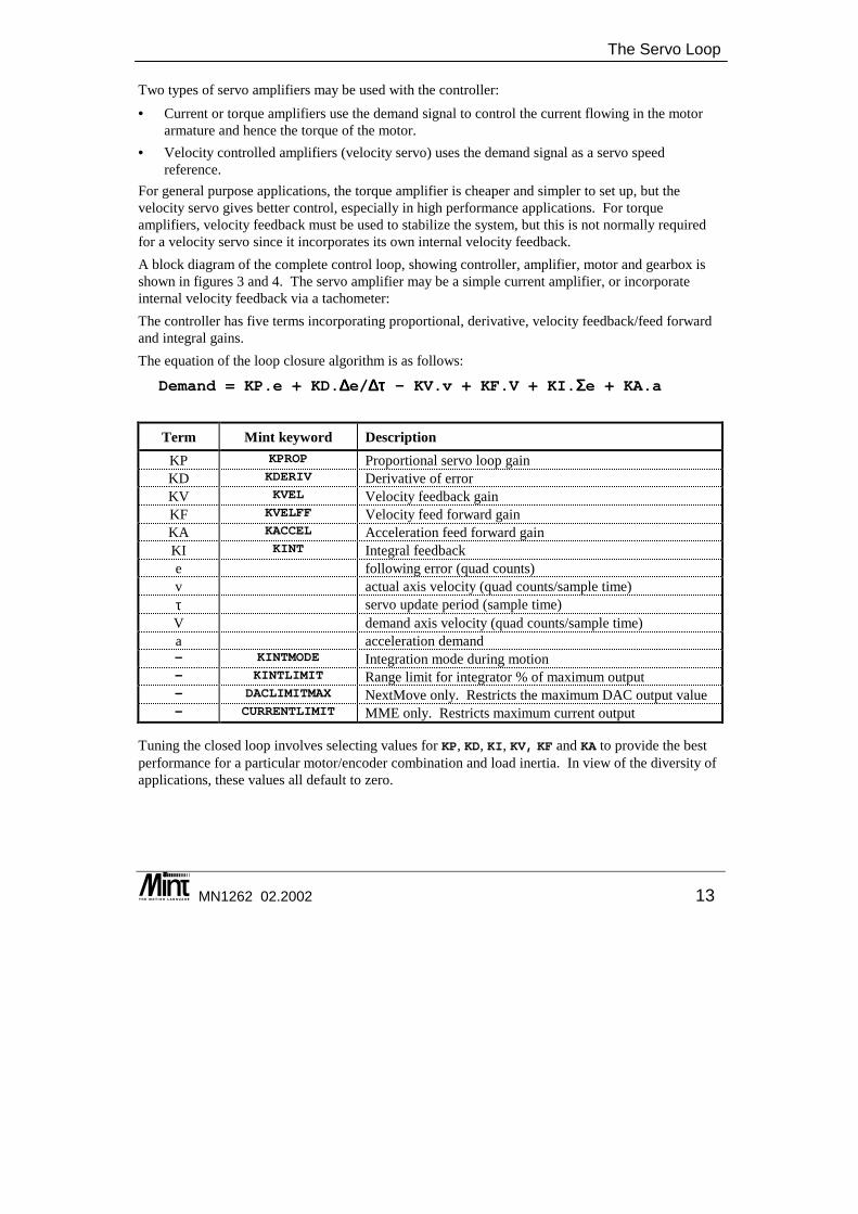
Two types of servo amplifiers may be used with the controller: • Current or torque amplifiers use the demand signal to control the current flowing in the motor
armature and hence the torque of the motor. • Velocity controlled amplifiers (velocity servo) uses the demand signal as a servo speed
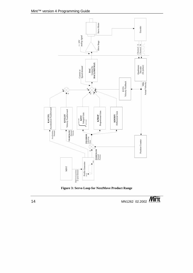
reference. For general purpose applications, the torque amplifier is cheaper and simpler to set up, but the velocity servo gives better control, especially in high performance applications. For torque amplifiers, velocity feedback must be used to stabilize the system, but this is not normally required for a velocity servo since it incorporates its own internal velocity feedback. A block diagram of the complete control loop, showing controller, amplifier, motor and gearbox is shown in figures 3 and 4. The servo amplifier may be a simple current amplifier, or incorporate internal velocity feedback via a tachometer: The controller has five terms incorporating proportional, derivative, velocity feedback/feed forward and integral gains. The equation of the loop closure algorithm is as follows:
Demand = KP.e + KD.∆∆∆∆e/∆∆∆∆ττττ - KV.v + KF.V + KI.ΣΣΣΣe + KA.a
Term Mint keyword Description KP KPROP Proportional servo loop gain KD KDERIV Derivative of error KV KVEL Velocity feedback gain KF KVELFF Velocity feed forward gain KA KACCEL Acceleration feed forward gain KI KINT Integral feedback e following error (quad counts) v actual axis velocity (quad counts/sample time) τ servo update period (sample time) V demand axis velocity (quad counts/sample time) a acceleration demand - KINTMODE Integration mode during motion - KINTLIMIT Range limit for integrator % of maximum output - DACLIMITMAX NextMove only. Restricts the maximum DAC output value - CURRENTLIMIT MME only. Restricts maximum current output
Tuning the closed loop involves selecting values for KP, KD, KI, KV, KF and KA to provide the best performance for a particular motor/encoder combination and load inertia. In view of the diversity of applications, these values all default to zero.
Mint™ version 4 Programming Guide
14 MN1262 02.2002
MIN
T
tim
e
sp
ee
d
Pro
file
Gen
erat
or
KV
EL
FF
Vel
oci
tyF
eed
forw
ard
KIN
T
Inte
gra
lG
ain
KP
RO
P
Pro
po
rtio
nal
Gai
n
KD
ER
IV
Dif
fere
nti
alG
ain
DA
C
DA
CL
IM
IT
MA
X
Lim
ited
by
+
+
+
Qu
adra
ture
Dec
od
er(4
xp
uls
es)
Po
siti
on
Co
un
ter
KV
EL
Vel
oci
tyF
eed
bac
k
-
Ch
an
ne
lA
Ch
an
ne
lB
En
cod
er
VE
L
Act
ual
Vel
oci
ty
+
-
FO
LE
RR
OR
Foll
ow
ing
Err
or
PO
SD
EM
AN
D
Dem
and
Posi
tion
VE
LD
EM
AN
D
Dem
and
Vel
oci
ty
Hig
hle
vel
posi
tion
or
spee
ddem
and
+/-
10
Van
alo
gsi
gn
alC
urr
ent
or
Sp
eed
dem
and
Dri
ve
Sta
ge
Ser
vo
Mo
tor
KA
CC
EL
Acc
eler
atio
nF
eed
forw
ard
+
+
Acc
eler
atio
nD
eman
d
KIN
TL
IMIT
-KIN
TL
IMIT
+
Figure 3: Servo Loop for NextMove Product Range
The Servo Loop
MN1262 02.2002 15
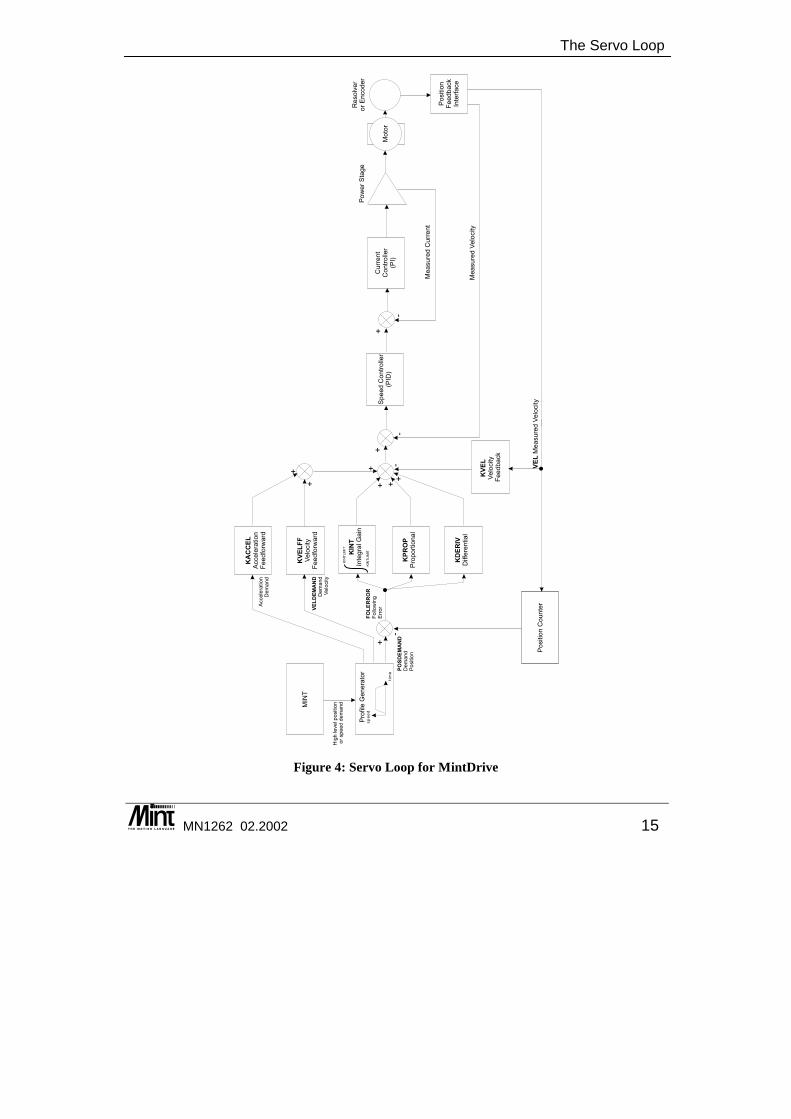
Figure 4: Servo Loop for MintDrive
Mint™ version 4 Programming Guide
16 MN1262 02.2002
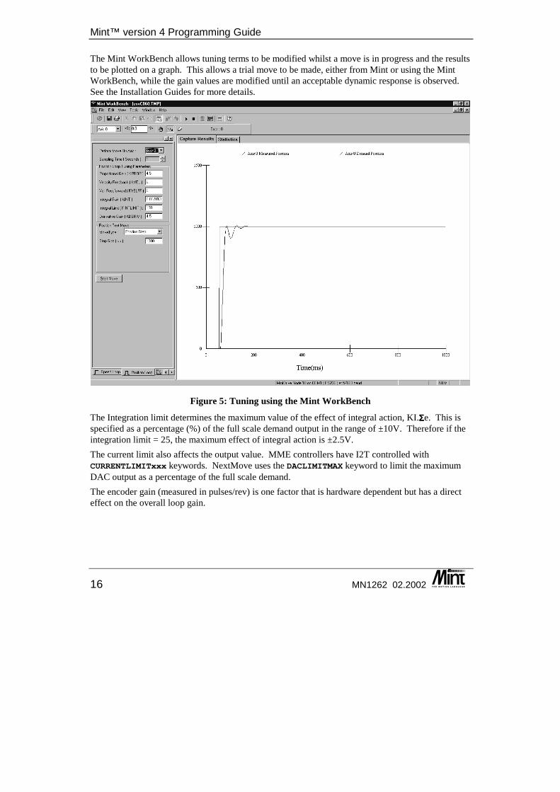
The Mint WorkBench allows tuning terms to be modified whilst a move is in progress and the results to be plotted on a graph. This allows a trial move to be made, either from Mint or using the Mint WorkBench, while the gain values are modified until an acceptable dynamic response is observed. See the Installation Guides for more details.
Figure 5: Tuning using the Mint WorkBench
The Integration limit determines the maximum value of the effect of integral action, KI.ΣΣΣΣe. This is specified as a percentage (%) of the full scale demand output in the range of ±10V. Therefore if the integration limit = 25, the maximum effect of integral action is ±2.5V. The current limit also affects the output value. MME controllers have I2T controlled with CURRENTLIMITxxx keywords. NextMove uses the DACLIMITMAX keyword to limit the maximum DAC output as a percentage of the full scale demand. The encoder gain (measured in pulses/rev) is one factor that is hardware dependent but has a direct effect on the overall loop gain.
The Servo Loop
MN1262 02.2002 17
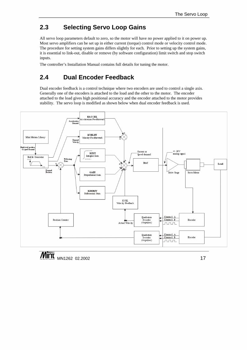
2.3 Selecting Servo Loop Gains All servo loop parameters default to zero, so the motor will have no power applied to it on power up. Most servo amplifiers can be set up in either current (torque) control mode or velocity control mode. The procedure for setting system gains differs slightly for each. Prior to setting up the system gains, it is essential to link-out, disable or remove (by software configuration) limit switch and stop switch inputs. The controller’s Installation Manual contains full details for tuning the motor.
2.4 Dual Encoder Feedback Dual encoder feedback is a control technique where two encoders are used to control a single axis. Generally one of the encoders is attached to the load and the other to the motor. The encoder attached to the load gives high positional accuracy and the encoder attached to the motor provides stability. The servo loop is modified as shown below when dual encoder feedback is used.

Mint™ version 4 Programming Guide
18 MN1262 02.2002
The implementation of Dual Encoder Feedback uses the two encoders to close two control loops, position and velocity. The encoder attached to the load is used to close the positional loop and the encoder attached to the motor shaft is used to close the velocity loop. This enables high positional accuracy to be achieved via the encoder attached to the load, yet the stability problems associated with coupling imperfections (compliance and backlash) are eliminated as these are now inside the velocity loop. To use dual encoder feedback, the VELENCODER keyword is used to specify the additional velocity encoder signal. Positional information is read from the standard axis encoder channel. See the Advanced Programming Guide for details on this keyword.

Mint™ Language
MN1262 02.2002 19
3. Mint™ Language
3 Mint™ is a very rich programming language supporting many keywords for different functions, in addition to user variables, arrays and constants. This chapter covers:
◊ The differences between Mint keyword groups ◊ Keywords ◊ Variables ◊ Arrays ◊ Numbers ◊ Constants
◊ The differences in syntax for single and multi-axis referencing
◊ Using Arrays ◊ Relational and Mathematical Operators ◊ Loop Constructs
Mint™ version 4 Programming Guide
20 MN1262 02.2002
Mint System Keywords Mint system keywords are those which are motion or control related that would not be found in most implementations of Basic. System keywords can be read only, write only, read and write or commands. A read keyword is one that will return a system parameter, for example:
a = SPEED? IDLE
A write keyword is one that accepts a value, for example: ACCEL = 20OUT = 37
A command is a keyword that does not write or return a value but causes something to happen. A command may accept an axis or channel specifier. For example:
ABORTGO[0,1]
In this example, multiple axes are referenced using [] and dot. See the next section for details. Write keywords are range checked when written to. For example:
SCALE = -1
will display the error message "Out of range on axis/channel x" because SCALE only accepts a positive value. Square brackets are used to reference axes as for commands. For example:
SPEED[1,2] = 10,20
set the speed of axis 1 to 10 units and axis 2 to 20 units.
3.1.1 Multi-Axis and Channel Syntax For keywords that are axis or channel dependant, setting a value on one axis or channel will have no effect on the other axes or channels. Mint uses the convention of axis number 0 to refer to the first axis, axis number 1 to refer to the second axis and so on. For axis based keywords, it is possible to address multiple axes with one keyword call. This is known as ‘multi-axis’ syntax. Channel based keywords cannot address multiple channels with one call. In a single axis system, you do not have to specify the axis number explicitly since Mint will default to axis 0 (the first axis in the system). Therefore:
KPROP = 1
will set the proportional gain of axis 0 to 1. To explicitly set a parameter on an axis, the axis number can be wrapped in square brackets [].
KPROP[0] = 1
Channel based keywords can only be accessed using the dot syntax.
Mint™ Language
MN1262 02.2002 21
ADCMODE.0 = 1
In a multi-axis system, each axis is referenced by enclosing the axis numbers in square brackets [] immediately after the motion keyword. For example, to set the speed of axis 0 and 1 to 10 and 30 respectively:
SPEED[0,1] = 10,30
or: SPEED[1,0] = 30,10
The number of parameters following the equal sign cannot be greater than the number of axes given except in a few cases (see CIRCLEA and CIRCLER for example). The following is invalid:
MOVEA[0,1] = 100,150,500
where MOVEA is used to set-up an absolute positional move. However: MOVEA[0,1,2] = 10,20
is valid and will set-up an absolute move on axis 0 and 1 only of 10 and 20 units respectively. Variables can be used as axis numbers:
MOVER[a] = 100
is valid provided a is a valid axis number. MOVER[a+1] = 100
is invalid. The expression "a+1" must be assigned to a variable before being passed as an axis number. The keyword AXES is used to set-up a default axis string. For example:
AXES[0,1]SCALE = 10,10SPEED = 200,300ACCEL = 500,500
is the same as: SCALE[0,1] = 10,10SPEED[0,1] = 200,300ACCEL[0,1] = 500,500
Not only does the AXES keyword save on typing, but it also speeds up program execution. To see the current status of the AXES keyword, type AXES at the command line. AXES on its own in a program will result in a run time error. When the controller is first powered up, the AXES keyword will default to the number of axes on the controller. For example, for a 4 axes NextMove BX:
AXES[0,1,2,3]
With the AXES string set, Mint will apply the following rules: Assuming AXES[0,1]
Example 1: Motion Commands STOP
Mint™ version 4 Programming Guide
22 MN1262 02.2002
will perform a controlled stop on axes 0 and 1 and is equivalent to STOP[0,1]
Example 2: Writing to keywords SPEED = 10
will set the speed of axis 0 to 10 and is equivalent to: SPEED[0] = 10
Example 3: Reading from keywords a = POS
will read the instantaneous position of axis 0 and is equivalent to: a = POS[0]
With the AXES keyword set a single axis can still be referenced. For example, assuming AXES[0,1,2]:
SPEED = 10
will set the speed of axis 0 to 10 SPEED = ,10
will set the speed of axis 1 to 10 SPEED = ,,20
will set the speed of axis 2 to 20. In some cases, the values assigned to each axis are the same. For example in a servo system with identical amplifiers and motors, the servo gains will no doubt be the same. Instead of writing the following:
AXES[0,1,2]KVEL = 10,10,10KPROP = 1.5,1.5,1.5KINT = .1,.1,.1
you can write AXES[0,1,2]KVEL = 10;KPROP = 1.5;KINT = .1;
The semi-colon will apply the last value to all the remaining axes. For example: SPEED[0,1,2] = 10,20;
will set the speed of axis 0 to 10 and the speed of axis 1 and 2 to 20 and 20. It is possible to read more than 1 axis using the square bracket notation. For example:
PAUSE IDLE[0,1]
Mint™ Language
MN1262 02.2002 23
will wait for both axis 0 and axis 1 to come to a stop. This is equivalent to: PAUSE IDLE[0] AND IDLE[1]
but the first expression is both quicker to execute and takes up less code space. However: PAUSE IDLE
will only wait for the first axis set by the AXES keyword to become idle. If we assume AXES[0,1] has been set, then this is equivalent to:
PAUSE IDLE[0]
Where more than one axis is read, the results are ANDed together using bitwise arithmetic. This is only really useful for keywords that return true (1) or false (0).
3.1.2 Single Axis or Channel References using Dot A single axis can be referenced using dot ‘.’, followed by the axis number. Channel based keywords can only use the dot syntax to reference the channel number. The axis or channel number can be expressed as either a number or a variable. For example:
b = POS.1
is the same as: b = POS[1]
The first expression has 2 advantages over the second. First, it occupies less code space, and secondly, it executes quicker. Note that:
b = POS.a + 1
is equivalent to: b = POS[a] + 1
Expressions can be used in the dot notation so b = POS.(a + 1)
is valid but the following is not. b = POS[a + 1]
The dot parameter is also used to access channels, for non axis related keywords. For example, to read analog input channel 1, the following would be used:
v = ADC.1
The following is invalid. v = ADC[1]
See section All numbers are stored in floating point format. The floating point number is represented by an 8

Mint™ version 4 Programming Guide
24 MN1262 02.2002
3.2 Mint Numbers and Variables
3.2.1 Numbers All numbers are stored in floating point format. The floating point number is represented by an 8 bit exponent and a twos complement 24 bit mantissa. For integer numbers, this gives a range of ±16777215. For decimal numbers, this gives a range of ±8388607.0. The way the floating point number is stored means that the larger the integer part of a number, the less accurate the decimal part will be and vice-versa.
Example: PRINT 1 + 0.5551.555
PRINT 8388600 + 0.5558388600.5
In Mint, a fractional number will be displayed with 4 decimal places. To see more than 4 places, the USING modifier must be used.
PRINT 1.0051031.0051
PRINT 1.005103 USING 1,61.005102
As can be seen, the PRINT keyword will cause rounding on the number displayed.
Larger numbers than ±1677215 can be stored but at a loss of accuracy in the integer part of the number.
3.2.2 Binary and HEX Notation Binary numbers are defined by placing a zero before the binary string. For example:
PRINT 01101127
Binary numbers are useful when writing to outputs. For example: OUT = 011111000
this will turn the output bits 3, 4, 5, 6 and 7 on the other output bits off. a = 11
is not a valid binary number and will assign the value of 11 to the variable a. a = 05
Mint™ Language
MN1262 02.2002 25
or: PRINT 05
is an invalid binary number and will generate a syntax error, however: a = 0.5
is acceptable and will define the value of 0.5 to the variable a. Numbers can be displayed in binary format by using the PRINT modifier BIN.
PRINT BIN 2711011
Hexadecimal numbers are defined by placing 0x before the hex number. For example: a = 0xF2FA
assigns a value of 62202 to variable a. Numbers can be displayed in hex format by using the PRINT modifier HEX.
PRINT HEX 744A
Underscore can be used to separate digits within a binary or hexadecimal string to make the numbers more readable. For example:
OUT = 01111_0000_1111OUT = 0xFF_00
There is no restriction to the location of underscores. They are not byte or word bound.
3.2.3 Constants A constant is a number in your program that does not change during program execution. For instance, the expression:
SPEED = 20.5
assigns the constant value 20.5 to the motion variable SPEED. Mint accepts four types of constants:
• Constant numbers • Character constants • Pre-defined constant keywords
By default, Mint interprets all constant numbers as decimal unless otherwise specified as binary or hex. Mint also provides character constants for use with the INKEY keyword. To define a character constant, enclose the character in single quotes, for example:
a = 'A'
Mint™ version 4 Programming Guide
26 MN1262 02.2002
will assign the value of 65 to a. Mint will convert all character constants to their upper case equivalent. Therefore:
'A''a'
both have the value of 65. Section 11.15 contains an ASCII character table. Character constants are useful for interpreting key presses as shown in the following section of code:
#mainMenuDIM key
LOOPLOCATE 1,1?"A .. Start"?"B .. Setup"
key = INKEYIF key = 'A' THEN GOSUB startIF key = 'B' THEN GOSUB setup
ENDLRETURN
#start...RETURN
#setup...RETURN
If key 'A' is pressed, the start subroutine will be called. If 'B' is pressed, set-up will be called.
3.2.4 Pre-defined Constants Mint has provided a number of pre-defined constants to prevent the user having to remember constant values or bitmap values and can be used to aid the readability of programs. Mint pre-defined constants are all pre-fixed with an underscore character, “_”, to distinguish them from Mint keywords. They are not case sensitive.
Examples: OFFSET = 10 : PAUSE AXISMODE = _mdFOLLOW : REM Wait for offset to finishOUT1 = _ON : REM Switch output bit 1 onCONFIG = _cfSTEPPER : REM Configure for stepper modeHOME = _hmPOSITIVE_SWITCH_INDEX : REM home in +ve direction and seek index
The following is a list of general purpose constants. Constants available for use with a keyword are detailed with that keyword.
Mint™ Language
MN1262 02.2002 27
The following are general purpose constants:
Pre-defined Constant Value _TRUE 1 _FALSE 0 _ON 1 _OFF 0
_MAXINT 8388607 _MININT -8388607
3.2.5 Variables Mint stores user variables on the variable stack, the size of which is dependent upon the controller. All controllers support a maximum of 255 variables with the exception of NextMove PC which supports 100. In MintDrive and NextMove BX, all variables are held in battery backed-up RAM. They will therefore remain resident on the controller between power-cycles and retain the last value assigned. This is also true for Mint arrays declared using the DIM statement. NextMove PCI, NextMove PC and ServoNode 51 do not have battery backed RAM and do not retain variables across a power cycle. NextMove PCI and ServoNode 51 have NVRAM for non-volatile storage. This is accessed with the NVLONG and NVFLOAT keywords. When creating a new program it is advisable to remove any existing variables from memory using the RELEASE keyword Variables are meaningful names that are used to represent data in a program. You can assign a value to a variable at the beginning of a program and use it like a constant, or its value may be set as the result of calculations or incremented in a loop. These variables are referred to as user variables to distinguish them from motion variables which are reserved keywords in Mint used to perform a specific task. User variables can have any name as long as it is not a reserved word or Mint keyword and begins with a letter followed by any alphanumeric character or an underscore. Alternatively, variable names can begin with an underscore as long as it is followed by an alphanumeric. Variable names may be any length but only the first ten characters are significant.
DIM thisIsAVariable1DIM thisIsAVaraible2
will only define one variable of the name thisIsAVar Examples of variable names:
DIM my_var1DIM xPositionDIM _myVar2
All variables must be declared before being used using the DIM keyword, otherwise an error is generated. For example:
Mint™ version 4 Programming Guide
28 MN1262 02.2002
DIM aVar = 100DIM thisIsAVariable
will define variables aVar and thisIsAVariable if they are not already defined. aVar will be given a value of 100.
DIM aVar, thisIsAVariable
is invalid and will result in a Syntax Error. Variables can be used in any valid expression. For example:
DIM newPosDIM oldPos
newPos = 2oldPos = newPos*2PRINT oldPos+newPos
Running this code fragment will define variables oldPos and newPos and print the value 6 to the screen. An extensive range of operators can be used on numbers and variables. These are discussed in more detail in a later section.
Mint only supports numeric variables, string variables are not supported.
There are two Mint commands associated with user variables. VIEW VAR lists all currently defined variables and their values. RELEASE erases the currently defined variables from memory.
There is a limit on the maximum number of variable names that can be defined in any one program. To clear all variables from memory, use RELEASE. Note that RELEASE cannot be used in a program. If you wish to clear all variables before executing a program each time,
place RELEASE in the configuration file, ensuring that no variables are defined in the configuration file.
Motion variables have an almost identical syntax to user variable assignment and can be used in a similar way:
c = POS * 10
will assign the position of the axis, multiplied by 10, to the variable c. The VIEW VAR keyword can be used to display all defined variables and their current value. For example:
VIEW VAR
a = 1length = 2304.5
2 variable(s) from a maximum 255 defined.
Mint™ Language
MN1262 02.2002 29
Non-volatile Variables Due to the way Mint compiles and executes programs, non-volatile variables can be set-up by assigning them in a subroutine, but never calling the routine. For example:
#non_volatileDIM my_var1DIM my_var2
RETURN
Mint code is compiled before it is executed. It is at this stage that variables are declared on to the variable stack. If the variable already exists on the stack, its value is preserved. If the variable does not exist, (i.e. has just been defined due to a change in the program), it is assigned to the stack with a value of 0. To work correctly, the non_volatile subroutine must be placed near the beginning of the program before any other references to the variables, otherwise an undefined variable error will be issued during compilation. A program structure may be as follows:
REM Program titleGOSUB init : REM InitialiseGOSUB main : REM Main program loopEND
#non_volatileDIM my_var1DIM my_var2
RETURN
#initREM Rest of program here
RETURN
#mainREM Main Program loop
RETURN
It may be that on first running a program, you want variables to default to a value other than zero. This can be done by checking a non-volatile variable as shown:
REM Program title
REM Check variables have been definedDIM non_volatileIF non_volatile = _false THEN GOSUB default
GOSUB init : REM InitialiseGOSUB main : REM Main program loopEND
REM Declare non volatile variables#non_volatilenon_volatile = 0
RETURN
REM Declare variable and initialize them
Mint™ version 4 Programming Guide
30 MN1262 02.2002
#defaultnon_volatile = _trueDIM my_var1 = 10DIM my_var2 = 20
RETURN#initREM Rest of program here
RETURN
#main#REM Main loop
RETURN
When the program is first executed the variable non_volatile is defined as zero and the routine default executed. When the program is re-executed, the routine default will be ignored since non_volatile is now 1.
3.2.6 Delimiters Valid delimiters within Mint are the characters:
• ^ or CHR (94) • space or CHR(32)
These can be used in conjunction with macros to allow the use of axes string definitions. For example:
DEFINE servos = [0,1,2,3]SPEED servos = 10;
is valid DEFINE servos = [0,1,2,3]SPEED^servos = 10;
is also valid. The characters ‘.’ and ‘_’ cannot be used as delimiters as they are used an special characters in Mint. The ‘.’ is used to precede keyword parameter such as an axis number or a channel number. The ‘_’ is used to precede all Mint constants.
3.3 Arrays A Mint array is also considered to be a variable and is therefore also placed on the variable stack, but takes up only one location on the stack. The space required for the array elements is placed at the top of the Mint User Memory area (see section 9.1). Each array element will take up 4 bytes.
Mint™ Language
MN1262 02.2002 31
An array is a table of values that is referenced by a single name. Each value in the array is called an element. Elements are numeric variables that can be used in expressions and Mint statements in the same way as simple variables described previously. Each element in the array is referenced by a number in parentheses which follows the array name, this number is termed an index. Note that the index is always enclosed in round brackets to distinguish it from a reference to axis numbers which are in square brackets. For example:
my_var(10) = 100.5
will assign the value 100.5 to the array variable my_var index 10 a = my_var(10)
will assign the value of array variable my_var index 10 to the variable a. Before using an array variable, memory space must be reserved for it's storage by use of the DIM statement:
DIM my_array(10)
declares an array variable called my_array with ten elements. PRINT my_array(4)
will print the contents of element four to the user terminal. Array variables are very useful for motion control applications since they can be used for storing a large number of data points that can be used in the program for positional moves. Mint supports only single dimensional arrays (one subscript per variable name).
The array variable name can also be used as a normal variable. For example "my_array = 1" is a valid expression for the above array.
Initialization of the contents of the variables is achieved by appending a list of the data after the DIM statement:
DIM y_position(10) = 1,2,3,4,5,6,7,8,9,10
declares an array y_position, where the first element, y_position(1), is equal to 1 etc. If the list of initialization parameters extends beyond one line then the last entry on each line should have a comma after it. This tells the Mint compiler that there is further data on the next line. A semi colon after the last entry will initialize all parameters to the value preceding it:
DIM y_position(10) = 10,0;
Initializes the first element in the array to ten and the remaining elements to zero.
Arrays are initialized at compile time and not run time. Therefore the above expressions will always be executed regardless of where they reside in the program.
The other way to initialize an array is at run time, for instance, a simple program may be written to record the position of the axis into an array for a teach-by-hand type application:
DIM pos_array(20) : REM define arrayDIM i
Mint™ version 4 Programming Guide
32 MN1262 02.2002
TORQUE = 0; : REM Turn off servo loop and apply 0vFOR i = 1 to 20PAUSE IN1 = 1 : REM wait in1 = 1pos_array(i) = POS : REM store positionPAUSE IN1 = 0 : REM wait in1 = 0
NEXT : REM back to start
This is a simple example of implementation of an application whereby the operator manually moves the motor and records positions by pressing a switch connected to input one. These data points may be used later in the program to duplicate operator input. This sort of approach is useful in linear table applications. One important consideration is that array variables are not initialized to zero at run time. On NextMove BX and MintDrive family controllers, this means that data stored in previous executions of the program is not lost when the system is turned off. You have seen how a series of points can be stored in an array in a teach-by-hand application. Once the data has been entered into an array, the data may be uploaded so it can be edited or stored. The Mint WorkBench provides array upload facilities. The VIEW ARRAY command can be used at the Mint command line to display the defined arrays and data. For example:
VIEW ARRAYs(10)10, 13, 18, 33, 3445, 23, 56, 32, 0
3.3.1 Advanced use of Arrays Consider an insertion application, whereby the machine must repeatedly move through a series of points and perform an insertion operation, but different work-pieces require a different series of positions. This is an ideal application for array data. The following code fragment defines two arrays, X and Y, that store fifty data points each for an X-Y insertion application:
DIM X(50)DIM Y(50)
A program to read the data in the arrays and perform the insertion might look something like this (the exact syntax of the move instructions is covered in later sections of this manual, consider for now only the way that we use the data):
DIM IFOR I = 1 TO 50MOVEA = X(I),Y(I) : REM read Ith elementsGOPAUSE IDLE[0,1] : REM wait for move to finishOUT1 = 1 : REM output one is connected to..WAIT = 50 : REM .. the insertion machineOUT1 = 0
NEXT

Mint™ Language
MN1262 02.2002 33
The statement MOVEA = X(I),Y(I) selects the Ith element of the arrays as the positions for the Ith iteration of the FOR loop. If different jobs require different numbers of insertion operations, we would probably store the maximum value of the loop as a variable as well. Array data is stored in the controller memory as a table of four byte variables. Data space is limited by memory on board the controller depending on the size of the application program. The statements:
DIM X(50)DIM Y(50)
reserve a one hundred element (400 byte) long table of data in the controller's memory. For advanced users, it is possible to externally generate the array data for X and Y in the example program above and download this is to the host without loading a new program. This data might be generated by any application that can produce a series of numbers in ASCII format. For instance, if you wished to interface a CAD (Computer Aided Design) system with your insertion machine, you could write a program that generated the data formatted as specified in the next section.
3.3.2 Array Data File Format Array data files are uploaded and downloaded to the controller in the format shown below:
my_array1(10)1, 2, 3, 4, 56, 7, 8, 9, 10
my_array2(5)5, 4, 3, 2, 1
The above might correspond to the following Mint program: DIM my_array1(10) = 1,2,3,4,5,6,7,8,9,10DIM my_array2(5) = 5,4,3,2,1
Array data files can be created or changed using a standard text editor, and the new data loaded into the system. The loading and saving of array data is discussed later on. The following restrictions apply to array data files:
• The array variable name is given followed by the number of elements in the array enclosed in brackets. For example:
my_array1(10)
• The data must appear on the next line following the variable name, otherwise when downloading data to the target, values may be missed.
• The last data value on a line must only have a carriage return following it. If it is followed by a comma, a value of zero will be recorded. This is unlike the DIM statement.
• No semi-colon is supported as with the DIM statement.
Mint™ version 4 Programming Guide
34 MN1262 02.2002
• Comments can be added to array data files by prefacing the comment with a colon (:). Comments are ignored by Mint, therefore uploaded array data files contain no comments.
• If an array variable was declared in a file with 10 elements, but 11 values follow, the 11th value will be lost. If less than 10 values are given, the remaining values will be random.
• If the target system has array variables defined that are not defined in the array data file, these values will be overwritten by the new array variables. This will also result in array variables sharing the same memory space. This is shown in the following example.
Assume the target has the following array variable defined: my_array(10)
The array data file defines the following array variables: my_array2(10)1,2,3,4,56,7,8,9,0
my_array3(10)10,20,30,40,5060,70,80,90,100
When this file is loaded into the target, typing VIEW ARRAY will show that the values of my_array are the same as that of my_array2. If a value is assigned to my_array2, it will also be assigned to my_array as shown below:
DIM my_array(10)my_array2(5) = 12.5
PRINT my_array(5)
Results in 12.5 being printed, as does: PRINT my_array2(5)
If the array variable names in the array data file do not correspond to the array variable names held in memory, the variables should be released from memory using the RELEASE command. If too many variables are defined, some array variables may be lost. If this is the case, clear all the variables from memory using the RELEASE keyword, and reload the array data. Make sure any necessary array data has been saved first.
3.4 Relational and Mathematical Operators A wide range of powerful relational and mathematical operators are available in Mint. These are used to construct expressions for conditional statements and loops, and to evaluate expressions.
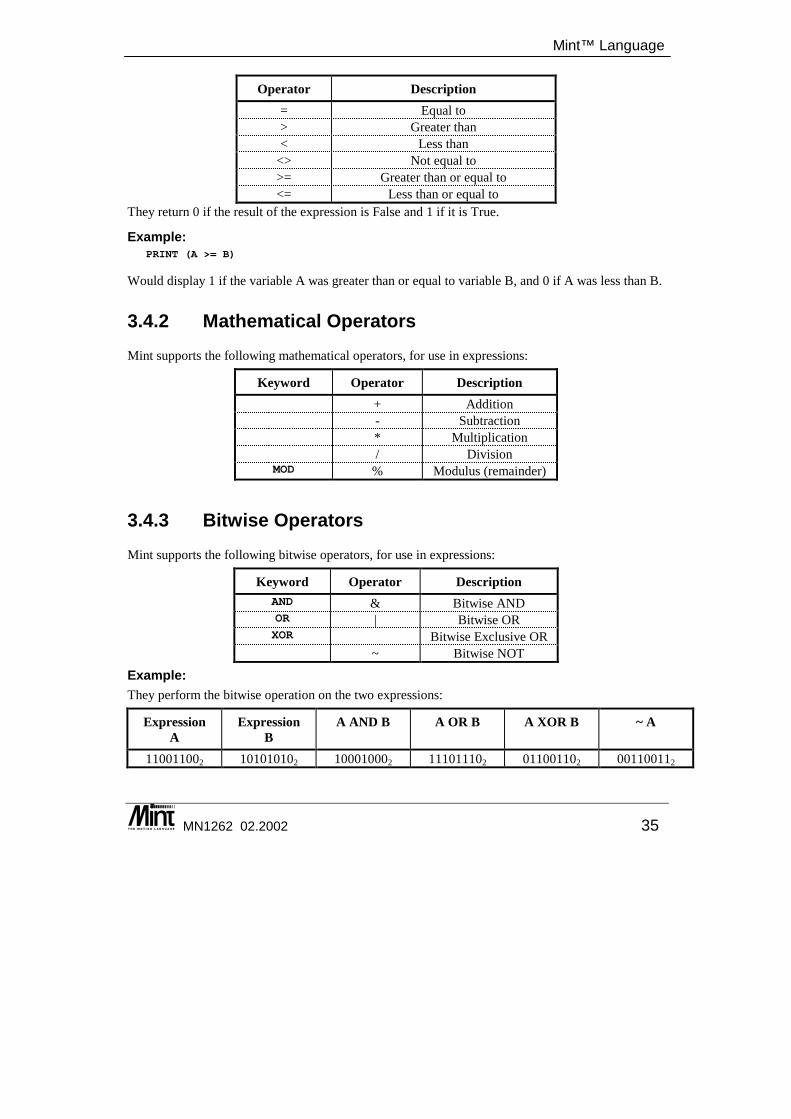
3.4.1 Relational Operators Mint supports the following relational operators, for use in conditional statements such as “IF .. THEN”:
Mint™ Language
MN1262 02.2002 35
Operator Description = Equal to > Greater than < Less than
<> Not equal to >= Greater than or equal to <= Less than or equal to
They return 0 if the result of the expression is False and 1 if it is True.
Example: PRINT (A >= B)
Would display 1 if the variable A was greater than or equal to variable B, and 0 if A was less than B.
3.4.2 Mathematical Operators Mint supports the following mathematical operators, for use in expressions:
Keyword Operator Description + Addition - Subtraction * Multiplication / Division
MOD % Modulus (remainder)
3.4.3 Bitwise Operators Mint supports the following bitwise operators, for use in expressions:
Keyword Operator Description AND & Bitwise AND OR | Bitwise OR XOR Bitwise Exclusive OR
~ Bitwise NOT
Example: They perform the bitwise operation on the two expressions:
Expression A
Expression B
A AND B A OR B A XOR B ~ A
110011002 101010102 100010002 111011102 011001102 001100112
Mint™ version 4 Programming Guide
36 MN1262 02.2002
Logical operators AND/& and OR/| can be used for more than simple comparisons, since they actually perform bitwise operations on the variables. For instance, consider the expression:
5 & 6
is evaluated to 4 i.e. in its binary representation: 0101 & 0100 = 0100
The AND/& operator can therefore be used to mask inputs in conditional expressions: PAUSE IN AND 12PAUSE IN2 = 1 OR IN3 = 1
are equivalent since 12 (1100 binary) masks off the lower bits of the inputs. The advantage of the first option is that it will execute faster. A binary constant could be used to make the expression more readable:
PAUSE IN AND 01100PAUSE IN AND 12
are equivalent. OUT = OUT & 15
will clear the digital outputs apart from bits 0 to 3 which are left intact. OUT = OUT | 15
will set output bits 0 to 3, leaving the other outputs intact where OUT is used to set the digital output bits. Reading OUT will return the last value written to the outputs. The XOR operator also performs bitwise operations:
01010 XOR 01101
results in: 111
Values are taken as 24 bit values. The bitwise toggle operator, ~ changes the state of each bit. PRINT BIN ~01100101
results in 111111111111111110011010
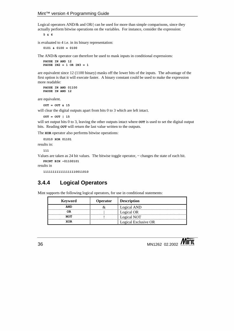
3.4.4 Logical Operators Mint supports the following logical operators, for use in conditional statements:
Keyword Operator Description AND & Logical AND OR | Logical OR NOT ! Logical NOT XOR Logical Exclusive OR
Mint™ Language
MN1262 02.2002 37
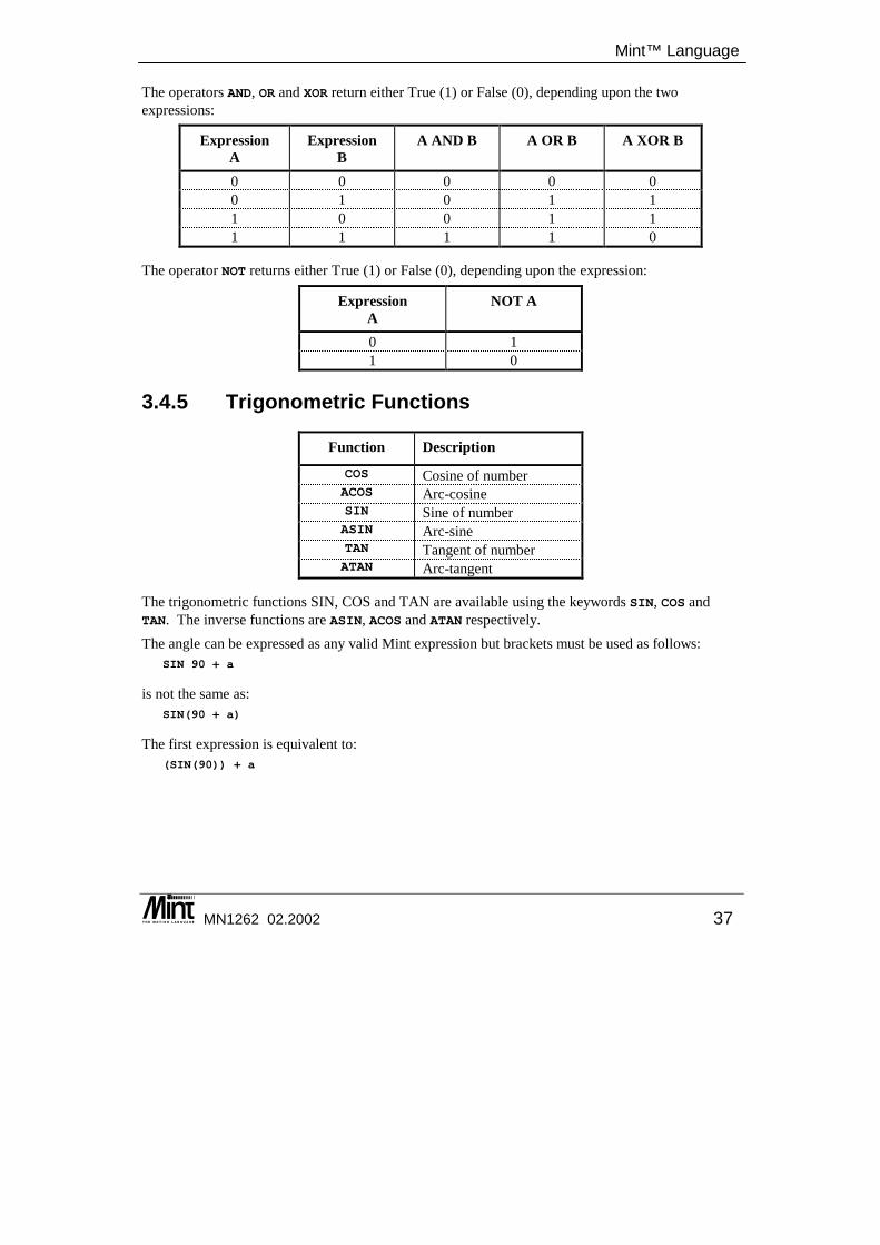
The operators AND, OR and XOR return either True (1) or False (0), depending upon the two expressions:
Expression A
Expression B
A AND B A OR B A XOR B
0 0 0 0 0 0 1 0 1 1 1 0 0 1 1 1 1 1 1 0
The operator NOT returns either True (1) or False (0), depending upon the expression:
Expression A
NOT A
0 1 1 0
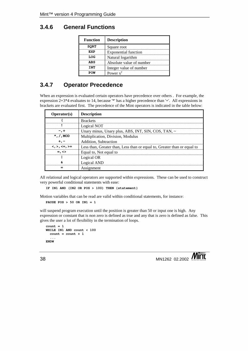
3.4.5 Trigonometric Functions
Function Description
COS Cosine of number ACOS Arc-cosine SIN Sine of number ASIN Arc-sine TAN Tangent of number ATAN Arc-tangent
The trigonometric functions SIN, COS and TAN are available using the keywords SIN, COS and TAN. The inverse functions are ASIN, ACOS and ATAN respectively. The angle can be expressed as any valid Mint expression but brackets must be used as follows:
SIN 90 + a
is not the same as: SIN(90 + a)
The first expression is equivalent to: (SIN(90)) + a
Mint™ version 4 Programming Guide
38 MN1262 02.2002
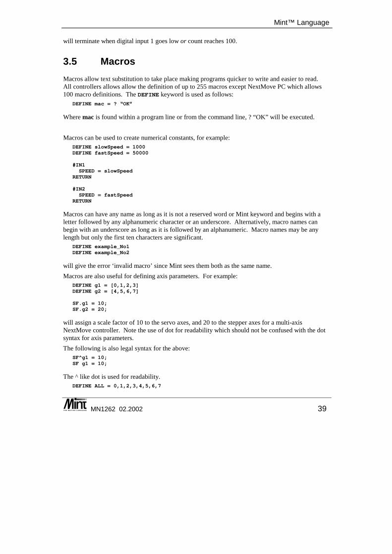
3.4.6 General Functions
Function Description SQRT Square root EXP Exponential function LOG Natural logarithm ABS Absolute value of number INT Integer value of number POW Power xy
3.4.7 Operator Precedence When an expression is evaluated certain operators have precedence over others . For example, the expression 2+3*4 evaluates to 14, because '*' has a higher precedence than '+'. All expressions in brackets are evaluated first. The precedence of the Mint operators is indicated in the table below:
Operator(s) Description ( Brackets ! Logical NOT -,+ Unary minus, Unary plus, ABS, INT, SIN, COS, TAN, ~
*,/,MOD Multiplication, Division, Modulus +,- Addition, Subtraction
<,>,<=,>= Less than, Greater than, Less than or equal to, Greater than or equal to =,<> Equal to, Not equal to | Logical OR & Logical AND = Assignment
All relational and logical operators are supported within expressions. These can be used to construct very powerful conditional statements with ease:
IF IN1 AND (IN2 OR POS > 100) THEN {statement}
Motion variables that can be read are valid within conditional statements, for instance: PAUSE POS > 50 OR IN1 = 1
will suspend program execution until the position is greater than 50 or input one is high. Any expression or constant that is non zero is defined as true and any that is zero is defined as false. This gives the user a lot of flexibility in the termination of loops.
count = 1WHILE IN1 AND count < 100count = count + 1...
ENDW
Mint™ Language
MN1262 02.2002 39
will terminate when digital input 1 goes low or count reaches 100.
3.5 Macros Macros allow text substitution to take place making programs quicker to write and easier to read. All controllers allows allow the definition of up to 255 macros except NextMove PC which allows 100 macro definitions. The DEFINE keyword is used as follows:
DEFINE mac = ? “OK”
Where mac is found within a program line or from the command line, ? “OK” will be executed. Macros can be used to create numerical constants, for example:
DEFINE slowSpeed = 1000DEFINE fastSpeed = 50000
#IN1SPEED = slowSpeed
RETURN
#IN2SPEED = fastSpeed
RETURN
Macros can have any name as long as it is not a reserved word or Mint keyword and begins with a letter followed by any alphanumeric character or an underscore. Alternatively, macro names can begin with an underscore as long as it is followed by an alphanumeric. Macro names may be any length but only the first ten characters are significant.
DEFINE example_No1DEFINE example_No2
will give the error ‘invalid macro’ since Mint sees them both as the same name. Macros are also useful for defining axis parameters. For example:
DEFINE g1 = [0,1,2,3]DEFINE g2 = [4,5,6,7]
SF.g1 = 10;SF.g2 = 20;
will assign a scale factor of 10 to the servo axes, and 20 to the stepper axes for a multi-axis NextMove controller. Note the use of dot for readability which should not be confused with the dot syntax for axis parameters. The following is also legal syntax for the above:
SF^g1 = 10;SF g1 = 10;
The ^ like dot is used for readability. DEFINE ALL = 0,1,2,3,4,5,6,7
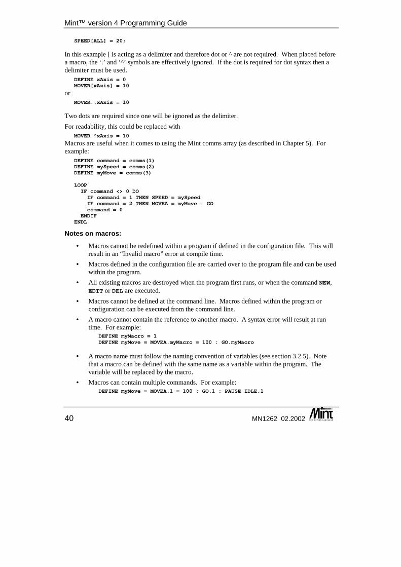
Mint™ version 4 Programming Guide
40 MN1262 02.2002
SPEED[ALL] = 20;
In this example [ is acting as a delimiter and therefore dot or ^ are not required. When placed before a macro, the ‘.’ and ‘^’ symbols are effectively ignored. If the dot is required for dot syntax then a delimiter must be used.
DEFINE xAxis = 0MOVER[xAxis] = 10
or MOVER..xAxis = 10
Two dots are required since one will be ignored as the delimiter. For readability, this could be replaced with
MOVER.^xAxis = 10
Macros are useful when it comes to using the Mint comms array (as described in Chapter 5). For example:
DEFINE command = comms(1)DEFINE mySpeed = comms(2)DEFINE myMove = comms(3)
LOOPIF command <> 0 DOIF command = 1 THEN SPEED = mySpeedIF command = 2 THEN MOVEA = myMove : GOcommand = 0
ENDIFENDL
Notes on macros:
• Macros cannot be redefined within a program if defined in the configuration file. This will result in an “Invalid macro” error at compile time.
• Macros defined in the configuration file are carried over to the program file and can be used within the program.
• All existing macros are destroyed when the program first runs, or when the command NEW, EDIT or DEL are executed.
• Macros cannot be defined at the command line. Macros defined within the program or configuration can be executed from the command line.
• A macro cannot contain the reference to another macro. A syntax error will result at run time. For example:
DEFINE myMacro = 1DEFINE myMove = MOVEA.myMacro = 100 : GO.myMacro
• A macro name must follow the naming convention of variables (see section 3.2.5). Note that a macro can be defined with the same name as a variable within the program. The variable will be replaced by the macro.
• Macros can contain multiple commands. For example: DEFINE myMove = MOVEA.1 = 100 : GO.1 : PAUSE IDLE.1
Mint™ Language
MN1262 02.2002 41
The command VIEW MACROS can be used to display all macro definitions.
3.6 Conditional Statements Three conditional statements are supported in Mint:
1. IF .. THEN 2. IF block structure. 3. PAUSE
3.6.1 IF .. THEN statement
Format: IF <condition> THEN <statements>
The simple IF .. THEN statement is the same as standard versions in Basic. If the condition is true the statements following THEN and up to the end of the line are executed. The condition can be any valid expression, full details of the alternatives are given in the section on relational operators.
Examples: IF POS[1] > 100 THEN SP = 20IF (a > 12) AND (in1 OR (b > 20)) THEN GOSUB label1
Multiple statements are separated by colons if they are to be executed in the same if statement. IF IN3 THEN STOP : PAUSE IDLE : OUT0 = _off
Note that there is no ELSE statement with the simple IF statement, the IF block structure must be used if an ELSE is required.
3.6.2 IF block structure Whereas the IF THEN statement can only be used to conditionally execute a single line of commands, the IF block structure can execute a series of commands. It has the following structure.
Format: IF condition DO{statements} : REM Execute if condition is true
ELSE{statements} : REM Execute if condition is false
ENDIF
If the condition is true, the statements up to the ELSE will be executed. If the condition is false, the statements after the ELSE statement will be executed. The ELSE is optional, statements following the ELSE will be executed only if the condition is false. If ELSE is not used, the code between the IF and the ENDIF statement will be executed only if the condition is true.

Mint™ version 4 Programming Guide
42 MN1262 02.2002
Example: DIM aDIM pos_x(10)
IF INKEY = 'A' DOOUT1 = _onFOR a = 1 to 10MOVER = pos_x(a) : GO
NEXTOUT1 = _off
ELSEJOG = 40
ENDIF
IF IN2 OR !IN4 DOSTOPPAUSE IDLEOUT1 = _on
ENDIF
IF THEN should be used for speed if no ELSE is required and all the statements can fit onto one line.
IF .. ENDIF constructs can be nested (IF within an IF) up to 255 levels. An example of one level of nesting is:
DIM aDIM bDIM cDIM d…
IF a = 5 DO{statements}IF b = 2 DO
c = 3{statements}
ENDIF{statements}ELSEd = 1
ENDIF
3.6.3 PAUSE statement
Format: PAUSE <expression>
The PAUSE keyword stops program execution until condition expression is true. This has many uses in synchronizing motion and waiting for inputs. For example:
PAUSE IN1 = 1
Mint™ Language
MN1262 02.2002 43
will halt program execution until input bit 1 reads 1. Alternatively: PAUSE IN1
is the same as the previous example but is quicker to evaluate and saves code space. PAUSE !IN1PAUSE IN1
pause until a rising edge is seen on input bit 1. PAUSE POS > 300
pauses until POS (axis position) is greater than 300. Due to the finite time that this loop takes to operate, the axis position upon executing the next line of code may be slightly greater than 300, especially at high motor speeds.
PAUSE IDLE[0,1]
will pause until both axis 0 and axis 1 are idle. i.e. AXISMODE is zero. Using INKEY to read the keyboard, the statement:
PAUSE INKEY = 'y'
will suspend program execution until key 'y' is pressed. PAUSE INKEY
will wait for any key press. PAUSE INKEY = 0
will clear the serial port buffer.
3.7 Loops Loops in Mint allow the execution of a block of statements a number of times, or while or until a condition is true. Four loop structures are supported in Mint.
• FOR .. NEXT
• REPEAT .. UNTIL
• WHILE .. ENDW
• LOOP .. ENDL
3.7.1 FOR .. NEXT loop The FOR .. NEXT loop executes a fixed number of times set by the value of an index variable, a step size and start and stop values for the index. The increment or decrement of the index on each iteration is defined by the STEP keyword. The start and end values can be any valid expression. All FOR loops are terminated with a NEXT statement. Unlike the standard implementation of Basic you must not append the index name after the NEXT statement, doing so will generate an error message.
Mint™ version 4 Programming Guide
44 MN1262 02.2002
Format: DIM index
FOR index = <expr1> TO <expr2> {STEP <expr3>}{statements}
NEXT
Below is an example of a FOR loop used as the index in a look-up table. DIM aDIM pos_x(20)
FOR a = 1 TO 20 STEP 2MOVEA = pos_x(a)GO
NEXT
FOR .. NEXT loops may be nested, up to a level of 50 deep. See section 3.9 for more details on Mint limitations.
Example: DIM aDIM b
AXES[0,1]FOR a = 1 TO 100MA = a : GO.0FOR b = 1 to 10 STEP 2 : REM Nesting Level 2MA = ,b : GO.1
NEXTNEXT
3.7.2 REPEAT .. UNTIL loop REPEAT .. UNTIL executes the statements within the loop until the condition after the UNTIL becomes true.
Format: REPEAT{statements}
UNTIL <condition>
Example: DIM a = 0REPEATMOVER = 1 : GOPAUSE IDLEPRINT "Position is: ",POS; CHR(13)
UNTIL POS > 100
When the UNTIL statement is true, the loop will terminate. A repeat loop will always execute at least once. The EXIT statement can be used to prematurely terminate a REPEAT loop.
Mint™ Language
MN1262 02.2002 45
REPEAT .. UNTIL loops may be nested, up to a level of 50 deep. See section 3.9 for more details on Mint limitations.
REPEAT : UNTIL INKEY = 0
this example will clear the serial port buffer. INKEY returns the value 0 when the serial buffer contents are empty. This can be replaced by:
PAUSE INKEY = 0
3.7.3 WHILE .. ENDW loop The WHILE .. ENDW loop will execute until the condition after the WHILE becomes false. Unlike a REPEAT loop which will always execute at least once, a WHILE loop will only execute if the condition is true. A WHILE loop must be terminated with an ENDW.
Example: WHILE IN1JOG = ADC.0 - 127
ENDWSTOP
jogs the motor at a value set by analog port 1. When input 1 goes low the loop terminates and the motor will stop. The EXIT statement can be used to prematurely terminate a WHILE loop.
WHILE .. ENDW loops may be nested, up to a level of 50 deep. See section 3.9 for more details on Mint limitations.
3.7.4 LOOP .. ENDL loop The simplest type of loop is the LOOP .. ENDL construct. This simply loops round indefinitely, for instance:
LOOPJOG = IN & 01111111 : REM speed set by IN0..6IF IN7 = 1 THEN EXIT
ENDL
loops round forever reading the digital inputs and jogging the motor at a speed set by the binary value of user inputs zero to six.
GOSUB start
DIM key
LOOPkey = INKEYIF key = 'A' THEN GOSUB teachIF key = 'B' THEN GOSUB replay
Mint™ version 4 Programming Guide
46 MN1262 02.2002
IF key = 'C' THEN GOSUB saveDataENDL
provides a simple menu interface. Loops round forever checking the keyboard and acts accordingly on certain key presses. The LOOP structure can be terminated with the EXIT keyword.
LOOP .. ENDL loops may be nested, up to a level of 50 deep. See section 3.9 for more details on Mint limitations.
3.7.5 EXIT statement The EXIT keyword is used to force the termination of a loop. The previous example shows the use of EXIT to terminate the LOOP .. ENDL structure when IN7 is high. EXIT can be used to leave any of the four loop constructs in Mint, program execution commences on the line following the terminating statement in the loop.
Example: LOOPJOG = IN & 01111111 : REM speed set by IN0..6IF IN7 = 1 THEN EXIT
ENDL
3.8 Subroutines Subroutines in Mint are called using the GOSUB command. Since Mint does not support line numbers, all subroutines are referenced by labels. A label is prefixed with a hash '#' and can be any combination of up to eleven alphanumeric characters. If two labels have the same name, an "Invalid label" error is generated at compile time.
#my_sub{statements}
RETURN
defines a subroutine called my_sub which is called by: GOSUB my_sub
Example, a subroutine that draws a 'b' shape on an X-Y table: #draw_bREM draw 'b'CONTOURMODE = 1 : REM contouring onVECTORR = 7.5,0 : GOCIRCLER = 0,5,180 : GOCIRCLER = 0,2.5,-90 : GOVECTORR = 0,2.5 : GOVECTORR = -2.5,0,180 : GOVECTORR = 0,-15 : GO
RETURN
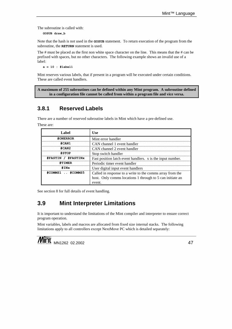
Mint™ Language
MN1262 02.2002 47
The subroutine is called with: GOSUB draw_b
Note that the hash is not used in the GOSUB statement. To return execution of the program from the subroutine, the RETURN statement is used. The # must be placed as the first non white space character on the line. This means that the # can be prefixed with spaces, but no other characters. The following example shows an invalid use of a label:
a = 10 : #label1
Mint reserves various labels, that if present in a program will be executed under certain conditions. These are called event handlers.
A maximum of 255 subroutines can be defined within any Mint program. A subroutine defined in a configuration file cannot be called from within a program file and vice versa.
3.8.1 Reserved Labels There are a number of reserved subroutine labels in Mint which have a pre-defined use. These are:
Label Use #ONERROR Mint error handler #CAN1 CAN channel 1 event handler #CAN2 CAN channel 2 event handler #STOP Stop switch handler
#FASTIN / #FASTINx Fast position latch event handlers. x is the input number. #TIMER Periodic timer event handler #INx User digital input event handlers
#COMMS1 .. #COMMS5 Called in response to a write to the comms array from the host. Only comms locations 1 through to 5 can initiate an event.
See section 8 for full details of event handling.
3.9 Mint Interpreter Limitations It is important to understand the limitations of the Mint compiler and interpreter to ensure correct program operation. Mint variables, labels and macros are allocated from fixed size internal stacks. The following limitations apply to all controllers except NextMove PC which is detailed separately:
Mint™ version 4 Programming Guide
48 MN1262 02.2002
Name All Controllers NextMove PC Label name length 10 characters 10 characters Number of labels 255 labels 100 labels Variable name length 10 characters 10 characters Number of variables 255 variables 100 variables Macro name length 10 characters 10 characters Number of macros 255 macros 100 macros
Nesting applies to all the Mint block structures. A block structure is defined as a structure beginning with an opening statement, such as FOR, executing some statements and closing the structure with a closing statement, such as NEXT. The opening statement opens up one level of nesting and its corresponding closing statement closes that level. The following example shows a nested FOR .. NEXT loop and WHILE loop nested to 2 levels. The WHILE statement gives a nesting level of 2 and the ENDW statement closes that level.
DIM aDIM b
FOR a = 1 TO 10REM Nesting level 1b = 1WHILE b < 10REM Nesting level 2b = b + 1
ENDWNEXT
Nesting is not the same as the number of block structures that are implemented in a program. This is limited only by available memory. In the following example, even though there is a FOR .. NEXT loop and two WHILE loops, the nesting level does not exceed 2.
DIM aDIM b
FOR a = 1 TO 10REM Nesting level 1b = 1WHILE b < 10REM Nesting level 2b = b + 1
ENDWWHILE b > 1REM Nesting level 2b = b - 1
ENDWNEXT
Mint™ Language
MN1262 02.2002 49
The maximum nesting levels shown in the following table apply to all controllers except NextMove PC which is detailed separately:
Block structure All Controllers NextMove PC IF..ENDIF blocks 255 levels 100 levels FOR..NEXT blocks 50 levels 20 levels GOSUB..RETURN blocks 100 levels 50 levels WHILE..ENDW / LOOP..ENDL / REPEAT..UNTIL blocks (combined)
50 levels 20 levels
The WHILE..ENDW, LOOP..ENDL and REPEAT..UNTIL blocks have a shared nesting limit. For example, 25 WHILE..ENDW blocks nested with 25 LOOP..ENDL blocks would reach the maximum level of nesting. A further restriction is that the number of WHILE..ENDW, LOOP..ENDL and REPEAT..UNTIL blocks nested with the number if IF..ENDIF blocks must not exceed 255. If a maximum number of levels is exceeded, then Mint will give a ‘Stack overflow’ error. Events are treated as subroutines and when called will result in an extra level of nesting, as with GOSUB, until it is terminated with RETURN. Since events can occur at any time during program execution, it is very important that the maximum possible level of nesting in the program should take into account the number of event handlers that are defined in the program. If the subroutine level of nesting is at its maximum value when the event handler is called, Mint will ignore the event request until the nesting level reduces by 1. See section 8 for more details on events.

Mint™ version 4 Programming Guide
50 MN1262 02.2002
Terminal Input/Output
MN1262 02.2002 51
4. Terminal Input/Output
4 The terminal capabilities within Mint allow machine interfaces to be developed with operator panels, either over a serial (RS232/485) or CAN bus. Mint keywords provide the ability to print data to the screen or to accept data from the operator panel or host computer. This chapter covers:
◊ The supported terminal input/output channels ◊ Terminal commands ◊ Setting up a RS485 network
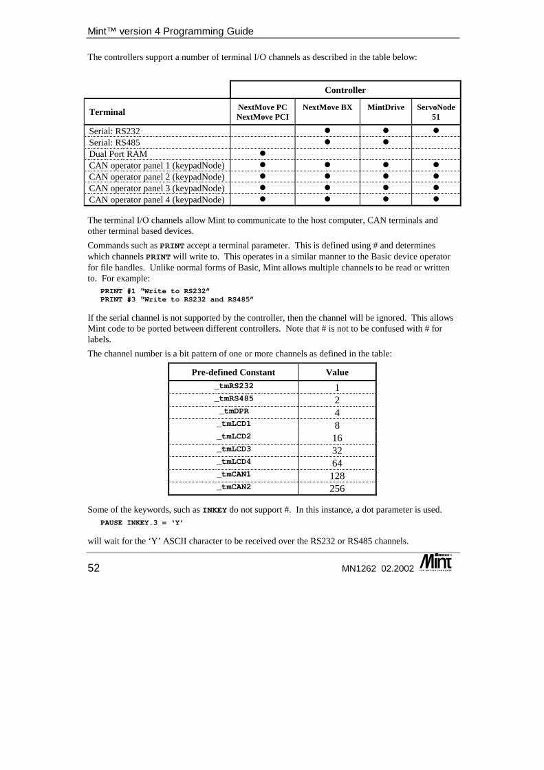
Mint™ version 4 Programming Guide
52 MN1262 02.2002
The controllers support a number of terminal I/O channels as described in the table below:
Controller
Terminal NextMove PCNextMove PCI
NextMove BX
MintDrive ServoNode 51
Serial: RS232 � � � Serial: RS485 � � Dual Port RAM � CAN operator panel 1 (keypadNode) � � � � CAN operator panel 2 (keypadNode) � � � � CAN operator panel 3 (keypadNode) � � � � CAN operator panel 4 (keypadNode) � � � �
The terminal I/O channels allow Mint to communicate to the host computer, CAN terminals and other terminal based devices. Commands such as PRINT accept a terminal parameter. This is defined using # and determines which channels PRINT will write to. This operates in a similar manner to the Basic device operator for file handles. Unlike normal forms of Basic, Mint allows multiple channels to be read or written to. For example:
PRINT #1 “Write to RS232”PRINT #3 “Write to RS232 and RS485”
If the serial channel is not supported by the controller, then the channel will be ignored. This allows Mint code to be ported between different controllers. Note that # is not to be confused with # for labels. The channel number is a bit pattern of one or more channels as defined in the table:
Pre-defined Constant Value _tmRS232 1 _tmRS485 2 _tmDPR 4 _tmLCD1 8 _tmLCD2 16 _tmLCD3 32 _tmLCD4 64 _tmCAN1 128 _tmCAN2 256
Some of the keywords, such as INKEY do not support #. In this instance, a dot parameter is used. PAUSE INKEY.3 = ‘Y’
will wait for the ‘Y’ ASCII character to be received over the RS232 or RS485 channels.
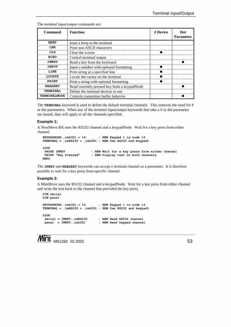
Terminal Input/Output
MN1262 02.2002 53
The terminal input/output commands are:
Command Function # Device Dot Parameter
BEEP Issue a beep at the terminal CHR Print non-ASCII characters CLS Clear the screen � ECHO Control terminal output INKEY Read a key from the keyboard � INPUT Input a number with optional formatting � LINE Print string at a specified line �
LOCATE Locate the cursor on the terminal � PRINT Print a string with optional formatting �
READKEY Read currently pressed key from a keypadNode � TERMINAL Define the terminal devices to use
TERMINALMODE Controls transmitter buffer behavior �
The TERMINAL keyword is used to define the default terminal channels. This removes the need for # or dot parameters. When any of the terminal input/output keywords that take a # or dot parameter are issued, they will apply to all the channels specified.
Example 1: A NextMove BX uses the RS232 channel and a keypadNode. Wait for a key press from either channel.
KEYPADNODE._tmLCD1 = 14 : REM Keypad 1 is node 14TERMINAL = _tmRS232 + _tmLCD1 : REM Use RS232 and keypad1
LOOPPAUSE INKEY : REM Wait for a key press from either channelPRINT “Key Pressed” : REM Display text on both channelsENDL
The INKEY and READKEY keywords can accept a terminal channel as a parameter. It is therefore possible to wait for a key press from specific channel.
Example 2: A MintDrive uses the RS232 channel and a keypadNode. Wait for a key press from either channel and write the text back to the channel that provided the key press.
DIM serialDIM panel
KEYPADNODE._tmLCD1 = 14 : REM Keypad 1 is node 14TERMINAL = _tmRS232 + _tmLCD1 : REM Use RS232 and keypad1
LOOPserial = INKEY._tmRS232 : REM Read RS232 channelpanel = INKEY._tmLCD1 : REM Read keypad channel
Mint™ version 4 Programming Guide
54 MN1262 02.2002
IF serial DOTERMINAL = _tmRS232PRINT “Key Pressed” : REM Display text on RS232ENDIF
IF panel DOTERMINAL = _tmLCD1PRINT “Key Pressed” : REM Display text on keypadENDIFENDL
4.1 RS232 Communication RS232 is a full duplex communication port which allows the host PC to communicate with a controller. The controller can support multiple communication protocols over the RS232 port simultaneously. These are Immediate Command Mode function calls, Comms data packets and standard serial data. The are a number of points to be aware of when using RS232 communications. RTS / CTS hardware handshaking is permanently enabled on the controller. If RTS / CTS is not used or supported by the host PC or cable, then communication errors may occur. When Mint transmits characters, such as with the statement:
PRINT “Hello World”
then these are placed in the serial transmit buffer. When this buffer becomes full, Mint will wait until a space becomes available. If the characters are not being removed from the buffer, such as if the RS232 cable is unplugged or the Mint WorkBench is not running, then Mint will wait indefinitely. In order not to stop program execution in this situation, the TERMINALMODE keyword can be used to set the transmit buffer to overwrite mode. This means that characters are written to the buffer regardless of if there is space. When the controller powers up, it will attempt to detect if host application is processing the serial port by looking at the state of the RTS line. It will then set TERMINALMODE appropriately. The Mint WorkBench will also alter the value of TERMINALMODE when the terminal window is opened or closed.
4.2 The RS485 Channel RS485 is a four wire full duplex communication protocol which can be used in the same fashion as RS232 or alternatively in a master/slave arrangement. The later allows a single master to communicate to multiple slaves. This allows controllers to be connected in RS485 ‘multi-drop’ networks. The master of these networks can either be a host PC or a controller.
4.2.1 Multi-Drop RS485 All controllers have a node number, the default node number for non-PC based controllers such as MintDrive and NextMove BX is 2. This node number is used as a unique identifier for messages being sent to controllers on multi-drop networks. Hence all controllers on a multi-drop network must have different node numbers.
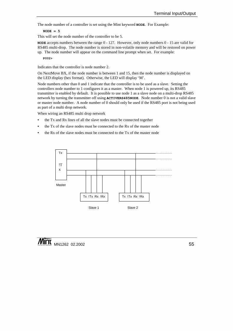
Terminal Input/Output
MN1262 02.2002 55
The node number of a controller is set using the Mint keyword NODE. For Example:NODE = 5
This will set the node number of the controller to be 5. NODE accepts numbers between the range 0 - 127. However, only node numbers 0 - 15 are valid for RS485 multi-drop. The node number is stored in non-volatile memory and will be restored on power up. The node number will appear on the command line prompt when set. For example:
P002>
Indicates that the controller is node number 2. On NextMove BX, if the node number is between 1 and 15, then the node number is displayed on the LED display (hex format). Otherwise, the LED will display ‘M’. Node numbers other than 0 and 1 indicate that the controller is to be used as a slave. Setting the controllers node number to 1 configures it as a master. When node 1 is powered up, its RS485 transmitter is enabled by default. It is possible to use node 1 as a slave node on a multi-drop RS485 network by turning the transmitter off using ACTIVERS485NODE. Node number 0 is not a valid slave or master node number. A node number of 0 should only be used if the RS485 port is not being used as part of a multi drop network. When wiring an RS485 multi drop network • the Tx and Rx lines of all the slave nodes must be connected together • the Tx of the slave nodes must be connected to the Rx of the master node • the Rx of the slave nodes must be connected to the Tx of the master node
Tx !Tx
Tx !Tx Rx !Rx Tx !Tx Rx !Rx
Master
Slave 1 Slave 2
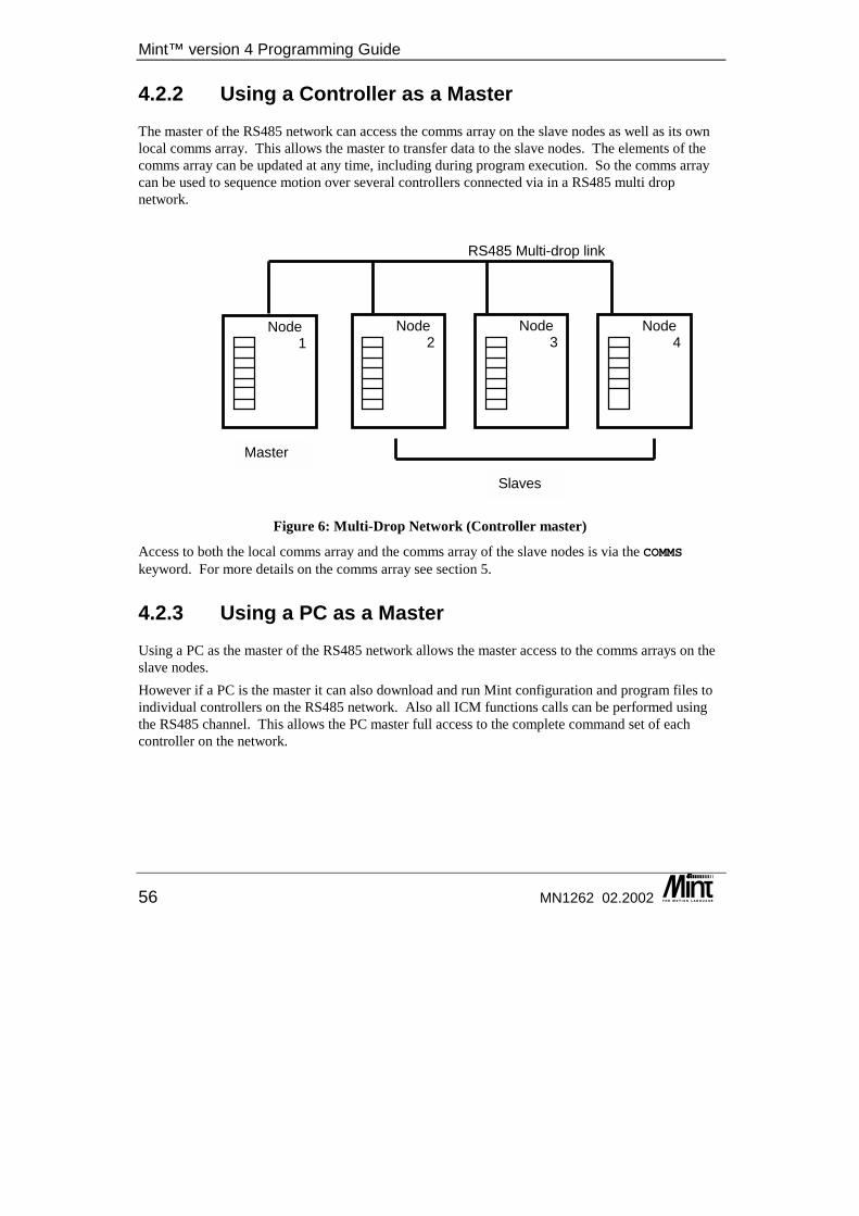
Mint™ version 4 Programming Guide
56 MN1262 02.2002
4.2.2 Using a Controller as a Master The master of the RS485 network can access the comms array on the slave nodes as well as its own local comms array. This allows the master to transfer data to the slave nodes. The elements of the comms array can be updated at any time, including during program execution. So the comms array can be used to sequence motion over several controllers connected via in a RS485 multi drop network.
Figure 6: Multi-Drop Network (Controller master)
Access to both the local comms array and the comms array of the slave nodes is via the COMMS keyword. For more details on the comms array see section 5.
4.2.3 Using a PC as a Master Using a PC as the master of the RS485 network allows the master access to the comms arrays on the slave nodes. However if a PC is the master it can also download and run Mint configuration and program files to individual controllers on the RS485 network. Also all ICM functions calls can be performed using the RS485 channel. This allows the PC master full access to the complete command set of each controller on the network.
Node 2
Node 3
Node 4
RS485 Multi-drop link
Node 1
Master
Slaves
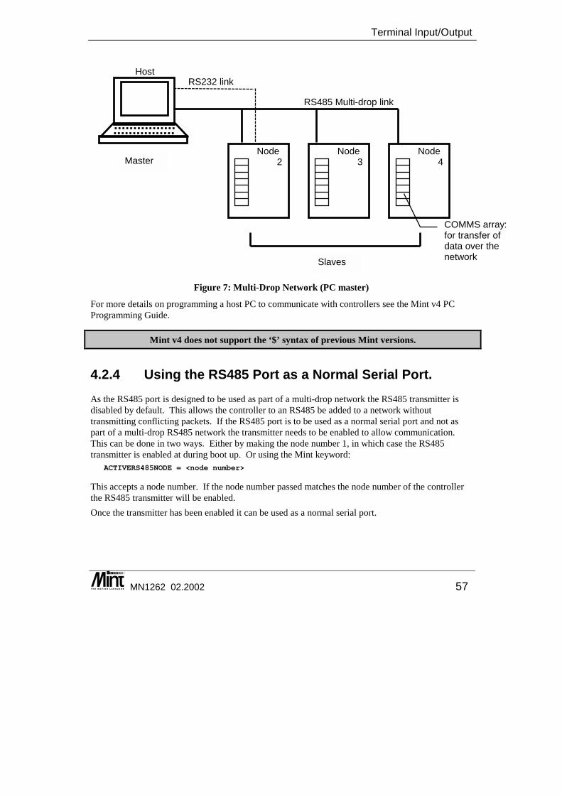
Terminal Input/Output
MN1262 02.2002 57
Figure 7: Multi-Drop Network (PC master)
For more details on programming a host PC to communicate with controllers see the Mint v4 PC Programming Guide.
Mint v4 does not support the ‘$’ syntax of previous Mint versions.
4.2.4 Using the RS485 Port as a Normal Serial Port. As the RS485 port is designed to be used as part of a multi-drop network the RS485 transmitter is disabled by default. This allows the controller to an RS485 be added to a network without transmitting conflicting packets. If the RS485 port is to be used as a normal serial port and not as part of a multi-drop RS485 network the transmitter needs to be enabled to allow communication. This can be done in two ways. Either by making the node number 1, in which case the RS485 transmitter is enabled at during boot up. Or using the Mint keyword:
ACTIVERS485NODE = <node number>
This accepts a node number. If the node number passed matches the node number of the controller the RS485 transmitter will be enabled. Once the transmitter has been enabled it can be used as a normal serial port.
Node 2
Node 3
Node 4
Host
RS485 Multi-drop link
RS232 link
COMMS array: for transfer of data over the network
Master
Slaves
Mint™ version 4 Programming Guide
58 MN1262 02.2002
4.3 Dual Port RAM Communication For NextMove PCI and NextMove PC, Dual Port RAM provides the communication interface. Within DPR, there is a pseudo serial buffer and a Comms area which mimic those available on serial controllers. The TERMINALMODE will default to not lose characters. The Mint WorkBench will also alter the value of TERMINALMODE when the terminal window is opened or closed.
4.4 CAN Communication It is also possible for the Mint WorkBench to access a controllers command line using the Baldor CAN network. This allows:
• Program download to multiple controllers over the network from a single host. • Transfer of data to an executing program on the node.
See the Mint v4 CAN Programming Guide for full details.

Mint Comms Communications
MN1262 02.2002 59
5. Mint Comms Communications
5 The comms array in Mint allows a host computer or PLC or remote node to communicate with Mint. Acting like Dual Ported RAM, data can be written to the Mint controller, which can then be read by the Mint application. Conversely, data can be updated by the Mint application to be read remotely. The Mint Comms protocol provides a simple method to transfer data. The chapter covers:
◊ Host Computer Comms ◊ The Comms data structure ◊ Using a Mint controller as the master
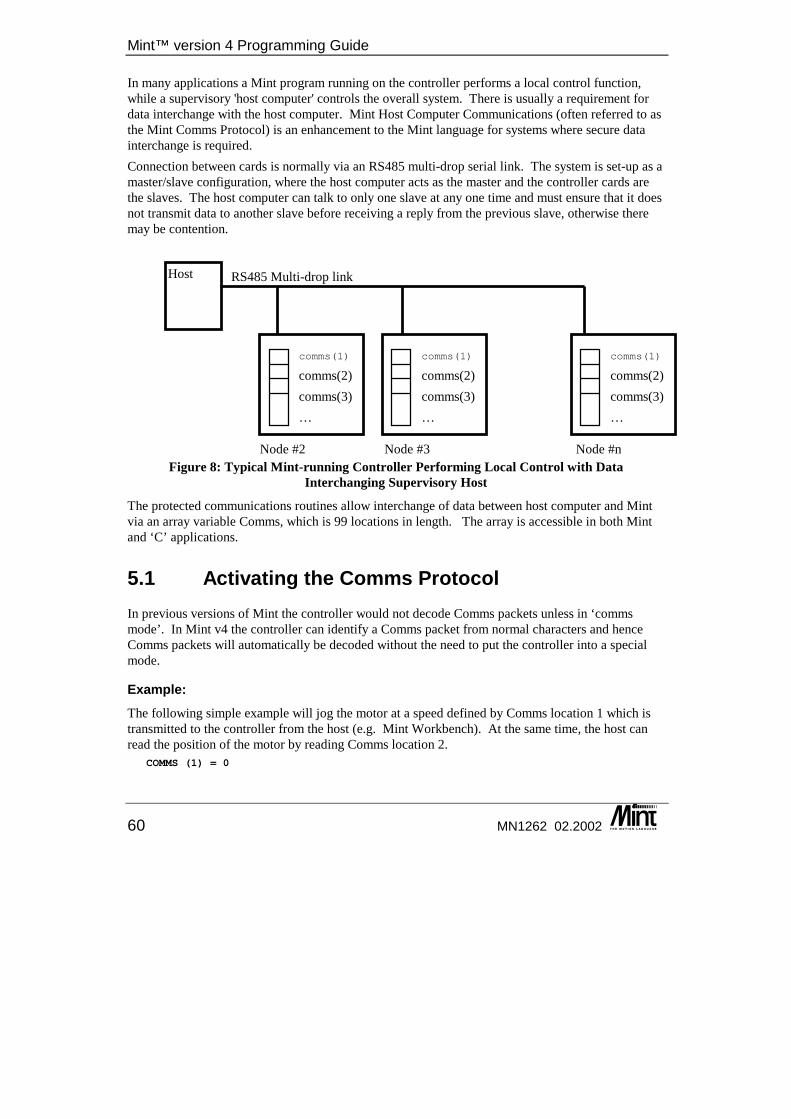
Mint™ version 4 Programming Guide
60 MN1262 02.2002
In many applications a Mint program running on the controller performs a local control function, while a supervisory 'host computer' controls the overall system. There is usually a requirement for data interchange with the host computer. Mint Host Computer Communications (often referred to as the Mint Comms Protocol) is an enhancement to the Mint language for systems where secure data interchange is required. Connection between cards is normally via an RS485 multi-drop serial link. The system is set-up as a master/slave configuration, where the host computer acts as the master and the controller cards are the slaves. The host computer can talk to only one slave at any one time and must ensure that it does not transmit data to another slave before receiving a reply from the previous slave, otherwise there may be contention.
Figure 8: Typical Mint-running Controller Performing Local Control with Data Interchanging Supervisory Host
The protected communications routines allow interchange of data between host computer and Mint via an array variable Comms, which is 99 locations in length. The array is accessible in both Mint and ‘C’ applications.
5.1 Activating the Comms Protocol In previous versions of Mint the controller would not decode Comms packets unless in ‘comms mode’. In Mint v4 the controller can identify a Comms packet from normal characters and hence Comms packets will automatically be decoded without the need to put the controller into a special mode.
Example: The following simple example will jog the motor at a speed defined by Comms location 1 which is transmitted to the controller from the host (e.g. Mint Workbench). At the same time, the host can read the position of the motor by reading Comms location 2.
COMMS (1) = 0
Host
comms(1)
comms(2) comms(3) …
Node #2
comms(1)
comms(2) comms(3) …
Node #3
comms(1)
comms(2) comms(3) …
Node #n
RS485 Multi-drop link
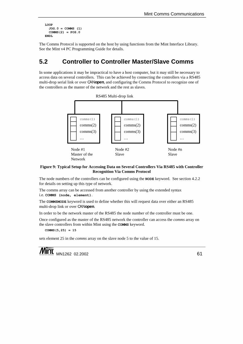
Mint Comms Communications
MN1262 02.2002 61
Node #1 Master of the Network
LOOPJOG.0 = COMMS (1)COMMS(2) = POS.0
ENDL
The Comms Protocol is supported on the host by using functions from the Mint Interface Library. See the Mint v4 PC Programming Guide for details.
5.2 Controller to Controller Master/Slave Comms In some applications it may be impractical to have a host computer, but it may still be necessary to access data on several controllers. This can be achieved by connecting the controllers via a RS485 multi-drop serial link or over CANopen, and configuring the Comms Protocol to recognize one of the controllers as the master of the network and the rest as slaves.
Figure 9: Typical Setup for Accessing Data on Several Controllers Via RS485 with Controller Recognition Via Comms Protocol
The node numbers of the controllers can be configured using the NODE keyword. See section 4.2.2 for details on setting up this type of network. The comms array can be accessed from another controller by using the extended syntax i.e. COMMS (node, element). The COMMSMODE keyword is used to define whether this will request data over either an RS485 multi-drop link or over CANopen. In order to be the network master of the RS485 the node number of the controller must be one. Once configured as the master of the RS485 network the controller can access the comms array on the slave controllers from within Mint using the COMMS keyword.
COMMS(5,25) = 15
sets element 25 in the comms array on the slave node 5 to the value of 15.
comms(1) comms(2) comms(3) …
comms(1) comms(2) comms(3) …
comms(1)
comms(2) comms(3) …
Node #2 Slave
Node #n Slave
RS485 Multi-drop link
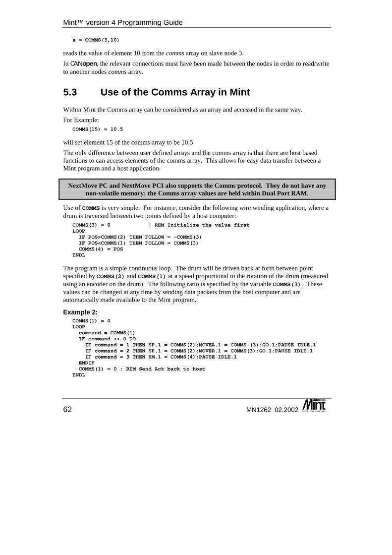
Mint™ version 4 Programming Guide
62 MN1262 02.2002
a = COMMS(3,10)
reads the value of element 10 from the comms array on slave node 3. In CANopen, the relevant connections must have been made between the nodes in order to read/write to another nodes comms array.
5.3 Use of the Comms Array in Mint Within Mint the Comms array can be considered as an array and accessed in the same way. For Example:
COMMS(15) = 10.5
will set element 15 of the comms array to be 10.5 The only difference between user defined arrays and the comms array is that there are host based functions to can access elements of the comms array. This allows for easy data transfer between a Mint program and a host application.
NextMove PC and NextMove PCI also supports the Comms protocol. They do not have any non-volatile memory; the Comms array values are held within Dual Port RAM.
Use of COMMS is very simple. For instance, consider the following wire winding application, where a drum is traversed between two points defined by a host computer:
COMMS(3) = 0 : REM Initialize the value firstLOOPIF POS>COMMS(2) THEN FOLLOW = -COMMS(3)IF POS<COMMS(1) THEN FOLLOW = COMMS(3)COMMS(4) = POS
ENDL
The program is a simple continuous loop. The drum will be driven back at forth between point specified by COMMS(2) and COMMS(1) at a speed proportional to the rotation of the drum (measured using an encoder on the drum). The following ratio is specified by the variable COMMS(3). These values can be changed at any time by sending data packets from the host computer and are automatically made available to the Mint program.
Example 2: COMMS(1) = 0LOOPcommand = COMMS(1)IF command <> 0 DOIF command = 1 THEN SP.1 = COMMS(2):MOVEA.1 = COMMS (3):GO.1:PAUSE IDLE.1IF command = 2 THEN SP.1 = COMMS(2):MOVER.1 = COMMS(3):GO.1:PAUSE IDLE.1IF command = 3 THEN HM.1 = COMMS(4):PAUSE IDLE.1
ENDIFCOMMS(1) = 0 : REM Send Ack back to host
ENDL

Mint Comms Communications
MN1262 02.2002 63
In this example, the host will transmit a command in COMMS(1). The data for the move type is held in indexes 2 to 4. When the move is complete, the command is set to zero. This acts as an acknowledgement to the host. Similarly, the host can read the position of the drum by reading the value of COMMS(4), which is updated once per loop (approximately every 10ms). The communications routines ensure that valid data is available to both Mint and host computer.
5.4 Comms Data Format In order to read from a location on a controller or write to a location, a data packet is send from the host. This is made up of ASCII characters, including control characters. In order to send a number, this is transmitted as a string, for example “1234.5”. All control characters are shown in the shaded boxes.
5.4.1 Writing Data The host sends the following data packet to write information to the card.
Reset: EOT (04H)
Card ID: ASCII character 0-9;A-F; set by NODE keyword
Card ID: Card ID repeated
Start: STX (02H)
Comms address digit 1: ASCII character 0-9; location in comms array M.S. digit
Comms address digit 2: ASCII character 0-9; location in comms array L.S. digit
Data field: Up to 60 characters, decimal format, comma separated, for example: “1234,45.6,-23.4”
End: ETX (03H)
Checksum: 1 byte, XOR of everything after (but not including) STX, up to and including ETX
Figure 10: Data Packet Description Sent By Host to Write Information to Card
Note: M.S.: most significant; L.S.: least significant Note that the card ID and the Comms address are both ASCII values. To write to Comms address 12, the user would send the ASCII character 1, followed by the ASCII character 2. The card will respond with an ACK (06H) or a NAK (015H), within 2mS of receipt of checksum. A NAK will be sent if the data field contains an invalid string, or the checksum is incorrect. The card ID is set by the 4 way address switch on the card.
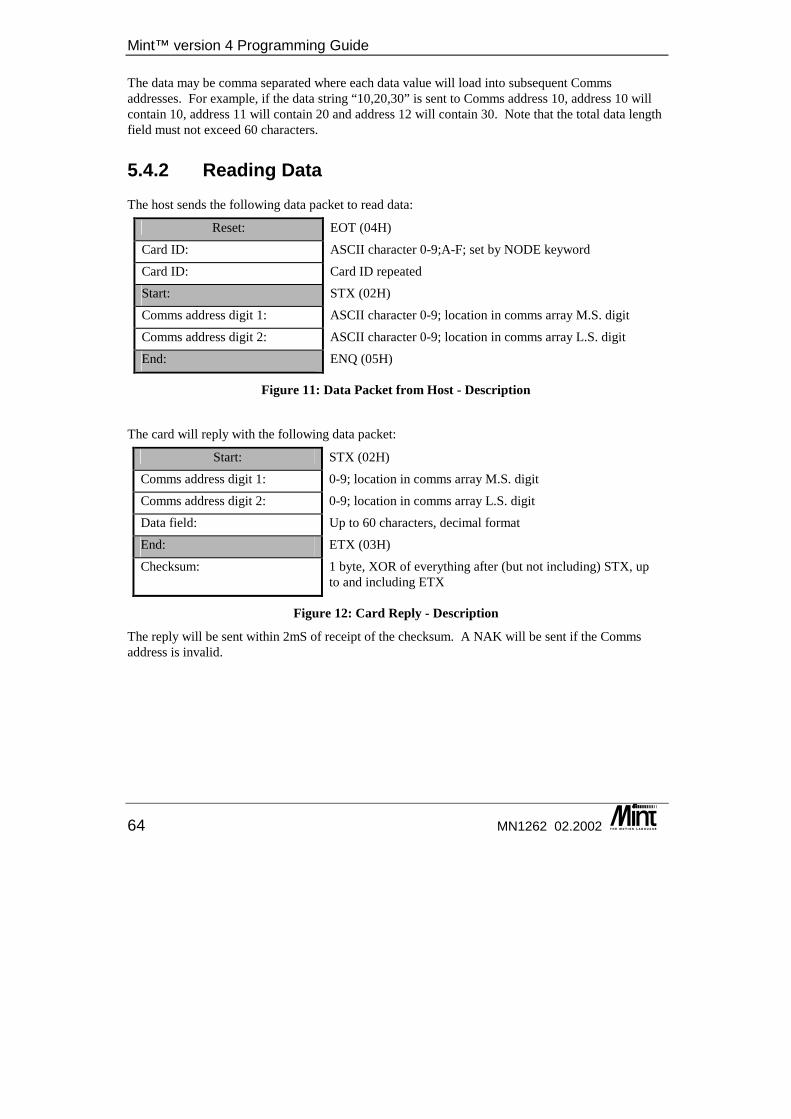
Mint™ version 4 Programming Guide
64 MN1262 02.2002
The data may be comma separated where each data value will load into subsequent Comms addresses. For example, if the data string “10,20,30” is sent to Comms address 10, address 10 will contain 10, address 11 will contain 20 and address 12 will contain 30. Note that the total data length field must not exceed 60 characters.
5.4.2 Reading Data The host sends the following data packet to read data:
Reset: EOT (04H)
Card ID: ASCII character 0-9;A-F; set by NODE keyword
Card ID: Card ID repeated
Start: STX (02H)
Comms address digit 1: ASCII character 0-9; location in comms array M.S. digit
Comms address digit 2: ASCII character 0-9; location in comms array L.S. digit
End: ENQ (05H)
Figure 11: Data Packet from Host - Description
The card will reply with the following data packet:
Start: STX (02H)
Comms address digit 1: 0-9; location in comms array M.S. digit
Comms address digit 2: 0-9; location in comms array L.S. digit
Data field: Up to 60 characters, decimal format
End: ETX (03H)
Checksum: 1 byte, XOR of everything after (but not including) STX, up to and including ETX
Figure 12: Card Reply - Description
The reply will be sent within 2mS of receipt of the checksum. A NAK will be sent if the Comms address is invalid.

Mint Comms Communications
MN1262 02.2002 65
5.5 Comms over a CANopenCANopenCANopenCANopen Network With CANopen, the comms functionality has become more flexible. Mint nodes on the network are able to communicate with other nodes on the network via the comms array. In order to read or write a ‘remote’ comms location, the comms array keyword is extended with an additional parameter:
COMMS(node, index)
To write a value to comms location 10 on node 5, the following would be used: COMMS(5,10) = 100
In order to allow a node number other than 1 to communicate with another node, CONNECT must first be used to create a ‘link’ between the two nodes. CONNECT can only be used on the CANopen master (node 1). See the Mint v4 CAN Programming Guide for further details.
5.6 Extended Comms Array Apart from the 99 locations of the Comms array that can be accessed through the Mint keyword COMMS, locations 100 through to 255 are mapped onto system parameters such as position or I/O information. The mapping allocates space for up to 15 axis parameters for a maximum of eight axes, and an additional 36 locations for miscellaneous digital I/O data. The mapping of these parameters is indicated below. The first table shows the location of the axis parameters, with the second table showing the offset for the system parameter.
Comms elements Contents 100 .. 114 Axis 0 115 .. 129 Axis 1 130 .. 144 Axis 2 145 .. 159 Axis 3 160 .. 174 Axis 4 175 .. 189 Axis 5 190 .. 204 Axis 6 205 .. 219 Axis 7 220 .. 255 I/O and Miscellaneous Data
The following table indicates the offset of data mapped for each axis:
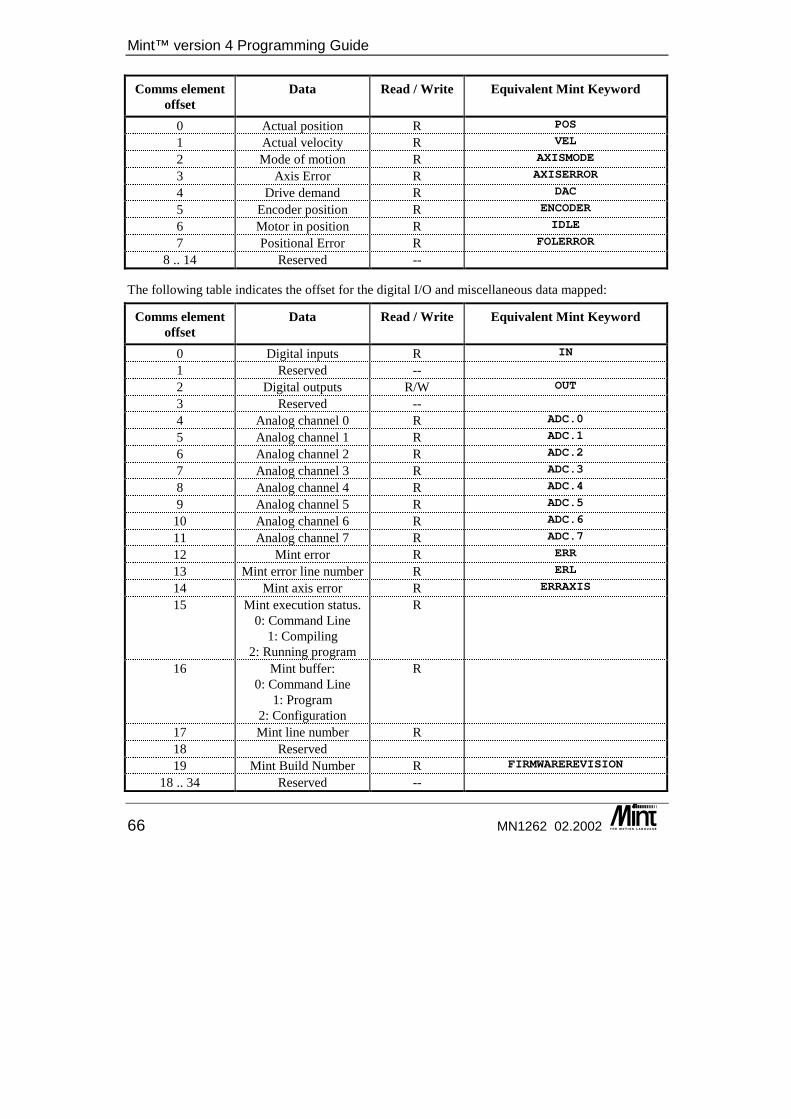
Mint™ version 4 Programming Guide
66 MN1262 02.2002
Comms element offset
Data Read / Write Equivalent Mint Keyword
0 Actual position R POS
1 Actual velocity R VEL
2 Mode of motion R AXISMODE
3 Axis Error R AXISERROR
4 Drive demand R DAC
5 Encoder position R ENCODER
6 Motor in position R IDLE
7 Positional Error R FOLERROR
8 .. 14 Reserved --
The following table indicates the offset for the digital I/O and miscellaneous data mapped:
Comms element offset
Data Read / Write Equivalent Mint Keyword
0 Digital inputs R IN
1 Reserved -- 2 Digital outputs R/W OUT
3 Reserved -- 4 Analog channel 0 R ADC.0
5 Analog channel 1 R ADC.1
6 Analog channel 2 R ADC.2
7 Analog channel 3 R ADC.3
8 Analog channel 4 R ADC.4
9 Analog channel 5 R ADC.5
10 Analog channel 6 R ADC.6
11 Analog channel 7 R ADC.7
12 Mint error R ERR
13 Mint error line number R ERL
14 Mint axis error R ERRAXIS
15 Mint execution status. 0: Command Line
1: Compiling 2: Running program
R
16 Mint buffer: 0: Command Line
1: Program 2: Configuration
R
17 Mint line number R 18 Reserved 19 Mint Build Number R FIRMWAREREVISION
18 .. 34 Reserved --

Mint Comms Communications
MN1262 02.2002 67
Example: To read the position of axis 2 on node 4, the following would be used:
DIM myPosmyPos = comms(4,130)

Mint™ version 4 Programming Guide
68 MN1262 02.2002

Creating Motion
MN1262 02.2002 69
6. Creating Motion
6 This chapter covers the use of Mint to perform motion. The following areas are included, and instruction provided to allow the user to explore motion control:
◊ Enabling axes ◊ Motion profiles ◊ Starting and Stopping Motion ◊ Speed control ◊ Establishing a datum or home position ◊ Positional moves ◊ Interpolated motion ◊ Encoder following and gearing ◊ Cam profiles ◊ Flying shears
Mint™ version 4 Programming Guide
70 MN1262 02.2002
6.1 Enabling Axes Before motion can be performed on an axis, it must be enabled. On NextMove products, the method by which a drive is enabled must be specified. Axes can use a dedicated digital output, the relay or be specified not to require a physical output which is the default selection. To assign a digital output as a drive enable output for an axis, the DRIVEENABLEOUTPUT keyword is used.
DRIVEENABLEOUTPUT.0 = 8 : REM Output 8 is drive enable for axis 0
To assign the relay as a drive enable output, DRIVENEABLEOUTPUT is set to _RELAY0. DRIVEENABLEOUTPUT.0 = _RELAY0 : REM Relay is drive enable for axis 0
To assign no physical output as the drive enable output, DRIVENEABLEOUTPUT is set to -1. DRIVEENABLEOUTPUT.0 = -1 : REM Axis 0 has no physical drive enable
To activate the enable output, the DRIVENABLE keyword is used. DRIVEENABLE.0 = 1 : REM Enable axis 0
Even if the drive enable output for an axis is set to -1 i.e. no physical drive enable, the drive must still be enabled internally using the DRIVEENABLE function. If an axis is not enabled when a move is loaded, the synchronous error 40 will be produced:
R0040: Drive is not enabled [axis 0]
MintDrive and ServoNode 51 have internal control of the drive stage. It is still possible to specify an external drive enable output but this is only for monitoring purposes. MintDrive has a dedicated enable input which must be active to enable the drive.
6.2 Open Loop Servo Control When a servo axis is disabled, the servo loop no longer runs on that axis and the DAC is zeroed. It is sometimes necessary to disable the servo loop while the axis is enabled. This can be performed with the TORQUE keyword.
6.2.1 Torque Control Torque control is achieved by controlling the current in the motor armature. For this purpose the amplifier must be configured as a current amplifier i.e. the analog demand input to the amplifier relates directly to an output current. Motor torque is directly related to current by the expression:
Torque = Armature Current * Kt
where Kt is the motor torque constant. The armature current will depend on the peak and continuous rating of the amplifier.

Creating Motion
MN1262 02.2002 71
TORQUE will accept any value between -100.0 and +100.0, where the maximum corresponds to the peak current from the drive1. For example, for a drive with 20A peak current rating:
TORQUE = -50
Sets the motor current equal to -10A, i.e. 50% of the peak current. Note that setting torque to 100% will cause the amplifier to deliver peak current continuously, which may cause it to burn out. When the TORQUE mode is being used, the servo loop is disabled and the DAC is controlled with the TORQUE value.
For velocity controlled drives where the motor speed is proportional to the analog input voltage, TORQUE is useful for setting an open loop speed demand, especially during
commissioning.
6.2.2 Servo Off When all axes have a common drive enable it is sometimes necessary for set up purposes to disable the DAC output to one or more of the drives while others remain servoing. This can be achieved using the TORQUE command. The TORQUE keyword allows the user to set the output level of the axes DAC to be a percentage of its maximum. So using the command:
TQ.0=0
the DAC for axis zero will be set to zero. Setting the DAC output to be zero may not be enough to keep the motor shaft stationary as small offsets within the drive can cause the motor shaft to turn. These can be compensated for by applying an appropriate torque value to the axis in the opposite direction. This functionality can also be employed to aid the manual positioning of drives as in the case of a current drive setting the DAC to zero will allow the motor shaft to be moved by hand. So enabling a machine to be moved accordingly. However, the recommended practice is to disable the drive stage before attempting to move the motor shaft or mechanics by hand. The servo loop can be re-enabled using the CANCEL or RESET keywords. The RESET keyword starts the axis servoing in its current position and resets all positional information (POS = 0). The CANCEL keyword starts the axis servoing in its current position but retains all positional data. This allows a controlled move to be loaded to take the axis back to its position prior to any manual movement. For example:
AXES[0]DIM axPOS
axPos = POS : REM store axis positionTORQUE = 0 : REM enable manual movement of axis zeroPAUSE INKEY : REM wait for key pressCANCEL : REM start servoing on axis zeroMOVEA = axPOS : REM load controlled move to previous positionGO
1 This is only true if the amplifier is set up as a current amplifier and not a velocity amplifier.
Mint™ version 4 Programming Guide
72 MN1262 02.2002
This example firstly sets the DAC for axis 0 to zero, this allows the axis to be moved by hand. Following a press of the space key the axis is re-enabled and moved back to its position prior to the TORQUE command. The profile for this move uses the current ACCEL, DECEL and SPEED settings.
6.3 Scale Factor The scale factor allows each axis to be scaled into engineering units for ease of use. It is a multiplication factor that is applied to all motion variables for that axis (speed, acceleration, move distances, etc). By default the scale factor is 1, i.e. all axis motion is recorded in encoder counts. If your axis has a 500 line encoder, giving 2000 quadrature pulses per revolution and is followed by a 18:1 gearbox and you are interested in the position of the output shaft in degrees. Using a scale factor 100 will allow axis variables to be defined in terms of degrees. To set the scale factor use the SCALE keyword.
SCALE.0 = 100
will set the scale factor for axis 0 to be 100. All motion variables accept parameters in scaled units, these units will be referred to as ‘user units’. For Example:
SCALE.0 = 100SPEED.0 = 10
This will set the scale factor of an axis to be 100, hence 1 user unit will be 100 encoder counts. The slew speed of the axis is then set to 10 user units per second, which equates to (10 * 100) = 1000 encoder counts per second. If you are doing very high precision motion it is advisable to work in encoder counts or use a scale factor with a round number reciprocal rather than a factional scale factor as you may experience slight positional drift because of the truncation of internal variables.
6.4 Motion Profiles Most move types are executed using a trapezoidal velocity profile. This means that the move can be considered to be in three segments:
• Acceleration performed at the acceleration rate set using the keyword ACCEL or ACCELTIME.
• Slew speed performed at the speed set using the keyword SPEED or FEEDRATE2.
• Deceleration performed at the deceleration rate set using the keyword DECEL or DECELTIME The keywords ACCEL and DECEL will set the acceleration of the axis in user units per second per second. The keywords ACCELTIME and DECELTIME will adjust the values of ACCEL or DECEL to give an acceleration or deceleration which will achieve slew speed in a specific number of milliseconds.
2 FEEDRATE functionality is only supported on NextMove controllers.
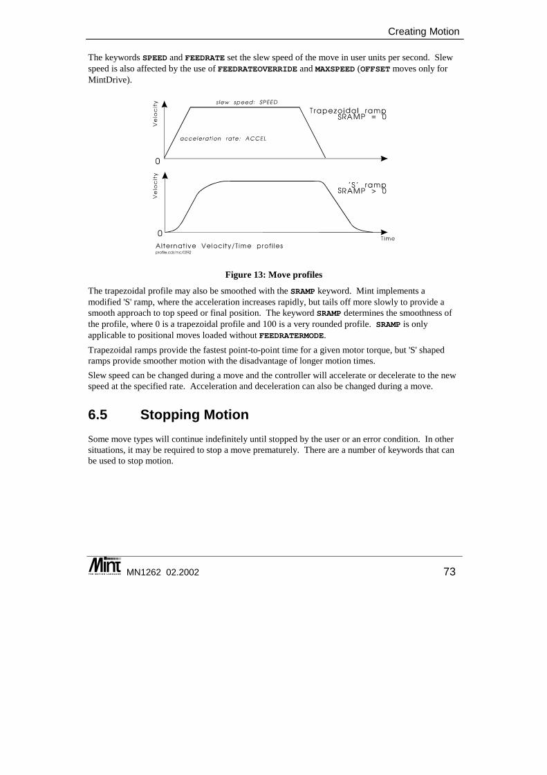
Creating Motion
MN1262 02.2002 73
The keywords SPEED and FEEDRATE set the slew speed of the move in user units per second. Slew speed is also affected by the use of FEEDRATEOVERRIDE and MAXSPEED (OFFSET moves only for MintDrive).
Figure 13: Move profiles
The trapezoidal profile may also be smoothed with the SRAMP keyword. Mint implements a modified 'S' ramp, where the acceleration increases rapidly, but tails off more slowly to provide a smooth approach to top speed or final position. The keyword SRAMP determines the smoothness of the profile, where 0 is a trapezoidal profile and 100 is a very rounded profile. SRAMP is only applicable to positional moves loaded without FEEDRATERMODE. Trapezoidal ramps provide the fastest point-to-point time for a given motor torque, but 'S' shaped ramps provide smoother motion with the disadvantage of longer motion times. Slew speed can be changed during a move and the controller will accelerate or decelerate to the new speed at the specified rate. Acceleration and deceleration can also be changed during a move.
6.5 Stopping Motion Some move types will continue indefinitely until stopped by the user or an error condition. In other situations, it may be required to stop a move prematurely. There are a number of keywords that can be used to stop motion.
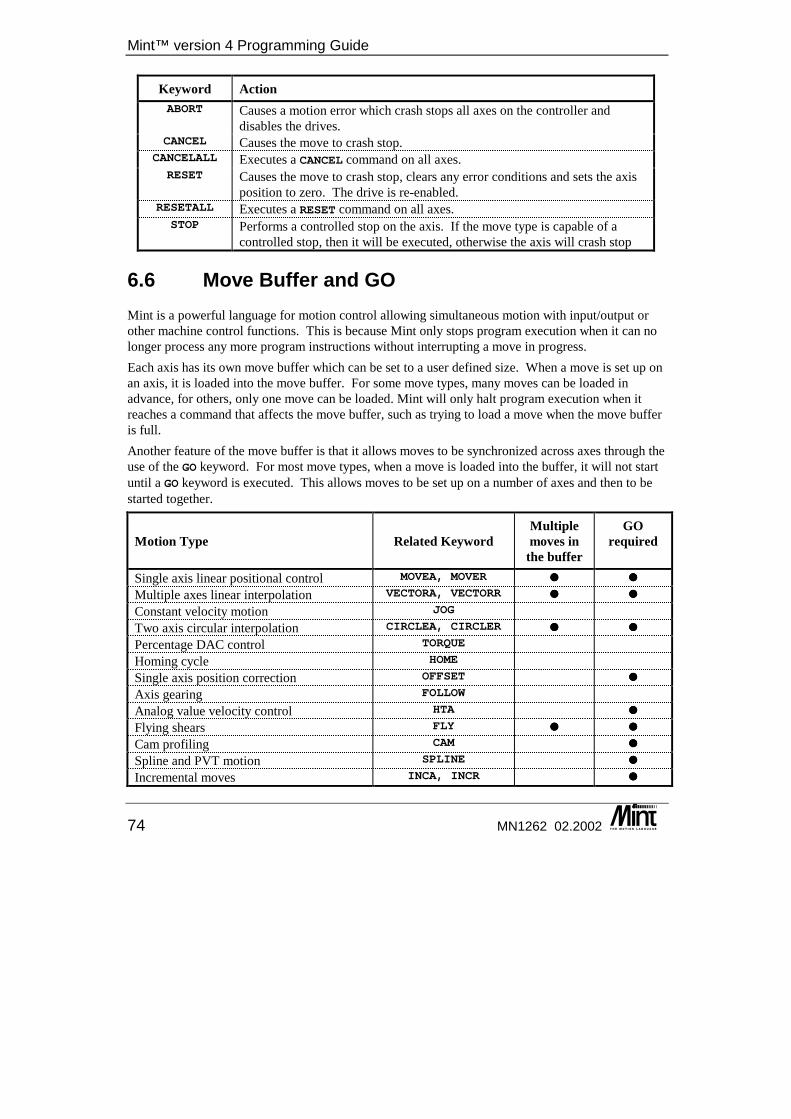
Mint™ version 4 Programming Guide
74 MN1262 02.2002
Keyword Action ABORT Causes a motion error which crash stops all axes on the controller and
disables the drives. CANCEL Causes the move to crash stop.
CANCELALL Executes a CANCEL command on all axes. RESET Causes the move to crash stop, clears any error conditions and sets the axis
position to zero. The drive is re-enabled. RESETALL Executes a RESET command on all axes.
STOP Performs a controlled stop on the axis. If the move type is capable of a controlled stop, then it will be executed, otherwise the axis will crash stop
6.6 Move Buffer and GO Mint is a powerful language for motion control allowing simultaneous motion with input/output or other machine control functions. This is because Mint only stops program execution when it can no longer process any more program instructions without interrupting a move in progress. Each axis has its own move buffer which can be set to a user defined size. When a move is set up on an axis, it is loaded into the move buffer. For some move types, many moves can be loaded in advance, for others, only one move can be loaded. Mint will only halt program execution when it reaches a command that affects the move buffer, such as trying to load a move when the move buffer is full. Another feature of the move buffer is that it allows moves to be synchronized across axes through the use of the GO keyword. For most move types, when a move is loaded into the buffer, it will not start until a GO keyword is executed. This allows moves to be set up on a number of axes and then to be started together.
Motion Type Related Keyword Multiple moves in
the buffer
GO required
Single axis linear positional control MOVEA, MOVER ���� ���� Multiple axes linear interpolation VECTORA, VECTORR ���� ���� Constant velocity motion JOG Two axis circular interpolation CIRCLEA, CIRCLER ���� ���� Percentage DAC control TORQUE Homing cycle HOME Single axis position correction OFFSET ���� Axis gearing FOLLOW Analog value velocity control HTA ���� Flying shears FLY ���� ���� Cam profiling CAM ���� Spline and PVT motion SPLINE ���� Incremental moves INCA, INCR ����
Creating Motion
MN1262 02.2002 75
The table above shows the different types of motion available and shows whether multiple moves can be buffered and if the GO keyword is required to start motion. For single axis moves or controllers, like the MintDrive, the GO command allows moves on the same axis to be executed in sequence. For the most of the motion types, trying to start motion of a different type to that which is in progress will result in an error message.
Example: MOVER.0 = 10
This loads a relative move of 10 units on axis 0. GO would be needed to start the move.
GO.0
Reading the AXISMODE keyword will show bit 2 as set, a linear move. The AXISMODE will continue to show bit 2 as set until the move finished, when it will become idle, AXISMODE 0.
PAUSE (AXISMODE & _mdLINEAR) = 0
For move types where multiple moves can be loaded, it is important to understand the operation of the move buffer. Consider the following code fragment, which shows three absolute moves, the first to position 10, the second to position 20 and the third to position 30:
MOVEA = 10GOMOVEA = 20GOMOVEA = 30GO
Mint will encounter the first statement and immediately execute it, followed by GO which will start the move. Mint now encounters the next move statement and will set it up as the move pending on that axis and trigger the motion with the GO. This means that when the first move finishes, the second will start straight away. When Mint encounters the next MOVEA statement it will identify that there are already two moves loaded in the move buffer. The default move buffer size is two, so at this point, program execution will stop. When the first move completes, a space will appear in the buffer so the third move will be loaded and program execution will continue. You can see that Mint is always one step ahead of the actual move in progress. This allows you to start a move on one axis and then execute other statements that might look at inputs or execute other moves on other axes that start at a specified delay after the first move.
MOVEA = 100 : GOPAUSE VEL > 20OUT1 = 1
This will start an absolute positional move on the default axis. Mint will then pause until the velocity of the axis exceeds 20 units/second. Digital output 1 is then activated. This concept is fundamental when writing Mint programs. There are some motion commands that are only valid when the axis is not moving (in IDLE mode), these restrictions are noted against the specific keywords in the keyword reference section.
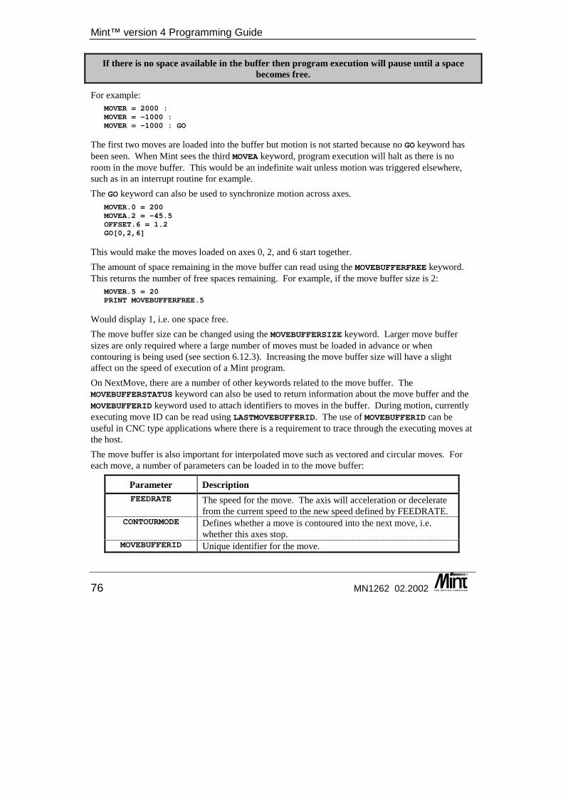
Mint™ version 4 Programming Guide
76 MN1262 02.2002
If there is no space available in the buffer then program execution will pause until a space becomes free.
For example: MOVER = 2000 :MOVER = -1000 :MOVER = -1000 : GO
The first two moves are loaded into the buffer but motion is not started because no GO keyword has been seen. When Mint sees the third MOVEA keyword, program execution will halt as there is no room in the move buffer. This would be an indefinite wait unless motion was triggered elsewhere, such as in an interrupt routine for example. The GO keyword can also be used to synchronize motion across axes.
MOVER.0 = 200MOVEA.2 = -45.5OFFSET.6 = 1.2GO[0,2,6]
This would make the moves loaded on axes 0, 2, and 6 start together. The amount of space remaining in the move buffer can read using the MOVEBUFFERFREE keyword. This returns the number of free spaces remaining. For example, if the move buffer size is 2:
MOVER.5 = 20PRINT MOVEBUFFERFREE.5
Would display 1, i.e. one space free. The move buffer size can be changed using the MOVEBUFFERSIZE keyword. Larger move buffer sizes are only required where a large number of moves must be loaded in advance or when contouring is being used (see section 6.12.3). Increasing the move buffer size will have a slight affect on the speed of execution of a Mint program. On NextMove, there are a number of other keywords related to the move buffer. The MOVEBUFFERSTATUS keyword can also be used to return information about the move buffer and the MOVEBUFFERID keyword used to attach identifiers to moves in the buffer. During motion, currently executing move ID can be read using LASTMOVEBUFFERID. The use of MOVEBUFFERID can be useful in CNC type applications where there is a requirement to trace through the executing moves at the host. The move buffer is also important for interpolated move such as vectored and circular moves. For each move, a number of parameters can be loaded in to the move buffer:
Parameter Description FEEDRATE The speed for the move. The axis will acceleration or decelerate
from the current speed to the new speed defined by FEEDRATE. CONTOURMODE Defines whether a move is contoured into the next move, i.e.
whether this axes stop. MOVEBUFFERID Unique identifier for the move.
Creating Motion
MN1262 02.2002 77
Example: DIM a = 1
FEEDRATE = 100CONTOURMODE = 1MOVEBUFFERID = aVECTORR = 100,100,200 :GOa = a + 1FEEDRATE = 200CONTOURMODE = 0MOVEBUFFERID = aVECTORR = 200,200,400 :GOa = a + 1FEEDRATE = 50CONTOURMODE = 1MOVEBUFFERID = aVECTORR = 200,200,400 :GOa = a + 1
There is no need to stop between moves to load the move buffer parameters.
6.7 AXISMODE and IDLE During a move, the mode of motion can be interrogated using the AXISMODE keyword. The AXISMODE values are given in the keyword reference section. AXISMODE is primarily useful for detecting when a move is complete, since the AXISMODE will always return to zero at this point. Imagine that you wish to set output one after the finish of a relative move:
MOVER = 150 : GO : REM mode is set to 2PAUSE AXISMODE = 0 : REM wait for motion to finishOUT1 = 1 : REM set output one
Alternatively: PAUSE AXISMODE = 0
can be replaced by: PAUSE IDLE
To check multiple axes: PAUSE IDLE[0,1]
The IDLE keyword is slightly different to the AXISMODE keyword in that it also waits for any following error on a servo axis to be within an ‘idle’ window, set by the IDLEPOS keyword. The idle velocity can also be set using the IDLEVEL keyword. The AXISMODE keyword will return zero as soon as the theoretical move has finished, regardless of whether the axis has actually finished physically moving.
Mint™ version 4 Programming Guide
78 MN1262 02.2002
6.8 Controlled Motion Mint supports a wide range of controlled motion types from point to point positional moves to complex software CAM’s. Below is a summary of the different move type supported by the Mint.
Description Related Keyword Single axis speed control see section 6.9 JOG
Single axis positional move see section 6.10 MOVEA, MOVER
Incremental move see section 6.11 INCA, INCR
Multi axis interpolated positional move see section 6.12.1 VECTORA, VECTORR
Two axis circular interpolation see section 6.12.2 CIRCLEA, CIRCLER
Datum cycle see section 6.13 HOME
Software gearing see section 6.14 FOLLOW
Single axis position correction see section 6.14 OFFSET
Flying shear see section 6.15 FLY
Software CAM see section 6.16 CAM
Spline and PVT motion see section 6.17 SPLINE
Analogue value velocity control see section 6.18 HTA
The following section describe each type of move in more detail including examples of how to generate the different types of motion using Mint.
6.9 Speed Control The JOG keyword provides straightforward speed control of an axis. JOG uses positional feedback from the motor, so that varying load will not affect long term speed accuracy.
Example: JOG = 30
If the system has been set up to scale factor in revolutions, this will jog the motor at a speed of 30 user units/second. Note that the GO command is not required. JOG may be changed up and down at any time, the motor will accelerate/decelerate to the new speed at the rate specified by ACCEL/DECEL3. Motion may be terminated by:
JOG = 0
Or: STOP
which both cause controlled deceleration to a stop. The rate of acceleration/deceleration for JOG is unaffected by the SRAMP keyword. The acceleration and deceleration rates can however be changed 'on the fly'.
3 ACCELTIME or DECELTIME can also be used.
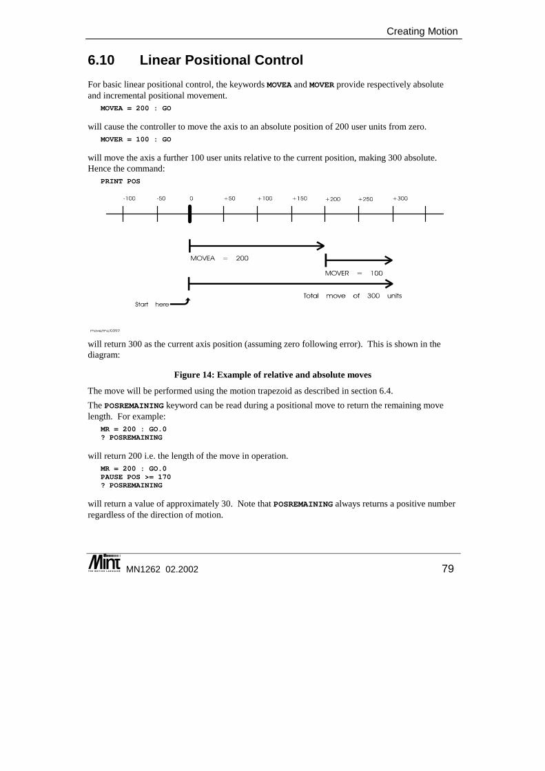
Creating Motion
MN1262 02.2002 79
6.10 Linear Positional Control For basic linear positional control, the keywords MOVEA and MOVER provide respectively absolute and incremental positional movement.
MOVEA = 200 : GO
will cause the controller to move the axis to an absolute position of 200 user units from zero. MOVER = 100 : GO
will move the axis a further 100 user units relative to the current position, making 300 absolute. Hence the command:
PRINT POS
will return 300 as the current axis position (assuming zero following error). This is shown in the diagram:
Figure 14: Example of relative and absolute moves
The move will be performed using the motion trapezoid as described in section 6.4. The POSREMAINING keyword can be read during a positional move to return the remaining move length. For example:
MR = 200 : GO.0? POSREMAINING
will return 200 i.e. the length of the move in operation. MR = 200 : GO.0PAUSE POS >= 170? POSREMAINING
will return a value of approximately 30. Note that POSREMAINING always returns a positive number regardless of the direction of motion.
Mint™ version 4 Programming Guide
80 MN1262 02.2002
6.11 Incremental Moves Incremental moves are similar to standard positional moves but the end point of the move may be changed while the move is in progress. Incremental moves are performed with the INCA and INCR keywords.
Example: INCA.6 = 230 : GO.6 : REM Start motion to position 230.
The move is loaded into the move buffer (this can be an absolute move using INCA or a relative move using INCR). The move is triggered by GO which will result in the axis accelerating at the ACCEL rate until slew speed is reached (set by SPEED or FEEDRATE). The axis will deceleration at the DECEL rate to come to rest the desired position. The example would start a move that uses the standard motion trapezoid, section 6.4, with an end point of position 230. During the move, the end point can be modified, the axis responding immediately to the change.
INCA.2 = 100 : GO.2 : REM Start motion to position 100PAUSE POS.2 > 75 : REM Wait until position > 75INCR.2 = -45 : REM Modify the end point by -45
The axis would immediately start to decelerate and change direction, heading for the new end point of position 55. INCR affects the end position and not the current position. The end position for the currently loaded move can be read using POSTARGET. Therefore in the example move, the end position of 100 is being adjusted by -45 to be 55. The INCA/INCR move will set bit 14 in the AXISMODE keyword. Motion can be stopped with the STOP keyword and will be terminated according to any error condition set up on the axis. The axis must be idle or in incremental move mode before the move can be loaded. Reading POSTARGET returns the absolute end point of the move. Reading the POSREMAINING keyword will return the distance left to travel for the move. If the axis is already at the absolute position specified then no move will be generated for an INCA move.
Example: LOOPINCA = COMMS(12) : GO
ENDL
In this example, the axis would constantly move towards the position specified by comms location 12. Each time round the loop, if the target position had changed, the axis would accelerate or decelerate as required to go to the new end point. During any phase of the move, the ACCEL, DECEL and SPEED can be changed and will have an immediate affect on the move in progress.
Creating Motion
MN1262 02.2002 81
6.12 Interpolated Moves This section applies only to multi-axis Mint controllers. The VECTORR/VECTORA keywords provide interpolated motion on two or more axes and the CIRCLER/CIRCLEA keywords provide circular interpolated motion on two orthogonal axes, for instance an X-Y table. These keywords are write only motion variables but are unique in that they always require at least two axes to be specified. In interpolated moves, the axis speed and acceleration refer not to individual axis speed, but to the path along which motion is in progress. Interpolated moves are positional moves and so use the motion trapezoid described in section 6.4. Interpolated moves can be used for CNC type applications which require a tool to follow a defined path. Useful keywords such as MOVEBUFFERID allow the application to track the moves as they are executed. FEEDRATE and FEEDRATEOVERRIDE allow feedrates to be attached to moves. In this instance, the speed will be modified to reflect the feedrate defined in the move buffer.
The move buffer is an important consideration when dealing with interpolated moves. The move buffer is described in section 6.6.
6.12.1 Linear Interpolation Multiple axis linear interpolation is executed with the keywords VECTORR and VECTORA, where VECTORR is a relative vector move, and VECTORA is an absolute vector move.
Example: AXES0,1]SPEED = 20;VECTORA = 30,40 : GO
Executes an absolute linear interpolated move on axes 0 and 1 at a speed of 20 along the vector. This differs from the command MOVEA:
SPEED = 20;MOVEA = 30,40 : GO
this will give the same absolute end position but the speed will be 20 on each axis, so axis 0 will reach its end point before axis 1.
Example: VECTORR = 100,200,300,200 : GO
this performs a 4 axes relative interpolated move.
Example: Assuming a starting position of 0,0 the profile seen can be generated using the following relative moves:
VECTORR = 20,25 : GOVECTORR = 20,15 : GOVECTORR = 40,-15 : GOVECTORR = 0,-15 : GO
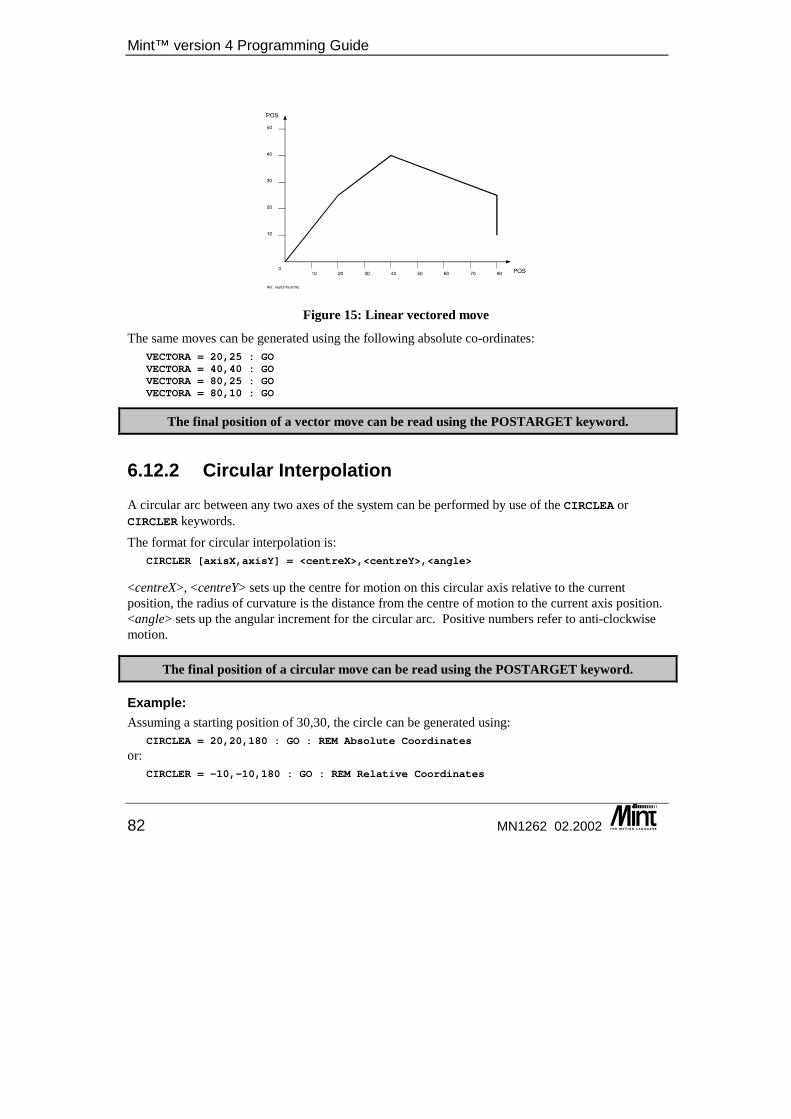
Mint™ version 4 Programming Guide
82 MN1262 02.2002
Figure 15: Linear vectored move
The same moves can be generated using the following absolute co-ordinates: VECTORA = 20,25 : GOVECTORA = 40,40 : GOVECTORA = 80,25 : GOVECTORA = 80,10 : GO
The final position of a vector move can be read using the POSTARGET keyword.
6.12.2 Circular Interpolation A circular arc between any two axes of the system can be performed by use of the CIRCLEA or CIRCLER keywords. The format for circular interpolation is:
CIRCLER [axisX,axisY] = <centreX>,<centreY>,<angle>
<centreX>, <centreY> sets up the centre for motion on this circular axis relative to the current position, the radius of curvature is the distance from the centre of motion to the current axis position. <angle> sets up the angular increment for the circular arc. Positive numbers refer to anti-clockwise motion.
The final position of a circular move can be read using the POSTARGET keyword.
Example: Assuming a starting position of 30,30, the circle can be generated using:
CIRCLEA = 20,20,180 : GO : REM Absolute Coordinates
or: CIRCLER = -10,-10,180 : GO : REM Relative Coordinates
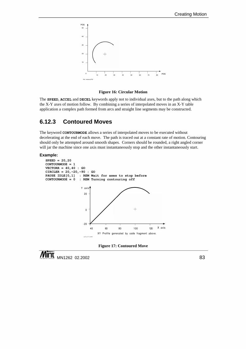
Creating Motion
MN1262 02.2002 83
Figure 16: Circular Motion
The SPEED, ACCEL and DECEL keywords apply not to individual axes, but to the path along which the X-Y axes of motion follow. By combining a series of interpolated moves in an X-Y table application a complex path formed from arcs and straight line segments may be constructed.
6.12.3 Contoured Moves The keyword CONTOURMODE allows a series of interpolated moves to be executed without decelerating at the end of each move. The path is traced out at a constant rate of motion. Contouring should only be attempted around smooth shapes. Corners should be rounded, a right angled corner will jar the machine since one axis must instantaneously stop and the other instantaneously start.
Example: SPEED = 20,20CONTOURMODE = 1VECTORR = 40,40 : GOCIRCLER = 20,-20,-90 : GOPAUSE IDLE[0,1] : REM Wait for axes to stop beforeCONTOURMODE = 0 : REM Turning contouring off
Figure 17: Contoured Move
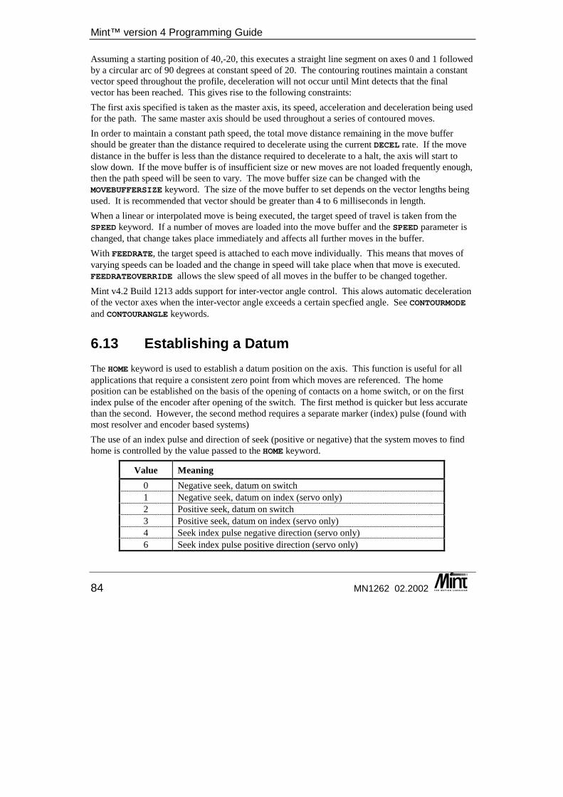
Mint™ version 4 Programming Guide
84 MN1262 02.2002
Assuming a starting position of 40,-20, this executes a straight line segment on axes 0 and 1 followed by a circular arc of 90 degrees at constant speed of 20. The contouring routines maintain a constant vector speed throughout the profile, deceleration will not occur until Mint detects that the final vector has been reached. This gives rise to the following constraints: The first axis specified is taken as the master axis, its speed, acceleration and deceleration being used for the path. The same master axis should be used throughout a series of contoured moves. In order to maintain a constant path speed, the total move distance remaining in the move buffer should be greater than the distance required to decelerate using the current DECEL rate. If the move distance in the buffer is less than the distance required to decelerate to a halt, the axis will start to slow down. If the move buffer is of insufficient size or new moves are not loaded frequently enough, then the path speed will be seen to vary. The move buffer size can be changed with the MOVEBUFFERSIZE keyword. The size of the move buffer to set depends on the vector lengths being used. It is recommended that vector should be greater than 4 to 6 milliseconds in length. When a linear or interpolated move is being executed, the target speed of travel is taken from the SPEED keyword. If a number of moves are loaded into the move buffer and the SPEED parameter is changed, that change takes place immediately and affects all further moves in the buffer. With FEEDRATE, the target speed is attached to each move individually. This means that moves of varying speeds can be loaded and the change in speed will take place when that move is executed. FEEDRATEOVERRIDE allows the slew speed of all moves in the buffer to be changed together. Mint v4.2 Build 1213 adds support for inter-vector angle control. This alows automatic deceleration of the vector axes when the inter-vector angle exceeds a certain specfied angle. See CONTOURMODE and CONTOURANGLE keywords.
6.13 Establishing a Datum The HOME keyword is used to establish a datum position on the axis. This function is useful for all applications that require a consistent zero point from which moves are referenced. The home position can be established on the basis of the opening of contacts on a home switch, or on the first index pulse of the encoder after opening of the switch. The first method is quicker but less accurate than the second. However, the second method requires a separate marker (index) pulse (found with most resolver and encoder based systems) The use of an index pulse and direction of seek (positive or negative) that the system moves to find home is controlled by the value passed to the HOME keyword.
Value Meaning 0 Negative seek, datum on switch 1 Negative seek, datum on index (servo only) 2 Positive seek, datum on switch 3 Positive seek, datum on index (servo only) 4 Seek index pulse negative direction (servo only) 6 Seek index pulse positive direction (servo only)

Creating Motion
MN1262 02.2002 85
Example: HOME[0,1] = 0, 2
This would cause axis 0 to datum on a switch in a negative direction and axis 1 to datum on a switch in a positive direction. Usually a homing sequence is followed by PAUSE IDLE to ensure all axes are at their datum position before continuing. For example:
HOME[0,1,2] = 0,0,0 : REM Datum axesPAUSE IDLE[0,1,2] : REM Wait for idle
Reading the HOME keyword returns the current phase of homing. Reading the HOMESWITCH keyword will return the current state of the home swictth input.
Example: HOMESPEED = 200,200,200HOMEBACKOFF = 5,5,5HOME = 1,1,1PAUSE IDLE[0,1,2]
will set a datum speed of 200 units/sec. When the home switch is seen, the axis will back off at a speed of 40 units/sec. For most applications you can leave HOMEBACKOFF at its default value of 10.
6.13.1 Datum Profiles The following graph represents the homing sequence for either a negative or positive seek and datum on the switch. When the home is started the axis will move in the direction specified at HOMESPEED until the home input becomes active. It will then reverse in the opposite direction, at the rate determined by dividing the HOMESPEED by HOMEBACKOFF parameter until the home input becomes inactive.
Figure 18: Homing – Positive or Negative Seek, Datum on Switch
Velocity
Time
HOMESPEED
HOMESPEED/HOMEBACKOFF
Home input active
ACCEL
DECEL
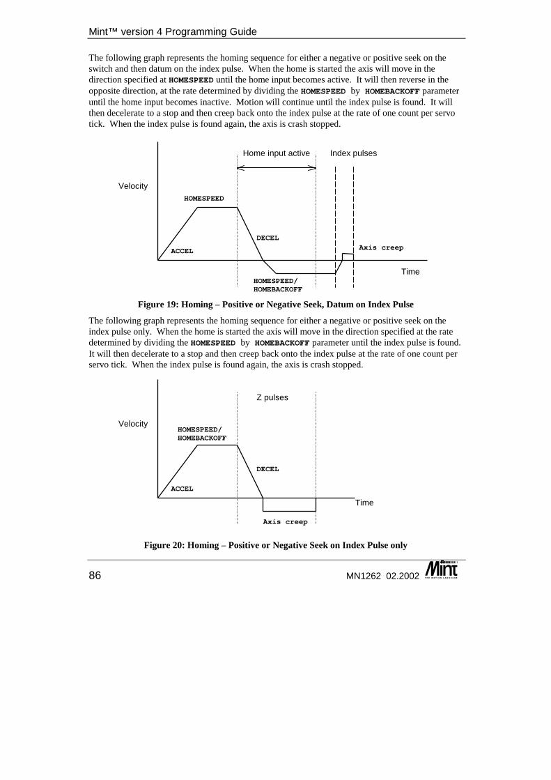
Mint™ version 4 Programming Guide
86 MN1262 02.2002
The following graph represents the homing sequence for either a negative or positive seek on the switch and then datum on the index pulse. When the home is started the axis will move in the direction specified at HOMESPEED until the home input becomes active. It will then reverse in the opposite direction, at the rate determined by dividing the HOMESPEED by HOMEBACKOFF parameter until the home input becomes inactive. Motion will continue until the index pulse is found. It will then decelerate to a stop and then creep back onto the index pulse at the rate of one count per servo tick. When the index pulse is found again, the axis is crash stopped.
Figure 19: Homing – Positive or Negative Seek, Datum on Index Pulse
The following graph represents the homing sequence for either a negative or positive seek on the index pulse only. When the home is started the axis will move in the direction specified at the rate determined by dividing the HOMESPEED by HOMEBACKOFF parameter until the index pulse is found. It will then decelerate to a stop and then creep back onto the index pulse at the rate of one count per servo tick. When the index pulse is found again, the axis is crash stopped.
Figure 20: Homing – Positive or Negative Seek on Index Pulse only
Velocity
Time
HOMESPEED
HOMESPEED/HOMEBACKOFF
Home input active
ACCEL Axis creep
Index pulses
DECEL
Velocity
Time
HOMESPEED/HOMEBACKOFF
Z pulses
ACCEL
DECEL
Axis creep
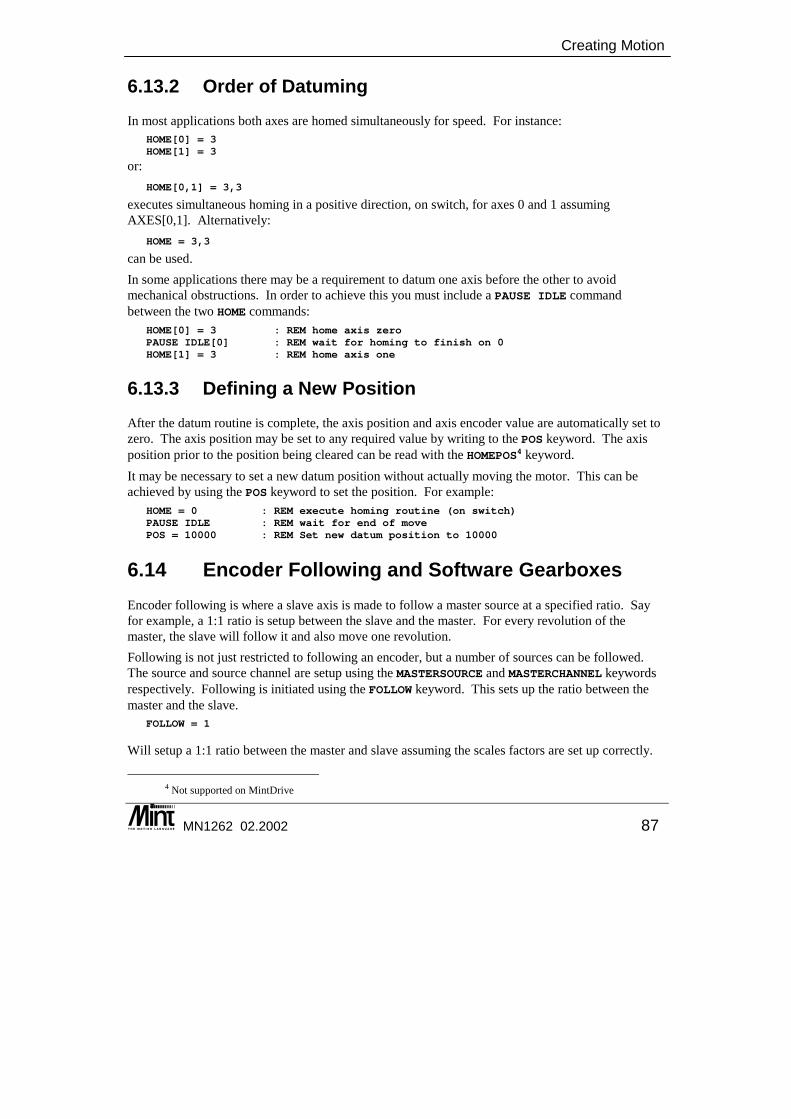
Creating Motion
MN1262 02.2002 87
6.13.2 Order of Datuming In most applications both axes are homed simultaneously for speed. For instance:
HOME[0] = 3HOME[1] = 3
or: HOME[0,1] = 3,3
executes simultaneous homing in a positive direction, on switch, for axes 0 and 1 assuming AXES[0,1]. Alternatively:
HOME = 3,3
can be used. In some applications there may be a requirement to datum one axis before the other to avoid mechanical obstructions. In order to achieve this you must include a PAUSE IDLE command between the two HOME commands:
HOME[0] = 3 : REM home axis zeroPAUSE IDLE[0] : REM wait for homing to finish on 0HOME[1] = 3 : REM home axis one
6.13.3 Defining a New Position After the datum routine is complete, the axis position and axis encoder value are automatically set to zero. The axis position may be set to any required value by writing to the POS keyword. The axis position prior to the position being cleared can be read with the HOMEPOS4 keyword. It may be necessary to set a new datum position without actually moving the motor. This can be achieved by using the POS keyword to set the position. For example:
HOME = 0 : REM execute homing routine (on switch)PAUSE IDLE : REM wait for end of movePOS = 10000 : REM Set new datum position to 10000
6.14 Encoder Following and Software Gearboxes Encoder following is where a slave axis is made to follow a master source at a specified ratio. Say for example, a 1:1 ratio is setup between the slave and the master. For every revolution of the master, the slave will follow it and also move one revolution. Following is not just restricted to following an encoder, but a number of sources can be followed. The source and source channel are setup using the MASTERSOURCE and MASTERCHANNEL keywords respectively. Following is initiated using the FOLLOW keyword. This sets up the ratio between the master and the slave.
FOLLOW = 1
Will setup a 1:1 ratio between the master and slave assuming the scales factors are set up correctly.
4 Not supported on MintDrive
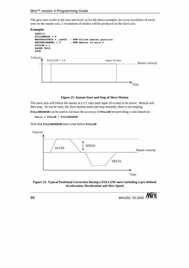
Mint™ version 4 Programming Guide
88 MN1262 02.2002
The gear ratio works at the user unit level, so for the above example, for every revolution of travel seen on the master axis, 2 revolutions of motion will be produced on the slave axis.
Example: AXES[1]FOLLOWMODE = 0MASTERSOURCE = _msPOS : REM Follow master positionMASTERCHANNEL = 3 : REM Master is axis 3FOLLOW = 1PAUSE IN18STOP
Velocity
Time
Master velocityFOLLOW = 1.0 Input 18 seen
Figure 21: Instant Start and Stop of Slave Motion
The slave axis will follow the master at a 1:1 ratio until input 18 is seen to be active. Motion will then stop. As can be seen, the slave motion starts and stop instantly; there is no ramping. FOLLOWDENOM can be used to increase the accuracy of FOLLOW but providing a ratio based on:
Ratio = FOLLOW / FOLLOWDENOM
Note that FOLLOWDENOM must come before FOLLOW.
Velocity
Time
Master velocity
DECEL
ACCELSPEED
Figure 22: Typical Positional Correction During a FOLLOW move including a pre-defined Acceleration, Deceleration and Slew Speed
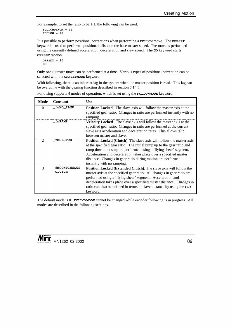
Creating Motion
MN1262 02.2002 89
For example, to set the ratio to be 1.1, the following can be used: FOLLOWDENOM = 11FOLLOW = 10
It is possible to perform positional corrections when performing a FOLLOW move. The OFFSET keyword is used to perform a positional offset on the base master speed. The move is performed using the currently defined acceleration, deceleration and slew speed. The GO keyword starts OFFSET motion.
OFFSET = 20GO
Only one OFFSET move can be performed at a time. Various types of positional correction can be selected with the OFFSETMODE keyword. With following, there is an inherent lag in the system when the master position is read. This lag can be overcome with the gearing function described in section 6.14.5. Following supports 4 modes of operation, which is set using the FOLLOWMODE keyword.
Mode Constant Use 0 _fmNO_RAMP Position Locked. The slave axis will follow the master axis at the
specified gear ratio. Changes in ratio are performed instantly with no ramping.
1 _fmRAMP Velocity Locked. The slave axis will follow the master axis at the specified gear ratio. Changes in ratio are performed at the current slave axis acceleration and deceleration rates. This allows ‘slip’ between master and slave.
2 _fmCLUTCH Position Locked (Clutch). The slave axis will follow the master axis at the specified gear ratio. The initial ramp up to the gear ratio and ramp down to a stop are performed using a ‘flying shear’ segment. Acceleration and deceleration takes place over a specified master distance. Changes in gear ratio during motion are performed instantly with no ramping.
3 _fmCONTINUOUS_CLUTCH
Position Locked (Extended Clutch). The slave axis will follow the master axis at the specified gear ratio. All changes in gear ratio are performed using a ‘flying shear’ segment. Acceleration and deceleration takes place over a specified master distance. Changes in ratio can also be defined in terms of slave distance by using the FLY keyword.
The default mode is 0. FOLLOWMODE cannot be changed while encoder following is in progress. All modes are described in the following sections.
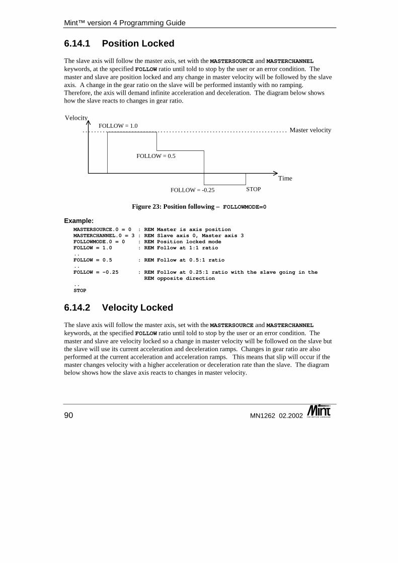
Mint™ version 4 Programming Guide
90 MN1262 02.2002
6.14.1 Position Locked The slave axis will follow the master axis, set with the MASTERSOURCE and MASTERCHANNEL keywords, at the specified FOLLOW ratio until told to stop by the user or an error condition. The master and slave are position locked and any change in master velocity will be followed by the slave axis. A change in the gear ratio on the slave will be performed instantly with no ramping. Therefore, the axis will demand infinite acceleration and deceleration. The diagram below shows how the slave reacts to changes in gear ratio.
Velocity
Time
Master velocityFOLLOW = 1.0
FOLLOW = 0.5
STOPFOLLOW = -0.25
Figure 23: Position following – FOLLOWMODE=0
Example: MASTERSOURCE.0 = 0 : REM Master is axis positionMASTERCHANNEL.0 = 3 : REM Slave axis 0, Master axis 3FOLLOWMODE.0 = 0 : REM Position locked modeFOLLOW = 1.0 : REM Follow at 1:1 ratio..FOLLOW = 0.5 : REM Follow at 0.5:1 ratio..FOLLOW = -0.25 : REM Follow at 0.25:1 ratio with the slave going in the
REM opposite direction..STOP
6.14.2 Velocity Locked The slave axis will follow the master axis, set with the MASTERSOURCE and MASTERCHANNEL keywords, at the specified FOLLOW ratio until told to stop by the user or an error condition. The master and slave are velocity locked so a change in master velocity will be followed on the slave but the slave will use its current acceleration and deceleration ramps. Changes in gear ratio are also performed at the current acceleration and acceleration ramps. This means that slip will occur if the master changes velocity with a higher acceleration or deceleration rate than the slave. The diagram below shows how the slave axis reacts to changes in master velocity.
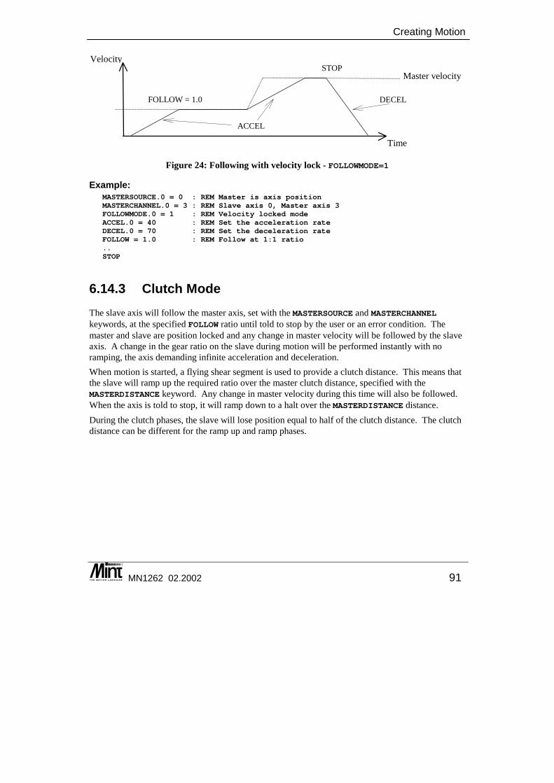
Creating Motion
MN1262 02.2002 91
Velocity
Time
Master velocity
FOLLOW = 1.0
STOP
ACCEL
DECEL
Figure 24: Following with velocity lock - FOLLOWMODE=1
Example: MASTERSOURCE.0 = 0 : REM Master is axis positionMASTERCHANNEL.0 = 3 : REM Slave axis 0, Master axis 3FOLLOWMODE.0 = 1 : REM Velocity locked modeACCEL.0 = 40 : REM Set the acceleration rateDECEL.0 = 70 : REM Set the deceleration rateFOLLOW = 1.0 : REM Follow at 1:1 ratio..STOP
6.14.3 Clutch Mode The slave axis will follow the master axis, set with the MASTERSOURCE and MASTERCHANNEL keywords, at the specified FOLLOW ratio until told to stop by the user or an error condition. The master and slave are position locked and any change in master velocity will be followed by the slave axis. A change in the gear ratio on the slave during motion will be performed instantly with no ramping, the axis demanding infinite acceleration and deceleration. When motion is started, a flying shear segment is used to provide a clutch distance. This means that the slave will ramp up the required ratio over the master clutch distance, specified with the MASTERDISTANCE keyword. Any change in master velocity during this time will also be followed. When the axis is told to stop, it will ramp down to a halt over the MASTERDISTANCE distance. During the clutch phases, the slave will lose position equal to half of the clutch distance. The clutch distance can be different for the ramp up and ramp phases.
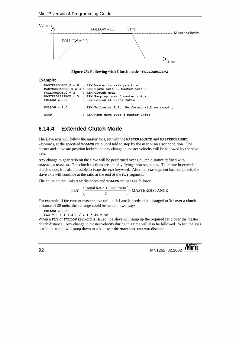
Mint™ version 4 Programming Guide
92 MN1262 02.2002
Velocity
Time
Master velocityFOLLOW = 1.0
FOLLOW = 0.5
STOP
Figure 25: Following with Clutch mode - FOLLOWMODE=2
Example: MASTERSOURCE.0 = 0 : REM Master is axis positionMASTERCHANNEL.0 = 3 : REM Slave axis 0, Master axis 3FOLLOWMODE.0 = 2 : REM Clutch modeMASTERDISTANCE = 5 : REM Ramp up over 5 master unitsFOLLOW = 0.5 : REM Follow at 0.5:1 ratio..FOLLOW = 1.0 : REM Follow at 1:1. Performed with no ramping..STOP : REM Ramp down over 5 master units
6.14.4 Extended Clutch Mode The slave axis will follow the master axis, set with the MASTERSOURCE and MASTERCHANNEL keywords, at the specified FOLLOW ratio until told to stop by the user or an error condition. The master and slave are position locked and any change in master velocity will be followed by the slave axis. Any change in gear ratio on the slave will be performed over a clutch distance defined with MASTERDISTANCE. The clutch sections are actually flying shear segments. Therefore in extended clutch mode, it is also possible to issue the FLY keyword. After the FLY segment has completed, the slave axis will continue at the ratio at the end of the FLY segment. The equation that links FLY distances and FOLLOW ratios is as follows:
For example, if the current master slave ratio is 1:1 and it needs to be changed to 3:1 over a clutch distance of 20 units, then change could be made in two ways:
FOLLOW = 3 orFLY = ( ( 1 + 3 ) / 2 ) * 20 = 40
When a FLY or FOLLOW keyword is issued, the slave will ramp up the required ratio over the master clutch distance. Any change in master velocity during this time will also be followed. When the axis is told to stop, it will ramp down to a halt over the MASTERDISTANCE distance.
ANCEMASTERDIST2
Ratio FinalRatio InitialFLY ×
+=
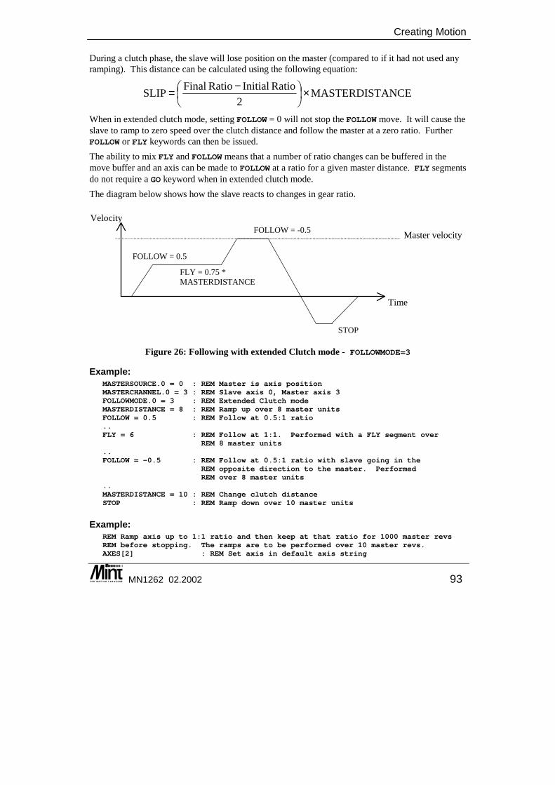
Creating Motion
MN1262 02.2002 93
During a clutch phase, the slave will lose position on the master (compared to if it had not used any ramping). This distance can be calculated using the following equation:
When in extended clutch mode, setting FOLLOW = 0 will not stop the FOLLOW move. It will cause the slave to ramp to zero speed over the clutch distance and follow the master at a zero ratio. Further FOLLOW or FLY keywords can then be issued. The ability to mix FLY and FOLLOW means that a number of ratio changes can be buffered in the move buffer and an axis can be made to FOLLOW at a ratio for a given master distance. FLY segments do not require a GO keyword when in extended clutch mode. The diagram below shows how the slave reacts to changes in gear ratio.
Velocity
Time
Master velocity
FOLLOW = 0.5
STOP
FLY = 0.75 *MASTERDISTANCE
FOLLOW = -0.5
Figure 26: Following with extended Clutch mode - FOLLOWMODE=3
Example: MASTERSOURCE.0 = 0 : REM Master is axis positionMASTERCHANNEL.0 = 3 : REM Slave axis 0, Master axis 3FOLLOWMODE.0 = 3 : REM Extended Clutch modeMASTERDISTANCE = 8 : REM Ramp up over 8 master unitsFOLLOW = 0.5 : REM Follow at 0.5:1 ratio..FLY = 6 : REM Follow at 1:1. Performed with a FLY segment over
REM 8 master units..FOLLOW = -0.5 : REM Follow at 0.5:1 ratio with slave going in the
REM opposite direction to the master. PerformedREM over 8 master units
..MASTERDISTANCE = 10 : REM Change clutch distanceSTOP : REM Ramp down over 10 master units
Example: REM Ramp axis up to 1:1 ratio and then keep at that ratio for 1000 master revsREM before stopping. The ramps are to be performed over 10 master revs.AXES[2] : REM Set axis in default axis string
ANCEMASTERDIST2
Ratio InitialRatio FinalSLIP ×
−=
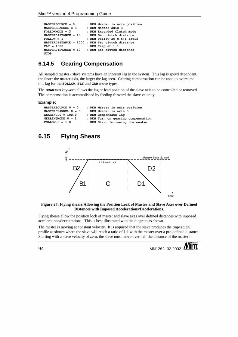
Mint™ version 4 Programming Guide
94 MN1262 02.2002
MASTERSOURCE = 0 : REM Master is axis positionMASTERCHANNEL = 3 : REM Master axis 3FOLLOWMODE = 3 : REM Extended Clutch modeMASTERDISTANCE = 10 : REM Set clutch distanceFOLLOW = 1 : REM Follow at 0.5:1 ratioMASTERDISTANCE = 1000 : REM Set clutch distanceFLY = 1000 : REM Keep at 1:1MASTERDISTANCE = 10 : REM Set clutch distanceSTOP
6.14.5 Gearing Compensation All sampled master / slave systems have an inherent lag in the system. This lag is speed dependant, the faster the master axis, the larger the lag seen. Gearing compensation can be used to overcome this lag for the FOLLOW, FLY and CAM move types. The GEARING keyword allows the lag or lead position of the slave axis to be controlled or removed. The compensation is accomplished by feeding forward the slave velocity.
Example: MASTERSOURCE.0 = 0 : REM Master is axis positionMASTERCHANNEL.0 = 3 : REM Master is axis 3GEARING.0 = 100.0 : REM Compensate lagGEARINGMODE.0 = 1 : REM Turn on gearing compensationFOLLOW.0 = 1.0 : REM Start following the master
6.15 Flying Shears
B1 C D1
B2 D2
Time
Ve
loc
ity
Master Base Speed
1:1 Speed Lock
Figure 27: Flying shears Allowing the Position Lock of Master and Slave Axes over Defined Distances with Imposed Accelerations/Decelerations.
Flying shears allow the position lock of master and slave axes over defined distances with imposed accelerations/decelerations. This is best illustrated with the diagram as shown. The master is moving at constant velocity. It is required that the slave produces the trapezoidal profile as shown where the slave will reach a ratio of 1:1 with the master over a pre-defined distance. Starting with a slave velocity of zero, the slave must move over half the distance of the master in
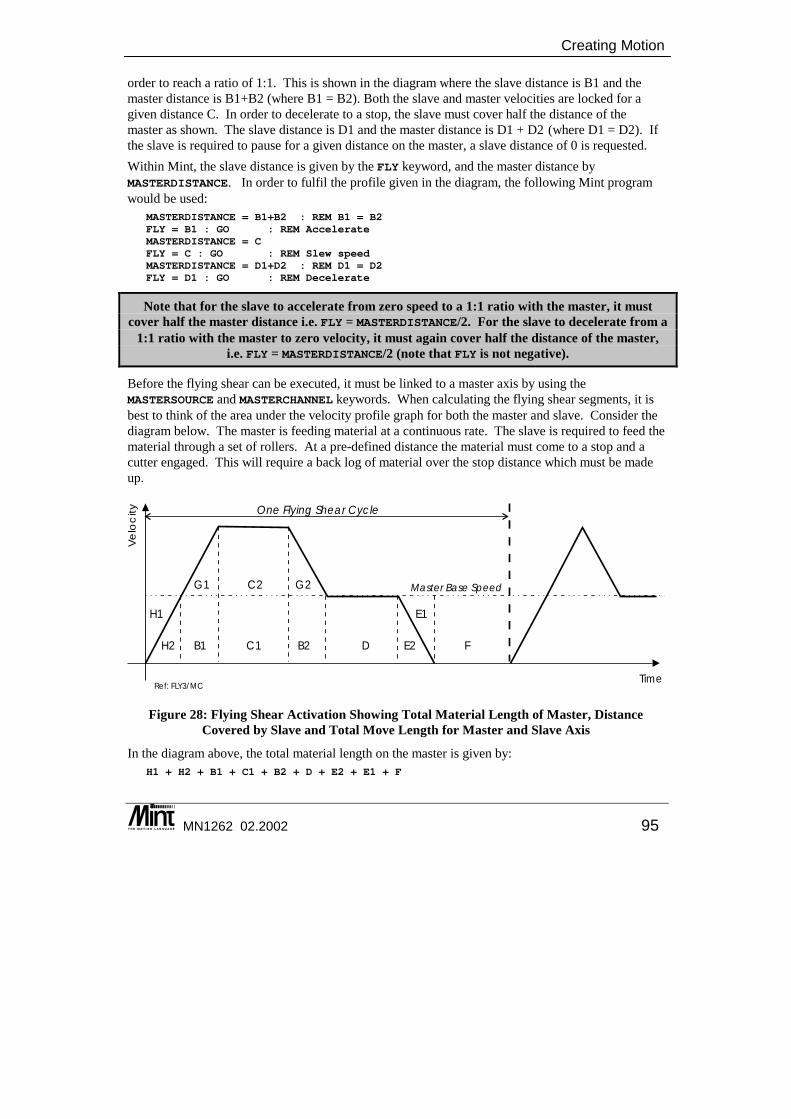
Creating Motion
MN1262 02.2002 95
order to reach a ratio of 1:1. This is shown in the diagram where the slave distance is B1 and the master distance is B1+B2 (where B1 = B2). Both the slave and master velocities are locked for a given distance C. In order to decelerate to a stop, the slave must cover half the distance of the master as shown. The slave distance is D1 and the master distance is D1 + D2 (where D1 = D2). If the slave is required to pause for a given distance on the master, a slave distance of 0 is requested. Within Mint, the slave distance is given by the FLY keyword, and the master distance by MASTERDISTANCE. In order to fulfil the profile given in the diagram, the following Mint program would be used:
MASTERDISTANCE = B1+B2 : REM B1 = B2FLY = B1 : GO : REM AccelerateMASTERDISTANCE = CFLY = C : GO : REM Slew speedMASTERDISTANCE = D1+D2 : REM D1 = D2FLY = D1 : GO : REM Decelerate
Note that for the slave to accelerate from zero speed to a 1:1 ratio with the master, it must cover half the master distance i.e. FLY = MASTERDISTANCE/2. For the slave to decelerate from a
1:1 ratio with the master to zero velocity, it must again cover half the distance of the master, i.e. FLY = MASTERDISTANCE/2 (note that FLY is not negative).
Before the flying shear can be executed, it must be linked to a master axis by using the MASTERSOURCE and MASTERCHANNEL keywords. When calculating the flying shear segments, it is best to think of the area under the velocity profile graph for both the master and slave. Consider the diagram below. The master is feeding material at a continuous rate. The slave is required to feed the material through a set of rollers. At a pre-defined distance the material must come to a stop and a cutter engaged. This will require a back log of material over the stop distance which must be made up.
Time
Ve
loc
ity
H2 B1 C1
C2
B2
G1 G2
D E2 F
One Flying Shear Cycle
H1 E1
Ref: FLY3/MC
Master Base Speed
Figure 28: Flying Shear Activation Showing Total Material Length of Master, Distance Covered by Slave and Total Move Length for Master and Slave Axis
In the diagram above, the total material length on the master is given by: H1 + H2 + B1 + C1 + B2 + D + E2 + E1 + F
Mint™ version 4 Programming Guide
96 MN1262 02.2002
The distance covered by the slave is given by: H2 + B1 + G1 + C1 + C2 + B2 + G2 + D + E2
The slave must make up the distance it has lost in coming to a stop. Therefore: (G1 + C2 + G2)slave = (H1 + E1 + F)master
If H2 = G1, C1 = C2 and G2 = G1 then the Mint program for the above profile will be: (substituting numbers for the denoted areas)
AXES[0]MASTERSOURCE = _msPOS : REM Follow master positionMASTERCHANNEL = 1 : REM Axis 1 is masterMASTERDISTANCE = 200 : REM H1+H2+B1FLY = 200 : GO : REM H2+B1+G1 - 2:1 ratio between slave and masterMASTERDISTANCE = 200 : REM C1FLY = 400 : GO : REM C1 + C2 - Slave must cover 2x distance of masterMASTERDISTANCE = 100 : REM B2FLY = 150 : GO : REM B2 + G2 - Decel to 1:1 ratio slave and masterMASTERDISTANCE = 400 : REM DFLY = 400 : GO : REM D - 1:1 ratio between slave and masterMASTERDISTANCE = 100 : REM E1 + E2FLY = 50 : GO : REM E2 - Decelerate to zero speedMASTERDISTANCE = 200 : REM FFLY = 0 : GO : REM - Remain stationary for master position
where the total move length for master and slave is 1200 units. With following, there is an inherent lag in the system when the master position is read. This lag can be overcome with the gearing function described in section 6.14.5.
6.16 Cam Profiling Cam profiling is where a slave axis is linked to a master axis and for a given move on the master, the slave will move a pre-defined distance linked to the master position. To create the software cam, the cam is broken down into discrete linear moves (segments). These moves are then linked with a master axis such that the slave will move the specified distance for a measured move on the master (creating a software gearbox). The cam segments are placed in a table for a background execution. Once these segments have been defined, the controller will interpolate between them. Cams can be performed on any number of servo or stepper axes. There are two forms of cam profile generation:
1. Interpolated. The motion between cam segments is linearly interpolated to give a path that is continuous in position but discontinuous in velocity.
2. Non-Interpolated. The motion between cam segments is not interpolated to give a path that is discontinuous in position.

Creating Motion
MN1262 02.2002 97
6.16.1 Cam Tables A cam cycle is broken up into a series of segments which make up the cam profile. A cam table is set-up in an array of any name where the normal Mint syntax applies to the array. For example:
DIM myCam(11) = 10,1,2,3,2,1,2,3,1,2,3
where the first element determines the number of points in the cam profile and each subsequent value defines a cam segment. A cam segment can be given in either relative or absolute positions. The actual move will be determined by value passed to the CAM keyword. Before the cam can be executed, it must be linked to an external source by using the MASTERSOURCE and MASTERCHANNEL keywords. The MASTERDISTANCE (master increment) keyword is used to determine the distance over which the slave (the cam) will move over. For example, if a cam segment is 250 and MASTERDISTANCE is 500, the cam will move 250 units over 500 units on the master. For a cam table, MASTERDISTANCE applies to each cam segment in the table. If different MASTERDISTANCE values are required for each individual cam segment, the master distance values can be defined in a master distance table of any name where the table is a standard Mint array. For example:
DIM myMaster(10) = 1,2,3,4,5,6,7,8,9,10
Note that the master table does not have a first element that specifies the number of Cam segments. The CAMTABLE keyword is used tell Mint which arrays to use as the cam table and optionally the master increment table. CAMTABLE is a function style keyword. For example, to use the myCam array defined above:
CAMTABLE ( 0, myCam, NULL )
where 0 is the axis number. The NULL parameter indicates that there is no master distance table. The CAM keyword is used to load the move and the GO keyword starts the motion. The value passed to the CAM keyword indicates whether the cam is to repeat and whether the values in the table are to be taken as relative or absolute. For example:
CAM.0 = 0 : GO.0
will execute a cam for axis 0 taking the values in the cam table as relative. The cam will finish when the last cam point has been executed.
CAM.1 = _cmABSOLUTE + _cmCONTINUOUS : GO.1
will execute a cam for axis 1 taking the values in the cam table as absolute motor positions. The cam will execute indefinitely. Once the last cam segment has been executed, the cam motion will begin again.
An absolute cam only defines absolute positions within one cam cycle and not to an absolute motor position. An absolute cam implies a zero at the start of each cycle. A true absolute cam
takes the table values as absolute to true motor position.
Stopping a continuous cam at the end if its profile can be achieved as follows:
Mint™ version 4 Programming Guide
98 MN1262 02.2002
CAM = _cmCONTINUOUS : GO : REM continuous relative camPAUSE IN1 : REM Wait for an inputSTOP : REM Issue stopPAUSE IDLE : REM cam will stop when the last segment is reached.
this will stop when the last cam segment has been executed.
Example: Regularly spaced product is fed into a bagging machine. The required motion is performed in one revolution. The master encoder has been scaled to mm and the slave to revolutions. The user interrupt routine on input 0 triggers the motion when the product is seen.
REM Set up cam tableDIM slave(20) = 14, 10, 20, 40, 70, 110, 160, 200, 250, 290, 320,
340, 350, 360, 360
MASTERSOURCE = _msENCODER : REM Master is encoder valueMASTERCHANNEL = 2 : REM Master is axis 2MASTERDISTANCE = 20 : REM Master distance is 20CAMTABLE(0, slave, NULL) : REM Load the tablesCAM = _cmABSOLUTE + _cmCONTINUOUS : REM Absolute and continuous
LOOPREM Perform other functions
ENDLEND
#IN0IF AXISMODE = _mdCAM THEN GO
RETURN
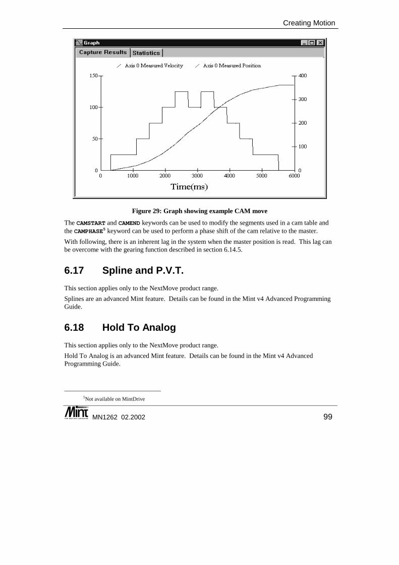
Creating Motion
MN1262 02.2002 99
Figure 29: Graph showing example CAM move
The CAMSTART and CAMEND keywords can be used to modify the segments used in a cam table and the CAMPHASE5 keyword can be used to perform a phase shift of the cam relative to the master. With following, there is an inherent lag in the system when the master position is read. This lag can be overcome with the gearing function described in section 6.14.5.
6.17 Spline and P.V.T. This section applies only to the NextMove product range. Splines are an advanced Mint feature. Details can be found in the Mint v4 Advanced Programming Guide.
6.18 Hold To Analog This section applies only to the NextMove product range. Hold To Analog is an advanced Mint feature. Details can be found in the Mint v4 Advanced Programming Guide.
5Not available on MintDrive

Mint™ version 4 Programming Guide
100 MN1262 02.2002
6.19 Blending This section applies only to the NextMove product range. Normally, in order to change between two different move types, the axis must be stopped first and allowed to become idle. Blending is where the transition between move types can be done on the fly, without the axis being forced to come to a halt. It is possible to blend into a JOG move or a TORQUE move from any other move type with the exception of a HOME cycle or a linear or circular interpolated move. When blending to a JOG move, the axis will ramp from its current speed to the new JOG speed using the current ACCEL, DECEL values.
6.20 Compensation Modes This section applies only to the NextMove product range. Compensation modes (backlash and leadscrew) are an advanced Mint feature. Details can be found in the Mint v4 Advanced Programming Guide.
6.21 Virtual Axes NextMove controllers support ‘virtual axes’. A virtual axis allows motion to be simulated without moving any physical axes. To is useful for system design and testing. A virtual axis allows most Mint commands to be executed as normal and the axis will simulate position and velocity information for any motion performed. To configure an axis as a virtual axis, the CONFIG keyword is used. Any axis can be configured to be a virtual axis. NextMove PCI and NextMove BX have additional software axes that be configured to be virtual axes without taking up any of the regular axes connected to physical hardware. See the Mint v4 Advanced Programming Guide for details on axis numbers and axis mappings.
Input/Output Handling Using Mint
MN1262 02.2002 101
7. Input/Output Handling Using Mint
7 Mint controllers have a flexible programmable I/O structure which is fully programming in Mint. This chapter covers the setting up of the I/O.
◊ Digital I/O ◊ Analog I/O ◊ Stepper I/O ◊ Setting the I/O ‘on the fly’
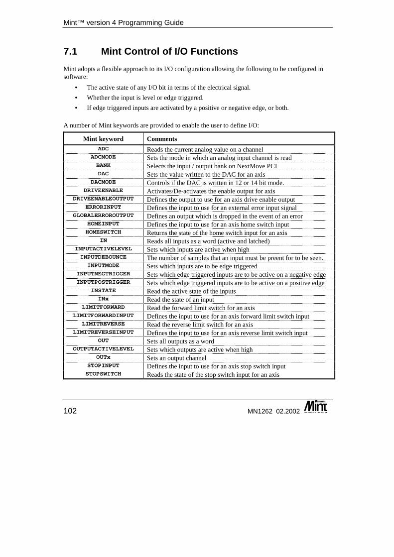
Mint™ version 4 Programming Guide
102 MN1262 02.2002
7.1 Mint Control of I/O Functions Mint adopts a flexible approach to its I/O configuration allowing the following to be configured in software:
• The active state of any I/O bit in terms of the electrical signal. • Whether the input is level or edge triggered. • If edge triggered inputs are activated by a positive or negative edge, or both.
A number of Mint keywords are provided to enable the user to define I/O:
Mint keyword Comments ADC Reads the current analog value on a channel
ADCMODE Sets the mode in which an analog input channel is read BANK Selects the input / output bank on NextMove PCI DAC Sets the value written to the DAC for an axis
DACMODE Controls if the DAC is written in 12 or 14 bit mode. DRIVEENABLE Activates/De-activates the enable output for axis
DRIVEENABLEOUTPUT Defines the output to use for an axis drive enable output ERRORINPUT Defines the input to use for an external error input signal
GLOBALERROROUTPUT Defines an output which is dropped in the event of an error HOMEINPUT Defines the input to use for an axis home switch input HOMESWITCH Returns the state of the home switch input for an axis
IN Reads all inputs as a word (active and latched) INPUTACTIVELEVEL Sets which inputs are active when high INPUTDEBOUNCE The number of samples that an input must be preent for to be seen.
INPUTMODE Sets which inputs are to be edge triggered INPUTNEGTRIGGER Sets which edge triggered inputs are to be active on a negative edge INPUTPOSTRIGGER Sets which edge triggered inputs are to be active on a positive edge
INSTATE Read the active state of the inputs INx Read the state of an input
LIMITFORWARD Read the forward limit switch for an axis LIMITFORWARDINPUT Defines the input to use for an axis forward limit switch input
LIMITREVERSE Read the reverse limit switch for an axis LIMITREVERSEINPUT Defines the input to use for an axis reverse limit switch input
OUT Sets all outputs as a word OUTPUTACTIVELEVEL Sets which outputs are active when high
OUTx Sets an output channel STOPINPUT Defines the input to use for an axis stop switch input STOPSWITCH Reads the state of the stop switch input for an axis
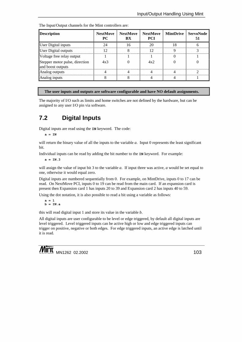
Input/Output Handling Using Mint
MN1262 02.2002 103
The Input/Output channels for the Mint controllers are:
Description NextMove PC
NextMove BX
NextMove PCI
MintDrive ServoNode 51
User Digital inputs 24 16 20 18 6 User Digital outputs 12 8 12 9 3 Voltage free relay output 1 1 1 0 1 Stepper motor pulse, direction and boost outputs
4x3 0 4x2 0 0
Analog outputs 4 4 4 4 2 Analog inputs 8 8 4 4 1
The user inputs and outputs are software configurable and have NO default assignments.
The majority of I/O such as limits and home switches are not defined by the hardware, but can be assigned to any user I/O pin via software.
7.2 Digital Inputs Digital inputs are read using the IN keyword. The code:
a = IN
will return the binary value of all the inputs to the variable a. Input 0 represents the least significant bit. Individual inputs can be read by adding the bit number to the IN keyword. For example:
a = IN.3
will assign the value of input bit 3 to the variable a. If input three was active, a would be set equal to one, otherwise it would equal zero. Digital inputs are numbered sequentially from 0. For example, on MintDrive, inputs 0 to 17 can be read. On NextMove PCI, inputs 0 to 19 can be read from the main card. If an expansion card is present then Expansion card 1 has inputs 20 to 39 and Expansion card 2 has inputs 40 to 59. Using the dot notation, it is also possible to read a bit using a variable as follows:
a = 1b = IN.a
this will read digital input 1 and store its value in the variable b. All digital inputs are user configurable to be level or edge triggered, by default all digital inputs are level triggered. Level triggered inputs can be active high or low and edge triggered inputs can trigger on positive, negative or both edges. For edge triggered inputs, an active edge is latched until it is read.
Mint™ version 4 Programming Guide
104 MN1262 02.2002
Example: INPUTMODE = 0xFF000INPUTNEGTRIGGER = 0xFF000
PAUSE IN.5? IN.5
This would pause until input 5 is seen to be active. If input 5 was configured to be edge triggered then the act of reading the input will clear the latched value. Therefore, the line that prints input 5 would print 0 since the input latched value had been cleared. INSTATE can be used to read the physical state of the input, if defined as edge triggered. In the example above, reading INSTATE.5 will return 1 until the input goes low. Events can be triggered when an input is active. An event on the input is created by adding a subroutine to the Mint program as shown:
#IN0PRINT “Hello”
RETURN
will display “Hello” when the input is active. Input events are discussed in section 8.
7.3 Digital Outputs Digital outputs are set by writing to the keyword. This works in a similar manner to the IN keyword, the outputs are set to the digital value of the number or variable assigned to them.
OUT = 129
would set outputs 0 and 7 active. Individual outputs can be set by adding the bit number to the OUT keyword. For example:
OUT.2 = 1
will set output 2. Digital outputs are numbered sequentially from 0. For example, on MintDrive, outputs 0 to 8 are available. On NextMove PCI, outputs 0 to 11 are available from the main card. If an expansion card is present then Expansion card 1 has outputs 12 to 23 and Expansion card 2 has outputs 24 to 35. Using the dot notation, it is also possible to set an output bit using a variable as follows:
a = 1OUT.a = 0
will clear output bit 1. Digital outputs may be assigned as drive enable signals with the DRIVEENABLEOUTPUT keyword.
Input/Output Handling Using Mint
MN1262 02.2002 105
7.4 I/O Banks NextMove PCI supports Expansion cards which have the same complement of digital inputs and outputs as the main card. These are organized into banks as follows:
Bank I/O Bank 0 I/O on main card 1 I/O on expansion card 1 2 I/O on expansion card 2
Any IO keyword that affects a bank of inputs or outputs uses the BANK keyword to select which bank is being accessed. For example, INPUTACTIVELEVEL sets which digital inputs are active high and which are active low. The keyword accepts a bit pattern which represents the digital input channels. By default, BANK is set to 0 so using INPUTACTIVELEVEL will affect only the inputs of bank 0. In order to affect the inputs on bank 1, the BANK keyword is used.
BANK = 0 : REM Select main card IOINPUTACTIVELEVEL = 0 : REM All main card inputs are active lowBANK = 1 : REM Select expansion card 1 IOINPUTACTIVELEVEL = 0 : REM All expansion card 1 inputs are active low
7.5 Analog Inputs Each of the Mint controllers have a number of analog inputs. Consult the appropriate installation guides for full details on these inputs. On NextMove each analog channel can be configured in software in a number of different modes with the ADCMODE keyword. The use of the ADCMODE keyword will depend upon the NextMove controller. For example, a low cost manual control positioning system for an x-y table could be based around a joystick fitted with two potentiometers. The two potentiometers are connected to analog inputs zero and one on the controller. The following code fragment will loop around (if digital input one is active) testing analog inputs ADC.0 and ADC.1 and jogging the motor at a speed set by these inputs. Assuming that the scale factor is set such that SPEED’s are in mm/sec on the table, this program gives a SPEED range of ±100 mm/sec.
WHILE IN.1JOG.0 = ADC.0 : REM 0V input produces..JOG.1 = ADC.1 : REM ..zero speed
ENDW
opening a switch connected to input one will cause the loop to terminate.
Mint™ version 4 Programming Guide
106 MN1262 02.2002
7.6 Analog Outputs Each of the Mint controllers have a number of analog output channels. On NextMove, these are used primarily for servo axis control. Unused channels can be used as a general purpose DAC output with the DAC keyword.. On MintDrive and ServoNode 51, these are general purpose analog outputs controlled with the AUXDAC keyword. Consult the appropriate installation guide for the full specification on the analog outputs. The following example shows using the 2nd DAC output on NextMove BX, by first turning the servo channel off.
Example: CONFIG.1 = _cfOFF : REM Axis is not usedDACMODE.1 = 1 : REM 14bit mode on NextMove BXDAC.1 = 50 : REM Set DAC output to 50% (5 volts)
Where a controller has an analog output channel greater than 12 bit resolution, the DACMODE keyword can be used to put the channel into 12 bit emulation mode. The analog outputs on MintDrive are referenced using the AUXDAC keyword and not the DAC keyword. For example:
AUXDAC.1 = 50
Both AUXDAC and DAC take a percentage value. For a bi-directional 10V output DAC = 25AUXDAC = 25
Will set the analog output to be 2.5V. DAC = -25AUXDAC = -25
Will set the analog output to be -2.5V Fractional values are allowed, giving finer control of the outputs.
7.7 Stepper I/O On NextMove PC, each stepper axis has three associated outputs; pulse, direction and boost. If the axis is not being used for stepper or PWM control, then these outputs may be used as general purpose user digital outputs. These are accessible with the STEPPERIO and BOOST keywords. The BOOST keyword accepts a state of the output, a 1 will turn the output on and a 0 will turn it off. The STEPPERIO keyword accepts a bit pattern where bit 0 is the state of the pulse pin and bit 1 is the state of the direction pin. NextMove PCI has two associated outputs; pulse and direction. If the axis is not being used for stepper control, then these outputs may be used as general purpose user digital outputs. These are accessible with the STEPPERIO keyword.
Input/Output Handling Using Mint
MN1262 02.2002 107
Example: CONFIG.7 = _off : REM Axis is not usedSTEPPERIO.7 = 0x01 : REM Turn on the pulse output and
: REM turn off the direction output on channel 7
7.8 Input/Output ‘On the Fly' Because Mint does not stop executing instructions until there is a move pending it is easy to write applications that perform I/O operations while a move is in progress. For example, if the application needs to test combinational logic on inputs and set outputs accordingly while a move is in progress then the following code segment illustrates a method for achieving this functionality:
MOVER = 150 : GO : REM start moveREPEAT
IF IN.1 AND IN.5 DO : REM check if inputs 1 and 5 are both onOUT.2 = 1 : REM if they are then turn on output 2
ELSEOUT.2 = 0 : REM if either is off then turn off output 2
ENDIFUNTIL IDLE : REM test of inputs stops when move completes
Another example is glue laying around car windows. In this application, the glue cannot be turned on until the axis has reached a critical velocity (VEL), otherwise the line of glue will not be consistently thick. Therefore we must wait until the axis has accelerated before turning on the glue gun:
MOVEA = 200 : GO : REM start movePAUSE VEL > 20 : REM wait until VEL > 20OUT1 = 1 : REM turn on gluePAUSE VEL < 20 : REM decelerating to endOUT1 = 0 : REM turn off glue
There are instances when you may wish to halt the program until the current move is complete. For instance:
OUT2 = 0MOVER = 10 : GO : REM relative movePAUSE IDLE : REM wait for end moveOUT2 = 1 : REM flag end move
In this code fragment the requirement is that output two is not set until the move is complete. The IDLE keyword will return zero during a positional move and one when the axis is idle at the end of the move. Therefore PAUSE IDLE will hang the program as required. For a 2 axis move, the code segment will be:
OUT2 = 0MOVER = 10,20 : GO : REM relative movePAUSE IDLE[0,1] : REM wait for end moveOUT2 = 1 : REM flag end move

Mint™ version 4 Programming Guide
108 MN1262 02.2002
Event and Error Hanlding
MN1262 02.2002 109
8. Event and Error Handling
8 Mint is capable of generating software events in response to certain external and internal events. This chapter covers the use of Mint events and how to use them for error handling.
◊ Mint Events ◊ Error Handling ◊ Synchronous errors ◊ Asynchronous errors

Mint™ version 4 Programming Guide
110 MN1262 02.2002
There are a number of reserved subroutine labels in Mint which have a pre-defined use. These are:
Label Use #ONERROR Mint error handler #CAN1 CAN channel 1 event handler #CAN2 CAN channel 2 event handler #STOP Stop switch handler
#FASTINx, #FASTIN Fast position latch event handlers #TIMER Periodic timer event handler #INx User digital input event handlers
#COMMSx Called in response to a write to the comms array from the host. Only comms locations 1 through to 5 can initiate an event.
Event processing is handled differently on NextMove, ServoNode 51 and MintDrive.
8.1 NextMove The Mint event priority is as follows:
Highest: #ONERROR
#CAN1
#CAN2
#STOP
#FASTINx, #FASTIN (the smaller number has the higher priority) #TIMER
#INx (the input with the smaller number has the higher priority)Lowest: #COMMSx (the smaller number has the higher priority)
The processing of an event may be interrupted by a higher priority event. For example, if while the timer event is active an error occurs, the processing of the timer event is halted while the error routine is processed. Below is a graphic representation of how Mint would react to several events of different priorities occurring together. #1 #2 #3 #4 #5 #6 #7 #8
Timer Event
Digital Input Event
Stop Switch Event
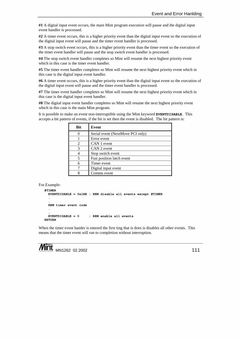
Event and Error Hanlding
MN1262 02.2002 111
#1 A digital input event occurs, the main Mint program execution will pause and the digital input event handler is processed. #2 A timer event occurs, this is a higher priority event than the digital input event so the execution of the digital input event will pause and the timer event handler is processed. #3 A stop switch event occurs, this is a higher priority event than the timer event so the execution of the timer event handler will pause and the stop switch event handler is processed. #4 The stop switch event handler completes so Mint will resume the next highest priority event which in this case is the timer event handler. #5 The timer event handler completes so Mint will resume the next highest priority event which in this case is the digital input event handler. #6 A timer event occurs, this is a higher priority event than the digital input event so the execution of the digital input event will pause and the timer event handler is processed. #7 The timer event handler completes so Mint will resume the next highest priority event which in this case is the digital input event handler. #8 The digital input event handler completes so Mint will resume the next highest priority event which in this case is the main Mint program. It is possible to make an event non-interruptible using the Mint keyword EVENTDISABLE. This accepts a bit pattern of events, if the bit is set then the event is disabled. The bit pattern is:
Bit Event 0 Serial event (NextMove PCI only) 1 Error event 2 CAN 1 event 3 CAN 2 event 4 Stop switch event 5 Fast position latch event 6 Timer event 7 Digital input event 8 Comms event
For Example:
#TIMEREVENTDISABLE = 0x1BE : REM disable all events except #TIMER..REM timer event code..EVENTDISABLE = 0 : REM enable all events
RETURN
When the timer event hander is entered the first ting that is does is disables all other events. This means that the timer event will run to completion without interruption.
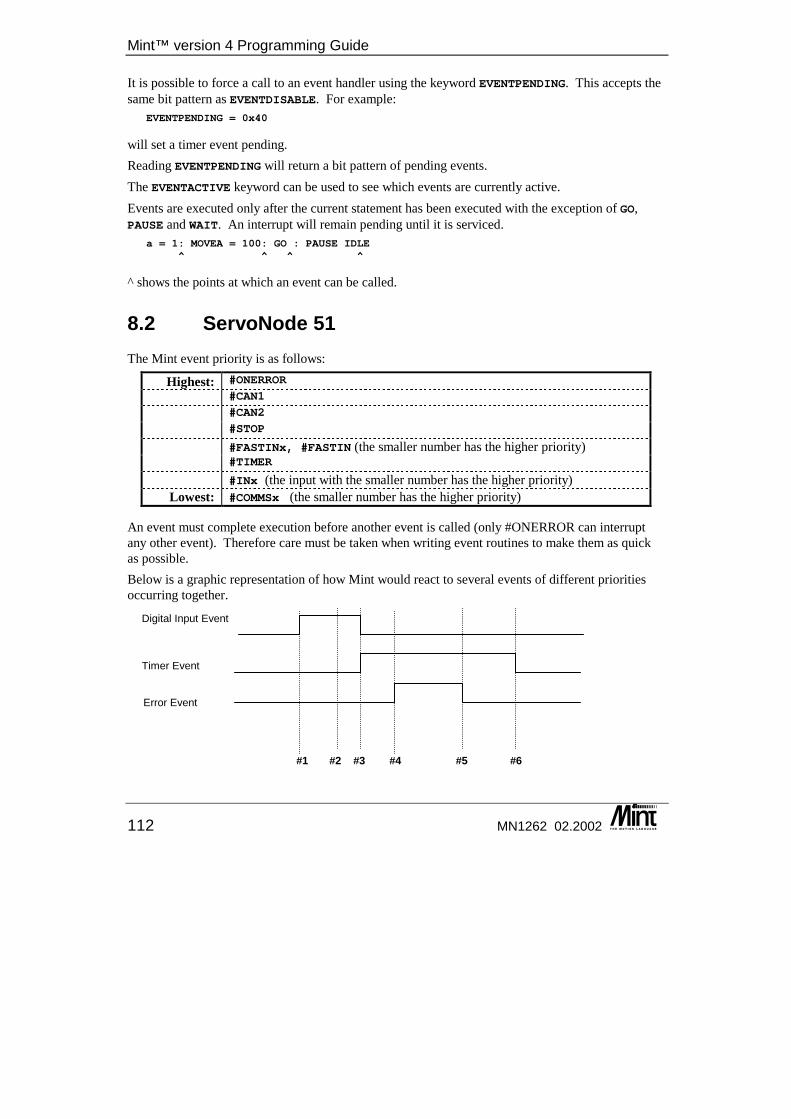
Mint™ version 4 Programming Guide
112 MN1262 02.2002
It is possible to force a call to an event handler using the keyword EVENTPENDING. This accepts the same bit pattern as EVENTDISABLE. For example:
EVENTPENDING = 0x40
will set a timer event pending. Reading EVENTPENDING will return a bit pattern of pending events. The EVENTACTIVE keyword can be used to see which events are currently active. Events are executed only after the current statement has been executed with the exception of GO, PAUSE and WAIT. An interrupt will remain pending until it is serviced.
a = 1: MOVEA = 100: GO : PAUSE IDLE^ ^ ^ ^
^ shows the points at which an event can be called.
8.2 ServoNode 51 The Mint event priority is as follows:
Highest: #ONERROR
#CAN1
#CAN2
#STOP
#FASTINx, #FASTIN (the smaller number has the higher priority) #TIMER
#INx (the input with the smaller number has the higher priority)Lowest: #COMMSx (the smaller number has the higher priority)
An event must complete execution before another event is called (only #ONERROR can interrupt any other event). Therefore care must be taken when writing event routines to make them as quick as possible. Below is a graphic representation of how Mint would react to several events of different priorities occurring together. #1 #2 #3 #4 #5 #6
Timer Event
Digital Input Event
Error Event
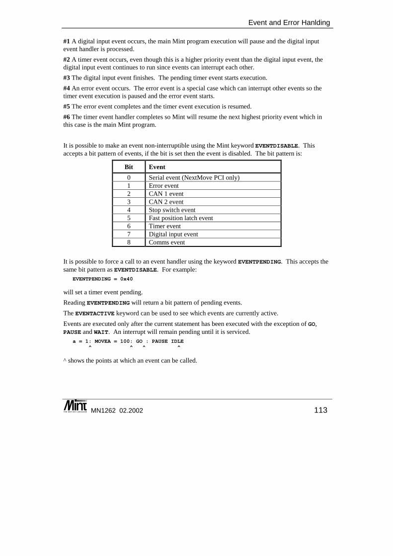
Event and Error Hanlding
MN1262 02.2002 113
#1 A digital input event occurs, the main Mint program execution will pause and the digital input event handler is processed. #2 A timer event occurs, even though this is a higher priority event than the digital input event, the digital input event continues to run since events can interrupt each other. #3 The digital input event finishes. The pending timer event starts execution. #4 An error event occurs. The error event is a special case which can interrupt other events so the timer event execution is paused and the error event starts. #5 The error event completes and the timer event execution is resumed. #6 The timer event handler completes so Mint will resume the next highest priority event which in this case is the main Mint program. It is possible to make an event non-interruptible using the Mint keyword EVENTDISABLE. This accepts a bit pattern of events, if the bit is set then the event is disabled. The bit pattern is:
Bit Event 0 Serial event (NextMove PCI only) 1 Error event 2 CAN 1 event 3 CAN 2 event 4 Stop switch event 5 Fast position latch event 6 Timer event 7 Digital input event 8 Comms event
It is possible to force a call to an event handler using the keyword EVENTPENDING. This accepts the same bit pattern as EVENTDISABLE. For example:
EVENTPENDING = 0x40
will set a timer event pending. Reading EVENTPENDING will return a bit pattern of pending events. The EVENTACTIVE keyword can be used to see which events are currently active. Events are executed only after the current statement has been executed with the exception of GO, PAUSE and WAIT. An interrupt will remain pending until it is serviced.
a = 1: MOVEA = 100: GO : PAUSE IDLE^ ^ ^ ^
^ shows the points at which an event can be called.
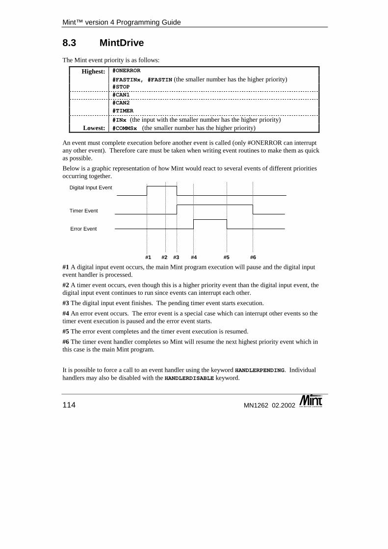
Mint™ version 4 Programming Guide
114 MN1262 02.2002
8.3 MintDrive The Mint event priority is as follows:
Highest: #ONERROR
#FASTINx, #FASTIN (the smaller number has the higher priority) #STOP
#CAN1
#CAN2
#TIMER
#INx (the input with the smaller number has the higher priority)Lowest: #COMMSx (the smaller number has the higher priority)
An event must complete execution before another event is called (only #ONERROR can interrupt any other event). Therefore care must be taken when writing event routines to make them as quick as possible. Below is a graphic representation of how Mint would react to several events of different priorities occurring together. #1 #2 #3 #4 #5 #6
#1 A digital input event occurs, the main Mint program execution will pause and the digital input event handler is processed. #2 A timer event occurs, even though this is a higher priority event than the digital input event, the digital input event continues to run since events can interrupt each other. #3 The digital input event finishes. The pending timer event starts execution. #4 An error event occurs. The error event is a special case which can interrupt other events so the timer event execution is paused and the error event starts. #5 The error event completes and the timer event execution is resumed. #6 The timer event handler completes so Mint will resume the next highest priority event which in this case is the main Mint program. It is possible to force a call to an event handler using the keyword HANDLERPENDING. Individual handlers may also be disabled with the HANDLERDISABLE keyword.
Timer Event
Digital Input Event
Error Event
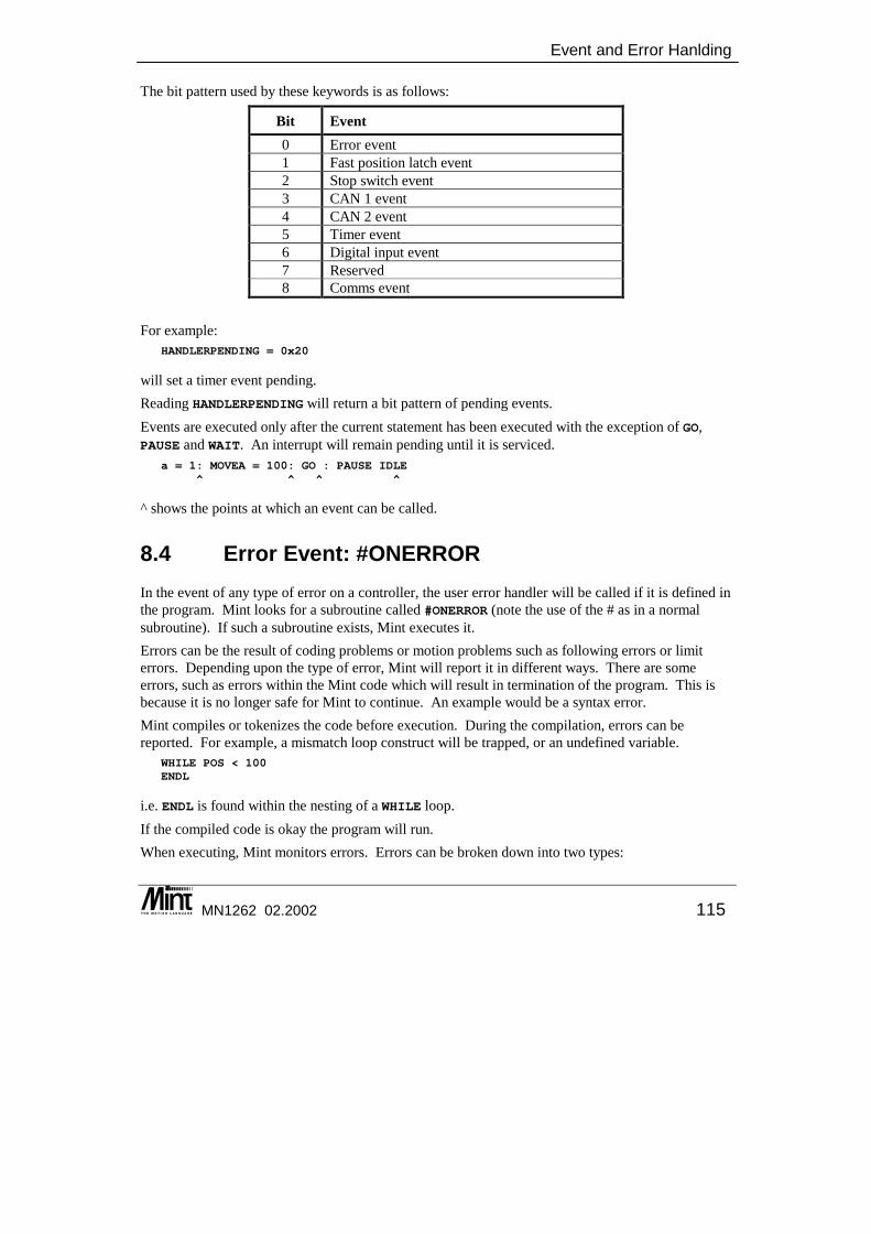
Event and Error Hanlding
MN1262 02.2002 115
The bit pattern used by these keywords is as follows:
Bit Event 0 Error event 1 Fast position latch event 2 Stop switch event 3 CAN 1 event 4 CAN 2 event 5 Timer event 6 Digital input event 7 Reserved 8 Comms event
For example:
HANDLERPENDING = 0x20
will set a timer event pending. Reading HANDLERPENDING will return a bit pattern of pending events. Events are executed only after the current statement has been executed with the exception of GO, PAUSE and WAIT. An interrupt will remain pending until it is serviced.
a = 1: MOVEA = 100: GO : PAUSE IDLE^ ^ ^ ^
^ shows the points at which an event can be called.
8.4 Error Event: #ONERROR In the event of any type of error on a controller, the user error handler will be called if it is defined in the program. Mint looks for a subroutine called #ONERROR (note the use of the # as in a normal subroutine). If such a subroutine exists, Mint executes it. Errors can be the result of coding problems or motion problems such as following errors or limit errors. Depending upon the type of error, Mint will report it in different ways. There are some errors, such as errors within the Mint code which will result in termination of the program. This is because it is no longer safe for Mint to continue. An example would be a syntax error. Mint compiles or tokenizes the code before execution. During the compilation, errors can be reported. For example, a mismatch loop construct will be trapped, or an undefined variable.
WHILE POS < 100ENDL
i.e. ENDL is found within the nesting of a WHILE loop. If the compiled code is okay the program will run. When executing, Mint monitors errors. Errors can be broken down into two types:
Mint™ version 4 Programming Guide
116 MN1262 02.2002
• Synchronous errors. Those errors found within the program, such as out of range or syntax errors.
• Asynchronous errors. Those errors typically from external events such as motion errors (following error exceeded or limit errors) or CAN bus errors.
When an error of any type occurs, Mint will look for a routine called #ONERROR. If this is defined, it will be called. If not, or at the command line, then an error message will be printed. Error messages are printed with the error number. Error numbers and messages are given in section 12.2.
R0003: PROGRAM Data specified out of range [axis/channel 0] [line 20]
Where R indicates a Run time error (C will indicate a Compile time error). PROGRAM indicates that the error occurred in the program file (CONFIGURATION will be displayed if the error occurred in the configuration file). The actual error message will be displayed along with the axis or channel number, followed by the line number. If the error occurs at the command line, #ONERROR will not be called.
8.4.1 Synchronous Errors Synchronous errors are generally programming errors. They occur at or because of a line of code that is either incorrect or is it is trying to do something that cannot be done at that time. Mostly they are usually silly mistakes like forgetting to put a bracket at the end of an expression, or forgetting a NEXT at the end of a FOR loop. When an error occurs, Mint will look for a routine called #ONERROR. If this is defined, it will be called. If not, or at the command line, then an error message will be printed.
Example: SCALE = -3 : REM This is invalid
R0003: PROGRAM Data specified out of range [axis/channel 0]
If this line was in a program with no #ONERROR routine, then the message would be: R0003: PROGRAM Data specified out of range [axis/channel 0] [line 20]
where the line number shows the line on which the error occurred. As the program stopped, the ABORT asynchronous error would be generated on all axes. See section 8.4.2. Synchronous errors are split into three groups; compiler errors, interpreter errors and system errors. Compiler errors occur during compile time of the Mint program. Due to the nature of the error such as ‘Out of memory’, ‘Invalid label’ and ‘Too many variables’, they cannot be recovered from. The program will terminate with an error message. Interpreter errors are generated by programming error such as mis-spelling a keyword or incorrectly placing a loop construct. The program will terminate with an error message.
Event and Error Hanlding
MN1262 02.2002 117
System Errors are generated by passing incorrect parameters to a keyword or attempting to do something that is not currently possible. For example, trying to set up a move on axis 12 would result in an ‘Invalid axis’ error message. System and interpreter errors will call the #ONERROR routine if it is defined. See the Mint v4 Advanced Programming Guide for details on advanced error handling.
8.4.2 Asynchronous Errors Asynchronous errors can occur at any time and are not directly related to a line of Mint code. They are grouped into motion and miscellaneous errors. Motion errors are reported in the AXISERROR keyword as a bit pattern where multiple errors are possible. Miscellaneous errors are reported with the MISCERROR keyword. When an asynchronous error occurs, the #ONERROR routine will be called if it is defined. Within the error handler, it is possible to determine the error type and to take appropriate action. The controller will take a ‘default action’ in response to asynchronous motion errors. The default action depends on the error and motion type. Some motion errors have a mode keyword which allows a choice of default action. The AXISSTATUS keyword can be used to monitor the status of potential errors on an axis. AXISSTATUS shows the instantaneous state of error conditions. Not all error conditions are possible on all controllers.
Software ABORT A software abort error is created when the ABORT keyword is called. All axes will show error bit 0 in AXISERROR. The default action is set with the ABORTMODE keyword.
Hardware Limit Error A forward or reverse hardware limit error is caused when the digital input assigned as the axis forward or reverse limit input is activated. A forward limit error will show error bit 1 in AXISERROR, a reverse limit error will show error bit 2. The limit inputs are assigned with the LIMITFORWARDINPUT and LIMITREVERSEINPUT keywords. The state of the limit switches can be read with the LIMIT, LIMITFORWARD and LIMITRREVERSE keywords. Hardware limit errors will be generated regardless of the direction of motion. The default action is set with the LIMITMODE keyword. Hardware limit detection can be enabled and disabled with the LIMITMODE keyword.
Software Limit Error A forward or reverse software limit error is caused when the axis position exceeds the values set as the forward or reverse limit positions. A forward software limit error will show error bit 3 in AXISERROR, a reverse software limit error will show error bit 4. The limit positions are assigned with the SOFTLIMITFORWARD and SOFTLIMITREVERSE keywords.
Mint™ version 4 Programming Guide
118 MN1262 02.2002
Software limit errors will be generated regardless of the direction of motion. The default action is set with the SOFTLIMITMODE keyword. Software limit detection can be enabled and disabled with the SOFTLIMITMODE keyword.
Following Error A following error is where the difference between the axis demand position and the axis measured position exceeds the limit set with the FOLERRORFATAL keyword. The current axis following error can be read with the FOLERROR keyword. A following error will show error bit 5 in AXISERROR. The default action is set with the FOLERRORMODE keyword.
External Error An external error is caused when the digital input assigned as the axis external error input is activated. An external error will show error bit 6 in AXISERROR. The default action is set with the ERRORINPUTMODE keyword. External error detection can be enabled and disabled with the ERRORINPUTMODE keyword. The external error input is assigned with the ERRORINPUT keyword.
Analog Limit Error This section applies to NextMove controllers only. An analog input channel can have upper and lower limit values assigned to it with the ADCMAX and ADCMIN keywords. In order to generate an asynchronous motion error, the analog channel must be associated with an axis with the ADCMONITOR keyword. If the value on the analog input channel, read with the ADC keyword, exceeds either of its limit values, the associated axis will show error bit 10 in AXISERROR. The default action is set with the ADCERRORMODE keyword. The ADCERROR keyword is used to see which analog channel and which limit caused the axis to have an analog limit error.
Synchronization Error If a Cam has been setup with CAMTABLE and an invalid element is detected (i.e. a negative master distance) then a synchronization error will show error bit 11 in AXISERROR and the axis will be crash stopped and the drive disabled. On a NextMove controller, an axis performing a cam profile, loaded with the CAM keyword, can skip over very short slave segments if the master velocity is such that the slave segment is less than 2ms in length. If more than 5 slave segments are skipped in a 2ms profile interval, a synchronization error will be generated on the axis, indicating that the master is travelling too fast for the length of the slave segments defined. A synchronization error will show error bit 11 in AXISERROR and the axis will be crash stopped and the drive disabled.
Event and Error Hanlding
MN1262 02.2002 119
8.4.3 #ONERROR Within the error handler routine, there are a number of keywords that can be used to determine information about the error. The ERR keyword will return a number relating to the error. The ERL keyword returns the line number on which the error occurred and ERRAXIS returns the axis or channel involved in the error if applicable. The ERR keyword returns one of the error codes indicated in section 12.2. The error codes are grouped roughly by type and depending on the value of the error, appropriate action can be taken. During system configuration and application development, the usual action to take is to display information about the error and stop the program. If the ERR code is 500, ‘Motion error’ then this indicates that there is an asynchronous motion error on the axis. The AXISERROR keyword can be used to find more information.
Example: #ONERRORREM Check for motion errorIF ERR = 500 DOREM Check for asynchronous errors ..
ENDIF
REM Check for miscellaneous errorsIF ERR = 501 DOREM Check for miscellaneous errors ..
ENDIF
REM Check for axis warningsIF ERR = 502 DOREM Check for axis warnings ..
ENDIF
PRINT “ERROR “PRINT “ERR :”, ERRPRINT “ERL :”, ERLPRINT “ERRAXIS :”, ERRAXISSTOP[0,1,2,3] : REM STOP[0,1,2,3,4,5,6,7] for NextMove PCPAUSE IDLE[0,1,2,3]END
RETURN
Within the error handler, the ERR and AXISERROR keywords are used to determine the type of error. The #ONERROR routine is called typically within the next servo tick of the error occurring. It may therefore be necessary to wait for default action to complete before attempting to recover from the error. The level of error recovery attempted depends on the application so the example #ONERROR shown below is quite simplistic. The CANCEL keyword will clear an error on an axis. However, it does not re-enable the drive. If the source of the error is not removed though, the error will be re-generated. Error detection may be disabled before calling CANCEL which allows the axis to be brought to a safe position prior to error detection being re-enabled. The RESET keyword can be used to clear the error and enable the axis but will clear axis position.
Mint™ version 4 Programming Guide
120 MN1262 02.2002
CANCEL also clears the miscellaneous errors (MISCERROR), ERR 501. On MintDrive, CANCEL also clears any fault detected on the drive (DRIVEFAULT). ERRAXIS may be used to read which axis has the error but there may be more than one axis in error.
Multi-Axis Error Handler: #ONERRORDIM axis
REM If a motion errorIF ERR = 500 DOaxis = ERRAXIS
IF AXISERROR.axis & 0x01 DOPRINT “Software ABORT”END : REM All axes have been crash stopped and disabled
ENDIFIF AXISERROR.axis = _erFWD_HARD_LIMIT DOREM Assuming a default action of ramp to a controlled haltPRINT “Forward limit error. Attempting recovery”PAUSE IDLE.axisLIMITMODE.axis = 0 : REM Turn off limit detectionCANCEL.axis : REM Clear the errorDRIVENABLE.axis = 1 : REM Enable the driveJOG.axis = -1 : REM Jog off limitPAUSE !LIMITFORWARD : REM Wait for limit to become inactiveLIMITMODE.axis = 3 : REM Turn on limit detectionSTOP.axis : REM Stop axisRETURN : REM Return from handler
ENDIF
IF AXISERROR.axis & _erFOLLOWING_ERROR DOPRINT “Maximum following error exceeded”END : REM All axes have been crash stopped and disabled
ENDIFENDIF
PRINT “ERROR “PRINT “ERR :”, ERRPRINT “ERL :”, ERLPRINT “ERRAXIS :”, ERRAXISSTOP[0,1,2,3] : REM STOP[0,1,2,3,4,5,6,7] for NextMove PCPAUSE IDLE[0,1,2,3]END
RETURN
Single-Axis Error Handler: #ONERRORREM If a motion errorIF ERR = 500 DO
IF AXISERROR & 0x01 DOPRINT “Software ABORT”END : REM Axis has been crash stopped and disabled
ENDIF

Event and Error Hanlding
MN1262 02.2002 121
IF AXISERROR = _erFWD_HARD_LIMIT DOREM Assuming a default action of ramp to a controlled haltPRINT “Forward limit error. Attempting recovery”PAUSE IDLELIMITMODE = 0 : REM Turn off limit detectionCANCEL : REM Clear the errorDRIVENABLE = 1 : REM Enable the driveJOG = -1 : REM Jog off limitPAUSE !LIMITFORWARD : REM Wait for limit to become inactiveLIMITMODE = 3 : REM Turn on limit detectionSTOP : REM Stop axisRETURN : REM Return from handler
ENDIF
IF AXISERROR & _erFOLLOWING_ERROR DOPRINT “Maximum following error exceeded”END
ENDIFENDIF
PRINT “ERROR “PRINT “ERR :”, ERRPRINT “ERL :”, ERLSTOPPAUSE IDLEEND
RETURN
8.4.4 Global Error Output When an asynchronous error occurs, Mint has the ability to de-activate a safety output known as the global error output signal6. This can be a digital output channel or a relay. The output is assigned with the GLOBALERROROUTPUT keyword. The output is deactivated as soon as an asynchronous error occurs on any axis. It does not wait for any assigned default action to be completed. The user must manually re-activate the output when required. By default, the relay is the global error output signal. If an axis drive enable output and the global error output are both configured to the same output, then the global error output functionality remains unchanged. The drive will be disabled even if the requested error mode was to leave the drive enabled.
8.5 CAN Event: #CANx CAN errors and events are stored in the CAN event queue. Each CAN channel has its own queue with the suffix denoting the can channel:
• #CAN1 – CAN channel 1 (CANopen)
6 Currently only supported on NextMove.
Mint™ version 4 Programming Guide
122 MN1262 02.2002
• #CAN2 – CAN channel 2 (Baldor CAN) When an entry appears in this queue, the #CANx routine, if it exists, will be called typically within the next servo tick; assuming a higher priority interrupt is not active. Information can be read and removed from the queue using the CANEVENT and CANEVENTINFO keywords.
Example of use: Use the #CAN1 routine to process the CAN 1 event queue and notify the user.
#CAN1DIM eventDIM infoDIM uniopComms
REM { Read the CAN event queue. Need to read both CANEVENT and }REM { CANEVENTINFO in order to remove the event from the queue. }event = CANEVENT.1info = CANEVENTINFO.1
IF event = _cetBUS_OPERATIONAL THEN ?"CAN bus 1 is operational"IF event = _cetBUS_PASSIVE THEN ?"CAN bus 1 is passive"IF event = _cetBUS_OFF THEN ?"CAN bus 1 is off"IF event = _cetRECEIVE_OVERRUN THEN ?"Receive overrun on CAN bus 1"IF event = _cetTRANSMIT_OVERRUN THEN ?"Transmit overrun on CAN bus 1"IF event = _cetLIVE THEN ?"Node ",info," has become live on CAN bus 1"IF event = _cetDIED THEN ?"Emergency on Node ",info," on CAN bus 1"IF event = _cetEMERGENCY THEN ?"CAN bus 1 is operational"IF event = _cetUNIOP_COMMS_UPDATE DOREM The UniOP CANopen node has a nodeID of #10?"UniOP Comms location ",info," has changed on CAN bus 1"uniopComms = comms(10,info)
ENDIFRETURN
Use the #CAN2 routine to process the CAN 2 event queue and notify the user. #CAN2DIM eventDIM infoDIM remoteEventDIM errorPattern
REM { Read the CAN event queue. Need to read both CANEVENT and }REM { CANEVENTINFO in order to remove the event from the queue. }event = CANEVENT.2info = CANEVENTINFO.2
IF event = _cetBUS_OPERATIONAL THEN ? "CAN bus 2 is operational"IF event = _cetBUS_PASSIVE THEN ? "CAN bus 2 is passive"IF event = _cetBUS_OFF THEN ? "CAN bus 2 is off"IF event = _cetRECEIVE_OVERRUN THEN ? "Receive overrun on CAN bus 2"IF event = _cetTRANSMIT_OVERRUN THEN ? "Transmit overrun on CAN bus 2"IF event = _cetLIVE THEN ? "Node ",info," has become live on CAN bus 2"IF event = _cetDIED THEN ? "Emergency on Node ",info," on CAN bus 2"IF event = _cetNODE_STATUS DOremoteEvent = REMOTESTATUS.2.infoIF remoteEvent = _rsLIVE THEN ? "Error cleared on node ",info," on CAN bus 2"IF remoteEvent & _rsABERR THEN ? "Node ",info," has bus errors on CAN bus 2"
Event and Error Hanlding
MN1262 02.2002 123
IF remoteEvent & _rsBUSOFF THEN ? "Node ",info," gone bus-off on CAN bus 2"IF remoteEvent & _rsOVER THEN ? "TX/RX overrun on Node ",info," on CAN bus 2"IF remoteEvent & _rsRNERR DOIF NODETYPE.2.info = _ntIONODE24_24 DOerrorPattern = REMOTEOUTPUTERROR.2.info? "Node ",info," has output driver errors on bits : ",HEX errorPatternREMOTEOUTPUTERROR.info = 0
ELSE? "Node ",info," has an output driver error"REM Output driver error cleared by writing to outputs
ENDIFENDIF
ENDIFRETURN
8.6 Stop Input Event: #STOP Each axis can have a stop input assigned to it. When a stop input becomes active, Mint looks for a subroutine called #STOP (note the use of the # as in a normal subroutine). If such a subroutine exists, it will be called within the next servo tick; assuming a higher priority interrupt is not active. The stop routine can be used to halt program execution and handle the stop condition. Under normal operation, the STOP input will only stop motion and not program execution. By reading the state of the stop input using the STOPSWITCH keyword, program execution can be paused. Should the STOP subroutine terminate before the stop input is de-activated, the STOP subroutine will not be called until another input is seen.
Example: #STOPPAUSE !STOPSWITCH : REM Wait for stop input to de-activate
RETURN
8.7 Fast Position Latch Event: #FASTIN[input] The #FASTINx routine, if defined, is called in response to a fast interrupt on a specific input where the ‘x’ denotes the physical input channel which has latched the position. For example:
• #FASTIN0 – called in response to position latching by input 0 The #FASTIN routine is a generic routine called in response to any fast input. The fast interrupt input will cause the positions and encoder values to be latched for each axis assigned to that fast input. The default assignment is for all axis data to be latched by fast input 0. All positional data is latched in a worst case time of 30 microseconds (this varies depending on the controller). The #FASTINx routine will be called within the next servo tick (typically 2ms on NextMove and 1ms by default on MintDrive); assuming a higher priority interrupt is not active. The latched values can be read with FASTPOS, FASTENCODER and FASTAUXENCODER keywords. These latched values will not be re-latched until the fast position event handler for the appropriate input exits.
Mint™ version 4 Programming Guide
124 MN1262 02.2002
Example of use: In a feed to length application, a slip encoder (AUXENCODER.0) is used to detect product slip by comparing it with the main machine encoder (POS.0). To avoid errors induced by the time delay in reading the two encoder positions in Mint, an output can be used, connected to the fast position, to latch both positions with in 30 micro-seconds.
DIM slipErrorDIM P1DIM P2
LOOPINCR = 500 : GO.0 : REM Move product 500mmPAUSE POSREMAINING < 15 : REM Wait for last 15mm of productOUT1 = 1 : OUT1 = 0 : REM Fire fast interruptslipError = P1 - P2INCR = slipError : REM Make up error
ENDL#FASTIN0P1 = FASTPOS.0P2 = FASTAUXENCODER.0
RETURN
In order to latch the positions of stepper axes on NextMove PCI, the CHANNELCONFIG keyword must be used. See the Mint v4 Advanced Programming Guide for details on this and further information on fast position latching.
8.8 Timer Event: #TIMER The #TIMER routine, if defined, is called in response to a periodic timer tick. The timer interval is set with the TIMEREVENT keyword. The #TIMER routine will be called typically within the next servo tick; assuming a higher priority interrupt is not active. The #TIMER routine provides a simple form of multi-tasking and is useful for periodic I/O handling.
Example of use: Check machine I/O every 50ms and action accordingly.
TIMEREVENT = 50 : REM Call #TIMER every 50ms
LOOPREM Main loop
ENDL
#TIMERREM Read error inputsIF IN21 THEN ABORT : PRINT “Air supply failed”IF IN22 THEN ABORT : PRINT “Oil supply failed”IF IN23 THEN ABORT : PRINT “Extraction failed”
OUT.5 = IN17 & IN16 & OUT4OUT.6 = IN14 AND POS.3 > 0.0
RETURN
Event and Error Hanlding
MN1262 02.2002 125
8.9 Digital Input Events: #IN[input] Mint allows you to define an event handler for each of the digital inputs on the controller. This will be called when the input changes state. An event handler is defined by the subroutines #IN0 to #INx, where #IN0 is the interrupt routine for digital input 0, #IN1 for digital input 1 and so on. If Mint detects any of these subroutines, the appropriate routine is called in response to that input becoming active. The routine is called only after the current statement has been completed. In order for the event to the called only once for a change of state on the input, the input must be configured as edge triggered. If a level triggered input is active, this will continuously call the interrupt routine.
Example of an interrupt routine: #IN5REM Interrupt routine for input 5OUT1 = 1 : REM Write to output 1
RETURN
Inputs may be defined as level triggered or edge triggered using the INPUTMODE,INPUTPOSTRIGGER and INPUTNEGTRIGGER keywords. To avoid multiple calls, it is preferable for inputs with an attached interrupt routine to be configured as edge triggered. For example:
INPUTMODE = 0x00F : REM Bottom 4 bits are edge triggeredINPUTPOSTRIGGER = 0x00F : REM Positive edge triggered
#IN0…
RETURN
#IN1…
RETURN
The IMASK keyword can be used to selectively disable input events. IMASK = IMASK AND 01111_1101 : REM disable input 1…IMASK = IMASK OR 0x0000_0010 : REM enable input 1
It is important to set the value of IMASK correctly when using #IN event handlers. If an input is enabled to generate events (as set with IMASK) but the corresponding handler is not present in the Mint program, lower priority events will not occur. Whilst in an interrupt routine, each input can have one pending event. The IPEND keyword can be used to read or write the current pending digital input interrupts. If multiple digital input events have occurred in the same 2ms period, the highest priority interrupt will be called first. #IN0 is the highest priority digital input handler. Once in a handler though, other digital input events will not be called until the current handler exits.

Mint™ version 4 Programming Guide
126 MN1262 02.2002
8.10 Comms Event: #COMMS[location] #COMMSx is called when the host or another node on the CANopen network updates one of the comms array locations 1 through to 5. Where #COMMS1 is the event routine for comms location 1, #COMMS2 for comms location 2 and so on. For Example:
#COMMS1SPEED = COMMS(1)
RETURN
This will get called when comms location 1 is updated. The axis speed is updated in this example. See Chapter 5 for details on the Mint comms array. See the Mint v4 CAN Programming Guide for details on CANopen.
Program Buffers
MN1262 02.2002 127
9. Program Buffers
9 Mint has two program areas and an on board editor. This chapter describes the use of the editor
◊ Controller memory use ◊ The program and configuration buffers ◊ The Mint keywords for use with the buffers
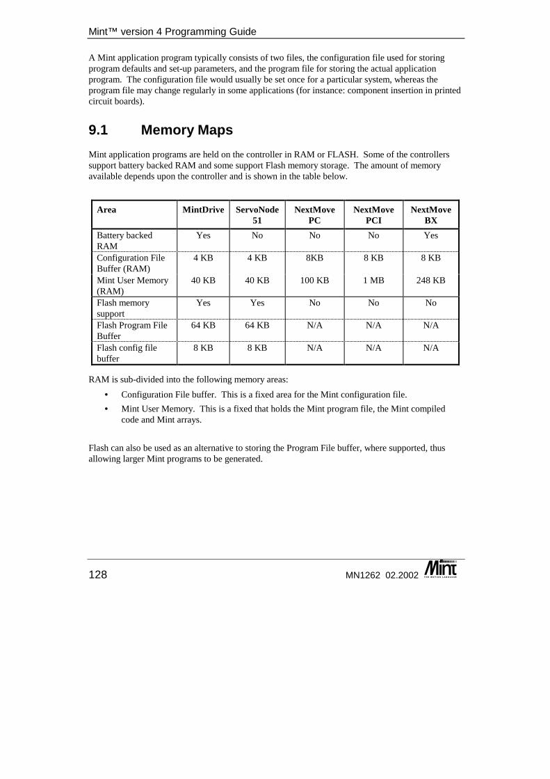
Mint™ version 4 Programming Guide
128 MN1262 02.2002
A Mint application program typically consists of two files, the configuration file used for storing program defaults and set-up parameters, and the program file for storing the actual application program. The configuration file would usually be set once for a particular system, whereas the program file may change regularly in some applications (for instance: component insertion in printed circuit boards).
9.1 Memory Maps Mint application programs are held on the controller in RAM or FLASH. Some of the controllers support battery backed RAM and some support Flash memory storage. The amount of memory available depends upon the controller and is shown in the table below.
Area MintDrive ServoNode 51
NextMove PC
NextMove PCI
NextMove BX
Battery backed RAM
Yes No No No Yes
Configuration File Buffer (RAM)
4 KB 4 KB 8KB 8 KB 8 KB
Mint User Memory (RAM)
40 KB 40 KB 100 KB 1 MB 248 KB
Flash memory support
Yes Yes No No No
Flash Program File Buffer
64 KB 64 KB N/A N/A N/A
Flash config file buffer
8 KB 8 KB N/A N/A N/A
RAM is sub-divided into the following memory areas: • Configuration File buffer. This is a fixed area for the Mint configuration file. • Mint User Memory. This is a fixed that holds the Mint program file, the Mint compiled
code and Mint arrays. Flash can also be used as an alternative to storing the Program File buffer, where supported, thus allowing larger Mint programs to be generated.

Program Buffers
MN1262 02.2002 129
The following sections show more detailed memory maps. In all cases, note the area of memory labeled compiled code. Mint programs are not interpreted in the true sense of the word but are compiled into an intermediate code for faster execution. When a program is first executed by the RUN command the source code is first compiled then executed. Depending upon the length of the application, this can take a couple of seconds. The compiled code is placed in the Mint User Memory area and in most cases is about 50% the size of the program code. The FREE keyword can be used to determine the amount of available free memory. If memory is a problem, the program code can be squashed using the SQUASH utility provided found in the Mint WorkBench.
9.1.1 MintDrive and ServoNode 51 Memory Map The user may switch between using battery backed-up RAM and Flash to store the Program Buffer file using the keyword BUFFERSTORE. When the BUFFERSTORE keyword is set for using battery backed-up RAM, the Memory Map is as indicated in the diagram below:
Figure 30: Memory Map when using RAM with FLASH Support
The maximum size of a Mint Program file will depend upon the amount of array data declared and the size of the compiled (tokenized) code. Although Flash isn’t being used in this configuration, a Mint Program file may still be resident in Flash.
Free Flash Program Memory
(not in use)
Flash Program File (not in use) Configuration File
Compiled Code
Free Memory
Array Data
Mint U
ser Mem
ory Program File
Free Flash Config Memory
(not in use)
Flash Config File
(not in use)
Application Firmware
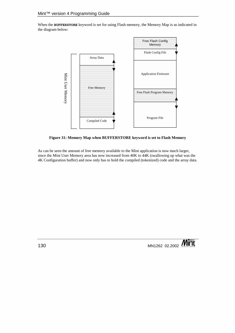
Mint™ version 4 Programming Guide
130 MN1262 02.2002
When the BUFFERSTORE keyword is set for using Flash memory, the Memory Map is as indicated in the diagram below:
Figure 31: Memory Map when BUFFERSTORE keyword is set to Flash Memory
As can be seen the amount of free memory available to the Mint application is now much larger, since the Mint User Memory area has now increased from 40K to 44K (swallowing up what was the 4K Configuration buffer) and now only has to hold the compiled (tokenized) code and the array data.
Free Flash Program Memory
Program File Compiled Code
Free Memory
Array Data
Mint U
ser Mem
ory
Free Flash Config Memory
Flash Config File
Application Firmware

Program Buffers
MN1262 02.2002 131
9.1.2 NextMove Memory Map
Figure 32: NextMove PC/PCI Memory Map
The maximum size of a Mint Program file will depend upon the amount of array data declared and the size of the compiled (tokenized) code
9.2 Using the Buffers To switch between the program and configuration buffers, the CON and PROG keywords are used. CON is used to switch to the configuration buffer. The Mint prompt will change to Cxxx> where xxx is the current controller NODE number. PROG is used to switch to the program buffer. The Mint prompt will change to Pxxx> where xxx is the current controller NODE number. The Program and Configuration files are normally generated off-line (using the Mint WorkBench editor) and downloaded to the controller. Alternatively, these files can be generated using the on-board command line editor, except when using Flash memory (where supported).
Mint U
ser Mem
ory
Configuration File
Compiled Code
Free Memory
Array Data
Program File
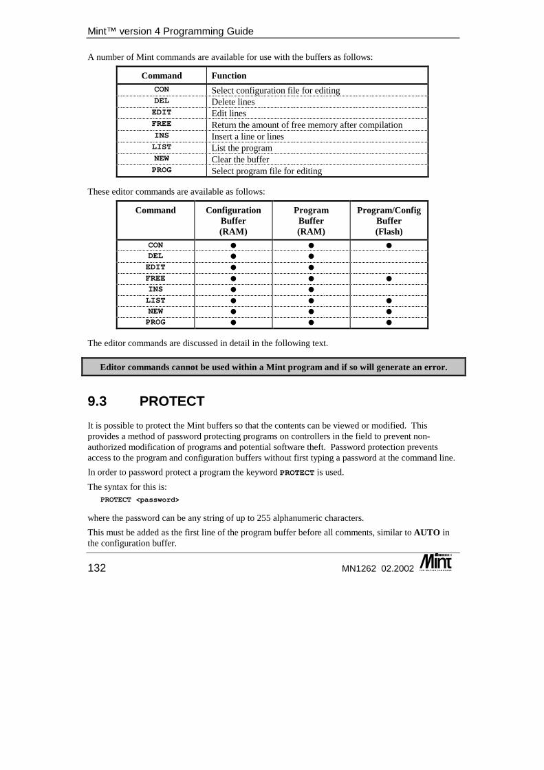
Mint™ version 4 Programming Guide
132 MN1262 02.2002
A number of Mint commands are available for use with the buffers as follows:
Command Function CON Select configuration file for editing DEL Delete lines EDIT Edit lines FREE Return the amount of free memory after compilation INS Insert a line or lines LIST List the program NEW Clear the buffer PROG Select program file for editing
These editor commands are available as follows:
Command Configuration Buffer (RAM)
Program Buffer (RAM)
Program/Config Buffer (Flash)
CON � � � DEL � � EDIT � � FREE � � � INS � � LIST � � � NEW � � � PROG � � �
The editor commands are discussed in detail in the following text.
Editor commands cannot be used within a Mint program and if so will generate an error.
9.3 PROTECT It is possible to protect the Mint buffers so that the contents can be viewed or modified. This provides a method of password protecting programs on controllers in the field to prevent non-authorized modification of programs and potential software theft. Password protection prevents access to the program and configuration buffers without first typing a password at the command line. In order to password protect a program the keyword PROTECT is used. The syntax for this is:
PROTECT <password>
where the password can be any string of up to 255 alphanumeric characters. This must be added as the first line of the program buffer before all comments, similar to AUTO in the configuration buffer.
Program Buffers
MN1262 02.2002 133
Example Mint Program: REMREM Simple Mint ProgramREMDIM a?"Hello"LOOP?"Press a key...",a = 0WHILE a = 0a = INKEY
ENDW?"You pressed ASCII code : ",a
ENDLEND
To add a password of ‘cokecan’ to the above program the line: PROTECT cokecan
must be inserted as line 1, for example: PROTECT cokecanREMREM Simple Mint ProgramREMDIM a?"Hello"LOOP?"Press a key...",a = 0WHILE a = 0a = INKEY
ENDW?"You pressed ASCII code : ",a
ENDLEND
As password protection controls access to the program and configuration buffers, keywords that access these will prompt for a password before continuing. For Example, typing LIST for a protected program will produce:
P002>LISTPassword ?
Typing an incorrect password will give the message: Password incorrect
and the controller will not execute the command. Once the password has been entered correctly once, the user will not be prompted again until the controller is reset or password checking is re-enabled. The following table shows which editor commands are affected by PROTECT.
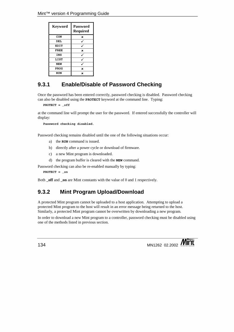
Mint™ version 4 Programming Guide
134 MN1262 02.2002
Keyword Password Required
CON � DEL � EDIT � FREE � INS � LIST � NEW � PROG � RUN �
9.3.1 Enable/Disable of Password Checking Once the password has been entered correctly, password checking is disabled. Password checking can also be disabled using the PROTECT keyword at the command line. Typing:
PROTECT = _off
at the command line will prompt the user for the password. If entered successfully the controller will display:
Password checking disabled.
Password checking remains disabled until the one of the following situations occur:
a) the RUN command is issued. b) directly after a power cycle or download of firmware. c) a new Mint program is downloaded. d) the program buffer is cleared with the NEW command.
Password checking can also be re-enabled manually by typing: PROTECT = _on
Both _off and _on are Mint constants with the value of 0 and 1 respectively.
9.3.2 Mint Program Upload/Download A protected Mint program cannot be uploaded to a host application. Attempting to upload a protected Mint program to the host will result in an error message being returned to the host. Similarly, a protected Mint program cannot be overwritten by downloading a new program. In order to download a new Mint program to a controller, password checking must be disabled using one of the methods listed in previous section.

Program Buffers
MN1262 02.2002 135
Editor Commands
CON Purpose: Select the configuration file for editing.
Format: CON
Selects the configuration file for editing. The number of bytes used by the configuration file will be displayed:
CONFIGURATION BUFFER:Storage Area: RAMSource: 248 bytes, 21 linesBytes Free: 3847
The number of variables defined is displayed as well as the number of array elements. The command line prompt will change to 'Cxxx>' where xxx refers to the controller node number.
See also: FREE, NEW, PROG
DEL Purpose: Delete a line or block of lines from the buffer
Format: DEL <line number> {, <line number>}
Deletes a single line, or a block of lines between two line numbers, from the source code. Once a line is deleted, it cannot be recovered.
Example: DEL 10,20
delete lines 10 to 20 inclusive.
See also: EDIT, INS, NEW
EDIT Format:
EDIT {<line number>}
Mint™ version 4 Programming Guide
136 MN1262 02.2002
If no line number is specified, the EDIT keyword appends lines of text to the end of the program. The prompt will change to the line number and '>' character. To terminate editing, press Return on a blank line. If a line number is specified, the line to be edited will be displayed. For instance, to edit line 4 of a program, type:
EDIT 4
The line editor allows you to edit lines using the cursor keys in the terminal. The cursor keys are used to move the cursor left and right over the line. The text can be overwritten or blank spaces inserted into the line using the Ins key. The Backspace key will delete characters to the left of the cursor. All characters to the right of the cursor are moved left one character space. The Home key will move the cursor to the beginning of the line and the End key will move the cursor to the end of the line. Once you have finished editing a line, press Return to get back to the command prompt.
See also: DEL, INS
FREE Format:
FREE
Displays the amount of free memory available after program compilation and array data has been assigned. Typing PROG at the command line displays the amount of free memory available for source code without taking into account the length of the compiled code. Depending on the size of the source code, FREE may take a couple of seconds to execute.
Example: P>progPROGRAM BUFFER:Storage Area: RAMArrays: 0 bytes, 0 elementsSource: 17 bytes, 2 linesBytes Free: 40942
P>free40892 Bytes of free memory space after compilation
If the compiled code does not fit into the available memory, FREE will return an Out of memory error.
Using FREE may destroy array data held in memory if there is insufficient memory space. Existing array data will be destroyed prior to execution of the FREE command.
Program Buffers
MN1262 02.2002 137
INS Format:
INS <line number>
A line is inserted above the line number specified and the line numbers are adjusted accordingly. For example:
INS 4
will insert the new line between lines 3 and 4. Further lines will be inserted as long as you continue to type. To terminate editing press Return on an empty line.
See also: DEL, EDIT
LIST Format:
LIST {<line number> {,<line number>}}
Lists a single line, or a block of lines between two line numbers. By entering LIST with no parameters, the entire program will be listed to the screen, this can be aborted by Ctrl-E.
Example: LIST 10,30
will list program lines 10 to 30 inclusive.
NEW Format:
NEW
Clears the source code from the current buffer. Once NEW has been entered, the source code cannot be retrieved.
See also: CON, PROG
PROG Format:
PROG
Selects the program file for editing. The number of bytes used by the program file will be displayed: PROGRAM BUFFER:Storage Area: RAMArrays: 0 bytes, 0 elements
Mint™ version 4 Programming Guide
138 MN1262 02.2002
Source: 17 bytes, 2 linesBytes Free: 40942
The number of variables defined is displayed as well as the number of array elements. The command line prompt will change to 'Pxxx>' where xxx refers to the controller node number.
See also: CON, FREE, NEW
RELEASE Format:
RELEASE
To clear all user variables and arrays from memory . All currently defined variables and arrays are released from memory.
See also: NEW, VIEW
Keyword Reference Guide
MN1262 02.2002 139
10. Keyword Reference Guide
10 This chapter presents, in alphabetical order, descriptions for all Mint keywords. Descriptions are broken down into:
◊ Purpose ◊ Format ◊ Syntax

Mint™ version 4 Programming Guide
140 MN1262 02.2002
10.1 Mint Keyword Syntax The following syntactical rules are applied throughout the following keyword definitions:-
Case Words in capital letters are keywords (for example FOLERRORFATAL) and must be entered as shown, except that they can be entered in any combination of upper and lower case. For example:
folerrorfatal = 10FolErrorFatal = 20FOLERRORFATAL = 30
Angled Brackets You are asked to supply any items shown in lower case letters between angled brackets. Where the term <expression> or <condition> is used, this refers to a variable, constant or other valid numeric expression. For example:
a * b / caPOS < 100
Curly Brackets Items in curly brackets { } are optional. For the example above:
FOLERRORFATAL[axis] = <expression> {,<expression> ...}
Continuation Dots The dots "..." signify that more expressions or statements can follow.
10.2 Mint Keyword Definitions Each keyword is defined using the structure described below. Where sections are not applicable to a particular keyword they may be omitted.
The ���� symbol denotes that this keyword has changed in its implementation in Mint v4. For details see the Mint v4 Code Analyzer Tool Guide.
Purpose The ‘Purpose’ section briefly summarizes the function of the keyword.
Controllers Supported The ‘Controllers Supported’ list indicates which Controllers support the keyword.
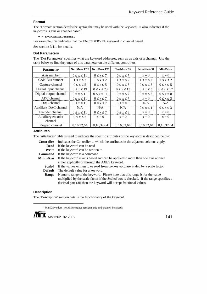
Keyword Reference Guide
MN1262 02.2002 141
Format The ‘Format’ section details the syntax that may be used with the keyword. It also indicates if the keywords is axis or channel based7.
v = ENCODERVEL.channel
For example, this indicates that the ENCODERVEL keyword in channel based. See section 3.1.1 for details.
Dot Parameters The ‘Dot Parameters’ specifies what the keyword addresses, such as an axis or a channel. Use the table below to find the range of this parameter on the different controllers.
Parameter NextMove PCI NextMove PC NextMove BX ServoNode 51 MintDrive
Axis number 0 ≤ x ≤ 11 0 ≤ x ≤ 7 0 ≤ x ≤ 7 x = 0 x = 0 CAN Bus number 1 ≤ x ≤ 2 1 ≤ x ≤ 2 1 ≤ x ≤ 2 1 ≤ x ≤ 2 1 ≤ x ≤ 2 Capture channel 0 ≤ x ≤ 5 0 ≤ x ≤ 5 0 ≤ x ≤ 5 0 ≤ x ≤ 5 0 ≤ x ≤ 5
Digital input channel 0 ≤ x ≤ 19 0 ≤ x ≤ 23 0 ≤ x ≤ 15 0 ≤ x ≤ 5 0 ≤ x ≤ 17 Digital output channel 0 ≤ x ≤ 11 0 ≤ x ≤ 11 0 ≤ x ≤ 7 0 ≤ x ≤ 2 0 ≤ x ≤ 8
ADC channel 0 ≤ x ≤ 11 0 ≤ x ≤ 7 0 ≤ x ≤ 7 x = 0 0 ≤ x ≤ 3 DAC channel 0 ≤ x ≤ 11 0 ≤ x ≤ 7 0 ≤ x ≤ 3 N/A N/A
Auxiliary DAC channel N/A N/A N/A 0 ≤ x ≤ 1 0 ≤ x ≤ 3 Encoder channel 0 ≤ x ≤ 11 0 ≤ x ≤ 7 0 ≤ x ≤ 3 x = 0 x = 0
Auxiliary encoder channel
0 ≤ x ≤ 2 x = 0 x = 0 x = 0 x = 0
Keypad channel 8,16,32,64 8,16,32,64 8,16,32,64 8,16,32,64 8,16,32,64
Attributes The ‘Attributes’ table is used to indicate the specific attributes of the keyword as described below:
Controller Indicates the Controller to which the attributes in the adjacent columns apply. Read If the keyword can be read
Write If the keyword can be written to Command If the keyword is a command Multi-Axis If the keyword is axis based and can be applied to more than one axis at once
either explicitly or through the AXES keyword. Scaled If the values written to or read from the keyword are scaled by a scale factor
Default The default value for a keyword Range Numeric range of the keyword. Please note that this range is for the value
multiplied by the scale factor if the Scaled box is checked. If the range specifies a decimal part (.0) then the keyword will accept fractional values.
Description The ‘Description’ section details the functionality of the keyword.
7 MintDrive does not differentiate between axis and channel keywords.
Mint™ version 4 Programming Guide
142 MN1262 02.2002
Example The ‘Examples’ section is used to provide one or more examples of the keyword use.
Restrictions The ‘Restrictions’ section details any restrictions that are placed on the keyword - for instance modes under which it can be used.
Controller Specifics The ‘Controller Specifics’ section lists any differences that are specific to a particular controller, that are not indicated in the attributes table.
See Also The ‘See Also’ section lists keywords that are related, alternatives to or can be used for related set-up purposes.
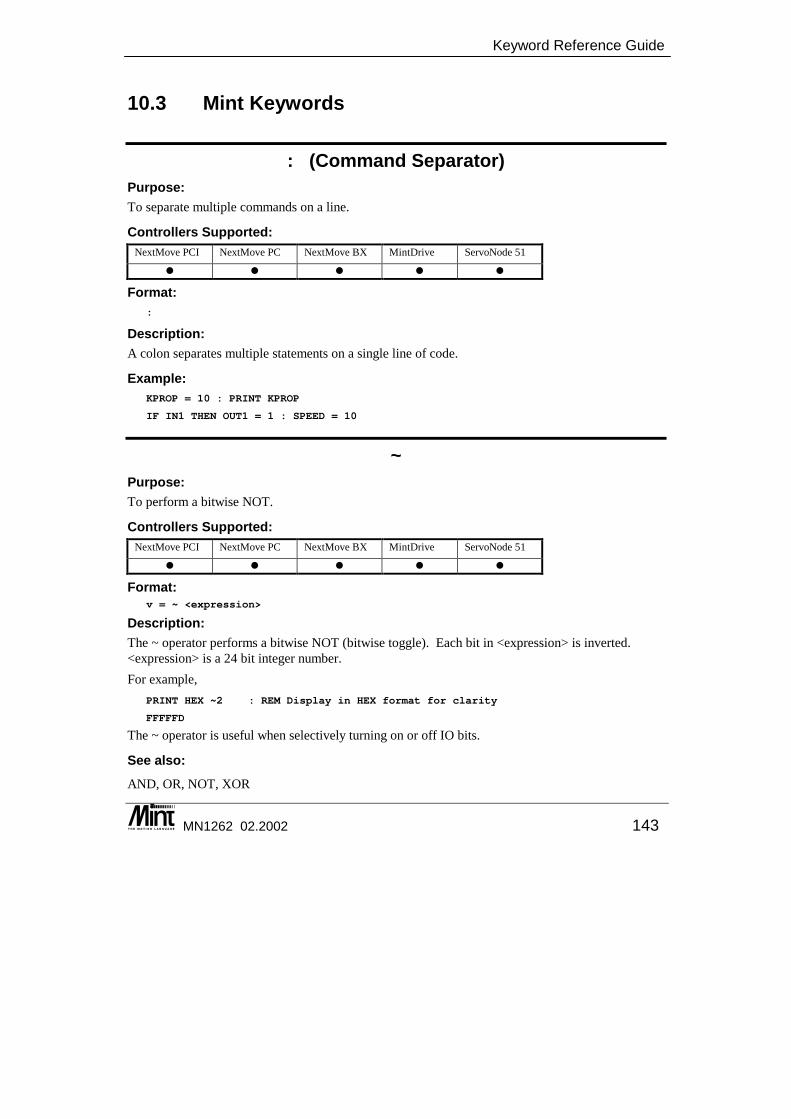
Keyword Reference Guide
MN1262 02.2002 143
10.3 Mint Keywords
: (Command Separator) Purpose: To separate multiple commands on a line.
Controllers Supported: NextMove PCI NextMove PC NextMove BX MintDrive ServoNode 51
� � � � �
Format: :
Description: A colon separates multiple statements on a single line of code.
Example: KPROP = 10 : PRINT KPROP
IF IN1 THEN OUT1 = 1 : SPEED = 10
~ Purpose: To perform a bitwise NOT.
Controllers Supported: NextMove PCI NextMove PC NextMove BX MintDrive ServoNode 51
� � � � �
Format: v = ~ <expression>
Description: The ~ operator performs a bitwise NOT (bitwise toggle). Each bit in <expression> is inverted. <expression> is a 24 bit integer number. For example,
PRINT HEX ~2 : REM Display in HEX format for clarity
FFFFFD
The ~ operator is useful when selectively turning on or off IO bits.
See also: AND, OR, NOT, XOR
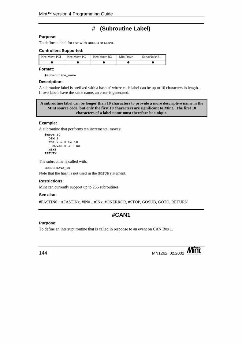
Mint™ version 4 Programming Guide
144 MN1262 02.2002
# (Subroutine Label) Purpose: To define a label for use with GOSUB or GOTO.
Controllers Supported: NextMove PCI NextMove PC NextMove BX MintDrive ServoNode 51
� � � � �
Format: #subroutine_name
Description: A subroutine label is prefixed with a hash '#' where each label can be up to 10 characters in length. If two labels have the same name, an error is generated.
A subroutine label can be longer than 10 characters to provide a more descriptive name in the Mint source code, but only the first 10 characters are significant to Mint. The first 10
characters of a label name must therefore be unique.
Example: A subroutine that performs ten incremental moves:
#move_10DIM iFOR i = 0 to 10MOVER = 1 : GO
NEXTRETURN
The subroutine is called with: GOSUB move_10
Note that the hash is not used in the GOSUB statement.
Restrictions: Mint can currently support up to 255 subroutines.
See also: #FASTIN0 .. #FASTINx, #IN0 .. #INx, #ONERROR, #STOP, GOSUB, GOTO, RETURN
#CAN1 Purpose: To define an interrupt routine that is called in response to an event on CAN Bus 1.
Keyword Reference Guide
MN1262 02.2002 145
Controllers Supported: NextMove PCI NextMove PC NextMove BX MintDrive ServoNode 51
� � � � �
Format: #CAN1...RETURN
Description: Whenever a new CANEVENT occurs on CAN bus 1, the Mint interrupt routine #CAN1 will be called. For more details on event handling see section 8. Full details on CAN can be found in the Mint v4 CAN Programming Guide.
See also: #CAN2
#CAN2 Purpose: To define an interrupt routine that is called in response to an event on CAN Bus 2.
Controllers Supported: NextMove PCI NextMove PC NextMove BX MintDrive ServoNode 51
� � � � �
Format: #CAN2...RETURN
Description: Whenever a new CANEVENT occurs on Can bus 2, the Mint interrupt routine #CAN2 will be called. For more details on event handling see section 8. Full details can be found in the Mint v4 CAN Programming Guide.
See also: #CAN1
#COMMS1 .. #COMMS5 Purpose: To define an interrupt routine that is called in response to a change in the value of the corresponding comms array element.
Mint™ version 4 Programming Guide
146 MN1262 02.2002
Controllers Supported: NextMove PCI NextMove PC NextMove BX MintDrive ServoNode 51
� � � � �
Format: #COMMS1...RETURN
Description: The first five elements of the comms array can have a Mint subroutine defined that will be called whenever the value of the element is updated. For more details on event handling see section 8. #COMMS will be called when an external source modifies a comms value such as from the host or via CANopen comms. Changing a comms value from a Mint program will not cause a comms event.
Example: DIM command = -1DIM newspeed = 10000LOOPIF command = 0 THEN ENDIF command = 1 THEN SPEED = newspeed....
ENDLEND
#COMMS1command = COMMS(1)
RETURN#COMMS2newspeed = COMMS(2)
RETURN
See also: COMMS, COMMSMODE
#FASTIN0 .. #FASTINx, #FASTIN Purpose: To define an interrupt routine that is called in response to a fast interrupt (position capture).
Controllers Supported: NextMove PCI NextMove PC NextMove BX MintDrive ServoNode 51
� � � � �
Format: #FASTINx...RETURN
Keyword Reference Guide
MN1262 02.2002 147
Description: Defines an interrupt routine that is called in response to a fast interrupt input. For more details on event handling see section 8. NextMove PC and NextMove BX all have dedicated fast position latch inputs. MintDrive, ServoNode 51 and NextMove PCI have configurable fast position latch inputs. See the Mint v4 Advanced Programming Guide for details. #FASTIN0, #FASTIN1, #FASTIN2 and #FASTIN3 are called in response to various inputs as detailed below. The interrupts will be called in response to the corresponding digital inputs:
Event Handler
MintDrive ServoNode 51
NextMove PC NextMove BX NextMove PCI
#FASTIN0 0 0 Dedicated input
Dedicated input 0 0
#FASTIN1 N/A N/A N/A Dedicated input 1 1 #FASTIN2 2 2 N/A Dedicated input 2 2 #FASTIN3 N/A N/A N/A Dedicated input 3 3
Example: DIM storedValue
#FASTIN0DIM correction
REM Calculate a correction valuecorrection = storedValue - FASTPOS.2REM Perform an offset to correct axis positionREM Only one offset can be performed at a time so ensure one is not activeREM by reading the mode keyword.PAUSE !(AXISMODE.2 & _mdOFFSET)OFFSET.2 = correctionGO.2
RETURN
See also: #IN0 .. #INx, #STOP, EVENTDISABLE, EVENTDISABLE, FASTPOS, RETURN
#FASTPOS0 .. #FASTPOSx This keyword has been replaced by #FASTINx in Mint v4. For details on converting existing Mint programs to Mint v4 see the Mint v4 Code Analyzer Tool Guide.
Mint™ version 4 Programming Guide
148 MN1262 02.2002
#IN0 .. #INx Purpose: To define an interrupt routine on a digital input.
Controllers Supported: NextMove PCI NextMove PC NextMove BX MintDrive ServoNode 51
� � � � �
Format: #INx..RETURN
Description: Defines an interrupt routine on a digital input (IN0 to INx). If the input is configured as level triggered, the interrupt routine will be called while the input is active. If the input is configured as edge triggered, the interrupt routine will be called on the active edges. For more details on event handling see section 8. Example:
INPUTMODE = 1 : REM Make input 0 edge triggeredINPUTPOSTRIGGER = 1 : REM Input 0 will trigger on a positive edge
#IN0STOP.0PAUSE IDLE.0
RETURN
will stop any motion on axis 0 if a positive edge, inactive to active transition, is seen on input 0.
Controller Specifics: • There are 24 digital inputs on NextMove PC. #IN0 .. #IN23 can be defined. • There are 20 digital inputs on NextMove PCI8. #IN0 .. #IN19 can be defined. • There are 16 digital inputs on NextMove BX. #IN0 .. #IN15 can be defined. • There are 18 digital inputs on MintDrive. #IN0 .. #IN17 can be defined. • There are 6 digital inputs on ServoNode 51. #IN0 .. #IN5 can be defined.
See also: #FASTIN0 .. #FASTINx, #STOP, INPUTACTIVELEVEL, INPUTMODE, INPUTNEGTRIGGER, INPUTPOSTRIGGER, IN, IN0..INx, RETURN
8 If a NextMove PCI Expansion card is present, the range increases to 39. With two Expansion cards, the range increases to 59.
Keyword Reference Guide
MN1262 02.2002 149
#ONERROR Purpose: To define the user supplied error handler.
Controllers Supported: NextMove PCI NextMove PC NextMove BX MintDrive ServoNode 51
� � � � �
Format: #ONERROR..RETURN
Description: In the event of any type of error on the controller, the user error handler will be called if it is defined in the program. Mint looks for a subroutine called #ONERROR (note the use of the # as in a normal subroutine). For more details on event handling see section 8.
See also: ERL, ERR, ERRAXIS, AXISERROR, RETURN
#STOP Purpose: To define a STOP subroutine that is called in response to a stop input.
Controllers Supported: NextMove PCI NextMove PC NextMove BX MintDrive ServoNode 51
� � � � �
Format: #STOP..RETURN
Description: Each axis can have a stop input assigned to it. When a stop input becomes active, Mint looks for a subroutine called #STOP (note the use of the # as in a normal subroutine). If such a subroutine exists, Mint executes it. The stop routine can be used to halt program execution and handle the stop condition. Only one stop input handler can be defined to handle all axes stop conditions.
Mint™ version 4 Programming Guide
150 MN1262 02.2002
To have individual stop input handlers for an axis, each axis must have a unique stop input assigned to it and that input must have an interrupt routine defined for it i.e. #STOP isn’t defined, but instead replaced by a #IN0 .. #INx subroutine for each input defined as a stop input. For more details on event handling see section 8.
Example: STOPINPUT[0,1] = 10,10STOPINPUTMODE[0,1] = 1,1
#STOPPAUSE !STOPSWITCH : REM Wait for stop input
RETURN : REM Resume execution
Should the STOP subroutine terminate before the stop input is de-activated, the STOP subroutine will not be called until another input is seen.
See also: #FASTIN0 .. #FASTINx, #IN0 .. #INx, INPUTACTIVELEVEL, INPUTMODE, INPUTNEGTRIGGER, INPUTPOSTRIGGER, RETURN, STOPINPUT, STOPINPUTMODE, STOPSWITCH
#TIMER Purpose: To define a time based event.
Controllers Supported: NextMove PCI NextMove PC NextMove BX MintDrive ServoNode 51
� � � � �
Format: #TIMER..
RETURN
Description: A timer event can be attached to Mint by use of the #TIMER subroutine. For example:
#TIMERIF IN1 THEN OUT2 = 1IF IN3 THEN OUT3 = 1 : OUT5 = 1IF IN4 THEN OUT2 = 0 : OUT3 = 0 : OUT5 = 0
RETURN
#TIMER is called every TIMEREVENT. TIMEREVENT has a resolution of 1ms from a minimum of 10ms up to a maximum value of 8 million. For more details on event handling see section 8.
If the execution of the #TIMER event takes longer than the rate set by TIMEREVENT, the foreground Mint task will be locked out.
Keyword Reference Guide
MN1262 02.2002 151
See Also: #IN0 .. #INx, TIME, TIMEREVENT
ABORT/AB Purpose: To abort motion on all axes.
Controllers Supported: NextMove PCI NextMove PC NextMove BX MintDrive ServoNode 51
� � � � �
Format: ABORT
Dot Parameters: None.
Attributes: Controller Read Write Command Multi-Axis Scaled Default Range
All � �
Description: The ABORT keyword causes the ‘software abort’ motion error to be generated. ABORT does not accept an axis parameter since it causes automatic shut-down on all axes. The drive enable outputs are deactivated. A software abort motion error condition is generated. The AXISERROR keyword will show an ABORT error in bit 0 and the ERR keyword will show a ‘Motion Error’. The #ONERROR routine will be called if it is defined according to the mode set with the ABORTMODE keyword. The error may be cleared with CANCEL or RESET. The AXISSTATUS keyword will show bit 0 as set until the error is cleared. ABORT is useful at the command line as it immediately disables all drives. The ABORT command should be avoided in the #ONERROR routine, as the ABORT itself will generate a motion error and cause a subsequent call to the #ONERROR routine again.
Example: #COMMS1REM The comms array is used to pass new commands to the controller.REM A command of zero instructs the controller to abort all motion.REM Other commands are picked up from within the main loop.IF COMMS(1) <> 0 THEN RETURNPRINT “Host has broadcast the ABORT command”ABORTEND
RETURN
In the event of a change to comms location 1 the #COMMS1 sub routine will be called. This sub routine will generate an ABORT error if the value in comms location 1 is zero.
Mint™ version 4 Programming Guide
152 MN1262 02.2002
Restrictions: ABORT will not stop motion controlled open-loop via the DAC keyword.
See also: AXISSTATUS, CANCEL, RELAY, ERR, AXISERROR, RESET, STOP
ABORTMODE/ABM This is an advanced Mint feature. Full details can be found in the Mint v4 Advanced Programming Guide.
ABS Purpose: To return the absolute value of an expression.
Controllers Supported: NextMove PCI NextMove PC NextMove BX MintDrive ServoNode 51
� � � � �
Format: v = ABS (<expression>)
Description: Calculates the absolute value of the expression.
Example: PRINT ABS (7 * -5)
will print 35 to the operator terminal. Some keywords such as FOLERROR and VEL return a signed number. To check that the velocity is greater than a certain value regardless of motor direction the following would be used:
IF ABS(VEL) > 20 THEN OUT4 = 1
this will set output bit 4 if the velocity is greater than 20 or less than -20.
See also: INT
ACCEL/AC Purpose: To define the acceleration rate of an axis.
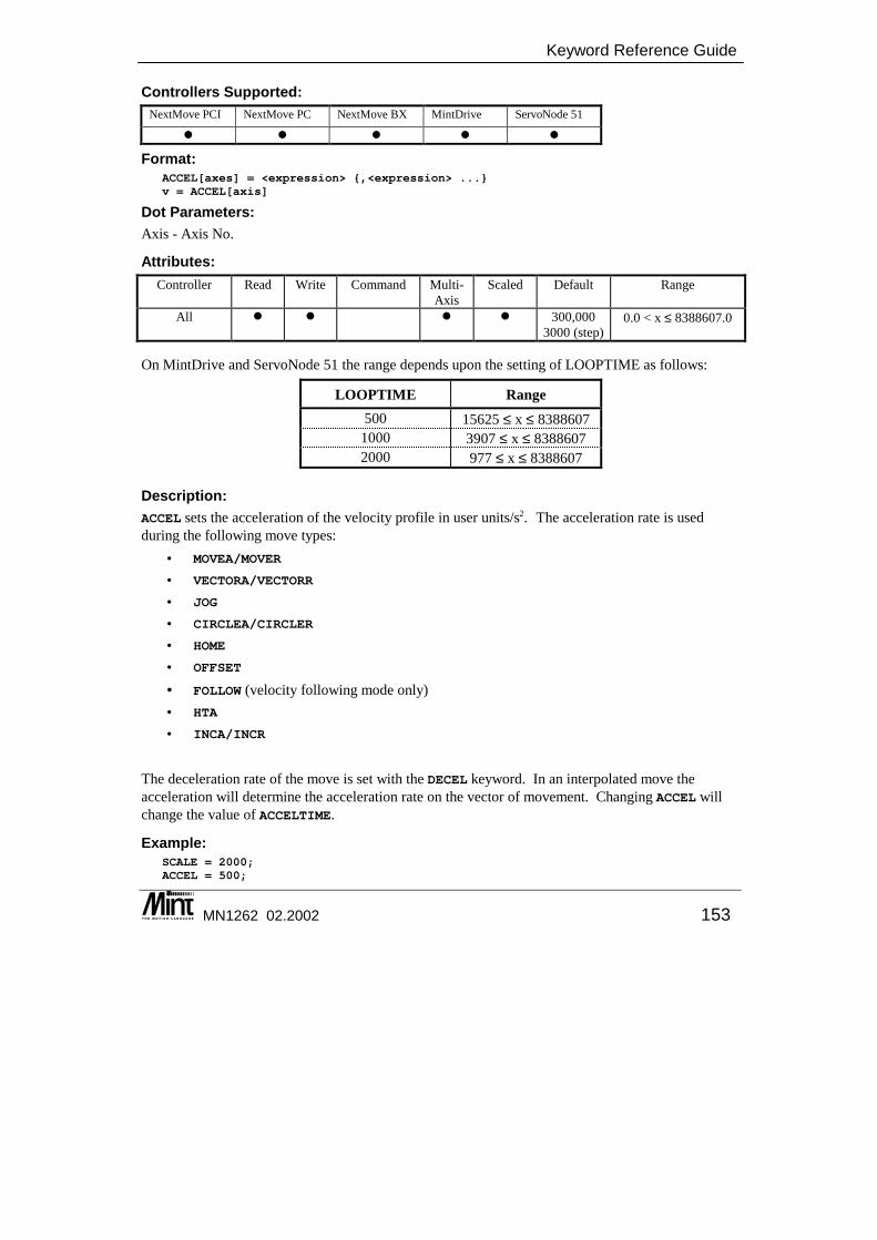
Keyword Reference Guide
MN1262 02.2002 153
Controllers Supported: NextMove PCI NextMove PC NextMove BX MintDrive ServoNode 51
� � � � �
Format: ACCEL[axes] = <expression> {,<expression> ...}v = ACCEL[axis]
Dot Parameters: Axis - Axis No.
Attributes: Controller Read Write Command Multi-
Axis Scaled Default Range
All � � � � 300,000 3000 (step)
0.0 < x ≤ 8388607.0
On MintDrive and ServoNode 51 the range depends upon the setting of LOOPTIME as follows:
LOOPTIME Range 500 15625 ≤ x ≤ 8388607
1000 3907 ≤ x ≤ 8388607 2000 977 ≤ x ≤ 8388607
Description: ACCEL sets the acceleration of the velocity profile in user units/s2. The acceleration rate is used during the following move types:
• MOVEA/MOVER
• VECTORA/VECTORR
• JOG
• CIRCLEA/CIRCLER
• HOME
• OFFSET
• FOLLOW (velocity following mode only) • HTA
• INCA/INCR
The deceleration rate of the move is set with the DECEL keyword. In an interpolated move the acceleration will determine the acceleration rate on the vector of movement. Changing ACCEL will change the value of ACCELTIME.
Example: SCALE = 2000;ACCEL = 500;

Mint™ version 4 Programming Guide
154 MN1262 02.2002
will set the acceleration rate, for the default axes, to 500 * 2000 counts / sec2.
See also: ACCELTIME, CIRCLEA, CIRCLER, DECEL, FOLLOW, HOLDTOANALOG, HOME, INCA, INCR, JOG, MOVEA, MOVER, OFFSET, SRAMP, SCALE, SPEED, VECTORA, VECTORR
ACCELTIME/ACT Purpose: To define the acceleration rate of an axis.
Controllers Supported: NextMove PCI NextMove PC NextMove BX MintDrive ServoNode 51
� � � � �
Format: ACCELTIME[axes] = <expression> {,<expression> ...}v = ACCELTIME[axis]
Dot Parameters: Axis - Axis No.
Attributes: Controller Read Write Command Multi-
Axis Scaled Default Range
All � � � 1 ≤ x ≤ 8388607
Description: ACCELTIME is specified in milli-seconds. ACCELTIME is used as an alternative method of setting the acceleration rate of the velocity profile. ACCELTIME is the time required to reach the profiler SPEED from zero. The acceleration, as defined by ACCELTIME, is based on the current SPEED when ACCELTIME was set. Therefore, if the SPEED is changed, the actual acceleration will remain unchanged. Changing ACCELTIME will change the value of ACCEL.
Example: SCALE = 4000SPEED = 5ACCELTIME = 5000
will set the acceleration rate, for the default axis, to reach a speed of 20000 counts / sec in 5000 mSecs (i.e. ACCEL = 1000 user counts / sec2).

Keyword Reference Guide
MN1262 02.2002 155
CAUTION: ACCELTIME can be used to set an internal acceleration rate that is higher than the range of values supported by the ACCEL keyword. If such an acceleration is set-up using
ACCELTIME, reading ACCEL will give a meaningless value.
See also: ACCEL, DECELTIME
ACOS Purpose: To return the arc cosine of an expression.
Controllers Supported: NextMove PCI NextMove PC NextMove BX MintDrive ServoNode 51
� � � � �
Format: angle = ACOS (<value>)
Description: Return the arc cosine of the value, where the <value> is in the range of -1 to 1 and can be any valid Mint expression. The return value will be in the range of 0 to 90º.
Example: PRINT ACOS (10 / 45)
will print 77.1604 to the operator terminal.
See also: ASIN, ATAN, COS, SIN, TAN
ACTIVERS485NODE Purpose Enables the transmitter of a controllers RS485 port.
Controllers Supported NextMove PCI NextMove PC NextMove BX MintDrive ServoNode 51
� �
Format ACTIVERS485NODE = <node number>
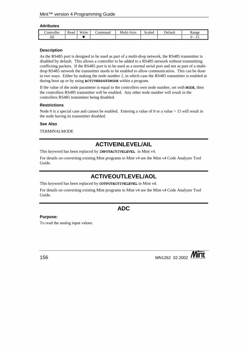
Mint™ version 4 Programming Guide
156 MN1262 02.2002
Attributes Controller Read Write Command Multi-Axis Scaled Default Range
All � 0 - 15
Description As the RS485 port is designed to be used as part of a multi-drop network, the RS485 transmitter is disabled by default. This allows a controller to be added to a RS485 network without transmitting conflicting packets. If the RS485 port is to be used as a normal serial port and not as part of a multi-drop RS485 network the transmitter needs to be enabled to allow communication. This can be done in two ways. Either by making the node number 1, in which case the RS485 transmitter is enabled at during boot up or by using ACTIVERS485NODE within a program. If the value of the node parameter is equal to the controllers own node number, set with NODE, then the controllers RS485 transmitter will be enabled. Any other node number will result in the controllers RS485 transmitter being disabled.
Restrictions Node 0 is a special case and cannot be enabled. Entering a value of 0 or a value > 15 will result in the node having its transmitter disabled.
See Also TERMINALMODE
ACTIVEINLEVEL/AIL This keyword has been replaced by INPUTACTIVELEVEL in Mint v4. For details on converting existing Mint programs to Mint v4 see the Mint v4 Code Analyzer Tool Guide.
ACTIVEOUTLEVEL/AOL This keyword has been replaced by OUTPUTACTIVELEVEL in Mint v4. For details on converting existing Mint programs to Mint v4 see the Mint v4 Code Analyzer Tool Guide.
ADC Purpose: To read the analog input values.
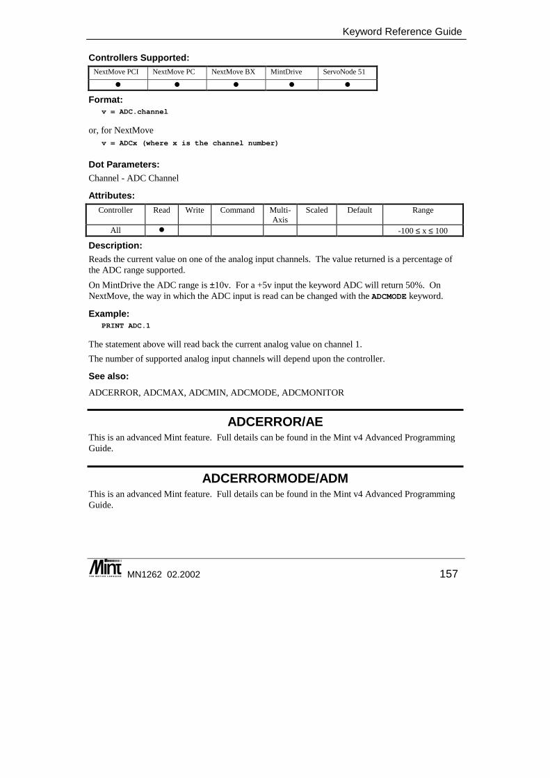
Keyword Reference Guide
MN1262 02.2002 157
Controllers Supported: NextMove PCI NextMove PC NextMove BX MintDrive ServoNode 51
� � � � �
Format: v = ADC.channel
or, for NextMove v = ADCx (where x is the channel number)
Dot Parameters: Channel - ADC Channel
Attributes: Controller Read Write Command Multi-
Axis Scaled Default Range
All � -100 ≤ x ≤ 100
Description: Reads the current value on one of the analog input channels. The value returned is a percentage of the ADC range supported. On MintDrive the ADC range is ±10v. For a +5v input the keyword ADC will return 50%. On NextMove, the way in which the ADC input is read can be changed with the ADCMODE keyword.
Example: PRINT ADC.1
The statement above will read back the current analog value on channel 1. The number of supported analog input channels will depend upon the controller.
See also: ADCERROR, ADCMAX, ADCMIN, ADCMODE, ADCMONITOR
ADCERROR/AE This is an advanced Mint feature. Full details can be found in the Mint v4 Advanced Programming Guide.
ADCERRORMODE/ADM This is an advanced Mint feature. Full details can be found in the Mint v4 Advanced Programming Guide.
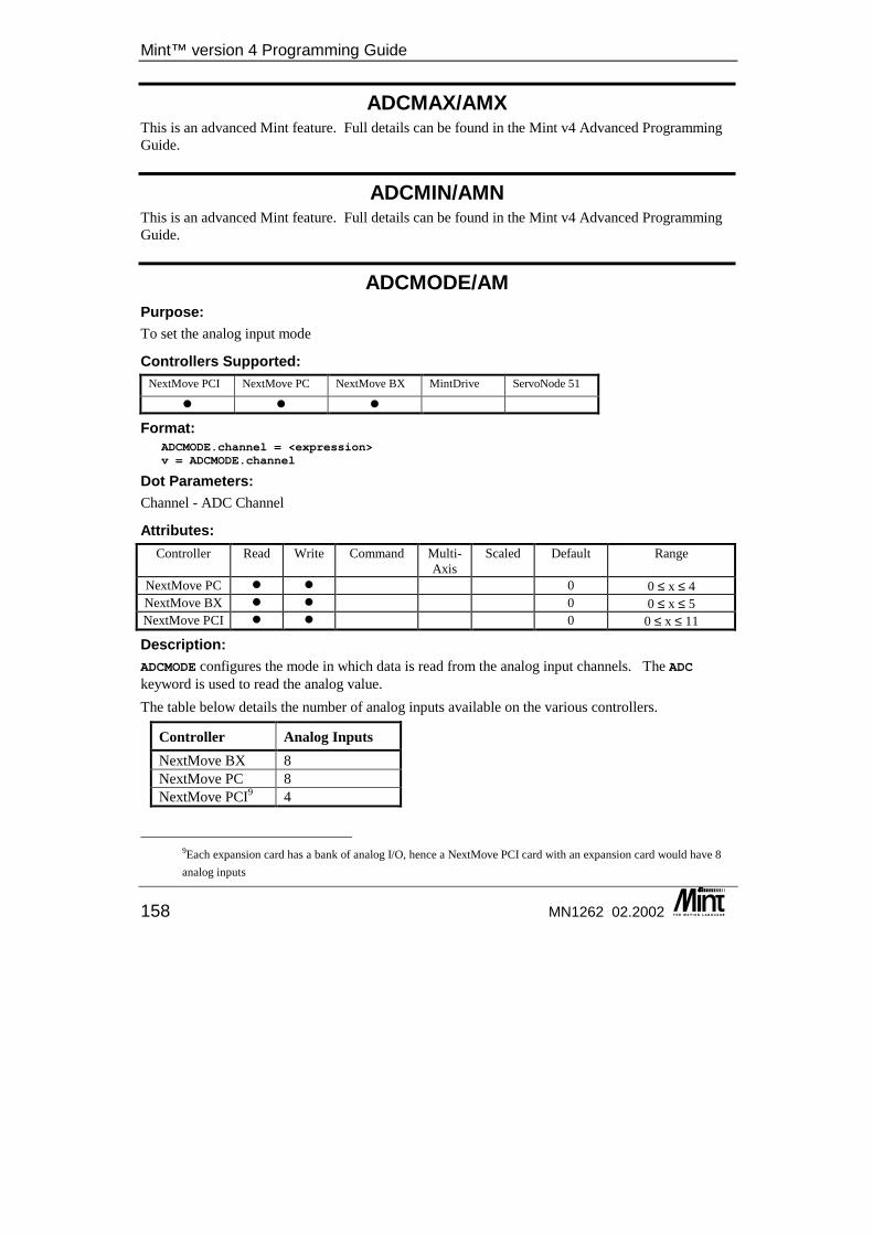
Mint™ version 4 Programming Guide
158 MN1262 02.2002
ADCMAX/AMX This is an advanced Mint feature. Full details can be found in the Mint v4 Advanced Programming Guide.
ADCMIN/AMN This is an advanced Mint feature. Full details can be found in the Mint v4 Advanced Programming Guide.
ADCMODE/AM Purpose: To set the analog input mode
Controllers Supported: NextMove PCI NextMove PC NextMove BX MintDrive ServoNode 51
� � �
Format: ADCMODE.channel = <expression>v = ADCMODE.channel
Dot Parameters: Channel - ADC Channel
Attributes: Controller Read Write Command Multi-
Axis Scaled Default Range
NextMove PC � � 0 0 ≤ x ≤ 4 NextMove BX � � 0 0 ≤ x ≤ 5 NextMove PCI � � 0 0 ≤ x ≤ 11
Description: ADCMODE configures the mode in which data is read from the analog input channels. The ADC keyword is used to read the analog value. The table below details the number of analog inputs available on the various controllers.
Controller Analog Inputs NextMove BX 8 NextMove PC 8 NextMove PCI9 4
9Each expansion card has a bank of analog I/O, hence a NextMove PCI card with an expansion card would have 8 analog inputs
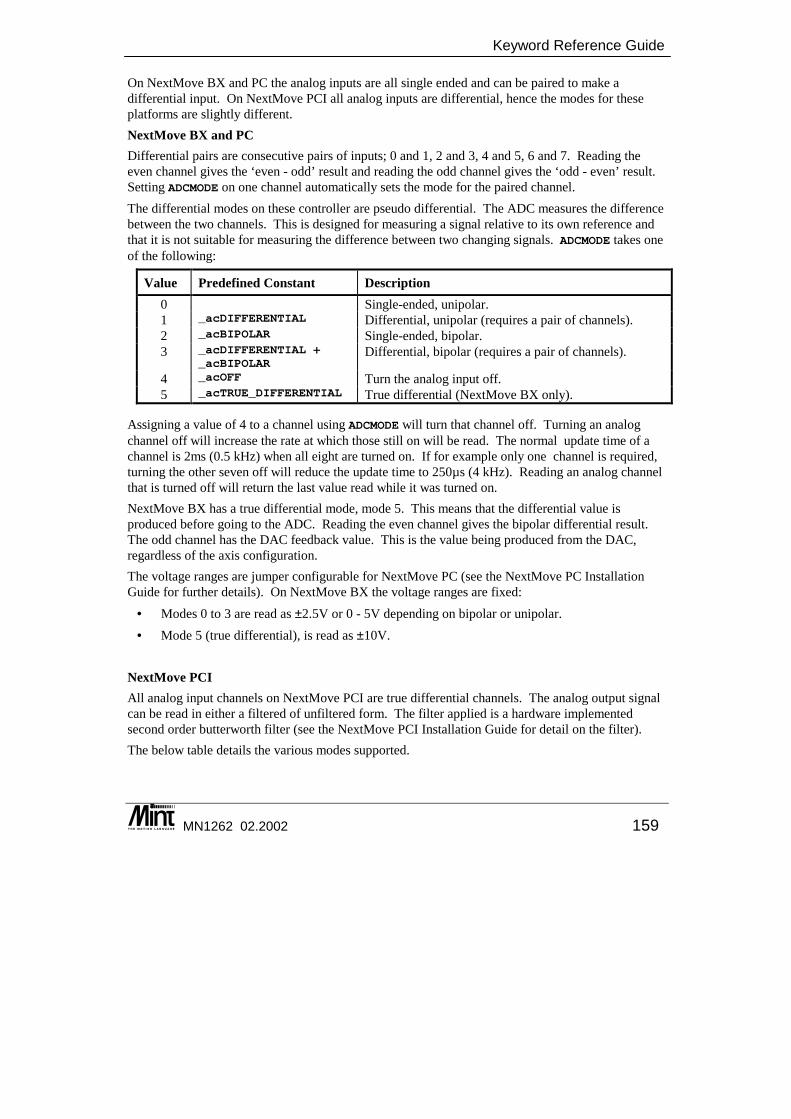
Keyword Reference Guide
MN1262 02.2002 159
On NextMove BX and PC the analog inputs are all single ended and can be paired to make a differential input. On NextMove PCI all analog inputs are differential, hence the modes for these platforms are slightly different. NextMove BX and PC Differential pairs are consecutive pairs of inputs; 0 and 1, 2 and 3, 4 and 5, 6 and 7. Reading the even channel gives the ‘even - odd’ result and reading the odd channel gives the ‘odd - even’ result. Setting ADCMODE on one channel automatically sets the mode for the paired channel. The differential modes on these controller are pseudo differential. The ADC measures the difference between the two channels. This is designed for measuring a signal relative to its own reference and that it is not suitable for measuring the difference between two changing signals. ADCMODE takes one of the following:
Value Predefined Constant Description 0 Single-ended, unipolar. 1 _acDIFFERENTIAL Differential, unipolar (requires a pair of channels). 2 _acBIPOLAR Single-ended, bipolar. 3 _acDIFFERENTIAL +
_acBIPOLARDifferential, bipolar (requires a pair of channels).
4 _acOFF Turn the analog input off. 5 _acTRUE_DIFFERENTIAL True differential (NextMove BX only).
Assigning a value of 4 to a channel using ADCMODE will turn that channel off. Turning an analog channel off will increase the rate at which those still on will be read. The normal update time of a channel is 2ms (0.5 kHz) when all eight are turned on. If for example only one channel is required, turning the other seven off will reduce the update time to 250µs (4 kHz). Reading an analog channel that is turned off will return the last value read while it was turned on. NextMove BX has a true differential mode, mode 5. This means that the differential value is produced before going to the ADC. Reading the even channel gives the bipolar differential result. The odd channel has the DAC feedback value. This is the value being produced from the DAC, regardless of the axis configuration. The voltage ranges are jumper configurable for NextMove PC (see the NextMove PC Installation Guide for further details). On NextMove BX the voltage ranges are fixed:
• Modes 0 to 3 are read as ±2.5V or 0 - 5V depending on bipolar or unipolar. • Mode 5 (true differential), is read as ±10V.
NextMove PCI All analog input channels on NextMove PCI are true differential channels. The analog output signal can be read in either a filtered of unfiltered form. The filter applied is a hardware implemented second order butterworth filter (see the NextMove PCI Installation Guide for detail on the filter). The below table details the various modes supported.

Mint™ version 4 Programming Guide
160 MN1262 02.2002
Value Predefined Constant Description 0 _acZERO_5_VOLTS 0 to 5 volts 1 _acZERO_10_VOLTS 0 to 10 volts 2 _acPLUS_MINUS_5_VOLTS ± 5 volts 3 _acPLUS_MINUS_10_VOLTS ± 10 volts 4 _acOFF Off 5 Reserved 6 Reserved 7 Reserved 8 _acZERO_5_VOLTS_UF 0 to 5 volts unfiltered 9 _acZERO_10_VOLTS_UF 0 to 10 volts unfiltered
10 _acPLUS_MINUS_5_VOLTS_UF ± 5 volts unfiltered 11 _acPLUS_MINUS_10_VOLTS_UF ± 10 volts unfiltered
All modes are software selectable. Assigning a value of 4 to a channel using ADCMODE will turn that channel off. Turning an analog channel off will increase the rate at which those still on will be read. The normal update time of a channel is 400µs (2.5 kHz) when all four are turned on. If for example only one channel is required, turning the other three off will reduce the update time to 100µs (10 kHz). Reading an analog channel that is turned off will return the last value read while it was turned on.
Example:
NextMove PC Setup 4 potentiometers connected as follows:
• Channel 0, single ended - voltage range of 0 to 10 volts. • Channel 1, not used. • Channel 2 and 3, differential pair - voltage range of 0 to 10 volts. • Channel 4, single ended – voltage range ± 10 volts. • Channel 5, not used. • Channel 6 and 7, differential pair – voltage range of ± 10 volts.
ADCMODE.0 = 0 : REM channel 0 single ended unipolarADCMODE.1 = 4 : REM Turn channel offADCMODE.2 = 1 : REM channel 2 and 3 differential unipolarADCMODE.4 = 2 : REM channel 4 single ended bipolarADCMODE.5 = 4 : REM Turn channel offADCMODE.6 = 3 : REM channel 6 and 7 differential bipolar
Voltage ranges must be set using the jumpers on the controller. NextMove PCI Setup 4 potentiometers connected as follows:
• Channel 0, voltage range of 0 to 10 volts.
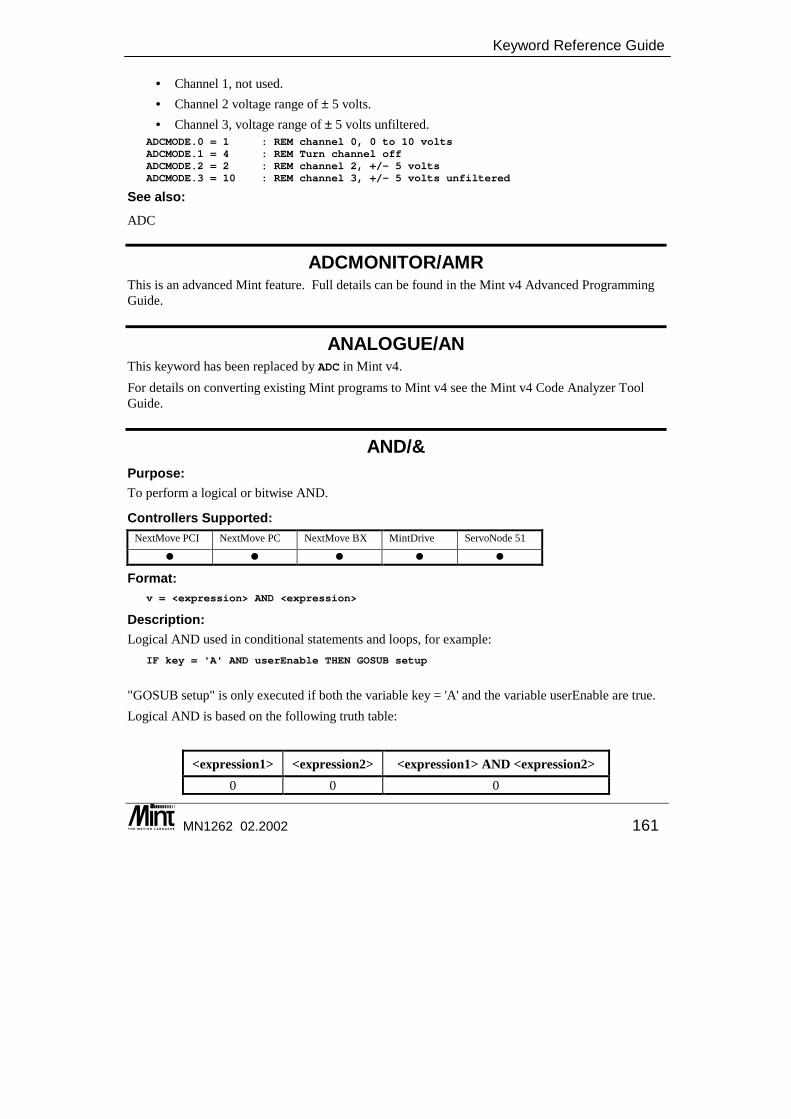
Keyword Reference Guide
MN1262 02.2002 161
• Channel 1, not used. • Channel 2 voltage range of ± 5 volts. • Channel 3, voltage range of ± 5 volts unfiltered.
ADCMODE.0 = 1 : REM channel 0, 0 to 10 voltsADCMODE.1 = 4 : REM Turn channel offADCMODE.2 = 2 : REM channel 2, +/- 5 voltsADCMODE.3 = 10 : REM channel 3, +/- 5 volts unfiltered
See also: ADC
ADCMONITOR/AMR This is an advanced Mint feature. Full details can be found in the Mint v4 Advanced Programming Guide.
ANALOGUE/AN This keyword has been replaced by ADC in Mint v4. For details on converting existing Mint programs to Mint v4 see the Mint v4 Code Analyzer Tool Guide.
AND/& Purpose: To perform a logical or bitwise AND.
Controllers Supported: NextMove PCI NextMove PC NextMove BX MintDrive ServoNode 51
� � � � �
Format: v = <expression> AND <expression>
Description: Logical AND used in conditional statements and loops, for example:
IF key = 'A' AND userEnable THEN GOSUB setup
"GOSUB setup" is only executed if both the variable key = 'A' and the variable userEnable are true. Logical AND is based on the following truth table:
<expression1> <expression2> <expression1> AND <expression2> 0 0 0
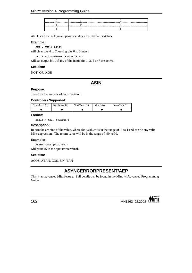
Mint™ version 4 Programming Guide
162 MN1262 02.2002
0 1 0 1 0 0 1 1 1
AND is a bitwise logical operator and can be used to mask bits.
Example: OUT = OUT & 01111
will clear bits 4 to 7 leaving bits 0 to 3 intact. IF IN & 010101010 THEN OUT1 = 1
will set output bit 1 if any of the input bits 1, 3, 5 or 7 are active.
See also: NOT, OR, XOR
ASIN Purpose: To return the arc sine of an expression.
Controllers Supported: NextMove PCI NextMove PC NextMove BX MintDrive ServoNode 51
� � � � �
Format: angle = ASIN (<value>)
Description: Return the arc sine of the value, where the <value> is in the range of -1 to 1 and can be any valid Mint expression. The return value will be in the range of -90 to 90.
Example: PRINT ASIN (0.707107)
will print 45 to the operator terminal.
See also: ACOS, ATAN, COS, SIN, TAN
ASYNCERRORPRESENT/AEP This is an advanced Mint feature. Full details can be found in the Mint v4 Advanced Programming Guide.
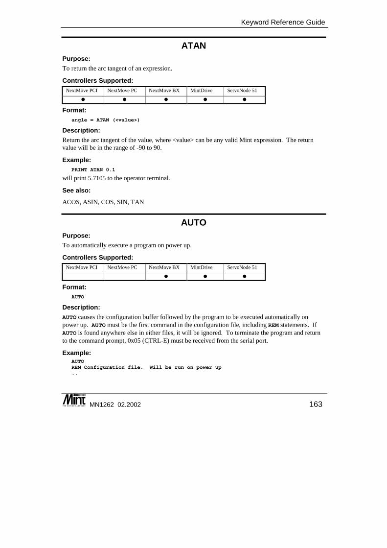
Keyword Reference Guide
MN1262 02.2002 163
ATAN Purpose: To return the arc tangent of an expression.
Controllers Supported: NextMove PCI NextMove PC NextMove BX MintDrive ServoNode 51
� � � � �
Format: angle = ATAN (<value>)
Description: Return the arc tangent of the value, where <value> can be any valid Mint expression. The return value will be in the range of -90 to 90.
Example: PRINT ATAN 0.1
will print 5.7105 to the operator terminal.
See also: ACOS, ASIN, COS, SIN, TAN
AUTO Purpose: To automatically execute a program on power up.
Controllers Supported: NextMove PCI NextMove PC NextMove BX MintDrive ServoNode 51
� � �
Format: AUTO
Description: AUTO causes the configuration buffer followed by the program to be executed automatically on power up. AUTO must be the first command in the configuration file, including REM statements. If AUTO is found anywhere else in either files, it will be ignored. To terminate the program and return to the command prompt, 0x05 (CTRL-E) must be received from the serial port.
Example: AUTOREM Configuration file. Will be run on power up..

Mint™ version 4 Programming Guide
164 MN1262 02.2002
See also: RUN
AUXDAC/AD Purpose: To read or set the auxiliary DAC outputs.
Controllers Supported: NextMove PCI NextMove PC NextMove BX MintDrive ServoNode 51
� �
Format: AUXDAC.channel = <expression>v = AUXDAC.channel
Dot Parameters: Channel - Aux. DAC
Attributes: Controller Read Write Command Multi-
Axis Scaled Default Range
MintDrive � � 0 -100 ≤ x ≤100
Description: The AUXDAC keyword controls the auxiliary analog output channels. There are two auxiliary analog output channels on ServoNode 51 and four on MintDrive. The value output is a ±10v value, where 100 is equivalent to +10v. The value output by the analog channel can also be taken from a parameter assigned by the keyword DACMONITORMODE.
See Also: DACMONITORMODE, DACMONITORGAIN
AUXENCODER/AEN Purpose: To read or set the auxiliary encoder input.
Controllers Supported: NextMove PCI NextMove PC NextMove BX MintDrive ServoNode 51
� � � � �
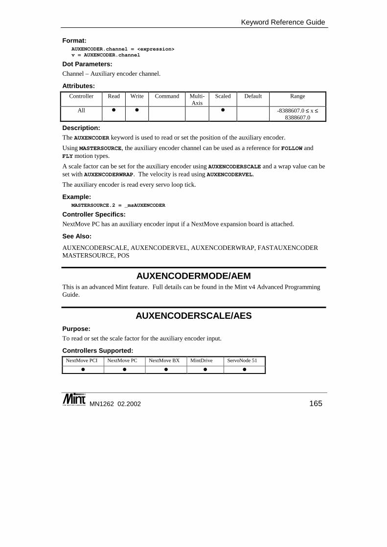
Keyword Reference Guide
MN1262 02.2002 165
Format: AUXENCODER.channel = <expression>v = AUXENCODER.channel
Dot Parameters: Channel – Auxiliary encoder channel.
Attributes: Controller Read Write Command Multi-
Axis Scaled Default Range
All � � � -8388607.0 ≤ x ≤ 8388607.0
Description: The AUXENCODER keyword is used to read or set the position of the auxiliary encoder. Using MASTERSOURCE, the auxiliary encoder channel can be used as a reference for FOLLOW and FLY motion types. A scale factor can be set for the auxiliary encoder using AUXENCODERSCALE and a wrap value can be set with AUXENCODERWRAP. The velocity is read using AUXENCODERVEL. The auxiliary encoder is read every servo loop tick.
Example: MASTERSOURCE.2 = _msAUXENCODER
Controller Specifics: NextMove PC has an auxiliary encoder input if a NextMove expansion board is attached.
See Also: AUXENCODERSCALE, AUXENCODERVEL, AUXENCODERWRAP, FASTAUXENCODER MASTERSOURCE, POS
AUXENCODERMODE/AEM This is an advanced Mint feature. Full details can be found in the Mint v4 Advanced Programming Guide.
AUXENCODERSCALE/AES Purpose: To read or set the scale factor for the auxiliary encoder input.
Controllers Supported: NextMove PCI NextMove PC NextMove BX MintDrive ServoNode 51
� � � � �
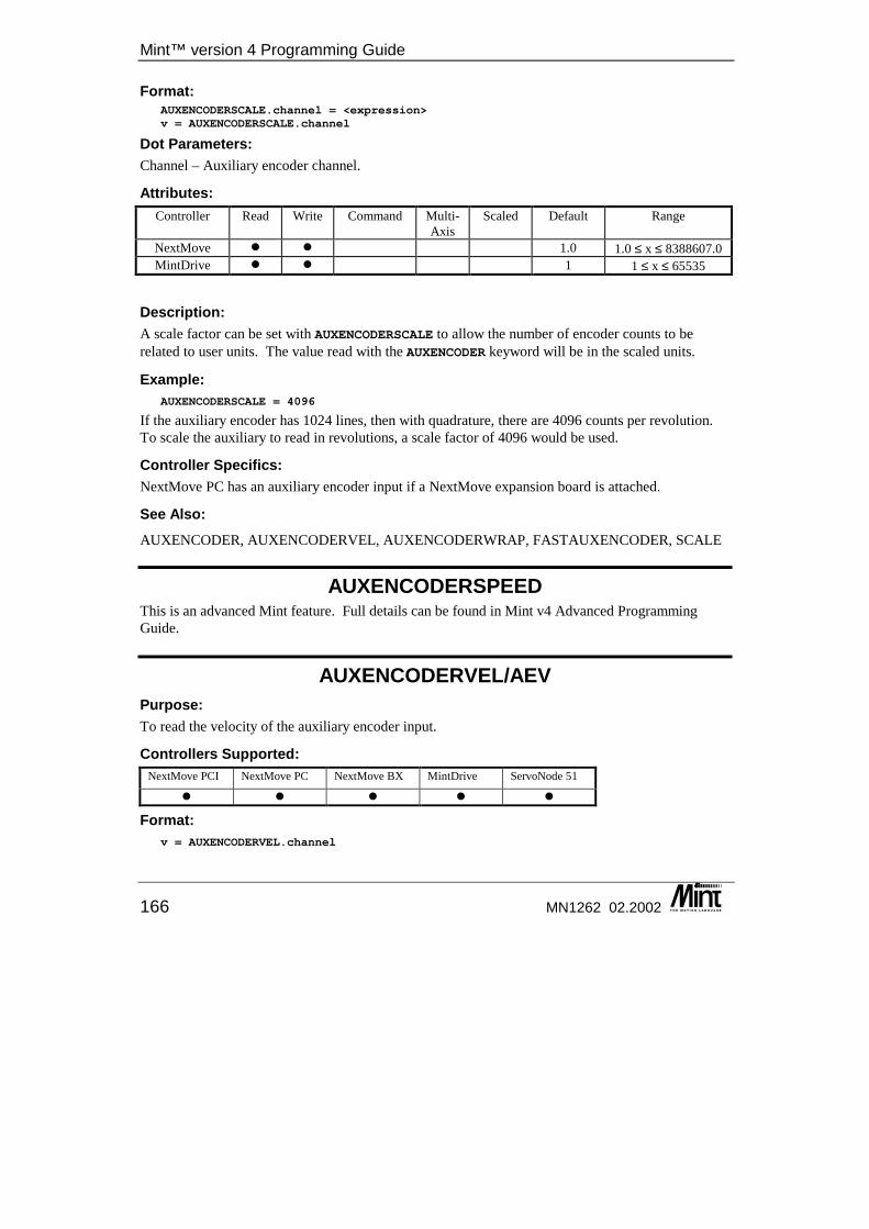
Mint™ version 4 Programming Guide
166 MN1262 02.2002
Format: AUXENCODERSCALE.channel = <expression>v = AUXENCODERSCALE.channel
Dot Parameters: Channel – Auxiliary encoder channel.
Attributes: Controller Read Write Command Multi-
Axis Scaled Default Range
NextMove � � 1.0 1.0 ≤ x ≤ 8388607.0 MintDrive � � 1 1 ≤ x ≤ 65535
Description: A scale factor can be set with AUXENCODERSCALE to allow the number of encoder counts to be related to user units. The value read with the AUXENCODER keyword will be in the scaled units.
Example: AUXENCODERSCALE = 4096
If the auxiliary encoder has 1024 lines, then with quadrature, there are 4096 counts per revolution. To scale the auxiliary to read in revolutions, a scale factor of 4096 would be used.
Controller Specifics: NextMove PC has an auxiliary encoder input if a NextMove expansion board is attached.
See Also: AUXENCODER, AUXENCODERVEL, AUXENCODERWRAP, FASTAUXENCODER, SCALE
AUXENCODERSPEED This is an advanced Mint feature. Full details can be found in Mint v4 Advanced Programming Guide.
AUXENCODERVEL/AEV Purpose: To read the velocity of the auxiliary encoder input.
Controllers Supported: NextMove PCI NextMove PC NextMove BX MintDrive ServoNode 51
� � � � �
Format: v = AUXENCODERVEL.channel
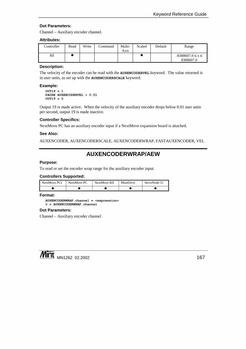
Keyword Reference Guide
MN1262 02.2002 167
Dot Parameters: Channel – Auxiliary encoder channel.
Attributes: Controller Read Write Command Multi-
Axis Scaled Default Range
All � � -8388607.0 ≤ x ≤ 8388607.0
Description: The velocity of the encoder can be read with the AUXENCODERVEL keyword. The value returned is in user units, as set up with the AUXENCODERSCALE keyword.
Example: OUT19 = 1PAUSE AUXENCODERVEL < 0.01OUT19 = 0
Output 19 is made active. When the velocity of the auxiliary encoder drops below 0.01 user units per second, output 19 is made inactive.
Controller Specifics: NextMove PC has an auxiliary encoder input if a NextMove expansion board is attached.
See Also: AUXENCODER, AUXENCODERSCALE, AUXENCODERWRAP, FASTAUXENCODER, VEL
AUXENCODERWRAP/AEW Purpose: To read or set the encoder wrap range for the auxiliary encoder input.
Controllers Supported: NextMove PCI NextMove PC NextMove BX MintDrive ServoNode 51
� � � � �
Format: AUXENCODERWRAP.channel = <expression>v = AUXENCODERWRAP.channel
Dot Parameters: Channel – Auxiliary encoder channel.

Mint™ version 4 Programming Guide
168 MN1262 02.2002
Attributes: Controller Read Write Command Multi-
Axis Scaled Default Range
NextMove � � 0.0 1.0 ≤ x ≤ 8388607.0 MintDrive � � � 0 1 ≤ x ≤ 65535
Description: Normally, the position of the auxiliary encoder is within the full range of +/- 8388607.0 counts. In a rotary system, for example, it may be desirable to have encoder position within a certain range. The AUXENCODERWRAP keyword allows a wrap value to be set such that the position read with the AUXENCODER keyword is between zero and the specified wrap value. If AUXENCODERSCALE was set to 1, the maximum value returned would be one less than AUXENCODERWRAP.
Example: AUXENCODERSCALE = 11.378AUXENCODERWRAP = 360.0
When the auxiliary encoder is read, the position must be in degrees within one revolution. If the encoder has 1024 lines, then there are 4096 counts per revolution. To scale the auxiliary to read in degrees, a scale factor of 11.378 would be used. Reading the AUXENCODER keyword would return a value in the range 0 - 360. To turn encoder wrap off, a wrap value of 0.0 is given. This returns the position to its full possible range.
Controller Specifics: NextMove PC has an auxiliary encoder input if a NextMove expansion board is attached.
See Also: AUXENCODER, AUXENCODERSCALE, AUXENCODERVEL, ENCODERWRAP, FASTAUXENCODER
AUXENCODERZLATCH/AEZ This is an advanced Mint feature. Full details can be found in Mint v4 Advanced Programming Guide.
AXISCHANNEL/ACH This is an advanced Mint feature. Full details can be found in the Mint v4 Advanced Programming Guide.
AXES Purpose: To define a default axis string.
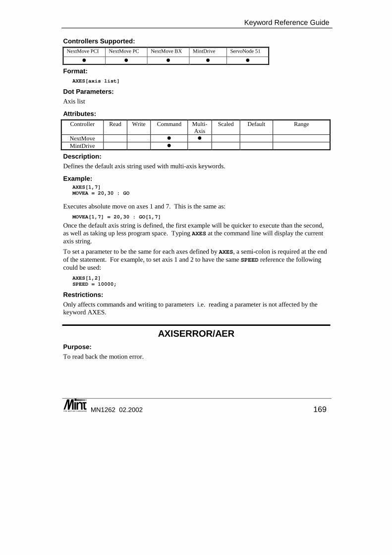
Keyword Reference Guide
MN1262 02.2002 169
Controllers Supported: NextMove PCI NextMove PC NextMove BX MintDrive ServoNode 51
� � � � �
Format: AXES[axis list]
Dot Parameters: Axis list
Attributes: Controller Read Write Command Multi-
Axis Scaled Default Range
NextMove � � MintDrive �
Description: Defines the default axis string used with multi-axis keywords.
Example: AXES[1,7]MOVEA = 20,30 : GO
Executes absolute move on axes 1 and 7. This is the same as: MOVEA[1,7] = 20,30 : GO[1,7]
Once the default axis string is defined, the first example will be quicker to execute than the second, as well as taking up less program space. Typing AXES at the command line will display the current axis string. To set a parameter to be the same for each axes defined by AXES, a semi-colon is required at the end of the statement. For example, to set axis 1 and 2 to have the same SPEED reference the following could be used:
AXES[1,2]SPEED = 10000;
Restrictions: Only affects commands and writing to parameters i.e. reading a parameter is not affected by the keyword AXES.
AXISERROR/AER Purpose: To read back the motion error.
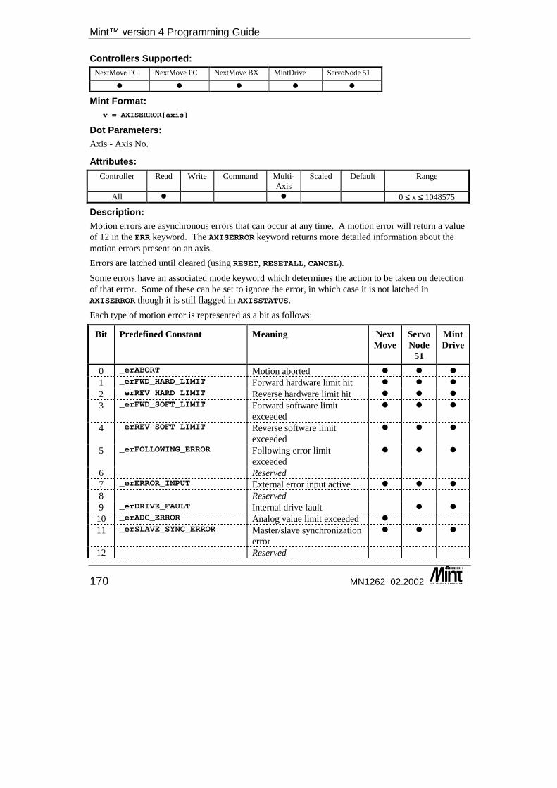
Mint™ version 4 Programming Guide
170 MN1262 02.2002
Controllers Supported: NextMove PCI NextMove PC NextMove BX MintDrive ServoNode 51
� � � � �
Mint Format: v = AXISERROR[axis]
Dot Parameters: Axis - Axis No.
Attributes: Controller Read Write Command Multi-
Axis Scaled Default Range
All � � 0 ≤ x ≤ 1048575
Description: Motion errors are asynchronous errors that can occur at any time. A motion error will return a value of 12 in the ERR keyword. The AXISERROR keyword returns more detailed information about the motion errors present on an axis. Errors are latched until cleared (using RESET, RESETALL, CANCEL). Some errors have an associated mode keyword which determines the action to be taken on detection of that error. Some of these can be set to ignore the error, in which case it is not latched in AXISERROR though it is still flagged in AXISSTATUS. Each type of motion error is represented as a bit as follows:
Bit Predefined Constant Meaning NextMove
ServoNode
51
MintDrive
0 _erABORT Motion aborted � � � 1 _erFWD_HARD_LIMIT Forward hardware limit hit � � � 2 _erREV_HARD_LIMIT Reverse hardware limit hit � � � 3 _erFWD_SOFT_LIMIT Forward software limit
exceeded � � �
4 _erREV_SOFT_LIMIT Reverse software limit exceeded
� � �
5 _erFOLLOWING_ERROR Following error limit exceeded
� � �
6 Reserved 7 _erERROR_INPUT External error input active � � � 8 Reserved 9 _erDRIVE_FAULT Internal drive fault � �
10 _erADC_ERROR Analog value limit exceeded � 11 _erSLAVE_SYNC_ERROR Master/slave synchronization
error � � �
12 Reserved
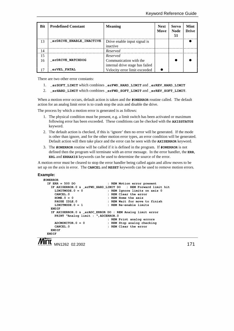
Keyword Reference Guide
MN1262 02.2002 171
Bit Predefined Constant Meaning NextMove
ServoNode
51
MintDrive
13 _erDRIVE_ENABLE_INACTIVE Drive enable input signal is inactive
�
14 Reserved 15 Reserved 16 _erDRIVE_WATCHDOG Communication with the
internal drive stage has failed � �
17 _erVEL_FATAL Velocity error limit exceeded �
There are two other error constants: 1. _erSOFT_LIMIT which combines _erFWD_HARD_LIMIT and _erREV_HARD_LIMIT 2. _erHARD_LIMIT which combines _erFWD_SOFT_LIMIT and _erREV_SOFT_LIMIT.
When a motion error occurs, default action is taken and the #ONERROR routine called. The default action for an analog limit error is to crash stop the axis and disable the drive. The process by which a motion error is generated is as follows:
1. The physical condition must be present, e.g. a limit switch has been activated or maximum following error has been exceeded. These conditions can be checked with the AXISSTATUS keyword.
2. The default action is checked, if this is ‘ignore’ then no error will be generated. If the mode is other than ignore, and for the other motion error types, an error condition will be generated. Default action will then take place and the error can be seen with the AXISERROR keyword.
3. The #ONERROR routine will be called if it is defined in the program. If #ONERROR is not defined then the program will terminate with an error message. In the error handler, the ERR, ERL and ERRAXIS keywords can be used to determine the source of the error.
A motion error must be cleared to stop the error handler being called again and allow moves to be set up on the axis in error. The CANCEL and RESET keywords can be used to remove motion errors.
Example: #ONERRORIF ERR = 500 DO : REM Motion error presentIF AXISERROR.0 & _erFWD_HARD_LIMIT DO : REM Forward limit hitLIMITMODE.0 = 0 : REM Ignore limits on axis 0CANCEL.0 : REM Clear the errorHOME.0 = 0 : REM Home the axisPAUSE IDLE.0 : REM Wait for move to finishLIMITMODE.0 = 1 : REM Re-enable limits
ENDIFIF AXISERROR.0 & _erADC_ERROR DO : REM Analog limit errorPRINT “Analog limit : “,ADCERROR.0
: REM Print analog errorsADCMONITOR.0 = 0 : REM Stop analog checkingCANCEL.0 : REM Clear the error
ENDIFENDIF
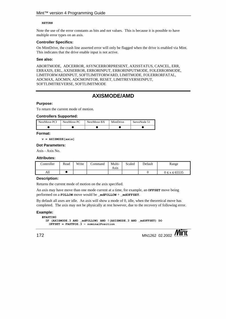
Mint™ version 4 Programming Guide
172 MN1262 02.2002
RETURN
Note the use of the error constants as bits and not values. This is because it is possible to have multiple error types on an axis.
Controller Specifics: On MintDrive, the crash line asserted error will only be flagged when the drive is enabled via Mint. This indicates that the drive enable input is not active.
See also: ABORTMODE, ADCERROR, ASYNCERRORPRESENT, AXISSTATUS, CANCEL, ERR, ERRAXIS, ERL, AXISERROR, ERRORINPUT, ERRORINPUTMODE, FOLERRORMODE, LIMITFORWARDINPUT, SOFTLIMITFORWARD, LIMITMODE, FOLERRORFATAL, ADCMAX, ADCMIN, ADCMONITOR, RESET, LIMITREVERSEINPUT, SOFTLIMITREVERSE, SOFTLIMITMODE
AXISMODE/AMD Purpose: To return the current mode of motion.
Controllers Supported: NextMove PCI NextMove PC NextMove BX MintDrive ServoNode 51
� � � � �
Format: v = AXISMODE[axis]
Dot Parameters: Axis - Axis No.
Attributes: Controller Read Write Command Multi-
Axis Scaled Default Range
All � 0 0 ≤ x ≤ 65535
Description: Returns the current mode of motion on the axis specified. An axis may have move than one mode current at a time, for example, an OFFSET move being performed on a FOLLOW move would be _mdFOLLOW + _mdOFFSET. By default all axes are idle. An axis will show a mode of 0, idle, when the theoretical move has completed. The axis may not be physically at rest however, due to the recovery of following error.
Example: #FASTIN0IF (AXISMODE.3 AND _mdFOLLOW) AND !(AXISMODE.3 AND _mdOFFSET) DOOFFSET = FASTPOS.3 - nominalPosition
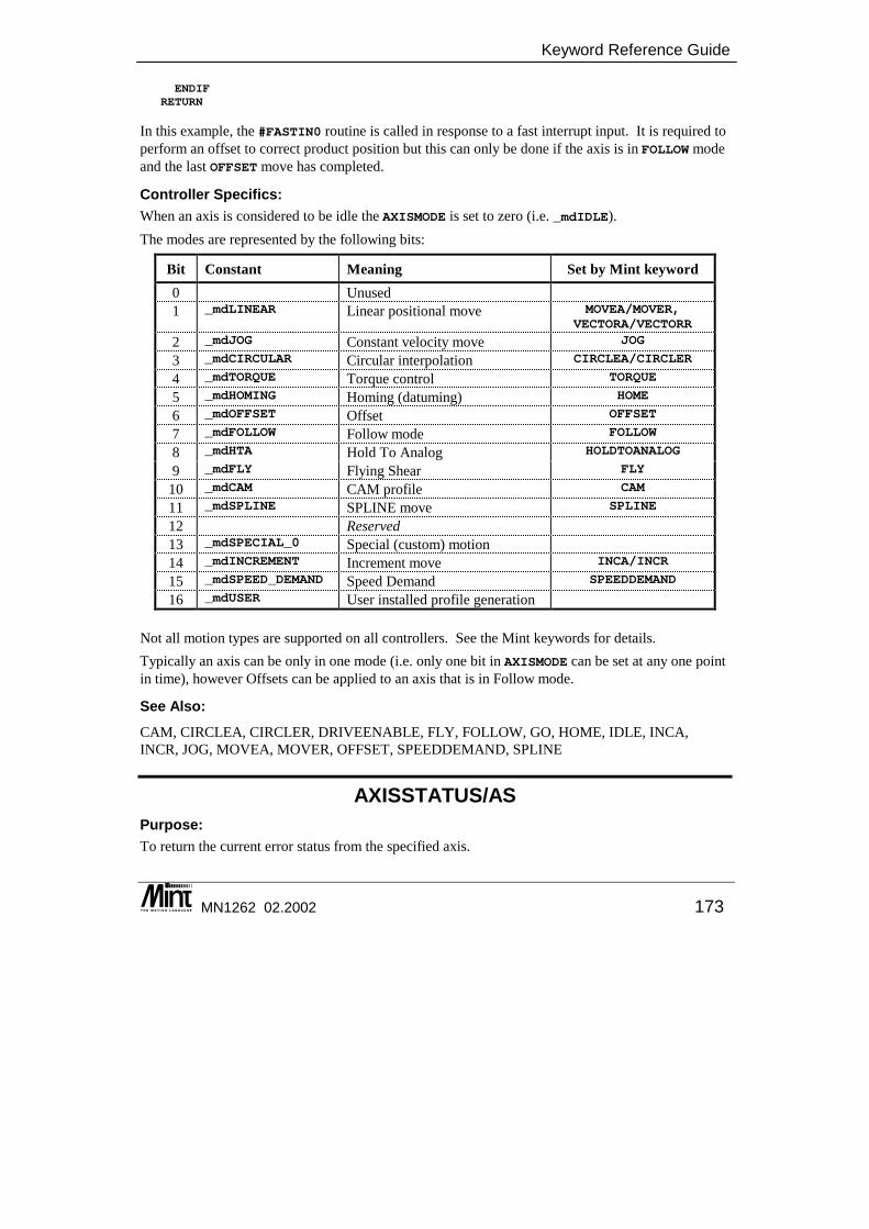
Keyword Reference Guide
MN1262 02.2002 173
ENDIFRETURN
In this example, the #FASTIN0 routine is called in response to a fast interrupt input. It is required to perform an offset to correct product position but this can only be done if the axis is in FOLLOW mode and the last OFFSET move has completed.
Controller Specifics: When an axis is considered to be idle the AXISMODE is set to zero (i.e. _mdIDLE). The modes are represented by the following bits:
Bit Constant Meaning Set by Mint keyword 0 Unused 1 _mdLINEAR Linear positional move MOVEA/MOVER,
VECTORA/VECTORR
2 _mdJOG Constant velocity move JOG
3 _mdCIRCULAR Circular interpolation CIRCLEA/CIRCLER
4 _mdTORQUE Torque control TORQUE
5 _mdHOMING Homing (datuming) HOME
6 _mdOFFSET Offset OFFSET
7 _mdFOLLOW Follow mode FOLLOW
8 _mdHTA Hold To Analog HOLDTOANALOG
9 _mdFLY Flying Shear FLY
10 _mdCAM CAM profile CAM
11 _mdSPLINE SPLINE move SPLINE
12 Reserved 13 _mdSPECIAL_0 Special (custom) motion 14 _mdINCREMENT Increment move INCA/INCR
15 _mdSPEED_DEMAND Speed Demand SPEEDDEMAND
16 _mdUSER User installed profile generation
Not all motion types are supported on all controllers. See the Mint keywords for details. Typically an axis can be only in one mode (i.e. only one bit in AXISMODE can be set at any one point in time), however Offsets can be applied to an axis that is in Follow mode.
See Also: CAM, CIRCLEA, CIRCLER, DRIVEENABLE, FLY, FOLLOW, GO, HOME, IDLE, INCA, INCR, JOG, MOVEA, MOVER, OFFSET, SPEEDDEMAND, SPLINE
AXISSTATUS/AS Purpose: To return the current error status from the specified axis.
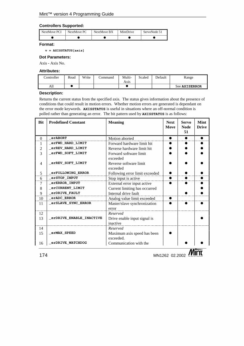
Mint™ version 4 Programming Guide
174 MN1262 02.2002
Controllers Supported: NextMove PCI NextMove PC NextMove BX MintDrive ServoNode 51
� � � � �
Format: v = AXISSTATUS[axis]
Dot Parameters: Axis - Axis No.
Attributes: Controller Read Write Command Multi-
Axis Scaled Default Range
All � � See AXISERROR
Description: Returns the current status from the specified axis. The status gives information about the presence of conditions that could result in motion errors. Whether motion errors are generated is dependant on the error mode keywords. AXISSTATUS is useful in situations where an off-normal condition is polled rather than generating an error. The bit pattern used by AXISSTATUS is as follows:
Bit Predefined Constant Meaning NextMove
ServoNode
51
MintDrive
0 _erABORT Motion aborted � � � 1 _erFWD_HARD_LIMIT Forward hardware limit hit � � � 2 _erREV_HARD_LIMIT Reverse hardware limit hit � � � 3 _erFWD_SOFT_LIMIT Forward software limit
exceeded � � �
4 _erREV_SOFT_LIMIT Reverse software limit exceeded
� � �
5 _erFOLLOWING_ERROR Following error limit exceeded � � � 6 _erSTOP_INPUT Stop input is active � � � 7 _erERROR_INPUT External error input active � � � 8 _erCURRENT_LIMIT Current limiting has occurred � 9 _erDRIVE_FAULT Internal drive fault � �
10 _erADC_ERROR Analog value limit exceeded � 11 _erSLAVE_SYNC_ERROR Master/slave synchronization
error � � �
12 Reserved 13 _erDRIVE_ENABLE_INACTIVE Drive enable input signal is
inactive �
14 Reserved 15 _erMAX_SPEED Maximum axis speed has been
exceeded. �
16 _erDRIVE_WATCHDOG Communication with the � �

Keyword Reference Guide
MN1262 02.2002 175
Bit Predefined Constant Meaning NextMove
ServoNode
51
MintDrive
internal drive stage has failed 17 _erVEL_FATAL Velocity error limit exceeded � AXISSTATUS also shows the status of the stop switch input for the axis, again regardless of the stop switch mode. No error will be generated. Once the error condition has cleared the relevant bit in AXISSTATUS will automatically be cleared.
Example: Turn off following error detection to allow an axis to move without incurring an error. Check AXISSTATUS to see if maximum following error has been exceeded.
FOLERRORMODE[2] = 0JOG[2] = 100LOOPIF AXISSTATUS & _erFOLLOWING_ERROR THEN ? “ Maximum following error exceeded ”ENDL
The bitmap returned and constants used are the same as for AXISERROR.
See also: ABORT, ERR, AXISERROR, ERRORINPUT, FOLERRORMODE, LIMITMODE, MAXSPEED, ADCMONITOR, SOFTLIMITMODE, STOPINPUTMODE
AXISWARNING/AW This is an advanced Mint feature. Full details can be found in the Mint v4 Advanced Programming Guide.
AXISWARNINGDISABLE/AWD This is an advanced Mint feature. Full details can be found in the Mint v4 Advanced Programming Guide.
BACKLASH/BL This is an advanced Mint feature. Full details can be found in the Mint v4 Advanced Programming Guide.
BACKLASHINTERVAL/BLI This is an advanced Mint feature. Full details can be found in the Mint v4 Advanced Programming Guide.
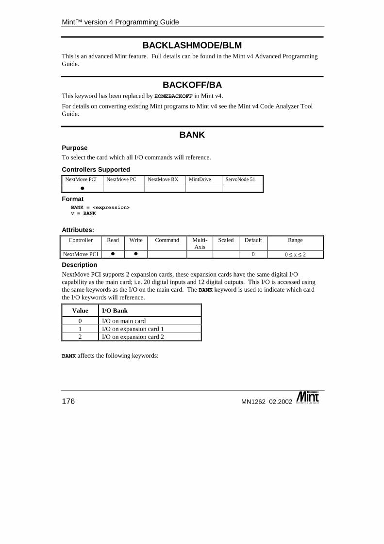
Mint™ version 4 Programming Guide
176 MN1262 02.2002
BACKLASHMODE/BLM This is an advanced Mint feature. Full details can be found in the Mint v4 Advanced Programming Guide.
BACKOFF/BA This keyword has been replaced by HOMEBACKOFF in Mint v4. For details on converting existing Mint programs to Mint v4 see the Mint v4 Code Analyzer Tool Guide.
BANK Purpose To select the card which all I/O commands will reference.
Controllers Supported NextMove PCI NextMove PC NextMove BX MintDrive ServoNode 51
�
Format BANK = <expression>v = BANK
Attributes:
Controller Read Write Command Multi-Axis
Scaled Default Range
NextMove PCI � � 0 0 ≤ x ≤ 2
Description NextMove PCI supports 2 expansion cards, these expansion cards have the same digital I/O capability as the main card; i.e. 20 digital inputs and 12 digital outputs. This I/O is accessed using the same keywords as the I/O on the main card. The BANK keyword is used to indicate which card the I/O keywords will reference.
Value I/O Bank 0 I/O on main card 1 I/O on expansion card 1 2 I/O on expansion card 2
BANK affects the following keywords:
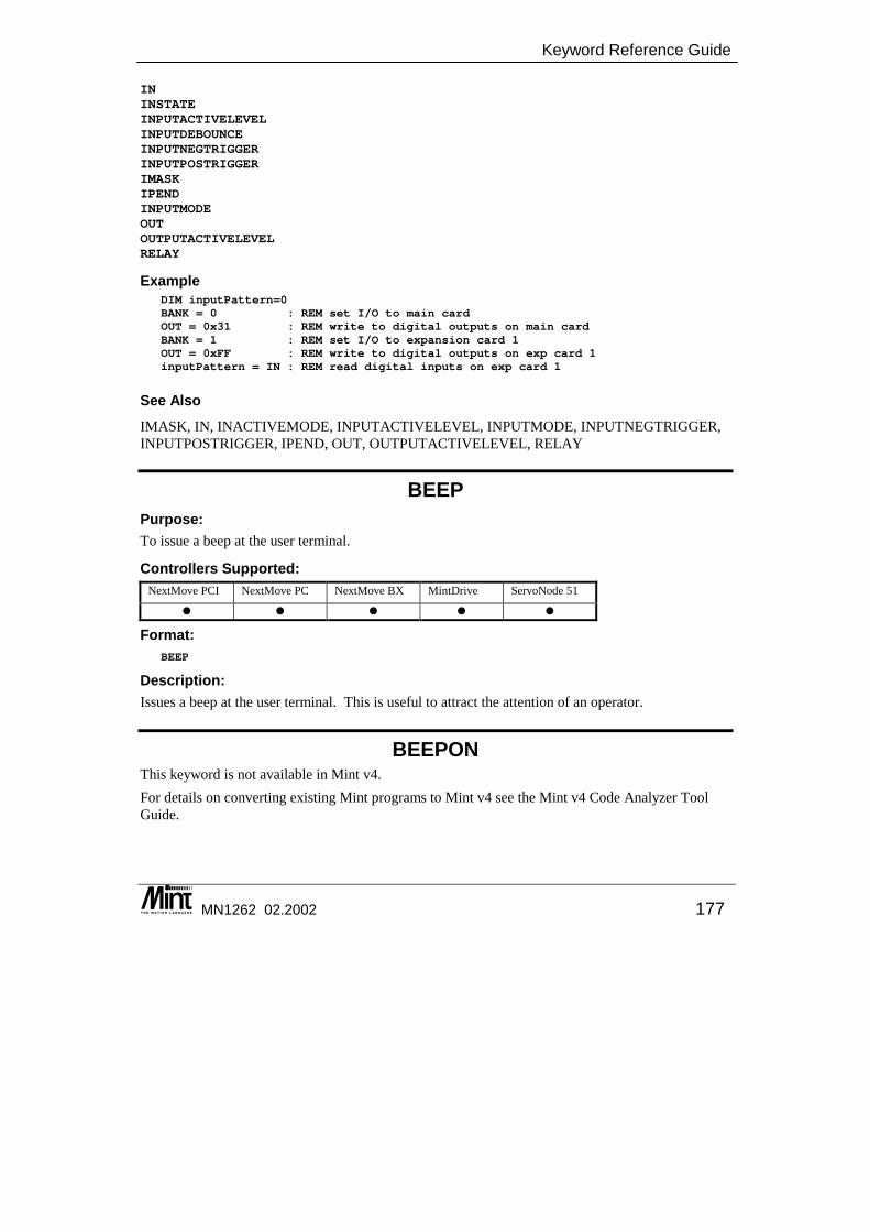
Keyword Reference Guide
MN1262 02.2002 177
ININSTATEINPUTACTIVELEVELINPUTDEBOUNCEINPUTNEGTRIGGERINPUTPOSTRIGGERIMASKIPENDINPUTMODEOUTOUTPUTACTIVELEVELRELAY
Example DIM inputPattern=0BANK = 0 : REM set I/O to main cardOUT = 0x31 : REM write to digital outputs on main cardBANK = 1 : REM set I/O to expansion card 1OUT = 0xFF : REM write to digital outputs on exp card 1inputPattern = IN : REM read digital inputs on exp card 1
See Also IMASK, IN, INACTIVEMODE, INPUTACTIVELEVEL, INPUTMODE, INPUTNEGTRIGGER, INPUTPOSTRIGGER, IPEND, OUT, OUTPUTACTIVELEVEL, RELAY
BEEP Purpose: To issue a beep at the user terminal.
Controllers Supported: NextMove PCI NextMove PC NextMove BX MintDrive ServoNode 51
� � � � �
Format: BEEP
Description: Issues a beep at the user terminal. This is useful to attract the attention of an operator.
BEEPON This keyword is not available in Mint v4. For details on converting existing Mint programs to Mint v4 see the Mint v4 Code Analyzer Tool Guide.
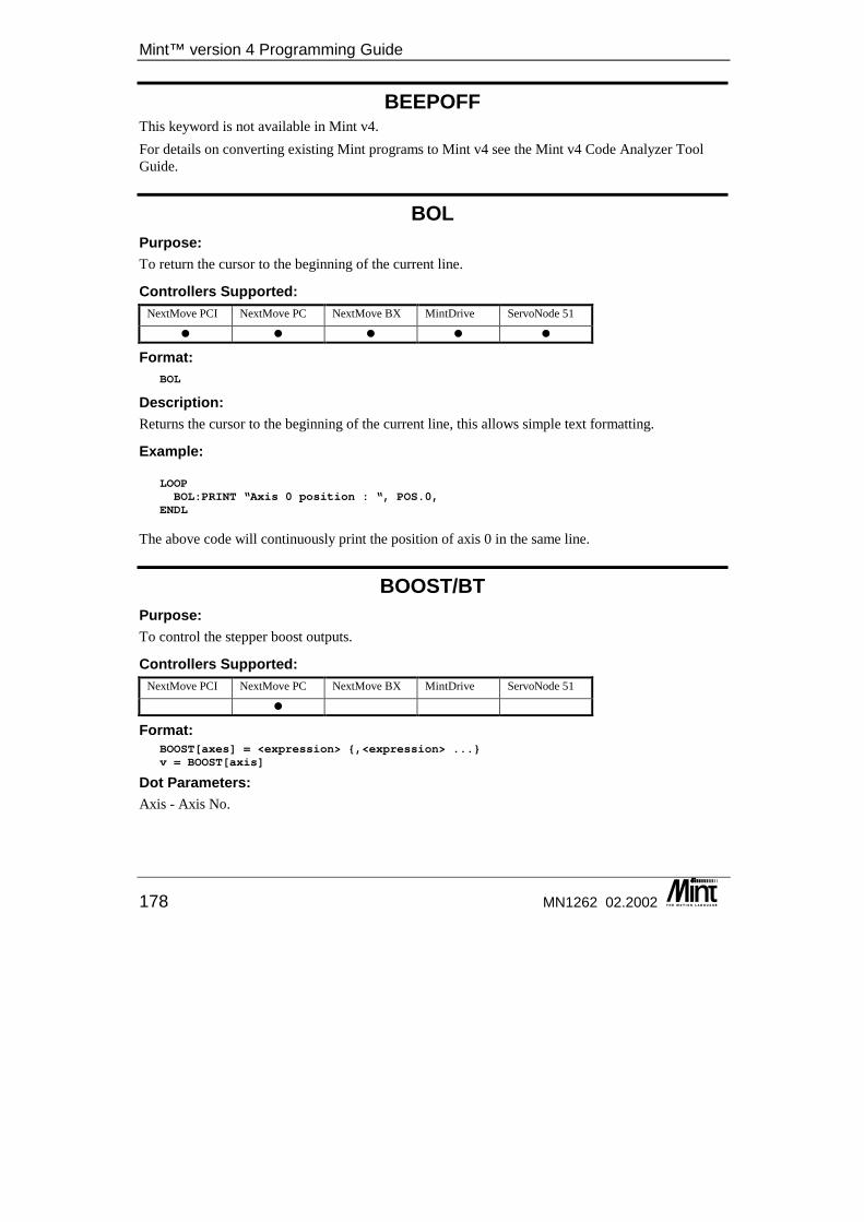
Mint™ version 4 Programming Guide
178 MN1262 02.2002
BEEPOFF This keyword is not available in Mint v4. For details on converting existing Mint programs to Mint v4 see the Mint v4 Code Analyzer Tool Guide.
BOL Purpose: To return the cursor to the beginning of the current line.
Controllers Supported: NextMove PCI NextMove PC NextMove BX MintDrive ServoNode 51
� � � � �
Format: BOL
Description: Returns the cursor to the beginning of the current line, this allows simple text formatting.
Example:
LOOPBOL:PRINT “Axis 0 position : “, POS.0,
ENDL
The above code will continuously print the position of axis 0 in the same line.
BOOST/BT Purpose: To control the stepper boost outputs.
Controllers Supported: NextMove PCI NextMove PC NextMove BX MintDrive ServoNode 51
�
Format: BOOST[axes] = <expression> {,<expression> ...}v = BOOST[axis]
Dot Parameters: Axis - Axis No.
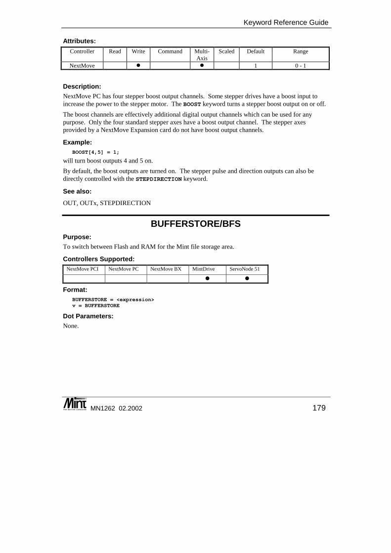
Keyword Reference Guide
MN1262 02.2002 179
Attributes: Controller Read Write Command Multi-
Axis Scaled Default Range
NextMove � � 1 0 - 1
Description: NextMove PC has four stepper boost output channels. Some stepper drives have a boost input to increase the power to the stepper motor. The BOOST keyword turns a stepper boost output on or off. The boost channels are effectively additional digital output channels which can be used for any purpose. Only the four standard stepper axes have a boost output channel. The stepper axes provided by a NextMove Expansion card do not have boost output channels.
Example: BOOST[4,5] = 1;
will turn boost outputs 4 and 5 on. By default, the boost outputs are turned on. The stepper pulse and direction outputs can also be directly controlled with the STEPDIRECTION keyword.
See also: OUT, OUTx, STEPDIRECTION
BUFFERSTORE/BFS Purpose: To switch between Flash and RAM for the Mint file storage area.
Controllers Supported: NextMove PCI NextMove PC NextMove BX MintDrive ServoNode 51
� �
Format: BUFFERSTORE = <expression>v = BUFFERSTORE
Dot Parameters: None.
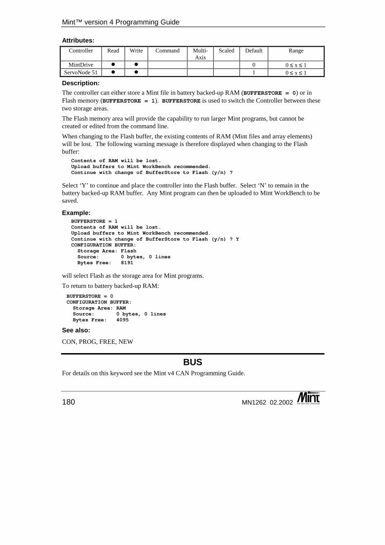
Mint™ version 4 Programming Guide
180 MN1262 02.2002
Attributes: Controller Read Write Command Multi-
Axis Scaled Default Range
MintDrive � � 0 0 ≤ x ≤ 1 ServoNode 51 � � 1 0 ≤ x ≤ 1
Description: The controller can either store a Mint file in battery backed-up RAM (BUFFERSTORE = 0) or in Flash memory (BUFFERSTORE = 1). BUFFERSTORE is used to switch the Controller between these two storage areas. The Flash memory area will provide the capability to run larger Mint programs, but cannot be created or edited from the command line. When changing to the Flash buffer, the existing contents of RAM (Mint files and array elements) will be lost. The following warning message is therefore displayed when changing to the Flash buffer:
Contents of RAM will be lost.Upload buffers to Mint WorkBench recommended.Continue with change of BufferStore to Flash (y/n) ?
Select ‘Y’ to continue and place the controller into the Flash buffer. Select ‘N’ to remain in the battery backed-up RAM buffer. Any Mint program can then be uploaded to Mint WorkBench to be saved.
Example: BUFFERSTORE = 1Contents of RAM will be lost.Upload buffers to Mint WorkBench recommended.Continue with change of BufferStore to Flash (y/n) ? YCONFIGURATION BUFFER:Storage Area: FlashSource: 0 bytes, 0 linesBytes Free: 8191
will select Flash as the storage area for Mint programs. To return to battery backed-up RAM: BUFFERSTORE = 0CONFIGURATION BUFFER:Storage Area: RAMSource: 0 bytes, 0 linesBytes Free: 4095
See also: CON, PROG, FREE, NEW
BUS For details on this keyword see the Mint v4 CAN Programming Guide.

Keyword Reference Guide
MN1262 02.2002 181
BUSVOLTAGE/BV This is an advanced Mint feature. Full details can be found in the Mint v4 Advanced Programming Guide.
BUSVOLTAGETHRESHOLD/BVT This is an advanced Mint feature. Full details can be found in the Mint v4 Advanced Programming Guide.
CAM/CM Purpose: Perform a cam profile.
Controllers Supported: NextMove PCI NextMove PC NextMove BX MintDrive ServoNode 51
� � � � �
Format: CAM[axes] = <expression> {,<expression> ...}v = CAM[axis]
Dot Parameters: Axis - Axis No.
Attributes: Controller Read Write Command Multi-
Axis Scaled Default Range
All � � � 0 ≤ x ≤ 15
Description: Cam profiling is where a slave axis is linked to a master axis so that a given move distance on the master will produce a motion of a pre-defined distance on the slave. A software cam is created by breaking the motion into a number of segments. Each segment defines how far the slave axis will travel for a given move distance on the master axis. Once these segments have been defined, a path between them is produced, the interpolation method being set by the user. The user controls the size and accuracy of the segments. Using a large number of small segments will produce smoother motion. Motion across each segment and across segment boundaries will go through all specified points. The segment information for a cam profile is defined in an array called a table. A table of positions has to be defined together with an optional table of master increments. The tables are selected with the CAMTABLE function. Slave positions defined in the table can be interpreted in one of three ways:
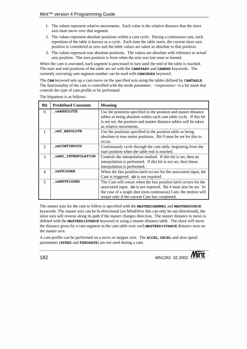
Mint™ version 4 Programming Guide
182 MN1262 02.2002
1. The values represent relative movements. Each value is the relative distance that the slave axis must move over that segment.
2. The values represent absolute positions within a cam cycle. During a continuous cam, each repetition of the table is known as a cycle. Each time the table starts, the current slave axis position is considered as zero and the table values are taken as absolute to that position.
3. The values represent true absolute positions. The values are absolute with reference to actual axis position. The zero position is from when the axis was last reset or homed.
When the cam is executed, each segment is processed in turn until the end of the table is reached. The start and end positions of the table are set with the CAMSTART and CAMEND keywords. The currently executing cam segment number can be read with CAMINDEX keyword. The CAM keyword sets up a cam move on the specified axis using the tables defined by CAMTABLE. The functionality of the cam is controlled with the mode parameter. <expression> is a bit mask that controls the type of cam profile to be performed. The bitpattern is as follows:
Bit Predefined Constants Meaning 0 _cmABSOLUTE Use the positions specified in the position and master distance
tables as being absolute within each cam table cycle. If this bit is not set, the position and master distance tables will be taken as relative movements.
1 _cmT_ABSOLUTE Use the positions specified in the position table as being absolute to true motor positions. Bit 0 must be set for this to occur.
2 _cmCONTINUOUS Continuously cycle through the cam table, beginning from the start position when the table end is reached.
3 _cmNO_INTERPOLATION Controls the interpolation method. If this bit is set, then no interpolation is performed. If this bit is not set, then linear interpolation is performed.
4 _cmTRIGGER When the fast position latch occurs for the associated input, the Cam is triggered. GO is not required.
5 _cmRETRIGGER The Cam will restart when the fast position latch occurs for the associated input. GO is not required. Bit 4 must also be set. In the case of a single shot (non-continuous) Cam, the motion will restart only if the current Cam has completed.
The master axis for the cam to follow is specified with the MASTERCHANNEL and MASTERSOURCE keywords. The master axis can be bi-directional (on MintDrive this can only be uni-directional), the slave axis will reverse along its path if the master changes direction. The master distance to move is defined with the MASTERDISTANCE keyword or using a master distance table. The slave will move the distance given by a cam segment in the cam table over each MASTERDISTANCE distance seen on the master axis. A cam profile can be performed on a servo or stepper axis. The ACCEL, DECEL and slew speed parameters (SPEED and FEEDRATE) are not used during a cam.
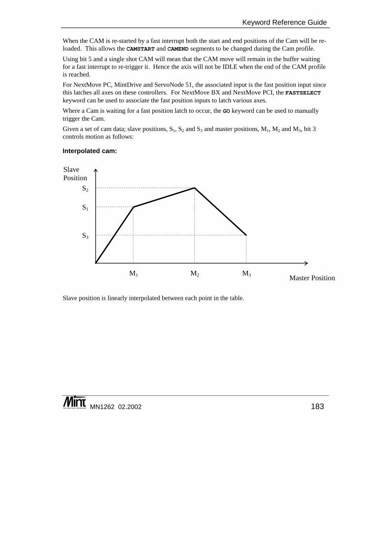
Keyword Reference Guide
MN1262 02.2002 183
When the CAM is re-started by a fast interrupt both the start and end positions of the Cam will be re-loaded. This allows the CAMSTART and CAMEND segments to be changed during the Cam profile. Using bit 5 and a single shot CAM will mean that the CAM move will remain in the buffer waiting for a fast interrupt to re-trigger it. Hence the axis will not be IDLE when the end of the CAM profile is reached. For NextMove PC, MintDrive and ServoNode 51, the associated input is the fast position input since this latches all axes on these controllers. For NextMove BX and NextMove PCI, the FASTSELECT keyword can be used to associate the fast position inputs to latch various axes. Where a Cam is waiting for a fast position latch to occur, the GO keyword can be used to manually trigger the Cam. Given a set of cam data; slave positions, S1, S2 and S3 and master positions, M1, M2 and M3, bit 3 controls motion as follows:
Interpolated cam:
Master Position
SlavePosition
M1 M3M2
S3
S2
S1
Slave position is linearly interpolated between each point in the table.

Mint™ version 4 Programming Guide
184 MN1262 02.2002
Non-Interpolated cam :
Master Position
SlavePosition
M1 M3M2
S3
S2
S1
Slave position is not interpolated so position is constant during a segment.
Example: To define a cam table with twelve segments, the segments are defined in an array.
DIM myPositions (20) = 12, 0, 1, 2, 3, 4, 5, 5, 4, 3, 2, 1, 0
The first element in the table defines the number of segments used to make up the cam, for the cam table only. This does not apply to the master table.
The cam table can be made up of relative positions or absolute positions within the cam profile. The nature of the positions is given by the command used to start cam profiling. The CAMTABLE keyword specifies the name of the array to use and the CAM keyword starts the cam.
DIM myPositions (20) = 12, 0, 1, 2, 3, 4, 5, 5, 4, 3, 2, 1, 0REM Use the MASTERDISTANCE keyword to specify the master distanceCAMTABLE (3, myPositions, NULL)MASTERDISTANCE.3 = 5 : REM Master distance is 5 user unitsREM Read cam table positions as absolute within the cam and perform aREM continuous cam cycleCAM.3 = 5GO.3 : REM Start the motion
Reading the CAM keyword will return the mode of the currently executing cam. The current segment index in the cam table is read using the CAMINDEX keyword. For example:
PAUSE CAMINDEX.3 = 5OUT1 = 1PAUSE CAMINDEX.3 = 9OUT1 = 0
When the 5th cam point is executed, output bit 1 is set. The output is cleared on the 9th cam point.
Keyword Reference Guide
MN1262 02.2002 185
The positions in the table are either relative or absolute to the start of the cam, depending on the mode of the cam. The number of positions must equal the number of positions in the cam table. The master distance table will override the MASTERDISTANCE keyword. The elements in the master distance table are all relative. A table of different master increments can be defined and used in the cam profile. For example:
DIM master(11) = 5, 5, 5, 5, 5, 0.5, 5, 5, 5, 5, 9.5
Note that the master table does not have a first element that specifies the number of Cam segments. The use of master distance table is indicated in the CAMTABLE keyword.
CAMTABLE (3, myPositions, master)
The cam profile executes in the background once started with the GO keyword. It will continue until the cam comes to a natural end or the move is terminated by the user with ABORT, STOP, CANCEL, RESET or RESETALL or by a motion error. If STOP is called, the cam will not terminate immediately but continue until the current end segment is reached. On NextMove, a move of type _mdCAM will be set up in the move buffer. No further moves can be loaded while the cam is in progress and the axis must be idle before the cam can be loaded.
Notes:
• The first element in the cam table defines the number of cam segments. This allows for greater flexibility in defining different tables. The master distance table does not have this element.
• Absolute cams have a starting position of 0 within the cam cycle. • Multiple cam tables can be defined using the CAMSTART and CAMEND keywords. • The master distance for a segment must be greater than zero. If a segment is found with an
invalid master distance then an asynchronous slave synchronization error (bit 11) will be generated and the cam will crash stop and the drive will be disabled.
• Cams are profiled every profiler tick: dependent on LOOPTIME for MintDrive; 2ms for NextMove. If a segment is shorter than 2ms, then that segment may be skipped and the next segment used. Up to five segments may be skipped in 2ms, giving an effective minimum segment duration of 400 microseconds. If more than 5 segments are skipped, an asynchronous slave synchronization error (AXISERROR bit 11) will be generated and the CAM will crash stop and the drive will be disabled.
See Also: CAMEND, CAMINDEX, CAMSTART, CAMTABLE, MASTERCHANNEL, MASTERDISTANCE, MASTERSOURCE, SPLINE, STOP
CAMAMPLITUDE/CMA This is an advanced Mint feature. Full details can be found in the Mint v4 Advanced Programming Guide.
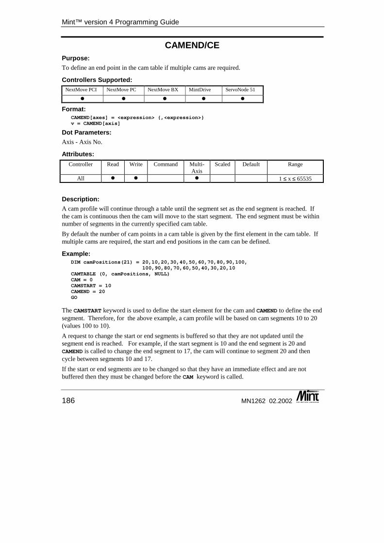
Mint™ version 4 Programming Guide
186 MN1262 02.2002
CAMEND/CE Purpose: To define an end point in the cam table if multiple cams are required.
Controllers Supported: NextMove PCI NextMove PC NextMove BX MintDrive ServoNode 51
� � � � �
Format: CAMEND[axes] = <expression> {,<expression>}v = CAMEND[axis]
Dot Parameters: Axis - Axis No.
Attributes: Controller Read Write Command Multi-
Axis Scaled Default Range
All � � � 1 ≤ x ≤ 65535
Description: A cam profile will continue through a table until the segment set as the end segment is reached. If the cam is continuous then the cam will move to the start segment. The end segment must be within number of segments in the currently specified cam table. By default the number of cam points in a cam table is given by the first element in the cam table. If multiple cams are required, the start and end positions in the cam can be defined.
Example: DIM camPositions(21) = 20,10,20,30,40,50,60,70,80,90,100,
100,90,80,70,60,50,40,30,20,10CAMTABLE (0, camPositions, NULL)CAM = 0CAMSTART = 10CAMEND = 20GO
The CAMSTART keyword is used to define the start element for the cam and CAMEND to define the end segment. Therefore, for the above example, a cam profile will be based on cam segments 10 to 20 (values 100 to 10). A request to change the start or end segments is buffered so that they are not updated until the segment end is reached. For example, if the start segment is 10 and the end segment is 20 and CAMEND is called to change the end segment to 17, the cam will continue to segment 20 and then cycle between segments 10 and 17. If the start or end segments are to be changed so that they have an immediate effect and are not buffered then they must be changed before the CAM keyword is called.

Keyword Reference Guide
MN1262 02.2002 187
The first element in a Mint array has an index value of 1. Since the first element in our cam table defines the number of cam segments, the first cam segment has an index of 2 in the Mint array. CAMEND refers to the cam segment, so to set it to point to the fifth cam segment it should be set to 5 (i.e. it refers to the cam segment not the element index in the Mint array).
See also: CAM, CAMINDEX, CAMSTART, CAMTABLE
CAMINDEX/CI Purpose: Returns the currently executing cam segment number.
Controllers Supported: NextMove PCI NextMove PC NextMove BX MintDrive ServoNode 51
� � � � �
Format: v = CAMINDEX[axis]
Dot Parameters: Axis - Axis No.
Attributes: Controller Read Write Command Multi-
Axis Scaled Default Range
All � 1 ≤ x ≤ 65535
Description: When a cam profile is performed, the currently executing segment in the table can be read using the CAMINDEX keyword.
? CAMINDEX
This will display the current segment number. To use this value as in index into the position array then 1 must be added to the value as the first array specifies the number of segments.
Example: ? myPosition (CAMINDEX + 1)
This will display the position value for the currently executing cam from the cam table myPosition. In order to interpret the value as relative or absolute, the CAM keyword can be read to see the mode of the cam. If no cam profile is in progress then the last segment number from the last cam profile is returned.
See also: CAM, CAMEND, CAMSTART, CAMTABLE
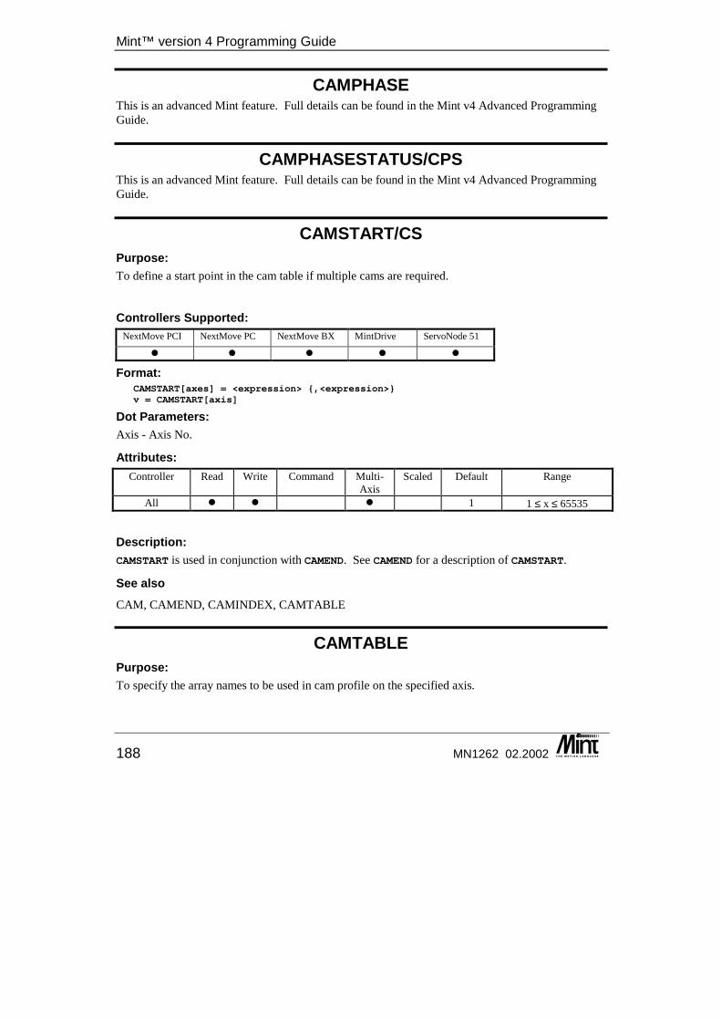
Mint™ version 4 Programming Guide
188 MN1262 02.2002
CAMPHASE This is an advanced Mint feature. Full details can be found in the Mint v4 Advanced Programming Guide.
CAMPHASESTATUS/CPS This is an advanced Mint feature. Full details can be found in the Mint v4 Advanced Programming Guide.
CAMSTART/CS Purpose: To define a start point in the cam table if multiple cams are required.
Controllers Supported: NextMove PCI NextMove PC NextMove BX MintDrive ServoNode 51
� � � � �
Format: CAMSTART[axes] = <expression> {,<expression>}v = CAMSTART[axis]
Dot Parameters: Axis - Axis No.
Attributes: Controller Read Write Command Multi-
Axis Scaled Default Range
All � � � 1 1 ≤ x ≤ 65535
Description: CAMSTART is used in conjunction with CAMEND. See CAMEND for a description of CAMSTART.
See also CAM, CAMEND, CAMINDEX, CAMTABLE
CAMTABLE Purpose: To specify the array names to be used in cam profile on the specified axis.

Keyword Reference Guide
MN1262 02.2002 189
Controllers Supported: NextMove PCI NextMove PC NextMove BX MintDrive ServoNode 51
� � � � �
Format: CAMTABLE ( axis, position array, {master increment array} )
Dot Parameters: Axis - Axis No. Position Array Master Increment Array
Attributes: Controller Read Write Command Multi-
Axis Scaled Default Range
MintDrive & ServoNode
� � � -65535.0 ≤ x ≤ 65535.0
NextMove � � � -8388607.0 ≤ x ≤ 8388607.0
Description: A cam profile is defined by splitting the motion into segments which form the cam table. The information about these segments are stored in normal user arrays which can have any name. Two tables can be defined for a cam profile, the position table and the master distance table. Each segment of the position array specifies how far and in which direction the slave axis will move for that segment. The table is defined using an array which defines the number of segments in the table and the table itself. The first element of the array specifies the number of segments defined in the table and the subsequent values define the cam segments. The values are in user units, as set with the SCALE keyword and the table can have any number of segments, (memory space permitting). When the cam is executed, each segment is processed in turn until the end of the table is reached. A single shot cam will stop when the end of the table is reached. A continuous cam will repeat the table when the end is reached. The CAM keyword controls whether the cam is single shot or continuous. The positions in the table can be interpreted in three ways; relative, absolute to the cycle or true absolute. See the CAM keyword for full details. The master distance tells the cam the distance the master axis must move to complete the segment being executed. The master distance can either be set identically for each segment or a separate value can be defined for each segment. The ability to define the master distance for each segment allows for critical points on a profile profiles to be defined more easily. Where the slave motion is not critical, a large master distance can be set so the slave travels a large distance in only one or two segments. Then where the motion is more important, smaller master increments are defined, allowing the segment moves to be smaller and more detailed. A general master distance is defined with the MASTERDISTANCE keyword.
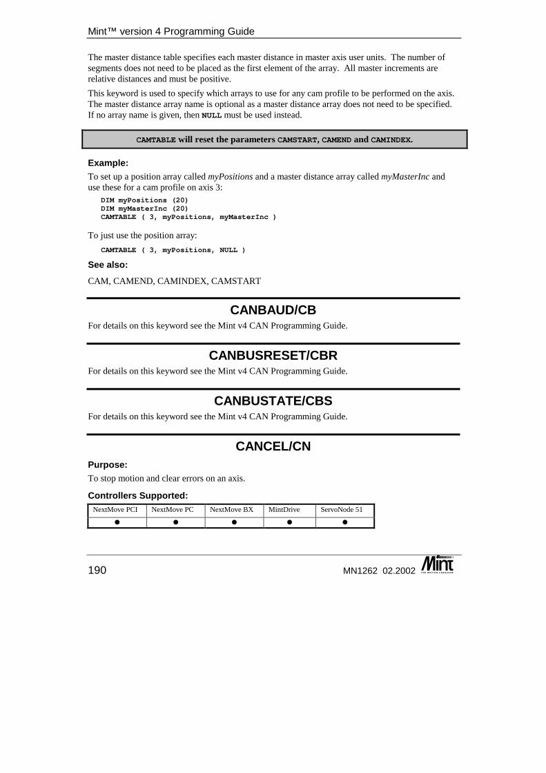
Mint™ version 4 Programming Guide
190 MN1262 02.2002
The master distance table specifies each master distance in master axis user units. The number of segments does not need to be placed as the first element of the array. All master increments are relative distances and must be positive. This keyword is used to specify which arrays to use for any cam profile to be performed on the axis. The master distance array name is optional as a master distance array does not need to be specified. If no array name is given, then NULL must be used instead.
CAMTABLE will reset the parameters CAMSTART, CAMEND and CAMINDEX.
Example: To set up a position array called myPositions and a master distance array called myMasterInc and use these for a cam profile on axis 3:
DIM myPositions (20)DIM myMasterInc (20)CAMTABLE ( 3, myPositions, myMasterInc )
To just use the position array: CAMTABLE ( 3, myPositions, NULL )
See also: CAM, CAMEND, CAMINDEX, CAMSTART
CANBAUD/CB For details on this keyword see the Mint v4 CAN Programming Guide.
CANBUSRESET/CBR For details on this keyword see the Mint v4 CAN Programming Guide.
CANBUSTATE/CBS For details on this keyword see the Mint v4 CAN Programming Guide.
CANCEL/CN Purpose: To stop motion and clear errors on an axis.
Controllers Supported: NextMove PCI NextMove PC NextMove BX MintDrive ServoNode 51
� � � � �
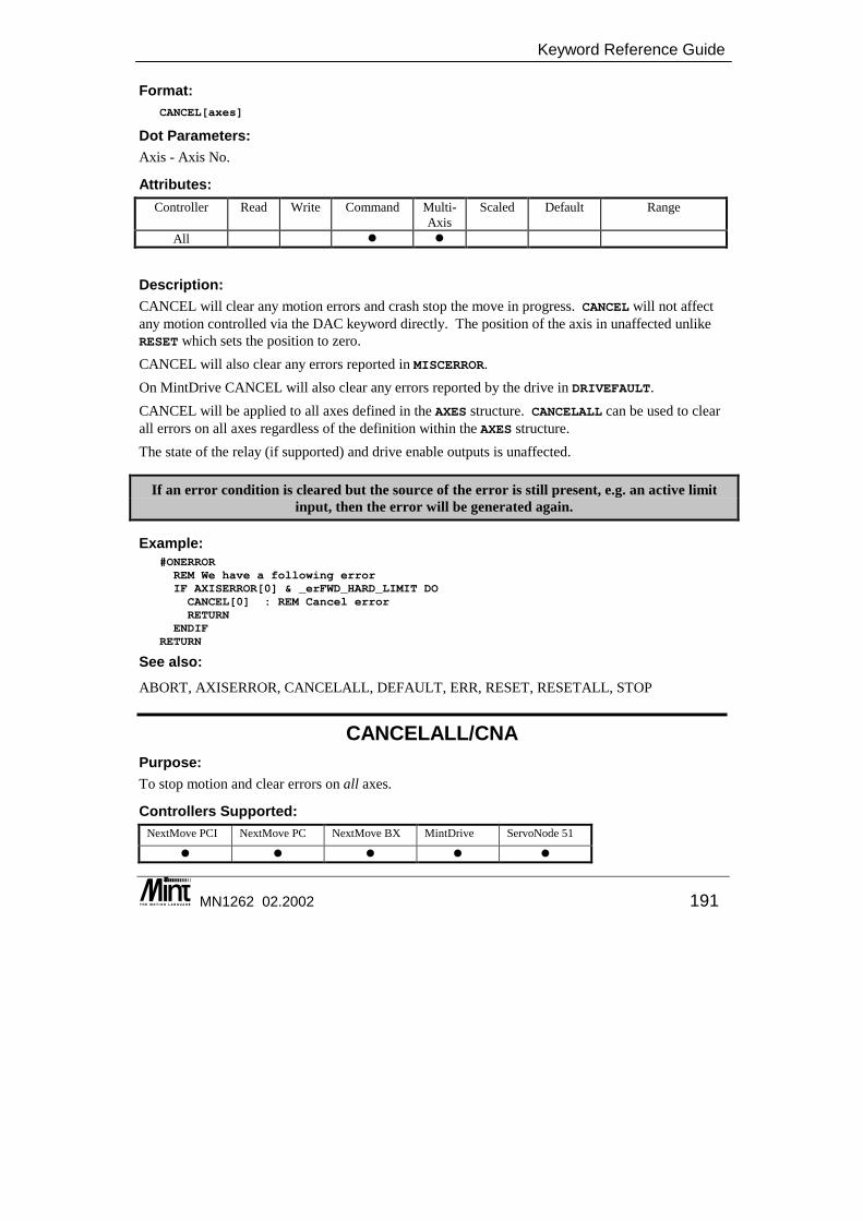
Keyword Reference Guide
MN1262 02.2002 191
Format: CANCEL[axes]
Dot Parameters: Axis - Axis No.
Attributes: Controller Read Write Command Multi-
Axis Scaled Default Range
All � �
Description: CANCEL will clear any motion errors and crash stop the move in progress. CANCEL will not affect any motion controlled via the DAC keyword directly. The position of the axis in unaffected unlike RESET which sets the position to zero. CANCEL will also clear any errors reported in MISCERROR. On MintDrive CANCEL will also clear any errors reported by the drive in DRIVEFAULT. CANCEL will be applied to all axes defined in the AXES structure. CANCELALL can be used to clear all errors on all axes regardless of the definition within the AXES structure. The state of the relay (if supported) and drive enable outputs is unaffected.
If an error condition is cleared but the source of the error is still present, e.g. an active limit input, then the error will be generated again.
Example: #ONERRORREM We have a following errorIF AXISERROR[0] & _erFWD_HARD_LIMIT DOCANCEL[0] : REM Cancel errorRETURN
ENDIFRETURN
See also: ABORT, AXISERROR, CANCELALL, DEFAULT, ERR, RESET, RESETALL, STOP
CANCELALL/CNA Purpose: To stop motion and clear errors on all axes.
Controllers Supported: NextMove PCI NextMove PC NextMove BX MintDrive ServoNode 51
� � � � �
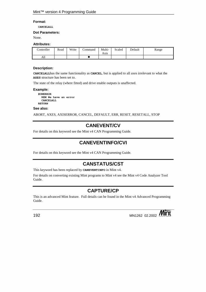
Mint™ version 4 Programming Guide
192 MN1262 02.2002
Format: CANCELALL
Dot Parameters: None.
Attributes: Controller Read Write Command Multi-
Axis Scaled Default Range
All �
Description: CANCELALLhas the same functionality as CANCEL, but is applied to all axes irrelevant to what the AXES structure has been set to. The state of the relay (where fitted) and drive enable outputs is unaffected.
Example: #ONERRORREM We have an errorCANCELALL
RETURN
See also: ABORT, AXES, AXISERROR, CANCEL, DEFAULT, ERR, RESET, RESETALL, STOP
CANEVENT/CV For details on this keyword see the Mint v4 CAN Programming Guide.
CANEVENTINFO/CVI For details on this keyword see the Mint v4 CAN Programming Guide.
CANSTATUS/CST This keyword has been replaced by CANEVENTINFO in Mint v4. For details on converting existing Mint programs to Mint v4 see the Mint v4 Code Analyzer Tool Guide.
CAPTURE/CP This is an advanced Mint feature. Full details can be found in the Mint v4 Advanced Programming Guide.
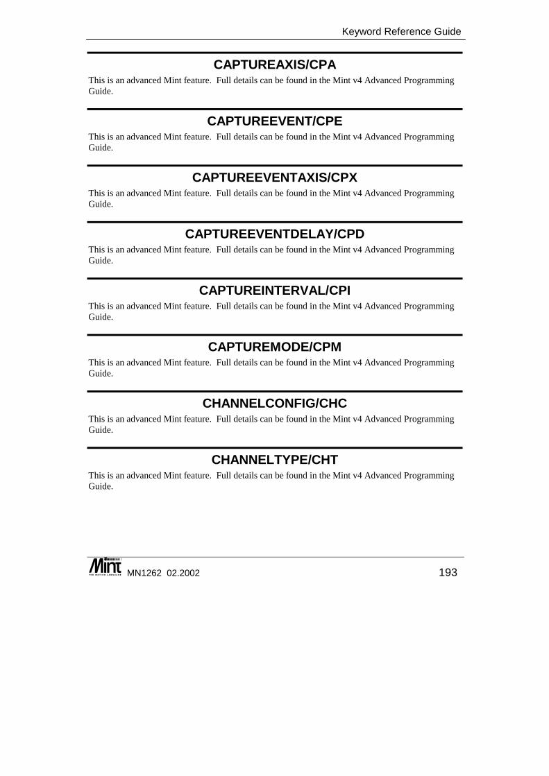
Keyword Reference Guide
MN1262 02.2002 193
CAPTUREAXIS/CPA This is an advanced Mint feature. Full details can be found in the Mint v4 Advanced Programming Guide.
CAPTUREEVENT/CPE This is an advanced Mint feature. Full details can be found in the Mint v4 Advanced Programming Guide.
CAPTUREEVENTAXIS/CPX This is an advanced Mint feature. Full details can be found in the Mint v4 Advanced Programming Guide.
CAPTUREEVENTDELAY/CPD This is an advanced Mint feature. Full details can be found in the Mint v4 Advanced Programming Guide.
CAPTUREINTERVAL/CPI This is an advanced Mint feature. Full details can be found in the Mint v4 Advanced Programming Guide.
CAPTUREMODE/CPM This is an advanced Mint feature. Full details can be found in the Mint v4 Advanced Programming Guide.
CHANNELCONFIG/CHC This is an advanced Mint feature. Full details can be found in the Mint v4 Advanced Programming Guide.
CHANNELTYPE/CHT This is an advanced Mint feature. Full details can be found in the Mint v4 Advanced Programming Guide.
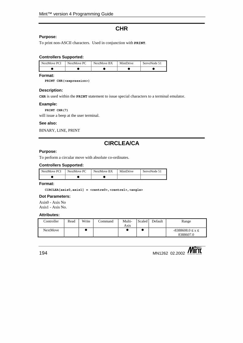
Mint™ version 4 Programming Guide
194 MN1262 02.2002
CHR Purpose: To print non-ASCII characters. Used in conjunction with PRINT.
Controllers Supported: NextMove PCI NextMove PC NextMove BX MintDrive ServoNode 51
� � � � �
Format: PRINT CHR(<expression>)
Description: CHR is used within the PRINT statement to issue special characters to a terminal emulator.
Example: PRINT CHR(7)
will issue a beep at the user terminal.
See also: BINARY, LINE, PRINT
CIRCLEA/CA Purpose: To perform a circular move with absolute co-ordinates.
Controllers Supported: NextMove PCI NextMove PC NextMove BX MintDrive ServoNode 51
� � �
Format: CIRCLEA[axis0,axis1] = <centre0>,<centre1>,<angle>
Dot Parameters: Axis0 - Axis No Axis1 - Axis No.
Attributes: Controller Read Write Command Multi-
Axis Scaled Default Range
NextMove � � � -8388608.0 ≤ x ≤ 8388607.0
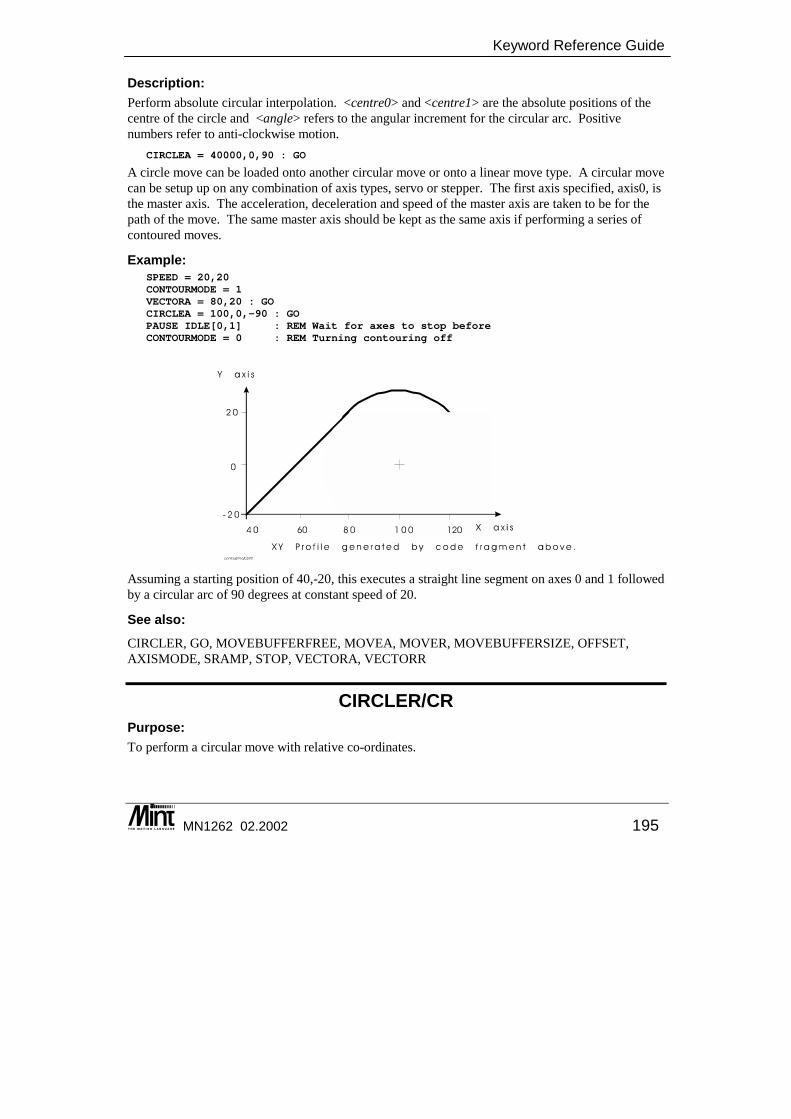
Keyword Reference Guide
MN1262 02.2002 195
Description: Perform absolute circular interpolation. <centre0> and <centre1> are the absolute positions of the centre of the circle and <angle> refers to the angular increment for the circular arc. Positive numbers refer to anti-clockwise motion.
CIRCLEA = 40000,0,90 : GO
A circle move can be loaded onto another circular move or onto a linear move type. A circular move can be setup up on any combination of axis types, servo or stepper. The first axis specified, axis0, is the master axis. The acceleration, deceleration and speed of the master axis are taken to be for the path of the move. The same master axis should be kept as the same axis if performing a series of contoured moves.
Example: SPEED = 20,20CONTOURMODE = 1VECTORA = 80,20 : GOCIRCLEA = 100,0,-90 : GOPAUSE IDLE[0,1] : REM Wait for axes to stop beforeCONTOURMODE = 0 : REM Turning contouring off
Assuming a starting position of 40,-20, this executes a straight line segment on axes 0 and 1 followed by a circular arc of 90 degrees at constant speed of 20.
See also: CIRCLER, GO, MOVEBUFFERFREE, MOVEA, MOVER, MOVEBUFFERSIZE, OFFSET, AXISMODE, SRAMP, STOP, VECTORA, VECTORR
CIRCLER/CR Purpose: To perform a circular move with relative co-ordinates.
Mint™ version 4 Programming Guide
196 MN1262 02.2002
Controllers Supported: NextMove PCI NextMove PC NextMove BX MintDrive ServoNode 51
� � �
Dot Parameters: Axis0 - Axis No Axis1 - Axis No.
Format: CIRCLER[axis0,axis1] = <centre0>,<centre1>,<angle>
Attributes: Controller Read Write Command Multi-
Axis Scaled Default Range
NextMove � � � -8388608.0 ≤ x ≤ 8388607.0
Description: Perform relative circular interpolation. <centre0> and <centre1> are the relative positions of the centre of the circle and <angle> refers to the angular increment for the circular arc. Positive numbers refer to anti-clockwise motion.
CIRCLER = -4500,45.6,-20 : GO
A circle move can be loaded onto another circular move or onto a linear move type. A circular move can be setup up on any combination of axis types, servo or stepper. The first axis specified, axis0, is the master axis. The acceleration, deceleration and speed of the master axis are taken to be for the path of the move. The same master axis should be kept as the same axis if performing a series of contoured moves.
Example: AXES[2,6]SPEED = 20,20CONTOURMODE = 1VECTORR = 40,40 : GOCIRCLER = 20,-20,-90 : GOPAUSE IDLE[2,6] : REM Wait for axes to stop beforeCONTOURMODE = 0 : REM Turning contouring off
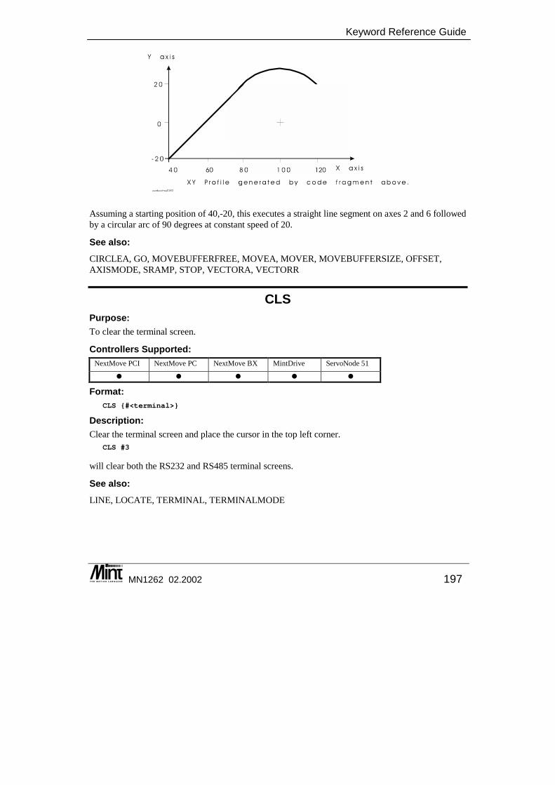
Keyword Reference Guide
MN1262 02.2002 197
Assuming a starting position of 40,-20, this executes a straight line segment on axes 2 and 6 followed by a circular arc of 90 degrees at constant speed of 20.
See also: CIRCLEA, GO, MOVEBUFFERFREE, MOVEA, MOVER, MOVEBUFFERSIZE, OFFSET, AXISMODE, SRAMP, STOP, VECTORA, VECTORR
CLS Purpose: To clear the terminal screen.
Controllers Supported: NextMove PCI NextMove PC NextMove BX MintDrive ServoNode 51
� � � � �
Format: CLS {#<terminal>}
Description: Clear the terminal screen and place the cursor in the top left corner.
CLS #3
will clear both the RS232 and RS485 terminal screens.
See also: LINE, LOCATE, TERMINAL, TERMINALMODE
Mint™ version 4 Programming Guide
198 MN1262 02.2002
COMMS Purpose: Accesses the reserved Comms array.
Controllers Supported: NextMove PCI NextMove PC NextMove BX MintDrive ServoNode 51
� � � � �
Format: COMMS( {node, } element) = <expression>v = COMMS( {node, } element)
Description: ‘COMMS’ is an array that is automatically defined by Mint. i.e. it cannot be redefined by the user with the DIM keyword. The array has 99 general purpose elements that can be used freely by the users’ program. Elements 100 through to 255 are mapped onto system parameters such as position or I/O information. The mapping of these elements are indicated in section 5.6. The Comms array is also accessible over CANopen, allowing one controller to access the contents of another controllers Comms array (see the Mint v4 CAN Programming Guide). The Comms array also supports a protocol that allows read / write access over a serial interface, thus allowing a host to access the Comms array of another controller. The comms protocol provides a simple and convenient method of data transfer and program control between a host and the Controller. The Mint WorkBench also provides the user with the ability to monitor and update individual Comms array elements by means of one or more ‘Comms Windows’. The Mint Interface Library provides communications functions. See the ‘Mint Interface Library’ manual for details.
Example: Using the Comms protocol, allow the PC to control the Mint program by transferring commands and data across dual port RAM.
REM Simple loop showing use of comms protocolREM Comms address 1 - commandREM Comms address 2 - axisREM Comms address 10 - data
COMMS(1) = 0 : REM Clear down the command
LOOPcommand = COMMS(1)axis = COMMS(2)IF command <> 0 DOIF command = 1 THEN SPEED.axis = COMMS(10)
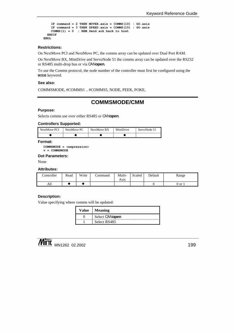
Keyword Reference Guide
MN1262 02.2002 199
IF command = 2 THEN MOVER.axis = COMMS(10) : GO.axisIF command = 3 THEN SPEED.axis = COMMS(10) : GO.axisCOMMS(1) = 0 : REM Send ack back to host
ENDIFENDL
Restrictions: On NextMove PCI and NextMove PC, the comms array can be updated over Dual Port RAM. On NextMove BX, MintDrive and ServoNode 51 the comms array can be updated over the RS232 or RS485 multi-drop bus or via CANopen. To use the Comms protocol, the node number of the controller must first be configured using the NODE keyword.
See also: COMMSMODE, #COMMS1 .. #COMMS5, NODE, PEEK, POKE,
COMMSMODE/CMM Purpose: Selects comms use over either RS485 or CANopen.
Controllers Supported: NextMove PCI NextMove PC NextMove BX MintDrive ServoNode 51
� � � �
Format: COMMSMODE = <expression>v = COMMSMODE
Dot Parameters: None
Attributes: Controller Read Write Command Multi-
Axis Scaled Default Range
All � � 0 0 or 1
Description: Value specifying where comms will be updated:
Value Meaning 0 Select CANopen 1 Select RS485
Mint™ version 4 Programming Guide
200 MN1262 02.2002
Example: Write to a Comms location on a remote CANopen node.
REM Select CANopenCOMSSMODE = 0COMMS (5, 10) = 24 : REM Write to node 5, location 10, data = 24
See also: COMMS
COMMSON This keyword is not available in Mint v4. For details on converting existing Mint programs to Mint v4 see the Mint v4 Code Analyzer Tool Guide.
COMMSOFF This keyword is not available in Mint v4. For details on converting existing Mint programs to Mint v4 see the Mint v4 Code Analyzer Tool Guide.
COMPARELATCH/CLT This is an advanced Mint feature. Full details can be found in the Mint v4 Advanced Programming Guide.
COMPAREMODE/CMD This is an advanced Mint feature. Full details can be found in the Mint v4 Advanced Programming Guide.
COMPAREPOS/CMP This is an advanced Mint feature. Full details can be found in the Mint v4 Advanced Programming Guide.
CONFIG/CF Purpose: To set the configuration of an axis for different motor types.
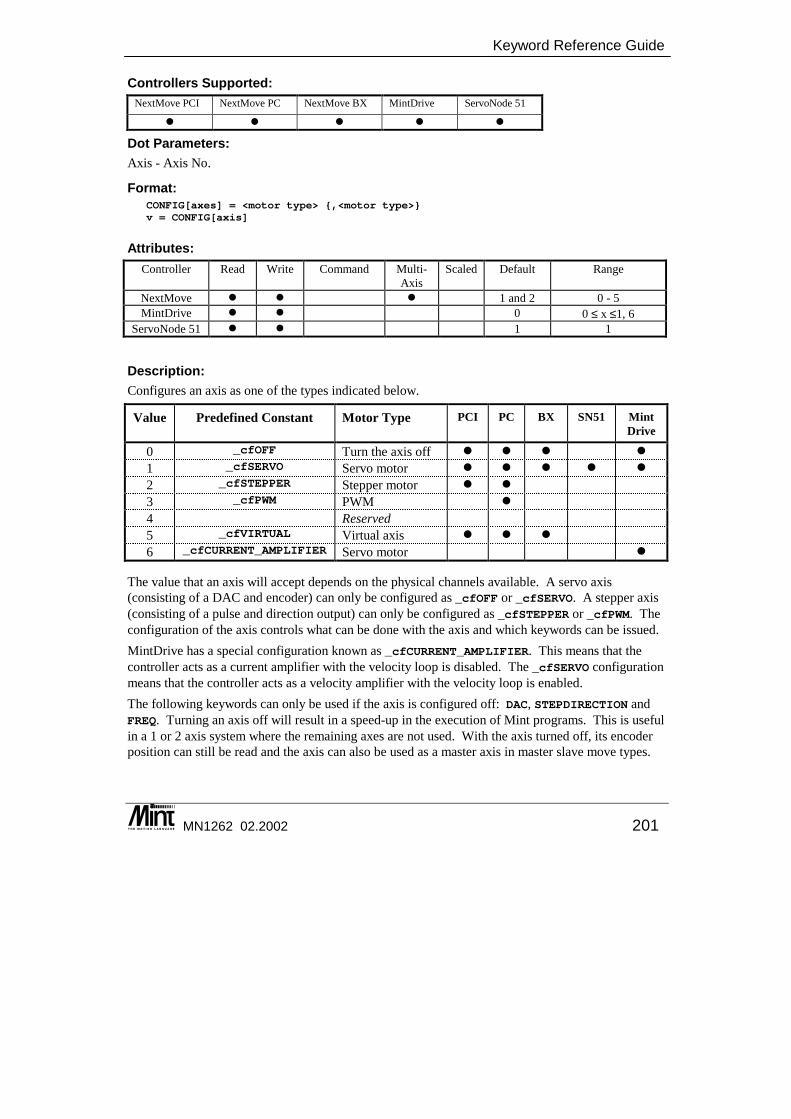
Keyword Reference Guide
MN1262 02.2002 201
Controllers Supported: NextMove PCI NextMove PC NextMove BX MintDrive ServoNode 51
� � � � �
Dot Parameters: Axis - Axis No.
Format: CONFIG[axes] = <motor type> {,<motor type>}v = CONFIG[axis]
Attributes: Controller Read Write Command Multi-
Axis Scaled Default Range
NextMove � � � 1 and 2 0 - 5 MintDrive � � 0 0 ≤ x ≤1, 6
ServoNode 51 � � 1 1
Description: Configures an axis as one of the types indicated below.
Value Predefined Constant Motor Type PCI PC BX
SN51 Mint Drive
0 _cfOFF Turn the axis off � � � � 1 _cfSERVO Servo motor � � � � � 2 _cfSTEPPER Stepper motor � � 3 _cfPWM PWM � 4 Reserved 5 _cfVIRTUAL Virtual axis � � � 6 _cfCURRENT_AMPLIFIER Servo motor �
The value that an axis will accept depends on the physical channels available. A servo axis (consisting of a DAC and encoder) can only be configured as _cfOFF or _cfSERVO. A stepper axis (consisting of a pulse and direction output) can only be configured as _cfSTEPPER or _cfPWM. The configuration of the axis controls what can be done with the axis and which keywords can be issued. MintDrive has a special configuration known as _cfCURRENT_AMPLIFIER. This means that the controller acts as a current amplifier with the velocity loop is disabled. The _cfSERVO configuration means that the controller acts as a velocity amplifier with the velocity loop is enabled. The following keywords can only be used if the axis is configured off: DAC, STEPDIRECTION and FREQ. Turning an axis off will result in a speed-up in the execution of Mint programs. This is useful in a 1 or 2 axis system where the remaining axes are not used. With the axis turned off, its encoder position can still be read and the axis can also be used as a master axis in master slave move types.

Mint™ version 4 Programming Guide
202 MN1262 02.2002
A virtual axis is where moves can be executed on that axis without producing any physical output. Axis position is simulated so that a motion program can be tested in the lab or a virtual axis can be created that can be used in other motion types. All axis keywords can be used as normal.
Example: CONFIG[3,4,7] = _cfOFF, _cfOFF, _cfOFF
This will configure axes 3, 4 and 7 as off. Due to the hardware restraints on NextMove, the stepper axes can not be configured as _cfPWM and _cfSTEPPER at the same time. Changing the configuration of one axis will automatically change the configuration of other axes.
Example: CONFIG[4,7] = _cfOFF;CONFIG[5,6] = _cfSTEPPER;
These would turn axes 4 and 7 off, allowing the stepper channels to be used as user outputs. Axes 5 and 6 are configured for normal use as steppers. Issuing the keyword
CONFIG.5 = _cfPWM
would result in both axes 5 AND 6 being changed to _cfPWM since _ cfPWM and _stepper are mutually exclusive across the stepper axes.
Restrictions: Drive must be disabled in order to change configuration. Calling CONFIG will cause an automatic call to the DEFAULT keyword for the axis requiring all tuning terms and axis parameters to be set to their default values.
Controller Specifics: On NextMove PC the default configuration is _cfSERVO for the servo axes (0 to 3) and _cfSTEPPER for the stepper axes (4 to 7). If a NextMove PC Expansion card is attached then the default configuration will depend on the type of expansion card. PWM is not available on a stepper NextMove PC Expansion card. NextMove PCI default configurations will be all _cfSERVO if there are up to 4 axes of control available. If there are eight axes of control then the default is as that for NextMove PC. On NextMove PCI, configuring an axis as off removes any fast input associations for that axis. When the axis is re-configured as a servo, the FASTSELECT keyword would have to be used to set up the fast inputs for that axis.
See also: DAC, FREQ, NUMBEROF, STEPDIRECTION, VIEW
CONNECT/CNN For details on this keyword see the Mint v4 CAN Programming Guide.
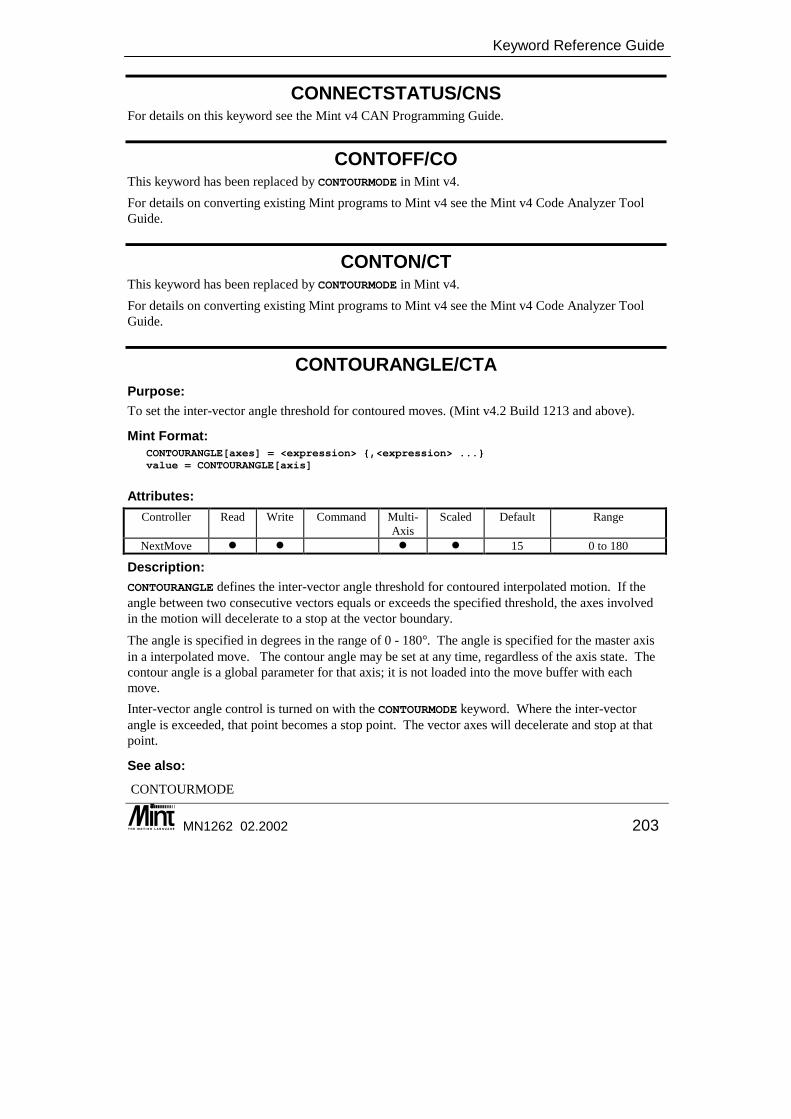
Keyword Reference Guide
MN1262 02.2002 203
CONNECTSTATUS/CNS For details on this keyword see the Mint v4 CAN Programming Guide.
CONTOFF/CO This keyword has been replaced by CONTOURMODE in Mint v4. For details on converting existing Mint programs to Mint v4 see the Mint v4 Code Analyzer Tool Guide.
CONTON/CT This keyword has been replaced by CONTOURMODE in Mint v4. For details on converting existing Mint programs to Mint v4 see the Mint v4 Code Analyzer Tool Guide.
CONTOURANGLE/CTA Purpose: To set the inter-vector angle threshold for contoured moves. (Mint v4.2 Build 1213 and above).
Mint Format: CONTOURANGLE[axes] = <expression> {,<expression> ...}value = CONTOURANGLE[axis]
Attributes: Controller Read Write Command Multi-
Axis Scaled Default Range
NextMove � � � � 15 0 to 180
Description: CONTOURANGLE defines the inter-vector angle threshold for contoured interpolated motion. If the angle between two consecutive vectors equals or exceeds the specified threshold, the axes involved in the motion will decelerate to a stop at the vector boundary. The angle is specified in degrees in the range of 0 - 180�. The angle is specified for the master axis in a interpolated move. The contour angle may be set at any time, regardless of the axis state. The contour angle is a global parameter for that axis; it is not loaded into the move buffer with each move. Inter-vector angle control is turned on with the CONTOURMODE keyword. Where the inter-vector angle is exceeded, that point becomes a stop point. The vector axes will decelerate and stop at that point.
See also: CONTOURMODE

Mint™ version 4 Programming Guide
204 MN1262 02.2002
CONTOURMODE/CTM Purpose: To enable contouring for interpolated moves.
Controllers Supported: NextMove PCI NextMove PC NextMove BX MintDrive ServoNode 51
� � �
Format: CONTOURMODE[axes] = <expression> {,<expression> ...}v = CONTOURMODE[axis]
Dot Parameters: Axis - Axis No.
Attributes: Controller Read Write Command Multi-
Axis Scaled Default Range
NextMove � � 0 0 or 1
Description: CONTOURMODE allows a series of interpolated moves to be blended together to give a continuous path velocity. When contouring is turned on, consecutive moves are blended together so that the axes do not decelerate to a stop at the vector boundaries. CONTOURMODE is called for the master axis in multi-axis motion. The contour mode is loaded with each move into the move buffer. This means that it is possible to pre-program a sequence of vectors that will then start and stop as they execute according to the mode they were loaded with. The way that contouring operates has been modified in Mint v4.2 Build 1213 and above. Pre Mint v4.2 Build 1213: A constant path speed bewteen two vectors will only be maintained (contoured) if both vectors were loaded with contouring turned on. This effectively creates two stop points if a single vector is loaded without contouring. The following example shows the behavior.
CONTOURMODE = 1MOVER = 10MOVER = 10CONTOURMODE = 0MOVER = 10CONTOURMODE = 1MOVER = 10MOVER = 10

Keyword Reference Guide
MN1262 02.2002 205
Loading one vector with contouring off results in two stop points. What we have requested is not to contour in or out of that vector. CONTOURMODE accepts the following values:
Value Constant Meaning 0 _ctmCONTOUR_OFF Contouring is turned off. The axes will decelerate to a stop
between moves. 1 _ctmCONTOUR_ON Contouring is turned on. The axes will travel at a constant path
speed between moves.
Mint v4.2 Build 1213 and above: CONTOURMODE also allows inter-vector angle control to be turned on. If the angle between two consecutive vectors exceeds a threshold set with CONTOURANGLE, then the axes will decelerate at that point. This would produce a single stop point in the velocity profile. This way, it is possible to specify which inter-vector boundaries result in a stop, which must not stop and which use inter-vector angle control. The implementation of inter-vector angle control has forced a slight change in the way that contouring operates. Inter-vector angle control is used to create a stop point where the inter-vector angle exceeds a threshold. This implies that only one stop point is created, i.e. where the angle threshold is exceeded. In the new implementation, the contour mode that a vector is loaded with controls the end point of that vector. If a vector is loaded with contouring off, only the end of that vector will be a stop point.
CONTOURMODE = 1MOVER = 10MOVER = 10CONTOURMODE = 0MOVER = 10CONTOURMODE = 1MOVER = 10MOVER = 10
Time
Vel
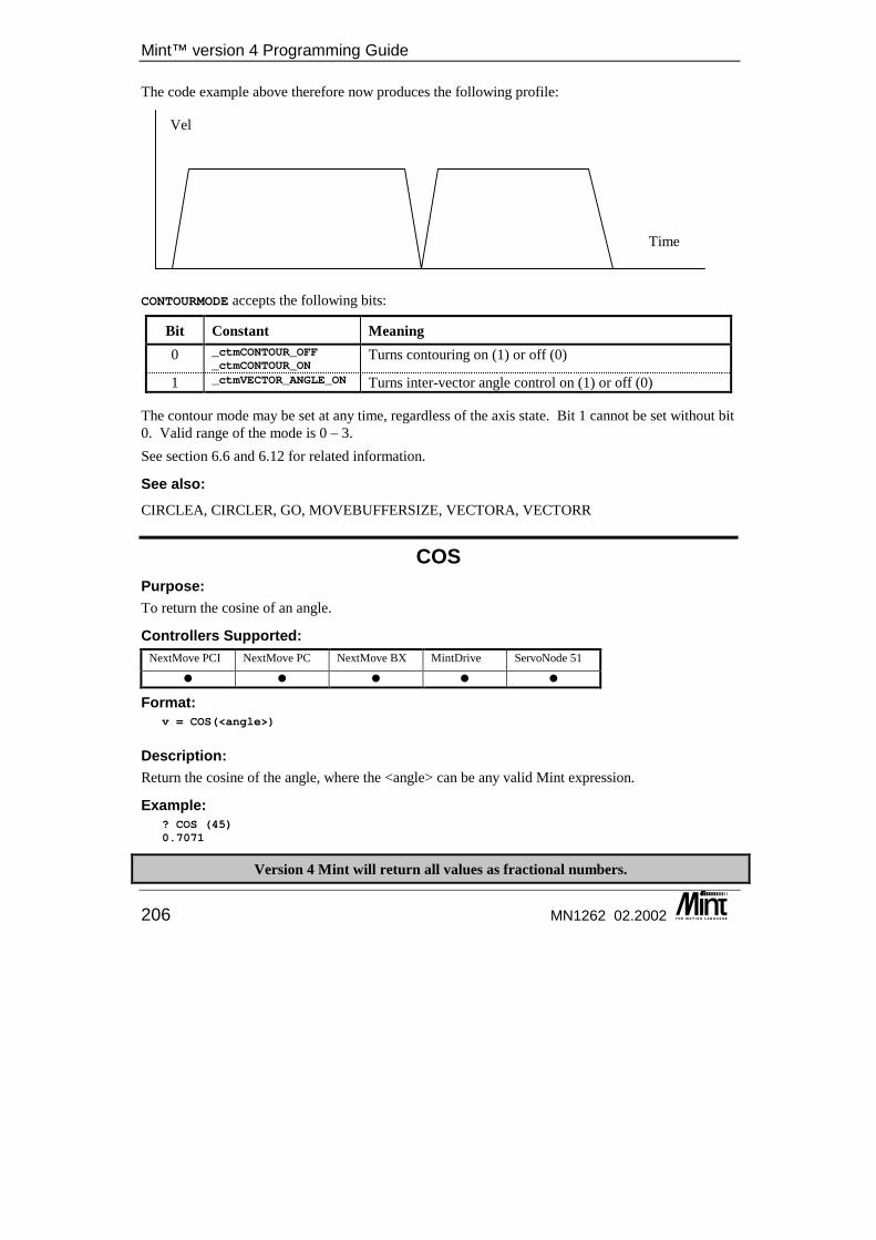
Mint™ version 4 Programming Guide
206 MN1262 02.2002
The code example above therefore now produces the following profile: CONTOURMODE accepts the following bits:
Bit Constant Meaning 0 _ctmCONTOUR_OFF
_ctmCONTOUR_ONTurns contouring on (1) or off (0)
1 _ctmVECTOR_ANGLE_ON Turns inter-vector angle control on (1) or off (0)
The contour mode may be set at any time, regardless of the axis state. Bit 1 cannot be set without bit 0. Valid range of the mode is 0 – 3. See section 6.6 and 6.12 for related information.
See also: CIRCLEA, CIRCLER, GO, MOVEBUFFERSIZE, VECTORA, VECTORR
COS Purpose: To return the cosine of an angle.
Controllers Supported: NextMove PCI NextMove PC NextMove BX MintDrive ServoNode 51
� � � � �
Format: v = COS(<angle>)
Description: Return the cosine of the angle, where the <angle> can be any valid Mint expression.
Example: ? COS (45)0.7071
Version 4 Mint will return all values as fractional numbers.
Time
Vel
Keyword Reference Guide
MN1262 02.2002 207
See also: ACOS, SIN, TAN, ASIN, ATAN
CURRENTLIMIT/CL This is an advanced Mint feature. Full details can be found in the Mint v4 Advanced Programming Guide.
CURRENTLIMITAREA/CLA This is an advanced Mint feature. Full details can be found in the Mint v4 Advanced Programming Guide.
CURRENTLIMITCONT/CLC This is an advanced Mint feature. Full details can be found in the Mint v4 Advanced Programming Guide.
CURRENTLIMITMODE/CLM This is an advanced Mint feature. Full details can be found in the Mint v4 Advanced Programming Guide.
CURRENTLIMITTIME/CLT This is an advanced Mint feature. Full details can be found in the Mint v4 Advanced Programming Guide.
CURRENTMEAS/CMS This is an advanced Mint feature. Full details can be found in the Mint v4 Advanced Programming Guide.
CURRLIMIT/CL This keyword has been replaced by CURRENTLIMIT in Mint v4. For details on converting existing Mint programs to Mint v4 see the Mint v4 Code Analyzer Tool Guide
DAC/DC Purpose: To write a value to the DAC or read the present DAC value.
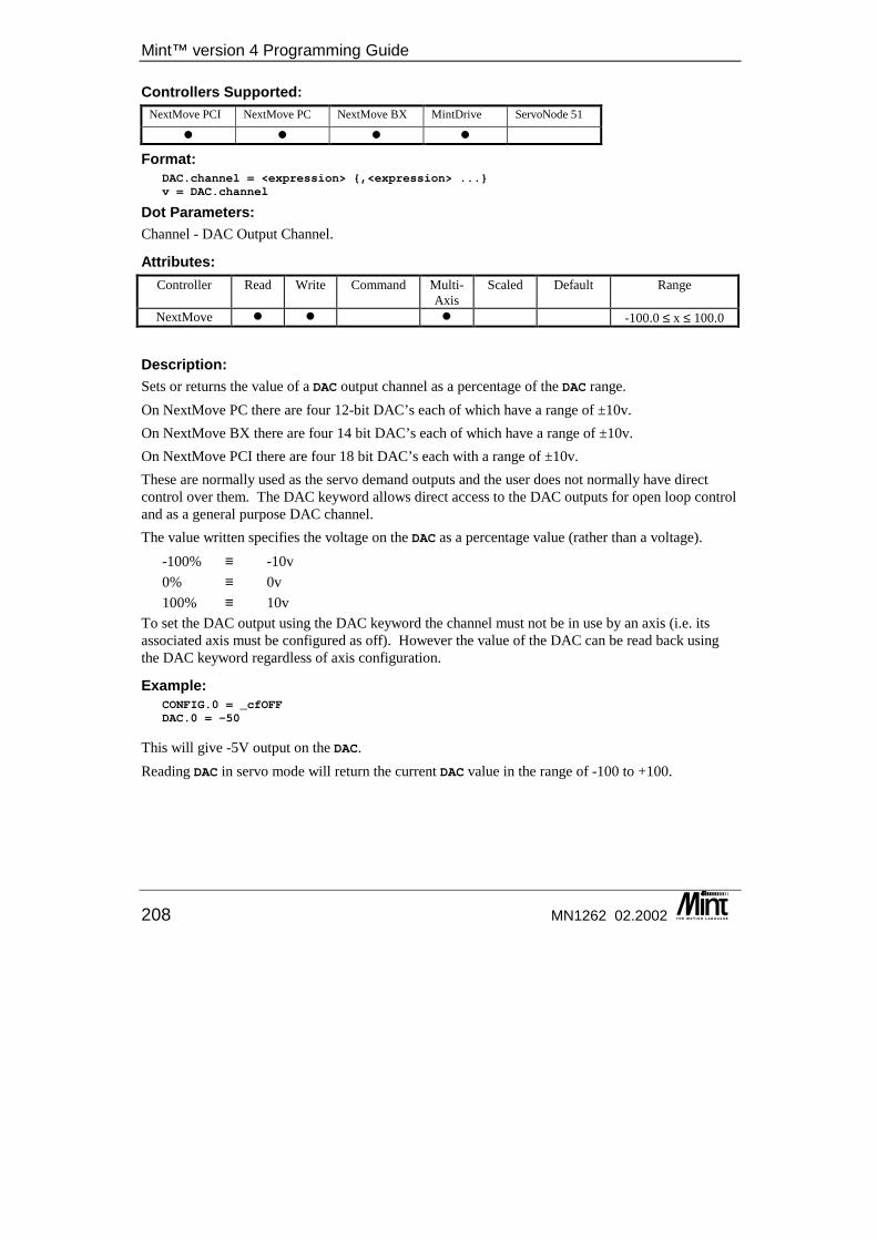
Mint™ version 4 Programming Guide
208 MN1262 02.2002
Controllers Supported: NextMove PCI NextMove PC NextMove BX MintDrive ServoNode 51
� � � �
Format: DAC.channel = <expression> {,<expression> ...}v = DAC.channel
Dot Parameters: Channel - DAC Output Channel.
Attributes: Controller Read Write Command Multi-
Axis Scaled Default Range
NextMove � � � -100.0 ≤ x ≤ 100.0
Description: Sets or returns the value of a DAC output channel as a percentage of the DAC range. On NextMove PC there are four 12-bit DAC’s each of which have a range of ±10v. On NextMove BX there are four 14 bit DAC’s each of which have a range of ±10v. On NextMove PCI there are four 18 bit DAC’s each with a range of ±10v. These are normally used as the servo demand outputs and the user does not normally have direct control over them. The DAC keyword allows direct access to the DAC outputs for open loop control and as a general purpose DAC channel. The value written specifies the voltage on the DAC as a percentage value (rather than a voltage).
-100% ≡ -10v 0% ≡ 0v 100% ≡ 10v
To set the DAC output using the DAC keyword the channel must not be in use by an axis (i.e. its associated axis must be configured as off). However the value of the DAC can be read back using the DAC keyword regardless of axis configuration.
Example: CONFIG.0 = _cfOFFDAC.0 = -50
This will give -5V output on the DAC. Reading DAC in servo mode will return the current DAC value in the range of -100 to +100.
Keyword Reference Guide
MN1262 02.2002 209
On MintDrive, the DAC keyword is the demanded speed given to the drive. This is specified as a percentage of the maximum motor speed specified by the MOTORSPEEDMAX keyword (as taken from the motor database in the Mint WorkBench’s Drive Setup dialog).
Example: REM Maximum motor speed is 7000 RPM (= 116 RPS)CONFIG = _cfSERVORESETSCALE = 4096 : REM Scale to Revs per Second (RPS)SPEEDDEMAND = 5LOOPPRINT “Measured Vel: “, VELPRINT “Demanded Speed: “, DAC
ENDL
In the above example you would find that DAC would be equal to 5% and VEL would read around 5.8 RPS (approximately 5% of 7000 RPM). If however, the MintDrive is being driven in Torque mode, then the DAC keyword is a percentage of the drive’s DAC output.
Controller Specifics: NextMove PC uses a 12 bit DAC. NextMove BX uses a 14 bit DAC. NextMove PCI uses a 18 bit DAC
See also: CONFIG, TORQUE, SPEEDDEMAND
DACLIMITMAX/DCX Purpose: To restrict the DAC output voltage to within a defined range.
Controllers Supported: NextMove PCI NextMove PC NextMove BX MintDrive ServoNode 51
� � �
Format: DACLIMITMAX.channel = <expression>v = DACLIMITMAX.channel
Dot Parameters: Channel – DAC Output Channel
Mint™ version 4 Programming Guide
210 MN1262 02.2002
Attributes: Controller Read Write Command Multi-
Axis Scaled Default Range
NextMove � � � 100 0.0 ≤ x ≤ 100.0
Description: The DACLIMITMAX keyword restricts the output voltage of the DAC output. This can be used to protect motors and drives from excessive current or demand speeds. A value is a percentage of the maximum DAC output (±10V).
Example: DACLIMITMAX.0 = 50
DACLIMITMAX.1 = 50
DACLIMITMAX.2 = 60
will set the current limit of axes 0 and 1 to 50% and axis 2 to 60%. Using DACLIMITMAX with velocity amplifiers will restrict the maximum velocity.
Restrictions: DACLIMITMAX is only applicable to axes configured as Servo axes.
See also: DAC, CURRENTLIMIT, KINTLIMIT
DACMODE/DCM This is an advanced Mint feature. Full details can be found in the Mint v4 Advanced Programming Guide.
DACMONITORAXIS/DMA This is an advanced Mint feature. Full details can be found in the Mint v4 Advanced Programming Guide.
DACMONITORGAIN/DMG This is an advanced Mint feature. Full details can be found in the Mint v4 Advanced Programming Guide.
DACMONITORMODE/DMM This is an advanced Mint feature. Full details can be found in the Mint v4 Advanced Programming Guide.

Keyword Reference Guide
MN1262 02.2002 211
DACOFFSET/DCO This is an advanced Mint feature. Full details can be found in the Mint v4 Advanced Programming Guide.
DACRAMP/DCR This is an advanced Mint feature. Full details can be found in the Mint v4 Advanced Programming Guide.
DECEL/DCL Purpose: To set the deceleration rate on the axis.
Controllers Supported: NextMove PCI NextMove PC NextMove BX MintDrive ServoNode 51
� � � � �
Format: DECEL[axes] = <expression> {,<expression> ...}v = DECEL[axis]
Dot Parameters: Axis - Axis No.
Attributes: Controller Read Write Command Multi-
Axis Scaled Default Range
NextMove � � � � 300,000 3000 (step)
1.0 ≤ x ≤ 8388607.0
MintDrive � � � � 300,000 See table below
On MintDrive and ServoNode 51 the range depends upon the setting of LOOPTIME as follows:
LOOPTIME Range 500 15625 ≤ x ≤ 8388607
1000 3907 ≤ x ≤ 8388607 2000 977 ≤ x ≤ 8388607
Description: DECEL sets the deceleration rate of the velocity profile in user units/s2. The deceleration rate is used during the following move types:
• MOVEA/MOVER
• VECTORA/VECTORR
Mint™ version 4 Programming Guide
212 MN1262 02.2002
• JOG
• CIRCLEA/CIRCLER
• HOME
• OFFSET • FOLLOW (velocity following mode only) • HTA
• INCA/INCR The acceleration rate of the move is set with the ACCEL keyword. A deceleration rate to be used in error conditions can be set with the ERRORDECEL keyword. In an interpolated move, the deceleration will determine the deceleration on the vector of movement. Changing DECEL will change the value of DECELTIME.
Example: SCALE = 1000;DECEL = 250;
will set the deceleration rate, for the default axes, to 250 * 1000 counts / sec2.
See also: ACCEL, CIRCLEA, CIRCLER, DECELTIME, ERRORDECEL, FOLLOW, HOLDTOANALOG, HOME, INCA, INCR, JOG, MOVEA, MOVER, OFFSET, SRAMP, SCALE, SPEED, VECTORA, VECTORR
DECELTIME/DCT Purpose: To set the deceleration rate on the axis.
Controllers Supported: NextMove PCI NextMove PC NextMove BX MintDrive ServoNode 51
� � � � �
Format: DECELTIME[axes] = <expression> {,<expression> ...}v = DECELTIME[axis]
Dot Parameters: Axis - Axis No.
Attributes: Controller Read Write Command Multi-
Axis Scaled Default Range
All � � � 0 ≤ x ≤ 8388607
Keyword Reference Guide
MN1262 02.2002 213
Description: DECELTIME is specified in milli-seconds. DECELTIME is used as an alternative method of setting the deceleration rate of the velocity profile. DECELTIME is the time required to decelerate from the profiler SPEED to zero. The deceleration, as defined by DECELTIME, is based on the current SPEED when DECELTIME was set. Therefore, if the SPEED is changed, the actual deceleration will remain unchanged. Changing DECELTIME will change the value of DECEL.
Example: SPEED = 5;DECELTIME = 5000;
will set the deceleration rate, for each axis, so the axes will decelerate from 5 user units/second to rest in 5 seconds. This is equivalent to a DECEL value of 1.
CAUTION: DECELTIME can be used to set an internal deceleration rate that is higher than the range of values supported by the DECEL keyword. If such an acceleration is set-up using
DECELTIME, reading DECEL will give a meaningless value.
See also: ACCEL, CIRCLEA, CIRCLER, DECEL, ERRORDECEL, FOLLOW, HOLDTOANALOG, HOME, INCA, INCR, JOG, MOVEA, MOVER, OFFSET, SRAMP, SCALE, SPEED, VECTORA, VECTORR
DEFAULT/DF Purpose: To return an axis motion variables to its power-up state.
Controllers Supported: NextMove PCI NextMove PC NextMove BX MintDrive ServoNode 51
� � � � �
Format: DEFAULT[axes]
Dot Parameters: Axis - Axis No.
Attributes: Controller Read Write Command Multi-
Axis Scaled Default Range
All � �

Mint™ version 4 Programming Guide
214 MN1262 02.2002
Description: Returns all motion variables to their power-up values. It allows you to start afresh in commissioning should things go wrong. DEFAULT sets the following parameters to their default values:
Motion Keyword Servo Axis Stepper Axis ACCEL 300,000 3,000
AXISERROR 0 0 AXISMODE 0 0
AXISSTATUS 0 0 CURRENTLIMIT 100 n/a DACLIMITMAX 100 n/a
DECEL 300,000 3,000 DRIVEENABLEOUTPUT -1 -1
ENCODER 0 n/a ENCODERPRESCALE 1 n/a ENCODERSCALE 1 n/a ENCODERWRAP 0 n/a ERRORDECEL 300,000 3,000 ERRORINPUT -1 -1 FOLERROR 0 n/a
FOLERRORFATAL 1000 n/a FOLLOW 0 0
FOLLOWDENOM 1 1 HOMEBACKOFF 10 10 HOMEINPUT -1 -1 HOMESPEED 40000 500 IDLEPOS 1000 n/a IDLEVEL 0 n/a KDERIV 0 n/a KINT 0 n/a
KINTLIMIT 100 n/a KPROP 0 n/a KVEL 0 n/a KVELFF 0 n/a
LIMITFORWARDINPUT -1 -1 LIMITREVERSEINPUT -1 -1 MASTERCHANNEL 0 0 MASTERDISTANCE 1000 1000 MASTERSOURCE 0 0
POS 0 0 SCALE 1 1
Keyword Reference Guide
MN1262 02.2002 215
Motion Keyword Servo Axis Stepper Axis SOFTLIMITFORWARD 8,388,607 8,388,607 SOFTLIMITREVERSE -8,388,607 -8,388,607
SPEED 20,000 1,000 STOPINPUT -1 -1
See also: CANCEL, CONFIG, RESET
DEFAULTALL/DFA Purpose: To return all axis motion variables to their power-up state.
Controllers Supported: NextMove PCI NextMove PC NextMove BX MintDrive ServoNode 51
� � � � �
Format: DEFAULTALL
Dot Parameters: Axis - Axis No.
Attributes: Controller Read Write Command Multi-
Axis Scaled Default Range
All � �
Description: Returns all motion variables on ALL axes to their power-up values. It allows you to start afresh in commissioning should things go wrong. See DEFAULT for full details of the parameters which are reset.
See also: CANCELALL, RESETALL
DEFINE Purpose: To define macro, allowing a string of keywords to be replaced by one name.
Mint™ version 4 Programming Guide
216 MN1262 02.2002
Controllers Supported: NextMove PCI NextMove PC NextMove BX MintDrive ServoNode 51
� � � � �
Format: DEFINE macro = <command string>
Description: The DEFINE keyword is used to define a macro name to replace a string of characters. Where the macro name is found in the program, it is replaced by its string definition. For example:
DEFINE a = [0,1,2,3]
This will define a macro called a which then can be used anywhere in a program or configuration file to replace [0,1,2,3].
SPEED^a = 10;
is equivalent to: SPEED[0,1,2,3] = 10;
The ^ character is used as a delimiter only. The ‘space’ character can also be used. The following are valid syntax’s for macros:
SPEED a = 10;SPEED^a = 10;
If the macro was defined as: DEFINE a = 0
then the following would be valid syntax: SPEED.a = 10;SPEED.^a = 10;
VIEW MACROS can be used to display all defined macro definitions. Macros cannot be redefined within a program or configuration file and all macros are lost when a program is run. A macro cannot contain a reference to another macro. See section 3.5 for further details on macros.
Restrictions: A maximum number of 255 macros can be defined. The first 10 characters of a macros name are significant. i.e. a macro cannot contain the same first 10 characters as one already defined.
See also: VIEW
DEMAND/DM This keyword has been replaced by DAC in Mint v4. For details on converting existing Mint programs to Mint v4 see the Mint v4 Code Analyzer Tool Guide.
Keyword Reference Guide
MN1262 02.2002 217
DGAIN/DG This keyword has been replaced by KDERIV in Mint v4. For details on converting existing Mint programs to Mint v4 see the Mint v4 Code Analyzer Tool Guide.
DIM Purpose: To reserve memory for array variables or create a user variable.
Controllers Supported: NextMove PCI NextMove PC NextMove BX MintDrive ServoNode 51
� � � � �
Format: DIM array_name(<no_of_elements>) {{ = <array values> }{;}}
DIM variable {= <initial value>}
where <no_of_elements> and <array values> are Mint numbers and not expressions.
Description: DIM performs two functions:
1. Defines variables and optionally allows an initial value to be set. 2. Reserve data space for array variables and optionally initialize the data.
Variable Declaration: All variables in Mint must be defined before use. DIM is used to define the variable and optionally, provide it with an initial value.
Example: DIM aDIM b = 10
This creates two variables, a and b. a will be defined a value of 0 if a has not been defined before. b will be defined with a value of 10. DIM can be used on the command line to create variables. If you try and create a variable using a keyword, a syntax error will result:
DIM speed = 100
If the variable is declared for the first time and no initial value is given, then the default value will be zero.
Array Declaration: Reserves data space for array variables and optionally initializes them. Example:
Mint™ version 4 Programming Guide
218 MN1262 02.2002
DIM my_array(100)
declares an array variable called my_array with one hundred elements. DIM y_position(10) = 1,2,3,4,5,6,7,8,9,10
declares an array y_position, where the first element, y_position(1), is equal to 1, second equal to 2 etc. The array variable name can also be used as a normal variable. For example:
y_position = 1
will treat y_position as a standard variable. A trailing semi-colon will assign the last value in the list to all remaining elements.
DIM y_position(15) = 1,2,3,4,5,6,7,8,9,10;
would assign the value 10 to elements 10 through to 15.
Restrictions: • The number of array elements that can be defined is limited by available memory. See
section 9.1. • The maximum number of elements that can be defined for any single array on MintDrive is
32767. This value is also limited by available memory.
See also: RELEASE, VIEW
DINT This keyword has been replaced by EVENTDISABLE in Mint v4. For details on converting existing Mint programs to Mint v4 see the Mint v4 Code Analyzer Tool Guide.
DISDRIVE/DD This keyword has been replaced by DRIVEENABLE in Mint v4. For details on converting existing Mint programs to Mint v4 see the Mint v4 Code Analyzer Tool Guide.
DISLIMIT/DL This keyword has been replaced by LIMITMODE and SOFTLIMITMODE in Mint v4. For details on converting existing Mint programs to Mint v4 see the Mint v4 Code Analyzer Tool Guide.
Keyword Reference Guide
MN1262 02.2002 219
DPREVENT/DPR This is an advanced Mint feature. Full details can be found in Mint v4 Advanced Programming Guide.
DPRFLOAT This is an advanced Mint feature. Full details can be found in the Mint v4 Advanced Programming Guide.
DPRLONG This is an advanced Mint feature. Full details can be found in the Mint v4 Advanced Programming Guide.
DPRWORD This is an advanced Mint feature. Full details can be found in the Mint v4 Advanced Programming Guide.
DRIVEENABLE/DE Purpose: To enable or disable the drive for the specified axis.
Controllers Supported: NextMove PCI NextMove PC NextMove BX MintDrive ServoNode 51
� � � � �
Format: DRIVEENABLE[axes] = <expression>v = DRIVEENABLE.axis
Dot Parameters: Axis - Axis No.
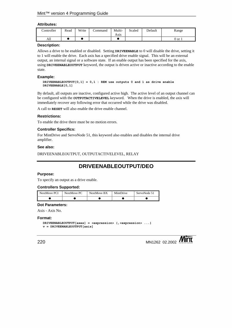
Mint™ version 4 Programming Guide
220 MN1262 02.2002
Attributes: Controller Read Write Command Multi-
Axis Scaled Default Range
All � � � 0 or 1
Description: Allows a drive to be enabled or disabled. Setting DRIVEENABLE to 0 will disable the drive, setting it to 1 will enable the drive. Each axis has a specified drive enable signal. This will be an external output, an internal signal or a software state. If an enable output has been specified for the axis, using DRIVEENABLEOUTPUT keyword, the output is driven active or inactive according to the enable state.
Example: DRIVEENABLEOUTPUT[0,1] = 0,1 : REM use outputs 0 and 1 as drive enableDRIVEENABLE[0,1]
By default, all outputs are inactive, configured active high. The active level of an output channel can be configured with the OUTPUTACTIVELEVEL keyword. When the drive is enabled, the axis will immediately recover any following error that occurred while the drive was disabled. A call to RESET will also enable the drive enable channel.
Restrictions: To enable the drive there must be no motion errors.
Controller Specifics: For MintDrive and ServoNode 51, this keyword also enables and disables the internal drive amplifier.
See also: DRIVEENABLEOUTPUT, OUTPUTACTIVELEVEL, RELAY
DRIVEENABLEOUTPUT/DEO Purpose: To specify an output as a drive enable.
Controllers Supported: NextMove PCI NextMove PC NextMove BX MintDrive ServoNode 51
� � � � �
Dot Parameters: Axis - Axis No.
Format: DRIVEENABLEOUTPUT[axes] = <expression> {,<expression> ...}v = DRIVEENABLEOUTPUT[axis]
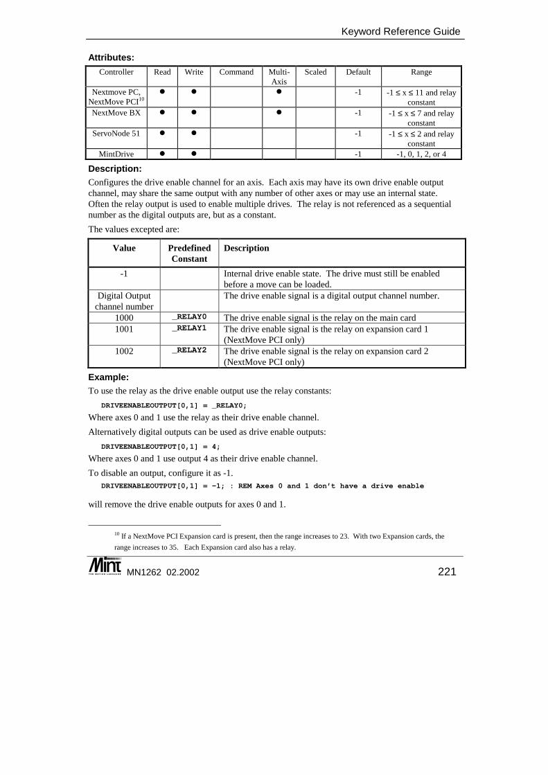
Keyword Reference Guide
MN1262 02.2002 221
Attributes: Controller Read Write Command Multi-
Axis Scaled Default Range
Nextmove PC, NextMove PCI10
� � � -1 -1 ≤ x ≤ 11 and relay constant
NextMove BX � � � -1 -1 ≤ x ≤ 7 and relay constant
ServoNode 51 � � -1 -1 ≤ x ≤ 2 and relay constant
MintDrive � � -1 -1, 0, 1, 2, or 4
Description: Configures the drive enable channel for an axis. Each axis may have its own drive enable output channel, may share the same output with any number of other axes or may use an internal state. Often the relay output is used to enable multiple drives. The relay is not referenced as a sequential number as the digital outputs are, but as a constant. The values excepted are:
Value Predefined Constant
Description
-1 Internal drive enable state. The drive must still be enabled before a move can be loaded.
Digital Output channel number
The drive enable signal is a digital output channel number.
1000 _RELAY0 The drive enable signal is the relay on the main card 1001 _RELAY1 The drive enable signal is the relay on expansion card 1
(NextMove PCI only) 1002 _RELAY2 The drive enable signal is the relay on expansion card 2
(NextMove PCI only)
Example: To use the relay as the drive enable output use the relay constants:
DRIVEENABLEOUTPUT[0,1] = _RELAY0;
Where axes 0 and 1 use the relay as their drive enable channel. Alternatively digital outputs can be used as drive enable outputs:
DRIVEENABLEOUTPUT[0,1] = 4;
Where axes 0 and 1 use output 4 as their drive enable channel. To disable an output, configure it as -1.
DRIVEENABLEOUTPUT[0,1] = -1; : REM Axes 0 and 1 don’t have a drive enable
will remove the drive enable outputs for axes 0 and 1.
10 If a NextMove PCI Expansion card is present, then the range increases to 23. With two Expansion cards, the range increases to 35. Each Expansion card also has a relay.
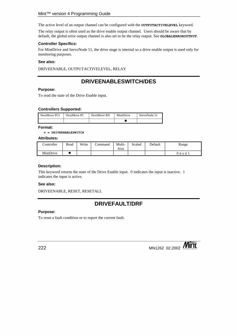
Mint™ version 4 Programming Guide
222 MN1262 02.2002
The active level of an output channel can be configured with the OUTPUTACTIVELEVEL keyword. The relay output is often used as the drive enable output channel. Users should be aware that by default, the global error output channel is also set to be the relay output. See GLOBALERROROUTPUT.
Controller Specifics: For MintDrive and ServoNode 51, the drive stage is internal so a drive enable output is used only for monitoring purposes.
See also: DRIVEENABLE, OUTPUTACTIVELEVEL, RELAY
DRIVEENABLESWITCH/DES Purpose: To read the state of the Drive Enable input.
Controllers Supported: NextMove PCI NextMove PC NextMove BX MintDrive ServoNode 51
�
Format: v = DRIVEENABLESWITCH
Attributes: Controller Read Write Command Multi-
Axis Scaled Default Range
MintDrive � 0 ≤ x ≤ 1
Description: This keyword returns the state of the Drive Enable input. 0 indicates the input is inactive. 1 indicates the input is active.
See also: DRIVEENABLE, RESET, RESETALL
DRIVEFAULT/DRF Purpose: To reset a fault condition or to report the current fault.
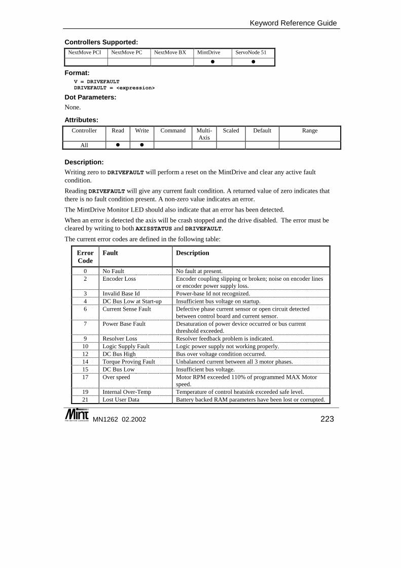
Keyword Reference Guide
MN1262 02.2002 223
Controllers Supported: NextMove PCI NextMove PC NextMove BX MintDrive ServoNode 51
� �
Format: V = DRIVEFAULTDRIVEFAULT = <expression>
Dot Parameters: None.
Attributes: Controller Read Write Command Multi-
Axis Scaled Default Range
All � �
Description: Writing zero to DRIVEFAULT will perform a reset on the MintDrive and clear any active fault condition. Reading DRIVEFAULT will give any current fault condition. A returned value of zero indicates that there is no fault condition present. A non-zero value indicates an error. The MintDrive Monitor LED should also indicate that an error has been detected. When an error is detected the axis will be crash stopped and the drive disabled. The error must be cleared by writing to both AXISSTATUS and DRIVEFAULT. The current error codes are defined in the following table:
Error Code
Fault Description
0 No Fault No fault at present. 2 Encoder Loss Encoder coupling slipping or broken; noise on encoder lines
or encoder power supply loss. 3 Invalid Base Id Power-base Id not recognized. 4 DC Bus Low at Start-up Insufficient bus voltage on startup. 6 Current Sense Fault Defective phase current sensor or open circuit detected
between control board and current sensor. 7 Power Base Fault Desaturation of power device occurred or bus current
threshold exceeded. 9 Resolver Loss Resolver feedback problem is indicated.
10 Logic Supply Fault Logic power supply not working properly. 12 DC Bus High Bus over voltage condition occurred. 14 Torque Proving Fault Unbalanced current between all 3 motor phases. 15 DC Bus Low Insufficient bus voltage. 17 Over speed Motor RPM exceeded 110% of programmed MAX Motor
speed. 19 Internal Over-Temp Temperature of control heatsink exceeded safe level. 21 Lost User Data Battery backed RAM parameters have been lost or corrupted.
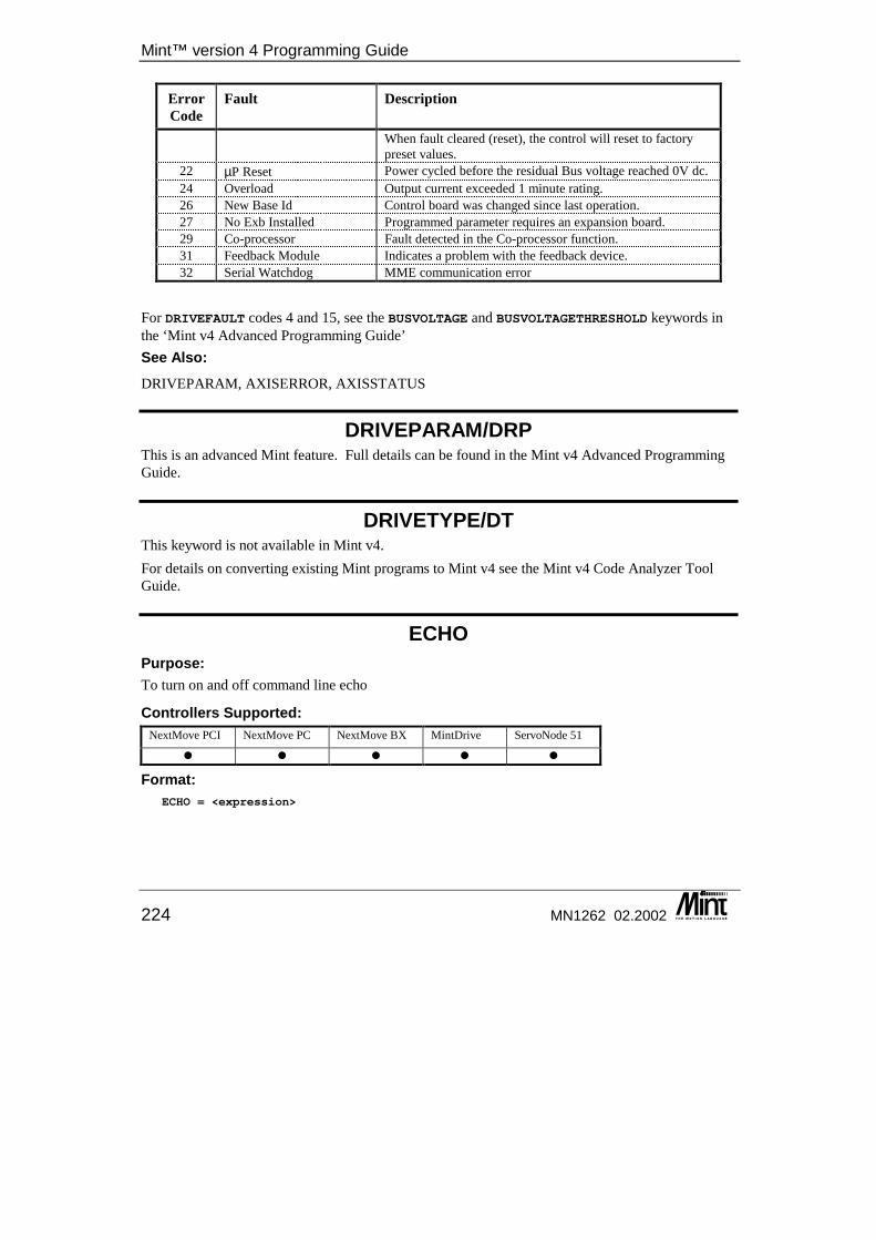
Mint™ version 4 Programming Guide
224 MN1262 02.2002
Error Code
Fault Description
When fault cleared (reset), the control will reset to factory preset values.
22 µP Reset Power cycled before the residual Bus voltage reached 0V dc. 24 Overload Output current exceeded 1 minute rating. 26 New Base Id Control board was changed since last operation. 27 No Exb Installed Programmed parameter requires an expansion board. 29 Co-processor Fault detected in the Co-processor function. 31 Feedback Module Indicates a problem with the feedback device. 32 Serial Watchdog MME communication error
For DRIVEFAULT codes 4 and 15, see the BUSVOLTAGE and BUSVOLTAGETHRESHOLD keywords in the ‘Mint v4 Advanced Programming Guide’ See Also: DRIVEPARAM, AXISERROR, AXISSTATUS
DRIVEPARAM/DRP This is an advanced Mint feature. Full details can be found in the Mint v4 Advanced Programming Guide.
DRIVETYPE/DT This keyword is not available in Mint v4. For details on converting existing Mint programs to Mint v4 see the Mint v4 Code Analyzer Tool Guide.
ECHO Purpose: To turn on and off command line echo
Controllers Supported: NextMove PCI NextMove PC NextMove BX MintDrive ServoNode 51
� � � � �
Format: ECHO = <expression>

Keyword Reference Guide
MN1262 02.2002 225
Attributes: Controller Read Write Command Multi-
Axis Scaled Default Range
All � � 7 0 ≤ x ≤ 7
Description: Using the ECHO keyword, command line echo can be turned off. ECHO uses bit setting to determine its action:
Bit Function 0 If set then command line echo is enabled. Characters are displayed as they are typed at
the command line. 1 If set them error messages are displayed to the terminal. 2 If set then the command line prompt, C> and P>, is displayed
For NextMove PC and PCI, the value of ECHO is also available in Dual Port RAM at address 0x195. There are Mint Interface Library functions that allow the value of ECHO to be read and written.
ECHO replaces POFF and PON
Example: ECHO = 0
This turns off all terminal output apart from data printed from within a program.
See also: TERMINALMODE
EFFORT/EF This is an advanced Mint feature. Full details can be found in the Mint v4 Advanced Programming Guide.
EINT This keyword has been replaced by EVENTDISABLE in Mint v4. For details on converting existing Mint programs to Mint v4 see the Mint v4 Code Analyzer Tool Guide.
ENABLE/EB This keyword has been replaced by RELAY in Mint v4. For details on converting existing Mint programs to Mint v4 see the Mint v4 Code Analyzer Tool Guide.
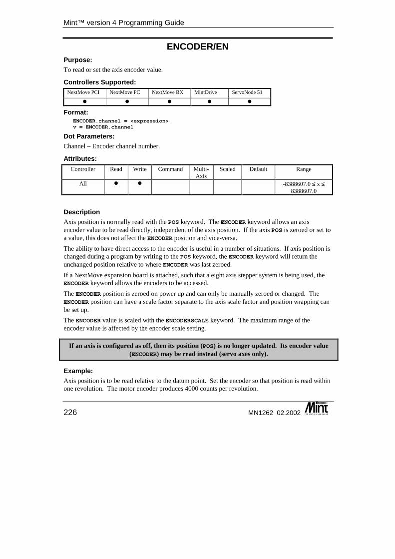
Mint™ version 4 Programming Guide
226 MN1262 02.2002
ENCODER/EN Purpose: To read or set the axis encoder value.
Controllers Supported: NextMove PCI NextMove PC NextMove BX MintDrive ServoNode 51
� � � � �
Format: ENCODER.channel = <expression>v = ENCODER.channel
Dot Parameters: Channel – Encoder channel number.
Attributes: Controller Read Write Command Multi-
Axis Scaled Default Range
All � � -8388607.0 ≤ x ≤ 8388607.0
Description Axis position is normally read with the POS keyword. The ENCODER keyword allows an axis encoder value to be read directly, independent of the axis position. If the axis POS is zeroed or set to a value, this does not affect the ENCODER position and vice-versa. The ability to have direct access to the encoder is useful in a number of situations. If axis position is changed during a program by writing to the POS keyword, the ENCODER keyword will return the unchanged position relative to where ENCODER was last zeroed. If a NextMove expansion board is attached, such that a eight axis stepper system is being used, the ENCODER keyword allows the encoders to be accessed. The ENCODER position is zeroed on power up and can only be manually zeroed or changed. The ENCODER position can have a scale factor separate to the axis scale factor and position wrapping can be set up. The ENCODER value is scaled with the ENCODERSCALE keyword. The maximum range of the encoder value is affected by the encoder scale setting.
If an axis is configured as off, then its position (POS) is no longer updated. Its encoder value (ENCODER) may be read instead (servo axes only).
Example: Axis position is to be read relative to the datum point. Set the encoder so that position is read within one revolution. The motor encoder produces 4000 counts per revolution.
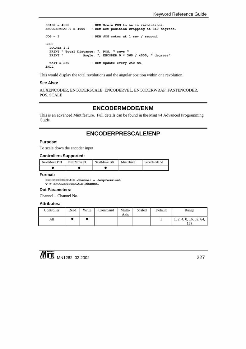
Keyword Reference Guide
MN1262 02.2002 227
SCALE = 4000 : REM Scale POS to be in revolutions.ENCODERWRAP.0 = 4000 : REM Set position wrapping at 360 degrees.
JOG = 1 : REM JOG motor at 1 rev / second.
LOOPLOCATE 1,1PRINT “ Total Distance: “, POS, “ revs “PRINT “ Angle: “, ENCODER.0 * 360 / 4000, “ degrees”
WAIT = 250 : REM Update every 250 ms.ENDL
This would display the total revolutions and the angular position within one revolution.
See Also: AUXENCODER, ENCODERSCALE, ENCODERVEL, ENCODERWRAP, FASTENCODER, POS, SCALE
ENCODERMODE/ENM This is an advanced Mint feature. Full details can be found in the Mint v4 Advanced Programming Guide.
ENCODERPRESCALE/ENP Purpose: To scale down the encoder input
Controllers Supported: NextMove PCI NextMove PC NextMove BX MintDrive ServoNode 51
� � �
Format: ENCODERPRESCALE.channel = <expression>v = ENCODERPRESCALE.channel
Dot Parameters: Channel – Channel No.
Attributes: Controller Read Write Command Multi-
Axis Scaled Default Range
All � � 1 1, 2, 4, 8, 16, 32, 64, 128
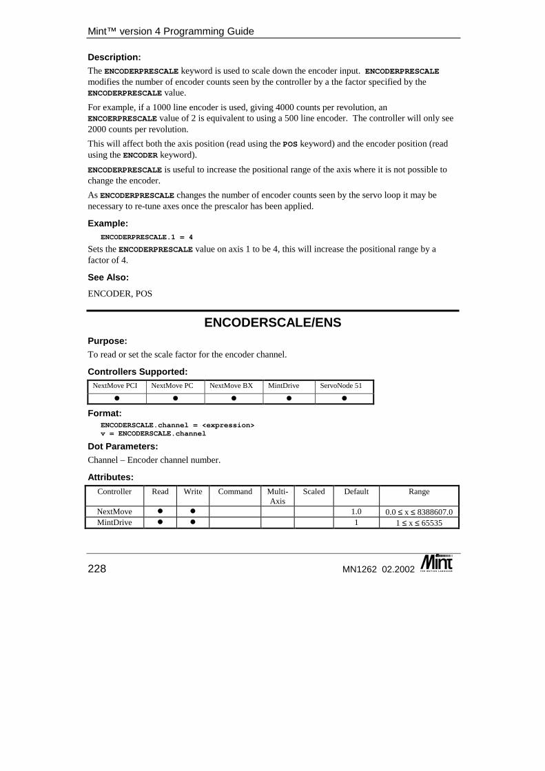
Mint™ version 4 Programming Guide
228 MN1262 02.2002
Description: The ENCODERPRESCALE keyword is used to scale down the encoder input. ENCODERPRESCALE modifies the number of encoder counts seen by the controller by a the factor specified by the ENCODERPRESCALE value. For example, if a 1000 line encoder is used, giving 4000 counts per revolution, an ENCOERPRESCALE value of 2 is equivalent to using a 500 line encoder. The controller will only see 2000 counts per revolution. This will affect both the axis position (read using the POS keyword) and the encoder position (read using the ENCODER keyword). ENCODERPRESCALE is useful to increase the positional range of the axis where it is not possible to change the encoder. As ENCODERPRESCALE changes the number of encoder counts seen by the servo loop it may be necessary to re-tune axes once the prescalor has been applied.
Example: ENCODERPRESCALE.1 = 4
Sets the ENCODERPRESCALE value on axis 1 to be 4, this will increase the positional range by a factor of 4.
See Also: ENCODER, POS
ENCODERSCALE/ENS Purpose: To read or set the scale factor for the encoder channel.
Controllers Supported: NextMove PCI NextMove PC NextMove BX MintDrive ServoNode 51
� � � � �
Format: ENCODERSCALE.channel = <expression>v = ENCODERSCALE.channel
Dot Parameters: Channel – Encoder channel number.
Attributes: Controller Read Write Command Multi-
Axis Scaled Default Range
NextMove � � 1.0 0.0 ≤ x ≤ 8388607.0 MintDrive � � 1 1 ≤ x ≤ 65535
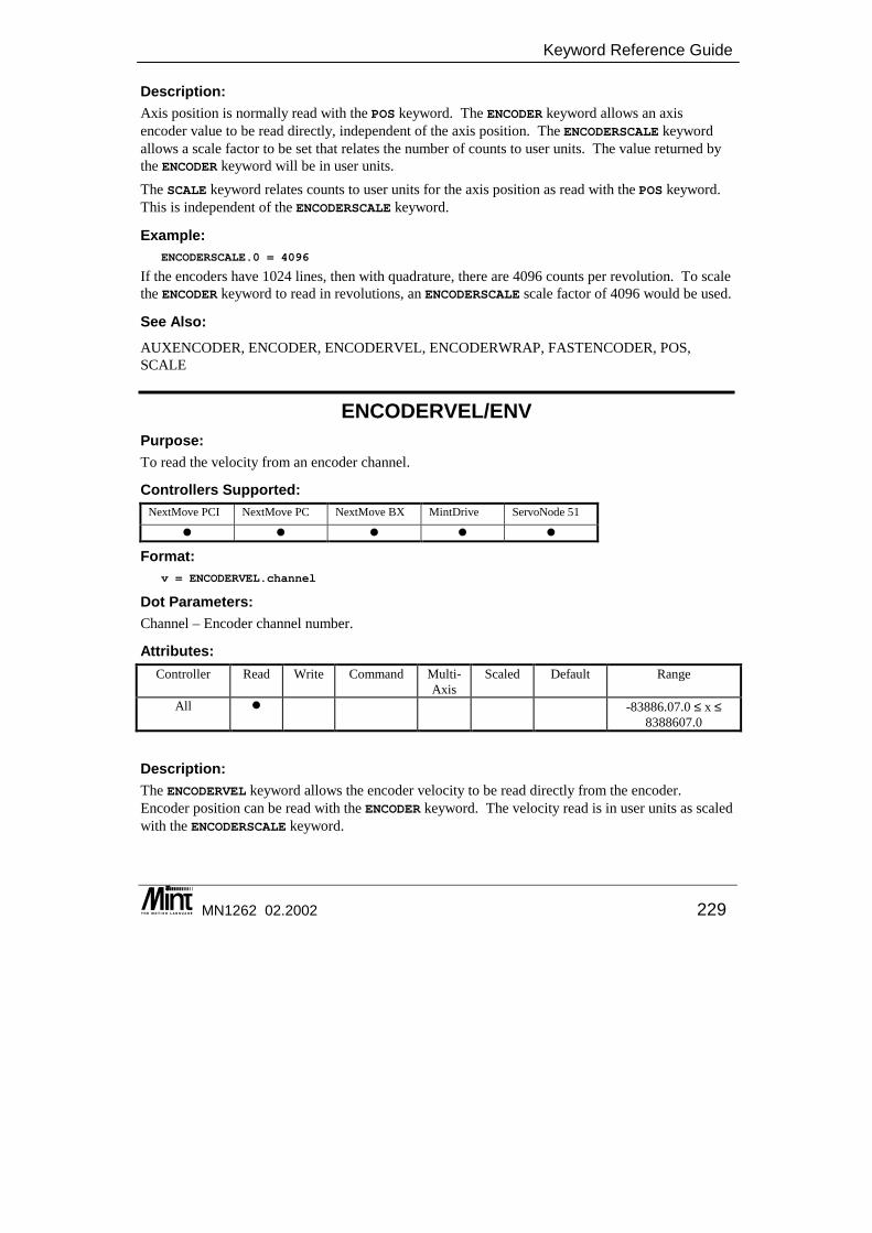
Keyword Reference Guide
MN1262 02.2002 229
Description: Axis position is normally read with the POS keyword. The ENCODER keyword allows an axis encoder value to be read directly, independent of the axis position. The ENCODERSCALE keyword allows a scale factor to be set that relates the number of counts to user units. The value returned by the ENCODER keyword will be in user units. The SCALE keyword relates counts to user units for the axis position as read with the POS keyword. This is independent of the ENCODERSCALE keyword.
Example: ENCODERSCALE.0 = 4096
If the encoders have 1024 lines, then with quadrature, there are 4096 counts per revolution. To scale the ENCODER keyword to read in revolutions, an ENCODERSCALE scale factor of 4096 would be used.
See Also: AUXENCODER, ENCODER, ENCODERVEL, ENCODERWRAP, FASTENCODER, POS, SCALE
ENCODERVEL/ENV Purpose: To read the velocity from an encoder channel.
Controllers Supported: NextMove PCI NextMove PC NextMove BX MintDrive ServoNode 51
� � � � �
Format: v = ENCODERVEL.channel
Dot Parameters: Channel – Encoder channel number.
Attributes: Controller Read Write Command Multi-
Axis Scaled Default Range
All � -83886.07.0 ≤ x ≤ 8388607.0
Description: The ENCODERVEL keyword allows the encoder velocity to be read directly from the encoder. Encoder position can be read with the ENCODER keyword. The velocity read is in user units as scaled with the ENCODERSCALE keyword.
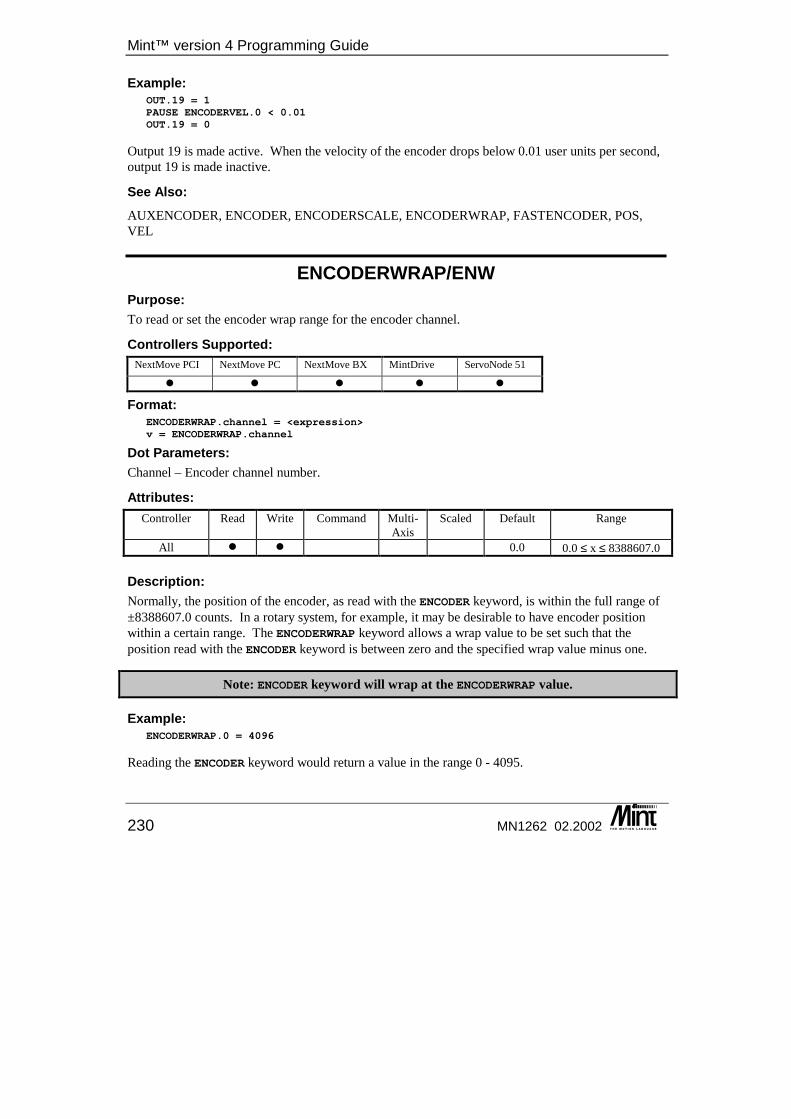
Mint™ version 4 Programming Guide
230 MN1262 02.2002
Example: OUT.19 = 1PAUSE ENCODERVEL.0 < 0.01OUT.19 = 0
Output 19 is made active. When the velocity of the encoder drops below 0.01 user units per second, output 19 is made inactive.
See Also: AUXENCODER, ENCODER, ENCODERSCALE, ENCODERWRAP, FASTENCODER, POS, VEL
ENCODERWRAP/ENW Purpose: To read or set the encoder wrap range for the encoder channel.
Controllers Supported: NextMove PCI NextMove PC NextMove BX MintDrive ServoNode 51
� � � � �
Format: ENCODERWRAP.channel = <expression>v = ENCODERWRAP.channel
Dot Parameters: Channel – Encoder channel number.
Attributes: Controller Read Write Command Multi-
Axis Scaled Default Range
All � � 0.0 0.0 ≤ x ≤ 8388607.0
Description: Normally, the position of the encoder, as read with the ENCODER keyword, is within the full range of ±8388607.0 counts. In a rotary system, for example, it may be desirable to have encoder position within a certain range. The ENCODERWRAP keyword allows a wrap value to be set such that the position read with the ENCODER keyword is between zero and the specified wrap value minus one.
Note: ENCODER keyword will wrap at the ENCODERWRAP value.
Example: ENCODERWRAP.0 = 4096
Reading the ENCODER keyword would return a value in the range 0 - 4095.
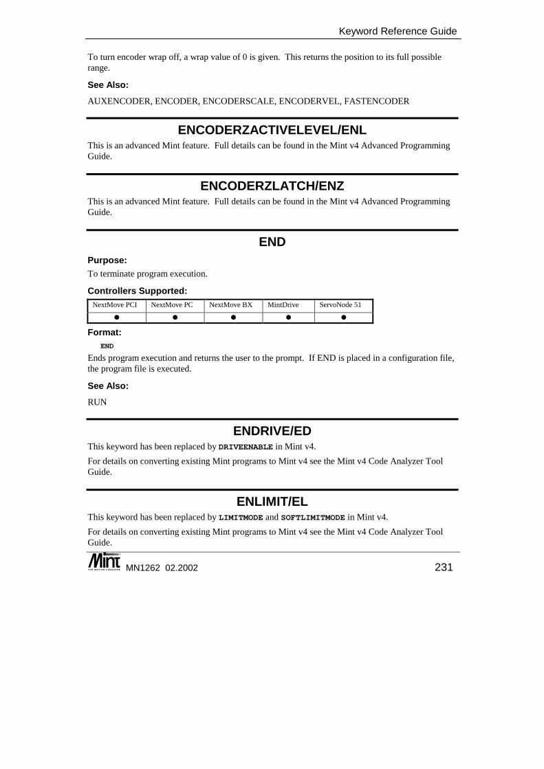
Keyword Reference Guide
MN1262 02.2002 231
To turn encoder wrap off, a wrap value of 0 is given. This returns the position to its full possible range.
See Also: AUXENCODER, ENCODER, ENCODERSCALE, ENCODERVEL, FASTENCODER
ENCODERZACTIVELEVEL/ENL This is an advanced Mint feature. Full details can be found in the Mint v4 Advanced Programming Guide.
ENCODERZLATCH/ENZ This is an advanced Mint feature. Full details can be found in the Mint v4 Advanced Programming Guide.
END Purpose: To terminate program execution.
Controllers Supported: NextMove PCI NextMove PC NextMove BX MintDrive ServoNode 51
� � � � �
Format: END
Ends program execution and returns the user to the prompt. If END is placed in a configuration file, the program file is executed.
See Also: RUN
ENDRIVE/ED This keyword has been replaced by DRIVEENABLE in Mint v4. For details on converting existing Mint programs to Mint v4 see the Mint v4 Code Analyzer Tool Guide.
ENLIMIT/EL This keyword has been replaced by LIMITMODE and SOFTLIMITMODE in Mint v4. For details on converting existing Mint programs to Mint v4 see the Mint v4 Code Analyzer Tool Guide.
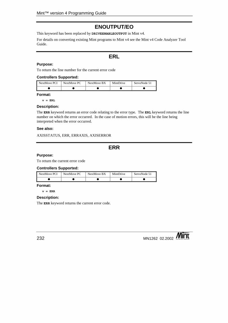
Mint™ version 4 Programming Guide
232 MN1262 02.2002
ENOUTPUT/EO This keyword has been replaced by DRIVEENABLEOUTPUT in Mint v4. For details on converting existing Mint programs to Mint v4 see the Mint v4 Code Analyzer Tool Guide.
ERL Purpose: To return the line number for the current error code
Controllers Supported: NextMove PCI NextMove PC NextMove BX MintDrive ServoNode 51
� � � � �
Format: v = ERL
Description: The ERR keyword returns an error code relating to the error type. The ERL keyword returns the line number on which the error occurred. In the case of motion errors, this will be the line being interpreted when the error occurred.
See also: AXISSTATUS, ERR, ERRAXIS, AXISERROR
ERR Purpose: To return the current error code
Controllers Supported: NextMove PCI NextMove PC NextMove BX MintDrive ServoNode 51
� � � � �
Format: v = ERR
Description: The ERR keyword returns the current error code.
Keyword Reference Guide
MN1262 02.2002 233
There are 5 groups of errors: 1. Motion Errors: These are errors usually associated with motion such as hitting limit
switches or exceeding a maximum following error. 2. System Errors: These are errors usually associated with the setting up of keywords. These
can include ‘Out of Range’ and ‘Motion in Progress’. 3. Interpreter Errors: These are errors associated with mistakes in the source code such as
‘Syntax Errors’ or ‘NEXT without FOR’. 4. Compiler Errors: These are errors that occur during compile time of the Mint program such
as ‘Out of Memory’ or ‘Too Many Variables’. 5. CAN Errors: These are errors generated through the use of the CAN ioNodes.
The ERR keyword returns one of the error codes shown in section 12.2. The error codes are grouped together by type and depending on the value of the error, appropriate action can be taken. For example, if the ERR code is 500, Motion Error, then the AXISERROR keyword can be used to see cause of the motion error. ERR will always return the last error code, regardless whether that error is still current.
Restrictions: If a Motion Error occurs while on the command line (i.e. not running a Mint program) then the error is not copied to the ERR keyword.
See also: AXISSTATUS, ERRAXIS, ERL, AXISERROR
ERRAXIS Purpose: To return the axis which is in error.
Controllers Supported: NextMove PCI NextMove PC NextMove BX MintDrive ServoNode 51
� � � � �
Format: v = ERRAXIS
Description: The ERR keyword returns an error code relating to the error type. The ERRAXIS keyword returns the axis number on which the error occurred. If the error is not axis dependant then -1 will be returned.
Example: 1 MOVER.0 = 102 MOVER.8 = 203 GO[0,7]
Mint™ version 4 Programming Guide
234 MN1262 02.2002
The above example is a simple 3 line program where there is typing mistake at line 2. The attempt to write to axis 8 will generate an error. The ERR keyword will return a value of 2 (invalid axis). The ERL keyword will return 2 (line 2) and the ERRAXIS keyword will return 8 (the attempted axis number).
See also: AXISSTATUS, ERR, AXISERROR
ERROR/ER This keyword has been replaced by AXISERROR in Mint v4. For details on converting existing Mint programs to Mint v4 see the Mint v4 Code Analyzer Tool Guide.
ERRORDECEL/EDC Purpose: To set the deceleration rate on the axis during powered stops in the event of an error or stop input.
Controllers Supported: NextMove PCI NextMove PC NextMove BX MintDrive ServoNode 51
� � � � �
Format: ERRORDECEL[axes] = <expression> {,<expression> ...}v = ERRORDECEL[axis]
Dot Parameters: Axis - Axis No.
Attributes: Controller Read Write Command Multi-
Axis Scaled Default Range
NextMove � � � � 300,000, 3000
0 ≤ x ≤ 8388607.0
MintDrive � � � 300,000 See table below
On MintDrive and ServoNode 51 the range depends upon the setting of LOOPTIME as follows:
LOOPTIME Range 500 15625 ≤ x ≤ 8388607
1000 3907 ≤ x ≤ 8388607 2000 977 ≤ x ≤ 8388607
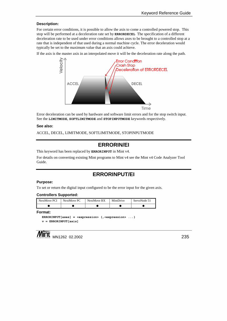
Keyword Reference Guide
MN1262 02.2002 235
Description: For certain error conditions, it is possible to allow the axis to come a controlled powered stop. This stop will be performed at a deceleration rate set by ERRORDECEL The specification of a different deceleration rate to be used under error conditions allows axes to be brought to a controlled stop at a rate that is independent of that used during a normal machine cycle. The error deceleration would typically be set to the maximum value that an axis could achieve. If the axis is the master axis in an interpolated move it will be the deceleration rate along the path.
Error deceleration can be used by hardware and software limit errors and for the stop switch input. See the LIMITMODE, SOFTLIMITMODE and STOPINPUTMODE keywords respectively.
See also: ACCEL, DECEL, LIMITMODE, SOFTLIMITMODE, STOPINPUTMODE
ERRORIN/EI This keyword has been replaced by ERRORINPUT in Mint v4. For details on converting existing Mint programs to Mint v4 see the Mint v4 Code Analyzer Tool Guide.
ERRORINPUT/EI Purpose: To set or return the digital input configured to be the error input for the given axis.
Controllers Supported: NextMove PCI NextMove PC NextMove BX MintDrive ServoNode 51
� � � � �
Format: ERRORINPUT[axes] = <expression> {,<expression> ...}
v = ERRORINPUT[axis]
Mint™ version 4 Programming Guide
236 MN1262 02.2002
Dot Parameters: Axis - Axis No.
Attributes: Controller Read Write Command Multi-Axis Scaled Default Range
NextMove PCI11 � � � -1 -1 ≤ x ≤ 19 NextMove PC � � � -1 -1 ≤ x ≤ 23 NextMove BX � � � -1 -1 ≤ x ≤ 15
MintDrive � � � -1 -1 ≤ x < 18
Description: Each axis may have its own error input, share an input with any number of other axes or have no error input. When the input becomes active, a motion error, _erERROR_INPUT, will be generated and the user supplied error handler will be called if it is defined. The default action is to crash stop the axis involved and remove the drive enable. ERRORINPUT is used to configure an input to be an external error signal for the given axis. For example:
ERRORINPUT[0,1,2,3] = 5;
configures input 5 to be an external error signal on axes 0 to 3. The value passed to ERRORINPUT is the number of the digital input to be used as an error signal for the specified axis. Setting ERRORINPUT to –1 will disable this feature. Reading ERRORINPUT will return the input channel assigned to the respective axis. In order to configure ERRORINPUT, the input must be configured as level active not edge triggered. This is done using the INPUTMODE keyword. The active level is set using the INPUTACTIVELEVEL keyword.
See also: INPUTACTIVELEVEL, INPUTMODE, ERR, AXISERROR
ERRORINPUTMODE/EIM This is an advanced Mint feature. Full details can be found in the Mint v4 Advanced Programming Guide.
ERRORMASK This is an advanced Mint feature. Full details can be found in the Mint v4 Advanced Programming Guide.
11 If a NextMove PCI Expansion card is present, the range increases to 39. With two Expansion cards, the range increases to 59.
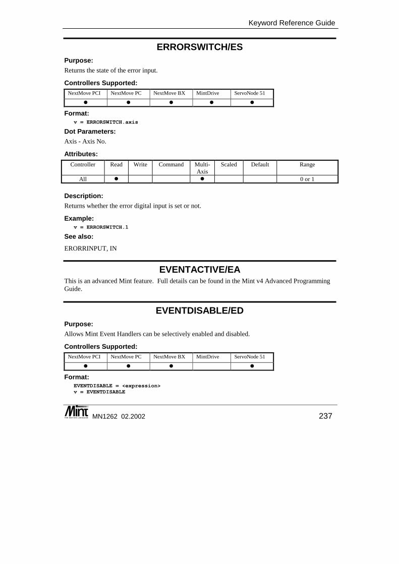
Keyword Reference Guide
MN1262 02.2002 237
ERRORSWITCH/ES Purpose: Returns the state of the error input.
Controllers Supported: NextMove PCI NextMove PC NextMove BX MintDrive ServoNode 51
� � � � �
Format: v = ERRORSWITCH.axis
Dot Parameters: Axis - Axis No.
Attributes: Controller Read Write Command Multi-
Axis Scaled Default Range
All � � 0 or 1
Description: Returns whether the error digital input is set or not.
Example: v = ERRORSWITCH.1
See also: ERORRINPUT, IN
EVENTACTIVE/EA This is an advanced Mint feature. Full details can be found in the Mint v4 Advanced Programming Guide.
EVENTDISABLE/ED Purpose: Allows Mint Event Handlers can be selectively enabled and disabled.
Controllers Supported: NextMove PCI NextMove PC NextMove BX MintDrive ServoNode 51
� � � �
Format: EVENTDISABLE = <expression>v = EVENTDISABLE
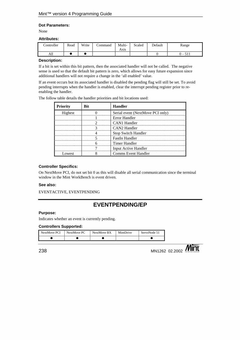
Mint™ version 4 Programming Guide
238 MN1262 02.2002
Dot Parameters: None
Attributes: Controller Read Write Command Multi-
Axis Scaled Default Range
All � � 0 0 – 511
Description: If a bit is set within this bit pattern, then the associated handler will not be called. The negative sense is used so that the default bit pattern is zero, which allows for easy future expansion since additional handlers will not require a change in the ‘all enabled’ value. If an event occurs but its associated handler is disabled the pending flag will still be set. To avoid pending interrupts when the handler is enabled, clear the interrupt pending register prior to re-enabling the handler. The follow table details the handler priorities and bit locations used:
Priority Bit Handler Highest 0 Serial event (NextMove PCI only)
1 Error Handler 2 CAN1 Handler 3 CAN2 Handler 4 Stop Switch Handler 5 FastIn Handler 6 Timer Handler
7 Input Active Handler Lowest 8 Comms Event Handler
Controller Specifics: On NextMove PCI, do not set bit 0 as this will disable all serial communication since the terminal window in the Mint WorkBench is event driven.
See also: EVENTACTIVE, EVENTPENDING
EVENTPENDING/EP Purpose: Indicates whether an event is currently pending.
Controllers Supported: NextMove PCI NextMove PC NextMove BX MintDrive ServoNode 51
� � � �
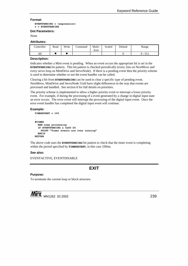
Keyword Reference Guide
MN1262 02.2002 239
Format: EVENTPENDING = <expression>v = EVENTPENDING
Dot Parameters: None
Attributes: Controller Read Write Command Multi-
Axis Scaled Default Range
All � � 0 0 - 511
Description: Indicates whether a Mint event is pending. When an event occurs the appropriate bit is set in the EVENTPENDING bit pattern. This bit pattern is checked periodically (every 2ms on NextMove and every servo loop on MintDrive and ServoNode). If there is a pending event then the priority scheme is used to determine whether or not the event handler can be called. Clearing a bit from EVENTPENDING can be used to clear a specific type of pending event. NextMove, MintDrive and ServoNode 51all have slight differences in the way that events are processed and handled. See section 8 for full details on priorities. The priority scheme is implemented to allow a higher priority event to interrupt a lower priority event. For example, if during the processing of a event generated by a change in digital input state an error occurs. The error event will interrupt the processing of the digital input event. Once the error event handler has completed the digital input event will continue.
Example: TIMEREVENT = 100..#TIMERREM some processingIF EVENTPENDING & 0x40 DOPRINT “Timer events are over running”
ENDIFRETURN
The above code uses the EVENTPENDING bit pattern to check that the timer event is completing within the period specified by TIMEREVENT, in this case 100ms.
See also: EVENTACTIVE, EVENTDISABLE
EXIT Purpose: To terminate the current loop or block structure.

Mint™ version 4 Programming Guide
240 MN1262 02.2002
Controllers Supported: NextMove PCI NextMove PC NextMove BX MintDrive ServoNode 51
� � � � �
Format: EXIT
Description: Forces termination of a loop. EXIT can be used to leave any of the following loop constructs:
• FOR .. NEXT
• LOOP .. ENDL
• REPEAT .. UNTIL
• WHILE .. ENDW
Program execution commences on the line following the terminating statement in the loop. EXIT is useful for terminating loops when a condition becomes true.
Example: LOOP{statements}IF IN.1 = 1 THEN EXIT{statements}
ENDL? "End Loop"
if input 1 goes active, "End Loop" will be printed to the terminal.
See also: FOR .. NEXT, LOOP..ENDL, REPEAT..UNTIL, WHILE..ENDW
EXP Purpose: To calculate the exponential of the expression.
Controllers Supported: NextMove PCI NextMove PC NextMove BX MintDrive ServoNode 51
� � � � �
Format: v = EXP(<value>)
Description: Return the exponential of the <value> where <value> can be any valid Mint expression.
Example: answer = EXP (number / 20)
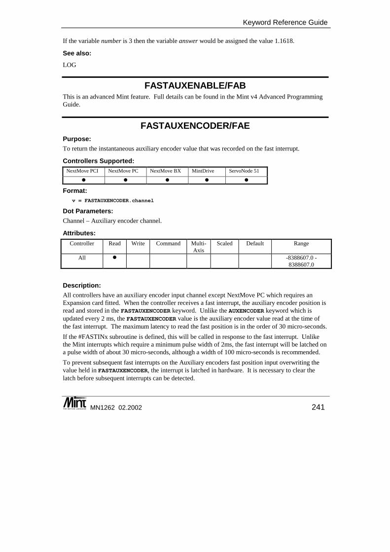
Keyword Reference Guide
MN1262 02.2002 241
If the variable number is 3 then the variable answer would be assigned the value 1.1618.
See also: LOG
FASTAUXENABLE/FAB This is an advanced Mint feature. Full details can be found in the Mint v4 Advanced Programming Guide.
FASTAUXENCODER/FAE Purpose: To return the instantaneous auxiliary encoder value that was recorded on the fast interrupt.
Controllers Supported: NextMove PCI NextMove PC NextMove BX MintDrive ServoNode 51
� � � � �
Format: v = FASTAUXENCODER.channel
Dot Parameters: Channel – Auxiliary encoder channel.
Attributes: Controller Read Write Command Multi-
Axis Scaled Default Range
All � -8388607.0 - 8388607.0
Description: All controllers have an auxiliary encoder input channel except NextMove PC which requires an Expansion card fitted. When the controller receives a fast interrupt, the auxiliary encoder position is read and stored in the FASTAUXENCODER keyword. Unlike the AUXENCODER keyword which is updated every 2 ms, the FASTAUXENCODER value is the auxiliary encoder value read at the time of the fast interrupt. The maximum latency to read the fast position is in the order of 30 micro-seconds. If the #FASTINx subroutine is defined, this will be called in response to the fast interrupt. Unlike the Mint interrupts which require a minimum pulse width of 2ms, the fast interrupt will be latched on a pulse width of about 30 micro-seconds, although a width of 100 micro-seconds is recommended. To prevent subsequent fast interrupts on the Auxiliary encoders fast position input overwriting the value held in FASTAUXENCODER, the interrupt is latched in hardware. It is necessary to clear the latch before subsequent interrupts can be detected.
Mint™ version 4 Programming Guide
242 MN1262 02.2002
The value returned by the FASTAUXENCODER keyword is dependent on the scale factor as set with the AUXENCODERSCALE keyword.
Example: #FASTIN0?FASTAUXENCODER.0 : REM Print latched auxiliary encoder valueRETURN
See also: AUXENCODER, FASTENCODER, FASTPOS, FASTAUXENABLE, FASTAUXLATCH, FASTAUXLATCHMODE, FASTAUXSELECT
FASTAUXLATCH/FAL This is an advanced Mint feature. Full details can be found in the Mint v4 Advanced Programming Guide.
FASTAUXLATCHMODE/FAM This is an advanced Mint feature. Full details can be found in the Mint v4 Advanced Programming Guide.
FASTAUXSELECT/FAS This is an advanced Mint feature. Full details can be found in the Mint v4 Advanced Programming Guide.
FASTENABLE/FEB This is an advanced Mint feature. Full details can be found in the Mint v4 Advanced Programming Guide.
FASTENCODER/FEN Purpose: To return the instantaneous encoder value that was recorded on the fast interrupt.
Controllers Supported: NextMove PCI NextMove PC NextMove BX MintDrive ServoNode 51
� � � � �
Format: v = FASTENCODER.channel
Dot Parameters: Channel – Encoder channel number.
Keyword Reference Guide
MN1262 02.2002 243
Attributes: Controller Read Write Command Multi-
Axis Scaled Default Range
All � � -8388607.0 ≤ x ≤ 8388607.0
Description: Axis position is normally read with the POS keyword. The ENCODER keyword allows an axis encoder value to be read directly, independent of the axis position. When the controller receives a fast interrupt, the encoder value is read and stored in the FASTENCODER keyword. Unlike the ENCODER keyword which is updated every servo loop, (250, 500 or 1000 micro-seconds), the FASTENCODER value is the axis encoder value read at the time of the fast interrupt. The maximum latency to read the fast position is in the order of 30 micro-seconds. If the #FASTINx subroutine is defined, this will be called in response to the fast interrupt. Unlike the Mint interrupts which require a minimum pulse width of 2ms, the fast interrupt will be latched on a pulse width of about 30 micro-seconds, although a width of 100 micro-seconds is recommended. To prevent subsequent fast interrupts on the encoders fast position input overwriting the value held in FASTENCODER, the interrupt is latched in hardware. It is necessary to clear the latch before subsequent interrupts can be detected. The value returned by the FASTENCODER keyword is dependent on the scale factor as set with the ENCODERSCALE keyword.
Example: #FASTIN0?FASTENCODER.2;FASTPOS.2 : REM Print latched encoder and pos of axes 2
RETURN
See also: ENCODER, FASTAUXENCODER, FASTPOS, FASTLATCH, FASTENABLE, FASTLATCHMODE
FASTLATCH/FLT This is an advanced Mint feature. Full details can be found in the Mint v4 Advanced Programming Guide.
FASTLATCHMODE/FTM This is an advanced Mint feature. Full details can be found in the Mint v4 Advanced Programming Guide.
Mint™ version 4 Programming Guide
244 MN1262 02.2002
FASTPOS/FP Purpose: To return the instantaneous axis position that was recorded on the fast interrupt.
Controllers Supported: NextMove PCI NextMove PC NextMove BX MintDrive ServoNode 51
� � � � �
Dot Parameters: Axis - Axis No.
Format: v = FASTPOS[axis]
Attributes: Controller Read Write Command Multi-
Axis Scaled Default Range
All � � � -8388607.0 ≤ x ≤ 8388607.0
Description: When the controller receives a fast interrupt, the axis position is read and stored in the FASTPOS keyword. Unlike the POS keyword which is updated every servo loop, the FASTPOS position is the axis position read at the time of the fast interrupt. The maximum latency to read the fast position is in the order of 30 micro-seconds. If the #FASTINx subroutines are defined, then the appropriate subroutine will be called in response to the fast interrupt. Unlike the Mint interrupts which require a minimum pulse width of 2ms, the fast interrupt will be latched on a pulse width of about 30 micro-seconds, although a width of 100 micro-seconds is recommended. To prevent subsequent fast interrupts on the fast position input overwriting the value held in FASTPOS, the interrupt is latched in hardware. It is necessary to clear the latch before subsequent interrupts can be detected. The value returned by the FASTPOS keyword is dependent on the scale factor. The positions of all axes are latched independently.
Example: #FASTIN0?FASTPOS.2;FASTPOS.3 : REM Print latched positions of axes 2 and 3
RETURN
See also: FASTAUXENCODER, FASTENCODER, POS, FASTENABLE, FASTLATCH, FASTAUXLATCHMODE, FASTSELECT
Keyword Reference Guide
MN1262 02.2002 245
FASTSELECT/FS This is an advanced Mint feature. Full details can be found in the Mint v4 Advanced Programming Guide.
FEEDRATE/FR This is an advanced Mint feature. Full details can be found in the Mint v4 Advanced Programming Guide.
FEEDRATEMODE/FRM This is an advanced Mint feature. Full details can be found in the Mint v4 Advanced Programming Guide.
FEEDRATEOVERRIDE/FRO This is an advanced Mint feature. Full details can be found in the Mint v4 Advanced Programming Guide.
FEMODE/FM This keyword has been replaced by FOLERRORMODE in Mint v4. For details on converting existing Mint programs to Mint v4 see the Mint v4 Code Analyzer Tool Guide.
FIRMWARERELEASE/FWR This is an advanced Mint feature. Full details can be found in Mint v4 Advanced Programming Guide.
FLY/FY Purpose: Create a flying shear by following a master axis with controlled acceleration and deceleration.
Controllers Supported: NextMove PCI NextMove PC NextMove BX MintDrive ServoNode 51
� � � � �
Format: FLY[axes] = <expression> {,<expression> ...}
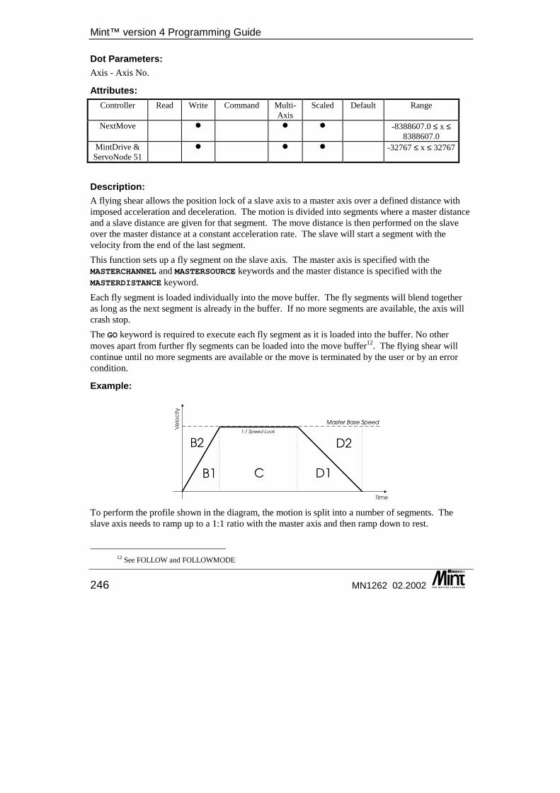
Mint™ version 4 Programming Guide
246 MN1262 02.2002
Dot Parameters: Axis - Axis No.
Attributes: Controller Read Write Command Multi-
Axis Scaled Default Range
NextMove � � � -8388607.0 ≤ x ≤ 8388607.0
MintDrive & ServoNode 51
� � � -32767 ≤ x ≤ 32767
Description: A flying shear allows the position lock of a slave axis to a master axis over a defined distance with imposed acceleration and deceleration. The motion is divided into segments where a master distance and a slave distance are given for that segment. The move distance is then performed on the slave over the master distance at a constant acceleration rate. The slave will start a segment with the velocity from the end of the last segment. This function sets up a fly segment on the slave axis. The master axis is specified with the MASTERCHANNEL and MASTERSOURCE keywords and the master distance is specified with the MASTERDISTANCE keyword. Each fly segment is loaded individually into the move buffer. The fly segments will blend together as long as the next segment is already in the buffer. If no more segments are available, the axis will crash stop. The GO keyword is required to execute each fly segment as it is loaded into the buffer. No other moves apart from further fly segments can be loaded into the move buffer12. The flying shear will continue until no more segments are available or the move is terminated by the user or by an error condition.
Example:
To perform the profile shown in the diagram, the motion is split into a number of segments. The slave axis needs to ramp up to a 1:1 ratio with the master axis and then ramp down to rest.
12 See FOLLOW and FOLLOWMODE
Keyword Reference Guide
MN1262 02.2002 247
The profile is defined in terms of the slave distance to travel for the master distance to travel. MASTERDISTANCE.1 = B1 + B2 : REM Area travelled by the master is B1 + B2FLY.1 = B1 : REM Area travelled by the slave is B1GO.1 : REM Start the FLY segmentMASTERDISTANCE.1 = C : REM Area travelled by the master is CFLY.1 = C : REM Area travelled by the slave is C,1:1 ratioGO.1 : REM Start the FLY segmentMASTERDISTANCE.1 = D1 + D2 : REM Area travelled by the master is D1 + D2FLY.1 = D1 : REM Area travelled by the slave is D1GO.1 : REM Start the FLY segment
Flying shear distances need to be calculated accurately in order to stop small errors in ratio. These are particularly noticeable where a number of segments are repeated. This is because FLY calculations are based on the current ratio at the start of each segment. If the physical system has complex gearings between the motor and axis, these ratios need to be calculated accurately. Assigning a value of 0 to FLY will cause the slave to wait the measured distance on the master.
Notes: • It is assumed that the master is moving uni-directionally. If the master changes direction,
the slave will only change direction for the distance of the current FLY segment. • FLY moves are buffered in the same was as position moves. To set an output, for example,
when the slave has reached its desired position, the OUT statement must be placed after the buffered move as shown:
MASTERDISTANCE = 1000FLY = 500 : GOFLY = 1000 : GOPAUSE MOVEBUFFERFREE = 1OUT.0 = 1 : REM Set output when FLY = 500 has finished
• It is possible to set up FLY segments with the FOLLOW keyword. See FOLLOW and FOLLOWMODE for details.
• If the master axis is normally rotating in a negative direction, then MASTERDISTANCE can be set to a negative value to indicate this (NextMove only).
• There is an equation that relates the master/slave ratio to the master and slave distances:
See also: FOLLOW, FOLLOWMODE, GO, MASTERCHANNEL, MASTERDISTANCE, MASTERSOURCE, STOP
FOLERR/FE This keyword has been replaced by FOLERROR in Mint v4. For details on converting existing Mint programs to Mint v4 see the Mint v4 Code Analyzer Tool Guide.
ANCEMASTERDIST2
Ratio FinalRatio InitialFLY ×
+=
Mint™ version 4 Programming Guide
248 MN1262 02.2002
FOLERROR/FE Purpose: To return the instantaneous following error value.
Controllers Supported: NextMove PCI NextMove PC NextMove BX MintDrive ServoNode 51
� � � � �
Format: v = FOLERROR[axis]
Dot Parameters: Axis - Axis No.
Attributes: Controller Read Write Command Multi-
Axis Scaled Default Range
All � � � -8388607.0 ≤ x ≤ 8388607.0
Description: Returns instantaneous following error where the following error is defined as the demand position (where you want to be) minus the actual motor position as calculated by the servo loop. The value of folowing error is the error signal used in the position control algorithm. See section 2 for details. If the following error exceeds the value set by FOLERRORFATAL (maximum following error) a motion error is generated dependent on the value of the error mode keyword, FOLERRORMODE. Reading the following error during a move is useful for tuning the system. For example:
MOVEA = 100 : GO[0]WHILE !IDLE[0]?FOLERROR[0]
ENDW?FOLERROR
will print the following error continuously to the terminal while the move is in progress. Note that the value returned is dependent on the scale factor, SCALE.
See also: AXISERROR, FOLERRORMODE, FOLERRORFATAL
FOLERRORFATAL/FEF Purpose: To set the maximum permissible following error before an error is generated.
Keyword Reference Guide
MN1262 02.2002 249
Controllers Supported: NextMove PCI NextMove PC NextMove BX MintDrive ServoNode 51
� � � � �
Format: FOLERRORFATAL[axes] = <expression> {,<expression> ...}v = FOLERRORFATAL[axis]
Dot Parameters: Axis - Axis No.
Attributes: Controller Read Write Command Multi-
Axis Scaled Default Range
NextMove � � � � 1000 0 ≤ x ≤ 8388607.0 MintDrive � � � 1000 0 ≤ x ≤ 32767
Description: Sets the maximum permissible following error before an error is generated. The following error is defined as the demand position (where you want to be) minus the actual motor position (where you are). If the following error exceeds the value set by FOLERRORFATAL (maximum following error) an error may be generated. If an error is generated, the axis will be crash stopped and drive will be disabled. The FOLERRORMODE keyword can be used to change the action taken in the event of an error. If the user error handler, #ONERROR, is defined it will be called. If the FOLERRORMODE is set to ignore, then AXISSTATUS will indicate when the maximum following error has been exceeded.
Example: SCALE = 500; : REM Scale to mmFOLERRORFATAL = 4; : REM Max following error = 4mmFOLERRORFATAL = 1; : REM Check for following errors
should the following exceed 4mm, an error will be generated.
See also: AXISSTATUS, ERR, AXISERROR, FOLERRORMODE, FOLERROR
FOLERRORMODE/FEM This is an advanced Mint feature. Full details can be found in Mint v4 Advanced Programming Guide.
FOLERRORWARNING/FEW This is an advanced Mint feature. Full details can be found in Mint v4 Advanced Programming Guide.
Mint™ version 4 Programming Guide
250 MN1262 02.2002
FOLLOW/FL Purpose: To enable encoder following with a specified gear ratio.
Controllers Supported: NextMove PCI NextMove PC NextMove BX MintDrive ServoNode 51
� � � � �
Dot Parameters: Axis - Axis No.
Format: FOLLOW[axes] = <expression> {,<expression> ...}v = FOLLOW[axis]
Attributes: Controller Read Write Command Multi-
Axis Scaled Default Range
All � � � -128.0 ≤ x ≤ 127.0
Description: The FOLLOW keyword allows an axis to ‘follow’ another axis with a specified gear ratio; a form of programmable software gearbox. The change in position of the slave is controlled by the change in position of a master axis. The expression defines the gear ratio and the direction between the two axes. The master axis is selected with the MASTERSOURCE and MASTERCHANNEL keywords. The MASTERDISTANCE keyword is used to specify the master axis. The gear ratio specified is in terms of user units i.e., a gear ratio of 2 implies that one unit of master travel will result in 2 units of slave travel. FOLLOW will cause the slave axis to follow the master axis in user units, i.e. if Axis 0 has an encoder with 2000 counts / rev and is following Axis 1 with an encoder of 4000 counts / rev, then providing that the SCALE keyword has been used to set the scale factors to 2000 and 4000 respectively, a move of two revs on axis 1 would result in a move of 2 revs on Axis 0. The encoder positions would have moved 4000 and 8000 counts respectively. The precise action of the FOLLOW keyword is determined by the FOLLOWMODE keyword which sets up the mode for FOLLOW. There are four possible modes. See section 6.14 for full details on each mode. When FOLLOW is called, motion will begin immediately and a FOLLOW move loaded into the move buffer. No other move types can be loaded unless in extended clutch mode which allows FLY moves to be loaded. The move will continue until a follow ratio of zero is set or the move is terminated by the user or an error condition.
Keyword Reference Guide
MN1262 02.2002 251
Setting FOLLOW = 0 will not stop the FOLLOW move. It will cause the slave to go to zero speed and follow the master at a zero ratio. Further FOLLOW or FLY keywords can then be issued. Positional offsets can be performed while in FOLLOW mode. These are performed by the current positional move profile being imposed on the slave speed. See the OFFSET keyword for details. Reading FOLLOW will return the last ratio assigned to it.
Example: REM Master scaled to mm. Slave scaled to revs.MASTERSOURCE[2] = 0 : REM Master is axis positionMASTERCHANNEL[2] = 3 : REM Master is axis 3FOLLOWMODE[2] = 2 : REM Clutch ModeMASTERDISTANCE[2] = 5 : REM Ramp up to speed over 5mm of master travelFOLLOW = 1.5 : REM Ramp up a 1.5:1 ratio with the masterPAUSE IN.16 : REM Wait until input 16 becomes activeSTOP
For every 1mm of master travel, the slave will produce 1.5 revolutions. It will take 5mm of master travel to ramp up to the required ratio. After the input the slave axis will stop over a further 5mm.
Restrictions: For MintDrive there must be no moves pending on the axis nor should it be currently following another axis.
See also: CAM, FLY, FOLLOWDENOM, FOLLOWMODE, MASTERCHANNEL, MASTERDISTANCE, MASTERSOURCE, OFFSET, SPLINE, STOP
FOLLOWAXIS/FLA This keyword has been replaced by MASTERCHANNEL in Mint v4. For details on converting existing Mint programs to Mint v4 see the Mint v4 Code Analyzer Tool Guide.
FOLLOWDENOM/FLD Purpose: To set or read the Follow ratios denominator.
Controllers Supported: NextMove PCI NextMove PC NextMove BX MintDrive ServoNode 51
� �
Format: FOLLOWDENOM[axes] = <expression> {,<expression> ...}v = FOLLOWDENOM[axis]
Mint™ version 4 Programming Guide
252 MN1262 02.2002
Dot Parameters: Axis - Axis No.
Attributes: Controller Read Write Command Multi-
Axis Scaled Default Range
All � � � 1 1 ≤ x ≤ 128
Description: To overcome the limitations of scaling error with fractional numbers, a follow ratio for position following can be defined in terms of a numerator and denominator. The denominator is set with this keyword and the numerator is set with the FOLLOW keyword.
Example: FOLLOWDENOM = 10FOLLOW = 11
Restrictions: The FOLLOWDENOM should be entered before the axis is put into follow mode with the FOLLOW keyword i.e. FOLLOWDENOM will not take affect until the next FOLLOW command.
See also: FOLLOW
FOLLOWMODE/FLM Purpose: To define the mode of operation on the FOLLOW keyword
Controllers Supported: NextMove PCI NextMove PC NextMove BX MintDrive ServoNode 51
� � � � �
Format: FOLLOWMODE[axes] = <expression> {,<expression> ...}v = FOLLOWMODE[axis]
Dot Parameters: Axis - Axis No.
Keyword Reference Guide
MN1262 02.2002 253
Attributes: Controller Read Write Command Multi-
Axis Scaled Default Range
All � � � 0 0 ≤ x ≤ 3
Description: FOLLOWMODE is used to select the way in which an axis executing a FOLLOW move type will react to a change in gear ratio. This function should be called prior to setting up a FOLLOW move. There are four types of follow mode that can be set up:
Mode Predefined Constant Use 0 _fmNO_RAMP Position Locked. The slave axis will follow the master axis
at the specified gear ratio. Changes in ratio are performed instantly with no ramping.
1 _fmRAMP Velocity Locked. The slave axis will follow the master axis at the specified gear ratio. Changes in ratio are performed at the current slave axis acceleration and deceleration rates. This allows ‘slip’ between master and slave.
2 _fmCLUTCH Position Locked (Clutch). The slave axis will follow the master axis at the specified gear ratio. The initial ramp up to the gear ratio and ramp down to a stop are performed using a ‘flying shear’ segment. Acceleration and deceleration takes place over a specified master distance. Changes in gear ratio during motion are performed instantly with no ramping.
3 _fmCONTINUOUS_CLUTCH Position Locked (Continuous Clutch). The slave axis will follow the master axis at the specified gear ratio. All changes in gear ratio are performed using a ‘flying shear’ segment. Acceleration and deceleration takes place over a specified master distance. Changes in ratio can also be defined by using the FLY keyword.
See section 6.14 for full details on each mode. For the clutch modes, the master distance for the Flying shear segments is set with the MASTERDISTANCE keyword. The default mode is 0. FOLLOWMODE cannot be changed while encoder following is in progress.
See also: FLY, FOLLOW, MASTERCHANNEL, MASTERDISTANCE, MASTERSOURCE, OFFSET
FOR .. NEXT Purpose: To execute a series of instructions a specified number of times in a loop.
Mint™ version 4 Programming Guide
254 MN1262 02.2002
Controllers Supported: NextMove PCI NextMove PC NextMove BX MintDrive ServoNode 51
� � � � �
Format: FOR <variable> = <expression1> TO <expression2> {STEP <expression3>}{statements}
NEXT
Description: The FOR loop is the Basic implementation of the FOR loop allowing for incrementing and decrementing of the <variable> as defined by the STEP size, <expression3>. <expression1> , <expression2> and <expression3> can be any valid expressions. FOR loops are terminated with a NEXT statement. There must be no variable name after the NEXT statement as with standard forms of Basic.
Example: DIM a
FOR a = 1 TO 10 : REM Perform loop 10 timesREM Move to the XY position in the arrayMOVEA = xpos(a), ypos(a) : GOPAUSE IDLE[0,1] : REM Wait for axes to stopOUT1 = _on : REM Set the outputWAIT = 250 : REM Wait 1/4 secondOUT = _off : REM Turn the output off
NEXT
When the loop terminates, the value of the variable will equal the upper limit (expression2). It will never exceed it for a positive number. FOR .. NEXT loops may be nested up to 50 levels as follows:
DIM a
FOR a = 1 TO 100 STEP 10MOVEA[0] = a : GOFOR b = 1 to 10MOVEA[1] = b : GO
NEXTNEXT
A FOR NEXT loop can be terminated prematurely using the EXIT keyword.
See also: EXIT, LOOP..ENDL, REPEAT..UNTIL, WHILE..ENDW
FREQ/FQ This is an advanced Mint feature. Full details can be found in Mint v4 Advanced Programming Guide.
Keyword Reference Guide
MN1262 02.2002 255
FWLIMITIN/FLI This keyword has been replaced by LIMITFORWARDINPUT in Mint v4. For details on converting existing Mint programs to Mint v4 see the Mint v4 Code Analyzer Tool Guide.
FWSOFTLIMIT/FSL This keyword has been replaced by SOFTLIMITFORWARD in Mint v4. For details on converting existing Mint programs to Mint v4 see the Mint v4 Code Analyzer Tool Guide.
GAIN/GN This keyword has been replaced by KPROP in Mint v4. For details on converting existing Mint programs to Mint v4 see the Mint v4 Code Analyzer Tool Guide.
GEARING/GR This is an advanced Mint feature. Full details can be found in the Mint v4 Advanced Programming Guide.
GEARINGMODE/GRM This is an advanced Mint feature. Full details can be found in the Mint v4 Advanced Programming Guide.
GLOBALERROROUTPUT/GEO Purpose: Allows the user to specify a global error output with will be dropped in the event of an error.
Controllers Supported: NextMove PCI NextMove PC NextMove BX MintDrive ServoNode 51
� � �
Format: GLOBALERROROUTPUT = <expression>v = GLOBALERROROUTPUT
Dot Parameters: None

Mint™ version 4 Programming Guide
256 MN1262 02.2002
Attributes: Controller Read Write Command Multi-
Axis Scaled Default Range
NextMove PCI13, NextMove PC
� � 1000 -1 ≤ x ≤ 11 and relay constants
NextMove BX � � 1000 -1 ≤ x ≤ 7 and relay constants
Description: When an asynchronous error occurs, Mint has the ability to de-activate a safety output known as the global error output signal. This can be a digital output channel or a relay. The output is deactivated as soon as an asynchronous error occurs on any axis. It does not wait for any assigned default action to be completed. The user must manually re-activate the output when required. If an axis drive enable output and the global error output are both configured to the same output, then the global error output functionality remains unchanged. The drive will be disabled even if the requested error mode was to leave the drive enabled.
Value Predefined Constant
Description
-1 There is no global error output. Digital Output
channel number The global error output is a digital output channel number.
1000 _RELAY0 The global error output is the relay on the main card 1001 _RELAY1 The global error output is the relay on expansion card 1
(NextMove PCI only) 1002 _RELAY2 The global error output is the relay on expansion card 2
(NextMove PCI only) By default, the relay is the global error output signal.
Example: GLOBALERROROUTPUT = _RELAY0
This will set the global error output channel to be the relay on the main card. In the event of an error this relay will be de-activated.
See also: DRIVEENABLEOUTPUT, OUT, RELAY
GO Purpose: To begin synchronized motion.
13 If a NextMove PCI Expansion card is present, then the range increases to 23. With two Expansion cards, the range increases to 35. Each Expansion card also has a relay.
Keyword Reference Guide
MN1262 02.2002 257
Controllers Supported: NextMove PCI NextMove PC NextMove BX MintDrive ServoNode 51
� � � � �
Format: GO[axes]
Dot Parameters: Axis - Axis No.
Attributes: Controller Read Write Command Multi-
Axis Scaled Default Range
All � �
Description: When a move is loaded it is put into the move buffer. The move buffer can store between 2 and 100 moves per axis. Certain move types will not start until told to start with a GO command. This allows moves to be synchronized across axes and with other events. The following move type require the GO keyword to begin the motion. Calling GO for other move types result in an error.
• CAM
• CIRCLEA, CIRCLER
• FLY
• HTA
• INCA, INCR
• MOVEA, MOVER
• OFFSET
• SPLINE
• VECTORA, VECTORR
If a relative positional move is loaded into the buffer, it will not start until the GO is issued MOVER.0 = 100 : REM Load the moveGO.0 : REM Start the move
Control will be returned to the interpreter immediately after the GO command. The GO command will start motion on all moves loaded into the buffer at that time.
MOVER[0] = 10 : REM Load a moveMOVER[0] = 20 : REM Load another moveGO[0] : REM Trigger both movesMOVER[0] = 30 : REM Load a move
Both moves will be executed, the second starting as soon as the first one has finished. The third move will not be started since it was added to the buffer after the GO command. GO can be used to start motion on multiple axes together.
Mint™ version 4 Programming Guide
258 MN1262 02.2002
MOVER[0] = 10 : REM Set up a move on axis 0MOVER[1] = 20 : REM Set up a move on axis 1GO[0,1] : REM Start both moves
The moves on both axis 0 and 1 will start together. In multi axis move types, such as VECTOR and CIRCLE, only one of the axes involved in the move needs the GO command to start all the axes involved.
VECTORR[2,5] = 10, 300 : REM Load a VECTOR on axes 2 and 5GO.2 : REM Start the VECTOR (both axes)
Note: GO sets an internal trigger which allows the pending motion to start. When the motion actually starts depends upon the existing motion status of the axis and any other axis which may be required to take part in the pending motion. If the move buffer is full when trying to load a move, the move will wait for a space in the buffer. If no GO has been issued then no space will become available and Mint will apparently lock-up. See the MOVEBUFFERSIZE keyword for full details on the move buffer.
Example: MOVEA = 100MOVER = ,200GO[0,1] : REM Synchronize absolute and relative movePAUSE IDLE[0,1]
will synchronize an absolute and a relative positional move. GO will take into account the AXES string as in the following example:
AXES[0,1] : REM Default to axis 0 and 1JOG[1] = 100 : REM Jog axis 1MA = 10 : GO : REM Absolute move on axis 0
will result in a motion in progress error because GO cannot be called for a JOG move. This can be solved as follows:
AXES[0,1] : REM Default to axis 0 and 1JOG[1] = 100 : REM Jog axis 1MA = 10 : GO[0] : REM Explicit axis reference on GO
See also: CAM, CIRCLEA, CIRCLER, FLY, IDLE, INCA, INCR, AXISMODE, MOVEA, MOVEBUFFERSIZE, MOVER, OFFSET, SPLINE, STOP, VECTORA, VECTORR
GOSUB Purpose: To branch program execution to a subroutine.
Keyword Reference Guide
MN1262 02.2002 259
Controllers Supported: NextMove PCI NextMove PC NextMove BX MintDrive ServoNode 51
� � � � �
Format: GOSUB <subroutine_name>
Description: Causes the program to branch to the subroutine with the label given by <subroutine_name>. Since Mint does not support line numbers, all subroutines are referenced by labels. RETURN is used to resume execution from the statement immediately following the GOSUB statement. Example:
GOSUB init...END
#initxpos = 0slow = 10
RETURN
Notes: • Up to 100 levels of GOSUB nesting are permitted. • A subroutine defined in the configuration file cannot be called from within the program file
and vice versa. • GOSUB cannot be used on the command line.
See also: GOTO, RETURN
GOTO Purpose: To branch unconditionally out of the normal program sequence to a specified label.
Controllers Supported: NextMove PCI NextMove PC NextMove BX MintDrive ServoNode 51
� � � � �
Format: GOTO label_name
Description: Branches unconditionally to a specified label.
Example: { statements }GOTO label1{statements }
Mint™ version 4 Programming Guide
260 MN1262 02.2002
#label1
GOTO should be used with care. Do not use GOTO to jump out of an interrupt routine, loops or block IFs. For example:
LOOP...IF IN1 DO...IF IN2 THEN GOTO abortLoop...
ENDIF#abortLoop...
ENDL
will eventually result in a "Stack overflow" error message.
GOTO cannot be used on the command line.
See also: GOSUB
GROUP/GP For details on this keyword see the Mint v4 CAN Programming Guide.
GROUPCOMMS/GC For details on this keyword see the Mint v4 CAN Programming Guide.
GROUPMASTER/GM For details on this keyword see the Mint v4 CAN Programming Guide.
GROUPMASTERSTATUS/GMS For details on this keyword see the Mint v4 CAN Programming Guide.
GROUPSTATUS/GPS For details on this keyword see the Mint v4 CAN Programming Guide.
HALL/HLL Purpose: To read the current Hall value for a motor.
Keyword Reference Guide
MN1262 02.2002 261
Controllers Supported: NextMove PCI NextMove PC NextMove BX MintDrive ServoNode 51
�
Format: v = HALL
Attributes: Controller Read Write Command Multi-
Axis Scaled Default Range
ServoNode 51 � 1 – 6
Description: ServoNode 51 uses a default Sextant/Hall mapping appropriate to Baldor BSM brushless motors. This mapping can be changed, so motors with different sextant/Hall mapping can be used. This is achieved by forcing the motor to a sextant and determining which Hall is active. As there are 3 Hall effect transducers (U, V & W), each being on or off, then there are 8 possible states. To complete the mapping, Hall 0 and 7 are included as illegal or null values. See the ServoNode 51 Installation manual for details on Hall / Sextant mapping.
See also: SEXTANT
HANDLERDISABLE/HD Purpose: Allows Mint Interrupt Handlers can be selectively enabled and disabled.
Controllers Supported: NextMove PCI NextMove PC NextMove BX MintDrive ServoNode 51
�
Format: HANDLERDISABLE = <expression>v = HANDLERDISABLE
Dot Parameters: None
Attributes: Controller Read Write Command Multi-
Axis Scaled Default Range
All � � 0 0 - 383
Mint™ version 4 Programming Guide
262 MN1262 02.2002
Description: If a bit is set within this bit pattern, then the associated handler will not be called. The negative sense is used so that the default bit pattern is zero, which allows for easy future expansion since additional handlers will not require a change in the ‘all enabled’ value. If an event occurs but its associated handler is disabled the pending flag will still be set. To avoid pending interrupts when the handler is enabled, clear the interrupt pending register prior to re-enabling the handler. The follow table details the handler priorities and bit locations used:
Priority Bit Handler 0: Highest 0 Error Handler 1 1 FastIn Handler 2 2 Stop Switch Handler 3 3 CAN1 Handler 4 4 CAN2 Handler 5 5 Timer Handler 6 6 Input Active Handler 7 7 Reserved 8: Lowest 8 COMMS Event Handler
See also: HANDLERPENDING
HANDLERPENDING/HP Purpose: Indicates whether a Mint Interrupt Handler is currently pending.
Controllers Supported: NextMove PCI NextMove PC NextMove BX MintDrive ServoNode 51
�
Format: HANDLERPENDING = <expression>v = HANDLERPENDING
Dot Parameters: None
Attributes: Controller Read Write Command Multi-
Axis Scaled Default Range
All � � 0 0 - 383
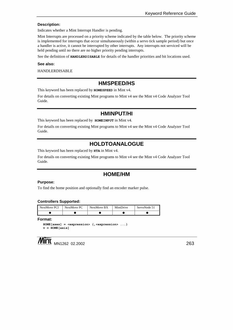
Keyword Reference Guide
MN1262 02.2002 263
Description: Indicates whether a Mint Interrupt Handler is pending. Mint Interrupts are processed on a priority scheme indicated by the table below. The priority scheme is implemented for interrupts that occur simultaneously (within a servo tick sample period) but once a handler is active, it cannot be interrupted by other interrupts. Any interrupts not serviced will be held pending until no there are no higher priority pending interrupts. See the definition of HANDLERDISABLE for details of the handler priorities and bit locations used.
See also: HANDLERDISABLE
HMSPEED/HS This keyword has been replaced by HOMESPEED in Mint v4. For details on converting existing Mint programs to Mint v4 see the Mint v4 Code Analyzer Tool Guide.
HMINPUT/HI This keyword has been replaced by HOMEINPUT in Mint v4. For details on converting existing Mint programs to Mint v4 see the Mint v4 Code Analyzer Tool Guide.
HOLDTOANALOGUE This keyword has been replaced by HTA in Mint v4. For details on converting existing Mint programs to Mint v4 see the Mint v4 Code Analyzer Tool Guide.
HOME/HM Purpose: To find the home position and optionally find an encoder marker pulse.
Controllers Supported: NextMove PCI NextMove PC NextMove BX MintDrive ServoNode 51
� � � � �
Format: HOME[axes] = <expression> {,<expression> ...}v = HOME[axis]
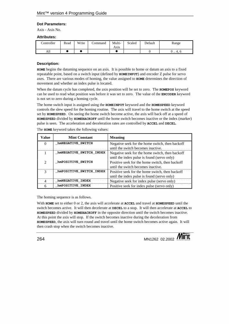
Mint™ version 4 Programming Guide
264 MN1262 02.2002
Dot Parameters: Axis - Axis No.
Attributes: Controller Read Write Command Multi-
Axis Scaled Default Range
All � � � 0 0 .. 4, 6
Description: HOME begins the datuming sequence on an axis. It is possible to home or datum an axis to a fixed repeatable point, based on a switch input (defined by HOMEINPUT) and encoder Z pulse for servo axes. There are various modes of homing, the value assigned to HOME determines the direction of movement and whether an index pulse is located. When the datum cycle has completed, the axis position will be set to zero. The HOMEPOS keyword can be used to read what position was before it was set to zero. The value of the ENCODER keyword is not set to zero during a homing cycle. The home switch input is assigned using the HOMEINPUT keyword and the HOMESPEED keyword controls the slew speed for the homing routine. The axis will travel to the home switch at the speed set by HOMESPEED. On seeing the home switch become active, the axis will back off at a speed of HOMESPEED divided by HOMEBACKOFF until the home switch becomes inactive or the index (marker) pulse is seen. The acceleration and deceleration rates are controlled by ACCEL and DECEL. The HOME keyword takes the following values:
Value Mint Constant Meaning 0 _hmNEGATIVE_SWITCH Negative seek for the home switch, then backoff
until the switch becomes inactive. 1 _hmNEGATIVE_SWITCH_INDEX Negative seek for the home switch, then backoff
until the index pulse is found (servo only) 2 _hmPOSITIVE_SWITCH Positive seek for the home switch, then backoff
until the switch becomes inactive. 3 _hmPOSITIVE_SWITCH_INDEX Positive seek for the home switch, then backoff
until the index pulse is found (servo only) 4 _hmNEGATIVE_INDEX Negative seek for index pulse (servo only) 6 _hmPOSITIVE_INDEX Positive seek for index pulse (servo only)
The homing sequence is as follows. With HOME set to either 0 or 2, the axis will accelerate at ACCEL and travel at HOMESPEED until the switch becomes active. It will then decelerate at DECEL to a stop. It will then accelerate at ACCEL to HOMESPEED divided by HOMEBACKOFF in the opposite direction until the switch becomes inactive. At this point the axis will stop. If the switch becomes inactive during the deceleration from HOMESPEED, the axis will turn round and travel until the home switch becomes active again. It will then crash stop when the switch becomes inactive.
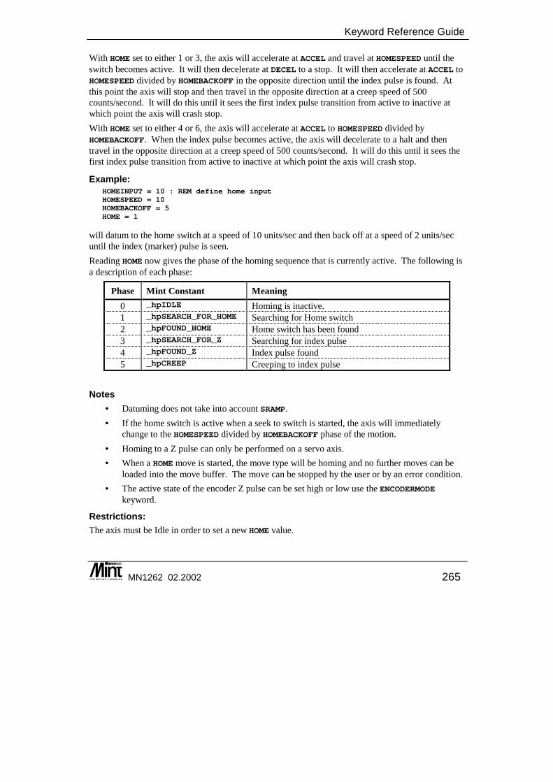
Keyword Reference Guide
MN1262 02.2002 265
With HOME set to either 1 or 3, the axis will accelerate at ACCEL and travel at HOMESPEED until the switch becomes active. It will then decelerate at DECEL to a stop. It will then accelerate at ACCEL to HOMESPEED divided by HOMEBACKOFF in the opposite direction until the index pulse is found. At this point the axis will stop and then travel in the opposite direction at a creep speed of 500 counts/second. It will do this until it sees the first index pulse transition from active to inactive at which point the axis will crash stop. With HOME set to either 4 or 6, the axis will accelerate at ACCEL to HOMESPEED divided by HOMEBACKOFF. When the index pulse becomes active, the axis will decelerate to a halt and then travel in the opposite direction at a creep speed of 500 counts/second. It will do this until it sees the first index pulse transition from active to inactive at which point the axis will crash stop.
Example: HOMEINPUT = 10 : REM define home inputHOMESPEED = 10HOMEBACKOFF = 5HOME = 1
will datum to the home switch at a speed of 10 units/sec and then back off at a speed of 2 units/sec until the index (marker) pulse is seen. Reading HOME now gives the phase of the homing sequence that is currently active. The following is a description of each phase:
Phase Mint Constant Meaning 0 _hpIDLE Homing is inactive. 1 _hpSEARCH_FOR_HOME Searching for Home switch 2 _hpFOUND_HOME Home switch has been found 3 _hpSEARCH_FOR_Z Searching for index pulse 4 _hpFOUND_Z Index pulse found 5 _hpCREEP Creeping to index pulse
Notes • Datuming does not take into account SRAMP. • If the home switch is active when a seek to switch is started, the axis will immediately
change to the HOMESPEED divided by HOMEBACKOFF phase of the motion. • Homing to a Z pulse can only be performed on a servo axis. • When a HOME move is started, the move type will be homing and no further moves can be
loaded into the move buffer. The move can be stopped by the user or by an error condition. • The active state of the encoder Z pulse can be set high or low use the ENCODERMODE
keyword.
Restrictions: The axis must be Idle in order to set a new HOME value.
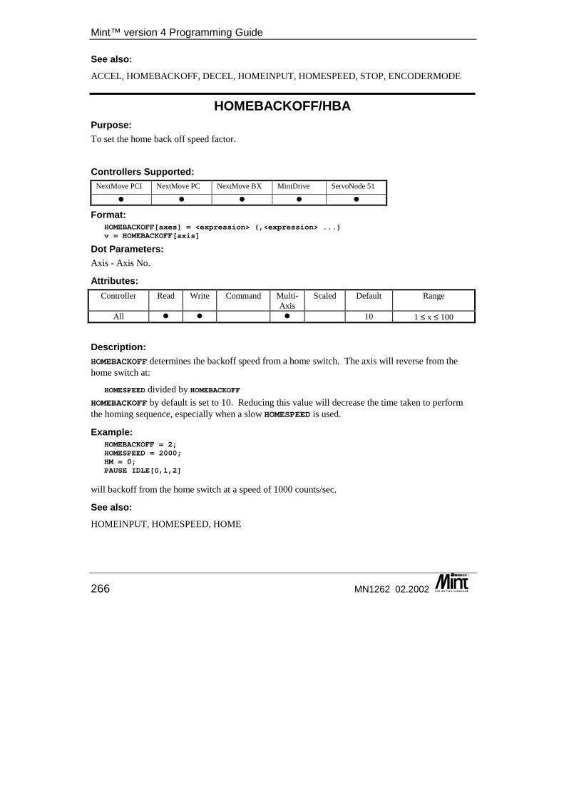
Mint™ version 4 Programming Guide
266 MN1262 02.2002
See also: ACCEL, HOMEBACKOFF, DECEL, HOMEINPUT, HOMESPEED, STOP, ENCODERMODE
HOMEBACKOFF/HBA Purpose: To set the home back off speed factor.
Controllers Supported: NextMove PCI NextMove PC NextMove BX MintDrive ServoNode 51
� � � � �
Format: HOMEBACKOFF[axes] = <expression> {,<expression> ...}v = HOMEBACKOFF[axis]
Dot Parameters: Axis - Axis No.
Attributes: Controller Read Write Command Multi-
Axis Scaled Default Range
All � � � 10 1 ≤ x ≤ 100
Description: HOMEBACKOFF determines the backoff speed from a home switch. The axis will reverse from the home switch at:
HOMESPEED divided by HOMEBACKOFFHOMEBACKOFF by default is set to 10. Reducing this value will decrease the time taken to perform the homing sequence, especially when a slow HOMESPEED is used.
Example: HOMEBACKOFF = 2;HOMESPEED = 2000;HM = 0;PAUSE IDLE[0,1,2]
will backoff from the home switch at a speed of 1000 counts/sec.
See also: HOMEINPUT, HOMESPEED, HOME
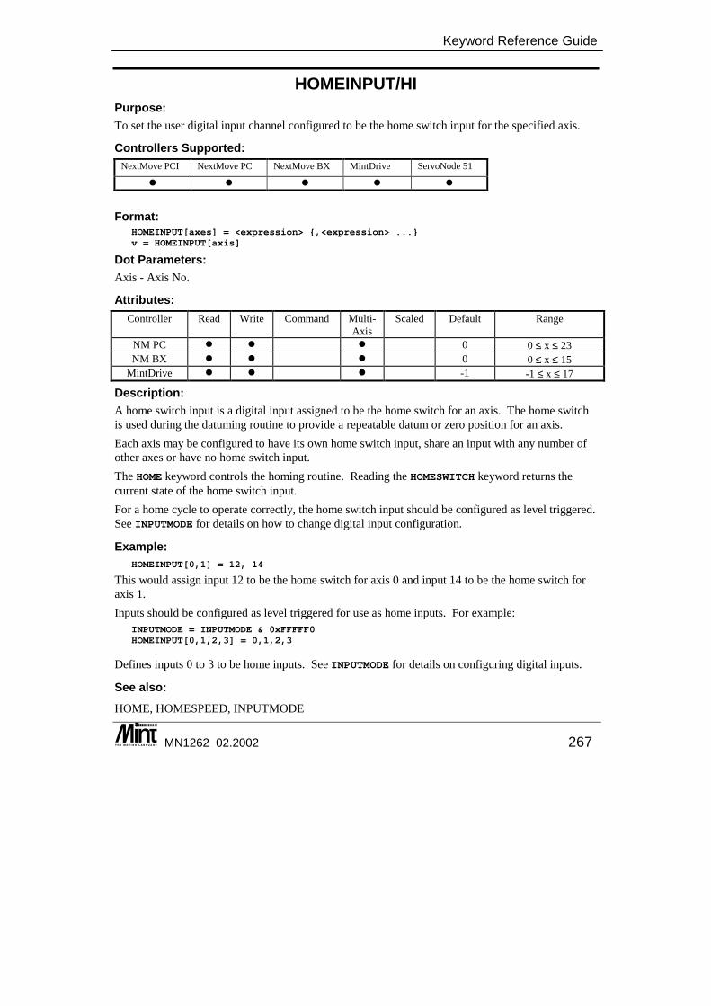
Keyword Reference Guide
MN1262 02.2002 267
HOMEINPUT/HI Purpose: To set the user digital input channel configured to be the home switch input for the specified axis.
Controllers Supported: NextMove PCI NextMove PC NextMove BX MintDrive ServoNode 51
� � � � �
Format: HOMEINPUT[axes] = <expression> {,<expression> ...}v = HOMEINPUT[axis]
Dot Parameters: Axis - Axis No.
Attributes: Controller Read Write Command Multi-
Axis Scaled Default Range
NM PC � � � 0 0 ≤ x ≤ 23 NM BX � � � 0 0 ≤ x ≤ 15
MintDrive � � � -1 -1 ≤ x ≤ 17
Description: A home switch input is a digital input assigned to be the home switch for an axis. The home switch is used during the datuming routine to provide a repeatable datum or zero position for an axis. Each axis may be configured to have its own home switch input, share an input with any number of other axes or have no home switch input. The HOME keyword controls the homing routine. Reading the HOMESWITCH keyword returns the current state of the home switch input. For a home cycle to operate correctly, the home switch input should be configured as level triggered. See INPUTMODE for details on how to change digital input configuration.
Example: HOMEINPUT[0,1] = 12, 14
This would assign input 12 to be the home switch for axis 0 and input 14 to be the home switch for axis 1. Inputs should be configured as level triggered for use as home inputs. For example:
INPUTMODE = INPUTMODE & 0xFFFFF0HOMEINPUT[0,1,2,3] = 0,1,2,3
Defines inputs 0 to 3 to be home inputs. See INPUTMODE for details on configuring digital inputs.
See also: HOME, HOMESPEED, INPUTMODE
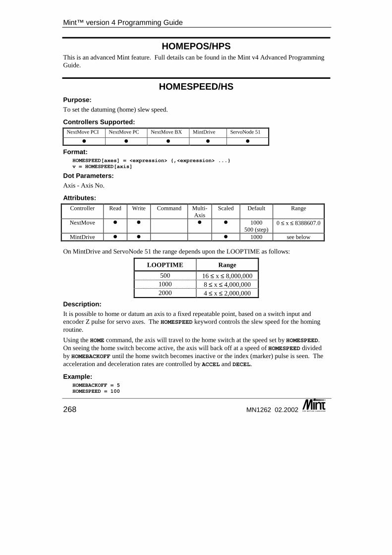
Mint™ version 4 Programming Guide
268 MN1262 02.2002
HOMEPOS/HPS This is an advanced Mint feature. Full details can be found in the Mint v4 Advanced Programming Guide.
HOMESPEED/HS Purpose: To set the datuming (home) slew speed.
Controllers Supported: NextMove PCI NextMove PC NextMove BX MintDrive ServoNode 51
� � � � �
Format: HOMESPEED[axes] = <expression> {,<expression> ...}v = HOMESPEED[axis]
Dot Parameters: Axis - Axis No.
Attributes: Controller Read Write Command Multi-
Axis Scaled Default Range
NextMove � � � � 1000 500 (step)
0 ≤ x ≤ 8388607.0
MintDrive � � � 1000 see below
On MintDrive and ServoNode 51 the range depends upon the LOOPTIME as follows:
LOOPTIME Range 500 16 ≤ x ≤ 8,000,000
1000 8 ≤ x ≤ 4,000,000 2000 4 ≤ x ≤ 2,000,000
Description: It is possible to home or datum an axis to a fixed repeatable point, based on a switch input and encoder Z pulse for servo axes. The HOMESPEED keyword controls the slew speed for the homing routine. Using the HOME command, the axis will travel to the home switch at the speed set by HOMESPEED. On seeing the home switch become active, the axis will back off at a speed of HOMESPEED divided by HOMEBACKOFF until the home switch becomes inactive or the index (marker) pulse is seen. The acceleration and deceleration rates are controlled by ACCEL and DECEL.
Example: HOMEBACKOFF = 5HOMESPEED = 100
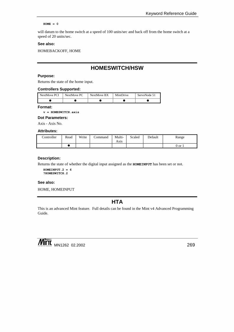
Keyword Reference Guide
MN1262 02.2002 269
HOME = 0
will datum to the home switch at a speed of 100 units/sec and back off from the home switch at a speed of 20 units/sec.
See also: HOMEBACKOFF, HOME
HOMESWITCH/HSW Purpose: Returns the state of the home input.
Controllers Supported: NextMove PCI NextMove PC NextMove BX MintDrive ServoNode 51
� � � � �
Format: v = HOMESWITCH.axis
Dot Parameters: Axis - Axis No.
Attributes: Controller Read Write Command Multi-
Axis Scaled Default Range
� 0 or 1
Description: Returns the state of whether the digital input assigned as the HOMEINPUT has been set or not.
HOMEINPUT.2 = 6?HOMESWITCH.2
See also: HOME, HOMEINPUT
HTA This is an advanced Mint feature. Full details can be found in the Mint v4 Advanced Programming Guide.
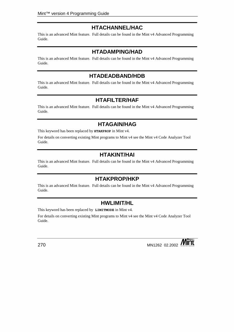
Mint™ version 4 Programming Guide
270 MN1262 02.2002
HTACHANNEL/HAC This is an advanced Mint feature. Full details can be found in the Mint v4 Advanced Programming Guide.
HTADAMPING/HAD This is an advanced Mint feature. Full details can be found in the Mint v4 Advanced Programming Guide.
HTADEADBAND/HDB This is an advanced Mint feature. Full details can be found in the Mint v4 Advanced Programming Guide.
HTAFILTER/HAF This is an advanced Mint feature. Full details can be found in the Mint v4 Advanced Programming Guide.
HTAGAIN/HAG This keyword has been replaced by HTAKPROP in Mint v4. For details on converting existing Mint programs to Mint v4 see the Mint v4 Code Analyzer Tool Guide.
HTAKINT/HAI This is an advanced Mint feature. Full details can be found in the Mint v4 Advanced Programming Guide.
HTAKPROP/HKP This is an advanced Mint feature. Full details can be found in the Mint v4 Advanced Programming Guide.
HWLIMIT/HL This keyword has been replaced by LIMITMODE in Mint v4. For details on converting existing Mint programs to Mint v4 see the Mint v4 Code Analyzer Tool Guide.
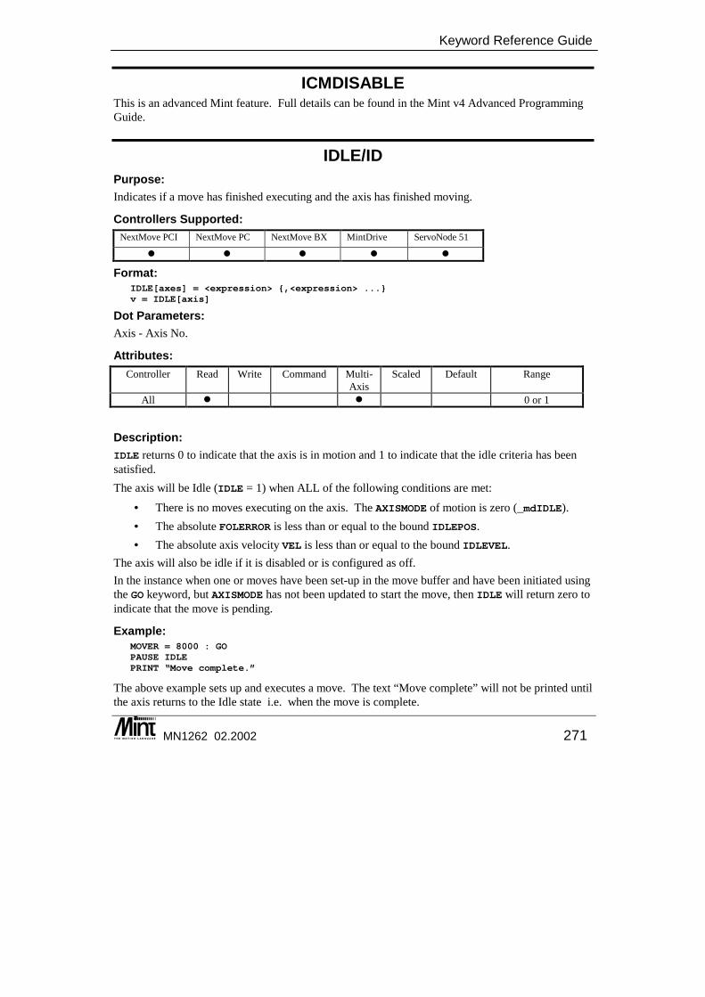
Keyword Reference Guide
MN1262 02.2002 271
ICMDISABLE This is an advanced Mint feature. Full details can be found in the Mint v4 Advanced Programming Guide.
IDLE/ID Purpose: Indicates if a move has finished executing and the axis has finished moving.
Controllers Supported: NextMove PCI NextMove PC NextMove BX MintDrive ServoNode 51
� � � � �
Format: IDLE[axes] = <expression> {,<expression> ...}v = IDLE[axis]
Dot Parameters: Axis - Axis No.
Attributes: Controller Read Write Command Multi-
Axis Scaled Default Range
All � � 0 or 1
Description: IDLE returns 0 to indicate that the axis is in motion and 1 to indicate that the idle criteria has been satisfied. The axis will be Idle (IDLE = 1) when ALL of the following conditions are met:
• There is no moves executing on the axis. The AXISMODE of motion is zero (_mdIDLE). • The absolute FOLERROR is less than or equal to the bound IDLEPOS. • The absolute axis velocity VEL is less than or equal to the bound IDLEVEL.
The axis will also be idle if it is disabled or is configured as off. In the instance when one or moves have been set-up in the move buffer and have been initiated using the GO keyword, but AXISMODE has not been updated to start the move, then IDLE will return zero to indicate that the move is pending.
Example: MOVER = 8000 : GOPAUSE IDLEPRINT “Move complete.”
The above example sets up and executes a move. The text “Move complete” will not be printed until the axis returns to the Idle state i.e. when the move is complete.
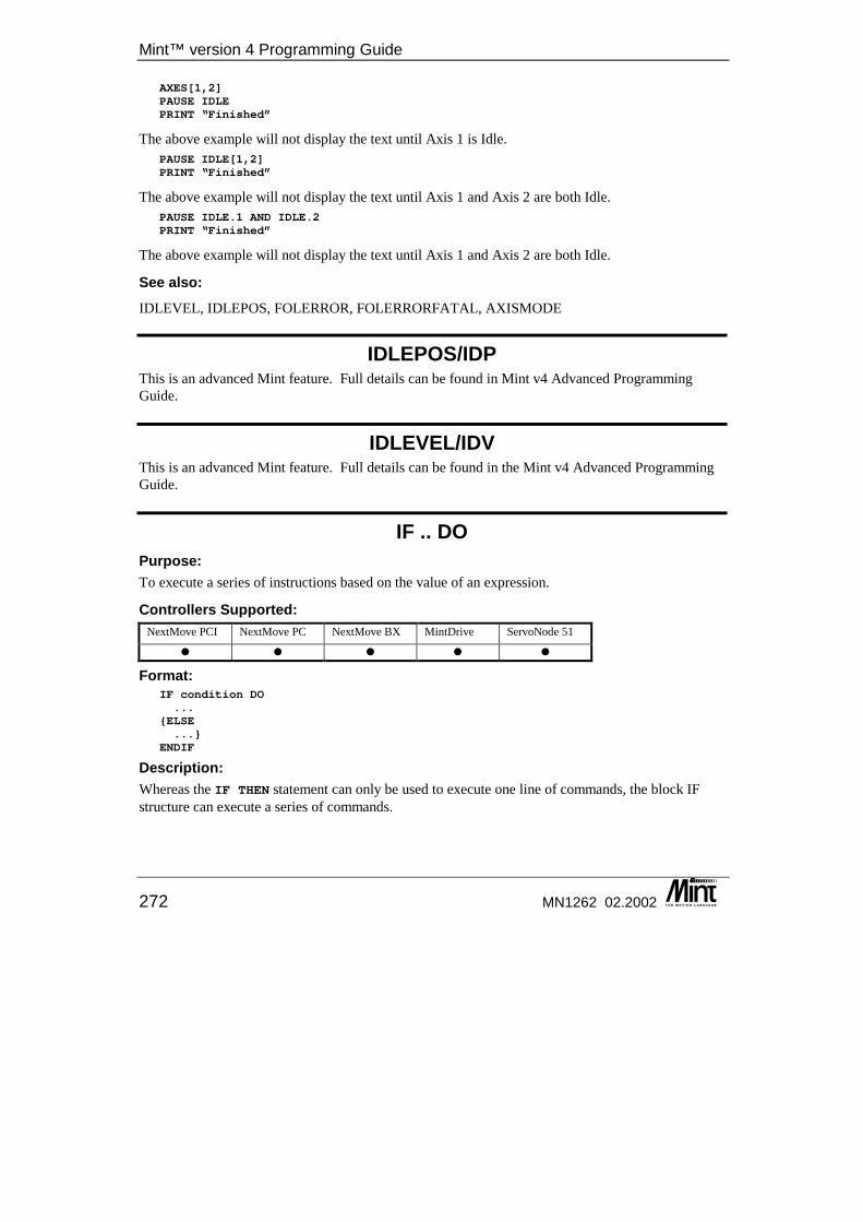
Mint™ version 4 Programming Guide
272 MN1262 02.2002
AXES[1,2]PAUSE IDLEPRINT “Finished”
The above example will not display the text until Axis 1 is Idle. PAUSE IDLE[1,2]PRINT “Finished”
The above example will not display the text until Axis 1 and Axis 2 are both Idle. PAUSE IDLE.1 AND IDLE.2PRINT “Finished”
The above example will not display the text until Axis 1 and Axis 2 are both Idle.
See also: IDLEVEL, IDLEPOS, FOLERROR, FOLERRORFATAL, AXISMODE
IDLEPOS/IDP This is an advanced Mint feature. Full details can be found in Mint v4 Advanced Programming Guide.
IDLEVEL/IDV This is an advanced Mint feature. Full details can be found in the Mint v4 Advanced Programming Guide.
IF .. DO Purpose: To execute a series of instructions based on the value of an expression.
Controllers Supported: NextMove PCI NextMove PC NextMove BX MintDrive ServoNode 51
� � � � �
Format: IF condition DO...
{ELSE...}
ENDIF
Description: Whereas the IF THEN statement can only be used to execute one line of commands, the block IF structure can execute a series of commands.
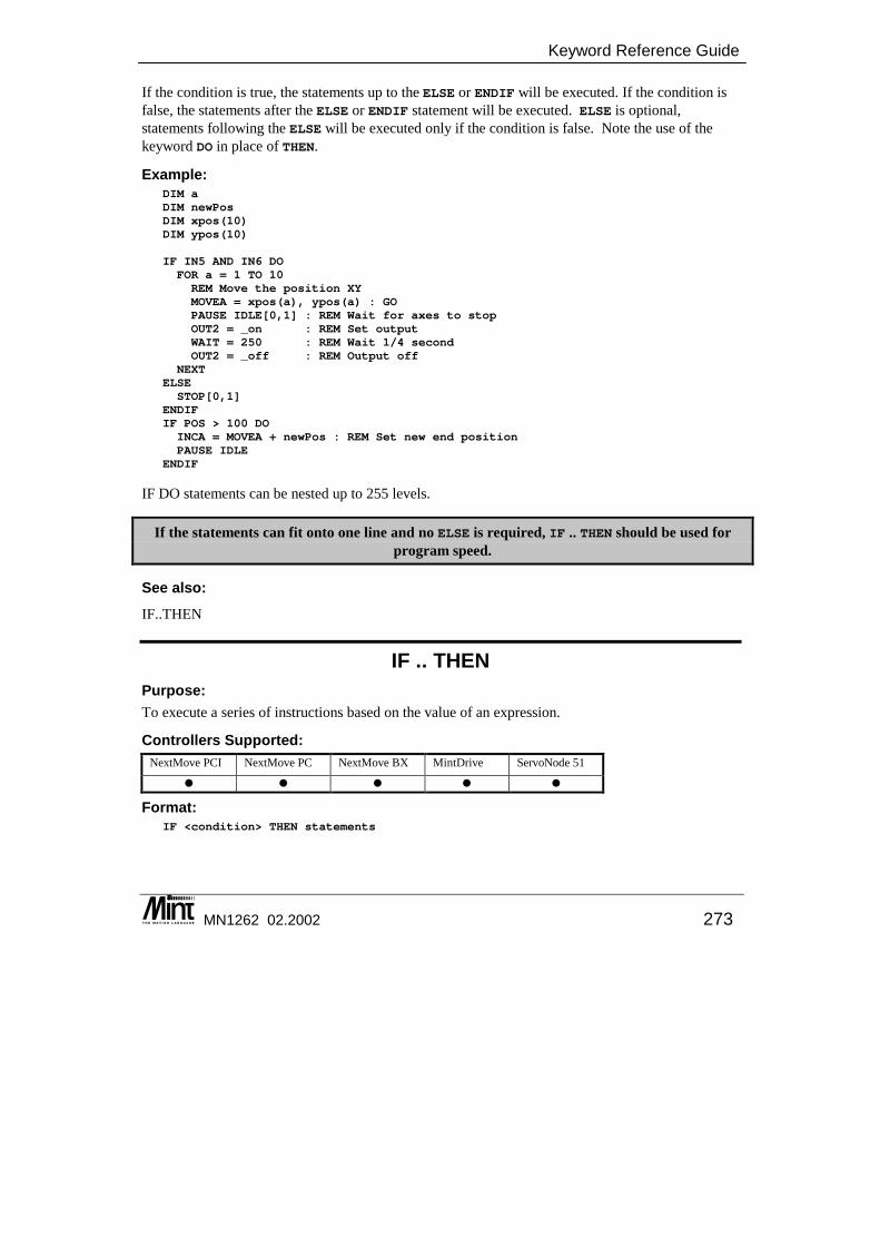
Keyword Reference Guide
MN1262 02.2002 273
If the condition is true, the statements up to the ELSE or ENDIF will be executed. If the condition is false, the statements after the ELSE or ENDIF statement will be executed. ELSE is optional, statements following the ELSE will be executed only if the condition is false. Note the use of the keyword DO in place of THEN.
Example: DIM aDIM newPosDIM xpos(10)DIM ypos(10)
IF IN5 AND IN6 DOFOR a = 1 TO 10REM Move the position XYMOVEA = xpos(a), ypos(a) : GOPAUSE IDLE[0,1] : REM Wait for axes to stopOUT2 = _on : REM Set outputWAIT = 250 : REM Wait 1/4 secondOUT2 = _off : REM Output off
NEXTELSESTOP[0,1]
ENDIFIF POS > 100 DOINCA = MOVEA + newPos : REM Set new end positionPAUSE IDLE
ENDIF
IF DO statements can be nested up to 255 levels.
If the statements can fit onto one line and no ELSE is required, IF .. THEN should be used for program speed.
See also: IF..THEN
IF .. THEN Purpose: To execute a series of instructions based on the value of an expression.
Controllers Supported: NextMove PCI NextMove PC NextMove BX MintDrive ServoNode 51
� � � � �
Format: IF <condition> THEN statements
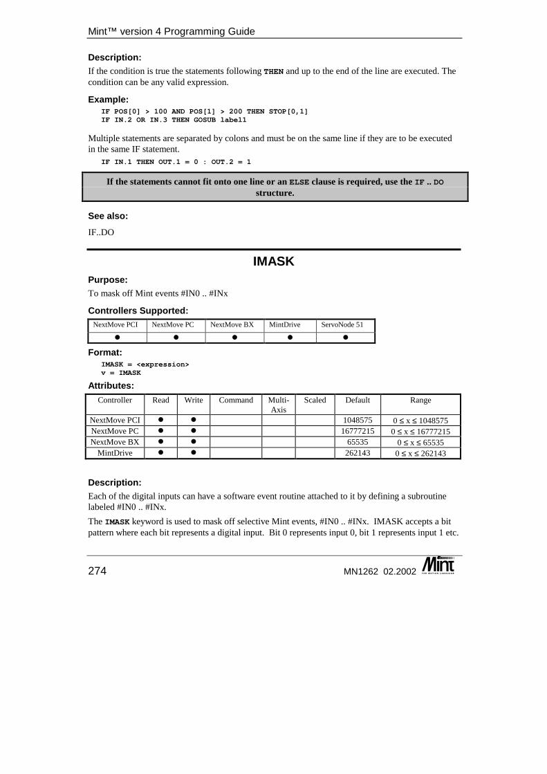
Mint™ version 4 Programming Guide
274 MN1262 02.2002
Description: If the condition is true the statements following THEN and up to the end of the line are executed. The condition can be any valid expression.
Example: IF POS[0] > 100 AND POS[1] > 200 THEN STOP[0,1]IF IN.2 OR IN.3 THEN GOSUB label1
Multiple statements are separated by colons and must be on the same line if they are to be executed in the same IF statement.
IF IN.1 THEN OUT.1 = 0 : OUT.2 = 1
If the statements cannot fit onto one line or an ELSE clause is required, use the IF .. DO structure.
See also: IF..DO
IMASK Purpose: To mask off Mint events #IN0 .. #INx
Controllers Supported: NextMove PCI NextMove PC NextMove BX MintDrive ServoNode 51
� � � � �
Format: IMASK = <expression>v = IMASK
Attributes: Controller Read Write Command Multi-
Axis Scaled Default Range
NextMove PCI � � 1048575 0 ≤ x ≤ 1048575 NextMove PC � � 16777215 0 ≤ x ≤ 16777215 NextMove BX � � 65535 0 ≤ x ≤ 65535
MintDrive � � 262143 0 ≤ x ≤ 262143
Description: Each of the digital inputs can have a software event routine attached to it by defining a subroutine labeled #IN0 .. #INx. The IMASK keyword is used to mask off selective Mint events, #IN0 .. #INx. IMASK accepts a bit pattern where each bit represents a digital input. Bit 0 represents input 0, bit 1 represents input 1 etc.

Keyword Reference Guide
MN1262 02.2002 275
If a bit is set in IMASK, then the corresponding digital input routine is enabled. To disable an input routine, the appropriate bit in IMASK must be cleared. IMASK is affected by the BANK keyword. See section 7.4 for details.
Example: To mask off input events #IN13 to #IN21 on NextMove PC the following command is used:
IMASK = 0xE01FFF
EVENTDISABLE can be used first to ensure no event is called before setting the IMASK value. Reading IMASK will return the event mask value.
Controller Specifics: • NextMove PCI has 20 digital inputs. • NextMove PC has 24 digital inputs. • NextMove BX has 16 digital inputs. • MintDrive has 18 digital inputs. • ServoNode 51 has 6 digital inputs.
See also: BANK, EVENTDISABLE, IN, INx, IPEND
IN Purpose: To read the state of a digital input or all digital inputs.
Controllers Supported: NextMove PCI NextMove PC NextMove BX MintDrive ServoNode 51
� � � � �
Format: v = INv = IN.channel
or v = INx (where x is the digital input channel number)
Dot Parameters: Channel - Dig. Input Channel
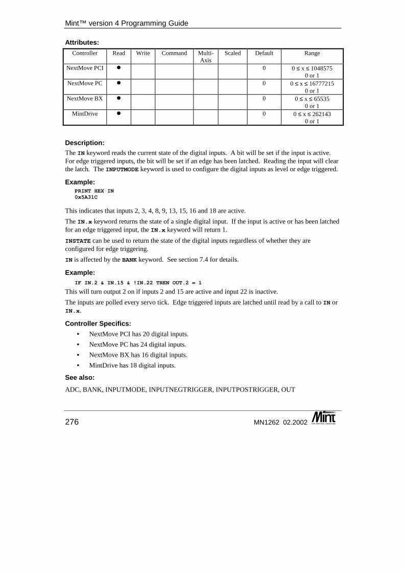
Mint™ version 4 Programming Guide
276 MN1262 02.2002
Attributes: Controller Read Write Command Multi-
Axis Scaled Default Range
NextMove PCI � 0 0 ≤ x ≤ 1048575 0 or 1
NextMove PC � 0 0 ≤ x ≤ 16777215 0 or 1
NextMove BX � 0 0 ≤ x ≤ 65535 0 or 1
MintDrive � 0 0 ≤ x ≤ 262143 0 or 1
Description: The IN keyword reads the current state of the digital inputs. A bit will be set if the input is active. For edge triggered inputs, the bit will be set if an edge has been latched. Reading the input will clear the latch. The INPUTMODE keyword is used to configure the digital inputs as level or edge triggered.
Example: PRINT HEX IN0x5A31C
This indicates that inputs 2, 3, 4, 8, 9, 13, 15, 16 and 18 are active. The IN.x keyword returns the state of a single digital input. If the input is active or has been latched for an edge triggered input, the IN.x keyword will return 1. INSTATE can be used to return the state of the digital inputs regardless of whether they are configured for edge triggering. IN is affected by the BANK keyword. See section 7.4 for details.
Example: IF IN.2 & IN.15 & !IN.22 THEN OUT.2 = 1
This will turn output 2 on if inputs 2 and 15 are active and input 22 is inactive. The inputs are polled every servo tick. Edge triggered inputs are latched until read by a call to IN or IN.x.
Controller Specifics: • NextMove PCI has 20 digital inputs. • NextMove PC has 24 digital inputs. • NextMove BX has 16 digital inputs. • MintDrive has 18 digital inputs.
See also: ADC, BANK, INPUTMODE, INPUTNEGTRIGGER, INPUTPOSTRIGGER, OUT
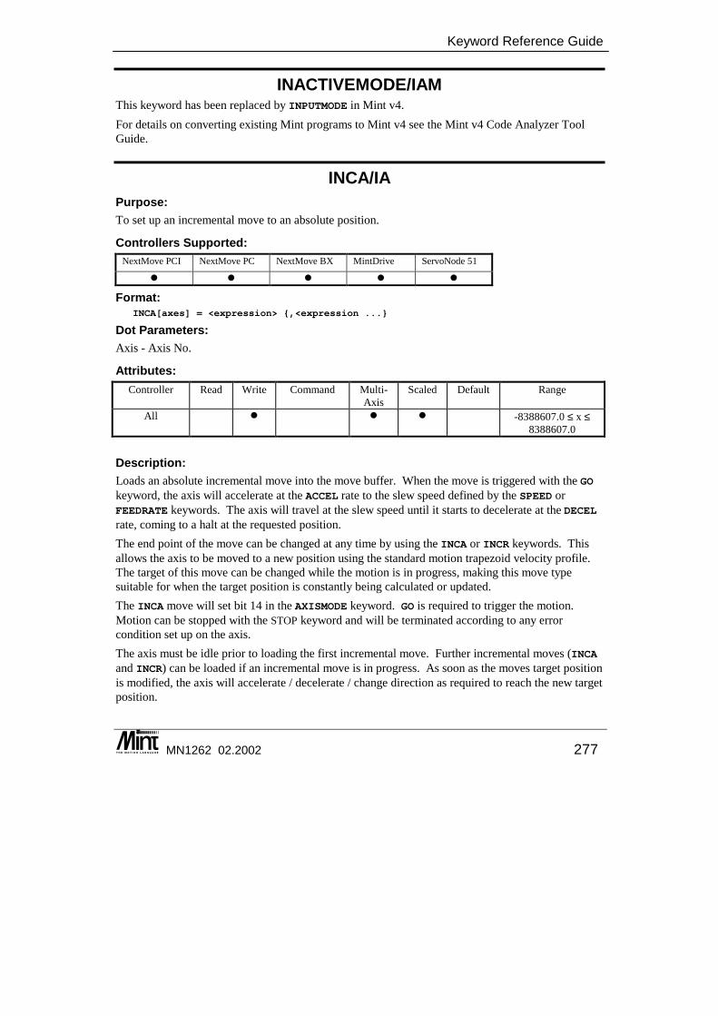
Keyword Reference Guide
MN1262 02.2002 277
INACTIVEMODE/IAM This keyword has been replaced by INPUTMODE in Mint v4. For details on converting existing Mint programs to Mint v4 see the Mint v4 Code Analyzer Tool Guide.
INCA/IA Purpose: To set up an incremental move to an absolute position.
Controllers Supported: NextMove PCI NextMove PC NextMove BX MintDrive ServoNode 51
� � � � �
Format: INCA[axes] = <expression> {,<expression ...}
Dot Parameters: Axis - Axis No.
Attributes: Controller Read Write Command Multi-
Axis Scaled Default Range
All � � � -8388607.0 ≤ x ≤ 8388607.0
Description: Loads an absolute incremental move into the move buffer. When the move is triggered with the GO keyword, the axis will accelerate at the ACCEL rate to the slew speed defined by the SPEED or FEEDRATE keywords. The axis will travel at the slew speed until it starts to decelerate at the DECEL rate, coming to a halt at the requested position. The end point of the move can be changed at any time by using the INCA or INCR keywords. This allows the axis to be moved to a new position using the standard motion trapezoid velocity profile. The target of this move can be changed while the motion is in progress, making this move type suitable for when the target position is constantly being calculated or updated. The INCA move will set bit 14 in the AXISMODE keyword. GO is required to trigger the motion. Motion can be stopped with the STOP keyword and will be terminated according to any error condition set up on the axis. The axis must be idle prior to loading the first incremental move. Further incremental moves (INCA and INCR) can be loaded if an incremental move is in progress. As soon as the moves target position is modified, the axis will accelerate / decelerate / change direction as required to reach the new target position.
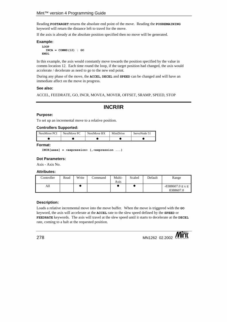
Mint™ version 4 Programming Guide
278 MN1262 02.2002
Reading POSTARGET returns the absolute end point of the move. Reading the POSREMAINING keyword will return the distance left to travel for the move. If the axis is already at the absolute position specified then no move will be generated.
Example: LOOPINCA = COMMS(12) : GO
ENDL
In this example, the axis would constantly move towards the position specified by the value in comms location 12. Each time round the loop, if the target position had changed, the axis would accelerate / decelerate as need to go to the new end point. During any phase of the move, the ACCEL, DECEL and SPEED can be changed and will have an immediate affect on the move in progress.
See also: ACCEL, FEEDRATE, GO, INCR, MOVEA, MOVER, OFFSET, SRAMP, SPEED, STOP
INCR/IR Purpose: To set up an incremental move to a relative position.
Controllers Supported: NextMove PCI NextMove PC NextMove BX MintDrive ServoNode 51
� � � � �
Format: INCR[axes] = <expression> {,<expression ...}
Dot Parameters: Axis - Axis No.
Attributes: Controller Read Write Command Multi-
Axis Scaled Default Range
All � � � -8388607.0 ≤ x ≤ 8388607.0
Description: Loads a relative incremental move into the move buffer. When the move is triggered with the GO keyword, the axis will accelerate at the ACCEL rate to the slew speed defined by the SPEED or FEEDRATE keywords. The axis will travel at the slew speed until it starts to decelerate at the DECEL rate, coming to a halt at the requested position.
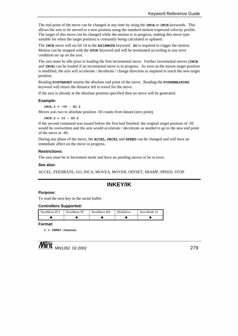
Keyword Reference Guide
MN1262 02.2002 279
The end point of the move can be changed at any time by using the INCA or INCR keywords. This allows the axis to be moved to a new position using the standard motion trapezoid velocity profile. The target of this move can be changed while the motion is in progress, making this move type suitable for when the target position is constantly being calculated or updated. The INCR move will set bit 14 in the AXISMODE keyword. GO is required to trigger the motion. Motion can be stopped with the STOP keyword and will be terminated according to any error condition set up on the axis. The axis must be idle prior to loading the first incremental move. Further incremental moves (INCA and INCR) can be loaded if an incremental move is in progress. As soon as the moves target position is modified, the axis will accelerate / decelerate / change direction as required to reach the new target position. Reading POSTARGET returns the absolute end point of the move. Reading the POSREMAINING keyword will return the distance left to travel for the move. If the axis is already at the absolute position specified then no move will be generated.
Example: INCA.2 = -50 : GO.2
Moves axis two to absolute position -50 counts from datum (zero point). INCR.2 = 10 : GO.2
If the second command was issued before the first had finished, the original target position of -50 would be overwritten and the axis would accelerate / decelerate as needed to go to the new end point of the move at -40. During any phase of the move, the ACCEL, DECEL and SPEED can be changed and will have an immediate affect on the move in progress.
Restrictions: The axis must be in Increment mode and have no pending moves or be in error.
See also: ACCEL, FEEDRATE, GO, INCA, MOVEA, MOVER, OFFSET, SRAMP, SPEED, STOP
INKEY/IK Purpose: To read the next key in the serial buffer.
Controllers Supported: NextMove PCI NextMove PC NextMove BX MintDrive ServoNode 51
� � � � �
Format: v = INKEY.channel

Mint™ version 4 Programming Guide
280 MN1262 02.2002
Dot Parameters: Channel - Serial channel.
Description: INKEY reads a single character from the input buffers. If a channel is specified INKEY will only interrogate the specified buffer otherwise it will look in all enabled buffers and return the most recent keypress. The possible channels are:
Value Constant Function 1 _tmRS232 RS232 port 2 _tmRS485 RS485 port 4 _tmDPR Dual Port RAM 8 _tmLCD1 CAN KeypadNode
16 _tmLCD2 CAN KeypadNode 32 _tmLCD3 CAN KeypadNode 64 _tmLCD4 CAN KeypadNode
If no character is present it will return zero, otherwise it returns the ASCII value of the character.
INKEY always returns the uppercase value of the characters A-Z. Thus: my_var = INKEY
will return the value 65 (the ASCII value of 'A') to the variable my_var if the character 'A' or 'a' is present in the buffer.
INKEY is useful for front end menu operations. For example: LOOP? "Press”? "1 .. Teach"? "2 .. Replay"key = 0WHILE key = 0key = INKEY._tmRS232 : REM Get character from RS232 bufferIF key = '1' THEN GOSUB teachIF key = '2' THEN GOSUB replay
ENDWENDL
This will wait for key presses 1 or 2 and execute the relevant subroutine. Note the use of 'key = INKEY' to capture the key press before interrogating it.
IF INKEY._tmRS232 = '1' THEN ...IF INKEY._tmRS232 = '2' THEN ...
would result in key-presses being lost since if INKEY returned '1' but Mint was executing the line "IFINKEY = '2'", the IF statement would evaluate to false and the keypress discarded.
In order for the receive buffers of the various channels to be updated they must be enabled by the TERMINAL keyword. If the INKEY command is executed on a buffer which is not enabled then INKEY will always return zero.
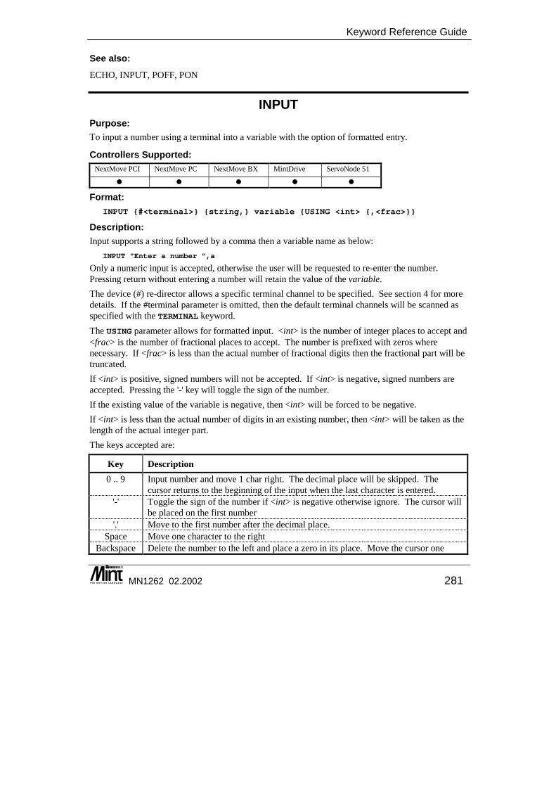
Keyword Reference Guide
MN1262 02.2002 281
See also: ECHO, INPUT, POFF, PON
INPUT Purpose: To input a number using a terminal into a variable with the option of formatted entry.
Controllers Supported: NextMove PCI NextMove PC NextMove BX MintDrive ServoNode 51
� � � � �
Format: INPUT {#<terminal>} {string,} variable {USING <int> {,<frac>}}
Description: Input supports a string followed by a comma then a variable name as below:
INPUT "Enter a number ",a
Only a numeric input is accepted, otherwise the user will be requested to re-enter the number. Pressing return without entering a number will retain the value of the variable. The device (#) re-director allows a specific terminal channel to be specified. See section 4 for more details. If the #terminal parameter is omitted, then the default terminal channels will be scanned as specified with the TERMINAL keyword. The USING parameter allows for formatted input. <int> is the number of integer places to accept and <frac> is the number of fractional places to accept. The number is prefixed with zeros where necessary. If <frac> is less than the actual number of fractional digits then the fractional part will be truncated. If <int> is positive, signed numbers will not be accepted. If <int> is negative, signed numbers are accepted. Pressing the '-' key will toggle the sign of the number. If the existing value of the variable is negative, then <int> will be forced to be negative. If <int> is less than the actual number of digits in an existing number, then <int> will be taken as the length of the actual integer part. The keys accepted are:
Key Description 0 .. 9 Input number and move 1 char right. The decimal place will be skipped. The
cursor returns to the beginning of the input when the last character is entered. '-' Toggle the sign of the number if <int> is negative otherwise ignore. The cursor will
be placed on the first number '.' Move to the first number after the decimal place.
Space Move one character to the right Backspace Delete the number to the left and place a zero in its place. Move the cursor one
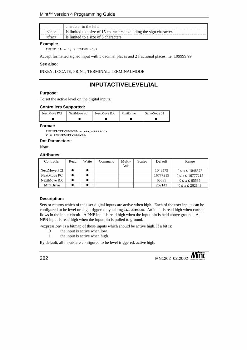
Mint™ version 4 Programming Guide
282 MN1262 02.2002
character to the left. <int> Is limited to a size of 15 characters, excluding the sign character.
<frac> Is limited to a size of 3 characters.
Example: INPUT "A = ", a USING -5,2
Accept formatted signed input with 5 decimal places and 2 fractional places, i.e. ±99999.99
See also: INKEY, LOCATE, PRINT, TERMINAL, TERMINALMODE
INPUTACTIVELEVEL/IAL Purpose: To set the active level on the digital inputs.
Controllers Supported: NextMove PCI NextMove PC NextMove BX MintDrive ServoNode 51
� � � � �
Format: INPUTACTIVELEVEL = <expression>v = INPUTACTIVELEVEL
Dot Parameters: None.
Attributes: Controller Read Write Command Multi-
Axis Scaled Default Range
NextMove PCI � � 1048575 0 ≤ x ≤ 1048575 NextMove PC � � 16777215 0 ≤ x ≤ 16777215 NextMove BX � � 65535 0 ≤ x ≤ 65535
MintDrive � � 262143 0 ≤ x ≤ 262143
Description: Sets or returns which of the user digital inputs are active when high. Each of the user inputs can be configured to be level or edge triggered by calling INPUTMODE. An input is read high when current flows in the input circuit. A PNP input is read high when the input pin is held above ground. A NPN input is read high when the input pin is pulled to ground. <expression> is a bitmap of those inputs which should be active high. If a bit is: 0 the input is active when low. 1 the input is active when high. By default, all inputs are configured to be level triggered, active high.
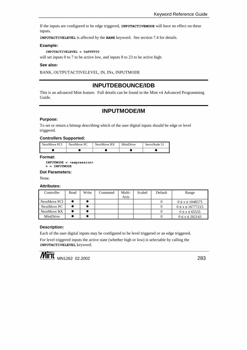
Keyword Reference Guide
MN1262 02.2002 283
If the inputs are configured to be edge triggered, INPUTACTIVEMODE will have no effect on these inputs. INPUTACTIVELEVEL is affected by the BANK keyword. See section 7.4 for details.
Example: INPUTACTIVELEVEL = 0xFFFF00
will set inputs 0 to 7 to be active low, and inputs 8 to 23 to be active high.
See also: BANK, OUTPUTACTIVELEVEL, IN, INx, INPUTMODE
INPUTDEBOUNCE/IDB This is an advanced Mint feature. Full details can be found in the Mint v4 Advanced Programming Guide.
INPUTMODE/IM Purpose: To set or return a bitmap describing which of the user digital inputs should be edge or level triggered.
Controllers Supported: NextMove PCI NextMove PC NextMove BX MintDrive ServoNode 51
� � � � �
Format: INPUTMODE = <expression>v = INPUTMODE
Dot Parameters: None.
Attributes: Controller Read Write Command Multi-
Axis Scaled Default Range
NextMove PCI � � 0 0 ≤ x ≤ 1048575 NextMove PC � � 0 0 ≤ x ≤ 16777215 NextMove BX � � 0 0 ≤ x ≤ 65535
MintDrive � � 0 0 ≤ x ≤ 262143
Description: Each of the user digital inputs may be configured to be level triggered or an edge triggered. For level triggered inputs the active state (whether high or low) is selectable by calling the INPUTACTIVELEVEL keyword.
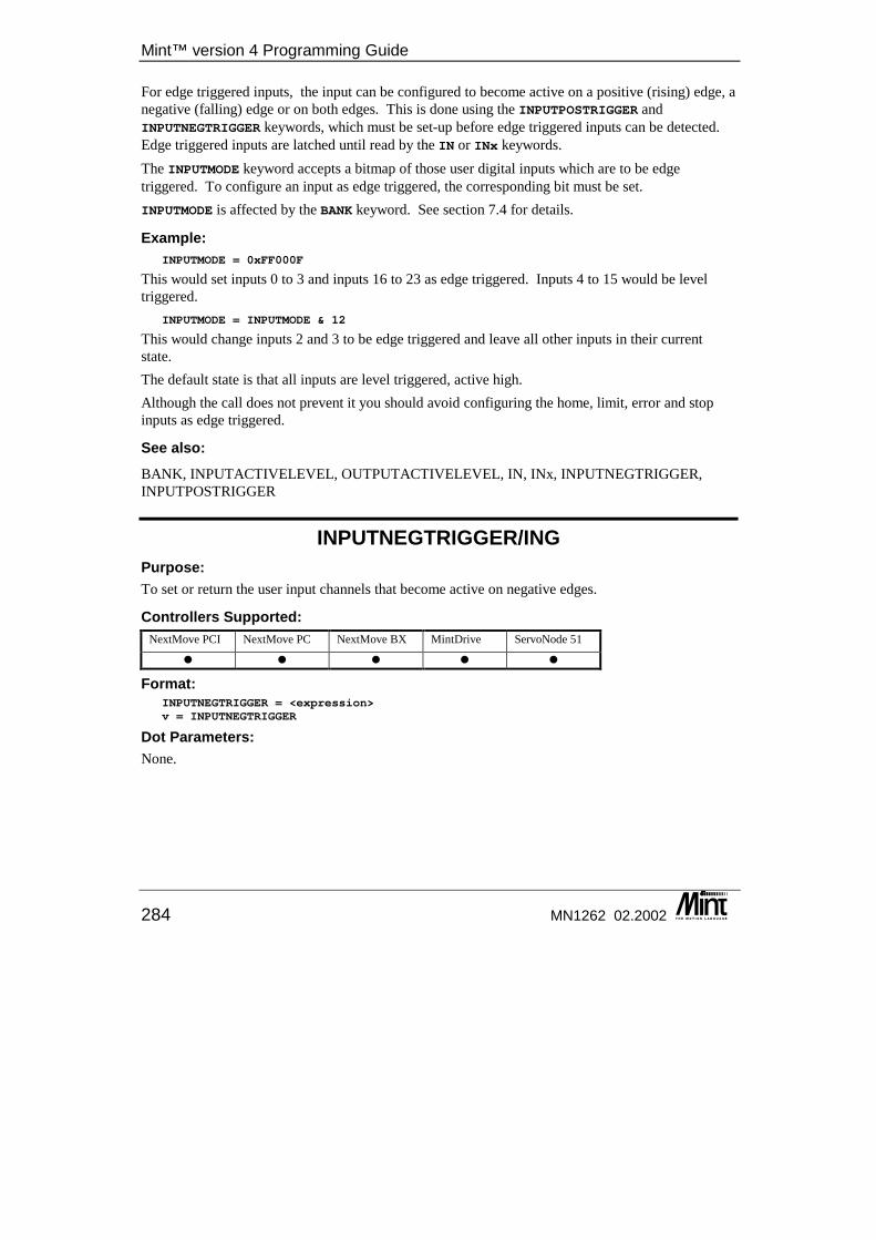
Mint™ version 4 Programming Guide
284 MN1262 02.2002
For edge triggered inputs, the input can be configured to become active on a positive (rising) edge, a negative (falling) edge or on both edges. This is done using the INPUTPOSTRIGGER and INPUTNEGTRIGGER keywords, which must be set-up before edge triggered inputs can be detected. Edge triggered inputs are latched until read by the IN or INx keywords. The INPUTMODE keyword accepts a bitmap of those user digital inputs which are to be edge triggered. To configure an input as edge triggered, the corresponding bit must be set. INPUTMODE is affected by the BANK keyword. See section 7.4 for details.
Example: INPUTMODE = 0xFF000F
This would set inputs 0 to 3 and inputs 16 to 23 as edge triggered. Inputs 4 to 15 would be level triggered.
INPUTMODE = INPUTMODE & 12
This would change inputs 2 and 3 to be edge triggered and leave all other inputs in their current state. The default state is that all inputs are level triggered, active high. Although the call does not prevent it you should avoid configuring the home, limit, error and stop inputs as edge triggered.
See also: BANK, INPUTACTIVELEVEL, OUTPUTACTIVELEVEL, IN, INx, INPUTNEGTRIGGER, INPUTPOSTRIGGER
INPUTNEGTRIGGER/ING Purpose: To set or return the user input channels that become active on negative edges.
Controllers Supported: NextMove PCI NextMove PC NextMove BX MintDrive ServoNode 51
� � � � �
Format: INPUTNEGTRIGGER = <expression>v = INPUTNEGTRIGGER
Dot Parameters: None.
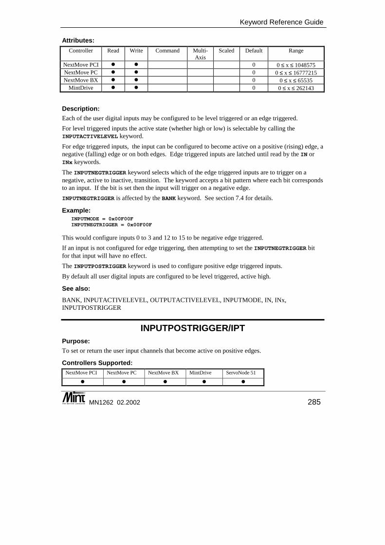
Keyword Reference Guide
MN1262 02.2002 285
Attributes: Controller Read Write Command Multi-
Axis Scaled Default Range
NextMove PCI � � 0 0 ≤ x ≤ 1048575 NextMove PC � � 0 0 ≤ x ≤ 16777215 NextMove BX � � 0 0 ≤ x ≤ 65535
MintDrive � � 0 0 ≤ x ≤ 262143
Description: Each of the user digital inputs may be configured to be level triggered or an edge triggered. For level triggered inputs the active state (whether high or low) is selectable by calling the INPUTACTIVELEVEL keyword. For edge triggered inputs, the input can be configured to become active on a positive (rising) edge, a negative (falling) edge or on both edges. Edge triggered inputs are latched until read by the IN or INx keywords. The INPUTNEGTRIGGER keyword selects which of the edge triggered inputs are to trigger on a negative, active to inactive, transition. The keyword accepts a bit pattern where each bit corresponds to an input. If the bit is set then the input will trigger on a negative edge. INPUTNEGTRIGGER is affected by the BANK keyword. See section 7.4 for details.
Example: INPUTMODE = 0x00F00FINPUTNEGTRIGGER = 0x00F00F
This would configure inputs 0 to 3 and 12 to 15 to be negative edge triggered. If an input is not configured for edge triggering, then attempting to set the INPUTNEGTRIGGER bit for that input will have no effect. The INPUTPOSTRIGGER keyword is used to configure positive edge triggered inputs. By default all user digital inputs are configured to be level triggered, active high.
See also: BANK, INPUTACTIVELEVEL, OUTPUTACTIVELEVEL, INPUTMODE, IN, INx, INPUTPOSTRIGGER
INPUTPOSTRIGGER/IPT Purpose: To set or return the user input channels that become active on positive edges.
Controllers Supported: NextMove PCI NextMove PC NextMove BX MintDrive ServoNode 51
� � � � �
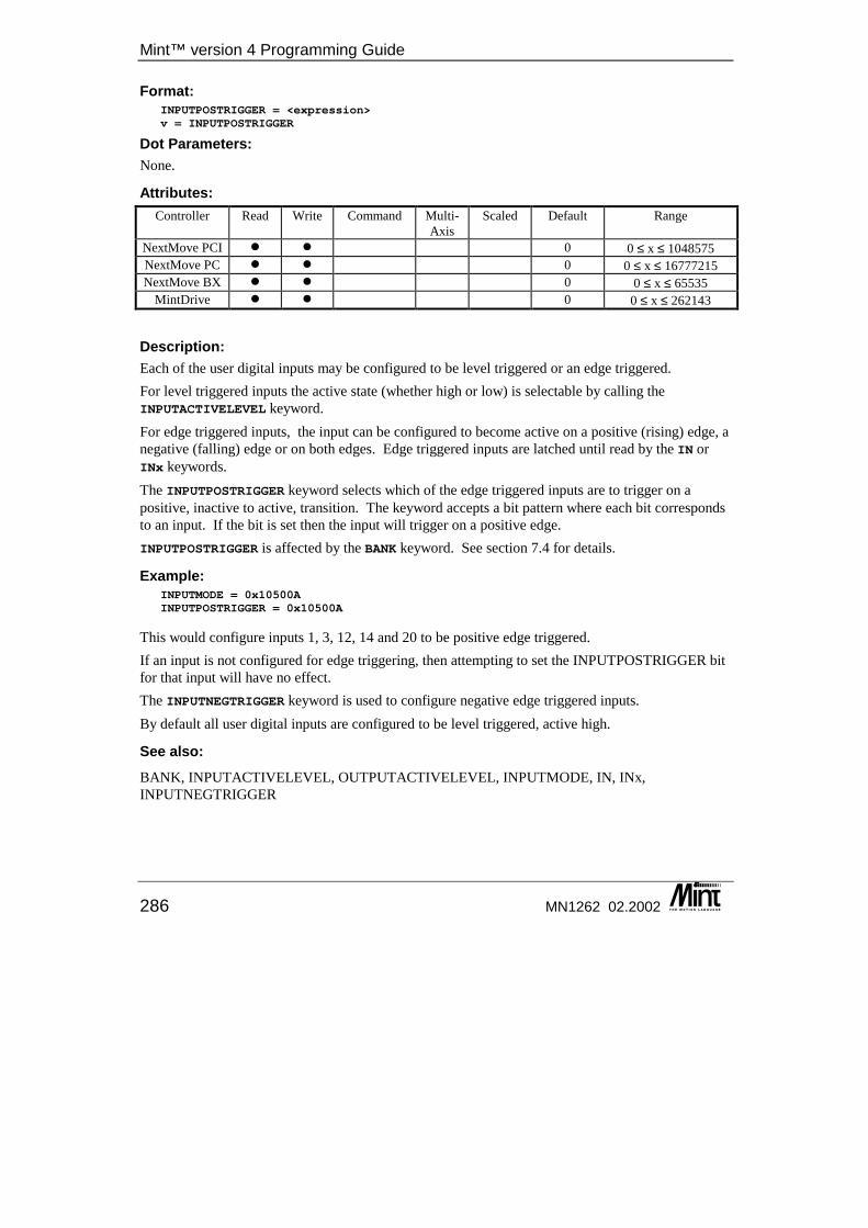
Mint™ version 4 Programming Guide
286 MN1262 02.2002
Format: INPUTPOSTRIGGER = <expression>v = INPUTPOSTRIGGER
Dot Parameters: None.
Attributes: Controller Read Write Command Multi-
Axis Scaled Default Range
NextMove PCI � � 0 0 ≤ x ≤ 1048575 NextMove PC � � 0 0 ≤ x ≤ 16777215 NextMove BX � � 0 0 ≤ x ≤ 65535
MintDrive � � 0 0 ≤ x ≤ 262143
Description: Each of the user digital inputs may be configured to be level triggered or an edge triggered. For level triggered inputs the active state (whether high or low) is selectable by calling the INPUTACTIVELEVEL keyword. For edge triggered inputs, the input can be configured to become active on a positive (rising) edge, a negative (falling) edge or on both edges. Edge triggered inputs are latched until read by the IN or INx keywords. The INPUTPOSTRIGGER keyword selects which of the edge triggered inputs are to trigger on a positive, inactive to active, transition. The keyword accepts a bit pattern where each bit corresponds to an input. If the bit is set then the input will trigger on a positive edge. INPUTPOSTRIGGER is affected by the BANK keyword. See section 7.4 for details.
Example: INPUTMODE = 0x10500AINPUTPOSTRIGGER = 0x10500A
This would configure inputs 1, 3, 12, 14 and 20 to be positive edge triggered. If an input is not configured for edge triggering, then attempting to set the INPUTPOSTRIGGER bit for that input will have no effect. The INPUTNEGTRIGGER keyword is used to configure negative edge triggered inputs. By default all user digital inputs are configured to be level triggered, active high.
See also: BANK, INPUTACTIVELEVEL, OUTPUTACTIVELEVEL, INPUTMODE, IN, INx, INPUTNEGTRIGGER
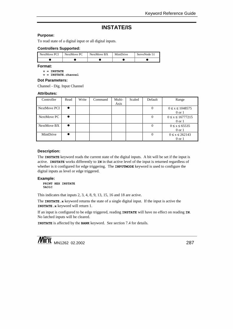
Keyword Reference Guide
MN1262 02.2002 287
INSTATE/IS Purpose: To read state of a digital input or all digital inputs.
Controllers Supported: NextMove PCI NextMove PC NextMove BX MintDrive ServoNode 51
� � � � �
Format: v = INSTATEv = INSTATE.channel
Dot Parameters: Channel - Dig. Input Channel
Attributes: Controller Read Write Command Multi-
Axis Scaled Default Range
NextMove PCI � 0 0 ≤ x ≤ 1048575 0 or 1
NextMove PC � 0 0 ≤ x ≤ 16777215 0 or 1
NextMove BX � 0 0 ≤ x ≤ 65535 0 or 1
MintDrive � 0 0 ≤ x ≤ 262143 0 or 1
Description: The INSTATE keyword reads the current state of the digital inputs. A bit will be set if the input is active. INSTATE works differently to IN in that active level of the input is returned regardless of whether is it configured for edge triggering. The INPUTMODE keyword is used to configure the digital inputs as level or edge triggered.
Example: PRINT HEX INSTATE5A31C
This indicates that inputs 2, 3, 4, 8, 9, 13, 15, 16 and 18 are active. The INSTATE.x keyword returns the state of a single digital input. If the input is active the INSTATE.x keyword will return 1. If an input is configured to be edge triggered, reading INSTATE will have no effect on reading IN. No latched inputs will be cleared. INSTATE is affected by the BANK keyword. See section 7.4 for details.
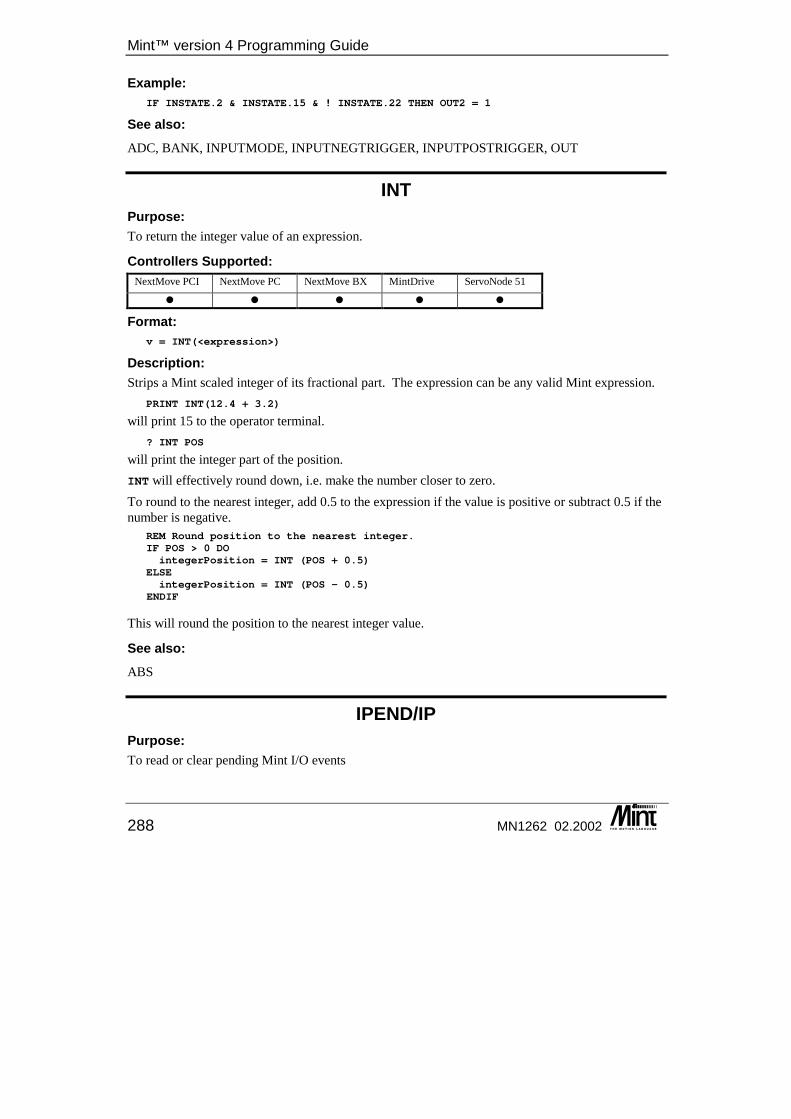
Mint™ version 4 Programming Guide
288 MN1262 02.2002
Example: IF INSTATE.2 & INSTATE.15 & ! INSTATE.22 THEN OUT2 = 1
See also: ADC, BANK, INPUTMODE, INPUTNEGTRIGGER, INPUTPOSTRIGGER, OUT
INT Purpose: To return the integer value of an expression.
Controllers Supported: NextMove PCI NextMove PC NextMove BX MintDrive ServoNode 51
� � � � �
Format: v = INT(<expression>)
Description: Strips a Mint scaled integer of its fractional part. The expression can be any valid Mint expression.
PRINT INT(12.4 + 3.2)
will print 15 to the operator terminal. ? INT POS
will print the integer part of the position. INT will effectively round down, i.e. make the number closer to zero. To round to the nearest integer, add 0.5 to the expression if the value is positive or subtract 0.5 if the number is negative.
REM Round position to the nearest integer.IF POS > 0 DOintegerPosition = INT (POS + 0.5)
ELSEintegerPosition = INT (POS - 0.5)
ENDIF
This will round the position to the nearest integer value.
See also: ABS
IPEND/IP Purpose: To read or clear pending Mint I/O events
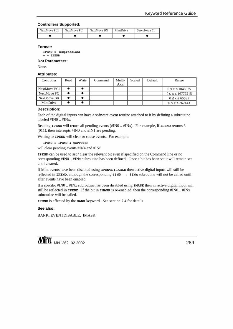
Keyword Reference Guide
MN1262 02.2002 289
Controllers Supported: NextMove PCI NextMove PC NextMove BX MintDrive ServoNode 51
� � � � �
Format: IPEND = <expression>v = IPEND
Dot Parameters: None.
Attributes: Controller Read Write Command Multi-
Axis Scaled Default Range
NextMove PCI � � 0 ≤ x ≤ 1048575 NextMove PC � � 0 ≤ x ≤ 16777215 NextMove BX � � 0 ≤ x ≤ 65535
MintDrive � � 0 ≤ x ≤ 262143
Description: Each of the digital inputs can have a software event routine attached to it by defining a subroutine labeled #IN0 .. #INx. Reading IPEND will return all pending events (#IN0 .. #INx). For example, if IPEND returns 3 (011), then interrupts #IN0 and #IN1 are pending. Writing to IPEND will clear or cause events. For example:
IPEND = IPEND & 0xFFFF5F
will clear pending events #IN4 and #IN6 IPEND can be used to set / clear the relevant bit even if specified on the Command line or no corresponding #IN0 .. #INx subroutine has been defined. Once a bit has been set it will remain set until cleared. If Mint events have been disabled using EVENTDISABLE then active digital inputs will still be reflected in IPEND, although the corresponding #IN0 .. #INx subroutine will not be called until after events have been enabled. If a specific #IN0 .. #INx subroutine has been disabled using IMASK then an active digital input will still be reflected in IPEND. If the bit in IMASK is re-enabled, then the corresponding #IN0 .. #INx subroutine will be called. IPEND is affected by the BANK keyword. See section 7.4 for details.
See also: BANK, EVENTDISABLE, IMASK
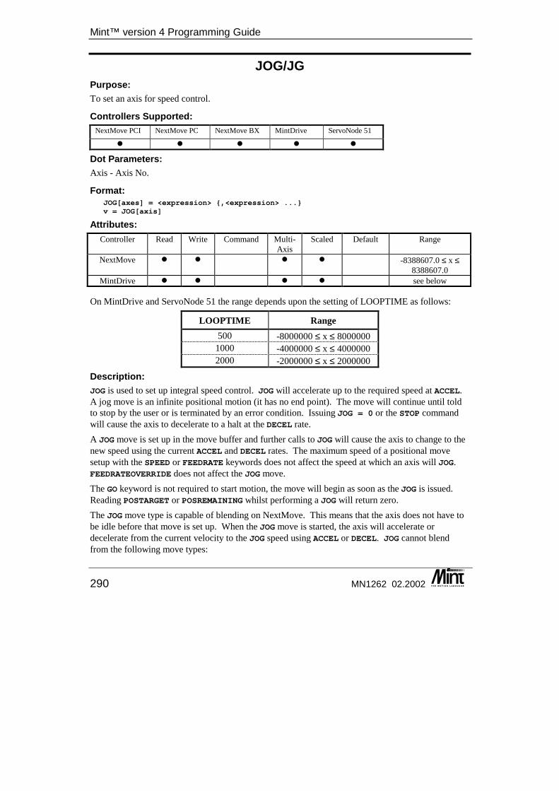
Mint™ version 4 Programming Guide
290 MN1262 02.2002
JOG/JG Purpose: To set an axis for speed control.
Controllers Supported: NextMove PCI NextMove PC NextMove BX MintDrive ServoNode 51
� � � � �
Dot Parameters: Axis - Axis No.
Format: JOG[axes] = <expression> {,<expression> ...}v = JOG[axis]
Attributes: Controller Read Write Command Multi-
Axis Scaled Default Range
NextMove � � � � -8388607.0 ≤ x ≤ 8388607.0
MintDrive � � � � see below
On MintDrive and ServoNode 51 the range depends upon the setting of LOOPTIME as follows:
LOOPTIME Range 500 -8000000 ≤ x ≤ 8000000
1000 -4000000 ≤ x ≤ 4000000 2000 -2000000 ≤ x ≤ 2000000
Description: JOG is used to set up integral speed control. JOG will accelerate up to the required speed at ACCEL. A jog move is an infinite positional motion (it has no end point). The move will continue until told to stop by the user or is terminated by an error condition. Issuing JOG = 0 or the STOP command will cause the axis to decelerate to a halt at the DECEL rate. A JOG move is set up in the move buffer and further calls to JOG will cause the axis to change to the new speed using the current ACCEL and DECEL rates. The maximum speed of a positional move setup with the SPEED or FEEDRATE keywords does not affect the speed at which an axis will JOG. FEEDRATEOVERRIDE does not affect the JOG move. The GO keyword is not required to start motion, the move will begin as soon as the JOG is issued. Reading POSTARGET or POSREMAINING whilst performing a JOG will return zero. The JOG move type is capable of blending on NextMove. This means that the axis does not have to be idle before that move is set up. When the JOG move is started, the axis will accelerate or decelerate from the current velocity to the JOG speed using ACCEL or DECEL. JOG cannot blend from the following move types:

Keyword Reference Guide
MN1262 02.2002 291
• HOME • CIRCLEA, CIRCLER • VECTORA, VECTORR
The TORQUE move type is also capable of blending.
Example: JOG = 10
will jog the motor at a constant speed of 10 revs/s. JOG = -150
will jog the motor in a negative direction at a speed of 150 revs/s. The motor will decelerate to a stop from its previous speed and accelerate to the new speed.
Example: MOVEA = 300GOPAUSE POSREMAINING < 10JOG = 10
This sets up a move for the axis to go an absolute position of 300 units. The POSREMAINING keyword returns the distance left to travel for a move. The program will wait until there is less than 10 units of travel left before blending into the JOG at a speed of 10 units/second.
Restrictions: For MintDrive the axis must be in either be Jogging or Idle mode and have no pending moves or be in error. MintDrive does not currently support blended moves.
See also: ACCEL, DECEL, FEEDRATE, SPEED, STOP, TORQUE, VEL
KACCEL/KA This is an advanced Mint feature. Full details can be found in the Mint v4 Advanced Programming Guide.
KDERIV/KD Purpose: To set the servo derivative gain on the servo axes.
Controllers Supported: NextMove PCI NextMove PC NextMove BX MintDrive ServoNode 51
� � � � �
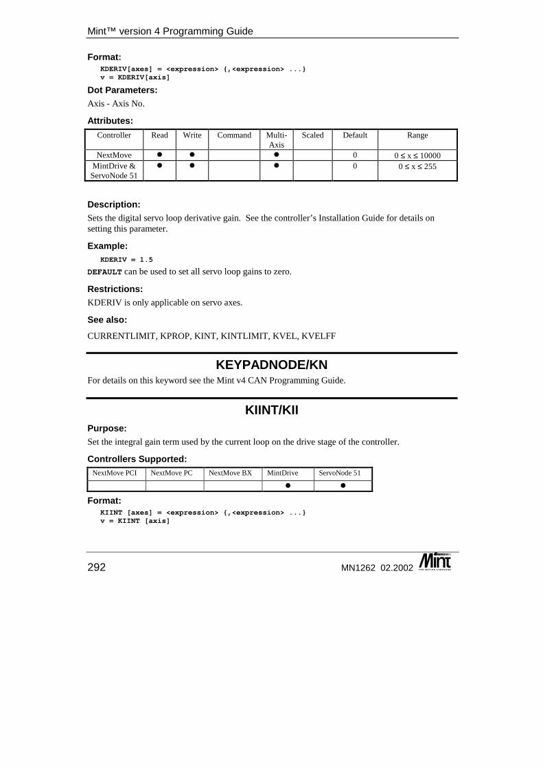
Mint™ version 4 Programming Guide
292 MN1262 02.2002
Format: KDERIV[axes] = <expression> {,<expression> ...}v = KDERIV[axis]
Dot Parameters: Axis - Axis No.
Attributes: Controller Read Write Command Multi-
Axis Scaled Default Range
NextMove � � � 0 0 ≤ x ≤ 10000 MintDrive &
ServoNode 51 � � � 0 0 ≤ x ≤ 255
Description: Sets the digital servo loop derivative gain. See the controller’s Installation Guide for details on setting this parameter.
Example: KDERIV = 1.5
DEFAULT can be used to set all servo loop gains to zero.
Restrictions: KDERIV is only applicable on servo axes.
See also: CURRENTLIMIT, KPROP, KINT, KINTLIMIT, KVEL, KVELFF
KEYPADNODE/KN For details on this keyword see the Mint v4 CAN Programming Guide.
KIINT/KII Purpose: Set the integral gain term used by the current loop on the drive stage of the controller.
Controllers Supported: NextMove PCI NextMove PC NextMove BX MintDrive ServoNode 51
� �
Format: KIINT [axes] = <expression> {,<expression> ...}v = KIINT [axis]
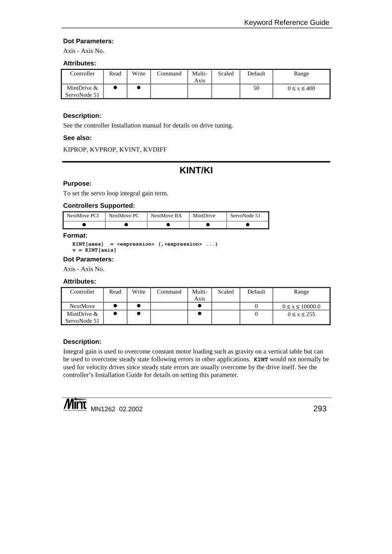
Keyword Reference Guide
MN1262 02.2002 293
Dot Parameters: Axis - Axis No.
Attributes: Controller Read Write Command Multi-
Axis Scaled Default Range
MintDrive & ServoNode 51
� � 50 0 ≤ x ≤ 400
Description: See the controller Installation manual for details on drive tuning.
See also: KIPROP, KVPROP, KVINT, KVDIFF
KINT/KI Purpose: To set the servo loop integral gain term.
Controllers Supported: NextMove PCI NextMove PC NextMove BX MintDrive ServoNode 51
� � � � �
Format: KINT[axes] = <expression> {,<expression> ...}v = KINT[axis]
Dot Parameters: Axis - Axis No.
Attributes: Controller Read Write Command Multi-
Axis Scaled Default Range
NextMove � � � 0 0 ≤ x ≤ 10000.0 MintDrive &
ServoNode 51 � � � 0 0 ≤ x ≤ 255
Description: Integral gain is used to overcome constant motor loading such as gravity on a vertical table but can be used to overcome steady state following errors in other applications. KINT would not normally be used for velocity drives since steady state errors are usually overcome by the drive itself. See the controller’s Installation Guide for details on setting this parameter.

Mint™ version 4 Programming Guide
294 MN1262 02.2002
The effect of the integral gain on the DAC output can be reduced by setting the KINTLIMIT parameter otherwise instability may arise. KINT is usually found to have a value of approximately KPROP/10. It is also possible to specify when integral action is used with the KINTMODE keyword. This allows integral action to be turned off and on and also provides a ‘smart’ mode where integral action is only used if the axis is moving with constant velocity.
Example: KPROP = 1;KINTLIMIT = 20; : REM KINT only has 20% effect on DAC
KINT = 0.1;
DEFAULT can be used to set all servo loop gains to zero.
KINT should only be set once all other servo gain parameters have been correctly set-up.
Restrictions: KINT is only applicable on servo axes.
See also: CURRENTLIMIT, DAC, DEFAULT, KDERIV, KPROP, KINTMODE, KINTLIMIT, KVEL, KVELFF, TORQUE
KINTLIMIT/KIL Purpose: To restrict overall effect the integral gain has on the DAC output.
Controllers Supported: NextMove PCI NextMove PC NextMove BX MintDrive ServoNode 51
� � � � �
Format: KINTLIMIT[axes] = <expression> {,<expression> ...}v = KINTLIMIT[axis]
Dot Parameters: Axis - Axis No.
Attributes: Controller Read Write Command Multi-
Axis Scaled Default Range
All � � � 100 1 ≤ x ≤ 100.0

Keyword Reference Guide
MN1262 02.2002 295
Description: Sets the integration limit for the integral gain. Accepts a value of 1 to 100%, where 100% corresponds to a maximum integration range of ±10V. See the controller’s Installation Guide for details on setting this parameter. The KINT keyword sets the gain of the integrator and the KINTMODE keyword controls when integral action takes place.
Example: KINTLIMIT = 50
KINT will have a maximum effect of +/-5.0V on the DAC output. DEFAULT can be used to set all servo loop gains to zero and KINTLIMIT to 100%..
Restrictions: KINTLIMIT is only applicable on servo axes.
See also: CURRENTLIMIT, DAC, DEFAULT, KDERIV, KPROP, KINT, KINTMODE, KVEL, KVELFF, TORQUE
KINTMODE/KIM This is an advanced Mint feature. Full details can be found in the Mint v4 Advanced Programming Guide.
KINTRANGE/KR This keyword has been replaced by KINTLIMIT in Mint v4. For details on converting existing Mint programs to Mint v4 see the Mint v4 Code Analyzer Tool Guide.
KIPROP/KIP Purpose: Set the proportional gain term used by the current loop on the drive stage of the controller.
Controllers Supported: NextMove PCI NextMove PC NextMove BX MintDrive ServoNode 51
� �
Format: KIPROP [axes] = <expression> {,<expression> ...}v = KIPROP [axis]
Mint™ version 4 Programming Guide
296 MN1262 02.2002
Dot Parameters: Axis - Axis No.
Attributes: Controller Read Write Command Multi-
Axis Scaled Default Range
MintDrive & ServoNode 51
� � 0 0 ≤ x ≤ 1000
Description: On MintDrive, this parameter is normally derived from the Current Loop Compensation test, using Mint WorkBench, if the motor inductance is not known. This gain can also be derived using the following equation:
VACVAL )(740KIPROP ∗∗=
where: L = Line to neutral inductance of the motor in mH, (The line to line inductance is specified
in the motor catalog – line to neutral inductance is one third of the line to line inductance)
VAC = Nominal line volts (115VAC or 230VAC depending on the local supply)
VA = The Amps/Volt scaling of the current feedback (This is the current scaling value returned in VIEW HARDWARE)
See also: KIINT, KVPROP, KVINT, KVDIFF
KIRFF/KIR Purpose: Set the feedforward term used by the current loop on the drive stage of the controller.
Controllers Supported: NextMove PCI NextMove PC NextMove BX MintDrive ServoNode 51
�
Format: KIRFF [axes] = <expression> {,<expression> ...}v = KIRFF [axis]
Dot Parameters: Axis - Axis No.
Keyword Reference Guide
MN1262 02.2002 297
Attributes: Controller Read Write Command Multi-
Axis Scaled Default Range
ServoNode 51 � � 0 -32767 ≤ x ≤ 32767
Description: See the controller Installation manual for details on setting this parameter. This parameter is useful when trying to tune a motor with a high resistance.
See also: KIINT, KIPROP
KPROP/KP Purpose: To set the servo loop proportional gain.
Controllers Supported: NextMove PCI NextMove PC NextMove BX MintDrive ServoNode 51
� � � � �
Format: KPROP[axes] = <expression> {,<expression> ...}v = KPROP[axis]
Dot Parameters: Axis - Axis No.
Attributes: Controller Read Write Command Multi-
Axis Scaled Default Range
NextMove � � � 0 0 ≤ x ≤ 10000.0 MintDrive &
ServoNode 51 � � � 0 0 ≤ x ≤ 255
Description: Sets the digital servo loop proportional gain. See the controller’s Installation Guide for details on setting this parameter.
Example: KPROP = 1.5,2.5
DEFAULT can be used to set all servo loop gains to zero.
Restrictions: KPROP is only applicable on servo axes.
Mint™ version 4 Programming Guide
298 MN1262 02.2002
See also: CURRENTLIMIT, KDERIV, KINT, KINTLIMIT, KVEL, KVELFF
KVEL/KV Purpose: To set the servo loop velocity feedback gain term.
Controllers Supported: NextMove PCI NextMove PC NextMove BX MintDrive ServoNode 51
� � � � �
Format: KVEL[axes] = <expression> {,<expression> ...}
v = KVEL[axis]
Dot Parameters: Axis - Axis No.
Attributes: Controller Read Write Command Multi-
Axis Scaled Default Range
NextMove � � � 0 0 ≤ x ≤ 10000.0 MintDrive &
ServoNode 51 � � � 0 0 ≤ x ≤ 255
Description: Digital servo loop velocity feedback gain. See the controller’s Installation Guide for details on setting this parameter. DEFAULT can be used to set all servo loop gains to zero.
Example: KPROP = 0.1KVEL = 2.3KVELFF = 2.7
This would set the proportional gain to 0.1, the velocity feedback term to 2.3 and the velocity feedforward term to 2.7.
Restrictions: KVEL is only applicable on servo axes.
See also: CURRENTLIMIT, DAC, DEFAULT, KDERIV, KPROP, KINT, KINTLIMIT, KINTMODE, KVELFF, TORQUE
Keyword Reference Guide
MN1262 02.2002 299
KVELFF/KF Purpose: To set the servo loop velocity feedforward gain term.
Controllers Supported: NextMove PCI NextMove PC NextMove BX MintDrive ServoNode 51
� � � � �
Format: KVELFF[axes] = <expression> {,<expression> ...}v = KVELFF[axis]
Dot Parameters: Axis - Axis No.
Attributes: Controller Read Write Command Multi-
Axis Scaled Default Range
NextMove � � � 0 0 ≤ x ≤ 10000.0 MintDrive &
ServoNode 51 � � � 0 0 ≤ x ≤ 255
Description: Digital servo loop velocity feedforward gain. See the controller’s Installation Guide for details on setting this parameter.
Example: KVELFF = 10.5;
DEFAULT can be used to set all servo loop gains to zero.
Restrictions: KVELFF is only applicable on servo axes.
See also: CURRENTLIMIT, DAC, DEFAULT, KDERIV, KPROP, KINT, KINTLIMIT, KINTMODE, KVEL, TORQUE
KVINT/KVI Purpose: Sets the integral gain term used be the velocity loop on the drive state of the controller.

Mint™ version 4 Programming Guide
300 MN1262 02.2002
Controllers Supported: NextMove PCI NextMove PC NextMove BX MintDrive ServoNode 51
� �
Format: KVINT [axes] = <expression> {,<expression> ...}v = KVINT [axis]
Dot Parameters: Axis - Axis No.
Attributes: Controller Read Write Command Multi-
Axis Scaled Default Range
MintDrive & ServoNode 51
� � 1 0 ≤ x ≤ 9.99
Setting the Speed Integral gain parameter to 0Hz removes integral compensation. This results in a proportional loop only. This selection is ideal for systems where overshoot must be avoided and substantial stiffness (the ability for the controller to maintain commanded speed despite varying torque loads) isn’t required. Increasing this gain increases the low frequency gain and stiffness of the control. An excessive integral gain will cause overshoot for transient speed demands and may lead to oscillation. If the Speed Proportional gain and Integral gain are set too high, an overshoot condition can also occur.
See also: KIINT, KIPROP, KVINT, KVDIFF
KVMEAS/KVM Purpose: Set the speed feedback term used by the velocity loop on the drive stage of the controller.
Controllers Supported: NextMove PCI NextMove PC NextMove BX MintDrive ServoNode 51
�
Format: KVMEAS [axes] = <expression> {,<expression> ...}v = KVMEAS [axis]
Dot Parameters: Axis - Axis No.
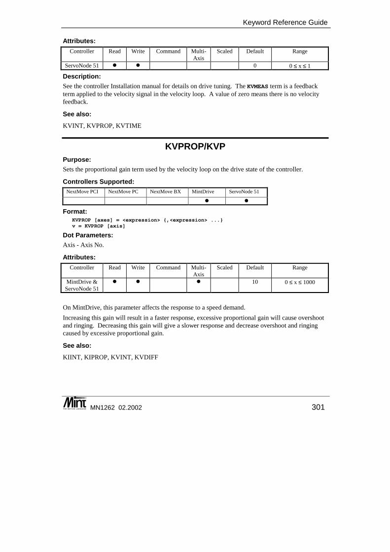
Keyword Reference Guide
MN1262 02.2002 301
Attributes: Controller Read Write Command Multi-
Axis Scaled Default Range
ServoNode 51 � � 0 0 ≤ x ≤ 1
Description: See the controller Installation manual for details on drive tuning. The KVMEAS term is a feedback term applied to the velocity signal in the velocity loop. A value of zero means there is no velocity feedback.
See also: KVINT, KVPROP, KVTIME
KVPROP/KVP Purpose: Sets the proportional gain term used by the velocity loop on the drive state of the controller.
Controllers Supported: NextMove PCI NextMove PC NextMove BX MintDrive ServoNode 51
� �
Format: KVPROP [axes] = <expression> {,<expression> ...}v = KVPROP [axis]
Dot Parameters: Axis - Axis No.
Attributes: Controller Read Write Command Multi-
Axis Scaled Default Range
MintDrive & ServoNode 51
� � � 10 0 ≤ x ≤ 1000
On MintDrive, this parameter affects the response to a speed demand. Increasing this gain will result in a faster response, excessive proportional gain will cause overshoot and ringing. Decreasing this gain will give a slower response and decrease overshoot and ringing caused by excessive proportional gain.
See also: KIINT, KIPROP, KVINT, KVDIFF
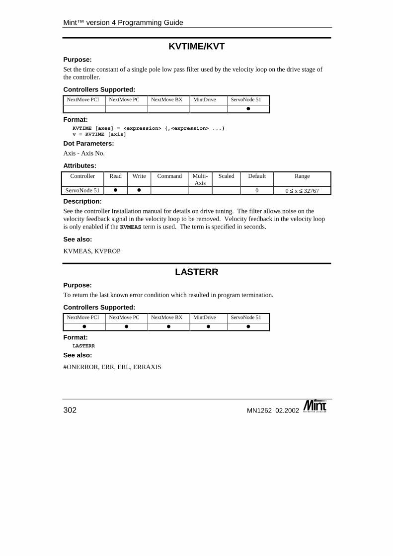
Mint™ version 4 Programming Guide
302 MN1262 02.2002
KVTIME/KVT Purpose: Set the time constant of a single pole low pass filter used by the velocity loop on the drive stage of the controller.
Controllers Supported: NextMove PCI NextMove PC NextMove BX MintDrive ServoNode 51
�
Format: KVTIME [axes] = <expression> {,<expression> ...}v = KVTIME [axis]
Dot Parameters: Axis - Axis No.
Attributes: Controller Read Write Command Multi-
Axis Scaled Default Range
ServoNode 51 � � 0 0 ≤ x ≤ 32767
Description: See the controller Installation manual for details on drive tuning. The filter allows noise on the velocity feedback signal in the velocity loop to be removed. Velocity feedback in the velocity loop is only enabled if the KVMEAS term is used. The term is specified in seconds.
See also: KVMEAS, KVPROP
LASTERR Purpose: To return the last known error condition which resulted in program termination.
Controllers Supported: NextMove PCI NextMove PC NextMove BX MintDrive ServoNode 51
� � � � �
Format: LASTERR
See also: #ONERROR, ERR, ERL, ERRAXIS
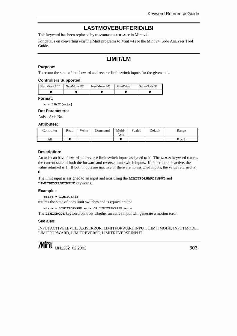
Keyword Reference Guide
MN1262 02.2002 303
LASTMOVEBUFFERID/LBI This keyword has been replaced by MOVEBUFFERIDLAST in Mint v4. For details on converting existing Mint programs to Mint v4 see the Mint v4 Code Analyzer Tool Guide.
LIMIT/LM Purpose: To return the state of the forward and reverse limit switch inputs for the given axis.
Controllers Supported: NextMove PCI NextMove PC NextMove BX MintDrive ServoNode 51
� � � � �
Format: v = LIMIT[axis]
Dot Parameters: Axis - Axis No.
Attributes: Controller Read Write Command Multi-
Axis Scaled Default Range
All � � 0 or 1
Description: An axis can have forward and reverse limit switch inputs assigned to it. The LIMIT keyword returns the current state of both the forward and reverse limit switch inputs. If either input is active, the value returned is 1. If both inputs are inactive or there are no assigned inputs, the value returned is 0. The limit input is assigned to an input and axis using the LIMITFORWARDINPUT and LIMITREVERSEINPUT keywords.
Example: state = LIMIT.axis
returns the state of both limit switches and is equivalent to: state = LIMITFORWARD.axis OR LIMITREVERSE.axis
The LIMITMODE keyword controls whether an active input will generate a motion error.
See also: INPUTACTIVELEVEL, AXISERROR, LIMITFORWARDINPUT, LIMITMODE, INPUTMODE, LIMITFORWARD, LIMITREVERSE, LIMITREVERSEINPUT
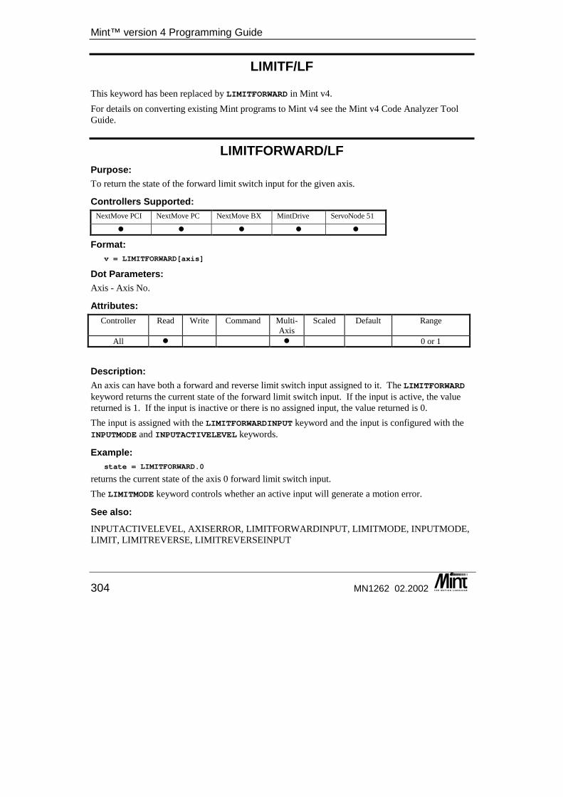
Mint™ version 4 Programming Guide
304 MN1262 02.2002
LIMITF/LF This keyword has been replaced by LIMITFORWARD in Mint v4. For details on converting existing Mint programs to Mint v4 see the Mint v4 Code Analyzer Tool Guide.
LIMITFORWARD/LF Purpose: To return the state of the forward limit switch input for the given axis.
Controllers Supported: NextMove PCI NextMove PC NextMove BX MintDrive ServoNode 51
� � � � �
Format: v = LIMITFORWARD[axis]
Dot Parameters: Axis - Axis No.
Attributes: Controller Read Write Command Multi-
Axis Scaled Default Range
All � � 0 or 1
Description: An axis can have both a forward and reverse limit switch input assigned to it. The LIMITFORWARD keyword returns the current state of the forward limit switch input. If the input is active, the value returned is 1. If the input is inactive or there is no assigned input, the value returned is 0. The input is assigned with the LIMITFORWARDINPUT keyword and the input is configured with the INPUTMODE and INPUTACTIVELEVEL keywords.
Example: state = LIMITFORWARD.0
returns the current state of the axis 0 forward limit switch input. The LIMITMODE keyword controls whether an active input will generate a motion error.
See also: INPUTACTIVELEVEL, AXISERROR, LIMITFORWARDINPUT, LIMITMODE, INPUTMODE, LIMIT, LIMITREVERSE, LIMITREVERSEINPUT
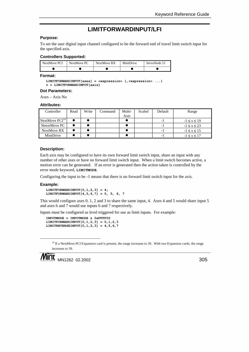
Keyword Reference Guide
MN1262 02.2002 305
LIMITFORWARDINPUT/LFI Purpose: To set the user digital input channel configured to be the forward end of travel limit switch input for the specified axis.
Controllers Supported: NextMove PCI NextMove PC NextMove BX MintDrive ServoNode 51
� � � � �
Format: LIMITFORWARDINPUT[axes] = <expression> {,<expression> ...}v = LIMITFORWARDINPUT[axis]
Dot Parameters: Axes – Axis No
Attributes: Controller Read Write Command Multi-
Axis Scaled Default Range
NextMove PCI14 � � � -1 -1 ≤ x ≤ 19 NenxtMove PC � � � -1 -1 ≤ x ≤ 23 NextMove BX � � � -1 -1 ≤ x ≤ 15
MintDrive � � � -1 -1 ≤ x ≤ 17
Description: Each axis may be configured to have its own forward limit switch input, share an input with any number of other axes or have no forward limit switch input. When a limit switch becomes active, a motion error can be generated. If an error is generated then the action taken is controlled by the error mode keyword, LIMITMODE. Configuring the input to be -1 means that there is no forward limit switch input for the axis.
Example: LIMITFORWARDINPUT[0,1,2,3] = 4;LIMITFORWARDINPUT[4,5,6,7] = 5, 5, 6, 7
This would configure axes 0, 1, 2 and 3 to share the same input, 4. Axes 4 and 5 would share input 5 and axes 6 and 7 would use inputs 6 and 7 respectively. Inputs must be configured as level triggered for use as limit inputs. For example:
INPUTMODE = INPUTMODE & 0xFFFF00LIMITFORWARDINPUT[0,1,2,3] = 0,1,2,3LIMITREVERSEINPUT[0,1,2,3] = 4,5,6,7
14 If a NextMove PCI Expansion card is present, the range increases to 39. With two Expansion cards, the range increases to 59.
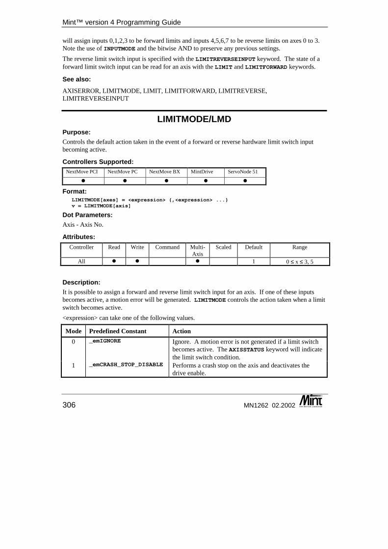
Mint™ version 4 Programming Guide
306 MN1262 02.2002
will assign inputs 0,1,2,3 to be forward limits and inputs 4,5,6,7 to be reverse limits on axes 0 to 3. Note the use of INPUTMODE and the bitwise AND to preserve any previous settings. The reverse limit switch input is specified with the LIMITREVERSEINPUT keyword. The state of a forward limit switch input can be read for an axis with the LIMIT and LIMITFORWARD keywords.
See also: AXISERROR, LIMITMODE, LIMIT, LIMITFORWARD, LIMITREVERSE, LIMITREVERSEINPUT
LIMITMODE/LMD Purpose: Controls the default action taken in the event of a forward or reverse hardware limit switch input becoming active.
Controllers Supported: NextMove PCI NextMove PC NextMove BX MintDrive ServoNode 51
� � � � �
Format: LIMITMODE[axes] = <expression> {,<expression> ...}v = LIMITMODE[axis]
Dot Parameters: Axis - Axis No.
Attributes: Controller Read Write Command Multi-
Axis Scaled Default Range
All � � � 1 0 ≤ x ≤ 3, 5
Description: It is possible to assign a forward and reverse limit switch input for an axis. If one of these inputs becomes active, a motion error will be generated. LIMITMODE controls the action taken when a limit switch becomes active. <expression> can take one of the following values.
Mode Predefined Constant Action 0 _emIGNORE Ignore. A motion error is not generated if a limit switch
becomes active. The AXISSTATUS keyword will indicate the limit switch condition.
1 _emCRASH_STOP_DISABLE Performs a crash stop on the axis and deactivates the drive enable.
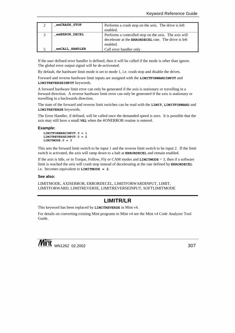
Keyword Reference Guide
MN1262 02.2002 307
2 _emCRASH_STOP Performs a crash stop on the axis. The drive is left enabled.
3 _emERROR_DECEL Performs a controlled stop on the axis. The axis will decelerate at the ERRORDECEL rate. The drive is left enabled.
5 _emCALL_HANDLER Call error handler only If the user defined error handler is defined, then it will be called if the mode is other than ignore. The global error output signal will be de-activeated. By default, the hardware limit mode is set to mode 1, i.e. crash stop and disable the drives. Forward and reverse hardware limit inputs are assigned with the LIMITFORWARDINPUT and LIMITREVERSEINPUT keywords. A forward hardware limit error can only be generated if the axis is stationary or travelling in a forward direction. A reverse hardware limit error can only be generated if the axis is stationary or travelling in a backwards direction. The state of the forward and reverse limit switches can be read with the LIMIT, LIMITFORWARD and LIMITREVERSE keywords. The Error Handler, if defined, will be called once the demanded speed is zero. It is possible that the axis may still have a small VEL when the #ONERROR routine is entered.
Example: LIMITFORWARDINPUT.0 = 1LIMITREVERSEINPUT.0 = 2LIMITMODE.0 = 3
This sets the forward limit switch to be input 1 and the reverse limit switch to be input 2. If the limit switch is activated, the axis will ramp down to a halt at ERRORDECEL and remain enabled. If the axis is Idle, or in Torque, Follow, Fly or CAM modes and LIMITMODE = 3, then if a software limit is reached the axis will crash stop instead of decelerating at the rate defined by ERRORDECEL i.e. becomes equivalent to LIMITMODE = 2.
See also: LIMITMODE, AXISERROR, ERRORDECEL, LIMITFORWARDINPUT, LIMIT, LIMITFORWARD, LIMITREVERSE, LIMITREVERSEINPUT, SOFTLIMITMODE
LIMITR/LR This keyword has been replaced by LIMITREVERSE in Mint v4. For details on converting existing Mint programs to Mint v4 see the Mint v4 Code Analyzer Tool Guide.
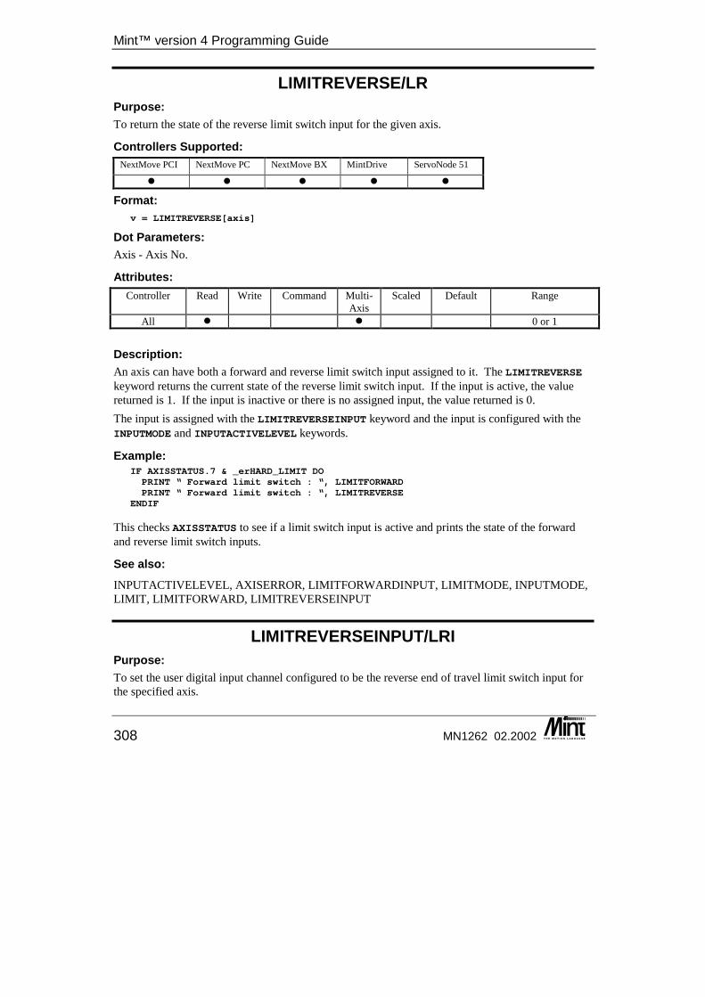
Mint™ version 4 Programming Guide
308 MN1262 02.2002
LIMITREVERSE/LR Purpose: To return the state of the reverse limit switch input for the given axis.
Controllers Supported: NextMove PCI NextMove PC NextMove BX MintDrive ServoNode 51
� � � � �
Format: v = LIMITREVERSE[axis]
Dot Parameters: Axis - Axis No.
Attributes: Controller Read Write Command Multi-
Axis Scaled Default Range
All � � 0 or 1 Description: An axis can have both a forward and reverse limit switch input assigned to it. The LIMITREVERSE keyword returns the current state of the reverse limit switch input. If the input is active, the value returned is 1. If the input is inactive or there is no assigned input, the value returned is 0. The input is assigned with the LIMITREVERSEINPUT keyword and the input is configured with the INPUTMODE and INPUTACTIVELEVEL keywords.
Example: IF AXISSTATUS.7 & _erHARD_LIMIT DOPRINT “ Forward limit switch : “, LIMITFORWARDPRINT “ Forward limit switch : “, LIMITREVERSE
ENDIF
This checks AXISSTATUS to see if a limit switch input is active and prints the state of the forward and reverse limit switch inputs.
See also: INPUTACTIVELEVEL, AXISERROR, LIMITFORWARDINPUT, LIMITMODE, INPUTMODE, LIMIT, LIMITFORWARD, LIMITREVERSEINPUT
LIMITREVERSEINPUT/LRI Purpose: To set the user digital input channel configured to be the reverse end of travel limit switch input for the specified axis.
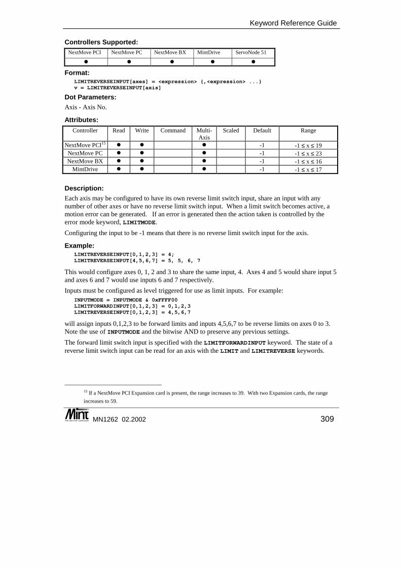
Keyword Reference Guide
MN1262 02.2002 309
Controllers Supported: NextMove PCI NextMove PC NextMove BX MintDrive ServoNode 51
� � � � �
Format: LIMITREVERSEINPUT[axes] = <expression> {,<expression> ...}v = LIMITREVERSEINPUT[axis]
Dot Parameters: Axis - Axis No.
Attributes: Controller Read Write Command Multi-
Axis Scaled Default Range
NextMove PCI15 � � � -1 -1 ≤ x ≤ 19 NextMove PC � � � -1 -1 ≤ x ≤ 23 NextMove BX � � � -1 -1 ≤ x ≤ 16
MintDrive � � � -1 -1 ≤ x ≤ 17 Description: Each axis may be configured to have its own reverse limit switch input, share an input with any number of other axes or have no reverse limit switch input. When a limit switch becomes active, a motion error can be generated. If an error is generated then the action taken is controlled by the error mode keyword, LIMITMODE. Configuring the input to be -1 means that there is no reverse limit switch input for the axis.
Example: LIMITREVERSEINPUT[0,1,2,3] = 4;LIMITREVERSEINPUT[4,5,6,7] = 5, 5, 6, 7
This would configure axes 0, 1, 2 and 3 to share the same input, 4. Axes 4 and 5 would share input 5 and axes 6 and 7 would use inputs 6 and 7 respectively. Inputs must be configured as level triggered for use as limit inputs. For example:
INPUTMODE = INPUTMODE & 0xFFFF00LIMITFORWARDINPUT[0,1,2,3] = 0,1,2,3LIMITREVERSEINPUT[0,1,2,3] = 4,5,6,7
will assign inputs 0,1,2,3 to be forward limits and inputs 4,5,6,7 to be reverse limits on axes 0 to 3. Note the use of INPUTMODE and the bitwise AND to preserve any previous settings. The forward limit switch input is specified with the LIMITFORWARDINPUT keyword. The state of a reverse limit switch input can be read for an axis with the LIMIT and LIMITREVERSE keywords.
15 If a NextMove PCI Expansion card is present, the range increases to 39. With two Expansion cards, the range increases to 59.
Mint™ version 4 Programming Guide
310 MN1262 02.2002
See also: AXISERROR, LIMITFORWARDINPUT, LIMITMODE, LIMIT, LIMITFORWARD, LIMITREVERSE
LINE Purpose: To write a string to a specified line on the terminal, clearing all characters to the end of the line.
Controllers Supported: NextMove PCI NextMove PC NextMove BX MintDrive ServoNode 51
� � � � �
Format: LINE {#<terminal>} <line number>, <expression>
Description: Although intended for writing to the LCD display on a KeypadNode, LINE can also be used to write to the Terminal window on Mint WorkBench. The LINE command will print the expression at the specified line on the display and then clear the display to the end of that line up to 20 characters (the width of the LCD display). The cursor is returned to the end of the printed text. The device (#) re-director allows a specific terminal channel to be specified. See section 4 for more details. If the #terminal parameter is omitted, then default terminal channels will be used as specified with the TERMINAL keyword. The format modifiers HEX, DEC and BIN may be used to specified the number format of displayed variables. DEC – print number in decimal format HEX – print number in hexadecimal format BIN – print number in binary format The expression can be any expression supported by PRINT and will allow the use of the USING parameter for formatted output. For example:
LINE #3 2, "A = ", a USING 5,2
will print the value of a at line 2 with formatted output. LINE 1," EXIT"LINE 2,"Main Menu"LINE 3,"Select Function"LINE 4,"SETUP START MANUAL",
Note the use of the comma at the end of the line to suppress line feeding which results in the display clearing. Writing beyond line 4 will result in the LCD display being cleared on a KeypadNode.
Keyword Reference Guide
MN1262 02.2002 311
LINE is designed for use on the CAN operator panel, KeypadNode.
See also: LOCATE, PRINT, TERMINAL, TERMINALMODE
LOCATE Purpose: To locate the cursor on the terminal.
Controllers Supported: NextMove PCI NextMove PC NextMove BX MintDrive ServoNode 51
� � � � �
Format: LOCATE {#<terminal>} <column>,<row>
Description: Using VT100 emulation, the cursor is located at <column>, <row>, where the top left corner is at location column 1, row 1. <column> and <row> are not range checked. The cursor will remain stationary if <column> or <row> are out of bounds of the screen co-ordinates. Example:
LOCATE 10,10 : PRINT "Column 10, Row 10"LOCATE #3 10,10 : PRINT "Column 10, Row 10"
The string "Column 10, Row 10" will be printed at column 10, row 10. <column> and <row> can be any valid Mint expression. The device (#) re-director allows a specific terminal channel to be specified. See section 4 for more details. If the #terminal parameter is omitted, then default terminal channels will be used as specified with the TERMINAL keyword.
See also: CLS, LINE, PRINT, TERMINAL, TERMINALMODE
LOG Purpose: To return the natural logarithm.
Controllers Supported: NextMove PCI NextMove PC NextMove BX MintDrive ServoNode 51
� � � � �
Mint™ version 4 Programming Guide
312 MN1262 02.2002
Format: v = LOG(<value>)
Description: Return the natural logarithm of the <value> where <value> is greater than 0 and can be any valid Mint expression.
Example: PRINT LOG (2)
will display 0.6931 to the terminal.
See also: EXP
LOOP .. ENDL Purpose: To perform an endless loop.
Controllers Supported: NextMove PCI NextMove PC NextMove BX MintDrive ServoNode 51
� � � � �
Format: LOOP{statements}
ENDL
Description: This is the simplest type of loop in Mint, it loops round forever, for instance:
LOOPJOG = ADC.1/10
ENDL
loops round forever reading analog input one and jogging the motor to a maximum value of 10.
Notes: • A loop can be terminated by use of the EXIT keyword. • LOOPs can be nested up to 50 levels deep.
See also: EXIT, FOR..NEXT, REPEAT..UNTIL, WHILE..ENDW

Keyword Reference Guide
MN1262 02.2002 313
LOOPTIME/LT This is an advanced Mint feature. Full details can be found in the Mint v4 Advanced Programming Guide.
MASTERCHANNEL/MSC Purpose: To set or read the channel of the input device used for gearing.
Controllers Supported: NextMove PCI NextMove PC NextMove BX MintDrive ServoNode 51
� � � � �
Format: MASTERCHANNEL[axes] = <expression> {,<expression> ...}v = MASTERCHANNEL[axis]
Dot Parameters: Axis - Axis No.
Attributes: Controller Read Write Command Multi-
Axis Scaled Default Range
NextMove � � � 0 ≤ x ≤ 11 MintDrive &
ServoNode 51 � � 0
Description: MASTERCHANNEL is used in conjunction with MASTERSOURCE to define the master position reference for gearing moves, CAM, FLY and FOLLOW. When MASTERSOURCE is used to set the master reference, the current MASTERCHANNEL value may be modified. On MintDrive and ServoNodse 51, the mater channel will be set to its default value as described in the table below. For NextMove, the master channel will be set to its default value if the current value is invalid for the specified master source.
Master Source MASTERSOURCE Constant
Default MASTERCHANNEL
Axis position _msPOS 0 Encoder value _msENCODER 0 Auxiliary encoder value _msAUXENCODER 0 Speed (virtual) _msSPEED The MASTERSOURCE axis Axis demand velocity _msDEMAND 0
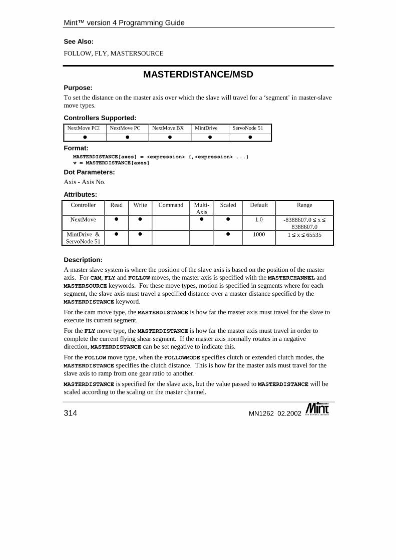
Mint™ version 4 Programming Guide
314 MN1262 02.2002
See Also: FOLLOW, FLY, MASTERSOURCE
MASTERDISTANCE/MSD Purpose: To set the distance on the master axis over which the slave will travel for a ‘segment’ in master-slave move types.
Controllers Supported: NextMove PCI NextMove PC NextMove BX MintDrive ServoNode 51
� � � � �
Format: MASTERDISTANCE[axes] = <expression> {,<expression> ...}v = MASTERDISTANCE[axes]
Dot Parameters: Axis - Axis No.
Attributes: Controller Read Write Command Multi-
Axis Scaled Default Range
NextMove � � � � 1.0 -8388607.0 ≤ x ≤ 8388607.0
MintDrive & ServoNode 51
� � � 1000 1 ≤ x ≤ 65535
Description: A master slave system is where the position of the slave axis is based on the position of the master axis. For CAM, FLY and FOLLOW moves, the master axis is specified with the MASTERCHANNEL and MASTERSOURCE keywords. For these move types, motion is specified in segments where for each segment, the slave axis must travel a specified distance over a master distance specified by the MASTERDISTANCE keyword. For the cam move type, the MASTERDISTANCE is how far the master axis must travel for the slave to execute its current segment. For the FLY move type, the MASTERDISTANCE is how far the master axis must travel in order to complete the current flying shear segment. If the master axis normally rotates in a negative direction, MASTERDISTANCE can be set negative to indicate this. For the FOLLOW move type, when the FOLLOWMODE specifies clutch or extended clutch modes, the MASTERDISTANCE specifies the clutch distance. This is how far the master axis must travel for the slave axis to ramp from one gear ratio to another. MASTERDISTANCE is specified for the slave axis, but the value passed to MASTERDISTANCE will be scaled according to the scaling on the master channel.
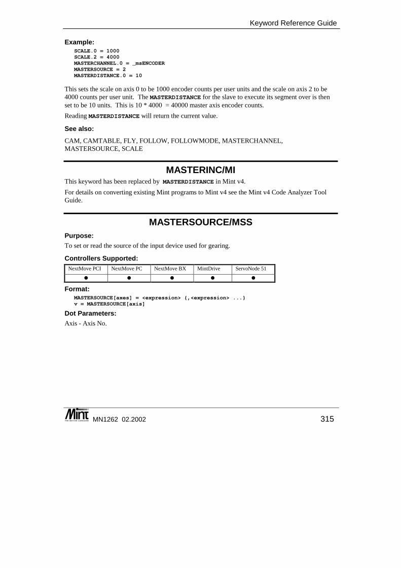
Keyword Reference Guide
MN1262 02.2002 315
Example: SCALE.0 = 1000SCALE.2 = 4000MASTERCHANNEL.0 = _msENCODERMASTERSOURCE = 2MASTERDISTANCE.0 = 10
This sets the scale on axis 0 to be 1000 encoder counts per user units and the scale on axis 2 to be 4000 counts per user unit. The MASTERDISTANCE for the slave to execute its segment over is then set to be 10 units. This is 10 * 4000 = 40000 master axis encoder counts. Reading MASTERDISTANCE will return the current value.
See also: CAM, CAMTABLE, FLY, FOLLOW, FOLLOWMODE, MASTERCHANNEL, MASTERSOURCE, SCALE
MASTERINC/MI This keyword has been replaced by MASTERDISTANCE in Mint v4. For details on converting existing Mint programs to Mint v4 see the Mint v4 Code Analyzer Tool Guide.
MASTERSOURCE/MSS Purpose: To set or read the source of the input device used for gearing.
Controllers Supported: NextMove PCI NextMove PC NextMove BX MintDrive ServoNode 51
� � � � �
Format: MASTERSOURCE[axes] = <expression> {,<expression> ...}v = MASTERSOURCE[axis]
Dot Parameters: Axis - Axis No.

Mint™ version 4 Programming Guide
316 MN1262 02.2002
Attributes: Controller Read Write Command Multi-
Axis Scaled Default Range
NextMove � � � 0 0 ≤ x ≤ 4 MintDrive &
ServoNode 51 � � � 2 2, 3
Description: MASTERSOURCE is used in conjunction with the MASTERCHANNEL keyword to define the master position reference for gearing moves, CAM, FLY and FOLLOW. MASTERSOURCE is used to set the master reference, accepting one of the following values:
Value Constant Function 0 _msPOS Use an axis position as the master reference. If the master axis
is configured as off, then use _msENCODER. 1 _msENCODER Use an axis encoder value as the master reference. 2 _msAUXENCODER Use the auxiliary encoder channel as the master reference. 3 _msSPEED Use a virtual axis as the master reference. The master speed is
set by writing to SPEED on the master channel.. 4 _msDEMAND Use an axis demand velocity as the master reference.
When the MASTERSOURCE is changed, MASTERCHANNEL is set to its default value.
MASTERCHANNEL and MASTERSOURCE replace the FOLLOWAXIS keyword.
Example: Axis 1 if required to follow axis 3.
MASTERSOURCE.1 = _msPOSMASTERCHANNEL.1 = 3
Example 2: It is required that axes 0, 1 and 2 are required to follow a virtual axis. A virtual axis is defined as an internal speed reference, but is not associated with a physical axis signal (encoder). The speed of the virtual axis is defined by writing to the SPEED keyword.
MASTERSOURCE[0,1,2] = _msSPEED;MASTERCHANNEL[0,1,2] = 3;SPEED.3 = 1000FOLLOW[0,1,2] = 1,2,-1.5
Note that the SPEED of axis 3 can be changed which will change the speed of all the axes following it. By default, a virtual follow will follow the SPEED of its own axis. If MASTERCHANNEL was not set, the following would need to be used:
SPEED[0,1,2] = 1000,1000,1000
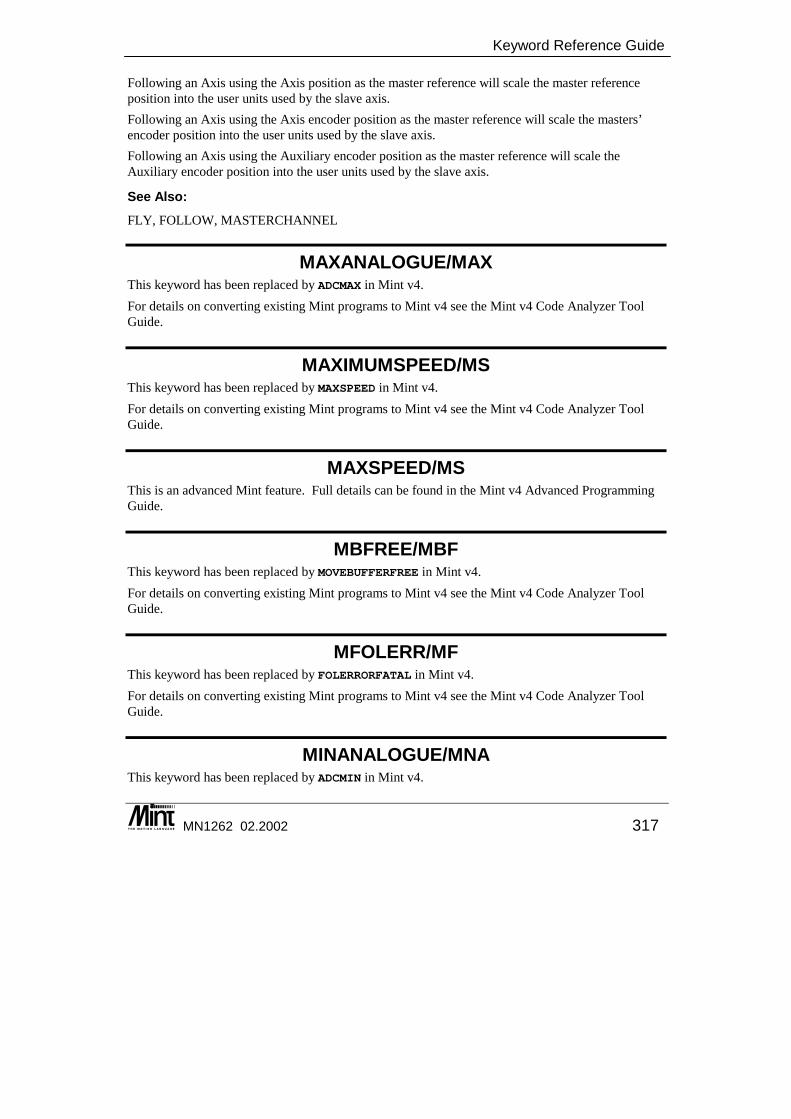
Keyword Reference Guide
MN1262 02.2002 317
Following an Axis using the Axis position as the master reference will scale the master reference position into the user units used by the slave axis. Following an Axis using the Axis encoder position as the master reference will scale the masters’ encoder position into the user units used by the slave axis. Following an Axis using the Auxiliary encoder position as the master reference will scale the Auxiliary encoder position into the user units used by the slave axis.
See Also: FLY, FOLLOW, MASTERCHANNEL
MAXANALOGUE/MAX This keyword has been replaced by ADCMAX in Mint v4. For details on converting existing Mint programs to Mint v4 see the Mint v4 Code Analyzer Tool Guide.
MAXIMUMSPEED/MS This keyword has been replaced by MAXSPEED in Mint v4. For details on converting existing Mint programs to Mint v4 see the Mint v4 Code Analyzer Tool Guide.
MAXSPEED/MS This is an advanced Mint feature. Full details can be found in the Mint v4 Advanced Programming Guide.
MBFREE/MBF This keyword has been replaced by MOVEBUFFERFREE in Mint v4. For details on converting existing Mint programs to Mint v4 see the Mint v4 Code Analyzer Tool Guide.
MFOLERR/MF This keyword has been replaced by FOLERRORFATAL in Mint v4. For details on converting existing Mint programs to Mint v4 see the Mint v4 Code Analyzer Tool Guide.
MINANALOGUE/MNA This keyword has been replaced by ADCMIN in Mint v4.
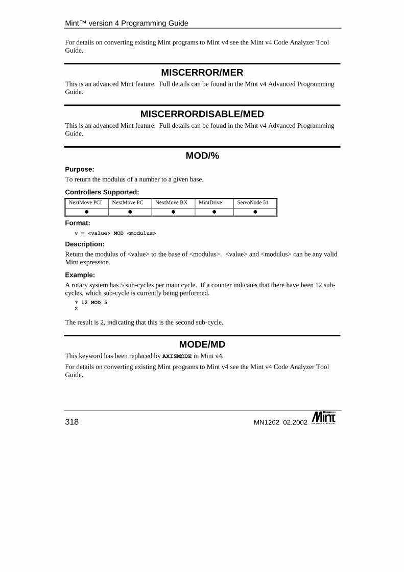
Mint™ version 4 Programming Guide
318 MN1262 02.2002
For details on converting existing Mint programs to Mint v4 see the Mint v4 Code Analyzer Tool Guide.
MISCERROR/MER This is an advanced Mint feature. Full details can be found in the Mint v4 Advanced Programming Guide.
MISCERRORDISABLE/MED This is an advanced Mint feature. Full details can be found in the Mint v4 Advanced Programming Guide.
MOD/% Purpose: To return the modulus of a number to a given base.
Controllers Supported: NextMove PCI NextMove PC NextMove BX MintDrive ServoNode 51
� � � � �
Format: v = <value> MOD <modulus>
Description: Return the modulus of <value> to the base of <modulus>. <value> and <modulus> can be any valid Mint expression.
Example: A rotary system has 5 sub-cycles per main cycle. If a counter indicates that there have been 12 sub-cycles, which sub-cycle is currently being performed.
? 12 MOD 52
The result is 2, indicating that this is the second sub-cycle.
MODE/MD This keyword has been replaced by AXISMODE in Mint v4. For details on converting existing Mint programs to Mint v4 see the Mint v4 Code Analyzer Tool Guide.
Keyword Reference Guide
MN1262 02.2002 319
MONCHANNELS/MCL This keyword has been replaced by ADCMONITOR in Mint v4. For details on converting existing Mint programs to Mint v4 see the Mint v4 Code Analyzer Tool Guide.
MOTORALIGNMENT/MAL Purpose: To read or set the Feedback alignment of the motor.
Controllers Supported: NextMove PCI NextMove PC NextMove BX MintDrive ServoNode 51
�
Format: MOTORALIGNMENT = <expression>v = MOTORALIGNMENT
Attributes: Controller Read Write Command Multi-
Axis Scaled Default Range
MintDrive � � 0 0 ≤ x < 360
Description: The MOTORALIGNMENT gives the alignment of the motor to the resolver / encoder. This is measured between the magnetic north of the motor and the Z index of the resolver / encoder. On Baldor BSM motors with a Resolver, a value of 44.6° is correct. This parameter is normally set by the Feedback Alignment test. This value will vary by 180° on a four pole motor and by 90° on an eight pole motor. See the Installation manual for more details on tuning.
See Also: MOTORDIRECTION
MOTORDIRECTION/MD Purpose: To read or set the Electrical Direction of the motor.
Controllers Supported: NextMove PCI NextMove PC NextMove BX MintDrive ServoNode 51
�
Mint™ version 4 Programming Guide
320 MN1262 02.2002
Format: MOTORDIRECTION = <expression>v = MOTORDIRECTION
Attributes: Controller Read Write Command Multi-
Axis Scaled Default Range
All � � 0 0 – Forward 1 – Reverse
Description: The MOTORDIRECTION gives the electrical direction of rotation of the resolver. This may be set to either forward or reverse to match the motor rotation. This parameter is normally set automatically by the Feedback Alignment test. See the Installation manual for more details on tuning.
See Also: MOTORALIGNMENT
MOTORENCODERLINES/MEL Purpose: To read or set the number of encoder lines of the motor.
Controllers Supported: NextMove PCI NextMove PC NextMove BX MintDrive ServoNode 51
� �
Format: MOTORENCODERLINES = <expression>v = MOTORENCODERLINES
Attributes: Controller Read Write Command Multi-
Axis Scaled Default Range
All � � 1024 0 < x ≤ 65535
Description: The MOTORENCODERLINES gives the number of encoder lines used by the motor. Motors with Resolver feedback, have a simulated MOTORENCODERLINES of 1024 (giving 4096 quad counts per rev.) which cannot be changed. Baldor BSM motors are either 1000 line or 2500 line encoders – this can be determined from the motor catalog number. For linear motors, this parameter is calculated automatically. For example, a 1 micron encoder with a motor pole pitch of 60.96mm results in 15240 lines.

Keyword Reference Guide
MN1262 02.2002 321
This parameter is normally set when the motor is selected from the Baldor database in the Mint WorkBench.
See Also: MOTORENCODERRESOLUTION
MOTORENCODERRESOLUTION/MES Purpose: To read or set the encoder resolution.
Controllers Supported: NextMove PCI NextMove PC NextMove BX MintDrive ServoNode 51
� �
Format: MOTORENCODERRESOLUTION = <expression>v = MOTORENCODERRESOLUTION
Attributes: Controller Read Write Command Multi-
Axis Scaled Default Range
All � � 0.5 < x ≤ 8388607
Description: This keyword allows the resolution of the linear encoder scale to be specified. It is used with linear UVW encoders. For example:
?MOTORENCODERRESOLUTION0.5
returns a value of 0.5 microns.
See Also: MOTORENCODERLINES
MOTORFEEDBACK/MFB Purpose: To read or set the Feedback type of the motor.
=
)MOTORPOLES x IONDERRESOLUT(MOTORENCO x 2000 1 x ITCHMOTORPOLEPERLINESMOTORENCOD
Mint™ version 4 Programming Guide
322 MN1262 02.2002
Controllers Supported: NextMove PCI NextMove PC NextMove BX MintDrive ServoNode 51
�
Format: MOTORFEEDBACK = <expression>v = MOTORFEEDBACK
Attributes: Controller Read Write Command Multi-
Axis Scaled Default Range
All � � 0 0 – 3
Description: The MOTORFEEDBACK specifies the feedback type of the motor. It is not possible to select a motor with Encoder feedback if the drive has resolver feedback and visa versa. Supported feedback types are:
Value Type 0 Resolver 1 UVW encoder 2 Reserved 3 Linear UVW encoder
This parameter is normally set when the motor is selected from the Baldor database in the Mint WorkBench.
MOTORINDUCTANCE/MID Purpose: To read or set the inductance of the motor.
Controllers Supported: NextMove PCI NextMove PC NextMove BX MintDrive ServoNode 51
�
Format: MOTORINDUCTANCE = <expression>v = MOTORINDUCTANCE
Attributes: Controller Read Write Command Multi-
Axis Scaled Default Range
All � � 0 ≤ x ≤ 98.3
Keyword Reference Guide
MN1262 02.2002 323
Description: The MOTORINDUCTANCE specifies the line-to-line inductance of the motor in mH. This parameter is normally set when the motor is selected from the Baldor database in the Mint WorkBench.
See Also: MOTORPEAKCURRENT
MOTORPEAKCURRENT/MPC Purpose: To read or set the Peak Current rating of the motor.
Controllers Supported: NextMove PCI NextMove PC NextMove BX MintDrive ServoNode 51
�
Format: MOTORPEAKCURRENT = <expression>v = MOTORPEAKCURRENT
Attributes: Controller Read Write Command Multi-
Axis Scaled Default Range
All � � 0 ≤ x ≤ Peak Drive Rating
Description: The MOTORPEAKCURRENT gives peak current rating of the motor. If this value is exceed by 150% for 1 minute or exceeded by 200% for 1 second then the drive will trip out with a fault. This can be read with the DRIVEFAULT keyword. This parameter is normally set when the motor is selected from the Baldor database in the Mint WorkBench.
See Also: MOTORINDUCTANCE, MOTORRATEDCURRENT
MOTORPHASEOFFSET/MPO Purpose: To read or set the phase offset on a UVW encoder.
Mint™ version 4 Programming Guide
324 MN1262 02.2002
Controllers Supported: NextMove PCI NextMove PC NextMove BX MintDrive ServoNode 51
� �
Format: MOTORPHASEOFFSET = <expression>v = MOTORPHASEOFFSET
Attributes: Controller Read Write Command Multi-
Axis Scaled Default Range
All � � 0 < x ≤ 180
Description: The MOTORPHASEOFFSET keyword is used to set the phase offset in degrees for UVW encoders. This parameter is normally set when the motor is selected from the Baldor database in the Mint WorkBench.
MOTORPOLEPITCH/MPP Purpose: To read or set size of the motor poles.
Controllers Supported: NextMove PCI NextMove PC NextMove BX MintDrive ServoNode 51
� �
Format: MOTOREPOLEPITCH = <expression>v = MOTORPOLEPITCH
Attributes: Controller Read Write Command Multi-
Axis Scaled Default Range
All � � 0 < x ≤ 8388607
Description: Sets the pitch of the motor poles for a linear motor in millimetres. The pitch is measured between consecutive north poles along the motor. Typically, Baldor linear motors have a pole pitch of 60.96 or 45.72mm.
MOTORPOLES/MP Purpose: To read or set the number of motor pole pairs.
Keyword Reference Guide
MN1262 02.2002 325
Controllers Supported: NextMove PCI NextMove PC NextMove BX MintDrive ServoNode 51
�
Format: MOTORPOLES = <expression>v = MOTORPOLES
Attributes: Controller Read Write Command Multi-
Axis Scaled Default Range
All � � 4 0 ≤ x ≤ 100
Description: The MOTORPOLES gives the number of pole pairs of the motor. This parameter is normally set when the motor is selected from the Baldor database in the Mint WorkBench. Standard Baldor motor poles can be assumed from the following:
Baldor linear motors = 2 poles BSM 50 = 4 poles BSM 63/80 = 4 poles BSM 90/100 = 8 poles BSM 4F/6F/8F = 8 poles
MOTORRATEDCURRENT/MRC Purpose: To read or set the rated current of the motor.
Controllers Supported: NextMove PCI NextMove PC NextMove BX MintDrive ServoNode 51
�
Format: MOTORRATEDCURRENT = <expression>v = MOTORRATEDCURRENT
Attributes: Controller Read Write Command Multi-
Axis Scaled Default Range
All � � 0 0 ≤ x ≤ Drive Rating
Description: The MOTORRATEDCURRENT gives rated current of the motor. This parameter is normally set when the motor is selected from the Baldor database in the Mint WorkBench.
Mint™ version 4 Programming Guide
326 MN1262 02.2002
See Also: MOTORPEAKCURRENT
MOTORRESOLVERSPEED/MRS Purpose: To read or set the Resolver speed.
Controllers Supported: NextMove PCI NextMove PC NextMove BX MintDrive ServoNode 51
�
Format: MOTORRESOLVERSPEED = <expression>v = MOTORRESOLVERSPEED
Attributes: Controller Read Write Command Multi-
Axis Scaled Default Range
All � � 0 0 ≤ x ≤ 10
Description: The MOTORRESOLVERSPEED gives the resolver speed of the motor. Baldor BSM motors all have a Resolver speed of 1. This parameter is normally set when the motor is selected from the Baldor database in the Mint WorkBench. This parameter is not applicable to motors with Encoder feedback.
MOTORSPEEDFILTER/MSF Purpose: To read or set the Speed Filter for Resolver motors.
Controllers Supported: NextMove PCI NextMove PC NextMove BX MintDrive ServoNode 51
�
Format: MOTORSPEEDFILTER = <expression>v = MOTORSPEEDFILTER
Attributes: Controller Read Write Command Multi-
Axis Scaled Default Range
All � � 0 0 ≤ x ≤ 7
Keyword Reference Guide
MN1262 02.2002 327
Description: The MOTORSPEEDFILTER defines the number of input samples over which to filter and determine the resolver speed. The preset filter may be reduced to obtain smoother slow speed operation. The greater the number, the more filtered the signal becomes and the bandwidth is also reduced. This parameter is normally set by the Speed Controller Calcs Test.
MOTORSPEEDMAX/MSM Purpose: To read or set the maximum speed of the motor.
Controllers Supported: NextMove PCI NextMove PC NextMove BX MintDrive ServoNode 51
� �
Format: MOTORSPEEDMAX = <expression>v = MOTORSPEEDMAX
Attributes: Controller Read Write Command Multi-
Axis Scaled Default Range
All � � 2500 0 ≤ x ≤ 22500
Description: The MOTORSPEEDMAX gives the maximum speed of the motor in RPM. The drive will be disabled and report an error if the motor speed exceeds 110% of this value. The error can be read with the DRIVEFAULT keyword. This parameter is normally set when the motor is selected from the Baldor database in the Mint WorkBench.
MOVEA/MA Purpose: To set up a positional move to an absolute position.
Controllers Supported: NextMove PCI NextMove PC NextMove BX MintDrive ServoNode 51
� � � � �
Format: MOVEA[axes] = <expression> {,<expression ...}
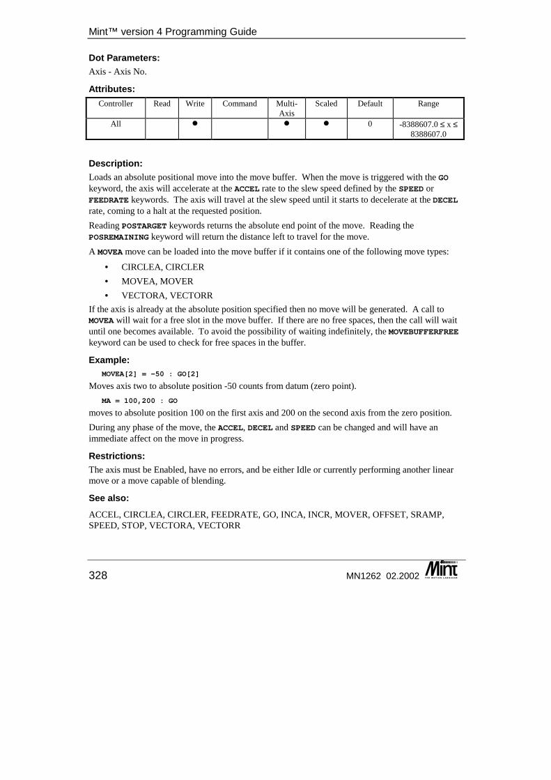
Mint™ version 4 Programming Guide
328 MN1262 02.2002
Dot Parameters: Axis - Axis No.
Attributes: Controller Read Write Command Multi-
Axis Scaled Default Range
All � � � 0 -8388607.0 ≤ x ≤ 8388607.0
Description: Loads an absolute positional move into the move buffer. When the move is triggered with the GO keyword, the axis will accelerate at the ACCEL rate to the slew speed defined by the SPEED or FEEDRATE keywords. The axis will travel at the slew speed until it starts to decelerate at the DECEL rate, coming to a halt at the requested position. Reading POSTARGET keywords returns the absolute end point of the move. Reading the POSREMAINING keyword will return the distance left to travel for the move. A MOVEA move can be loaded into the move buffer if it contains one of the following move types:
• CIRCLEA, CIRCLER • MOVEA, MOVER • VECTORA, VECTORR
If the axis is already at the absolute position specified then no move will be generated. A call to MOVEA will wait for a free slot in the move buffer. If there are no free spaces, then the call will wait until one becomes available. To avoid the possibility of waiting indefinitely, the MOVEBUFFERFREE keyword can be used to check for free spaces in the buffer.
Example: MOVEA[2] = -50 : GO[2]
Moves axis two to absolute position -50 counts from datum (zero point). MA = 100,200 : GO
moves to absolute position 100 on the first axis and 200 on the second axis from the zero position. During any phase of the move, the ACCEL, DECEL and SPEED can be changed and will have an immediate affect on the move in progress.
Restrictions: The axis must be Enabled, have no errors, and be either Idle or currently performing another linear move or a move capable of blending.
See also: ACCEL, CIRCLEA, CIRCLER, FEEDRATE, GO, INCA, INCR, MOVER, OFFSET, SRAMP, SPEED, STOP, VECTORA, VECTORR
Keyword Reference Guide
MN1262 02.2002 329
MOVEBUFFER/MB This keyword has been replaced by MOVEBUFFERSIZE in Mint v4. For details on converting existing Mint programs to Mint v4 see the Mint v4 Code Analyzer Tool Guide.
MOVEBUFFERFREE/MBF This is an advanced Mint feature. Full details can be found in the Mint v4 Advanced Programming Guide.
MOVEBUFFERID/MBI This is an advanced Mint feature. Full details can be found in the Mint v4 Advanced Programming Guide.
MOVEBUFFERIDLAST/MBL This is an advanced Mint feature. Full details can be found in the Mint v4 Advanced Programming Guide.
MOVEBUFFERLOW/MBW This is an advanced Mint feature. Full details can be found in the Mint v4 Advanced Programming Guide.
MOVEBUFFERSIZE/MB This is an advanced Mint feature. Full details can be found in the Mint v4 Advanced Programming Guide.
MOVEBUFFERSTATUS/MBS This is an advanced Mint feature. Full details can be found in the Mint v4 Advanced Programming Guide.
MOVER/MR Purpose: To set up a positional move to a relative position.
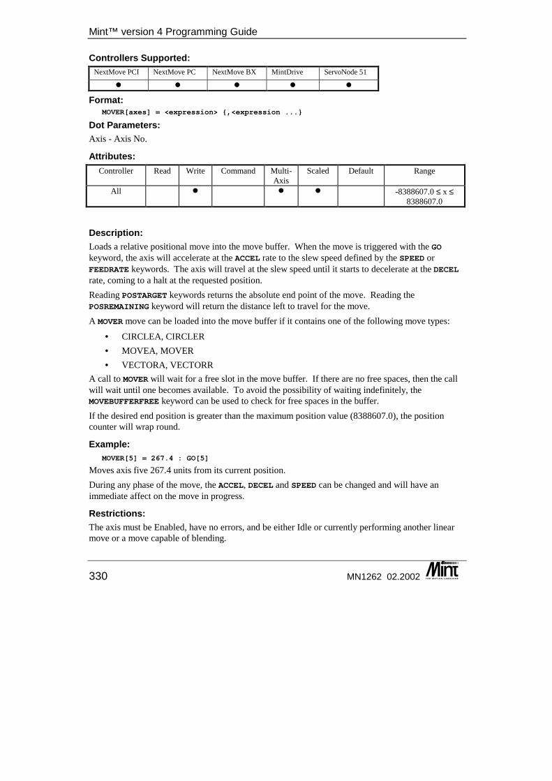
Mint™ version 4 Programming Guide
330 MN1262 02.2002
Controllers Supported: NextMove PCI NextMove PC NextMove BX MintDrive ServoNode 51
� � � � �
Format: MOVER[axes] = <expression> {,<expression ...}
Dot Parameters: Axis - Axis No.
Attributes: Controller Read Write Command Multi-
Axis Scaled Default Range
All � � � -8388607.0 ≤ x ≤ 8388607.0
Description: Loads a relative positional move into the move buffer. When the move is triggered with the GO keyword, the axis will accelerate at the ACCEL rate to the slew speed defined by the SPEED or FEEDRATE keywords. The axis will travel at the slew speed until it starts to decelerate at the DECEL rate, coming to a halt at the requested position. Reading POSTARGET keywords returns the absolute end point of the move. Reading the POSREMAINING keyword will return the distance left to travel for the move. A MOVER move can be loaded into the move buffer if it contains one of the following move types:
• CIRCLEA, CIRCLER • MOVEA, MOVER • VECTORA, VECTORR
A call to MOVER will wait for a free slot in the move buffer. If there are no free spaces, then the call will wait until one becomes available. To avoid the possibility of waiting indefinitely, the MOVEBUFFERFREE keyword can be used to check for free spaces in the buffer. If the desired end position is greater than the maximum position value (8388607.0), the position counter will wrap round.
Example: MOVER[5] = 267.4 : GO[5]
Moves axis five 267.4 units from its current position. During any phase of the move, the ACCEL, DECEL and SPEED can be changed and will have an immediate affect on the move in progress.
Restrictions: The axis must be Enabled, have no errors, and be either Idle or currently performing another linear move or a move capable of blending.
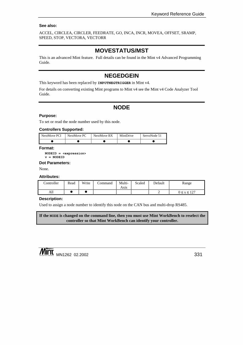
Keyword Reference Guide
MN1262 02.2002 331
See also: ACCEL, CIRCLEA, CIRCLER, FEEDRATE, GO, INCA, INCR, MOVEA, OFFSET, SRAMP, SPEED, STOP, VECTORA, VECTORR
MOVESTATUS/MST This is an advanced Mint feature. Full details can be found in the Mint v4 Advanced Programming Guide.
NEGEDGEIN This keyword has been replaced by INPUTNEGTRIGGER in Mint v4. For details on converting existing Mint programs to Mint v4 see the Mint v4 Code Analyzer Tool Guide.
NODE Purpose: To set or read the node number used by this node.
Controllers Supported: NextMove PCI NextMove PC NextMove BX MintDrive ServoNode 51
� � � � �
Format: NODEID = <expression>v = NODEID
Dot Parameters: None.
Attributes: Controller Read Write Command Multi-
Axis Scaled Default Range
All � � 2 0 ≤ x ≤ 127
Description: Used to assign a node number to identify this node on the CAN bus and multi-drop RS485.
If the NODE is changed on the command line, then you must use Mint WorkBench to reselect the controller so that Mint WorkBench can identify your controller.

Mint™ version 4 Programming Guide
332 MN1262 02.2002
The controllers support both an RS232 and RS485 serial port. The RS485 port can be used in a multi-drop configuration, but before it can used on the bus, it’s node number must be set. This is achieved with the NODE keyword. When set, the NODE will be stored into EEPROM (if supported) and the node number will be restored on power up. If the NODE number is set to one then the RS485 port will automatically be enabled on boot up. See section 4.2 for details on using the RS485 port.
Note: The RS485 port is inaccessible until the node number is set. It is recommended that Mint is used to set up the node number if an embedded 'C' application is written. Once set, it is
stored in EEPROM and will be restored on power up.
On a CANopen network, node 1 allows the controller to be the master of a network. Node numbers above one indicate the node can be a slave. No CANopen activity is possible if the node number is zero. See the Mint v4 CAN Programming Guide for more details.
NODELIVE/NL For details on this keyword see the Mint v4 CAN Programming Guide.
NODESCAN/NS For details on this keyword see the Mint v4 CAN Programming Guide.
NODETYPE/NT For details on this keyword see the Mint v4 CAN Programming Guide.
NOT/! Purpose: To perform a logical not on an expression.
Controllers Supported: NextMove PCI NextMove PC NextMove BX MintDrive ServoNode 51
� � � � �
Format: v = NOT <expression>
Description: If <expression> is true (non-zero) NOT <expression> will be 0 as shown in the table:
Keyword Reference Guide
MN1262 02.2002 333
<expression> NOT <expression> 0 1 1 0
NOT is very useful when testing the state of binary inputs. For example:
IF !IN.1 THEN OUT.1 = 1
is the same as IF IN.1 = 0 THEN OUT.1 = 1
The first expression however uses less code space and is quicker to execute. Note that the expression:
IF A NOT = B THEN {statement}
is not valid, instead use: IF A <> B THEN {statement}
See also: ~, AND, OR, XOR
NUMBEROF/NO This is an advanced Mint feature. Full details can be found in the Mint v4 Advanced Programming Guide.
NVFLOAT/NVF This is an advanced Mint feature. Full details can be found in the Mint v4 Advanced Programming Guide.
NVLONG/NVL This is an advanced Mint feature. Full details can be found in the Mint v4 Advanced Programming Guide.
OFFSET/OF Purpose: To perform a positional offset move.
Controllers Supported: NextMove PCI NextMove PC NextMove BX MintDrive ServoNode 51
� � � � �
Format: OFFSET[axes] = <expression> {,<expression> ...}
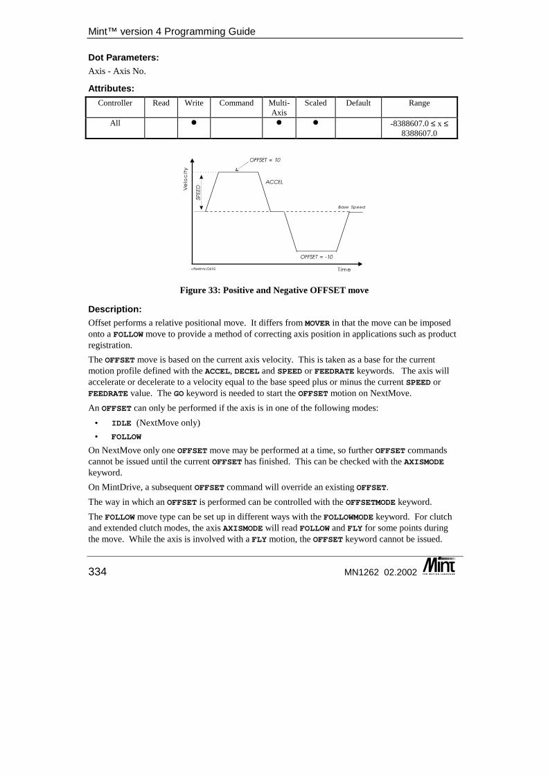
Mint™ version 4 Programming Guide
334 MN1262 02.2002
Dot Parameters: Axis - Axis No.
Attributes: Controller Read Write Command Multi-
Axis Scaled Default Range
All � � � -8388607.0 ≤ x ≤ 8388607.0
Figure 33: Positive and Negative OFFSET move
Description: Offset performs a relative positional move. It differs from MOVER in that the move can be imposed onto a FOLLOW move to provide a method of correcting axis position in applications such as product registration. The OFFSET move is based on the current axis velocity. This is taken as a base for the current motion profile defined with the ACCEL, DECEL and SPEED or FEEDRATE keywords. The axis will accelerate or decelerate to a velocity equal to the base speed plus or minus the current SPEED or FEEDRATE value. The GO keyword is needed to start the OFFSET motion on NextMove. An OFFSET can only be performed if the axis is in one of the following modes:
• IDLE (NextMove only)• FOLLOW
On NextMove only one OFFSET move may be performed at a time, so further OFFSET commands cannot be issued until the current OFFSET has finished. This can be checked with the AXISMODE keyword. On MintDrive, a subsequent OFFSET command will override an existing OFFSET. The way in which an OFFSET is performed can be controlled with the OFFSETMODE keyword. The FOLLOW move type can be set up in different ways with the FOLLOWMODE keyword. For clutch and extended clutch modes, the axis AXISMODE will read FOLLOW and FLY for some points during the move. While the axis is involved with a FLY motion, the OFFSET keyword cannot be issued.
Keyword Reference Guide
MN1262 02.2002 335
For clutch mode, this means that OFFSET’s cannot be performed during the initial ramp up to the gear ratio or ramp down to a halt. For extended clutch mode, OFFSET cannot be issued while the axis is changing gear ratio. While the axis is performing the OFFSET in extended clutch mode, a change in the gear ratio cannot be requested. If the STOP keyword is issued while the axis is performing an OFFSET on a FOLLOW move, the OFFSET move is immediately cancelled and the axis will stop according to the FOLLOWMODE of the move.
Example: MASTERSOURCE = _msENCODERMASTERCHANNEL = 2FOLLOWMODE = 0FOLLOW = 1LOOPIF IN.4 THEN OFFSET = 10 : GO : REM Load offset and start itPAUSE !(AXISMODE & _mdOFFSET) : REM Wait for offset to finish
ENDL
This starts a follow move and will perform an OFFSET if input 4 is active. It will wait until the OFFSET finishes before continuing. An offset move will continue until the specified move distance has been completed or the move is terminated by the user. The axis will ramp down to a halt at the DECEL rate.
Restrictions: The axis must be Enabled and must be in either the Follow or Offset modes.
Controller Specifics: On MintDrive the GO keyword is not required to initiate the move.
See also: ACCEL, FEEDRATE, FOLLOW, FOLLOWMODE, AXISMODE, MOVER, SPEED, OFFSETDISTANCE, OFFSETMODE, OFFSETSTATUS
OFFSETDISTANCE/OFD This is an advanced Mint feature. Full details can be found in the Mint v4 Advanced Programming Guide.
OFFSETMODE/OFM This is an advanced Mint feature. Full details can be found in the Mint v4 Advanced Programming Guide.
OFFSETSTATUS/OFS This is an advanced Mint feature. Full details can be found in the Mint v4 Advanced Programming Guide.
Mint™ version 4 Programming Guide
336 MN1262 02.2002
OR/| Purpose: To perform a logical or bitwise OR operation.
Controllers Supported: NextMove PCI NextMove PC NextMove BX MintDrive ServoNode 51
� � � � �
Format: <expression1> OR <expression2>
Description: Logical OR used in conditional statements and loops, for example:
WHILE IN.1 = 1 OR IN.2 = 0{statements}
ENDW
Logical OR is based on the following truth table
<expression1> <expression2> <expression1> OR <expression2>
0 0 0 0 1 1 1 0 1 1 1 1
OR is a bitwise or logical operator and can be used for setting bits in digital outputs. For example:
OUT = OUT | 15
will set bits 0 to 3 and leave bits 4 to 7 intact.
See also: AND, NOT, XOR
OUT/OT Purpose: To set a digital output or all the outputs.
Controllers Supported: NextMove PCI NextMove PC NextMove BX MintDrive ServoNode 51
� � � � �
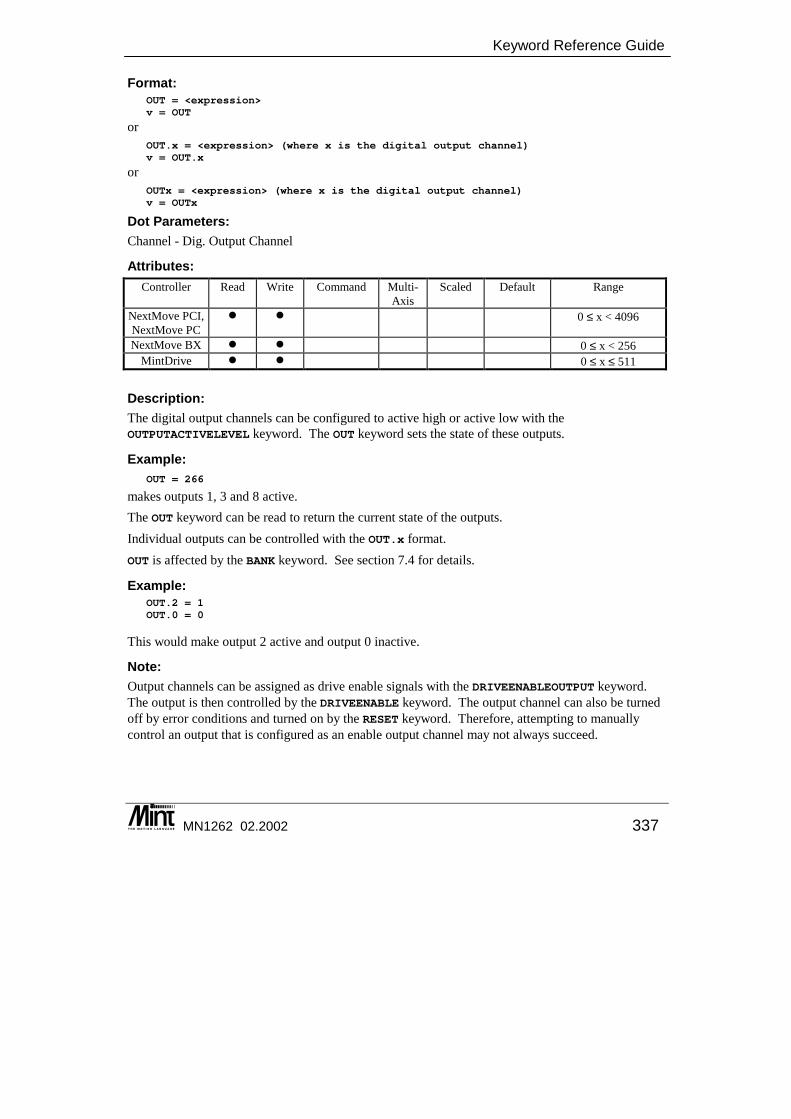
Keyword Reference Guide
MN1262 02.2002 337
Format: OUT = <expression>v = OUT
or OUT.x = <expression> (where x is the digital output channel)v = OUT.x
or OUTx = <expression> (where x is the digital output channel)v = OUTx
Dot Parameters: Channel - Dig. Output Channel
Attributes: Controller Read Write Command Multi-
Axis Scaled Default Range
NextMove PCI, NextMove PC
� � 0 ≤ x < 4096
NextMove BX � � 0 ≤ x < 256 MintDrive � � 0 ≤ x ≤ 511
Description: The digital output channels can be configured to active high or active low with the OUTPUTACTIVELEVEL keyword. The OUT keyword sets the state of these outputs.
Example: OUT = 266
makes outputs 1, 3 and 8 active. The OUT keyword can be read to return the current state of the outputs. Individual outputs can be controlled with the OUT.x format. OUT is affected by the BANK keyword. See section 7.4 for details.
Example: OUT.2 = 1OUT.0 = 0
This would make output 2 active and output 0 inactive.
Note: Output channels can be assigned as drive enable signals with the DRIVEENABLEOUTPUT keyword. The output is then controlled by the DRIVEENABLE keyword. The output channel can also be turned off by error conditions and turned on by the RESET keyword. Therefore, attempting to manually control an output that is configured as an enable output channel may not always succeed.
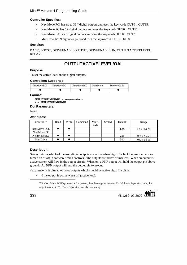
Mint™ version 4 Programming Guide
338 MN1262 02.2002
Controller Specifics: • NextMove PCI has up to 3616 digital outputs and uses the keywords OUT0 .. OUT35. • NextMove PC has 12 digital outputs and uses the keywords OUT0 .. OUT11. • NextMove BX has 8 digital outputs and uses the keywords OUT0 .. OUT7. • MintDrive has 9 digital outputs and uses the keywords OUT0 .. OUT8.
See also: BANK, BOOST, DRIVEENABLEOUTPUT, DRIVEENABLE, IN, OUTPUTACTIVELEVEL, RELAY
OUTPUTACTIVELEVEL/OAL Purpose: To set the active level on the digital outputs.
Controllers Supported: NextMove PCI NextMove PC NextMove BX MintDrive ServoNode 51
� � � � �
Format: OUTPUTACTIVELEVEL = <expression>v = OUTPUTACTIVELEVEL
Dot Parameters: None.
Attributes: Controller Read Write Command Multi-
Axis Scaled Default Range
NextMove PCI, NextMove PC
� � 4095 0 ≤ x ≤ 4095
NextMove BX � � 255 0 ≤ x ≤ 255 MintDrive � � 511 0 ≤ x ≤ 511
Description: Sets or returns which of the user digital outputs are active when high. Each of the user outputs are turned on or off in software which controls if the outputs are active or inactive. When an output is active current will flow in the output circuit. When on, a PNP output will hold the output pin above ground. An NPN output will pull the output pin to ground. <expression> is bitmap of those outputs which should be active high. If a bit is:
• 0 the output is active when off (active low).
16 If a NextMove PCI Expansion card is present, then the range increases to 23. With two Expansion cards, the range increases to 35. Each Expansion card also has a relay.
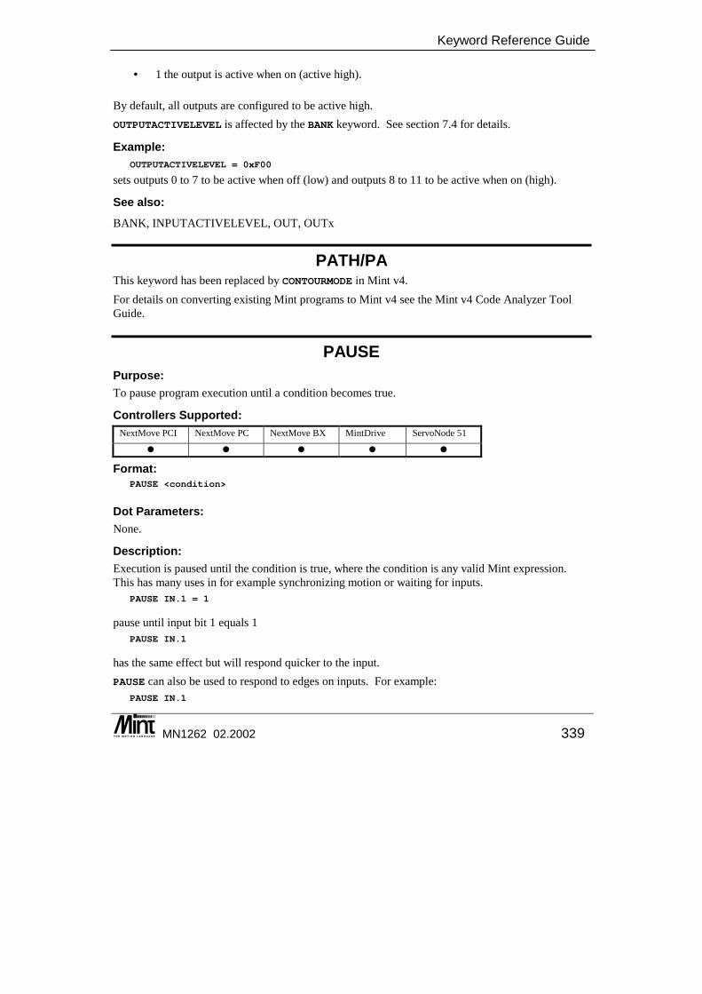
Keyword Reference Guide
MN1262 02.2002 339
• 1 the output is active when on (active high).
By default, all outputs are configured to be active high. OUTPUTACTIVELEVEL is affected by the BANK keyword. See section 7.4 for details.
Example: OUTPUTACTIVELEVEL = 0xF00
sets outputs 0 to 7 to be active when off (low) and outputs 8 to 11 to be active when on (high).
See also: BANK, INPUTACTIVELEVEL, OUT, OUTx
PATH/PA This keyword has been replaced by CONTOURMODE in Mint v4. For details on converting existing Mint programs to Mint v4 see the Mint v4 Code Analyzer Tool Guide.
PAUSE Purpose: To pause program execution until a condition becomes true.
Controllers Supported: NextMove PCI NextMove PC NextMove BX MintDrive ServoNode 51
� � � � �
Format: PAUSE <condition>
Dot Parameters: None.
Description: Execution is paused until the condition is true, where the condition is any valid Mint expression. This has many uses in for example synchronizing motion or waiting for inputs.
PAUSE IN.1 = 1
pause until input bit 1 equals 1 PAUSE IN.1
has the same effect but will respond quicker to the input. PAUSE can also be used to respond to edges on inputs. For example:
PAUSE IN.1
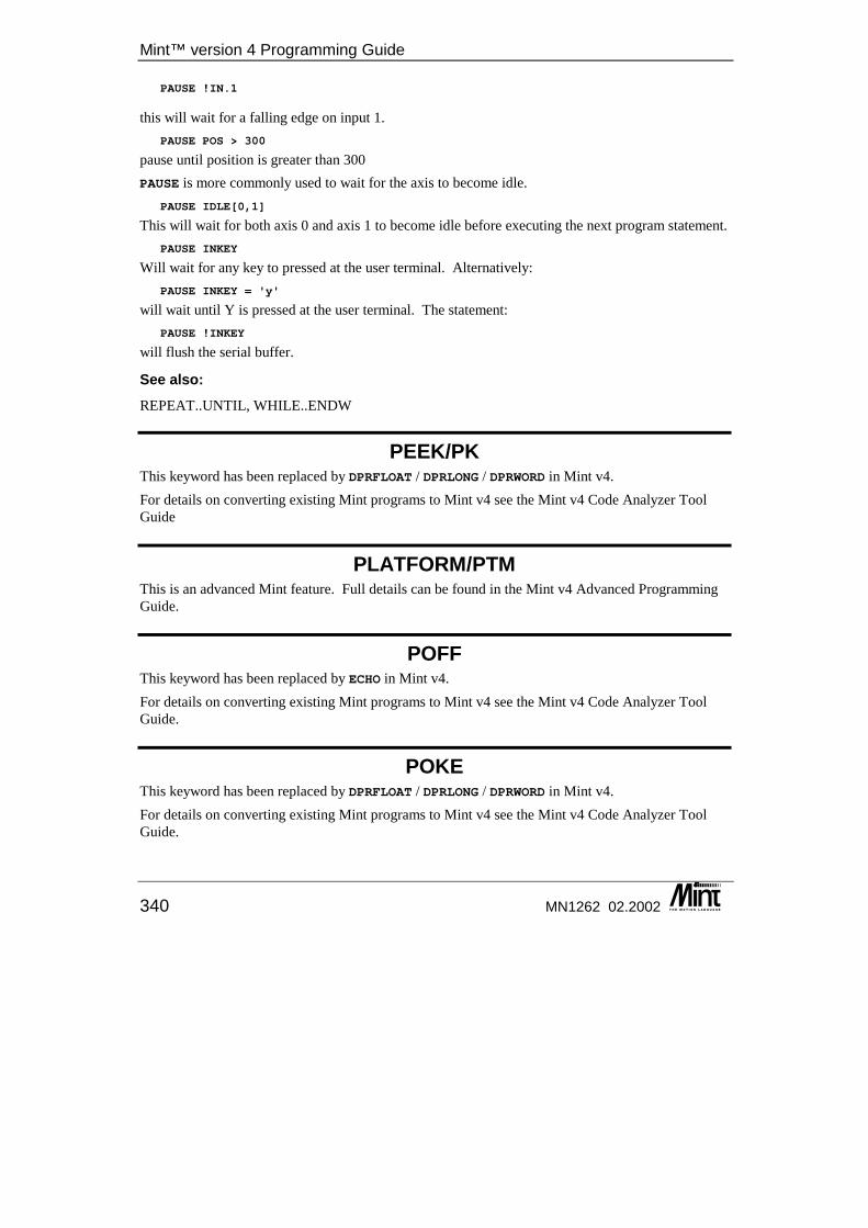
Mint™ version 4 Programming Guide
340 MN1262 02.2002
PAUSE !IN.1
this will wait for a falling edge on input 1. PAUSE POS > 300
pause until position is greater than 300 PAUSE is more commonly used to wait for the axis to become idle.
PAUSE IDLE[0,1]
This will wait for both axis 0 and axis 1 to become idle before executing the next program statement. PAUSE INKEY
Will wait for any key to pressed at the user terminal. Alternatively: PAUSE INKEY = 'y'
will wait until Y is pressed at the user terminal. The statement: PAUSE !INKEY
will flush the serial buffer.
See also: REPEAT..UNTIL, WHILE..ENDW
PEEK/PK This keyword has been replaced by DPRFLOAT / DPRLONG / DPRWORD in Mint v4. For details on converting existing Mint programs to Mint v4 see the Mint v4 Code Analyzer Tool Guide
PLATFORM/PTM This is an advanced Mint feature. Full details can be found in the Mint v4 Advanced Programming Guide.
POFF This keyword has been replaced by ECHO in Mint v4. For details on converting existing Mint programs to Mint v4 see the Mint v4 Code Analyzer Tool Guide.
POKE This keyword has been replaced by DPRFLOAT / DPRLONG / DPRWORD in Mint v4. For details on converting existing Mint programs to Mint v4 see the Mint v4 Code Analyzer Tool Guide.
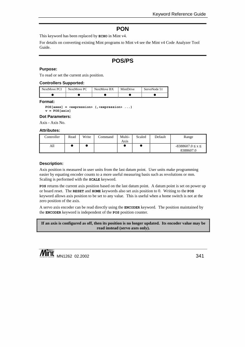
Keyword Reference Guide
MN1262 02.2002 341
PON This keyword has been replaced by ECHO in Mint v4. For details on converting existing Mint programs to Mint v4 see the Mint v4 Code Analyzer Tool Guide.
POS/PS Purpose: To read or set the current axis position.
Controllers Supported: NextMove PCI NextMove PC NextMove BX MintDrive ServoNode 51
� � � � �
Format: POS[axes] = <expression> {,<expression> ...}v = POS[axis]
Dot Parameters: Axis - Axis No.
Attributes: Controller Read Write Command Multi-
Axis Scaled Default Range
All � � � � -8388607.0 ≤ x ≤ 8388607.0
Description: Axis position is measured in user units from the last datum point. User units make programming easier by equating encoder counts to a more useful measuring basis such as revolutions or mm. Scaling is performed with the SCALE keyword. POS returns the current axis position based on the last datum point. A datum point is set on power up or board reset. The RESET and HOME keywords also set axis position to 0. Writing to the POS keyword allows axis position to be set to any value. This is useful when a home switch is not at the zero position of the axis. A servo axis encoder can be read directly using the ENCODER keyword. The position maintained by the ENCODER keyword is independent of the POS position counter.
If an axis is configured as off, then its position is no longer updated. Its encoder value may be read instead (servo axes only).
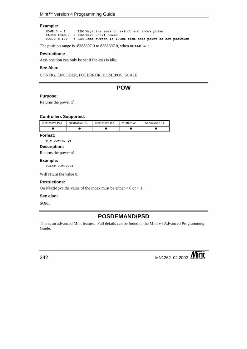
Mint™ version 4 Programming Guide
342 MN1262 02.2002
Example: HOME.0 = 1 : REM Negative seek on switch and index pulsePAUSE IDLE.0 : REM Wait until homedPOS.0 = 100 : REM Home switch is 100mm from zero point so set position
The position range is -8388607.0 to 8388607.0, when SCALE = 1.
Restrictions: Axis position can only be set if the axis is idle.
See Also: CONFIG, ENCODER, FOLERROR, HOMEPOS, SCALE
POW Purpose: Returns the power xy.
Controllers Supported: NextMove PCI NextMove PC NextMove BX MintDrive ServoNode 51
� � � � �
Format: v = POW(x, y)
Description: Returns the power xy.
Example: PRINT POW(2,3)
Will return the value 8.
Restrictions: On NextMove the value of the index must be either < 0 or > 1.
See also: SQRT
POSDEMAND/PSD This is an advanced Mint feature. Full details can be found in the Mint v4 Advanced Programming Guide.
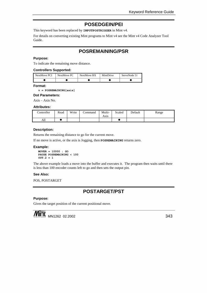
Keyword Reference Guide
MN1262 02.2002 343
POSEDGEIN/PEI This keyword has been replaced by INPUTPOSTRIGGER in Mint v4. For details on converting existing Mint programs to Mint v4 see the Mint v4 Code Analyzer Tool Guide.
POSREMAINING/PSR Purpose: To indicate the remaining move distance.
Controllers Supported: NextMove PCI NextMove PC NextMove BX MintDrive ServoNode 51
� � � � �
Format: v = POSREMAINING[axis]
Dot Parameters: Axis – Axis No.
Attributes: Controller Read Write Command Multi-
Axis Scaled Default Range
All � � Description: Returns the remaining distance to go for the current move. If no move is active, or the axis is Jogging, then POSREMAINING returns zero.
Example: MOVER = 10000 : GOPAUSE POSREMAINING < 100OUT.2 = 1
The above example loads a move into the buffer and executes it. The program then waits until there is less than 100 encoder counts left to go and then sets the output pin.
See Also: POS, POSTARGET
POSTARGET/PST Purpose: Gives the target position of the current positional move.

Mint™ version 4 Programming Guide
344 MN1262 02.2002
Controllers Supported: NextMove PCI NextMove PC NextMove BX MintDrive ServoNode 51
� � � � �
Format: v = POSTARGET[axis]
Dot Parameters: Axis – Axis No.
Attributes: Controller Read Write Command Multi-
Axis Scaled Default Range
All � �
Description: Returns the target position of the current positional move. The target position is defined as the end point for the move. For example:
MOVEA = 100 : GOPRINT POSTARGETMOVER = 50 : GOPRINT POSTARGET
The value of 100 followed by 150 will be printed.
See also: INCA, INCR, MOVEA, MOVER, POS, POSDEMAND, POSREMAINING
PRECISIONINCREMENT/PCI This is an advanced Mint feature. Full details can be found in the Mint v4 Advanced Programming Guide.
PRECISIONMODE/PCM This is an advanced Mint feature. Full details can be found in the Mint v4 Advanced Programming Guide.
PRECISIONOFFSET/PCO This is an advanced Mint feature. Full details can be found in the Mint v4 Advanced Programming Guide.
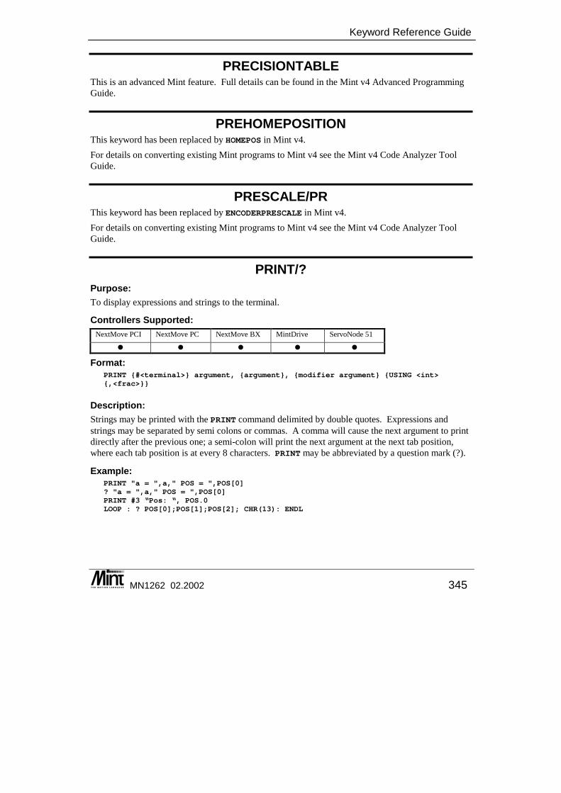
Keyword Reference Guide
MN1262 02.2002 345
PRECISIONTABLE This is an advanced Mint feature. Full details can be found in the Mint v4 Advanced Programming Guide.
PREHOMEPOSITION This keyword has been replaced by HOMEPOS in Mint v4. For details on converting existing Mint programs to Mint v4 see the Mint v4 Code Analyzer Tool Guide.
PRESCALE/PR This keyword has been replaced by ENCODERPRESCALE in Mint v4. For details on converting existing Mint programs to Mint v4 see the Mint v4 Code Analyzer Tool Guide.
PRINT/? Purpose: To display expressions and strings to the terminal.
Controllers Supported: NextMove PCI NextMove PC NextMove BX MintDrive ServoNode 51
� � � � �
Format: PRINT {#<terminal>} argument, {argument}, {modifier argument} {USING <int>{,<frac>}}
Description: Strings may be printed with the PRINT command delimited by double quotes. Expressions and strings may be separated by semi colons or commas. A comma will cause the next argument to print directly after the previous one; a semi-colon will print the next argument at the next tab position, where each tab position is at every 8 characters. PRINT may be abbreviated by a question mark (?).
Example: PRINT "a = ",a," POS = ",POS[0]? "a = ",a," POS = ",POS[0]PRINT #3 “Pos: “, POS.0LOOP : ? POS[0];POS[1];POS[2]; CHR(13): ENDL
Mint™ version 4 Programming Guide
346 MN1262 02.2002
The last example will repeatedly print the position of axes 0, 1 and 2 to the same line. Note the use of semi-colon to suppress line feeding. This is especially useful when writing to the LCD display. If a carriage return is performed on the last line of the display, the display will be cleared. Use a comma to suppress this. The USING parameter allows for formatted output. <int> is the number of decimal places to print (up to a maximum of 15) and <frac> is the number of fractional places to print (up to a maximum of 15). The printed number is prefixed with zeroes where necessary. If <frac> is less than the actual number of fractional digits then the fractional part will be truncated. If <int> is positive, the number will be printed without a sign. If <int> is negative, the number will be printed with a leading + or - sign. If <int> is less than the actual number of digits in an existing number, then <int> will be taken as the length of the actual integer part.
a = -123.5PRINT a USING -5,1
will display -00123.5 a = 123.5PRINT a USING 5,2
will display 0123.50 a = 123.5PRINT a USING 4
will display 0123 The TERMINAL keyword is used to control the default terminal channels. For example:
TERMINAL = _tmRS232 | _tmRS485PRINT “Serial Channels”
This will print “Serial Channels” to both the RS232 and RS485 channels (if supported). The device (#) re-director can also be used to direct characters to the chosen channels:
PRINT #3 “Serial Channels”
In addition to the PRINT keyword, Mint also has the LINE keyword for terminal output. The LINE keyword is used, in conjunction with the KeypadNode display, to write to a specified line and clearing all characters to the end of that line. LINE will replace:
LOCATE 1,2 : REM Locate to line 2PRINT "A Message “ REM Print message and clear rest of line
with: LINE 2, "A Message"
LINE accepts all the parameters that PRINT uses.

Keyword Reference Guide
MN1262 02.2002 347
Modifiers can be used to convert numbers between different data formats. Modifiers are:
Modifier Use DEC print number decimal format HEX print number in hexadecimal format BIN print number in binary format
PRINT HEX 255
will display 0xFF PRINT BIN 0x1A
will display 11010.
See also: CHR, INPUT, INKEY, LINE, LOCATE, TERMINAL, TERMINALMODE
PROFILETIME/PT This is an advanced Mint feature. Full details can be found in the Mint v4 Advanced Programming Guide.
PROTECT Purpose: To protect a Mint program and configuration file from unauthorized viewing or deletion.
Controllers Supported: NextMove PCI NextMove PC NextMove BX MintDrive ServoNode 51
� � � � �
Format: PROTECT <password>
PROTECT = <value>
Description: Provides a method of password protecting programs on controllers in the field to prevent non-authorized modification of programs and potential software theft. Password protection prevents access to the program and configuration buffers without first typing a password at the command line. PROTECT must be added as the fist line of the program buffer before all comments. The password can be any string of up to 255 alphanumeric characters and is not case sensitive.
Example: PROTECT tincanREMREM Simple Mint ProgramREM
Mint™ version 4 Programming Guide
348 MN1262 02.2002
DIM a?"Hello"LOOP?"Press a key...",a = 0WHILE a = 0a = INKEY
ENDW?"You pressed ASCII code : ",a
ENDLEND
RELAY = _off : REM Disable the drivesPAUSE INKEY : REM Move motors until a key is pressedRELAY = _on : REM Enable the drives
Password checking may be turned on and off by writing to PROTECT: PROTECT = _on : REM Write 1 to turn on checking
PROTECT = _off : REM Write 0 to turn off checking
See section 9.3 for full details on PROTECT.
See also: AUTO
PULSE/PU This keyword has been replaced by STEPPERIO in Mint v4. For details on converting existing Mint programs to Mint v4 see the Mint v4 Code Analyzer Tool Guide.
PWMONTIME/PWM This is an advanced Mint feature. Full details can be found in the Mint v4 Advanced Programming Guide.
PWMPERIOD/PWP This is an advanced Mint feature. Full details can be found in the Mint v4 Advanced Programming Guide.
RAMP/RP This keyword has been replaced by SRAMP in Mint v4. For details on converting existing Mint programs to Mint v4 see the Mint v4 Code Analyzer Tool Guide.
Keyword Reference Guide
MN1262 02.2002 349
READKEY/RK For details on this keyword see the Mint v4 CAN Programming Guide.
RELAY/RL Purpose: To enable and disable the relay.
Controllers Supported: NextMove PCI NextMove PC NextMove BX MintDrive ServoNode 51
� � �
Format: RELAY.channel = <expression>value = RELAY.channel
Dot Parameters: None.
Attributes: Controller Read Write Command Multi-
Axis Scaled Default Range
NextMove � 0 or 1 Description: Provides direct control over the relay output. The RELAY keyword allows the relay to be turned on or off. RELAY accepts one of two values, 0 to turn the enable signal off, and 1 to turn it on. An axis may be configured to use the relay as its drive enable output signal with the DRIVEENABLEOUTPUT keyword. This will prevent the relay from being accessed directly with the RELAY keyword. The DRIVENABLE and RESET keywords provide control of the relay in this situation. The relay can also be used as the global error output signal.
Example: RELAY = _off : REM De-activate relayPAUSE INKEY : REM Wait for a key pressRELAY = _on : REM Activate the relay
See also: BANK, DRIVEENABLE, DRIVEENABLEOUTPUT, ERR, GLOBALERROROUTPUT, RESET

Mint™ version 4 Programming Guide
350 MN1262 02.2002
REM Purpose: To place comments into a program file.
Controllers Supported: NextMove PCI NextMove PC NextMove BX MintDrive ServoNode 51
� � � � �
Format: REM {string}
Description: Allows remarks to be placed in a program file. All characters after the REM until the end of line are ignored. If remarks are to be placed after a line of code, the REM should be separated from the statement by a colon although this is not necessary. For example:
PRINT : REM this prints a blank linePRINT REM This also prints a blank line
REMOTEADC/RAD For details on this keyword see the Mint v4 CAN Programming Guide.
REMOTEADCDELTA/RDL For details on this keyword see the Mint v4 CAN Programming Guide.
REMOTEDAC/RDC For details on this keyword see the Mint v4 CAN Programming Guide.
REMOTEDEBOUNCE/RD For details on this keyword see the Mint v4 CAN Programming Guide.
REMOTEESTOP/RES For details on this keyword see the Mint v4 CAN Programming Guide.
REMOTEEVENTMODE/RVM This keyword has been replaced by REMOTEMODE in Mint v4. For details on converting existing Mint programs to Mint v4 see the Mint v4 Code Analyzer Tool Guide.
Keyword Reference Guide
MN1262 02.2002 351
REMOTEIN/RI For details on this keyword see the Mint v4 CAN Programming Guide.
REMOTEINPUTACTIVELEVEL/RIA For details on this keyword see the Mint v4 CAN Programming Guide.
REMOTEINX/RIX For details on this keyword see the Mint v4 CAN Programming Guide.
REMOTEMODE/RM For details on this keyword see the Mint v4 CAN Programming Guide.
REMOTEOUT/RO For details on this keyword see the Mint v4 CAN Programming Guide.
REMOTEOUTPUTACTIVELEVEL/ROA For details on this keyword see the Mint v4 CAN Programming Guide.
REMOTEOUTPUTERROR/ROE For details on this keyword see the Mint v4 CAN Programming Guide.
REMOTEOUTX/ROX For details on this keyword see the Mint v4 CAN Programming Guide.
REMOTERESET/RR For details on this keyword see the Mint v4 CAN Programming Guide.
REMOTESETUP/RMS For details on this keyword see the Mint v4 CAN Programming Guide.
REMOTESTATUS/RS For details on this keyword see the Mint v4 CAN Programming Guide.
Mint™ version 4 Programming Guide
352 MN1262 02.2002
REPEAT .. UNTIL Purpose: To perform a loop until a condition becomes true.
Controllers Supported: NextMove PCI NextMove PC NextMove BX MintDrive ServoNode 51
� � � � �
Format: REPEAT{statements}
UNTIL <condition>
Description: Executes the statements until the condition becomes true. In Mint any value other than 0 is defined as true and only 0 is false. A REPEAT loop can be terminated by setting the condition after UNTIL to zero. By defining a variable, the loop could terminate for a number of conditions.
Example: REPEATIF IN.1 THEN EXIT
UNTIL POS.2 > 20.0
This code would wait until the position of axis 2 was greater than 20. The loop will exit early if digital input 1 becomes active. A repeat loop will always execute at least once. REPEAT .. UNTIL loops can be nested up to 50 levels. EXIT can be used to prematurely terminate the loop.
See also: EXIT, FOR..NEXT, LOOP..ENDL, PAUSE, WHILE..ENDW
RESET/RE Purpose: To clear the motion error, set the position to zero and re-enable the drive.
Controllers Supported: NextMove PCI NextMove PC NextMove BX MintDrive ServoNode 51
� � � � �
Format: RESET[axes]
Dot Parameters: Axis - Axis No.
Keyword Reference Guide
MN1262 02.2002 353
Attributes: Controller Read Write Command Multi-
Axis Scaled Default Range
All � �
Description: Clears all motion errors and sets the axis position to zero. It also enables the drive enable output if one has been assigned with the DRIVEENABLEOUTPUT keyword. On MintDrive and ServoNode 51, the drive stage will be enabled. To clear motion errors but retain axis position, use CANCEL followed by DRIVEENABLE. RESET will also crash stop any motion on the axis.
Example: IF AXISERROR.0 THEN RESET.0
If axis 0 has a motion error then reset the axis. RESETALL can be used to RESET all axes at once. DEFAULT can be used to return all motion variables to their power up values.
See also: AXISERROR, CANCEL, CONFIG, DEFAULT, DRIVEENABLE, ERR, RELAY
RESETALL/RA Purpose: To perform a RESET on all axes.
Controllers Supported: NextMove PCI NextMove PC NextMove BX MintDrive ServoNode 51
� � � � �
Format: RESETALL
Dot Parameters: None.
Attributes: Controller Read Write Command Multi-
Axis Scaled Default Range
All � � Description: This RESETALL keyword is equivalent to issuing a RESET command to every axis but requires no axis parameters.

Mint™ version 4 Programming Guide
354 MN1262 02.2002
See Also: RESET
RETURN Purpose: To return program execution from the subroutine to the calling GOSUB.
Controllers Supported: NextMove PCI NextMove PC NextMove BX MintDrive ServoNode 51
� � � � �
Format: RETURN
Description: Returns execution of the program to the line or statement following the calling GOSUB statement.
GOSUB label1END#label1? “A Label”
RETURN
RETURN can also be used to return execution from the subroutine on a condition. For example: GOSUB label1...#label1IF IN1 THEN RETURN : REM Return from subroutine if IN1 becomes true...
RETURN
See also: GOSUB
REVLIMITIN/RLI This keyword has been replaced by LIMITREVERSEINPUT in Mint v4. For details on converting existing Mint programs to Mint v4 see the Mint v4 Code Analyzer Tool Guide.
REVSOFTLIMIT/RSL This keyword has been replaced by SOFTLIMITREVERSE in Mint v4. For details on converting existing Mint programs to Mint v4 see the Mint v4 Code Analyzer Tool Guide.
Keyword Reference Guide
MN1262 02.2002 355
RUN Purpose: To execute the program from the command line or re-execute the currently running program.
Controllers Supported: NextMove PCI NextMove PC NextMove BX MintDrive ServoNode 51
� � � � �
Format: RUN {<buffer>}
Description: Begins program execution from the command line or re-executes the currently running program. Either the configuration buffer or the program buffer can be run by passing the name of the buffer to run: RUN CON – will execute only the configuration buffer. RUN PROG – will execute only the program buffer.
If the <buffer> parameter is not passed, then the configuration file is executed first followed by the program file.
Example: RUN PROG
The above example will run only the program file, the configuration file will not be executed. If RUN is encountered in a file (configuration or program) during execution, only the current file is re-executed. This is useful for re-executing the program after an error.
Example: #ONERROR : REM Re-execute the program on an errorRESET[0,1,2]RUN
RETURN
Execution of the Configuration file/buffer will delete all pre-defined array data. To prevent loss of pre-defined array data the configuration buffer should not be executed.
See also: AUTO
SCALE/SF Purpose: To scale axis encoder counts / steps, into user defined units.
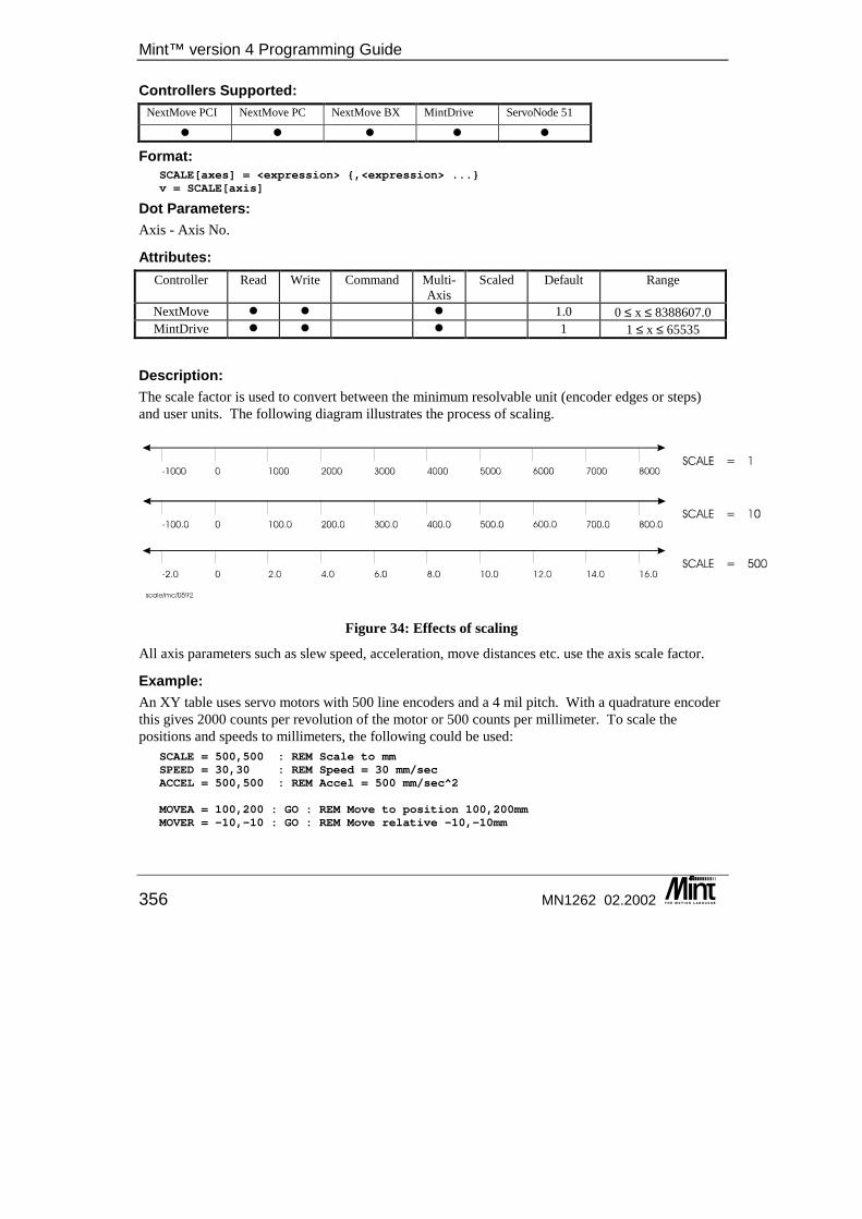
Mint™ version 4 Programming Guide
356 MN1262 02.2002
Controllers Supported: NextMove PCI NextMove PC NextMove BX MintDrive ServoNode 51
� � � � �
Format: SCALE[axes] = <expression> {,<expression> ...}v = SCALE[axis]
Dot Parameters: Axis - Axis No.
Attributes: Controller Read Write Command Multi-
Axis Scaled Default Range
NextMove � � � 1.0 0 ≤ x ≤ 8388607.0 MintDrive � � � 1 1 ≤ x ≤ 65535
Description: The scale factor is used to convert between the minimum resolvable unit (encoder edges or steps) and user units. The following diagram illustrates the process of scaling.
Figure 34: Effects of scaling
All axis parameters such as slew speed, acceleration, move distances etc. use the axis scale factor.
Example: An XY table uses servo motors with 500 line encoders and a 4 mil pitch. With a quadrature encoder this gives 2000 counts per revolution of the motor or 500 counts per millimeter. To scale the positions and speeds to millimeters, the following could be used:
SCALE = 500,500 : REM Scale to mmSPEED = 30,30 : REM Speed = 30 mm/secACCEL = 500,500 : REM Accel = 500 mm/sec^2
MOVEA = 100,200 : GO : REM Move to position 100,200mmMOVER = -10,-10 : GO : REM Move relative -10,-10mm
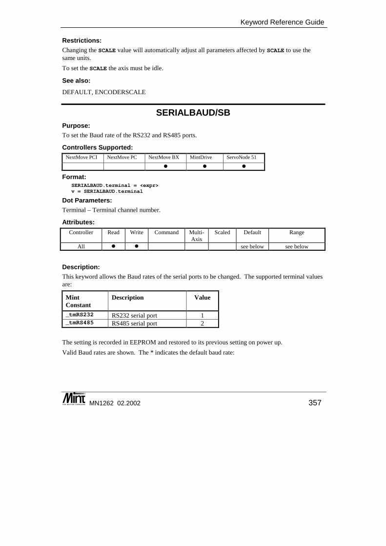
Keyword Reference Guide
MN1262 02.2002 357
Restrictions: Changing the SCALE value will automatically adjust all parameters affected by SCALE to use the same units. To set the SCALE the axis must be idle.
See also: DEFAULT, ENCODERSCALE
SERIALBAUD/SB Purpose: To set the Baud rate of the RS232 and RS485 ports.
Controllers Supported: NextMove PCI NextMove PC NextMove BX MintDrive ServoNode 51
� � �
Format: SERIALBAUD.terminal = <expr>v = SERIALBAUD.terminal
Dot Parameters: Terminal – Terminal channel number.
Attributes: Controller Read Write Command Multi-
Axis Scaled Default Range
All � � see below see below
Description: This keyword allows the Baud rates of the serial ports to be changed. The supported terminal values are:
Mint Constant
Description Value
_tmRS232 RS232 serial port 1 _tmRS485 RS485 serial port 2
The setting is recorded in EEPROM and restored to its previous setting on power up. Valid Baud rates are shown. The * indicates the default baud rate:
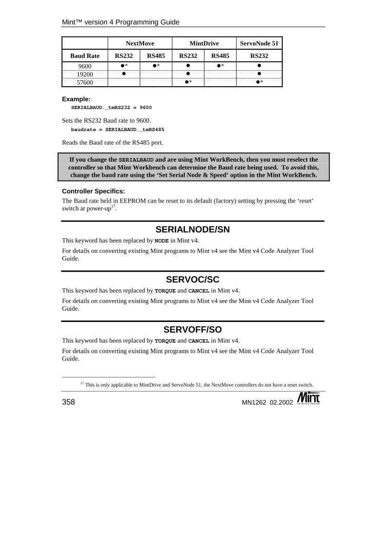
Mint™ version 4 Programming Guide
358 MN1262 02.2002
NextMove MintDrive ServoNode 51
Baud Rate RS232 RS485 RS232 RS485 RS232 9600 �* �* � �* �
19200 � � � 57600 �* �*
Example: SERIALBAUD._tmRS232 = 9600
Sets the RS232 Baud rate to 9600. baudrate = SERIALBAUD._tmRS485
Reads the Baud rate of the RS485 port.
If you change the SERIALBAUD and are using Mint WorkBench, then you must reselect the controller so that Mint Workbench can determine the Baud rate being used. To avoid this, change the baud rate using the ‘Set Serial Node & Speed’ option in the Mint WorkBench.
Controller Specifics: The Baud rate held in EEPROM can be reset to its default (factory) setting by pressing the ‘reset’ switch at power-up17.
SERIALNODE/SN This keyword has been replaced by NODE in Mint v4. For details on converting existing Mint programs to Mint v4 see the Mint v4 Code Analyzer Tool Guide.
SERVOC/SC This keyword has been replaced by TORQUE and CANCEL in Mint v4. For details on converting existing Mint programs to Mint v4 see the Mint v4 Code Analyzer Tool Guide.
SERVOFF/SO This keyword has been replaced by TORQUE and CANCEL in Mint v4. For details on converting existing Mint programs to Mint v4 see the Mint v4 Code Analyzer Tool Guide.
17 This is only applicable to MintDrive and ServoNode 51, the NextMove controllers do not have a reset switch.

Keyword Reference Guide
MN1262 02.2002 359
SERVON/SV This keyword has been replaced by TORQUE and CANCEL in Mint v4. For details on converting existing Mint programs to Mint v4 see the Mint v4 Code Analyzer Tool Guide.
SEXTANT/SEX Purpose: To read and write the sextant table for a motor.
Controllers Supported: NextMove PCI NextMove PC NextMove BX MintDrive ServoNode 51
�
Format: SEXTANT = <expression>value = SEXTANT
Attributes: Controller Read Write Command Multi-
Axis Scaled Default Range
ServoNode 51 � 1 – 6
Description: ServoNode 51 uses a default Sextant/Hall mapping appropriate to Baldor BSM brushless motors. This mapping can be changed, so motors with different sextant/Hall mapping can be used. This is achieved by forcing the motor to a sextant and determining which Hall is active. As there are 3 Hall effect transducers (U, V & W), each being on or off, then there are 8 possible states. See the ServoNode 51 Installation manual for details on Hall / Sextant mapping.
See also: HALL
SIN Purpose: To return the sine of an angle.
Controllers Supported: NextMove PCI NextMove PC NextMove BX MintDrive ServoNode 51
� � � � �
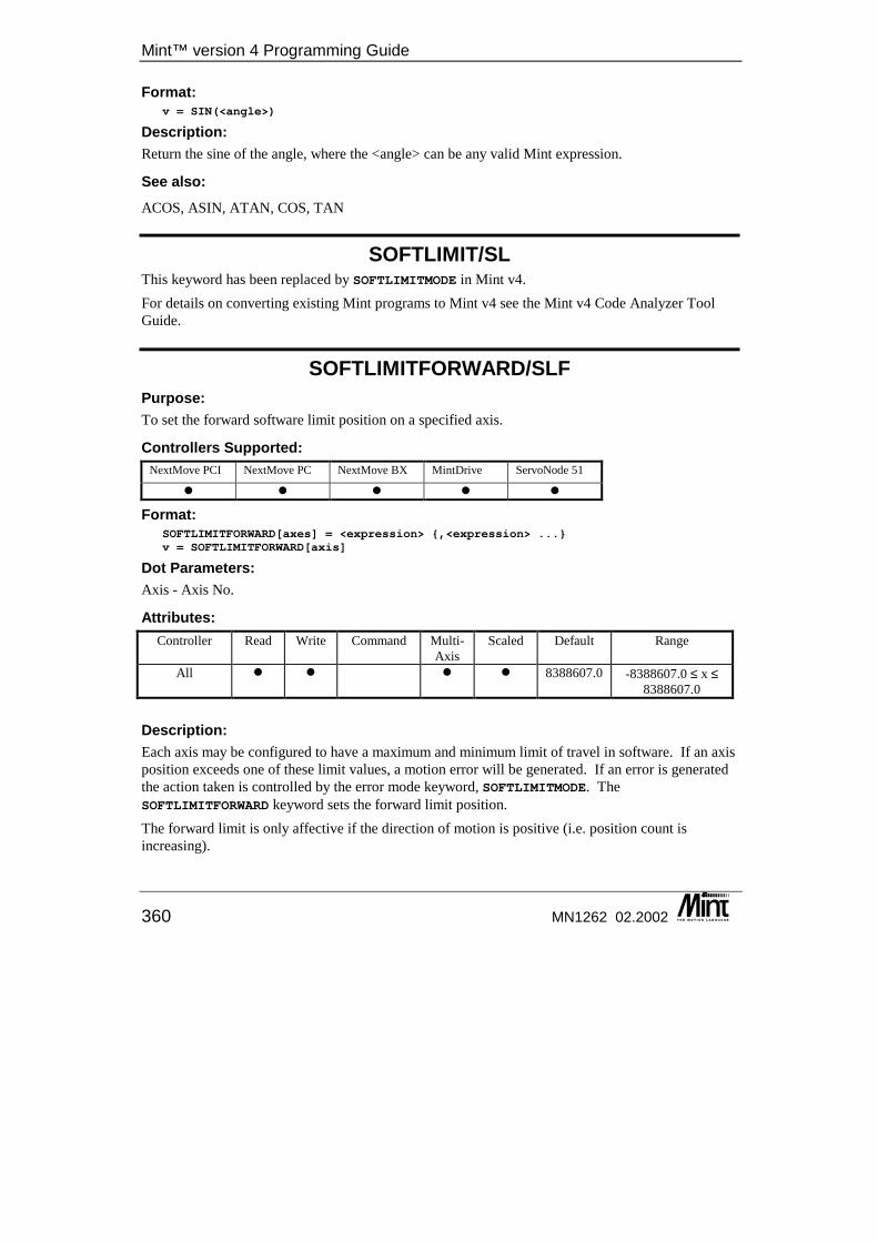
Mint™ version 4 Programming Guide
360 MN1262 02.2002
Format: v = SIN(<angle>)
Description: Return the sine of the angle, where the <angle> can be any valid Mint expression.
See also: ACOS, ASIN, ATAN, COS, TAN
SOFTLIMIT/SL This keyword has been replaced by SOFTLIMITMODE in Mint v4. For details on converting existing Mint programs to Mint v4 see the Mint v4 Code Analyzer Tool Guide.
SOFTLIMITFORWARD/SLF Purpose: To set the forward software limit position on a specified axis.
Controllers Supported: NextMove PCI NextMove PC NextMove BX MintDrive ServoNode 51
� � � � �
Format: SOFTLIMITFORWARD[axes] = <expression> {,<expression> ...}v = SOFTLIMITFORWARD[axis]
Dot Parameters: Axis - Axis No.
Attributes: Controller Read Write Command Multi-
Axis Scaled Default Range
All � � � � 8388607.0 -8388607.0 ≤ x ≤ 8388607.0
Description: Each axis may be configured to have a maximum and minimum limit of travel in software. If an axis position exceeds one of these limit values, a motion error will be generated. If an error is generated the action taken is controlled by the error mode keyword, SOFTLIMITMODE. The SOFTLIMITFORWARD keyword sets the forward limit position. The forward limit is only affective if the direction of motion is positive (i.e. position count is increasing).
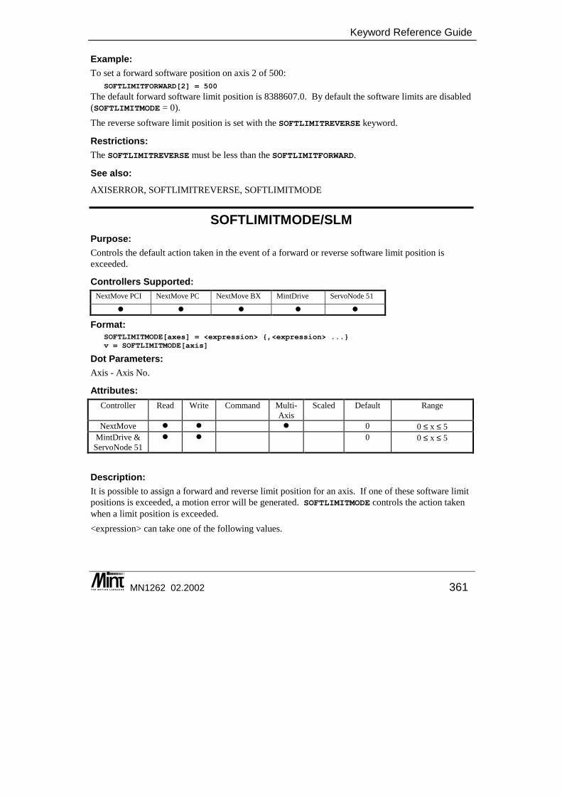
Keyword Reference Guide
MN1262 02.2002 361
Example: To set a forward software position on axis 2 of 500:
SOFTLIMITFORWARD[2] = 500
The default forward software limit position is 8388607.0. By default the software limits are disabled (SOFTLIMITMODE = 0). The reverse software limit position is set with the SOFTLIMITREVERSE keyword.
Restrictions: The SOFTLIMITREVERSE must be less than the SOFTLIMITFORWARD.
See also: AXISERROR, SOFTLIMITREVERSE, SOFTLIMITMODE
SOFTLIMITMODE/SLM Purpose: Controls the default action taken in the event of a forward or reverse software limit position is exceeded.
Controllers Supported: NextMove PCI NextMove PC NextMove BX MintDrive ServoNode 51
� � � � �
Format: SOFTLIMITMODE[axes] = <expression> {,<expression> ...}v = SOFTLIMITMODE[axis]
Dot Parameters: Axis - Axis No.
Attributes: Controller Read Write Command Multi-
Axis Scaled Default Range
NextMove � � � 0 0 ≤ x ≤ 5 MintDrive &
ServoNode 51 � � 0 0 ≤ x ≤ 5
Description: It is possible to assign a forward and reverse limit position for an axis. If one of these software limit positions is exceeded, a motion error will be generated. SOFTLIMITMODE controls the action taken when a limit position is exceeded. <expression> can take one of the following values.
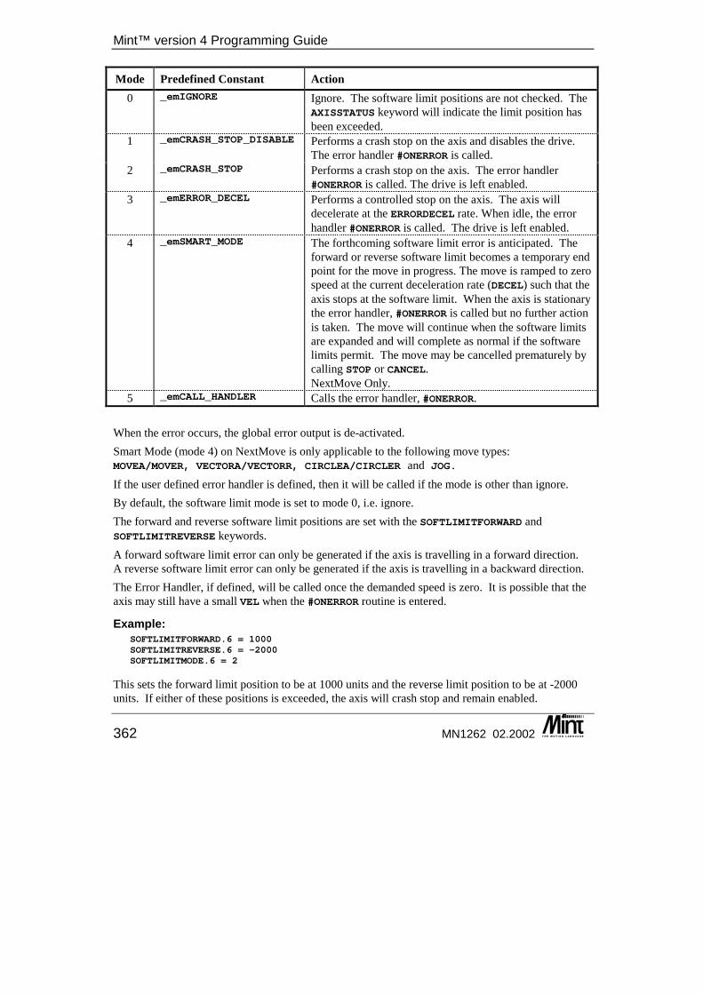
Mint™ version 4 Programming Guide
362 MN1262 02.2002
Mode Predefined Constant Action 0 _emIGNORE Ignore. The software limit positions are not checked. The
AXISSTATUS keyword will indicate the limit position has been exceeded.
1 _emCRASH_STOP_DISABLE Performs a crash stop on the axis and disables the drive. The error handler #ONERROR is called.
2 _emCRASH_STOP Performs a crash stop on the axis. The error handler #ONERROR is called. The drive is left enabled.
3 _emERROR_DECEL Performs a controlled stop on the axis. The axis will decelerate at the ERRORDECEL rate. When idle, the error handler #ONERROR is called. The drive is left enabled.
4 _emSMART_MODE The forthcoming software limit error is anticipated. The forward or reverse software limit becomes a temporary end point for the move in progress. The move is ramped to zero speed at the current deceleration rate (DECEL) such that the axis stops at the software limit. When the axis is stationary the error handler, #ONERROR is called but no further action is taken. The move will continue when the software limits are expanded and will complete as normal if the software limits permit. The move may be cancelled prematurely by calling STOP or CANCEL. NextMove Only.
5 _emCALL_HANDLER Calls the error handler, #ONERROR. When the error occurs, the global error output is de-activated. Smart Mode (mode 4) on NextMove is only applicable to the following move types: MOVEA/MOVER, VECTORA/VECTORR, CIRCLEA/CIRCLER and JOG.
If the user defined error handler is defined, then it will be called if the mode is other than ignore. By default, the software limit mode is set to mode 0, i.e. ignore. The forward and reverse software limit positions are set with the SOFTLIMITFORWARD and SOFTLIMITREVERSE keywords. A forward software limit error can only be generated if the axis is travelling in a forward direction. A reverse software limit error can only be generated if the axis is travelling in a backward direction. The Error Handler, if defined, will be called once the demanded speed is zero. It is possible that the axis may still have a small VEL when the #ONERROR routine is entered.
Example: SOFTLIMITFORWARD.6 = 1000SOFTLIMITREVERSE.6 = -2000SOFTLIMITMODE.6 = 2
This sets the forward limit position to be at 1000 units and the reverse limit position to be at -2000 units. If either of these positions is exceeded, the axis will crash stop and remain enabled.
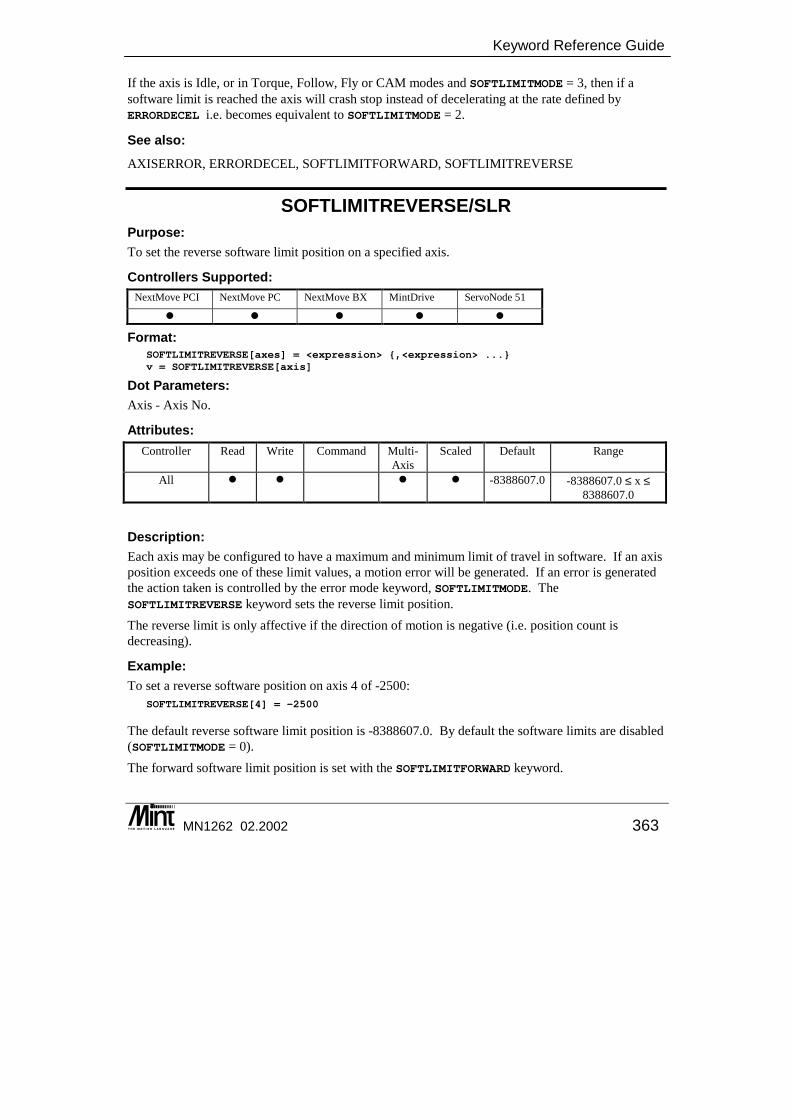
Keyword Reference Guide
MN1262 02.2002 363
If the axis is Idle, or in Torque, Follow, Fly or CAM modes and SOFTLIMITMODE = 3, then if a software limit is reached the axis will crash stop instead of decelerating at the rate defined by ERRORDECEL i.e. becomes equivalent to SOFTLIMITMODE = 2.
See also: AXISERROR, ERRORDECEL, SOFTLIMITFORWARD, SOFTLIMITREVERSE
SOFTLIMITREVERSE/SLR Purpose: To set the reverse software limit position on a specified axis.
Controllers Supported: NextMove PCI NextMove PC NextMove BX MintDrive ServoNode 51
� � � � �
Format: SOFTLIMITREVERSE[axes] = <expression> {,<expression> ...}v = SOFTLIMITREVERSE[axis]
Dot Parameters: Axis - Axis No.
Attributes: Controller Read Write Command Multi-
Axis Scaled Default Range
All � � � � -8388607.0 -8388607.0 ≤ x ≤ 8388607.0
Description: Each axis may be configured to have a maximum and minimum limit of travel in software. If an axis position exceeds one of these limit values, a motion error will be generated. If an error is generated the action taken is controlled by the error mode keyword, SOFTLIMITMODE. The SOFTLIMITREVERSE keyword sets the reverse limit position. The reverse limit is only affective if the direction of motion is negative (i.e. position count is decreasing).
Example: To set a reverse software position on axis 4 of -2500:
SOFTLIMITREVERSE[4] = -2500
The default reverse software limit position is -8388607.0. By default the software limits are disabled (SOFTLIMITMODE = 0). The forward software limit position is set with the SOFTLIMITFORWARD keyword.
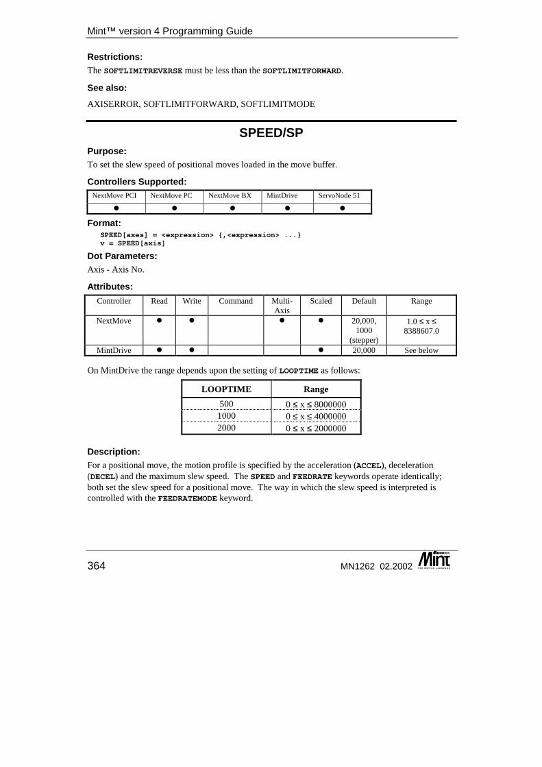
Mint™ version 4 Programming Guide
364 MN1262 02.2002
Restrictions: The SOFTLIMITREVERSE must be less than the SOFTLIMITFORWARD.
See also: AXISERROR, SOFTLIMITFORWARD, SOFTLIMITMODE
SPEED/SP Purpose: To set the slew speed of positional moves loaded in the move buffer.
Controllers Supported: NextMove PCI NextMove PC NextMove BX MintDrive ServoNode 51
� � � � �
Format: SPEED[axes] = <expression> {,<expression> ...}v = SPEED[axis]
Dot Parameters: Axis - Axis No.
Attributes: Controller Read Write Command Multi-
Axis Scaled Default Range
NextMove � � � � 20,000, 1000
(stepper)
1.0 ≤ x ≤ 8388607.0
MintDrive � � � 20,000 See below
On MintDrive the range depends upon the setting of LOOPTIME as follows:
LOOPTIME Range 500 0 ≤ x ≤ 8000000
1000 0 ≤ x ≤ 4000000 2000 0 ≤ x ≤ 2000000
Description: For a positional move, the motion profile is specified by the acceleration (ACCEL), deceleration (DECEL) and the maximum slew speed. The SPEED and FEEDRATE keywords operate identically; both set the slew speed for a positional move. The way in which the slew speed is interpreted is controlled with the FEEDRATEMODE keyword.
Keyword Reference Guide
MN1262 02.2002 365
In ‘speed mode’ (as set by the FEEDRATEMODE keyword), the SPEED is applied to all positional moves, including those already in the buffer. In ‘feedrate mode’ the SPEED only applies to new moves loaded into the move buffer. Moves already in the move buffer will be executed at the slew speed they were loaded with. The SPEED keyword is useful in making Mint programs easier to read. When in ‘feedrate mode’, the FEEDRATE keyword is used to set slew speed. When in ‘speed mode’ the SPEED keyword is used to set slew speed. Reading SPEED returns the last value written. It does not returned the slew speed of the currently executing move if in ‘feedrate mode’. See FEEDRATEMODE for further details. SPEED is applicable with the following move types:
• MOVEA/MOVER • VECTORA/VECTORR • CIRCLEA/CIRCLER • OFFSET • HOLDTOANALOG
The slew speed set with SPEED may not be achieved if the move length is not sufficient to achieve a trapezoidal profile. If the SPEED is changed while in ‘speed mode’, it will affect all moves loaded into the buffer. The move in progress will ramp using the current ACCEL and DECEL values to the new SPEED. Slew speed can also be affected by the FEEDRATEOVERRIDE keyword which allows the SPEED value to be modified by a percentage multiplier. See FEEDRATEOVERRIDE for further details.
Example: SPEED = 20 : REM Set slew speed to 20 user units/secondFEEDRATE = 20 : REM Set slew speed to 20 user units/second
Both of these are equivalent. FEEDRATEMODE = 0 : REM Set ‘speed mode’SPEED = 50 : REM Slew speed of 50 uu/sMOVER = 20SPEED = 30 : REM Set slew speed to 30 uu/sMOVER = 20GO
In the above example, both moves are executed at a slew speed of 30 user units per second. This is because the FEEDRATEMODE keyword was used to set the move buffer to ‘speed mode’. Therefore, any change in the SPEED affects moves already loaded into the buffer.
See also: ACCEL, DECEL, FEEDRATE, FEEDRATEMODE, FEEDRATEOVERRIDE, MAXSPEED
Mint™ version 4 Programming Guide
366 MN1262 02.2002
SPEEDDEMAND/SPD Purpose: To apply a constant demand to the speed control loop.
Controllers Supported: NextMove PCI NextMove PC NextMove BX MintDrive ServoNode 51
� �
Format: SPEEDDEMAND[axes] = <expression> {,<expression> ...}v = SPEEDDEMAND[axis]
Dot Parameters: Axis - Axis No.
Attributes: Controller Read Write Command Multi-
Axis Scaled Default Range
MintDrive � � 0 -100 ≤ x ≤ 100
Description: Applies a constant speed demand to the speed control loop. The demand is specified as a percentage of the maximum motor rated speed.
Example: SPEEDDEMAND = 50WAIT = 1000SPEEDDEMAND = 0
The above example runs the motor at 50% of its maximum speed for 1 second.
See also: MOTORSPEEDMAX
SPLINE/SPL This is an advanced Mint feature. Full details can be found in the Mint v4 Advanced Programming Guide.
SPLINEEND/SPE This is an advanced Mint feature. Full details can be found in the Mint v4 Advanced Programming Guide.
Keyword Reference Guide
MN1262 02.2002 367
SPLINEINDEX/SPI This is an advanced Mint feature. Full details can be found in the Mint v4 Advanced Programming Guide.
SPLINESTART/SPS This is an advanced Mint feature. Full details can be found in the Mint v4 Advanced Programming Guide.
SPLINESUSPENDTIME/SPD This is an advanced Mint feature. Full details can be found in the Mint v4 Advanced Programming Guide.
SPLINETABLE This is an advanced Mint feature. Full details can be found in the Mint v4 Advanced Programming Guide.
SPLINETIME/SPT This is an advanced Mint feature. Full details can be found in the Mint v4 Advanced Programming Guide.
SQRT Purpose: To return the square root of a value.
Controllers Supported: NextMove PCI NextMove PC NextMove BX MintDrive ServoNode 51
� � � � �
Format: v = SQRT(<value>)
Description: Return the square root of the <value> where the <value> can be any valid Mint expression that is greater than 0. If the value is less than zero, SQRT() will return a value of zero.
Mint™ version 4 Programming Guide
368 MN1262 02.2002
Example: PRINT SQRT(4.4)PRINT SQRT(INT(a))
See Also: POW
SRAMP/SRP This is an advanced Mint feature. Full details can be found in the Mint v4 Advanced Programming Guide.
STATUSNODE/SN This keyword has been replaced by CANEVENTINFO in Mint v4. For details on converting existing Mint programs to Mint v4 see the Mint v4 CAN Programming Guide.
STEPDIRECTION/SD This keyword has been replaced by STEPPERIO in Mint v4. For details on converting existing Mint programs to Mint v4 see the Mint v4 Code Analyzer Tool Guide.
STEPPERIO/SI This is an advanced Mint feature. Full details can be found in the Mint v4 Advanced Programming Guide.
STOP/ST Purpose: To perform a controlled stop during motion.
Controllers Supported: NextMove PCI NextMove PC NextMove BX MintDrive ServoNode 51
� � � � �
Format: STOP[axes]
Dot Parameters: Axis - Axis No.
Keyword Reference Guide
MN1262 02.2002 369
Attributes: Controller Read Write Command Multi-
Axis Scaled Default Range
All � �
Description: Performs a controlled stop on the specified axes. For move types that use the deceleration ramp set with the DECEL keyword, the axis will ramp down to a halt. Other move types will crash stop. If moves are loaded in the move buffer, these will be cleared.
Example: JOG = 1000 : REM Jog motorPAUSE IN1 : REM Wait for inputSTOP : REM Stop motionPAUSE IDLE : REM Wait for stopMOVER = 100 : GO : REM Perform positional move
When the input is seen, the axis will ramp to a halt before starting the positional move. The action taken on a STOP for the different move types is as follows.
Mode of Motion Action IDLE Do nothing CAM Crash stop
CIRCLEA/CIRCLER Decelerate at rate defined by the DECEL keyword FLY Decelerate over a master axis distance defined by the
MASTERDISTANCE keyword FOLLOW Differs depending on the mode set with the FOLLOWMODE
keyword. HOLDTOANALOG Decelerate at rate defined by the DECEL keyword
HOME Decelerate at rate defined by the DECEL keyword INCA/INCR Decelerate at rate defined by the DECEL keyword
JOG Decelerate at rate defined by the DECEL keyword MOVEA/MOVER Decelerate at rate defined by the DECEL keyword
OFFSET Decelerate at rate defined by the DECEL keyword SPLINE Crash stop TORQUE Crash stop
VECTORA/VECTORR Decelerate at rate defined by the DECEL keyword
See also: ABORT, CANCEL, FOLLOWMODE, RESET, SUSPEND
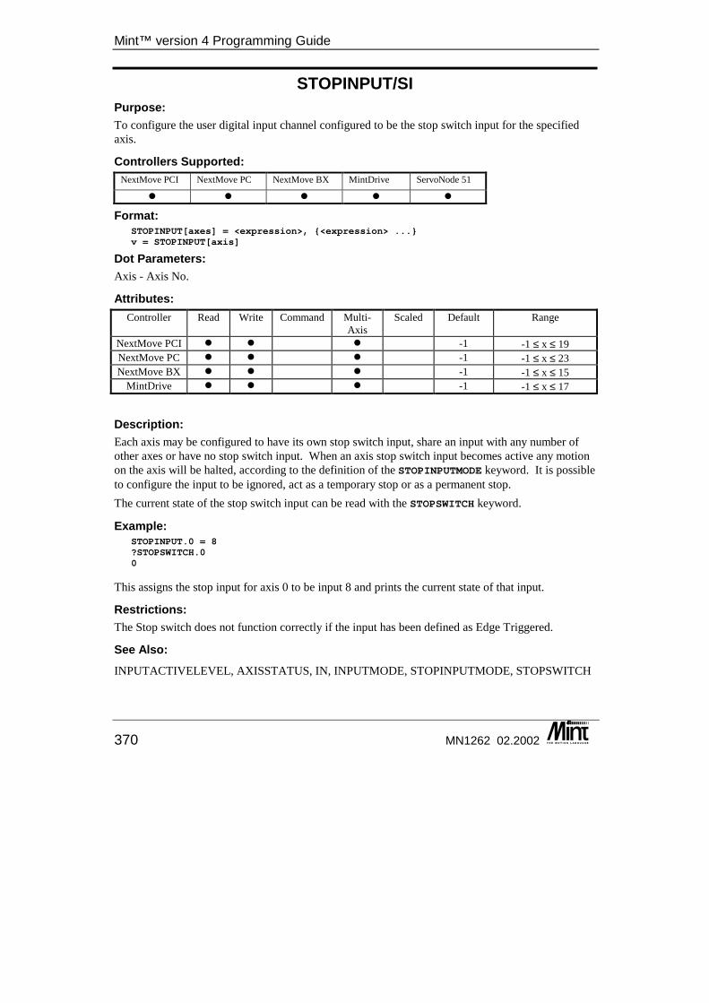
Mint™ version 4 Programming Guide
370 MN1262 02.2002
STOPINPUT/SI Purpose: To configure the user digital input channel configured to be the stop switch input for the specified axis.
Controllers Supported: NextMove PCI NextMove PC NextMove BX MintDrive ServoNode 51
� � � � �
Format: STOPINPUT[axes] = <expression>, {<expression> ...}v = STOPINPUT[axis]
Dot Parameters: Axis - Axis No.
Attributes: Controller Read Write Command Multi-
Axis Scaled Default Range
NextMove PCI � � � -1 -1 ≤ x ≤ 19 NextMove PC � � � -1 -1 ≤ x ≤ 23 NextMove BX � � � -1 -1 ≤ x ≤ 15
MintDrive � � � -1 -1 ≤ x ≤ 17
Description: Each axis may be configured to have its own stop switch input, share an input with any number of other axes or have no stop switch input. When an axis stop switch input becomes active any motion on the axis will be halted, according to the definition of the STOPINPUTMODE keyword. It is possible to configure the input to be ignored, act as a temporary stop or as a permanent stop. The current state of the stop switch input can be read with the STOPSWITCH keyword.
Example: STOPINPUT.0 = 8?STOPSWITCH.00
This assigns the stop input for axis 0 to be input 8 and prints the current state of that input.
Restrictions: The Stop switch does not function correctly if the input has been defined as Edge Triggered.
See Also: INPUTACTIVELEVEL, AXISSTATUS, IN, INPUTMODE, STOPINPUTMODE, STOPSWITCH
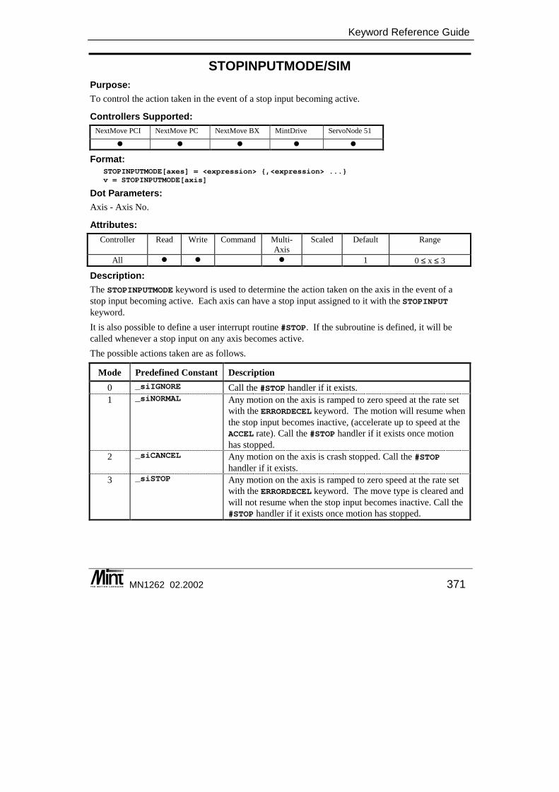
Keyword Reference Guide
MN1262 02.2002 371
STOPINPUTMODE/SIM Purpose: To control the action taken in the event of a stop input becoming active.
Controllers Supported: NextMove PCI NextMove PC NextMove BX MintDrive ServoNode 51
� � � � �
Format: STOPINPUTMODE[axes] = <expression> {,<expression> ...}v = STOPINPUTMODE[axis]
Dot Parameters: Axis - Axis No.
Attributes: Controller Read Write Command Multi-
Axis Scaled Default Range
All � � � 1 0 ≤ x ≤ 3
Description: The STOPINPUTMODE keyword is used to determine the action taken on the axis in the event of a stop input becoming active. Each axis can have a stop input assigned to it with the STOPINPUT keyword. It is also possible to define a user interrupt routine #STOP. If the subroutine is defined, it will be called whenever a stop input on any axis becomes active. The possible actions taken are as follows.
Mode Predefined Constant Description 0 _siIGNORE Call the #STOP handler if it exists. 1 _siNORMAL Any motion on the axis is ramped to zero speed at the rate set
with the ERRORDECEL keyword. The motion will resume when the stop input becomes inactive, (accelerate up to speed at the ACCEL rate). Call the #STOP handler if it exists once motion has stopped.
2 _siCANCEL Any motion on the axis is crash stopped. Call the #STOP handler if it exists.
3 _siSTOP Any motion on the axis is ramped to zero speed at the rate set with the ERRORDECEL keyword. The move type is cleared and will not resume when the stop input becomes inactive. Call the #STOP handler if it exists once motion has stopped.
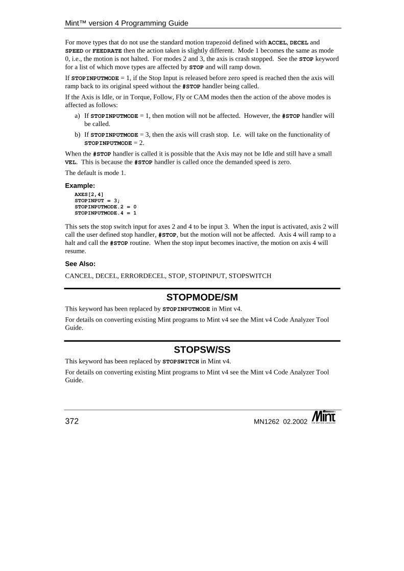
Mint™ version 4 Programming Guide
372 MN1262 02.2002
For move types that do not use the standard motion trapezoid defined with ACCEL, DECEL and SPEED or FEEDRATE then the action taken is slightly different. Mode 1 becomes the same as mode 0, i.e., the motion is not halted. For modes 2 and 3, the axis is crash stopped. See the STOP keyword for a list of which move types are affected by STOP and will ramp down. If STOPINPUTMODE = 1, if the Stop Input is released before zero speed is reached then the axis will ramp back to its original speed without the #STOP handler being called. If the Axis is Idle, or in Torque, Follow, Fly or CAM modes then the action of the above modes is affected as follows:
a) If STOPINPUTMODE = 1, then motion will not be affected. However, the #STOP handler will be called.
b) If STOPINPUTMODE = 3, then the axis will crash stop. I.e. will take on the functionality of STOPINPUTMODE = 2.
When the #STOP handler is called it is possible that the Axis may not be Idle and still have a small VEL. This is because the #STOP handler is called once the demanded speed is zero. The default is mode 1.
Example: AXES[2,4]STOPINPUT = 3;STOPINPUTMODE.2 = 0STOPINPUTMODE.4 = 1
This sets the stop switch input for axes 2 and 4 to be input 3. When the input is activated, axis 2 will call the user defined stop handler, #STOP, but the motion will not be affected. Axis 4 will ramp to a halt and call the #STOP routine. When the stop input becomes inactive, the motion on axis 4 will resume.
See Also: CANCEL, DECEL, ERRORDECEL, STOP, STOPINPUT, STOPSWITCH
STOPMODE/SM This keyword has been replaced by STOPINPUTMODE in Mint v4. For details on converting existing Mint programs to Mint v4 see the Mint v4 Code Analyzer Tool Guide.
STOPSW/SS This keyword has been replaced by STOPSWITCH in Mint v4. For details on converting existing Mint programs to Mint v4 see the Mint v4 Code Analyzer Tool Guide.
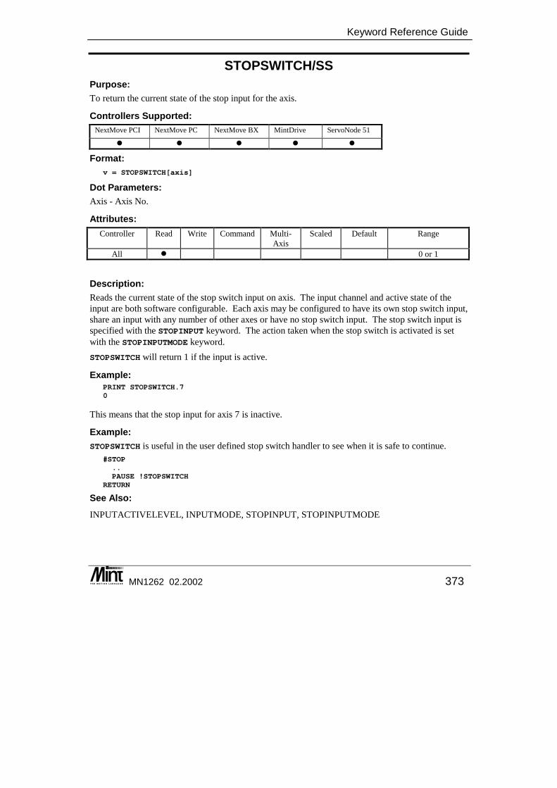
Keyword Reference Guide
MN1262 02.2002 373
STOPSWITCH/SS Purpose: To return the current state of the stop input for the axis.
Controllers Supported: NextMove PCI NextMove PC NextMove BX MintDrive ServoNode 51
� � � � �
Format: v = STOPSWITCH[axis]
Dot Parameters: Axis - Axis No.
Attributes: Controller Read Write Command Multi-
Axis Scaled Default Range
All � 0 or 1
Description: Reads the current state of the stop switch input on axis. The input channel and active state of the input are both software configurable. Each axis may be configured to have its own stop switch input, share an input with any number of other axes or have no stop switch input. The stop switch input is specified with the STOPINPUT keyword. The action taken when the stop switch is activated is set with the STOPINPUTMODE keyword. STOPSWITCH will return 1 if the input is active.
Example: PRINT STOPSWITCH.70
This means that the stop input for axis 7 is inactive.
Example: STOPSWITCH is useful in the user defined stop switch handler to see when it is safe to continue.
#STOP..PAUSE !STOPSWITCH
RETURN
See Also: INPUTACTIVELEVEL, INPUTMODE, STOPINPUT, STOPINPUTMODE
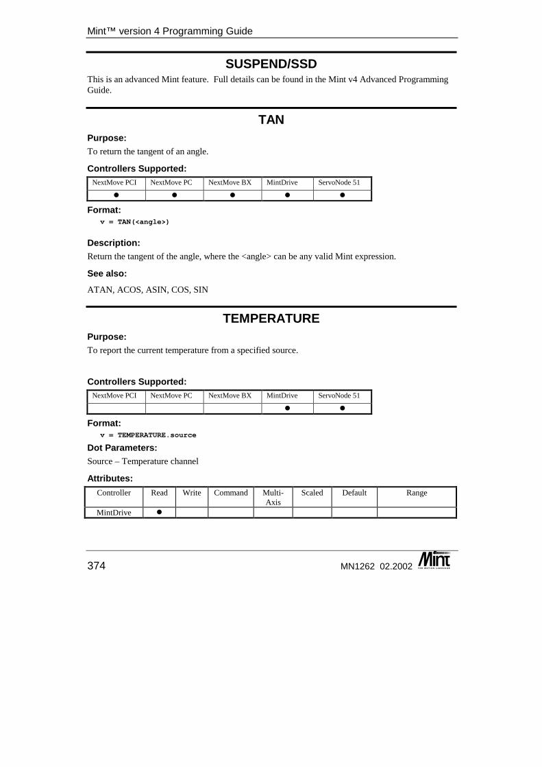
Mint™ version 4 Programming Guide
374 MN1262 02.2002
SUSPEND/SSD This is an advanced Mint feature. Full details can be found in the Mint v4 Advanced Programming Guide.
TAN Purpose: To return the tangent of an angle.
Controllers Supported: NextMove PCI NextMove PC NextMove BX MintDrive ServoNode 51
� � � � �
Format: v = TAN(<angle>)
Description: Return the tangent of the angle, where the <angle> can be any valid Mint expression.
See also: ATAN, ACOS, ASIN, COS, SIN
TEMPERATURE Purpose: To report the current temperature from a specified source.
Controllers Supported: NextMove PCI NextMove PC NextMove BX MintDrive ServoNode 51
� �
Format: v = TEMPERATURE.source
Dot Parameters: Source – Temperature channel
Attributes: Controller Read Write Command Multi-
Axis Scaled Default Range
MintDrive �

Keyword Reference Guide
MN1262 02.2002 375
Description: TEMPERATURE will return the current temperature reading from the MME temperature source in degrees Centigrade. This will read the air temperature within the enclosure. If the temperature reaches 70ºC then a reset will occur.
Example: PRINT “MME Temperature is ”, TEMPERATURE.0
Restrictions: A valid source must be specified.
TERM/TM This keyword has been replaced by TERMINAL in Mint v4. For details on converting existing Mint programs to Mint v4 see the Mint v4 Code Analyzer Tool Guide.
TERMINAL/TM Purpose: To set the terminal input/output channels.
Controllers Supported: NextMove PCI NextMove PC NextMove BX MintDrive ServoNode 51
� � � � �
Format: TERMINAL = <expression>v = TERMINAL
Dot Parameters: None.
Attributes: Controller Read Write Command Multi-
Axis Scaled Default Range
All � � 123 see table Description: TERMINAL is used to set the default terminal input and output channels for the Controller:
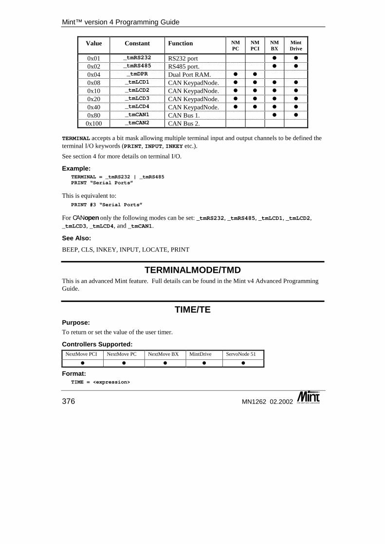
Mint™ version 4 Programming Guide
376 MN1262 02.2002
Value Constant Function NM PC
NM PCI
NM BX
Mint Drive
0x01 _tmRS232 RS232 port � � 0x02 _tmRS485 RS485 port. � � 0x04 _tmDPR Dual Port RAM. � � 0x08 _tmLCD1 CAN KeypadNode. � � � � 0x10 _tmLCD2 CAN KeypadNode. � � � � 0x20 _tmLCD3 CAN KeypadNode. � � � � 0x40 _tmLCD4 CAN KeypadNode. � � � � 0x80 _tmCAN1 CAN Bus 1. � �
0x100 _tmCAN2 CAN Bus 2.
TERMINAL accepts a bit mask allowing multiple terminal input and output channels to be defined the terminal I/O keywords (PRINT, INPUT, INKEY etc.). See section 4 for more details on terminal I/O.
Example: TERMINAL = _tmRS232 | _tmRS485PRINT “Serial Ports”
This is equivalent to: PRINT #3 “Serial Ports”
For CANopen only the following modes can be set: _tmRS232, _tmRS485, _tmLCD1, _tmLCD2, _tmLCD3, _tmLCD4, and _tmCAN1.
See Also: BEEP, CLS, INKEY, INPUT, LOCATE, PRINT
TERMINALMODE/TMD This is an advanced Mint feature. Full details can be found in the Mint v4 Advanced Programming Guide.
TIME/TE Purpose: To return or set the value of the user timer.
Controllers Supported: NextMove PCI NextMove PC NextMove BX MintDrive ServoNode 51
� � � � �
Format: TIME = <expression>
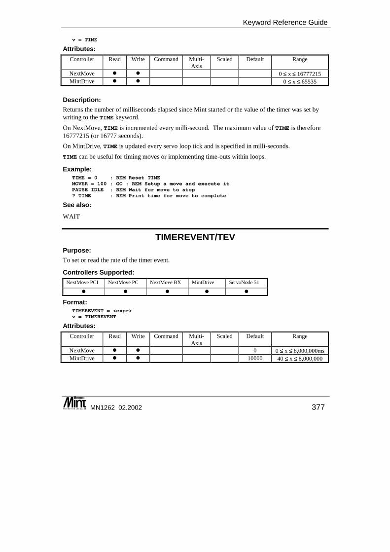
Keyword Reference Guide
MN1262 02.2002 377
v = TIME
Attributes: Controller Read Write Command Multi-
Axis Scaled Default Range
NextMove � � 0 ≤ x ≤ 16777215 MintDrive � � 0 ≤ x ≤ 65535
Description: Returns the number of milliseconds elapsed since Mint started or the value of the timer was set by writing to the TIME keyword. On NextMove, TIME is incremented every milli-second. The maximum value of TIME is therefore 16777215 (or 16777 seconds). On MintDrive, TIME is updated every servo loop tick and is specified in milli-seconds. TIME can be useful for timing moves or implementing time-outs within loops.
Example: TIME = 0 : REM Reset TIMEMOVER = 100 : GO : REM Setup a move and execute itPAUSE IDLE : REM Wait for move to stop? TIME : REM Print time for move to complete
See also: WAIT
TIMEREVENT/TEV Purpose: To set or read the rate of the timer event.
Controllers Supported: NextMove PCI NextMove PC NextMove BX MintDrive ServoNode 51
� � � � �
Format: TIMEREVENT = <expr>v = TIMEREVENT
Attributes: Controller Read Write Command Multi-
Axis Scaled Default Range
NextMove � � 0 0 ≤ x ≤ 8,000,000ms MintDrive � � 10000 40 ≤ x ≤ 8,000,000

Mint™ version 4 Programming Guide
378 MN1262 02.2002
Description: A timer event can be attached to Mint by use of the #TIMER subroutine. The TIMEREVENT keyword defines the rate in milli-seconds. For example:
TIMEREVENT = 100
#TIMERIF IN.1 = 1 THEN OUT.1 = 1
RETURN
will call #TIMER every 100ms. On MintDrive, the resolution of TIMEREVENT will depend upon LOOPTIME. There will be an inherent latency to when #TIME is actually called, hence TIME may not reflect the frequency precisely. On NextMove, setting TIMEREVENT to 0 stops events from being generated. The minimum value above 0 is 10ms. If a value under 10ms is specified it is automatically rounded up to 10ms. The value must be a multiple of 2 (even number of milliseconds). If an odd number is specified, it will be automatically rounded. On MintDrive and ServoNode 51, the minimum value is 40ms. The value must be a multiple of milliseconds. To disable timer events, the EVENTDISABLE or HANDLERDISABLE keywords should be used.
See Also: #IN0 .. #INx, TIME, #TIMER
TORQUE/TQ Purpose: To execute torque control; constant current mode to the amplifier.
Controllers Supported: NextMove PCI NextMove PC NextMove BX MintDrive ServoNode 51
� � � � �
Format: TORQUE[axes] = <expression> {,<expression> ...}v = TORQUE[axis]
Dot Parameters: Axis - Axis No.
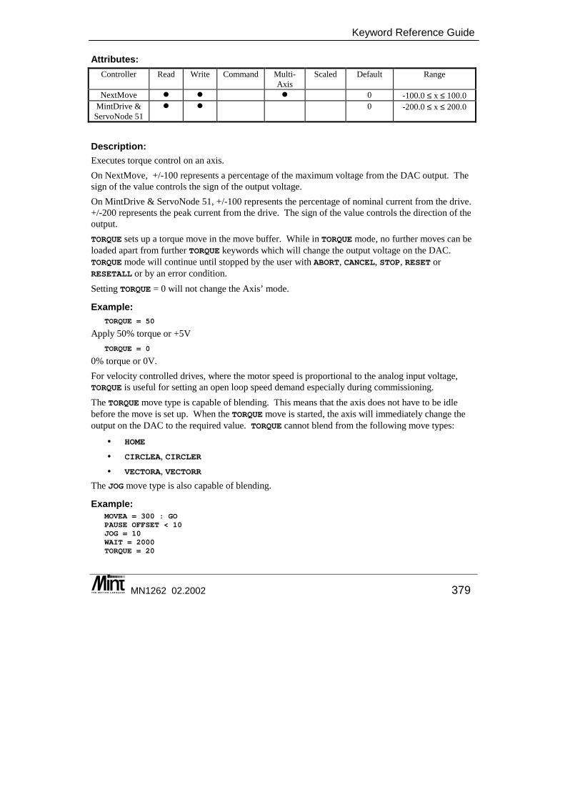
Keyword Reference Guide
MN1262 02.2002 379
Attributes: Controller Read Write Command Multi-
Axis Scaled Default Range
NextMove � � � 0 -100.0 ≤ x ≤ 100.0 MintDrive &
ServoNode 51 � � 0 -200.0 ≤ x ≤ 200.0
Description: Executes torque control on an axis. On NextMove, +/-100 represents a percentage of the maximum voltage from the DAC output. The sign of the value controls the sign of the output voltage. On MintDrive & ServoNode 51, +/-100 represents the percentage of nominal current from the drive. +/-200 represents the peak current from the drive. The sign of the value controls the direction of the output. TORQUE sets up a torque move in the move buffer. While in TORQUE mode, no further moves can be loaded apart from further TORQUE keywords which will change the output voltage on the DAC. TORQUE mode will continue until stopped by the user with ABORT, CANCEL, STOP, RESET or RESETALL or by an error condition. Setting TORQUE = 0 will not change the Axis’ mode.
Example: TORQUE = 50
Apply 50% torque or +5V TORQUE = 0
0% torque or 0V. For velocity controlled drives, where the motor speed is proportional to the analog input voltage, TORQUE is useful for setting an open loop speed demand especially during commissioning. The TORQUE move type is capable of blending. This means that the axis does not have to be idle before the move is set up. When the TORQUE move is started, the axis will immediately change the output on the DAC to the required value. TORQUE cannot blend from the following move types:
• HOME • CIRCLEA, CIRCLER • VECTORA, VECTORR
The JOG move type is also capable of blending.
Example: MOVEA = 300 : GOPAUSE OFFSET < 10JOG = 10WAIT = 2000TORQUE = 20
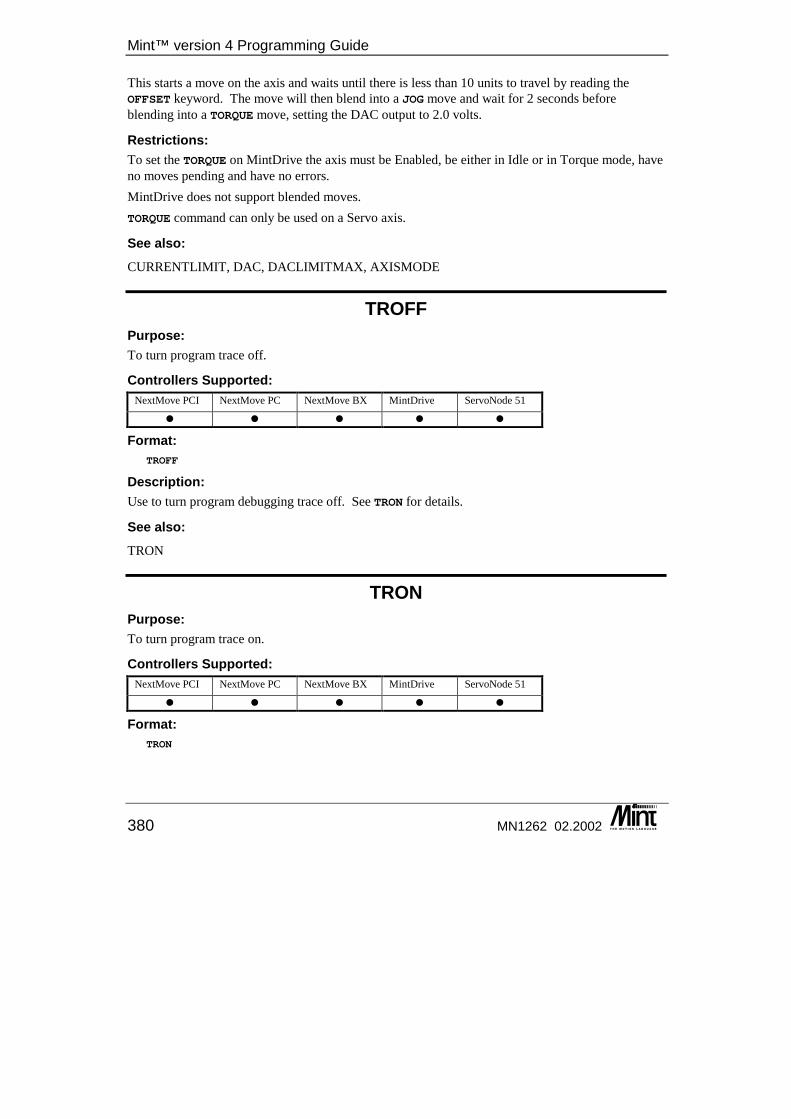
Mint™ version 4 Programming Guide
380 MN1262 02.2002
This starts a move on the axis and waits until there is less than 10 units to travel by reading the OFFSET keyword. The move will then blend into a JOG move and wait for 2 seconds before blending into a TORQUE move, setting the DAC output to 2.0 volts.
Restrictions: To set the TORQUE on MintDrive the axis must be Enabled, be either in Idle or in Torque mode, have no moves pending and have no errors. MintDrive does not support blended moves. TORQUE command can only be used on a Servo axis.
See also: CURRENTLIMIT, DAC, DACLIMITMAX, AXISMODE
TROFF Purpose: To turn program trace off.
Controllers Supported: NextMove PCI NextMove PC NextMove BX MintDrive ServoNode 51
� � � � �
Format: TROFF
Description: Use to turn program debugging trace off. See TRON for details.
See also: TRON
TRON Purpose: To turn program trace on.
Controllers Supported: NextMove PCI NextMove PC NextMove BX MintDrive ServoNode 51
� � � � �
Format: TRON
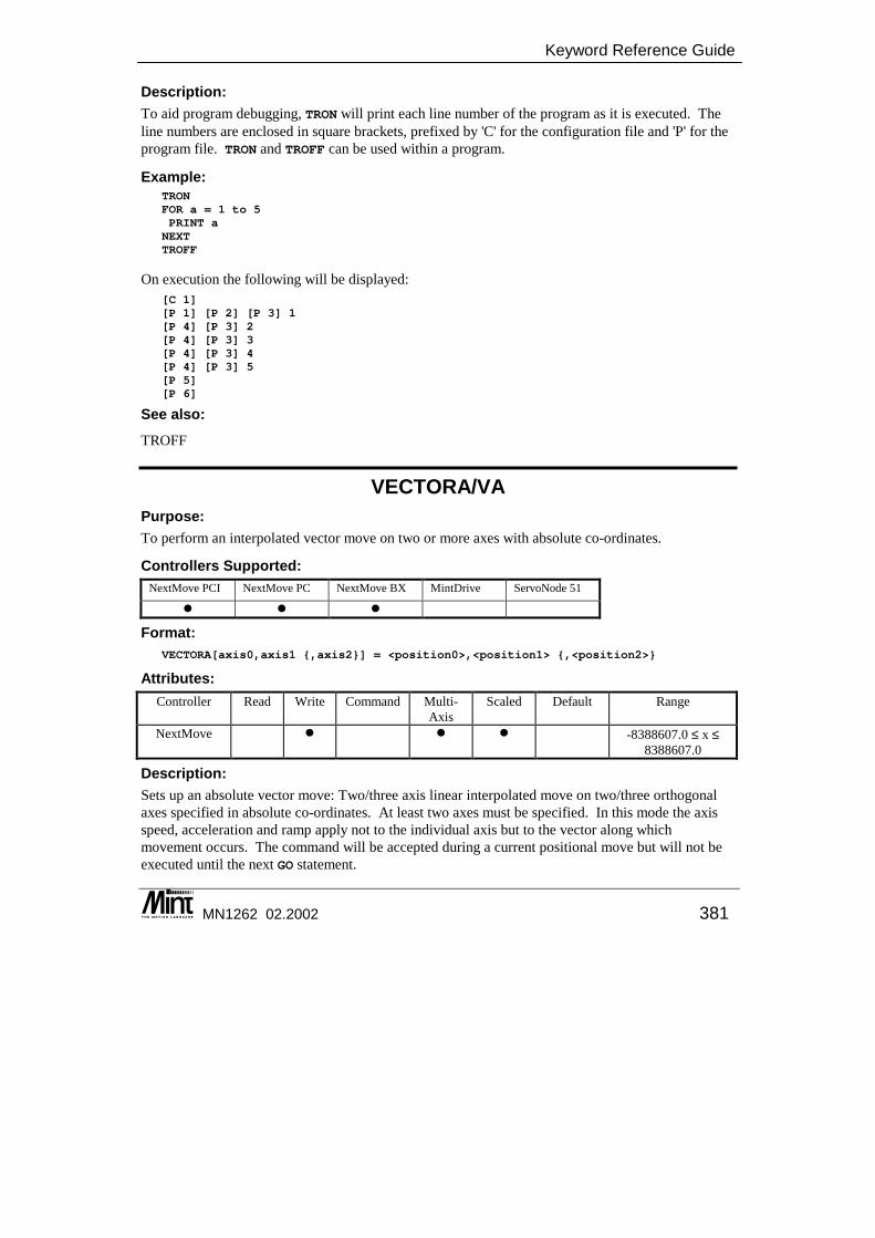
Keyword Reference Guide
MN1262 02.2002 381
Description: To aid program debugging, TRON will print each line number of the program as it is executed. The line numbers are enclosed in square brackets, prefixed by 'C' for the configuration file and 'P' for the program file. TRON and TROFF can be used within a program.
Example: TRONFOR a = 1 to 5PRINT aNEXTTROFF
On execution the following will be displayed: [C 1][P 1] [P 2] [P 3] 1[P 4] [P 3] 2[P 4] [P 3] 3[P 4] [P 3] 4[P 4] [P 3] 5[P 5][P 6]
See also: TROFF
VECTORA/VA Purpose: To perform an interpolated vector move on two or more axes with absolute co-ordinates.
Controllers Supported: NextMove PCI NextMove PC NextMove BX MintDrive ServoNode 51
� � �
Format: VECTORA[axis0,axis1 {,axis2}] = <position0>,<position1> {,<position2>}
Attributes: Controller Read Write Command Multi-
Axis Scaled Default Range
NextMove � � � -8388607.0 ≤ x ≤ 8388607.0
Description: Sets up an absolute vector move: Two/three axis linear interpolated move on two/three orthogonal axes specified in absolute co-ordinates. At least two axes must be specified. In this mode the axis speed, acceleration and ramp apply not to the individual axis but to the vector along which movement occurs. The command will be accepted during a current positional move but will not be executed until the next GO statement.
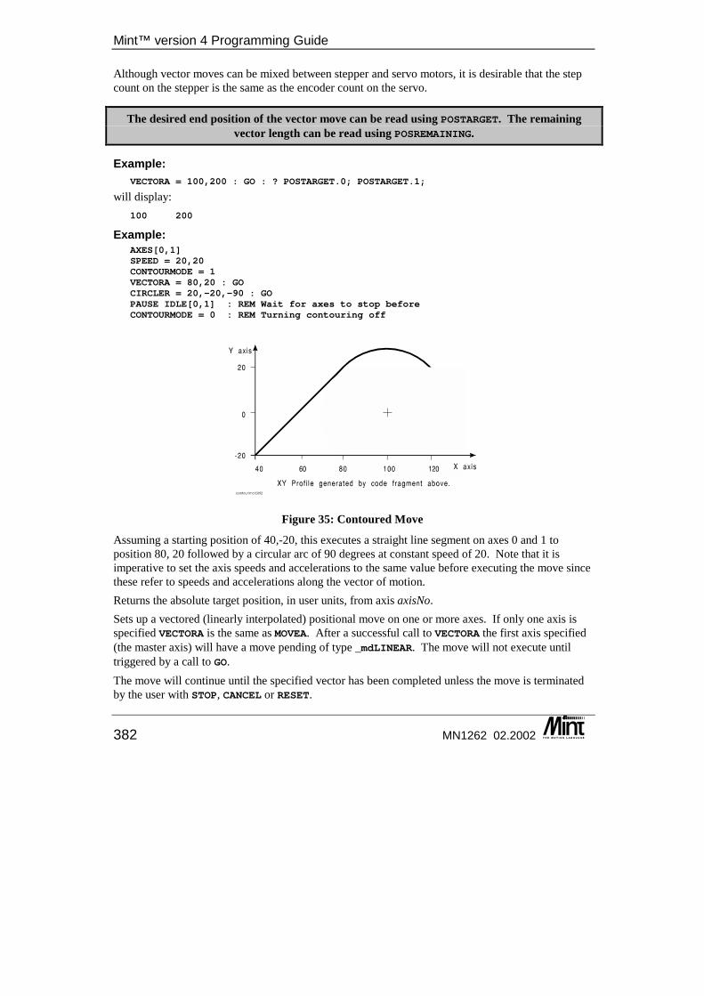
Mint™ version 4 Programming Guide
382 MN1262 02.2002
Although vector moves can be mixed between stepper and servo motors, it is desirable that the step count on the stepper is the same as the encoder count on the servo.
The desired end position of the vector move can be read using POSTARGET. The remaining vector length can be read using POSREMAINING.
Example: VECTORA = 100,200 : GO : ? POSTARGET.0; POSTARGET.1;
will display: 100 200
Example: AXES[0,1]SPEED = 20,20CONTOURMODE = 1VECTORA = 80,20 : GOCIRCLER = 20,-20,-90 : GOPAUSE IDLE[0,1] : REM Wait for axes to stop beforeCONTOURMODE = 0 : REM Turning contouring off
Figure 35: Contoured Move
Assuming a starting position of 40,-20, this executes a straight line segment on axes 0 and 1 to position 80, 20 followed by a circular arc of 90 degrees at constant speed of 20. Note that it is imperative to set the axis speeds and accelerations to the same value before executing the move since these refer to speeds and accelerations along the vector of motion. Returns the absolute target position, in user units, from axis axisNo. Sets up a vectored (linearly interpolated) positional move on one or more axes. If only one axis is specified VECTORA is the same as MOVEA. After a successful call to VECTORA the first axis specified (the master axis) will have a move pending of type _mdLINEAR. The move will not execute until triggered by a call to GO. The move will continue until the specified vector has been completed unless the move is terminated by the user with STOP, CANCEL or RESET.
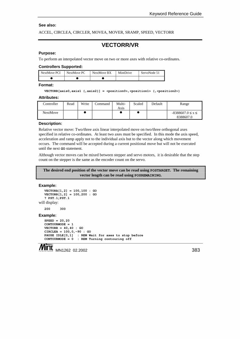
Keyword Reference Guide
MN1262 02.2002 383
See also: ACCEL, CIRCLEA, CIRCLER, MOVEA, MOVER, SRAMP, SPEED, VECTORR
VECTORR/VR Purpose: To perform an interpolated vector move on two or more axes with relative co-ordinates.
Controllers Supported: NextMove PCI NextMove PC NextMove BX MintDrive ServoNode 51
� � �
Format: VECTORR[axis0,axis1 {,axis2}] = <position0>,<position1> {,<position2>}
Attributes: Controller Read Write Command Multi-
Axis Scaled Default Range
NextMove � � � -8388607.0 ≤ x ≤ 8388607.0
Description: Relative vector move: Two/three axis linear interpolated move on two/three orthogonal axes specified in relative co-ordinates. At least two axes must be specified. In this mode the axis speed, acceleration and ramp apply not to the individual axis but to the vector along which movement occurs. The command will be accepted during a current positional move but will not be executed until the next GO statement. Although vector moves can be mixed between stepper and servo motors, it is desirable that the step count on the stepper is the same as the encoder count on the servo.
The desired end position of the vector move can be read using POSTARGET. The remaining vector length can be read using POSREMAINING.
Example: VECTORA[1,2] = 100,100 : GOVECTORR[1,2] = 100,200 : GO? PST.1;PST.1
will display: 200 300
Example: SPEED = 20,20CONTOURMODE = 1VECTORR = 40,40 : GOCIRCLEA = 100,0,-90 : GOPAUSE IDLE[0,1] : REM Wait for axes to stop beforeCONTOURMODE = 0 : REM Turning contouring off
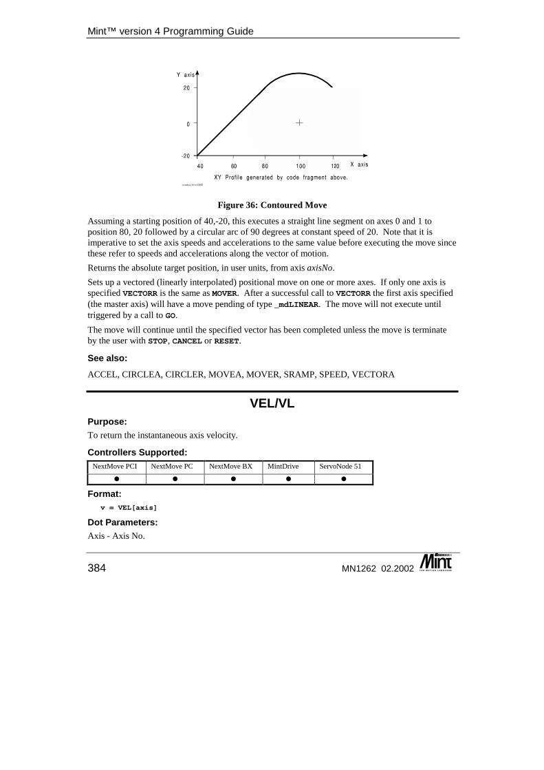
Mint™ version 4 Programming Guide
384 MN1262 02.2002
Figure 36: Contoured Move
Assuming a starting position of 40,-20, this executes a straight line segment on axes 0 and 1 to position 80, 20 followed by a circular arc of 90 degrees at constant speed of 20. Note that it is imperative to set the axis speeds and accelerations to the same value before executing the move since these refer to speeds and accelerations along the vector of motion. Returns the absolute target position, in user units, from axis axisNo. Sets up a vectored (linearly interpolated) positional move on one or more axes. If only one axis is specified VECTORR is the same as MOVER. After a successful call to VECTORR the first axis specified (the master axis) will have a move pending of type _mdLINEAR. The move will not execute until triggered by a call to GO. The move will continue until the specified vector has been completed unless the move is terminate by the user with STOP, CANCEL or RESET.
See also: ACCEL, CIRCLEA, CIRCLER, MOVEA, MOVER, SRAMP, SPEED, VECTORA
VEL/VL Purpose: To return the instantaneous axis velocity.
Controllers Supported: NextMove PCI NextMove PC NextMove BX MintDrive ServoNode 51
� � � � �
Format: v = VEL[axis]
Dot Parameters: Axis - Axis No.
Keyword Reference Guide
MN1262 02.2002 385
Attributes: Controller Read Write Command Multi-
Axis Scaled Default Range
All � � �
Description: Returns instantaneous axis velocity in user units/second where the sign indicates direction. VEL is applicable in all modes of motion. Due to quantization, as in any sampled system, the value returned by VEL is inaccurate at low speeds. VEL returns the change in position measured during the last sampling period expressed in user units. The minimum value, other than zero, that VEL can return equates to an encoder edge frequency of 1 kHz, i.e. 500.
Example: MOVEA = 100 : GOWHILE IDLE <> 1? VEL
ENDW
Print the axis velocity during a positional move.
Restrictions: A Stepper axis will only provide a VEL reading if it has an Encoder attached.
See also: ENCODERVEL, FEEDRATE, SPEED, POS
VELDEMAND/VLD This is an advanced Mint feature. Full details can be found in the Mint v4 Advanced Programming Guide.
VELENCODER/VEN This is an advanced Mint feature. Full details can be found in the Mint v4 Advanced Programming Guide.
VELFATAL/VLF This is an advanced Mint feature. Full details can be found in the Mint v4 Advanced Programming Guide.
Mint™ version 4 Programming Guide
386 MN1262 02.2002
VELFATALMODE/VLM This is an advanced Mint feature. Full details can be found in the Mint v4 Advanced Programming Guide.
VER Purpose: To display the current Mint version number.
Controllers Supported: NextMove PCI NextMove PC NextMove BX MintDrive ServoNode 51
� � � � �
Format: VER
Description: Display the version banner of the Mint software.
The version number of the software should be quoted in technical support enquiry’s.
VIEW Purpose: To display information on the hardware configuration, CAN and user data.
Controllers Supported: NextMove PCI NextMove PC NextMove BX MintDrive ServoNode 51
� � � � �
Dot Parameters: None.
Format: VIEW <type>
Description: VIEW is used to conveniently display various information about the system. VIEW on its own displays the options available as indicated in the table below:
VIEW ARRAY Displays all defined arrays and data. For example:
VIEW ARRAYsize(10)
Keyword Reference Guide
MN1262 02.2002 387
1, 2, 3, 2, 32, 4, 7, 6, 3
VIEW CANBUSSTATE{.bus} For example:
VIEW CANBUSSTATE.2
CAN Bus 2=========The CAN Baud rate is 125The CAN bus is operational
VIEW CANEVENT Displays CAN events along with the recorded CANEVENTINFO. It will monitor the CAN bus until Ctrl-E is pressed.
VIEW CANSTATUS Displays CANSTATUS events along with the node number. The CANSTATUS value is displayed in binary, with the bit values corresponding to those documented for CANSTATUS. It will monitor the CAN bus until Ctrl-E is pressed. This is only available if there is a CAN channel present. See VIEW PLATFORM.
VIEW CAPTURE Displays the mode and axis, if any, assigned to each capture channel.
VIEW CAPTURE
Capture settings.
Channel 0 captures nothingChannel 1 captures measured speed from axis 2Channel 2 captures following error from axis 0Channel 3 captures measured position from axis 1Channel 4 captures nothingChannel 5 captures nothing
Capture interval is 2 ms.
Capture is running in single fill mode.Buffer has 250 ms of data.
VIEW CONFIG Displays information on the current use of all axes. For Example:
Axis Configurations
Axis 0 – [channel 0] - Servo on Main Card – DAC 0 & Encoder AAxis 1 – [channel 1] - Servo on Main Card – DAC 1 & Encoder BAxis 2 – [channel 2] - Servo on Main Card – DAC 2 & Encoder CAxis 3 – [channel 3] - Servo on Main Card – DAC 3 & Encoder DAxis 4 – [channel 0] – Stepper on Main Card – Stepper EAxis 5 – [channel 1] – Stepper on Main Card – Stepper F
Mint™ version 4 Programming Guide
388 MN1262 02.2002
Axis 6 – [channel 2] – Stepper on Main Card – Stepper GAxis 7 – [channel 3] – Stepper on Main Card – Stepper HAxis 8 – [channel 0] – OffAxis 9 – [channel 1] – OffAxis 10 – [channel 2] – OffAxis 11 – [channel 3] – Off
VIEW ENCODER Displays the following parameters for each axis and the Auxiliary Encoder:
ENCODERENCODERVELENCODERSCALEENCODERWRAPFASTENCODERFASTLATCHENCODERZLATCH
VIEW HARDWARE Displays the following data:
Serial Number; Type; Revision.
for each of the following: MME Carrier Board Power
VIEW MACROS Displays all defined macros.
VIEW MEMORY Displays a break down of the memory usage of the controller.
VIEW NODELIVE Displays all active nodes on the network, showing the name of the node against each node number. This is only available if there is a CAN channel present. See VIEW PLATFORM.
VIEW PLATFORM Displays the set-up for the hardware platform, detailing the following:
• No. of Axis • No. of Servo Axis • No. of Stepper Axis • No. of Digital Inputs • No. of Digital Outputs • No. of Analog Inputs
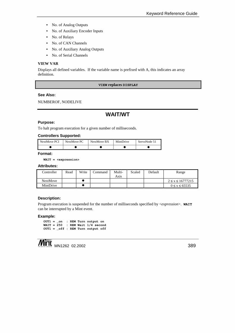
Keyword Reference Guide
MN1262 02.2002 389
• No. of Analog Outputs • No. of Auxiliary Encoder Inputs • No. of Relays • No. of CAN Channels • No. of Auxiliary Analog Outputs • No. of Serial Channels
VIEW VAR Displays all defined variables. If the variable name is prefixed with A, this indicates an array definition.
VIEW replaces DISPLAY
See Also: NUMBEROF, NODELIVE
WAIT/WT Purpose: To halt program execution for a given number of milliseconds.
Controllers Supported: NextMove PCI NextMove PC NextMove BX MintDrive ServoNode 51
� � � � �
Format: WAIT = <expression>
Attributes: Controller Read Write Command Multi-
Axis Scaled Default Range
NextMove � 2 ≤ x ≤ 16777215 MintDrive � 0 ≤ x ≤ 65535
Description: Program execution is suspended for the number of milliseconds specified by <expression>. WAIT can be interrupted by a Mint event.
Example: OUT1 = _on : REM Turn output onWAIT = 250 : REM Wait 1/4 secondOUT1 = _off : REM Turn output off
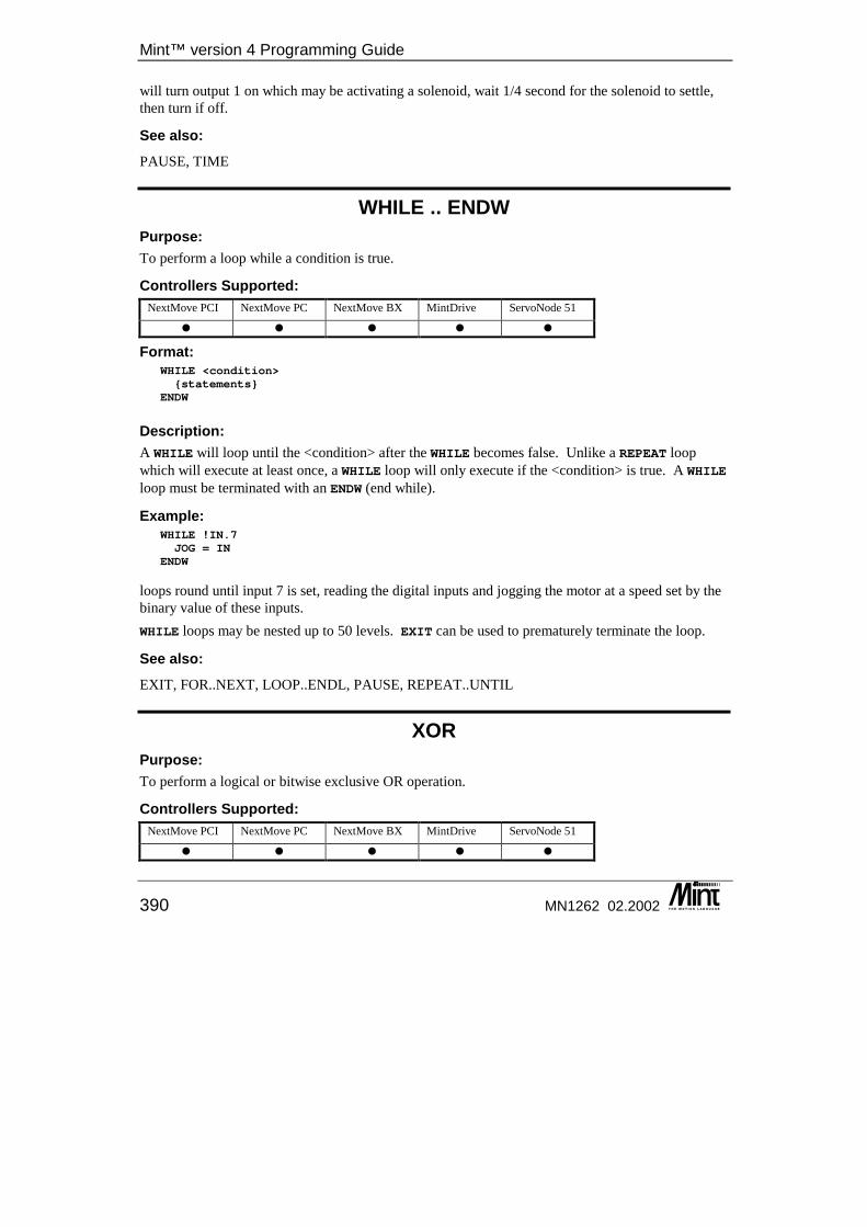
Mint™ version 4 Programming Guide
390 MN1262 02.2002
will turn output 1 on which may be activating a solenoid, wait 1/4 second for the solenoid to settle, then turn if off.
See also: PAUSE, TIME
WHILE .. ENDW Purpose: To perform a loop while a condition is true.
Controllers Supported: NextMove PCI NextMove PC NextMove BX MintDrive ServoNode 51
� � � � �
Format: WHILE <condition>{statements}
ENDW
Description: A WHILE will loop until the <condition> after the WHILE becomes false. Unlike a REPEAT loop which will execute at least once, a WHILE loop will only execute if the <condition> is true. A WHILE loop must be terminated with an ENDW (end while).
Example: WHILE !IN.7JOG = IN
ENDW
loops round until input 7 is set, reading the digital inputs and jogging the motor at a speed set by the binary value of these inputs. WHILE loops may be nested up to 50 levels. EXIT can be used to prematurely terminate the loop.
See also: EXIT, FOR..NEXT, LOOP..ENDL, PAUSE, REPEAT..UNTIL
XOR Purpose: To perform a logical or bitwise exclusive OR operation.
Controllers Supported: NextMove PCI NextMove PC NextMove BX MintDrive ServoNode 51
� � � � �
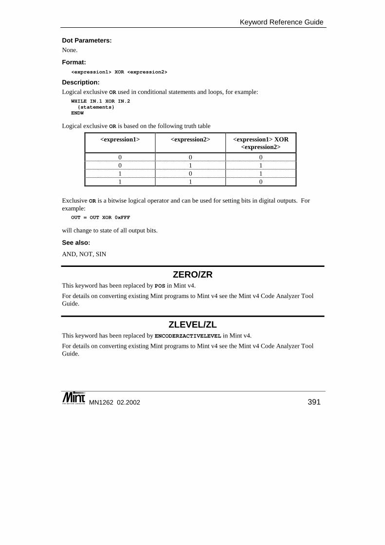
Keyword Reference Guide
MN1262 02.2002 391
Dot Parameters: None.
Format: <expression1> XOR <expression2>
Description: Logical exclusive OR used in conditional statements and loops, for example:
WHILE IN.1 XOR IN.2{statements}
ENDW
Logical exclusive OR is based on the following truth table
<expression1> <expression2> <expression1> XOR <expression2>
0 0 0 0 1 1 1 0 1 1 1 0
Exclusive OR is a bitwise logical operator and can be used for setting bits in digital outputs. For example:
OUT = OUT XOR 0xFFF
will change to state of all output bits.
See also: AND, NOT, SIN
ZERO/ZR This keyword has been replaced by POS in Mint v4. For details on converting existing Mint programs to Mint v4 see the Mint v4 Code Analyzer Tool Guide.
ZLEVEL/ZL This keyword has been replaced by ENCODERZACTIVELEVEL in Mint v4. For details on converting existing Mint programs to Mint v4 see the Mint v4 Code Analyzer Tool Guide.

Mint™ version 4 Programming Guide
392 MN1262 02.2002

Quick Reference
MN1262 02.2002 393
11. Quick Reference
11 This chapter provides a quick reference detailing the usage of each Mint keyword. The keywords are split into sections covering what effect they have. There is also a list of ASCII Character codes.
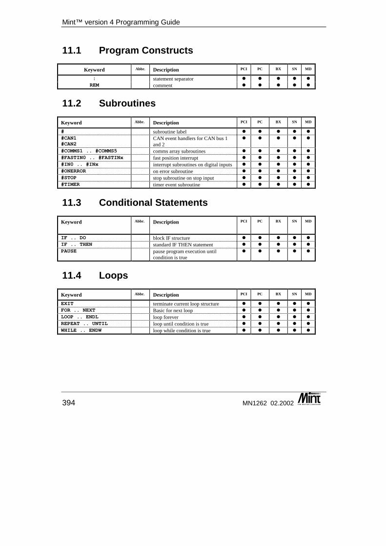
Mint™ version 4 Programming Guide
394 MN1262 02.2002
11.1 Program Constructs
Keyword Abbr. Description PCI PC BX SN MD
: statement separator � � � � � REM comment � � � � �
11.2 Subroutines
Keyword Abbr. Description PCI PC BX SN MD
# subroutine label � � � � � #CAN1#CAN2
CAN event handlers for CAN bus 1 and 2
� � � � �
#COMMS1 .. #COMMS5 comms array subroutines � � � � � #FASTIN0 .. #FASTINx fast position interrupt � � � � � #IN0 .. #INx interrupt subroutines on digital inputs � � � � � #ONERROR on error subroutine � � � � � #STOP stop subroutine on stop input � � � � � #TIMER timer event subroutine � � � � �
11.3 Conditional Statements
Keyword Abbr. Description PCI PC BX SN MD
IF .. DO block IF structure � � � � � IF .. THEN standard IF THEN statement � � � � � PAUSE pause program execution until
condition is true � � � � �
11.4 Loops
Keyword Abbr. Description PCI PC BX SN MD
EXIT terminate current loop structure � � � � � FOR .. NEXT Basic for next loop � � � � � LOOP .. ENDL loop forever � � � � � REPEAT .. UNTIL loop until condition is true � � � � � WHILE .. ENDW loop while condition is true � � � � �
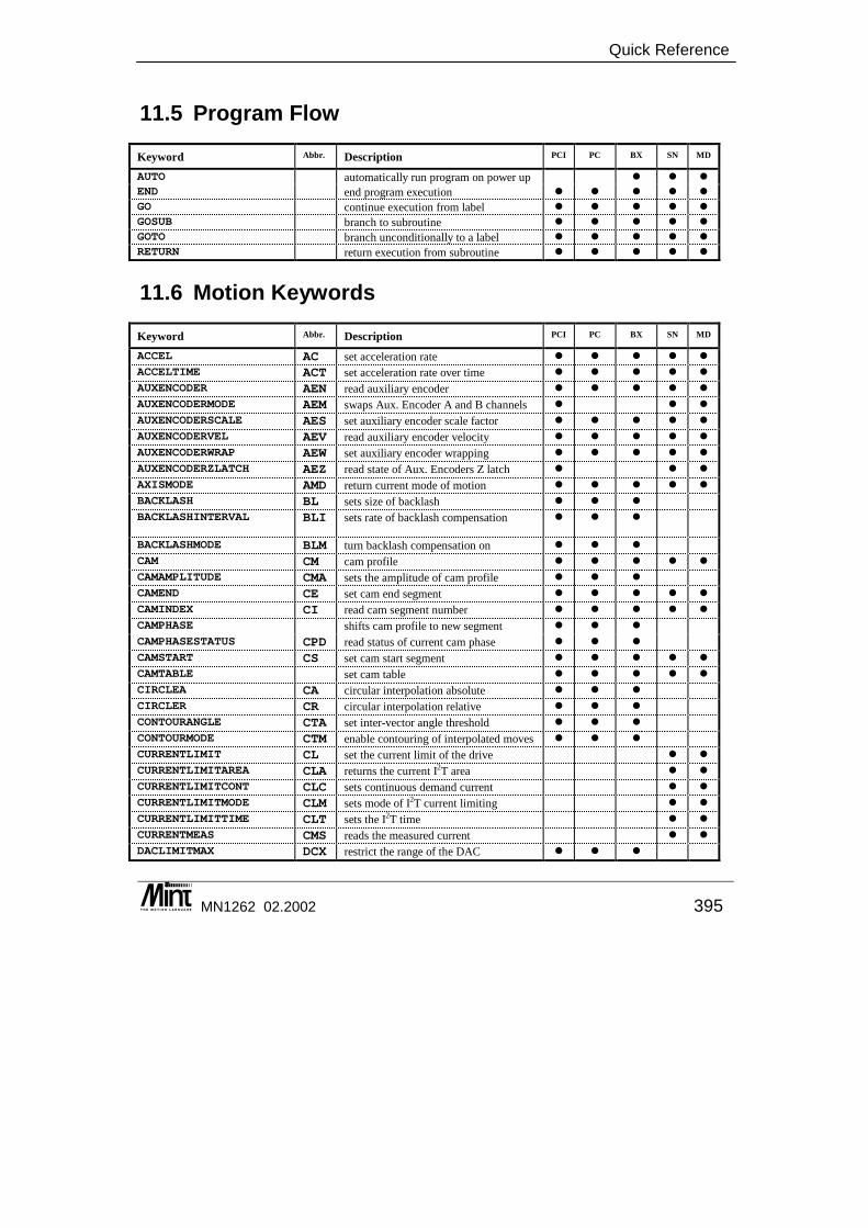
Quick Reference
MN1262 02.2002 395
11.5 Program Flow
Keyword Abbr. Description PCI PC BX SN MD
AUTO automatically run program on power up � � �
END end program execution � � � � � GO continue execution from label � � � � � GOSUB branch to subroutine � � � � � GOTO branch unconditionally to a label � � � � �
RETURN return execution from subroutine � � � � �
11.6 Motion Keywords
Keyword Abbr. Description PCI PC BX SN MD
ACCEL AC set acceleration rate � � � � �
ACCELTIME ACT set acceleration rate over time � � � � �
AUXENCODER AEN read auxiliary encoder � � � � �
AUXENCODERMODE AEM swaps Aux. Encoder A and B channels � � �
AUXENCODERSCALE AES set auxiliary encoder scale factor � � � � �
AUXENCODERVEL AEV read auxiliary encoder velocity � � � � �
AUXENCODERWRAP AEW set auxiliary encoder wrapping � � � � �
AUXENCODERZLATCH AEZ read state of Aux. Encoders Z latch � � �
AXISMODE AMD return current mode of motion � � � � �
BACKLASH BL sets size of backlash � � �
BACKLASHINTERVAL BLI sets rate of backlash compensation � � �
BACKLASHMODE BLM turn backlash compensation on � � �
CAM CM cam profile � � � � �
CAMAMPLITUDE CMA sets the amplitude of cam profile � � �
CAMEND CE set cam end segment � � � � �
CAMINDEX CI read cam segment number � � � � �
CAMPHASE shifts cam profile to new segment � � �
CAMPHASESTATUS CPD read status of current cam phase � � �
CAMSTART CS set cam start segment � � � � �
CAMTABLE set cam table � � � � �
CIRCLEA CA circular interpolation absolute � � �
CIRCLER CR circular interpolation relative � � �
CONTOURANGLE CTA set inter-vector angle threshold � � �
CONTOURMODE CTM enable contouring of interpolated moves � � �
CURRENTLIMIT CL set the current limit of the drive � �
CURRENTLIMITAREA CLA returns the current I2T area � �
CURRENTLIMITCONT CLC sets continuous demand current � �
CURRENTLIMITMODE CLM sets mode of I2T current limiting � �
CURRENTLIMITTIME CLT sets the I2T time � �
CURRENTMEAS CMS reads the measured current � �
DACLIMITMAX DCX restrict the range of the DAC � � �
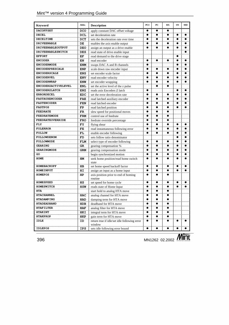
Mint™ version 4 Programming Guide
396 MN1262 02.2002
Keyword Abbr. Description PCI PC BX SN MD
DACOFFSET DCO apply constant DAC offset voltage � � �
DECEL DCL set deceleration rate � � � � �
DECELTIME DCT sets the deceleration rate over time � � � � �
DRIVEENABLE DE enables the axis enable output � � � � �
DRIVEENABLEOUTPUT DEO assign an output as a drive enable � � � � �
DRIVEENABLESWITCH DES read state of drive enable input �
EFFORT EF read demand to the drive stage �
ENCODER EN read encoder � � � � �
ENCODERMODE ENM swaps DAC A and B channels � � �
ENCODERPRESCALE ENP scale down raw encoder input � � � � �
ENCODERSCALE ENS set encoder scale factor � � � � �
ENCODERVEL ENV read encoder velocity � � � � �
ENCODERWRAP ENW set encoder wrapping � � � � �
ENCODERZACTIVELEVEL ENL set the active level of the z pulse � �
ENCODERZLATCH ENZ reads axis Encoders Z latch � � �
ERRORDECEL EDC set the error deceleration rate � � � � �
FASTAUXENCODER FAE read latched auxiliary encoder � � � � �
FASTENCODER FEN read latched encoder � � � � �
FASTPOS FP read latched position � � � � �
FEEDRATE FR slew speed for positional moves � � �
FEEDRATEMODE FRM control use of feedrate � � �
FEEDRATEOVERRIDE FRO feedrate override percentage � � �
FLY FY flying shear � � � � �
FOLERROR FE read instantaneous following error � � � � �
FOLLOW FL enable encoder following � � � � �
FOLLOWDENOM FD sets follow ratio denominator � �
FOLLOWMODE FLM select type of encoder following � � � � �
GEARING GR gearing compensation % � � � � �
GEARINGMODE GRM gearing compensation mode � � � � �
GO begin synchronized motion � � � � �
HOME HM seek home position/read home switch state
� � � � �
HOMEBACKOFF HB set home speed backoff factor � � � � �
HOMEINPUT HI assign an input as a home input � � � � �
HOMEPOS HP axis position prior to end of homing routine
� � �
HOMESPEED HS set speed for home cycle � � � � �
HOMESWITCH HSW reads state of Home Input � � � � �
HTA start hold to analog HTA move � � �
HTACHANNEL HAC analog channel for HTA move � � �
HTADAMPING HAD damping term for HTA move � � �
HTADEADBAND HDB deadband for HTA move � � �
HTAFILTER HAF analog filter for HTA move � � �
HTAKINT HKI integral term for HTA move � � �
HTAKPROP HKP gain term for HTA move � � �
IDLE ID return true if idle/set idle following error window
� � � � �
IDLEPOS IPS sets idle following error bound � � � � �
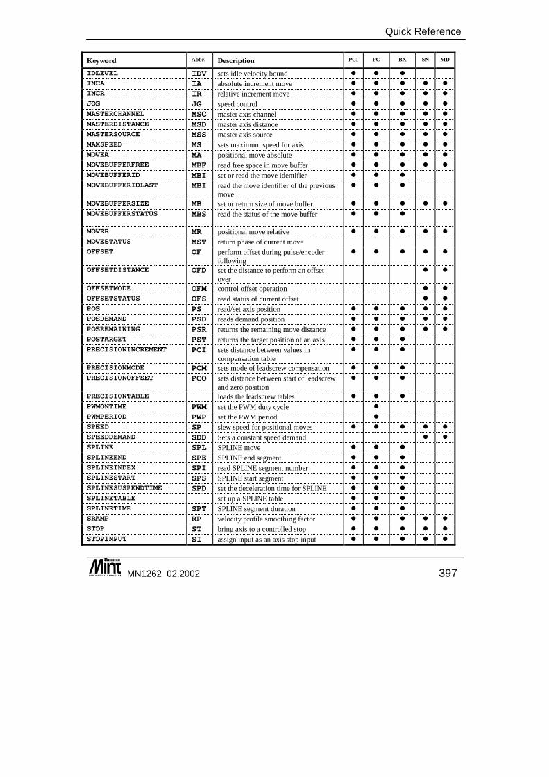
Quick Reference
MN1262 02.2002 397
Keyword Abbr. Description PCI PC BX SN MD
IDLEVEL IDV sets idle velocity bound � � �
INCA IA absolute increment move � � � � �
INCR IR relative increment move � � � � �
JOG JG speed control � � � � �
MASTERCHANNEL MSC master axis channel � � � � �
MASTERDISTANCE MSD master axis distance � � � � �
MASTERSOURCE MSS master axis source � � � � �
MAXSPEED MS sets maximum speed for axis � � � � �
MOVEA MA positional move absolute � � � � �
MOVEBUFFERFREE MBF read free space in move buffer � � � � �
MOVEBUFFERID MBI set or read the move identifier � � �
MOVEBUFFERIDLAST MBI read the move identifier of the previous move
� � �
MOVEBUFFERSIZE MB set or return size of move buffer � � � � �
MOVEBUFFERSTATUS MBS read the status of the move buffer � � �
MOVER MR positional move relative � � � � �
MOVESTATUS MST return phase of current move
OFFSET OF perform offset during pulse/encoder following
� � � � �
OFFSETDISTANCE OFD set the distance to perform an offset over
� �
OFFSETMODE OFM control offset operation � �
OFFSETSTATUS OFS read status of current offset � �
POS PS read/set axis position � � � � �
POSDEMAND PSD reads demand position � � � � �
POSREMAINING PSR returns the remaining move distance � � � � �
POSTARGET PST returns the target position of an axis � � �
PRECISIONINCREMENT PCI sets distance between values in compensation table
� � �
PRECISIONMODE PCM sets mode of leadscrew compensation � � �
PRECISIONOFFSET PCO sets distance between start of leadscrew and zero position
� � �
PRECISIONTABLE loads the leadscrew tables � � �
PWMONTIME PWM set the PWM duty cycle �
PWMPERIOD PWP set the PWM period �
SPEED SP slew speed for positional moves � � � � �
SPEEDDEMAND SDD Sets a constant speed demand � �
SPLINE SPL SPLINE move � � �
SPLINEEND SPE SPLINE end segment � � �
SPLINEINDEX SPI read SPLINE segment number � � �
SPLINESTART SPS SPLINE start segment � � �
SPLINESUSPENDTIME SPD set the deceleration time for SPLINE � � �
SPLINETABLE set up a SPLINE table � � �
SPLINETIME SPT SPLINE segment duration � � �
SRAMP RP velocity profile smoothing factor � � � � �
STOP ST bring axis to a controlled stop � � � � �
STOPINPUT SI assign input as an axis stop input � � � � �
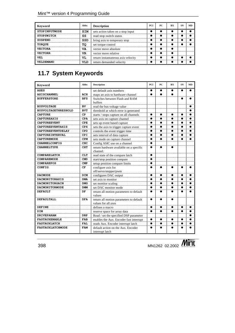
Mint™ version 4 Programming Guide
398 MN1262 02.2002
Keyword Abbr. Description PCI PC BX SN MD
STOPINPUTMODE SIM sets action taken on a stop input � � � � �
STOPSWITCH SS read stop switch status � � � � �
SUSPEND SSD bring axis to temporary stop � � � � �
TORQUE TQ set torque control � � � � �
VECTORA VA vector move absolute � � �
VECTORR VR vector move relative � � �
VEL VL return instantaneous axis velocity � � � � �
VELDEMAND VLD return demanded velocity � � � � �
11.7 System Keywords
Keyword Abbr. Description PCI PC BX SN MD
AXES set default axis numbers � � � � �
AXISCHANNEL ACH maps an axis to hardware channel � � �
BUFFERSTORE BFS Switches between Flash and RAM buffers
� �
BUSVOLTAGE BV read the bus voltage value �
BUSVOLTAGETHRESHOLD BVT threshold at which error is generated �
CAPTURE CP starts / stops capture on all channels � � � � �
CAPTUREAXIS CPA sets axis on capture channel � � � � �
CAPTUREEVENT CPE sets up event based capture � � � � �
CAPTUREEVENTAXIS CPX sets the axis to trigger capture event � � � � �
CAPTUREEVENTDELAY CPD controls the event trigger time � � � � �
CAPTUREINTERVAL CPI sets interval of data capture � � � � �
CAPTUREMODE CPM sets mode on capture channel � � � � �
CHANNELCONFIG CHC Config ASIC use on a channel �
CHANNELTYPE CHT return hardware available on a specific channel.
� � �
COMPARELATCH CLT read state of the compare latch �
COMPAREMODE CMD start/stop position compare �
COMPAREPOS CMP setup position compare limits �
CONFIG CF configure axis for off/servo/stepper/pwm
� � � � �
DACMODE DCM configures DAC output � � � � �
DACMONITORAXIS DMA set axis to monitor � � � � �
DACMONITORGAIN DMG set monitor scaling � � � � �
DACMONITORMODE DMM set DAC monitor mode � � � � �
DEFAULT DF return all motion parameters to default values
� � � � �
DEFAULTALL DFA return all motion parameters to default values for all axes
� � �
DEFINE defines a macro � � � � �
DIM reserve space for array data � � � � �
DRIVEPARAM DRP Read / set the specified DSP parameter �
FASTAUXENABLE FAB enables the Aux. Encoder fast interrupt � � � � �
FASTAUXLATCH FAL reads Aux. Encoder interrupt latch � � � � �
FASTAUXLATCHMODE FAM default action on the Aux. Encoder interrupt latch
� � � � �

Quick Reference
MN1262 02.2002 399
Keyword Abbr. Description PCI PC BX SN MD
FASTAUXSELECT FAS selects the digital input for the Aux. Encoder fast interrupt
� � � � �
FASTENABLE FEB enables the axis fast interrupt � � � � �
FASTLATCH FLT reads axis fast interrupt latch � � � � �
FASTLATCHMODE FTM default action on the axis interrupt latch � � � � �
FASTSELECT FS selects the digital input for the axis fast interrupt
� � � � �
FIRMWARERELEASE FWR reads firmware release number � � � � �
FREE display free memory � � � � �
HALL HLL read current motor hall value �
ICMDISABLE enable/disable ICM � � �
KACCEL KA servo loop acceleration ff gain � � �
KDERIV KD derivative gain term � � � � �
KIINT KII current loop integral gain � �
KINT KI servo loop integral gain � � � � �
KINTLIMIT KIL servo loop integration range � � � � �
KINTMODE KIM set how integral gain is used � � � � �
KIPROP KIP current loop proportional gain � �
KIRFF KIR current loop feedforward gain � �
KPROP KP servo loop proportional gain � � � � �
KVEL KV servo loop velocity gain � � � � �
KVELFF KF servo loop velocity feed forward gain � � � � �
KVMEAS KVM velocity loop feedback gain �
KVPROP KVP velocity loop proportional gain � �
KVTIME KVT velocity loop time constant �
LOOPTIME LT set servo loop time � � � � �
MOTORALIGNMENT MAL set feedback alignment of the motor �
MOTORDIRECTION MD set electrical direction of motor �
MOTORENCODERLINES MEL set number of encoder lines of the motor �
MOTORENCODERESOLUTION MES set the encoder resolution of the motor � �
MOTORFEEDBACK MFB set the motor feedback type �
MOTORINDUCTANCE MID set the inductance of the motor �
MOTORPEAKCURRENT MPC set peak current rating of the motor �
MOTORPHASEOFFSET MPO set the phase offset of the motor �
MOTORPOLEPITCH MPP set the pitch of motor poles � �
MOTORPOLES MP set the number of motor pole pairs �
MOTORRATEDCURRENT MRC set the rated current of the motor �
MOTORRESOLVERSPEED MRS set the motor resolver speed �
MOTORSPEEDFILTER MSF set speed filter for resolver motors �
MOTORSPEEDMAX MSM set the maximum speed of the motor �
NUMBEROF NO displays number of hardware resources � � � � �
PLATFORM PTM Returns the platform type � � � � �
PROFILETIME PT set the rate at which the profiler runs � � �
RELEASE clear user variables from memory � � � � �
RUN execute a program � � � � �
SCALE SF scale encoder counts to user units � � � � �
SEXTANT SEX set the motor sextant �
TEMPERATURE returns the current temperature of the controller
� �
TIME TE user timer � � � � �
TROFF program trace off � � � � �
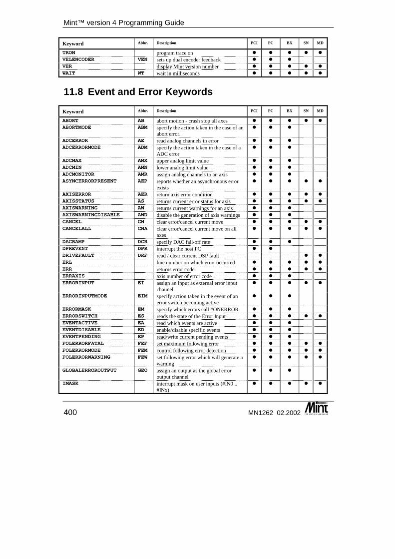
Mint™ version 4 Programming Guide
400 MN1262 02.2002
Keyword Abbr. Description PCI PC BX SN MD
TRON program trace on � � � � �
VELENCODER VEN sets up dual encoder feedback � � �
VER display Mint version number � � � � �
WAIT WT wait in milliseconds � � � � �
11.8 Event and Error Keywords
Keyword Abbr. Description PCI PC BX SN MD
ABORT AB abort motion - crash stop all axes � � � � �
ABORTMODE ABM specify the action taken in the case of an abort error.
� � �
ADCERROR AE read analog channels in error � � �
ADCERRORMODE ADM specify the action taken in the case of a ADC error
� � �
ADCMAX AMX upper analog limit value � � �
ADCMIN AMN lower analog limit value � � �
ADCMONITOR AMR assign analog channels to an axis � � �
ASYNCERRORPRESENT AEP reports whether an asynchronous error exists
� � � � �
AXISERROR AER return axis error condition � � � � �
AXISSTATUS AS returns current error status for axis � � � � �
AXISWARNING AW returns current warnings for an axis � � �
AXISWARNINGDISABLE AWD disable the generation of axis warnings � � �
CANCEL CN clear error/cancel current move � � � � �
CANCELALL CNA clear error/cancel current move on all axes
� � � � �
DACRAMP DCR specify DAC fall-off rate � � �
DPREVENT DPR interrupt the host PC � �
DRIVEFAULT DRF read / clear current DSP fault � �
ERL line number on which error occurred � � � � �
ERR returns error code � � � � �
ERRAXIS axis number of error code � � �
ERRORINPUT EI assign an input as external error input channel
� � � � �
ERRORINPUTMODE EIM specify action taken in the event of an error switch becoming active
� � �
ERRORMASK EM specify which errors call #ONERROR � � �
ERRORSWITCH ES reads the state of the Error Input � � � � �
EVENTACTIVE EA read which events are active � � �
EVENTDISABLE ED enable/disable specific events � � �
EVENTPENDING EP read/write current pending events � � �
FOLERRORFATAL FEF set maximum following error � � � � �
FOLERRORMODE FEM control following error detection � � � � �
FOLERRORWARNING FEW set following error which will generate a warning
� � � � �
GLOBALERROROUTPUT GEO assign an output as the global error output channel
� � �
IMASK interrupt mask on user inputs (#IN0 .. #INx)
� � � � �

Quick Reference
MN1262 02.2002 401
Keyword Abbr. Description PCI PC BX SN MD
IPEND IP user interrupts pending � � � � �
LIMIT LM read limit switch input values � � � � �
LIMITFORWARD LF read state of forward hardware limit � � � � �
LIMITFORWARDINPUT LFI assign input as forward limit input � � � � �
LIMITMODE LMD set action taken on a hardware limit input
� � � � �
LIMITREVERSE LR read state of reverse hardware limit � � � � �
LIMITREVERSEINPUT LRI assign input as reverse limit input � � � � �
MISCERROR MER reads the miscellaneous error � � � � �
MISCERRORDISABLE MED masks the miscellaneous errors � � � � �
RESET RE re-initialize motion variables � � � � �
RESETALL RA RESET all axes � � � � �
SOFTLIMITFORWARD SLF set forward software position limit � � � � �
SOFTLIMITMODE SLM sets action taken on a soft (position) limit
� � � � �
SOFTLIMITREVERSE SLR set reverse software position limit � � � � �
TIMEREVENT TEV Start a user timer event � � � � �
VELFATAL VLF set velocity deviation limit � � �
VELFATALMODE VLM specify action taken in event of exceeding velocity deviation
� � �
11.9 Input/Output Keywords
Keyword Abbr. Description PCI PC BX SN MD
ADC read the analog inputs � � � � �
ADCMODE sets the mode for the analog input channel
� � �
AUXDAC reads or sets the Aux. DAC output � �
BANK select I/O bank to access �
BOOST BT control stepper boost output �
DAC DC write direct to DAC output � � � � �
FREQ FQ set frequency on stepper output �
IN read 24 bit value of digital inputs � � � � �
INPUTACTIVELEVEL IAL sets or returns active high inputs � � � � �
INPUTDEBOUNCE IDB the number of samples for debounce � � �
INPUTMODE INM sets edge or level triggering on digital inputs
� � � � �
INPUTNEGTRIGGER IGT sets negative edge triggered inputs � � � � �
INPUTPOSTRIGGER IPT sets positive edge triggered inputs � � � � �
INSTATE IS read the raw state of the digital inputs � � �
OUT OT write value to digital output � � � � �
OUTPUTACTIVELEVEL OAL sets outputs to be active high when on � � � � �
RELAY RL enable/disable relay output � � �
STEPPERIO SIO control pulse and direction outputs � �
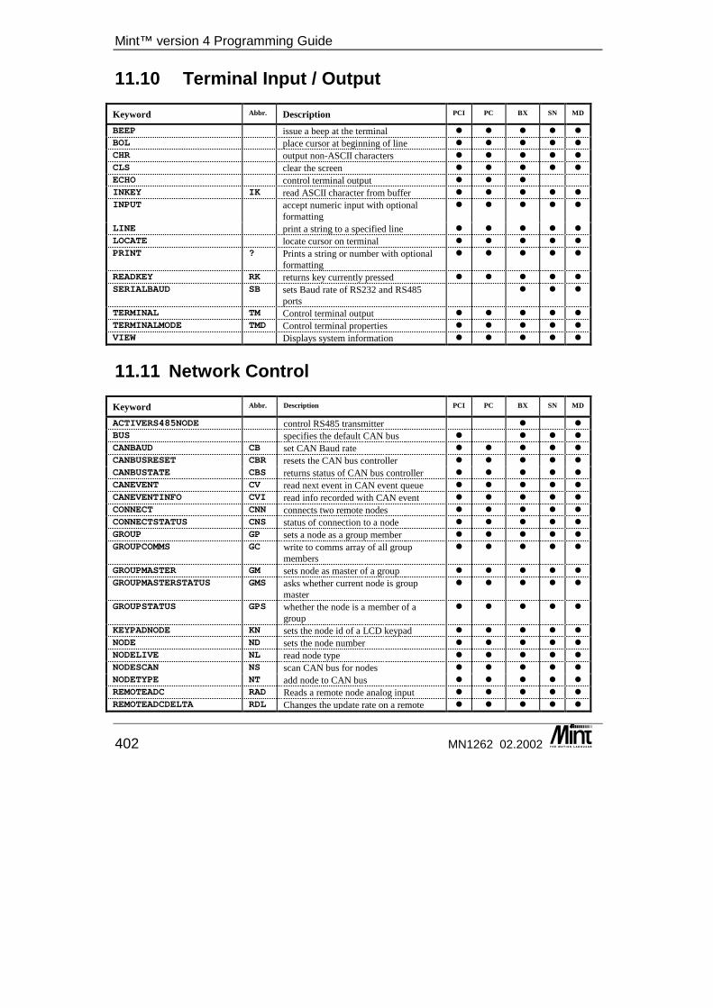
Mint™ version 4 Programming Guide
402 MN1262 02.2002
11.10 Terminal Input / Output
Keyword Abbr. Description PCI PC BX SN MD
BEEP issue a beep at the terminal � � � � �
BOL place cursor at beginning of line � � � � �
CHR output non-ASCII characters � � � � �
CLS clear the screen � � � � �
ECHO control terminal output � � �
INKEY IK read ASCII character from buffer � � � � �
INPUT accept numeric input with optional formatting
� � � � �
LINE print a string to a specified line � � � � �
LOCATE locate cursor on terminal � � � � �
PRINT ? Prints a string or number with optional formatting
� � � � �
READKEY RK returns key currently pressed � � � � �
SERIALBAUD SB sets Baud rate of RS232 and RS485 ports
� � �
TERMINAL TM Control terminal output � � � � �
TERMINALMODE TMD Control terminal properties � � � � �
VIEW Displays system information � � � � �
11.11 Network Control
Keyword Abbr. Description PCI PC BX SN MD
ACTIVERS485NODE control RS485 transmitter � �
BUS specifies the default CAN bus � � � �
CANBAUD CB set CAN Baud rate � � � � �
CANBUSRESET CBR resets the CAN bus controller � � � � �
CANBUSTATE CBS returns status of CAN bus controller � � � � �
CANEVENT CV read next event in CAN event queue � � � � �
CANEVENTINFO CVI read info recorded with CAN event � � � � �
CONNECT CNN connects two remote nodes � � � � �
CONNECTSTATUS CNS status of connection to a node � � � � �
GROUP GP sets a node as a group member � � � � �
GROUPCOMMS GC write to comms array of all group members
� � � � �
GROUPMASTER GM sets node as master of a group � � � � �
GROUPMASTERSTATUS GMS asks whether current node is group master
� � � � �
GROUPSTATUS GPS whether the node is a member of a group
� � � � �
KEYPADNODE KN sets the node id of a LCD keypad � � � � �
NODE ND sets the node number � � � � �
NODELIVE NL read node type � � � � �
NODESCAN NS scan CAN bus for nodes � � � � �
NODETYPE NT add node to CAN bus � � � � �
REMOTEADC RAD Reads a remote node analog input � � � � �
REMOTEADCDELTA RDL Changes the update rate on a remote � � � � �
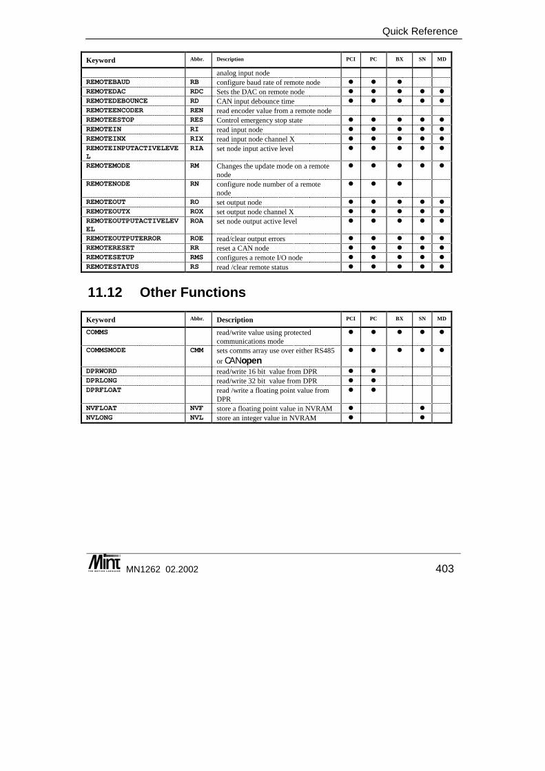
Quick Reference
MN1262 02.2002 403
Keyword Abbr. Description PCI PC BX SN MD
analog input node REMOTEBAUD RB configure baud rate of remote node � � �
REMOTEDAC RDC Sets the DAC on remote node � � � � �
REMOTEDEBOUNCE RD CAN input debounce time � � � � �
REMOTEENCODER REN read encoder value from a remote node
REMOTEESTOP RES Control emergency stop state � � � � �
REMOTEIN RI read input node � � � � �
REMOTEINX RIX read input node channel X � � � � �
REMOTEINPUTACTIVELEVEL
RIA set node input active level � � � � �
REMOTEMODE RM Changes the update mode on a remote node
� � � � �
REMOTENODE RN configure node number of a remote node
� � �
REMOTEOUT RO set output node � � � � �
REMOTEOUTX ROX set output node channel X � � � � �
REMOTEOUTPUTACTIVELEVEL
ROA set node output active level � � � � �
REMOTEOUTPUTERROR ROE read/clear output errors � � � � �
REMOTERESET RR reset a CAN node � � � � �
REMOTESETUP RMS configures a remote I/O node � � � � �
REMOTESTATUS RS read /clear remote status � � � � �
11.12 Other Functions
Keyword Abbr. Description PCI PC BX SN MD
COMMS read/write value using protected communications mode
� � � � �
COMMSMODE CMM sets comms array use over either RS485 or CANopen
� � � � �
DPRWORD read/write 16 bit value from DPR � �
DPRLONG read/write 32 bit value from DPR � �
DPRFLOAT read /write a floating point value from DPR
� �
NVFLOAT NVF store a floating point value in NVRAM � �
NVLONG NVL store an integer value in NVRAM � �

Mint™ version 4 Programming Guide
404 MN1262 02.2002
11.13 Line Editor Commands
Keyword Abbr. Description PCI PC BX SN MD
CON change to configuration buffer � � � � � DEL delete lines from a program � � � � � EDIT edit a program line � � � � � INS insert lines into program � � � � � LIST list a program � � � � � NEW clear program from memory � � � � � PROG change to program buffer � � � � �
11.14 Relational and Mathematical Operators
Keyword Abbr. Description PCI PC BX SN MD
+ - / * < > <= >= <>=
Arithmetic & relational operators � � � � �
~ bitwise toggle � � � � �
ABS return absolute value of number � � � � �
ACOS returns arc-cosine � � � � �
AND & logical (bitwise) AND � � � � �
ASIN returns arc-sine � � � � �
ATAN returns arc-tangent � � � � �
COS returns cosine of angle � � � � �
EXP exponential function � � � � �
INT returns integer of number � � � � �
LOG returns natural logarithm of number � � � � �
MOD % modulo arithmetic operator � � � � �
NOT ! Logical not � � � � �
OR | logical (bitwise) OR � � � � �
POW power of � � � � �
SIN returns sine of angle � � � � �
SQRT returns square root of number � � � � �
TAN returns tangent of angle � � � � �
XOR exclusive OR � � � � �
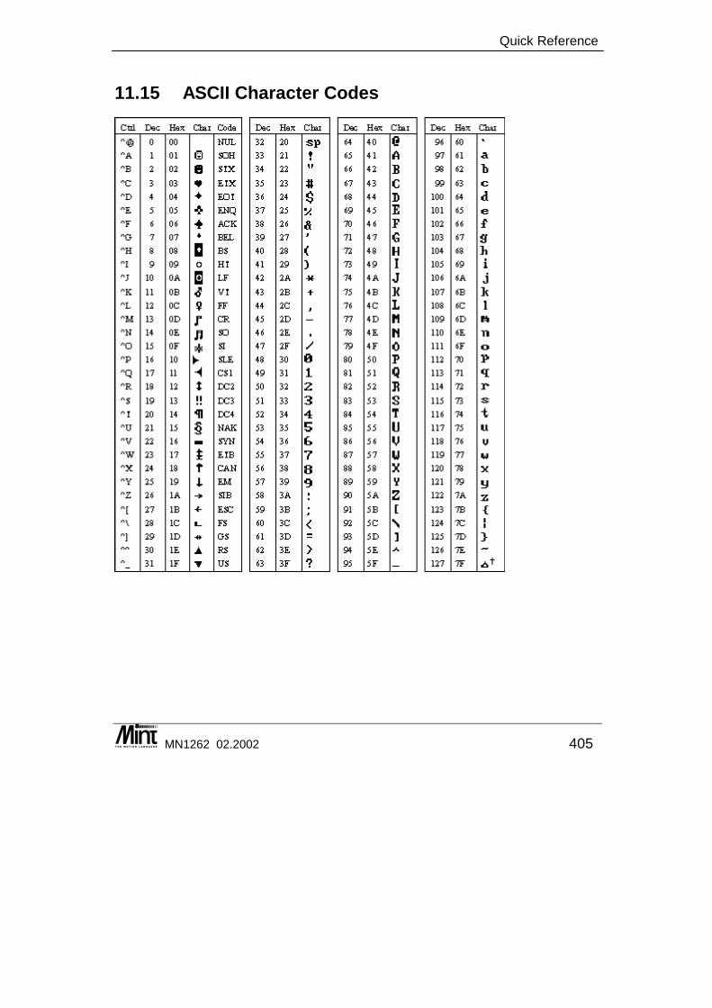
Quick Reference
MN1262 02.2002 405
11.15 ASCII Character Codes

Mint™ version 4 Programming Guide
406 MN1262 02.2002

Troubleshooting
MN1262 02.2002 407
12. Troubleshooting
12 This chapter provides:
◊ A cross reference of symptoms to possible solutions ◊ A cross reference of error codes and messages to their
meanings.

Mint™ version 4 Programming Guide
408 MN1262 02.2002
12.1 Troubleshooting Common Problems AUTO doesn’t seem to work ? AUTO must be the first statement in the configuration file. Check that you have no other statements prior to AUTO, including any REM statements. Garbage is written to the terminal screen ? Check the serial port Baud rate setting on the terminal. How can I check whether my program compiles without running it ? Use FREE. FREE compiles your downloaded program held in the configuration and program buffers. I cannot use INPUT to assign a value to an array ? You must first assign the value to a variable using INPUT and then assign that to the array. You can also use the array as a variable for this purpose. E.g. INPUT “Enter position ”, position position(x) = position I cannot declare a variable with the same name as an array ? Array names are stored on the variable stack, while the elements are stored in free memory. A variable of the same name cannot therefore be declared, however the array may also be assigned a value like a variable, independent of the array elements. I cannot declare two macros with similar names ? Only the first 10 characters of a macro name are stored on the stack – the first 10 characters of the macro name must therefore be unique. I cannot declare two variables with similar names ? Only the first 10 characters of a variable name are stored on the variable stack – the first 10 characters of the variable must therefore be unique. I cannot edit my program from the command line editor ? Are you storing your program in Flash? You cannot edit your program from the command line editor when it has been downloaded into Flash. My FOR loop looks to be syntactically correct, but I get an ‘Invalid command’ error reported ? Are you using a reserved keyword as the loop counter ? Reserved keywords such as LOOP cannot be re-used as variable names. e.g. FOR LOOP = 1 TO 10 : REM Code : NEXT My program won’t download because a line is too long ? The maximum line length is 255 characters, including comments. Shorten the line if possible, by breaking compounded statements into several lines. Use keyword abbreviations or macros to replace commonly used string definitions.

Troubleshooting
MN1262 02.2002 409
My program is too big to download ? Try turning squash on download on – this will abbreviate all keywords, remove comments and unnecessary spaces from your program when downloaded onto the controller. Try deleting any arrays that may have been left over from a previous application. Use the keyword RELEASE. Try downloading your program into Flash. See the keyword BUFFERSTORE. RELEASE doesn’t delete all variable and array definitions ? There will always be two pre-defined Mint arrays present: COMMS and GROUPCOMMS. These don’t use any memory space, but do use space on the variable stack. The controller reports corrupted variables at power-up ? The variable stack held in battery-backed up RAM may have been corrupted. All variables previously stored will have been lost. The controller reports memory corruption at power-up ? The data held in battery-backed up RAM may have been corrupted. Type NEW from both the Configuration and Program buffers to clear memory contents, then download your program files again. The controller reports “Fatal Initialisation Error. Contact your supplier.” at power-up ? There has been a failure reading the EEPROM devices on the controller. The controller reports “Initialisation Error.” at power-up ? There has been a failure reading an EEPROM device on the controller – try using the EEPROM defaults by resetting the controller at power-up. The floating-point value stored in a variable isn’t what I assigned to it ? Mint stores values as scaled integers. Not all values can be stored accurately and therefore slight rounding errors are inherent in Mint when using floating-point values. The value I assigned to a profiler keyword (e.g. SPEED) is not what I read back ? The controller stores many parameters, such as SPEED, as a scaled integer scaled according to the servo loop frequency. Only certain values may be accurately stored using this scaling and the value is therefore rounded accordingly. There is not enough memory to compile my program ? If you are using battery backed-up RAM, then try squashing your program when you download it – this will take up less space on the controller. Try deleting any arrays that may have been left over from a previous application or are not used from within your program. Use the keyword RELEASE. Try running your program from Flash. This frees up more battery backed-up RAM for compiling your program. See the keyword BUFFERSTORE. If you are using battery backed-up RAM, then try abbreviating commonly used strings with macros. Macros are substituted at compile time and can therefore save space used to store the program.
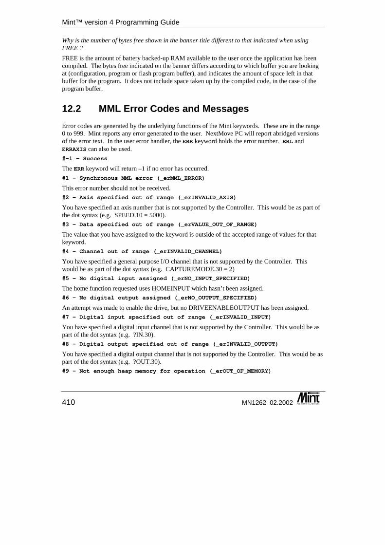
Mint™ version 4 Programming Guide
410 MN1262 02.2002
Why is the number of bytes free shown in the banner title different to that indicated when using FREE ? FREE is the amount of battery backed-up RAM available to the user once the application has been compiled. The bytes free indicated on the banner differs according to which buffer you are looking at (configuration, program or flash program buffer), and indicates the amount of space left in that buffer for the program. It does not include space taken up by the compiled code, in the case of the program buffer.
12.2 MML Error Codes and Messages Error codes are generated by the underlying functions of the Mint keywords. These are in the range 0 to 999. Mint reports any error generated to the user. NextMove PC will report abridged versions of the error text. In the user error handler, the ERR keyword holds the error number. ERL and ERRAXIS can also be used. #-1 – Success
The ERR keyword will return –1 if no error has occurred. #1 – Synchronous MML error (_erMML_ERROR)
This error number should not be received. #2 – Axis specified out of range (_erINVALID_AXIS)
You have specified an axis number that is not supported by the Controller. This would be as part of the dot syntax (e.g. SPEED.10 = 5000). #3 – Data specified out of range (_erVALUE_OUT_OF_RANGE)
The value that you have assigned to the keyword is outside of the accepted range of values for that keyword. #4 – Channel out of range (_erINVALID_CHANNEL)
You have specified a general purpose I/O channel that is not supported by the Controller. This would be as part of the dot syntax (e.g. CAPTUREMODE.30 = 2) #5 - No digital input assigned (_erNO_INPUT_SPECIFIED)
The home function requested uses HOMEINPUT which hasn’t been assigned. #6 - No digital output assigned (_erNO_OUTPUT_SPECIFIED)
An attempt was made to enable the drive, but no DRIVEENABLEOUTPUT has been assigned. #7 – Digital input specified out of range (_erINVALID_INPUT)
You have specified a digital input channel that is not supported by the Controller. This would be as part of the dot syntax (e.g. ?IN.30). #8 – Digital output specified out of range (_erINVALID_OUTPUT)
You have specified a digital output channel that is not supported by the Controller. This would be as part of the dot syntax (e.g. ?OUT.30). #9 – Not enough heap memory for operation (_erOUT_OF_MEMORY)
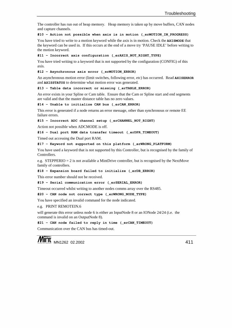
Troubleshooting
MN1262 02.2002 411
The controller has run out of heap memory. Heap memory is taken up by move buffers, CAN nodes and capture channels. #10 – Action not possible when axis is in motion (_erMOTION_IN_PROGRESS)
You have tried to write to a motion keyword while the axis is in motion. Check the AXISMODE that the keyword can be used in. If this occurs at the end of a move try ‘PAUSE IDLE’ before writing to the motion keyword. #11 – Incorrect axis configuration (_erAXIS_NOT_RIGHT_TYPE)
You have tried writing to a keyword that is not supported by the configuration (CONFIG) of this axis. #12 – Asynchronous axis error (_erMOTION_ERROR)
An asynchronous motion error (limit switches, following error, etc) has occurred. Read AXISERROR and AXISSTATUS to determine what motion error was generated. #13 – Table data incorrect or missing (_erTABLE_ERROR)
An error exists in your Spline or Cam table. Ensure that the Cam or Spline start and end segments are valid and that the master distance table has no zero values. #14 – Unable to initialize CAN bus (_erCAN_ERROR)
This error is generated if a node returns an error message, other than synchronous or remote EE failure errors. #15 - Incorrect ADC channel setup (_erCHANNEL_NOT_RIGHT)
Action not possible when ADCMODE is off. #16 - Dual port RAM data transfer timeout (_erDPR_TIMEOUT)
Timed out accessing the Dual port RAM. #17 – Keyword not supported on this platform (_erWRONG_PLATFORM)
You have used a keyword that is not supported by this Controller, but is recognised by the family of Controllers. e.g. STEPPERIO = 2 is not available a MintDrive controller, but is recognised by the NextMove family of controllers. #18 - Expansion board failed to initialize (_erDB_ERROR)
This error number should not be received. #19 - Serial communication error (_erSERIAL_ERROR)
Timeout occurred whilst writing to another nodes comms array over the RS485. #20 – CAN node not correct type (_erWRONG_NODE_TYPE)
You have specified an invalid command for the node indicated. e.g. PRINT REMOTEIN.6 will generate this error unless node 6 is either an InputNode 8 or an IONode 24/24 (i.e. the command is invalid on an OutputNode 8). #21 – CAN node failed to reply in time (_erCAN_TIMEOUT)
Communication over the CAN bus has timed-out.
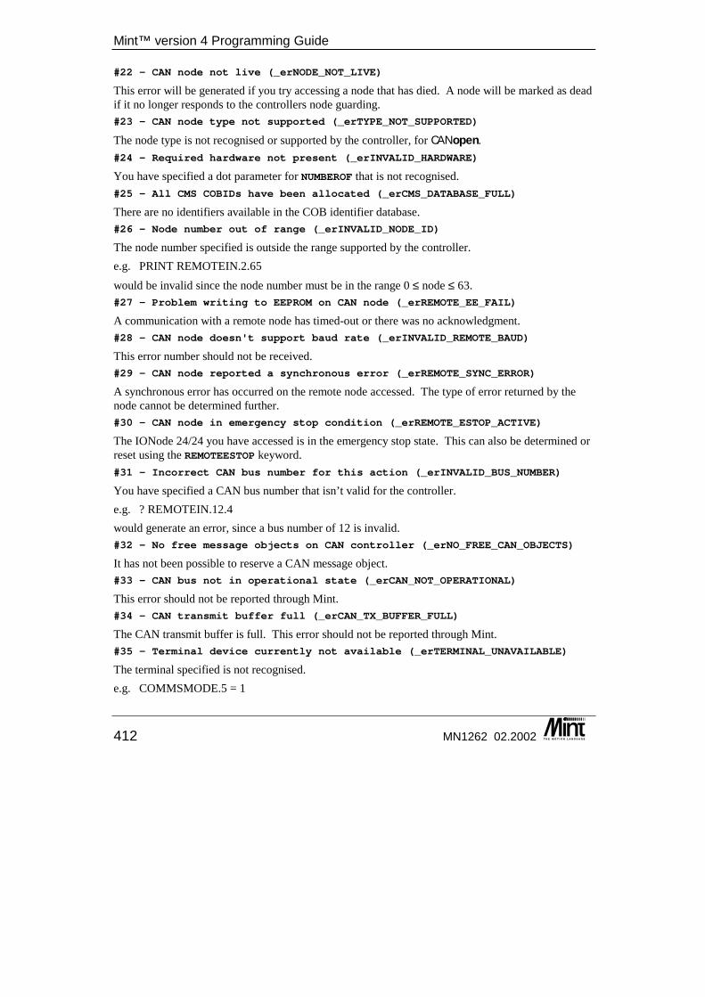
Mint™ version 4 Programming Guide
412 MN1262 02.2002
#22 – CAN node not live (_erNODE_NOT_LIVE)
This error will be generated if you try accessing a node that has died. A node will be marked as dead if it no longer responds to the controllers node guarding. #23 – CAN node type not supported (_erTYPE_NOT_SUPPORTED)
The node type is not recognised or supported by the controller, for CANopen. #24 – Required hardware not present (_erINVALID_HARDWARE)
You have specified a dot parameter for NUMBEROF that is not recognised. #25 – All CMS COBIDs have been allocated (_erCMS_DATABASE_FULL)
There are no identifiers available in the COB identifier database. #26 – Node number out of range (_erINVALID_NODE_ID)
The node number specified is outside the range supported by the controller. e.g. PRINT REMOTEIN.2.65 would be invalid since the node number must be in the range 0 ≤ node ≤ 63. #27 – Problem writing to EEPROM on CAN node (_erREMOTE_EE_FAIL)
A communication with a remote node has timed-out or there was no acknowledgment. #28 – CAN node doesn't support baud rate (_erINVALID_REMOTE_BAUD)
This error number should not be received. #29 – CAN node reported a synchronous error (_erREMOTE_SYNC_ERROR)
A synchronous error has occurred on the remote node accessed. The type of error returned by the node cannot be determined further. #30 – CAN node in emergency stop condition (_erREMOTE_ESTOP_ACTIVE)
The IONode 24/24 you have accessed is in the emergency stop state. This can also be determined or reset using the REMOTEESTOP keyword. #31 – Incorrect CAN bus number for this action (_erINVALID_BUS_NUMBER)
You have specified a CAN bus number that isn’t valid for the controller. e.g. ? REMOTEIN.12.4 would generate an error, since a bus number of 12 is invalid. #32 – No free message objects on CAN controller (_erNO_FREE_CAN_OBJECTS)
It has not been possible to reserve a CAN message object. #33 – CAN bus not in operational state (_erCAN_NOT_OPERATIONAL)
This error should not be reported through Mint. #34 – CAN transmit buffer full (_erCAN_TX_BUFFER_FULL)
The CAN transmit buffer is full. This error should not be reported through Mint. #35 – Terminal device currently not available (_erTERMINAL_UNAVAILABLE)
The terminal specified is not recognised. e.g. COMMSMODE.5 = 1
Troubleshooting
MN1262 02.2002 413
is invalid, since there is no terminal with an identifier of 5. #36 – Terminal device out of range (_erTERMINAL_OUT_OF_RANGE)
The terminal specified is not valid for the keyword. e.g. COMMSMODE._tmLCD1 = 1 is invalid, since COMMSMODE is only applicable to the RS232 and RS485 terminals. #37 – Non-volatile data corrupted (_erNON_VOLATILE_MEMORY_ERROR)
An error accessing EEPROM or NVRAM data has occurred. #38 – Terminal buffer empty (_erTERMINAL_BUFFER_EMPTY)
The receive buffer is full. This error should not be reported through Mint. This error will be generated if the controllers receive buffer is empty when attempting to read it. #39 – Terminal buffer full (_erTERMINAL_BUFFER_FULL)
The transmit buffer is full. This error should not be reported through Mint. This error will be generated if the controllers transmit buffer becomes full when transmitting over the RS232, RS485 or CAN ports. If this error occurs on the RS232 serial port a bit will also be set in MISCERROR. #40 – Drive is not enabled (_erDRIVE_DISABLED)
You have tried starting a move while the drive is disabled. Use DRIVEENABLE to enable the drive. #41 – No connection exists (_erNO_CONNECTION)
There is no connection between the CANopen nodes. #42 – CAN protocol error during comms (_erCAN_PROTOCOL_ERROR)
This error is only applicable to CANopen applications. A protocol error has been detected when communicating over the CAN bus. #43 – Local CAN node not correct (_erINVALID_LOCAL_NODE)
This error is only applicable to CANopen applications. A command has been given that is only valid if you are a master node. #44 - Must be RS485 master node (_erNOT_NETWORK_MASTER)
Action is not possible unless you are the master node on the RS485. #45 – COMMS element is read only (_erCOMMS_READ_ONLY)
You have tried writing to a reserved COMMS array element. #46 – COMMS element is reserved (_erCOMMS_RESERVED_ELEMENT)
You have tried accessing an extended COMMS array element that has been reserved for future use. #47 – Digital output driver fault (_erOUTPUT_FAULT)
You have tried setting a digital output that has an output fault. This will only be generated on a ServoNode 51 or when writing to the outputs on an ioNODE 24/24 node. #48 – Drive failed to clear the error (_erDSP_FAILED_TO_CLEAR_ERROR)
DSP (Motor control) failed to clear error condition. #49 – The offset cannot be profiled (_erOFFSET_PROFILE_ERROR)
This error number should not be received.
Mint™ version 4 Programming Guide
414 MN1262 02.2002
#50 – Error programming Flash (_erFLASH_PROGRAMMING)
The controller has failed to write data to the Flash program buffer. If this problem persists contact your supplier. #51 – Error addressing flash (_erADDRESS_OUT_OF_RANGE)
The controller has specified an invalid Flash address while downloading your program to Flash. If this problem persists contact your supplier. #52 – Error in checksum (_erCRC_CHECKSUM_ERROR)
The controller has received a different checksum, for the file that you was downloading, to that calculated. Try downloading the file again. If the problem persists check your serial port cable. #53 – Cannot write to flash with drive enabled (_erFLASH_BEING_PROGRAMMED)
You have tried downloading a file to Flash while a drive is enabled. Disable all drives prior to downloading files to Flash. #54 – File too big (_erFILE_TOO_BIG)
The file is too large to fit into the controller memory space reserved for the applicable buffer. Try reducing the size of your program by removing redundant code and variables or using the SQUASH utility to abbreviate code. Try using Flash to store your Mint program. #55 - Invalid CAN object (_erCAN_INVALID_OBJECT)
This error number should not be received. #56 - CAN object is reserved (_erCAN_RESERVED_OBJECT)
This error number should not be received. #57 - Invalid remote I/O channel (_erCAN_INVALID_CHANNEL)
This error number should not be received. #58 - CAN parameter out of range (_erCAN_VALUE_OUT_OF_RANGE)
The parameter passed to a CANopen keyword is out of range. #59 - Move buffer full (_erMOVE_BUFFER_FULL)
The move cannot be loaded into the move buffer because it is full. #60 - ICM protocol error (_erICM_ARRAY_ERROR)
This error number should not be received. #61 - ICM protocol error (_erICM_TOO_MANY_ARRAYS)
This error number should not be received. #62 - ICM timeout (Controller data timeout) (_erICM_DATA_TIMEOUT)
This error number should not be received. #63 - ICM protocol error (_erICM_BLOCK_TOO_BIG)
This error number should not be received. #64 - ICM protocol error (_erICM_TX_SIZE_MISMATCH)
This error number should not be received. #65 - ICM timeout (Controller return timeout) (_erICM_DATA_TIMEOUT)
Troubleshooting
MN1262 02.2002 415
This error number should not be received. #66 - Function not available (_erMML_NOT_SUPPORTED)
This error number should not be received. #67 - Pointer access outside valid memory range (_erINVALID_POINTER)
This error number should not be received. #68 - Invalid error action mode (_erINVALID_MODE)
This error number should not be received. #69 - Debug keywords are disabled (_erDEBUG_DISABLED)
This error number should not be received. #70 - Invalid Master Channel (_erINVALID_MASTER_CHANNEL)
You have setup a master/slave move that is trying to follow itself. e.g. MASTERCHANNEL = 0 FOLLOW.0 = 1 #71 - All axes must be configured Off (_erALL_AXES_MUST_BE_OFF)
This error number should not be received. #72 - Move not allowed in this mode (_erINVALID_AXISMODE)
The move that you have tried setting up is not valid in this AXISMODE. #73 - Timeout during file download (_erDOWNLOAD_TIMEOUT)
Mint has not received a character within the specified timeout whilst downloading a Mint program. #74 - Cannot upload while capture in progress (_erCAPTURE_IN_PROGRESS)
An attempt was made to upload capture data to the host application whilst data is still being captured. #75 - Invalid number of capture points (_erINVALID_NUM_CAP_PTS)
This error number should not be received. #76 - Invalid BBP transaction number (_erINVALID_BBP_TRANS_NO)
This error number should not be received. #77 - Invalid BBP field length (_erINVALID_BBP_FIELD_LENGTH)
This error number should not be received. #78 - Drive data out of range (_erBBP_DATA_OUT_OF_RANGE)
You have specified a value that is out of range on the drive. #79 - Drive data modified by control (_erBBP_DATA_OUT_OF_BOUNDS)
The data you have specified was out of range, but the drive has modified this value. #80 - Drive fault prevents execution (_erBBP_FAULT_PREVENTS_EXEC)
The drive is in error and cannot execute this command. #81 - Drive state/mode prevents execution (_erBBP_MODE_PREVENTS_EXEC)
This error number should not be received.
Mint™ version 4 Programming Guide
416 MN1262 02.2002
#82 - BBP Block transfer not accepted (_erBBP_BLOCK_NOT_ACCEPTED)
This error number should not be received. #83 - BBP End of block reached (_erBBP_END_OF_BLOCK_REACHED)
This error number should not be received. #84 - BBP transaction error unknown (_erUNKNOWN_BBP_ERROR)
This error number should not be received. #85 - Drive transaction timed-out (_erBBP_TIMEOUT)
Communication with the integral drive has timed-out. #86 - BBP Transaction Rx overflow (_erBBP_OVERFLOW)
This error number should not be received. #87 - Invalid BBP Transaction size Rxd (_erINVALID_BBP_PACKET_SIZE_RXD)
This error number should not be received. #88 - Invalid BBP Transaction Rxd (_erINVALID_BBP_TRANSACTION_RXD)
This error number should not be received. #89 - Hardware channel required is in use (_erCHANNEL_IN_USE)
The hardware resource required for this operation is already being used. You must break the existing association in order to remap the hardware. #90 - Action not possible when axis is enabled (_erDRIVE_ENABLED)
The command is not possible whilst the drive is enabled. #91 - Drive parameter not supported (_erINVALID_DRIVE_PARAM)
The DRIVEPARAM number specified is not recognised. #92 - BBP transaction in progress (_erBBP_TRANSACTION_IN_PROGRESS)
This error number should not be received. #93 - No BBP transaction was requested (_erNO_BBP_TRANSACTION_REQUESTED)
This error number should not be received. #94 – ICM is disabled on this channel (_erICM_DISABLED)
The ICM interface is disabled on this channel. #95 – Output is already in use (_erOUTPUT_IN_USE)
The specified output is under firmware control as a drive enable output or a compare output. #96 – Invalid capture channel mix (_erCAPTURE_CHANNEL_MIX)
This error number should not be received. #97 - All controllable axes in use (_erALL_CONTROL_AXES_IN_USE)
All available hardware is assigned to an axis. #98 - Invalid CANopen variable type (_erINVALID_VAR_TYPE)
Data size of a remote object is incorrect. #99 - CAN confirmed service is busy(_erCAN_CONFIRMED_BUSY)

Troubleshooting
MN1262 02.2002 417
It is not possible to perform a CAN function because one is already in progress. This situation may occur where both a Mint program and a host application are both accessing a CAN bus. If a Mint CAN keyword is executing when a host CAN function call is received, this error will be returned to the host. #100 - Mint file protected (_erFILE_PROTECTED)
The Mint program or Configuration file is password protected. #101 - Remote Mint file download in progress
(_erREMOTE_DOWNLOAD_IN_PROGRESS)
Remote Mint file download is already in progress. #102 - Timeout on BBP request (_erBBP_REQUEST_TIMEOUT)
It is not possible to perform a keyword that requires drive parameter information since a call is already in progress. This situation may occur where both a Mint program and a host application are both accessing the drive stage. If a Mint keyword that accesses the drive stage is executing when a host call is received, this error will be returned to the host. #103 - Two devices updating same parameter (_erPARAMETER_ACCESS_CONFLICT)
It is not possible for this parameter to be updated from multiple sources. #104 - CANopen node is already connected (_erCAN_ALREADY_CONNECTED)
Attempting to CONNECT to a CANOpen node that already has an existing connection will result in theis error. #105 - The remote drive is disabled (_erREMOTE_DRIVE_DISABLED)
An action sent to a remote drive has failed because the drive is disabled. #106 - The remote drive is in fault mode (_erREMOTE_DRIVE_FAULT)
An action sent to a remote drive has failed because the drive is in fault mode. #107 - Transaction aborted due to nodes state (_erREMOTE_STATE_INCORRECT)
An action sent to a remote drive has failed because the drive is in the incorrect state. #108 - The remote drive didnt accept the move(_erREMOTE_DRIVE_MOVE_FAILED)
An move request sent to a remote drive has failed.
12.3 Mint Workbench Error Codes and Messages Errors detected by Mint WorkBench are reported with an error code within the range 1000 to 1999.
12.4 Mint Error Codes and Messages Mint generates errors based upon the programming rules of the Mint language. These are reported in the range 500 – 999 and 2000 to 2999. #500 – Axis error present
An asynchronous axis error has occurred (following error, limit error, cam sync. error for example). This will call #ONERROR if defined. Check AXISERROR for details on the error.
Mint™ version 4 Programming Guide
418 MN1262 02.2002
#501 – Miscellaneous error present
An asynchronous axis error has occurred. This will call #ONERROR if defined. Check MISCERROR for details on the error. #502 – Axis warning present
A warning has been generated. Check AXISWARNING for details on the error. #2000 – Read only or Command
You have tried writing a value to a keyword that is read only or is a command. e.g. CAMINDEX = 4 #2001 – Missing parameter
A parameter is missing in the brackets notation. e.g. SPEED[0,,2]=1000; SPEED[0,1,]=1000; would both generate this error. #2002 – Write only
You have tried to read a keyword that can only be written to. e.g. PRINT “Acceleration time is “, ACCELTIME would generate this error since it is a write only keyword. #2003 – Syntax error
The statement is syntactically incorrect. Check the syntax of your statement. e.g. IF (( a > b) AND (c > b) THEN PRINT “b is the lowest value” would generate a syntax error because a closing bracket is missing. #2004 – Parentheses error
Incorrect number of brackets within an expression. For example: a = (b + 2) *3)
#2005 – No expression
This error will be generated when a keyword is referenced incorrectly e.g. SPEED : REM ** Axis Slew Speed ** would generate an error since the keyword SPEED is not being read or assigned a value. #2006 – Invalid command
A keyword that is not valid on the command line has been used on the command line. i.e. keywords such as GOSUB, GOTO, DEFINE and DIM can only be used from within a program. Conversely, command line editor command (e.g. NEW, EDIT, etc) cannot be used within a program. A reserved keyword has been used instead of a variable. e.g. FOR loop = 1 TO 10 : … : NEXT INPUT “Enter speed”, SPEED

Troubleshooting
MN1262 02.2002 419
are both invalid since LOOP and SPEED are reserved keywords. #2007 – THEN or DO expected
You have started an IF construct, but are missing either the THEN or DO statement e.g. IF (a < b) PRINT “a is less than b” would generate an error since the THEN statement is missing. #2008 – TO expected
You have started a FOR..NEXT loop, but haven’t specified the FOR construct correctly. Check the syntax of your FOR loop, it should be: FOR <variable> = <expression> TO <expression> : … : NEXT #2009 – NEXT w/o FOR
The keyword NEXT has been found and an associated FOR is not at the top of the stack. If you are nesting loops, check that the nesting is correct: e.g. FOR index = 1 TO 10 REPEAT INPUT “Enter Master Distance”, master_dist NEXT UNTIL master_dist > 100 would generate the error since the FOR..NEXT loop has been terminated before the inner REPEAT..UNTIL loop. #2010 – RETURN w/o GOSUB
The keyword RETURN has been found without a GOSUB having being executed. Check that your main program is terminated correctly (i.e. with END). e.g. REM ** Main Program ** WHILE running REM ** Execution code ** ENDW PRINT “Program terminating” #ONERROR REM ** Error handler code RETURN this program would drop out of the WHILE loop when the variable ‘running’ is zero, but would also execute the code within the #ONERROR subroutine, since no END statement was found. #2011 – ELSE/ENDIF w/o IF DO
The keywords ELSE or ENDIF have been found without an associated IF..DO. Check that you haven’t used an IF..THEN construct instead of the IF..DO construct.
Mint™ version 4 Programming Guide
420 MN1262 02.2002
e.g. IF (a > b) THEN ?”a is greater than b” ELSE ?”a is less than or equal to b” ENDIF is invalid since the IF..DO construct should have been used for compound IF statements. Also check the nesting of IF statements: e.g. IF (a > b) DO ?”a is greater than b” ELSE ?”a is less than b” ELSE ?”a is equal to b” ENDIF ENDIF is invalid since a second ELSE statement has been found, without a corresponding IF..DO construct nested after the first ELSE statement. #2012 – ENDW w/o WHILE
The keyword ENDW has been found and an associated WHILE is not at the top of the stack. If you are nesting loops, check that the nesting is correct: e.g. WHILE master_dist = 0 REPEAT INPUT “Enter Master Distance”, master_dist ENDW UNTIL master_dist > 100 would generate the error since the WHILE..ENDW loop has been terminated before the inner REPEAT..UNTIL loop. #2013 – UNTIL w/o REPEAT
The keyword UNTIL has been found and an associated REPEAT is not at the top of the stack. If you are nesting loops, check that the nesting is correct: e.g. REPEAT WHILE master_dist = 0 INPUT “Enter Master Distance”, master_dist UNTIL master_dist > 100 ENDW would generate the error since the REPEAT..UNTIL loop has been terminated before the inner WHILE..ENDW loop. #2014 – Incorrect loop terminator
The keyword ENDL has been found and an associated LOOP is not at the top of the stack. If you are nesting loops, check that the nesting is correct:
Troubleshooting
MN1262 02.2002 421
e.g. LOOP WHILE master_dist = 0 INPUT “Enter Master Distance”, master_dist ENDL ENDW would generate the error since the LOOP..ENDL loop has been terminated before the inner WHILE..ENDW loop. #2015 – Stack overflow
You have defined more macros (using the DEFINE keyword) than can be supported by the controller. Alternatively, this could mean that you have exceeded the nesting allowed for FOR loops, GOSUB’s and GOTO’s. #2016 – Invalid index
You have specified an array index that is outside the dimensions of the array. e.g. DIM axis_speeds(100) : axis_speeds(0) = 1000 axis_speeds(101) = 2000 Both of these assignments would generate an error, since the array indices are in the range 1 ≤ index ≤ 100. #2017 – Too many parameters
You have specified more axes than is supported by the controller. e.g. AXES[0,1,3] SPEED[0,1,3] = 5000; are valid on a 4 axes controller, but invalid on a single axis controller. #2018 – Axis set more than once
You have specified the same axis in the bracket notation more than once. e.g. AXES[0,1,1,2] SPEED [2,2,3] = 5000; would both generate this error, since an axis has been specified twice. #2019 – Break
#2020 – Cannot execute with corrupted memory
#2021 – Divide by zero
You have tried to perform a division with a divisor of zero. If the divisor is a variable or array element, check its contents. If dividing by a system variable then may have a zero value (e.g. VEL), then it may be worth assigning it to a variable and checking for a zero value. e.g. axis_speed = VEL IF ( axis_speed <> 0 ) THEN movetime = move_dist / axis_speed #3000 – Too many labels

Mint™ version 4 Programming Guide
422 MN1262 02.2002
You have defined more subroutines than can be supported by the controller.. #3001 –Variable undefined, use DIM
A reference has been made to what has been interpreted as a variable, although the variable has not been declared. Check the spelling of the variable name. A variable must be declared before it can be referenced. For example
PRINT “Current axis speed is “, axis_speed
would generate an error if axis_speed had not been declared earlier. It is good programming practice to initialise all variables used within a program at the start, thus ensuring all variables are declared. See DIM for details. #3002 – Too many variables
You have defined more variables (including arrays) than can be supported by the controller. #3003 – Out of memory
The controller has run out of memory. This error will be generated when trying to compile your Mint program and there isn’t enough user memory available to store the tokenised code and array definitions. This error can also be generated from the command line, if editing the Mint program causes it to run out of memory. If this error occurs when editing the configuration file, it means that the configuration file buffer is full - there may still be space left in the program buffer. This error may also be generated when using the capture facility or attempting to increase the size of the move buffer. These are internal memory allocation faults on the controller and should be referenced to your supplier. #3004 – Invalid label
You have specified a name in a GOTO or GOSUB statement that is not recognised. Make sure the subroutine referenced is defined. #3005 – Invalid macro
The macro name specified is not valid. e.g. DEFINE 100 = “100” is not valid, since the macro name must be a alphanumeric string. #3006 – #FASTIN conflicts with #FASTINx
Both #FASTINx and #FASTIN have been defined. #3007 – Keyword not defined
You have specified a command that Mint does not recognise as a keyword. Check whether the keyword is supported by the controller and check your spelling of the keyword (particularly if you are using keyword abbreviations).
Bibliography
MN1262 02.2002 423
13. Bibliography
13 Bibliography
[1] Mint v4 Advanced Programming Guide (MN1270) [2] Mint v4 CAN Programming Guide (MN1282) [3] Mint v4 PC Programming Guide (MN1278) [4] Mint v4 Embedded Programming Guide (MN1279) [5] Mint v4 Function Reference Guide (MN1280) [6] Mint v4 Code Analyzer Tool Guide (MN1281) [7] Mint WorkBench Users Guide (MN1293) [8] NextMove PCI Installation Guide (MN1277) [9] NextMove PC Installation Guide (MN1257) [10] NextMove BX Installation Guide (MN1258) [11] CAN Peripherals Hardware Guide (MN1255) All manuals can be found in the Mint v4 section of the Baldor Motion Toolkit CD which accompanies the controllers.

Mint™ version 4 Programming Guide
424 MN1262 02.2002