minor project
TRANSCRIPT

UNIVERSITY OF PETROLEUM AND ENERGY STUDIES
DESIGN , ANALYSIS AND FABRICATION OF
A UAV FOR AERIAL PHOTOGRAPHY
By
Shivam Kapri-R890213030
Rajat Saklani –R890213022
Prashant Singh-R890213017
Rishabh Kumar-R890213023
Project mentor : Prof. Vijay Kumar Patidar
Department: Aerospace
FOREWORD
We would like to express our deep appreciation and thanks to our project
mentor for allowing us to work in the project “Design and fabrication of
UAV”in his guidance and for all the support we will get for achieving our
project goal.
May 16, 2016

Table of Contents
1.Summary
2.Introduction
3.Purpose of the project
4.Background
5.Methodology
5.1 Structure
5.1.1 Ribs
5.1.2 Spars
5.1.3 Stringers
5.1.4 Bulkhead
5.2 Aerodynamics
6. Operational Plan
6.1 Design
6.2 Fabrication
6.3 Testing
7.The basic design of the airplane
7.1 CAD models of airplane parts
8.Designing of the airplane
8.1 Weight estimation of airplane
8.2 Power and thrust required for level unaccelerated level flight
8.3 Estimating the available thrust and power.
8.4 Stalling calculation
8.5 Gliding flight calculations
8.6 CG moment calculations
9. Aircraft model fluent analysis
10.Some plots
11.Material to be used
12. Conclusion
13. References
List of Figures
Figure 1: Use of UAV in disaster management (source:TED)
Figure 2: Balsa wood
Figure 3:Reference model
Figure4:Main wing
Figure 5:Main wing inner structure
Figure6:Fuselage
Figure 7:Vertical stabilizer
Figure 8: Complete assembly
Figure 9:Available thrust estimation
Figure 10:Distances of ac from CG
Figure 11: Meshed domain
Figure 12:upper pressure contour
Figure 13:lower pressure contour
Figure 14:streamline pattern at 24 deg angle of attack
Figure 15:streamline pattern at 28 deg angle of attack
Figure 16:Lift and Drag plot of wing
Figure 17:Cl-alpha plot for wing
Figure 18:Cl-alpha plot for airfoil
Figure 19:Lift and Drag plot of horizontal stabilizer
Figure 20:Drag polar
Figure 21:L/D-alpha plot
Figure 22:Moment coefficient plot

1.SUMMARY
A model aircraft is a small sized unmanned aircraft or, in the case of a scale
model, a replica of an existing or imaginary aircraft. Model aircraft are divided
into two basic groups: flying and non-flying. Non-flying models are also
termed static, display, or shelf models.
Flying models range from simple toy gliders made of card stock or
foam polystyrene to powered scale models made from materials such as balsa
wood, bamboo, plastic, styrofoam, carbon fiber or fibreglass and are skinned
with tissue paper . Some can be very large, especially when used to research the
flight properties of a proposed full scale design.
Aircraft manufacturers and researchers also make wind tunnel models not
capable of free flight, used for testing and development of new designs.
Sometimes only part of the aircraft is modelled.
The r/c model aircraft fabricated for this project will be radio controlled.
Radio-controlled aircraft have a transmitter operated by the controller, sending
signals to a receiver in the model which in turn actuates servos which
manipulate the model's flight controls in a similar manner to a full sized
aircraft. In traditional aircraft, the radio has directly controlled the servos.
However, modern aircraft often use flight controlling computers to stabilize an
aircraft or even to fly the aircraft autonomously. This is particularly the case
with quadcopters.

2. INTRODUCTION
Aerial photography is the taking of photographs of the ground from an elevated
position. Platforms for aerial photography include fixed-
wing aircraft, helicopters, multirotor Unmanned Aircraft Systems
(UAS), balloons, rockets, pigeons, kites, parachutes. Advances in radio
controlled models have made it possible for model aircraft to conduct low-
altitude aerial photography. Unlike planes and helicopters, where the costs
quickly mount, drones allow to capture aerial shots quickly and inexpensively.
Small scale model aircraft offer increased photographic access to these
previously restricted areas. Miniature vehicles do not replace full size aircraft,
as full size aircraft are capable of longer flight times, higher altitudes, and
greater equipment payloads. They are, however, useful in any situation in
which a full-scale aircraft would be dangerous to operate. Examples would
include the inspection of transformers atop power transmission lines and slow,
low-level flight over agricultural fields, both of which can be accomplished by
a large-scale radio controlled helicopter.
Aerial photography using UAV/drones either fixed wing or rotary wing can
also be used for other applications some of which include-fire scene inspection,
monitoring catastrophes, monitoring climate, monitoring volcanic eruptions,
iceberg monitoring ,monitoring of coastal regions, forestry monitoring,
counting animal population, for police operations, for monitoring nuclear
accidents and gas pipeline inspections.
Figure 1 Use of UAV in disaster management (source:TED)

3. PURPOSE OF THE PROJECT
Our purpose in this project is to design and fabricate a small scale model fixed
wing aircraft for general purpose aerial photography.
4. BACKGROUND
The drone seen today started innovation in the early 1900s and was originally
used for target practice to train military personnel. It continued to be developed
during World War I. The first scale remote piloted vehicle was developed by
the film star and model airplane enthusiast Reginald Denny in 1935. More were
made in the technology rush during World War II; these were used both to train
antiaircraft gunners and to fly attack missions. Nazi Germany produced and
used various UAV aircraft during the course of WWII. The use of aerial
photography rapidly matured during the war, as reconnaissance aircraft were
equipped with cameras to record enemy movements and defenses. Later the
aerial photography was done with the drones/UAV and their use for aerial
photography as we see today emerged.
The first U.S. patent for a radio control device was issued to Nikola Tesla in
1898. Tesla demonstrated his invention to a crowd of onlookers at New York’s
Madison Square Garden in the form of a radio controlled boat. The boat seemed
to respond to verbal commands, however, Tesla was using his new invention to
steer the vessel.
In the 1920’s this burgeoning technology was being used by navies across the
word to control boats used for artillery practice. This new technology was
quickly put to use during the First World War. Several countries used radio
control to pilot aircraft as target drones.
5. METHODOLOGY
We are focusing on Structure and Aerodynamics of our UAV.
5.1 STRUCTURE
The basis arrangement of structural components which include the ribs ,skin of
and wing ,bulkhead and skin of fuselage, length of all the components and their
design is the work in the structure of the UAV.As the UAV is a small scale
radio controlled aircraft the design will simple in construction and component
arrangement. Some of the structural components of wing and fuselage are:
5.1.1 RIBS
They are forming elements of the structure of a wing, especially in traditional
construction. Ribs attach to the main spar, and by being repeated at frequent
intervals, form a skeletal shape for the wing. Usually ribs incorporate
the airfoil shape of the wing, and the skin adopts this shape when stretched over
the ribs.
5.1.2 SPARS
In a fixed-wing aircraft, the spar is often the main structural member of the
wing, running spanwise at right angles to the fuselage. The spar carries flight
loads and the weight of the wings while on the ground. Other structural and
forming members such as ribs may be attached to the spar or spars,
with stressed skin construction also sharing the loads where it is used. There
may be more than one spar in a wing or none at all. However, where a single
spar carries the majority of the forces on it, it is known as the main spar.
5.1.3 STRINGERS
In aircraft construction, a Longeron, or stringer or stiffener, is a thin strip of
material to which the skin of the aircraft is fastened. In the fuselage, stringers
are attached to formers (also called frames) and run in the longitudinal direction
of the aircraft. They are primarily responsible for transferring the aerodynamic
loads acting on the skin onto the frames and formers

5.1.4 BULKHEAD
A bulkhead is an upright wall within the fuselage of an aeroplane. On an
aircraft, bulkheads divide the cabin into multiple areas.On passenger aircraft a
common application is for physically dividing cabins used for different classes
of service (e.g. economy and business.) On combination cargo/ passenger, or
"combi" aircraft, bulkhead walls are inserted to divide areas intended for
passenger seating and cargo storage.It increases the structural rigidity of the
vessel
5.2 AERODYNAMICS
All the design calculation will be done according to the overall weight of the
aircraft .Proper airfoil shape will be chosen according to the weight of the
aircraft which will give us proper lift for that weight. Understanding the motion
of air around an object (often called a flow field) enables the calculation of
forces and moments acting on the object.The aerodynamic forces like Lift and
Drag can be calculated using aerodynamic experiments. Aerodynamics is
important in a number of applications other than aerospace engineering. It is a
significant factor in any type of vehicle design, including automobiles. It is
important in the prediction of forces and moments in sailing. Structural
engineers also use aerodynamics, and particularly aeroelasticity, to
calculate wind loads in the design of large buildings and bridges.

6. OPERATIONAL PLAN
6.1 DESIGN [Oct-25 to Dec-10]
- The first set of operation going to be executed is the design phase.
- The basic airfoil to be selected will be analyzed through xflr5
software.
- Then the basic calculations required for the design and fabrication of
aircraft such as length of the wing span, configuration of the wing,
length of the fuselage, basic design of the fuselage, tail rudder
length, propeller to be used, landing gears, etc. will be done.
- After making the calculations on paper, the basic design of the
aircraft will be made on the software Catia V5.
- On the same software, testing of the aircraft under different
conditions (with balsa wood selected as the basic material) will be
done.
- After basic design, weight analysis of the aircraft will be done.
- This completes the design phase of the project.
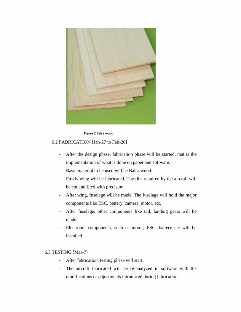
Figure 2 Balsa wood
6.2 FABRICATION [Jan-27 to Feb-20]
- After the design phase, fabrication phase will be started, that is the
implementation of what is done on paper and software.
- Basic material to be used will be Balsa wood.
- Firstly wing will be fabricated. The ribs required by the aircraft will
be cut and filed with precision.
- After wing, fuselage will be made. The fuselage will hold the major
components like ESC, battery, camera, motor, etc.
- After fuselage, other components like tail, landing gears will be
made.
- Electronic components, such as motor, ESC, battery etc will be
installed.
6.3 TESTING [Mar-7]
- After fabrication, testing phase will start.
- The aircraft fabricated will be re-analyzed in software with the
modifications or adjustments introduced during fabrication.

- After final software analysis, the final real time testing and flight
testing will be done before demonstration.
7. THE BASIC DESIGN OF THE AIRPLANE
figure 3 reference model
The dimensioning of the airplane we will fabricate will be based on the model
above. The wing span was decided to be 120cm and all the other dimensions
are according to the ratio of the above design.
Chord of the wing=20cm (NACA 2414 AIRFOIL SECTION).
Span of the wing=120cm.
Horizontal stabilizer span=46cm.
Horizontal stabilizer chord=9cm.
Distance between trailing edge of wing and leading edge of horizontal
stabilizer=39cm.
Distance between engine cowling and leading edge of the wing=22cm.
Distance between engine cowling and leading edge of vertical
stabilizer=74cm.
Root chord of vertical stabilizer=15cm.
Tip chord of vertical stabilizer=9cm.
Height of vertical stabilizer=18.5cm.
Width of fuselage=8cm.
Elevator width=3cm.
Aeiloron width=4.5cm.
Rudder width=4.5cm.
Length of fuselage=88cm.
The wing and the horizontal stabilizer are both rectangular with no taper
and the fuselage will also be made rectangular for the ease of
fabrication. The airfoil chosen for the wing is NACA 2414 and the
airfoil section for horizontal as well as vertical stabilizer is chosen to be
NACA 0010.
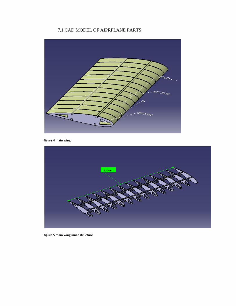
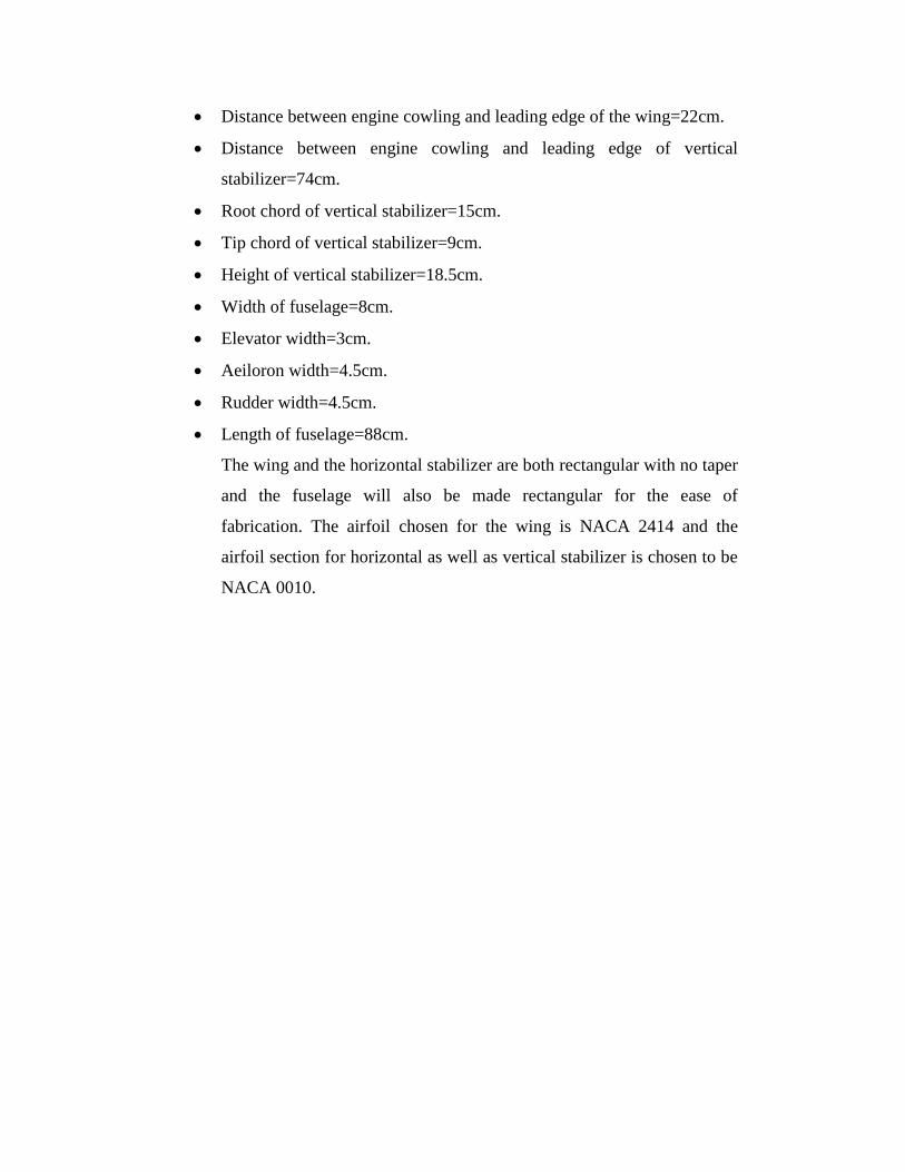
7.1 CAD MODEL OF AIPRPLANE PARTS
figure 4 main wing
figure 5 main wing inner structure

figure 6 fuselage
figure 7 vertical stabilizer
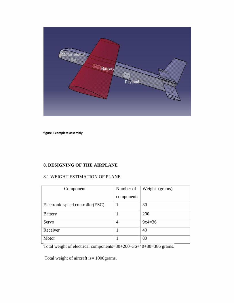
figure 8 complete assembly
8. DESIGNING OF THE AIRPLANE
8.1 WEIGHT ESTIMATION OF PLANE
Component Number of
components
Weight (grams)
Electronic speed controller(ESC) 1 30
Battery 1 200
Servo 4 9x4=36
Receiver 1 40
Motor 1 80
Total weight of electrical components=30+200+36+40+80=386 grams.
Total weight of aircraft is= 1000grams.
8.2 POWER AND THRUST REQUIRED FOR LEVEL,UNACCELERATED
FLIGHT
The airfoil shape we chosen for the wing is NACA 2414 airfoil and as takeoff
should be done at nearly zero degree angle of attack so is the further calculation
according to it.
The velocity during the level flight is taken as 10m/s.
Thrust required(Tr)=(Weight of airplane)/(Cl/Cd).
Maximum thrust required during level,unaccelerated flight can be calculated by
taking the Cl/Cd at 00
angle of attack,which is=0.9789.
Thus Tr=10.21N
Power required Pr=Tr×V∞=100.16N-m/s
8.3 ESTIMATING THE AVAILABLE THRUST AND POWER
Using the formula for knowing the rpm of a brushless motor
RPM=0.8×3.5V×(Series cell count)×(Motor kv rating)
For our project we have selected a 820kv brushless motor and a 3 cell lipo
battery.
So RPM of the used motor=(0.8×3.5×3×820)=6880 rotations per minute.
For the RPM we have from the above calculation and choosing a 10×7
propeller, 10 being the diameter and 7 being the pitch of the propeller in
inches(in), gives the estimated thrust the propeller and motor combination can
give us. It is shown in the below graph.
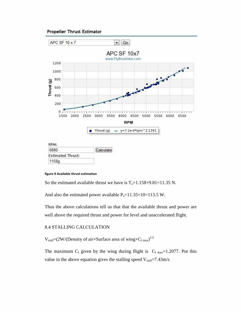
figure 9 Available thrust estimation
So the estimated available thrust we have is Ta=1.158×9.81=11.35 N.
And also the estimated power available Pa=11.35×10=113.5 W.
Thus the above calculations tell us that that the available thrust and power are
well above the required thrust and power for level and unaccelerated flight.
8.4 STALLING CALCULATION
Vstall=(2W/(Density of air×Surface area of wing×Cl max)1/2
The maximum Cl given by the wing during flight is Cl max=1.2077. Put this
value in the above equation gives the stalling speed Vstall=7.43m/s

8.5 GLIDING FLIGHT CALCULATIONS
Range(R)=h/tan(α) where tan(α)=1/(L/D).
For maximum range at the time of glide the lift to drag ratio should be
maximum.
Thus put it in the above relation considering the glide from a height of 50 m we
get R=60.38m.
8.6 CG MOMENT CALCULATION
The CG position of the model as shown in figure 8 is shown in the above
figure. The position of CG as shown above is given by CATIA V5.The
moments at this CG position is calculated for the model. The moment
contribution of wing and the horizontal stabilizer have been considered in the
following calculations.
The vertical and horizontal distances of aerodynamic centers of wing and
horizontal stabilizer from the CG position is summarized in the figure below.
The vertical stabilizer has been removed for ease of understanding. The lift and
drag forces of wing and horizontal stabilizer have been assumed to act at
0.25mac where mac(mean aerodynamic chord)=20cm.
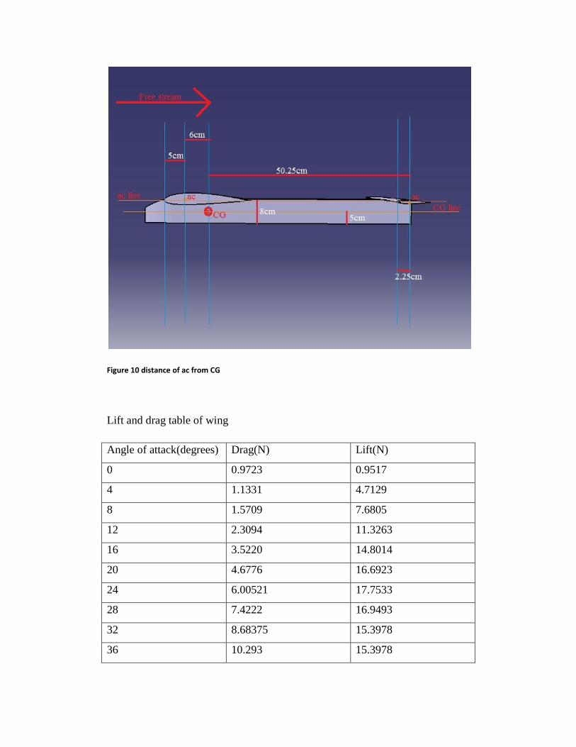
Figure 10 distance of ac from CG
Lift and drag table of wing
Angle of attack(degrees) Drag(N) Lift(N)
0 0.9723 0.9517
4 1.1331 4.7129
8 1.5709 7.6805
12 2.3094 11.3263
16 3.5220 14.8014
20 4.6776 16.6923
24 6.00521 17.7533
28 7.4222 16.9493
32 8.68375 15.3978
36 10.293 15.3978

40 11.7312 14.7701
44 13.5573 14.718
Lift and drag table of horizontal stabilizer
Angle of attack(degrees) Drag(N) Lift(N)
0 0.1559 0
3 0.1734 0.4404
6 0.232 0.9239
9 0.3298 1.3977
12 0.4656 1.8796
The lift and drag forces as tabulated are always perpendicular to the free stream
velocity direction as shown in the above figure whatever be the angle of attack
of the plane and acting at the respective aerodynamic centers. The effect of
angle of attack on distances between different points have been neglected.
1. (MCG)α=0=(0.9517× 0.06)+(0.9723 ×0.03)+(0.1559×0.03)=0.0909Nm so
(CmCG)α=0=0.0309.
Now after the angle of attack crosses 1.20
,the aerodynamic center of
horizontal tail will come below CG hence the drag force acting on it
will contribute negative moment at CG i.e anticlockwise moment unlike
the clockwise moment it contributed when it was above CG.
2. (MCG)α=4=(4.7129×0.06)+(1.1331×0.03)-(0.6×0.5025)-
(0.20×.03)=0.00926Nm
(CmCG)α=2=0.00314.
3. (MCG)α=8=(7.6805× 0.06)+(1.5709× 0.03)-(1.2× 0.5025)-(0.3× 0.03)=
-0.104Nm
(CmCG)α=8= -0.03537.
4. (MCG)α=12=(11.3263×0.06)+(2.3894×0.03)-(1.8796×0.5025)-
(0.4656×0.03)= -0.2072Nm
(CmCG)α=12= -0.07048.
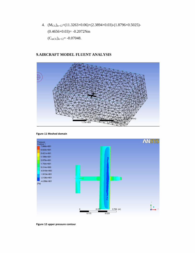
9.AIRCRAFT MODEL FLUENT ANALYSIS
Figure 11 Meshed domain
Figure 12 upper pressure contour
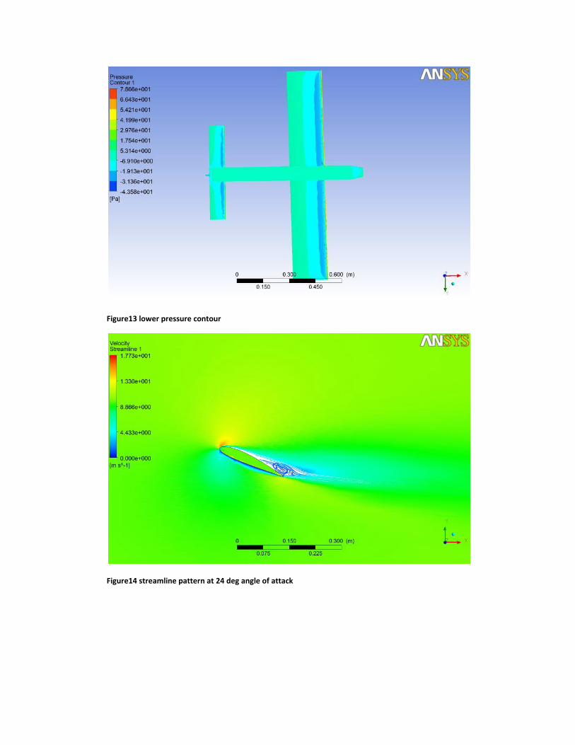
Figure13 lower pressure contour
Figure14 streamline pattern at 24 deg angle of attack

Figure 15 streamline pattern at 28 deg angle of attack
10.Some Plots
Figure16 Lift and drag plot of wing
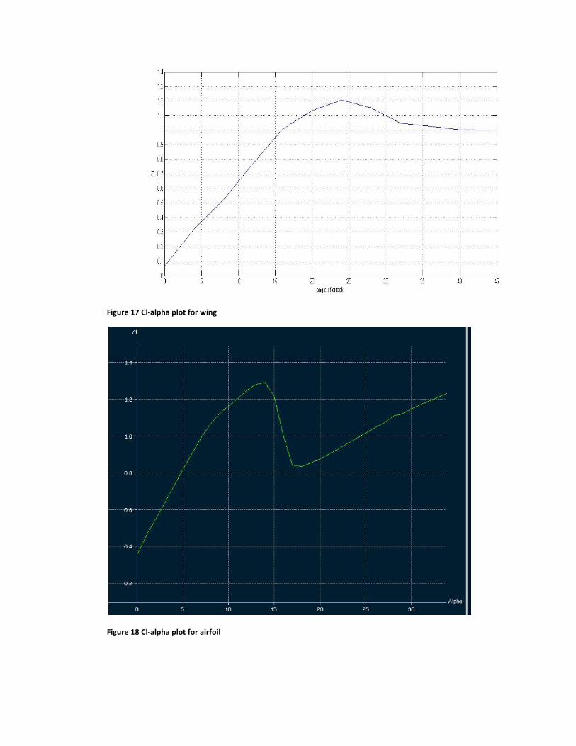
Figure 17 Cl-alpha plot for wing
Figure 18 Cl-alpha plot for airfoil

Figure 19 Lift and Drag plot of horizontal stabilizer
Figure 20 Drag polar

Figure 21 L/D-alpha plot
Figure 22 CG moment coefficient plot

11 MATERIAL TO BE USED
- Ribs: Light medium grade balsa wood (6.0 lb density; 3mm thick)
- Bulkheads: Plywood (5mm thick)
- Spacers: Medium grade balsa wood (6.0 lb density; 5mm thick)
- Spar: Medium hard grade balsa wood (9.6 lb density; 5mm thick)
- Skin: Heat shrink sheet
The basic material to be used is balsa wood.The secret to balsa wood's lightness
can only be seen with a microscope. The cells are big and very thinned walled,
so that the ratio of solid matter to open space is as small as possible. To give a
balsa
tree the strength it needs to stand in the jungle, nature pumps each cell in the
wood full of water until they become rigid like a car tire full of air. Green balsa
wood must therefore be carefully kiln dried to remove most of the water before
it can be sold.
Most people are surprised to learn that compared to other woods, balsa is only
about the third or fourth lightest wood in the world. It is not until balsa is
reached in that line that there is any sign of real strength combined with
lightness. In fact, balsa wood is often considered the strongest wood for its
weight in the world. Pound for pound it is stronger in some respects than pine,
hickory, or even oak.
Apart from the major components, the basic material to be used in skin would
be heat shrink sheet.
They are special type of sheets which shrink and stick to the surface on
application of heat, hence they form the best material for the skin of our aircraft
as it will be a major weight saver.

12. CONCLUSION
UAVs have their use in wide range of areas and they are helping in reducing the
cost and risk associated with any field they are used in. They need not be a
large in size and can be very easy to fabricate and install with their small size
and weight. The UAV we will design and fabricate will fulfill its purpose and
will have all the advantages of a UAV .
13. REFERENCES
Raymer,D.P. Aircraft Design:Aconceptual approach.
Lenon,A.Basics of R/C model aircraft design.
Horgen,John.Modified UAVs.
Aerial photography.wikipedia.org(retrieved October 15, 2015).
Anderson,J.D.Introduction to flight