minnesota manual on uniform traffic control devices
TRANSCRIPT

Minnesota Manualon
Uniform TrafficControl Devices
Minnesota Manualon
Uniform TrafficControl Devices
MN MUTCDJanuary 2014


MINNESOTAMANUAL
ONUNIFORMTRAFFIC
CONTROLDEVICES
MNMUTCD
MNMUTCD
January 2014


Minnesota Department of Transportation
Office of Traffic, Safety, and TechnologyMail Stop 7251500 West County Road B2Roseville, MN 55113
Sincerely,
Susan M. Groth, PE, PTOEState Traffic Engineer
December 30, 2013 Phone (651)234-7000
TO: Holders of the 2011 Minnesota Manual on Uniform Traffic Control Devices (2011 MN MUTCD)
Transmitted herewith is Revision Number 3 (dated January, 2014) to the "2011 Minnesota Manual on UniformTraffic Control Devices" (2011 MN MUTCD) as adopted by the Commissioner of the Minnesota Department ofTransportation (MnDOT). The attached pages to the 2011 MN MUTCD incorporate changes or correctionsbrought about by changes in the FHWA MUTCD and Minnesota practices or procedures.
All revised pages are attached herewith and shall replace corresponding pages in this manual. The attachedCommissioner’s Order No. 94040 amends Commissioner's Orders 93799, 93167 and 92452. It is important toretain all Orders because they amend but do not replace previous Orders.
The 2011 MN MUTCD including Revision Numbers 1, 2, and 3 is available on the MnDOT website athttp://www.dot.state.mn.us/trafficeng/publ/mutcd/index.html. This manual will be updated annually, typicallynear the beginning of each calendar year. The latest version will be available on the website after it has beenadopted by the Commissioner of Transportation.
MnDOT no longer maintains a mailing list for printed updates to this manual. Users of the the manual must fillout the “Updates Notification Form” found on the website above under “Quick Links.” When an update/revisionis made to the manual, an email will be sent out advising users to visit the website. The user must then downloadand print the revised pages and insert them into the printed version of their 2011 MN MUTCD.
To purchase additional copies of this manual or other State of Minnesota manuals call the MnDOT Map & ManualSales Unit at 651-366-3017 for current costs and ordering information. They are located at the following address:
MnDOT Map & Manual Sales Unit395 John Ireland Blvd. - MS 260St. Paul, Minnesota 55155-1899
Comments regarding the content of the 2011 MN MUTCD should be referred to Janelle Anderson, MnDOT, Officeof Traffic, Safety and Technology, phone (651) 234-7388, email address:[email protected].


REVISIONS TO THE2011 MINNESOTA UNIFORM TRAFFIC CONTROL DEVICES MANUAL
ORDER NO. 94040
This is the third order revising the 2011 Minnesota Manual on Uniform Traffic Control Devices(2011 MN MUTCD).
By Order number 92452 dated December 15, 2011 and published in the State Register ofDecember 26, 2011, the Commissioner of Transportation (Commissioner) has adopted the2011 MN MUTCD establishing a uniform system of traffic control devices for streets andhighways of the State of Minnesota as required by Minnesota Statutes, Section 169.06,Subdivision 1 (2011). The 2011 MN MUTCD correlates with and so far as possible conformsto the current system as approved by the American Association of State Highway Officials andthe national Manual on Uniform Traffic Control Devices (Federal MUTCD). (Minn. Stat. §169.06, subd. 1 (2011); Federal Highway Administration, 23 C.F.R. § 655.603 (2011).)
The Commissioner adopted revisions and changes to the 2011 MN MUTCD by Ordernumbers:
93167 dated July 12, 2012 published in the State Register of July 23, 2012, and93799 dated July 8, 2013 published in the State Register of August 5, 2013.
A multi-agency committee has reviewed the changes in the 2009 Federal MUTCD andrecommended further revisions and additions.
Pursuant to Minnesota Statutes, Section 169.06, subd. 1 (2011), and 169.215, subd. 2 (2011),the Commissioner hereby adopts the revisions listed below:
Record of Revisions or Additions to the MN MUTCD
Revision Date Pages Revised or AddedNumber Issued
3 12/11/2013 v, ix, 2B-i, 2B-17, 2B-55, 2C-ii, 2C-23, 2C-26 thru 2C-36, 2D-28,2E-11, 3B-14, 3C-1, 4G-3, 4L-1, 6A-iii thru 6A-vi, 6F-3 thru 6F-5,6F-14, 6F-17, 6F-19, 6F-20, 6F-40 thru 6F-53, 6G-7, 6J-iii, 6J-2,6J-4, 6J-5, 6J-7, 6J-8, 6J-10, 6J-11, 6J-14 thru 6J-21, 6J-24a thru6J-25b, Chapter 6K (the Field Manual) in its entirety, 7B-2, 8B-2,9B-6, C-3, C-19, C-38, C-39, C-46, C-56 thru C-58, removeAppendix B in its entirety.

This Order revises Commissioner's Order number 92452, dated December 15, 2011 asrevised by Commissioner's Orders numbers 93167 dated July 12, 2012 and 93799 dated July8, 2013.
Signed this 11th day of December 2013.
Charlie ZelleCommissioner of Transportation

Table I-1a. Evolution of the Minnesota MUTCD
Manual on Uniform Traffic Control Devices for Streets andHighways of the State of Minnesota
Manual on Uniform Traffic Control Devices for Streets andHighways of the State of Minnesota
Manual on Uniform Traffic Control Devices for Streets andHighways of the State of Minnesota
Manual on Uniform Traffic Control Devices for Streets andHighways of the State of Minnesota
Minnesota Manual on Uniform Traffic Control Devices for Streetsand Highways
Minnesota Manual on Uniform Traffic Control Devices for Streetsand Highways (MN MUTCD)
Minnesota Manual on Uniform Traffic Control Devices for Streetsand Highways (MN MUTCD)
Minnesota Manual on Uniform Traffic Control Devices(MN MUTCD)
Minnesota Manual on Uniform Traffic Control Devices(MN MUTCD)
Minnesota Manual on Uniform Traffic Control Devices(MN MUTCD)
1939
1949
1956
1962
1974
1986
1991
2001
2005
2011
12328
19270
25729
325174989450987
54014
7079771787
7758878988799018074880878815518223282843833878424085045
862528712787570
88522894539003890627
92952931679379994040
4/21/39
3/22/49
5/23/56
2/16/629/15/714/21/72
12/20/73
4/15/86,12/19/86
10/3/911/4/932/4/941/6/954/3/95
3/15/961/10/971/2/98
11/17/991/26/00
12/20/00
4/15/025/22/031/2/04
5/5/051/2/07
2/15/083/26/09
12/15/117/15/127/29/1312/11/13
Year Commissioner’sOrder Number
Name Month/Day/Yearof Adoption
MN
Rev
. 1M
NR
ev. 2
MN
Rev
. 3
v January, 2014
The States should adopt Section 15-116 of the UVC,which states that "No person shall install or maintain in anyarea of private property used by the public any sign, signal,marking, or other device intended to regulate, warn, or guidetraffic unless it conforms with the State manual and specifi-cations adopted under Section 15-104."
The Standard, Guidance, Option, and Support materialdescribed in this edition of the MUTCD provide the trans-portation professional with the information needed to makeappropriate decisions regarding the use of traffic controldevices on streets, highways, bikeways, and private roadsopen to public travel (see definition in Section 1A.13).
Throughout this Manual the headings Standard,Guidance, Option, and Support are used to classify thenature of the text that follows. Figures and tables, includingthe notes contained therin, supplement the text and mightconstitute a Standard, Guidance, Option, or Support. Theuser needs to refer to the appropriate text to classify thenature of the figure, table, or note contained therein.
When used in this Manual, the text headings of Standard,Guidance, Option, and Support shall be as defined in the firstparagraph of Section 1A.13.
Throughout this Manual all dimensions and distances areprovided in English units. Appendix A2 contains tables forconverting each of the English unit numerical values that areused in this Manual to the equivalent Metric (InternationalSystem of Units) values.
If Metric units are to be used in laying out distances ordetermining sizes of devices, such units should be specifiedon plan drawings and made known to those responsible fordesigning, installing, or maintaining traffic control devices.
Except when a specific numeral is required orrecommended by the text of a Section of the Manual,numerals displayed on the images of devices in the figuresthat specify quantities such as times, distances, speed limits,and weights should be regarded as examples only. Wheninstalling any of these devices, the numerals should beappropriately altered to fit the specific situation.
The following information will be useful when referenceis being made to a specific portion of text in this Manual.
There are nine Parts in this Manual and each Part is
SUPPORT:SUPPORT:
GUIDANCE:GUIDANCE:
SUPPORT:SUPPORT:
STANDARD:STANDARD:
SUPPORT:SUPPORT:
GUIDANCE:GUIDANCE:comprised of one or more Chapters. Each Chapter iscomprised of one or more Sections. Parts are given anumerical identification, such as Part 2-Signs. Chapters areidentified by the Part number and a letter, such as Chapter2B-Regulatory Signs, Barricades and Gates. Sections areidentified by the Chapter number and letter followed by adecimal point and a number, such as Section 2B.3-Size ofRegulatory Signs.
Each Section is comprised of one or more paragraphs.The paragraphs are indented but are not identified by anumber. Paragraphs are counted from the beginning of eachSection without regard to the intervening text headings(Standard, Guidance, Option, or Support). Some paragraphshave lettered or numbered items. As an example of how tocite this Manual, the phrase "Not less than 40 feet beyondthe stop line" that appears in Section 4D-14 of this Manualwould be referenced in writing as "Section 4D.14, P7, D1,A.1," and would be verbally referenced as "Item A.1ofParagraph 1 of Section 4D.14."
In accordance with 23 CFR 655.603(b)(3), Minnesotashall revise the MN MUTCD to be in substantialconformance with changes to the National MUTCD within2 years of the effective date of the Final Rule for thechanges. Substantial conformance of such State or otherFederal agency MUTCDs or Supplements shall be asdefined in 23 CFR 655.603(b)(1).
After the adoption and issuance of a new edition of theMN MUTCD or a revision thereto, new or reconstructeddevices installed shall be in compliance with the new editionor revision.
In cases involving Federal-aid projects for new street,highway or bicycle trail construction or reconstruction, thetraffic control devices installed (temporary or permanent)shall be in conformance with the most recent edition of theMN MUTCD before that highway is opened or re-opened tothe public for unrestricted travel [23 CFR 655.603(d)(2) and(d)(3)].
Unless a particular device is no longer serviceable, non-compliant devices on existing highways and bikeways shallbe brought into compliance with the current edition of theMN MUTCD as part of the systematic upgrading ofsubstandard traffic control devices (and installation of newrequired traffic control devices) required pursuant to theHighway Safety Program, 23 U.S.C. § 402(a). The FHWAand the State of Minnesota have the authority to establishother target compliance dates for implementation ofparticular changes to the MN MUTCD [23 CFR655.603(d)(1)]. These target compliance dates establishedby the FHWA shall be as shown in Table I-2.
STANDARD:STANDARD:
viDecember, 2011

Rxcept as provided in the following Option,when a non-compliant traffic control device is being replaced orrefurbished because it is damaged, missing, or no longerserviceable for any reason, it shall be replaced with acompliant device.
In addition, the section, portion of a section or graphicwhich shall be in compliance for future dates shall beencased in a red box or continuation of a red box togetherwith the compliance date which is also in red. That section,portion of a section, or graphic which shall have alreadybeen in compliance for past dates shall be encased in a reddashed box or continuation of a red box together with thecompliance date which is also in red.
This user of this Manual is encouraged to refer to TableI-2 for further information.
A damaged, missing, or otherwise non-serviceable devicethat is non-compliant may be replaced in kind if engineeringjudgment indicates that:
A.One compliant device in the midst of a series ofadjacent non-compliant devices would be confusingto road users; and/or
B. The schedule for replacement of the whole series ofnon-compliant devices will result in achieving timelycompliance with the MN MUTCD.
OPTION:OPTION:
vii January, 2014
Approved Revisions
This loose-leafed edition of the MN MUTCD incorporatesall revisions which have been approved by the FederalHighway Administrator. This 2011 Edition of the MNMUTCD includes all official final rulings, interpretations, andmodifications as of December 15, 2011.
A list of all official changes/revisions to this manual canbe found in the Record of Revisions starting on page ix. Aschanges/revisions are made to each page, the revisionnumber and date of revision will be added and so markedin the outside margin adjacent to the appropriate text orfigure. The date at the bottom outside corner of each pageindicates the date the official text revisions were distributed.
Symbols and Additions
This edition of the MN MUTCD continues the nationaltrend set in the Federal MUTCD toward a broader use ofsymbols as alternatives to word messages. Also, thefollowing new parts have been added to the MN MUTCD:
Appendix A1, Congressional Legislation
Appendix A2, Metric Conversions
Appendix A3, Retroreflective SheetingIdentification Guide
Appendix C, Sign Listing
MN
Rev
. 1
MN
Rev
. 3

viiiJuly, 2012
Table I-2. Target Compliance Dates Established by the FHWA
MN
Rev
. 1

ix January, 2014
RECORD OF REVISIONS OR ADDITIONS
Revision Date Pages Revised or Added Number Issued
12/15/2011 Issued as a new manual
1 6/15/2012 v, viii, ix, 1A-4, 1A-28, 1A-29, 2A-5, 2A-18, 2B-1 thru 2B-6, 2B-11, 2B-15,2B-34, 2B-35, 2B-38, 2B-41, 2B-53, 2B-56, 2B-57, 2C-3, 2C-4, 2C-11, 2C-13,2C-17, 2C-18, 2C-20, 2C-24 thru 2C-28, 2C-30, 2C-34, 2D-23, 2D-27 thru2D-29, 2E-6, 2E-33, 2E-37, 2E-41, 2E-51, 2F-6, 2G-11, 2G-16, 2I-2, 2I-5, 2I-10,2I-11, 2I-13, 2J-5, 2M-1, 2M-2, 2N-2, 3B-27, 3B-35, 4D-1, 4D-39, 4D-46, 4E-3,4E-6, 4F-3, 5C-2, 6D-1, 6D-2, 6D-4, 6E-1, 6F-3, 6F-7, 6F-20, 6F-29, 6F-37,6F-52, 6G-1, 7B-1, 7B-5, 7B-6, 7B-9, 7B-11, 7C-1, 7D-1, 7E-a thru 7E-21, 8B-1,8B-3, 8B-4, 8B-7 thru 8B-10, 8B-14, 8B-18, 8C-4, 8C-8, 8C-9, 9A-i, 9A-ii, 9B-2thru 9B4, 9B-6, 9B-9, 9B-18, 9C-1, A2-1, C-1 thru C-8, C-15 thru C-24, C-26,C-28 thru C-31, C-33 thru C-40, C-42, C-43, C-47, C-52 thru C-60, C-62thru C-70, C-75 thru C-77, C-79 thru C-83
2 6/29/2013 ii, vi, 2A-4, 2A-18, 2A-19, 2B-2 thru 2B-6, 2B-11, 2B-12, 2B-18, 2B-21, 2B-22,2B-37, 2B-40, 2B-47, 2B-48, 2B-51, 2B-56, 2B-59, 2C-4, 2C-5, 2C-7, 2C-10,2C-26, 2C-32, 2D-1, 2D-9, 2D-27, 2D-39, 2E-18, 2E-47, 2E-48, 2E-51, 2G-3,2G-4, 2H-i, 2H-2, 2H-7 thru 2H-9, 2I-2 thru 2I-4, 2I-7, 2I-10, 2J-4, 2J-6, 2K-1,2K-5, 2M-i, 2M-1, 2M-2, 2M-9, 2M-12 thru 2M-14, 3B-9, 4D-2, 4D-31, 4D-33,6F-5, 6J-4, 6J-17, 7A-i, 7B-2, 7B-10, 9B-9, 9B-16, 9B-18, C-1, C-2, C-5, C-13,C-14, C-16 thru C-21, C-24, C-26 thru C-39, C-41 thru C-57, C-59 thru C-61,C-63 thru C-66, C-82 thru C-95, INDEX-9 thru INDEX-16.
3 12/11/2013 v, ix, 2B-i, 2B-17, 2B-55, 2C-ii, 2C-23, 2C-26 thru 2C-36, 2D-28, 2E-11, 3B-14,3C-1, 4G-3, 4L-1, 6A-iii thru 6A-vi, 6F-3 thru 6F-5, 6F-14, 6F-17, 6F-19, 6F-20,6F-40 thru 6F-53, 6G-7, 6J-iii, 6J-2, 6J-4, 6J-5, 6J-7, 6J-8, 6J-10, 6J-11, 6J-14thru 6J-21, 6J-24a thru 6J-25b, Chapter 6K (the Field Manual) in its entirety,7B-2, 8B-2, 9B-6, C-3, C-19, C-38, C-39, C-46, C-56 thru C-58, removeAppendix B in its entirety.


Chapter 2B. REGULATORY SIGNSTABLE OF CONTENTS
Chapter 2B. Regulatory Signs PageSection 2B.1 Application of Regulatory Signs . . . . . . . . . . . . . . . . . . . . . . . . . . . . . . . . . . . . . . . . . . . . 2B-1
2B.2 Design of Regulatory Signs. . . . . . . . . . . . . . . . . . . . . . . . . . . . . . . . . . . . . . . . . . . 2B-12B.3 Size of Regulatory Signs . . . . . . . . . . . . . . . . . . . . . . . . . . . . . . . . . . . . . . . . . . . . . . . . . . 2B-12B.4 Right-of-Way at Intersections . . . . . . . . . . . . . . . . . . . . . . . . . . . . . . . . . . . . . . . . . . . . . . 2B-72B.5 STOP Sign (R1-1) and ALL WAY Plaque (R1-3P) . . . . . . . . . . . . . . . . . . . . . . . . . . . . . 2B-82B.6 STOP Sign Applications . . . . . . . . . . . . . . . . . . . . . . . . . . . . . . . . . . . . . . . . . . . . . . . . . . 2B-92B.7 Multi-Way Stop Applications . . . . . . . . . . . . . . . . . . . . . . . . . . . . . . . . . . . . . . . . . . . . . . 2B-92B.8 YIELD Sign (R1-2) . . . . . . . . . . . . . . . . . . . . . . . . . . . . . . . . . . . . . . . . . . . . . . . . . . . . . . 2B-102B.9 YIELD Sign Applications . . . . . . . . . . . . . . . . . . . . . . . . . . . . . . . . . . . . . . . . . . . . . . . . . 2B-102B.10 STOP Sign or YIELD Sign Placement . . . . . . . . . . . . . . . . . . . . . . . . . . . . . . . . . . . . . . . 2B-102B.11 Stop Here For Pedestrian Signs (R1-5 Series) . . . . . . . . . . . . . . . . . . . . . . . . . . . . . . . . . 2B-112B.12 In-Street Pedestrian Crossing Signs (R1-6a, R1-6b,R1-9a, and R1-9b). . . . . . . . . . . . . . 2B-122B.13 Speed Limit Sign (R2-1) . . . . . . . . . . . . . . . . . . . . . . . . . . . . . . . . . . . . . . . . . . . . . . . . . . 2B-142B.13.1 Bridge Speed Limit Sign (R2-X5) . . . . . . . . . . . . . . . . . . . . . . . . . . . . . . . . . . . . . . . . . . 2B-162B.14 Truck Speed Limit Sign (R2-2P). . . . . . . . . . . . . . . . . . . . . . . . . . . . . . . . . . . . . . . . . . . . 2B-162B.15 Night Speed Limit Sign (R2-3P). . . . . . . . . . . . . . . . . . . . . . . . . . . . . . . . . . . . . . . . . . . . 2B-162B.16 Minimum Speed Limit Sign (R2-4P) . . . . . . . . . . . . . . . . . . . . . . . . . . . . . . . . . . . . . . . . 2B-172B.16.1 This section has been eliminated2B.16.2 End Work Speed Zone Sign (R2-6c). . . . . . . . . . . . . . . . . . . . . . . . . . . . . . . . . . . . . . . . . 2B-172B.17 Higher Fines Signs and Plaque (R2-6P, R2-10, and R2-11) . . . . . . . . . . . . . . . . . . . . . . . 2B-172B.18 Movement Prohibition Signs (R3-1 through R3-4, R3-18, and R3-27) . . . . . . . . . . . . . . 2B-182B.19 Intersection Lane Control Signs (R3-5 through R3-8) . . . . . . . . . . . . . . . . . . . . . . . . . . . 2B-192B.20 Mandatory Movement Lane Control Signs (R3-5, R3-5a, and R3-7) . . . . . . . . . . . . . . . 2B-202B.21 Optional Movement Lane Control Sign (R3-6) . . . . . . . . . . . . . . . . . . . . . . . . . . . . . . . . 2B-212B.22 Advance Intersection Lane Control Signs (R3-30 Series) . . . . . . . . . . . . . . . . . . . . . . . . 2B-222B.23 RIGHT (LEFT) LANE MUST EXIT (R3-33) . . . . . . . . . . . . . . . . . . . . . . . . . . . . . . . . . 2B-222B.24 Two-Way Left Turn Only Signs (R3-9a, R3-9b) . . . . . . . . . . . . . . . . . . . . . . . . . . . . . . . 2B-222B.25 BEGIN and END Plaques (R3-9cP and R3-9dP) . . . . . . . . . . . . . . . . . . . . . . . . . . . . . . 2B.232B.26 Reversible Lane Control Signs (R3-9e through R3-9i) . . . . . . . . . . . . . . . . . . . . . . . . . . 2B-232B.27 Jughandle Signs (R3-23, R3-24, R3-25, and R3-26 Series) . . . . . . . . . . . . . . . . . . . . . . . 2B-262B.28 DO NOT PASS Sign (R4-1) . . . . . . . . . . . . . . . . . . . . . . . . . . . . . . . . . . . . . . . . . . . . . . . 2B-262B.29 PASS WITH CARE Sign (R4-2). . . . . . . . . . . . . . . . . . . . . . . . . . . . . . . . . . . . . . . . . . . . 2B-302B.30 KEEP RIGHT EXCEPT TO PASS (R4-16) and
SLOWER TRAFFIC KEEP RIGHT Sign (R4-3) . . . . . . . . . . . . . . . . . . . . . . . . . . 2B-302B.31 TRUCKS USE RIGHT LANE Sign (R4-5) . . . . . . . . . . . . . . . . . . . . . . . . . . . . . . . . . . . 2B-302B.32 Keep Right and Keep Left Signs (R4-7, R4-8). . . . . . . . . . . . . . . . . . . . . . . . . . . . . . . . . 2B-312B.33 STAY IN LANE Sign (R4-9) . . . . . . . . . . . . . . . . . . . . . . . . . . . . . . . . . . . . . . . . . . . . . . 2B-312B.33.1 DO NOT CROSS DOUBLE WHITE LINE Sign (R16-X16) . . . . . . . . . . . . . . . . . . . . . 2B-312B.34 RUNAWAY VEHICLES ONLY Sign (R4-10) . . . . . . . . . . . . . . . . . . . . . . . . . . . . . . . . . 2B-322B.35 Slow Vehicle Turn-Out Signs (R4-12, R4-13, and R4-14) . . . . . . . . . . . . . . . . . . . . . . . . 2B-322B.36 NO DRIVING ON SHOULDER Sign (R4-17a) and
NO PASSING ON SHOULDER Sign (R4-18a) . . . . . . . . . . . . . . . . . . . . . . . . . . . 2B-322B.37 DO NOT ENTER Sign (R5-1) . . . . . . . . . . . . . . . . . . . . . . . . . . . . . . . . . . . . . . . . . . . . . 2B-332B.38 WRONG WAY Sign (R5-1a). . . . . . . . . . . . . . . . . . . . . . . . . . . . . . . . . . . . . . . . . . . . . . . 2B-33
2B-i January, 2014
MN
Rev
. 3

. . . . . . . . . . . . . . . . . . . . . . . . . . . . . . . . . . . . . . . . . . . . . . . . . . . . . . . . . . . . . . . . . PageSection 2B.39 Selective Exclusion Signs . . . . . . . . . . . . . . . . . . . . . . . . . . . . . . . . . . . . . . . . . . . . . . . . . 2B-33
2B.39.1 Other Selective Exclusion Signs (R5-X1). . . . . . . . . . . . . . . . . . . . . . . . . . . . . . . . . . . . . 2B-352B.40 ONE WAY Signs (R6-1, R6-2) . . . . . . . . . . . . . . . . . . . . . . . . . . . . . . . . . . . . . . . . . . . . . 2B-352B.41 Wrong-Way Traffic Control at Interchange Ramps . . . . . . . . . . . . . . . . . . . . . . . . . . . . . 2B-402B.42 Divided Highway Crossing Signs (R6-3, R6-3a) . . . . . . . . . . . . . . . . . . . . . . . . . . . . . . . 2B-412B.43 Roundabout Directional Arrow Signs (R6-4, R6-4a, and R6-4b). . . . . . . . . . . . . . . . . . . 2B-412B.44 Roundabout Circulation Plaque (R6-5P). . . . . . . . . . . . . . . . . . . . . . . . . . . . . . . . . . . . . . 2B-452B.45 Examples of Roundabout Signing. . . . . . . . . . . . . . . . . . . . . . . . . . . . . . . . . . . . . . . . . . . 2B-452B.46 Parking, Standing, and Stopping Signs (R7 and R8 Series) . . . . . . . . . . . . . . . . . . . . . . . 2B-452B.47 Design of Parking, Standing, and Stopping Signs . . . . . . . . . . . . . . . . . . . . . . . . . . . . . . 2B-472B.48 Placement of Parking, Stopping, and Standing Signs . . . . . . . . . . . . . . . . . . . . . . . . . . . . 2B-482B.48.1 Disabled Parking Signs (R7-8m). . . . . . . . . . . . . . . . . . . . . . . . . . . . . . . . . . . . . . . . . . . . 2B-482B.49 Emergency Restriction Signs (R8-4, R8-7, R8-8, R16-X4) . . . . . . . . . . . . . . . . . . . . . . . 2B-492B.50 WALK ON LEFT FACING TRAFFIC and No Hitchhiking Signs
(R9-1, R9-4, R9-4a). . . . . . . . . . . . . . . . . . . . . . . . . . . . . . . . . . . . . . . . . . . . . . . . . 2B-492B.51 Pedestrian Crossing Signs (R9-2, R9-3) . . . . . . . . . . . . . . . . . . . . . . . . . . . . . . . . . . . . . . 2B-492B.52 Traffic Signal Pedestrian and Bicycle Actuation Signs
(R10-1 through R10-4, and R10-24 through R10-26) . . . . . . . . . . . . . . . . . . . . . . 2B-502B.53 Traffic Signal Signs (R10-5 through R10-30). . . . . . . . . . . . . . . . . . . . . . . . . . . . . . . . . . 2B-512B.54 No Turn on Red Signs (R10-11 Series and R10-30). . . . . . . . . . . . . . . . . . . . . . . . . . . . . 2B-522B.55 Photo Enforcement Signs and Plaques (R10-18, R10-19P, and R10-19aP) . . . . . . . . . . . 2B-532B.56 Ramp Metering Signs (R20-28a and R10-29a). . . . . . . . . . . . . . . . . . . . . . . . . . . . . . . . . 2B-532B.57 KEEP OFF MEDIAN Sign (R11-1) . . . . . . . . . . . . . . . . . . . . . . . . . . . . . . . . . . . . . . . . . 2B-542B.58 ROAD CLOSED Sign (R11-2) and
LOCAL TRAFFIC ONLY Signs (R11-3 Series, R11-4). . . . . . . . . . . . . . . . . . . . . 2B-542B.58.1 Bridge Closed Signs (R11-2a and R11-3c) . . . . . . . . . . . . . . . . . . . . . . . . . . . . . . . . . . . . 2B-542B.58.2 Sidewalk Closed Signs (R9-9, R9-10) . . . . . . . . . . . . . . . . . . . . . . . . . . . . . . . . . . . . . . . 2B-552B.59 Weight Limit Signs (R12-1 through R12-5) . . . . . . . . . . . . . . . . . . . . . . . . . . . . . . . . . . . 2B-552B.59.1 Bridge and Structure Weight, Width and Height Restriction Signs
(R12-1a, R12-5 Supplement, R12-X2, R12-X4, and R12-X4a) . . . . . . . . . . . . . . . 2B-562B.60 Weigh Station Signs (R13 Series) . . . . . . . . . . . . . . . . . . . . . . . . . . . . . . . . . . . . . . . . . . . 2B-572B.61 Truck Route Sign (R14-1) . . . . . . . . . . . . . . . . . . . . . . . . . . . . . . . . . . . . . . . . . . . . . . . . . 2B-572B.62 Hazardous Material Signs (R14-2, R14-3) . . . . . . . . . . . . . . . . . . . . . . . . . . . . . . . . . . . . 2B-572B.63 National Network Signs (R14-4, R14-5). . . . . . . . . . . . . . . . . . . . . . . . . . . . . . . . . . . . . . 2B-572B.64 Headlight Use Signs (R16-5 through R16-11) . . . . . . . . . . . . . . . . . . . . . . . . . . . . . . . . . 2B-582B.65 FENDER BENDER Sign (R16-4) . . . . . . . . . . . . . . . . . . . . . . . . . . . . . . . . . . . . . . . . . . 2B-582B.66 Seat Belt Symbol . . . . . . . . . . . . . . . . . . . . . . . . . . . . . . . . . . . . . . . . . . . . . . . . . . . . . . . . 2B-582B.66.1 Other Regulatory Signs . . . . . . . . . . . . . . . . . . . . . . . . . . . . . . . . . . . . . . . . . . . . . . . . . . . 2B-582B.66.2 State Law Signs . . . . . . . . . . . . . . . . . . . . . . . . . . . . . . . . . . . . . . . . . . . . . . . . . . . . . . . . . 2B-592B.67 Barricades . . . . . . . . . . . . . . . . . . . . . . . . . . . . . . . . . . . . . . . . . . . . . . . . . . . . . . . . . . . . . 2B-592B.68 Gates . . . . . . . . . . . . . . . . . . . . . . . . . . . . . . . . . . . . . . . . . . . . . . . . . . . . . . . . . . . . . . . . . 2B-59
2B-iiDecember, 2011

2B.16 Minimum Speed Limit Sign (R2-4P)
A Minimum Speed Limit (R2-4P) plaque shall bedisplayed only in combination with a Speed Limit sign.
Where engineering judgment determines that slow speedson a highway might impede the normal and reasonablemovement of traffic, the Minimum Speed Limit plaque maybe installed below a Speed Limit (R2-1) sign to indicate theminimum legal speed. If desired, the Speed Limit sign andthe Minimum Speed Limit plaque may be combined on theR2-4b sign.
There are many secondary roads (county, township andmunicipal) which have had speed zones established. Thesezones are in and on the fringes of urban districts (as definedin Minnesota Statute, section 169.011) where the ruralspeed limit remains at that provided in the statutes andcontinuous speed zoning has not been warranted. In manyinstances, the posting of the statutory speed limit in order toterminate the reduced speed zone would be inappropriatebecause the statutory speed limit would be misleading andencourage drivers to travel too fast for conditions. Soundengineering judgement would dictate that no numericalvalue should be posted and that the basic rule ( MinnesotaStatute, section 169.14, subd. 1) should apply.
In order to provide for the termination of the reducedspeed zone, either a Speed Limit (R2-1) sign with theending speed limit and an END (R3-9dP) or a Speed Limit(R2-1) sign with the new speed limit may be used.
OPTION:OPTION:
SUPPORT:SUPPORT:
R2-1
3 5
SP EEDL I M I T
R3-9dPEN D
OPTION:OPTION:
STANDARD:STANDARD:
R2-4bR2-4P
6 5
40M I N I M U M
S P E EDL I M I T
40S P E EDM I N I M U M
2B.16.2 END WORK SPEED ZONE Sign(R2-6c)
Certain street and highway construction andmaintenance operations may justify the erection ofregulatory signs with a recommended speed as determinedby the appropriate road authority. It is necessary to install aregulatory sign to inform the motorists of the end of theregulatory speed zone.
The sign shall be installed on its own structure at the endof the zone in accordance with standard signing practicesfor construction zone signs.
2B.17 Higher Fines Signs and Plaque(R2-6P, R2-10, and R2-11)
If increased fines are imposed for traffic violations withina designated zone of a roadway, a BEGIN HIGHER FINESZONE (R2-10) sign or a FINES HIGHER (R2-6P) plaqueshall be used to provide notice to road users. If used, theFINES HIGHER plaque shall be mounted below anapplicable regulatory or warning sign in a temporary trafficcontrol zone, a school zone, or other applicable designatedzone.
If an R2-10 sign or an R2-6P plaque is posted to providenotice of increased fines for traffic violations, an ENDHIGHER FINES ZONE (R2-11) sign shall be installed at thedownstream end of the zone to provide notice to road usersof the termination of the increased fines zone.
STANDARD:STANDARD:
R2-11R2-10R2-6P
EN DH I G H ERF I N ESZO N E
B EG I NH I G H ERF I N ESZO N E
F I N ES
H I G H ER
STANDARD:STANDARD:
SUPPORT:SUPPORT:
R2-6c
EN DWO R KS P E EDZO N E
2B-17 January, 2014
MN
Rev
. 3M
NR
ev. 3
If used, the BEGIN HIGHER FINES ZONE sign orFINES HIGHER plaque should be located at the beginningof the temporary traffic control zone, school zone, or otherapplicable designated zone and just beyond any inter-changes, major intersections, or other major trafficgenerators.
The Higher Fines signs and plaque shall have a blacklegend and border on a white rectangular background. Allsupplemental plaques mounted below the Higher Fines signsand plaque shall have a black legend and border on a whiterectangular background.
Agencies should limit the use of the Higher Fines signsand plaque to locations where work is actually underway, orto locations where the roadway, shoulder, or otherconditions, including the presence of a school zone and/or areduced school speed limit zone, require a speed reductionor extra caution on the part of the road user.
Alternate legends such as BEGIN (or END) DOUBLEFINES ZONE may also be used for the R2-10 and R2-11signs.
The legend FINES HIGHER on the R2-6P plaque may bereplaced by FINES DOUBLE (R2-6aP), $XX FINE (R2-6bP), or another legend appropriate to the specificregulation.
The following may be mounted below an R2-10 sign orR2-6P plaque:
A.A supplemental plaque specifying the times that thehigher fines are in effect (similar to the S4-1P plaque),or
B. A supplemental plaque WHEN CHILDREN(WORKERS) ARE PRESENT, or
C. A supplemental plaque WHEN FLASHING (similarto the S4-4P plaque) if used in conjunction with ayellow flashing beacon.
Section 6F.12 contains information regarding other signsand plaques associated with increased fines for trafficviolations in temporary traffic control zones. Section7B.10 contains information regarding other signs andplaques associated with increased fines for trafficviolations in designated school zones.
SUPPORT:SUPPORT:
OPTION:OPTION:
GUIDANCE:GUIDANCE:
STANDARD:STANDARD:
GUIDANCE:GUIDANCE: 2B.18 Movement Prohibition Signs(R3-1 through R3-4, R3-18and R3-27)
Except as provided in the following second Option, wherespecific movements are prohibited, Movement Prohibitionsigns shall be installed.
Movement Prohibition signs should be placed where theywill be most easily seen by road users who might beintending to turn.
If No Right Turn (R3-1) signs are used, at least oneshould be placed either over the roadway or at a right-handcorner of the intersection.
If No Left Turn (R3-2) signs are used, at least one shouldbe placed over the roadway, at the far left-hand corner of theintersection, on a median, or in conjunction with the STOPsign or YIELD sign located on the near right-hand corner.
Except as provided in Item C In the Guidance below, forsignalized locations, if NO TURNS (R3-3) signs are used,two signs should be used, one at a location specified for a NoRight Turn sign and one at a location specified for a No LeftTurn sign.
If No U-Turn (R3-4) signs or combination No U-Turn/NoLeft Turn (R3-18) signs are used, at least one should be usedat a location specified for No Left Turn signs.
If both left turns and U-turns are prohibited, thecombination No U-Turn/No Left Turn (R3-18) sign may beused instead of separate R3-2 and R3-4 signs.
OPTION:OPTION:
GUIDANCE:GUIDANCE:
STANDARD:STANDARD:
R3-27R3-18R3-4
R3-3R3-2R3-1
N OTU R N S
2B-18July, 2013
MN
Rev
. 2M
NR
ev. 2
MN
Rev
. 2M
NR
ev. 2

2B.58.2 Sidewalk Closed Signs(R9-9, R9-10)
The Sidewalk Closed signs should be used wherepedestrian flow is restricted or rerouted due to road work.The SIDEWALK CLOSED sign (R9-9) should be installed atthe beginning of the closed sidewalk section and elsewherealong the closed section as needed. The SIDEWALKCLOSED USE OTHER SIDE sign (R9-10) should beinstalled at the beginning of the restricted sidewalk sectionwhen a parallel sidewalk exists on the other side of theroadway.
These signs are typically installed on a barricade deviceto act as a reminding message to encourage compliance.
2B.59 Weight Limit Signs(R12-1 through R12-5)
R12-5R12-3
WE I G H TL I M I T
8 T
1 6 T1 2 T
N OT R U C K S
7000 L B S
EM P TY WT
OVER
R12-4R12-2R12-1
WE I G H T L I M I T
1 0 T O N S G RO S S
2 TO N S P E R AXLE
AXLEWE I G H TL I M I TTO N S5
WE I G H TL I M I T
1 0TO N S
GUIDANCE:GUIDANCE:
R9-10R9-9
S I D EWA L K C LOS E D
U S E O T H E R S I D E
S I D EWALK
CLOS ED
The Weight Limit (R12-1) sign carrying the legendWEIGHT LIMIT XX TONS may be used to indicate vehicleweight restrictions including load.
Where the restriction applies to axle weight rather thangross load, the legend may be AXLE WEIGHT LIMIT XXTONS or AXLE WEIGHT LIMIT XXXX LBS (R12-2).
To restrict trucks of certain sizes by reference to emptyweight in residential areas, the legend may be NO TRUCKSOVER XX TONS EMPTY WT or NO TRUCKS OVER XXLBS EMPTY WT (R12-3).
In areas where multiple regulations of the type describedin the three previous paragraphs are applicable, a signcombining the necessary messages on a single sign may beused, such as WEIGHT LIMIT XX TONS PER AXLE, XXTONS GROSS (R12-4).
Posting of specific load limits may be accomplished byuse of the Weight Limit symbol sign (R12-5). A signcontaining the legend WEIGHT LIMIT on the top two lines,and showing three different truck symbols and theirrespective weight limits for which restrictions apply may beused, with the weight limits displayed to the right of eachsymbol as XX T. A bottom line of legend stating GROSSWT may be included if needed for enforcement purposes.
If used, the Weight Limit sign shall be located in advanceof the applicable section of highway or structure.
If used, the Bridge Weight Limit sign (R12-5) shall beinstalled on or immediately in advance of bridges or bridgestructures where it is necessary to limit the load permittedon that structure. The proper weights to display on the signshall be based on an engineering study.
If used, the Weight Limit sign with an advisory distanceahead legend should be placed at approach road intersec-tions or other points where prohibited vehicles can detour orturn around.
GUIDANCE:GUIDANCE:
STANDARD:STANDARD:
OPTION:OPTION:
2B-55 January, 2014
MN
Rev
. 3

2B.59.1 Bridge and Structure Weight, Widthand Height Restriction Signs
(R12-1a, R12-5 Supplement,R12.X2, R12-X4, and R12-X4A)
These signs shall be installed in advance of bridges orstructures where it is necessary to limit the weight permittedon the bridge or structure and/or to show the clearanceavailable on or below the bridge or structure:
1. BRIDGE WEIGHT LIMIT (x) TONS (R12-1a)2. BRIDGE - WEIGHT LIMIT (w/symbols) - xx MILES
(R12-5 Supplement)3. RESTRICTED BRIDGE (xx) MILES AHEAD WEIGHT
LIMIT (X) TONS (R12-X2)4. RESTRICTED BRIDGE (xx) MILES AHEAD PERMIT
WEIGHT LIMIT (X) TONS (R12-X2a5. RESTRICTED BRIDGE (xx) MILES AHEAD WEIGHT
LIMIT (X) TONS - CLEARANCE (xx) FT. (XX) IN.(R12-X4)
6. RESTRICTED BRIDGE (xx) MILES AHEADCLEARANCE (xx) FT. (xx) IN. (R12-X4a)
The weights to display on the sign shall be the sameweights displayed on the Bridge Weight Limit sign (seeSection 2B.59).
STANDARD:STANDARD:
R12-X4aR12-X4
R ESTR I CT EDB R I DG E
FT I N1 4 1 0C L EARAN CE
1 4 M I L ES AH EAD
R ESTR I CT EDB R I DG E
FT I NCL EARAN CE 1 4 1 0WE I G H T L I M I T 1 0 TO N S
1 4 M I L ES AH EAD
R12-X2aR12-X2
R ESTR I CT EDB R I DG EM I L E S A H EA D
P E R M I T W E I G H T L I M I T 4 5 T O N S
1 4
R ESTR I CT EDB R I DG EM I L ES AH EAD
TO N S1 0L I M I TWE I G H T1 4
R12-5Supplements
R12-1a
WE I G H TL I M I T
8 T
1 6 T1 2 T
B R I DG E
1 4 M I L ES
WE I G H TL I M I T
TO N S9
B R I DG E
These signs should also be placed at the nearest inter-secting roadway where a motorist can detour around therestriction or at wide point in the roadway so that themotorist can turn around to avoid the restriction.
When a bridge is restricted for specific load limits, theWeight Limit symbol sign (R12-5) shall be installedimmediately in advance of the bridge.
The R12-5 Supplement combination sign consists of aBRIDGE plaque installed above and a (xx) MILES plaqueinstalled below the Weight Limit symbol sign to present amessage to the motorist that is consistent with the advancewarning sign assembly.
Both plaques shall have a black legend on a yellowreflectorized background. The length of the plaques shallmatch that of the Weight Limit symbol sign.
When a restriction on a bridge applies to the gross loadof a vehicle, the BRIDGE WEIGHT LIMIT sign (R12-1a)shall be installed immediately in advance of the bridge. If anadvance warning sign is to be used, the (xx) MILES plaqueof the R12-5 Supplement sign combination shall beinstalled below the R12-1a sign. The plaque shall have ablack legend on a yellow reflectorized background andshall match the length of the R12-1a sign.
The TRUCKS MUST NOT MEET ON BRIDGE sign(R12-X3) should be installed on two-way roadways inadvance of bridges or structures:
1. Where the clear opening width is greater than 18 feetand less than 20 feet, the approach alignment is poorand the structure type is such that commercialvehicles cannot pass safely on the structure, or
2. Where a restriction on the meeting or passing ofcommercial vehicles would provide increased loadcapacity upon the structure.
The VEHICLES MUST NOT MEET ON BRIDGE sign(R12-X3a) should be installed on two-way roadways inadvance of one-lane bridges or structures where the clearopening width is less than 16 feet. The WEIGHTRESTRICTION AHEAD sign (W14-X3) should be installedin advance of the bridge weight limit signs.
GUIDANCE:GUIDANCE:
R12-X3aR12-X3
VEH I C L ES M U STM EETN O T
O N B R I DG E
TR U CKS M U STM EETN O T
O N B R I DG E
STANDARD:STANDARD:
GUIDANCE:GUIDANCE:
2B-56July, 2013
MN
Rev
. 1M
NR
ev. 2
MN
Rev
. 2

PART 2. SIGNSChapter 2C. Warning Signs and Object Markers
TABLE OF CONTENTS
Chapter 2C. WARNING SIGNS PageSection 2C.1 Function of Warning Signs . . . . . . . . . . . . . . . . . . . . . . . . . . . . . . . . . . . . . . . . . . . . . . . . 2C-1
2C.2 Application of Warning Signs . . . . . . . . . . . . . . . . . . . . . . . . . . . . . . . . . . . . . . . . . . . . . . 2C-12C.3 Design of Warning Signs. . . . . . . . . . . . . . . . . . . . . . . . . . . . . . . . . . . . . . . . . . . . . . . . . . 2C-12C.4 Size of Warning Signs . . . . . . . . . . . . . . . . . . . . . . . . . . . . . . . . . . . . . . . . . . . . . . . . . . . . 2C-62C.5 Placement of Warning Signs . . . . . . . . . . . . . . . . . . . . . . . . . . . . . . . . . . . . . . . . . . . . . . . 2C-62C.6 Horizontal Alignment Warning Signs . . . . . . . . . . . . . . . . . . . . . . . . . . . . . . . . . . . . . . . . 2C-82C.7 Horizontal Alignment Signs (W1-1 through W1-5, W1-11, W1-15) . . . . . . . . . . . . . . . . 2C-82C.8 Advisory Speed Plaque (W13-1P) . . . . . . . . . . . . . . . . . . . . . . . . . . . . . . . . . . . . . . . . . . 2C-102C.9 Chevron Alignment Sign (W1-8) . . . . . . . . . . . . . . . . . . . . . . . . . . . . . . . . . . . . . . . . . . . 2C-112C.10 Combination Horizontal Alignment/Advisory Speed Signs (W1-1a, W1-2a) . . . . . . . . . 2C-112C.11 Combination Horizontal Alignment/Intersection Signs (W1-10 Series) . . . . . . . . . . . . . 2C-122C.12 One-Direction Large Arrow Sign (W1-6) . . . . . . . . . . . . . . . . . . . . . . . . . . . . . . . . . . . . . 2C-122C.13 Truck Rollover Warning Sign (W1-13). . . . . . . . . . . . . . . . . . . . . . . . . . . . . . . . . . . . . . . 2C-132C.14 Advisory Exit and Ramp Speed Signs (W13-2, W13-3) . . . . . . . . . . . . . . . . . . . . . . . . . 2C-132C.15 Combination Horizontal Alignment/Advisory Exit and Ramp Speed Signs
(W13-6, W13-7). . . . . . . . . . . . . . . . . . . . . . . . . . . . . . . . . . . . . . . . . . . . . . . . . . . . 2C-142C.16 Hill Signs (W7-1, W7-1a) . . . . . . . . . . . . . . . . . . . . . . . . . . . . . . . . . . . . . . . . . . . . . . . . . 2C-142C.17 Truck Escape Ramp Signs (W7-4 Series) . . . . . . . . . . . . . . . . . . . . . . . . . . . . . . . . . . . . . 2C-162C.18 HILL BLOCKS VIEW Sign (W7-6). . . . . . . . . . . . . . . . . . . . . . . . . . . . . . . . . . . . . . . . . 2C-162C.19 ROAD NARROWS Sign (W5-1) . . . . . . . . . . . . . . . . . . . . . . . . . . . . . . . . . . . . . . . . . . . 2C-162C.20 NARROW BRIDGE Sign (W5-2) . . . . . . . . . . . . . . . . . . . . . . . . . . . . . . . . . . . . . . . . . . 2C-172C.21 ONE LANE BRIDGE Sign (W5-3) . . . . . . . . . . . . . . . . . . . . . . . . . . . . . . . . . . . . . . . . . 2C-172C.22 Divided Highway Sign (W6-1) . . . . . . . . . . . . . . . . . . . . . . . . . . . . . . . . . . . . . . . . . . . . . 2C-172C.23 Divided Highway Ends Sign (W6-2) . . . . . . . . . . . . . . . . . . . . . . . . . . . . . . . . . . . . . . . . 2C-172C.24 Freeway or Expressway Ends Signs (W19 Series) . . . . . . . . . . . . . . . . . . . . . . . . . . . . . . 2C-182C.25 Double Arrow Sign (W12-1). . . . . . . . . . . . . . . . . . . . . . . . . . . . . . . . . . . . . . . . . . . . . . . 2C-182C.26 DEAD END/NO OUTLET Signs (W14-1, W14-1a, W14-2, W14-2a) . . . . . . . . . . . . . . 2C-182C.27 Low Clearance Signs (W12-2, W12-2a, W2-X2) . . . . . . . . . . . . . . . . . . . . . . . . . . . . . . . 2C-192C.28 BUMP and DIP Signs (W8-1, W8-1a, W8-1b, W8-2) . . . . . . . . . . . . . . . . . . . . . . . . . . . 2C-192C.29 SPEED HUMP Sign (W17-1) . . . . . . . . . . . . . . . . . . . . . . . . . . . . . . . . . . . . . . . . . . . . . . 2C-202C.30 PAVEMENT ENDS Sign (W8-3) . . . . . . . . . . . . . . . . . . . . . . . . . . . . . . . . . . . . . . . . . . . 2C-202C.31 Shoulder Signs (W8-4, W8-9, W8-17, W8-23, W8-25, W5-X1) . . . . . . . . . . . . . . . . . . . 2C-202C.32 Surface Condition Signs (W8-5, W8-7, W8-8, W8-11, W8-13, W8-14) . . . . . . . . . . . . . 2C-212C.33 Warning Signs and Plaques for Motorcyclists (W8-15, W8-15P, W8-16) . . . . . . . . . . . . 2C-212C.34 NO CENTER LINE Sign (W8-12) . . . . . . . . . . . . . . . . . . . . . . . . . . . . . . . . . . . . . . . . . . 2C-222C.35 Weather Condition Signs (W8-18, W8-19, W8-21, W8-22). . . . . . . . . . . . . . . . . . . . . . . 2C-222C.36 Advance Traffic Control Signs (W3-1, W3-2, W3-3, W3-4, W3-X2, W3-X4) . . . . . . . 2C-232C.37 Advance Ramp Control Signal Signs (W3-7, W3-8) . . . . . . . . . . . . . . . . . . . . . . . . . . . . 2C-232C.38 Reduced Speed Limit Ahead Signs (W3-5, W3-5a) . . . . . . . . . . . . . . . . . . . . . . . . . . . . . 2C-242C.39 DRAW BRIDGE Sign (W3-6) . . . . . . . . . . . . . . . . . . . . . . . . . . . . . . . . . . . . . . . . . . . . . 2C-242C.40 Merge Signs (W4-1, W4-5). . . . . . . . . . . . . . . . . . . . . . . . . . . . . . . . . . . . . . . . . . . . . . . . 2C-242C.41 Added Lane Signs (W4-3, W4-6) . . . . . . . . . . . . . . . . . . . . . . . . . . . . . . . . . . . . . . . . . . . 2C-25
2C-i July, 2013

PageSection 2C.42 Lane Ends Signs (W4-2, W9-1, W9-2) . . . . . . . . . . . . . . . . . . . . . . . . . . . . . . . . . . . . . . . 2C-25
2C.43 RIGHT (LEFT) LANE EXIT ONLY AHEAD Sign (W9-7) . . . . . . . . . . . . . . . . . . . . . . 2C-252C.44 Two-Way Traffic Sign (W6-3) . . . . . . . . . . . . . . . . . . . . . . . . . . . . . . . . . . . . . . . . . . . . . 2C-262C.45 NO PASSING ZONE Sign (W14-3) . . . . . . . . . . . . . . . . . . . . . . . . . . . . . . . . . . . . . . . . . 2C-262C.46 Intersection Warning Signs (W2-1 through W2-8) . . . . . . . . . . . . . . . . . . . . . . . . . . . . . . 2C-262C.47 Two-Direction Large Arrow Sign (W1-7). . . . . . . . . . . . . . . . . . . . . . . . . . . . . . . . . . . . . 2C-272C.48 Traffic Signal Signs (W25-1, W25-2) . . . . . . . . . . . . . . . . . . . . . . . . . . . . . . . . . . . . . . . . 2C-282C.49 Vehicular Traffic Warning Signs (W8-6, W11-1, W11-5, W11-5a, W11-6,
W11-8, W11-10, W11-11, W11-12P, W11-14, W11-15, W11-15a, W11-15P). . . . 2C-282C.50 Non-Vehicular Warning Signs (W11-2, W11-3, W11-4, W11-7, W11-9,
W11-16 through W11-22) . . . . . . . . . . . . . . . . . . . . . . . . . . . . . . . . . . . . . . . . . . . . 2C-292C.51 Playground Sign (W15-1) . . . . . . . . . . . . . . . . . . . . . . . . . . . . . . . . . . . . . . . . . . . . . . . . . 2C-312C.52 NEW TRAFFIC PATTERN AHEAD Sign (W23-2) . . . . . . . . . . . . . . . . . . . . . . . . . . . . 2C-312C.53 Use of Supplemental Warning Plaques . . . . . . . . . . . . . . . . . . . . . . . . . . . . . . . . . . . . . . . 2C-312C.54 Design of Supplemental Warning Plaques . . . . . . . . . . . . . . . . . . . . . . . . . . . . . . . . . . . . 2C-312C.55 Distance Plaques (W16-2 series, W16-3 series, W16-4P, W7-3aP) . . . . . . . . . . . . . . . . . 2C-322C.56 Supplemental Arrow Plaques (W16-5P, W16-6P) . . . . . . . . . . . . . . . . . . . . . . . . . . . . . . 2C-322C.57 Hill-Related Plaques (W7-2 series, W7-3 series) . . . . . . . . . . . . . . . . . . . . . . . . . . . . . . . 2C-322C.58 Advance Street Name Plaque (W16-8P, W16-8aP) . . . . . . . . . . . . . . . . . . . . . . . . . . . . . 2C-322C.59 CROSS TRAFFIC DOES NOT STOP Plaque (W4-4P Series) . . . . . . . . . . . . . . . . . . . . 2C-332C.60 SHARE THE ROAD Plaque (W16-1P) . . . . . . . . . . . . . . . . . . . . . . . . . . . . . . . . . . . . . . 2C-332C.61 PHOTO ENFORCED Plaque (W16-10P). . . . . . . . . . . . . . . . . . . . . . . . . . . . . . . . . . . . . 2C-342C.62 NEW Plaque (W16-15P) . . . . . . . . . . . . . . . . . . . . . . . . . . . . . . . . . . . . . . . . . . . . . . . . . . 2C-342C.63 Object Marker Design and Placement Height. . . . . . . . . . . . . . . . . . . . . . . . . . . . . . . . . . 2C-342C.64 Object Markers for Obstructions Within the Roadway. . . . . . . . . . . . . . . . . . . . . . . . . . . 2C-352C.65 Object Markers for Obstructions Adjacent to the Roadway . . . . . . . . . . . . . . . . . . . . . . . 2C-362C.66 Object Markers for Ends of Roadways . . . . . . . . . . . . . . . . . . . . . . . . . . . . . . . . . . . . . . . 2C-36
2C-iiJanuary, 2014
2C.36 Advance Traffic Control Signs(W3-1, W3-2, W3-3, W3-4,
W3-X2, W3-X4)
The Advance Traffic Control signs include the StopAhead (W3-1), Yield Ahead (W3-2), and Signal Ahead (W3-3) signs. These signs shall be installed on an approach to aprimary traffic control device that is not visible for asufficient distance to permit the road user to respond to thedevice (see Table 2C-4). The visibility criteria for a trafficcontrol signal shall be based on having a continuous view ofat least two signal faces for the distance specified in Table4D-2.
Figure 2A-4 shows the typical placement of an AdvanceTraffic Control sign.
Permanent obstructions causing the limited visibilitymight include roadway alignment or structures. Intermittentobstructions might include foliage or parked vehicles.
Where intermittent obstructions occur, engineeringjudgment should determine the treatment to beimplemented.
An Advance Traffic Control sign may be used foradditional emphasis of the primary traffic control device,even when the visibility distance to the device is satisfacto-ry.
An advance street name plaque (see Section 2C.58) maybe installed above or below an Advance Traffic Control sign.
OPTION:OPTION:
GUIDANCE:GUIDANCE:
SUPPORT:SUPPORT:
STANDARD:STANDARD:
W3-X4W16-13PW3-4
P R EPAR ETO STO PWH EN F LAS H I N G
WH E N
F LAS H I N G
B E
P R E PAR E D
T O S T O P
W3-3W3-2W3-1
A warning beacon may be used with an Advance TrafficControl sign.
A BE PREPARED TO STOP (W3-4) sign may be used towarn of stopped traffic caused by a traffic control signal orin advance of a section of roadway that regularlyexperiences traffic congestion.
When a BE PREPARED TO STOP sign is used inadvance of a traffic control signal, it shall be used in additionto a Signal Ahead sign and shall be placed downstream fromthe Signal Ahead (W3-3) sign.
The BE PREPARED TO STOP sign may be supplement-ed with a warning beacon (see Section 4L.3).
When the warning beacon is interconnected with a trafficcontrol signal or queue detection system, the BEPREPARED TO STOP sign shall be supplemented with aWHEN FLASHING plaque (W3-X2) or use the PREPARETO STOP WHEN FLASHING sign (W3-X4). See Section4M.
Section 2C.40 contains information regarding the use of aNO MERGE AREA (W4-5P) supplemental plaque inconjunction with a Yield Ahead sign.
2C.37 Advance Ramp Control Signal Signs(W3-7, W3-8)
A RAMP METER AHEAD (W3-7) sign may be used towarn road users that a freeway entrance ramp is metered andthat they will encounter a ramp control signal (see Chapter4I).
When the ramp control signals are operated only duringcertain periods of the day, a RAMP METERED WHENFLASHING (W3-8) sign should be installed in advance ofthe ramp control signal near the entrance to the ramp, or onthe arterial on the approach to the ramp, to alert road usersto the presence and operation of ramp meters.
GUIDANCE:GUIDANCE:
OPTION:OPTION:
W3-8W3-7
RAM P
M ET ER ED
WH EN
F LAS H I N G
RAM PM ET ERAH EAD
SUPPORT:SUPPORT:
STANDARD:STANDARD:
OPTION:OPTION:
STANDARD:STANDARD:
2C-23 January, 2014
MN
Rev
. 3

The RAMP METERED WHEN FLASHING sign shall besupplemented with a warning beacon (see Section 4L.3) thatflashes when the ramp control signal is in operation.
2C.38 Reduced Speed Limit Ahead Signs(W3-5, W3-5a)
A Reduced Speed Limit Ahead (W3-5 or W3-5a) signshould be used to inform road users of a reduced speed zonewhere the speed limit is being reduced by more than 10 mph,or where engineering judgment indicates the need foradvance notice to comply with the posted speed limit ahead.
If used, Reduced Speed Limit Ahead signs shall befollowed by a Speed Limit (R2-1) sign installed at thebeginning of the zone where the speed limit applies.
The speed limit displayed on the Reduced Speed LimitAhead sign shall be identical to the speed limit displayed onthe subsequent Speed Limit sign.
2C.39 DRAW BRIDGE Sign (W3-6)
A DRAW BRIDGE (W3-6) sign shall be used in advanceof movable bridge signals and gates (see Section 4J.2) togive warning to road users, except in urban conditions wheresuch signing would not be practical.
STANDARD:STANDARD:
W3-6
D RAWB R I DG E
STANDARD:STANDARD:
GUIDANCE:GUIDANCE:
W3-5aW3-5
45 M P H
S P E E D ZO N E
AH EA D
S P EED
L I M I T
4 5
STANDARD:STANDARD: 2C.40 Merge Signs (W4-1)
A Merge (W4-1) sign may be used to warn road users onthe major roadway that merging movements might beencountered in advance of a point where lanes from twoseparate roadways converge as a single traffic lane and noturning conflict occurs.
A Merge sign may also be installed on the side of theentering roadway to warn road users on the enteringroadway of the merge condition.
The Merge sign should be installed on the side of themajor roadway where merging traffic will be encounteredand in such a position as to not obstruct the road user's viewof entering traffic.
Where two roadways of approximately equal importanceconverge, a Merge sign should be placed on each roadway.
When a Merge sign is to be installed on an enteringroadway that curves before merging with the major roadway,such as a ramp with a curving horizontal alignment as itapproaches the major roadway, the Entering RoadwayMerge (W4-5) sign should be used to better portray theactual geometric conditions to road users on the enteringroadway.
The Merge sign should not be used where two roadwaysconverge and merging movements are not required.
The Merge sign should not be used in place of a LaneEnds sign (see Section 2C.42) where lanes of traffic movingon a single roadway must merge because of a reduction inthe actual or usable pavement width.
For a yield-controlled channelized right-turn movementonto a roadway without an acceleration lane, a NO MERGEAREA (W4-5P) supplemental plaque may be mountedbelow a Yield Ahead (W3-2) sign and/or below a YIELD(R1-2) sign when engineering judgment indicates that roadusers would expect an acceleration lane to be present. (seeSection 2B.9 for YIELD sign applications)
OPTION:OPTION:
GUIDANCE:GUIDANCE:
OPTION:OPTION:
W4-1
2C-24July, 2012
MN
Rev
. 1

2C.41 Added Lane Sign (W4-3, W4-6)
The Added Lane (W4-3) sign should be installed inadvance of a point where two roadways converge andmerging movements are not required. When possible, theAdded Lane sign should be placed such that it is visible fromboth roadways; if this is not possible, an Added Lane signshould be placed on the side of each roadway.
When an Added Lane sign is to be installed on a roadwaythat curves before converging with another roadway that hasa tangent alignment at the point of convergence, the EnteringRoadway Added Lane (W4-6) sign should be used to betterportray the actual geometric conditions to road users on thecurving roadway.
2C.42 Lane Ends Signs(W4-2, W9-1, W9-2)
The LANE ENDS MERGE RIGHT (LEFT) (W9-2) signor the Lane Ends (W4-2) sign should be used to warn of thereduction in the number of traffic lanes in the direction oftravel on a multi-lane highway.
The RIGHT (LEFT) LANE ENDS (W9-1) sign may beused in advance of the Lane Ends (W4-2) sign or the LANEENDS MERGE LEFT (RIGHT) (W9-2) sign as additionalwarning or to emphasize that the traffic lane is ending andthat a merging maneuver will be required.
OPTION:OPTION:
GUIDANCE:GUIDANCE:
W9-2W9-1W4-2
LAN E EN DS
M ERG ER I G H T
R I G H TLAN EEN DS
GUIDANCE:GUIDANCE:
W4-6W4-3
If used, the RIGHT (LEFT) LANE ENDS (W9-1) signshould be installed adjacent to the Lane-Reduction Arrowpavement markings.
On one-way streets or on divided highways where thewidth of the median will permit, two Lane Ends signs maybe placed facing approaching traffic, one on the right-handside and the other on the left-hand side or median.
Section 3B.9 contains information regarding the use ofpavement markings in conjunction with a lane reduction.
Where an extra lane has been provided for slower movingtraffic (see Section 2B.31), a Lane Ends word sign or a LaneEnds (W4-2) symbol sign should be installed in advance ofthe downstream end of the extra lane.
Lane Ends signs should not be installed in advance of thedownstream end of an acceleration lane.
In dropped lane situations, regulatory signs (see Section2B.20) shall be used to inform road users that a through laneis becoming a mandatory turn lane. The W4-2, W9-1, andW9-2 signs shall not be used in dropped lane situations.
2C.43 RIGHT (LEFT) LANE EXIT ONLYAHEAD Sign (W9-7)
The RIGHT (LEFT) LANE EXIT ONLY AHEAD (W9-7) sign may be used to provide advance warning to roadusers that traffic in the right-hand (left-hand) lane of aroadway that is approaching a grade-separated interchangewill be required to depart the roadway on an exit ramp at thenext interchange.
The W9-7 sign shall be a horizontal rectangle with a blacklegend and border on a yellow background.
STANDARD:STANDARD:
OPTION:OPTION:
W9-7
R I G HT LAN E
EX I T O N LY
AH EAD
STANDARD:STANDARD:
GUIDANCE:GUIDANCE:
SUPPORT:SUPPORT:
OPTION:OPTION:
GUIDANCE:GUIDANCE:
2C-25 July, 2013
MN
Rev
. 1M
NR
ev. 1

2C-26January, 2014
If used, the W9-7 sign should be installed upstream fromthe first overhead guide sign that contains an EXIT ONLYsign panel or upstream from the first RIGHT (LEFT) LANEMUST EXIT (R3-33) regulatory sign, whichever is fartherupstream from the exit.
Section 2B.23 contains information regarding aregulatory sign that can also be used for lane drops at grade-separated interchanges.
2C.44 Two-Way Traffic Sign (W6-3)
A Two-Way Traffic (W6-3) sign should be used to warnroad users of a transition from a multi-lane divided sectionof roadway to a two-lane, two-way section of roadway.
A Two-Way Traffic (W6-3) sign with an AHEAD (W16-9P) plaque should be used to warn road users of a transitionfrom a one-way street to a two-lane, two-way section ofroadway (see Figure 2B-14).
The Two-Way Traffic sign may be used at intervals alonga two-lane, two-way roadway.
OPTION:OPTION:
GUIDANCE:GUIDANCE:
W16-9PAH EAD
W6-3
SUPPORT:SUPPORT:
GUIDANCE:GUIDANCE: 2C.45 NO PASSING ZONE Sign (W14-3)
The NO PASSING ZONE (W14-3) sign shall be apennant-shaped isosceles triangle with its longer axishorizontal and pointing to the right. When used, the NOPASSING ZONE sign shall be installed on the left side ofthe roadway at the beginning of no-passing zones identifiedby pavement markings or DO NOT PASS signs or both (seeSections 2B.29 and 3B.2).
2C.46 Intersection Warning Signs(W2-1 through W2-8)
W2-8W2-7RW2-7L
W2-5W2-4
W2-3W2-2W2-1
STANDARD:STANDARD:
W14-3
N OPASS I N GZONE
MN
Rev
. 1M
NR
ev. 2
MN
Rev
. 3

A Cross Road (W2-1) symbol, Side Road (W2-2 orW2-3) symbol, T-Intersection symbol (W2-4), or Y-Intersection symbol (W2-5) sign may be used in advance ofan intersection to indicate the presence of an intersection andthe possibility of turning or entering traffic.
The Circular Intersection (W2-6) symbol sign may beinstalled in advance of a circular intersection (see Figures2B-21 through 2B-23).
If an approach to a roundabout has a statutory or postedspeed limit of 40 mph or higher, the Circular Intersection(W2-6) symbol sign should be installed in advance of thecircular intersection.
A ROUNDABOUT (W16-17P) educational plaque maybe mounted above or below a circular intersection symbolsign on the approach to a roundabout but may not be usedon an approach to a traffic circle.
A TRAFFIC CIRCLE (W16-12P) educational plaque maybe mounted above or below a circular intersection symbolsign on the approach to a traffic circle but may not be usedon an approach to a roundabout.
The relative importance of the intersecting roadways maybe shown by different widths of lines in the symbol.
An advance street name plaque (see Section 2C.49) maybe installed above or below an Intersection Warning sign.
The Intersection Warning sign should illustrate and depictthe general configuration of the intersecting roadway, suchas cross road, side road, T-intersection, or Y-intersection.
Intersection Warning signs, other than the CircularIntersection (W2-6) symbol sign and the T-Intersection (W2-4) symbol sign should not be used on approaches controlledby STOP signs, YIELD signs, or signals.
GUIDANCE:GUIDANCE:
OPTION:OPTION:
W16-17PW16-12PW2-6
R O U N D A B O U T
TRAFF I CC I R C L E
GUIDANCE:GUIDANCE:
OPTION:OPTION: If an Intersection Warning sign is used where the sideroads are not opposite of each other, Offset Side Roads (W2-7) symbol sign should be used instead of the Cross Roadsymbol sign.
If an Intersection Warning sign is used where two closely-spaced side roads are on the same side of the highway, theDouble Side Roads (W2-8) symbol sign should be usedinstead of the Side Road symbol sign.
No more than two side road symbols should be displayedon the same side of the highway on a W2-7 or W2-8 symbolsign, and no more than three side road symbols should bedisplayed on a W2-7 or W2-8 symbol sign.
2C.47 Two-Direction Large Arrow Sign(W1-7)
The Two-Direction Large Arrow (W1-7) sign shall be ahorizontal rectangle.
If used, it shall be installed on the far side of a T-intersec-tion in line with, and at approximately a right angle to, trafficapproaching from the stem of the T-intersection.
The Two-Direction Large Arrow sign shall not be usedwhere there is no change in the direction of travel such as atthe beginnings and ends of medians or at center piers.
The Two-Direction Large Arrow sign directing traffic tothe left and right shall not be used in the central island of aroundabout.
The Two-Direction Large Arrow sign should be visiblefor a sufficient distance to provide the road user withadequate time to react to the intersection configuration.
GUIDANCE:GUIDANCE:
STANDARD:STANDARD:
W1-7
2C-27 January, 2014
MN
Rev
. 1

2C.48 Traffic Signal Signs (W25-1, W25-2)
At locations where either a W25-1 or a W25-2 sign isrequired based on the provisions in Section 4D.05, the W25-1 or W25-2 sign shall be installed near the left-most signalhead. The W25-1 and W25-2 signs shall be verticalrectangles.
2C.49 Vehicular Traffic Signs(W8-6, W11-1, W11-5, W11-5a,W11-6, W11-8, W11-10, W11-11,W11-12p, W11-14, W11-15,W11-15a, W11-15P, W11-X3,)
W11-14W11-11W11-10
W11-6W11-5aW11-5
W11-1W11-1W8-6
TR U CKCROSS I N G
STANDARD:STANDARD:
W25-2W25-1
O N CO M I N G
T RA F F I C
M AY HAV E
E XT E N D E D
G R E E N
O N CO M I N G
T RA F F I C
H A S
E XT E N D E D
G R E E N
Vehicular Traffic Warning (W8-6, W11-1, W11-5, W11-5a, W11-6, W11-8, W11-11, W11-12P, W11-14, W11-15,and W11-15a, W11-X3) signs may be used to alert road usersto locations where unexpected entries into the roadway bytrucks, bicyclists, farm vehicles, snowmobiles, emergencyvehicles, golf carts, horse-drawn vehicles, or other vehiclesmight occur.
These locations might be relatively confined or mightoccur randomly over a segment of roadway.
Vehicular Traffic Warning signs should be used only atlocations where the road user’s sight distance is restricted, orthe condition, activity, or entering traffic would beunexpected.
If the condition or activity is seasonal or temporary, theVehicular Traffic Warning signs should be removed orcovered when the condition or activity does not exist.
The combined Bicycle/Pedestrian (W11-15) sign may beused where both bicyclists and pedestrians might be crossingthe roadway, such as at an intersection with a shared-usepath. A TRAIL X-ING (W11-15P) supplemental plaque maybe mounted below the W11-15 sign. The TRAILCROSSING (W11-15a) sign may be used to warn of shared-use path crossings where pedestrians, bicyclists, and otheruser groups might be crossing the roadway.
OPTION:OPTION:
GUIDANCE:GUIDANCE:
SUPPORT:SUPPORT:
OPTION:OPTION:
W16-13PW11-12PW11-15PW11-15P
WH E N
F LAS H I N G
EM E R G E N CY
S I G NA L
A H EA D
W11-X3W11-15aW11-15a
T R U C K S
E N T E R I N G
T RA I L
C RO S S I N G
T RA I L
C R O S S I N G
W11-15W11-15W11-8
2C-28January, 2014
MN
Rev
. 1

The W11-1, W11-15, and W11-15a signs and their relatedsupplemental plaques may have a fluorescent yellow-greenbackground with a black legend and border.
Supplemental plaques (see Section 2C.53) with legendssuch as AHEAD, XX FEET, NEXT XX MILES, or SHARETHE ROAD may be mounted below Vehicular TrafficWarning signs to provide advance notice to road users ofunexpected entries.
If used in advance of a pedestrian and bicycle crossing, aW11-15 or W11-15a sign should be supplemented with anAHEAD or XX FEET plaque to inform road users that theyare approaching a point where crossing activity might occur.
If a post-mounted W11-1, W11-6, W11-11, W11-15, orW11-15a sign is placed at the location of the crossing pointwhere golf carts, pedestrians, bicyclists, or other shared-usepath users might be crossing the roadway, a diagonaldownward pointing arrow (W16-7P) plaque shall bemounted below the sign. If the W11-1, W11-6, W11-11,W11-15, or W11-15a sign is mounted overhead, the W16-7Psupplemental plaque shall not be used.
The crossing location identified by a W11-1, W11-6,W11-11, W11-15, or W11-15a sign may be defined withcrosswalk markings (see Section 3B.18).
The Emergency Vehicle (W11-8) sign with theEMERGENCY SIGNAL AHEAD (W11-12P) supplementalplaque shall be placed in advance of all emergency-vehicletraffic control signals (see Chapter 4F).
The Emergency Vehicle (W11-8) sign, or a word messagesign indicating the type of emergency vehicle (such asrescue squad), may be used in advance of the emergencyvehicle station when no emergency-vehicle traffic controlsignal is present.
A Warning Beacon (see Section 4L.3) may be used withany Vehicular Traffic Warning sign to indicate specificperiods when the condition or activity is present or is likelyto be present, or to provide enhanced sign conspicuity.
A supplemental WHEN FLASHING (W16-13P) plaquemay be used with any Vehicular Traffic Warning sign that issupplemented with a Warning Beacon to indicate specificperiods when the condition or activity is present or is likelyto be present.
OPTION:OPTION:
STANDARD:STANDARD:
OPTION:OPTION:
STANDARD:STANDARD:
GUIDANCE:GUIDANCE:
2C.50 Non-Vehicular Signs(W11-2, W11-3, W11-4, W11-7,W11-9, W11-16 through W11-22)
W11-22W11-21W11-20
W11-19W11-18W11-17
W11-16W11-9W11-9
W11-7W11-4
W11-3W11-2W11-2
2C-29 January, 2014

Non-Vehicular Warning (W11-2, W11-3, W11-4, W11-7,W11-9, and W11-16 through W11-22) signs may be used toalert road users in advance of locations where unexpectedentries into the roadway might occur or where shared use ofthe roadway by pedestrians, animals, or equestrians mightoccur.
These conflicts might be relatively confined, or mightoccur randomly over a segment of roadway.
If used in advance of a pedestrian, snowmobile, orequestrian crossing, the W11-2, W11-7, and W11-9 signsshould be supplemented with plaques (see Section 2C.55)with the legend AHEAD or XX FEET to inform road usersthat they are approaching a point where crossing activitymight occur.
If a post-mounted W11-2, W11-6, W11-7, or W11-9 signis placed at the location of the crossing point wherepedestrians, snowmobilers, or equestrians might be crossingthe roadway, a diagonal downward pointing arrow (W16-7P) plaque shall be mounted below the sign. If the W11-2,W11-7, or W11-9 sign is mounted overhead, the W16-7Pplaque shall not be used.
A Pedestrian Crossing (W11-2) sign may be placedoverhead or may be post-mounted with a diagonaldownward pointing arrow (W16-7P) plaque at the crosswalklocation where Yield Here To (Stop Here For) Pedestrianssigns (see Section 2B.11) have been installed in advance ofthe crosswalk.
OPTION:OPTION:
STANDARD:STANDARD:
GUIDANCE:GUIDANCE:
SUPPORT:SUPPORT:
OPTION:OPTION:
If a W11-2 sign has been post-mounted at the crosswalklocation where a Yield Here To (Stop Here For) Pedestrianssign is used on the approach, the Yield Here To (Stop HereFor) Pedestrians sign shall not be placed on the same post asor block the road user's view of the W11-2 sign.
An advance Pedestrian Crossing (W11-2) sign with anAHEAD or a distance supplemental plaque may be used inconjunction with a Yield Here To (Stop Here For)Pedestrians sign on the approach to the same crosswalk.
The crossing location identified by a W11-2, W11-7, orW11-9 sign may be defined with crosswalk markings (seeSection 3B.18).
The W11-2 and W11-9 signs and their related supple-mental plaques may have a fluorescent yellow-greenbackground with a black legend and border.
Pedestrian and School Crossing signs and their relatedsupplemental plaques may have a fluorescent yellow-greenbackground with a black legend and border.
When a fluorescent yellow-green background is used, asystematic approach featuring one background color withina zone or area should be used. The mixing of standardyellow and fluorescent yellow-green backgrounds within aselected site area should be avoided.
Non-vehicular signs should be used only at locationswhere the crossing activity is unexpected or at locations notreadily apparent.
Additional information on crossings can be found in thefollowing sections:
Section 7B School Crossing signSection 9B Bicycle Crossing signAppendix B Warrants, Standards, and Guidelines
for Traffic Control Devices used atSenior Citizen and Disabled PersonsCrossings
A Warning Beacon (see Section 4L.3) may be used withany Non-Vehicular Warning sign to indicate specific periodswhen the condition or activity is present or is likely to bepresent, or to provide enhanced sign conspicuity.
A supplemental WHEN FLASHING (W16-13P) plaquemay be used with any Non-Vehicular Warning sign that issupplemented with a Warning Beacon to indicate specificperiods when the condition or activity is present or is likelyto be present.
OPTION:OPTION:
GUIDANCE:GUIDANCE:
OPTION:OPTION:
STANDARD:STANDARD:
2C-30January, 2014
MN
Rev
. 1

2C.51 Playground Sign (W15-1)
The Playground (W15-1) sign may be used to giveadvance warning of a designated children's playground thatis located adjacent to the road.
The Playground sign may have a fluorescent yellow-green background with a black legend and border.
If the access to the playground area requires a roadwaycrossing, the application of crosswalk pavement markings(see Section 3B.18) and Non-Vehicular Warning signs (seeSection 2C.50) should be considered.
2C.52 NEW TRAFFIC PATTERN AHEADSign (W23-2)
A NEW TRAFFIC PATTERN AHEAD (W23-2) signmay be used on the approach to an intersection or along asection of roadway to provide advance warning of a changein traffic patterns, such as revised lane usage, roadwaygeometry, or signal phasing.
The NEW TRAFFIC PATTERN AHEAD sign should beremoved when the traffic pattern returns to normal, when thechanged pattern is no longer considered to be new, or withinsix months.
GUIDANCE:GUIDANCE:
OPTION:OPTION:
W23-2
N EWTRAFF I CPATT ER NAH EAD
GUIDANCE:GUIDANCE:
OPTION:OPTION:
W15-1W15-1
2C.53 Use of Supplemental WarningPlaques
A supplemental warning plaque may be displayed with awarning or regulatory sign when engineering judgmentindicates that road users require additional warninginformation beyond that contained in the main message ofthe warning or regulatory sign.
Supplemental warning plaques shall be used only incombination with warning or regulatory signs. They shallnot be mounted alone or displayed alone. If used, a supple-mental warning plaque shall be installed on the same post(s)as the warning or regulatory sign that it supplements.
Unless otherwise provided in this Manual for a particularplaque, supplemental warning plaques shall be mountedbelow the sign they supplement.
2C.54 Design of Supplemental WarningPlaques
A supplemental warning plaque used with a warning signshall have the same legend, border, and background color asthe warning sign with which it is displayed. A supplementalwarning plaque used with a regulatory sign shall have ablack legend and border on a yellow background.
Supplemental warning plaques shall be square orrectangular.
STANDARD:STANDARD:
STANDARD:STANDARD:
OPTION:OPTION:
2C-31 January, 2014

2C.55 Distance Plaques(W16-2 series, W16-3 series,W16-4P, W7-3aP)
The Distance Ahead (W16-2 series and W16-3 series)plaques may be used to inform the road user of the distanceto the condition indicated by the warning sign.
The Next Distance (W7-3aP and W16-4P) plaques maybe used to inform road users of the length of roadway overwhich the condition indicated by the warning sign exists.
2C.56 Supplemental Arrow Plaques(W16-5P, W16-6P)
If the condition indicated by a warning sign is located onan intersecting road and the distance between the intersec-tion and condition is not sufficient to provide adequateadvance placement of the warning sign, a SupplementalArrow (W16-5P or W16-6P) plaque should be used belowthe warning sign.
Supplemental Arrow plaques shall have the same legenddesign as the Advance Turn Arrow and Directional Arrowauxiliary signs (see Sections 2D.26 and 2D.28) except thatthey shall have a black legend and border on a yellow orfluorescent yellow-green background, as appropriate.
STANDARD:STANDARD:
GUIDANCE:GUIDANCE:
W16-6PW16-5P
OPTION:OPTION:
W7-3aPW16-3aPW16-3P
M I L E S4
N E XT2 M I L E S
2M I L ES
W16-4PW16-2aPW16-2P
N E XT
500 FT500 FT
500FE ET
2C.57 Hill-Related Plaques(W7-2 Series and W7-3 Series)
Hill-Related (W7-2 series, W7-3 series) plaques or otherappropriate legends and larger signs should be used foremphasis or where special hill characteristics exist.
On longer grades, the use of the distance plaque (W7-3aPor W7-3bP) at periodic intervals of approximately 1-milespacing should be considered.
2C.58 Advance Street Name Plaque(W16-8P, W16-8aP)
An Advance Street Name (W16-8P or W16-8aP) plaquemay be used with any Intersection sign (W2 series, W10-2,W10-3, or W10-4) or Advance Traffic Control (W3 series)sign to identify the name of the intersecting street. AdvanceStreet Name plaques may be mounted above or belowthe sign.
The lettering on Advance Street Name plaques shall becomposed of a combination of lower-case letters with initialupper-case letters.
STANDARD:STANDARD:
OPTION:OPTION:
W16-8aP
E l m St reet
L u msd e n R d
W16-8P
F i rs t S t
GUIDANCE:GUIDANCE:
W7-3bPW7-3aPW7-3P
G RAD E
M I L ES7
9
M I L E S4
N E XT
G RAD E9
W7-2bPW7-2P
G EAR
TR U CKSLOWERU S E
G EAR
U S E L OW
2C-32January, 2014
MN
Rev
. 2M
NR
ev. 2

If two street names are used on the Advance Street Nameplaque, a directional arrow pointing in the direction of thestreet shall be placed next to each street name. Arrowspointing to the left shall be placed to the left of the streetname, and arrows pointing to the right shall be placed to theright of the street name.
If two street names are used on the Advance Street Nameplaque, the street names and associated arrows should bedisplayed in the following order:
A. For a single intersection, the name of the street to theleft should be displayed above the name of the streetto the right; or
B. For two sequential intersections, such as where theplaque is used with an Offset Side Roads (W2-7) or aDouble Side Road (W2-8) symbol sign, the name ofthe first street encountered should be displayed abovethe name of the second street encountered, and thearrow associated with the second street encounteredshould be an advance arrow, such as the arrow shownon the W16-6P arrow plaque.
2C.59 CROSS TRAFFIC DOES NOTSTOP Plaque (W4-4P Series)
The CROSS TRAFFIC DOES NOT STOP (W4-4P)plaque may be used in combination with a STOP sign whenengineering judgment indicates that conditions are presentthat are causing or could cause drivers to misinterpret theintersection as an all-way stop.
Alternate messages such as TRAFFIC FROM LEFT(RIGHT) DOES NOT STOP (W4-4aP) or ONCOMINGTRAFFIC DOES NOT STOP (W4-4bP) may be used whensuch messages more accurately describe the traffic controlsestablished at the intersection.
Plaques with the appropriate alternative messages ofTRAFFIC FROM LEFT (RIGHT) DOES NOT STOP orONCOMING TRAFFIC DOES NOT STOP should be usedat intersections where STOP signs control all but oneapproach to the intersection, unless the only non-stoppedapproach is from a one-way street.
GUIDANCE:GUIDANCE:
OPTION:OPTION:
W4-4bPW4-4aPW4-4P
DO E S N O T S T O P
O N CO M I N G T RA F F I CT R A F F I C F RO M L E FT
DO E S N O T S T O P
C RO S S T RA F F I C
DO E S N O T S T O P
GUIDANCE:GUIDANCE:
If a W4-4P plaque or a plaque with an alternative messageis used, it shall be mounted below the STOP sign.
A double-headed arrow may be included within theplaque (W4-4P) except at one-way crossings.
A single headed arrow shall not be used.
2C.60 SHARE THE ROAD Plaque(W16-1P)
In situations where there is a need to warn drivers towatch for other slower forms of transportation travelingalong the highway, such as bicycles, golf carts, horse-drawnvehicles, or farm machinery, a SHARE THE ROAD (W16-1P) plaque may be used.
A W16-1P plaque shall not be used alone. If a W16-1Pplaque is used, it shall be mounted below either a VehicularTraffic Warning sign (see Section 2C.49) or a Non-VehicularWarning sign (see Section 2C.50). The background color ofthe W16-1P plaque shall match the background color of thewarning sign with which it is displayed.
STANDARD:STANDARD:
OPTION:OPTION:
W16-1P
S HAR ETH EROAD
STANDARD:STANDARD:
OPTION:OPTION:
STANDARD:STANDARD:
2C-33 January, 2014

2C.61 PHOTO ENFORCED Plaque(W16-10P, W16-10aP)
A Photo Enforced (W16-10P) plaque or a PHOTOENFORCED (W16-10aP) word message plaque may bemounted below a warning sign to advise road users that theregulations associated with the condition being warnedabout (such as a traffic control signal or a toll plaza) arebeing enforced by photographic equipment.
If used below a warning sign, the Photo Enforced (W16-10P or W16-10aP) plaque shall be a rectangle with a blacklegend and border on a yellow background.
2C.62 NEW Plaque (W16-15P)
A NEW (W16-15P) plaque may be mounted above aregulatory sign when a new regulation takes effect in orderto alert road users to the new traffic regulation. A NEWplaque may also be mounted above an advance warning sign(such as a Signal Ahead sign for a newly-installed trafficcontrol signal) for a new traffic regulation.
The NEW plaque shall not be used alone.
The NEW plaque shall be removed no later than 6 monthsafter the regulation has been in effect.
STANDARD:STANDARD:
OPTION:OPTION:
W16-15P
N EW
STANDARD:STANDARD:
OPTION:OPTION:
W16-10aPW16-10P
PH OTO
EN FO RC ED
2C.63 Object Marker Design and PlacementHeight
Type 1, 2, and 3 object markers are used to mark obstruc-tions within or adjacent to the roadway. Type 4 objectmarkers are used to mark the end of a roadway.
When used, object markers shall not have a border andshall consist of an arrangement of one or more of thefollowing types:
Type 1-a diamond-shaped sign, at least 18 inches on aside, consisting of either a yellow (OM1-1) or black (OM1-2) sign with nine yellow retroreflective devices, each with aminimum diameter of 3 inches, mounted symmetrically onthe sign, or an all-yellow retroreflective sign (OM1-3).
Type 2-either a marker (OM2-1V or OM2-1H) consistingof three yellow retroreflective devices, each with aminimum diameter of 3 inches, arranged either horizontallyor vertically on a white sign measuring at least 6 x 12 inches;or an all-yellow horizontal or vertical retroreflective sign(OM2-2V or OM2-2H), measuring at least 6 x 12 inches.
Type 3-a striped marker, 12 x 36 inches, consisting of avertical rectangle with alternating black and retroreflectiveyellow stripes sloping downward at an angle of 45 degreestoward the side of the obstruction on which traffic is to pass.The minimum width of the yellow and black stripes shall be3 inches.
Type 4-a diamond-shaped sign, at least 18 inches on aside, consisting of either a red (OM4-1) or black (OM4-2)sign with nine red retroreflective devices, each with aminimum diameter of 3 inches, mounted symmetrically onthe sign, or an all-red retroreflective sign (OM4-3).
A better appearance can be achieved if the black stripesare wider than the yellow stripes.
Type 3 object markers with stripes that begin at the upperright side and slope downward to the lower left side aredesignated as right object markers (OM3-R). Object markerswith stripes that begin at the upper left side and slopedownward to the lower right side are designated as leftobject markers (OM3-L).
SUPPORT:SUPPORT:
STANDARD:STANDARD:
SUPPORT:SUPPORT:
2C-34January, 2014
MN
Rev
. 1
MN
Rev
. 1

When used for marking obstructions within the roadwayor obstructions that are 8 feet or less from the shoulder orcurb, the minimum mounting height, measured from thebottom of the object marker to the elevation of the near edgeof the traveled way, should be 4 feet When used to markobstructions more than 8 feet from the shoulder or curb, theclearance from the ground to the bottom of the object markershould be at least 4 feet.
GUIDANCE:GUIDANCE:
Object markers should not present a vertical or horizontalclearance obstacle for pedestrians.
When object markers or markings are applied to anobstruction that by its nature requires a lower or highermounting, the vertical mounting height may vary accordingto need.
Section 9B.26 contains information regarding the use ofobject markers on shared-use paths.
2C.64 Object Markers for ObstructionsWithin the Roadway
Obstructions within the roadway shall be marked with aType 1 or Type 3 object marker. In addition to markers onthe face of the obstruction, warning of approach to theobstruction shall be given by appropriate pavementmarkings (see Section 3B.10).
Object markers may be installed alone or in combinationwith signs (such as KEEP RIGHT, KEEP LEFT, doublearrows, or guide signs) located within the the island.
To provide additional emphasis, a Type 1 or Type 3 objectmarker may be installed at or near the approach end of amedian island.
To provide additional emphasis, large surfaces such asbridge piers may be painted with diagonal stripes, 12 inchesor greater in width, similar in design to the Type 3 objectmarker.
The alternating black and retroreflective yellow stripes(OM3-L, OM3-R) shall be sloped down at an angle of 45degrees toward the side on which traffic is to pass theobstruction. If traffic can pass to either side of theobstruction, the alternating black and retroreflective yellowstripes (OM3-C) shall form chevrons that point upwards.
Appropriate signs (see Sections 2B.32 and 2C.25)directing traffic to one or both sides of the obstruction maybe used instead of the object marker.
OPTION:OPTION:
STANDARD:STANDARD:
OPTION:OPTION:
STANDARD:STANDARD:
SUPPORT:SUPPORT:
OPTION:OPTION:
2C-35 January, 2014
Figure 2C-13 Object Markers
Type 1 Object Markers(obstructions within the roadway)
Type 2 Object Markers(obstructions adjacent to the roadway)
Type 3 Object Markers(obstructions adjacent to or within the roadway)
Type 4 Object Markers(end of roadway)
OM-3L OM-3C OM-3R
OM1-1 OM1-2 OM1-3
OM4-1 OM4-2 OM4-3
OM2-1V OM2-1H OM2-2HOM2-2V

2C.65 Object Markers for ObstructionsAdjacent to the Roadway
Obstructions not actually within the roadway aresometimes so close to the edge of the road that they need amarker. These include underpass piers, bridge abutments,handrails, ends of traffic barriers, utility poles, and culvertheadwalls. In other cases there might not be a physicalobject involved, but other roadside conditions exist, such asnarrow shoulders, drop-offs, gores, small islands, and abruptchanges in the roadway alignment, that might make itundesirable for a road user to leave the roadway, andtherefore would create a need for a marker.
If a Type 2 or Type 3 object marker is used to mark anobstruction adjacent to the roadway, the edge of the objectmarker that is closest to the road user shall be installed inline with the closest edge of the obstruction.
Where Type 3 object markers are applied to the approachends of guardrail and other roadside appurtenances, sheetingwithout a substrate shall be directly affixed to the approachend of the guardrail in a rectangular shape conforming to thesize of the approach end of the guardrail with alternatingblack and retroreflective yellow stripes sloping downward ata angle of 45 degrees toward the side of the obstruction onwhich traffic is to pass.
Type 1 and Type 4 object markers shall not be used tomark obstructions adjacent to the roadway.
Standard warning signs in this Chapter should also beused where applicable.
GUIDANCE:GUIDANCE:
STANDARD:STANDARD:
SUPPORT:SUPPORT:
2C.66 Object Markers for Ends ofRoadways
The Type 4 object marker is used to warn and alert roadusers of the end of a roadway in other than construction ormaintenance areas.
If an object marker is used to mark the end of a roadway,a Type 4 object marker shall be used.
The Type 4 object marker may be used in instances wherethere are no alternate vehicular paths.
Where conditions warrant, more than one marker, or alarger marker with or without a Type 3 Barricade (seeSection 2B.67), may be used at the end of the roadway.
The minimum mounting height, measured vertically fromthe bottom of a Type 4 object marker to the elevation of thenear edge of the traveled way, shall be 4 feet.
Appropriate advance warning signs in this Chaptershould be used.
GUIDANCE:GUIDANCE:
STANDARD:STANDARD:
OPTION:OPTION:
STANDARD:STANDARD:
SUPPORT:SUPPORT:
2C-36January, 2014

2D.43 Street Name Sign (D3-1or D3-1a)
Street Name (D3-1 or D3-1a) signs should be installed inurban areas at all street intersections regardless of otherroute signs that might be present and should be installed inrural areas to identify important roads that are not otherwisesigned.
For streets that are part of a U.S., State, or countynumbered route, a D3-1a Street Name sign that incorporatesa route shield may be used to assist road users who might nototherwise be able to associate the name of the street with theroute number.
The lettering for names of streets and highways on StreetName signs shall be composed of a combination of lower-case letters with initial upper-case letters (see Section2A.13).
Lettering on post-mounted Street Name signs should becomposed of initial upper-case letters at least 6 inches inheight and lower-case letters at least 4.5 inches in height.
On multi-lane streets with speed limits greater than 40mph, the lettering on post-mounted Street Name signsshould be composed of initial upper-case letters at least 8inches in height and lower-case letters at least 6 inches inheight.
D3-1
E M a i n St
GUIDANCE:GUIDANCE:
STANDARD:STANDARD:
OPTION:OPTION:
GUIDANCE:GUIDANCE:
For local roads with speed limits of 25 mph or less, thelettering on post-mounted Street Name signs may becomposed of initial upper-case letters at least 4 inches inheight and lower-case letters at least 3 inches in height.
If overhead Street Name signs are used, the letteringshould be composed of initial upper-case letters at least 12inches in height and lower-case letters at least 9 inches inheight.
The recommended minimum letter heights for StreetName signs are summarized in Table 2D-2.
Supplementary lettering to indicate the type of street(such as Street, Avenue, or Road) or the section of the city(such as NW) on the D3-1 and D3-1a signs may be insmaller lettering, composed of initial upper-case letters atleast 3 inches in height and lower-case letters at least 2.25inches in height. Conventional abbreviations (see Section1A.15) may be used except for the street name itself.
A pictograph (see definition in Section 1A.13) may beused on a D3-1 sign.
Pictographs shall not be displayed on D3-1a or AdvanceStreet Name (D3-2) signs (see Section 2D.44).
If a pictograph is used on a D3-1 sign, the height andwidth of the pictograph shall not exceed the upper-case letterheight of the principal legend of the sign.
STANDARD:STANDARD:
OPTION:OPTION:
SUPPORT:SUPPORT:
GUIDANCE:GUIDANCE:
OPTION:OPTION:
D3-1a
E StW i n c h este r5 6
2D-27 July, 2013
Table 2D-2. Recommended Minimum Letter Heights on Street Name Signs
Overhead
Post-Mounted
Post Mounted
Post-Mounted
All types
Multi-lane
Multi-lane
2-lane
All speed limits
More than 40 mph
40 mph or less
All speed limits
12 inches
8 inches
6 inches
6 inches
9 inches
6 inches
4.5 inches
4.5 inches
Type of Mounting
Recommended MinimumLetter HeightType of Street or Highway Speed Limit
Initial Upper-Case Lower-Case
* *On local two-lane streets with speed limits of 25 mph or less,4-inch initial upper-case letters with 3-inch lower-case letters may be used.
*
MN
Rev
. 1M
NR
ev. 2
MN
Rev
. 1

The pictograph should be positioned to the left of thestreet name.
The Street Name sign shall be retroreflective orilluminated to show the same shape and similar color bothday and night. The color of the legend (and border, if used)shall contrast with the background color of the sign.
The border may be omitted from a Street Name sign.
An alternative background color other than the normalguide sign color of green may be used for Street Name (D3-1 or D3-1a) signs where the highway agency determines thisis necessary to assist road users in determining jurisdiction-al authority for roads.
Alternative background colors shall not be used forAdvance Street Name (D3-2) signs (see Section 2D.44).
The only acceptable alternative background colors forStreet Name (D3-1 or D3-1a) signs shall be blue, brown, orwhite. Regardless of whether green, blue, or brown is usedas the background color for Street Name (D3-1 or D3-1a)signs, the legend (and border, if used) shall be white. ForStreet Name signs that use a white background, the legend(and border, if used) shall be black.
An alternative background color for Street Name signs, ifused, should be applied to the Street Name (D3-1 or D3-1a)signs on all roadways under the jurisdiction of a particularhighway agency.
In business or commercial areas and on principal arterials,Street Name signs should be placed at least on diagonallyopposite corners. In residential areas, at least one StreetName sign should be mounted at each intersection. Signsnaming both streets should be installed at each intersection.They should be mounted with their faces parallel to thestreets they name.
To optimize visibility, Street Name signs may be mountedoverhead. Street Name signs may also be placed above aregulatory or STOP or YIELD sign with no required verticalseparation.
In urban or suburban areas, especially where AdvanceGUIDANCE:GUIDANCE:
OPTION:OPTION:
GUIDANCE:GUIDANCE:
STANDARD:STANDARD:
OPTION:OPTION:
STANDARD:STANDARD:
GUIDANCE:GUIDANCE:Street Name signs for signalized and other major intersec-tions are not used, the use of overhead Street Name signsshould be strongly considered.
At intersection crossroads where the same road has twodifferent street names for each direction of travel, both streetnames may be displayed on the same sign along withdirectional arrows.
On lower speed roadways, historic street name signswithin locally identified historic districts that are consistentwith the criteria contained in 36 CFR 60.4 for suchstructures and districts may be used without complying withthe provisions of the 1st Standard; 2nd Guidance, 1stparagraph; 2nd Option; 3rd Option, 1st paragraph; 2ndStandard, 2nd paragraph; 4th Guidance; 3rd Standard; 4thStandard, 2nd paragraph; and 5th Guidance of this section.
Information regarding the use of street names on supple-mental plaques for use with intersection-related warningsigns is contained in Section 2C.58.
2D.44 Advance Street Name Sign (D3-2)
Advance Street Name (D3-2) signs identify an upcomingintersection. Although this is often the next intersection, itcould also be several intersections away in cases where thenext signalized intersection is referenced.
Advance Street Name (D3-2) signs, if used, shallsupplement rather than be used instead of the Street Name(D3-1) signs at the intersection.
D3-2D3-2
Sco t t B l vd
L i n co l n AveN EXT S I G NAL
OR
C e n t u ry D r
1 4 t h St
N EXT RO U N DABO U T
OR
D3-2D3-2
Sh ady G rove Rd
P l ea sa n t St
N EXT I NTERSECT I ON
2 N D I N T E RS E C T I O N
OR
STANDARD:STANDARD:
SUPPORT:SUPPORT:
SUPPORT:SUPPORT:
OPTION:OPTION:
2D-28January, 2014
MN
Rev
. 3M
NR
ev. 1

2E-11 January, 2014
Table 2E-5 Minimum Letter and Numeral Sizes for FreewayGuide Signs According to Sign Type
A. Pull-Through Signs
B. Supplemental Guide Signs
C. Interchange Sequence or Community
Interchanges Identification Signs
D. Next XX Exits Sign
E. Distance Signs
F. Next XX Exits Sign
Destinations -- Upper-Case Letters
Destinations -- Lower-Case Letters
Route Signs
1- or 2- Digit Shields
3-Digit Shields
Cardinal Directions -- First Letters
Cardinal Directions -- Rest of Word
Exit Number -- Words
Exit Number -- Numerals & Letters
Place Names -- Upper-Case Letters
Place Names -- Lower-Case Letters
Action Message
Route Signs
Numerals
1- or 2-Digit Shield
3-Digit Shield
Words -- Upper-Case Letters
Words -- Lower-Case Letters
Numerals
Fraction Numerals
Route Signs
Numerals
1- or 2-Digit Shield
3-Digit Shield
Place Names -- Upper-Case Letters
Place Names -- Lower-Case Letters
NEXT XX EXITS -- Words
NEXT XX EXITS -- Number
Words -- Upper-Case Letters
Words -- Lower-Case Letters
Numerals
Route Signs
Numerals
1- or 2-Digit Shield
3-Digit Shield
Exit Numeral Words
Exit Number Numerals and Letters
Services
Minimum SizeType of Sign
16
12
36 x 36
45 x 36
15
12
10
15
13.33
10
8
12
24 x 24
30 x 24
13.33
10
13.33
10
12
24 x 24
30 x 24
13.33
10
10
15
8
6
8
9
18 x 18
22.5 x 18
10
15
10
G. Rest Area, Scenic Area, and Roadside Area Signs
(see Chapter 2I)
H. Reference Location Signs (see Chapter 2H)
I. Boundary and Orientation Signs (see Chapter 2H)
J. Next Exit and Next Services Signs
K. Exit Only Signs
L. Overhead Arrow-Per-Lane Signs
M. Diagrammatic Signs
Words
Distance Numerals
Distance Fraction Numerals
Distance Words
Action Message Words
Words
Numerals
Word -- Upper-Case Letters
Word -- Lower-Case Letters
Words and Numerals
Words
Arrowhead (Type D Directional Arrow)
Arrow Shaft Width
Arrow Height
Through
Left Only
Right Only
Optional-Diverge (Through with Left or Right)
Optional-Split (Left and Right)
Vertical Separator Width
Vertical Space between Vertical Separator
and Top of Nearest Arrow
Horizontal Space between Vertical Separator
and Top of Nearest Through Arrow
Horizontal Space between Arrow Shaft and
EXIT and ONLY Panels
EXIT and ONLY Panels
Arrowhead (Type D Directional Arrow)
Lane Widths
Lane Line Segments
Spacing between Lane Line Segments
Stem Height to Upper Point of Departure
Horizontal Space between Arrowhead and
Route Shield or Destination
MinimumSize
Type of Sign
12
15
10
10
12
4
10
8
6
8
12
21
7.75
66
45
45
66
55
2
8
15
12
54 x 18
13.5 *
5
1 x 6
6
30
12
* The size shown is the arrowhead width per lane depicted on thecorresponding arrow shaft.
Note: Sizes are shown in inches and where applicable are shownas width x height
MN
Rev
. 3

A sign mounted over a particular roadway lane to whichit applies might have to be limited in horizontal dimensionto the width of the lane, so that another sign can be placedover an adjacent lane. The necessity to maintain propervertical clearance might also place a further limitation on thesize of the overhead sign and the legend that can be accom-modated.
2E.15 lnterline and Edge Spacing
Interline spacing of upper-case letters should be approxi-mately three-fourths the average of upper-case letter heightsin adjacent lines of letters.
The spacings to the top and bottom borders should beequal to the average of the letter height of the adjacent lineof letters. The lateral spacing to the vertical borders shouldbe essentially the same as the height of the largest letter.
2E.16 Sign Borders
Signs shall have a border of the same color as the legendin order to outline their distinctive shape and thereby givethem easy recognition and a finished appearance.
For guide signs larger than 120 x 72 inches, the bordershould have a width of 2 inches. For smaller guide signs, aborder width of 1.25 inches should be used, but the widthshould not exceed the stroke width of the lettering of theprincipal legend on the sign.
Corner radii of sign borders should be 1/8 of theminimum sign dimension on guide signs, except that theradii should not exceed 12 inches on any sign.
The sign material in the area outside of the corner radiusmay be trimmed.
OPTION:OPTION:
GUIDANCE:GUIDANCE:
STANDARD:STANDARD:
GUIDANCE:GUIDANCE:
SUPPORT:SUPPORT: 2E.17 Abbreviations
Abbreviations should be kept to a minimum; however,they are useful when complete destination messages produceexcessively long signs. If used, abbreviations should beunmistakably recognized by road users (see Section 1A.15).Longer commonly used words that are not part of a propername and are readily recognizable, such as Street,Boulevard, and Avenue, should be abbreviated to expediterecognition of the sign legend by reducing the amount andcomplexity of the legend.
Periods, apostrophes, question marks, ampersands, orother punctuation or characters that are not letters, numerals,or hyphens should not be used in abbreviations, unlessnecessary to avoid confusion.
The solidus (slanted line or forward slash) is intended tobe used for fractions only and should not be used to separatewords on the same line of legend. Instead, a hyphen shouldbe used for this purpose, such as "CARS - TRUCKS."
The words NORTH, SOUTH, EAST, and WEST shall notbe abbreviated when used with route signs to indicatecardinal directions on guide signs.
2E.18 Symbols
Symbol designs shall be unmistakably like those shownin Appendix C of this Manual and the MnDOT “StandardSigns Manual”, and the Federal "Standard Highway Signsand Markings" book.
A special effort should be made to balance legendcomponents for maximum legibility of the symbol with therest of the sign.
Educational plaques may be used below symbol signswhere needed.
OPTION:OPTION:
GUIDANCE:GUIDANCE:
STANDARD:STANDARD:
STANDARD:STANDARD:
GUIDANCE:GUIDANCE:
2E-12December, 2011
3B-13 December, 2011
Figure 3B-9 Examples of Dotted Line and Channelizing Lane Applications for Entrance Ramp Markings(Sheet 2 of 2)
Optional normal width dottedextension of right-hand edge line
Full lane width
Physical gore
Neutral area
Theoretical gore
Edge ofthrough lane
White channelizing lines
Direction of travel
B = Distance from physical gore
to downstream end of full
width acceleration lane
Legend
C - Tapered acceleration lane
0.5 BMIN.
B

3B-14January, 2014
For entrance ramps with a tapered acceleration lane, anormal width dotted white line extension may be installedfrom the downstream end of the channelizing line adjacentto the through lane to the downstream end of the accelera-tion taper, as shown in Drawings B and C of Figure 3B-9.
A wide dotted white lane line shall be used:
A. As a lane drop marking in advance of lane drops atexit ramps to distinguish a lane drop from a normalexit ramp (see Drawings A, B, and C of Figure 3B-10),
B. In advance of freeway route splits with dedicatedlanes (see Drawing D of Figure 3B-10),
C. To separate a through lane that continues beyond aninterchange from an adjacent auxiliary lane betweenan entrance ramp and an exit ramp (see Drawing E ofFigure 3B-10),
D. As a lane drop marking in advance of lane drops atintersections to distinguish a lane drop from an inter-section through lane (see Drawing A of Figure 3B-11),and
E. To separate a through lane that continues beyond anintersection from an adjacent auxiliary lane betweentwo intersections (see Drawing B of Figure 3B-11).
Lane drop markings used in advance of lane drops atfreeway and expressway exit ramps should begin at least 1/2mile in advance of the theoretical gore.
On the approach to a multi-lane exit ramp having anoptional exit lane that also carries through traffic, lane linemarkings should be used as illustrated in Drawing B ofFigure 3B-10. In this case, if the right-most exit lane is anadded lane such as a parallel deceleration lane, the lane dropmarking should begin at the upstream end of the full-widthdeceleration lane, as shown in Drawing C of Figure 3B-8.
Lane drop markings used in advance of lane drops atintersections should begin a distance in advance of the inter-section that is determined by engineering judgment assuitable to enable drivers who do not desire to make themandatory turn to move out of the lane being dropped priorto reaching the queue of vehicles that are waiting to makethe turn. The lane drop marking should begin no closer to theintersection than the most upstream regulatory or warningsign associated with the lane drop.
The dotted white lane lines that are used for lane dropmarkings and that are used as a lane line separating throughlanes from auxiliary lanes should consist of line segmentsthat are 3 feet in length separated by 9-foot gaps.
GUIDANCE:GUIDANCE:
STANDARD:STANDARD:
Section 3B.20 contains information regarding othermarkings that are associated with lane drops, such as lane-use arrow markings and ONLY word markings.
Section 3B.9 contains information about the lane linemarkings that are to be used for transition areas where thenumber of through lanes is reduced.
Where crossing the lane line markings is discouraged, thelane line markings shall consist of a normal or wide solidwhite line.
Where it is intended to discourage lane changing on theapproach to an exit ramp, a wide solid white lane line mayextend upstream from the theoretical gore or, for multi-laneexits, as shown in Drawing B of Figure 3B-10, for a distancethat is determined by engineering judgment.
Where lane changes might cause conflicts, a wide ornormal solid white lane line may extend upstream from anintersection.
In the case of a lane drop at an exit ramp or intersection,such a solid white line may replace a portion, but not all ofthe length of the wide dotted white lane line.
On approaches to intersections, a solid white lane linemarking should be used to separate a through lane from anadded mandatory turn lane.
On approaches to intersections, solid white lane linemarkings may be used to separate adjacent through lanes oradjacent mandatory turn lanes from each other.
Where the median width allows the left-turn lanes to beseparated from the through lanes to give drivers on opposingapproaches a less obstructed view of opposing throughtraffic, white pavement markings may be used to form chan-nelizing islands as shown in Figure 2B-17.
Solid white lane line markings may be used to separatethrough traffic lanes from auxiliary lanes, such as an addeduphill truck lane or a preferential lane (see Section 3D.2).
Wide solid lane line markings may be used for greateremphasis.
OPTION:OPTION:
GUIDANCE:GUIDANCE:
OPTION:OPTION:
STANDARD:STANDARD:
SUPPORT:SUPPORT:
MN
Rev
. 3

3C.1 General
A roundabout (see definition in Section 1A.13) is aspecific type of circular intersection designed to controlspeeds and having specific traffic control features.
Pavement markings and signing for a roundabout shouldbe integrally designed to correspond to the geometric designand intended lane use of a roundabout.
Markings on the approaches to a roundabout and on thecircular roadway should be compatible with each other toprovide a consistent message to road users and shouldfacilitate movement through the roundabout such thatvehicles do not have to change lanes within the circulatoryroadway in order to exit the roundabout in a given direction.
Figure 3C-1 provides an example of the pavementmarkings for approach and circulatory roadways at aroundabout. Figure 3C-2 shows the options that areavailable for lane-use pavement marking arrows on
SUPPORT:SUPPORT:
GUIDANCE:GUIDANCE:
SUPPORT:SUPPORT:
approaches to roundabouts. Figures 3C-3 through 3C-14illustrate examples of markings for roundabouts of variousgeometric and lane-use configurations.
Traffic control signals or pedestrian hybrid beacons (seePart 4) are sometimes used at roundabouts to facilitate thecrossing of pedestrians or to meter traffic.
Section 8C.12 contains information about roundaboutsthat contain or are in close proximity to grade crossings.
3C.2 White Lane Line Pavement Markingsfor Roundabouts
Multi-lane approaches to roundabouts shall have lanelines.
A through lane on a roadway that becomes a dropped lane(mandatory turn lane) at a roundabout shall be marked witha dotted white lane line in accordance with Section 3B.04.
Multi-lane roundabouts should have lane line markingswithin the circulatory roadway to channelize traffic to theappropriate exit lane.
GUIDANCE:GUIDANCE:
STANDARD:STANDARD:
3C-1 January, 2014
PART 3. MARKINGSChapter 3C. Roundabout Markings
Figure 3C-1 Example of Markings for Approach and Circulatory Roadways at a Roundabout
�����������������������������������������������������������������������������������������������������������������������������������������������������������������������������������������������������������������������������������������������������������������������������������������������������������������������������������������������������������������������������������������������������������������������������������������������������������������������������������������������������������������������������������������������������������������������������������������������������������������������������������������������������������������������������������������������������������������������������������������������������������������������������������������������������������������������������������������������������������������������������������������������������������������������������������������������������������������������������������������������������������������������������������������������������������������������������������������������������������������������������������������������������������������������������������������������������������������������������������������������������������������������������������������������������������������������������������������������������������������������������������������������������������������������������������������������������������������������������������������������������������������������������������������������������������������������������������������������������������������������������������������������������������������������������������������������������������������������������������������������������������������������������������������������������������������������������������������������������������������������������������������������������������������������������������������������������������������������������������������������������������������������������������������������������������������������������������������������������������������������������������������������������������������������������������������������������������������������������������������������������������������������������������������������������������������������������������������������������������������������������������������������������������������������������������������������������������������������������������������������������������������������������������������������������������������������������������������������������������������������������������������
� ���������������������
� ���������������������
� ���������������������
� � � � � �������������������������
� � � � � �������������������������
� � � � � �������������������������
� ���������������������
� ���������������������
� ���������������������
� � � � � �������������������������
� � � � � �������������������������
� � � � � �������������������������
� � � � � �������������������������� � � � � �
� � � � � �������������������������� � � � � �
� � � � � �������������������������� � � � � �
� � � � � �������������������������
� � � � � �������������������������
� � � � � �������������������������
� � �����������������������������
� � �����������������������������
� � �����������������������������
� � �������������������������
� � �������������������������
� � �������������������������
Landscape buffer
Wide dotted white extension ofcirculatory roadway edge line
20 feet MIN.20 feet MIN.
Optional Optional
MN
Rev
. 3

3C-2December, 2011
Figure 3C-2 Lane-Use Arrow Pavement Marking Optional for Roundabout Approaches
Optional forleft-most lane
Optional forleft-most lane
Match arrow(s)with desired laneuse configuration
Match arrow(s)with desired laneuse configuration
A - Normal arrows B - Fish-hook arrows
Figure 3C-3 Example of Markings for a One-Lane Roundabout
���������������������������������������������������������������������������������������������������������������������������������������������������������������������������������������������������������������������������������������������������������������������������������������������������������������������������������������������������������������������������������������������������������������������������������������������������������������������������������������������������������������������������������������������������������������������������������������������������������������������������������������������������������������������������������������������������������������������������������������������������������������������������������������������������������������������������������������������������������������������������������������������������������������������������������������������������������������������������������������������������������������������������������������������������������������������������������������������������������������������������������������������������������������������������������������������������������������������������������������������������������������������������������������������������������������������������������������������������������������������������������������������������������������������������������������������������������������������������������������������������������������������������������������������������������������������������������������������������������������������������������������������������������������������������������������������������������������������������������������������������������������������������������������������������������������������������������������������������������������������������������������������������������������������������������������������������������������������������������������������������������������������������������������������������������������������������������������������������������������������������������������������������������������������������������������������������������������������������������������������������������������������������������������������������������������������������������������������������������������������������������������������������������������������������������������������������������������������������������������������������������������������������������������������������������������������������������������������������������������������������������������������������������������������������������������������������������������������������������������������������������������������������������������������������������������������������������������������������������������������������������������������������������������������������������������������������������������������������������������������������������������������������������������������������������������������������������������������������������������������������������������������������������������������������������������������������������������������������������������������������������������������������������������������������������������������������������������������������������������������������������������������������������������������������������������������������������������������������������������������������������������������������������������������������������������������������������������������������������������������������������������������������������������������������������������������������������������������������������������������������������������������������������������������������������������������������������������������������������������������������������������������������������������������������������������������������������������������������������������������������������������������������������������������������������������������������������������������������������������������������������������������������������������������������������������������������������������������������������������������������������������������������������������������������������������������������������������������������������������������������������������������������������������������������������������������������������������������������������������������������������������������������������������������������������������������������������������������������������������������������������������������������������������������������������������������������������������������������������������������������������������������������������������������������������������������������������������������������������������������������������������������������������������������������������������������������������������������������������������������������������������������������������������������������������������������������������������������������������������������������������������������������������������������������������������������������������������������������������������������������������������������������������������������������������������������������������������������������������������������������������������������������������������������������������������������������������������������������������������������������������������������������������������������������������������������������������������������������������������������������������������������������������������������������������������������������������������������������������������������������������������������������������������������������������������������������������������������������������������������������������������������������������������������������������������������������������������������������������������������������������������������������������������������������������������������������������������������������������������������������������������������������������������������������������������������������������������������������������������������������������������������������������������������������������������������������������������������������������������������������������������������������������������������������������� � � � � � � � � � � � � � � � � � � � � � � � � � � � � � � � � � � � � � � � � � � �
� � �����������������������������
� � �����������������������������
� � �����������������������������
� � �����������������������������
� � �����������������������������
� � �����������������������������
� � � � � ���������������������������� � � � � � �
� � � � � ���������������������������� � � � � � �
� � � � � ���������������������������� � � � � � �
� � �����������������������������
� � �����������������������������
� � �����������������������������
� � �����������������������������
� � �����������������������������
� � �����������������������������
������������������������������������������������������������������������������������������������������������������������������������������������������������������������������������������������������������������������������������������������������������������������������������������������������������������������������������������������������������������������������������������������������������������������������������������������������������������������������������������������������������������������������������������������������������������������������������������������������������������������������������������������������������������������������������������������������������������������������������������������������������������������������������������������������������������������������������������������������������������������������������������������������������������������������������������������������������������������������������������������������������������������������������������������� � � � � � � � � � � � � � � � � � � � �
� � � � � ���������������������������� � � � � � �
� � � � � ���������������������������� � � � � � �
� � � � � ���������������������������� � � � � � �
� � � � � ���������������������������� � � � � � �
� � � � � ���������������������������� � � � � � �
� � � � � ���������������������������� � � � � � �
� � ������������������������������ � � �
� � ������������������������������ � � �
� � ������������������������������ � � �
� � �������������������������
� � �������������������������
� � �������������������������
� � ������������������������������ � � �
� � ������������������������������ � � �
� � ������������������������������ � � �
� � �������������������������
� � �������������������������
� � �������������������������
� � � � � ���������������������������� � � � � � �
� � � � � ���������������������������� � � � � � �
� � � � � ���������������������������� � � � � � �
� � � � � ���������������������������� � � � � � �
� � � � � ���������������������������� � � � � � �
� � � � � ���������������������������� � � � � � �
� � � � � ���������������������������� � � � � � �
� � � � � ���������������������������� � � � � � �
� � � � � ���������������������������� � � � � � �
Central island might also bemountable or painted yellow
Legend
Optional*
*
*
*
*
*
**
*
*
Splitter island formed by twosets of double yellow lines
Splitter island mountable orpainted yellow

Emergency-vehicle hybrid beacons shall be placed in adark mode (no indications displayed) during periodsbetween actuations.
Upon actuation by authorized emergency personnel, theemergency-vehicle hybrid beacon faces shall each display aflashing yellow signal indication, followed by a steadyyellow change interval, prior to displaying two CIRCULARRED signal indications in an alternating flashing array for aduration of time adequate for egress of the emergencyvehicles. The alternating flashing red signal indications shallonly be displayed when it is required that drivers on themajor street stop and then proceed subject to the rulesapplicable after making a stop at a STOP sign. Upontermination of the flashing red signal indications, theemergency-vehicle hybrid beacons shall revert to a darkmode (no indications displayed) condition.
The duration of the flashing yellow interval should bedetermined by engineering judgment.
The duration of the steady yellow change interval shall bedetermined using engineering practices.
The steady yellow change interval should have aminimum duration of 3 seconds and a maximum duration of6 seconds (see Section 4D.26). The longer intervals shouldbe reserved for use on approaches with higher speeds.
A steady red clearance interval may be used after thesteady yellow change interval.
Emergency-vehicle hybrid beacons may be equipped witha light or other display visible to the operator of theegressing emergency vehicle to provide confirmation thatthe beacons are operating.
Emergency-vehicle hybrid beacons may be supplementedwith an advance warning sign, which may also be supple-mented with a Warning Beacon (see Section 4L.3).
If a Warning Beacon is used to supplement the advancewarning sign, it should be programmed to flash only whenthe emergency-vehicle hybrid beacon is not in the dark mode.
At least two emergency-vehicle hybrid beacon faces shallbe installed for each approach of the major street and a stopline shall be installed for each approach of the major street.
STANDARD:STANDARD:
GUIDANCE:GUIDANCE:
OPTION:OPTION:
GUIDANCE:GUIDANCE:
STANDARD:STANDARD:
GUIDANCE:GUIDANCE:
On approaches having posted or statutory speed limits or85th-percentile speeds in excess of 40 mph, and onapproaches having traffic or operating conditions that wouldtend to obscure visibility of roadside beacon faces, both ofthe minimum of two emergency-vehicle hybrid beacon facesshould be installed over the roadway.
On multi-lane approaches having posted or statutoryspeed limits or 85th-percentile speeds of 40 mph or less,either an emergency-vehicle hybrid beacon face should beinstalled on each side of the approach (if a median ofsufficient width exists) or at least one of the emergency-vehicle hybrid beacon faces should be installed over theroadway.
An emergency-vehicle hybrid beacon should comply withthe signal face location provisions described in Sections4D.11 through 4D.16.
Stop lines and EMERGENCY SIGNAL-STOP ONFLASHING RED (R10-14 or R10-14a) signs (see Section2B-53) shall be used with emergency-vehicle hybridbeacons.
If needed for extra emphasis, a STOP HERE ONFLASHING RED (R10-14b) sign (see Section 2B.53) maybe installed with an emergency-vehicle hybrid beacon.
OPTION:OPTION:
STANDARD:STANDARD:
GUIDANCE:GUIDANCE:
4G-3 January, 2014
MN
Rev
. 3


4L.1 General Design and Operation ofFlashing Beacons
A Flashing Beacon is a highway traffic signal with one ormore signal sections that operates in a flashing mode. It canprovide traffic control when used as an intersection controlbeacon (see Section 4L.2) or it can provide warning whenused in other applications (see Sections 4L.3, 4L.4, and4L.5).
Flashing Beacon units and their mountings shall complywith the provisions of Chapter 4D, except as provided in thisChapter.
Beacons shall be flashed at a rate of not less than 50 ormore than 60 times per minute. The illuminated period ofeach flash shall be a minimum of ½ and a maximum of 2/3of the total cycle.
A beacon shall not be included within the border of a signexcept for SCHOOL SPEED LIMIT sign beacons (seeSections 4L.4 and 7B.15).
If used to supplement a warning or regulatory sign, theedge of the beacon signal housing should normally belocated no closer than 12 inches outside of the nearest edgeof the sign.
An automatic dimming device may be used to reduce thebrilliance of flashing yellow signal indications during nightoperation.
4L.2 Intersection Control Beacon
An Intersection Control Beacon shall consist of two ormore signal faces mounted overhead directed toward eachapproach to an intersection to supplement an all-way Stopsign configuration. Each signal face shall consist of one ormore signal sections of a standard traffic signal face, withflashing CIRCULAR RED signal indications in each signalface.
STANDARD:STANDARD:
OPTION:OPTION:
GUIDANCE:GUIDANCE:
STANDARD:STANDARD:
SUPPORT:SUPPORT:
Application of Intersection Control Beacon signalindications shall be limited to Red for all approaches.
A STOP sign shall be used on approaches to which aflashing red signal indication is displayed on an IntersectionControl Beacon (see Section 2B.4).
Red signal indications used on an approach for anIntersection Control Beacon, shall be flashed simultaneous-ly to avoid being confused with grade crossing flashing-lightsignals.
An Intersection Control Beacon should not be mountedon a pedestal in the roadway unless the pedestal is within theconfines of a traffic or pedestrian island.
Supplemental signal indications may be used on one ormore approaches in order to provide adequate visibility toapproaching road users.
Intersection Control Beacons may be used at intersectionswhere traffic or physical conditions do not justify conven-tional traffic control signals but crash rates indicate thepossibility of a special need.
An Intersection Control Beacon is generally located overthe center of an intersection; however, it may be used atother suitable locations.
Studies have shown that at Intersection Control Beaconshaving flashing CIRCULAR YELLOW signal indications forthe major approach and flashing CIRCULAR RED signalindications for the minor approach, drivers facing theflashing red on the minor approach may assume that themajor approach is also displaying a flashing red, and couldpull out in front of a conflicting vehicle.
If there is a need for warning at a two-way stop intersec-tion, a warning beacon in an Intersection Ahead (W2 series)sign for the major approach and/or a stop beacon with theSTOP sign for the minor approach may be appropriate.
OPTION:OPTION:
SUPPORT:SUPPORT:
OPTION:OPTION:
GUIDANCE:GUIDANCE:
4L-1 January, 2014
PART 4. HIGHWAY TRAFFIC SIGNALSChapter 4L. Flashing Beacons
MN
Rev
. 3

4L.3 Warning Beacon
Typical applications of Warning Beacons include thefollowing:
A. At obstructions in or immediately adjacent to theroadway;
B. As supplemental emphasis to warning signs;C. As emphasis for mid-block crosswalks;D. As supplemental emphasis to regulatory signs, except
STOP, DO NOT ENTER, WRONG WAY, and SPEEDLIMIT signs.; and
E. In conjunction with a regulatory or warning sign thatincludes the phrase WHEN FLASHING in its legendto indicate that the regulation is in effect or that thecondition is present only at certain times.
A Warning Beacon shall consist of one or more signalsections of a standard traffic signal face with a flashingCIRCULAR YELLOW signal indication in each signalsection.
A Warning Beacon shall be used only to supplement anappropriate warning or regulatory sign or marker.
Warning Beacons, if used at intersections, shall not faceconflicting vehicular approaches.
If a Warning Beacon is suspended over the roadway, theclearance above the pavement shall be a minimum of 17 feetand a maximum of 19 feet.
The condition or regulation justifying Warning Beaconsshould largely govern their location with respect to theroadway.
If an obstruction is in or adjacent to the roadway, illumi-nation of the lower portion or the beginning of theobstruction or a sign on or in front of the obstruction, inaddition to the beacon, should be considered.
Warning Beacons should be operated only during thoseperiods or times when the condition or regulation exists.
Warning Beacons that are actuated by pedestrians,bicyclists, or other road users may be used as appropriate toprovide additional warning to vehicles approaching acrossing or other location.
If Warning Beacons have more than one signal section,they may be flashed either alternately or simultaneously.
A flashing yellow beacon interconnected with a trafficsignal controller assembly may be used with a traffic signalwarning sign (see Section 2C.36).
OPTION:OPTION:
GUIDANCE:GUIDANCE:
STANDARD:STANDARD:
SUPPORT:SUPPORT:
4L.4 Speed Limit Sign Beacon
A Speed Limit Sign Beacon shall be used only tosupplement a Speed Limit sign.
A Speed Limit Sign Beacon shall consist of one or moresignal sections of a standard traffic control signal face, witha flashing CIRCULAR YELLOW signal indication in eachsignal section. The signal indications shall have a nominaldiameter of not less than 8 inches. If two signal indicationsare used, they shall be vertically aligned, except that theyshall be permitted to be horizontally aligned if the SpeedLimit (R2-1) sign is longer horizontally than vertically. Iftwo signal indications are used, they shall be alternatelyflashed.
A Speed Limit Sign Beacon may be used with a fixed orvariable Speed Limit sign. If applicable, a flashing SpeedLimit Sign Beacon (with an appropriate accompanying sign)may be used to indicate that the speed limit is in effect.
A Speed Limit Sign Beacon may be included within theborder of a School Speed Limit (S5-1) sign (see Section7B.15).
4L.5 Stop Beacon
A Stop Beacon shall be used only to supplement a STOPsign, a DO NOT ENTER sign, or a WRONG WAY sign.
A Stop Beacon shall consist of one or more signalsections of a standard traffic signal face with a flashingCIRCULAR RED signal indication in each signal section. Iftwo horizontally aligned signal indications are used for aStop Beacon, they shall be flashed simultaneously to avoidbeing confused with grade crossing flashing- light signals. Iftwo vertically aligned signal indications are used for a StopBeacon, they shall be flashed alternately. Vertically alignedsignal indications used for a Stop Beacon shall not be usedto supplement a STOP sign.
The bottom of the signal housing of a Stop Beacon shallbe not less than 12 inches or more than 24 inches above thetop of a STOP sign, a DO NOT ENTER sign, or a WRONGWAY sign.
STANDARD:STANDARD:
OPTION:OPTION:
STANDARD:STANDARD:
4L-2December, 2011

Page
Section 6F.41 BLASTING ZONE AHEAD Sign (W22-1) . . . . . . . . . . . . . . . . . . . . . . . . . . . . . . . . . . . 6F-186F.42 TURN OFF 2-WAY RADIO AND CELLULAR PHONE Sign (W22-2b) . . . . . . . . . . . 6F-186F.43 END BLASTING ZONE Sign (W22-3) . . . . . . . . . . . . . . . . . . . . . . . . . . . . . . . . . . . . . . 6F-186F.44 Shouldert Signs . . . . . . . . . . . . . . . . . . . . . . . . . . . . . . . . . . . . . . . . . . . . . . . . . . . . . . . . . 6F.186F.44.1 SHOULDER DROP-OFF Sign (W8-9a) . . . . . . . . . . . . . . . . . . . . . . . . . . . . . . . . . . . . . 6F-196F.44.2 LOW SHOULDER Sign (W8-9), HIGH SHOULDER Sign (W21-X9) . . . . . . . . . . . . . 6F-196F.44.3 NO SHOULDER SIGN (W8-23) . . . . . . . . . . . . . . . . . . . . . . . . . . . . . . . . . . . . . . . . . . . 6F-196F.44.4 SOFT SHOULDER SIGN (W8-4) . . . . . . . . . . . . . . . . . . . . . . . . . . . . . . . . . . . . . . . . . . 6F-196F.45 UNEVEN LANES Sign (W8-11) . . . . . . . . . . . . . . . . . . . . . . . . . . . . . . . . . . . . . . . . . . . 6F-196F.46 STEEL PLATE AHEAD Sign (W8-24) . . . . . . . . . . . . . . . . . . . . . . . . . . . . . . . . . . . . . . 6F-196F.47 NO CENTER STRIPE Sign (W8-12a) . . . . . . . . . . . . . . . . . . . . . . . . . . . . . . . . . . . . . . . 6F-206F.48 Reverse Curve Signs (W1-4 Series) . . . . . . . . . . . . . . . . . . . . . . . . . . . . . . . . . . . . . . . . . 6F-206F.49 Double Reverse Curve Signs (W1-X1, W1-X1b). . . . . . . . . . . . . . . . . . . . . . . . . . . . . . . 6F-206F.50 Other Warning Signs . . . . . . . . . . . . . . . . . . . . . . . . . . . . . . . . . . . . . . . . . . . . . . . . . . . . . 6F-206F.50.1 BUMP and DIP Signs (W8-1, W8-2) . . . . . . . . . . . . . . . . . . . . . . . . . . . . . . . . . . . . . . . . 6F-226F.50.2 BE PREPARED TO STOP Sign (W3-4). . . . . . . . . . . . . . . . . . . . . . . . . . . . . . . . . . . . . . 6F-226F.51 Special Warning Signs. . . . . . . . . . . . . . . . . . . . . . . . . . . . . . . . . . . . . . . . . . . . . . . . . . . . 6F-226F.52 Advisory Speed Plaque (W13-1P) . . . . . . . . . . . . . . . . . . . . . . . . . . . . . . . . . . . . . . . . . . 6F-236F.53 Supplementary Distance Plaque (W7-3aP) . . . . . . . . . . . . . . . . . . . . . . . . . . . . . . . . . . . . 6F-236F-54 Motorcycle Plaque (W8-15P) . . . . . . . . . . . . . . . . . . . . . . . . . . . . . . . . . . . . . . . . . . . . . . 6F-236F.55 Guide Signs . . . . . . . . . . . . . . . . . . . . . . . . . . . . . . . . . . . . . . . . . . . . . . . . . . . . . . . . . . . . 6F-236F.56 ROAD WORK NEXT XX MILES Sign (G20-1). . . . . . . . . . . . . . . . . . . . . . . . . . . . . . . 6F-246F.56.1 Closure Notice Sign (G20-X1) . . . . . . . . . . . . . . . . . . . . . . . . . . . . . . . . . . . . . . . . . . . . . 6F-246F.57 END ROAD WORK Sign (G20-2a) . . . . . . . . . . . . . . . . . . . . . . . . . . . . . . . . . . . . . . . . . 6F-246F.58 PILOT CAR FOLLOW ME Sign (G20-4) . . . . . . . . . . . . . . . . . . . . . . . . . . . . . . . . . . . . 6F-246F.59 Detour Signs and Markers (M4-8, M4-8a, M4-8b, M4-9, M4-9b, M4-9c, and M4-10) . 6F-256F.60 Portable Changeable Message Signs. . . . . . . . . . . . . . . . . . . . . . . . . . . . . . . . . . . . . . . . . 6F-256F.61 Arrow Boards . . . . . . . . . . . . . . . . . . . . . . . . . . . . . . . . . . . . . . . . . . . . . . . . . . . . . . . . . . 6F-286F.62 High-Level Warning Devices (Flag Trees) . . . . . . . . . . . . . . . . . . . . . . . . . . . . . . . . . . . . 6F-306F.63 Channelizing Devices . . . . . . . . . . . . . . . . . . . . . . . . . . . . . . . . . . . . . . . . . . . . . . . . . . . . 6F-316F.64 Cones . . . . . . . . . . . . . . . . . . . . . . . . . . . . . . . . . . . . . . . . . . . . . . . . . . . . . . . . . . . . . . . . . 6F-346F.65 Tubular Markers . . . . . . . . . . . . . . . . . . . . . . . . . . . . . . . . . . . . . . . . . . . . . . . . . . . . . . . . 6F-356F.65.1 Surface Mounted Delineators . . . . . . . . . . . . . . . . . . . . . . . . . . . . . . . . . . . . . . . . . . . . . . 6F-356F.65.2 Weighted Channelizers . . . . . . . . . . . . . . . . . . . . . . . . . . . . . . . . . . . . . . . . . . . . . . . . . . . 6F-366F.66 Vertical Panels . . . . . . . . . . . . . . . . . . . . . . . . . . . . . . . . . . . . . . . . . . . . . . . . . . . . . . . . . . 6F-366F.67 Drums . . . . . . . . . . . . . . . . . . . . . . . . . . . . . . . . . . . . . . . . . . . . . . . . . . . . . . . . . . . . . . . . 6F-366F.68 Type I, II, or III Barricades . . . . . . . . . . . . . . . . . . . . . . . . . . . . . . . . . . . . . . . . . . . . . . . . 6F-376F.69 Direction Indicator Barricades . . . . . . . . . . . . . . . . . . . . . . . . . . . . . . . . . . . . . . . . . . . . . 6F-386F.70 Temporary Traffic Barriers as Channelizing Devices . . . . . . . . . . . . . . . . . . . . . . . . . . . . 6F-386F.71 Longitudinal Channelizing Barricades . . . . . . . . . . . . . . . . . . . . . . . . . . . . . . . . . . . . . . . 6F-396F.72 Temporary Lane Separators. . . . . . . . . . . . . . . . . . . . . . . . . . . . . . . . . . . . . . . . . . . . . . . . 6F-396F.73 Other Channelizing Device . . . . . . . . . . . . . . . . . . . . . . . . . . . . . . . . . . . . . . . . . . . . . . . . 6F-396F.74 Detectable Edging for Pedestrians . . . . . . . . . . . . . . . . . . . . . . . . . . . . . . . . . . . . . . . . . . 6F-396F.74.1 Temporary Walkway Surface . . . . . . . . . . . . . . . . . . . . . . . . . . . . . . . . . . . . . . . . . . . . . . 6F-406F.75 Temporary Raised Islands . . . . . . . . . . . . . . . . . . . . . . . . . . . . . . . . . . . . . . . . . . . . . . . . . 6F-406F.76 Opposing Traffic Lane Divider Sign (W6-4) . . . . . . . . . . . . . . . . . . . . . . . . . . . . . . . . . . 6F-406F.77 Pavement Markings . . . . . . . . . . . . . . . . . . . . . . . . . . . . . . . . . . . . . . . . . . . . . . . . . . . . . . 6F-41
6A-iii January, 2014
MN
Rev
. 3M
NR
ev. 3

PageSection 6F.78 Interim Pavement Markings . . . . . . . . . . . . . . . . . . . . . . . . . . . . . . . . . . . . . . . . . . . . . . . 6F-41
6F.79 Temporary Raised Pavement Markers . . . . . . . . . . . . . . . . . . . . . . . . . . . . . . . . . . . . . . . 6F-446F.80 Post Mounted Delineators . . . . . . . . . . . . . . . . . . . . . . . . . . . . . . . . . . . . . . . . . . . . . . . . . 6F-446F.81 Lighting Devices . . . . . . . . . . . . . . . . . . . . . . . . . . . . . . . . . . . . . . . . . . . . . . . . . . . . . . . . 6F-456F.82 Floodlights . . . . . . . . . . . . . . . . . . . . . . . . . . . . . . . . . . . . . . . . . . . . . . . . . . . . . . . . . . . . . 6F-456F.83 Warning Lights . . . . . . . . . . . . . . . . . . . . . . . . . . . . . . . . . . . . . . . . . . . . . . . . . . . . . . . . . 6F-456F.83.1 Warning Lights on STOP Signs . . . . . . . . . . . . . . . . . . . . . . . . . . . . . . . . . . . . . . . . . . . . 6F-466F.83.2 Steady-Burn Electric Lamps . . . . . . . . . . . . . . . . . . . . . . . . . . . . . . . . . . . . . . . . . . . . . . . 6F-466F.83.3 Roadway Lighting . . . . . . . . . . . . . . . . . . . . . . . . . . . . . . . . . . . . . . . . . . . . . . . . . . . . . . . 6F-466F.84 Temporary Traffic Control Signals . . . . . . . . . . . . . . . . . . . . . . . . . . . . . . . . . . . . . . . . . . 6F-466F.85 Temporary Traffic Barriers . . . . . . . . . . . . . . . . . . . . . . . . . . . . . . . . . . . . . . . . . . . . . . . . 6F-476F.86 Crash Cushions . . . . . . . . . . . . . . . . . . . . . . . . . . . . . . . . . . . . . . . . . . . . . . . . . . . . . . . . . 6F-526F.87 Rumble Strips . . . . . . . . . . . . . . . . . . . . . . . . . . . . . . . . . . . . . . . . . . . . . . . . . . . . . . . . . . 6F-526F.88 Screens. . . . . . . . . . . . . . . . . . . . . . . . . . . . . . . . . . . . . . . . . . . . . . . . . . . . . . . . . . . . . . . . 6F-53
Chapter 6G. TYPE OF TEMPORARY TRAFFIC CONTROL ZONE ACTIVITIESSection 6G.a Introduction . . . . . . . . . . . . . . . . . . . . . . . . . . . . . . . . . . . . . . . . . . . . . . . . . . . . . . . . . . . . 6G-1
6G.1 Typical Applications . . . . . . . . . . . . . . . . . . . . . . . . . . . . . . . . . . . . . . . . . . . . . . . . . . . . . 6G-16G.2 Work Duration . . . . . . . . . . . . . . . . . . . . . . . . . . . . . . . . . . . . . . . . . . . . . . . . . . . . . . . . . . 6G-26G.2.1 Long-Term Temporary Traffic Control Zones . . . . . . . . . . . . . . . . . . . . . . . . . . . . . . . . . 6G-26G.2.2 Intermediate-Term/Night Temporary Traffic Control Zones . . . . . . . . . . . . . . . . . . . . . . 6G-36G.2.3 Short-Term Temporary Traffic Control Zones . . . . . . . . . . . . . . . . . . . . . . . . . . . . . . . . . 6G-36G.2.4 Short Duration Temporary Traffic Control Zones. . . . . . . . . . . . . . . . . . . . . . . . . . . . . . . 6G-36G.2.5 Mobile Temporary Traffic Control Zones . . . . . . . . . . . . . . . . . . . . . . . . . . . . . . . . . . . . . 6G-46G.3 Location of Work. . . . . . . . . . . . . . . . . . . . . . . . . . . . . . . . . . . . . . . . . . . . . . . . . . . . . . . . 6G-56G.4 Modifications to Fulfill Special Needs . . . . . . . . . . . . . . . . . . . . . . . . . . . . . . . . . . . . . . . 6G-56G.5 Work Affecting Pedestrian and Bicycle Facilities. . . . . . . . . . . . . . . . . . . . . . . . . . . . . . . 6G-66G.6 Work Outside of the Shoulder . . . . . . . . . . . . . . . . . . . . . . . . . . . . . . . . . . . . . . . . . . . . . . 6G-66G.7 Work on the Shoulder with No Encroachment . . . . . . . . . . . . . . . . . . . . . . . . . . . . . . . . . 6G-76G.8 Work on the Shoulder with Minor Encroachment . . . . . . . . . . . . . . . . . . . . . . . . . . . . . . 6G-76G.9 Work Within the Median . . . . . . . . . . . . . . . . . . . . . . . . . . . . . . . . . . . . . . . . . . . . . . . . . . 6G-86G.9.1 Detours and Diversions . . . . . . . . . . . . . . . . . . . . . . . . . . . . . . . . . . . . . . . . . . . . . . . . . . . 6G-86G.10 Work Within the Traveled Way of a Two-Lane Highway. . . . . . . . . . . . . . . . . . . . . . . . . 6G-86G.10.1 Work Within the Traveled Way of a Rural Highway . . . . . . . . . . . . . . . . . . . . . . . . . . . . 6G-96G.11 Work Within the Traveled Way of an Urban Street . . . . . . . . . . . . . . . . . . . . . . . . . . . . . 6G-96G.12 Work Within the Traveled Way of a Multi-Lane, Non-Access Controlled Highway. . . . 6G-106G.13 Work Within the Traveled Way at an Intersection . . . . . . . . . . . . . . . . . . . . . . . . . . . . . . 6G-116G.14 Work Within the Traveled Way of a Freeway or Expressway . . . . . . . . . . . . . . . . . . . . . 6G-126G.15 Two-Lane, Two-Way Traffic on One Roadway of a Normally Divided Highway. . . . . . 6G-136G.16 Crossovers . . . . . . . . . . . . . . . . . . . . . . . . . . . . . . . . . . . . . . . . . . . . . . . . . . . . . . . . . . . . . 6G-146G.17 Interchanges. . . . . . . . . . . . . . . . . . . . . . . . . . . . . . . . . . . . . . . . . . . . . . . . . . . . . . . . . . . . 6G-146G.18 Work in Vicinity of a Grade Crossing. . . . . . . . . . . . . . . . . . . . . . . . . . . . . . . . . . . . . . . . 6G-146G.19 Temporary Traffic Control During Nighttime Hours . . . . . . . . . . . . . . . . . . . . . . . . . . . . 6G-146G.20 Installation, Maintenance, and Inspection of Temporary Traffic Control. . . . . . . . . . . . . 6G-15
6A-ivJanuary, 2014
MN
Rev
. 3

PageChapter 6H. SPEED LIMITS IN TEMPORARY TRAFFIC CONTROL ZONESSection 6H.1 General. . . . . . . . . . . . . . . . . . . . . . . . . . . . . . . . . . . . . . . . . . . . . . . . . . . . . . . . . . . . . . . . 6H-1
6H.2 Advisory Speeds . . . . . . . . . . . . . . . . . . . . . . . . . . . . . . . . . . . . . . . . . . . . . . . . . . . . . . . . 6H-16H.3 Temporary Speed Limits in a Construction Zone . . . . . . . . . . . . . . . . . . . . . . . . . . . . . . . 6H-16H.4 Work Zone Speed Limits. . . . . . . . . . . . . . . . . . . . . . . . . . . . . . . . . . . . . . . . . . . . . . . . . . 6H-26H.5 Guidelines for Work Zone Speed Limits. . . . . . . . . . . . . . . . . . . . . . . . . . . . . . . . . . . . . . 6H-3
Chapter 6I. CONTROL OF TRAFFIC THROUGHTRAFFIC INCIDENT MANAGEMENT AREAS
Section 6I.1 General. . . . . . . . . . . . . . . . . . . . . . . . . . . . . . . . . . . . . . . . . . . . . . . . . . . . . . . . . . . . . . . . 6I-16I.2 Major Traffic Incidents . . . . . . . . . . . . . . . . . . . . . . . . . . . . . . . . . . . . . . . . . . . . . . . . . . . 6I-26I.3 Intermediate Traffic Incidents . . . . . . . . . . . . . . . . . . . . . . . . . . . . . . . . . . . . . . . . . . . . . . 6I-36I.4 Minor Traffic Incidents . . . . . . . . . . . . . . . . . . . . . . . . . . . . . . . . . . . . . . . . . . . . . . . . . . . 6I-36I.5 Use of Emergency-Vehicle Lighting . . . . . . . . . . . . . . . . . . . . . . . . . . . . . . . . . . . . . . . . . 6I-3
Chapter 6J. LONG TERM TEMPORARY TRAFFIC CONTROL ZONE LAYOUTSSection 6J.1 General. . . . . . . . . . . . . . . . . . . . . . . . . . . . . . . . . . . . . . . . . . . . . . . . . . . . . . . . . . . . . . . . 6J-1
Chapter 6K. SHORT TERM TEMPORARY TRAFFIC CONTROL ZONE LAYOUTSThe Field Manual
FIGURESPage
Figure 6C-1 Component Parts of a Temporary Traffic Control Zone . . . . . . . . . . . . . . . . . . . . . . . . . . 6C-3Figure 6C-2 Types of Tapers and Buffer Spaces . . . . . . . . . . . . . . . . . . . . . . . . . . . . . . . . . . . . . . . . . . 6C-5Figure 6C-3 Example of a One-Lane, Two-Way Traffic Taper . . . . . . . . . . . . . . . . . . . . . . . . . . . . . . . 6C-9Figure 6D-1 Pedestrian Accessibility Checklist. . . . . . . . . . . . . . . . . . . . . . . . . . . . . . . . . . . . . . . . . . . 6D-5Figure 6E-1a Example of the Use of a STOP/SLOW Automated Flagger Assistance
Device (AFAD) . . . . . . . . . . . . . . . . . . . . . . . . . . . . . . . . . . . . . . . . . . . . . . . . . . . . 6E-4Figure 6E-3 Use of Hand-Signaling Devices by Flaggers . . . . . . . . . . . . . . . . . . . . . . . . . . . . . . . . . . 6E-8Figure 6F-1 Height and Lateral Location of Signs - Typical Installations . . . . . . . . . . . . . . . . . . . . . . 6F-6Figure 6F-2 Methods of Mounting Signs Other Than on Posts . . . . . . . . . . . . . . . . . . . . . . . . . . . . . . 6F-8Figure 6F-3 This figure has been eliminatedFigure 6F-4 Other Warning Signs That May be Found in Temporary Traffic Control Zones . . . . . . . 6F-21Figure 6F-5 This figure has been eliminatedFigure 6F-6 Advance Warning Arrow Display Specifications . . . . . . . . . . . . . . . . . . . . . . . . . . . . . . . 6F-29Figure 6F-7 Channelizing Devices (sheet 1 of 2) . . . . . . . . . . . . . . . . . . . . . . . . . . . . . . . . . . . . . . . . . 6F-32Figure 6F-7 Channelizing Devices (sheet 2 of 2) . . . . . . . . . . . . . . . . . . . . . . . . . . . . . . . . . . . . . . . . . 6F-33Figure 6F-8a Interim Pavement Markings - 3 Days or Less . . . . . . . . . . . . . . . . . . . . . . . . . . . . . . . . . 6F-43Figure 6F-8b Interim Pavement Markings - 14 Days or Less . . . . . . . . . . . . . . . . . . . . . . . . . . . . . . . . 6F-44Figure 6F-9 Portable Concrete Barrier Placement and End Treatments (sheet 1 of 2) . . . . . . . . . . . . 6F-51Figure 6F-9 Portable Concrete Barrier Placement and End Treatments (sheet 2 of 2) . . . . . . . . . . . . 6F-52Figure 6J-1 Symbols used in Typical Layouts . . . . . . . . . . . . . . . . . . . . . . . . . . . . . . . . . . . . . . . . . . . 6J-iiFigure 6J-2 Temporary Traffic Control Devices and Distance Charts . . . . . . . . . . . . . . . . . . . . . . . . . 6J-iii
6A-v January, 2014
MN
Rev
. 3

Page TABLES
Table 6C-1 Advance Warning Sign Spacing . . . . . . . . . . . . . . . . . . . . . . . . . . . . . . . . . . . . . . . . . . . . 6C-2Table 6C-2 Guidelines for the Length of a Longitudinal Buffer . . . . . . . . . . . . . . . . . . . . . . . . . . . . . 6C-6Table 6C-3 Taper Length Criteria for Temporary Traffic Control Zones . . . . . . . . . . . . . . . . . . . . . . 6C-7Table 6E-1 Decision Sight Distance . . . . . . . . . . . . . . . . . . . . . . . . . . . . . . . . . . . . . . . . . . . . . . . . . . 6E-9Table 6F-1 Temporary Traffic Control Zone Sign and Plaque Sizes (sheet 1 of 3) . . . . . . . . . . . . . . 6F-3Table 6F-1 Temporary Traffic Control Zone Sign and Plaque Sizes (sheet 2 of 3) . . . . . . . . . . . . . . 6F-4Table 6F-1 Temporary Traffic Control Zone Sign and Plaque Sizes (sheet 3 of 3) . . . . . . . . . . . . . . 6F-5Table 6F-2 Specifications for Portable Changeable Message Use . . . . . . . . . . . . . . . . . . . . . . . . . . . 6F-27Table 6F-3 Recommended Spacing of Type A, B, and C Channelizing Devices . . . . . . . . . . . . . . . . 6F-34Table 6F-4 This table has been eliminated . . . . . . . . . . . . . . . . . . . . . . . . . . . . . . . . . . . . . . . . . . . . . 6F-31Table 6F-5a Drop-offs to Commonly Justify PCB Non-Construction Speed Limits of 45-55mph . . . 6F-49Table 6F-5b Drop-offs to Commonly Justify PCB Non-Construction Speed Limits of 60-70mph . . . 6F-49
LAYOUTSLayout 6J-1 Typical Striping and Stripe Removal for a Lane Closure
on a Multi-lane Divided Road . . . . . . . . . . . . . . . . . . . . . . . . . . . . . . . . . . . . . . . . . 6J-1Layout 6J-2 Placement and Spacing of Temporary Raised Pavement Markers (TRPMs) . . . . . . . . . . 6J-2Layout 6J-3 Typical Section for Two-Lane, Two-Way Operations on a Multi-lane Divided Road . . . 6J-3Layout 6J-4 Typical Crossover to Two-Lane, Two-Way Operations
on a Multi-lane Divided Road . . . . . . . . . . . . . . . . . . . . . . . . . . . . . . . . . . . . . . . . . 6J-4Layout 6J-5 Typical Crossover from a Two-Lane, Two-Way Operations
on a Multi-lane Divided Road . . . . . . . . . . . . . . . . . . . . . . . . . . . . . . . . . . . . . . . . . 6J-5Layout 6J-6 Two-Lane, Two-Way Operations at Ramps on an Open Roadway . . . . . . . . . . . . . . . . . 6J-6Layout 6J-7 Two-Lane, Two-Way Operation at an Exit Ramp across a Closed Roadway . . . . . . . . . 6J-7Layout 6J-8 Two-Lane, Two-Way Operation at an Entrance Ramp across a Blosed Roadway. . . . . . 6J-8Layout 6J-9 Mainline Right Lane Closed with an Exit Ramp Open . . . . . . . . . . . . . . . . . . . . . . . . . . 6J-9Layout 6J-10 Mainline Right Lane Closed with an Entrance Ramp Open. . . . . . . . . . . . . . . . . . . . . . . 6J-10Layout 6J-11 Two-Lane, Two-Way Operations through a Typical Intersection . . . . . . . . . . . . . . . . . . . 6J-11Layout 6J-12 Lane Closure with Stop Signs on a Two-Lane, Two-Way Road. . . . . . . . . . . . . . . . . . . . 6J-12Layout 6J-13 Lane Closure with Signals on a TwoTwo-Lane, Two-Way Road . . . . . . . . . . . . . . . . . . . 6J-13Layout 6J-14 Multiple Lane Shift on a Multi-Lane Divided Road. . . . . . . . . . . . . . . . . . . . . . . . . . . . . 6J-14Layout 6J-15 Road Closure at an Interchange . . . . . . . . . . . . . . . . . . . . . . . . . . . . . . . . . . . . . . . . . . . . 6J-15Layout 6J-16 Road Closure with a Diversion (Bypass) on a Two-Lane, Two-Way Road . . . . . . . . . . . 6J-16Layout 6J-17 Road Closure with a Detour . . . . . . . . . . . . . . . . . . . . . . . . . . . . . . . . . . . . . . . . . . . . . . . 6J-17Layout 6J-18 Detour for a Closed Street . . . . . . . . . . . . . . . . . . . . . . . . . . . . . . . . . . . . . . . . . . . . . . . . . 6J-18Layout 6J-19 Detour for One Travel Direction . . . . . . . . . . . . . . . . . . . . . . . . . . . . . . . . . . . . . . . . . . . . 6J-19Layout 6J-20 Typical Signing for a Road Closure . . . . . . . . . . . . . . . . . . . . . . . . . . . . . . . . . . . . . . . . . 6J-20Layout 6J-21 Entrance Ramp Closures . . . . . . . . . . . . . . . . . . . . . . . . . . . . . . . . . . . . . . . . . . . . . . . . . . 6J-21Layout 6J-22 Typical Termini Signing . . . . . . . . . . . . . . . . . . . . . . . . . . . . . . . . . . . . . . . . . . . . . . . . . . 6J-22Layout 6J-23 Typical Advance Signing. . . . . . . . . . . . . . . . . . . . . . . . . . . . . . . . . . . . . . . . . . . . . . . . . . 6J-23Layout 6J-24a Crosswalk Closures and Pedestrian Detours. . . . . . . . . . . . . . . . . . . . . . . . . . . . . . . . . . . 6J-24aLayout 6J-24b Crosswalk Closures and Pedestrian Detours. . . . . . . . . . . . . . . . . . . . . . . . . . . . . . . . . . . 6J-24bLayout 6J-25a Sidewalk Bypass . . . . . . . . . . . . . . . . . . . . . . . . . . . . . . . . . . . . . . . . . . . . . . . . . . . . . . . . 6J-25aLayout 6J-25b Sidewalk Bypass . . . . . . . . . . . . . . . . . . . . . . . . . . . . . . . . . . . . . . . . . . . . . . . . . . . . . . . . 6J-25a.
6A-viJanuary, 2014
MN
Rev
. 3
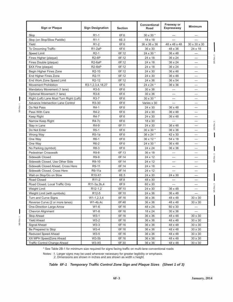
6F-3 January, 2014
Table 6F-1 Temporary Traffic Control Zone Sign and Plaque Sizes (Sheet 1 of 3)
Stop
Stop (on Stop/Slow Paddle)
Yield
To Oncoming Traffic
Speed Limit
Fines Higher (plaque)
Fines Double (plaque)
$XX Fine (plaque)
Begin Higher Fines Zone
End Higher Fines Zone
End Work Zone Speed Limit
Movement Prohibition
Mandatory Movement (1 lane)
Optional
Do Not Pass
Pass With Care
Keep Right
Narrow Keep Right
Stay in Lane
Do Not Enter
Wrong Way
One Way
One Way
No Parking (symbol)
Pedestrian Crosswalk
Sidewalk Closed
Closed
Road Closed, Local Traffic Only
Weight Limit
Weight Limit (with symbols)
Turn and Curve Signs
Reverse Curve (2 or more lanes)
One-Direction Large Arrow
Chevron Alignment
Stop Ahead
Yield Ahead
Signal Ahead
Be Prepared to Stop
Reduced Speed Ahead
XX MPH SpeedZone Ahead
Traffic Control Change Ahead
Movement (1 lane)
Right (Left) Lane Must Turn Right (Left)
Advance Intersection Lane Control
Sidewalk Closed, Use Other Side
Sidewalk Closed Ahead, Cross Here
Sidewalk Closed, Cross Here
Wait on Stop/Go on Slow
Road
R1-1
R1-1
R1-2
R1-2aP
R2-1
R2-6P
R2-6aP
R2-6bP
R2-10
R2-11
R2-12
R3-1,2,3,4,18,27
R3-5
R3-6
R3-7
R3-30
R4-1
R4-2
R4-7
R4-7c
R4-9
R5-1
R5-1a
R6-1
R6-2
R8-3
R9-8
R9-9
R9-10
R9-11
R9-11a
R10-X1
R11-2
R11-3a,3b,4
R12-1,2
R12-5
W1-1,2,3,4
W1-4b,4c
W1-6
W1-8
W3-1
W3-2
W3-3
W3-4
W3-5
W3-5b
W3-X5
6F.6
6E.3
6F.6
6F.6
6F.12
6F.6
6F.12
6F.12
6F.12
6F.12
6F.12
6F.12
6F.6
6F.6
6F.6
6F.6
6F.6
6F.6
6F.6
6F.6
6F.11
6F.6
6F.6
6F.6
6F.6
6F.6
6F.13
6F.14
6F.14
6F.14
6F.14
6E.5
6F.8
6F.9
6F.10
6F.10
6F.16
6F.48
6F.16
6F.16
6F.16
6F.16
6F.16
6F.16
6F.16
6F.16
6F.30
30 x 30 *
18 x 18
36 x 36 x 36
36 x 30
24 x 30 *
24 x 18
24 x 18
24 x 18
24 x 30
24 x 30
24 x 36
24 x 24 *
30 x 36
30 x 36
30 x 30 *
Varies x 30
24 x 30
24 x 30
24 x 30
18 x 30
24 x 30
30 x 30 *
36 x 24 *
36 x 12 *
24 x 30 *
24 x 24
36 x 18
24 x 12
24 x 12
24 x 18
24 x 12
24 x 30
48 x 30
60 x 30
24 x 30
24 x 36
36 x 36
36 x 36
48 x 24
18 x 24
36 x 36
36 x 36
36 x 36
36 x 36
36 x 36
36 x 36
36 x 36
---
---
30 x 30 x 30
24 x 18
---
---
---
---
---
---
---
---
---
---
---
---
---
---
---
---
---
---
---
---
---
---
---
---
---
---
---
---
---
---
---
---
30 x 30
30 x 30
---
---
30 x 30
30 x 30
30 x 30
30 x 30
30 x 30
30 x 30
30 x 30
---
---
48 x 48 x 48
48 x 36
36 x 48
36 x 24
36 x 24
36 x 24
36 x 48
36 x 48
36 x 54
36 x 36
---
---
---
---
36 x 48
36 x 48
36 x 48
---
36 x 48
36 x 36
42 x 30
54 x 18
36 x 48
36 x 36
---
---
---
---
---
24 x 30
---
---
36 x 48
36 x 48
48 x 48
48 x 48
60 x 30
30 x 36
48 x 48
48 x 48
48 x 48
48 x 48
48 x 48
48 x 48
48 x 48
Sign or Plaque SectionConventional
RoadSign DesignationFreeway orExpressway Minimum
* See Table 2B-1 for minimum size required for signs facing traffic on multi-lane conventional roads
Notes: 1. Larger signs may be used wherever necessary for greater legibility or emphasis.2. Dimensions are shown in inches and are shown as width x height.
MN
Rev
. 1
MN
Rev
. 3M
NR
ev. 3
MN
Rev
. 3M
NR
ev. 3
MN
Rev
. 1

6F-4January, 2014
Table 6F-1 Temporary Traffic Control Zone Sign and Plaque Sizes (Sheet 2 of 3)
Merging traffic
Lane Ends
Added Lane
No Merge Area (plaque)
Road Narrows
Narrow Bridge
One Lane Bridge
Ramp Narrows
Divided Highway
Divided highway Ends
Two-Way Traffic
Two-Way Traffic
Hill (symbol)
Next XX Miles (plaque)
Bump
Dip
Pavement Ends
Soft Shoulder
Slippery When Wet
Truck Crossing
Loose Gravel
Rough Road
Low Shoulder
Shoulder Drop-Off
Uneven Lanes
No Center Stripe
Fallen Rocks
Grooved Pavement
Motorcycle (plaque)
Road May Flood
No Shoulder
Steel Plate Ahead
Shoulder Ends
Lane Ends
Grade Crossing Advance Warning
Truck
Double Arrow
Low Clearance
Advisory Speed (plaque)
On Ramp (plaque)
No Passing Zone (pennant)
Emergency Scene Ahead
XX Feet (plaque)
Road Work Ahead
Detour Ahead
Road (Street) Closed Ahead
Trail Closed Ahead
W4-1,1a,5
W4-2
W4-3,6
W4-5P
W5-1
W5-2
W5-3
W5-4
W6-1
W6-2
W6-3
W6-4
W7-1
W7-3aP
W8-1,1a
W8-2
W8-3
W8-4
W8-5
W8-6
W8-7
W8-8
W8-9
W8-9a
W8-11
W8-12a
W8-14
W8-15
W8-15P
W8-18
W8-23
W8-24
W8-25
W9-1,2
W10-1
W11-10
W12-1
W12-2
W13-1P
W13-4P
W14-3
W14-X15
W16-2P
W20-1
W20-2
W20-3
W20-3a
6F.16
6F.24
6F.16
6F.16
6F.16
6F.16
6F.16
6F.26
6F.16
6F.16
6F.32
6F.76
6F.16
6F.53
6F.16
6F.16
6F.16
6F.44
6F.16
6F.36
6F.16
6F.16
6F.44
6F.44.1
6F.45
6F.47
6F.16
6F.16
6F.54
6F.16
6F.44.3
6F.46
6F.16
6F.16
6F.16
6F.36
6F.16
6F.16
6F.52
6F.25
6F.16
6I.1
6F.16
6F.18
6F.19
6F.20
6F.20.1
36 x 36
36 x 36
36 x 36
18 x 24
36 x 36
36 x 36
36 x 36
36 x 36
36 x 36
36 x 36
36 x 36
12 x 18
36 x 36
24 x 18
36 x 36
36 x 36
36 x 36
36 x 36
36 x 36
36 x 36
36 x 36
36 x 36
36 x 36
36 x 36
36 x 36
36 x 36
36 x 36
36 x 36
24 x 18
36 x 36
36 x 36
36 x 36
36 x 36
36 x 36
36 Diameter
36 x 36
30 x 30
36 x 36
24 x 24
36 x 36
48 x 48 x 36
36 x 36
24 x 18
36 x 36
36 x 36
36 x 36
18 x 18
36 x 36
30 x 30
30 x 30
---
30 x 30
30 x 30
30 x 30
30 x 30
30 x 30
30 x 30
30 x 30
---
30 x 30
---
30 x 30
30 x 30
30 x 30
30 x 30
30 x 30
30 x 30
30 x 30
30 x 30
30 x 30
30 x 30
30 x 30
30 x 30
30 x 30
30 x 30
---
24 x 24
30 x 30
30 x 30
30 x 30
30 x 30
---
30 x 30
---
30 x 30
18 x 18
---
40 x 40 x 30
---
---
30 x 30
30 x 30
30 x 30
---
48 x 48
48 x 48
48 x 48
24 x 30
48 x 48
48 x 48
48 x 48
48 x 48
48 x 48
48 x 48
48 x 48
12 x 18
48 x 48
36 x 30
48 x 48
48 x 48
48 x 48
48 x 48
48 x 48
48 x 48
48 x 48
48 x 48
48 x 48
48 x 48
48 x 48
48 x 48
48 x 48
48 x 48
30 x 24
48 x 48
48 x 48
48 x 48
48 x 48
48 x 48
---
48 x 48
---
48 x 48
30 x 30
36 x 36
64 x 64 x 48
48 x 48
30 x 24
48 x 48
48 x 48
48 x 48
---
Sign or Plaque SectionConventional
RoadSign DesignationFreeway orExpressway Minimum
* See Table 2B-1 for minimum size required for signs facing traffic on multi-lane conventional roads
Notes: 1. Larger signs may be used wherever necessary for greater legibility or emphasis.2. Dimensions are shown in inches and are shown as width x height.
MN
Rev
. 1
MN
Rev
. 3M
NR
ev. 3
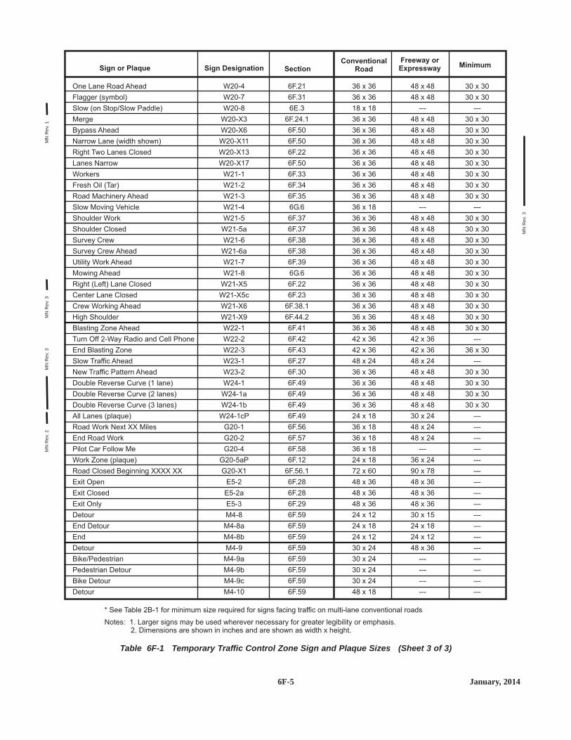
6F-5 January, 2014
Table 6F-1 Temporary Traffic Control Zone Sign and Plaque Sizes (Sheet 3 of 3)
One Lane Road Ahead
Flagger (symbol)
Slow (on Stop/Slow Paddle)
Merge
Bypass Ahead
Narrow Lane (width shown)
Right Two Lanes Closed
Lanes Narrow
Workers
Fresh Oil (Tar)
Road Machinery Ahead
Slow Moving Vehicle
Shoulder Work
Shoulder Closed
Survey Crew
Survey Crew Ahead
Utility Work Ahead
Mowing Ahead
Right (Left) Lane Closed
Center Lane Closed
Crew Working Ahead
High Shoulder
Blasting Zone Ahead
Turn Off 2-Way Radio and Cell Phone
End Blasting Zone
Slow Traffic Ahead
New Traffic Pattern Ahead
Double Reverse Curve (1 lane)
All Lanes (plaque)
Road Work Next XX Miles
End Road Work
Pilot Car Follow Me
Work Zone (plaque)
Road Closed Beginning XXXX XX
Exit Open
Exit Closed
Exit Only
Detour
End Detour
End
Detour
Bike/Pedestrian
Pedestrian Detour
Bike Detour
Detour
Double Reverse Curve (2 lanes)
Double Reverse Curve (3 lanes)
W20-4
W20-7
W20-8
W20-X3
W20-X6
W20-X11
W20-X13
W20-X17
W21-1
W21-2
W21-3
W21-4
W21-5
W21-5a
W21-6
W21-6a
W21-7
W21-8
W21-X5
W21-X5c
W21-X6
W21-X9
W22-1
W22-2
W22-3
W23-1
W23-2
W24-1
W24-1a
W24-1b
W24-1cP
G20-1
G20-2
G20-4
G20-5aP
G20-X1
E5-2
E5-2a
E5-3
M4-8
M4-8a
M4-8b
M4-9
M4-9a
M4-9b
M4-9c
M4-10
6F.21
6F.31
6E.3
6F.24.1
6F.50
6F.50
6F.22
6F.50
6F.33
6F.34
6F.35
6G.6
6F.37
6F.37
6F.38
6F.38
6F.39
6G.6
6F.22
6F.23
6F.38.1
6F.44.2
6F.41
6F.42
6F.43
6F.27
6F.30
6F.49
6F.49
6F.49
6F.49
6F.56
6F.57
6F.58
6F.12
6F.56.1
6F.28
6F.28
6F.29
6F.59
6F.59
6F.59
6F.59
6F.59
6F.59
6F.59
6F.59
36 x 36
36 x 36
18 x 18
36 x 36
36 x 36
36 x 36
36 x 36
36 x 36
36 x 36
36 x 36
36 x 36
36 x 18
36 x 36
36 x 36
36 x 36
36 x 36
36 x 36
36 x 36
36 x 36
36 x 36
36 x 36
36 x 36
36 x 36
42 x 36
42 x 36
48 x 24
36 x 36
36 x 36
36 x 36
36 x 36
24 x 18
36 x 18
36 x 18
36 x 18
24 x 18
72 x 60
48 x 36
48 x 36
48 x 36
24 x 12
24 x 18
24 x 12
30 x 24
30 x 24
30 x 24
30 x 24
48 x 18
30 x 30
30 x 30
---
30 x 30
30 x 30
30 x 30
30 x 30
30 x 30
30 x 30
30 x 30
30 x 30
---
30 x 30
30 x 30
30 x 30
30 x 30
30 x 30
30 x 30
30 x 30
30 x 30
30 x 30
30 x 30
30 x 30
---
36 x 30
---
30 x 30
30 x 30
30 x 30
30 x 30
---
---
---
---
---
---
---
---
---
---
---
---
---
---
---
---
---
48 x 48
48 x 48
---
48 x 48
48 x 48
48 x 48
48 x 48
48 x 48
48 x 48
48 x 48
48 x 48
---
48 x 48
48 x 48
48 x 48
48 x 48
48 x 48
48 x 48
48 x 48
48 x 48
48 x 48
48 x 48
48 x 48
42 x 36
42 x 36
48 x 24
48 x 48
48 x 48
48 x 48
48 x 48
30 x 24
48 x 24
48 x 24
---
36 x 24
90 x 78
48 x 36
48 x 36
48 x 36
30 x 15
24 x 18
24 x 12
48 x 36
---
---
---
---
Sign or Plaque SectionConventional
RoadSign DesignationFreeway orExpressway Minimum
* See Table 2B-1 for minimum size required for signs facing traffic on multi-lane conventional roads
Notes: 1. Larger signs may be used wherever necessary for greater legibility or emphasis.2. Dimensions are shown in inches and are shown as width x height.
MN
Rev
. 1M
NR
ev. 3
MN
Rev
. 3M
NR
ev. 2
MN
Rev
. 3

6F-6December, 2011
All i h ll b t d 3 d f t li ht
B. RURAL AREA WITHADVISORY SPEED PLATE
Paved Shoulder
A. RURAL AREA
Advance street name plaques or route markersnay be installed above or below warning signs
C. BUSINESS, COMMERCIAL,OR RESIDENTIAL AREA
D. BUSINESS, COMMERCIAL,OR RESIDENTIAL
AREA (WITHOUT CURB)
Walkway
6 to 12feet
6 to 12feet
6 feetMinimum
5 feetMinimum 4 feet
Minimum
2 feetMinimum
2 feetMinimum
7 feetMinimum
7 feetMinimum
XX
F I RST ST
F I RST ST
OPTIONAL
OPTIONAL
Figure 6F-1 Height and Lateral Location of Signs - Typical Installations

6F.18 ROAD (STREET) WORK AHEADSign (W20-1)
The ROAD (STREET) WORK AHEAD (W20-1) sign,which serves as a general warning of obstructions or restric-tions, should be located in advance of the work space or anydetour, on the road where the work is taking place, and on allintersecting roadways.
Where traffic can enter a TTC zone from a crossroad or amajor (high-volume) driveway, an advance warning signshould be used on the crossroad or major driveway.
The ROAD (STREET) WORK (W20-1) sign shall havethe legend ROAD (STREET) WORK, XX FT, XX MILES,or AHEAD.
6F.19 DETOUR AHEAD Sign (W20-2)
The DETOUR AHEAD (W20-2) sign should be used inadvance of a road user detour over a different roadway orroute.
The DETOUR sign shall have the legend DETOUR, XXFEET, XX MILES, or AHEAD.
STANDARD:STANDARD:
GUIDANCE:GUIDANCE:
W20-2
D ETO U RAH EAD
STANDARD:STANDARD:
GUIDANCE:GUIDANCE:
W20-1
ROA D
WO R K
A H EA D
6F.20 ROAD (STREET) CLOSED AHEADSign (W20-3)
The ROAD (STREET) CLOSED AHEAD (W20-3) signshould be used in advance of the point where a highway isclosed to all road users, or to all but local road users.
The ROAD (STREET) CLOSED sign shall have thelegend ROAD (STREET) CLOSED, XX FEET, XXMILES, or AHEAD.
6F.20.1 TRAIL CLOSED AHEAD Sign(W20-3a)
The TRAIL CLOSED AHEAD (W20-3a) sign should beused in advance of the point where a recreational trail isclosed to all users.
6F.21 ONE LANE ROAD AHEAD Sign(W20-4)
The ONE LANE ROAD AHEAD (W20-4) sign shall beused only in advance of that point where motor vehicletraffic in both directions must use a common single lane (seeSection 6C.10). It shall have the legend ONE LANE ROAD,XX FEET, XX MILES, or AHEAD.
If the affected one lane roadway is not visible from oneend to the other, or if the traffic is such that simultaneousarrivals at both ends occur frequently, flagging procedures,stop sign or signal control should be used to controlalternate traffic flows.
GUIDANCE:GUIDANCE:
STANDARD:STANDARD:
W20-4
ON E LANE
ROA D
A H EA D
GUIDANCE:GUIDANCE:
W20-3aW20-3
TRA I LC LOS EDAH EAD
ROADCLOS EDAH EAD
STANDARD:STANDARD:
GUIDANCE:GUIDANCE:
6F-13 December, 2011

6F.22 Lane(s) Closed Signs(W21-X5, W20-X13)
Lane closed signs shall be used in advance of that pointwhere one or more through lanes of a multiple-lane roadwayare closed.
For a single lane closure, the RIGHT (LEFT) LANECLOSED (W21-X5) sign shall be used. Where two adjacentlanes are closed, the RIGHT (LEFT) TWO LANES CLOSED(W20-X13) shall be used.
6F.23 CENTER LANE CLOSED Sign(W21-X5c)
The CENTER LANE CLOSED (W21-X5c) sign should beused in advance of that point where work occupies the centerlane(s) and approaching motor vehicle traffic is directed tothe right or left of the work zone in the center lane.
6F.23.1 THRU TRAFFIC MERGERIGHT (LEFT) Sign (W4-1a)
The THRU TRAFFIC MERGE RIGHT (LEFT) (W4-1a)sign should be used in advance of an intersection whereone or more lane closures on the far side of a multi-laneintersection require through motor vehicle traffic on theapproach to the intersection to use the right (left) lane toproceed through the intersection.
GUIDANCE:GUIDANCE:
W4-1aW21-X5c
T H R U
T RA F F I C
M E R G E
R I G H T
C E N T E R
LA N E
C L O S E D
GUIDANCE:GUIDANCE:
STANDARD:STANDARD:
W20-X13W21-X5
R I G H T
CLOS EDLAN ESTWO
R I G H TLAN EC LOS ED
6F.24 Lane Ends Sign (W4-2)
The Lane Reduction (W4-2) symbol sign may be used towarn drivers of the reduction in the number of motor vehicletraffic lanes in the direction of travel on a multi-laneroadway.
6F.24.1 MERGE Sign (W20-X3)
The MERGE sign (W20-X3) with a demountable arrowshould be used when closing one or more lanes of a multi-lane roadway.
The MERGE sign (W20-X3) may be used in conjunctionwith the LANE REDUCTION Sign (W4-2).
6F.25 ON RAMP Plaque (W13-4P)
When work is being done on a ramp, but the rampremains open, the ON RAMP (W13-4) plaque may be usedto supplement the advance ROAD WORK sign.
OPTION:OPTION:
W13-4P
RAM PO N
OPTION:OPTION:
GUIDANCE:GUIDANCE:
W20-X3
M E R G E
OPTION:OPTION:
W4-2LW4-2R
6F-14January, 2014
MN
Rev
. 3

6F.36 Motorized Traffic Signs(W8-6, W11-10)
Motorized Traffic (W8-6, W11-10) signs may be used toalert road users to locations where unexpected travel on theroadway or entries into or departures from the roadway byconstruction vehicles might occur. The TRUCK CROSSING(W8-6) word message sign may be used as an alternate tothe Truck Crossing symbol (W11-10) sign where there is anestablished construction vehicle crossing of the roadway.
These locations might be relatively confined or mightoccur randomly over a segment of roadway.
6F.37 SHOULDER WORK Signs(W21-5, W21-5a)
Shoulder Work signs warn of maintenance, reconstruc-tion, or utility operations on the highway shoulder where theroadway is unobstructed.
The Shoulder Work sign shall have the legendSHOULDER WORK (W21-5), RIGHT (LEFT)SHOULDER CLOSED (W21-5a), or RIGHT (LEFT)SHOULDER CLOSED XXX FT or AHEAD (W21-5b).
The Shoulder Work sign may be used in advance of thepoint on a nonlimited access highway where there isshoulder work. The Shoulder Work sign may be used singlyor in combination with a ROAD WORK NEXT X MILES orROAD WORK AHEAD sign.
OPTION:OPTION:
STANDARD:STANDARD:
SUPPORT:SUPPORT:
W21-5aW21-5
R I G H T
S H O U L D E R
C L O S E DS H O U L D E R
WO R K
SUPPORT:SUPPORT:
OPTION:OPTION:
W11-10W8-6
TR U CKCROSS I N G
On freeways and expressways, the RIGHT (LEFT)SHOULDER CLOSED XXX FT or AHEAD (W21-5b) signfollowed by RIGHT (LEFT) SHOULDER CLOSED (W21-5a) sign should be used in advance of the point where theshoulder work occurs and should be preceded by a ROADWORK AHEAD sign.
6F.38 SURVEY CREW Sign(W21-6, W21-6a)
The SURVEY CREW (W21-6) or the SURVEY CREWAHEAD (W21-6a) sign should be used to warn of surveyingcrews working in or adjacent to the roadway.
6F.38.1 CREW WORKING AHEAD Sign(W21-X6)
The CREW WORKING AHEAD (W21-X6) sign should beused for short duration activities being done on or off theroadway for such things as filming, surveying, treetrimming, road inspection, lighting, signal work, utility work,and other activities where a crew is visible to traffic.
The CREW WORKING AHEAD (W21-X6) sign may beused in place of the SURVEY CREW (W21-6) sign or theSURVEY CREW AHEAD (W21-6a) sign.
OPTION:OPTION:
GUIDANCE:GUIDANCE:
W21-X6
CR EWWO R K I N GAH EAD
GUIDANCE:GUIDANCE:
W21-6aW21-6
S U RVEYCR EWAH EAD
GUIDANCE:GUIDANCE:
6F-17 January, 2014
MN
Rev
. 3M
NR
ev. 3

6F.39 UTILITY WORD AHEAD Sign(W21-7)
The UTILITY WORK (W21-7) sign may be used as analternate to the ROAD (STREET) WORK (W20-1) sign forutility operations on or adjacent to a highway.
Typical examples of where the UTILITY WORK sign isused appear in Chapter 6K (the Field Manual), Layouts 6K-3, 6K-9, 6K-13, 6K-22, 6K-28, 6K-40, and 6K-51.
The UTILITY WORK sign shall carry the legendUTILITY WORK, XX FT, XX MILES, or AHEAD.
6F.40 Signs for Blasting Areas
Radio-Frequency (RF) energy can cause the prematurefiring of electric detonators (blasting caps) used in TTCzones.
Road users shall be warned to turn off mobile radio trans-mitters and cellular telephones where blasting operationsoccur. A sequence of signs shall be prominently displayed todirect operators of mobile radio equipment, includingcellular telephones, to turn off transmitters in a blasting area.These signs shall be covered or removed when there are noexplosives in the area or the area is otherwise secured.
STANDARD:STANDARD:
SUPPORT:SUPPORT:
STANDARD:STANDARD:
SUPPORT:SUPPORT:
OPTION:OPTION:
W21-7
U T I L I TYWO R KAH EAD
6F.41 BLASTING ZONE AHEAD Sign(W22-1)
The BLASTING ZONE AHEAD (W22-1) sign shall beused in advance of any TTC zone where explosives arebeing used. The TURN OFF 2-WAY RADIO AND CELLPHONE and END BLASTING ZONE signs shall be used insequence with this sign.
6F.42 TURN OFF 2-WAY RADIO ANDCELLULAR PHONE Sign (W22-2)
The TURN OFF 2-WAY RADIO AND CELLULARPHONE (W22-2) sign shall follow the BLASTING ZONEAHEAD sign and shall be placed at least 1,000 feet beforethe beginning of the blasting zone.
6F.43 END BLASTING ZONE Sign(W22-3)
The END BLASTING ZONE (W22-3) sign shall beplaced a minimum of 1,000 feet past the blasting zone.
The END BLASTING ZONE sign may be placed eitherwith or preceding the END ROAD WORK sign.
6F.44 Shoulder Signs
The signs in the following sections are to be used asdescribed.
SUPPORT:SUPPORT:
OPTION:OPTION:
STANDARD:STANDARD:
W22-3W22-2
E N D
B LAS T I N G
Z O N E
T U R N O F F2-WAY RA D I O
A N D
C E L L P H O N E
STANDARD:STANDARD:
W22-1
B LAS T I N G
Z O N E
AH EA D
6F-18July, 2012
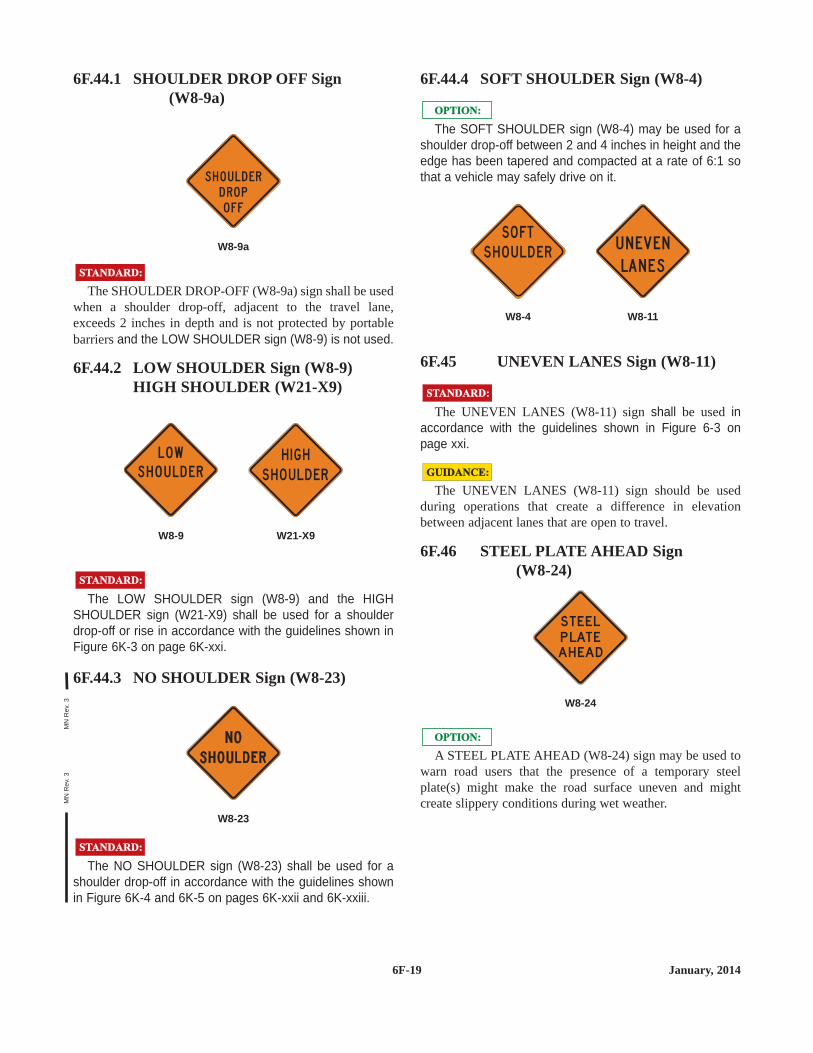
6F.44.1 SHOULDER DROP OFF Sign(W8-9a)
The SHOULDER DROP-OFF (W8-9a) sign shall be usedwhen a shoulder drop-off, adjacent to the travel lane,exceeds 2 inches in depth and is not protected by portablebarriers and the LOW SHOULDER sign (W8-9) is not used.
6F.44.2 LOW SHOULDER Sign (W8-9)HIGH SHOULDER (W21-X9)
The LOW SHOULDER sign (W8-9) and the HIGHSHOULDER sign (W21-X9) shall be used for a shoulderdrop-off or rise in accordance with the guidelines shown inFigure 6K-3 on page 6K-xxi.
6F.44.3 NO SHOULDER Sign (W8-23)
The NO SHOULDER sign (W8-23) shall be used for ashoulder drop-off in accordance with the guidelines shownin Figure 6K-4 and 6K-5 on pages 6K-xxii and 6K-xxiii.
STANDARD:STANDARD:
W8-23
STANDARD:STANDARD:
W21-X9W8-9
H I G HS H O U LD ER
L OW
S H O U L D E R
STANDARD:STANDARD:
W8-9a
S H O U L D E R
D RO P
O F F
6F.44.4 SOFT SHOULDER Sign (W8-4)
The SOFT SHOULDER sign (W8-4) may be used for ashoulder drop-off between 2 and 4 inches in height and theedge has been tapered and compacted at a rate of 6:1 sothat a vehicle may safely drive on it.
6F.45 UNEVEN LANES Sign (W8-11)
The UNEVEN LANES (W8-11) sign shall be used inaccordance with the guidelines shown in Figure 6-3 onpage xxi.
The UNEVEN LANES (W8-11) sign should be usedduring operations that create a difference in elevationbetween adjacent lanes that are open to travel.
6F.46 STEEL PLATE AHEAD Sign(W8-24)
A STEEL PLATE AHEAD (W8-24) sign may be used towarn road users that the presence of a temporary steelplate(s) might make the road surface uneven and mightcreate slippery conditions during wet weather.
OPTION:OPTION:
W8-24
STE E LP LAT EAH EAD
GUIDANCE:GUIDANCE:
STANDARD:STANDARD:
W8-11W8-4
U N EV E N
LA N E S
SO FTS H O U LD ER
OPTION:OPTION:
6F-19 January, 2014
MN
Rev
. 3M
NR
ev. 3

6F.47 NO CENTER STRIPE Sign (W8-12a)
The NO CENTER STRIPE (W8-12a) sign shall be usedas detailed in Section 6F.78.
This sign should also be used at major connection, trafficgenerators, and/or at appropriate intervals to advisemotorists entering the zone.
6F.48 Reverse Curve Signs (W1-4 Series)
In order to give road users advance notice of a lane shift,a Reverse Curve (W1-4, W1-4b, or W1-4c) sign (see Figure6F-4) should be used when a lane (or lanes) is being shiftedto the left or right. If the design speed of the curves is 30mph or less, a Reverse Turn (W1-3) sign should be used.
If a Reverse Curve (or Turn) sign is used, the direction ofthe reverse curve (or turn) symbol shall be consistent withthe desired vehicle path. Except as provided in the followingOption, the number of lanes illustrated on the sign shall bethe same as the number of through lanes available to roadusers.
Where two or more lanes are being shifted, a W1-4 (orW1-3) sign with an ALL LANES (W24-1cP) plaque (seeFigure 6F-4) may be used instead of a sign that illustrates thenumber of lanes.
Where more than three lanes are being shifted, theReverse Curve (or Turn) sign may be rectangular.
OPTION:OPTION:
STANDARD:STANDARD:
GUIDANCE:GUIDANCE:
W1-4cW1-4bW1-4
GUIDANCE:GUIDANCE:
STANDARD:STANDARD:
W8-12a
N O
C E N T E R
S T R I P E
6F.49 Double Reverse Curve Signs(W24-1 series)
The Double Reverse Curve (W24-1, W24-1a, W24-1b)sign may be used where the tangent distance between tworeverse curves is less than 600 feet, thus making it difficultfor a second Reverse Curve (W1-4 series) sign to be placedbetween the curves. If the design speed of the curves is 30mph or less, Double Reverse Turn signs should be used.
If a Double Reverse Curve (or Turn) sign is used, thedirection of the double reverse curve (or turn) symbol shallbe consistent with the desired vehicle path. Except asprovided in the first paragraph of the following Option, thenumber of lanes illustrated on the sign shall be the same asthe number of through lanes available to road users.
Where two or more lanes are being shifted, a W24-1 (orDouble Reverse Turn sign showing one lane) sign with anALL LANES (W24-1cP) plaque may be used instead of asign that illustrates the number of lanes.
Where more than three lanes are being shifted, the DoubleReverse Curve (or Turn) sign may be rectangular.
6F.50 Other Warning Signs
Advance warning signs may be used by themselves orwith other advance warning signs.
Besides the warning signs specifically related to TTCzones, several other warning signs in Part 2 may apply inTTC zones.
Except as provided in Section 6F.02, other warning signsthat are used in TTC zones shall have black legends andborders on an orange background.
STANDARD:STANDARD:
OPTION:OPTION:
OPTION:OPTION:
STANDARD:STANDARD:
OPTION:OPTION:
W24-1bW24-1aW24-1
6F-20January, 2014
MN
Rev
. 1
MN
Rev
. 3M
NR
ev. 3

6F.71 Longitudinal ChannelizingBarricades
Longitudinal channelizing devices are lightweight,deformable devices that are highly visible, have good targetvalue, and can be connected together.
If used singly as Type 1, 2, or 3 barricades, longitudinalchannelizing devices shall comply with the general size,color, stripe pattern, retroreflectivity, and placement charac-teristics established for the devices described in this Chapter.
If used to channelize vehicular traffic at night, longitudi-nal channelizing devices should be supplemented withretroreflective material or delineation for improvednighttime visibility.
Longitudinal channelizing barricades may be used insteadof a line of cones, drums, or barricades.
Longitudinal channelizing barricades may be hollow andfilled with water as a ballast.
Longitudinal channelizing devices may be used forpedestrian traffic control.
If used for pedestrian traffic control, longitudinal chan-nelizing devices shall be interlocked to delineate orchannelize flow. The interlocking devices shall not havegaps that allow pedestrians to stray from the channelizingpath.
Longitudinal channelizing devices have not met thecrashworthy requirements for temporary traffic barriers andshould not be used to shield obstacles or provide positiveprotection for pedestrians or workers.
6F.72 Temporary Lane Separators
Temporary lane separators may be used to channelizeroad users, to divide opposing vehicular traffic lanes, todivide lanes when two or more lanes are open in the samedirection, and to provide continuous pedestrian channeliza-tion.
Temporary lane separators shall be crashworthy.Temporary lane separators shall have a maximum height of4 inches and a maximum width of 1 foot, and shall havesloping sides in order to facilitate crossover by emergencyvehicles.
STANDARD:STANDARD:
OPTION:OPTION:
GUIDANCE:GUIDANCE:
STANDARD:STANDARD:
OPTION:OPTION:
GUIDANCE:GUIDANCE:
STANDARD:STANDARD:
SUPPORT:SUPPORT:
Temporary lane separators may be supplemented withany of the approved channelizing devices contained in thisChapter, such as tubular markers, vertical panels, andopposing traffic lane dividers.
If appropriate channelizing devices are used tosupplement a temporary lane separator, the channelizingdevices shall be retroreflectorized to provide nighttimevisibility. If channelizing devices are not used, thetemporary lane separator shall contain retroreflectorizationto enhance its visibility.
A temporary lane separator should be stabilized byaffixing it to the pavement in a manner suitable to its design,while allowing the unit to be shifted from place to placewithin the TTC zone in order to accommodate changingconditions.
At pedestrian crossing locations, temporary laneseparators shall have an opening or be shortened to providea pathway that is at least 60 inches wide for crossingpedestrians.
6F.73 Other Channelizing Devices
Channelizing devices other than those described in thisChapter may be used in special situations based on anengineering study.
Other channelizing devices should conform to the generalsize, color, stripe pattern, retroreflection, and placementcharacteristics established for the devices described in thisChapter.
6F.74 Detectable Edging for Pedestrians
Individual channelizing devices, tape or rope used toconnect individual devices, other discontinuous barriers anddevices, and pavement markings are not detectable bypersons with visual disabilities and are incapable ofproviding detectable path guidance on temporary orrealigned sidewalks or other pedestrian facilities.
When it is determined that a facility should be accessibleto and detectable by pedestrians with visual disabilities, acontinuously detectable edging should be providedthroughout the length of the facility such that it can befollowed by pedestrians using long canes for guidance. Thisedging should protrude at least 6 inches above the surface of
GUIDANCE:GUIDANCE:
SUPPORT:SUPPORT:
GUIDANCE:GUIDANCE:
OPTION:OPTION:
STANDARD:STANDARD:
GUIDANCE:GUIDANCE:
STANDARD:STANDARD:
OPTION:OPTION:
6F-39 December, 2011
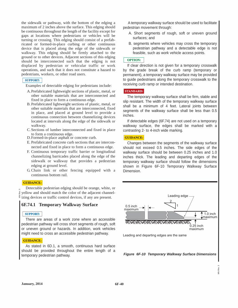
the sidewalk or pathway, with the bottom of the edging amaximum of 2 inches above the surface. This edging shouldbe continuous throughout the length of the facility except forgaps at locations where pedestrians or vehicles will beturning or crossing. This edging should consist of a prefab-ricated or formed-in-place curbing or other continuousdevice that is placed along the edge of the sidewalk orwalkway. This edging should be firmly attached to theground or to other devices. Adjacent sections of this edgingshould be interconnected such that the edging is notdisplaced by pedestrian or vehicular traffic or workoperations, and such that it does not constitute a hazard topedestrians, workers, or other road users.
Examples of detectable edging for pedestrians include:A.Prefabricated lightweight sections of plastic, metal, or
other suitable materials that are interconnected andfixed in place to form a continuous edge.
B. Prefabricated lightweight sections of plastic, metal, orother suitable materials that are interconnected, fixedin place, and placed at ground level to provide acontinuous connection between channelizing deviceslocated at intervals along the edge of the sidewalk orwalkway.
C. Sections of lumber interconnected and fixed in placeto form a continuous edge.
D.Formed-in-place asphalt or concrete curb.E. Prefabricated concrete curb sections that are intercon-
nected and fixed in place to form a continuous edge.F. Continuous temporary traffic barrier or longitudinal
channelizing barricades placed along the edge of thesidewalk or walkway that provides a pedestrianedging at ground level.
G. Chain link or other fencing equipped with acontinuous bottom rail.
Detectable pedestrian edging should be orange, white, oryellow and should match the color of the adjacent channel-izing devices or traffic control devices, if any are present.
6F.74.1 Temporary Walkway Surface
There are areas of a work zone where an accessiblepedestrian pathway will cross short segments of rough, softor uneven ground or hazards. In addition, work vehiclesmight need to cross an accessible pedestrian pathway.
As stated in 6D.1, a smooth, continuous hard surfaceshould be provided throughout the entire length of atemporary pedestrian pathway.
GUIDANCE:GUIDANCE:
SUPPORT:SUPPORT:
GUIDANCE:GUIDANCE:
SUPPORT:SUPPORT:
A temporary walkway surface should be used to facilitatepedestrian movement through:
A. Short segments of rough, soft or uneven groundsurfaces; and
B. segments where vehicles may cross the temporarypedestrian pathway and a detectable edge is notfeasible, such as work vehicle access points.
If clear direction is not given for a temporary crosswalkby the grade break of the curb ramp (temporary orpermanent), a temporary walkway surface may be providedto guide pedestrians along the temporary crosswalk to thereceiving curb ramp or intended destination.
The temporary walkway surface shall be firm, stable andslip resistant. The width of the temporary walkway surfaceshall be a minimum of 4 feet. Lateral joints betweensegments of the walkway surface shall be less than 0.5inches.
If detectable edges (6F.74) are not used on a temporarywalkway surface, the edges shall be marked with acontrasting 2- to 4-inch wide marking.
Changes between the segments of the walkway surfaceshould not exceed 0.5 inches. The side edges of thewalkway surface should be between 0.25 inches and 1.0inches thick. The leading and departing edges of thetemporary walkway surface should follow the dimensionsshown in Figure 6F-10 Temporary Walkway SurfaceDimension.
GUIDANCE:GUIDANCE:
STANDARD:STANDARD:
OPTION:OPTION:
6F-40January, 2014
MN
Rev
. 3
MN
Rev
. 3
Figure 6F-10 Temporary Walkway Surface Dimensions
0.25 inchmaximum
Leading and departing edges are the same
Leading edge
1.0 inchmaximum
0.5 inchmaximum
2
1
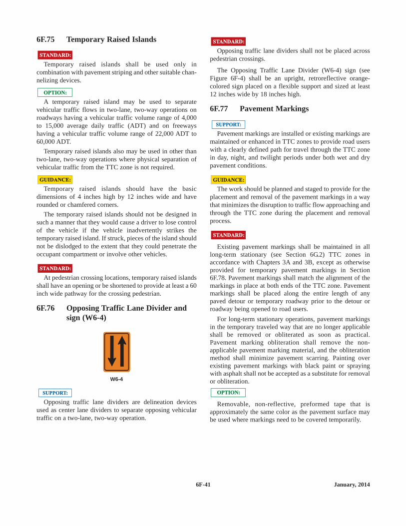
6F.75 Temporary Raised Islands
Temporary raised islands shall be used only incombination with pavement striping and other suitable chan-nelizing devices.
A temporary raised island may be used to separatevehicular traffic flows in two-lane, two-way operations onroadways having a vehicular traffic volume range of 4,000to 15,000 average daily traffic (ADT) and on freewayshaving a vehicular traffic volume range of 22,000 ADT to60,000 ADT.
Temporary raised islands also may be used in other thantwo-lane, two-way operations where physical separation ofvehicular traffic from the TTC zone is not required.
Temporary raised islands should have the basicdimensions of 4 inches high by 12 inches wide and haverounded or chamfered corners.
The temporary raised islands should not be designed insuch a manner that they would cause a driver to lose controlof the vehicle if the vehicle inadvertently strikes thetemporary raised island. If struck, pieces of the island shouldnot be dislodged to the extent that they could penetrate theoccupant compartment or involve other vehicles.
At pedestrian crossing locations, temporary raised islandsshall have an opening or be shortened to provide at least a 60inch wide pathway for the crossing pedestrian.
6F.76 Opposing Traffic Lane Divider andsign (W6-4)
Opposing traffic lane dividers are delineation devicesused as center lane dividers to separate opposing vehiculartraffic on a two-lane, two-way operation.
SUPPORT:SUPPORT:
W6-4
STANDARD:STANDARD:
GUIDANCE:GUIDANCE:
OPTION:OPTION:
STANDARD:STANDARD:Opposing traffic lane dividers shall not be placed across
pedestrian crossings.
The Opposing Traffic Lane Divider (W6-4) sign (seeFigure 6F-4) shall be an upright, retroreflective orange-colored sign placed on a flexible support and sized at least12 inches wide by 18 inches high.
6F.77 Pavement Markings
Pavement markings are installed or existing markings aremaintained or enhanced in TTC zones to provide road userswith a clearly defined path for travel through the TTC zonein day, night, and twilight periods under both wet and drypavement conditions.
The work should be planned and staged to provide for theplacement and removal of the pavement markings in a waythat minimizes the disruption to traffic flow approaching andthrough the TTC zone during the placement and removalprocess.
Existing pavement markings shall be maintained in alllong-term stationary (see Section 6G.2) TTC zones inaccordance with Chapters 3A and 3B, except as otherwiseprovided for temporary pavement markings in Section6F.78. Pavement markings shall match the alignment of themarkings in place at both ends of the TTC zone. Pavementmarkings shall be placed along the entire length of anypaved detour or temporary roadway prior to the detour orroadway being opened to road users.
For long-term stationary operations, pavement markingsin the temporary traveled way that are no longer applicableshall be removed or obliterated as soon as practical.Pavement marking obliteration shall remove the non-applicable pavement marking material, and the obliterationmethod shall minimize pavement scarring. Painting overexisting pavement markings with black paint or sprayingwith asphalt shall not be accepted as a substitute for removalor obliteration.
Removable, non-reflective, preformed tape that isapproximately the same color as the pavement surface maybe used where markings need to be covered temporarily.
OPTION:OPTION:
STANDARD:STANDARD:
GUIDANCE:GUIDANCE:
SUPPORT:SUPPORT:
STANDARD:STANDARD:
6F-41 January, 2014

6F.78 Interim Pavement Markings
Interim pavement markings are those that are allowed toremain in place until the earliest date when it is practicaland possible to install pavement markings that meet thePart 3 standards for pavement markings.
Interim pavement markings should not be in place formore than 14 calendar days unless justified by anengineering study.
White lane lines and yellow centerlines, including nopassing zones should be installed before opening theroadway to traffic. If it is not possible or practical to installthese markings before opening the roadway to traffic theinterim markings should be installed at the end of eachworking day or provided by signing in accordance with theprovisions of this section.
The temporary use of edge lines, channelizing lines, lanereduction transitions, gore markings, and other longitudinalmarkings, and the various non-longitudinal markings (suchas stop lines, railroad crossings, crosswalks, words orsymbols) should be in accordance with the State's orhighway agency's policy.
Warning signs, channelizing devices, and delineationshall be used to indicate required road user paths in TTCzones where it is not possible to provide a clear path bypavement markings.
Except as otherwise provided in this Section, all interimpavement markings for no-passing zones shall comply withthe requirements of Chapters 3A and 3B. All interim broken-line pavement markings shall use the same cycle length aspermanent markings and shall have line segments that are atleast 2 feet long.
All pavement markings and devices used to delineateroad user paths should be reviewed during daytime andnighttime periods.
Half-cycle lengths with a minimum of 2-foot stripes maybe used on roadways with severe curvature (see Section3A.6) for broken line center lines in passing zones and forlane lines.
OPTION:OPTION:
GUIDANCE:GUIDANCE:
STANDARD:STANDARD:
GUIDANCE:GUIDANCE:
GUIDANCE:GUIDANCE:
SUPPORT:SUPPORT:
For temporary situations of 14 calendar days or less, for atwo- or three-lane road, no-passing zones may be identifiedby using DO NOT PASS (R4-1), PASS WITH CARE (R4-2), and NO PASSING ZONE (W14-3) signs (see Sections2B.28, 2B.29, and 2C.45) rather than pavement markings.Also, DO NOT PASS, PASS WITH CARE, and NOPASSING ZONE signs may be used instead of pavementmarkings on roads with low volumes for longer periods inaccordance with the State's or highway agency's policy.
If used, the DO NOT PASS, PASS WITH CARE, and NOPASSING ZONE signs should be placed in accordance withSections 2B.28, 2B.29, and 2C.45.
If used, the NO CENTER STRIPE sign should be placedin accordance with Section 6F.47.
On low volume roads with an ADT (Average Daily Traffic)of less than 400 vehicles, the signs may be used in lieu ofpavement markings for up to 14 calendar days (see Section5A.1).
If no passing zone signing is used in lieu of pavementmarkings the following shall be installed before opening theroadway to traffic:
If no interim markings are used A NO CENTERSTRIPE sign (W8-12a) shall be used for eachdirection of travel in accordance with Section 6F.47.This sign shall be repeated at major intersections oron one-mile intervals, whichever is greater.
If interim no passing zone markings are not installedbut interim broken markings are installed a NOCENTER STRIPE sign (W8-12a) shall be installed inadvance of each no passing zone.
If not already in place, a DO NOT PASS sign (R4-1)shall be installed on the right side of the road at thebeginning of the zone opposite of the NO PASSINGZONE sign (W14-3).
A PASS WITH CARE sign (R4-2) shall be installed onthe right side of the road at the end of the no passingzone.
6F.79 Temporary Raised PavementMarkers
Retroreflective or internally illuminated raised pavementmarkers, or non-retroreflective raised pavement markerssupplemented by retroreflective or internally illuminatedmarkers, may be substituted for markings of other types inTTC zones.
OPTION:OPTION:
STANDARD:STANDARD:
OPTION:OPTION:
GUIDANCE:GUIDANCE:
6F-42January, 2014
MN
Rev
. 1

6F-43 January, 2014
Figure 6F-8a Interim Pavement Markings - 3 Days or Less
F F
F F
DON O TPASS
DON O TPASS
DONOTPASS
DONOTPASS
PASSWITHCARE
PASSWITHCARE
PASSW I THCAR E
PASSW I THCAR E
N O
C E N T E R
S T R I P E
F
N O
C E N T E R
S T R I P E
F
NO
CENTER
STRIPE
F
NO
CENTER
STRIPE
F
N O
C E N T E R
S T R I P E
N O
C E N T E R
S T R I P E
NO
CENTER
STRIPE
NO
CENTER
STRIPE
Variable based onAdvance WarningSign Placementsee Table 6C-1
Variable based onAdvance WarningSign Placementsee Table 6C-1
Variable based onAdvance WarningSign Placementsee Table 6C-1
Variable based onAdvance WarningSign Placementsee Table 6C-1
1m
ile
max
imu
m1m
ile
max
imu
m
1m
ile
max
imu
m
1m
ile
max
imu
m
TWO-LANE, TWO-WAY TWO-LANE, TWO-WAY
Broken LineCycle Length
(N)
2 feetminimum
NOTE:1. Either layout may be used for up to 14 days
when the Average daily Traffic is less than 400.2. Any NO PASSING ZONE sign (W14-3) used in temporary traffic
control zone that is applicable in its current location or will remaininplace after completion of the construction project may have a blacklegend and border on a yellow retroreflectorive background.
N OPASS I N GZONE
N OPASS I N GZONE
OR
seeNote 2
N OPASS I N GZONE
N OPASS I N GZONE
OR
seeNote 2
NOPASSINGZONE
NOPASSINGZONE
OR
seeNote 2
NOPASSINGZONE
NOPASSINGZONE
OR
seeNote 2
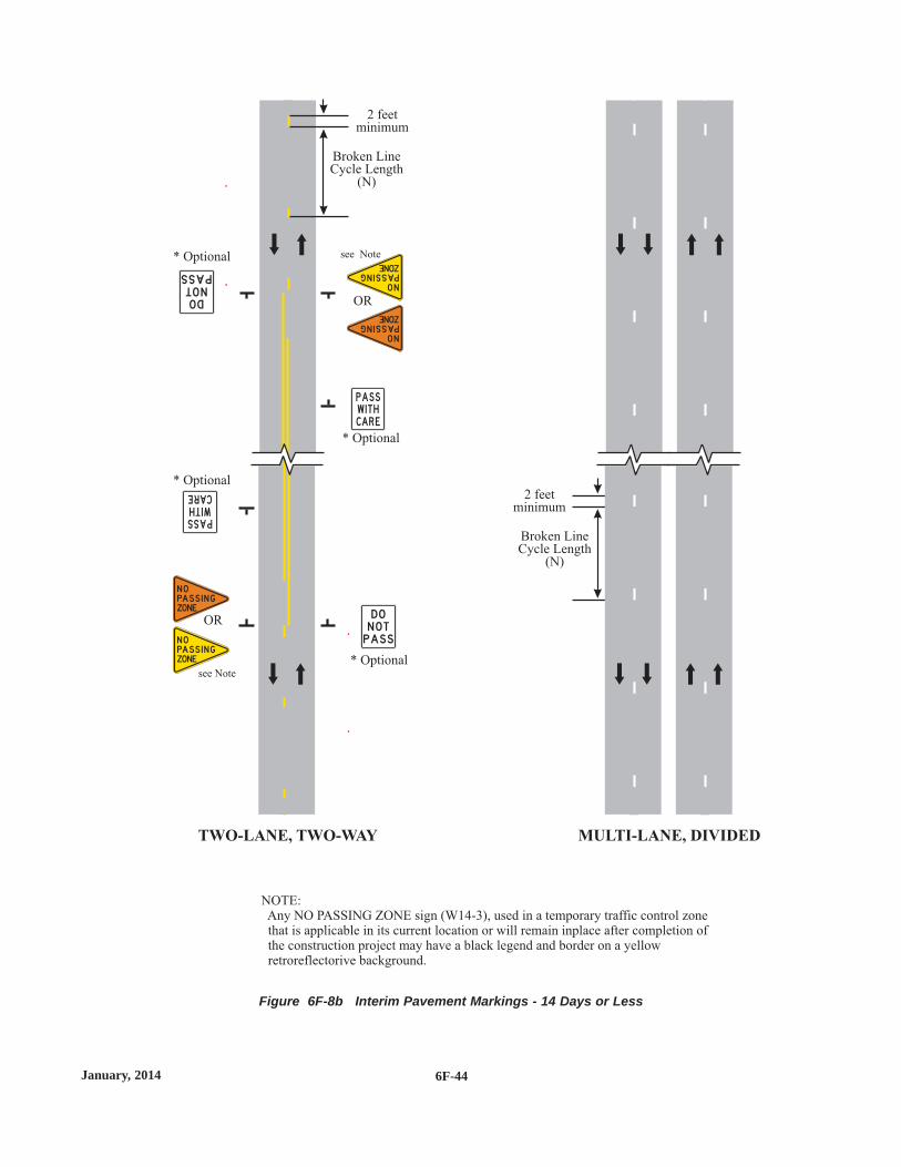
6F-44January, 2014
Figure 6F-8b Interim Pavement Markings - 14 Days or Less
DON O TPASS
DONOTPASS
PASSWITHCARE
PASSW I THCAR E
MULTI-LANE, DIVIDEDTWO-LANE, TWO-WAY
Broken LineCycle Length
(N)
Broken LineCycle Length
(N)
2 feetminimum
* Optional
* Optional
* Optional
* Optional
2 feetminimum
N OPASS I N GZONE
N OPASS I N GZONE
OR
see Note
NOPASSINGZONE
NOPASSINGZONE
OR
see Note
NOTE:Any NO PASSING ZONE sign (W14-3), used in a temporary traffic control zonethat is applicable in its current location or will remain inplace after completion ofthe construction project may have a black legend and border on a yellowretroreflectorive background.

If used, the color and pattern of the raised pavementmarkers shall simulate the color and pattern of the markingsfor which they substitute.
If temporary raised pavement markers are used tosubstitute for broken line segments, a group of at least threeretroreflective markers shall be equally spaced at no greaterthan N/10 (see Section 3B.14). The value of N for a brokenor dotted line shall equal the length of one line segment plusone gap.
If temporary raised pavement markers are used tosubstitute for solid lines, the markers shall be equally spacedat no greater than N/5, with retroreflective or internallyilluminated units at a spacing no greater than N/2. The valueof N referenced for solid lines shall equal the N for thebroken or dotted lines that might be adjacent to or mightextend the solid lines (see Section 3B.11).
Temporary raised pavement markers may be used tosubstitute for broken line segments by using at least tworetroreflective markers placed at each end of a segment of 2to 5 feet in length, using the same cycle length as permanentmarkings.
Temporary raised pavement markers used on 2- to 5-footsegments to substitute for broken line segments should notbe in place for more than 14 days unless justified byengineering judgment.
Raised pavement markers should be considered for usealong surfaced diversions (bypasses) or temporaryroadways, and other changed or new travel-lane alignments,because of the need to accentuate changed travel pathsand their wet weather capabilities.
Retroreflective or internally illuminated raised pavementmarkers, or non-retroreflective raised pavement markerssupplemented by retroreflective or internally illuminatedmarkers, may also be used in TTC zones to supplementmarkings as prescribed in Chapters 3A and 3B.
6F.80 Post-Mounted Delineators
When used, post-mounted delineators shall combine withor supplement other TTC devices. They shall be mounted oncrashworthy supports so that the reflecting unit is approxi-mately 4 feet above the near roadway edge. The standard
STANDARD:STANDARD:
OPTION:OPTION:
GUIDANCE:GUIDANCE:
OPTION:OPTION:
STANDARD:STANDARD: color for post-mounted delineators used along both sides oftwo-way streets and highways and the right side of one-wayroadways shall be white. Post-mounted delineators usedalong the left side of one-way roadways shall be yellow.
Spacing along roadway curves should be as set forth inSection 3F.4 and should be such that several delineators arealways visible to the driver.
Post-mounted delineators may be used in TTC zones toindicate the alignment of the roadway and to outline therequired vehicle path through the TTC zone.
6F.81 Lighting Devices
Lighting devices should be provided in TTC zones basedon engineering judgment.
When used to supplement channelization, the maximumspacing for warning lights should be identical to the chan-nelizing device spacing requirements.
Lighting devices may be used to supplement retroreflec-torized signs, barriers, and channelizing devices.
During normal daytime maintenance operations, thefunctions of flashing warning beacons may be provided byhigh-intensity rotating, flashing, oscillating, or strobe lightson a maintenance vehicle.
Although vehicle hazard warning lights are permitted to beused to supplement high-intensity rotating, flashing,oscillating, or strobe lights, they shall not be used insteadof high-intensity rotating, flashing, oscillating, or strobelights.
6F.82 Floodlights
Utility, maintenance, or construction activities onhighways are frequently conducted during nighttime periodswhen motor vehicle traffic volumes are lower. Large con-struction projects are sometimes operated on a double-shiftbasis requiring night work.
When nighttime work is being performed, floodlightsshould be used to illuminate the work area, flagger stations,equipment crossings, and other areas.
GUIDANCE:GUIDANCE:
SUPPORT:SUPPORT:
STANDARD:STANDARD:
OPTION:OPTION:
GUIDANCE:GUIDANCE:
OPTION:OPTION:
GUIDANCE:GUIDANCE:
6F-45 January, 2014

Except in emergency situations, flagger stations shall beilluminated at night.
Floodlighting shall not produce a disabling glarecondition for approaching road users, flaggers, or workers.
The adequacy of the floodlight placement and eliminationof potential glare should be determined by driving throughand observing the floodlighted area from each direction onall approaching roadways after the initial floodlight setup, atnight, and periodically.
Desired illumination levels vary depending upon thenature of the task involved. An average horizontalluminance of 5 foot candles can be adequate for generalactivities. Tasks requiring high levels of precision andextreme care can require an average horizontal luminance of20 foot candles.
6F.83 Warning Lights
Type A, Type B, Type C, and Type D 360-degree warninglights are portable, powered, yellow, lens-directed, enclosedlights.
Warning lights shall be in accordance with the currentITE "Purchase Specification for Flashing and Steady-BurnWarning Lights" (see Section 1A.11).
When warning lights are used, they shall be mounted onsigns or channelizing devices in a manner that, if hit by anerrant vehicle, they will not be likely to penetrate thewindshield.
The maximum spacing for warning lights should beidentical to the channelizing device spacing requirements.
The light weight and portability of warning lights areadvantages that make these devices useful as supplements tothe retroreflectorization on signs and channelizing devices.The flashing lights are effective in attracting road users'attention.
Warning lights may be used in either a steady-burn orflashing mode.
OPTION:OPTION:
SUPPORT:SUPPORT:
GUIDANCE:GUIDANCE:
STANDARD:STANDARD:
SUPPORT:SUPPORT:
SUPPORT:SUPPORT:
GUIDANCE:GUIDANCE:
STANDARD:STANDARD:
Except for the sequential flashing warning lights that aredescribed in Paragraphs 8 and 9, flashing warning lightsshall not be used for delineation, as a series of flashers failsto identify the desired vehicle path.
A series of sequential flashing warning lights may beplaced on channelizing devices that form a merging taper inorder to increase driver detection and recognition of themerging taper.
If a series of sequential flashing warning lights is used,the successive flashing of the lights shall occur from theupstream end of the merging taper to the downstream end ofthe merging taper in order to identify the desired vehiclepath. Each flashing warning light in the sequence shall beflashed at a rate of not less than 55 or more than 75 times perminute.
Type A Low-Intensity Flashing warning lights, Type CSteady-Burn warning lights, and Type D 360-degree Steady-Burn warning lights shall be maintained so as to be capableof being visible on a clear night from a distance of 3,000feet. Type B High-Intensity Flashing warning lights shall bemaintained so as to be capable of being visible on a sunnyday when viewed without the sun directly on or behind thedevice from a distance of 1,000 feet.
Warning lights shall have a minimum mounting height of30 inches to the bottom of the lens.
Type A Low-Intensity Flashing warning lights are used towarn road users during nighttime hours that they areapproaching or proceeding in a potentially hazardous area.
Type A warning lights may be mounted on channelizingdevices.
Type B High-Intensity Flashing warning lights are used towarn road users during both daylight and nighttime hoursthat they are approaching a potentially hazardous area.
Type B warning lights are designed to operate 24 hoursper day and may be mounted on advance warning signs oron independent supports.
Type C Steady-Burn warning lights and Type D 360-degree Steady-Burn warning lights may be used duringnighttime hours to delineate the edge of the traveled way.
OPTION:OPTION:
SUPPORT:SUPPORT:
OPTION:OPTION:
SUPPORT:SUPPORT:
STANDARD:STANDARD:
OPTION:OPTION:
STANDARD:STANDARD:
6F-46January, 2014

When used to delineate a curve, Type C and Type D 360-degree warning lights should only be used on devices on theoutside of the curve, and not on the inside of the curve.
6F.83.1 Warning Lights on STOP Signs
Type A warning lights are portable, powered, red, lens-directed, enclosed lights.
Warning lights shall be in accordance with the currentITE “Purchase Specification for Flashing and Steady-BurnWarning Lights” except except that they shall be red incolor.
Warning lights shall flash when placed on STOP signs.
The warning lights shall be maintained according to theType A Low-Intensity Flashing warning lights standard (seeSection 6F.83).
6F.83.2 Steady-Burn Electric Lamps
Steady-Burn electric lamps are a series of low-wattage,yellow, electric lamps, generally hard-wired to a 110-voltexternal power source.
Steady-Burn electric lamps may be used in place of TypeC Steady-Burn warning lights (see Section 6F.78).
6F.83.3 Roadway Lighting
On long term projects, the use of roadway lighting maybe beneficial. Areas that may benefit from the installation ofroadway lighting include high hazard areas, high volumeareas, crossovers, diversions (bypasses), areas withsudden alignment changes, curves, intersections andtransitions from multi-lane divided roadways to two-lane,two-way roadways.
When possible, all roadway lighting shall be protected orhave breakaway bases.
STANDARD:STANDARD:
SUPPORT:SUPPORT:
OPTION:OPTION:
SUPPORT:SUPPORT:
STANDARD:STANDARD:
SUPPORT:SUPPORT:
GUIDANCE:GUIDANCE: 6F.84 Temporary Traffic Control Signals
Temporary traffic control signals (see Section 4D.32)used to control road user movements through TTC zonesand in other TTC situations shall meet the applicableprovisions of Part 4.
Temporary traffic control signals are typically used inwork zones such as temporary haul road crossings;temporary one-way operations along a one-lane, two-wayhighway; temporary one-way operations on bridges,reversible lanes, and intersections.
A temporary traffic control signal that is used to controltraffic through a one-lane, two-way section of roadway shallcomply with the provisions of Section 4H.2.
Where pedestrian traffic is detoured to a temporary trafficcontrol signal, engineering judgment should be used todetermine if pedestrian signals or accessible pedestriansignals (see Section 4E.9) are needed for crossing along analternate route.
When temporary traffic control signals are used, conflictmonitors typical of traditional traffic control signaloperations should be used.
Temporary traffic control signals may be portable ortemporarily mounted on fixed supports.
Temporary traffic control signals should only be used insituations where temporary traffic control signals arepreferable to other means of traffic control, such as changingthe work staging or work zone size to eliminate one-waymotor vehicle traffic movements, using flaggers to controlone-way or crossing movements, using STOP or YIELDsigns, and using warning devices alone.
GUIDANCE:GUIDANCE:
OPTION:OPTION:
GUIDANCE:GUIDANCE:
STANDARD:STANDARD:
SUPPORT:SUPPORT:
STANDARD:STANDARD:
6F-47 January, 2014

Factors related to the design and application of temporarytraffic control signals include the following:
A.Safety and road user needs;B. Work staging and operations;C. The feasibility of using other TTC strategies (for
example, flaggers, providing space for two lanes, ordetouring road users, including bicyclists andpedestrians);
D.Sight distance restrictions;E. Human factors considerations (for example, lack of
driver familiarity with temporary traffic controlsignals);
F. Road user volumes including roadway and intersec-tion capacity;
G. Affected side streets and driveways;H.Vehicle speeds;I. The placement of other TTC devices;J. Parking;K.Turning restrictions;L. Pedestrians;M. The nature of adjacent land uses (such as residential
or commercial);N.Legal authority;O.Signal phasing and timing requirements;P. Full-time or part-time operation;Q.Actuated, fixed-time, or manual operation;R. Power failures or other emergencies;S. Inspection and maintenance needs;T. Need for detailed placement, timing, and operation
records; andU.Operation by contractors or by others.
Although temporary traffic control signals can bemounted on trailers or lightweight portable supports, fixedsupports offer superior resistance to displacement or damageby severe weather, vehicle impact, and vandalism.
Other TTC devices should be used to supplementtemporary traffic control signals, including warning andregulatory signs, pavement markings, and channelizingdevices.
Temporary traffic control signals not in use should becovered or removed.
If a temporary traffic control signal is located within 1/2mile of an adjacent traffic control signal, considerationshould be given to interconnected operation.
Temporary traffic control signals shall not be locatedwithin 200 feet of a grade crossing unless the temporarytraffic control signal is provided with preemption inaccordance with Section 4D.27, or unless a uniformedofficer or flagger is provided at the crossing to preventvehicles from stopping within the crossing.
STANDARD:STANDARD:
GUIDANCE:GUIDANCE:
SUPPORT:SUPPORT: 6F.85 Temporary Traffic Barriers
Temporary traffic barriers are devices designed to helpprevent penetration by vehicles while minimizing injuries tovehicle occupants, and designed to protect workers,bicyclists, and pedestrians.
There are five primary functions of temporary trafficbarriers:
A To keep motor vehicle traffic from entering workareas, such as excavations or material storage sites;
B. To separate workers, bicyclists, and pedestrians frommotor vehicle traffic;
C. To separate opposing directions of motor vehicletraffic; and
D.To separate motor vehicle traffic, bicyclists, andpedestrians from the work area such as false work forbridges and other exposed objects; and
E. To protect drop-offs of greater than 12 inches onlonger term projects when a suitable buffer lanecannot be provided.
Temporary traffic barriers may be used to separate two-way motor vehicle traffic.
Because of the risks to the driver and the risks involvedin placement and removal of temporary traffic barriers, thefollowing alternatives to using them should be stronglyconsidered:
A. Buffer lane closures;B. Nightly backfill of excavations;C. Temporary tapers;D. Temporary detours or crossovers;E. For lower speed projects, additional or closer spacing
of channelizing devices in conjunction with extradelineation (TRPM's, pavement markings) and extrawarning signs (in advance and within work area).
Because the protective requirements of a TTC situationhave priority in determining the need for temporary trafficbarriers, their use should be based on an engineering study.The following factors should be considered before usingtemporary traffic barriers:
A. Speed/volume of traffic;B. Vertical/horizontal roadway alignment;C. Severity of hazard/excavation/obstacle;D. Lateral clearance to hazard;E. Duration of exposure;F. Duration of the TTC zone;G. Hazard presented by barrier itself once inplace;H. Hazard presented to workers and traffic during barrier
placement.
GUIDANCE:GUIDANCE:
OPTION:OPTION:
SUPPORT:SUPPORT:
6F-48January, 2014

Tables 6F-5a and 6F-5b should be used to determinewhen temporary traffic barrier in edge drop-off situations.
Temporary traffic barriers shall be supplemented withstandard delineation, pavement markings, or channelizingdevices for improved daytime and nighttime visibility if theyare used to channelize vehicular traffic. The delineationcolor shall match the applicable pavement marking color.
All temporary traffic barriers shall be crashworthy.
Each type of temporary traffic barrier (steel , water-filledor concrete, etc.) requires a specific basic minimum lengthto achieve its crashworthy compliance. Refer to the barrier'scrash testing results to determine the minimum length forpredicted crash deflections. Shorter intermittent segmentsof temporary traffic barrier shall not be used because theynullify the containment and re-directive capabilities of the
STANDARD:STANDARD:
Table 6F-5b Drop-offs to Commonly Justify PCBNon-Construction Speed Limits of 60-70 mph
Lateral Offset *
* Lateral offset is measured from the edgeof the traffic carrying lane to the edgeof the vertical drop-off.
feet
0 - 4
4 - 12
12 - 20
inches
12 - 24
24 - 36
>36
Depth of Drop-off
Table 6F-5a Drop-offs to Commonly Justify PCBNon-Construction Speed Limits of 45-55 mph
Lateral Offset *
* Lateral offset is measured from the edgeof the traffic carrying lane to the edgeof the vertical drop-off.
feet
0 - 4
4 - 8
8 - 20
inches
12 - 24
24 - 36
>36
Depth of Drop-off
temporary traffic barrier, increase the potential for seriousinjury both to vehicle occupants and pedestrians, andencourage the presence of blunt, leading ends. Allupstream leading ends that are present shall be appropri-ately flared or protected with properly installed andmaintained crashworthy cushions. Adjacent temporarytraffic barrier segments shall be properly connected in orderto provide the overall strength required for the temporarytraffic barrier to perform properly.
In order to mitigate the effect of striking the end of atemporary traffic barrier, the end shall be installed inaccordance with AASHTO's "Roadside Design Guide" (seeSection 1A.11) by flaring until the end is outside theacceptable clear zone or by providing crashworthy endtreatments (see Section 6F.76). See Figure 6F-9 fortemporary traffic barrier placement and end treatments.
End attenuation may be necessary at both ends ofbarrier used on a two-lane two-way roadway.
Since the barrier itself is a hazard, the use of it should betoward the overall safety benefit.
Excessive/acute tapers and pronounced turns/cornersshould be avoided. Tapers should be made as smooth aspossible.
Sufficient area should be maintained behind the barrierto allow for deflection. Barriers should not typically bebutted up to, or mounted on top of curbs or medians.Placing barriers across a curb section should be avoided.
Temporary traffic barriers should be anchored in anylocation that does not allow adequate area for deflection.
Temporary traffic barriers are designed to deflect whenstruck by a vehicle. Tapers, transition areas and barrierused outside of horizontal curves will see more deflectionbecause of possibility higher angle hits. Tangent areas willgenerally see less deflection.
Different designs of barrier shall not be intermixed on thesame run of temporary traffic barrier. Barrier runs ofdifferent designs on the same project are acceptable, butthe barrier runs shall not be connected.
Separate shorter runs with different barrier design typesshould be discouraged if a longer run of one type ispossible.
GUIDANCE:GUIDANCE:
STANDARD:STANDARD:
SUPPORT:SUPPORT:
GUIDANCE:GUIDANCE:
OPTION:OPTION:
6F-49 January, 2014
Normal vertical curbing shall not be used as a substitutefor temporary traffic barriers when temporary traffic barriersare clearly needed.
Warning lights or steady-burn electric lamps may bemounted on temporary traffic barrier installations. When intransition/taper areas or close to traffic lanes, retroreflectivebarrier markers or tape may be placed on barriers.
Depending on roadway geometrics, temporary speedreduction may be used in barrier areas.
When serving the additional function of channelizingmotor vehicle traffic, temporary traffic barriers should be alight color for increased visibility.
Temporary traffic barrier is subjected to considerableabuse. The placement process itself can causes damage tothe base and ends. Connection loops can be bent anddeformed when being placed. Temporary traffic barrier canalso degrade over the long term. Barrier is often in place forlong periods and is subject to winter road salt spray andsnow plows. Over a period, delamination can result, often tothe point of section loss. Also, the repeated process oftransport and handling causes a good deal of longitudinalflexure, which can cause cracking.
Barrier sections and connections should be routinelyinspected for damage.
Movable barriers are capable of being repositionedlaterally using a transfer vehicle that travels along thebarrier. Movable barriers enable short-term closures to beinstalled and removed on long-term projects. Providing abarrier-protected work space for short-term closures andproviding unbalanced flow to accommodate changes in thedirection of peak-period traffic flows are two of theadvantages of using movable barriers.
Figure 6H-45 shows a temporary reversible lane usingmovable barriers. The notable feature of the movable barrieris that in both Phase A and Phase B, the lanes used byopposing traffic are separated by a barrier.
Figure 6H-34 shows an exterior lane closure using atemporary traffic barrier. Notes 7 through 9 address theoption of using a movable barrier. By using a movablebarrier, the barrier can be positioned to close the lane during
SUPPORT:SUPPORT:
GUIDANCE:GUIDANCE:
SUPPORT:SUPPORT:
GUIDANCE:GUIDANCE:
OPTION:OPTION:
STANDARD:STANDARD: the off-peak periods and can be relocated to open the laneduring peak periods to accommodate peak traffic flows.With one pass of the transfer vehicle, the barrier can bemoved out of the lane and onto the shoulder. Furthermore, ifso desired, with a second pass of the transfer vehicle, thebarrier could be moved to the roadside beyond the shoulder.
More specific information on the use of temporary trafficbarriers is contained in Chapters 8 and 9 of AASHTO's"Roadside Design Guide" (see Section 1A.11).
6F.86 Crash Cushions
Crash cushions are systems that mitigate the effects oferrant vehicles that strike obstacles, either by smoothlydecelerating the vehicle to a stop when hit head-on, or byredirecting the errant vehicle. The two types of crashcushions that are used in TTC zones are stationary crashcushions and truck-mounted attenuators. Crash cushions inTTC zones help protect the drivers from the exposed ends ofbarriers, fixed objects, shadow vehicles, and other obstacles.Specific information on the use of crash cushions can befound in AASHTO's "Roadside Design Guide" (see Section1A.11).
Crash cushions shall be crashworthy. They shall also bedesigned for each application to stop or redirect errantvehicles under prescribed conditions. Crash cushions shallbe periodically inspected to verify that they have not beenhit or damaged. Damaged crash cushions shall be promptlyrepaired or replaced to maintain their crashworthiness.
Stationary crash cushions are used in the same manner aspermanent highway installations to protect drivers from theexposed ends of barriers, fixed objects, and other obstacles.More detailed information on the use of portable barriersand crash cushions can be obtained from Figure 6F-9.
Stationary crash cushions shall be designed for thespecific application intended.
Truck-mounted attenuators shall be energy-absorbingdevices attached to the rear of shadow trailers or trucks. Ifused, the shadow vehicle with the attenuator shall be locatedin advance of the work area, workers, or equipment toreduce the severity of rear-end crashes from errant vehicles.
Trucks or trailers are often used as shadow vehicles toprotect workers or work equipment from errant vehicles.These shadow vehicles are normally equipped with flashingarrows, changeable message signs, and/ or high-intensity
SUPPORT:SUPPORT:
STANDARD:STANDARD:
SUPPORT:SUPPORT:
STANDARD:STANDARD:
SUPPORT:SUPPORT:
6F-50January, 2014
MN
Rev
. 1
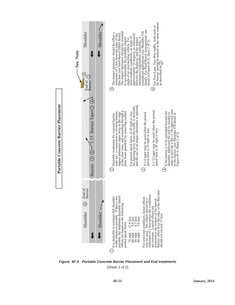
6F-51 January, 2014
Figure 6F-9 Portable Concrete Barrier Placement and End treatments(Sheet 1 of 2)
Sh
ou
lder
Sh
ou
lder
See
No
te
Sh
ou
lder
Sh
ou
lder
6
12
5 6
2
3
13
2
5
24
En
do
fB
arri
erE
nd
of
Bar
rier
Bar
rier
1:1
5B
arri
erT
aper
Itis
des
irab
leto
mai
nta
infu
llsh
ould
erw
idth
when
ever
poss
ible
.If
that
isnot
poss
ible
,th
em
inim
um
des
irab
lela
tera
loff
sets
are
bas
edon
the
foll
ow
ing
post
edsp
eed
lim
its:
Des
irab
letr
eatm
ents
for
expose
dbar
rier
ends
are:
aco
nnec
tion
toex
isti
ng
bar
rier
;im
pac
tat
tenuat
or;
taper
away
toth
eed
ge
of
the
clea
rzo
ne;
and
exte
ndin
gth
rough
apla
tebea
mguar
dra
ilby
rem
ovin
ga
pan
el.
For
post
edsp
eed
lim
its
of
30
mph
or
less
,th
eta
per
ing
away
from
the
traf
fic
isdes
irab
lean
dth
euse
of
anim
pac
tat
tenuat
or
isopti
onal
.
The
impac
tat
tenuat
or
should
be
off
set
am
inim
um
of
2fe
etfr
om
the
edge
of
the
thru
lane
(see
San
dB
arre
lO
ffse
tdet
ail)
.T
he
impac
tat
tenuat
or
should
be
ori
ente
dto
acco
mm
odat
eth
epro
bab
leim
pac
tan
gle
of
anen
croac
hin
gveh
icle
.F
or
most
road
side
condit
ions,
anan
gle
of
appro
xim
atel
y10
deg
rees
,as
mea
sure
dbet
wee
nth
ehig
hw
ayan
dth
eim
pac
tat
tenuat
ors
longit
udin
alce
nte
rlin
e,is
consi
der
edap
pro
pri
ate
(see
Should
erF
ill
det
ail)
.F
or
San
dB
arre
lA
rran
gem
ent,
see
det
ail
of
Fig
ure
6F
-6,sh
eet
2of
2).
For
Tw
o-L
ane,
Tw
o-W
aytr
affi
c,both
ends
of
the
bar
rier
should
be
trea
ted
inth
esa
me
man
ner
asdes
crib
edin
.
A1:8
taper
may
be
use
dw
hen
the
post
edsp
eed
lim
itis
35
mph
or
less
.
A1:1
2ta
per
may
be
use
dw
hen
the
post
edsp
eed
lim
itis
45
mph
or
less
.
4If
the
bar
rier
isto
be
exte
nded
bey
ond
the
should
er,ad
dit
ional
fill
wil
lbe
nee
ded
inord
erto
pro
vid
ea
flat
(1:1
0)
appro
ach
area
toth
ebar
rier
.(s
eeS
hould
erF
ill
det
ail
inF
igure
6F
-6,S
hee
t2
of
2)
For
rest
rict
edco
ndit
ions,
less
eroff
sets
may
be
use
d.
The
off
sets
should
be
am
inim
um
of
2fe
etunle
ssth
eco
ndit
ions
are
extr
eme.
Lat
eral
off
sets
are
mea
sure
dto
the
bott
om
of
the
bar
rier
.B
arri
eroff
set
from
the
edge
of
the
thru
lane
should
not
exce
ed15
feet
.
70
mph
-12.0
feet
60
mph
-8.0
feet
50
mph
-6.5
feet
40
mph
-5.0
feet

6F-52January, 2014
Figure 6F-9 Portable Concrete Barrier Placement and End treatments(Sheet 2 of 2)
Sand Barrel Offset
Barrier
1.0 - 2.0 feet
2.0 feet Minimum
2.5 feet
Edge of Lane
Distance may be reduced to a minimumof 1.25 feet. This is acceptable onlywhere a greater offset would causeunacceptable interference with traffic.
Shoulder Fill
B A
Attenuator
Section BSection A1:10 Slope or Flatter1:10 Slope
or Flatter
ExistingSlope
Existing Slope
Same Slope as Existing
LaneLaneShoulderShoulder
10 Maxo
1:10 Slope or FlatterShoulder
Portable Concrete Barrier

rotating, flashing, oscillating, or strobe lights locatedproperly in advance of the workers and/or equipment thatthey are protecting. However, these shadow vehicles mightthemselves cause injuries to occupants of the errant vehiclesif they are not equipped with truck-mounted attenuators.
The shadow truck should be positioned in advance of theworkers or equipment being protected so that there will besufficient distance, but not so much so that errant vehicleswill travel around the shadow truck and strike the protectedworkers and/or equipment.(see Chapter Part 6K-TemporaryTraffic Control Zone Layouts for the recommendeddistance charts)
Chapter 9 of AASHTO's "Roadside Design Guide" (seeSection 1A.11) contains additional information regardingthe use of shadow vehicles.
If used, the truck-mounted attenuator should be used inaccordance with the manufacturer's specifications.
6F.87 Rumble Strips
Transverse rumble strips consist of intermittent, narrow,transverse areas of rough-textured or slightly raised ordepressed road surface that extend across the travel lanes toalert drivers to unusual vehicular traffic conditions. Throughnoise and vibration they attract the driver's attention to suchfeatures as unexpected changes in alignment and toconditions requiring a stop.
Longitudinal rumble strips consist of a series of rough-textured or slightly raised or depressed road surfaces locatedalong the shoulder to alert road users that they are leavingthe travel lanes.
If it is desirable to use a color other than the color of thepavement for a longitudinal rumble strip, the color of therumble strip shall be the same color as the longitudinal linethe rumble strip supplements.
If the color of a transverse rumble strip used within atravel lane is not the color of the pavement, the color of therumble strip shall be white, black, or orange.
Intervals between rumble strips may be reduced as thedistance to the approached conditions is diminished in order
OPTION:OPTION:
STANDARD:STANDARD:
SUPPORT:SUPPORT:
GUIDANCE:GUIDANCE:
SUPPORT:SUPPORT:
GUIDANCE:GUIDANCE:
to convey an impression that a closure speed is too fastand/or that an action is imminent. A sign warning drivers ofthe onset of rumble strips may be placed in advance of anyrumble strip installation.
Transverse rumble strips should be placed transverse tomotor vehicle traffic movement. They should not adverselyaffect overall pavement skid resistance under wet or dryconditions.
In urban areas, even though a closer spacing might bewarranted, transverse rumble strips should be designed in amanner that does not promote unnecessary braking or erraticsteering maneuvers by road users.
Transverse rumble strips should not be placed on sharphorizontal or vertical curves.
Rumble strips should not be placed through pedestriancrossings or within marked bicycle lanes.
Transverse rumble strips should not be placed onroadways used by bicyclists unless a minimum clear path of4 feet is provided at each edge of the roadway or on eachpaved shoulder as described in AASHTO's "Guide to theDevelopment of Bicycle Facilities" (see Section 1A.11).
Longitudinal rumble strips should not be placed on theshoulder of a roadway that is used by bicyclists unless aminimum clear path of 4 feet is also provided on theshoulder.
6F.88 Screens
Screens are used to block the road users' view of activitiesthat can be distracting. Screens might improve safety andmotor vehicle traffic flow where volumes approach theroadway capacity because they discourage gawking andreduce headlight glare from oncoming motor vehicle traffic.
Screens should not be mounted where they couldadversely restrict motorist visibility and sight distance andadversely affect the safe operation of vehicles.
Screens may be mounted on the top of temporary trafficbarriers that separate two-way motor vehicle traffic.
Design of screens should be in accordance with Chapter 9of AASHTO's "Roadside Design Guide" (see Section1A.11).
GUIDANCE:GUIDANCE:
OPTION:OPTION:
GUIDANCE:GUIDANCE:
SUPPORT:SUPPORT:
GUIDANCE:GUIDANCE:
6F-53 January, 2014


If the equipment travels on or crosses the roadway, itshould be equipped with appropriate flags, flashing lights,and/or a SLOW MOVING VEHICLE symbol. If vehicles areusing the shoulder, a ROAD WORK AHEAD (W20-1) orSHOULDER WORK (W21-5) sign is appropriate.
6G.7 Work on the Shoulder with NoEncroachment
The provisions of this Section apply to short-term throughlong-term stationary operations.
Parking lanes should be treated the same as shoulders.They should be posted for any restrictions at least 24 hoursprior to commencing work.
If the parking lane is normally open to vehicle travelduring the time of day the closure will be in effect, theparking lane shall be considered a traveled lane.
When a highway shoulder is occupied, warning isneeded to advise the driver and protect the workers. Asingle warning sign SHOULDER WORK or ROAD WORKAHEAD shall be used.
When paved shoulders having a width of 8 feet or moreare closed, at least one advance warning sign shall be used.In addition, channelizing devices shall be used to close theshoulder in advance to delineate the beginning of the workspace and direct motor vehicle traffic to remain within thetraveled way.
When paved shoulders having a width of 8 feet or moreare closed on freeways and expressways, road users shouldbe warned about potential disabled vehicles that cannot getoff the traveled way. An initial general warning sign, such asROAD WORK AHEAD (W20-1), should be used, followedby a RIGHT or LEFT SHOULDER CLOSED (W21-5a)sign. Where the downstream end of the shoulder closureextends beyond the distance that can be perceived by roadusers, a supplementary plaque bearing the message NEXTXX FEET (W16-4P) or MILES (W7-3aP) should be placedbelow the SHOULDER CLOSED (W21-5a) sign. On multi-lane, divided highways, signs advising of shoulder work orthe condition of the shoulder should be placed only on theside of the affected shoulder.
When an improved shoulder is closed on a high-speedroadway, it should be treated as a closure of a portion of the
GUIDANCE:GUIDANCE:
STANDARD:STANDARD:
GUIDANCE:GUIDANCE:
SUPPORT:SUPPORT:
road system because road users expect to be able to use it inemergencies. Road users should be given ample advancewarning that shoulders are closed for use as refuge areasthroughout a specified length of the approaching TTC zone.The sign(s) should read SHOULDER CLOSED (W21-5a)with distances indicated. The work space on the shouldershould be closed off by a taper or channelizing devices witha length of 1/3 L using the formulas in Tables 6C-3 and 6C-4.
When the shoulder is not occupied but work hasadversely affected its condition, other warning signs anddevices are appropriate. The LOW SHOULDER (W8-9),NO SHOULDER (W8-23), HIGH SHOULDER (W21-X9) orSOFT SHOULDER (W8-4) sign should be used. SeeFigures 6K-3, 4, and 5 in the Field Manual for longitudinaldrop offs and Sections 6F-44.2 through 6F-44.4. In areaswhere the speed limit is greater than 30 mph and thecondition extends over a distance in excess of one mile, thesign should be repeated at one mile intervals. In areaswhere the speed limit is 30 mph or less, the sign should berepeated at 1/4 mile increments.
In addition, a supplementary plaque bearing the messageNEXT XX MILES (W7-3aP) may be placed below the firstsuch warning sign. Temporary traffic barriers may beneeded to inhibit encroachment of errant vehicles into thework space and to protect workers.
Signs advising of shoulder work or the condition of theshoulder should be placed only on the side of the affectedshoulder.
When used for shoulder work, arrow boards shall operateonly in the caution mode.
If work is directly adjacent to the travel lane, workersneed to be protected. In some instances, this may requirethe use of portable barriers.
6G.8 Work on the Shoulder with MinorEncroachment
Chapter 6D and Sections 6F.74 and 6G.05 containadditional information regarding the steps to follow whenpedestrian or bicycle facilities are affected by the worksite.
SUPPORT:SUPPORT:
OPTION:OPTION:
STANDARD:STANDARD:
GUIDANCE:GUIDANCE:
OPTION:OPTION:
6G-7 January, 2014
MN
Rev
. 3

When work takes up part of a lane, vehicular trafficvolumes, vehicle mix (buses, trucks, cars, and bicycles),speed, and capacity should be analyzed to determinewhether the affected lane should be closed. Unless the laneencroachment permits a remaining lane width of 10 feet, thelane should be closed.
Truck off-tracking should be considered whendetermining whether the minimum lane width of 10 feet isadequate.
Traffic should not be directed onto a lane that is onlypartially paved.
A lane width of 9 ft may be used for short-term stationarywork on intermediate volume, low-speed roadways whenmotor vehicle traffic does not include longer and widerheavy commercial vehicles.
6G.9 Work Within the Median
Chapter 6D and Sections 6F.68 and 6G.5 containadditional information regarding the steps to follow whenpedestrian or bicycle facilities are affected by the worksite.
If the work is in a narrow median of a divided highway,traffic control for both directions of travel may be necessary.
If work in the median of a divided highway is within 15feet from the edge of the traveled way for either direction oftravel, TTC should be used through the use of advancewarning signs and channelizing devices.
If the work is long term, the use of portable barriersshould be considered.
6G.9.1 Detours and Diversions
Detour signing is usually designed by the traffic engineerwith authority over the closed roadway because it isconsidered a traffic routing problem. Detour signs are usedto direct traffic onto another roadway. At diversions, roadusers are directed onto a temporary roadway or alignmentplaced within or adjacent to the right-of-way. Typical appli-cations for detouring or diverting road users on two-lanehighways are shown in Layouts 6J-16, 6J-17, and 6J-18.Layout 6J-15 illustrates the controls around an area where asection of roadway has been closed and a diversion has beenconstructed. Channelizing devices and pavement markings
SUPPORT:SUPPORT:
GUIDANCE:GUIDANCE:
OPTION:OPTION:
SUPPORT:SUPPORT:
OPTION:OPTION:
GUIDANCE:GUIDANCE:are used to indicate the transition to the temporary roadway.
A diversion (bypass) should be designed the same as acrossover (see Section 6G.16).
A diversion may carry either one direction or bothdirections of traffic.
When the detour is long, Detour (M4-8, M4-9) signsshould be installed periodically and at major intersectionsto remind and reassure drivers that they are still on a detour.
When a roadway is closed at some point beyond thedetour, traffic should be advised as to what location theroad is open. If local road users are allowed to use theroadway up to the closure, the ROAD CLOSED AHEAD,LOCAL TRAFFIC ONLY (R11-3a) sign should be used.The portion of the road open to local road users should haveadequate signing, marking, and delineation.
Detours should be signed so that traffic will be able to getthrough the entire detour area and back to the originalroadway.
When an entire roadway is closed, as illustrated inLayout 6J-19, a detour should be provided and road usersshould be warned in advance of the closure, which in thisexample is a closure 16 km (10 mi) from the intersection.
6G.10 Work Within the Traveled Way of aTwo-Lane Highway
Chapter 6D and Sections 6F.68 and 6G.5 containadditional information regarding the steps to follow whenpedestrian or bicycle facilities are affected by the worksite.
Techniques for one lane, two-way traffic control aredescribed in Section 6C-10.
When one lane of a two lane road is closed, theremaining lane shall accommodate both lanes of travel. Aminimum lane width of 10 feet shall be maintained at alltimes (see Section 6H-3).
On intermediate volume residential streets, traffic may beself regulating.
Where conditions permit, parking may be prohibited andtraffic shifted into the parking lanes.
OPTION:OPTION:
STANDARD:STANDARD:
SUPPORT:SUPPORT:
GUIDANCE:GUIDANCE:
OPTION:OPTION:
GUIDANCE:GUIDANCE:
6G-8December, 2011

6J-iii January, 2014
Figure 6J-2 Temporary Traffic Control Devices and Distance Charts
feet
DecisionSight
Distance
(D)
550
700
900
1200
1400
1600
AdvanceWarning
SignSpacing
(A)feet
250
325
600
750
1000
1200
TaperLength
( )12 ft lane
(L)feet
200
325
600
700
800
900
Posted SpeedLimit Prior
to WorkStarting(mph)
G = 25 ft
G = 50 ft
0 - 30
35 - 40
45 - 50
55
60 - 65
70 - 75
ShiftingTaper
(L/2)feet
100
175
300
350
400
450
TypicalShoulder
Taper
(L/3)feet
75
125
200
250
275
300
Posted SpeedLimit Prior
to WorkStarting(mph)
G = 25 ft
G = 50 ft
0 - 30
35 - 40
45 - 50
55
60 - 65
70 - 75
feet
BufferSpace
(B)
200
305
425
500
650
820
Shadow VehicleFollowing Distance
(F)feet
250 - 550
325 - 700
600 - 900
750 - 1200
1000 - 1400
1200 - 1600
Protection VehicleRoll-Ahead Buffer Distance
(with or without TMA)(R)
feet feet
100 100
100 100
175 125
175 125
225 175
225 175
Moving(15 mph max)
Stopped
Temporary Traffic Control Distance Charts
See the MN MUTCD, Part 6F for more details on application restrictions.
TUBULAR MARKERS CONES WEIGHTED
CHANNELIZER
36 inchMinimum
18 inchMinimum
18 inchMinimum
28 - 36 inchMinimum
42 inchMinimum
TYPE A CHANNELIZERS:
daytimelow speed
only
daytimelow speed
only
4 inch Diameter Minimum
Type A channelizing devices are typically used in attendedtemporary traffic control zones.*
TYPE B CHANNELIZERS: 270 square inch minimum of retroreflective sheeting surface
Type B channelizing devices shall be used if the temporary trafficcontrol zone will be installed for more than 12 hours or if it is leftunattended. *
*
TYPE I
BARRICADE
TYPE II BARRICADEVERTICAL PANEL DIRECTION INDICATOR
BARRICADE
DRUM
36 inchesminimum
36 inchesminimum
24inches
36inches
MN
Rev
. 3M
NR
ev. 3


6J-1 December, 2011
LONG TERM LAYOUT 6J-1
TYPICAL STRIPING AND STRIPE REMOVALFOR LANE CLOSURE
MULTILANE DIVIDED ROAD
Rem
ov
eo
rC
ov
erC
on
flic
tin
g
Pav
emen
tM
ark
ing
s
Tem
po
rary
Wet
Opt
iona
lT
empo
rary
Wet
Ref
lect
ive
Pav
emen
tM
arki
ngs
Ref
lect
ive
Pav
emen
tM
ark
ing
s
LA
/4B
NOTES:1. See page iii for Temporary Traffic Control
Distance Charts.
2. Traffic control devices are not shown.Use appropriate lane closure.
2. Install wet reflective edgelines through thetransition and alignment change areasincluding lane closure tapers, sharp curves,exits, shifts onto temporary roadways, etc.

6J-2January, 2014
LONG TERM LAYOUT 6J-2
PLACEMENT AND SPACING OFTEMPORARY RAISED PAVEMENT MARKERS (TRPMs)
TRPM TRPM TRPM
TRPM TRPM TRPM
Pavement Marking Line
Pavement Marking Line
TRAFFIC LANE
SUPPLEMENTING A SOLID LINE
N/5 N/5
TRPM TRPM TRPM
TRPM TRPM TRPM
TRAFFIC LANE
SIMULATING A SOLID LINE
N/5 N/5
N = the length of one line segment plus one gap
TRAFFIC LANE
TRAFFIC LANE
SIMULATING A BROKEN LINE
N
TRPM TRPM TRPMTRPM TRPM TRPM
TRAFFIC LANE
TRAFFIC LANE
SUPPLEMENTING A BROKEN LINE
N
1 foot 1 foot10 feet
10 feet 10 feet
5 feet
10 feet
TRPM TRPMPavement Marking Line TRPM TRPMPavement Marking Line
MN
Rev
. 3
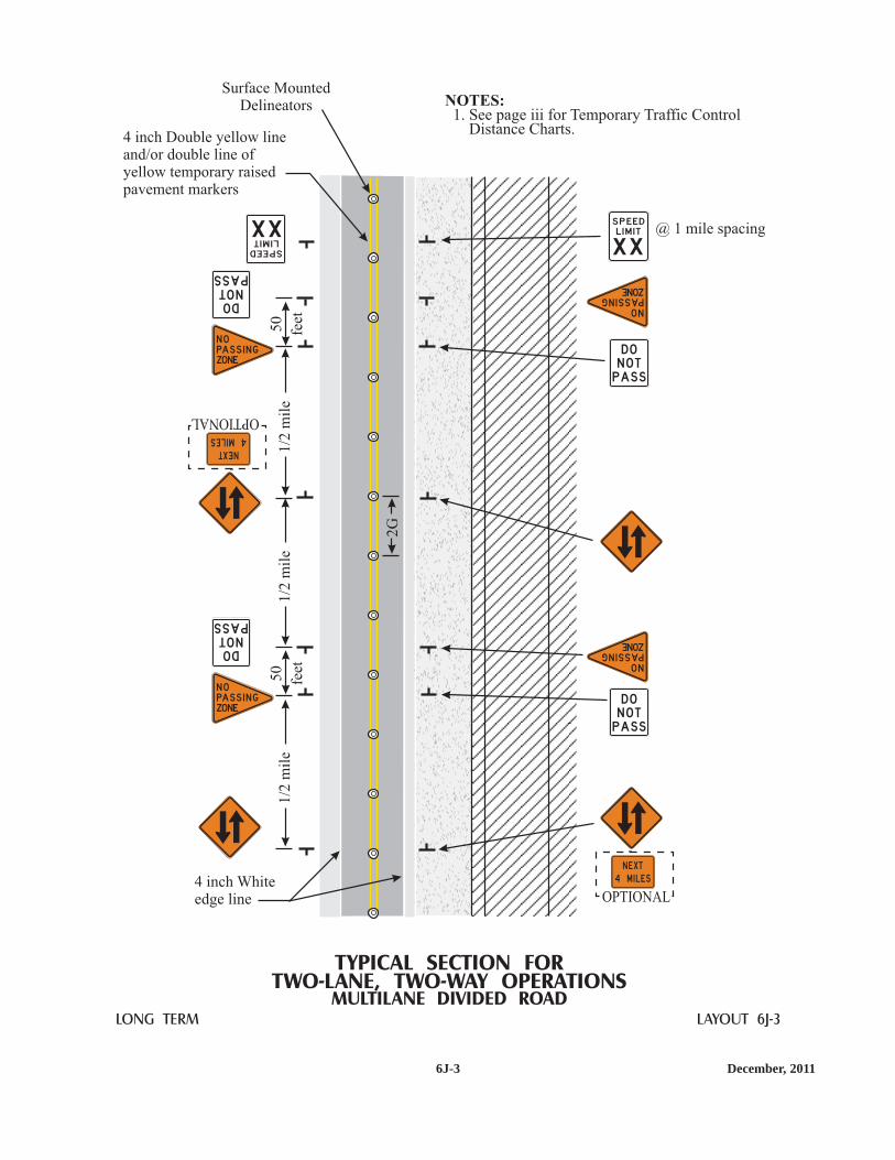
6J-3 December, 2011
LONG TERM LAYOUT 6J-3
TYPICAL SECTION FORTWO-LANE, TWO-WAY OPERATIONS
MULTILANE DIVIDED ROAD
4 inch Whiteedge line
1/2
mil
e1
/2m
ile
1/2
mil
e5
0
feet
50
feet
XX
S P EEDL I M I T
XX
SPEEDLIMIT
@ 1 mile spacing
DON O TPASS
NOPASSINGZONE
DON O TPASS
NOPASSINGZONE
DONOTPASS
N OPASS I N GZONE
DONOTPASS
N OPASS I N GZONE
OPTIONAL
M I L E S4
N EXT
OPTIONAL
MILES 4
NEXT
2G
Surface MountedDelineators
4 inch Double yellow lineand/or double line ofyellow temporary raisedpavement markers
NOTES:1. See page iii for Temporary Traffic Control
Distance Charts.

6J-4January, 2014
LONG TERM LAYOUT 6J-4
TYPICAL CROSSOVER TOTWO-LANE, TWO-WAY OPERATIONS
MULTILANE DIVIDED ROAD
XX
use the appropriatedevices and spacingfor a lane closure
NOTES:1.
Traffic controls are shown for only oneapproach.
3. Supplemental delineation (such aschevrons, down arrows, etc.) may berequired in the bypass.
4. Design of the bypass shall be as directedby the engineer or as shown in the plans.
5. Optional distance plaques and “BYPASSAHEAD” signs may be included in theadvance signing sequence.
6. Install wet reflective edge lines thru thetransition and 250 feet past the tangentareas.
See page iii for Temporary Traffic ControlDistance Charts.
2.
Rem
ov
eo
rC
ov
erC
on
flic
tin
gM
ark
ing
sIn
stal
lT
emp
ora
ryM
ark
ing
s(s
eeF
igu
re6
J-1
)
250
feet
250
feet
2G
Spac
ing
Rem
ove
or
Cover
Confl
icti
ng
Mar
kin
gs
Inst
all
Tem
pora
ryM
arkin
gs
(see
Fig
ure
6J-
1)
A
G/2
OPTIONAL
MN
Rev
. 2M
NR
ev. 3

6J-5 January, 2014
LONG TERM LAYOUT 6J-5
TYPICAL CROSSOVER FROM ATWO-LANE, TWO-WAY OPERATION
MULTILANE DIVIDED ROAD
1.Traffic controls are shown for only one approach.
3. Supplemental delineation (such as chevrons, down arrows,etc.) may be required in the bypass.
4. Install wet reflective edge lines thru the transition and250 feet past the tangent areas.
See page iii for Temporary Traffic Control Distance Charts.2.
End transition areawet reflective edgelines
A
2G
Rem
ove
or
Cover
Confl
icti
ng
Mar
kin
gs
and
Inst
all
Tem
pora
ryM
arkin
gs
(see
Lay
out
6J-
1)
Use appropriateleft lane closure
50
-100
feet
var
iable
G/2
XX
OPTIONALwith no speed
reduction
MN
Rev
. 3

6J-6December, 2011
LONG TERM LAYOUT 6J-6
TWO-LANE, TWO-WAY OPERATIONSAT RAMPS ON OPEN ROADWAY
EXIT
InplaceCover or Remove
2G
Sp
acin
g2
GS
pac
ing
ENTRANCE RAMP EXIT RAMP
2G
Sp
acin
g2
GS
pac
ing
G/2
Sp
acin
gS
urf
ace
Mo
un
ted
Del
inea
tors
G/2
Sp
acin
gS
urf
ace
Mo
un
ted
Del
inea
tors
Inplace
Inplace
Cover or Install
Cover or Install
E X I T
EX I T
CLOS ED
L i n c o l n Ave12/ M I LEEX I T
NOTES:1. See page iii for Temporary Traffic
Control Distance Charts.2. Install at least 7 days prior to the
start of work.
E X I T C L O S E D
RAM PC LOS EDB EG I N N I N GXXXX XX
2

6J-7 January, 2014
LONG TERM LAYOUT 6J-7
TWO-LANE, TWO-WAY OPERATIONAT EXIT RAMP ACROSS CLOSED ROADWAY
EXITEXIT2G
Spac
ing
G/2
Spac
ing
Surf
ace
Mounte
dD
elin
eato
rs2G
Spac
ing
NOTES:1.
The design of the deceleration lane and exitramp shall be as directed by the engineer oras shown in the plans.
3. Supplemental delineation (such as chevrons,down arrows, etc.) may be required for theramp.
See page iii for Temporary Traffic ControlDistance Charts.
2.M . P . H .
XX
EX I T
MN
Rev
. 3

6J-8January, 2014
LONG TERM LAYOUT 6J-8
TWO-LANE, TWO-WAY OPERATIONAT ENTRANCE RAMP ACROSS CLOSED ROADWAY
NOTES:1.
The design of the acceleration lane and entrance ramp shall be as directedby the engineer or as shown in the plans.
3. Supplemental delineation (such as chevrons, down arrows, etc.) may be required for the ramp.4. The advance warning sign spacing is dependent on the ramp length and the location of inplace
signing. The spacing should be as long as is practical.5. Remove conflicting pavement markings and install temporary markings (see Figure 6J-1).6. When an adequate acceleration lane is provided, this sign should be omitted.
See page iii for Temporary Traffic Control Distance Charts.2.
ROA D
WO R K
A H EA D
Y I E LD
G
2Gspacing
G/2spacing
2G spacing
6
6
MN
Rev
. 3M
NR
ev. 3

6J-9 December, 2011
LONG TERM LAYOUT 6J-9
MAINLINE RIGHT LANE CLOSEDEXIT RAMP OPEN
NOTES:1.
The design of the deceleration lane and the exit ramp shallbe as directed by the engineer or as shown in the plans.
3. The advance warning sign spacing is dependent on theramp length and the location of inplace signing.The spacing should be as long as is practical.
See page iii for Temporary Traffic Control Distance Charts.2.
Use appropriate devices andspacing for lane closure.
A/4
Remove or coverconflicting markings
200 - 400 feet
G
2G
2G
Temporarywhite edgeline
Temporaryyellow edgeline
EXITG
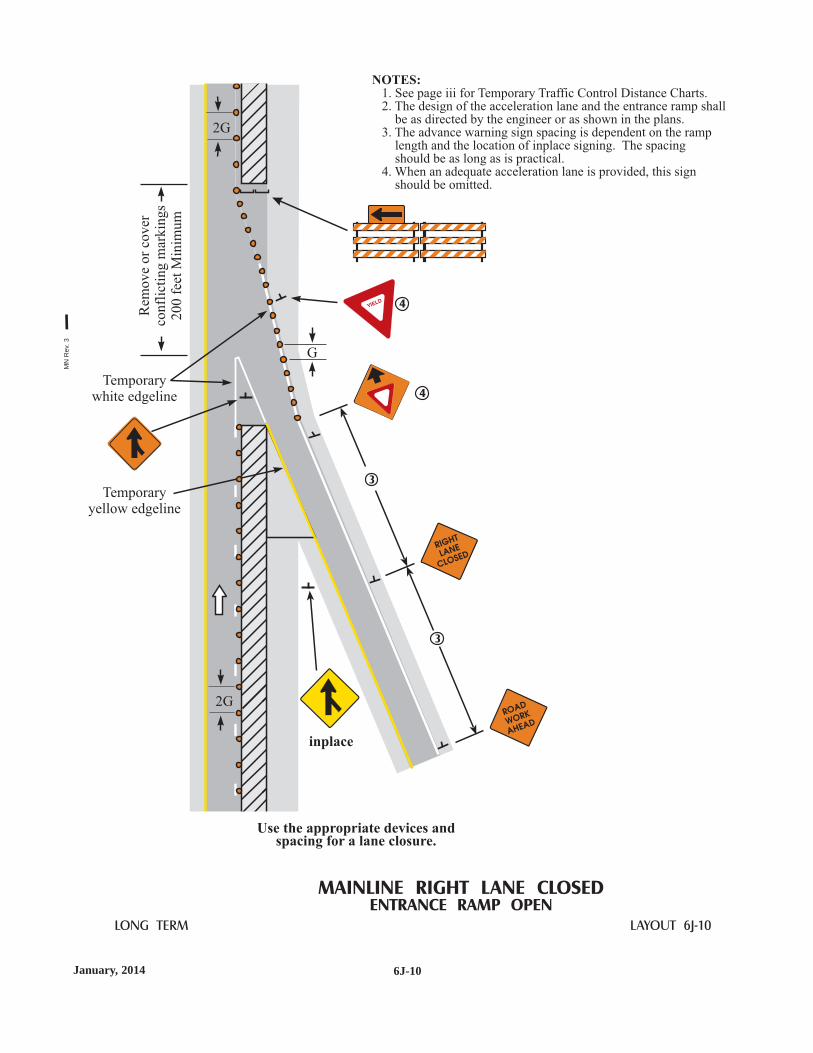
6J-10January, 2014
LONG TERM LAYOUT 6J-10
MAINLINE RIGHT LANE CLOSEDENTRANCE RAMP OPEN
NOTES:1.
The design of the acceleration lane and the entrance ramp shallbe as directed by the engineer or as shown in the plans.
3. The advance warning sign spacing is dependent on the ramplength and the location of inplace signing. The spacingshould be as long as is practical.
4
See page iii for Temporary Traffic Control Distance Charts.2.
. When an adequate acceleration lane is provided, this signshould be omitted.
Use the appropriate devices andspacing for a lane closure.
inplace
Rem
ov
eo
rco
ver
con
flic
tin
gm
ark
ing
s2
00
feet
Min
imu
m
Temporarywhite edgeline
Temporaryyellow edgeline
G
2G
3
3
4
4
2G
MN
Rev
. 3

6J-11 January, 2014
LONG TERM LAYOUT 6J-11
TWO-LANE, TWO-WAY OPERATIONTHROUGH TYPICAL INTERSECTION
F
F
24
inch
Sto
pL
ine
Optional doubleyellow marking
Pavement MarkingArrows
25
0fe
etM
in.
Rem
ove
or
Rel
oca
teth
eex
isti
ng
ST
OP
sign
OPTIONAL
NOTES:1. See page iii for Temporary Traffic Control
Distance Charts.2. Leave room for a proper radius at
intersections.3. Remove conflicting signing such as
“ONE WAY”, “DO NOT ENTER”, etc.4. Remove or cover conflicting striping such
as stop bars, crosswalks, etc.
OR
OR
MN
Rev
. 3M
NR
ev. 3
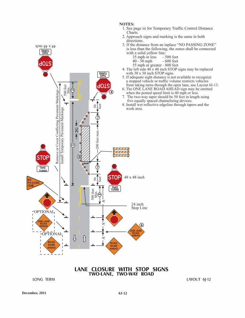
6J-12December, 2011
LONG TERM LAYOUT 6J-12
LANE CLOSURE WITH STOP SIGNSTWO-LANE, TWO-WAY ROAD
48 x 48 inch
48x48inch
Rem
ove
or
Cover
Confl
icti
ng
Pav
emen
tM
arkin
gs
Inst
all
Tem
pora
ryP
avem
ent
Mar
kin
gs
50
0fe
etM
in.
50
0fe
etM
in.
24 inchStop Line
2G
20
0fe
etm
ax.
50
feet
50
feet
NOTES:1.
2. Approach signs and marking is the same in bothdirections.
3. If the distance from an inplace “NO PASSING ZONE”is less than the following, the zones shall be connectedwith a solid yellow line:
35 mph or less - 500 feet40 - 50 mph - 600 feet55 mph or greater - 800 feet
4.
See page iii for Temporary Traffic Control DistanceCharts.
The left side 48 x 48 inch STOP signs may be replacedwith 30 x 30 inch STOP signs.
5. If adequate sight distance is not available to recognizea stopped vehicle or traffic volume restricts vehiclesfrom taking turns through the open lane, use Layout 6J-13.
6. The ONE LANE ROAD AHEAD sign may be omittedwhen the posted speed limit is 40 mph or less.
7. The two-way taper should be 50 feet in length usingfive equally spaced channelizing devices.
8. Install wet reflective edgeline through tapers and thework area.
N OPASS I N GZONE
5
8
7
7
6
3
4
3
F
F
F
F

6J-13 December, 2011
LONG TERM LAYOUT 6J-13
LANE CLOSURE WITH SIGNALSTWO-LANE, TWO-WAY ROAD
50
-120
feet
2G
Rem
ov
eo
rC
ov
erC
on
flic
tin
gP
avem
ent
Mar
kin
gs
Inst
all
Tem
po
rary
Pav
emen
tM
ark
ing
s
500
feet
Min
.
24 inchStop Line
N OPASS I N GZONE
NOTES:1. See page iii for Temporary Traffic Control Distance Charts.2. Approach signing and marking is the same in both directions.3. Signal timing shall be established by qualified personnel.4.
5. If the distance from an inplace “NO PASSING ZONE” isless than the following, the zones shall be connected with asolid yellow line:
35 mph or less - 500 feet40 - 50 mph - 600 feet55 mph or greater - 800 feet
6. The two-way taper should be 50 feet in length using fiveequally spaced channelizing devices.
7
Two signal heads shall be installed per approach. The firstshall be installed on the right shoulder. The second signalhead may be installed on either the left shoulder or mountedover head on the same structure as the first signal head.
. Install wet reflective edgeline through tapers and thework area.
40
-120
feet
50
feet
4
5
6
6
500
feet
Min
.
7
3

6J-14January, 2014
LONG TERM LAYOUT 6J-14
MULTIPLE LANE SHIFTMULTILANE DIVIDED ROAD
ROADWORKAHEAD
ROADWORKAHEAD
End temporary wetreflective 4-inchwhite solid line
Temporary wet reflectivewhite edge line
Temporary wet reflectiveyellow edge line
Rem
ove
or
cover
confl
icti
ng
pav
emen
t
mar
kin
gs
and
inst
all
tem
pora
ry
pav
emen
tm
arkin
gs
Tan
gen
t
NOTES:1.
2. The minimum lane width shall be 10 feet.3. The curve advisory speed will be determined
by the Road Authority at the time of installation.4. The bypass sign should be used when the tangent
length is 600 feet or less.5. Omit if the bypass sign is used.6. Install continuous solid wet reflective lane lines
through the bypass if the tangent is 600 feetor less.
See page iii for Temporary Traffic ControlDistance Charts.
Begin temporary wetreflective 4-inchwhite solid line
OR
OR
A/4
L/2
3
6 6
33
3 3
4
4
3
5
5
MN
Rev
. 3M
NR
ev. 3

6J-15 January, 2014
SHORT TERMLONG TERM LAYOUT 6J-15
ROAD CLOSURE AT INTERCHANGE
NOTES:1.2. The closed road volume should be below 800-1000 vehicles per hour.3. Supplemental delineation such as chevrons, down arrows, etc. may
be required in the bypass.
See page iii for Temporary Traffic Control Distance Charts.
Law enforcementofficer is to directtraffic as needed.
Variable:prior to lane closure
3
use the appropriatedevices and spacingfor a lane closure
MN
Rev
. 3M
NR
ev. 3

6J-16January, 2014
LONG TERM LAYOUT 6J-16
ROAD CLOSURE WITH DIVERSION (BYPASS)TWO-LANE, TWO-WAY ROAD
ROADWORKAHEAD
BYPASSAHEAD
Po
int
of
Cu
rvat
ure
(PC
)
50
0fe
etM
in.
Po
int
of
Cu
rvat
ure
(PC
)
Rem
ov
eo
rco
ver
con
flic
tin
gm
ark
ing
san
dIn
stal
lte
mp
ora
rym
ark
ing
s
NOTES:1.
Typical traffic control is shown for one approach only.3. Supplemental delineation (such as chevrons, down arrows, etc.)
may be required on the bypass.4. The exact location of No Passing Zones is to be determined
by the Road Authority. If the distance from an inplace NoPassing Zone is less than the following, the zones shall beconnected with a solid yellow line:
35 mph or less - 500 feet40 - 50 mph - 600 feet55 mph or greater - 800 feet
See page iii for Temporary Traffic Control Distance Charts.2.
N OPASS I N GZONE
3
3
MN
Rev
. 3

6J-17 January, 2014
LONG TERM LAYOUT 6J-17
ROAD CLOSURE WITH DETOUR
NOTES:1.
Detour signing is shown for one direction only. The otherdirection shall be similar.
3. See Long Term Layout 6J-20 for devices and spacing.4. Use this sign when it is 2 miles or greater to the road closure.
See page iii for Temporary Traffic Control Distance Charts.2.
EN DD ETO U R
EN DD ETO U R
Optio
nal
Locatio
n
N O R TH
D ET O U R
NORTH
DETOUR
N O R TH
D ET O U R
NORTH
DETOUR
N O R TH
D ET O U R
NORTH
DETOUR
N O R TH
D ET O U R
NORTH
DETOUR
NORTH
DETOUR
NORTH
DETOUR
N O R TH
D ET O U R
N O R TH
NORTH
DETOUR
NORTH
DETOUR
A
A
A
NORT H
DETOUR
D ETOUR
3
4ROAD C LOS ED1 0 M I L E S AH EADLOCA L TRA F F I C O N LY
orROAD C LOS ED
TH R U TRA F F I CTO
MN
Rev
. 2M
NR
ev. 2
MN
Rev
. 3M
NR
ev. 3
MN
Rev
. 3M
NR
ev. 3

6J-18January, 2014
LONG TERM LAYOUT 6J-18
DETOUR FOR CLOSED STREET
NOTES:1.
3. See Long Term Layout 6J-20 for devices and spacing.
See page iii for Temporary Traffic Control Distance Charts.
2. A M4-9 Detour Sign with an advance turn arrowmay be used in advance of a turn. On multi-lanestreets, such signs should be used.
ROADCLOSED
THRUTRAFFICTO
3
2
MN
Rev
. 3M
NR
ev. 3

6J-19 January, 2014
LONG TERM LAYOUT 6J-19
DETOUR FOR ONE TRAVEL DIRECTION
NOTES:1.
Additional “DO NOT ENTER” signs may be desirable atintersections with intervening streets.
3. For sidewalk and crosswalk closures, see Layouts 6K-24and 6K-25.
4. Additional side street signs may be required.
See page iii for Temporary Traffic Control Distance Charts.2.
A
A
ROADCLOSED
THRUTRAFFI C
TO
NORTH
MN
Rev
. 3

6J-20January, 2014
LONG TERM LAYOUT 6J-20
TYPICAL SIGNING FOR ROAD CLOSURE
NOTES:1.
All devices are shown for one direction. Devices for the other direction should be similar.3
See page iii for Temporary Traffic Control Distance Charts.2.. The Road Authority will determine if a detour is required and specify the detour route.
4. Advance warning signs should be used seven days in advance of the closure.5. Install at the last driveway or intersection beyond which there is no public access.
ROADC LOS ED
5
4
A
A
B
Minor Roador Driveway
ROADC LOS EDB EG I N N I N GXXXX XX
XXX
F E ET
MN
Rev
. 3M
NR
ev. 3
MN
Rev
. 3
MN
Rev
. 3
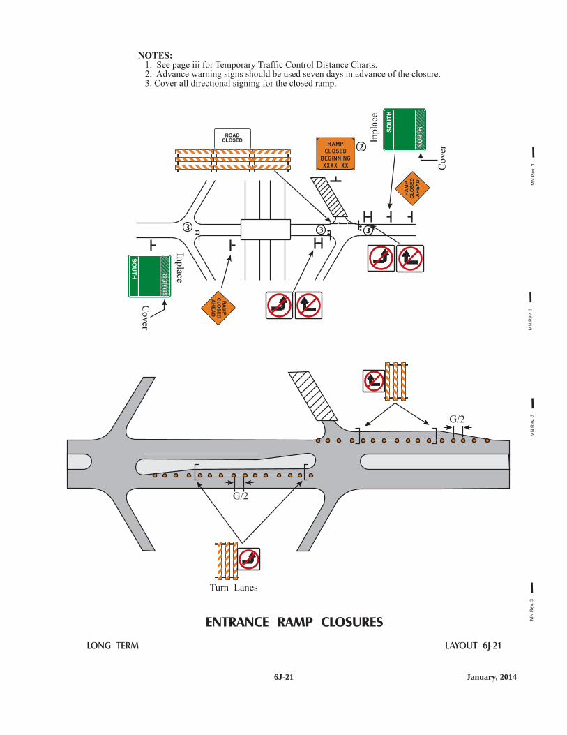
6J-21 January, 2014
LONG TERM LAYOUT 6J-21
ENTRANCE RAMP CLOSURES
RAM PC LOS EDB EG I N N I N GXXXX XX
Co
ver
Turn Lanes
Co
ver
Inp
lace
Inp
lace
NOTES:1.2. Advance warning signs should be used seven days in advance of the closure.3. Cover all directional signing for the closed ramp.
See page iii for Temporary Traffic Control Distance Charts.
2
3 3 3
G/2
G/2
MN
Rev
. 3M
NR
ev. 3
MN
Rev
. 3M
NR
ev. 3
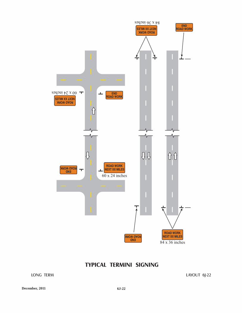
6J-22December, 2011
LONG TERM LAYOUT 6J-22
TYPICAL TERMINI SIGNING
84 x 36 inches
84x36inches
60 x 24 inches
60x24inches

6J-23 December, 2011
LONG TERM LAYOUT 6J-23
TYPICAL ADVANCE SIGNING
Install at least 7 daysprior to the start of work
Installatleast7dayspriortothestartofwork
Install within the projectlimits at least 7 days
prior to the start of work
Installwithintheprojectlimitsatleast7days
priortothestartofwork
Remove on theday that work starts
Removeonthedaythatworkstarts
Remove on theday that work starts
Removeonthedaythatworkstarts

6J-24aJanuary, 2014
LONG TERM LAYOUT 6J-24a
CROSSWALK CLOSURES ANDPEDESTRIAN DETOURS
NOTES:1. When crosswalks, sidewalks or other pedestrian facilities are blocked, closed or
relocated, temporary facilities shall include accessibility features consistent withthe features present in the existing pedestrian facility.
2. The examples show only key typical dimensions. Refer to the MnDOT"Temporary Pedestrian Access Route" (TPAR) website( ) for standards,guidance and options when blocking, closing, or relocating pedestrian facilities.
3. Only traffic control devices controlling pedestrian flows are shown. Otherdevices may be needed to control traffic on the streets.
4. An approved audible message device or tactile message should be providedfor sight-impaired pedestrians. When used, a message device should provide acomplete physical description of the temporary pedestrian detour includingduration, length of (and/or distance to) the bypass, any restrictions or hazardsand project information as listed in note 5 below. The number and location ofdevices should be determined for each project prior to starting work. Devicesmay be placed prior to sidewalk work to warn regular users of the planned work.
5. Typical sign message for a temporary pedestrian detour should includeinformation such as the duration of the walkway restrictions (beginning and/orend dates) and a project contact number for 24/7 questions or reporting hazards.
6. The International Symbol of Accessibility should be displayed when anywalkway through a work zone has been determined to be TPAR compliant.The Symbol of Accessibility shall not be displayed if persons with disabilitiesshould not use the primary temporary pedestrian detour. The reason for thenon-compliance should be posted and an alternate route should be posted whenthe primary temporary pedestrian detour is non-complaint to TPAR standards.
7. Conditions that are beyond recommended standards should be documented.A walkway is non-compliant if it is missing key ADA elements such as curbramp(s), truncated domes, and detectable edging. Other restrictions or hazardsmay include insufficient width or pinch-point widths, traffic conflicts, steepgrades, non-continuous railings, tripping hazards, or uneven/rough/soft surfaceconditions, etc.
8. Pedestrian traffic signal displays controlling closed crosswalks shall be covered.Temporary pedestrian signals should be considered when creating a newcrossing location.
9. Curb marking shall be prohibited for a minimum of 30 feet in advance of themid-block pedestrian crossing. Crosswalk marking shall be installed andconflicting marking removed or covered. Curb ramps with detectable warningsshall be provided to transition from the sidewalk to the crosswalk.
10. Pedestrian detour trailblazing signs should be used if the pedestrian detour islocated someplace other than across the street from the sidewalk closure.
http://www.dot.state.mn.us/trafficeng/workzone/tpar.htmlhttp://www.dot.state.mn.us/trafficeng/workzone/tpar.html
MN
Rev
. 3M
NR
ev. 3
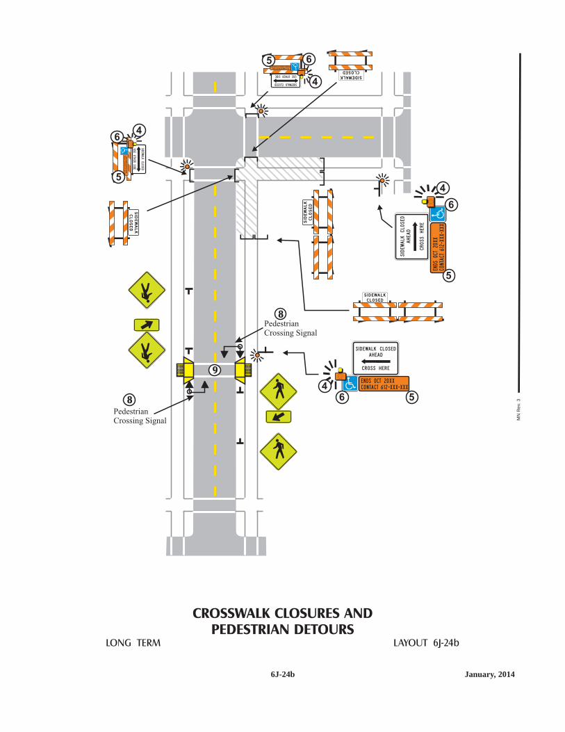
6J-24b January, 2014
LONG TERM LAYOUT 6J-24b
CROSSWALK CLOSURES ANDPEDESTRIAN DETOURS
PedestrianCrossing Signal
PedestrianCrossing Signal
8
8
9
SIDEWALKCLOSED
USEOTHERSIDE
SIDEWALKCLOSED
USEOTHERSIDE
SIDEWALK
CLOSED
SIDEWALK
CLOSED
S I D EWAL K
C L O S E D
SIDEWALK
CLOSED
ES
T.C
OM
PL
ET
ION
OC
T20X
X
PR
OJE
CT
CO
NTA
CT
612-X
XX
-XX
X
EST.COMPLETIONOCT20XX
PROJECTCONTACT612-XXX-XXX
E N D S O CT 2 0 X X
C O N TA CT 6 1 2 -X X X-X X X46 5
ENDSOCT20XX
CONTACT61 2-XXX-XXX
4
6
5
4
4
6
6
5
5
S I D EWA L K C LO S E D
A H EA D
C RO S S H E R E
SI DEWALKCLOSED
AHEAD
CROSSHERE
MN
Rev
. 3

6J-25aJanuary, 2014
LONG TERM LAYOUT 6J-25a
SIDEWALK BYPASS
NOTES:1. When crosswalks, sidewalks or other pedestrian facilities are blocked, closed or
relocated, temporary facilities shall include accessibility features consistent withthe features present in the existing pedestrian facility.
2. The examples show only key typical dimensions. Refer to the MnDOT"Temporary Pedestrian Access Route" (TPAR) website( ) for standards,guidance and options when blocking, closing, or relocating pedestrian facilities.
3. Where high speeds and/or high traffic volumes are anticipated, barrier shouldbe used to separate the temporary pedestrian walkway from vehicular traffic.When used, barriers shall be installed as detailed in the MN MUTCD, Part 6F.
4. Only traffic control devices controlling pedestrian flows are shown.Other devices may be needed to control traffic on the streets.
5. When both sides of a temporary pedestrian bypass require channelizingdevices, then the devices should be a similar type (railing system, barricade,or fencing system), excluding when TTC barrier (such as concrete barrier) isused to protect pedestrians from an open traffic lane.
6. An approved audible message device or tactile message should be provided forsight-impaired pedestrians. When used, a message device should provide acomplete physical description of the temporary pedestrian by-pass includingduration, length of (and/or distance to) the bypass, any restrictions or hazardsand project information as listed in note 7 below. The message device(s) mayalso describe an alternate route. The number and location of devices should bedetermined for each project prior to starting work. Devices may be placed priorto sidewalk work to warn regular users of the planned work.
7. Typical sign message for a temporary pedestrian bypass should includeinformation such as the duration of the walkway restrictions (beginning and/orend dates) and a project contact number for 24/7 questions or reporting hazards.
8. The International Symbol of Accessibility should be displayed when anywalkway through a work zone has been determined to be TPAR compliant.The Symbol of Accessibility shall not be displayed if persons with disabilitiesshould not enter the temporary pedestrian bypass. An alternate route should beposted when the temporary pedestrian bypass is non-complaint to TPARstandards.
9. Conditions that are beyond recommended standards should be documented.A walkway is non-compliant if it is missing key ADA elements such as curbramp(s), truncated domes, and detectable edging. Other restrictions or hazardsmay include insufficient width or pinch-point widths, traffic conflicts, steepgrades, non-continuous railings, tripping hazards, or uneven/rough/soft surfaceconditions, etc.
10. When a sidewalk is closed but workers are present who will provide assistanceor directions to pedestrians, then the devices as shown are not required.
http://www.dot.state.mn.us/trafficeng/workzone/tpar.htmlhttp://www.dot.state.mn.us/trafficeng/workzone/tpar.html
MN
Rev
. 3

6J-25b January, 2014
LONG TERM LAYOUT 6J-25b
SIDEWALK BYPASS
MINOR ROAD
Curb & gutter or other transitionbetween roadway and sidewalk
TPAR width of 60 inches is preferred.If width is 48 inch, then at least one60 x 60-inch passing space is requiredfor every 200 feet of length.
TPAR width of 60 inches is preferred.If width is 48 inch, then at least one60 x 60-inch passing space is requiredfor every 200 feet of length.
Temporary walkway surface coveringrough, soft or uneven ground or hazards
Additional audible message devicesmay be needed for route information
Temporary curb ramp providing 12:1 (8%)slope or flatter and non-slip treatment added
Temporary curb ramp providing12:1 (8%) slope or flatter andnon-slip treatment added
Ramp landing area providing48 x 48 inch minimum area and 2% orflatter cross-slope
Ramp landing area providing a 48 x 48 inchminimum area and 2% or flatter cross-slope
TTC barrier with taper andattenuation (length as required)
Temporary truncated domes, optionalbased upon usage of cross-street
5 device taper 25 feet long (1 stall),recommended when the closed area wasused as ab intermittent traffic lane orbypass lane.
LOW-SPEED ROADWAY
HIGH-SPEED ROADWAYor
LOW-SPEED MULTI-LANE
5
5
S I D EWALK
WO R K AH EAD
E N D S O CT 2 0 X X
C O N TA CT 6 1 2 -X X X-X X X6
78
S I D EWALK
WO R K AH EAD
E N D S O CT 2 0 X X
C O N TA CT 6 1 2 -X X X-X X X6
78
MN
Rev
. 3


Stan
dard
s &
Spec
ifica
tions
Two-
Lan
eTw
o-W
ayM
ulti-
Lan
eU
ndiv
ided
Mul
ti-L
ane
Div
ided
Mis
cella
neou
sL
ayou
tsQ
ualit
ySt
anda
rds
Flag
ging
Han
dboo
k
FF ii ee llddMMaannuuaall
JJaannuuaarryy,, 22001144
TTTTeeeemmmmppppoooorrrraaaarrrryyyyTTTTrrrraaaaffff ffff iiii cccc CCCCoooonnnnttttrrrroooo llllZZZZoooonnnneeee LLLLaaaayyyyoooouuuutttt ssss

January, 2014 A2
K. The Field Manual
IndexPages
Introduction . . . . . . . . . . . . . . . . . . . . . . . . . . . . . . . . . . . . . . . . . . . . . . . . . . . . . . . . . . . . . .6K-iDefinitions of Shall, Should, and May . . . . . . . . . . . . . . . . . . . . . . . . . . . . . . . . . . . . . . . . .6K-iDefinitions . . . . . . . . . . . . . . . . . . . . . . . . . . . . . . . . . . . . . . . . . . . . . . . . . . . . .6K-ii thru 6K-viiTemporary Traffic Control General Guidelines . . . . . . . . . . . . . . . . . . . . . . .6K-viii thru 6K-xiChecklist for Establishing a Temporary Traffic Control Zone . . . . . . . . . . . . . . . . . . . . .6K-xiiTemporary Traffic Control Devices . . . . . . . . . . . . . . . . . . . . . . . . . . . . . . . . . . . . . . . . .6K-xiiiWork Zone Signing . . . . . . . . . . . . . . . . . . . . . . . . . . . . . . . . . . . . . . . . . . . . . . . . . . . . . .6K-xivCrashworthy Testing Compliance . . . . . . . . . . . . . . . . . . . . . . . . . . . . . . . . . . . . . . . . . . . .6K-xvGuidelines for Portable Changeable Message Signs . . . . . . . . . . . . . . . . . .6K-xvi thru 6K-xviiStandard Abbreviations for Use on
Portable Changeable Message Signs . . . . . . . . . . . . . . . . . . . . . . . . . . . .6K-xviii thru 6K-xixArrow Board Specifications . . . . . . . . . . . . . . . . . . . . . . . . . . . . . . . . . . . . . . . . . . . . . . . .6K-xxLongitudinal Drop-off Guidelines . . . . . . . . . . . . . . . . . . . . . . . . . . . . . . . . .6K-xxi thru 6K-xiiiComponents of a Temporary Traffic Control Zone . . . . . . . . . . . . . . . . . .6K-xxiv thru 6K-xxvSign Codes Quick Reference . . . . . . . . . . . . . . . . . . . . . . . . . . . . . . . . . .6K-xxvi thru 6K-xxviiSample Project Inspection Checklist . . . . . . . . . . . . . . . . . . . . . . . . . . . . . . . . . . . . . . .6K-xxviiiChannelizing Devices . . . . . . . . . . . . . . . . . . . . . . . . . . . . . . . . . . . . . . . . . . . . . . . . . . .6K-xxixMN TPAR Devices . . . . . . . . . . . . . . . . . . . . . . . . . . . . . . . . . . . . . . . . . . . . .6K-xxx thru -xxxiSymbols used in Typical Layouts . . . . . . . . . . . . . . . . . . . . . . . . . . . . . . . . . . . . . . . . . .6K-xxxiiTemporary Traffic Control Distance Charts . . . . . . . . . . . . . . . . . . . . . . . . . . . . . . . . .6K-xxxiii
*Two-Lane, Two-Way Roads (Layouts 1 - 30) . . . . . . . . . . . . . . . . . . . . . . . . .6K-1thru 6K-30(A roadway consisting of two opposing lanes of undivided traffic.)
*Multi-Lane Undivided Roads (Layouts 31 - 43) . . . . . . . . . . . . . . . . . . . . . .6K-31 thru 6K-43(A roadway with two or more lanes of traffic in the same direction with nophysical barrier separating the opposing traffic lanes.)
*Multi-Lane Divided Road (Layouts 45 - 66) . . . . . . . . . . . . . . . . . . . . . . . .6K-45 thru 6K-66(Two separate roadways where opposing traffic is separated by a physicalbarrier or median.)
*Miscellaneous Layouts (Layouts 67 - 90) . . . . . . . . . . . . . . . . . . . . . . . . . . .6K-67 thru 6K-90(Layouts for Continuously Moving and Miscellaneous Signing Operations)
Quality Standards . . . . . . . . . . . . . . . . . . . . . . . . . . . . . . . . . . . . . . . . . . . . . .6K-91 thru 6K-106
Flagging Handbook . . . . . . . . . . . . . . . . . . . . . . . . . . . . . . . . . . . . . . . . . . .6K-107 thru 6K-118
Notes . . . . . . . . . . . . . . . . . . . . . . . . . . . . . . . . . . . . . . . . . . . . . . . . . . . . . . . . . . . . . . . . .6K-119Mn/DOT Telephone Numbers . . . . . . . . . . . . . . . . . . . . . . . . . . . . . . . . . . .6K-120 thru 6K-121Temporary Traffic Control Distance Charts . . . . . . . . . . . . . . . . . . . . .Inside of the Back CoverTemporary Traffic Control Distance Charts . . . . . . . . . . . . . . . . . . . . . . . . . . . . . .Flip out Panel* See inside front cover of each section for specific index to layouts.
This document as well as the Flagging Handbook and other documents are available on the Mn/DOT,Traffic Engineering website at: http://www.dot.state.mn.us/trafficeng/
January, 2014
INTRODUCTION
This Field Manual is a section of the Part 6 of the Minnesota Manual on Uniform TrafficControl Devices (MN MUTCD). It has been reprinted as a separate document for use in fieldoperations. This Field Manual contains the general Temporary Traffic Control (TTC) standardsand the user should refer to the MN MUTCD - Part 6 for more details, and follow any TTC plans,specifications, and special provisions written for a specific project. When specific TTC plans fora specific operation are not available, any public or private agency whose work affects vehicularand pedestrian traffic should use this Field Manual to provide proper temporary traffic control(TTC).
The typical layouts contained in this manual do not cover all situations encountered. Becauseall situations differ, engineering judgment should be used to insure proper traffic control. Thegoal of the temporary traffic control zone is to provide for the safe and efficient movement oftraffic around a location where the normal function of the roadway is temporarily suspended. Toaccomplish this, the respect of the driver must be earned by appropriate and prudent use of trafficcontrol devices. When work is not in progress or the hazard no longer exists, the temporary trafficcontrol devices shall be covered, turned away from traffic, or removed from the area.
This manual contains typical layouts for temporary traffic control zones ranging from mobileoperations to zones which may remain inplace overnight for up to three days. If the temporarytraffic control zone is to remain in one place for more than three days or involves a detour, roadclosure or a situation where the typical layouts do not apply, the governing road authority'sTraffic Engineering staff should be consulted and a project specific Temporary Traffic ControlPlan prepared. Advance planning is necessary for a successful temporary traffic control zone. Achecklist is included on page 6K-xii to assist you in planning your temporary traffic control zone.
Prior to starting work on any public roadway right-of-way, permission shall be obtained fromthe governing road authority. The use of any regulatory temporary traffic control device or signshall be approved by the governing road authority prior to installation. To assist you on statehighways, numbers for the Minnesota Department of Transportation are included in the back ofthis manual. You may wish to note the number of other road authorities on the NOTES page inthe back of this book.
DEFINITION OF SHALL, SHOULD, AND MAYShall - indicates a statement of required, mandatory, or specifically prohibitive practice
regarding a traffic control device.
Should - indicates a statement of recommended practice, but not mandatory, in typicalsituations, with deviations allowed if engineering judgment or engineering study indicates thedeviation to be appropriate.
May - indicates a statement of practice that is a permissive condition and carries norequirement or recommendation.
6K-i
January, 2014 6K-ii
DEFINITIONS
Activity Area - that part of a TTC zone activity area where the work actually takes place. Itconsists of the work space, traffic space and one or more buffer spaces.
Advance Warning Area - that part of a TTC zone used to inform the motorist what to expectahead. This area may contain anywhere from a single sign or a rotating/strobe light on avehicle to a series of signs and the use of a portable changeable message sign (PCMS). Thelocation of the beginning of the TTC zone is dependent on its visibility to motorists. Goodvisibility is achieved where the sight distance is sufficient to meet decision sight distance.
Advance Warning Sign Spacing - the distance between signs or between a sign and someother location or device with the TTC zone. It is determined by the posted speed limit. Thiswill ensure that the motorist has sufficient time to read the signs and react accordingly.Typical Advance Warning Sign Spacings (A) are included in the TTC Distance Charts.
Advisory Speed - the recommended speed for all vehicles operating on a section of highwayand based on the highway design, operating characteristics, and conditions. (See Layout 6K-77).
Approach Sight Distance - the distance which a motorist can visually identify a work space.The work space may be the flagger station, a lane closure, a slow moving or stopped vehicle,or any other situation which requires adjustments by the motorist.
Attended Work Space - a work space is considered to be attended when the TTC devices arereviewed for knock-downs or other needed adjustments on an hourly basis.
Average Daily Traffic (ADT) - the average 24-hour volume, being the total volume during astated period divided by the number of days in that period.
Buffer Space - the space which provides a margin of safety for both the driver and theworkers. It is important that the buffer space be free of equipment, workers, material andvehicles.
Crashworthy - is a characteristic of roadside devices that have been successfully crash testedin accordance with a national standard such as the National Cooperative Highway ResearchProgram Report 350, “Recommended Procedures for the Safety Performance Evaluation ofHighway Features.”

January, 20146K-iii
Decision Sight Distance - the total distance traveled during the length of time required for adriver to: detect an unexpected or otherwise difficult-to-perceive
information source or hazard in a roadway environment that maybe visually cluttered,
recognize the hazard or its potential threat, select an appropriate speed and path, and initiate and complete the required maneuver safely and efficiently. The decision sight distance is used to determine the minimum advance warning distance tothe furthest and/or single sign. When determining minimum sight distance to flaggers andmobile operations, these distances also apply. The required Decision Sight Distances (D) areincluded in the TTC Distance Charts.
Divided Road - a highway or two roadways where opposing traffic is separated by a median(ditch, barrier, curbing, etc.), and the median is generally wide enough to place TTC devices.Temporary traffic control for divided multi-lane roads may be also used for one-wayroadways.
Downstream Taper - the taper at the end of the activity area which guides traffic back into itsoriginal lane. When used, this taper is a minimum length of approximately 100 feet with a 20-foot spacing between channelizing devices.
Duration - the length of time any work operation occupies a specific location or causes atraffic obstruction without changing the location. This time is measured from the firstdisruption to traffic until the total clearing of the area. The following durations are defined inoverlapping intervals since TTC layouts for longer durations may always be used for shorterdurations, especially when roadway attributes such as traffic volume and speed, and the workspace location may warrant higher levels of traffic control.
Mobile - when an operation is continuously moving or stopped in onelocation for periods of 15 minutes or less. The traffic control devicesare typically vehicle-mounted. The work area should change by atleast the decision sight distance for it to be considered a change inlocation.
Short Duration - when an operation stays in one location duringdaylight conditions from 15 minutes to one hour, such that minimalTTC devices are deployed.
Short Term - when an operation stays in one location during daylightconditions from 15 minutes to twelve hours, such that advancesigning and channelizing devices are required.
Intermediate Term/Night - when an operation stays in one locationduring daylight conditions from 15 minutes to no more than 3 days,or stays in one location during hours of darkness. Advance signingand larger channelizing devices (Type B) are required.
Long Term - when an operation stays in one location for more than3 days. A project specific Traffic Control Plan is typically required.
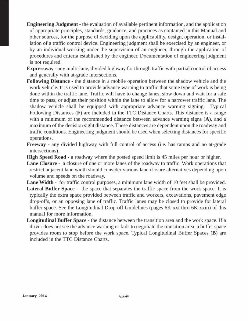
January, 2014 6K-iv
Engineering Judgment - the evaluation of available pertinent information, and the applicationof appropriate principles, standards, guidance, and practices as contained in this Manual andother sources, for the purpose of deciding upon the applicability, design, operation, or instal-lation of a traffic control device. Engineering judgment shall be exercised by an engineer, orby an individual working under the supervision of an engineer, through the application ofprocedures and criteria established by the engineer. Documentation of engineering judgmentis not required.
Expressway - any multi-lane, divided highway for through traffic with partial control of accessand generally with at-grade intersections.
Following Distance - the distance in a mobile operation between the shadow vehicle and thework vehicle. It is used to provide advance warning to traffic that some type of work is beingdone within the traffic lane. Traffic will have to change lanes, slow down and wait for a safetime to pass, or adjust their position within the lane to allow for a narrower traffic lane. Theshadow vehicle shall be equipped with appropriate advance warning signing. TypicalFollowing Distances (F) are included in the TTC Distance Charts. This distance is a rangewith a minimum of the recommended distance between advance warning signs (A), and amaximum of the decision sight distance. These distances are dependent upon the roadway andtraffic conditions. Engineering judgment should be used when selecting distances for specificoperations.
Freeway - any divided highway with full control of access (i.e. has ramps and no at-gradeintersections).
High Speed Road - a roadway where the posted speed limit is 45 miles per hour or higher.Lane Closure - a closure of one or more lanes of the roadway to traffic. Work operations that
restrict adjacent lane width should consider various lane closure alternatives depending uponvolume and speeds on the roadway.
Lane Width - for traffic control purposes, a minimum lane width of 10 feet shall be provided.Lateral Buffer Space - the space that separates the traffic space from the work space. It is
typically the extra space provided between traffic and workers, excavations, pavement edgedrop-offs, or an opposing lane of traffic. Traffic lanes may be closed to provide for lateralbuffer space. See the Longitudinal Drop-off Guidelines (pages 6K-xxi thru 6K-xxiii) of thismanual for more information.
Longitudinal Buffer Space - the distance between the transition area and the work space. If adriver does not see the advance warning or fails to negotiate the transition area, a buffer spaceprovides room to stop before the work space. Typical Longitudinal Buffer Spaces (B) areincluded in the TTC Distance Charts.

January, 20146K-v
Low Speed Road - a roadway where the posted speed limit is 40 miles per hour or lower.Merging Taper - the taper used on a multi-lane road to close a lane and combine its traffic
from that of the adjacent lane. Its length is dependent on the posted speed of the roadway.Higher speeds require a longer distance for traffic to merge lanes. Typical Merging Tapers (L)are included in the TTC Distance Charts.
Mobile Buffer Space - the distance in a mobile operation between the shadow vehicle and thework vehicle. This distance is dependent on whether the shadow vehicle is being used as anadvance warning device or as a blocking/protection device for the work vehicle.
Motorist - an operator of a motorized vehicle intended to be used on a roadway.Multi-Lane Road - a roadway where two or more lanes of traffic travel in the same direction.
A multi-lane roadway may be classified as either undivided or divided.Occupied Work Space - a work space is considered to be occupied when workers are present
within the work space. TTC devices should continuously be reviewed by workers andadjustments made as needed.
Off Shoulder - a work space located primarily off of the shoulder, or which causes little or norestrictions on the use of the shoulder. This work space should have little or no interferencewith traffic such that traffic speeds generally are not reduced.
Portable Changeable Message Sign (PCMS) - a sign either trailer-mounted or vehicle-mounted that is capable of displaying more than one message, changeable by remote orautomatic control.
Posted Speed Limit - the speed limit determined by law and shown on Speed Limit signs. Itis used in the charts to determine the spacings of TTC devices and the lengths of varioustapers on the TTC Layouts. Typical Posted Speed Limits (S) are included in the TTC DistanceCharts.
Protection Vehicle - the vehicle that is placed in advance of the work space and equipment toblock errant motorists from entering the work space.
Road, Roadway - That portion of a highway improved, designed, or ordinarily used forvehicular travel and parking lanes, but exclusive of the sidewalk, berm, or shoulder eventhough such sidewalk, berm, or shoulder is used by persons riding bicycles or other human-powered vehicles.
Roll Ahead Distance - the recommended minimum distance between a protection vehicle andthe work space. A protection vehicle may be used in a mobile operation to provide extra safetyfor the workers. Typical Roll Ahead Distances (R) are included in the TTC Distance Charts.
Roundabout - a circular intersection with yield at entry, which permits a vehicle on thecirculatory roadway to proceed, and with deflection of the approaching vehicle counter-clockwise around a circular island.
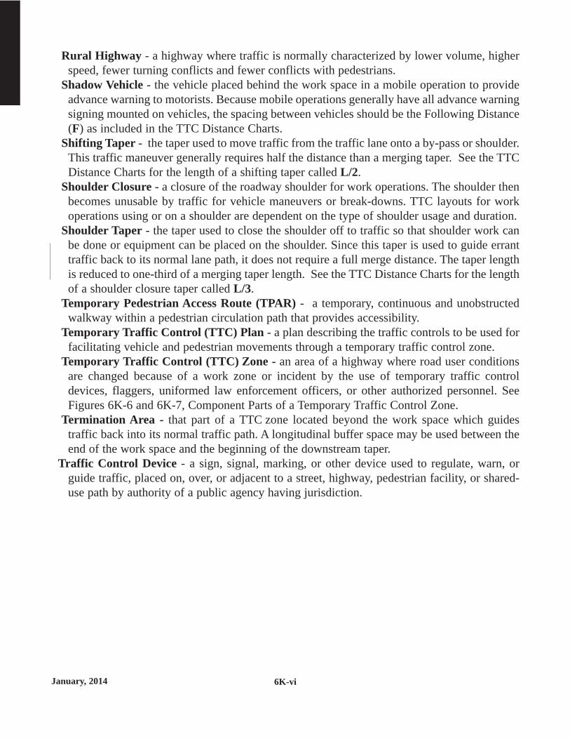
January, 2014 6K-vi
Rural Highway - a highway where traffic is normally characterized by lower volume, higherspeed, fewer turning conflicts and fewer conflicts with pedestrians.
Shadow Vehicle - the vehicle placed behind the work space in a mobile operation to provideadvance warning to motorists. Because mobile operations generally have all advance warningsigning mounted on vehicles, the spacing between vehicles should be the Following Distance(F) as included in the TTC Distance Charts.
Shifting Taper - the taper used to move traffic from the traffic lane onto a by-pass or shoulder.This traffic maneuver generally requires half the distance than a merging taper. See the TTCDistance Charts for the length of a shifting taper called L/2.
Shoulder Closure - a closure of the roadway shoulder for work operations. The shoulder thenbecomes unusable by traffic for vehicle maneuvers or break-downs. TTC layouts for workoperations using or on a shoulder are dependent on the type of shoulder usage and duration.
Shoulder Taper - the taper used to close the shoulder off to traffic so that shoulder work canbe done or equipment can be placed on the shoulder. Since this taper is used to guide erranttraffic back to its normal lane path, it does not require a full merge distance. The taper lengthis reduced to one-third of a merging taper length. See the TTC Distance Charts for the lengthof a shoulder closure taper called L/3.
Temporary Pedestrian Access Route (TPAR) - a temporary, continuous and unobstructedwalkway within a pedestrian circulation path that provides accessibility.
Temporary Traffic Control (TTC) Plan - a plan describing the traffic controls to be used forfacilitating vehicle and pedestrian movements through a temporary traffic control zone.
Temporary Traffic Control (TTC) Zone - an area of a highway where road user conditionsare changed because of a work zone or incident by the use of temporary traffic controldevices, flaggers, uniformed law enforcement officers, or other authorized personnel. SeeFigures 6K-6 and 6K-7, Component Parts of a Temporary Traffic Control Zone.
Termination Area - that part of a TTC zone located beyond the work space which guidestraffic back into its normal traffic path. A longitudinal buffer space may be used between theend of the work space and the beginning of the downstream taper.
Traffic Control Device - a sign, signal, marking, or other device used to regulate, warn, orguide traffic, placed on, over, or adjacent to a street, highway, pedestrian facility, or shared-use path by authority of a public agency having jurisdiction.

January, 20146K-vii
Traffic Space - that part of the roadway open to traffic that is next to the activity area. Trafficrouting is provided with channelizing devices of various sizes and shapes. For a descriptionof the various types of channelizing devices and their general uses, see the Temporary TrafficControl Devices Section (page 6K-xiii) of this manual.
Transition Area - that part of the TTC zone that moves the traffic from its normal path or laneinto the traffic space. This movement of traffic is done through the use of channelizingdevices and directional signing placed in various types of tapers.
Turn Lane Closure - the closure of a right or left turn lane for work operations. Signing in theTTC zone shall provide adequate warning to the motorists and provide an alternative turningmaneuver. Layouts from the various roadway types should be reviewed for the best alternatedepending upon roadway intersection design, traffic control (stop, yield, signals, etc.), speedlimit and volume.
Two-Lane, Two-Way Road - a roadway consisting of two opposing lanes of undivided traffic.Two-Way Left Turn Lane - that part of the roadway that has a continuous two-way left turn
lane located between the opposing lanes of traffic. This design variation may be found oneither two-lane, two-way roads or multi-lane roads.
Two Way Taper - the taper used on two-lane, two-way road to change the road into a singlelane of two-way traffic. It is primarily used for flagging operations and other traffic controlsituations. It is typically 50 feet in length and contains five equally spaced channelizingdevices.
Undivided Road - a roadway where opposing traffic lanes have no physical separation barriersexcept pavement markings (where required).
Urban Street - a type of street normally characterized by relatively low speed, wide ranges intraffic volume, narrower roadway lanes, frequent intersections, significant pedestrian traffic,and more roadside obstacles.
Volume - the number of vehicles passing a given point on the roadway or, the Average DailyTraffic (ADT).
Work Space - that part of the TTC zone closed to traffic and set aside for workers, equipmentand materials. The space requirements for a specific TTC Zone will determine the type ofTTC layout that is appropriate for the project. The layout will specify the appropriate signlocations, flagger stations and tapers depending on the type of work space.
Work Zone Speed Limits - a regulatory speed limit in a temporary traffic control zone. Thisspeed limit requires proper documentation to approve and install. See Work Zone Speed LimitGuidelines at the following website for details:http://www.dot.state.mn.us/speed/pdf/WZSpeedLimitGuideline.pdf

January, 2014 6K-viii
TEMPORARY TRAFFIC CONTROLGENERAL GUIDELINES
INDIVIDUAL RESPONSIBILITIESBefore beginning work, you should familiarize yourself with this manual, the definitions,
principles and the following General Responsibilities. Qualified individuals who have adequatetraining in temporary traffic control and have a basic understanding of the MN MUTCD shouldsupervise the selection, placement and maintenance of traffic control devices in temporary trafficcontrol zones.
GENERAL RESPONSIBILITIESExcept where otherwise specified any public or private agency performing work within the
right-of-way of streets or highways open to public travel shall be responsible for: supplying, installing, and maintaining all necessary traffic control devices outlined in this
manual and as stipulated by the governing road authority to protect the work space andsafely direct traffic around the temporary traffic control zone.
supplying their own flagger(s) when required. informing occupants of abutting properties, either orally or by written notice, of parking
prohibitions or access limitations. notifying the governing road authority when existing traffic signs need to be removed or
relocated or any regulatory sign must be installed for construction or maintenance work. replacing or reimbursing the governing road authority for any damage to or loss of existing
traffic signs. keeping all traffic control devices clean and in proper position to ensure optimum
effectiveness. removing traffic control equipment when it is no longer required or appropriate. keeping proper records of traffic control that contain starting and ending times, location,
names of personnel, traffic controls used, etc. The method of record keeping may varyfrom a log entry to a complete Traffic Control Plan.
PERMISSION TO WORK WITHIN THE RIGHT-OF-WAYPrior to starting work permission must be obtained from the governing road authority. All road
work must be coordinated to protect the public's interest.The governing road authority may limit the hours of work. Peak traffic periods vary by hour or
day of week and all work should be scheduled during non-peak hours.When working in or near an intersection with a traffic control signal system, the road authority
with jurisdiction over the signal should be contacted to ensure proper operation of the signalwhile the work is in progress.

January, 20146K-ix
SELECTING AN APPROPRIATE TEMPORARY TRAFFICCONTROL LAYOUT
This Field Manual, which is Temporary Traffic Control Zone Layouts, Part 6K of theMinnesota Manual on Uniform Traffic Control Devices (MN MUTCD), has been organized suchthat field personnel should easily be able to determine the proper temporary traffic control layoutfor the work zone they need. The layouts are divided primarily by the type of roadway and typeof work space. The roadway designations are:
Two-Lane, Two-Way Roads (with and without continuous left-turn lanes)These roads are further divided by traffic volume (low, intermediate, high),
Multi-Lane Undivided Roads (with and without continuous left-turn lanes),and
Multi-Lane Divided Roads After determining the type of roadway upon which the work space will be located, the type of
work space needs to be determined. The work space is the area within the right-of-way that willbe closed from normal usage. It includes all the area needed by support equipment, materials,workers and vehicles. It may require the closing of a roadway lane(s), the shoulder of the road,or a turn lane within an intersection. The work space may even be completely off the roadwayshoulder such as on side-slopes or along sidewalks. The layouts are listed by the typical workspace areas.
Within some layouts, there are TTC options that may be omitted based upon several factors.These may include: duration of the operation, volume of the road, speed limit on the road, anddepartmental (or company) policy. TTC supervisors should be fully aware of the variations in thelayouts due to the various factors, and when and how the layouts may be modified. See theChecklist for Establishing a TTC Zone on page 6K-xii.
All distances shown on the layouts and charts are approximate. In general, all chart distancesvary based upon the posted speed limit. Adjustments in these distances should be made based ontraffic entry points and decision sight distance. As stated previously, not all situations could beaddressed and engineering judgment should be exercised. Features from several layouts mayneed to be combined together for one project. For example, work in or near an intersection mayrequire a layout for a lane closure, a layout for work in the intersection and a layout for acrosswalk closure.
In some situations, a TTC layout usually required for a longer duration may be needed due tothe nature of the work or the traffic. For example, a patching a pothole on a high-volume, high-speed freeway may require less than 15 minutes of time (mobile operation) but a stationary laneclosure may be needed because of the high volumes of traffic.
Additional layouts have been placed in the manual for unique operations and special signingconditions. These layouts may have special restrictions and guidelines contained within theirnotes.

January, 2014 6K-x
ENHANCEMENT OF THE TEMPORARY TRAFFIC CONTROLLAYOUTS
To improve safety, typical layouts contained in this manual may need to be modified to fit morecomplex roadway conditions or operations. When conditions are more complex, modificationsmay incorporate devices and practices from the following list:
1. Additional Devices:a. more signs or enhanced signs (using LEDs, flags, beacons, etc.)b. “flashing” arrow boardc. more channelizing devices at close spacingd. temporary raised pavement markerse. high-level warning devicesf. portable changeable message signsg. portable traffic signalsh. portable barriersi. impact attenuator crash cushionsj. glare screensk. rumble stripsl. more delineation
2. Upgrading of Devices a. a complete set of standard pavement markings in high hazard areasb. brighter and/or wider pavement markingsc. larger and/or brighter signsd. more visible channelizing devices with greater conspicuitye. temporary traffic barriers in place of channelizing devices
3. Improved Geometrics at Diversions or Crossovers4. Increased Distances
a. longer advance warning areab. longer tapers
5. Lightinga. temporary roadway lightingb. steady burn lights used with channelizing devicesc. flashing lights for isolated hazardsd. illuminated signse. work space lighting
6. Work zone speed limitsSee Work Zone Speed Limit Guidelines at the following website for details:http://www.dot.state.mn.us/speed/pdf/WZSpeedLimitGuideline.pdf

January, 2014
INSTALLING THE TEMPORARY TRAFFIC CONTROL ZONE
Traffic control devices shall be installed in the order that drivers will see them, starting withthe sign or device that is furthest from the work space. If traffic in both directions will be affected,such as work in the center lanes, the devices may be placed in both directions at the same time.When one direction of traffic will be directed into the opposing lanes of traffic, all traffic controlsfor the opposing traffic should be installed first.
The devices should be removed as soon as the work is completed and are no longer needed.Devices should be removed in the opposite order from which they were installed. Devices whichthe driver sees last should be removed first.
A clear lane at least 10 feet wide shall be maintained at all times. After the temporary trafficcontrol zone is inplace, it should be inspected by driving through the zone. Motorists' actions andreactions should be noted and if any problems are encountered, they should be quickly corrected.Any modifications to the Traffic Control Plan or standard layouts and the reasons for the modi-fications should be documented.
During the life of a temporary traffic control zone, maintenance of devices is frequentlyneeded. On short term operations, vehicles may knock over cones which then need to be placedupright. If problems are encountered, they should be corrected immediately and documented.
6K-xi

January, 2014 6K-xii
CHECKLIST FOR ESTABLISHING ATEMPORARY TRAFFIC CONTROL ZONE
COMPLETED ITEM
Obtain permit from governing road authority.
Determine the type of roadway
Determine the type of work space
Determine the duration of work.
Select hours of work to avoid peak periods.
Select the appropriate layout(s) using type of roadway,type of , duration, volume, speed and impact onpedestrian and bicycle travel.( appropriate at the start of each section)
Determine any modifications to typical layout(s).( page 6K-x)
Check decision sight distance.
Advance signing distance.
If possible, maintain access to intersections, parking areas, anddriveways (public and private).
Allow for buffer space free of obstructions.
Contact the proper road authority if the work zone interfereswith normal signal operation in the area.
Check the condition of devices.( on pages 6K-91 thru 6K-106)
Install devices beginning with the first device the driver will see.
Conduct a drive thru to check for problems.( on page 6K-x)
Document temporary traffic control zone, problems andmajor modifications to the layouts.
Traffic should be observed to see if the taper is working correctly.
Remove the devices as soon as work is completed,beginning with the last device seen by the motorist.
Index Chart
Enhancement of the TTC Layouts on
Quality Standards
Enhancement of the TTC Layouts
work traffic
See the
See the
See the
See the
Figure 6K-1

January, 2014
TEMPORARY TRAFFIC CONTROL DEVICES
Channelizing Devices
The function of channelizing devices is to delineate a desired vehicle path, mark specifichazards on or near the roadway, separate opposing traffic flows and partially or totally close theroadway. See the "Longitudinal Drop-off Guidelines" on pages 6K-xxi thru 6K-xxiii for the useof channelizing devices adjacent to shoulder edge drop-offs or uneven lanes.
Channelizing devices include cones, drums, barricades, temporary raised islands and variouskinds of markers. The devices are broken into two type classifications based upon the nighttimevisibility of the device. Their visibility is determined upon the total amount of reflective area ofthe device. Devices with less than 270 sq. in. are classified as Type A Channelizing devices anddevices with more than 270 sq. in of reflective area are Type B devices. Type A channelizingdevices may be used in attended TTC zones and Type B channelizing devices shall be used if theTTC zone will be left unattended overnight or be in place longer than 12 hours. Where a Type Bchannelizing device, such as a drum, causes an isolated sight restriction, or is too wide for aspace, a 42-inch tall weighted channelizer may be substituted. This substitution may be used inunattended overnight conditions at sight or space restricted locations as approved by the roadauthority. When used, the spacing of the devices should be reduced by up to 50 percent. Figure6K-11 shows a breakdown of devices by Channelizer Type (drawn to approximate scale). See theMN MUTCD, Part 6F for additional details on application restrictions.
Flashing Warning Lights
Flashing warning lights shall supplement all road, ramp and sidewalk closure signing, and maybe added to other warning signs and/or barricades to attract the road user's attention.
Vehicle Warning Lights
All vehicles shall have approved operating vehicle warning lights when decelerating to enter aTTC zone and again when a vehicle leaves the TTC zone and enters the traveled traffic lane. Allvehicles within a mobile TTC operation; or working within 15 feet of an open traffic lane shouldhave approved vehicle warning lights.
High Visibility Clothing
All workers who are exposed to traffic, work vehicles or construction equipment within theTTC zone shall wear high-visibility safety apparel that meets the Performance Class 2 or 3requirements of the ANSI/ISEA 107-2004 publication entitled "American National Standard forHigh-Visibility Safety Apparel and Headwear" (see Section 1A.11), or equivalent revisions, andlabeled as meeting the ANSI 107-2004 standard performance for Class 2 or 3 risk exposure.
6K-xiii

January, 2014 6K-xiv
Work Zone Signing
Advance warning should be installed for drivers entering the TTC zone from cross streets.ROAD WORK AHEAD signs on intersecting roadways shall be installed if the motorist will notencounter another advance warning sign prior to reaching the activity area except for mobileoperations.
As a general rule, signs should be located on the right-hand side of a two-way roadway and onboth the right and left sides of a multi-lane divided roadway. See the "TTC Distance Charts" forthe advance warning sign spacing distance called A. When special emphasis is needed, signs maybe placed on both the left and right sides of a two-way roadway. Signs, although ordinarilymounted on posts for long term operations, may be mounted on or above barricades or ontemporary supports.
Signs mounted on temporary supports should not be placed in the open traveled lane wherethey pose a hazard to traffic. Generally these signs are placed on the shoulder or in the parkinglane of the street or highway. The signs should not be blocked from view by parked vehicles,trees or other sight obstructions on or near the roadway.
Signs shall not be mounted on existing traffic signs, posts or other utility structures withoutpermission from the proper authority. All signs shall be mounted longitudinally perpendicular tothe roadway surface and vertically plumb in accordance with the Quality Standards starting onpage 6K- 87. The bottom of signs mounted on barricades or temporary supports shall be no lessthan one foot above the traveled way. All regulatory signs on portable supports shall be mountedwith a minimum mounting height of 4 feet measured from the ground to the center of the signface.
Some activity areas move slowly down a roadway and away from the operation's advancesigning. The distance from the last advance warning sign to the activity area should not allowthe motorist to forget the existence of the temporary traffic control zone. For high-speed streetsand rural highways, the maximum distance from the last sign to a point where the driver detectsthe activity area shall not exceed one mile. In urban areas, the number of intersections shall beconsidered and this distance reduced accordingly.
All advance warning signs shall be at least 48 x 48 inch in size when used on high speedroadways. Warning signs used on low speed roadways shall be at least 36 x 36 inch in size.Smaller signs may be used as approved by the governing road authority where larger signsbecome an additional hazard to motorists and pedestrians.
All signs used at night shall be retroreflective with a material that has a smooth sealed outersurface that shows the same shape and color both day and night. Non-retroreflective mesh signsshall not be used at any time. Retroreflectorized roll-up signs may be used for daytime, and fornighttime only when workers are present to monitor the signs.

January, 20146K-xv
On multi-lane divided roadways, where the median shoulder is narrow (less than 6 feet, the 48x 48 inch advance warning signs, as shown on the TTC layouts, may not fit on the left side of theroadway. Where this situation occurs, one of the following options may be used:
A.) Reduce the left side signs sizes, orB.) Eliminate the left side signing, use an additional RIGHT LANE CLOSED (or LEFT as
appropriate) sign on the right side, and require the use of an arrow board on the shoulder atthe beginning of the lane closure taper.
Optional Signs
Several signs are shown on the TTC layouts as optional or have factors that may make themoptional. Some advance warning signs may be omitted for low speed roads and/or if the durationwill be less than an hour. Read the associated notes on each layout for options. The ONE LANEROAD AHEAD sign is an example of a sign that is only required for higher speeds. The BEPREPARED TO STOP sign is shown as optional on most TTC layouts. This sign is usually addedto the compliment of signs when restricted sight distances warrant additional warning to themotorist or the advance warning area becomes extremely long due to sight distances or a moveof the operation.
All advance warning signs shall be removed, covered, or turned to face away from trafficwhen they are no longer required or appropriate.
Crashworthy Testing Compliance
All temporary traffic control devices, including Type A and Type B channelizing devices, TypeIII barricades, ballast systems and sign support structures, used on any roadway open to publictravel shall be crashworthy when installed facing traffic or turned away from traffic.
FHWA policy requires that all roadside appurtenances, including temporary traffic controldevices, have been successfully crash tested in accordance with the National CooperativeHighway Research Program (NCHRP) Report 350, "Recommended Procedures for the SafetyPerformance Evaluation of Highway Features" or the American Association of State Highwayand Transportation Officials (AASHTO) “Manual for Accessing Safety Hardware (MASH).”

January, 2014 6K-xvi
GUIDELINES FOR THE USE OF PORTABLECHANGEABLE MESSAGE SIGNS (PCMS)
The primary purpose of Portable Changeable Message Signs (PCMS) is to advise the driver ofunexpected traffic and routing situations.
Important items when using a Portable Changeable Message Sign are:
General A PCMS should be used to supplement conventional signs, pavement marking and lighting. If a PCMS is used as an arrow board, it shall meet all of the requirements of an arrow panel,
and shall be used solely as an arrow board. Performance specifications can be found in the current version of the Minnesota Manual
on Uniform Traffic Control Devices (MN MUTCD), Part 6, Section 6F. A PCMS installed on the shoulder of a road shall be accompanied with Type B
channelizing devices (see Layout 4).
Messages Each display should contain a single thought. The entire display should be readable twice at the posted speed limit prior to work starting. An accurate description of the work location or the incident location is critical. The PCMS shall have readable up-to-date information. Any delay message should
accurately reflect the traffic delay time. A PCMS message shall use days of the week not calendar dates. The use of abbreviations is discouraged. The entire word should be spelled out whenever
space permits. If abbreviations are used, they should be easily understood (see the list of standard
abbreviations on Page 6K-xxviii and xix). Displays shall not scroll horizontally or vertically across the face of the sign.
For more information on the use of PCMSs, see “2012 CMS Manual of Practice” at thefollowing website:http://dotapp7.dot.state.mn.us/edms/download?docId=1244587

January, 2014
The
6K-xvii
Table 6F-2
RequirementsThe specifications for use of a PCMS are in the following table.
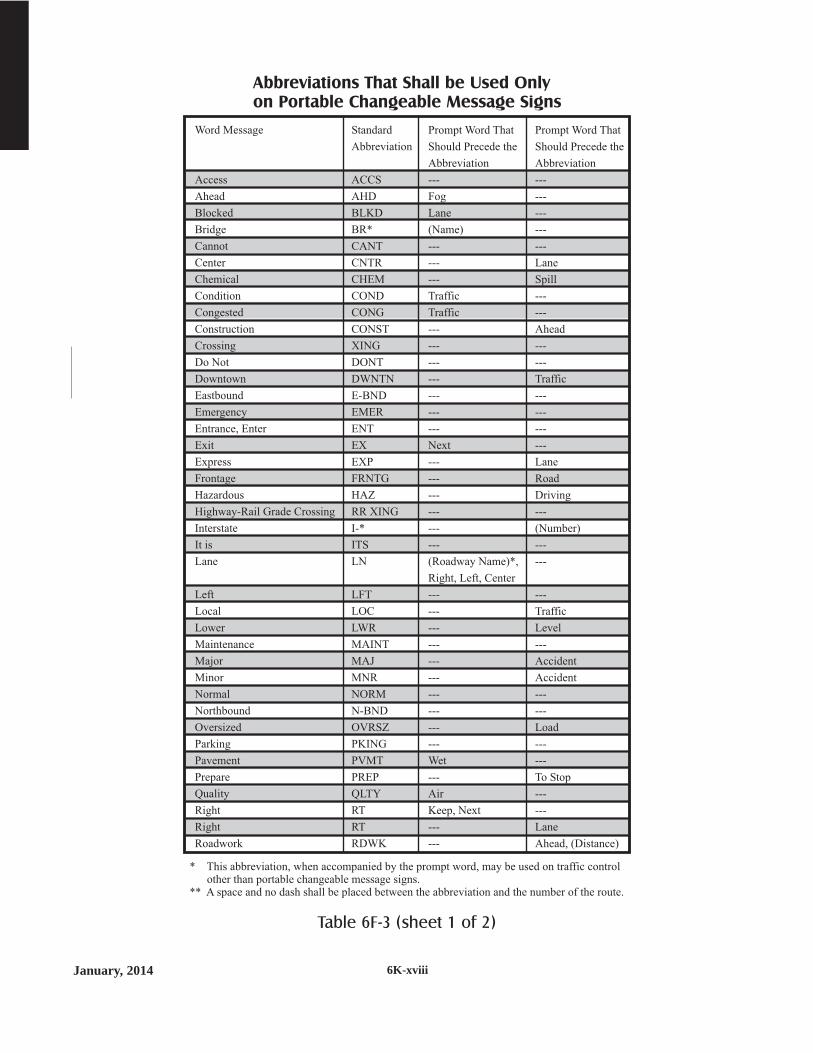
January, 2014 6K-xviii
Table 6F-3 (sheet 1 of 2)
Word Message
Access
Ahead
Blocked
Bridge
Cannot
Center
Chemical
Condition
Congested
Construction
Crossing
Do Not
Downtown
Eastbound
Emergency
Entrance, Enter
Exit
Express
Frontage
Hazardous
Highway-Rail Grade Crossing
Interstate
It is
Lane
Left
Local
Lower
Maintenance
Major
Minor
Normal
Northbound
Oversized
Parking
Pavement
Prepare
Quality
Right
Right
Roadwork
Standard
Abbreviation
ACCS
AHD
BLKD
BR*
CANT
CNTR
CHEM
COND
CONG
CONST
DONT
DWNTN
E-BND
EMER
ENT
EX
EXP
FRNTG
HAZ
RR XING
I-*
ITS
LN
LFT
LOC
LWR
MAINT
MAJ
MNR
NORM
N-BND
OVRSZ
PKING
PVMT
PREP
QLTY
RT
RT
RDWK
Prompt Word That
Should Precede the
Abbreviation
---
Fog
Lane
(Name)
---
---
---
Traffic
Traffic
---
---
---
---
---
---
---
Next
---
---
---
---
---
---
(Roadway Name)*,
Right, Left, Center
---
---
---
---
---
---
---
---
---
---
Wet
---
Air
Keep, Next
---
---
Prompt Word That
Should Precede the
Abbreviation
---
---
---
---
---
Lane
Spill
---
---
Ahead
---
---
Traffic
---
---
---
---
Lane
Road
Driving
---
(Number)
---
---
---
Traffic
Level
---
Accident
Accident
---
---
Load
---
---
To Stop
---
---
Lane
Ahead, (Distance)
* This abbreviation, when accompanied by the prompt word, may be used on traffic controlother than portable changeable message signs.
** A space and no dash shall be placed between the abbreviation and the number of the route.
Abbreviations That Shall be Used Onlyon Portable Changeable Message Signs

January, 20146K-xix
Word Message
Route
Service
Shoulder
Slippery
Southbound
Speed
State, county, or other
non-US or non-Interstate
numbered route
Tires with Lugs
Traffic
Travelers
Two-Wheeled Vehicles
Upper
Vehicle(s)
Warning
Westbound
Will Not
Standard
Abbreviation
RT,RTE
SERV
SHLDR
SLIP
S-BND
SPD
(Route Abbreviation
determined by
highway agency)**
LUGS
TRAF
TRVLRS
CYCLES
UPR
VEH, VEHS
WARN
W-BND
WONT
Prompt Word That
Should Precede the
Abbreviation
Best
---
---
---
---
---
---
---
---
---
---
---
---
---
---
---
Prompt Word That
Should Precede the
Abbreviation
---
---
---
---
---
---
Number
---
---
---
---
---
---
---
---
---
* This abbreviation, when accompanied by the prompt word, may be used on traffic controlother than portable changeable message signs.
** A space and no dash shall be placed between the abbreviation and the number of the route.
Abbreviations That Shall be Used Onlyon Portable Changeable Message Signs
Table 6F-3 (sheet 2 of 2)
Abbreviation
ACC
CLRS
DLY
FDR
L
LT
PARK
POLL
RED
STAD
TH
Intended Word
Accident
Clears
Delay
Feeder
Left
Light (Traffic)
Parking
Pollution (Index)
Reduce
Stadium
Trunk Highway
Common Misinterpretation
Access (Road)
Colors
Daily
Federal
Lane (Merge)
Left
Park
Poll
Red
Standard
misunderstood
Unacceptable Abbreviations
Table 6F-4

January, 2014 6K-xx
Operating Mode Panel Display *
1. At least one of the following twomodes shall be provided:
( Right arrow is shown,left arrow is similar )
Flashing Arrow
Sequential Chevron
Sequential Arrow
2. The following mode shall be provided:
3. At least one of the following threemodes shall be provided:
Move/Merge Right
Move/Merge Right
Move/Merge Right
Caution
Move/Merge Right or Left
Arrow StickArrow Sticks may supplement other TTC devices,but shall not be used in place of arrow boards
Advance Warning Arrow Board Specifications
Flashing Double Arrow
Flashing Four Corners
Flashing Bar
Alternating Flashing Diamonds
* Element layout for Type C panel shown
Minimum LegibilityDistance(miles)
Minimum Size
(inches)Minimum Number
of ElementsRecommended
Usage
PanelType
48 x 24 0.5 Low speed streets
60 x 30 0.75 Anything not coveredin A or C
96 x 48 1Freeways andExpressways
A 12
B 13
C 15
Figure 6K-2

January, 20146K-xxi
Longitudinal Drop-off Guidelines
UNEVEN LANESDROPOFF
1:3 Taper
Traffic Lane Milled Edge
0.5
-2
inch
esw
ithout
taper
Gre
ater
than
2-
4in
ches
wit
h1:3
taper
Gre
ater
than
2-
4in
ches
wit
hout
taper
TrafficLane
TrafficLane
Shoulder
Traffic Lane
Traffic Lane
Traffic Lane
>2 - 4inches
>2 - 4inches
Note: Milled edges greater than 2 inchesrequire tapers and/or delineation asdetailed for edge drop-offs in additionto the HIGH SHOULDER signs.
H I G H
S H O U LD ER
H I G H
S H O U LD ER
TrafficLane Traffic Lane
0.5 - 2inches
U N EVEN
LAN ES
U N EVEN
LAN ES
U N EVEN
LAN ES
U N EVEN
LAN ES
These guidelines are intended to increase trafficsafety using traffic control devices, safetyrelated appurtenances, and constructiontechniques for uneven lanes, milled edges, andedge drop-offs that occur in highway work zones.The best way to increase traffic safety is to makeevery attempt to minimize exposure to unevenlanes, milled edges, and edge drop-offs. Onlywhen uneven lanes, milled edges, and edgedrop-offs are deemed necessary, shall theappropriate portion(s) of these guideline beapplied to enhance traffic safety.
No traffic control treatments are needed ifedgelines are installed and shoulder widths andcross section slopes are the same as existingadjacent roadway sections.
Drop-offs of 0.5-4 inches, at least 8 feet fromfrom the edge of traffic carrying lanes do notrequire any traffic control treatments.
Drop-offs of greater than 4 - 12 inches adjacentto traffic carrying lanes are permitted without\tapers or portable concrete barriers for:
A. Projects within an urban area when thespeed limit is 30 mph or less; or
B. Short term (3 calendar days or less) repair,less than 50 feet in length when the speedlimit is greater than 30 mph.
Weather permitting, milling and pavingoperations shall be required to complete the fullwidth of the section under construction at theend of each work period. At no time shall therebe more than one uneven lane condition betweenthe traffic carrying lanes which include auxiliarylanes, turn lanes, and ramp access or egress areas.
Tapered slopes shall be adequately compacted toprovide a firm driving surface.
Appropriate uneven lane warning signs orshoulder warning signs shall be repeated aftereach intersection.
Where space is limited or there is a sightrestriction, weighted channelizers may be usedin place of drums to delineate longitudinaldrop-offs.
Maximum spacing of traffic control devicesshall be determined based on the posted speedlimit and using the following table.
TrafficControlDevice
Maximum Spacingof Devices
low speed = ¼ milehigh speed = 1 mile
2G
G
20G
Sign
Drum
WeightedChannelizer
orTubular Marker
Type IIIBarricade
Figure 6K-3

January, 2014 6K-xxii
Longitudinal Drop-off Guidelines
DISTANCE FROM THE TRAFFIC LANE
0 - 3 feet
0.5
-2
inch
esw
ith
ou
tta
per
Gre
ater
than
2-
4in
ches
wit
h1
:3ta
per
Gre
ater
than
2-
4in
ches
wit
ho
ut
tap
er
3 - 8 feet
EDGEDROPOFF
Edge ofTraffic Lane
Edge ofTraffic Lane
Edge ofTraffic Lane
Edge ofTraffic Lane
Edge ofTraffic Lane
Edge ofTraffic Lane
Note: Signs are optional when an edgeline is installed.
Note: Signs are optional when an edgeline is installed.
AlternatePosition
AlternatePosition
OptionalEdgeline
OptionalEdgeline
>2 - 4 inches
>2 - 4 inches
>2 - 4 inches
>2 - 4 inches
>2 - 4 inches
>2 - 4 inches
1:3 Taper 1:3 Taper
0.5 - 2 inches0.5 - 2 inches
0 - 3 feet
0 - 3 feet
0 - 3 feet
0 - 3 feet
3 - 8 feet
3 - 8 feet
3 - 8 feet
3 - 8 feet
LOW
S H O U LD ER
LOW
S H O U LD ER
LOW
S H O U LD ER
LOW
S H O U LD ER
N O
S H O U LD ER
N O
S H O U LD ER
LOW
S H O U LD ER
LOW
S H O U LD ER
LOW
S H O U LD ER
LOW
S H O U LD ER
N O
S H O U LD ER
N O
S H O U LD ER
or or
Edge ofTraffic Lane
Edge ofTraffic Lane
Edgeline
For Rural Highwayswith Less than 5000 ADT
For Rural Highwayswith Less than 5000 ADT
N O
S H O U LD ER
N O
S H O U LD ERN O
S H O U LD ER
N O
S H O U LD ER
Figure 6K-4

January, 20146K-xxiii
1:3 Taper
1:3 Taper
Longitudinal Drop-off Guidelines
DISTANCE FROMTHE TRAFFIC LANE
All Distances
Greater than 8 feet
Gre
ater
than
4-
12
inch
esw
ith
ou
tta
per
Gre
ater
than
12
inch
es
EDGEDROPOFF
Edge ofTraffic Lane
Edge ofTraffic Lane
Minimum8 feet
For any excavation or drop-offs in excess of12 inches, see the Minnesota Manual onUniform Traffic Control Devices, Part VI,Section 6F, Temporary Traffic Barriers.
>4 - 12 inches
N O
S H O U LD ER
N O
S H O U LD ER
N O
S H O U LD ER
N O
S H O U LD ER
or
Edge ofTraffic Lane
For Rural Highwayswith Less than 5000 ADT
N O
S H O U LD ER
N O
S H O U LD ER
These guidelines are intended to increase trafficsafety using traffic control devices, safetyrelated appurtenances, and constructiontechniques for uneven lanes, milled edges, andedge drop-offs that occur in highway work zones.The best way to increase traffic safety is to makeevery attempt to minimize exposure to unevenlanes, milled edges, and edge drop-offs. Onlywhen uneven lanes, milled edges, and edgedrop-offs are deemed necessary, shall theappropriate portion(s) of these guideline beapplied to enhance traffic safety.
No traffic control treatments are needed ifedgelines are installed and shoulder widths andcross section slopes are the same as existingadjacent roadway sections.
Drop-offs of 0.5 - 4 inches, at least 8 feet fromfrom the edge of traffic carrying lanes do notrequire any traffic control treatments.
Drop-offs of greater than 4 - 12 inches adjacentto traffic carrying lanes are permitted withouttapers or portable concrete barriers for:
A. Projects within an urban area when thespeed limit is 30 mph or less; or
B. Short term (3 calendar days or less) repair,less than 50 feet in length when the speedlimit is greater than 30 mph.
Weather permitting, milling and pavingoperations shall be required to complete the fullwidth of the section under construction at theend of each work period. At no time shall therebe more than one uneven lane condition betweenthe traffic carrying lanes which include auxiliarylanes, turn lanes, and ramp access or egress areas.
Tapered slopes shall be adequately compacted toprovide a firm driving surface.
Appropriate uneven lane warning signs orshoulder warning signs shall be repeated aftereach intersection.
Where space is limited or there is a sightrestriction, weighted channelizers may be usedin place of drums to delineate longitudinaldrop-offs.
Maximum spacing of traffic control devicesshall be determined based on the posted speedlimit and using the following table.
0 - 3 feet
Gre
ater
than
4-
12
inch
esw
ith
1:4
tap
erG
reat
erth
an4
-1
2in
ches
wit
h1
:3ta
per
Edge ofTraffic Lane >4 - 12 inches
1:4 or flatterTaper
0 - 3 feet
LOW
S H O U LD ER
LOW
S H O U LD ER
3 feet and Greater
Edge ofTraffic Lane
Note: Signs are optional when an edgeline is installed.
OptionalEdgeline
>4 - 12 inches
>4 - 12 inches
>4 - 12 inches
1:4 or flatterTaper
3 - 8 feet
LOW
S H O U LD ER
LOW
S H O U LD ER
TrafficControlDevice
Maximum Spacingof Devices
low speed = ¼ milehigh speed = 1 mile
2G
G
20G
Sign
Drum
WeightedChannelizer
orTubular Marker
Type IIIBarricade
Figure 6K-5

January, 2014 6K-xxiv
MERGINGTAPER
SIGN SPACING
SIGN SPACING
SIGN SPACING
SIGN SPACING
LONGITUDINALBUFFER
WORKSPACE
END ROAD
WORK SIGN
(optional)
DOWNSTREAM
TAPER
DOWNSTREAM
TAPER
BUFFER
SHIFTINGTAPER
SHOULDERTAPER
SPACING
SPACING
B
B
2G
G
G
L
A
A
A
A
SIGN SPACING
SIGN SPACING
SIGN SPACING
TWO WAY TAPER
A
A
A
BUFFER B
SPACING 2G
AdvanceWarning Area
where trafficis told what
to expect ahead
AdvanceWarning Area
where trafficis told what
to expect ahead
TransitionArea
where trafficmoves out
of its normal path
TransitionArea
where trafficmoves out
of its normal path
Activity Areawhere worktakes place
Activity Areawhere worktakes place
TerminationArea
where trafficresumes
normal operations
Components of aStationary Temporary Traffic Control Zone
�
���
���SHOULDER
CLOSURESHOULDERCLOSURE
SHOULDERCLOSURE
SHOULDERCLOSURE
LANECLOSURE
LANECLOSURE
LANECLOSURE
LANECLOSURE
LANESHIFTLANESHIFTLANESHIFTLANESHIFT
2 WAYTRAFFIC
2 WAYTRAFFIC
2 WAYTRAFFIC
2 WAYTRAFFIC
Figure 6K-6

January, 20146K-xxv
ROLL AHEADDISTANCE
FOLLOWINGDISTANCE
FOLLOWINGDISTANCE
R
F/2
F
D
SIGN SPACING
AdvanceWarning Area
where trafficis told what
to expect ahead
AdvanceWarning Area
where trafficis told what
to expect ahead
TransitionArea
where trafficmoves out
of its normal path
TransitionArea
where trafficmoves out
of its normal path
Activity Areawhere worktakes place
Activity Areawhere worktakes place
Components of aMobile Temporary Traffic Control Zone
OPTIONAL
OPTIONAL
WORK SPACE
PROTECTIONVEHICLE
WORKVEHICLE
SHADOWVEHICLE
SHADOWVEHICLE
DECISIONSIGHT
DISTANCE
���
���
LANECLOSURE
LANECLOSURE
LANECLOSURE
LANECLOSURE
Figure 6K-7

January, 2014 6K-xxvi
SIGN CODES QUICK REFERENCEFor additional signs and information on typical sizes and usage,see the Minnesota Manual on Uniform Traffic Control Deviceshttp://www.dot.state.mn.us/trafficeng/publ/mutcd/index.html
S I D EWALK
CLOS ED
R OADCLOS ED
ROAD CLOS ED
TH R U TRAFF I CTO
ROAD CLOS EDX M I L E S AH EADLOCAL TRAFF I C O N LY
M I L E SX
N E XT
B U M P
AH EAD
RO U G HROAD
3 5M P H
S I D EWA L K
WO R K AH EAD
S I D EWAL K C L O S E D
AH EAD
C RO S S H E R E
S I D EWA L K C L O S E D
AH EAD
C RO S S H E R E
S I D EWA L K C L O S E D
U S E O T H E R S I D E
B U M P
B E
P R E PAR E D
T O S T O PR OAD
WO R K
AH EAD
ON E LANE
R OAD
AH EAD
STOP
Y I E LD
TAKE
TU R N S
L OW
S H O U L D E R
N O
S H O U L D E R
U N EV E N
LA N E S
CE N T E R
LA N E
C L O S E D
R1-1
R11-4
R11-3a W8-1
W8-1a
W8-9
W8-8
W8-11
W8-15P
W8-23
W9-3a
W13-1P
W20-1
W20-1a
W20-4
W1-4R
W1-4L
W3-1
W1-6
W3-2
W3-3
W3-4
W4-2R
W4-2L
W7-3aP
R1-2
R1-X3
R3-1
R3-2
R4-7c
STO PH ER E O N
R E D
S TO PH ER E O N
R E D R10-6R
R10-6L
R9-9
R9-10
R9-11R
R9-11L
R11-2W20-7
Figure 6K-8
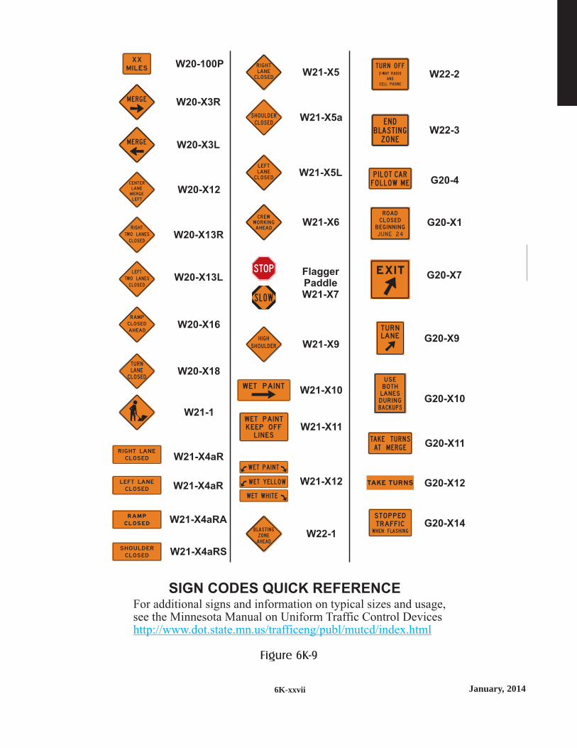
January, 20146K-xxvii
SIGN CODES QUICK REFERENCEFor additional signs and information on typical sizes and usage,see the Minnesota Manual on Uniform Traffic Control Deviceshttp://www.dot.state.mn.us/trafficeng/publ/mutcd/index.html
ROAD
B EG I N N I N G
C LOS ED
J U N E 24
R I G H T LAN E
CLOS ED
L E FT LAN E
CLOS ED
S H O U LD ER
CLOS ED
P I L O T CAR
F O L L OW M E
STO P P EDTRAFF I CWH E N F LA S H I N G
M I LES
XX
TA K E T U R N S
AT M E R G E
W ET PA I N T
L I N E SKE EP O FF
W ET PA I N T
WET PA I N T
W ET Y E L L OW
WET WH I T E
B LAS T I N G
Z O N E
AH EAD
T U R N O F F2-WAY RAD I O
A N D
C E L L P H O N E
E N D
B LA S T I N G
Z O N E
RAM P
C L O S E D
EX I T
TAKE TU R N S
BOTHLAN ESD U R I N GBAC K U P S
U S E
M E R G E
M E R G E
S L OW
RAM P
AH EAD
CLOS ED
L E FTLAN ECLOS ED
R I G H TLAN ECLOS ED
S H O U L D E R
C L O S E D
H I G H
S H O U LD ER
CLOS ED
TU R NLAN E
CENT ER
M ERG E
L E FT
LAN E
LE FT
CLOS ED
LAN ESTWO
R I G H T
C LOS ED
LAN ESTWO
CR EWWO R K I N GAH EAD
W20-X13R
W20-X3L
W20-X12
W20-X3R
W20-100P
W21-X5L
W21-X6
FlaggerPaddleW21-X7
W21-X9
W21-X10
W21-X11
W21-X12
W22-1
W22-2
W22-3
G20-4
G20-X1
G20-X7
G20-X14
G20-X10
G20-X9
G20-X11
G20-X12
W20-X13L
W20-X16
W20-X18
W21-1
W21-X4aR
W21-X4aR
W21-X4aRA
W21-X4aRS
W21-X5a
W21-X5
TU R NLAN E
Figure 6K-9

January, 2014 6K-xxviii
SAMPLE
PROJECT INSPECTION CHECKLIST
PROJECT - ____________________
ITEM YES NO HOW MANY?
1. Are any devices missing? ________
Do any devices need repair? ________
Were all replaced or repaired? ________
2. Are any lights (flashers, etc.) ________
not functioning
Were they all replaced or repaired?
3. Are any devices improperly placed? ________
Were all positions corrected?
4. Do any devices need cleaning? ________
Were all devices cleaned?
ADDITIONAL COMMENTS ON THE
BACK OF THIS FORM
The above check was completed by ______________________________________
(name / title)
on ______________________ at __________________ a.m. p.m.
(date) (time)
Figure 6K-10

January, 20146K-xxix
Channelizing Devices
TYPE A CHANNELIZERS
TYPE B CHANNELIZERS
TYPE C CHANNELIZER
TYPE III BARRICADE
60 inchesminimum
TYPE I
BARRICADE
TYPE II BARRICADEVERTICAL PANEL DIRECTION
INDICATOR
BARRICADE
DRUM
36 inchesminimum
36 inchesminimum
24inches
36inches
SURFACE
MOUNTED
DELINEATOR
WEIGHTED
CHANNELIZER
TUBULAR MARKERS CONESOPPOSING
TRAFFIC
LANE DIVIDER
36 inchesminimum
36 inchesminimum
18 inchesminimum
18inches
42inches
28-36inches
Figure 6K-11
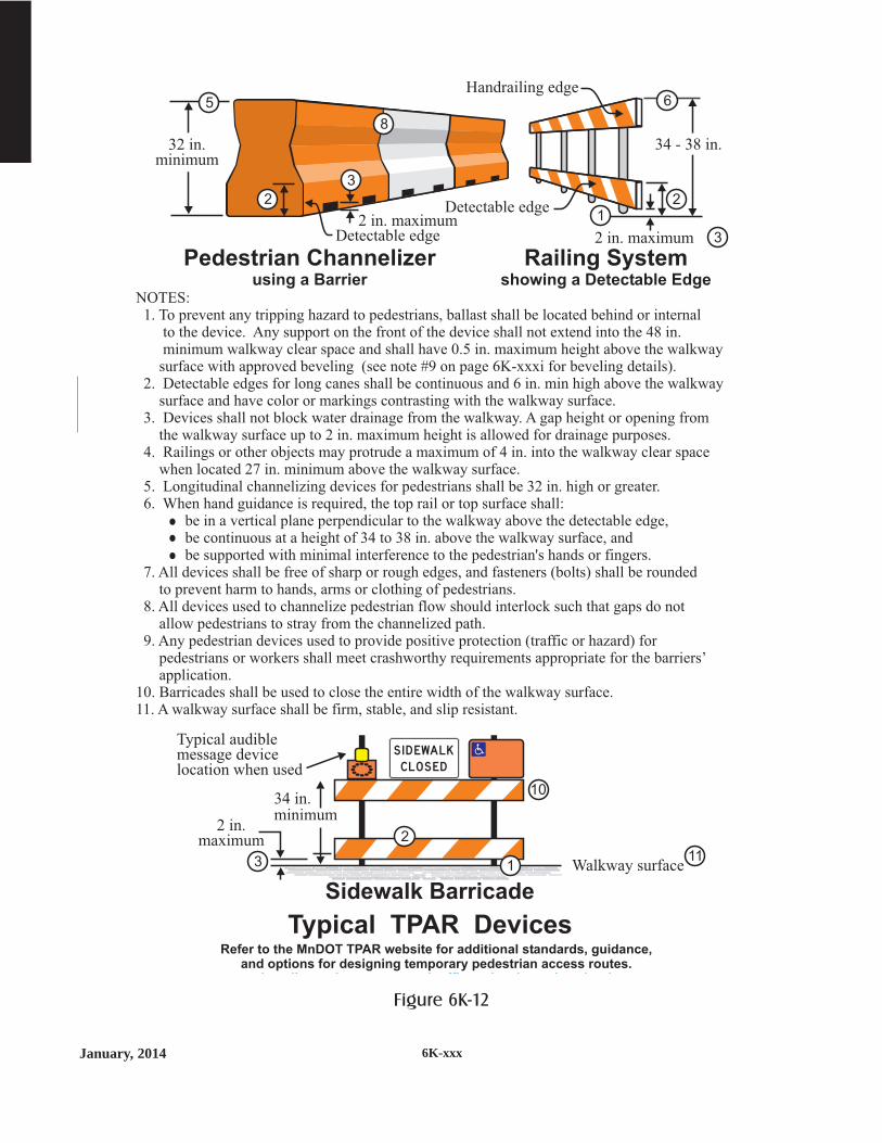
January, 2014 6K-xxx
NOTES:1. To prevent any tripping hazard to pedestrians, ballast shall be located behind or internal
to the device. Any support on the front of the device shall not extend into the 48 in.minimum walkway clear space and shall have 0.5 in. maximum height above the walkwaysurface with approved beveling (see note #9 on page 6K-xxxi for beveling details).
2. Detectable edges for long canes shall be continuous and 6 in. min high above the walkwaysurface and have color or markings contrasting with the walkway surface.
3. Devices shall not block water drainage from the walkway. A gap height or opening fromthe walkway surface up to 2 in. maximum height is allowed for drainage purposes.
4. Railings or other objects may protrude a maximum of 4 in. into the walkway clear spacewhen located 27 in. minimum above the walkway surface.
5. Longitudinal channelizing devices for pedestrians shall be 32 in. high or greater.6. When hand guidance is required, the top rail or top surface shall:
be in a vertical plane perpendicular to the walkway above the detectable edge,be continuous at a height of 34 to 38 in. above the walkway surface, andbe supported with minimal interference to the pedestrian's hands or fingers.
7. All devices shall be free of sharp or rough edges, and fasteners (bolts) shall be roundedto prevent harm to hands, arms or clothing of pedestrians.
8. All devices used to channelize pedestrian flow should interlock such that gaps do notallow pedestrians to stray from the channelized path.
9. Any pedestrian devices used to provide positive protection (traffic or hazard) forpedestrians or workers shall meet crashworthy requirements appropriate for the barriers’application.
10. Barricades shall be used to close the entire width of the walkway surface.11. A walkway surface shall be firm, stable, and slip resistant.
32 in.minimum
Pedestrian Channelizerusing a Barrier
Railing Systemshowing a Detectable Edge
2 in. maximumDetectable edge
Detectable edge
Handrailing edge
34 - 38 in.
2
5 6
3
12 in. maximum
2
3
8
Typical TPAR DevicesRefer to the MnDOT TPAR website for additional standards, guidance,
and options for designing temporary pedestrian access routes.htt // d t t t /t ffi / k /t ht l
Sidewalk Barricade
Walkway surface
2 in.maximum
34 in.minimum
Typical audiblemessage devicelocation when used
3 111
10
2
S I D EWALK
CLOS ED
Figure 6K-12
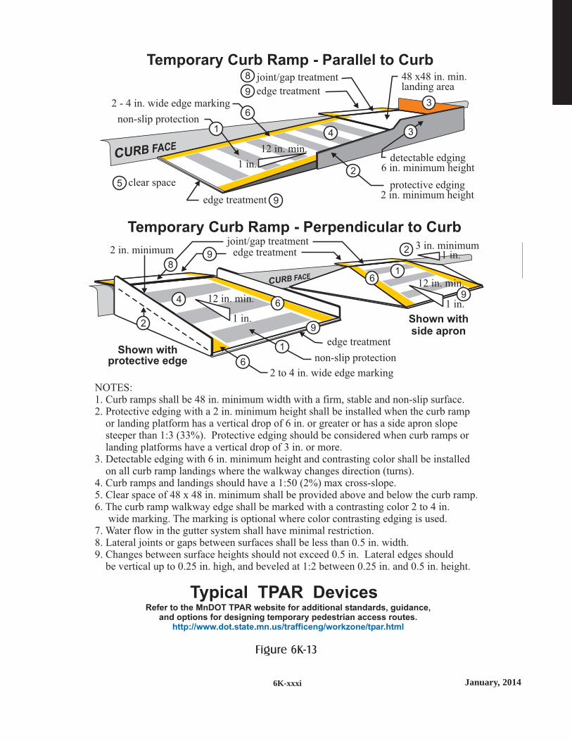
January, 20146K-xxxi
NOTES:1. Curb ramps shall be 48 in. minimum width with a firm, stable and non-slip surface.2. Protective edging with a 2 in. minimum height shall be installed when the curb ramp
or landing platform has a vertical drop of 6 in. or greater or has a side apron slopesteeper than 1:3 (33%). Protective edging should be considered when curb ramps orlanding platforms have a vertical drop of 3 in. or more.
3. Detectable edging with 6 in. minimum height and contrasting color shall be installedon all curb ramp landings where the walkway changes direction (turns).
4. Curb ramps and landings should have a 1:50 (2%) max cross-slope.5. Clear space of 48 x 48 in. minimum shall be provided above and below the curb ramp.6. The curb ramp walkway edge shall be marked with a contrasting color 2 to 4 in.
wide marking. The marking is optional where color contrasting edging is used.7. Water flow in the gutter system shall have minimal restriction.8. Lateral joints or gaps between surfaces shall be less than 0.5 in. width.9. Changes between surface heights should not exceed 0.5 in. Lateral edges should
be vertical up to 0.25 in. high, and beveled at 1:2 between 0.25 in. and 0.5 in. height.
Typical TPAR DevicesRefer to the MnDOT TPAR website for additional standards, guidance,
and options for designing temporary pedestrian access routes.http://www.dot.state.mn.us/trafficeng/workzone/tpar.html
Temporary Curb Ramp - Parallel to Curb48 x48 in. min.landing area
2 - 4 in. wide edge marking
protective edging2 in. minimum height
detectable edging6 in. minimum height
non-slip protection
edge treatment
joint/gap treatment
edge treatment9
8
9
12 in. min.
1 in.2
3
36
41
5 clear space
Temporary Curb Ramp - Perpendicular to Curb
1 in.3 in. minimum
2 to 4 in. wide edge marking
non-slip protection
edge treatment
joint/gap treatmentedge treatment
Shown withprotective edge
Shown withside apron
2 in. minimum
1 in.
12 in. min.
1 in.
12 in. min.
2
9
9
98
6
6
6
1
1
4
2
Figure 6K-13

January, 2014 6K-xxxii
Symbols Used in Typical Layouts
Channelizing Device.
A combination of Type A and B channelizing devices
360-Degree Yellow Flashing Vehicle Light(s)
Work Vehicle
Motor Grader
Mower
Work Vehicle with Crash Attenuator(Truck or Trailer Mounted)
Direction of Traffic
See Note; i.e. See Note 6
Work Space
Type III Barricade
Traffic Control Sign
Type A Flashing Warning Light
6
ROAD
WO R K
AH EAD
Flashing Arrow Board (FAB)
Portable Changeable Message Sign (PCMS)
Portable Traffic Signal
Flagger or Operator ofAutomated Flagging Assistance Device
Automated Flagging Assistance Device (AFAD)
Portable Equipment - includes testing devices,detection, surveying, etc.
CHANGEABLE
MESSAGE
SIGN (PCMS)SIGN (PCMS)
RIGHT
LANE
CLOSED
Symbols Meaning
AFAD
Figure 6K-14

January, 20146K-xxxiii
feet
DecisionSight
Distance
(D)
550
700
900
1200
1400
1600
AdvanceWarning
SignSpacing
(A)feet
250
325
600
750
1000
1200
TaperLength
( )12 ft lane
(L)feet
200
325
600
700
800
900
Posted SpeedLimit Prior
to WorkStarting(mph)
G = 25 ft
G = 50 ft
0 - 30
35 - 40
45 - 50
55
60 - 65
70 - 75
ShiftingTaper
(L/2)feet
100
175
300
350
400
450
TypicalShoulder
Taper
(L/3)feet
75
125
200
250
275
300
Posted SpeedLimit Prior
to WorkStarting(mph)
G = 25 ft
G = 50 ft
0 - 30
35 - 40
45 - 50
55
60 - 65
70 - 75
feet
BufferSpace
(B)
200
305
425
500
650
820
Shadow VehicleFollowing Distance
(F)feet
250 - 550
325 - 700
600 - 900
750 - 1200
1000 - 1400
1200 - 1600
Protection VehicleRoll-Ahead Buffer Distance
(with or without TMA)(R)
feet feet
100 100
100 100
175 125
175 125
225 175
225 175
Moving(15 mph max)
Stopped
Temporary Traffic Control Distance Charts
See the MN MUTCD, Part 6F for more details on application restrictions.
TUBULAR MARKERS CONES WEIGHTED
CHANNELIZER
36 inchMinimum
18 inchMinimum
18 inchMinimum
28 - 36 inchMinimum
42 inchMinimum
TYPE A CHANNELIZERS:
daytimelow speed
only
daytimelow speed
only
4 inch Diameter Minimum
Type A channelizing devices are typically used in attendedtemporary traffic control zones.*
TYPE B CHANNELIZERS: 270 square inch minimum of retroreflective sheeting surface
Type B channelizing devices shall be used if the temporary trafficcontrol zone will be installed for more than 12 hours or if it is leftunattended. *
*
TYPE I
BARRICADE
TYPE II BARRICADEVERTICAL PANEL DIRECTION INDICATOR
BARRICADE
DRUM
36 inchesminimum
36 inchesminimum
24inches
36inches
Figure 6K-15

The Temporary Traffic ControlDistance Charts can be found on
page 6K-125
This page has been intentionally left blank.

Two-
Lan
eTw
o-W
ay
TTwwoo--LLaanneeTTwwoo--WWaayy
A road consisting of two opposinglanes of undivided traffic.

January, 2014
TWO LANE - TWO WAY ROADS
15 Minutesor Less
One Houror Less
3 Daysor Less
12 Hoursor Less
MOBILE SHORT
DURATION
SHORT
TERM
INTERMEDIATE
TERM
Lane Closure
Flagger Control
AFAD
Work in Center of Road
Intermediate VolumeUp to 1500 ADT
5
11 *
15 Minutesor Less
One Houror Less
3 Daysor Less
12 Hoursor Less
MOBILE SHORT
DURATION
SHORT
TERM
INTERMEDIATE
TERM
Lane Closure
Uncontrolled
One Flagger Control
Work in Center of Road
Work in Intersection
Low VolumeLess than 400 ADT
5
10 *9
22
15 Minutesor Less
One Houror Less
3 Daysor Less
12 Hoursor Less
MOBILE SHORT
DURATION
SHORT
TERM
INTERMEDIATE
TERM
Work on Shoulder
Work off Shoulder
Parking Lane Closure
Lane Closure
2 Flagger Control
Moving Work Spaces
Near Intersection
Pilot Car Operation
Near Railroad Xing
Portable Signal Control
STOP Sign Control
Work in Center of Road
Lane Shift
Two-Way Left Turn Lanes
Lane Shift
Center Lane Closure
Turn Lane Closures
Work in Intersection
Road Closure
Sidewalk Closure
All ADTs
7, 8
20
2, 4
2
13 *14 *
24
25
42
29 (low speed only)
26
3
84, 85
81 * 80
This layout may be used for night time operations only if theflagging stations are occupied and illuminated with portable lights.*
6, 7 *
1
12 *8 *
21 *
28 (low speed only)
18 *17 *
15, 16 *
19
22 *
These Layouts as well as the entire Field Manual, the Flagging Handbook and other documents areavailable on the Mn/DOT, Traffic Engineering website at:
http://www.dot.state.mn.us/trafficeng/
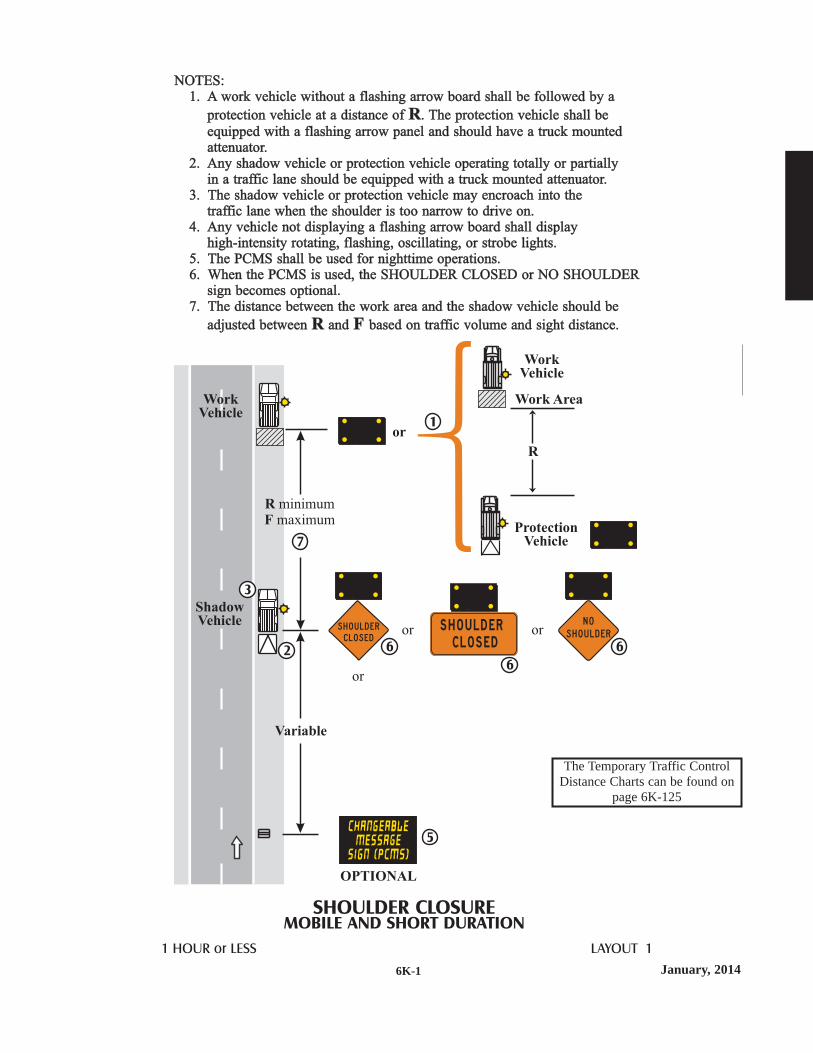
January, 20146K-1
NOTES:1.
2. Any shadow vehicle or protection vehicle operating totally or partiallyin a traffic lane should be equipped with a truck mounted attenuator.
3. The shadow vehicle or protection vehicle may encroach into thetraffic lane when the shoulder is too narrow to drive on.
4. Any vehicle not displaying a flashing arrow board shall displayhigh-intensity rotating, flashing, oscillating, or strobe lights.
5. The PCMS shall be used for nighttime operations.6. When the PCMS is used, the SHOULDER CLOSED or NO SHOULDER
sign becomes optional.7.
A work vehicle without a flashing arrow board shall be followed by a
protection vehicle at a distance of . The protection vehicle shall be
equipped with a flashing arrow panel and should have a truck mountedattenuator.
The distance between the work area and the shadow vehicle should be
adjusted between and based on traffic volume and sight distance.
R
R F
SHOULDER CLOSUREMOBILE AND SHORT DURATION
1 HOUR or LESS LAYOUT 1
OPTIONAL
WorkVehicle
WorkVehicle
Work Area
ProtectionVehicle
ShadowVehicle
or
R
Variable
1
3
26
S H O U L D E R
C L O S E Dor or
or
6
S H O U L D E R
C L O S E D
RF
minimummaximum
7
5
6
N O
S H O U L D E R
The Temporary Traffic ControlDistance Charts can be found on
page 6K-125

January, 2014 6K-2
3 DAYS or LESS LAYOUT 2
SHOULDER CLOSUREWORK ON OR NEAR SHOULDER
NOTES:1. All signs, barricades and channelizing devices may be omitted when the work
occupies an isolated shoulder location for less than one hour and it has littleor no interference with traffic.
2. An operation which moves between work spaces that are less than the decisionsight distance along the shoulder should use a stationary or mobile shoulderclosure.
3. The ROAD WORK AHEAD sign may be omitted for short term daylightoperations if:
a. the distance from curb face to the work space is at least 2 feet, orb. the distance from the edge of the roadway to the work space is at least
15 feetand a vehicle displaying a 360-degree flashing beacon is operating.
4. This ROAD WORK AHEAD sign shall be installed on 2-lane, 2-way roadsif traffic control devices are installed for a work space in the opposite shoulder.
L/3
2G
G
N O
S H O U L D E R
OPTIONAL
WORK ON SHOULDERWORK OFFSHOULDER
4
3
3
SEENOTE 1
SEENOTE 1
The Temporary Traffic ControlDistance Charts can be found on
page 6K-125

January, 20146K-3
3 DAYS or LESS LAYOUT 3
PARKING LANE CLOSURE
OPTIONAL
OPTIONAL
NoParking
For two-wayroad only
NOTE:1. This layout is intended for use where a parking lane is closed.
If this parking lane is normally open to vehicle travel during thetime of day this closure will be in effect, the lane shall be considereda traveled lane and not a parking lane. The appropriate layout shallthen be used to provide traffic control for the lane closure.
L/3
1
The Temporary Traffic ControlDistance Charts can be found on
page 6K-125

January, 2014 6K-4
3 DAYS or LESS LAYOUT 4
PARTIAL SHOULDER CLOSURETRAILER MOUNTED TRAFFIC CONTROL
DEVICES ON SHOULDER
NOTES:1. Type B channelizing devices shall be used in the shoulder taper regardless
of the location on the shoulder or the width of the shoulder.2. Trailer mounted traffic control devices shall be placed at least 4 feet from
the edge of the traveled lane. If the 4 feet clearance can not be met, then afull shoulder closure shall be provided.
3. Typical trailer mounted traffic control devices may include flashing arrowboards, automated flagging assistance devices (AFADs), portable signals,portable changeable message signs, portable dynamic speed display signs,communications equipment, or other data collection devices.
2
1
3
4 foot Minimum
50 feetNumber
of Devices
3
5
50
50
0 - 40
45 - 75
DeviceSpacing
(feet)
SpeedLimit(mph)
The Temporary Traffic ControlDistance Charts can be found on
page 6K-125

January, 20146K-5
NOTES:1. If the approach sight distance is restricted, a spotter should be used to
protect the work area and to warn the driver.2. If the visibility is poor or the operation does not move at least the
Decision Sight Distance every 15 minutes, the appropriate stationary
layout should be used.3. This layout may be used for nighttime operations only in locations
where the posted speed limit is 40 mph or less.4. The slow moving or stopped work vehicle should keep the traffic lane
as wide as possible by using the shoulder space whenever possible.
( )D
15 MINUTES or LESS LAYOUT 5
LANE CLOSURETWO-LANE TWO-WAY ROAD
4
USE FOR ROADSLESS THAN
1500 ADT ONLY
USE FOR ROADSLESS THAN
1500 ADT ONLY
The Temporary Traffic ControlDistance Charts can be found on
page 6K-125

January, 2014 6K-6
NOTES:1. If the work space is not visible for at least the Decision Sight Distance,
the motorists cannot see beyond the work space or traffic volumes donot allow passage, then Layout 7 shall be used.
2. Any shadow vehicle or protection vehicle operating totally or partiallyin a traffic lane should be equipped with a truck mounted attenuator.
3.
4. If the work space does not move at least the Decision Sight Distance every15 minutes, the appropriate stationary layout should be used.
5. This layout may be used for nighttime operations only in locations where theposted speed limit is 40 mph or less.
6. For nighttime operations, the flashing arrow board shall be used.7. The slow moving or stopped work vehicle and shadow vehicle should
keep the traffic lane as wide as possible by using the shoulder spacewhenever practical.
8. The distance between the work area and the shadow vehicle should be
adjusted between and based on traffic volume and sight distance.
The shadow vehicle or protection vehicle may encroach into the trafficlane when the shoulder is too narrow to drive on.
R F
15 MINUTES or LESS LAYOUT 6
LANE CLOSUREWITH RANDOM WORK AREAS
TWO-LANE TWO-WAY ROAD
2 3
7
RF
minimummaximum
8
ShadowVehicle
WorkVehicle
or
The Temporary Traffic ControlDistance Charts can be found on
page 6K-125

January, 20146K-7
NOTES:1. The advance warning signs should be moved or reset after each major
road intersection or after each mile whichever comes first.2. Any shadow vehicle or protection vehicle operating totally or partially in
a traffic lane should be equipped with a truck/trailer mounted attenuator.3. The shadow vehicle or protection vehicle may encroach into the traffic
lane when the shoulder is too narrow to drive on.
4. If the work area does not move at least the Decision Sight Distance ( )every 15 minutes, the appropriate stationary layout should be used.
5. A compact work area should be maintained with minimum space allowedbetween work vehicles. When the work area extends beyond 500 feet intotal length, other traffic control layouts should be considered.
6. This layout may be used for nighttime operations only in locationswhere the posted speed limit is 40 mph or less.
7. The Shadow Vehicle with flashing arrow board shall be used duringnighttime operations.
8. Flaggers shall be used when the approach sight distance is restricted,the motorists can not see beyond the work area, or traffic volumes donot allow safe passage.
D
15 MINUTES or LESS LAYOUT 7
LANE CLOSUREWITH A MOVING WORK AREA
TWO-LANE TWO-WAY ROAD
100 feet Minimum
MultipleWork
Vehicles
ShadowVehicle
Length ofCompact
Work AreaD Maximum
2
18
5
7
7
3OPTIONAL
OPTIONAL
R Minimum
A
A up to 1 mile Maximum
A up to 1 mile Maximum
50 feet Minimum
18
A
The Temporary Traffic ControlDistance Charts can be found on
page 6K-125
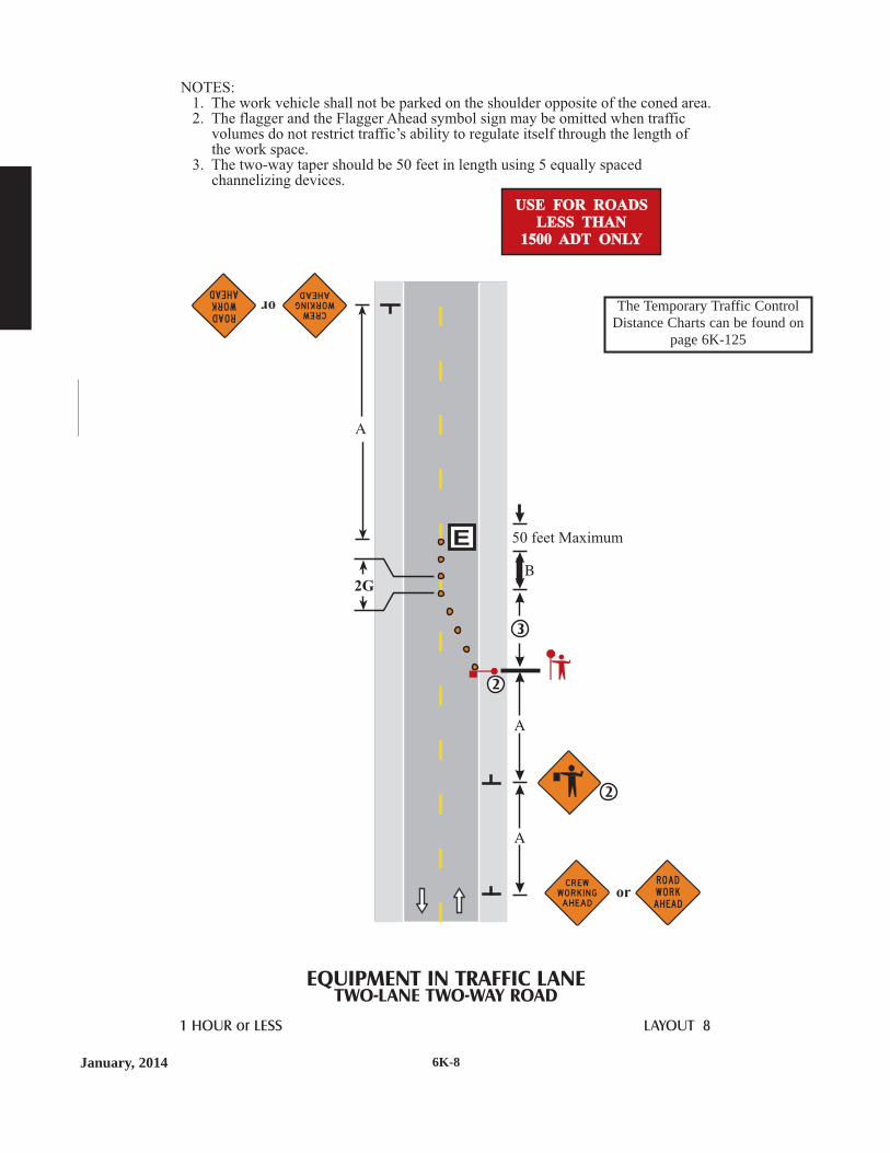
January, 2014 6K-8
EQUIPMENT IN TRAFFIC LANETWO-LANE TWO-WAY ROAD
1 HOUR or LESS LAYOUT 8
NOTES:1. The work vehicle shall not be parked on the shoulder opposite of the coned area.2. The flagger and the Flagger Ahead symbol sign may be omitted when traffic
volumes do not restrict traffic’s ability to regulate itself through the length ofthe work space.
3. The two-way taper should be 50 feet in length using 5 equally spacedchannelizing devices.
USE FOR ROADSLESS THAN
1500 ADT ONLY
USE FOR ROADSLESS THAN
1500 ADT ONLY
2G
3
2
2
50 feet Maximum
orCR EW
WO R K I N GAH EAD
ROAD
WO R K
AH EAD
orCREW
WORKINGAHEAD
ROAD
WORK
AHEAD
The Temporary Traffic ControlDistance Charts can be found on
page 6K-125

January, 20146K-9
LAYOUT 912 HOURS or LESS
LANE CLOSURE, NO FLAGGERTWO-LANE TWO-WAY ROAD
NOTES:1. When traffic can not regulate itself through the length of the work space, use
Layout 10.2. STOP signs shall be installed if the work space must be left unattended
at night - see Layout 20.3. The two-way taper should be 50 feet in length using 5 equally spaced
channelizing devices.
3
3
2G
USE FOR ROADSLESS THAN
400 ADT ONLY
USE FOR ROADSLESS THAN
400 ADT ONLY
500 feetMaximum
OPTIONAL
OPTIONAL
The Temporary Traffic ControlDistance Charts can be found on
page 6K-125
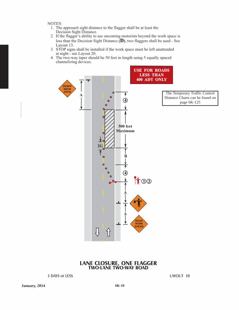
January, 2014 6K-10
LANE CLOSURE, ONE FLAGGERTWO-LANE TWO-WAY ROAD
3 DAYS or LESS LAYOUT 10
NOTES:1. The approach sight distance to the flagger shall be at least the
Decision Sight Distance.2. If the flagger’s ability to see oncoming motorists beyond the work space is
less than the Decision Sight Distance , two flaggers shall be used - SeeLayout 13.
3.
( )D
STOP signs shall be installed if the work space must be left unattendedat night - see Layout 20.
4. The two-way taper should be 50 feet in length using 5 equally spacedchannelizing devices.
( )D
1 2
4
4
2G
B
A
A
A
USE FOR ROADSLESS THAN
400 ADT ONLY
USE FOR ROADSLESS THAN
400 ADT ONLY
500 feetMaximum
The Temporary Traffic ControlDistance Charts can be found on
page 6K-125

January, 20146K-11
3 DAYS or LESS LAYOUT 11
LANE CLOSURE, ONE FLAGGERTWO-LANE TWO-WAY ROAD
OPTIONAL
NOTES:1. The approach sight distance to the flagger shall be at least the
Decision Sight Distance.2.
3. The ONE LANE ROAD AHEAD sign my be omitted when the postedspeed limit is 40 mph or less.
4. f the work space must be left unattendedat night, - see Layout 20.
5. The two-way taper should be 50 feet in length and using five equallyspaced channelizing devices.
If the flagger’s ability to see oncoming motorists beyond the work space is less
than the Decision Sight Distance , two flaggers shall be used - SeeLayout 13.
STOP signs shall be installed i
( )D( )D
A
A
2G
B
A
A
A
A
3
3
5
21
5
USE FOR ROADSLESS THAN
1500 ADT ONLY
USE FOR ROADSLESS THAN
1500 ADT ONLY
500 feetMaximum
The Temporary Traffic ControlDistance Charts can be found on
page 6K-125

January, 2014 6K-12
50 feet
B
A up to 1 mileMaximum
A up to 1 mileMaximum
Operators
3 DAYS or LESS LAYOUT 12
LANE CLOSURE, AUTOMATED FLAGGERSTWO-LANE TWO-WAY ROAD
NOTES:1. The approach sight distance to the Automated Flagging Assistance
Device (AFAD) shall be at least the Decision Sight Distance .2.
3.
( )DThe ONE LANE AHEAD sign may be omitted when the posted speed limit is40 mph or less.The two-way taper should be 50 feet in length using 5 equally spacedchannelizing devices.
4. When using a single operator, theyshall be located so they can to seetraffic at both AFAD locations.
5. Use the appropriate sign on theAFAD.
( )D
4
3
3
5
5
2G
AFAD
50 feet
2
2
AFAD
G12 x 18inches
OPTIONAL
G12 x 18inches
OPTIONAL The Temporary Traffic ControlDistance Charts can be found on
page 6K-125

January, 20146K-13
50 feet
A up 1 MileMaximum
A up to 1 MileMaximum
A
A
A
A
A
A
3 DAYS or LESS LAYOUT 13
LANE CLOSURE, TWO FLAGGERSTWO-LANE TWO-WAY ROAD
OPTIONAL
OPTIONAL
2G
NOTES:1. The approach sight distance to the flagger shall be at least the Decision
Sight Distance .2. The ONE LANE ROAD AHEAD sign may be omitted when the posted
speed limit is 40 mph or less.3
( )D
. The two-way taper should be 50 feet and using five equally spacedchannelizing devices.
( )D
2
3
3
1
1
2
The Temporary Traffic ControlDistance Charts can be found on
page 6K-125

January, 2014 6K-14
LAYOUT 14
MOVING WORK SPACESTRAFFIC CONTROL ZONE
1mile
1mile
1mile
1mile
NOTES:1.
2. This layout may be used forthose short term stationarytraffic control zones thatcover a relatively longsegment of highway in a shortperiod of time but do not meetthe requirements for a mobiletraffic control zone.It is intended to be used toeliminate the multiplemovement of signs along acorridor.
3. The maximum distance fora traffic control zone is3 miles.
4. This Flagger Ahead symbolsign shall be used atLocation A during TimePeriod 1 and at Location Bduring Time Periods 2 and 3.
5. This Flagger Ahead symbolsign shall be used atLocation C during TimePeriods 1 and 2 and atLocation D during TimePeriod 3.
6. For advance warning signson crossroads, see Layout 76.
This layout shall be usedwith the appropriateflagger layout to select thelocation of additionalrequired traffic controldevices.
OPTIONAL
OPTIONAL1
1
6
6
6
6
1
1
4
5
A
B
C
D
TimePeriod 2
TimePeriod 1
TimePeriod 3
12 HOURS or LESS
The Temporary Traffic ControlDistance Charts can be found on
page 6K-125
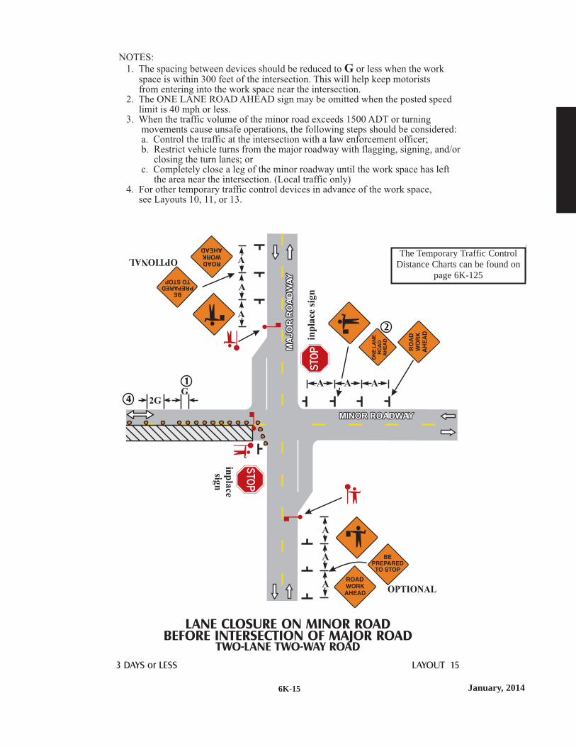
January, 20146K-15
3 DAYS or LESS LAYOUT 15
NOTES:
1. The spacing between devices should be reduced to or less when the workspace is within 300 feet of the intersection. This will help keep motoristsfrom entering into the work space near the intersection.
2. The ONE LANE ROAD AHEAD sign may be omitted when the posted speedlimit is 40 mph or less.
3. When the traffic volume of the minor road exceeds 1500 ADT or turningmovements cause unsafe operations, the following steps should be considered:a. Control the traffic at the intersection with a law enforcement officer;b. Restrict vehicle turns from the major roadway with flagging, signing, and/or
closing the turn lanes; orc. Completely close a leg of the minor roadway until the work space has left
the area near the intersection. (Local traffic only)4. For other temporary traffic control devices in advance of the work space,
see Layouts 10, 11, or 13.
G
MA
JO
RR
OA
DW
AY
MA
JO
RR
OA
DW
AY
MINOR ROADWAYMINOR ROADWAY
LANE CLOSURE ON MINOR ROADBEFORE INTERSECTION OF MAJOR ROAD
TWO-LANE TWO-WAY ROAD
OPTIONAL
OPTIONAL
A
A
A
A
A
AA
A
A
1
4
2
2GG
inp
lace
sign
inp
lace
sign
The Temporary Traffic ControlDistance Charts can be found on
page 6K-125
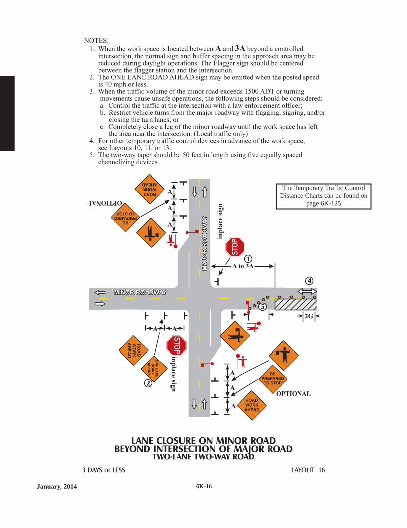
January, 2014 6K-16
3 DAYS or LESS LAYOUT 16
NOTES:
1. When the work space is located between and beyond a controlledintersection, the normal sign and buffer spacing in the approach area may bereduced during daylight operations. The Flagger sign should be centeredbetween the flagger station and the intersection.
2. The ONE LANE ROAD AHEAD sign may be omitted when the posted speedis 40 mph or less.
3. When the traffic volume of the minor road exceeds 1500 ADT or turningmovements cause unsafe operations, the following steps should be considered:a. Control the traffic at the intersection with a law enforcement officer;b. Restrict vehicle turns from the major roadway with flagging, signing, and/or
closing the turn lanes; orc. Completely close a leg of the minor roadway until the work space has left
the area near the intersection. (Local traffic only)4. For other temporary traffic control devices in advance of the work space,
see Layouts 10, 11, or 13.5. The two-way taper should be 50 feet in length using five equally spaced
channelizing devices.
A 3A
MA
JO
RR
OA
DW
AY
MA
JO
RR
OA
DW
AY
MINOR ROADWAYMINOR ROADWAY
LANE CLOSURE ON MINOR ROADBEYOND INTERSECTION OF MAJOR ROAD
TWO-LANE TWO-WAY ROAD
OPTIONAL
OPTIONAL
A
A
A
A
A
A
A A
4
1
2
2G
A to 3A
inp
lace
sign
inp
lace
sign
5
The Temporary Traffic ControlDistance Charts can be found on
page 6K-125

January, 20146K-17
A
A
A
A
3 DAYS or LESS LAYOUT 17
LANE CLOSURE, PILOT CAR METHODTWO-LANE TWO-WAY ROAD
OPTIONAL
2G
NOTES:1. The approach sight distance to the flagger shall be at least the
Decision Sight Distance .2. The ONE LANE ROAD AHEAD sign may be omitted when the posted
speed limit is 40 mph or less.3. Channelizing devices along the edge of the work space may be omitted unless:
a. Traffic is traveling next to longitudinal drop-offs that are greater than4 inches, or
b. Visibility of the open traveled lane is restricted.4. Pilot cars should lead traffic through the work zone at a safe speed.
See the for additional guidance.5. Advance warning signs are the same for both directions approaching
the work area.6. The two-way taper should be 50 feet in length using five equally spaced
channelizing devices.
Flagger Handbook
( )D( )D
2
1
3
6
5
1
6
4P I L O T CAR
F O L L OW M E
50 feet The Temporary Traffic ControlDistance Charts can be found on
page 6K-125

January, 2014 6K-18
3 DAYS or LESS LAYOUT 18
LANE CLOSURE NEAR GRADE CROSSINGTWO-LANE TWO-WAY ROAD
2G
NOTES:1. If the backup of vehicles across active railroad tracks cannot be avoided,
a law enforcement officer or a flagger shall be provided at the crossingto prevent vehicles from stopping within the railroad crossing even ifautomatic warning devices are in place.
2. The approach sight distance to the flagger shall be at least the
Decision Sight Distance .3. The activity area should be extended beyond the railroad crossing so that
the backup of traffic created by the flagging operation will not extendacross the railroad crossing.
( )D( )D
OPTIONAL
A
A
A
A
OPTIONAL
A
A
A
A
50 feet
ExtendedBufferSpace
4
4
2
4. The ONE LANE ROADAHEAD sign may be omittedwhen the posted speed limit is40 mph or less.
5. The two-way taper should be50 feet in length using fiveequally spaced channelizingdevices.
5
52
STO P
TRACKS
DO N OT
O N
RAI L
CROSSI NG
ROAD
STOPON
TRACKS
DONOT
RAIL
CROSSIN
G
ROAD
The Temporary Traffic ControlDistance Charts can be found on
page 6K-125

January, 20146K-19
LANE CLOSURE WITH PORTABLE SIGNALSTWO-LANE, TWO-WAY ROAD
3 DAYS or LESS LAYOUT 19
50 feet50
feet
50feet
2G
STOPHEREON
RED
S TO PH ER E O N
R E D
1
43
3
4
NOTES:1. Approach signs are the same in both directions.2. Signal timing and signal head locations shall be established by qualified
personnel and approved by the local road authority.3. Two signal heads shall be installed per approach. The first shall be installed on
the right shoulder. The second signal head may be installed on either the leftshoulder or mounted over head on the same structure as the first signal head.
4. The two-way taper should be 50 feet in length using five equally spacedchannelizing devices.
G12 x 18inches
G12 x 18inches
The Temporary Traffic ControlDistance Charts can be found on
page 6K-125

January, 2014 6K-20
LANE CLOSURE WITH STOP SIGNSTWO-LANE, TWO-WAY ROAD
3 DAYS or LESS LAYOUT 20
OPTIONAL
50feet
50feet
2G
200 feetMaximum
400 feetMaximum
NOTES:1. Approach signs are the same in both directions.2. STOP signs shall be 48 x 48 inch. The left-side STOP sign may be 30 x 30 inch.3. If adequate sight distance is not available to recognize a stopped vehicle or
traffic volume restricts vehicles from taking turns through the open lane,use Layout 13 or 19.
4. The ONE LANE ROAD AHEAD sign may be omitted when the postedspeed limit is 40 mph or less.
5. The two-way taper should be 50 feet in length using five equally spacedchannelizing devices.
- Type A Red FlashingWarning Light
TAKE
TU R N S
TAKE
TURNS
TAKE
TURNS
TAKE
TU R N S
4
1
5
3
5
2
2
USE FOR ROADSLESS THAN
1500 ADT ONLY
USE FOR ROADSLESS THAN
1500 ADT ONLY
The Temporary Traffic ControlDistance Charts can be found on
page 6K-125

January, 20146K-21
EQUIPMENT ON CENTERLINETWO-LANE TWO-WAY ROAD
1 HOUR or LESS LAYOUT 21
Use shoulder, ditchor field entrance
NOTES:1. The work vehicle shall be parked off of the roadway.
Do not obstruct the shoulder in the coned areas.2. The flagger and Flagger Ahead sign may be omitted if there is at least
10 feet of roadway and shoulder available to safely pass the workequipment on the centerline of the roadway.
2
2
1
2
2
USE FOR ROADSLESS THAN
1500 ADT ONLY
USE FOR ROADSLESS THAN
1500 ADT ONLY
L/2
L/2
50 feetMaximum
orCR EW
WO R K I N GAH EAD
ROAD
WO R K
AH EAD
orCREW
WORKINGAHEAD
ROAD
WORK
AHEAD The Temporary Traffic ControlDistance Charts can be found on
page 6K-125

January, 2014 6K-22
12 HOURS or LESS LAYOUT 22
WORK SPACE IN CENTER OF ROADTWO-LANE TWO-WAY ROAD
NOTES:1. Minimum paved lane width from the channelizing devices to the
edge of pavement or outside edge of the shoulder shall be 10 feet.2. Parking and stopping may be prohibited along the work area and tapers.
3. The flagger shall be visible for at least the Decision Sight Distance .
4. The flaggers and Flagger Ahead signs may be omitted if the posted speedlimits is 40 mph or less.
(D)
A
A
L/2
A
B
2G
B
L/2
A
A
A
43
43
4
4
1
1
2 2
OPTIONAL
OPTIONAL
The Temporary Traffic ControlDistance Charts can be found on
page 6K-125
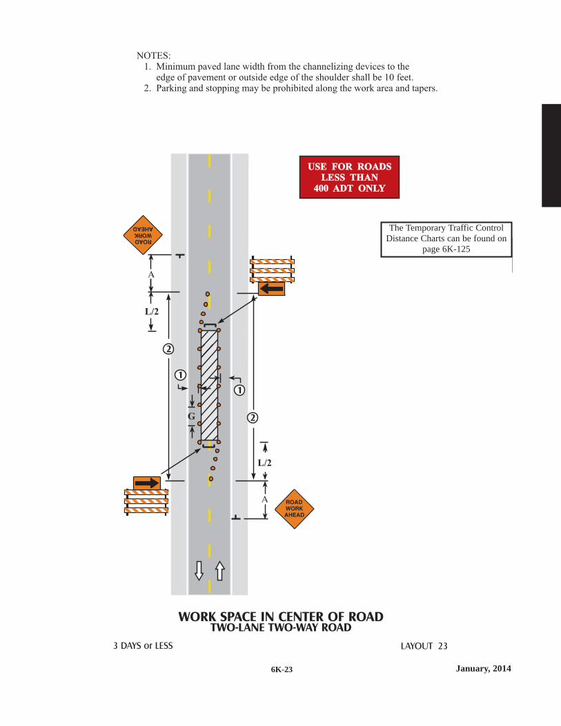
January, 20146K-23
3 DAYS or LESS LAYOUT 23
WORK SPACE IN CENTER OF ROADTWO-LANE TWO-WAY ROAD
NOTES:1. Minimum paved lane width from the channelizing devices to the
edge of pavement or outside edge of the shoulder shall be 10 feet.2. Parking and stopping may be prohibited along the work area and tapers.
G
L/2
L/2
USE FOR ROADSLESS THAN
400 ADT ONLY
USE FOR ROADSLESS THAN
400 ADT ONLY
1
1
2
2
The Temporary Traffic ControlDistance Charts can be found on
page 6K-125

January, 2014 6K-24
3 DAYS or LESS LAYOUT 24
WORK SPACE OCCUPIES ONE HALF OF ROADTWO-LANE TWO-WAY ROAD
NOTES:1. Parking and stopping may be prohibited along the work space and taper.2. The minimum paved lane width from the channelizing devices to the
edge of pavement or outside edge of the shoulder shall be 10 feet.
B
A
L/2
L/2
100feet
L/2
B
G
A
A
ONLY FORSPEED LIMITS
40 MPHOR LESS
ONLY FORSPEED LIMITS
40 MPHOR LESS
11
2
OPTIONAL
OPTIONAL
OPTIONAL
12 x 18inches
12 x 18inches
The Temporary Traffic ControlDistance Charts can be found on
page 6K-125

January, 20146K-25
LANE CLOSURETWO-LANE TWO-WAY ROAD
WITH TWO WAY LEFT TURN LANE
3 DAYS or LESS LAYOUT 25
NOTES:1. The minimum paved lane width from channelizing devices to edge of
pavement or outside edge of paved shoulder or face of curb shall be 10 feet.2. Parking, stopping, and left turning movements may be prohibited along the
work space and taper.3. The Lane Shift symbol sign may be omitted when the posted speed limit
is 40 mph or less.
L/2 100feet
50feet
50feet
L/2
3
2
2
1
The Temporary Traffic ControlDistance Charts can be found on
page 6K-125

January, 2014 6K-26
TURN LANE CLOSURETWO-LANE TWO-WAY ROAD
WITH TWO WAY LEFT TURN LANE
3 DAYS or LESS LAYOUT 26
NOTES:1. The minimum paved lane width from channelizing devices to edge of
pavement or outside edge of paved shoulder or face of curb shall be 10 feet.2. Parking, stopping, and left turning movements may be prohibited along the
work space and taper.
50feet
50feet
G
1 1 2
The Temporary Traffic ControlDistance Charts can be found on
page 6K-125
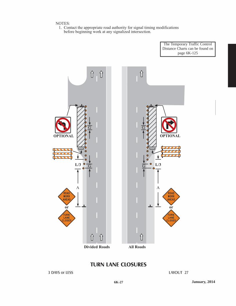
January, 20146K-27
3 DAYS or LESS LAYOUT 27
TURN LANE CLOSURES
OPTIONALOPTIONAL
NOTES:1. Contact the appropriate road authority for signal timing modifications
before beginning work at any signalized intersection.
L/3L/3
Divided Roads All Roads
TU R NLAN ECLOS ED
TU R NLAN ECLOS ED
oror
ROAD
WO R K
AH EAD
ROAD
WO R K
AH EAD
The Temporary Traffic ControlDistance Charts can be found on
page 6K-125

January, 2014 6K-28
3 DAYS or LESS LAYOUT 28
CLOSURE IN CENTER OF INTERSECTION
NOTES:1. The minimum paved lane width from channelizing devices to the edge of
the pavement or to the outside edge of the shoulder shall be 10 feet.
USE FOR ROADSLESS THAN
400 ADT ONLY
USE FOR ROADSLESS THAN
400 ADT ONLY
ONLY FORSPEED LIMITS
40 MPHOR LESS
ONLY FORSPEED LIMITS
40 MPHOR LESS
The Temporary Traffic ControlDistance Charts can be found on
page 6K-125

January, 20146K-29
3 DAYS or LESS LAYOUT 29
CLOSURE IN CENTER OF INTERSECTION
NOTES:1. Contact the appropriate road authority for signal timing modifications
before beginning work at any signalized intersection.2. The minimum paved lane width from channelizing devices to the edge of
the pavement or to the outside edge of the shoulder shall be 10 feet.
LP
LP
LP
LP
ONLY FORSPEED LIMITS
40 MPHOR LESS
ONLY FORSPEED LIMITS
40 MPHOR LESS
Posted SpeedLimit Prior
to WorkStarting
(mph)
G=25 ft0 - 30
35 - 40
feet feet feet feet feet
Partial Lane Closure Taper Lengths
( )based on encroachment distance
into the lane W( LP )
2
50
75
4
75
100
6 8
100
175
125
225
10
150
300
W
LP
The Temporary Traffic ControlDistance Charts can be found on
page 6K-125

This page has been intentionally left blank.There is no Layout 30
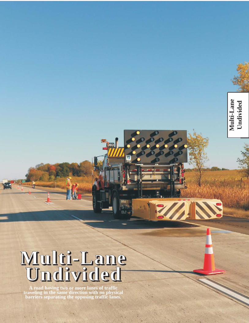
Mul
ti-L
ane
Und
ivid
ed
MMuull tt ii --LLaanneeUUnnddiivv iiddeedd
A road having two or more lanes of traffictraveling in the same direction with no physicalbarriers separating the opposing traffic lanes.
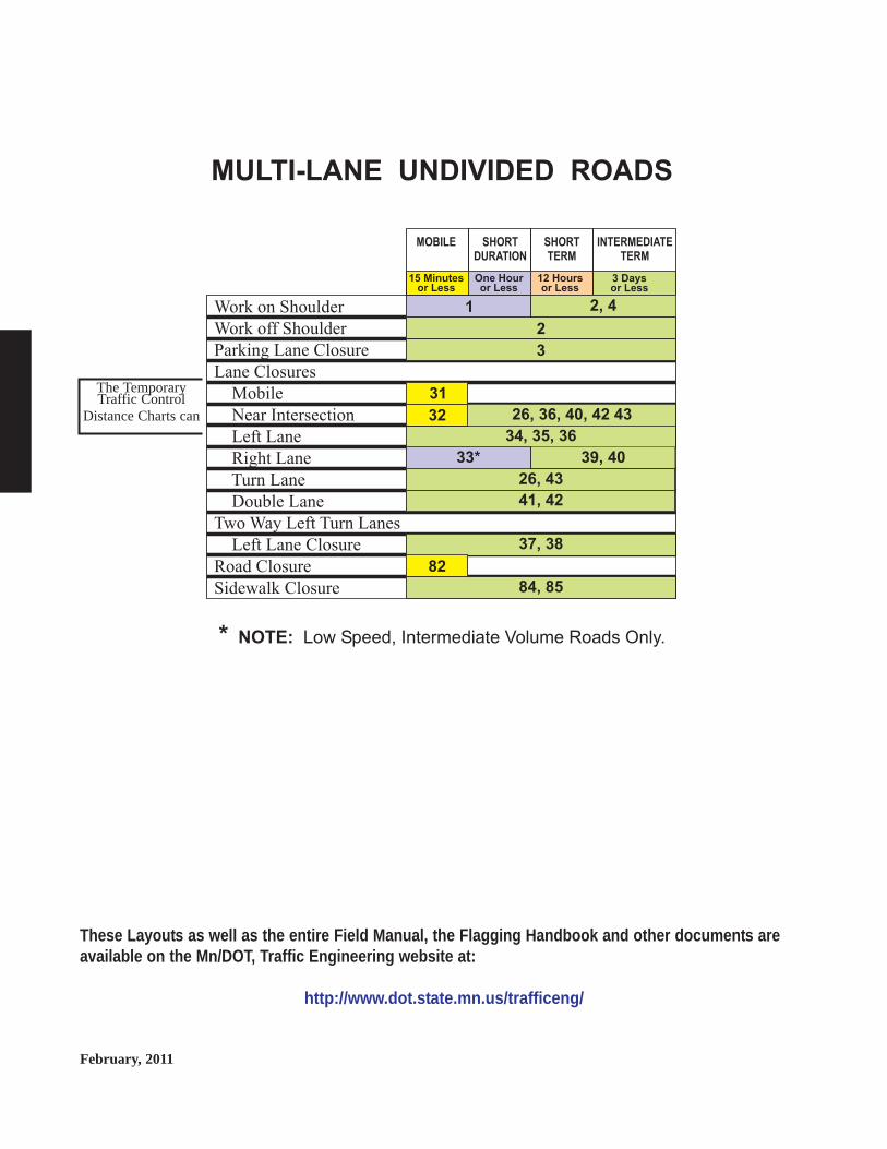
The TemporaryTraffic Control
Distance Charts can
February, 2011
These Layouts as well as the entire Field Manual, the Flagging Handbook and other documents areavailable on the Mn/DOT, Traffic Engineering website at:
http://www.dot.state.mn.us/trafficeng/
* NOTE: Low Speed, Intermediate Volume Roads Only.
MULTI-LANE UNDIVIDED ROADS
15 Minutesor Less
One Houror Less
3 Daysor Less
12 Hoursor Less
MOBILE SHORT
DURATION
SHORT
TERM
INTERMEDIATE
TERM
Work on Shoulder
Work off Shoulder
Parking Lane Closure
Lane Closures
Mobile
Near Intersection
Left Lane
Right Lane
Turn Lane
Double Lane
Two Way Left Turn Lanes
Left Lane Closure
Road Closure
Sidewalk Closure
2, 4
2
26, 36, 40, 42 43
34, 35, 36
39, 40
84, 85
26, 43
41, 42
37, 38
1
3
82
31
32
33*

January, 20146K-31
MOBILE LANE CLOSUREMULTI-LANE ROAD
15 MINUTES or LESS LAYOUT 31
OPTIONAL
NOTES:1.
2. Any shadow vehicle operating totally or partially in a traffic lane should beequipped with a truck mounted attenuator.
3. The Shadow Vehicle may encroach into the traffic lane.
4. If the operation does not move at least the Decision Sight Distance ( ) every
15 minutes, the appropriate stationary layout should be used.5. If this layout is used for nighttime operations, the PCMS shall be used.6. The RIGHT LANE CLOSED sign may be omitted when the PCMS is used.
A work vehicle without a flashing arrow board shall be followed by a
protection vehicle at a distance of . The protecting vehicle shall be equipped
with a flashing arrow board and should have a truck mounted attenuator.
R
D
WorkVehicle
ShadowVehicle
F
or
Variable
5
0-40 mph
6
All Speeds
6
NOT FORUSE ON
FREEWAYS
NOT FORUSE ON
FREEWAYS
oror
All Speeds
Work Vehicle
WorkArea
ProtectionVehicle
R
10 - 40mph
R I G H T LAN E
C L O S E D
2
2 3
The Temporary Traffic ControlDistance Charts can be found on
page 6K-125

January, 2014 6K-32
NOTES:1. The operation shall not to remain in one location for more than 15 minutes.2. There should be little or no encroachment into the cross-street traffic path3. The traffic control signal should be put in an ALL-RED flash mode to
facilitate traffic control at the work site. If the intersection flashesYEL-RED, the appropriate stationary layout shall be used.
4. If the work space is not visible for at least the Decision Sight Distance ( ),
the appropriate stationary layout shall be used.
D
15 MINUTES or LESS LAYOUT 32
LANE CLOSUREFAR SIDE OF SIGNALIZED INTERSECTION
signal heads
The Temporary Traffic ControlDistance Charts can be found on
page 6K-125

February, 20116K-33
EQUIPMENT IN TRAFFIC LANEMULTI-LANE ROAD
1 HOUR or LESS LAYOUT 33
or
USE FOR ROADSLESS THAN
1500 ADT ONLY
USE FOR ROADSLESS THAN
1500 ADT ONLY
ONLY FORSPEED LIMITS
40 MPHOR LESS
ONLY FORSPEED LIMITS
40 MPHOR LESS
50 feetMaximum
CR EWWO R K I N GAH EAD
ROAD
WO R K
AH EAD
R I G H TLAN ECLOS ED
The Temporary Traffic ControlDistance Charts can be found on
page 6K-125

January, 2014 6K-34
EQUIPMENT IN TRAFFIC LANEMULTI-LANE ROAD
1 HOUR or LESS LAYOUT 33
or
USE FOR ROADSLESS THAN
1500 ADT ONLY
USE FOR ROADSLESS THAN
1500 ADT ONLY
ONLY FORSPEED LIMITS
40 MPHOR LESS
ONLY FORSPEED LIMITS
40 MPHOR LESS
50 feetMaximum
CR EWWO R K I N GAH EAD
ROAD
WO R K
AH EAD
R I G H TLAN ECLOS ED
The Temporary Traffic ControlDistance Charts can be found on
page 6K-125

January, 20146K-35
3 DAYS or LESS LAYOUT 35
LEFT LANE CLOSUREMULTI-LANE UNDIVIDED ROAD
NOTES:1. The advance warning sign sequence is shown for one way direction only.
Signing from the other direction shall be identical.2. The flashing arrow panel shall be used where the posted speed limit is
45 mph or greater.
OPTIONAL
variable
1
2
2
100 feet
100 feet
The Temporary Traffic ControlDistance Charts can be found on
page 6K-125

January, 2014 6K-36
LEFT LANE CLOSUREWORK SPACE AT INTERSECTION
MULTI-LANE UNDIVIDED ROAD
3 DAYS or LESS LAYOUT 36
100 feetMinimum
variable
variable
variable
OPTIONALOPTIONAL
or
A
G
L
A
A
NOTES:1. The flashing arrow board shall be used when the posted speed limit is
45 mph or greater.2. The lane closure may be omitted when the posted speed limit is
40 mph or less, or when the workers are not at the work site.
11
2
2
2
22
2
2
1G
or
The Temporary Traffic ControlDistance Charts can be found on
page 6K-125

January, 20146K-37
3 DAYS or LESS LAYOUT 37
LEFT LANE CLOSUREMULTI-LANE UNDIVIDED ROAD
WITH TWO-LANE TWO-WAY LEFT TURN LANE
OPTIONAL
variable
ONLY FORSPEED LIMITS
40 MPHOR LESS
ONLY FORSPEED LIMITS
40 MPHOR LESS
NOTES:1. Parking, stopping and left turning vehicles may be prohibited along the
work space and taper.
1
1
100feet
The Temporary Traffic ControlDistance Charts can be found on
page 6K-125

January, 2014 6K-38
3 DAYS or LESS LAYOUT 38
LEFT LANE CLOSUREMULTI-LANE UNDIVIDED ROAD
WITH TWO-LANE TWO-WAY LEFT TURN LANE
OPTIONAL
variable
100feet
50 feet
50 feet
NOTES:1. The flashing arrow board shall be used when the posted speed limit is
45 mph or greater.2. Parking, stopping and left turning vehicles may be prohibited along the
work space and taper.
or
1
2
2
2
The Temporary Traffic ControlDistance Charts can be found on
page 6K-125

January, 20146K-39
3 DAYS or LESS LAYOUT 39
RIGHT LANE CLOSUREMULTI-LANE UNDIVIDED ROAD
100 feetMinimum
NOTES:1. The flashing arrow board shall be used where the posted speed limit
is 45 mph or greater.2. The RIGHT LANE CLOSED sign and the MERGE with arrow sign or
Lane Drop sign, may be omitted when the posted speed limit is 40 mphor less.
variable
OPTIONAL
1
22
2
The Temporary Traffic ControlDistance Charts can be found on
page 6K-125

January, 2014 6K-40
3 DAYS or LESS LAYOUT 40
RIGHT LANE CLOSUREWORK SPACE AT INTERSECTION
MULTI-LANE UNDIVIDED ROAD
variable
100 feetMinimum
variable
OPTIONAL
NOTES:1. The flashing arrow board shall be used when the posted speed limit
is 45mph or greater.
1
G
The Temporary Traffic ControlDistance Charts can be found on
page 6K-125

January, 20146K-41
3 DAYS or LESS LAYOUT 41
DOUBLE LANE CLOSUREMULTI-LANE UNDIVIDED ROAD
variable
OPTIONAL
NOTES:1. The flashing arrow board shall be used when the posted speed limit
is 45 mph or greater.
1
1
G
G
2G
L/2
L
L
L/2
100 feet
The Temporary Traffic ControlDistance Charts can be found on
page 6K-125

January, 2014 6K-42
3 DAYS or LESS LAYOUT 42
DOUBLE LANE CLOSURE AT INTERSECTIONMULTI-LANE UNDIVIDED ROAD
NOTES:1. The flashing arrow board shall be used when the posted speed limit
is 45 mph or greater.2. Contact the appropriate road authority for the placement of temporary STOP
signs or signal timing modifications before beginning work at any signalizedintersection.
3. For the placement of advance warning signs, see Layout 41.4. For the placement of advance warning signs, see Layout 34 or 35.
OPTIONAL
OPTIONAL
G
G
G
G
G
3
4
100 feet
1
12 x 18inches
12 x 18inches
The Temporary Traffic ControlDistance Charts can be found on
page 6K-125

January, 20146K-43
3 DAYS or LESS LAYOUT 43
LEFT TURN LANE CLOSURE
OPTIONAL
NOTES:1. Contact the appropriate road authority for signal timing modifications
before beginning work at any signalized intersection.
G
G
G
TU R N
LAN EC LOS ED
orROAD
WO R K
A H EAD
ROAD
WORK
AHEAD
The Temporary Traffic ControlDistance Charts can be found on
page 6K-125

This page has been intentionally left blank.
There is no Layout 44.

Mul
ti-L
ane
Div
ided
MMuull tt ii --LLaanneeDDiivv iiddeedd
Two separate roadways where opposing trafficis separated by a median.

January, 2014
These Layouts as well as the entire Field Manual, the Flagging Handbook and other documents areavailable on the Mn/DOT, Traffic Engineering website at:
http://www.dot.state.mn.us/trafficeng/
* NOTE: Low Speed, Intermediate Volume Roads Only.
MULTI-LANE DIVIDED ROADS
15 Minutesor Less
One Houror Less
3 Daysor Less
12 Hoursor Less
MOBILE SHORT
DURATION
SHORT
TERM
INTERMEDIATE
TERM
Work on Shoulder
Work off Shoulder
Parking Lane Closure
Lane Closures
Mobile/Short Duration
Nighttime
Center Lane
Left/Right Lane
Left/Right Lane
Turn Lane
Double Lane
Extended Lane
Lane Shift
Near Ramp
Partial Ramp Closure
Ramp Closure
Work near Intersection
Road Closure
Sidewalk Closure
2, 4
2
3
51
52
59
60
61, 62, 63
83
64
84, 85
57, 58
27
53, 54, 55, 56
1
45, 46 50
32
47, 48, 49 65, 66
27, 54, 55
33*
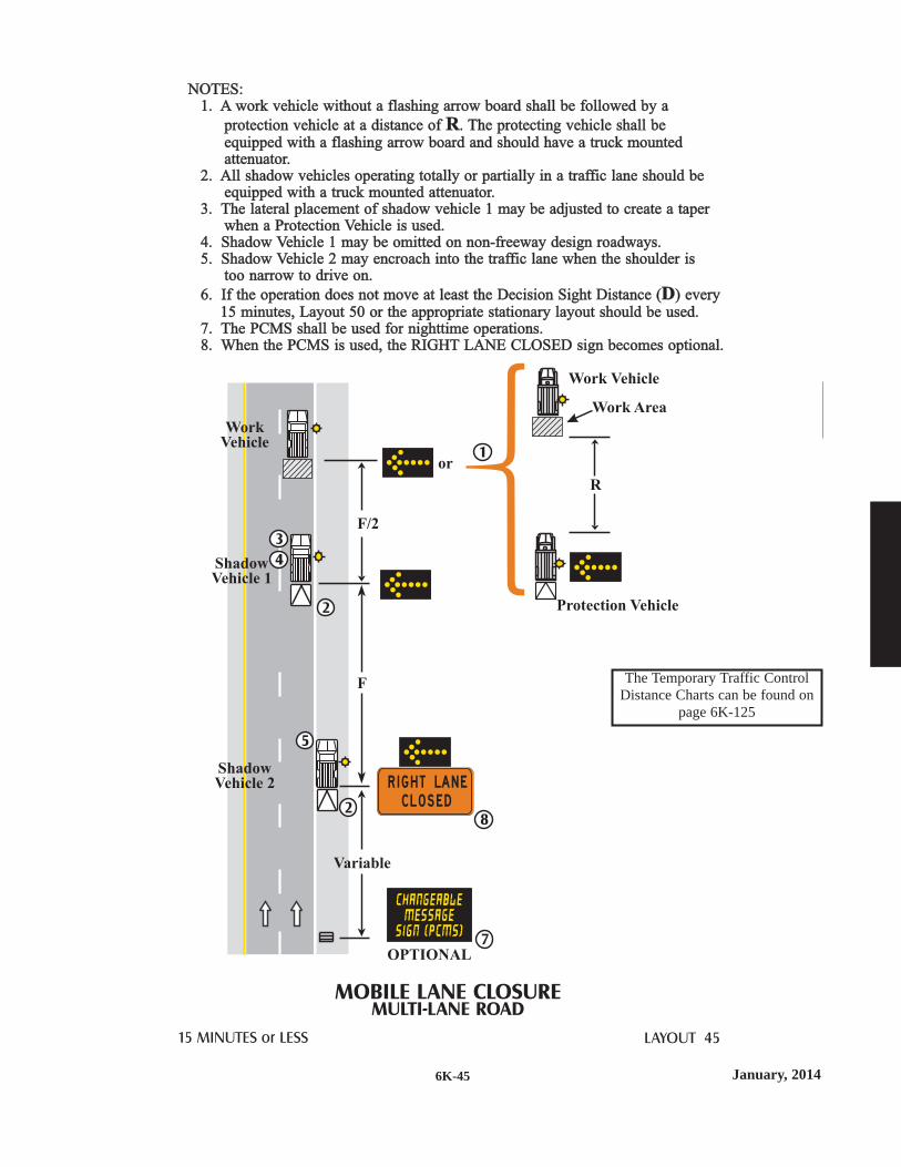
January, 20146K-45
NOTES:1. A work vehicle without a flashing arrow board shall be followed by a
protection vehicle at a distance of . The protecting vehicle shall beequipped with a flashing arrow board and should have a truck mountedattenuator.
2. All shadow vehicles operating totally or partially in a traffic lane should beequipped with a truck mounted attenuator.
3. The lateral placement of shadow vehicle 1 may be adjusted to create a taperwhen a Protection Vehicle is used.
4. Shadow Vehicle 1 may be omitted on non-freeway design roadways.5. Shadow Vehicle 2 may encroach into the traffic lane when the shoulder is
too narrow to drive on.
6. If the operation does not move at least the Decision Sight Distance ( ) every15 minutes, Layout 50 or the appropriate stationary layout should be used.
7. The PCMS shall be used for nighttime operations.8. When the PCMS is used, the RIGHT LANE CLOSED sign becomes optional.
R
D
MOBILE LANE CLOSUREMULTI-LANE ROAD
15 MINUTES or LESS LAYOUT 45
OPTIONAL
WorkVehicle
Work Vehicle
Work Area
Protection Vehicle
ShadowVehicle 1
ShadowVehicle 2
or
F/2
R
F
Variable
R I G H T LAN E
C L O S E D
1
3
5
8
7
2
2
4
The Temporary Traffic ControlDistance Charts can be found on
page 6K-125

January, 2014 6K-46
NOTES:1. All shadow vehicles operating totally or partially in a traffic lane should be
equipped with a truck mounted attenuator.2. The lateral placement of shadow vehicle 1 may be adjusted to create a taper
when a Protection Vehicle is used.3. Shadow Vehicle 1 may be omitted on non-freeway design roadways.4. Shadow Vehicle 2 may encroach into the traffic lane when the shoulder is
too narrow to drive on.
MOBILE LANE CLOSUREWITH LATE MERGEMULTI-LANE ROAD
15 MINUTES or LESS LAYOUT 46
WorkVehicle
ShadowVehicle 1
AdvanceWarningVehicle
ProtectionVehicle
ShadowVehicle 2
F/2
F
As stated in Layout 45, the Protection Vehiclemay be omitted when the Work Vehicle has anoperating flashing arrow board.
R
MERGELEFT
MERGELEFT
BEGINMERGE
rt laneclosed No Queuing
Queuing Detected
PCMS MESSAGE OPTIONS
Shadow Truck 2 Operator is responsible fordetecting the traffic queue and changing thePCMS message appropriately for the conditions.Operators of the two PCMS’s shall have radiocommunication.
Signage shall be at least Distancebefore queue (area where traffic slows)
F
End of Queueplus (min.)F
STOPPEDTRAFFIC
SlowTRAFFIC
USE ALLLANES
rt laneclosed No Queuing
Queuing Detected
PCMS MESSAGE OPTIONS
OR
TAKE TU R N S
AT M ERG E
TAKE TU R N S
The Temporary Traffic ControlDistance Charts can be found on
page 6K-125

January, 20146K-47
NOTES:1. The protection vehicle should remain positioned near the ramp gore to prevent
traffic from using the exit ramp. If a protection vehicle follows the work
vehicle up the ramp, then it shall remain a minimum distance from thework area.
2. Any shadow or protection vehicle operating totally or partially in a traffic laneshould be equipped with a truck mounted attenuator.
3. The vehicles blocking the exit ramp should not encroach into lanes open totraffic.
4. If the ramp can not be reopened within 15 minutes, the appropriate stationarylayout should be used.
5. The PCMS shall be used for nighttime operations.
R
MOBILE RAMP CLOSUREEXPRESSWAY/FREEWAY
15 MINUTES or LESS LAYOUT 47
WorkVehicle
ShadowVehicle 1
ShadowVehicle 2
F
Variable
Vehicle should not encroach into traffic laneexcept where the shoulder is too narrow
OPTIONAL
or
or
2
5
2
3
RAM PC LOS ED
RAM PC LOS ED
OPTIONAL
The PCMS’s shall display the“RAMP CLOSED” message.
The Temporary Traffic ControlDistance Charts can be found on
page 6K-125

January, 2014 6K-48
NOTES:1. The protection vehicle should remain positioned near the ramp gore to prevent
traffic from using the exit ramp. If the operation requires one protectionvehicle to follow the work vehicle up the ramp, then it shall remain a
minimum distance from the work area.2. Any shadow or protection vehicle operating totally or partially in a traffic lane
should be equipped with a truck mounted attenuator.3. The vehicles blocking the exit ramp should not encroach into lanes open to
traffic and should allow traffic to use the escape lane.4. If the ramp can not be reopened within 15 minutes, the appropriate stationary
layout should be used.5. The PCMS’s shall be used for nighttime operations.6. The optional second protection vehicle may be needed to block wider
exit ramps.
R
MOBILE RAMP CLOSURE with ESCAPE LANEEXPRESSWAY/FREEWAY
15 MINUTES or LESS LAYOUT 48
WorkVehicle
ShadowVehicle 1
F
Variable
Both vehicles should display the same message.Vehicles should not encroach into the escape lane.
Vehicle should not encroach into traffic laneexcept where the shoulder is too narrow
OPTIONAL
2
5
2
2
6
3
1
OPTIONAL
OPTIONAL
AU
XIL
IAR
YL
AN
EA
UX
ILIA
RY
LA
NE
ES
CA
PE
LA
NE
ES
CA
PE
LA
NE
orRAM PC LOS ED
orRAM PC LOS ED
ProtectionVehicles
The PCMS’s shall display the“RAMP CLOSED” message.
The Temporary Traffic ControlDistance Charts can be found on
page 6K-125

January, 20146K-49
NOTES:1. The protection vehicle should remain positioned near the ramp gore to prevent
traffic from using the exit ramp. If a protection vehicle follows the workvehicle up the ramp, then the flashing arrow display shall change to the
caution mode shall remain a minimum distance from the work area.2. Any shadow or protection vehicle operating totally or partially in a traffic lane
should be equipped with a truck mounted attenuator.3. The vehicles blocking the exit ramp should not encroach into lanes open to
traffic.4. If the ramp can not be reopened within 15 minutes, the appropriate stationary
layout should be used.5. The PCMS shall be used for nighttime operations.6. The optional second protection vehicle may be needed to block wider
exit ramps.
R
MOBILE RAMP CLOSURE with LANE DROPEXPRESSWAY/FREEWAY
15 MINUTES or LESS LAYOUT 49
WorkVehicle
ShadowVehicle 1
ShadowVehicle 2
F
F/2
Variable
Both vehicles should display the same message
Vehicle should not encroach into traffic laneexcept where the shoulder is too narrow
OPTIONAL
2
2
5
2
2
6
3
1
OPTIONAL
OPTIONAL
AU
XIL
IAR
YL
AN
EA
UX
ILIA
RY
LA
NE
orRAM PC LOS ED
orRAM PC LOS ED
orRAM PC LOS ED
ProtectionVehicles
The PCMS’s shall display the“RAMP CLOSED” message.
The Temporary Traffic ControlDistance Charts can be found on
page 6K-125

January, 2014 6K-50
NOTES:1. All Shadow and Protection Vehicles shall be equipped with a truck-mounted
attenuator.2. The lateral placement of Shadow Vehicle 1 may be adjusted to create a taper.3. Shadow Vehicle 2 may encroach into the traffic lane when the shoulder
is too narrow to drive on.4. If the operation does not move at least the Decision Sight Distance once
each hour, the appropriate stationary layout should be used.5. A typical message should be ROAD WORK AHEAD and RIGHT LANE
CLOSED.
SHORT DURATION LANE CLOSUREMULTI-LANE ROAD
1 HOUR or LESS LAYOUT 50
OPTIONAL
ShadowVehicle 1
WorkVehicle
ProtectionVehicle
ShadowVehicle 2
R
F/2
F
Variable
R I G H T LAN E
C L O S E D
3
5
1
1
2
1
G
The Temporary Traffic ControlDistance Charts can be found on
page 6K-125

January, 20146K-51
12 HOURS or LESS LAYOUT 51
LANE CLOSUREOCCUPIED NIGHTTIME WORK SPACE
MULTI-LANE DIVIDED ROAD
1 1
2
2
2
3
3
4
4
NOTES:1. The Lane Reduction sign and the MERGE sign may be omitted when the
posted speed limit is 40 mph or less.2. In order to use this layout, two flashing arrow boards, at least one PCMS, and
advance warning signs shall be used. If these devices are not available, eitherLayout 52 shall be used.
3. When using a combination of cones (28 inch minimum height) and DirectionIndicator Barricades every third device in the merge taper and every tenthdevice in the tangent area shall be a Directional Indicator Barricade.
4. All shadow vehicles operating totally or partially in a traffic lane shouldbe equipped with a truck mounted attenuator.
A
A
or
A
variable
The Temporary Traffic ControlDistance Charts can be found on
page 6K-125

January, 2014 6K-52
3 DAYS or LESS LAYOUT 52
CENTER LANE CLOSUREMULTI-LANE DIVIDED OR ONE WAY ROAD
OPTIONAL
NOTE:1. If traffic volumes are low, a double lane closure is preferred.
ONLY FORSPEED LIMITS
40 MPHOR LESS
ONLY FORSPEED LIMITS
40 MPHOR LESS
or
The Temporary Traffic ControlDistance Charts can be found on
page 6K-125

January, 20146K-53
3 DAYS or LESS LAYOUT 53
LANE CLOSUREMULTI-LANE DIVIDED ROAD
OPTIONAL
variable
100feet
22
3
3
3
3
3
3
3
3
1
NOTES:1. The flashing arrow board shall be used when the posted speed limit is
45 mph or greater.2. The Lane Drop symbol sign and the Merge with arrow sign may be omitted
when the posted speed limit is 40 mph or less.3. Use the appropriate traffic control devices for a right lane closure.
or
or
The Temporary Traffic ControlDistance Charts can be found on
page 6K-125

January, 2014 6K-54
3 DAYS or LESS LAYOUT 54
LANE CLOSURE WITH LATE MERGEMULTI-LANE DIVIDED ROAD
NOTES:1. This layout should be used on high speed roadways where traffic queues may
extend at least 0.5 mile upstream of the taper. If little or no queuing isanticipated, use the typical lane closure Layout 52.
2. Use the appropriate traffic control devices for a left lane closure.3. A PCMS may be used in place of a pair of USE BOTH LANES DURING
BACKUPS signs.4. Distance plaques are recommended when the distance is 2 miles or more.
22
2
2
3 3
3
3
44
3
3
2
2
TA K E T U R N S
AT M E R G ETA K E T U R N S
AT M E R G E
TAKE
TU R N S
TAKE
TU R N S
XX
M I L E S
XX
M I L E S
A
1 to 2 mile spacing
A
Continue spacing forthe estimated maximum
queue distance
A
1 mile
BOTHLAN ESD U R I N GBAC K U P S
U S E
BOTHLAN ESD U R I N GBAC K U P S
U S EBOTHLAN ESD U R I N GBAC K U P S
U S E
BOTHLAN ESD U R I N GBAC K U P S
U S E
BOTHLAN ESD U R I N GBAC K U P S
U S E
BOTHLAN ESD U R I N GBAC K U P S
U S E
LAN EL E FT
CLOS ED
AH EAD
LAN EL E FT
CLOS ED
AH EAD
M ERG EB EG I N
The Temporary Traffic ControlDistance Charts can be found on
page 6K-125

January, 20146K-55
G
L
200 feet
200 feet
25 feet
25 feet
G
G
3 DAYS or LESS LAYOUT 55
LEFT LANE CLOSUREWORK SPACE BEYOND INTERSECTION
MULTI-LANE DIVIDED ROAD
100feet
NOTES:1. Use the appropriate advance warning sign spacing for the speed on the
cross road.2. The flashing arrow board shall be used when the posted speed limit is 45
or greater.3. The Lane Drop symbol sign and the MERGE with Arrow sign may be
omitted when the posted speed limit is 40 mph or less.
variable
OPTIONAL
33
2
or
or
TU R NLAN E
The Temporary Traffic ControlDistance Charts can be found on
page 6K-125

January, 2014 6K-56
G
L
200feet
G
G
RIGHT LANE CLOSUREWORK SPACE BEYOND INTERSECTION
MULTI-LANE DIVIDED ROAD
3 DAYS or LESS LAYOUT 56
100feet
NOTES:1. Use the appropriate advance warning sign spacing for the
speed on the cross road.2. The flashing arrow board shall be used when the posted speed
limit is 45 mph or greater.3. The Lane Drop symbol sign and the MERGE with Arrow sign
may be omitted when the posted speed limit is 40 mph or less.
variable
OPTIONAL
3
2
3 3
or
or
25 feet
25 feet
200feet
TU R NLAN E
The Temporary Traffic ControlDistance Charts can be found on
page 6K-125

January, 20146K-57
or
or
LEFT TWO LANES CLOSEDMULTI-LANE DIVIDED ROAD
3DAYS or LESS LAYOUT 57
OPTIONAL
variable
100feet
NOTES:1. The flashing arrow board shall be used when the posted speed limit is
45 mph or greater.2. The Lane Drop symbol signs, the Merge with arrow signs, and the
arrow board may be omitted when the posted speed limit is 40 mph or less.3. If the flashing arrow board will not fit entirely on the left shoulder, it should
be placed behind the taper, encroaching on the lane as little as possible.4. When the Lane Drop symbol sign or the MERGE with arrow sign is used,
the same sign shall be used for both lane closures in each direction.
1
1 32
2
or
or2 24 4
2 42 4or
The Temporary Traffic ControlDistance Charts can be found on
page 6K-125

January, 2014 6K-58
or
or
or
or
or
3 DAYS or LESS LAYOUT 58
RIGHT TWO LANES CLOSEDMULTI-LANE DIVIDED ROAD
OPTIONAL
variable
100feet
2
2
2
2
2
2
3
3
3
3
1
1
NOTES:1. The flashing arrow board shall be used when the posted speed
limit is 45 mph or greater.2. The Lane Drop symbol sign and the Merge with arrow sign
may be omitted when the posted speed limit is 40 mph or less.3. When the Lane Drop symbol sign or the MERGE with arrow sign is used,
the same sign shall be used for both lane closures in each direction.
The Temporary Traffic ControlDistance Charts can be found on
page 6K-125

January, 20146K-59
3 DAYS or LESS LAYOUT 59
LANE CLOSURE EXTENSIONMULTI-LANE DIVIDED OR ONE WAY ROAD
NOTES:1. Install a Type III barricade at the beginning of each work space and at
intervals from 500 feet minimum to 1000 feet maximum within theclosed lane.
2. The Type III barricade within the work space may be omitted when thework space is occupied.
3. For advance signing, placement of traffic control devices, and lane taper,see the appropriate stationary layout.
or
or
or
or
2
1
3
1
1
The Temporary Traffic ControlDistance Charts can be found on
page 6K-125

January, 2014 6K-60
3 DAYS or LESS LAYOUT 60
LANE SHIFTMULTI-LANE DIVIDED OR ONE WAY ROAD
NOTES:1. For one lane of traffic only.2. Continue the pattern and the spacing of devices for additional
lateral shift.3. For advance signing, placement of traffic control devices, lane taper,
see the appropriate stationary layout.4. The Lane Shift sign may be omitted when the posted speed limit
is 40 mph or less.5. Directional arrows shall be used on either the drums or the Type III
barricade
G Spacingbetween
each device
GSpacingbetween
eachdevice
L/2or
B
2G A
2G
3
2
5
5
3
4
2
The Temporary Traffic ControlDistance Charts can be found on
page 6K-125

January, 20146K-61
EXIT
MAINLINE RIGHT LANE CLOSEDEXIT RAMP OPEN
3 DAYS or LESS LAYOUT 61
NOTES:1. Adjust the ramp exit to fit the conditions.2. For advance signing, placement of traffic control devices,
and lane closure, see the appropriate stationary layout.
2
2G
G
200 - 400feet
The Temporary Traffic ControlDistance Charts can be found on
page 6K-125

January, 2014 6K-62
MAINLINE LEFT LANE CLOSEDENTRANCE RAMP OPEN
3 DAYS or LESS LAYOUT 62
inplace
NOTES:1. The advance warning sign spacing is dependent
on the ramp length and the location of inplace signing.The spacing should be as long as is practical.
1
The Temporary Traffic ControlDistance Charts can be found on
page 6K-125

January, 20146K-63
MAINLINE RIGHT LANE CLOSEDENTRANCE RAMP OPEN
LAYOUT 63
inplace
NOTES:1. Adjust the ramp entrance to fit the conditions.2. The advance warning sign spacing is dependent on
the ramp length and the location of inplace signing.The spacing should be as long as is practical.
3. For advance signing, placement of traffic control devices,and lane closure, see the appropriate stationary layout.
3 DAYS or LESS
2
3
2
2G
G
The Temporary Traffic ControlDistance Charts can be found on
page 6K-125

January, 2014 6K-64
PARTIAL RAMP CLOSURE
3 DAYS or LESS LAYOUT 64
OPTIONAL
See Road Authorityfor appropriate speed.
250 feetMinimum
12 feet Minimum
NOTES:1. Truck off-tracking should be considered when determining whether the
12 foot minimum lane width is adequate.2. Use a minimum of a 250 foot taper.3. For Loops use 25 foot spacing between devices.
For Ramps use 50 foot spacing between devices.4. The spacing for advance warning signs is dependent on the design of the
interchange, and the location of inplace signing.
1
3
2
4A
The Temporary Traffic ControlDistance Charts can be found on
page 6K-125

January, 20146K-65
EXIT LOOP CLOSURE
3 DAYS or LESS LAYOUT 65
NOTE:1. The spacing for advance warning
signs is dependent on the ramplength and design, and the locationof inplace signing. The spacingshould be as long as practical.
2. The taper length is dependent ontraffic speeds and volumes andshould be as long as practical.
3. Detour signing should beconsidered if the ramp is closedfor an hour or greater.
2
11
MON5a m
FRI1 0pm
CLOSED
RAMP
THRU
The Temporary Traffic ControlDistance Charts can be found on
page 6K-125

6K-66
This page has been intentionally left blank.
There is no Layout 66.
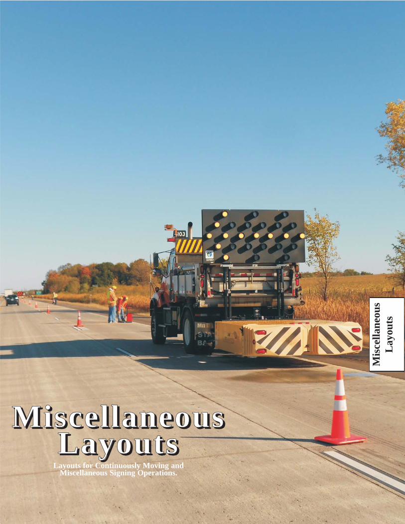
Mis
cella
neou
sL
ayou
ts
MMii ssccee ll llaanneeoouussLLaayyoouutt ss
Layouts for Continuously Moving andMiscellaneous Signing Operations.

January, 2014
These Layouts as well as the entire Field Manual, the Flagging Handbook and other documents areavailable on the Mn/DOT, Traffic Engineering website at:
http://www.dot.state.mn.us/trafficeng/
MISCELLANEOUS LAYOUTS
Miscellaneous OperationsNormally, these are continuously moving operationswhere the equipment operators remain inside/on thework vehicle.
Miscellaneous SigningThese are unusual layouts that may be used to warnmotorists of unexpected roadway operations.
67, 68
69, 70
86
71
87
88
89
90
72
LayoutNo.
Pavement Marking -
Pavement Marking -
Motor Grader - Gravel Road Maintenance
Flagging Cross-Roads and Blind Curves
Flagging Station Options
Lane Closure, Single Lane Roundabout
Left Lane Closure, 2 Lane Roundabout
Right Lane Closure, 2 Lane Roundabout
Two-Lane Roads
Multi-Lane Roads
Off Road Operation
Refer to the layouts for roadway type,volume, or speed limit restrictions.
73
75
74
76
77
78
79
LayoutNo.
Blasting
Advisory Speed Limits
Dynamic Speed Display Sign
Stopped Traffic Warning System
Surfacing Operation at Intersection
Bump
Multiple Work Spaces
Multiple Cross-Road Intersections
74
Miscellaneous ClosuresThese are specialized layouts for closures orroadway or pedestrian facilities.
82
83
84
LayoutNo.
2-Lane, 2-Way Road Closure
Undivided, Multi-Lane Road Closure
Divided, Multi-Lane Closure
Sidewalk Detour
80, 81

January, 20146K-67
15 MINUTES or LESS LAYOUT 67
STRIPING OPERATIONSTWO LANE TWO WAY ROAD
NOTES:1. All vehicles shall display two 360-degree yellow flashing
vehicle lights or strobes.2. The separation distance between the striper and the last
shadow vehicle should be determined by the track free timeof the pavement marking material.
3. Any vehicle(s) operated totally or partially in a high speedtraffic lane should be equipped with a truck mountedattenuator.
4. If tracking of the wet paint is anticipated, the use of conesor stationary “Wet Paint” signs should be considered.
ShadowVehicle
Striper
OptionalVehicle
WETPAINT W ET PA I N T
L I N E SKE EP O FF
All optional vehiclesshall have the samesigning as the striper.
WET PA I N T
W ET Y E L L OW
WET WH I T E
or
or
Selectappropriate
message
Selectappropriate
message
W ET PA I N T
L I N E SKE EP O FF
WET PA I N T
W ET Y E L L OW
WET WH I T E
or
or
FRONT FACINGSIGNS
REAR FACINGSIGNS
WETPAINT
OPTIONAL
orWET
PAINT
WET
PAINT
KEEP
OFF
KEEP
OFF
and
The Temporary Traffic ControlDistance Charts can be found on
page 6K-125

January, 2014 6K-68
15 MINUTES or LESS LAYOUT 68
STRIPING OPERATIONSTWO LANE TWO WAY ROAD - PASSING ON SHOULDER
NOTES:1. All vehicles shall display two 360-degree yellow flashing
vehicle lights or strobes.2. The separation distance between the striper and the last
shadow vehicle should be determined by the track free timeof the pavement marking material.
3. Any vehicle(s) operated totally or partially in a high speedtraffic lane should be equipped with a truck mountedattenuator.
4. If tracking of the wet paint is anticipated, the use of conesor stationary “Wet Paint” signs should be considered.
ShadowVehicle
Striper
OptionalVehicle
orWETPAINT W ET PA I N T
L I N E SKE EP O FF
All optional vehiclesshall have the samesigning as the striper.
WET PA I N T
W ET Y E L L OW
WET WH I T E
or
or
Selectappropriate
message
W ET PA I N T
L I N E SKE EP O FF
WET PA I N T
W ET Y E L L OW
WET WH I T E
or
or
FRONT FACINGSIGNS
REAR FACINGSIGNS
WETPAINT
OPTIONAL
10 footMinimum width
WET
PAINT
WET
PAINT
PASS ON
SHOULDER
PASS ON
SHOULDER
and
The Temporary Traffic ControlDistance Charts can be found on
page 6K-125

January, 20146K-69
15 MINUTES or LESS LAYOUT 69
STRIPING OPERATIONSCENTERLINE - LANE LINE - EDGELINE STRIPING
FOUR LANE UNDIVIDED ROAD
NOTES:1. All vehicles shall display two 360-degree yellow flashing
vehicle lights or strobes.2. The separation distance between the striper and the last
shadow vehicle should be determined by the track free timeof the pavement marking material.
3. Any vehicle(s) operated totally or partially in a high speedtraffic lane should be equipped with a truck mountedattenuator.
4. If tracking of the wet paint is anticipated, the use of conesor stationary “Wet Paint” signs should be considered.
5. Remove sign when operating this vehicle in the right lane.
WETPAINT
W ET PA I N T
L I N E SKE EP O FF
All optional vehiclesshall have the samesigning as the striper.
WET PA I N T
W ET Y E L L OW
or
FRONT FACINGSIGNS
REAR FACINGSIGNS
Selectappropriate
message
ShadowVehicle
Striper
OptionalVehicle
or
Selectappropriate
message
W ET PA I N T
L I N E SKE EP O FF
WET PA I N T
W ET Y E L L OW
WET WH I T E
or
or
5
LANE
CLOSED
LANE
CLOSED
NEXT
1/2 MILE
NEXT
1/2 MILE
and
The Temporary Traffic ControlDistance Charts can be found on
page 6K-125

January, 2014 6K-70
15 MINUTES or LESS LAYOUT 70
STRIPING OPERATIONSLANE LINE STRIPING - CENTER LANE OPERATIONS
MULTI-LANE DIVIDED ROAD
NOTES:1. All vehicles shall display two 360-degree yellow flashing
vehicle lights or strobes.2. The separation distance between the striper and the last
shadow vehicle should be determined by the track free timeof the pavement marking material.
3. Any vehicle(s) operated totally or partially in a high speedtraffic lane should be equipped with a truck mountedattenuator.
4. If tracking of the wet paint is anticipated, the use of conesor stationary “Wet Paint” signs should be considered.
W ET PA I N T
L I N E SKE EP O FF
All optional vehiclesshall have the samesigning as the striper.
WET PA I N T
W ET PA I N T
REAR FACINGSIGNS
W ET PA I N T
L I N E SKE EP O FF
ShadowVehicle
Striper
OptionalVehicle
or or
orLANE
CLOSED
LANE
CLOSED
NEXT
1/2 MILE
NEXT
1/2 MILE
and
The Temporary Traffic ControlDistance Charts can be found on
page 6K-125

January, 20146K-71
15 MINUTES or LESS LAYOUT 71
WORK OFF ROADWAYMOBILE OPERATIONS HAVING LITTLEOR NO INTERFERENCE WITH TRAFFIC
NOTES:1. The operations should be scheduled and completed during daylight work shifts
and have little or no interference with traffic. The work should be suspendedduring periods of poor weather or visibility.
2. All vehicles shall be equipped with a flashing vehicle light visible360-degrees around the vehicle when viewed from a distance of 60 feet.
when there is an adequateapproach decision sight distance to the equipment along the majority of theroute
3. The ROAD WORK AHEAD sign may be omitted
.4. When advance warning signs are used, the signs should be no more than
3 miles from the work vehicle. The location of the signs should be determinedby the sources of traffic, such as major cross roads.
5. On roadways where decision sight distance is restricted and the equipmentmust encroach into the traffic lane routinely, a shadow vehicle may beused as shown.
3
4
1 2
5
required for all slowmoving vehiclesoperating onpublic roadways
SEENOTE 5
SEENOTE 5
OptionalShadowVehicle
OPTIONAL
F
The Temporary Traffic ControlDistance Charts can be found on
page 6K-125

January, 2014 6K-72
15 MINUTES or LESS LAYOUT 72
GRAVEL ROAD MAINTENANCEGRADING OPERATIONSTWO LANE TWO WAY ROAD
5
NOTES:1. Grading operations should be scheduled and completed during daylight work
shifts. Work should be suspended during poor weather or visibility conditions.2. Motor Graders shall be equipped with a flashing vehicle light visible
360 degrees around the vehicle when viewed from a distance of 60 feet.3. Motor grader blade end(s) may be marked with red or orange flags to provide
additional warning and make the equipment more visible to passing vehicles.when there is an adequate
approach decision sight distance to the motor grader along the majority of theroute
4. The ROAD WORK AHEAD signs may be omitted
.5. When advance warning signs are used, the signs should be no more than
3 miles from the work vehicle. The location of the signs should be determinedby the sources of traffic, such as major cross roads.
4
4
required for all slowmoving vehiclesoperating onpublic roadways
A
The Temporary Traffic ControlDistance Charts can be found on
page 6K-125

January, 20146K-73
3 DAYS or LESS LAYOUT 73
TYPICAL BUMP SIGNING
For multi-lane dividedor one-way road only
For multi-lane dividedor one-way road only(optional on two-lane,
two way road)
For two-lanetwo-way road
For two-lanetwo-way road
XX
XX
XX
XX
XXXX
5feet
5feet
NOTES:1. When used, Advisory Speed plaques shall be installed below the
appropriate warnings.2. These devices may be omitted when the posted speed limit is
40 mph or less.
1
1
1
1
1
1
2
22
B U M P
B U M P
BUMP
The Temporary Traffic ControlDistance Charts can be found on
page 6K-125

January, 2014 6K-74
RE-SURFACING OPERATIONWORK SPACE BEFORE AND THRU INTERSECTION
MULTI-LANE DIVIDED ROAD
3 DAYS or LESS LAYOUT 74
NOTES:1. When used, Advisory Speed plaques shall be installed below
the appropriate warnings.2. Use the same advance warning signs and spacings for the other
approach to the milled roadway surface area.3. The BUMP AHEAD and Advisory Speed plaque may be omitted
when the posted speed is 40 mph or less.4. Use the appropriate advance warning sign for the roadway
condition, i.e. GROOVED PAVEMENT, LOOSE GRAVEL,ROUGH ROAD, STEEL PLATE AHEAD. A Motorcycle plaque maybe installed below the appropriate advance warning sign if the warningis directed primarily to motorcyclists.
XX
XX
RO U G HROAD
XX
RO U G HROAD
XX
RO U G HROAD
XX
ROUGHROAD
1
1
1
1
1
1
4
4
4
4
1
2
1
3
3
3
XX
B U M P
XX
B U M P
XX
BUMP
BUMP
BUMP
BUMP
BUMP
The Temporary Traffic ControlDistance Charts can be found on
page 6K-125

January, 20146K-75
BLASTING ZONE
3 DAYS or LESS LAYOUT 75
300 - 500feet
1000feet
BLASTINGZONE
1000feet
300 - 500feet
NOTES:1. Whenever electric blasting caps are used for blasting within 1000 feet of a
roadway, the signing shown shall be used. On a divided highway, the signsshould be installed on both sides of the directional roadways.
2. The signs shall be covered or removed when there are no explosives in the areaor the area is otherwise secure.
3. Any intersecting road within the 1000-foot radius of the blasting area shall besigned in a similar manner.
4. Prior to blasting, the blaster in charge shall determine whether highway trafficin the blasting zone will be endangered by the blasting operation. If there isdanger, highway traffic will not be permitted to pass through the blasting zoneduring blasting operations. See Layouts 81, 82, or 83.
1000foot
Radius
1000foot
Radius
T U R N O F F2-WAY RAD I O
A N D
C E L L P H O N E
TURNOFF2-WAYRADIO
AND
CELLPHONE
The Temporary Traffic ControlDistance Charts can be found on
page 6K-125

January, 2014 6K-76
3 DAYS or LESS LAYOUT 76
CROSSROAD & CONFIRMATION SIGNINGTRAFFIC CONTROL ZONE
NOTES:1. This layout should be used for those stationary temporary traffic
control zones that extend over a relatively long segment of roadway.2. The appropriate layout shall be used for the active work space
(such as area of paving, etc).3. Confirmation signing for a continuous condition should be placed
at approximately 1 mile spacing.4. Use the appropriate advance warning sign for the roadway condition,
i.e. GROOVED PAVEMENT, LOOSE GRAVEL, ROUGH ROADSTEEL PLATE AHEAD.A Motorcycle plaque may be installed below the appropriate advancewarning sign if the warning is directed primarily to motorcyclists.
ROAD
WORK
AHEAD
ROAD
WO R K
AH EAD
ROAD
WORK
AHEAD
ROAD
WORK
AHEAD
ROAD
WORK
AHEAD
ROAD
WORK
AHEAD
LOW LOW
SHOULDER
LOWLOW
S H O U LD ER
LOWLOW
S H O U LD ER
LOWLOW
S H O U LD ER
LOW LOW
SHOULDER
LOWLOW
S H O U LD ER
LOW LOW
SHOULDER
LOW LOW
SHOULDER
A
A
A
A
A
A
A
A
A
A
1 mileMaximum 1 mile
Maximum
4
4
4
4
4
4
4
4
The Temporary Traffic ControlDistance Charts can be found on
page 6K-125

January, 20146K-77
ADVISORY SPEED LIMITMULTI-LANE ROAD
A
A
Notes:1. Use the appropriate layout for channelizing, advance signing, and spacing.2. In long work zones, this sign assembly may be repeated before each worker
area. When used, it shall be installed less than one mile in advance of the workers.3. If used, an Advisory Speed Limit plaque shall be installed beneath the Worker
Ahead symbol sign or the appropriate advance warning sign(s).4. The advisory speed value shall not be higher than any inplace regulatory speed
limit.5. An advance warning sign with an Advisory Speed Limit plaque should not be
placed near a regulatory speed sign.6. See “ ” for more information on work zone
speed limits.Work Zone Speed Limit Guidelines
12 HOURS or LESS LAYOUT 77
XX
XX
1
3
3
2
The Temporary Traffic ControlDistance Charts can be found on
page 6K-125

January, 2014 6K-78
A/2
A/2
12 HOURS or LESS LAYOUT 78
DYNAMIC SPEED DISPLAY SIGN(YOUR SPEED SIGN)
Worker location is adjacentto an open traffic lane
NOTES:1. The advisory speed plaque and appropriate warning sign should be located near
the Dynamic Speed Display (DSD) (also known as "YOUR SPEED") sign,but may be up to a maximum of 100 feet ahead if found necessary.
2. The advisory speed plaque shall be removed when workers are not present,and the DSD sign should be removed, disabled, or re-programmed for the postedspeed limit.
3. If the DSD sign is used with a regulatory speed limit (black on white sign), thenthe "YOUR SPEED" sign on the DSD device shall also be black legend on awhite background.
4 TTC devices required to closed the traffic lane have not been shown.5. Refer to the for additional guidance on
setting Advisory Speed Limits and optimum layout distances."Work Zone Speed Limit Guidelines"
3
1
4XXM P H
XXM P H
The Temporary Traffic ControlDistance Charts can be found on
page 6K-125

This page has been intentionally left blank.
January, 2014 6K-79a
3 DAYS or LESS LAYOUT 79a & b
STOPPED TRAFFIC AHEAD WARNING SYSTEMLayout 79a
NOTES:1. The layout only shows the additional signs and devices required to setup a
Stopped Traffic System. See other Temporary Traffic Control layouts for theproper temporary traffic control devices beyond the ROAD WORK AHEADsigns.
2 . The STOPPED TRAFFIC WHEN FLASHING signs or the PCMS shouldactivate and deactivate when the downstream detector senses average trafficspeeds meeting threshold values as set by the engineer. A maximum one minuteaverage speed drop of 20 mph or more below the posted speed limit (postedprior to road work in the queue area) may typically be used for a threshold valueon high speed roadways. To deactivate the signage, the maximum one minuteaverage speed typically should recover to within 10 mph of the posted speedlimit or higher.
3. The estimated maximum queue length may be determined by engineeringanalysis or previous experience, and should be reviewed and field adjusted to fitactual traffic conditions such that the first warning device is upstream of thequeue.
4. When PCMS devices are used, the two part message should read: STOPPEDTRAFFIC - - PREPARE TO STOP and the PCMS may be used for otherappropriate messages whenever the stopped traffic message is not required.

January, 20146K-79b
3 DAYS or LESS LAYOUT 79a & b
STOPPED TRAFFIC AHEAD WARNING SYSTEMLayout 79b
3
4
4
4
4
WORK AREA andADVANCE SIGNINGas required
One milespacing
One milespacing
One milespacing
A
Detector Location for warningsign one mile upstream
Detector Location for warningsign one mile upstream
Detector Location for warningsign one mile upstream
Detector Location for warningsign one mile upstream
or
Continue spacing toextend beyond anticipated
maximum queue length
STO P P EDTRAFF I CWH E N F LA S H I N G
orSTO P P EDTRAFF I CWH E N F LA S H I N G
orSTO P P EDTRAFF I CWH E N F LA S H I N G
orSTO P P EDTRAFF I CWH E N F LA S H I N G
R OAD
WO R K
AH EAD
ROAD
WO R K
AH EAD
The Temporary Traffic ControlDistance Charts can be found on
page 6K-125

January, 2014 6K-80
3 DAYS or LESS LAYOUT 80
ROAD CLOSURE
NOTES:1. The Road Authority will determine if a detour is required and specify the
detour route.2. Road Closure Notice sign should be installed seven days in advance of the
closure.3. Install at the last driveway or intersection beyond which there is no public access.
ROADCLOS ED
3
2
A
A
A
B
ROAD CLOS ED1 0 M I L E S AH EADLOCAL TRAFF I C O N LY
ROAD CLOS ED
TH R U TRAFF I CTO
or
Use when it is 2 miles orgreater to the road closure
Minor Roador Driveway
ROAD
CLOS ED
B EG I N N I N G
XXXX XX
XXX
FE ET
The Temporary Traffic ControlDistance Charts can be found on
page 6K-125

January, 20146K-81
TEMPORARY ROAD CLOSURETWO LANE TWO WAY ROAD
15 MINUTES or LESS LAYOUT 81
50 feet
50 feet
A
A
A
A
A
A
NOTES:1. The traffic from both lanes should not be stopped for more than
15 minutes.2. Conditions represented are for work during daytime hours only.3. For night closures, the following should be used:
a. Law enforcement officers with squad car for flaggers.b. A changeable message sign in each direction.
4. The BE PREPARED TO STOP sign may be omitted when the postedspeed limit is 40 mph or less.
4
4
The Temporary Traffic ControlDistance Charts can be found on
page 6K-125

January, 2014 6K-82
TEMPORARY ROAD CLOSUREMULTI-LANE UNDIVIDED ROAD
15 MINUTES or LESS LAYOUT 82
NOTES:1. The traffic from both lanes should not be stopped for more than 15 minutes.2.
3.
4. A law enforcement officer with squad car shall be used instead of a flaggerduring night operations.
5. Advance traffic control devices for a left lane closure shall be as shown inLayouts 34 or 35.
6. The advance warning sign sequence is shown for one way direction only.The other direction shall be identical.
The BE PREPARED TO STOP sign and the flashing arrow board shall beused when the posted speed limit is 45 mph or greater.For roads with 3 or more lanes of traffic in one direction, use theappropriate stationary layout.
4
22
5 6
50 feet
AMinimum
5
2
or
The Temporary Traffic ControlDistance Charts can be found on
page 6K-125

January, 20146K-83
TEMPORARY ROAD CLOSUREMULTI-LANE DIVIDED ROAD
15 MINUTES or LESS LAYOUT 83
NOTES:1. The traffic from both lanes should not be stopped for more than 15 minutes.2.
3.
4. A law enforcement officer with squad car shall be used instead of a flaggerduring night operations.
5. Advance traffic control devices for a left lane closure shall be as shown inLayout 52.
The BE PREPARED TO STOP sign and the flashing arrow board shall beused when the posted speed limit is 45 mph or greater.For roads with 3 or more lanes of traffic in one direction, use theappropriate stationary layout.
50 feet
AMinimum
5
4
22
2
or
The Temporary Traffic ControlDistance Charts can be found on
page 6K-125

January, 2014 6K-84a
3 DAYS or LESS LAYOUT 84a & b
CROSSWALK CLOSURES AND PEDESTRIAN DETOURSLAYOUT 84a
NOTES:1. When crosswalks, sidewalks or other pedestrian facilities are blocked, closed or
relocated, temporary facilities shall include accessibility features consistent withthe features present in the existing pedestrian facility.
2. The examples show only key typical dimensions. Refer to the MnDOTTemporary Pedestrian Access Route (TPAR) website( ) for standards,guidance and options when blocking, closing, or relocating pedestrian facilities.
3. Only traffic control devices controlling pedestrian flows are shown. Otherdevices may be needed to control traffic on the streets.
4. An approved audible message device or tactile message should be providedfor sight-impaired pedestrians. When used, a message device should provide acomplete physical description of the temporary pedestrian detour includingduration, length of (and/or distance to) the by-pass, any restrictions or hazardsand project information as listed in note 5 below. The number and location ofdevices should be determined for each project prior to starting work. Devicesmay be placed prior to sidewalk work to warn regular users of the planned work.
5. Typical sign message for a temporary pedestrian detour should includeinformation such as the duration of the walkway restrictions (beginning and/orend dates) and a project contact number for 24/7 questions or reporting hazards.
6. The International Symbol of Accessibility should be displayed when anywalkway through a work zone has been determined to be TPAR compliant.The Symbol of Accessibility shall not be displayed if persons with disabilitiesshould not use the primary temporary pedestrian detour. The reason for thenon-compliance should be posted and an alternate route should be posted whenthe primary temporary pedestrian detour is non-complaint to TPAR standards.
7. Conditions that are beyond recommended standards should be documented.A walkway is non-compliant if it is missing key ADA elements such as curbramp(s), truncated domes, and detectable edging. Other restrictions or hazardsmay include insufficient width or pinch-point widths, traffic conflicts, steepgrades, non-continuous railings, tripping hazards, or uneven/rough/soft surfaceconditions, etc.
8. Pedestrian traffic signal displays controlling closed crosswalks shall be covered.
9. Pedestrian detour trailblazing signs should be used if the pedestrian detour islocated someplace other than across the street from the sidewalk closure.
http://www.dot.state.mn.us/trafficeng/workzone/tpar.html

January, 20146K-84b
3 DAYS or LESS LAYOUT 84a & b
CROSSWALK CLOSURES AND PEDESTRIAN DETOURSLAYOUT 84b
SIDEWALKCLOSED
USEOTHERSIDE
SIDEWALKCLOSED
USEOTHERSIDE
SIDEWALK
CLOSED
SIDEWALK
CLOSED
S I D EWAL K
C L O S E D
SIDEWALK
CLOSED
ES
T.
CO
MP
LE
TIO
NO
CT
20
XX
PR
OJ
EC
TC
ON
TA
CT
61
2-X
XX
-XX
X
EST.COMPLETIONOCT20XX
PROJECTCONTACT612-XXX-XXX
E N D S O CT 2 0 X X
C O N TA CT 6 1 2 -X X X-X X X46 5
ENDSOCT20XX
CONTACT61 2-XXX-XXX
4
6
5
4
4
6
6
5
5
S I D EWA L K C L O S E D
AH EAD
C RO S S H E R E
SIDEWALKCLOSED
AHEAD
CROSSHERE

January, 2014 6K-85a
3 DAYS or LESS LAYOUT 85a & b
SIDEWALK BY-PASSLAYOUT 85a
NOTES:1. When crosswalks, sidewalks or other pedestrian facilities are blocked, closed or
relocated, temporary facilities shall include accessibility features consistent withthe features present in the existing pedestrian facility.
2. The examples show only key typical dimensions. Refer to the MnDOTTemporary Pedestrian Access Route (TPAR) website( ) for standards,guidance and options when blocking, closing, or relocating pedestrian facilities.
3. Where high speeds and/or high traffic volumes are anticipated, barrier shouldbe used to separate the temporary pedestrian walkway from vehicular traffic.When used, barriers shall be installed as detailed in the MN MUTCD Part 6F.
4. Only traffic control devices controlling pedestrian flows are shown.Other devices may be needed to control traffic on the streets.
5. When both sides of a temporary pedestrian bypass require channelizingdevices, then the devices should be a similar type (railing system, barricade,or fencing system), excluding when a barrier (such as concrete barrier) isused to protect pedestrians from an open traffic lane.
6. An approved audible message device or tactile message should be provided forsight-impaired pedestrians. When used, a message device should provide acomplete physical description of the temporary pedestrian by-pass includingduration, length of (and/or distance to) the bypass, any restrictions or hazardsand project information as listed in note 7 below. The message device(s) mayalso describe an alternate route. The number and location of devices should bedetermined for each project prior to starting work. Devices may be placed priorto sidewalk work to warn regular users of the planned work.
7. Typical sign message for a temporary pedestrian bypass should includeinformation such as the duration of the walkway restrictions (beginning and/orend dates) and a project contact number for 24/7 questions or reporting hazards.
8. The International Symbol of Accessibility should be displayed when anywalkway through a work zone has been determined to be TPAR compliant.The Symbol of Accessibility shall not be displayed if persons with disabilitiesshould not enter the temporary pedestrian by-pass. An alternate route should beposted when the temporary pedestrian bypass is non-complaint to TPARstandards.
9. Conditions that are beyond recommended standards should be documented.A walkway is non-compliant if it is missing key ADA elements such as curbramp(s), truncated domes, and detectable edging. Other restrictions or hazardsmay include insufficient width or pinch-point widths, traffic conflicts, steepgrades, non-continuous railings, tripping hazards, or uneven/rough/soft surfaceconditions, etc.
10. When a sidewalk is closed but workers are present who will provide assistanceor directions to pedestrians, then the devices as shown are not required.
http://www.dot.state.mn.us/trafficeng/workzone/tpar.html

January, 20146K-85b
3 DAYS or LESS LAYOUT 85a & b
SIDEWALK BY-PASSLAYOUT 85b
MINOR ROAD
Curb & gutter or other transitionbetween roadway and sidewalk
TPAR width of 60 inches is preferred.If width is 48 inches, then at least one60 x 60 inch passing space is requiredfor every 200 feet of length.
TPAR width of 60 inches is preferred.If width is 48 inches, then at least one60 x 60 inch passing space is requiredfor every 200 feet of length.
Temporary walkway surface coveringrough, soft or uneven ground or hazards
Additional audible message devicesmay be needed for route information
Temporary curb ramp providing 12:1 (8%)slope or flatter and non-slip treatment added
Temporary curb ramp providing12:1 (8%) slope or flatter andnon-slip treatment added
Ramp landing area providing48 x 48 inch minimum area and 2% orflatter cross-slope
Ramp landing area providing a 48 x 48 inchminimum area and 2% or flatter cross-slope
A barrier with taper andattenuation (length as required)
Temporary truncated domes, optionalbased upon usage of cross-street
5 device taper 25 feet long (1 stall),recommended when the closed area wasused as an intermittent traffic lane orbypass lane.
LOW-SPEED ROADWAY
HIGH-SPEED ROADWAYor
LOW-SPEED MULTI-LANE
5
5
S I D EWALK
WO R K AH EAD
E N D S O CT 2 0 X X
C O N TA CT 6 1 2 -X X X-X X X6
78
S I D EWALK
WO R K AH EAD
E N D S O CT 2 0 X X
C O N TA CT 6 1 2 -X X X-X X X6
78

January, 2014 6K-86a
3 DAYS or LESS LAYOUT 86a & b
FLAGGING CROSSROADS AND BLIND CURVESPILOT CAR OPERATIONS
LAYOUT 86a
NOTE:1. Approach signs are the same in both directions.2. Full flagging station signing and pilot car turn-around areas shall be located
at both ends of the work area.3. When a flagger is positioned at a low volume intersection, they:
• shall have 2-way radio communications with the pilot car; and• may need additional flaggers to direct traffic when the crossroad
consistently has multiple vehicles per direction waiting each pilot car cycle.4. A flagger may be placed at a blind curve, crest of a hill or other site
obstruction where traffic might enter from other driveways or entrances towarn the pilot car that there may be oncoming traffic.When used, the flagger:• shall be located to clearly see traffic from both directions;• shall not be positioned in the open traffic lane;• shall have 2-way radio communications with the pilot car;• shall have a flagger paddle; and• should have a means to warn an errant driver such as a air horn.
5. This sign may be used in work areas where pilot car brochures have beendistributed to the local residents and businesses.
6. This sign shall be mounted on the pilot car.7. Channelizers shall be placed near intersections and flagging stations.8. Channelizers are optional with pilot car operations.9. The two-way taper should be 50 feet using 5 equally spaced channelizing
devices.
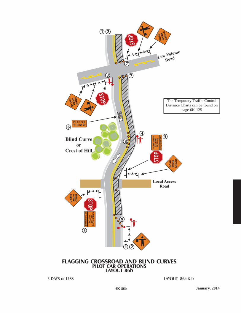
January, 20146K-86b
3 DAYS or LESS LAYOUT 86a & b
FLAGGING CROSSROAD AND BLIND CURVESPILOT CAR OPERATIONS
LAYOUT 86b
STOP
STOP
STOP
STOP
P I LO T CAR
FO L LOW M E
Low Volume
Road
Local AccessRoad
Blind Curveor
Crest of Hill
8
6
5
54
9
7
73
1 2
1 2
The Temporary Traffic ControlDistance Charts can be found on
page 6K-125

This page has been intentionally left blank.

January, 20146K-87
3 DAYS or LESS LAYOUT 87
2G
Portablerumble strips
B
NOTE:1. Approach signs are the same in both directions.2. The flagger may be equipped with an airhorn.3. The STOP/SLOW paddle may have flashing conspicuity lights on the signs.4. The Flagger Ahead sign may have flashing conspicuity lights on it.5.
The centerline channelizers are optional with pilot car operations.8. The portable rumble strips shall be spaced according to the manufacturer’s
recommendations or typical 4 foot on center.
Type A channelizing devices such as weighted channelizers, cones, tubularmarkers, or centerline delineators.
6. The two-way taper should be 50 feet using 5 equally spaced channelizingdevices.
7.
6
7
FLAGGING STATION OPTIONSTWO-LANE TWO-WAY ROAD
50 feet
or
G12 x 18inches
OPTIONAL
5
OPTIONAL
2 3
OPTIONAL
OPTIONAL
4
1
The Temporary Traffic ControlDistance Charts can be found on
page 6K-125

January, 2014 6K-88a
3 DAYS or LESS LAYOUT 88a & b
LANE CLOSURE IN ROUNDABOUTSINGLE LANE ROUNDABOUT
LAYOUT 88a
NOTES:
1.
The two-way taper should be 50 feet using 5 equally spaced channelizing
devices.
Each roundabout is unique and the traffic control shall be developed to
meet the specific conditions of the location and the work operation.
A detour could better serve traffic movement and shall be considered as an
alternative to the flagger operation.
2. Flagging operations may not be necessary when working on the shoulders
or in the island of the roundabout. If a driving lane(s) width of at least
10 feet (or more) can be maintained while shoulder work on an approach
is being conducted, the driving lane(s) may remain open to traffic.
3. Approach signs are the same in all directions.
4. Flaggers shall control traffic flow on all approaches of the one-lane
roundabout.
5. A lead flagger shall be designated and radio communication shall be used
by the flaggers.
6. Only one approach of traffic shall be released at a time.
7. At night, flagger stations shall be illuminated. Street lights and vehicle
headlights shall not be used to illuminate the flagger station.
8. Type B channelizers may be used.
9. A PCMS sign should be considered as part of this operation to provide
clear guidance to motorists on all approaches of the roundabout, especially
approaches that must reverse traffic flow.
10.

January, 20146K-88b
3 DAYS or LESS LAYOUT 88a & b
LANE CLOSURE IN ROUNDABOUTSINGLE LANE ROUNDABOUT
LAYOUT 88b
G
��������������������������������������������������������������������������������������������������������������������������������������������������������������������������������������������������������������������������������������������������������������������������������������������������������������������������������������������������������������������������������������������������������������������������������������������������������������������������������������������������������������������������������������������������������������������������������������������������������������������������������������������������������������������
variable
3
3
10
10
10
10
10
10 10
3
OPTIONAL
ON E LANE
R OAD
AH EAD
The Temporary Traffic ControlDistance Charts can be found on
page 6K-125

This page has been intentionally left blank.

January, 20146K-89
3 DAYS or LESS LAYOUT 89
LEFT LANE CLOSURE IN ROUNDABOUTTWO LANE ROUNDABOUT
or
or
variable
G
25 feet
2
3 3
3
3
5
OPTIONAL
��������������������������������������������������������������������������������������������������������������������������������������������������������������������������������������������������������������������������������������������������������������������������������������������������������������������������������������������������������������������������������������������������������������������������������������������������������������������������������������������������������������������������������������������������������������������������������������������������������������������������������������������������������������������������������������������������������������������������������������������������������������������������������������������������������������������������������������������������������������������������������������������������������������������������������������������������������������������������������������������������������������������������� � � � � � � � � � � � � � � � �
2
2
NOTES:1. Each roundabout is unique and the traffic control shall be developed to
meet the specific conditions of the location and the work operation.A detour could better serve traffic movement and shall be considered as analternative to the flagger operation.
2. Approach signs are the same in all directions.3. On divided highways having a median wider than 8 feet, right and left
sign assemblies shall be required.4. Type B channelizers may be used.5. The flashing arrow board shall be used when the posted speed limit is
45 mph or greater.
4
The Temporary Traffic ControlDistance Charts can be found on
page 6K-125

January, 2014 6K-90
3 DAYS or LESS LAYOUT 90
RIGHT LANE CLOSURE IN ROUNDABOUTTWO LANE ROUNDABOUT
��������������������������������������������������������������������������������������������������������������������������������������������������������������������������������������������������������������������������������������������������������������������������������������������������������������������������������������������������������������������������������������������������������������������������������������������������������������������������������������������������������������������������������������������������������������������������������������������������������������������������������������������������������������������������������������������������������������������������������������������������������������������������������������������������������������������������������������������������������������������������������������������������������������������������������������������������������������������������������������������������������������������������� � � � � � � � � � � � � � � � �
����
���
����
���
����
���
or
or
variable
100feet
G
2
66
6
6
2
3 3
4
3
3
5
OPTIONAL
OPTIONAL
2
NOTES:1. Each roundabout is unique and the traffic control shall be developed to
meet the specific conditions of the location and the work operation.A detour could better serve traffic movement and shall be considered as analternative to the flagger operation.
2. Approach signs and devices are the same in all directions.3. On divided highways having a median wider than 8 feet, right and left
sign assemblies shall be required.4. Type B channelizers may be used.5. The flashing arrow board shall be used when the posted speed limit is
45 mph or greater.6. The distance between channelizing devices should be 10 feet or adjusted
for local conditions.
The Temporary Traffic ControlDistance Charts can be found on
page 6K-125

Qua
lity
Stan
dard
s
QQuuaall ii ttyySSttaannddaarrddss
Methods to determine whether the various trafficcontrol devices are Acceptable, Marginal, or
Unacceptable.

January, 2014
ContentsPage
Introduction . . . . . . . . . . . . . . . . . . . . . . . . . . . . . . . . . . . . . . . . . . . . . . . . . . . . . . . . . . . . .6K-91Quality Classification & Requirements of Devices . . . . . . . . . . . . . . . . . . . . . . . . . . . . . .6K-93Evaluation Guide - Warning Signs . . . . . . . . . . . . . . . . . . . . . . . . . . . . . . . . . . . . . . . . . . .6K-95Evaluation Guide - Type A and B Channelizers . . . . . . . . . . . . . . . . . . . . . . . . . . . . . . . . .6K-98Evaluation Guide - Type I, II or III Barricade Panels or Vertical Panels . . . . . . . . . . . .6K-100Evaluation Guide - Warning Lights . . . . . . . . . . . . . . . . . . . . . . . . . . . . . . . . . . . . . . . . .6K-101Evaluation Guide - Arrow Boards . . . . . . . . . . . . . . . . . . . . . . . . . . . . . . . . . . . . . . . . . .6K-102Evaluation Guide - Portable Changeable Message Signs . . . . . . . . . . . . . . . . . . . . . . . .6K-105Evaluation Guide - Trailer-Mounted Electronic TCDs . . . . . . . . . . . . . . . . . . . . . . . . . .6K-106
These Layouts as well as the entire Field Manual, the Flagging Handbook and other documents areavailable on the Mn/DOT, Traffic Engineering website at:
http://www.dot.state.mn.us/trafficeng/

January, 20146K-91
INTRODUCTION
Traffic controls are a necessary part of a Temporary Traffic Control Zone to warn motorists ofhazards, advise them of the proper path through the zone, delineate areas where they may notoperate, and to separate them from the workers. This is accomplished by the deployment of asystem of devices. The success of this system depends on the visibility of each device at the timeof a project's initial installation as well as throughout the life of the project. Since it is notpractical to require new devices at all times, standards are needed to evaluate the condition of thedevices to assure their continued effectiveness. The standards in this publication should aid in thedetermination of the quality of temporary traffic control devices.
The use of temporary traffic control zone devices subjects them to wear which does not occurwith permanent devices. Although errant vehicles cause much of the damage to the devices, theyalso deteriorate in appearance from wear occurred during their storage, shipment, installation,relocation, and removal. Whenever a high number of these worn and damaged devices appear onthe same project, the general appearance of the Temporary Traffic Control Zone deteriorates,reducing the level of safety provided to the workers, pedestrians, and traveling public.
These standards have been developed in an effort to offset the deterioration in the appearanceof Temporary Traffic Control Zone devices. A determination of the condition of device qualityshould be made at several stages: while in storage, during preparation for delivery to theTemporary Traffic Control Zone, during initial set up and periodically during the course of thework. Suppliers and contractors are encouraged to apply this standard prior to delivery of devicesto the jobsite. Doing so will minimize agency involvement and reduce costs related to on-sitereplacement.
These standards are intended to address the day-to-day operations of traffic control within aTemporary Traffic Control Zone and are not meant to cover the needs of emergency situations.

January, 2014
The Temporary Traffic ControlDistance Charts can be found on
page 6K-125
6K-92
This page has been intentionally left blank.

January, 20146K-93
QUALITY CLASSIFICATIONS AND REQUIREMENTS
The quality of the Temporary Traffic Control Zone devices in this standard has been dividedinto three classifications: acceptable, marginal, and unacceptable. Acceptable devices meet theall MN MUTCD requirements such as design, size, color, weight, etc., and are properly placedas specified, and clearly perform their intended function. The term "Marginal" for the purpose ofthis manual means "marginally acceptable", reaching the lower end of acceptability. Devices thatfall into the “unacceptable” classification shall not be delivered to the jobsite.
The required minimum percentage of acceptable devices has been established for each type ofdevice and varies upon the duration of the Temporary Traffic Control Zone.
Intermediate and Long Term Duration
Within each Temporary Traffic Control Zone that is planned to remain inplace for more thantwelve (12) hours, the following requirements shall be followed:
At the time of the initial set up or at the time of major stage changes, one hundred percent(100%) of each type of device (channelizers, barricades, signs, warning lights, arrow panelsportable changeable message signs, pavement tape and raised pavement markers) shall beclassified as "acceptable".
Throughout the duration of the project, the number of acceptable devices may decrease toseventy-five percent (75%) of the initial quantity of each particular device, as a result ofdamage and/or deterioration during the course of the work with the remainder of the devicesin the “marginal” category.
Devices in the marginal category may remain in the Temporary Traffic Control Zone untiltheir total number exceeds the twenty-five percent (25%) maximum for that type of device,which is considered an “unacceptable“ situation. Should the percentage of devices in themarginal category exceed twenty-five percent (25%), all marginal devices shall be replacedso as to bring the group of devices back up to acceptable standards.
All devices categorized as unacceptable shall be replaced within twelve (12) hours ofnotification.
Missing or knocked down devices should be replaced or re-set in a timely manner.

January, 2014 6K-94
Short Term DurationWithin Temporary Traffic Control Zones that are planned to be inplace for less than twelve (12)
hours, the following requirements may be followed:
At the time of the initial set up, one hundred percent (100%) of all TTC devices except channelizing devices and barricades shall be classified as "acceptable". During the short term duration of the project, the intermediate and long term duration standards shall be maintained for these devices.
At the time of the initial set up, a minimum of seventy-five percent (75%) of each type of channelizer and barricade shall be classified as "acceptable". Up to a maximum of twenty-five percent (25%) of these devices may be classified as "marginal". “Unacceptable” devices shall not be installed.
During the short term duration of the project, the number of marginal devices may increase beyond the twenty-five percent (25%) of the initial quantity, as a result of damage and/or deterioration during the course of the work.
Missing or knocked down devices should be replaced or re-set in a timely manner.
The following descriptions, together with the accompanying photographs, should be used todetermine if the device is acceptable, marginal or unacceptable.
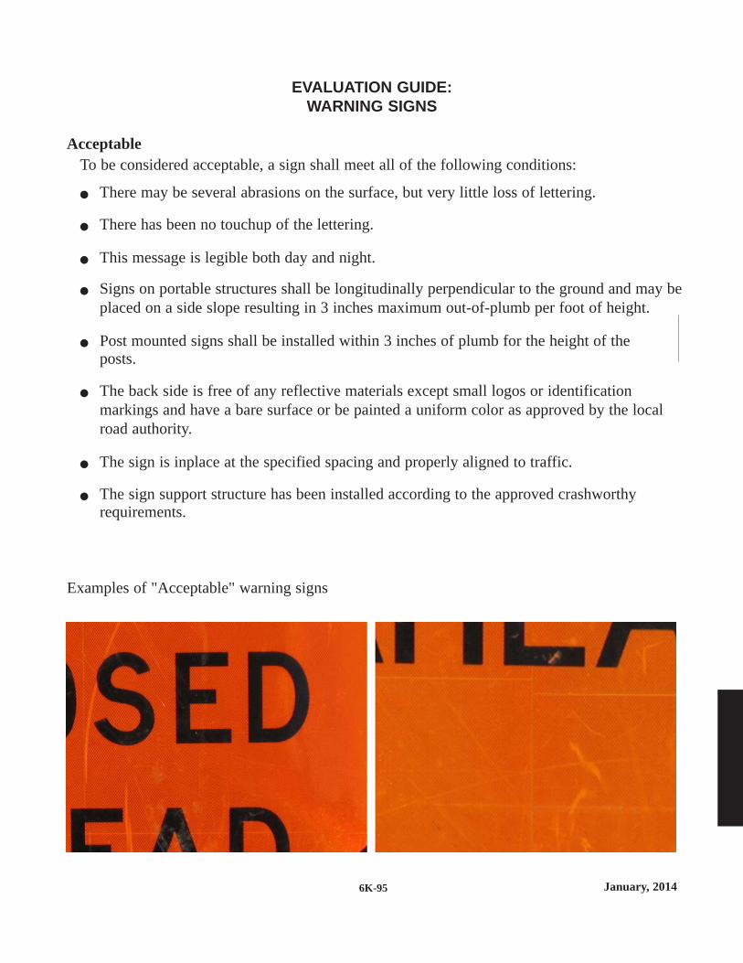
January, 20146K-95
EVALUATION GUIDE:WARNING SIGNS
AcceptableTo be considered acceptable, a sign shall meet all of the following conditions:
There may be several abrasions on the surface, but very little loss of lettering.
There has been no touchup of the lettering.
This message is legible both day and night.
Signs on portable structures shall be longitudinally perpendicular to the ground and may be placed on a side slope resulting in 3 inches maximum out-of-plumb per foot of height.
Post mounted signs shall be installed within 3 inches of plumb for the height of theposts.
The back side is free of any reflective materials except small logos or identification markings and have a bare surface or be painted a uniform color as approved by the local road authority.
The sign is inplace at the specified spacing and properly aligned to traffic.
The sign support structure has been installed according to the approved crashworthy requirements.
Examples of "Acceptable" warning signs

January, 2014 6K-96
EVALUATION GUIDE:WARNING SIGNS
MarginalThe sign is considered marginal, if it meets any of the following conditions:
There are many surface abrasions throughout the sign face, and only a few are within the individual letters of the message.
The sign face is free of any residue.
Some color fading may be evident, but the background color and retroreflectivity are still apparent at night.
This message is legible both day and night.
Signs on portable structures are longitudinally perpendicular to the ground and the side slope results is no more than 3 inches out-of-plumb per foot of height.
Post mounted signs shall be within 3 inches of plumb for the height of the posts.
All warning signs are inplace at the specified spacing and properly aligned to traffic.
Examples of "Marginal" warning signs

January, 20146K-97
EVALUATION GUIDE:WARNING SIGNS
Unacceptable
A sign is considered unacceptable if it meets any of the following conditions: Asphalt splatter, cement slurry, other residue, or abrasions that are evident throughout the
face of this sign.
Portions of letters are missing such that they become confusing to identify.
The message is illegible.
There is noticeable color fading or loss of retroreflectivity at night.
The sign face is not perpendicular to the roadway.
iPost-mounted signs are installed more that 3 inches out-of-plumb for the entire height ofthe assembly.
Signs on portable structures are more than 3 inches out-of-plumb for the entire height ofthe assembly.
Signs are damaged or defaced in a way that they no longer have the same shape as a newsign.
Examples of "Unacceptable" warning signs
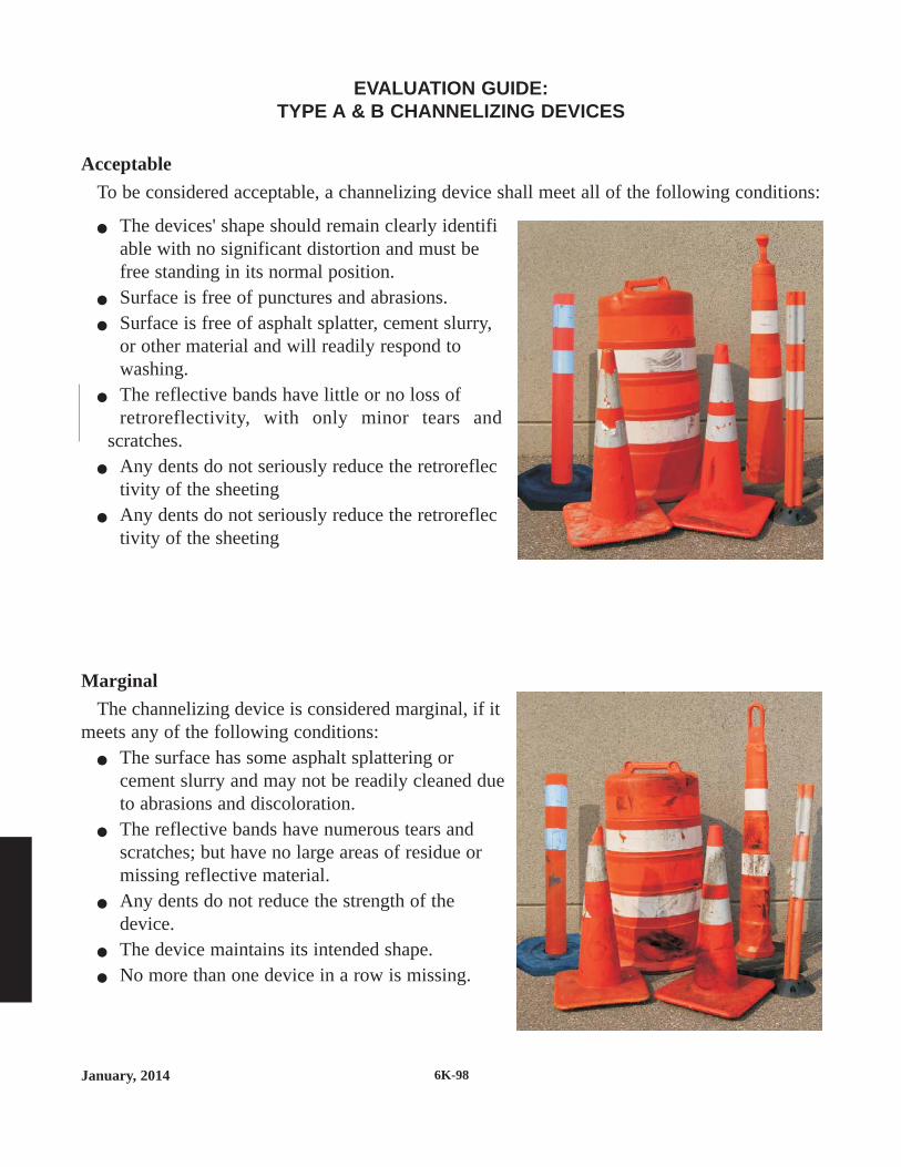
January, 2014 6K-98
EVALUATION GUIDE:TYPE A & B CHANNELIZING DEVICES
AcceptableTo be considered acceptable, a channelizing device shall meet all of the following conditions:
The devices' shape should remain clearly identifiable with no significant distortion and must be free standing in its normal position.
Surface is free of punctures and abrasions. Surface is free of asphalt splatter, cement slurry,
or other material and will readily respond to washing.
The reflective bands have little or no loss of retroreflectivity, with only minor tears and
scratches. Any dents do not seriously reduce the retroreflec
tivity of the sheeting Any dents do not seriously reduce the retroreflec
tivity of the sheeting
MarginalThe channelizing device is considered marginal, if it
meets any of the following conditions: The surface has some asphalt splattering or
cement slurry and may not be readily cleaned due to abrasions and discoloration.
The reflective bands have numerous tears and scratches; but have no large areas of residue or missing reflective material.
Any dents do not reduce the strength of the device.
The device maintains its intended shape. No more than one device in a row is missing.
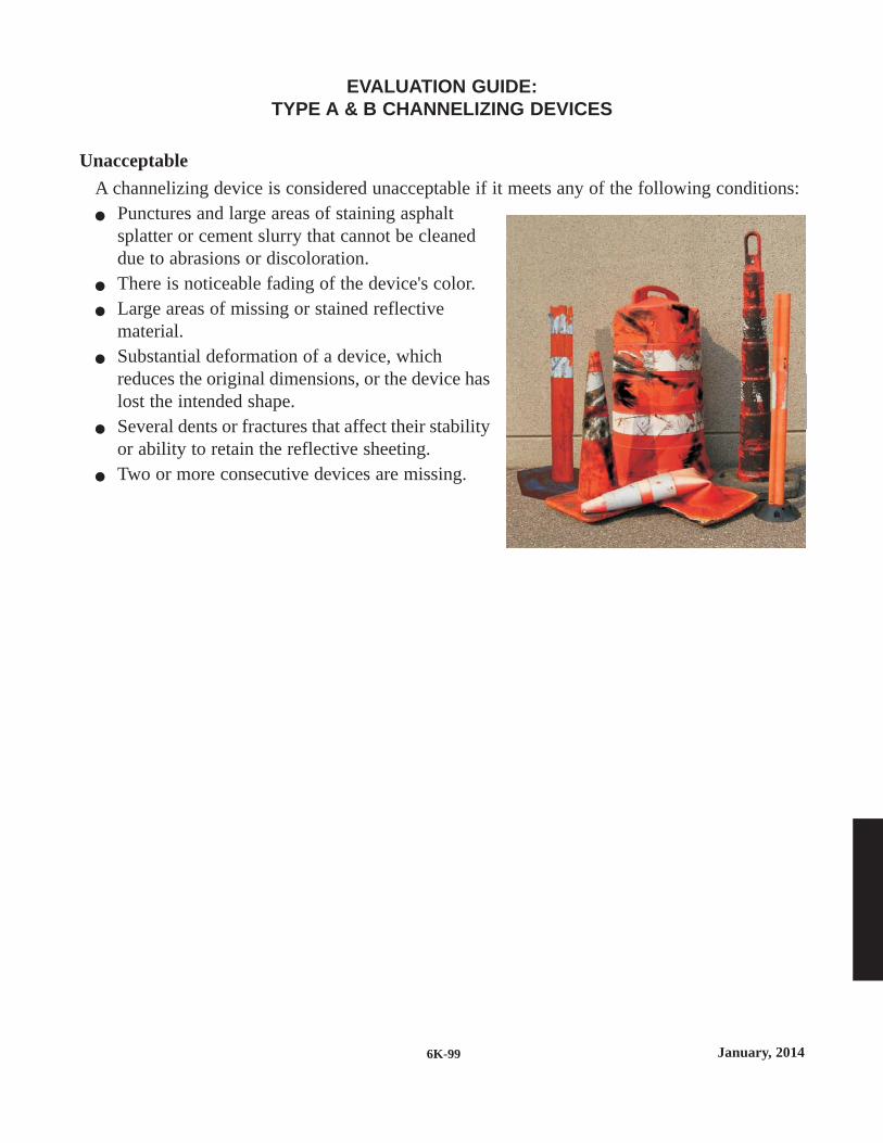
January, 20146K-99
EVALUATION GUIDE:TYPE A & B CHANNELIZING DEVICES
UnacceptableA channelizing device is considered unacceptable if it meets any of the following conditions: Punctures and large areas of staining asphalt
splatter or cement slurry that cannot be cleaned due to abrasions or discoloration.
There is noticeable fading of the device's color. Large areas of missing or stained reflective
material. Substantial deformation of a device, which
reduces the original dimensions, or the device haslost the intended shape.
Several dents or fractures that affect their stabilityor ability to retain the reflective sheeting.
Two or more consecutive devices are missing.

January, 2014 6K-100
EVALUATION GUIDE:TYPE I, II OR III BARRICADE PANELS
OR VERTICAL PANELS
AcceptableTo be acceptable, the panel shall meet all of the following conditions: Panels are not deformed to an extent so as to decrease the
panels target value. There may be several abrasions on the surface but very
little loss of reflective sheeting. The orange is vivid and the stripes provide contrast. The barricade is installed in its specified location with
adequate ballast, and properly aligned to traffic. The Type III barricade has been fabricated according to the approved crashworthy
requirements.
MarginalThe panel is considered marginal, if it meets any of the following conditions: There are numerous surface abrasions through the panel
surface. Some color fading is evident; however, it has no large
areas of residue or missing reflective material. The orange is vivid and the stripes provide contrast. The barricade is turned at a skew to traffic that reduces
it's effectiveness.
UnacceptableA panel is considered unacceptable if it meets any of the following conditions: The surface is marred over a high percentage of the panel
area. There is a noticeable loss of reflectivity and obvious
color fading. Panels with asphalt splatter and/or cement slurry, or any
combination of missing and covered reflective materialwould make the panel unacceptable.
Barricades have bent or twisted legs, or deformation of the support assembly to the extent that the barricade panel is not reasonably parallel to the roadway surface.
The barricade is missing, knocked down, or turned away from traffic.

January, 20146K-101
EVALUATION GUIDE:WARNING LIGHTS
AcceptableTo be acceptable, the warning lights shall meet all of the following conditions: One hundred percent (100%) of all warning lights shall be operating properly. Any warning
light that is out of alignment from the intended driver's line of vision is considered not operating properly.
Type A Low-Intensity Flashing warning lights and Type C Steady-Burn warning lights shallbe maintained so as to be capable of being visible on a clear night from a distance of 3000feet.
Type B High-Intensity Flashing warning lights shall be maintained so as to be capable of being visible on a sunny day when viewed without the sun directly on or behind the device from a distance of 1000 feet.
Warning lights shall have a minimum mounting height of 30 inches to the bottom ofthe lens.
MarginalThe warning light is marginal, when it meets any of the following conditions: Type A and C warning lights - at least ninety percent (90%) of the warning lights shall be
operating properly with no more than three (3) adjacent lights failing, or
Type B warning lights - one (1) light failing. Unacceptable
A warning light is considered unacceptable if it meets any of the following conditions: Type A and C warning lights - less than ninety percent (90%) of the warning lights operating
properly, or more than three (3) adjacent lights failing, or
Type B warning lights - more than one (1) light failing.

January, 2014 6K-102
EVALUATION GUIDE:ARROW BOARDS
Acceptable conditions for all arrow boardsFor an arrow board to be acceptable, it must meet all of the following conditions: All lamps are properly aligned for the intended driver's line of vision. Any operating lamp
which is out of alignment shall be considered not functioning properly.
No lamps are burnt out.
All lamps dim properly.
All lamps are the same level of intensity.
Unacceptable conditions only for truck or trailer-mounted arrow boardsAn arrow board is considered unacceptable if it meets any of the following conditions: The arrow board is not within 3 inches of plumb for the height of the board,
The trailer-mounted arrow board is not raised to at least 7 feet above the roadway surface(measured to the bottom of the board), or
The truck-mounted arrow panel is mounted less than 6 feet above the roadway surface(measured to the bottom of the panel) unless the road authority determines the height is ashigh as practical..
FLASHING ARROW MODE andSEQUENTIAL ARROW MODE
MarginalAn arrow board in this mode is marginal, when it meets the following condition: Up to two (2) lamps out in the stem and no lamps out in the head.
UnacceptableAn arrow board in this mode is considered unacceptable if it meets any of the following
conditions: Any lamp out in the head,
More than two (2) lamps out in the stem, or
The arrow message is not visible at 1000 feet.

January, 20146K-103
EVALUATION GUIDE:ARROW BOARDS
CHEVRON MODE
MarginalAn arrow board in this mode is marginal, when it meets the following condition: No more than one (1) lamp out in any one chevron segment.
UnacceptableAn arrow board in this mode is considered unacceptable if it meets any of the following
conditions: Two (2) or more lamps out in any one chevron
The arrow message is not visible at 1000 feet.
CAUTION MODE (Bar, 4 Corners, or Alternating Diamonds)
MarginalAn arrow board in this mode is marginal, when it meets the following condition: At least four (4) lamps functioning properly (on the Bar or 4 Corners), or
At least seven (7) lamps functioning properly in each diamond shape (on the AlternatingDiamonds).
UnacceptableAn arrow board in this mode is considered unacceptable if it meets any of the following
conditions: Less than four (4) lamps functioning properly (on the Bar or 4 Corners), or less than seven
(7) lamps functioning properly in either of the 2 diamond shapes (on the AlternatingDiamonds), or
The arrow message is not visible at 1000 feet.
or or

January, 2014 6K-104
EVALUATION GUIDE:ARROW BOARDS
DOUBLE ARROW MODE
MarginalAn arrow board in this mode is marginal, when it meets the following condition: Two (2) lamps out in the stem and both heads completely functional with no lamps out.
UnacceptableAn arrow board in this mode is considered unacceptable if it meets any of the following
conditions: More than two (2) lamps out in the stem,
One (1) lamp out in the head, or
The arrow message is not visible at 1000 feet.

January, 20146K-105
EVALUATION GUIDE:PORTABLE CHANGEABLE MESSAGE SIGNS (PCMS)
Acceptable To be acceptable, a PCMS shall meet the following condition: One hundred percent (100%) of the pixels per character module shall be operating properly.
Marginal A PCMS is marginal, when it meets the following condition: At least ninety percent (90%) of the pixels per character module shall be operating properly.
Unacceptable for all PCMSsA PCMS is considered unacceptable if it meets any of the following conditions: Less than ninety percent (90%) of the pixels per character module are operating properly,
or.
The PCMS is not properly aligned for the intended driver’s line of vision.
Unacceptable for Trailer-Mounted PCMSA trailer-mounted PCMS is considered unacceptable if it meets any of the following
conditions: The sign panel is more than 3 inches out of plumb, or
The sign panel is raised less than 5 feet above the roadway surface on rural roadways or lessthan 7 feet on urban toadways (measured to the bottom of the board).

6K-106January, 2014
EVALUATION GUIDE:TRAILER-MOUNTED ELECTRONIC TRAFFIC CONTROL DEVICES
This includes devices such as Automated Flagges Assistance Debices (AFADs), Portable TrafficSignals, and Dynamic Speed Display Signs:Acceptable
For an electronic traffic control device to be acceptable, shall meet the following conditions: The device shall be operating correctly for its intended usage within allowable tolerances
and with all fail-safes properly functioning. All lamps, LED displays and signs are properly aligned for the intended driver's line of
vision. Any operating lamp, LED display or sign which is out of alignment shall beconsidered not functioning properly.
One hundred percent (100%) of the LED pixels per character module are operatingproperly.
One hundred percent (100%) of the lamps are operational.. All lamps and LED displays dim properly. The signs meet or exceed the quality standards for acceptable "Warning Signs". The device's leveling stands shall be adjusted to properly plumb the device. The bottom of any overhead signal head shall be between 17 and 19 feet above the roadway
surface.Marginal
An electronic traffic control device when it meets any of the following conditions: At least ninety percent (90%) of the LED pixels per character module are operating
properly. The signs meet the quality standards for marginl “Warning Signs”.
Unacceptable
An electronic traffic control device is considered unacceptable if it meets any of the followingconditions:
The device is malfunctioning for any of its intended functions including but not limited tosignal operations, radio communications, detection, or message display,
Any of the lamps are bumned out, Less than ninety percent (90%) of the LED pixels per character module are operating
properly, The device is not properly aligned for the intended driver's line of vision, The lamps and LED displays are not dimming properly, The device is not within 3 inches of plumb for the height of the device (excluding an
overhead signal head mast), or The bottom of any overhead signal head is lower than 17 feet or higher than 19 feet above
the roadway surface.

January, 2014
MINNESOTA
FLAGGING
HANDBOOK
Qua
lity
Stan
dard
s

January, 2014 6K-108
These Layouts as well as the entire Field Manual, the Flagging Handbook and other documents areavailable on the Mn/DOT, Traffic Engineering website at:
http://www.dot.state.mn.us/trafficeng/
This Flagger Handbook has been developed following the guidelines of the 2005 edition of theMinnesota Manual on Uniform Traffic Control Devices, including its latest update.
According to Minnesota Statute 169.06, Subd. 4(e), a flagger is permitted to stop and hold trafficas necessary to ensure the safety of highway workers and the motoring public.

January, 20146K-109
INTRODUCTIONTo You, the Flagger:REMEMBER - Your job is the most important one on the crew. The lives of all individuals in thework space depend on YOU!
The following information is designed to give you some basic guidelines regarding flaggingoperations. Familiarize yourself with these procedures. If you have any questions or concerns,don't hesitate to ask your supervisor.
For your personal safety as a flagger NEVER turn your back on or stand in the path of movingtraffic.
EQUIPMENTClothing
All clothing shall be in accordance with current Minnesota OSHA Rules and your agency'spolicies.
• Vest, shirt, or jacket and pants (when required) shall be orange, yellow, strong yellow-greenor a fluorescent version of these colors.
• At night and in low visibility situations, the vest, shirt or jacket and pants shall be retrore-flective.
• Pants shall be worn at night and in low visibility situations.• A hat in the above colors is also recommended.• Neat appearance
Retroreflective clothingRetroreflective clothing shall:
• Be visible at a minimum distance of 1000 feet.• Identify the wearer as a person through the full range of body motions.
Tools• Standard STOP/SLOW paddle
- 18 x 18 inch minimum octagon - 5 foot minimum staff (to the bottom of the sign). 7 foot is recommended- Fully reflectorized in standard colors
• Two-way radios for two flagger situations• Floodlights and Flashlight with wand, if flagging at night.
FLAGGING POSITION• Be alert, remain standing at all times• Face oncoming traffic - NEVER turn your back to oncoming traffic or stand in the path
of moving traffic. See Figure 1.• A flagger’s normal station is on the shoulder of the road.• Park your vehicle off the road, away from your station.• Stand alone, do not mingle with the work crew or the public.• Make sure you are visible to oncoming traffic, not standing where the sun is impeding
visibility or in a shadow.• Stand in a location that allows approaching traffic adequate time to respond. Use the Decision
Sight Distance in the following chart to determine a good visibility location. The driver mustbe able to recognize you as a flagger for at least the Decision Sight Distance.

January, 2014 6K-110
FLAGGING SITUATIONSPrior to the start of flagging operations, all signing shall be inplace. A good visibility location
is one where the sight distance is sufficient and the flagger is clearly visible to approachingmotorists.
When the temporary traffic control zone covers a long segment of highway, additional flaggersigns may be needed. In high speed areas, the maximum distance from the last sign to a pointwhere the driver detects the flagger shall not exceed 1 mile.
When more than one flagger is being used, all communication procedures should be clearbefore any flagging begins. If there is a major intersection within the closed area, an additionalflagger may be needed to control traffic entering the temporary traffic control zone from themajor intersection.
Decision Sight Distance
Posted Speed(mph)
Decision SightDistance
(feet)
0 - 30
35 - 40
45 - 50
55
60 - 65
70 - 75
550
700
900
1200
1400
1600
Figure 1Preferred Flagging Position
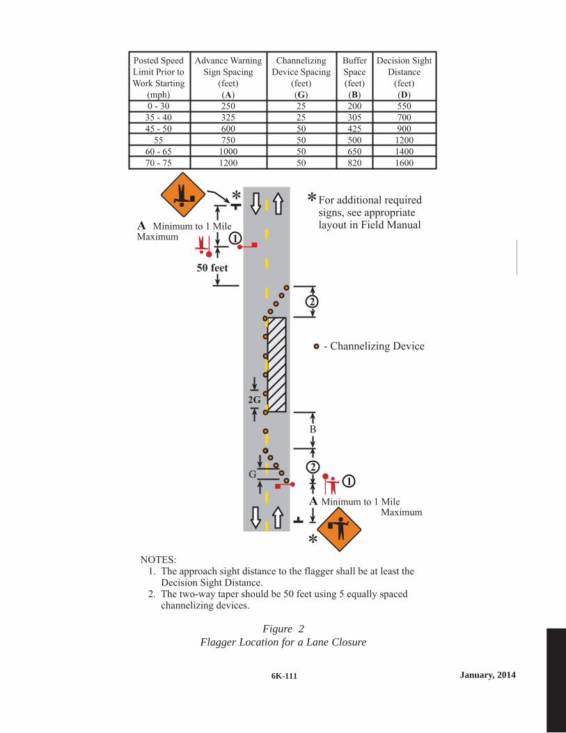
January, 20146K-111
For additional requiredsigns, see appropriatelayout in Field Manual
50 feet
**
*
- Channelizing Device
Posted Speed
Limit Prior to
Work Starting
(mph)
0 - 30
35 - 40
45 - 50
55
60 - 65
70 - 75
Advance Warning
Sign Spacing
(feet)
( )
250
325
600
750
1000
1200
A
Channelizing
Device Spacing
(feet)
( )
25
25
50
50
50
50
G
Buffer
Space
(feet)
( )
200
305
425
500
650
820
B
Decision Sight
Distance
(feet)
( )
550
700
900
1200
1400
1600
D
NOTES:1. The approach sight distance to the flagger shall be at least the
Decision Sight Distance.2. The two-way taper should be 50 feet using 5 equally spaced
channelizing devices.
2
1
1
2
2G
A Minimum to 1 MileMaximum
A Minimum to 1 MileMaximum
Figure 2Flagger Location for a Lane Closure

January, 2014 6K-112
Traffic backing up over long distances due to flagging operations may cause potentiallydangerous situations. These situations may include traffic backing up through an intersection, upan exit ramp onto the freeway, or stopping prior to the first warning signs. When the flaggerobserves this type of situation occurring, they should notify their immediate supervisor. Toreduce traffic backups, the flagger may be given instructions on how to help maintain a shorterbackup of vehicles.Single Flagger
There are two different applications of the single flagger situation.1. On a intermediate volume road (less than 1500 ADT) with good visibility, a single flagger
may be used to control one direction of traffic while the other direction flows free. In thissituation, the flagger is positioned in the closed lane at the beginning of the taper. The flaggerstops the traffic approaching in the closed lane. When the open lane is clear, the flagger allowstraffic to proceed. If the Decision Sight Distance is not available beyond the work space forthe flagger to detect oncoming traffic, two flaggers shall be used. Two flaggers may also berequired during high peak traffic periods or if there is a major intersection near the activityarea.
2. A single flagger may also be used to stop traffic in a lane while that lane is closed. Anexample would be a truck depositing material off the edge of the roadway. In this situation,the flagger would stop the traffic in this lane while the other lane flows free. When the laneis open again, the flagger allows the traffic to proceed in their normal lane. After stoppedtraffic is allowed to proceed, the flagger should turn the flagger paddle parallel to traffic sothat no message is displayed to either direction of traffic.
Two FlaggersWhen two flaggers are required, lines of communication must be established prior to the start
of flagging operations. The two flaggers must be able to see each other or have two-way radiosdesignated for proper communication. One flagger should be the lead flagger and coordinate allactivities.
Figure 3Two Flagger Operation

January, 20146K-113
When two flaggers are used and two-way radios are unavailable, the flag transfer method maybe used. The driver of the last vehicle proceeding into the one lane section is given a flag (or othertoken object) and instructed to deliver it to the flagger at the other end. The opposite flagger thenknows that it is safe to allow traffic to move in the other direction. The flag (or token object)being carried should always be clean and dry.
Two flaggers may also be used in conjunction with a pilot car. In this situation, the flagger stopsthe traffic until the pilot car arrives and has pulled into position to lead the traffic through oraround the activity area. The flagger then releases traffic to follow the pilot. When a large gapin traffic or a pre-determined length of time occurs, as instructed by the supervisor, traffic isstopped. During pilot car operations, traffic should follow the pilot car and remain in a tightgroup to prevent traffic from separating along the route. To help keep the traffic group tight,flaggers should not allow additional cars to follow the group if last car in the group has proceededmore than 300 feet from the flagging location. The flagger shall then stop and hold all traffic untilthe pilot car has returned for the next trip.
Advance FlaggerAn advance flagger may be used where there is limited sight distance to the activity area or
where long lines of traffic form. In a situation such as limited sight distance, the advance flaggershould stop each vehicle and inform the driver of the situation ahead. Where there are long linesof stopped traffic waiting to proceed, the advance flagger should move down the line and informeach driver of the reason for the delay and the approximate length of the delay.
Figure 4Use of a Pilot Vehicle

January, 2014 6K-114
FLAGGING PROCEDURESTo Stop Traffic
Stand on the shoulder of the road, away from moving traffic. Face traffic and extend the STOPpaddle in a stationary position with the arm extended horizontally away from the body. The freearm should be raised with the palm toward approaching traffic. Look directly at the approachingdriver. Make sure that you make direct eye contact with this driver!
Remain on the shoulder of the road after the first vehicle has stopped. Always make certain thatthe flagger and the paddle are visible to the drivers of all stopped vehicles. The flagger shouldnever stand in the traffic lane unless, in the flagger's opinion, the drivers of the stopped vehiclesare unaware of the flagger's presence. If it is necessary for the flagger to stand in the traffic lane,the flagger may only stand near the centerline and never cross it. When the flagger is satisfiedthat the drivers of all stopped vehicles are aware of his/her presence, the flagger should return tothe shoulder of the road.
NOTE: Anytime the flagger is required to take a position near the centerline of the traffic lane,the flagger should remain aware of the traffic traveling in the opposite direction.To Direct Stopped Traffic to Proceed
Remain at the flagger station on the shoulder. If the flagger is in the stopped traffic lane, returnto the shoulder. Face traffic and turn the SLOW paddle to face traffic. Hold the SLOW paddle ina stationary position with the arm extended horizontally away from the body. The flagger maymotion with the free hand for traffic to proceed. Do not wave the paddle.To Alert or Slow Traffic
Stand on the shoulder of the road and face traffic with the SLOW sign paddle held in astationary position with the arm extended horizontally away from the body. The flagger maymotion up and down with the free hand, palm down, indicating that the vehicle should slowdown. Never stand in the path of oncoming traffic.AUTOMATED FLAGGING DEVICES
Automated Flagging Assistance Devices (AFADs) enable the operator to be positioned out ofthe lane of traffic and are used to control road users through temporary, one-lane, two-way trafficcontrol zones. These devices are capable of displaying a STOP message followed by a SLOWmessage without the need for a flagger in the immediate vicinity of the sign or on the roadway.They can be remotely operated by a one operator at a central location or by separate operatorsnear each device location. A single operator may only be used on roadways with unobstructedsight lines, less than 1500 ADT, and less than 1000 feet between the devices.NIGHTTIME FLAGGING
At night, flagger stations should be well illuminated. The flagger shall wear retroreflectivepants, and vest, shirt or jacket. Reflective channelizing devices shall be used.EMERGENCY SITUATIONS
In emergency situations a minimum size 24 x 24 inch red flag may be used in lieu of a paddleuntil a paddle is available. However, as soon as a STOP/SLOW paddle is available it shall beused.

January, 20146K-115
18” min.
To Stop Traffic
Traffic Proceed
To Alert andSlow Traffic
18” min.
6” min.
6” min.
Figure 5Preferred Flagging Method
Using a Paddle.
Figure 6Alternate Flagging Method
Using a Flag.
The Use of Hand Signalling Devices by a Flagger
January, 2014 6K-116
FLAGGING AT INTERSECTIONSA flagging operation within a non-signalized intersection may override STOP and YIELD signs
in the intersection. When traffic signals are set to flash red for all approaches, or turned off andtemporary STOP signs are installed, the intersection may be treated as a non-signalized intersec-tion. Only a licensed uniformed law enforcement officer may override a fully operating trafficcontrol signal system.
When flagging in an intersection, consider the following:• The flagger should use hand signals with a flag or light wand to control traffic movements
rather than the typical STOP/SLOW paddle.• The flagger may direct vehicles to proceed through a STOP sign controlled condition while
holding traffic on other approaches. Although the flagger may urge motorists to continuethrough the STOP, the flagger has no authority to prevent traffic from stopping and mustallow for this stopping within the operation.
• The flagger should be aware of traffic conditions at adjacent intersections and shouldcoordinate their operations to minimize traffic backups.
• High-volume intersections, large intersections, or complicated situations may requireadditional flaggers. The flaggers shall coordinate their flagging operations to eliminateconflicts.
PROPER CONDUCT• Do not abandon your post for any reason until the work is finished or a replacement flagger
arrives.• Do not engage in extended conversations with motorists or lean on vehicles. Be polite, but
brief.• Do not argue with a motorist. Be courteous.• If a driver refuses to obey instructions, record a description of the car, driver, license plate and
the circumstances. Report this information to your supervisor as soon as possible.• Remove or cover all signs indicating the presence of a flagger, when a flagger is not actually
flagging. This includes lunch and breaks.• Be alert for emergency vehicles. They have "priority rights". Allow them to pass as quickly
as possible.
NOTES TO THE SUPERVISOR• All flaggers should be properly instructed prior to the start of work. Training or certification
of flaggers is recommended.• The importance of the job should be impressed upon the flagger. They are responsible for all
workers safety.• Arrange for the flagger to have rest breaks. • Drive through the temporary traffic control zone after all signs, devices and the flagger are
inplace. Check the visibility of the signs, flagger and the activity area.
Refer to Sections 6C and Section 6E of the Minnesota Manual on Uniform Traffic ControlDevices (MN MUTCD) for further information on flaggers and flagging procedures.

CHECKLIST FOR FLAGGER TRAINING
Contractor:
Name of MnDOT Qualified Trainer:
Qualification #:
Remember your job is the most important oneon the crew. The lives of all individuals in thework space depend on
For your personal safety as a flaggerturn your back on or stand in the path ofmoving traffic.
YOU!
NEVER
Clothing
Any flagger on a MnDOT project shall beattired with high visibility, retro-reflective vests,pants and cap that are in accordance withcurrent high visibility apparel contractsapproved by MnDOT's safety director.
Tools
Standard STOP/SLOW paddle (in good condition)shall be used unless it is not available in anemergency situation- 18" x 18" minimum octagon with letters at
least 6 inches high- 5 foot minimum staff (to bottom of the sign)
7 foot is recommended- Fully retroreflective in standard colors
Illuminated flagger station and flashlights withwand if flagging at night
Warning signs posted in proper position ahead ofthe flagger
�
�
�
�� Two-way radios for multiple flagger situations
Continued on next page.
January, 20146K-117
The Temporary Traffic ControlDistance Charts can be found on
page 6K-125
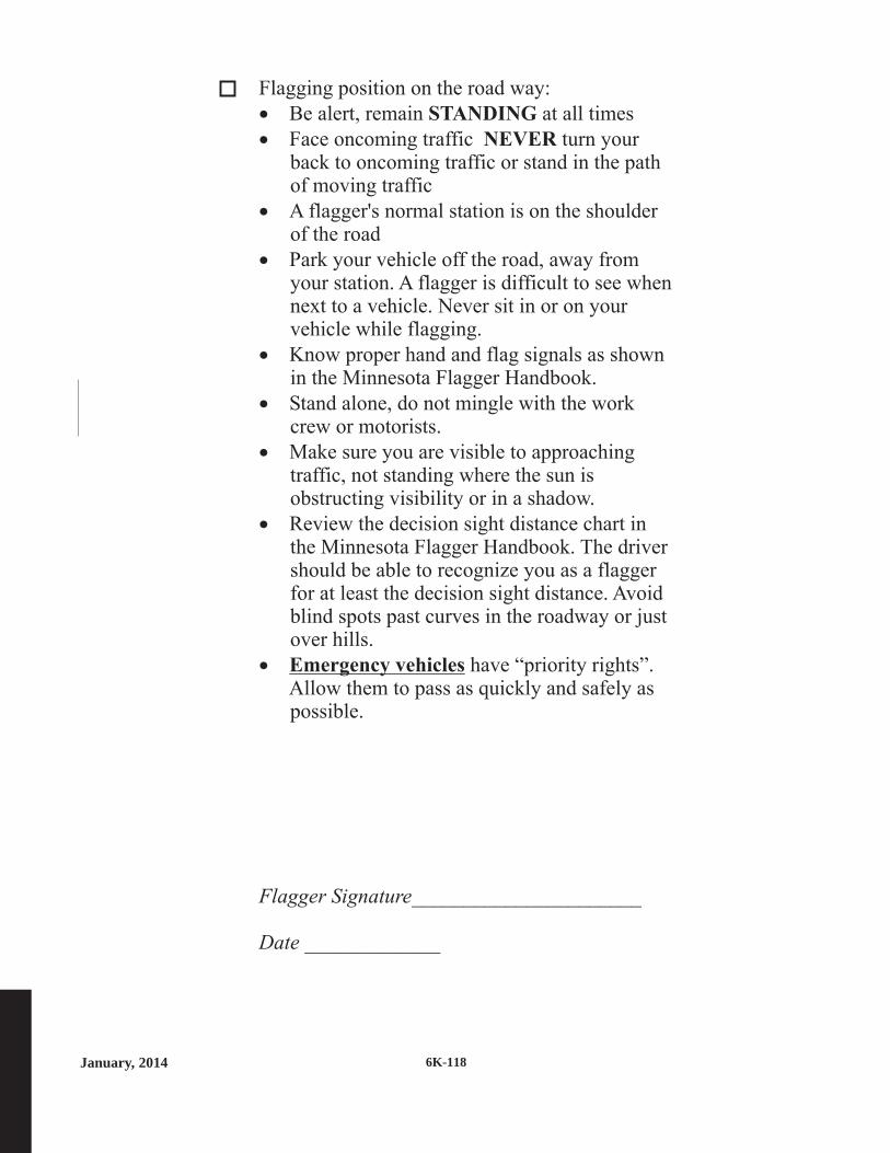
January, 2014 6K-118
Flagging position on the road way:
Be alert, remain at all times
Face oncoming traffic turn yourback to oncoming traffic or stand in the pathof moving traffic
A flagger's normal station is on the shoulderof the road
Park your vehicle off the road, away fromyour station. A flagger is difficult to see whennext to a vehicle. Never sit in or on yourvehicle while flagging.
Know proper hand and flag signals as shownin the Minnesota Flagger Handbook.
Stand alone, do not mingle with the workcrew or motorists.
Make sure you are visible to approachingtraffic, not standing where the sun isobstructing visibility or in a shadow.
Review the decision sight distance chart inthe Minnesota Flagger Handbook. The drivershould be able to recognize you as a flaggerfor at least the decision sight distance. Avoidblind spots past curves in the roadway or justover hills.
have “priority rights”.Allow them to pass as quickly and safely aspossible.
______________________
_____________
··
·
·
·
·
·
·
·
STANDING
NEVER
Emergency vehicles
Flagger Signature
Date

January, 20146K-119
NOTES

January, 2014 6K-120
Mn/DOT District & Central Office and Gopher State One-CallOffice Phone Numbers
District 1 Hdqrs. - Duluth Minnesota Dept. of Transportation1123 Mesaba AvenueDuluth, MN 55811218-725-2700
District 1 - Virginia Minnesota Dept. of Transportation101 N. Hoover RoadVirginia, MN 55792218-742-1100
District 2A - Bemidji Minnesota Dept. of Transportation3919 Highway 2 WestBemidji, MN 56619218-755-6500
District 2B - Crookston Minnesota Dept. of Transportation1320 Sunflower StreetCrookston, MN 56716218-277-7950
District 3 Hdqrs. - Baxter Minnesota Dept. of Transportation7694 Industrial Park RoadBaxter, MN 56425-8096218-828-5700
District 3 - St. Cloud Minnesota Dept. of Transportation3725 12th Street NorthSt. Cloud, MN 56303-2107320-223-6500
District 4 Hdqrs. - Detroit Lakes Minnesota Dept. of Transportation100 Highway 10 WestDetroit Lakes, MN 56501218-846-3600
District 4 - Morris Minnesota Dept. of Transportation610 Highway 9 SouthMorris, MN 56267320-208-7000
District 6 Hqdrs. - Rochester Minnesota Dept. of Transportation2900 48th Street NWRochester, MN 55901-5848507-286-7500
District 6 - Owatonna Minnesota Dept. of Transportation1010 21st Avenue NWOwatonna, MN 55060-1005507-446-5500

January, 20146K-121
Mn/DOT District & Central Office and Gopher State One-CallOffice Phone Numbers
District 7 Hdqrs. - Mankato Minnesota Dept. of Transportation2151 Bassett DriveMankato, MN 56001-6888507-304-6100
District 7 - Windom Minnesota Dept. of Transportation180 South County Road 26Windom, MN 56101-1868507-831-8000
District 8 Hdqrs. - Willmar Minnesota Dept. of Transportation2505 Transportation RoadWillmar, MN 56201320-231-5195
District 8 - Marshall Minnesota Dept. of TransportationRegional Office 1800 East College Drive
Marshall, MN 56258507-537-6146
District 8 - Hutchinson Minnesota Dept. of TransportationRegional Office 1400 Adams Street SE
Hutchinson, MN 55350320-234-8480
Metropolitan District Minnesota Dept. of Transportation1500 West County Road B-2Roseville, MN 55113-3174651-234-7500
Central Office Minnesota Dept. of TransportationOffice of Traffic, Mail Stop 725
Safety and Operations 1500 West County Road B2Roseville, MN 55113-3174651-234-7000
To order more manuals Minnesota Dept. of TransportationMail Stop 260, Manual Sales395 John Ireland BoulevardSt. Paul, MN 55155-1899651-366-3017
Gopher State One-CallTwin City Area 612-454-0002Greater Minnesota 800-252-1166

January, 2014 6K-122
NOTES

January, 20146K-123
feet
DecisionSight
Distance
(D)
550
700
900
1200
1400
1600
AdvanceWarning
SignSpacing
(A)feet
250
325
600
750
1000
1200
TaperLength
( )12 ft lane
(L)feet
200
325
600
700
800
900
Posted SpeedLimit Prior
to WorkStarting(mph)
G = 25 ft
G = 50 ft
0 - 30
35 - 40
45 - 50
55
60 - 65
70 - 75
ShiftingTaper
(L/2)feet
100
175
300
350
400
450
TypicalShoulder
Taper
(L/3)feet
75
125
200
250
275
300
Posted SpeedLimit Prior
to WorkStarting(mph)
G = 25 ft
G = 50 ft
0 - 30
35 - 40
45 - 50
55
60 - 65
70 - 75
feet
BufferSpace
(B)
200
305
425
500
650
820
Shadow VehicleFollowing Distance
(F)feet
250 - 550
325 - 700
600 - 900
750 - 1200
1000 - 1400
1200 - 1600
Protection VehicleRoll-Ahead Buffer Distance
(with or without TMA)(R)
feet feet
100 100
100 100
175 125
175 125
225 175
225 175
Moving(15 mph max)
Stopped
Temporary Traffic Control Distance Charts
See the MN MUTCD, Part 6F for more details on application restrictions.
TUBULAR MARKERS CONES WEIGHTED
CHANNELIZER
36 inchMinimum
18 inchMinimum
18 inchMinimum
28 - 36 inchMinimum
42 inchMinimum
TYPE A CHANNELIZERS:
daytimelow speed
only
daytimelow speed
only
4 inch Diameter Minimum
Type A channelizing devices are typically used in attendedtemporary traffic control zones.*
TYPE B CHANNELIZERS: 270 square inch minimum of retroreflective sheeting surface
Type B channelizing devices shall be used if the temporary trafficcontrol zone will be installed for more than 12 hours or if it is leftunattended. *
*
TYPE I
BARRICADE
TYPE II BARRICADEVERTICAL PANEL DIRECTION INDICATOR
BARRICADE
DRUM
36 inchesminimum
36 inchesminimum
24inches
36inches

Minnesota Department of Transportation
Minnesota Manual on Uniform
Traffic Control Devices

7B.1 Size of School Signs
Detailed drawings of the standard signs illustrated inthis Manual can be found in the Minnesota StandardSigns Manual (see Map & Manual Sales Unit, page ii).Other questions regarding signs and their usage can bereferred to the Office of Traffic, Safety and Technology(see page ii). The size of signs to be used in school areasshall be as shown in Table 7B-1 and Appendix C of thisManual.
The Conventional Road sign size shall be used on publicroads, streets, and highways unless engineering judgmentdetermines that a Minimum or Oversized sign size would bemore appropriate.
The Minimum sign size shall be used only where trafficvolumes are low and speeds are 30 mph or lower, asdetermined by engineering judgment.
The Oversized sign size shall be used on expressways.
The Oversized sign sizes should be used on roadways thathave four or more lanes with posted speed limits of 40 mphor higher.
The sizes in the Oversized column may also be used atother locations that require increased emphasis, improvedrecognition, or increased legibility.
Signs and plaques larger than those shown in Table 7B-1and Appendix C of this Manual may be used (see Section2A.11).
7B.2 Illumination and Reflectorization
The signs used for school area traffic control shall beretroreflectorized or illuminated.
STANDARD:STANDARD:
OPTION:OPTION:
GUIDANCE:GUIDANCE:
STANDARD:STANDARD:
7B.3 Position of Signs
Sections 2A.16 and 2A.17 contain provisions regardingthe placements and locations of signs.
Section 2A.19 contains provisions regarding the lateraloffsets of signs.
In-roadway signs for school traffic control areas may beused consistent with the requirements of Sections 2B.12,7B.11, and 7B.12.
7B.4 Height of Signs
Section 2A.18 contains provisions regarding themounting height of signs.
7B.5 Installation of Signs
Section 2A.16 contains provisions regarding the installa-tion of signs.
7B.6 Lettering
The Federal Highway Administration's "StandardHighway Signs and Markings" book contains informationregarding sign lettering.
7B.7 Sign Color for School Warning Signs
School warning signs, including the "SCHOOL" portionof the School Speed Limit (S5-1) sign and including anysupplemental plaques used in association with these warningsigns, shall have a fluorescent yellow-green backgroundwith a black legend and border unless otherwise provided inthis Manual for a specific sign.
When the fluorescent yellow-green background color isused, a systematic approach featuring one backgroundcolor within a zone or area shall be used. The mixing ofstandard yellow and fluorescent yellow-green backgroundswithin a zone or area is not allowed.
STANDARD:STANDARD:
SUPPORT:SUPPORT:
SUPPORT:SUPPORT:
SUPPORT:SUPPORT:
OPTION:OPTION:
SUPPORT:SUPPORT:
7B-1 July, 2012
Part 7. TRAFFIC CONTROLS FOR SCHOOL AREAS7B. Signs
MN
Rev
. 1M
NR
ev. 1

7B-2January, 2014
School
School Bus Stop Ahead
School Bus Turn Around
Reduced School Speed
Limit Ahead
School Speed Limit XX
When Flashing
End School Zone
End School Speed Limit
In-Street Ped Crossing
Speed Limit (School Use)
Begin Higher Fines Zone
End Higher Fines Zone
XXX to XXX AM
XXX to XXX PM
When Children Are Present
School
When Flashing
Mon-Fri
All Year
Fines Higher
XX Feet
XX FT
Turn Arrow
Advance Turn Arrow
Diagonal Arrow
Diagonal Arrow (optional size)
Ahead
S1-1
S3-1
S3-2a
S4-5, S4-5a
S5-1
S5-2
S5-3
R1-6a, R1-6c
R2-1
R2-10
R2-11
S4-1P
S4-2P
S4-3P
S4-4P
S4-6P
S4-7P
R-2-6P
W16-2P
W16-2aP
W16-5P
W16-6P
W16-7P
W16-7P
W16-9P
7B.8
7B.13
7B.14
7B.16
7B.15
7B.9
7B.15
7B.11, 7B.12
7B.15
7B.10
7B.10
7B.15
7B.15
7B.9, 7B.15
7B.15
7B.15
7B.9
7B.10
7B.8
7B.8
7B.8, 7B.9,
7B.11
7B.12
7B.12
7B.11
7B.8, 7B.9,
7B.11
36 x 36
36 x 36
24 x 48
24 x 30
24 x 30
12 x 36
24 x 30
24 x 30
24 x 30
36 x 36
36 x 36
24 x 10
24 x 10
24 x 8
24 x 10
24 x 10
24 x 12
24 x 18
24 x 18
24 x 12
24 x 12
24 x 12
24 x 12
21 x 15
24 x 12
48 x 48
---
36 x 48
36 x 48
36 x 48
48 x 48
48 x 48
48 x 48
36 x 72
36 x 48
36 x 48
36 x 18
36 x 18
36 x 12
36 x 18
36 x 18
36 x 18
36 x 24
30 x 24
30 x 18
30 x 18
30 x 18
30 x 18
---
30 x 18
30 x 30
30 x 30
30 x 30
30 x 30
---
---
---
---
---
---
---
---
---
---
---
---
---
---
---
---
---
---
---
---
---
---
Sign
Plaque
Section
Section
Conventional Road
Conventional Road
Sign Designation
Sign Designation
Minimum
Minimum
Oversized
Oversized
Notes: 1. Larger signs may be used when appropriate.2. Dimensions are shown in inches and are shown as width x height.3. Minimum sizes for multi-;ane conventional roads shall be as shown
in the Conventional Roads column.that face shared-use paths and pedestrian facilities.
Table 7B-1. School Area Sign and Plaque Sizes
MN
Rev
. 2M
NR
ev. 3
MN
Rev
. 3
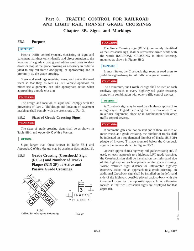
8B.1 Purpose
Passive traffic control systems, consisting of signs andpavement markings only, identify and direct attention to thelocation of a grade crossing and advise road users to slowdown or stop at the grade crossing as necessary in order toyield to any rail traffic occupying, or approaching and inproximity to, the grade crossing.
Signs and markings regulate, warn, and guide the roadusers so that they, as well as LRT vehicle operators onmixed-use alignments, can take appropriate action whenapproaching a grade crossing.
The design and location of signs shall comply with theprovisions of Part 2. The design and location of pavementmarkings shall comply with the provisions of Part 3.
8B.2 Sizes of Grade Crossing Signs
The sizes of grade crossing signs shall be as shown inTable 8B-1 and Appendix C of this Manual.
Signs larger than those shown in Table 8B-1 andAppendix C of this Manual may be used (see Section 2A.11).
8B.3 Grade Crossing (Crossbuck) Sign(R15-1) and Number of TracksPlaque (R15-2P) at Active andPassive Grade Crossings
R15-2PR15-1
Drilled for 90-degree mounting
T R A C K S
39
inches
9inches
9inches
27 inches
RAI L
CROSSI NG
ROAD
9inches
48inches
90o
OPTION:OPTION:
STANDARD:STANDARD:
STANDARD:STANDARD:
SUPPORT:SUPPORT: The Grade Crossing sign (R15-1), commonly identifiedas the Crossbuck sign, shall be retroreflectorized white withthe words RAILROAD CROSSING in black lettering,mounted as shown in Figure 8B-2
In most States, the Crossbuck sign requires road users toyield the right-of-way to rail traffic at a grade crossing.
.As a minimum, one Crossbuck sign shall be used on eachroadway approach to every highway-rail grade crossing,alone or in combination with other traffic control devices.
A Crossbuck sign may be used on a highway approach toa highway-LRT grade crossing on a semi-exclusive ormixed-use alignment, alone or in combination with othertraffic control devices.
If automatic gates are not present and if there are two ormore tracks at a grade crossing, the number of tracks shallbe indicated on a supplemental Number of Tracks (R15-2P)plaque of inverted T shape mounted below the Crossbucksign in the manner shown in Figure 8B-2.
On each approach to a highway-rail grade crossing and, ifused, on each approach to a highway-LRT grade crossing,the Crossbuck sign shall be installed on the right-hand sideof the highway on each approach to the grade crossing.Where restricted sight distance or unfavorable highwaygeometry exists on an approach to a grade crossing, anadditional Crossbuck sign shall be installed on the left-handside of the highway, possibly placed back-to-back with theCrossbuck sign for the opposite approach, or otherwiselocated so that two Crossbuck signs are displayed for thatapproach.
STANDARD:STANDARD:
OPTION:OPTION:
STANDARD:STANDARD:
SUPPORT:SUPPORT:
STANDARD:STANDARD:
8B-1 July, 2012
Part 8. TRAFFIC CONTROL FOR RAILROADAND LIGHT RAIL TRANSIT GRADE CROSSINGS
Chapter 8B. Signs and Markings
MN
Rev
. 1
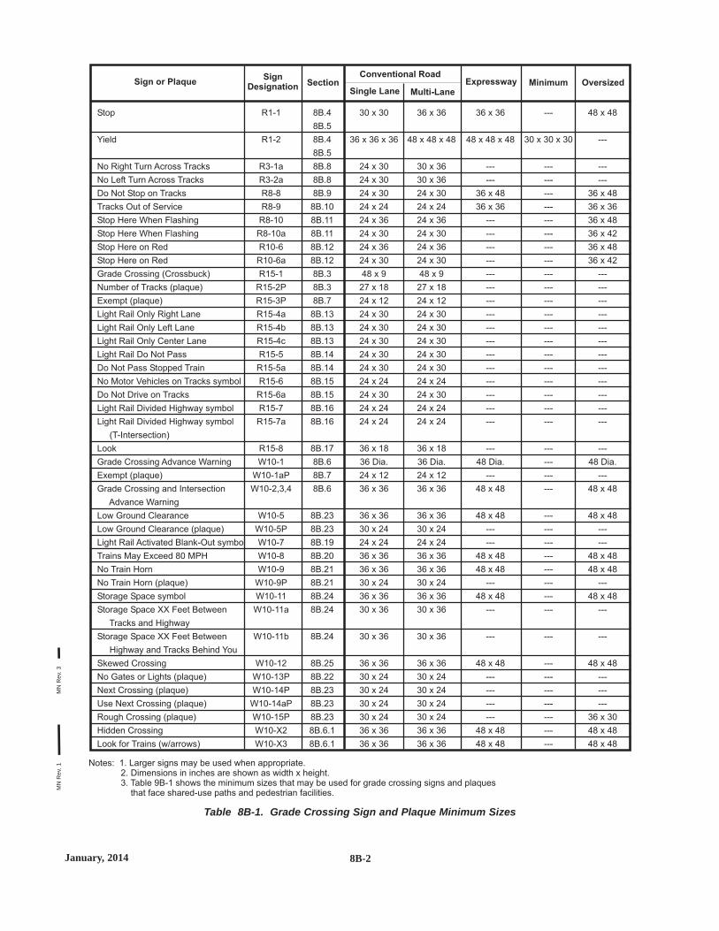
8B-2January, 2014
Table 8B-1. Grade Crossing Sign and Plaque Minimum Sizes
Stop
Yield
No Right Turn Across Tracks
No Left Turn Across Tracks
Do Not Stop on Tracks
Tracks Out of Service
Stop Here When Flashing
Stop Here When Flashing
Stop Here on Red
Stop Here on Red
Grade Crossing (Crossbuck)
Number of Tracks (plaque)
Exempt (plaque)
Light Rail Only Right Lane
Light Rail Only Left Lane
Light Rail Only Center Lane
Light Rail Do Not Pass
Do Not Pass Stopped Train
No Motor Vehicles on Tracks symbol
Do Not Drive on Tracks
Light Rail Divided Highway symbol
Light Rail Divided Highway symbol
(T-Intersection)
Look
Grade Crossing Advance Warning
Exempt (plaque)
Grade Crossing and Intersection
Advance Warning
Low Ground Clearance
Low Ground Clearance (plaque)
Light Rail Activated Blank-Out symbol
Trains May Exceed 80 MPH
No Train Horn
No Train Horn (plaque)
Storage Space symbol
Storage Space XX Feet Between
Tracks and Highway
Storage Space XX Feet Between
Highway and Tracks Behind You
Skewed Crossing
No Gates or Lights (plaque)
Next Crossing (plaque)
Use Next Crossing (plaque)
Rough Crossing (plaque)
Hidden Crossing
Look for Trains (w/arrows)
R1-1
R1-2
R3-1a
R3-2a
R8-8
R8-9
R8-10
R8-10a
R10-6
R10-6a
R15-1
R15-2P
R15-3P
R15-4a
R15-4b
R15-4c
R15-5
R15-5a
R15-6
R15-6a
R15-7
R15-7a
R15-8
W10-1
W10-1aP
W10-2,3,4
W10-5
W10-5P
W10-7
W10-8
W10-9
W10-9P
W10-11
W10-11a
W10-11b
W10-12
W10-13P
W10-14P
W10-14aP
W10-15P
W10-X2
W10-X3
8B.4
8B.5
8B.4
8B.5
8B.8
8B.8
8B.9
8B.10
8B.11
8B.11
8B.12
8B.12
8B.3
8B.3
8B.7
8B.13
8B.13
8B.13
8B.14
8B.14
8B.15
8B.15
8B.16
8B.16
8B.17
8B.6
8B.7
8B.6
8B.23
8B.23
8B.19
8B.20
8B.21
8B.21
8B.24
8B.24
8B.24
8B.25
8B.22
8B.23
8B.23
8B.23
8B.6.1
8B.6.1
30 x 30
36 x 36 x 36
24 x 30
24 x 30
24 x 30
24 x 24
24 x 36
24 x 30
24 x 36
24 x 30
48 x 9
27 x 18
24 x 12
24 x 30
24 x 30
24 x 30
24 x 30
24 x 30
24 x 24
24 x 30
24 x 24
24 x 24
36 x 18
36 Dia.
24 x 12
36 x 36
36 x 36
30 x 24
24 x 24
36 x 36
36 x 36
30 x 24
36 x 36
30 x 36
30 x 36
36 x 36
30 x 24
30 x 24
30 x 24
30 x 24
36 x 36
36 x 36
36 x 36
48 x 48 x 48
30 x 36
30 x 36
24 x 30
24 x 24
24 x 36
24 x 30
24 x 36
24 x 30
48 x 9
27 x 18
24 x 12
24 x 30
24 x 30
24 x 30
24 x 30
24 x 30
24 x 24
24 x 30
24 x 24
24 x 24
36 x 18
36 Dia.
24 x 12
36 x 36
36 x 36
30 x 24
24 x 24
36 x 36
36 x 36
30 x 24
36 x 36
30 x 36
30 x 36
36 x 36
30 x 24
30 x 24
30 x 24
30 x 24
36 x 36
36 x 36
36 x 36
48 x 48 x 48
---
---
36 x 48
36 x 36
---
---
---
---
---
---
---
---
---
---
---
---
---
---
---
---
---
48 Dia.
---
48 x 48
48 x 48
---
---
48 x 48
48 x 48
---
48 x 48
---
---
48 x 48
---
---
---
---
48 x 48
48 x 48
48 x 48
---
---
---
36 x 48
36 x 36
36 x 48
36 x 42
36 x 48
36 x 42
---
---
---
---
---
---
---
---
---
---
---
---
---
48 Dia.
---
48 x 48
48 x 48
---
---
48 x 48
48 x 48
---
48 x 48
---
---
48 x 48
---
---
---
36 x 30
48 x 48
48 x 48
---
30 x 30 x 30
---
---
---
---
---
---
---
---
---
---
---
---
---
---
---
---
---
---
---
---
---
---
---
---
---
---
---
---
---
---
---
---
---
---
---
---
---
---
---
---
Sign or Plaque SectionSingle Lane Multi-Lane
Conventional RoadSignDesignation
Expressway Minimum Oversized
Notes: 1. Larger signs may be used when appropriate.2. Dimensions in inches are shown as width x height.3. Table 9B-1 shows the minimum sizes that may be used for grade crossing signs and plaques
that face shared-use paths and pedestrian facilities.
MN
Rev
. 1M
NR
ev. 3

9B.5 BEGIN RIGHT TURN LANEYIELD TO BIKES Sign (R4-4)
Where motor vehicles entering an exclusive right-turnlane must weave across bicycle traffic in bicycle lanes, theBEGIN RIGHT TURN LANE YIELD TO BIKES (R4-4)sign may be used to inform both the motorist and thebicyclist of this weaving maneuver (see Figures 9C-1, 9C-4,and 9C-5).
The R4-4 sign should not be used when bicyclists need tomove left because of a right-turn lane drop situation.
9B.6 Bicycles May Use Full Lane Sign(R4-11)
The Bicycles May Use Full Lane (R4-11) sign may beused on roadways where no bicycle lanes or adjacentshoulders usable by bicyclists are present and where travellanes are too narrow for bicyclists and motor vehicles tooperate side by side.
The Bicycles May Use Full Lane sign may be used inlocations where it is important to inform road users thatbicyclists might occupy the travel lane.
Section 9C.7 describes a Shared Lane Marking that maybe used in addition to or instead of the Bicycles May UseFull Lane sign to inform road users that bicyclists mightoccupy the travel lane.
The Uniform Vehicle Code (UVC) defines a "substandardwidth lane" as a "lane that is too narrow for a bicycle and avehicle to travel safely side by side within the same lane."
SUPPORT:SUPPORT:
OPTION:OPTION:
R4-11
MAY U S EFU L L LAN E
GUIDANCE:GUIDANCE:
OPTION:OPTION:
R4-4
B EG I NR I G H T TU R N LAN E
Y I E LD TO B I K ES
9B.7 Bicycle WRONG WAY Sign andRIDE WITH TRAFFIC Plaque
(R5-1b, R9-3cP)
The Bicycle WRONG WAY (R5-1b) sign and RIDEWITH TRAFFIC (R9-3c) plaque may be placed facingwrong-way bicycle traffic, such as on the left side of aroadway.
This sign and plaque may be mounted back-to-back withother signs to minimize visibility to other traffic.
If used, the RIDE WITH TRAFFIC plaque shall be usedonly in conjunction with the Bicycle WRONG WAY sign,and be mounted directly below the Bicycle WRONG WAYsign.
9B.8 NO MOTOR VEHICLES Sign (R5-3)
The NO MOTOR VEHICLES (R5-3) sign may beinstalled at the entrance to a shared-use path.
OPTION:OPTION:
R5-3
N OM O TO RVEH I C L ES
STANDARD:STANDARD:
OPTION:OPTION:
R9-3cPR5-1b
R I D E
W I T H
T RA F F I C
W R O N G
WAY
9B-5 July, 2013
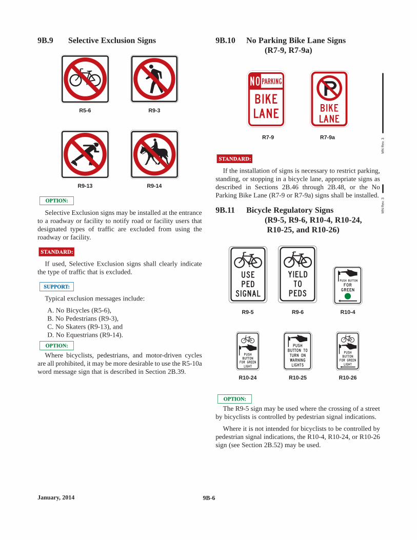
9B.9 Selective Exclusion Signs
Selective Exclusion signs may be installed at the entranceto a roadway or facility to notify road or facility users thatdesignated types of traffic are excluded from using theroadway or facility.
If used, Selective Exclusion signs shall clearly indicatethe type of traffic that is excluded.
Typical exclusion messages include:
A. No Bicycles (R5-6),B. No Pedestrians (R9-3),C. No Skaters (R9-13), andD. No Equestrians (R9-14).
Where bicyclists, pedestrians, and motor-driven cyclesare all prohibited, it may be more desirable to use the R5-10aword message sign that is described in Section 2B.39.
OPTION:OPTION:
SUPPORT:SUPPORT:
STANDARD:STANDARD:
OPTION:OPTION:
R9-14R9-13
R9-3R5-6
9B.10 No Parking Bike Lane Signs(R7-9, R7-9a)
If the installation of signs is necessary to restrict parking,standing, or stopping in a bicycle lane, appropriate signs asdescribed in Sections 2B.46 through 2B.48, or the NoParking Bike Lane (R7-9 or R7-9a) signs shall be installed.
9B.11 Bicycle Regulatory Signs(R9-5, R9-6, R10-4, R10-24,R10-25, and R10-26)
The R9-5 sign may be used where the crossing of a streetby bicyclists is controlled by pedestrian signal indications.
Where it is not intended for bicyclists to be controlled bypedestrian signal indications, the R10-4, R10-24, or R10-26sign (see Section 2B.52) may be used.
OPTION:OPTION:
R10-26R10-25R10-24
B U TTO NFO R G R EENL I G H T
P U S HB U TTO N TOTU R N O NWAR N I N GL I G H TS
P U S H
B U TTO NFO R G R EENL I G H T
P U S H
R10-4R9-6R9-5
FO RG R EEN
P U S H B U TTO N
Y I E L D
T O
P E D S
U S E
P E D
S I G N A L
STANDARD:STANDARD:
R7-9aR7-9
B I K E
LA N E
N O PARK I N G
B I K E
LA N E
9B-6January, 2014
MN
Rev
. 3M
NR
ev. 3
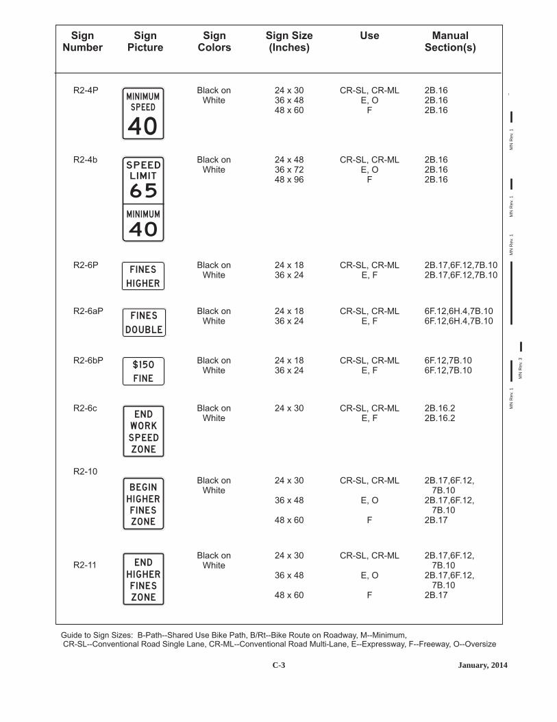
C-3 January, 2014
SignNumber
SignPicture
SignColors
Sign Size(Inches)
Use ManualSection(s)
Guide to Sign Sizes: B-Path--Shared Use Bike Path, B/Rt--Bike Route on Roadway, M--Minimum,CR-SL--Conventional Road Single Lane, CR-ML--Conventional Road Multi-Lane, E--Expressway, F--Freeway, O--Oversize
CR-SL, CR-MLE, O
F
CR-SL, CR-MLE, O
F
CR-SL, CR-MLE, F
CR-SL, CR-MLE, F
CR-SL, CR-MLE, F
CR-SL, CR-MLE, F
CR-SL, CR-ML
E, O
F
CR-SL, CR-ML
E, O
F
R2-4P
R2-4b
R2-6P
R2-6aP
R2-6bP
R2-6c
R2-10
R2-11
2B.162B.162B.16
2B.162B.162B.16
2B.17,6F.12,7B.102B.17,6F.12,7B.10
6F.12,6H.4,7B.106F.12,6H.4,7B.10
6F.12,7B.106F.12,7B.10
2B.16.22B.16.2
2B.17,6F.12,7B.10
2B.17,6F.12,7B.10
2B.17
2B.17,6F.12,7B.10
2B.17,6F.12,7B.10
2B.17
Black onWhite
Black onWhite
Black onWhite
Black onWhite
Black onWhite
Black onWhite
Black onWhite
Black onWhite
24 x 3036 x 4848 x 60
24 x 4836 x 7248 x 96
24 x 1836 x 24
24 x 1836 x 24
24 x 1836 x 24
24 x 30
24 x 30
36 x 48
48 x 60
24 x 30
36 x 48
48 x 60
40S P EEDM I N I M U M
6 5
40M I N I M U M
S P E EDL I M I T
F I N E S
H I G H ER
F I N E S
DO U B L E
$ 1 50
F I N E
EN DWO R KS P EEDZO N E
B EG I NH I G H ERF I N E SZO N E
EN DH I G H ERF I N E SZO N E
MN
Rev
. 1M
NR
ev. 1
MN
Rev
. 1
MN
Rev
. 3
MN
Rev
. 1

C-4July, 2012
MN
Rev
. 1

C-19 January, 2014
SignNumber
SignPicture
SignColors
Sign Size(Inches)
Use ManualSection(s)
Guide to Sign Sizes: B-Path--Shared Use Bike Path, B/Rt--Bike Route on Roadway, M--Minimum,CR-SL--Conventional Road Single Lane, CR-ML--Conventional Road Multi-Lane, E--Expressway, F--Freeway, O--Oversize
CR-SL, CR-ML
CR-SL, CR-ML
CR-SL, CR-ML
CR-SL, CR-ML
CR-SL, CR-ML
CR-SL, CR-ML
B/Rt
B/Rt
CR-SL, CR-ML
R7-5
R7-7
R7-8bP
R7-4
R7-6
R7-8m
R7-9
R7-9a
R7-20
2B.46
2B.46
2B.46,2B.48.1
2B.46
2B.46
2B.46,2B.48.1
9B.10
9B.10
2B.46
Green onWhite
Red onWhite
White onBlue
Red onWhite
Red onWhite
White onBlue
Red onWhite
Black andRed onWhite
Green onWhite
12 x 18
12 x 18
18 x 9
12 x 18
12 x 18
12 x 18
12 x 18
12 x 18
24 x 18
0 N E
H O U R
PARK I N G
9 A M -7 P M
N OS TA N D I N G
A NY
T I M E
N O
PARK I NGLOA D I N G
ZO N E
N O
PARK I NGB U S
S TO P
VANACC ESS I B L E
PAR K I N G
V EH I C L E I DR EQ U I R ED
U P TO $200 F I N EFO R V I O LAT I O N
1H O U R
N O PARK I N G
B I K E
LA N E
B I K E
LA N E
CR-SL, CR-MLR7-21 2B.46Green andBlack on
White
12 x 18P
1 H O U RPAY
PAR K I N G
CR-SL, CR-MLR7-3 2B.46Red onWhite
12 x 18N OPARK I NG
EXC E P T
S U N DAY S A N D
H O L I DAY S
MN
Rev
. 1M
NR
ev. 3
MN
Rev
. 1M
NR
ev. 1
MN
Rev
. 1M
NR
ev. 1
MN
Rev
. 1M
NR
ev. 1
MN
Rev
. 1M
NR
ev. 1
MN
Rev
. 1

C-20July, 2013
SignNumber
SignPicture
SignColors
Sign Size(Inches)
Use ManualSection(s)
Guide to Sign Sizes: B-Path--Shared Use Bike Path, B/Rt--Bike Route on Roadway, M--Minimum,CR-SL--Conventional Road Single Lane, CR-ML--Conventional Road Multi-Lane, E--Expressway, F--Freeway, O--Oversize
CR-SL, CR-ML
CR-SL, CR-ML
CR-SL, CR-ML
CR-SL, CR-ML
CR-SL, CR-ML
CR-SL, CR-ML
CR-SL, CR-ML
R7-23
R7-107
R7-108
R7-23a
R7-107b
R7-200
R7-200a
2B.46
2B.46
2B.46
2B.46
2B.46
2B.46
2B.46
Black andRed onWhite
Red onWhite
Green onWhite
Green andBlack on
White
Red andBlack on
White
Red andGreen on
White
Red andGreen on
White
12 x 18
12 x 18
12 x 18
12 x 18
12 x 30
24 x 18
12 x 30
P1 H O U R
7A M - 6 P M
N O PARK I N G
B U S
S TO P
THIS AREA MAY BE USED
FOR A TRANSIT LOGO.
(IF NOT USED, DECREASE
SIGN HEIGHT BY 6 INCHES)
BUS STOP
1 5M I N
PARKI NG
8:00 A M
T O 5:0 0 P M
A NY
T I M E
PA R K I N G
O N E
H O U R
PA R K I N G
9 A M 7 P M-
N O
A NY
T I M E
PA R K I N G
N O
O N E
H O U R
PA R K I N G
9 A M 7 P M-
CR-SL, CR-MLR7-22 2B.46Green andBlack on
White
12 x 18PPAY
PAR K I N G
P8 : 3 0 A M
P M5 : 3 0T O
CR-SL, CR-MLR7-21a 2B.46Green andBlack on
White
12 x 18PPAY
1 5M I N U T E
L I M I T
PA R K I N G
MN
Rev
. 1M
NR
ev. 1
MN
Rev
. 1M
NR
ev. 1
MN
Rev
. 1M
NR
ev. 1
MN
Rev
. 1M
NR
ev. 1
MN
Rev
. 1

C-37 July, 2013
SignNumber
SignPicture
SignColors
Sign Size(Inches)
Use ManualSection(s)
Guide to Sign Sizes: B-Path--Shared Use Bike Path, B/Rt--Bike Route on Roadway, M--Minimum, LV--Low VolumeCR-SL--Conventional Road Single Lane, CR-ML--Conventional Road Multi-Lane, E--Expressway, F--Freeway, O--Oversize
B-PathB/Rt, LV
CR-SL, CR-MLO
LVCR-SL, CR-ML
OEF
CR-SL, CR-ML, EF
CR-SL, CR-ML, EF
CR-SL, CR-ML, EF
CR-SL, CR-ML, EF
CR-SL, CR-ML, EF
CR-SL, CR-ML, EF
W1-7
W1-8(R or L)
W1-10(R or L)
W1-10a(R or L)
W1-10b(R or L)
W1-10c(R or L)
W1-10d(R or L)
W1-10e(R or L)
9B.155C.2,9B.152C.47,5C.2,6F.502C.47,6F.50
5C.22C.9,5C.2,6F.502C.92C.9,6F.502C.9,6F.50
2C.112C.11
2C.112C.11
2C.112C.11
2C.112C.11
2C.112C.11
2C.112C.11
Black onYellow
Black onYellow
Black onYellow
Black onYellow
Black onYellow
Black onYellow
Black onYellow
Black onYellow
24 x 1236 x 1848 x 2460 x 30
12 x 1818 x 2424 x 3030 x 3636 x 48
36 x 3648 x 48
36 x 3648 x 48
36 x 3648 x 48
36 x 3648 x 48
36 x 3648 x 48
36 x 3648 x 48
CR-SL, CR-MLE
F, O
CR-SL, CR-ML,E, O
F
W1-11(R or L)
W1-13(R or L)
2C.72C.72C.7
2C.13
2C.13
Black onYellow
Black onYellow
30 x 3036 x 3648 x 48
36 x 36
48 x 48
MN
Rev
. 1M
NR
ev. 2
MN
Rev
. 2M
NR
ev. 1
MN
Rev
. 1M
NR
ev. 1
MN
Rev
. 1M
NR
ev. 1
MN
Rev
. 1M
NR
ev. 1
MN
Rev
. 1M
NR
ev. 1

C-38January, 2014
SignNumber
SignPicture
SignColors
Sign Size(Inches)
Use ManualSection(s)
Guide to Sign Sizes: B-Path--Shared Use Bike Path, B/Rt--Bike Route on Roadway, M--Minimum, LV--Low VolumeCR-SL--Conventional Road Single Lane, CR-ML--Conventional Road Multi-Lane, E--Expressway, F--Freeway, O--Oversize
CR-SL, CR-MLE
F, O
B-PathB/Rt, M
LV, CR-SL, CR-MLEO
B-PathB/Rt, M
LV, CR-SL, CR-MLEO
B-PathB/Rt, M
LV, CR-SL, CR-MLEO
B-PathB/Rt, M
LV, CR-SL, CR-MLEO
B-PathB/Rt, M
LV, CR-SL, CR-MLEO
MLV, CR-SL, CR-ML
EO
W1-15(R or L)
W2-1
W2-2(R or L)
W2-3(R or L)
W2-4
W2-5
W2-6
2C.72C.72C.7
9B.169B.162C.46,5C.32C.46,5C.32C.46
9B.169B.162C.46,5C.32C.46,5C.32C.46
9B.169B.162C.46,5C.32C.46,5C.32C.46
9B.169B.162C.46,5C.32C.46,5C.32C.46
9B.169B.162C.46,5C.32C.46,5C.32C.46
2C.46,5C.32C.46,5C.32C.462C.46
Black onYellow
Black onYellow
Black onYellow
Black onYellow
Black onYellow
Black onYellow
Black onYellow
30 x 3036 x 3648 x 48
18 x 1824 x 2430 x 3036 x 3648 x 48
18 x 1824 x 2430 x 3036 x 3648 x 48
18 x 1824 x 2430 x 3036 x 3648 x 48
18 x 1824 x 2430 x 3036 x 3648 x 48
18 x 1824 x 2430 x 3036 x 3648 x 48
24 x 2430 x 3036 x 3648 x 48
MCR-SL, CR-ML
EO
W2-7(R or L)
2C.462C.462C.462C.46
Black onYellow
24 x 2430 x 3036 x 3648 x 48
MN
Rev
. 1M
NR
ev. 1
MN
Rev
. 1
MN
Rev
. 2M
NR
ev. 2
MN
Rev
. 2M
NR
ev. 2
MN
Rev
. 2M
NR
ev. 2

C-39 January, 2014
SignNumber
SignPicture
SignColors
Sign Size(Inches)
Use ManualSection(s)
Guide to Sign Sizes: B-Path--Shared Use Bike Path, B/Rt--Bike Route on Roadway, M--Minimum, LV--Low VolumeCR-SL--Conventional Road Single Lane, CR-ML--Conventional Road Multi-Lane, E--Expressway, F--Freeway, O--Oversize
B-PathB/Rt, M, LV
CR-SL, CR-MLCR-SL, CR-ML
E, F
B-PathB/Rt, M, LV
CR-SL, CR-MLCR-SL, CR-ML
E, F
B-PathB/Rt, M,
CR-SL, CR-MLCR-SL, CR-ML
E, F
MLV, CR-SL, CR-ML
E, F
MCR-SL, CR-ML
E, F, O
MCR-SL, CR-ML
EO
CR-SL, CR-MLO
CR-SL, CR-MLO
W2-8(R or L)
W2-X1
W2-X12
W3-1
W3-2
W3-3
W3-4
W3-5
9B.192C.36,5C.4,6F.16,
8B.6,9B.195C.4,6F.50,8B.62C.36,6F.50.8B.6
9B.192C.36,5C.4,6F.16.
8B.6,9B.195C.4,6F.50,8B.62C.36,6F.50,8B.6
9B.192C.36,6F.50,9B.196F.502C.36,6F.50
2C.36,6F.50.22C.36,5C.4,
6F.50.2,6I.12C.36,5C.4,
6F.50.2,6I.1
6F.502C.38,5G.4,6F.502C.36,5G.4,6F.50
2C.462C.462C.462C.46
2C.462C.46
2C.462C.46
Black onYellow
Black onYellow
Black onYellow
Black onYellow
Black onYellow
Black onYellow
Black onYellow
Black onYellow
18 x 1830 x 30
36 x 3648 x 48
18 x 1830 x 30
36 x 3648 x 48
18 x 1830 x 30
36 x 3648 x 48
30 x 3036 x 36
48 x 48
30 x 3036 x 3648 x 48
24 x 2430 x 3036 x 3648 x 48
36 x 3648 x 48
30 x 3036 x 36
H I D D EN
I N T ERS ECT I O N
AH EAD
H I D D E N
E N T RA N C E
B E
P R E PA R E D
TO S TO P
S P EED
L I M I T
4 5
MN
Rev
. 1M
NR
ev. 2
MN
Rev
. 2M
NR
ev. 2
MN
Rev
. 1M
NR
ev. 1
MN
Rev
. 1M
NR
ev. 1
MN
Rev
. 1

C-40June, 2012
SignNumber
SignPicture
SignColors
Sign Size(Inches)
Use ManualSection(s)
Guide to Sign Sizes: B-Path--Shared Use Bike Path, B/Rt--Bike Route on Roadway, M--Minimum,CR-SL--Conventional Road Single Lane, CR-ML--Conventional Road Multi-Lane, E--Expressway, F--Freeway, O--Oversize
CR-SL, CR-ML,M, E, O
MCR-SL, CR-ML
E, F
MCR-SL, CR-ML
E, F
CR-SL, CR-ML, ME, F
MCR-SL, CR-ML
E, F
MCR-SL, CR-ML
E, F
MCR-SL, CR-ML
E, F
CR-SL, CR-MLEO
CR-SL, CR-ML
CR-SL, CR-ML
W3-5a
W3-6
W3-7
W3-8
W3-X4
W3-X5
W4-1(R or L)
W4-1a(R or L)
W4-2(R or L)
W4-3(R or L)
2C.36
6F.306F.306F.30
2C.402C.40,6F.502C.40,6F.50
6F.23.16F.23.1
2C.42,6F.242C.42,6F.242C.426F.24
2C.41,6F.502C.41,6F.502C.41,6F.50
2C.38,6F.502C.38,6F.502C.38,6F.50
2C.392C.392C.39
2C.37
2C.37
Black onYellow
Black onYellow
Black onYellow
Black onYellow
Black onYellow
Black onOrange
Black onYellow
Black onOrange
Black onYellow
Black onYellow
66 x 42
30 x 3036 x 3648 x 48
30 x 3036 x 3648 x 48
36 x 3648 x 48
30 x 3036 x 3648 x 48
30 x 3036 x 3648 x 48
30 x 3036 x 3648 x 48
36 x 3648 x 4860 x 60
36 x 36
36 x 36
4 5 M P H
S P E E D ZO N E
A H EA D
D RAWB R I D G E
RAM PM ETERAH EAD
RAM P
M ETER ED
WH EN
F LAS H I N G
P R EPAR ETO STO PWH EN F LAS H I N G
TRA F F I CCO NTRO LCHAN G EAH EAD
T H R U
T RA F F I C
M E R G E
R I G H T
MN
Rev
. 1
MN
Rev
. 1M
NR
ev. 1
MN
Rev
. 1
MN
Rev
. 1M
NR
ev. 1
MN
Rev
. 1
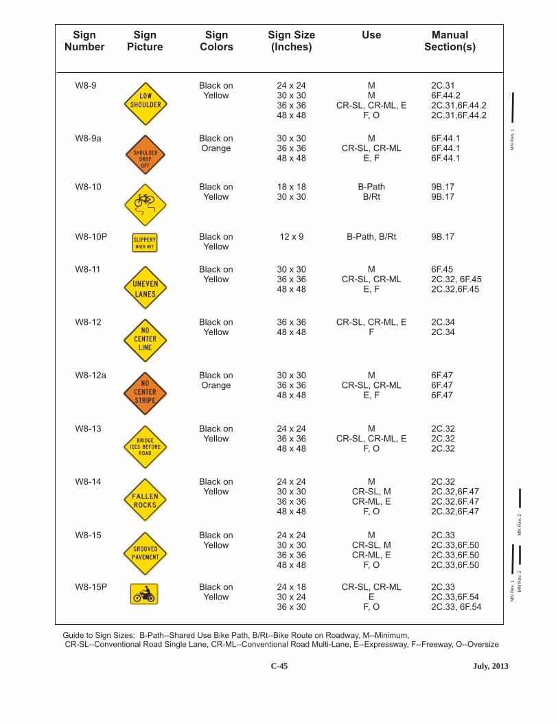
C-45 July, 2013
SignNumber
SignPicture
SignColors
Sign Size(Inches)
Use ManualSection(s)
Guide to Sign Sizes: B-Path--Shared Use Bike Path, B/Rt--Bike Route on Roadway, M--Minimum,CR-SL--Conventional Road Single Lane, CR-ML--Conventional Road Multi-Lane, E--Expressway, F--Freeway, O--Oversize
MM
CR-SL, CR-ML, EF, O
MCR-SL, CR-ML
E, F
CR-SL, CR-ML, EF
MCR-SL, CR-ML
E, F
MCR-SL, CR-ML, E
F, O
MCR-SL, MCR-ML, E
F, O
MCR-SL, MCR-ML, E
F, O
CR-SL, CR-MLE
F, O
B-PathB/Rt
MCR-SL, CR-ML
E, F
B-Path, B/Rt
W8-9a
W8-10P
W8-9
W8-11
W8-12
W8-12a
W8-13
W8-14
W8-15
W8-15P
W8-10
2C.316F.44.22C.31,6F.44.22C.31,6F.44.2
6F.452C.32, 6F.452C.32,6F.45
2C.342C.34
6F.476F.476F.47
2C.322C.322C.32
2C.322C.32,6F.472C.32,6F.472C.32,6F.47
2C.332C.33,6F.502C.33,6F.502C.33,6F.50
2C.332C.33,6F.542C.33, 6F.54
9B.179B.17
6F.44.16F.44.16F.44.1
9B.17
Black onOrange
Black onYellow
Black onYellow
Black onYellow
Black onYellow
Black onOrange
Black onYellow
Black onYellow
Black onYellow
Black onYellow
Black onYellow
24 x 2430 x 3036 x 3648 x 48
30 x 3036 x 3648 x 48
36 x 3648 x 48
30 x 3036 x 3648 x 48
24 x 2436 x 3648 x 48
24 x 2430 x 3036 x 3648 x 48
24 x 2430 x 3036 x 3648 x 48
24 x 1830 x 2436 x 30
18 x 1830 x 30
30 x 3036 x 3648 x 48
12 x 9
LOW
S H O U L D E R
S H O U L D E R
D RO P
O F F
U N EV E N
LA N E S
N O
C E N T E R
L I N E
N O
C E N T E R
S T R I P E
B R I D G E
I C E S B E F O R E
ROA D
ROCKSFA L L EN
G ROOV E D
PAV EM E N T
MN
Rev
. 1M
NR
ev. 2
MN
Rev
. 2M
NR
ev. 1

C-46January, 2014
SignNumber
SignPicture
SignColors
Sign Size(Inches)
Use ManualSection(s)
Guide to Sign Sizes: B-Path--Shared Use Bike Path, B/Rt--Bike Route on Roadway, M--Minimum, LV--Low VolumeCR-SL--Conventional Road Single Lane, CR-ML--Conventional Road Multi-Lane, E--Expressway, F--Freeway, O--Oversize
MCR-SL
CR-ML, EF, O
CR-SL, CR-MLE
F, O
MCR-SL
CR-ML, EF, O
MLV, CR-SL
CR-SL, CR-ML,E
F, O
CR-SL, CR-ML
MCR-SL, CR-ML ,E
F, O
MCR-SL, CR-ML ,E
F, O
MM
CR-SL, CR-ML ,EF, O
MCR-SL, CR-ML
E, F
MCR-SL
CR-ML, EF, O
W8-17
W8-18
W8-19
W8-21
W8-22
W8-23
W8-24
W8-25
W8-16
W8-17P
2C.332C.332C.332C.33
2C.312C.31
2C.312C.312C.312C.31
2C.355G.5,6F.502C.35,5G.5
6F.502C.35,6F.50
2C.35
2C.352C.352C.35
2C.352C.352C.35
2C.316F.44.32C.31,6F.44.32C.31,6F.44.3
6F.466F.466F.46
2C.312C.31,6F.502C.31,6F.502C.31,6F.50
Black onYellow
Black onYellow
Black onYellow
Black onYellow
Black onYellow
Black onYellow
Black onOrange
Black onYellow
Black onYellow
Black onYellow
24 x 2430 x 3036 x 3648 x 48
24 x 1830 x 2436 x 30
24 x 2430 x 3036 x 3648 x 48
24 x 2430 x 3036 x 36
48 x 48
12 x 72
24 x 2436 x 3648 x 48
24 x 2436 x 3648 x 48
24 x 2430 x 3036 x 3648 x 48
30 x 3036 x 3648 x 48
24 x 2430 x 3036 x 3648 x 48
M ETA L
B R I D G E
D E C K
S H O U LD ER
D RO P -O F F
ROA D
MAY
F LOO D
1
2
3
4
5F E ET
G U S TY
W I N D S
A R EA
AR EAFOG
N O
S H O U L D E R
STE E LP LAT EAH EAD
S H O U LD EREN DS
MN
Rev
. 1M
NR
ev. 2
MN
Rev
. 2M
NR
ev. 3
MN
Rev
. 1

C-55 July, 2013
SignNumber
SignPicture
SignColors
Sign Size(Inches)
Use ManualSection(s)
Guide to Sign Sizes: B-Path--Shared Use Bike Path, B/Rt--Bike Route on Roadway, M--Minimum, LV--Low VolumeCR-SL--Conventional Road Single Lane, CR-ML--Conventional Road Multi-Lane, E--Expressway, F--Freeway, O--Oversize
E, F
MLV, CR-SL, CR-ML
E, F, O
MLV, CR-SL, CR-ML
E, F, O
MCR-SL, CR-ML
E, F, O
MLV, CR-SL, CR-ML
E, F, O
B-Path
MLV, CR-SL, CR-ML
E, F, O
W19-5
W20-1
W20-7
W20-2
W20-3
W20-3a
W20-4
2C.24
6F.185G.5,6F.185G.5,6F.18
6F.31,6I.15G.5,6F.31,6I.15G.5,6F.31,6I.1
6F.19,6I.16F.19,6I.16F.19,6I.1
6F.20,6I.15G.5,6F.20,6I.15G.5,6F.20,6I.1
6F.20.1
6F.215G.5,6F.215G.5,6F.21
Black onYellow
Black onOrange
Black onOrange or
FluorescentPink
Black onOrange or
FluorescentPink
Black onOrange or
FluorescentPink
Black onOrange
Black onOrange
90 x 48
30 x 3036 x 3648 x 48
30 x 3036 x 3648 x 48
30 x 3036 x 3648 x 48
30 x 3036 x 3648 x 48
18 x 18
30 x 3036 x 3648 x 48
A L L TRA F F I C
M U ST EX I T
ROA D
WO R K
A H EA D
D ETO U RAH EAD
ROADC LOS EDAH EAD
ON E LANE
ROA D
A H EA D
MCR-SLCR-ML
O
F
E
F
E
W17-1
W19-1
W19-2
W19-3
W19-4
2C.292C.292C.292C.29
2C.24
2C.24
2C.24
2C.24
Black onYellow
Black onYellow
Black onYellow
Black onYellow
Black onYellow
24 x 2430 x 3036 x 3648 x 48
144 x 48
144 x 48
48 x 48
48 x 48
S P EED
H U M P
FR EEWAY EN DS
1 M I L E
EXP R ESSWAY EN DS
1 M I L E
FR E EWAYEN DS
EXP R ESSWAYEN DS
TRA I LC LOS EDAH EAD
MN
Rev
. 1M
NR
ev. 1
MN
Rev
. 2M
NR
ev. 2
MN
Rev
. 2M
NR
ev. 2
MN
Rev
. 1M
NR
ev. 1
MN
Rev
. 1

C-56January, 2014
SignNumber
SignPicture
SignColors
Sign Size(Inches)
Use ManualSection(s)
Guide to Sign Sizes: B-Path--Shared Use Bike Path, B/Rt--Bike Route on Roadway, M--Minimum, LV--Low VolumeCR-SL--Conventional Road Single Lane, CR-ML--Conventional Road Multi-Lane, E--Expressway, F--Freeway, O--Oversize
MCR-SL, CR-ML
E, F
E, F
MLV, CR-SL, CR-ML
E, F, O
MLV, CR-SL, CR-ML
E, F, O
MLV, CR-SL, CR-ML
E, F, O
CR-SL, CR-ML
MLV, CR-SL, CR-ML
E, F, O
W20-X17
W20-X16
W21-1
W21-2
W21-3
W21-4
W21-5
6F.506F.506F.50
6F.50
6F.336F.335G.5,
5G.5,6F.33
6F.346F.345G.5,
5G.5,6F.34
5G.5,6F.356F.355G.5,6F.35
6 6G.
6F.376F.375G.5,
5G.5,6F.37
Black onOrange
Black onOrange
Black onOrange
Black onOrange
Black onOrange
Black onOrange
Black onOrange
30 x 3036 x 3648 x 48
48 x 48
30 x 3036 x 3648 x 48
30 x 3036 x 3648 x 48
30 x 3036 x 3648 x 48
36 x 18
30 x 3036 x 3648 x 48
FR ES HO I L
ROADMACH I N ERYAH EAD
S H O U L D E R
WO R K
S LOW M OV I N G
V E H I C L E
LAN ESNAR ROW
CR-SL, CR-ML
MCR-SL, CR-ML
E, F
MCR-SL, CR-ML
E, F
MCR-SL, CR-ML
E, F
MCR-SL, CR-ML
E, F
W20-8
W20-X3
W20-X6
W20-X11
W20-X13(R or L)
6E.3
6F.24.1,6I.16F.24.1,6I.16F.24.1,6I.1
6F.506F.506F.50
6F.506F.506F.50
6F.226F.226F.22
Black onOrange
Black onOrange or
FluorescentPink
Black onOrange
Black onOrange
Black onOrange
18 x 18
30 x 3036 x 3648 x 48
30 x 3036 x 3648 x 48
30 x 3036 x 3648 x 48
30 x 3036 x 3648 x 48
M E R G E
S L OW
AH EADBYPASS
R I G H T
C LOS EDLAN ESTWO
1 0FT
RAM P
AH EAD
C LOS ED
MN
Rev
. 1M
NR
ev. 1
MN
Rev
. 1M
NR
ev. 1
MN
Rev
. 1M
NR
ev. 1
MN
Rev
. 3M
NR
ev. 2
MN
Rev
. 2M
NR
ev. 2
MN
Rev
. 2

C-57 January, 2014
SignNumber
SignPicture
SignColors
Sign Size(Inches)
Use ManualSection(s)
Guide to Sign Sizes: B-Path--Shared Use Bike Path, B/Rt--Bike Route on Roadway, M--Minimum, LV--Low VolumeCR-SL--Conventional Road Single Lane, CR-ML--Conventional Road Multi-Lane, E--Expressway, F--Freeway, O--Oversize
MCR-SL, CR-ML
E, F
MCR-SL, CR-ML
E, F
MCR-SL, CR-ML
E, F
MCR-SL, CR-ML
E, F
LV
MCR-SL, CR-ML
E, F
W21-X5(R or L)
W21-X6
W21-X9
W21-X5c
W21-X8
W22-1
6F.22,6I.16F.22,6I.16F.22,6I.1
6F.38.16F.38.16F.38.1
6F.44.26F.44.26F.44.2
6F.236F.236F.23
5C.11.1
6F.416F.416F.41
Black onOrange or
FluorescentPink
Black onOrange
Black onOrange
Black onOrange
Black onYellow
Black onOrange
30 x 3036 x 3648 x 48
30 x 3036 x 3648 x 48
30 x 3036 x 3648 x 48
30 x 3036 x 3648 x 48
36 x 30
30 x 3036 x 3648 x 48
R I G H TLAN EC LOS ED
C E N T E R
LA N E
C LO S E D
CR EWWO R K I N GAH EAD
M I N I M U M
MA I N T E NA N C E
ROA D
T RAV E L AT YO U R OW N R I S K
H I G HS H O U LD ER
B LAS T I N G
ZO N E
A H EA D
MLV, CR-SL, CR-ML
E, F, O
MCR-SL, CR-ML
E, F, O
MLV, CR-SL, CR-ML
E, F, O
MCR-SL, CR-ML
E, F, O
W21-6
W21-6a
W21-7
W21-8
6F.386F.385G.5,
5G.5,6F.38
6F.386F.386F.38
6F.396F.395G.5,
5G.5,6F.39
6G.66G.66G.6
Black onOrange
Black onOrange
Black onOrange
Black onOrange
30 x 3036 x 3648 x 48
30 x 3036 x 3648 x 48
30 x 3036 x 3648 x 48
30 x 3036 x 3648 x 48
S U RV EYCR EWAH EAD
U T I L I TYWO R KAH EAD
AH EADM OW I N G
MCR-SL, CR-ML
E, F, O
W21-5a(R or L)
6F.376F.376F.37
Black onOrange
30 x 3036 x 3648 x 48
R I G H T
S H O U L D E R
C LO S E D
MN
Rev
. 1
MN
Rev
. 1M
NR
ev. 1
MN
Rev
. 1
MN
Rev
. 2M
NR
ev. 2
MN
Rev
. 2
MN
Rev
. 3

C-58January, 2014
SignNumber
SignPicture
SignColors
Sign Size(Inches)
Use ManualSection(s)
Guide to Sign Sizes: B-Path--Shared Use Bike Path, B/Rt--Bike Route on Roadway, M--Minimum,CR-SL--Conventional Road Single Lane, CR-ML--Conventional Road Multi-Lane, E--Expressway, F--Freeway, O--Oversize
CR-SL, CR-MLE, F
CR-SL, CR-ML
CR-SL, CR-ML
W24-1cP
W25-1
W25-2
6F.496F.49
2C.48
2C.48
Black onOrange
Black onYellow
Black onYellow
24 x 1830 x 24
24 x 30
24 x 30
A L LLA N E S
O N CO M I N G
T RA F F I C
HAS
EXT E N D E D
G R E E N
O N CO M I N G
T RA F F I C
MAY HAV E
EXT E N D E D
G R E E N
MCR-SL, CR-ML
E, F
CR-SL, CR-MLE, F
CR-SL, CR-MLE, F
CR-SL, CR-MLE, F
CR-SL, CR-ML,E, F
MCR-SL, CR-ML,
E, F
CR-SL, CR-ML,E, F
W23-2
W24-1(R or L)
W24-1a(R or L)
W24-1b(R or L)
W22-2
W22-3
W23-1
6F.302C.52,6F.306F.30
6F.496F.49
6F.496F.49
6F.496F.49
6F.42
6F.436F.436F.43
6F.27
Black onYellow
Black onOrange
Black onOrange
Black onOrange
Black onOrange
Black onOrange
Black onOrange
30 x 3036 x 3648 x 48
36 x 3648 x 48
36 x 3648 x 48
36 x 3648 x 48
42 x 36
36 x 3042 x 36
48 x 24
T U R N O F F2-WAY RA D I O
A N D
C E L L P H O N E
E N D
B LAS T I N G
ZO N E
S LOW T RA F F I C
A H EA D
N EWTRA F F I CPATT ER NAH EAD
MN
Rev
. 3M
NR
ev. 3