minibaja vehicle front suspension design -...
TRANSCRIPT

1
1. INTRODUCTION
ABSTRACT
The MiniBaja SAE program is an intercollegiate competition focused on designing and building
an off-road vehicle that will be submitted to the extremely rough terrain. Such vehicle is
intended to be designed by the engineering students of each university which main purpose is
to provide the students a real world engineering designing experience. The purpose of this
design project is to optimize the suspension design used on the MiniBaja vehicle which has
already been developed by the students of SAE in the University of Texas at El Paso.
Within the next pages of this report we will explain new ideas in the optimization of the
suspension used on the already existing vehicle. The analysis of forces and stresses acting on
the suspension will also be examined and discussed, and if possible a solution will be provided.
Hard work has been put into this design where the outcome has been significant improved
design over the previous suspension.
MiniBaja Vehicle Front Suspension Design
2011
Mechanical Design Dr. Mujibur Khan
11/29/2011

2
DEFINITION
Suspension is the term given to the system of shock absorbers and linkages that connects a
vehicle to its wheels. The job of a suspension system is to contribute to the car’s handling and
braking for a better safety driving, and to keep the driver as isolated possible from bumps,
vibrations, etc. It is important for the suspension to keep the wheel in contact with the road
surface as much as possible, since all the forces acting on the vehicle do so through the tires.
The suspension also has the important task to protect the vehicle itself and any cargo from
damage. In this report the design of the front suspension for the miniBaja vehicle will be
improved.
PROBLEM IDENTIFICATION
Analyzing the current suspension there are several points that could be improved in order to
optimize the functionality of the suspension. The first issue with the current suspension being
used on the UTEP MiniBaja vehicle is that there is no recorded analysis for stresses nor forces; it
was fabricated without previous examination nor calculations of the components used. The lack
of study of these components results in the failure to provide the required information to
whether the components will fail under the circumstances to which the suspension will be
submitted. That means there is no reference point to know at what point they could fail. It may
be noted too that the material used in the current suspension is unknown.
The two A arms that constitute the suspension are another point to discuss. Even when this
design is frequently used in different types of suspension the use of space and appearance
could be improved. The upper A arm is not adjustable therefore the vehicle cannot take
advantage of the different tracks that it might experience.
SOLUTION IDEAS
After taking into account all the missing data and realizing the points that could be improved,
we started the optimization of the components of the suspension. We analyzed each
component separately with their respective forces and stresses and calculated the required
information to perform a stress analysis to see if they would fail and if so at which point.

3
Another optimization point that we worked on was the design of the two A arms. Even when
the current design of the arms is good and broadly used in suspensions, we realized that it
could be improved by changing the design of the upper and lower arms giving a better use of
the space and making the performance more efficient. The upper arm was altered to be a single
adjustable rod to take advantage of the different scenarios of tracks. This upper arm will also
work as a support for the lower arm which will be a machined plate that will be supporting the
shock absorber. This lower arm was adjusted to support more strength since we will take
material from the upper arm and also to accommodate the pieces better.
As mentioned before the material used in the current suspension is unknown. In order to fix
this issue we researched for different materials frequently used in suspension and looked for
the one that will meet our criteria. The material that will be used for our design is AISI steel
4130 for which the properties are known as well as the methods to use it. The reasons to
choose this material will be explained more broadly in the “Design Introduction” section.
DESIGN TOOLS
Various tools were used in the development of our design. The NX6 software is used for tasks
such as the three dimensional solid modeling of each component. The use of solid modeling
techniques allows us the computerization of many difficult engineering calculations that are
carried out as a part of the design process. Simulation, planning, and verification of processes
such as machining and assembly of the components of the suspension are some of the tasks
that will be performed in NX6. Also this software will be used to perform an engineering
analysis of the stresses acting on each component to reveal the state of stress and failure on
the device.
The use of NX6 is very important, but the use of other tools is also necessary. These will be the
knowledge acquired in engineering mechanisms and design from our current and prior classes
such as mechanical design, mechanics of material, dynamics, etc.
2. DESIGN CRITERIA
Weight and loads:
4
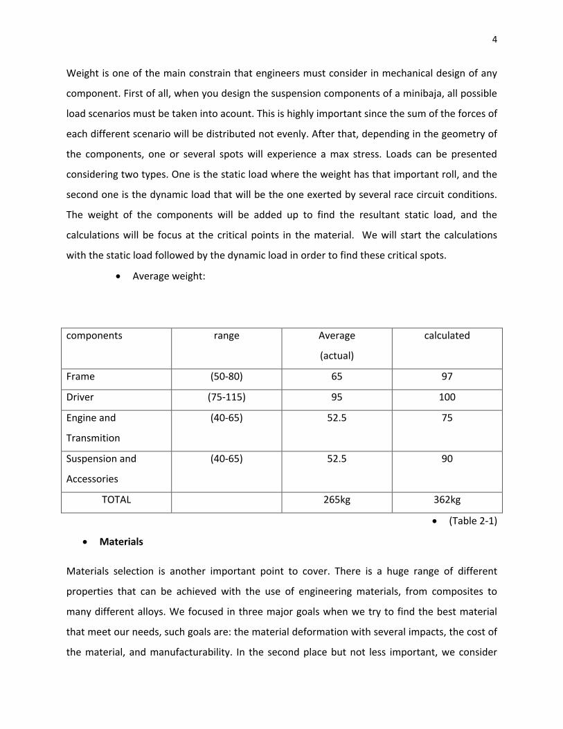
Weight is one of the main constrain that engineers must consider in mechanical design of any
component. First of all, when you design the suspension components of a minibaja, all possible
load scenarios must be taken into acount. This is highly important since the sum of the forces of
each different scenario will be distributed not evenly. After that, depending in the geometry of
the components, one or several spots will experience a max stress. Loads can be presented
considering two types. One is the static load where the weight has that important roll, and the
second one is the dynamic load that will be the one exerted by several race circuit conditions.
The weight of the components will be added up to find the resultant static load, and the
calculations will be focus at the critical points in the material. We will start the calculations
with the static load followed by the dynamic load in order to find these critical spots.
Average weight:
components range Average
(actual)
calculated
Frame (50-80) 65 97
Driver (75-115) 95 100
Engine and
Transmition
(40-65) 52.5 75
Suspension and
Accessories
(40-65) 52.5 90
TOTAL 265kg 362kg
(Table 2-1)
Materials
Materials selection is another important point to cover. There is a huge range of different
properties that can be achieved with the use of engineering materials, from composites to
many different alloys. We focused in three major goals when we try to find the best material
that meet our needs, such goals are: the material deformation with several impacts, the cost of
the material, and manufacturability. In the second place but not less important, we consider

5
the weight of components and the operating temperature since this project is design to operate
at a temperature of 23.9 degrees Celsius. The material which best match these requisites was
the alloy steel 4130 which is also known as chromoly. Steel 4130 properties are explained in
detail in the following paragraphs.
Properties

6
Properties chart:
Materials
Modulus of
elasticity
(GPa)
Yield strength
(MPa)
Tensile
Strength
(MPa)
Percent
Elongation
Density
(g/cmE3)
Alloy ti-6AL-
4V
114 830 900 14 4.43
Tungsten
(commercial)
400 760 960 2 19.3
Steel alloy
A36
207 220-250 400-500 23 7.85
AISI 4130
CHROMOLY
210 360.6 560.6 28.2 8
Stainless alloy
304
193 205 515 40 8
(TABLE 2-2)
AISI 4130 chromoly has Average properties that match a wide range of operating
scenarios, unlike it fails in extreme loaded conditions, those extraordinary cases were
calculated assuming top speed impacts, neglecting any driver maneuvers and without
applying braking.
Since the elongation range is considerably wide, we have found out that chromoly can be
an excellent option. A big range in the plastic region will give us a warning when the
components must be replaced, and it will also help us to avoid a sudden fracture. Also, the
yield strength is high enough to withstand several scenarios with considerable load range
without being deformed.

7
LOADS
Horizontal impact
with a magnitude
of 80325 N
Static load
Horizontal force
impact
Vertical load due to the weight of the
vehicle with a magnitude of 1252 N

8
3. DESIGN INTRODUCTION
OVERLOOK
The suspension designed for the
MiniBaja cart consists of two single
control arms that are attached to the
upright and the hub that is mounted on
the spindle, as shown in Figure 3.1. The
frame of the existing cart will have to be
modified in order to hold the top arm,
the bottom arm, and the shock absorber.
The following paragraphs will go more
in detail in the description of each
individual part.
Figure 3.1: Front view of the complete assembled
suspension.
Load due to falling
Highest suspension load generated due to
a fall of .5 Meters which has a magnitude
of 11,014.4 N

9
PARTS
The top arm will be connected by a ball joint to the upright, and will be pinned to the frame,
and was designed to have an adjustable length. The top arm will consist of one solid shaft
that will have a nut fixed in the center and it will be threaded on both sides. The solid shaft
will fit into the two shafts that will have a hole at the ends. Both shafts will have an inner
thread and the ends will be secured by two additional nuts, one on each side. The top arm
was designed adjustable in length to take advantage of the track and the environment in
which the cart will be placed. For example, if the track only requires the cart to take right
turns the length of the arm can be adjusted to change the angle of the tire which will
minimize over steer. The range of the length of the upper arm can be adjusted between the
lengths of 420 millimeters and 480 millimeters. The ball joint that will have to be placed at
one ends of the arm will have to be placed into the arm by force. The following image
shows the finished arm.
Figure 3.2
The bottom control arm is considered a reinforced single arm. The bottom arm, like
the top arm, will be pinned to the frame and will be attached to the upright with a ball joint.
The bottom arm will also hold the shock absorber in place at approximately two thirds of
the whole length away from the frame. The bottom arm will have two connections that
were designed so that the shock will not have touch the top face of the arm. The dimensions
of the shock that we used will be given further on. If a shock with different dimensions is

10
used, then the extrusions should be modified accordingly. In order to reduce the weight of
the bottom arm, material will be removed between the connection at the pin and the shock
absorber connection. In order to reduce the stress concentration we added two solid shafts
that form an “X”. The lower arm also contains a reduction in cross-sectional area. This was
done so that the bottom arm does not limit the tire’s turning angle. The ball joint that will
connect the arm to the upright will be put in by force, and the appropriate dimensions for
the lower control arm will be given further on.
Figure 3.3
The upright will hold the upper control arm, the lower control arm, the spindle, the
tie rod and the brake caliper. The control arm connections will be aligned vertically with
the spindle. The hole in which both the upper arm ball joint and the bottom arm ball joint
was given a diameter of 11 millimeters which will give a clearance of 1 millimeter. The hole
in which the spindle will be placed will be approximately in the center of the spindle. The
hole will perforate the upright. The upright has a small extrude of a thickness of 5
millimeters. This will not allow the hub to come into contact with the upright and cause
friction. In order to avoid a direct impact to the tie rod, the upright was designed to hold
the tie rod between the control arms and at the position farthest away from the front of the
cart. Additional extrudes were placed on the upright toward the front of the cart in order to
mount the brake caliper.

11
Figure 3.4
The spindle will be placed by force into the upright. The spindle has three different
diameters. The largest diameter will be inserted into the upright. Then the following
diameters hold the hub in place. There is a gradual decrease of diameter in the two smaller
diameters in order to avoid the concentration of stress in the shoulder. The spindle will
also have a thread at the smallest diameter with a length of approximately 25 millimeters.
This will allow the tire rim to also be placed here and reinforced with a nut.
Figure 3.4
The hub will be mounted on the spindle and will also hold the disk. The main shape
of the hub consists of a large “X” which will hold the tire rim in place. The hub also has an
area in which the disk will be mounted. The hub was also designed with holes which allow
the disk to be tightly secured. The inside of the hub will also include the gradual decrease of
diameter between the two smaller diameters in order to match the design of the spindle.
12
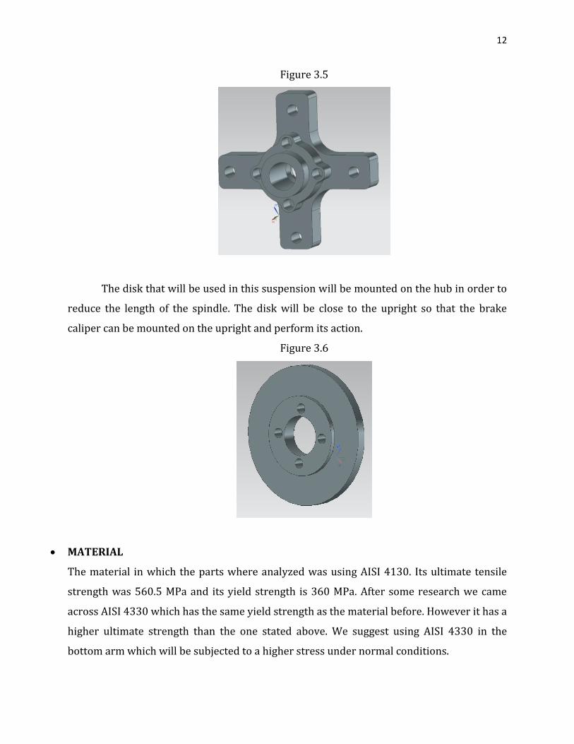
Figure 3.5
The disk that will be used in this suspension will be mounted on the hub in order to
reduce the length of the spindle. The disk will be close to the upright so that the brake
caliper can be mounted on the upright and perform its action.
Figure 3.6
MATERIAL
The material in which the parts where analyzed was using AISI 4130. Its ultimate tensile
strength was 560.5 MPa and its yield strength is 360 MPa. After some research we came
across AISI 4330 which has the same yield strength as the material before. However it has a
higher ultimate strength than the one stated above. We suggest using AISI 4330 in the
bottom arm which will be subjected to a higher stress under normal conditions.

13
PROS
In comparison with the original design this new design has many pros and cons. One of the
advantages that our new design has is that the whole design has calculations behind it.
Another advantage is that our design has an adjustable upper arm that will allow the driver
to take advantage of the track and the environment in which the cart will be placed. Also
our design has a completely different lower control arm. The lower control arm is a single
arm that has a larger cross-sectional area that will reduce the normal stress of the part.
Also when taking into account the spindle, we added a chamfer in order to reduce the
stress that a shoulder will cause between the hub and spindle. Another advantage to this
design is that we placed the tie rod in the back of the assembly. The reason for this is to
protect the tie rod from a frontal impact. However there are some details that will make
our design less ideal.
CONS
One of the disadvantages to our design is that the lower arm compared to the current
design will weight a significantly more. Also another disadvantage to this design is that if
the upper arm were to be modified to a smaller diameter, it may fail even in static load.
Also another disadvantage to our design is that all of the parts must be machined.
4. 3D MODEL DRAWING
The 3D modeling was created using the software NX6 which has been a very helpful and handy
tool in the design. Within the next pages we can appreciate a series of pictures where every
component of the suspension is described. Also there are a couple is images where every single
component has been assembled in order to appreciate the final look of this suspension
prototype.

14
Frontal left side view
Down side view

15
Upside view
True shading
16
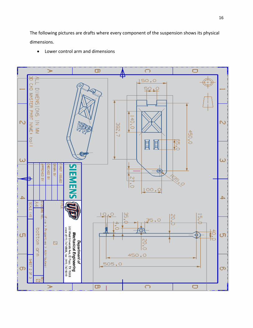
The following pictures are drafts where every component of the suspension shows its physical
dimensions.
Lower control arm and dimensions
17
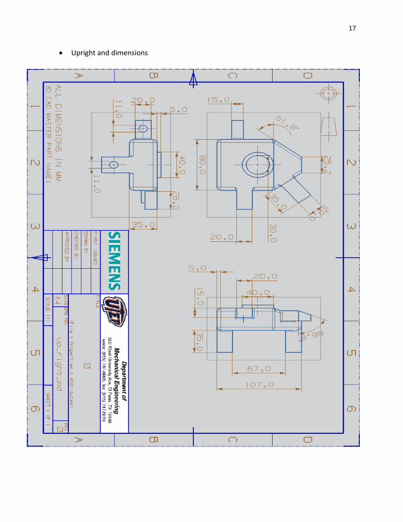
Upright and dimensions

18
Upper arm and dimensions
19
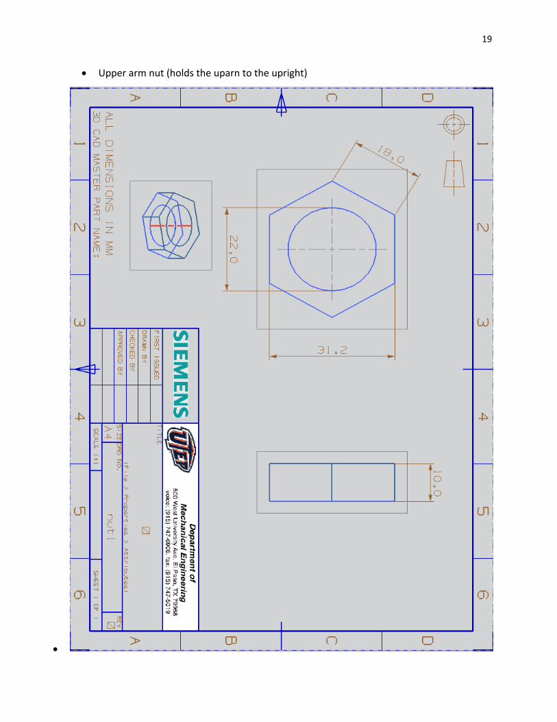
Upper arm nut (holds the uparn to the upright)

20
Disk and dimensions
21
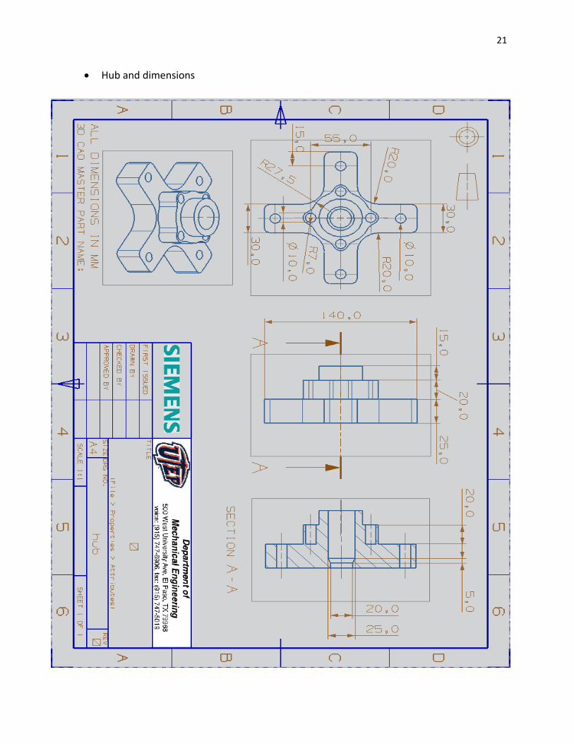
Hub and dimensions

22
Shock screw and nut and dimensions

23
Spindle and dimensions

24
5. ANALYSIS
Our mass of the car + person will be converted into a force and then divided into four parts,
one for each suspension (two frontal, two in the back). This was calculated to b 887.8 N,
from the maximum considerations in the mini-baja rules.
The weight W=887.8 N was then magnified for each part of the suspension, due to the fact
that its equivalent moment needed to be taken into account. It’s assumed that the center of
mass of the cart is at the middle, .634 m away from the tire. These are the calculations
which show the weight equivalence for each bar:
Top arm: ( )
Bottom arm: ( )
These equivalent forces are according to the moment equivalence, due to the fact that the
top arm is shorter, and farther away from the center of mass. Since both arms are parallel,
but at an angle (30) according to the applied force, we need to establish a new set of axis,
which will show us the normal and bending forces applied, according to each situation. x’
will represent the axial forces, parallel to the bar; y’ will characterize those that are
perpendicular.
In the picture, the parallel axes are shown along with the direction of the applied force. The
normal x-y plane is shown in the upper right corner. Once these have been established, one
realizes that the applied force can be broken up into x’ and y’ components. The formula for
these will be as such:
25
After these particularities have been exposed, different cases were ready to be analyzed. In
the following scenarios, a rough sketch of setup is provided.
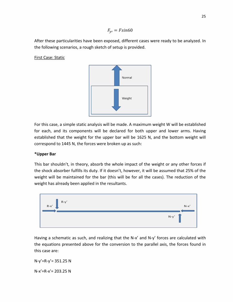
First Case: Static
For this case, a simple static analysis will be made. A maximum weight W will be established
for each, and its components will be declared for both upper and lower arms. Having
established that the weight for the upper bar will be 1625 N, and the bottom weight will
correspond to 1445 N, the forces were broken up as such:
*Upper Bar
This bar shouldn’t, in theory, absorb the whole impact of the weight or any other forces if
the shock absorber fulfills its duty. If it doesn’t, however, it will be assumed that 25% of the
weight will be maintained for the bar (this will be for all the cases). The reduction of the
weight has already been applied in the resultants.
Having a schematic as such, and realizing that the N-x’ and N-y’ forces are calculated with
the equations presented above for the conversion to the parallel axis, the forces found in
this case are:
N-y’=R-y’= 351.25 N
N-x’=R-x’= 203.25 N

26
One must also realize that the summation of forces must overall equal to zero, and such the
net forces will be nonexistent. The shear and moment diagrams will be presented next:
With these, one can realize that the maximum moment will exist at the edge of the bar. The
moment calculated using F*d equals 140.7 N*m. (The length of the bar is .4m). This
moment will later be used in the calculation of bending stress.
Checking for yielding
A=.00196 C=.0125
( )
( )( )
( )
( ) ( )
( )
27
( )( )
( )
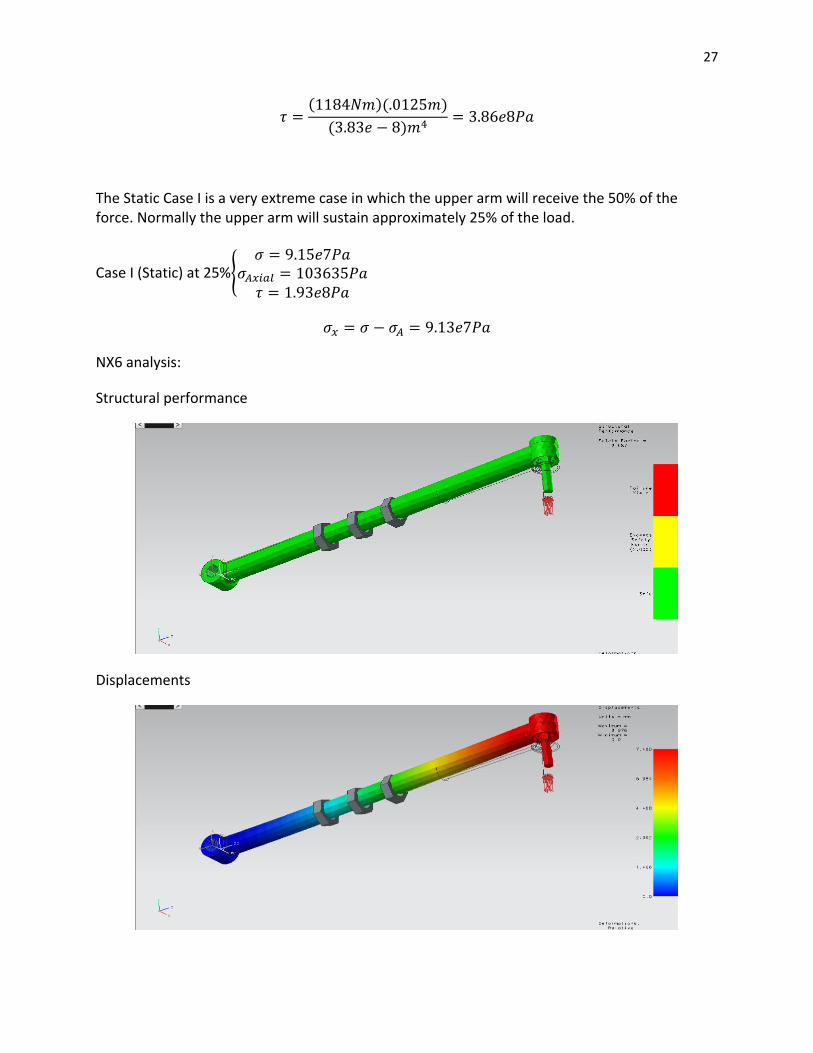
The Static Case I is a very extreme case in which the upper arm will receive the 50% of the force. Normally the upper arm will sustain approximately 25% of the load.
Case I (Static) at 25%{
NX6 analysis:
Structural performance
Displacements

28
Stresses
*Lower Bar
Since the shock absorber will not fulfill its duty when the suspension is at a static position,
the force diagram for the lower bar will be equal to the one in the upper bar. For all cases, it
will be assumed that the impact is absorbed 100% by this component.
The value of the calculated forces is as such:
N-y’=R-y’=1252 N
N-x’=R-x’=722.5 N
The shear and moment diagrams are, then, the same as the last case.

29
The calculation of the maximum moment is obtained by simply multiplying the N-y’ force by
the .45 m (length of the bar). This value is equal to 563.4 N*m.
Checking for yielding
( )( )
( )( )
( )
( )
( )
( )
*Note: The shear stress will be that same in each case scenario since there is no Polar moment
of Inertia, and just one Torque is acting on the element. The formula used to obtain the Shear
stress was attained from a book for Mechanics of Materials, that formula was intended for a
square cross-sectional area therefore we used our dimension to obtain an area and from there
we obtained an equivalent dimension.
C=.02m A=.00216m
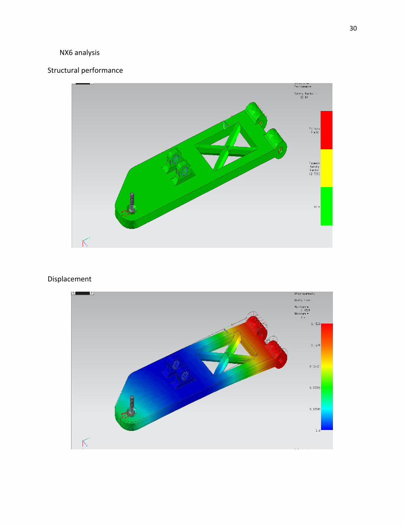
30
NX6 analysis
Structural performance
Displacement

31
Stresses
Spindle
Check for yielding
F=1252N
( )
( ) (
) ( )
( )
NX6 analysis
STRUCTURAL PERFORMANCE

32
DISPLACEMENTS
STRESSES

33
Upright
F=1252N(0.70) =876.4N
( )( )
( )( )( )
( )
NX6 analysis
Structural performance
Displacements

34
Stresses
Second Case: Horizontal Crash
The second case presents us with an impact in the leftover axis, which would correspond to
z’. (Frontal impact to the car). In this case, the force was calculated by generating an impact
force, described by
Since the average velocity of the car is calculated to be 40 mph, this would correspond to
17.85 m/s; the time assumed for the impact is .04 seconds, derived from different examples
present in physics books. The final velocity is 0m/s. If the mass is calculated to be 90 kg (a
fourth of the combined masses), the impact force is calculated to be 80325 N. Since this
new force is presented in the z’ axis, the remaining x’ and y’ forces will continue to have the
same values. The pictures present here are assumed to be of the x’-z’ plane.
*Upper bar

35
As stated, the total force will only be applied by 25% of its magnitude. The schematic will
remain as such:
It is to be noted however that the y’ axis forces are replaced by z’ axis ones (frontal impact).
The values for these are as such:
R-x’=N-x’=203.25 N
R-z’=N-z’=10040.8 N
The shear and moment diagrams are omitted as their inclusion will be redundant; one can
appreciate that for the upper bar, the maximum moment will be generated at the edge.
Once again, multiplying the bending force times the length of the bar (.4m), the resultant
moment will be: 4015 N*m.
Check for yielding
A=cross-sectional area
C=distance from neutral axis to edge
A=.00196 C=.0125
Case II at 25%{
( )( )
( )( )
We now substitute our values in the von Mises stress equation
√ [( )
( )
( )
(
)]
⁄
We get
Now we substitute this value in the equation:

36
*Note: For this given scenario the stress will be greater than the Ultimate strength of the
material, therefore it will fail.
NX6 analysis
Answer quality
Displacement

37
Stresses
*Lower bar
In the lower bar, the shock absorber has not been included in the forces yet, due to its
parallel configuration in this setup. The force schematic will be repeated.
The values for the forces found to be acting as reactions were found to be:
N-x’=R-x’=722.5 N
N-z’=R-z’=40163 N
The shear and moment diagrams will have the same schematic as before, for which the
multiplication of the bending force times the length of the bar (of .45 m), the maximum
moment calculated is to be 18073.15 N*m.
Check for yielding
For Case II {

38
( )( )
( )( )
We now substitute our values in the von Mises stress equation
√ [( )
( )
( )
(
)]
⁄
We get
Now we substitute this value in the equation:
Lower arm structural performance
Displacement
39
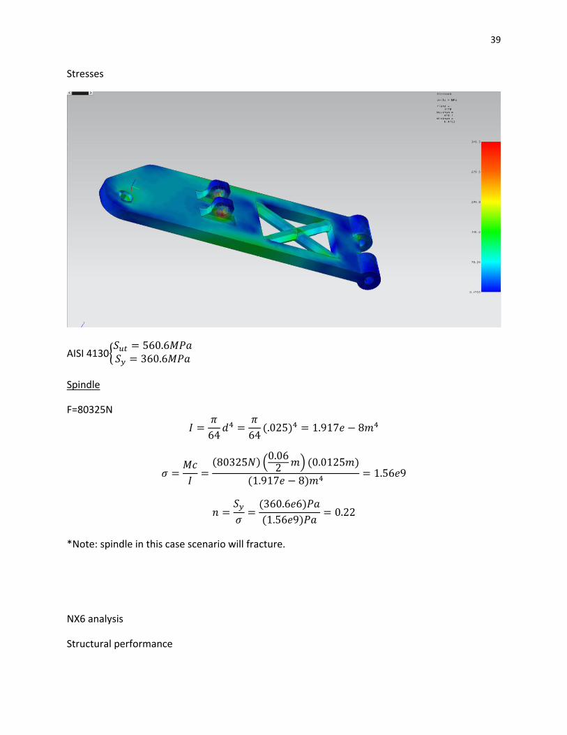
Stresses
AISI 4130{
Spindle
F=80325N
( )
( ) (
) ( )
( )
( )
( )
*Note: spindle in this case scenario will fracture.
NX6 analysis
Structural performance
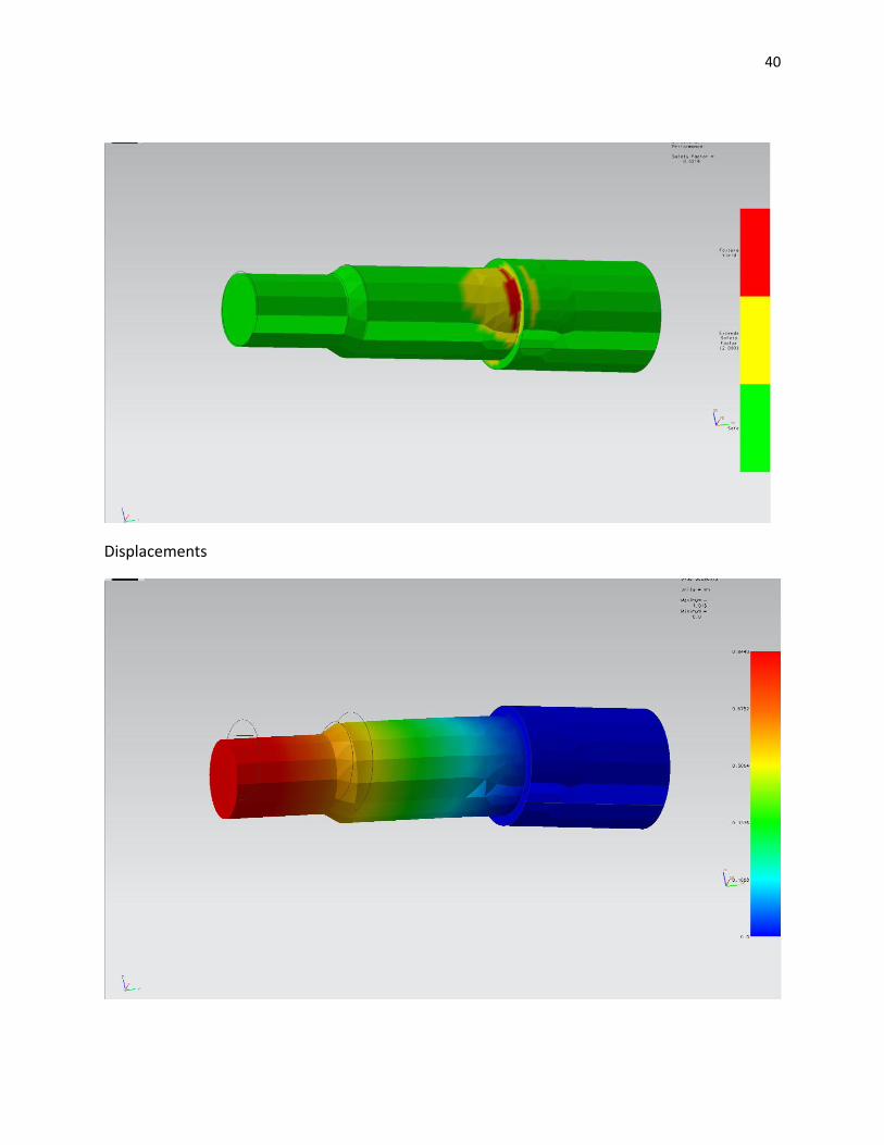
40
Displacements

41
Stresses
Upright
F=80325N
( )( )
( )( )( )
( )
( )
( )
*Note: upright in this case scenario will fracture.
NX6 analysis
Upright Structural performance

42
Displacements
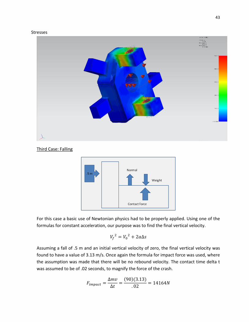
43
Stresses
Third Case: Falling
For this case a basic use of Newtonian physics had to be properly applied. Using one of the
formulas for constant acceleration, our purpose was to find the final vertical velocity.
Assuming a fall of .5 m and an initial vertical velocity of zero, the final vertical velocity was
found to have a value of 3.13 m/s. Once again the formula for impact force was used, where
the assumption was made that there will be no rebound velocity. The contact time delta t
was assumed to be of .02 seconds, to magnify the force of the crash.
( )( )

44
Since the contact force and the weight are in different directions, the normal force (that will
ultimately be applied to the bars) was calculated by taking the difference between them.
*Upper Bar
Basically, the schematic diagram for the force analysis will remain constant for this bar.
Once again, only 25% of the whole force was used, for idealization purposes.
R-y’=N-y’=2715 N
R-x’=N-x’=1567.5 N
The shear and moment diagrams remain the same
Finally, the maximum moment is calculated to be the bending force times the length (.4 m).
The moment magnitude is 1086 N*m.

45
Check for yielding
A=.00196 C=.0125
( )
( )( )
( )( )
( )
( )( )
( )
*Note: For this given scenario the stress will be greater than the Ultimate strength of the
material, therefore it will fail.
NX6 analysis
Structural performance

46
Displacement
Stresses

47
*Lower Bar
For the lower bar, the shock absorber will finally play a role, stabilizing the system and
allowing the energy to be dispersed. Since the summation of forces always needs to be
zero, one end of the bar will sustain an enormous normal force, while the other maintains
its original values. The schematic of forces will be as such, along with the magnitude of the
reactions:
N-x’=R-x’=6359 N
R-y’=1252 N
N-y’= 11014.4 N
Shock Absorber Reaction= 9762.4 N
The shear and moment diagrams finally change, but still show us that the maximum
moment will be present at the end of the bar, where the piece joins the spindle.
The calculation of the maximum moment is as such:
( ) ( )( )
This takes into account the distance from the shock absorber to the edge of the bar.
Check for yielding

48
( )( )
( )( )
( )
( )
( )
( )
NX6 analysis
Lower arm structural performance
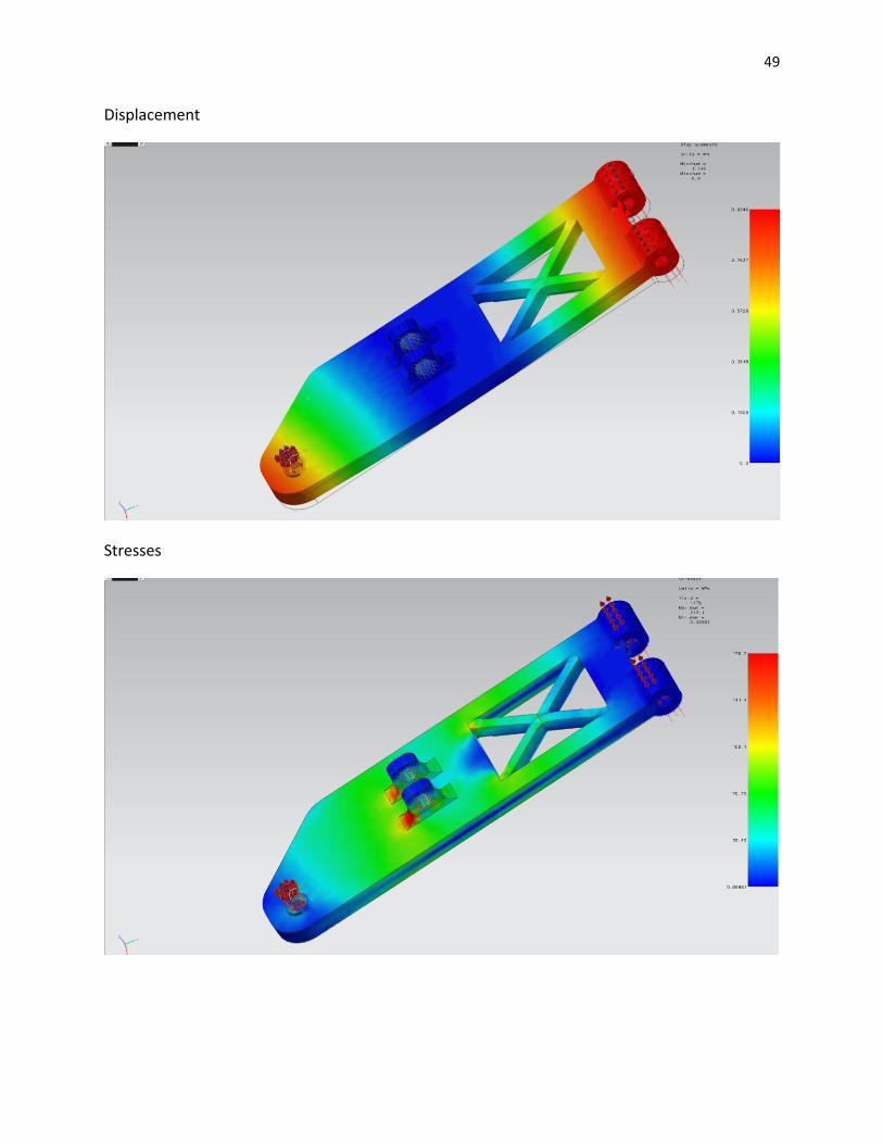
49
Displacement
Stresses
50
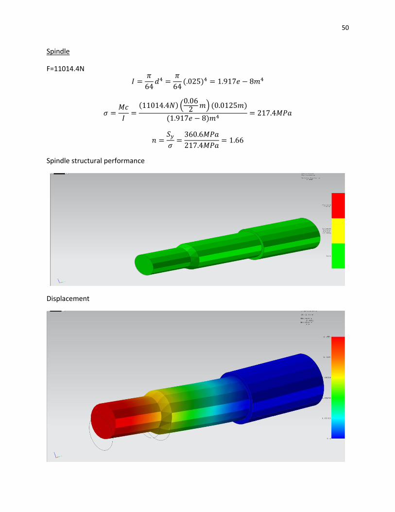
Spindle
F=11014.4N
( )
( ) (
) ( )
( )
Spindle structural performance
Displacement
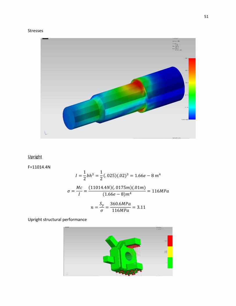
51
Stresses
Upright
F=11014.4N
( )( )
( )( )( )
( )
Upright structural performance

52
DISPLACEMENT
Stresses

53
Fourth Case: Bump
In this case, we will assume that the vehicle cruises by at 40mph=17 m/s and sees a semi-
circular bump of .5 m radius. Passing through this bump generates a resultant centripetal
force, which then magnifies our normal force. The equation for this schematic is:
The weight (maximum) was given by the first case, where the setup is static with a
maximum mass. The centripetal force is given by this formula:
The normal force, which will affect our bars, was taken then by subtracting the individual
components of weight from the centripetal force schematic in axial and shear.
*Upper Bar
The upper bar will receive this greatly magnified force by only 25%, as stated. The moment
created will, however still be large and might compromise the integrity of the design.
The force schematic remains as:
Where,
R-x’=N-x’=7412.1 N

54
R-y’=N-y’=12837.8 N.
The shear and moment diagrams show us that the maximum moment is still concentrated
on the end of the bar. Since there are no sharp diameter changes to be considered, it is to
be noted that this will be used to calculate the critical location of the bar. A stress analysis
of the joints of a machine such as this one show us that this assumption is correct, as failure
occurs more than often in these locations.
The calculated maximum moment is then 5135.2 N*m.
*Lower Bar
For the lower bar, the shock absorber will once again have a chance to act and balance the
system. The force schematic is then:
Where:
R-x’=N-x’= 29557.5 N
R-y’= 1252 N
Shock Absorber Reaction=49944.3 N
N-y’= 51196.3 N
The shear and moment diagrams repeat themselves for this case.
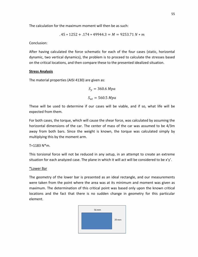
55
The calculation for the maximum moment will then be as such:
Conclusion:
After having calculated the force schematic for each of the four cases (static, horizontal
dynamic, two vertical dynamics), the problem is to proceed to calculate the stresses based
on the critical locations, and then compare these to the presented idealized situation.
Stress Analysis
The material properties (AISI 4130) are given as:
These will be used to determine if our cases will be viable, and if so, what life will be
expected from them.
For both cases, the torque, which will cause the shear force, was calculated by assuming the
horizontal dimensions of the car. The center of mass of the car was assumed to be 4/3m
away from both bars. Since the weight is known, the torque was calculated simply by
multiplying this by the moment arm.
T=1183 N*m.
This torsional force will not be reduced in any setup, in an attempt to create an extreme
situation for each analyzed case. The plane in which it will act will be considered to be x’y’.
*Lower Bar
The geometry of the lower bar is presented as an ideal rectangle, and our measurements
were taken from the point where the area was at its minimum and moment was given as
maximum. The determination of this critical point was based only upon the known critical
locations and the fact that there is no sudden change in geometry for this particular
element.

56
The area moment of inertia for this is described with the formula
( )( )
The area of this cross section will have a value of .00216 m^2
The value of c (distance from the neutral axis to the upper surface) will correspond to .01 m
In the case of the calculation of the torsional shear stress, since the polar moment of inertia
of the rectangle is unknown, and the usual formula cannot be applied, it was found that the
maximum torsional shear stress of a square is given by
Where “a” is the value of one side of the square. In order to find a, the area of the rectangle
was calculated, and an equivalent square imagined. “a” would be the value of the square
root of the area, giving the length.
The normal stress of the loads was given with the formula
Where P is the axial load present in each situation. This was calculated in the force setup.
Since the value for all Ps is in compression, the normal stress will be subtracted from the
bending stress.
Finally, the bending stress is given by the formula
The values needed for this equation have already been found. The results of all the stresses
and torsional shear stress is presented below.
Case I

57
Case II
Case III
Case IV
*Upper Bar
The geometry of the upper bar is a perfect, solid circle with a diameter of .25 mm. The
determination of the critical point was given as the place where the moment is greatest,
which is at the joints. The diameter will not decrease suddenly, which also helps us assume
a specific critical location.
The area moment of inertia for this is described with the formula
( )
The polar moment of inertia for the cross section is given with
( )
The area of this cross section will have a value of .00196 m^2

58
The value of r (distance from the neutral axis to the upper surface) will correspond to .0125
m
Using the moments calculated in the force analysis the maximum stresses and torsional
shear forces were able to be calculated. The values for normal and bending stress are given
by the formulas presented in the lower bar analysis. The only formula that will differ is that
one for torsional shear stress. The formula, corresponding to a more traditional (and much
more used) setup is then
The individual results for the upper bar are presented as such:
Case I
Case II
Case III
Case IV
Failure Analysis
Even though the last three cases given correspond to a dynamic setup, one must also
analyze what effect would these forces, if given as static, have on the suspension. For this,

59
there are several manners in which the calculations can be done, the first one
corresponding to the formula
For this case, however, it would be best to use one of the conservative, ductile theories, in
this case distortion energy. This theory uses the main formula
For which corresponds to the von misses stress. The formula to obtain the factor of
safety is based upon the yield strength of the material and this calculated, modified stress.
√ [( )
( )
( )
(
)]
⁄
Using the solutions found in the stress analysis, the factor of safety for a static configuration
is able to be obtained.
*Upper Bar
Case 1
Case 2
Case 3
Case 4

60
Conclusion: From the point where the stresses were calculated, it was apparent that some
exceeded the ultimate tensile strength, corresponding to 560.5 MPa. The calculation of the
factor of safety was just a formality, as one knows that after this limit is reached, the
material will break. Thus, only case one will hold the required load. This shows us that if our
shock absorber were to fail, and the upper bar need to take ¼ of the load, it would hold for
a period of time; if the mini-baja was driven and set up in extreme situations (both
horizontal and vertical dynamic) the components would break and the setup fail. This,
however, does not mean that the design is flawed. It simply implies that the shock absorber
is a very important component of every suspension design.
*Lower Bar
Case 1
Case 2
Case 3
Case 4
Conclusion: Out of this setup, two factors of safety resulted as more than one, which is the
limit that allows us to conclude that the material will hold. Cases two and four represent
61
extreme situations in which the lower arm would immediately break. When the setup of
these was calculated, this was unknown; the calculation of these was informative and
shows us that an optimization, or several designs would be needed to achieve maximum
reliability and strength.
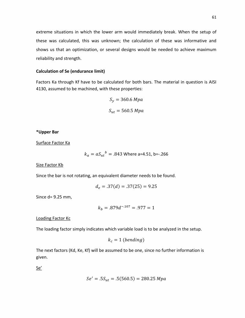
Calculation of Se (endurance limit)
Factors Ka through Kf have to be calculated for both bars. The material in question is AISI
4130, assumed to be machined, with these properties:
*Upper Bar
Surface Factor Ka
Where a=4.51, b=-.266
Size Factor Kb
Since the bar is not rotating, an equivalent diameter needs to be found.
( ) ( )
Since d= 9.25 mm,
Loading Factor Kc
The loading factor simply indicates which variable load is to be analyzed in the setup.
( )
The next factors (Kd, Ke, Kf) will be assumed to be one, since no further information is
given.
Se’
( )

62
Se
( )( )( )
*Lower Bar
Surface Factor Ka
Size Factor Kb
Since the cross section of the bar is not circular, and it’s not rotating, an equivalent
diameter needs to be found.
( )
Since d=26.5 mm,
Loading Factor Kc
The loading factor simply indicates which variable load is to be analyzed in the setup.
( )
The next factors (Kd, Ke, Kf) will be assumed to be one, since no further information is
given.
Se’
( )
Se
( )( )( )
Operating Range
Dynamic

63
The operating range for the dynamic cases is able to be found using the modified Goodman
equation, if one were to consider the stress as having fluctuating characteristics. In all cases,
our idealized factor of safety will correspond to 2.
Modified Goodman
Stress Amplitude
Mean Stress
*Horizontal
For this case, our minimum stress would obviously correspond to a value of zero, as it’s not
expected for the vehicle to be continuously hit horizontally by other than the force of air
resistance or small pebbles. If one were to determine our maximum stress using the
modified Goodman equation and assuming this, the setup would look as such:
The value for maximum stress will then be 7.52 E7 Pa, or 75.2 Mpa.
The operating range for horizontal, continuous impact will thus be from 0 to 75.2 Mpa.
*Vertical
In this case, our minimum stress will be given by our maximum total load-calculated stress,
which is already in the past calculations. Two situations are presented: where the shock
absorber fails and the upper bar needs to carry 25% of the load, and that where the lower
bar takes 100% of the shock. Modified Goodman is once again applied for a safety factor of
two, and our operating range is found.
-Upper bar
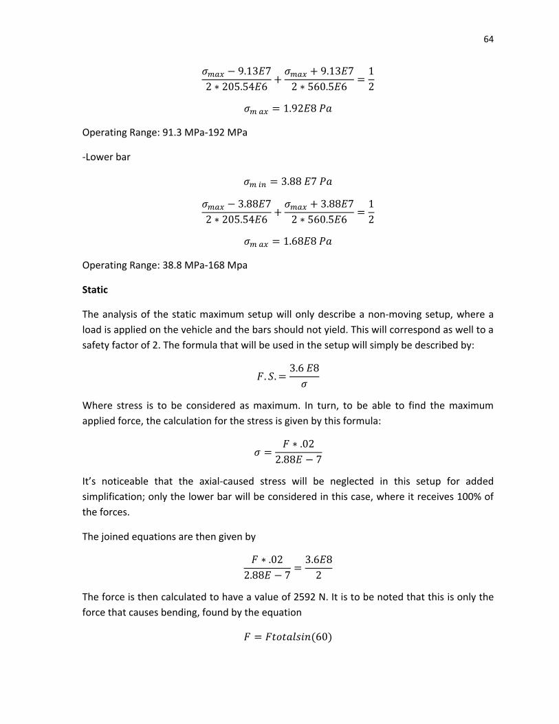
64
Operating Range: 91.3 MPa-192 MPa
-Lower bar
Operating Range: 38.8 MPa-168 Mpa
Static
The analysis of the static maximum setup will only describe a non-moving setup, where a
load is applied on the vehicle and the bars should not yield. This will correspond as well to a
safety factor of 2. The formula that will be used in the setup will simply be described by:
Where stress is to be considered as maximum. In turn, to be able to find the maximum
applied force, the calculation for the stress is given by this formula:
It’s noticeable that the axial-caused stress will be neglected in this setup for added
simplification; only the lower bar will be considered in this case, where it receives 100% of
the forces.
The joined equations are then given by
The force is then calculated to have a value of 2592 N. It is to be noted that this is only the
force that causes bending, found by the equation
( )

65
For which the total force is found to be 6651 N. If this total force is then assumed to be
corresponding to a weight, and multiplied by 4 suspensions, the maximum amount of mass
that would be accepted in this setup would be of 2712 kg. (For both the frame and other
added weights).
The operating range is then from the original mass of the frame to 2712 kg.
Life Cycle
It is to be noted that the modification factor kf is going to be neglected for simplification,
and also due to the fact that in these bars there are no sharp changes in geometry, but
rather happen gradually.
Given that the factors of safety of three cases obtained by the distortion energy theory are
more than one, the lives for these situations would be assumed to be infinite. For
instructive purposes, however, the cycles to failure will be calculated. Note: Infinite life is
assumed where the cycles to failure exceed E6. The factor f, to be used in a and b, is found
to be approximately .875, according to a specialized table. For simplification purposes, the
reversible stress will be assumed to be that which was found in the initial assessment. The
equations that will be used in this case are as such:
(
)
( )
(
)
*Upper Bar
( )
(
)
Case I
(
)
66
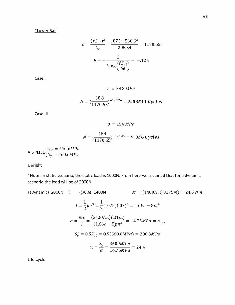
*Lower Bar
( )
(
)
Case I
(
)
Case III
(
)
AISI 4130{
Upright
*Note: In static scenario, the static load is 1000N. From here we assumed that for a dynamic
scenario the load will be of 2000N.
F(Dynamic)=2000N F(70%)=1400N ( )( )
( )( )
( )( )
( )
( )
Life Cycle

67
*Note: All the factors and necessary data were obtained from figures and tables in Shigley’s
Mechanical Engineering Design book.
These are factors of temperature, surface, size, loading, reliability and miscellaneous-effects taking into account to calculate the endurance limit: Ka=0.84 Kb=0.91 Kc=1 Kd=1
( )( )( )
Using Figure A-15-6 {
From Figure 6-20 we assume q=0.8
( ) ( )
“f” is a material property that varies with Sut. From fig. 6-18 we get that f=0.87
( )
( )
(
)
(
)
⁄
( ( )
)
⁄
Spindle
( )
( )( )( )
( )
Life Cycle
*Note: All the factors and necessary data were obtained from figures and tables in Shigley’s
Mechanical Engineering Design book.

68
These are factors of temperature, surface, size, loading, reliability and miscellaneous-effects taking into account to calculate the endurance limit: Ka=0.843 Kb=0.879 Kc=1 Kd=1
( )
( )( )( )
Using Figure A-15-6 {
From Figure 6-20 we assume q=0.7
( ) ( )
“f” is a material property that varies with Sut. From fig. 6-18 we get that f=0.87
( )
( )
(
)
(
)
⁄
( ( )
)
⁄
Bottom Arm (under normal driving conditions)
*Note: Because the static load of the cart is approximately 1000N, we assume that in normal
driving conditions the force applied will be 2000N
F=2000N
( )( )
( )( )( )( )
( )
( )( )

69
( )
( )
( )
√ √ ( )
Life Cycle
*Note: All the factors and necessary data were obtained from figures and tables in Shigley’s
Mechanical Engineering Design book.
These are factors of temperature, surface, size, loading, reliability and miscellaneous-effects
taking into account to calculate the endurance limit:
Ka=0.84
Kb=0.88
Kc=1
Kd=1
( )
( )( )( )
Using Figure A-15-6 we assumed an approximation for a notch radius of 1mm, because the
geometry we used for our component doesn’t match the tables at the back of the book.
From Figure 6-20 we assume q=0.7
( ) ( )
“f” is a material property that varies with Sut. From fig. 6-18 we get that f=0.87
( )
( )
(
)
70
(
)
⁄
( ( )
)
⁄
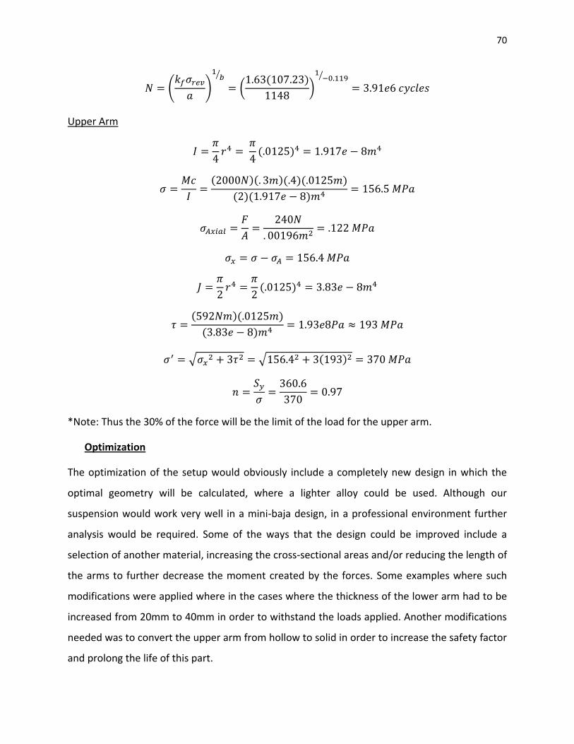
Upper Arm
( )
( )( )( )( )
( )( )
( )
( )( )
( )
√ √ ( )
*Note: Thus the 30% of the force will be the limit of the load for the upper arm.
Optimization
The optimization of the setup would obviously include a completely new design in which the
optimal geometry will be calculated, where a lighter alloy could be used. Although our
suspension would work very well in a mini-baja design, in a professional environment further
analysis would be required. Some of the ways that the design could be improved include a
selection of another material, increasing the cross-sectional areas and/or reducing the length of
the arms to further decrease the moment created by the forces. Some examples where such
modifications were applied where in the cases where the thickness of the lower arm had to be
increased from 20mm to 40mm in order to withstand the loads applied. Another modifications
needed was to convert the upper arm from hollow to solid in order to increase the safety factor
and prolong the life of this part.

71
6. DRAWBACKS (LIMITATIONS OF DESIGN)
Just like any other design, this prototype suspension has some drawbacks, in other words there
are some limitations in its design. The following points do explain and develop such limitations:
MANUFACTURABILITY/MACHINE
It is very important for engineers to design for manufacturability. In other words the
components, parts or the entire assembly being designed need to be relatively easy to
manufacture. If a component can be easily manufactured, it means the productions costs can
be taken to a minimum and production speed can be improved. For this project it was taken
into consideration to design the components of the suspension to be ease to manufacture. In
other words most of the parts can be fabricated with basic tools.
The most challenging part to manufacture is the lower arm of the suspension. The frame of this
arm needs to be machined in order to obtain the best results. This lower arms was designed to
save weight, therefore mass was removed in designated points of the arm without scarifying
the integrity of the structure while some reinforcement were added where the mass was
removed. Such reinforcement is tubular in shape and need to be welded in place in an X shape
which adds some degree and difficulty to manufacture. The end link which attaches to the
upright is another point of the lower arm which is a little complex to fabricate. This is because it
is necessary to place a ball joint in this place which will hold the lower arm and upright
together. This ball joint base needs to be manufactured with very strict standards of
measurement in order to provide the best performance.
The upright is one of the most important parts of this system since it connects all parts of the
suspension together. Thus it was important for our team to come up with an efficient, strong,
light weight model. The model proposed is a very exceptional piece which its benefits are low
mass, light weight, improved use of space and durability. The drawbacks of this part are the
awkward shape of this part which increases the difficulty in manufacturability. The upright
needs to possess several connection links that need to be strong enough to hold the critical

72
loads which the cart is going to be put into. Such links need to be welded in place, which means
change in geometry is going to be present leading to creating stress concentration factors.
Materials used as described before are going to be AISI 4340 and AISI 4130(most commonly
used as chromoly). Both steels are widely used in the industry which facilitated the ease of
access to them. Machinability of both alloys is considered to be done by conventional methods,
and best with the alloys in normalized and tempered conditions. Respecting to welding both
alloys is noted for their weld ability by all commercial methods. Materials are not really
considered as drawbacks.
7. DISCUSSION
The design project is based on a suspension unit that has a combination of functionality for the
purpose of (SAE Mini-Baja cart) and a concept of saving space.
Actually the cart has a front suspension unit that consists of:
-Two control arms these are made of two tubes at an angle with link connection to the upright
(both upper and lower arm have triangle shape and equal length, but lower arm has a shock
absorber connection).
-The upright has a bolt in connection for the control arms and brake caliper, tie rod and spindle
mounting area respectively.
-The spindle is a solid shaft with diameter reduction along its length and tread at the end to use
a safety nut to maintain the hub on its place.
-The hub with a 4 bolt pattern for the wheel and brake disk respectively and inside bearing.
*Our design has basically the same number of parts but, we decided to save space and material
(as we mentioned in the introduction) by doing some modifications on the control arms and
their connections. We also modify the upright but we kept the same design format for the
spindle and hub in order to obtain better results.
The design we are offering is a front suspension unit with modifications on parts previously
mentioned consists of:
-Two control arms:
73
Upper arm is a single hollow tube that is adjustable using a treaded solid tube in the middle of
the part which has a fixed nut on the center of it and safety nuts a on each side at the end of
the tread. We used a ball joint to connect it with the up right.
Lower arm is a single part (rectangular shape but it has a diagonal cut at the end where is
connected with the upright.) we also use a ball joint as connection with the upright.
-The upright:
We decided to change the width of this part and considered the same height in order to use the
same wheel diameter. We relocated the position of brake caliper, tie rod and control arms
connections to obtain good braking, to use the tie bar in the back of the whole suspension unit
avoiding breakage under hard driving conditions and arm connections in the back of the upright
to obtain good results with the ball joints that we have on the control arms. We use different
dimensions on the mountings to balance the changes we made on the upright.
-We considered that the spindle and the hub will be able to produce good results using them
same as the actual model of the cart.
After we complete some analysis we defined the following:
-The upper arm that we modify fails in certain scenarios, so we notice that failure was produce
on the hollow tube then we decide to make it solid under the same format. Then we find better
results on the analysis.
-We notice certain weaknesses during the analysis of the bottom arm. Then we decided to
double its height and we find good results on different scenarios where we apply load.
-During the analysis of the modified upright we figure out certain load then after applying it on
our critical points, we found that it was having a good reaction with the changes previously
mentioned.
Since our design is completely different to the actual model we compare and discuss its
functionality, material usage, expenses, and other different criteria. Then we decide to design
on the format shown in this report.

74
8. CONCLUSION
After an in depth analysis of each individual part of our suspension unit design we have come to
the conclusion that if we optimize our design it will be a good choice for SAE Mini –Baja
requirements. Some of the optimizations we have in mind include further analyzing the upper
control arm and possibly increasing its diameter; and also considering finding a more
appropriate ball joint for this part. In the optimization section of this report it was mentioned
that because of the increase in height of the bottom arm, we will need to find a more adequate
ball joint for this component that will adapt more to the modified dimensions and increase its
performance. After further review of our analysis we took notice that our spindle and upright
did not fail in any of the presented scenarios. This implies that the two parts that we designed
do not need additional modifications to improve their performance. Putting aside the analysis
of our design, we can say that each of our group members have become more familiar with the
useful tools that were applied during the design process. This includes the NX6 software,
knowledge acquired during lectures, as well as applying basic concepts of design. Furthermore
we had to use knowledge acquired from prior classes not just our current ones.