miniature rain simulator for field measurement of soil infiltration
TRANSCRIPT

DIVISION S-l—NOTES
MINIATURE RAIN SIMULATOR FORFIELD MEASUREMENT OF SOIL
INFILTRATION
C. B. OGDEN,* H. M. VAN Es, AND R. R. SCHINDELBECK
AbstractIn studies of erosion, runoff, and infiltration, high soil variability
may demand many replicate measurements and rapid, inexpensivemethodology. We developed a drop-forming rainfall simulator inwhich flow through long, coiled capillary drip tubes is controlled byan adjustable Mariotte-type bubbling tube. These rain simulators areinexpensive, rugged, simple to operate, easily transported, and requireminimal maintenance. Responses to pressure head and water tempera-ture changes were determined for two simulators using tap water.Flow response to pressure head changes corresponded closely to thatpredicted by Poiseuille's Law. Response to increasing water tempera-tures was somewhat less than predicted, due to formation of bubblesin the capillary tubes. Simulators incorporating long, coiled capillarytubes can provide combinations of low flow rates and large drop sizes,or a desired range of flow rates when appropriate drip tube diameters,lengths, and numbers of tubes per unit area are combined.
RAINFALL SIMULATORS, commonly used in studies oferosion, particle detachment, overland flow, infil-
tration, and surface sealing, fall into two broad catego-ries: nozzle types (e.g., Tossell et al., 1987), and drop-forming types (e.g., Bubenzer and Jones, 1971; Romkenset al., 1975). Moving parts increase the uniformity of
Department of Soil, Crop, and Atmospheric Sciences, Cornell Univ.,Ithaca, NY 14853. Received 20 Mar. 1995. * Corresponding author([email protected]).
Published in Soil Sci. Soc. Am. J. 61:1041-1043 (1997).
rain application, but decrease operational simplicity;one recent design (Kamphorst, 1987) has no movingparts but cannot provide a range of rainfall intensities.
Due to inherent high variability, the parameterizationof spatial, temporal, and treatment effects on soil infil-tration often requires that measurements be completedat many locations within short time periods (van Es,1993). In such cases, the unwieldiness, high water con-sumption, range of application rates, and expense ofmany rainfall simulators can be disadvantageous. In-stantaneous ponding is often used to acquire infiltrationparameters such as sorptivity and field-saturated infil-tration rate (e.g., Reynolds and Elrick, 1990). In manycases, however, the use of a sprinkling device is moreappropriate, as it more realistically simulates gradualsoil wetting by rainfall and avoids the problems of airentrapment and rapid slaking.
Sorptivity integrates information on other soil hy-draulic properties, including time to ponding, Tp (T)(White and Perroux, 1987). Direct measurement ofsorptivity can be difficult because many accurate mea-surements, performed at very short time intervals, arerequired. Rainfall simulation allows direct measurementof Tp, which is useful in predicting runoff and erosion.Time to ponding and sorptivity are related through(Kutilek, 1980; White and Perroux, 1987)
T si = <t>m(ef - e,)P 2V? 2V] [1]
where 5 is sorptivity (L T~1/2), V, is the steady rainfallrate (L T"1), 4>m is the matric flux potential (L2 T"1),and Of and 9; are the final and initial volumetric watercontents (L3 L~3), respectively. Therefore, if Tp is mea-sured directly using known VT, S can be estimated; if 6fand 6j are found from other measurements such as coresamples or time-domain reflectometry, 4>m can be esti-
1042 SOIL SCI. SOC. AM. J., VOL. 61, JULY-AUGUST 1997
Large stopperfor filling
Removable stopper
Bubbling tube
50
Lucite sheet
Lucite tube
'Coiled capillary tube oflength L and inside radius r
Fig. 1. Schematic of the miniature rainfall simulator.
mated. This, in turn, allows for generalization of infiltra-tion behavior under different soil water conditions. Theobjective of this work was to design, construct, and testa drop-forming rainfall simulator for field use. Designcriteria included simple operation, efficient water use,portability, durability, low maintenance, and low ex-pense.
Materials and MethodsThe simulator consists of an air-tight reservoir with a num-
ber of capillary drip tubes piercing the bottom, and an adjust-able Mariotte-type bubbling tube for control of pressure head(Fig. 1). The bubbling tube may be stoppered to prevent un-wanted water loss prior to its use. A simulator can be designedto provide a desired range of rainfall intensities by selectingappropriate drip tube diameters, lengths, and numbers oftubes per unit area. The use of long, coiled capillary tubescan provide combinations of low application rates and largedrop sizes not found in most other designs.
Twenty-four simulators (Fig. 1) were constructed of 0.40-m-long sections of 0.15-m (6-in.) i.d. Lucite tubing of 3-mm(1/8-in.) wall thickness, closed at each end with 8-mm (5/16-in.) Lucite sheet. Bubbling tubes (16-mm o.d. and 13-mm i.d.Lucite tube) were inserted through no. 11 Neoprene stoppers,which fit into 50-mm (2-in.) diameter holes in the top plate.Bubbling tubes were lubricated with vacuum grease for easyadjustment while also fitting tightly in the stopper. In thebottom plate, 19 2.4-mm (3/32-in.) holes, 30 mm apart in ahexagonal pattern of five rows, were drilled for insertion ofthe drip tubes. These were 0.35-m lengths of Tygon microboretubing, each 0.76 mm (0.03 in.) i.d. and 2.3 mm (0.09 in.) o.d.(Thomas Scientific, Swedesboro, NJ, Catalog no. 9561-S83 in1992). Consistent coils were formed by wrapping the capillarytubing around a dowel, which was then removed. Coils were
fc 40-
CO
§ 30 -
?£ 20-
O 5 10 15 20HYDRAULIC HEAD (cm)
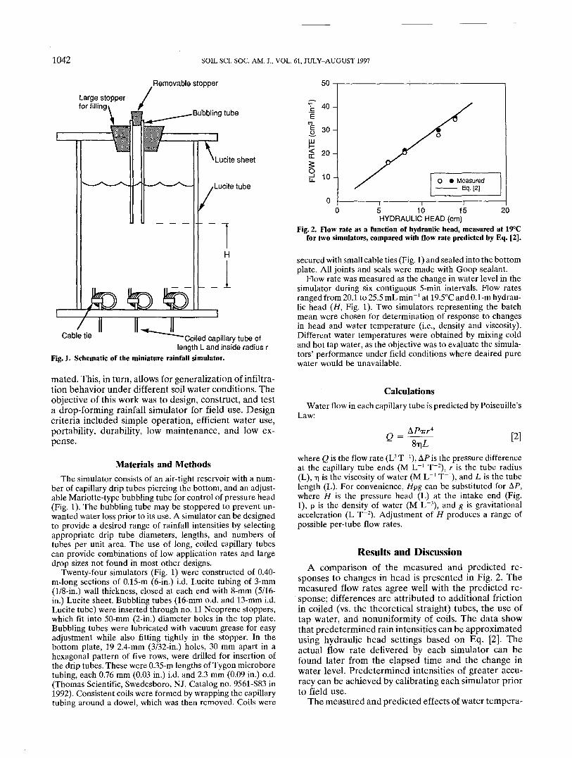
Fig. 2. Flow rate as a function of hydraulic head, measured at 19°Cfor two simulators, compared with flow rate predicted by Eq. [2].
secured with small cable ties (Fig. 1) and sealed into the bottomplate. All joints and seals were made with Goop sealant.
Flow rate was measured as the change in water level in thesimulator during six contiguous 5-min intervals. Flow ratesranged from 20.1 to 25.5 mL min"1 at 19.5°C and 0.1-m hydrau-lic head (H, Fig. 1). Two simulators representing the batchmean were chosen for determination of response to changesin head and water temperature (i.e., density and viscosity).Different water temperatures were obtained by mixing coldand hot tap water, as the objective was to evaluate the simula-tors' performance under field conditions where deaired purewater would be unavailable.
CalculationsWater flow in each capillary tube is predicted by Poiseuille's
Law:
e = 8-qL[2]
where Q is the flow rate (L3 T"1), AP is the pressure differenceat the capillary tube ends (M L"1 T"2), r is the tube radius(L), T| is the viscosity of water (M L"1 T"1), and L is the tubelength (L). For convenience, Hpg can be substituted for AP,where H is the pressure head (L) at the intake end (Fig.1), p is the density of water (M L~3), and g is gravitationalacceleration (L T"2). Adjustment of H produces a range ofpossible per-tube flow rates.
Results and DiscussionA comparison of the measured and predicted re-
sponses to changes in head is presented in Fig. 2. Themeasured flow rates agree well with the predicted re-sponse; differences are attributed to additional frictionin coiled (vs. the theoretical straight) tubes, the use oftap water, and nonuniformity of coils. The data showthat predetermined rain intensities can be approximatedusing hydraulic head settings based on Eq. [2]. Theactual flow rate delivered by each simulator can befound later from the elapsed time and the change inwater level. Predetermined intensities of greater accu-racy can be achieved by calibrating each simulator priorto field use.
The measured and predicted effects of water tempera-

NOTES 1043
50-
I 40 H
1o.ill 30 -
O 2(H
1010 20 30
I40 50 60
WATER TEMPERATURE (°C)Fig. 3. Flow rate as a function of water temperature, measured at
0.1-m hydraulic head for two simulators, compared with flow ratepredicted by Eq. [2].
ture changes are shown in Fig. 3. Flow rates did notincrease with temperature as rapidly as predicted byEq. [2]. This may in part be attributed to formation ofsmall bubbles in the coils as the cold tap water degassedwhen heated through mixing with hot tap water. Wehave observed similar bubble formation during field usewhen direct sunlight heated the water in the simulators.In many situations, temperature changes are negligible;however, if the simulators are used for long applicationsin direct sunlight and predetermined application ratesare critical, temperature effects should be considered.
Uniformity of flow rates between drip tubes within asimulator was not evaluated. Between-tube variationwould result primarily from nonuniform construction,particularly pinching of drip tubes if the cable ties areovertightened. For field measurements, variability dueto differences in soil hydraulic properties between loca-tions would greatly exceed variations due to nonunifor-mity within simulators, particularly when ponding oc-curs. However, it is important to level the simulators sothat all tubes operate under the same hydraulic head.A related consideration is the growth of microorganisms
in the drip tubes, which changes the wetting characteris-tics and inner diameters of the tubes, resulting in re-duced flow rates. This can be prevented by flushing witha 10% solution of household bleach after each day'suse. Drop impact beneath the stationary drip tubes maybe prevented by protecting bare soil surfaces withcheesecloth.
ConclusionsThese small rain simulators are durable, portable, and
water efficient enough for convenient use in the field.We have used them to give precise application ratesfrom 9 to 36 mL mirr1. Only minimal worker trainingis required for their operation and maintenance. Costof materials was approximately $25 per unit in 1992.Their low cost and flexibility in design and use are anadvantage in many field situations. We have successfullyused this design in several field studies of infiltrationand runoff. Larger rainfall simulators based on the sameprinciple have been constructed for runoff studies onsteep hillslopes and for large-column leaching exper-iments.