miniature circuit breakers (mcbs) - elektro- · pdf fileminiature circuit breakers (mcbs)...
TRANSCRIPT

Miniature Circuit Breakers
(MCBs)
Description of Miniature
Circuit Breakers Page 10
Technical Data Page 14
“S” Product Range
B and C Characteristic
- 1-pole,1-pole with switched neutral, 2-pole Page 21
- 3-pole, 3-pole with switched neutral Page 22
“SL” Product Range
B and C Characteristic
- 1-pole, 3-pole Page 23
“T” Product Range
B, C, D, K and Z Characteristic
- 1-pole, 1-pole with switched neutral Page 24 - 2-pole, 3-pole Page 25
- 3-pole with switched neutral, 4-pole Page 26
Accessories
- Shunt trip Page 27
- Undervoltage trip Page 27
- Auxiliary contacts Page 28
- Busbars Page 29

1/2
The next generation in
installation technology –
innovative and modular
miniature circuit breakers
from ABL SURSUM.
Designed for all electrical
engineering applications.
The requirements of modern installation technology were
systematically implemented with three product ranges of
innovative miniature circuit breakers. Thus the right products
can be made available for each project.
The system components which are designed with different
functions and performance allow an optimal covering of
different applications:
– Conventional house installation.
– Industrial installation.
– Industry applications, machine and system installation.
A future-oriented concept:
application-oriented innovations, time-saving easier
installation and reliable quality.
The S Range
The installation-friendly 6-kA miniature circuit breakers for house installations.
The SL Range
The innovative 6 kA miniature circuit breakers with screwless top terminal for fast mounting.
The T Range
The flexible 10 kA miniature circuit breakers for industry applications on the highest level.
Building a future means successfully advancing tradition.
Circuit breakers are an 80-year-old tradition at ABL SURSUM.
The first screw-in circuit breaker came onto the market in 1925.
Even then there was thermal and electromagnetic tripping.
The first high-performance circuit breaker followed less than
10 years later. A socket circuit breaker, which even achieved the
American UL certification. These circuit breakers ushered in the
long success story of ABL SURSUM circuit-protection devices.
We are continuing this success story with the new miniature circuit
breakers. They combine our experience with the requirements of
modern installation technology. With a broad-ranging, product-
specific knowledge and in cooperation with our customers, we
have developed three innovative product ranges of miniature
circuit breakers.
Application-orientation, functionality and the highest quality were
just as important as reliable operation, maximum safety and effective
time-saving installation.
The result is application-oriented products with a perfect
combination of all requirements on the highest quality level
and in a modern design. They continue to stand for quality
and reliability.
10

1/3
Miniature Circuit Breakers
S, SL, T Product Ranges
B Characteristic
16 Rated current
T Product range
1 No. of poles
Approval
Rated voltage
Circuit diagram
Rated breaking capacity
Form and function combined
perfectly.
• Compact dimensions (only
83 mm vertical height) for
more convenient mounting.
• Modern design, optimum
comfort and user-friendliness.
• Easy-to-understand product
designations.
Convenient and time-saving
mounting.
• Innovative DIN-rail clip for
easy removal from a busbar
combination
• No laborious moving of the
other components
• T product range with “twin-fix”
for removal from the busbar –
no matter whether top or
bottom-mounted.
• S and SL product ranges with
“single-fix” for removal from
a bottom-mounted busbar.
11

1/4
00
00 00
00
00
00
00
00 00
00
00
00
Fast and safe.
The innovative, screwless
“plug2power” connection
technology results in safety
and more time:
• Fast mounting.
• Highest wiring safety.
• Extreme tensile load capacity.
• Easy to release.
• Integrated test opening for
voltage measurement.
Perfect and compact.
• Optimum labeling possibility.
• User-friendly labeling form.
• Free labeling software.
12

1/5
Miniature Circuit Breakers
S, SL, T Product Ranges
Compatibility without limitations.
• Multi-system compatibility of
the S, SL and T product
ranges as well as with RCCDs
and DIN-rail panel products.
• Suitable for busbar installation
with previous products.
• Use of standard busbars.
• Compatibility to available
side-by-side-mounting
devices.
Quality and Safety.
• Highest quality without
compromises.
• Maximum protection function.
• Tested three times and inde-
pendently – fulfilling all
standards, approvals and
degrees of protection.
• Low maintenance,
high life expectancy.
13

1/6
Miniature Circuit Breakers
S, SL and T Product Ranges
Technical Data
Characteristic B C D K Z
Application Wiring protectionWiring protectionDevice protection
Wiring protectionPower circuitsTransformers
Motors
Wiring protectionPower circuitsTransformers
Motors
Wiring protectionSemiconductor protection
High impedance
Number of poles
Product range „S“ 1-3; 1+N; 3+N - - -
Product range „SL“ 1 and 3 - - -
Product range „T“ 1 - 4; 1 + N; 3 + N 1 - 3
Standardsshort circuit withstand rating
IEC 60898-1, DIN EN 60898-1, VDE 0641-11 IEC 60947-2, DIN EN 60947-2, VDE 0660-101
Product range „S“ 6 kA 6 kA - - -
Product range „SL“ 6 kA 6 kA - - -
Product range „T“ 10 kA 10 kA 10 kA 10 kA 10 kA
Current limiting class 3 3
Max. back-up fuse Fuse according to DIN VDE 0636 125 A operating class gL/gG
Rated AC voltage 230 / 400 V
Rated DC voltageL/R = 4 ms
1-pole 60 V, 2-pole 125 V in serial connection of both poles
Rated current range In
Product range „S“ 6 - 63 A 1 - 63 A - - -
Product range „SL“ 6 - 20 A 6 - 20 A - - -
Product range „T“ 1 - 63 A 0,3 - 63 A 0,3 - 63 A 0,3 - 63 A 0,3 - 32 A
Test
cu
rre
nts
Thermal not tripping I1 (A) > 1 h
1,13 x In 1,13 x In 1,13 x In 1,05 x In 1,05 x In
Thermal tripping I2 (A) < 1 h
1,45 x In 1,45 x In 1,45 x In 1,2 x In 1,35 x In
Electromagnetic not tripping I4 (A) > 0,1 s
3 x In 5 x In 10 x In 8 x In 2 x In
Electromagnetic tripping I5 (A) < 0,1 s
5 x In 10 x In 20 x In 12 x In 3 x In
Reference calibration tempera-ture of the thermal tripping
30° C + 5° CInfl uence of the ambient temperature on the thermal tripping: Decrease of the current values with higher
ambient temperature and increase with lower temperatures of approximately 5% per 10°C difference in temperature
Frequency range of the electromagnetic trip
16 2/3 to 60 HzWith higher frequencies, the electromagnetic tripping values increase by approximately
a factor of 1,1 at 100 Hz; 1,2 at 200 Hz; 1,3 at 300 Hz; 1,4 at 400 Hz; 1,5 for DC
Ambient temperature -25° C to +55° C
Storage temperature -40° C to +70° C
Device depth according to DIN 43880
68 mm
Mechanical endurance 20.000 switching cycles (20.000 ON/20.000 OFF)
Protection cover Finger safe and safe to back of hand according to DIN EN 50274/ VDE0660-514, BGV A2
Insulation group according to DIN VDE 0110
C at 250 V AC, B at 400 V AC
Degree of protection according to EN / IEC 60529
IP 20
Installation position any
Mounting DIN-rail according to DIN EN 60715 35 mm
Lockability The handle can be secured against manual switching in the on and off position by a lead seal
Climatic resistanceHumid heat constant according to DIN IEC 60068-2-78
Humid heat cycle according to DIN EN 60068-2-30
Vibration resistance > 15 g according to DIN EN 60068-2-59 during a load with I1
Resistance to mechanical shocks 25g 11ms
14

1/7
Miniature Circuit Breakers
S, SL and T Product Ranges
Technical Data
Conductor cross sections product ranges S and T
Box terminal bottom Box terminal top
Type of conductor max. min. max. min.
Single wire 35 mm2 0,5 mm2 25 mm2 0,5 mm2
Multiple wire 35 mm2 1,5 mm2 25 mm2 1,5 mm2
Stranded wire 25 mm2 1 mm2 16 mm2 1 mm2
Stranded wire with ferrule 16 mm2 0,5 mm2 16 mm2 0,5 mm2
Busbar cable lug Up to 3 mm thickness Up to 3 mm thickness
Combined, connector and bus-bar or cable lug
Up to 35 mm2 and up to 2 mm thickness
Up to 25 mm2 and up to 2 mm thickness
Torque max. 2 Nm
Conductor cross sections SL product range
Box terminal bottom Screwless terminal top *)
Type of conductor max. min. max. min.
Single wire 35 mm2 0,5 mm2 4 mm2 1 mm2
Multiple wire 35 mm2 1,5 mm2 4 mm2 1,5 mm2
Stranded wire 25 mm2 1 mm2 4 mm2 1 mm2
Stranded wire with ferrule 16 mm2 0,5 mm2 2,5 mm2 1 mm2
Busbar cable lug Up to 3 mm thickness -
Combined, connector and bus-bar or cable lug
Up to 35 mm2 and up to 2 mm thickness
-
Torque max. 2 Nm -
*) Stripped length 12 - 14 mm
15
1/8
Miniature Circuit Breakers
S, SL and T Product Ranges
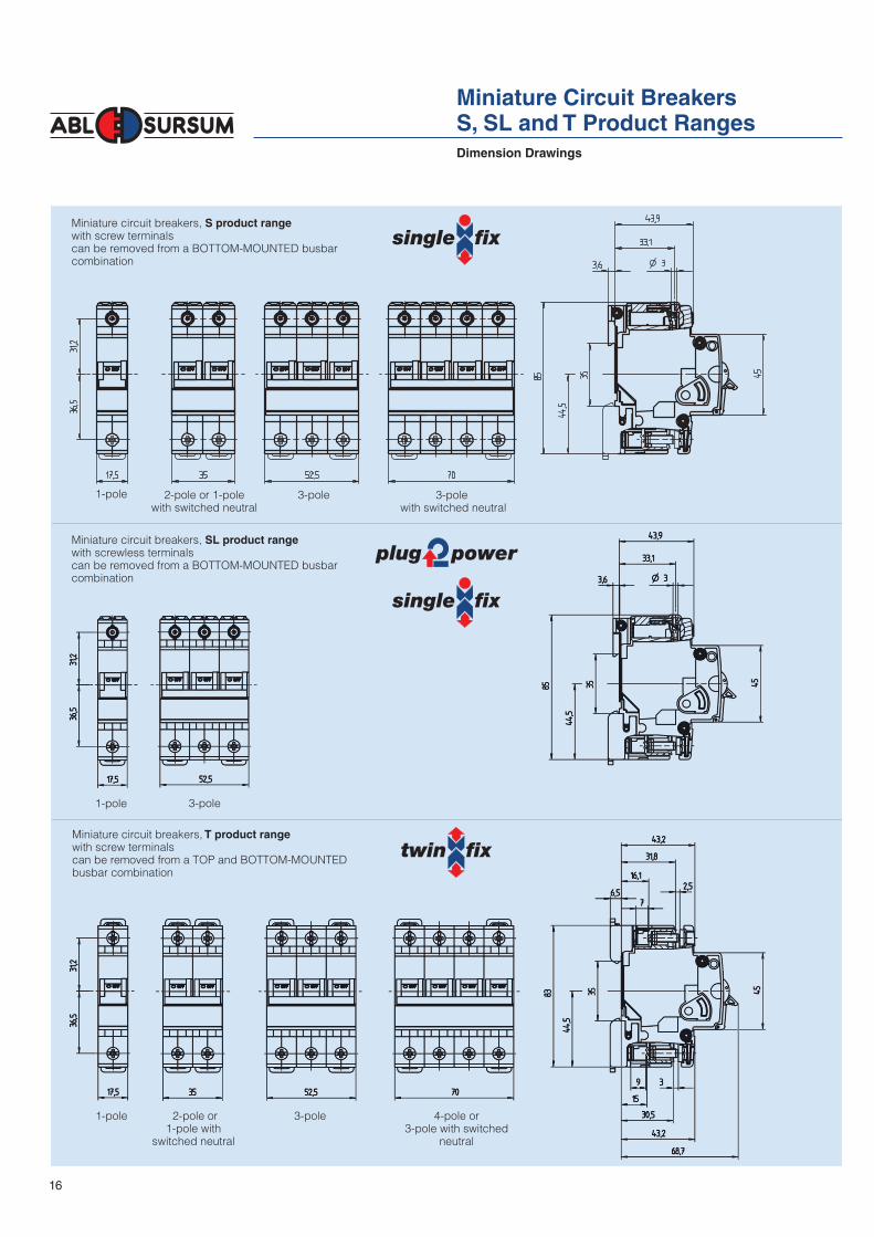
Dimension Drawings
Miniature circuit breakers, S product range
with screw terminals can be removed from a BOTTOM-MOUNTED busbar combination
Miniature circuit breakers, SL product range
with screwless terminalscan be removed from a BOTTOM-MOUNTED busbar combination
Miniature circuit breakers, T product range
with screw terminalscan be removed from a TOP and BOTTOM-MOUNTED busbar combination
1-pole
1-pole 3-pole
2-pole or 1-pole with
switched neutral
1-pole 3-pole 4-pole or3-pole with switched
neutral
2-pole or 1-pole with switched neutral
3-pole 3-pole with switched neutral
16

1/9
1,13-1,45 x IN
1 2 3 4 5 6 8 10 20 40 100
10
4x10
10
4x10
10
0,4
1
4
10
1
4
10
40
60
-1
-2
-2
-3
-3
x Rated current
I1 I21,13-1,45 x IN
1 2 3 4 5 6 8 10 20 40 100
10
10
10
0,4
1
4
10
1
4
10
40
60
-1
-2
-2
-3
-3
4x10
4x10
x Rated current
I1 I21,13-1,45 x IN
1 2 3 4 5 6 8 10 20 40 100
10
10
10
0,4
1
4
10
1
4
10
40
60
-1
-2
-2
-3
-3
4x10
4x10
x Rated current
1,13-1,45 x IN
1 2 3 4 5 6 8 10 20 40 100
10
4x10
10
4x10
10
0,4
1
4
10
1
4
10
40
60
-1
-2
-2
-3
-3
x Rated current
Miniature Circuit Breakers
S, SL and T Product Ranges
B-C-D characteristic In = 0,3 - 8 A B-C-D characteristic In = 10 - 63 A
Delayed thermal overload tripping
In = Rated current
Current which the miniature circuit breaker can sustain in uninterrupted operation
Ib = Rated operational current
Current determined by the load during undisturbed operation
I1 = Thermal not tripping current
Current which, under defined conditions, does not lead to switching off within 60 min
I2 = Thermal tripping current
Current which, under defined conditions, leads to switching off within 60 min
I1 to I2 = Conditions
Current which, under defined conditions, is run up from I1 to I2 with a continuous increase, and leads to switch off within 60 min
I3 = Tolerance limitation
at 2,55-times the rated current/ nominal current
Current which, under defined conditions, does not lead to switch off within 1 sec Current which, under defined conditions, leads to switch off at rated currents up to 32 A within 60 sec, at rated currents above 32A within 120 sec
Undelayed electromagnetic short circuit tripping
I4 = Magnetic not tripping current
Current which, under defined conditions, does not lead to switching off within 0,1 sec
I5 = Magnetic tripping current
Current which, under defined conditions, leads to switching off within 0,1 sec
Dependence of the short circuit trip
at higher frequencies and for direct current.
at 100 Hz about 1,1 times at 200 Hz about 1,2 times at 300 Hz about 1,3 times at 400 Hz about 1,4 times at 500 Hz about 1,5 times for DC about 1,5 times
Characteristic
According to IEC 60898-1, DIN EN 60898 and VDE 0641-11
Sec
onds
Min
utes
Sec
onds
Min
utes
B BC CD D
17

1/10
1001 2 3 4 5 6 8 10 20 4012
1,05-1,2 x IN
10
4x10
10
4x10
10
0,4
1
4
10
1
4
10
40
60
-1
-2
-2
-3
-3
x Rated current
1 2 3 4 5 6
10
4x10
10
4x10
10-1
-2
-2
-3
-3
0,4
1
4
10
1
4
10
40
60
8 10 20 40 10012
1,05-1,2 x IN
x Rated current
1,05-1,35 x IN
1 21,5 3 4 5 6 8
10
20 40 100
10
4x10
10
4x10
10
0,4
1
4
10
20
40
1
4
10
40
60
-1
-2
-2
-3
-3
1512
DC
AC ~
x Rated current
1,05-1,35 x IN
1 21,5 3 4 5 6 8
10
20 40 100
10
4x10
10
4x10
10
0,4
1
4
10
20
40
1
4
10
40
60
-1
-2
-2
-3
-3
1512
DC
AC ~
x Rated current
1,05-1,35 x IN
1 21,5 3 4 5 6 8
10
20 40 100
10
4x10
10
4x10
10
0,4
1
4
10
20
40
1
4
10
40
60
-1
-2
-2
-3
-3
1512
5
DC
AC ~
x Rated current
1,05-1,35 x IN
1 21,5 3 4 5 6 8
10
20 40 100
10
4x10
10
4x10
10
0,4
1
4
10
20
40
1
4
10
40
60
-1
-2
-2
-3
-3
1512
5
DC
AC ~
x Rated current
1 2 3 4 5 6
10
4x10
10
4x10
10-1
-2
-2
-3
-3
0,4
1
4
10
1
4
10
40
60
8 10 20 40 100
1,05-1,2 x IN
x Rated current
1001 2 3 4 5 6 8 10 20 40
1,05-1,2 x IN
10
4x10
10
4x10
10
0,4
1
4
10
1
4
10
40
60
-1
-2
-2
-3
-3
x Rated current
Miniature Circuit Breakers
S, SL and T Product Ranges
Characteristic
According to IEC 60947-2, DIN EN 60947-2 and VDE 0660-101
K characteristic In = 0,3 - 10 A K characteristic In = 13 - 63 A
Z characteristic In = 0,3 - 10 A Z characteristic In = 13 - 32 A
Sec
onds
Min
utes
Sec
onds
Min
utes
Sec
onds
Min
utes
Sec
onds
Min
utes
18

1/11
Internal resistances in mOhm and power losses in Watt per pole (at In)
Rated currentIn (A)
B-characteristic C-characteristic D-characteristic K-characteristic Z-characteristic
Internal resistance
mOhm
Power loss Watt
Internal resistance
mOhm
Power loss Watt
Internal resistance
mOhm
Power loss Watt
Internal resistance
mOhm
Power loss Watt
Internal resistance
mOhm
Power loss Watt
0,3 - - 16600 1,5 16600,0 1,5 16860,0 1,5 31500,0 2,8
0,5 - - 6850 1,7 6850,0 1,7 6850,0 1,7 10250,0 2,6
0,8 - - 3050 2,0 3050,0 2,0 3050,0 2,0 5150,0 3,3
1 1950 2,0 1750 1,8 1750,0 1,8 1750,0 1,8 2690,0 2,7
1,6 720 1,8 590 1,5 590,0 1,5 590,0 1,5 940,0 2,4
2 510 2,0 420 1,7 420,0 1,7 420,0 1,7 690,0 2,8
2,5 325 2,0 295 1,8 295,0 1,8 295,0 1,8 430,0 2,7
3 211 1,9 200 1,8 173,0 1,6 200,0 1,8 345,0 3,1
3,5 159 1,9 125 1,5 125,0 1,5 125,0 1,5 225,0 2,8
4 131 2,1 109 1,7 105,0 1,7 109,0 1,7 225,0 3,6
5 85 2,1 61,6 1,5 61,6 1,5 65,4 1,6 105,0 2,6
6 52,9 1,9 49,1 1,8 45,9 1,7 49,1 1,8 82,3 3,0
8 26 1,7 24 1,5 20,7 1,3 44,0 2,8 37,1 2,4
10 13,4 1,3 13,4 1,3 13,4 1,3 31,5 3,1 27,8 2,8
13 11,3 1,9 8,04 1,4 8,1 1,4 8,8 1,5 15,1 2,6
16 8,04 2,1 8,04 2,1 8,1 2,1 7,5 1,9 11,3 2,9
20 7,1 2,8 7,45 3,0 6,4 2,5 6,3 2,5 7,4 3,0
25 5 3,1 5 3,1 4,1 2,5 4,7 2,9 5,8 3,7
32 3,6 3,7 3,6 3,7 2,7 2,8 2,8 2,9 3,6 3,7
40 2,2 3,5 2,2 3,5 2,2 3,5 2,2 3,5 - -
50 1,95 4,9 1,9 4,8 1,8 4,6 2,0 4,9 - -
63 1,77 7,0 1,77 7,0 1,7 6,8 1,8 7,0 - -
Overload and short circuit currents
Overload Short circuit
B,C,D K Z B C D K Z
I1 I2 I1 I2 I1 I2 I4 I5 I4 I5 I4 I5 I4 I5 I4 I5
In (A) 1,13 1,45 1,05 1,2 1,05 1,35 3 5 5 10 10 20 8 12 2 3
0,3 0,339 0,435 0,315 0,360 0,315 0,405 0,9 1,5 1,5 3 3 6 2,4 3,6 0,6 0,9
0,5 0,565 0,725 0,525 0,600 0,525 0,675 1,5 2,5 2,5 5 5 10 4 6 1 1,5
0,75 0,848 1,088 0,788 0,900 0,788 1,013 2,25 3,75 3,75 7,5 7,5 15 6 9 1,5 2,25
1 1,13 1,45 1,05 1,20 1,05 1,35 3 5 5 10 10 20 8 12 2 3
1,6 1,81 2,32 1,68 1,92 1,68 2,16 4,8 8 8 16 16 32 12,8 19,2 3,2 4,8
2 2,26 2,90 2,10 2,40 2,10 2,70 6 10 10 20 20 40 16 24 4 6
2,5 2,83 3,63 2,63 3,00 2,63 3,38 7,5 12,5 12,5 25 25 50 20 30 5 7,5
3 3,39 4,35 3,15 3,60 3,15 4,05 9 15 15 30 30 60 24 36 6 9
3,5 3,96 5,08 3,68 4,20 3,68 4,73 10,5 17,5 17,5 35 35 70 28 42 7 10,5
4 4,52 5,80 4,20 4,80 4,20 5,40 12 20 20 40 40 80 32 48 8 12
5 5,65 7,25 5,25 6,00 5,25 6,75 15 25 25 50 50 100 40 60 10 15
6 6,78 8,70 6,30 7,20 6,30 8,10 18 30 30 60 60 120 48 72 12 18
8 9,04 11,60 8,40 9,60 8,40 10,80 24 40 40 80 80 160 64 96 16 24
10 11,3 14,5 10,5 12,0 10,5 13,5 30 50 50 100 100 200 80 120 20 30
13 14,7 18,9 13,7 15,6 13,7 17,6 39 65 65 130 130 260 104 156 26 39
16 18,1 23,2 16,8 19,2 16,8 21,6 48 80 80 160 160 320 128 192 32 48
20 22,6 29,0 21,0 24,0 21,0 27,0 60 100 100 200 200 400 160 240 40 60
25 28,3 36,3 26,3 30,0 26,3 33,8 75 125 125 250 250 500 200 300 50 75
32 36,2 46,4 33,6 38,4 33,6 43,2 96 160 160 320 320 640 256 384 64 96
40 45,2 58,0 42,0 48,0 - - 120 200 200 400 400 800 320 480 - -
50 56,5 72,5 52,5 60,0 - - 150 250 250 500 500 1000 400 600 - -
63 71,2 91,4 66,2 75,6 - - 189 315 315 630 630 1260 504 756 - -
Miniature Circuit Breakers
S, SL and T Product Ranges
Technical Data
19

1/12
6 kA miniature circuit breakers, S and SL product ranges
Short circuit selectivity to fuses in kA
Rated current In (A)
Characteristic B 6
6
10
10
13
13
16
16
20
20
25
25
32
32
40
40
50
50
63
63C
In (A)25
0,85
0,7
0,8
0,7
0,8
0,7
0,75
0,65
0,7
0,6
0,6
0,55
1.)
LV
HR
C f
use
Ch
ara
cte
ristic
gL
/gG
ac
co
rdin
g t
oD
IN V
DE
0
63
6
351,6
1,3
1,6
1,3
1,5
1,25
1,5
1,2
1,4
1,2
1,2
1,1
1,1
1,0
0,8
0,7
502,4
2,1
2,35
2,1
2,3
2,0
2,3
2,0
2,2
1,9
1,6
1,5
1,5
1,4
1,3
1,2
1,2
1,1
633,5
2,9
3,3
2,8
3,2
2,7
3,2
2,7
3,0
2,6
2,5
2,1
2,4
2,0
1,8
1,6
1,7
1,5
1,6
1,4
805,0
4,1
4,8
4,0
4,7
3,9
4,6
3,9
4,3
3,6
3,4
2,8
3,3
2,8
2,5
2,1
2,4
2,0
2,3
1,9
1006,0
5,0
5,1
4,0
5,0
3,9
3,5
2,9
3,3
2,8
3,1
2,6
1.) There is no more overload selectivity above the step line.
Miniature Circuit Breakers
S, SL and T Product Ranges
Short circuit selectivity
10 kA miniature circuit breakers, T product range
Short circuit selectivity to fuses in kA
Rated current In (A)
Characteristic
B 66/8
6/8
1010
10
1313
13
1616
16
2020
20
2525
25
3232
32
4040
40
5050
50
6363
63C
D
In (A)
250,85
0,70,7
0,80,7
0,6
0,80,7
0,6
0,750,65
0,6
0,70,6
0,55
0,60,55
0,51.)
LV H
RC
fu
se
Ch
ara
cte
ristic
gL
/gG
ac
co
rdin
g t
o D
IN V
DE
0
63
6
351,6
1,31,2
1,61,3
1,15
1,51,25
1,1
1,51,2
1,1
1,41,2
1,0
1,21,1
0,9
1,11,0
0,8
0,80,7
0,5
502,4
2,11,9
2,352,1
1,8
2,32,0
1,7
2,32,0
1,7
2,21,9
1,6
1,61,5
1,3
1,51,4
1,2
1,31,2
1,1
1,21,1
1,0
633,5
2,92,5
3,32,8
2,4
3,22,7
2,4
3,22,7
2,3
3,02,6
2,3
2,52,1
1,8
2,42,0
1,8
1,81,6
1,4
1,71,5
1,3
1,61,4
1,2
805,0
4,13,5
4,84,0
3,4
4,73,9
3,3
4,63,9
3,2
4,33,6
3,1
3,42,8
2,5
3,32,8
2,4
2,52,1
1,9
2,42,0
1,8
2,31,9
1,7
1007,6
6,35,2
7,36,1
4,9
7,15,9
4,8
7,05,7
4,7
6,55,0
4,4
5,14,0
3,5
5,03,9
3,4
3,52,9
2,5
3,32,8
2,4
3,12,6
2,3
12510
108,8
1010
8,0
1010
7,7
1010
7,6
108,7
7,1
8,86,9
5,7
8,56,8
5,6
5,44,5
3,8
5,14,3
3,6
4,94,1
3,5
1.) There is no more overload selectivity above the step line.
20

1/13
6 kA B and C characteristic according to IEC 60898-1, DIN EN 60898-1, VDE 0641-11
Miniature Circuit Breakers
S Product Range
1-pole
with switched neutral
1 C1S8 240 6
2 C2S8 240 6
3 C3S8 240 6
4 C4S8 240 6
5 C5S8 240 6
6 B6S8 C6S8 240 6
10 B10S8 C10S8 240 6
13 B13S8 C13S8 240 6
16 B16S8 C16S8 240 6
20 B20S8 C20S8 240 6
25 B25S8 C25S8 240 6
32 B32S8 C32S8 240 6
40 B40S8 C40S8 250 6
50 B50S8 C50S8 270 6
63 B63S8 C63S8 270 6
1-pole
1 C1S1 120 12
2 C2S1 120 12
3 C3S1 120 12
4 C4S1 120 12
5 C5S1 120 12
6 B6S1 C6S1 120 12
10 B10S1 C10S1 120 12
13 B13S1 C13S1 120 12
16 B16S1 C16S1 120 12
20 B20S1 C20S1 120 12
25 B25S1 C25S1 120 12
32 B32S1 C32S1 120 12
40 B40S1 C40S1 125 12
50 B50S1 C50S1 135 12
63 B63S1 C63S1 135 12
6
3�
2-pole
1 C1S2 240 6
2 C2S2 240 6
3 C3S2 240 6
4 C4S2 240 6
5 C5S2 240 6
6 B6S2 C6S2 240 6
10 B10S2 C10S2 240 6
13 B13S2 C13S2 240 6
16 B16S2 C16S2 240 6
20 B20S2 C20S2 240 6
25 B25S2 C25S2 240 6
32 B32S2 C32S2 240 6
40 B40S2 C40S2 250 6
50 B50S2 C50S2 270 6
63 B63S2 C63S2 270 6
Rated current Characteristic Weight PackingB C g/each unit
In A Article no. Article no
21

1/14
6 kA B and C characteristic according to IEC 60898-1, DIN EN 60898-1, VDE 0641-11
Miniature Circuit Breakers
S Product Range
6
3�
3-pole
with switched neutral
1 C1S9 480 3
2 C2S9 480 3
3 C3S9 480 3
4 C4S9 480 3
5 C5S9 480 3
6 B6S9 C6S9 480 3
10 B10S9 C10S9 480 3
13 B13S9 C13S9 480 3
16 B16S9 C16S9 480 3
20 B20S9 C20S9 480 3
25 B25S9 C25S9 480 3
32 B32S9 C32S9 480 3
40 B40S9 C40S9 500 3
50 B50S9 C50S9 540 3
63 B63S9 C63S9 540 3
3-pole
1 C1S3 360 4
2 C2S3 360 4
3 C3S3 360 4
4 C4S3 360 4
5 C5S3 360 4
6 B6S3 C6S3 360 4
10 B10S3 C10S3 360 4
13 B13S3 C13S3 360 4
16 B16S3 C16S3 360 4
20 B20S3 C20S3 360 4
25 B25S3 C25S3 360 4
32 B32S3 C32S3 360 4
40 B40S3 C40S3 375 4
50 B50S3 C50S3 405 4
63 B63S3 C63S3 405 4
Rated current Characteristic Weight PackingB C g/each unit
In A Article no. Article no
22

1/15
1-pole
6 B6SL1 C6SL1 120 12
10 B10SL1 C10SL1 120 12
13 B13SL1 C13SL1 120 12
16 B16SL1 C16SL1 120 12
20 B20SL1 C20SL1 120 12
3-pole
6 B6SL3 C6SL3 360 4
10 B10SL3 C10SL3 360 4
13 B13SL3 C13SL3 360 4
16 B16SL3 C16SL3 360 4
20 B20SL3 C20SL3 360 4
Miniature Circuit Breakers
SL Product Range
With screwless top terminal (plug2power)6 kA B and C characteristic according to IEC 60898-1, DIN EN 60898-1, VDE 0641-11
6
3�
“plug2power”
The innovative screwless terminal technology
for fast and safe connections
Rated current Characteristic Weight PackingB C g/each unit
In A Article no. Article no
23

1/16
Miniature Circuit Breakers
T Product Range
1-pole
0,3 C0.3T1 D0.3T1 K0.3T1 Z0.3T1 120 12
0,5 C0.5T1 D0.5T1 K0.5T1 Z0.5T1 120 12
0,8 C0.8T1 D0.8T1 K0.8T1 Z0.8T1 120 12
1 B1T1 C1T1 D1T1 K1T1 Z1T1 120 12
1,6 C1.6T1 D1.6T1 K1.6T1 Z1.6T1 120 12
2 B2T1 C2T1 D2T1 K2T1 Z2T1 120 12
2,5 C2.5T1 D2.5T1 K2.5T1 Z2.5T1 120 12
3 B3T1 C3T1 D3T1 K3T1 Z3T1 120 12
3,5 C3.5T1 D3.5T1 K3.5T1 Z3.5T1 120 12
4 B4T1 C4T1 D4T1 K4T1 Z4T1 120 12
5 B5T1 C5T1 D5T1 K5T1 Z5T1 120 12
6 B6T1 C6T1 D6T1 K6T1 Z6T1 120 12
8 C8T1 D8T1 K8T1 Z8T1 120 12
10 B10T1 C10T1 D10T1 K10T1 Z10T1 120 12
13 B13T1 C13T1 D13T1 K13T1 Z13T1 120 12
16 B16T1 C16T1 D16T1 K16T1 Z16T1 120 12
20 B20T1 C20T1 D20T1 K20T1 Z20T1 120 12
25 B25T1 C25T1 D25T1 K25T1 Z25T1 120 12
32 B32T1 C32T1 D32T1 K32T1 Z32T1 120 12
40 B40T1 C40T1 D40T1 K40T1 125 12
50 B50T1 C50T1 D50T1 K50T1 135 12
63 B63T1 C63T1 D63T1 K63T1 135 12
1-pole with switched neutral
0,3 C0.3T8 D0.3T8 K0.3T8 240 6
0,5 C0.5T8 D0.5T8 K0.5T8 240 6
0,8 C0.8T8 D0.8T8 K0.8T8 240 6
1 B1T8 C1T8 D1T8 K1T8 240 6
1,6 C1.6T8 D1.6T8 K1.6T8 240 6
2 B2T8 C2T8 D2T8 K2T8 240 6
2,5 C2.5T8 D2.5T8 K2.5T8 240 6
3 B3T8 C3T8 D3T8 K3T8 240 6
3,5 C3.5T8 D3.5T8 K3.5T8 240 6
4 B4T8 C4T8 D4T8 K4T8 240 6
5 B5T8 C5T8 D5T8 K5T8 240 6
6 B6T8 C6T8 D6T8 K6T8 240 6
8 C8T8 D8T8 K8T8 240 6
10 B10T8 C10T8 D10T8 K10T8 240 6
13 B13T8 C13T8 D13T8 K13T8 240 6
16 B16T8 C16T8 D16T8 K16T8 240 6
20 B20T8 C20T8 D20T8 K20T8 240 6
25 B25T8 C25T8 D25T8 K25T8 240 6
32 B32T8 C32T8 D32T8 K32T8 240 6
40 B40T8 C40T8 D40T8 K40T8 250 6
50 B50T8 C50T8 D50T8 K50T8 270 6
63 B63T8 C63T8 D63T8 K63T8 270 6
Rated Characteristic Weight Packingcurrent B C D K Z g/each unit
In A Article no. Article no. Article no. Article no. Article no.
10kA B, C and D characteristic according to IEC 60898-1, DIN EN 60898-1, VDE 0641-11
10kA K and Z characteristic according to IEC 60947-2, DIN EN 60947-2, VDE 0660-101
This product range differentiates between:• standard products for normal market applications (shown in the table in bold)
• exclusive products for branch-specifi c applications (shown in the table in normal print)
� 3
24

1/17
Rated Characteristic Weight Packingcurrent B C D K Z g/each unit
In A Article no. Article no. Article no. Article no. Article no.
2-pole
0,3 C0.3T2 D0.3T2 K0.3T2 Z0.3T2 240 6
0,5 C0.5T2 D0.5T2 K0.5T2 Z0.5T2 240 6
0,8 C0.8T2 D0.8T2 K0.8T2 Z0.8T2 240 6
1 B1T2 C1T2 D1T2 K1T2 Z1T2 240 6
1,6 C1.6T2 D1.6T2 K1.6T2 Z1.6T2 240 6
2 B2T2 C2T2 D2T2 K2T2 Z2T2 240 6
2,5 C2.5T2 D2.5T2 K2.5T2 Z2.5T2 240 6
3 B3T2 C3T2 D3T2 K3T2 Z3T2 240 6
3,5 C3.5T2 D3.5T2 K3.5T2 Z3.5T2 240 6
4 B4T2 C4T2 D4T2 K4T2 Z4T2 240 6
5 B5T2 C5T2 D5T2 K5T2 Z5T2 240 6
6 B6T2 C6T2 D6T2 K6T2 Z6T2 240 6
8 C8T2 D8T2 K8T2 Z8T2 240 6
10 B10T2 C10T2 D10T2 K10T2 Z10T2 240 6
13 B13T2 C13T2 D13T2 K13T2 Z13T2 240 6
16 B16T2 C16T2 D16T2 K16T2 Z16T2 240 6
20 B20T2 C20T2 D20T2 K20T2 Z20T2 240 6
25 B25T2 C25T2 D25T2 K25T2 Z25T2 240 6
32 B32T2 C32T2 D32T2 K32T2 Z32T2 240 6
40 B40T2 C40T2 D40T2 K40T2 250 6
50 B50T2 C50T2 D50T2 K50T2 270 6
63 B63T2 C63T2 D63T2 K63T2 270 6
3-pole
0,3 C0.3T3 D0.3T3 K0.3T3 Z0.3T3 360 4
0,5 C0.5T3 D0.5T3 K0.5T3 Z0.5T3 360 4
0,8 C0.8T3 D0.8T3 K0.8T3 Z0.8T3 360 4
1 B1T3 C1T3 D1T3 K1T3 Z1T3 360 4
1,6 C1.6T3 D1.6T3 K1.6T3 Z1.6T3 360 4
2 B2T3 C2T3 D2T3 K2T3 Z2T3 360 4
2,5 C2.5T3 D2.5T3 K2.5T3 Z2.5T3 360 4
3 B3T3 C3T3 D3T3 K3T3 Z3T3 360 4
3,5 C3.5T3 D3.5T3 K3.5T3 Z3.5T3 360 4
4 B4T3 C4T3 D4T3 K4T3 Z4T3 360 4
5 B5T3 C5T3 D5T3 K5T3 Z5T3 360 4
6 B6T3 C6T3 D6T3 K6T3 Z6T3 360 4
8 C8T3 D8T3 K8T3 Z8T3 360 4
10 B10T3 C10T3 D10T3 K10T3 Z10T3 360 4
13 B13T3 C13T3 D13T3 K13T3 Z13T3 360 4
16 B16T3 C16T3 D16T3 K16T3 Z16T3 360 4
20 B20T3 C20T3 D20T3 K20T3 Z20T3 360 4
25 B25T3 C25T3 D25T3 K25T3 Z25T3 360 4
32 B32T3 C32T3 D32T3 K32T3 Z32T3 360 4
40 B40T3 C40T3 D40T3 K40T3 375 4
50 B50T3 C50T3 D50T3 K50T3 405 4
63 B63T3 C63T3 D63T3 K63T3 405 4
Miniature Circuit Breakers
T Product Range
10 kA B, C and D characteristic according to IEC 60898-1, DIN EN 60898-1, VDE 0641-11
10 kA K and Z characteristic according to IEC 60947-2, DIN EN 60947-2, VDE 0660-101
This product range differentiates between:• standard products for normal market applications (shown in the table in bold)
• exclusive products for branch-specifi c applications (shown in the table in normal print)
� 3
25

1/18
Miniature Circuit Breakers
T Product Range
Rated Characteristic Weight Packingcurrent B C D K Z g/each unit
In A Article no. Article no. Article no. Article no. Article no.
3-pole with switched neutral
0,3 C0.3T9 D0.3T9 K0.3T9 480 3
0,5 C0.5T9 D0.5T9 K0.5T9 480 3
0,8 C0.8T9 D0.8T9 K0.8T9 480 3
1 B1T9 C1T9 D1T9 K1T9 480 3
1,6 C1.6T9 D1.6T9 K1.6T9 480 3
2 B2T9 C2T9 D2T9 K2T9 480 3
2,5 C2.5T9 D2.5T9 K2.5T9 480 3
3 B3T9 C3T9 D3T9 K3T9 480 3
3,5 C3.5T9 D3.5T9 K3.5T9 480 3
4 B4T9 C4T9 D4T9 K4T9 480 3
5 B5T9 C5T9 D5T9 K5T9 480 3
6 B6T9 C6T9 D6T9 K6T9 480 3
8 C8T9 D8T9 K8T9 480 3
10 B10T9 C10T9 D10T9 K10T9 480 3
13 B13T9 C13T9 D13T9 K13T9 480 3
16 B16T9 C16T9 D16T9 K16T9 480 3
20 B20T9 C20T9 D20T9 K20T9 480 3
25 B25T9 C25T9 D25T9 K25T9 480 3
32 B32T9 C32T9 D32T9 K32T9 480 3
40 B40T9 C40T9 D40T9 K40T9 500 3
50 B50T9 C50T9 D50T9 K50T9 540 3
63 B63T9 C63T9 D63T9 K63T9 540 3
4-pole
0,3 C0.3T4 D0.3T4 K0.3T4 480 3
0,5 C0.5T4 D0.5T4 K0.5T4 480 3
0,8 C0.8T4 D0.8T4 K0.8T4 480 3
1 B1T4 C1T4 D1T4 K1T4 480 3
1,6 C1.6T4 D1.6T4 K1.6T4 480 3
2 B2T4 C2T4 D2T4 K2T4 480 3
2,5 C2.5T4 D2.5T4 K2.5T4 480 3
3 B3T4 C3T4 D3T4 K3T4 480 3
3,5 C3.5T4 D3.5T4 K3.5T4 480 3
4 B4T4 C4T4 D4T4 K4T4 480 3
5 B5T4 C5T4 D5T4 K5T4 480 3
6 B6T4 C6T4 D6T4 K6T4 480 3
8 C8T4 D8T4 K8T4 480 3
10 B10T4 C10T4 D10T4 K10T4 480 3
13 B13T4 C13T4 D13T4 K13T4 480 3
16 B16T4 C16T4 D16T4 K16T4 480 3
20 B20T4 C20T4 D20T4 K20T4 480 3
25 B25T4 C25T4 D25T4 K25T4 480 3
32 B32T4 C32T4 D32T4 K32T4 480 3
40 B40T4 C40T4 D40T4 K40T4 500 3
50 B50T4 C50T4 D50T4 K50T4 540 3
63 B63T4 C63T4 D63T4 K63T4 540 3
B miniature circuit breakers 10 A
for the special designation of circuits e.g. EDP, fire warning, cash desk and telephone systems
10 B10T1R 150 12
10kA B, C and D characteristic according to IEC 60898-1, DIN EN 60898-1, VDE 0641-11
10kA K and Z characteristic according to IEC 60947-2, DIN EN 60947-2, VDE 0660-101
This product range differentiates between:• standard products for normal market applications (shown in the table in bold)
• exclusive products for branch-specifi c applications (shown in the table in normal print)
� 3
26
1/19
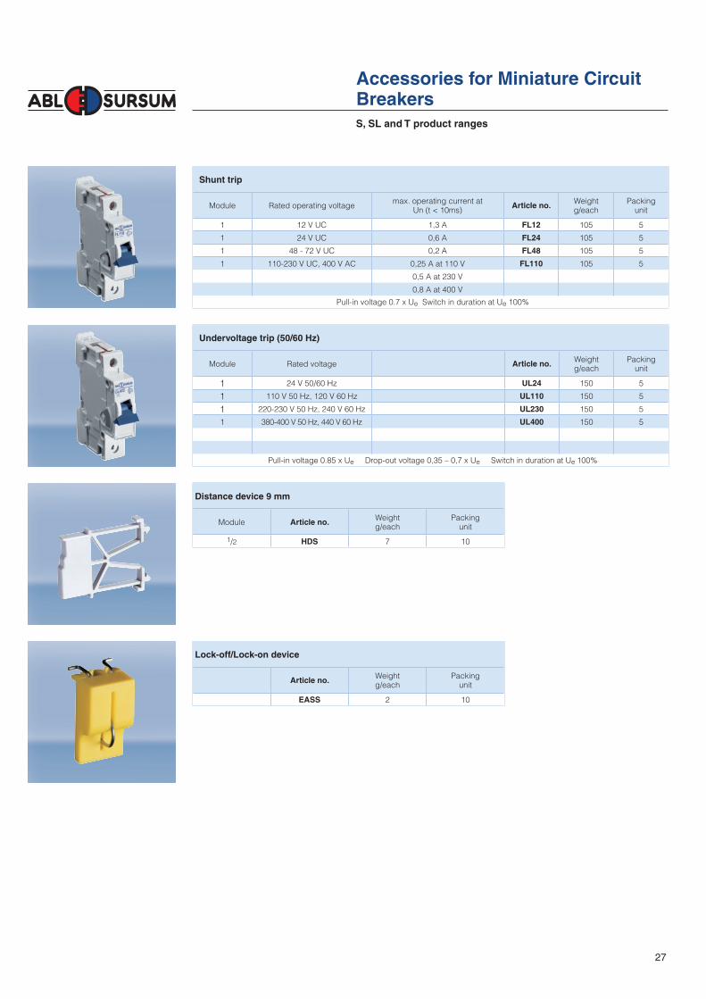
S, SL and T product ranges
Accessories for Miniature Circuit
Breakers
Shunt trip
Module Rated operating voltagemax. operating current at
Un (t < 10ms)Article no.
Weight g/each
Packingunit
1 12 V UC 1,3 A FL12 105 5
1 24 V UC 0,6 A FL24 105 5
1 48 - 72 V UC 0,2 A FL48 105 5
1 110-230 V UC, 400 V AC 0,25 A at 110 V FL110 105 5
0,5 A at 230 V
0,8 A at 400 V
Pull-in voltage 0.7 x Ue Switch in duration at Ue 100%
Undervoltage trip (50/60 Hz)
Module Rated voltage Article no.Weight g/each
Packingunit
1 24 V 50/60 Hz UL24 150 5
1 110 V 50 Hz, 120 V 60 Hz UL110 150 5
1 220-230 V 50 Hz, 240 V 60 Hz UL230 150 5
1 380-400 V 50 Hz, 440 V 60 Hz UL400 150 5
Pull-in voltage 0.85 x Ue Drop-out voltage 0,35 – 0,7 x Ue Switch in duration at Ue 100%
Distance device 9 mm
Module Article no.Weight g/each
Packingunit
1/2 HDS 7 10
Lock-off/Lock-on device
Article no.Weight g/each
Packingunit
EASS 2 10
27

1/20
Accessories
for Miniature Circuit Breakers
Auxiliary contact
Module Type of contact Contacts Article no.Weight g/each
Packingunit
1/2 1 auxiliary contact 1NO HL10 35 201/2 2 auxiliary contacts 1NO + 1NC HL11 40 201/2 3 auxiliary contacts 1NO + 2NC HL12 45 201/2 3 auxiliary contacts 2NO + 1NC HL21 45 20
13
14
HL10
21
22
13
14
HL11
31
32
13
14
21
22
HL12
31
32
13
14
23
24
HL21
HWL20
22
21
24
1214
11
HWL10
12
11
14
Auxiliary contact
Module Type of contact Contacts Article no.Weight g/each
Packingunit
1/2 1 auxiliary contact 1 change-over HWL10 40 201/2 2 auxiliary contacts 2 change-over HWL20 50 20
Auxiliary contact with signal contact
Module Type of contact Contacts Article no.Weight g/each
Packingunit
1/2 1 signal contact / 1 auxiliary contact 2 change-over HSL11 50 201/2 1 signal contact 1 change-over HSL10 40 20
HSL10
1
2
I >
12
11
14
HSL11
1
2
I >
9698
95
9698
95
The signal contact and the auxiliary contact are each fitted with a floating change-over contact.
Both contacts have trip-free mechanisms, i.e. manipulating the contact positions from outside is not possible. The signal contact only indicates when the main device is overloaded or short circuited but not when switched off by hand. The auxiliary contact clearly shows the switched condition of the main device i.e. when overloaded or short circuited and when switched off manually.
Technical Data HL10, HL11, HL12, HL21 HWL10, HWL20, HSL10, HSL11
Standards IEC 60947-5-1, DIN EN 60947-5-1, VDE 0660-200
Rated voltage 230 V~
Conventional thermal current in enclosure
Ith e 16 A
Rated operating currents Ie
Usage category AC-15Usage category AC-15Usage category DC-13Usage category DC-13
10 A / 230 V16 A / 110 V1 A / 250 V3 A / 125 V
4,8 A / 230 V9,6 A / 120 V1,8 A / 250 V2 A / 125 V
Minimum switching capacity 0,05 VA bei 6 V UC
S, SL and T product ranges
28

1/21
Busbars
Cross section Busbar current Modules/ Article no. Weight Packing Suitable
(mm2) Start of busbar/ Phases g/each unit end cap
Middle infeed Article no.
Busbars fork type
1-phase
12 65/110 56 SB16010 250 50
1-phase 1-pole circuit breaker + auxiliary contact
24 90/150 37/1 SDO.124 200 50
2-phase and 1-phase + N
10 63/100 28/2 SB26010 390 20 SB.A5
2-phase 2-pole circuit breaker + auxiliary contact
16 80/130 22/2 SB26216 310 20 SB.A2
3-phase
10 63/100 4/3 SB31210 84 25 SB.A1
10 63/100 19/3 SB36010 420 20 SB.A1
16 80/130 19/3 SB36016 675 20 SB.A2
3-phase 3-pole circuit breaker + auxiliary contact
16 80/130 16/3 SB36316 630 20 SB.A2
3-phase 1-pole circuit breaker + auxiliary contact
16 80/130 36/1 SDO.316 500 20 SB.A2
4-phase and 3-phase + N
16 80/130 14/4 SB46016 835 15 SB.A3
End caps for busbars
for busbars article no. Article no.Weight
g/each
Packing
unit
SB31210, SB36010 SB.A1 0,8 10
SB36016, SB36316, SDO.316, SB718U, SB26216 SB.A2 1 10
SB46016 SB.A3 1,1 10
SB26010 SB.A5 0,8 10
Busbars for S, SL and T miniature circuit breakers, MA motor
circuit breakers and residual current circuit breakers
29