mini spilt chiller &mini unitary chiller 50hz 2012 - midea nordic · 2012-07-25 · 3 full dc...
TRANSCRIPT

2012
MCAC-2012-22
Mini Spilt Chiller &Mini Unitary Chiller 50Hz
Commercial Air Conditioner Business UnitsMidea Air Conditioning and Refrigeration SectorAdd: West region of Midea commercial air conditioner department, Industry Avenue, Beijiao, Shunde, Foshan, Guangdong, P.R. China Postal code:528311Tel: +86-757-22394101 Fax: +86-757-26338003http://www.midea.com http://www.mideaaircon.com
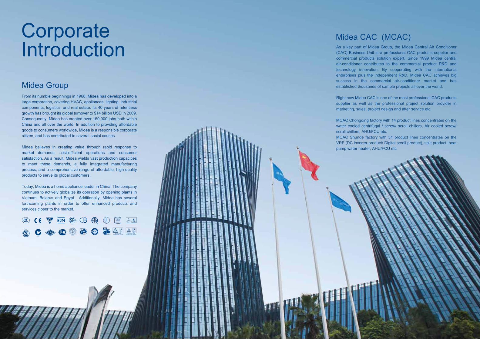
Corporate Introduction
From its humble beginnings in 1968, Midea has developed into a large corporation, covering HVAC, appliances, lighting, industrial components, logistics, and real estate. Its 40 years of relentless growth has brought its global turnover to $14 billion USD in 2009. Consequently, Midea has created over 150,000 jobs both within China and all over the world. In addition to providing affordable goods to consumers worldwide, Midea is a responsible corporate citizen, and has contributed to several social causes. Midea believes in creating value through rapid response to market demands, cost-efficient operations and consumer satisfaction. As a result, Midea wields vast production capacities to meet these demands, a fully integrated manufacturing process, and a comprehensive range of affordable, high-quality products to serve its global customers.
Today, Midea is a home appliance leader in China. The company continues to actively globalize its operation by opening plants in Vietnam, Belarus and Egypt. Additionally, Midea has several forthcoming plants in order to offer enhanced products and services closer to the market.
Midea Group
Midea CAC (MCAC)As a key part of Midea Group, the Midea Central Air Conditioner (CAC) Business Unit is a professional CAC products supplier and commercial products solution expert. Since 1999 Midea central air-conditioner contributes to the commercial product R&D and technology innovation. By cooperating with the international enterprises plus the independent R&D, Midea CAC achieves big success in the commercial air-conditioner market and has established thousands of sample projects all over the world.
Right now Midea CAC is one of the most professional CAC products supplier as well as the professional project solution provider in marketing, sales, project design and after service etc.
MCAC Chongqing factory with 14 product lines concentrates on the water cooled centrifugal / screw/ scroll chillers, Air cooled screw/ scroll chillers, AHU/FCU etc.MCAC Shunde factory with 31 product lines concentrates on the VRF (DC inverter product/ Digital scroll product), split product, heat pump water heater, AHU/FCU etc.

Full DC Inverter Mini VRF3
05
06
07
27
Nomenclature
Product lineup
Mini spilt chiller
Mini unitary chiller
Midea Mini chiller series is air-cooled water heat pump chiller, no need cooling water tower at the condensing side, easy for installation. The units can freely combined with indoor fan coil units, additionally combined with indoor top level decoration, this bring you to enjoy the nobility coming from central air conditioner.Midea Mini chiller series include unitary type (built-in water pump and expansion tank ) and spilt type, and the capacity of full range product is from 5kW to 16kW.Improved the features such as high efficiency, low noise, compactness ,safety running, easy maintenance etc.,They are widely applied in small business office building, apartments, villas, as well as restaurant and the similar places.
Product general introduction Contents

Mini chiller unit 50Hz 06Mini chiller unit 50Hz05
Product lineupSplit type
Refrigerant typeN1: R410A
M -G A D W N116 S
Design Series CodeA: Split chillerC: Unitary chiller
Compressor TypeD: Digital scroll compressor F: Fixed speed scroll compressor
Midea
Power SupplyS: 380-415V/50Hz/3phNone: 220-240V/50Hz/1ph
Outdoor Unit
Nominal Cooling Capacity (kW)
Light Commercial Chiller System
Nomenclature(Digital scroll compressor adopted)
Unitary type(Hydraulic module integrated)
MGA-D10/N1
MGA-D12/N1
MGA-D14/N1
MGA-D16/N1
220~240 V 1Ph 50Hz
220~240 V 1Ph 50Hz
380~415 V 3Ph 50Hz
380~415 V 3Ph 50Hz
Digital scroll
Digital scroll
Digital scroll
Digital scroll
R410A
R410A
R410A
R410A
Plate type
Plate type
Plate type
Plate type
Heat pump
Heat pump
Heat pump
Heat pump
SBX/N1-01
SBX/N1-01A
SBX/SN1-01
SBX/SN1-01A
Model Power supply Compressor type Refrigerant Heat exchanger A/C mode Water pump
MGC-F05W/N1
MGC-F07W/N1
MGC-F10W/N1
MGC-F10W/SN1
MGC-F12W/SN1
MGC-F14W/SN1
MGC-F16W/SN1
220~240 V 1Ph 50Hz
220~240 V 1Ph 50Hz
220~240 V 1Ph 50Hz
380~415 V 3Ph 50Hz
380~415 V 3Ph 50Hz
380~415 V 3Ph 50Hz
380~415 V 3Ph 50Hz
Fixed scroll
Fixed scroll
Fixed scroll
Fixed scroll
Fixed scroll
Fixed scroll
Fixed scroll
R410A
R410A
R410A
R410A
R410A
R410A
R410A
Plate type
Plate type
Plate type
Plate type
Plate type
Plate type
Plate type
Heat pump
Heat pump
Heat pump
Heat pump
Heat pump
Heat pump
Heat pump
Built- in
Built- in
Built- in
Built- in
Built- in
Built- in
Built- in
Model Power supply Compressor type Refrigerant Heat exchanger A/C mode Water pump
10.5kW
5/7.2kW 10.5kW 12/14/16kW
12/14/16kWWater Pump BOX
Mini chiller unit 50Hz 8Mini chiller unit 50Hz 7
Mini spilt chillerProdcut descripition
Features and benefits
Description of main components
Specification
Operation limits
Hydraulic performance
Dimension
Service space
Piping diagram
Capacity tables
Pipe connection information
Hydraulic connections
Wiring specifications
Accessories
Mini spilt chiller

Mini chiller unit 50Hz 10Mini chiller unit 50Hz 09
Product description
Features and benefits
Midea mini spilt chiller is air cooled revese-cycle chiller with axial-flow fans operate with refrigerant fluid, they are suitable for outdoor installation, the units conform to the essential requisites of 2004/108/EC.The units is international popular split design, the pump box is spilt from the outdoor units ,which can be installed inside the room or outside, the installation is very convenient and simple.
All the components and accessories of the mini chiller (evaporator, com-pressor, air-cooled condenser, expansion device and hydraulic module, such as expansion tank, water pump,water flow switch and so on ) have been manufactured, assembledand tested as a completed package within the factory. These packaged systems can reduce field labor, speed installation and improve reliability.
By adopting Copeland digital scroll compressor, the capacity can be stepless adjusted and the chiller can bring you more comfortable living conditions with less energy consumption. The system has no EMC prob-lem.
R410a environment friendly refrigerant, no harm to ozone layer.
Air-cooled system, no need cooling water tower, packaged design, easy for installation
Energy saving and high reliabilityConvenient and simple installation
By adopting high efficiency plate heat exchanger, the energy consumption can be reduced.
Metallic protective cabinet with rustproof plyester paint.
Built-in with voltage protection, current protection,anti-freezing protection, differential water flow protection,compressor,water pump and fan motor overload protection and etc., effectively guarantee the system towork safety.
With international popular split design, the pump box can be installed inside the matched room and its outdoor unit is compact and light.
No harm to ozone leyer Greenhouse effect is small
Expansion tank
Plate heat exchanger
Water pump
Water flow switch
Compressor current protection Phase protection signal output

Mini chiller unit 50Hz 12Mini chiller unit 50Hz11
Adopt wired controller KJR-08B/BEwith the auto-restart functions of adjusting outlet water temperature and power failure memory, etc..
Panels and base are made from galvanized steel plate painted with epoxy power to ensure total resistance to atmospheric pollution, condensate collection pan as standard.
Midea mini spilt chiller are equipped with Copeland brand high efficiency, reliable and silence digital scroll compressor, the capacity can be stepless adjusted and the chiller can bring you more comfortable living condition with less energy consumption; The system has no EMC problem.
The heat exchanger is made of AISI 316 stainless steel high efficiency plate heat exchanger to ensure high heat exchange efficiency, complete with electric heater and differential pressure switch. The complete heat exchanger is insulated with thermal insulation closed cell rubber foam to give optimum thermal insulation.
The mini spilt chiller water pump box are fully integrated and equipped with key hydraulic components such as expansion tank, water flow switch, plate type heat-exchanger, water circulating pump.
The refrigerant circuit is factory brazed and evacuated before accurately charged with R410A to ensure optimum operating requirement. To ensure flawless continuous operation, each refrigerant circuit is equipped with a carefully sized capillary tube.
Power and control electrical panel constructed in accordance with IEC 204-1/EN60335-2-40,complete with compressor contactor, control via “HSW7”control panel.
The coils are made from high performance and seamless copper tuber and high surface area aluminium fins to ensure optimum heat exchange capability. Condenser coil protection grill as standard.
Reserved control port for electrical heaterSignal output: 230V/50Hz/3PH.Electrical heater needs power supply separately.
Emergency switchStop the chiller directly by the switch in any urgent case.
Flexible and convenient control
Structure
Compressor
Air cooled condenser
Evaporator (in the water pump box)
Water pump box
Refrigerant circuit
Power and control electrical panel
1 ON/OFF
8
97
12
TEMP.SET6TIME ON
TIME OFF
MODE
QUERY
OK
PAGEUP/TEMP+2
MANUAL/AUTO 3 13 PAGEDOWN/TEMP-
104
HEAT
LOCK
RESET
5
ADDRESS-
11
161514
ADDRESS+
ADDRESS SET
Description of main components
Coils
To achieve high efficiency heat exchange, the units is equiped with the high performance axial-flow fans. The fan is direct driven by weather proof motor to ensure reliable operation, the fan motor is six –pole electric motor with built-in thermal cut-out.
Low noise fan and fan motor

Mini chiller unit 50Hz 14Mini chiller unit 50Hz 13
Specification
Nominal capacity is based on the following conditions:1. Cooling: outdoor ambient temperature 35°C,inlet/outlet water temperature 12/7°C.2. Heating: outdoor ambient temperature 7°C 85% R.H; inlet/outlet water temperature 40/45°C.3. 1m away in open field(sound pressure).
Model MGA-D10/N1 MGA-D12/N1
Power supply
Cooling
Refrigerant
Throttle Type
Compressor
Condenser coil
Other information
Model
Water pump
Expansion tank
Heat exchange
Water flow switchHydraulic module
Outdoor units
Other information
Refrigerant pipe diameter
Wired controller KJR-08B/BE(standard)
Ambient temperature
Pipe diameter
Control
Condenser fan motor
Heating
Max. input consumption
Max. input current
Capacity
Input
Capacity
Input
Refrigerant Type
Refrigerant Charged volume
Type
Brand
Number of Compressor
Thermal protector
Refrigerant oil
Type
Brand
Number of fan
Input (Hi/Lo)
Speed (Hi/Lo)
Max. air flow
Number of rows
Fin type
Number of circuits
Throttle Type
Noise level (sound pressure)
Dimension (W×H×D)
Packing (W×H×D)
Net/ Gross weight
Input
Pumping head
volume
Type
Rated water flow
Minimum water flow
The max. and min. water inlet
pressure
Noise level (sound pressure)
Dimension (W×H×D)
Packing (W×H×D)
Net/ Gross weight
Liquid side
Gas side
Water inlet/outlet
Tube outside dia. and type
V-Ph-Hz
kW
W
kW
W
W
A
g
ml
W
r/min
m3/h
mm
dB(A)
mm
mm
kg
W
m
L
m3/h
m3/h
bar
dB(A)
mm
mm
kg
mm
mm
mm
°C
220-240, 1, 50
10.5
3912
13
4216
6150
29.2
R410A
2700
Capillary
Digital Scroll
Copeland
1
Inner
POE OIL, 1892
AC motor
Welling
1
307/194
740/530
4500
2
Hydrophilic aluminium
Φ9.53
inner grooved tube
4
Capillary
57
990×966×340
1120×1100×440
109/115
CE-SBX/N1-01
420
22
3
Plate
1.80
standard
0.9
5.0/0.5
38.4
905×370×366
1057×439×436
52/57
Φ9.5
Φ19
DN32
Cooling: 10°C~43°C
Heating: -15°C~24°C
220-240, 1, 50
12
3978
14
4260
6200
29.4
R410A
3600
Capillary
Digital Scroll
Copeland
1
Inner
POE OIL, 1892
AC motor
Welling
1
185/120(×2)
860/610
5800
2
Hydrophilic aluminium
Φ9.53
inner grooved tube
7
Capillary
60
940×1250×340
1058×1380×435
122/128
CE-SBX/N1-01A
420
20
3
Plate
2.06
standard
1.03
5.0/0.5
38.9
905×370×366
1057×439×436
54/59
Φ9.5
Φ19
DN32
Cooling: 10°C~43°C
Heating: -15°C~24°C
Outdoor unitModel 12, 14, 16kW
1
1
1 2 3 4
5
6
789
10
11
12
13
2
4
58
7
9
6
10111213
3
4
5
6
789
10
11
1213
2
3
Model 10.5kW
Water pupm container
1 Condenser2 Motor3 Axlal-flow fan4 Electrical panel5 Emergency stop pushbuttons6 Liquid receiver7 4-way valve8 Low pressure switch9 Solenoid valve
10 Compressor11 High pressure switch12 Gas side13 Liquid side
1 Condenser2 Motor3 Axlal-flow fan4 Electrical panel5 Emergency stop pushbuttons6 Accumulater7 4-way valve8 Low pressure switch9 Solenoid valve
10 Compressor11 High pressure switch12
Gas side13Liquid side
1 Flow switch2 Pump3 Liquid receiver4 Plate heat exchanger56 Liquid side7 Electrical panel8 Expansion tank9 Auto-water replenishing
10 Water discharge11 Auto-water pipe12
Gas side
13Water intletWater outlet

Mini chiller unit 50Hz 16Mini chiller unit 50Hz 15
Water and ethylene glycol solutions used as a thermal vector in the place of water reduce the performance of the unit. Multiply the performance figures by the values given in the following table.
Ethylene glycol solutions
Operation limits
1. During winter leaving the unit unused, please drain water out completely from unit if no antifreeze were charged into pipeline, or keep power on (at standby or off status) and ensure that water is contained inside of unit. 2. When ambient temperature is lower than 5°C, running cooling mode must be charged antifreeze. Refer to upper parameters for the charged volume.
Notes:
cPf: correction factor refrigerating capacity.cQ: correction factor flow rate. cdp: correction factor pressure drop.
Nominal capacity is based on the following conditions:1. Cooling: outdoor ambient temperature 35°C,inlet/outlet water temperature 12/7°C.2. Heating: outdoor ambient temperature 7°C 85% R.H; inlet/outlet water temperature 40/45°C.3. 1m away in open field(sound pressure).
Model MGA-D14/N1 MGA-D16/N1
Power supply
Cooling
Refrigerant
Throttle Type
Compressor
Condenser coil
Other information
Model
Water pump
Expansion tank
Heat exchange
Water flow switch
Hydraulicmodule
Outdoor units
Other information
Refrigerant pipe diameter
Wired controller KJR-08B/BE(standard)
Ambient temperature
Pipe diameter
Control
Condenser fan motor
Heating
Max. input consumption
Max. input current
Capacity
Input
Capacity
Input
Refrigerant Type
Refrigerant Charged volume
Type
Brand
Number of Compressor
Thermal protector
Refrigerant oil
Type
Brand
Number of fan
Input (Hi/Lo)
Speed (Hi/Lo)
Max. air flow
Number of rows
Fin type
Number of circuits
Noise level (sound pressure)
Dimension (W×H×D)
Packing (W×H×D)
Net/ Gross weight
Input
Pumping head
volume
Type
Rated water flow
Model
Minimum water flow
The max. and min. water inlet
pressure
Noise level (sound pressure)
Dimension (W×H×D)
Packing (W×H×D)
Net/ Gross weight
Liquid side
Gas side
Water inlet/outlet
Tube outside dia. and type
V-Ph-Hz
kW
W
kW
W
W
A
g
ml
W
r/min
m3/h
mm
dB(A)
mm
mm
kg
W
m
L
m3/h
m3/h
bar
dB(A)
mm
mm
kg
mm
mm
mm
°C
380-415, 3, 50
14
4453
16
4828
6400
12.4
R410A
4100
Capillary
Digital Scroll
Copeland
1
Inner
POE OIL, 1892
AC motor
Welling
2
185/120(×2)
860/610
5600
3
Hydrophilic aluminium
Φ9.53
inner grooved tube
12
60
940×1250×340
1058×1380×435
123/130
CE-SBX/SN1-01
420
18
3
Plate
2.4
standard
1.2
5.0/0.5
41.2
905×370×366
1057×439×436
54/59
Φ9.5
Φ19
DN32
Cooling: 10°C~43°C
Heating: -15°C~24°C
380-415, 3, 50
16
4904
17
4943
6600
12.5
R410A
4400
Capillary
Digital Scroll
Copeland
1
Inner
POE OIL, 1892
AC motor
Welling
2
185/120(×2)
860/610
5600
3
Hydrophilic aluminium
Φ9.53
inner grooved tube
8
60
940×1250×340
1058×1380×435
126/133
CE-SBX/SN1-01A
420
17
3
Plate
2.58
standard
1.29
5.0/0.5
37.8
905×370×366
1057×439×436
55/60
Φ9.5
Φ19
DN32
Cooling: 10°C~43°C
Heating: -15°C~24°C
Cooling operation
Heating operation
Outdoor ambient temperature: 10°C~43°C
Outlet water temperature: 4°C-20°C
Outdoor ambient temperature: 4°C~24°C (-15°C~24°C, when charge enough antifreeze)
Outlet water temperature: 30°C-50°C
0
0
1
1
1
cPf
cQ
cdp
-5
12%
0.98
1.02
1.07
-10
20%
0.97
1.04
1.11
-15
28%
0.965
1.075
1.18
-20
35%
0.96
1.11
1.22
-25
40%
0.955
1.14
1.24
Freezing point (°C)
Percentage of ethylene glycol in weight
-10 4 5 7 15 20 t(°C) t(°C)
t(°C) t(°C)
OUTLET WATER TEMPERATURE OUTLET WATER TEMPERATURE
10
20
35
40
COOLING
30 35 45 50
-15
-3
7
20
24
HEATING Recommendedoperating area
Cooling and heating operation temperature range
OU
TDO
OR
AM
BIE
NT
TEM
PE
RA
TUR
E
OU
TDO
OR
AM
BIE
NT
TEM
PE
RA
TUR
E

Mini chiller unit 50Hz 18Mini chiller unit 50Hz17
The performance data given refer to conditions with clean evaporator plates (fouling factor=1). For different fouling factors, multiply the figures in the performance tables by the coefficient given in the following table.
If the total water volume in the system is less than the value in the table above, the additional water tank is necessary in order to avoid the compressor On/Off frequency.The minimum size of the water tank is calculated as: size of additional water tank(L)=Minimum water volume (L) –Actual water volume(L)
Pump head curves(*)
Heat exchanger pressure drop (water side)
Note: (*) To obtain the useful head for installation, subtract the pressure drop of the plate heat exchanger.
Outdoor unit
Water pump box
Hydraulic performance
Dimensions
(m2 °C/W)
4.4×10⁻⁵
0.86×10⁻⁴
1.72×10⁻⁴
f1
-
0.96
0.93
fx1
-
0.99
0.98
fk1
-
0.99
0.98
EvaporatorFouling factors
f1: capacity correction factor fk1: compressor power input correction factor fx1: total power input correction factor
Minimum water volume (L)
MGA-D12/N1
50
MGA-D14/SN1
60
MGA-D16/SN1
68
MGA-D10/N1
43
Model
m3/ h
l/sec
kPa
Water flow
Pressure drop10.5kW
0.8
0.222
26
1.0
0.278
29
1.2
0.333
33
1.4
0.389
37
1.6
0.444
42
1.8
0.500
46
2.0
0.556
50
m3/ h 1.2Water flow
Pressure drop
12 kW
14 kW
16 kW
1.4 1.6 1.8 2.0 2.2 2.4 2.6
0.389
39
31
29
0.444
44
36
32
0.500
47
40
37
0.556
50
43
41
0.611
53
46
45
0.667
58
50
49
0.722
54
52
l/sec
kPa
kPa
kPa
0.333
35
28
26
MGA-D10/N1
MGA-D12/N1
MGA-D14/SN1
MGA-D16/SN1
990
940
940
940
966
1250
1250
1250
366
376
376
376
340
340
340
340
624
600
600
600
Dimensions A B C D E
00 0.4 0.8 1.2 1.6 2.0 2.4 2.8 3.2 3.6 4.0
4
812
16
20
24
28
3236
WATER FLOW [m3/h]
PUM
P H
EAD
H[m
]
953
905
362 312
370
334
Fouling factors
Water volume for installation
Model
Model
A
E
B
C
D

Mini chiller unit 50Hz 20Mini chiller unit 50Hz 19
Service space
400
400
900
600
600mm
M10 Foot screw4 pieces per unit
Piping diagram
Remark:
1
2
3
4
5
6
7
8
9
10
11
12
13
Compressor
High pressure switch
4 -way valve
Condenser
Filter
Capillary
Liquid receiver
Plate heat exchanger
PWM valve
Water temperature sensor
Liquid receiver
Low pressure switch
Crank heater
No Name Name NameNo No
12
11
9
13 2 34
8
10
107
7
5 6 5
5 6 5
Capacity tablesCooling capacity
Remark:Ta: outside air temperature (°C) Tw : evaporator water outlet temperature (°C)Pf: cooling capacity (kW) Pa: compressor power input (kW)Pat: total power input (kW) Qev: evaporator water flow (m3/h)ΔPev: evaporator pressure drop (kPa)
Tw (°C)
Pf (kW)
Pa (kW)
Pat (kW)
Qev (m3/h)
ΔPev (kPa)
Pf (kW)
Pa (kW)
Pat (kW)
Qev (m3/h)
ΔPev (kPa)
Pf (kW)
Pa (kW)
Pat (kW)
Qev (m3/h)
ΔPev (kPa)
Pf (kW)
Pa (kW)
Pat (kW)
Qev (m3/h)
ΔPev (kPa)
Pf (kW)
Pa (kW)
Pat (kW)
Qev (m3/h)
ΔPev (kPa)
5
10.9
3.3
4.1
1.9
47.3
10.4
2.9
3.4
1.8
44.7
9.9
3.3
3.8
1.7
40.5
9.4
3.6
4.1
1.6
36.0
9.0
3.8
4.3
1.5
31.5
6
11.2
3.3
4.1
1.9
47.6
10.8
2.9
3.4
1.8
45.6
10.2
3.3
3.8
1.7
41.3
9.7
3.6
4.1
1.6
36.6
9.3
3.8
4.3
1.6
35.7
7
11.5
3.4
4.2
2.0
50.0
11.1
3.0
3.5
1.9
47.7
10.5
3.4
3.9
1.8
45.0
10.0
3.7
4.2
1.7
40.8
9.5
3.9
4.4
1.6
36.6
8
11.8
3.4
4.2
2.0
50.3
11.5
3.1
3.6
2.0
49.8
10.7
3.4
3.9
1.9
48.0
10.3
3.7
4.2
1.7
41.4
9.8
3.9
4.4
1.7
40.5
9
12.1
3.4
4.2
2.1
54.0
11.8
3.1
3.6
2.0
50.4
11.0
3.5
4.0
1.9
48.6
10.6
3.8
4.3
1.8
45.5
10.0
4.0
4.5
1.7
41.3
10
12.4
3.5
4.3
2.2
57.0
12.1
3.1
3.6
2.0
50.9
11.3
3.5
4.0
2.0
51.0
11.0
3.8
4.3
1.8
45.8
10.3
4.0
4.5
1.8
46.5
MGA-D10/N1Model
Ta. (°C)
25
30
35
40
43
Tw (°C)
Pf (kW)
Pa (kW)
Pat (kW)
Qev (m3/h)
ΔPev (kPa)
Pf (kW)
Pa (kW)
Pat (kW)
Qev (m3/h)
ΔPev (kPa)
Pf (kW)
Pa (kW)
Pat (kW)
Qev (m3/h)
ΔPev (kPa)
Pf (kW)
Pa (kW)
Pat (kW)
Qev (m3/h)
ΔPev (kPa)
Pf (kW)
Pa (kW)
Pat (kW)
Qev (m3/h)
ΔPev (kPa)
5
12.4
3.5
4.1
2.2
46.6
11.9
3.8
4.4
2.0
37.0
11.4
4.2
4.8
2.0
33.8
10.9
4.5
5.1
1.9
32.3
10.5
4.7
5.3
1.8
28.0
6
12.7
3.5
4.1
2.2
47.8
12.2
3.8
4.4
2.1
37.1
11.7
4.2
4.8
2.0
37.1
11.2
4.5
5.1
2.0
35.0
10.8
4.7
5.3
1.9
30.1
7
13.0
3.5
4.1
2.3
49.6
12.5
3.8
4.4
2.1
40.6
12.0
4.2
4.8
2.1
40.6
11.5
4.5
5.1
2.0
36.3
11.1
4.7
5.3
1.9
33.8
8
13.3
3.6
4.2
2.3
51.8
12.8
3.9
4.5
2.2
43.2
12.3
4.3
4.9
2.1
43.2
11.8
4.6
5.2
2.0
38.4
11.4
4.8
5.4
2.0
37.4
9
13.6
3.6
4.2
2.3
54.6
13.1
3.9
4.5
2.2
46.1
12.6
4.3
4.9
2.2
46.1
12.1
4.6
5.2
2.1
41.0
11.7
4.8
5.4
2.0
38.6
10
13.9
3.6
4.2
2.4
60.0
13.4
3.9
4.5
2.3
48.0
12.9
4.3
4.9
2.2
48.0
12.4
4.6
5.2
2.1
45.1
12.0
4.8
5.4
2.0
40.5
MGA-D12/N1Model
Ta. (°C)
25
30
35
40
43

Mini chiller unit 50Hz 22Mini chiller unit 50Hz21
Remark:Ta: outside air temperature (°C ) Tw : evaporator water outlet temperature (°C)Pf: cooling capacity (kW) Pa: compressor power input (kW)Pat: total power input (kW) Qev: evaporator water flow (m3/h)ΔPev: evaporator pressure drop (kPa)
Tw (°C)
Pf (kW)
Pa (kW)
Pat (kW)
Qev (m3/h)
ΔPev (kPa)
Pf (kW)
Pa (kW)
Pat (kW)
Qev (m3/h)
ΔPev (kPa)
Pf (kW)
Pa (kW)
Pat (kW)
Qev (m3/h)
ΔPev (kPa)
Pf (kW)
Pa (kW)
Pat (kW)
Qev (m3/h)
ΔPev (kPa)
Pf (kW)
Pa (kW)
Pat (kW)
Qev (m3/h)
ΔPev (kPa)
5
14.8
3.6
4.1
2.6
49.3
14.1
4.1
4.6
2.4
43.9
13.4
4.6
5.1
2.3
40.8
12.5
5.1
5.6
2.2
33.3
12.0
5.5
6.0
2.1
30.6
6
15.1
3.6
4.1
2.6
50.0
14.4
4.1
4.6
2.5
47.9
13.7
4.6
5.1
2.4
43.5
12.8
5.1
5.6
2.2
34.5
12.3
5.5
6.0
2.1
32.5
7
15.4
3.6
4.1
2.7
51.7
14.7
4.1
4.7
2.5
48.3
14.0
4.6
5.1
2.4
44.2
13.1
5.1
5.6
2.3
36.7
12.6
5.5
6.0
2.2
35.2
8
15.7
3.7
4.2
2.7
53.0
15.0
4.2
4.7
2.6
49.1
14.3
4.7
5.2
2.5
46.9
13.4
5.2
5.7
2.3
39.8
12.9
5.6
6.1
2.2
36.2
9
16.1
3.7
4.2
2.8
56.1
15.3
4.2
4.7
2.6
50.2
14.6
4.7
5.2
2.5
47.8
13.7
5.2
5.7
2.4
43.7
13.2
5.6
6.1
2.3
39.1
10
16.4
3.7
4.2
2.8
57.8
15.6
4.2
4.7
2.7
52.7
14.9
4.7
5.2
2.5
48.3
14.0
5.2
5.7
2.4
44.9
13.5
5.6
6.1
2.3
40.5
MGA-D14/SN1Model
Ta. (°C)
25
30
35
40
43
Remark:Ta: outside air temperature (°C ) Tw : evaporator water outlet temperature (°C)Pt: heating capacity (kW) Pa: compressor power input (kW)Pat: total power input (kW) Qc: condenser water flow (m3/h)ΔPc: evaporator pressure drop (kPa) - : conditions outside of operating limits
Tw (°C)
Pf (kW)
Pa (kW)
Pat (kW)
Qev (m3/h)
ΔPev (kPa)
Pf (kW)
Pa (kW)
Pat (kW)
Qev (m3/h)
ΔPev (kPa)
Pf (kW)
Pa (kW)
Pat (kW)
Qev (m3/h)
ΔPev (kPa)
Pf (kW)
Pa (kW)
Pat (kW)
Qev (m3/h)
ΔPev (kPa)
Pf (kW)
Pa (kW)
Pat (kW)
Qev (m3/h)
ΔPev (kPa)
5
15.5
3.9
4.7
2.7
54.9
14.9
4.4
5.2
2.6
51.0
14.4
4.9
5.7
2.6
50.8
13.9
5.3
6.1
2.5
46.8
13.5
5.7
6.5
2.4
41.4
6
15.7
3.9
4.7
2.7
57.6
15.2
4.4
5.2
2.6
52.9
14.7
4.9
5.7
2.6
53.1
14.2
5.3
6.1
2.5
49.1
13.8
5.7
6.5
2.4
44.3
7
16.0
3.9
4.7
2.8
59.4
15.5
4.4
5.2
2.7
50.9
15.0
4.9
5.7
2.7
55.8
14.5
5.3
6.1
2.6
51.5
14.1
5.7
6.5
2.5
47.0
8
16.3
4.0
4.8
2.8
62.1
15.8
4.5
5.4
2.7
54.7
15.3
5.0
5.8
2.7
58.1
14.8
5.4
6.2
2.6
53.1
14.4
5.8
6.6
2.5
49.1
9
16.5
4.0
4.8
2.9
65.2
16.1
4.5
5.4
2.8
59.9
15.6
5.0
5.8
2.8
61.2
15.1
5.4
6.2
2.7
55.8
14.7
5.8
6.6
2.6
51.5
10
16.8
4.0
4.8
2.9
67.7
16.4
4.5
5.4
2.8
63.0
15.9
5.0
5.8
2.8
63.2
15.2
5.4
6.2
2.7
59.4
14.8
5.8
6.6
2.6
59.4
MGA-D16/SN1Model
Ta. (°C)
25
30
35
40
43
Tw (°C)
Pt (kW)
Pa (kW)
Pat (kW)
Qc (m3/h)
ΔPc (kPa)
Pt (kW)
Pa (kW)
Pat (kW)
Qc (m3/h)
ΔPc (kPa)
Pt (kW)
Pa (kW)
Pat (kW)
Qc (m3/h)
ΔPc (kPa)
Pt (kW)
Pa (kW)
Pat (kW)
Qc (m3/h)
ΔPc (kPa)
Pt (kW)
Pa (kW)
Pat (kW)
Qc (m3/h)
ΔPc (kPa)
35
8.3
3.6
4.4
1.5
29.4
9.4
3.7
4.5
1.8
27.5
13.2
3.8
4.6
2.2
37.2
12.3
3.9
4.7
2.3
40.5
13.8
4.0
4.8
2.4
45.8
40
8.3
3.9
4.7
1.5
28.4
9.4
4.0
4.8
1.8
25.6
13.1
4.1
4.9
2.2
35.8
12.2
4.2
5.0
2.3
40.0
13.7
4.3
5.1
2.4
45.1
45
8.3
4.2
5.0
1.5
27.0
9.4
4.3
5.1
1.8
24.8
13.0
4.4
5.2
2.2
34.5
12.1
4.5
5.3
2.3
39.2
13.6
4.6
5.4
2.3
43.6
50
-
-
-
-
-
9.2
4.5
5.3
1.8
23.2
12.9
4.7
5.5
2.2
33.1
12.0
4.8
5.1
2.3
38.8
13.5
4.9
5.7
2.3
42.9
MGA-D10/N1Model
Ta. U.R.87% (°C)
-5
0
7
10
15
Heating capacity
Tw (°C)
Pt (kW)
Pa (kW)
Pat (kW)
Qc (m3/h)
ΔPc (kPa)
Pt (kW)
Pa (kW)
Pat (kW)
Qc (m3/h)
ΔPc (kPa)
Pt (kW)
Pa (kW)
Pat (kW)
Qc (m3/h)
ΔPc (kPa)
Pt (kW)
Pa (kW)
Pat (kW)
Qc (m3/h)
ΔPc (kPa)
Pt (kW)
Pa (kW)
Pat (kW)
Qc (m3/h)
ΔPc (kPa)
35
11.0
3.7
4.5
1.7
41.6
12.2
3.8
4.6
2.0
33.0
14.2
3.9
4.7
2.4
44.0
15.2
4.0
4.8
2.5
38.0
16.7
4.1
4.9
2.8
45.0
40
10.9
4.0
4.8
1.7
41.0
12.1
4.1
4.9
2.0
32.6
14.1
4.2
5.0
2.4
43.6
15.1
4.3
5.1
2.5
37.6
16.6
4.4
5.2
2.8
44.8
45
10.8
4.3
5.1
1.7
40.3
12.0
4.4
5.2
2.0
32.1
14.0
4.5
5.3
2.4
43.1
15.0
4.6
5.4
2.5
37.2
16.5
4.7
5.5
2.8
44.6
50
-
-
-
-
-
11.9
4.6
5.4
2.0
31.8
13.9
4.8
5.6
2.4
42.8
14.9
4.9
5.7
2.5
37.0
16.4
5.0
5.8
2.8
44.2
MGA-D12/N1Model
Ta. U.R.87% (°C)
-5
0
7
10
15

Mini chiller unit 50Hz 24Mini chiller unit 50Hz23
Tw (°C)
Pt (kW)
Pa (kW)
Pat (kW)
Qc (m3/h)
ΔPc (kPa)
Pt (kW)
Pa (kW)
Pat (kW)
Qc (m3/h)
ΔPc (kPa)
Pt (kW)
Pa (kW)
Pat (kW)
Qc (m3/h)
ΔPc (kPa)
Pt (kW)
Pa (kW)
Pat (kW)
Qc (m3/h)
ΔPc (kPa)
Pt (kW)
Pa (kW)
Pat (kW)
Qc (m3/h)
ΔPc (kPa)
35
10.4
4.0
4.8
1.9
25.8
13.1
4.0
4.8
2.3
21.1
16.2
4.1
4.9
2.8
31.2
17.6
4.2
5.0
3.1
36.4
19.8
4.3
5.1
3.5
45.4
40
10.5
4.4
5.2
1.9
27.2
13.0
4.4
5.2
2.3
21.1
16.1
4.5
5.3
2.8
31.1
17.5
4.6
5.4
3.1
36.2
19.7
4.7
5.5
3.5
45.2
45
10.6
4.9
5.7
1.9
27.0
13.0
4.9
5.7
2.3
21.0
16.0
5.0
5.8
2.8
31.0
17.4
5.1
5.9
3.1
36.0
19.6
5.2
6.0
3.5
45.0
50
-
-
-
-
-
12.9
5.4
6.1
2.3
21.0
15.9
5.5
6.3
2.8
31.0
17.4
5.6
6.4
3.1
35.9
19.4
5.7
6.5
3.5
44.9
MGA-D14/SN1Model
Ta. U.R.87% (°C)
-5
0
7
10
15
Remark:Ta: outside air temperature (°C ) Tw : evaporator water outlet temperature (°C)Pt: heating capacity (kW) Pa: compressor power input (kW)Pat: total power input (kW) Qc: condenser water flow (m3/h)ΔPc: evaporator pressure drop (kPa) - : conditions outside of operating limits
Tw (°C)
Pt (kW)
Pa (kW)
Pat (kW)
Qc (m3/h)
ΔPc (kPa)
Pt (kW)
Pa (kW)
Pat (kW)
Qc (m3/h)
ΔPc (kPa)
Pt (kW)
Pa (kW)
Pat (kW)
Qc (m3/h)
ΔPc (kPa)
Pt (kW)
Pa (kW)
Pat (kW)
Qc (m3/h)
ΔPc (kPa)
Pt (kW)
Pa (kW)
Pat (kW)
Qc (m3/h)
ΔPc (kPa)
35
11.5
4.1
4.9
2.0
25.0
14.2
4.2
5.0
5.0
20.2
17.2
4.3
5.1
2.9
30.2
18.7
4.4
5.2
3.2
35.4
21.0
4.5
5.3
3.6
46.2
40
11.4
4.5
5.3
2.0
25.0
14.1
4.6
5.4
5.4
20.1
17.1
4.7
5.5
2.9
30.1
18.6
4.8
5.6
3.2
35.2
20.9
4.9
5.7
3.6
45.6
45
11.3
5.0
5.8
2.0
24.8
14.0
5.1
5.1
5.9
20.0
17.0
5.2
6.0
2.9
30.0
18.5
5.3
6.1
3.2
35.0
20.8
5.4
6.2
3.6
45.0
50
-
-
-
-
-
13.9
5.6
5.6
6.4
19.9
16.9
5.7
6.5
2.9
30.0
18.4
5.8
6.6
3.2
34.8
20.7
5.9
6.7
3.6
44.4
MGA-D16/SN1Model
Ta. U.R.87% (°C)
-5
0
7
10
15
Pipe connection informationPipe connection
Pipe length and height difference between main unit and water pump box
Additional refrigerant charge
Water inlet
Water outlet
Top cover
Refrigerant pipe junction
Wire connection
Water charging
Water drain out
Gas side
Water side
Ф19
DN32 ( 1-1/4" )
Ф9.53Liquid side
Less than 5m
5-10m
No need
(Pipe length-5)×60g
Additional refrigerantLiquid pipe length
Max.height difference between chiller and waterpump box is 5m.
Max.pipe length between water pump box and chiller is 10m.

Mini chiller unit 50Hz 26Mini chiller unit 50Hz25
Overall power cord
Overall power cord
Water-flow controlling wire
Temp. sensor signal wire(shielded wire)
Water pump power cord
Auxiliary heater controlling wire
Controlling wire for central & wired controller
3×6.0mm2
5×4.0mm2
7-cord shielded wire
3×1.0mm2
3×1.0mm2
3×1.0mm2
2×0.5mm2
(2-cord shielded wire)
For outdoor unit
For outdoor unit
Between outdoor units and water
pump box
Between outdoor units and
Auxiliary heater
Between outdoor units and water
pump box
Between outdoor units and
Auxiliary heater
Between outdoor units and central &
wired controller(shorter than 120m)
1
1
1
1
1
1
10.5/12kW
14/16kW
10.5/12/14/16kW
Model Name Qty Specifications(for reference) Note (purchased by customers)
Hydraulic connections
Wiring specification
The choice and installation of components is the responsibility of the installer who should follow good work-ing practice and current legislation.
The power cord type designation is H07RN-F.Connecting cable between indoor unit and outdoor unit shall be approved polychloroprene sheathed flexible cord, type designation H07RN-F or heavier cord.The means for disconnection from a power supply shall be incorporated in the fixed wiring and have an air gap contact separation of at least 3mm in each active(phase) conductors.
9
2 4
1
11
7
2 3
10
5
6T
F 1
13
14
812
15
Site connections
WATER INLET
WATER OUTLET
Factory connections1 P r essure gauge2 Vibration damper joint3 Gate valve4 Calibrating valve5 Flow switch67 Pump8 Safety valve9 Air vent10 Expansion tank11 Mesh filter12 Auto-water replenishing13
Temperature sensor
14Outdoor unitDrain/chemical washing valvePlate heat exchanger
6T
6
T
T 6
15
It is recommended that the following devices are installed in the water circuit of the system.
Accessories
The main unit must use water pump box and wired controller.
Water pump box and wired controller are standard with the units.
One wired controller can control more than 1 chiller.
Water pump box: SBX/(S)N1(A)
Wired controller: KJR-08B/BE
10.5kW
12kW
14kW
16kW
SBX/N1-01 SBX/N1-01A SBX/SN1-01 SBX/SN1-01A KJR-08B/BE
Accessories table

Mini chiller unit 50Hz 28Mini chiller unit 50Hz 27
Mini unitary chillerProduct description
Features and benefits
Description of main components
Specification
Operation limits
Hydraulic performance
Dimension
Service space
Piping diagram
Capacity tables
Hydraulic connections
Wiring specifications
Accessories
Mini unitary chiller

Mini chiller unit 50Hz 30Mini chiller unit 50Hz 29
Product description
Features and benefits
Midea mini unitary chiller is air cooled reverse-cycle chiller with axial-flow fans operate with refrigerant fluid, they are suitable for outdoor installation, the units conform to the essential requisites of 2004/108/EC.The units are integrated and compact design, the chiller built in water pump, expansion tank, plate heat-exchanger and so on, it is very simple for installation such kind of system.
All the components and accessoryies of the mini chiller (evaporator, compressor, air-cooled condenser, expansion device and Hydraulic module, such as expansion tank, water pump, water flow switch and so on. ) have been manufactured, assembled, and tested as a complete package within the factory. The packaged systems can reduce field labor and increase reliability.
Built in water pump, expansion tank and plate heat-exchanger. It is very easy for installation.
R410a environment friendly refrigerant, no harm to ozone layer
Air-cooled system, no need cooling water tower, packaged design, easy for installation.
Integrated and compact design, simple installation and save space
No harm to Ozone leyer Greenhouse effect is small
Expansion Tank
Pressure Difference Switch
Water Pump
Plate Heat-exchanger
Energy saving and high reliability
Flexible and convenient control
By adopting high efficiency plate heat exchanger, the energy consumption can be reduced.
Metallic protective cabinet with rustproof plyester paint.
Built-in with voltage protection, current protection, anti-freezing protection, water flow protection and etc., effectively guarantee the system to work safety.
Built-in with Eliwell ST542 electronic controller at factory. Compact devices with advanced function and friendly user interface.The front panel of the device functions as the user interface and is used to perform all operations relating to the device.
Signal output: 230V/50Hz/3PhElectrical heater needs power supply separately.
The chiller also can be controlled by the Eliwell remote control keyboard kit SKW210, which is LCD remote terminal with integrated room temperature control (optional).
Reserved control port for electrical heater
Compressor current protection Phase protection signal output

Mini chiller unit 50Hz 32Mini chiller unit 50Hz31
Can be used to connect with an ON/OFF switch or a timer controller.Reserved ON/OFF control port
Can be used to connect the alarm light to show the error of the chiller.Reserved alarm signal output port
Resume former running status automatically after power failure.Auto-restart function
Stop the chiller directly by the switch in any urgent caseEmergency switch
Inspect water pressure all the time.Built-in with water pressure gauge:
Water pressure gauge: inspect the water pressure any timeEmergency switch:stop the chiller directly by the switch in any urgent case
Controller: control interface of the chiller
Panels and base are made from galvanized steel plate painted with epoxy power to ensure total resistance to atmospheric pollution, condensate collection pan as standard.
Hermetic rotary or scroll compressor with crankcase heater and thermal cut-outMGC-F05W/N1 and MGC-F07W/N1 adopt Midea-Toshiba Rotary compressor; the other adopt Copeland or SANYO high efficiency scroll compressor.
The coils are made from high performance and seamless copper tuber and high surface area aluminium fins to ensure optimum heat exchange capability. Condenser coil protection grill is standard.
Structure
Compressor
Air cooled condenser
Description of main components
Coils
The heat exchanger is made of AISI 316 stainless steel high efficiency plate heat exchanger to ensure high heat exchange efficiency, complete with electric heater and differential pressure switch. The complete heat exchanger is insulated with thermal insulation closed cell rubber foam to give optimum thermal insulation.
Midea mini unitary chiller are fully integrated and equipped with key hydraulic components such as expan-sion tank, plate type of heat-exchanger, water circulating pump. The water pressure difference switch is provided in the units to protect against damage to the water pump.
Power and control electrical panel constructed in accordance with IEC 204-1/EN60335-2-40, complete with compressor contactor, control via “A2”control panel.
Evaporator
Hydraulic module
Power and control electrical panel
To achieve high efficiency heat exchange, the unit is equipment with the high performance axial-flow fans. The fan is driven directly by weather proof motor to ensure reliable operation, the fan motor is six-pole electric motor with built-in thermal cut-out.
Low noise fan and fan motor
Condenser Expansion tankAccumulaterAxial-flow fanHigh pressure switchCompressorElectrical panel Control panel Plate heat exchangerReversing valve (only cooling only)Water differential pressure switchPump connecting pipe(model 12/14/16kW only)Low pressure switch CapillaryPump
1
2
34
5
6
7
8
91011
12
1314
15
16
Emergency stop pushbuttons
123456789
10111213141516

Mini chiller unit 50Hz 34Mini chiller unit 50Hz33
Specification Model MGC-F05W/N1 MGC-F07W/N1
Power supply
Cooling
Refrigerant
Throttle Type
Compressor
Outdoor coil
Hydraulic
module
Water pump
Expansion tank
Heat exchange
Pressure Difference Switch
Outdoor unit
The Max. and Min. water inlet pressure
Outdoor noise level (sound pressure)
Pipe diameter
Control
Ambient temp.
Water inlet setting temp. range (default)
Outdoor fan motor
Heating
Max. input consumption
Max. input current
Starting current
Capacity
Input
Capacity
Input
Refrigerant Type
Refrigerant Charged volume
Type
Brand
Number of Compressor
Thermal protector
Refrigerant oil
Type
Brand
Number of fan
Input (Hi/Lo)
Speed (Hi/Lo)
Max. air flow
Number of rows
Fin type
Input (H/M/L)
Pumping head
volume
Type
Rated water flow
heat-exchanger water pressure drop
Dimension (W×H×D)
Packing (W×H×D)
Net/ Gross weight
Water inlet/outlet
V-Ph-Hz
kW
W
kW
W
W
A
A
g
ml
W
r/min
m3/h
W
m
L
m3/h
kpa
kpa
dB(A)
mm
mm
kg
mm
°C
°C
220-240, 1, 50
5
1938
5.5
1987
2350
11.7
36.8
R410A
1600
Capillary
ROTARY
Midea-Toshiba
1
Inner
ESTER OIL VG74, 750
AC motor
Welling
1
220
660
5563
1
Hydrophilic aluminium
Φ7.94
Inner grooved copper tube
93/67/46
5.5
2
Plate
0.86
21
standard
500/150
55
990×966×354
1120×1100×435
83/89
R1
electronic controller
220-240, 1, 50
7.2
2755
7.7
2834
3200
16.7
55
R410A
2100
Capillary
ROTARY
Midea-Toshiba
1
Inner
ESTER OIL VG74, 1100
AC motor
Welling
1
220
660
5624
1
Hydrophilic aluminium
Φ7.94
Inner grooved copper tube
93/67/46
5.5
2
Plate
1.24
35
standard
500/150
56
990×966×354
1120×1100×435
94/100
R1
electronic controller
Tube outside dia. and type mm
MGC-F10W/N1
220-240 , 1, 50
10.5
3614
12
4004
5500
25.7
110
R410A
3000
Capillary
Fix speed Scroll type
Copeland
1
Inner
POE OIL, 1656
AC motor
Welling
2
185/120
860/610
6500/4300
3
Hydrophilic aluminium foil
Φ9.53
inner groove tube
210/175/120
8.5
3
Plate
1.74
44
standard
60/50
500/150
940×1245×360
1058×1380×438
138/145
R5/4
electronic controller
Model MGC-F10W/SN1 MGC-F12W/SN1 MGC-F14W/SN1 MGC-F16W/SN1
MGC-F10W/SN1 MGC-F12W/SN1Power supply
Cooling
Refrigerant type/Quantity
Throttle
Compressor
Outdoor coil
Hydraulic
module
Water pump
Expansion tank
Heat exchange
Pressure Difference Switch
Outdoor unit
The Max. and Min. water inlet pressure
Outdoor noise level (sound pressure)
Pipe diameter
Control
Ambient temp.
Water inlet setting temp. range (default)
Outdoor fan motor
Heating
Max. input consumption
Max. input current
Starting current
Capacity
Input
Capacity
Input
Type
Charged volume
Type
Brand
Capacity
Input
Thermal protector
Refrigerant oil
Type
Brand
Number of fan
Input (Hi/Lo)
Speed (Hi/Lo)
Outdoor air flow
Number of rows
Fin type
Input (H/M/L)
Pumping head
volume
Type
Rated water flow
Water pressure drop
Dimension (W×H×D)
Packing (W×H×D)
Net/ Gross weight
Water inlet/outlet
V-Ph-Hz
kW
W
kW
W
W
A
A
g
Btu/h
W
ml
W
r/min
m3/h
W
m
L
m3/h
kpa
kpa
dB(A)
mm
mm
kg
mm
°C
°C
Tube outside dia. and type mm
380-415 , 3, 50
14
4859
16.12
5218
6550
10.5
60
R410A
3600
Capillary
Fix speed Scroll type
SANYO
56000
5750
Inner
FV68S, 1600
AC motor
Welling
2
185/120
860/610
6500/4300
3
Hydrophilic aluminium foil
Φ9.53
Inner grooved copper tube
210/175/120
8.5
3
plate
2.4
34
standard
500/150
60/50
1070×1249×420
1188×1385×498
145/160
R5/4
electronic controller
380-415 , 3, 50
16
6430
18
6444
7700
14.3
92
R410A
4200
Capillary
Fix speed Scroll type
SANYO
65510
6750
Inner
FV68S, 1700
AC motor
Welling
2
185/120
860/610
6550/4483
3
Hydrophilic aluminium foil
Φ7.94
Inner grooved copper tube
210/175/120
8.5
3
plate
2.8
38
standard
500/150
60/51
1070×1249×420
1188×1385×498
142/150
R5/4
electronic controller
380-415 , 3, 50
10.5
3930
12
4240
4400
8.3
45
R410A
2700
Capillary
Fix speed Scroll type
Copeland
42300
4100
Inner
POE OIL, 1952
AC motor
Welling
2
185/120
860/610
6465/4270
2
Hydrophilic aluminium foil
Φ7.94
Inner grooved copper tube
210/175/120
8.5
3
plate
1.72
44
standard
500/150
58/48
940×1245×360
1058×1380×438
131/139
R5/4
electronic controller
380-415 , 3, 50
12
4410
14
4643
5000
9.1
66
R410A
3000
Capillary
Fix speed Scroll type
SANYO
48100
4750
Inner
FV68S, 1700
AC motor
Welling
2
185/120
860/610
6470/4280
2
Hydrophilic aluminium foil
Φ7.94
Inner grooved copper tube
210/175/120
8.5
3
plate
2.0
40
standard
500/150
59/49
1070×1249×420
1188×1385×498
137/145
R5/4
electronic controller
Cooling: 10°C~43°C; Heating: -15-24°C
Cooling: 4~20°C; Heating mode: 30~55°C
Cooling: 10°C~43°C; Heating: -15-24°C
Cooling: 4~20°C; Heating mode: 30~55°C
Nominal capacity is based on the following conditions:1. Cooling: outdoor ambient temperature 35°C,inlet/outlet water temperature 12/7°C.2. Heating: outdoor ambient temperature 7°C 85% R.H; inlet/outlet water temperature 40/45°C.3. 1m away in open field(sound pressure).
Nominal capacity is based on the following conditions:1. Cooling: outdoor ambient temperature 35°C,inlet/outlet water temperature 12/7°C.2. Heating: outdoor ambient temperature 7°C 85% R.H; inlet/outlet water temperature 40/45°C.3. 1m away in open field(sound pressure).

Mini chiller unit 50Hz 36Mini chiller unit 50Hz 35
Water and ethylene glycol solutions used as a thermal vector in the place of water reduce the performance of the unit. Multiply the performance figures by the values given in the following table.
Ethylene glycol solutions
Operation Limits
1. During winter leaving the unit unused, please drain water out completely from unit if no antifreeze were charged into pipeline, or keep power on (at standby or off status) and ensure that water is contained inside of unit.2. When ambient temperature lower 5°C, running cooling mode must be charged antifreeze. Refer to upper parameters for the charged volume.
Notes:cPf: correction factor refrigerating capacity cQ: correction factor flow rate cdp: correction factor pressure drop
Cooling operation
Heating operation
Outdoor ambient temperature: 10°C~43°C
Outlet water temperature: 4°C-20°C
Outdoor ambient temperature: 4°C~24°C (-15°C~24°C, when charge enough antifreeze)
Outlet water temperature: 30°C-55°C
0
0
1
1
1
cPf
cQ
cdp
-5
12%
0.98
1.02
1.07
-10
20%
0.97
1.04
1.11
-15
28%
0.965
1.075
1.18
-20
35%
0.96
1.11
1.22
-25
40%
0.955
1.14
1.24
Freezing point (°C)
Percentage of ethylene glycol in weight
Cooling and heating operation temperature range
t(°C) t(°C)
t(°C)t(°C)
OU
TDO
OR
AM
BIE
NT
TEM
PE
RA
TUR
E
OU
TDO
OR
AM
BIE
NT
TEM
PE
RA
TUR
E
COOLING HEATING
OUTLET WATER TEMPERATURE OUTLET WATER TEMPERATURE
Recommendedoperating area
10
-10 4 5 7 15 20
20
35
43 24
20
7
-3
-15
30 35 45 55
The performance data given refer to conditions with clean evaporator plates (fouling factor=1). For different fouling factors, multiply the figures in the performance tables by the coefficient given in the following table.
(m2 °C/W)
4.4×10⁻⁵
0.86×10⁻⁴
1.72×10⁻⁴
f1
-
0.96
0.93
fx1
-
0.99
0.98
fk1
-
0.99
0.98
EvaporatorFouling factors
f1: Capacity correction factor fk1: Compressor power input correction factor fx1: Total power input correction factor
Minimum water volume (L)
MGC-F07W/N1
30
MGC-F05W/N1
21
Model
Minimum water volume (L)
MGC-F12W/SN1
50
MGC-F14W/SN1
60
MGC-F16W/SN1
68
MGC-F10W/(S)N1
43
Model
Fouling factors
Minimum water volume
Pump head curve(5/7.2kW)
Pump head curve(10.5/12/14/16kW)
Heat exchanger pressure drop (water side)
Hydraulic performance
m3/ h
l/sec
kPa
kPa
Water flow
5 kW
7.2 kW
0.8
0.222
13
12
1.0
0.278
23
21
1.2
0.333
36
33
1.4
0.389
52
47
1.6
0.444
-
65
1.8
0.500
-
-
2.0
0.556
-
-
Water flow[m3/h]
PUM
P H
EAD
H[m
]
Model
6
Power input P1
Head
max.
min.
min.
max.
min.
0.40.81.21.6
22.42.83.23.6
44.44.85.25.6
[m]
0.0050.01
0.0150.02
0.0250.03
0.0350.04
0.0450.05
0.0550.06
0.0650.07
0.0750.08
0.0850.09[kW]
0 0.4 0.8 1.2 1.6 2 2.4 2.8 3.2 3.6 [m h]2
00 2 4 6 8
1
2
3
4
5
6
7
8
9
Note: (*) To obtain the useful head of the installation, subtract the pressure drop of the plate heat exchanger.
Pressure drop
m3/ h
l/sec
kPa
kPa
kPa
kPa
Water flow
10.5KW
12 kW
14 kW
16 kW
1.2
0.333
8
7
6
6
1.4
0.389
11
10
8
7
1.6
0.444
15
14
10
9
1.8
0.500
19
18
14
13
2.0
0.556
24
23
17
16
2.2
0.611
30
29
21
20
2.4
0.667
37
36
26
24
Model
Pressure drop

Mini chiller unit 50Hz 38Mini chiller unit 50Hz 37
MGC-F05W/N1 MGC-F07W/N1
MGC-F10W/N1 MGC-F10W/SN1
MGC-F12W/SN1 MGC-F14W/SN1 MGC-F16W/SN1
Dimensions (unit: mm)
1092
460
430
420
1070698
962940600
340
360
1245
1249
376
400
1012990624
340
354
366
396
966
Service Space
400
400
900
600
Piping Diagram
Remark:
1
2
3
4
5
6
7
8
9
10
11
12
13
14
Compressor
High pressure switch
4-way valve
Condenser
Filter
Capillary
Liquid receiver
Plate heat exchanger
Defrost heater
Water temperature sensor
Water differential pressure switch
Accumulator
Low pressure switch
Crankcase heater
No. Name Name NameNo. No.
13
14
1
23
45 5 8
10
10
1197
6
12

Mini chiller unit 50Hz 40Mini chiller unit 50Hz 39
Capacity tablesCooling capacity
Note:Ta: outside air temperature (°C) Pa: compressor power input (kW)Tw : evaporator water outlet temperature (°C) Pat: total power input (kW)Pf: cooling capacity (kW) Qev: evaporator water flow (m3/h)ΔPev: evaporator pressure drop (kPa)
Tw
Pf
Pa
Pat
Qev
ΔPev
Pf
Pa
Pat
Qev
ΔPev
Pf
Pa
Pat
Qev
ΔPev
Pf
Pa
Pat
Qev
ΔPev
Pf
Pa
Pat
Qev
ΔPev
5.0
5.1
1.5
1.8
0.88
21.6
4.9
1.8
2.1
0.84
18.4
4.8
1.8
2.1
0.83
18.5
4.6
1.9
2.2
0.79
17.1
4.3
2.1
2.4
0.74
14.8
6.0
5.2
1.5
1.8
0.89
23.0
5.0
1.8
2.1
0.86
19.7
4.9
1.8
2.1
0.84
19.8
4.7
1.9
2.2
0.81
18.3
4.5
2.1
2.4
0.77
15.9
7.0
5.4
1.5
1.8
0.93
24.6
5.1
1.8
2.1
0.88
22.1
5.0
1.8
2.1
0.86
21.0
4.9
1.9
2.2
0.84
19.6
4.6
2.1
2.4
0.79
17.1
8.0
5.5
1.5
1.8
0.95
26.3
5.3
1.8
2.1
0.91
23.6
5.1
1.9
2.2
0.88
22.5
5.0
2.0
2.3
0.86
20.9
4.7
2.2
2.5
0.81
18.3
9.0
5.6
1.6
1.9
0.96
27.8
5.4
1.9
2.2
0.93
25.1
5.2
1.9
2.2
0.89
24.0
5.1
2.0
2.3
0.88
22.3
4.9
2.2
2.5
0.84
19.5
10.0
5.8
1.6
1.9
1.00
29.5
5.5
1.9
2.2
0.95
26.6
5.3
1.9
2.2
0.91
25.5
5.2
2.0
2.3
0.89
23.7
5.0
2.2
2.5
0.86
20.8
MGC-F05W/N1Model
Ta
25
30
35
40
43
Tw
Pf
Pa
Pat
Qev
ΔPev
Pf
Pa
Pat
Qev
ΔPev
Pf
Pa
Pat
Qev
ΔPev
Pf
Pa
Pat
Qev
ΔPev
Pf
Pa
Pat
Qev
ΔPev
5.0
7.3
2.3
2.6
1.26
35.6
7.1
2.6
2.9
1.22
32.4
7.0
2.6
2.9
1.20
32.5
6.8
2.7
3.0
1.17
31.1
6.5
2.9
3.2
1.12
28.8
6.0
7.4
2.3
2.6
1.27
37.0
7.2
2.6
2.9
1.24
33.7
7.1
2.6
2.9
1.22
33.8
6.9
2.7
3.0
1.19
32.3
6.7
2.9
3.2
1.15
29.9
7.0
7.6
2.3
2.6
1.31
38.6
7.3
2.6
2.9
1.26
36.1
7.2
2.6
2.9
1.24
35.0
7.1
2.7
3.0
1.22
33.6
6.8
2.9
3.2
1.17
31.1
8.0
7.7
2.3
2.6
1.32
40.3
7.5
2.6
2.9
1.29
37.6
7.3
2.7
3.0
1.26
36.5
7.2
2.8
3.1
1.24
34.9
6.9
3.0
3.3
1.19
32.3
9.0
7.8
2.4
2.7
1.34
41.8
7.6
2.7
3.0
1.31
39.1
7.4
2.7
3.0
1.27
38.0
7.3
2.8
3.1
1.26
36.3
7.1
3.0
3.3
1.22
33.5
10.0
8.0
2.4
2.7
1.38
43.5
7.7
2.7
3.0
1.32
40.6
7.5
2.7
3.0
1.29
39.5
7.4
2.8
3.1
1.27
37.7
7.2
3.0
3.3
1.24
34.8
MGC-F07W/N1Model
Ta
25
30
35
40
43
Tw
Pf
Pa
Pat
Qev
ΔPev
Pf
Pa
Pat
Qev
ΔPev
Pf
Pa
Pat
Qev
ΔPev
Pf
Pa
Pat
Qev
ΔPev
Pf
Pa
Pat
Qev
ΔPev
5
10.9
2.6
3.1
1.9
31.5
10.4
2.9
3.4
1.8
29.8
9.9
3.3
3.8
1.7
27.0
9.4
3.6
4.1
1.6
24.0
9.0
3.8
4.3
1.5
21.0
6
11.2
2.6
3.1
1.9
31.7
10.8
2.9
3.4
1.8
30.4
10.2
3.3
3.8
1.7
27.5
9.7
3.6
4.1
1.6
24.4
9.3
3.8
4.3
1.6
23.8
7
11.5
2.7
3.2
2.0
33.0
11.1
3.0
3.5
1.9
31.8
10.5
3.4
3.9
1.8
30.0
10.0
3.7
4.2
1.7
27.2
9.5
3.9
4.4
1.6
24.4
8
11.8
2.7
3.2
2.0
33.5
11.5
3.1
3.6
2.0
33.2
10.7
3.4
3.9
1.9
32.0
10.3
3.7
4.2
1.7
27.6
9.8
3.9
4.4
1.7
27.0
9
12.1
2.7
3.2
2.1
36.0
11.8
3.1
3.6
2.0
33.6
11.0
3.5
4.0
1.9
32.4
10.6
3.8
4.3
1.8
30.3
10.0
4.0
4.5
1.7
27.5
10
12.4
2.8
3.3
2.2
38.0
12.1
3.1
3.6
2.0
33.9
11.3
3.5
4.0
2.0
34.0
11.0
3.8
4.3
1.8
30.5
10.3
4.0
4.5
1.8
31.0
MGC-F10W/N1Model
Ta
25
30
35
40
43
Note:Ta: outside air temperature (°C) Pa: compressor power input (kW)Tw : evaporator water outlet temperature (°C) Pat: total power input (kW)Pf: cooling capacity (kW) Qev: evaporator water flow (m3/h)ΔPev: evaporator pressure drop (kPa)
Tw
Pf
Pa
Pat
Qev
ΔPev
Pf
Pa
Pat
Qev
ΔPev
Pf
Pa
Pat
Qev
ΔPev
Pf
Pa
Pat
Qev
ΔPev
Pf
Pa
Pat
Qev
ΔPev
5
10.9
2.6
3.1
1.9
31.5
10.4
2.9
3.4
1.8
29.8
9.9
3.3
3.8
1.7
27.0
9.4
3.6
4.1
1.6
24.0
9.0
3.8
4.3
1.5
21.0
6
11.2
2.6
3.1
1.9
31.7
10.8
2.9
3.4
1.8
30.4
10.2
3.3
3.8
1.7
27.5
9.7
3.6
4.1
1.6
24.4
9.3
3.8
4.3
1.6
23.8
7
11.5
2.7
3.2
2.0
33.0
11.1
3.0
3.5
1.9
31.8
10.5
3.4
3.9
1.8
30.0
10.0
3.7
4.2
1.7
27.2
9.5
3.9
4.4
1.6
24.4
8
11.8
2.7
3.2
2.0
33.5
11.5
3.1
3.6
2.0
33.2
10.7
3.4
3.9
1.9
32.0
10.3
3.7
4.2
1.7
27.6
9.8
3.9
4.4
1.7
27.0
9
12.1
2.7
3.2
2.1
36.0
11.8
3.1
3.6
2.0
33.6
11.0
3.5
4.0
1.9
32.4
10.6
3.8
4.3
1.8
30.3
10.0
4.0
4.5
1.7
27.5
10
12.4
2.8
3.3
2.2
38.0
12.1
3.1
3.6
2.0
33.9
11.3
3.5
4.0
2.0
34.0
11.0
3.8
4.3
1.8
30.5
10.3
4.0
4.5
1.8
31.0
MGC-F10W/SN1Model
Ta
25
30
35
40
43

Mini chiller unit 50Hz 42Mini chiller unit 50Hz41
Tw
Pf
Pa
Pat
Qev
ΔPev
Pf
Pa
Pat
Qev
ΔPev
Pf
Pa
Pat
Qev
ΔPev
Pf
Pa
Pat
Qev
ΔPev
Pf
Pa
Pat
Qev
ΔPev
5
12.4
3.5
4.1
2.2
29.1
11.9
3.8
4.4
2.0
23.1
11.4
4.2
4.8
2.0
21.1
10.9
4.5
5.1
1.9
20.2
10.5
4.7
5.3
1.8
17.5
6
12.7
3.5
4.1
2.2
29.9
12.2
3.8
4.4
2.1
23.2
11.7
4.2
4.8
2.0
23.2
11.2
4.5
5.1
2.0
21.9
10.8
4.7
5.3
1.9
18.8
7
13.0
3.5
4.1
2.3
31.0
12.5
3.8
4.4
2.1
25.4
12.0
4.2
4.8
2.1
25.4
11.5
4.5
5.1
2.0
22.7
11.1
4.7
5.3
1.9
21.1
8
13.3
3.6
4.2
2.3
32.4
12.8
3.9
4.5
2.2
27.0
12.3
4.3
4.9
2.1
27.0
11.8
4.6
5.2
2.0
24.0
11.4
4.8
5.4
2.0
23.4
9
13.9
3.6
4.2
2.3
34.1
13.1
3.9
4.5
2.2
28.8
12.6
4.3
4.9
2.2
28.8
12.1
4.6
5.2
2.1
25.6
11.7
4.8
5.4
2.0
24.1
10
3.6
4.2
2.4
37.5
13.4
3.9
4.5
2.3
30.0
12.9
4.3
4.9
2.2
30.0
12.4
4.6
5.2
2.1
28.2
12.0
4.8
5.4
2.0
25.3
MGC-F12W/SN1Model
Ta
25
30
35
40
43
Note:Ta: outside air temperature (°C) Pa: compressor power input (kW)Tw : evaporator water outlet temperature (°C) Pat: total power input (kW)Pf: cooling capacity (kW) Qev: evaporator water flow (m3/h)ΔPev: evaporator pressure drop (kPa)
Note:Ta: outside air temperature (°C) Pa: compressor power input (kW)Tw : evaporator water outlet temperature (°C) Pat: total power input (kW)Pf: cooling capacity (kW) Qev: evaporator water flow (m3/h)ΔPev: evaporator pressure drop (kPa)
Tw
Pf
Pa
Pat
Qev
ΔPev
Pf
Pa
Pat
Qev
ΔPev
Pf
Pa
Pat
Qev
ΔPev
Pf
Pa
Pat
Qev
ΔPev
Pf
Pa
Pat
Qev
ΔPev
5
14.8
3.6
4.1
2.6
29.0
14.1
4.1
4.6
2.4
25.8
13.4
4.6
5.1
2.3
24.0
12.5
5.1
5.6
2.2
19.6
12.0
5.5
6.0
2.1
18.0
6
15.1
3.6
4.1
2.6
29.4
14.4
4.1
4.6
2.5
28.2
13.7
4.6
5.1
2.4
25.6
12.8
5.1
5.6
2.2
20.3
12.3
5.5
6.0
2.1
19.1
7
15.4
3.6
4.1
2.7
30.4
14.7
4.1
4.7
2.5
28.4
14.0
4.6
5.1
2.4
26.0
13.1
5.1
5.6
2.3
21.6
12.6
5.5
6.0
2.2
20.7
8
15.7
3.7
4.2
2.7
31.2
15.0
4.2
4.7
2.6
28.9
14.3
4.7
5.2
2.5
27.6
13.4
5.2
5.7
2.3
23.4
12.9
5.6
6.1
2.2
21.3
9
16.1
3.7
4.2
2.8
33.0
15.3
4.2
4.7
2.6
29.5
14.6
4.7
5.2
2.5
28.1
13.7
5.2
5.7
2.4
25.7
13.2
5.6
6.1
2.3
23.0
10
16.4
3.7
4.2
2.8
34.0
15.6
4.2
4.7
2.7
31.0
14.9
4.7
5.2
2.5
28.4
14.0
5.2
5.7
2.4
26.4
13.5
5.6
6.1
2.3
23.8
MGC-F14W/SN1Model
Ta
25
30
35
40
43
Tw
Pf
Pa
Pat
Qev
ΔPev
Pf
Pa
Pat
Qev
ΔPev
Pf
Pa
Pat
Qev
ΔPev
Pf
Pa
Pat
Qev
ΔPev
Pf
Pa
Pat
Qev
ΔPev
5
15.5
5.0
5.5
2.7
30.5
14.8
4.5
5.0
2.6
28.3
14.9
6.0
6.5
2.6
28.2
14.2
5.5
6.0
2.5
26.0
13.5
5.0
5.5
2.4
23.0
6
15.7
5.0
5.5
2.7
32.0
15.0
4.5
5.0
2.6
29.4
15.2
6.0
6.5
2.6
29.5
14.5
5.5
6.0
2.5
27.3
13.8
5.0
5.5
2.4
24.6
7
16.0
5.0
5.5
2.8
33.0
15.3
4.5
5.0
2.7
28.3
15.5
6.0
6.5
2.7
31.0
14.8
5.5
6.0
2.6
28.6
14.1
5.0
5.5
2.5
26.1
8
16.3
5.1
5.6
2.8
34.5
15.6
4.6
5.1
2.7
30.4
15.8
6.1
6.6
2.7
32.3
15.1
5.6
6.1
2.6
29.5
14.4
5.1
5.6
2.5
27.3
9
16.5
5.1
5.6
2.9
36.2
15.8
4.6
5.1
2.8
33.3
16.1
6.1
6.6
2.8
34.0
15.4
5.6
6.1
2.7
31.0
14.7
5.1
5.6
2.6
28.6
10
16.8
5.1
5.6
2.9
37.6
16.1
4.6
5.1
2.8
35.0
16.4
6.1
6.6
2.8
35.1
15.7
5.6
6.1
2.7
33.0
15.0
5.1
5.6
2.6
30.0
MGC-F16W/SN1Model
Ta
25
30
35
40
43
Note:Ta: outside air temperature (°C) Tw : evaporator water outlet temperature (°C)Pt: heating capacity (kW) Pa: compressor power input (kW)Pat: total power input (kW) Qc: condenser water flow (m3/h)ΔPc: evaporator pressure drop (kPa) - : Exceed operating limits
Heating capacity
Tw
Pt
Pa
Pat
Qc
ΔPc
Pt
Pa
Pat
Qc
ΔPc
Pt
Pa
Pat
Qc
ΔPc
Pt
Pa
Pat
Qc
ΔPc
Pt
Pa
Pat
Qc
ΔPc
35
4.2
1.3
1.5
0.72
14.6
4.8
1.3
1.6
0.83
18.5
5.6
1.4
1.7
0.96
23.9
6.1
1.4
1.7
1.05
27.8
6.5
1.4
1.7
1.12
33.2
40
4.2
1.5
1.7
0.72
14.5
4.8
1.5
1.8
0.83
18.4
5.5
1.5
1.8
0.95
23.4
6.1
1.5
1.8
1.05
27.5
6.5
1.6
1.9
1.12
33
45
4.1
1.6
1.8
0.71
14.1
4.7
1.7
2
0.81
18.1
5.5
1.7
2
0.95
23
6
1.7
2
1.03
27.1
6.5
1.7
2
1.12
32.9
50
-
-
-
-
-
4.7
1.9
2.2
0.81
18.1
5.4
1.9
2.2
0.93
22.9
6
1.9
2.2
1.03
27
6.4
1.9
2.2
1.10
32.5
MGC-F05W/N1Model
Ta(U.R.87%)
-5
0
7
10
15

Mini chiller unit 50Hz 44Mini chiller unit 50Hz43
Tw
Pt
Pa
Pat
Qc
ΔPc
Pt
Pa
Pat
Qc
ΔPc
Pt
Pa
Pat
Qc
ΔPc
Pt
Pa
Pat
Qc
ΔPc
Pt
Pa
Pat
Qc
ΔPc
35
6.4
2.2
2.5
1.10
27.6
7
2.2
2.5
1.20
31.5
7.8
2.3
2.6
1.34
36.9
8.3
2.3
2.6
1.43
40.8
8.7
2.3
2.6
1.50
46.2
40
6.4
2.4
2.7
1.10
27.5
7
2.4
2.7
1.20
31.4
7.7
2.4
2.7
1.32
36.4
8.3
2.4
2.7
1.43
40.5
8.7
2.5
2.8
1.50
46
45
6.3
2.5
2.8
1.08
27.1
6.9
2.6
2.9
1.19
31.1
7.7
2.6
2.9
1.32
36
8.2
2.6
2.9
1.41
40.1
8.7
2.6
2.9
1.50
45.9
50
-
-
-
-
-
6.9
2.8
3.1
1.19
31.1
7.6
2.8
3.1
1.31
35.9
8.2
2.8
3.1
1.41
40
8.6
2.8
3.1
1.48
45.5
MGC-F07W/N1Model
Ta(U.R.87%)
-5
0
7
10
15
Note:Ta: outside air temperature (°C) Tw : evaporator water outlet temperature (°C)Pt: heating capacity (kW) Pa: compressor power input (kW)Pat: total power input (kW) Qc: condenser water flow (m3/h)ΔPc: evaporator pressure drop (kPa) - : Exceed operating limits
Tw
Pt
Pa
Pat
Qc
ΔPc
Pt
Pa
Pat
Qc
ΔPc
Pt
Pa
Pat
Qc
ΔPc
Pt
Pa
Pat
Qc
ΔPc
Pt
Pa
Pat
Qc
ΔPc
35
8.3
3.0
3.5
1.4
19.6
9.4
3.1
3.6
1.7
27.5
11.4
3.3
3.8
2.0
37.2
12.3
3.4
3.9
2.1
40.5
13.8
3.5
4.0
2.4
45.8
40
8.3
3.2
3.7
1.4
18.9
9.4
3.3
3.8
1.6
25.6
11.3
3.6
4.1
2.0
35.8
12.2
3.7
4.2
2.1
40.0
13.7
3.8
4.3
2.4
45.1
45
8.3
3.5
4.0
1.4
18.0
9.4
3.6
4.1
1.6
24.8
11.2
3.8
4.3
2.0
34.5
12.1
3.9
4.4
2.1
39.2
13.6
4.0
4.5
2.3
43.6
50
-
-
-
-
-
9.2
3.8
4.3
1.6
23.2
11.1
4.1
4.6
1.9
33.1
12.0
4.2
4.7
2.1
38.8
13.5
4.3
4.8
2.3
42.9
MGC-F10W/N1Model
Ta(U.R.87%)
-5
0
7
10
15
Note:Ta: outside air temperature (°C) Tw : evaporator water outlet temperature (°C)Pt: heating capacity (kW) Pa: compressor power input (kW)Pat: total power input (kW) Qc: condenser water flow (m3/h)ΔPc: evaporator pressure drop (kPa) - : Exceed operating limits
Tw
Pt
Pa
Pat
Qc
ΔPc
Pt
Pa
Pat
Qc
ΔPc
Pt
Pa
Pat
Qc
ΔPc
Pt
Pa
Pat
Qc
ΔPc
Pt
Pa
Pat
Qc
ΔPc
35
8.3
3.0
3.5
1.4
19.6
9.4
3.1
3.6
1.7
27.5
11.4
3.3
3.8
2.0
37.2
12.3
3.4
3.9
2.1
40.5
13.8
3.5
4.0
2.4
45.8
40
8.3
3.2
3.7
1.4
18.9
9.4
3.3
3.8
1.6
25.6
11.3
3.6
4.1
2.0
35.8
12.2
3.7
4.2
2.1
40.0
13.7
3.8
4.3
2.4
45.1
45
8.3
3.5
4.0
1.4
18.0
9.4
3.6
4.1
1.6
24.8
11.2
3.8
4.3
2.0
34.5
12.1
3.9
4.4
2.1
39.2
13.6
4.0
4.5
2.3
43.6
50
-
-
-
-
-
9.2
3.8
4.3
1.6
23.2
11.1
4.1
4.6
1.9
33.1
12.0
4.2
4.7
2.1
38.8
13.5
4.3
4.8
2.3
42.9
MGC-F10W/SN1Model
Ta(U.R.87%)
-5
0
7
10
15
Tw
Pt
Pa
Pat
Qc
ΔPc
Pt
Pa
Pat
Qc
ΔPc
Pt
Pa
Pat
Qc
ΔPc
Pt
Pa
Pat
Qc
ΔPc
Pt
Pa
Pat
Qc
ΔPc
35
9.9
3.7
4.3
1.7
26.0
11.1
3.8
4.4
1.9
33.0
13.4
3.9
4.5
2.3
44.0
14.4
4.0
4.6
2.5
38.0
15.9
4.1
4.7
2.8
45.0
40
9.8
4.0
4.6
1.7
25.6
11.0
4.1
4.7
1.9
32.6
13.3
4.2
4.8
2.3
43.6
14.3
4.3
4.9
2.5
37.6
15.8
4.4
5.0
2.8
44.8
45
9.8
4.3
4.9
1.7
25.2
11.0
4.4
5.0
1.9
32.1
13.2
4.5
5.1
2.3
43.1
14.2
4.6
5.2
2.5
37.2
15.7
4.7
5.3
2.8
44.6
50
-
-
-
-
-
11.0
4.6
5.2
1.9
31.8
13.1
4.8
5.4
2.3
42.8
14.1
4.9
5.5
2.5
37.0
15.6
5.0
5.6
2.8
44.2
MGC-F12W/SN1Model
Ta(U.R.87%)
-5
0
7
10
15
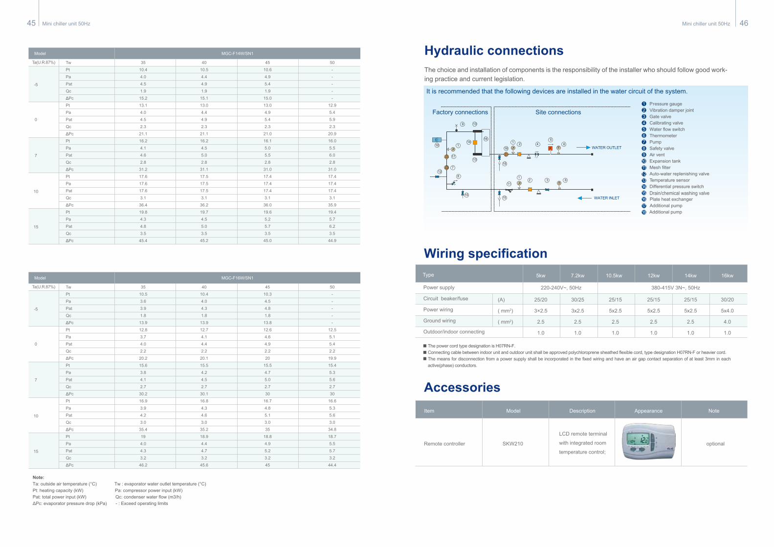
Mini chiller unit 50Hz 46Mini chiller unit 50Hz45
Note:Ta: outside air temperature (°C) Tw : evaporator water outlet temperature (°C)Pt: heating capacity (kW) Pa: compressor power input (kW)Pat: total power input (kW) Qc: condenser water flow (m3/h)ΔPc: evaporator pressure drop (kPa) - : Exceed operating limits
Tw
Pt
Pa
Pat
Qc
ΔPc
Pt
Pa
Pat
Qc
ΔPc
Pt
Pa
Pat
Qc
ΔPc
Pt
Pa
Pat
Qc
ΔPc
Pt
Pa
Pat
Qc
ΔPc
35
10.4
4.0
4.5
1.9
15.2
13.1
4.0
4.5
2.3
21.1
16.2
4.1
4.6
2.8
31.2
17.6
17.6
17.6
3.1
36.4
19.8
4.3
4.8
3.5
45.4
40
10.5
4.4
4.9
1.9
15.1
13.0
4.4
4.9
2.3
21.1
16.2
4.5
5.0
2.8
31.1
17.5
17.5
17.5
3.1
36.2
19.7
4.5
5.0
3.5
45.2
45
10.6
4.9
5.4
1.9
15.0
13.0
4.9
5.4
2.3
21.0
16.1
5.0
5.5
2.8
31.0
17.4
17.4
17.4
3.1
36.0
19.6
5.2
5.7
3.5
45.0
50
-
-
-
-
-
12.9
5.4
5.9
2.3
20.9
16.0
5.5
6.0
2.8
31.0
17.4
17.4
17.4
3.1
35.9
19.4
5.7
6.2
3.5
44.9
MGC-F14W/SN1Model
Ta(U.R.87%)
-5
0
7
10
15
Tw
Pt
Pa
Pat
Qc
ΔPc
Pt
Pa
Pat
Qc
ΔPc
Pt
Pa
Pat
Qc
ΔPc
Pt
Pa
Pat
Qc
ΔPc
Pt
Pa
Pat
Qc
ΔPc
35
10.5
3.6
3.9
1.8
13.9
12.8
3.7
4.0
2.2
20.2
15.6
3.8
4.1
2.7
30.2
16.9
3.9
4.2
3.0
35.4
19
4.0
4.3
3.2
46.2
40
10.4
4.0
4.3
1.8
13.9
12.7
4.1
4.4
2.2
20.1
15.5
4.2
4.5
2.7
30.1
16.8
4.3
4.6
3.0
35.2
18.9
4.4
4.7
3.2
45.6
45
10.3
4.5
4.8
1.8
13.8
12.6
4.6
4.9
2.2
20
15.5
4.7
5.0
2.7
30
16.7
4.8
5.1
3.0
35
18.8
4.9
5.2
3.2
45
50
-
-
-
-
-
12.5
5.1
5.4
2.2
19.9
15.4
5.3
5.6
2.7
30
16.6
5.3
5.6
3.0
34.8
18.7
5.5
5.7
3.2
44.4
MGC-F16W/SN1Model
Ta(U.R.87%)
-5
0
7
10
15
Hydraulic connectionsThe choice and installation of components is the responsibility of the installer who should follow good work-ing practice and current legislation.
123456789101112131415161718
It is recommended that the following devices are installed in the water circuit of the system.
9
2 4
1
15
16
11
15
7
17
18
2 3
10
5
6T
6TF
11
13
13
14
812
15
Site connections
WATER INLET
WATER OUTLET
Factory connectionsP r essure gaugeVibration damper jointGate valveCalibrating valveWater flow switchThermometerPumpSafety valveAir ventExpansion tankMesh filterAuto-water replenishing valveTemperature sensorDifferential pressure switchDrain/chemical washing valvePlate heat exchangerAdditional pumpAdditional pump
Power supply
Circuit beaker/fuse
Power wiring
Ground wiring
Outdoor/indoor connecting
(A)
( mm2)
( mm2)
25/20
3×2.5
2.5
1.0
30/25
3x2.5
2.5
1.0
25/15
5x2.5
2.5
1.0
25/15
5x2.5
2.5
1.0
25/15
5x2.5
2.5
1.0
30/20
5x4.0
4.0
1.0
Type 5kw 7.2kw 10.5kw 12kw 14kw 16kw
Wiring specification
Accessories
220-240V~, 50Hz 380-415V 3N~, 50Hz
Item Model Description Appearance Note
The power cord type designation is H07RN-F.Connecting cable between indoor unit and outdoor unit shall be approved polychloroprene sheathed flexible cord, type designation H07RN-F or heavier cord.The means for disconnection from a power supply shall be incorporated in the fixed wiring and have an air gap contact separation of at least 3mm in each active(phase) conductors.
Remote controller SKW210 optional
LCD remote terminal
with integrated room
temperature control;