mini metal lathe 7 x 12 - northern tool - quality tools for serious work · 2016-01-29 · mini...
TRANSCRIPT

Thank you very much for choosing a Klutch product. For future reference, please complete the owner’s record below:Serial Number/Lot Date Code: _______________ Purchase Date: _______________Save the receipt, warranty and these instructions. It is important that you read the entire manual to become familiar with this product before you begin using it.
This mini metal lathe is designed for certain applications only. Northern Tool and Equipment cannot be responsible for issues arising from modification or use of this product in an application for which it was not designed. We strongly recommend that this product not be modified and/or used for any application other than that for which it was designed.
For technical questions please call 1-800-222-5381.
Table of ContentsIntended Use.......................................................................................................................................1Technical Specifications....................................................................................................................2Important Safety Information.............................................................................................................2Specific Operation Warnings..............................................................................................................4Grounding...........................................................................................................................................5Extension Cords..................................................................................................................................5Assembly ............................................................................................................................................6 Main Parts........................................................................................................................................7Before Each Use.................................................................................................................................9Operating Instructions......................................................................................................................10 Settings and Adjustments..............................................................................................................10 Operation........................................................................................................................................12After Each Use..................................................................................................................................14Maintenance.....................................................................................................................................15Parts Diagram...................................................................................................................................16Parts List ..........................................................................................................................................19Troubleshooting................................................................................................................................22Replacement Parts...........................................................................................................................24Limited Warranty...............................................................................................................................24
Intended UseThis compact 7" x 12" lathe is light-duty multi-purpose machine used for typical turning processes to economically produce small precision parts, threaded parts, fittings, and dies. The lathe features a low and high spindle speed, a change gear set, a wrench set and an oil can.
Mini Metal Lathe 7 x 12OWNER’S MANUAL
Mini Metal Lathe 7 x 12OWNER’S MANUAL
Item# 49656
1 of 24
WARNING:Read carefully and understand all ASSEMBLY AND OPERATIONINSTRUCTIONS before operating. Failure to follow the safety rules and other basic safety precautions may result in serious personal injury.

Mini Metal Lathe 7 x 12OWNER’S MANUAL
Mini Metal Lathe 7 x 12OWNER’S MANUAL
Technical Specifications
Important Safety Information
WARNING:• Read and understand all instructions. Failure to follow all instructions may result in serious
injury or property damage.• The warnings, cautions, and instructions in this manual cannot cover all possible conditions
or situations that could occur. Exercise common sense and caution when using this tool. Always be aware of the environment and ensure that the tool is used in a safe and responsible manner.
• Do not allow persons to operate or assemble the product until they have read this manual and have developed a thorough understanding of how it works.
• Do not modify this product in any way. Unauthorized modification may impair the function and/or safety and could affect the life of the product. There are specific applications for which the product was designed.
• Use the right tool for the job. DO NOT attempt to force small equipment to do the work of larger industrial equipment. There are certain applications for which this equipment was designed. It will do the job better and more safely at the capacity for which it was intended. DO NOT use this equipment for a purpose for which it was not intended.
• Industrial or commercial applications must follow OSHA requirements.
WARNING:• This product may contain chemicals known to the State of California to cause cancer, birth
defects or other reproductive harm.• Some dust created by power sanding, sawing, grinding, drilling, and other construction
activities contains chemicals known to the State of California to cause cancer, birth defects, or other reproductive harm. Some examples of these chemicals are:
- lead from lead-based paints, - crystalline silica from bricks and cement and other masonry products, and - arsenic and chromium from chemically-treated lumber.
Your risk from these exposures varies, depending on how often you do this type of work. To reduce your exposure to these chemicals: work in a well-ventilated area, and work with approved safety equipment, such as dust masks that are specially designed to filter out microscopic particles.
• Handling power cords on corded products may expose you to lead, a chemical known to the State of California to cause cancer and birth defects or other reproductive harm. Wash your hands after handling.
WARNING:WORK AREA SAFETY• Inspect the work area before each use. Keep work area clean, dry, free of clutter, and well lit.
Cluttered, wet, or dark work areas can result in injury. Using the mini metal lathe in confined work areas may put you dangerously close to other cutting tools and rotating parts.
• Do not use the mini metal lathe where there is a risk of causing a fire or an explosion; e.g., in the presence of flammable liquids, gases, or dust. The product can create sparks, which may ignite the flammable liquids, gases, or dust.
• Do not allow the mini metal lathe to come into contact with an electrical source. The tool is not insulated and contact will cause electrical shock.
• Keep children and bystanders away from the work area while operating the tool. Do not allow children to handle the mini metal lathe.
• Be aware of all power lines, electrical circuits, water pipes, and other mechanical hazards in your work area. Some of these hazards may be hidden from your view and may cause personal injuryand/or property damage if contacted.
WARNING:PERSONAL SAFETY• Stay alert, watch what you are doing, and use common sense when operating the tool. Do
not use the tool while you are tired or under the influence of drugs, alcohol, or medication. A moment of inattention while operating the tool may result in serious personal injury.
• Dress properly. Do not wear loose clothing, dangling objects, or jewelry. Keep your hair, clothing and gloves away from moving parts. Loose clothes, jewelry, or long hair can be caught in moving parts. Air vents on the tool often cover moving parts and should be avoided.
• Wear the proper personal protective equipment when necessary. Use ANSI Z87.1 compliant safety goggles (not safety glasses) with side shields, or when needed, a face shield. Use a dust mask in dusty work conditions. Also use non-skid safety shoes, hardhat, gloves, dust collection systems, and hearing protection when appropriate. This applies to all persons in the work area.
• Do not overreach. Keep proper footing and balance at all times.• Do not use the tool when tired or under the influence of drugs, alcohol or medication.• Ensure the power switch is off prior to plugging in the tool.• Remove keys or wrenches before connecting the tool to an air supply, power supply, or
turning on the tool. A wrench or key that is left attached to a rotating part of the tool may cause personal injury.
• Secure the work with clamps or a vise instead of your hand when practical. This safety precaution allows for proper tool operation using both hands.
WARNING:ELECTRICAL SAFETY• Grounded tools must be plugged into an outlet properly installed and grounded in accordance
with all codes and ordinances. Never remove the grounding prong or modify the plug in any way. Do not use any adapter plugs. Check with a qualified electrician if you are in doubt as to whether the outlet is properly grounded. If the tools should electrically malfunction or break down, grounding provides a low resistance path to carry electricity away from the user.
• Double insulated tools are equipped with a polarized plug (one blade is wider than the other). This plug will fit in a polarized outlet only one way. If the plug does not fit fully in the outlet, reverse the plug. If it still does not fit, contact a qualified electrician to install a polarized outlet. Do not change the plug in any way. Double insulation eliminates the need for the three wire grounded power cord and grounded power supply system.
2 of 24 3 of 24
PropertyMax. swing over bed
Distance between centers (Max. length of workpiece) Hole through spindleSpindle hole taperTailstock taperCross slide travelCompound travelRange of threads - Metric versionImperial versionSpindle speed-Low range - High rangeMotorDimensionsShipping Weight
Specification7-1/16” (180mm)
11-7/8” (300mm)
3/4” (20mm)MT#3MT#22-1/2” (65mm)2-3/16” (55mm)0.5-1.25mm(5 thread pitches) 16-24TPI(5 thread pitches)100-1100RPM100-2500 RPM3/4 HP27-1/2 x 11-7/8 x 11-7/888 lbs.

Mini Metal Lathe 7 x 12OWNER’S MANUAL
Mini Metal Lathe 7 x 12OWNER’S MANUAL
• Do not allow the product to come into contact with an electrical source. The tool is not insulated and contact will cause electrical shock.
• Avoid body contact with grounded surfaces such as pipes, radiators, ranges, and refrigerators. There is an increased risk of electric shock if your body is grounded.
• Do not expose power tools to rain or wet conditions. Water entering a power tool will increase the risk of electric shock.
• Do not abuse the power cord. Never use the power cord to carry the tools or pull the plug from an outlet. Keep the power cord away from heat, oil, sharp edges, or moving parts. Replace damaged power cords immediately. Damaged power cords increase the risk of electric shock.
• When operating a power tool outside, use an outdoor extension cords marked “W-A” or “W”. These extension cords are rated for outdoor use, and reduce the risk of electric shock.
CAUTION:MINI METAL LATHE USE AND CARE• Do not force the product. Products do a better and safer job when used in the manner for
which they are designed. Plan your work, and use the correct product for the job.• Check for damaged parts before each use. Carefully check that the product will operate
properly and perform its intended function. Replace damaged or worn parts immediately. Never operate the product with a damaged part.
• Do not use a product with a malfunctioning switch. Any power tool that cannot be controlled with the power switch is dangerous and must be repaired by an authorized service representative before using.
• Disconnect the power/air supply from the product and place the switch in the locked or off position before making any adjustments, changing accessories, or storing the tool. Such preventive safety measures reduce the risk of starting the tool accidentally.
• Store the product when it is not in use. Store it in a dry, secure place out of the reach of children. Inspect the tool for good working condition prior to storage and before re-use.
• Use only accessories that are recommended by the manufacturer for use with your product. Accessories that may be suitable for one product may create a risk of injury when used with another tool. Never use an accessory that has a lower operating speed or operating pressure than the tool itself.
• Keep guards in place and in working order. Never operate the product without the guards in place.
• Do not leave the tool running unattended.
Specific Operation Warnings
WARNING:• To prevent serious injury or property damage read owner’s manual before operating. • DO NOT wear loose clothing, jewelry, gloves, or unrestrained hair that may get caught in
moving parts of the machine.• Wear the proper safety gear including ANSI Z87.1 approved eye protection.• Moving Parts Hazard. Keep hands clear of spindle chuck and work piece.• Remove keys and adjusting wrenches before starting the machine.• Feed cutter into work piece against direction of rotation.• Always secure work piece before machining operation.• DO NOT operate without guards in place.• Electric shock hazard. Be sure equipment is properly grounded. • Turn power OFF before servicing.• Wait for machine to come to a complete stop before changing gears.• Not for use by or around children.
Grounding
WARNING:• This machine must be grounded while in use to protect the operator from electrical shock.
This drill press is equipped with an electric cord that has an equipment-grounding conductor and a grounding plug. The plug MUST be plugged into a matching receptacle that is properly installed and grounded in accordance with ALL local codes and ordinances.
• DO NOT MODIFY THE PLUG PROVIDED. If it will not fit the receptacle, have the proper receptacle installed by a qualified electrician.
• CHECK with a qualified electrician or service person if you do not completely understand the grounding instructions, or if you are not sure the tool is properly grounded.
Grounded Tools: Tools with 3-Prong PlugsTools marked with Grounding Required have a 3-wire cord and 3-prong grounding plug. The plug must be connected to a properly grounded outlet. If the tool should electrically malfunction or break down, grounding provides a low resistance path to carry electricity away from the user, reducing the risk of electric shock. (See Figure A.)The grounding prong in the plug is connected through the green wire inside the cord to the grounding system in the tool. The green wire in the cord must be the only wire connected to the tool’s grounding system and must never be attached to an electrically live terminal. Your tool must be plugged into an appropriate outlet, properly installed and grounded in accordance with all codes and ordinances. The plug and outlet should look like those in the following illustration.
Double Insulated Tools: Tools with Two-Prong PlugsTools marked Double Insulated do not require grounding. They have a special double insulation system which satisfies OSHA requirements and complies with the applicable standards of Underwriters Laboratories, Inc., the Canadian Standard Association, and the National Electrical Code. (See Figure B.)Double insulated tools may be used in either of the 120 volt outlets shown in the following illustration.
Extension Cords
WARNING:• USE A PROPER EXTENSION CORD. Make sure your extension cord is in good condition.
When using an extension cord, be sure to use one heavy enough to carry the current your product will draw. An undersized cord will cause a drop in line voltage, resulting in loss of power and cause overheating.
4 of 24 5 of 24

150'14 AWG12 AWG12 AWG
Nameplate AMPS25'
18 AWG18 AWG16 AWG14 AWG
50'16 AWG16 AWG16 AWG12 AWG
100'16 AWG14 AWG14 AWG
Minimum Wire Size Of Extension Cords
0-66-1010-1212-16
Cord Length
NOT RECOMMENDED
6 of 24 7 of 24
Mini Metal Lathe 7 x 12OWNER’S MANUAL
• Be sure your extension cord is properly wired and in good condition. Always replace a damaged extension cord or have it repaired by a qualified person before using it. Protect your extension cords from sharp objects, excessive heat and damp or wet areas.
• Grounded tools require a 3-wire extension cord. Double Insulated tools can use either a 2- or 3-wire extension cord.
• As the distance from the supply outlet increases, you must use a heavier gauge extension cord. Using extension cords with inadequately sized wire causes a serious drop in voltage, resulting in loss of power and possible tool damage.
• The smaller the gauge number of the wire, the greater the capacity of the cord. For example, a 14-gauge cord can carry a higher current than a 16-gauge cord. Minimum extension cord wire size is shown in the following table:
• When using more than one extension cord to make up the total length, make sure each cord contains at least the minimum wire size required.
• If you are using one extension cord for more than one tool, add the nameplate amperes and use the sum to determine the required minimum cord size.
• If you are using an extension cord outdoors, make sure it is marked with the suffix W-A (W in Canada) to indicate it is acceptable for outdoor use.
• Make sure your extension cord is properly wired and in good electrical condition. Always replace a damaged extension cord or have it repaired by a qualified electrician before using it.
• Protect your extension cords from sharp objects, excessive heat, and damp or wet areas.
AssemblyWhen unpacking the milling machine, check the shipping crate contents to ensure all parts are present. If any pieces are missing, call the distributor at the number in the Replacement Parts section of this manual.
UNPACKINGWhen unpacking the lathe, check that all items are present:
If any parts are missing, call the distributor at the number in the Replacement Parts section of this manual.
Mini Metal Lathe 7 x 12OWNER’S MANUAL
MOUNTING THE MACHINEConsider the weight of the lathe (88 lbs.) and, with assistance, place it onto a good solid surface or workbench. Ensure the location is adequately lit and that you will not be working in your own shadow.Remove all traces of the factory preservative coating with paraffin or a good quality solvent then spread a thin layer of oil on all machined surfaces.Mount the machine to a workbench, of sufficient height so that you do not need to bend your back to perform normal operations. We strongly recommend bolting the machine to a workbench using the tapped holes used to secure the feet to the machine. This provides added stability and safety. To do this, first drill four M6 clearance holes in a worktop, at the dimensions shown in the diagram opposite, and with appropriate length M6 bolts, or screws, with flat washers (not included).
The saddle, cross-slide, and compound slide adjustments are all factory set to ensure smooth movement in both directions. lf however the adjustments have drifted in transit, as indicated by stiff or erratic movement, refer to the Settings and Adjustments subsection in the Operating Instructions section for adjustment procedures.All hex keys and wrenches for necessary adjustments are supplied, together with a chuck key for the 3-jaw chuck and a spare fuse. The fuse holder is located on the main control panel.
Main Parts
Part No.
1
2
3
4
5
6
Description
Lathe
Spindle center, MT#3
Tailstock, MT #2
External jaws
Key for chuck
Change gear:30, 35, 40, 50, 60
Q’ty
1
1
1
3
1
1
Part No.
7
8
9
10
11
12
Description
Bakelite straight handle
Double end wrench 8*10
Socket head wrench:3
Plastic oil can
Fuse
Instruction manual (this manual)
Q’ty
2
1
1
1
1
1

8 of 24 9 of 24
Mini Metal Lathe 7 x 12OWNER’S MANUAL
THE HEADSTOCKThe motor provides a direct drive to the spindle via an internal tooth type belt. Spindle speed is variable, and is regulated by the Speed Control Knob (23)on the main control panel.The spindle is provided with an internal No.3 Morse taper to accommodate a center for use with a face plate or turning clamp.The 3-jaw self-centering chuck(4) is mounted on the spindle flange. To remove the chuck, simply remove the three securing nuts on the rear of the flange then pull it out together with the three mounting studs.Note: The chuck has a protection cover. Opening the cover turns off the main power of the lathe, so keep the cover closed during operation.
THE RUNNING GEARThe Running Gear is protected by a cover (22). Open the cover of the gear box on the left side of the machine, and select the gear of the correct size according to the desired feeding rate or pitch size (refer to ‘The Gear Box’ in the Operating Instruction/Settings and Adjustments section). Install the appropriate gear into the gearbox and connect it to the leadscrew. (Refer to the “changing gear label “on the machine.)Automatic feeding (forward or reverse) is enabled or disabled by the control clutch toggle switch (24) on the main panel. Turn the switch to the center position for manual feeding or to the forward or reverse position for automatic feeding.
THE TAILSTOCKThe Tailstock Casting (9) may be moved along the bed to any desired position and secured in position by two screws on the front of the tailstock to lock the tailstock wedge. The tailstock spindle includes an internal No. 2Morse taper for use with the Center provided.
THE SADDLE AND THE CROSS-SLIDEThe saddle carries the Compound Slide (7), on which is mounted the Tool Post (5) allowing intricate and delicate operations to be performed. It is driven by a leadscrew via a Drive Nut, to provide automatic feed when the Clutch (24) is positioned for forward or reverse feeding.
Mini Metal Lathe 7 x 12OWNER’S MANUAL
Bolt Chart
Before Each Use• Check for damaged parts before each use. Replace damaged or worn parts immediately.
Never operate the lathe with a damaged part.• Check the lathe for correct function before starting operation. Ensure that the lathe is clean
to perform its function correctly and that all the parts of the machine are present and in place.
See the Maintenance section for repair of machined surfaces.
REF
1
2
3
4
5
6
7
8
9
10
11
12
13
14
Description
Headstock
Spindle flange
Chuck guard
3-Jaw chuck
Tool post
Cross slide (saddle)
Compound slide
Chip tray
Tailstock
Quick lock
Bed
Leadscrew support
Compound slide feed handle
Thread dial indicator(Optional accessory)
Part No.
15
16
17
18
19
20
21
22
23
24
25
26
27
Description
Automatic feed lever
Cross-slide feed handle
Apron
Manual(saddle)feed handle
Leadscrew
Motor brush cap
Thread dial indicator table(optional accessory)
Running gear cover
Variable speed control knob
Forward/off/reverse switch
Emergency speed range lever
High/Low speed range lever
Lead screw Fwd/Neutral/Rvrse lever
10 of 24 11 of 24
Mini Metal Lathe 7 x 12OWNER’S MANUAL
Operating Instructions
WARNING: • Only trained and properly supervised personnel should operate the lathe. Make sure
operation instructions are clearly understood.• Many machines will eject a workpiece toward the operator. Know and avoid conditions that
cause the workpiece to “kickback”.• Do not use the lathe with a malfunctioning switch. Any power tool that cannot be controlled
with the power switch is dangerous and must be repaired by an authorized service representative before use.
• Always lock mobile bases (if used) before operating the lathe.• Put the switch in the locked or off position before making any adjustments, changing
accessories, or storing the tool. Such preventive safety measures reduce the risk of starting the tool accidentally.
• Do not force the lathe. Tools do a better and safer job when used in the manner for which they are designed. Plan your work, and use the correct tool for the job.
• Keep guards in place and in working order. Never operate the tool without the guards in place.
• Do not leave the lathe running unattended.
Settings and AdjustmentsOccasionally, it may be necessary to readjust various components in order to maintain optimum performance. The adjustments that may be performed are as follows:
TAILSTOCK ADJUSTMENTSThe tailstock (9) is locked by two lock screws at the front of the tailstock. When the lock screws are loose, the tailstock can moved to the left or right; when the lock screws are tight, the tailstock can be fixed any position on the bed (11).
CROSS-SLIDE ADJUSTMENTSThe cross-slide (6) is mounted on a dovetail slide, as shown below. Between the sloping surfaces on one side of the dovetail, a “jib strip “is inserted, which may be tightened against the dovetail by three adjuster, or “jib” screws mounted along its length.The jib screws are found on the right-hand side of the slide, directly beneath the compound slide handle. In time, wear will occur on the mating surfaces resulting in a “sloppiness” of action.NOTE: It is important that the cross-slide and compound slide adjustments are correctly set and that there is no “sloppiness” of action. Any sloppiness will seriously effect on the quality of the work. It is vital that there is as little movement as possible.
Adjust the jib strip to account for wear and ensure the slide moves evenly and smoothly as follows:1. Loosen then tighten the lock nuts and screws on the jib
evenly, i.e. use the same torque for each screw. The slide should be held firmly. Test by trying to turn the handle, but do not force it.
2. Screw out each jib screw by one quarter of a turn only, and snug up the lock nuts.
3. Test again, by turning the handle, the movement should be even and smooth along its complete length.
4. If the movement is too slack, screw all adjusters “in” by one eighth of a turn, and re-try. Similarly, if the movement istoo stiff, screw “out” the adjusters by one eighth of a turn until the correct adjustment is attained.
5. Tighten all lock nuts taking care to ensure you do not move the jib screws while doing so.6. When completed, retract the slide fully and apply oil to all mating surfaces and the feed
screw thread, then wind the slid back to its normal position.
CROSS-SLIDE FEED HANDLEThe cross-slide (6) feed should run smoothly, and the scale must rotate with the handle.If any stiffness occurs, it is probably the result of shavings lodged between the mating surfaces. Undo the screw securing the handwheel. Remove the handwheel and pull off the collar with the scale taking great care to retain the small spring plate which sits in a groove beneath the collar.Clean the assembly and reassemble it in reverse order. It is necessary to hold the spring plate in place with a small screw driver, or similar tool, and pushing down on it to allow the collar to be correctly located on to the shaft.
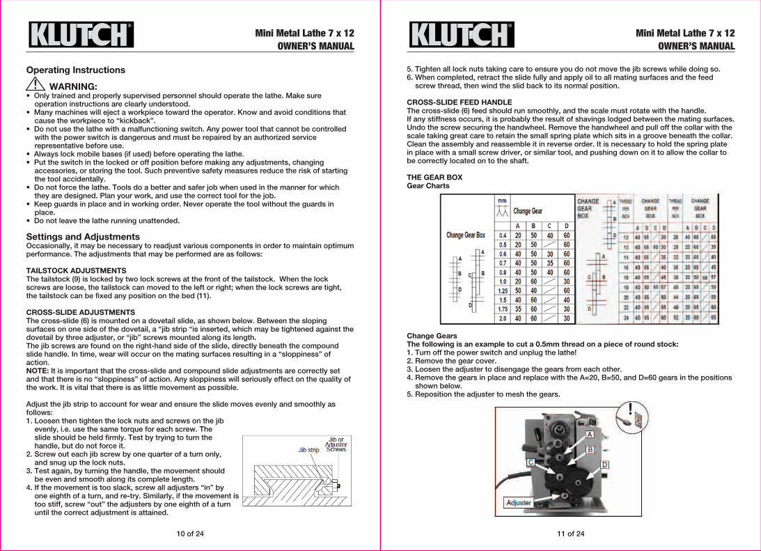
THE GEAR BOXGear Charts
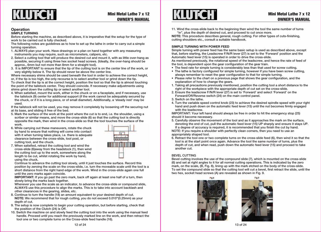
Change GearsThe following is an example to cut a 0.5mm thread on a piece of round stock:1. Turn off the power switch and unplug the lathe!2. Remove the gear cover.3. Loosen the adjuster to disengage the gears from each other.4. Remove the gears in place and replace with the A=20, B=50, and D=60 gears in the positions
shown below.5. Reposition the adjuster to mesh the gears.
Mini Metal Lathe 7 x 12OWNER’S MANUAL
12 of 24 13 of 24
Mini Metal Lathe 7 x 12OWNER’S MANUAL
Mini Metal Lathe 7 x 12OWNER’S MANUAL
OperationSIMPLE TURNINGBefore starting the machine, as described above, it is imperative that the setup for the type of work to be carried out is fully checked.The following notes are guidelines as to how to set up the lathe in order to carry out a simple turning operation.1. ALWAYS plan your work. Have drawings or a plan on hand together with any measuring
instruments you may require, such as micrometers, calipers, etc.2. Select a cutting tool that will produce the desired cut and mount it, with as little over-hang as
possible, securing it using three hex socket head screws. (Ideally, the over-hang should be approx., 6mm but not more than 8mm for a straight tool).
3. It is IMPORTANT to ensure that the tip of the cutting tool is on the center line of the work, or very slightly below it. The tip should never be above the center line.
Where necessary shims should be used beneath the tool in order to achieve the correct height, or, if the tip is too high, the only recourse is to select another tool or grind down the tip.To check that the tip is at the correct height, position the tool so that the tip is almost touching the point of the tailstock center. They should coincide. lf necessary make adjustments using shims grind down the cutting tip or select another tool.4. When satisfied, mount the work, either in the chuck or on a faceplate, and if necessary, use
the tailstock (9) center for additional support (if the work cannot be adequately secured by the chuck, or if it is a long piece, or of small diameter). Additionally, a ‘steady rest’ may be used.
If the tailstock will not be used, you may remove it completely by loosening off the securing nut at its base, and sliding it free of the bed.5. Mark the surface of the work at the point where the cut is to end, i.e. the shoulder, using a
scriber or similar means, and move the cross-slide (6) so that the cutting tool is directly opposite the mark, then wind in the cross-slide so that the tool touches the surface of the work.
6. While carrying out these maneuvers, rotate the chuck by hand to ensure that nothing will come into contact with it when turning takes place, i.e. there is adequate clearance between the cross-slide, tool post, or cutting tool, and the chuck.
7. When satisfied, retract the cutting tool and wind the cross-slide (6)away from the headstock (1), then wind the cutting tool up to the work, somewhere along the length to be cut, whilst rotating the work by hand, using the chuck.Continue to advance the cutting tool slowly, until it just touches the surface. Record this position by zeroing the scale on the cross-slide, i.e. turn the moveable scale until the tool is a short distance from the right hand edge of the work. Wind in the cross-slide again one full until the zero marks again coincide.IMPORTANT: If you go past the zero mark, back off again at least one half of a turn, then slowly bring the marks back together.Whenever you use the scale as an indicator, to advance the cross-slide or compound slide, ALWAYS use this procedure to align the marks. This is to take into account backlash and other clearances in the gearing, slides, etc.
8. Continue to turn the handle (18) an amount equivalent to your desired depth of cut.NOTE: We recommend that for rough cutting, you do not exceed 0.010"(0.25mm) as your depth of cut.
9. The setup is now complete to begin your cutting operation, but before starting, check that the position of the Clutch (24) is Off.
10. Switch the machine on and slowly feed the cutting tool into the work using the manual feed handle. Proceed until you reach the previously marked line on the work, and then retract the tool one or two complete turns on the Cross-slide feed handle (16).
11. Wind the cross-slide back to the beginning then wind the tool the same number of turns “in”, plus the depth of desired cut, and proceed to cut once more.
NOTE: This procedure describes general, rough cutting. For other types of cuts-finishing, cutting shoulders etc., consult a suitable handbook.
SIMPLE TURNING WITH POWER FEEDSimple turning with power feed has the same basic setup is used as described above, except that, before starting, the Leadscrew F/N/R lever (27) is set to the ‘Forward’ position and the Automatic feed lever (15) is operated in order to drive the cross-slide.As mentioned previously, the rotational speed of the leadscrew, and hence the rate of feed of the tool, is dependent upon the gear configuration of the gear train.• The feed rate for simple turning is considerably less than that used for screw cutting.• The lathe is factory configured for simple turning, however if you have been screw cutting,
always remember to reset the gear configuration to that for simple turning.• Please refer to the chart on a previous page that shows the gear configuration, and the
explanation of how to change the gears.1. Taking all precautions previously mentioned, position the cutting tool a short distance to the
right of the workpiece with the appropriate depth of cut set on the cross-slide. 2. Ensure the leadscrew F/N/R lever (27) is set to ‘Forward’ and select ‘Forward’ on the
Forward/Off/Reverse switch (24) on the main control panel. 3. Switch on the lathe.4. Turn the variable speed control knob (23) to achieve the desired spindle speed with your right
hand and push down on the automatic feed lever (15) until the nut becomes firmly engaged with the leadscrew.
IMPORTANT: Your left hand should always be free in order to hit the emergency stop (25) should it become necessary.5. Carefully observe the movement of the tool and as it approaches the mark on the surface,
denoting the end of cut, pull the automatic feed lever (15) UP sharply and ensure it stays UP. If a degree of accuracy is required, it is recommended that you finish the cut by hand.
NOTE: If you require a shoulder with perfectly clean corners, then you need to use an appropriately shaped tool.6. Retract the tool one or two complete turns on the cross-slide feed (6), then wind it so that the
tool is at the start point once again. Advance the tool the same number of turns, plus the depth of cut, and when read, push down the automatic feed lever (15) and proceed to take another cut.
BEVEL CUTTINGBevel cutting involves the use of the compound slide (7), which is mounted on the cross-slide (6) and set at right angles to it for all normal cutting operations. This is indicated by the zero mark, on the scale, (B, Fig. 8), lining up with the mark etched on the body of the cross-slide. To set the compound slide so that the cutting tool will cut a bevel, first retract the slide, until the two hex, socket head screws (A) are revealed as shown in Fig. 9.

14 of 24 15 of 24
Loosen the screws sufficiently to allow the compound slide to be turned to the desired angle, as indicated on the scale, and secure the slide in this position by retightening the socket head screws. The taper, or bevel, is cut by setting the cross-slide appropriately then using the compound slide feed handle to advance the cutting tool in the direction of the arrow as shown in Fig. 9.
SCREWCUTTINGThis operation requires a degree of skill and accuracy, and should not be attempted unless you are completely familiar with all aspects of the lathe.Essentially, the cross-slide (6)will move towards the headstock (1) under power, the same as cutting using auto feed, except the rate of feed is faster, as determined by the gear configuration. The cutting tool therefore, is moving ever closer to the rotating chuck. WARNING: Great care and concentration must be exercised to ensure that the two do not meet when the machine is operating, as the possible damage caused could be disastrous. The lathe is supplied with a leadscrew that will produce Imperial Treads in a range from 12 to 52 threads per inch, or metric threads in a range from 0.4-2.0mm pitch. It is important to remember that the type of thread you need to cut, i.e. UNF, BA, BSP, BSW etc., will be totally dependent upon the cutting tool profile, as profiles differ from thread to thread.For detailed information regarding screwcutting techniques, cutting tools etc., you should consult a suitable handbook or obtain advice from a qualified person.The general procedure for screwcutting is as follows:1. Try to get as much distance from the chuck to the end of the proposed screw thread as
possible, and if your design allows, cut a ‘run-off’ into the workpiece which is of a smaller diameter than the root diameter of the proposed screw thread.Note: for long threads it may be necessary to use a separate ‘steady rest’ (not included).
2. Install the appropriate gears for the thread required, and correctly mount the cutting tool.3. Set the required depth of cut, and position the tool ready to begin cutting.
Note: The depth of cut is vitally important and may be calculated or obtained from an appropriate reference manual.
4. Take all necessary precautions previously stated, and start the lathe with automatic feed lever (15) in the disengaged position (UP).
5. Push the automatic feed lever down sharply and turn the Forward/Off/Reverse switch (24) to ‘FORWARD’.
6. As the tool approaches the end of the desired thread, turn the Forward/Off/Reverse switch to ‘OFF’ but do not disengage the auto-feed lever.
7. Retract the tool, using the cross-slide feed handle (18), noting the exact position on the scale and the exact number of turns (this will be used in step 9).
8. Turn the Forward/Off/Reverse switch to ‘REVERSE’. The cross-slide will wind back to the beginning then turn switch to ‘OFF’.
9. Reset the lathe by winding the cross-slide IN the exact number of turns previously wound OUT (step 7) then continue to wind IN to the desired depth of cut.
10. Repeat steps 5 – 7 until the thread is completed.
After Each UseRemove all metal shavings from the lathe and thoroughly clean all surfaces. If coolant was used, ensure it has completely drained from the tray.
StorageStore the lathe when it is not in use. Store it in a dry, secure place out of the reach of children. Inspect the lathe for good working condition prior to storage and again before re-use.Components should be dry, and all machined surfaces should be lightly oiled. Always remove cutting tools before storage store them separately.Put the switch in the locked or off position before storing the lathe. Such preventive safety measures reduce the risk of starting the lathe accidentally when used next.
Maintenance
WARNING: • Always disconnect the lathe from power before servicing it. Make sure the switch is in OFF
position before reconnecting.Maintain the Lathe by adopting a program of conscientious repair and maintenance in accordance with the following recommended procedures. It is recommended that the general condition of any tool be examined before it is used. Keep your tool in good repair. Keep all cutting tools sharp and clean. Properly maintained cutting tools with sharp cutting edges are less likely to bind and are easier to control. Keep handles dry, clean, and free from oil and grease. The following chart is based on a normal operation schedule.
MOTOR BRUSHESThe motor brushes may be changed by unscrewing the caps, on the upper side of the motor, beneath the headstock..
Mini Metal Lathe 7 x 12OWNER’S MANUAL
Mini Metal Lathe 7 x 12OWNER’S MANUAL
USE LUBRICATING OIL
Daily maintenance
Monthly maintenance
Maintenance PointCheck loose mounting bolts.Check damaged parts.Check poorly adjusted parts.Check worn or damaged wires.Check any other unsafe condition.Clean tooling and storage.Cleaning the machine is relatively easy. Remove all chips at the end of the day. Wipe up any coolant used that settled in the bottom of the chip tray or has settled on any other part of the lathe. Dry off entire machine with a clean, dry towel. do not use compressed air to clean your lathe.
Check gear damage, wear, rust, sludge, or chip build-up inside gearbox and off motor. Clean and lube as necessary.

17 of 2416 of 24
Mini Metal Lathe 7 x 12OWNER’S MANUAL
Mini Metal Lathe 7 x 12OWNER’S MANUAL
Parts Diagram
Wiring Diagram 1(220~240V/50HZ) Wiring Diagram 2 (100~120V/60HZ)

18 of 24 19 of 24
Parts Diagram
Mini Metal Lathe 7 x 12OWNER’S MANUAL
Mini Metal Lathe 7 x 12OWNER’S MANUAL
Parts ListERP No
LC2A0101
LCH001
LC2A0202
GB77-85 M6×25
GB6170-85 M6
GB1096-79 5×50
GB1096-79 4×8
GB70-85 M5×12
LC2A0203
YD01201018
LC2A0206
LC2A0201
LC2A0207
LC2A0205
LC2A0208
GB810-88 M27×1.5
GB78-85 M5×8
YD004004
YD00302013
GB78-85 M6×6
GB894.1-86 12
YD01201005
LC2A0204 H/L
GB1096-79 4×45
LC2A0210
LC2A0209A
GB894.1-86 10
YD00803001
LC2A0211A
LC2A0212
LC2A0214
GB953-88 M8×70
YD011001
LC2A0808
LC2A083000
YD00302028
LC2A0807
LC2A0814
LC2A0811
LC2A0815
LC2A0803
GB70-85 M6X20
Qty.
1
1
1
5
10
1
2
6
2
2
2
1
1
1
1
2
1
2
3
1
2
2
1
1
1
1
1
1
1
1
1
1
1
1
1
1
1
1
2
1
1
5
Qty.
1
1
1
1
2
2
2
4
1
2
1
1
1
1
2
1
1
2
4
1
2
3
1
1
3
2
2
2
1
2
1
1
1
1
1
1
2
2
2
1
1
1
No
1
2
3
4
6
7
8
9
10
11
12
13
14
15
16
17
18
19
20
21
22
23
24
25
26
27
28
29
30
31
32
33
34
35
36
37
38
39
40
41
42
43
Description
Bed Way
3 Jaws Chuck
Spindle
Set screw M6 × 25
Nut M6
Key M5 × 40
Key M4 × 8
Cap screw M5 × 12
Cover
Ball Bearing
Spacer
Head Stock Casting
H/L Gear 21/29T
Spacer
Spur Gear 45T
Nut M27×1.5
Screw M5×8
Steel Ball
Fixed Spring
Screw M6×6
Retaining Ring M12
Ball Bearings
Gear 12T/20T
Parallel Key M4 × 45
H/L Gear Shaft
Pulley
Retaining Ring M10
Timing Belt
Shifting Fork
Shifting Arm
Shifting Knob
Shifting Lever
Shifting Grip
Handle
Handle Mount
Compressive Spring
Indicator
Pinion 25T
Support Screw
Pinion 20T
Fixed Cover
Cap screw M6×20
Part No.
LC2A0812
LC2A0805
GB1096-79
LC2A0802
GB70-85 M5X18
LC2A0816
LC2A0810
GB70-85 M6X8
LC2A0828
GB70-85 M5X45
DC22514
GB70-85 M5X8
GB96-85 5
LC2A0813
LC2A0826
LC2A0804
LC2A0801
GB97.1-85 8
GB6170-86 M8
LC2A0827
GB70-85 M6×16
GB71-85 M4×10
LC2A0601
LC2A0606
GB96-85 5*12
GB818-85 M4×8
GB119-86 A5×12
LC2A0602B
LC2A0413
GB819-85 M4×10
LC2A0609
LC2A0613
LC2A0604
LC2A0607
LC2A0603
GB78-85 M6×12
LC2A030200
LC2A0307
LC2A0508
LC2A0509
RS180501
LC2A0503
#
45
46
47
48
49
50
51
52
53
54
55
56
57
58
59
60
61
62
63
64
67
69
70
71
72
73
74
75
76
77
78
79
80
81
82
83
84
85
87
88
*88A
89
Description
Gear 45T
Shaft
LC3X8 Parallel Key 4 × 8
Mount
Cap screw M5 × 18
Pinion 20T
Washer M6
Cap screw M6 × 8
Cover
Cap screw M5 × 45
Threads Cutting Chart
Cap screw M5 × 8
Washer M5
Bush W/Key
Gear 80T
Shaft
Support Plate
Washer M8
Nut M8
Shaft
Cap screw M5×16
Screw M4×10
Carrige
Gib Strip
Washer
Phillips Head Screw M4 × 8
Shaft
Half Nut Base
Angle Block
Screw M4×10
Groove Cam
Handle
Shaft
Feeding Gear (A) 11T/54T
Feeding Gear (B) 24T
Screw M6 × 10
Wheel
Knob+ Screw M8 × 55 +Nut M8
Dial
Bracket
The plate guide
Feeding Screw

20 of 24 21 of 24
Mini Metal Lathe 7 x 12OWNER’S MANUAL
Mini Metal Lathe 7 x 12OWNER’S MANUAL
ERP No
RS180502
GB6172-86 M5
GB70-85 M6×12
LC2A0505
LC2A0501
LC2A0507
LC2A0504
LC2A0506
GB70-85 M8×20
GB6172-86 M4
GB79-85 M4×16
LC2A0502
GB77-86 M5×10
GB70-85 M4×8
LC2A0401
GB79-85 M4×14
LC2A0403
LC3D0402
LC2A0407
GB70-85 M6×25
LC2A0409
LC2A0405
GB77-85 M10×65
LC2A0406
RS180407
LC2A0404
RS180406
GB70-85 M4×12
LC2A0415
DC2A2503A
DC22511A
LC2A180101
YE012009
LC2A010100
LC2A0107A
LC2A0104
GB1096-79 3×16
LC2A0103B
LC2A0105
GB70-85 M3×10
LC2A0102
LC2A030100
Qty.
1
1
5
6
2
1
1
1
1
2
8
3
1
5
2
1
3
1
1
1
9
1
1
1
1
1
1
4
1
1
1
1
4
1
1
2
1
1
3
1
1
Qty.
1
1
1
1
1
1
1
4
1
1
1
1
1
1
1
1
1
1
1
1
1
1
1
2
1
1
1
1
1
1
1
1
1
1
4
1
7
2
1
1
1
1
No
*89A
90
91
92
93
94
95
96
97
*98
99
100
101
102
105
106
107
108
109
110
111
112
113
114
*114A
115
*115A
116
119
120
122
123
124
125
126
127
128
129
131
133
134
135
Description
Feeding Screw
Nut M5
Cap Screw M6×12
Slide Plate
Saddle
Gib Strip
Feeding Nut
Swivel Disk
Cap Screw M8 × 20
Nut M4
Cap Screw M4 × 16
Cross Slide
Set Screw M5 × 10
Cap Screw M4 × 8
Compound Rest
Cap Screw M4 × 14
Gib Strip
Compound Rest (A)
Positioning Pin
Cap Screw M6 × 25
Clamping Lever
Tool Rest
Stud M10 × 65
Cross Feeding Screw
Cross Feeding Screw
Bracket
Small slide guide
Cap Screw M4 × 12
Nut M18
Model Label
Indicator Table Label
Electric Cover
Plug
Rubber Foot
Chip Tray
Bracket
Key
Lead Screw
Bracket
Cap Screw M3×10
Rack
Clamp Plate
Part No.
LC2A03A0100B
GB97.1-85 10
GB79-85 M6×14
LC2A0301
LC2A0301B
LC2A0304
LC2A0305
GB70-85 M4×10
LC2A0303D
LC2A2001
GB77-85 M8×40
LC2A0308
LC2A0309
LC2A1501
YE00101009
LC2A1802
YE013007
LC2A230100
DC22508
DC22507
DC22502
LC2A0817
LC2A0818
LC2A0819
LC2A0812
LC2A0821
LC2A0822
LC2A0823
LC2A0825
LC2A0824
N/A
N/A
LX21806
GB894.1-86 8
GB819-85 M5x8
LC2A1806
GB818-2000 M5x8
GB77-85 M6×20
YE00503008
YE010004A
YE008001
YE00501006
#
*135A
136
137
138
*138A
139
140
*141
142
143
144
145
146
148
150
151
152
153
154
155
156
157
158
159
160
161
162
163
164
165
166
167
171
172
173
174
175
177
178
179
180
181
Description
Clamp Plate
Flat Washer M10
Cap Screw M5 × 16
Tailstock Casting
Tailstock Casting
Tailstock Screw
Bracket
Cap Screw M4 × 10
Tailstock Quilt
Center
Stud M8 × 40
Clamp
Handle
Pulley
Motor
Motor Cover
Power cord Guard
Rear Splash Guard
H/L Label
H/L Label
Warning Label
Gear 30T
Gear 35T
Gear 40T
Gear 45T
Gear 50T
Gear 55T
Gear 57T
Gear 60T
Gear 65T
Cover
Key
Clamp Block
Check Ring φ9
Flat Head Screw M5 × 10
Protector
Phillips Head Screw M5 × 10
Screw M6 × 25
Emergency Stop Switch
Fuse Box
Variable Speed Control Knob
Toggle Switch
ERP No
1YE00201011
GB818-85 M5X10
GB93-87 5
LC2A0806
LC2A0106
YD00304004
GB93-87 6
GB65-85 M8×55
GB77-85 M4×38
GB6170-86 M4
LC2A0302
GB70-85 M5×16
LC2A0306
GB75-85 M5×25
LC2A2302C
LC2A2304A
GB923-88 M6
GB6172-86 M6
YD00302022
GB97.1-85 6
GB818-85 M3×4
LC2A2305
LC2A2303D
GB818-85 M4×6
LC3D0401
LC3D0403
YD00302027
GB65-85 M6×30
GB848-85 6
LC2A03A09
GB78-85 M6×8
LC2A03A10
LC2A03A12
LC2A03A11
GB894.1-86
Qty.
1
1
1
1
1
2
4
2
1
1
1
3
1
1
1
1
1
2
1
2
4 *
1
1
7
1
1
1
1
1
1
1
1
1
1
1
Qty.
1
1
1
1
1
3
1
1
1
1
3
2
2
6
2
2
3
1
1
1
1
1
1
4
Qty.
4
1
3
2
1
2
1
1
1
No
182
184
185
187
188
190
192
193
194
195
196
197
198
199
201
202
205
206
207
208
209
210
212
*232
*235
*236
*237
*238
*239
*241
*242
*243
*244
*245
*246
Description
PC Board
Phillips Head Screw M5 × 10
Spring washer 5
Key 3*16
Small spacer
Spring
Washer 8
Screw M8*55
Set Screw M4*38
Nut M4
Plate of tailstock
Cap Screw M5*16
Panel set of tailstock
Screw M5*25
Chuck guard
Shaft
Screw M6
Nut M6
Compression Spring
Washer 6
Phillips Head Screw M3*4
Switch Cover
Block
Phillips Head Screw M4×16
Clamp Cover
Screw
Compression Spring
Screw M6×30
Washer
Brake tight handle shaft
Screw M6×8
Brake lever
Shaft sleeve
Eocentric brake tight shaft
12 Shaft with elastic ring 12
Part No.
GB894.1-86
LC2A03A13B
GB2089-80
LC2A03A14
GB4141.14A-84 M8×40
GB119-86 3×8
GB845-85 ST2.9×4.5
LC2A2308A
YE00502003
LC2A1820
LC2A0110
GB97.1-86 4
RS180402
RS182501
GB70-85 M4×25
YE018014
GB71-85 M3×4
GB96-85 6
GB6170-86 M10
LC2A0614
LC2A0829
GB848-85 10
GB70-85 M5×20
GB97.1-85 5
GB77-85 M6×10
GB818-85 M6x16
GB1096-79 LC3X6
GB70-85 M8×25
GB819-85 M4×8
LC2A1502
GB846-85 ST2.9X9.5-LC
GB79-85 M6×8
LC2A0511
LC2A0411
#
*247
*248
*249
*250
251
253
254
255
256
257
*258
*260
*261
*262
*263
*264
266
268
*270
*272
303
318
319
320
No.
321
322
323
324
325
326
327
86A
86B
Description
Link block
Common cylindrical
Belt thread pin shaft
Long sleeve knob
Cylinder Pin
Tap Screw
Cover
Micro switch
Dust sheet
Lead Screw Cover
Washer 4
Drive briquetting
Carved film before
Screw M4×25
Let grid scale
Screw M3×4
Washer 6
Screw 10
Support Pin
Protective Cover
Washer
Cap Screw M5*20
Washer
Set Screw M6×10
Description
Phillips Head Screw M6×16
Key
Cap Screw M8×25
Flat Head Screw M4×8
Flange
Screw
Cap Screw M6×8
Three Ball Handle
Three Ball Handle

23 of 24
Troubleshooting
Machine does not start or a breaker trips.
Machine stalls or is underpowered.
Loud, repetitious noise coming from machine near the motor.
Motor overheats.
Motor is loud when cutting. Overheats or bogs down in the cut.
1. Fuse has blown. 2. Emergency stop push-button is
engaged/ faulty.3. Plug/receptacle is at fault or wired
incorrectly.4. Computer board is at fault.5. Power supply is at fault/switched OFF.6. Motor on button or on /OFF switch
is at fault.7. Spindle rotation switch is at fault.8. Wiring is open/has high resistance.9. Motor is at fault.
1. Wrong workpiece material (metal).2. Computer board is at fault.3. Motor speed rheostat is at fault.4. Motor brushes are at fault.5. Pulley/sprocket slipping on shaft.6. Motor bearings are at fault.7. Machine is undersized for the task.8. Spindle rotation switch at fault.
1. Pulley setscrews or keys are missing or loose.
2. Motor fan is hitting the cover.
1. Motor overloaded.2. Air circulation through the motor
restricted.
1. Excessive depth of cut or feed rate.2. RPM or feed rate wrong for cutting
operation.3. Cutting tool is dull.4. Gear setup is too tight, causing
them to bind.
Possible SolutionSymptom Possible Cause
Motor & Electrical
1. Correct short/replace fuse on control panel.2. Rotate clockwise slightly until it pops
out/replace it.3. Test for good contacts; correct the wiring.4. Inspect computer board; replace if faulty.5. Ensure hot lines have correct voltage on
all legs and main power supply is switched on.
6. Replace faulty on button or on /OFF switch.7. Turn switch to FWD/REV; replace bad
switch.8. Check for broken wires or disconnected/
corroded connections, and repair/replace as necessary.
9. Test/repair/replace.
1. Use metal with correct properties for your type ofmachining.
2. Inspect and replace if faulty.3. Test and replace if faulty.4. Remove brushes and clean/replace.5. Replace loose pulley/shaft.6. Test by rotating shaft; rotational grinding
/loose shaftrequires bearing replacement.7. Use sharp lathe bits/chisels at correct
angle; reducefeed rate/depth of cut; use cutting fluid if possible.
8. Turn switch to FWD/OFF/REV; replacebad switch.
1. Inspect keys and setscrews. Replace or tighten if necessary.
2. Tighten fan or shim cover, or replace items.
1. Reduce load on motor.2. Clean out motor to provide normal air
circulation.
1. Decrease depth of cut or feed rate.2. Refer to RPM feed rate chart for
appropriate rates.3. Sharpen or replace the cutting tool.4. Readjust the gear setup with a small
amount ofbacklash so the gears move freely and smoothlywhen the chuck is rotated by hand.
Entire machine vibrates successively upon start up and while running.
Bad surface finish.
Can't remove tapered tool from tailstock quill.
Cross slide, compound slide, or carriage feed has sloppy operation.
Cross slide, compound slide, or carriage feed handwheel is hard to move.
Cutting tool or machinecomponents vibrate excessivelyduring cutting.
Inaccurate turning results all along the workpiece .
Chuck jaws won't move or don't move easily.
Carriage won't feed.
1.Workpiece is unbalanced.2. Loose or damaged belt(s).3. V-belt pulleys are not properly
aligned.4. Worn or broken gear present.5. Chuck or faceplate has become
unbalanced.6. Spindle bearings badly worn.
1. Wrong rpm or feed rate.2. Dull tooling or poor tool selection.3. Too much play in the gibs.4. Tool too high.
1. Quill had not retracted all the wayback into the tailstock.
2. Debris was not removed from taperbefore inserting into quill.
1. Gibs are out of adjustment.2. Handwheel is loose.3. Lead screw mechanism worn or
out of adjustment.
1. Gibs are loaded up with shavings,dust, or grime.
2. Gib screws are too tight.3. Backlash setting too tight (cross
slide only).4. Bedways are dry.
1. Tool holder not tight enough.2. Cutting tool sticks too far out of
tool holder; lack of support.3. Gibs are out of adjustment.4. Dull cutting tool.5. Incorrect spindle speed or feed rate.
1. Headstock and tailstock are notproperly aligned with each other.
1. Chips lodged in the jaws.
1. Gears are not all engaged.2. Gears are broken.3. Loose screw on the feed handle.
Possible SolutionSymptom Possible Cause
Operation and Work Results
1. Reinstall workpiece so it is as centered with the spindle bore as possible.
2. Tighten/replace the belt as necessary.3.Align the V-belt pulleys.4. Inspect gears and replace if necessary.5. Rebalance chuck or faceplate; contact a
local machine shop for help.6. Replace spindle bearings.
1. Adjust for appropriate RPM and feed rate.2. Sharpen tooling or select a better tool for
the intended operation.3. Tighten the gibs.4. Lower the tool position.
1. Turn the quill handwheel until it forces taper out of quill.
2. Always make sure that taper surfaces are clean.
1. Adjust gib screw(s) (see Page 35).2. Tighten handwheel fasteners.3. Tighten any loose fasteners on lead screw
mechanism.
1. Remove gibs, clean ways/dovetails, lubricate, and readjust gibs.
2. Loosen gib screw(s) slightly, and lubricate bedways.
3. Slightly loosen backlash setting by loosening the locking screw and adjusting the spanner ring at the end of the handle.
4. Lubricate bedways and handles.
1. Check for debris, clean, and retighten.2. Reinstall cutting tool so no more than
1⁄3 of the total length is sticking out of tool holder.
3. Tighten gib screws at affected component.
4. Replace or re-sharpen cutting tool.5. Use the recommended spindle speed.
1. Realign the tailstock to the headstock spindle bore center line.
1. Remove jaws, clean and lubricate chuck threads, and replace jaws.
1. Adjust gear positions.2. Replace.3. Tighten.
22 of 24
Mini Metal Lathe 7 x 12OWNER’S MANUAL
Mini Metal Lathe 7 x 12OWNER’S MANUAL

Mini Metal Lathe 7 x 12OWNER’S MANUAL
Obligations of Purchaser You must retain Your product purchase receipt to verify date of purchase and that You are the original purchaser. To make a warranty claim, contact Us at 1-800-222-5381, identify the product by make and model number, and follow the claim instructions that will be provided. The product and the purchase receipt must be provided to Us in order to process Your warranty claim. Any returned product that is replaced or refunded by Us becomes our property. You will be responsible for return shipping costs or costs related to Your return visit to a retail store.
Remedy LimitsProduct replacement or a refund of the purchase price is Your sole remedy under this limited warranty or any other warranty related to the product. We shall not be liable for: service or labor charges or damage to Your property incurred in removing or replacing the product; any damages, including, without limitation, damages to tangible personal property or personal injury, related to Your improper use, installation, or maintenance of the product; or any indirect, incidental or consequential damages of any kind for any reason.
Assumption of RiskYou acknowledge and agree that any use of the product for any purpose other than the specified use(s) stated in the product instructions is at Your own risk.
Governing LawThis limited warranty gives You specific legal rights, and You also may have other rights which vary from state to state. Some states do not allow limitations or exclusions on implied warranties or incidental or consequential damages, so the above limitations may not apply to You. This limited warranty is governed by the laws of the State of Minnesota, without regard to rules pertaining to conflicts of law. The state courts located in Dakota County, Minnesota shall have exclusive jurisdiction for any disputes relating to this warranty.
Distributed byNorthern Tool and Equipment Company, Inc.
Burnsville, Minnesota 55306NorthernTool.com
Made in China
Replacement Parts• For replacement parts and technical questions, please call Customer Service at
1-800-222-5381.• Not all product components are available for replacement. The illustrations provided are a
convenient reference to the location and position of parts in the assembly sequence. • When ordering parts, the following will be required: Model Number, Serial Number/Lot Date
Code, and Description. • The distributor reserves the rights to make design changes and or improvements to product
lines and manuals without notice.
Limited WarrantyNorthern Tool and Equipment Company, Inc. ("We'' or '"Us'') warrants to the original purchaser only ("You'' or “Your”) that the Ironton Air Tool product purchased will be free from material defects in both materials and workmanship, normal wear and tear excepted, for a period of one year from date of purchase. The foregoing warranty is valid only if the installation and use of the product is strictly in accordance with product instructions. There are no other arranties,express or implied, including the warranty of merchantability or fitness for a particular purpose.If the product does not comply with this limited warranty, Your sole and exclusive remedy is that We will, at our sole option and within a commercially reasonable time, either replace the product without charge to You or refund the purchase price (less shipping). This limited warranty is not transferable.
Limitations on the WarrantyThis limited warranty does not cover: (a) normal wear and tear; (b) accessories both consumable and durable; (c) damage through abuse, neglect, misuse, or as a result of any accident or in any other manner; (d) damage from misapplication, overloading, or improper installation; (e) improper maintenance and repair; and (f) product alteration in any manner by anyone other than Us, with the sole exception of alterations made pursuant to product instructions and in a workmanlike manner.
24 of 24
Carriage hard to move.
Gear change levers will not shift into position.
Loud, repetitious noise coming from machine.
Tailstock quill will not feed out of tailstock.
1. Carriage lock is tightened down.2. Chips have loaded up on bedways.3. Bedways are dry and in need of
lubrication.4. Longitudinal stops are interfering.5.Gibs are too tight.
1. Gears not aligned in headstock.
1. Gears not aligned in headstock or no backlash.
2. Broken gear or bad bearing.3.Workpiece is hitting stationary object.
1. Quill lock knob is tightened down.
Possible SolutionSymptom Possible Cause
Operation and Work Results
1. Check to make sure table locks are fully released.
2. Frequently clean away chips that load up during turning operations.
3. Lubricate bedways and handles.4. Check to make sure that stops are floating
and not hitting the center stop.5. Loosen gib screw(s) slightly.
1. Rotate spindle by hand until gear falls into place.
1. Adjust gears and establish backlash.2. Replace broken gear or bearing.3. Stop lathe immediately and correct
interference problem.
1. Turn knob counterclockwise.
Mini Metal Lathe 7 x 12OWNER’S MANUAL