mini disposable inline = “most popular” desiccant...
TRANSCRIPT
Catalog 9EM-TK-190-5
F13 Pneumatic DivisionRichland, Michiganwww.wilkersoncorp.com
F
Drye
rs
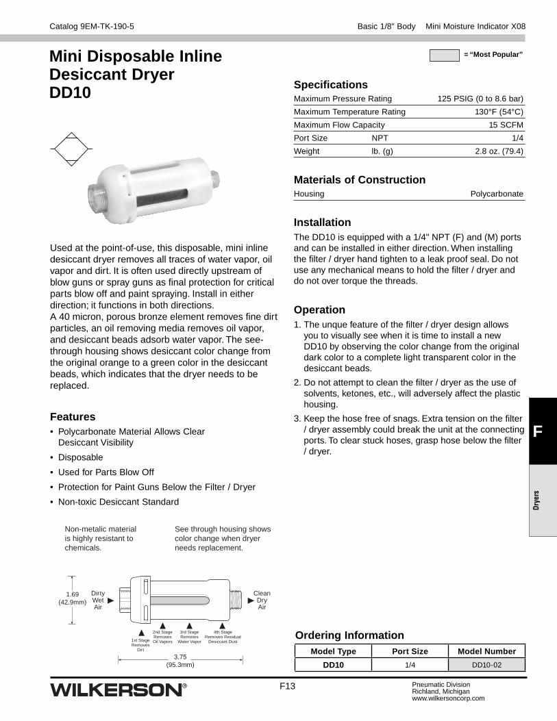
Used at the point-of-use, this disposable, mini inline desiccant dryer removes all traces of water vapor, oil vapor and dirt. It is often used directly upstream of blow guns or spray guns as fi nal protection for critical parts blow off and paint spraying. Install in either direction; it functions in both directions. A 40 micron, porous bronze element removes fi ne dirt particles, an oil removing media removes oil vapor, and desiccant beads adsorb water vapor. The see-through housing shows desiccant color change from the original orange to a green color in the desiccant beads, which indicates that the dryer needs to be replaced.
Features• Polycarbonate Material Allows Clear
Desiccant Visibility
• Disposable
• Used for Parts Blow Off
• Protection for Paint Guns Below the Filter / Dryer
• Non-toxic Desiccant Standard
3.75(95.3mm)
1.69(42.9mm)
CleanDryAir
DirtyWetAir
See through housing shows color change when dryer needs replacement.
Non-metalic material is highly resistant to chemicals.
2nd StageRemovesOil Vapors
3rd StageRemoves
Water Vapor
4th StageRemoves Residual
Desiccant Dust1st StageRemoves
Dirt
Mini Disposable Inline Desiccant DryerDD10
Basic 1/8" Body Mini Moisture Indicator X08
Specifi cationsMaximum Pressure Rating 125 PSIG (0 to 8.6 bar)
Maximum Temperature Rating 130°F (54°C)
Maximum Flow Capacity 15 SCFM
Port Size NPT 1/4
Weight lb. (g) 2.8 oz. (79.4)
Materials of ConstructionHousing Polycarbonate
Ordering InformationModel Type Port Size Model Number
DD10 1/4 DD10-02
InstallationThe DD10 is equipped with a 1/4" NPT (F) and (M) ports and can be installed in either direction. When installing the fi lter / dryer hand tighten to a leak proof seal. Do not use any mechanical means to hold the fi lter / dryer and do not over torque the threads.
Operation1. The unque feature of the fi lter / dryer design allows
you to visually see when it is time to install a new DD10 by observing the color change from the original dark color to a complete light transparent color in the desiccant beads.
2. Do not attempt to clean the fi lter / dryer as the use of solvents, ketones, etc., will adversely affect the plastic housing.
3. Keep the hose free of snags. Extra tension on the fi lter / dryer assembly could break the unit at the connecting ports. To clear stuck hoses, grasp hose below the fi lter / dryer.
= “Most Popular”

Catalog 9EM-TK-190-5
F15 Pneumatic DivisionRichland, Michiganwww.wilkersoncorp.com
F
Drye
rs
Manual Desiccant Dryer Numbering System
Family 06 Compact 03 Large 04 Twin Large 25 Extra Large
Unit Function X Manual Desiccant Dryers
OptionsMiniature (M03)
0 Standard Silica Gel, -45°F ADP E Non-Toxic Desiccant, -45°F ADP M Metal Bowl* U 4A Molecular Sieve, -100°F ADP
If more than one option is desired, arrange them in alphabetical order in positions 6, 7, and 8.
NOTE: 000 in position 6, 7, and 8 signifi es standard product.
Unit Thread Pipe Function Family Type Size Options Options Options
X 0 6 – 0 2 – 0 0 0
Thread Type 0 NPT C BSPP*
= “Most Popular”
CodePipe Size
Series06 03 04 25
2 1/4" X X X4 1/2" X X
* X03 and X04 units only.X25 is standard with metal bowl.
* Not available on X04 units.
Desiccant Dryer Numbering System

F16
Catalog 9EM-TK-190-5
Pneumatic DivisionRichland, Michiganwww.wilkersoncorp.com
F
Dryers
Features and Benefi ts• Atmospheric Dew Points as Low as -100°F
• No Electrical Connection Necessary
• Color change of the Desiccant Provides an Instant Status of the Compressed Air System
Desiccant DryerX06
A
B
G
C
E
FBowlRemovalClearance
Dimensions
Models Inches (mm) A B C E F G
Standard UnitX06-02-000
2.99(75.9)
2.72(69)
.90(22.8)
6.41(162.8)
1.50(38)
1.36(34.5)
X06-02-000
= “Most Popular”
Specifi cationsAtmospheric Dew Point*– Model 000 Silica Gel -45°F (-43°C) Model E00 Silica Gel (Non-toxic) -45°F (-43°C) Model U00 4A Molecular Sieve -100°F (-52°C)
Maximum Continuous Air Flow* 5 SCFM (2.3 dm3/s)
Maximum Pressure 150 PSIG (10.3 bar)
Maximum Temperature 125°F (52°C)
Port Size NPT / BSPP-G 1/4
Total Air Flow* 1/4 600 SCF (16.6 m3)
Total Minutes of Operation @Continuous Air Flow 120 Minutes
Weight (with Desiccant) lb. (kg) 1.13 (0.51)
Weight Desiccant Alone lb. (kg) 0.25 (0.11)* With dry desiccant at 100 PSIG (7 bar) and 70°F 21°C), saturated inlet
(100% RH).
Materials of ConstructionBody Zinc
Bowls Plastic Polycarbonate
Bowl Guard Steel
Seals Fluorocarbon
Basic 1/4" Body

Catalog 9EM-TK-190-5
F17 Pneumatic DivisionRichland, Michiganwww.wilkersoncorp.com
F
Drye
rs
Typical Installation Arrangement
-100°F ADP Models:
Afterfi lter(recommended)
“U00” ModelDryer
Prefi lter(s)(recommended)
Liquid Separator(recommended) X08-02-000
Moisture Indicator
“000” Model Pre-Dryer (If desired)
Coalescing Filter
PRESS
TURN
PRESS
TURN
-45°F ADP Models:
Refrigerated Air Dryer
(If desired)
PRESS
TURN
Afterfi lter(recommended)
Liquid Separator(recommended)
Coalescing Filter
Prefi lter(s)(recommended)
“000” ModelDryer
Replacement PartsBowl Guard ............................................................ GRP-95-013
Bowl O-ring ............................................................ GRP-95-259
Transparent Bowl ................................................... DRP-96-459
= “Most Popular”
Ordering InformationModel Type Port Size Polycarbonate Bowl
X06 1/4 X06-02-000
Options - To order an option supplied with the unit model, add the appropriate coded suffi x letter in the designated position of the model number.
Compact Desiccant Dryer X06
Slight restriction (if necessary) to
assure at least 1 SCFM
through X08 Moisture Indicator
Replacement Desiccant KitsSilica Gel (000) -40°F ADP
Old Replacement Kit Number
New Replacement Kit Number
# of Replacement Charges for X06
DRP-95-303 DRP-04-10B/001 1
DRP-04-10B/005 5
Non Toxic Desiccant (E00) -40°F ADP
Old Replacement Kit Number
New Replacement Kit Number
# of Replacement Charges For X06
DRP-04-447/001 1
DRP-04-447/005 5
4A Molecular Sieve (U00) -100°F ADP
Old Replacement Kit Number
New Replacement Kit Number
# of Replacement Charges For X06
DRP-95-304 DRP-04-514/001 1
DRP-04-514/005 5

F18
Catalog 9EM-TK-190-5
Pneumatic DivisionRichland, Michiganwww.wilkersoncorp.com
F
Dryers
Features and Benefi ts• Atmospheric Dew Points as Low as -100°F
• No Electrical Connection Necessary
• Twin Units Available for Double Service Life
• Color change of the Desiccant Provides an Instant Status of the Compressed Air System
Desiccant DryerX03 / X04
Dimensions
Models Inches (mm) A B C D E F
Standard UnitX03-02-000
—4.79
(121.6)1.23(31)
12.60(320)
13.83(351)
2.00(50.8)
Metal BowlX03-02-M00
—4.79
(121.6)1.23(31)
12.60(320)
13.83(351)
2.00(50.8)
Standard Twin UnitX04-02-000
14.42(366)
4.79(121.6)
1.23(31)
11.71(297.4)
12.65(322)
2.00(50.8)
X03-02-000
= “Most Popular”
Specifi cationsAtmospheric Dew Point*– Model 000 Silica Gel -45°F (-43°C) Model E00 Silica Gel (Non-toxic) -45°F (-43°C) Model U00 4A Molecular Sieve -100°F (-52°C)
Maximum Continuous Air Flow* 10 SCFM (4.7 dm3/s)
Maximum Pressure 150 PSIG (10.3 bar)
Maximum Temperature – X03 Transparent Bowl 125° F (52° C) X03 Metal Bowl 150°F (66°C) X04 Transparent Bowl 125° F (52 °C)
Port Size – X03 NPT / BSPP-G 1/4, 1/2 X04 NPT 1/4
Total Air Flow* 1/4 4,400 SCF (311 m3)
Total Minutes of Operation @Continuous Air Flow X03 440 Minutes X04 880 Minutes
Weight (with Desiccant) lb. (kg) – X03 Transparent Bowl 7.4 (3.4) X03 Metal Bowl 6.8 (3.1) X04 Transparent Bowl 15.0 (6.8)
Weight Desiccant Alone lb. (kg) – X03 Transparent Bowl 1.8 (0.8) X03 Metal Bowl 1.3 (0.6) X04 Transparent Bowl 3.6 (1.6)* With dry desiccant at 100 PSIG (7 bar) and 70°F 21°C), saturated inlet
(100% RH).
Materials of ConstructionBody Zinc
Bowls Plastic Polycarbonate Metal Bowl Aluminum
Bowl Guard Steel
Seals Fluorocarbon
A
D
C
B
1/4" NPTInlet Port
D EE
C
B
FBowl Removal Clearance
X04 X03
Basic 1/4" Body

Catalog 9EM-TK-190-5
F19 Pneumatic DivisionRichland, Michiganwww.wilkersoncorp.com
F
Drye
rs
Replacement PartsBowl Guard – X03 / X04 Transparent Bowl ............................... GRP-95-810
Bowl O-ring ............................................................ GRP-95-256
Clamp Ring ............................................................GRP-96-404
Moisture Indicator* – X03 Metal Bowl ................................................... DRP-95-623
Replacement Cap for Moisture Removal ............... GRP-95-020
Screen Assembly ................................................... DRP-96-434
Transparent Bowl – X03 / X04 ............................................................GRP-95-089
Tube Assembly with Screen – X03 / X04 Transparent Bowl ............................... DRP-96-435 X03 Metal Bowl ................................................... DRP-96-451* The Moisture Indicator contains a weep orifi ce to provide an air sample to
the moisture indicating paper. Air bleed from this indicator is necessary and normal.
= “Most Popular”
Ordering InformationModel Type Port Size Polycarbonate Bowl Metal Bowl
X03 1/4 X03-02-000 X03-02-M00
X04 1/4 X04-02-000 X04-02-M00
Options - To order an option supplied with the unit model, add the appropriate coded suffi x letter in the designated position of the model number.
X03-02-000Desiccant Dryer
(2 Required)
4-WayValve
Shuttle Valve1/4" NPT Outlet Port(On Bottom of Shuttle Valve)
Upper Port in 4-Way Valveto be open to Atmosphere
1/4" NPTInlet Port
X04-02-000
Compact Desiccant Dryer X03 / X04
Note: Since X04 consists of two X03 dryers assembled together the amount of desiccant required for a total recharge is twice the amount listed above.
Replacement Desiccant KitsSilica Gel (000) -40°F ADP
Old Replacement Kit Number
New Replacement Kit Number
# of Replacement Charges for X03
DRP-85-059 DRP-14-10B/002 1
DRP-14-10B/008 4
Non Toxic Desiccant (E00) -40°F ADP
Old Replacement Kit Number
New Replacement Kit Number
# of Replacement Charges For X03
DRP-14-447/002 1
DRP-14-447/008 4
4A Molecular Sieve (U00) -100°F ADP
Old Replacement Kit Number
New Replacement Kit Number
# of Replacement Charges For X03
DRP-85-060 DRP-14-514/002 1
DRP-14-514/008 4

F20
Catalog 9EM-TK-190-5
Pneumatic DivisionRichland, Michiganwww.wilkersoncorp.com
F
Dryers
Replacement PartsBowl O-ring ............................................................ GRP-95-256
Clamp Ring ............................. GRP-96-404Moisture Indicator* DRP-95-623
Replacement Cap for Moisture Removal ............... GRP-95-020
Screen Assembly ................................................... DRP-96-434
Tube Assembly with Screen .................................. DRP-95-622* The Moisture Indicator contains a weep orifi ce to provide an air sample to
the moisture indicating paper. Air bleed from this indicator is necessary and normal.
Ordering InformationModel Type Port Size Metal Bowl
X25 1/2 X25-04-000
Options - To order an option supplied with the unit model, add the ap-propriate coded suffi x letter in the designated position of themodel number.
Features and Benefi ts• Atmospheric Dew Points as Low as -100°F
• No Electrical Connection Necessary
• Color change of the Desiccant Provides an Instant Status of the Compressed Air System
Desiccant DryerX25
Dimensions
Models Inches (mm) A B C D E F G
Standard UnitX25-04-000
4.61(117)
4.79(121.6)
1.70(43)
19.58(497)
21.28(540.5)
2.00(50.8)
2.39(60.8)
Specifi cationsAtmospheric Dew Point*– Model 000 Silica Gel -45°F (-43°C) Model E00 Silica Gel (Non-toxic) -45°F (-43°C) Model U00 4A Molecular Sieve -100°F (-52°C)
Maximum Continuous Air Flow* 25 SCFM (11.8 dm3/s)
Maximum Pressure 150 PSIG (10.3 bar)
Maximum Temperature 150°F (66°C)
Port Size NPT / BSPP-G 1/2
Total Air Flow* 11,000 SCF (311 m3)
Total Minutes of Operation @Continuous Air Flow 440 min.
Weight (with Desiccant) lb. (kg) 11.23 (5.1)
Weight Desiccant Alone lb. (kg) 4.4 (2.0)* With dry desiccant at 100 PSIG (7 bar) and 70°F 21°C), saturated inlet
(100% RH).
Materials of ConstructionBody Zinc
Bowls Metal Bowl Aluminum
Bowl Guard Aluminum
Seals Fluorocarbon
X25-04-000
= “Most Popular”
A
C
D
BG
E
PressTurn
FBowl Removal Clearance
Basic 1/2" Body Standard Desiccant Dryer X25
Replacement Desiccant KitsSilica Gel (000) -40°F ADPOld Replacement Kit Number
New Replacement Kit Number
# of Replacement Charges for X25
DRP-85-280 DRP-14-10B/005 1
DRP-14-10B/015 3
Non Toxic Desiccant (E00) -40°F ADPOld Replacement Kit Number
New Replacement Kit Number
# of Replacement Charges For X25
DRP-14-447/005 1
DRP-14-447/015 3
4A Molecular Sieve (U00) -1000F ADPOld Replacement Kit Number
New Replacement Kit Number
# of Replacement Charges For X25
DRP-85-281 DRP-14-514/005 1
DRP-14-514/015 3

Catalog 9EM-TK-190-5
F21 Pneumatic DivisionRichland, Michiganwww.wilkersoncorp.com
F
Drye
rs
= “Most Popular”Moisture IndicatorX08
X08-02-000
Features• Transparent Plastic Bowl Standard
• Silica Gel Changes Color For Moisture Indication
Specifi cationsMaximum Supply Pressure 150 PSIG (10.3 bar)
Operating Temperature 32° to 120°F (0° to 49°C)
Port Size NPT / BSPT-Rc 1/4
Weight lb. (kg) 0.34 (0.15)
Materials of ConstructionBody Zinc
Bowls Plastic Bowl Polyurethane
Seals Nitrile
CG
D
B
A
F E
Dimensions
Models Inches(mm) A B C D E F G H
Standard UnitX08-02-000
1.59(40.5)
1.59(40.5)
0.81(20.6)
4.25(107.9)
5.06(128.5)
0.80(20.2)
0.58(14.7)
1.31(33.3)
ManualDrain
= “Most Popular”
Basic 1/8" Body Mini Moisture Indicator X08

F22
Catalog 9EM-TK-190-5
Pneumatic DivisionRichland, Michiganwww.wilkersoncorp.com
F
Dryers
Drying compressed air through adsorption represents a purely physical process in which water vapor (adsorbate) is bound to the drying medium (adsorbent) through binding forces of molecular adhesion. Adsorbents are solids in spherical and granular form which are permeated by an array of pores. The water vapor is deposited onto the internal and external surface of the adsorption medium, without the formation of chemical compounds taking place, therefore the adsorption medium does not have to be replenished but only periodically regenerated.
Heatless
The layout of adsorption dryers with heatless regeneration is clear and simple. Compared with other adsorption dryer systems, pressure dewpoints down to -100°F (-73°C) can be achieved without additional effort.
Use in the higher pressure ranges and at low inlet temperatures causes the quantity of air needed for desorption to be reduced to an economical value.
What is adsorption drying?At low operating pressure the demand for already dried compressed air for purposes of regeneration is increased. This increase causes a large proportion of the prepared compressed air to be no longer available for productive purposes.
Depending on the cycle, the quantity of air enclosed in the adsorber expands upon release at regular intervals with an emission noise level of about 90-95dB(A). Given suitable noise attenuation measures, a reduction of the noise emission level to the region of 10-15 dB(A) can be accomplished.
The use of adsorption dryers with heatless regeneration is preferred in the following applications:
• Capacity Range of Up to 800 SCFM
• Higher Pressure Ranges
• High Inlet Temperatures
• Installation in Explosion Proof Areas
• Use Under Ground Portable Applications
• Hazardous Locations (Pneumatic Controls)
Adsorping Drying

Catalog 9EM-TK-190-5
F23 Pneumatic DivisionRichland, Michiganwww.wilkersoncorp.com
F
Drye
rs
Specifi cationsOperating Temperature 35°F (1.5°C) Min
Inlet Temperature 122°F (50°C) Max
Operating Pressure 58 to 175 PSIG (4 to 12 bar)
Flow Range 3 SCFM to 20 SCFM @ 100 PSIG (85 L/min to 567 L/min @ 7 bar)
Noise Level (Average) 70dB(A)
Pressure Dewpoint – Standard -40°F (-40°C) pdp (ISO 8573-1:2010) Class 2
Standard Electrical Supply 115/1ph/60Hz (Tolerance +/- 10%)
Controls Electronic Control Timer
Connections 3/8 NPT
Features• Point of use application bringing clean dry air just where you
need it.
• Approved to International Standards designed in accordance with ASME VIII Div.1, approved to CSA/UL/CRN and fully CE Marked (PED, EMC, LVD) as standard.
• Simple to Install - fl exible installation utilising the multiple in-line inlet & outlet connection ports.
• Compact and Lightweight - can be fl oor, bench or wall / canopy mounted.
• Very Quiet Operation - noise level less than 70dB(A).
• Can be Installed Almost Anywhere, IP66 / NEMA 4 protection as standard.
• Audible Alarm - indicating service interval for optimal performance.
• Simple & Easy to Maintain - due to the quick release top cap arrangement, which does NOT require the inlet / outlet ports to be disconnected as with traditional systems, maintenance can be achieved in under 15 minutes.
The WDAS is the reliable, cost effective and fl exible way to provide clean dry air exactly where needed.
Service KitsDescription Part Number
Mounting Bracket
Fixed Wall WDASMB1
45° Tilt Wall WDASMB2
Regenerative Desiccant Dryer
Sizing Chart (correction factor)minimum drying capacity = compressed air fl ow rate x CFT x CFP x CFDTemperature Correction Factor (CFT)
Maximum Inlet Temperature
°F 77 86 95 104 113 122°C 25 30 35 40 45 50
CFT 1.00 1.00 1.00 1.04 1.14 1.37Pressure Correction Factor (CFP)
Minimum Inlet Pressure
PSIG 58 73 87 102 116 131 145 160 174bar g 4 5 6 7 8 9 10 11 12CFP 1.60 1.33 1.14 1.00 1.03 0.93 0.85 0.78 0.71
Dewpoint Correction Factor (CFD) Standard
Required Dewpoint
PDP °F -40PDP °C -40
CFD 1.00
A
11.38(289)
5.87(149)
A Weight (Kg) SCFM Part Number Maintenance Kit
16.6 (422) 24.2 (11) 3 WDAS1 WDASMK1
19.7 (500) 28.7 (13) 5 WDAS2 WDASMK2
24.2 (616) 35.3 (16) 8 WDAS3 WDASMK3
27.2 (692) 39.7 (18) 10 WDAS4 WDASMK4
33.3 (847) 44.1 (20) 13 WDAS5 WDASMK5
35.7 (906) 50.7 (23) 15 WDAS6 WDASMK6
43.2 (1098) 61.7 (28) 20 WDAS7 WDASMK7
Dimensions & Ordering Information
Regenerative Desiccant Dryers WDAS Series
= “Most Popular”
F24
Catalog 9EM-TK-190-5
Pneumatic DivisionRichland, Michiganwww.wilkersoncorp.com
F
Dryers
The Regenerative Desiccant Dryers will benefi t users who have a specifi c need for Clean Dry Air (CDA) directly after a compressor, or for a particular application where the air is critical to the operating process or end product.
• Computer Numerical Control (CNC) Machines
• Coordinate Measuring Machines
• Laboratories
• Lasers
• Packaging Machines
• Instrumentation
• Processing Equipment
• Conveying Machines
Typical applications:Product Applications
Regenerative Desiccant Dryers WDAS Series
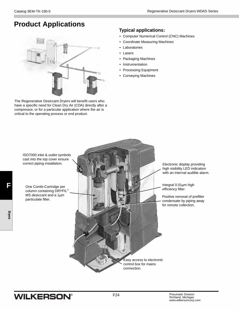
ISO7000 inlet & outlet symbols cast into the top cover ensure correct piping installation.
Integral 0.01µm high effi ciency fi lter.
Positive removal of prefi lter condensate by piping away for remote collection.
One Combi-Cartridge per column containing DRYFIL® MS desiccant and a 1µm particulate fi lter.
Easy access to electronic control box for mains connection.
Electronic display providing high visibility LED indication with an internal audible alarm.

Catalog 9EM-TK-190-5
F25 Pneumatic DivisionRichland, Michiganwww.wilkersoncorp.com
F
Drye
rs
Compressed air enters the integral pre-fi lter and passes into the left hand chamber (Column A) where the air is dried before passing to the application.
A small amount of dry purge air is used to regenerate the right hand chamber(Column B) which is wet, using the PSA (Pressure Swing Adsorption) method of regeneration, venting the saturated air to atmosphere under pressure. The same regeneration air is also used to “back fl ush” the integral fi lter to prolong its working life.
ColumnA
ColumnA
ColumnB
ColumnB
1
2
Regenerative Desiccant Dryers WDAS Series
Prior to changeover, the right hand chamber (Column B) enters repressurization where the exhaust valve is closed to allow pressure to increase. This process ensures a smooth uninterrupted changeover, preventing the loss of any system pressure, before the process repeats itself.

F26
Catalog 9EM-TK-190-5
Pneumatic DivisionRichland, Michiganwww.wilkersoncorp.com
F
Dryers
Electronic control box can be remotely located
Optional features• For totally quiet operation, the regeneration exhaust air can
be positively piped away.
• Remote indication provides a warning of the dryers need for servicing. (Audible alarm not included)
• Wall mounting kit for vertically securing the dryer to a wall or canopy.
A 45° tilt, wall mounting kit is also available for vertically securing the dryer to a wall, canopy or inside a customers product where access to the top of the dryer is restricted.
• In conditions of limited access, the electronic control box (base) can be detached and relocated remotely from the dryer.
Service indication sequence & alarm During operation, The Regenerative Desiccant Dryers Power On (yellow) LED and Check (Green) LED indicators will illuminate, remaining in this confi guration for 11500 hours. At this time, the Warning (Yellow) LED will illuminate and cancel the Check (Green) LED. This signals the user to order service replacement components at the optimum time.
500 hours later (a total of 12000 hours from initial start up) the Service (Red) LED will illuminate and cancel the Warning (Yellow) LED, the Audible Alarm housed inside the display will sound intermittently (every 6 seconds) drawing attention to the need for a service.
Regenerative Desiccant Dryers WDAS Series

Catalog 9EM-TK-190-5
F27 Pneumatic DivisionRichland, Michiganwww.wilkersoncorp.com
F
Drye
rs
Heatless Desiccant Air Dryers
Capacity CFM @ 100 PSIG
(m3/min @ 6.9 bar)
Approximate Purge SCFM
(Nm3/min)Primary Voltage
Part Number
Port Size
Filtration Package Included With Dryer
Pre-fi lter (5µ) Pre-fi lter (.01µ) After-fi lter (0.5µ)
25 (.70) 4 (.11) 120V/1ph/60Hz WTW25 * 1/2 F18-04-SH00 M18-04-CG00 M18-04-BG00
42 (1.19) 6 (.19) 120V/1ph/60Hz WTW40 * 1/2 F28-04-SH00 M28-04-CG00 M28-04-BG00
60 (1.70) 9 (.25) 120V/1ph/60Hz WTW55 * 3/4 F28-06-SH00 M28-06-CH00 M28-06-BH00
75 (2.13) 11 (.31) 120V/1ph/60Hz WTW75 * 3/4 F39-06-SH00 M39-06-CH00 M39-06-BH00
107 (3.03) 16 (.45) 120V/1ph/60Hz WTW100 * 1 F39-08-SH00 M39-08-CH00 M39-08-BH00
135 (3.82) 20 (.56) 120V/1ph/60Hz WTW130 * 1 F39-08-SH00 M39-08-CH00 M39-08-BH00
200 (5.66) 30 (.84) 120V/1ph/60Hz WTW200 * 1-1/2 F35-0B-F00 M35-0B-F00 M35-0B-FS0
250 (7.07) 38 (1.07) 120V/1ph/60Hz WTW250 * 1/1/2 F35-0B-F00 M35-0B-F00 M35-0B-FS0
300 (8.49) 45 (1.27) 120V/1ph/60Hz WTW300 * 1-1/2 F35-0B-F00 M35-0B-F00 M35-0B-FS0
400 (11.32) 60 (1.69) 120V/1ph/60Hz WTW400 * 2 F35-0C-F00 M35-0C-F00 M35-0C-FS0
500 (14.44) 77 (2.18) 120V/1ph/60Hz WTW500 * 2 F35-0C-F00 M35-0C-F00 M35-0C-FS0
600 (18.40) 98 (2.77) 120V/1ph/60Hz WTW600 * 2 F35-0C-F00 M35-0C-F00 M35-0C-FS0
800 (22.65) 120 (3.39) 120V/1ph/60Hz WTW800 * 2 F35-0C-F00 M35-0C-F00 M35-0C-FS0
* Options: Dewpoint dependent switching (DDS). DDS Light includes: energy saving purge cycle control with high humidity alarm and indicator light. When ordering use -DL as suffi x. DDS includes: energy saving purge cycle control with high humidity alarm and digital dewpoint display. When ordering use -DS as suffi x.
Specifi cationsInlet or Ambient Air Temperature 120°F (49°C) maximum
Operating Pressure 80 PSIG (5.5 bar) minimum
Working Pressure 150 PSIG (10.5 bar) maximum
Pressure Drop At Rated Flow Less than 5 PSI (0.34 bar)
Parker WTW Series Heatless Desiccant Air Dryers remove water vapor from compressed air through a process known as pressure swing adsorption. Pressure dewpoints ranging from -40°F (-40°C) standard to -100°F (-70°C) optional are attained by directing the fl ow of saturated compressed air over a bed of desiccant.
Features• Pre-Filter and After Filters Included with Dryers
• Solid State Controller
• CycleLoc™ Demand Control
• Variable Cyle Control (Models WTW75 - WTW800 SCFM)
• Purge Flow Indicator
• Purge Flow Regulator (Models WTW75 - WTW800 SCFM)
• Repressurization Circuit (Models WTW75 - WTW800 SCFM)
• Control Air Filter (Models WTW75 - WTW800 SCFM)
• Safety Valves
• Pressure Equalization
• 150 PSIG Design Standard
• Moisture Indicator (Models WTW75 - WTW800 SCFM)
Options• DDS Light / DDS (Dewpoint Dependent Switching)
Heatless Desiccant Air Dryers WTW Series
Heatless Desiccant Air DryersWTW Series
= “Most Popular”

F28
Catalog 9EM-TK-190-5
Pneumatic DivisionRichland, Michiganwww.wilkersoncorp.com
F
Dryers
Parker WTW Series Heatless Desiccant Air Dryers remove water vapor from compressed air through a process known as Pressure Swing Adsorption. Pressure dewpoints ranging from -40°F (-40°C ) standard to -100°F (-70°C) optional are attained by directing the fl ow of saturated compressed air over a bed of desiccant.
This physically tough and chemically inert material is contained in two separate but identical pressure vessels commonly referred to as “dual” or “twin” towers.
As the saturated compressed air fl ows up through the “on line” tower, its moisture content adheres to the surface of the desiccant. The dry compressed air is then discharged from the chamber into the distribution system.
A solid state controller automatically cycles the fl ow of compressed air between the towers, while the “on line” tower is drying, the “off line” tower is regenerating. Regeneration, sometimes referred to as purging, is the process by which moisture accumulated during the “on line” cycle is stripped away during the “off line” cycle. As low pressure dry purge air fl ows gently through the regenerating bed, it attracts the moisture that had accumulated on the surface of the desiccant during the drying cycle and exhausts it to the atmosphere.
To protect the desiccant bed from excess liquid, all Wilkerson WTW Series Heatless Air Dryers are designed to work with the natural pull of gravity. By directing the saturated air into the bottom of the “on line” tower and fl owing up through the bed, liquid condensate caused by system upset, is kept away from the desiccant and remains at the bottom of the tower where it can be easily exhausted during the regeneration cycle. Counter fl ow purging ensures optimum performance by keeping the driest desiccant at the discharge end of the dryer.
Moisture load, velocity, cycle time and contact time determine tower size and the amount of desiccant. To ensure design dewpoint, each tower is carefully sized to allow a minimum of 5.5 seconds of contact. To prevent desiccant dusting and bed fl uidization, air fl ow velocities are kept below 50 feet per minute. The dryer can cycle for years without changing the desiccant.
Heatless dryers in general are the most reliable and least expensive of all desiccant type dryers. Wilkerson WTW Series Heatless Desiccant Air Dryers are the most energy effi cient thanks to standard features like, “Variable Cycle control”, Dewpoint Dependent Switching (DDS) and purge fl ow regulator.
Air Out
Air In
Purging
ExhaustMufflers Pre-Exhaust Valve
Main Exhaust Valve
Inlet Valve
Drying
PurgeRegulator
Heatless Desiccant Air Dryers WTW Series
Standard equipment• Electric 120V/1PH/60Hz
• Solid State Controller
• Centrifugal Compressor Surge Protection(Models WTW75 - WTW800 SCFM)
• System Sequence Annunciator
• CycleLocTM Demand Control
• Variable Cycle Control (Models WTW75 - WTW800 SCFM)
• Purge Flow Indicator
• Purge Flow Regulator (Models WTW75 - WTW800 SCFM)
• Repressurization Circuit (Models WTW75 - WTW800 SCFM)
• ASME Coded Pressure Vessels(Models WTW100 - WTW800 SCFM)
• Separate Tower Pressure Gauges
• Separate Fill / Drain Ports
• NEMA 4 Controls
• Stainless Steel Diffuser Screen
• Pressure Equalization
• 150 PSIG Design Standard
• Structural Steel Base
• Moisture Indicator (WTW25 - WTW800 SCFM)
• Pre and Post Filtration
Optional equipment• Dewpoint Dependent Switching (DDS)
• 4-20 mA Output
• All NEMA Classifi cations
• Pressure to 1,000 PSIG (69 bar)
• High Humidity Alarm
• Fail to Switch Alarm
• Electronic Drain Systems
• -80°F (-62 °C) to -100°F (-70 °C) Dewpoints
• Contacts for Remote Alarms
Catalog 9EM-TK-190-5
F29 Pneumatic DivisionRichland, Michiganwww.wilkersoncorp.com
F
Drye
rs
Dewpoint Dependent Switching (DDS)An Overview
The adsorption capacity of the desiccant within the dryer is essentially constant whereas the moisture loading and the air fl ow through the dryer are continuously varying as ambient and plant conditions change. In order to maintain the specifi ed air quality downstream of the dryer, it has to be sized for the worst case conditions, namely the lowest pressure, highest fl ow and highest inlet temperature. These conditions may only occur for a small part of the service life of the dryer, for example, the highest inlet temperatures may only be present during the summer months. This means that the moisture loading on the desiccant beds is below the dryer’s capacity for much of its service life (ie quiet periods in between shifts usually have lower air supply requirements). To gain access to this dynamic adsorption capacity, a moisture sensor is fi tted which continually monitors the downstream dewpoint. DDS interrupts the normal sequence of the controller, which is only permitted to change over when the desiccant has adsorbed moisture to its capacity, effectively elongating the drying cycle. However, as regeneration has been optimized for a fully laden desiccant bed, this remains of constant duration resulting in a period of zero energy consumption (i.e. purging is discontinued).In this way, energy savings are obtained while maintaining a constant supply of clean dry air to your plant.
Dewpoint Dependent Switching (Optional)Compressed air systems are rarely constant and the dryer regeneration cycle frequency is dependent upon the actual inlet fl ow, pressure and temperature. Operation under inlet conditions where there is lower than design fl ow and temperature and or higher pressure, will result in less regeneration cycles and a maximum in the cost of utilities.
Dewpoint Dependent Switching (DDS) provides a precision demand cycle control which terminates the adsorption (drying). This results in the full adsorptive capacity of the desiccant bed being utilized prior to switch over and regeneration.
DDS is built into the dryer control system, with a precision hygrometer producing a continuous display of the outlet dewpoint. The preset contacts of the instruments are utilized to initiate tower changeover.
Variable Cycle ControlAdditional energy savings can be achieved by adjusting the amount of purge to the actual moisture load. When demand is expected to be less than maximum, Wilkerson’s Variable Cycle Control provides a means to adjust the purge cycle time to reduce the total amount of purge used for regeneration. As a result of less frequent cycling, the desiccant will last longer and the switching valves will require less maintenance. The Variable Cycle Control incorporates a short cycle position that can be employed to provide dewpoints as low as -80°F (-60°C).
Surge ProtectionTo accommodate the unique requirements of centrifugal compressors, all Wilkerson desiccant dryers are now programmed with a special anti-surge control. A sequenced timing circuit eliminates potential compressor surge by preventing momentary fl ow restrictions from occurring at tower switch over.
Total dryer operation is managed by a NEMA 4 automatic control center. The solid state module controls all dryer functions including the Sequence Annunciator.
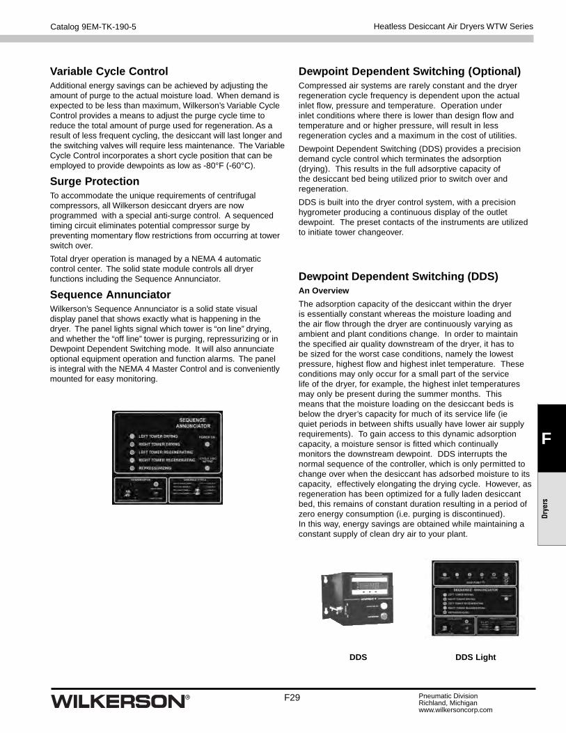
Sequence AnnunciatorWilkerson’s Sequence Annunciator is a solid state visual display panel that shows exactly what is happening in the dryer. The panel lights signal which tower is “on line” drying, and whether the “off line” tower is purging, repressurizing or in Dewpoint Dependent Switching mode. It will also annunciate optional equipment operation and function alarms. The panel is integral with the NEMA 4 Master Control and is conveniently mounted for easy monitoring.
Heatless Desiccant Air Dryers WTW Series
DDS DDS Light

F30
Catalog 9EM-TK-190-5
Pneumatic DivisionRichland, Michiganwww.wilkersoncorp.com
F
Dryers
Heatless Desiccant Air Dryers
Part Number A (length) B (width) C (height)
Weight lbs. (kg)
WTW Series WTW25 19 (483) 16 (406) 64 (1626) 156 (71)
WTW40 21 (533) 17 (432) 48 (1219) 190 (86)
WTW55 21 (533) 20 (508) 67 (1702) 230 (104)
WTW75 35 (889) 27 (686) 80 (2032) 384 (174)
WTW100 35 (889) 27 (686) 80 (2032) 468 (212)
WTW130 35 (899) 21 (533) 70 (1778) 496 (225)
WTW200 44 (1118) 28 (711) 78 (1981) 692 (314)
WTW250 44 (1118) 30 (762) 78 (1981) 776 (352)
WTW300 44 (1118) 30 (762) 78 (1981) 796 (361)
WTW400 74 (1880) 41 (1041) 84 (2134) 1626 (738)
WTW500 74 (1880) 41 (1041) 85 (2159) 1735 (787)
WTW600 74 (1880) 41 (1041) 86 (2184) 1740 (789)
WTW800 74 (1880) 41 (1041) 91 (2311) 2120 (962)
Inch (mm)
C
A
B
Flow correction factorsCapacities are based upon:
• Pressure Drop At Rated Flow Less Than 5 PSI (0.34 bar)
• Maxium Inlet Air or Ambient Air Temperature 120°F (49°C)
• Maximum Working Pressure: 150 PSIG (10.5 bar) Standard Units for High Maximum Working Pressure are Available
• Minimum Operating Pressure: 80 PSIG (5.5 bar)
Service KitsElement Kits
Series 5µ 0.01µ 0.5µ
18 FRP-96-639 MTP-96-646 MSP-96-647
28 FRP-96-653 MTP-96-648 MSP-96-649
39 P3NKA00ESE P3NKA00ESCB P3KNA00ES9
35 FRP-95-505 MTP-95-502 MSP-95-502
Heatless Desiccant Air Dryers WTW Series
= “Most Popular”
Sizing Chart (correction factor)minimum drying capacity = compressed air fl ow rate x CFT x CFP x CFDTemperature Correction Factor (CFT)
Maximum Inlet Temperature(C1)
°F 80 85 90 95 100 105 110 115 120°C 27 29 32 35 38 41 43 46 49CFT 1.17 1.17 1.17 1.15 1.00 0.87 0.76 0.66 0.58
Pressure Correction Factor (CFP)
Minimum Inlet Pressure(C2)
PSIG 80 85 90 95 100 105 110 115 120 125 130 135bar g 5.51 5.86 6.21 6.55 6.89 7.24 7.58 7.93 8.27 8.62 8.96 9.31CFP 0.83 0.87 0.91 0.96 1.00 1.04 1.09 1.13 1.17 1.22 1.26 1.31
Dewpoint Correction Factor (CFD) Standard Option
Required Dewpoint (C3)
PDP °F -40 -100PDP °C -40 -70CFD 1.00 1.43