mini clearflow gas flue block system installation guide ... · dunbrik mini - traditional...
TRANSCRIPT

Dunbrik Mini - traditional installation page 1 January 2016
Mini Clearflow Gas Flue Block System
Installation guide for traditionally built dwellings
Example of gas flue in external wall to ridge
Dunbrik concrete gas flue blocks are CE marked to certified performance standards in EN1858:2008/A1:2011. Manufacturing is to a Quality Assurance Scheme certificate ref. FM 24104. Products are type tested by BSRIA and the Factory Production Control certified by BSI Assurance UK Ltd ref 0086-CPD-597467.
Dunbrik (Yorks) Ltd, 172 Ferry Lane, Stanley, Wakefield, WF3 4LT Tel: 01924 373694 Fax: 01924 383459
Email: [email protected] Web: www.dunbrik.co.uk

Dunbrik Mini - traditional installation page 2 January 2016
Mini Clearflow Components Sample diagrams - shapes vary with different sizes available
Recess block Gather block Straight flue block Non-bonded flue block Offset block 3ME
Backset block 2BM Top exit block 4M Side exit block 5M Dense backup block MD100
Gas flue components Product code
Weight kg
Overall size mm width x depth x height
Coursing height
Red-set wide recess block (3 per flue) 1RM 7.5 460 x 140 x 222 225 Red-set wide gather block 1GM 16.5 460 x 140 x 222 225 M-set recess block (3 per flue) MS 22.9 554 x 272 x 222 225 M-set gather block MG 53.9 554 x 272 x 222 225 Dense backup block 100mm MD100 25.6 525 x 100 x 215 225 B-set recess block (3 per flue) BRU 40.9 900 x 367 x 268 276 B-set gather block BTL900 59.8 900 x 367 x 140 148
Straight bonded gas flue block 225mm 2M 12.0 320 x 140 x 225 225 Straight bonded gas flue block 150mm 2M/150 7.8 320 x 140 x 150 150 Straight bonded gas flue block 75mm 2M/75 4.0 320 x 140 x 75 75 Lateral offset gas flue block 3ME 12.8 340 x 140 x 225 225
35mm Backset gas flue block 3MS 12.5 245 x 175 x 225 225 25mm Backset gas flue block 3MU 12.0 245 x 165 x 225 225 125mm Backset gas flue block 2BM 22.9 245 x 265 x 260 260 Double tongue flue block 190mm 2MDT190 7.3 245 x 140 x 190 190
Gas flue block without bonding nib 225mm 2MN225 7.1 245 x 140 x 225 225 Gas flue block without bonding nib 150mm 2MN150 4.9 245 x 140 x 150 150 Gas flue block without bonding nib 75mm 2MN75 2.7 245 x 140 x 75 75
Top exit gas flue transfer block 4M 10.4 265 x 200 x 160 - Top exit block with connector pipe 4MP 11.0 - - Side exit gas flue transfer block 5M 24.6 285 x 280 x 290 - Side exit block with connector pipe 5MP 26.8 - -
Flue block silicone sealant 310ml cartridge 1581 0.4 - - Blakbord insulation panel Blakbord 1.0 600 x 50 x 900 - Smoke pellet tube (6 pellets per tube) Smoke - - - Flue notice plate Plates - 147 x 160 -
125mm diameter (5”) SFL Twin-wall Metal Flue Pipe and accessories Connected length mm
Flue block connector / adaptor STWBC 0.3 132 Flue pipe 1524mm (60” length) STW60 3.0 1486 Flue pipe 914mm (36” length) STW36 1.8 876 Flue pipe 457mm (18” length) STW18 0.9 419 Flue pipe 305mm (12” length) STW12 0.7 267 Flue pipe 152mm (6” length) STW6 0.4 114 Adjustable length 457mm (18”) STW18A 0.9 75 to 356
Adjustable bend 0 to 90 degree STW090 0.8 Use to max of 45 deg angle from vertical Adjustable wall bracket STWB245 0.3 Adjustable up to 245mm wall clearance Adjustable flashing from 5 to 30 degrees STWAF0530 0.6 Requires storm collar Adjustable flashing 32 to 45 degree STWAF3245 0.6 Requires storm collar Storm collar and sealant STWSC 0.1 For adjustable flashing Gas vent terminal STWGVT 0.4 Overall height 163mm Guy wire bracket STWGWB 0.3 For attaching stays to pipe Ridge tile adaptor STWRTA 0.4 For circular to rectangular connection Sealing tape - aluminium 50mm wide 45M STWST 0.1 For joints and seams
Chimney pots and terminals (other chimney pot heights and styles also available) Variations
Dunvent low profile ridge vent terminal Dunvent 16.6 3 profiles and 6 colours Gastyle II ridge vent terminal Gastyle 8.3 3 profiles and 6 colours Cannon head chimney pot - 450mm tall CANN450 14 red or buff colour Stellgas terminal insert 185mm external spigot STELL380 11 red or buff colour Topguard steel cowl with fixing straps TG260 1.6 red or buff colour

Dunbrik Mini - traditional installation page 3 January 2016
Mini Clearflow Gas Flue Block System - System Overview
System Description The Dunbrik Mini Clearflow gas flue block system is a neat, efficient method of providing a flue in new domestic dwellings. Gas fires suitable for "pre-cast flues" may be fitted - these are class two gas fires, under 7kW input, and include many live fuel effect gas fires. Gas flues to BSEN1858 are often called "precast flues" in the gas fire manufacturers' brochures. For gas fires over 7kW input, an A1 chimney system is required, see below.
The gas flue blocks are built into and interlocked with house walling in a traditionally built house. This can be into the inner leaf blockwork of an outer wall, into a party wall or against a partition wall.
For timber frame houses use the Triple 7 components detailed in the installation guide for timber frame dwellings.
The flue outlet depends upon the house design. It is usually through twin-wall flue pipe in the roof space to a ridge vent or to a gas terminal at eaves or through the roof slope. If you require a traditional chimney stack please contact the Dunbrik technical staff.
The gas flue block system consists of concrete fireplace recess blocks, concrete gas flue blocks, jointing sealant, insulation, twinwall metal flue pipe and outlet terminals. The flueway is rectangular 185mm by 90mm giving a flue cross sectional area of 16,650 sq. mm. The flue block walls have a minimum thickness of 25mm.
When planning the design, allow for a 75mm clearance between the inner flueway and combustible materials. These include joists and trusses but not floorboards, skirting, dado and picture rails. For twin-wall flue pipe, the required clearance is 50mm. Care is required at the ridge where space may be tight.
Standards and Guidance The flue blocks are made of concrete and comply with British Standards BSEN1858. They have been tested by BSRIA Limited - BSEN1858 Certificate C18705/2 Issue 2. Flue block guidance is given in BS5440, NHBC guidance chapter 6.8, the Lead Sheet Association Guide. Dunbrik concrete flue blocks are CE marked from 1
st July 2013.
Building Regulations National Building Regulations and guidance documents cover issues regarding Flues and Chimneys, Fire Safety and Sound Insulation; in the UK Approved Documents J, B and E; in Ireland Technical Guidance Documents parts J, B and E; in Scotland sections 2, 3.17 to 3.22 and 5.
Components The gas flue blocks are made of concrete with a tongue and socket joint for ease of location and construction. This joint is a tight concrete-to-concrete internal joint and an external compressive seal using special heat-resistant silicone sealant applied by cartridge. The blocks have a bonding nib with a 10mm horizontal mortar cut-out to assist coursing with the adjacent blockwork.
The fireplace recess units form an opening for face-fixed or suitable inset live fuel effect (ILFE) fires under 7kW. Three sizes of recess opening are available to match the size of gas appliance likely to be fitted. The Red-set recess usually needs no chimney breast. The larger recess of the M-set and B-set accepts a wider choice of appliances.
Dunbrik ridge vent terminals are available for installation as part of the ridgeline. Metal gas vent terminals can be used at either eaves level or above the roof slope.
Dunbrik products are available in the UK.
Technical Assistance Dunbrik Flues is the specialist manufacturer in the UK of concrete gas flue block systems and chimney flue liner systems for domestic dwellings. We offer technical assistance to help you select your flue system and components. System details and guidance is available on our website www.dunbrik.co.uk.
We can also produce a flue costing based on your requirements, please contact our technical staff for details.
Telephone: 01924 373694 Fax 01924 383459 email: [email protected]
Dunbrik A1 chimney systems
For the construction of domestic chimneys (for all domestic fuels) in traditional or timber-frame houses, please ask for details of the Dunbrik A1 flue liner systems for domestic chimneys.
Installation Guide Contents
1 Gas fire recess 10 Appliance Suitability 2 Party wall sound insulation 11 Air Ventilation 3 Flue block installation 12 Flue Testing Procedures 4 Insulation board in an external wall 13 Product safety information
5 Wall finishes 14 Flue completion certificate 6 Flue termination to gas vent terminal 15 Flue notice plate 7 Twin wall flue pipe installation Appendix A UK Gas flue checklist
8 Stack termination Appendix B UK Gas flue notice plate guide 9 Flue draw test

Dunbrik Mini - traditional installation page 4 January 2016
Mini Clearflow Gas Flue Block System - Installation guide for traditional dwellings
Before commencing installation refer to the general flue layout on page 1, the walling detail in sections 2, party wall details in section 3 and the insulation board instructions in section 5.
Gas Fire Recess
Select the correct size recess units for the required fireplace recess size.
Recess set Red set M Set B Set
Recess blocks 3 required
1RM MS BRU
Gather block 1GM MG BTL900 and MG
Recess dimensions Width depth height
400 115 675
450 220 675
800 315 836
Overall outer dims. Width depth height
460 140 900
554 272 900
900 367 1,200
Red set recess
M set recess
B set recess
Create a gas fire recess using three starter blocks and a gather block
1 Installation steps
• So that the full recess height is provided for the fire, establish a base for the recess blocks at finished floor level using bricks or blocks.
• Install the first recess block at the finished floor level on a mortar bed (not silicone sealant).
• Install two more recess blocks, each on a 5mm (for BRU 8mm) mortar bed as illustrated, incorporating Blakbord if required, see section 4.
• Mortar bed the appropriate gather block onto the top recess block. It is important to ensure that the tops of the gather block is level in all directions.
• For the Bset, install an MG gather block with a 3mm mortar bed onto the BTL900 gather block. A 150mm tall straight flue block may be needed to bring back into course with adjacent blockwork.
• When plaster-boarding seal any gap between the recess units and plasterboard with a continuous 50mm seal of non-combustible plasterboard adhesive.

Dunbrik Mini - traditional installation page 5 January 2016
Mini Clearflow Gas Flue Block System - Installation guide for traditional dwellings
2. Party Wall Airborne Sound Insulation – Robust Details
Sound insulation standard of separating walls (Building Regulations Part E 2003 Eng. & Wales) can be achieved by following pre-completion acoustic testing or by building to a Robust Details Ltd specification. The following RD configurations have passed acoustic tests in houses, for single or staggered gas flues in separating walls.
• E-WM-3 dense blocks, 75mm cavity, board on dabs and render
• E-WM-4 lightweight blocks, 75mm cavity, board on dabs and render
• E-WM-5 Besblock “Star Performer” 5-bridge blocks, 75mm cavity, board on dabs and render
• E-WM-11 lightweight blocks, 100mm cavity, board on dabs and render
• E-WM-8 lightweight blocks SG RD35 acoustic batt & board on dabs, 75mm cavity no render • E-WM-14 lightweight blocks SG RD35 acoustic batt & board on dabs, 100mm cavity no render
• E-WM-16 dense blocks, 100mm cavity, gypsum board on dabs and render
The Robust Details Ltd handbook includes detailed construction requirements for the separating walls, floors, junctions and flanking conditions in houses needed to meet requirement E1. To register or obtain details telephone 0870 2408210 or go to www.robustdetails.com. For apartments, pre-completion acoustic testing will be required.
E-WM-3 Example. The following details show the Dunbrik standard recess incorporated in the wall using Dunbrik 1RM recess blocks and Dunbrik MD100 dense backup blocks in the wall behind each fire recess.
The E-WM-3 design is constructed using:
• Building blocks of a density from 1850 to 2300 kg/m3
• Dunbrik fireplace recess blocks 1RM at 500mm stagger - three per flue (see other recess units below)
• Dunbrik high density building blocks MD100 - three behind each recess
• Gypsum-based board (nominal 8 kg/m3) on dabs and 8mm nominal render across the wall
RD E-WM-3 - Masonry separating walls Dunbrik flue blocks with 1RM recess blocks
Plan at first floor
Plan through recess opening
If a flue bridges the cavity of a separating wall, the Robust Detail will not apply and pre-completion acoustic testing will be needed.
Flue Recess Sizes The Dunbrik Red-set and M-set recess units can be used within the above Robust Detail configurations. The flue stagger and Dunbrik recess components are as follows:
Dunbrik recess Flue stagger 3 Recess blocks Gather block 3 Dense blocks Red-set 500mm minimum 1RM 1GM MD100 M-set 560mm minimum. MS MG MD100
Dunbrik Mini - traditional installation page 6 January 2016
Mini Clearflow Gas Flue Block System - Installation guide for traditional dwellings
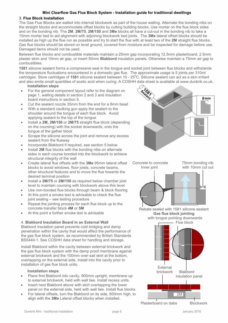
3. Flue Block Installation The Gas Flue Blocks are walled into internal blockwork as part of the house walling. Alternate the bonding nibs on the straight blocks and accommodate offset blocks by cutting building blocks. Use mortar on the flue block sides and on the bonding nib. The 2M, 2M/75, 2M/150 and 3Me blocks all have a cut-out in the bonding nib to take a 10mm mortar bed to aid alignment with adjoining blockwork bed joints. The 3Me lateral offset blocks should be installed as high up the flue run as possible and try to start the flue with at least two of the 2M straight flue blocks. Gas flue blocks should be stored on level ground, covered from moisture and be inspected for damage before use. Damaged items should not be used.
Between flue blocks and combustible materials maintain a 25mm gap incorporating 12.5mm plasterboard, 2.5mm plaster skim and 10mm air gap, or insert 50mm Blakbord insulation panels. Otherwise maintain a 75mm air gap to combustibles.
1581 silicone sealant forms a compressive seal in the tongue and socket joint between flue blocks and withstands the temperature fluctuations encountered in a domestic gas flue. The approximate usage is 5 joints per 310ml cartridges. Store cartridges of 1581 silicone sealant between 10 - 25
oC. Silicone sealant can act as a skin irritant
and also emits small quantities of acetic acid when curing. A COSHH data sheet is available at www.dunbrik.co.uk. Installation steps
• For the general component layout refer to the diagram on page 1, walling details in section 2 and 3 and insulation board instructions in section 5.
• Cut the sealant nozzle 35mm from the end for a 8mm bead
• With a standard caulking gun apply the sealant to the shoulder around the tongue of each flue block. Avoid applying sealant to the top of the tongue
• Install a 2M, 2M/150 or 2M/75 straight flue block (depending on the coursing) with the socket downwards, onto the tongue of the gather block
• Scrape the silicone across the joint and remove any excess sealant from the flueway
• Incorporate Blakbord if required, see section 5 below
• Install 2M flue blocks with the bonding nibs on alternate sides in each course bonded into the blockwork to achieve structural integrity of the wall
• Create lateral flue offsets with the 3Me 95mm lateral offset blocks to avoid windows, floor joists, concrete beams, other structural features and to move the flue towards the desired terminal position
• Install a 2M/75 or 2M/150 as required below chamber joist level to maintain coursing with blockwork above this level
• Use non-bonded flue blocks through beam & block flooring
• At this point a smoke test is advisable to check the flue joint sealing – see testing procedure
• Repeat the jointing process for each flue block up to the concrete transfer block 4M or 5M
• At this point a further smoke test is advisable
Concrete to concrete 75mm bonding nib Inner joint with 10mm cut out
Rebate sealed with 1581 silicone sealant
Gas flue block jointing with tongue pointing downwards
4. Blakbord Insulation Board in an External Wall Blakbord insulation panel prevents cold bridging and damp penetration within the cavity that would affect the performance of the gas flue block system, as recommended by British Standards BS5440-1. See COSHH data sheet for handling and storage.
Install Blakbord within the cavity between external brickwork and the gas flue block system with the damp proof membrane against external brickwork and the 100mm over-sail skirt at the bottom, overlapping on the external side. Install into the cavity prior to installation of gas flue block units.
Flue block
External brickwork Blakbord insulation panel
2M Plasterboard on dabs Blockwork
Installation steps
• Place first Blakbord into cavity, 900mm upright, membrane up to external brickwork, held with wall ties. Install recess units.
• Insert next Blakbord above with skirt overlapping the lower panel on the external side, held with wall ties. Install flue blocks.
• For lateral offsets, turn the Blakbord on its side, 600mm high, to align with the 3Me Lateral offset blocks when installed.

Dunbrik Mini - traditional installation page 7 January 2016
Mini Clearflow Gas Flue Block System - Installation guide for traditional dwellings
5. Wall Finishes Use plasterboard on dabs over the entire flue block run, but do not place dabs directly on the gas flue blocks as this can transmit heat. Plaster should not be applied to the face of the flue blocks as plaster cracking may occur from the heat. Do not use expanded wire mesh directly in front of the flue block system as this also transmits heat. Plaster may be applied directly to a blockwork chimney breast in front of the flue block system. For separating party walls, follow the RD walling details (see section 3).
6. Flue Termination Three examples of flue termination using twinwall flue
pipe in the roof space to gas vent terminals Ridge termination Mid-roof termination Eaves termination B Twinwall Flue pipe A C 5M 5M
4M
Recommended flue heights and clearance from roof slope
A = Distance from roof breakout to underside of GVT B = Distance from roof slope to underside of GVT. This is always a minimum of 1500mm. C = Degree of roof pitch
Pitch C Degrees
Height A (minimum)
30 830mm
35 1050mm
40 1260mm
45 1500mm
Ridge terminals Termination can be to a Gastyle or Dunvent ridge vent terminal. Dunbrik ridge vent terminals are supplied with a SFL IL 125mm internal diameter twinwall pipe for direct connection to SFL IL pipe in the roof space. Ridge terminals should be a minimum distance of 1500mm away from adjacent higher structures and adjacent terminals should not be less than 300mm apart (600mm from openings in Ireland). Installation steps (see also twinwall guidance item 8)
• Install a 5M side exit transfer block. Cement a Dunbrik twin-wall metal flue block connector pipe, STWBC, into the circular exit hole using a cement/water paste, leave to set.
• Fit twinwall flue pipe from the connector pipe to the terminal, keeping the pipe at an angle no more than 45 degrees from vertical. (In Ireland, no more than 37.5 deg. from vertical)
• Clip or bed the Dunvent or Gastyle terminal in line with the other ridge tiles. Allow the mortar to set.
• Align the dimples on the twinwall flue pipe coupling with the dimples on the Dunvent or Gastyle pipe, push together and twist to lock.
• If connecting to pipe other than SFL, use an adaptor and securely fix with gas tape.
Stop end cavity tray
125mm twinwall flue pipe 5M block
Blakbord insulation panel
Through the roof slope or at eaves to a gas vent terminal If the required minimum 45 degree angle of twinwall flue pipe cannot be achieved from the flue transfer block to the under-side of the ridge tile connector, the twinwall flue pipe can be taken through the roof slope or at eaves. Installation steps (see also twinwall guidance item 8)
• Install a 5M side exit transfer block or a 4M top exit transfer block depending on flue and terminal positions
• Cement a Dunbrik twin-wall metal flue block connector pipe, STWBC, into the circular exit hole using a cement/water paste and leave to set.
• Fit twinwall flue pipe from the connector pipe to the terminal, keeping the pipe at an angle no more than 45 degrees from vertical.
• Install an adjustable flashing STWAF0530 and storm collar STWSC for weather proofing.
• Fit a Gas Vent Terminal, STWGVT, at the recommended height and roof slope clearance.
• Support any pipe higher than 1 metre above the roof breakout point using a guywire bracket STWGWB and rigid angle-iron stays to allow for local wind-loading.
Gas Vent Terminal Minimum 1500mm Storm collar
Adjustable Flashing
Twinwall flue pipe
Blakbord
Termination at eaves through 4M block

Dunbrik Mini - traditional installation page 8 January 2016
Mini Clearflow Gas Flue Block System - Installation guide for traditional dwellings
7. Twin Wall Flue Pipe Use 125mm twin-wall metal flue pipe to BS715 to connect the concrete gas flue block system to a gas flue terminal outlet. Maintain a minimum clearance of 50mm from twin-wall flue pipe to combustible materials. Do not cut the flue pipe.
Installation steps
Push lengths Turn to together aligning lock dimples
• Flue pipe must be fitted by a competent/approved gas installer and tested prior to the installation of the fire.
• Cement an STWBC flue block connector using cement/water paste, into the concrete gas flue transfer block and leave to set before joining the first piece of twin-wall pipe
• Join each pipe section by aligning the dimples on the couplers and push fitting together with the inserted piece pointing upwards. Twist the upper pipe 1/6 turn clockwise to complete the connection.
• Connect further pieces, adjustable lengths and adjustable bends to keep the pipe run at no greater than 45 degrees from vertical and near to fixing points.
• Use an STW18A adjustable length, to achieve lengths of 75mm to 356mm. Achieve the required length by sliding the STW18A over the fixed pipe below it. Secure the pipe by tightening the fixing band supplied around the bottom of the adjustable length.
• Use STW090 adjustable bends, to angle the pipe around obstructions and near to fixing points. Twist the segments to convert from a straight to the required bend, not exceeding 45 degree angle from vertical.
• Use STWB245 wall bands, to support the pipe within the roof space so that it does not pull on the connection to the flue terminal. Screw to a wall or batten to support the flue pipe at not more than 1.8 metre centres.
• Use an STWAF0530 or an STWAF3245 angled flashing and an STWSC storm collar when going through the roof slope to provide weather proofing. Nail or screw fix the base of the flashing to the roof battens above the cone section prior to tiling and lap the roof tiles over the flashing base. Seal the flashing to the flue pipe. Fit the storm collar and seal it to the flue pipe. The flashing kit is not suitable for profiled roof tiles.
• Fit an STWGVT gas vent terminal, when terminating through the roof slope. Twist-lock the terminal to the final section of pipe with the standard twist lock connection
• Support any pipe higher than 1 metre above the roof breakout point using a guywire bracket STWGWB and rigid angle-iron stays to allow for local wind-loading. Ask your structural engineer for support details.
• When connecting to a ridge vent with a rectangular shape connection, fit an STWRTA ridge tile adaptor, This adaptor is not required to connect to a Dunbrik Gastyle or Dunvent ridge vent terminal which is a twist fit.
• Make sure that the full flue pipe run, from the gas flue block to the terminal, is a permanent secure connection.
• Tape the seams and joints of any STW090 in the flue with aluminium gas tape STWST.
8. Flue Termination through Chimney Stack
If you require the flue to exit through a chimney stack, please refer to the Dunbrik technical staff. 9. Flue Draw Test
On completion of the flue system, check that the flue run is complete from the fire recess to the terminal. Carry out a flue draw test to check that smoke draws freely up the flue - see testing procedure below. 10. Appliance Suitability
Fires suitable for gas flue block systems to BSEN1858 and BS1289 (often called precast flues) may be fitted. The fire manufacturer should have details of the gas fire suitability. In Ireland, the fire should also be on the Bord Gais listing. An approved installer should carry out a flow test prior to appliance fitting. 11. Ventilation
Although suitable fires are rated under 7kW, and do not need additional ventilation under UK Building Regulations, it may be advisable to install a permanent outside air ventilation into the room via an air brick, to ensure proper operation of the flue.

Dunbrik Mini - traditional installation page 9 January 2016
Mini Clearflow Gas Flue Block System - Installation guide for traditional dwellings
12. Flue Testing Procedures
a. Smoke testing during construction
It is advisable to check the flue during construction to reveal any problems at the earliest possible stage.
At chamber joist level we advise that a smoke test be carried out to ensure that all joints up to this level are sealed.
The test needs two people to conduct. Read the instructions on the use of smoke pellets shown on the tube, follow the directions and avoid inhaling smoke. A COSHH data sheet is available by fax and from the Dunbrik website.
• Visually check that the flueway is clear of obstructions, including mortar and silicone intrusions.
• Place a smoke pellet on blocks, 225mm below the gather block and ignite.
• After a few seconds close off the flueway at chamber joist level and then close off the fireplace recess.
• Check for any joint leakage (especially in the cavity) and rectify if necessary.
• After any remedial work, repeat the test. Perform this test again after the 4M or 5M flue transfer block is installed, but prior to wall boarding over the flue.
b. Flue draw test on complete flue Once the twinwall flue pipe has been connected to the flue terminal, a flue draw test based should be carried out in accordance with BS5440 or IS813 with no restriction at the fireplace recess.
• Close all doors and windows in the room in which the appliance is to be installed.
• Introduce some heat into the flue e.g. using a blowtorch for at least 5 minutes.
• Place a smoke pellet on blocks, 225mm below the gather block and ignite.
• Ensure that there is no spillage of smoke into the room or leakage from the flue.
The smoke should be drawn freely up the flue and out of the terminal. Should any smoke seepage be observed from joints or seams of the IL flue then those joints and seams should be taped using 50mm wide aluminium sealing tape ref. STWST. If you need further advice, contact our technical staff on 01924 373694.
c. Flow Testing During Appliance Fitting
A smoke test should be carried out in accordance with BS5440 : Part1 or IS:813 in order to ascertain the
satisfactory operation of the complete flue system and should be carried out by an approved gas fire installer. 13. Product safety information
Product safety data sheets under COSHH regulations are available by post, fax or website for the following:
Smoke pellets, silicone sealant, Dunseal, Dunfil, Blakbord, concrete flue blocks and dense backup blocks.
Manual handling should be avoided as far as is reasonably practical. An assessment should be made, taking into account the load, environment, task and the individual's capacity and training. Employ good lifting techniques. Individual product weights are listed on page 2.
Storage should be on level ground. When stacked, the components should be restrained from falling over. Remove products from the top of the pallet and avoid cutting the wrapping at the side.
14. Gas Flue Checklist – appendix A
Building Regulations for England and Wales ADJ 2010 Appendix A sets out a suggested checklist report and certificate to enable a flue installer/chimney builder to show building control how an installation complies with Building Regulations. Dunbrik Flues can provide a checklist with standard data. Some information, such as the actual fireplace opening sizes, actual ventilation installed and variations to usual configurations are added later by the installer/builder when the installation is completed. 15. Notice Plate for Hearths and Flues – appendix B
Building Regulations (England and Wales J4 and Scotland F3.12) require each flue and chimney to be identified with a notice plate in the dwelling. To assist you in meeting the requirements, Dunbrik can supply notice plates and guidance. Details are given in appendix B, including a facsimile of a completed plate with sample data for a gas flue.
Dunbrik (Yorks) Ltd, 172 Ferry Lane, Stanley, Wakefield, WF3 4LT Tel: 01924 373694 Fax: 01924 383459
Email: [email protected] Web: www.dunbrik.co.uk

Dunbrik Mini - traditional installation page 10 January 2016
Installation Guide Appendix A
UK Gas Flue Checklist
Mini Clearflow Gas Flue Block System
This checklist is based on Building Regulations ADJ Appendix A, using standard Dunbrik gas flue data. The builder/installer should insert details of the actual fireplace opening sizes, actual ventilation installed and any variations to the usual data.
Checklist for Hearths, fireplaces, flues and chimneys This checklist can help you to ensure hearths, fireplace, flues and chimneys are satisfactory. If you have been directly engaged, copies should also be offered to the client and to the Building control body to show what you have done to comply with the requirements of part J. If you are a sub-contractor, a copy should be offered to the main contractor. 1. Building address, where work has been carried out:
_____________________________________________________________________________ ADJ appendix A Details to amend or complete
2. Identification of hearth, fireplace, chimney or flue Fireplace in Lounge
3. Firing capability Gas only
4. Intended type of appliance. State type or make. If open fire give finished fireplace opening dimensions.
Gas fire - radiant/convector up to 7kW heat input suitable for installation into gas flue block system to BSEN1858
5. Ventilation provisions for the appliance. State type and area of permanently open air vents
Additional ventilation not required
6. Chimney or flue construction a) State the type or make and whether new or existing b) Internal flue size (and equivalent height, where calculated - natural draught gas appliances only) c) If liners used confirm they are correctly jointed in accordance with manufacturers instructions and state jointing materials used. d) If an existing chimney has been refurbished with a new liner, type or make of liner fitted e) Details of flue outlet terminal Outlet detail: Complies with: f) Number and angle of bends g) Provision for cleaning and recommended frequency
New. Gas flue blocks to BSEN1858 185mm x 90mm Equivalent flue height =____________ Tongue upwards into rebate and joined with Dunbrik 1581 silicone sealant Not Applicable _______________________________ _______________________________ ________lateral offsets at 30 degrees Annual service by Corgi Engineer
7. Hearth. Form of construction. New or existing
8. Inspection and testing after completion Tests in Appendix E of ADJ 2010
Tests carried out by:
Flue Inspection results: Appliance (where included)
Visual Sweeping Coring ball Smoke Spillage
______________
Sweeping not applicable Coring ball not applicable
______________
I/We the undersigned confirm that the above details are correct. In my opinion, these works comply with the relevant requirements in Part J of Schedule 1 to the Building Regulations.
Print name and title _________________________________________ Capacity _________________________________________ Address _________________________________________ Signed _________________________________________ Registered membership of (e.g. CORGI, OFTEC, HETAS, NACE, NACS)
Profession _____________________ Tel No. _____________________ Postcode _____________________ Date _____________________ Reg. _____________________
Dunbrik (Yorks) Ltd, 172 Ferry Lane, Stanley, Wakefield, WF3 4LT. Tel 01924 373694

Dunbrik Mini - traditional installation page 11 January 2016
Installation Guide - Appendix B
UK Gas Flue Notice Plate Guide
Mini Clearflow Gas Flue Block System
Building Regulations (England and Wales J4 and Scotland F3.12) require each flue and chimney to be identified with a notice plate in the dwelling. To assist you in meeting the requirements, Dunbrik can supply metal notice plates as example below.
Peel off the protective film. Enter the data with an indelible pen such as a CD marker. Fix the plate securely with strong adhesive to a clean wall in an unobtrusive but obvious position within the building such as next to; the electricity consumer unit; the water supply stopcock; or the chimney or hearth described.
To assist you with the details, the Dunbrik gas flue block system has the following descriptions, dimensions and appliance suitability:
Flue type Flue sizes internal Fire/Appliance suitability
Dunbrik Mini Clearflow gas flue block system to BSEN1858 - T250 N1
185mm x 90mm internal rectangular flue
Gas fires suitable for gas flue block systems (precast flues) to BSEN1858
Where a flue has a terminal fitted for air ventilation purposes only, the notice must state that
"the flue is not to be used for fires". The equivalent flue height for your Dunbrik gas flue can be calculated by the Dunbrik technical staff.
Example of Notice Plate with sample Dunbrik gas flue data (actual metal plate is 147mm by 160mm)
Dunbrik Flues
Notice Plate for Hearths and Flues
IMPORTANT SAFETY INFORMATION This plate must be permanently affixed and must not be removed or covered
Address of property
Sample house 20 Main Street Newtown N1 ANY
Room where hearth, fireplace or start of flue located
Lounge
The flue is suitable for these types of appliances For gas flues the equivalent flue height is
Gas fires suitable for gas flue block systems (precast flues) to BSEN1858 ----------- meters
Manufacturer, flue type and internal dimension
Dunbrik Mini Clearflow gas flue block system to BSEN1858 185mm x 90mm internal rectangular flue
Installer
Smith Building Co
Date installed
01/09/2015
Other information
Condensing appliances: Maintenance: Installation guidance:
The flue is not suitable for condensing appliances The flue and/or chimney should be regularly inspected and maintained as advised by a qualified person. website: www.dunbrik.co.uk Tel: 01924 373694
Dunbrik (Yorks) Ltd, 172 Ferry Lane, Stanley, Wakefield, WF3 4LT
Tel: 01924 373694 Fax: 01924 383459 Email: [email protected] Web: www.dunbrik.co.uk