mimo-ofdm pilot symbol design for sparse channel estimation · mimo-ofdm pilot symbol design for...
TRANSCRIPT
MIMO-OFDM Pilot Symbol Design For SparseChannel Estimation
Roozbeh Mohammadian∗, Arash Amini∗, Babak H. Khalaj∗ and Naeimeh Omidvar∗†∗ Department of Electrical Engineering, Sharif University of Technology,
† Department of Electronic and Computer Engineering, The Hong Kong University of Science and Technology.E-mail: [email protected]
Abstract—Channel equalization is a crucial part of the OFDMcommunications protocols, which in turn requires channel esti-mation. In this paper, we consider the problem of orthogonal pilotdesign in MIMO-OFDM systems for sparse channel estimation.The pilot design in MIMO scenarios compared to the conven-tional SISO case has the additional constraint that the capabilityof recovery should be uniformly provided for all single channels.For instance, perfect estimation of a channel at the cost of anotherone is not permitted. This requirement is even more significantin the emerging Massive-MIMO systems. Our pilot design isbased on the compressed sensing technique of minimizing thecoherence measure of the Fourier submatrix associated with thepilot subcarriers. However, we desire to minimize the coherencevalue of such matrices simultaneously for all channels. Here,we optimize over both the pilot locations and values. As findingthe global minimizer is a combinatorial problem, we resort to agreedy method. Although there is no guarantee for the optimalityof the achieved patterns, our simulation results confirm theirsuitability in practice.
Index Terms—OFDM, Pilot Design, Sparse channel estimation,Compressive Sensing, Massive MIMO
I. INTRODUCTION
OFDM channel estimation has been one of the main con-cerns of the researchers, and many OFDM channel estimationmethods have been developed so far. Recent studies revealthat some wireless channels such as mmWave channels, highdefinition television (HDTV), and underwater acoustic chan-nels have sparse structures [1]–[4]. Considering the sparsestructures of the channels results in the design of algorithmswith better performance and lower pilot overhead [5]–[7].Therefore, many researchers have used Compressive Sensing(CS) theory [8], [9] for sparse channel estimation [5]–[7].
To efficiently utilize CS for sparse channel estimation inOFDM systems, the pilot symbols should be designed prop-erly. In [7] it is shown that random pilot locations can guaran-tee the perfect channel reconstruction. However, random pilotsare not applicable in practical systems [10]. Therefore, somepilot design schemes are proposed to design deterministicpilots [10]–[14]. The deterministic pilots are designed basedon minimizing the coherence of the measurement matrix [10]–[14]. Under some specific conditions, it is shown in [10] and[12] that the pilot locations designed according to the cyclicdifference sets (CDS) are optimum. However, in practicalsystems the necessary conditions for existence of the CDSsare not satisfied. Therefore, a greedy method is proposed in
[10], to design suboptimal pilot patterns. The authors of [12]propose three different schemes for suboptimal pilot patterndesign, where two methods are based on stochastic searchand the other one applies a tree-based searching structure. In[13] and [14], it is shown that joint design of pilot patternand power results in better performance. Both the methodsin [13] and [14] decouple the joint design of pilot pattern andpower into the disjoint pattern and power design sub-problemsand solve them sequentially. The pilot design method of [13]is only applicable for the cases where either CDS or almostdifferent set (ADS) exist. In [13], the exhaustive search forfinding the optimal pilot pattern and powers is implementedusing backtracking which reduces the computational cost inmany cases. Another OFDM pilot design is introduced in[14] for the application of cognitive radios. Replacing theexhaustive search for the pilot locations with a sequentialstochastic search is shown to achieve descent results withtolerable computational cost [12].
To have interference-free channel estimation in multiuserand MIMO OFDM systems, orthogonal pilot design is acommon technique; in this approach, pilot subcarriers of allusers occupy distinct frequencies and do not coincide with anyof the data subcarriers. In this paper we do not consider non-orthogonal settings, as they suffer from pilot contamination, anundesired effect that can severely limit the overall performance[15], [16]. Beside the orthogonality, multiple pilot sequencesshould be designed in a fair manner. By fair design of pilots,we mean all the pilot sequences should estimate CSI with thesame quality under the same conditions.
In CS based channel estimation, fair design of pilots resultsin the design of measurement matrices with equal coherencevalue. MIMO-OFDM pilot pattern design for sparse channelestimation is considered in [11], [12]. To have fair pilotsequences, the authors in [11] use genetic algorithm (GA)to generate a core pilot sequence and design the other pilotsequences by shifting the entries of the core pilot sequence.In [12] the single user pilot pattern design algorithms areextended to the MIMO case, and two methods are proposedbased on the stochastic search. In one method they sequentiallydesign pilot sequences for multiple antennas. In the othermethod, to prevent unfair pilot design, they jointly designmultiple pilot sequences.
In this paper, we consider the pilot design for MIMO-
Proceedings of APSIPA Annual Summit and Conference 2015 16-19 December 2015
978-988-14768-0-7©2015 APSIPA 975 APSIPA ASC 2015

OFDM sparse channel estimation. The joint design of pilotpattern and power is considered based on minimizing the co-herence of the measurement matrix. We decouple the problemin to the disjoint subproblems of pattern design and pilotallocation, and sequentially solve them. Different from themethods in [11] and [12], the pilot patterns are determineddeterministically in a greedy manner. To find the pilot powers,like [14] we cast the pilot power problem as a SOCP problem.In order to design fair pilot sequences we design the algorithmbased on minimizing the maximum coherence value of thetransmitters. Simulation results show that the pilot patterndesigned by the proposed method outperforms the others interms of designing sensing matrices with smaller coherenceand estimating channels with lower MSE.
The rest of the paper is organized as follows. The MIMO-OFDM pilot design problem is formulated in Section II.Section III considers the pilot power allocation. Section IVpresents the MIMO-OFDM pilot design algorithm. The simu-lation results are given in Section V. Finally, conclusions areprovided in Section VI.
The following notations are used throughout the paper.Matrices and vectors are represented by boldface upper caseand boldface lower case letters, respectively. The entry at thei-th row and the j-th column of A is denoted by [A]i,j .a(i) stands for the i-th entry of a vector a. 1 and 0 meana vector with all-one entries and a vector with all-zero entries,respectively. a > 0 means that all the entries of the vectora are greater than 0. [ · ]T and diag· denote the transposeand the diagonal matrix, respectively. 〈a,b〉 denotes the innerproduct of a and b. The sets N and L are defined asN =
1, 2, · · · , N
and L =
1, 2, · · · , L − 1
. Z stands
for the integer numbers set, and ∅ shows the empty set.
II. PROBLEM FORMULATION
Consider a MIMO-OFDM system, where the transmitterand the receiver employ nT and nR antennas, respectively.The signals are transmitted on N subcarriers. To estimatethe channels at the receiver, each transmit antenna occupiesNP subcarriers for pilot symbol transmission. The pilot sub-carriers assigned to the i-th transmit antenna are denoted asPi =
pi,1, pi,2, · · · , pi,NP
, where we assume that 1 ≤
pi,1 < pi,2 < · · · < pi,NP ≤ N . In order to have interferencefree channel estimation, we use frequency orthogonal pilottransmission strategy, which means that Pi ∩ Pj = ∅ for1 ≤ i, j ≤ nT and i 6= j. Under such assumption, MIMO-OFDM channel estimation is decomposed into simultaneousestimation of nT × nR SISO-OFDM channels. Representingthe pilot symbols transmitted by i-th transmit antenna as xi =[xi(1), xi(2), · · · , xi(NP )]T , the associated received vector atj-th receive antenna, yj,i = [yj(pi,1), · · · , yj(pi,NP )]T , canbe written as,
yj,i = XiFihj,i + nj,i. (1)
Here, Xi = diagxi(1), xi(2), · · · , xi(NP )
, hj,i =
[hj,i(1), · · · , hj,i(L)]T represents the channel impulse re-sponse between (j, i)-th receiver-transmitter pair, and nj,i =
[nj(pi,1), n(pi,2), · · · , n(pi,NP )
]Tshows the additive white
Gaussian noise (AWGN), which is modeled as nj,i ∼CN (0, σ2INP ). the j-th receive antenna noise at the pilotsubcarriers assigned to the transmitter i. Also, Fi is a DFTsubmatrix with elements defined as
[Fi
]n,l
= e−j2πN (n−1)(l−1)
for n ∈pi,1, pi,2, · · · , pi,NP
and l ∈
1, · · · , L
. Defining
Φi = XiFi, (1) can be written as
yj,i = Φihj,i + nj,i. (2)
Here, we refer to Φi as the measurement matrix for i-thtransmitter.
We assume that the channel hj,i is a k-sparse vector oflength L, meaning that hj,i has at most k non-zero elementswhere k L. Therefore, the CS theory can be applied forestimation of hj,i with significantly less number of pilots thanconventional methods. In [8], it is shown that if the measure-ment matrix satisfies the Restricted Isometry Property (RIP),then hj,i can be reconstructed from yj,i with an overwhelmingprobability. However, there is no polynomial time algorithmto check whether a matrix satisfies the RIP [17]. A commonalternative to guarantee the perfect reconstruction of sparsesignals is the coherence of the measurement matrix. Coherenceof a matrix is defined as the maximum cross-correlationsbetween its normalized columns. The coherence condition isstronger than RIP, and can be evaluated easily. Therefore,many sparse channel estimation methods have used coherenceas a basis for designing pilot signals.
In (2), the coherence of Φi is formulated as
µΦi= max
1≤m,n≤Lm6=n
|〈φm, φn〉|‖φm‖2 · ‖φn‖2
(3)
= max1≤m,n≤L
m6=n
∣∣∣∑NPj=1|xi(j)|
2e−j2πN pi,j(m−n)
∣∣∣∑NPj=1|xi(j)|2
.
Here, µΦi represents the coherence of Φi, and φm denotesthe m-th column of Φi. According to the periodic structure ofΦi, the cross-correlation between φm and φn only depends onthe difference between the indices m and n. Therefore, lettingr = m− n, µΦi can be written as,
µΦi = maxr∈L
∣∣∣∑NPj=1|xi(j)|
2e−j2πN pi,jr
∣∣∣∑NPj=1|xi(j)|2
(4)
The sparse recovery methods such as `1 minimization andgreedy methods, are guaranteed to perfectly recover hj,i whenµΦi
< 12k [18]. Therefore, we design the pilot symbols based
on minimizing the coherence of the measurement matrix.Most of the OFDM pilot design methods proposed for sparsechannel estimation only consider the design of pilot patternand assume equal powers for all pilots. However, accordingto (4), it is obvious that besides the pilot locations, the pilotpowers can control the value of µΦi
. Consequently, as in [13]and [14], we consider the joint design of pilot pattern and pilotpower based on minimizing the coherence of the measurementmatrix.
Proceedings of APSIPA Annual Summit and Conference 2015 16-19 December 2015
978-988-14768-0-7©2015 APSIPA 976 APSIPA ASC 2015

Therefore, the pilot design problem for i-th transmit antennais formulated as
Ωopti = arg min
ΩµΦi (5)
= arg minΩ
maxr∈L
∣∣∣∑NPj=1 vi(j)e
−j 2πN pi,jr
∣∣∣∑NPj=1 vi(j)
.
Here, vi(j) denotes the power assigned to the j-th pilot symbolof transmitter i, i.e., vi(j) = |xi(j)|2. Ω is the feasible set andis defined as Ω =
vi,Pi
, where vi = [vi(1), · · · , vi(NP )]T .
Also in (5), Ωopti =
vopti ,Popt
i
, where
vopti = [vopt
i (1), · · · , vopti (NP )]
Popti =
popti,1 , · · · , p
opti,NP
. (6)
The pilot design problem of (5) is a joint optimization ofcontinues and discrete variables, and finding optimal solutionfor it is almost impossible. Therefore, to find the suboptimalpilot powers and pattern, we disjoint (5) into the pilot and pat-tern optimization subproblems and solve them in a sequentialmanner.
III. PILOT POWER DESIGN
Assume that P =pi,1, · · · , pi,m
represents the m pilot
locations for i-th transmit antenna. For the given pilot pattern,the optimal pilot powers are found through the followingoptimization problem.
vopti = arg minvi max
r∈L
∣∣∣∑mj=1 vi(j)e
−j 2πN pi,jr
∣∣∣∑mj=1 vi(j)
s.t. vi > 0 (7)
According to (4), if vopti is a solution for (7), then vi =
[αvi(1), · · · , αvi(m)]T will be another solution for (7) for anyα > 0. Therefore, we propose to put the following constrainton the pilot powers.
m∑j=1
vi(j) = 1. (8)
Obviously, while making the search region as small as possi-ble, the proposed power constraint preserves all the solutionsof (7). Considering the pilot powers constraint of (8), anddefining g(P,vi) as
g(P,vi) = maxr∈L
∣∣∣∣∣∣m∑j=1
vi(j)e−j 2π
N pi,jr
∣∣∣∣∣∣ , (9)
the power allocation problem for a given pilot pattern of P iswritten as
vopti = arg min
vi∈Vg(P,vi) (10)
where
V =vi|
m∑j=1
vi(j) = 1, vi(j) > 0 ∀j.
As mentioned in [14], (10) can be casted as a SOCP problemwhich can be solved using convex optimization packages suchas CVX [19] and MOSEK [20].
IV. MIMO-OFDM PILOT DESIGN ALGORITHM
To design orthogonal pilot sequences for all the transmitantennas, (5) should be considered simultaneously for i =1, · · · , nT . Since there is no priority between the transmitantennas, the pilots should be designed fairly. By fair designof pilots, we mean that all the measurement matrices shouldhave the same coherence value. According to (4), it is obviousthat if P∗i =
p∗i,1, · · · , p∗i,NP
is a solution for (5), then
Pi =p∗i,1 + q, · · · , p∗i,NP + q
, achieved by shifting the
entries of P∗i by q ∈ Z, is also a solution for (5). Therefore,as proposed in [11], one possible method for designing fairpilot sequences is to generate a core pilot sequence and thendesign the other pilot sequences by shifting the entries of thecore sequence. However, this method depends on the availablenumber of subcarriers N , the number of transmit antennas nT ,and the number of pilots NP . For instance, consider a casewhere N = 256, nT = 16 and NP = 16. To design orthogonalpilot sequences using the method proposed in [11], each twoconsecutive pilot subcarriers of the core sequence should bespaced at least 16 subcarriers apart, which is similar to theconventional pilot design methods.
Therefore, in this section we propose a pilot design algo-rithm to design multiple pilot sequences as fair as possible.The proposed algorithm is consisted of two parts. In thefirst part of the algorithm, nT orthogonal pilot sequences aredesigned jointly in NP − 1 steps. Then, in the second part ofthe algorithm, we try to improve the achieved pilot patternsin a limited number of iterations. The detailed algorithm ispresented in Table I. N , nT , NP , L and Imax are the inputs ofthe algorithm, where Imax determines the maximum iterationsof the second part of the algorithm.
The first part of the algorithm, indicated from step 1 tostep 6, contains one outer loop and one inner loop. The outerloop and the inner loop involve NP − 1 and nT iterations,respectively. Let us define Pi(n) =
pi,1, · · · , pi,n
as the i-th
optimal pilot pattern achieved in the n-th iteration of the outerloop. In the initialization step we arbitrarily set Pi(1) =
i
for i = 1, · · · , nT . The other pilot locations are determined asfollows.• Given Pi(n−1), in the n-th iteration of the outer loop, we
sequentially determine the n-th pilot subcarrier of eachtransmit antenna through nT iterations of the inner loop.
• In the i-th iteration of the inner loop, form all possibleP =
Pi(n− 1) ∪ p
and find f(P) as,
f(P) = minv∈V
g(P,v). (11)
In the definition of P , p is an element in set An,i, whereAn,i contains the available subcarriers which is definedas
An,i = N \( i−1⋃
j=1
Pj(n)
nT⋃j=i
Pj(n− 1)). (12)
Evaluating f(P) for all possible sets of P , we find Pi(n)as
Pi(n) = arg minP
f(P). (13)
Proceedings of APSIPA Annual Summit and Conference 2015 16-19 December 2015
978-988-14768-0-7©2015 APSIPA 977 APSIPA ASC 2015

TABLE ITHE PROPOSED MIMO-OFDM PILOT DESIGN ALGORITHM.
Input: N , nT , NP , L, Imax.1: Initialization: Pi(1)⇐ i for i = 1, · · · , nT .2: for n = 2, · · · , NP
3: for i = 1, · · · , nT
4: Obtain Pi(n) according to (13).5: end for(i)6: end for(n)7: Popt
i ⇐ Pi(NP ) and C(i)⇐ f(Popti ) for i = 1, · · · , nT .
8: for l = 1, · · · , Imax
9: Find s according to (14).10: Paux ⇐ Popt
s .11: for n = 1, · · · , NP
12: Obtain Pn according to (15).13: if f(Pn) < C(s)
14: Popts ⇐ Pn and C(s)⇐ f(Pn).
16: end if17: end for(n)18: if Popt
s 6= Paux
19: Go to step 8.20: end if21: for n = 1, · · · , nT , n 6= s.22: for m = 1, · · · , NP
23: Evaluate Cperm(n,m).24: end for(m)25: end for(n)26: Find Popt
s and Poptn∗ using (16).
27: if Popts = Paux
28: break.29: end if30: end for(l)31: Using (10), design the pilot powers for each pilot pattern.
At the end of the first part of the algorithm, step 7, we setPopti = Pi(NP ), and evaluate µΦi
for each transmit antenna,i.e., C(i) = f(Popt
i ).The second part of the algorithm, indicated from step 8 to
step 31, contains one outer loop and two inner loops. The outerloop, the first inner loop and the second inner loop containImax, NP , and nT number of iterations, respectively. In eachiteration of the outer loop we reduce the maximum coherenceof the pilot sequences through the following procedure.• Given the pilot sequences resulted from iteration l − 1
of the outer loop, i.e., Popti for i = 1, · · · , nT , in the
l-th iteration of the outer loop we find the set with themaximum coherence,
s = arg maxiC(i). (14)
• Finding s, in the n-th iteration of the first inner-loop, weevaluate f(P) for all possible P =
Popts \ popt
s,n
∪p
.Here, p is an element in the set N \
⋃nTi=1 P
opti . Then we
find Pn as,Pn = arg min
Pf(P). (15)
Now, if f(Pn) < C(s), then we set Popts = Pn and
C(s) = f(Pn).• If the maximum coherence is reduced in the first inner
loop, the second inner loop will be skipped; otherwisewe go through the second inner loop. This procedure,indicated from the step 18 to step 20, is done using theauxiliary set Paux defined in the step 10.
TABLE IIFREQUENCY-ORTHOGONAL PILOT PATTERNS DESIGNED FOR SPARSE
CHANNEL ESTIMATION IN MIMO-OFDM SYSTEMS.
1st antenna 1, 33, 41, 45, 53, 57, 81, 85, 113133, 149, 157, 173, 233, 245, 253
2nd antenna 2, 34, 42, 46, 54, 58, 82, 86, 114134, 150, 158, 174, 234, 246, 254
3rd antenna 3, 15, 35, 55, 71, 91, 95, 103, 107111, 119, 155, 179, 199, 227, 231
4th antenna 4, 16, 36, 56, 72, 92, 96, 104, 108112, 120, 156, 180, 200, 228, 232
5th antenna 5, 61, 77, 93, 97, 101, 137, 141, 145165, 169, 197, 205, 217, 225, 249
6th antenna 6, 62, 78, 94, 98, 102, 138, 142, 146166, 170, 198, 206, 218, 226, 250
7st antenna 7, 19, 47, 51, 79, 99, 123, 159, 167171, 175, 183, 187, 207, 223, 243
8th antenna 8, 20, 188, 48, 52, 80, 100, 160, 168176, 208, 124, 224, 184, 244, 172
• In the n-th iteration of the second inner loop, wheren 6= s, we search whether exchanging the entries of Popt
s
with Poptn reduces the maximum coherence. Therefore,
we repeat the following steps for m = 1, · · · , NP .1) Form P1 and P2 as,
P1 =Popts \ popt
s,m
∪poptn,m
P2 =
Poptn \ popt
n,m
∪popts,m
.
and evaluate f(P1) and f(P2).2) If max
f(P1), f(P2)
< C(s) then we set
Cperm(n,m) = maxf(P1), f(P2)
; otherwise
we set Cperm(n,m) = 1.• At the end of the second inner loop, we search for the best
permutation. The best permutation results in the largestreduction in the maximum coherence. Therefore, the bestpilot sequences are determined as follows.
(n∗,m∗) = arg min n,mn=1,··· ,nT and n6=s
m=1,··· ,NP
Cperm(n,m)
Popts =
Popts \ popt
s,m∗
∪poptn∗,m∗
Poptn∗ =
Poptn∗ \ popt
n∗,m∗
∪popts,m∗
. (16)
Note that if the maximum coherence does not reduce at theend of l-th iteration of the outer loop, then no improvementwill happen in the next iterations of the outer loop. Therefore,we check this situation in the steps 27 − 29. Finally, at step31, we find the optimum pilot powers for the resulted pilotpatterns, i.e., Popt
i .
V. SIMULATION RESULTS
In this section, a number of simulations are conducted toshow the performance of the proposed pilot design algorithm.Obviously, employing orthogonal pilot sequences decouples aMIMO-OFDM channel estimation into a several SISO-OFDMones. Therefore, to evaluate the performance of the proposedpilot design method, we consider MISO-OFDM system in allsimulations. Note that in all simulations we set Imax = 20.
In the first simulation, we compare the proposed pilot designalgorithm with the method proposed in [12]. We consider
Proceedings of APSIPA Annual Summit and Conference 2015 16-19 December 2015
978-988-14768-0-7©2015 APSIPA 978 APSIPA ASC 2015
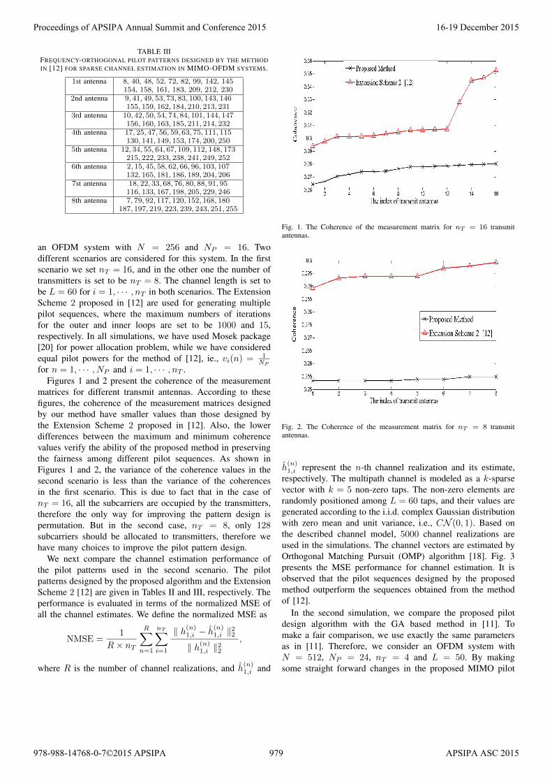
TABLE IIIFREQUENCY-ORTHOGONAL PILOT PATTERNS DESIGNED BY THE METHODIN [12] FOR SPARSE CHANNEL ESTIMATION IN MIMO-OFDM SYSTEMS.
1st antenna 8, 40, 48, 52, 72, 82, 99, 142, 145154, 158, 161, 183, 209, 212, 230
2nd antenna 9, 41, 49, 53, 73, 83, 100, 143, 146155, 159, 162, 184, 210, 213, 231
3rd antenna 10, 42, 50, 54, 74, 84, 101, 144, 147156, 160, 163, 185, 211, 214, 232
4th antenna 17, 25, 47, 56, 59, 63, 75, 111, 115130, 141, 149, 153, 174, 200, 250
5th antenna 12, 34, 55, 64, 67, 109, 112, 148, 173215, 222, 233, 238, 241, 249, 252
6th antenna 2, 15, 45, 58, 62, 66, 96, 103, 107132, 165, 181, 186, 189, 204, 206
7st antenna 18, 22, 33, 68, 76, 80, 88, 91, 95116, 133, 167, 198, 205, 229, 246
8th antenna 7, 79, 92, 117, 120, 152, 168, 180187, 197, 219, 223, 239, 243, 251, 255
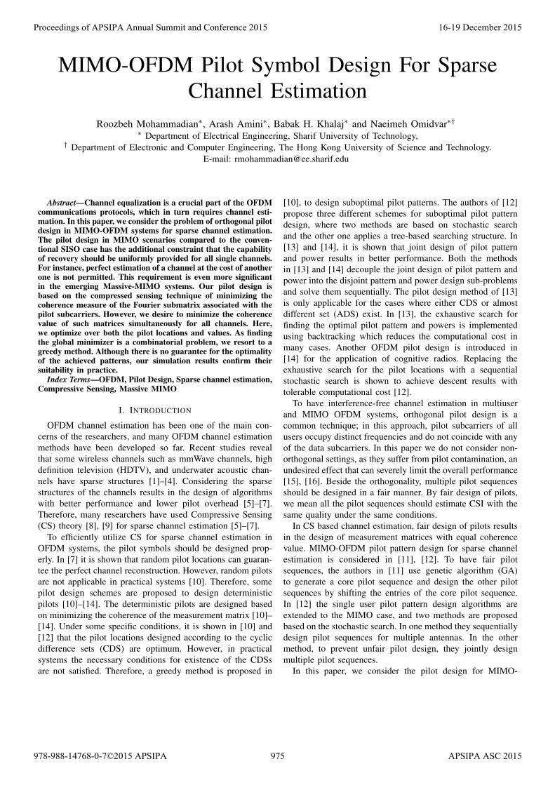
an OFDM system with N = 256 and NP = 16. Twodifferent scenarios are considered for this system. In the firstscenario we set nT = 16, and in the other one the number oftransmitters is set to be nT = 8. The channel length is set tobe L = 60 for i = 1, · · · , nT in both scenarios. The ExtensionScheme 2 proposed in [12] are used for generating multiplepilot sequences, where the maximum numbers of iterationsfor the outer and inner loops are set to be 1000 and 15,respectively. In all simulations, we have used Mosek package[20] for power allocation problem, while we have consideredequal pilot powers for the method of [12], ie., vi(n) = 1
NPfor n = 1, · · · , NP and i = 1, · · · , nT .
Figures 1 and 2 present the coherence of the measurementmatrices for different transmit antennas. According to thesefigures, the coherence of the measurement matrices designedby our method have smaller values than those designed bythe Extension Scheme 2 proposed in [12]. Also, the lowerdifferences between the maximum and minimum coherencevalues verify the ability of the proposed method in preservingthe fairness among different pilot sequences. As shown inFigures 1 and 2, the variance of the coherence values in thesecond scenario is less than the variance of the coherencesin the first scenario. This is due to fact that in the case ofnT = 16, all the subcarriers are occupied by the transmitters,therefore the only way for improving the pattern design ispermutation. But in the second case, nT = 8, only 128subcarriers should be allocated to transmitters, therefore wehave many choices to improve the pilot pattern design.
We next compare the channel estimation performance ofthe pilot patterns used in the second scenario. The pilotpatterns designed by the proposed algorithm and the ExtensionScheme 2 [12] are given in Tables II and III, respectively. Theperformance is evaluated in terms of the normalized MSE ofall the channel estimates. We define the normalized MSE as
NMSE =1
R× nT
R∑n=1
nT∑i=1
‖ h(n)1,i − h
(n)1,i ‖22
‖ h(n)1,i ‖22
,
where R is the number of channel realizations, and h(n)1,i and
Fig. 1. The Coherence of the measurement matrix for nT = 16 transmitantennas.
Fig. 2. The Coherence of the measurement matrix for nT = 8 transmitantennas.
h(n)1,i represent the n-th channel realization and its estimate,
respectively. The multipath channel is modeled as a k-sparsevector with k = 5 non-zero taps. The non-zero elements arerandomly positioned among L = 60 taps, and their values aregenerated according to the i.i.d. complex Gaussian distributionwith zero mean and unit variance, i.e., CN (0, 1). Based onthe described channel model, 5000 channel realizations areused in the simulations. The channel vectors are estimated byOrthogonal Matching Pursuit (OMP) algorithm [18]. Fig. 3presents the MSE performance for channel estimation. It isobserved that the pilot sequences designed by the proposedmethod outperform the sequences obtained from the methodof [12].
In the second simulation, we compare the proposed pilotdesign algorithm with the GA based method in [11]. Tomake a fair comparison, we use exactly the same parametersas in [11]. Therefore, we consider an OFDM system withN = 512, NP = 24, nT = 4 and L = 50. By makingsome straight forward changes in the proposed MIMO pilot
Proceedings of APSIPA Annual Summit and Conference 2015 16-19 December 2015
978-988-14768-0-7©2015 APSIPA 979 APSIPA ASC 2015

Fig. 3. NMSE performance comparisons of channel estimation for differentpilot design schemes.
TABLE IVCOHERENCE OF THE MEASUREMENT MATRIX USING THE SHIFTING
MECHANISM.
Scheme Coherence valueProposed Method 0.1763
GA based Method [11] 0.2186
design algorithm, we generate a core pilot sequence. Then,to determine the pilot patterns of other transmitters we useshifting mechanism proposed in [11]. The resulted coherencevalues of different pilot design schemes are summarized inTable IV. According to results given in Table IV, using theproposed method we achieve exactly fair pilot sequences withcoherence of 0.1763, which is approximately 0.04 smallerthan the coherence achieved from the GA algorithm of [11].
VI. CONCLUSIONS
In this paper, the pilot design for sparse channel estimationin MIMO-OFDM systems is investigated. Based onminimizing the coherence of the measurement matrix,we have proposed a greedy algorithm to design orthogonalpilot sequences. To generate pilot sequences with lowercoherence values, we consider the joint optimization of pilotpatterns and powers. In order to preserve the fairness betweenmultiple pilot sequences, we have designed the algorithmbased on joint optimization of multiple pilot sequences andminimizing the maximum coherence. Simulation resultsverify that the proposed method outperforms the others interms of designing sensing matrices with smaller coherenceand estimating channels with lower NMSE.
REFERENCES
[1] S. Rangan, T. S. Rappaport, and E. Erkip, “Millimeter-wave cellularwireless networks: Potentials and challenges,” in Proc. of the IEEE,vol. 102, pp. 366-385, March 2014.
[2] T. Rappaport, F. Gutierrez, E. Ben-Dor, J. Murdock, Y. Qiao, and J. Tamir,“Broadband millimeter-wave propagation measurements and models us-ing adaptive-beam antennas for outdoor urban cellular communications,”IEEE Trans. on Antennas and Propagation, vol. 61, no. 4, pp. 1850-1859,April 2013.
[3] W. F. Schreiber, “Advanced television system for terrestrial broadcasting:Some problems and some proposed solutions,” in Proc. of the IEEE,vol. 83, pp. 958-981, June 1995.
[4] C. R. Berger, S. Zhou, J. C. Preisig, and P. Willett, “Sparse channelestimation for multicarrier underwater acoustic communication: fromsubspace methods to compressed sensing,” IEEE Trans. Signal Process.,vol. 58, no. 3, pp. 1708-1721, March 2010.
[5] W. U. Bajwa, J. Haupt, A. M. Sayeed, and R. Nowak, “Compressed chan-nel sensing: A new approach to estimating sparse multipath channels,”Proceedings of the IEEE, vol. 98, no. 6, pp. 1058-1076, June 2010.
[6] G. Taubock, and F. Hlawatsch, D. Eiwen, and H. Rauhut, “Compressiveestimation of doubly selective channels in multicarrier systems: leakageeffects and sparsity-enhancing processing,” IEEE J. Sel. Top. SignalProcess., vol. 4, no. 2, pp. 255-271, April 2010.
[7] G. Taubock, and F. Hlawatsch, “A compressed sensing technique forOFDM channel estimation in mobile environments: Exploiting channelsparsity for reducing pilots,” in Proc. IEEE Int. Conf. Acoust. SpeechSignal Process., pp. 2885-2888, April 2008.
[8] E. J. Candes, J. K. Romberg, and T. Tao, “Stable signal recovery fromincomplete and inaccurate measurements,” Comm. Pure Appl. Math.,vol. 59, no. 8, pp. 1207-1223, 2006.
[9] D. Donoho, “Compressed Sensing,” IEEE Trans. Inform. Theory, vol. 52,no. 4, pp. 1289-1306, April 2006.
[10] P. Pakrooh, A. Amini, and F. Marvasti, “OFDM pilot allocation forsparse channel estimation,” in EURASIP J. Adv. Signal Process., 2012,vol. 59, 10.1186/1687-6180-2012-59.
[11] X. He, R. Song, and W.-P. Zhu, “Pilot allocation for sparse channelestimation in MIMO-OFDM systems,” IEEE Trans. Circuits Syst. II Exp.Briefs, vol. 60, no. 9, pp. 612-616, Sep. 2013.
[12] C. Qi, G. Yue, L. Wu, Y. Huang, and A. Nallanathan, “Pilot designschemes for sparse channel estimation in OFDM systems,” IEEE Trans.Veh. Tech., vol. 64, no. 4, pp. 1493-1505, April 2015.
[13] M. Khosravi, and S. Mashhadi, “Joint pilot power and pattern design forcompressive OFDM channel estimation,” IEEE Commun. Lett., vol. 19,No. 1, pp. 50-53, Jan. 2015.
[14] C. Qi, L. Wu, Y. Huang, and A. Nallanathan, “Joint Design of PilotPower and Pilot Pattern for Sparse Cognitive Radio Systems,” DOI10.1109/TVT.2014.2374692, IEEE Transactions on Vehicular Technology
[15] E. G. Larsson, O. Edfors, F. Tufvesson, and T. L. Marzetta, “MassiveMIMO for next generation wireless systems” IEEE Commun. Magazine,February 2014.
[16] T. L. Marzetta, “Noncooperative cellular wireless with unlimited num-bers of base station antennas,” IEEE Trans. Wireless Comm., vol. 9,no. 11, pp. 3590-3600 , November 2010.
[17] Z. Ben-Haim, Y. C. Eldar, M. Elad, “Coherence-based near oracleperformance guarantees,” IEEE Trans. Wireless Comm., vol. 6, no. 5,pp. 1743-1763, 2007.
[18] J. A. Tropp, “Greed is good: algorithmic results for sparse approxi-mation,” IEEE Trans. Inform. Theory, vol. 50, no. 10, pp. 2231-2242,October 2004.
[19] M. Grant and S. Boyd, “CVX: Matlab software for disciplined convexprogramming,” version 2.0 beta. http://cvxr.com/cvx, September 2013.
[20] MOSEK ApS, “The MOSEK optimization toolboxfor MATLAB manual.” Version 7.1 (Revision 28),http://docs.mosek.com/7.1/toolbox/index.html, 2015.
Proceedings of APSIPA Annual Summit and Conference 2015 16-19 December 2015
978-988-14768-0-7©2015 APSIPA 980 APSIPA ASC 2015