mimo hinf control for power source coordination ... · mimo hinf control for power source...
TRANSCRIPT

MIMO Hinf control for power source coordination -
application to energy management systems of electric
vehicles
Waleed Nwesaty, Antoneta Iuliana Bratcu, Olivier Sename
To cite this version:
Waleed Nwesaty, Antoneta Iuliana Bratcu, Olivier Sename. MIMO Hinf control for powersource coordination - application to energy management systems of electric vehicles. 19th IFACWorld Congress (IFAC WC 2014), Aug 2014, Le Cap, South Africa. IFAC 2014 proceedings, 7p., 2014. <hal-00968393>
HAL Id: hal-00968393
https://hal.archives-ouvertes.fr/hal-00968393
Submitted on 2 Aug 2016
HAL is a multi-disciplinary open accessarchive for the deposit and dissemination of sci-entific research documents, whether they are pub-lished or not. The documents may come fromteaching and research institutions in France orabroad, or from public or private research centers.
L’archive ouverte pluridisciplinaire HAL, estdestinee au depot et a la diffusion de documentsscientifiques de niveau recherche, publies ou non,emanant des etablissements d’enseignement et derecherche francais ou etrangers, des laboratoirespublics ou prives.
MIMO H∞ control for power sourcecoordination – application to energy
management systems of electric vehicles
W. Nwesaty, A. I. Bratcu, O. Sename
Grenoble Institute of Technology, GIPSA-lab, Control SystemsDepartment, 38402, Saint-Martin d’Heres, France. e-mail:
(waleed.nwesaty, antoneta.bratcu, olivier.sename)@gipsa-lab.grenoble-inp.fr
Abstract: This paper deals with a control strategy used for designing energy managementsystems within average-power electric vehicles. The power supply system is composed of threesources, namely a fuel cell, a battery and an ultracapacitor – specialized within distinct frequencyranges – which must be coordinated in order to satisfy power demand of the vehicle’s electricalmotor. The three sources with their associated DC-DC converters are paralleled on a commonDC-bus supplying the electrical motor. The DC-bus is required to be constant regardless ofthe load state thanks to the fuel cell which provides the mean power and to the other twosources – auxiliary sources – which are controlled to supply the high-frequency variations ofpower demand according to an H∞ optimization strategy. MATLABR©/SimulinkR© numericalsimulation is used to validate the proposed strategy under real driving cycle condition proposedby IFSTTAR (Institut Francais des Sciences et Technologies des Transports, de l’Amenagementet des Reseaux), and this approach is assessed against another optimal strategy that uses LQRas control design.
Keywords: H∞ control, Optimal power flow, Electric vehicles, Energy management systems,Multi sources power supply system.
1. INTRODUCTION
Electric vehicles are the key to solve problems concern-ing pollution issue due to their zero CO2 and noise
emission; moreover, they are relatively cheap compared tothe growing petrol prices (Florescu et al., 2012a). Manyresearch works are performed in this field to find cleanpower sources as fuel cells or photovoltaic panels, and alsoto develop on-board energy management systems in orderto maximize efficiency of energy consumption (Li and Liu,2009). Alternately, auxiliary power sources – like batteriesand ultracapacitors – are used not only to energize thedifferent electrical peripherals in the vehicle, but also tocollect kinetic energy whenever the vehicle slows downor stops which also leads to maximize the efficiency ofthe power system. On the other hand, several studieshave reported that the use of the fuel cell for automotiveapplications is limited by the slow transient and the oxygenstarvation phenomena. In addition, the large current rippleallowed to the fuel cell and the battery may shorten theirlifetime (Ozatay et al. (2004); Iannuzzi (2007)). All theseconstraints make it more challenging to design an efficientenergy-management system and a power-sharing methodinvolving fuel cells, batteries and ultracapacitors. Thereare two terms to describe a power source with respectto its power supply ability (Thounthong et al., 2009) asdescribed here after:
• source with high energy density which is able toprovide power during a long period of time with
slow dynamic characteristics; fuel cells and batteriesbelong to this class of sources, and
• source with high power density which is able to pro-vide high power for a short period of time with highdynamic characteristics; ultracapacitors are typicalexamples of such type of sources.
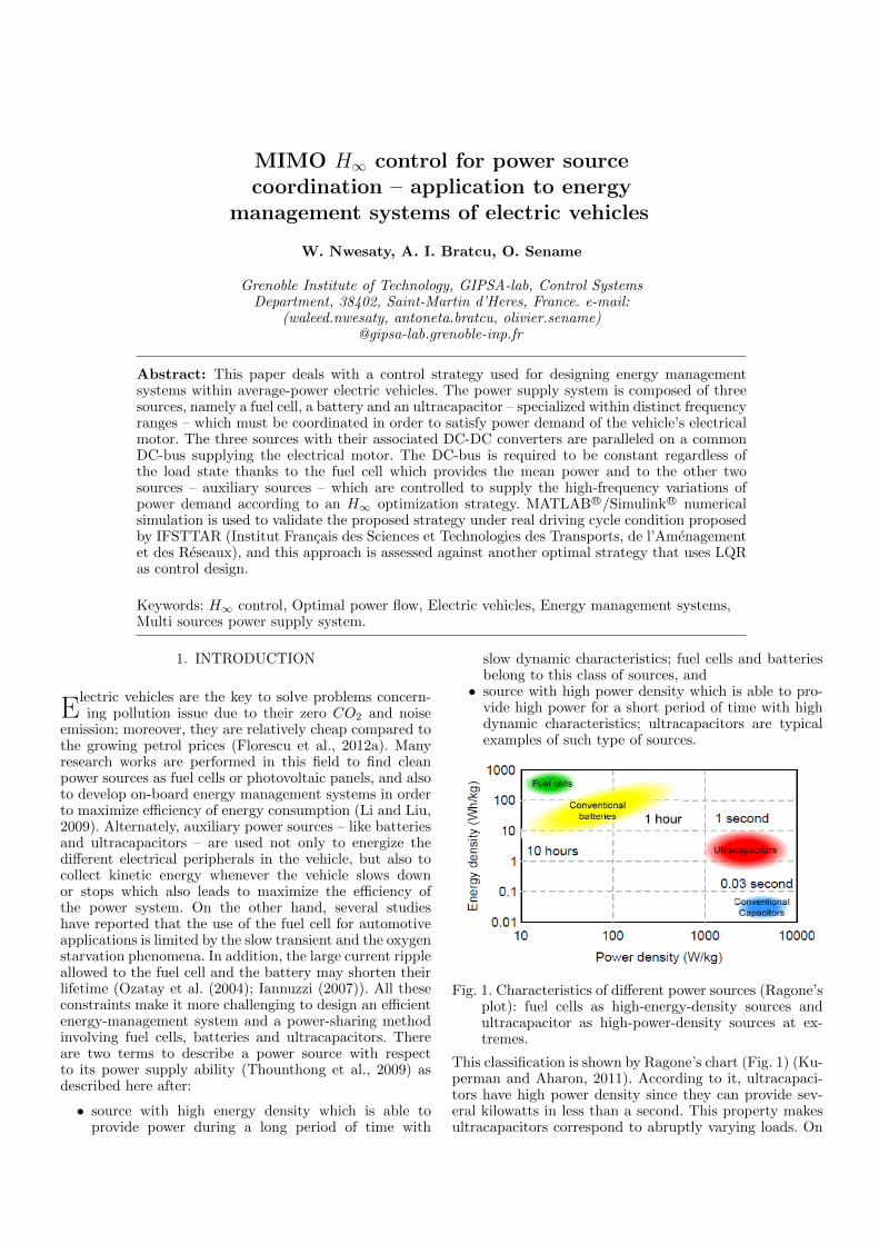
Fig. 1. Characteristics of different power sources (Ragone’splot): fuel cells as high-energy-density sources andultracapacitor as high-power-density sources at ex-tremes.
This classification is shown by Ragone’s chart (Fig. 1) (Ku-perman and Aharon, 2011). According to it, ultracapaci-tors have high power density since they can provide sev-eral kilowatts in less than a second. This property makesultracapacitors correspond to abruptly varying loads. On

the contrary, fuel cells can provide power for several hourswhen load is in steady state or for charging other auxiliarysources like battery and ultracapacitor. Thus, fuel cells arewell suited to provide energy when power demand variesvery slowly.
This paper deals with power flow coordination betweenthree power sources – fuel cell, battery and ultracapacitor– within an electrical vehicle, each one of the sourcesis controlled by means of a DC-DC converter. Sourcesare connected in parallel to the load (consisting of anelectrical motor with its associated converter) througha DC-bus (Fig. 2). The fuel cell is considered as themain source of power and connected to a 1-quadrantboost converter which only allows unidirectional powerflow, whereas the battery and the ultracapacitor representauxiliary sources able to cover variations of power demandthat are placed in relatively high frequency. In this way,the lifetime of the main source is extended by restrictingits utilization at low frequency. Each auxiliary source isconnected to a 2-quadrant boost converter which allowscharging/discharging. The full electrical schematic of thesystem is shown in Fig. 2. The element values are providedin the Appendix A.
The control objective is to regulate the DC-bus voltage at150 V with a tracking error of ±10 V in the presence ofload power perturbation. This is achieved thanks to powerflow coordination between sources with respect to theirfrequency characteristics, which in consequence leads toimprove utilization and extend life of both fuel cell andbattery.
In the literature, most of the studied systems consist oftwo power sources such as a fuel cell as main source andan auxiliary source like a battery or an ultracapacitor (Yuet al., 2011). In general, each source is treated as a cur-rent source whose current should be controlled accordingto a reference. The current reference is generated usingdifferent methods such as PID-controller-based strategies(Wong et al., 2011), fuzzy logic control (Fadel and Zhou,2011), or strategies based on high/low-pass filtering of theglobal current reference in order to achieve frequency sepa-ration between the power sources (Florescu et al. (2012b);Florescu et al. (2012c)). LQG control can also be used togenerate the current references (Florescu et al., 2012a).
This paper proposes an application of H∞ control tocoordinate efficiently auxiliary power sources –battery andultracapacitor–. The same problem has recently been ap-proached by means of Linear Parameter Varying (LPV)control (Nwesaty et al., 2014). Different from this paper,given that the global system exhibits bilinear dynamics,current references are here generated by H∞ control syn-thesis which guarantees the global stability of the closed-loop system and specifies the frequency domain use of eachsource by means of the associated weighting functions. Thecurrent references generated by this algorithm cover thehigh-frequency variations of load current, while the fuelcell is supposed to supply the steady-state load current–mean value–. A PI controller is used to generate therequired fuel cell’s current reference by regulating the DC-bus voltage within a cascade control structure. Note thateach auxiliary source’s current reference is generated intwo stages, as follows: one stage is used to regulate the
DCC
DCR
Load
DCV
Luc
Lbat
Lfc
Fuel cell
model
Battery
model
Ultra
cap.
model
1-quadrant boost converter
2-
DC-bus 150 V
+ Load
quadrant converter
2- quadrant converter
Fig. 2. System block and electrical representation.
state of charge (SOC) with a slow dynamic, thus providingthe low-frequency component of current reference to thelow-level current control loop –which has fast dynamic–.The other stage provides the high-frequency componentof current reference, which is computed according to theproposed H∞ control strategy (Fig. 3).
2. MODELING
The considered system consists of three power sourcesconnected in parallel via DC-DC boost converters andfinally attached to a single DC-bus which supplies power tothe vehicle motor. The full electrical scheme of the systemis represented in Fig. 2. The DC-bus voltage is supposed tobe regulated by using a PI controller which generates thecurrent reference of the main source –fuel cell–, whereasthe auxiliary sources handle variations in power demandcaused by the motor by using an H∞ controller. The DC-DC converters are represented by their respective averagedmodels. Energy conservation laws lead to a nonlinearmodel and they are expressed by the following dynamicequations:
Ifc =1
Lfc[Vfc − Vdc(1− αfc)] (1)
Iuc =1
Luc[Vuc − Vdcαuc] (2)
Ibat =1
Lbat[Vbat − Vdcαbat] (3)
Vdc =1
CDC[−1
RDCVdc − ILoad + Ifc(1− αfc)
+Ibatαbat + Iucαuc] (4)
I∗fc = Kpe+Ki
∫e (5)

Fig. 3. Global control block diagram.
where Ifc, Ibat, and Iuc are currents of fuel cell, battery,and ultracapacitor, respectively. Vfc, Vbat, and Vuc arethe respective source voltages. αfc, αbat, and αuc are therespective converter duty ratios. CDC and RDC are theDC-bus capacitor and resistance, respectively. Vdc is theDC-bus voltage, ILoad is the load current. e is the DC-bus voltage tracking error. Ifc
∗ is the fuel cell currentreference. Kp and Ki are controller proportional andintegral gain, respectively.
Equations (4) and (5) correspond to the DC-bus voltageclosed-loop second-order dynamics. We are interested inits linearized model around different operating pointsdefined by the DC-bus voltage setpoint, Vdc
∗=150 V,and the different mean values of fuel cell current whichcorresponds to mean load current. By computing thenormalized variations of the variables in (4) and (5) weobtain:
˙∆V dc =1
CDC .V ∗dc[−V ∗dcRDC
.∆V dc
+ (1− αfc).I∗fc.∆Ifc −∆ILoad
+ αbat.∆Ibat + αuc.∆Iuc]
˙∆Ifc = Ki.V∗dc.∆V dc −Kp.
˙∆V dc
(6)
where notation ∆x = x−xx
denotes normalized variation
in the desired operating point. x is the average value ofx.The load current ILoad acts as a disturbance on system(6). The basic idea of the proposed control strategy isto consider variations of currents of the two auxiliarysources, ∆Ibat and ∆Iuc, as control inputs for system (6),which should result from requiring that disturbance to berejected, as Fig. 3 shows. In this paper, ∆Ibat and ∆Iuc aregenerated by optimal control design, where controllers ineach operating point of the working load interval comply
with the requirement of separating sources in frequency.Thus, these controllers result from an H∞ control design.
In the sequel, we will consider I∗fc = Ifc because the fuelcell current control loop exhibits a dynamic faster thanthat of the PI-controller-based loop generating I∗fc(see Fig.
3).
3. CONTROL DESIGN
This section details the control approach used to coor-dinate the on-board power sources. The control objec-tive is to handle the variation of power demand by theauxiliary sources, meanwhile ensuring the DC-bus voltageregulation at 150 V within an accepted error of ±10V .For this purpose an H∞ controller is synthesized to guar-antee frequency separation between the auxiliary sources(battery and ultracapacitor) and to keep the main source(fuel cell) supplying the mean power to the load. Fig. 3shows the global control diagram of the system. All currentcontrol loops have fast closed-loop dynamics comparedto the other control loops; therefore, they are groupedtogether. Similarly, state of charge (SOC) control loopsare characterized by slow closed-loop dynamics and thenthey are also grouped together. Design of these loops isnot detailed in this work (Astrom and Hagglund, 1995).Measured values of voltages and currents are used asfeedback variables for control purpose and supposed to beavailable in real time.
3.1 Current control loops
Current of each source must be controlled and pre-vented from exceeding admissible limits. To this end,PI-controller-based control loops are built around plant

transfer functions given by (1), (2) and (3), respectively.References of these control loops are provided by theouter loops, i.e., by the DC-bus voltage loop for fuel cellcurrent, by the battery SOC loop for battery current, byultracapacitor SOC loop for ultracapacitor current and bythe H∞ control loop which generates the variation of theauxiliary sources’ currents (see block control diagram inFig. 3). PI controllers are designed according to imposedperformance in terms of bandwidth and damping.
3.2 DC-bus voltage control loop
The fuel cell as main source is in charge with regulationof DC-bus voltage at reference value V ∗dc=150 V. A PIcontroller is used to this end – tuned analogously with cur-rent PI controllers – while the auxiliary sources (batteryand ultracapacitor) are required to contribute for reducingvariations of DC-bus voltage and fuel cell current.
3.3 State of charge control loops
States of charge of auxiliary sources are maintained withinimposed limits – 0% and 100% of full charge – by gen-erating the averaged components of the correspondingcurrent references, I0
bat and I0uc (Fig. 3). Two PI controllers
ensure that battery and ultracapacitor be ready to use.Dynamics of these loops must be imposed slower than thatof DC-bus voltage loop. Battery SOC reference is set at100% – representing full charge – while ultracapacitor SOCreference is chosen 50% to preserve source capability toabsorb/provide high currents in response to load currentvariation.
3.4 H∞ control design
Equation (6) shows the second-order dynamics corre-sponding to the DC-bus voltage closed-loop, this can alsobe represented as:
x = A · x+B1 · ω +B2 · uy = [1 0]x
(7)
with matrices
A =
−1
CDC ·RDC
(1− αfc) · I∗fcCDC · V ∗dc
(Kp · V ∗dc
CDC ·RDC .I∗fc− Ki · V ∗dc
I∗fc) − (1− αfc) ·Kp
CDC
B1 =
−1
CDC · V ∗dcKp
CDC · I∗fc
B2 =
αbat
CDC · V ∗dcαuc
CDC · V ∗dc− Kpαbat
CDC · I∗fc− Kpαuc
CDC · I∗fc
where state vector Sy(s) = (I + G(s)K(s))−1 x =
[∆V dc ∆Ifc]T is composed of DC-bus voltage and fuel
cell current normalized variations around the chosen op-erating point, respectively, ω = ∆ILoad is load currentvariation, which represents the disturbance input, u =[∆Ibat ∆Iuc]
T is the control input vector composed ofvariations of battery and ultracapacitor current, respec-tively. The objective is to minimize the variations of DC-bus voltage and also the variations of the fuel cell cur-rent by varying battery and ultracapacitor currents inthe desired frequency ranges. The control formulation is
considered in the H∞ framework as represented in Fig.4. The generalized plant has three inputs, namely, theload –electrical motor– current, which is considered asdisturbance input, and variations of auxiliary sources’currents, which are the control inputs. Plant outputs arethe DC-bus voltage variation, which should be minimizedto be within ±10V around setpoint, and the variationof the fuel cell current. The selection of weighting func-tions is the key to confine the contribution of each sourcewithin a desired frequency range. The DC-bus voltagetracking error is bounded by using a first-order weightingfunction(We∆Vdc
). Fuel cell is kept supplying power in thelow-frequency range, and the variation of its current isbounded by a first-order weighting function (We∆Ifc
) aswell. The battery and ultracapacitor roles are boundedby a low-pass, Wu∆Ibat
, and a band-pass weighting func-tion, Wu∆Iuc
, respectively, that correspond to fourth-order filters, as shown in Fig. 5. These relatively high-order filters have been chosen to ensure more distinct fre-quency separation. The bandwidth of each source is chosenas ωn∆Ifc
=0.05 rad/s, ωn∆Ibat=0.1 rad/s and ωn∆Iuc
=1
rad/s. according to the desired performance and sourcetypes (e.g., maximum admissible current gradient).
Several operating points are taken into account to linearizethe system; these points are determined by the fuel cellcurrent averaged value I∗fc and DC-bus voltage setpoint
V ∗dc=150 V. An H∞ controller Ki =
[Ai Bi
Ci Di
]is synthe-
sized for each operating point. Depending on the loadcurrent actual value, a first-order interpolation is madewhich involves its nearest two neighbor operating points.The optimization problem is represented by a set of linearmatrix inequalities and solved using Yalmip/Sedumi solver(Poussot-Vassal (2008); Apkarian et al. (1995)). Existenceof an unique Lyapunov function has also been verified,which guarantees overall closed-loop stability.
4. SIMULATION RESULTS
MATLABR©/SimulinkR© numerical simulation is performedto prove the effectiveness of the proposed power sourcecoordination method. A comparison with an LQR– Lin-ear Quadratic Regulator–control-based solution is pro-vided. Nonlinear electrical models (1), (2), (3) and (4)are used for simulation purpose. A driving cycle with richhigh-frequency content proposed by IFSTTAR (InstitutFrancais des Sciences et Technologies des Transports, del’Amenagement et des Reseaux) is used to apply variable
Fig. 4. H∞ Robust control design block diagram.

Fig. 5. Weighting function used to confine frequencyranges of battery and ultracapacitor current varia-tions within imposed frequency domains.
power load demand (Fig. 6). This profile represents vari-ous driving conditions including acceleration, deceleration,steady speed and full brake and allows assessing perfor-mance of DC-bus voltage regulation and the way how thethree sources are coordinated to provide the needed power.
Fig. 6. IFSTTAR load current profile used in simulation.
4.1 LQR optimization method
We used another optimal control method, namely LQRfor a comparative evaluation of performance of the H∞approach. Like the proposed approach, the LQR opti-mization method is used to synthesize a controller Ki ateach operating point for the linearized system in (7), then,depending on the load current actual value, a first-orderinterpolation is made between its two neighbor operatingpoints. This approach is also used to generate currentreferences for the auxiliary power sources in the system,battery and ultracapacitor, according to the method pro-posed in (Florescu et al., 2012a), and aiming at minimizing
the criterion I = limT→∞1T
∫ T
0[∆I2
fc + βI2bat + λI2
uc]dt,where β and λ are the weighting factors that adjust thetrade-off between fuel cell current variations and variationsof auxiliary sources’ currents. Fig. 7 shows that fuel cell
current is smoothed while the DC-bus voltage is regulatedto the reference value (150 V)(Fig. 8). The amplitudevariation of battery current is reduced in detriment ofultracapacitor current variation. The drawback is that thetwo auxiliary sources cannot be separated in frequencydomain; only amplitudes of their variations are different.To show that, further analysis of sources’ currents is per-formed by computing the power spectral density (PSD)of each one. Since the amount of power delivered by eachsource is different, normalization of these densities is donewith respect to the maximum power of each source in orderto be comparable. The percentage of power supplied byeach source and the corresponding frequency ranges areshown in Fig. 9. The H∞ method adds flexibility to thecontrol design because it allows frequency separation bymeans of appropriate choice of weighting functions.
Fig. 7. Sources’ currents according to LQR approach.
Fig. 8. DC-bus voltage well regulated around 150 ±10Vaccording to LQR approach.
4.2 H∞ optimization method
One can see that the system is able to provide thedemanded power and the DC-bus voltage shown in Fig. 10is well regulated to reference 150 V within the allowed error±10V . Fig. 11 shows how currents of different sources areprovided to the system, with fuel cell supplying the averagecurrent and ultracapacitor handling the peak variations,while battery provides the midrange-frequency current.Normalized PSD also is calculated for each power source(Fig. 12). According to it, the frequency separation ofthe three sources corresponds to the chosen weightingfunctions.

Fig. 9. Normalized power spectrum of the sources’ currentscorresponding to IFSTTAR load current profile byusing LQR approach.
Fig. 10. DC-bus voltage well regulated around 150 ±10Vaccording to H∞ approach.
Fig. 11. Sources’ currents according to H∞ approach.
5. CONCLUSION
This paper has considered design of energy managementstrategy with guaranteed performance to be applied onboard of an electric vehicle. This strategy is used to coordi-nate three different kinds of power sources represented bya fuel cell as main power source and two auxiliary sources,namely a battery and an ultracapacitor. This means thatthe fuel cell is managed to provide the mean power (low-frequency variations), whereas the battery and the ul-tracapacitor supply power in relatively high frequency.The ultracapacitor provides/absorbs the high-frequencycontent of load power in order to protect the other sourcesfrom sudden variation in power, and that helps to extend
Fig. 12. Normalized power spectrum of the sources’ cur-rents corresponding to IFSTTAR load current profileby using H∞ approach.
the life of both fuel cell and battery. The battery’s role isplaced in between the other two sources according to thefrequency separation in the supplied load power, besides itsrole to energize the different peripherals within the vehicle.
Some test on representative driving cycle show that theproposed strategy is effective regarding the regulationof the DC-bus voltage and supplying the load powerwith respect to frequency separation between sources, inparticular compared with an LQR optimal control which isnot able to separate the frequency-domain use of auxiliarypower sources’ currents.
For future work, different power supply configurations canbe analysed. For example, fuel cell could only be requiredto recharge the other sources at its maximum efficiencyoperating point, for sake of increasing the global powerefficiency of the system. To this end, switching controlcould be applied to switch between two control laws takinginto consideration two different system models, namelyincluding/excluding the fuel cell.
Note also that the proposed power sharing strategy caneasily be generalized to any kind of on-board energymanagement systems, potentially containing any numberof power sources. Experimental validation should also beenvisaged.
Appendix A.
Ultracapacitor converter: Luc=0.5 mH; Battery converter:Lbat=0.5 mH; Fuel cell converter: Lfc=6 µH; DC-bus:VDC=150 V, CDC=22 mF, RDC=100 kΩ. Vdc PI con-troller: Kp = 71 · 10−3,Ki =4.41.
REFERENCES
P. Apkarian, P. Gahinet, and G. Becker. Self-scheduledH∞ control of linear parameter-varying systems: a de-sign example. Automatica, 31(9):1251–1261, 1995.
A. Fadel and B. Zhou. An experimental and analyticalcomparison study of power management methodologiesof fuel cell–battery hybrid vehicles. Journal of PowerSources, 196(6):3271 – 3279, 2011.
A. Florescu, A.I. Bratcu, I. Munteanu, and S. Bacha.Energy management system within electric vehicles us-ing ultracapacitors: An LQG-optimal-control-based so-
lution. In 15th IFAC Workshop on Control Applicationsof Optimization, Rimini, Italy, 2012a.
A. Florescu, I. Munteanu, A.I. Bratcu, and S. Bacha.Frequency-sepation-based energy management controlstrategy of power flows within electric vehicles usingultracapacitors. In 38th Annual Conference of the IEEEIndustrial Electronics Society, Montreal, Canada, 2012b.
A. Florescu, I. Munteanu, A.I. Bratcu, and S. Bacha.Results concerning ultracapacitor-based energy man-agement strategy within electric vehicles. In 16th In-ternational Conference on System Theory, Control andComputing, Sinaia, Romania, 2012c.
D. Iannuzzi. Use of supercapacitors, fuel cells and electro-chemical batteries for electric road vehicles: A controlstrategy. In The 33rd Annual Conference of the IEEEIndustrial Electronics Society (IECON), pages 539–544,Taipei, Taiwan, NOV 5-8 2007.
A. Kuperman and I. Aharon. Battery–ultracapacitorhybrids for pulsed current loads: A review. Renewableand Sustainable Energy Reviews, 15(2):981 – 992, 2011.
C. Li and G. Liu. Optimal fuzzy power control and man-agement of fuel cell/battery hybrid vehicles. Journal ofPower Sources, 192(2):525 – 533, 2009.
W. Nwesaty, A.I. Bratcu, and O. Sename. LPV controlfor power source coordination – application to elec-tric vehicles energy energy management systems. In14thEuropean Control Conference (ECC), Strasbourg,France, 2014. (Accepted for presentaion).
E. Ozatay, B. Zile, J. Anstrom, and S. Brennan. Powerdistribution control coordinating ultracapacitors andbatteries for electric vehicles. In American Control Con-ference, pages 4716–4721, Boston Massachusetts,USA,2004.
C. Poussot-Vassal. Multi-variable LPV robust control forvehicle chasis (Commande Robuste LPV Multivariablede Chssis Automobile). PhD thesis, Grenoble INP,Grenoble, France, 2008.
K. J. Astrom and T. Hagglund. PID Controllers: Theory,Design, and Tuning. Instrument Society of America,Research Triangle Park, NC, 2 edition, 1995.
P. Thounthong, S. Ral, and B. Davat. Energy managementof fuel cell/battery/supercapacitor hybrid power sourcefor vehicle applications. Journal of Power Sources, 193(1):376 – 385, 2009.
J. H. Wong, N. R N Idris, M. Anwari, and T. Taufik.A parallel energy-sharing control for fuel cell-battery-ultracapacitor hybrid vehicle. In Energy ConversionCongress and Exposition (ECCE), 2011 IEEE, pages2923–2929, 2011.
Z. Yu, D. Zinger, and A. Bose. An innovative optimalpower allocation strategy for fuel cell, battery andsupercapacitor hybrid electric vehicle. Journal of PowerSources, 196(4):2351 – 2359, 2011.