milltronics msi belt scale - prtsprts.com.au/support/siemens_pdf/msi manual.pdf · conveyor idler...
TRANSCRIPT
Instruction Manual August 2003
MSI BELT SCALEmilltronics

© Siemens Milltronics Process Instruments Inc. 2003
Safety Guidelines
Warning notices must be observed to ensure personal safety as well as that of others, and toprotect the product and the connected equipment. These warning notices are accompaniedby a clarification of the level of caution to be observed.
Qualified Personnel
This device/system may only be set up and operated in conjunction with this manual.Qualified personnel are only authorized to install and operate this equipment in accordancewith established safety practices and standards.
Warning: This product can only function properly and safely if it is correctly transported,stored, installed, set up, operated, and maintained.
Note: Always use product in accordance with specifications.
Copyright Siemens Milltronics ProcessInstruments Inc. 2003. All Rights Reserved
Disclaimer of Liability
This document is available in bound version and inelectronic version. We encourage users topurchase authorized bound manuals, or to viewelectronic versions as designed and authored bySiemens Milltronics Process Instruments Inc.Siemens Milltronics Process Instruments Inc. willnot be responsible for the contents of partial orwhole reproductions of either bound or electronicversions.
While we have verified the contents ofthis manual for agreement with theinstrumentation described, variationsremain possible. Thus we cannotguarantee full agreement. Thecontents of this manual are regularlyreviewed and corrections are includedin subsequent editions. We welcomeall suggestions for improvement.
Technical data subject to change.
MILLTRONICS®is a registered trademark of Siemens Milltronics Process Instruments Inc.
Contact SMPI Technical Publications at the following address:
Technical PublicationsSiemens Milltronics Process Instruments Inc.1954 Technology Drive, P.O. Box 4225Peterborough, Ontario, Canada, K9J 7B1Email: [email protected]
For the library of SMPI instruction manuals, visit our Web site: www.siemens-milltronics.com

1
Table of Contents
Milltronics MSI Belt Scale ................................................................................................ 1Safety Notes .............................................................................................................................................1The Manual ...............................................................................................................................................1
Specifications ...................................................................................................................... 2
Operation .............................................................................................................................. 4
Installation ........................................................................................................................... 5Welding ......................................................................................................................................................5Load Cell Handling ..................................................................................................................................5Installation Precautions .........................................................................................................................5Installation Procedure ............................................................................................................................6
Calibration .......................................................................................................................... 10Test Load .................................................................................................................................................10Zero ...........................................................................................................................................................10Span ..........................................................................................................................................................10Material Test ...........................................................................................................................................11Re-Rating .................................................................................................................................................11
Maintenance ...................................................................................................................... 12Spare Parts ...................................................................................................................................12Maintenance Precautions .........................................................................................................12
Idler Mounting ................................................................................................................... 13Troughed Idler With Channel Spine ................................................................................................13Troughed Idler With Pipe Spine .........................................................................................................14Flat Idler ..................................................................................................................................................15
MSI Wiring ........................................................................................................................ 16
Outline Dimensions .......................................................................................................... 17

2

7ML19985CY01 MSI Belt Scale � INSTRUCTION MANUAL Page 1
Milltronics MSI Belt Scale
Milltronics MSI belt scale is a heavy-duty, high-accuracy single idler scale for process and load-out control.
The MSI belt scale includes:
� one weighbridge with two load cells with leads run in liquid-tite conduit and 150 cm (5 ft.) of interconnecting cable terminated with lugs and conduit fitting
� Siemens Milltronics test weight(s)
The addition of an idler (supplied and installed by the customer) to the weighbridge completes the weighing assembly. The MSI load cells provide an electronic signal, proportional to load, which is fed to the Siemens Milltronics integrator. Thus, weighing is accomplished without interrupting the process and without affecting the process material.
The MSI is an accurate and repeatable force sensor. Its performance is ultimately dependent upon the conveyor system and the quality of the installation and alignment.
Safety NotesSpecial attention must be paid to warnings and notes highlighted from the rest of the text by grey boxes.
The ManualThis instruction manual covers the installation, operation and maintenance of the MSI belt scale.
Please refer to this manual for proper installation and operation of any component of the weighing system to which the MSI is being applied. Adhering to the installation and operating procedures will ensure a quick, trouble-free installation and allow for the maximum accuracy and reliability of your weighing system. Because the MSI belt scale is used in conjunction with an integrator, refer to the integrator�s manual as well.
If you have any questions, comments, or suggestions about the manual contents, please email us at [email protected].
For the complete library of Siemens Milltronics manuals, go to www.siemens-milltronics.com.
Note: The Milltronics MMI belt scale comprises two or more MSI belt scales installed in succession.
WARNING means that failure to observe the necessary precautions can result in death, serious injury, and/or considerable material damage.
Note: means important information about the product or that part of the operating manual.

Page 2 MSI Belt Scale � INSTRUCTION MANUAL 7ML19985CY01
Specifications
Accuracy � ± 0.5% of totalization over 5 to 1 operating range
Load Cell� construction: stainless steel with superior moisture protection
� excitation: 10 V DC nominal , 15 V DC maximum
� output: 2 mV / V excitation at rated load cell capacity
� non-linearity: 0.02% of rated output
� hysteresis: 0.02% of rated output
� non-repeatability: 0.01% of rated output
� capacity: maximum ranges: 50, 100, 250, 500, 750, 1000 lb
� overload: safe 150% of rated capacity ultimate 300% of rated capacity
� temperature: � 40 to 85 °C (� 40 to 185 °F) operating range � 18 to 65 °C (0 to 150 °F) compensated
Belt Width � 18" to 96" in 1� increments to suit CEMA sizes, equivalent to 500 to 2000 mm in metric
sizes� refer to Outline Dimensions on page 17
Belt Speed � up to 4 m/s (800 fpm)
Capacity� up to 5000 t/h (5500 STPH) at maximum belt speed
Conveyor Incline� ± 20° from horizontal, fixed incline � up to ±3 0° with reduced accuracy
Conveyor Idler� flat to 35° � up to 45° with reduced accuracy

7ML19985CY01 MSI Belt Scale � INSTRUCTION MANUAL Page 3
Idler Diameter� 50 to 180 mm (2 to 7")
Idler Spacing � 0.5 to 1.5 m (1.5 to 5.0 ft)
Weight
� see chart, Outline Dimensions on page 17
Hazardous Locations � with the use of approved intrinsically safe barrier strips
Approvals � CSA certified for general purpose
Note: The combination of capacity, speed, and idler spacing must result in a usable conveyor belt loading value.

Page 4 MSI Belt Scale � INSTRUCTION MANUAL 7ML19985CY01
Operation
The MSI weighbridge is designed to react only to the vertical component of the force being applied to it. The MSI consists of a fixed support frame (static) and a live frame (dynamic).
The static frame is the main scale support between the conveyor stringers which in turn supports the dynamic frame including the load cells.
The dynamic frame supports the scale idler and transfers the weight of the material to the load cells.
As the material travels along the conveyor belt, a force is exerted through the suspended idler to the dynamic frame. The dynamic frame is forced down proportionally. The movement in the load cell is sensed by its strain gauges when excited by voltage from the electronic integrator and produces a signal proportional to weight, which is returned to the integrator. The movement in each load cell is limited by the positive stop incorporated in the design of the load cell.
idler bracket test weight bar
force
static beam
dynamic beam
scale mounting bracket
idler clip
idler frame
weighbridge
7ML19985CY01 MSI Belt Scale � INSTRUCTION MANUAL Page 5
Installation
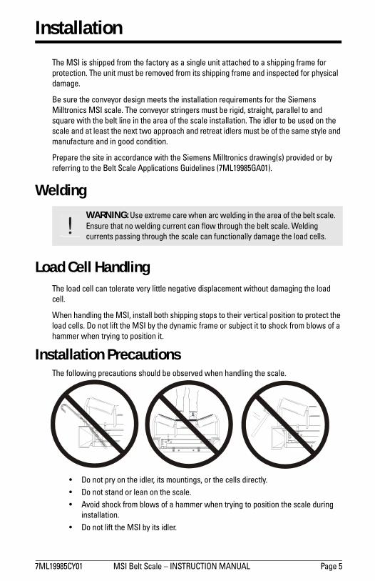
The MSI is shipped from the factory as a single unit attached to a shipping frame for protection. The unit must be removed from its shipping frame and inspected for physical damage.
Be sure the conveyor design meets the installation requirements for the Siemens Milltronics MSI scale. The conveyor stringers must be rigid, straight, parallel to and square with the belt line in the area of the scale installation. The idler to be used on the scale and at least the next two approach and retreat idlers must be of the same style and manufacture and in good condition.
Prepare the site in accordance with the Siemens Milltronics drawing(s) provided or by referring to the Belt Scale Applications Guidelines (7ML19985GA01).
Welding
Load Cell HandlingThe load cell can tolerate very little negative displacement without damaging the load cell.
When handling the MSI, install both shipping stops to their vertical position to protect the load cells. Do not lift the MSI by the dynamic frame or subject it to shock from blows of a hammer when trying to position it.
Installation PrecautionsThe following precautions should be observed when handling the scale.
� Do not pry on the idler, its mountings, or the cells directly.� Do not stand or lean on the scale.� Avoid shock from blows of a hammer when trying to position the scale during
installation.� Do not lift the MSI by its idler.
WARNING: Use extreme care when arc welding in the area of the belt scale. Ensure that no welding current can flow through the belt scale. Welding currents passing through the scale can functionally damage the load cells.

Page 6 MSI Belt Scale � INSTRUCTION MANUAL 7ML19985CY01
Installation Procedure 1. Remove the conveyor idler currently at the point of installation.
2. Remove the idler foot plate and modify the idler frame at both ends of the idler as shown below.
(Occasionally (in less than 5% of applications) the combined effect of the idler rework and the clamping of the scale at its inboard mounting position could result in abnormal idler vibration. When this occurs, gusset plate reinforcements should be welded to the idler at the joints of the horizontal spine and the outer vertical leg member. See Idler Mounting on page 13 for further details.)
12.7 mm(0.5�)
100 mm(4�)
customer�s idler
before after
Typical Troughed Idler For other types, refer to Idler Mounting, page 13.

7ML19985CY01 MSI Belt Scale � INSTRUCTION MANUAL Page 7
3. Insert the MSI in the place of the removed idler. The MSI is designed to use the existing holes in the stringer and should not require further drilling. Install the mounting bolts and nuts but do not tighten. Remove the idler clips from the scale (see diagram below). Refer to Outline Dimensions on page 17, for working dimensions.
4. Position the scale so that it is centered and square to the stringer. Mount the modified idler so that it is centered on the scale using the idler clips. Tighten all mounting hardware.
Position the scale so that the large arrow on the scale mounting brackets is pointing in the direction of belt travel.
Note: Be sure there is sufficient clearance between the return belt, MSI, and its test weight (when used during the calibration procedure).
belt travel location ofremoved idler
MSI belt scale test weight(s)
conveyor stringer(typical)
idler clips

Page 8 MSI Belt Scale � INSTRUCTION MANUAL 7ML19985CY01
5. Release the shipping stops in order to free the weighing mechanism. Loosen screws �A� and rotate both shipping stops inward until the underside slots slide around the screws �B�. Tighten screws �A� to secure in place.
6. The idlers in the weighing area must be properly aligned and leveled by shimming the scale idler, the two approach and the two retreat idlers until they are within ± 0.8 mm (1/32") of each other. Be sure to check that the idlers are centered and squared to the conveyor during the shimming process.
�B� screwsshipping stop shipping stop
�A� screws
C
90°
center of idlers to bein line
belt travel
belt travel idlers must be square to stringersalignment of idlers A2 to R2 to be within ± 0.8 mm (1/32�)
R 2R 1A 1A 2

7ML19985CY01 MSI Belt Scale � INSTRUCTION MANUAL Page 9
7. Precise idler alignment is very important to achieve maximum accuracy of the weighing system. Misaligned idlers will result in unwanted forces being applied on each idler in the weighing area, causing calibration and measurement errors. Use a good quality wire or string to check for alignment. The wire or string must be able to withstand sufficient tension in order to eliminate any sag. Adjust shims so that all rolls of the A2 through to the R2 idlers are in line within ± 0.8 mm (1/32").
Although the accepted tolerance for idler alignment is ± 0.8 mm (1/32"), the scale mounted idler should never be lower than the adjacent idlers. Establishing good idler alignment is the most important part of the installation procedure. Scale accuracy is directly affected by alignment.
R 2
MSI with modified idler
approach idlers
wire or string (for alignment)
R 1
A 1
A 2
retreat idlers
S 1

Page 10 MSI Belt Scale � INSTRUCTION MANUAL 7ML19985CY01
Calibration
After the MSI has been properly installed, calibration of the weighing system must be done in conjunction with the integrator. Refer to the integrator instruction manual for programming and calibration. The calibration is initially done using the supplied test load. Material tests are recommended to achieve maximum accuracy.
Test Load The test load value for your MSI is given on the accompanying data sheet. The value is to be entered into the dedicated programming parameter of the integrator, in kilograms per meter or pounds per foot.
If the actual idler spacing differs from that recorded on the design data sheet, the test load must be recalculated as follows. Failure to do so will cause the design test load value to be in error.
test load = Total weight of all test weights Kg or lb idler spacing m ft
Zero Perform the zero calibration as described in the Calibration section of the integrator manual.
Span The test load used in the calibration procedure is a set of factory sized and supplied test weights (1 to 12).
The test weights are all to be placed on the test weight bar as shown.
Perform the span calibration as described in the Calibration section of the integrator instruction manual.
After the span calibration has been completed, remove the test load and store it.
test weight(s)
MSI
( () )

7ML19985CY01 MSI Belt Scale � INSTRUCTION MANUAL Page 11
Material Test The MSI is guaranteed to be accurate to ± 0.5% when installed on a conveyor in accordance with this manual and meeting the qualifications outlined in Belt Scale Applications Guidelines (7ML19985GA01). This guarantee is based on calibrations performed using the test weights furnished with the scale and as referenced on the previous page.
When the existing conditions are such that the installation of the scale cannot meet the above mentioned requirements for an approved installation it is recommended that material tests be performed. This will enable the user to compare the present scale results to the results of the material tests. The scale is then adjusted or factored so that subsequent scale calibrations with test weights will agree with actual run of material.
Re-Rating To be sure that proper design parameters are maintained, consult your Siemens Milltronics representative for any significant change in rate, speed and /or idler spacing from original design specifications.

Page 12 MSI Belt Scale � INSTRUCTION MANUAL 7ML19985CY01
Maintenance
Keep the weighbridge clean. Accumulation of material between the fixed support frame (static) and the live frame (dynamic) as well as around each load cell could affect the scale accuracy.
Periodically check the alignment of the stringers and idlers in the weighing area.
When a problem arises in the conveyor, it is possible that the scale will be affected. Therefore, periodic conveyor maintenance is important to proper scale operation which should include:
� lubrication of all pulleys and idlers � proper belt tracking and training � proper belt cleaning and scraping � proper take up operation � proper material feeding and spillage � control
You can observe the integrity of the load cells by performing zero and span calibrations. If the zero and span deviations display a continuous unidirectional drift or the system becomes uncalibratable for no apparent mechanical reason, the load cells may be suspect.
Spare PartsThe only spare part recommended for the MSI is the load cell. Refer to the load cell nameplate for the proper size and model number.
Re-balance any load cell that has been replaced. Refer to the Load Cell Balancing Procedure For Four Load Cells in the integrator manual.
Maintenance Precautions� When welding near the scale, do not allow current to pass through the belt scale. � Reset the shipping stops to reduce physical shock to the load cells during
maintenance. � Recalibrate the scale after maintenance and prior to use.

7ML19985CY01 MSI Belt Scale � INSTRUCTION MANUAL Page 13
Idler Mounting
The MSI is usually installed in conveyors employing conventional rigid structure idlers. Within this type of idler, construction will vary depending on the manufacture and the application. The idler depicted in the Installation Procedure section on page 6 uses an angle iron spine. The following images depict alternate idler construction and tips on how they should be modified and installed.
Troughed Idler With Channel Spine
idler modification
idler installation
gusset reinforcement if required. See Installation Procedure, page 6.
12.7 mm(0.5�)
100 mm(4�)
customer�s idler
foot pads weldedto idler spine
before afterbefore
customer bolts(4 places)
idler clip

Page 14 MSI Belt Scale � INSTRUCTION MANUAL 7ML19985CY01
Troughed Idler With Pipe Spine
idler modification
idler installation
gusset reinforcement if required. See Installation Procedure, on page 6.
12.7 mm(0.5�)
100 mm(4�)
customer�s idler
foot pads weldedto idler spine
afterbefore
customer bolts(4 places)
idler clip
welded to idler pipe (be sure idler is square to scale & conveyor frame)

7ML19985CY01 MSI Belt Scale � INSTRUCTION MANUAL Page 15
Flat Idler
idler modification
idler installation
In most applications standard conveyor manufacturers� brackets cannot be used; replacement brackets (as shown) are needed.
12.7 mm(0.5�)
customer�s idler
afterbefore
customer bolts(4 places)
idler clip

Page 16 MSI Belt Scale � INSTRUCTION MANUAL 7ML19985CY01
MSI Wiring
Detail �A�
see Detail �A�
Load Cell�A�
Load Cell�B�
load cell�A�
load cell�B�
customer junction box
RED
�A�
RED
BLK
BLK
+EXC
- EXC
- S I G
A
+ S I G
A
WHT
GRN
WHT
GRN
SHIELD
SH I E LD
SHIELD
+ S I G
B
- S I G
B
�B� �A� �A� �A� �A� �B� �B� �B� �B�
to integrator

7ML19985CY01 MSI Belt Scale � INSTRUCTION MANUAL Page 17
Outline Dimensions
Other widths available. Sizes are from 18 to 96� (457 to 2438 mm) in 1� (25.4 mm) increments. All sizes are nominal.*As shown for North America; 8.5� (216 mm) Europe.
conveyor belt width
mounting scale width A
minimum drop-in width B C D E weight
18� (457 mm)
27� (686 mm)
23.25� (591 mm)
9.5�(241 mm)
5.5�(140 mm)
7�(178 mm)
82 lbs.(37 kg)
20� (508 mm )
29� (737 mm)
25.25� (641 mm)
9.5�(241 mm)
5.5�(140 mm)
7�(178 mm)
85 lbs.(39 kg)
24� (610 mm)
33� (838 mm)
29.25� (743 mm)
9.5�(241 mm)
5.5�(140 mm)
7�(178 mm)
90 lbs.(41 kg)
30� (762 mm)
39� (991 mm)
35.25� (895 mm)
9.5�(241 mm)
5.5�(140 mm)
7�(178 mm)
99 lbs.(45 kg)
36� (914 mm)
45� (1143 mm)
41.25� (1048 mm)
9.5�(241 mm)
5.5�(140 mm)
7�(178 mm)
107 lbs. (49 kg)
42� (1067 mm)
51� (1295 mm)
47.25� (1200 mm)
9.5�(241 mm)
5.5�(140 mm)
7�(178 mm)
116 lbs. (53 kg)
48� (1219 mm)
57� (1448 mm)
53.25� (1353 mm)
9.5�(241 mm)
8�(203 mm)
7�(178 mm)
125 lbs. (57 kg)
54� (1372 mm)
63� (1600 mm)
59.25� (1505 mm)
12�(305 mm)
8�(203 mm)
7�(178 mm)
175 lbs. (79 kg)
60� (1524 mm )
69� (1753 mm)
65.25� (1657 mm)
12�(305 mm)
8�(203 mm)
7�(178 mm)
193 lbs. (88 kg)
66� (1676 mm)
75� (1905 mm)
71.25� (1810 mm)
12�(305 mm)
8�(203 mm)
8�*(203 mm)
229 lbs. (104 kg)
72� (1829 mm)
81� (2057 mm)
77.25� (1962 mm)
12�(305 mm)
8�(203 mm)
8�*(203 mm)
247 lbs. (112 kg)
A
D C
�B�
E

IQ300IX.fm Page 5 Tuesday, October 2, 2001 1:43 PM

IQ300IX.fm Page 5 Tuesday, October 2, 2001 1:43 PM

*7ml19985cy01* Rev. 1.0
www.siemens-milltronics.com
Siemens Milltronics Process Instruments Inc.
1954Technology Drive, P.O. Box 4225
Peterborough, ON, Canada K9J 7B1
Tel: (705) 745-2431 Fax: (705) 741-0466
Email: [email protected]
Siemens Milltronics Process Instruments Inc. 2003
Subject to change without prior notice
Printed in Canada