miller spectrum 1250 plasma cutter
TRANSCRIPT

And Non-CE Models
Processes
Description
Air Plasma Cuttingand Gouging
Air Plasma Cutter
OM-217 168 808K
October 2004
Spectrum 1250�
Visit our website at
www.MillerWelds.com

Miller Electric manufactures a full lineof welders and welding related equipment.For information on other quality Millerproducts, contact your local Miller distributor to receive the latest fullline catalog or individual catalog sheets. To locate your nearestdistributor or service agency call 1-800-4-A-Miller, or visit us atwww.MillerWelds.com on the web.
Thank you and congratulations on choosing Miller. Now you can getthe job done and get it done right. We know you don’t have time to doit any other way.
That’s why when Niels Miller first started building arc welders in 1929,he made sure his products offered long-lasting value and superiorquality. Like you, his customers couldn’t afford anything less. Millerproducts had to be more than the best they could be. They had to be thebest you could buy.
Today, the people that build and sell Miller products continue thetradition. They’re just as committed to providing equipment and servicethat meets the high standards of quality and value established in 1929.
This Owner’s Manual is designed to help you get the most out of yourMiller products. Please take time to read the Safety precautions. Theywill help you protect yourself against potential hazards on the worksite.
We’ve made installation and operation quickand easy. With Miller you can count on yearsof reliable service with proper maintenance.And if for some reason the unit needs repair,there’s a Troubleshooting section that willhelp you figure out what the problem is. Theparts list will then help you to decide theexact part you may need to fix the problem.Warranty and service information for yourparticular model are also provided.
Miller is the first weldingequipment manufacturer inthe U.S.A. to be registered tothe ISO 9001:2000 QualitySystem Standard.
Working as hard as you do− every power source fromMiller is backed by the mosthassle-free warranty in thebusiness.
From Miller to You
Mil_Thank 7/03

TABLE OF CONTENTS
SECTION 1 − SAFETY PRECAUTIONS - READ BEFORE USING 1 . . . . . . . . . . . . . . . . . . . . . . . . . . . . . . . . . . 1-1. Symbol Usage 1 . . . . . . . . . . . . . . . . . . . . . . . . . . . . . . . . . . . . . . . . . . . . . . . . . . . . . . . . . . . . . . . . . . . . . . . . 1-2. Plasma Arc Cutting Hazards 1 . . . . . . . . . . . . . . . . . . . . . . . . . . . . . . . . . . . . . . . . . . . . . . . . . . . . . . . . . . . . 1-3. Additional Symbols For Installation, Operation, And Maintenance 3 . . . . . . . . . . . . . . . . . . . . . . . . . . . . . 1-4. California Proposition 65 Warnings 3 . . . . . . . . . . . . . . . . . . . . . . . . . . . . . . . . . . . . . . . . . . . . . . . . . . . . . . .
1-5. Principal Safety Standards 4 . . . . . . . . . . . . . . . . . . . . . . . . . . . . . . . . . . . . . . . . . . . . . . . . . . . . . . . . . . . . . 1-6. EMF Information 4 . . . . . . . . . . . . . . . . . . . . . . . . . . . . . . . . . . . . . . . . . . . . . . . . . . . . . . . . . . . . . . . . . . . . . .
SECTION 2 − CONSIGNES DE SÉCURITÉ − LIRE AVANT UTILISATION 5 . . . . . . . . . . . . . . . . . . . . . . . . . . . . 2-1. Signification des symboles 5 . . . . . . . . . . . . . . . . . . . . . . . . . . . . . . . . . . . . . . . . . . . . . . . . . . . . . . . . . . . . . 2-2. Dangers liés au coupage à l’arc au plasma 5 . . . . . . . . . . . . . . . . . . . . . . . . . . . . . . . . . . . . . . . . . . . . . . . .
2-3. Dangers supplémentaires en relation avec l’installation, le fonctionnement et la maintenance 7 . . . . . . . . . . . . . . . . . . . . . . . . . . . . . . . . . . . . . . . . . . . . . . . . . . . . . . . . . . . . . . . . . . . . .
2-4. Principales normes de sécurité 8 . . . . . . . . . . . . . . . . . . . . . . . . . . . . . . . . . . . . . . . . . . . . . . . . . . . . . . . . . . 2-5. Information sur les champs électromagnétiques 8 . . . . . . . . . . . . . . . . . . . . . . . . . . . . . . . . . . . . . . . . . . . .
SECTION 3 − DEFINITIONS 9 . . . . . . . . . . . . . . . . . . . . . . . . . . . . . . . . . . . . . . . . . . . . . . . . . . . . . . . . . . . . . . . . . . . 3-1. Warning Label Definitions 9 . . . . . . . . . . . . . . . . . . . . . . . . . . . . . . . . . . . . . . . . . . . . . . . . . . . . . . . . . . . . . . 3-2. Manufacturer’s Rating Label For CE Products 11 . . . . . . . . . . . . . . . . . . . . . . . . . . . . . . . . . . . . . . . . . . . . . 3-3. Symbols And Definitions 12 . . . . . . . . . . . . . . . . . . . . . . . . . . . . . . . . . . . . . . . . . . . . . . . . . . . . . . . . . . . . . . .
SECTION 4 − INSTALLATION 12 . . . . . . . . . . . . . . . . . . . . . . . . . . . . . . . . . . . . . . . . . . . . . . . . . . . . . . . . . . . . . . . . . . 4-1. Specifications 12 . . . . . . . . . . . . . . . . . . . . . . . . . . . . . . . . . . . . . . . . . . . . . . . . . . . . . . . . . . . . . . . . . . . . . . . . 4-2. Duty Cycle And Overheating 13 . . . . . . . . . . . . . . . . . . . . . . . . . . . . . . . . . . . . . . . . . . . . . . . . . . . . . . . . . . . . 4-3. Cutting Speed 13 . . . . . . . . . . . . . . . . . . . . . . . . . . . . . . . . . . . . . . . . . . . . . . . . . . . . . . . . . . . . . . . . . . . . . . . . 4-4. Selecting A Location 14 . . . . . . . . . . . . . . . . . . . . . . . . . . . . . . . . . . . . . . . . . . . . . . . . . . . . . . . . . . . . . . . . . . . 4-5. Dimensions And Weight 15 . . . . . . . . . . . . . . . . . . . . . . . . . . . . . . . . . . . . . . . . . . . . . . . . . . . . . . . . . . . . . . . .
4-6. Tipping 15 . . . . . . . . . . . . . . . . . . . . . . . . . . . . . . . . . . . . . . . . . . . . . . . . . . . . . . . . . . . . . . . . . . . . . . . . . . . . . . 4-7. Connecting Work Clamp And Gas/Air Supply 16 . . . . . . . . . . . . . . . . . . . . . . . . . . . . . . . . . . . . . . . . . . . . . . 4-8. Remote Control Connections 17 . . . . . . . . . . . . . . . . . . . . . . . . . . . . . . . . . . . . . . . . . . . . . . . . . . . . . . . . . . . 4-9. Electrical Service Guide 18 . . . . . . . . . . . . . . . . . . . . . . . . . . . . . . . . . . . . . . . . . . . . . . . . . . . . . . . . . . . . . . . . 4-10. Placing Jumper Links And Connecting Input Power 19 . . . . . . . . . . . . . . . . . . . . . . . . . . . . . . . . . . . . . . . . .
SECTION 5 − OPERATION 20 . . . . . . . . . . . . . . . . . . . . . . . . . . . . . . . . . . . . . . . . . . . . . . . . . . . . . . . . . . . . . . . . . . . . 5-1. Controls 20 . . . . . . . . . . . . . . . . . . . . . . . . . . . . . . . . . . . . . . . . . . . . . . . . . . . . . . . . . . . . . . . . . . . . . . . . . . . . .
SECTION 6 − MAINTENANCE & TROUBLESHOOTING 21 . . . . . . . . . . . . . . . . . . . . . . . . . . . . . . . . . . . . . . . . . . . 6-1. Routine Maintenance 21 . . . . . . . . . . . . . . . . . . . . . . . . . . . . . . . . . . . . . . . . . . . . . . . . . . . . . . . . . . . . . . . . . . 6-2. Overload Protection: Fuses 22 . . . . . . . . . . . . . . . . . . . . . . . . . . . . . . . . . . . . . . . . . . . . . . . . . . . . . . . . . . . . .
6-3. Overload Protection: Trouble Lights & Checking Shield Cup Shutdown System 23 . . . . . . . . . . . . . . . . . . 6-4. Adjusting Spark Gap 24 . . . . . . . . . . . . . . . . . . . . . . . . . . . . . . . . . . . . . . . . . . . . . . . . . . . . . . . . . . . . . . . . . . 6-5. Torch And Work Cable Connections 25 . . . . . . . . . . . . . . . . . . . . . . . . . . . . . . . . . . . . . . . . . . . . . . . . . . . . . . 6-6. Troubleshooting 26 . . . . . . . . . . . . . . . . . . . . . . . . . . . . . . . . . . . . . . . . . . . . . . . . . . . . . . . . . . . . . . . . . . . . . .
SECTION 7 − ELECTRICAL DIAGRAMS 28 . . . . . . . . . . . . . . . . . . . . . . . . . . . . . . . . . . . . . . . . . . . . . . . . . . . . . . . . SECTION 8 − HF IN PLASMA CUTTING 30 . . . . . . . . . . . . . . . . . . . . . . . . . . . . . . . . . . . . . . . . . . . . . . . . . . . . . . . . .
8-1. High Frequency In Plasma Arc Cutting (PAC) 30 . . . . . . . . . . . . . . . . . . . . . . . . . . . . . . . . . . . . . . . . . . . . . . 8-2. Sources Of High-Frequency Radiation From Incorrect Installation 30 . . . . . . . . . . . . . . . . . . . . . . . . . . . . . 8-3. Correct Installation 31 . . . . . . . . . . . . . . . . . . . . . . . . . . . . . . . . . . . . . . . . . . . . . . . . . . . . . . . . . . . . . . . . . . . .
SECTION 9 − PARTS LIST 32 . . . . . . . . . . . . . . . . . . . . . . . . . . . . . . . . . . . . . . . . . . . . . . . . . . . . . . . . . . . . . . . . . . . . . OPTIONS AND ACCESSORIESWARRANTY

dec_plas_2/04
Declaration of Conformity forEuropean Community (CE) Products
This information is provided for units with CE certification (see rating label on unit).NOTE
Manufacturer’s Name: Miller Electric Mfg. Co.Manufacturer’s Address: 1635 W. Spencer Street
Appleton, WI 54914 USA
Declares that the product: Spectrum 1250conforms to the following Directives and Standards:
Directives
Low Voltage Directive: 73/23/EEC
Electromagnetic Compatibility Directives: 89/336/EEC, 92/31/EEC
Machinery Directives: 98/37/EEC, 91/368/EEC, 92/31/EEC, 133/04, 93/68/EEC
Standards
Arc Welding Equipment, Plasma Cutting Systems: prEN 50192: 1995
Arc Welding Equipment − Part 1: Welding Power Sources. IEC 60974-1 Ed. 2.1
Degrees Of Protection Provided By Enclosures (IP Code): IEC 60529: Ed. 2.1
Plasma Cutting Systems For Manual Use: EN 50192: 1995
Insulation Coordination For Equipment Within Low Voltage Systems − Part 1: Principles,Requirements And Tests. IEC 60664-1 Ed. 1.1
Arc Welding Equipment − Part 10: Electromagnetic Compatibility (EMC) Requirements. IEC 60974-10 August 2002
Additional Standards (Writer: Delete additional standards not applicable)
Arc Welding Equipment − Part 2: Liquid Cooling Systems. IEC 60974-2 Ed. 1
Arc Welding Equipment − Part 3: Arc Striking And Stabilizing Devices. IEC 60974-3 Ed. 1
Arc Welding Equipment − Part 5: Wire Feeders. IEC 60974-5 Ed. 1
Arc Welding Equipment − Part 7: Torches. IC 60974-7 Ed.1
European Contact: Mr. Danilo Fedolfi, Managing DirectorITW WELDING PRODUCTS ITALY S.r.l.Via Privata Iseo 6/E20098 San GiulianoMilanese, Italy
Telephone: 39(02)98290-1Fax: 39(02)98290-203

OM-217 Page 1
SECTION 1 − SAFETY PRECAUTIONS - READ BEFORE USINGpom _nd_5/04
1-1. Symbol Usage
Means Warning! Watch Out! There are possible hazardswith this procedure! The possible hazards are shown inthe adjoining symbols.
� Marks a special safety message.
� Means “Note”; not safety related.
This group of symbols means Warning! Watch Out! possibleELECTRIC SHOCK, MOVING PARTS, and HOT PARTS hazards.Consult symbols and related instructions below for necessary actionsto avoid the hazards.
1-2. Plasma Arc Cutting Hazards
� The symbols shown below are used throughout this manual tocall attention to and identify possible hazards. When you seethe symbol, watch out, and follow the related instructions toavoid the hazard. The safety information given below is onlya summary of the more complete safety information found inthe Safety Standards listed in Section 1-5. Read and follow allSafety Standards.
� Only qualified persons should install, operate, maintain, andrepair this unit.
� During operation, keep everybody, especially children, away.
CUTTING can cause fire or explosion.
Hot metal and sparks blow out from the cutting arc.The flying sparks and hot metal, hot workpiece, andhot equipment can cause fires and burns. Checkand be sure the area is safe before doing any cutting.
� Protect yourself and others from flying sparks and hot metal.� Do not cut where flying sparks can strike flammable material.� Remove all flammables within 35 ft (10.7 m) of the cutting arc. If this
is not possible, tightly cover them with approved covers.� Be alert that sparks and hot materials from cutting can easily go
through small cracks and openings to adjacent areas.� Watch for fire, and keep a fire extinguisher nearby.� Be aware that cutting on a ceiling, floor, bulkhead, or partition can
cause fire on the hidden side.� Do not cut on closed containers such as tanks or drums.� Connect work cable to the work as close to the cutting area as prac-
tical to prevent cutting current from traveling long, possiblyunknown paths and causing electric shock and fire hazards.
� Never cut containers with potentially flammable materials inside −they must be emptied and properly cleaned first.
� Do not cut in atmospheres containing explosive dust or vapors.� Do not cut pressurized cylinders, pipes, or vessels.� Do not cut containers that have held combustibles.� Wear oil-free protective garments such as leather gloves, heavy
shirt, cuffless trousers, high shoes, and a cap.� Do not locate unit on or over combustible surfaces.� Remove any combustibles, such as a butane lighter or matches,
from your person before doing any cutting.
Touching live electrical parts can cause fatal shocksor severe burns. The torch and work circuit areelectrically live whenever the output is on. The inputpower circuit and machine internal circuits are alsolive when power is on. Plasma arc cutting requires
higher voltages than welding to start and maintain the arc (200 to 400volts dc are common), but also uses torches designed with safetyinterlock systems which turn off the machine when the shield cup isloosened or if tip touches electrode inside the nozzle. Incorrectlyinstalled or improperly grounded equipment is a hazard.
ELECTRIC SHOCK can kill.
� Do not touch live electrical parts.� Wear dry, hole-free insulating gloves and body protection.� Insulate yourself from work and ground using dry insulating mats or
covers big enough to prevent any physical contact with the work orground.
� Do not touch torch parts if in contact with the work or ground.� Turn off power before checking, cleaning, or changing torch parts.� Disconnect input power before installing or servicing this equip-
ment. Lockout/tagout input power according to OSHA CFR1910.147 (see Safety Standards).
� Properly install and ground this equipment according to its Owner’sManual and national, state, and local codes.
� Check and be sure that input power cord ground wire is properlyconnected to ground terminal in disconnect box or that cord plug isconnected to a properly grounded receptacle outlet − always verifythe supply ground.
� When making input connections, attach proper grounding conduc-tor first.
� Frequently inspect input power cord for damage or bare wiring − re-place cord immediately if damaged − bare wiring can kill.
� Turn off all equipment when not in use.� Inspect and replace any worn or damaged torch cable leads.� Do not wrap torch cable around your body.� Ground the workpiece to a good electrical (earth) ground if required
by codes.� Use only well-maintained equipment. Repair or replace damaged
parts at once.� Wear a safety harness if working above floor level.� Keep all panels and covers securely in place.� Do not bypass or try to defeat the safety interlock systems.� Use only torch(es) specified in Owner’s Manual.� Keep away from torch tip and pilot arc when trigger is pressed.� Clamp work cable with good metal-to-metal contact to workpiece
(not piece that will fall away) or worktable as near the cut aspractical.
� Insulate work clamp when not connected to workpiece to preventcontact with any metal object.
SIGNIFICANT DC VOLTAGE exists oninternal parts of inverter powersources AFTER the removal of inputpower.
� Turn Off unit, disconnect input power, check voltage on input ca-pacitors, and be sure it is near zero (0) volts before touching anyparts. Check capacitors according to instructions in Mainte-nance Section of Owner’s Manual or Technical Manual beforetouching any parts.
ELECTRIC SHOCK can kill.

OM-217 Page 2
� On inverter power sources, failed parts can ex-plode or cause other parts to explode whenpower is applied. Always wear a face shieldand long sleeves when servicing inverters.
EXPLODING PARTS can injure.
Sparks and hot metal blow out from the cutting arc.Chipping and grinding cause flying metal.
FLYING SPARKS can cause injury.
� Wear approved face shield or safety goggles with side shields.� Wear proper body protection to protect skin.� Wear flame-resistant ear plugs or ear muffs to prevent sparks from
entering ears.
Arc rays from the cutting process produce intensevisible and invisible (ultraviolet and infrared) raysthat can burn eyes and skin.
ARC RAYS can burn eyes and skin.
� Wear face protection (helmet or shield) with correct shade of filter toprotect your face and eyes when cutting or watching. ANSI Z49.1(see Safety Standards) suggests a No. 9 shade (with No. 8 as mini-mum) for all cutting currents less than 300 amperes. Z49.1 addsthat lighter filter shades may be used when the arc is hidden by theworkpiece. As this is normally the case with low current cutting, theshades suggested in Table 1 are provided for the operator’s conve-nience.
� Wear approved safety glasses with side shields under your helmetor shield.
� Use protective screens or barriers to protect others from flash andglare; warn others not to watch the arc.
� Wear protective clothing made from durable, flame-resistantmaterial (leather and wool) and foot protection.
Table 1. Eye Protection For Plasma Arc Cutting
Current Level In Amperes Minimum Shade NumberBelow 2020 − 4040 − 6060 − 80
#4#5#6#8
Prolonged noise from some cutting applications candamage hearing if levels exceed limits specified byOSHA (see Safety Standards).
NOISE can damage hearing.
� Use approved ear plugs or ear muffs if noise level is high.� Warn others nearby about noise hazard.
FUMES AND GASES can be hazardous.
Cutting produces fumes and gases. Breathingthese fumes and gases can be hazardous toyour health.
� Keep your head out of the fumes. Do not breathe the fumes.
� If inside, ventilate the area and/or use exhaust at the arc to removecutting fumes and gases.
� If ventilation is poor, use an approved air-supplied respirator.� Read the Material Safety Data Sheets (MSDSs) and the manufac-
turer’s instruction for metals to be cut, coatings, and cleaners.� Work in a confined space only if it is well ventilated, or while wearing
an air-supplied respirator. Fumes from cutting and oxygen deple-tion can alter air quality causing injury or death. Be sure thebreathing air is safe.
� Do not cut in locations near degreasing, cleaning, or spraying oper-ations. The heat and rays of the arc can react with vapors to formhighly toxic and irritating gases.
� Do not cut on coated metals, such as galvanized, lead, or cadmiumplated steel, unless the coating is removed from the cutting area,the area is well ventilated, and if necessary, while wearing an air-supplied respirator. The coatings and any metals containing theseelements can give off toxic fumes when cut.
� Do not cut containers with toxic or reactive materials inside orcontainers that have held toxic or reactive materials − they must beemptied and properly cleaned first.
PLASMA ARC can cause injury.
The heat from the plasma arc can cause seriousburns. The force of the arc adds greatly to the burnhazard. The intensely hot and powerful arc canquickly cut through gloves and tissue.
� Keep away from the torch tip.� Do not grip material near the cutting path.� The pilot arc can cause burns − keep away from torch tip when trig-
ger is pressed.� Wear proper flame-retardant clothing covering all exposed body ar-
eas.� Point torch away from your body and toward work when pressing
the torch trigger − pilot arc comes on immediately.� Turn off power source and disconnect input power before disas-
sembling torch or changing torch parts.� Use only torch(es) specified in the Owner’s Manual.
Gas cylinders contain gas under high pressure. Ifdamaged, a cylinder can explode. Since gas cylin-ders are normally part of metalworking processes,be sure to treat them carefully.
CYLINDERS can explode if damaged.
� Protect compressed gas cylinders from excessive heat, mechani-cal shocks, slag, open flame, sparks, and arcs.
� Install and secure cylinders in an upright position by chaining themto a stationary support or equipment cylinder rack to prevent fallingor tipping.
� Keep cylinders away from any cutting or other electrical circuits.� Never allow electrical contact between a plasma arc torch and a
cylinder.� Never cut on a pressurized cylinder − explosion will result.� Use only correct gas cylinders, regulators, hoses, and fittings de-
signed for the specific application; maintain them and associatedparts in good condition.
� Turn face away from valve outlet when opening cylinder valve.� Keep protective cap in place over valve except when cylinder is in
use or connected for use.� Read and follow instructions on compressed gas cylinders, asso-
ciated equipment, and CGA publication P-1 listed in SafetyStandards.

OM-217 Page 3
1-3. Additional Symbols For Installation, Operation, And Maintenance
HOT PARTS can cause severe burns.
� Do not touch hot parts bare handed.� Allow cooling period before working on torch.
MOVING PARTS can cause injury.
� Keep away from moving parts such as fans.� Keep all doors, panels, covers, and guards
closed and securely in place.
FLYING METAL can injure eyes.
� Wear safety glasses with side shields or faceshield.
MAGNETIC FIELDS can affect pacemakers.
� Pacemaker wearers keep away.� Wearers should consult their doctor before go-
ing near plasma arc cutting operations.
OVERUSE can cause OVERHEATING.
� Allow cooling period; follow rated duty cycle.� Reduce amperage (thickness) or reduce duty
cycle before starting to cut again.
EXPLODING HYDROGEN hazard.
� When cutting aluminum underwater or with thewater touching the underside of the aluminum,free hydrogen gas may collect under the work-piece.
� See your cutting engineer and water table instructions for help.
FALLING UNIT can cause injury.
� Use lifting eye to lift unit only, NOT runninggear, gas cylinders, or any other accessories.
� Use equipment of adequate capacity to lift unit.
� If using lift forks to move unit, be sure forks are long enough to ex-tend beyond opposite side of unit.
FIRE OR EXPLOSION hazard.
� Do not locate unit on, over, or near combustiblesurfaces.
� Do not install unit near flammables.
� Do not overload building wiring − be sure power supply system isproperly sized, rated, and protected to handle this unit.
STATIC (ESD) can damage PC boards.
� Put on grounded wrist strap BEFORE handlingboards or parts.
� Use proper static-proof bags and boxes tostore, move, or ship PC boards.
H.F. RADIATION can cause interference.
� High frequency (H.F.) can interfere with radionavigation, safety services, computers, andcommunications equipment.
� Have only qualified persons familiar with elec-tronic equipment perform this installation.
� The user is responsible for having a qualified electrician promptlycorrect any interference problem resulting from the installation.
� If notified by the FCC about interference, stop using the equipmentat once.
� Have the installation regularly checked and maintained.
� Keep high-frequency source doors and panels tightly shut, keepspark gaps at correct setting, and use grounding and shielding tominimize the possibility of interference.
ARC CUTTING can cause interference.
� Electromagnetic energy can interfere withsensitive electronic equipment such ascomputers and computer-driven equipmentsuch as robots.
� To reduce possible interference, keep cables as short as possible,close together, and down low, such as on the floor.
� Locate cutting operation 100 meters from any sensitive electronicequipment.
� Be sure this cutting power source is installed and groundedaccording to this manual.
� If interference still occurs, the user must take extra measures suchas moving the machine, using shielded cables, using line filters, orshielding the work area.
1-4. California Proposition 65 Warnings
� Welding or cutting equipment produces fumes or gases whichcontain chemicals known to the State of California to causebirth defects and, in some cases, cancer. (California Health &Safety Code Section 25249.5 et seq.)
� Battery posts, terminals and related accessories contain leadand lead compounds, chemicals known to the State ofCalifornia to cause cancer and birth defects or otherreproductive harm. Wash hands after handling.
For Gasoline Engines:� Engine exhaust contains chemicals known to the State of
California to cause cancer, birth defects, or other reproductiveharm.
For Diesel Engines:� Diesel engine exhaust and some of its constituents are known
to the State of California to cause cancer, birth defects, andother reproductive harm.

OM-217 Page 4
1-5. Principal Safety Standards
Safety in Welding and Cutting, ANSI Standard Z49.1, from AmericanWelding Society, 550 N.W. LeJeune Rd, Miami FL 33126
Safety and Health Standards, OSHA 29 CFR 1910, from Superinten-dent of Documents, U.S. Government Printing Office, Washington, D.C.20402.
Recommended Practices for Plasma Arc Cutting, American WeldingSociety Standard AWS C5.2, from American Welding Society, 550 N.W.LeJeune Rd, Miami, FL 33126
Recommended Safe Practices for the Preparation for Welding and Cut-ting of Containers That Have Held Hazardous Substances, AmericanWelding Society Standard AWS F4.1, from American Welding Society,550 N.W. LeJeune Rd, Miami, FL 33126
National Electrical Code, NFPA Standard 70, from National Fire Protec-tion Association, Batterymarch Park, Quincy, MA 02269.
Safe Handling of Compressed Gases in Cylinders, CGA Pamphlet P-1,from Compressed Gas Association, 1235 Jefferson Davis Highway,Suite 501, Arlington, VA 22202.
Code for Safety in Welding and Cutting, CSA Standard W117.2, fromCanadian Standards Association, Standards Sales, 178 Rexdale Bou-levard, Rexdale, Ontario, Canada M9W 1R3.
Safe Practices For Occupation And Educational Eye And Face Protec-tion, ANSI Standard Z87.1, from American National Standards Institute,1430 Broadway, New York, NY 10018.
Cutting And Welding Processes, NFPA Standard 51B, from NationalFire Protection Association, Batterymarch Park, Quincy, MA 02269.
1-6. EMF Information
Considerations About Welding Or Cutting And The Effects Of LowFrequency Electric And Magnetic FieldsWelding or cutting current, as it flows through the welding or cuttingcables, will cause electromagnetic fields. There has been and still issome concern about such fields. However, after examining more than500 studies spanning 17 years of research, a special blue ribboncommittee of the National Research Council concluded that: “The bodyof evidence, in the committee’s judgment, has not demonstrated thatexposure to power-frequency electric and magnetic fields is a human-health hazard.” However, studies are still going forth and evidencecontinues to be examined. Until the final conclusions of the research arereached, you may wish to minimize your exposure to electromagneticfields when welding or cutting.
To reduce magnetic fields in the workplace, use the following proce-dures:
1. Keep cables close together by twisting or taping them.
2. Arrange cables to one side and away from the operator.
3. Do not coil or drape cables around your body.
4. Keep cutting power source and cables as far away from operatoras practical.
5. Connect work clamp to workpiece as close to the cut as possi-ble.
About Pacemakers:Pacemaker wearers consult your doctor first. If cleared by your doctor,then following the above procedures is recommended.

OM-217 Page 5
SECTION 2 − CONSIGNES DE SÉCURITÉ − LIRE AVANT UTILISATIONpom_fre 5/04
2-1. Signification des symbolesSignifie Mise en garde ! Soyez vigilant ! Cette procédureprésente des risques de danger ! Ceux-ci sont identifiéspar des symboles adjacents aux directives.
� Identifie un message de sécurité particulier.
� Signifie NOTA ; n’est pas relatif à la sécurité.
Ce groupe de symboles signifie Mise en garde ! Soyez vigilant ! Il y a des ris-ques de danger reliés aux CHOCS ÉLECTRIQUES, aux PIÈCES EN MOUVE-MENT et aux PIÈCES CHAUDES. Reportez-vous aux symboles et aux directi-ves ci-dessous afin de connaître les mesures à prendre pour éviter tout dan-ger.
2-2. Dangers liés au coupage à l’arc au plasma
� Les symboles présentés ci-après sont utilisés tout au long duprésent manuel pour attirer votre attention et identifier les ris-ques de danger. Lorsque vous voyez un symbole, soyezvigilant et suivez les directives mentionnées afin d’éviter toutdanger. Les consignes de sécurité présentées ci-après ne fontque résumer l’information contenue dans les normes de sécu-rité énumérées à la section 2-4. Veuillez lire et respecter toutesces normes de sécurité.
� L’installation, l’utilisation, l’entretien et les réparations ne doi-vent être confiés qu’à des personnes qualifiées.
� Au cours de l’utilisation, tenir toute personne à l’écart et plusparticulièrement les enfants.
LE COUPAGE présente un risque defeu ou d’explosion.
Des particules de métal chaud et des étincellespeuvent jaillir de la pièce au moment du coupage.Les étincelles et le métal chaud, la pièce à couperchauffée et l’équipement chaud peuvcnt causer un
feu ou des brûlures. Avant de commencer à travailler, assurez-vousque l’endroit est sécuritaire.
� Protégez−vous, ainsi que toute autre personne travaillant sur leslieux, contre les étincelles et le métal chaud.
� Ne coupez pas dans un endroit où des étincelles pourraient attein-dre des matières inflammables.
� Déplacez toute matière inflammable se trouvant à l’intérieur d’unpérimètre de 10,7 m (35 pi) de la pièce à couper. Si cela est impos-sible, vous devez les couvrir avec des housses approuvées et bienajustées.
� Assurez−vous qu’aucune étincelle ni particule de métal ne peut seglisser dans de petites fissures ou tomber dans d’autres pièces.
� Afin d’éliminer tout risque de feu, soyez vigilant et gardez toujoursun extincteur à la portée de la main.
� Si vous coupez sur un plafond, un plancher ou une cloison, soyezconscient que cela peut entraîner un feu de l’autre côté.
� Ne coupez pas sur un contenant fermé tel qu’un réservoir ou un bi-don.
� Fixez le câble de masse sur la pièce à couper, le plus près possiblede la zone à couper afin de prévenir que le courant de coupage neprenne une trajectoire inconnue ou longue et ne cause ainsi une dé-charge électrique ou un feu.
� Ne coupez jamais des contenants qui peuvent contenir des matiè-res inflammables. Vous devez en premier lieu les vider et lesnettoyer convenablement.
� Ne coupez pas dans un endroit où l’atmosphère risque de contenirde la poussière ou des vapeurs explosives.
� Ne coupez pas de bouteilles, de tuyaux ou de contenants pressuri-sés.
� Ne coupez pas de contenants qui ont déjà reçu des combustibles.� Portez des vêtements de protection exempts d’huile tels que des
gants en cuir, une veste résistante, des pantalons sans revers, desbottes et un casque.
� Ne placez pas le poste sur une surface combustible ou au−dessusde celle−ci.
� Avant le coupage, retirez tout combustible de vos poches, parexemple un briquet au butane ou des allumettes.
Le fait de toucher à une pièce électrique soustension peut donner une décharge fatale ou entraî-ner des brûlures graves. Le chalumeau et le circuitde masse sont automatiquement actifs lorsque le
poste est sous tension. L’alimentation d’entrée et les circuits internesde l’appareil le sont également. Le coupage au plasma d’arc exige destensions plus élevées que le soudage pour amorcer et maintenir l’arc(souvent de 200 à 400 V CC), c’est pourquoi on fait appel à deschalumeaux conçus avec un système de verrouillage sécuritaire quimet l’appareil hors tension lorsque la capsule anti−feu est desserréeou si le tube touche l’électrode à l’intérieur de la buse. Un posteincorrectement installé ou inadéquatement mis à la terre constitue undanger.
UNE DÉCHARGE ÉLECTRIQUE peutentraîner la mort.
� Ne touchez pas aux pièces électriques sous tension.� Portez des gants isolants et des vêtements de protection secs et
sans trous.� Isolez−vous de la pièce à couper et du sol en utilisant des housses
ou des tapis assez grands afin d’éviter tout contact physique avecla pièce à couper ou le sol.
� Ne touchez pas aux pièces du chalumeau si vous êtes en contactavec la pièce à couper ou le sol.
� Mettez l’appareil hors tension avant d’effectuer la vérification, lenettoyage ou le changement d’une pièce du chalumeau.
� Coupez l’alimentation d’entrée avant d’installer l’appareil ou d’ef-fectuer l’entretien. Verrouillez ou étiquetez la sortie d’alimentationselon la norme OSHA 29 CFR 1910.147 (reportez−vous aux Princi-pales normes de sécurité).
� Installez le poste correctement et mettez-le à la terre convenable-ment selon les consignes du manuel de l’opérateur et les normesnationales, provinciales et locales.
� Assurez−vous que le fil de terre du cordon d’alimentation est cor-rectement relié à la borne de terre dans la boîte de coupure ou quela fiche du cordon est branchée à une prise correctement mise à laterre − vous devez toujours vérifier la mise à la terre.
� Avant d’effectuer les connexions d’alimentation, vous devez relierle bon fil de terre.
� Vérifiez fréquemment le cordon d’alimentation afin de vous assurerqu’il n’est pas altéré ou à nu, remplacez−le immédiatement s’il l’est.Un fil à nu peut entraîner la mort.
� L’équipement doit être hors tension lorsqu’il n’est pas utilisé.� Vérifiez et remplacez les cosses du câble du chalumeau si elles
sont usées ou altérées.� Le câble du chalumeau ne doit pas s’enrouler autour de votre corps.� Si les normes le stipulent, la pièce à couper doit être mise à la terre.� Utilisez uniquement de l’équipement en bonne condition. Réparez
ou remplacez immédiatement toute pièce altérée.� Portez un harnais de sécurité si vous devez travailler au−dessus du
sol.� Assurez−vous que tous les panneaux et couvercles sont correcte-
ment en place.� N’essayez pas d’aller à l’encontre des systèmes de verrrouillage
de sécurité ou de les contourner.� Utilisez uniquement le ou les chalumeaux recommandés dans le
manuel de l’opérateur.� N’approchez pas le tube du chalumeau et l’arc pilote lorsque la gâ-
chette est enfoncée.� Le câble de masse doit être pincé correctement sur la pièce à cou-
per, métal contre métal (et non de telle sorte qu’il puisse sedétacher), ou sur la table de travail le plus près possible de la lignede coupage.

OM-217 Page 6
� Isoler la pince de masse quand pas mis à la pièce pour éviter lecontact avec tout objet métallique.
Il y a DU COURANT CONTINU IMPORTANT dansles convertisseurs après la suppression de l’ali-mentation électrique.� Arrêter les convertisseurs, débrancher le courant électrique, et dé-
charger les condensateurs d’alimentation selon les instructionsindiquées dans la partie entretien avant de toucher les pièces.
DÉCHARGES ÉLECTRIQUES poten-tiellement mortelles.
Les pièces internes des sources d’ali-mentation de l’inverseur ont DESCHARGES C.C. SIGNIFICATIVESmême APRÈS coupure du courantd’alimentation.
� Mettre l’unité hors tension, mesurer la tension des condensateursd’entrée et s’assurer qu’elle est pratiquement nulle avant de tou-cher à l’une quelconque des pièces. Mesurer cette tension confor-mément aux directives énoncées à la section Entretien du manuelde l’utilisateur ou du manuel technique avant de toucher à l’unequelconque des pièces.
Risque de blessure en casD’EXPLOSION DES PIÈCES.
� Mise sous tension, toute pièce défectueuse dessources d’alimentation de l’inverseur peut explo-ser ou faire exploser d’autres pièces. Pour entre-tenir les inverseurs, toujours porter un masqueprotecteur et un vêtement à manches longues.
Le coupage plasma produit des étincelles et projections demétal à très haute température. Lorsque la pièce refroidit,du laitier peut se former.
LES ÉTINCELLES VOLANTES ris-quent de provoquer des blessures.
� Portez une visière ou des lunettes de sécurité avec des écrans laté-raux approuvées.
� Portez des vêtements de protection adéquats afin de protéger votrepeau.
� Ayez recours à des protège−tympans ou à un serre−tête ignifuges afind’éviter que les étincelles n’entrent dans vos oreilles.
Les rayons d’arc provenant du procédé de coupageproduisent des rayons visibles et invisibles intenses
(ultraviolets et infrarouges) qui peuvent entraîner des brûlures aux yeux et à lapeau.
LES RAYONS D’ARC peuvent entraî-ner des brûlures aux yeux et à la peau.
� Lorsque vous coupez ou regardez quelqu’un couper, portez un mas-que ou un écran facial avec le filtre approprié. La norme ANSI Z49.1(reportez−vous aux Principales normes de sécurité) suggère d’utiliserun filtre de teinte n� 9 (n� 8 étant le minimum) pour tout travail de cou-page faisant appel à un courant de moins de 300 A. On mentionneégalement dans la norme Z49.1 qu’un filtre plus faible peut être utilisélorsque l’arc est caché par la pièce à couper. Comme cela est habi-tuellement le cas pour les travaux de coupage à faible courant, lesteintes énumérées au tableau 1 sont fournies à titre d’information pourl’opérateur.
� Porter des lunettes de sécurité à coques latérales sous votre casqueou écran facial.
� Ayez recours à des écrans protecteurs ou à des rideaux pour protégerles autres contre les rayonnements et les éblouissements; préveneztoute personne sur les lieux de ne pas regarder l’arc.
� Portez des vêtements confectionnés avec des matières résistanteset ignifuges (cuir et laine) et des bottes de protection.
Tableau 1. Protection des yeux pour le coupage au plasma d’arc
Intensité de courant en ampères Filtre de teinte (minimum)
Moins de 20 no. 420 − 40 no. 540 − 60 no. 660 − 80 no. 8
Certaines applications de coupage produisent un bruitconstant, ce qui peut endommager l’ouïe si le niveausonore dépasse les limites permises par l’OSHA (repor-tez−vous aux Principales normes de sécurité).
LE BRUIT peut endommager l’ouïe.
� Utilisez des protège−tympans ou un serre−tête antibruit si le niveausonore est élevé.
� Prévenez toute personne sur les lieux du danger relié au bruit.
LES FUMÉES ET LES GAZ peuventêtre dangereux.Le coupage produit des vapeurs et des gaz. Respirerces vapeurs et ces gaz peut être dangereux pour lasanté.
� Ne mettez pas votre tête au−dessus des vapeurs. Ne respirez pas cesvapeurs.
� Si vous êtes à l’intérieur au moment du coupage, ventilez la pièce ouayez recours à une ventilation aspirante installée près de l’arc pourévacuer les vapeurs et les gaz.
� Si la ventilation est médiocre, utilisez un respirateur anti−vapeursapprouvé.
� Veuillez lire le Material Safety Data Sheets (MSDS) et les instructionsdu fabricant pour obtenir plus de renseignements sur les métaux àcouper, les enrobages et les nettoyants.
� Travaillez dans un espace restreint uniquement s’il est bien ventilé ousi vous portez un respirateur anti−vapeurs. Les vapeurs causées parle coupage et l’épuisement de l’oxygène peuvent altérer la qualité del’air et entraîner des blessures ou la mort. Assurez−vous que l’air am-biant est sain pour la santé.
� Ne coupez pas dans un endroit près d’opérations de décapage, denettoyage ou de vaporisation. La chaleur et les rayons d’arc peuventréagir avec les vapeurs et former des gaz hautement toxiques et irri-tants.
� Ne coupez pas des métaux enrobés tels que des métaux galvanisés,contenant du plomb ou de l’acier plaqué au cadmium, à moins quel’enrobage ne soit ôté de la surface du métal à couper, que l’endroit oùvous travaillez ne soit bien ventilé, ou, si nécessaire, que vous ne por-tiez un respirateur anti−vapeurs. Les enrobages ou tous métaux quicontiennent ces éléments peuvent créer des vapeurs toxiques s’ilssont coupés.
� Ne coupez pas de contenants qui renferment ou ont renfermés desmatières toxiques ou réactives − vous devez en premier lieu les videret les nettoyer convenablement.
LE PLASMA D’ARC peut entraînerdes blessures.La chaleur dégagée par le plasma d’arc peut entraîner desérieuses brûlures. La force de l’arc est un facteur quis’ajoute au danger de brûlures. La chaleur intense et lapuissance de l’arc peuvent rapidement passer au traversde gants et de tissus.
� N’approchez pas le tube du chalumeau.� Ne saisissez pas la pièce à couper près de la ligne de coupage.� L’arc pilote peut causer des brûlures − n’approchez pas le tube du cha-
lumeau lorsque vous avez appuyé sur le gâchette.� Portez des vêtements de protection adéquats qui recouvrent tout vo-
tre corps.� Ne pointez pas le chalumeau en direction de votre corps ni de la pièce
à couper lorsque vous appuyez sur la gâchette − l’arc pilote s’allumeautomatiquement.
� Mettez l’alimentation hors tension et débranchez le cordon d’alimen-tation avant de démonter le chalumeau ou de changer une pièce duchalumeau.
� Utilisez uniquement le ou les chalumeaux recommandés dans le ma-nuel de l’opérateur.

OM-217 Page 7
Les bouteilles de gaz contiennent du gaz sous hautepression. Si une bouteille est endommagée, elle peutexploser. Puisque les bouteilles de gaz font habituellementpartie d’un processus de travail des métaux, assurez−vousde les manipuler correctement.
LES BOUTEILLES peuvent explosersi elles sont endommagées.
� Protégez les bouteilles de gaz comprimé contre la chaleur excessive,les chocs mécaniques, le laitier, la flamme, les étincelles et l’arc.
� Installez et attachez les bouteilles dans la position verticale à l’aided’une chaîne, sur un support stationnaire ou un châssis porte−bouteil-le afin de prévenir qu’elles ne tombent ou ne basculent.
� Les bouteilles ne doivent pas être près de la zone de coupage ni detout autre circuit électrique.
� Un contact électrique ne doit jamais se produire entre un chalumeaude plasma d’arc et une bouteille.
� Ne coupez jamais sur une bouteille pressurisée − une explosion enrésulterait.
� Utilisez uniquement des bouteilles de gaz, des détendeurs, desboyaux et des raccords conçus pour l’application déterminée. Gar-dez−les, ainsi que toute autre pièce associée, en bonne condition.
� Détournez votre visage du détendeur−régulateur lorsque vous ouvrezla soupape de la bouteille.
� Le couvercle du détendeur doit toujours être en place, sauf lorsquevous utilisez la bouteille ou qu’elle est reliée pour usage ultérieur.
� Lisez et suivez les instructions sur les bouteilles de gaz comprimé,l’équipement connexe et le dépliant P−1 de la CGA mentionné dansles Principales normes de sécurité.
2-3. Dangers supplémentaires en relation avec l’installation, le fonctionnement et la maintenance
DES PIECES CHAUDES peuvent pro-voquer des brûlures graves.
� Ne pas toucher des parties chaudes à mains nues.� Laisser refroidir avant d’intervenir sur la torche.
DES ORGANES MOBILES peuventprovoquer des blessures.
� S’abstenir de toucher des organes mobiles tels quedes ventilateurs.
� Maintenir fermés et verrouillés les portes, panneaux,recouvrements et dispositifs de protection.
DES PARTICULES VOLANTESpeuvent blesser les yeux.
� Porter des lunettes de sécurité avec protections laté-rales ou frontales.
LES CHAMPS MAGNÉTIQUES peu-vent affecter les stimulateurs cardia-ques.
� Porteurs de stimulateur cardiaque, restez à distance.� Les porteurs sont priés de consulter leur médecin
avant d’approcher les opérations de coupageplasma.
L’EMPLOI EXCESSIF peutSURCHAUFFER L’ÉQUIPEMENT.
� Prévoir une période de refroidissement; respecter lecycle opératoire nominal.
� Réduire l’ampérage (épaisseur) avant de continuer àcouper ou réduire le facteur de marche.
Danger D’EXPLOSIOND’HYDROGÈNE.
� Lors du coupage d’aluminium partiellement ou totale-ment immergé dans l’eau, de l’hydrogène libre peuts’accumuler sous la pièce.
� Consultez votre ingénieur de coupage et les instruc-tions de la table de coupage.
LA CHUTE DE L’APPAREIL peutblesser.
� Utiliser l’anneau de levage uniquement pour souleverl’appareil, NON PAS les chariot, les bouteilles de gazou tout autre accessoire.
� Utiliser un engin d’une capacité appropriée pour sou-lever l’appareil.
� En utilisant des fourches de levage pour déplacer l’unité, s’assurerque les fourches sont suffisamment longues pour dépasser du côtéopposé de l’appareil.
Risque D’INCENDIE OUD’EXPLOSION.
� Ne pas placer l’appareil sur, au-dessus ou à proximitéde surfaces infllammables.
� Ne pas installer l’appareil à proximité de produits in-flammables
� Ne pas surcharger l’installation électrique − s’assurer quel’alimentation est correctement dimensionné et protégé avant demettre l’appareil en service.
LES CHARGES ÉLECTROSTATI-QUES peuvent endommager les cir-cuits imprimés.
� Etablir la connexion avec la barrette de terre avant demanipuler des cartes ou des pièces.
� Utiliser des pochettes et des boîtes antistatiquespour stocker, déplacer ou expédier des cartes PC.
LE RAYONNEMENT HAUTE FRÉ-QUENCE (H.F.) risque de provoquerdes interférences.
� Le Rayonnement haute frequence (H.F.) peut provo-quer des interférences avec les équipements de ra-dio−navigation et de communication, les services desécurité et les ordinateurs.
� Demander seulement à des personnes qualifiées familiarisées avecdes équipements électroniques de faire fonctionner l’installation.
� L’utilisateur est tenu de faire corriger rapidement par un électricienqualifié les interférences résultant de l’installation.
� Si le FCC signale des interférences, arrêter immédiatement l’appareil.� Effectuer régulièrement le contrôle et l’entretien de l’installation.� Maintenir soigneusement fermés les portes et les panneaux des sour-
ces de haute fréquence, maintenir les éclateurs à une distancecorrecte et utiliser une terre et et un blindage pour réduire les interfé-rences éventuelles.
LE COUPAGE Ã L’ARC peut causerdes interférence.
� L’énergie électromagnétique peut gêner le fonction-nement d’appareils électroniques comme des ordi-nateurs et des robots.
� Pour réduire la possibilité d’interférence, maintenir les câbles aussicourts que possible, les grouper, et les poser aussi bas que possible(ex. par terre).
� Veiller à couper à une distance de 100 mètres de tout équipementélectronique sensible.
� S’assurer que la source de coupage est correctement branchée etmise à la terre.
� Si l’interférence persiste, l’utilisateur doit prendre des mesures sup-plémentaires comme écarter la machine, utiliser des câbles blindésde des filtres, ou boucler la zone de travail.

OM-217 Page 8
2-4. Principales normes de sécuritéSafety in Welding and Cutting, norme ANSI Z49.1, de l’American Wel-ding Society, 550 N.W. Lejeune Rd, Miami FL 33126
Safety and Health Sandards, OSHA 29 CFR 1910, du Superintendentof Documents, U.S. Government Printing Office, Washington, D.C.20402.
Recommended Safe Practice for the Preparation for Welding and Cut-ting of Containers That Have Held Hazardous Substances, norme AWSF4.1, de l’American Welding Society, 550 N.W. Lejeune Rd, Miami FL33126
National Electrical Code, NFPA Standard 70, de la National Fire Protec-tion Association, Batterymarch Park, Quincy, MA 02269.
Safe Handling of Compressed Gases in Cylinders, CGA Pamphlet P-1,de la Compressed Gas Association, 1235 Jefferson Davis Highway,Suite 501, Arlington, VA 22202.
Règles de sécurité en soudage, coupage et procédés connexes, normeCSA W117.2, de l’Association canadienne de normalisation, vente denormes, 178 Rexdale Boulevard, Rexdale (Ontario) Canada M9W 1R3.
Safe Practices For Occupation And Educational Eye And Face Protec-tion, norme ANSI Z87.1, de l’American National Standards Institute,1430 Broadway, New York, NY 10018.
Cutting and Welding Processes, norme NFPA 51B, de la National FireProtection Association, Batterymarch Park, Quincy, MA 02269.
2-5. Information sur les champs électromagnétiques
Données sur le soudage électrique et sur les effets, pour l’organisme,des champs magnétiques basse fréquence
Le courant de soudage ou de coupage passant dans les câbles de puis-sance crée des causera des champs électromagnétiques. Il y a eu etil y a encore un certain souci à propos de tels champs. Cependant,après avoir examiné plus de 500 études qui ont été faites pendant unepériode de recherche de 17 ans, un comité spécial ruban bleu du Natio-nal Research Council a conclu: “L’accumulation de preuves, suivant lejugement du comité, n’a pas démontré que l’exposition aux champs ma-gnétiques et champs électriques à haute fréquence représente unrisque à la santé humaine”. Toutefois, des études sont toujours en courset les preuves continuent à être examinées. En attendant que lesconclusions finales de la recherche soient établies, il vous serait sou-haitable de réduire votre exposition aux champs électromagnétiquespendant le soudage ou le coupage.
Afin de réduire les champs électromagnétiques dans l’environnementde travail, respecter les consignes suivantes :
1 Garder les câbles ensembles en les torsadant ou en lesattachant avec du ruban adhésif.
2 Mettre tous les câbles du côté opposé de l’opérateur.
3 Ne pas courber pas et ne pas entourer pas les câbles autour devous.
4 Garder le poste de soudage et les câbles le plus loin possible devous.
5 Relier la pince de masse le plus près possible de la zone desoudure.
Consignes relatives aux stimulateurs cardiaques :
Les consignes mentionnées précédemment font partie de celles desti-nées aux personnes ayant recours à un stimulateur cardiaque. Veuillezconsulter votre médecin pour obtenir plus de détails.

OM-217 Page 9
SECTION 3 − DEFINITIONS
3-1. Warning Label Definitions
Warning! Watch Out! There arepossible hazards as shown by thesymbols.
1 Cutting sparks can causeexplosion or fire.
1.1 Keep flammables away fromcutting. Do not cut nearflammables.
1.2 Cutting sparks can causefires. Have a fire extinguishernearby, and have awatchperson ready to use it.
1.3 Do not cut on drums or anyclosed containers.
2 The plasma arc can causeinjury and burns.
2.1 Turn off power beforedisassembling torch.
2.2 Do not grip material nearcutting path.
2.3 Wear complete bodyprotection.
3 Electric shock from torch orwiring can kill.
3.1 Wear dry insulating gloves.Do not wear wet or damagedgloves.
3.2 Protect yourself from electricshock by insulating yourselffrom work and ground.
3.3 Disconnect input plug orpower before working onmachine.
4 Breathing cutting fumes canbe hazardous to your health.
4.1 Keep your head out of thefumes.
4.2 Use forced ventilation or localexhaust to remove the fumes.
4.3 Use ventilating fan to removefumes.
5 Arc rays can burn eyes andinjure skin.
5.1 Wear hat and safety glasses.Use ear protection and buttonshirt collar. Use weldinghelmet with correct shade offilter. Wear complete bodyprotection.
6 Become trained and read theinstructions before working onthe machine or cutting.
7 Do not remove or paint over(cover) the label.
1/96
1 1.1 1.2 1.3
3 3.1 3.2 3.3
4 4.1
+
2 2.1 2.2
+5
+
2.3
S-179 219
+6 7
5.1
4.2 4.3

OM-217 Page 10
Warning! Watch Out! There arepossible hazards as shown by thesymbols.
Electric shock from wiring can kill.
Disconnect input plug or powerbefore working on machine.
Read the Owner’s Manual beforeworking on this machine.
1 Consult rating label for inputpower requirements, andcheck power available at thejob site − they must match.
2 Read Owner’s Manual andinside labels for connectionpoints and procedures.
3 Move jumper links as shownon inside label to matchvoltage at job site.
4 Having a loop of extra length,connect grounding conductorfirst.
5 Connect line input conductorsas shown on inside label −double-check all connections,jumper link positions, andinput voltage before applyingpower.
S-179 290
1
4
5ÍÍÍÍÍÍÍÍÍ
3
ÍÍÍÍÍÍ
2
? V? A
? V
3
1/96
1 Input connection point fornitrogen gas.
2 Input connection point forcompressed air.
3 Air/gas pressure adjustmentcontrol with recommendedsetting.
1/96
2
1
S-175 971
N− +
70 psi4.8 bar
483 kPa)(
3
OM-217 Page 11
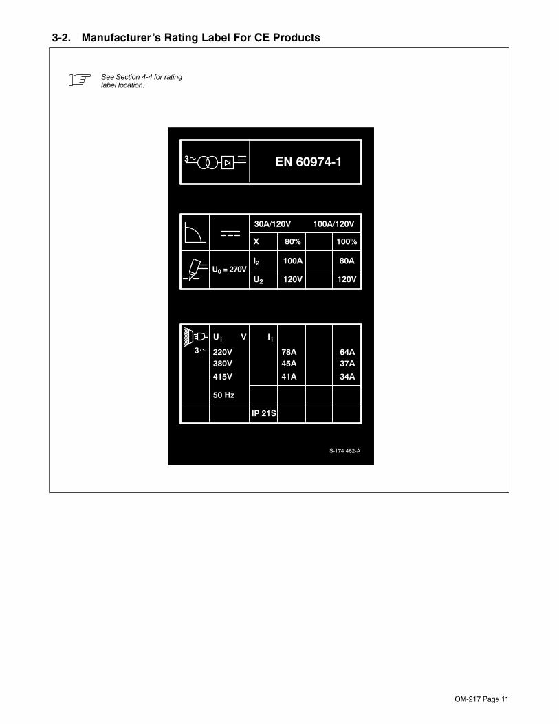
3-2. Manufacturer’s Rating Label For CE Products
See Section 4-4 for ratinglabel location.
S-174 462-A
3 EN 60974-1
X 80% 100%
30A/120V 100A/120V
U0 = 270VI2 100A 80A
U2 120V 120V
78A 64A
IP 21S
50 Hz
U1 V
220V
I1
45A 37A380V
41A 34A415V
3

OM-217 Page 12
3-3. Symbols And Definitions
Some symbols are found only on CE products.NOTE
A AmperesPlasma Arc Cutting
(PAC) Trigger Hold On Trigger Hold Off
V Volts Pilot/Pulse StartingContinuous Pilot
Arc Pulse
Output IncreaseNo − Do Not Do
This Temperature
Protective Earth(Ground) Three Phase High Frequency Input
On Off Percent Direct Current
U0Rated No Load
Voltage (Average) U1Primary Voltage U2
Conventional LoadVoltage Line Connection
I1 Primary Current I2Rated Welding
Current X Duty CycleThree PhaseTransformer
Rectifier
IP Degree OfProtection Loose Shield Cup
Torch-Tip-ToElectrode Short Hz Hertz
Air/Gas PressureAdjustment Work
Low Air PressureLight
Nitrogen Gas InputConnection
Adjust Air/GasPressure
SECTION 4 − INSTALLATION4-1. Specifications
Model/Rated
Amperes Input at Rated Output,50 or 60 Hz, Three-Phase
Plasma
PlasmaGas
Flow/ Max IPRatedOutput 200 V 220 V 230 V 380 V 415 V 460 V 575 V KVA KW
PlasmaGas
Flow/Pressure
MaxOCV
IPRating
1250 / 100Amperes At
120 Volts DCAt 80% Duty
Cycle
85(3.4*)
77(4.0*)
74(2.9*)
45(2.5*)
41(1.5*)
37(1.5*)
30(1.0*)
30(1.2*)
16(0.5*)
Air OrNitrogen
Only
7 CFM(198 L/min)At 70 PSI(482 kPa)
270VoltsDC
21S
*While idling

OM-217 Page 13
8 Minutes Welding 2 Minutes Resting
4-2. Duty Cycle And Overheating
Duty Cycle is percentage of 10 min-utes that unit can cut at rated loadwithout overheating.
If unit overheats, thermostat(s)opens, output stops, Temperaturetrouble light goes On, and coolingfan runs. Wait fifteen minutes forunit to cool or temperature light togo off. Reduce amperage or dutycycle before cutting or gouging.
� Exceeding duty cycle candamage unit and voidwarranty.
Overheating
0
15
duty1 4/95 − Ref. 159 463-B
Minutes
A
ORReduce Duty Cycle
80% Duty Cycle At 100 Amperes
4-3. Cutting Speed
The cutting speed curves show therecommended maximum cuttingspeed capabilities of the powersource and torch for mild steel ofvarious thickness.
Cut at speeds below the linesshown to avoid poor cuts and torchwear.
171 820

OM-217 Page 14
4-4. Selecting A Location
1 Lift Hook
Install lift hooks using suppliedbolts. Tighten to 25 ft/lb (34 N·m).
2 Spreader Bar (Not Supplied)
3 Lifting Cable (Not Supplied)
If lifting unit, use spreader andcable.
4 Lifting Eye
5 Lifting Forks
If using lifting forks, extend forksbeyond opposite side of unit.
6 Rating Label (Non CE ModelsOnly)
7 Rating Label (CE ModelsOnly, See Section 3-2)
Use rating label to determine inputpower needs.
8 Plate Label (CE Models Only)
9 Line Disconnect Device
Locate unit near correct input pow-er supply.
� Special installation may berequired where gasoline orvolatile liquids are present −see NEC Article 511 or CECSection 20.
4
5
Movement
S-0439 / Ref. 800 402-B / 159 463-B
9
18 in (460mm)
Location And Airflow
OR
18 in (460mm)
6
8
3
2
1
7

OM-217 Page 15
4-5. Dimensions And Weight
DimensionsDimensions
Height 37-1/4 in (946 mm)
B
A Width 22-3/4 in (578 mm)
BC
Length 20 in (508 mm)C
A 22-1/16 in (560 mm)
B 21-1/32 in (210 mm)
D C 1-1/32 in (26 mm)
E D 18-13/16 in (478 mm)
E 17-11/16 (449 mm)
FF 5-5/8 (143 mm)
F
Bottom FrontG 1-1/8 (29 mm)
H 159 464-BGBottom Front
H 7/16 in (11 mm) DiaG
Weight
405 lbs (184 kg)
4-6. Tipping
� Be careful when placing ormoving unit over unevensurfaces.

OM-217 Page 16
4-7. Connecting Work Clamp And Gas/Air Supply
Ref. 803 640-A / 800 701 / S-0818
1 Work Clamp
2 Workpiece
Connect work clamp to a clean,paint-free location on workpiece, asclose to cutting area as possible.
� Use only clean, dry air or nitro-gen gas. Do not use any othergas or combination of gases.
3 Air Filter/Regulator
4 Gas/Air Inlet Opening
5 Hose
6 Teflon Tape
Obtain hose with 5/8-18 right-handthread fitting. Wrap threads withteflon tape, and install fitting inopening.
Adjust gas/air pressure accordingto Section 5-1.
Tools Needed:
5/8, 1-1/8 in
From Gas/Air Supply
4
3
5
6
1
2

OM-217 Page 17
Panel
4-8. Remote Control Connections
Ref. 159 466-C / Ref. 150 802-A
� Turn Off power before instal-ling remote control.
Remove left side panel.
1 Terminal Strip 1T
2 Connection Label
� Lead colors shown matchthose of Remote Pendant Con-trol supplied with machine-heldtorches.
Route leads through hole belowtorch and work cable access holes.Refer to connection label and makeconnections as follows:
Torch On/Off Connections:
3 Remote On/Off Switch
Connect switch leads to terminals 3and 4 as shown. Switch closurestarts cutting arc.
Output Control Connections:
4 Jumper Link
For remote output control, removejumper link between terminals 9and 10, and reinstall between termi-nals 8 and 9 as shown. This dis-ables front panel Output Controland enables remote output control.
5 Remote Output Control
Connect control leads to terminals7, 8, and 11 as shown.
Output Sensor Connections:
6 Output Sensor Terminals
Terminals 5 and 6 connect to inter-nal, normally-open contacts whichclose when cutting output is pres-ent. For example, use signal to startautomatic fixture.
Reinstall side panel.
Tools Needed:
3/8 in
21
1
2
3
4
5
6
7
8
9
10
11
71
72
84
85
64
63
65
66
70
43
3
54
6
S-169 259
N.O.OutputSensor
CommandRef.
Remote
JumperCommon
SignalGround
TorchSwitch
+10 Volts DC(Brown)
BlackWhite
Wiper (Red)
GND (Green)
1T

OM-217 Page 18
4-9. Electrical Service Guide
60 Hertz Models
Input Voltage 200 230 460 575
Input Amperes At Rated Output 85 74 37 30
Max Recommended Standard Fuse Or Circuit Breaker Rating InAmperes 125 125 60 45
Min Input Conductor Size In AWG 4 4 8 10
Max Recommended Input Conductor Length In Feet (Meters) 160(49)
212(65)
389(119)
413(126)
Min Grounding Conductor Size In AWG 6 6 10 10
Reference: 1993 National Electrical Code (NEC) S-0092-J
50 Hertz Models
Input Voltage 220 380 415
Input Amperes At Rated Output 77 45 41
Max Recommended Standard Fuse Or Circuit Breaker Rating In Amperes 125 70 60
Min Input Conductor Size In AWG 4 8 8
Max Recommended Input Conductor Length In Feet (Meters) 190(58)
260(79)
310(94)
Min Grounding Conductor Size In AWG 6 8 10
Reference: 1993 National Electrical Code (NEC) S-0092-J

OM-217 Page 19
4-10. Placing Jumper Links And Connecting Input Power
Ref. 800 718
Check input voltage available atsite.
1 Jumper Link Label
Check label − only one is on unit.
2 Jumper Links
Move jumper links to match inputvoltage.
3 Input And GroundingConductors
Select size and length using Sec-tion 4-9.
4 Line Disconnect Device
Select type and size of overcurrentprotection using Section 4-9.
Reinstall side panel.
� Special installation may berequired where gasoline orvolatile liquids are present −see NEC Article 511 or CECSection 20.
Tools Needed:
4
230 VOLTS
S-012 242-A
L1 L2 L3
460 VOLTS
L1 L2 L3
575 VOLTS
L1 L2 L3
1
200 VOLTS
S-031 770-A
L1 L2 L3
230 VOLTS
L1 L2 L3
460 VOLTS
L1 L2 L3
L1 (U)
L2 (V)
GND/PEEarth Ground
L3 (W)
Connect GND/PEConductor First
3/8, 7/12, 1/2 in
L3 (W)
2
Connect GND/PEConductor First
L1 (U) L2 (V)
3
1
220 VOLTS
S-151 770
L1 L2 L3
380 VOLTS
L1 L2 L3
415 VOLTS
L1 L2 L3

OM-217 Page 20
SECTION 5 − OPERATION
5-1. Controls
Ref. 159 465-A / 800 701 / S-0818
12345678
1 Pilot Light
2 Power Switch
3 Output Control
Use control to set cutting output.
For non-shielded cutting, use a 1/8 in (3 mm)standoff distance between torch tip andworkpiece.
4 Set/Run Switch
Place switch up to safely adjust gas/air pres-sure. Only gas/air circuit is activated.
Place switch down to cut or gouge.
5 Ready Light
Use light to tell if unit is ready for operation.
Ready light comes on when Power switch isplaced in On position, indicating that all safe-ty shutdown systems are okay.
If Ready light does not come on, checkTrouble Lights.
6 Trouble Lights (See Section 6-3)
7 Trigger Hold Switch
To cut without holding torch trigger, placeswitch up, and begin cutting by pressing andreleasing torch trigger. To stop cutting, pressand release trigger.
When set in down position, trigger must beheld closed while cutting.
8 Pilot Arc Control Switch
Place switch down for pulsed pilot arcoutput. Use this position whenever possibleto reduce wear on torch and consumables.
Place switch up for a continuous pilot arc.Use this position when cutting starts arecritical or while cutting expanded metals.
Setting Gas/Air Pressure
9 Air Filter/Regulator
10 Pressure Adjustment Knob
Place Set/Run switch up and turn on gas/airsupply. Lift knob and turn to adjust pressure.Push knob down to lock in setting.
Place Set/Run switch down to begin cutting.
Requires80-150 psi
(552-1034 kPa)Supply
9
10
Setting Gas/Air Pressure
4 Set To 70 psi(482 kPa)

OM-217 Page 21
SECTION 6 − MAINTENANCE & TROUBLESHOOTING6-1. Routine Maintenance
� Disconnect power before maintaining.
� Maintain more oftenduring severe conditions.
Each Use
Check TorchTip, Electrode,And Shield Cup
Check Gas/AirPressure
Every Week
Check Shield CupShutdown System
3 Months
Service AirFilter/Regulator
ReplaceUnreadable
Labels
Clean AndTighten Weld
Terminals
Tape Torn OuterCovering
ReplaceCracked
PartsGas/Air Hose Torch Body, Cable
AdjustSparkGaps
6 Months
Blow Out Or Vacuum InsideOR

OM-217 Page 22
6-2. Overload Protection: Fuses
� Turn Off power and discon-nect input power beforechecking fuses.
Remove left side panel.
1 Main Fuse F1
F1 protects control transformer T2from overload. If F1 opens, thepower source shuts down.
2 Timer/Control Board PC1
3 PC1 Fuse F1
4 PC1 Fuse F2
5 PC1 Fuse F4
6 Isolator/Filter Board PC5
7 PC5 Fuse F1
Fuses on PC1 and PC5 protect thecircuit boards from overload. If anyfuse opens, Ready light goes off,and the unit does not cut.
Replace fuses as needed. SeeParts List for fuse ratings. Useproper tool when removing fuses.
Reinstall side panel.
Tools Needed:
Ref. 159 466-C / Ref. 135 352-A / Ref. 137 070-D / 141 468-C
3/8 in
1
6
7
4
2
5
3

OM-217 Page 23
6-3. Overload Protection: Trouble Lights & Checking Shield Cup Shutdown System
If certain problems occur, theReady light goes off, a trouble lightcomes on, and output stops.
1 Gas/Air Or Shield Cup Light
Lights if low gas/air pressure oc-curs, if shield cup is loose, or if o-ring is defective.
Turn power Off, and check shieldcup connection (see torch Owner’sManual). Check for proper gas/airpressure (see Section 5-1).
Check shield cup shutdown systemonce a week as shown.
2 Torch-To-Tip Short Light
Lights if a short exists between tipand electrode. Check tip and elec-trode (see torch Owner’s Manual).
3 Temperature Light
Lights if power source overheats(see Section 4-2).
4 Torch Shield Cup
Turn Power On and loosen shieldcup. If shutdown system worksproperly, Ready light goes off andGas/Air Or Shield Cup light comeson. If not, turn power Off and checkfor proper gas/air pressure (seeSection 5-1), blocked or leakinghose, or loose shield cup (see torchOwner’s Manual).
If system works properly, retightencup and turn Off power.
Ref. 800 713
1
2
3
Checking Torch Shield Cup Shutdown System
4

OM-217 Page 24
6-4. Adjusting Spark Gap
� Turn Off power before ad-justing spark gap.
Remove left side panel.
1 Tungsten End Of Point
Replace point if tungsten end dis-appears; do not clean or dresstungsten.
2 Spark Gap
Normal spark gap is 0.030 in (0.762mm).
If adjustment is needed, proceed asfollows:
3 Adjustment Screw
Loosen screw. Place gauge ofproper thickness in spark gap.
4 Pressure Point
Apply slight pressure at point untilgauge is held firmly in gap. Tightenscrew.
Reinstall side panel.
Ref. 159 466-C / S-0201
2
3
4
1
Tools Needed:
3/8 in
5/32 in
0.030 in (0.762 mm)

OM-217 Page 25
1T
6-5. Torch And Work Cable Connections
� Turn Off power before re-moving side panel.
If torch or work cable needs to beremoved or replaced, remove leftside panel, and proceed as follows:
1 Work Cable
2 Work (+) Output Terminal
3 Torch Cable
4 Pilot Cable
5 Torch (−) And Gas/Air OutputConnector
6 Pilot (+) Output Terminal
Connect cables as shown.
7 Terminal Strip 1T
8 Connection Label
9 Torch Switch Leads
For hand-held torches, refer to labelto connect leads. Reinstall sidepanel.
10 Nut
11 Hose Clamp
For machine-held torches, tightennut and clamp to secure cables.See Section 4-8 for remote controlconnections.
Tools Needed:
Ref. 159 466-C / 800 702-B3/8 in
1/2 in
8
7
5
7
2 4 3 1
1
2
3
4
5
6
7
8
9
10
11
71
72
84
85
64
63
65
66
70
43 9
6
1
3
41110
Hand-Held Torch
Machine-Held Torch
Side View
OR
Panel
N.O.OutputSensor
CommandRef.
Remote
Jumper Com-mon
1T
TorchSwitch
S-169 259
SignalGround

OM-217 Page 26
6-6. Troubleshooting
Trouble Remedy
No cutting output; Power light off;Trouble lights off; Ready light off; fan mo-tor FM does not run.
Place Power switch in On position.
Place line disconnect device in On position (see Section 4-10).
Check line fuse(s) and replace if needed or reset circuit breakers (see Section 4-10).
Check main fuse F1 and replace if needed (see Section 6-2).
Have Factory Authorized Service Agent check contactor W.
No cutting output; Power light on; Readylight on; Trouble lights off; fan motor FMrunning.
Be sure work clamp is connected.
Check for proper torch switch lead connections (see Sections 4-8 and 6-5).
Check for for proper position of jumper link on terminal strip 1T (see Section 4-8).
Have Factory Authorized Service Agent check contactor W, control relay CR3, and firing board PC2.
No cutting output; Power light on; Readylight off; Trouble lights off; fan motor FMrunning.
Check fuses on timer/control board PC1 and isolator/filter board PC5 (see Section 6-2).
Have Factory Authorized Service Agent check timer/control board PC1.
No control of output. Check for for proper position of jumper link on terminal strip 1T (see Sections 4-8).
Have Factory Authorized Service Agent check Output control R1, timer/control board PC1, hall deviceHD1, and firing board PC2.
No gas/air flow; Power light on; Readylight on; Trouble lights off; fan motor FMrunning.
Check fuses on timer/control board PC1 and isolator/filter board PC5 (see Section 6-2).
Check for proper torch connections (see torch Owner’s Manual).
No gas/air flow; Power light on; Readylight off; Trouble lights off; fan motor FMrunning.
Check fuses on timer/control board PC1 and isolator/filter board PC5 (see Section 6-2).
No pilot arc or high frequency; difficultyin establishing an arc.
Check fuses on timer/control board PC1 and isolator/filter board PC5 (see Section 6-2).
Check and adjust spark gap, if needed (see Section 6-4).
Check for damaged torch or torch cable (see torch Owner’s Manual).
Have Factory Authorized Service Agent check control relay CR1, timer/control board PC1, and firingboard PC2.
Erratic pilot arc, difficulty in establishingan arc, and lowered cutting capacity.
Check for excessive moisture and/or contaminants in gas/air supply.
Check for dirty air filter/regulator and clean, if needed (see manufacturer’s instructions).
Gas/Air Or Shield Cup Trouble lighton; Ready light off.
Place Set/Run switch in Run position.
Check for sufficient gas/air supply pressure and correct gas/air pressure adjustment (see Section 5-1).
Check torch shield cup and o-ring (see torch Owner’s Manual).
Check for dirty air filter/regulator and clean, if needed (see manufacturer’s instructions).
Have Factory Authorized Service Agent check timer/control board PC1.
Torch-To-Tip Short Trouble light on;Ready light off.
Check to make sure torch electrode is not touching tip inside the torch (see torch Owner’s Manual).
Check to make sure torch lead connections are tight on terminal strip 1T (see Sections 4-8 and 6-5).

OM-217 Page 27
Trouble Remedy
Temperature Trouble light on; Readylight off.
Thermostat TP1 and/or TP2 open (overheating). Allow fan to run; the thermostat closes when the unit hascooled (see Section 4-2).
Have Factory Authorized Service Agent check timer/control board PC1.
No high gas/air flow (cutting air), or de-creased cutting ability.
Check for sufficient gas/air supply pressure and correct gas/air pressure adjustment (see Section 5-1).
Have Factory Authorized Service Agent check reed switch RS1, high air solenoid AS2, and air circuitry.
Fan motor FM does not run; Power lightand Ready light both on.
Check fan motor connections.
Trouble lights not working. Have Factory Authorized Service Agent check indicator board PC3 and timer/control board PC1.
Power light on; Trouble lights on; cuttingoutput available.
Have Factory Authorized Service Agent check timer/control board PC1.

OM-217 Page 28
SECTION 7 − ELECTRICAL DIAGRAMS
Figure 7-1. Circuit Diagram For 60 Hertz Power Sources
183 062-A

OM-217 Page 29
Figure 7-2. Circuit Diagram For 50 Hertz Power Sources176 919-A

OM-217 Page 30
SECTION 8 − HF IN PLASMA CUTTING8-1. High Frequency In Plasma Arc Cutting (PAC)
ÉÉÉÉÉÉ
high_freq2 4/95 − S-0753
1 Plasma Arc Torch
2 High-Frequency Voltage
Used inside torch to ionize gapbetween electrode and tip to helpstart the pilot arc.
3 Electrode
4 Pilot Arc
5 Tip
6 Shield Cup
1
ÉÉÉÉÉÉÉÉÉÉÉÉ
ÉÉÉÉÉÉÉÉÉÉÉÉÉÉÉ
35
4
ÉÉÉÉÉÉÉÉÉÉÉÉÉÉÉÉÉÉÉÉÉÉÉÉÉÉÉÉÉÉÉÉÉÉÉÉ
6
2
Work
Plasma Arc Cutting (PAC)
8-2. Sources Of High-Frequency Radiation From Incorrect Installation
50 ft(15 m)
S-0754
Sources Of Direct High-FrequencyRadiation
1 High-Frequency Source (Plasma ArcCutting Power Source)
2 Cables
3 Torch
4 Work Clamp
5 Workpiece
6 Work Table
Sources Of Conduction Of HighFrequency
7 Input Power Cable
8 Line Disconnect Device9 Input Supply Wiring
Sources Of Reradiation Of HighFrequency
10 Ungrounded Metal Objects
11 Lighting
12 Wiring
13 Water Pipes And Fixtures
14 External Phone And Power Lines
9
3
1
Cutting Zone
13 2
4 5
6
8
7
10
11, 12
14

OM-217 Page 31
8-3. Correct Installation
A. Worksite Requirements
1 Plasma Arc Cutting Source
Ground metal machine case, line disconnectdevice, input supply, and workpiece (ifrequired).
2 Center Point Of Cutting Zone
Midpoint between high-frequency sourceand cutting torch.
3 Cutting Zone
A circle 50 ft (15 m) from center point in alldirections.
4 Torch And Work Cables
Keep cables close together.
5 Conduit Joint Bonding And Grounding
Electrically join (bond) all conduit sectionsusing copper straps or braided wire. Groundconduit every 50 ft (15 m).
6 Water Pipes And Fixtures
Ground water pipes every 50 ft (15 m).
7 External Power Or Telephone Lines
Locate high-frequency source at least 50 ft(15 m) away from power and phone lines.
8 Grounding Rod
Consult the National Electrical Code forspecifications.
Metal Building Requirements
9 Metal Building Panel Bonding Methods
Bolt or weld building panels together, installcopper straps or braided wire across seams,and ground frame.
10 Windows And Doorways
Cover all windows and doorways withgrounded copper screen of not more than1/4 in (6.4 mm) mesh.
11 Overhead Door Track
Ground the track.
Ref. S-0755
1
2
3 50 ft(15 m)
4
7
50 ft(15 m)
8
8
5
6
GroundWorkpieceIf RequiredBy Codes
Ground AllMetal ObjectsAnd All WiringIn Cutting ZoneUsing #12 AWG
Wire
Cutting Zone
Nonmetal Building
9
811
10Metal Building
8
OM-217 Page 32
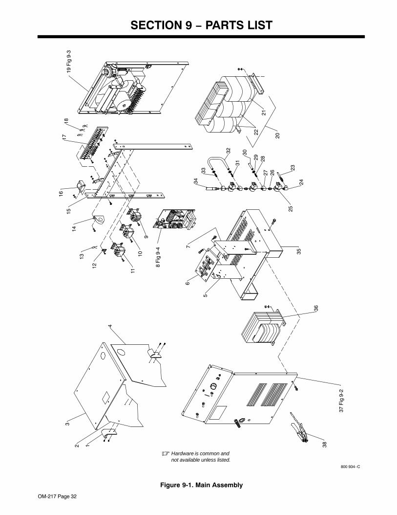
SECTION 9 − PARTS LIST
800 934−C
� Hardware is common andnot available unless listed.
38
36
35
5
12
3
4
67
1110
12
13
34
20
25
24
2333 27 26
31
29 28
30
22
21
32
9
1514
1618
17
8 F
ig 9
-4
19 F
ig 9
-3
37 F
ig 9
-2
Figure 9-1. Main Assembly

OM-217 Page 33
Replace Coils at Factory or Authorized Factory Service Station
DescriptionPartNo.
Dia.Mkgs.
ItemNo.
Figure 9-1. Main Assembly
Quantity
1 015 531 HOOK, lift 1. . . . . . . . . . . . . . . . . . . . . . . . . . . . . . . . . . . . . . . . . . . . . . . . . . . . . . . . . . . . . . . . . . . . . . . . . 2 132 940 PANEL, side LH 1. . . . . . . . . . . . . . . . . . . . . . . . . . . . . . . . . . . . . . . . . . . . . . . . . . . . . . . . . . . . . . . . . . . 3 168 943 COVER, top 1. . . . . . . . . . . . . . . . . . . . . . . . . . . . . . . . . . . . . . . . . . . . . . . . . . . . . . . . . . . . . . . . . . . . . . . 4 192 404 PANEL, side RH 1. . . . . . . . . . . . . . . . . . . . . . . . . . . . . . . . . . . . . . . . . . . . . . . . . . . . . . . . . . . . . . . . . . . 5 126 700 BRACKET, mtg heatsink LH 1. . . . . . . . . . . . . . . . . . . . . . . . . . . . . . . . . . . . . . . . . . . . . . . . . . . . . . . . . 6 SR1 170 831 RECTIFIER, main (consisting of) 1. . . . . . . . . . . . . . . . . . . . . . . . . . . . . . . . . . . . . . . . . . . . . . . .
SCR1-3 168 065 POWER BLOCK, thyristor 55A 1200PIV 3. . . . . . . . . . . . . . . . . . . . . . . . . . . . . . . . . . . . . . . . 112 250 FOIL, interface heat transfer 3. . . . . . . . . . . . . . . . . . . . . . . . . . . . . . . . . . . . . . . . . . . . . . . . . . . . . . . . . . . . 173 625 HEAT SINK, rectifier 1. . . . . . . . . . . . . . . . . . . . . . . . . . . . . . . . . . . . . . . . . . . . . . . . . . . . . . . . . . . . . . . . . . . 170 830 HEAT SINK, rect 3. . . . . . . . . . . . . . . . . . . . . . . . . . . . . . . . . . . . . . . . . . . . . . . . . . . . . . . . . . . . . . . . . . . . . .
TP2 129 552 THERMOSTAT, NC 1. . . . . . . . . . . . . . . . . . . . . . . . . . . . . . . . . . . . . . . . . . . . . . . . . . . . . . . . . . . . . . . 126 495 BUS BAR 2. . . . . . . . . . . . . . . . . . . . . . . . . . . . . . . . . . . . . . . . . . . . . . . . . . . . . . . . . . . . . . . . . . . . . . . . . . . .
C7-12 127 082 CAPACITOR 6. . . . . . . . . . . . . . . . . . . . . . . . . . . . . . . . . . . . . . . . . . . . . . . . . . . . . . . . . . . . . . . . . . VR1 105 779 VARISTOR 1. . . . . . . . . . . . . . . . . . . . . . . . . . . . . . . . . . . . . . . . . . . . . . . . . . . . . . . . . . . . . . . . . . . . . .
7 126 701 BRACKET, mtg heatsink RH 1. . . . . . . . . . . . . . . . . . . . . . . . . . . . . . . . . . . . . . . . . . . . . . . . . . . . . . . . . 8 169 882 HF PANEL, (Fig 9-4) 1. . . . . . . . . . . . . . . . . . . . . . . . . . . . . . . . . . . . . . . . . . . . . . . . . . . . . . . . . . . . . . . 9 CR1 188 633 CONTACTOR, def prp 40A 3P 120V 1. . . . . . . . . . . . . . . . . . . . . . . . . . . . . . . . . . . . . . . . . . . .
181 014 LINK, connecting contactor term 2. . . . . . . . . . . . . . . . . . . . . . . . . . . . . . . . . . . . . . . . . . . . . . . . . . . . . . . . 10 W 188 634 CONTACTOR, def prp 60A 3P 24V 1. . . . . . . . . . . . . . . . . . . . . . . . . . . . . . . . . . . . . . . . . . . . . . . . 11 CR3 186 355 CONTACTOR, def prp 60A 3P 120VAC coil 1. . . . . . . . . . . . . . . . . . . . . . . . . . . . . . . . . . . . . . 12 2T 072 253 STUD, connection single 10-32 x .500 x 1.250 1. . . . . . . . . . . . . . . . . . . . . . . . . . . . . . . . . . . . . 13 C20 031 688 CAPACITOR, cer disc .01uf 1000VDC 1. . . . . . . . . . . . . . . . . . . . . . . . . . . . . . . . . . . . . . . . . . .
010 913 WASHER, flat brs .218 ID x .460 OD x .031thk 1. . . . . . . . . . . . . . . . . . . . . . . . . . . . . . . . . . . . . . . . . . . . 601 835 NUT, brs hex 10-32 1. . . . . . . . . . . . . . . . . . . . . . . . . . . . . . . . . . . . . . . . . . . . . . . . . . . . . . . . . . . . . . . . . . .
14 HD1 177 453 TRANSDUCER, current 200A 1. . . . . . . . . . . . . . . . . . . . . . . . . . . . . . . . . . . . . . . . . . . . . . . . . . PLG18 115 094 CONNECTOR & SOCKETS, (consisting of) 1. . . . . . . . . . . . . . . . . . . . . . . . . . . . . . . . . . . . . .
113 746 CONNECTOR, rect skt 24-18ga 4. . . . . . . . . . . . . . . . . . . . . . . . . . . . . . . . . . . . . . . . . . . . . . . . . . . . . . . . . 15 168 850 FRAME, center base 1. . . . . . . . . . . . . . . . . . . . . . . . . . . . . . . . . . . . . . . . . . . . . . . . . . . . . . . . . . . . . . . 16 T2 174 308 TRANSFORMER, kVA 1/3 24-24 (200/230/460) 1. . . . . . . . . . . . . . . . . . . . . . . . . . . . . . . . . . . . 16 T2 174 304 TRANSFORMER, kVA 1/3 24-24 (230/460/575) 1. . . . . . . . . . . . . . . . . . . . . . . . . . . . . . . . . . . . 16 T2 174 306 TRANSFORMER, kVA 1/3 24-24-18 (220/380/415) 1. . . . . . . . . . . . . . . . . . . . . . . . . . . . . . . . . 17 TE1 038 126 TERMINAL ASSEMBLY, pri 3ph 3V (200/230/460) (consisting of) 1. . . . . . . . . . . . . . . . . . . 17 TE1 168 854 TERMINAL ASSEMBLY, pri 3ph 3V (230/460/575) (consisting of) 1. . . . . . . . . . . . . . . . . . .
601 835 NUT, brs hex 10-32 reg As Reqd. . . . . . . . . . . . . . . . . . . . . . . . . . . . . . . . . . . . . . . . . . . . . . . . . . . . . . . . . . . . 038 058 TERMINAL BOARD, pri 1. . . . . . . . . . . . . . . . . . . . . . . . . . . . . . . . . . . . . . . . . . . . . . . . . . . . . . . . . . . . . . . . 038 887 STUD, pri bd brs 10-32 x 1.375 23. . . . . . . . . . . . . . . . . . . . . . . . . . . . . . . . . . . . . . . . . . . . . . . . . . . . . . . . 010 913 WASHER, flat brs .218 ID x .460 OD x .031thk 23. . . . . . . . . . . . . . . . . . . . . . . . . . . . . . . . . . . . . . . . . . . 038 618 LINK, jumper term bd pri 7. . . . . . . . . . . . . . . . . . . . . . . . . . . . . . . . . . . . . . . . . . . . . . . . . . . . . . . . . . . . . . . 601 836 NUT, brs hex .250-20 jam hvy 6. . . . . . . . . . . . . . . . . . . . . . . . . . . . . . . . . . . . . . . . . . . . . . . . . . . . . . . . . . . 010 915 WASHER, flat brs .250 ID x .625 OD x .031thk 6. . . . . . . . . . . . . . . . . . . . . . . . . . . . . . . . . . . . . . . . . . . . 038 888 STUD, pri bd brs .250-20 x 1.500 3. . . . . . . . . . . . . . . . . . . . . . . . . . . . . . . . . . . . . . . . . . . . . . . . . . . . . . . .
18 C21-23 091 141 CAPACITOR, cer disc. .0022uf 3000VAC 3. . . . . . . . . . . . . . . . . . . . . . . . . . . . . . . . . . . . . 19 Fig 9-3 PANEL, rear w/components 1. . . . . . . . . . . . . . . . . . . . . . . . . . . . . . . . . . . . . . . . . . . . . . . . . . . . . . . . . . 20 T1 150 311 TRANSFORMER, pwr main 200/230/460 (consisting of) 1. . . . . . . . . . . . . . . . . . . . . . . . . . . . 21 149 734 COIL, pri/sec 200/230/460 LH 1. . . . . . . . . . . . . . . . . . . . . . . . . . . . . . . . . . . . . . . . . . . . . . . . . . . . . . . . 22 131 559 COIL, pri/sec 200/230/460 (center & RH) 2. . . . . . . . . . . . . . . . . . . . . . . . . . . . . . . . . . . . . . . . . . . . . . 20 T1 150 310 TRANSFORMER, pwr main 230/460/575 (consisting of) 1. . . . . . . . . . . . . . . . . . . . . . . . . . . . 21 149 736 COIL, pri/sec 230/460/575 LH 1. . . . . . . . . . . . . . . . . . . . . . . . . . . . . . . . . . . . . . . . . . . . . . . . . . . . . . . . 22 135 984 COIL, pri/sec 230/460/575 center & RH 2. . . . . . . . . . . . . . . . . . . . . . . . . . . . . . . . . . . . . . . . . . . . . . . 20 T1 176 914 TRANSFORMER, pwr main 220/380/415 (consisting of) 1. . . . . . . . . . . . . . . . . . . . . . . . . . . . 21 176 915 COIL, pri/sec 220/380/415 LH 1. . . . . . . . . . . . . . . . . . . . . . . . . . . . . . . . . . . . . . . . . . . . . . . . . . . . . . . . 22 176 916 COIL, pri/sec 220/380/415 center & RH 2. . . . . . . . . . . . . . . . . . . . . . . . . . . . . . . . . . . . . . . . . . . . . . .
TP1 119 581 THERMOSTAT, NC 1. . . . . . . . . . . . . . . . . . . . . . . . . . . . . . . . . . . . . . . . . . . . . . . . . . . . . . . . . . . . . . 23 168 944 HOSE, air 36 in 1. . . . . . . . . . . . . . . . . . . . . . . . . . . . . . . . . . . . . . . . . . . . . . . . . . . . . . . . . . . . . . . . . . . .

OM-217 Page 34
DescriptionPartNo.
Dia.Mkgs.
ItemNo.
Figure 9-1. Main Assembly
Quantity
24 010 296 FITTING, hose brs elb M 1/4NPT x .625-18RH 1. . . . . . . . . . . . . . . . . . . . . . . . . . . . . . . . . . . . . . . . 25 AS1-3 003 538 VALVE, 115VAC 2 way 1/4 IPS port 1/8orf 3. . . . . . . . . . . . . . . . . . . . . . . . . . . . . . . . . . . . . .
VR2-5,7,8 186 491 VARISTOR, w/terminals 1. . . . . . . . . . . . . . . . . . . . . . . . . . . . . . . . . . . . . . . . . . . . . . . . . . . . 26 010 830 FITTING, piped brs nipple hex 1/4NPT 2. . . . . . . . . . . . . . . . . . . . . . . . . . . . . . . . . . . . . . . . . . . . . . . . 27 071 270 FITTING, pipe brs tee st 1/4NPT 3. . . . . . . . . . . . . . . . . . . . . . . . . . . . . . . . . . . . . . . . . . . . . . . . . . . . . 28 169 688 FITTING, brs barbed M 3/16tbg x 1/4NPT 1. . . . . . . . . . . . . . . . . . . . . . . . . . . . . . . . . . . . . . . . . . . . . 29 010 323 CLAMP, hose .250-.625clp dia 3. . . . . . . . . . . . . . . . . . . . . . . . . . . . . . . . . . . . . . . . . . . . . . . . . . . . . . . 30 222 211 HOSE, air 40 in 1. . . . . . . . . . . . . . . . . . . . . . . . . . . . . . . . . . . . . . . . . . . . . . . . . . . . . . . . . . . . . . . . . . . . 31 602 958 FITTING, brs barbed M 1/4tbg x 1/4NPT 1. . . . . . . . . . . . . . . . . . . . . . . . . . . . . . . . . . . . . . . . . . . . . . 32 161 860 HOSE, SAE .250 ID x .500 OD 1. . . . . . . . . . . . . . . . . . . . . . . . . . . . . . . . . . . . . . . . . . . . . . . . . . . . . . 33 161 308 FITTING, brs barbed M 1/4tbg x 1/4NPT .059 ID 1. . . . . . . . . . . . . . . . . . . . . . . . . . . . . . . . . . . . . . . 34 132 753 HOSE, air 27 in 1. . . . . . . . . . . . . . . . . . . . . . . . . . . . . . . . . . . . . . . . . . . . . . . . . . . . . . . . . . . . . . . . . . . . 35 168 851 BASE 1. . . . . . . . . . . . . . . . . . . . . . . . . . . . . . . . . . . . . . . . . . . . . . . . . . . . . . . . . . . . . . . . . . . . . . . . . . . . 36 Z1 139 709 STABILIZER 1. . . . . . . . . . . . . . . . . . . . . . . . . . . . . . . . . . . . . . . . . . . . . . . . . . . . . . . . . . . . . . . . . . 37 Fig 9-2 PANEL, front w/components 1. . . . . . . . . . . . . . . . . . . . . . . . . . . . . . . . . . . . . . . . . . . . . . . . . . . . . . . . . . 38 170 826 CABLE, work 30 ft no 4 w/clamp strain rlf & term 1. . . . . . . . . . . . . . . . . . . . . . . . . . . . . . . . . . . . . . .
213 619 CLAMP, work 300 amp stl chrome pld w/cop contacts 1. . . . . . . . . . . . . . . . . . . . . . . . . . . . . . . . . . . . . . 213 620 CONTACT TIP, work clamp 300 amp copper 2. . . . . . . . . . . . . . . . . . . . . . . . . . . . . . . . . . . . . . . . . . . . .
To maintain the factory original performance of your equipment, use only Manufacturer’s SuggestedReplacement Parts. Model and serial number required when ordering parts from your local distributor.

OM-217 Page 35
1
Figure 9-2. Panel, Front w/Components
2
3
45
7
6
89
1112
13
10
14
15
17
16
18
19
20
2122
23
24
800 935-A
� Hardware is common andnot available unless listed.
DescriptionPartNo.
Dia.Mkgs.
ItemNo.
Figure 9-2. Panel, Front w/Components (Fig 9-1 Item 37)
Quantity
1 NAMEPLATE, (order by model and serial number) 1. . . . . . . . . . . . . . . . . . . . . . . . . . . . . . . . . . . . . . . . . . . . . . 2 PL2 125 521 LIGHT, ind grn lens 28V snap mtg 1. . . . . . . . . . . . . . . . . . . . . . . . . . . . . . . . . . . . . . . . . . . . . . 3 S4-6 089 085 SWITCH, tgl SPST 20A 125VAC 3. . . . . . . . . . . . . . . . . . . . . . . . . . . . . . . . . . . . . . . . . . . . . . 4 115 443 STAND-OFF, 6-32 x .750 lg 2. . . . . . . . . . . . . . . . . . . . . . . . . . . . . . . . . . . . . . . . . . . . . . . . . . . . . . . . . . 5 PC3 165 552 CIRCUIT CARD, display 1. . . . . . . . . . . . . . . . . . . . . . . . . . . . . . . . . . . . . . . . . . . . . . . . . . . . . .
PLG8 134 859 CONNECTOR & SOCKETS, (consisting of) 1. . . . . . . . . . . . . . . . . . . . . . . . . . . . . . . . . . . . . . . 125 748 CONNECTOR, rect skt 22-18ga JST SVH-21T-1.1 6. . . . . . . . . . . . . . . . . . . . . . . . . . . . . . . . . . . . . . . .
6 PL1 157 958 LIGHT, ind white lens 28V snap mtg 1. . . . . . . . . . . . . . . . . . . . . . . . . . . . . . . . . . . . . . . . . . . . 7 R1 035 897 POTENTIOMETER, CP std slot 1/T 2W 1K linear 1. . . . . . . . . . . . . . . . . . . . . . . . . . . . . . . . . 8 S1 111 997 SWITCH, rocker SPST 10A 250VAC 1. . . . . . . . . . . . . . . . . . . . . . . . . . . . . . . . . . . . . . . . . . . . . . 9 110 375 STAND-OFF SUPPORT, PC card No. 6 screw 16. . . . . . . . . . . . . . . . . . . . . . . . . . . . . . . . . . . . . . . . .
10 PC1 188 871 CIRCUIT CARD, control (consisting of) 1. . . . . . . . . . . . . . . . . . . . . . . . . . . . . . . . . . . . . . . . . . 11 F2 *012 633 FUSE, mintr gl 1A 1. . . . . . . . . . . . . . . . . . . . . . . . . . . . . . . . . . . . . . . . . . . . . . . . . . . . . . . . . . . . . 12 F4 *012 663 FUSE, mintr gl slo-blo 3A 1. . . . . . . . . . . . . . . . . . . . . . . . . . . . . . . . . . . . . . . . . . . . . . . . . . . . . . . 13 F1 *012 653 FUSE, mintr gl .5A 1. . . . . . . . . . . . . . . . . . . . . . . . . . . . . . . . . . . . . . . . . . . . . . . . . . . . . . . . . . . . .
PLG3 115 093 CONNECTOR & SOCKETS, (consisting of) 1. . . . . . . . . . . . . . . . . . . . . . . . . . . . . . . . . . . . . . . . 113 746 CONNECTOR, rect skt 24-18ga Molex 39-00-0038 6. . . . . . . . . . . . . . . . . . . . . . . . . . . . . . . . . . . . . . . .
PLG4,5 131 052 CONNECTOR & SOCKETS, (consisting of) 2. . . . . . . . . . . . . . . . . . . . . . . . . . . . . . . . . . . . . 113 746 CONNECTOR, rect skt 24-18ga Molex 39-00-0038 16. . . . . . . . . . . . . . . . . . . . . . . . . . . . . . . . . . . . . . . .
PLG6 115 091 CONNECTOR & SOCKETS, (consisting of) 1. . . . . . . . . . . . . . . . . . . . . . . . . . . . . . . . . . . . . . . . 113 746 CONNECTOR, rect skt 24-18ga Molex 39-00-0038 10. . . . . . . . . . . . . . . . . . . . . . . . . . . . . . . . . . . . . . . .
14 PC2 097 772 CIRCUIT CARD, SCR firing circuit (60 Hz) 1. . . . . . . . . . . . . . . . . . . . . . . . . . . . . . . . . . . . . . . 14 PC2 107 510 CIRCUIT CARD, SCR firing circuit (50 Hz) 1. . . . . . . . . . . . . . . . . . . . . . . . . . . . . . . . . . . . . . .

OM-217 Page 36
DescriptionPartNo.
Dia.Mkgs.
ItemNo.
Figure 9-2. Panel, Front w/Components (Fig 9-1 Item 37)
Quantity
PLG1 081 379 CONNECTOR, rect 12skt plug Amp 1-87159-2 1. . . . . . . . . . . . . . . . . . . . . . . . . . . . . . . . . . . . 081 378 CONNECTOR, rect skt 22-18ga Amp 102100-2 12. . . . . . . . . . . . . . . . . . . . . . . . . . . . . . . . . . . . . . . . . .
PLG2 090 469 CONNECTOR, rect 10skt plug Amp 1-87159-0 1. . . . . . . . . . . . . . . . . . . . . . . . . . . . . . . . . . . . 081 378 CONNECTOR, rect skt 22-18ga Amp 102100-2 10. . . . . . . . . . . . . . . . . . . . . . . . . . . . . . . . . . . . . . . . . .
15 PC4 162 880 CIRCUIT CARD, filter 1. . . . . . . . . . . . . . . . . . . . . . . . . . . . . . . . . . . . . . . . . . . . . . . . . . . . . . . . . PLG14 115 092 CONNECTOR & SOCKETS, (consisting of) 1. . . . . . . . . . . . . . . . . . . . . . . . . . . . . . . . . . . . . . .
113 746 CONNECTOR, rect skt 24-18ga Molex 39-00-0038 8. . . . . . . . . . . . . . . . . . . . . . . . . . . . . . . . . . . . . . . . PLG15 115 093 CONNECTOR & SOCKETS, (consisting of) 1. . . . . . . . . . . . . . . . . . . . . . . . . . . . . . . . . . . . . . .
113 746 CONNECTOR, rect skt 24-18ga Molex 39-00-0038 6. . . . . . . . . . . . . . . . . . . . . . . . . . . . . . . . . . . . . . . . 16 PC5 141 467 CIRCUIT CARD, isolator/filter (consisting of) 1. . . . . . . . . . . . . . . . . . . . . . . . . . . . . . . . . . . . . 17 F1 *012 653 FUSE, mintr gl .5A 1. . . . . . . . . . . . . . . . . . . . . . . . . . . . . . . . . . . . . . . . . . . . . . . . . . . . . . . . . . . . .
PLG11 131 054 CONNECTOR & SOCKETS, (consisting of) 1. . . . . . . . . . . . . . . . . . . . . . . . . . . . . . . . . . . . . . . 113 746 CONNECTOR, rect skt 24-18ga Molex 39-00-0038 2. . . . . . . . . . . . . . . . . . . . . . . . . . . . . . . . . . . . . . . .
PLG12 115 092 CONNECTOR & SOCKETS, (consisting of) 1. . . . . . . . . . . . . . . . . . . . . . . . . . . . . . . . . . . . . . . 113 746 CONNECTOR, rect skt 24-18ga Molex 39-00-0038 8. . . . . . . . . . . . . . . . . . . . . . . . . . . . . . . . . . . . . . . .
PLG13 115 093 CONNECTOR & SOCKETS, (consisting of) 1. . . . . . . . . . . . . . . . . . . . . . . . . . . . . . . . . . . . . . . 113 746 CONNECTOR, rect skt 24-18ga Molex 39-00-0038 6. . . . . . . . . . . . . . . . . . . . . . . . . . . . . . . . . . . . . . . .
18 126 368 STAND-OFF SUPPORT, PC card No. 6 screw 1. . . . . . . . . . . . . . . . . . . . . . . . . . . . . . . . . . . . . . . . 19 +180 170 PANEL, front 1. . . . . . . . . . . . . . . . . . . . . . . . . . . . . . . . . . . . . . . . . . . . . . . . . . . . . . . . . . . . . . . . . . . . 20 024 376 BLANK, snap-in nyl .625mtg hole 1. . . . . . . . . . . . . . . . . . . . . . . . . . . . . . . . . . . . . . . . . . . . . . . . . . . . 21 170 647 BUSHING, snap-in nyl 1.312 ID x 1.500mtg hole 1. . . . . . . . . . . . . . . . . . . . . . . . . . . . . . . . . . . . . . 22 134 900 STRAIN, relief cable flexible .270-.480 cable 1. . . . . . . . . . . . . . . . . . . . . . . . . . . . . . . . . . . . . . . . . . 23 171 007 KNOB, pointer 1. . . . . . . . . . . . . . . . . . . . . . . . . . . . . . . . . . . . . . . . . . . . . . . . . . . . . . . . . . . . . . . . . . . . 24 136 156 LABEL, warning precautionary plasma cutting equipment 1. . . . . . . . . . . . . . . . . . . . . . . . . . . . . . .
*Recommended Spare Parts.+When ordering a component originally displaying a precautionary label, the label should also be ordered.To maintain the factory original performance of your equipment, use only Manufacturer’s SuggestedReplacement Parts. Model and serial number required when ordering parts from your local distributor.

OM-217 Page 37
DescriptionPartNo.
Dia.Mkgs.
ItemNo.
Figure 9-3. Panel, Rear w/Components (Fig 9-1 Item 19)
Quantity
1 R2,3 126 736 RESISTOR, WW fxd 375W 20-161 ohm dual 1. . . . . . . . . . . . . . . . . . . . . . . . . . . . . . . . . . . 2 F1 *604 259 FUSE, crtg 3A 600V one time 1. . . . . . . . . . . . . . . . . . . . . . . . . . . . . . . . . . . . . . . . . . . . . . . . . . . 3 070 404 HOLDER, fuse crtg 1. . . . . . . . . . . . . . . . . . . . . . . . . . . . . . . . . . . . . . . . . . . . . . . . . . . . . . . . . . . . . . . . 4 032 611 BLADE, fan 14 in 3wg 23deg .375 bore CCW 1. . . . . . . . . . . . . . . . . . . . . . . . . . . . . . . . . . . . . . . . . . 5 192 402 PANEL, rear 1. . . . . . . . . . . . . . . . . . . . . . . . . . . . . . . . . . . . . . . . . . . . . . . . . . . . . . . . . . . . . . . . . . . . . . 6 168 944 HOSE, air 36 in 1. . . . . . . . . . . . . . . . . . . . . . . . . . . . . . . . . . . . . . . . . . . . . . . . . . . . . . . . . . . . . . . . . . . 7 192 399 REGULATOR/FILTER, 250PSIG in 0-150PSIG out 1/4NPT 1. . . . . . . . . . . . . . . . . . . . . . . . . . . . . 8 168 945 BRACKET, mtg air filter/regulator 1. . . . . . . . . . . . . . . . . . . . . . . . . . . . . . . . . . . . . . . . . . . . . . . . . . . . 9 168 252 NUT, knrl .187-12 1. . . . . . . . . . . . . . . . . . . . . . . . . . . . . . . . . . . . . . . . . . . . . . . . . . . . . . . . . . . . . . . . . .
10 169 260 GASKET, neoprene 3.000 OD x 1.250 ID x .500 1. . . . . . . . . . . . . . . . . . . . . . . . . . . . . . . . . . . . . . . 11 117 125 GAUGE, air 0-160psi 1/4NPT 1. . . . . . . . . . . . . . . . . . . . . . . . . . . . . . . . . . . . . . . . . . . . . . . . . . . . . . . . 12 188 962 HOSE, vinyl braided .125 ID x .312 OD 1. . . . . . . . . . . . . . . . . . . . . . . . . . . . . . . . . . . . . . . . . . . . . . . 13 015 733 FITTING, pipe brs nipple L 1/4NPT x 2.000 1. . . . . . . . . . . . . . . . . . . . . . . . . . . . . . . . . . . . . . . . . . . 14 602 963 FITTING, pipe brs coupling 1/4NPT 1. . . . . . . . . . . . . . . . . . . . . . . . . . . . . . . . . . . . . . . . . . . . . . . . . . 15 044 426 CONNECTOR, clamp cable .690/1.070 1. . . . . . . . . . . . . . . . . . . . . . . . . . . . . . . . . . . . . . . . . . . . . . . 16 131 361 CHAMBER, plenum 14 in 1. . . . . . . . . . . . . . . . . . . . . . . . . . . . . . . . . . . . . . . . . . . . . . . . . . . . . . . . . . . 17 R4 181 631 RESISTOR, w/mtg hardware 1. . . . . . . . . . . . . . . . . . . . . . . . . . . . . . . . . . . . . . . . . . . . . . . . . . . . 18 FM 116 190 MOTOR, 1/12hp 230V 1550RPM 50/60Hz 1.5A 1. . . . . . . . . . . . . . . . . . . . . . . . . . . . . . . . . . .
047 838 BLANK, snap-in nyl 1.000mtg hole 2. . . . . . . . . . . . . . . . . . . . . . . . . . . . . . . . . . . . . . . . . . . . . . . . . . . . . .
800 936-A
� Hardware is common andnot available unless listed.
1
2 3 4
5
6
7
8
910
11
12
13
14
15
1617
18
Figure 9-3. Panel, Rear w/Components
*Recommended Spare Parts.To maintain the factory original performance of your equipment, use only Manufacturer’s SuggestedReplacement Parts. Model and serial number required when ordering parts from your local distributor.

OM-217 Page 38
DescriptionPartNo.
Dia.Mkgs.
169 882
ItemNo.
Figure 9-4. HF Panel (Fig 9-1 Item 8)
Quantity
1 125 689 FITTING, pipe brs adapter bhd .562-18 x .750-16 1. . . . . . . . . . . . . . . . . . . . . . . . . . . . . . . . . . . . . . 2 169 883 STRIP, mtg torch 1. . . . . . . . . . . . . . . . . . . . . . . . . . . . . . . . . . . . . . . . . . . . . . . . . . . . . . . . . . . . . . . . . . 3 605 884 NUT, stl hex jam .750-16 2. . . . . . . . . . . . . . . . . . . . . . . . . . . . . . . . . . . . . . . . . . . . . . . . . . . . . . . . . . . 4 010 604 FITTING, hose brs bushing 1/4NPT x .625-18 RH 1. . . . . . . . . . . . . . . . . . . . . . . . . . . . . . . . . . . . . 5 071 270 FITTING, pipe brs tee st 1/4NPT 1. . . . . . . . . . . . . . . . . . . . . . . . . . . . . . . . . . . . . . . . . . . . . . . . . . . . 6 S2 168 773 SWITCH, pressure air NO-NC cont adj 45 to 65 PSI 1. . . . . . . . . . . . . . . . . . . . . . . . . . . . . . . 7 RS1 125 508 RELAY, reed 1. . . . . . . . . . . . . . . . . . . . . . . . . . . . . . . . . . . . . . . . . . . . . . . . . . . . . . . . . . . . . . . . .
VR6 186 505 VARISTOR ASSEMBLY 1. . . . . . . . . . . . . . . . . . . . . . . . . . . . . . . . . . . . . . . . . . . . . . . . . . . . . . . . . . SN1 186 538 SNUBBER ASSEMBLY 1. . . . . . . . . . . . . . . . . . . . . . . . . . . . . . . . . . . . . . . . . . . . . . . . . . . . . . . . . .
8 C4,14 142 133 CAPACITOR 2. . . . . . . . . . . . . . . . . . . . . . . . . . . . . . . . . . . . . . . . . . . . . . . . . . . . . . . . . . . . . . . 9 WORK 026 947 STAND-OFF, insul .250-20 x 1.000 lg x .312thd 2. . . . . . . . . . . . . . . . . . . . . . . . . . . . . . .
038 328 STUD, brs .250-20 x 1.250 1. . . . . . . . . . . . . . . . . . . . . . . . . . . . . . . . . . . . . . . . . . . . . . . . . . . . . . . . . . . . 601 836 NUT, brs hex .250-20 jam hvy 3. . . . . . . . . . . . . . . . . . . . . . . . . . . . . . . . . . . . . . . . . . . . . . . . . . . . . . . . . .
10 175 585 PANEL, mtg HF 1. . . . . . . . . . . . . . . . . . . . . . . . . . . . . . . . . . . . . . . . . . . . . . . . . . . . . . . . . . . . . . . . . . . 11 605 538 CABLE TIE, 0-4.500 bundle 2. . . . . . . . . . . . . . . . . . . . . . . . . . . . . . . . . . . . . . . . . . . . . . . . . . . . . . . . 12 113 146 CABLE TIE MOUNT, for lashing 2. . . . . . . . . . . . . . . . . . . . . . . . . . . . . . . . . . . . . . . . . . . . . . . . . . . . . . 13 T4 162 884 COIL, HF coupling 1. . . . . . . . . . . . . . . . . . . . . . . . . . . . . . . . . . . . . . . . . . . . . . . . . . . . . . . . . . . . . 14 C3,16 096 761 CAPACITOR, mica .002uf 10000V 2. . . . . . . . . . . . . . . . . . . . . . . . . . . . . . . . . . . . . . . . . . . . 15 010 886 STRIP, conductor 2. . . . . . . . . . . . . . . . . . . . . . . . . . . . . . . . . . . . . . . . . . . . . . . . . . . . . . . . . . . . . . . . . 16 T3 208 045 TRANSFORMER, high voltage 115V pri 3600V sec 30mA 1. . . . . . . . . . . . . . . . . . . . . . . . . . 17 103 947 TUBING, stl .312 OD x 17ga wall x .937 2. . . . . . . . . . . . . . . . . . . . . . . . . . . . . . . . . . . . . . . . . . . . . . 18 113 000 STRIP, mtg spark gap 2. . . . . . . . . . . . . . . . . . . . . . . . . . . . . . . . . . . . . . . . . . . . . . . . . . . . . . . . . . . . . . . 19 020 622 HOLDER, points 2. . . . . . . . . . . . . . . . . . . . . . . . . . . . . . . . . . . . . . . . . . . . . . . . . . . . . . . . . . . . . . . . . . 20 G *020 603 POINT, spark gap 2. . . . . . . . . . . . . . . . . . . . . . . . . . . . . . . . . . . . . . . . . . . . . . . . . . . . . . . . . . . . . . 21 010 493 BUSHING, snap-in nyl .625 ID x .875mtg hole 1. . . . . . . . . . . . . . . . . . . . . . . . . . . . . . . . . . . . . . . . . 22 1T ♦073 586 BLOCK, term 20A 11P 1. . . . . . . . . . . . . . . . . . . . . . . . . . . . . . . . . . . . . . . . . . . . . . . . . . . . . . . .
♦601 219 LINK, jumper term blk 20A 1. . . . . . . . . . . . . . . . . . . . . . . . . . . . . . . . . . . . . . . . . . . . . . . . . . . . . . . . . . . . 23 C18,19 ♦126 450 CAPACITOR ASSEMBLY 1. . . . . . . . . . . . . . . . . . . . . . . . . . . . . . . . . . . . . . . . . . . . . . . . . 24 169 884 FITTING, pipe brs adapter BHD .375-24 x .750-16 1. . . . . . . . . . . . . . . . . . . . . . . . . . . . . . . . . . . . .
1
800 937-A
2 3
45
6
7 8
9
10
11
12
13
14
15
1617
1819
20
2324
2122
� Hardware is common andnot available unless listed.
Figure 9-4. HF Panel
*Recommended Spare Parts.♦Item is not part of HF Panel.To maintain the factory original performance of your equipment, use only Manufacturer’s SuggestedReplacement Parts. Model and serial number required when ordering parts from your local distributor.

OM-217 Page 39
Notes

OM-217 Page 40
Notes

OM-217 Page 41
Notes

OM-217 Page 42
Notes

Warranty Questions?
Call1-800-4-A-MILLERfor your localMiller distributor.
miller_warr 6/04
Your distributor also givesyou ...
ServiceYou always get the fast,reliable response youneed. Most replacementparts can be in yourhands in 24 hours.
SupportNeed fast answers to thetough welding questions?Contact your distributor.The expertise of thedistributor and Miller isthere to help you, everystep of the way.
Effective January 1, 2004(Equipment with a serial number preface of “LE” or newer)This limited warranty supersedes all previous Miller warranties and is exclusive with no other
guarantees or warranties expressed or implied.
LIMITED WARRANTY − Subject to the terms and conditionsbelow, Miller Electric Mfg. Co., Appleton, Wisconsin, warrants toits original retail purchaser that new Miller equipment sold afterthe effective date of this limited warranty is free of defects inmaterial and workmanship at the time it is shipped by Miller.THIS WARRANTY IS EXPRESSLY IN LIEU OF ALL OTHERWARRANTIES, EXPRESS OR IMPLIED, INCLUDING THEWARRANTIES OF MERCHANTABILITY AND FITNESS.
Within the warranty periods listed below, Miller will repair orreplace any warranted parts or components that fail due to suchdefects in material or workmanship. Miller must be notified inwriting within thirty (30) days of such defect or failure, at whichtime Miller will provide instructions on the warranty claimprocedures to be followed.
Miller shall honor warranty claims on warranted equipmentlisted below in the event of such a failure within the warrantytime periods. All warranty time periods start on the date that theequipment was delivered to the original retail purchaser, or oneyear after the equipment is sent to a North American distributoror eighteen months after the equipment is sent to anInternational distributor.
1. 5 Years Parts — 3 Years Labor
* Original main power rectifiers* Inverters (input and output rectifiers only)
2. 3 Years — Parts and Labor
* Transformer/Rectifier Power Sources* Plasma Arc Cutting Power Sources* Semi-Automatic and Automatic Wire Feeders* Inverter Power Sources (Unless Otherwise Stated)* Water Coolant Systems (Integrated)* Intellitig* Maxstar 150* Engine Driven Welding Generators
(NOTE: Engines are warranted separately bythe engine manufacturer.)
3. 1 Year — Parts and Labor Unless Specified
* DS-2 Wire Feeder* Motor Driven Guns (w/exception of Spoolmate
Spoolguns)* Process Controllers* Positioners and Controllers* Automatic Motion Devices* RFCS Foot Controls* Induction Heating Power Sources and Coolers* Water Coolant Systems (Non-Integrated)* Flowgauge and Flowmeter Regulators (No Labor)* HF Units* Grids* Maxstar 85, 140* Spot Welders* Load Banks* Arc Stud Power Sources & Arc Stud Guns* Racks* Running Gear/Trailers* Plasma Cutting Torches (except APT & SAF
Models)* Field Options
(NOTE: Field options are covered under TrueBlue for the remaining warranty period of theproduct they are installed in, or for a minimum ofone year — whichever is greater.)
4. 6 Months — Batteries
5. 90 Days — Parts
* MIG Guns/TIG Torches
* Induction Heating Coils and Blankets
* APT & SAF Model Plasma Cutting Torches
* Remote Controls
* Accessory Kits
* Replacement Parts (No labor)
* Spoolmate Spoolguns
* Canvas Covers
Miller’s True Blue Limited Warranty shall not apply to:
1. Consumable components; such as contact tips,cutting nozzles, contactors, brushes, slip rings,relays or parts that fail due to normal wear. (Exception:brushes, slip rings, and relays are covered on Bobcat,Trailblazer, and Legend models.)
2. Items furnished by Miller, but manufactured by others,such as engines or trade accessories. These items arecovered by the manufacturer’s warranty, if any.
3. Equipment that has been modified by any party other thanMiller, or equipment that has been improperly installed,improperly operated or misused based upon industrystandards, or equipment which has not had reasonableand necessary maintenance, or equipment which hasbeen used for operation outside of the specifications for theequipment.
MILLER PRODUCTS ARE INTENDED FOR PURCHASE ANDUSE BY COMMERCIAL/INDUSTRIAL USERS ANDPERSONS TRAINED AND EXPERIENCED IN THE USE ANDMAINTENANCE OF WELDING EQUIPMENT.
In the event of a warranty claim covered by this warranty, theexclusive remedies shall be, at Miller’s option: (1) repair; or (2)replacement; or, where authorized in writing by Miller inappropriate cases, (3) the reasonable cost of repair orreplacement at an authorized Miller service station; or (4)payment of or credit for the purchase price (less reasonabledepreciation based upon actual use) upon return of the goods atcustomer’s risk and expense. Miller’s option of repair orreplacement will be F.O.B., Factory at Appleton, Wisconsin, orF.O.B. at a Miller authorized service facility as determined byMiller. Therefore no compensation or reimbursement fortransportation costs of any kind will be allowed.
TO THE EXTENT PERMITTED BY LAW, THE REMEDIESPROVIDED HEREIN ARE THE SOLE AND EXCLUSIVEREMEDIES. IN NO EVENT SHALL MILLER BE LIABLE FORDIRECT, INDIRECT, SPECIAL, INCIDENTAL ORCONSEQUENTIAL DAMAGES (INCLUDING LOSS OFPROFIT), WHETHER BASED ON CONTRACT, TORT ORANY OTHER LEGAL THEORY.
ANY EXPRESS WARRANTY NOT PROVIDED HEREIN ANDANY IMPLIED WARRANTY, GUARANTY ORREPRESENTATION AS TO PERFORMANCE, AND ANYREMEDY FOR BREACH OF CONTRACT TORT OR ANYOTHER LEGAL THEORY WHICH, BUT FOR THISPROVISION, MIGHT ARISE BY IMPLICATION, OPERATIONOF LAW, CUSTOM OF TRADE OR COURSE OF DEALING,INCLUDING ANY IMPLIED WARRANTY OFMERCHANTABILITY OR FITNESS FOR PARTICULARPURPOSE, WITH RESPECT TO ANY AND ALL EQUIPMENTFURNISHED BY MILLER IS EXCLUDED AND DISCLAIMEDBY MILLER.
Some states in the U.S.A. do not allow limitations of how long animplied warranty lasts, or the exclusion of incidental, indirect,special or consequential damages, so the above limitation orexclusion may not apply to you. This warranty provides specificlegal rights, and other rights may be available, but may varyfrom state to state.
In Canada, legislation in some provinces provides for certainadditional warranties or remedies other than as stated herein,and to the extent that they may not be waived, the limitationsand exclusions set out above may not apply. This LimitedWarranty provides specific legal rights, and other rights may beavailable, but may vary from province to province.

PRINTED IN USA 2004 Miller Electric Mfg. Co. 10/04
Miller Electric Mfg. Co.An Illinois Tool Works Company1635 West Spencer StreetAppleton, WI 54914 USA
International Headquarters−USAUSA Phone: 920-735-4505 Auto-AttendedUSA & Canada FAX: 920-735-4134International FAX: 920-735-4125
European Headquarters −United KingdomPhone: 44 (0) 1204-593493FAX: 44 (0) 1204-598066
www.MillerWelds.com
Model Name Serial/Style Number
Purchase Date (Date which equipment was delivered to original customer.)
Distributor
Address
City
State Zip
Please complete and retain with your personal records.
Always provide Model Name and Serial/Style Number.
Contact a DISTRIBUTOR or SERVICE AGENCY near you.
Welding Supplies and Consumables
Options and Accessories
Personal Safety Equipment
Service and Repair
Replacement Parts
Training (Schools, Videos, Books)
Technical Manuals (Servicing Informationand Parts)
Circuit Diagrams
Welding Process Handbooks
Contact the Delivering Carrier to:
For Service
Owner’s Record
File a claim for loss or damage duringshipment.
For assistance in filing or settling claims, contactyour distributor and/or equipment manufacturer’sTransportation Department.
Contact your Distributor for:
To locate a Distributor or Service Agency visitwww.millerwelds.com or call 1-800-4-A-Miller