millennium - arup.com
TRANSCRIPT
I
MILLENNIUM
ARUP
EditorialThis sixth Millennium Issue of The Arup Journalincludes projects related to education, transportation, housing, sport, manufacturing,and telecommunications in four continents. It also includes one small instance of civilisedsociety renewing and rebuilding where terroristsdestroy. Following the bomb in the centre ofManchester, England, in 1996, the reconstructionincludes the Arup-engineered footbridge (pp46-47) that links two buildings in the centre. In theshadow of acts of unprecedented urban terror,disruption, and destruction, the avowal to ‘shapea better world’ through the positive deploymentof our wide range of skills and expertise musttake on ever greater force and meaning. The engineering design of university buildingshas engaged the firm for decades in the UK, but the Jubilee Campus, Nottingham University(pp3-10) sets new benchmarks, with energy use figures around half those of comparable ‘energy-efficient’ buildings. Though mainland Europe is not a new locationfor our work, the design of the new coach for the Spanish operator Irizar (pp11-15) marks asignificant extension of the firm’s skills base, in the first major project of Arup’s vehicle styling activity. Air transport is represented in two German projects that exploit the potential of tensile structures. The Munich Airport Centre Forum roof(pp19-23) covers an international focal point -comprising offices, shops, etc - for travellersusing the city’s new airport. Conventional airliners will carry passengers forthe foreseeable future, but freight will have analternative. At Brand, 60km south of Berlin, the world’s largest enclosed space has beenstructurally engineered by Arup as part of thedesign team for the CargoLifter hangar, to housea new generation of vast cargo-carrying airships(pp24-31).For nearly five years the Zimbabwean practicehas worked on the Dandaro residential retirement village (pp16-18) in Harare. A newconcept in old age care for Zimbabwe, it drawson South African models, and transportationengineering expertise from Arup’s South Africanpractice contributed to the project. Reciprocally,Arup Zimbabwe MEP specialists joined with theirSouth African civil and structural colleagues, plusother local collaborators, on the design of theIbhayi Brewery at Port Elizabeth (pp38-42).Different aspects of telecommunications andinformation technology on opposite sides of theworld are represented by the roll-out programmeof datacentres for IX Europe (pp43-46), and theIT installation for the Bank of China HQ in Beijing(pp48-51). And whilst preparations begin inChina for the 2008 Olympics, among the permanent legacy of the 2000 Sydney Games isthe International Tennis Centre (pp32-37).
2 THE ARUP JOURNAL 2/2001
InternationalTennis Centre,Olympic Park,SydneyGraeme Bardsley-SmithGeoff HermanDaryl McClureRobert Pugh
JubileeCampus,
University ofNottinghamJim McCarthyRobin Riddall
Christian Topp
The IrizarCoach
Adrian GriffithsGraham Lewis
DandaroRetirement
Village, HarareAndy Marks
Munich Airport Centre
Forum RoofTristram Carfrae
Ross ClarkeRaymond Crane
Tom Dawes
CargoLifter hangar in
Brand, Germany
Michele JannerRüdiger Lutz
Pieter MoerlandTristan Simmonds
THE ARUP JOURNALVol 36 No 2, (Millennium Issue 6), Editor: David J BrownArt Editor and Designer: Desmond Wyeth FCSD, Deputy Editor: Karen SvenssonEditorial: Tel: +44 (0)20 7755 3828 Fax: +44 (0)20 7755 3716
Published by Arup Group Ltd, 13 Fitzroy Street, London W1T 4BQ, UK. Tel: +44 (0)20 7636 1531 Fax: +44 (0)20 7580 3924 website:www.arup.com e-mail: [email protected]
Arup is a global organisation of designers. It has a constantly evolving skills base, and works for local and international clients throughout the world.
We shape a better world
32
Ibhayi Brewery,Port Elizabeth,South AfricaRoger HayimRic SnowdenBarrie Williams
38
CorporationStreetFootbridge,ManchesterStuart Clarke Andy Foster Rick Houghton
46
IT for the newBank of ChinaHeadquarters,BeijingMichael Tomordy
48
European datacentresfor IX EuropeEd Russell
43
11
3
16
19
24
Front cover: CargoLifter hangar, Brand, Germany (pp24-31) Photo: Palladium Photodesign
Back cover: The Irizar Coach (pp 11-15) Photo: Arup
All articles copyright Arup Group Ltd 2001
THE ARUP JOURNAL 2/2001 3
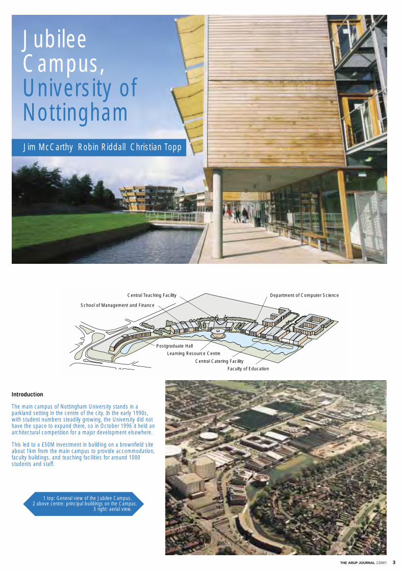
Introduction
The main campus of Nottingham University stands in aparkland setting in the centre of the city. In the early 1990s,with student numbers steadily growing, the University did nothave the space to expand there, so in October 1996 it held anarchitectural competition for a major development elsewhere.
This led to a £50M investment in building on a brownfield siteabout 1km from the main campus to provide accommodation,faculty buildings, and teaching facilities for around 1000 students and staff.
Postgraduate Hall
Learning Resource Centre
School of Management and Finance
Central Teaching Facility Department of Computer Science
Central Catering Facility
Faculty of Education
JubileeCampus,University ofNottinghamJim McCarthy Robin Riddall Christian Topp
1 top: General view of the Jubilee Campus.2 above centre: principal buildings on the Campus.
3 right: aerial view.
4 THE ARUP JOURNAL 2/2001
The low-energy challenge
Arup had a wide-ranging appointment for the engineering design,starting with the original scheme for the competition entry, andfinishing with commissioning and monitoring the building systems at the end of the project. The firm's involvement on the site will continue for some time; the innovative low-energyair-handling systems were partly funded by an EU grant underthe Thermie scheme, and Arup is involved in monitoring the system over the first few years of its use.
However the achievements of the project lie not only in theeconomy of the design or in its sustainable aspects, but in theremarkable figures for energy use. These are summarised in Fig 5, with the inclusion for comparison of ‘best practice’ figures2
for energy-efficient buildings. It can be seen that the measuredenergy use is half that of a similar ‘energy-efficient’ building. Fig 6 gives the equally important figures for the campus’s CO2production, again in comparison to ‘best practice’, showing a75% reduction in emissions when compared to a similar building.
The brief
The client required a wide range of facilities on the new campus- from student accommodation to a high-specification facultybuilding for the School of Management and Finance.
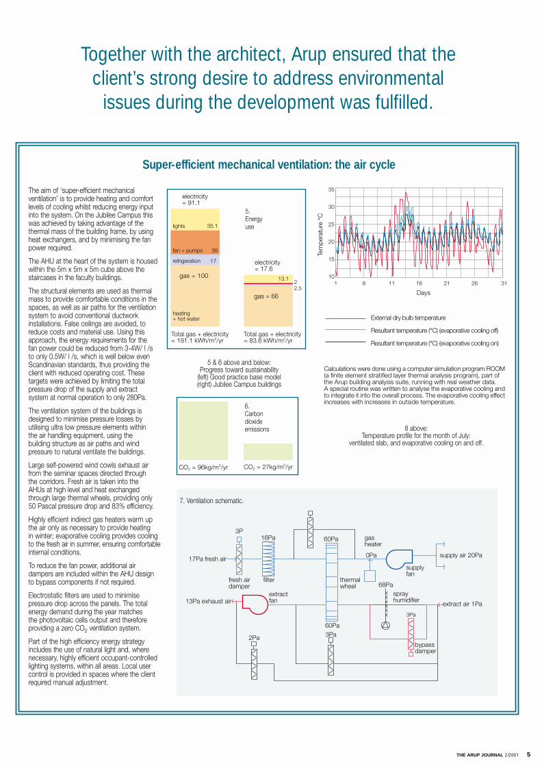
Underlying this was a strong desire for the development toaddress environmental issues, both in the choice of materialsand in the energy demands of the building systems. Arup waspart of the design team with the architects, Michael Hopkins &Partners, from early in the competition, and the environmentalsystems designed then were carried through to the final design.
The cost of the development was also important, it being fundedpartly from donations as well as by the client. The Universitywanted to build as much as it could for the budget and at thesame time have a quality of accommodation appropriate to thefunctions of the buildings.
Energy use
How did the Arup team achieve the energy targets? Answer - through a combination of specifying low-energy systems and integrating the services carefully into the buildingframe. Several innovative systems were brought together to fulfilthe required university building functions with a fraction of theenergy consumption of traditional buildings.
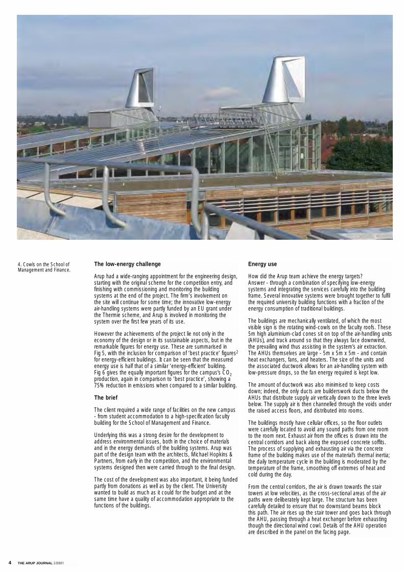
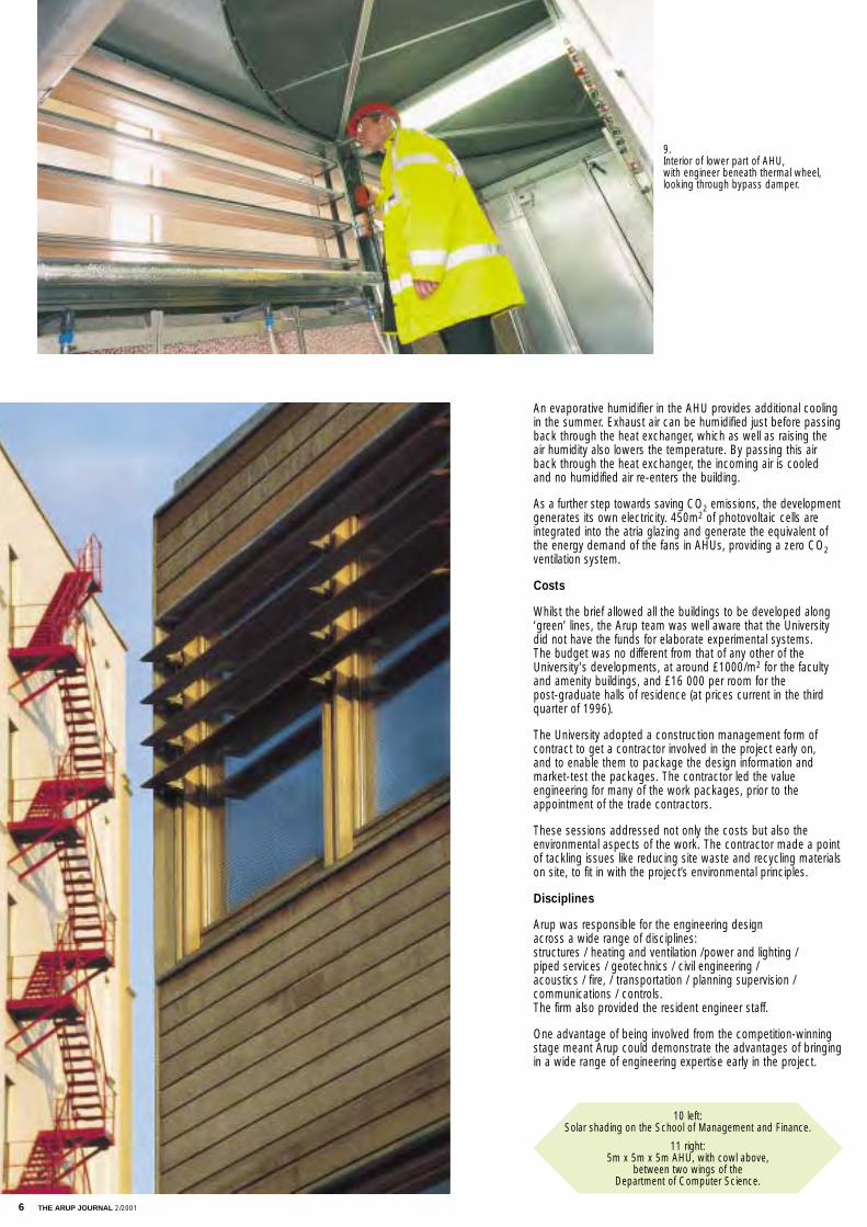
The buildings are mechanically ventilated, of which the most visible sign is the rotating wind-cowls on the faculty roofs. These5m high aluminium-clad cones sit on top of the air-handling units(AHUs), and track around so that they always face downwind,the prevailing wind thus assisting in the system’s air extraction.The AHUs themselves are large - 5m x 5m x 5m - and containheat exchangers, fans, and heaters. The size of the units and the associated ductwork allows for an air-handling system withlow-pressure drops, so the fan energy required is kept low.
The amount of ductwork was also minimised to keep costsdown; indeed, the only ducts are builderswork ducts below theAHUs that distribute supply air vertically down to the three levelsbelow. The supply air is then channelled through the voids underthe raised access floors, and distributed into rooms.
The buildings mostly have cellular offices, so the floor outletswere carefully located to avoid any sound paths from one roomto the room next. Exhaust air from the offices is drawn into thecentral corridors and back along the exposed concrete soffits.The process of supplying and exhausting air via the concreteframe of the building makes use of the material’s thermal inertia;the daily temperature cycle in the building is moderated by thetemperature of the frame, smoothing off extremes of heat andcold during the day.
From the central corridors, the air is drawn towards the stairtowers at low velocities, as the cross-sectional areas of the airpaths were deliberately kept large. The structure has been carefully detailed to ensure that no downstand beams block this path. The air rises up the stair tower and goes back through the AHU, passing through a heat exchanger before exhaustingthough the directional wind cowl. Details of the AHU operationare described in the panel on the facing page.
4. Cowls on the School ofManagement and Finance.
THE ARUP JOURNAL 2/2001 5
3P16Pa
17Pa fresh air
fresh airdamper
filter
extractfan13Pa exhaust air
2Pa 3Pa60Pa
60Pa
thermalwheel
gasheater
0Pa
supplyfan
68Pasprayhumidifier
3Pa
supply air 20Pa
extract air 1Pa
bypassdamper
CO2 = 27kg/m2/yrCO2 = 96kg/m2/yr
The aim of ‘super-efficient mechanical ventilation’ is to provide heating and comfort levels of cooling whilst reducing energy inputinto the system. On the Jubilee Campus thiswas achieved by taking advantage of the thermal mass of the building frame, by usingheat exchangers, and by minimising the fanpower required.
The AHU at the heart of the system is housedwithin the 5m x 5m x 5m cube above the staircases in the faculty buildings.
The structural elements are used as thermalmass to provide comfortable conditions in thespaces, as well as air paths for the ventilationsystem to avoid conventional ductwork installations. False ceilings are avoided, toreduce costs and material use. Using thisapproach, the energy requirements for the fan power could be reduced from 3-4W/ l /s to only 0.5W/ l /s, which is well below even Scandinavian standards, thus providing theclient with reduced operating cost. These targets were achieved by limiting the total pressure drop of the supply and extractsystem at normal operation to only 280Pa.
The ventilation system of the buildings isdesigned to minimise pressure losses by utilising ultra low pressure elements within the air handling equipment, using the building structure as air paths and wind pressure to natural ventilate the buildings.
Large self-powered wind cowls exhaust air from the seminar spaces directed through the corridors. Fresh air is taken into the AHUs at high level and heat exchanged through large thermal wheels, providing only 50 Pascal pressure drop and 83% efficiency.
Highly efficient indirect gas heaters warm up the air only as necessary to provide heating in winter; evaporative cooling provides cooling to the fresh air in summer, ensuring comfortableinternal conditions.
To reduce the fan power, additional air dampers are included within the AHU design to bypass components if not required.
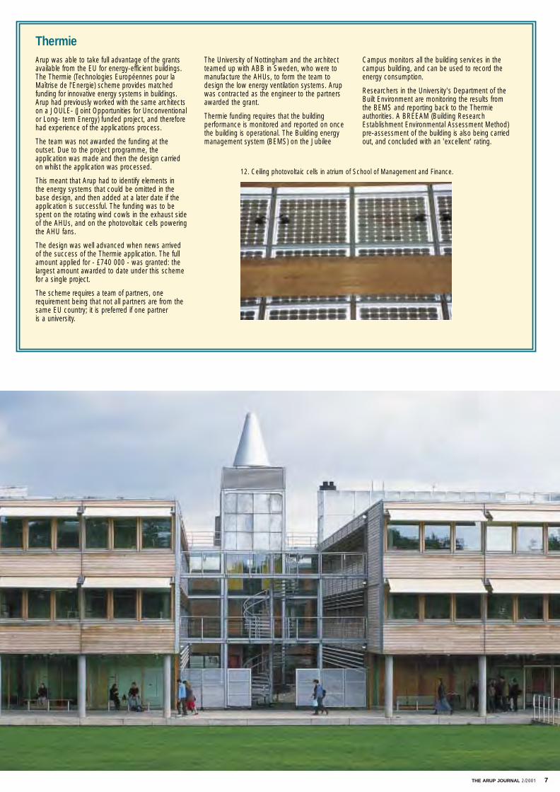
Electrostatic filters are used to minimise pressure drop across the panels. The total energy demand during the year matches the photovoltaic cells output and therefore providing a zero CO2 ventilation system.
Part of the high efficiency energy strategyincludes the use of natural light and, where necessary, highly efficient occupant-controlledlighting systems, within all areas. Local usercontrol is provided in spaces where the clientrequired manual adjustment.
Super-efficient mechanical ventilation: the air cycle
gas = 66
electricity= 17.6
2.52
13.1
Total gas + electricity= 83.6 kWh/m2/yr
17
39
35.1
electricity= 91.1
gas = 100
Total gas + electricity= 191.1 kWh/m2/yr
lights
fan + pumps
refrigeration
heating+ hot water
35
30
25
20
15
101 6 11 16 21 26 31
Tem
pera
ture
°C
Days
External dry bulb temperature
Resultant temperature (°C) (evaporative cooling off)
Resultant temperature (°C) (evaporative cooling on)
Calculations were done using a computer simulation program ROOM(a finite element stratified layer thermal analysis program), part ofthe Arup building analysis suite, running with real weather data.A special routine was written to analyse the evaporative cooling andto integrate it into the overall process. The evaporative cooling effectincreases with increases in outside temperature.
5. Energy use
6. Carbon dioxide emissions
7. Ventilation schematic.
5 & 6 above and below: Progress toward sustainability
(left) Good practice base model (right) Jubilee Campus buildings
8 above: Temperature profile for the month of July:
ventilated slab, and evaporative cooling on and off.
Together with the architect, Arup ensured that theclient’s strong desire to address environmental
issues during the development was fulfilled.
6 THE ARUP JOURNAL 2/2001
An evaporative humidifier in the AHU provides additional coolingin the summer. Exhaust air can be humidified just before passingback through the heat exchanger, which as well as raising the air humidity also lowers the temperature. By passing this airback through the heat exchanger, the incoming air is cooled and no humidified air re-enters the building.
As a further step towards saving CO2 emissions, the developmentgenerates its own electricity. 450m2 of photovoltaic cells are integrated into the atria glazing and generate the equivalent ofthe energy demand of the fans in AHUs, providing a zero CO2ventilation system.
Costs
Whilst the brief allowed all the buildings to be developed along‘green’ lines, the Arup team was well aware that the Universitydid not have the funds for elaborate experimental systems. The budget was no different from that of any other of theUniversity's developments, at around £1000/m2 for the facultyand amenity buildings, and £16 000 per room for the post-graduate halls of residence (at prices current in the third quarter of 1996).
The University adopted a construction management form of contract to get a contractor involved in the project early on, and to enable them to package the design information and market-test the packages. The contractor led the value engineering for many of the work packages, prior to the appointment of the trade contractors.
These sessions addressed not only the costs but also the environmental aspects of the work. The contractor made a pointof tackling issues like reducing site waste and recycling materialson site, to fit in with the project’s environmental principles.
Disciplines
Arup was responsible for the engineering design across a wide range of disciplines: structures / heating and ventilation /power and lighting /piped services / geotechnics / civil engineering / acoustics / fire, / transportation / planning supervision / communications / controls. The firm also provided the resident engineer staff.
One advantage of being involved from the competition-winningstage meant Arup could demonstrate the advantages of bringingin a wide range of engineering expertise early in the project.
11 right: 5m x 5m x 5m AHU, with cowl above,
between two wings of theDepartment of Computer Science.
10 left: Solar shading on the School of Management and Finance.
9. Interior of lower part of AHU, with engineer beneath thermal wheel, looking through bypass damper.
THE ARUP JOURNAL 2/2001 7
Arup was able to take full advantage of the grantsavailable from the EU for energy-efficient buildings.The Thermie (Technologies Européennes pour laMaîtrise de l'Energie) scheme provides matchedfunding for innovative energy systems in buildings.Arup had previously worked with the same architectson a JOULE- (Joint Opportunities for Unconventionalor Long- term Energy) funded project, and thereforehad experience of the applications process.
The team was not awarded the funding at the outset. Due to the project programme, the application was made and then the design carriedon whilst the application was processed.
This meant that Arup had to identify elements in the energy systems that could be omitted in thebase design, and then added at a later date if theapplication is successful. The funding was to bespent on the rotating wind cowls in the exhaust sideof the AHUs, and on the photovoltaic cells poweringthe AHU fans.
The design was well advanced when news arrivedof the success of the Thermie application. The fullamount applied for - £740 000 - was granted: thelargest amount awarded to date under this schemefor a single project.
The scheme requires a team of partners, onerequirement being that not all partners are from thesame EU country; it is preferred if one partner is a university.
The University of Nottingham and the architectteamed up with ABB in Sweden, who were to manufacture the AHUs, to form the team to design the low energy ventilation systems. Arupwas contracted as the engineer to the partnersawarded the grant.
Thermie funding requires that the building performance is monitored and reported on once the building is operational. The Building energymanagement system (BEMS) on the Jubilee
ThermieCampus monitors all the building services in thecampus building, and can be used to record theenergy consumption.
Researchers in the University's Department of theBuilt Environment are monitoring the results fromthe BEMS and reporting back to the Thermieauthorities. A BREEAM (Building ResearchEstablishment Environmental Assessment Method)pre-assessment of the building is also being carriedout, and concluded with an 'excellent' rating.
12. Ceiling photovoltaic cells in atrium of School of Management and Finance.
8 THE ARUP JOURNAL 2/2001
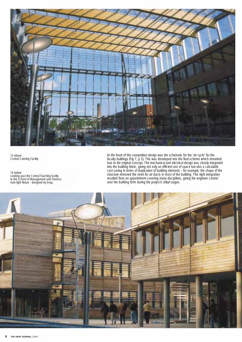
At the heart of the competition design was the schematic for the ‘air cycle’ for the faculty buildings (Fig 7, p 5). This was developed into the final scheme which remainedtrue to the original concept. The mechanical and electrical design was closely integratedinto the building fabric, giving not only an efficient use of space but also a calculablecost saving in terms of duplication of building elements - for example, the shape of thestructure removed the need for air ducts in most of the building. This tight integrationresulted from an appointment covering many disciplines, giving the engineer controlover the building form during the project’s initial stages.
14 below: Looking past the Central Teaching facility to the School of Management and Finance; note light fixture - designed by Arup.
13 above: Central Catering Facility.

THE ARUP JOURNAL 2/2001 9
The buildings
There are seven principal buildings: the three faculty buildings(Education, the Department of Computer Science, and theSchool of Management and Finance); three amenity buildings(the Learning Resource Centre, Central Catering Facility, andCentral Teaching Facility); and postgraduate halls of residence.
The low energy systems described in this article are incorporated into the faculty buildings - three similar buildingswhere the combination of cellular offices and teaching spaces isbest suited to the low energy ventilation system.
The Central Teaching Facility houses three lecture theatres(100, 200, and 300-seater), stacked on top of each other withraking seating. Here the ventilation demands are higher and theplant more conventional, though it still makes use of the stairtowers for exhaust air.
The site
The site formerly housed the main warehouse and distributionarea of a Raleigh bicycle factory, and some chemical processesto do with manufacturing had gone on there in the past. To thesouth was the Sturmey Archer factory where saddles, spokes,and hub gears were made. Underground service trenches linkedthe two factories. Searches of existing documentation revealedthat a canal had run along the east side of the site until the1950s, and more investigations at the Coal Board indicated thatcoal had been mined at three levels below the site, with a shaftsomewhere on the site. This shaft was abandoned in the 1840s,and no records survived showing exactly where it was. Someevidence indicated that prior to that there was a mediaeval village on the north end of the site.
Arup had much to do on the site before construction couldbegin. The site investigation was more far-reaching than usual,including local archaeologists being asked if they wanted toexcavate any part of the mediaeval site - they did not.
Also, as contamination ‘hotspots’ were likely to have been leftbehind from the factory processes, remediation had alreadybeen carried out when the team arrived. The new developmentis extensively planted, however, so Arup did further chemicaltests to ensure that the plants would thrive.
The contractors were alerted about the mineshaft, and thedesign team had to be satisfied that the worked seams underthe site did not affect the foundations. The contractors spentsome time digging trial pits on the site, searching for the mineshaft, the main concern being that it might not have been adequately capped after it was abandoned. However, no evidence of it came to light in the area of the new buildingsso it was concluded that the shaft is either well backfilled orelsewhere on the site.
Environmental objectives
At the masterplanning stage the University set ambitious goalsin respect of environmental objectives, with declared aims forenergy, traffic, waste, and ground management. The latterincluded promoting new habitats for wildlife and ecology andenhancing the visual amenity, whilst preserving the biodiversityin the existing woodland.
A high quality landscape setting was proposed, central to this strategy being the creation of a 1.1ha lake longitudinallythrough the site As the major feature of the development it hasseveral functions: together with other associated watercoursesit provides:
• an attenuation facility for run-off generated from the development, prior to discharging at a controlled rate to the off-site drainage system
• a valuable new wildlife habitat
• a social amenity for students and the general public, includinga link to a public cycleway
• a buffer between the buildings, adjacent residential properties,and existing woodland along the site’s southern boundary
• a defined and restricted edge to the main pedestrian corridor.
Lake design
To maintain acceptable water quality, targets were set and thenecessary management systems identified. In line with bestpractice, a protective management approach was proposed, tobe implemented by:
• treating run-off before it enters the lake to remove suspended solids, hydrocarbons and nutrients
• providing extensive aquatic planting to help oxygenate the water and provide a habitat for zooplankton
• re-circulation systems (sadly the proposed wind pump did not prove viable, and small mechanical pumps were ultimately specified)
• water top-up during periods of drought; in the short term the provision of a groundwater borehole was not feasible, but development on an adjacent linked site will allow the lake to be topped up via a borehole
• a system of air diffusers, given that until a stable ecosystem within the lake is established an acceptable water quality will be difficult to maintain.
These help to oxygenate the water, assisting in the removal oftoxic gases and nutrients. This reduces risk of algae growth and improves invertebrate growth.
A sustainable infrastructure
The University is committed to using products from renewablesources and to recycling waste. To achieve these objectives, the infrastructure elements included:
• a cut/fill balance, ensuring that all excavated materials remained on site
• encapsulation of unsuitable materials to allow their use in landscape areas
• use of re-processed materials, particularly concrete and brickwork
• use of a geocomposite clay liner, which avoided the customary use of petroleum derivative-based membranes.
PVC in particular was highlighted as a major polluter in manufacturing and disposal, and so was avoided throughoutthe project. It was replaced by low smoke and fume (LSF) insulated cabling, and high density and medium density polyethylene (HDPE/MDPE) ducts and pipework. In addition,sustainable cladding to buildings in the form of Western RedCedar from renewable sources was specified.
Brownfield development – urban generation
This development has successfully taken a brownfieldsite in a light industrial area in Nottingham and turnedit into a sustainable urban landscaped park setting for
several university buildings.
15. Lecture theatre in Central Teaching Facility.
10 THE ARUP JOURNAL 2/2001
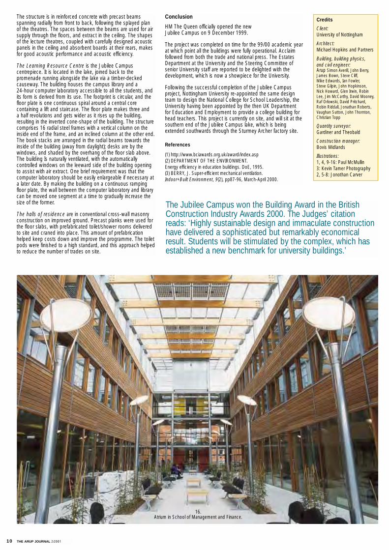
The structure is in reinforced concrete with precast beams spanning radially from front to back, following the splayed plan of the theatres. The spaces between the beams are used for airsupply through the floors, and extract in the ceiling. The shapesof the lecture theatres, coupled with carefully designed acousticpanels in the ceiling and absorbent boards at their rears, makesfor good acoustic performance and acoustic efficiency.
The Learning Resource Centre is the Jubilee Campus centrepiece. It is located in the lake, joined back to the promenade running alongside the lake via a timber-deckedcauseway. The building houses the campus library and a 24-hour computer laboratory accessible to all the students, andits form is derived from its use. The footprint is circular, and thefloor plate is one continuous spiral around a central core containing a lift and staircase. The floor plate makes three and a half revolutions and gets wider as it rises up the building,resulting in the inverted cone-shape of the building. The structurecomprises 16 radial steel frames with a vertical column on theinside end of the frame, and an inclined column at the other end.The book stacks are arranged in the radial beams towards theinside of the building (away from daylight); desks are by the windows, and shaded by the overhang of the floor slab above.The building Is naturally ventilated, with the automatically controlled windows on the leeward side of the building openingto assist with air extract. One brief requirement was that thecomputer laboratory should be easily enlargeable if necessary ata later date. By making the building on a continuous rampingfloor plate, the wall between the computer laboratory and librarycan be moved one segment at a time to gradually increase thesize of the former.
The halls of residence are in conventional cross-wall masonryconstruction on improved ground. Precast planks were used forthe floor slabs, with prefabricated toilet/shower rooms deliveredto site and craned into place. This amount of prefabricationhelped keep costs down and improve the programme. The toiletpods were finished to a high standard, and this approach helpedto reduce the number of trades on site.
Conclusion
HM The Queen officially opened the new Jubilee Campus on 9 December 1999.
The project was completed on time for the 99/00 academic yearat which point all the buildings were fully operational. Acclaim followed from both the trade and national press. The EstatesDepartment at the University and the Steering Committee ofsenior University staff are reported to be delighted with thedevelopment, which is now a showpiece for the University.
Following the successful completion of the Jubilee Campus project, Nottingham University re-appointed the same designteam to design the National College for School Leadership, theUniversity having been appointed by the then UK Department for Education and Employment to provide a college building forhead teachers. This project is currently on site, and will sit at thesouthern end of the Jubilee Campus lake, which is beingextended southwards through the Sturmey Archer factory site.
References
(1) http://www.bciawards.org.uk/award/index.asp(2) DEPARTMENT OF THE ENVIRONMENT. Energy efficiency in education buildings. DoE, 1995.(3) BERRY, J. Super-efficient mechanical ventilation. Indoor+Built Environment, 9(2), pp87-96, March-April 2000.
Credits
Client:University of Nottingham
Architect:Michael Hopkins and Partners
Building, building physics, and civil engineer:Arup Simon Averill, John Berry,James Bown, Steve Cliff, Mike Edwards, Ian Fowler, Steve Gilpin, John Hopkinson, Nick Howard, Glen Irwin, RobinLee, Jim McCarthy, David Mooney,Raf Orlowski, David Pritchard,Robin Riddall, Jonathan Roberts,Vaughan Sutton, John Thornton,Christian Topp
Quantity surveyor:Gardiner and Theobald
Construction manager:Bovis Midlands
Illustrations:1, 4, 9-16: Paul McMullin3: Kevin Tamer Photography 2, 5-8: Jonothan Carver
16. Atrium in School of Management and Finance.
The Jubilee Campus won the Building Award in the BritishConstruction Industry Awards 2000. The Judges’ citationreads: ‘Highly sustainable design and immaculate constructionhave delivered a sophisticated but remarkably economical result. Students will be stimulated by the complex, which has established a new benchmark for university buildings.’
THE ARUP JOURNAL 2/2001 11
Introduction
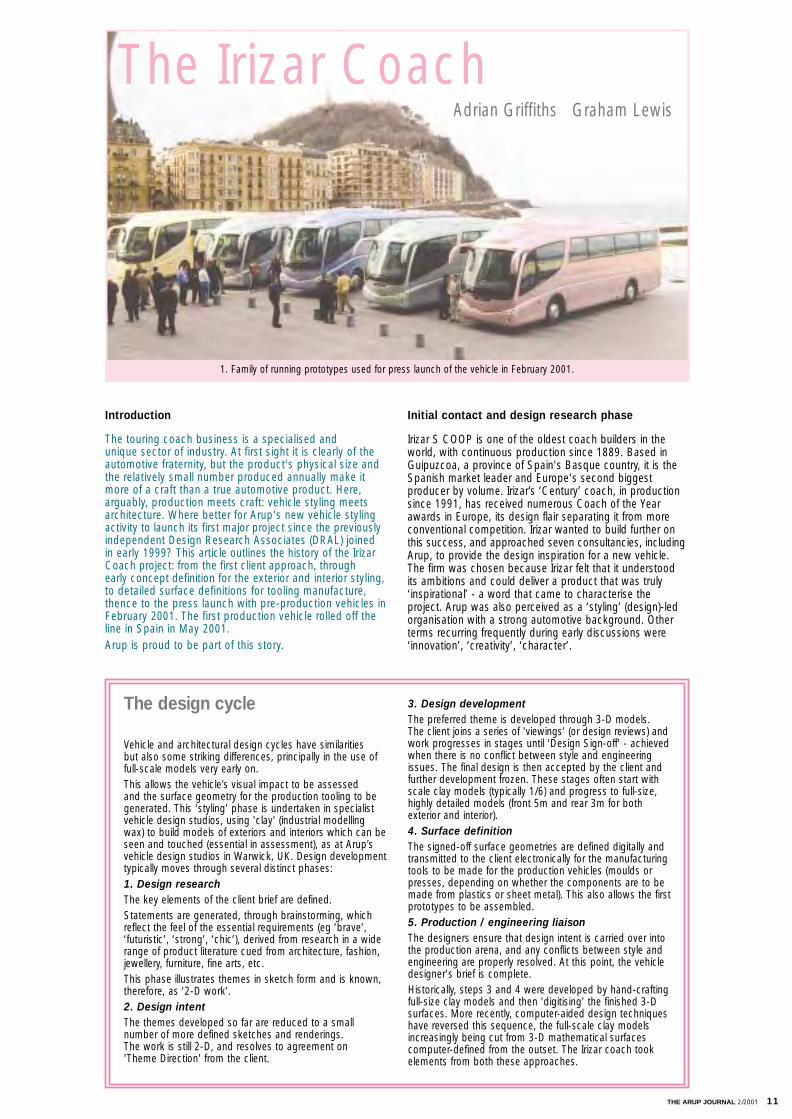
The touring coach business is a specialised and unique sector of industry. At first sight it is clearly of theautomotive fraternity, but the product's physical size andthe relatively small number produced annually make itmore of a craft than a true automotive product. Here,arguably, production meets craft: vehicle styling meetsarchitecture. Where better for Arup's new vehicle stylingactivity to launch its first major project since the previouslyindependent Design Research Associates (DRAL) joined in early 1999? This article outlines the history of the IrizarCoach project: from the first client approach, through early concept definition for the exterior and interior styling, to detailed surface definitions for tooling manufacture,thence to the press launch with pre-production vehicles inFebruary 2001. The first production vehicle rolled off theline in Spain in May 2001. Arup is proud to be part of this story.
Initial contact and design research phase
Irizar S COOP is one of the oldest coach builders in theworld, with continuous production since 1889. Based inGuipuzcoa, a province of Spain's Basque country, it is theSpanish market leader and Europe's second biggest producer by volume. Irizar’s ‘Century’ coach, in productionsince 1991, has received numerous Coach of the Yearawards in Europe, its design flair separating it from moreconventional competition. Irizar wanted to build further onthis success, and approached seven consultancies, includingArup, to provide the design inspiration for a new vehicle. The firm was chosen because Irizar felt that it understood its ambitions and could deliver a product that was truly‘inspirational’ - a word that came to characterise the project. Arup was also perceived as a ‘styling’ (design)-ledorganisation with a strong automotive background. Otherterms recurring frequently during early discussions were‘innovation’, ‘creativity’, ‘character’.
Vehicle and architectural design cycles have similarities but also some striking differences, principally in the use offull-scale models very early on. This allows the vehicle’s visual impact to be assessed and the surface geometry for the production tooling to begenerated. This 'styling' phase is undertaken in specialist vehicle design studios, using 'clay' (industrial modellingwax) to build models of exteriors and interiors which can beseen and touched (essential in assessment), as at Arup’svehicle design studios in Warwick, UK. Design development typically moves through several distinct phases:1. Design researchThe key elements of the client brief are defined. Statements are generated, through brainstorming, whichreflect the feel of the essential requirements (eg ‘brave’,‘futuristic’, ‘strong’, ‘chic’), derived from research in a widerange of product literature cued from architecture, fashion,jewellery, furniture, fine arts, etc. This phase illustrates themes in sketch form and is known,therefore, as ‘2-D work’.2. Design intentThe themes developed so far are reduced to a small number of more defined sketches and renderings. The work is still 2-D, and resolves to agreement on 'Theme Direction' from the client.
3. Design developmentThe preferred theme is developed through 3-D models. The client joins a series of 'viewings' (or design reviews) andwork progresses in stages until ‘Design Sign-off’ - achievedwhen there is no conflict between style and engineeringissues. The final design is then accepted by the client andfurther development frozen. These stages often start withscale clay models (typically 1/6) and progress to full-size,highly detailed models (front 5m and rear 3m for both exterior and interior).4. Surface definitionThe signed-off surface geometries are defined digitally andtransmitted to the client electronically for the manufacturingtools to be made for the production vehicles (moulds orpresses, depending on whether the components are to bemade from plastics or sheet metal). This also allows the firstprototypes to be assembled.5. Production / engineering liaisonThe designers ensure that design intent is carried over intothe production arena, and any conflicts between style andengineering are properly resolved. At this point, the vehicledesigner's brief is complete.Historically, steps 3 and 4 were developed by hand-craftingfull-size clay models and then 'digitising' the finished 3-Dsurfaces. More recently, computer-aided design techniqueshave reversed this sequence, the full-scale clay modelsincreasingly being cut from 3-D mathematical surfacescomputer-defined from the outset. The Irizar coach tookelements from both these approaches.
The design cycle
The Irizar Coach Adrian Griffiths Graham Lewis
1. Family of running prototypes used for press launch of the vehicle in February 2001.
12 THE ARUP JOURNAL 2/2001
All these thoughts and feelings were developed by Arup withthe client during the design research phase until a brief forthe product was agreed. Strong elements established by theteam in the brief were:
• a powerful ‘face’ on the front of the vehicle (‘down-the-road graphic’)
• a feeling of energy in the overall shape
• a visual impression of safety and robustness
• a clear definition for the panel section to the vehicle sides, and ‘flow’
• an overall ‘Spanish’ character and a stylish and distinctive ‘personality’ apt for a luxury touring coach.
These were demonstrated through a series of sketches (Fig 2), and excited Irizar’s management team sufficiently tolaunch the project into its next phase of development.
Exterior and interior design
It was immediately clear that Irizar would be a challengingclient. Rarely had Arup encountered so many senior managers with an intimate understanding of their productand such singular dedication and enthusiasm to make itsuccessful in the global market-place. Apart from Irizar’s keypersonnel, the team was completed by Sener, responsiblefor the engineered structure, and LKS, who would providethe relevant market research inputs. At the outset, all spentmuch time discussing the competition, analysing its goodpoints and weaknesses and comparing them to the‘Century’, and defining the essential improvements that had to be incorporated into the new design.
After this design research phase, agreeing initial parameterslike height, width, length, wheel positions, etc, the designintent stage began (Fig 3).
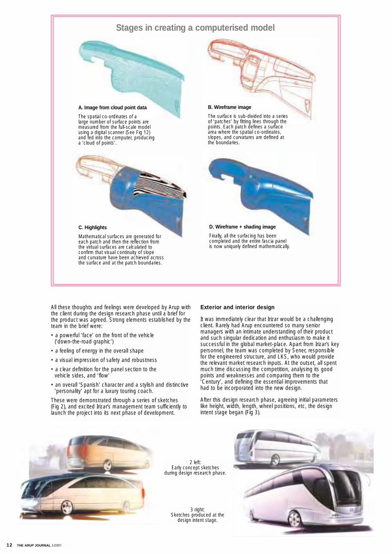
Stages in creating a computerised model
A. Image from cloud point data
The spatial co-ordinates of a large number of surface points aremeasured from the full-scale modelusing a digital scanner (See Fig 12) and fed into the computer, producing a ‘cloud of points’.
B. Wireframe image
The surface is sub-divided into a seriesof ‘patches’ by fitting lines through thepoints. Each patch defines a surfacearea where the spatial co-ordinates,slopes, and curvatures are defined atthe boundaries.
2 left:Early concept sketches
during design research phase.
3 right:Sketches produced at the
design intent stage.
C. Highlights
Mathematical surfaces are generated foreach patch and then the reflection fromthe virtual surfaces are calculated to confirm that visual continuity of slope and curvature have been achieved acrossthe surface and at the patch boundaries.
D. Wireframe + shading image
Finally, all the surfacing has been completed and the entire fascia panel is now uniquely defined mathematically.

THE ARUP JOURNAL 2/2001 13
Within four weeks, the first sketch presentation was made to Irizar and the process of style selection began.Clearly, some sketches were too innovative and ambitious,whilst others more closely reflected the client’s aspirations.With this critique, the designers could focus the follow-upwork to the management team’s requirements, and over twomonths narrowed the design intent phase down to threedefinitive renderings (Fig 4).
At this stage, the client relied heavily on Arup’s advice onwhich design direction the new product should take.
The renderings helped to narrow down and focus the designelements of the exterior, but only scale models (Fig 5) couldconvey a more consolidated feel for the exterior appearanceto Irizar. After agreeing on a single exterior theme sketch,Arup accordingly began developing the 1/6 scale models.Why 1/6? Simply because this size is the optimum betweenbeing large enough to incorporate a reasonable amount ofdesign detail and small enough to be transportable. Alsowhen photographed they can be electronically blended intoreal backgrounds (Fig 6) to give an early realistic impressionof the product.
On 14 September 1998, two models of the new vehiclewere reviewed at Arup’s Warwick studios. These representeda 3.5m (height) x 12m (length) coach (showing two-axle layout) and 3.7m x 12m and 15m coaches, (with the alternative lengths showing two-axle and tri-axle layouts). At the same meeting, the first sketches of the interior themewere reviewed (Figs 7 & 8). Clear, concise decisions weremade regarding the exterior, and design theme direction was given for continued interior development. Detailed modifications for the exterior were discussed, and then itwas agreed to proceed to full-size clay development.
These processes are second nature to a large automobileOEM (Original Equipment Manufacturer) with its vast financialresources, and Arup’s experience and expertise derived from this industry. By showing Irizar how some automotivepractices would directly benefit development of the newvehicle, Arup could import relevant best practices, applythem advantageously, and still work within the prescribedbudget targets.
Full-size clay allowed Irizar to appreciate immediately thetranslation of the theme design into reality (Fig 9). At thesame time, it enabled the engineers to consolidate theirstructural and component packaging design by monitoringprogress on the full-size clay development both visually andby processing the digitised data generated as the claymodel developed.
A series of style review dates was agreed with Irizar andseveral meetings held at Warwick to monitor and agree the3D design development stages. As exterior developmentprogressed, Irizar provided packaging and ergonomic 'hardpoints' (functional spaces that individual elements require inthe overall structural package,) for the roof-mounted HVACsystem, mirrors, glass requirements, motor packages anddrive train, and occupants. Discussions also proceeded withthe exterior lamp manufacturers, whilst the glazing suppliers visited Arup to assess the feasibility of the largecompound-curvature front windscreen.
4.Sketches of the definitive renderings that helped make the choice of designdirection that the new product should take.
5.Developing the 1/6 scale models of the coach.
6.Model photograph electronicallyblended into real background.
7 & 8.First sketches of the interiorfrom which the design themedirection was evaluated.
9.Full-size clay development.
10.Full-size models of front and rearends were presented atthe exteriorsign off meeting.
14 THE ARUP JOURNAL 2/2001
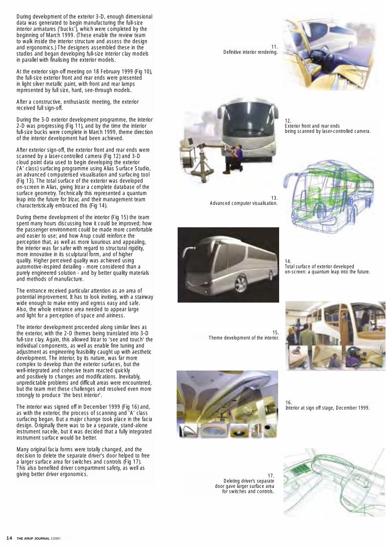
During development of the exterior 3-D, enough dimensionaldata was generated to begin manufacturing the full-sizeinterior armatures ('bucks'), which were completed by thebeginning of March 1999. (These enable the review team to walk inside the interior structure and assess the designand ergonomics.) The designers assembled these in the studios and began developing full-size interior clay models in parallel with finalising the exterior models.
At the exterior sign-off meeting on 18 February 1999 (Fig 10),the full-size exterior front and rear ends were presented in light silver metallic paint, with front and rear lamps represented by full size, hard, see-through models.
After a constructive, enthusiastic meeting, the exteriorreceived full sign-off.
During the 3-D exterior development programme, the interior2-D was progressing (Fig 11), and by the time the interiorfull-size bucks were complete in March 1999, theme directionof the interior development had been achieved.
After exterior sign-off, the exterior front and rear ends werescanned by a laser-controlled camera (Fig 12) and 3-Dcloud point data used to begin developing the exterior ('A' class) surfacing programme using Alias Surface Studio,an advanced computerised visualisation and surfacing tool(Fig 13). The total surface of the exterior was developed on-screen in Alias, giving Irizar a complete database of thesurface geometry. Technically this represented a quantumleap into the future for Irizar, and their management teamcharacteristically embraced this (Fig 14).
During theme development of the interior (Fig 15) the teamspent many hours discussing how it could be improved; howthe passenger environment could be made more comfortableand easier to use; and how Arup could reinforce the perception that, as well as more luxurious and appealing,the interior was far safer with regard to structural rigidity,more innovative in its sculptural form, and of higher quality. Higher perceived quality was achieved using automotive-inspired detailing - more considered than a purely engineered solution - and by better quality materials and methods of manufacture.
The entrance received particular attention as an area ofpotential improvement. It has to look inviting, with a stairwaywide enough to make entry and egress easy and safe. Also, the whole entrance area needed to appear large and light for a perception of space and airiness.
The interior development proceeded along similar lines asthe exterior, with the 2-D themes being translated into 3-Dfull-size clay. Again, this allowed Irizar to 'see and touch' theindividual components, as well as enable fine tuning andadjustment as engineering feasibility caught up with aestheticdevelopment. The interior, by its nature, was far more complex to develop than the exterior surfaces, but the well-integrated and cohesive team reacted quickly and positively to changes and modifications. Inevitably, unpredictable problems and difficult areas were encountered,but the team met these challenges and resolved even morestrongly to produce 'the best interior'.
The interior was signed off in December 1999 (Fig 16) and,as with the exterior, the process of scanning and 'A' classsurfacing began. But a major change took place in the faciadesign. Originally there was to be a separate, stand-aloneinstrument nacelle, but it was decided that a fully integratedinstrument surface would be better.
Many original facia forms were totally changed, and thedecision to delete the separate driver's door helped to free a larger surface area for switches and controls (Fig 17). This also benefited driver compartment safety, as well asgiving better driver ergonomics.
11. Definitive interior rendering.
12. Exterior front and rear ends being scanned by laser-controlled camera.
13.Advanced computer visualisation.
14.Total surface of exterior developed on-screen: a quantum leap into the future.
15. Theme development of the interior.
16.Interior at sign off stage, December 1999.
17. Deleting driver’s separate
door gave larger surface area for switches and controls.
THE ARUP JOURNAL 2/2001 15
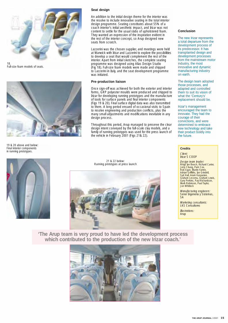
Seat design
An addition to the initial design theme for the interior wasthe resolve to include innovative seating in the total interiordesign programme. Seating constitutes about 55% of acoach interior's initial aesthetic impact, and Irizar was notcontent to settle for the usual slabs of upholstered foam.They wanted an expression of the inspiration evident in the rest of the interior concept, so Arup designed new seats from scratch.
Lazzerini was the chosen supplier, and meetings were heldat Warwick with Irizar and Lazzerini to explore the possibilitiesto develop a seat that would complement the rest of theinterior. Apart from initial sketches, the complete seatingprogramme was designed using Alias Design Studio (Fig 18). Full-size foam models were made and shipped to Lazzerini in Italy, and the seat development programmewas initiated.
Pre-production liaison
Once sign-off was achieved for both the exterior and interiorforms, GRP polyester moulds were produced and shipped toIrizar for developing running prototypes and the manufactureof tools for surface panels and final interior components(Figs 19 & 20). Final surface digital data was also transmittedto them. A long period ensued of occasional visits to Spainto resolve engineering and production conflicts, plus themany small adjustments and modifications inevitable in anydesign process.
Throughout this period, Arup managed to preserve the cleardesign intent conveyed by the full-scale clay models, and afamily of running prototypes was used for the press launch ofthe vehicle in February 2001 (Figs 21& 22).
Conclusion
The new Irizar represents a total departure from thedevelopment process of its predecessor. It hastransplanted design anddevelopment processesfrom the mainstream motorindustry, the mostinnovative and dynamicmanufacturing industryon earth.
The design team adoptedthose processes, andadapted and controlledthem to suit its vision ofwhat the ‘Century’s’replacement should be.
Irizar's managementencouraged the team toinnovate. They had thecourage of theirconvictions, and weredetermined to embracenew technology and taketheir product boldly intothe future.
‘The Arup team is very proud to have led the development process which contributed to the production of the new Irizar coach.’
19 & 20 above and below:Final interior components in running prototypes.
21 & 22 below:Running prototypes at press launch
18. Full-size foam models of seats.
Credits
Client: Irizar S COOP
Design team leader: Arup Ian Beech, Richard Carter,Jerry Chung, Pam Cox, Rob Egan, Martin Farren, Adrian Griffiths, Ian Grindell, Syd Hall, Aram Kasparian, Graham Lecornu, Graham Lewis,Gary Perkins, Paul Richardson,Mark Robinson, Paul Taylor, Jon Whitlock
Manufacturing engineers:Sener Ingeneria y Sistemas,SA
Marketing consultants:LKS Consultores
Illustrations:Arup
16 THE ARUP JOURNAL 2/2001
Introduction
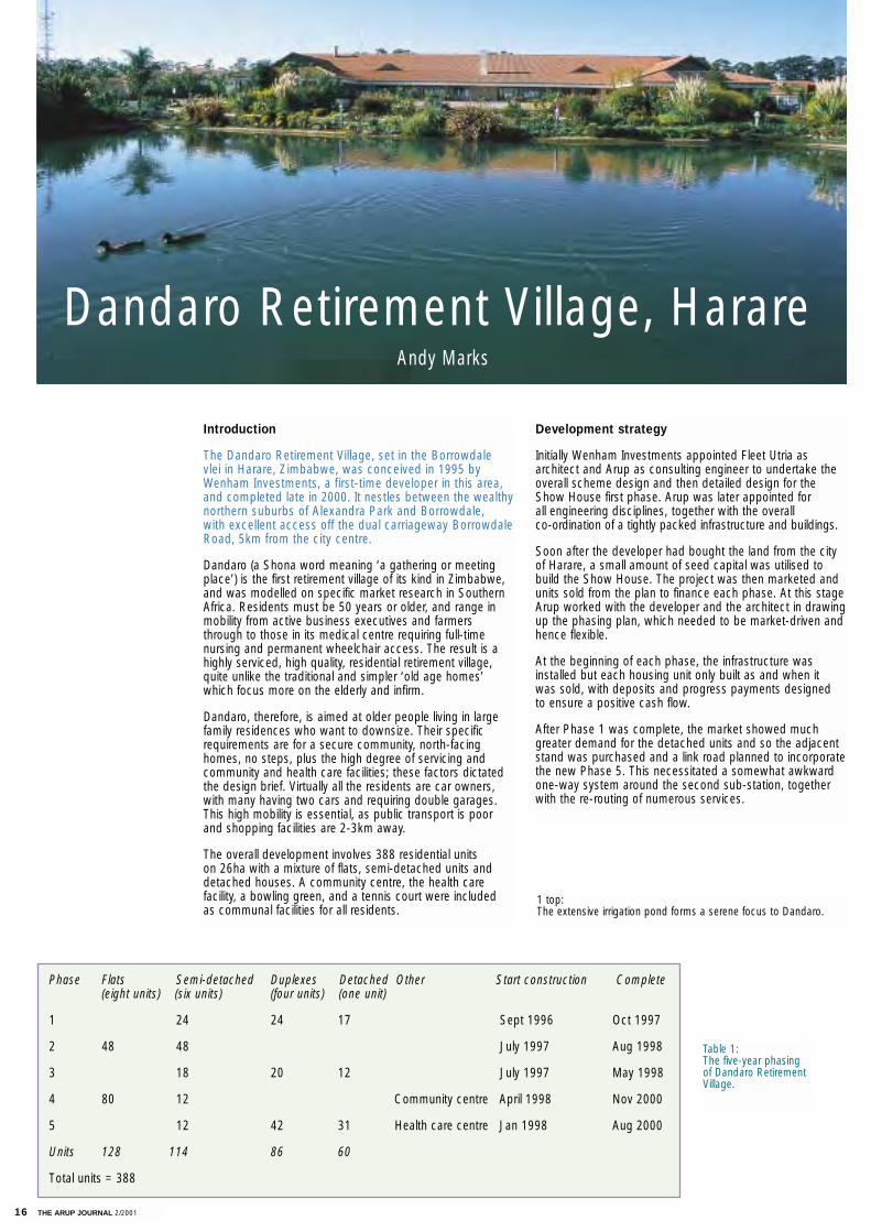
The Dandaro Retirement Village, set in the Borrowdale vlei in Harare, Zimbabwe, was conceived in 1995 byWenham Investments, a first-time developer in this area, and completed late in 2000. It nestles between the wealthynorthern suburbs of Alexandra Park and Borrowdale,with excellent access off the dual carriageway BorrowdaleRoad, 5km from the city centre.
Dandaro (a Shona word meaning ‘a gathering or meetingplace’) is the first retirement village of its kind in Zimbabwe,and was modelled on specific market research in SouthernAfrica. Residents must be 50 years or older, and range inmobility from active business executives and farmersthrough to those in its medical centre requiring full-timenursing and permanent wheelchair access. The result is ahighly serviced, high quality, residential retirement village,quite unlike the traditional and simpler ‘old age homes’which focus more on the elderly and infirm.
Dandaro, therefore, is aimed at older people living in largefamily residences who want to downsize. Their specificrequirements are for a secure community, north-facinghomes, no steps, plus the high degree of servicing andcommunity and health care facilities; these factors dictatedthe design brief. Virtually all the residents are car owners,with many having two cars and requiring double garages.This high mobility is essential, as public transport is poorand shopping facilities are 2-3km away.
The overall development involves 388 residential units on 26ha with a mixture of flats, semi-detached units anddetached houses. A community centre, the health care facility, a bowling green, and a tennis court were included as communal facilities for all residents.
Development strategy
Initially Wenham Investments appointed Fleet Utria as architect and Arup as consulting engineer to undertake theoverall scheme design and then detailed design for theShow House first phase. Arup was later appointed for all engineering disciplines, together with the overall co-ordination of a tightly packed infrastructure and buildings.
Soon after the developer had bought the land from the cityof Harare, a small amount of seed capital was utilised tobuild the Show House. The project was then marketed andunits sold from the plan to finance each phase. At this stageArup worked with the developer and the architect in drawingup the phasing plan, which needed to be market-driven andhence flexible.
At the beginning of each phase, the infrastructure wasinstalled but each housing unit only built as and when it was sold, with deposits and progress payments designed to ensure a positive cash flow.
After Phase 1 was complete, the market showed muchgreater demand for the detached units and so the adjacentstand was purchased and a link road planned to incorporatethe new Phase 5. This necessitated a somewhat awkwardone-way system around the second sub-station, togetherwith the re-routing of numerous services.
Phase Flats Semi-detached Duplexes Detached Other Start construction Complete(eight units) (six units) (four units) (one unit)
1 24 24 17 Sept 1996 Oct 1997
2 48 48 July 1997 Aug 1998
3 18 20 12 July 1997 May 1998
4 80 12 Community centre April 1998 Nov 2000
5 12 42 31 Health care centre Jan 1998 Aug 2000
Units 128 114 86 60
Total units = 388
Dandaro Retirement Village, HarareAndy Marks
1 top: The extensive irrigation pond forms a serene focus to Dandaro.
Table 1:The five-year phasingof Dandaro RetirementVillage.
17
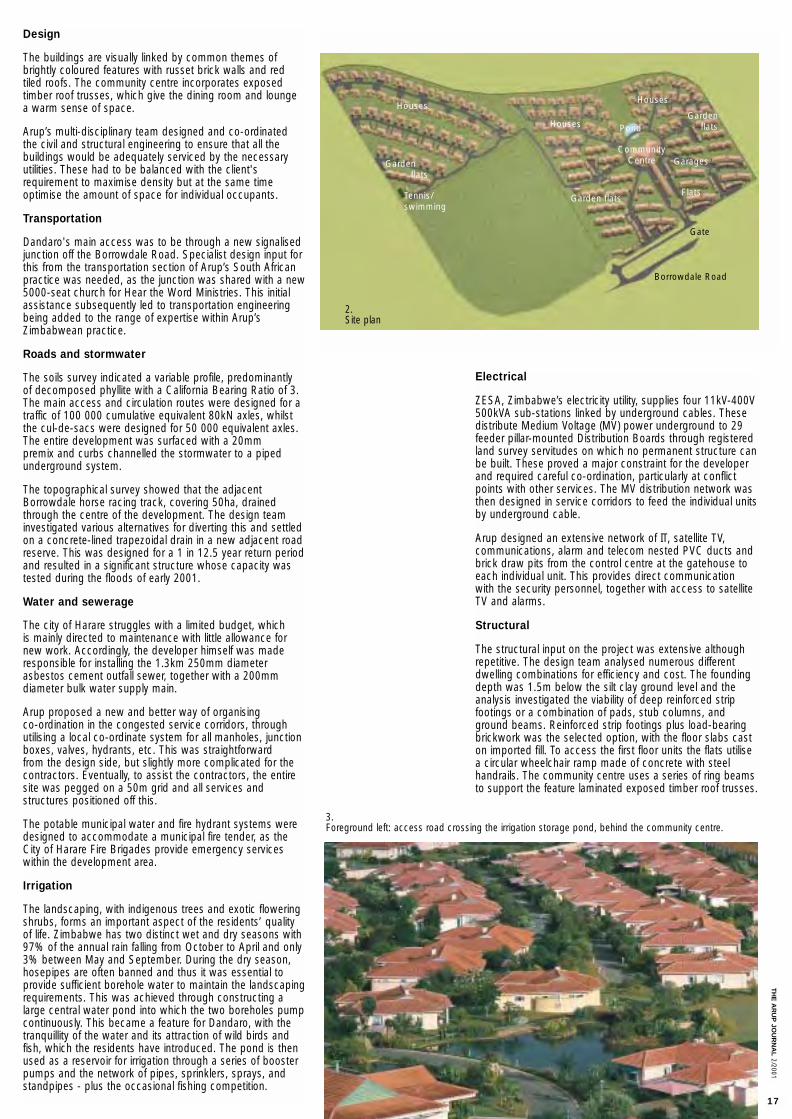
Design
The buildings are visually linked by common themes ofbrightly coloured features with russet brick walls and redtiled roofs. The community centre incorporates exposed timber roof trusses, which give the dining room and loungea warm sense of space.
Arup’s multi-disciplinary team designed and co-ordinatedthe civil and structural engineering to ensure that all thebuildings would be adequately serviced by the necessaryutilities. These had to be balanced with the client's requirement to maximise density but at the same time optimise the amount of space for individual occupants.
Transportation
Dandaro's main access was to be through a new signalisedjunction off the Borrowdale Road. Specialist design input forthis from the transportation section of Arup’s South Africanpractice was needed, as the junction was shared with a new5000-seat church for Hear the Word Ministries. This initialassistance subsequently led to transportation engineeringbeing added to the range of expertise within Arup’sZimbabwean practice.
Roads and stormwater
The soils survey indicated a variable profile, predominantly of decomposed phyllite with a California Bearing Ratio of 3.The main access and circulation routes were designed for atraffic of 100 000 cumulative equivalent 80kN axles, whilstthe cul-de-sacs were designed for 50 000 equivalent axles.The entire development was surfaced with a 20mm premix and curbs channelled the stormwater to a pipedunderground system.
The topographical survey showed that the adjacentBorrowdale horse racing track, covering 50ha, drainedthrough the centre of the development. The design teaminvestigated various alternatives for diverting this and settledon a concrete-lined trapezoidal drain in a new adjacent roadreserve. This was designed for a 1 in 12.5 year return periodand resulted in a significant structure whose capacity wastested during the floods of early 2001.
Water and sewerage
The city of Harare struggles with a limited budget, which is mainly directed to maintenance with little allowance fornew work. Accordingly, the developer himself was maderesponsible for installing the 1.3km 250mm diameterasbestos cement outfall sewer, together with a 200mmdiameter bulk water supply main.
Arup proposed a new and better way of organising co-ordination in the congested service corridors, throughutilising a local co-ordinate system for all manholes, junctionboxes, valves, hydrants, etc. This was straightforward from the design side, but slightly more complicated for the contractors. Eventually, to assist the contractors, the entiresite was pegged on a 50m grid and all services and structures positioned off this.
The potable municipal water and fire hydrant systems weredesigned to accommodate a municipal fire tender, as theCity of Harare Fire Brigades provide emergency serviceswithin the development area.
Irrigation
The landscaping, with indigenous trees and exotic floweringshrubs, forms an important aspect of the residents’ qualityof life. Zimbabwe has two distinct wet and dry seasons with97% of the annual rain falling from October to April and only3% between May and September. During the dry season,hosepipes are often banned and thus it was essential toprovide sufficient borehole water to maintain the landscapingrequirements. This was achieved through constructing alarge central water pond into which the two boreholes pumpcontinuously. This became a feature for Dandaro, with thetranquillity of the water and its attraction of wild birds andfish, which the residents have introduced. The pond is thenused as a reservoir for irrigation through a series of boosterpumps and the network of pipes, sprinklers, sprays, andstandpipes - plus the occasional fishing competition.
Electrical
ZESA, Zimbabwe’s electricity utility, supplies four 11kV-400V500kVA sub-stations linked by underground cables. Thesedistribute Medium Voltage (MV) power underground to 29feeder pillar-mounted Distribution Boards through registeredland survey servitudes on which no permanent structure canbe built. These proved a major constraint for the developerand required careful co-ordination, particularly at conflictpoints with other services. The MV distribution network wasthen designed in service corridors to feed the individual unitsby underground cable.
Arup designed an extensive network of IT, satellite TV, communications, alarm and telecom nested PVC ducts andbrick draw pits from the control centre at the gatehouse toeach individual unit. This provides direct communication with the security personnel, together with access to satelliteTV and alarms.
Structural
The structural input on the project was extensive althoughrepetitive. The design team analysed numerous differentdwelling combinations for efficiency and cost. The foundingdepth was 1.5m below the silt clay ground level and theanalysis investigated the viability of deep reinforced stripfootings or a combination of pads, stub columns, andground beams. Reinforced strip footings plus load-bearingbrickwork was the selected option, with the floor slabs caston imported fill. To access the first floor units the flats utilisea circular wheelchair ramp made of concrete with steelhandrails. The community centre uses a series of ring beamsto support the feature laminated exposed timber roof trusses.
Houses
Tennis/swimming
Houses
Gate
Borrowdale Road
Houses
GaragesGarden flats
CommunityCentre
Pond
Garden flatsFlats
Garden flats
3.Foreground left: access road crossing the irrigation storage pond, behind the community centre.
2.Site plan
TH
E A
RU
P JO
UR
NA
L2/2001
18 THE ARUP JOURNAL 2/2001
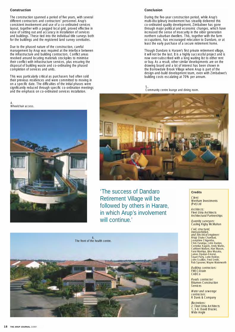
Construction
The construction spanned a period of five years, with severaldifferent contractors and contractors’ personnel. Arup’s consistent involvement and use of a co-ordinated serviceslayout, together with a pegged local grid, proved effective inease of setting out and accuracy in installation of services and buildings. These tied into the individual title surveys bothfor the buildings and the registered land survey servitudes.
Due to the phased nature of the construction, careful management by Arup was required at the interface betweenthe infrastructure and building contractors. Conflict areasrevolved around locating materials stockpiles to minimisetheir conflict with infrastructure services, plus ensuring thedisposal of building waste and co-ordinating the phasedcompletion of services and units.
This was particularly critical as purchasers had often soldtheir previous residences and were committed to moving inon a specific date. The difficulties of the initial phases weresignificantly reduced through specific co-ordination meetingsand the emphasis on co-ordinated services installation.
Conclusion
During the five-year construction period, while Arup’s multi-disciplinary involvement has steadily delivered this co-ordinated quality development, Zimbabwe has gonethrough major political and economic changes, which haveincreased the sense of insecurity in the older generationnorthern suburban dwellers. This, together with the farmoccupations, has encouraged relocation to Dandaro, or atleast the early purchase of a secure retirement home.
Though Dandaro is Harare’s first private retirement village, it will not be the last. It is a highly successful project and isnow over-subscribed with a long waiting list to either rent or buy. As a result, other similar developments are on thedrawing board and a lot of interest has been shown in the Borrowdale Brook Village where Arup is part of thedesign-and-build development team, even with Zimbabwe’sbuilding costs escalating at 70% per annum.
Credits
Client:Wenham Investments (Pvt) Ltd
Architects:Fleet Utria ArchitectsArchitectural Partnerships
Quantity surveyors:Casling Rigby McMahon
Civil, structural, transportation, and electrical engineer:Arup Shake Chambati,Josephine Chigamba, Chris Furukiya, John Hanlon,Cornelius Kagoro, Andy Marks,Cuthbert Makoni, Alan Mason,Farai Mavhiya, Idea Musaka,James Oputan-Emorut, Stuart Perry, Lotte Reimer, John Scullion, Fred Smith, Rob Spooner, Wayne Waterworth
Building contractors:FMI CostainCABCo
Roads contractor:Bitumen ConstructionServices
Water and sewerage contractors:R Davis & Company
Illustrations:2: Fleet Utria Architects1, 3-6: David Brazier, Wide Angle
‘The success of DandaroRetirement Village will befollowed by others in Harare,in which Arup’s involvementwill continue.’
5.. Community centre lounge and dining room.
4.Wheelchair access.
6. The front of the health centre.
THE ARUP JOURNAL 2/2001 19
Early design
Arup’s New York office acted as project manager to deliver the firm's design and documentation, co-ordinating with thearchitects in Chicago and the client in Munich. Arup Sydney provided advice, in collaboration with New York, to the architectsin Chicago on the structural scheme for the long-span Forumroof over the top of the office development, with further supportprovided by Arup's German offices in Düsseldorf and Berlin.Wind tunnel testing of the roof was carried out by RWDI (RowanWilliams Davies Irwin) in Canada.
It was a truly global collaboration.
The design process accelerated in early 1995, and a team wasassembled in the New York office to complete the structuraldesign and manage calculations submission and review by theGerman proof engineer (see below). Full structural engineeringservices were provided for the Forum roof, in addition to variouselevator tower and stair elements, in accordance with all relevantGerman DIN standards.
German contracts are subdivided into several distinct stagesunder the HOAI (Honorar Ordnung für Architekten undIngenieure) (terms of agreement for architects and engineers inGermany), with responsibilities and submission requirementsstrictly defined. These stages correspond approximately to thefollowing for a structural steelwork project:
Stage 1: concept design
Stage 2: schematic design
Stage 3: design development
Stage 4: submission of AFC (Approved for Construction) calculations to proof engineer
Stage 5: submission of AFC contract drawings to proof engineer
Stage 6: review of shop drawings
Stage 7: site inspection.
Arup’s full structural engineering services covered Stages 1-6inclusive. In addition, Arup in New York reported to the client onoffice environmental factors such as daylight, occupant comfort,and wind environment.
Some history
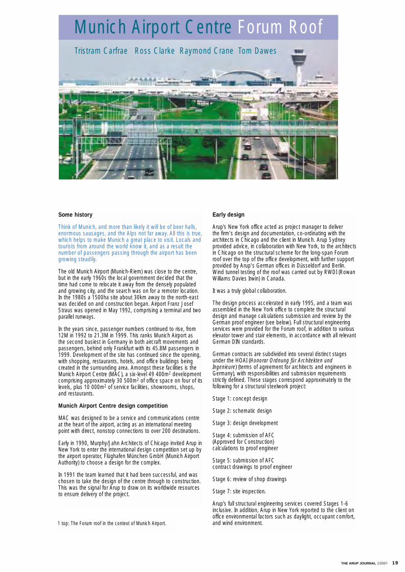
Think of Munich, and more than likely it will be of beer halls,enormous sausages, and the Alps not far away. All this is true,which helps to make Munich a great place to visit. Locals andtourists from around the world know it, and as a result the number of passengers passing through the airport has beengrowing steadily.
The old Munich Airport (Munich-Riem) was close to the centre,but in the early 1960s the local government decided that thetime had come to relocate it away from the densely populatedand growing city, and the search was on for a remoter location.In the 1980s a 1500ha site about 30km away to the north-eastwas decided on and construction began. Airport Franz JosefStraus was opened in May 1992, comprising a terminal and twoparallel runways.
In the years since, passenger numbers continued to rise, from12M in 1992 to 21.3M in 1999. This ranks Munich Airport as the second busiest in Germany in both aircraft movements andpassengers, behind only Frankfurt with its 45.8M passengers in1999. Development of the site has continued since the opening,with shopping, restaurants, hotels, and office buildings beingcreated in the surrounding area. Amongst these facilities is theMunich Airport Centre (MAC), a six-level 49 400m2 developmentcomprising approximately 30 500m2 of office space on four of itslevels, plus 10 000m2 of service facilities, showrooms, shops,and restaurants.
Munich Airport Centre design competition
MAC was designed to be a service and communications centreat the heart of the airport, acting as an international meetingpoint with direct, nonstop connections to over 200 destinations.
Early in 1990, Murphy/Jahn Architects of Chicago invited Arup inNew York to enter the international design competition set up bythe airport operator, Flüghafen München GmbH (Munich AirportAuthority) to choose a design for the complex.
In 1991 the team learned that it had been successful, and waschosen to take the design of the centre through to construction.This was the signal for Arup to draw on its worldwide resourcesto ensure delivery of the project.
Tristram Carfrae Ross Clarke Raymond Crane Tom Dawes
Munich Airport Centre Forum Roof
1 top: The Forum roof in the context of Munich Airport.
20 THE ARUP JOURNAL 2/2001
The Forum roof
The most striking part of the development is the 19 000m2
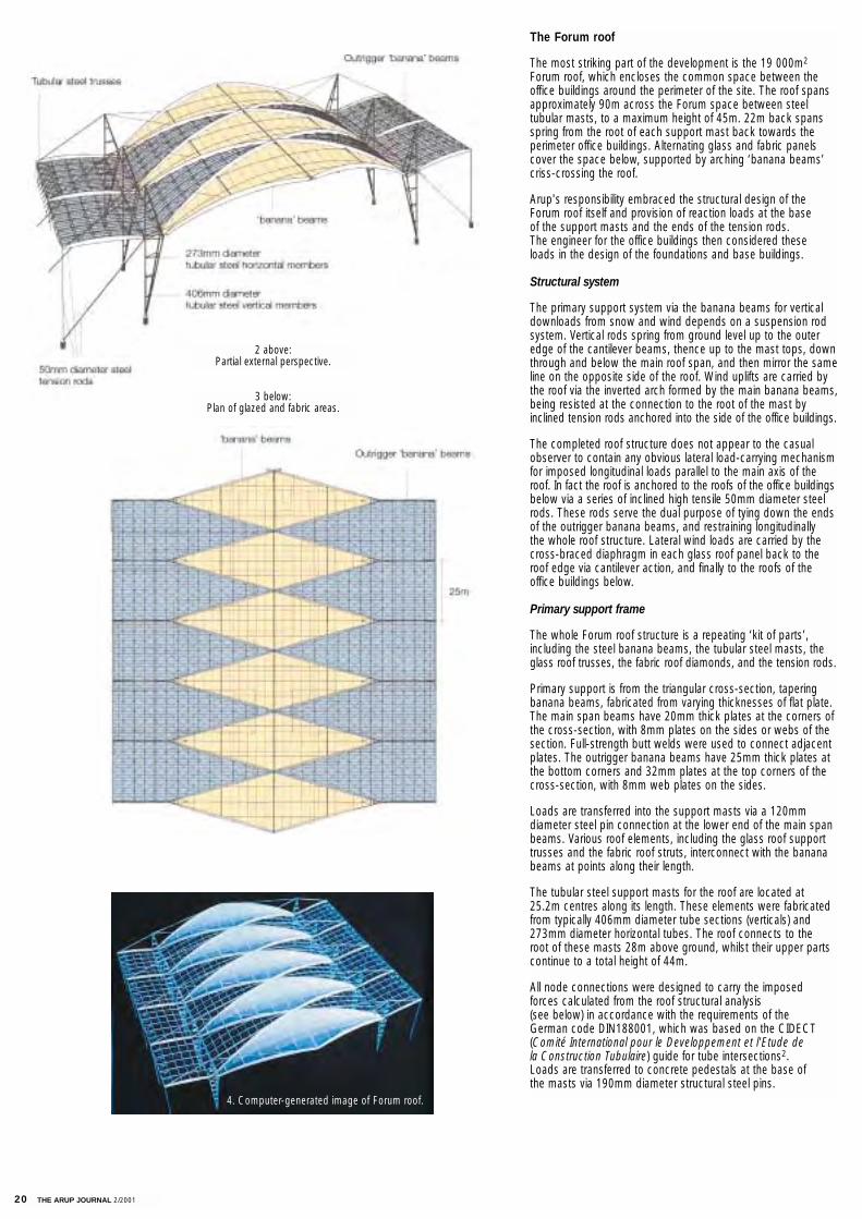
Forum roof, which encloses the common space between theoffice buildings around the perimeter of the site. The roof spansapproximately 90m across the Forum space between steel tubular masts, to a maximum height of 45m. 22m back spansspring from the root of each support mast back towards theperimeter office buildings. Alternating glass and fabric panelscover the space below, supported by arching ‘banana beams’criss-crossing the roof.
Arup's responsibility embraced the structural design of theForum roof itself and provision of reaction loads at the base of the support masts and the ends of the tension rods. The engineer for the office buildings then considered these loads in the design of the foundations and base buildings.
Structural system
The primary support system via the banana beams for verticaldownloads from snow and wind depends on a suspension rodsystem. Vertical rods spring from ground level up to the outeredge of the cantilever beams, thence up to the mast tops, downthrough and below the main roof span, and then mirror the sameline on the opposite side of the roof. Wind uplifts are carried bythe roof via the inverted arch formed by the main banana beams,being resisted at the connection to the root of the mast byinclined tension rods anchored into the side of the office buildings.
The completed roof structure does not appear to the casualobserver to contain any obvious lateral load-carrying mechanismfor imposed longitudinal loads parallel to the main axis of theroof. In fact the roof is anchored to the roofs of the office buildingsbelow via a series of inclined high tensile 50mm diameter steelrods. These rods serve the dual purpose of tying down the endsof the outrigger banana beams, and restraining longitudinally the whole roof structure. Lateral wind loads are carried by thecross-braced diaphragm in each glass roof panel back to theroof edge via cantilever action, and finally to the roofs of theoffice buildings below.
Primary support frame
The whole Forum roof structure is a repeating ‘kit of parts’,including the steel banana beams, the tubular steel masts, theglass roof trusses, the fabric roof diamonds, and the tension rods.
Primary support is from the triangular cross-section, taperingbanana beams, fabricated from varying thicknesses of flat plate.The main span beams have 20mm thick plates at the corners ofthe cross-section, with 8mm plates on the sides or webs of thesection. Full-strength butt welds were used to connect adjacentplates. The outrigger banana beams have 25mm thick plates atthe bottom corners and 32mm plates at the top corners of thecross-section, with 8mm web plates on the sides.
Loads are transferred into the support masts via a 120mm diameter steel pin connection at the lower end of the main spanbeams. Various roof elements, including the glass roof support trusses and the fabric roof struts, interconnect with the bananabeams at points along their length.
The tubular steel support masts for the roof are located at 25.2m centres along its length. These elements were fabricatedfrom typically 406mm diameter tube sections (verticals) and273mm diameter horizontal tubes. The roof connects to the root of these masts 28m above ground, whilst their upper partscontinue to a total height of 44m.
All node connections were designed to carry the imposed forces calculated from the roof structural analysis (see below) in accordance with the requirements of the German code DIN188001, which was based on the CIDECT(Comité International pour le Developpement et l'Etude de la Construction Tubulaire) guide for tube intersections2. Loads are transferred to concrete pedestals at the base of the masts via 190mm diameter structural steel pins.
2 above: Partial external perspective.
3 below: Plan of glazed and fabric areas.
4. Computer-generated image of Forum roof.

The glass roof zones
Over 12 000m2 of glass roof - or rather 12 individual 1000m2
glass roofs - are suspended between the main and outriggerbanana beams at a height of between 30m and 40m. Tubularsteel trusses span up to 25m between outriggers, with 193mmdiameter horizontal top chords, 139mm diameter curved bottomchords, and 114mm diameter vertical webs typically.
120mm x 60mm rectangular hollow section mullions at 1.35mcentres carry the glass panes. Small diameter rods run betweeneach of the adjacent glass roof trusses, forming a cross-braceddiaphragm within the plane of the glass roof panels to resist longitudinal lateral roof loads.
Bottom chord stability under uplift loads is achieved via restraintprovided by the vertical legs of the truss acting together with thehorizontal tubes at roof level. These two elements form a seriesof inverted frames with moment continuity at tube connectionnode points.
The fabric roof zones
In the diamond-shaped zones between the masts and the mainspan banana beams, the fabric roof segments of the roof totalabout 7000m2 in seven panels. Curvature in two directions provides load-carrying capability, enhanced for wind uplift casesby stainless steel spiral strand tension cables laid on the curvingtop surface of the fabric. The fabric panels are connected ontothe edge of the banana beams via continuous powder-coatedaluminium clamp plates. A nominal prestress of 5kN/m wasintroduced into the fabric before achieving the final geometry.
Sloping side walls
Running along the length of the roof is a sloped glass wallbetween the roof of the office buildings below and the outeredge of the Forum roof. Slotted hole connections at the tops ofthe sloping walls' mullion elements allow the Forum roof to moveunder load, independently of the office buildings.
Structural analysis
Structural analysis models were produced in the GSA program for two bay-width segments of the Forum roof structure, including all steel elements. In addition, analysismodels for the diamond-shaped fabric roof segments were produced in the FABLON program to determine the non-linear response of the material under imposed wind andsnow loads.
Wind loads were estimated from the results of the wind tunnel testing, while snow loads (uniform and drifting) were based on the requirements of DIN1055: Part 43. The maximum tensile stresses in the fabric were then compared with fabric strengths toensure adequate factors of safety against fabric failure. Reaction loads from the FABLONanalyses applied to the supporting roof structure (ie the banana beams) for each loadcasecombination in the corresponding GSA analysis of the remainder of the roof structure.
GSA models were used to analyse the remainder of the roof structure. One second ordereffect that needed to be monitored was the possibility of tension rods going slack undervarious loadcase combinations. In cases where this occurred, the slack rods were simplyremoved from the analysis model.
Reaction loads at support points were tabulated and provided to the design engineer forthe base buildings so that they could be considered in the design of those elements.
7. CFD analysis of Forumspace beneath roof, plottingwind environment.
5. Truss node detail in the glass roof zone.
6. Backstay connection to building.
8. Underside of Forum roof, showing tension cables below fabric roof zones.
TH
E A
RU
P JO
UR
NA
L2/2001
21
22 THE ARUP JOURNAL 2/2001
Additional items
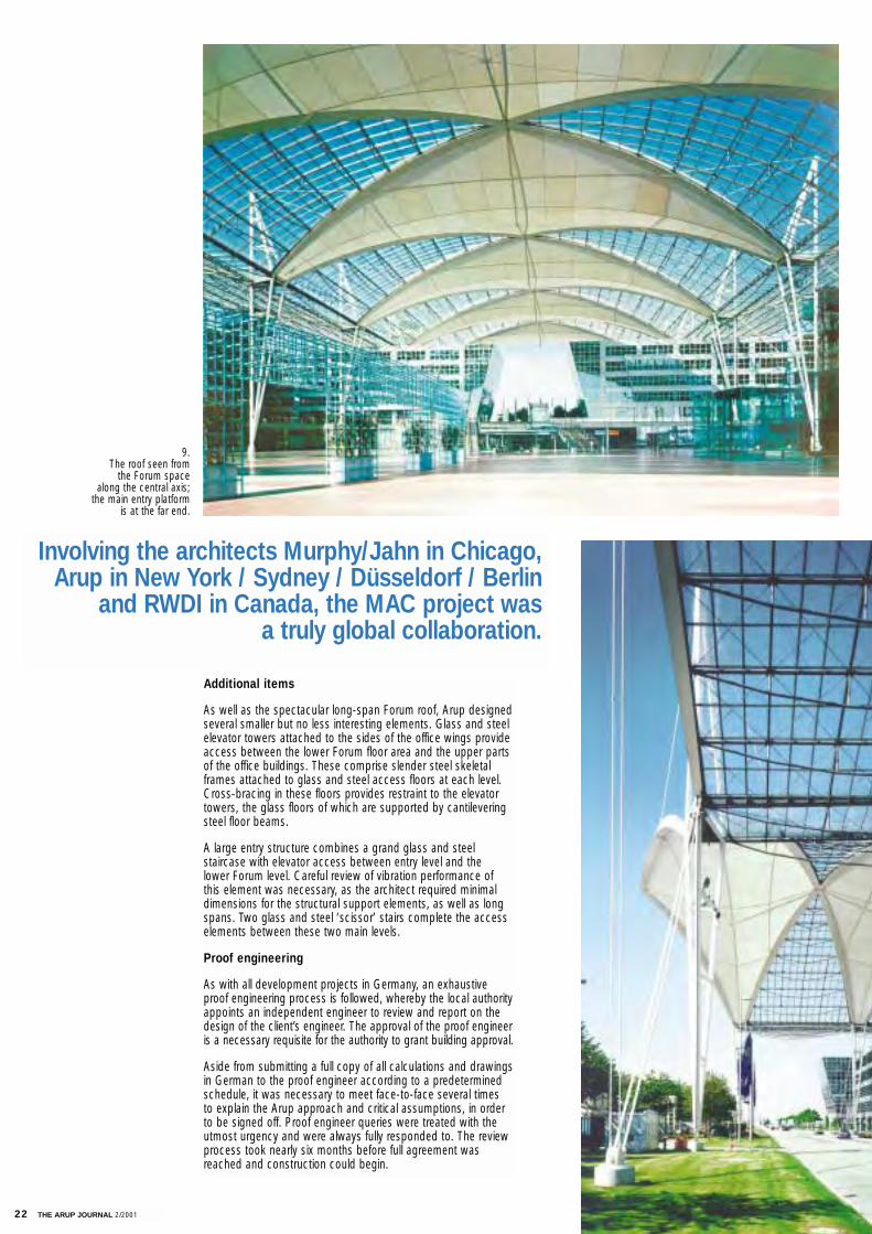
As well as the spectacular long-span Forum roof, Arup designedseveral smaller but no less interesting elements. Glass and steelelevator towers attached to the sides of the office wings provideaccess between the lower Forum floor area and the upper partsof the office buildings. These comprise slender steel skeletalframes attached to glass and steel access floors at each level.Cross-bracing in these floors provides restraint to the elevatortowers, the glass floors of which are supported by cantileveringsteel floor beams.
A large entry structure combines a grand glass and steel staircase with elevator access between entry level and the lower Forum level. Careful review of vibration performance of this element was necessary, as the architect required minimaldimensions for the structural support elements, as well as longspans. Two glass and steel ‘scissor’ stairs complete the accesselements between these two main levels.
Proof engineering
As with all development projects in Germany, an exhaustiveproof engineering process is followed, whereby the local authorityappoints an independent engineer to review and report on thedesign of the client’s engineer. The approval of the proof engineeris a necessary requisite for the authority to grant building approval.
Aside from submitting a full copy of all calculations and drawingsin German to the proof engineer according to a predeterminedschedule, it was necessary to meet face-to-face several times to explain the Arup approach and critical assumptions, in order to be signed off. Proof engineer queries were treated with theutmost urgency and were always fully responded to. The reviewprocess took nearly six months before full agreement wasreached and construction could begin.
Involving the architects Murphy/Jahn in Chicago, Arup in New York / Sydney / Düsseldorf / Berlin
and RWDI in Canada, the MAC project was a truly global collaboration.
9. The roof seen from
the Forum space along the central axis;
the main entry platform is at the far end.
THE ARUP JOURNAL 2/2001 23
Credits
Client:Flüghafen GmbH (Munich Airport Authority)
Project manager:Alba GmbH, Munich,Germany
Architect:Murphy/Jahn Inc, Chicago
Joint venture partners:Grebner GmbH,
Structural, daylighting, and fire consultants:Arup Paul Anderson, Tristram Carfrae, Ross Clarke,Raymond Crane, Tom Dawes,Dieter Feurich, Peter MacDonald,Alexander Schmidt-Narishkin, Alan Shuttleworth
Prüfingenieur:Professor Grimme, Munich, Germany
Illustrations:1, 8-11: Sellin/Engelhardt /Murphy/Jahn Inc2-4, 7: Arup5, 6: Tom Dawes
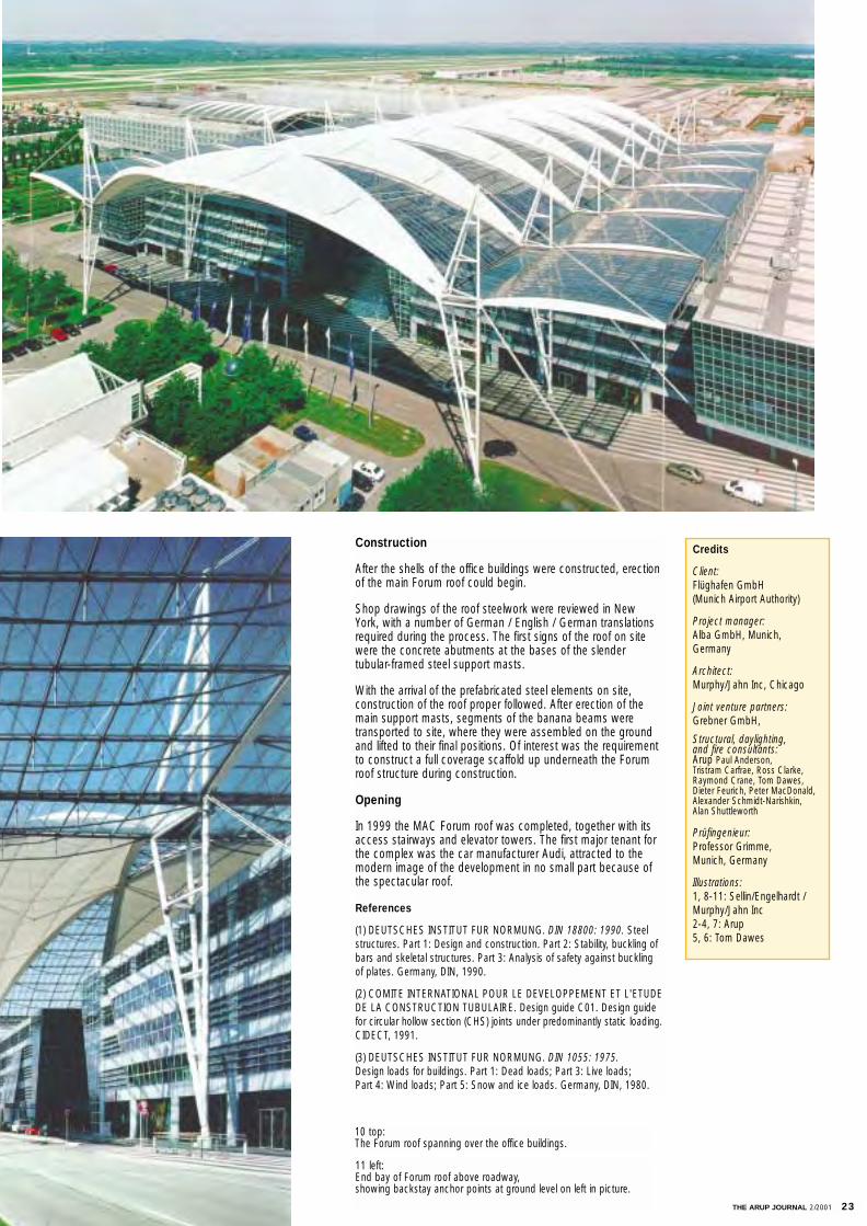
10 top: The Forum roof spanning over the office buildings.
11 left: End bay of Forum roof above roadway, showing backstay anchor points at ground level on left in picture.
Construction
After the shells of the office buildings were constructed, erectionof the main Forum roof could begin.
Shop drawings of the roof steelwork were reviewed in New York, with a number of German / English / German translationsrequired during the process. The first signs of the roof on sitewere the concrete abutments at the bases of the slender tubular-framed steel support masts.
With the arrival of the prefabricated steel elements on site, construction of the roof proper followed. After erection of themain support masts, segments of the banana beams weretransported to site, where they were assembled on the groundand lifted to their final positions. Of interest was the requirementto construct a full coverage scaffold up underneath the Forumroof structure during construction.
Opening
In 1999 the MAC Forum roof was completed, together with itsaccess stairways and elevator towers. The first major tenant forthe complex was the car manufacturer Audi, attracted to themodern image of the development in no small part because ofthe spectacular roof.
References
(1) DEUTSCHES INSTITUT FUR NORMUNG. DIN 18800: 1990. Steelstructures. Part 1: Design and construction. Part 2: Stability, buckling ofbars and skeletal structures. Part 3: Analysis of safety against buckling of plates. Germany, DIN, 1990.
(2) COMITE INTERNATIONAL POUR LE DEVELOPPEMENT ET L'ETUDEDE LA CONSTRUCTION TUBULAIRE. Design guide C01. Design guidefor circular hollow section (CHS) joints under predominantly static loading.CIDECT, 1991.
(3) DEUTSCHES INSTITUT FUR NORMUNG. DIN 1055: 1975.Design loads for buildings. Part 1: Dead loads; Part 3: Live loads; Part 4: Wind loads; Part 5: Snow and ice loads. Germany, DIN, 1980.
24 THE ARUP JOURNAL 2/2001
‘The world’s largest self-supporting enclosure’
Introduction
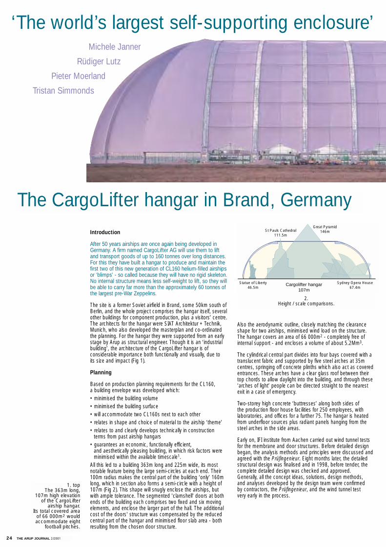
After 50 years airships are once again being developed inGermany. A firm named CargoLifter AG will use them to liftand transport goods of up to 160 tonnes over long distances.For this they have built a hangar to produce and maintain thefirst two of this new generation of CL160 helium-filled airshipsor ‘blimps’ - so called because they will have no rigid skeleton. No internal structure means less self-weight to lift, so they will be able to carry far more than the approximately 60 tonnes ofthe largest pre-War Zeppelins.
The site is a former Soviet airfield in Brand, some 50km south ofBerlin, and the whole project comprises the hangar itself, severalother buildings for component production, plus a visitors’ centre.The architects for the hangar were SIAT Architektur + Technik,Munich, who also developed the masterplan and co-ordinatedthe planning. For the hangar they were supported from an earlystage by Arup as structural engineer. Though it is an ‘industrialbuilding’, the architecture of the CargoLifter hangar is of considerable importance both functionally and visually, due to its size and impact (Fig 1).
Planning
Based on production planning requirements for the CL160, a building envelope was developed which:• minimised the building volume• minimised the building surface• will accommodate two CL160s next to each other• relates in shape and choice of material to the airship ‘theme’• relates to and clearly develops technically in construction
terms from past airship hangars• guarantees an economic, functionally efficient,
and aesthetically pleasing building, in which risk factors were minimised within the available timescale1.
All this led to a building 363m long and 225m wide, its mostnotable feature being the large semi-circles at each end. Their100m radius makes the central part of the building ‘only’ 160mlong, which in section also forms a semi-circle with a height of107m (Fig 2). This shape will snugly enclose the airships, butwith ample tolerance. The segmented 'clamshell' doors at bothends of the building each comprises two fixed and six movingelements, and enclose the larger part of the hall. The additionalcost of the doors' structure was compensated by the reducedcentral part of the hangar and minimised floor slab area - bothresulting from the chosen door structure.
Also the aerodynamic outline, closely matching the clearanceshape for two airships, minimised wind load on the structure.The hangar covers an area of 66 000m2 - completely free ofinternal support - and encloses a volume of about 5.2Mm3.
The cylindrical central part divides into four bays covered with atranslucent fabric and supported by five steel arches at 35mcentres, springing off concrete plinths which also act as coveredentrances. These arches have a clear glass roof between theirtop chords to allow daylight into the building, and through these‘arches of light’ people can be directed straight to the nearestexit in a case of emergency.
Two-storey high concrete ‘buttresses’ along both sides of the production floor house facilities for 250 employees, with laboratories, and offices for a further 75. The hangar is heatedfrom underfloor sources plus radiant panels hanging from thesteel arches in the side areas.
Early on, IFI institute from Aachen carried out wind tunnel testsfor the membrane and door structures. Before detailed designbegan, the analysis methods and principles were discussed andagreed with the Prüfingenieur. Eight months later, the detailedstructural design was finalised and in 1998, before tender, thecomplete detailed design was checked and approved.Generally, all the concept ideas, solutions, design methods, and analyses developed by the design team were confirmed by contractors, the Prüfingenieur, and the wind tunnel test very early in the process.
St Pauls Cathedral111.5m
Statue of Liberty46.5m
Sydney Opera House67.4m
Great Pyramid146m
Cargolifter hangar107m
Michele Janner
Rüdiger Lutz
Pieter Moerland
Tristan Simmonds
The CargoLifter hangar in Brand, Germany
2.Height / scale comparisons.
1. topThe 363m long,
107m high elevationof the CargoLifter
airship hangar. Its total covered area
of 66 000m2 wouldaccommodate eight
football pitches.
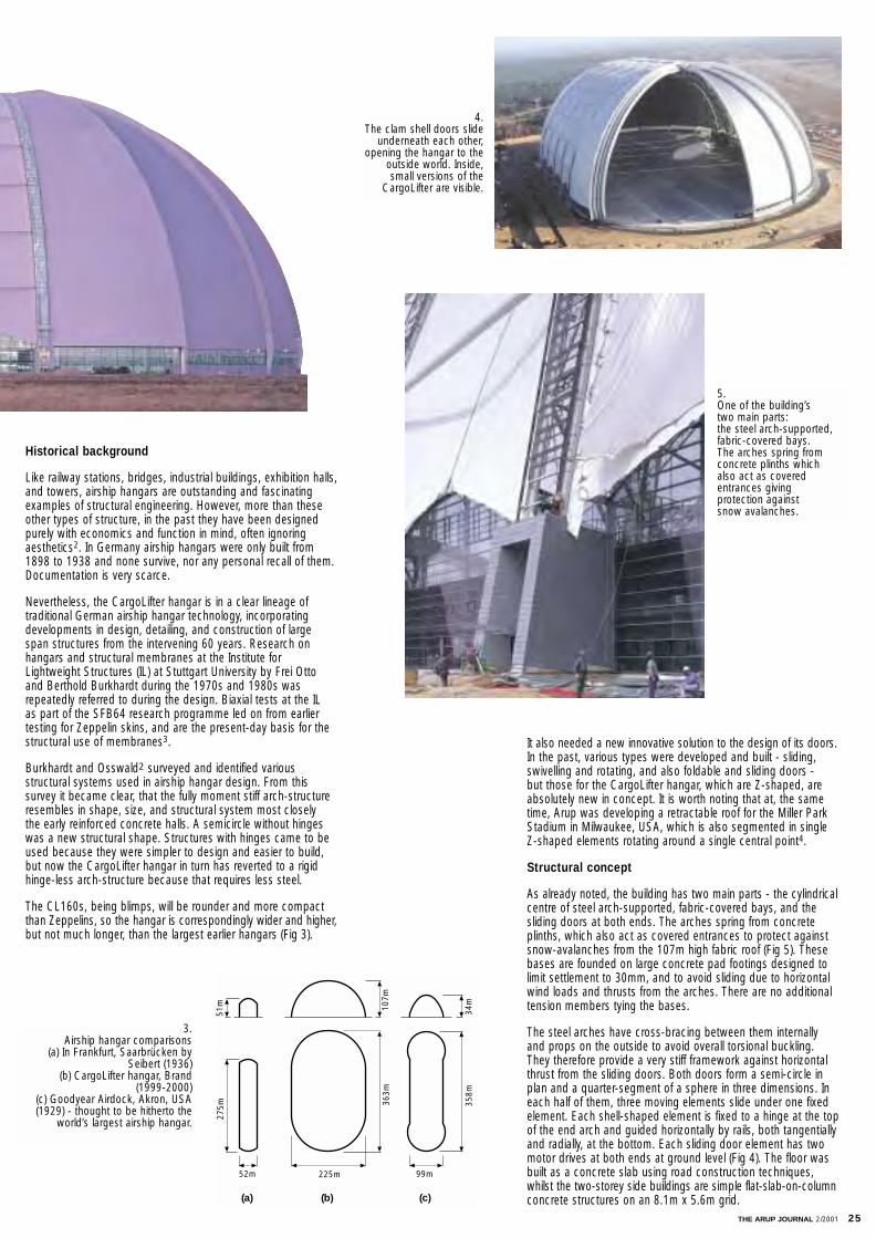
THE ARUP JOURNAL 2/2001 25
It also needed a new innovative solution to the design of its doors.In the past, various types were developed and built - sliding,swivelling and rotating, and also foldable and sliding doors - but those for the CargoLifter hangar, which are Z-shaped, areabsolutely new in concept. It is worth noting that at, the sametime, Arup was developing a retractable roof for the Miller ParkStadium in Milwaukee, USA, which is also segmented in singleZ-shaped elements rotating around a single central point4.
Structural concept
As already noted, the building has two main parts - the cylindricalcentre of steel arch-supported, fabric-covered bays, and thesliding doors at both ends. The arches spring from concreteplinths, which also act as covered entrances to protect againstsnow-avalanches from the 107m high fabric roof (Fig 5). Thesebases are founded on large concrete pad footings designed tolimit settlement to 30mm, and to avoid sliding due to horizontalwind loads and thrusts from the arches. There are no additionaltension members tying the bases.
The steel arches have cross-bracing between them internallyand props on the outside to avoid overall torsional buckling.They therefore provide a very stiff framework against horizontalthrust from the sliding doors. Both doors form a semi-circle inplan and a quarter-segment of a sphere in three dimensions. Ineach half of them, three moving elements slide under one fixedelement. Each shell-shaped element is fixed to a hinge at the topof the end arch and guided horizontally by rails, both tangentiallyand radially, at the bottom. Each sliding door element has twomotor drives at both ends at ground level (Fig 4). The floor wasbuilt as a concrete slab using road construction techniques,whilst the two-storey side buildings are simple flat-slab-on-columnconcrete structures on an 8.1m x 5.6m grid.
Historical background
Like railway stations, bridges, industrial buildings, exhibition halls,and towers, airship hangars are outstanding and fascinatingexamples of structural engineering. However, more than theseother types of structure, in the past they have been designedpurely with economics and function in mind, often ignoring aesthetics2. In Germany airship hangars were only built from1898 to 1938 and none survive, nor any personal recall of them.Documentation is very scarce.
Nevertheless, the CargoLifter hangar is in a clear lineage of traditional German airship hangar technology, incorporatingdevelopments in design, detailing, and construction of largespan structures from the intervening 60 years. Research onhangars and structural membranes at the Institute forLightweight Structures (IL) at Stuttgart University by Frei Ottoand Berthold Burkhardt during the 1970s and 1980s wasrepeatedly referred to during the design. Biaxial tests at the IL as part of the SFB64 research programme led on from earliertesting for Zeppelin skins, and are the present-day basis for thestructural use of membranes3.
Burkhardt and Osswald2 surveyed and identified various structural systems used in airship hangar design. From this survey it became clear, that the fully moment stiff arch-structureresembles in shape, size, and structural system most closely the early reinforced concrete halls. A semicircle without hingeswas a new structural shape. Structures with hinges came to beused because they were simpler to design and easier to build,but now the CargoLifter hangar in turn has reverted to a rigid hinge-less arch-structure because that requires less steel.
The CL160s, being blimps, will be rounder and more compactthan Zeppelins, so the hangar is correspondingly wider and higher,but not much longer, than the largest earlier hangars (Fig 3).
51m 10
7m
34m
275m 36
3m
358m
52m 225m 99m
(a) (b) (c)
5.One of the building’s two main parts:the steel arch-supported, fabric-covered bays.The arches spring from concrete plinths which also act as covered entrances giving protection against snow avalanches.
4.The clam shell doors slide
underneath each other,opening the hangar to the
outside world. Inside,small versions of the
CargoLifter are visible.
3.Airship hangar comparisons
(a) In Frankfurt, Saarbrücken bySeibert (1936)
(b) CargoLifter hangar, Brand (1999-2000)
(c) Goodyear Airdock, Akron, USA(1929) - thought to be hitherto the
world’s largest airship hangar.
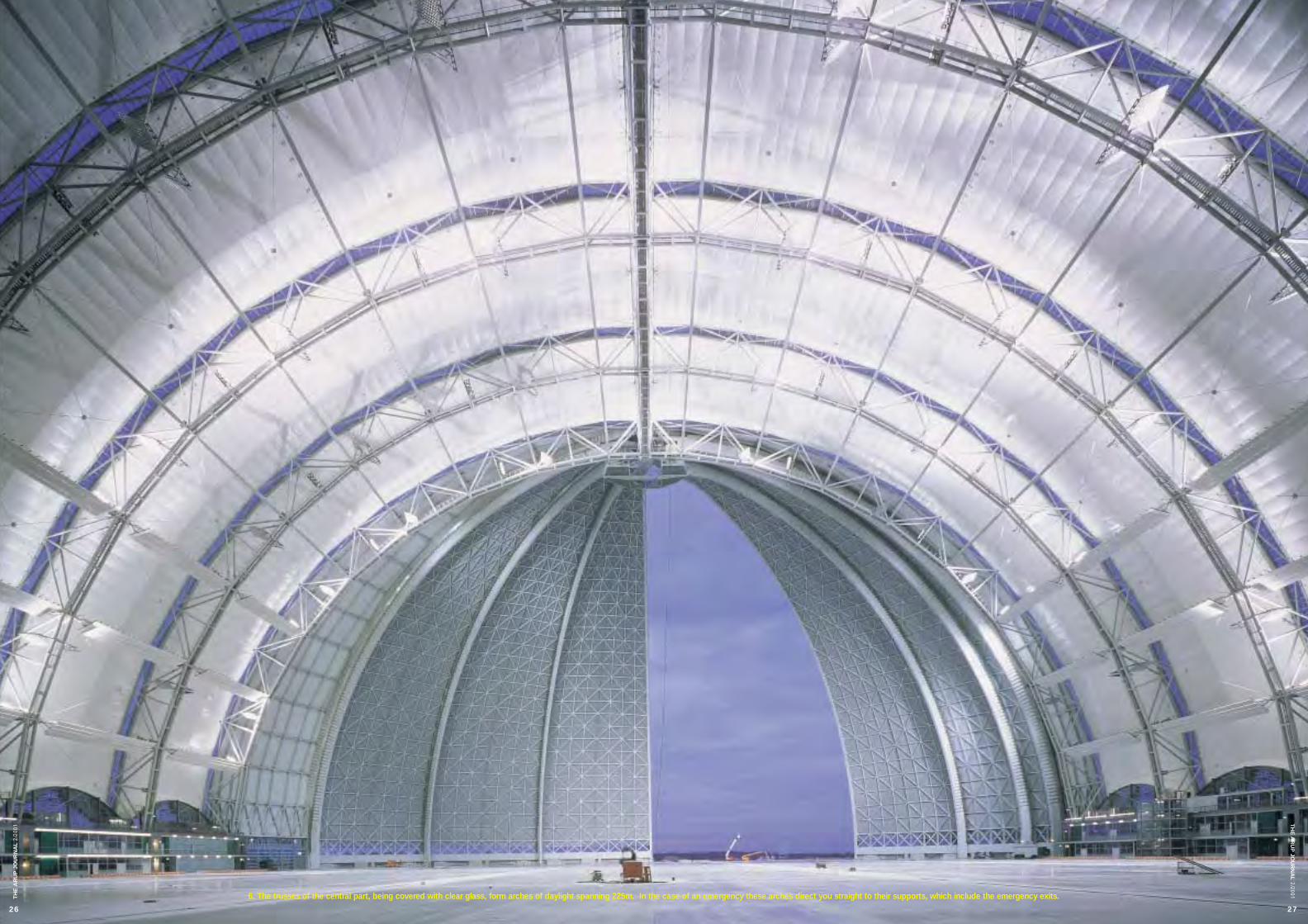
6. The trusses of the central part, being covered with clear glass, form arches of daylight spanning 225m. In the case of an emergency these arches direct you straight to their supports, which include the emergency exits.
26
TH
E A
RU
P J
OU
RN
AL
2/20
01
27
TH
E A
RU
P JO
UR
NA
L2/2001

28 THE ARUP JOURNAL 2/2001
Loading assumptions
Initially, all the known and assumed loading data were assembledinto one document, which was sent to and checked by the entireproject team. After receiving approval for all the loading, this'Loading Assumptions Report' formed a very important basis for the whole engineering team carrying out the calculations.
The snow load considered is based on the German standardDIN1055: Part 5, using a base value of 0.75kN/m2, which can bereduced depending on the slope of the surface. The IFI Instituteof the Fachhochschule Aachen carried out a wind tunnel test todetermine the wind loading, though for the closed-door caseonly because the hangar doors will only be opened at windvelocities up to 10m/s. Hand calculations were sufficient to show that the open door case would not be a design load case.
As for special loads, a ±45˚C temperature variation was appliedto the external steelwork and ±10˚C to the internal steelwork,whilst an additional load from ice up to 30mm thick (0.21kN/m2)was applied to the external steel. The influence of foundationsettlement (50mm) was analysed, but as expected the effects offoundation settlements on a structure this size were negligible.
The cylindrical part of the building
The five arches have a structural height of 8m and span 225m,with top chords at 3.441m centres and bottom chords at 2.0mcentres. The chords are brace-connected to each other, with theexception of the two bottom chords; only straight members,forming a Vierendeel system, connect these (Fig 7).
Although the arches are always referred to as forming the 'cylindrical part' of the building, in fact they are not perfectly circular but polygonal: each consists of 17 straight segmentsabout 18m long. The wind bracing is connected to the bottomchords at each intersection of two arch-segments. At the sameintersection between the top chords, external props restrain anytorsion in the arches induced by the eccentrically connectedmembrane (Fig 8). At their ridge the arches are longitudinallyconnected by a four-chord, 8m deep truss, similar in structure to the arches. This ridge beam enables the membrane and thevalley cable at the top to be connected, and takes up the largecompression force between the two end arches generated by the doors (Fig 9).
7.‘Charlie’, a small version of the future CargoLifter.
The CargoLifter hangar shows an awesome realisation of the original concept in the massive scale of the building envelope...
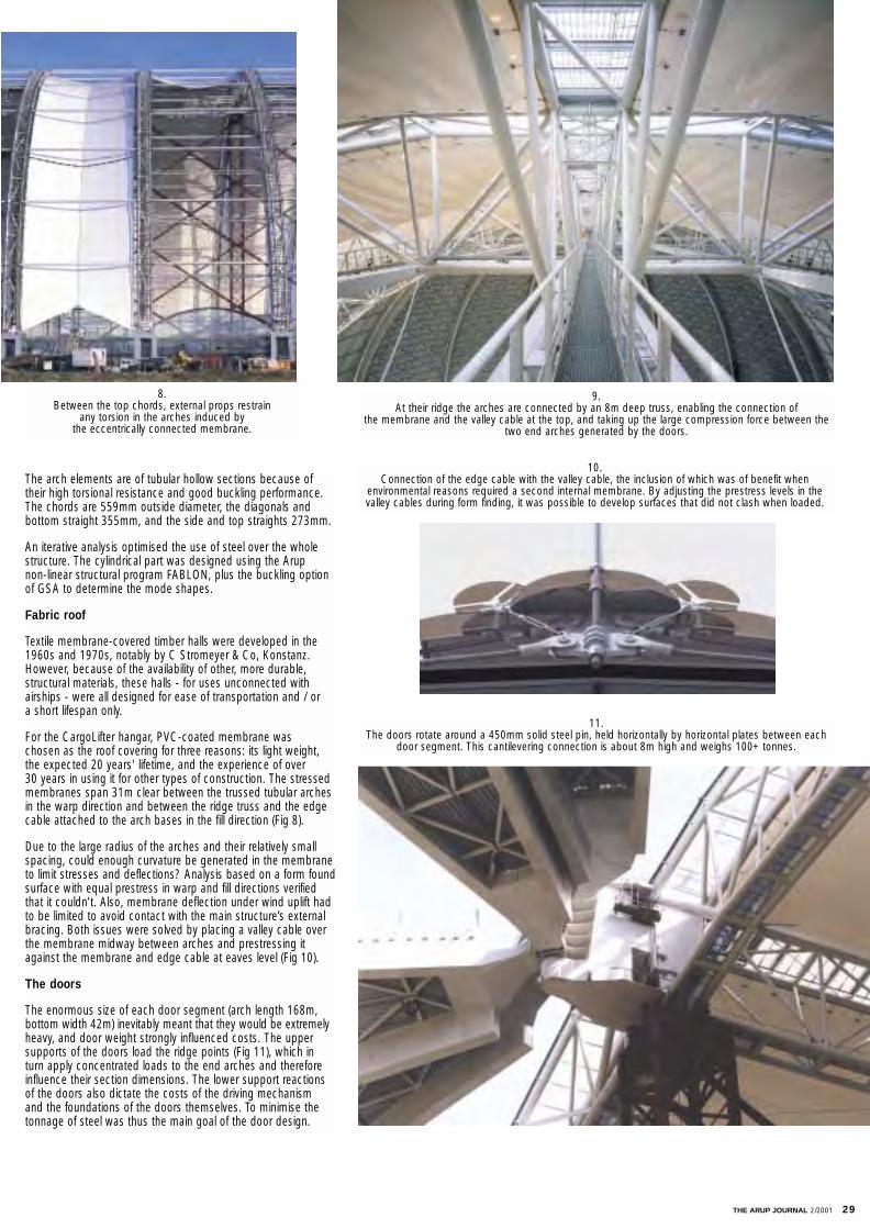
THE ARUP JOURNAL 2/2001 29
The arch elements are of tubular hollow sections because oftheir high torsional resistance and good buckling performance.The chords are 559mm outside diameter, the diagonals and bottom straight 355mm, and the side and top straights 273mm.
An iterative analysis optimised the use of steel over the wholestructure. The cylindrical part was designed using the Arup non-linear structural program FABLON, plus the buckling optionof GSA to determine the mode shapes.
Fabric roof
Textile membrane-covered timber halls were developed in the1960s and 1970s, notably by C Stromeyer & Co, Konstanz.However, because of the availability of other, more durable,structural materials, these halls - for uses unconnected with airships - were all designed for ease of transportation and / or a short lifespan only.
For the CargoLifter hangar, PVC-coated membrane was chosen as the roof covering for three reasons: its light weight,the expected 20 years' lifetime, and the experience of over 30 years in using it for other types of construction. The stressed membranes span 31m clear between the trussed tubular archesin the warp direction and between the ridge truss and the edgecable attached to the arch bases in the fill direction (Fig 8).
Due to the large radius of the arches and their relatively smallspacing, could enough curvature be generated in the membraneto limit stresses and deflections? Analysis based on a form foundsurface with equal prestress in warp and fill directions verifiedthat it couldn’t. Also, membrane deflection under wind uplift hadto be limited to avoid contact with the main structure’s externalbracing. Both issues were solved by placing a valley cable overthe membrane midway between arches and prestressing itagainst the membrane and edge cable at eaves level (Fig 10).
The doors
The enormous size of each door segment (arch length 168m,bottom width 42m) inevitably meant that they would be extremelyheavy, and door weight strongly influenced costs. The uppersupports of the doors load the ridge points (Fig 11), which inturn apply concentrated loads to the end arches and thereforeinfluence their section dimensions. The lower support reactionsof the doors also dictate the costs of the driving mechanism and the foundations of the doors themselves. To minimise thetonnage of steel was thus the main goal of the door design.
9. At their ridge the arches are connected by an 8m deep truss, enabling the connection of
the membrane and the valley cable at the top, and taking up the large compression force between thetwo end arches generated by the doors.
10. Connection of the edge cable with the valley cable, the inclusion of which was of benefit when
environmental reasons required a second internal membrane. By adjusting the prestress levels in the valley cables during form finding, it was possible to develop surfaces that did not clash when loaded.
11. The doors rotate around a 450mm solid steel pin, held horizontally by horizontal plates between each
door segment. This cantilevering connection is about 8m high and weighs 100+ tonnes.
8. Between the top chords, external props restrain
any torsion in the arches induced by the eccentrically connected membrane.
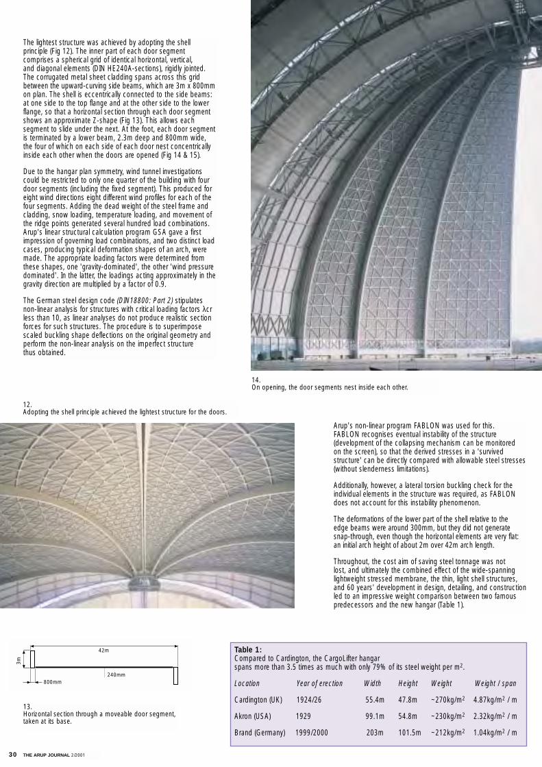
30 THE ARUP JOURNAL 2/2001
The lightest structure was achieved by adopting the shell principle (Fig 12). The inner part of each door segment comprises a spherical grid of identical horizontal, vertical, and diagonal elements (DIN HE240A-sections), rigidly jointed.The corrugated metal sheet cladding spans across this gridbetween the upward-curving side beams, which are 3m x 800mmon plan. The shell is eccentrically connected to the side beams:at one side to the top flange and at the other side to the lowerflange, so that a horizontal section through each door segmentshows an approximate Z-shape (Fig 13). This allows each segment to slide under the next. At the foot, each door segmentis terminated by a lower beam, 2.3m deep and 800mm wide,the four of which on each side of each door nest concentricallyinside each other when the doors are opened (Fig 14 & 15).
Due to the hangar plan symmetry, wind tunnel investigationscould be restricted to only one quarter of the building with fourdoor segments (including the fixed segment). This produced foreight wind directions eight different wind profiles for each of thefour segments. Adding the dead weight of the steel frame andcladding, snow loading, temperature loading, and movement ofthe ridge points generated several hundred load combinations.Arup's linear structural calculation program GSA gave a firstimpression of governing load combinations, and two distinct loadcases, producing typical deformation shapes of an arch, weremade. The appropriate loading factors were determined fromthese shapes, one 'gravity-dominated', the other 'wind pressuredominated'. In the latter, the loadings acting approximately in thegravity direction are multiplied by a factor of 0.9.
The German steel design code (DIN18800: Part 2) stipulatesnon-linear analysis for structures with critical loading factors λcrless than 10, as linear analyses do not produce realistic sectionforces for such structures. The procedure is to superimposescaled buckling shape deflections on the original geometry andperform the non-linear analysis on the imperfect structure thus obtained.
Arup's non-linear program FABLON was used for this. FABLON recognises eventual instability of the structure (development of the collapsing mechanism can be monitored on the screen), so that the derived stresses in a 'survived structure' can be directly compared with allowable steel stresses(without slenderness limitations).
Additionally, however, a lateral torsion buckling check for theindividual elements in the structure was required, as FABLONdoes not account for this instability phenomenon.
The deformations of the lower part of the shell relative to the edge beams were around 300mm, but they did not generatesnap-through, even though the horizontal elements are very flat:an initial arch height of about 2m over 42m arch length.
Throughout, the cost aim of saving steel tonnage was not lost, and ultimately the combined effect of the wide-spanninglightweight stressed membrane, the thin, light shell structures,and 60 years' development in design, detailing, and constructionled to an impressive weight comparison between two famouspredecessors and the new hangar (Table 1).
Table 1:Compared to Cardington, the CargoLifter hangar spans more than 3.5 times as much with only 79% of its steel weight per m2.
Location Year of erection Width Height Weight Weight / span
Cardington (UK) 1924/26 55.4m 47.8m ~270kg/m2 4.87kg/m2 / m
Akron (USA) 1929 99.1m 54.8m ~230kg/m2 2.32kg/m2 / m
Brand (Germany) 1999/2000 203m 101.5m ~212kg/m2 1.04kg/m2 / m
800mm
3m
240mm
42m
12. Adopting the shell principle achieved the lightest structure for the doors.
14. On opening, the door segments nest inside each other.
13.Horizontal section through a moveable door segment,taken at its base.
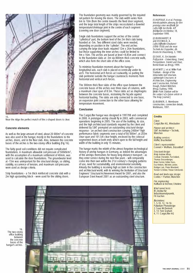
THE ARUP JOURNAL 2/2001 31
Concrete elements
As well as the large amount of steel, about 20 000m3 of concretewas also used in the hangar, mostly in the foundations to thearches, doors, and in the floor slab. Also, between the concretebases of the arches is the two-storey office building (Fig 16).
The fairly good soil conditions did not require complicated foundations. A maximum allowable soil pressure of 500kN/m2,with the assumption of a maximum settlement of 40mm, wasused to calculate the door foundations. The groundwater level at -15m was unimportant for the structural design, so sliding,stability, occurrence of tension, and maximum soil pressureswere used as design criteria.
Strip foundations - a 1m thick reinforced concrete slab with a2m high upstanding block - were used for the sliding doors.
The foundation geometry was mainly governed by the requiredrail pattern for moving the doors. The slab width varies from 6m to 10m (from the centre towards the fixed door segment,and the large total length of the strips necessitated a doweled temperature/shrinkage joint in the centre of each segment (covering one door segment).
Single slab foundations support the arches of the central 'cylindrical' part, the bottom level of the 2m thick slab beingfounded at -5m. Two different sized slabs were needed, depending on position in the 'cylinder'. The end arches carrying the large door loads required 12m x 26m foundations,but those supporting the inner arches could be limited to 9m x 16m. The arches are based at level +8.85m and connectto the foundation slabs at -3m via 800mm thick concrete walls, which also form the short side of the office zone.
To minimise foundation moment about the hangar's longitudinal axis, each slab is placed eccentrically under its arch. The horizontal arch forces act outwardly, so putting theslab perimeter outside the hangar counteracts moments fromhorizontal and vertical arch forces.
The 300mm thick floor slabs of the office span between the concrete bases of the arches over three rows of columns, with a maximum clear span of 8.5m. These slabs act as diaphragmsbetween the concrete bases, restraining the façade against horizontal loading. The slabs are only connected to one base, an expansion joint connection to the other base allowing fortemperature movement.
Conclusion
The CargoLifter hangar was designed in 1997/98 and completedin 2000. A prototype airship should fly in 2003, with commercialoperations beginning in 2005. The use of the building, its size,and the high architectural standards required by the client anddelivered by SIAT prompted an outstanding structural designresponse - an arched steel construction carrying 2400m2 highperformance fabric segments over a total of 66 000m2, at 203mclear span and 101.5m clear height, enclosed by the colossalsegmented doors at both ends which open to the full height andwidth of the building in only 15 minutes.
The hangar marks the rebirth of the almost forgotten technologicalhistory of airship hangars in Germany, as indeed the advantagesof the airships themselves for heavy long-distance transport - asthey enter service during the next few years - will comparablycome into their own within the 21st century's changing patternsof use, need for sustainability, and environmental sensitivity.Already the building is receiving high acclaim in the constructionand architectural world, with its winning the Institution of StructuralEngineers' Structural Achievement Award for 2001, and also theEuropean Steel Award 2001 as an outstanding steel structure.
Credits
Client:CargoLifter AG, Wiesbaden
Planner and architect:SIAT Architektur + Technik,München
Building services:Klöffel, Bruchköbel
Client's representative:Connert + Wolfram, Düsseldorf
Structural design:Arup Andrew Allsop, Cordula Cherubim, Pat Dallard,Thomas Dossenberger, Brian Forster, Volker Hass, Eva Hinkers, Michele Janner,Rüdiger Lutz, Pieter Moerland,Torsten Schröter, Tristan Simmonds
Road and landscape design:Cordes + Partner, München
Fire engineering:Halfkann & Kirchner, Erkelenz
Wind tunnel tests:IFI, Institut fürIndustrieaerodynamik, FH Aachen
Illustrations:1, 5-10, 12, 14-16: Palladium Photodesign2: Sean McDermott3, 13: Tom Graham4, 11: CargoLifter AG
References
(1) HUPFAUF, A et al. Prototyp,interdisziplinäre planung für den prototyp einer werfthalle fürLuftschiffe bei Berlin. AITIntelligente Architektur, 18,September 1999.
(2) BURKHARDT, B and OSSWALD, A.Luftschiffhallen Baukunst (1898-1938) und die neueTechnik der Zeppeline, db.Deutsche Bauzeitung, 5, 1985.
(3) SAXE, K. Ein biaxialesPrüfsystem - Entwicklung, Stand, Perspektiven. Skelett und Haut,Bernd Baier ua (Hrsg), 1999.
(4) HEWITT, J et al. Miller ParkStadium - design of theretractable roof structure.Lightweight Structures inArchitecture, Engineering and Construction, RichardHough, Robert Melchers (Hrsg.) Sydney, 1998. [Miller Park Stadium will be the subject of a future article inThe Arup Journal.]
(5) BUBNER, E. Membrane construction, connection details. Wehlmann, 1997.
15. Near the ridge the perfect match of the z-shaped doors is clear.
16.The two-storey
office building between
the concrete bases of the
hangar’s arches.
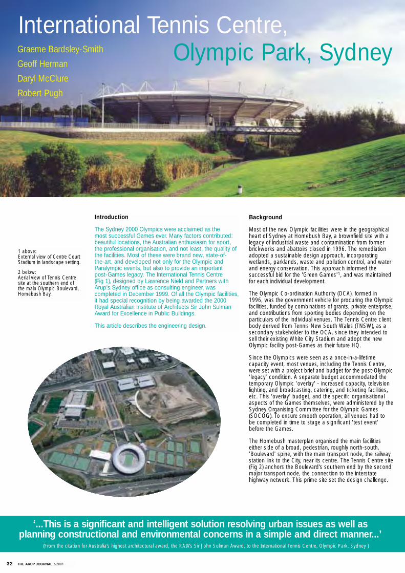
32 THE ARUP JOURNAL 2/2001
Background
Most of the new Olympic facilities were in the geographicalheart of Sydney at Homebush Bay, a brownfield site with alegacy of industrial waste and contamination from formerbrickworks and abattoirs closed in 1996. The remediationadopted a sustainable design approach, incorporating wetlands, parklands, waste and pollution control, and waterand energy conservation. This approach informed the successful bid for the 'Green Games'1, and was maintainedfor each individual development.
The Olympic Co-ordination Authority (OCA), formed in 1996, was the government vehicle for procuring the Olympicfacilities, funded by combinations of grants, private enterprise,and contributions from sporting bodies depending on theparticulars of the individual venues. The Tennis Centre clientbody derived from Tennis New South Wales (TNSW), as asecondary stakeholder to the OCA, since they intended tosell their existing White City Stadium and adopt the newOlympic facility post-Games as their future HQ.
Since the Olympics were seen as a once-in-a-lifetimecapacity event, most venues, including the Tennis Centre,were set with a project brief and budget for the post-Olympic‘legacy’ condition. A separate budget accommodated thetemporary Olympic 'overlay' - increased capacity, televisionlighting, and broadcasting, catering, and ticketing facilities,etc. This 'overlay' budget, and the specific organisationalaspects of the Games themselves, were administered by theSydney Organising Committee for the Olympic Games(SOCOG). To ensure smooth operation, all venues had to be completed in time to stage a significant 'test event'before the Games.
The Homebush masterplan organised the main facilitieseither side of a broad, pedestrian, roughly north-south,'Boulevard' spine, with the main transport node, the railwaystation link to the City, near its centre. The Tennis Centre site(Fig 2) anchors the Boulevard’s southern end by the secondmajor transport node, the connection to the interstate highway network. This prime site set the design challenge.
Introduction
The Sydney 2000 Olympics were acclaimed as the most successful Games ever. Many factors contributed:beautiful locations, the Australian enthusiasm for sport, the professional organisation, and not least, the quality ofthe facilities. Most of these were brand new, state-of-the-art, and developed not only for the Olympic andParalympic events, but also to provide an importantpost-Games legacy. The International Tennis Centre(Fig 1), designed by Lawrence Nield and Partners withArup’s Sydney office as consulting engineer, wascompleted in December 1999. Of all the Olympic facilities,it had special recognition by being awarded the 2000Royal Australian Institute of Architects Sir John SulmanAward for Excellence in Public Buildings.
This article describes the engineering design.
International Tennis Centre, Olympic Park, SydneyGraeme Bardsley-Smith
Geoff Herman
Daryl McClure
Robert Pugh
‘...This is a significant and intelligent solution resolving urban issues as well as planning constructional and environmental concerns in a simple and direct manner...’
(From the citation for Australia’s highest architectural award, the RAIA’s Sir John Sulman Award, to the International Tennis Centre, Olympic Park, Sydney )
1 above: External view of Centre CourtStadium in landscape setting.
2 below: Aerial view of Tennis Centresite at the southern end of the main Olympic Boulevard,Homebush Bay.
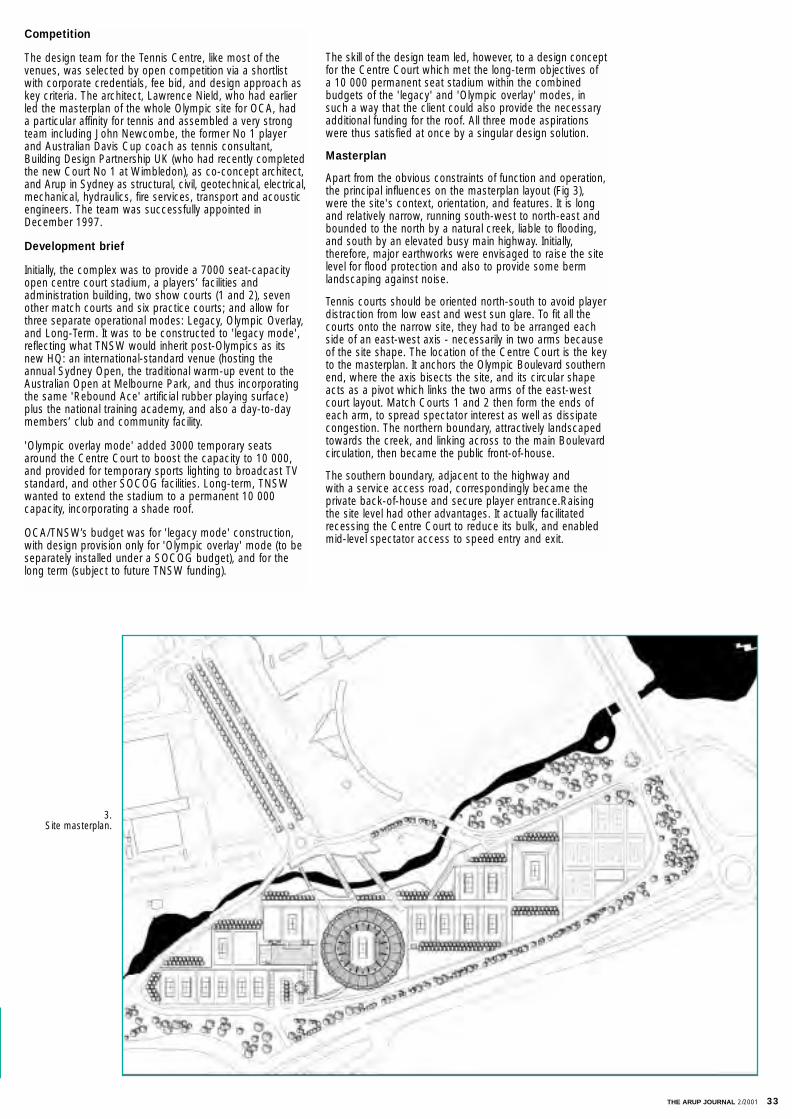
THE ARUP JOURNAL 2/2001 33
Competition
The design team for the Tennis Centre, like most of thevenues, was selected by open competition via a shortlistwith corporate credentials, fee bid, and design approach askey criteria. The architect, Lawrence Nield, who had earlierled the masterplan of the whole Olympic site for OCA, had a particular affinity for tennis and assembled a very strongteam including John Newcombe, the former No 1 playerand Australian Davis Cup coach as tennis consultant,Building Design Partnership UK (who had recently completedthe new Court No 1 at Wimbledon), as co-concept architect,and Arup in Sydney as structural, civil, geotechnical, electrical,mechanical, hydraulics, fire services, transport and acousticengineers. The team was successfully appointed inDecember 1997.
Development brief
Initially, the complex was to provide a 7000 seat-capacityopen centre court stadium, a players’ facilities and administration building, two show courts (1 and 2), sevenother match courts and six practice courts; and allow forthree separate operational modes: Legacy, Olympic Overlay,and Long-Term. It was to be constructed to 'legacy mode',reflecting what TNSW would inherit post-Olympics as itsnew HQ: an international-standard venue (hosting the annual Sydney Open, the traditional warm-up event to theAustralian Open at Melbourne Park, and thus incorporatingthe same 'Rebound Ace' artificial rubber playing surface)plus the national training academy, and also a day-to-daymembers’ club and community facility.
'Olympic overlay mode' added 3000 temporary seatsaround the Centre Court to boost the capacity to 10 000,and provided for temporary sports lighting to broadcast TVstandard, and other SOCOG facilities. Long-term, TNSWwanted to extend the stadium to a permanent 10 000capacity, incorporating a shade roof.
OCA/TNSW’s budget was for 'legacy mode' construction,with design provision only for 'Olympic overlay' mode (to beseparately installed under a SOCOG budget), and for thelong term (subject to future TNSW funding).
The skill of the design team led, however, to a design conceptfor the Centre Court which met the long-term objectives ofa 10 000 permanent seat stadium within the combinedbudgets of the 'legacy' and 'Olympic overlay' modes, in such a way that the client could also provide the necessaryadditional funding for the roof. All three mode aspirationswere thus satisfied at once by a singular design solution.
Masterplan
Apart from the obvious constraints of function and operation,the principal influences on the masterplan layout (Fig 3),were the site's context, orientation, and features. It is longand relatively narrow, running south-west to north-east andbounded to the north by a natural creek, liable to flooding,and south by an elevated busy main highway. Initially, therefore, major earthworks were envisaged to raise the sitelevel for flood protection and also to provide some bermlandscaping against noise.
Tennis courts should be oriented north-south to avoid playerdistraction from low east and west sun glare. To fit all thecourts onto the narrow site, they had to be arranged eachside of an east-west axis - necessarily in two arms becauseof the site shape. The location of the Centre Court is the keyto the masterplan. It anchors the Olympic Boulevard southernend, where the axis bisects the site, and its circular shapeacts as a pivot which links the two arms of the east-westcourt layout. Match Courts 1 and 2 then form the ends ofeach arm, to spread spectator interest as well as dissipatecongestion. The northern boundary, attractively landscapedtowards the creek, and linking across to the main Boulevardcirculation, then became the public front-of-house.
The southern boundary, adjacent to the highway and with a service access road, correspondingly became the private back-of-house and secure player entrance.Raisingthe site level had other advantages. It actually facilitatedrecessing the Centre Court to reduce its bulk, and enabledmid-level spectator access to speed entry and exit.
3. Site masterplan.
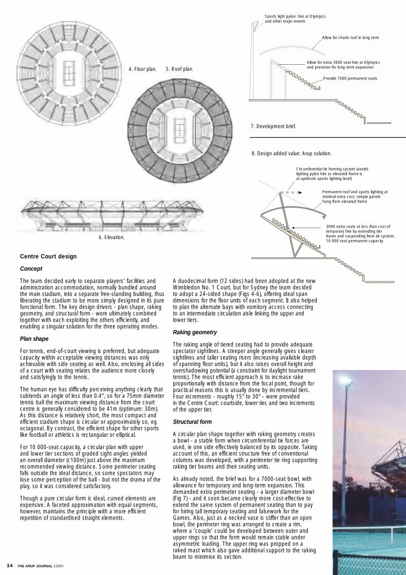
34 THE ARUP JOURNAL 2/2001
A duodecimal form (12 sides) had been adopted at the newWimbledon No. 1 Court, but for Sydney the team decidedto adopt a 24-sided shape (Figs 4-6), offering ideal spandimensions for the floor units of each segment. It also helpedto plan the alternate bays with vomitory access connectingto an intermediate circulation aisle linking the upper andlower tiers.
Raking geometry
The raking angle of tiered seating had to provide adequatespectator sightlines. A steeper angle generally gives clearersightlines and taller seating risers (increasing available depthof spanning floor units), but it also raises overall height andovershadowing potential (a constraint for daylight tournamenttennis). The most efficient approach is to increase rake proportionally with distance from the focal point, though forpractical reasons this is usually done by incremental tiers.Four increments - roughly 15° to 30° - were provided in the Centre Court: courtside, lower tier, and two incrementsof the upper tier.
Structural form
A circular plan shape together with raking geometry createsa bowl - a stable form when circumferential tie forces areused, ie one side effectively balanced by its opposite. Takingaccount of this, an efficient structure free of conventionalcolumns was developed, with a perimeter tie ring supportingraking tier beams and their seating units.
As already noted, the brief was for a 7000-seat bowl, withallowance for temporary and long-term expansion. Thisdemanded extra perimeter seating - a larger diameter bowl(Fig 7) - and it soon became clearly more cost-effective toextend the same system of permanent seating than to payfor hiring tall temporary seating and falsework for theGames. Also, just as a necked vase is stiffer than an openbowl, the perimeter ring was arranged to create a rim,where a ‘couple’ could be developed between outer andupper rings so that the form would remain stable underasymmetric loading. The upper ring was propped on araked mast which also gave additional support to the rakingbeam to minimise its section.
Centre Court design
Concept
The team decided early to separate players’ facilities andadministration accommodation, normally bundled aroundthe main stadium, into a separate free-standing building, thusliberating the stadium to be more simply designed in its purefunctional form. The key design drivers - plan shape, rakinggeometry, and structural form - were ultimately combinedtogether with each exploiting the others efficiently, andenabling a singular solution for the three operating modes.
Plan shape
For tennis, end-of-court viewing is preferred, but adequatecapacity within acceptable viewing distances was onlyachievable with side seating as well. Also, enclosing all sidesof a court with seating relates the audience more closelyand satisfyingly to the tennis.
The human eye has difficulty perceiving anything clearly thatsubtends an angle of less than 0.4°, so for a 75mm diametertennis ball the maximum viewing distance from the courtcentre is generally considered to be 41m (optimum: 30m).As this distance is relatively short, the most compact andefficient stadium shape is circular or approximately so, egoctagonal. By contrast, the efficient shape for other sportslike football or athletics is rectangular or elliptical.
For 10 000-seat capacity, a circular plan with upper and lower tier sections of graded sight angles yielded an overall diameter (c100m) just above the maximum recommended viewing distance. Some perimeter seatingfalls outside the ideal distance, so some spectators maylose some perception of the ball - but not the drama of theplay, so it was considered satisfactory.
Though a pure circular form is ideal, curved elements areexpensive. A faceted approximation with equal segments,however, maintains the principle with a more efficient repetition of standardised straight elements.
Sports light pylon: hire at Olympicsand other major events
Allow for shade roof in long term
Allow for extra 3000 seat hire at Olympicsand provision for long-term expansion
Provide 7000 permanent seats
Circumferential tie framing system (avoidslighting pylon hire as elevated frame isat optimum sports lighting level)
Permanent roof and sports lighting atminimal extra cost: simple panelshung from elevated frame
3000 extra seats at less than cost oftemporary hire by extending tierframe and suspending from tie system:10 000 seat permanent capacity
7. Development brief.
8. Design added value: Arup solution.
4. Floor plan. 5. Roof plan.
6. Elevation.
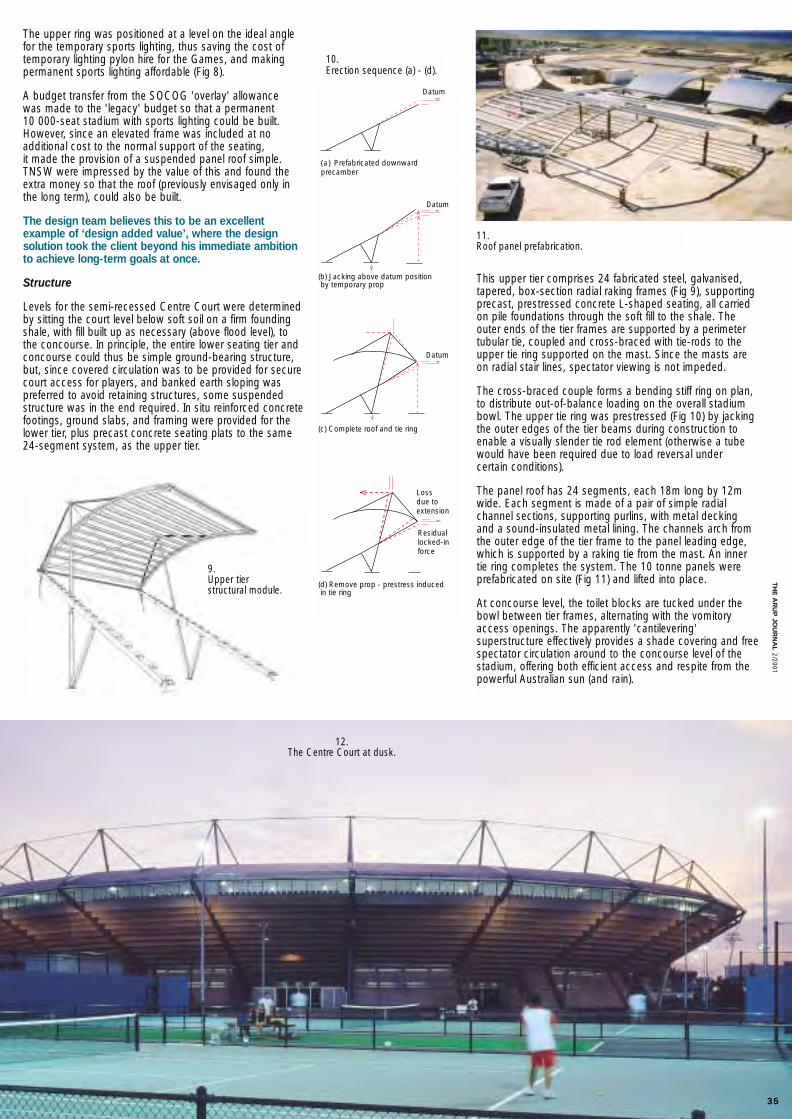
TH
E A
RU
P JO
UR
NA
L2/2001
The upper ring was positioned at a level on the ideal anglefor the temporary sports lighting, thus saving the cost oftemporary lighting pylon hire for the Games, and makingpermanent sports lighting affordable (Fig 8).
A budget transfer from the SOCOG 'overlay' allowance was made to the 'legacy' budget so that a permanent 10 000-seat stadium with sports lighting could be built.However, since an elevated frame was included at no additional cost to the normal support of the seating, it made the provision of a suspended panel roof simple.TNSW were impressed by the value of this and found theextra money so that the roof (previously envisaged only inthe long term), could also be built.
The design team believes this to be an excellent example of ‘design added value’, where the designsolution took the client beyond his immediate ambitionto achieve long-term goals at once.
Structure
Levels for the semi-recessed Centre Court were determinedby sitting the court level below soft soil on a firm foundingshale, with fill built up as necessary (above flood level), tothe concourse. In principle, the entire lower seating tier andconcourse could thus be simple ground-bearing structure,but, since covered circulation was to be provided for securecourt access for players, and banked earth sloping was preferred to avoid retaining structures, some suspendedstructure was in the end required. In situ reinforced concretefootings, ground slabs, and framing were provided for thelower tier, plus precast concrete seating plats to the same24-segment system, as the upper tier.
This upper tier comprises 24 fabricated steel, galvanised,tapered, box-section radial raking frames (Fig 9), supportingprecast, prestressed concrete L-shaped seating, all carriedon pile foundations through the soft fill to the shale. Theouter ends of the tier frames are supported by a perimetertubular tie, coupled and cross-braced with tie-rods to theupper tie ring supported on the mast. Since the masts areon radial stair lines, spectator viewing is not impeded.
The cross-braced couple forms a bending stiff ring on plan,to distribute out-of-balance loading on the overall stadiumbowl. The upper tie ring was prestressed (Fig 10) by jackingthe outer edges of the tier beams during construction toenable a visually slender tie rod element (otherwise a tubewould have been required due to load reversal under certain conditions).
The panel roof has 24 segments, each 18m long by 12mwide. Each segment is made of a pair of simple radial channel sections, supporting purlins, with metal decking and a sound-insulated metal lining. The channels arch fromthe outer edge of the tier frame to the panel leading edge,which is supported by a raking tie from the mast. An inner tie ring completes the system. The 10 tonne panels were prefabricated on site (Fig 11) and lifted into place.
At concourse level, the toilet blocks are tucked under thebowl between tier frames, alternating with the vomitoryaccess openings. The apparently 'cantilevering' superstructure effectively provides a shade covering and freespectator circulation around to the concourse level of thestadium, offering both efficient access and respite from thepowerful Australian sun (and rain).
Datum
Datum
Datum
Residuallocked-inforce
Lossdue toextension
(a) Prefabricated downwardprecamber
(b) Jacking above datum position by temporary prop
(c) Complete roof and tie ring
(d) Remove prop - prestress induced in tie ring
10. Erection sequence (a) - (d).
9. Upper tier structural module.
11. Roof panel prefabrication.
35
12. The Centre Court at dusk.
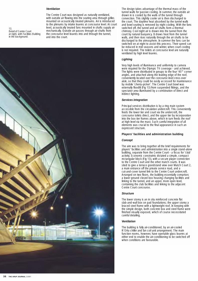
36 THE ARUP JOURNAL 2/2001
Ventilation
The Centre Court was designed as naturally ventilated, with outside air flowing into the seating area through grillesmounted on acoustically treated plenums. Air is introducedto the plenums by intake louvres at concourse level. At courtlevel, acoustically treated fans mounted in shafts supply airmechanically. Outside air passes through air shafts from the concourse level louvres into and through the tunnel, and into the court.
The design takes advantage of the thermal mass of the tunnel walls for passive cooling. In summer, the outside airdrawn in is cooled by the walls of the tunnel through convection. This slightly cooler air is then discharged to the court. The daytime heat absorbed by the tunnel wallsand bowl seating is removed by night cooling. With the fansswitched off, the tunnel and air shafts form a thermal chimney. Cool night air is drawn into the tunnel from thecourt by natural buoyancy. It draws heat from the tunnelwalls, and then rises naturally through the air shafts to bedischarged to the atmosphere. In summer the fans can beswitched on at night to assist this process. Their speed canbe reduced in mid seasons and winter, when court coolingis not required. The toilets at concourse level are naturallyventilated by high level louvres.
Lighting
Very high levels of illuminance and uniformity to camerawere required for the Olympic TV coverage - and achieved.The lights were distributed in groups to the four '45°' cornerangles, and attached along the leading edge of the roof,conveniently located over the concourse level cross-overaisle, so that they could be easily accessed for maintenanceby mobile ‘cherry-picker’. The Centre Court bowl was externally floodlit (Fig 13) from suspended fittings, and thespectator area illuminated by a combination of direct andindirect lighting.
Services integration
Principal services distribution is by a ring main systemaccessible from the circulation undercroft. This convenientlyfeeds the lower tier and court via the undercroft, the concourse toilets direct, and the upper tier by incorporationinto the box tier frames above, which in turn feeds the roofat high level via the mast. Such careful integration of all elements was crucial to the final appearance in such anexpressed structure.
Players’ facilities and administration building
Concept
The aim was to bring together all the brief requirements forplayers’ facilities and administration into a single stand-alonebuilding, separate from the Centre Court - a focus for 'club'activity. Economic constraints dictated a simple, compactrectangular block (Fig 13), with a secure player connectionto the Centre Court and the other match courts. It was sited to give a terrace grandstand view over Match Court 2,a main entrance off the private service road, and a cut-and-cover tunnel link to the Centre Court undercroft.Arranged on two floors, the building essentially comprises a lower ground closed box housing changing facilities andlinking to the tunnel, and an upper, more open level, containing the club facilities and linking to the adjacentCentre Court concourse.
Structure
The lower storey is an in situ reinforced concrete flat slab-and-wall box on pad foundations; the upper storey abraced steel frame with a lightweight roof. In keeping withthe simple design, both concrete box and steel frame werefinished visually exposed, which of course necessitatedcareful detailing.
Ventilation
The building is fully air-conditioned, by an air-cooled R134a chiller and fan coil unit arrangement. The main function rooms, however, have openable glass louvres ateither end to enable the air-conditioning to be switched offwhen conditions are favourable.
13. Detail of Centre Court at night, with Facilities Buildingin the background.
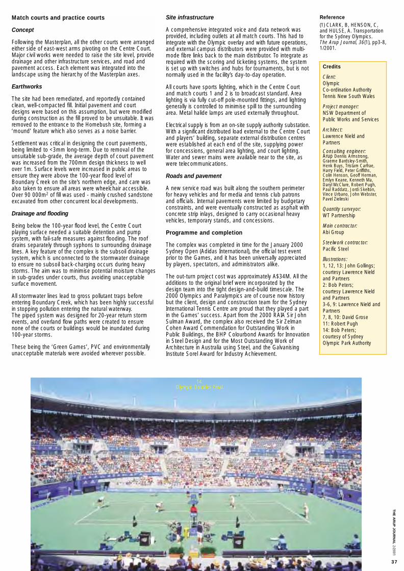
Site infrastructure
A comprehensive integrated voice and data network wasprovided, including outlets at all match courts. This had tointegrate with the Olympic overlay and with future operations,and external campus distributors were provided with multi-mode fibre links back to the main distributor. To integrate asrequired with the scoring and ticketing systems, the systemis set up with switches and hubs for tournaments, but is notnormally used in the facility’s day-to-day operation.
All courts have sports lighting, which in the Centre Courtand match courts 1 and 2 is to broadcast standard. Arealighting is via fully cut-off pole-mounted fittings, and lightinggenerally is controlled to minimise spill to the surroundingarea. Metal halide lamps are used externally throughout.
Electrical supply is from an on-site supply authority substation.With a significant distributed load external to the Centre Courtand players’ building, separate external distribution centreswere established at each end of the site, supplying powerfor concessions, general area lighting, and court lighting.Water and sewer mains were available near to the site, aswere telecommunications.
Roads and pavement
A new service road was built along the southern perimeterfor heavy vehicles and for media and tennis club patronsand officials. Internal pavements were limited by budgetaryconstraints, and were eventually constructed as asphalt withconcrete strip inlays, designed to carry occasional heavyvehicles, temporary stands, and concessions.
Programme and completion
The complex was completed in time for the January 2000Sydney Open (Adidas International), the official test eventprior to the Games, and it has been universally appreciatedby players, spectators, and administrators alike.
The out-turn project cost was approximately A$34M. All theadditions to the original brief were incorporated by thedesign team into the tight design-and-build timescale. The2000 Olympics and Paralympics are of course now historybut the client, design and construction team for the SydneyInternational Tennis Centre are proud that they played a partin the Games’ success. Apart from the 2000 RAIA Sir JohnSulman Award, the complex also received the Sir ZelmanCohen Award Commendation for Outstanding Work inPublic Buildings, the BHP Colourbond Awards for Innovationin Steel Design and for the Most Outstanding Work ofArchitecture in Australia using Steel, and the GalvanisingInstitute Sorel Award for Industry Achievement.
Match courts and practice courts
Concept
Following the Masterplan, all the other courts were arrangedeither side of east-west arms pivoting on the Centre Court.Major civil works were needed to raise the site level, providedrainage and other infrastructure services, and road andpavement access. Each element was integrated into thelandscape using the hierarchy of the Masterplan axes.
Earthworks
The site had been remediated, and reportedly containedclean, well-compacted fill. Initial pavement and courtdesigns were based on this assumption, but were modifiedduring construction as the fill proved to be unsuitable. It wasremoved to the entrance to the Homebush site, forming a‘mound’ feature which also serves as a noise barrier.
Settlement was critical in designing the court pavements,being limited to <3mm long-term. Due to removal of theunsuitable sub-grade, the average depth of court pavementwas increased from the 700mm design thickness to wellover 1m. Surface levels were increased in public areas toensure they were above the 100-year flood level ofBoundary Creek on the site’s northern edge, and care wasalso taken to ensure all areas were wheelchair accessible.Over 90 000m2 of fill was used - mainly crushed sandstoneexcavated from other concurrent local developments.
Drainage and flooding
Being below the 100-year flood level, the Centre Court playing surface needed a suitable detention and pump system, with fail-safe measures against flooding. The roofdrains separately through syphons to surrounding drainagelines. A key feature of the complex is the subsoil drainagesystem, which is unconnected to the stormwater drainageto ensure no subsoil back-charging occurs during heavystorms. The aim was to minimise potential moisture changesin sub-grades under courts, thus avoiding unacceptable surface movement.
All stormwater lines lead to gross pollutant traps beforeentering Boundary Creek, which has been highly successfulin stopping pollution entering the natural waterway. The piped system was designed for 20-year return stormevents, and overland flow paths were created to ensurenone of the courts or buildings would be inundated during100-year storms.
These being the ‘Green Games’, PVC and environmentallyunacceptable materials were avoided wherever possible.
Credits
Client:Olympic Co-ordination AuthorityTennis New South Wales
Project manager:NSW Department of Public Works and Services
Architect:Lawrence Nield andPartners
Consulting engineer:Arup Dennis Armstrong,Graeme Bardsley-Smith, Henk Buys, Tristam Carfrae,Harry Field, Peter Griffiths, Colin Henson, Geoff Herman,Emlyn Keane, Kenneth Ma,Daryl McClure, Robert Pugh,Paul Raddatz, Jordi Skelton,Vince Urbano, John Webster,Pavel Zielinski
Quantity surveyor:WT Partnership
Main contractor:Abi Group
Steelwork contractor:Pacific Steel
Illustrations:1, 12, 13: John Gollings;courtesy Lawrence Nieldand Partners2: Bob Peters; courtesy Lawrence Nieldand Partners 3-6, 9: Lawrence Nield andPartners7, 8, 10: David Grose11: Robert Pugh14: Bob Peters; courtesy of Sydney Olympic Park Authority
14. Olympic Doubles Final.
Reference(1) CLARK, B, HENSON, C,and HULSE, A. Transportationfor the Sydney Olympics. The Arup Journal, 36(1), pp3-8,1/2001.
TH
E A
RU
P JO
UR
NA
L2/2001
37
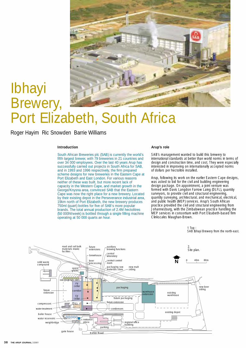
Arup’s role
SAB’s management wanted to build this brewery to international standards at better than world norms in terms ofdesign and construction time, and cost. They were especiallyinterested in improving on internationally accepted norms of dollars per hectolitre installed.
Arup, following its work on the earlier Eastern Cape designs,was asked to bid for the civil and building engineeringdesign package. On appointment, a joint venture wasformed with Davis Langdon Farrow Laing (DLFL), quantitysurveyors, to provide civil and structural engineering, quantity surveying, architectural, and mechanical, electrical,and public health (MEP) services. Arup’s South African practice provided the civil and structural engineering fromJohannesburg, with the Zimbabwean practice handling theMEP services in consortium with Port Elizabeth-based firmClinkscales Maughan-Brown.
Introduction
South African Breweries plc (SAB) is currently the world’sfifth largest brewer, with 79 breweries in 21 countries andover 34 000 employees. Over the last 40 years Arup hassuccessfully carried out projects in South Africa for SAB,and in 1993 and 1996 respectively, the firm preparedscheme designs for new breweries in the Eastern Cape atPort Elizabeth and East London. For various reasonsneither of these was built, but more recent lack ofcapacity in the Western Cape, and market growth in theGeorge/Knysna area, convinced SAB that the EasternCape was now the right place for a new brewery. Locatedby their existing depot in the Perseverance industrial area,19km north of Port Elizabeth, the new brewery produces750ml (quart) bottles for five of SAB's more popularbrands. The total annual production of 2.4M hectolitres(50 000hl/week) is bottled through a single filling machineoperating at 50 000 quarts an hour.
0 80m40m
packaging
road and rail bulkmaterials intakefacilites
futureextension
raw materials silo’sFV
cellar
SVcellar
corridor
spentgrains
futureextensions
compressors
brewhouse
beerprocessing
auxiliarybrewing functions
centrallaboratory
central controlroom
packaging rawmaterials store
future packaging
warehouseextension
new beersiding
new maltsiding
existingwarehouse
existing depot
future extension
water treatment
boiler house
water reservoirs
weighbridge
gate house
entranceplaza
Kohler Road
parking
regional officebuilding
condensors
solid wastecompound
N
Roger Hayim Ric Snowden Barrie Williams
Ibhayi Brewery, Port Elizabeth, South Africa
1 Top : SAB Ibhayi Brewery from the north-east.
2. Site plan.
38 THE ARUP JOURNAL 2/2001

The architects were Winterbach Pretorius Letele fromJohannesburg, together with Robertson Baker and Lochnerfrom Port Elizabeth. Other services were provided by PortElizabeth-based consultants and previously disadvantagedconsulting firms. Contractually, standard FIDIC joint ventureand sub-consultancy agreements were used.
Such a multi-faceted team required additional project management to establish skills requirements and availability.Arup was design and administrative leader within the jointventure, and with the design team embracing 14 differentfirms located in three cities and two countries, this leadershipand technical co-ordination role was critical to the project’ssuccess. Process design was excluded, except for certainpiped utility services and the refrigeration of the cellar storage buildings. Danbrew of Denmark were the processconcept design engineers, and senior Arup personnelworked with them and SAB’s project personnel to establishthe site layout.
The scope of services provided by or under the direction ofthe Arup/DLFL joint venture was:
• principal agent for all civil and building work• site selection and planning, including comparison of
possible sites at the Coega Industrial Development Zone, Struandale, and Perseverance
• geotechnical engineering• site services and infrastructure• utilities and piped services (separate appointment)• civil and structural engineering• architecture• quantity surveying and cost control• mechanical engineering including natural ventilation,
specialist refrigeration services and fire protection• electrical engineering• public health• rail siding engineering• access control and security• full-time construction monitoring.
Shortly after finalising the basic layout, the client appointedproject managers to assist their own project team in co-ordinating the process design, project implementation,cost and time management. A project office was establishedin Arup's Johannesburg office, which facilitated good communication between the various players.
The site
Arup looked at five possible locations around East Londonand Port Elizabeth, at one of which, Perseverance, an SABdepot already existed. The possibility of integrating this intothe new scheme, plus the good road and rail access andmunicipal services, and the general attractiveness of thelocation, were the main factors in its choice. Some 17.9hawere already owned by the client. Conceptual planningbegan, to integrate the following facilities to achieve an efficient and economic layout:
• bulk malt road and rail intake facility, including road and rail weighbridges
• work tower for milling malt• silos for 3000 tonnes malt storage• brewhouse and beer process area• compressor house• Fermentation vessel (FV) and storage vessel (SV) cellars• Ancillary brewing products and packaging store areas• Control rooms and central services offices with laboratory• service corridors and pipe spines• packaging hall• warehouse extension• miscellaneous service buildings and external facilities
including:• water treatment building and reservoirs• truck wash bay• boilerhouse• waste compound• effluent balancing tank• rail dispatch facility• regional offices (scheme design only).
The site is in the Swartkops River valley some 8km from the sea, and thus not unexpectedly its geology contains fairlysubstantial layers of hillwash and transported clayey sandymaterial with gravel layers and small boulders. Below thisare layered siltstones and shales varying from very soft to soft rock.
Strip or pad foundations were founded on a stiff, coarse,alluvium layer at bearing pressures not exceeding 300kPa,whilst pre-drilled driven cast in situ piles were used underthe main process buildings and heavy equipment foundations.A perched water table was present some 4m below ground level, and the aggressive groundwater required the pile and pilecap concrete to have an increased cement content of 425kg/m3. To resist excessive chlorides and sulphates, a 50/50 mix of ordinary Portland cement and Slagment was used.
Piling was used to support all the buildings, whose totalfloor area is around 28 000m2, except for the east end ofthe packaging hall and warehouse extension.
The 40 SV/FV tanks in the cellars, 480 tonnes each, werealso supported on piles. The cellar floor slabs were stiffenedwith ground beams along the routes taken by the emptytanks during installation, whilst all other process equipment,including the heavy fuel oil boilers, is on ground slabs with or without thickenings.
3 above: Cellar building.
4 below:View from south.
THE ARUP JOURNAL 2/2001 39
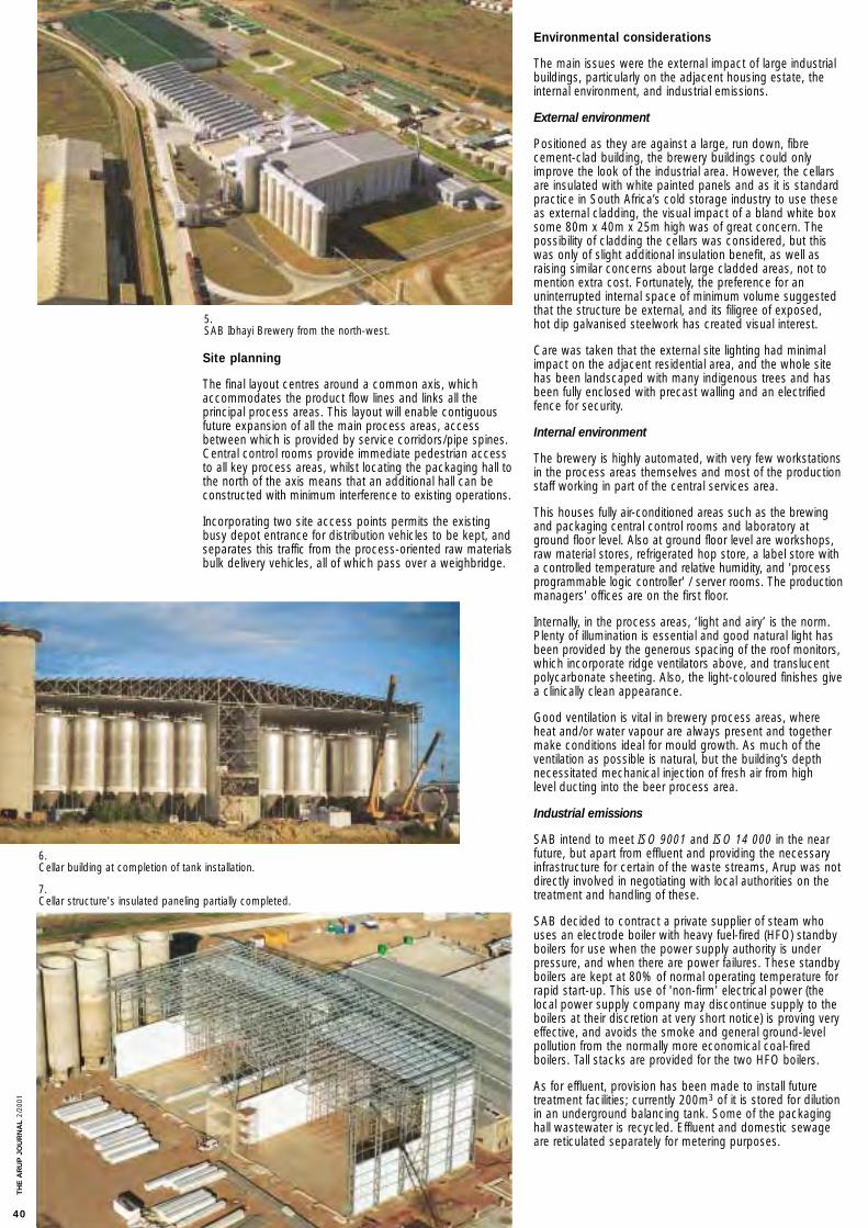
Environmental considerations
The main issues were the external impact of large industrialbuildings, particularly on the adjacent housing estate, theinternal environment, and industrial emissions.
External environment
Positioned as they are against a large, run down, fibrecement-clad building, the brewery buildings could onlyimprove the look of the industrial area. However, the cellarsare insulated with white painted panels and as it is standardpractice in South Africa’s cold storage industry to use theseas external cladding, the visual impact of a bland white boxsome 80m x 40m x 25m high was of great concern. Thepossibility of cladding the cellars was considered, but thiswas only of slight additional insulation benefit, as well asraising similar concerns about large cladded areas, not tomention extra cost. Fortunately, the preference for an uninterrupted internal space of minimum volume suggestedthat the structure be external, and its filigree of exposed, hot dip galvanised steelwork has created visual interest.
Care was taken that the external site lighting had minimalimpact on the adjacent residential area, and the whole sitehas been landscaped with many indigenous trees and hasbeen fully enclosed with precast walling and an electrifiedfence for security.
Internal environment
The brewery is highly automated, with very few workstationsin the process areas themselves and most of the productionstaff working in part of the central services area.
This houses fully air-conditioned areas such as the brewingand packaging central control rooms and laboratory atground floor level. Also at ground floor level are workshops,raw material stores, refrigerated hop store, a label store witha controlled temperature and relative humidity, and 'process programmable logic controller' / server rooms. The productionmanagers' offices are on the first floor.
Internally, in the process areas, ‘light and airy’ is the norm.Plenty of illumination is essential and good natural light hasbeen provided by the generous spacing of the roof monitors,which incorporate ridge ventilators above, and translucentpolycarbonate sheeting. Also, the light-coloured finishes givea clinically clean appearance.
Good ventilation is vital in brewery process areas, whereheat and/or water vapour are always present and togethermake conditions ideal for mould growth. As much of theventilation as possible is natural, but the building’s depthnecessitated mechanical injection of fresh air from high level ducting into the beer process area.
Industrial emissions
SAB intend to meet ISO 9001 and ISO 14 000 in the nearfuture, but apart from effluent and providing the necessaryinfrastructure for certain of the waste streams, Arup was notdirectly involved in negotiating with local authorities on thetreatment and handling of these.
SAB decided to contract a private supplier of steam whouses an electrode boiler with heavy fuel-fired (HFO) standbyboilers for use when the power supply authority is underpressure, and when there are power failures. These standbyboilers are kept at 80% of normal operating temperature forrapid start-up. This use of 'non-firm' electrical power (thelocal power supply company may discontinue supply to theboilers at their discretion at very short notice) is proving veryeffective, and avoids the smoke and general ground-levelpollution from the normally more economical coal-fired boilers. Tall stacks are provided for the two HFO boilers.
As for effluent, provision has been made to install futuretreatment facilities; currently 200m3 of it is stored for dilutionin an underground balancing tank. Some of the packaginghall wastewater is recycled. Effluent and domestic sewageare reticulated separately for metering purposes.
Site planning
The final layout centres around a common axis, whichaccommodates the product flow lines and links all the principal process areas. This layout will enable contiguousfuture expansion of all the main process areas, accessbetween which is provided by service corridors/pipe spines.Central control rooms provide immediate pedestrian accessto all key process areas, whilst locating the packaging hall tothe north of the axis means that an additional hall can beconstructed with minimum interference to existing operations.
Incorporating two site access points permits the existingbusy depot entrance for distribution vehicles to be kept, andseparates this traffic from the process-oriented raw materialsbulk delivery vehicles, all of which pass over a weighbridge.
5. SAB Ibhayi Brewery from the north-west.
7. Cellar structure's insulated paneling partially completed.
6. Cellar building at completion of tank installation.
TH
E A
RU
P J
OU
RN
AL
2/20
01
40
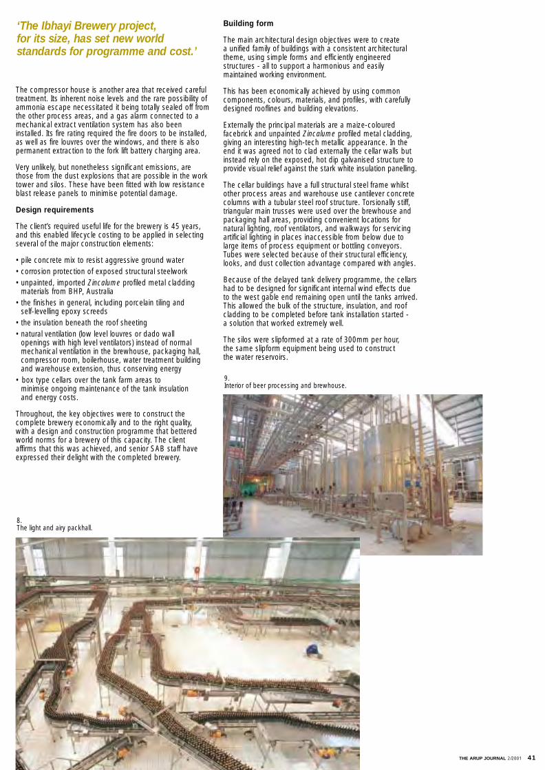
The compressor house is another area that received carefultreatment. Its inherent noise levels and the rare possibility ofammonia escape necessitated it being totally sealed off fromthe other process areas, and a gas alarm connected to amechanical extract ventilation system has also beeninstalled. Its fire rating required the fire doors to be installed,as well as fire louvres over the windows, and there is alsopermanent extraction to the fork lift battery charging area.
Very unlikely, but nonetheless significant emissions, arethose from the dust explosions that are possible in the worktower and silos. These have been fitted with low resistanceblast release panels to minimise potential damage.
Design requirements
The client’s required useful life for the brewery is 45 years,and this enabled lifecycle costing to be applied in selectingseveral of the major construction elements:
• pile concrete mix to resist aggressive ground water• corrosion protection of exposed structural steelwork• unpainted, imported Zincalume profiled metal cladding
materials from BHP, Australia• the finishes in general, including porcelain tiling and
self-levelling epoxy screeds• the insulation beneath the roof sheeting• natural ventilation (low level louvres or dado wall
openings with high level ventilators) instead of normal mechanical ventilation in the brewhouse, packaging hall, compressor room, boilerhouse, water treatment building and warehouse extension, thus conserving energy
• box type cellars over the tank farm areas to minimise ongoing maintenance of the tank insulation and energy costs.
Throughout, the key objectives were to construct the complete brewery economically and to the right quality, with a design and construction programme that betteredworld norms for a brewery of this capacity. The client affirms that this was achieved, and senior SAB staff haveexpressed their delight with the completed brewery.
Building form
The main architectural design objectives were to create a unified family of buildings with a consistent architecturaltheme, using simple forms and efficiently engineered structures - all to support a harmonious and easily maintained working environment.
This has been economically achieved by using commoncomponents, colours, materials, and profiles, with carefullydesigned rooflines and building elevations.
Externally the principal materials are a maize-coloured facebrick and unpainted Zincalume profiled metal cladding,giving an interesting high-tech metallic appearance. In theend it was agreed not to clad externally the cellar walls butinstead rely on the exposed, hot dip galvanised structure toprovide visual relief against the stark white insulation panelling.
The cellar buildings have a full structural steel frame whilstother process areas and warehouse use cantilever concretecolumns with a tubular steel roof structure. Torsionally stiff,triangular main trusses were used over the brewhouse andpackaging hall areas, providing convenient locations for natural lighting, roof ventilators, and walkways for servicingartificial lighting in places inaccessible from below due tolarge items of process equipment or bottling conveyors.Tubes were selected because of their structural efficiency,looks, and dust collection advantage compared with angles.
Because of the delayed tank delivery programme, the cellarshad to be designed for significant internal wind effects dueto the west gable end remaining open until the tanks arrived.This allowed the bulk of the structure, insulation, and roofcladding to be completed before tank installation started - a solution that worked extremely well.
The silos were slipformed at a rate of 300mm per hour, the same slipform equipment being used to construct the water reservoirs.
‘The Ibhayi Brewery project,for its size, has set new world standards for programme and cost.’
8. The light and airy packhall.
9.Interior of beer processing and brewhouse.
THE ARUP JOURNAL 2/2001 41
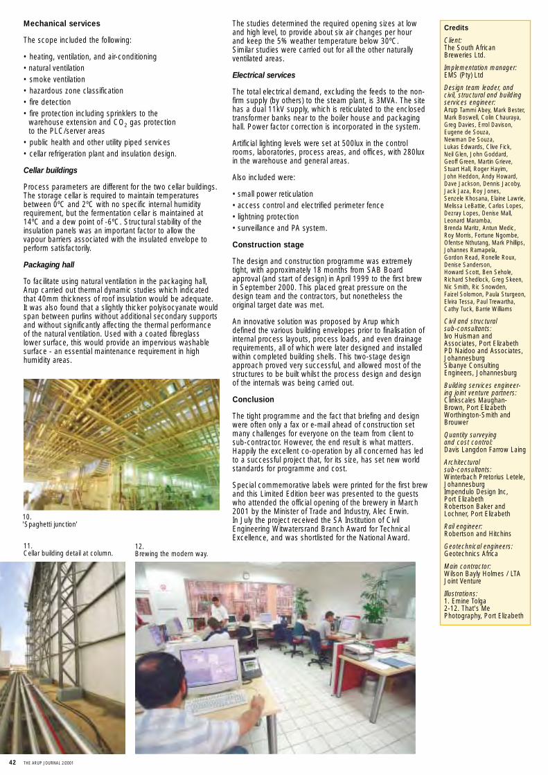
Mechanical services
The scope included the following:
• heating, ventilation, and air-conditioning• natural ventilation• smoke ventilation• hazardous zone classification• fire detection• fire protection including sprinklers to the
warehouse extension and CO2 gas protection to the PLC/server areas
• public health and other utility piped services• cellar refrigeration plant and insulation design.
Cellar buildings
Process parameters are different for the two cellar buildings.The storage cellar is required to maintain temperaturesbetween 0ºC and 2ºC with no specific internal humidityrequirement, but the fermentation cellar is maintained at14ºC and a dew point of -6ºC. Structural stability of theinsulation panels was an important factor to allow thevapour barriers associated with the insulated envelope toperform satisfactorily.
Packaging hall
To facilitate using natural ventilation in the packaging hall,Arup carried out thermal dynamic studies which indicatedthat 40mm thickness of roof insulation would be adequate.It was also found that a slightly thicker polyisocyanate wouldspan between purlins without additional secondary supportsand without significantly affecting the thermal performanceof the natural ventilation. Used with a coated fibreglasslower surface, this would provide an impervious washablesurface - an essential maintenance requirement in highhumidity areas.
The studies determined the required opening sizes at lowand high level, to provide about six air changes per hour and keep the 5% weather temperature below 30ºC. Similar studies were carried out for all the other naturallyventilated areas.
Electrical services
The total electrical demand, excluding the feeds to the non-firm supply (by others) to the steam plant, is 3MVA. The sitehas a dual 11kV supply, which is reticulated to the enclosedtransformer banks near to the boiler house and packaginghall. Power factor correction is incorporated in the system.
Artificial lighting levels were set at 500lux in the controlrooms, laboratories, process areas, and offices, with 280luxin the warehouse and general areas.
Also included were:
• small power reticulation• access control and electrified perimeter fence• lightning protection• surveillance and PA system.
Construction stage
The design and construction programme was extremelytight, with approximately 18 months from SAB Boardapproval (and start of design) in April 1999 to the first brewin September 2000. This placed great pressure on thedesign team and the contractors, but nonetheless the original target date was met.
An innovative solution was proposed by Arup which defined the various building envelopes prior to finalisation ofinternal process layouts, process loads, and even drainagerequirements, all of which were later designed and installedwithin completed building shells. This two-stage designapproach proved very successful, and allowed most of thestructures to be built whilst the process design and designof the internals was being carried out.
Conclusion
The tight programme and the fact that briefing and designwere often only a fax or e-mail ahead of construction setmany challenges for everyone on the team from client tosub-contractor. However, the end result is what matters.Happily the excellent co-operation by all concerned has ledto a successful project that, for its size, has set new worldstandards for programme and cost.
Special commemorative labels were printed for the first brewand this Limited Edition beer was presented to the guestswho attended the official opening of the brewery in March2001 by the Minister of Trade and Industry, Alec Erwin. In July the project received the SA Institution of CivilEngineering Witwatersrand Branch Award for TechnicalExcellence, and was shortlisted for the National Award.
Credits
Client:The South African Breweries Ltd.
Implementation manager:EMS (Pty) Ltd
Design team leader, and civil, structural and buildingservices engineer:Arup Tammi Abey, Mark Bester,Mark Boswell, Colin Chauraya,Greg Davies, Errol Davison,Eugene de Souza, Newman De Souza, Lukas Edwards, Clive Fick, Neil Glen, John Goddard, Geoff Green, Martin Grieve,Stuart Hall, Roger Hayim, John Heddon, Andy Howard,Dave Jackson, Dennis Jacoby,Jack Jaza, Roy Jones, Senzele Khosana, Elaine Lawrie,Melissa LeBattie, Carlos Lopes,Dezray Lopes, Denise Mall,Leonard Maramba, Brenda Maritz, Antun Medic, Roy Morris, Fortune Ngombe,Ofentse Nthutang, Mark Phillips,Johannes Ramapela, Gordon Read, Ronelle Roux,Denise Sanderson, Howard Scott, Ben Sehole,Richard Shedlock, Greg Skeen,Nic Smith, Ric Snowden, Faizel Solomon, Paula Sturgeon,Elvira Tessa, Paul Trewartha,Cathy Tuck, Barrie Williams
Civil and structural sub-consultants:Ivo Huisman andAssociates, Port ElizabethPD Naidoo and Associates,JohannesburgSibanye ConsultingEngineers, Johannesburg
Building services engineer-ing joint venture partners:Clinkscales Maughan-Brown, Port ElizabethWorthington-Smith andBrouwer
Quantity surveying and cost control:Davis Langdon Farrow Laing
Architectural sub-consultants:Winterbach Pretorius Letele,JohannesburgImpendulo Design Inc, Port ElizabethRobertson Baker andLochner, Port Elizabeth
Rail engineer:Robertson and Hitchins
Geotechnical engineers:Geotechnics Africa
Main contractor:Wilson Bayly Holmes / LTAJoint Venture
Illustrations:1. Emine Tolga2-12. That's MePhotography, Port Elizabeth
10. 'Spaghetti junction'
11. Cellar building detail at column.
12. Brewing the modern way.
42 THE ARUP JOURNAL 2/2001

THE ARUP JOURNAL 2/2001 43
Introduction
Neutral colocation datacentres are large computer rooms, covering thousands of square metres, where many different companies house their computer equipmentin a controlled and managed environment. The buildingsprovide a high level of M&E systems with the necessaryresilience to support the '24/7' operational computer facility. 'Neutral' means that it is not owned or controlledby an individual telecom carrier company, and can thussupply its customers with a choice of carriers - betweenwhich they can swap with minimum disruption. Individualclients are also encouraged to trade between themselvesin a mini-market within the datacentre, with the host company offering managed services that can include someof their client’s products.
IX Europe (IXE) is one such company, formed in 1998 to set up a pan-European network of 24 individual datacentres in 10 different European countries by the end of 2002. In May 2000 IXE asked Arup to undertake adesign review of their second datacentre site at Heathrow.Following this, the firm was asked to quote both for producing a standard reference design and for carryingout the project management of the roll-out. IXE acceptedboth of these, and by the end of May 2000 design and project management teams were in place. By April2001 eight datacentres were already established in fivecountries - two in London, Paris, Antibes, Zürich,Frankfurt, Düsseldorf, and Milan.
Two further sites were being developed - in Barcelona andat a second location in Zürich.
Project managementArup initially proposed to IXE that a project management teambe set up comprising a senior project manager based atIXE’s London headquarters, and individual project managerson each site for the duration of the works. IXE accepted thisas the best route to delivery, and the senior project managerjoined them at the end of May 2000. The first site projectmanager was appointed soon after for the Paris project, andthe team continued to grow as individual sites were selecteduntil Arup had nine project managers based in six differentcountries in Europe. This project management team wasboth multi-national and multi-lingual.
Project stages
The project management services provided to IXE can bedivided as follows:1 Locate suitable buildings / sites,
undertake due diligence surveys2 Negotiate building lease / purchase
and organise local utility supplies 3 Assemble the consultant design team and manage4 Negotiate with landlords and local building
permitting authorities5 Manage the tender process and appointment
of contractors6 Manage construction to quality and time7 Manage completion of the project.
Suitable buildings
IXE had a clear rollout strategy of 24 cities to have datacentres by the end of 2002. The cities were also prioritised, so Arup knew which were likely to be first. IXEhad also engaged Colliers as their real estate agent to carryout a pan-European search for suitable sites in these cities.Once Colliers had identified a possible site, Arup and IXEsurveyed it for suitability. The basic requirements are listedbelow; some easily checkable with a site visit, others necessitating further investigation: • minimum clear height of 8m for installing a mezzanine• floor slab strong enough for a mezzanine• clear span areas with minimum 6m column spacings• external area for electrical and mechanical plant• availability of local carriers and utilities• access into the building - office and reception space.
UK
City of London andLondon Heathrow
Paris
France
Sophia - Antipolis
BarcelonaSpain
Germany
Düsseldorf
Frankfurt
Zürich 1 & 2
Switzerland
Milan
Italy
European datacentres for IX EuropeEd Russell
1 top:Interior of London Heathrow datacentre.
2 left:European locations for IX Europe datacentre roll-out.
By April 2001IX Europe hadestablishedeightdatacentresin fivecountries...
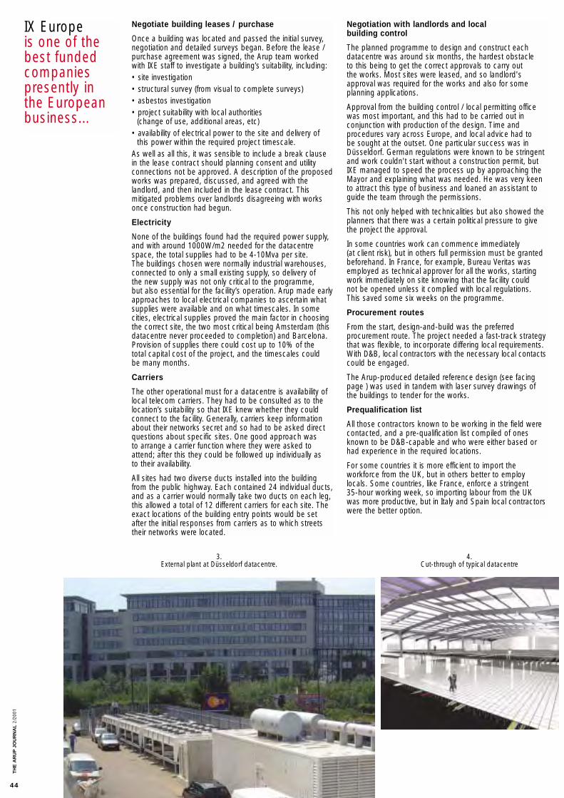
Negotiate building leases / purchase
Once a building was located and passed the initial survey,negotiation and detailed surveys began. Before the lease /purchase agreement was signed, the Arup team workedwith IXE staff to investigate a building’s suitability, including:• site investigation• structural survey (from visual to complete surveys)• asbestos investigation• project suitability with local authorities
(change of use, additional areas, etc)• availability of electrical power to the site and delivery of
this power within the required project timescale.As well as all this, it was sensible to include a break clausein the lease contract should planning consent and utilityconnections not be approved. A description of the proposedworks was prepared, discussed, and agreed with the landlord, and then included in the lease contract. This mitigated problems over landlords disagreeing with worksonce construction had begun.
Electricity
None of the buildings found had the required power supply,and with around 1000W/m2 needed for the datacentrespace, the total supplies had to be 4-10Mva per site. The buildings chosen were normally industrial warehouses,connected to only a small existing supply, so delivery of the new supply was not only critical to the programme, but also essential for the facility’s operation. Arup made earlyapproaches to local electrical companies to ascertain whatsupplies were available and on what timescales. In somecities, electrical supplies proved the main factor in choosingthe correct site, the two most critical being Amsterdam (thisdatacentre never proceeded to completion) and Barcelona.Provision of supplies there could cost up to 10% of the total capital cost of the project, and the timescales could be many months.
Carriers
The other operational must for a datacentre is availability oflocal telecom carriers. They had to be consulted as to thelocation’s suitability so that IXE knew whether they couldconnect to the facility. Generally, carriers keep informationabout their networks secret and so had to be asked directquestions about specific sites. One good approach was to arrange a carrier function where they were asked toattend; after this they could be followed up individually as to their availability.
All sites had two diverse ducts installed into the buildingfrom the public highway. Each contained 24 individual ducts,and as a carrier would normally take two ducts on each leg,this allowed a total of 12 different carriers for each site. Theexact locations of the building entry points would be setafter the initial responses from carriers as to which streetstheir networks were located.
Negotiation with landlords and localbuilding control
The planned programme to design and construct each datacentre was around six months, the hardest obstacle to this being to get the correct approvals to carry out the works. Most sites were leased, and so landlord'sapproval was required for the works and also for some planning applications.
Approval from the building control / local permitting officewas most important, and this had to be carried out in conjunction with production of the design. Time and procedures vary across Europe, and local advice had to be sought at the outset. One particular success was inDüsseldorf. German regulations were known to be stringentand work couldn't start without a construction permit, butIXE managed to speed the process up by approaching theMayor and explaining what was needed. He was very keento attract this type of business and loaned an assistant toguide the team through the permissions.
This not only helped with technicalities but also showed theplanners that there was a certain political pressure to givethe project the approval.
In some countries work can commence immediately (at client risk), but in others full permission must be grantedbeforehand. In France, for example, Bureau Veritas wasemployed as technical approver for all the works, startingwork immediately on site knowing that the facility could not be opened unless it complied with local regulations. This saved some six weeks on the programme.
Procurement routes
From the start, design-and-build was the preferred procurement route. The project needed a fast-track strategythat was flexible, to incorporate differing local requirements.With D&B, local contractors with the necessary local contactscould be engaged.
The Arup-produced detailed reference design (see facingpage ) was used in tandem with laser survey drawings ofthe buildings to tender for the works.
Prequalification list
All those contractors known to be working in the field werecontacted, and a pre-qualification list compiled of onesknown to be D&B-capable and who were either based orhad experience in the required locations.
For some countries it is more efficient to import the workforce from the UK, but in others better to employlocals. Some countries, like France, enforce a stringent 35-hour working week, so importing labour from the UK was more productive, but in Italy and Spain local contractorswere the better option.
IX Europeis one of thebest fundedcompaniespresently inthe Europeanbusiness...
3.External plant at Düsseldorf datacentre.
4.Cut-through of typical datacentre
TH
E A
RU
P J
OU
RN
AL
2/20
01
44
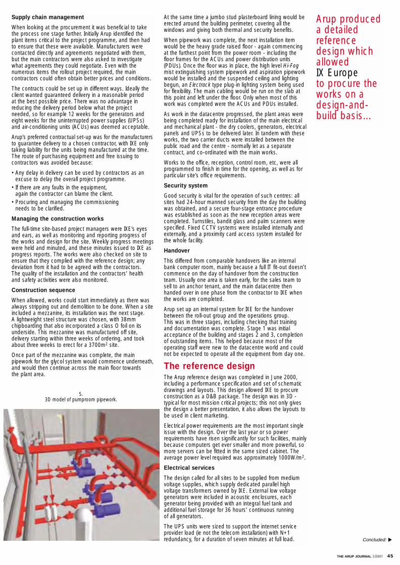
THE ARUP JOURNAL 2/2001 45
Supply chain management
When looking at the procurement it was beneficial to takethe process one stage further. Initially Arup identified theplant items critical to the project programme, and then hadto ensure that these were available. Manufacturers werecontacted directly and agreements negotiated with them,but the main contractors were also asked to investigatewhat agreements they could negotiate. Even with thenumerous items the rollout project required, the main contractors could often obtain better prices and conditions.
The contracts could be set up in different ways. Ideally theclient wanted guaranteed delivery in a reasonable period at the best possible price. There was no advantage inreducing the delivery period below what the project needed, so for example 12 weeks for the generators andeight weeks for the uninterrupted power supplies (UPSs) and air-conditioning units (ACUs) was deemed acceptable.
Arup’s preferred contractual set-up was for the manufacturersto guarantee delivery to a chosen contractor, with IXE onlytaking liability for the units being manufactured at the time.The route of purchasing equipment and free issuing to contractors was avoided because:
• Any delay in delivery can be used by contractors as an excuse to delay the overall project programme.
• If there are any faults in the equipment, again the contractor can blame the client.
• Procuring and managing the commissioning needs to be clarified.
Managing the construction works
The full-time site-based project managers were IXE’s eyesand ears, as well as monitoring and reporting progress ofthe works and design for the site. Weekly progress meetingswere held and minuted, and these minutes issued to IXE asprogress reports. The works were also checked on site toensure that they complied with the reference design; anydeviation from it had to be agreed with the contractors. The quality of the installation and the contractors’ health and safety activities were also monitored.
Construction sequence
When allowed, works could start immediately as there wasalways stripping out and demolition to be done. When a siteincluded a mezzanine, its installation was the next stage. A lightweight steel structure was chosen, with 38mm chipboarding that also incorporated a class O foil on itsunderside. This mezzanine was manufactured off site, delivery starting within three weeks of ordering, and tookabout three weeks to erect for a 3700m2 site.
Once part of the mezzanine was complete, the mainpipework for the glycol system would commence underneath,and would then continue across the main floor towards the plant area.
At the same time a jumbo stud plasterboard lining would beerected around the building perimeter, covering all the windows and giving both thermal and security benefits.
When pipework was complete, the next installation itemwould be the heavy grade raised floor - again commencingat the furthest point from the power room - including thefloor frames for the ACUs and power distribution units(PDUs). Once the floor was in place, the high level Hi-Fogmist extinguishing system pipework and aspiration pipeworkwould be installed and the suspended ceiling and lightingbegun, an Electrack type plug-in lighting system being usedfor flexibility. The main cabling would be run on the slab atthis point and left under the floor. Only when most of thiswork was completed were the ACUs and PDUs installed.
As work in the datacentre progressed, the plant areas werebeing completed ready for installation of the main electricaland mechanical plant - the dry coolers, generators, electricalpanels and UPSs to be delivered later. In tandem with theseworks, the two carrier ducts were installed between thepublic road and the centre - normally let as a separate contract, and co-ordinated with the main works.
Works to the office, reception, control room, etc, were allprogrammed to finish in time for the opening, as well as forparticular site’s office requirements.
Security system
Good security is vital for the operation of such centres: allsites had 24-hour manned security from the day the buildingwas obtained, and a secure four-stage entrance procedurewas established as soon as the new reception areas werecompleted. Turnstiles, bandit glass and palm scanners werespecified. Fixed CCTV systems were installed internally andexternally, and a proximity card access system installed forthe whole facility.
Handover
This differed from comparable handovers like an internalbank computer room, mainly because a full IT fit-out doesn’tcommence on the day of handover from the constructionteam. Usually one area is taken early, for the sales team tosell to an anchor tenant, and the main datacentre thenhanded over in one phase from the contractor to IXE whenthe works are completed.
Arup set up an internal system for IXE for the handoverbetween the roll-out group and the operations group. This was in three stages, including checking that trainingand documentation was complete. Stage 1 was initialacceptance of the building and stages 2 and 3, completionof outstanding items. This helped because most of the operating staff were new to the datacentre world and couldnot be expected to operate all the equipment from day one.
The reference designThe Arup reference design was completed in June 2000,including a performance specification and set of schematicdrawings and layouts. This design allowed IXE to procureconstruction as a D&B package. The design was in 3D -typical for most mission critical projects; this not only givesthe design a better presentation, it also allows the layouts tobe used in client marketing.
Electrical power requirements are the most important singleissue with the design. Over the last year or so powerrequirements have risen significantly for such facilities, mainlybecause computers get ever smaller and more powerful, somore servers can be fitted in the same sized cabinet. Theaverage power level required was approximately 1000W/m2.
Electrical services
The design called for all sites to be supplied from mediumvoltage supplies, which supply dedicated parallel high voltage transformers owned by IXE. External low voltagegenerators were included in acoustic enclosures, each generator being provided with an integral fuel tank and additional fuel storage for 36 hours' continuous running of all generators.
The UPS units were sized to support the internet serviceprovider load (ie not the telecom installation) with N+1redundancy, for a duration of seven minutes at full load.
Arup produceda detailedreferencedesign whichallowedIX Europeto procure theworks on adesign-and-build basis...
5.3D model of pumproom pipework.
Concluded: ▼
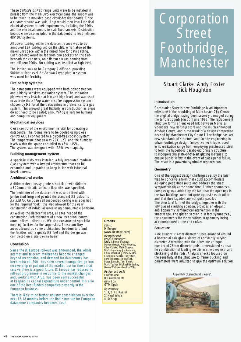
46 THE ARUP JOURNAL 2/2001
These Chloride EDP90 range units were to be installed inparallel; from the main UPS electrical panel the supply wasto be taken to moulded case circuit-breaker boards. Once a customer suite was sold, Arup would then install the finalelectrical system to their requirements, including the PDUsand the electrical runouts to slab-fixed sockets. Distributionboards were also included in the datacentre to feed telecom48V DC systems.
All power cabling within the datacentre area was to bearmoured LSF cabling laid on the slab, which allowed themaximum space within the raised floor for data cabling.Each cabinet would be fed from two sockets on the slabbeneath the cabinets, on different circuits coming from two different PDUs. No cabling was installed at high level.
The lighting was to be Category 2 diffused, providing 500lux at floor level. An Electrack type plug-in system was used for flexibility.
Fire safety systems
The datacentres were equipped with both point detectionand a highly sensitive aspiration system. The aspirationpipework was installed at low and high level, and was usedto activate the Hi-Fog water mist fire suppression system -chosen by IXE for all the datacentres in preference to a gassystem. This allowed great flexibility in construction as areasdo not need to be sealed; also, Hi-Fog is safe for humansand computer equipment.
Mechanical services
Close control of the environment is vital for operating a datacentre. The rooms were to be cooled using close control ACUs connected to a glycol-free cooling system.The temperature chosen was 22˚C ±2˚C and the humiditylevels within the space controlled to 48% ±15%. The system was designed with 133% over-capacity.
Building management system
A specialist BMS was installed, a fully integrated modularCylon system with a layered architecture that can beexpanded and upgraded to keep in line with industrial developments.
Architectural works
A 600mm deep heavy grade raised floor with 600mm x 600mm antistatic laminate floor tiles was specified. The perimeter of the datacentre was to be lined with jumbo stud lining and painted the standard IXE colour to BS 22B15. An open cell suspended ceiling was specified for the required 'look'; this also allowed for the easy construction of individual suites using demountable partitions.As well as the datacentre area, all sites needed the construction / refurbishment of a new reception, controlroom, offices, toilets, etc. We also constructed specialistmeeting facilities for the larger sites. These ancillary areas allowed us some architectural freedom to brand the facilities with a quality IXE feel and the design was completed on a site-by-site basis.
Conclusion
Since the IX Europe roll-out was announced, the wholeinternet and telecom market has become changedbeyond recognition, and demand for datacentres hasbeen reduced. 2001 has seen several companies go intoreceivership or pull out of the market, but for those thatsurvive there is a good future. IX Europe has reduced itsroll-out programme in response to the market changesand, working with Arup, has been very successful at keeping its capital expenditure under control. It is alsoone of the best-funded companies presently in theEuropean business.
There is likely to be further industry consolidation over thenext 12-18 months before the final structure for Europeandatacentre companies becomes clear.
CreditsClient:IX Europe(www.ixeurope.com)Designer and project manager:Arup Alberto Bounous, Darren Briggs, Andy Brooks, Clive Cooke, Meik Graeve, Mark Grynberg, Jo Kennedy,Chris Marshall, Jimme Moller,Francisco Parrilla, Toby Reid,Jane Roberts, Ed Russell, Peter Samain, Tom Smith, Mark Togher, Michael Underhay,Owen Webber, Gordon Wills
Design-and-build contractors:IT EnvironmentsAsta SpaGTM SpainIllustrations:1, 3, 6: Ed Russell2: Nigel Whale 4, 5: Arup
Introduction
Corporation Street’s new footbridge is an important milestone in the rebuilding of Manchester City Centre, the original bridge having been severely damaged during the terrorist bomb blast of June 1996. The replacementstructure forms an enclosed link between Marks &Spencer’s new flagship store and the much enhancedArndale Centre, and is the result of a design competitiondevised by Manchester City Council. The bridge has set new standards of structural and façade engineering in urban footbridge design. Innovative techniques used in its realisation range from employing prestressed steelto form the hyperbolic paraboloid primary structure, to incorporating state-of-the-art glazing materials toensure public safety in the event of glass panel failure.The result is a powerful symbol of regeneration.
Geometry
One of the biggest design challenges set by the briefwas to conceive a form that could accommodate a sloping pedestrian route and address the street sympathetically at the same time. Further geometricalcomplexity was added by the fact that the openings inthe two buildings were not quite opposite each otherand that their façades are not quite parallel. The structural form of the bridge, together with the fully glazed cladding solution, provides an elegant and apparently symmetrical intervention in thestreetscape. The glazed section is in fact symmetrical,the adjustments for the variations in geometry beingaccommodated at the end collars.
Structure
Nine straight 114mm diameter tubes arranged arounda horizontal axis give a sleeve of constantly varyingdiameter. Alternating with the tubes are an equal number of 28mm diameter rods, pretensioned so thatno combination of loading results in stress reversal andslackening of the rods. Analysis checks focused on the sensitivity of the structure to frame buckling andparameters were adjusted to give the optimum solution.
CorporationStreet
Footbridge,Manchester
Stuart Clarke Andy Foster Rick Houghton
1.Assembly of structural ‘sleeve’.
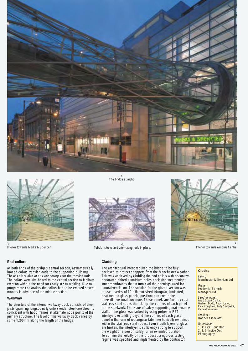
Cladding
The architectural intent required the bridge to be fullyenclosed to protect shoppers from the Manchester weather.This was achieved by cladding the end collars with decorativeperforated ribbed aluminium grilles enclosing weathertightinner membranes that in turn clad the openings used fornatural ventilation. The solution for the glazed section was to use a series of 10 different-sized triangular, laminated,heat-treated glass panels, positioned to create the three-dimensional curvature. These panels are fixed by caststainless steel nodes that clamp the corners of each panelto the steelwork. The issue of safely supporting maintenancestaff on the glass was solved by using polyester PET interlayers extending beyond the corners of each glasspanel in the form of rectangular tabs mechanically restrained within the stainless steel nodes. Even if both layers of glassare broken, the interlayer is sufficiently strong to support the weight of a person safely for an extended duration. To confirm the viability of this proposal, a rigorous testingregime was specified and implemented by the contractor.
End collars
At both ends of the bridge’s central section, asymmetricallybraced collars transfer loads to the supporting buildings.These collars also act as anchorages for the tension rods.The collars were site-bolted to the central section to facilitateerection without the need for costly in situ welding. Due toprogramme constraints the collars had to be erected severalmonths in advance of the middle section.
Walkway
The structure of the internal walkway deck consists of steeljoists spanning longitudinally onto slender steel crossbeamscoincident with hoop frames at alternate node points of theprimary structure. The level of this walkway deck varies bysome 1200mm along the length of the bridge.
THE ARUP JOURNAL 2/2001 47
Credits
Client: Manchester Millennium Ltd
Owner: Prudential PortfolioManagers Ltd
Lead designer: Arup Stuart Clarke, Graham Dodd, Andy Foster, Rick Houghton, Andy Sedgwick,Richard Summers
Architect: Hodder Associates
Illustrations:1, 4: Rick Houghton2, 3, 5: Inside OutPhotography
2. The bridge at night.
3.Interior towards Marks & Spencer
5.Interior towards Arndale Centre.
4.Tubular sleeve and alternating rods in place.
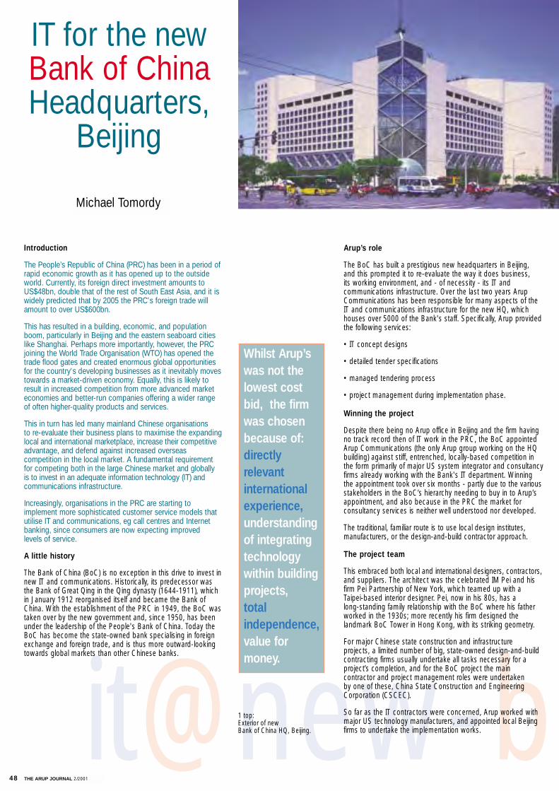
48 THE ARUP JOURNAL 2/2001
it@new-b
Michael Tomordy
1 top: Exterior of new Bank of China HQ, Beijing.
Introduction
The People’s Republic of China (PRC) has been in a period ofrapid economic growth as it has opened up to the outsideworld. Currently, its foreign direct investment amounts toUS$48bn, double that of the rest of South East Asia, and it iswidely predicted that by 2005 the PRC's foreign trade willamount to over US$600bn.
This has resulted in a building, economic, and populationboom, particularly in Beijing and the eastern seaboard citieslike Shanghai. Perhaps more importantly, however, the PRCjoining the World Trade Organisation (WTO) has opened thetrade flood gates and created enormous global opportunitiesfor the country's developing businesses as it inevitably movestowards a market-driven economy. Equally, this is likely toresult in increased competition from more advanced marketeconomies and better-run companies offering a wider range of often higher-quality products and services.
This in turn has led many mainland Chinese organisations to re-evaluate their business plans to maximise the expandinglocal and international marketplace, increase their competitiveadvantage, and defend against increased overseas competition in the local market. A fundamental requirementfor competing both in the large Chinese market and globally is to invest in an adequate information technology (IT) andcommunications infrastructure.
Increasingly, organisations in the PRC are starting to implement more sophisticated customer service models thatutilise IT and communications, eg call centres and Internetbanking, since consumers are now expecting improved levels of service.
A little history
The Bank of China (BoC) is no exception in this drive to invest innew IT and communications. Historically, its predecessor wasthe Bank of Great Qing in the Qing dynasty (1644-1911), whichin January 1912 reorganised itself and became the Bank ofChina. With the establishment of the PRC in 1949, the BoC wastaken over by the new government and, since 1950, has beenunder the leadership of the People's Bank of China. Today theBoC has become the state-owned bank specialising in foreignexchange and foreign trade, and is thus more outward-lookingtowards global markets than other Chinese banks.
Arup’s role
The BoC has built a prestigious new headquarters in Beijing, and this prompted it to re-evaluate the way it does business, its working environment, and - of necessity - its IT and communications infrastructure. Over the last two years ArupCommunications has been responsible for many aspects of theIT and communications infrastructure for the new HQ, whichhouses over 5000 of the Bank's staff. Specifically, Arup providedthe following services:
• IT concept designs
• detailed tender specifications
• managed tendering process
• project management during implementation phase.
Winning the project
Despite there being no Arup office in Beijing and the firm havingno track record then of IT work in the PRC, the BoC appointedArup Communications (the only Arup group working on the HQbuilding) against stiff, entrenched, locally-based competition inthe form primarily of major US system integrator and consultancyfirms already working with the Bank's IT department. Winningthe appointment took over six months - partly due to the variousstakeholders in the BoC’s hierarchy needing to buy in to Arup’sappointment, and also because in the PRC the market for consultancy services is neither well understood nor developed.
The traditional, familiar route is to use local design institutes,manufacturers, or the design-and-build contractor approach.
The project team
This embraced both local and international designers, contractors,and suppliers. The architect was the celebrated IM Pei and hisfirm Pei Partnership of New York, which teamed up with a Taipei-based interior designer. Pei, now in his 80s, has a long-standing family relationship with the BoC where his fatherworked in the 1930s; more recently his firm designed the landmark BoC Tower in Hong Kong, with its striking geometry.
For major Chinese state construction and infrastructure projects, a limited number of big, state-owned design-and-buildcontracting firms usually undertake all tasks necessary for a project’s completion, and for the BoC project the main contractor and project management roles were undertaken by one of these, China State Construction and EngineeringCorporation (CSCEC).
So far as the IT contractors were concerned, Arup worked withmajor US technology manufacturers, and appointed local Beijingfirms to undertake the implementation works.
Whilst Arup’swas not thelowest costbid, the firmwas chosenbecause of:directly relevant internationalexperience,understanding of integratingtechnology within buildingprojects,total independence,value formoney.
IT for the new Bank of ChinaHeadquarters,
Beijing
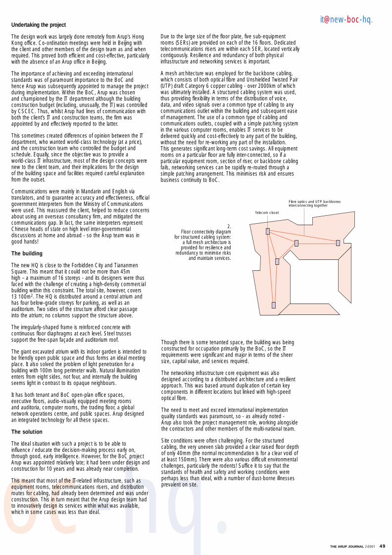
THE ARUP JOURNAL 2/2001 49
oc-hq.
Due to the large size of the floor plate, five sub-equipmentrooms (SERs) are provided on each of the 16 floors. Dedicatedtelecommunications risers are within each SER, located verticallycontiguously. Resilience and redundancy of both physical infrastructure and networking services is important.
A mesh architecture was employed for the backbone cabling,which consists of both optical fibre and Unshielded Twisted Pair(UTP) draft Category 6 copper cabling - over 2000km of whichwas ultimately installed. A structured cabling system was used,thus providing flexibility in terms of the distribution of voice, data, and video signals over a common type of cabling to anycommunications outlet within the building and subsequent easeof management. The use of a common type of cabling and communications outlets, coupled with a simple patching systemin the various computer rooms, enables IT services to be delivered quickly and cost-effectively to any part of the building,without the need for re-working any part of the installation. This generates significant long-term cost savings. All equipmentrooms on a particular floor are fully inter-connected, so if a particular equipment room, section of riser, or backbone cablingfails, networking services can be rapidly re-routed through a simple patching arrangement. This minimises risk and ensuresbusiness continuity to BoC.
2. Floor connectivity diagram
for structured cabling system: a full mesh architecture is
provided for resilience andredundancy to minimise risks
and maintain services.
Telecom closet
Fibre optics and UTP backbonesinterconnecting together
it@new-boc-hq.
Though there is some tenanted space, the building was beingconstructed for occupation primarily by the BoC, so the ITrequirements were significant and major in terms of the sheersize, capital value, and services required.
The networking infrastructure core equipment was alsodesigned according to a distributed architecture and a resilientapproach. This was based around duplication of certain keycomponents in different locations but linked with high-speedoptical fibre.
The need to meet and exceed international implementation quality standards was paramount, so - as already noted - Arup also took the project management role, working alongsidethe contractors and other members of the multi-national team.
Site conditions were often challenging. For the structuredcabling, the very uneven slab provided a clear raised floor depthof only 40mm (the normal recommendation is for a clear void ofat least 150mm). There were also various difficult environmentalchallenges, particularly the rodents! Suffice it to say that thestandards of health and safety and working conditions were perhaps less than ideal, with a number of dust-borne illnessesprevalent on site.
Undertaking the project
The design work was largely done remotely from Arup’s HongKong office. Co-ordination meetings were held in Beijing with the client and other members of the design team as and whenrequired. This proved both efficient and cost-effective, particularlywith the absence of an Arup office in Beijing.
The importance of achieving and exceeding international standards was of paramount importance to the BoC and hence Arup was subsequently appointed to manage the project during implementation. Within the BoC, Arup was chosen and championed by the IT department although the building construction budget (including, unusually, the IT) was controlledby CSCEC. Thus, whilst Arup had lines of communication withboth the client’s IT and construction teams, the firm wasappointed by and effectively reported to the latter.
This sometimes created differences of opinion between the ITdepartment, who wanted world-class technology (at a price),and the construction team who controlled the budget andschedule. Equally, since the objective was to provide a world-class IT infrastructure, most of the design concepts werenew to the client team, and their implications for the design of the building space and facilities required careful explanationfrom the outset.
Communications were mainly in Mandarin and English via translators, and to guarantee accuracy and effectiveness, officialgovernment interpreters from the Ministry of Communicationswere used. This reassured the client, helped to reduce concernsabout using an overseas consultancy firm, and mitigated thecommunications gap. In fact, the same interpreters representChinese heads of state on high level inter-governmental discussions at home and abroad - so the Arup team was ingood hands!
The building
The new HQ is close to the Forbidden City and TiananmenSquare. This meant that it could not be more than 45m high – a maximum of 16 storeys - and its designers were thusfaced with the challenge of creating a high-density commercialbuilding within this constraint. The total site, however, covers 13 100m2. The HQ is distributed around a central atrium andhas four below-grade storeys for parking, as well as an auditorium. Two sides of the structure afford clear passage into the atrium; no columns support the structure above.
The irregularly-shaped frame is reinforced concrete with continuous floor diaphragms at each level. Steel trusses support the free-span façade and auditorium roof.
The giant excavated atrium with its indoor garden is intended tobe friendly open public space and thus forms an ideal meetingplace. It also solved the problem of light penetration for a building with 100m long perimeter walls. Natural illuminationenters from eight sides, not four, and internally the buildingseems light in contrast to its opaque neighbours.
It has both tenant and BoC open-plan office spaces, executive floors, audio-visually equipped meeting rooms and auditoria, computer rooms, the trading floor, a global network operations centre, and public spaces. Arup designed an integrated technology for all these spaces.
The solution
The ideal situation with such a project is to be able to influence / educate the decision-making process early on,through good, early intelligence. However, for the BoC projectArup was appointed relatively late; it had been under design and construction for 10 years and was already near completion.
This meant that most of the IT-related infrastructure, such asequipment rooms, telecommunications risers, and distributionroutes for cabling, had already been determined and was underconstruction. This in turn meant that the Arup design team hadto innovatively design its services within what was available,which in some cases was less than ideal.
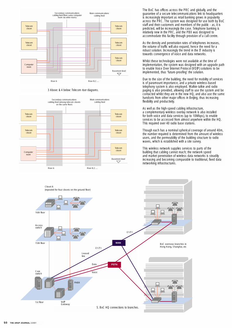
50 THE ARUP JOURNAL 2/2001
The BoC has offices across the PRC and globally, and the guarantee of a secure telecommunications link to headquartersis increasingly important as retail banking grows in popularityacross the PRC. The system was designed for use both by BoCstaff and their customers and members of the public - as, it ispredicted, will be increasingly the case. Telephone banking is relatively new in the PRC, and the PBX was designed to accommodate this facility through provision of a call centre.
As the density and penetration rates of telephones increases,the volume of traffic will also expand, hence the need for arobust solution. Increasingly the trend in the IT industry istowards convergence of voice and data networks.
Whilst these technologies were not available at the time of implementation, the system was designed with an upgrade pathto enable Voice Over Internet Protocol (VOIP) solutions to beimplemented, thus ‘future-proofing’ the solution.
Due to the size of the building, the need for mobility of servicesis of paramount importance, and a private wireless-based telephony system is also employed. Walkie-talkie and radio paging is also provided, allowing staff to use the system and becontacted whilst they are in the new HQ, and also use the samehandsets from other major offices in Beijing, thus increasing flexibility and productivity.
As well as the high-speed cabling infrastructure, a complementary wireless overlay network is also installed for both voice and data services (up to 10Mbps), to enable services to be accessed from almost anywhere within the HQ. This required over 40 radio base stations.
Though each has a nominal spherical coverage of around 40m,the number required is determined from the amount of wirelessusers, and the permeability of the building structure to radiowaves, which is established with a site survey.
This wireless network supplies services to parts of the building that cabling cannot reach; the network speed and market penetration of wireless data networks is steadilyincreasing and becoming comparable to traditional, fixed datanetworking infrastructures.
Telecomcloset
Telecomcloset
Telecomcloset
Basement level
Riser B,C....Riser A
Computerroom
Telecomcloset
Telecomcloset
Main communicationscabling feed
Secondary communicationscabling feed (from same computer
room via other risers)
Telecomcloset
Telecomcloset
Telecomcloset
Telecomcloset
Telecomcloset
Computerroom
Basement level
Riser B,C....Riser A
Main communicationscabling feed
Secondary communicationscabling feed (among telecom closets
on the same floor)
3 Above: & 4 below: Telecom riser diagrams.
5. BoC HQ connections to branches.
Accessswitch
Closet A(repeated for four closets on the ground floor)
16th floor
15th floor
1st floor
Coreswitch
VoIPGateway
PABX
Leasedline
E1/T1
WAN
PSTN
E1/T1
Data
Voice
BoC overseas branches inHong Kong, Shanghai, etc

THE ARUP JOURNAL 2/2001 51
The wider context
Inevitably, technologies are being introduced at widely varyingrates from country to country, but the same products, manufacturers, and design principles cover the globe, and so apply as much to the PRC as to Europe, the USA, or anywhere else. Nonetheless, this rapidly developing new market has many different local cultures, design practices, and ways of doing business, and so the challenges are asnumerous as are the opportunities.
Piracy and counterfeit products are major concerns for manyoverseas manufacturers supplying the PRC, and this equallyapplies to the IT and networking products being introduced byUS vendors. Also, more and more mainland firms are developingsimilar (in some cases improved) networking products for thehome market at significantly lower costs than those of their overseas counterparts.
During the implementation phase of the BoC project, the checking of products being installed and collaboration with the manufacturers was critical, as this is where the largest margins are generated, as opposed to labour costs.
Conclusion
The new Bank of China headquarters has one of the largest and most advanced structured cabling, voice and data networking infrastructures currently installed in the PRC; indeedit would be a major installation in any part of the world. Arup’sproject management aimed to ensure that the installation was world-class, matching the high standards demanded by otherleading international financial institutions. This was partiallyachieved by working closely with (indeed, to some extent educating) the contractors during implementation.
On the project as a whole, the technology design, procurement,and implementation issues were not the greatest challenges, but rather the ‘soft’ issues. The latter included the procurementprocess, the high-profile nature and importance of the project,the hierarchical nature of the organisation leading to slow decision-making, considerable cultural issues (both national and organisational), and inter-personal relationships with theclient, the design team, and the contractors. Understanding theclient's brief, as anywhere else in the world, was fundamental tothe success of the project.
It should never be forgotten by anyone undertaking a project in the PRC that assuming a Western approach is not likely to bewidely understood or appreciated.
VoIPgateway
Voicemall
Paging
CTI
DECT
Consoles
Callcentre
PABX
Routers
Firewall
BackboneLAN
switch
Network server farm
Accessswitch
PC
PC
PSTN WAN
Credits
Client:The Bank of China
Architect:The Pei Partnership
Structural engineer:Weidlinger Associates
Main contractor and project manager:China State Construction and Engineering Corporation
IT and communications designerand project manager: Arup Jimmy Chan, Simon Chung,Patrick Leung, Michael Tomordy
Illustrations:1. Martin Saunders / Arup2-6. Jimmy Chan / Jonothan Carver7. Courtesy Weidlinger Associates
‘Understanding the client’s brief is fundamental to success. Do not assume that in the PRC
a Western approach to a project is likely to be understood or appreciated.’
7. Internal atrium.
it@new-boc-hq.
6. Internal communications links.

Printed in England by Reedprint Limited, Windsor, Berkshire