mill handling system hoist o&m manual
DESCRIPTION
Underslug crane Operation manualTRANSCRIPT
GLOBAL TECHNOLOGIES HYDERABAD
OPERATION & MAINTENANCE MANUAL Customer Name : M/s Bharat Heavy Electricals Limited, Hyderabad.
Purchase Order No : K613A00157 Dt. 19.09.2013
Project Name : M/ HNPCL VIZAG (2x520 MW)
Capacity : 20/20 Ton
Type of Crane : Under Slung Crane
Year of Mfg. : 2013 – 14
Suppliers Name & Address
M/s Global Technologies Sy. No: 303, Ram Reddy Nagar, Jeedimetla, Quthbullapur Mdl., R.R. Dist. Hyderabad – 500055.
Tel: 08418-257268, Mobile: 9848486806, 9848031866 E-mail: [email protected]

INDEX
S.No Description Page No.
1. Introduction 1
2. Description of items supplied 2
3. Technical details 2
4. Procedure for erection, assembly & commissioning of Crane and Hoist 5
5. Testing of Crane 7
6. Commissioning of Crane 8
7. Operation 8
8. Maintenance 9
9. Routine inspection 9
10. Maintenance of Mechanical units 11
11. Maintenance of Electrical equipments 12
12. General instruction for crane operation 13
13. General introduction for Electrical Hoist 15
14. Installation 16
15. Hoist operation 17
16. Maintenance instruction for shoe type brakes 18
17. Trouble shooting & remedy 19
18. Conclusion 21
19. Hoist lubrication chart 22
20. Geared Coupling 23
21. Maintenance instructions for Motor 24
22. Brake specification 41
23. Application of limit switches 45
24. General arrangement drawings 49
25. Approved electrical drawing 56
26. List of recommended spares 58

INDEX FOR TABLES
S.No Description Page No.
1. Torque adjustment 18
2. Lubrication chart for Hoist 22
3. Recommended spares 61
INDEX FOR DRAWINGS
S.No Description Page No.
1. Uncoiling & unreeling wire rope 11
2. Flexible geared coupling 23
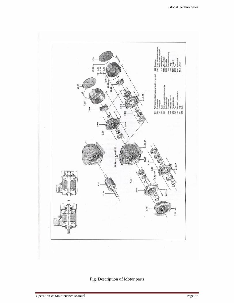
3. Description of Motor parts 35
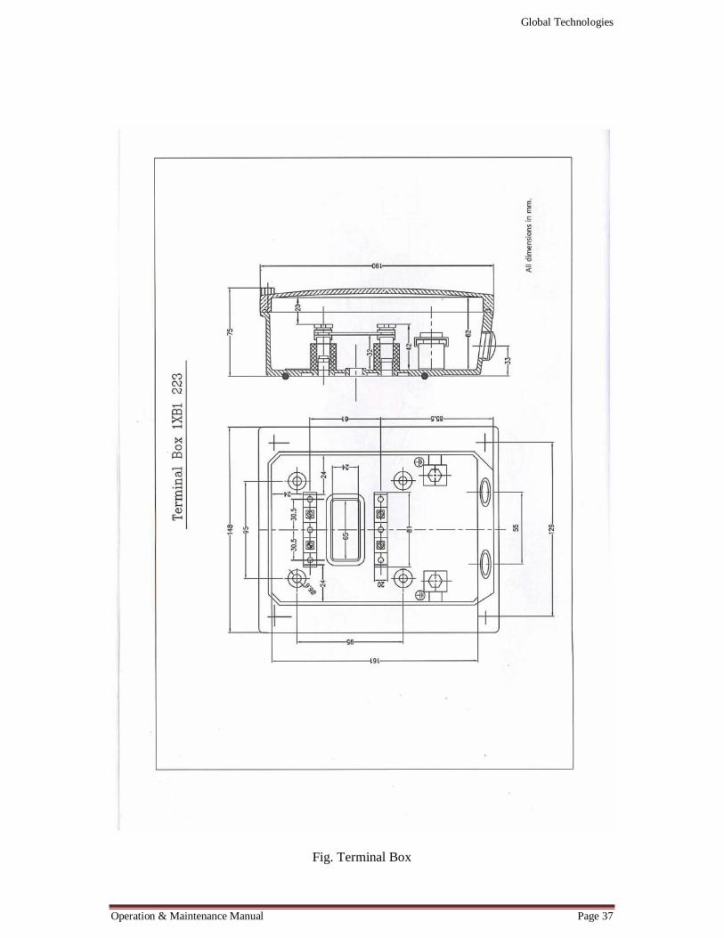
4. Terminal Box 37
5. Terminal Box Dimensional Chart 39
6. Brake working principle and components 42
7. Brake dimensional chart 43
8. Technical data for rotary geared limit switches 45
9. Dimensional chart & components for rotary limit switches 46
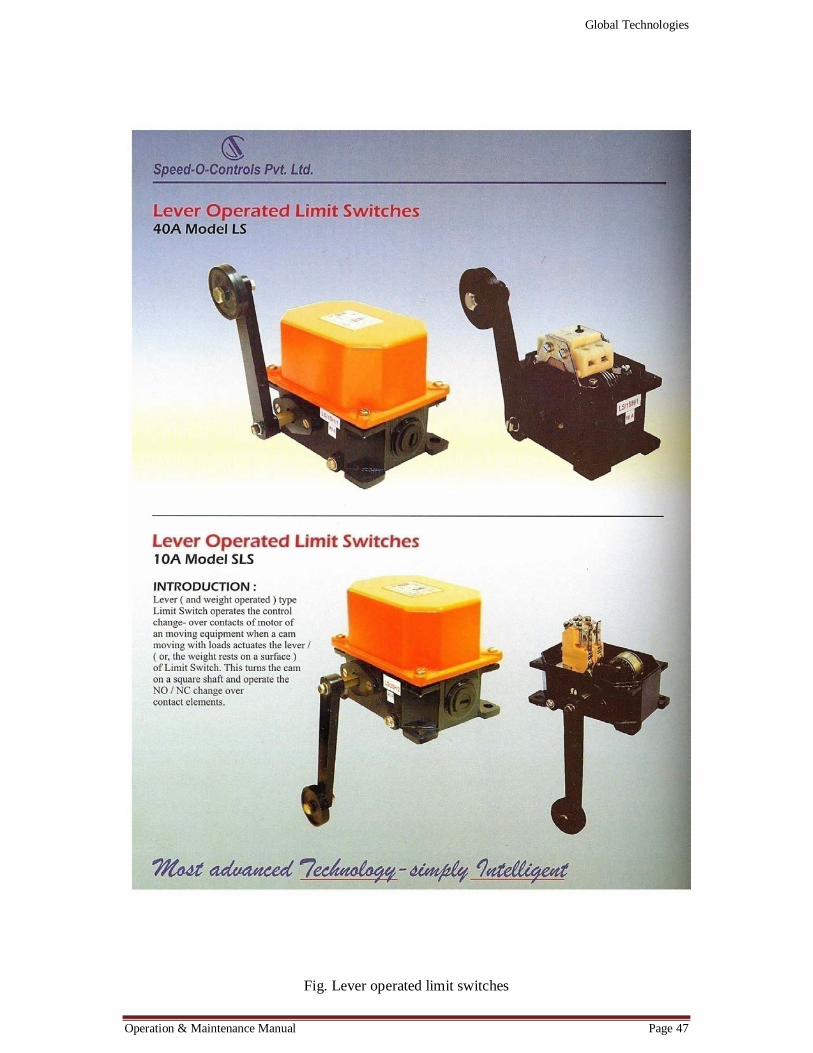
10. Lever operated limit switches 47
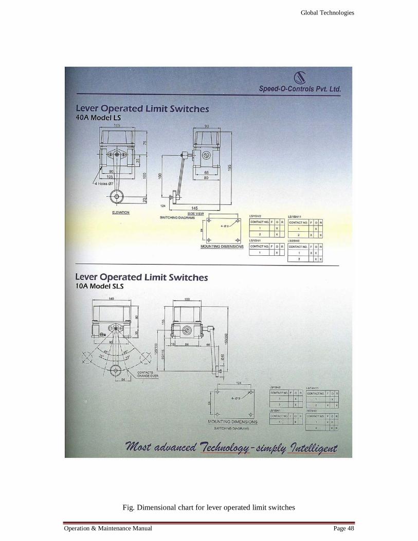
11. Dimensional chart for lever operated limit switches 48
12. GA of 20Ton cap x 2.4 Mtrs span US crane 50
13. GA of 20Ton cap x 4.45 Mtrs span US crane 51
14. GA of 20Ton cap x 9.325 Mtrs lift Electrical hoist 52
15. GA of DSL 01 & 02 Systems for Service Cranes 53
16. GA of Interlocking Mechanism 54
17. GA of Hoist Maintenance Platform – 2.4 Mts Span 55
18. GA for electrical circuit for US crane (CT & Hoist) 56
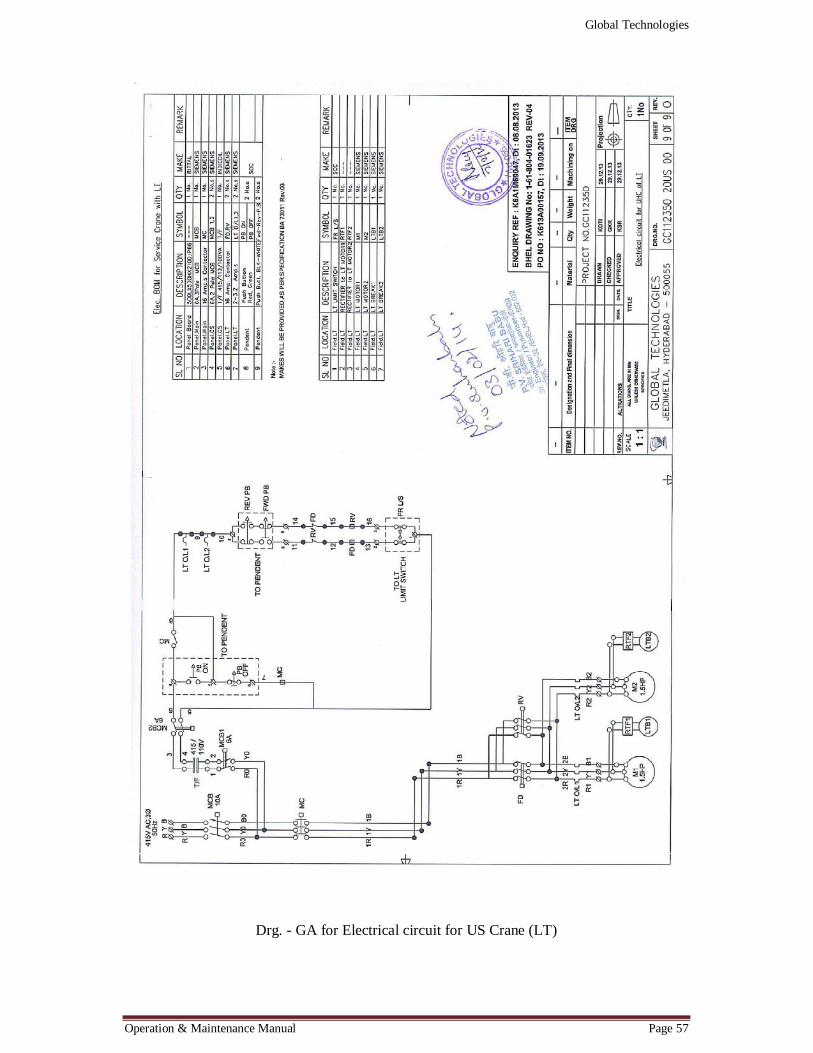
19. GA for electrical circuit for US crane (LT) 57
Global Technologies
Operation & Maintenance Manual Page 1
INTRODUCTION
CRANES
The Cranes manufactured by us are in compliance to IS 3177 to meet Class II Duty applications. Type of cranes ranging from Single Girder EOT Cranes, Single Girder Under slung Cranes, Double Girder EOT Cranes, Gantry cranes and jib Cranes etc.
All these Cranes are custom built to the specifications of clients and are fully manufactured, inspected and tested at our works only. Stringent quality controls at all levels of manufacturing results in quality cranes to suit the customer’s requirements.
HOISTS
The Hoists manufactured by us are in compliance to IS 3938/1967 to meet Class II Duty applications. The Hoists are robust, Reliable and ideal for Heavy Duty applications. Hoist with motorized trolley is recommended for continuous production units, where travelling of load is essential. Hoist units are driven through squirrel cage crane duty motor of 'F' Class insulation and are provided with D.C. Electromagnetic brake for instant stoppage of the unit.
The Hoists are custom built to suit the customer’s requirement like lift, speeds, end projections, headroom and hook approaches. Controlling of these wide ranging parameters is the essence for complete satisfaction of customer’s requirements.

Global Technologies
Operation & Maintenance Manual Page 2
DESCRIPTION OF ITEMS SUPPLIED
1) 2 Nos 20 Ton x 2.4 Mtrs span Under Slung Cranes 2) 10 Nos 20 Ton x 4.45 Mtrs span Under Slung Crane 3) 2 Nos 20 Ton capacity trolley with Hoist with 9.325 Mtrs lift 4) 2 Nos DSL-1 for service crane, cable trolley type – 44.75 Mtrs 5) 8 Nos DSL-2 for mill crane, taut wire type – 15 Mtrs 6) Hoist Maintenance Platforms – 4 Nos 7) 2 Nos Interlock mechanism – Male 8) 18 Nos Interlock mechanism – Female
DRAWINGS
All Drawings viz. G.A. Drawings, wiring diagrams, DSL drawings, Bill of Materials with specifications, ratings, makes and quantity, motor Data sheet with characteristics curves are approved from the client before taking up of manufacturing.
G.A. Drawings submitted and approved S.No DESCRIPTION Drg. No.
1. General arrangement of Mill Handling system (Cap20/20 Ton)
GC112350 20 US.00 (1 OF 9)
2. General arrangement of 20T Cap x 2.4 Mtrs span US Crane GC112350 20 US.00 (2 OF 9)
3. General arrangement of 15T Cap x 4.45Mtrs span US Crane GC112350 20 US.00 (3 OF 9)
4. General arrangement of 20T Cap x 9.325 Mtrs Lift Hoist GC112350 20 US.00 (4 OF 9)
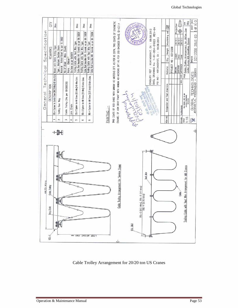
5. Cable Trolley arrangement for 20/15T Cap US Mill Crane GC112350 20 US.00 (5 OF 9)
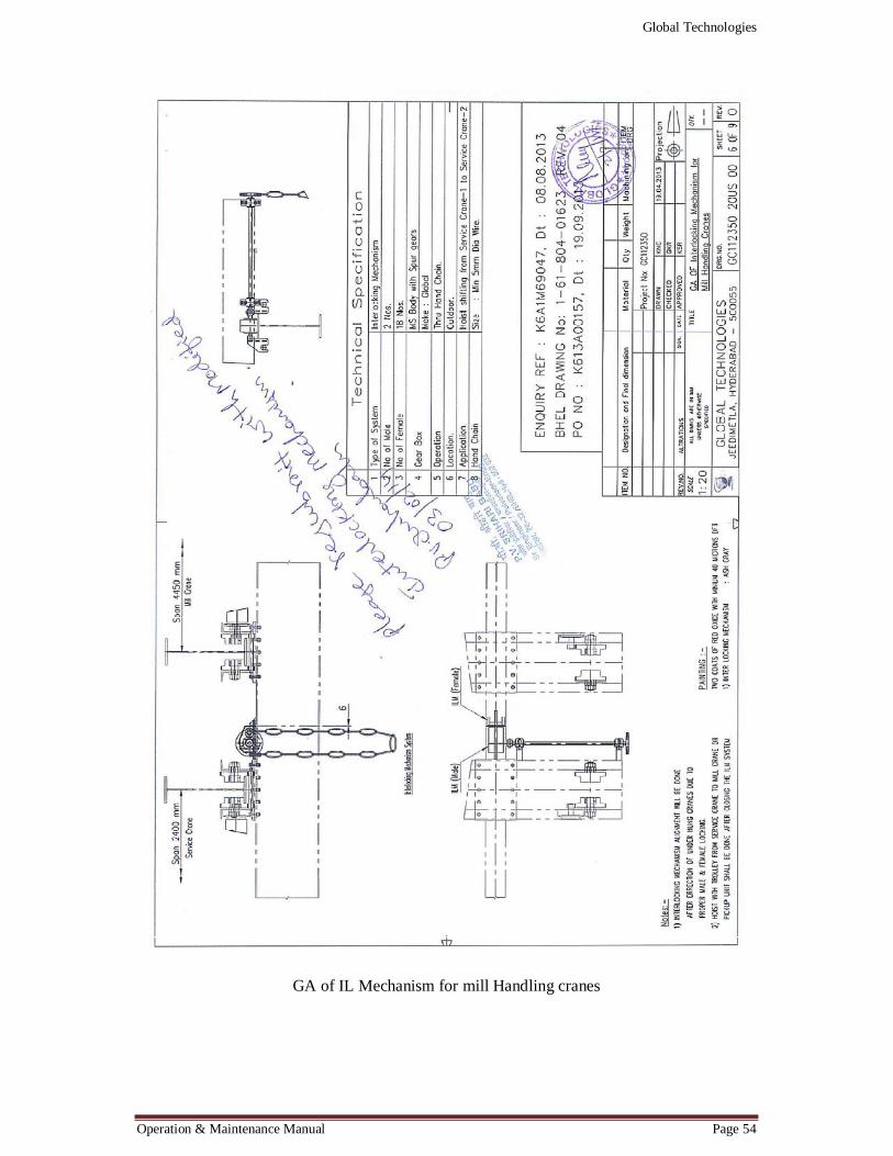
6. General arrangement of ILM for Mill Crane GC112350 20 US.00 (6 OF 9)
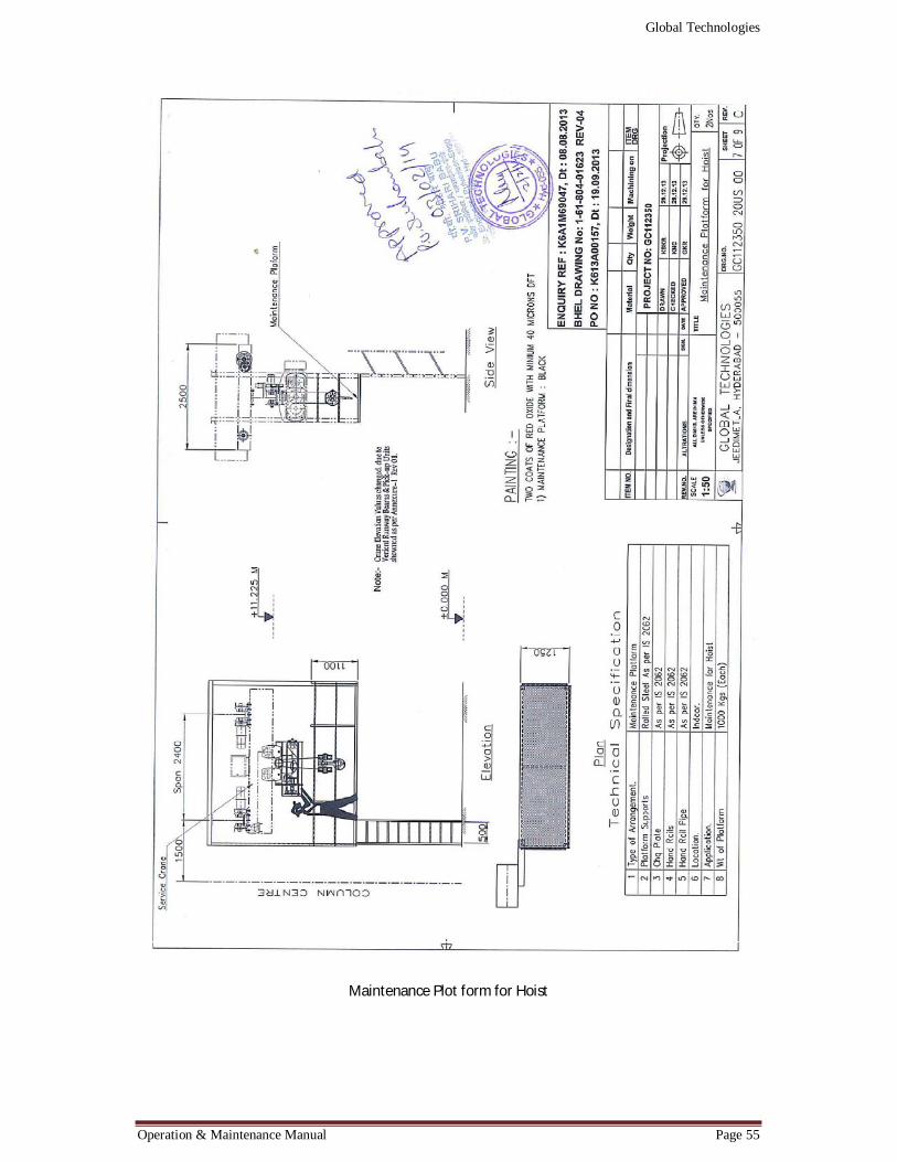
7. Maintenance platform for Hoist (2.4 Mtrs Span) GC112350 20 US.00 (7 OF 9)
8. Electrical Circuits for US Cranes (LT) GC112350 20 US.00 (8 OF 9)
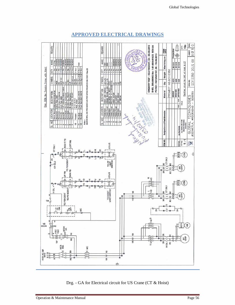
9. Electrical Circuits for US Cranes (CT & Hoist) GC112350 20 US.00 (9 OF 9)
TECHNICAL DETAILS
1. CRANES: Cranes supplied are manufactured as per IS3177 Class II Duty applications. Various parameters like Gantry Girder size/Gantry Rail, overhang of cranes on either side of cranes (For Under slung Cranes) level of the gantry beam, operating level of the crane, speeds for hoisting, cross travel and long travel, hook approach, headroom, end clearances are all noted while preparation of GA Drawing.
2. HOISTS: Hoists supplied are manufactured as per IS3938 Class II Duty applications. While manufacturing, for hoists, seamless tubes are used for rope drums. While preparation of GA drawing, No. of falls, wire rope specifications, motor size with adequate HP ratings, headroom and end clearances are required as per customers requirements. After assembly of the Hoist, load test and overload test are being conducted as per IS 3938.
3. DSL SYSTEM: DSL system composes of two basic systems i.e. 'Tee' track/I Beam system and taut wire loop system. 'Tee' track/I Beam system is provided with rolled section suitable for cable trolley wheels. Four wheel cable trolleys are of sturdy
Global Technologies
Operation & Maintenance Manual Page 3
design constructed with suitable steel material. Diameter of trolley wheels is kept 40 mm with double seal ball bearing. Cable trolleys are designed to take load of cable and moving with cable load smoothly on the 'T' track. Suitable arrangement is provided to tie the power cable and link chain with cable trolley. The power supply flexible trailing cable shall comply with IS 694. System is supplied with isolators to take full load current when the equipment is working with maximum safe working load. The system shall provide with suitable supports to take load of 'Tee' track, cable trolleys and power cable with other materials.
4. GEAR BOXES: Gear boxes which are totally enclosed, grease lubricated are designed for transmission of motion for motor to rope drum/wheels. Gears and pinions shall be confirming to IS 4460. Hardness of cross travel and long travel for pinions shall be in the range of 250-275 BHN and for gears 215-240 BHN. Hardness for hoisting gears is in the range of 285-300 BHN for pinions and 250-265 BHN for gears. Difference in hardness of gear and pinion is maintained 35 BHN. Spur gears are used for hoist, CT and LT gear boxes. All gears and pinions are checked by LPI/MPI for surface cracks after hardening. All gear boxes are lapped before final assembly and ensured for noiseless running of the system.
5. MOTORS: All motors are mostly of Siemens make with IP-55 weather protection and provided with double compression glands for top and bottom entry. Motors are painted with Epoxy based gray paint and are provided with eye bolts or lugs to facilitate safe lifting. All motors are DOL starting and are provided with double shaft extension for brake mounting. Motors are suitable for 415 V ± 10%, 50 HZ ± 5% 3 Ph. Supply is rated for 40% CDF with duty cycle S3/S4 and confirm to IS 325. (Installation & Maintenance instructions of Siemens motor is enclosed)
6. INTERLOCK MECHANISM (Male & Female) GENERAL: The Interlock mechanism employed in the crane has been designed on the basis of the specifications and the guidelines given by BHEL, Hyderabad and the drawings for which also have been approved by them taking into consideration the operation and the safety involved thereof. The interlock mechanism has been designed primarily keeping in view the safety aspects during operation.
DESIGN: The Interlock mechanism has been designed to transfer the trolley with hoist with rated safe working load from master crane to slave crane or master crane to fixed monorails and vice versa. The interlock mechanism is capable of withstanding the forces when even one of the cranes is being operated by mistake. The cross travel stoppers should give way to the hoist when interlock mechanism is coupled. Dimensional tolerance for the male & female component of the interlock mechanism shall be very close which will ensure proper locking without play and smooth transfer of trolley from one crane to the other.
A chain with chain wheel is provided for activating the interlock mechanism. The cross travel movement of the hoist is restricted by the stoppers provided in the interlock mechanism in the normal position. A limit switch also has been provided for instantaneous stoppage of the long travel movement of the crane, activated by the interlock mechanism. Pendant push button stations have been provided separately for the hoist with trolley and long travel motion of all the cranes. 8way pendant push button station provided for the hoist has lockable OFF push button in addition to ON

Global Technologies
Operation & Maintenance Manual Page 4
and OFF push buttons to ensure that the hoist cannot be operated once the lockable push button is operated. This is a backup safety measure.
OPERATION: The Mill handling crane is positioned in alignment with the service crane and the chain provided in the Service crane is pulled with sufficient force for enabling the interlock mechanism to be activated. Once this process is complete, only then the hoist can travel from service crane to the mill handling crane. Unless the interlock mechanism is activated, the hoist at any cost cannot travel from service crane to mill handling crane in view of the stoppers provided in the interlock mechanism. Limit switch provided for the cross travel movement of the hoist trolley ensures that the hoist does not over-travel either at one extreme end of the service crane and the other extreme end of the mill handling crane. If the force employed is not sufficient while the chain is pulled, the stoppers will come to the original position restricting any movement of trolley of the Electric Hoist.
Positive safety and back-up safety measures
a) Limit switch ensures LT movement comes to a halt in case Interlock mechanism is operated by chain either manually or by accident.
b) Cross travel movement of Hoist cannot be operated since Push button stations are provided separately for Hoist and Long travel.
c) Lockable push buttons have been provided to ensure back-up safety. d) Stoppers provided in the Interlock mechanism need to be lifted by minimum 300 mm
from bottom of the flange of the girder. This requires extra amount of manual effort for activation. Failure to lift a minimum of 300 mm height will stop the movement of cross travel.
e) Accidental pulling of the chain cannot activate Interlock mechanism for providing 300 mm clearance, since limit switch provided for LT will be operational, at once.
7. HOOKS: Hooks shall meet the dimensional, material testing & inspection requirement of IS 3815/8610, whichever is applicable. The hook shall be provided with standard depress type safety latch and swivel thrust bearings with hardened race. Lugs for fixing safety latch shall be either forged along with the hook or clamp type latch with lugs shall be provided. Locking arrangement shall be provided to avoid unscrewing of the hook in service. All the hooks shall be tested for twice the safe working load.
8. WIRE ROPE: Wire rope shall meet the requirement of 1S 2266 and shall have 6x36 construction as per strand with an ultimate tensile strength of 180 kg/sq.mm. The wire rope shall be galvanized as per IS 1835 type B. All wire ropes shall be proof load tested for 2 times of SWL/Fall. Breaking load shall not be less than five times SWL.
9. DRUM AND SHEAVE: Drum shall be of welded steel or seamless steel and Sheave shall be cast or welded steel. The drum shall accommodate all the length of rope required for the lift plus two dead wraps at each anchor point without overlap. Drum can be grooved right or left or both, and grooves shall suit the ropes used. Sheaves shall be equipped with sheave guards to retain the rope in groove.
10. GEARS AND PINIONS: Gears and pinions shall be confirming to IS 4460. Hardness of cross travel and long travel for pinions shall be in the range of 250-275 BHN and for gears 215-240 BHN. Hardness for hoisting gears is in the range of 285-300 BHN
Global Technologies
Operation & Maintenance Manual Page 5
for pinions and 250-265 BE-IN for gears.
Difference in hardness of gear and pinion is maintained 35 BHN. Spur gears are used for hoist, CT and LT gears. All gears and pinions are checked by LP, UM & PI for surface cracks after hardening.
11. WHEELS: All wheels shall be made out of forged or low carbon steel/cast steel with heat treated to 175-200 BHN hardness. Trolley wheels for hoists shall be spur geared type cast/forged 4 wheeled & driven by motor.
12. ROTATING AND STATIONARY SHAFTS: The material for shafts shall be as per relevant Indian Standard or its equivalent and shall be hardened and tempered with a minimum tensile strength of 60 kg/sq.mm and hardness shall be in the range of 175 to 250 BHN. Shafts shall be tested with UT for more than 50 mm dia. UT acceptance norms shall be as per ASME section VIII: Division 2.
13. BEARINGS: All bearings used shall be of reputed make and shall be designed to give a minimum service lift of 20 years. Only antifriction bearing are used.
14. BRAKES: All Brakes provided shall be DC Electro Magnetic Brakes for instant stoppage. (Catalogue of Emco Brake giving safety precautions, operating principles, assembly instructions etc is enclosed)
Expectations of Vendor with respect to the structure provided at site, on which the Cranes and Hoists are assembled:
a) Hoists: Many times hoist is governed by critical dimensions for which all the care is taken while manufacturing. Site should be ready with required beam size as per approved drawing and necessary clearances should be maintained as per approved GA drawing.
b) Cranes: All Under Slung cranes are manufactured with strict clearance. However it is very much essential to maintain gantry girder alignments and water levels at site very accurately, so as to facilitate proper erection and commissioning. During operation, hoist is required to travel from Master Crane to Service crane, thus it is very much essential to maintain gantry girder for both crane with water level at 0-0.
PROCEDURE FOR ERECTION, ASSEMBLY & COMMISSIONING OF UNDER SLUNG CRANES & HOISTS
General instructions: These are instructions for assembly, erection and wiring of the cranes. We would advise you to follow the same carefully, in order to ensure smooth and trouble-free operation.
The crane has been fully assembled and checked at our works before dispatch. All the motors were run light to check for proper functioning. Before dismantling, the components have been match-marked to facilitate erection at site.
Parts should be checked up against the packing list, it should be seen that the components are received in good condition before commencing the erection.
Design of Gantry Girders: A correctly made runway is an important factor to ascertain that the crane will work for years with a minimum of maintenance cost. The crane runway should be dimensioned such that stress due to bending is less than 1200 Kg/Cm2.
Global Technologies
Operation & Maintenance Manual Page 6
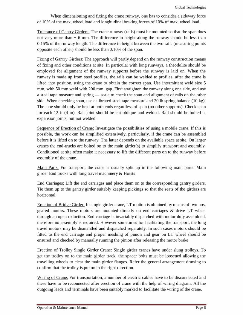
When dimensioning and fixing the crane runway, one has to consider a sideway force of 10% of the max, wheel load and longitudinal braking forces of 10% of max, wheel load.
Tolerance of Gantry Girders: The crane runway (rails) must be mounted so that the span does not vary more than + 6 mm. The difference in height along the runway should be less than 0.15% of the runway length. The difference in height between the two rails (measuring points opposite each other) should be less than 0.10% of the span.
Fixing of Gantry Girders: The approach will partly depend on the runway construction means of fixing and other conditions at site. In particular with long runways, a theodolite should be employed for alignment of the runway supports before the runway is laid on. When the runway is made up from steel profiles, the rails can be welded to profiles, after the crane is lifted into position, using the crane to obtain the correct span. Use intermittent weld size 5 mm, with 50 mm weld with 200 mm. gap. First straighten the runway along one side, and use a steel tape measure and spring — scale to check the span and alignment of rails on the other side. When checking span, use calibrated steel tape measure and 20 lb spring balance (10 kg). The tape should only be held at both ends regardless of span (no other supports). Check span for each 12 ft (4 m). Rail joint should be cut oblique and welded. Rail should be bolted at expansion joints, but not welded.
Sequence of Erection of Crane: Investigate the possibilities of using a mobile crane. If this is possible, the work can be simplified extensively, particularly, if the crane can be assembled before it is lifted on to the runway. The latter depends on the available space at site. On larger cranes the end-trucks are bolted on to the main girder(s) to simplify transport and assembly. Conditioned at site often make it necessary to lift the different parts on to the runway before assembly of the crane.
Main Parts: For transport, the crane is usually split up in the following main parts: Main girder End trucks with long travel machinery & Hoists
End Carriages: Lift the end carriages and place them on to the corresponding gantry girders. Tie them up to the gantry girder suitably keeping pickings so that the seats of the girders are horizontal.
Erection of Bridge Girder: In single girder crane, LT motion is obtained by means of two nos. geared motors. These motors are mounted directly on end carriages & drive LT wheel through an open reduction. End carriage is invariably dispatched with motor duly assembled, therefore no assembly is required. However sometimes for facilitating the transport, the long travel motors may be dismantled and dispatched separately. In such cases motors should be fitted to the end carriage and proper meshing of pinion and gear on LT wheel should be ensured and checked by manually running the pinion after releasing the motor brake
Erection of Trolley Single Girder Crane: Single girder cranes have under slung trolleys. To get the trolley on to the main girder track, the spacer bolts must be loosened allowing the travelling wheels to clear the main girder flanges. Refer the general arrangement drawing to confirm that the trolley is put on in the right direction.
Wiring of Crane: For transportation, a number of electric cables have to be disconnected and these have to be reconnected after erection of crane with the help of wiring diagram. All the outgoing leads and terminals have been suitably marked to facilitate the wiring of the crane.

Global Technologies
Operation & Maintenance Manual Page 7
Erection of Down Shop Leads and Current Collector: When power supply is vertical, the conductors shall lie on support insulators. These must be positioned vertically, spacing 8 in (200 mm) along runway. The conductors are stretched by means of end insulators fitted with cable tension bolts.
When power supply is horizontal, the conductors are suspended and fixed in support insulators. Erection is otherwise as stated above. The spring load current collectors used in conjunction force of 10-15 lbs (5-7 kgs).
Note: Current carrying conductors must not be closer to building wall than 2 in. (5 cm)
Erection of DSL (Trailing cable trolley type): All Fasteners shall be of 4.6 Grade 8.8 Galvanised. The distance of the cable trolley assembly from the Runway beam centre line shall be adjusted to suit site condition.
End Stoppers are sent loose and to be welded after completing the assembly of the cable trolley. End cable trolley should be fixed at the extreme end of the DSL Track at Fixed cable end.
Painting: Two coats of Red oxide and two coats of synthetic enamel paint of ash gray with each of min. 40 Microns OFT.
Earthing of Electrical system: The crane push button station or controller is always "earthed" to the crane steel structure. All other parts are also earthed by means of copper wire & GI strip and brought to a common earthing point on structure. Most electricity boards accept the crane rail as earth connection along the crane runway. In addition to this an earth-wire must be installed together with the crane power supply conductors connected to a connection box at one end of the runway. From this box, cables are connected to the down shop leads conductors along the runway and earth is connected to the crane structure.
Protection of Electrical Equipment: The electrical layout of the crane is protected by fuses in the crane control panels. Fuse ratings are shown in writing diagram. Over load relays are also provided wherever desired.
TESTING OF CRANE
a) The machined bolts joining the bridge with the end carriage are fully tightened. b) Ensure proper lubrication for all parts, oil is filled in the gear boxes up to the levels
marked. c) The hoisting wire rope is properly lubricated. d) All grease nipples or cups are in positions and all bearings are properly lubricated. e) The limit switch and brake settings are properly done. f) The wiring is correctly done as per the diagram enclosed and check that all the
terminals are tight. g) Check insulation of the complete electrical system. h) Switch on the main power, and check that there is no electrical leakage. i) Make sure that sequence of supply is correct. The direction of the controllers
corresponds with the markings on them. If hook moves upward on operating lowering control, interchange the two phases of supply in the corresponding Motor Terminal Box or Control Panel.
Global Technologies
Operation & Maintenance Manual Page 8
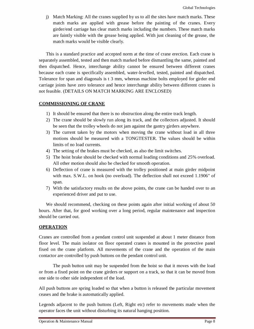
j) Match Marking: All the cranes supplied by us to all the sites have match marks. These match marks are applied with grease before the painting of the cranes. Every girder/end carriage has clear match marks including the numbers. These match marks are faintly visible with the grease being applied. With just cleaning of the grease, the match marks would be visible clearly.
This is a standard practice and accepted norm at the time of crane erection. Each crane is
separately assembled, tested and then match marked before dismantling the same, painted and then dispatched. Hence, interchange ability cannot be ensured between different cranes because each crane is specifically assembled, water-levelled, tested, painted and dispatched. Tolerance for span and diagonals is t 3 mm, whereas machine bolts employed for girder end carriage joints have zero tolerance and hence interchange ability between different cranes is not feasible. (DETAILS ON MATCH MARKING ARE ENCLOSED) COMMISSIONING OF CRANE
1) It should be ensured that there is no obstruction along the entire track length. 2) The crane should be slowly run along its track, and the collectors adjusted. It should
be seen that the trolley wheels do not jam against the gantry girders anywhere. 3) The current taken by the motors when moving the crane without load in all three
motions should be measured with a TONGTESTER. The values should be within limits of no load currents.
4) The setting of the brakes must be checked, as also the limit switches. 5) The hoist brake should be checked with normal loading conditions and 25% overload.
All other motion should also be checked for smooth operation. 6) Deflection of crane is measured with the trolley positioned at main girder midpoint
with max. S.W.L. on hook (no overload). The deflection shall not exceed 1.1906" of span.
7) With the satisfactory results on the above points, the crane can be handed over to an experienced driver and put to use.
We should recommend, checking on these points again after initial working of about 50 hours. After that, for good working over a long period, regular maintenance and inspection should be carried out.
OPERATION
Cranes are controlled from a pendant control unit suspended at about 1 meter distance from floor level. The main isolator on floor operated cranes is mounted in the protective panel fixed on the crane platform. All movements of the crane and the operation of the main contactor are controlled by push buttons on the pendant control unit.
The push button unit may be suspended from the hoist so that it moves with the load or from a fixed point on the crane girders or support on a track, so that it can be moved from one side to other side independent of the load.
All push buttons are spring loaded so that when a button is released the particular movement ceases and the brake is automatically applied.
Legends adjacent to the push buttons (Left, Right etc) refer to movements made when the operator faces the unit without disturbing its natural hanging position.
Global Technologies
Operation & Maintenance Manual Page 9
Starting-Up:
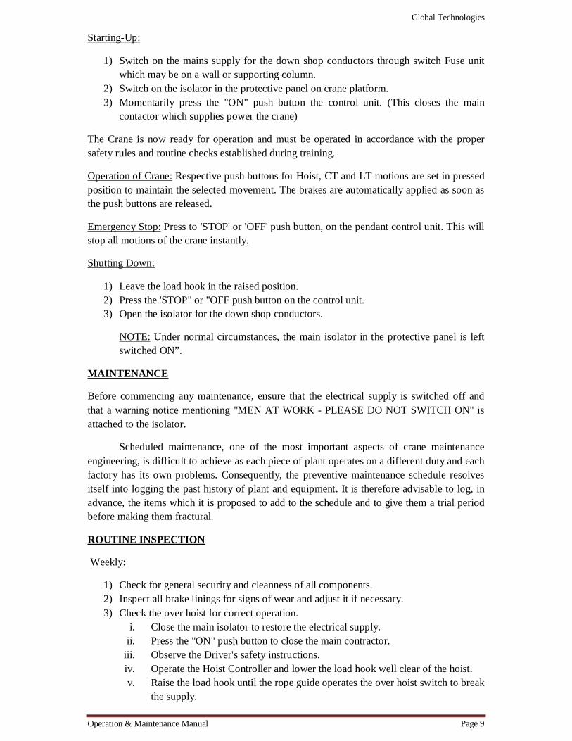
1) Switch on the mains supply for the down shop conductors through switch Fuse unit which may be on a wall or supporting column.
2) Switch on the isolator in the protective panel on crane platform. 3) Momentarily press the "ON" push button the control unit. (This closes the main
contactor which supplies power the crane)
The Crane is now ready for operation and must be operated in accordance with the proper safety rules and routine checks established during training.
Operation of Crane: Respective push buttons for Hoist, CT and LT motions are set in pressed position to maintain the selected movement. The brakes are automatically applied as soon as the push buttons are released.
Emergency Stop: Press to 'STOP' or 'OFF' push button, on the pendant control unit. This will stop all motions of the crane instantly.
Shutting Down:
1) Leave the load hook in the raised position. 2) Press the 'STOP" or "OFF push button on the control unit. 3) Open the isolator for the down shop conductors.
NOTE: Under normal circumstances, the main isolator in the protective panel is left switched ON”.
MAINTENANCE
Before commencing any maintenance, ensure that the electrical supply is switched off and that a warning notice mentioning "MEN AT WORK - PLEASE DO NOT SWITCH ON" is attached to the isolator.
Scheduled maintenance, one of the most important aspects of crane maintenance engineering, is difficult to achieve as each piece of plant operates on a different duty and each factory has its own problems. Consequently, the preventive maintenance schedule resolves itself into logging the past history of plant and equipment. It is therefore advisable to log, in advance, the items which it is proposed to add to the schedule and to give them a trial period before making them fractural.
ROUTINE INSPECTION
Weekly:
1) Check for general security and cleanness of all components. 2) Inspect all brake linings for signs of wear and adjust it if necessary. 3) Check the over hoist for correct operation.
i. Close the main isolator to restore the electrical supply. ii. Press the "ON" push button to close the main contractor.
iii. Observe the Driver's safety instructions. iv. Operate the Hoist Controller and lower the load hook well clear of the hoist. v. Raise the load hook until the rope guide operates the over hoist switch to break
the supply.
Global Technologies
Operation & Maintenance Manual Page 10
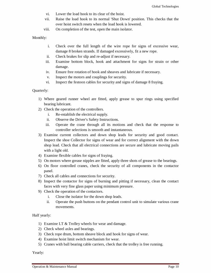
vi. Lower the load hook to its clear of the hoist. vii. Raise the load hook to its normal 'Shut Down' position. This checks that the
over hoist switch resets when the load hook is lowered. viii. On completion of the test, open the main isolator.
Monthly:
i. Check over the full length of the wire rope for signs of excessive wear, damage 8 broken strands. If damaged excessively, fit a new rope.
ii. Check brakes for slip and re-adjust if necessary. iii. Examine bottom block, hook and attachment for signs for strain or other
damage. iv. Ensure free rotation of hook and sheaves and lubricate if necessary. v. Inspect the motors and couplings for security.
vi. Inspect the festoon cables for security and signs of damage 8 fraying.
Quarterly:
1) Where geared runner wheel are fitted, apply grease to spur rings using specified bearing lubricant.
2) Check the operation of the controllers. i. Re-establish the electrical supply.
ii. Observe the Driver's Safety Instructions. iii. Operate the crane through all its motions and check that the response to
controller selections is smooth and instantaneous. 3) Examine current collectors and down shop leads for security and good contact.
Inspect the shoe Collector for signs of wear and for correct alignment with the down shop lead. Check that all electrical connections are secure and lubricate moving pails with a light old.
4) Examine flexible cables for signs of fraying. 5) On motors where grease nipples are fitted, apply three shots of grease to the bearings. 6) On floor controlled cranes, check the security of all components in the contactor
panel. 7) Check all cables and connections for security. 8) Inspect the contactor for signs of burning and pitting if necessary, clean the contact
faces with very fine glass paper using minimum pressure. 9) Check the operation of the contactors.
i. Close the isolator for the down shop leads. ii. Operate the push buttons on the pendant control unit to simulate various crane
movements.
Half yearly:
1) Examine LT & Trolley wheels for wear and damage. 2) Check wheel axles and bearings. 3) Check rope drum, bottom sheave block and hook for signs of wear. 4) Examine hoist limit switch mechanism for wear. 5) Cranes with ball bearing cable carriers, check that the trolley is free running.
Yearly:
Global Technologies
Operation & Maintenance Manual Page 11
1) Inspect the motor Gear Boxes for wear and breakage. 2) Blow out the windings with clear, dry compressed air at medium pressure. 3) Using a 500 Volt megger, test the insulation resistance of the winding of each motor.
(If a reading of one megohm is obtained, the motor should be dried out by one of the approved methods)Caution: Before carrying out the insulation resistance test, disconnect the supply leads at the motor terminal box so that only the motor windings are tested. This is necessary in order to protect electronic control equipment which would be damaged by the tests voltage. On completion of the test, reconnect the motor supply leads exactly as before the test.
4) i. On motors where grease nipples are fitted, inject grease until it is apparently
passing through. ii. For motors not fitted with grease nipples, the bearings must be repacked with
the correct lubricant at each major overhaul. This is usually at intervals of 2 to 3 years.
MAINTENANCE OF MECHANICAL UNITS
1. Wire Rope: A steel wire rope is lubricated by rope grease at the time of winding on drum
and not less than twice a month when it is in use.
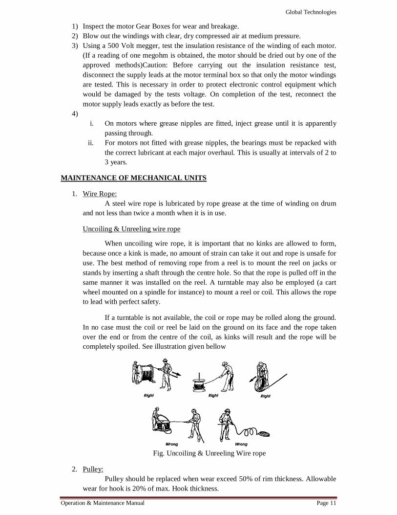
Uncoiling & Unreeling wire rope
When uncoiling wire rope, it is important that no kinks are allowed to form, because once a kink is made, no amount of strain can take it out and rope is unsafe for use. The best method of removing rope from a reel is to mount the reel on jacks or stands by inserting a shaft through the centre hole. So that the rope is pulled off in the same manner it was installed on the reel. A turntable may also be employed (a cart wheel mounted on a spindle for instance) to mount a reel or coil. This allows the rope to lead with perfect safety.
If a turntable is not available, the coil or rope may be rolled along the ground. In no case must the coil or reel be laid on the ground on its face and the rope taken over the end or from the centre of the coil, as kinks will result and the rope will be completely spoiled. See illustration given bellow
Fig. Uncoiling & Unreeling Wire rope
2. Pulley: Pulley should be replaced when wear exceed 50% of rim thickness. Allowable
wear for hook is 20% of max. Hook thickness.

Global Technologies
Operation & Maintenance Manual Page 12
3. Bearings: It should be checked that bearing housings are firmly fixed with structure and
lubrication system is alright. A clearing of 0.1 to 0.2 mm between bearing outer race and end face of cover is allowed. If clearance is more, it should be adjusted to proper value by changing the shims. Bearing housings should be washed with kerosene while regreasing bearings must be rejected if cavities appear on the grooves of races or on rollers/balls. Bearings should also be rejected if there is excessive radial play between inner and outer race, loosing of vaces in housing cracks & signs of local wear in race, rollers or balls.
4. Gear Boxes: Appropriate filtered oil should be filled up to level in between higher & lower
mark on dipstick. Every six months gear box is to be checked for gear wear, bearings bolts & nuts and overheating. Permissible wear on gear tooth thickness on PCD is 10% on input and 20% on other pairs. Oil should be changed every six months.
5. Hoist Drum: Maximum wear of 3mm over drum thickness is allowed. Drum should be
inspected for grooves, rim surfaces, rope fasteners, toothed open gear bearing and covers.
6. Brakes: Proper stroke is to be adjusted as lining gets wearied out. Spring should be
adjusted for proper braking torque. Brake hinge joints must be periodically lubricated. It is to be checked that hinges are not jamming shoes hold the brake drum properly and withdraw of shoe is uniform. Lining of hoes is to be changed when wear reaches 50% at the middle portion. Re-machining of brake drum is allowed up to 30% reduction in brake drum rim thickness, if required. New brake shoe lining are subjected to intensive wear in beginning and should be frequently inspected and readjusted.
7. Wheels: Housing and bearings are to be checked. Wheels should not have cracks or
worn out flanges and surfaces should not have excessive wear. Wear allowed on flanges is 40% and on rim is 30% of original values. In case of uneven wear, surfaces should be re-machined.
MAINTENANCE OF ELECTRICAL EQUIPMENT
1. Motors: Periodically motor insulation resistance is to be checked. If it is less than 3
megohms on 1000 volt meggar parts should be cleaned and painted with insulation varnishes and rechecked for insulation. Terminal boxes should be checked for tightness and cleanliness.
2. Isolating Switches: Switches should be cleaned periodically by compressed air. Contacts should
be lubricated periodically. ARC chambers should be checked up occasionally for burning of the quenching plates or of the side walls and should be replaced, if necessary. All bolt connection must here-tightened from time to time. Contacts should be checked occasionally and should be changed whenever required. All bolt connections must be tightened from time to time.
Global Technologies
Operation & Maintenance Manual Page 13
3. Air Brake Contactors: Copper contacts should be cleaned smooth with file cut and surfaces t be
polished with glass paper. Cleaning should be done with care so as to remove least metal. Contact with silver tips should not be replaced even if they are blackened. Contact should be checked for correct pressure between fix and moving contacts. Unstable operation of contactors caused welding effect. When the contact spring action becomes very poor, contacts should be changed. ARC chutes should be inspected occasionally and burnt one should be replaced by new one. Damaged coil be replaced.
4. Relays: Relays should be cleaned by means of bellows. Contacts should be checked
occasionally and replaced if required. Damage coils should be replaced. 5. Brake Solenoid:
When the solenoid works, it should not hum. The magnet faces must be clean. The temperature should not exceed 100 C. It should be checked that the insulation of the supply leads to solenoid is satisfactory between themselves & earth. All bolts & nuts must be checked that they are tightened to the full. The rod must move freely. In case of burnt out coils, they should be replaced.
6. Controllers: In case of copper contacts, fusion and formation of metal drops on the contact
surfaces should be prevented. The excess pf metal should be cleaned away with a file. Contact spring must be adjusted for worn out contacts. When the contacts have worn out excessively they should be replaced. Silver tipped contacts of master controllers should not be filed. They should be replaced whenever tips become excessively thin. Connections inside the controller should be checked to ensure proper operations. Ball bearings must be inspected and lubricated with grease of proper composition. Controllers should be regularly cleaned of dust and dirt.
7. Limit switches:
In order to ensure a trouble- free operation, it is necessary to open and examine the switch periodically. While examining the switch, following should be checked : Wear of contacts are to be considered worn out, if their thickness has reduced to 0.5 mm after tightening all contact joints, screws etc.
General Instructions for crane operation:
1) Operator should inspect all mechanisms of crane before going on duty. 2) Check for lubrication of ropes and mechanism, lights, sounds signals and foreign
objects on crane which may fall on crane when it moves. 3) "Stop" signals given by anybody during operation should be obeyed. 4) Start & stop of crane should be done smoothly & more than two motions should be
operated at a time. Limit switches should not be used as a means of stopping the crane.
5) Load should not exceed safe working load. While lifting, ropes should be vertical and load should be clear of any obstruction.
6) When lifting maximum permissible weight, it should be lifted first 100 mm and check that brake is holding the load properly. In case brake fails when load is suspended,

Global Technologies
Operation & Maintenance Manual Page 14
hoisting mechanism should be operated so as load should not fall immediately, and then crane is to be taken to safe place and load lowered.
7) One crane used to push another crane is not at all permitted. 8) If power supply is out, all handles of controllers should be bought to zero position. 9) It is strictly prohibited to climb from one crane to another crane. 10) Do not use any overhead material handling equipment for handling personnel. 11) Stand clear of all load 12) Be sure that all motions are operating as per the markings on controllers. 13) Do not leave the load suspended in the air unattended.
Points to be checked and tolerances to be achieved during and after erection of the crane.
1) Dimensional tolerances on bridge and end carriages. i. Distance between centre lines of LT wheels (Span) = ± 3 mm
ii. Distance of LT wheels base = ± 3 mm iii. Difference in measurement of diagonals across LT wheels = ± 3 mm
GENERAL INTRODUCTION FOR ELECTRICAL HOIST
‘GLOBAL’ electric hoists are manufactured in compliance to IS-3938/1967 to meet class II duty applications. Our hoists are robust, reliable as per applications.

Global Technologies
Operation & Maintenance Manual Page 15
This hoist does not require elaborate instructions for general care. It is of sound design and sturdily built, yet so simply constructed that if the following suggestions are adhered to, no trouble should be experienced except the normal wear after long service.
If anything does go wrong with the machine, have it repaired at once. It is better to spend little time in making minor repairs when trouble first develops, than to take a chance and have the machine idle while major repairs are being done at a later date.
You are entitled to the best we can give you in machinery and service, but no matter how much has gone into the manufacture and construction of the machine it still require reasonable care while in operation, therefore, see that lubrication is attend to regularly. See that the brakes are in good condition and are correctly adjusted. The hoisting is done by pressing the 'Raise' push button only.
INSTALLATION
The 'GLOBAL' Electric Hoist is tested to overload and adjusted for proper operation before leaving the factory. The 'GLOBAL' Electric Hoist is supplied in assembled condition. The Electric hoist should be un-packed at the place where it is going to be used. Before the unit is

Global Technologies
Operation & Maintenance Manual Page 16
placed in service, there are several items that must be checked to ensure correct application and avoid service trouble.
1. Check the power supply which is indicated on the name plate of the hoist. Check the voltage frequency and phase. The voltage supplied to the hoist must be same as indicated on the name plate, otherwise over heating of the motor will reduce the lifting capacity and result in improper functioning of all electrical components.
2. Before mounting the hoist on rail track, it is necessary to check the distance between the flanges of the driving wheels and width the I-beam. It is necessary to ensure a play of 3 to 6 mm. for free movement of the wheels. While checking the operation of the trolley, ensure that the beam should be cleaned from dust, lubricants etc.,
3. Refer to the lubrication chart to determine if the hoist is properly lubricated. 4. After mounting the hoist on the I-Beam, press the 'UP' push button. The hook will
start going upward. If the hook lowers instead of going up, two phases at the supply terminals should be changed over.
5. Check the operation of the limit switches. Limit switches are set to give minimum headroom and maximum run out of the wire rope. If required, these limit switch may be adjusted to give any intermediate height of lift.
6. Test the operation of direct acting electromagnetic brake to determine if the correct adjustment of the brake is obtained. Ensure that the travel of the load block stops, when the power is cut-off. Although the brake is set before leaving the factory, it is necessary to make slight adjustment to compensate for initial gear on the lining after 1-2 weeks usage (refer page No 5.6 &7).
HOIST OPERATION
‘GLOBAL’ Wire Rope Electric Hoist is extremely simple to operate. The operation of the Hoist is through Pendent Push Button operated from floor with control voltage either 10 volts or 24 as per customer's specifications. To ensure maximum life of the Hoist, ensure the following while operating the Hoist.

Global Technologies
Operation & Maintenance Manual Page 17
1. The load should be placed centrally under the Hoist. Dragging of loads will damage the rope guides wheels.
2. Use slings or any other safe method of attachment to the hook for lifting load. 3. Avoid swinging and trapping of the Wire Rope. 4. Lift such load as is within the rated capacity of the hoist. 5. Entrust control of the hoist to knowledgeable person who can ensure good working
conditions and safety of operation. 6. Ensure that the area of operation is well - lit and free from constructions. 7. Avoid unnecessary 'inching' as this may cause burning or contacts and motors.
DON'TS
1. Do not Hoist and transport loads above the rated lifting capacity of the Hoist. The Hoist is designed for lifting only 25% excess over the rated capacity.
2. Do not use the Hoist for any other work which is not typical to its use and operation. 3. Do not use to haul loads by pulling the rope in a diagonal direction. 4. Do not allow swinging of the load during horizontal movement. Reduce swinging by
switching on the mechanism of horizontal movement several times in the initial stage. 5. Do not use Hoist without ensuring the proper operation of limit switches. This can be
done by hoisting and lowering the hook couple of time without load. 6. Do not use limit switches as a constantly operating automatic appliance.
A.C. SOLENOID BRAKE TYPE
The oversize wheel type construction permits use of a smaller operating solenoid that required less current for a given torque rating.
a) Long mechanical life due to low shoe pressure. b) Brake is electrically released and spring - applied for fail safe operation. c) Easily replaceable brake linings. d) Simple adjustment of torque. e) Separate adjustments for braking torque and lining clearance. f) Coil can be removed without disturbing the brake adjustment. g) Noiseless operation.
MAINTENANCE INSTRUCTION FOR SHOE TYPE BRAKES
i. General: This brake works on the solenoid principle. When the solenoid is energized, an
armature which is linked with the shoe levers pulls the shoe lever apart to release the brake. When supply is cut of the armature, returns to its original position under spring action and brake is applied.

Global Technologies
Operation & Maintenance Manual Page 18
Thus the solenoid brake being electrically released and spring applied is fail device. The brake is usually applied on the extended shaft of the motor but may be applied to the intermediate shaft of the transmission system.
ii. Installation: a) Place brake on mounting holes. Insert mounting holes but do not tighten. b) Connect coil to supply and energize. c) Assemble the brake wheel on the shaft. d) Fix the base is most suitable position such that the clearance between brakes
wheel and lining is equal on both sides of both the shoes when brake is energized. e) Operate the brake two / three times. f) Tighten the bolts. g) Brake is installed.
iii. Torque Adjustment:
Compress the torque spring by emerging the coil to get the required torque. The approximate compressed length of this spring should be as follows:
Size of Brake
Continuous Torque rating. Lb. Ft.
Intermittent Torque Rating. Lb. Ft.
Compressed Length of
4” 3 10
3 10 15
1.1/16”
5.1/2” 25 25 35
1.3/4”
7” 50 50 2.1/16”
Table 1.0
This length should be maintained by turning the torque screw nut. When brake is energized the wear allowance for lining should be kept 1/16" (wear allowance is measured between the stop nut and rocket block at tope of outer shoe lever). When the lining wears out the gap increases and this should be adjusted by turning stop nut. Adjustment of shoe's travel should be done by turning the hexagonal nuts on which the inner shoe rests. This adjustment is done to make travel of both shoes equal.
Disc Brake and its Maintenance:
Disc brakes are constructed to fit directly on to the non driving end of motors having flanges and extended shaft at non driving end. A driving, hub (normally square) is keyed and grubbed to the motors shaft. Liner plates are fully floating on driving hub. The brake is spring applied and it is release by Electro Magnets. The braking torque is easily adjustable.
Adjustment of Brake:
Adjust the required braking torque by compressing three main springs equally by tightening main spring nut. Then adjust air gap (0.5 to 1 mm. max) with the help of magnet plate nut gap/gaps must be equal all round, Armature plate. In any case air gap should not be more than 1 mm. It is exceeds the coils may burn off. Connect the incoming supply leads to terminal blocks and supply current referring name plate for proper voltage. Armature plate

Global Technologies
Operation & Maintenance Manual Page 19
should be attracted smoothly without any ehatterim2, noise. When supply is on Motor shaft will be free. Then switch off the supply. Repeat ON 2/3 times to ensure free movements of armature. It armature is not attractim2, immediately after supplying current, reduce spring pressure. After adjusting torque, lock main spring nuts and lock nuts firmly by applying two spanners simultaneously: 14.a.se not as soon as brake is switched on, Armature must be attracted to magnet closin,2, air gap otherwise coils will burn within fraction of minutes. After confirming smooth operation of brake, remove incoming supply leads and connect brake directly to motor's terminal or us per your requirement.
Maintenance:
Check periodically for liner wear. When air gap is found more than 1 mm. it means brake needs adjustment. Slacken the magnet plate nuts and adjust the air gap (approximately 0.55 mm) and retighten the nuts.
Renewal Liner Plates:
Remove magnet plate, springs, nuts and Armature Plate, remove worn out liner plate and fit new one. Check up whether driving hub has also worn out, replace it if necessary, re-assemble and set brake.
To Remove Coil:
Disconnect incoming supply leads and remove magnet plate only disconnect coils not in position and colour of leads. Bend up coil clamps and remove coils. Fit new coils taking care that all leads are exactly as before (all leads are downward and at same side). Bend down coil clamps so that they hold the coils firmly. But ends of clamps are not touching the windings. in case of single phase brakes i.e. when there is only one coil, direction of or colour of leads is not important just connect two leads of coil to terminal block.
TROUBLE SHOOTING AND REMEDY
a. Magnet fails to pick up 1. Check up for loose connection and proper voltage. 2. Check up coil continuity replace if burnt out.
b. Brake makes chattering noise
1. Check that all the three springs are equally compressed. 2. Air gap is equal round. 3. All phases are showing same voltage. 4. Magnet and armature surface are clean and no foreign particles are imbedded. 5. If faces of magnet and armature and found un-even after long use, grind both
surfaces.
c. Braking is insufficient 1. Check up main spring setting. 2. Check up liner plate wear. 3. Check that armature plate of friction plate is not touching to mounting bolts. 4. Driving hub & motor shaft is not touching to armature plate at centre.
d. Reversing contactors not operating
Global Technologies
Operation & Maintenance Manual Page 20
1. Check control circuit. 2. Tighten any loose connections. 3. Check Transformer output. 4. Check the tripping of overload relay. 5. Check the coil, replace if burnt out. 6. Check Push buttons. 7. Check the continuity of pendent cable.
CONCLUSION
In closing this write-up, let us urge that the operator pays very careful attention to the lubrication of machine. The life of the moving parts depends greatly on the care and lubrication that they get. It is your machines do your best to preserve it.
MAINTENANCE

Global Technologies
Operation & Maintenance Manual Page 21
"GLOBAL" Electric hoist require little maintenance. Regular attention to the 161 lowing points will give you best service and longer life of our 'GLOBAL' Hoists.
Weekly:
1. Pass a rag over the wire rope to detect broken strands. The rag will snag, on the broken strands. If there are a number of broken strands found further operation will be unsafe, immediately replace the wire rope.
2. Lubricate the wire rope as recommended in the lubrication chart. 3. Ropes subjected to corrosion should also be checked on their internal condition.
Should be replaced if corrosion is severe. 4. Examine guide clamping for correct tension. 5. Examine Thruster Brakes for slip and re-adjust IF REQUIRED. 6. Ensure that all screws and bolts are tight. 7. Examine bottom block and its attachments for strain or any other damage. 8. Ensure free rotation of hook and sheave, lubricate if required as recommended. 9. Grease all nipples wherever provided.
Monthly:
1. Check oil level in the gear box. IF REQUIRED add some with recommended oil to bring it to the OIL LEVEL PLUG.
2. Grease all nipples (wherever provided) and bearings as recommended. 3. Examine Thruster brake operating linkage. Lubricate with very small amount of oil if
found necessary. While doing so, see that oil does not go in to the brake linings. 4. Examine contacts for wear and fittings. Clean or replace if found necessary. 5. Examine push button connections. Ensure that weight of' the push button station is
taken by a chain / wire rope and NOT BY THE CABLE. 6. Examine all electrical connections and see that they are secured, as per wiring
diagram.
Half yearly:
1. Examine trolley, runner wheels, pinions gears and bearings or wear and any sort of damage.
2. Examine rope drum, rope guides, bottom block for wear or any sort of damage, lubricate them properly as recommended.
3. Examine limit switch connection / mechanism for proper operation. 4. Drain off oil from the gear box and refill with fresh oil as recommended in the
lubrication chart.
Hoist Lubrication Chart
S.No Component to be lubricated
Access point Specification of lubricant
Qty. to be used for application
Frequency
1. Bearing in cross travel
Grease nipple on the gear box
Shell MP 3 or Equivalent
4 – 5 strokes with grease gun
Monthly
Global Technologies
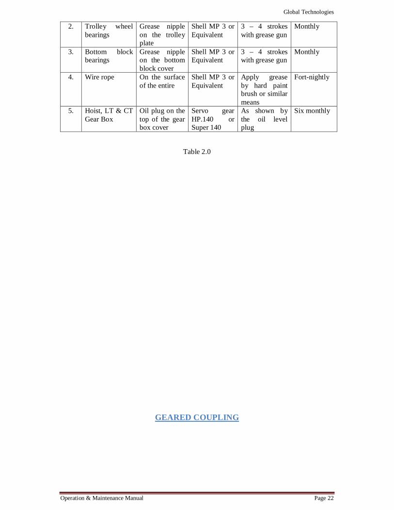
Operation & Maintenance Manual Page 22
2. Trolley wheel bearings
Grease nipple on the trolley plate
Shell MP 3 or Equivalent
3 – 4 strokes with grease gun
Monthly
3. Bottom block bearings
Grease nipple on the bottom block cover
Shell MP 3 or Equivalent
3 – 4 strokes with grease gun
Monthly
4. Wire rope On the surface of the entire
Shell MP 3 or Equivalent
Apply grease by hard paint brush or similar means
Fort-nightly
5. Hoist, LT & CT Gear Box
Oil plug on the top of the gear box cover
Servo gear HP.140 or Super 140
As shown by the oil level plug
Six monthly
Table 2.0
GEARED COUPLING

Global Technologies
Operation & Maintenance Manual Page 23
The fundamental characteristic of flexible full gear coupling is to provide smooth and efficient transmissions of mechanical power, thus offering a compact assembly capable for
higher torques, higher Speed and accommodates sufficient flexibility to overcome misalignment of various angularity within allowable rating and permit float. Fig. Flexible Geared Coupling CONSTRUCTION FLEXIBLE GEAR COUPLING:
Flexible gear coupling is forged from EN-9/C-55 steel and heat treated to 35-40 RC consist of two identical external teeth hubs, two flanged sleeves with internal teeth are identical and interchangeable and are connected with each other by forged tempered alloy steel bolts and nuts in a jig drilled and jig reamed flange hole with provision of ‘O’ ring for sealing of oil/grease, eliminates the necessity of dismantling the hubs from shafts for changing the oil. APPLICATION FLEXIBLE GEAR COUPLING:
It can be used effectively and economically for transmission of mechanical power in industries like- cement, brewing and distilling, food, rolling mills, oil and petroleum, chemical, fertilizers, paper, rubber, sugar, textile, thermal power and others etc.
Global Technologies
Operation & Maintenance Manual Page 24
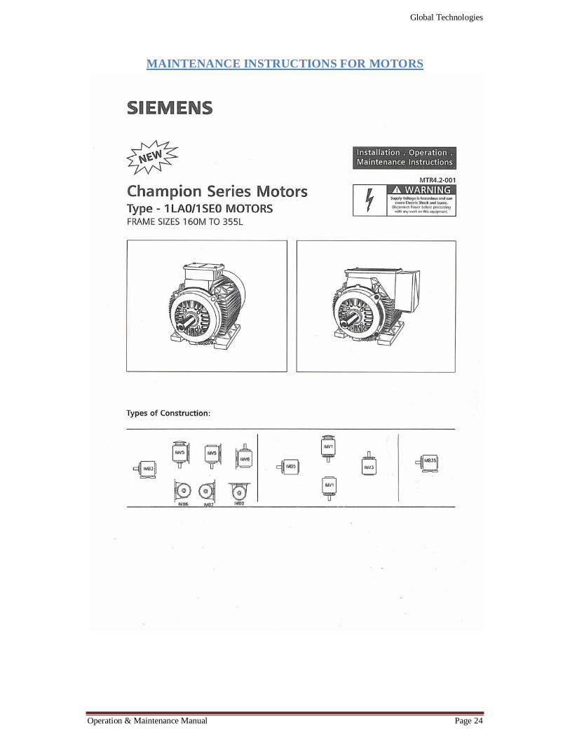
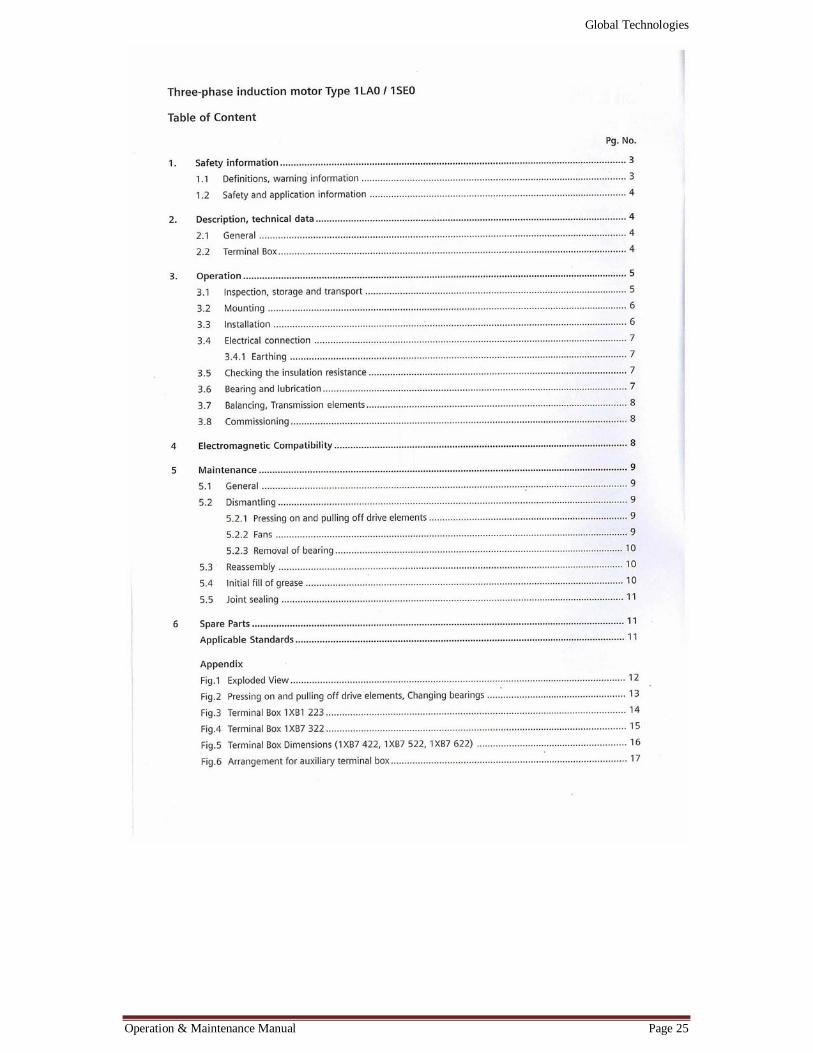
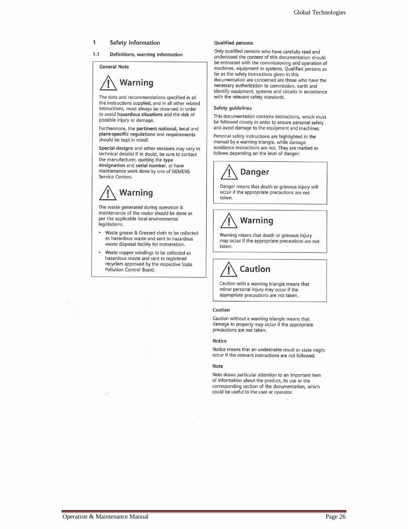
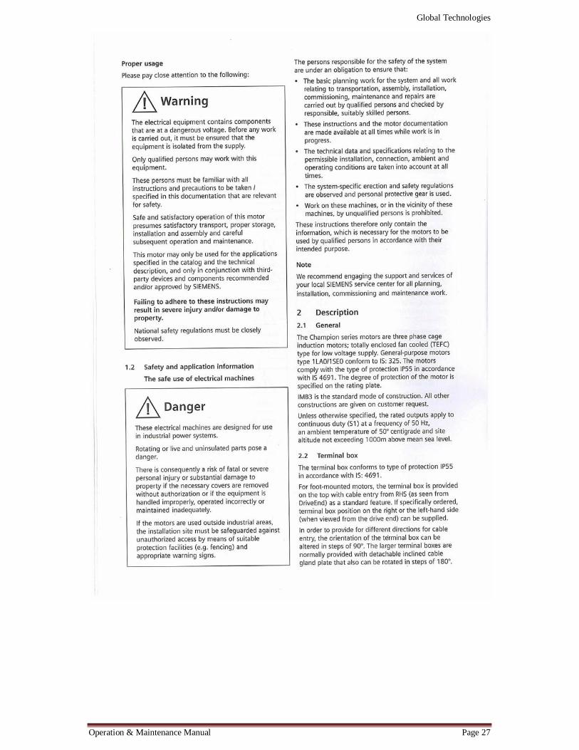
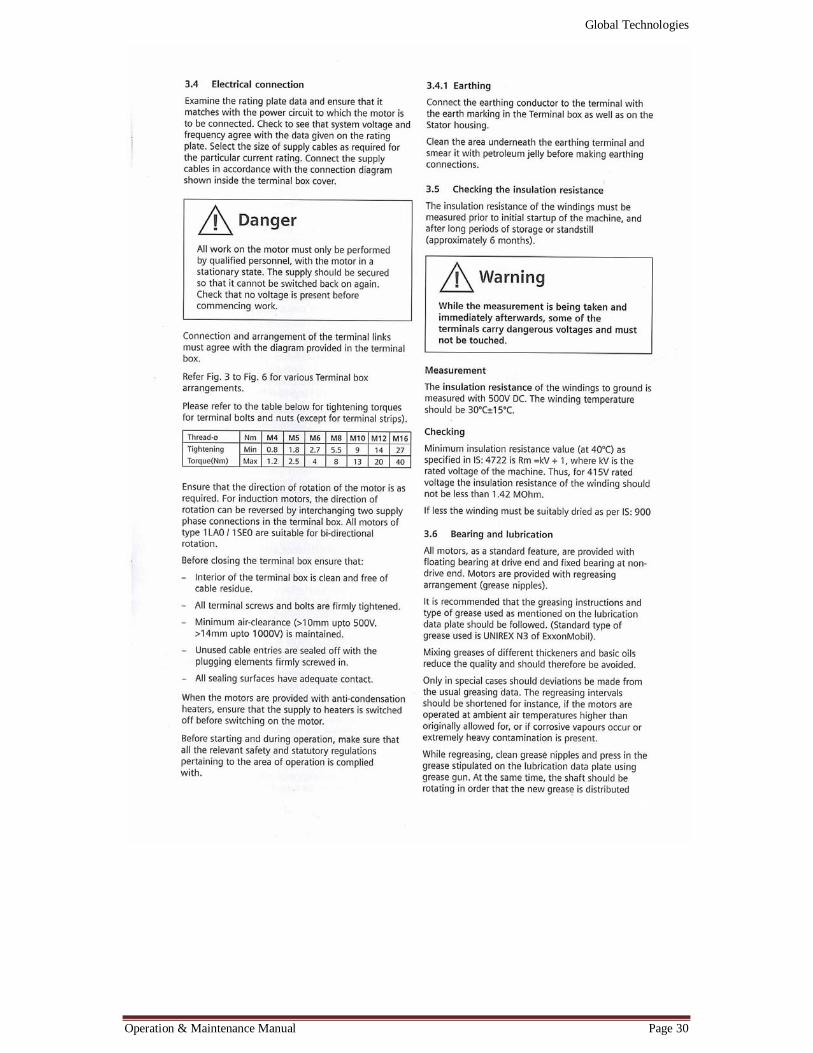
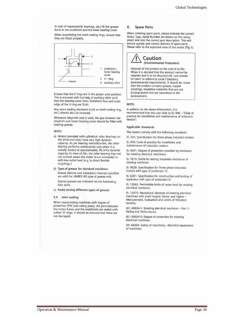
MAINTENANCE INSTRUCTIONS FOR MOTORS
Global Technologies
Operation & Maintenance Manual Page 25
Global Technologies
Operation & Maintenance Manual Page 26
Global Technologies
Operation & Maintenance Manual Page 27

Global Technologies
Operation & Maintenance Manual Page 28

Global Technologies
Operation & Maintenance Manual Page 29
Global Technologies
Operation & Maintenance Manual Page 30

Global Technologies
Operation & Maintenance Manual Page 31

Global Technologies
Operation & Maintenance Manual Page 32

Global Technologies
Operation & Maintenance Manual Page 33
Global Technologies
Operation & Maintenance Manual Page 34
Global Technologies
Operation & Maintenance Manual Page 35
Fig. Description of Motor parts

Global Technologies
Operation & Maintenance Manual Page 36
Global Technologies
Operation & Maintenance Manual Page 37
Fig. Terminal Box

Global Technologies
Operation & Maintenance Manual Page 38
Global Technologies
Operation & Maintenance Manual Page 39
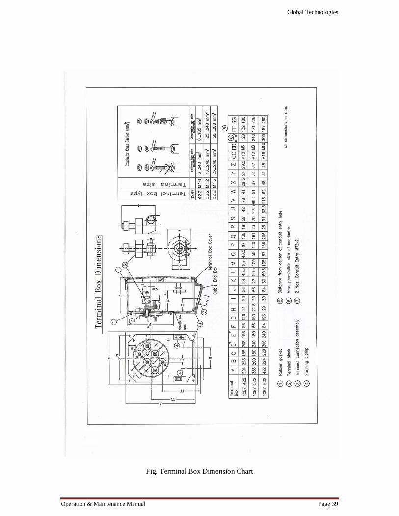
Fig. Terminal Box Dimension Chart
Global Technologies
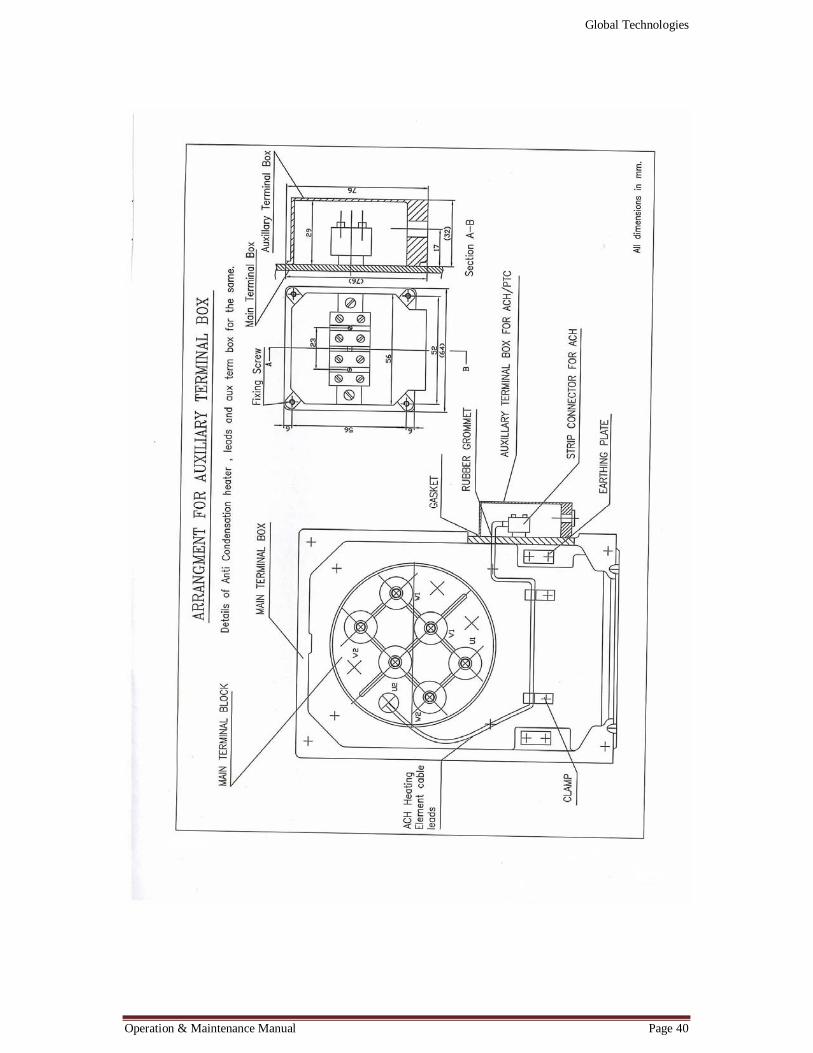
Operation & Maintenance Manual Page 40

Global Technologies
Operation & Maintenance Manual Page 41
BRAKE SPECIFICATION

Global Technologies
Operation & Maintenance Manual Page 42
Fig. Brake working principle and components
Global Technologies
Operation & Maintenance Manual Page 43
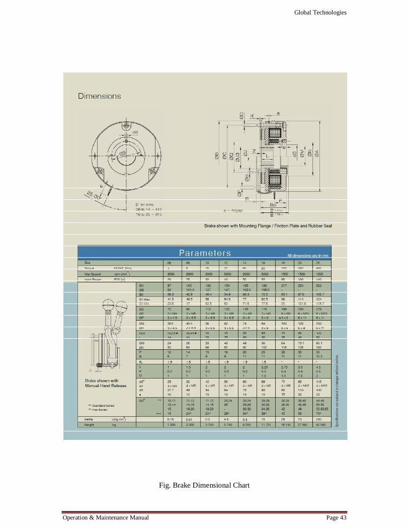
Fig. Brake Dimensional Chart

Global Technologies
Operation & Maintenance Manual Page 44

Global Technologies
Operation & Maintenance Manual Page 45
APPLICATION OF LIMIT SWITCHES
Fig. Technical Data for Rotary geared limit switches
Global Technologies
Operation & Maintenance Manual Page 46
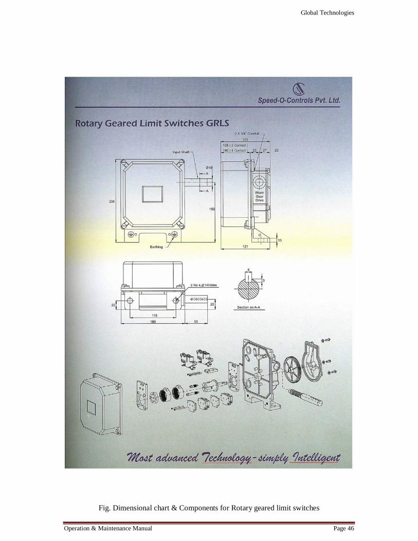
Fig. Dimensional chart & Components for Rotary geared limit switches
Global Technologies
Operation & Maintenance Manual Page 47
Fig. Lever operated limit switches
Global Technologies
Operation & Maintenance Manual Page 48
Fig. Dimensional chart for lever operated limit switches
Global Technologies
Operation & Maintenance Manual Page 49
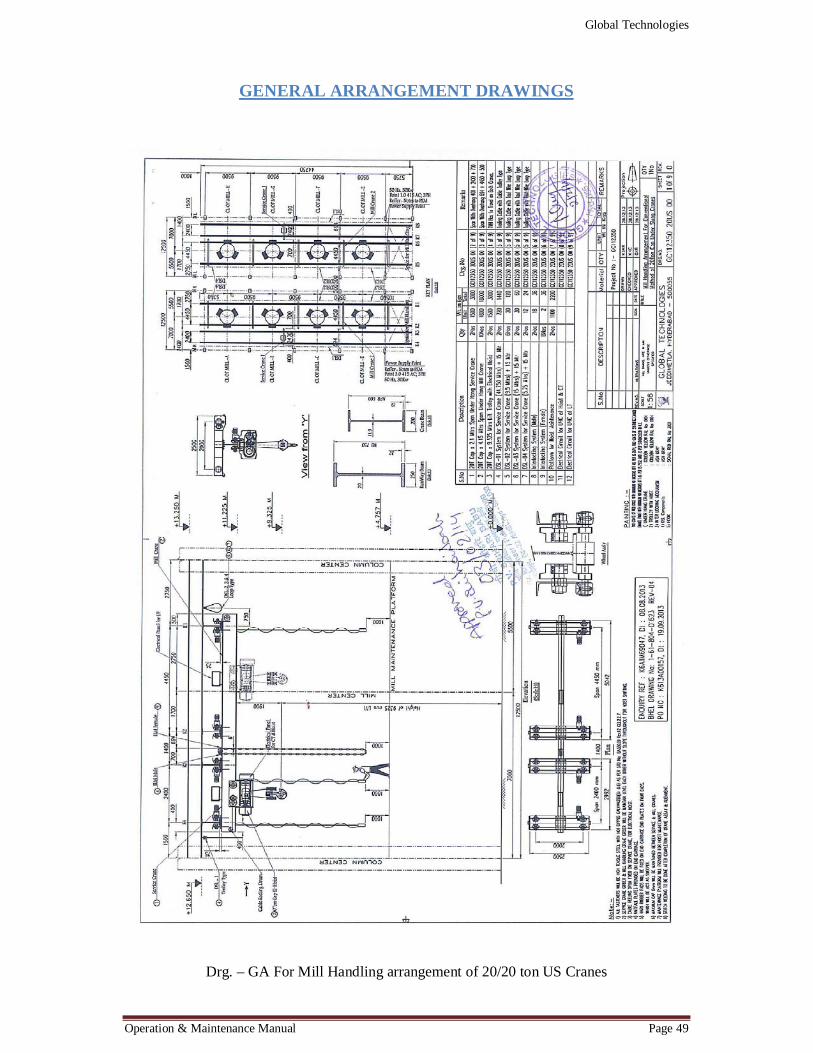
GENERAL ARRANGEMENT DRAWINGS
Drg. – GA For Mill Handling arrangement of 20/20 ton US Cranes

Global Technologies
Operation & Maintenance Manual Page 50
Drg. - GA for 20Ton Cap x 2.4 Mtrs Span US Crane
Global Technologies
Operation & Maintenance Manual Page 51
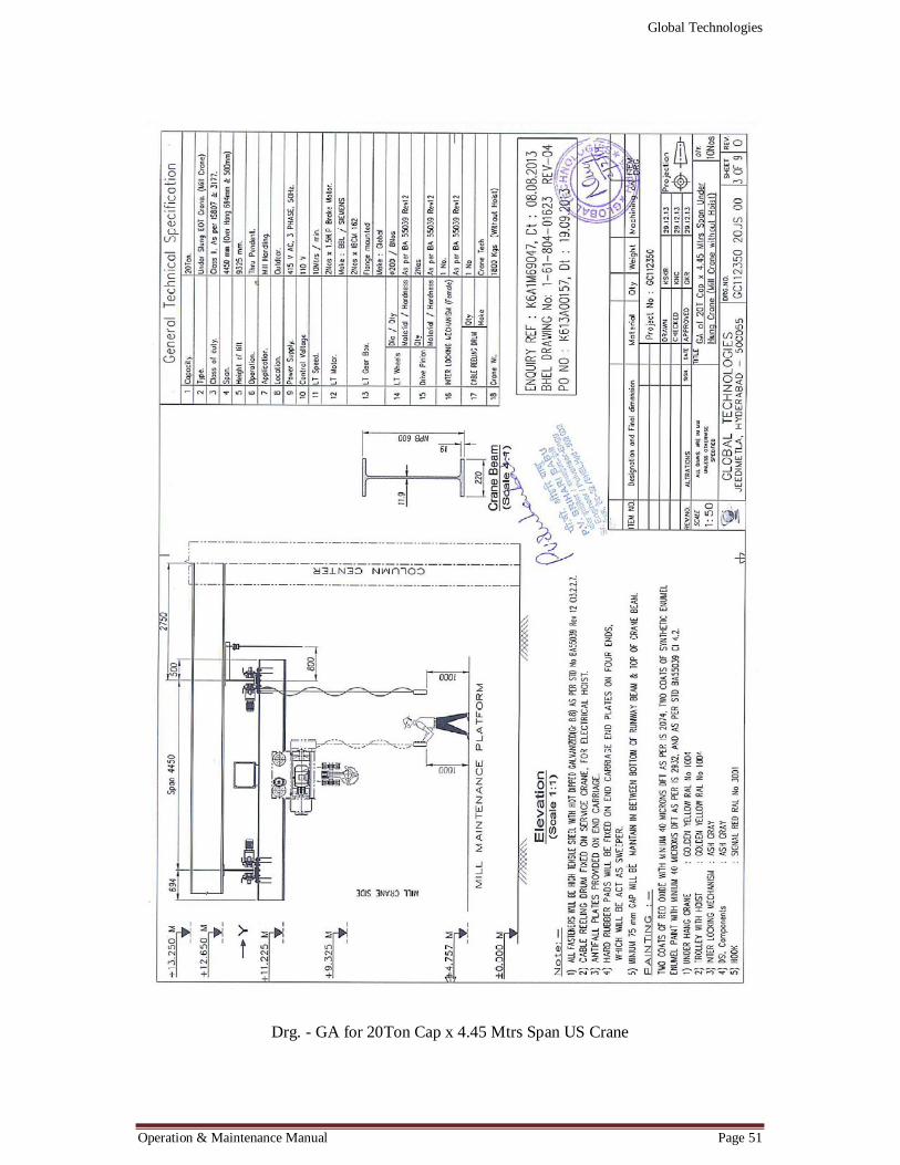
Drg. - GA for 20Ton Cap x 4.45 Mtrs Span US Crane

Global Technologies
Operation & Maintenance Manual Page 52
Drg. - GA for 20Ton Cap x 9.375 Mtrs lift Electrical Hoist
Global Technologies
Operation & Maintenance Manual Page 53
Cable Trolley Arrangement for 20/20 ton US Cranes
Global Technologies
Operation & Maintenance Manual Page 54
GA of IL Mechanism for mill Handling cranes
Global Technologies
Operation & Maintenance Manual Page 55
Maintenance Plot form for Hoist
Global Technologies
Operation & Maintenance Manual Page 56
APPROVED ELECTRICAL DRAWINGS
Drg. - GA for Electrical circuit for US Crane (CT & Hoist)
Global Technologies
Operation & Maintenance Manual Page 57
Drg. - GA for Electrical circuit for US Crane (LT)

Global Technologies
Operation & Maintenance Manual Page 58
LIST OF RECOMMENDED SPARES
S.No Description Qty 1. Roller Bearing 2 Nos 2. Brake spring 1 No 3. Adjusting spacer 1 Set 4. Thrust Bearing 1 No 5. Wire rope (Ø18) 2 Lengths 6. Drive pinion 1 No 7. Adjusting shims 1 Set 8. Limit switches 1 No
Table 3.0 Recommended spares

MANUAL SIGNALS FOR CRANE OPERATION