milk powder processing facility development proposal...
TRANSCRIPT

Prepared for: Tasmanian Dairy Products Co Ltd
Prepared by: Andrew Buckley & Douglas TangneyJune 2011
transport infrastructure | community infrastructure | industrial infrastructure | climate change
Milk Powder Processing Facility
Development Proposal and EnvironmentalManagement Plan

pitt&sherry ref: L22325/LN11027L001 FinalDPEMPrep 33P Rev01/AB/as
Table of Contents
Foreword .......................................................................................................... iExecutive Summary ............................................................................................ iii1. Introduction ............................................................................................... 12. Background Information ................................................................................. 2
2.1 Dairy Industry .................................................................................... 22.2 Milk Quality ....................................................................................... 22.3 Milk Supply in Northern Tasmania ............................................................ 22.4 Company Profile ................................................................................. 32.5 Proposal Outline ................................................................................. 42.6 General and Regional Location .............................................................. 172.7 Site Plan ......................................................................................... 182.8 Road Access..................................................................................... 192.9 Vehicle Movements ............................................................................ 192.10 On Site Infrastructure ......................................................................... 202.11 Off-site Infrastructure ........................................................................ 202.12 Technical and Management Alternatives .................................................. 22
3. Existing Environment .................................................................................. 223.1 Planning Aspects ............................................................................... 223.2 Environmental Aspects ....................................................................... 223.3 Socio-economic Aspects ...................................................................... 303.4 Alternative Sites ............................................................................... 30
4. Potential Effects and their Management ........................................................... 334.1 Air ................................................................................................ 334.2 Liquid Waste .................................................................................... 344.3 Groundwater ................................................................................... 474.4 Noise Emissions ................................................................................ 474.5 Solid and Controlled Waste Management ................................................. 504.6 Dangerous Goods and Environmentally Hazardous Materials .......................... 514.7 Biodiversity and Nature Values .............................................................. 534.8 Marine and Coastal ............................................................................ 534.9 Greenhouse Gases and Ozone Depleting Substances .................................... 534.10 European Heritage............................................................................. 574.11 Land Use and Development .................................................................. 584.12 Visual ............................................................................................ 584.13 Health and Safety Issues ..................................................................... 604.14 Hazard Analysis and Risk Assessment ...................................................... 614.15 Fire Risk ......................................................................................... 624.16 Environmental Management Systems ...................................................... 654.17 Cumulative and Interactive Effects ........................................................ 654.18 Traffic Impacts ................................................................................. 66
5. Monitoring and Review ................................................................................ 665.1 Monitoring....................................................................................... 665.2 Review ........................................................................................... 69
6. Decommissioning and Rehabilitation ............................................................... 707. Commitments ........................................................................................... 728. Conclusion ............................................................................................... 74

pitt&sherry ref: L22325/LN11027L001 FinalDPEMPrep 33P Rev01/AB/as
List of Figures
Figure 1: Annual Milk Intake and Milk Powder ProducedFigure 2: Annual Milk Intake and AMF ProducedFigure 3: Estimated Annual Milk IntakeFigure 4: Estimated Annual Powder ProductionFigure 5: Summary of Milk Drying ProcessFigure 6: Regional Location of Proposed SiteFigure 7: Local Location of Proposed SiteFigure 8: Wastewater Flow DiagramFigure 9: Evaporator Condensate ProductionFigure 10: Ambient Noise Measurement Locations
List of Tables
Table 1: Anticipated Organisational StructureTable 2: Construction Noise Modelling BasisTable 3: Summary of Traffic MovementsTable 4: Surface Water Quality Monitoring PointsTable 5: Monthly Rainfall and TemperatureTable 6: Site ConsiderationsTable 7: Wastewater ParametersTable 8: Characteristics of Evaporator CondensateTable 9: Summary of Process Water ReuseTable 10: Noise Measurement Results (dBA)Table 11: Anticipated Quantities of Chemicals on SiteTable 12: Operational Carbon EmissionsTable 13: Electrical ConsumptionTable 14: Anticipated Greenhouse Gas Emissions during TransportTable 15: Anticipated Water Consumption per Kg of Milk SolidsTable 16: Proposed Monitoring RegimeTable 17: Commitments
Appendix A Detailed Process SummaryAppendix B Site PlanAppendix C Photo MontageAppendix D Aquatic SurveyAppendix E Surface Water Quality Monitoring PointsAppendix F European Heritage InvestigationAppendix G AUSPLUME Modelling ReportAppendix H Wastewater Flow DiagramAppendix I Correspondence from Cradle Mountain WaterAppendix J Noise SurveyAppendix K Land Use Planning ReportAppendix L Traffic Impact AssessmentAppendix M Abbreviations
© 2011 pitt&sherry
This document is and shall remain the property of pitt&sherry. The document may only beused for the purposes for which it was commissioned and in accordance with the Terms ofEngagement for the commission. Unauthorised use of this document in any form is prohibited.
Authorised by: ____________________________ Date: 29 June 2011Andrew Buckley

pitt&sherry ref: L22325/LN11027L001 FinalDPEMPrep 33P Rev01/AB/as i
ForewordThis Development Proposal and Environmental Management Plan (DPEMP) has been prepared tosupport a development Application by Tasmanian Dairy Products Co Limited (TDP) to theCircular Head Council.
The application is for the development and operation of a new milk processing facility (‘thefacility’) on the former Gunns Timber Mill on the corner of Bass Highway and Irishtown Road inSmithton, northwest Tasmania.
The facility will produce Whole Milk Powder (WMP), Skim Milk Powder (SMP) and AnhydrousMilk Fat (AMF) for the international market using state of the art dairy technology inside a fullyenclosed factory, operated by trained staff.
The purpose of this DPEMP is to provide:
Support to the development application to the Circular Head Council
A basis for the Circular Head Council and the Board of the Environment ProtectionAuthority (EPA) to consider the planning and environmental aspects of the proposal
A basis for the conditions under which any approval can be given
A source of information for stakeholders and groups to gain an understanding andappreciation of the proposed facility
The DPEMP has been prepared according to the EPA’s General Guidelines for the preparationof a Development Proposal and Environmental Management Plan for Level 2 activities and‘called in’ activities, May 2010 and the EPA’s Development Proposal and EnvironmentalManagement Plan Project Specific Guidelines for Tasmanian Dairy Products Co Ltd, PowderedMilk Processing Facility.
The DPEMP project specific guidelines were developed by the EPA based on the informationsupplied by TDP in a Notice of Intent (NOI) submitted March 2011 in accordance with the EPA’sNOI guidelines and the requirements of Section 27B of the Environmental Management andPollution Control Act 1994.
The development application will be advertised by the Circular Head Council in the Advocatenewspaper and the DPEMP will be available for public scrutiny at the:
Circular Head Council offices in Smithton
The Environment Protection Authority’s internet site
The Department of Primary Industries, Parks, Water and Environment library in Hobart, fora period of 28 days following the formal newspaper advertisement of the application
Any member of the public may submit a representation on the proposal, describing theircomments and/or objections. Representations must be in writing and lodged within thestatutory period with:
Mr Greg WintonThe General ManagerCircular Head CouncilPO Box 348Smithton TAS 7330
Council will consider the development application in accordance with its obligations under theLand Use Planning and Approvals Act 1994 and the Environmental Management and PollutionControl Act 1994.

pitt&sherry ref: L22325/LN11027L001 FinalDPEMPrep 33P Rev01/AB/as ii
Because the proposed activity is deemed a Level 2 activity under Schedule 2 of theEnvironmental Management and Pollution Control Act 1994, the EPA will assess the potentialenvironmental impacts and conditions for the proposed activity in accordance with theEnvironmental Management and Pollution Control Act 1994. The EPA advised TDP on 1 April2011 that the assessment will be undertaken as a Class 2B.
The environmental conditions from the EPA’s assessment will be forwarded to the CircularHead Council for inclusion in the permit, if and when Council approves the proposed activity.Any persons who made written representations on the proposal will be notified by CircularHead Council of its decision. Persons aggrieved by a decision to approve the development, orby the conditions or restrictions of the permit, may appeal to the Resource Management andPlanning Appeal Tribunal (the Tribunal). The applicant, TDP, may also appeal a refusal of theproposal by the EPA, or appeal the conditions or restrictions imposed by the EPA.
Appeals must be lodged in writing within 14 days of the Council’s decision. The Tribunal willhear appeals and independently reassess the proposal, to either confirm, overturn or modifythe decision and/or the permit conditions and restrictions.
TDP has not referred, and does not intend to refer, the project to the CommonwealthGovernment for a determination on whether approval under the Environment Protection andBiodiversity Conservation Act 1999 is required because the project is very unlikely to impactupon matters of national environmental significance or upon Commonwealth land. Approvalunder the Commonwealth’s Environment Protection and Biodiversity Act 1999 is not required.
No other planning or environmental approvals are deemed necessary.

pitt&sherry ref: L22325/LN11027L001 FinalDPEMPrep 33P Rev01/AB/as iii
Executive SummaryTasmanian Dairy Products Co Limited (TDP) propose to develop a new milk processing facilityon the former Gunns Sawmill site on the corner of Bass Highway and Irishtown Road inSmithton.
The operation will process 480,000 L of milk per 8 hours. Note that for the purposes of thisdocument, 1m3 = 1kl = 1000l. When weights of milk are discussed, assume 1m3 of milk = 1t.
TDP was formed by Little Lion Holdings (LLH), the principals and management of which haveextensive background in dairy farming, commercial real estate development, projectmanagement, dairy processing, green field development and enterprise building.
TDP have an agreement in principle to purchase the land and site buildings from Gunns Limitedand redevelop part of the site for the milk processing facility. As part of the agreement, GunnsLimited will rehabilitate the site in accordance with their existing permit to operate.
Existing reticulated infrastructure (power, water and wastewater), site buildings and roadaccesses will be retained and reused for the proposed facility. Upgrades to the site powersupply infrastructure will be undertaken during construction and a rising main for the sewerwill be established on site to allow liquid wastes to be directly discharged to the CradleMountain Water (CMW) network.
TDP have an in-principle agreement with a nearby premise, Ta Ann, to supply all heat (steam)requirements for the facility. As part of this agreement, Ta Ann will utilise excess condensatefrom the proposed facility as boiler feed water to reduce emissions to the environment. TaAnn is an existing facility operating under a current license.
Site buildings will compose:
Storage and warehouse building (existing dry mill building of approximately 2450 m2)incorporating:
- Compressor/electrical control room
- Toilets and basic amenities
- Palletising belt
- Finished product storage (nominally 100 pallets)
Dryer Building (320 m2)
Wet Processing (210 m2)
Amenities building (105 m2)
3 x 150 to 200 kL milk storage silos
2 Bay milk unloading facility
20 staff car spaces (a further 15 car spaces are located outside the existing administrationbuilding)
Chemical storage area
1 potable water tank and 2 fire water tanks
Landscaped ‘break out’ area for staff
Construction will occur over a 10 month period, nominally commencing from September 2011or when suitable contractors have been engaged. Existing site buildings will be utilised ascovered and secure construction areas.

pitt&sherry ref: L22325/LN11027L001 FinalDPEMPrep 33P Rev01/AB/as iv
All site vehicles will access the site the via the established site access of Bass Highway >Irishtown Road (for vehicles travelling east/west) or directly from Irishtown Road.
The existing Bass Highway/Irishtown Road intersection has suitable layout, turning circles andsight distances for B-Double vehicles and anticipated traffic loads and volumes.

pitt&sherry ref: L22325/LN11027L001 FinalDPEMPrep 33P Rev01/AB/as 1
1. IntroductionTasmanian Dairy Products Co Ltd (TDP) is planning to develop and operate a milkpowder processing facility (“the facility”) on the site currently occupied by the GunnsTimber Mill, Smithton (“the proposed site”).
The facility will be capable of processing 480,000 litres of milk in an 8 hour periodduring peak processing. Note that for the purposes of this document, 1m3 = 1kl = 1000l.
The proposed site occupies 3 titles and is commonly referred to as 2 Irishtown Road,Smithton. Any reference to the proposed site is a reference to all three titles. Refer tothe Land Use Planning Report, Appendix K, for more detail on the title boundaries.
Tasmanian Dairy Products Co Ltd (TDP) is a public company that has been establishedto undertake the construction and operation of a milk powder processing facility inCircular Head, Tasmania.
The company has been formed by Little Lion Holdings (LLH), the principals andmanagement of which have extensive background in dairy farming, commercial realestate development, project management, dairy processing, green field developmentand enterprise building.
LLH has accumulated a portfolio of dairy farms in Circular Head, currently valued atapproximately $100 million. The farms were purchased, developed, cleared andimproved over a 5-year period. Productivity is well in excess of industry norms, andLLH is currently pursuing additional opportunities to enhance the value of these farms,including investing over $1.5 million to date to advance the milk drying plant that isthe subject of this DPEMP.
Executives of TDP/LLH have career experience in dairy processing, having worked withregional industry leaders since the mid-1970’s. Responsibilities included building anddesigning dairy processing plants, quality control, operations management andoversight of multiple, complex operations throughout Tasmania and other states.
These industry leaders have agreed to work with TDP, providing additional evidencethat the business concept and operational plan are achievable.
In addition to LLH’s activities in the dairy industry, the company and its principals alsohave a successful track record in commercial and residential real estate developmentand property management. Affiliates of the company have developed numerousresidential sub-divisions in Tasmania, as well as industrial parks and other commercialprojects. Principals of the company have the requisite engineering and financebackgrounds to successfully undertake and manage such projects. LLH’s ongoingmanagement of commercial ventures also provides additional financial resources tosupport the plant development.
Prior to LLH’s involvement in the dairy industry, its principals were successfuloperators in the Tasmanian timber industry, having built a company that achieved amarket capitalisation of over $200 million. This company acquired, developed andharvested timber assets, building significant value for shareholders and otherstakeholders.
In addition to LLH’s investment in the farms and the drying plant to date, the companyhas also retained KPMG Corporate Finance to assist in raising the requisite equity anddebt capital to complete the plant and achieve commercialization. KPMG has preparedthe requisite collateral materials, including extensive financial models, and has alreadybegun discussions with prospective strategic and financial investors.

pitt&sherry ref: L22325/LN11027L001 FinalDPEMPrep 33P Rev01/AB/as 2
2. Background Information2.1 Dairy Industry
The Dairy Industry is a significant rural industry in Australia, third to the beef andwheat industries based on a farm gate value of production of 3.4 billion dollars in2009/2010. Dairying is also a significant source of value adding to local farmingcommunities, through significant economic activity and employment.
Fat and protein concentrations in Tasmania’s milk are high on a per capita basis, dueto favourable climatic conditions and industry knowledge, much of which isconcentrated in the North West.
Tasmania produces approximately 673 million litres of milk per annum and employs2700 people in the industry. Both of these numbers are expected to rise in the future,aligned with industry innovation and the adoption of new technologies.
Approximately 8% of Tasmania’s milk production is used for drinking, with theremainder used for butter, cheese, cream, ice cream, yoghurts, custards, wheyproteins and nutraceuticals (e.g. natural health products).
Skim and whole milk powder, like that to be produced by the proposed facility,accounted for approximately 35% of milk utilisation in Australia during 2009/2010. Asiaremains the dominant export market for milk powder, purchasing close to 80% ofproduction. Future markets in the Middle East will continue to increase demand formilk powder.
A by-product of milk powder production is Anhydrous Milk Fat (AMF), which is primarily99.9% pure butter fat utilised in the confectionary and bakery industries in bothdomestic and export markets. Powder production deems AMF to be a waste; however,it remains a valuable commodity in the dairy industry and offsets the costs ofproduction.
2.2 Milk QualityCows’ milk consists of milk fat, protein, lactose and minerals (generally grouped underthe term solids) in water, with water making 88% of milk volume. The composition ofsolids varies in Tasmania and nationwide due to cow breed, age, nutrition and feedquality.
Concentrations of average milk fat and protein in Tasmanian herds is higher thanmainland herds, resulting in greater yield of saleable product per litre manufactured.
2.3 Milk Supply in Northern TasmaniaThe North West of Tasmania produces 250 million litres of milk per year and this isexpected to rise to 319 million litres by 2015. The increase in production is generatedby increasing herd numbers, better on-farm management of herds to reduce waste milkand increased production per cow.
The initial production requirement for the proposed facility is 140 million litres, ofwhich 35% will be sourced from farms owned by the proponent, and the remaindersourced under contract from dairy farms located within a 30 km radius of Smithton.

pitt&sherry ref: L22325/LN11027L001 FinalDPEMPrep 33P Rev01/AB/as 3
2.4 Company ProfileTasmanian Dairy Products Co Ltd (TDP) is a public company that has been establishedto undertake the construction and operation of a milk powder processing facility inCircular Head, Tasmania.
The company has been formed by Little Lion Holdings (LLH), the principals andmanagement of which have extensive background in dairy farming, commercial realestate development, project management, dairy processing, green field developmentand enterprise building.
LLH has accumulated a portfolio of dairy farms in Circular Head, currently valued atapproximately $100 million. The farms were purchased, developed, cleared andimproved over a 3-year period. Productivity is well in excess of industry norms, andLLH is currently pursuing additional opportunities to enhance the value of these farms,including investing over $1.5 million to date to advance the milk drying plant that isthe subject of this DPEMP.
Executives of TDP have substantial experience in dairy processing, having worked withregional industry leaders since the mid-1970’s. Responsibilities included building anddesigning dairy processing plants, quality control, operations management andoversight of multiple, complex operations throughout Tasmania and other states.
These industry leaders have agreed to work with TDP, providing additional evidencethat the business concept and operational plan are achievable.
In addition to LLH’s activities in the dairy industry, the company and its principals alsohave a successful track record in commercial and residential real estate developmentand property management. Affiliates of the company have developed numerousresidential sub-divisions in Tasmania, as well as industrial parks and other commercialprojects. Principals of the company have the requisite engineering and financebackgrounds to successfully undertake and manage such projects. LLH’s ongoingmanagement of commercial ventures also provides additional financial resources tosupport the plant development.
Prior to LLH’s involvement in the dairy industry, its principals were successfuloperators in the Tasmanian timber industry, having built a company that achieved amarket capitalisation of over $200 million. This company acquired, developed andharvested timber assets, building significant value for shareholders and otherstakeholders.
In addition to LLH’s investment in the farms and the drying plant to date, the companyhas also retained KPMG Corporate Finance to assist in raising the requisite equity anddebt capital to complete the plant and achieve commercialization. KPMG has preparedthe requisite collateral materials, including extensive financial models, and has alreadybegun discussions with prospective strategic and financial investors.
2.4.1 Organisation StructureThe proposed organisation structure will incorporate 52 people into the running,delivery and management of the proposed facility. Table 1 summarises the roles andemployee numbers.
It is anticipated that flow-on effects will also increase employment on farms due to thesecure milk demand and better farm gate prices.

pitt&sherry ref: L22325/LN11027L001 FinalDPEMPrep 33P Rev01/AB/as 4
Roles and responsibilities in the organisation will be further developed during thebusiness planning phase.
Phase Supervisors/Managers Workers
Chief Executive Officer 1 -
Milk Procurement - 1
Production – WMP/SMP 2 24
Production – AMF 1 4
Maintenance - 2
Sales & Marketing - 1
Administration - 4
Milk Collection (under contract) 1 12*
Table 1: Anticipated Organisational Structure
Milk production will consist of 3 plant operators split between wet processing,warehouse/milk receival and shift supervision.
2.5 Proposal OutlineTDP propose to construct and operate a milk drying facility in Smithton that willprocess 1.60 ML of milk per 24 hours (during peak processing).The factory will becapable of producing approximately 130 tonnes of milk powder from this 1.6 ML input.Approximately 3.5t AMF will be produced during the same period.
TDP have an agreement in principle to purchase the land and site buildings from GunnsLimited and redevelop part of the site for the milk processing facility. Gunns Limitedwill rehabilitate the entire site, in accordance with the existing Gunns Limited permitto operate, prior to TDP taking possession of the site.
Existing reticulated infrastructure (power, water and wastewater), some site buildingsand road accesses will be retained and reused for the proposed facility (refer to theplan shown in Appendix B for more detail). Upgrades to the site power supplyinfrastructure will be undertaken during construction and a rising main for the sewerwill be established on site to allow liquid wastes to be directly discharged to the CMWnetwork.
TDP have an in-principle agreement with a nearby premise, Ta Ann, to supply all heat(steam) requirements for the facility. As part of this agreement, Ta Ann will utiliseexcess condensate from the proposed facility as boiler feed water to reduce wateremissions to the environment. Ta Ann are an existing facility operating under a currentlicense.
The proposed facility will feature the latest milk processing technology, with energyefficient driers and steam provided by Ta Ann, and will take approximately 10 monthsto construct and commission. Some construction of key infrastructure will take placeinterstate and be delivered to site during the construction program.
When completed, the milk processing building (both the wet and dry processing areasas defined on the plan in Appendix B) will be fully sealed by an internal positivepressure air system to prevent ingress of foreign materials, thereby maintaining thestrict hygiene requirements dictated by food manufacturing legislation and standards.

pitt&sherry ref: L22325/LN11027L001 FinalDPEMPrep 33P Rev01/AB/as 5
It is proposed that the milk drying facility will operate 24 hours a day, 7 days a week(peak production). Potential exists for seasonal variation with shorter daily operatinghours from May - August when on-farm milk production is lower. Operating hours duringthis period could be a low as 8 hours, or a single shift.
During peak production, milk powder production occurs for 21.5 hours per day, withthe remaining 2.5 hours used for cleaning and maintenance (as required). Factoryoperating hours for non peak production will be determined by milk supply.
2.5.1 Variability in ProductionThe milk volumes processed, and therefore milk powder produced, will vary over theseason, with peak milk supply occurring during the spring months, generally fromOctober through to December.
The graph of typical yearly milk intake and milk powder produced is shown below inFigure 1, with Figure 2 showing milk intake vs. AMF produced. The figures representthe plant operating at full production.
From the graphs, it can be determined that the monthly average anticipated milkintake is just under 21,000 kL, producing a monthly average of 2900 tonnes of milkpowder and 77 tonnes of AMF.
Figure 1: Annual Milk Intake and Milk Powder Produced
0
1000
2000
3000
4000
5000
6000
7000
8000
9000
0
5000
10000
15000
20000
25000
30000
Jul Aug Sep Oct Nov Dec Jan Feb Mar Apr May Jun
Milk
Pow
der P
rodu
ced
(t)
Milk
Pro
cess
ed (t
)
Total Milk Processed (kl) Total Milk Powder Produced (t)

pitt&sherry ref: L22325/LN11027L001 FinalDPEMPrep 33P Rev01/AB/as 6
Figure 2: Annual Milk Intake and AMF Produced
TDP plan to ramp production up to these annualised production levels over a few years,as milk supply in the regional area grows and they are able to contract additionalsuppliers.
The graph of the anticipated production ramp up is shown in Figure 3 below. Theresulting anticipated milk powder production levels are shown in Figure 4.
Figure 3: Estimated Annual Milk Intake
0
20
40
60
80
100
120
140
160
180
200
0
5000
10000
15000
20000
25000
30000
Jul Aug Sep Oct Nov Dec Jan Feb Mar AprMay
Jun
AM
F Pr
oduc
ed (t
)
Milk
Pro
cess
ed (t
)
Total Milk Processed (kl) AMF produced (t)
-
50,000
100,000
150,000
200,000
250,000
300,000
FY13
FY14
FY15
FY16
FY17
FY18
FY19
FY20
FY21
FY22
FY23
FY24
FY25
FY26
FY27
Estimated Annual Milk Intake (kl/yr)

pitt&sherry ref: L22325/LN11027L001 FinalDPEMPrep 33P Rev01/AB/as 7
Figure 4: Estimated Annual Powder Production
2.5.2 ProcessTDP will source fresh milk from dairy farms located typically in Circular Head toproduce milk powder for the international market, particularly Asia. TDP haveconfirmed milk supply commitments with Circular Head farmers (however details arestrictly confidential).
Milk will be delivered to the facility via B-Double tanker, under contract (a transportoperator has yet to be confirmed). Tanker cleaning will occur off site as part ofcontract conditions. Milk will be stored on site in two or three 200 kL silos at as-delivered temperature. This storage will provide buffer capacity only, beingapproximately 1 day of total production.
The production process will use powdered lactose to standardise proteinconcentrations in the final product. TDP will buy the lactose from local andinternational suppliers and have this delivered to site on an as needed basis.Finished product will be packed into 25 kg bags, sealed and distributed oncontainerised wooden pallets or stored on site in site warehouses, until distribution isrequired.
All wet and dry processing equipment will be contained inside a fully bunded andenclosed section of the factory in accordance with best practice guidelines andlegislation for dairy manufacturing facilities.
While the process design is still at concept design stage, TDP anticipate that thefacility will process approximately 350,000 litres of milk per 8 hours on average and480,000 litres per 8 hours during peak processing. The facility will process milk for 24hours per day, 7 days per week.
The facility will maintain a small buffer storage of raw milk, prior to evaporating anddrying the milk to make the milk powder, then packaging powder into 25 kg bags.Finished product will be stored on wooden pallets and transferred to a warehouse fordistribution.
0
5000
10000
15000
20000
25000
30000
35000
FY13
FY14
FY15
FY16
FY17
FY18
FY19
FY20
FY21
FY22
FY23
FY24
FY25
FY26
FY27
Estimated Annual Powder Production(t/yr)

pitt&sherry ref: L22325/LN11027L001 FinalDPEMPrep 33P Rev01/AB/as 8
TDP have an in-principle agreement with CMW to discharge all liquid waste generatedinside the factory to the existing sewerage network. The actual amount discharged willbe the surplus above the facility and Ta Ann requirements (expected only during thepeak production months).
TDP will have a single discharge to atmosphere (from the spray dryer) via a bag filterand will generate some noise emissions during operations.
The facility will be accessed off Bass Highway > Irishtown Road > existing site entranceoff Irishtown Road. While the site access route has not been finalised, it is unlikely thatIrishtown Road will require upgrading to facilitate B Double access, as the road layout,width and site distances are sufficient for the anticipated vehicle types and volumes.
TDP plan to commence construction on 1 September 2011 or earlier if possible, subjectto all statutory planning and environmental approvals.
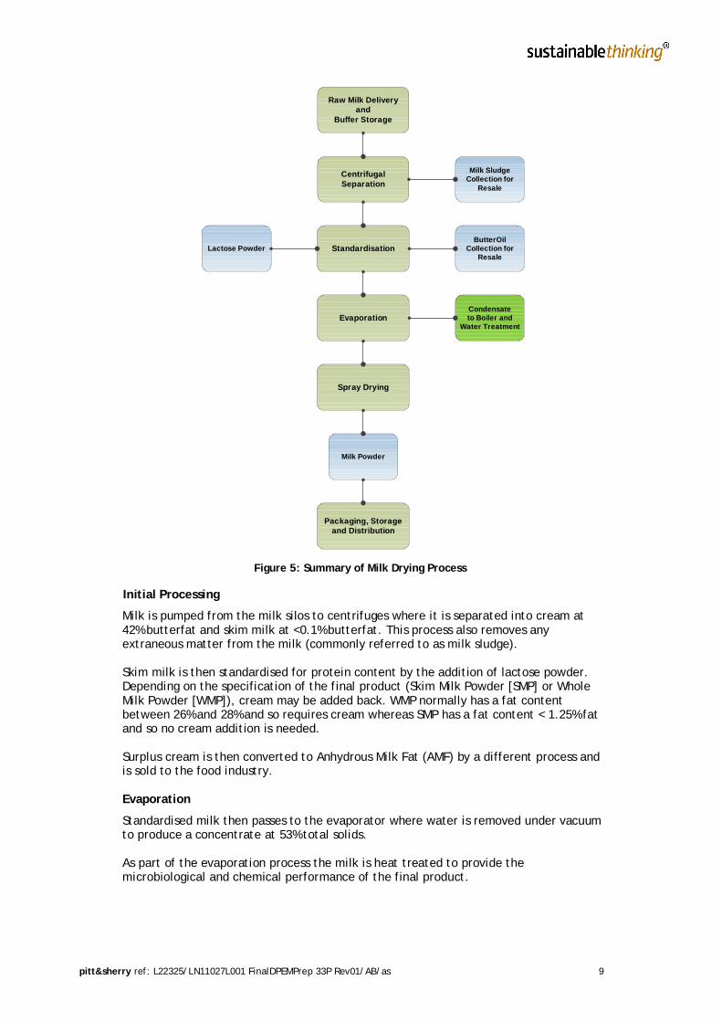
Process SummaryA summary of the milk drying process is provided below in Figure 5 and a shortsummary of each stage is also provided. A more detailed process summary is providedin Appendix A which identifies major inputs and outputs at each stage of theproduction process.
In general terms, approximately 88% of milk is water content, which is removed in a 2stage milk drying process:
Milk is concentrated by evaporation to remove up to 90% of the total water contentof the milk
Removal of the remaining 10% water by spray drying
The water is removed as condensate, and with little additional treatment (likely to bechlorine dioxide, via a package plant delivery system, for disinfection) is of suitablequality for reuse on site as wash and cleaning water, mainly in the CIP system.
The two stage approach is used because the energy required per kilogram of waterevaporated in the spray drying process is up to twenty times more than is required inthe evaporation process.
The remaining 12% product is predominantly milk solids, with further processingproducing Milk Sludge and Butter Oil by products for re-sale.
pitt&sherry ref: L22325/LN11027L001 FinalDPEMPrep 33P Rev01/AB/as 9
Figure 5: Summary of Milk Drying Process
Initial Processing
Milk is pumped from the milk silos to centrifuges where it is separated into cream at42% butterfat and skim milk at <0.1% butterfat. This process also removes anyextraneous matter from the milk (commonly referred to as milk sludge).
Skim milk is then standardised for protein content by the addition of lactose powder.Depending on the specification of the final product (Skim Milk Powder [SMP] or WholeMilk Powder [WMP]), cream may be added back. WMP normally has a fat contentbetween 26% and 28% and so requires cream whereas SMP has a fat content < 1.25% fatand so no cream addition is needed.
Surplus cream is then converted to Anhydrous Milk Fat (AMF) by a different process andis sold to the food industry.
Evaporation
Standardised milk then passes to the evaporator where water is removed under vacuumto produce a concentrate at 53% total solids.
As part of the evaporation process the milk is heat treated to provide themicrobiological and chemical performance of the final product.
Raw Milk Deliveryand
Buffer Storage
CentrifugalSeparation
Milk SludgeCollection for
Resale
Standardisation
Evaporation
Spray Drying
Packaging, Storageand Distribution
Lactose PowderButterOil
Collection forResale
Condensateto Boiler and
Water Treatment
Milk Powder

pitt&sherry ref: L22325/LN11027L001 FinalDPEMPrep 33P Rev01/AB/as 10
Drying
Concentrate from the evaporator then passes to spray drying where it is sprayed athigh pressure into the drying chamber and mixes with heated air. Water is furtherremoved before powder at a maximum of 4% moisture is powdered from the chamber.
Basic quality testing of the powder is performed by the plant operator to provideinformation for the optimum operation of the plant.
Packing
In some cases the powder may be inert gas packed, dependant on customerspecifications. The inert gases are normally a mixture of nitrogen (mostly) and carbondioxide. Given the quantities of gas required (refer section 4.6), it is likely that storageon site will be in the form of either banks (skid mounted) of bottled gas, or largersingle tanks filled from delivery vehicles. Note that the latter has been shown on theplans included in this document.
TDP are also evaluating use of an onsite package nitrogen generator for supply of thisgas. In general terms, these generators produce nitrogen gas utilising air separation bymechanical means - taking atmospheric air ( 78% nitrogen & 21% oxygen), pressurisingit in an air compressor and then separating it with either a membrane or PressureSwing Adsorption generator. The advantages of this method of nitrogen supply are:
Less transport costs
Generation of gas on demand (less storage requirements)
Cheaper operating costs
A decision on whether to install this equipment will be made during the detailed designphase of the project.
Powder packing has been designed to operate autonomously to provide an opportunityfor labour to be utilised in other areas of the facility for short times when required.
Finished powder can be stored in the processing area for up to 4 hours beforepackaging starts and the packing line can pack 30% faster than production (to make upfor delays or interruptions).
Storage, Distribution & Marketing
All products will be stored in ambient temperature warehouses prior to export. Initiallymilk powder storage will occur on site in the warehouse. This will be approximately 2weeks of product, as quality assurance requirements dictate that testing results bereceived prior to dispatch. This equates to approximately 2000t of milk powder.Following transfer to an external warehouse or port of loading, the product will befurther handled by shipping firms under contract.
A LPG powered forklift will be utilised to transfer product from the end of the packingline into storage and onto dispatch vehicles. Note that loading of dispatch vehiclesoccurs in the warehouse. This same forklift would be utilised for unloading generaldeliveries to the processing area.
Further InformationAnhydrous Milk Fat
Anhydrous Milk Fat (AMF) or butter oil is the product produced from cream not used inthe powder process. The process involves concentration of the fat up to 99.5%butterfat by using a series of centrifuges. The non fat milk solids taken out by thecentrifuges are returned to the powder process.

pitt&sherry ref: L22325/LN11027L001 FinalDPEMPrep 33P Rev01/AB/as 11
The temperature of operation ensures that all butterfat is in a liquid state. This variesand can be as high as 80 degrees Celsius. The final step in the process removes the lasttrace of moisture and ideally produces AMF of 99.9% purity. Note that the purer the oilcontent of the AMF, the more value it may attract in the market place, and thereforethere will be a continual production focus on ensuring the quality is maintained.
This product will be packed into 200 litre drums
Milk Sludge
This waste is a mixture of dirt and excrement, commonly referred to as ‘milk sludge’.Quantities generated per day vary according to the time of year, quality of milk andoperational requirements, but may be as much as 1.5m3 per day.
The sludge will be stored in covered waste bins for daily collection. TDP will secureagreements with local pig farmers (or similar) in the North West to reuse the sludge asfeed and negate the need for disposal at a landfill.
Cleaning In Place (CIP)
At the end of each daily production run (21.5 hours at peak production, 8 hours duringthe winter months and commissioning), all equipment that has come in contact withmilk and milk products is fully cleaned to maintain hygiene standards, using what isknown as CIP equipment. This equipment is fully automated and integral to the plantequipment being cleaned, so that the only location of losses from the system is thedischarge to the local sewer network via a dedicated TWA.
The automated process of cleaning will follow the following steps:
Rinse with cold water
Additional of detergents (sodium hydroxide)
Circulation of cleaning solution through the equipment with turbulent flow toloosen and suspend soils
Rinse with fresh water
Nitric or phosphoric acid rinse to prevent build-up of milk scale
Rinse with fresh water
Refer to Section 4.6 for likely quantities of the chemicals listed above.
Major Services InputsThe major services inputs to the production process are steam, water and electricity.Steam will be sourced under a supply contract from the adjacent Ta Ann boiler, withwater (where not recycled as part of the condensate reuse system) and electricitysourced from the local network.
Ta Ann has confirmed that TDP can take the steam from their boiler to use in theproduction process. The water/electricity network providers have confirmed that TDPcan utilise the existing network.
2.5.3 Site BuildingsOne of the attractions of redeveloping the former Gunns Site is to utilise existing sitebuildings during both construction and operational phases with the existing amenitiesand administration block providing a functional space from which to control andoversee the construction program, and then the same facilities will be used during fulloperations.

pitt&sherry ref: L22325/LN11027L001 FinalDPEMPrep 33P Rev01/AB/as 12
Below is a summary of the site buildings (including nominal sizes), with an indicativesite plan provided in Appendix B. Appreciation views of the new buildings are providedin Appendix C.
Storage and warehouse building (existing dry mill building of approximately2450 m2) incorporating:
- Compressor/electrical control room
- Toilets and basic amenities
- Palletising belt
- Finished product storage (nominally 100 pallets)
Dryer Building (320 m2)
Wet Processing (210 m2)
Amenities building (105 m2)
Three 200 kL milk storage silos
2 Bay milk unloading facility
20 staff car spaces (a further 15 car spaces are located outside the existingadministration building)
Chemical storage area
One potable water tank and 2 fire water tanks
Landscaped ‘break out’ area for staff
Some site sheds will eventually be removed to make way for the new facilities.However, as demonstrated on the plan, most site buildings will remain for future use inthe proposed facility.
2.5.4 Construction
GeneralConstruction will occur over a 10 month period, nominally commencing fromSeptember 2011 or when suitable contractors have been engaged and approvals havebeen granted. Existing site buildings will be utilised as covered and secure constructionareas.
The building works and process equipment installation will occur in tandem with up to100 contractors on site during the peak construction phase of the project.
A detailed safety management plan will be developed to ensure the works areundertaken in a responsible manner, and to ensure all contracting parties are fullyaware of their OH&S requirements.
Local building and contracting firms will be utilised for the construction of the mainbuilding and infrastructure works (where required).
While local manufacture of the processing equipment is preferred, to maintain a strongTasmanian presence on the project and to minimise transport costs, it is envisaged thata reasonable percentage of the processing equipment will be sourced from interstate.

pitt&sherry ref: L22325/LN11027L001 FinalDPEMPrep 33P Rev01/AB/as 13
Site PreparationA 1.8m high chain link screen fence will be established around the works area tomaintain security and prevent unauthorised access. Signage at the site entry willprevent general traffic mixing with construction related traffic. No changes areproposed to the existing site access entry and exits during construction.
Reusing the existing site sheds, hard stand areas, topography, established utilities andsite accesses significantly reduces the site preparation works required to facilitate theconstruction of the facility. No bulk earthworks are anticipated.
Shallow utility trenches will be excavated to facilitate the upgrading and realignmentof power, water and sewerage lines. Shallow excavations will also be required for theconstruction of concrete footings and floor slabs for the new processing buildings.
Existing office facilities in the proposed storage/warehouse building will be used in thefirst instance, supplemented by temporary construction offices as required.
Working Hours and DaysWhile the construction hours will generally be limited to 0630-1800 Monday toSaturday, it is possible that construction will need to occur on a 24 hour basis (3 shifts)from Monday to Saturday, with an additional 8 hour shift from 7am to 4pm Sunday.
Any night time fabrication work will be completed in existing site workshops with doorsand windows closed. Once the main building is erected, installation works maycontinue overnight or when scheduling permits.
Construction NoiseThe construction of the proposed plant will utilize typical conventional buildingerection and process equipment installation, techniques and equipment. No high noiseoperations such as pile driving or blasting will be required. Major building componentsand process equipment will be fabricated off site, requiring only final assembly on site.
The noise emissions during construction have been estimated by setting up a specificconstruction scenario within the SoundPLAN noise model, developed to predict theplant’s operation noise. Two cases were investigated, one for day work and one fornight work.
The following external noise sources were used to characterize the noise emissions forthese two cases:
Day Night1 Mobile Crane 1 Mobile Crane3 Trucks 1 Truck1 Forklift truck 1 Forklift truck3 Angle Grinders (or similar power tools) 2 Angle Grinders (or similar power tool)s1 Mobile Air Compressor / Generator1 Excavator
Table 2: Construction Noise Modelling Basis
In both cases, in addition to these external noise sources, it was assumed that a forklifttruck and two angle grinders (or similar power tools) were operating inside thewarehouse.

pitt&sherry ref: L22325/LN11027L001 FinalDPEMPrep 33P Rev01/AB/as 14
The noise levels due to these emissions were calculated for the same nearby houses,checked in the operational noise assessment. The daytime noise levels ranged between30.2 and 46.5 dBA and the night time noise levels between 23.3 and 44.2 dBA.
Working AreasConstruction work will be restricted to existing site sheds and the footprint of the newbuildings.
All onsite fabrication will be carried out inside existing site sheds. Some constructionplant and equipment will be stored on hard stand areas, with most processing plantand equipment stored in site sheds to provide an appropriate level of security andweather protection.
Plant and EquipmentMobile cranes will be used on site to assist with the erection of building componentsand the installation of process equipment. General construction will be supported byforklift trucks and other light vehicles and equipment. Materials deliveries will bereceived on site from utility trucks, rigid trucks, semitrailers and concrete agitatortrucks.
Tracked excavators, bobcats and backhoes will be utilised to excavate footings andservice trenches. Electricity supply will generally be from the mains, but smallgenerators and other petrol or diesel powered equipment may be used from time totime
No rock crushers, concrete batching plants, asphalt makers, gravel pits, clay pits orworkers accommodation will be required on site.
Raw MaterialsRaw materials will be sourced locally where possible. This includes:
Pre-mixed concrete from Burnie or Wynyard
Cladding materials manufactured in either Hobart or Launceston
Precast concrete panels manufactured on the NW Coast, Hobart or Launceston
Environmental ManagementAll contractors working on site will be required to establish an appropriateenvironmental management plan for the work they will conduct on site, as part of theirterms of engagement.
An erosion and sediment control plan (ESCP) will be established to ensure thatconstruction works do not cause runoff of sediment into the nearby water courses. Noworks will be conducted during periods of high winds. Dust suppression measures willbe deployed where required.
All solid waste will be collected in bulk skip bins. Final offsite disposal of solid wastewill be to the municipal landfill. The existing sewerage facilities will be utilised.
Site AccessThe existing main site access, from the corner of the Bass Highway and Irishtown Road,will be used for the majority of deliveries and personnel movements. The site also hasmultiple secondary entrances, which will be used less frequently during construction asrequired. The Bass Highway and Irishtown road geometry has sufficient room toaccommodate B-double vehicles and any large loads transported in accordance withDIER protocols.

pitt&sherry ref: L22325/LN11027L001 FinalDPEMPrep 33P Rev01/AB/as 15
The site has more than sufficient space to provide parking on site for all contractorvehicles, plant and equipment. At the peak of construction activity, up to 100contractor vehicles would be expected on site. The majority of these vehicles wouldenter and exit the site once per day, mostly on short trips to accommodation inSmithton. Some contractors are likely to travel from other locations on the North Westcoast using the Bass Highway each day.
Some specialist contractors will be engaged from interstate. These contractors wouldgenerally fly into Tasmania via one of the northern airports and hire a vehicle, or bringtheir own vehicle via Devonport using the Spirit of Tasmania ferry service. Interstatecontractors are likely to utilise accommodation in Smithton, for periods of several daysor weeks at a time.
2.5.5 CommissioningThe commissioning process is expected to take 6 to 8 weeks to complete.
Commissioning follows mechanical completion of the installed components – this is akey deliverable of the main equipment supply contract, and must be certified by asuitably responsible person (superintendent) prior to commissioning commencing.
Commissioning TeamA dedicated commissioning team will be engaged to be responsible for the timely,efficient and effective commissioning of the plant. The commissioning team will havethe skills, experience and knowledge required to commission the processing plant.
Key components of the commissioning process are detailed as follows:
Dry Commissioning and IO TestingInput/Output (IO) testing is undertaken on all electrical connections, including fielddevices, motors, and Programmable Logic Controllers (PLC’s) to ensure equipment isconnected as required.
Once complete, dry runs (virtual operations) will be undertaken of all the equipmentand process control equipment. The MSDS and operating manuals will be studied andoperator training will commence. The equipment suppliers and commissioning teamwill commence training of new operators. Equipment drawings and the as-constructeddrawings will be studied and filed.
Operators will learn the unit process operations, operating parameters, and OHSrequirements from the commissioning team.
Wet CommissioningAll tanks, pipes, pumps, and major items of equipment will be filled with water forpressure testing and pump motor direction and flow checks. All problems will besystematically reported to the commissioning team leader for repairs or modificationprior to coming on line.
It is expected that the process section will be commissioned using clean water in smallbatch operational runs on distinct processes, to ensure that each complies withoperational and environmental requirements.
Once testing with water is complete, equipment will be commissioned using steam, ina similar manner to the water process described above.

pitt&sherry ref: L22325/LN11027L001 FinalDPEMPrep 33P Rev01/AB/as 16
HOLD POINT – Critical AnalysisProduction performance of equipment and ancillary infrastructure is reviewed and alloutstanding issues addressed as required. Repairs, calibration or maintenance isscheduled and signed off.
Critical Hygiene and Cleaning in Place (CIP)All equipment, surfaces and interconnecting parts are cleaned to ensure allconstruction and installation related dust/dirt is removed and does not contaminatethe first batch of milk and powder.
A CIP run will then be completed for three main reasons:
Ensure the CIP process works to specification and does not interfere with otherprocesses or equipment
Sterilise the manufacturing equipment in readiness for the first milk processingrun. This is an important step to ensure the powder produced in the first run issafe for human consumption
Ensure all wastewater connections and processes work appropriately andcompetently
At this stage, the process is considered a milk processing facility, and although anyoutput, in terms of milk powder and AMF, may be suitable for sale should they meetoperational parameters, all production is sold for stock feed.
Primary Milk ProcessingA known volume of milk will be processed for 1 hour. The efficiency and timing of theprocess will be noted and assessed using the manufacturer’s specifications.The milk sludge and AMF process is critically analysed at this stage to ensureoperational efficiency.
Any wastewater generated at this stage will be assessed by the online water qualitymechanism and directed to either CMW or on site for reuse as appropriate.
Full ProductionOnce commissioning is completed to the satisfaction of the contract, the equipment isdeemed Practically Complete, and therefore suitable for full production.
2.5.6 Complaint ManagementTDP are committed to maintain a positive relationship with the Smithton community,local residents and adjacent site users to foster an ongoing constructive workingrelationship. As such, TDP are committed to ensuring all works necessary for theconstruction and commissioning of the facility do not adversely affect thesestakeholders.
In the highly unlikely event that a complaint is received in the construction orcommissioning phase, the following procedure will be used to document, address andresolve the complaint.
Any complaints received will be reported to the site supervisor immediately and theywill either delegate responsibility or assume responsibility themselves, to respond tothe complaint.
To manage the complaint process and ensure the complaint is documentedappropriately, a complaint/incident management pro forma will be developed whichcaptures the following information:

pitt&sherry ref: L22325/LN11027L001 FinalDPEMPrep 33P Rev01/AB/as 17
Nature of the complaint including:
- Date
- Time
- Complainant
- Works occurring at time of the complaint
- How the complaint was received (in person, phone call etc)
- When the event/issue generating the complaint occurred
The response to the complaint will be addressed in the following format:
A person will be assigned to the complaint to ensure it is addressed and managedand primarily responsible for documenting:
- Urgency of complaint (negligible, moderate, major)
- Steps taken to verify the nature of complaint
- Steps taken to address the complaint (including notifying appropriateauthorities if necessary)
- Complaint resolution including notifying the complainant
- Necessary actions/procedures to prevent further complaints of this nature
- Date/time complaint resolved
- Communicating complaints to site contractors at site meetings
Completed proformas will be filed by TDP for future reference and retrieval ifrequired
2.6 General and Regional LocationThe regional location of the proposed facility is provided in Figure 6 and local locationis provided in Figure 7. The proposed site is located approximately 3 km from Smithtonand 5 km from Irishtown.
The proposed site is surrounded by other industrial uses with the nearest sensitive useapproximately 380 m from the proposed site, on the Bass Highway.

pitt&sherry ref: L22325/LN11027L001 FinalDPEMPrep 33P Rev01/AB/as 18
Figure 6: Regional Location of Proposed Site
Figure 7: Local Location of Proposed Site
2.7 Site PlanThe site layout plan is provided in Appendix B. The site plan includes the followingmain features:
Wet processing area and milk unloading area
Milk unloading bay
Electrical transformer bay
Administration and office area (including amenities)
Services supply, including water treatment and compressed air supply (internal)
Smithton
Proposed Site

pitt&sherry ref: L22325/LN11027L001 FinalDPEMPrep 33P Rev01/AB/as 19
Car parking and site access
2.8 Road AccessAll site vehicles will access the site the via the established site access of Bass Highway> Irishtown Road (for vehicles travelling east/west) or directly from Irishtown Road.
The existing Bass Highway/Irishtown Road intersection has suitable layout, turningcircles and sight distances for B-Double vehicles and anticipated traffic loads andvolumes.
2.9 Vehicle MovementsIt is estimated at peak demand 38 B-double vehicle movements will be required formilk delivery and approximately 6 semi-trailer movements for despatch per daydelivering palletised milk powder to either external storage facilities or to the wharffor containerisation (both under contract). Peak demand is anticipated for October –January. Outside of peak demand, B-double and semi-trailer movements will be alignedwith farm gate production.
Milk delivery and despatch movements are expected during daylight hours only(nominally 0800 – 1700 hours), 7 days per week.
It should be noted that the vehicle movements associated with milk delivery anddespatch is existing traffic transporting milk from the farm gate, along the BassHighway to processing facilities in either Burnie or Wynyard.The proposed facility will not create more vehicle movements; rather, existingmovements out of Smithton will be rerouted locally.
In addition to the B-Double movements, normal car movements for the workforce ofapproximately 50 persons will be generated. Due to the staff being shift workers(anticipated 3 x 8 hour shifts during peak production), large concentrations of vehiclemovements are not expected and there should be no significant traffic issues.
The existing Bass Highway/Irishtown Road intersection has suitable layout, turningcircles and sight distances for B-Double vehicles. A summary of traffic movement isprovided in Table 3.
Number ofmovements Austroads
VehicleClassActivity Hours /
dayDays /week Per day Per
annum
IN
Milk Delivery 10 7 39 14200 10
General maintenance 12 1 10 520 1
General deliveries 12 5 2 520 3
Staff 24 7 20 7280 1
OUT
Milk Powder 8 6 6 1870 9
AMF 8 6 1 312 6 or 7
General outgoing 12 5 2 520 3
Table 3 – Summary of Traffic Movements

pitt&sherry ref: L22325/LN11027L001 FinalDPEMPrep 33P Rev01/AB/as 20
2.10 On Site InfrastructureThe envisaged key infrastructure is listed below. It is anticipated that thisinfrastructure will generally be housed in the ‘wet’ area and ‘warehouse’ area:
Raw milk receiving station (2 bay)
3 x 200 kL silos for raw milk buffer storage
A wet processing area, including a fully bunded and controlled chemical storagearea
A dry processing area, including:
- One stage mechanical vapour recompression evaporator
- Spray dryer (with bag-house emission control)
- Powder packing system (hermetically sealed)
A palletising system
Despatch awning
2.11 Off-site InfrastructurePotable WaterThe proposed plant requires little potable water due to the extraction of water fromthe milk during processing (evaporator condensate) being suitable for plant cleaningand general process requirements. Given this, and the fact that the site has 3 existingwater connections (fed from an existing 150 mm diameter water main at IrishtownRoad), there are no additional off site water supply connection requirements.
It is proposed that for fire fighting purposes an onsite water storage facility anddedicated fire booster pumps will be installed.
SewerWhen the plant is operational, approximately 170 to 236 cubic metres per day ofeffluent will be created. This will be discharged to a CMW maintained sewer systemunder a trade waste agreement.
CMW has indicated that it has capacity at its existing treatment plant to deal with theeffluent generated and have categorised the proposed plant as a Category 4 TradeWaste Producer due to the volume discharged.
The nearest point of connection is via an existing sewer pump station in Britton Road.A new sewer rising main will be installed to provide this connection via the roadreservation. The connection point will be at the northern end of the site.
The sewer will be designed to ensure that it is capable of accepting all trade wastefrom the site, including an allowance for evaporator condensate in the event that it isnot suitable for reuse on site, and also an allowance for potential future load fromadditional industry on the site.
ElectricityElectricity usage has been estimated as follows:
Evaporator and Dryer 2100 kW
Ancillary Drying Equip 350 kW
Dryer Bldg Power & Lighting 400 kW

pitt&sherry ref: L22325/LN11027L001 FinalDPEMPrep 33P Rev01/AB/as 21
Separators & Milk Receival 350 kW
AMF 450 kW
CIP 150 kW
Power & Lighting Warehouse & Wet Process 400 kW
Contingency 100 kW
Total 3980 kW
Up to 3 X 2 MVA 22kV/433V privately owned transformers will be supplied and installedin a separate fenced and bunded area at ground level adjacent to the MCC room. Thetransformers will be an oil filled type for outdoors installation.Each transformer will have the following features:
5 position off circuit tapchanger
Rapid rise relay
Oil thermometer with 2 contacts
Winding temperature indicator with 4 sets of contacts
Self resealing pressure relief device
HV/LV air insulated cable boxes
Skid base
Aurora Energy have confirmed that the existing infrastructure to site is capable ofsupporting this load (as it is a similar loading to that of the existing saw mill), andtherefore there are no additional electrical off-site infrastructure requirements.
Steam SupplyThe proposed plant requires steam to be provided in one of two forms:
If high pressure steam is provided at 30 bar pressure, 9 tonnes/hour will be used ofthe 30 bar and a further 4 tonnes/hour will be used at a reduced pressure of 10 bar
If steam is provided entirely at a lower pressure of 10 bar, 15 tonnes/hour will berequired and electricity will be used to provide a top up in the manufacturingprocess
The adjoining Ta Ann site is capable of producing steam through the combustion ofbiomass, a renewable product. The current Ta Ann operation does not currently utiliseall of their existing wood waste, which is a by-product of their operation, and there isexcess available for generating steam additional to their current requirements.
The use of steam provided by another party within the manufacturing process hasadditional efficiencies. Once the steam is used, the by-product is the return of 100% ofthe condensate at approximately 80 degrees C. This in turn can be used to producefurther steam from water at an already elevated temperature.In addition to the return of condensate, the process of drying milk through anevaporator produces (essentially) distilled water, which is extremely clean. As well assite re-use opportunities discussed elsewhere in this document, Ta Ann will utilise thiswater for further steam production.
Environmentally, the existing Ta Ann steam boiler is of very high quality. There is anextremely modern and efficient system of emission control, effectively removing allfine particulates. From an environmental perspective it is far more desirable to utilisean existing state of the art system, rather than construct a duplicate facility.

pitt&sherry ref: L22325/LN11027L001 FinalDPEMPrep 33P Rev01/AB/as 22
Ta Ann is currently considering their preferred method of steam provision andcorresponding pricing structure. However, in general terms the supply of steam will bemetered, either at the Ta Ann boiler or at the milk processing facility, and paymentmade for pressure and volume supplied. For the purposes of the contract:
Steam supply will be considered as ‘over the fence’
Equipment (in the form of steam supply and condensate return piping andassociated pipe supports) will most likely be installed by TDP, who will retainownership and therefore maintain the infrastructure. There will be a dedicatedisolation valve system in place, located near the boiler, to facilitate this
2.12 Technical and Management AlternativesTDP are a progressive and innovative company formed by a diverse group of directorswith significant experience in the Dairy Industry, both on farm and in primaryprocessing.
Considerable capital will be invested in the milk processing facility using world’s bestdairy processing technology. Similar technology is currently being used as used inVictoria, South Australia, New Zealand and South America.
The technology reflects high hygiene standards required for the milk processing, themanufacturing process, the finished product and international markets demanding ahigh quality product from 21st Century technology.
Inferior technology available internationally would reduce the efficiency of themanufacturing process and compromise powder quality. Investment in such technologywould be detrimental to the project and the long term viability.
3. Existing Environment3.1 Planning Aspects
The land is zoned general industrial under the Circular Head Planning Scheme 1995.The surrounding land is zoned rural or rural residential.
It has been agreed in discussions with Circular Head Council that the use will bedefined as Industry, Noxious and Hazardous because of the sheer volume of productbeing processed, rather than the implication that the plant will be a source ofemissions or create a community danger from processing.
Full planning matters are discussed in the Planning Statement prepared by Brothers &Newton – Opteon, which should be read in conjunction with this document.
3.2 Environmental AspectsThe proposed site has been heavily modified by historical industrial activities, all ofwhich have been centred around timber processing since the 1960s.
The site was established by Kauri Timbers in the 1960’s before Gunns purchased thesite in 1994 and continued to operate a hardwood sawmill and timber processing millproducing green and dried timber for the local, national and international market.
The site is mostly cleared of vegetation, aside from perimeter trees planted by Gunnsto screen the site and minimise dust nuisance during high winds and some riparianvegetation along the drainage line.

pitt&sherry ref: L22325/LN11027L001 FinalDPEMPrep 33P Rev01/AB/as 23
The site is surrounded by a mixture of industrial and residential land uses, with thenearest residence approximately 380 m to the east of the proposed facility. The Ta Annveneer mill is immediately south of the proposed site, with the local abattoir locatedto the North West. Vacant industrial land lies to the west.
There is no evidence of any protected environments (e.g. State or Federally protectedflora/fauna or geomorphological features of significance to the Smithton region) on theproposed site, which is consistent with historical heavy industrial use. No land useconflicts are anticipated during construction or operation of the facility.
3.2.1 Site ConditionThe site has been used as a sawmilling operation for over 50 years, with no timbertreatment occurring on site.
Gunns Limited have owned and operated the site since 1994 processing timber forlocal, national and international markets. Recently, the site has been licensed by theDirector, Environment Protection Authority (EPA) under Environment Protection Notice(EPN) 7100/2.
Part of the EPN requirements include development and approval of a decommissioningand rehabilitation plan, detailing actions required to ensure that site infrastructure isremediated appropriately to prevent the risk of ongoing environmental nuisance andharm to the surrounding environment or future site users.
The intention of the DRP is to ensure the site is suitable for future industrial orcommercial use. While development, approval and implementation of the plan is theresponsibility of Gunns Limited, it is understood that the plan will include:
Removal of underground storage tanks
Removal of hydrocarbon contaminated soil areas of the site
Removal of all asbestos from site
General equipment and site clean-up to a state suitable for sale and re-use.
The DRP will be implemented by Gunns Limited in 2011, prior to TDP acceptingownership of the site.
3.2.2 TopographyThe site is relatively flat with little or no significant undulations or topographicalfeatures.
The site ranges from 26 m AHD towards the northern extent of the site, to 31 m AHD onthe southern boundary. The facility is likely to be located at the higher elevations totake advantage of site access and existing buildings.
The construction plan, site layouts, operation and rehabilitation are unlikely to altersite topography.
3.2.3 GeologyThe geology of the area is shown on the Smithton 1:50 000 geological atlas sheet.1
The site is located on Quaternary windblown sands, on the slightly elevated areas onthe north and east, and Quaternary alluvium to the west and south. These sedimentsare underlain by chert and dolomite of the Cambrian Smithton Dolomite.
1 Lennox et al 1982. Smithton. Geological Atlas 1:50000 Series, Sheet 21, Department ofMines, Tasmania

pitt&sherry ref: L22325/LN11027L001 FinalDPEMPrep 33P Rev01/AB/as 24
There are interbedded Cambrian sediments and volcanics outcrop on Marthicks Hill tothe west and conglomerate and quartzite on Beacon Hills to the east.
An extensive area of Quaternary limestone, the Pulbeena Limestone, occurs to thesouth of the site.
3.2.4 Acid Sulphate SoilsThe site is mapped as a low risk of acid sulphate soils (ASS) being present on site andany ASS is likely to be below 1 m from the ‘surface’2.
The risk mapping does not clarify the presence/absence of ASS on site, uniformdistribution across the site or the horizontal and vertical delineation of ASS in the soilprofile.
No known validation sampling has been undertaken following the mapping to quantifyor delineate the potential ASS.
No signs of ASS have been observed on site and no further action is required.
Commitment 1: If any ASS are intercepted on site during construction, they will behandled in accordance with State guidelines.
3.2.5 Duck River CatchmentThe Duck River catchment has been described in the Environmental Management Goalsfor Tasmanian Surface Waters, Catchments within the Circular Head &Waratah/Wynyard Municipal Areas, January 2000.
The catchment is approximately 655 km2 and drains into Duck Bay on the North Coastnear Smithton. Recent water quality and macro invertebrate sampling3 has identifiedthe following trends:
Forestry and agriculture are the primary land uses in the catchment
The lower extent of the catchment has been heavily modified by agriculturalactivities, with flat, straight drainage lines modified to improve grazingopportunities
Water quality is generally poor with high nutrient, faecal bacteria and conductivitylevels and low dissolved oxygen levels, consistent with uncontrolled agriculturaland industrial discharges
Aquatic communities have been impacted by modification of drainage lines andassociated habitat destruction, poor water quality and willow infestations
Duck Bay supports marine farm activities but poor catchment water quality and poorestuarine water quality from the urban area has not allowed the marine farm potentialto be fully realised.
Around the proposed site, the abattoir and Ta Ann Veneer Mill discharge to thedrainage lines. The water quality from these premises is regulated by the EPA and thedischarges are generally compliant with licence guidelines.
2http://www.thelist.tas.gov.au/listmap/listmap.jsp?cookieteststate=check&llx=402975.6724330638&lly=5393206.006334315&urx=456997.67339720455&ury=5417987.411164698&layers=17,243 using Inland ASS layer.Accessed 13 April 2011.3 State of the Environment Report –Tasmania (1996) Volume 1: Conditions and Trends.

pitt&sherry ref: L22325/LN11027L001 FinalDPEMPrep 33P Rev01/AB/as 25
Aquatic SurveyAn aquatic survey of the adjacent drainage lines was completed by Kanunnah Pty Ltdon April 20 and 21 20114. The survey is summarised below with the full report providedin Appendix D.
The drainage line adjacent to former Gunns Limited sawmill was surveyed for presenceof and habitat suitability for the Giant Freshwater Lobster and Australian Grayling.
The instream and riparian habitat within the drainage line has been heavily disturbedand can be described as a ‘ditch’ at best. The drainage line has little overstorey and nounderstorey cover.
No lobsters were captured after 66 hours of fishing time and there appears to be a verylow chance of finding any populations in the near future. The lack of suitable habitatlowers the possibility of transient specimens populating the surveyed area.
Due to significant sedimentation in the drainage line, there is little to no riparian zoneor in-stream woody debris to assist with habitat. There were some patches of cobble,which may provide habitat for juvenile lobsters but no juveniles were observed.Kanunnah Pty Ltd concluded that little or no aquatic fauna values of Commonwealth orState significance exist within the survey area.
3.2.6 Water Management PlansNo water management plans exist for the proposed site, or in the surrounding area.
3.2.7 Surface WaterThe proposed facility is located in the Duck River Catchment, with the Duck Riverlocated approximately 3 km west of the proposed site.
Two drainage lines flow from the site and join Coventry Creek, a minor tributary of theDuck River. The confluence of the Coventry Creek and Duck River is located betweenScotchtown Road and Kubanks Road, immediately south west of the SmithtonTownship.
The two drainage lines are described as follows:
An unnamed tributary of Coventry Creek drains north-south on the western borderof the proposed site and intersects the site near the former wood storage area.This drainage line has been referred to as ‘Berringers Creek’ in previous reports.This drainage line has been highly modified by historical agricultural activities withvertical embankments, flat gradient, little or no riffles or pools and the channel isapproximately 1.5 m deep and 1 m wide. The flow is ~ 0.3 m deep. An intermittentdrainage line also drains west along the southern boundary
Another small tributary drains east-west, along the southern boundary of theproposed site. This drainage line is intermittent, has a flat gradient and is likely toonly carry localised stormwater runoff.
Water quality data is available for Coventry Creek based upon the State of the RiversReporting5, completed in 2003. The report concluded water quality in Coventry Creekand its tributaries is adversely impacted by high nutrient levels from upstreamdischarges and agricultural runoff, suffers from high concentrations of suspendedsediments from bank erosion and damage by stock. These inputs have resulted in poorwater quality characterised by excessive siltation and algal blooms.
4 Walsh, T and Walsh, B. (2011). Freshwater Tributaries Survey of Coventry Creek, Smithton.5 Index of River Condition for the Duck River Catchment (2003)

pitt&sherry ref: L22325/LN11027L001 FinalDPEMPrep 33P Rev01/AB/as 26
A surface water monitoring program commenced in April 2011 to characterise thewater quality of the drainage lines and establish a baseline water quality database.
The surface water quality monitoring locations are provided in Appendix E. Anexplanation of the monitoring points is provided below in Table 4.
Monitoring Point Explanation
TDPSW01 Drainage line 1 above the site.
TDPSW02 Drainage line 1 below the site.
TDPSW03 Main tributary of Coventry Creek
Table 4 - Surface Water Quality Monitoring Points
The State Policy on Water Quality Management 1995 requires the quality of Tasmaniansurface waters to be maintained or enhanced.
Any potential aqueous emissions from the proposed facility must not jeopardise thewater quality of the drainage line, Coventry Creek or the Duck River.
The former Department of Primary Industries, Water and the Environment (now theDepartment of Primary Industries, Parks, Water and Environment) and the CircularHead Council established and ratified the Protected Environmental Values (PEVs) forthe Duck River catchment under the State Policy for Water Quality Management inJanuary 2000.
The document is entitled the Environmental Management Goals for Tasmanian SurfaceWaters, Catchments within the Circular Head & Waratah/Wynyard Municipal Areas,January 2000.
The PEVs for the Duck River catchment in the area of the proposed facility areinterpreted (based on the Surface Water under Private land tenure) to be:
A: Protection of Aquatic Ecosystems
(ii) Protection of modified (not pristine) ecosystems
a. from which edible fish are harvested
B: Recreational Water Quality & Aesthetics
(i) Primary contact water quality (Duck River at Trowutta Road - River Bend YouthCamp)
(ii) Secondary contact water quality
(iii) Aesthetic water quality
D: Agricultural Water Uses
(i) Irrigation
(ii) Stock watering
E: Industrial Water Supply – Food Processing

pitt&sherry ref: L22325/LN11027L001 FinalDPEMPrep 33P Rev01/AB/as 27
That is, as a minimum, water quality management strategies should seek to providewater of a physical and chemical nature to support a modified, but healthy aquaticecosystem.
The management strategy should also seek to provide water that is acceptable forirrigation and stock watering purposes, which will allow people to safely engage inprimary contact recreational activities such as swimming on the Duck River at TrowuttaRoad (River Bend Youth Camp) and secondary contact recreation activities such aspaddling or fishing in aesthetically pleasing waters, and allow Edith Creek to supplywater suitable for use in food processing.
3.2.8 GroundwaterOne groundwater bore is used intermittently on site by Gunns Limited. Details aroundbore depth, yield and groundwater chemistry are unknown.
The proposed facility has no use for groundwater, and therefore the groundwater borewill be decommissioned during the construction phase of the project
3.2.9 GeoconservationThe proposed site has been heavily modified by historical industrial activities for over50 years. The southern end of the proposed site is included in the Smithton DistrictMound Springs and Spring Deposit group mapping.However, no such features are located on the site and the proposed activity will haveno impact on areas of geoconservation value.
There have been validation studies undertaken6 to determine whether any springmounds are present on and around the proposed site. These studies have confirmedthat the spring mounds are located in the Circular Head Wood Centre, not within theproposed site.
No other geoconservation features e.g. dunes, lunettes or deflation hollows are located onthe proposed site.
3.2.10 Public or Tasmanian ReservesNo public or Tasmanian reserves are recorded on the proposed site.
3.2.11 ClimateThe nearest Bureau of Meteorology (BOM) weather station to the Smithton mill site is inGrant Street, Smithton, Site Number 091092.
The site commenced measurement in 1911 and closed in 1997. The site isapproximately 3 km to the north of the site at an altitude of 7m.
The rainfall and temperature data are summarised as follows:
Mean annual rainfall is 1106.3 mm/year;
Maximum mean monthly temperature is 21.5°C in February; and
Minimum mean monthly temperature is 4.5°C in July
Table 5 shows the monthly rainfall statistics and temperature from the Smithton BOMstation.
6 pitt&sherry, January 2009, Circular Head Wood Centre Geoconservation Inspection, prepared for NewoodSmithton Pty Ltd.

pitt&sherry ref: L22325/LN11027L001 FinalDPEMPrep 33P Rev01/AB/as 28
Statistic Jan Feb Mar Apr May Jun Jul Aug Sep Oct Nov Dec Annual
Rainfall
Highest (mm) 128.7 155.0 157.5 261.6 285.4 289.4 282.6 295.2 210.4 249.6 172.5 228.2 1557.0
Mean (mm) 49.6 49.6 57.4 91.6 110.4 118.0 138.5 131.3 107.0 100.1 81.5 70.6 1106.3
Median (mm) 41.2 44.0 53.4 84.8 102.2 110.3 129.4 124.3 102.8 95.7 77.2 63.1 1105.4
Lowest (mm) 5.7 5.6 7.0 2.0 18.9 32.3 49.2 31.0 16.8 8.2 19.8 1.3 698.0
Temperature
Mean maximum (°C) 21.0 21.5 20.2 17.7 15.4 13.5 12.8 13.4 14.5 16.2 17.8 19.4 17.0
Mean minimum (°C) 11.1 11.4 10.3 8.4 6.9 5.1 4.5 5.1 6.0 7.0 8.5 9.8 7.8
Table 5 - Monthly Rainfall and Temperature
3.2.12 Land SystemsThe only land system7 to occur at the site is the Plains land system.
593111 PlainsThis land system is principally sandy Quaternary deposits. A complex array of soils in azone around the base of neighbouring higher geologies has developed, with clayoverlying sand and alternating layers of clay and sandy material also found. Soils arediverse with mostly deep sands. Colours range from greys to brown and were wholecoloured or had varying degrees of mottling.
Soils are susceptible to moderate wind erosion and have a low susceptibility to rillerosion.
3.2.13 Land CapabilityThe proposed site has not been formally classified for land capability as it is privatefreehold or crown land.
The surrounding land is classified as Class 5 and described as:
Land unsuited to cropping and with slight to moderatelimitations to pastoral use.
3.2.14 Flora/FaunaThe site is largely void of vegetation, aside from some perimeter trees planted byGunns for aesthetic purposes and pockets of vegetation along the drainage linetraversing the site.
No flora/fauna of local, State or Commonwealth significance have been recorded onsite by Gunns. Investigations in the adjacent Circular Head Wood Centre did not recordany species of local, State or Federal significance.
7 Richley, LR (1978), Land Systems of Tasmania Region 3, Department of Agriculture, Tasmania.

pitt&sherry ref: L22325/LN11027L001 FinalDPEMPrep 33P Rev01/AB/as 29
3.2.15 European HeritagePraxis Environmental completed a European Heritage review of the Gunns Sawmillusing all available historical resources. A copy of the report is provided in Appendix F.
No European heritage values of local, State or Federal significance were identified.
3.2.16 Aboriginal HeritageThe site has been heavily modified by industrial activities over time, and no Aboriginalheritage sites or areas of potential archaeological sensitivity are likely to be present onsite.
3.2.17 Previous ActivitiesThe proposed site has been used for timber processing since the 1960’s when it wasconverted from pasture and swamp by the original owner, Kauri Timber Company.
The mill was established in 1964/65 with various components added until 1986,including a major rebuild in 1974 following a fire a year earlier.
In 1994 Gunns Limited brought out Kauri Timber and has been operating the sitecontinuously since then. In recent times, Gunns has operated the site as a hardwoodsawmill and timber processing mill, producing green and dried timber products forlocal, domestic and export markets.
The main features of the site include:
Sawmill
Boiler and Kilns
Dry Mill
Lamination plant
Despatch area
Log wash/storage
Woodchip stockpile
Finished product storage/despatch
Site office
The site operated under an Environmental Protection Notice (EPN), regulated by theDirector, Environment Protection Authority (EPA). Regular environmental reportsindicate the site operates within the requirements of the EPN. Few complaints havebeen recorded against the site regarding its non conformance with EPN conditions.
No known significant environmental incidents been recorded on the site from thecurrent operations. Two fires have caused minor damage to site buildings, with little orno ongoing impact.
3.2.18 Air QualityThe nearest weather station to the site is located on Grant Street, Smithton. Analysisof the wind rose indicates the dominate wind direction is south westerly, with strongnorth easterly winds in the afternoons.
Ambient air quality monitoring of carbon monoxide, nitrogen oxide, and sulphurdioxide is not available for the Smithton area. Similar data sets for Hobart, Launcestonand George Town are not considered appropriate.

pitt&sherry ref: L22325/LN11027L001 FinalDPEMPrep 33P Rev01/AB/as 30
3.2.19 Baseline SurveysBaseline surveys have been completed for proposed facility as follows:
Air quality and AUSPLUME analysis of anticipated air emission
European heritage values in either the site or site buildings
Aquatic ecology of adjacent drainage lines
Baseline water quality of adjacent drainage lines
Noise survey of existing area and modelling of emissions from future facility
Traffic impact assessment on the Bass Highway/Irishtown Road
3.3 Socio-economic AspectsThe proposed facility will represent a $60 million investment in Smithton and theTasmanian Dairy Industry for the next 20 years. The facility will provide 50 jobs in theprocessing and administration areas and a further 25 indirect jobs in the maintenanceand ancillary services area. The flow on effect to the local community is estimated tobe $15 million annually.
It is expected the construction phase will create 150 -200 jobs for a period of 9months, with local contractors used where required.
The proposed facility provides new economic opportunities for Circular Head dairyfarms and the dairy industry in Tasmania.
Whilst jobs will be lost when the Gunns Sawmill closes, TDP have indicated that therewill be an opportunity for this skilled labour (including those displaced from the foodprocessing industry) to be utilised in the proposed facility, with some up-skilling andretraining to diversify the existing skill base.
The redevelopment of the former Gunns Sawmill site will reinvigorate a high profilesite on the primary approach to the town and prevent the site falling into decay,becoming abandoned and unattractive to future investment. Establishing essentialutilities to the remainder of the site will provide opportunities for future industrialinvestment.
The proposed facility will have significant positive economic and social benefit toSmithton and Circular Head and there appears to be no negative impacts to thecommunity or the dairy industry.
3.4 Alternative SitesTDP have put significant effort into the selection of a suitable site for the operation ofthe proposed milk processing facility. The site selection process has been ongoing forover 3 years.
Numerous factors were considered by TDP when making the choice, including but notlimited to:
Proximity to high quality milk and abundant supply
Proximity to port facilities for transport of finished product to market
Availability of skilled or semi skilled labour
Appropriate infrastructure
Ability to discharge process wastewater to sewer
Price and availability of industrial land

pitt&sherry ref: L22325/LN11027L001 FinalDPEMPrep 33P Rev01/AB/as 31
The search for a suitable site focussed on three main areas: Port Latta, Wynyard andSmithton.
Port Latta was considered as a possible location for the establishment of the processingfacility, as it was perceived to fulfil the primary site selection criteria.
The Port Latta industrial area has been set aside by the Circular Head Council for thePort Latta Special Area, focusing on major industries of State significance requiringlocational advantages such as proximity to major mining, forestry and vegetableproduction.
The current occupant is a major mineral processing facility operated by Australian BulkMinerals, manufacturing iron ore pellets mined at its Savage River mine site.
The main advantages of Port Latta are that it is adjacent to the end of the natural gaspipeline, capable of supplying gas for the creation of steam for the new facility.
Negatives with the site are the complete lack of potable water supply and an effluenttreatment plant, both of which are necessary infrastructure for the proposed facility.Furthermore, the perception of a food processing facility immediately adjacent to aheavy industrial mineral processor (Australian Bulk Minerals) may negatively affect themarketing of the finished product.
Due to the lack of major utilities and potential land use conflicts, TDP did not pursueany opportunities in Port Latta.
The only site considered in Wynyard was off the end of Terra Nova Drive, immediatelyadjacent to the airport. The land is owned by the Burnie Airport Corporation and iszoned Industrial under the Waratah-Wynyard Planning Scheme 2000.
An advantage of the site is proximity to skilled labour, the Port of Burnie and thenatural gas pipeline.
The main disadvantages of the site are:
Wynyard is approximately 100 km from the milk supply resulting in high transportcosts significantly increasing the costs of production
The potential location near the airport would mean the height restrictions on thedryer building to avoid impacting the flight path of airport users. The factory couldnot operate effectively if the height of the dryer building is restricted
Smithton has always been the preferred location for the facility, and a number of siteswere investigated.
One potential site is located off Marthicks Road, immediately behind the Ta Ann rotaryveneer mill, owned by Newood Smithton Pty Ltd. This site is zoned industrial, is closeto the source of milk supply and skilled labour, is surrounded by a community focusedon the dairy industry with necessary support industries and is close to establishedpower, water and sewerage infrastructure.
This site is a greenfield site requiring significant earthworks to construct site buildingsand establish services around the site. Marthicks Road would need to upgraded for B-double access and part of this site is a geoconservation area of State significance(although no geoconservation values would be impacted by the proposed locationfacility).
Another potential site looked at closely by TDP was the now disused McCains potatoprocessing plant in the town centre.

pitt&sherry ref: L22325/LN11027L001 FinalDPEMPrep 33P Rev01/AB/as 32
The site has necessary industrial infrastructure, including site buildings andwarehousing, to assist construction and operation of the facility in addition to suitablepower and water supply. Although not required, the onsite wastewater treatment plantcould also prove useful.
Site buildings could be converted for a milk processing facility, with the addition ofnecessary dryer building and finished product storage.
Whilst this site would be ideal for food processing, there are implications for localtraffic flow when bringing large milk trucks through the central business district.
While the road network is suitable for B-double traffic, there are doubts as to whetherthe network could handle the anticipated load and volumes required for the proposedfacility, which is more than McCains.
A third site (and the preferred site) is the Gunns Limited timber mill on the corner ofthe Bass Highway and Irishtown Road, at the southern entrance to the township. Thesite fulfils all of the primary site selection criteria and provides added benefits.
This site has much of the infrastructure needed by the proposed facility including sitebuildings, administration, amenities, utilities, B-Double access and parking. All of thesefeatures can be used by the proposed facility in both construction and operationalphases.
The site buildings are particularly useful as they provide an opportunity forconstruction to be undertaken on site, in covered/secure buildings. This will enableTDP to utilise local contractors from the Circular Head municipality and provide furthereconomic benefit to the region and assist with the timely delivery of the project.
The Gunns site is also close to the steam supply provided by Ta Ann and allows TDP toreuse steam raised by Ta Ann, but not used by their operations and send Ta Anncondensate generated by TDP.
The remainder of the site not used by TDP may be subdivided into land parcels ofvarious sizes and network utilities established in these areas, enabling TDP to offerthese sites for sale/lease. It is hoped these established industrial lots will attractbusiness to the municipality and prevent the site from becoming underutilised. Referto the planning report located in Appendix K for a plan of the potential land parcelareas.
The following table is a brief summary showing scores for some of the aspectsconsidered for each site. (1 = good, 5=poor). Note the table does not indicateweighting for each of the criteria considered.
Location Community MilkProximity
PortProximity
EffluentDisposal
WaterSupply
PowerSupply
SteamSupply
Smithton 1 1 5 1 1 1 1
Port Latta 5 3 3 5 5 2 1
Wynyard 1 5 1 2 1 1 2
Table 6: Site Considerations

pitt&sherry ref: L22325/LN11027L001 FinalDPEMPrep 33P Rev01/AB/as 33
4. Potential Effects and their Management4.1 Air
PAE Holmes has completed an air quality assessment of the stack emissions on thesurrounding environment, on behalf of TDP. This report summarised below andattached in full in Appendix G.
The AUSPLUME dispersion model assessment focused on emissions of PM10 and totalsuspended particulate matter (less than 30 microns in size) from the stack on the localair quality and surrounding residential properties.
The model was informed with local meteorological data and stack emission tests fromthe Ta Ann boiler.
An odour assessment was not part of the scope of works as odour emissions are notassociated with a milk powder processing facility.
Fugitive emissions from the factory site were not part of the scope of works as:
All driveway areas will be sealed
Packaging is undertaken internal to the factory, and in fully enclosed equipment,as dictated by strict food health and safety hygiene requirements
Finished milk powder will be stored undercover in a large warehouse. Any spillagewill be cleaned up at the end of each shift (if not immediately).
The AUSPLUME analysis concluded the following:
The maximum predicted ground level concentration was 34.6 ug/m3
The maximum concentration expected to occur at any of the surrounding sensitivereceptors is 27.9 ug/m3
These concentrations are below the Tasmanian EPA criteria ground levelconcentrations of 150 ug/m3
No further works, assessments or mitigation measures are required
4.1.1 Existing ConditionsLittle air quality data exists for the greater Smithton area or the industrial zone, whichprovides details on the pollution concentrations or major pollutants. The followingobservations were made during a site visit:
Steam from the boiler and dust from wood chip stockpiles are the major sources ofair pollution on the proposed site. No odour sources are located on proposed site
The major sources of air discharges in the surrounding industrial area are steamfrom the Ta Ann boiler and odour from the abattoir
The proposed site has sealed and unsealed access ways with a number of site sheds.The unsealed accesses are generally covered in gravel and are well compacted fromtraffic movements and unlikely to be a source of dust nuisance during periods of highwinds.
Evergreen perimeter trees along Bass Highway and Irishtown Road offer windprotection by restricting wind movements onto and around the site and ultimatelyreducing the potential for environmental nuisance and harm to surrounding land users.
pitt&sherry ref: L22325/LN11027L001 FinalDPEMPrep 33P Rev01/AB/as 34
The existing configuration of site buildings encourages wind tunnelling. However, themajority of site buildings are located on sealed surfaces and the effect of windtunnelling is low to negligible.
The major sources of dust emissions on the existing site, being sawdust, wood fibresand wood chips, will be removed during the proposed decommissioning andrehabilitation by Gunns Limited.
4.1.2 Performance RequirementsTasmanian OHS requirements (Workplace Health and Safety Regulations 1998)
National Environment Protection Measure (Air) – PM10 limits at the boundary of thepremises
Tasmanian Environment Protection Policy (Air Quality) 2004
Tasmanian Environmental Management and Pollution Control 1994 environmentalnuisance provisions
4.1.3 Potential EffectsEmissions of particulate matter from any source has the potential to adversely affectlocal air quality, the surrounding industrial area, residential properties, the health ofthe Smithton Community and biological diversity in the local area.
Large emissions generating noticeable fallout, can be a nuisance to surroundingproperties and settle on structures and vegetation. No emission fallouts of this natureare expected from the proposed facility.
4.1.4 Avoidance and Mitigation MeasuresDue to the AUSPLUME analysis confirming the stack emissions are below the TasmanianEnvironment Protection Policy (Air Quality) 2004 requirements, no potential effectshave been identified and no formal mitigation measures are proposed.
The bag-house, which captures all particulate entrained airflows from the fullycontained production process (from the evaporator and spray dryer), uses some of thebest available modern technology, including continually operating reverse air jetcleaning and CIP cleanable bags (which will get washed once per day). The bag-housewill be maintained in accordance with the manufacturer’s specifications. It is likelythat a complete bag filter replacement will be required every two years.
4.2 Liquid Waste
4.2.1 OperationsThe facility is located in the Duck River catchment with an unnamed drainage line ofCoventry Creek aligned north-south along the western boundary and east west alongthe southern boundary of the site (referred to as drainage line). Any discharges ofliquid wastes into the drainage line from the facility would have the potential toadversely impact on water quality and water flow in the drainage line.
The sources of wastewater produced on site are as follows:
Cleaning in Place (CIP)
Evaporator Condensate (also referred to as ‘Cow Water’). Essentially the separatedwater component of the incoming milk stream
General spillage to trade waste drains, including in the milk unloading/deliveryarea

pitt&sherry ref: L22325/LN11027L001 FinalDPEMPrep 33P Rev01/AB/as 35
General Sewer
The process diagram provided in Figure 8 below shows the sources of waste water, thepredicted volumes, and volumes able to be re-used on site. Also shown and detailedfurther in this document are the proposed hierarchy of re-use on site and themethodology behind control of this. A larger copy of the diagram is included inAppendix H.
A discussion of each liquid waste source, with detail provided on quality, quantity andannual variability follows the figure. Avoidance and mitigation measures are providedin Section 4.2.6.
Figure 8: Wastewater Flow Diagram
Cleaning in Place (CIP) Waste WaterCleaning in Process (CIP) waste water is the liquid waste generated from the dailycleaning of processing equipment (including storage silos). CIP will take approximately2.5 hours to complete in this milk powder processing facility. CIP includes a chemicalwash to clean and sterilise equipment, then a clean water wash to remove residualchemical wash from the equipment.
TDP expect to generate 171 m3/day (average) or 236 m3/day (higher quality cleangenerally once per month) of liquid waste from CIP. The CIP process does not varyannually as the requirements for CIP are set by the manufacturing equipment andhealth standards, rather than milk quality and quantity.
The chemical composition of the CIP is difficult to predict or model as it is dependenton a number of factors including on-farm milk quality (which varies with rainfall, stockfeed, grass quality etc), powder type (whole vs. skim), the nature of cleaning agentsand the number of cleaning cycles required in each CIP process. Due to thesevariables, using data from similar interstate facilities can be misleading.
Raw Milk Deliveryand
Buffer Storage
CentrifugalSeparation 61 m3/day
Evaporationand
Drying
Milk PowderPackaging, Storage
and Distribution
Evaporator Condensate
971 m3/day max produced
FY13: 411 m3/day averageFY25: 738 m3/day average
AMF Processing 44 m3/day
65 m3/day ave.131 m3/day max
CMW WWTP
171m3/d Average236 m3/d Maxand971m3/d Condensate Maxdischarge (until DMPapproved)
Steam SupplySteam Supply
Condensate Return
Process WaterStorage Tank
(~ 400m3)
Used for CIP and OtherProcess Requirements
BufferStorage Tank
(~100m3)
Water Treatmentfor reuse ofevaporator
condensate in CIP
Town WaterBuffer Supply
Maintains 25%Storage Level
Local Drainage Channel
971 m3/day max discharge
FY13: 213 m3/day averageFY25: 520 m3/day average
3
5Optional Future
Discharge
2
1
minor volumes
4
Online Monitoring -If contamination too high for process
use, water diverted to CMW(expected infrequently)
Boiler FeedWater Tank
Re-Use Operation Logic
A. Determination made if water quality suitable for process cleaning andoperational purposes
1. If above is true, Valve 1 operates until the Process Water StorageTank is full
2. Once the process water storage tank is full, Valve 2 opens to directflow to Ta Ann (via the Buffer Storage Tank)
3. Ta Ann takes process condensate until their boiler feed water tank is full
4. In the event that the water quality is not suitable for process use (asmeasured at Step A), or that the Ta Ann boiler feed water tank is full, Valve4 opens and all waste is diverted to CMW
5. Once a Discharge Management Plan (DMP) has been submitted and approvedby the EPA, excess condensate may be discharged to the local drainagechannel (via Valve 5). Until this time, all excess evaporator condensate willbe directed to CMW (via Valve 4)
A
Daily Effluent to CMWvia dedicated TWA
Process CIP Cleaning
Ta Ann Steam Supply to FactoryUnder Contract
Fixed CIP Re-Use
~170 m3/dayOne day per month usageincreases to ~ 236m3/d
Boiler Feed Water Supply
63 m3/day max usage
FY13: 26 m3/day averageFY25: 46 m3/day average
pitt&sherry ref: LN11027 Process Flow Chart_v6.vsd
Subject to DischargeManagement Plan
Approval

pitt&sherry ref: L22325/LN11027L001 FinalDPEMPrep 33P Rev01/AB/as 36
However, TDP will meet the following parameters at start up and operation of theprocessing facility. They are based on the National Wastewater Source ManagementGuidelines, July 2008 in accordance with Section 56 Z1 of the Water & SewerageIndustry Act, with the exception of BOD and SS:
Anticipated Concentration
Parameter Unit Year 1 Year 2 Year 3+
Flow – Average m3/d 170 170 170
Flow - Peak m3/d 236 236 236
BOD5 mg/l 7000 2200 1000
Suspended Solids mg/l 2500 800 720
pH Units 6.5 – 10 6.5 – 10 6.5 – 10
Total oil and grease (FOG)- Max mg/l 100 100 100
Temperature °C < 38 < 38 < 38
Total Nitrogen (TN) mg/l < 200 < 180 < 180
Total Oxidisable Sulphur (TOS) mg/l < 680 < 600 < 600
Total Phosphorous mg/l < 50 < 50 < 50
Total Sodium mg/l < 800 < 800 < 800
Table 7: Wastewater Parameters
CIP wastewater will be 100% discharged to CMW for treatment in dedicated piping tothe CMW owned and operated pump station located on the eastern side of BrittonsRoad approximately mid way between Rifle Range Road and Bass Highway.CMW have confirmed the Smithton WWTP has sufficient capacity to treat the qualityand quantity of CIP wastewater (refer Appendix I)
Evaporator CondensateEvaporator condensate (or Cow Water) is generated during the evaporation and dryingstages of the milk powder production process and, as described above, is essentiallythe separated clean water component of the incoming milk stream.
The graph shown in Figure 9 shows the volume of evaporator condensate produced onsite during the first three years of operation, and during a typical peak year ofproduction, in this case planned for the financial year starting 2025.
As can be seen, based on the type of manufacturing equipment, process throughputand anticipated milk quality, TDP expect to generate 411 m3/day average during thefirst three years of production (2011-2013) increasing to an annual average of 738m3/day as milk throughput ramps to full production. Note that the maximum volume ofevaporator condensate generated during peak production will be 971 m3 / day. Alsonote that the ‘Anticipated Flow to Local Drain’ is based on the assumption that TDPhave in place an EPA approved Discharge Management Plan (DMP). Until this occurs, allevaporator condensate will be sent to CMW under a dedicated trade waste agreement.

pitt&sherry ref: L22325/LN11027L001 FinalDPEMPrep 33P Rev01/AB/as 37
Figure 9: Evaporator Condensate Production
The evaporator condensate is expected to have the concentrations summarised inTable 8 below. The quality of the evaporator condensate is such that it can be reusedin the production process and for boiler feed water for steam generation (underagreement with Ta Ann, who are supplying the steam for this operation) to reduce thevolume of water discharged and reduce the demand for reticulated water.
Parameter Unit AnticipatedConcentration
Total Solids mg/L 46Dissolved ReactivePhosphorous mg/L <0.02
Total Dissolved Phosphorous mg/L <0.02
Total Dissolved Nitrogen mg/L 0.64
Nitrite:Nitrate Ratio mg N/L 0.18
Ammonia mg N/L 0.46
pH Units 8.3
Electrical Conductivity uS/cm 8
Temperature 38°C 40
Table 8: Characteristics of Evaporator Condensate

pitt&sherry ref: L22325/LN11027L001 FinalDPEMPrep 33P Rev01/AB/as 38
As shown in Figure 8 above, it is proposed that evaporator condensate be reused on siteaccording to the following methodology:
1) A determination will be made if the evaporator condensate water is of suitablequality for use in the process. This will be determined by online monitoring of keywater quality parameters. Note that if the condensate does not meet the qualityrequired, 100% of the flow (to a predicted maximum of 971 m3/day) will bedirected to the CMW WWTP
2) Once the quality of the water is suitable for reuse on site, it will first be directedto the Process Water Reuse tank, for CIP cleaning of the centrifugal separation,AMF processing and evaporation/drying processing equipment. Approximately 170m3 will be reused per day with no annual variation. Generally one day per monththis reuse will increase to 236 m3/day (higher level of clean). The process waterreuse tank will be nominally 400 m3 and therefore provide approximately 2 daysstorage.Chlorine dioxide sterilisation/disinfection will occur prior to storage in this tank, asthe water from here is used to clean food manufacturing process equipment. Thedosing system is likely to take the form of a small fully contained and bundedpackage plant with a maximum storage capacity of approximately 1000l of chlorinedioxide in liquid form. It will be located close to the Process Water Reuse tank.
3) Once the Process Water Reuse tank is full, evaporator condensate will be directedto the Ta Ann Boiler, for use as feed water – on average 26 m3/day will be reusedduring the first year of production, ramping up to 46 m3/day average as productionincreases. Maximum usage is predicted at 63 m3/day, during peak productionperiods. Water will be sourced from the Buffer Storage Tank of nominal 100 m3
capacity. No treatment of this water is necessary.
4) Until a DMP has been approved, discharge to CMW sewerage network would occurfor any excess condensate – nominally 213 m3/day average during the first year ofproduction, ramping up to 520 m3/day as production increases. Maximumdischarge will be 971 m3/day. Note that this maximum will occur only if the on-linemonitoring of water quality deems the evaporator condensate to be unsuitable forprocess reuse (as detailed in 2 and 3 above) and no other reuse options are utilised.
5) Once a DMP has been submitted and approved by the EPA, discharge to theDrainage Line will occur as a priority over sending the excess condensate to CMW(as per item 4 above).The DMP will take into consideration
(a) the final quality of the evaporator condensate and
(b) the drainage channel’s water quality and volumetric flows
Table 9 below provides a summary of the above volumes. Note again the 2013 and 2025figures are annual averages, and will vary as production increases and decreasesthroughout the seasons (to the maximum stated).
Evaporator CondensateReuse Hierarchy
FY 2013(m3 day)
FY2025(m3 day)
Max Discharge /Reuse (m3 day)
2 Process Water Reuse 170 170 2363 Boiler Feed Water Supply 26 46 63
4 CMW as trade waste(until DMP approved) 213 520 971
5 Local Drainage Channel(once DMP approved)
To bedetermined TBD TBD
Table 9: Summary of Process Water Reuse

pitt&sherry ref: L22325/LN11027L001 FinalDPEMPrep 33P Rev01/AB/as 39
The process water storage tank and buffer storage tank provide approximately 3.5 dayson site storage should equipment malfunction or environmental conditions remove anyor all of the reuse options.
There is no upper flow limit for discharging to the CMW network, as such this will bethe primary option for discharging liquid wastes should no onsite reuse options beavailable and the onsite storage is at 100% capacity.
Milk Unloading/DeliverySpills of raw milk from this area are highly unlikely as the unloading and deliveryprocess is strictly controlled as:
Any spilt milk cannot be reused in the production process for hygiene reasons
Therefore spillage can have significant financial impact on the costs of production
It is inherently difficult to predict the quantity of milk likely to be spilt. Strictoperating procedures, trained and experienced tanker drivers from reputable transportcompanies, appropriately sized, installed and maintained delivery piping andsupervision by TDP during unloading, greatly reduces the potential for a spill.
Analysis of similar unloading facilities around North West Tasmania indicates thatspillages are rare.
Milk spillage in the unloading area will be 100% discharged to CMW for treatment, againvia the dedicated pipe route to the local pump station. CMW have confirmed that theSmithton WWTP has sufficient capacity to treat the minimal volumes of thiswastewater stream. Correspondence from CMW is included in Appendix I.
Note that all unloading is undertaken in a covered area with all drainage directed toCMW. No stormwater will enter this system.
GeneralWastewater from toilets and common areas will be discharged to the CMW network asmunicipal wastewater.
All cleaning agents will be housed in properly designed storage areas in the processingareas in accordance with Australian Standards, Material Safety Data Sheets (MSDS) andDangerous Good regulations.
Condensate from the steam supply for heat generation in the evaporation and dryingprocess will be returned to Ta Ann in dedicated piping. Note that this is a separate(and fully contained) condensate stream to that of the evaporator condensate
Milk tanker washing (either inside tanks or general cleaning of exterior) will not occuron site under any circumstances. Milk delivery will be completed under contract via alocal transport company with specific terms and conditions that all tankerwashing/cleaning occurs off site in a dedicated facility. TDP will not be responsible fortanker cleaning.
No bulk fuel storage or refuelling facilities will be located on site. Dust suppressionmay be required during the construction phase and periods of high winds.

pitt&sherry ref: L22325/LN11027L001 FinalDPEMPrep 33P Rev01/AB/as 40
4.2.2 Existing Conditions
On siteThe site was owned and operated by Gunns Limited and liquid waste discharges wereregulated by an EPN. A summary of the known liquid waste discharges is containedbelow:
Site stormwater from the yards and site buildings was treated in onsite stormwaterponds and discharged to the drainage line
Log wash wastewater was collected in a dedicated treatment basin and dischargedto a drainage line aligned east/west along the boundary with Ta Ann. This waterwas reused by Gunns in the log wash facility until suspended solid concentrationswere deemed too high and reusing the water was counterproductive
Site sewerage was treated on site in the soakage trench
Water accumulating in the bund from the above ground diesel storage, drained intosite stormwater
Any other extraneous discharges were directed into the site stormwater system
Surface water discharge quality from the stormwater ponds and log wash was regularlymonitored by Gunns and generally complied with EPN limits. The volume and frequencyof these discharges is unknown.
Water remaining in stormwater storage ponds, log wash facility and diesel bund havebeen decommissioned and remediated (where required) by Gunns.
Off SiteStormwater from the adjacent Circular Head Wood centre (excluding Ta Ann)drains to naturally occurring drainage lines and ultimately into Coventry Creek
It is expected that other local industries around the site discharge stormwater intothe local drainage lines
No known downstream users exist in Coventry Creek (e.g. irrigation off takes orstock water). It is anticipated that the Duck River supports primary and secondarycontact recreational values and aquaculture industries
4.2.3 Performance RequirementsAny emissions to receiving waters during construction and operations must comply withthe following:
State Policy on Water Quality Management 1997
Environmental Management and Pollution Control Act 1994
Water Management Act 1999
Any emissions to the CMW sewerage network will need to comply with
Cradle Mountain Water Trade Waste Agreement
Water and Sewer Industry (General) Regulations 2009
Surface Water DischargesThe discharge to the drainage line of site surface water will be managed to ensure thatexisting environmental values are maintained or enhanced in accordance with theState Policy on Water Quality Management 1997 (State Policy) and PEV’s for privateland.

pitt&sherry ref: L22325/LN11027L001 FinalDPEMPrep 33P Rev01/AB/as 41
The objectives of the State Policy are as follows:
Focus water quality management on the achievement of water quality objectiveswhich will maintain or enhance water quality and further the objectives ofTasmania’s Resource Management and Planning system
Ensure that diffuse source and point source pollution does not prejudice theachievement of water quality objectives and that pollutants discharged intowaterways are reduced as far as is reasonable and practical by the use of bestpractice environmental management
Ensure that efficient and effective water quality monitoring programs are carriedout and that the responsibility for monitoring is shared by those who use andbenefit from the resource, including polluters, who should bear an appropriateshare of the costs arising from their activities, water resource managers and thecommunity
Facilitate and promote integrated catchment management through theachievement of objectives above
Apply the precautionary principle to part 4 of the State Policy
The former Department of Primary Industries, Water and the Environment (now theDepartment of Primary Industries, Parks, Water and Environment) and the CircularHead Council established and ratified the Protected Environmental Values (PEVs) forthe Duck River catchment under the State Policy for Water Quality Management inJanuary 2000.
The Duck River catchment has been described in the Environmental Management Goalsfor Tasmanian Surface Waters, Catchments within the Circular Head &Waratah/Wynyard Municipal Areas, January 2000.
The PEVs for the Duck River catchment in the area of the proposed facility areinterpreted (based on the Surface Water under Private land tenure) to be:
A: Protection of Aquatic Ecosystems
(ii) Protection of modified (not pristine) ecosystems
a. from which edible fish are harvested
B: Recreational Water Quality & Aesthetics
(i) Primary contact water quality (Duck River at Trowutta Road - River Bend YouthCamp)
(ii) Secondary contact water quality
(iii) Aesthetic water quality
D: Agricultural Water Uses
(i) Irrigation
(ii) Stock watering
E: Industrial Water Supply – Food Processing
That is, as a minimum, water quality management strategies should seek to providewater of a physical and chemical nature to support a modified, but healthy aquaticecosystem.
The management strategy should also seek to provide water that is acceptable forirrigation and stock watering purposes, which will allow people to safely engage inprimary contact recreational activities such as swimming on the Duck River at Trowutta

pitt&sherry ref: L22325/LN11027L001 FinalDPEMPrep 33P Rev01/AB/as 42
Road (River Bend Youth Camp) and secondary contact recreation activities such aspaddling or fishing in aesthetically pleasing waters and on Edith Creek a supply ofwater suitable for use in food processing.
4.2.4 Potential EffectsThe potential environmental impacts to the drainage line from site stormwater (bothduring construction and operations) are discussed below.
Site Stormwater - During ConstructionSoil disturbed during construction has the potential to adversely impact the drainageline and aquatic species, if run off from disturbed soil is not managed appropriatelywith erosion and sediment controls.
Sediment loss to the drainage line has the potential to:
Increase turbidity and reduce visibility for natural predation and sunlight forphotosynthesis
Displace aquatic animals from river bed habitat by filling up the spaces betweenthe rocks and gravels on the river bed
Adversely affect fish gills and respiration under extreme sediment loads
Due to the flat gradient and large proportions of sealed surface on the site, anyimpacts from sediment laden water are expected to be minor.
Site Stormwater - Post ConstructionImpacts on drainage and water quality will be significantly reduced following thecommissioning of the factory as the majority of site surfaces will be hard-stand areaswith little or no potential for sediment discharges.
Potential exists for small traces of oils from transport vehicles to drip onto hard-standareas and be washed into site stormwater and contributing to surface water sheenswhen discharged.
In the highly unlikely event of a small milk spill outside of the milk unloading area, thisproduct may enter site stormwater adversely affecting the drainage line anddownstream users.
Rainfall on the remainder of the site will soak into site soils, as has been the caseduring occupation by Gunns.
Discharges to CMW NetworkThe discharge of CIP water and any other discharges to the CMW network are deemedto have a low risk of environmental nuisance and harm. This is based on the following:
Discharge pipes from the facility to the site will be correctly sized, installed andmaintained such that risks from overflowing, ruptures or breakages are low tonegligible
CMW have confirmed the WWTP has sufficient capacity to treat the anticipateddischarge volume and concentration (refer to Appendix I for documentation)
Surface Water Discharges – Evaporator Condensate –– Initial DiscussionThe anticipated contaminants in the evaporator condensate are very low inconcentration of nutrients, pH and solids, with no or very little concentrations ofmetals due to the organic nature of milk.

pitt&sherry ref: L22325/LN11027L001 FinalDPEMPrep 33P Rev01/AB/as 43
The expected concentrations are comparable with Australian Drinking WaterGuidelines, indicating the low risk the contaminants have to humans.
Based on the existing understanding of the expected evaporator condensate qualityand drainage line water quality, any future discharge of condensate to the drainageline is unlikely to compromise the PEV’s for the Duck River, or render the Duck Riverunsuitable for primary/secondary contact, stock watering or agricultural irrigation.
The State Policy does not contain any appropriate Emission Limit Guidelines for milkprocessing facilities when discharging to surface waters. Current guidelines forvegetable processing are considered inappropriate as the nature of the waste stream isquite different.
The reuse hierarchy is consistent with the key principles for limiting emissions frompoint sources, in particular, Section 16.2 (b), as contained in the State Policy.Discharging to the drainage channel is the last option to be used, where viable reuse onsite is not feasible.
The volume or rate of evaporator condensate discharged over a 24 hour period has thepotential to:
Erode the channel of the drainage line causing downstream sedimentation issuesand channel instability at the discharge point
Displace riparian vegetation
Overflow the channel during periods of sustained heavy rainfall when the channelis at carrying capacity
A discharge of condensate to the drainage line is unlikely to have significant impacts,due to the low concentrations of nutrients, BOD and solids. The most significantpotential impacts are:
Low dissolved oxygen levels in the discharge may reduce oxygen concentrationsavailable to invertebrates, leading to suffocation and death
If temperature is not controlled adequately, the water could scald aquatic speciesor destroy habitat
The water quality in the drainage line indicates the highly degraded nature, comparedto 95% level of protection provided in the ANZECC guidelines:
Concentrations of total heavy metals generally exceed ANZECC guidelines
Concentrations of nutrients exceed guideline levels, further indicating the poorwater quality
Although oil and grease concentrations are low, a number of surface sheens wereobserved in the drainage line
The above considerations will be further developed in a Discharge Management Plan tobe submitted to, and approved by, the EPA prior to any release of evaporatorcondensate to the drainage lines
4.2.5 Avoidance and Mitigation MeasuresThe proposed environmental objectives are to reduce potential environmental nuisanceand harm in the drainage lines downstream of the proposed facility. This objective willbe achieved by the following strategies.

pitt&sherry ref: L22325/LN11027L001 FinalDPEMPrep 33P Rev01/AB/as 44
Stormwater – Pre and During ConstructionConstruction management controls will be implemented by TPD to manage sedimentdischarges during construction from disturbed areas.
The controls are consistent with the Soil and Water Management on Large Building andConstruction Sites (Fact Sheet 1, December 2008 NRM South, in particular thefollowing features:
A ‘sure-gro silt stop’ (or similar) silt fence attached to 1.5m star pickets (using zipties) at 3m spacing (or closer if required) placed down gradient of disturbed areas
The silt fence will capture runoff and prevent ‘under cutting’ or ‘out flanking’
Where lengths of silt fabric join, they will overlap by 2m
Protection of Stormwater Connections:
- Around site stormwater sumps 3 ‘sure-gro filter socks’ (or similar) filled withscoria and sand will be secured in place to prevent uncontrolled and untreateddischarges
- Where individual filter socks join, a minimum 300 mm overlap will occur
- If any material is stockpiled, a 400 mm (width) by 100 mm (depth) strip drain(nominal but subject to change dependent on site conditions) will beestablished around the stockpile to capture runoff
All controls will be maintained appropriately during construction and repairs carriedout where required. The controls will be modified to incorporate any changes in siteactivities that cannot be fully realised until construction commences.
All sedimentation controls will be removed following the completion of constructiononce all disturbed surfaces have stabilised.
Stormwater – Post ConstructionSite stormwater generated from the roof and exterior of site buildings, paved areasand hard stand areas from the works area will accumulate in a 3 stage interceptor (viaappropriately sized and located spoon drains located around the perimeter of the milkprocessing site) located on the western extent of the site, then discharge into theexisting drainage line. The interceptor will be of sufficient capacity to take the largestanticipated annual rainfall event, with buffer capacity to contain a milk spillage. Notethe buffer capacity size will be based on the results of a detailed risk analysis of likelyspillage from the largest source (likely to be the main milk storage tanks or milk tankerdelivery vehicles), to be undertaken during the design phase of the project.
The interceptor will provide some primary treatment to remove floating material andoil sheens, to prevent these materials entering the drainage line.
Prior to undertaking the above mentioned risk assessment, it is believed that milkspillage from the process is highly unlikely to occur, as all milk pumping, piping andtank storage equipment prior to use in the fully bunded process buildings is constructedusing fully welded piping with minimal flanged joints, operated via computercontrolled valve switching, level and pressure control systems, and is completelysealed due to strict regulated hygiene requirements. In the highly unlikely event thatmilk is spilt from the process or during delivery, management procedures will dictatethat an operator (or milk delivery driver) will activate a valve located at the outlet ofthe triple interceptor, capturing the (potentially) contaminated water prior to off-sitedischarge. This will provide TDP with time to address the spill and clean up wherenecessary. Note that milk delivery will only occur when TDP staff are on site.

pitt&sherry ref: L22325/LN11027L001 FinalDPEMPrep 33P Rev01/AB/as 45
Maintenance of the interceptor will be undertaken on an as needed basis by TDP toensure performance expectations are maintained and debris accumulations are kept toa minimum.
Note that milk powder handling (including truck loading) is undertaken within theconfines of the building, and therefore has very little chance of entering thestormwater system.
Spills during Milk Unloading/DeliveryThe milk unloading and delivery process will be strictly controlled to ensure that nomilk is spilt at this stage and subsequently wasted. In the highly unlikely event a spilldoes occur, the unloading area has been specifically designed with the following:
The unloading area will be hard-stand with no opportunity for spilt product tocontaminate near surface soils or enter groundwater
Any unloading will be strictly monitored by the tanker driver. Interconnecting pipeswill be regularly checked to ensure they do not rupture or have any slow leaks
The milk unloading/delivery bay will be contoured to direct any spilt milk into adedicated sump and hard piped to CMW for discharge
A perimeter strip will also capture any spilt milk and direct to the collection sump.Site stormwater will be prevented from entering the strip drain
Any spills outside the perimeter strip drain will be controlled with temporarybooms and remediate appropriately
Strict speed limits will be set on site (5 km/hr) to ensure tankers and dispatchvehicles have little chance of accident, including roll-over. In the very unlikelyevent that this occurs, little damage will result at this speed
Cleaning in ProcessNo specific avoidance or mitigation measures will be required for the CIP process. CMWhave not indicated pre-treatment will be required and no buffer storage is required tocontrol the volume of water discharged.
If necessary, an oil/grease trap can be used to provide on-site treatment, should theTWA warrant such pre-treatment.
Evaporator CondensateThe following avoidance and mitigation measures would be incorporated into anyDischarge Management Plan that is developed.
As a precautionary principle, prior to Practical Completion when the plant is still beingcommissioned all evaporator condensate produced will be discharged to CMW via thededicated sewer line – i.e. there will be no discharge to the local drainage network.
Note that once commissioning is completed to the satisfaction of the contract, theequipment is deemed Practically Complete, and therefore suitable for full production.At this stage all evaporator condensate discharged from the process evaporator/dryerwill be monitored on line for the following parameters:
pH
Dissolved Oxygen
Conductivity
Temperature

pitt&sherry ref: L22325/LN11027L001 FinalDPEMPrep 33P Rev01/AB/as 46
If the on-line monitoring indicates one or more of the parameters is unsuitable forprocess reuse, 100% of the Evaporator Condensate will be discharged to CMW. Thepotential maximum volume discharged to CMW may be 971 m3/day, on the basis thatall available storages are full (process water storage tank and buffer storage tank) andno- site reuse opportunities exist, potentially due to mechanical or plant failureprevents process water reuse/ rate of reuse.
The discharge to CMW will continue until such time that online monitoring indicatesthat evaporator condensate is once again suitable for reuse.Evaporator condensate will be reused on site in the following hierarchy, to reduce thevolume discharged to CMW and the demand for reticulated water.
Evaporator condensate will be primarily discharged to the Process Water ReuseStorage Tank. The storage tank will be 400 m3 in volume with nominally 170 m3
being reused per day
When the process water reuse tank is full, water will discharge to the 100 m3
Buffer Storage Tank. This tank will provide an additional 1.5 days storage(approximately, depending on the season and stage in the production ramp upplan) of evaporator condensate
From the Buffer Storage tank, evaporator condensate will be reused for the Ta Annboiler feed. Ta Ann have indicated the boiler will require nominally 26 to 46 m3 ofwater per day, with a maximum of approximately 63 m3/day
Subject to final approval of the DMP, surplus water will then be discharged to thelocal drainage channel Monitoring will identify any changes in the water quality inthe drainage line. The likely full monthly monitoring regime is provided in Section5.1
4.2.6 Assessment of Effects Stormwater generated during construction does not present a significant risk to localwater quality. The use of sediment controls, flat site gradient and distance to surfacewaters from the works area (nominally 100 m) mitigate the potential risks.
The use of silt stop fences will be an effective sediment control tool where run off isgenerated from disturbed ground.
The proposed reuse scheme for evaporator condensate will reduce the volume andfrequency of water discharged to CMW.
Commitment 2: Erosion and sediment controls will be established prior to works andmaintained by the site supervisor (visually) as necessary and after prolonged and/orheavy rainfall.
Commitment 3: Evaporator condensate will be reused as per the reuse hierarchy.
Commitment 4: Until a Discharge Management Plan for discharge of evaporatorcondensate to the drainage line has been approved, all excess evaporator condensatewill be discharged to CMW via the dedicated sewer line.
Commitment 5: During the first 3 months of production, evaporator condensate willbe tested once a week to ensure the online monitoring equipment is performing tospecification. Thereafter tests will be undertaken annually.

pitt&sherry ref: L22325/LN11027L001 FinalDPEMPrep 33P Rev01/AB/as 47
4.3 GroundwaterThere are no anticipated impacts on groundwater level, chemistry or use in thesurrounding catchment, for the following reasons:
The proposed facility will not take groundwater, either during construction oroperations
Liquid wastes will not be discharged to the environment to either directly orindirectly recharge groundwater
There will be no underground storage of fuels or other liquid wastes, with potentialto leak into site groundwater
The site will be on hardstand, with no pathways for liquid wastes to rechargegroundwater
All liquid wastes will be enclosed in the building and discharged in properlyconstructed and maintained pipes of appropriate capacity for the anticipated loads
As there are no anticipated impacts on groundwater, no formal mitigation measuresare proposed.
4.4 Noise EmissionsA noise survey has been undertaken, summarised below, and provided in full inAppendix J.
The proposed plant includes a milk tanker unloading area, a powdered milk productionfacility and associated packaging plant, warehouse and services. Most equipment isinstalled inside the drying tower or wet processing buildings, however some plant itemsare located externally.
The external equipment includes two milk transfer pumps, a water supply pump, anitrogen generation plant (modelled, but not planned to occur), a cooling tower andtwo rooftop exhaust fans.
Some traffic noise will be generated on site, by milk tankers and product dispatchtrucks entering and leaving the milk unloading bay and the warehouse.
4.4.1 Existing ConditionsThe level of existing ambient noise at residences near the proposed plant has beenassessed by carrying out attended noise measurements at three representativelocations.
Measurements were made during Day, Evening and Night periods of the day, on the 3rd
and 4th of May 2011. A map identifying ambient noise locations is provided in Figure 10.
The measurements were made with a Bruel and Kjaer “Observer 2260” sound meterand were carried out in accordance with the DPIPWE “Noise Measurements ProceduresManual” – July 2004.
Weather conditions during the evening and night measurements were cold (5-9°C) andclear with no wind. Conditions for the daytime measurements were cool (9-11°C) andovercast with some short periods of light rain and light westerly winds varying between0 and 10kmh.
The results are shown in Table 10 below, expressed as continuous equivalent noiselevel (Leq ) and background noise level (L90). Note that the night measurement for Site 3was not completed successfully. Where required elsewhere in this report, the evening

pitt&sherry ref: L22325/LN11027L001 FinalDPEMPrep 33P Rev01/AB/as 48
result for this site has been used instead. Conditions including traffic volumes wereobserved to be quite similar at both times so this result should be representative.
Location Day Evening Night
Leq L90 Leq L90 Leq L90
1. Bacon Factory Road 58.9 55.4 49.8 48.6 49.3 48.3
2. Irishtown Road 68.1 46.2 46.9 43.1 37.9 36.6
3. Bass Highway 70.7 53.8 45.4 43.8 - -
Table 10 – Noise Measurement Results (dBA)
Figure 10 – Ambient Noise Measurement Locations
The ambient noise at Site 1 was dominated by noise from refrigeration equipment atthe abattoir during all three measurements. During the daytime measurement, noisefrom vehicles including forklifts and trucks at the abattoir and on the Bass Highwaywere audible.
At Sites 2 and 3, the dominant noise was from Ta Ann which operates 24 hours per day.The noise appeared to be mostly from ventilation fans and was relatively constant. Nodominant tones or impulsive noise was noted during the measurement. During thedaytime measurements similar noise from the Gunns’ saw mill was also audible. TheGunns’ saw mill was not operating during the night and evening measurements.
In addition to the industrial noise, significant noise was contributed by traffic onIrishtown Road and the Bass Highway, both of which carry significant numbers of lightand heavy vehicles. As would be expected, traffic was much less frequent during theevening and night measurements.
ProposedPlant Site Note Ta Ann not shown in
this aerial photograph
1
2
3

pitt&sherry ref: L22325/LN11027L001 FinalDPEMPrep 33P Rev01/AB/as 49
4.4.2 Performance RequirementsEnvironmental Management and Pollution Control Act 1994 – environmentalnuisance
Environment Protection (Miscellaneous Noise) Regulation 2004
4.4.3 Avoidance and Mitigation MeasuresWhile it is not possible for the proposed plant to implement mitigation measures thatwould eliminate the impact of noise from other sources, it is possible to put in placemeasures to ensure that the noise emissions from the plant are no louder than isabsolutely necessary.
The following noise mitigation measures have been included in the plant design:
The drier tower building, which contains the most noise power, is constructed withprecast concrete walls, has no openable windows and all access is via otherconnecting buildings
All vehicle doorways to the warehouse are equipped with fast roller doors that arenormally kept shut
All external personnel doors will be provided with door closers and be kept shut
All ventilation fans and ventilation inlet / outlets will be provided with silencers
Any nitrogen generation plant (modelled, but not planned) will be provided with anacoustic enclosure
All external pumps will be provided with acoustic enclosures
All access roads on the site will be sealed to minimise tyre noise and a low speedlimit set
All vehicles and equipment used will fully comply with or exceed the requirementsof the current Australian vehicle design rules
4.4.4 Assessment of EffectsThe calculated results of the modelling were combined with the measured noise levelsto assess the impact of the noise from the proposed plant on the nearby residences.
The results of the modelling show that TDP on its own will generate a predicted noiselevel of 31 dB(A) at the nearest residence.
The results of the noise measurements indicate that noise levels at most of theresidences already exceed levels likely to cause sleep disturbance and affect outdoorliving.
Noise mitigation measures have been incorporated in the design of the plant to ensurethat the additional noise is kept as low as possible.
Commitment 6: Undertake a further noise measurement survey after commissioning toprovide confirmation of the results.
Commitment 7: Implement the noise mitigation measures as described in Section 4.4.3of this document.

pitt&sherry ref: L22325/LN11027L001 FinalDPEMPrep 33P Rev01/AB/as 50
4.5 Solid and Controlled Waste ManagementThe proposed facility will generate the following solid wastes:
Milk sludge (essentially dirt/excrement in milk) and non-performing product
Powder spills in the packing line and storage area
Miscellaneous packaging wastes including plastic bags, cardboard, packaging tapeand shrink wrap
Bag filters from the bag house (disposal approximately every 2 years uponreplacement)
The wastes are not classified as a controlled waste as interpreted under the Schedule Aof the National Environment Protection (Movement of Controlled Waste betweenStates and Territories) Measure as varied November 2010.
Out of specification product will not be delivered to site, as it is tested prior to loadinginto the milk delivery vehicle at the farm.
No under or above ground bulk fuel stores will be located on site.
There will be small quantities of waste chemicals generated on site from laboratorytesting operations for both milk and milk powder quality. Although the quantities willbe minimal (refer Section 4.6) they are classified as a controlled waste.
Other chemicals used on site, as discussed in Section 4.6, are used in the process forinternal cleaning purposes, and will therefore be discharged to Cradle Mountain Watervia the Trade Waste Agreement
4.5.1 Existing ConditionsThe proposed site has been recently decommissioned and rehabilitated by GunnsLimited and all solid or controlled wastes removed by an appropriate contractor fordisposal at a licensed waste facility.
No solid or controlled wastes remain on site.
4.5.2 Performance RequirementsTasmanian Environmental Management and Pollution Control Act 1994 –Environmental nuisance or harm provisions
National Environment Protection (Movement of Controlled Waste between Statesand Territories) Measure as varied November 2010
Tasmanian Environmental Management and Pollution Control (Waste Management)Regulations 2000
4.5.3 Potential EffectsMilk sludge and non-conforming product can cause significant environmental nuisanceor harm to the surrounding environment if this material is not contained and managedappropriately.
Both wastes could degrade surface water quality due to increasing BOD and turbidityand low dissolved oxygen and adversely impact aquatic species, riparian vegetation andmay render the water unsuitable for stock or irrigation.
Large spills could be a significant source of nuisance odour to surrounding land uses.

pitt&sherry ref: L22325/LN11027L001 FinalDPEMPrep 33P Rev01/AB/as 51
Powder spills in the packing line or storage areas are relatively low risk as both ofthese areas are indoors and little risks of powder escaping from the building withpotential to be become air borne and deposited off site.
Although the quantities of laboratory chemicals used on site will be minor, should theynot be contained and managed appropriately, they could cause environmental nuisanceor harm.
4.5.4 Avoidance and Mitigation MeasuresThe following mitigation measures will be utilised to minimise the environmental risksfrom solid waste generation and handling.
Milk sludge will be generated inside the wet processing area during the productionprocess. There is low risk of an uncontrolled discharge outside the factory. It willbe stored inside sealed/covered storage containers (200 L drums) inside thefactory, for daily collection by waste transporter. Containers are loaded ontopallets and shrink wrapped for safe transport
Powder spills are vacuumed up using mobile vacuum cleaners and disposed insealed bags for use as stock feed
Non conforming product will be packaged as if for sale (confirmation of non-conformance is generally undertaken after packaging)
Ripped or unusable bags and waste shrink wrap will be stored in the factory in asecure lidded garbage bins and regularly taken to a waste transfer station fordisposal.
Filters from the bag-house will be disposed of in this manner also.
Laboratory chemicals will be stored, handled, managed and disposed of accordingto legislated requirements, by suitably trained operators. Quantities to be storedon site will also be kept to a minimum (refer Section 4.6)
In the highly unlikely event that any soil is contaminated during construction, thecontaminated soil will be removed and excavation area remediated, then thecontaminated soil disposed of at an appropriate treatment facility by an authorisedtransporter. If necessary, appropriate authorities will be notified and state wasteclassification guidelines used as guidance.
4.5.5 Assessment of EffectsThe factory layout and wet/dry processing areas are designed to maintain criticalhygiene and there are no feasible pathways for solid wastes to emanate outside thebuilding.
The laboratory is to be located internal to the main processing building, and thereforeas above, there are no feasible pathways for waste to emanate outside the building.
Although milk sludge and out of specification milk power is deemed a ‘waste’, it is atradable commodity that will offset the costs of production.
Commitment 8: Milk sludge will be stored in secure bunded storage containers insidethe factory to prevent unnecessary discharges.
Commitment 9: General wastes will be stored in lidded waste bins for collection anddisposal.
4.6 Dangerous Goods and Environmentally Hazardous MaterialsMilk processing requires the following environmentally hazardous materials during theproduction process:

pitt&sherry ref: L22325/LN11027L001 FinalDPEMPrep 33P Rev01/AB/as 52
Material Storage Type AnticipatedQuantity
CIP detergent - Sodium Hydroxide (ofapproximately 45 % concentration)
Tank 4000l
CIP Cleaning Acid (nitrogen or phosphate based) Tank 4000l
Carbon Dioxide and Nitrogen (to gas pack thefinished product and protect whole milk powderfrom oxidising)
Either tank orbanks of bottles
2000 m3 eachgas
Chlorine Dioxide (for evaporator condensatewater sterilisation prior to use as CIP washwater)
Tank 1000l
LPG Gas Bottles 200kg
Laboratory chemicals as determined by FoodSafety requirements As required Micro quantities
Table 11: Anticipated Quantities of Chemicals on Site
4.6.1 Existing ConditionsThe saw mill site will be decommissioned and rehabilitated by Gunns Limited and nodangerous goods or environmental hazardous material remain on site.
4.6.2 Performance RequirementsEnvironmental Management and Pollution Control Act 1994 – Environmentalnuisance or harm provisions
Environmental Management and Pollution Control (Waste Management)Regulations 2000
Dangerous Substances (Safe Handling) Act 2005
4.6.3 Potential EffectsThe known potential effects are as follows:
Acids and cleaning agents can cause environmental nuisance and harm tostructures, surface waters and site users
Carbon dioxide and LPG storages are an explosion risk
4.6.4 Avoidance and Mitigation MeasuresChemicals and acids will be stored/bunded in accordance with the DangerousSubstances (Safe Handling) Act 2005
All necessary chemical licenses will be sought from Workplace Standards Tasmania
Material Safety Data Sheets will be filled as necessary for chemicals stored on siteand used by emergency authorities and reference as required
All chemicals will be handled appropriately and training undertaken by staff ifnecessary
pitt&sherry ref: L22325/LN11027L001 FinalDPEMPrep 33P Rev01/AB/as 53
4.6.5 Assessment of EffectsThe mitigation measures will significantly reduce the risk of an explosion oruncontrolled spill causing environmental nuisance or harm to the surroundingenvironment, site users or staff.
Should a spill occur, appropriate measures will be employed to contain the spill usingdedicated equipment.
Commitment 10: Dangerous Goods storage and handling will comply with therequirements of Dangerous Substances (Safe Handling) Act 2005.
4.7 Biodiversity and Nature ValuesThe site has been industrial in nature since 1960’s, used for the timber processingindustry. Prior to 1960, the site was pastoral and it is assumed used as grazing for beefcattle.
Aside from perimeter trees and riparian vegetation, no known botanical values exist onsite. This is a function of the industrial use for over 50 years.
The riparian vegetation on site consists of reeds in poor condition. This is attributed topoor water quality from industrial runoff over a long period of time.
No natural values exist on the site, including spring mounds.
Due to the absence of botanical and aquatic values of local, State or Federalsignificance, no formal mitigation measures are proposed.
4.8 Marine and CoastalThe proposed milk powder processing facility is located almost 3 km from the nearestcoastal area, being Bass Strait.
The construction and operation will not be affected by any marine or coastal hazardsincluding:
Potential tidal inundation
Storm surge inundation or wave impacts
Climate change induced sea level rise impacts
Potential coastal erosion processes
The proposed facility will not impact on any marine or coastal areas and no formalmitigation measures are proposed.
4.9 Greenhouse Gases and Ozone Depleting SubstancesGreenhouse gases will be generated by the project as a result of:
Diesel powered mobile equipment operations
Processing operations
Onsite and offsite heavy duty and light vehicle transport activities
The site selected is central to the various dairies to be used for supply of raw milk.This centralization minimises the offsite transport requirements and therefore thecarbon dioxide emissions.

pitt&sherry ref: L22325/LN11027L001 FinalDPEMPrep 33P Rev01/AB/as 54
The proposed processing site is significantly closer to the dairies than the existingprocess sites used by these dairies and this will result in a reduction of greenhouse gasemissions from bulk transport when compared with current operations.
There is no expectation of production of ozone depleting substances.
4.9.1 Existing ConditionsThere is currently an active sawmill on the site that produces greenhouse gasemissions. This, however, is being scaled out of production.
The processing of the milk that will supply this factory currently occurs at Spreyton,Burnie or Wynyard, at significant distance (average 100 km) from Circular Head farmssurrounding the proposed facility.
Comparative figures available internationally for existing milk powder production arefor benchmarks of approximately 1.4 kg CO2e/per kg of milk powder produced (IFC20078, Flapper 20099).
There are few studies of reported energy inputs (rather than CO2e) for milk powderproduction, that can be used as an estimate as part of the emissions profile (usuallythe major component). These figures vary greatly, but for processing and distributionto market, the minimum appears to be 5 MJ/kg of milk powder produced (Flapper,2009).
4.9.2 Performance RequirementsThere are no performance requirements for operations. There are no reportingrequirements relating to the National Greenhouse and Energy Reporting Act 2007.Current trigger points are 100 ktonneCO2e / 25TJ for a facility, neither of which areexceeded by the operation.
4.9.3 Potential EffectsThere is significant operational usage of electricity and fuels. The production ofelectricity and the combustion of fuels all contribute to greenhouse gas emissions
The primary heat supply will be by steam delivery from the nearby peeler mill.Steam will thus be generated from biomass and this process will have a net carbonfootprint very close to zero
4.9.4 Assessment of EffectsA summary of operational carbon emissions is given in the Table 12 below. This tableincludes only the major elements of production with other known aspects not expectedto contribute materially to the sum. Anticipated production is assumed to be 75,000tonne p.a. of milk powder from approximately 570,000 tonne of raw milk.
Other by-products have not been included in the greenhouse or energy attributions –that means the greenhouse footprint has been distributed only across the mass of theprimary product (milk powder) even though other products are produced.
8 IFC, (2007). Environmental, Health, and Safety Guidelines for Dairy Processing. International FinanceCorporation (World Bank Group). As cited in Murray 2010.9 Flapper, J. (2009). Environmental impact analysis and benchmarking in the dairy processing industry.Thesis, University of Groningen. As cited in Murray 2010.

pitt&sherry ref: L22325/LN11027L001 FinalDPEMPrep 33P Rev01/AB/as 55
Table 12: Operational Carbon Emissions
Please see reference section for details of references used.
The electricity usage corresponds to 56TJ per annum. The level of energy consumedand the level of greenhouse gas emissions are thus expected to be below the annualreporting threshold of 25 ktonne CO2-e and the annual threshold of 100 TJ. At theselevels it is determined that application for registration to report under the NationalGreenhouse and Energy Reporting (NGER) Act 2007 is not required.
4.9.5 Implementing Greenhouse Best PracticeThe estimated greenhouse effect of the operation results in 0.14 tonne CO2e per tonneof product at port. This can be compared very favourably to the reference point of 1.4tonne CO2e per tonne of product from reviews of current plants. The advantage here isthe use of heat from a greenhouse neutral process - burning of wood waste isconsidered a short term cycle following the growth of the original wood and (forexample) is assumed to be followed by regeneration from the CO2. It is greenhouseneutral under the IPCC rules.
The primary contributor to the greenhouse footprint for most plants is about is 80-84%thermal energy and by supplying this from a greenhouse neutral source the plantoperation has a significant advantage.
The electrical consumption is detailed in Table 13 below and is expected to be760kJ/kg product and can be compared to an assessment by Murray (2010)10 as 890kJ/kg product for a conventional plant.
The overall footprint of the operation from a greenhouse gas and energy perspective, isbetter than world practice.
10 Murray, A.N. 2010: Conference proceedings paper IUFOST. Theoretical Calculations of Energy Usage andCarbon Emissions from Food Processing Plants.
amount units
Carbon
factor factor units reference tonne CO2e
Electricity 15777 MWh/yr 0.32 kgCO2e/kWh NGER 5,049
Potable water 93,000 tonnes (kL) 40 kgCO2e/tonne Bakhshi 2009 3,720
NaOH 50% solution 360 tonne 1.1 tonneCO2e/tonne EcoInvent 2010 396
HNO3 126 tonne 2.17 tonneCO2e/tonne National Accounts 273
Off site bulk movements 12,111,237 tonne km 0.000044 kg CO2/kg/km EU LCA Dataset 533
return journey 70% 373
total 10,344
total tonne per tonne milk powder produced 0.138

pitt&sherry ref: L22325/LN11027L001 FinalDPEMPrep 33P Rev01/AB/as 56
Table 13: Electrical Consumption
For transport it is clear that the proposed operation has greenhouse gas advantagesover the current operation. If we substitute the transport outcomes into the operationcompared with current operations we have a reduction in tonne km of 44 million. Thenet effect, shown in the table below is a reduction to an even lower figure foremissions per kilogram of product.
Table 14: Anticipated Greenhouse Gas Emissions during Transport
Water is a large component of the greenhouse footprint of this operation. A comparisonwith a conventional plant indicates the water performance of the plant is alsoconsistent with current international practice. Using figures from Ridoutt (2010)11 wecan calculate the following comparison:
Water comparison L/kg total milk solids
farm gate 14.4at export 15.8difference (processing) 1.4
this process 1.2
Table 15: Anticipated Water Consumption per kg of Milk Solids
In summary it appears that in many respects this proposal exceeds the sustainabilityaspects of current practice. In any event the overall carbon footprint is very smallcompared with current practice.
11 Ridoutt, B.G., Williams, S.R.O., Baud, S., Fraval, S. And Marks, N. 2010. The water footprint of dairyproducts: Case study involving skim milk powder. Journal of Dairy Science 93 (11)
stage item kW no. % active total kW
hours
process hours CIP kWh/day
21.5 2.5
kWh/day kWh/day
separation centrifuge 55 2 50% 55 1182.5 137.5 1,320
AMF processing 45 6 50% 135 2902.5 337.5 3,240
Water treatment included in GEA
cooling included in GEA
compressed air included in GEA
drying process GEA total 2215 47,623
pumping to process 10 1 100% 10 215 215
pumping milk store 10 2 40% 8 172 20 192
Total all operations 2,191 52,590
kW installed capacity 2,600
electrical nominal hours days/wk wks/yr hours/yr MWh/yr TJ/year
2.19 mW 24 6 50 7200 15777 56.8
consideration of nett effect on transport units
Carbon
factor factor units reference tonne CO2e
Off site bulk movements reduced 20,857,094 tonne km 0.000044 kg CO2/kg/km EU LCA Dataset 918-
return journey 70% 642-
new total 7,878
new tonne per tonne milk powder produced 0.105

pitt&sherry ref: L22325/LN11027L001 FinalDPEMPrep 33P Rev01/AB/as 57
4.9.6 Ozone Depleting SubstancesThe proposed facility will not involve the generation or use of any ozone depletingsubstances.
4.9.7 Additional ReferencesNGER – National Greenhouse Accounts Factors. Department of Climate Change andEnergy Efficiency, July 2010.
ICE– Hammond G. and Jones, C. 2008: University of Bath Inventory of Carbon andEnergy (ICE) Version 1.6a.
EU LCA Dataset – from SimaPro Australian and other databases: The database is used apriori and references to the database are not expanded upon.
Bakhshi, A. 2009: Carbon Footprint Estimation of Municipal Water Cycle. MastersThesis, George Mason University VA, USA (final number used is moderated by verbaladvice from local Water Authorities – Hobart Water for their greenhouse accounting).
EcoInvent, 2010. Swiss Centre for Life Cycle Inventories, Data v2.1
4.10 European Heritage
4.10.1 Existing ConditionsThe site has been heavily modified by historical industrial activities for close to 50years. The most recent sawmill operated by Gunns Limited has been subject to anEnvironmental Protection Notice (EPN).
The ‘footprint’ proposed facility including factory, raw milk and finished productstorage, loading/unloading and site access is within the boundary of the former Gunnssite.
Brad Williams of Praxis Environmental completed a Historic Heritage Assessment of theformer Gunns site and processing infrastructure, on behalf of TDP, in May 2011. Thereport is attached in Appendix F.
The findings of the heritage assessment are that no European heritage sites or valueson the former Gunns site (including saw mill equipment or buildings) of local, State orNational value.
4.10.2 Performance RequirementsHistoric Cultural Heritage Act 1995
4.10.3 Potential EffectsThere are no site specific historic heritage values identified and no avoidance ormitigation measures are required.
4.10.4 Aboriginal HeritageThe site has been heavily modified by historical industrial activities for close to 50years. The most recent sawmill operated by Gunns Limited has been subject to anEnvironmental Protection Notice (EPN). No Aboriginal Heritage values are protectedunder this EPN.

pitt&sherry ref: L22325/LN11027L001 FinalDPEMPrep 33P Rev01/AB/as 58
The ‘footprint’ proposed facility including factory, raw milk and finished productstorage, loading/unloading and site access is within the boundary of the former GunnsMill, as such, there is little or no risk of any undiscovered Aboriginal heritage valuesbeing intercepted during construction or operation of the proposed facility.
4.10.5 Existing ConditionsNo Aboriginal heritage values, relics or areas of potential archaeological sensitivity(PAS) exist on the site due to the historical industrial use of the site.
4.10.6 Performance RequirementsAboriginal Relics Act 1975
Commonwealth Aboriginal and Torres Strait Islander Heritage Protection Act 1984
4.10.7 Potential EffectsNo potential effects are anticipated as no Aboriginal values are likely to be present onthe proposed site.
4.10.8 Avoidance and Mitigation MeasuresNo specific avoidance or mitigation measures are proposed. However, all site workswill be conducted in accordance with Section 14 (1), of the Aboriginal Relics Act 1975which states in part:
‘Except as otherwise provided in this Act, no person shall, otherwise than inaccordance with the terms of a permit granted by the Minister on therecommendation of the Director’
Destroy, damage, deface, conceal, or otherwise interfere with a relic’
In the event that any Aboriginal artefacts are discovered during the land clearance, allwork will stop immediately in that area and the Tasmanian Aboriginal Land Council andthe Manager of the Aboriginal Heritage Section at the Department of PrimaryIndustries, Parks, Water and Environment will be contacted to assess the situation.
4.10.9 Assessment of EffectsThere are no site specific archaeological requirements or impediments to the proposeddevelopment activity. No specific commitments are made.
4.11 Land Use and DevelopmentA full assessment of this proposal is covered in the document prepared by Brothers &Newton – Opteon in Appendix K.
4.12 VisualThe existing visual landscape setting is industrial land surrounded by agricultural land,with pockets of residential areas. The proposed site is located within an establishedindustrial zone, adjacent to Ta Ann.
Smithton has an industrial context with food processing and agricultural supportindustries merging with a local shopping district and residential areas. Irishtown islocated south of the proposed facility and is the transition between theindustrial/residential areas of Smithton and dairying/beef/forestry industries.
Tourist accommodation at Tall Timbers is located approximately 1.6 km from theproposed site.

pitt&sherry ref: L22325/LN11027L001 FinalDPEMPrep 33P Rev01/AB/as 59
The surrounding visual landscape is dominated by the large blue shed, timber/logstorage and the associated boiler at Ta Ann. The highest feature on the existing Gunnssite is the stack approximately 30 m high.
The closest residential property is 380 m from the proposed site (east of BassHighway/Irishtown Road intersection). It is likely the dryer building will be visible fromthis property, although the building is likely to blend into the landscape at thisdistance. Properties south of the proposed site on Marthicks Road and Irishtown Roadare 400-500 m from the site and are unlikely to notice any significant landscapechanges.
The proposed facility will introduce the following elements into the visual landscape:
A dryer building 33 m high – this is a critical element to the process
3 milk storage silos
Milk unloading facility approximately 6.9 high
The colour scheme will be muted to blend with the natural and industriallandscape
Existing site sheds will be retained with no modifications to the exterior colours orsize. The interior will be modified to suit the future use. No changes to theadministration areas are proposed.
The highest part of the building is 33 m in height and the process will not work withouta building of this scale. The building will be read in the landscape as part of an existingindustrial area and be visible from Irishtown Road and the Bass Highway.
The building has been designed to be set back to the rear of the existing site to blendthe building into the existing landscape. Photo montages of the proposed facility onthe existing site are provided in Appendix C.
Existing landscaping/perimeter trees around the site will be maintained to assist visualscreening. Post construction vegetation planting will reduce some of the visual impact(if any) of the site from users of Irishtown Road and Bass Highway.
The facility is unlikely to impact on vantage points around Smithton including MarthicksHill, Christmas Hills, Pokes Hill and Ollingtons Hill.
The elevations of the site and site buildings do not breach height restrictions imposedby the Smithton Aerodrome (5 km to the North West).

pitt&sherry ref: L22325/LN11027L001 FinalDPEMPrep 33P Rev01/AB/as 60
4.13 Health and Safety Issues
4.13.1 Public SafetyThe public’s safety during construction and operation of the site will be managed inaccordance with all State and Commonwealth guidelines. Appropriate signage will beused to delineate construction areas and maintain a safe working distance for othersite users.
The construction crew will be subject to contemporary occupational health and safety(OHS) requirements. These requirements will be implemented prior to construction andadjusted to reflect site activities and complexity of construction tasks.
The site will be managed with site signage and temporary site fences (if required) toprevent unauthorised access.
Site layout has been designed to minimise human/traffic interactions with car parkingand factory access located away from major trafficked areas around milkunloading/despatch.
Access inside the processing areas and around major infrastructure will be restricted toappropriate staff only and controlled appropriately.
Speed limits on arterial roads will be strictly observed by staff and necessarycontractors.
4.13.2 Occupational Health and SafetyEmployee safety will be managed in accordance with the requirements of theTasmanian Workplace Health and Safety Act 1995, dairy industry regulations and anyWorkplace Standards Tasmania requirements. The legislation and regulations apply toboth the company and employees alike.
TDP will design the site and construct the factory to fulfil necessary contemporaryhealth and safety regulations where required. Employees will be appropriatelyqualified, trained and skilled operators. Specific training will be undertaken andmaintained as required.
General safety practices include:
Appropriate clothing (including hair nets, footwear etc) to be used in processingareas. Changing rooms will be provided where necessary
Critical hygiene areas and roll over benches associated with raw milk and treatedmilk. Signage will be placed in these areas to notify contractors they are entering acritical hygiene area
The interior of the dry process building is pressurised such that air flows fromcritical hygiene to non-critical hygiene. This assists with controlling biologicalhazards. The air intake is filtered to remove other hazards
A critical hygiene tool set to facilitate repairs to mechanical equipment in criticalhygiene areas. This prevents contractors using their own tools and introducingpotential hazards to processing areas
Processing areas are designed to ensure a physical separation of work areas andamenities to reduce biological hazards
Fire protection equipment, including fixed (e.g. pressurised hydrants) and mobileequipment (e.g. extinguishers) around the site
Appropriately trained staff will operate machinery and equipment

pitt&sherry ref: L22325/LN11027L001 FinalDPEMPrep 33P Rev01/AB/as 61
Mechanical equipment will be used to reduce manual lifting, where appropriate
Hearing and protection will be provided and used where necessary
Chemical use is restricted to adequately trained staff and all chemicals will bestored and used appropriately
4.14 Hazard Analysis and Risk AssessmentThe risk of major incident at the proposed site is low due to the design and operationof the facility. Risks to surrounding site users and the community will be addressedwith the design and site layout and implemented then maintained during constructionand operation.
Chemical storage is minimal and will be in accordance with Australian Standards andguidelines to prevent and control potential hazards.
The construction of the factory presents a low risk to workers and site users as a siteoccupational health and safety plan will manage risks associated with each stage ofconstruction. The construction area will be clearly delineated from the remainder ofthe site to prevent unauthorised access or vandalism during evenings and weekends.Only appropriately trained and resourced contractors will be used.
The design of the milk unloading area reduces the likelihood of a spill caused byruptured couplings on either the tanker or milk supply line. The milk storage siloscannot be overfilled or over pressurised (the milk unloading pumps will be interlockedutilising computer controls to level and pressure sensors on the milk silos).
A spill during milk unloading is a possibility but highly unlikely as the unloading iscompleted by trained drivers and staff using properly designed, operated andmaintained equipment.
In the event of a spill, perimeter strip drains will capture spilt milk and direct this tothe sewerage network. Any overflow from the perimeter drains will be contained onsite or in the worst case scenario, in the interceptor and pumped out by a wastecontractor.
The hazards and risks associated with the decommissioning and rehabilitation of thesite will be identified, assessed, and managed when the nature of these works isknown.
Offsite hazards are related to vehicle use and transport of raw materials or finishedproduct. All transport will be under contract using reputable drivers and licensedtransport companies. Strict compliance with speed limits and exercising safety drivingprotocols will be a requirement of the transport contract.
An HAZOP analysis will be undertaken as part of the detailed design process for thefacility. The HAZOP will systematically review each part of the process to determinehow deviations from design intent can occur. The process will be divided into sectionsand applied to identify possible deviations. For each deviation the consequences andexisting safeguards will be analysed and mitigating actions assigned.
The HAZOP will be minuted and documented in pre-prepared record sheets, and willinclude the following:
A description of the process
A description of the HAZOP methodology
A summary of main findings and recommendations
The minutes of the HAZOP

pitt&sherry ref: L22325/LN11027L001 FinalDPEMPrep 33P Rev01/AB/as 62
4.15 Fire RiskTDP are committed to managing site fire risks to prevent damaging or disturbingpersons, infrastructure and the natural values that occur on and around the site.The construction and design of the process equipment and site buildings will be theprimary management tool to ensure fire risks are identified, addressed, managed andmanagement systems will continually review fire risk associated with site activities.
Fire Risk and Management ReferencesGuidance on appropriate fire management will be sought from the following agenciesand references:
Smithton/Circular Head Fire Brigades and relevant personnel
Circular Head Planning Scheme requirements
The Fire Services Act 1979
The Workplace Health and Safety Act 1995
Relevant Australian Standards
The proposed facility will be located on an established industrial site within anestablished industrial zone. The site has full frontage to Bass Highway and good roadaccess and internal access for large vehicles.
Sources of FireFire risks associated with the facility emanate from three main areas:
Fire originating from outside the boundary of the facility
Fire originating within the boundary of the facility
Fire originating from within the wet/dry processing areas
Outside the FacilityThe risk of an uncontrolled fire originating outside the premise and disturbing thefacility is low, because the surrounding industrial premises are managed appropriatelyto prevent and manage fire risks.
The Ta Ann log storage area presents a fire risk due to the nature of material and largevolumes that can accumulate in this area. The storage area is approximately 150 mfrom the packaging warehouse.
The remaining Circular Head Wood Centre and surrounding land on Marthicks Road,Irishtown Road and Bass Highway is pastoral and relatively clear with no topographicalfeatures reducing visibility or access to the proposed site in the event of a fire. Noareas of bush land, forestry or other features give rise to a significant risk or fireoriginating outside the facility.
Inside the FacilityThe land parcel housing the facility is relatively barren, with some perimeter treesalong the Bass Highway and internally around the drainage line. There are no othersignificant patches of vegetation or sources of combustible material on site includingbulk fuel storage.

pitt&sherry ref: L22325/LN11027L001 FinalDPEMPrep 33P Rev01/AB/as 63
Processing AreasPotential fire risks associated with site activities (including ancillary administration andmilk unloading buildings) include:
Fire and dust explosions within the spray drier and other plant that handles milkpowder and adjoining spaces
Electrical fire
Exhaust fumes on dry vegetation
Discarded cigarette butts on dry vegetation
Oven and microwave electrical failure in common areas
General building fire
Fire Risk AssessmentDust explosion / milk powder fire in the processing and packaging areas is the mostsignificant fire hazard on site. The high potential of this hazard is due to:
Powdered milk is flammable and in suspension as a dust cloud, explosive
An initial explosion may cause secondary explosions in adjoining spaces if the dustfrom the first explosion is not effectively vented to the outside of the plant
Accumulations of milk powder are subject to self ignition under certain conditionssuch as where a layer of powder builds up on a hot surface
Serious explosions and fires have occurred in powdered milk plants in the past
The following low fire risk has been identified:
There is a low risk of fire originating inside the chemical storage areas. Theseareas will have fire detection and sprinkler systems as required and emergency firefighting equipment and infrastructure. Chemicals will be stored in appropriatefacilities and segregated as required. Onsite fire water tanks ensure there is aready volume of water should this be required for fire fighting purposes
The other potential fire risks associated with this proposal are generally considered tobe very low for the following reasons:
There is a very low risk of fire originating outside the processing areas and withinthe site boundary as there is little or no combustible material on the site. Hydrantsand mobile fire fighting equipment will assist in managing risks on the site
There is little risk of a fire spreading from Ta Ann or the abattoir as these sites aremanaged appropriately to minimise fire risk. Both sites have fire responseprocedures (mobile equipment, fire water tanks etc) to manage risks
The Ta Ann log storage areas on the western side of the site do not present a firerisk as the logs are watered to maintain moisture for operational purposes. Bydefault, regular watering reduces the likelihood of these logs combusting
There is little or no risk of a wildfire originating outside the site and impacting sitefacilities or infrastructure because of the cleared land around the site
The Circular Head area and Smithton township are well serviced by the TasmaniaFire Service, with stations in close proximity to the site
There will be no bulk fuel storage or refuelling facilities on site
There will be no burning of solid waste on site

pitt&sherry ref: L22325/LN11027L001 FinalDPEMPrep 33P Rev01/AB/as 64
4.15.1 Fire Risk ManagementTDP have committed to managing all fire risks associated with the processing areaswith the following measures:
A detailed hazard analysis will be carried out to address the risk of dust explosionand milk powder fire. This will encompass the entire plant, including all processequipment, the process buildings and warehouse. The hazard assessment will drawon the Approved Code of Practice for the prevention, detection and control of fireand explosion in New Zealand Dairy Industry Spray Drying Plant, June 1993, as wellas all relevant Australian standards and legislation relating to design andmanagement of hazardous areas. The required control measures will bedetermined from this analysis. These are likely to include:
- Explosion relief venting systems in the Spray Dryer. The basic principle ofventing provides for the rapid opening of a sealed but weak vent toatmosphere (explosion vents must discharge to a safe location – usuallyexternal to the main process building) of sufficient area to allow unburned dustand explosion products to escape, thus limiting the pressure rise to anacceptable level. The acceptable pressure rise is determined by therequirement that the vessel should not rupture and, in some cases, that itshould not deform. Dust monitoring systems and dust extraction system toprevent build up of milk powder
- Strict housekeeping standards and procedures to control any possible build upof milk powder
- Hazardous area rated electrical equipment will be specified as required
- Hazardous areas will be identified by signage and work in these areas strictlycontrolled through hot work permits and other relevant procedures
A properly designed building compliant with all relevant fire regulations andmeasures to prevent fires occurring and spreading throughout the processing areas.Smoke detectors will be used as appropriate
Requirement for active and passive fire safety systems and evacuation procedureswill be assessed and implemented as required in accordance with the BuildingCode of Australia
Install electrical equipment with appropriate insulation and safety detectiondevices/systems
Installing pressurised fire hydrants around the site
Appropriate mobile fire fighting equipment will be kept on site during constructionphases and inside processing areas during operations. Staff will be trained inemergency procedures and the use of mobile fire fighting equipment
Establish evacuation procedures and display these in processing, common andadministration areas
Maintain site access for fire fighting vehicles
Complete regular safety audits to ensure all fire risks are known and appropriatelyaddressed or mitigated
Site vigilance during the construction phases
TDP will develop the mitigation strategies into a formal Fire Management Plan (FMP)once all design and fire system compliance details for processing buildings and ancillarybuildings have been confirmed.
The FMP will be developed in accordance with relevant legislation, regulations andguidelines. The development of the FMP will also include consultation with appropriatelocal authorities and agencies.

pitt&sherry ref: L22325/LN11027L001 FinalDPEMPrep 33P Rev01/AB/as 65
Commitment 11: Develop and implement Fire Management Plans and EvacuationProcedures in consultation with relevant agencies, prior to construction andoperations.
Commitment 12: Review the FMP after 12 months and on the 3 year anniversary of theCircular Head Council permit and after a significant event.
4.16 Environmental Management SystemsThis DPEMP outlines the significant environmental issues, management prescriptionsand commitments that TDP have developed to ensure that risks to site personnel, thesurrounding community, site infrastructure and surrounding natural environments areremoved or minimised.
Translating commitments into sustainable actions requires implementation of anenvironmental management system (EMS) that forms an integral part of the facilitiesoverall management, where commitments are clearly identified, roles andresponsibilities defined with an underpinning framework of transparency,accountability and continuous improvement.
TDP propose a staged process towards development and implementation of a certifiedEMS.
Prior to start-up, a site Environmental Management Plan will be prepared thatconsolidates the environmental management and monitoring commitments made in thisDPEMP, any special conditions that form part of the operating permit andresponsibilities for compliance, improvement and adding new aspects that cannot befully realised until operations commence. This EMP will be refined over the first 3years of operation.
Development and implementation of the EMP will be the primary responsibility of theCEO, with delegated person ensuring the smooth and timely delivery. The delegatedpersons will be confirmed when the workforce has been engaged by TDP andappropriate roles are known.
The EMP will be disturbed to employees and contractors to ensure they are aware ofcommitments, requirements and steps to achieve successful implementation. The EMPwill be included in employee induction packages and part of the employeeperformance reviews.
Commitment 13: TDP will develop an Environmental Management Plan for submissionand approval of the EPA prior to start-up of the facility.
4.17 Cumulative and Interactive EffectsThe proposed facility presents no cumulative or interactive effects which willnegatively affect the Smithton community, dairy industry, the local environment or thefuture use and development of the Circular Head Wood Centre.
The facility will provide significant employment opportunities to the region during bothconstruction and operation. The facility will utilise existing skilled labour provideopportunities for employees to diversify existing industrial and dairy processing skills.
TDP plan to redevelop the Gunns site and provide opportunities for other industrialuses by establishing utilities of sufficient capacity to support industrial uses.
The employment opportunities and provision of suitable infrastructure can only havepositive effects on the community and local economy.

pitt&sherry ref: L22325/LN11027L001 FinalDPEMPrep 33P Rev01/AB/as 66
4.18 Traffic ImpactsA traffic impact assessment was completed by pitt&sherry to quantify the trafficimpact of the proposed development and to identify any adverse impacts that need tobe addressed
The report is summarised below and contained in full in Appendix L.
The traffic impact generated by the proposed facility was found to be minimal. Trafficoperations on the surrounding road network will continue to operate at an acceptablelevel of service.
The Safe Intersection Sight Distances from the proposed access onto Irishtown Roadand at the Bass Highway – Irishtown junction are in accordance with Council’s PlanningScheme and Austroads Guidelines. It was found that there is sufficient parking at thedevelopment.
Turning paths within the development were assessed as part of the traffic impactassessment which found that a b-double cannot turn left out of the Bass Highway-Irishtown Road junction sufficiently without driving over the western corner of thejunction. It is recommended that minor adjustments to the junction be made to allowfor b-doubles to make sufficient left turns out of the junction.
The width of the access road into the property narrows allowing for only one b-doubletruck to enter or exit at one time. It was recommended that this section of the accessis widened to allow for two-way traffic flow at this location and enable safermovements in and out of the development.
SIDRA analysis results indicate that the 95% back of queue is 0.9 vehicles will bequeuing at the Irishtown Road north approach of the proposed development access.The worst case is if the vehicle queuing at this location is a b-double truck. Theturning movement assessment indicated that there is sufficient space for a b-doubletruck to prop opposite the development access to turn into the access and not protrudeonto the Bass Highway.
Commitment 14: Widen the left turn out junction at Bass Highway/Irishtown Road tofacilitate B-Double access.
Commitment 15: Widen the internal access road to provide dual access.
5. Monitoring and Review5.1 Monitoring
During ConstructionThe following monitoring and maintenance plan will be implemented by TDP for theconstruction period (nominally 9 months):
Drainage lines will be inspected regularly during construction to identify anypotential impacts or obvious changes in appearance. Issues will be identified andaddressed as appropriate
Erosion and sediment controls will be inspected regularly after establishment andafter heavy sustained rainfall, to ensure all controls are in an acceptable standard
Construction hours will be limited to those permissible under the Circular HeadPlanning Scheme
pitt&sherry ref: L22325/LN11027L001 FinalDPEMPrep 33P Rev01/AB/as 67
Dust emissions from the site will be managed during periods of high winds withwatering and construction will cease if site activities are causing dust nuisance
CommissioningIn addition to the above actions, the following actions will be incorporated during thecommissioning period:
Strip drains will be inspected to ensure they are free from debris
On line water quality equipment will be monitored to ensure it is operational andcalibrated as per manufacturer’s specification. In the unlikely event thatperformance deficiencies are identified, they will be addressed accordingly
The performance expectations of the bag filter will be monitored and deficienciesaddressed accordingly
The contract between TDP and supplier of processing equipment has provisions for thecommissioning of equipment, namely all commissioning and adjustments ofmanufacturing equipment will be undertaken by appropriately qualified personsexperienced with the nature and scale of the equipment.
Appropriate records will be filed to document the commissioning of manufacturingequipment.
During Normal OperationsThe following monitoring and maintenance plan will be implemented by TDP whenoperations commence:
Drainage lines will be inspected weekly to identify any potential impacts or obviouschanges in appearance. Issues will be identified and addressed as appropriate
The interceptor will be inspected weekly to ensure it is operational at all timesand meets performance expectations
Strip drains around the milk unloading area will be inspected daily to ensure thatthey are free from debris and remain operational
Bag filters will be cleaned and maintained in line with operating specifications
Online monitoring equipment will be maintained in accordance with manufacturesspecifications
The results of any equipment related inspections and monitoring will be filed withTDP for future reference
Surface Water MonitoringSurface water monitoring will be undertaken in the drainage line aligned north-south,along the western boundary of the proposed site during operations, as detailed below:
Three surface water monitoring locations are proposed in the drainage line (asindicated in Appendix E):
- TDPSW01: Upstream, where the drainage line enters the proposed site
- TDPSW02: In the drainage line
- TDPSW03: Downstream, in the main tributary to Coventry Creek
All three monitoring locations have been inspected, with access and safety deemedaccessible and feasible for 1 person. The monitoring locations or accesses areunlikely be impacted by site operations or future industrial activity in the CircularHead Wood Centre

pitt&sherry ref: L22325/LN11027L001 FinalDPEMPrep 33P Rev01/AB/as 68
The following parameters will be field analysed monthly for 6 months following wetand dry commissioning:
- pH
- Dissolved Oxygen (%)
- Conductivity (uS/cm)
- Temperature (°C)
- General appearance: scums, floating material, discolouration or odours etc
If water quality samples for laboratory analysis are taken, samples would beanalysed for the field parameters and the following:
- Oil and Grease
- Total Nitrogen
- Total Phosphorous
- Total heavy metals (including Mercury)
- Biochemical Oxygen Demand
- Total Suspended Solids
- General appearance would be noted in a field book (e.g. scums, floatingmaterial, discolouration or odours etc)
All samples will be obtained in appropriate sampling vessels and submitted to thelaboratory within the nominated holding time
All samples will be collected in accordance with AS/NZS 5667.1:1998 Water quality– Sampling Part 1: Guidance on the design of sampling programs, samplingtechniques and the preservation and handling of samples and other appropriate orrelevant guidelines
All samples will be analysed in a NATA accredited laboratory
All sampling and sample handling will be undertaken by a suitably qualified ortrained person
Sample results will be tabulated electronically in Microsoft EXCEL for assessmentagainst appropriate guidelines. Results will be graphed to allow trends andcompliance with assessment criteria to be observed
All analytical reports will be filed for later reference and retrieval
At the end of 6 months, if monitoring data is consistent with the ambient waterquality data, the frequency will be reduced to 3 monthly. Otherwise, monitoringwill continue as normal and reviewed at the 12 month anniversary of commissioning
Commitment 16: Implement the monitoring regimes as detailed in Section 5.1.
Commitment 17: All surface water quality monitoring data will be forwarded to theDirector, EPA as soon as reasonable practicable after results are received.

pitt&sherry ref: L22325/LN11027L001 FinalDPEMPrep 33P Rev01/AB/as 69
5.2 ReviewA review of the environmental management plan will be undertaken on the 12 monthanniversary of wet commissioning.
It is anticipated the review report will incorporate the following aspects (as aminimum):
Environmental performance of the facility and management systems
Monitoring results to date and performance trends
Expected environmental management and performance for the following 3 years
The review report will recommend operational changes where necessary to rectifyany environmental issues or actions to reduce the potential for environmentalnuisance or harm. Any recommendations will have a timeframe and a responsibleperson to ensure recommendations are achieved and implemented
The review report will be provided to the Director, EPA, for review andauthorisation
The 3 yearly environmental performance review is expected to include the above andthe following:
Changes in the operational performance/capacity of the facility
Expected changes in production (diversity, timing or materials)
Scheduled improvements to environmental performance and management of thefacility
Any other aspects relevant during the operation or performance of the facility
A summary of the proposed monitoring regime is shown in the table below.
Parameter WeedControl/ GPT/
Strip Drain
Erosion andSedimentControls
Drainage Line Frequency
Assessment DuringConstruction NA Y Y
Weekly andfollowingheavy rainfall
Assessment DuringOperations Y Y Y Regularly
pH/SuspendedSolids/Temperature NA NA Y Monthly
Laboratory analysis ofsurface water qualitysamples
NA NA Y As required
File Reports Y Y Y As required
Table 16: Proposed Monitoring Regime
Commitment 18: Undertake a review of the environmental management plan onthe 12 month anniversary for authorisation by the Director, EnvironmentProtection Authority.

pitt&sherry ref: L22325/LN11027L001 FinalDPEMPrep 33P Rev01/AB/as 70
6. Decommissioning and RehabilitationThe decommission and rehabilitation strategy (DRS) provided below outlines theprocess TDP are likely to undertake if and when the site no longer continues as a milkprocessing facility.
TDP are committed to an open and progressive DRS that will reflect the contemporaryexpectations of stakeholders and intended future use or users for the site.
A three phase DRS has been developed as a means to attract a new owner and operatorto continue the milk processing facility and enable ongoing economic benefit to theCircular Head community.
Phase 1A new owner would be sought for the milk processing facility while TDP continue tooperate the facility.
The site would be advertised ‘as is’, with infrastructure fully operational to attractnew owners who have the intention to continue milk processing.
Phase 1 may continue for months or years, depending on a number of factors includingeconomic conditions, future performance in the Dairy Industry and internationalcommodity markets.
The EPA will be notified if a new owner/operator is found.
Phase 2Phase 2 would commence when or if Phase 1 does not yield a viable new owner withintentions to continue milk processing. The anticipated scope of works for Stage 2 mayinvolve:
Ceasing milk processing (TDP may maintain a presence on site)
Disconnect utilities if necessary
Clean processing equipment following the final manufacturing process
Dispose of dangerous good using a suitably qualified waste contractor
Clean chemical bunds and stores
Removing the bag-house filters and cleaning the bag-house itself
All solid waste will be disposed of by a waste contractor
All finished product (including milk sludge and AMF) will be sold as usual. Anysmall quantities remaining on site will be sold to local farmers
Clean and secure administration areas
The site will remain secure with fire fighting capability and appropriate perimetersecurity.
Phase 3Phase 3 would be implemented if there are no known future milk processers or futureusers of the site for a different industrial process.
Anticipated actions would include:
Sell or recycle process related equipment
Empty fire water tanks and other bulk water storages
pitt&sherry ref: L22325/LN11027L001 FinalDPEMPrep 33P Rev01/AB/as 71
Secure the site
Site sheds, hard stands and access roads would remain on site
Following the decommissioning of site infrastructure, TDP would continue with arehabilitation phase, appropriate to the contemporary expectations of the future useof the site.
The rehabilitation plan would be determined by considering the following elements:
Necessary permits required during rehabilitation (local and state level)
Environmental standards for industrial/commercial land uses
Stakeholder input
Performance expectations and targets
Validation/verification of rehabilitation
Safety considerations of staff, contractors and surrounding site users
It is likely that TDP personnel (assuming TDP own the site when rehabilitation occurs)would be appointed to manage the rehabilitation process, ensure all objectives aremet and document the rehabilitation process including variations to the process inaddition to maintaining communications with the EPA.
Commitment 19: A formal decommissioning and rehabilitation plan will be developedduring the 3 year review of the DPEMP review and reviewed periodically thereafter.

pitt&sherry ref: L22325/LN11027L001 FinalDPEMPrep 33P Rev01/AB/as 72
7. Commitments
No. Commitment When ResponsiblePerson
ReportSection
Acid Sulphate Soils
1 If any ASS are intercepted on site duringconstruction, they will be handled inaccordance with State guidelines.
During Construction ConstructionSupervisor 3.2
Liquid Waste
2
Erosion and sediment controls will beestablished prior to works and maintainedby the site supervisor (visually) as necessaryand after prolonged and/or heavy rainfall.
Prior to construction ConstructionSupervisor
4.2
3 Evaporator condensate will be reused as perthe reuse hierarchy. During operations Site Manager
4
Unless a Discharge Management Plan fordischarge of evaporator condensate to thedrainage line has been approved, allevaporator condensate will be discharged toCMW via the dedicated sewer line.
As required Site Manager
5
During the first 3 months of production,evaporator condensate will be tested once aweek to ensure the online monitoringequipment is performing to specification.Thereafter tests will be undertakenannually.
During operations Site Manager
Noise
6Undertake a further noise measurementsurvey after commissioning to provideconfirmation of the results.
Immediately afteroperations commence Site Manager
4.4
7 Implement the noise mitigation measures asdescribed in Section 4.4.3 of this document.
Duringconstruction/commissioni
ng
ConstructionSupervisor
Solid and Controlled Waste Management
8Milk sludge will be stored in secure storagecontainers inside the factory to preventunnecessary discharges.
During operations Site Manager4.5
9 General wastes will be stored in liddedwaste bins for collection and disposal. During operations Site Manager
Dangerous Goods and Environmentally Hazardous Materials
10Dangerous Goods storage will comply withthe requirements of Dangerous Substances(Safe Handling) Act 2005.
During operations Site Manager 4.6

pitt&sherry ref: L22325/LN11027L001 FinalDPEMPrep 33P Rev01/AB/as 73
Fire Risk
11
Develop and implement Fire ManagementPlans and Evacuation Procedures inconsultation with relevant agencies, prior toconstruction and operations
Duringconstruction/operations Site Manager
4.15
12Review the FMP after 12 months and on the3 year anniversary of the Circular HeadCouncil permit and after a significant event.
As required Site Manager
Environmental Management Systems
13
TDP will develop an EnvironmentalManagement Plan for submission andapproval of the EPA prior to start-up of thefacility.
As required Site Manager 4.16
Traffic
14
Widen the left turn out junction at BassHighway/Irishtown Road to facilitate B-Double access. During construction Construction
Manager4.18
15 Widen the internal access road to providedual access. During construction Construction
Manager
Monitoring
16 Implement the monitoring regimes asdetailed in Section 5.1. During operations Site Manager
5.1
17
All surface water quality monitoring datawill be forwarded to the Director, EPA assoon as reasonable practicable after resultsare received
During operations Site Manager
Review
18
Undertake a review of the environmentalmanagement plan on the 12 monthanniversary for authorisation by theDirector, Environment Protection Authority.
As required Site Manager 5.2
Decommissioning and Rehabilitation
19
A formal decommissioning andrehabilitation plan will be developed duringthe 3 year review of the DPEMP review andreviewed periodically thereafter.
During decommissioningAs required
duringdecommissioning
6
Table 17: Commitments

pitt&sherry ref: L22325/LN11027L001 FinalDPEMPrep 33P Rev01/AB/as 74
8. ConclusionThe DPEMP has been developed in accordance with the EPA Division’s genericDPEMP guidelines and the site specific guidelines from the Board of the EPA issuedon 6 May 2011
The DPEMP has identified and assessed the potential environmental and healthimpacts associated with the proposed facility and provided mitigation measures toreduce the identified impact
The commitments developed by TPD demonstrate appropriate operational andmanagement measures to minimise any potential impacts and minimise any risks tothe environment and human health
The DPEMP demonstrates that the proposal will be compliant with TasmanianPolicies, Legislation and Regulations relevant to the proposed facility
The community will benefit from the socioeconomic advantages associated with theproject through local employment, expenditure and job creation/security.

pitt&sherry ref: L22325/LN11027L001 FinalDPEMPrep 33P Rev01/AB/as
Appendix A
Detailed Process Summary

pitt&sherry ref: L22325/LN11027L001 FinalDPEMPrep 33P Rev01/AB/as
Appendix B
Site Plan

pitt&sherry ref: L22325/LN11027L001 FinalDPEMPrep 33P Rev01/AB/as
Appendix C
Photo Montage

pitt&sherry ref: L22325/LN11027L001 FinalDPEMPrep 33P Rev01/AB/as
Appendix D
Aquatic Survey

pitt&sherry ref: L22325/LN11027L001 FinalDPEMPrep 33P Rev01/AB/as
Appendix E
Surface Water Quality Monitoring Points

pitt&sherry ref: L22325/LN11027L001 FinalDPEMPrep 33P Rev01/AB/as
Appendix F
European Heritage InvestigationCourtesy of Praxis Environmental

pitt&sherry ref: L22325/LN11027L001 FinalDPEMPrep 33P Rev01/AB/as
Appendix G
AUSPLUME Modelling ReportCourtesy of PAE Holmes

pitt&sherry ref: L22325/LN11027L001 FinalDPEMPrep 33P Rev01/AB/as
Appendix H
Wastewater Flow Diagram
pitt&sherry ref: L22325/LN11027L001 FinalDPEMPrep 33P Rev01/AB/as
Appendix I
Correspondence from Cradle Mountain Water

pitt&sherry ref: L22325/LN11027L001 FinalDPEMPrep 33P Rev01/AB/as
Appendix J
Noise Survey

pitt&sherry ref: L22325/LN11027L001 FinalDPEMPrep 33P Rev01/AB/as
Appendix K
Land Use Planning Report

pitt&sherry ref: L22325/LN11027L001 FinalDPEMPrep 33P Rev01/AB/as
Appendix L
Traffic Impact Assessment

pitt&sherry ref: L22325/LN11027L001 FinalDPEMPrep 33P Rev01/AB/as
Appendix M
Abbreviations

transport infrastructure | community infrastructure | industrial infrastructure | climate change
incorporated asPitt and Sherry (Operations) Pty LtdABN 67 140 184 309
BrisbaneSuite 8, Level 183 Leichhardt StreetSpring Hill QLD 4000PO Box 1080Spring Hill QLD 4004T: (07) 3832 8874
Canberra1st Floor20 Franklin StreetPO Box 4442Manuka ACT 2603T: (02) 6295 2100F: (02) 6260 6555
Devonport1st Floor35 Oldaker StreetPO Box 836Devonport Tasmania 7310T: (03) 6424 1641F: (03) 6424 9215
HobartGF, 199 Macquarie StreetGPO Box 94Hobart Tasmania 7001T: (03) 6210 1400F: (03) 6223 1299
Hobart Building Surveying199 Macquarie StreetT: (03) 6210 1476F: (03) 6223 7017
Launceston4th Floor113 – 115 Cimitiere StreetPO Box 1409Launceston Tasmania 7250T: (03) 6323 1900F: (03) 6334 4651
MelbourneLevel 1, HWT Tower40 City Road, Southbank VIC 3006PO Box 259South Melbourne Victoria 3205T: (03) 9682 5290F: (03) 9682 5292

Tanker Cleaning
Milk Receipt
Raw MilkBuffer Storage
Waste WaterMilk Losses
Waste Water
WaterDetergentsCausticAcid
Electricity
Electricity
Raw milk delivered bytanker
(4-6 Deg C)
Raw Milk
CentrifugalSeparation
Milk SludgeCollection for
ResaleElectricity
Milk Cream
Standardisation
Skimmed MilkStandardised Milk
Evaporation
Milk ConcentrateExcess Condensate
Noise
SteamElectricityWater
Spray Drying
Exhaust AirExhaust Heat
Milk Powder DustMoisture
SteamAirWater
Milk Powder
Packaging andStorage
ElectricityCompressed airPackaging MaterialsNitrogen Gas or CO2
Milk Powder DustDamaged Packaging
Compressed Air
Air
ElectricityCompressor OilAir FiltersCooling Water
NoiseUsed compressor oil
Used Air FiltersWarm Cooling Water
Compressed Airto Equipment
(10 Bar InstrumentQuality)
Water Treatment
CondensateReturn
ElectricityChlorine Dioxide
SiltBackflush water
Clean Water
Cooling System
Expandedammonia
Warm spirit/glycol
ElectricityWaterCompressor Oil
NoiseWater Vapour
Ammonia lossesSpirit/glycol lossesOld compressor oil
Cold ammoniaCold spirit/glycol
Little LionMilk Powder Processing FacilityProcess Flow Chart: Rev B
pitt&sherry Internal Project Number : LN11027March 2011
Lactose Powder
Tanker Cleaning Off-SiteUnder Total Control of Cartage Contractor
CIP of ProcessingEquipment
Wastewater
DetergentsCausticAcidSteam
AMF Processing
Milk Solids
AMF(ButterOil)
Bag Filter
Condensateto Boiler and
Water Treatment
Boiler
Boiler Feed WaterCondensate
Return (80°C)
Fuel SourceElectricityBoiler Acid
Noise and HeatAir Emissions (CO2, NOx,
SOx, and PAH)
Steam 15 - 30 bar
Steam Supplied by Others under Contract

IRISHTOWN ROAD
10 m
etre o
ffset
from bo
unda
ry19495
4800
28.73NS
28.02TOP01
25.85INV CREEK
27.71SL
28.00
29.00
28.00
26.00
27.00
29.00
29.00
29.00
28.00
27.00
26.00
25.00
25.50
26.50
28.50
27.50
29.50
28.50
28.50
28.50
26.50
27.50
28.50
28.50
29.50
27.50
sample room
lunch room
15 lockers
15 lockers
male
female
area o
f buil
dings
to be
remov
edtitle boundary
screen fence
screen fence
filling room
lab
office
control room
lactose
recon.
bag fill
DRYER BUILDING(new building)
water tank (potable)
fire water storage tank
pipe bridge
pipe bridge steam supply & condensate return
WET PROCESS (new building)
covered link
pipe bridge
MILK STORAGE TANKS
truck loading station with existing building
fallSliding door
Escape Apron
Electrical
room
Compressor
room
existing roller door
Spoon Drain Fall
Spoon Drain
existing sliding door
spoon drain
STAFF CARPARK
existing open sheds
LANDSCAPED AREA
fire water storage tank
STORAGE / WAREHOUSE(existing building)
A
B
A
B
C
C
TRUCK UNLOADING STATION
all existing hardstand area to remain
all existing hardstand area to remain
existing main siteentry & exit
title boundary
existing timber laminating building(to be used for storage & maintenance)
existing siteentry & exit
existing workshop
existing boiler
existing timber dying buildings
existing saw mill
existing chip hopper
existing chippper
existing saw shop
existing storage shed
existing open shed
title boundary
screen fence
screen fence
truck exit route truck & staff entry route
site plan scale 1:500@A1
0 10 20 30 40 50M
29 April 2011
area of site for initial development
existing open sheds
EXISTING OPEN SHEDS
OFFICE / AMENITIES(existing building)
screen fence
screen fence
screen fence
EXISTING CARPARK
new illuminated signage 2.5M x 2.5M alumninium on 0.5M high stone base
fire water storage tank
AMENITIES BUILDING
new & redeveloped buildings & structures
transformer bay
air compressor
N2 & CO2
dangerous
goods store
chemical store
(bunded)
evaporater condensatewater treatment
extent of milk processing facility operations
extent of milk processing facility operations
extent of milk processing facility operations
Proposed Milk Processing PlantSmithton Tasmania
site plan scale 1:500@A1
0 10 20 30 40 50M
N
May 2011 Dwg No. 1113-01

From Bass Highway Approach to Smithton

From Bass Highway Departing Smithton

From Irishtown Road

Freshwater Survey Tributaries of
Coventry Creek, Smithton.
Prepared by Kanunnah Pty Ltd ABN: 44 126 160 692
28 April 2011

Walsh, T and Walsh, B. (2011). Survey of the Giant Freshwater Lobster (Astacopsis gouldi) on Coventry Creek. i
This report can be cited as: Walsh, T and Walsh, B. (2011). Survey of the Giant Freshwater Lobster
(Astacopsis gouldi) at Coventry Creek. Report by Bronwyn Walsh and Todd Walsh of Kanunnah Pty
Ltd 28 April 2011.
CITATION
Field assessment: Todd Walsh
AUTHORSHIP
Report production: Bronwyn Walsh, Todd Walsh
Except where otherwise stated, the opinions and interpretations of legislation and policy expressed in this report are the authors’ own and may not necessarily reflect those of the relevant agency. It is the client’s responsibility to confirm management prescriptions with the relevant agency before acting on the content and recommendations of this report.
Disclaimer

Walsh, T and Walsh, B. (2011). Survey of the Giant Freshwater Lobster (Astacopsis gouldi) on Coventry Creek. ii
Contents Table of Figures .................................................................................................................................... ii
Table of Tables ..................................................................................................................................... ii
1 Executive Summary .................................................................................................................... iii
2 Introduction .................................................................................................................................... 1
2.1 Background ........................................................................................................................... 1
2.2 Site Description ..................................................................................................................... 1
2.3 Survey Aims .......................................................................................................................... 2
2.4 Surveyor................................................................................................................................. 2
2.5 Permits ................................................................................................................................... 2
3 Methods ......................................................................................................................................... 2
3.1 Background information on Astacopsis gouldi ................................................................. 2
3.2 Field survey ........................................................................................................................... 4
4 Results ........................................................................................................................................... 5
5 Discussion and Recommendations ........................................................................................... 5
6 References .................................................................................................................................... 6
7 Appendix ........................................................................................................................................ 7
Table of Figures Page
Figure 1 1 : General location of proposed Habitat restoration project
Figure 2 3 : Distribution map for Astacopsis species
Table of Tables Page
Table 1 5 : Substrate composition of survey sites
Table 2: 5 Astacopsis captures

Walsh, T and Walsh, B. (2011). Survey of the Giant Freshwater Lobster (Astacopsis gouldi) on Coventry Creek. iii
1 Executive Summary
The lower section of tributaries of Coventry Creek were surveyed on April 20 and 21 2011 for the purpose of determining the presence of the Giant Freshwater Lobster (Astacopsis gouldi) and the Australian Grayling (Prototroctes maraena). Trapping and visual searches yielded no A. gouldi specimens. The habitat in Coventry Creek appears unsuitable for a significant population of A. gouldi, and is likely to only hold a minute number of transient individuals who may migrate temporarily from the Duck River (confluence approximately 1km downstream). The habitat appears highly unsuitable for Australian Grayling, and none were sighted in this survey. There is little to no available habitat for either species. The area should be classed as one of very low significance for either species, due to the degraded state of the waterway.

Walsh, T and Walsh, B. (2011). Survey of the Giant Freshwater Lobster (Astacopsis gouldi) on Coventry Creek. 1
2 Introduction
2.1 Background The Giant Freshwater Lobster (Astacopsis gouldi) is a designated Threatened Species endemic to parts of Northern Tasmania. The water release is to be located in or near a potential A. gouldi habitat area (Coventry Creek), thus requiring an investigation relating to A. gouldi and its presence/absence. Kanunnah Pty Ltd has been contracted to provide a report detailing the population of A. gouldi in this area.
This report covers the surveys for the proposed water releasing project on Coventry Creek.
2.2 Site Description The drainage line is a tributary of Coventry Creek is situated in the North-West of Tasmania, as shown in Figure 1. It is adjacent to an abattoir and Gunns Limited wood milling Smithton operations. It is approximately 2km south of Smithton, and is a tributary of the Duck River.
Figure 1: General location of the proposed project. Tasmap 1:25000 3447 Smithton

Walsh, T and Walsh, B. (2011). Survey of the Giant Freshwater Lobster (Astacopsis gouldi) on Coventry Creek. 2
2.3 Survey Aims To determine the likelihood of the presence of A. gouldi and P. maraena populations at the proposed water releasing site.
2.4 Surveyor The surveys were conducted by Todd Walsh of Kanunnah Pty Ltd, on the 20th and 21st of April 2011. The report was compiled by Todd Walsh and Bronwyn Walsh of Kanunnah Pty Ltd
Kanunnah contact details:
85 Lovett St, ULVERSTONE, TAS, 7315
Ph: 03- 6425 5302
Mob: 0439 693377
Email: [email protected]
2.5 Permits Survey, collection and specimen handling/management is permitted under DPIW permits TFA10138, in the name of Todd Walsh, and Inland Fisheries Service Permit IFS 2010-18, in the name of Todd Walsh and Bronwyn Walsh. As required by permit conditions, relevant data will be forwarded to the relevant authorities.
3 Methods
3.1 Background information on Astacopsis gouldi Astacopsis gouldi, commonly known as the Giant Freshwater Lobster, is the largest freshwater crustacean in the world, with recorded sizes of 76cm and more than 3kg (Hamr, 1990; Horwitz, 1991), and recent surveys obtaining a specimen over 4.5 kg (Walsh, 2006a). Its recorded distribution ranges from the Arthur-Pieman catchment in North-West Tasmania, across the northern part of the state in most river systems discharging into Bass Strait (see Figure 2). Two other species of Astacopsis are recognised: A. franklinii and A. tricornis. These are smaller Astacopsis species, and have different distributions to A. gouldi, although there is some overlap for all three species’ distributions.

Walsh, T and Walsh, B. (2011). Survey of the Giant Freshwater Lobster (Astacopsis gouldi) on Coventry Creek. 3
Figure 2
Habitat requirements for Astacopsis gouldi may vary, depending on the age-class in question. Juveniles (approx. 10mm – 75 mm Carapace Length (CPL ) (T. Walsh, pers. comm.)) require shallow, fast-flowing streams with substrates containing primarily cobbles and boulders, that are used for shelter; adults often move to slower-flowing reaches where they dig burrows in stream banks and underneath logs and boulders in the stream bed (Lynch and Bluhdorn, 1997; Walsh, pers. comm.). As a general rule, A. gouldi requires well-vegetated forest streams with low turbidity and even temperatures (ibid). Abundant in-stream and riparian vegetation provides both food and habitat for A. gouldi; it also protects the water from temperature extremes and often acts as a filtration system, reducing the turbidity level of the water (Lynch and Bluhdorn, 1997). In-stream woody debris is of particular importance to A. gouldi (Hamr, 1990), and is usually considered a critical habitat requirement; A. gouldi subsists primarily on woody debris and leaf litter (Hamr, 1990; Walsh, pers. comm.) and large logs provide the bulk of in-stream structures that A. gouldi uses for shelter (Hamr, 1990; Lynch and Bluhdorn, 1997; Walsh, pers. comm.). Davies (2004) states that A. gouldi prefers water temperatures of less than 18˚C and oxygen levels greater than 7mg/L, and notes that they are sensitive to sedimentation. Davies and Cook (2004) give an approximate threshold value of 5% silt substrate and salinity threshold of 160 microSiemens/cm (no A. gouldi were captured in these conditions during their surveys). These are important factors to consider when evaluating both the likelihood of A. gouldi being present at any given site within its distribution, and also when considering the potential impacts that any development may have on these values.
: distribution map for Astacopsis species (image courtesy of Richardson, Doran and Hansen, 2006)

Walsh, T and Walsh, B. (2011). Survey of the Giant Freshwater Lobster (Astacopsis gouldi) on Coventry Creek. 4
3.2 Field survey One nominated location was surveyed for habitat suitability and presence of Astacopsis. The site was as follows:
1. COV1 – Coventry Creek approx. 342109mE/5474997mN and drainage line 343378mE/5474652mN to 342943mE/5474650mN.
2. This covered the proposed drainage outlet to the junction with Coventry Creek and downstream.
Geographic datum used: – Map Grid of Australia MGA94 Zone 55.
Survey location is marked on the map in Figure 1
Site survey covered approximately 500m stretch of stream. A combination of opera house traps
(p.1).
1; baited stringlines2, ring nets and baited box traps3 were used for the trapping component of the surveys. Visual searching4
Surveys were conducted during daylight hours, with some traps left overnight. The prevailing weather conditions during the survey period were wet and cool. Mr Walsh has been trapping Astacopsis professionally for over ten years, and recreationally for over thirty years. He uses his years of experience to find the most likely sites for Astacopsis habitation and he has a high success rate for catching Astacopsis species where they are present.
for Astacopsis was also undertaken. The exact amount of time spent at each site depended on the amount of available habitat: sites with no shelter (e.g., cobble, boulder or woody debris) were not surveyed as intensively as sites assessed with suitable habitat; the amount of man-hours spent at each site was based on the habitat suitability and ease of access through the site. There was no suitable habitat of any significance located, so traps were left at regular intervals.
There was no suitable habitat of any significance located, so traps were left at regular intervals.
1 Baited traps: The animal must enter the trap to access the bait; once in the animal has almost no chance of exiting the trap. 2 Baited stringlines: Bait is tied to a length of cord; when the animal approaches the bait, it is “walked” in (the bait is slowly pulled closer to the shore while the animal follows it) and/or captured using a hand net. 3 Baited Box Traps: The animal must enter the trap to access the bait; once in the animal has almost no chance of exiting the trap. The baited box trap is approximately one metre in length and is much larger than the opera house traps. The baited box trap can capture extremely large lobsters. 4 Visual searching: This involves the lifting of larger rocks where juveniles may be present. A hand net is placed immediately downstream of the rock/woody debris in order to capture any animals flushed out by the water current in the process of lifting the rock/woody debris. Larger specimens may also be observed using this method.

Walsh, T and Walsh, B. (2011). Survey of the Giant Freshwater Lobster (Astacopsis gouldi) on Coventry Creek. 5
4 Results
No lobsters were captured at the site after 66 hours of fishing time. There appears to be a very low chance of finding any specimens at this site in the near future. The lack of any available habitat dramatically lowers the possibility of even transient specimens being in the surveyed area.
5 Discussion and Recommendations
Davies and Cook, in their 2004 report to the Forest Practices Board, cite the habitat preferences of juvenile Astacopsis gouldi as being for wide streams at intermediate catchment sizes with low levels of silt/sediment, low salinity and high levels of moss cover and boulder substrate. A number of sources also state that in-stream woody debris is an important habitat feature (Hamr, 1990; Lynch and Bluhdorn, 1997); this has been borne out by experience, with the incidence of location of A. gouldi in streams with little to no available larger substrate cover and low in-stream woody debris being negligible (Walsh, pers. comm.).
The in-stream and riparian habitat within the surveyed area has been heavily disturbed and the drainage line and Coventry Creek can only be described as a ditch at best. The drainage line and Coventry Creek ran through paddocks, with little overstorey and no understorey cover to speak of (grass, weeds and blackberries). There is little to no likelihood of finding A. gouldi and P. maraena in the area.
There is significant sedimentation in Coventry Creek, which is likely having an impact on lobster recruitment. There is also little to no riparian zone or in-stream woody debris to assist with habitat, food and sediment mitigation. There are some small patches of cobble, which could be potential habitat for juvenile lobsters; however none were located with visual searching.
It is starkly obvious that this site is extremely impacted by agriculture and industry. The likelihood of finding A. gouldi and P. maraena at any time of year would be low, and extremely opportunistic. Lobsters do tend to migrate upstream during rain events, and this would be the only time that there may be a realistic opportunity of locating a specimen in the surveyed region.
It is the authors’ opinion that little to no aquatic fauna values of federal or state significance exist within the survey area.
The proposed discharge should not have a significant impact upon the area provided that the water quality is within all ANZECC guidelines. (http://www.mincos.gov.au/__data/assets/pdf_file/0019/316126/wqg-ch3.pdf).
Dissolved Oxygen 90% saturation.
pH 6.5-7.5
Salinity micro-siemens 30-350
Turbidity (NTU) 2-25

Walsh, T and Walsh, B. (2011). Survey of the Giant Freshwater Lobster (Astacopsis gouldi) on Coventry Creek. 6
The drainage water from the proposed development should be of a quality to ensure that no downstream impacts occur in areas where threatened species (and other species) could possibly reside. The water quality should be constantly measured to ensure that it is within recommended guidelines. The oxygen and temperature levels should also be measured at point of release, to ensure that they are similar to that in the waterway, to minimise temperature and oxygen shock issues.
If possible, the water should be released over a large flat area such as a paddock, to minimise erosion and sedimentation issues. Releasing the water through a wide flume onto grassed areas would reduce erosion potential, and allow the water to cool or warm to the temperature of the soil and therefore the drain. This would also allow some reoxygenation if the oxygen levels are lower than anticipated.
The proponents may wish to have AusRivAS assessments (http://ausrivas.canberra.edu.au/) carried out in the drainage line where the discharge is to occur and at a point further downstream. These assessments provide a before and after picture of the aquatic fauna health, and is a nationally recognised rapid fauna assessment. AusRivAS assessments can only be carried out in autumn and spring, and the final date for the 2011 autumn assessment is May 15. Each assessment would cost $500.00 per site through the authors.
6 References
Davies P and Cook L. (2004). Juvenile Astacopsis gouldi in headwater streams-relative abundance and habitat. Report to the Forest Practices Board.
Hamr, P. (1990). Comparative Reproductive Biology of the Tasmanian Freshwater Crayfishes Astacopsis gouldi (Clark), Astacopsis franklinii (Clark), and Parastacoides tasmanicus (Clark) (Decapoda; Parastacidae). PhD thesis, University of Tasmania.
Horwitz, P. (1991). On the distribution and exploitation of the Tasmanian Giant Freshwater Lobster Astacopsis gouldi Clark. Centre for Environmental Studies, University of Tasmania. Report to the Office of the National Estate
Lynch T. P. and Bluhdorn, D. R. (1997) Reservation assessment and habitat requirements of the giant freshwater lobster, Astacopsis gouldi. Report to the Tasmanian RFA Environment and Heritage Technical Committee.
Richardson, A, Doran, N and Hansen, B (2006) The geographic ranges of Tasmanian crayfish: extent and pattern School of Zoology, University of Tasmania. Papers from the Fifteenth International Symposium on Freshwater Crayfish held in London, England, 29 March - 2 April, 2004 (published 2006)
Walsh, T. (2006a). Lobster ID 861 (DIP022). In Microsoft Access database recording all Astacopsis gouldi captures by Todd Walsh 1998 – current, annually reported to Threatened Species Unit, DPIW.
Walsh, T. and Nash, W. (2002). Factors influencing the health of the Giant Freshwater Lobster in Tasmanian Rivers. Unpub. Report, Inland Fisheries Service, Hobart.

Walsh, T and Walsh, B. (2011). Survey of the Giant Freshwater Lobster (Astacopsis gouldi) on Coventry Creek. 7
7 Appendix
Summary of Essential Habitat Assessment Criteria
In stream habitat
• Shelter must be available; adults require woody debris, undercut banks or boulders for habitat. One of these must be present.
:
• Sediment which fills in all available pools and undercut banks severely restricts habitat availability for adults and juveniles.
Substrate
• Predominantly cobble substrate or larger.
:
• Riffle areas must be relatively sediment free (<5% silt for juveniles). • Other fine sediments such as sand, gravel and pebble appear to be unsuitable for
juvenile A. gouldi and cannot be the largest available substrate.
Water Quality
• High in oxygen content, temperature range 4-21˚C,
:
• Electrical conductivity <500 microsiemens • Low turbidity after rainfall events to prevent sedimentation.
Riparian zone and canopy
• Riparian zone predominantly trees with closed canopy (especially smaller tributaries), shading important for temperature regime.
:
• Riparian zone must have ability to supply waterway with in-stream woody debris and plant material for food. Trees provide a good food source and habitat.
• Grassland, tea tree and scrub do not appear to provide suitable habitat for A. gouldi.
Complete assessment criteria may be accessed at:
• Walsh, T. and Nash, W. (2002). Factors influencing the health of the Giant Freshwater Lobster in Tasmanian Rivers. Unpub. Report, Inland Fisheries Service, Hobart.
• Davies P and Cook L. (2004). Juvenile Astacopsis gouldi in headwater streams-relative abundance and habitat. Report to the Forest Practices Board.


Historic Heritage Assessment
Kauri Timber Irishtown Road
SMITHTON TASMANIA
Brad Williams Historical Archaeologist
For Pitt and Sherry Pty. Ltd.
on behalf of Tasmanian Dairy Products Pty Ltd
May 2011

Contents:
1. RATIONALE, STUDY AREA AND LIMITATIONS 3
2. EXISTING HERITAGE LISTINGS 5
2.1 CIRCULAR HEAD PLANNING SCHEME 1995 5
2.2 HISTORIC CULTURAL HERITAGE ACT 1995 5
2.3 ENVIRONMENT PROTECTION & BIODIVERSITY CONSERVATION ACT 1999 5
2.4 NON-STATUTORY HERITAGE LISTS 5
3. METHODOLOGY AND SOURCES CONSULTED 6
3.1 CONTEXTUAL HISTORY – THE SMITHTON AREA 6
3.2 PREVIOUS HISTORIC HERITAGE INVESTIGATIONS 6
3.3 DEPARTMENT OF PRIMARY INDUSTRY, PARKS, WATER AND ENVIRONMENT – HISTORICAL MAPS
AND LANDS TITLES 7
3.4 DEPARTMENT OF PRIMARY INDUSTRY, PARKS, WATER AND ENVIRONMENT – AERIAL
PHOTOGRAPH COLLECTIONS 8
4. ASSESSMENT OF HISTORIC HERITAGE SIGNIFICANCE 10
4. CONCLUSION AND RECOMMENDATIONS 12
This document was written by Brad Williams (BA.Hons Archaeology, G.Dip Maritime Archaeology, MA Cultural Heritage Management)
Historical Archaeologist and Director of Praxis Environment.
Unless otherwise stated, the north point (or approximate) of maps, aerials and plans is to the top of the page.
Document control Date Cleared
Draft complete 280411 Brad Williams
Client signoff on draft 010511 Andrew Buckley
Final provided 030511 Brad Williams

PraxisEnvironment 2011 3
1. Rationale, study area and limitations
This report has been commissioned by Pitt and Sherry Pty. Ltd. (Launceston), on behalf of Tasmanian Dairy Products
Pty. Ltd. to assess the possibility of historic cultural heritage values at the Kauri Timber Company Pty. Ltd. site at
Irishtown Road, Smithton. The site comprises of a number of titles as shown on Figure 1.1, and for the purposes of
this report only, particularly for the historical context, these titles have been designated ‘Areas’ as also shown on
Figure 1.1.
Figure 1.1– Title and location plan of the study area (outlined in red). Adapted from www.thelist.tas.gov.au

PraxisEnvironment 2011 4
Figure 1.2 - Aerial photograph of the subject site, approximate study area denoted by red lines.. Adapted from GoogleEarth.
The brief for this project was to undertake a desktop assessment of available historical and secondary sources, in
order to determine whether the site is likely to have some level of historic heritage significance. A site visit was not
undertaken, and this assessment has not considered wider landscape or community/social values. This assessment
has not considered any possible Aboriginal heritage values.

PraxisEnvironment 2011 5
2. Existing heritage listings
The following possible heritage listings and overarching legislative provisions have been considered for their
relevance to the management of the historic cultural heritage values (including archaeological values) of the study
area (and any adjacent heritage place):
2.1 Circular Head Planning Scheme 1995 No part of the study area, nor adjacent sites, are listed as heritage items, or within a heritage/historic area/zone
under the Circular Head Planning Scheme 1995. Nonetheless, regardless of whether a site is listed on a local
planning scheme schedule, an objective of the Tasmanian Resource Management and Planning System, through the
Land Use Planning and Approvals Act 1993 (Schedule 1, Objective 2g) is to require a planning authority to consider
historic heritage values in land use planning – therefore historic heritage may be a consideration in any development
application if a case for such is deemed reasonable.
2.2 Historic Cultural Heritage Act 1995
No part of the study area, nor adjacent sites, are listed on the Tasmanian Heritage Register, therefore are not
subject to the Historic Cultural Heritage Act 1995.
2.3 Environment Protection & Biodiversity Conservation Act 1999
No part of the study area, nor adjacent sites, are listed on the National or Commonwealth Heritage Lists, therefore
are not subject to the historic cultural heritage provisions of the Environment Protection and Biodiversity
Conservation Act 1999.
2.4 Non-statutory heritage lists
No part of the study area, nor adjacent sites, are recognised by the (now defunct) Register of the National Estate,
nor the superseded register of the National Trust of Australia (Tasmania).

PraxisEnvironment 2011 6
3. Methodology and sources consulted
3.1 Contextual history – the Smithton area
A brief survey of secondary historical sources were consulted to build a very brief overview of the developmental
context of the Smithton Area. Two key historical works were consulted, these being:
Grey, B. 1996: The Duck: A History of Smithton CBD C1856-1996. B. Grey, Smithton.
Pink, K. & Ebden, A. 1988: Beyond the Ramparts: A Bicentennial History of Circular Head,
Tasmania. Mercury Walch, Hobart.
From these works, the following brief points are drawn regarding relevant contextual history of the area:
- The first survey of the Smithton township site was undertaken by Surveyor Gordon Burgess in 1855.
Burgess laid out seven streets and 30 lots. This plan also shows three sawpits and three huts – indicative of
the area’s initial timber industry. The lots were advertised in the Hobart Town Gazette in 1856. A further
10 lots were surveyed in 1858.
- By 1870, a bridge had been built over the Duck River, and a wharf erected into Duck Bay, although by 1877,
Smithton had still not grown, and was only home to a single family of six people.
- The first administrative building, a public school, was constructed in 1880. It was not until 1900 when a
post and telegraph office was established, and not until 1925 that the town had a church.
- By 1890 the town had only a dozen houses, but by 1919 there were over 100 (Weekly Courier 21/8/1919).
- The first settlement of the wider Smithton vicinity was not until after 1884, when the Lee Family took up
land in the Mowbray Swamp, to the west of the township (just north of the study area).
Whilst the above certainly is not a definitive history of the context of the study area, it demonstrates that Smithton
was not a comparatively early settled area of Tasmania, and in particular the study area was unlikely to have been
settled prior to 1900. This is further confirmed by the lands titles and grants data described below.
3.2 Previous historic heritage investigations No historic heritage documents specific to the site were found in a search of the collections of the State Library of
Tasmania, and the Department of Primary Industry, Parks, Water and Environment (DPIPWE) library. Nonetheless,
two documents were searched which may have included these values:
Gunns Limited Smithton, Environmental Management Plan. Environmental & Technical Services Pty. Ltd. Hobart,
1995.

PraxisEnvironment 2011 7
This document assessed an array of potential environment impacts arising from the operation of the timber
operations within the study area. With the exception of a very brief overview of the history of the operation
of the sawmill complex, did not consider historic heritage impacts of that operation.
An Archaeological Assessment of the Burnie to Smithton Optical Fibre Cable Route, A report to Telecom Australia.
Robert Paton, October 1990.
This document assessed the possible archaeological resources along the line of a proposed optical fibre
cable, which runs very near to the north-eastern boundary of the study area. Whilst the brief for this report
stated that historic heritage values would be considered, the report was limited solely to Aboriginal heritage
values, therefore of little use to the current report.
3.3 Department of Primary Industry, Parks, Water and Environment –
Historical maps and lands titles
A search of the DPIPWE historic map archives did not yield any useful information on the study area itself. Early
Smithton Town Plans (e.g. DPIPWE S/23) only showed the township itself, and not the study area (being 2.6
kilometers from the town centre). Similarly, county charts as also held by DPIPWE (as well as the State Library of
Tasmania) were of little use, as these (at most) only showed the original land grant allotments. Nonetheless, the
original grant size, location and grantee were determined from these county charts, as also verified from Lands Titles
records (Purchase Grant books and Certificate of Title folios).
The land upon which Areas 1 and 2, and most of Area 3 are situated was part of 99ac 2r 9p originally granted to
Harry Hanson and William Geale, a Smithton Auctioneer, in 1925 (DPIPWE CT CCXCVII/180)1. A former road reserve
(which once intersected the original Hanson & Geale grant) was added to Area 1 by way of a Purchase Grant to the
(then) owner Arnolds Association Holding Ltd. in 1988 (DPIPWE Purchase Grant 341/9). On the death of Geale, his
share in the land passed to Hanson, who sold part (52ac 3r 32p) of the land (which included Areas 1 & 2 plus the
road reserve described above, as well as part of Area 3) to Margaret Quilliam in 1931 (DPIPWE CT 375/17). The
Quilliam family sold the land to Louis Miller, motor mechanic, in 1949 (DPIPWE 549/29). The Miller family held the
land until the mid 1960s when it was purchased by the Kauri Timber Company Pty. Ltd. and a sawmill established.
The land upon which part of Area 3 is situated was part of 66ac 1r 36p originally purchased form the Crown by
Chester Ward, a Smithton Bootmaker, at a cost of £44 61/- 8p in 1919 (DPIPWE Purchase Grant CLXVI/146). Ward
sold the land to local farmer Thomas William Marthick in 1936 (DPIPWE CT 406/134). Part of that land marked on
1 It is possible that this was a grant under the Returned Soldiers Settlement Act 1916, as the grant shows no fee paid for the land,
which is unusual for such a late grant. Further research in the DPIPWE Applications for Free Selection – Returned Soldiers
Settlement Act (DPIPWE N/RSS(16) may yield further information on this grant.

PraxisEnvironment 2011 8
Figure 1.1 as Area 3 was sold to the Kauri Timber Company in 1970 (DPIPWE CT 2869/27) for the expansion of
sawmilling operations.
3.4 Department of Primary Industry, Parks, Water and Environment – Aerial
photograph collections
The DPIPWE collection of aerial photographs were consulted, as a means of gaining a pictorial overview of the site
and area development. Images from the 1940s to the 1960s were examined, with excerpts from these in relation to
the study area illustrated below:
A 1947 aerial photograph of the area shows the land as undeveloped, with light scrub. No cultural or historical
features are evident, and it is likely that the land was being used only for grazing purposes.
Figure 3.1 – Excerpt from a 1947 aerial photograph of the area – the approximate study area bounded in red. DPIPWE Smithton
306-58.
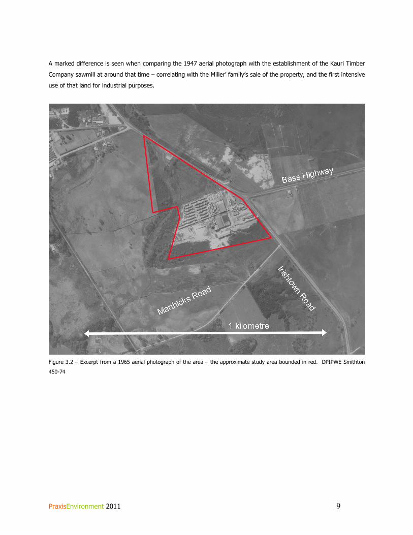
PraxisEnvironment 2011 9
A marked difference is seen when comparing the 1947 aerial photograph with the establishment of the Kauri Timber
Company sawmill at around that time – correlating with the Miller’ family’s sale of the property, and the first intensive
use of that land for industrial purposes.
Figure 3.2 – Excerpt from a 1965 aerial photograph of the area – the approximate study area bounded in red. DPIPWE Smithton
450-74

PraxisEnvironment 2011 10
4. Assessment of historic heritage significance
Given the information outlined above, in order to test the possibility that the site has some form of historic cultural
heritage significance, a standard benchmark for significance is used here. The following statements of significance
are based on the national HERCON standard for statements of significance, based on the amount of information
currently at-hand. Note that natural history values have not been assessed here, as these are beyond the scope of
this assessment.
A. Importance to the course, or pattern of our cultural or natural history.
Section 3 has demonstrated that the areas was not developed until the 1960s, when the Kauri Timber Company
established a sawmill within the study area. It is not considered that the site is of any importance to either state or
local history.
B. Possession of uncommon, rare or endangered aspects of our cultural or natural history.
It is not considered that the place possesses any uncommon, rare or endangered aspects of cultural history.
C. Potential to yield information that will contribute to an understanding of our cultural or natural
history.
Given that the place is unlikely to have been used for any cultural activities other than pastoralism until the 1960s,
and that the area was not settled until the turn of the twentieth century, it is unlikely that the place would yield any
information that would contribute to an understanding of either state or local historical themes.
D. Important in demonstrating the principal characteristics of a class of cultural or natural place.
From the desktop assessment undertaken here, it is not considered that the place demonstrates the principal
characteristics of a type of place which is important to state or local history.
E. Importance in exhibiting particular aesthetic characteristics
The place is not considered to exhibit any important aesthetic characteristics.
F. Importance in demonstrating a high degree of creative or technical achievement at a particular
period.
It is not considered that the place demonstrates any high degree of creative or technical achievement that is
important to the history of the state or local area.
G. Strong or special association with a particular community or cultural group for social, cultural or
spiritual reasons. This includes the significance of a place to Indigenous peoples as part of their
continuing and developing cultural traditions.

PraxisEnvironment 2011 11
The scope of this assessment has not extended to community or social significance, however it is considered unlikely
that the place would have a strong or special association with any particular group or importance to the state or local
area.
An assessment of the significance of the wider place to the Aboriginal community is beyond the scope of this
assessment.
H. Special association with the life or works of a person, or group of persons, of importance in our
history.
The place has no known associations with the life or works of a person or groups of persons of importance to state
or local history.

PraxisEnvironment 2011 12
4. Conclusion and recommendations
Given that this report has been unable to find any evidence that the site would reach even a local threshold for
historic cultural heritage significance, it is concluded that any foreseeable future development of the site not be
required to consider historic cultural heritage values unless any evidence comes to hand which has been outside the
scope of this assessment.