militarily critical technologies list · department of defense militarily critical technologies...
TRANSCRIPT

DEPARTMENT OF DEFENSE
MILITARILY CRITICAL TECHNOLOGIES
LIST SECTION 19: SPACE SYSTEMS TECHNOLOGY
April 2008
Under Secretary of Defense, Acquisition, Technology and Logistics Pentagon, VA

MCTL-19-iii
PREFACE
A. THE MILITARILY CRITICAL TECHNOLOGIES PROGRAM (MCTP)
The MCTP supports the development and promulgation of the congressionally mandated Militarily Critical Technologies List (MCTL) and the Developing Science and Technologies List (DSTL).
Congress assigns the Secretary of Defense the responsibility of providing a list of militarily critical technolo-gies (the MCTL) and of updating this list on an ongoing basis. The MCTL identifies technologies crucial to weapons development and has been a key element in evaluating U.S. and worldwide technological capabilities. The MCTP has provided the support for a wide range of assessments and judgments, along with technical justifications for devising U.S. and multilateral controls on exports. The DSTL, another MCTP product, identifies technologies that may enhance future military capabilities and provides an assessment of worldwide science and technology (S&T) capabilities.
The MCTP process is a continuous analytical and information-gathering process that refines data and updates existing technology lists to provide thorough and complete technical information. It covers the worldwide technology spectrum and provides a systematic, ongoing assessment and analysis of technologies and determines values and parameters for these technologies.
Technology Working Groups (TWGs), which are part of this process, provide a reservoir of technical experts who can assist in time-sensitive and quick-response tasks. TWG chairpersons continuously screen technologies and nominate items to be added or removed from the MCTL and DSTL. TWG members are subject matter experts (SMEs) from the military Services, DoD and other federal agencies, industry, and academia. A balance is maintained between public officials and private-sector representatives. TWGs collect a core of intellectual knowledge and reference information on an array of technologies, and these data are used as a resource for projects and other assignments. Working within an informal structure, TWG members strive to produce precise and objective analyses across dissimilar and often disparate areas. Currently, the TWGs are organized to address 20 technology areas:
Aeronautics Information Systems
Armament and Energetic Materials Lasers, Optics, and Imaging
Biological Processing and Manufacturing
Biomedical Marine Systems
Chemical Materials and Processes
Directed Energy Systems Nuclear Systems
Electronics Positioning, Navigation, and Time
Energy Systems Signature Control
Ground Systems Space Systems
Information Security Weapons Systems
B. THE MILITARILY CRITICAL TECHNOLOGIES LIST (MCTL)
The MCTL provides a coordinated description of existing goods and technologies that DoD assesses would permit significant advances in the development, production, and use of military capabilities by potential adversaries. It includes goods and technologies that enable the development, production, and employment of weapons of mass destruction (WMD) and their means of delivery. It includes discrete parameters for systems; equipment;

MCTL-19-iv
subassemblies; components; and critical materials; unique test, inspection, and production equipment; unique software, development, production, and use know-how; and worldwide technology capability assessments.
C. LEGAL BASIS FOR THE LIST OF MILITARILY CRITICAL TECHNOLOGIES
The Export Administration Act (EAA) of 1979 assigned responsibilities for export controls to protect technologies and weapons systems. It established the requirement for DoD to compile a list of militarily critical technologies. Specifically the EAA stated: “(5)(d)(2) The Secretary of Defense shall bear primary responsibility for developing a list of militarily critical technologies. In developing such list, primary emphasis shall be given to—
(A) arrays of design and manufacturing know-how,
(B) keystone manufacturing, inspection, and test equipment,
(C) goods accompanied by sophisticated operation, application, or maintenance know-how, and
(D) keystone equipment which would reveal or give insight into the design and manufacture of a United States military system, which are not possessed by, or available in fact from sources outside the United States to, controlled countries and which, if exported, would permit a significant advance in a military system of any such country.
(3) The list referred to in paragraph (2) shall be sufficiently specific to guide the determinations of any official exercising export licensing responsibilities under this Act.”
The EAA and its provisions, as amended, were extended by Executive Orders and Presidential directives.
D. USES AND APPLICATIONS
The MCTL is not an export control list. It is DoD’s recommendation for what should be controlled. When goods are identified as being militarily critical, the technology for the development or production is also recommended for control. The document is to be sufficiently specific for evaluating potential technology transfers and has been used for reviewing technical reports and scientific papers for public release. Technical judgment must be used when applying the information. It should be used to determine if the proposed transaction would result in a transfer that would give potential adversaries access to technologies whose specific performance levels are at or above the characteristics identified as militarily critical. It should be used with other information to determine whether a transfer should be approved.
This document, MCTL Section 19: Space Systems Technology supersedes MCTL Section 19, Space Systems Technology, October 2005.
MCTL-19-v
INTRODUCTION
A. ORGANIZATION OF THE MILITARILY CRITICAL TECHNOLOGIES LIST (MCTL)
The MCTL is a documented snapshot in time of the ongoing MCTP militarily critical technology process. It includes text and graphic displays of technical data on individual technology data sheets.
Each section contains subsections devoted to specific technology areas. The section front matter contains the following:
• Scope identifies the technology groups covered in the section. Each group is covered in a separate subsection.
• Highlights identify the key facts in the section.
• Overview discusses the technology groups identified under “Scope.”
• Background provides additional information.
Each technology group identified under Scope has a subsection that contains the following:
• Highlights identify the key facts found in the subsection.
• Overview identifies and discusses technologies listed in data sheets that follow.
• Background provides additional information.
• Data Sheets, which are the heart of the MCTL, present data on individual militarily critical technologies. The principal data element is the Critical Technology Parameter, which is the technology parameter that defines where the technology would permit significant advances in the development, production and use of military capabilities of potential adversaries.
B. TECHNOLOGY DATA SHEETS
The technology data sheets are of primary interest to all users. They contain the detailed parametric information that export control policy makers and licensing officials need to execute their responsibilities.
• Critical Technology Parameter(s) includes the parameter, data argument, value, or level of the technology which would permit significant advances in the development, production and use of military capabilities of potential adversaries.
• Critical Materials are those materials that are unique or enable the capability or function of the technology.
• Unique Test, Production and Inspection Equipment includes that type of equipment that is critical or unique.
• Unique Software is software needed to produce, operate, or maintain this technology that is unique.
• Major Commercial Applications addresses commercial uses of this technology.
• Affordability Issues are those factors that affect the cost of the technology.
• Export Control References indicate international and U.S. control lists where this technology is controlled.
Note: Export control references are:
WA ML 2 (Wassenaar Arrangement Munitions List Item)
WA Cat 1C (Wassenaar Dual Use List Subcategory)

MCTL-19-vi
MTCR 17 (Missile Technology Control Regime Item)
NTL B3 (Nuclear Trigger List Subitem – Nuclear Suppliers Group)
NDUL 1 (Nuclear Dual Use List Item – Nuclear Suppliers Group)
AG List (Australia Group List)
BWC (Biological Weapons Convention)
CWC (Chemical Weapons Convention)
USML XII (United States Munitions List Category – ITAR)
CCL Cat 2B (Commerce Control List Subcategory – EAR) NRC A (Nuclear Regulatory Commission Item)
• Background provides a description of the technology.
MCTL-19-1
SECTION 19—SPACE SYSTEMS TECHNOLOGY
Scope
19.1 Space Avionics and Autonomy ...................... MCTL 19-5
19.2 Electronics and Computer Technologies for Space....................................................... MCTL 19-23
19.3 Space Launch Vehicles ................................ MCTL 19-31
19.4 Space Optics ................................................. MCTL 19-43
19.5 Power and Thermal Management................. MCTL 19-55
19.6 Launch Propulsion for Space Systems ......... MCTL 19-81
19.7 Propulsion for Space Systems .................... MCTL 19-127
19.8 Space Sensor Systems ................................ MCTL 19-137
19.9 Space Survivability..................................... MCTL 19-147
19.10 Space Communication/Connectivity with Ground Controls, User Platforms and Other Customer Systems ..................... MCTL 19-157
19.11 Space-Based Laser Technologies ............... MCTL 19-165
19.12 Space Systems Engineering and Design Tools........................................................... MCTL 19-173
Highlights
• Space systems perform functions that enhance battlefield capability and communications in real-time.
• Space systems include the developments to enable new autonomous functions for both military missions and commercial applications.
• The space environment is uniquely harsh. Space systems must be designed specifically for the shock and vibrations of launch, extreme temperatures, temperature cycling, temperature gradients, radiation exposure, and vacuum conditions, while maintaining high reliability over extended lifetimes.
• The technologies used in space systems are generally based on those used in terrestrial and/or airborne applications but have many additional space-unique requirements and specifications that need to be satisfied.
• The inaccessibility of space and the cost of placing payloads in useful orbit place premiums on technologies for quality assurance, careful material selection, multifunctional structures, reduced mass and volume, reprogrammability, and autonomy.
• The development of microtechnologies and nanotechnologies may significantly impact many aspects of space systems, especially as these technologies contribute to reduced mass and volume and the associated reduction in overall costs.
(Continued)

MCTL-19-2
Highlights (Continued)
• Improving the prediction accuracy of space devices, components, or systems required significantly improved models for gauging the response of electronics, microelectronics, sensors, and other photonic systems in the space environment.
• Laser communications in space and from space may revolutionize the battlefield command and control capabilities as well as future commercial ventures.
• Because of the increasing availability and capabilities of commercial off-the-shelf (COTS) technologies, there is a current and continuing emphasis within the space industry to use COTS products in space and launch vehicle applications in place of unique, custom radiation hardened designs.
OVERVIEW
Militarily Critical Space Technologies included in this section are only those technologies, which are unique to space applications, payloads, platforms, and military space missions, including technologies required for launching assets into space and space surveillance applications. Each space technology listed in this section has specific goals, which include:
• Reducing the cost of access to space and the cost of space assets by innovative engineering and weight reduction techniques;
• Improving technologies which enable space missions and systems applications to function for long time frames and enable ambitious future space missions and systems applications;
• Providing significant technological improvements and higher efficiencies for space superiority; and
• Improving the battlefield command and control with real-time communications.
Technology for space platforms includes not only the technologies related to space sensors, experimental apparatuses, electronics, communications, information handling, and data analysis, but also those technologies necessary for the spacecraft and launch systems (e.g., spacecraft power, launch vehicles, control and structural systems, and propulsion). The space sciences have traditionally used new and modified technologies to enable more ambitious missions. The commercial industries, the National Aeronautics and Space Administration (NASA), and the U.S. military complex have developed many technologies for unique and complex space applications. A quick look at space launch and spacecraft technologies illustrates the range of disciplines and functional areas for which space-unique technologies are required. These include items such as orbital mechanics, launch and transfer propulsion, launch and space vehicles, environmental protection, structures and packaging constraints, stability and control, thermal control, data and voice communications, power generation and distribution, sensors and instrumentation, electronics and computer processors, remote sensors, and ground station interfaces.
In addition to the obvious military applications, space technologies have made possible the current scientific concept of the earth as a complex system. From Apollo photographs of the earth as a blue marble to the recent shuttle-based radar images of rain tracks in the Midwest or ancient drainage structures under Middle Eastern deserts, the space perspective has revolutionized our understanding of atmospheric, oceanic, and land processes. Mankind has measured centimeter-scale distortions of the earth’s crust associated with plate tectonics; detected and monitored the polar ozone holes; begun to understand the dynamics and chemistry of the stratosphere and upper atmosphere; correlated climate variations with the Pacific El Niño and La Niña and with major volcanic eruptions; learned to use satellite radiometry to estimate global atmospheric temperature and moisture profiles; bounded solar variability; measured the components of the earth’s radiation; and used satellite observations to validate greatly improved atmospheric models for prediction of weather and climate.
In recent years, NASA’s emphasis on operations has increased while its pursuit of new technology has narrowed to focus on specific mission needs. The new 2004 NASA space imperative places increased emphasis on the International Space Station, using the moon as a base for interplanetary missions, and enabling human exploration of Mars. Meanwhile, the Department of Defense (DoD) has continued to fund industry, academia, and government laboratories to develop a broad range of space technologies. Consequently, DoD has become the

MCTL-19-3
primary agent of technological advancement, and industry and academia have become the primary U.S. developers of new space technologies. Many space-based sensors used today were developed through the collaborative efforts of industry/university/national laboratories and are based on DoD technologies.
Many space technologies are unique because of specifications and the specific technical parameters required for a given space application and because they have been developed to withstand the conditions and parameters of the highly ionized space environment. For a system to get to space, it first must endure the shock, vibrations, and forces of launch. Once in space, it is often subjected to rapid and continuous cycling between the extremes of heat and cold, to high internal temperature gradients, and to constant high energy radiation and particle bombardment—especially that of atomic oxygen. Space assets are generally inaccessible for upgrade or maintenance and, thus, must be capable of operating reliably for their design life.
The inaccessibility of space and the cost of placing payloads into useful orbit dictate several additional considerations for space technologies. Miniaturization reduces the size and weight of the payload that must be boosted into orbit and reduces system power-consumption and heat-management requirements. Therefore, the motivation to reduce the size and power requirements of space assets is strong and has initiated many new microtechnologies and nanotechnologies specifically developed for space applications.
Quality assurance programs can test systems in the laboratory, and simulations can be used to improve the likelihood that the systems will perform properly after being placed in space. However, laboratory quality assurance testing must be conducted with caution since simulations of physical parameter effects must be performed in a concurrent fashion. For example, researchers now know that radiation exposure and atomic oxygen exposure are about 10 times more damaging (corrosively) when an item is exposed to them concurrently than when the same item is exposed to them separately. Materials must also be carefully selected to minimize out-gassing in space or to mitigate its impacts. All these “assurances” must be observed during the development of space technologies to ensure reliability. In addition, the development of reprogrammability and autonomy, which can provide self-governing or allow commanding from ground controllers, will allow space systems to be adapted to new or changing requirements.
Space sensors are required for many military and commercial missions including weather surveillance, monitoring crops, target surveillance and battlefield management to name a few. In recent years, space surveillance has become a major commercial venture with many companies participating. The military has also stepped up its use of space surveillance to spot targets of opportunity and along with GPS improve the guidance of missile systems and precision munitions.
Space launch and space propulsion technologies have also improved significantly over the past few years with higher specific impulse (Isp) and improved thrust for both launch and inter-orbit activities. There are now many countries involved with developing improved space launch vehicles and propulsion mechanisms that will be outlined in this section.
A new arena has unfolded in both space and terrestrial applications using micro and especially nano-technologies. By using structures at the nanoscale, it is possible to greatly expand the range of performance of existing chemicals and materials. Scientists can already foresee using patterned monolayers for a new generation of chemical and biological sensors; nanoscale switching devices to improve computer storage capacity by a factor of a million; tiny medical probes that will not damage tissues; entirely new drug and gene delivery systems; nanostructured ceramics, polymers, metals, and other materials with greatly improved mechanical properties; nanoparticle reinforced polymers in lighter cars; and nanostructured silicates and polymers as better contaminant scavengers for cleaner designs and fabrication of complex nanoscale assemblies. Most of these technologies will first be developed for terrestrial applications and then modified for space systems.
All of these technologies including the micro and nano-technology lead to significant reduction of mass for space applications, and some predict that nanotechnology will lead the way for the 21st century space applications. The broad scope of developing new and improved space technologies must include the National Nanotechnology Initiative (NNI) announced by the President in February 2000. A September 1999 report by the administration’s National Science and Technology Council (NSTC) and the Interagency Working Group (IWG) on Nanoscience, Engineering and Technology, summarizes the prospects for nanoscale science and engineering (NS&E).

MCTL-19-4
Microtechnologies and nanotechnologies will not only provide size, weight, power, and thermal management benefits, but they also promise far greater functionality and higher operating speeds. Microelectro-mechanical systems (MEMS) and micro-optoelectro-mechanical systems (MOEMS) are experiencing tremendous growth. These technologies use optics, electronics, and mechanics in miniaturized space applications. According to a National Academy of Engineering (NAE) symposium report, MEMS and MOEMS technologies have opened many new opportunities for optics, electronics, and micropositioning equipment, especially as these pertain to space applications. For the first time, reliable microactuators and three-dimensional (3-D) optomechanical structures can be monolithically integrated with microoptical elements. MEMS and MOEMS technologies have also made possible, the integration of an entire optical table onto a single silicon chip. This capability translates to smaller, lighter, and more cost-effective space payload launches and will impact many space applications, including posi-tioning, scanning, and telecommunications.
For many radiation-intensive applications, such as deep space, strategic environments, and mid-earth orbits (MEO), the electronics have traditionally been produced using silicon foundry processes and Very Large Scale Integration (VLSI) design techniques that were specifically designed for non-standard (i.e., “non-COTS”) radiation hardened components. As Moore’s law continues to hold, and computer power per unit size continues to shrink, foundries dedicated to terrestrial applications and COTS continue to improve. The influence of COTS technologies on space systems is significant. Radiation hardened technologies are no longer limited to device and component level, and specific radiation-hardened components may not be needed. Rather, technologies such as shielding and hardening at the case level may enable reliable and long-lived operation of COTS products in space. Other techniques, such as incorporating redundant COTS units, using improved error detecting and correcting software, and relying on the radiation protection inherent in smaller feature sizes and improved designs of newer COTS technologies, can also be used. Use of photonics devices for intra- and inter-component communications would enhance electrical isolation and mitigate impacts of individual faults, while enabling higher speed interconnects. Clearly, however, a combination of technologies in an overall systems design will allow increased use of COTS components and subsystems in space system today and into the future.
In summary, each space technology development program or strategic plan—whether at NASA, DoD, or commercial firms—has specific goals. The common goals of all members of the space technology community include the four items mentioned in the first paragraph of this section as well as:
• Building capability in the U.S. space military/industry complex through collaborative and focused space technology development efforts.
• Sharing the results of space technology R&D with the rest of the U.S. space community.
MCTL-19-5
SECTION 19.1—SPACE AVIONICS AND AUTONOMY
Highlights
• Major advances in timing: Next-generation, space-qualified clocks will be several orders of magnitude more stable < 1 × 10–15 per day).
• Absolute positioning of a space vehicle/platform to < 10 m accuracy is now achievable with relative position control to < 1 m.
• Contingency operations can be enacted in < 0.1 second with new space-qualified processors, which can detect an anomaly, determine when it can be corrected to either restore capability or eliminate the chance of domino effects.
• New processors and algorithms enable autonomous operation of “clusters” of microsatellites or nanosatellites to < 1 mm in all three dimensions.
• Higher satellite acceleration sensitivity, < 0.001 g’s, is now achievable.
• It now takes < 2 seconds reaction time to decompose a set of high-level objectives, incorporate locally determined information, and create an execution plan autonomously.
• One can now demonstrate a “weapon safing” class of response in < 0.01 second.
• Absolute orbital position or ephemeris calculation on-board at Low-Earth Orbit (LEO) to < 5 m.
• MEMS technology will significantly improve existing functions to be performed in smaller sized packages and will replace and enable entirely new categories of functions.
• Space autonomy has significantly improved allowing spacecraft to fly in formation or to operate/maneuver around a space object.
• Determination of position and attitude relative to another space object to < 3 m when within 200-m range is now possible.
OVERVIEW
Technologies identified in this section support navigation, attitude control, orbit determination, space vehicle dynamics, autonomy and other similar avionics functions unique to space systems. To perform their functions properly, space vehicles must navigate through space; orient their sensors, antennas, solar panels, and other systems properly; monitor and control their dynamics; and determine their orbits and necessary corrections. For the most part, technologies to support these avionics functions in space systems are similar to those used in aircraft avionics. The space environment often requires that technologies be modified significantly from their airborne or terrestrial counterparts. One example is space-qualified atomic frequency standards (AFSs) or “clocks.” While the basic reference atomic element and the quartz oscillator may be very similar to their terrestrial counterparts, the electronics control package and elements of the physics package for operation in zero gravity and stabilizing the internal environment are entirely different. The high radiation environment and very high velocities also require unique solutions to similar problems on aircraft.
BACKGROUND
The DoD and NASA have utilized space for many applications. These range from space surveillance of adversaries moves and locations, to space communications and navigation, or to the understanding of weather patterns and movements. Many commercial space ventures have also developed over the past 30 years. Space has
MCTL-19-6
become a required arm of the new battlefield for modern warfare. As such, some space technologies have become militarily critical for various aspects of war fighting and battlefield management.
The space environment provides unique technology requirements as well as opportunities, which in some cases are significantly different from their terrestrial complements. For example, precisely determining inertial attitude in space by means of “star trackers,” or gyro-astro trackers is possible because these trackers do not have to contend with distortion caused by the earth’s atmosphere. However, they have to constantly correct for orbit fluctuations and other space unique attributes. Only those avionics and autonomy technologies that have unique space aspects or unique technical differences in the critical parameter set for space applications are included in this section. See MCTL Section 16, Positioning, Navigation, and Time, for additional and complementary airborne and terrestrial technologies in these disciplines.

MCTL-19-7
LIST OF MCTL TECHNOLOGY DATA SHEETS 19.1. SPACE AVIONICS AND AUTONOMY
19.1-1 Space-Qualified Clocks ............................................................................................................. MCTL-19-9
19.1-2 Global Positioning System–Differential GPS (GPS-DGPS) Use in Space ............................. MCTL-19-10
19.1-3 Space Cluster Navigation Control Software............................................................................ MCTL-19-11
19.1-4 Fault Detection, Isolation, and Recovery (FDIR) and Telemetry Tracking and Controls (TT&C) .............................................................................................................. MCTL-19-12
19.1-5 Solid-State Micro-Electro-Mechanical Systems (MEMS) Navigation Instrumentation.......... MCTL-19-14
19.1-6 Advanced Command and Control and Proximity/Rendezvous Planning ................................ MCTL-19-15
19.1-7 Proximity and Formation Flying.............................................................................................. MCTL-19-17
19.1-8 On-orbit Servicing (in Space Docking and Fluid Transfer) .................................................... MCTL-19-18
19.1-9 Relative Attitude Determination.............................................................................................. MCTL-19-20
19.1-10 Absolute Position/Orbit Determination ................................................................................... MCTL-19-21

MCTL-19-9
MCTL DATA SHEET 19.1-1. SPACE-QUALIFIED CLOCKS
Discusses atomic frequency standards (AFS, commonly called “clocks”) for use in on-orbit space systems.
Critical Technology Parameter(s)
1. > 15-year service life in a space environment.
2. > 12-year life on-orbit, in dormant state (ability to turn on and stabilize rapidly on command during the 12-year dormant time frame).
3. < 1 × 10–15 per day—long-term stability.
Critical Materials High-quality quartz crystals; oscillator package; physics packages including rubidium cells; cesium tubes.
Unique Test, Production, Inspection Equipment
Fabrication techniques to achieve precise shape in critical physics package components; hand machining/tuning of many components; hand assembly and testing of each clock.
Testing requirements are nontrivial.
Unique Software Control algorithms require a deep, detailed understanding of all aspects of the performance of the clock physics package.
Major Commercial Applications
Communications satellites, positioning and timing services that may compete with GPS (such as EU’s Galileo system); other space systems requiring precise on-board time information.
Small overall commercial demand. Some commercial satellite providers may incorporate clocks in some future satellites.
Affordability Issues Current-generation rubidium and cesium clocks are $250K–400K each. Newer technologies will require additional development costs, and early models will likely cost more for increased capability. If hand machining and tuning can be eliminated in new technology clocks, unit costs should decrease.
Export Control References
WA Cat 3A; CCL Cat 3A.
BACKGROUND
The United States maintains a lead in terrestrial atomic frequency standard (AFS) capability and, up through the rubidium and cesium AFSs used in the most recently acquired GPS satellite generations (Block IIR and initial Block IIF), had maintained a lead for space-qualified AFS capability. Current reliance on U.S. industrial R&D and commercial developments, however, has diminished this lead. Space-qualified AFS constitutes less than 3 percent of the total AFS commercial market, which is small. Government sponsorship of R&D and continued production may be required to maintain a lead in this technology.
New physics packages include new technology initiatives: ion traps and optically pumped units, reduced size/weight hydrogen maser, and next-generation cesium and rubidium technologies.
MCTL-19-10
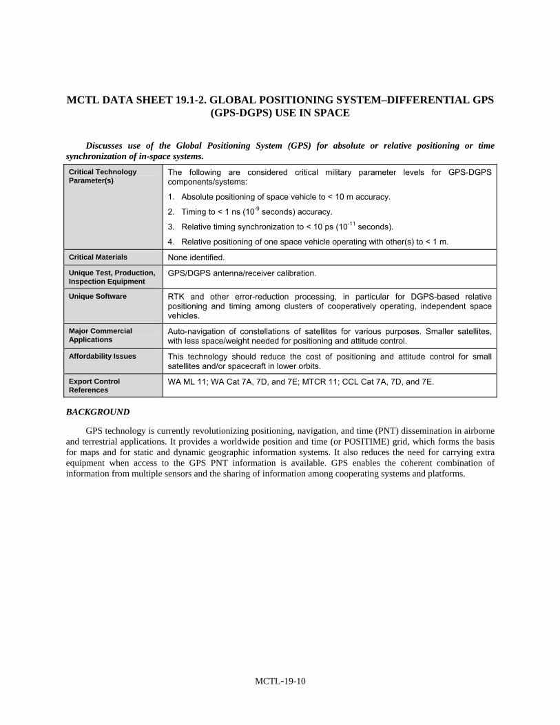
MCTL DATA SHEET 19.1-2. GLOBAL POSITIONING SYSTEM–DIFFERENTIAL GPS (GPS-DGPS) USE IN SPACE
Discusses use of the Global Positioning System (GPS) for absolute or relative positioning or time synchronization of in-space systems.
Critical Technology Parameter(s)
The following are considered critical military parameter levels for GPS-DGPS components/systems:
1. Absolute positioning of space vehicle to < 10 m accuracy.
2. Timing to < 1 ns (10-9 seconds) accuracy.
3. Relative timing synchronization to < 10 ps (10-11 seconds).
4. Relative positioning of one space vehicle operating with other(s) to < 1 m.
Critical Materials None identified.
Unique Test, Production, Inspection Equipment
GPS/DGPS antenna/receiver calibration.
Unique Software RTK and other error-reduction processing, in particular for DGPS-based relative positioning and timing among clusters of cooperatively operating, independent space vehicles.
Major Commercial Applications
Auto-navigation of constellations of satellites for various purposes. Smaller satellites, with less space/weight needed for positioning and attitude control.
Affordability Issues This technology should reduce the cost of positioning and attitude control for small satellites and/or spacecraft in lower orbits.
Export Control References
WA ML 11; WA Cat 7A, 7D, and 7E; MTCR 11; CCL Cat 7A, 7D, and 7E.
BACKGROUND
GPS technology is currently revolutionizing positioning, navigation, and time (PNT) dissemination in airborne and terrestrial applications. It provides a worldwide position and time (or POSITIME) grid, which forms the basis for maps and for static and dynamic geographic information systems. It also reduces the need for carrying extra equipment when access to the GPS PNT information is available. GPS enables the coherent combination of information from multiple sensors and the sharing of information among cooperating systems and platforms.

MCTL-19-11
MCTL DATA SHEET 19.1-3. SPACE CLUSTER NAVIGATION CONTROL SOFTWARE
Discusses software needed to self-organize, navigate, and manage clusters of systems operating together in space.
Critical Technology Parameter(s)
1. Relative Position Control to < 1 cm in all three dimensions.
2. Temporal synchronization < 10 ps (10-11 seconds).
Critical Materials None identified.
Unique Test, Production, Inspection Equipment
None identified.
Unique Software Self-managing, self-healing network software.
Major Commercial Applications
Auto-navigation of clusters of satellites for various purposes.
Affordability Issues This technology should reduce the cost of space systems (e.g., large aperture sensors) that would normally require extremely large space vehicles.
Export Control References
WA ML 21; WA Cat 7D; MTCR 11; CCL Cat 7D.
BACKGROUND
Position, navigation, and time (PNT) information from the Global Positioning System (GPS) can be used on space vehicles for functions including navigation and relative position control, among other applications. Applying with these software concepts, such as those used in self-forming and self-healing terrestrial networks and for controlling massively parallel systems, would enable precise control of clusters of small satellites operating cooperatively on orbit. Such clusters would perform in-space functions not currently available due limited size of single-satellite systems, or would perform existing functions more efficiently with clusters of smaller satellites.

MCTL-19-12
MCTL DATA SHEET 19.1-4. FAULT DETECTION, ISOLATION, AND RECOVERY (FDIR) AND TELEMETRY TRACKING AND CONTROLS (TT&C)
Discusses fault detection, isolation, and recovery (FDIR) software, specific to telemetry tracking and control (TT&C), to support autonomous operations of space systems.
Critical Technology Parameter(s)
1. < 0.01 seconds “Weapons Safing” (response time to detect an anomaly and terminate an operation).
2. < 0.05 seconds: reinstate a parameter via fault detection and corrective action.
3. Ability to locate the source and attribute a cause for an anomaly in < 10 seconds and to a location accuracy of < 10 km.
4. Detect a spacecraft or environment anomaly in < 0.1 seconds and enact a contingency.
Critical Materials None identified.
Unique Test, Production, Inspection Equipment
Space flight qualified reprogrammable FPGAs with greater than 3 million bits, > 5 krad radiation tolerance, and Single Event Upset (SEU) recoverable (through hardening, scrubbing, or redundancy).
Unique Software Software to determine and define the autonomous parameters, based on current research in satellite anomaly resolution, with special emphasis on model-based reasoning technologies.
Major Commercial Applications
Reduced ground control infrastructure for commercial satellites; assistance in restoring functionality after space system failures. There is value to keep things operating and avoiding additional damage, but time scales for the need are longer. Commercial applications generally will only need the ability to recover to detect and change to a safe mode in a matter of 15 minutes. If possible, commercial applications will require anomalies to be corrected within hours. However, civil spacecraft such as NASA research vehicles, will require faster fault responses to safe their vehicles autonomously due to long periods between ground communication (e.g., for inter-planetary missions).
Affordability Issues This technology should reduce the cost of ground infrastructure.
Export Control References
WA ML 21; WA Cat 7D; MTCR 11; CCL Cat 7D.
BACKGROUND
Satellite control by manual methods is expensive, error prone, and performance limiting. Currently, raw data are telemetered on a defined schedule to ground control stations, where human operators manually analyze these data to determine satellite health, status, and position. These operators then execute commands to maintain and control the satellite. Because most satellite maintenance and payload functions can now be automated, the manual mode of operation wastes communications bandwidth (since large amounts of data are unnecessarily sent to ground stations), minimizes vehicle survivability and safety (since an anomaly will not be discovered until its telemetry is delivered as scheduled), and wastes manpower resources (since human analysis of telemetry data is constantly required even though anomalies rarely occur). An evolutionary architecture and component set for automating satellite operations migrates functionality from ground centers to space processors for implementing on-board autonomy while minimizing risk to the spacecraft. Hybridization of sensor data at the satellite level reduces the latency problems associated with manual methods. In effect, this changes the TT&C function from a process of continuous observation and control by human operators to one in which human operation is required only when exceptions occur.

MCTL-19-13
This technology area provides the components and architecture for autonomous satellite health and status analysis and FDIR. With this technology, autonomous satellite operations become the norm and reduce the need for labor-intensive, human-directed satellite control functions.
MCTL-19-14
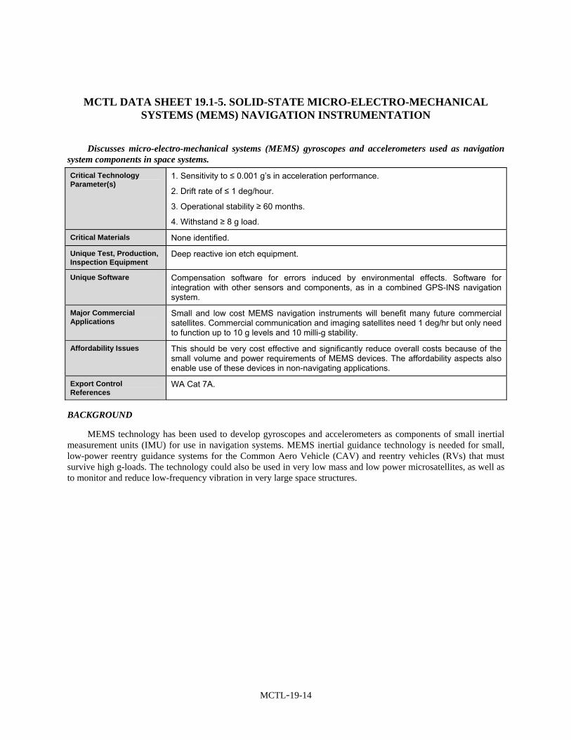
MCTL DATA SHEET 19.1-5. SOLID-STATE MICRO-ELECTRO-MECHANICAL SYSTEMS (MEMS) NAVIGATION INSTRUMENTATION
Discusses micro-electro-mechanical systems (MEMS) gyroscopes and accelerometers used as navigation system components in space systems.
Critical Technology Parameter(s)
1. Sensitivity to ≤ 0.001 g’s in acceleration performance.
2. Drift rate of ≤ 1 deg/hour.
3. Operational stability ≥ 60 months.
4. Withstand ≥ 8 g load.
Critical Materials None identified.
Unique Test, Production, Inspection Equipment
Deep reactive ion etch equipment.
Unique Software Compensation software for errors induced by environmental effects. Software for integration with other sensors and components, as in a combined GPS-INS navigation system.
Major Commercial Applications
Small and low cost MEMS navigation instruments will benefit many future commercial satellites. Commercial communication and imaging satellites need 1 deg/hr but only need to function up to 10 g levels and 10 milli-g stability.
Affordability Issues This should be very cost effective and significantly reduce overall costs because of the small volume and power requirements of MEMS devices. The affordability aspects also enable use of these devices in non-navigating applications.
Export Control References
WA Cat 7A.
BACKGROUND
MEMS technology has been used to develop gyroscopes and accelerometers as components of small inertial measurement units (IMU) for use in navigation systems. MEMS inertial guidance technology is needed for small, low-power reentry guidance systems for the Common Aero Vehicle (CAV) and reentry vehicles (RVs) that must survive high g-loads. The technology could also be used in very low mass and low power microsatellites, as well as to monitor and reduce low-frequency vibration in very large space structures.

MCTL-19-15
MCTL DATA SHEET 19.1-6. ADVANCED COMMAND AND CONTROL AND PROXIMITY/RENDEZVOUS PLANNING
Discusses command and control technology related to spacecraft flying in close proximity to or rendezvousing with other spacecraft.
Critical Technology Parameter(s)
1. < 2 seconds reaction time to decompose a set of high-level objectives, incorporate locally determined information, and create an execution plan.
2. Calculate and propagate forward desired orbital position > 1 hour in advance.
3. Execute high level complicated tasking with < 2 ground contacts per day.
4. Continuous operations in proximity to a space object with < 5 m relative position error.
5. On-board calculation of trajectories and propulsive maneuvers exceeding 10 m/s or exceeding 2 maneuvers per orbit.
Critical Materials None identified.
Unique Test, Production, Inspection Equipment
None identified.
Unique Software The command and control of spacecraft can be implemented from ground control segments with both currently available commercial packages (EPOCH, SCS21, SCL OS/COMET), or with company proprietary, spacecraft specific, or specialized military C2 software.
Improvements over such systems would include software algorithms that predict spacecraft performance in close proximity to other objects, that examine quickly the capability to maneuver a spacecraft among other on-orbit objects (Resident Space Objects or RSOs), that model national asset capabilities, and that account for spacecraft resource utilization against on-orbit position constraints in inertial space, or in RSO proximity.
Major Commercial Applications
Commercial applications employ automated systems to reduce needs for interactive commanding, to simplify determination of commanding actions, and to reduce numbers of people needed in ground control segments. As complexities increase in commercial applications (e.g., larger satellite constellations, mixed generations of satellites, etc.) or costly problems are experienced, commercial satellite providers may opt for more sophisticated processing capabilities.
This software would also be very useful for long-term civil space missions (Pluto, comets, etc.) which often involve international partners.
Affordability Issues Because of the potential to greatly reduce the ground staffing required to operate spacecraft, the potential to reduce mission operational costs is large. One or two operators will be able to control multiple complex spacecraft.
Export Control References
WA Cat 7A and 7D.
BACKGROUND
Coordinated commanding of spacecraft by other spacecraft allows for on-orbit system-like redundancy in certain operating scenarios (downlink windows, reduced sensor gathering capabilities, etc.). For some systems, close coordination is required for mission success, such as multiple spacecraft interferometry missions. Because of the demand within the civil space community to employ these techniques for space and earth imaging, which increasingly involves international partnerships, protection of this technology presents challenges.

MCTL-19-16
This technology supports and automates complex satellite control and command functions, addresses complicated problems with multiple objectives, manages competition for resources and dynamic operational environments, and simultaneously optimizes the allocation and scheduling of space-based resources. The approach includes algorithms and software for streamlined connectivity such as satellite IP node interfaces, centralized and distributed control techniques. Examples include a single satellite commanding a cluster, real-time distributed sensing and response among satellites in a cluster, (e.g., one satellite sensing the actions of another and responding), and queuing appropriate responses and actions in other systems accordingly.

MCTL-19-17
MCTL DATA SHEET 19.1-7. PROXIMITY AND FORMATION FLYING
Discusses technologies needed for formation flying of satellites, and for flying satellites in close proximity to other satellites.
Critical Technology Parameter(s)
1. Separation distance between spacecraft: < 200 m.
2. Accuracy of relative navigation, guidance, and control < 3 m when within 200 m.
3. Location accuracy for all spacecraft: < 20-cm absolute range measurement (assumes range not obtained from cooperation and communication with object).
4. Location accuracy for all spacecraft: < 2-mm absolute cooperative range determination (assumes range is between cooperative and communicating spacecraft).
Critical Materials Lasers with high-frequency stability.
Unique Test, Production, Inspection Equipment
None identified.
Unique Software Algorithms and software for determining of the relative position and attitude of the target vehicle and for the planning and control of proximity operations.
Major Commercial Applications
There is some commercial opportunity for satellite servicing and inspection that would use this. Accuracy levels only need to be as good as 3 meters, unless docking; most commercial applications will be cooperative or aided in their operations.
Affordability Issues This technology should lower overall operational costs by reducing the need for ground control personnel and should enable repair of on-orbit assets.
Export Control References
WA Cat 7A and 7D.
BACKGROUND
Flying one satellite in close relative proximity to another satellite or flying so as to maintain a desired separation or range of separations from other satellite(s) is an enabling capability for inspection and repair of on-orbit assets. This technology includes the ability to plan and execute relative trajectories, methods to determine relative range and bearing without aid from the object. It also includes methods to effectively and efficiently control the relative position and orientation of satellites. Algorithms for fail-safe maneuvers and planned reaction to faults are also a part of this technology.
Specific metrics used in this technology include:
1. How close one can safely operate.
2. Accuracy of position information.
3. Responsiveness to events.
4. Degree of cooperation of the other object.
5. Potential damage to the other object from sensors.

MCTL-19-18
MCTL DATA SHEET 19.1-8. ON-ORBIT SERVICING (IN SPACE DOCKING AND FLUID TRANSFER)
Discusses technologies related to in-space servicing of satellites, including the ability to transfer fluids into existing on-orbit satellites.
Critical Technology Parameter(s)
• The ability to dock/grapple a satellite not designed for servicing.
• The ability to transfer fuel (bi-propellant, mono-propellant, and pressurant) across satellites.
• The ability to transfer cryogenic fluid and/or space-based “Laser” reactants. • Replacement or upgrade of satellite components.
• Accuracy of attitude/position knowledge between satellites as follows: Operating
Range (m)
Range
(mm)
Azimuth Elevation (Radians) {Degrees}
Roll
(Radians) {Degrees}
Pitch/Yaw
(Radians) {Degrees}
1–3 ± 12 ± 0.00058 {± 0.033}
± 0.00227 {± 0.13}
± 0.00349 {± 0.2}
> 3–5 ± 35 ± 0.00058 {± 0.033}
± 0.00436 {± 0.25}
± 0.00576 {± 0.33}
> 5–10 ± 150 ± 0.00061 {± 0.035}
± 0.00785 {± 0.45}
± 0.01222 {± 0.7}
> 10–30 ± 1500 ± 0.00065 {± 0.037}
± 0.02269 {± 1.3}
± 0.0349 {± 2}
> 30–50 ± 400 ± 0.00052 {± 0.03}
± 0.00436 {± 0.25}
± 0.02094 {± 1.2}
> 50–100 ± 1666 ± 0.00058 {± 0.033}
± 0.00873 {± 0.5}
± 0.04189 {± 2.4}
> 100–300 ± 15,000 ± 0.00061 {± 0.035}
± 0.02443 {± 1.4}
± 0.12217 {± 7.0}
Critical Materials None identified.
Unique Test, Production, Inspection Equipment
None identified.
Unique Software Sensor Processing—Process sensor data to determine the relative range, azimuth, roll, pitch, and yaw of the target vehicle.
Autonomous Navigation—Ability to integrate inertial and other sensor data to determine relative position, velocity, and attitude rates of the target vehicle.
Autonomous Guidance—Algorithms to maneuver a spacecraft inside a cone while traversing an approach or separation vector with velocity limits relative to the targets body coordinates. Algorithms to allow a spacecraft to station-keeping relative to the targets body coordinates.
Major Commercial Applications
Routine automated on-orbit satellite servicing; refueling and selected bus/payload equipment upgrades can extend the useful lifetime of satellites and reduce life cycle costs. Docking is a critical requirement for servicing or refueling operations.
Affordability Issues On-orbit satellite servicing has been studied and shown to reduce the life-cycle costs of both military and commercial space programs.
Export Control References
WA Cat 7A and 7D.

MCTL-19-19
BACKGROUND
On-orbit space assets are expensive. The ability to dock with them will enable options to upgrade components, repair failed components, or transfer fuel. Thus, this technology supports extending the life of such assets.

MCTL-19-20
MCTL DATA SHEET 19.1-9. RELATIVE ATTITUDE DETERMINATION
Discusses the ability to determine the relative position, velocity, attitude, and attitude rates between two spacecraft to support docking, proximity, and formation flying operations.
Critical Technology Parameter(s)
1. Accuracy of relative attitude determination: ≤ 2°.
2. Speed of determination: ≤ 5 minutes.
3. Distance away that relative attitude determination can be made: > 20 meters.
Critical Materials None identified.
Unique Test, Production, Inspection Equipment
None identified.
Unique Software Sensor Processing—Process sensor data to determine the relative range, azimuth, roll, pitch, and yaw of the target vehicle.
Autonomous Navigation—Use the inertial navigation data and sensor data to determine relative position, velocity, and attitude rates of the target vehicle.
Major Commercial Applications
Commercial uses are very limited but some servicing applications and formation flying applications could use determination down to 1 degree, determination with aids in 5 minutes, determination without aids in several hours, and from a distance of zero to 50 meters. This is one of the major technologies required to service commercial spacecraft autonomously. Servicing includes the transfer of propellant or the replacement/upgrade of critical components such as processors or batteries. This technology is also required to autonomously rendezvous and service the International Space Station.
Affordability Issues None identified.
Export Control References
WA Cat 7A and 7D.
BACKGROUND
The ability to determine the relative position, velocity, attitude and attitude rates between two spacecraft is required to perform autonomous rendezvous, proximity operations, and capture. This capability enables such operations as autonomous servicing or close up inspection of on-orbit assets. The capability for on-orbit autonomous rendezvous, proximity operations, and docking requires several technologies, including the ability to accurately determine the relative attitude of the target spacecraft.

MCTL-19-21
MCTL DATA SHEET 19.1-10. ABSOLUTE POSITION/ORBIT DETERMINATION
Discusses technologies needed to determine the absolute position and orbit parameters of spacecraft in various orbits.
Critical Technology Parameter(s)
1. < 5 m LEO determination within 10 minutes.
2. < 50 m uncertainty in predicted position for LEO orbits, during any 6-hour period.
3. < 150 m uncertainty in real-time position determination for GEO or HEO (e.g., above GPS orbits).
Critical Materials None identified.
Unique Test, Production, Inspection Equipment
Testing must be performed with high-fidelity RF signal simulators with receivers in the loop and realistic modeling of the ionosphere, multipath, and the orbital environment.
Unique Software Multi-source estimation algorithms (which include orbit dynamic models/propagators with high-fidelity models of all relevant disturbances—solar, ionospheric, atmospheric, high-order gravity, etc.) to combine GPS with other sensor outputs and tracking data. Integrated tracking loops with advanced filtering algorithms to enable weak signal tracking.
Major Commercial Applications
Commercial remote sensing spacecraft. All spacecraft, which require geopositioning of image on Earth. Accuracy for commercial applications < 100 m and predictions within 1 km over 24-hour period.
Wide commercial demand.
Affordability Issues High-end DoD GPS grade receivers are $250 K and above, but a flurry of highly capable receivers are entering the market in the $10-K–$25-K regime. Weak signal tracking capabilities for higher altitude and high Doppler applications will drive up cost.
Export Control References
WA Cat 7A and 7D.
BACKGROUND
The ability to estimate position, accurately and in real-time, is essential for many satellite operations. This is particularly true for earth observing satellites, especially if data from multiple sensors on multiple platforms are to be integrated into a common operational picture. For some satellites systems, such as military GPS or similar civil position (or time) dissemination systems (including GEOs augmenting GPS, such as in the Federal Aviation Administration’s Wide Area Augmentation System, or WAAS), precise knowledge of satellite position is essential to system accuracy. Finally, for docking, rendezvous, or simply situational awareness, accurate knowledge of each space asset’s current and predicted position is very important.

MCTL-19-23
SECTION 19.2—ELECTRONICS AND COMPUTER TECHNOLOGIES FOR SPACE
Highlights
• Radiation hardened data processing microelectronics and photonics are required for the manufacture of survivable space and missile systems.
• Commercial Off-The-Shelf (COTS) technologies may be used to build flyable space and launch systems.
• Processing and radiation performance are critical criteria of electronics components and flight computers comprised of those components.
• Critical parameters are fault coverage, overhead processing load, and latency.
• Photonics technologies provide high-speed interconnects between electronic processors and on-board communications for space systems.
• Critical parameters for photonics interconnect technologies include inherent radiation tolerance and data rate over short distances (< 1 km).
OVERVIEW
This section covers electronics and computing technologies for space systems. Because of the high costs and difficulties of getting payloads into space, critical electronics systems, subsystems, and components must be as small and light, and thermally efficient, as possible. Because of the inaccessibility of space systems once in orbit, and to survive the forces of launch and orbit insertion, these technologies must produce systems that are extremely rugged and reliable. This section includes datasheets on the following technologies:
• Space Flight Computer and Component Technologies include radiation hardened electronics, microelectronics and very large scale integrated circuits (VLSI), and flight computers and components. These technologies are combined in one datasheet because of the influence of commercial off-the-shelf (COTS) technologies.
• Fault Tolerant Computing Technologies include use of protective redundancy to enhance dependability, automated capability to detect and correct hardware and software faults, and capabilities to recover from such faults and continue mission performance. Fault tolerance technologies may be implemented in hardware, software, or firmware, which may be upgradeable over the mission duration.
• Photonics Technologies include semiconductor lasers, photodiodes, and related optical components, similar to those used in consumer digital video disc (DVD) players, to provide interconnects within and between electronic processors and other on-board systems in space.
Because of the increasing availability and capabilities of COTS technologies, there is a current and continuing emphasis within the space industry to use COTS products in space and launch vehicle applications in place of unique, custom radiation hardened designs.
BACKGROUND
Space systems perform functions and use technologies in a manner similar to terrestrial and airborne systems. However, because of the difficulty of getting to space and the harshness of the overall space environment, space systems must be specifically designed for stringent criteria, which include:
• extreme levels of acceleration, vibration, shock, and other forces of launch;
• rapid and continuous cycling from extreme heat to extreme cold, and often extreme internal temperature gradients between “hot” solar facing and “cool” sides;

MCTL-19-24
• high levels of electron, proton, ion, and atom (such as atomic oxygen), and X-ray, gamma ray, and neutron radiation in a nuclear-engendered environment; and
• high reliability—long life, redundancy of critical elements, and generally the inability to service them once in operation.
During the launch operation, the space system is a payload in the launch vehicle. It will generally be dormant or in state of suspended operations. On reaching space, the system must be capable of being activated and performing its mission as designed.
To survive and operate within the radiation environment of space, electronics and computers at the system and component level must be designed to survive and operate over the planned lifetime. For many radiation-intensive applications, such as deep space, strategic environments, and mid-earth orbits (MEO), the electronics have traditionally been produced using silicon foundry processes and VLSI design techniques that were specifically designed for non-standard (i.e., “non-COTS”) radiation hardened components. Those components and foundries generally had no terrestrial application, and as a result, they were costly to obtain and maintain. In general, they lagged several generations behind terrestrial technology in feature size and other capabilities, often because the foundries themselves were fully depreciated terrestrial assets superseded by newer technology. They were then converted and dedicated to radiation hardened technologies.
As Moore’s law continues to hold, and computer power per unit size continues to shrink, foundries dedicated to terrestrial applications and COTS continue to improve. COTS technology is thus continually miniaturized. Miniaturization, due to mostly these smaller feature sizes in electronics but also to software improvements, allows current functions to be accomplished in smaller components and enables development of new functions within existing size and power constraints. Miniaturization thus has an increasing benefit for space systems; smaller size (and corresponding reductions in weight and power) enables less expensive space systems or space systems with greater functionality for a given size. Using new software to enable reprogramming from the ground while on orbit, operators might adapt these smaller, more capable systems in the future for new or changed functions.
The influence of COTS technologies on space systems is significant. Radiation hardened technologies are no longer limited to device and component level, and specific radiation-hardened components may not be needed. Rather, technologies such as shielding and hardening at the case level may enable reliable and long-lived operation of COTS products in space. Other techniques, such as incorporating redundant COTS units, using improved error detecting and correcting software, and relying on the radiation protection inherent in smaller feature sizes and improved designs of newer COTS technologies, can also be used. Use of photonics devices for intra- and inter-component communications would enhance electrical isolation and mitigate impacts of individual faults, while enabling higher speed interconnects. Clearly, however, a combination of technologies in an overall systems design will allow increased use of COTS components and subsystems in space system today and into the future.

MCTL-19-25
LIST OF MCTL TECHNOLOGY DATA SHEETS 19.2. ELECTRONICS AND COMPUTER TECHNOLOGIES FOR SPACE
19.2-1 Flight Computers and Component Technologies .................................................................... MCTL-19-27
19.2-2 Fault Tolerant Computing Technology.................................................................................... MCTL-19-29
19.2-3 Photonics Technologies for Signal Processing and Interconnects Technology....................... MCTL-19-30
MCTL-19-27
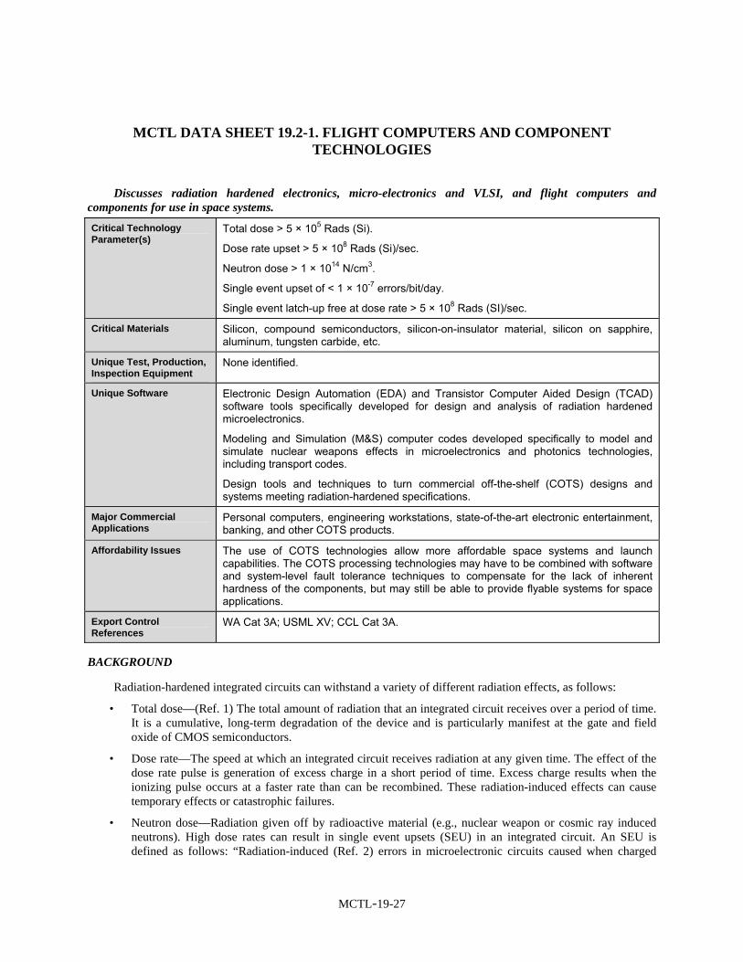
MCTL DATA SHEET 19.2-1. FLIGHT COMPUTERS AND COMPONENT TECHNOLOGIES
Discusses radiation hardened electronics, micro-electronics and VLSI, and flight computers and components for use in space systems.
Critical Technology Parameter(s)
Total dose > 5 × 10⁵ Rads (Si).
Dose rate upset > 5 × 10⁸ Rads (Si)/sec.
Neutron dose > 1 × 10¹⁴ N/cm3.
Single event upset of < 1 × 10⁻⁷ errors/bit/day.
Single event latch-up free at dose rate > 5 × 10⁸ Rads (SI)/sec.
Critical Materials Silicon, compound semiconductors, silicon-on-insulator material, silicon on sapphire, aluminum, tungsten carbide, etc.
Unique Test, Production, Inspection Equipment
None identified.
Unique Software Electronic Design Automation (EDA) and Transistor Computer Aided Design (TCAD) software tools specifically developed for design and analysis of radiation hardened microelectronics.
Modeling and Simulation (M&S) computer codes developed specifically to model and simulate nuclear weapons effects in microelectronics and photonics technologies, including transport codes.
Design tools and techniques to turn commercial off-the-shelf (COTS) designs and systems meeting radiation-hardened specifications.
Major Commercial Applications
Personal computers, engineering workstations, state-of-the-art electronic entertainment, banking, and other COTS products.
Affordability Issues The use of COTS technologies allow more affordable space systems and launch capabilities. The COTS processing technologies may have to be combined with software and system-level fault tolerance techniques to compensate for the lack of inherent hardness of the components, but may still be able to provide flyable systems for space applications.
Export Control References
WA Cat 3A; USML XV; CCL Cat 3A.
BACKGROUND
Radiation-hardened integrated circuits can withstand a variety of different radiation effects, as follows:
• Total dose—(Ref. 1) The total amount of radiation that an integrated circuit receives over a period of time. It is a cumulative, long-term degradation of the device and is particularly manifest at the gate and field oxide of CMOS semiconductors.
• Dose rate—The speed at which an integrated circuit receives radiation at any given time. The effect of the dose rate pulse is generation of excess charge in a short period of time. Excess charge results when the ionizing pulse occurs at a faster rate than can be recombined. These radiation-induced effects can cause temporary effects or catastrophic failures.
• Neutron dose—Radiation given off by radioactive material (e.g., nuclear weapon or cosmic ray induced neutrons). High dose rates can result in single event upsets (SEU) in an integrated circuit. An SEU is defined as follows: “Radiation-induced (Ref. 2) errors in microelectronic circuits caused when charged

MCTL-19-28
particles (usually from the radiation belts or from cosmic rays) lose energy by ionizing the medium through which they pass, leaving behind a wake of electron-hole pairs.”
With the current emphasis to consider use of COTS technologies in space and launch vehicle applications, it is important to consider radiation hardening at the system, vice individual component, level. Thus, for the microchip technologies that may be used (e.g., bulk CMOS, CMOS/SOI, GaAs, SiGe, and Microwave On Insulator (MOI) technologies), the important criteria are processing performance and radiation performance of the flight computers and other systems comprised of those components.

MCTL-19-29
MCTL DATA SHEET 19.2-2. FAULT TOLERANT COMPUTING TECHNOLOGY
Discusses fault tolerance, a capability to automatically detect and manage hardware and software faults, in space-qualified electronics and computers.
Critical Technology Parameter(s)
Fault Coverage: ≥ 0.999999.
Overhead: ≤ 10% of power, mass, and computing cycles (compared to identical system without the fault tolerance).
Latency: ≤ 1msec.
Critical Materials None identified.
Unique Test, Production, Inspection Equipment
None identified.
Unique Software Software must achieve fault detection, isolation, recovery, and system restoration without loss of data and meet real time requirements at peak upset rates.
Major Commercial Applications
All commercial satellites and launch vehicles, as well as many critical terrestrial applications.
Affordability Issues May enable more capability at lower cost if COTS electronics can be used. Tradeoff is higher nonrecurring cost of redundant equipment and/or fault-tolerant software development.
Export Control References
WA Cat 4A.
BACKGROUND
Fault tolerance is the use of protective redundancy to enhance the dependability of systems. It is an automated capability that allows a circuit, component, module, subsystem, or system to detect and manage hardware and some software faults which would otherwise compromise the ability of the system to properly deliver the expected services. Fault tolerance capabilities may be implemented in hardware, software or firmware.
The critical technology parameter is the logical AND of the following sub-parameters: fault coverage (probability of detecting and successfully recovering from a fault), overhead (cost of the fault tolerance capability in terms of added power, mass, and computing cycles), and latency (time between occurrence of fault or fault induced error and completion of fault recovery or return to normal operation).

MCTL-19-30
MCTL DATA SHEET 19.2-3. PHOTONICS TECHNOLOGIES FOR SIGNAL PROCESSING AND INTERCONNECTS TECHNOLOGY
Discusses using photonics devices, generally radiation-hardened semiconductor lasers and photodiodes, as signal processing and system interconnection technologies in space systems.
Critical Technology Parameter(s)
Total dose > 5 × 10⁵ Rads (Si)
Dose rate upset > 5 × 10⁸ Rads (Si)/sec
Neutron dose > 1 × 10¹⁴ N/cm3
Single event upset of < 1 × 10⁻⁷ errors/bit/day
Single event latch-up free at dose rate > 5 × 10⁸ Rads (SI)/sec
Data rate > 1 Gbps at 1 km
Critical Materials None identified.
Unique Test, Production, Inspection Equipment
None identified.
Unique Software None identified.
Major Commercial Applications
High reliability, high availability, and secure ground-based telecommunications applications utilize some of these technologies.
Affordability Issues Commercial versions of these technologies are available because of the worldwide use of the technologies in telecommunications applications.
Export Control References
WA Cat 3A.
BACKGROUND
Photonics technologies impact applications from high performance computing to very low cost consumer devices. For example, semiconductor lasers, photodiodes, and related optical components are found in every CD and DVD player. Of interest to the space systems community, however are applications of photonics devices for providing interconnects among electronic processors and on-board communications in space systems. In this application, photonics technologies have much in common with telecommunication applications; however, interconnect distances are significantly shorter (50 m maximum was assumed when evaluating in-space applications).
Solutions optimized for on-board processing in space systems differ from optimized terrestrial telecommunication solutions. In particular, radiation requirements drive the use of non-telecommunication fibers, and short interconnect distances eliminate the need for single-mode fiber, at least on the basis of bandwidth alone. Architectures may differ from telecommunication solutions to provide acceptable reliability. Optical loss budgets in the absence of radiation are more generous than for terrestrial telecommunications applications, since in the latter, repeaters are separated by as great a distance as signal attenuation will allow. Additionally, the wavelength of operation may be shorter than for telecommunications applications, since chromatic dispersion is not an issue.
Today, photonics technologies designed for on-board processing can be simpler than for terrestrial telecommunications; however future opportunities will emerge in space systems that will exploit performance of telecommunications components for new, high performance applications. For example, single mode systems using wavelength-sensitive routing components could be used on-board. Radiation performance of the components required to implement these networks currently lags ruggedized multimode components.

MCTL-19-31
SECTION 19.3—SPACE LAUNCH VEHICLES
Highlights
• Today’s launch vehicle technology includes significantly larger liquid fueled rockets, smaller solid and liquid fuel motors, and major advances in fuels and motor technologies.
• Payload and upper stage vibro-acoustic mitigation technologies significantly reduce vibration and acoustic loading during launch.
• Conversion of former ICBM assets to target and orbital launch vehicles led to a need for fairing and environment mitigation technologies, which now have demonstrated significant advancements.
OVERVIEW
The data sheets in this section discuss the critical technologies directly related to launch vehicles. These include the areas of:
1. Vibration Isolation—to protect payloads or launch vehicle systems from mechanical loads during ascent or descent.
2. Acoustic Mitigation—to protect payloads from damage due to mechanical coupling with the acoustic environment.
3. Guidance, Navigation and Control—to guide the spacecraft accurately along a planned path.
4. Cryogenic Composite Tanks—to reduce the weight of subsystems necessary to contain fuels and reactants.
5. Thermal Control—to protect the launch vehicle and payload from harsh thermal loads.
6. Fault Tolerant Electronics—to increase mission success rate.
7. Low-Shock Separation—to increase risk margin for survival after payload release.
Other launch-related space technologies (not explicitly launch vehicle technologies) are discussed in Section 19.1; “Space Avionics and Autonomy,” Section 19.6; “Launch Propulsion for Space Systems,” and in Section 19.10; “Space Structures.” Due to the need for launch services in many countries throughout the world, the potential for international cooperation to bring technologies to maturity more quickly has been demonstrated in a number of cases, especially with the European and Japanese space launch interests.
BACKGROUND
Most nations seek access to space for civil and commercial means and for military capability. Some nations purchase this access from nations that have more developed launch technology, and other nations aggressively obtain and develop their own launch technology. Demonstrating multistage booster technology sufficient to reach GEO is an indication that a nation has capability to seriously pursue ICBM capabilities.
Of all current military systems, launch vehicles are one of the most natural “dual-use” examples. Most expendable launch vehicles designed for the military have been modified for commercial use. EELV launch vehicles developed by Boeing and Lockheed Martin were developed specifically to take advantage of the synergy between military and commercial launch technology.
Vibro-acoustic-induced structural stress and fatigue failures, causing performance degradation of sensitive subsystems can be avoided by designing the launch vehicle with appropriate acoustic dampening techniques prior to fabrication.
MCTL-19-33
LIST OF MCTL TECHNOLOGY DATA SHEETS 19.3. SPACE LAUNCH VEHICLES
19.3-1 Vibration Isolation Technology............................................................................................... MCTL-19-35
19.3-2 Acoustic Mitigation Technology ............................................................................................. MCTL-19-36
19.3-3 Guidance, Navigation and Control (GNC) Technology .......................................................... MCTL-19-37
19.3-4 Cryogenic Composite Tanks Technology................................................................................ MCTL-19-38
19.3-5 Thermal Control Technology .................................................................................................. MCTL-19-39
19.3-6 Low-Shock Separation Technology ........................................................................................ MCTL-19-41
19.3-7 Launch Vehicle Fairings Technology...................................................................................... MCTL-19-42

MCTL-19-35
MCTL DATA SHEET 19.3-1. VIBRATION ISOLATION TECHNOLOGY
Discusses technologies to isolate axial and lateral vibrations of space launch vehicles from space systems carried as payloads.
Critical Technology Parameter(s)
• All Vibration Isolation technologies for both axial and lateral axes producing root-mean-square transmissibility between base and payload of –5 dB (reduction of factor of 3) over the 0–1000 Hz bandwidth.
• A Vibration Isolation System mass < 5% of payload mass.
Critical Materials High “E” damping materials; lightweight composite materials for composite fairings; innovative lightweight, low-cost acoustic damping and active attenuation composites. Hybrid multi-component blankets with tuned acoustic impedance.
Unique Test, Production, Inspection Equipment
Systems incorporating active control elements require pre-launch checkout equipment.
Unique Software Systems incorporating active control elements require control algorithm software.
Major Commercial Applications
Commercial payloads will benefit from this technology since current vibration conditions cause payloads to be lost or degraded significantly. This allows the launching of less rugged payload components.
Affordability Issues This technology should provide more affordable launch systems or allow more capability for a given payload weight. The increase in successful launches will significantly reduce overall program costs in the future.
Export Control References
WA Cat 9A; CCL Cat 9A.
BACKGROUND
Spacecraft are typically mounted on launch vehicles using a Payload Adaptor Fitting (PAF) structure. The launch loads are transmitted from the launch vehicle to the spacecraft through the PAF. Improvements in vibration isolation technologies in the PAF structures are needed to reduce the spacecraft launch loading. The requirement to design the spacecraft for the launch environment, in addition to the space environment, adds weight, cost, and risk to the spacecraft design and development.
PAF structures are designed to withstand axial acceleration during boost, which causes static and dynamic compression loads along the launch vehicle’s long (z) axis (Figure 19.3-1). Lateral loads occur due to maneuvers initiated by the vehicles’ guidance system and encounters with wind shear situations. This lateral loading tends to excite the launch vehicles’ body bending modes and in turn drives lateral displacements of the spacecraft. Also, coupling between axial sinusoidal motion and lateral modes causes significant lateral loads. Launch vehicle vibration isolation technology would add substantial flexibility and damping to the PAF in both the axial and lateral directions without inducing excessive axial, lateral, or rotational displacements that might cause impact of the spacecraft with the payload fairing or control instability.
Figure 19.3-1. Arrangement of launch vehicle, PAF, and spacecraft, with coordinate systems definition

MCTL-19-36
MCTL DATA SHEET 19.3-2. ACOUSTIC MITIGATION TECHNOLOGY
Discusses active and passive technologies to reduce the vibro-acoustic noise transmission from space launch vehicles to space system payloads.
Critical Technology Parameter(s)
• Active/Passive Acoustic Attenuation technologies providing ≥ 20 dB reduction for all frequencies (from the baseline system without the attenuator) in the 0–500-Hz bandwidth; and
• Active/Passive Acoustic System Mass ≤ 5% Fairing Mass without increasing the volume (envelope) of the Fairing.
Critical Materials High “E” damping materials; lightweight composite materials for composite fairings; innovative lightweight, low-cost acoustic damping and active attenuation composites. Hybrid multi-component blankets with tuned acoustic impedance.
Unique Test, Production, Inspection Equipment
Systems incorporating active control elements require pre-launch checkout equipment.
Unique Software Control software for active systems necessary to meet performance goals.
Major Commercial Applications
Commercial payloads will benefit from this technology since currently all weight (mass) is a costly commodity to launch. In addition, current vibration conditions cause payloads to be lost or degraded significantly.
Affordability Issues This technology should provide more affordable launch systems, using cheaper and less robust components. The increase in successful launches will significantly reduce overall program costs in the future.
Export Control References
WA Cat 9A; CCL Cat 9A.
BACKGROUND
Vibro-acoustic energy due to launch can cause spacecraft payload failures. The acoustic noise is generated by engine noise, aerodynamics, and other sources. The nominal acoustic level is 135 to 145 dB without vibration isolation technology. The spacecraft systems most affected are solar arrays, antennas, tube amplifiers, bearings and joints. Current acoustic attenuation is achieved by using custom-sewn acoustic blankets, which are expensive and heavy and decrease overall fairing volume. In addition, acoustic attenuation is affected by the mass of the fairing. Since the mass of the fairing components is reduced significantly with advanced composites, the acoustic disturbances within the fairing during launch will increase. This is particularly true in large launch vehicles, where low-frequency acoustic transmission is complicated by low-ring frequencies and low-frequency cavity modes (inversely related to cavity dimensions). Since blanket thickness and mass are inversely proportional to the frequency they must attenuate, low-frequency acoustics are especially difficult to control with traditional acoustic blankets.
Acoustic mitigation technology attempts to overcome these problems through a variety of approaches. Acoustic energy can be attenuated or redirected away from critical areas through innovative design of structural elements such as payload fairings. Discrete passive devices can be located within a fairing acoustic cavity to dampen acoustic modes. Discrete or distributed active devices can insert additional energy into the system in such a way that the overall acoustic environment is minimized. This could allow the launch of less robust spacecraft payloads narrowing the government to commercial gap, or to enable the design of lighter weight spacecraft structures that can survive the reduced launch loads. A benign launch environment could even allow the launch of compliant structures or high aspect ratio military spacecraft that otherwise could not fly.

MCTL-19-37
MCTL DATA SHEET 19.3-3. GUIDANCE, NAVIGATION AND CONTROL (GNC) TECHNOLOGY
Discusses guidance, navigation, and control (GN&C) technologies for space launch vehicles; dominant focus on inertial navigation systems (INS).
Critical Technology Parameter(s)
• INS assemblies with navigational performance errors < 0.8 nmi/hr.
• Gyroscope bias < 0.1 deg/hr.
• Accelerometer bias < 125 micro-g.
Critical Materials None identified.
Unique Test, Production, Inspection Equipment
None identified.
Unique Software System and sensor calibration techniques and associated software have significant bearing on the ultimate performance (orbital insertion accuracy) for the GN&C system.
Major Commercial Applications
Commercial applications for the technology are the same as the military applications. Launch vehicles are inherently dual-use systems providing access to space for both military and commercial payloads.
Affordability Issues Improved orbital placement accuracy provides for longer useful satellite service life, due to the reduced usage of payload attitude control fuel to correct insertion errors.
Export Control References
WA ML 9, 11, 21, and 22; WA Cat 7A, B, D, and E; MTCR 9; USML VIII, 121, and 16; CCL Cat 7A, B, D, and E.
BACKGROUND
Payload spacecraft mission performance is affected by the orbital insertion error (from desired location) imposed by the launch vehicle GN&C. Deviation from planned orbital location requires consumption of valuable attitude control and maneuvering fuel to compensate for the placement error. Useful on-orbit life can be substantially reduced and limited for large errors. Significant deviation from the planned orbital parameters may cause loss of mission.
MCTL-19-38
MCTL DATA SHEET 19.3-4. CRYOGENIC COMPOSITE TANKS TECHNOLOGY
Discusses cryogenic pressure vessels (tanks), which are lighter and less expensive alternatives to metal tanks.
Critical Technology Parameter(s)
• Composite material able to withstand microcracking due to thermal stresses ≥ 50 K and pressure of ≥ 800 psi.
• RLV tanks that maintain structural soundness and is qualified through 1000 pressurization and depressurization cycles without structural failure.
Critical Materials Resins with low coefficient of thermal expansion. Composite materials that are chemically inert to LOX, LN2, peroxide, rocket and jet fuels.
Unique Test, Production, Inspection Equipment
None identified.
Unique Software None identified.
Major Commercial Applications
Low-cost access to space in addition to prolonged space flight and reduced weight of non-space vehicles. Low weight structures will greatly reduce deployment costs for both space and non-space vehicles. Will also allow single-stage-to-orbit launches.
Affordability Issues With much of the technology described herein, affordability is tied primarily to refinements in associated processes, through standardized production and higher production volumes.
Export Control References
Controlled as a material in WA Cat 1A, 1C, and 9A; CCL Cat 1A, 1C, and 9A.
BACKGROUND
Composite cryogenic pressure vessels used for launch vehicle fuel tanks are a lighter and cheaper alternative to conventional metal tanks. The weight savings of up to 60 percent have a significant effect on the cost of launching a vehicle into space. These cost savings are applicable to all space vehicles as well as non-space vehicles. However, implementation of composite tanks in a cryogenic environment has been limited due to microcracking of the resin material of the tank. These microcracks propagate to the point of tank leakage or ultimate failure.
MCTL-19-39
MCTL DATA SHEET 19.3-5. THERMAL CONTROL TECHNOLOGY
Discusses technologies, materials, and systems needed to withstand or control the thermal impacts of space launch vehicles.
Critical Technology Parameter(s)
• Ultra-high Temperature Ceramic (UHTC) leading fairing edges with use temperature ≥ 1400 °C for ≥ 10-minute soaks, and 50 reuses.
• Ceramic matrix composite (CMC) tiles capable of withstanding 2000 °C for ≥ 20 minutes, and 50 reuses.
• TPS adhesive/attachment systems with capability to withstand 200 °C without loss of structural integrity.
• High temperature heat pipes operating at temperatures in excess of 1100 °C for 50 minutes.
• Advanced Flexible Reusable Surface Insulation (AFRSI) with a use temperature to 650 °C.
• Ablative shields providing effective thermal protection for flight at greater than Mach 18 for longer than 50 minutes with mass loss not exceeding 25%.
• Metallics and Metal Matrix Composites (MMC) with cost and mechanical properties analogous to Ti, but with lower mass densities and higher use temperatures (use temperatures > 700 °C).
• Use temperatures above that of Inconel 617 (> 1100 °C) with mass density < 8360 kg/m3.
• Reinforced carbon-carbon composites (RCC) to withstand minimal ablation (loss not exceeding 25%) at ≥ Mach 18 for ≥ 50 minutes.
Critical Materials Ceramics or CMCs: UHTCs—Zirconium Diboride, Hafnium Diboride, CMCs—carbon reinforced silicon carbide, silicon carbide reinforced silicon carbide.
Flexible Insulation: Alumina-borosilicate fibers, high-purity silica fibers, Nextel 312.
Metallics and MMCs: Titanium alloys, Titanium aluminides, Inconel 617.
RCC—3-D and 4-D carbon-carbon. Cyanide ester adhesives.
Unique Test, Production, Inspection Equipment
Arc-heated or plasma wind tunnels.
Facilities for making carbon-carbon.
Unique Software None identified.
Major Commercial Applications
Low-cost commercial access to space is leveraged by enhanced thermal control technology especially where technology advancements significantly lower operational costs and reduce vehicle dry weight, e.g., fly-back boosters for commercial launch vehicles. Enhancements in service temperatures and producibility will also enable uses in high temperature processes in manufacturing and energy, improving safety and efficiency.
Affordability Issues With much of the technology described herein, affordability is tied primarily to refinements in associated processes, through standardized production and higher production volumes.
Export Control References
WA ML 12; WA Cat 1A; USML IV; CCL Cat 1A.

MCTL-19-40
BACKGROUND
The purpose of the thermal control system is to protect the launch vehicle from heat damage during launch, in space, and during reentry, if necessary. It is composed of several subsystems and technologies designed to meet the unique requirements for the launch system. The thermal control system will vary greatly from one launch vehicle system to the next due the multiplicity of vehicle architectures (expendable, reusable, space shuttle, multi-stage), missions (light/heavy lift, manned, polar, etc.), and design heritage among other things. Emerging launch system requirements are emphasizing rapid response, reduced operational costs, and increased reliability.

MCTL-19-41
MCTL DATA SHEET 19.3-6. LOW-SHOCK SEPARATION TECHNOLOGY
Discusses low-shock technologies needed to release a space system (payload) from a launch vehicle in space.
Critical Technology Parameter(s)
• Release shock < 10 g, without increase in rotational forces at release over that of conventional systems.
Note: Typical rotational forces without low-shock technology are in the range of 0.1 to 0.2 deg/s.
Critical Materials Several critical materials can be associated with low-shock separation systems, including paraffin and shape memory alloys (SMAs), but these materials are critical only to specific approaches rather than the technology as a whole.
Unique Test, Production, Inspection Equipment
None identified.
Unique Software None identified.
Major Commercial Applications
The same as the military applications, namely low-shock mechanical systems for separation of spacecraft, mechanical actuators, mechanical release devices, etc.
Affordability Issues Not an issue.
Export Control References
WA Cat 9A; CCL Cat 9A.
BACKGROUND
A payload delivered to orbit from a launch vehicle must typically be separated from the vehicle payload attachment fitting prior to operation. Typical pyrotechnic separation systems generate shock loads between 5,000 and 10,000 g. This shock loading has the potential to damage the payload, requiring more massive and robust designs to survive these loads. A reduction in separation shock loads can translate into reduced mass designs or increased risk margin.
MCTL-19-42
MCTL DATA SHEET 19.3-7. LAUNCH VEHICLE FAIRINGS TECHNOLOGY
Discusses technologies for the fairings covering large space systems during launch operations.
Critical Technology Parameter(s)
Launch vehicle fairings capable of supporting maximum payload dimensions of 10 meters in diameter and able to withstand aerodynamic pressure loads exceeding 3000 psi.
Critical Materials None identified.
Unique Test, Production, Inspection Equipment
Out-of-autoclave curing techniques can increase manufacturability. Large out-of-autoclave processes have been identified from COTS processes already in the open literature.
Unique Software Control algorithms to maintain launch vehicle stability, reduce flutter inputs, and minimize fuel consumption to orbit are critical to successful launch of high aspect hammerhead fairings and non-circular cross-sections.
Major Commercial Applications
Commercial payloads will benefit from this technology to the extent that very large payload volumes can be used without exceeding mass limits.
Affordability Issues None identified.
Export Control References
WA Cat 9A; CCL Cat 9A.
BACKGROUND
The greatest difficulty in placing a large fairing, particularly one that is not entirely symmetric to a practical orbit would be in providing measures during launch to insure stability, minimize buffeting, and reduce fuel requirements as needed to attain the desired orbit.

MCTL-19-43
SECTION 19.4—SPACE OPTICS
Highlights
• Space optics structures and components with an areal density1 of < 15 kg/m2 are needed to provide lightweight, high stiffness precision monolithic structures.
• Significantly improved optical “Composite” components having a coefficient of linear thermal expansion < 5 × 10⁻⁶ in all coordinate axes and an areal density* of < 20 kg/m2 are scheduled for the military space program.
• Segment mirrors or assemblies of mirrors designed to be assembled in space with optical aperture segments > 0.5 m or full apertures > 3.0 m.
• Nanometer optical tolerances of space platforms with large deployable mirrors (tens of meters in diameter) will provide near diffraction limited optical surveillance and significantly improve space surveillance resolution and image quality.
• Significant improvements in Deformable Mirrors (DMs) for space applications, from improved frequency response to larger throw distances and less hysteresis.
• Space Optics Tip/Tilt mirrors (2-axis controls) with bandwidths > 500 Hz have significantly improved capabilities for Space Relay Optics.
• New high frequency, low hysteresis actuators are greatly improving the capability of active optics.
• Liquid crystals have often been too slow for adaptive optics application, but with recent developments, that has been overcome by switching speeds > 250 µsec.
• A new and novel method of electrically addressing liquid crystals for adaptive optics is called modal addressing and the improvements are very significant.
• Optical component and coating protection from atomic oxygen is a key new development.
• Major advances in optical coating material technologies improve the hardness and environmental survivability of military optics hardware.
• Vibration-isolation and damping systems in conjunction with precision fixtures of flexible space structures can now achieve better than 30-nm mirror position stability.
• Significantly improved Micro-Opto-Electro-Mechanical Systems (MOEMS) are now replacing electronic components where optical switching and high bandwidth is required.
OVERVIEW
Space optics includes all space unique optics technologies. If an optics technology for terrestrial applications is modified for space use or if it is specially designed for a space application, it will be included in this section.
The specific optics technologies outlined in this section include large optical mirrors for space surveillance and as relay optics. The very large mirror structures planned for some military applications require new innovative approaches to what looks like “erector set” optics where segments of the large pieces of the optic are erected or positioned at appropriate locations within the aperture of the optic. This means the optical components must be folded for launch and then erected in space by remote or in situ placement of components via robotics.
1 Areal density is a two-dimensional term in optics representing the mass of the optical mirror per unit area of the optical
surface.

MCTL-19-44
Some deployable optics are currently envisioned to be used as HEL reflectors for ground-based laser weapons as well as surveillance applications. Others are required for the many surveillance applications currently being utilized. Commercial, as well as military, surveillance applications are demanding higher resolution and larger light gathering power.
Space applications require large, extremely lightweight mirrors that have diameters in the 4- to 100-m range and F numbers in the 1.5 to 2.5 range. A fast focal ratio is needed for compact, lightweight space optics that have the light-gathering power and resolution required to meet current military requirements, which include fractional wavelength tolerances. Thin glass shells attached to actuators on a lightweight rigid support structure constitute the current developing technology. Alternate technologies are also being addressed and include thin plastic, mylar, and/or metal-foil-stretched membranes. Using many smaller flat surfaces to form a primary optic configuration may be an acceptable technology to meet this requirement. The technology will require hundreds to thousands of square-meter surface for some applications. All these large-optics technologies are currently being investigated at a low developmental level.
Many space optics require special preparations including specially designed optical coatings to avoid or minimize the effects of the space environment. Protection coatings are required on some optical components that are not themselves optical surfaces but still require special preparation for space use. Protection from atomic oxygen and other harsh environmental contaminants is required of all space optics. Space surveillance optics for some specialized applications require stringent temperature control of the optics. Active or passive cooling becomes a necessity in such cases. Cooled optics include those with passive cooling methods using phase change materials and radiative transfer techniques. The cooled optics technologies are covered in the Terrestrial Applications Optic, Section 11-3 of the MCTL.
Deformable Mirrors (DMs) are sometimes identified by different names including “Adaptive Optics” or “Active Optics.” Deformable mirrors include mirrors for which the surface can be statically or dynamically repositioned to optimize the beam’s wavefront. Some of these mirrors are currently being developed for space applications such as space surveillance for GEO laser communication links. Adaptive optics, when used in space, have some additional requirement such as the hermetically sealed actuator assemblies to avoid out-gassing and reduction by atomic oxygen. In addition, one needs special lubricants to maintain movement on mount points and special fixturing to withstand the high “g” loads of a launch. In addition to the actuators supporting the mirror surface, special structural support actuators are also needed to maintain alignment of structural components as in the deployable optics that unfold into the desired optical format.
The hardware one needs for space optics involves many autonomous and robotic structures including remote positioning to sub-micron accuracy. The opto-mechanical controls required for some space optics involve techniques and technologies, which are quite different from terrestrial applications.
Space applications for MOEMs are becoming the “fast-track” approach to optical applications such as optical switching where electronic connections and switches are a hazard or arrays of micro mirrors actuated independently for communication applications. Space applications of MOEMS technology are now under development for space applications since MOEMS represent reliable, durable, light-weight replacements for many space electronic components, especially where static electricity is a common problem and the need for mitigating EMI is highly desired.
Many of the space technologies listed in this section have been developed in concert with or in a cooperative development arrangement with our allies. This area of research and development remains a window of opportunity for future space related endeavors. Many related technologies, which are common to both space and terrestrial applications, are covered in the Lasers, Optics and Imaging Technology section of the MCTL.
BACKGROUND
The need for larger aperture optics in space is driven by many applications and goals. The U.S. Government’s space program at NASA requires space telescopes with greater resolution and light gathering power in an effort to search out other earth-like planets in the galaxy and to continue the extended study the universe. Near-term plans call for telescopes with 9- to 20-m apertures. More ambitious plans are calling for 100+ meter diameter systems. All deep-space imaging missions could benefit tremendously from such systems.
MCTL-19-45
Additionally, the military needs telescopes that point toward earth rather than away from it. The military requires large aperture surveillance optics to monitor global areas of interest. An 8+ m optical surveillance system could, in principle, provide militarily significant imaging from geosynchronous orbit, allowing it to observe a region of the world 24 hours a day, seven days a week, eliminating the need to wait for revisit times. Such a system could provide continuous coverage of a battlefield or sensitive area, a capability of obvious military and political significance. Of special interest to the military is the fact that any future space-based laser systems will require large apertures.
Therefore, large, monolithic uncooled optics are required for many space applications, which include mirrors for both military and commercial surveillance, reconnaissance, acquisition, pointing, tracking, and communications. These optics require high-reflectivity coatings, antireflective or partially transmissive coatings for selective wavelengths, and/or coatings with holographic elements. More advanced uncooled optics, particularly desirable for military space applications, include advanced transmissive capabilities of single-crystal silicon and silicon-carbide optics. These technologies use lightweight, inexpensive components to achieve the same capability that was available only with much more expensive and heavier components.
Size and weight are major considerations in any space launch. Optical elements are currently limited in size by space booster payload fairings. Optics, larger than those that can be boosted into space by such launch-vehicle limitations, must be assembled in space (either from separate pieces or by unfolding elements), or the optical assemblies must be bolted together in space. “In-space construction” technologies remain critical, particularly for applications that require exceptionally large, fragile membrane or very lightweight optics (too large and/or too fragile for launch stresses). Technologies for unfolding or assembling large optics and for obtaining and maintaining proper shape and finish in the process also remain critical but are now under development. In addition, software algorithms that determine and then compensate for deformations or that purposely deform elements in space optics are critical for obtaining and maintaining high resolution for space optics.
Deformable Optics are also referred to as Smart Optics, Adaptive Optics or Active Optics. They include any optical component whose optical surface can be controlled or adjusted dynamically to enhance the optical system performance. Deformable mirrors are required in some applications for improving space surveillance optics resolution. It should be noted that (quasi-static) errors in optics such as telescope optics are usually controlled by a low bandwidth optical system, usually referred to as “Active Optics.” The (high dynamic) controlled optics typically required for correcting atmospheric turbulence inside and above the telescope are usually referred to as “Adaptive Optics” and in the case of a closed loop system they are sometimes referred to as “Smart Optics.”
The technique of deforming optical surfaces has succeeded in producing even sharper and clearer images than the Hubble Space telescope from terrestrial telescopes. As the use of optics in space has increased and size and weight have become more important, changes have become necessary in the design, manufacturing, and process controls of these new technologies to provide affordable, lightweight, rugged, and highly reliable systems. Many new MEMS and MOEMS applications incorporating lasers and optics have spawned numerous designs for reducing the weight and size of space electronics and optical components such as in-line adaptive optics.
MOEMS and optical micromirrors technology has been extended to optical communication where fast switching of laser light is enabled with micromirrors, microshutters, or microbubbles. The communication industry will soon see MOEMS devices as tunable lasers (VCSELs), resonators, interferometers, and multiplexers. The same technology that is embodied in these components is used by the military for adaptive optics and switching applications.
The use by commercial firms of space optics technologies is important in the overall affordability of the space component or system for both the commercial and the military sectors. Many satellite payloads are now planning on using micro-optic technologies in the form of MEMS and MOEMS for space platform components.

MCTL-19-47
LIST OF MCTL TECHNOLOGY DATA SHEETS 19.4. SPACE OPTICS
19.4-1 Deployable Monolithic and Segmented Optics ....................................................................... MCTL-19-49
19.4-2 Deformable Mirrors/Adaptive Optics and Support Mechanisms ............................................ MCTL-19-51
19.4-3 Micro-Opto-Electro-Mechanical Systems (MOEMS) ............................................................. MCTL-19-53

MCTL-19-49
MCTL DATA SHEET 19.4-1. DEPLOYABLE MONOLITHIC AND SEGMENTED OPTICS
Discusses technologies to isolate axial and lateral vibrations of space launch vehicles from space systems carried as payloads. Critical Technology Parameter(s)
• Lightweight, high stiffness precision monolithic structures with:
a. an areal density of < 15 kg/m2; and
b. a fundamental frequency > 1.5 kHz.
• Optical “Composite” Components having:
a. a coefficient of linear thermal expansion < 5 × 10⁻⁶ in any coordinate axis;
b. an areal density of < 20 kg/m2; and
c. a fundamental frequency > 1.5 kHz.
• Segment mirrors or mirror assemblies designed to be assembled in space with:
a. optical segments (for segmented mirrors) > 0.5 m; or
b. full aperture optics > 3 m.
• Technology for measuring Zero-g figure and tolerances in 1-g conditions (terrestrial setting) for lightweight space optics structures < 30 kg/m2.
• Rapid optical fabrication technology for large (> 10 m2) monolithic or segmented primary mirrors.
• Hinges, latches and related mechanisms capable of providing < 10 nm mirror surface figure stability.
• Optical structure isolation systems with:
a. damping coefficients of > 30 dB; and
b. for frequencies between 1 Hz and 105 Hz.
• Vibration-isolation and damping systems for flexible structures to achieve < 30 nm mirror position stability.
• Visible and infrared wavelength high reflectance, low stress, durable, optical coatings which can survive the space environment of atomic oxygen for > 5 years.
• Optical component coating protection technology for atomic oxygen.
• All space-based high energy laser (HEL) optics.
Critical Materials Corning ULE, Schott Zerodur, silicon carbide, beryllium, graphite (and other) composites, ceramic bearing components, adhesives used in construction of these materials and the assembly of components/structures.
Unique Test, Production, Inspection Equipment
Production: Large, high temperature furnaces for the above ultra-high purity materials, including very high pressure autoclaves for beryllium, large CNC machines, machine tools for precision bearing production, large thermal-vacuum chambers in clean rooms and associated coating application instrumentation.
Testing: large, high precision coordinate measuring machines, high speed visible wavelength and infrared wavelength interferometers, precision lenses and diffractive optical elements for aspheric primary mirror null correctors, large, precision air bearings, high density CCD focal planes and associated electronics, large thermal-vacuum space-simulation chambers and gravity-offload devices.
Inspection: Technology for measuring 0-g figure and tolerances in 1-g conditions (terrestrial setting) for lightweight structures < 30 kg/m2.

MCTL-19-50
Unique Software Software developed for the modeling and analysis of figure-controlled mirrors, wavefront sensing software; possibly software tools developed specifically for the analysis of lightweight structures.
Major Commercial Applications
Earth resources instruments and satellites use similar technology but at small or modest size. Ground-based telescopes use similar materials but with much more massive designs. Many new space surveillance applications are emerging daily so the growth in the commercial area will expand significantly.
Affordability Issues Lightweight optics tend to be significantly more costly than ground-based optics due to the need for new technology investment, material purity and certification, and the increased need for design, analysis, and verification for space programs.
Commercial business practices provide the means to dramatically reduce the costs of sophisticated government satellites. However, in the area of large space optics, government is the primary user, exclusively responsible for supporting advances in technology and implementing cost saving measures.
Since the global investment in space is overwhelmingly dominated by the commercial sector, beneficial partnerships should expand beyond government interests. To participate in the ever increasing commercial investments in space, the optics community needs to develop a broader perspective of future technology applications. Distributed spacecraft technology and automated operations are examples of near term industrial partnership opportunities.
Export Control References
WA ML 15 and 19; WA Cat 6A and 6C; USML XII; CCL Cat 6B.
BACKGROUND
To have timely and precise space surveillance, orbital mechanics require that a space telescope (capable of viewing a given location on the earth for increasingly long periods of time) orbit the earth at increasingly higher altitudes. On the other hand, optical physics require that to maintain constant angular resolution, higher orbiting telescopes must have proportionally larger primary mirror diameters. The limited available suite of launch vehicle fairing diameters constrains large aperture telescopes from being placed on-orbit without first folding them for launch and deploying or assembling the components once on-orbit. The cost of launch vehicles capable of lifting very large masses to orbit is high, leading to a desire to reduce the mass of the telescopes, both optics and structures, thereby allowing the use of less costly launchers.
The need to reduce mass leads to thinner, more flexible mirrors but without any relaxation in the surface figure tolerances of those mirrors. Furthermore, the segmentation of the primary mirror adds a new dimension to fabrication tolerance to ensure that the various segments are capable of functioning as a single, large optic on-orbit.
The increased flexibility of the mirrors results in significantly more deformation of the mirror surface due to gravity, making ground verification in 1-g for a 0-g performance design increasingly challenging. Furthermore, the difficulty of verification increases the attractiveness of being able to adjust the mirror shape on-orbit, leading to an increased need for space-rated figure-control actuators. An increased reliance on adjustability drives the need for increasingly-capable wavefront sensing subsystems that can rapidly measure the multiple degrees of freedom required. In an effort to reduce system complexity, designers turn to more exotic, higher-stiffness materials for large, lightweight mirrors and structures.
Lightweight future system concepts include collaborating satellite constellations, integrated sensor-craft, sparse arrays, and inflatable, deployable membranes or gossamer optics. When combined with inflatable or other novel structures, weight and packaging volume could be reduced to a fraction of today’s figures. A number of exciting programs have shown potential and are developing the technology to meet the technical challenges of space optics systems.

MCTL-19-51
MCTL DATA SHEET 19.4-2. DEFORMABLE MIRRORS/ADAPTIVE OPTICS AND SUPPORT MECHANISMS
Discusses technologies to isolate axial and lateral vibrations of space launch vehicles from space systems carried as payloads. Critical Technology Parameter(s)
The militarily critical parameters listed below are for optical space components, which dynamically or statically move the surface of an optic. This list includes components specially designed for space applications which can correct laser beam wavefronts such as non-linear optical components or liquid crystal modulators (in conjunction with advanced optics or as stand alone components) as follows: 1. Actuators
a. Working at a frequency > 200 Hz but ≤ 300 Hz; b. with a positioning and repositioning accuracy < 30 nm; c. precision < 20 nm; and d. a full stroke > 3 µm.
2. Actuators a. At a frequency > 300 Hz; b. with a positioning and repositioning accuracy < 30 nm; c. precision of < 50 nm; and d. a full stroke > 3 µm.
3. Actuators a. With large stroke range > 5 mm; and b. high resolution positioning accuracy (< 30 nm).
4. Deformable optical mirror surfaces a. With < 30 nm deviation from prescribed figure in dynamic or static
configurations; and b. optical diameter or major axis of > 25 mm.
5. High-precision mechanisms for optical system deployment in space with positioning of: a. < 1 × 10⁻⁵ meter accuracy; and b. < 1 part in 106 precision.
6. Advanced control system and actuator designs for optical-precision structural controls with controlled movement of < 10-9 meters/meter of separation between optical elements.
7. Optical beam steering optical components with: a. Diameters (or major axis) > 10 cm; b. flatness < 50 nm; and c. a control bandwidth > 200 Hz.
8. Non-linear optics components, such as liquid crystals and other phase control material components, specially designed for space optics applications and use as follows: a. Nonlinear phased arrays with > 250 µsec switching speed; b. wide-angle beam steering > ± 45° field of regard; and c. high-speed liquid crystals > 104 Hz.
MCTL-19-52
Critical Materials None identified. Unique Test, Production, Inspection Equipment
Testing: Improved nulling techniques for the control surface.
Unique Software None identified. Major Commercial Applications
Ground-based Optical Telescopes: developmental items such as artificial eyes, high-speed telecommunication links, ophthalmic instrumentation as well as the well established applications such as semiconductor lithography, and industrial laser system optimization components. Other possible application areas include commercial laser beam correction, laser beam forming, laser materials processing, scanning optical systems, optical probes and confocal microscopes, coupling of micro-optics, and several areas of optical imaging, including imaging of the retina in vivo.
Affordability Issues Lower cost will result with further development work, which should improve performance, decrease complexity and increase the bandwidth substantially. This will reduce the cost for the next generation of giant telescopes.
Export Control References
WA Cat 6A and 1E; WA ML 15 and 19; USML XII; CCL Cat 6A and 6B.
BACKGROUND
A significant technological development in the field of laser optics is deformable or adaptive optics. Developed to combat fluctuations in air temperature and the consequent atmospheric turbulence that weakens and scatters the laser’s beam, adaptive optics relies on a deformable mirror, sometimes called a “rubber mirror,” to compensate for tilt and phase distortions in the atmosphere. The mirror typically has hundreds of actuators that change hundreds to thousands of times per second when driven by a wavefront sensor, enabling the mirror to modify the laser beam so that it can travel further through turbulent air.
Today, deformable mirrors for astronomy are usually made of a very thin sheet of glass or low thermal expansion material with a diameter of several inches to meters in size. Attached to the back of the glass are various kinds of “actuator” devices which expand or contract in length in response to a voltage signal, bending the thin sheet of glass locally to the intended wavefront correction. A deformable mirror is able to correct a distorted beam of light from a star, by straightening out the incoming wavefront.
For astronomy and for military applications, wavefront sensors must measure turbulence hundreds to thousands of times a second. The detector doing this work is typically a fast charge coupled device (CCD), similar to those used at slower speeds in today’s video cameras, or else a set of avalanche photodiodes (APDs) mapping out the centroid of beamlets in a Shack-Hartmann set up.

MCTL-19-53
MCTL DATA SHEET 19.4-3. MICRO-OPTO-ELECTRO-MECHANICAL SYSTEMS (MOEMS)
Discusses optical systems for space based on micro-opto-electro-mechanical systems (MOEMS) technology.
Critical Technology Parameter(s)
MOEMS with a frequency > 500 Hz.
MOEMS with:
1. ≥ 100 actuator mirrors;
2. ≥ ± 1-micrometer displacement throw; and
3. > 95% areal density (fill factor).
Critical Materials None identified.
Unique Test, Production, Inspection Equipment
Production:
1. Very stringent tolerances are required for micro-opto devices and components for space applications; and
2. Micro lenses and micro-beam splitters require position tolerances of < 1 mrad.
Unique Software None identified.
Major Commercial Applications
MOEMS are used in a wide range of applications for medical, biotechnology, automotive, wireless telecommunications, fiber optic telecommunications, information peripherals, environmental monitoring, and industrial automation, including:
• Sensing, sorting and monitoring of solids, liquids and gases based on spectroscopy, e.g., for environmental monitoring, waste management or food quality control;
• Development of miniature medical sensors and recorders for permanent implantation in patients;
• Mass data storage devices;
• Systems for storing densities of terabytes per square centimeter;
• Integrated micro-opto-mechanical components for identify-friend-or-foe systems;
• Displays and fiber-optic switches/modulators;
• Active, conformable surfaces for distributed aerodynamic control of aircraft;
• Adaptive optics; and
• Gyro applications and motion sensing and correction.
Affordability Issues The lower cost comes about since MOEMS can be fabricated with current IC technology on Silicon substrates. Mass production can achieve tremendous cost savings and the small size provides utility in new and diverse applications.
Export Control References
None identified.
BACKGROUND
Micro-opto-electro-mechanical systems (or as some say “micro-optic- electro-mechanical systems”) MOEMS are the optical-electronic devices which are fabricated on silicon chips using silicon processor fabrication technology. These novel optical elements are characterized by high efficiency, design flexibility, lightweight, small size and ruggedness. Furthermore, they can be replicated at low cost in mass production. They use the same

MCTL-19-54
processing technologies required for the IC semiconductor industry. They are typically of the same scale as silicon integrated circuits.
Movement of a micro-optical element permits the dynamic manipulation of a light beam. This dynamic manipulation can involve (amplitude or wavelength) modulation, temporal delay, diffraction, reflection, refraction or simple spatial re-alignment. Any two or three of these operations can be combined to form a complex operation on the light beam. The ability to carry out these operations, using miniaturized optical elements, is one of the key attributes that distinguishes MOEMS from classical physical optics and provide the potential to replace key components in future space optical and electro-optical systems.
The primary goal of any MOEMS program is to develop the technology to merge sensing, actuation, and computing in order to realize new systems that bring enhanced levels of perception, control, and performance to military and commercial systems. MOEMS programs focus on projects whose primary goal is to endow systems with the ability to alter or modulate the path of a light beam; and in some cases, to temporally or spectrally modify the light beam itself. The most common micro-optical elements are those that reflect, diffract or refract light.
Figures 19.4-1 and 19.4-2 are photos of existing MOEMS mirrors. There are many possible uses for these optics as identified above including: Adaptive Optic Correction for telescopes, AO for Imagers/ Multi/Hyper-spectral Imagers or as optical switches. Figure 19.4-2 is a concept that uses each of the (1,000 or more) small MOEMS mirrors to tip and tilt a given segment of the beam, to reduce atmospheric errors in the beam path at that position. Each segment can be moved in a piston mode as well to correct for displacements. When this MOEMS element is used in conjunction with an adaptive optics control loop, one can correct beam distortions real time at kilohertz frequencies.
Figure 19.4-1. Three-Axis Tip/Tilt MOEMS Figure 19.4-2. Two-Axis Tip/Tilt with Piston Mirrors Correction Mode MOEMS for Adaptive Optics
SEM of tilted 100 μm mirror
MCTL-19-55
SECTION 19.5—POWER AND THERMAL MANAGEMENT
Highlights
• Multijunction photovoltaic arrays with solar conversion efficiencies of 28% have become standard for new applications.
• Solar concentrators applied at the cell level are being demonstrated in flight and could be fielded technology by 2008.
• Super-lightweight thin-film photovoltaic arrays are expected to be demonstrated and to begin enabling very-high-power space missions by 2008.
• Nickel-hydrogen batteries continue to be the essential energy storage workhorse, but are beginning to be displaced by lithium-ion batteries in new space systems.
• Energy storage flywheels are slated to move to demonstration and application by 2008, offering mass and life improvements as well as integration with attitude control subsystems.
• A growing variety of heat pipes along with fixed and deployable radiators support the ever-increasing heat transport and rejection demands of today’s large spacecraft, while providing precise local temperature control for sensitive and critical components.
• Cryocoolers enable infrared detectors that provide high identification and discrimination capability at moderate, practical sensor apertures.
OVERVIEW
This section covers spacecraft technologies for acquisition and management of electrical energy to enable the operation of a spacecraft payload and supporting subsystems, and the management and rejection of thermal energy that is the by-product of the operation of that payload and supporting subsystems. The following technology groups are discussed in detail in the data sheets:
• Electrical power generation via photovoltaic arrays, covering crystalline multijunction solar cells and arrays, thin-film arrays, and solar concentrators.
• Electrical energy storage in nickel-hydrogen and lithium-ion batteries, and in flywheel systems.
• Heat transport, storage, and rejection, using heat pipes in a wide variety of forms, phase-change materials, and radiators with associated surface treatments. The application of these technologies inherently provides temperature control.
• Cryocoolers: a specialized thermal management technology which covers a range of devices that reject heat at a higher temperature than that at which it is collected. These devices are used in space vehicles mainly as coolers for imaging instruments that gain sensitivity at cryogenic temperatures.
BACKGROUND
The dominant means of producing electrical power for use on space systems is solar cell technology. The paramount goal of the solar cell community has been to improve the solar-to-electrical energy conversion efficiency of solar cells. The size, mass, and cost of conventional satellite space power systems depends strongly and directly on this efficiency. High solar cell energy conversion efficiency is desired to reduce the area of a solar cell array, thereby enabling a greater payload mass or reduced launch vehicle costs.
In early space technologies, conversion efficiencies were on the order of 20 percent. Higher energy cells have become possible based on multijunction cell technology. Progress toward the development of multijunction solar

MCTL-19-56
cells began in the 1980s. In 1994, two-junction solar cells were reported and in 1996 three-junction cells, with energy conversion efficiencies of 29.5 and 25.7 percent, respectively. In 2003, triple junction solar cells became commercially available with 28-percent efficiency.
Another technology for providing more power in space is low cost thin-film photovoltaic materials deposited on inexpensive substrates in high volume roll-to-roll production processes. These types of solar cells were originally developed for terrestrial applications and were usually deposited on glass substrates. The advantages of monolithic integration and lighter mass have led to the development of thin-film solar cells on polymer substrates. These new solar cell technologies are being developed for space applications.
A final technology area which can improve the generation of electrical power is the use of solar concentrators. The technologies employed are generally of two types—reflectors and lenses. Both, however, improve the performance of photovoltaic solar cells by focusing the sun’s energy directly on the cells. The advantages they provide are reduced mass and reduced cost compared to a standard, flat solar panel which the same power output. These advantages come at the cost of increased fabrication complexity and, in some cases, the need to more precisely maintain the incident angle of the solar energy.
In this section, there are several battery types discussed, as well as mechanical (flywheel) power storage systems. The critical need met by energy storage systems is the ability to continue providing power to space systems when they are not in view of the sun, which occurs primarily when eclipsed by the earth or the moon. Energy storage systems must withstand deep discharge cycles, daily at geosynchronous earth orbit (GEO) and as much as 18 times per day in low earth orbit (LEO), over the multi-year life of the space systems.
Nickel-hydrogen batteries have been used in space systems since 1983 and are currently the most common energy storage system in satellites today.
Nickel-hydrogen batteries in GEO are used for design lifetimes of up to 18 years or 1,600 cycles at up to 80-percent DOD. In LEO, the DOD is selected as a function of planned mission duration. An example is the ISS battery system which supports a minimum of 6.5 years or 38,000 cycles at 35-percent DOD.
The performance capabilities of space-qualified nickel-hydrogen batteries have essentially reached a plateau with little technological advancement being pursued. Nickel-hydrogen technology will likely be largely phased out in favor of Lithium-Ion batteries over the next 10 years.
Space battery manufacturers have begun serious development of lithium-ion batteries in order to realize a substantial mass and some cost advantage. These systems have much higher cell voltages than the nickel-based batteries. Other benefits provided by lithium-ion are improved compactness, reduced maximum heat loads, much better charge retention, virtually 100-percent coulombic roundtrip efficiency, and inherently lower material costs.
Manufacturers have adapted commercial lithium-ion products into space product lines at the cell level, and life tests have been conducted to characterize the life capability as a function of depth-of-discharge and other conditions and parameters. Life capability for GEO applications has been established. Lithium-ion batteries in GEO can support design lifetimes of up to 18 years or 1,600 cycles at depth-of-discharge of around 60 percent. For LEO applications, life tests are in progress and limited applications have been undertaken. Small lithium-ion batteries have been flown in scientific missions and have been used in cameras and other equipment on the Space Shuttle.
Energy Storage Flywheels (ESFs) efficiently store electrical energy as kinetic energy, and return it as electrical energy when discharged. The kinetic energy is typically stored in high-speed carbon composite rotors suspended on magnetic bearings in a vacuum container. A brushless DC motor/generator serves to transform electrical energy to kinetic energy and vice versa.
Benefits include improving specific energy over chemical batteries, supporting repeated deep-discharge cycles, and providing maintenance-free service, with a lifetime often exceeding chemical batteries by a factor of > 15 for many applications. The ESF, unlike a chemical battery, can be repeatedly deep discharged and operated in a wide range of spacecraft thermal environments (-30 to 40 °C) without adverse effect on its expected life. An ESF could be sized for an 80–90-percent discharge every orbit without sacrificing life and has a roundtrip energy efficiency of 90 percent, a significant improvement over nickel-based batteries and competitive with lithium-ion batteries. The potential simultaneous use of ESF for energy storage and for momentum management makes ESF a unique high-leverage application for spacecraft.

MCTL-19-57
Thermal transport technologies, chiefly variants of heat pipes, are critical for removing (cooling) waste heat and regulating optimum operating temperature. The heat pipe group of technologies has enabled significant growth in: spacecraft power capability; more efficient packaging of electronics and other equipment; high utilization of internal spacecraft volume; and regulation of operating temperatures for sensitive payload and bus components.
Heat pipes passively circulate a two-phase fluid (vapor/liquid) to transport and reject heat.
All thermal control systems ultimately require heat rejection to space by radiation. High efficiency radiators require heat spreading (utilizing heat pipes and conductive materials) and optimized long life optical coatings. Thermal control attributes can be added by the use of variable conductance heat pipes or two-phase loops. Variable emittance coatings (either electro-optical or pyro-optical) also hold promise for future applications. Deployable radiators can be added for higher power spacecraft; these are plumbed to flexible heat pipe loop systems that transport waste heat from the spacecraft, across hinges, to spread it across external panels.
Thermal storage devices permit cyclic or pulsed operation of high power components. This energy is stored in an intermediate thermal storage device, which is then cooled at a much lower steady state rate. Thermal storage devices can also be applied to make micro-satellites with low system mass thermally more stable during orbital environmental variations. These devices typically use melting and freezing of a wax (PCM-phase change material) within a conductive matrix to store energy.
The final technology discussed is cryocooler technology. In certain types of spacecraft, such as those used in Earth-observing applications, infrared detectors and optics need to be very cold while co-existing with much warmer components. Many NASA and Air Force near-term, future, and advanced space instruments and programs depend on the successful use of long-life, low-vibration space cryocoolers to meet their scientific objectives.
Cryocoolers provide a cold heat sink by removing the heat in the cold area and dissipating it in the warm area. Heat pumping can be achieved using an open- or closed-cycle configuration. The open cycle corresponds to the use of stored cryogens, where the work is performed on the ground before the mission by a liquefier. The closed cycle relies on the use of mechanical coolers, where the work is done continuously during satellite operation.
The cryocooler’s control electronics and associated software are critical elements of a state-of-the-art cryocooler system in monitoring and processing sensor inputs in order to provide feedback to reduce vibration levels. Cryogenic thermal systems interface sensors with mechanical coolers with operating ranges from 200 to 2 K. They include heat transport devices, thermal switches and diodes, thermal storage, mechanical supports, thermal isolation, and thermal insulation. This hardware is critical in that it must provide excellent thermal interfaces while minimizing transmission of mechanical forces.

MCTL-19-59
LIST OF MCTL TECHNOLOGY DATA SHEETS 19.5. POWER AND THERMAL MANAGEMENT
19.5-1 Crystalline Multijunction Photovoltaic Cells and Arrays ........................................................ MCTL-19-61
19.5-2 Thin-Film Photovoltaic Arrays................................................................................................ MCTL-19-63
19.5-3 Solar Concentrators ................................................................................................................. MCTL-19-65
19.5-4 Nickel-Hydrogen Battery Systems .......................................................................................... MCTL-19-67
19.5-5 Lithium-Ion Battery Systems................................................................................................... MCTL-19-69
19.5-6 Energy Storage Flywheels ....................................................................................................... MCTL-19-71
19.5-7 Heat Transport ......................................................................................................................... MCTL-19-73
19.5-8 Heat Rejection ......................................................................................................................... MCTL-19-75
19.5-9 Thermal Storage ...................................................................................................................... MCTL-19-76
19.5-10 Cryocoolers.............................................................................................................................. MCTL-19-78
MCTL-19-61
MCTL DATA SHEET 19.5-1. CRYSTALLINE MULTIJUNCTION PHOTOVOLTAIC CELLS AND ARRAYS
Discusses multijunction photovoltaic cell and array technologies supporting solar-to-electrical energy conversion for space systems.
Critical Technology Parameter(s)
The critical technology parameter for crystalline multijunction solar cells is solar energy to electrical power conversion efficiency:
• Efficiency: > 27.5% at Beginning-of-Life (BOL).
Solar cell cover glass must be radiation resistance (without darkening) of 1 MeV exposures up to levels of 5 × 10¹⁵/cm2.
Critical Materials Germanium (Ge) wafers (substrate on which the cell junctions are grown) are required for multijunction solar cells. Ceria-doped borosilicate glass is required for solar cell cover glass.
Unique Test, Production, Inspection Equipment
Organo-metallic chemical vapor deposition (MOCVD) equipment. Solar simulators that provide the correct spectral distributions for correct cell, panel and array testing.
Unique Software None identified.
Major Commercial Applications
High-efficiency solar cells have tremendous leverage for space power systems in all commercial applications. Improved solar cell end-of-mission efficiencies reduce satellite mass and launch cost and enable higher-power payloads within launch vehicle mass and stowage constraints.
Affordability Issues Increased solar cell efficiency results in smaller array size, mass and stowed volume, in turn resulting in reduced system and launch costs. This allows a larger fraction of available resources to be allocated to the payload, more than compensating for the small incremental cost of multijunction solar cells.
Export Control References
USML XV (if specifically designed or modified for spacecraft); CCL Cat 3A.
BACKGROUND
Since the early 1960s, the paramount goal of the solar cell community has been to improve the solar-to-electrical energy conversion efficiency of solar cells. The size, mass, and cost of conventional satellite space power systems depends strongly and directly on this efficiency. High solar cell energy conversion efficiency is desired to reduce the area of a solar cell array, thereby enabling a greater payload mass and reduced launch vehicle costs.
For example, an End-of-Life (EOL) electrical power requirement for a typical geosynchronous communications satellite might be 10 kW or more. Since the air mass zero (AM0) solar energy flux in space is 1.367 kW/m2, the 10-kW electrical power requirement would equate to a solar array panel area of about 50 m2 when using 20-percent efficient solar cells. However, by increasing the solar cell efficiency to 30 percent, the same 10-kW electrical power requirement could be met with a solar array panel two-thirds the area and weight. Achieving such high efficiencies requires the use of multijunction cells.
Progress toward the development of multijunction solar cells was first reported in the 1980s. In 1994, a two-junction InGaP/GaAs solar cell was disclosed, with an energy conversion efficiency of 29.5 percent for incident light from the sun at 45° above the horizon (denoted as AM1.5). In 1996, a 3-junction InGaP/GaAs/Ge solar cell was disclosed, with an AM0 (space solar spectrum) energy conversion efficiency of 25.7 percent. In 2003, triple junction solar cells became commercially available with an efficiency of 28 percent (see Figure 19.5-1).

MCTL-19-62
Figure 19.5-1. Typical multijunction solar cell and deployable solar array employing such cells
Complex multilayer cover-glass coatings may be added to solar arrays comprised of multifunction solar cells in order to improve the performance. Cover-glass provides protection from low energy protons, incorporates anti-reflection coatings, increases thermal emissivity to lower the operating array temperature, and provides protection against high voltage arcing and micrometeoroid damage. Cover-glass can be made of fused silica or borosilicate glass and can contain dopants or coatings to protect against degradation of the cover-glass adhesive. Typical coatings are anti-reflection (AR) coatings, conductive coatings to reduce charge build-up, and ultraviolet reflector coatings.

MCTL-19-63
MCTL DATA SHEET 19.5-2. THIN-FILM PHOTOVOLTAIC ARRAYS
Discusses thin-film photovoltaic cell array technology for solar-to-electrical energy conversion for space systems.
Critical Technology Parameter(s)
Specific Power: > 150 W/kg.
Stowage Density: > 35 kW/m3.
Blanket Cost: < $150/W (2003 $).
Critical Materials High-efficiency photovoltaics that can be developed in thin-film form for space environments; CIS, CIS-alloys (such as CIGS, CIAlS), and amorphous silicon photovoltaics; high temperature polymers for CIS-alloy substrates.
Unique Test, Production, Inspection Equipment
None identified.
Unique Software None identified.
Major Commercial Applications
Many commercial satellite firms will use this technology once output performance reaches clearly competitive levels and system-level issues are accommodated.
Affordability Issues This technology will enable a substantial cost reduction in solar arrays. The process for manufacturing thin-film solar cells in sheet form costs much less than the current practice of manufacturing individual cells and then electrically interconnecting them and bonding them onto a substrate.
Export Control References
WA ML 11; WA Cat 3A; USML XV (if specifically designed or modified for spacecraft); CCL Cat 3A.
BACKGROUND
Low cost thin-film photovoltaics are comprised of polycrystalline or amorphous materials deposited on inexpensive substrates in high volume roll-to-roll production processes. Because of their low cost, these types of solar cells were originally developed for terrestrial applications and were usually deposited on glass substrates.
The drive to exploit the flexible, lightweight, and low-cost nature of thin-film solar cells for space applications led to the development of Copper-Indium-Gallium-diSelenide (CIS) and amorphous silicon (a-Si) solar cells on flexible metal foil substrates. More recently, the advantages of monolithic integration and lighter mass have led to the development of thin-film solar cells on polymer substrates, including high temperature substrates that can withstand the 500-degree processing temperatures required for CIS processing. Space qualification testing of thin-film solar cells has demonstrated their improved radiation resistance compared to GaAs solar cells and has led to space-compatible electrical contacts and interconnection designs.
Requirements for space PV power systems can vary widely depending on the intended mission of the satellite. Satellites in low earth orbit (LEO) are exposed to relatively low levels of radiation, but must tolerate up to 6000 thermal cycles between 80 ºC and –80 ºC per year. In contrast, geosynchronous earth orbit (GEO) satellites experience much less thermal cycling, but are exposed to relatively high levels of damaging high energy radiation. Deep space missions experience high levels of radiation, little thermal cycling, and low solar insulation levels.
Specific mission requirements will determine which solar cell and array parameters are important for the satellite power system. Important solar cell parameters for space include conversion efficiency, tolerance to radiation, weight, cost, and availability. Important array parameters are watts per kilogram (W/kg), dollars per watt ($/W), rad hard levels, and watts per square meter (W/m2).
Large telecommunications satellites normally require PV arrays of about 10 kW. Thus, with the present state of the art, the PV array for a telecommunications satellite can weigh over 200 kg and add over $14 million to the

MCTL-19-64
launch costs of a satellite bound for geosynchronous orbit. In addition, space-qualified PV arrays cost approximately $1000/W. Thus, a 10-kW array adds $10 million to the cost of a satellite. As the commercial use of space becomes more commonplace, with large constellations of communications satellites being launched for global telephone service, there is increasing emphasis on reducing the cost and weight of space PV arrays.
Thus, one must consider thin-film solar arrays, in order to exploit the lightweight advantages of thin-film solar cells. Thin film arrays are designed with lightweight support structures. These arrays, using support elements comprised of lightweight materials such as high-stiffness composites and deployment actuation using shape memory alloys (SMA), enable array-level specific power levels of greater than 150 W/kg.
Conventional state of practice and current state-of-the-art solar arrays use rigid honeycomb substrates to provide the launch stowage and deployed structural support of rigid crystalline silicon and single- and multijunction GaAs cells. Rigid-panel composite face sheet thickness [~ 0.010 in. and honeycomb densities (1.6 kg/m3)] have reached the practical producible limits, limiting rigid panel solar array technology to a specific power of ~ 50–80 W/kg, depending on the specific cell type used.
Flexible Thin-film Photovoltaics (FTFPV) are a revolutionary new solar power generation technology that, combined with lightweight array support structures being designed, promises a 5-times reduction in solar array cost, a 5–7-times reduction in stowed volume, and increased radiation resistance compared to state-of-the-art rigid panel solar arrays. In detailed trade studies for a 20-kW GEO mission, these advantages have been found to hold despite the 2 to 2.5-times larger size of FTFPV arrays. Thin-film solar arrays on metal foil substrates will yield greater than 160 W/kg at 15-percent efficiency. FTFPV on polymer substrates will result in even higher specific power levels.
Revolutionary solar array approaches that can meet the ambitious DoD and NASA specific power (> 150 W/kg), packaging (300 W/m2), and stowage (> 45 kW/m3) targets are becoming feasible. Recent advances in SMA devices, ultralight composites, and thin-film CIS photovoltaics have shown potential in providing low-cost solar array systems that are a factor of five lighter than the current state of the practice and a factor of three lighter than the current state of the art.
These technologies may result in a rollable membrane solar panel. A program is underway that will investigate innovative and efficient solar array deployment schemes that use SMA-actuated flexures and mechanisms, thin-film photovoltaics, and high stiffness and lightweight composite frame structures that can meet the challenging power goal of > 150 W/kg. Flight hardware demonstrating 160 W/kg has been designed and built for microsatellite applications. These efforts will result in improved cost, weight, risk, reliability, and power.

MCTL-19-65
MCTL DATA SHEET 19.5-3. SOLAR CONCENTRATORS
Discusses solar concentrator array technology to increase the efficiency and enhance the service life of solar cells in space applications.
Critical Technology Parameter(s)
• Specific power density > 350 W/Kg;
• Mass reduction > 5% for a given power level; or
• Cost reduction > 25% for a given power level.
Critical Materials Flexible metallic reflector or flexible lens materials.
Unique Test, Production, Inspection Equipment
None identified.
Unique Software None identified.
Major Commercial Applications
Many commercial satellites are expected to use solar concentrators once associated risks have been retired via flight demonstrations.
Affordability Issues This technology will enable a cost reduction in the range of 5–10% for compared to standard flat panel arrays.
Export Control References
USML XV (if specifically designed or modified for spacecraft).
BACKGROUND
Concentrator arrays offer a number of generic benefits for space (i.e., high array efficiency, added protection from space radiation effects, minimized plasma interactions, etc.). The efficiency of solar cells is significantly increased by concentrators which increase the intensity of incident sunlight on the solar PV cells, provided there are temperature controls. An efficiency of 32.5 percent has been demonstrated for multijunction concentration, compared to 27-percent efficiency solar cells under 50 under one sun. Solar concentrator arrays have been designed to increase the solar intensity through refractor elements such as Fresnel lenses or through the use of simple metallic reflectors. With solar concentration, power requirements can be met with fewer solar cells, resulting in significant reductions in array cost and mass.
Solar concentrator systems using multijunction solar cells and relatively low levels of solar concentration (< 10×) can provide power with reduced mass and cost without high operational risks from extremely tight pointing tolerances and complicated refractor elements (see Figure 19.5-2). An example is the CellSaver approach developed by Able Engineering. This concept departs from a traditional array that is fully covered by solar cells by effectively replacing alternate rows of solar cells with simple metallic reflectors which direct light on the remaining cells at about 2× concentration ratio. This approach maintains normal temperature levels and has a fairly high off-pointing tolerance of ± 10°. The resulting arrays represent a cost savings of 25 percent and a mass savings of 5–10 percent compared to standard, unconcentrated, rigid panel arrays. Specific power levels of up to 125 W/kg are possible with the design. The CellSaver metallic reflectors are thin and flexible, and are stowed in a folded condition between array panels in a stowed array. As the array is deployed they spring back into their intended shape.

MCTL-19-66
Figure 19.5-2. Typical multijunction solar cell and deployable solar array employing such cells
MCTL-19-67
MCTL DATA SHEET 19.5-4. NICKEL-HYDROGEN BATTERY SYSTEMS
Discusses technologies to improve the efficiency or extend the life of nickel-hydrogen batteries used in space systems.
Critical Technology Parameter(s)
Specific energy at the cell level > 50 W-hrs/kg.
Life capability: > 1,600 cycles at 80% depth-of-discharge at GEO; or > 38,000 cycles at 35% depth-of-discharge at LEO.
Critical Materials None identified.
Unique Test, Production, Inspection Equipment
Reliable performance that supports the life capability requires well-controlled manufacturing equipment and processes, in particular for the nickel electrodes and their porous substrate. Even limited departure from optimal process parameters can significantly degrade performance. These assets are vital to maintaining acceptable nickel-hydrogen battery capability.
Unique Software None identified.
Major Commercial Applications
Nickel-hydrogen batteries are used in virtually all commercial spacecraft flown in LEO and GEO. These applications have historically provided a push toward higher performance due to the relatively large spacecraft mass fraction taken up by batteries. However, the performance levels have not improved substantially in the last 10 years.
Affordability Issues Not an issue.
Export Control References
USML XV (if specifically designed or modified for spacecraft).
BACKGROUND
Nickel-hydrogen batteries have been operationally used in space systems since 1983 and are currently the most common energy storage system in satellites. The nickel electrode has been derived and evolved from the nickel-cadmium battery technology that is still used in some very small satellites. The hydrogen electrode has been derived from fuel cell technology. The inherent high stability of these electrodes gives the nickel-hydrogen system its long life capability at relatively high depth-of-discharge.
Space nickel-hydrogen batteries store their hydrogen at high-pressure and thus are built as pressure vessels. The predominant configuration consists of series connected cells that each have their own pressure vessel (“individual pressure vessel” design), but there have been systems flown with multiple series-connected cells contained in a “common pressure vessel” configuration. Other high-pressure variants have been developed but are not in significant use. Low-pressure nickel-metal hydride batteries represent another variant that has found broad application in consumer products (e.g., cell phones, laptop computers) but has seen little space use since it trades away some mass and life performance for volume and packaging efficiency.
Figure 19.5-3 shows one of the International Space Station (ISS) battery assemblies under construction, illustrating the typical packaging arrangement with an array of interconnected cells on a base plate, with each held in a sleeve for structural and thermal support.
Nickel-hydrogen batteries in GEO are used for design lifetimes of up to 18 years or 1,600 cycles at depth-of-discharges up to 80 percent. In LEO, the depth-of-discharge is selected as a function of planned mission duration. An example is the ISS battery system which supports a minimum of 6.5 years or 38,000 cycles at 35-percent depth-of-discharge.

MCTL-19-68
Figure 19.5-3. Space Station battery assembly under construction
The performance capabilities of space nickel-hydrogen batteries have essentially reached a plateau with little technological advancement being pursued. The technology is stable, with the main focus being placed on materials and process controls to assure that the desired cycle life performance is met. Nickel-hydrogen technology will likely be largely phased out in favor of Lithium-Ion batteries over the next 10 years.

MCTL-19-69
MCTL DATA SHEET 19.5-5. LITHIUM-ION BATTERY SYSTEMS
Discusses technology to adapt lithium-ion battery systems for use in space systems.
Critical Technology Parameter(s)
• Specific energy at the cell level > 130 W-hrs/kg; and
• Battery-level usable specific energy > 65 W-hrs/kg after:
1. 1,600 cycles at 60% depth-of-discharge at GEO; or
2. 38,000 cycles at 25% depth-of-discharge at LEO.
Critical Materials None identified.
Unique Test, Production, Inspection Equipment
Reliable performance that supports the life capability requires well-controlled manufacturing equipment and processes, in particular for the electrodes.
Unique Software None identified.
Major Commercial Applications
Lithium-Ion batteries are coming into use on commercial spacecraft flown in GEO. Savings of 100 kg or more drive a strong incentive for such large spacecraft to switch from nickel-hydrogen batteries to Lithium-Ion. Small Lithium-Ion batteries have flown on small scientific missions.
Affordability Issues Not an issue. Lithium-Ion batteries are expected to be slightly less expensive than the nickel-hydrogen technology being replaced.
Export Control References
USML XV (if specifically designed or modified for spacecraft).
BACKGROUND
On most spacecraft, the battery system is one of the heaviest components and is typically also quite costly. The space battery technologies of choice in the last several decades have been nickel-hydrogen and nickel-cadmium. However, in recent years, space battery manufacturers have begun serious development of Lithium-Ion batteries in order to realize a substantial mass and some cost advantage.
Lithium-Ion systems have much higher cell voltages than the nickel-based batteries, in the 3–4-V range versus 1.2–1.5 V. These voltages would break down aqueous electrolytes, but are enabled in lithium batteries by the use of non-aqueous electrolytes composed of organic liquids and lithium salts. The higher voltage accounts almost entirely for the higher specific energy of around 130 W-hrs/kg for Lithium-Ion versus about 55 W-hrs/kg for nickel-hydrogen at the cells level. Other benefits provided by Lithium-Ion are improved compactness, since it is a low-pressure system; reduced maximum heat loads; much better charge retention; virtually 100-percent coulombic roundtrip efficiency; and inherently lower material costs.
In recent years, Lithium-Ion technology has been pushed along by many commercial applications in consumer products (such as cell phones and laptop computers) and developments for electric vehicles. This has led to high-quantity production under high levels of process and material control, which has always been difficult to realize for the limited-production-volume and raw-material-driven nickel-based systems. Thus, while the Lithium-Ion system is relatively new and as such carries risk, the promise of a stable and controlled product has made the jump to space use feasible.
Manufacturers have adapted commercial products into space product lines at the cell level, and life tests have been conducted to characterize the life capability as a function of depth-of-discharge and various other conditions and parameters. Life capability for GEO applications has been established and packaging designs have been developed, and the system has been baselined for specific spacecraft programs. Lithium-Ion batteries in GEO can support design lifetimes of up to 18 years or 1,600 cycles at depth-of-discharges of around 60 percent. Appropriate charge management techniques are employed to ensure this life capability.

MCTL-19-70
For LEO applications, life tests are in progress and limited applications have been undertaken. In LEO, the depth-of-discharge is selected as a function of planned mission duration. A representative target identified by the commercial industry is 10 years at 25-percent depth-of-discharge. Small Lithium-Ion batteries have been flown in scientific missions, and have also been used in cameras and other equipment on the Space Shuttle.
Lithium-Ion batteries use cylindrical or prismatic cells. Illustrations of typical cells are provided in Figure 19.5-4. Typical sizes range from 20–100 Ah, although some as large as 275 Ah have been reported. One type of Lithium-Ion space battery is based on the use of the small (1.5 Ah) Sony 18650 commercial cell, which is produced in quantities of nearly 100,000 per day and thus is a very stable product; the batteries use large series and parallel arrangements of these cells to achieve the necessary energy storage and power capacity.
Figure 19.5-4. Lithium-Ion battery cells
Battery assemblies of prismatic cells take the typical form of a rectangular, horizontal stack of cells contained in a structure. Cylindrical cells are each provided with a thermal and structural support sleeve and arrayed consistent with the desired footprint. Figure 19.5-5 shows a variety of current space battery designs.
Figure 19.5-5. Representative space Lithium-Ion battery configurations

MCTL-19-71
MCTL DATA SHEET 19.5-6. ENERGY STORAGE FLYWHEELS
Discusses flywheel technology for energy storage in space systems.
Critical Technology Parameter(s)
The critical parameter is a compound parameter, defined as the product of three technology parameters listed below:
• ESF Specific Energy—Efficiency—Life at LEO > 40,000 Wh/kg-%-yr.
For this critical compound parameter the important technology parameters are specific energy, efficiency, and cycle life. Targets for these parameters are:
• Specific Energy, usable, in LEO > 50 Wh/kg;
• Round-trip Energy Efficiency > 90%; and
• Cycle Life at above levels > 87,600 cycles (e.g., 10 years in LEO).
A compound critical parameter is needed since various combinations of the technology performance levels above are possible in a given ESF system design. Technologies with performance levels that are high in two areas but only moderate in a third can still provide major leverage in overall satellite system capability.
Critical Materials Flight qualification of high-tensile-strength carbon composite fiber.
Unique Test, Production, Inspection Equipment
High-energy containment flywheel rotor spin facilities.
Unique Software Adaptive state-space control algorithms for active magnetic bearings and motor/generator control.
Major Commercial Applications
Electric utility applications including UPSs, load leveling, diurnal peak shaving, and distributed on-grid energy storage. Other applications will include renewable energy-source power systems, commercial satellites, and electric vehicles of various types, including trucks, buses, trains, and automobiles as well as magnetic levitated launch vehicles.
Affordability Issues Initial ESF costing for spacecraft application is comparable to the cost of the equipment it replaces (chemical battery, reaction wheel, and control electronics). In production quantities for terrestrial applications, there should be a significant decrease in the cost of the flywheel systems due to the operating conditions.
Export Control References
USML XV (if specifically designed or modified for spacecraft).
BACKGROUND
Energy Storage Flywheels (ESFs) efficiently store electrical energy as kinetic energy, and return it as electrical energy when discharged. The kinetic energy is typically stored in high-speed carbon composite rotors suspended on magnetic bearings in a vacuum container. A brushless DC motor/generator serves to transform electrical energy to kinetic energy and vice versa.
Benefits include improving specific energy over chemical batteries, supporting repeated deep-discharge cycles, and providing maintenance-free service, with a lifetime often exceeding chemical batteries by a factor > 15 for many applications. The ESF, unlike a chemical battery, can be repeatedly deep discharged and operated in a wide range of spacecraft thermal environments (-30 to 40 °C) without adverse effect on its expected life. To achieve long life, typical chemical batteries in LEO must be maintained at or below a temperature of 20 °C and thus can drive the entire spacecraft thermal design, and they are usually shallowly discharged to about 20–40 percent of their rated energy storage capacity. An ESF could be sized for an 80 to 90-percent discharge every orbit without sacrificing life. An ESF system also has a roundtrip energy efficiency of 90 percent, accounting for bearing power and power

MCTL-19-72
processing, which is a significant improvement over nickel-based batteries and competitive with lithium-ion batteries.
The simultaneous use of ESF for energy storage and for momentum management makes ESF a unique high-leverage application for spacecraft. While ESF is currently a development item for satellites, it benefits satellite missions by increasing the payload mass fraction, improving electrical efficiency, reducing platform jitter, and improving reliability. The reduction in platform jitter over a conventional momentum control wheel is achieved by suspending the ESF rotor on a magnetic bearing. The magnetic suspension provides excellent isolation of the mount from the rotating assembly (between –40 to –70 dB) when compared with the vibration transmitted by conventional rolling element bearing. Of course, magnetic bearings are active-feedback devices and thus require complicated feedback and control systems. Precise alignment is also critical.

MCTL-19-73
MCTL DATA SHEET 19.5-7. HEAT TRANSPORT
Discusses technologies to transport heat from various components within space systems; includes heat pipes and various heat transport loop technologies.
Critical Technology Parameter(s)
Fixed Conductance Heat Pipes (FCHP):
Heat transport capability: up to 20,000 W-in (e.g., 400 W moved 50).
Heat transfer coefficient: 3 W/ °C per inch of interface area (e.g., overall heat transfer coefficient could be 10 W/°C for 5Evaporator and 20 Condenser).
Operating temperature range: -40 to +60 °C (i.e., for ammonia working fluid).
Variable Conductance Heat Pipes: same as FCHP plus:
Temperature control: within ± 1°C.
Temperature control power for feedback active control: 5 W.
Diode Heat Pipes: same as FCHP plus:
Reverse shut down energy: 2.5 kJ (depends on HP size and fluid charge).
Loop Heat Pipes:
Heat transport capability: in microgravity: 1.5 kW moved 50 feet In 1-G: 1 kW moved downhill 10 feet.
Overall heat transfer coefficient: > 100 W/ °C.
Temperature control: within ± 5 °C.
Temperature control power for feedback active control: 50 W.
Capillary Pumped Loops:
Heat transport capability: in microgravity: 1 kW moved 50 feet.
In 1-G: 1 kW moved downhill 1 foot.
Overall heat transfer coefficient: 50 W/ °C.
Temperature control: within ± 1 °C.
Temperature control power for feedback active control: 5 W.
Mechanically Pumped Loops:
Pump power versus transport power and distance. Two-phase pumps enjoy a factor of 10 less fluid flow rate and less pressure drop requirements.
Critical Materials None identified.
Unique Test, Production, Inspection Equipment
Supplier optimized unit operations for specific technologies.
Unique Software Supplier developed design and analysis tools.
Major Commercial Applications
GEO-communications S/C use several hundred Heat Pipes each. Higher power S/C can have 4 deployable radiators with 12 flexible Loop Heat Pipes. Smaller S/C and payloads have smaller sets of heat pipes for specific cooling needs. Spot cooling of high power components is also important. Terrestrial electronics and HVAC utilize related devices although materials and methods differ.
Affordability Issues Not an issue. Technology provides high value solutions.
Export Control References
USML XV (if specifically designed or modified for spacecraft).

MCTL-19-74
BACKGROUND
Thermal transport technologies, chiefly variants of heat pipes, are critical for removing waste heat (cooling) and regulating optimum operating temperature. The heat pipe group of technologies has enabled significant growth in spacecraft power capability, more efficient packaging of electronics and other equipment, high utilization of the internal volume of spacecraft, and tight regulation of operating temperatures for sensitive payload and bus components. Tight temperature regulation can improve payload performance, sensitivity and accuracy, and provide life extension for items such as batteries.
Most spacecraft thermal architectures utilize the efficient heat transport capability of heat pipes. These devices passively (with no moving parts) circulate a two-phase fluid (vapor/liquid) to transport and reject heat. Heat pipes either 1) remove heat from a specific source such as a sensor, cryocooler, or high power electronic component, or 2) form a thermal network with up to several hundred per spacecraft to collect heat from all the equipment decks and transport to and across radiators for heat rejection to space. The heat pipe family includes heat pipes (fixed/constant conductance), Variable Conductance Heat Pipes, Heat Pipe Diodes, Loop Heat Pipes, and Capillary Pumped Loops. Heat pipes can be rigid or include flexible sections.
Mechanically pumped loops sacrifice passive operation with no moving parts to provide higher flow rates across larger distances with higher waste heat power levels. Single-phase systems (circulating only liquid) are typically heavier and require larger pumps with more electrical power. Two-phase systems (circulating liquid and vapor) cool by vaporization and are therefore more efficient and significantly smaller, lighter and consume less power.
Greater power levels and power densities may require heat transport systems with more advanced heat acquisition and heat rejection features including flow impingement, spray, and microchannel cooling. Heat pumps will allow increased radiator heat rejection temperatures.
Most applications at ambient temperatures utilize Al, SS, and Ti with ammonia working fluid. Ethane, methane, nitrogen, neon and helium fluids can be used for cryogenics. Organic fluids support operation at warm ambient (100 °C) conditions. Emerging high temperature applications can use water and eventually liquid metals. CTE stable applications may require beryllium pipe or interface materials.

MCTL-19-75
MCTL DATA SHEET 19.5-8. HEAT REJECTION
Discusses heat radiation devices and other technologies to remove heat from space vehicles.
Critical Technology Parameter(s)
Fixed Radiators: Performance is dependent on orbital parameters, spacecraft orientation and radiator configuration. Parameter values are: Effective radiation flux: 25 W/ft2 at 20 C for LEO nadir pointer; and
34 W/ft2 at 20 C for GEO orbit.
Loop Heat Pipes Deployable Radiators: Transport of 2 kW across deployment hinge lines for each Satellite Panel.
Radiator surface end-of-life properties are dependent on contamination environment, orbit, solar degradation, etc. Parameter values are:
End-of-life α/ε of 0.3/0.85 for white paint; and
End-of-life α/ε of 0.25/0.85 for Optical Solar Reflectors.
Critical Materials Optical Solar Reflector material—mirror tiles—is now only available on the world market from one source in the UK.
Unique Test, Production, Inspection Equipment
None identified.
Unique Software None identified.
Major Commercial Applications
Heat pipe radiators are used on all telecommunications satellites. Deployable radiators with Loop Heat Pipes are used for additional heat rejection on high power telecom spacecraft.
Affordability Issues Not an issue. Technology is a necessary part of the spacecraft design and cost.
Export Control References
USML XV (only if heat pipes are embedded in a spacecraft).
BACKGROUND
All thermal control systems ultimately require heat rejection to space by radiation. (A limited life exception is venting of a stored cryogen.) High-efficiency radiators require heat spreading (utilizing heat pipes and conductive materials) and optimized long life optical coatings. Thermal control attributes can be added by the use of variable conductance heat pipes or two-phase loops. Variable emittance coatings (either electro-optical or pyro-optical) also hold promise for future applications.
Large spacecraft with high powers or small spacecraft with high power densities require deployed radiators for additional heat rejection surface. Deployable radiators are plumbed to flexible heat pipe loop systems that transport waste heat from the spacecraft, across hinges, to spread it across the panel.

MCTL-19-76
MCTL DATA SHEET 19.5-9. THERMAL STORAGE
Discusses thermal storage technologies to enable cyclic or pulsed application of various systems and components in space systems.
Critical Technology Parameter(s)
Ambient phase-change materials (PCMs):
PCM heat of fusion: 30 Wh/lb;
Fusion temperature: available every few degrees;
Effective thermal storage capacity: 15 Wh/lb; and
Through conductance: 30 W/ °C.
Cryogenic PCMs:
PCM heat of fusion: 1 to 3 Wh/lb;
Fusion temperature: available at intervals;
Effective thermal storage capacity: 0.2 to 1 Wh/lb; and
Through conductance: 15 W/ °C.
Critical Materials None identified.
Unique Test, Production, Inspection Equipment
None identified for ambient applications. Cryogenic beryllium containers require assembly using specialized diffusion weld techniques.
Unique Software None identified.
Major Commercial Applications
Terrestrial industrial applications of PCM typically utilize hydrated salts that provide too high a corrosion risk for space containment.
Affordability Issues None identified.
Export Control References
USML XV.
BACKGROUND
Thermal storage devices permit cyclic or pulse operation of high power components. This energy is stored in an intermediate thermal storage device, which is then cooled at a much lower steady state rate. Thermal storage devices can also be applied to make micro-satellites with low system mass, thermally more stable during orbital environmental variations. Thermal storage devices typically use melting and freezing of a wax (PCM-phase change material) within a conductive matrix to store energy. Design of a thermal storage device requires selection of a PCM that melts/freezes at the desired control temperature.
Total PCM contained must provide total energy storage for the periods of high power followed by the periods of regeneration. The conductive matrix must be optimized to minimize temperature overshoot at the source, as heat conducts to the PCM moving melt boundary. Conductive matrixes vary from aluminum honeycomb and foam, to high conductivity carbon foam and fiber bundles. Container envelopes may be bonded assemblies, but hermetically sealed, welded thin walled aluminum vessels are preferred.
Typical ambient temperature PCMs include hexadecane (Melting Point =18 °C), and eicosane (MP = 36 °C). Cryogenic PCMs can include nitrogen, which has a freezing point at 63 K and a solid-solid transition at 35 K. Other cryogenics can include elements such as argon, which melts at 87 K.
A wide range of organic waxes, which provide the desired melt temperature, service ambient electronics and sensors. Past Russian applications have used low temperature eutectic alloys for warm ambient temperatures. Low

MCTL-19-77
cryogenic sensors can utilize the freezing of gases and elements such as nitrogen, neon, or even helium. Cryogenic applications may require beryllium containers.
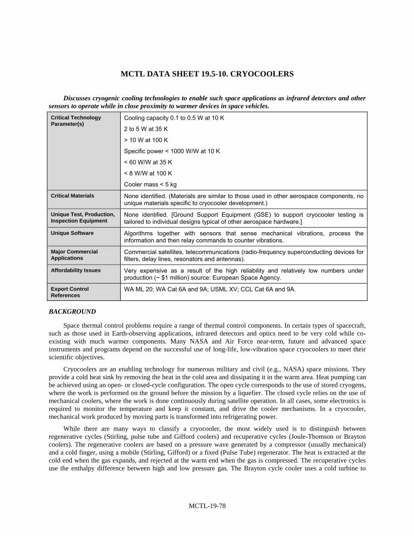
MCTL-19-78
MCTL DATA SHEET 19.5-10. CRYOCOOLERS
Discusses cryogenic cooling technologies to enable such space applications as infrared detectors and other sensors to operate while in close proximity to warmer devices in space vehicles.
Critical Technology Parameter(s)
Cooling capacity 0.1 to 0.5 W at 10 K
2 to 5 W at 35 K
> 10 W at 100 K
Specific power < 1000 W/W at 10 K
< 60 W/W at 35 K
< 8 W/W at 100 K
Cooler mass < 5 kg
Critical Materials None identified. (Materials are similar to those used in other aerospace components, no unique materials specific to cryocooler development.)
Unique Test, Production, Inspection Equipment
None identified. [Ground Support Equipment (GSE) to support cryocooler testing is tailored to individual designs typical of other aerospace hardware.]
Unique Software Algorithms together with sensors that sense mechanical vibrations, process the information and then relay commands to counter vibrations.
Major Commercial Applications
Commercial satellites, telecommunications (radio-frequency superconducting devices for filters, delay lines, resonators and antennas).
Affordability Issues Very expensive as a result of the high reliability and relatively low numbers under production (~ $1 million) source: European Space Agency.
Export Control References
WA ML 20; WA Cat 6A and 9A; USML XV; CCL Cat 6A and 9A.
BACKGROUND
Space thermal control problems require a range of thermal control components. In certain types of spacecraft, such as those used in Earth-observing applications, infrared detectors and optics need to be very cold while co-existing with much warmer components. Many NASA and Air Force near-term, future and advanced space instruments and programs depend on the successful use of long-life, low-vibration space cryocoolers to meet their scientific objectives.
Cryocoolers are an enabling technology for numerous military and civil (e.g., NASA) space missions. They provide a cold heat sink by removing the heat in the cold area and dissipating it in the warm area. Heat pumping can be achieved using an open- or closed-cycle configuration. The open cycle corresponds to the use of stored cryogens, where the work is performed on the ground before the mission by a liquefier. The closed cycle relies on the use of mechanical coolers, where the work is done continuously during satellite operation. In all cases, some electronics is required to monitor the temperature and keep it constant, and drive the cooler mechanisms. In a cryocooler, mechanical work produced by moving parts is transformed into refrigerating power.
While there are many ways to classify a cryocooler, the most widely used is to distinguish between regenerative cycles (Stirling, pulse tube and Gifford coolers) and recuperative cycles (Joule-Thomson or Brayton coolers). The regenerative coolers are based on a pressure wave generated by a compressor (usually mechanical) and a cold finger, using a mobile (Stirling, Gifford) or a fixed (Pulse Tube) regenerator. The heat is extracted at the cold end when the gas expands, and rejected at the warm end when the gas is compressed. The recuperative cycles use the enthalpy difference between high and low pressure gas. The Brayton cycle cooler uses a cold turbine to

MCTL-19-79
expand the gas, whereas the Joule-Thomson coolers use the expansion though an orifice, and the properties of real gas to get the cooling effect. Being irreversible, the Joule-Thomson cooler (normally coupled to Stirling units) is less efficient than the Brayton type, but it is simpler.
Initial cryocoolers for space applications were based on the Stirling cycle or on the Joule-Thomson expansion, but more recently a variation using a pulse tube cold head with the Stirling cycle compressors has been used in the United States, due to its lack of moving parts and thus reduced vibration levels.
Cryogenic detectors have driven the utilization of cryogenics in space, thus, determining the requirements in terms of operating temperature, temperature stability and architecture of the payload system. This trend is now well established across the electromagnetic spectrum. Applications involving the lower energy end of the electromagnetic spectrum (i.e., submillimeter wave and infrared) are the ones that benefit most from the utilization of cryogenic detectors and therefore, cryocoolers. Besides cryogenic detectors another technology that will require cryogenics is in the area of telecommunications. Progress in high-temperature superconductors has opened new perspectives for the fabrication of radio-frequency super-conducting devices such as filters, delay lines, resonators and antennas. These devices provide the capability to improve the performance of telecommunications satellite.
Beside the cryocooler itself, the cryocooler’s control electronics and associated software are critical elements of a state-of-the-art cryocooler system in monitoring and processing sensor inputs in order to provide feedback to reduce vibration levels.
Cryogenic thermal systems interface sensors with mechanical coolers with operating ranges from 200 to 2 K. They include heat transport devices, thermal switches and diodes, thermal storage, mechanical supports, thermal isolation, and thermal insulation. This hardware is critical in that it must provide excellent thermal interfaces while minimizing transmission of mechanical forces.

MCTL-19-81
SECTION 19.6—LAUNCH PROPULSION FOR SPACE SYSTEMS
Highlights
• Space Launch Propulsion Systems are key critical elements of U.S. national security and U.S. economic power.
• Many of the technologies used in space launch propulsion systems are used in both commercial and defense applications therefore they are dual-use technologies.
• Improving the specific impulse, Isp, of propellants has been a major factor in the United States maintaining a technological lead in this area.
• There are two basic types of launch propulsion systems—Solid Rocket Motor (SRM) and Liquid Rocket Motor (LRM). Many of their respective technologies are quite different.
• A third category of rocket engines is hybrid rocket motors (HRM)—essentially an SRM in which one chemical, generally the oxidizer, is a liquid.
• Propulsion technologies include propellants and propellant ingredients, turbo-machinery, cases, nozzles, actuators and controls, and design and fabrication of specific components.
• Modern launch propulsion technology is a refinement (albeit a significant one) of Germany’s World War II V2 rockets.
• New refinements include advanced propellants and chemicals, new bearing designs, and technologies using exotic materials for combustion chambers and nozzles.
• Increasingly, design codes, fabrication techniques, and specialized test equipment are critical elements of the technologies.
• Ramjet technology currently used in tactical missiles, has the potential to be used in launch propulsion.
• Improving the performance of hybrid systems will have a significant effect on the overall thrust to weight ratio and therefore payload costs.
• Emerging critical propulsion technology areas include chemical, low-thrust electrical, and nuclear thermal.
• Nuclear thermal propulsion appears attractive for high-energy upper stage propulsion and for co-generated electrical systems.
• Further developments continue in high-energy-density propulsion materials, improved propellant bonding, and advanced cryocooling and storage.
OVERVIEW
The launch propulsion technology section encompasses many individual critical technologies that are required to support and maintain our military capabilities. The list above identifies the thirteen (13) specific technologies with critical parameters and parameter values needed to maintain this capability. These include: High-Energy Propellant Ingredients, Ramjet Launch Propulsion, Liquid Rocket Engines, Liquid Rocket Engines Combustion Chamber Devices, Liquid Rocket Engine Nozzles and Exit Cone Technology, Liquid Rocket Engine Turbo Machinery, Rocket Engine Nozzle Technology, Solid Rocket Engines, Solid Rocket Propulsion, Composite Motor Cases, Thrust Vector Actuation Systems, Thrust Vector Control Systems, and High-Energy Propellant Ingredients.
All of these critical technologies are dual-use technologies since commercial satellites use the same technologies as required for those of military needs. Therefore, careful consideration has been given to what is truly

MCTL-19-82
critical in military applications so as to minimize the economic impact of any limitations that might result by governmental use of these militarily critical technologies and respective parameters.
BACKGROUND
The two main types of rocket engine in use today are solid and liquid propellant rocket engines. There are also some hybrid rocket engines which combine portions of these two types. A hybrid rocket burns a mixture of solid fuel and liquid or gaseous oxidizer. A hybrid rocket engine almost matches the high specific impulse of liquid propellant rocket, and requires at most half the number of expensive turbo-pumps. Most hybrid designs forgo turbo-pumps entirely with the liquid oxygen feeding into the fuel combustion chamber by tank pressure.
The word propellant does not mean simply fuel; it means both fuel and oxidizer. The fuel is the chemical rockets burn mechanism, but, for burning to take place, an oxidizer (oxygen) must be present. Jet engines draw oxygen into their engines from the surrounding air. Rockets do not have the luxury that jet planes have; they must carry oxygen with them into space, where there is no air.
The gauge for rating efficiency of rocket propellants is specific impulse, stated in seconds. Specific impulse indicates how many pounds (or kilograms) of thrust are obtained by the consumption of one pound (or kilogram) of propellant in one second. Specific impulse is characteristic of the type of propellant. The exact value of specific impulse will vary to some extent with the operating conditions and design of the rocket engine.
1. Liquid Rocket Engines
In a liquid rocket, the propellants, the fuel and the oxidizer, are stored separately as liquids and are pumped into the combustion chamber of the nozzle where burning occurs. Under normal temperature conditions, the propellants do not burn; but they will burn when exposed to a source of heat provided by an igniter. Once the burning starts, it proceeds until the propellant flow is interrupted. The thrust can be controlled by varying the amount of propellant that enters the combustion chamber. Thrust can be stopped by turning off the flow of propellants. Liquid rockets tend to be heavy and complex because of the pumps and storage tanks.
Nozzles are used to on both liquid and solid rocket engines to increase the acceleration of the gases as they leave the rocket and thereby maximize the thrust. It does this by cutting down the opening through which the gases can escape. The size of the opening can be varied depending on the desired thrust and other requirements.
As with the inside of the rocket case, insulation is needed to protect the nozzle from the hot gases. The usual insulation is one that gradually erodes as the gas passes through. Small pieces of the insulation get very hot and break away from the nozzle. As they are blown away, heat is carried away with them.
The fuel of a liquid-propellant rocket is usually kerosene or liquid hydrogen; the oxidizer is usually liquid oxygen. They are combined inside a cavity called the combustion chamber. Here the propellants burn and build up high temperatures and pressures, and the expanding gas escapes through the nozzle at the lower end. To get the most power from the propellants, they must be mixed as completely as possible. Small injectors (nozzles) on the roof of the chamber spray and mix the propellants at the same time. Because the chamber operates under high pressures, the propellants need to be forced inside. Powerful, lightweight turbine pumps between the propellant tanks and combustion chambers take care of this job.
With any rocket, and especially with liquid-propellant rockets, weight is an important factor. In general, the heavier the rocket, the more the thrust needed to get it off the ground. Because of the pumps and fuel lines, liquid engines are much heavier than solid engines.
One especially good method of reducing the weight of liquid engines is to make the exit cone of the nozzle out of very lightweight metals. However, the extremely hot, fast-moving gases that pass through the cone would quickly melt thin metal. Therefore, a cooling system is needed. A highly effective though complex cooling system that is used with some liquid engines takes advantage of the low temperature of liquid hydrogen. Hydrogen becomes a liquid when it is chilled to –2530 °C. Before injecting the hydrogen into the combustion chamber, it is first circulated through small tubes that lace the walls of the exit cone. In a cutaway view, the exit cone wall looks like the edge of corrugated cardboard. The hydrogen in the tubes absorbs the excess heat entering the cone walls and

MCTL-19-83
prevents it from melting the walls away. It also makes the hydrogen more energetic because of the heat it picks up. This kind of cooling system is regenerative cooling.
There are two metal or composite tanks required for a liquid rocket engine, holding the fuel and oxidizer, respectively. Due to properties of these two liquids, they are typically loaded into their tanks just prior to launch. The separate tanks are necessary, for many liquid fuels burn upon contact. Upon a set launching sequence two valves open, allowing the liquid, hitherto blocked, to flow down the pipe-work. If these valves simply opened allowing the liquid propellants to flow into the combustion chamber at their own leisure, a weak (if any at all) thrust production would incur as well as an unstable flow rate (leading to an unstable thrust rate). Two solutions have been devised to solve this problem: (1) a pressurized gas feed and (2) a turbopump feed.
Figure 19.6-1 shows a typical liquid rocket engine similar to the type used in space launches of the shuttle. This figure which illustrates the basics of liquid rocket engine technology is taken from the NASA web site: http://www.grc.nasa.gov/WWW/K-12/airplane/srockth.html
Figure 19.6-1. Courtesy of the NASA web site: http://www.grc.nasa.gov/WWW/K-12/airplane/srockth.html
2. Solid Rocket Engines
A solid-propellant rocket has the simplest form of engine. It has a nozzle, a case, insulation, propellant, and an igniter. The case of the engine is usually a relatively thin metal that is lined with insulation to keep the propellant from burning through. The propellant itself is packed inside the insulation layer.
Many solid-propellant rocket engines feature a hollow core that runs through the propellant. Rockets that do not have the hollow core must be ignited at the lower end of the propellants and burning proceeds gradually from one end of the rocket to the other. In all cases, only the surface of the propellant burns. However, to get higher thrust, a hollow core is used. This increases the surface of the propellants available for burning. The propellants burn from the inside out at a very high rate, and the gases produced escape the engine at much higher speeds. This gives a greater thrust. Some propellant cores are star shaped to increase the burning surface even more.
To fire solid propellants, many kinds of igniters can be used. A safe and reliable form of ignition used is one that employs electricity. An electric current, coming through wires from some distance away, heats up a special wire inside the rocket. The wire raises the temperature of the propellant it is in contact with to the combustion point.
Solid-propellant rockets are not as easy to control as liquid rockets. Once started, the propellants burn until they are gone. They are very difficult to stop or slow down part way into the burn. Sometimes fire extinguishers are built into the engine to stop the rocket in flight. But using them is a tricky procedure and doesn’t always work. Some solid-fuel engines have hatches on their sides that can be cut loose by remote control to release the chamber pressure and terminate thrust.
The burn rate of solid propellants must be carefully planned in advance. At first, there is a very large surface available for burning, but as the points of the star burn away, the surface area is reduced. For a time, less of the

MCTL-19-84
propellant burns, and this reduces thrust. The Space Shuttle uses this technique to reduce vibrations early in its flight into orbit.
Solid rocket engines have a specific set of advantages and drawbacks. In solid rocket motors, the fuel and oxidizer are chemically premixed to form a solid fuel grain. By simply igniting this substance, the oxidizer and fuel in the solid react and produce the high-energy combustion gases desired. A variety of designs for the central burning port of the solid fuel can be created so as to produce the desired thrust performance. Solid rockets provide good thrust and are the simplest systems available. On the down side, they also are fairly inefficient fuel burners and cannot be throttled. In some cases there may also be explosion dangers since the oxidizer and fuel are not separated.
Solid rocket propellants, which are dry to the touch, contain both the fuel and oxidizer combined together in the chemical itself. The propellants are mixed together and packed into a solid cylinder. Usually the fuel is a mixture of hydrogen compounds and carbon and the oxidizer is made up of oxygen compounds (see Figure 19.6-2).
Figure 19.6-2. Illustrates a solid rocket thrust engine, taken from the NASA web site:
http://www.grc.nasa.gov/WWW/K-12/airplane/srockth.html
The amount of thrust produced by the rocket depends on the design of the nozzle. The smallest cross-sectional area of the nozzle is called the throat of the nozzle. The hot exhaust flow is choked at the throat, which means that the Mach number is equal to 1.0 in the throat and the mass flow rate m dot is determined by the throat area. The area ratio from the throat to the exit Ae sets the exit velocity Ve and the exit pressure pe. The free stream pressure is given by po.
The thrust equation given above works for both liquid and solid rocket engines. There is also an efficiency parameter called the specific impulse which works for both types of rockets and greatly simplifies the performance analysis for rocket engines (Ref. 2).
3. Hybrid Rocket Engines
Hybrid rockets combine elements from both types of liquid and solid rockets. In a hybrid rocket, a gaseous or liquid oxidizer is stored in a tank separate from a solid fuel. The fuel or fuel grain is placed inside a pressure chamber which lies between an oxidizer injector and the exit nozzle. The solid grain is hollowed out in the same fashion to produce a combustion port, very similar to that of a solid rocket motor type system. Unless the fuel is hypergolic (spontaneously combustible in the presence of an oxidizer), the fuel must be initially ignited in order to vaporize some of the fuel into a region just above the solid surface. Then, by injecting the oxidizer at a high mass flow rate and pressure into the pressure chamber or combustion port area, the oxidizer and fuel are free to react just above the surface of the fuel grain. The high energy released and the high temperature attained both increase the energy in the flow and sustain the solid fuel vaporization. The combustion gases pass down the remainder of the combustion port and are expanded via the nozzle. By changing the flow rate of the oxidizer, the total production of combustion gases and the energy going into them will be changed in a like fashion (increasing or decreasing). This fact demonstrates that hybrid rockets can be throttled. Given a simple ignition system that would efficiently initiate

MCTL-19-85
fuel burning prior to injecting the oxidizer, it also shows that hybrid rockets have start-stop-restart capabilities which can be a major attribute for some applications.
On the down side, the nature of the system renders itself to marginally higher combustion inefficiencies and also to variations in specific impulse. This has much to do with the incompleteness of the mixing in the active combustion zone above the solid fuel surface. These effects are not so bad however; as far as specific impulse is concerned. Typical performance numbers are not difficult to find: for liquid systems, typical impulses can range from 300 sec up to 400 sec for the Space Shuttle Main Engine (SSME); typical solid systems operate at a specific impulse of between 200–270 sec. Performances generated thus far for experimental hybrid test engines lie in the range of 275–350 sec. Moreover, it is not beyond possibility that further dedicated research and development of hybrid rocket motors will relieve some of the inefficiency problems and therefore boost the performance figures even higher. Another disadvantage to hybrids is that there will usually be unburned fuel slivers remaining after burning; however, this effect also plagues solid rockets.
The performance for these rockets is approaching that of liquid systems. Furthermore, hybrid rocket systems require support for only one fluid system, including tanks, valves, regulators, etc. In other words, although hybrid rockets are more complex than solid systems, they compare in performance to liquid systems while requiring only half of the “plumbing.” This vastly reduces the overall systems weight and cost, while increasing its reliability (there will be fewer parts to fail). Hybrid rocket systems are also safer to produce and store, can be more ecologically safe with proper propellant choice, and the fuel grain, being inert, is stronger than manufactured solid propellant grains (for solid rockets), and is therefore more reliable. Finally the solid fuel grain of the hybrid gives it volumetric sizing advantages over the tankage required for liquid systems. Clearly, hybrid rocket motors offer numerous benefits at a small price (Ref. 3).

MCTL-19-87
LIST OF MCTL TECHNOLOGY DATA SHEETS 19.6. LAUNCH PROPULSION FOR SPACE SYSTEMS
19.6-1 High-Energy Propellant ........................................................................................................... MCTL-19-89
19.6-2 High-Energy Propellant Ingredients ........................................................................................ MCTL-19-93
19.6-3 Liquid Rocket Engines ............................................................................................................ MCTL-19-95
19.6-4 Liquid Rocket Engines Combustion Chamber Devices........................................................... MCTL-19-99
19.6-5 Liquid Rocket Engine Nozzle (Exit Cone) Technology........................................................ MCTL-19-103
19.6-6 Liquid Rocket Engine Turbomachinery ................................................................................ MCTL-19-106
19.6-7 Liquid Rocket Engine Injectors ............................................................................................. MCTL-19-109
19.6-8 Solid Rocket Engine Nozzle Technology.............................................................................. MCTL-19-111
19.6-9 Solid Rocket Propulsion ........................................................................................................ MCTL-19-114
19.6-10 Composite Motor Cases......................................................................................................... MCTL-19-116
19.6-11 Thrust Vector Actuation Systems .......................................................................................... MCTL-19-119
19.6-12 Thrust Vector Control Systems ............................................................................................. MCTL-19-120
19.6-13 Ramjet Launch Propulsion .................................................................................................... MCTL-19-124

MCTL-19-89
MCTL DATA SHEET 19.6-1. HIGH-ENERGY PROPELLANT
Discusses high energy propellants used in space launch vehicles; includes solid, hybrid, and liquid propellants.
Critical Technology Parameter(s)
Solid and Hybrid Propulsion:
• Solid Booster Propellant Capability: Isp [1000–14.7 psi] > 253 lbfs/lbm (delivered impulse of composite, class 1.3 propellant); Density Ispdel > 16.5 lbfs/in3.
• Hybrid Booster Baseline Capability: Isp [1000–14.7 psi] > 278 lbfs/lbm (delivered impulse of solid fuel grain, LOX injected).
• Solid/Hybrid Tactical Motor Capability: Ispdel [1000–14.7 psi] Minimum Smoke/Reduced Smoke/Smoky > 240/246/253 lbfs/lbm; Density Ispdel > 14.3/15.3/16.0 lbfs/in3.
Liquid Propulsion:
• Hydrocarbon-Fueled Booster Capability: Isp [1000 -14.7 psi] > 272 lbfs/lbm (delivered impulse for hydrocarbon/ LOX system).
• Spacecraft Monopropellant and Storable Bipropellant Engine Capability: Density Isp [300 psi–vac; 50:1 exp] (theoretical), Monopropellant (storable)/Bipropellant (storable) = 10.9/15.1 lbfs/in3.
Critical Materials Solid and Hybrid Propulsion Ingredients:
Ingredients/materials include dinitramide-based (e.g., ADN), trinitromethide-based (e.g. HNF), perchlorate-based (e.g., AP), tetrazole-based (e.g., aminotetrazole), triazole-based (e.g., aminotriazole), azetidine-based (e.g., TNAZ), hydrazine-based (e.g., hydrazine nitrate), hydroxylamine-based (e.g., HAN), other high nitrogen- and/or oxygen-containing materials (e.g., CL-20, HMX, BuNENA, and BTTN), and strained ring compounds (e.g., molecules comprised of cyclopropyl and/or cyclobutyl functionality). Also high energy binder monomers that yield polymers that constitute a structural matrix for advanced solid propellants and are comprised of nitro-, nitrato-, azido-, nitramino- or other energy-conferring functionalities (e.g., NMMO, BAMO, AMMO, glycidyl nitrate, and glycidyl azide). Ballistic modifiers such as metal resorcylates and salicylates are often required to produce acceptable propellant regression rate behavior. Also ballistic modifiers capable of generating steady-state burning rates in excess of 1.5 inch per second at 1,000 psi pressure. (e.g., metals, metal oxides and solid oxidizers with submicron particle size). Stabilizers for advanced propellants including N-methyl-p-nitroaniline and Protech. Nanometals with submicron materials. Burning rate modifiers (e.g., ferrocenes, carboranes). Liquid nitrate esters (e.g., PGDN, TMETN, DEGDN, TEGDN, etc.) and energetic liquid plasticizers (e.g., BDNPA/F). Fuels (e.g., Alane).
Liquid Propulsion Ingredient:
Additives for controlling the coking, polymerization, and combustion behavior of liquid hydrocarbons. Low sulfur kerosene. Stabilizers for hydrogen peroxide. HAN and HAP.
Unique Test, Production, Inspection Equipment
Solid and Hybrid: Specialized equipment, instrumentation and tests necessary for evaluating propellant characteristics include: impact sensitivity, friction sensitivity, electrostatic discharge sensitivity, Naval Ordnance Laboratory (NOL) card gap, combustion window bomb, propellant strand-burner, and liquid adiabatic compressibility (U-tube). Production equipment includes planetary mixers capable of vacuum operation with capacities ranging from 1 pint to over 600 gallon. Other processing equipment includes extruders.
Liquid: None identified.

MCTL-19-90
Unique Software Chemical analysis, reaction analysis codes, chemical structure, estimate of chemical and
physical properties of energetic molecules, quality control, performance prediction.
Major Commercial Applications
Commercial launch and spacecraft propulsion.
Affordability Issues None identified.
Export Control References
WA ML 8; MTCR 4; USML IV.
BACKGROUND
Rockets have evolved from simple gunpowder devices into giant vehicles capable of traveling into outer space. Current rockets are propelled by a variety of fuel mixtures. The array includes: liquid propellants, solid propellants and hybrids. The hybrid propellant engines represent an intermediate group between solid and liquid propellant engines.
Propellant is the chemical mixture burned to produce thrust in rockets and consists of a fuel and an oxidizer. Fuel is a substance, which burns when combined with oxygen producing gas for propulsion. An oxidizer is an agent that releases oxygen for combination with a fuel. Propellants are classified according to their state—liquid, solid, or hybrid.
Liquid Propellants. In a liquid propellant rocket, the fuel and oxidizer are stored in separate tanks, and are fed through a system of pipes, valves, and turbopumps to a combustion chamber where they are combined and burned to produce thrust. Liquid propellant engines are more complex then their solid propellant counterparts, however, they offer several advantages. By controlling the flow of propellant to the combustion chamber, the engine can be throttled, stopped, or restarted. The restarting is a key issue for on-orbit maneuvering.
A good liquid propellant is one with a high specific impulse, i.e., one with a high speed of exhaust gas ejection. This implies a high combustion temperature and exhaust gases with small molecular weights. However, there is another important factor, which must be taken into consideration: the density of the propellant. Using low-density propellants means that larger storage tanks will be required, thus increasing the mass of the launch vehicle. Storage temperature is also important. A propellant with a low storage temperature, i.e., a cryogenic, will require thermal insulation, thus further increasing the mass of the launcher. The toxicity of the propellant is likewise important. Safety hazards exist when handling, transporting, and storing highly toxic compounds. Also, some propellants are very corrosive, however, materials that are resistant to certain propellants have been identified for use in rocket construction.
Liquid propellants used by NASA and in commercial launch vehicles can be classified into three types: petroleum, cryogenic, and hypergolic.
Petroleum fuels are refined from crude oil and are a mixture of complex hydrocarbons, i.e. organic compounds containing only carbon and hydrogen. The main petroleum used as rocket fuel is kerosene, or a type of highly refined kerosene called RP-1 (refined petroleum). It is used in combination with liquid oxygen as the oxidizer. RP-1 and liquid oxygen are used as the propellant in the first-stage boosters of the Atlas/Centaur and Delta launch vehicles. It also powered the first-stages of the Saturn 1B and Saturn V rockets. RP-1 delivers a specific impulse considerably less than cryogenic fuels.
Cryogenic propellants are liquefied gases stored at very low temperatures, namely liquid hydrogen (LH2) as the fuel and liquid oxygen (LO2) as the oxidizer. LH2 remains liquid at temperatures of -423 °F (-253 °C) and LO2 remains in a liquid state at temperatures of -298 °F (-183 °C).
Because of the low temperatures of cryogenic propellants, they are difficult to store over long periods of time. For this reason, they are less desirable for use in military rockets, which must be kept launch ready for months at a time. Also, liquid hydrogen has a very low density (0.59 lbs/gal) and, therefore, requires a storage volume many times greater than other fuels. Despite these drawbacks, the high efficiency of liquid hydrogen/liquid oxygen makes

MCTL-19-91
these problems worth coping with when reaction time and storability are not too critical. Liquid hydrogen delivers a specific impulse about 40-percent higher than other rocket fuels.
Liquid hydrogen and liquid oxygen are used as the propellant in the high efficiency main engines of the space shuttle. LH2/LO2 also powered the upper stages of the Saturn V and Saturn lB rockets as well as the second stage of the Atlas/Centaur launch vehicle, the United States’ first LH2/LO2 rocket (1962).
Hypergolic propellants are fuels and oxidizers, which ignite spontaneously on contact with each other and require no ignition source. The easy start and restart capability of hypergolics make them ideal for spacecraft maneuvering systems. Also, since hypergolics remain liquid at normal temperatures, they do not pose the storage problems of cryogenic propellants. Hypergolics are highly toxic and must be handled with extreme care.
Hypergolic fuels commonly include hydrazine, monomethyl hydrazine (MMH) and unsymmetrical dimethyl hydrazine (UDMH). The oxidizer is typically nitrogen tetroxide (N2O4) or nitric acid (HNO3). UDMH is used in many Russian, European, and Chinese rockets while MMH is used in the orbital maneuvering system (OMS) and reaction control system (RCS) of the Space Shuttle orbiter. The Titan family of launch vehicles and the second stage of the Delta use a fuel called Aerozine 50, a mixture of 50-percent UDMH and 50-percent hydrazine.
Hydrazine is also frequently used as a mono-propellant in catalytic decomposition engines. In these engines, a liquid fuel decomposes into hot gas in the presence of a catalyst. The decomposition of hydrazine produces temperatures of about 1700 °F and a specific impulse of about 230 or 240 seconds.
Solid Propellants. Solid propellant motors are the simplest of all rocket designs. They consist of a casing, usually steel, filled with a mixture of solid compounds (fuel and oxidizer), which burns at a rapid rate, expelling hot gases from a nozzle to produce thrust. When ignited, a solid propellant burns from the center out towards the sides of the casing. The shape of the center channel determines the rate and pattern of the burn, thus providing a means to control thrust. Unlike liquid propellant engines, solid propellant motors cannot be shut down. Once ignited, they will burn until all the propellant is exhausted.
There are two families of solids propellants: homogeneous and composite. Both types are dense, stable at ordinary temperatures, and easily storable.
Homogeneous propellants are either simple base or double base. A simple base propellant consists of a single compound, usually nitrocellulose, which has both an oxidation capacity and a reduction capacity. Double base propellants usually consist of nitrocellulose and nitroglycerine, to which a plasticizer is added. Homogeneous propellants do not usually have specific impulses greater than about 210 seconds under normal conditions. Their main asset is that they do not produce traceable fumes and are, therefore, commonly used in tactical weapons. They are also often used to perform subsidiary functions such as jettisoning spent parts or separating one stage from another.
Modern composite propellants are heterogeneous powders (mixtures), which use a crystallized or finely ground mineral salt as an oxidizer, often ammonium perchlorate, which constitutes between 60 percent and 90 percent of the mass of the propellant. The fuel itself is aluminum. The propellant is held together by a polymeric binder, usually polyurethane or polybutadienes. Additional compounds are sometimes included, such as a catalyst to help increase the burning rate, or other agents to make the powder easier to manufacture. The final product is rubber-like substance with the consistency of a hard rubber eraser.
Solid propellant motors have a variety of uses. Small solids often power the final stage of a launch vehicle, or attach to payloads to boost them to higher orbits. Medium solids such as the Payload Assist Module (PAM) provide the added boost to place satellites into geosynchronous orbit or on planetary trajectories.
The Delta II, Delta IV, Atlas V, and Space Shuttle launch vehicles use strap-on solid propellant rockets to provide added thrust at liftoff. The Space Shuttle uses the largest solid rocket motors ever built and flown. Each booster contains 1,100,000 lbs (499,000 kg) of propellant and can produce up to 3,300,000 lbs (14,680,000 Newtons) of thrust.
Hybrid Propellants. Hybrid propellant engines represent an intermediate group between solid and liquid propellant engines. One of the substances is solid, usually the fuel, while the other, usually the oxidizer, is liquid. The liquid is injected into the solid, whose fuel reservoir also serves as the combustion chamber. The main

MCTL-19-92
advantage of such engines is that they have high performance, similar to that of solid propellants, but the combustion can be moderated, stopped, or even restarted. It is difficult to make use of this concept for vary large thrusts, and thus, hybrid propellant engines are rarely built.

MCTL-19-93
MCTL DATA SHEET 19.6-2. HIGH-ENERGY PROPELLANT INGREDIENTS
Discusses ingredients for use in solid and hybrid and also liquid rocket fuel launch propellants.
Critical Technology Parameter(s)
• Solid and hybrid propulsion ingredient critical parameters. Those meeting the following critical structural parameters: (1) Nonhalogenated solid oxidizers that have an oxygen balance > +20 percent and
density > 1.73 g/cm3; (2) Chemical compounds that are near stoichiometric balance:
a. with enthalpy of formation > +66 calorie/g, b. density > 1.8 g/cm3, c. heat of detonation > 1.68 kcal/g, and d. Yielding combustion products with an average molecular weight < 27 amu.
(3) Monomers capable of polymerization to produce high-energy binder polymers that constitute a structural matrix for advanced solid propellants (such compounds are monomers comprised of nitro-, nitrato-, azido-, nitramino-, or other energy-conferring functionalities and may incorporate oxygenated, cyclic functionality such as epoxy or oxetane and polymers resulting from these monomers);
(4) Compounds that constitute energetic fuels, have low or no oxygen content, and have low molecular weight (< 5,000 amu) (development is focused on strained-ring molecules with positive enthalpy of formation and density greater than 1.2 g/cm3, high-nitrogen molecules, and metal hydrides); and
(5) Fuel technology defined by ultrafine (< 1 µm average particle diameter) materials with development focused on metals with average atomic mass generally ≤ 27 amu.
• Liquid propulsion ingredient critical parameters. High-performance hydrocarbon fuel ingredients for bipropellant systems comprised of strained-ring and/or unsaturated hydrocarbon molecules meeting the following parameters: (1) With molecular property objectives that include a carbon-to-hydrogen ratio close o
1:1; (2) Enthalpy of formation > 0 calorie/g; and (3) Density > 0.8 g/cm3.
Critical Materials (1) Strained-ring and/or unsaturated hydrocarbon molecule materials that have density > 1.4 g/cm3 and oxygen balance > +33 percent;
(2) Precursor materials critical to production of high-energy ingredients include dinitramide-based, trinitromethide-based, tetrazole-based, triazole-based, hydrazines, nitration reagents, other high nitrogen- and/or oxygen-containing materials; and
(3) Strained-ring compounds (e.g., molecules comprised of cyclopropyl and/or cyclobutyl functionality). Reagents for accomplishing C-nitrations, O-nitrations and N-nitrations are often required for ingredient production.
Unique Test, Production, Inspection Equipment
Specialized equipment and tests necessary for evaluating ingredient characteristics include impact sensitivity tester, friction sensitivity tester, electrostatic discharge sensitivity tester, Naval Ordnance Laboratory (NOL) card gap test, and liquid adiabatic compressibility (U-tube) tester. Note: Some test, production, and inspection equipment for high-energy materials is common to the explosives industries.

MCTL-19-94
Unique Software Chemical analysis; reaction analysis codes; chemical structure; estimate of chemical and
physical properties of energetic molecules; quality control; performance prediction.
Major Commercial Applications
Many of these materials can be used in producing pharmaceuticals, commercial explosives and fuels, as well as other commercial products. Satellite launch systems; gun propellants; emergency and auxiliary power units; explosives; vehicular restraint systems all have direct commercial utility.
Affordability Issues When developed, this technology will increase booster range/payload for same or lower costs.
Export Control References
WA ML 8; WA Cat 1; MTCR 4; USML V; CCL Cat 1.
BACKGROUND
The two main categories of rocket engines are liquid rockets and solid rockets. In a liquid rocket, the propellants, the fuel and the oxidizer, are stored separately as liquids and are pumped into the combustion chamber of the nozzle where burning occurs. In a solid rocket, the propellants are mixed together and packed into a solid cylinder. There are also hybrid rocket engines which is a combination of these two types. A hybrid rocket burns a mixture of solid fuel and liquid or gaseous oxidizer. A hybrid rocket almost matches the high specific impulse of liquid propellant rocket, and requires only half the number of expensive turbopumps. Hybrid designs typically forgo turbopumps and the liquid oxygen is fed into the combustion chamber by tank pressure.
Under normal temperature conditions, the propellants do not burn; but they will burn when exposed to a source of heat provided by an igniter. In a solid rocket motor, once the burning starts, it proceeds until all the propellant is exhausted. With a liquid rocket motor, one can stop the thrust by turning off the flow of propellants. Liquid rockets tend to be heavier and more complex because of the pumps and storage tanks. A solid rocket is much easier to handle and can sit for years before firing.
A liquid propellant rocket burns a mixture of liquid fuel and liquid oxidizer, e.g., hydrogen and oxygen. Hydrogen, like chlorine, has negative impacts on the ozone layer. The cheapest and the least toxic fuels are methane, ethane, and propane. Liquid oxygen is the cheapest and the least toxic oxidizer. Hydrogen peroxide (H2O2) is not as energetic as liquid oxygen and is much more expensive but it can be stored at room temperature and it is a better regenerative coolant. Diluted hydrogen peroxide can be concentrated up to 90–98 percent by distillation and up to 100 percent by crystallization. Kerosene fuel and its purified form known as RP-1 can also be stored at room temperature and it burns well with hydrogen peroxide. Unlike kerosene, RP-1 (Rocket Propellant-1) has uniform density, high coking temperature, and is free of sulfur.
The overall density of the peroxide/kerosene combination is 1.312 g/cm3, better than overall density of liquid oxygen/methane, which is only 0.828 g/cm3. On the other hand, the liquid oxygen/methane combination has 12 percent higher specific impulse and these propellants can be self pressurized, which means that their vapor pressure forces them into the rocket engine. The self-pressurized rocket has simpler design and lower dry weight than a rocket using conventional pressurization system made of a helium tank and a flexible bladder separating the helium and the propellant. The fuel and oxidizer are mixed and burned in the combustion chamber.

MCTL-19-95
MCTL DATA SHEET 19.6-3. LIQUID ROCKET ENGINES
Discusses propulsion technologies related to liquid fueled launch vehicles, or liquid rocket engines (LRE).
Critical Technology Parameter(s)
• Specific Impulse (chamber):
Type Isp Chamber Pressure LOX/LH2 > 400 seconds > 1000 psi, LOX/Kerosene > 300 seconds > 500 psi, NTO > 280 seconds > 300 psi, Nitric Acid > 280 seconds > 300 psi, or IRFNA/Hydrazine > 280 seconds > 300 psi.
• The ratio of delivered Isp (at the exit plane) to Theoretical maximum: > 85% (0.85);
• Delivered Thrust: First stage or booster > 200 Klbs, Second or upper stage > 5 Klbs, or Research engines > 100 lbs
• A Thrust to Weight ratio: T/W > 30; or
• Any liquid rocket engine with one or more of the following features:
• Integrated control and health monitoring systems;
• Monocoque thrust chamber and nozzle;
• Gimbal angle > 5°;
• Turbomachinery with delivered horsepower per unit weight > 30 hp/lb;
• Throttling range > 40%; or
• In-flight ignition (Air Start).
Critical Materials • Staged combustion: single crystal nickel superalloys, narloy Z, hydrogen embrittlement resistant coatings (gold);
• Full flow staged combustion: hot oxygen compatible nickel-based superalloys;
• All: copper-chrome-niobium alloys;
• Upper stage: CMCs and refractory metals;
• Advanced propellants or propellant additives other than water; and
• Noble metals and alloys.
Unique Test, Production, Inspection Equipment
• Test Equipment: large (> 250 Klb thrust capability) test stands, large propellant storage systems; cryogenic equipment rated to pressures above 1000 psi;
• Production Equipment: friction stir welding, electrode position, electro-discharge machining, ultrafine grained nickel casting, large autoclaves and FSW equipment for tankage.
Unique Software Specialized software for engine design and balancing energy utilization (power balance), specialized cost analysis codes, combustion modeling, control software for engine ignition and valve timing, specialized health monitoring architecture, CEA one-dimensional equilibrium (ODE), two-dimensional kinetic (TDK), combined thermal fluid structure analysis networks, transient analyses, propellant property data bases, integrated vehicle health monitoring.
Major Commercial Applications
Commercial launch vehicle propulsion.
Affordability Issues Limited production runs and quantities, specialized manufacturing processes, and complex parts make affordability an issue. Extreme performance requirements limit application of affordability technologies. Implementing design for producibility practices will improve affordability of next generation systems.

MCTL-19-96
Export Control References
WA ML 4, 9, and 22; WA Cat 1; MTCR 2; USML IV; CCL Cat 9.
BACKGROUND
Liquid rocket engines are used to propel a variety of systems including commercial launch systems, military satellite launch systems, and weapons systems. There is no difference between engines used for military and commercial launch vehicle or satellite propulsion systems, while there are significant differences between engines used for different propulsion applications. Therefore, it is the mission for which the engine is designed, not the technology inherent in the engine which determines the parameter space and level of parameters that define military criticality for a particular engine. For example, the hydrostatic bearing technology used to improve the performance of turbopumps for advanced launch vehicle engines is not applicable to the pressure fed engine systems used to propel commercial satellites or the Scud A missile. In contrast, roller element bearing technology that is commonplace in commercial products like jet ski engines and vacuum cleaners or materials technologies for machine tools can be used to improve the performance of low performing engines like those used to propel the pump driven Scud B-D variants. To simplify discussions, LRE technologies can be grouped into three categories: low performance, high performance, and exo-atmospheric.
Low performance engines have thrust to weight ratios measured at sea level below 30 and theoretical sea level delivered specific impulses below 300 seconds. They are generally expendable, single stages of small geometric size (less than 3 ft in diameter) with simple propellant pressurization systems, limited thermal management of the combustion chamber (ablative), and limited control systems (no staging capability). Most do not have the capability to throttle (regulate thrust output) over a range greater than 15 percent. They can propel payloads of 100 lbs or less 1500 miles.
High performance engines have thrust to weight ratios above 30 and theoretical maximum sea level Isps of 300 secs or more. Engines in this category are used to launch payloads into orbit. In the late 1950s in the United States and in the former Soviet Block nations, LREs in this category were also used to propel ballistic missiles (IRBM and ICBMs). Because of the difficulties storing liquid propellants for extended periods of time and readying vehicles for immediate launch, liquid engines fell out of favor for the ICBM mission in the 1960s in the United States. Launch vehicles require multiple engines whose thrust output varies as function of altitude. Therefore, throttleability, controllability, and the ability to sequentially ignite, or stage engines, become critical technologies. Engines in this category can be either expendable or reusable, are usually turbopump fed, with complex regenerative cooling of the thrust chamber and control systems. The most well known engine in this category is the Space Shuttle Main Engine (SSME).
Exo-atmospheric engines propel satellites for orbit insertion, station keeping, and repositioning. These engines tend to be small in geometric size, have high thrust to weight ratios, simple propellant pressurization mechanisms, and Isps in the range from 250 to 350 sec, due to the requirement for propellants to be storable in space. (Isp is a function of the chemical energy stored in the propellants. Therefore different propellant combinations have different theoretical maximum Isps. Liquid Hydrogen has the highest maximum, followed by RP-1, and storables.)
Liquid fueled rockets burn a fuel and an oxidizer. The distinction is the liquid state of the fuel and the oxidizer. More advanced propulsion systems have been developed, but it will be many years before the dominance of the liquid fueled rocket will wane. There are two main reasons for using liquids. First, chemical rocket engines using liquid propellants have the highest specific impulse (Isp). Second, liquid propellant engines are among the most flexible rocket propulsion systems available.
LREs were first reduced to practice in the 1910s by Robert Goddard in the United States starting in the 1910s as a means of reaching the upper atmosphere for scientific purposes. Robert Goddard’s first turbopump driven, liquid oxygen (LO)–gasoline, liquid engine flew in 1941. In Europe, particularly in Germany, launch vehicle enthusiasts began experimenting with LREs in the 1920s also, well before WW II. The first LRE used by the military was the A4 engine powering the V-2 rocket, used by Germany to bomb England during WW II and first launched in 1942. A mixture of alcohol and water fueled the V-2 with liquid oxygen as the oxidizer. A 1-ton/sec flow rate of propellants generated 56 kilopound, propelling the V-2 to Mach 5. Most launch vehicle propulsion

MCTL-19-97
systems are based on V-2 technologies to some extent. This system is equivalent in performance and similar in technology to Scud type missile systems in operation in parts of the world today.
There are two metal tanks holding the fuel and oxidizer, respectively. Due to properties of these liquids, they are typically loaded into their tanks just prior to launch. The separate tanks are necessary, for many liquid fuels ignite and burn upon contact with the oxidizer. Upon a set launching sequence, two valves open allowing the liquid to flow down the pipe-works. If these valves simply opened allowing the liquid propellants to flow into the combustion chamber at their own leisure, a weak (if any at all) thrust production would incur as well as an unstable flow rate (leading to a unstable thrust rate). Two solutions have been devised to solve this problem: (1) pressurized gas feed and (2) turbopump feed.
Engine manufacturers use a wide range of terminology to describe LREs. Some of the terminology describes the engine configuration and others list quantitative parameters of engine performance.
Thrust: Thrust is the force generated by the engine. It is generally measure in pounds force (or kilopounds) in the United States and metric tons or kiloNewtons (kN) elsewhere. The actual thrust quantity has more to do with the mission the engine is performing and its configuration in a vehicle than to its level of technology or performance characteristics. A single first stage booster engine might generate one million pounds of thrust, while a gang of smaller LREs in the 200 Kelvin pound thrust class might also be used of a first stage booster mission. Upper stage engines tend to be in the 20 to 80 kilopound thrust class, while orbital maneuvering and vernier engines can produce very small, 10 lb, thrusts.
Geometric size is generally related to thrust class. Large booster engines can be 20 ft tall with nozzle exit planes over 10 ft in diameter. Most of the engine’s size is taken up by the nozzle/exit cone. Exo-atmospheric thrusters can fit in a shoe box.
Thrust to weight ratio, T/W: The ratio of the force generated by the engine at sea level to weight of the engine including the nozzle/exit cone, but excluding any mounting hardware. A direct measure of the structural efficiency of a rocket engine, T/W indicates the sophistication of the engine machinery. High performance engines have T/W > 30/1.
Specific Impulse, Isp or Is: The thrust of the engine divided by the weight flow rate of propellants. Measured in lbs/lbs/sec or simply, secs. A function of the chemical energy stored in the propellants, pressure in the combustion chamber, area ratio of the nozzle/exit con, and the efficiency of the engine. Directly related to the final velocity of the vehicle, and therefore the range and payload capability of the vehicle. Engines with ratios of delivered Isp (what is actually achieved by the functioning engine) to theoretical maximum (predicted from chemical equilibrium) greater than 85 are high performance engines.
Mixture ratio, O/F: The ratio of oxidizer to fuel burned in the combustion chamber. Stochoimetric (ratio necessary to fully react all the fuel with all the oxidizer) ratio varies with propellant combination. Ratio actually employed by an engine is a function of the engine design.
Propellant type: Cryogenic (LOX/LH2), hydrocarbon (LOx/RP-1), storable (NTO/MMH). Propellant combination sets maximum theoretical Isp, range of useful mixture ratios, and implies certain engine configurations. Different propellant types are optimal for different missions.
Reusability: While aircraft engine lives are measured in the thousands of operational flight hours, general rocket engine single mission lives are less than 12 minutes. Whether an engine is reusable or expendable defines assumptions made during the design process.
Performance data for some of the commonly used rocket engines are shown in Table 19.6-1. These data are taken from the following web site:
http://dutlsisa.lr.tudelft.nl/Propulsion/Data/Rocket_motor_data.htm#Large_bipropellant

MCTL-19-98
Table 19.6-1. Performance data of typical large liquid thermo-chemical rocket engines
SSME HM60 LE-7 RS-68 RD-170 RD-180 RS-27A
Propellants LOX/ LH2
LOX/ LH2
LOX/ LH2
LOX/ LH2
LOX/ Kerosene
LOX/ Kerosene
LOX Kerosene
Engine cycle SC GG SC GG SC SC GG
Vacuum thrust (kN) 2090 1075 1078 3310 7910 4152 1054
Specific impulse (s) 455,2 430 446 410 336-337 338 302
Overall mixture ratio; O/F (-)
6.0 5.3 6.0 NA 2.63 2.72 2.25
Propellant density (kg/m3)
333 346 333 NA 1008 1011 1141
Length (m) 4.24 3.00 3.40 5.18 4.0 3.8 3.78
Total dry mass (kg) 3170 1300 1714 6597 9750 5393 1091
Mission duty cycle (s) 480 600 346 NA 140–150 150 274
Thrust/weight ratio (-) 67 84 64 51 83 79 102
Throttle capability (%)
67–109 NA None 60–100 56–100 50–100 100
Operational use (year)
1981 1996 1994 2001 1985 1999 1989
Reliability 0.999 0.9927 0.9935 NA 0.999 NA 0.999
Engine cycle: defined as the path the propellants take to the combustion chamber and what source is used to push, or pull the propellants from their tanks. Engine cycle implies the configuration, arrangement, and specific environments of engine components. Different cycles are optimum for different applications. Closed cycle pump-fed engines tend to be higher performance than open cycle or pressure fed engines. Categories of open (turbine drive gas dumped overboard) or closed (turbine drive gas fed into the combustion chamber): expander (uses energy picked up by the propellant from cooling the combustion chamber to drive the turbines), gas generator (uses hot gas from an auxiliary reaction to drive the turbine), pressure-fed (no turbopump, tank pressure alone feeds the combustion chamber), staged combustion (uses a small combustion device to create drive gas for the turbine from the propellants), full flow (uses two combustion devices, one fuel-rich to drive the fuel pump turbine and the other oxygen-rich to rich the oxidizer turbine). Combinations and specifications of these cycles are possible.

MCTL-19-99
MCTL DATA SHEET 19.6-4. LIQUID ROCKET ENGINES COMBUSTION CHAMBER DEVICES
Discusses technologies used in combustion chambers of liquid rocket engines (LRE) for space launch vehicles.
Critical Technology Parameter(s)
Any LRE combustion chamber device that meets any of the following criteria:
• Pressure ≥ 2500 psia;
• PV/W (Pressure times internal Volume divided by weight) < 8 Kpsi in3/lbs;
• Maximum Temperature ≥1500 °F;
• Heat Flux > 10 btu/in2 per second; or
• Any specially designed thermal management control system, components or techniques for transpiration, such as:
- Regenerative (with either fuel or oxidizer), film coolant;
- Radiative cooling; or
- Thermal barrier coatings.
Critical Materials • Narloy Z, copper-chrome-niobium alloys.
• Titanium alloys for hydrocarbon engines.
• Polymer matrix composites overcoats and stiffners.
• Ceramic matrix composites.
Unique Test, Production, Inspection Equipment
Test: Operating chamber pressure(s) exceeding 2500 psia.
Production:
• Friction Stir Welding;
• Electrodeposition;
• Electro-discharge machining; and
• Filament winding and tape placement.
Inspection: UT, CT, real time X-ray, flash thermography and dye-penetrant are all critical techniques.
Unique Software Specialized software for cooling design and conjugate heat transfer, cost analysis codes, Combustion modeling, injector design, control software for engine ignition and valve timing, and health-monitoring architecture.
Major Commercial Applications
Commercial launch vehicle propulsion. Commercial industry and NASA mission requirements drive engine reusability requirements.
Affordability Issues Limited production runs and quantities, specialized manufacturing processes, and complex parts make affordability an issue. Extreme performance requirements limit application of many more affordable technologies. Implementing design for producibility practices will improve affordability of next generation systems or production runs.
Export Control References
WA ML 4; WA Cat 9; MTCR 3; USML IV; CCL Cat 9.

MCTL-19-100
BACKGROUND
The arrangement of components in an lLRE leads to two fundamental categories of LRE subsystems: propellant management devices, (PMD) and combustion and energy conversion devices (C&ECD). For C&ECD, the technologies generally concern achieving and surviving combustion and combustion products in a high temperature and high heat flux environment. C&ECD can be subdivided into the main combustion chamber (MCC),* turbine powering systems, main injector and igniter.
* Please note, in the U.S. nomenclature, MCC includes the throat plane. An LRE can employ technology to allow the MCC throat plane and Nozzle to be a monolithic unit.
In the MCC, the energy from a high-pressure combustion reaction of propellant chemicals, usually a fuel and an oxidizing chemical, permits the heating of reaction product gases to very high temperature (4500 to 7500 °F). These gases subsequently expand in the nozzle and accelerate to high velocities (6000 to 14,000 ft/sec). In the thrust chamber the propellants react to form hot gases, which in turn are accelerated and ejected at a high velocity through a supersonic nozzle, thereby imparting momentum to the system. The main purpose of the MCC is to contain the propellants (providing a volume for combustion) in a manner to allow the “orderly” conversion of their chemical potential energy into kinetic energy (hot, high pressure gas). Thrust results from acceleration and ejection of the gas.
MCC Performance Measures
• Heat flux.
• Thrust to weight.
• Component weight.
• Component life (# of cycles).
• Maximum chamber pressure.
• Maximum cooling circuit pressure (REGEN).
MCC Chamber Thermal Management Techniques
• Ablative
- Process using a combination of melting, vaporization, and chemical changes to dissipate heat. The ablative material is a good insulator and keeps heat from being transferred to the outer structure.
- Materials are essentially reinforced plastics.
- Reinforcing fibers can be either organic or inorganic.
- Fibers often have different geometric arrangements, as well as different resins or plastic fillers depending upon requirements.
- Chambers are created by bonding together layers. Proper bonding is critical.
- Not typically reusable.
• Regenerative
- Utilizes one or possibly both propellants fed through cooling passages in the chamber wall for cooling, before being injected into the combustion chamber through the injector.
- Design characteristics include:
— Thin hot gas wall (HGW) to reduce thermal stress;
— Material with high thermal conductivity;
— Formed tubes; and

MCTL-19-101
— Milled channels.
• Dump cooling—Similar to regenerative cooling except coolant is ‘dumped’ into the main combustion gases and not routed back through the main injection system.
• Radiation
- Provides cooling by radiating heat directly from the chamber to its surroundings.
- Common technique for small thrusters, gas generators, or the nozzle extension, which may be attached to a regeneratively cooled chamber.
- Chamber materials include:
— Inconel for temperatures up to 2050 °F;
— Coated refractory materials for temperatures up to 2050 °F;
— Columbium, niobium, rhenium, platinum, molybdenum;
— Carbon-reinforced-carbons have potential beyond 5000 °F.
- Surrounding components may have to be shielded from the high temperature.
• Film
- Process in which a relatively cool, thin fluid film covers and protects exposed wall surfaces from excessive heat flux.
- Injects fluid parallel to combustion gases at injector face or at throat.
- A related technique, transpiration cooling, introduces coolant in small quantities through a large number of small orifices located in the hottest regions.
• MR Basis
- Process in which the main injector mixture ratio of propellants is varied to give a lower combustion temperature on the hot gas wall.
MCC Combustion Instability Prevention Devices
These devices are treated in more detail in the injector MCTL document (Data Sheet 19.6-7), but for completeness examples are listed below.
• Acoustic design.
• Cavities.
• Baffles.
• Injector MR biasing.
Turbine Powering Systems (Preburners/Gas Generators)
Preburner/gas generator provides ‘drive gas’ to turbopump turbine at the temperature required to provide design energy transfer for the pump rotor assembly. The term “preburner” is typically used in staged combustion engines where the oxidizer or fuel rich preburner drive gas is routed to the main injector for enhanced engine performance. The term “gas generator” is typically used when the drive gas is exhausted to the atmosphere or to the nozzle to enhance performance.
• Thermal Issues (similar to MCC)
- Do materials of construction maintain strength required to meet design requirements.
- Cooling of chamber due to hot spots.

MCTL-19-102
• Design preburner combustion so that wall temperature meets component life requirement (MR bias).
• Prevention of propellant/hardware incompatibility.
• Ensure proper purging to ensure proper combustion and ignition sequencing.
• Design for uniform exhaust temperature to enhance turbopump turbine blade life.
Igniter
The igniter is required for starting the combustion process. Igniter issues for C&ECD are treated in more detail in the injector MCTL Data Sheet 19.6-7 but for completeness examples are listed below.
• Torch system using engine propellants ignited with a spark plug and an exciter system.
• Pyrophorics are highly reliable ignition sources in the presence of an oxidizer.
• Continuous wave ignition of propellants with microwave detonations.
• Laser ignition of propellants with laser beams carried by fiber optic cables.
• Hypergolic propellants ignite on contact with each other, so they do not need an igniter.

MCTL-19-103
MCTL DATA SHEET 19.6-5. LIQUID ROCKET ENGINE NOZZLE (EXIT CONE) TECHNOLOGY
Discusses technologies used in nozzle and exit cone structures for liquid rocket engines.
Critical Technology Parameter(s)
Any nozzle/exit cone that meets any of the following criteria. The temperature extremes seen by these nozzles distinguishes them from commercial nozzles for other applications:
• Temperature environments > 3000 °F;
• Area ratio: AR > 15;
• Monocoque designs with main combustion chamber;
• Defined starting area ratio < 6;
• Regenerative cooling, ablation < 0.5 mils/sec ablation rate;
• Thermal barrier coating/ thermal management schemes for extreme temperatures > 3000 °F; or
• Complex nozzle designs/contours—Rao (parabola shaped), DeLaval, or < 80% bell designs, dual bell and altitude compensating designs (including extendable exit cones).
Critical Materials Inco 718, 347 CRES, thermal barrier coatings, Cu-Cr-Nb alloys, SiC/SiC, C/SiC, Si3N4; refractory metals: rhenium, iridium, tungsten, tungsten carbide.
Unique Test, Production, Inspection Equipment
Production: Large braise furnaces, micro-welding capabilities for repair, large infiltration and CVD furnaces for ceramic matrix composites (CMC) materials.
Unique Software Design tools, many based on historical data, tools for creating efficient contours like Rao method calculations.
Major Commercial Applications
Commercial launch vehicle systems.
Affordability Issues Size, reparability, and limited market make affordability an issue, particularly for CMC and graphite-based structures.
Export Control References
WA ML 4; WA Cat 9; MTCR 3, USML IV; CCL Cat 9.
BACKGROUND
The nozzle is the component of a rocket engine that produces thrust. This is accomplished by converting the thermal energy of the hot chamber gases into kinetic energy and directing that energy along the nozzle’s axis, as illustrated below in Figure 19.6-3. Specific liquid nozzle geometries can be Parabolic, Conical, Bell, or Free-Form. The nozzle or exit cone of a liquid rocket engine directs and contains expanding combustion gases to create thrust efficiently. Ideally, a rocket would like each molecule of expanding combustion gas to reach ambient pressure with a velocity vector exactly opposite the vehicle’s trajectory. Causing the expansion to happen in this way creates the shape of the exit cone structure. Cone, bell, and parabola shapes known as Rao contours are common shapes for liquid rocket engine nozzles. A de Laval nozzle (or convergent-divergent nozzle, CD nozzle or con-di nozzle) is a tube that is pinched in the middle, making an hourglass-shape. It is used as a means of accelerating the flow of a gas passing through it. It is widely used in some types of steam turbine and is an essential part of the modern rocket engine.

MCTL-19-104
Figure 19.6-3. Simple representation of a rocket nozzle [from Rocketdyne, 1999]
This figure illustrates how a rocket nozzle works. The propellant is composed of a fuel (H2) in Figure 19.6-3 and an oxidizer (O2). The propellant is pumped into a combustion chamber at the rate (m-dot). The fuel and oxidizer are mixed and burned. The exhaust gases are pushed into the throat region of the nozzle. Since the throat is of less cross-sectional area than the rest of the engine, the gases are compressed to a high pressure. The increase in cross-sectional area in the nozzle allows the gases to expand. As the gases do so, they push against the walls creating thrust.
In theory, the only important parameter in rocket nozzle design is the expansion area ratio (e), or the ratio of exit area (Aexit) to throat area (Athroat).
If all other variables are fixed, there exists only one such ratio that optimizes overall system performance for a given altitude (or ambient pressure). However, a rocket typically does not travel at only one altitude. Thus, an engineer must be aware of the trajectory over which a rocket is to travel so that an expansion ratio that maximizes performance over a range of ambient pressures can be selected.
In a rocket nozzle other factors must be considered that alter the design from this expansion ratio-based optimum. These factors include nozzle weight, length, manufacturability, cooling (heat transfer), and aerodynamic characteristics.
(A major portion of the above information and schematic are courtesy of the Aerospace web site: http://www.aerospaceweb.org/design/aerospike/shapes.shtml)
Unlike their solid counterparts in U.S. terminology, liquid rocket engine nozzles and exit cones do not include the throat section. They are only the diverging section necessary to expand the hot combustion gases in a controlled manner to create thrust. The nozzle or exit cone section of a liquid rocket engine is generally defined to start at a manifold attachment aft of the throat where gas temperature and pressure conditions permit joint survivability. The size of a nozzle is generally measured by its area ratio, also called the expansion ratio. This ratio is usually 4–10. Vehicle constraints for engine packing and maximum vehicle diameter and length generally limit the maximum diameter of the nozzle exit plane.
Because nozzle area ratio is directly related to the delivered Isp of a rocket engine, most vehicle applications desire as long a nozzle as possible that fits within their total diameter envelope. The expansion ratio has grown significantly since the early 1960s. It started as low as 8, but is now pushing 80 with a single bell.
Because of size and uniqueness of shape, there are no commercial applications for liquid rocket engine nozzles and exit cones outside of the commercial launch industry.
Two factors drive nozzle/exit cone design: thermal management and structural survivability. The combustion gas temperature expanding through the nozzle can exceed 6000 °F of mostly steam. Because of the high

MCTL-19-105
temperature, high velocities, and two-phase flow, some mechanism must exist to protect the nozzle material from erosion and ablation during engine operation. Methods of thermal management are similar to those employed in the main combustion chamber. Regenerative cooling, ablation, fluid film or dump cooling, and thermal barrier coating systems are mechanisms for guaranteeing survivability of nozzle structures. Nozzle structures must also react to the thrust loads, gimballing loads, and severe vibrations, both acoustic and mechanical. Careful structural design minimizes weight of these shell structures while reacting to loads and surviving severe fatigue environments. Nozzles can be expendable or reusable, depending on the application.
Control of the thrust vector, the speed and direction of the exhaust gases to control the vehicle’s trajectory, is accomplished in many ways with liquid rocket engines. Some vehicles use small engines in the nose of the vehicle to control roll and yaw. These are separate vernier engines that do not affect the performance of the main thrust producing engine(s). In most liquid rocket engine systems, the engine and thrust chamber themselves are gimbaled so the entire engine and nozzle as a unit can be rotated off the main vehicle axis by several degrees. This ability to rotate implies significant flexibility in the lines, ducts, and power cables feeding the engine. Unlike their solid motor counterparts, few liquid rocket engines gimbal only the thrust chamber or nozzle assemblies. While it is possible to rotate only the nozzle assembly, the structures required to duct and seal against the hot combustion gasses tend to be complicated and heavy, reducing the overall performance of the system. In early rocket systems mechanical vanes in the nozzle redirected the exhaust plume. Due to survivability of the vanes, their weight, and complexity, the vane concepts for thrust vector control (TVC) has also fallen out of favor. Secondary injection of fluids into the thrust chamber or along the nozzle hot gas wall has also been proven effective for controlling the direction of the exhaust within a range of angles.

MCTL-19-106
MCTL DATA SHEET 19.6-6. LIQUID ROCKET ENGINE TURBOMACHINERY
Discusses turbo pumps and other turbo machinery used in liquid rocket engines.
Critical Technology Parameter(s)
• Turbomachinery with delivered horsepower per unit weight > 30 hp/lb;
• Throttling range > 40% of maximum design thrust;
• In-flight ignition (Air Start) capability; or
• Any combination of two or more of the following:
- DN* (applies only to those systems using ball bearings): greater than 2,000,000 (long life LOX/LH2); and greater than 470,000 (LOX/RP*) turbomachinery;
- AN2*: greater than 5.5 × 10¹⁰ in2 × RPM2 (LH2 turbomachinery); N/A for (LOX turbomachinery) and 23 × 1011 for (Rocket Propellant [RP] machinery);
- Nss*: greater than 40,000 RPM (LH2); greater than 20,000 (LOX); 18,000 for (RP*);
- Light weight material with specific strengths comparable to that of 215 to 370 ksi/lbm/in3 but for materials such as Ti, 5Al, 2.5Sn, Ti 6 Al 4V, Inco 718 and Haynes 214;
- Horse power greater than: 1900 kW (LOX boost); 1200 kW (LH2 boost); 80 kW (LOX upper stage); 50 kW (fuel upper stage);
- Shaft speeds greater than: 19,000 (LOX boost); 40,000 (LH2 boost) 12,000 rpm (LOX upper stage); 30,000 rpm (LH2 upper stage); and
- Propellant mass flow rates greater than: 200 kg/s (LOX boost); 35 kg/s (LH2 boost); 190 kg/s (RP* boost); 10 kg/s (LOX upper stage); 3 kg/s (LH2 upper stage); 174 kg/s (RP* upper stage).
Critical Materials High specific strength materials (compatible with cryogenic hydrogen) for service as liquid hydrogen inducers and impellers.
High specific strength materials and coatings for service in hot hydrogen-rich turbine environments where hydrogen embrittlement is an issue.
High specific strength materials and coatings for service in hot oxygen-rich high flow turbine environments where flammability and combustion is an issue.
Unique Test, Production, Inspection Equipment
Test and production machinery to efficiently balance the rotordynamic motion of extremely high-speed turbopump rotors.
Axial stacking and alignment tooling and software to minimize imbalance for very high speed turbopump rotors (e.g., AXIAM).
Unique Software Fluid film bearing design and analysis tools for liquid hydrogen, rotor balancing software.
Major Commercial Applications
Liquid rocket turbopumps are applicable to civil, commercial, and military boost and orbit insertion/transfer without regard to the technology employed within the turbopump. So there is not a clear distinction between military and commercial technology for liquid rocket engine turbomachinery. There are many other applications for turbomachinery in commercial aircraft engines, automobiles, jet skis, and other industries.
Affordability Issues High costs for low production rate rocket hardware have historically been a problem.
Export Control References
WA ML 4; WA Cat 9; MTCR 3; USML IV; CCL Cat 9.

MCTL-19-107
BACKGROUND
Liquid rocket engines typically require devices to facilitate the rapid and reliable transfer of large volumes of propellant (cryogenic and/or room-temperature storable oxidizers and fuels) from rocket storage vessels to the combustion chamber(s). Rocket engines can be separated into two different categories: pressure-fed and pump-fed. Pressure-fed engines use positive expulsion devices such as high-pressure tanks to force the propellants into the combustion chamber under high pressure. The weight of these high-pressure tanks is a direct function of the pressure desired in the combustion chamber. Pressure-fed engines do not use turbomachinery. Pump-fed engines use the lowest tank pressures (and consequently lightest tank weight possible) and utilize a turbopump to provide the high-pressure propellants to the combustion chamber.
For small increases in velocity, such as for satellite orbit changes, only small amounts of thrust and propellants are required. Pressure-fed systems are adequate for this mission. For large changes in velocity, such as for launch from the surface of the Earth to orbit, large amounts of thrust and propellants are required. Under these circumstances, pressure-fed systems would be large and heavy because the propellant tanks must be strong enough to contain large amounts of high-pressure rocket propellant. Turbopump-fed systems can reduce overall launch vehicle weight when, for a given payload weight and corresponding rocket engine chamber pressure and thrust, the weight of the pressure-fed tanks is greater than the sum of the weight of the turbopumps plus the lower pressure propellant tanks. The vast majority of launch vehicles today utilize turbopumps rather than pressure-fed tankage because of superior performance for boost and orbital insertion/transfer applications.
The military uses highly efficient turbomachinery (turbines, centrifugal as well as axial pumps, and their associated subcomponents) to achieve effective mass transfer and thermal management of the LRE for rocket or missile boost and orbit insertion/transfer missions. Turbomachinery pumps propellant to high pressures (> 3000 psia) through the engine and can also support engine start transients from 1 to 5 seconds to generate up to 2 million pounds of thrust. They must also be capable of supporting off-on (restart) as well as provide a wide range of throttleability (> 40 percent of maximum design thrust) in order to be of significant military criticality. Turbomachinery used in LREs are capable of rotating at speeds in excess of 28,000 rpm and render practical the ability to inject a payload weighing over 42,000 lbm into Low Earth Orbit or a payload of over 12,000 lbm into GeoSynchronous Orbit.
Sample combinations of two or more critical specifications include:
• High AN2 plus light weight, high specific strength material for rocket propulsion;
• High DN rolling element bearings for rocket turbomachinery application or hydrostatic or magnetic bearings plus high strength, light weight case material;
• High Nss, high mass or volume flow plus light weight, high specific strength material plus centrifugal pump design;
• High NPSH plus light weight, high specific strength material, plus high AN2;
• High flow rate turbomachinery plus high specific strength material plus rotating-to-stationary component (e.g., case-to-blade) machine tolerances greater than 1/10 of a mil (mil—1/1000th inch);
• High horse power turbomachinery plus high specific strength material; and
• High horse power turbomachinery plus high specific strength material plus throttleability greater than 60 percent of maximum design thrust.
WHERE
Nss—“Suction Specific Speed”: a measure of inducer suction performance.
NPSH—“Critical Net Positive Suction Head”: the difference between the propellant inlet total pressure head and the propellant vapor pressure.
DN—“Bearing Dynamic Number”: a function of specific bearing type which describes expected rolling element bearing life.

MCTL-19-108
AN2—“Turbine Annulus Area times Speed Squared”: a function of turbine material blade specific strength, stress and other properties at turbine operating temperatures and rotation speed. This measures structural efficiency at speed.
RP—“Rocket Propellant –1”: a purified for of kerosene of uniform density, high coking temperature, and free of sulfur.
Pump head rise, pump developed head; pump discharge pressure: the difference between pump-discharge total head and pump suction head. “Head” is the height of a column of liquid with equivalent pressure at its bottom is an indication of the pumping capability and is a function of the combustion chamber pressure and hydraulic losses downstream of the pump.
Throttleability range greater than 40 percent of maximum design thrust to over 105 percent of maximum design thrust in increments smaller than 10 percent/step: ability to decelerate or accelerate the turbomachinery on command.

MCTL-19-109
MCTL DATA SHEET 19.6-7. LIQUID ROCKET ENGINE INJECTORS
Discusses technologies used in liquid rocket engine injectors.
Critical Technology Parameter(s)
Three independent parameters define the militarily critical parameters of liquid rocket engine injectors. They are thrust generation, efficiency, and specially designed computer codes and algorithms.
• Thrust generation > 5000 lbf (at any efficiency);
• C* efficiency > 90% of the theoretical limit for any thrust class of single or multiple elements; or
• Computational environment prediction codes and algorithms.
Note: The theoretical limit can be calculated from one-dimensional chemical equilibrium or two-dimensional chemical kinetic equations.
Critical Materials Regimesh.
Unique Test, Production, Inspection Equipment
Unique test facilities are needed for injector development. These include test stands capable of providing high-pressure (greater than 500 psi) liquid or gaseous rocket propellants. High pressure (greater than 1000 psi) instrumented water spray facilities that have flow visualization tools such as high-speed cameras, laser velocity measurement, and other flow visualization tools.
Production: Chemical etching of metals, EDM, small diameter laser drilling and other technology that produces long, small holes (0.01–0.25 in diameter) (holes with length to diameter ratios greater than 4 with tolerances less than 0.08% of hole diameter).
Cleaning and inspecting: LOX cleaning equipment and chemicals.
Unique Software Fluid Dynamic codes that have the following: Mixing, spray, atomization, vaporization, turbulence, combustion flow, finite rate chemistry, ignition and acoustics.
Design: The design processes uses finite element codes that have integrated structural and thermal analysis.
Data Bases: Liquid propellant fluid properties including transport properties, physical properties over wide thermal range (-200 °F > temperatures > 2500 °F for cryogenics and < 500 °F for non-cryogenic propellants, and pressures > 1000 psi) (not just Standard Temp & Pres).
Major Commercial Applications
None for Oxidizer and Fuel injector: Notable similar commercial products are Air and Fuel Injectors for Internal Combustion Engines (examples: gas turbines, auto, and diesel).
Affordability Issues Rocket injector development is unaffordable. While the cost to fabricate many injectors is very low, the cost to develop, integrate, and test injectors in a system is the barrier.
Export Control References
WA ML 4, 9, and 22; WA Cat 1 and 9; MTCR 3; USML IV; CCL Cat 1, 2B, and 9.
BACKGROUND
The injectors for liquid rocket engines (LREs) can be classified in either the propellant management device or combustion and energy conversion device taxonomy. They are also considered flow control devices, mixing plates, or propellant (or fuel) metering devices. The purpose of the injector is to both meter the flow of propellants into the combustion device (flow/time) and control the location and momentum of fuel entry to create a uniform mixture for combustion, while keeping the fuel and oxidizer separate until combustion. Due to the structural efficiency of the cylindrical shape for the combustion chamber, injectors for LREs tend to be circular with diameters ranging from
MCTL-19-110
several inches to several feet. While they appear to be fairly simple devices of thick round plates with many small diameter tubes and holes (hole diameters from 0.01 in to 0.25 inch), injectors are hydro-dynamically complex. Ensuring injectors can precisely control liquid quantities over a wide range of throttle ratios (flow rates from 40–110 percent of engine rated maximum), start, and shutdown conditions while maintaining a stable combustion environment implies complex and precise internal features. Injectors range in size from several inches diameter for 1000 lb thrust research engines to 18 inches for the SSME (475-Kelvin pound thrust class). They must survive combustion environment by cooling their structure and create flame front stand off by incorporating features to maintain stable combustion.
Design has not matured sufficiently for there to be a single configuration for a given application. Much of injector design is art and empirically based. Significant vocabulary exists to describe details of the injector design. The state of propellants exiting injector face (gas-gas, gas-liquid, liquid-liquid), orifice pattern (co-axial, pentad, etc.), and flow stream characteristics (impinging, swirl, etc.) describe the injector and imply specific features. However, this vocabulary is not critical in determining the criticality of a liquid rocket engine injector to military applications.
Injectors are used in every other device that uses liquid fuel and air; i.e., automotive internal combustion engines, jet engines, stationary power generation turbines, chemical processes, and furnaces for every purpose from residential heating to steel making. What makes rocket injectors different is the injection of both a strong oxidizer and fuel. Furnaces, autos, jets, etc. use air as their oxidizer which is typically 70-percent nitrogen dilutents. Due to the lack of nitrogen diluents the operating conditions of rocket injectors are more severe. The thermal environment in a rocket engine combustor can be ten times worse than a jet engine, requiring intricate cooling and extreme design/manufacturing precision to create the cooling passages. The operating conditions for a rocket injector are, therefore, very limited, in terms of throttling, range of oxidizer to fuel quantity ratio, and start/stop. In addition, special care is taken to clean and protect the injector itself from contaminates as well as contaminants in the propellants.
In addition, there are many technologies that go into making injector efficiency—specialized drilling of the orifices for smooth, precision, injection pattern, and mixing efficiency. However, it is more art than science in most cases. Computational environment prediction codes and algorithms are uniquely enabling and considered a critical technology area. Many companies have proprietary component designs such as for platelet injectors, posted injectors, drilled orifice plates, regimesh, and foam injectors. However, these technologies are not published and not covered here due to limited known specifications.

MCTL-19-111
MCTL DATA SHEET 19.6-8. SOLID ROCKET ENGINE NOZZLE TECHNOLOGY
Discusses technologies used in solid rocket engine nozzles.
Critical Technology Parameter(s)
For space system rocket engine* nozzles:
• Thrust > 45 kN (200,160 lbf);
• Max erosion rate < 0.075 mm/sec (< 0.00295 in/sec = 2.95 mils/sec);
• Carbon-carbon densities > 1.94 g/cc; and
• Production times < 3 months to form carbon-carbon densities to > 1.7 g/cc.
*Note: This technology covers all solid rocket engine nozzles and the liquid rocket engine nozzles that use ablative nozzles and /or thrust chambers.
Critical Materials Carbon-carbon, high-temperature, low erosion materials (> 2500 °C). The material chosen can depend upon the propellant exhaust environment.
• The following materials, when combined in specific combinations produce the carbon-carbon’s described earlier are critical:
– T300/AS4 standard modulus PAN fibers;
– P30X, P55, P25 Pitch fiber; and
– 15-V coal tar pitch.
• Refractory metals and alloys: tungsten, tantalum carbide, tungsten rhenium. Noble metals.
Unique Test, Production, Inspection Equipment
Production equipment for manufacturing of carbon-carbon materials. Composite curing equipment.
Equipment for depositing metals, diamond, etc., onto substrates and/or into performs.
Large curing and winding machines, 3, 4, and 5 degrees of freedom braiding machines.
Vacuum plasma spray, CVD, powder injection molding/metal injection molding, laser assisted manufacturing.
Unique Software Design codes.
Structural finite element analysis and unique user subroutines.
Thermal analysis codes.
Control software used in design, test, and fabrication.
Major Commercial Applications
3D and 4D carbon-carbons and low erosion versions are used on many commercial solid rocket motor nozzle throats such as: Castor 120, GEM family, Pegasus, Taurus, STAR motor family, Castor IV-XL.
Affordability Issues Decreased production rates due to decreasing DoD and commercial launch rate requirements.
Export Control References
WA ML 4 and 22; WA Cat 9; MTCR 3; USML IV; CCL Cat 9.

MCTL-19-112
BACKGROUND
The functions of a nozzle are to provide a ballistics throat for the rocket motor and control motor pressure via throat erosion, direct subsonic gases into the throat, provide additional thrust and provide thrust vector control (TVC).
Nozzles are one of the most complicated components of a solid rocket motor. They require knowledge of internal aerodynamics, thermal, and structural analyses, as well as materials and their characteristics up to very high temperatures. Temperatures, pressures, and gas velocities vary greatly from the inlet region of a nozzle through the throat and into the exit cone. The solid rocket nozzle can be described more as a throat ring than as a typical nozzle as in the liquid engine nozzles.
Typically, solid rocket nozzle configurations are either submerged with a portion of the nozzle extending forward into the loaded motor aft region, or de-submerged (semi submerged) where the majority of the nozzle extends aft beyond the nozzle-to-loaded chamber interface. Nozzles can also provide thrust vector control (TVC) or planned movement of the exhaust gases thereby providing direction control for the motor.
Figure 19.6-4 shows a cut away (cross section) of a solid rocket nozzle. The different colors illustrate the different sections and different materials one uses in constructing a solid rocket nozzle. The nozzle inlet directs subsonic gases smoothly into the throat where they transition to sonic flow. The throat chokes the subsonic flow and controls motor pressure by the initial size and material erosion rate interactively with the propellant burn rate. The exit cone expands and controls the supersonic gas flow.
Figure 19.6-4. Ceramic Solid Rocket Nozzle Cutaway Photos (Courtesy of Lockheed Martin web site:
http://lmms.external.lmco.com/photos/fleet_ballistic_missiles/fbm_nozzle/fbm_nozzle.html
Typical throat material selection is based on performance requirements and type of propellant. A high pressure, performance driven motor with aluminized propellant often requires a low eroding throat material. Typical throat materials used with aluminized propellant motors range from carbon phenolic used on the large Space Shuttle reusable solid rocket motor (RSRM) nozzle throat, to low eroding carbon-carbons or non-eroding tungsten alloys used in high performance motors. Previously used bulk or pyrolytic graphite throat materials have been predominately replaced with similar erosion resistant and significantly more thermal shock resistant, reinforced carbon-carbon materials. Typical throat material erosion rates as a function of propellant type range from zero for tungsten or tungsten-based alloys to 20–27 mils/sec for silica or carbon phenolics. Lightweight carbon-carbon exit cones have been used to increase performance on length and weight constrained upper stage systems. They are often made of thin lightweight two-directional (2D) involute or three-directional (3D) carbon-carbon composites. The 2D involute material begins with a rayon or polyacrylonitrile (PAN) based graphite phenolic preform that is subsequently carbonized, densified and graphitized at high temperatures to achieve a free standing - high temperature ablative liner-structure. There are several processes to fabricate nozzle components using refractory metals. The oldest and most well established is forging methods. Pure tungsten, rhenium, and their alloys can and are made using these very old and reliable techniques. The billets made using these processes are typically expensive, thick, and require time-consuming machining steps. However, refractory metals made using these methods are the best characterized and provide a baseline for comparison. Less well-developed processes for manufacturing articles using these materials include electroforming from molten salts, laser assisted manufacturing

MCTL-19-113
(LAM), chemical vapor deposition (CVD), vacuum plasma spraying (VPS), and powder injection molding techniques. Each has its particular advantages. These new techniques lend themselves to making net- or near-net-shaped components in a fairly rapid manner (weeks rather than months). These new materials are not identical to the forged alloys, but are good reproducible materials. Limited work has been done to evaluate most of them and the feasibility of using them in solid fuel rocket motor nozzles. Many of these techniques have been and are being used currently in small rocket nozzles and thrust chambers for liquid engines used on satellites and in other applications where the nozzle environment is not as severe.

MCTL-19-114
MCTL DATA SHEET 19.6-9. SOLID ROCKET PROPULSION
Discusses technologies related to solid rocket motors for launch vehicles.
Critical Technology Parameter(s)
Overall motor level:
• Total Impulse, I(t) > 1.1 MN F(vac)> 220 kN;
• Specific Impulse, Isp (vac) > 2.4 kN-s/kg;
• Stage mass fraction > 88%; and
• Propellant solids loading > 86%. This technology also addresses the propellant/insulator interface liner. The space launch propellant/insulator interface liner must have high bond strength.
• A bond strength > the propellant cohesive strength; and
• Bond strength that is maintained for > 10-year life cycle.
Critical Materials For the liner, the combinations of the materials and the manufacturing steps for both liner and propellant are critical. These critical materials and material processes produce solid rocket motors (SRMs) with significantly higher mass fraction and higher energy than competing technologies.
Unique Test, Production, Inspection Equipment
Production:
• Specialized SRM production equipment, for mixing, casting and lining.
• Unique production parameters and equipment for curing.
Testing:
• Motor test stands and associated hardware.
Inspection:
• None identified.
Unique Software • Computer codes that are unique to the optimization of SRM preliminary designs.
• Motor ballistics performance codes.
• Integrated SRM analyses—that is codes which link discreet analyses to form overall motor solutions.
• Custom subroutines or material databases.
Major Commercial Applications
Commercial applications of SRMs are found in the commercial launch industry. SRMs are used as primary launch vehicle applications and as strap-ons to liquid launch vehicles for thrust augmentation.
Affordability Issues None identified.
Export Control References
WA ML I and 8; WA Cat 1C and 9; MTCR 17; USML V; CCL Cat 1, 6B, and 8.
BACKGROUND
An SRM is a completely self-contained heat engine used to convert latent chemical energy into thrust. SRMs generate thrust by exhausting combustion products through a supersonic nozzle. Although there is much to know about the science, engineering, and manufacture of SRMs, they are eloquently simple devices. Central to the simplicity of SRMs is preplacement of the propellant in the combustion chamber. This results in few moving parts, and low part count. SRMs consist of four main components: 1) a propellant grain; 2) an insulated thrust chamber;

MCTL-19-115
3) an igniter; and 4) a nozzle. The propellant grain consists of the propellant charge, in a geometry designed to deliver the desired thrust profile. The thrust chamber contains the pressure of propellant combustion, and is frequently a major portion of the vehicle airframe. Insulation is necessary to protect the thrust chamber structure from the high-temperature (6000 °F) combustion products. The igniter provides the substantial heat necessary to initiate combustion at the propellant surface. The nozzle directs and accelerates the propellant exhaust gases.
The propellant is in solid form, completely housed within the combustion chamber. Rocket thrust depends primarily on the mass flow rate of propellant exhaust through the nozzle. The exhaust mass flow rate is essentially the same as the rate of generation of combustion products within the combustion chamber. In liquid rocket engines, the exhaust rate equals the rate at which propellant is fed into the combustion chamber. With SRMs, the mass flow rate depends on the burn rate of the propellant, the propellant density, and on the burning surface area size. Burn rate is a propellant characteristic, which can be formulated over a wide range during development, and held to close tolerance during production. Burning surface area depends on propellant grain geometry. Since the geometry is fixed, the thrust profile is pre-determined. Because it is not necessary to feed propellant into the combustion chamber, SRMs can be designed to deliver very high thrust levels compared to liquid rocket engines. Solid rocket propellant is typically a rubber-based material, with texture and elasticity similar to that of a pencil eraser. A typical state-of-the-art booster propellant contains a mixture of 15-percent rubber binder, 20-percent aluminum fuel, and 65-percent ammonium perchlorate oxidizer. These formulations offer low cost, high density, good specific impulse, insensitivity to accidental ignition, 10+ year shelf life, tailorable mechanical properties, and tailorable burn rate. Mechanical properties are targeted such that the propellant grain is stiff enough to hold its shape, while being pliable enough so that it does not crack.
Directional control is attained through a number of different means, but commonly the nozzle is jointed so it can be vectored by mechanical actuators.

MCTL-19-116
MCTL DATA SHEET 19.6-10. COMPOSITE MOTOR CASES
Discusses technologies associated with cases for solid rocket motors for launch vehicles.
Critical Technology Parameter(s)
• All composite motor cases with diameters > 0.61 m (2 ft or 24 inches);
• Structural efficiency; PV/W > 25 km (1 × 106 inches);
• Specific strength > 12 × 106 inches; and
• Specific stiffness > 600 × 106 inches.
Critical Materials Resins are critical to composite motor case improvements. The key elements of resins include:
• Improved high-temperature resins; and
• Longer shelf-life resins.
See Table 19.6-2 for typical motor case material comparisons. Comparisons or the measure of case performance is usually performed using mass fraction or PV/W for the rocket motor case and specific strength and stiffness for the material.
Unique Test, Production, Inspection Equipment
• Production—4 and 5 axis filament winding machine.
• 3, 4 and 5 degrees of freedom braiding machine.
• Large winding and curing equipment.
• Acoustic emission measurement equipment specially designed to access the health of composite motor case structures.
• The levels and rates of proof testing for large composite structures such as solid rocket motors (SRMs) is considered militarily critical.
• Proof testing, burst testing and how this relates to material strength/capability, safety factor and margin of safety is also militarily critical.
• High-performance SRM cases may use any or all of the following: dome caps, dome reinforcement, and wafers (hoop reinforcement). The information relating to the design, analysis, and fabrication of these components is considered militarily critical.
Unique Software None identified.
Major Commercial Applications
High-strength/stiffness composite materials are used in many commercial applications even commercial SRMs.
• Tanks for commercial launch vehicles;
• Fairings and other components for military and non-military aircraft;
• Sporting goods; and
• C&G tanks and other high performance storage tanks.
Affordability Issues High-strength/stiffness carbon fiber is becoming more readily available, due to its low cost; and, therefore, being used is a wide array of commercial products. Fibers such as M30S, and T700 are use to create relatively cheap high performance composite materials used for many applications. While the use of composite materials, especially composites utilizing carbon fiber, expands in the commercial world, information in SRM applications should not be made readily available.
Export Control References
WA ML 10, 21, and 22; WA Cat 9; MTCR 3; USML IV; CCL Cat 9.

MCTL-19-117
BACKGROUND
Current state-of-the-art (SOTA) large SRMs (not tactical) are usually made from composite materials. This primarily includes the family of carbon fiber/epoxy resins. Beginning with the Minuteman third stage and Polaris rocket motor cases, almost all subsequent motor cases for ballistic missiles have been built from composite materials (fiber and epoxy resin). These materials generally have the highest specific strength (strength/weight) and specific stiffness (modulus/weight) of available materials. Initially the materials used in high performance composite cases comprised of fiber such as S2 glass (first generation), then progressed to Arimid fiber such as Kevlar 49 (second generation), then progressed to the lower strength carbon fibers such as AS4 and now has progressed to higher strength carbon fibers such as IM7 or T1000 (third generation). These fibers are predominately used in an epoxy matrix or resin with a Tg of less that 300 °F. There has not been a lot of advancement in new fibers or pushing the strength of current carbon fibers for the last 10 years or more with the notable exception of the introduction of PBO and M5.
Table 19.6-2 shows the values for typical materials used for SRM cases.
Table 19.6-2. Comparison Efficiency, Strength and Stiffness of motor case materials. Those in blue are considered militarily critical technology.
Motor Case Material
Pressure Vessel
Efficiency PV/W
(inch × 106)
Specific Strength
(inch ×106)
Specific Stiffness
(inch ×106) Glass 0.93 5.43 136
Kevlar 49 Aramid 1.38 9.57 347 T300 Carbon 1.24 8.05 525
M30SC Carbon 1.94 12.7 683 T1000G Carbon 2.19 14.2 657
PBO 2.22 15.1 692 M5 3.40 22.4 1010
The above listed carbon fibers along with many others are used in commercial products; however, information used to design, process, and improve material strength as it relates to SRM composite cases is considered militarily critical and should not be disclosed.
Delivered fiber strength is critical for high performing rocket motor cases. Using composite cases for commercial rocket motors is now becoming common in highly developed countries (United States, Europe and Japan). But the technology (design and analysis tools) on how to design, analyze and fabricate a large composite SRM case is not readily available and is not common knowledge. This information is closely held by several large manufacturing companies in the United States, Europe and Japan. Japan (NASDA/Nissan) recently purchased the technology from ATK Thiokol to fabricate the SRB-A for the HII-A launch system. The material system used in this motor is T1000/TCR.
The design methods, equations, database, tools (software) and other technology needed for the design, analysis, and fabrication of SRM cases should continue to be controlled. This includes the design methods for sizing and designing the port reinforcement wafers and polar boss or port adaptors.
Motor Case Materials
Carbon fibers case materials (see Table 19.6-1) along with many other composite materials are used in commercial products, which may or may not be related to SRM applications.
The fibers are usually combined with an epoxy resin (25–35 percent by weight) to make up the composite material. The resins typically used must be stored in a cold box however; recently developed resins can be stored at ambient temperature for extended periods of time. In most cases the resin used for SRM cases have a Tg above

MCTL-19-118
250 °F. In some cases the resin may even have a higher Tg than its cure temperature (temperature at which the resin “transitions” (T) from a hard, glassy state (g) to a soft rubbery state is called its Tg).
It is primarily the information on the material system after the fiber and resin are combined and used in the composite form that the information becomes valuable to the composite case designer/analyst. The fiber supplier typically publishes fiber properties and the data is readily available. This is also often the case with resins. However when the two are combined and processed into a composite on a large SRM case the information becomes more critical. The published strand data must be reduced to an allowable (fiber strength translation) which can be used in the pressure vessel as the failure strength. Attaching the skirts, which takes the external loads and transfers it from payload to pressure vessel cylinder wall, is typically done with an elastomeric shear ply. The skirts are typically separated from the pressure vessel by an elastomeric shear ply or are attached in some other method. This elastomeric material and the design of this interface are critical to the performance of the SRM. The general information surrounding this interface is generally known and understood but the specific design and processing detailed information of this interface are generally not readily available.
Commercial SRM Cases
Almost universally most SRM cases have had their genesis in military programs. The material and technology is first developed for a military or government launch vehicle and then transitions to the commercial sector. Most high performance ballistic missile systems today contain at least some high performance composite material. This technology is then carried over into commercial application. However, the Minuteman system currently being refurbished is based on a steel first stage.

MCTL-19-119
MCTL DATA SHEET 19.6-11. THRUST VECTOR ACTUATION SYSTEMS
Discusses technologies related to thrust vector actuation in solid rocket motors in space launch vehicles.
Critical Technology Parameter(s)
DC motor power density: > 0.02 hp/cm3;
Battery specific energy: > 500 W-hr/kg;
Battery specific power: > 5 kW/kg; and
Battery combined specific energy and power: > 200 W-hr/kg and > 200 W/kg.
Critical Materials DC Motors: Rare earth magnets [e.g., Samarium Cobalt (Sm-Co), Neodymium-Iron-Boron (Nd-Fe-B)].
Batteries: Lithium alloy batteries [e.g., Li(Al) FeS2, Li(Si) FeS2].
Rapid reaction pneumatic and fluidic controls.
Unique Test, Production, Inspection Equipment
Test: None identified.
Production: None identified.
Inspection: None identified.
Unique Software None identified.
Major Commercial Applications
Launch vehicles (manned and unmanned), satellites, aircraft (manned and unmanned) control surfaces, robots, manufacturing machinery.
Affordability Issues None identified.
Export Control References
WA ML 4 and 22; WA Cat 9; MTCR 2; USML IV; CCL Cat 9.
BACKGROUND
The purpose of Thrust Vector Actuation (TVA) and the Thrust Vector Control (TVC) is to regulate turning moments on a vehicle by regulating the side thrust direction and magnitude in proportion to guidance and control system commands. The TVA is a sub-component of the thrust vector control system and consists of the mechanisms that accomplish TVC. These mechanisms can be relatively simple but involve critical valves that regulate fluid injection into the flow of a nozzle or throttling the thrust by controlling the nozzle throat area. The mechanisms to manipulate devices that redirect the flow from a fixed nozzle such as jet vanes or flaps require a complex system. The capability to actually change the direction of the nozzle requires mechanisms with a higher power output and sometimes a very complex design.
Many innovative design concepts have been developed to accomplish these methods of thrust vector control. The liquid injection thrust vector control system uses a valve to regulate the amount of fluid injected into the flow passing through a fixed nozzle and causes a disturbance to the flow that is also amplified due to the subsequent chemical reactions. This results in a diversion of the flow and produces side forces. Other methods to redirect the flow using a fixed nozzle has been accomplished by moving objects into the flow path such as vanes, flaps, or sections of the nozzle exit cone. These methods require lower power but usually produce losses in thrust that are not acceptable. Another method with fixed nozzles is to align small nozzles such the resultant thrust produced is a side force and the magnitude is regulated with valves that control the flow of gases through each nozzle. Moving the nozzle to redirect the thrust forces has produced larger side forces. This has been commonly accomplished with hydraulic actuators or pneumatic actuators. With the recent advancements in technology relative to electronics and electric motors, electro mechanical actuators have become more desirable. These advancements in technology have been accomplished through both government and commercial research.

MCTL-19-120
MCTL DATA SHEET 19.6-12. THRUST VECTOR CONTROL SYSTEMS
Discusses technologies related to thrust vector control of solid rocket motors in space launch vehicles.
Critical Technology Parameter(s)
Military critical technologies are those that increase the thrust vector angle, the slew rate or rate of change of the thrust vector, and the angular acceleration capability above the following levels:
• Total thrust vector angle > 8 degrees in magnitude;
• Thrust vector angular velocity > 40 deg/sec; and
• Thrust vector angular acceleration > 40 deg/sec2.
Critical Materials High-temperature and erosion resistant metal, metal matrix or ceramic composite matrix for intrusive vane.
Materials possessing both high strength and strain to failure capability for shim applications.
High-temperature composite materials and insulators/shim materials that can withstand constant temperatures > 2000 °F.
Elastomeric materials possessing high ultimate strength and strain capability, and high compressive load capability.
Refractories.
Jet vanes and jet tabs.
Unique Test, Production, Inspection Equipment
Production: special machining or forming of high temperature, erosion resistant materials, shim manufacture, controllers, special manufacturing processes associated with the type of thrust vector control (TVC) concept.
Test: high temperature and high deformation strain gages and high capability thermocouples.
Unique Software Specially developed design and analysis codes. Control software.
Major Commercial Applications
• Commercial launch vehicles;
• Off-shore drilling platforms currently use a type of flexible bearing very similar to those used in rocket motors; and
• Commercial helicopter bearings.
Affordability Issues When developed this technology will allow increased performance by lowering weight but at an increased cost.
Export Control References
WA ML 4 and 22; WA Cat 9; MTCR 11; USML IV and VIII; CCL Cat 9.
BACKGROUND
The most common TVC system uses moveable nozzles. The most common type of moveable nozzle uses a flex bearing TVC system. TVC is the use of external means (typically mechanical or fluidic) to alter the direction of the thrust, thus changing the direction of the missile’s flight path. Figure 19.6-5 shows how one type of TVC, a movable nozzle, creates a turning moment on the missile equal to the thrust times the moment arm. TVC systems can be configured to provide control in all three axes: pitch (up and down motion), yaw (side to side motion), and roll (rotation about the longitudinal axis of the missile).

MCTL-19-121
Figure 19.6-5. How Thrust Vector Control Works
TVC systems can be classified according to the chart in Figure 19.6-6.
Figure 19.6-6. Classification of TVC Systems
Fixed Nozzles
Thrusters are multiple discrete nozzles placed in strategic locations on the missile to create the desired turning forces. The gas may be supplied by a pressurized bottle (cold gas), a gas generator (warm gas), or may be taken directly from the combustion chamber of the rocket motor (hot gas). Thrusters have a very fast response time, and they also create a shock wave on the outside of the missile that can amplify the resulting force. Disadvantages include the expensive exotic materials required for hot gas valves, and the weight and volume penalty of packaging.
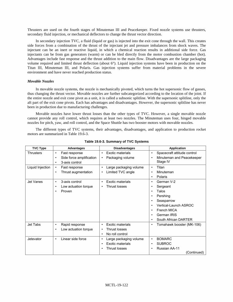
MCTL-19-122
Thrusters are used on the fourth stages of Minuteman III and Peacekeeper. Fixed nozzle systems use thrusters, secondary fluid injection, or mechanical deflectors to change the thrust vector direction.
In secondary injection TVC, a fluid (liquid or gas) is injected into the exit cone through the wall. This creates side forces from a combination of the thrust of the injectant jet and pressure imbalances from shock waves. The injectant can be an inert or reactive liquid, in which a chemical reaction results in additional side force. Gas injectants can be from gas generators (warm) or can be bled directly from the motor combustion chamber (hot). Advantages include fast response and the thrust addition to the main flow. Disadvantages are the large packaging volume required and limited thrust deflection (about 6°). Liquid injection systems have been in production on the Titan III, Minuteman III, and Polaris. Gas injection systems suffer from material problems in the severe environment and have never reached production status.
Movable Nozzles
In movable nozzle systems, the nozzle is mechanically pivoted, which turns the hot supersonic flow of gasses, thus changing the thrust vector. Movable nozzles are further subcategorized according to the location of the joint. If the entire nozzle and exit cone pivot as a unit, it is called a subsonic splitline. With the supersonic splitline, only the aft part of the exit cone pivots. Each has advantages and disadvantages. However, the supersonic splitline has never been in production due to manufacturing challenges.
Movable nozzles have lower thrust losses than the other types of TVC. However, a single movable nozzle cannot provide any roll control, which requires at least two nozzles. The Minuteman uses four, hinged movable nozzles for pitch, yaw, and roll control, and the Space Shuttle has two booster motors with movable nozzles.
The different types of TVC systems, their advantages, disadvantages, and application to production rocket motors are summarized in Table 19.6-3.
Table 19.6-3. Summary of TVC Systems
TVC Type Advantages Disadvantages Application Thrusters • Fast response
• Side force amplification • 3-axis control
• Exotic materials • Packaging volume
• Spacecraft attitude control • Minuteman and Peacekeeper
Stage IV Liquid Injection • Fast response
• Thrust augmentation • Large packaging volume • Limited TVC angle
• Titan • Minuteman • Polaris
Jet Vanes • 3-axis control • Low actuation torque • Proven
• Exotic materials • Thrust losses
• German V-2 • Sergeant • Talos • Pershing • Seasparrow • Vertical-Launch ASROC • French MICA • German IRIS • South African DARTER
Jet Tabs • Rapid response • Low actuation torque
• Exotic materials • Thrust losses • No roll control
• Tomahawk booster (MK-106)
Jetevator • Linear side force • Large packaging volume • Exotic materials • Thrust losses
• BOMARC • SUBROC • Russian AA-11
(Continued)

MCTL-19-123
Table 19.6-3. Summary of TVC Systems (Cont’d)
TVC Type Advantages Disadvantages Application Flexbearing • Most well-proven
• Predictable actuation forces
• Lower vector angles • Space Shuttle • Trident • Peacekeeper • Ariane
Trapped Ball • High vector angles • Unpredictable actuation forces
• Susceptible to contamination
• Tomahawk booster (MK-111) • Aegis booster
Techroll® • Low actuation force • Low stiffness • Thrust misalignment
• IUS space motor
Hinged • High TVC angles • Low actuation force
• Requires multiple nozzles • Minuteman
Rotatable • Low actuation force • Requires multiple nozzles • Polaris

MCTL-19-124
MCTL DATA SHEET 19.6-13. RAMJET LAUNCH PROPULSION
Discusses technologies related to ramjet space launch vehicles.
Critical Technology Parameter(s)
Critical Technology Parameter(s)
Solid Fueled Solid Fueled Liquid Fueled Ducted Rocket
• Combustion efficiency > 90% > 90% > 93%
• Fuel regression rates > 0.4 in/sec > 0.4 in/sec N/A
• Propellant density > 0.06 lbsm/in.3 > 0.06 lbm/in.3 > 0.036 lbsm/in.3
• Fuel expulsion efficiency N/A > 94% > 97%
• Isp > 900 sec. > 700 sec. > 1100 sec.
Critical Technology Parameters for Ramjet boosters include:
• Solid* rocket boosters with:
- Isp > 210 seconds,
- Storage life > 10 years, and
- Operable at temperatures from -65 °F to +145 °F.
• Control valves for ducted rockets with:
- Operating temp ≥ 3500 °F,
- Duration ≥ 5 minutes,
- Area ratios ≥ 10:1, and
- Tolerant of multiphase (gas, liquid, solid) materials (generated by the combustion process).
* Requires low smoke solid fuels with volumetric heating values over 500 BTU/cubic inch having pressure exponents (around 0.7) and constant over a wide range of pressures and combustible at altitudes over 70,000 feet.
Critical Materials High strength to weight materials for structures; erosion resistant materials for nozzles; high temperature materials for use in nozzles and thrust chambers. Thermal protection systems/coatings/materials for high speed, long duration flight.
Unique Test, Production, Inspection Equipment
Production: stir friction-welding equipment for tank fabrication. Similar manufacturing issues as with solid rocket motors—see “Solid Rocket Propulsion” (Section 19.6-9).
Unique Software Missile system guidance and control software—particularly coupling of fuel control to missile flight control processors and guidance logic. Engine-specific fuel flow control algorithms.
Major Commercial Applications
There are currently no commercial applications for this technology. This technology has only military applications though some of the components could have commercial applications or have similarity to commercial items, e.g., control valves.
Affordability Issues Always working on reducing costs but efficiency and Isp are the key issues. It represents a reduced weight potential for a given Isp.
Export Control References
WA ML 10; WA Cat 9; MTCR 3; USML IV; CCL Cat 9.

MCTL-19-125
BACKGROUND
There are three types of ramjet propulsion systems; solid fueled, liquid fueled, and solid fueled ducted rocket. The militarily critical components that enable successful ramjet missile operations are vehicle: propulsion systems, air inlet design, ignition systems, solid fuel gas generators, combustion sustainment methods, booster design, vehicle guidance controls and cooling systems for long flight times. All of these components are covered as separate critical technologies. Also included in the militarily critical components list are: solid gas generator control valve design and flow control logic (ducted rockets) and the fuel injector design (ducted rockets and liquids). Ramjets are a technology that has application for anti-satellite rockets and as a dual propulsion system for launches that combines rockets and air-breathers.
Ramjet propulsion has been used for over 50 years. A number of nations currently operate or have the capability to deploy ramjet-powered missiles, most notably France, the United Kingdom, Germany, China and Russia. It greatly increases the range and speed of these systems resulting in significant military capability. Ramjets use atmospheric oxygen as the oxidizer and can use either solid fuel gas generators or liquid fuels to provide the necessary fuel. Ramjets have to be boosted, usually by a solid rocket motor (SRM), to a speed at which the ramjet can be ignited and takes over as the primary propulsion. Future missile designs may incorporate stealth technology to make the missiles compatible with stealthy platforms such as the F/A-22 and JSF. The U.S. Government has pursued joint missile development programs in the past with the United Kingdom and ramjet propulsion was one of the candidate technologies for that system. The United States may seek a cooperative program again in the future.

MCTL-19-127
SECTION 19.7—PROPULSION FOR SPACE SYSTEMS
Highlights
• Electrical propulsion technologies are available in several power levels, ranging from low-power systems useful in maneuvering microsatellites/nanosatellites through medium-power to high-power systems useful in orbit raising, space-based maintenance, and other space-based maneuvering applications.
• Chemical propulsion technologies cover both long-term storable and cryogenic propellant based systems. Technologies include solid propellant and liquid propellant based technologies. Chemical propulsion provides high thrust to rapidly move satellites. They are used for orbit transfer, final orbit insertion, and for repositioning.
• Cryogenic storage and refrigeration technologies with low loss rates are required for use of liquid oxygen (LOX), liquid hydrogen (LH2), and liquid fluorine propellants in space.
OVERVIEW
The technologies addressed in this section are associated with in-space propulsion of satellites and spacecraft. They are used to provide satellites with attitude control, station keeping, orbit maintenance, and repositioning. In addition, these technologies are used to assist in placing satellites into their proper orbits, including circularization, orbit topping, and orbit raising.
Orbit transfer vehicle (OTV) propulsion is also covered in this section, but upper stages for launch vehicles are not. The former tends to operate between low earth orbit and other orbits, e.g., geosynchronous. OTVs can be used to move satellites from one orbit to another, i.e., to a higher orbit or to a different orbital plane, or they can be used to rescue a satellite that was not put into its proper orbit. Upper stage systems are part of the space launch vehicle. They provide the added lift capability for very heavy payloads and for payloads needing to get to very high orbits, e.g., geosynchronous. Upper stage propulsion is addressed under Launch Propulsion Systems, Section 19.6. The definition of an upper stage can vary from one person to another. A review of this section and Launch Propulsion Systems is prudent.
Many of the technologies found in this section are also used by the commercial market to power their satellites. This section addresses the critical performance levels that provide significant military capability that is above and beyond what is needed by the commercial market place. The technologies in this section are also dependent on or have relationship with technologies found under Launch Propulsion for Space Systems (Section 19.6), Space Optics (Section 19.4), Power and Thermal Management (Section 19.5), and Space Sensor Systems (Section 19.8).
The technologies addressed in this section include low, medium, and high power electric propulsion, storage and refrigeration for cryogenic propellants, and chemical propulsion. The United States has over the last ten years taken advantage of opportunities to collaborate, cooperate, and leverage the former Soviet Union, now Russian, technical lead in Hall Effect thrusters to bring that capability to U.S. space systems. It is being used on both U.S. commercial and government satellites today. The United States continues to further developments in this area and others to ensure parity and superiority in satellite propulsion.
BACKGROUND
In-space propulsion for satellites is used for attitude control, station keeping, orbit maintenance, repositioning, assist in placing satellites into their proper orbits, including circularization, orbit topping, and orbit raising. This is a diverse set of mission requirements requiring significantly different propulsion systems. Historically cold gas and chemical systems were used, greatly limiting the operational life of the satellite. Currently liquid oxygen/liquid hydrogen (LOX/LH2) and nitrogen tetroxide/monomethyl hydrazine (NTO/MMH) are the predominant chemical

MCTL-19-128
systems for orbit raising. Solid propellant upper stages are also used not only for orbit raising but also for apogee topping and final insertion.
LOX and LH2 have relatively short lives on orbit due to the cryogenic nature of these propellants. They require storage and refrigeration, yet they provide the greatest propulsive performance. NTO/MMH propellants are storable but highly toxic, and they have about 1/3 less performance than LOX/LH2. Hydrazine is also used as a monopropellant in some systems. It too is highly toxic; it is also used in terrestrial applications, such as auxiliary power units on aircraft.
Research in the United States and elsewhere, is focused on finding alternatives to the highly toxic propellants, which could be ready in the next five years for system designers to incorporate the technology into their designs. Eliminating the toxic propellants will reduce overall system operating costs due to greater flexibility in handling the materials. In addition, the propellants under development have better performance than hydrazine and possibly even NTO/MMH. Thus, they will also provide increased capability in operational satellites.
The development of various forms of electric propulsion since the 1980s through today have greatly improved on-orbit life and opened up other applications and opportunities to be exploited. Current electric propulsion systems include ion, resistojets, and arcjets. These systems are used for station keeping, attitude control, and orbit maintenance. Resistojets and arcjets are early forms of electric propulsion systems that leveraged existing chemical systems adding significant heat to increase the engine’s efficiency. These are giving way to improved ion engines, pulsed plasma thrusters, and Hall Effect thrusters. These technologies provide greater efficiency, as well as greater control of the impulse bit; the latter is used to correct orbit variations due to atmospheric drag (on low earth orbit satellites), fluctuations in gravity, or effect of solar winds.
One limitation of electric propulsion systems is the amount of thrust they can produce. This is directly related to the amount of power available to the engine. The available power on satellites has steadily increased over the years; 30 kW systems are now state of the art for large commercial communications satellites at geosynchronous earth orbit (GEO), and it is not unreasonable to expect developments to continue towards 100 kW satellites. This will enable the use of electric propulsion in many applications where chemical systems now reign as the primary source of propulsion.
Greater power for in-space propulsion systems yields greater thrust, which results in shorter trip times to place the satellite in its proper orbit. Most satellites currently use chemical propulsion systems to put the satellite into final orbit within a few days. Current electric systems take tens of days to accomplish the same mission but with much better fuel efficiency. A significant benefit of electric propulsion systems is the significantly greater payload mass they can place into orbit. So, currently, this is a trade between time to orbit and payload mass.
The commercial market seeks improved propulsion capability in order to place greater payloads into orbit and to increase on-orbit life, which translate into billions of dollars in increased revenue. The scientific community also uses various mixes of chemical and electric propulsion to address their needs for in-space propulsion or interplanetary propulsion. NASA develops satellites ranging from very small nanosatellites to very large orbiting telescopes and interplanetary vehicles. The best propulsion system for a given mission is a system design issue specific to the mission. It may be possible to use a chemical system, an electric system, or some combination of both.
As power availability increases, however, it appears that electric systems will be able to provide more and more of the in-space propulsion capability spectrum. In addition, satellite payloads will be able to grow in mass, doubling or tripling in size over the next two decades, given expected improvements in both electric and chemical propulsion technologies.

MCTL-19-129
LIST OF MCTL TECHNOLOGY DATA SHEETS 19.7. LAUNCH PROPULSION FOR SPACE SYSTEMS
19.7-1 Low-Power Electric Propulsion............................................................................................. MCTL-19-131
19.7-2 Medium-Power Electric Propulsion....................................................................................... MCTL-19-132
19.7-3 High-Power Electric Propulsion ............................................................................................ MCTL-19-133
19.7-4 Storage and Refrigeration—Cryogenic Propellant ................................................................ MCTL-19-134
19.7-5 Chemical Propulsion.............................................................................................................. MCTL-19-135
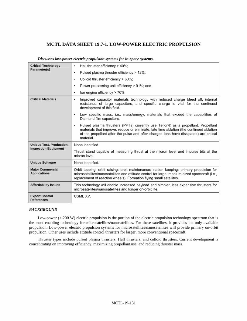
MCTL-19-131
MCTL DATA SHEET 19.7-1. LOW-POWER ELECTRIC PROPULSION
Discusses low-power electric propulsion systems for in-space systems.
Critical Technology Parameter(s)
• Hall thruster efficiency > 40%;
• Pulsed plasma thruster efficiency > 12%;
• Colloid thruster efficiency > 60%;
• Power processing unit efficiency > 91%; and
• Ion engine efficiency > 70%.
Critical Materials • Improved capacitor materials technology with reduced charge bleed off, internal resistance of large capacitors, and specific charge is vital for the continued development of this field.
• Low specific mass, i.e., mass/energy, materials that exceed the capabilities of Diamond film capacitors.
• Pulsed plasma thrusters (PPTs) currently use Teflon® as a propellant. Propellant materials that improve, reduce or eliminate, late time ablation (the continued ablation of the propellant after the pulse and after charged ions have dissipated) are critical material.
Unique Test, Production, Inspection Equipment
None identified.
Thrust stand capable of measuring thrust at the micron level and impulse bits at the micron level.
Unique Software None identified.
Major Commercial Applications
Orbit topping; orbit raising; orbit maintenance; station keeping; primary propulsion for microsatellites/nanosatellites and attitude control for large, medium-sized spacecraft (i.e., replacement of reaction wheels). Formation flying small satellites.
Affordability Issues This technology will enable increased payload and simpler, less expensive thrusters for microsatellites/nanosatellites and longer on-orbit life.
Export Control References
USML XV.
BACKGROUND
Low-power (< 200 W) electric propulsion is the portion of the electric propulsion technology spectrum that is the most enabling technology for microsatellites/nanosatellites. For these satellites, it provides the only available propulsion. Low-power electric propulsion systems for microsatellites/nanosatellites will provide primary on-orbit propulsion. Other uses include attitude control thrusters for larger, more conventional spacecraft.
Thruster types include pulsed plasma thrusters, Hall thrusters, and colloid thrusters. Current development is concentrating on improving efficiency, maximizing propellant use, and reducing thruster mass.

MCTL-19-132
MCTL DATA SHEET 19.7-2. MEDIUM-POWER ELECTRIC PROPULSION
Discusses medium-power electric propulsion systems for in-space systems.
Critical Technology Parameter(s)
• Hall thruster > 50% efficiency;
• Arc-jet > 35% efficiency;
• Ion engines > 70% efficiency; and
• Power processing unit efficiency > 93% (output/input).
Critical Materials Ceramic insulators in the ion acceleration channel; low-sputter yield materials that provide greater than 1500 hours of thruster life are critical to Hall thrusters.
Unique Test, Production, Inspection Equipment
Large vacuum chambers with cryogenic pumping (such as at Edwards AFB, CA) are required to simulate the space environment during thruster testing, pumping capacity > 500,000 liters/second. Other similarly capable facilities include those at NASA Glenn Research Center (Cleveland, OH), JPL (Pasadena, CA), and Boeing EED (Torrance, CA).
Unique Software None identified.
Major Commercial Applications
North-south station-keeping, orbit topping, orbit repositioning, and limited orbit raising.
Affordability Issues This technology should reduce costs of some on-orbit repositioning operations. Increase payload mass fraction, increase on-orbit life.
Export Control References
USML XV.
BACKGROUND
Medium power (500 W–5 kW) electric propulsion is the most mature portion of the electric propulsion technology spectrum. Common thruster types include Hall thrusters, arcjets, resistojets, and ion engines. Hall thrusters have higher Isp (1,800 s) than arcjets and higher thruster densities than ion engines.
This technology was developed by the Russians and has recently been adopted by the West.
All of these medium power electric thruster types are currently commercialized in the United States. Commercial applications are similar to Air Force missions—north-south station-keeping, orbit topping, orbit repositioning, and limited orbit raising.

MCTL-19-133
MCTL DATA SHEET 19.7-3. HIGH-POWER ELECTRIC PROPULSION
Discusses high-power electric propulsion systems for in-space systems.
Critical Technology Parameter(s)
Electric propulsion systems with an Isp < 2500 seconds with efficiencies > 55%.
Critical Materials None identified.
Unique Test, Production, Inspection Equipment
Large vacuum chambers with cryogenic pumping (such as at Edwards AFB, CA) are required to simulate the space environment during thruster testing, pumping capacity > 500,000 liters/second.
Unique Software None identified.
Major Commercial Applications
Orbit transfer vehicle applications; space tug; orbit raising; North-south station-keeping; orbit topping; orbit repositioning.
Affordability Issues None identified.
Export Control References
USML XV.
BACKGROUND
High-power (> 5 kW) electric propulsion is of interest because much higher power satellites are now being built which can provide the necessary power for these engines. Hall thrusters (Isp ~1800–2500 seconds) are the primary engines of interest at these power levels. Arcjets can also operate at these power levels as well as ion thrusters. A 30-kW arcjet was developed by the Air Force and flown in the mid 1990s. The Air Force then changed direction to pursue Hall thrusters because of their improved performance over arcjets.

MCTL-19-134
MCTL DATA SHEET 19.7-4. STORAGE AND REFRIGERATION—CRYOGENIC PROPELLANT
Discusses storage and refrigeration for cryogenic propellants for in-space systems.
Critical Technology Parameter(s)
Loss rate: < 30% per year of cryogenic liquid (all chemical systems).
Critical Materials Lightweight, liquid oxygen-compatible tankage materials, high-fracture toughness cryogenic tank materials, highly efficient thermal insulation, active thermal insulators, and compatible line, duct, tankage, gasket, and seal materials.
Unique Test, Production, Inspection Equipment
Cryogenic fluids for testing and chemicals passivation.
Friction stir welding equipment for production.
Low- or zero-gravity test facilities. Vacuum jacketed equipment.
Unique Software Adaptable for current simple control logic.
Major Commercial Applications
Except for the use of liquid oxygen, which is a common industrial chemical used in welding and the medical industry, commercial applications for these technologies are specialized niche markets (e.g., launch vehicles, satellite propulsion, upper-stage propulsion, liquefied gas industry, and specialty chemical processes).
Affordability Issues These technologies, though expensive, tend to increase heavy lift capability, thus increasing the effectiveness of on-orbit assets. They avoid the need for multiple launches and on-orbit assembly of some assets.
Export Control References
WA ML 20; WA Cat 9A; USML XV; CCL Cat 9A.
BACKGROUND
Cryogenic fluids, solids, slushes, and slurries must be maintained at temperatures below 100 °K, with loss rates less than 30 percent/year of storage. Cryogenic propellants retain a large amount of energy per unit mass and are high-efficiency rocket, missile, air vehicle fuels, and fuels for lasers. Liquid oxygen (LOX) and liquid hydrogen (LH2) are the current state-of-the-art fluids. Research is continuing on liquid fluorine, nitrogen/fluorine compounds, oxygen/fluorine compounds, slush hydrogen (also referred to as increased density propellant), slush oxygen, and doped hydrogen and oxygen slurries. Cryogenic storage and refrigeration systems include fluid-compatible and impermeable materials (tankage and seals), active and passive insulation systems, high-efficiency pumps and condensers, heat exchangers, near-zero thermal shrinkage materials, and environmentally benign refrigerants.
Advances in this technology area are aimed at improving the refrigeration and storage efficiency at cryogenic temperatures, lengthening the duration of storage, broadening the types of fluids stored (to include semisolids), and storing fluorine-based compounds.

MCTL-19-135
MCTL DATA SHEET 19.7-5. CHEMICAL PROPULSION
Discusses chemical propulsion for in-space systems.
Critical Technology Parameter(s)
For monopropellant
• Isp > > = 233 sec; density Isp > > = 8.5 lb sec/cu. in.
For liquid bipropellant
• Isp > > = 322 sec; density Isp > > = 14.3 lb sec/cu. in.
• Catalyst beds or other ignition systems performing better than Shell 405 catalyst bed, able to handle temperatures of decomposition of advanced monopropellants greater than 1100 °C.
Thrust chamber materials
• Performance better, when used with advanced monopropellants, than Iridium-coated/Rhenium chambers, capable of combustion temperatures exceeding 1800 °C.
Solid propellants [Aluminum/HTPB/Ammonium Perchlorate (AP) based]
• Isp > > 299 sec, mass fraction > 0.92%.
Liquid oxygen/liquid hydrogen
• Isp > > 460 seconds, density Isp > > 13.5 lbs sec/cubic inch.
Fluorine/Ammonia (F2/N2H4)
• Isp > = 370 sec, density Isp > > = 17.2 lbs sec/cubic inch.
Critical Materials Advanced monopropellants, bipropellants, and ingredients. Due to very high operating temperatures, advanced materials are required for ignition, combustion, and nozzle components.
Unique Test, Production, Inspection Equipment
None identified.
Unique Software None identified.
Major Commercial Applications
Orbit/apogee topping, orbit raising, repositioning, orbit transfer, primary propulsion for microsatellites/nanosatellites, and attitude control for large spacecraft. Also, emergency power units and other applications needing non-toxic replacement for hydrazine for energy generation or propulsion. Future applications could include small launch vehicles.
Affordability Issues Non-toxic monopropellants greatly reduce operations costs compared to very toxic hydrazine. All greatly increase the mission payload delivered from a given launch vehicle, providing significant military and commercial payback.
Export Control References
MTCR 4; USML V and XV.
BACKGROUND
Monopropellant and bipropellant and solid rocket propulsion systems are used for spacecraft in-space propulsion and orbit placement. Current state-of-the-art systems use cold gas, warm gas, hydrazine based, and hydrazine/nitrogen tetroxide (bipropellant) and solid rocket propulsion systems. Some systems use cryogenic propellants, such as liquid hydrogen and liquid oxygen. Hydrazine and Nitrogen Tetroxide are highly toxic. Liquid oxygen is used in a number of terrestrial industrial applications. Both liquid hydrogen and liquid oxygen are relatively easy to obtain from air or water.

MCTL-19-136
Liquid propellant-based systems can be divided into storable (e.g., hydrazine and nitrogen tetroxide) and non-storable (e.g. cryogenic propellants like liquid oxygen and liquid hydrogen). Storable propellants enable very long on-orbit life for satellites, providing maneuvering capability until the propellant is exhausted. Cryogenic based systems have much shorter on-orbit life times as the cryogenic propellants evaporate over time even when using active refrigerated storage techniques.
Solid rockets are used in upper stage and apogee topping applications. In the apogee topping application, they are combined with electric propulsion systems to provide significant increases in mission payload. The high performance of solid rocket propulsion is due to a combination of motor pressure, nozzle and propellant performance.

MCTL-19-137
SECTION 19.8—SPACE SENSOR SYSTEMS
Highlights
• Significant improvements in battlefield awareness and mission control have been achieved by multispectral and hyperspectral space sensor technologies.
• Space Sensors now provide near real-time information to the warfighter.
• Major improvements in measurement and signature intelligence (MASINT) software have made significant effects in the speed and accuracy of data analyses and target identification.
• The military utility of both hyperspectral and multispectral space sensor systems has improved significantly with the development of key software programs such as COSMEC.
• IR sensors are considered the most important items in missile warning optical space sensor systems, such as the Defense Support Program (DSP), Space-Based Infrared System (SBIRS), NMD and TMD missions.
• Synthetic aperture radar (SAR) is particularly well suited to space applications, and researchers are investigating many new high-resolution improvements in this technology area.
• MASINT software technologies exploit advances in multispectral and hyperspectral target phenomenology providing fast, accurate and timely decision making inputs.
• Significantly improved signal processing, high-performance computing, and low-cost microelectronics have greatly improved our space surveillance systems.
• Quantum well IR photodetectors (QWIPs) are particularly useful for space surveillance of cold objects. Their multispectral sensitivity and efficiency capability can be used with both high-resolution multispectral and hyperspectral response for greater discrimination between targets or in modes that produces a very broadband response.
• Hyperspectral imaging has two major defense applications: characterizing the battlespace environment and identifying tactical targets of military interest.
• Advanced space-based radar technologies are leading to a new generation of space-based intelligence, surveillance, and reconnaissance (ISR) systems, which will significantly impact the MASINT data base and ultimately the warfighter.
• SAR relies on advanced radar algorithms, high-power aperture and sparse aperture concepts, as well as MMICs, RF photonics technology, and low-power, high-performance computing, which have all improved significantly over the past decade providing space-based SAR technology a significant boost.
• Nuclear detonation detection sensors for atmospheric tests, observed from space platforms, have proven an invaluable tool in recent years as our eyes-in-the-sky.
OVERVIEW
Electro-optical, radar, and nuclear detonation surveillance from spacecraft play a major role in the U.S. surveillance program.
With the advent of optical space platforms with on-board electro-optical sensors in the early 1970s, space sensors have been providing an ever-increasing military advantage for both battlefield assessment as well as strategic operations. This has been true for both offensive and defensive military operations. The ability to have real time space surveillance has proven to be of tremendous value for the modern battlefield warfighter. Space sensors

MCTL-19-138
allow the examination of radiation, points of interest and objects on or near the earth for both tactical and strategic applications on a continuing basis.
In addition, nuclear detonation detection of atmospheric bursts is a key deterrent to adversaries and has proven beneficial to our national interests. The United States Nuclear Detonation Detection System (USNDS) technology development program carries crossover technologies. It leverages major investments already made in photonics, microelectronics, signal processing, high-performance computing antennas, and the latest advances in digital receivers and antenna arrays. These efforts have helped produce systems that have lower power requirements and are capable of extracting improved target information from challenging background environments. Thus, many technologies incorporated in or directly supporting space-based electro-optic, nuclear detonation detection, and radar sensor systems are critical to U.S. national security. These are technology areas where we need to maintain a leadership position.
BACKGROUND
Since the launch of the first space multispectral sensor, the Landsat 1 in early 1972, multispectral image data have been used for numerous studies in a wide variety of fields. The success of Landsat and other multispectral sensors led to the development of the first hyperspectral imaging sensor. This was an airborne sensor known as the Airborne Imaging Spectrometer (AIS). The AIS was flown in 1982 by NASA’s Jet Propulsion Lab (JPL). Although multispectral imagery continues to be among the most widely used remote sensing data, hyperspectral imagery is maturing into one of the most powerful and fastest growing sources of remotely sensed information.
In general, multispectral sensors measure multiple, wide, separated wavelength bands whereas hyperspectral sensors generally measure multiple, narrow and contiguous wavelength bands. Although most hyperspectral sensors measure hundreds of wavelength bands, and most multispectral sensors measure only a few. It’s not the number of measured wavelengths that defines if a sensor is multispectral or hyperspectral—it’s the narrowness and contiguous nature of the measurements that determines the difference of these instruments.
In cases where scattered sunlight or thermal radiation is not adequate to form images of sufficient detail and clarity, laser illumination can be used as an augmenting source of light. One such application is Light Detection and Ranging (LIDAR). A LIDAR instrument transmits light out to a target. The transmitted light interacts with and/or is changed by the target. Some of this light is reflected/scattered back to the instrument where it is analyzed. The change in the properties of the light enables some property of the target to be determined. The time for the light to travel out to the target and back to the LIDAR is used to determine the range to the target. LIDAR can be used to determine an object’s distance, speed, rotation or chemical composition. Once the LIDAR is calibrated, the magnitude of the surface return can be used to obtain the surface reflectance or albedo. The spectral dependence of the surface reflectance can be used to discriminate vegetation, camouflage or different land surface types. The high range resolution feature of LIDAR also provides the capability to generate high resolution 3-D image maps over areas of interest.

MCTL-19-139
LIST OF MCTL TECHNOLOGY DATA SHEETS 19.8. SPACE SENSOR SYSTEMS
19.8-1 Cooled Infrared (IR) Focal Plane Detectors .......................................................................... MCTL-19-141
19.8-2 Multispectral and Hyperspectral Space Sensor Systems ....................................................... MCTL-19-143
19.8-3 Space LIDAR Technology .................................................................................................... MCTL-19-145
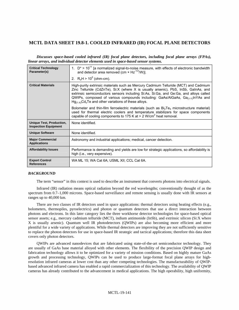
MCTL-19-141
MCTL DATA SHEET 19.8-1. COOLED INFRARED (IR) FOCAL PLANE DETECTORS
Discusses space-based cooled infrared (IR) focal plane detectors, including focal plane arrays (FPAs), linear arrays, and individual detector elements used in space-based sensor systems.
Critical Technology Parameter(s)
1. D* > 1011 [a normalized signal-to-noise measure, with effects of electronic bandwidth and detector area removed (cm × Hz-1/2/W)].
2. RoH > 105 (ohm-cm).
Critical Materials High-purity extrinsic materials such as Mercury Cadmium Telluride (MCT) and Cadmium Zinc Telluride (CdZnTe), Si:X (where X is usually arsenic), PbS, InSb, GaInAs, and extrinsic semiconductors sensors including Si:As, Si:Ga, and Ge:Ga, and alloys called QWIPs, composed of various compounds including: GaAs/AlGaAs, Ga(1-Y)InYAs and Hg(1-X)CdxTe and other variations of these alloys.
Bolometer and thin-film ferroelectric materials (such as Bi2Te3 microstructure material) used for thermal electric coolers and temperature stabilizers for space components capable of cooling components to 175 K at > 2 W/cm2 heat removal.
Unique Test, Production, Inspection Equipment
None identified.
Unique Software None identified.
Major Commercial Applications
Astronomy and industrial applications; medical, cancer detection.
Affordability Issues Performance is demanding and yields are low for strategic applications, so affordability is high (i.e., very expensive).
Export Control References
WA ML 15; WA Cat 6A; USML XII; CCL Cat 6A.
BACKGROUND
The term “sensor” in this context is used to describe an instrument that converts photons into electrical signals.
Infrared (IR) radiation means optical radiation beyond the red wavelengths; conventionally thought of as the spectrum from 0.7–1,000 microns. Space-based surveillance and remote sensing is usually done with IR sensors at ranges up to 40,000 km.
There are two classes of IR detectors used in space applications: thermal detectors using heating effects (e.g., bolometers, thermopiles, pyroelectrics) and photon or quantum detectors that use a direct interaction between photons and electrons. In this later category lies the three workhorse detector technologies for space-based optical sensor assets; e.g., mercury cadmium telluride (MCT), indium antimonide (InSb), and extrinsic silicon (Si:X where X is usually arsenic). Quantum well IR photodetectors (QWIPs) are also becoming more efficient and more plentiful for a wide variety of applications. While thermal detectors are improving they are not sufficiently sensitive to replace the photon detectors for use in space-based IR strategic and tactical applications; therefore this data sheet covers only photon detectors.
QWIPs are advanced nanodevices that are fabricated using state-of-the-art semiconductor technology. They are usually of GaAs base material alloyed with other elements. The flexibility of the precision QWIP design and fabrication technology allows it to be optimized for a variety of mission conditions. Based on highly mature GaAs growth and processing technology, QWIPs can be used to produce large-format focal plane arrays for high-resolution infrared cameras at lower cost than any other competing technologies. The manufacturability of QWIP-based advanced infrared camera has enabled a rapid commercialization of this technology. The availability of QWIP cameras has already contributed to the advancement in medical applications. The high operability, high uniformity,

MCTL-19-142
high stability, and high radiation tolerance of QWIP cameras simplify the on-board and ground-based data analysis for NASA missions, thus providing a significant cost reduction in software development, data processing, and major system level benefits upon integration.

MCTL-19-143
MCTL DATA SHEET 19.8-2. MULTISPECTRAL AND HYPERSPECTRAL SPACE SENSOR SYSTEMS
Discusses multispectral imaging (MSI) and hyperspectral imaging (HSI) space sensor systems in the 100-nm to 1,000-µ wavelength range.
Critical Technology Parameter(s)
1. All image processing algorithms, autonomous channel correlations, automated spectral mapping software tools designed or developed for military, other defense measurement, and signatures intelligence interests;
2. Space optical sensor systems with an instantaneous-field-of-view (IFOV) < 200 microradians and having a spatial resolution < 5 m within any of the sensor wavelength bands; or
3. Ground terminal instrumentation that receives, processes, and exploits MSI or HSI data for conversion into near-real time military data products.
Critical Materials Sensor materials with high uniformity and high purity. Extrinsic materials such as Mercury Cadmium Telluride (MCT) and Cadmium Zinc Telluride (CdZnTe), Si:X (where X is usually arsenic), PbS, InSb, GaInAs, and extrinsic semiconductors sensors including Si:As, Si:Ga, and Ge:Ga.
There are also alloys and bolometer sensor materials that are critical including: Ga(1-Y)InYAs, Hg(1-y)CdXTe, amorphous Silicon, Vanadium Oxide (VOx) and QWIPs.
Unique Test, Production, Inspection Equipment
None identified.
Unique Software All specially developed software for defense analyses of multispectral and hyperspectral data and measurements.
Major Commercial Applications
Astronomy and industrial applications.
Affordability Issues Performance is demanding and yields are low for strategic applications, so cost is high.
Export Control References
WA ML 15; WA Cat 6A; USML XV; CCL Cat 6A.
BACKGROUND
Optical remote sensing makes use of visible, near infrared, and short-wave infrared sensors to form images of the earth’s surface or objects on or near the earth’s surface by detecting the solar radiation reflected from them. Different materials reflect and absorb differently at different wavelengths, thus, the targets can be differentiated by their spectral reflectance signatures in the remotely sensed images. Modern remote space sensing is take advantage of digital spectral image sensors and the distinct reflections in various bands of the spectra from different materials.
Optical remote sensing systems are classified into the following types for convenience depending on the number of spectral bans used and their spectral separation in the imaging process. Multispectral imaging systems collect images from several separate spectral bands that may be selected from any portion of the spectrum from ultraviolet to thermal-infrared. A hyperspectral imaging system acquires images from the same spectral source, though in many narrow, contiguous spectral bands over a given spectral range. The difference between multispectral and hyperspectral imagery is the detail of the spectral signature and the contiguous nature of the hyperspectral imaging versus the separated band imagining of the multispectral paradigm.
The common denominator of all multispectral systems is reliance on identifying the target through its shape. This requires improved spatial resolution to detect smaller objects or objects partially hidden by surrounding materials. Hyperspectral imagery breaks the multispectral paradigm. With hundreds of spectral bands, hyperspectral

MCTL-19-144
systems basically obtain a spectrum of the energy reflected or emitted by each element in the scene and identifies an object, or terrain element from the spectrum. Hyperspectral imaging does not depend on the object’s shape.
The spectral correlation that exists between the narrow spectral bands in the pixel spectra enables dimensionality reduction. Spectral correlation indicates the presence of redundant information in spectral data and, through removal of the redundant information, the possibility to represent the data in a much lower dimensional space exists. Reducing the dimensionality of hyperspectral imaging (HSI) involves projecting the pixel spectral vectors to a lower dimensional space that preserves the separability between target and background classes.
Even though hyperspectral systems identify objects by their optical/ infrared spectrum, spatial resolution plays a significant role. Hyperspectral systems can potentially identify an object even if image only has a few (or even one) picture elements (or pixels) covering the object. Spectral analysis of each pixel provides additional information about the materials in the pixel, which the analyst can use to identify it.

MCTL-19-145
MCTL DATA SHEET 19.8-3. SPACE LIDAR TECHNOLOGY
Discusses space-based light detection and ranging (LIDAR) technology for space systems.
Critical Technology Parameter(s)
a. Detect changes in surface elevation < 1.5 cm (0.6 in) per year; and
b. Integrated over areas > 100 km × 100 km (62 mi × 62 mi).
Critical Materials Damage resistant laser materials and coated optics. Robust laser materials and coated optics able to endure in the space environment including atomic oxygen.
Unique Test, Production, Inspection Equipment
None identified.
Unique Software None identified.
Major Commercial Applications
Laser altimetry is the basis of airborne laser terrain mapping, which is enjoying significant commercial application for rapid surveying in urban and rural environments. Detection and tracking of fugitive emissions from industrial plants.
Affordability Issues Such lasers pose significant challenges in the area of thermal control and lifetime/damage resistance and constitute a major cost driver for any such implementation in the future.
Export Control References
WA Cat 6A; CCL Cat 6A.
BACKGROUND
The United States is the world leader in spaceborne laser altimetry and has successfully orbited instruments around Earth, Mars, the moon, and asteroid Eros. The geoscience laser altimeter system (GLAS) is the first LIDAR instrument for continuous global observations of Earth. Launched into a 600-km polar orbit on January 12, 2003 aboard the Ice Cloud and Elevation Satellite (ICESat) spacecraft, it is currently measuring land and ice-sheet topography, cloud and atmospheric properties, and the height and thickness of cloud layers for accurate short-term climate and weather prediction. Anticipated mission duration is 3–5 years, during which GLAS will detect changes in surface elevation as small as 1.5 cm (0.6 in) per year integrated over areas of 100 km by 100 km.

MCTL-19-147
SECTION 19.9—SPACE SURVIVABILITY
Highlights
• Spacecraft charging electrostatic discharge (ESD) is a major cause of space system anomalies, affecting mostly sensitive instruments and telemetry systems.
• Mitigation methods include sharp spike, hot filament, conducting grids, semi-conducting pain, high secondary electron yield material, electron and ion beam, plasma emission, evaporation, and metal-based dielectrics.
• Micrometeoroids are naturally occurring debris in space; they may impact spacecraft, causing cratering, cracking, penetration, or spallation damage.
• Mitigation methods include modeling of sporadic background meteoroid flux and time-correlated streams, assessing potential damage through testing and hydrocode simulations, and designing and operating spacecraft to minimize impact potential.
• Space debris is material that is on orbit as a result of space initiatives but is no longer serving any function; it includes discarded hardware, degraded materials, and even flaked paint bits.
• Mitigation methods include tracking debris and conducting maneuvers to avoid collisions, spacecraft design to minimize damage, and spacecraft and upper stage design to limit future debris.
OVERVIEW
This section is intended to cover space survivability in the event of naturally occurring, accidental, and intentional threats to space systems. Initially, however, it includes datasheets on naturally occurring and accidental threats, specifically electrostatic discharge, micrometeorite, and orbital debris. The technologies focus surviving the threat environment and mitigating future threats. The following technology groups are discussed in detail in the data sheets:
• ESD consists of both surface charge storage and discharge of stored energy. Technologies can be applied to limit stored charge on both external surfaces and internal components, and to safely discharge the stored energy with minimal impact on mission performance.
• Collisions with micrometeoroid can damage spacecraft. There is a sporadic background flux of meteoroids, as well as periodic, time-correlated streams (such as the Leonid meteor shower). Modeling of flux and stream activities, testing with hypervelocity projectiles and simulation using hydrocodes to assess impacts, and spacecraft design and in some cases maneuvering to present minimal impact area are the technologies that can be applied to mitigate the effects of impact.
• Collisions with on orbit space debris can also damage spacecraft. These objects, the detritus of prior space missions, tend to fly in fairly regular orbits, and can be tracked and catalogued to assist in avoiding collisions. Mitigation technologies also include modeling and simulation of debris objects that decay or new debris that results from potential collisions. Other mitigation technologies seek to limit the growth in debris through management of orbit insertion, upper stage disposal, and ultimate satellite disposal.
BACKGROUND
The natural space system environment is a hostile, unfriendly place for operating complicated systems. Principal among the dangers are surface charge buildup, collisions with micrometeoroids, and collisions with space debris. Additional dangers are based on intentional interference with spacecraft operations, either to eliminate military capabilities or to harm critical civil and commercial infrastructures.

MCTL-19-148
Spacecraft charging ESD has caused by far most of the environmentally related anomalies on spacecraft, and surface charging has caused the most serious anomalies. ESD encompasses both surface and internal charging, and the most serious effects of ESD are current flow to disrupt sensitive instruments and electromagnetic (EM) wave interference to telemetry.
Although the basic principles governing most ESD mechanisms have been known for nearly 20 years, more research is needed to better understand spacecraft charging and ESD. Surface and payload design should account for and mitigate the expected levels of electron accumulation as allowed in the system design to meet the mission profile. For example, surface charging can largely be mitigated with careful attention to grounding. Using materials of finite conductivity can limit deep dielectric charging. Filters can be used to minimize electromagnetic wave interference.
Meteoroids are naturally occurring debris of asteroidal and cometary origin. The flux of meteoroids encountered by a spacecraft consists of two components: the sporadic background, and time-correlated streams. The sporadic background flux is always present. Meteoroid streams consist of particles that have emanated from comets after passing through perihelion. The particles leave the comet as it undergoes heating while near the sun. These particles loosely follow the orbit of the parent comet or asteroid, and meteor showers occur when the Earth passes through clouds of these particles near the orbit of the parent body. Example meteor showers are the Perseids, Leonids, and Draconids. The average relative velocity of stream meteoroids is generally much higher than that of sporadic meteoroids.
Direct impact of meteoroids on surfaces can lead to cratering, cracking, penetration or spallation. Meteoroid streams can subject a spacecraft to sandblasting, as experienced by all spacecraft during the Leonids shower. Because most particle sizes are very small, the impact on the overall health of a satellite is usually minimal. Meteoroids can cause electrical damage to space systems by ESD and electromagnetic pulse (EMP). EMPs are created from the direct vaporization of impacting particles into plasma. ESDs and EMPs that result from micrometeroid impact and the surrounding plasma adversely affect the electrical properties of the spacecraft. Erroneous signals in telemetry and short circuits can occur.
Orbital debris refers to material that is on orbit as the result of space initiatives, but is no longer serving any function. One source is discarded hardware, such as upper stages left on orbit after spent or satellites abandoned at end of life. Material degradation due to atomic oxygen, solar heating, and solar radiation has resulted in the production of particulates such as paint flakes and bits of multilayer insulation. Solid rocket motors used to boost satellite orbits have produced, for example, aluminum oxide exhaust particles, nozzle slag, motor-liner residuals, solid-fuel fragments, and exhaust cone bits resulting from erosion during the burn.
A major contributor to the orbital debris background has been object breakup. The leading cause is thought to be explosions. Only three collision-induced breakups are known to have occurred; two were planned. Modern debris environmental models generally predict more collisions to occur in low-earth orbit (LEO) during the next few decades.

MCTL-19-149
LIST OF MCTL TECHNOLOGY DATA SHEETS 19.9. SPACE SURVIVABILITY
19.9-1 Electrostatic Discharge .......................................................................................................... MCTL-19-151
19.9-2 Micrometeroids...................................................................................................................... MCTL-19-152
19.9-3 Space Debris .......................................................................................................................... MCTL-19-154

MCTL-19-151
MCTL DATA SHEET 19.9-1. ELECTROSTATIC DISCHARGE
Discusses technologies to protect spacecraft against electrostatic discharge.
Critical Technology Parameter(s)
Energy (10 mJ) stored by surface charge.
Electric field (106 to 108 V/m) for dielectric breakdown.
Critical Materials None identified.
Unique Test, Production, Inspection Equipment
Laboratory vacuum chamber tests.
Large computers for simulations and computations.
Unique Software Validated computer programs and algorithms for predicting spacecraft surface potentials and internal electric fields inside dielectrics.
Major Commercial Applications
Protection of commercial communications satellites in hazardous space environment.
Affordability Issues None identified; essentially requires care in system engineering, design, and fabrication, including selection of materials to limit possibilities of system failure or anomaly.
Export Control References
USML Cat XV(e) and (f).
BACKGROUND
Spacecraft charging electrostatic discharge (ESD) has caused by far most of the environmentally related anomalies on spacecraft, and surface charging has caused the most serious anomalies, i.e., those that have resulted in the loss of mission (Ref. 1). ESD encompasses both surface and internal charging. The effects of ESD are a result of the electron environment in space and its interaction with specific spacecraft surfaces and components.

MCTL-19-152
MCTL DATA SHEET 19.9-2. MICROMETEROIDS
Discusses technologies for tracking micrometeoroids or for the protection against micrometeoroid impacts with spacecraft.
Critical Technology Parameter(s)
Environmental modeling technology:
• Reduced cumulative flux vs. mass uncertainty factor of 0.8 to 1.2; and
• Improved accuracy time of peak flux to 15 minutes (3 sigma).
Meteoroid impact damage assessment technology:
• Hypervelocity tests: 75 km/s; and
• Computer simulation of all impactor velocities, angles, and masses within 1 hour.
Critical Materials None identified.
Unique Test, Production, Inspection Equipment
Hypervelocity projectile guns, shaped charge technology.
Unique Software Meteoroid stream models.
Hydrocodes—material models for composites, capability to model phase changes, faster run times, parallel processing.
Major Commercial Applications
Commercial satellites face similar risk from meteoroids as do military satellites. However, they do not drive this technology need more than military systems.
Hydrocodes are widely used for improving automobile crash-worthiness. However, the impact velocity range is too low for application to meteoroid impacts.
Affordability Issues Requires telescope surveys of stream parent bodies, in-situ measurements for resolving particle mass and velocity, hypervelocity testing, and developing hydrocodes, and creating target surface models for hydrocodes. Benefits are reduced, losses to space systems.
Export Control References
USML Cat XV(e) and (f).
BACKGROUND
Meteoroids are naturally occurring debris of asteroidal and cometary origin. The flux of meteoroids encountered by a spacecraft consists of two components: the sporadic background, and time-correlated streams. The sporadic background flux is always present, shows only a slight annual variation as the Earth travels in its orbit, and the associated meteoroids have a variety of sources.
Meteoroid streams consist of particles that have emanated from comets after passing through perihelion. The particles leave the comet as it undergoes heating while near the sun. Streams may also originate from dust particles extruding from asteroids, although these streams usually do not reach the intensity of comet-produced streams. These particles loosely follow the orbit of the parent comet or asteroid, and meteor showers occur when the Earth passes through clouds of these particles near the orbit of the parent body. Example meteor showers are the Perseids, Leonids, and Draconids. During a shower, particles smaller than the head of a pin are very common while large particles are rare. The average relative velocity of stream meteoroids is generally much higher than that of sporadic meteoroids.
While these storms are annual events as the earth crosses the orbits of the parent comets, there are occasional enhancements every few decades to the particle flux after the comet’s perihelion passage. For the 2001 Leonid event the actual risk of a satellite being hit by a particle that could cause damage was approximately one-in-one-thousand

MCTL-19-153
to one-in-ten-thousand per square meter of exposed spacecraft area. The next major meteor shower event that may have implications for spacecraft is expected to be the Draconid storm in 2018. However, it should be noted that while predicting meteor events has increased in accuracy in recent years, outbursts unrelated to known meteor streams do occur. A historical analysis indicates that high levels of meteor stream activity can be expected to occur at an average rate of once every five years.
Physical mechanical damage to a spacecraft can occur in several ways. Direct impact of meteoroids on surfaces can lead to cratering, cracking, penetration or spallation. Spallation occurs when fragments separate from spacecraft surfaces due to impact momentum transfer. For example, spall from the rear wall of spacecraft bus surfaces can cause damage to internal components, such as electrical and fuel lines.
Meteoroid streams can subject a spacecraft to sandblasting, as experienced by all spacecraft during the Leonids shower. This is due to the predominance of finer particles moving at high relative velocities. Sandblasting causes general surface degradation and pitting as the smallest particles hit the spacecraft. Because most particle sizes are very small, the impact on the overall health of a satellite is usually minimal.
There are examples of historical satellite anomalies that have been determined to be most likely the result of meteoroid impacts. In 1991 the Solar A satellite was believed to have experienced a hit from a Perseid particle. The telescope filter was damaged and substantial capability was lost. In 1993 the Olympus communication satellite lost its Earth-acquisition capability and had to be abandoned. This incident took place during a Perseid shower. The damage was attributed to a power surge caused by a micrometeoroid impact (Ref. 1).
Satellite operators can employ a number of techniques to avoid many of the potential dangers that arise during a meteoroid shower. For example, surfaces of components on the satellite can be re-oriented, either by mechanisms or spacecraft attitude control, to lower the probability of a damaging impact. This can be done, for example, by “feathering” the solar panels so that they point edge-on into the meteor stream. The probability of occurrence of a damaging impact on these components will depend upon the materials and shielding involved, the total surface area projected into the stream flux, and the angle of the stream flux relative to the surface (i.e., angle of impact).
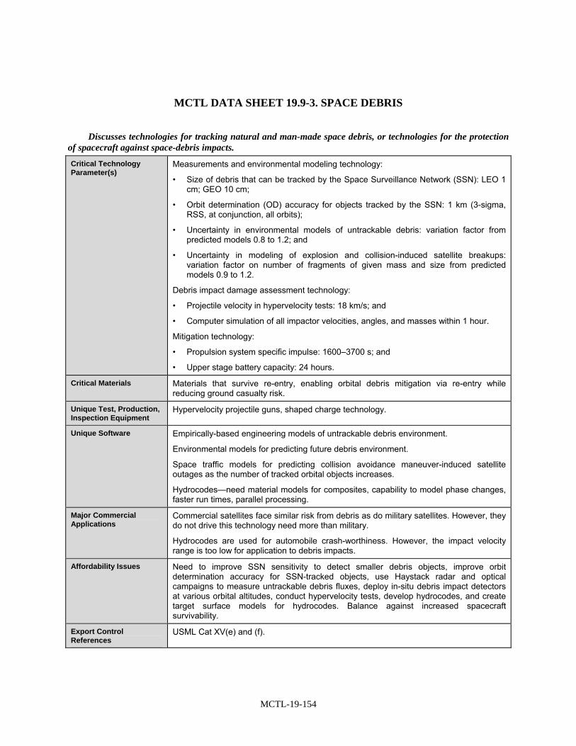
MCTL-19-154
MCTL DATA SHEET 19.9-3. SPACE DEBRIS
Discusses technologies for tracking natural and man-made space debris, or technologies for the protection of spacecraft against space-debris impacts.
Critical Technology Parameter(s)
Measurements and environmental modeling technology:
• Size of debris that can be tracked by the Space Surveillance Network (SSN): LEO 1 cm; GEO 10 cm;
• Orbit determination (OD) accuracy for objects tracked by the SSN: 1 km (3-sigma, RSS, at conjunction, all orbits);
• Uncertainty in environmental models of untrackable debris: variation factor from predicted models 0.8 to 1.2; and
• Uncertainty in modeling of explosion and collision-induced satellite breakups: variation factor on number of fragments of given mass and size from predicted models 0.9 to 1.2.
Debris impact damage assessment technology:
• Projectile velocity in hypervelocity tests: 18 km/s; and
• Computer simulation of all impactor velocities, angles, and masses within 1 hour.
Mitigation technology:
• Propulsion system specific impulse: 1600–3700 s; and
• Upper stage battery capacity: 24 hours.
Critical Materials Materials that survive re-entry, enabling orbital debris mitigation via re-entry while reducing ground casualty risk.
Unique Test, Production, Inspection Equipment
Hypervelocity projectile guns, shaped charge technology.
Unique Software Empirically-based engineering models of untrackable debris environment.
Environmental models for predicting future debris environment.
Space traffic models for predicting collision avoidance maneuver-induced satellite outages as the number of tracked orbital objects increases.
Hydrocodes—need material models for composites, capability to model phase changes, faster run times, parallel processing.
Major Commercial Applications
Commercial satellites face similar risk from debris as do military satellites. However, they do not drive this technology need more than military.
Hydrocodes are used for automobile crash-worthiness. However, the impact velocity range is too low for application to debris impacts.
Affordability Issues Need to improve SSN sensitivity to detect smaller debris objects, improve orbit determination accuracy for SSN-tracked objects, use Haystack radar and optical campaigns to measure untrackable debris fluxes, deploy in-situ debris impact detectors at various orbital altitudes, conduct hypervelocity tests, develop hydrocodes, and create target surface models for hydrocodes. Balance against increased spacecraft survivability.
Export Control References
USML Cat XV(e) and (f).

MCTL-19-155
BACKGROUND
Orbital debris generally refers to material that is on orbit as the result of space initiatives but is no longer serving any function. The problems associated with space debris are collisions of space debris with active satellites and the effects of space debris on operations in space, such as surveillance, tracking, and outages due to collision avoidance maneuvers. There are many sources of debris. One source is discarded hardware. For example, many launch vehicle upper stages have been left on orbit after they are spent. Many satellites are also abandoned at the end of useful life. Another source of debris is spacecraft and mission operations, such as deployments and separations. These have typically involved the release of items such as separation bolts, lens caps, momentum flywheels, clamp bands, auxiliary motors, launch vehicle fairings, and adapter shrouds.
Material degradation due to atomic oxygen, solar heating, and solar radiation has resulted in the production of particulates such as paint flakes and bits of multilayer insulation. Solid rocket motors used to boost satellite orbits have produced various debris items, including motor casings, aluminum oxide exhaust particles, nozzle slag, motor-liner residuals, solid-fuel fragments, and exhaust cone bits resulting from erosion during the burn.
A major contributor to the orbital debris background has been object breakup. More than 170 breakups have been verified including the recent Chinese anti-satellite test. Object breakups continue to occur at an average rate of four to five per year. While the causes of many breakups remain unknown, the leading cause is thought to be explosions. Explosions can occur when propellant and oxidizer inadvertently mix, when residual propellant becomes over pressurized due to heating, or when batteries become over pressurized. Some satellites have been deliberately detonated.
Only four collision-induced breakups are known to have occurred. Three were planned including the recent Chinese anti-satellite test, and one occurred as part of the natural background collision process. Modern debris environmental models generally predict more collisions to occur in low-Earth orbit during the next few decades.
Approximately 70,000 objects estimated to be 2 cm in size have been observed in the 850–1,000-km altitude band. NASA has hypothesized that these objects are frozen bits of nuclear reactor coolant that are leaking from a number of Russian RORSATs. At altitudes of 2,000 km and lower, it is generally accepted that the debris flux is dominated by the natural meteoroid flux for object sizes 1 mm and larger.
The performance of spacecraft materials is degraded by impact damage, and impact damage may render the spacecraft unable to perform its mission. The likelihood of debris impact depends on exposed surface area, surface orientation relative to the debris, and mission duration. Impact damage typically occurs in the form of cratering, cracking, surface penetration, and spallation. If debris penetration of spacecraft structures occurs, internal system and mission critical components can be damaged.
Debris impact that could result in penetration does occur. One example of debris penetration is illustrated by considering that a piece of aluminum debris ~ 0.7 mm in diameter having a relative impact velocity of 10 km/s will penetrate a 2.5-mm thick aluminum satellite wall.
Smaller impacts (particles of size less than 1 mm) are much more common with tens of thousands, if not millions of such impacts/m2 of exposed surface area occurring throughout a satellite’s lifetime. Over 4,000 visible impact craters were found on the return of LDEF 5.7 years after it was launched, with another 15,000 smaller features documented during later inspections. An inspection of the solar arrays returned from the first Hubble servicing mission 3.6 years after launch revealed over 5000 particle impacts.
Less likely but potentially much more devastating are impacts by objects larger than 10 cm. Consequences can range from loss of solar panels and other appendages (antennas, gravity gradient booms) to complete bus fragmentation. The debris from satellite fragmentations in constellations occupying narrow altitude bands can inflict multiple satellite losses within the constellation. The likelihood of such events will grow if the background debris environment is permitted to undergo unrestrained growth without implementation of mitigation measures such as passivation and end-of-life disposal.
Another potential effect of growth in the trackable population is increased interference with operational satellites via outages induced by more frequent collision avoidance maneuvers. Debris object tracking position errors are generally much larger than satellite dimensions. As a result, collision avoidance maneuvers often have to

MCTL-19-156
be performed for close approaches as far away as a few kilometers in order to be effective at reducing collision risk. As the trackable debris population increases, either due to launch activity or to improvements in the size-detection capability of tracking networks, the frequency of such collision avoidance maneuvers will increase.
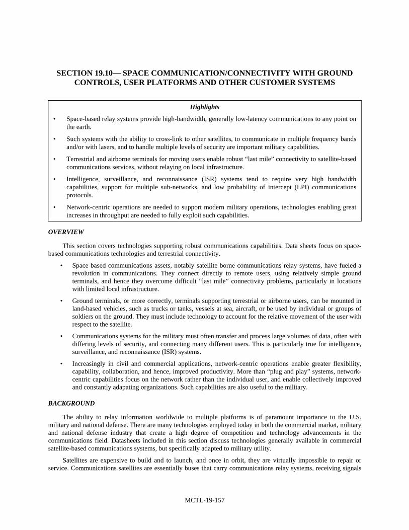
MCTL-19-157
SECTION 19.10— SPACE COMMUNICATION/CONNECTIVITY WITH GROUND CONTROLS, USER PLATFORMS AND OTHER CUSTOMER SYSTEMS
Highlights
• Space-based relay systems provide high-bandwidth, generally low-latency communications to any point on the earth.
• Such systems with the ability to cross-link to other satellites, to communicate in multiple frequency bands and/or with lasers, and to handle multiple levels of security are important military capabilities.
• Terrestrial and airborne terminals for moving users enable robust “last mile” connectivity to satellite-based communications services, without relaying on local infrastructure.
• Intelligence, surveillance, and reconnaissance (ISR) systems tend to require very high bandwidth capabilities, support for multiple sub-networks, and low probability of intercept (LPI) communications protocols.
• Network-centric operations are needed to support modern military operations, technologies enabling great increases in throughput are needed to fully exploit such capabilities.
OVERVIEW
This section covers technologies supporting robust communications capabilities. Data sheets focus on space-based communications technologies and terrestrial connectivity.
• Space-based communications assets, notably satellite-borne communications relay systems, have fueled a revolution in communications. They connect directly to remote users, using relatively simple ground terminals, and hence they overcome difficult “last mile” connectivity problems, particularly in locations with limited local infrastructure.
• Ground terminals, or more correctly, terminals supporting terrestrial or airborne users, can be mounted in land-based vehicles, such as trucks or tanks, vessels at sea, aircraft, or be used by individual or groups of soldiers on the ground. They must include technology to account for the relative movement of the user with respect to the satellite.
• Communications systems for the military must often transfer and process large volumes of data, often with differing levels of security, and connecting many different users. This is particularly true for intelligence, surveillance, and reconnaissance (ISR) systems.
• Increasingly in civil and commercial applications, network-centric operations enable greater flexibility, capability, collaboration, and hence, improved productivity. More than “plug and play” systems, network-centric capabilities focus on the network rather than the individual user, and enable collectively improved and constantly adapating organizations. Such capabilities are also useful to the military.
BACKGROUND
The ability to relay information worldwide to multiple platforms is of paramount importance to the U.S. military and national defense. There are many technologies employed today in both the commercial market, military and national defense industry that create a high degree of competition and technology advancements in the communications field. Datasheets included in this section discuss technologies generally available in commercial satellite-based communications systems, but specifically adapted to military utility.
Satellites are expensive to build and to launch, and once in orbit, they are virtually impossible to repair or service. Communications satellites are essentially buses that carry communications relay systems, receiving signals

MCTL-19-158
from uplink transmitting stations and relaying them, either directly or through other satellites via crosslinks, to downlink receiving stations. In commercial satellites, uplinks and downlinks tend to operate in the same frequency bands.
MCTL-19-159
LIST OF MCTL TECHNOLOGY DATA SHEETS 19.10. SPACE COMMUNICATION/CONNECTIVITY WITH GROUND CONTROLS,
USER PLATFORMS AND OTHER CUSTOMER SYSTEMS
19.10-1 Multi-Satellite Communications and Multi-Access Technologies ........................................ MCTL-19-161
19.10-2 Mobile Terminals................................................................................................................... MCTL-19-162
19.10-3 Intelligence, Reconnaissance, and Surveillance Relay .......................................................... MCTL-19-163
19.10-4 Network-Centric Communications ........................................................................................ MCTL-19-164

MCTL-19-161
MCTL DATA SHEET 19.10-1. MULTI-SATELLITE COMMUNICATIONS AND MULTI-ACCESS TECHNOLOGIES
Discusses technologies that enable communications between multiple satellites or constellations in more than two frequency bands.
Critical Technology Parameter(s)
Ability of a single deployed satellite communication relay system to work simultaneously:
• In more than two (2) frequency bands; or
• With more than three (3) distinct satellite systems.
Ability to change frequency band or satellite system in less than 5 minutes.
Ability to communicate using a laser medium.
Critical Materials Metalized plastics for reduced size and weight of optical elements, and for improved power handling capabilities in RF elements.
Unique Test, Production, Inspection Equipment
Fabrication techniques to achieve precise shapes in optics structures.
Unique Software Control algorithms that allow adjustments for filtering and polarization, reliably and within tine constraints. Feedback mechanisms to calculate and adjust for relative motion among space relay systems and terrestrial terminals. Pointing and tracking accuracy improvements for microradian control of the beams.
Major Commercial Applications
Worldwide newsgathering and news delivery.
Affordability Issues Current relay systems are in the $500 K range. New capabilities must be added without increasing the current costs.
Export Control References
WA ML 11; WA Cat 4; MTCR 12; USML XI; CCL Cat 4.
BACKGROUND
Space-based communications assets, notably satellite-borne communications relay systems have fueled a revolution in communications capabilities since the earliest days of space age. While fiber optic cables have enabled robust, wide-bandwidth, low latency communications within and between developed nations, including across oceans, they remain limited in their “last mile” connectivity by existing infrastructure deficiencies and expenses. Satellite-based communications systems, however, can reach virtually anywhere in the world. Ground terminal equipment is required, but in many cases, this can be relatively inexpensive.
Satellites are expensive to build and launch, and currently most are extremely difficult (virtually impossible) to upgrade once in orbit. Communications satellites generally carry communications relay systems as their payloads. Most such systems receive communications from uplink transmitters, and then rebroadcast them on downlinks, generally on different frequencies in the same frequency band. Others may “cross link” signals to other satellites that may downlink them, in that way extending the reach of geosynchronous earth orbiting (GEO) satellites around the globe.
Newer technology systems that can change frequency bands, communicate more broadly with other satellites, and use laser communications in lieu of radio frequency (RF) technology, have the potential to significantly increase the flexibility of space-based communications infrastructure once on orbit.
MCTL-19-162
MCTL DATA SHEET 19.10-2. MOBILE TERMINALS
Discusses space-based relay communications terminals for connectivity between terrestrial mobile terminals and space or airborne mobile terminals.
Critical Technology Parameter(s)
Maintain connectivity:
• Between terrestrial terminal and space or airborne relay, while terrestrial terminal moving > 50 mph; and
• Between airborne terminal and space airborne-based relay, while airborne terminal moving > Mach 5.
Point and track while in motion with control microradian accuracies.
Support data transfers as follows:
• C2 transfers at narrow rates up to 1.544 Mbps;
• C2 Transfers at medium rates between 1.544 Mbps and 6.176 Mbps; and
• C2 and ISR transfers at high, ultra high, and extremely high rates from 6.176 Mbps to 10 Gbps.
Critical Materials None identified.
Unique Test, Production, Inspection Equipment
Improved test equipment and procedures to simulate motion of the terrestrial/aerial vehicles and verify control/tracking loop closures.
Unique Software New software algorithms to provide real time calculations for pointing and tracking at microradian accuracies.
Major Commercial Applications
Internet connectivity for commercial airliners in flight, also for cruise ships and other vessels at sea; terrestrial mobile vehicle tracking (e.g., buses, trucks, etc.); and location based services for mobile users. Anticipate such services to expand within all sectors of the personal and commercial mobile market: aviation, maritime, road, rail, etc.
Affordability Issues Capabilities need to be added at minimal relative cost increases to current systems.
Export Control References
WA ML 11; WA Cat 5; USML XI; CCL Cat 5.
BACKGROUND
Mobile terminals are needed to support terrestrial and airborne users of space-based or airborne communications relays. Terminals will be mounted in land-based vehicles, such as trucks, vessels at sea, and aircraft. Connectivity is maintained using pointing and tracking software to compensate for relative motion between the terminal and the communications relay segment.

MCTL-19-163
MCTL DATA SHEET 19.10-3. INTELLIGENCE, RECONNAISSANCE, AND SURVEILLANCE RELAY
Satellite relays for intelligence, reconnaissance, and surveillance data.
Critical Technology Parameter(s)
Connectivity to four independent relay paths simultaneously, with:
• Data rate > 1.5 Gbps for RF-based systems; or
• Data rate > 10 Gbps for laser/optical-based systems. Capability to access multiple space-based or airborne relay systems, with:
• Dynamic routing and switching;
• Providing network interfaces, with ability to connect in real time to multiple sub-networks;
• Switching between RF and optical media; and
• Dynamically supporting multiple security during operation. Jam resistant waveforms, with LPI/LPD processing gains over isotropic > 45 dBi.
Critical Materials Lasers for all environments that are adaptable to varying channel conditions.
Unique Test, Production, Inspection Equipment
New inspection and production equipment capable of measuring carrier stability and phase noise of enhanced RF systems, and to conduct laser system measurements under dynamic acquisition situations.
Unique Software Upgraded control software for pointing and signal acquisition, data flow control, security interfaces, and media access management.
Major Commercial Applications
Advanced communications architectures for wideband data transfers in a mobile environment.
Affordability Issues Systems must be within current cost range: $500 K to $1.5 million.
Export Control References
WA ML 11; WA Cat 5; USML XI; CCL Cat 5.
BACKGROUND
Communications relay systems for intelligence, surveillance, and reconnaissance (ISR) applications must process large volumes of data with high throughput (high data rates) and low latency, and frequently must process data with different security classifications and under stressing conditions. These relay systems may be aboard communications satellites or airborne assets; the platforms may be dedicated to ISR relay but may also be used for other communications requirements.
MCTL-19-164
MCTL DATA SHEET 19.10-4. NETWORK-CENTRIC COMMUNICATIONS
Discusses space-based network-centric communications technologies.
Critical Technology Parameter(s)
Data at rates > 10 Gbps while supporting the mobility and security requirements of the various networks and sub networks.
Systems availability > 99.999.
Critical Materials None identified.
Unique Test, Production, Inspection Equipment
Wide area network simulation, using various equipment and development software.
The ability to generate a “gold certification” standard.
Unique Software Software that creates the real time media access control environment.
Major Commercial Applications
Mobile heterogeneous networks that operate over significant communications distances.
Affordability Issues Development costs and verification/certification will predominate. Deployment costs should be minimal.
Export Control References
WA ML 11; WA Cat 5; USML XI; CCL Cat 5.
BACKGROUND
Network-centric communications enable collaboration, information exchange, and data sharing among authorized users and applications in the network. Many users view this as meaning “plug and play,” in that they connect to the network and have access to its resources. However, it is more than a user simply plugging into the network, it is the user becoming part of the network—drawing information from the network and providing information to the network, and collectively improving operations for all within the network.
Network-centricity derives from improved information technology and the evolution of business processes to take advantage of this technology. Rather than individual users as the focus of all work, the network is the focus. Individual users are thus effectively parts of an adaptive, evolving system—the network—which constantly adjusts to changing environments and situations.

MCTL-19-165
SECTION 19.11—SPACE-BASED LASER TECHNOLOGIES
Highlights
• Space-to-space laser communications systems currently support slightly better than 1 Gbps data transfer rates over a single channel.
• In the next five years technologies enabling 5–15-Gbps data transfer rates on a single channel should be available for military systems with the Transformational Communications Architecture (TCA).
• Terahertz radiation is used to probe such phenomena as intermolecular vibrations, rotations of small atmospheric and intergalactic molecules, and longitudinal phonons in semiconductors.
• Space-based terahertz radiation sources and detectors, using laser-based methods requiring laser pulses of less than 10 picoseconds.
• Operation of such laser-based terahertz radiation sources and detectors must be radiation hardened for the space environment and operate at low power.
• Diode lasers are semiconductor devices that directly and efficiently convert electrical power into optical power.
• For space-based applications, diode lasers must achieve 50 percent or greater efficiency and produce high fidelity, short duration pulses.
OVERVIEW
This section covers space-based laser technologies enabling communications and the probing of physical phenomena. The laser technologies discussed are low power devices only; high-power lasers for terrestrial applications are discussed in Section 11, Lasers, Optics and Imaging Technology. The following technology groups are discussed in detail in the data sheets:
• Space-based laser communications;
• Laser-based terahertz radiation sources and detectors; and
• Space laser diodes.
Technologies used in space should generally be tolerant of radiation effects. To that end, semiconductor lasers and other technologies discussed in this section should meet radiation hardened requirements, outlined in Section 19.2, Electronics and Computer Technologies for Space, for use in military applications in space.
BACKGROUND
As early as the 1950s NASA had been exploring spaced based optical relay systems by bouncing laser beams off satellites in orbit to ground receiving stations. Space-based data relay systems have been around for many years. The benefits of optical communication technology over the conventional RF allows for: four orders of magnitude more bandwidth than RF frequencies, smaller equipment for reduced payload, and the narrow transmission beams reduce the security risk in transmitting information.
Space-based optical communications rely on lasers for signal transmission, optics, detectors, pointing and tracking mechanisms, and electronics subsystems. Integration of these system elements, plus calibration and testing, are also among the cost drivers in increasing data transfer rates in space-to-space communications links.
The terahertz region of the electromagnetic spectrum spans the frequency (wavelength) range of 300 GHz to 10 THz (1 mm to 30 µm) and lies between the electrical (RF) and optical regions of the spectrum. Radiation at these

MCTL-19-166
frequencies is suited to probe phenomena that occur in the 10–300 cm-1 (1.2–40 MeV) energy range, such as intermolecular vibrations and rotations of small molecules including atmospheric and intergalactic species and longitudinal phonons in semiconductor materials. Terahertz wavelengths also are transmittable through many materials such as skin, plastics, paper and clothing. Technologies based on terahertz radiation have potential for many applications in imaging, chemical detection, and remote sensing. However, the scarcity of sources and detectors of THz radiation has left this region of the spectrum relatively unutilized.
The potential for a variety of applications including imaging, remote sensing and communications combined with recent developments in laser and semiconductor technologies have stimulated efforts for the development of laser-based sources of terahertz frequencies. Laser-based methods of generating terahertz frequencies can be divided into three categories: down-conversion of optical frequencies, laser-pumped chemical lasers, and semiconductor lasers.
For operation in space, laser-based methods are preferred for their lower power consumption. Applications for space-based terahertz radiation include passive remote sensing of various molecules in Earth’s atmosphere; an example is for NASA’s EOS-MLS (Microwave Limb Sounder), which will use an optically pumped terahertz laser. Other applications include imaging, an active technology, such as terahertz imaging (T-ray imaging) to “see” through certain materials. The technique uses a split laser beam, one part to interrogate the target and the other to illuminate the detector for coherent detection of the retransmitted beam. In terrestrial applications, use of T-ray imaging might replace some X-ray diagnostics, because the terahertz radiation is non-ionizing and less hazardous.
Laser diode technology pervades every aspect of space-based laser technology. Diode lasers are semiconductor devices that directly and efficiently convert electrical power into optical power. The fundamental components of a diode laser are a series of planar crystalline layers grown to form both an optical waveguide, which confines that light, and a pn junction to provide current injection in the active layers (light-emitting region). Lasers can be divided into two classes: single spatial mode and multispatial modes. Diode laser wavelengths are available from near ultra-violet (blue) through the mid-infrared and, consequently, find applications in many vital space missions.

MCTL-19-167
LIST OF MCTL TECHNOLOGY DATA SHEETS 19.11. SPACE-BASED LASER TECHNOLOGIES
19.11-1 Satellite Laser Communication.............................................................................................. MCTL-19-169
19.11-2 Laser Technology for Terahertz Radiation............................................................................ MCTL-19-170

MCTL-19-169
MCTL DATA SHEET 19.11-1. SATELLITE LASER COMMUNICATION
Discusses satellite laser communications for inter-satellite and satellite-ground communications.
Critical Technology Parameter(s)
Data rate (single channel) ≥ 10 Gbps.
Critical Materials High rate InP and GaAs modulation drivers that are space qualifiable.
Unique Test, Production, Inspection Equipment
None identified.
Unique Software None identified.
Major Commercial Applications
Interactive media, real-time video, video conferencing and accessing and transferring large databases.
Affordability Issues Integrating the laser, optics, and pointing and tracking mechanisms and electronics together as well as calibrating and testing the item is a highly complex and expensive proposition. The benefit is higher bandwidth.
Export Control References
USML XI.
BACKGROUND
The benefits of optical communication technology over the conventional RF allows for: four orders of magnitude more bandwidth than RF frequencies, smaller equipment for reduced payload, and the narrow transmission beams reduce the security risk in transmitting information. Currently, the commercial industry standard for data rate transfer for a single channel is slightly above 1 Gbps.
The main advantage of optical communications is that it allows high data rates and minimizes the risk of interference with other communication systems. The narrow optical beam has a divergence of about 0.001 degree compared to the several milliradians for RF transmissions. Thus, optical systems are relatively free of interference and also difficult to intercept.
Another advantage to satellite laser communication technology over RF links is reduction of mass and volume to payloads to be launched into space. The flight terminal telescope diameters for optical antennas are on the order of 0.1 m to 0.3 m versus 1.5 m to 3 m for RF antenna. The high-energy concentration enables the use of much lower energy sources and allows for more efficiently delivered power to the receiver. The use of optical technology permits the use of smaller antennas, thus the power requirements are smaller as well.

MCTL-19-170
MCTL DATA SHEET 19.11-2. LASER TECHNOLOGY FOR TERAHERTZ RADIATION
Discusses laser diodes for use in in-space communications and interconnection systems.
Critical Technology Parameter(s)
Lasers meeting all of the following:
Diode efficiency > 60%.
Wavelength range: 600 nm–1000 nm.
Narrow bandwidth (± 10 nm).
Pulse duration: 10 ns.
Pulse power: 1 J/pulse.
High repetition rate: > 20 kHz.
Critical Materials Laser diodes require long compositionally uniform single crystalline layers of Indium Gallium Arsenide or other semiconductor crystal compounds.
Unique Test, Production, Inspection Equipment
None identified.
Unique Software None identified.
Major Commercial Applications
Many applications could benefit if most of the goals are achieved. The most promising application is satellite laser communications and power beaming.
Affordability Issues The development costs should be offset during system life cycle if the improvements in efficiency can be obtained.
Export Control References
USML XI.
BACKGROUND
Laser diode technology pervades every aspect of space-based laser technology. Diode lasers are semiconductor devices that directly and efficiently convert electrical power into optical power. The fundamental components of a diode laser are a series of planar crystalline layers grown to form both an optical waveguide, which confines that light, and a pn junction to provide current injection in the active layers (light-emitting region). Two mirrors are created by dividing the crystal along cleavage planes; the two mirrors and the active layer between them form a laser cavity. The active layer is composed of one or more ultra thin layers of low-band gap material surrounded by higher-band gap material. The ultra thin layers produce a quantum well that, due to a reduced density of states and improved carrier confinement of the quantum well, results in significant performance improvements in diode lasers.
Lasers, in general, can be divided into two classes: single spatial mode and multispatial modes, also respectively known as single transverse and multiple transverse modes. Single transverse mode diode lasers are often used as a direct emitter while the high power multiple transverse mode diode lasers and arrays are used most often as pump sources for other solid-state or fiber lasers. In every case, high electrical efficiency and extremely high reliability are the driving technological factors in space qualification. Diode laser wavelengths are available from near ultra-violet (blue) through the mid-infrared and, consequently, find applications in many vital space missions.
Diode lasers can achieve total electrical-to-optical conversion, with efficiencies greater than 60 percent, making them by far the most efficient light source to date. Diode laser chips are extremely small and their small size and high efficiency are key attributes that make diode lasers extremely useful for space-based applications where small mass and high power efficiency are necessary.

MCTL-19-171
The wavelengths necessary for optical communications are application specific. Wavelengths between 1000 nm and 1500 nm are used primarily in ground-based optical communications, while shorter wavelengths between 400 nm and 600 nm are used in tasks were a highly focused beam is important. A natural wavelength range of optical communication for space is between 600 nm and 1000 nm, as these wavelengths require less power than the shorter wavelengths but still offer the accuracy of a more focused beam. The diodes need not produce a mono-mode wavelength but rather should be tunable within this range.
MCTL-19-173
SECTION 19.12—SPACE SYSTEMS ENGINEERING AND DESIGN TOOLS
CRITICAL ISSUES
Space systems engineering and the performance models and design tools required to perform the engineering and modeling tasks to meet specific military requirements may need to be reviewed for military criticality on a case by case basis.
BACKGROUND
There will be no formal data sheet for the Space System Engineering and Design Tools technology item since it is not defined or described in terms of quantifiable physical parameters. System engineering is not unique to space but rather is a pervasive management method employed in almost all advanced technology development efforts. Because it is so pervasive and includes intellectual items rather than hardware items, system engineering related items do not lend themselves to description or categorization methods used for hardware items. This means that extra diligence is required when determining if a system engineering item is militarily critical or not. Particularly so when the system engineering item is also space related because the United States currently enjoys a decided superiority in space-based systems and those systems may be particularly vulnerable.