mil-w-22759 vertical flammablity test versus the 60 ... vertical flammability test versus the 60...
TRANSCRIPT

MIL-W-22759 Vertical Flammability Test Versus the 60 Degree Flammability Test Cesar Gomez June 2004 DOT/FAA/AR-TN04/21 This document is available to the public through the National Technical Information Service (NTIS), Springfield, Virginia 22161.
U.S. Department of Transportation Federal Aviation Administration
ote
tech
nica
l not
e te
chni
caot
e te
chni
cal n
ote
tech
nica
NOTICE
This document is disseminated under the sponsorship of the U.S. Department of Transportation in the interest of information exchange. The United States Government assumes no liability for the contents or use thereof. The United States Government does not endorse products or manufacturers. Trade or manufacturer's names appear herein solely because they are considered essential to the objective of this report. This document does not constitute FAA certification policy. Consult your local FAA aircraft certification office as to its use. This report is available at the Federal Aviation Administration William J. Hughes Technical Center’s Full-Text Technical Reports page: actlibrary.tc.faa.gov in Adobe Acrobat portable document format (PDF).

Technical Report Documentation Page
1. Report No.
DOT/FAA/AR-TN04/21
2. Government Accession No.
3. Recipient's Catalog No.
4. Title and Subtitle
MIL-W-22759 VERTICAL FLAMMABILITY TEST VERSUS THE 60 DEGREE
5. Report Date
June 2004 FLAMMABILITY TEST 6. Performing Organization Code
7. Author(s)
Cesar A. Gomez
8. Performing Organization Report No.
9. Performing Organization Name and Address Federal Aviation Administration William J. Hughes Technical Center Airport and Aircraft Safety Research and Development
10. Work Unit No. (TRAIS)
Airworthiness Assurance Branch Atlantic City International Airport, NJ 08405
11. Contract or Grant No.
12. Sponsoring Agency Name and Address U.S. Department of Transportation Federal Aviation Administration
13. Type of Report and Period Covered
Technical Note Office of Aviation Research Washington, DC 20591
14. Sponsoring Agency Code
ANM-111 15. Supplementary Notes
16. Abstract
There is a need to clarify the wire flammability compliance requirements specified in the latest amendments of Title 14 Code of Federal Regulations and the Airworthiness Manual (CFR/AWM) for the detailed specification sheet MIL-W-22759/16. CFR requirements prescribe a 60 degree flammability test for the MIL-W-22759 specification sheet, while MIL-W-22759/16 calls for a vertical flammability test. Confusion lies as to which of the requirements should be followed. This technical note will show how the MIL-W-22759/16 specification sheet satisfies both flammability requirements.
17. Key Words
MIL-W-22759, MIL-W-22759/16, Vertical flammability test, 60 degree flammability test
18. Distribution Statement
This document is available to the public through the National Technical Information Service (NTIS), Springfield, Virginia 22161.
19. Security Classif. (of this report)
Unclassified
20. Security Classif. (of this page)
Unclassified
21. No. of Pages
46
22. Price
Form DOT F1700.7 (8-72) Reproduction of completed page authorized

TABLE OF CONTENTS
Page INTRODUCTION 1
TEST METHOD 2
The 60 Degree Flame Test 2 The Vertical Flame Test 2
Apparatus 2 Procedure 3
RESULTS 3
CONCLUSION 4
APPENDICES
A—14 CFR Part 23
B—14 CFR Part 25
C—14 CFR Parts 27 and 29
D—Flammability, Smoke, and Dry Arc Tracking Tests of Aircraft Electrical Wire Insulations
LIST OF TABLES
Table Page
1 The 60 Degree Flammability Test Results 4 2 Vertical Flammability Test Results 4
iii/iv

INTRODUCTION
There is a need to clarify wire flammability compliance requirements specified in the latest amendments of Title 14 Code of Federal Regulations and the Airworthiness Manual ((CFR/AWM) for the detailed specification sheets in MIL-W-22759/16, specifically 14 CFR 23.1359, 25.869, 27.1365, and 29.1359. The detailed specification sheets for MIL-W-22759/16 call out a different flammability test methodology and pass or fail criteria than those specified by the CFR/AWM requirements. In general, the Federal Aviation Administration (FAA) accepts MIL standard tests as acceptable equivalents to FAA requirements where these standards meet or exceed FAA requirements. This Technical Note provides a comparison of flammability test results on MIL-W-22759/16 wire using both FAA and MIL-W test methodologies. The text shown in bold type emphasizes the parts related to flammability in each of the CFRs in question.
The Airworthiness Standards of electrical systems and equipment for normal, utility, acrobatic, and commuter category airplanes 14 CFR 23.1359 states (a) each component of the electrical system must meet the applicable fire protection requirements of §§23.863 and 23.1182 (see appendix A of this report). (b) Electrical cables, terminals, and equipment in designated fire zones that are used during emergency procedures must be fire-resistant. (c) Insulation on electrical wire and electrical cable must be self-extinguishing when tested at an angle of 60 degrees in accordance with the applicable portions of appendix F of this part (see appendix A of this report), or other approved equivalent methods. The average burn length must not exceed 3 inches (76 mm) and the average flame time after removal of the flame source must not exceed 30 seconds. Drippings from the test specimen must not continue to flame for more than an average of 3 seconds after falling.
The Airworthiness Standards for fire protection of systems for transport category airplanes 14 CFR 25.869 states (a) Electrical system components:
(1) Components of the electrical system must meet the applicable fire and smoke protection requirements of §§25.831(c) and 25.863 (see appendix B of this report). (2) Electrical cables, terminals, and equipment in designated fire zones, that are used during emergency procedures, must be at least fire resistant. (3) Main power cables (including generator cables) in the fuselage must be designed to allow a reasonable degree of deformation and stretching without failure and must be (i) Isolated from flammable fluid lines; or (ii) Shrouded by means of electrically insulated, flexible conduit, or equivalent, which is in addition to the normal cable insulation. (4) Insulation on electrical wire and electrical cable installed in any area of the fuselage must be self-extinguishing when tested in accordance with the applicable portions of part I, appendix F of this part (see appendix B of this report).
The Airworthiness Standards of electrical systems and equipment, specifically electric cables for normal category rotorcraft 14 CFR 27.1365 states (a) each electric connecting cable must be of adequate capacity. (b) Each cable that would overheat in the event of circuit overload or fault must be at least flame resistant and may not emit dangerous quantities of toxic fumes. (c) Insulation on electrical wire and cable installed in the rotorcraft must be self-extinguishing
1

when tested in accordance with Appendix F, Part I (a)(3), of part 25 of this chapter (see appendix B of this report).
The Airworthiness Standards of electrical systems and equipment for the protection of fire and smoke of transport category rotorcraft 14 CFR 29.1359 states (a) Components of the electrical system must meet the applicable fire and smoke protection provisions of §§29.831 and 29.863 (see appendix C of this report). (b) Electrical cables, terminals, and equipment, in designated fire zones, and that are used in emergency procedures, must be at least fire resistant. (c) Insulation on electrical wire and cable installed in the rotorcraft must be self-extinguishing when tested in accordance with Appendix F, Part I (a)(3), of part 25 of this chapter (see appendix B of this report).
TEST METHOD
THE 60 DEGREE FLAME TEST.
The 60 degree test as written in Appendix F, Part I (a)(3) test procedures states that a minimum of three specimens of each wire specification (make and size) must be tested. The specimen of wire or cable (including insulation) must be placed at an angle of 60-degrees with the horizontal in the cabinet specified in subparagraph (3) of this paragraph with the cabinet door open during the test, or must be placed within a chamber approximately 2 feet high by 1 foot by 1 foot, open at the top and at one vertical side (front), and which allows sufficient flow of air for complete combustion, but which is free from drafts. The specimen must be parallel to and approximately 6 inches from the front of the chamber. The lower end of the specimen must be held rigidly clamped. The upper end of the specimen must pass over a pulley or rod and must have an appropriate weight attached to it so that the specimen is held tautly throughout the flammability test. The test specimen span between lower clamp and upper pulley or rod must be 24 inches and must be marked 8 inches from the lower end to indicate the central point for flame application. A flame from a Bunsen or Tirrill burner must be applied for 30 seconds at the test mark. The burner must be mounted underneath the test mark on the specimen, perpendicular to the specimen and at an angle of 30-degrees to the vertical plane of the specimen. The burner must have a nominal bore of 3/8-inch and be adjusted to provide a 3-inch high flame with an inner cone approximately one-third of the flame height. The minimum temperature of the hottest portion of the flame, as measured with a calibrated thermocouple pyrometer, may not be less than 1750°F. The burner must be positioned so that the hottest portion of the flame is applied to the test mark on the wire. Flame time, burn length, and flaming time of drippings, if any, must be recorded. The burn length determined in accordance with paragraph (8) of this paragraph must be measured to the nearest tenth of an inch. Breaking of the wire specimens is not considered a failure.
THE VERTICAL FLAME TEST.
APPARATUS. The flammability test chamber shall be approximately 1 foot square by 2 feet in height and shall be open at the top and front to provide adequate ventilation for combustion but prevent drafts. Inside the chamber, near the open top, a clamp shall be provided from which the wire specimen may be suspended vertically about 6 inches in front of the rear wall of the
2

chamber and equidistant from the two sides. The test burner shall be a Bunsen type gas burner having a 1/4-inch inlet, a bore of 3/8 inch nominal, and a length of approximately 4 inches above the primary air inlets. The burner shall be capable of providing the specified test flame, which shall be a 3-inch flame with an inner core approximately one-third of total flame height and a temperature, at its hottest portion, of 1010° ±56°C (1850° ±100°F), as measured by a thermocouple pyrometer.
PROCEDURE. An 18 ±1/2-inch wire specimen, marked 14 ±1/2 inches from its upper end to indicate where the test flame is to be applied, shall be suspended in the vertical position in the chamber and a weight equal to that specified for life cycle test of the same wire shall be attached to the lower end of the specimen to keep it taut during the flame exposure. With the test flame adjusted as specified in the preceding paragraph and with the burner held upright but inclined 20 degrees from the vertical toward the specimen, the hottest portion of the flame shall be applied for 15 seconds to the approximate position of the test mark on the wire and shall then be withdrawn. The duration of flaming in the specimen after withdrawal of the gas test flame shall be timed and recorded in seconds. The burn length on the specimen as indicated by burned, charred, or melted insulation shall be measured and recorded to the nearest 1/8 inch. Areas of the specimen having the original insulation undamaged but covered with soot deposit removable by wiping or covered with material which has melted and flowed down the wire shall no be considered as part of the burn length. Breaking of the wire specimen in size 24 or smaller shall not be considered as a failure. If breaking occurs in three or more specimens, a 22-gage specimen may be substituted for purpose of this test.
RESULTS
Industry experts state that the vertical flammability test, as specified in the MIL-W-22759/16 sheet, is more stringent than the tests used in the base MIL-W-22759 specification, the SAE AS4373, or in the CFR, which all require the 60 degree flame test with minor variations. To test this theory, the FAA conducted an experiment using both flammability tests; two random M22759/16 wires were chosen and tested using the vertical and 60 degree flame tests. The wires were of two gauge sizes (18 and 22 AWG) and from two manufacturers. Acknowledgement is given that different manufacturers of this type of wire may produce wire with different construction and physical properties. The designer or engineer must show compliance to the specification when choosing this type of wire for an application. The 60 degree flammability test was done per the SAE AS4373 test method, and the vertical flammability test was done per MIL-W-22759/16.
The 14 CFR Part 25 Appendix F Part I (3) electrical system components for transport category airplanes states that insulation on electrical wire or cable installed in any area of the fuselage must be self-extinguishing when subjected to the 60 degree test specified in part I of this appendix. The average burn length may not exceed 3 inches, and the average flame time after removal of the flame source may not exceed 30 seconds. Drippings from the test specimen may not continue to flame for more than an average of 3 seconds after falling. A sheet of facial tissue, conforming to A-A-1505, is used to test the after-flame of the specimen per SAE AS4373 Method 801, Flammability.
3

Table 1 shows that the MIL-22759/16 wire passed the 60 degree flammability test, according to the CFR requirements.
TABLE 1. THE 60 DEGREE FLAMMABILITY TEST RESULTS
Sample
Time of Flame Application
(sec.)
Duration of After-Flame
(sec.)
Travel of Flame (in.)
Flaming Drops (y/n)
Tissue Ignites (y/n)
Result (Pass/Fail)
M22759/16-18 30 0.1 2 N N P M22759/16-22 30 0.2 2 N N P
MIL-W-22759/16 specification sheets prescribe a vertical flame test where the pass criteria for these wire types include a 2-inch (maximum) after-flame, 5.5-inch (maximum) burn length, and no post dielectric test.
Table 2 shows that the MIL-22759/16 wire passed the vertical flammability test, according to its specification sheet.
TABLE 2. VERTICAL FLAMMABILITY TEST RESULTS
Sample
Time of Flame Application
(sec.)
Duration of After-Flame
(sec.)
Travel of Flame (in.)
Flaming Drops (y/n)
Tissue Ignites (y/n)
Result (Pass/Fail)
M22759/16-18 15 0.2 4.375 N N P M22759/16-22 15 0.2 3.5 N N P
Patricia Cahill, in support of the Fire Safety Branch at the FAA William J. Hughes Technical Center, has been performing wire flammability tests in accordance with the applicable portions of Part I, Appendix F of 14 CFR 25.869 since 1987. Wire under MIL-W-22759/16 have been included in these tests and have been tested numerous times. As expected, different manufacturing lots and dates come into play. One of the earliest reports, DOT/FAA/CT-89/21, “Flammability, Smoke, and Dry Arc Tracking Tests of Aircraft Electrical Wire Insulations,” evaluated the flammability of MIL-W-22759/16 (see appendix D of this report). The average burn length was found to be 2 inches with no after-flame or drippings. The most recent 60 degree flammability test of this insulation was conducted in 2003, and an average burn length of 2 inches with no after-flame or drippings was found. A report has not yet been issued for the 2003 testing.
CONCLUSION
The Aging Electrical Systems Research Program at the FAA William J. Hughes Technical Center conducted experiments comparing both flammability requirements (60 degree test versus vertical test) using a sample of wires chosen at random from different manufacturers. For the MIL-W-22759/16 wires tested, if the wire passed the MIL spec test, then it also passed the
4
FAA’s pass/fail criteria. The results from these experiments support the theory that flammability testing per the MIL-W-22759/16 standard is sufficient to satisfy FAA flammability requirements prescribed in the CFR (14 CFR 23.1359, 25.869, 27.1365, and 29.1359) for the wire samples tested. Finally, these results are consistent with previous tests done at the FAA William J. Hughes Technical Center on MIL-W-22759/16 wire, which showed that this wire construction passes the FAA 60 degree burn requirements.
5/6

APPENDIX A—14 CFR PART 23
§ 23.863 Flammable fluid fire protection
(a) In each area where flammable fluids or vapors might escape by leakage of a fluid system, there must be means to minimize the probability of ignition of the fluids and vapors, and the resultant hazard if ignition does occur. (b) Compliance with paragraph (a) of this section must be shown by analysis or tests, and the following factors must be considered:
(1) Possible sources and paths of fluid leakage, and means of detecting leakage. (2) Flammability characteristics of fluids, including effects of any combustible or absorbing materials. (3) Possible ignition sources, including electrical faults, overheating of equipment, and malfunctioning of protective devices. (4) Means available for controlling or extinguishing a fire, such as stopping flow of fluids, shutting down equipment, fireproof containment, or use of extinguishing agents. (5) Ability of airplane components that are critical to safety of flight to withstand fire and heat.
(c) If action by the flight crew is required to prevent or counteract a fluid fire (e.g. equipment shutdown or actuation of a fire extinguisher), quick acting means must be provided to alert the crew. (d) Each area where flammable fluids or vapors might escape by leakage of a fluid system must be identified and defined.
§ 23.1182 Nacelle areas behind firewalls
Components, lines, and fittings, except those subject to the provisions of §23.1351(e), located behind the engine-compartment firewall must be constructed of such materials and located at such distances from the firewall that they will not suffer damage sufficient to endanger the airplane if a portion of the engine side of the firewall is subjected to a flame temperature of not less than 2000 °F for 15 minutes.
Appendix F to Part 23—Test Procedure
Acceptable test procedure for self-extinguishing materials for showing compliance with §§23.853, 23.855 and 23.1359 (a) Conditioning. Specimens must be conditioned to 70 degrees F, plus or minus 5 degrees, and at 50 percent plus or minus 5 percent relative humidity until moisture equilibrium is reached or for 24 hours. Only one specimen at a time may be removed from the conditioning environment immediately before subjecting it to the flame.
A-1

(b) Specimen configuration. Except as provided for materials used in electrical wire and cable insulation and in small parts, materials must be tested either as a section cut from a fabricated part as installed in the airplane or as a specimen simulating a cut section, such as: a specimen cut from a flat sheet of the material or a model of the fabricated part. The specimen may be cut from any location in a fabricated part; however, fabricated units, such as sandwich panels, may not be separated for a test. The specimen thickness must be no thicker than the minimum thickness to be qualified for use in the airplane, except that: (1) Thick foam parts, such as seat cushions, must be tested in 1/2 inch thickness; (2) when showing compliance with §23.853(d)(3)(v) for materials used in small parts that must be tested, the materials must be tested in no more than 1/8 inch thickness; (3) when showing compliance with §23.1359(c) for materials used in electrical wire and cable insulation, the wire and cable specimens must be the same size as used in the airplane. In the case of fabrics, both the warp and fill direction of the weave must be tested to determine the most critical flammability conditions. When performing the tests prescribed in paragraphs (d) and (e) of this appendix, the specimen must be mounted in a metal frame so that (1) in the vertical tests of paragraph (d) of this appendix, the two long edges and the upper edge are held securely; (2) in the horizontal test of paragraph (e) of this appendix, the two long edges and the edge away from the flame are held securely; (3) the exposed area of the specimen is at least 2 inches wide and 12 inches long, unless the actual size used in the airplane is smaller; and (4) the edge to which the burner flame is applied must not consist of the finished or protected edge of the specimen but must be representative of the actual cross section of the material or part installed in the airplane. When performing the test prescribed in paragraph (f) of this appendix, the specimen must be mounted in metal frame so that all four edges are held securely and the exposed area of the specimen is at least 8 inches by 8 inches. (c) Apparatus. Except as provided in paragraph (g) of this appendix, tests must be conducted in a draft-free cabinet in accordance with Federal Test Method Standard 191 Method 5903 (revised Method 5902) which is available from the General Services Administration, Business Service Center, Region 3, Seventh and D Streets SW., Washington, D.C. 20407, or with some other approved equivalent method. Specimens that are too large for the cabinet must be tested in similar draft-free conditions. (d) Vertical test. A minimum of three specimens must be tested and the results averaged. For fabrics, the direction of weave corresponding to the most critical flammability conditions must be parallel to the longest dimension. Each specimen must be supported vertically. The specimen must be exposed to a Bunsen or Tirrill burner with a nominal 3/8-inch I.D. tube adjusted to give a flame of 1 1/2 inches in height. The minimum flame temperature measured by a calibrated thermocouple pryometer in the center of the flame must be 1550 °F. The lower edge of the specimen must be three-fourths inch above the top edge of the burner. The flame must be applied to the centerline of the lower edge of the specimen. For materials covered by §§23.853(d)(3)(i) and 23.853(f), the flame must be applied for 60 seconds and then removed. For materials covered by §23.853(d)(3)(ii), the flame must be applied for 12 seconds and then removed. Flame time, burn length, and flaming time of drippings, if any, must be recorded. The burn length determined in accordance with paragraph (h) of this appendix must be measured to the nearest one-tenth inch.
A-2

(e) Horizontal test. A minimum of three specimens must be tested and the results averaged. Each specimen must be supported horizontally. The exposed surface when installed in the airplane must be face down for the test. The specimen must be exposed to a Bunsen burner or Tirrill burner with a nominal 3/8-inch I.D. tube adjusted to give a flame of 1 1/2 inches in height. The minimum flame temperature measured by a calibrated thermocouple pyrometer in the center of the flame must be 1550 °F. The specimen must be positioned so that the edge being tested is three-fourths of an inch above the top of, and on the centerline of, the burner. The flame must be applied for 15 seconds and then removed. A minimum of 10 inches of the specimen must be used for timing purposes, approximately 1 1/2 inches must burn before the burning front reaches the timing zone, and the average burn rate must be recorded. (f) Forty-five degree test. A minimum of three specimens must be tested and the results averaged. The specimens must be supported at an angle of 45 degrees to a horizontal surface. The exposed surface when installed in the aircraft must be face down for the test. The specimens must be exposed to a Bunsen or Tirrill burner with a nominal 3/8 inch I.D. tube adjusted to give a flame of 1 1/2 inches in height. The minimum flame temperature measured by a calibrated thermocouple pyrometer in the center of the flame must be 1550°F. Suitable precautions must be taken to avoid drafts. The flame must be applied for 30 seconds with one-third contacting the material at the center of the specimen and then removed. Flame time, glow time, and whether the flame penetrates (passes through) the specimen must be recorded. (g) Sixty-degree test. A minimum of three specimens of each wire specification (make and size) must be tested. The specimen of wire or cable (including insulation) must be placed at an angle of 60 degrees with the horizontal in the cabinet specified in paragraph (c) of this appendix, with the cabinet door open during the test or placed within a chamber approximately 2 feet high × 1 foot × 1 foot, open at the top and at one vertical side (front), that allows sufficient flow of air for complete combustion but is free from drafts. The specimen must be parallel to and approximately 6 inches from the front of the chamber. The lower end of the specimen must be held rigidly clamped. The upper end of the specimen must pass over a pulley or rod and must have an appropriate weight attached to it so that the specimen is held tautly throughout the flammability test. The test specimen span between lower clamp and upper pulley or rod must be 24 inches and must be marked 8 inches from the lower end to indicate the central point for flame application. A flame from a Bunsen or Tirrill burner must be applied for 30 seconds at the test mark. The burner must be mounted underneath the test mark on the specimen, perpendicular to the specimen and at an angle of 30 degrees to the vertical plane of the specimen. The burner must have a nominal bore of three-eighths inch, and must be adjusted to provide a three-inch-high flame with an inner cone approximately one-third of the flame height. The minimum temperature of the hottest portion of the flame, as measured with a calibrated thermocouple pyrometer, may not be less than 1,750 °F. The burner must be positioned so that the hottest portion of the flame is applied to the test mark on the wire. Flame time, burn length, and flaming time drippings, if any, must be recorded. The burn length determined in accordance with paragraph (h) of this appendix must be measured to the nearest one-tenth inch. Breaking of the wire specimen is not considered a failure. (h) Burn length. Burn length is the distance from the original edge to the CFRthest evidence of damage to the test specimen due to flame impingement, including areas of partial or complete
A-3

consumption, charring, or embrittlement, but not including areas sooted, stained, warped, or discolored, nor areas where material has shrunk or melted away from the heat source.
A-4

APPENDIX B—14 CFR PART 25
§ 25.831 Ventilation
(a) Under normal operating conditions and in the event of any probable failure conditions of any system, which would adversely affect the ventilating air, the ventilation system must be designed to provide a sufficient amount of uncontaminated air to enable the crewmembers to perform their duties without undue discomfort or fatigue and to provide reasonable passenger comfort. For normal operating conditions, the ventilation system must be designed to provide each occupant with an airflow containing at least 0.55 pounds of fresh air per minute. (b) Crew and passenger compartment air must be free from harmful or hazardous concentrations of gases or vapors. In meeting this requirement, the following apply:
(1) Carbon monoxide concentrations in excess of 1 part in 20,000 parts of air are considered hazardous. For test purposes, any acceptable carbon monoxide detection method may be used. (2) Carbon dioxide concentration during flight must be shown not to exceed 0.5 percent by volume (sea level equivalent) in compartments normally occupied by passengers or crewmembers.
(c) There must be provisions made to ensure that the conditions prescribed in paragraph (b) of this section are met after reasonably probable failures or malfunctioning of the ventilating, heating, pressurization, or other systems and equipment. (d) If accumulation of hazardous quantities of smoke in the cockpit area is reasonably probable, smoke evacuation must be readily accomplished, starting with full pressurization and without depressurizing beyond safe limits. (e) Except as provided in paragraph (f) of this section, means must be provided to enable the occupants of the following compartments and areas to control the temperature and quantity of ventilating air supplied to their compartment or area independently of the temperature and quantity of air supplied to other compartments and areas:
(1) The flight crew compartment. (2) Crewmember compartments and areas other than the flight crew compartment unless the crewmember compartment or area is ventilated by air interchange with other compartments or areas under all operating conditions.
(f) Means to enable the flight crew to control the temperature and quantity of ventilating air supplied to the flight crew compartment independently of the temperature and quantity of ventilating air supplied to other compartments are not required if all of the following conditions are met:
(1) The total volume of the flight crew and passenger compartments is 800 cubic feet or less. (2) The air inlets and passages for air to flow between flight crew and passenger compartments are arranged to provide compartment temperatures within 5 degrees F. of each other and adequate ventilation to occupants in both compartments.
B-1

(3) The temperature and ventilation controls are accessible to the flight crew.
(g) The exposure time at any given temperature must not exceed the values shown in the following graph after any improbable failure condition.
§ 25.863 Flammable fluid fire protection
(a) In each area where flammable fluids or vapors might escape by leakage of a fluid system, there must be means to minimize the probability of ignition of the fluids and vapors, and the resultant hazards if ignition does occur. (b) Compliance with paragraph (a) of this section must be shown by analysis or tests, and the following factors must be considered:
(1) Possible sources and paths of fluid leakage, and means of detecting leakage. (2) Flammability characteristics of fluids, including effects of any combustible or absorbing materials. (3) Possible ignition sources, including electrical faults, overheating of equipment, and malfunctioning of protective devices. (4) Means available for controlling or extinguishing a fire, such as stopping flow of fluids, shutting down equipment, fireproof containment, or use of extinguishing agents. (5) Ability of airplane components that are critical to safety of flight to withstand fire and heat.
(c) If action by the flight crew is required to prevent or counteract a fluid fire (e.g., equipment shutdown or actuation of a fire extinguisher) quick acting means must be provided to alert the crew. (d) Each area where flammable fluids or vapors might escape by leakage of a fluid system must be identified and defined.
B-2

Appendix F to Part 25
Part I—Test Criteria and Procedures for Showing Compliance with §25.853, or §25.855 (a) Material test criteria (1) Interior compartments occupied by crew or passengers.
(i) Interior ceiling panels, interior wall panels, partitions, galley structure, large cabinet walls, structural flooring, and materials used in the construction of stowage compartments (other than underseat stowage compartments and compartments for stowing small items such as magazines and maps) must be self-extinguishing when tested vertically in accordance with the applicable portions of part I of this appendix. The average burn length may not exceed 6 inches and the average flame time after removal of the flame source may not exceed 15 seconds. Drippings from the test specimen may not continue to flame for more than an average of 3 seconds after falling. (ii) Floor covering, textiles (including draperies and upholstery), seat cushions, padding, decorative and nondecorative coated fabrics, leather, trays and galley furnishings, electrical conduit, air ducting, joint and edge covering, liners of Class B and E cargo or baggage compartments, floor panels of Class B, C, D, or E cargo or baggage compartments, cargo covers and transparencies, molded and thermoformed parts, air ducting joints, and trim strips (decorative and chafing), that are constructed of materials not covered in subparagraph (iv) below, must be self-extinguishing when tested vertically in accordance with the applicable portions of part I of this appendix or other approved equivalent means. The average burn length may not exceed 8 inches, and the average flame time after removal of the flame source may not exceed 15 seconds. Drippings from the test specimen may not continue to flame for more than an average of 5 seconds after falling. (iii) Motion picture film must be safety film meeting the Standard Specifications for Safety Photographic Film PHI.25 (available from the American National Standards Institute, 1430 Broadway, New York, NY 10018). If the film travels through ducts, the ducts must meet the requirements of subparagraph (ii) of this paragraph. (iv) Clear plastic windows and signs, parts constructed in whole or in part of elastomeric materials, edge lighted instrument assemblies consisting of two or more instruments in a common housing, seat belts, shoulder harnesses, and cargo and baggage tiedown equipment, including containers, bins, pallets, etc., used in passenger or crew compartments, may not have an average burn rate greater than 2.5 inches per minute when tested horizontally in accordance with the applicable portions of this appendix. (v) Except for small parts (such as knobs, handles, rollers, fasteners, clips, grommets, rub strips, pulleys, and small electrical parts) that would not contribute significantly to the propagation of a fire and for electrical wire and cable insulation, materials in items not specified in paragraphs (a)(1)(i), (ii), (iii), or (iv) of part I of this appendix may not have a burn rate greater than 4.0 inches per minute when tested horizontally in accordance with the applicable portions of this appendix.
B-3

(2) Cargo and baggage compartments not occupied by crew or passengers. (i) [Reserved] (ii) A cargo or baggage compartment defined in §25.857 as Class B or E must have a liner constructed of materials that meet the requirements of paragraph (a)(1)(ii) of part I of this appendix and separated from the airplane structure (except for attachments). In addition, such liners must be subjected to the 45-degree angle test. The flame may not penetrate (pass through) the material during application of the flame or subsequent to its removal. The average flame time after removal of the flame source may not exceed 15 seconds, and the average glow time may not exceed 10 seconds. (iii) A cargo or baggage compartment defined in §25.857 as Class B, C, D, or E must have floor panels constructed of materials which meet the requirements of paragraph (a)(1)(ii) of part I of this appendix and which are separated from the airplane structure (except for attachments). Such panels must be subjected to the 45-degree angle test. The flame may not penetrate (pass through) the material during application of the flame or subsequent to its removal. The average flame time after removal of the flame source may not exceed 15 seconds, and the average glow time may not exceed 10 seconds. (iv) Insulation blankets and covers used to protect cargo must be constructed of materials that meet the requirements of paragraph (a)(1)(ii) of part I of this appendix. Tiedown equipment (including containers, bins, and pallets) used in each cargo and baggage compartment must be constructed of materials that meet the requirements of paragraph (a)(1)(v) of part I of this appendix.
(3) Electrical system components. Insulation on electrical wire or cable installed in any area of the fuselage must be self-extinguishing when subjected to the 60 degree test specified in part I of this appendix. The average burn length may not exceed 3 inches, and the average flame time after removal of the flame source may not exceed 30 seconds. Drippings from the test specimen may not continue to flame for more than an average of 3 seconds after falling. (b) Test Procedures (1) Conditioning. Specimens must be conditioned to 70±5 F., and at 50 percent ±5 percent relative humidity until moisture equilibrium is reached or for 24 hours. Each specimen must remain in the conditioning environment until it is subjected to the flame. (2) Specimen configuration. Except for small parts and electrical wire and cable insulation, materials must be tested either as section cut from a fabricated part as installed in the airplane or as a specimen simulating a cut section, such as a specimen cut from a flat sheet of the material or a model of the fabricated part. The specimen may be cut from any location in a fabricated part; however, fabricated units, such as sandwich panels, may not be separated for test. Except as noted below, the specimen thickness must be no thicker than the minimum thickness to be qualified for use in the airplane. Test specimens of thick foam parts, such as seat cushions, must be 1/2-inch in thickness. Test specimens of materials that must meet the requirements of paragraph (a)(1)(v) of part I of this appendix must be no more than 1/8-inch in thickness. Electrical wire and cable specimens must be the same size as used in the airplane. In the case of fabrics, both the warp and fill direction of the weave must be tested to determine the most critical flammability condition. Specimens must be mounted in a metal frame so that the two long edges and the upper edge are held securely during the vertical test prescribed in subparagraph (4) of
B-4

this paragraph and the two long edges and the edge away from the flame are held securely during the horizontal test prescribed in subparagraph (5) of this paragraph. The exposed area of the specimen must be at least 2 inches wide and 12 inches long, unless the actual size used in the airplane is smaller. The edge to which the burner flame is applied must not consist of the finished or protected edge of the specimen but must be representative of the actual cross-section of the material or part as installed in the airplane. The specimen must be mounted in a metal frame so that all four edges are held securely and the exposed area of the specimen is at least 8 inches by 8 inches during the 45° test prescribed in subparagraph (6) of this paragraph. (3) Apparatus. Except as provided in subparagraph (7) of this paragraph, tests must be conducted in a draft-free cabinet in accordance with Federal Test Method Standard 191 Model 5903 (revised Method 5902) for the vertical test, or Method 5906 for horizontal test (available from the General Services Administration, Business Service Center, Region 3, Seventh & D Streets SW., Washington, DC 20407). Specimens which are too large for the cabinet must be tested in similar draft-free conditions. (4) Vertical test. A minimum of three specimens must be tested and results averaged. For fabrics, the direction of weave corresponding to the most critical flammability conditions must be parallel to the longest dimension. Each specimen must be supported vertically. The specimen must be exposed to a Bunsen or Tirrill burner with a nominal 3/8-inch I.D. tube adjusted to give a flame of 1 1/2 inches in height. The minimum flame temperature measured by a calibrated thermocouple pyrometer in the center of the flame must be 1550 °F. The lower edge of the specimen must be 3/4-inch above the top edge of the burner. The flame must be applied to the centerline of the lower edge of the specimen. For materials covered by paragraph (a)(1)(i) of part I of this appendix, the flame must be applied for 60 seconds and then removed. For materials covered by paragraph (a)(1)(ii) of part I of this appendix, the flame must be applied for 12 seconds and then removed. Flame time, burn length, and flaming time of drippings, if any, may be recorded. The burn length determined in accordance with subparagraph (7) of this paragraph must be measured to the nearest tenth of an inch. (5) Horizontal test. A minimum of three specimens must be tested and the results averaged. Each specimen must be supported horizontally. The exposed surface, when installed in the aircraft, must be face down for the test. The specimen must be exposed to a Bunsen or Tirrill burner with a nominal 3/8-inch I.D. tube adjusted to give a flame of 1 1/2 inches in height. The minimum flame temperature measured by a calibrated thermocouple pyrometer in the center of the flame must be 1550 °F. The specimen must be positioned so that the edge being tested is centered 3/4-inch above the top of the burner. The flame must be applied for 15 seconds and then removed. A minimum of 10 inches of specimen must be used for timing purposes, approximately 1 1/2 inches must burn before the burning front reaches the timing zone, and the average burn rate must be recorded. (6) Forty-five degree test. A minimum of three specimens must be tested and the results averaged. The specimens must be supported at an angle of 45° to a horizontal surface. The exposed surface when installed in the aircraft must be face down for the test. The specimens must be exposed to a Bunsen or Tirrill burner with a nominal 3/8-inch I.D. tube adjusted to give a flame of 1 1/2 inches in height. The minimum flame temperature measured by a calibrated
B-5

thermocouple pyrometer in the center of the flame must be 1550 °F. Suitable precautions must be taken to avoid drafts. The flame must be applied for 30 seconds with one-third contacting the material at the center of the specimen and then removed. Flame time, glow time, and whether the flame penetrates (passes through) the specimen must be recorded. (7) Sixty-degree test. A minimum of three specimens of each wire specification (make and size) must be tested. The specimen of wire or cable (including insulation) must be placed at an angle of 60-degree with the horizontal in the cabinet specified in subparagraph (3) of this paragraph with the cabinet door open during the test, or must be placed within a chamber approximately 2 feet high by 1 foot by 1 foot, open at the top and at one vertical side (front), and which allows sufficient flow of air for complete combustion, but which is free from drafts. The specimen must be parallel to and approximately 6 inches from the front of the chamber. The lower end of the specimen must be held rigidly clamped. The upper end of the specimen must pass over a pulley or rod and must have an appropriate weight attached to it so that the specimen is held tautly throughout the flammability test. The test specimen span between lower clamp and upper pulley or rod must be 24 inches and must be marked 8 inches from the lower end to indicate the central point for flame application. A flame from a Bunsen or Tirrill burner must be applied for 30 seconds at the test mark. The burner must be mounted underneath the test mark on the specimen, perpendicular to the specimen and at an angle of 30° to the vertical plane of the specimen. The burner must have a nominal bore of 3/8-inch and be adjusted to provide a 3-inch high flame with an inner cone approximately one-third of the flame height. The minimum temperature of the hottest portion of the flame, as measured with a calibrated thermocouple pyrometer, may not be less than 1750 °F. The burner must be positioned so that the hottest portion of the flame is applied to the test mark on the wire. Flame time, burn length, and flaming time of drippings, if any, must be recorded. The burn length determined in accordance with paragraph (8) of this paragraph must be measured to the nearest tenth of an inch. Breaking of the wire specimens is not considered a failure. (8) Burn length. Burn length is the distance from the original edge to the farthest evidence of damage to the test specimen due to flame impingement, including areas of partial or complete consumption, charring, or embrittlement, but not including areas sooted, stained, warped, or discolored, nor areas where material has shrunk or melted away from the heat source.
B-6

APPENDIX C—14 CFR PARTS 27 AND 29
§ 27.1365 Electric cables
(a) Each electric connecting cable must be of adequate capacity. (b) Each cable that would overheat in the event of circuit overload or fault must be at least flame resistant and may not emit dangerous quantities of toxic fumes. (c) Insulation on electrical wire and cable installed in the rotorcraft must be self-extinguishing when tested in accordance with Appendix F, Part I (a)(3), of part 25 of this chapter.
§ 29.831 Ventilation
(a) Each passenger and crew compartment must be ventilated, and each crew compartment must have enough fresh air (but not less than 10 cu. ft. per minute per crewmember) to let crewmembers perform their duties without undue discomfort or fatigue. (b) Crew and passenger compartment air must be free from harmful or hazardous concentrations of gases or vapors. (c) The concentration of carbon monoxide may not exceed one part in 20,000 parts of air during forward flight. If the concentration exceeds this value under other conditions, there must be suitable operating restrictions. (d) There must be means to ensure compliance with paragraphs (b) and (c) of this section under any reasonably probable failure of any ventilating, heating, or other system or equipment.
§ 29.863 Flammable fluid fire protection
(a) In each area where flammable fluids or vapors might escape by leakage of a fluid system, there must be means to minimize the probability of ignition of the fluids and vapors, and the resultant hazards if ignition does occur. (b) Compliance with paragraph (a) of this section must be shown by analysis or tests, and the following factors must be considered:
(1) Possible sources and paths of fluid leakage, and means of detecting leakage. (2) Flammability characteristics of fluids, including effects of any combustible or absorbing materials. (3) Possible ignition sources, including electrical faults, overheating of equipment, and malfunctioning of protective devices. (4) Means available for controlling or extinguishing a fire, such as stopping flow of fluids, shutting down equipment, fireproof containment, or use of extinguishing agents.
C-1

(5) Ability of rotorcraft components that are critical to safety of flight to withstand fire and heat.
(c) If action by the flight crew is required to prevent or counteract a fluid fire (e.g. equipment shutdown or actuation of a fire extinguisher), quick acting means must be provided to alert the crew. (d) Each area where flammable fluids or vapors might escape by leakage of a fluid system must be identified and defined.
C-2

APPENDIX D—FLAMMABILITY, SMOKE, AND DRY ARC TRACKING TESTS OF AIRCRAFT ELECTRICAL WIRE INSULATIONS
D-1

DOT/FAA/CT-89/21 FAA Technical Center Atlantic City International Airport, N.J. 08405
Flammability, Smoke, and Dry Arc Tracking Tests of Aircraft Electrical Wire Insulations
Patricia Cahill
July 1989

NOTICE
This document is disseminated under the sponsorship of the U.S. Department of Transportation in the interest of information exchange. The United States Government assumes no liability for the contents or use thereof.
The United States Government does not endorse products or manufacturers. Trade or manufacturer’s names appear herein solely because they are considered essential to the object of this report.

Technical Report Documentation Page 1. Report No.
DOT/FAA/CT-89/21
2. Government Accession No. 3. Recipient’s Catalog No.
4. Title and Subtitle
FLAMMABILITY, SMOKE AND DRY ARCH TRACKING TESTS OF
5. Report Date
July 1989 AIRCRFT ELECTRICAL WIRE INSULATIONS 6. Performing Organization Code
7. Author(s)
Patricia L. Cahill 8. Performing Organization Report No. DOT/FAA/CT-89/21
9. Performing Organization Name and Address
Federal Aviation Administration
10. Work Unit No. (TRAIS)
Technical Center Atlantic City International Airport, NJ 08405
11. Contract or Grant No.
12. Sponsoring Agency Name and Address
U.S. Department of Transportation Federal Aviation Administration
13. Type of Report and Period Covered
Final Report
Technical Center Atlantic City International Airport, NJ 08405
14. Sponsoring Agency Code
15. Supplementary Notes 16. Abstract
Although three different laboratory-scale tests were evaluated in this wire program, only the sixty-degree test is currently required by the Federal Aviation Administration (FAA). All test specimens with the exception of MIL-W-5086/1-PVC nylon passed this test with average burn lengths within the 3-inch maximum and no flame time. The MIL-W-5086/1 samples marginally passed the 30-second flame time, and the average burn length was greater than the 3-inch maximum specified in the FAR. The smoke test method used in this program called for a straight pilot burner when testing insulated conductor specimens. However, data for a multidirectional pilot burner were also included in this report. Large variations in Ds occurred between the two burners for ETFE constructions at both the 5- and 20-minute test points. The MIL-W-81381/12 aromatic polyimide and the composite construction (Teflon/polyimide/Teflon or TPT) showed no appreciable difference in Ds between the two burner types. Moreover, test duration did not affect smoke generation for these two samples. A direct correlation can be seen between the dry arc tracking tests and wet arc tracking tests (DOT/FAA/CT-88/4). The halogenated polymers formed no conductive chars upon thermal decomposition and, therefore, no dry arc tracking. The MIL-W-81381/12 aromatic polyimide samples formed a conductive char upon thermal degradation, and severe arc tracking occurred. Extensive damage to all wires in the bundle occurred due to arc tracking propagation upon circuit breaker resetting. The TPT composite construction performed well. No dry arc tracking was evident. This construction behaved similarly to a halogenated polymer in this respect.
17. Key Words
Dry Arc Tracking Sixty-degree Flammability Tests Electrical Wire Insulations Smoke Test
18. Distribution Statement
Document is available to the U.S. public through the National Technical Information Service, Springfield, VA 22161.
19. Security Classif. (of this report) Unclassified
20. Security Classif. (of this page) Unclassified
21. No. of Pages
21 22. Price
Form DOT F1700.7 (8-72) Reproduction of completed page authorized

TABLE OF CONTENTS EXECUTIVE SUMMARY v INTRODUCTION 1
Purpose 1 Background 1
DISCISSION 1
Test Descriptions 1 Test Procedures 1 Test Samples 2 Test Results 3
SUMMARY 4 CONCLUSIONS 5 APPENDIX A – Sixty-degree Test
iii

LIST OF ILLUSTRATIONS Figure Page 1 Test Drive 6
2 TPT Photograph 15
3 MIL-W-81381/12 Photograph 15
4 MIL-W-22759/16 Photograph 16
5 MIL-W-5086/1 Photograph 16
6 MIL-W-22759/41 Photograph 17
7 Lab Sample Photograph 17
LIST OF TABLES Table Page 1 Test Sample Summary - Sixty-Degree Test 7
2 Test Sample Summary - Smoke Test 8
3 Test Sample Summary - Dry Arc Tracking Test - TPT 9
4 Test Sample Summary - Dry Arc Tracking Test – MIL-W-81381/12 10
5 Test Sample Summary - Dry Arc Tracking Test – MIL-W-22759/16 11
6 Test Sample Summary - Dry Arc Tracking Test – MIL-W-5086/1 12
7 Test Sample Summary - Dry Arc Tracking Test – MIL-W-22759/41 13
8 Test Sample Summary - Dry Arc Tracking Test – Laboratory Sample 14
iv

EXECUTIVE SUMMARY New material technology and new Federal Aviation Regulations (FAR) have focused attention on the need to explore additional types of wire insulation testing. This report contains the results of an evaluation of flammability, smoke characteristics, and dry arc tracking of aircraft electrical wire insulations. The sixty-degree flammability test, as specified in the FAR (appendix A), is the only flammability test required at the present time. All test specimens with the exception of MIL-W-5086/1-PVC nylon passed the sixty-degree test. The average burn length of the PVC nylon specimen was greater than the 3-inch maximum specified in the FAR. Smoke tests were run in the National Bureau of Standards (NBS) smoke chamber. Flaming combustion was evaluated in this program. Specific optical density (Ds) was evaluated at both the 5- and 20-minute test points. While the smoke test method employed calls for a straight pilot burner when testing insulated conductor specimens, tests were also run with the multidirectional pilot burner. When tested with both burner types at the 20-minute test point, MIL-W-81381/12 aromatic polyimide and the composite construction Teflon outer wrap/polyimide middle wrap/Teflon inner wrap (TPT) had Ds values of under one. Large variations in Ds values between the 5- and 20-minute test points occurred for ethylene-tetrafluoroethylene (ETFE) constructions when testing with both types of burners. Also, Ds values were significantly higher for both modified and unmodified ETFE constructions when tested with the straight versus the multidirectional burner.
Dry arc tracking test results compared well with wet arc tracking test results (DOT/FAA/CT-88/4 “Aircraft Electrical Wet-Wire Arc Tracking;”). Severe dry arc tracking occurred for all MIL-W-81381/12 aromatic polyimide samples. Extensive damage to all wires in the bundles was evident. The TPT composite and the halogenated polymer constructions formed no conductive char upon thermal degradation and therefore, no arc tracking occurred.
v

INTRODUCTION PURPOSE. The objective of this project was to evaluate flammability, smoke characteristics, and dry arc tracking resistance of aircraft electrical wire insulations.
BACKGROUND.
At the present time, the only flammability test required for wire insulation is the sixty-degree test in compliance with Part 25.1359(d) in Appendix F of the Federal Aviation Regulations (FAR). With the advent of new material technology and new Federal Aviation Administration (FAA) regulations requiring more stringent flammability and smoke testing of aircraft materials, a need for additional types of wire insulation testing would seem apparent. Two candidates for these additional types of wire insulation testing are a smoke test and a dry arc tracking test.
DISCUSSION TEST DESCRIPTIONS. SIXTY-DEGREE TEST. The sixty-degree test evaluates (1) ease of ignition, (2) flame propagation, (3) self-extinguishment time upon flame removal, and (4) flame time of drippings. This test has shown itself to be a quick and effective means for screening flammability characteristics of wire insulations. SMOKE TEST. In recent years, increased attention has been focused on the effects of smoke emanating from burning aircraft materials. In the confined environment of an aircraft cabin, it is imperative that smoke emission from all sources be minimized as the smoke may cause passenger panic and obscure exits and routes of escape. Transport category aircraft contain miles of wiring, therefore, limiting the smoke produced by wiring insulation in a fire would help to minimize the effects discussed above. DRY ARC TRACKING TEST. One problem that the United States Navy has encountered is the phenomenon of wet arc tracking (DOT/FAA/CT-88/4 “Aircraft Electrical Wet-Wire Arc Tracking”). While wet arc tracking is not a common occurrence in commercial aircraft, a dry arc tracking test would be beneficial in that a wire insulation’s tendency to form a char upon thermal degradation could be characterized. Thermal degradation is primarily initiated by the extremely high temperature of an electrical arc. Upon thermal breakdown, a wire insulation will (1) decompose and give off gaseous byproducts or (2) form a char which may be conductive. If the initial arc were to trip one or more circuit breakers, resetting of the breakers, may result in severe damage propagation to the wire bundle if a conductive char is present. This phenomenon is known as arc tracking. TEST PROCEDURES. SIXTY-DEGREE TEST. The sixty-degree test was performed in accordance with the procedure specified in Appendix F of Part 25 of the FAR. Refer to appendix A for the test description.
1

SMOKE TEST. The Smoke test was performed in accordance with the procedure specified in the American Society for Testing and Materials (ASTM) Standards F814 titled, “Standard Test Method for Specific Optical Density of Smoke Generated by Solid Materials for Aerospace Applications.” Refer to this method for the test description. Only the flaming condition was evaluated in this program. While this procedure calls for a straight pilot burner when testing insulated conductor specimens, data for a multidirectional pilot burner is included in the test results. DRY ARC TRACKING TEST. This test was performed using a seven-wire bundle cut to a length of 14 inches. Insulation of 3/16 inches was stripped from both ends of each wire. The wires were tied in a six-around-one configuration using an appropriate tying material (waxed linen lacing cord, nylon lacing cord, plastic tie-wraps, etc.) with the tie nearest the end of the bundle, 1/4 inch back on the insulation from the stripped wire ends. A second tie was made around the bundle 2 inches farther back from the first tie. The tie material used was the waxed linen lacing cord. After the bundle was tied, all the exposed wire ends on one side of the bundle were splayed out such that the strands of each conductor were interming1ed with those of adjacent conductors. A small amount of finely powdered conductive graphite was applied to the splayed wire ends to insure that an arc was struck. The bundle was then supported horizontally in a lab stand using two clamps approximately 8 inches apart. Power was supplied through a 115/220-volt, 400-cycle motor-generator rated at 18.75 kVA. It was located approximately 50 feet from the test stand and was wired to the test bench through a 75- and a 20-ampere circuit breaker inside the generator control box. Individual fuses in a separate fuse box for each phase, a heavy duty manual on-off switch at the test bench, and seven 7-1/2 ampere Klixon aircraft circuit breakers in a box on the test bench completed the electrical configuration. Two breakers were connected to phase “A,” two to phase “B,” two to phase “C,” and one to neutral. All seven test leads had alligator clips on the ends to facilitate connecting to the wires being tested. The test leads were randomly connected to the seven wires in the test bundle. A 3- by 4-foot shield was placed in front of the test setup to protect personnel from the molten metal and burned insulation thrown off when the test arc occurred. Figure 1 is a photograph of the test device. The test arc was initiated by closing the heavy duty manual switch at the test bench. After the initial arc was struck, only one attempt was made to reset any open circuit breakers. Ten tests were run on each wire sample. TEST SAMPLES. Six wire types were evaluated in this test program. Four of these constructions are currently in service wires:
MIL-W-81381/12 - Kapton aromatic polyimide - liquid H-301 topcoat MIL-W-22759/41 - Extruded radiation cross-linked ETFE MlL-W-22759/16 - Extruded Tefzel (ETFE) MIL-W-5086/1 - PVC nylon
2

The fifth wire type evaluated was an experimental composite construction consisting of a Teflon outer wrap/polyimide middle wrap/Teflon inner wrap (TPT). The sixth wire type was a proprietary cross-linked irradiated ethylene-tetrafluoroethylene (ETFE). All test specimens were American Wire Gauge (AWG) 20 interconnect wires. TEST RESULTS. SIXTY-DEGREE TEST. Table 1 summarizes the results of the sixty-degree test. The average burn length of all samples, with the exception of MIL-W-5086/1 was within the 3-inch maximum specified in the FAR. The average burn length of the MIL-W-5086/1 samples was 5.1 inches, which exceeds the 3-inch maximum. No flame time after removal of the flame source was recorded for the samples, with the exception of MIL-W-5086/1. The average flame time for MIL-W-5086/1 was 26 seconds. This is within the 30-second time limit defined in the FAR. No drippings from any of the test samples were detected. SMOKE TEST. Table 2 summarizes the results of the smoke tests performed on the wire test samples. While the ASTM method employed specifies a straight flame burner, some laboratories use the multidirectional burner. Therefore, data for both burners are presented. From table 2, the specific optical density (Ds) for TPT and MIL-W-81381/12 does not significantly vary when comparing 5-minute with 20-minute values for both types of burners. Both TPT and MIL-W-81381/12 produced extremely small amounts of smoke. In both cases, Ds values were under one. When tested with both burner types, MIL-W-5086/1 generated large quantities of dark smoke. Specific optical density values reached the highest number capable of computer generation at the 5-minute test interval (Ds=776.5) therefore, samples were not run for 20 minutes. The MIL-W-22759/16 samples showed a large variation in Ds values between the 5- and 20-minute test intervals for both burners. Moreover, significant differences in Ds values occurred between the two different burners at both the 5- and 20-minute test points with the straight burner producing higher Ds values. The MIL-W-22759/41 test samples also showed a noticeable difference in Ds values between the 5- and 20-minute test points. This difference occurred with both burner types: again, the straight burner producing higher Ds values than the multidirectional burner. The extruded radiation crosslinked ETFE laboratory samples produced large quantities of smoke. At the 20-minute test point, Ds values for both burners were 775.0. At the 5-minute test point, the Ds was significantly higher with the straight burner (55.5) than the multidirectional burner (7.7). DRY ARC TRACKING TEST. Tables 3 through 8 summarize the results of the dry arc tracking tests and figures 2 through 7 are photographs of the wire bundles after testing. Table 3 presents the data for the on1y composite construction among the test specimens. This wire sample incorporated a Teflon outer wrap/polyimide middle wrap/Teflon inner wrap. No dry arc tracking was found. The initial arcs struck were all moderate in severity. Figure 2 shows the TPT wire bundles after testing. Note the appearance of welds and some tube effects (i.e., vaporization of conductor with insulation material remaining). No evidence of carbonization was found on the wire insulation. Data on MIL-W-81381/12 (aromatic polyimide) samples are presented in table 4. All initial arcs were massive in severity and caused multiple circuit breakers to trip. Carbonization of the po1yimide due to the temperature of the initial arc
3

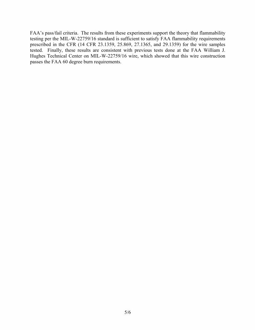
occurred each time. Upon resetting of the circuit breakers, severe re-arcing took place resulting in more insulation degradation. The polyimide samples are shown in figure 3. Tables 5, 6, and 7 summarize arc tracking data on three halogenated polymers. All insulation systems are currently in service. Initial arcs were mild to moderate for all three sets of samples. No dry arc tracking was found for any of the test specimens. Upon resetting of tripped circuit breakers, tables 5, 6, and 7 show that all breakers either stayed in, retripped immediately, or resulted in a small arc restrike followed by a circuit breaker retrip. Figures 4, 5, and 6 show the wire bundles after testing. Note the similar appearance of all three specimens with the welds and tube effects. Minimal insulation damage is seen for all samples. Table 8 presents the data on the laboratory sample of extruded radiation crosslinked ETFE. Five tests were performed due to a shortage of sample wire. Initial arcs were mild to moderate. No dry arc tracking was found. Upon resetting of tripped circuit breakers all breakers retripped immediately or stayed in. The wire bundles are shown in figure 7.
SUMMARY Although three different laboratory-scale tests were evaluated in this wire program, only the sixty-degree test is currently required by the Federal Aviation Administration (FAA). All test specimens with the exception of MIL-W-5086/1-PVC nylon passed this test with average burn lengths within the 3-inch maximum and no flame time. The MIL-W-5086/1 samples marginally passed the 30-second flame time, and the average burn length was greater than the 3-inch maximum specified in the FAR. The smoke test method used in this program called for a straight pilot burner when testing insulated conductor specimens. However, data for a multidirectional pilot burner were also included in this report. Large variations in Ds occurred between the two burners for ETFE constructions at both the 5- and 20-minute test points. The MIL-W-81381/12 aromatic polyimide and the composite construction (Teflon/polyimide/Teflon or TPT) showed no appreciable difference in Ds between the two burner types. Moreover, test duration did not affect smoke generation for these two samples. A direct correlation can be seen between dry arc tracking tests and wet arc tracking tests (DOT/FAA/CT-88/4). The halogenated polymers formed no conductive chars upon thermal decomposition and, therefore, no dry arc tracking. The MIL-W-81381/12 aromatic polyimide samples formed a conductive char upon thermal degradation, and severe arc tracking occurred. Extensive damage to all wires in the bundle occurred due to arc tracking propagation upon circuit breaker resetting. The TPT composite construction performed well. No dry arc tracking vas evident. This construction behaved similarly to a halogenated polymer in this respect.
4

CONCLUSIONS 1. Specific optical density (Ds) of both modified and unmodified ethylene-tetrafluoroethylene (ETFE) polymers varies significantly when tested with the straight versus the multidirectional pilot burner. 2. No difference in Ds was seen for either Kapton aromatic polyimide or the composite construction Teflon outer wrap/polyimide middle wrap/Teflon inner wrap (TPT) when tested with both burn holders. 3. No dry arc tracking was seen for any of the specimens tested with the exception of the MIL-W-81381/12 Kapton samples. 4. The Teflon fluoropolymer tapes of the TPT construction prevented dry arc tracking.
5

FIGURE 1. TEST DEVICE
6

TABLE 1. TEST SAMPLE SUMMARY - SIXTY-DEGREE TEST
Material Burn Length Specification (Average of 3 tests) Flame Time Drippings
TPT 1.3 inches 0 0
MIL-W-81381/12 1.4 inches 0 0
MIL-W-22759/16 2.0 inches 0 0
MIL-W-5086/1 5.1 inches 26 seconds 0
MIL-W-22759/41 1.7 inches 0 0
Lab Sample - 1.6 inches 0 0 extruded radiation crosslinked ETFE
7

TABLE 2. TEST SAMPLE SUMMARY - SMOKE TEST
Flaming Combustion Straight Pilot Burner
Material 5-minute Ds 20-minute Ds Specification (Average of 3 Tests) (Average of 3 Tests) TPT 0.19 0.84
MIL-W-81381/12 0.05 0.36
MIL-W-22759/16 68.60 364.39
MIL-W-5086/1 776.20 not run (PVC) nylon MIL-W-22759/41 11.14 182.37 Lab Sample - 55.50 775.00 extruded radiation crosslinked ETFE
Multidirectional Pilot Burner
Material 5-minute Ds 20-minute Ds Specification (Average of 3 Tests) (Average of 3 Tests)
TPT 0.013 0.85
MIL-W-81381/12 0.13 0.13
MIL-W-22759/16 18.67 207.12
MIL-W-5086/1 776.52 not run
MIL-W-22759/41 2.86 105.56
Lab Sample - 7.70 775.00 extruded radiation crosslinked ETFE
8

TABLE 3. TEST SAMPLE SUMMARY - DRY ARC TRACKING TEST
Teflon /Polyimide/Teflon (TPT)
Wire Bundle Initial Arc
Tripped Circuit Breakers (Upon Initial Arc)
Arc Track
Notes (CB's reset 1 time)
1 moderate 0 no
2 Moderate 0 no
3 moderate 0 no
4 moderate 0 no
5 moderate 0 no
6 moderate 1 no CB stayed in
7 moderate 0 no
8 moderate 2 no Small arc restrike and retrip. CB retripped.
9 moderate 0 no
10 moderate 0 no
9

TABLE 4. TEST SAMPLE SUMMARY - DRY ARC TRACKING TEST
MIL-W-81381/12 - Kapton /aromatic polyimide Wire Bundle Initial Arc
Tripped Circuit Breakers(Upon Initial Arc)
Arc Track
Notes (CB's reset 1 time)
1 massive 4 yes Severe rearcing, all breakers retripped.
2 massive 6 yes Severe rearcing, all breakers retripped.
3 massive 4 yes Severe rearcing, all breakers retripped.
4 massive 6 yes Severe rearcing, all breakers retripped.
5 massive 6 yes Severe rearcing, all breakers retripped.
6 massive 6 yes Severe rearcing, all breakers retripped.
7 massive 6 yes Severe rearcing, all breakers retripped.
8 massive 6 yes Severe rearcing, all breakers retripped.
9 massive 6 yes Severe rearcing, all breakers retripped.
10 massive 6 yes Severe rearcing, all breakers retripped.
10

TABLE 5. TEST SAMPLE SUMMARY - DRY ARC TRACKING TEST
MIL-W-22759/16 – TEFZEL (ETFE) Wire Bundle Initial Arc
Tripped Circuit Breakers (Upon Initial Arc)
Arc Track
Notes (CB's reset 1 time)
1 moderate 1 no CB’s stayed in.
2 moderate 2 no Small arc restrikes and retrip. CB stayed in.
3 moderate 0 no
4 moderate 1 no CB’s stayed in.
5 moderate 3 no All CB’s stayed in.
6 moderate 0 no
7 moderate 2 no Small arc restrikes and retrips for both CBs.
8 mild 0 no
9 moderate 2 no Both CB’s stayed in.
10 moderate 1 no Immediate retrip.
11

TABLE 6. TEST SAMPLE SUMMARY - DRY ARC TRACKING TEST
MIL-W-5086/1 – PVC Nylon
Wire Bundle Initial Arc
Tripped Circuit Breakers(Upon Initial Arc)
Arc Track
Notes (CB's reset 1 time)
1 moderate 0 no
2 mild 0 no
3 mild 0 no
4 moderate 0 no
5 moderate 1 no CB stayed in.
6 mild 0 no
7 mild 1 no CB stayed in.
8 mild 0 no
9 mild 0 no
10 mild 0 no
12

TABLE 7. TEST SAMPLE SUMMARY - DRY ARC TRACKING TEST
MIL-W-22759/41 – Extruded radiation crosslinked ETFE
Wire Bundle Initial Arc
Tripped Circuit Breakers(Upon Initial Arc)
Arc Track
Notes (CB's reset 1 time)
1 mild 0 no
2 moderate 0 no
3 moderate 1 no CB stayed in.
4 mild 2 no Immediate retrip, CB stayed in.
5 mild 0 no
6 moderate 0 no
7 moderate 0 no
8 moderate 0 no
9 mild 0 no
10 moderate 0 no
13
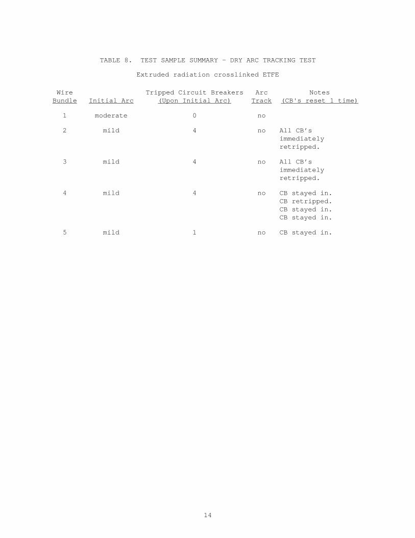
TABLE 8. TEST SAMPLE SUMMARY - DRY ARC TRACKING TEST
Extruded radiation crosslinked ETFE
Wire Bundle Initial Arc
Tripped Circuit Breakers(Upon Initial Arc)
Arc Track
Notes (CB's reset 1 time)
1 moderate 0 no
2 mild 4 no All CB’s immediately retripped.
3 mild 4 no All CB’s immediately retripped.
4 mild 4 no CB stayed in. CB retripped. CB stayed in. CB stayed in.
5 mild 1 no CB stayed in.
14

FIGURE 3. MIL-W-81381/12 PHOTOGRAPH
FIGURE 2. TPT PHOTOGRAPH
15
FIGURE 5. MIL-W-5086/1 PHOTOGRAPH
FIGURE 4. MIL-W-22759/16 PHOTOGRAPH
16
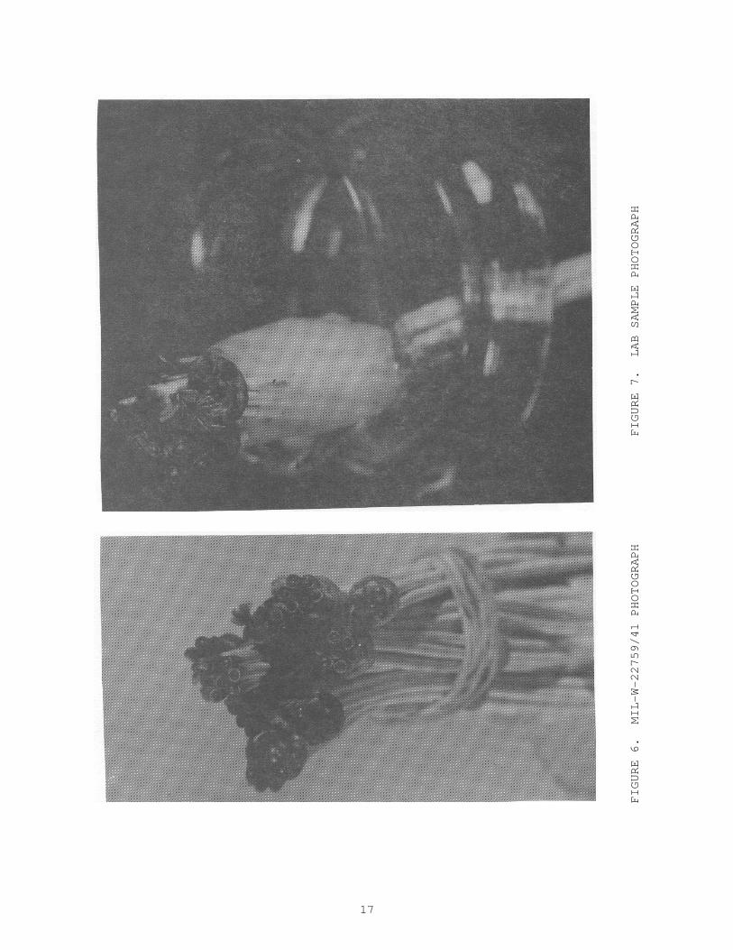
FIGURE 7. LAB SAMPLE PHOTOGRAPH
FIGURE 6. MIL-W-22759/41 PHOTOGRAPH
17

APPENDIX A – SIXTY DEGREE TEST
Chapter 1 – Federal Aviation Administration Part 25, App. G (g) Sixty-degree test in compliance with Part 25.1359(d). A minimum of three specimens of each wire specification (make and size) must be tested. The specimen of wire or cable (including insulation) must be placed at an angle of 60° with the horizontal in the cabinet specified in paragraph(c) of this appendix with the cabinet door open during the teat or must be placed within a chamber approximately 2 feet high x 1 foot x 1 foot, open at the top and at one vertical side (front), and which allows sufficient flow of air for complete combustion, but which is free from drafts. The specimen must be parallel to and approximately 6 inches from the front of the chamber. The lower end of the specimen must be held rigidly clamped. The upper end of the specimen must pass over a pulley or rod and must have an appropriate weight attached to it so that the specimen is held tautly throughout the flammability test. The test specimen span between lower clamp and upper pulley or rod must be 24 inches and must be marked 8 inches from the lower end to indicate the central point for flame application. A flame from a Bunsen or Tirrill burner must be applied to 30 seconds at the test mark. The burner must be mounted underneath the test mark on the specimen, perpendicular to the specimen and at an angle of 30° to the vertical plane of the specimen. The burner must have a nominal bore of three-eighths inch and must be adjusted to provide a 3-inch-high flame with an inner cone approximately one-third of the flame height. The minimum temperature of the hottest portion of the flame, as measured with a calibrated thermocouple pyrometer, may not be less than 1,750°F. The burner must be positioned so that the hottest portion of the flame is applied to the test mark on the wire. Flame time, burn length, and flaming time of drippings, if any, must be recorded. The burn length determined in accordance with paragraph(h) of the appendix must be measured to the nearest one-tenth inch. Breaking of the wire specimens is not considered a failure. (h) Burn length. Burn length is the distance from the original edge to the farthest evidence of damage to the test specimen due to flame impingement, including areas of partial or complete consumption, charring, or embrittlement, but not including areas sooted, stained, warped, or discolored, nor areas where material has shrunk or melted away from the heat source.
U.S. GOVERNMENT PRINTING OFFICE: 1989-0-606-911
A-1